TrackMan A S TMAN Field Disturbance Sensor User Manual ISG Manu 06001i1
TrackMan A/S Field Disturbance Sensor ISG Manu 06001i1
UserManual.wiki
>
TrackMan A S
>
TMAN User Manual
>
Users Manual
Contents
1.
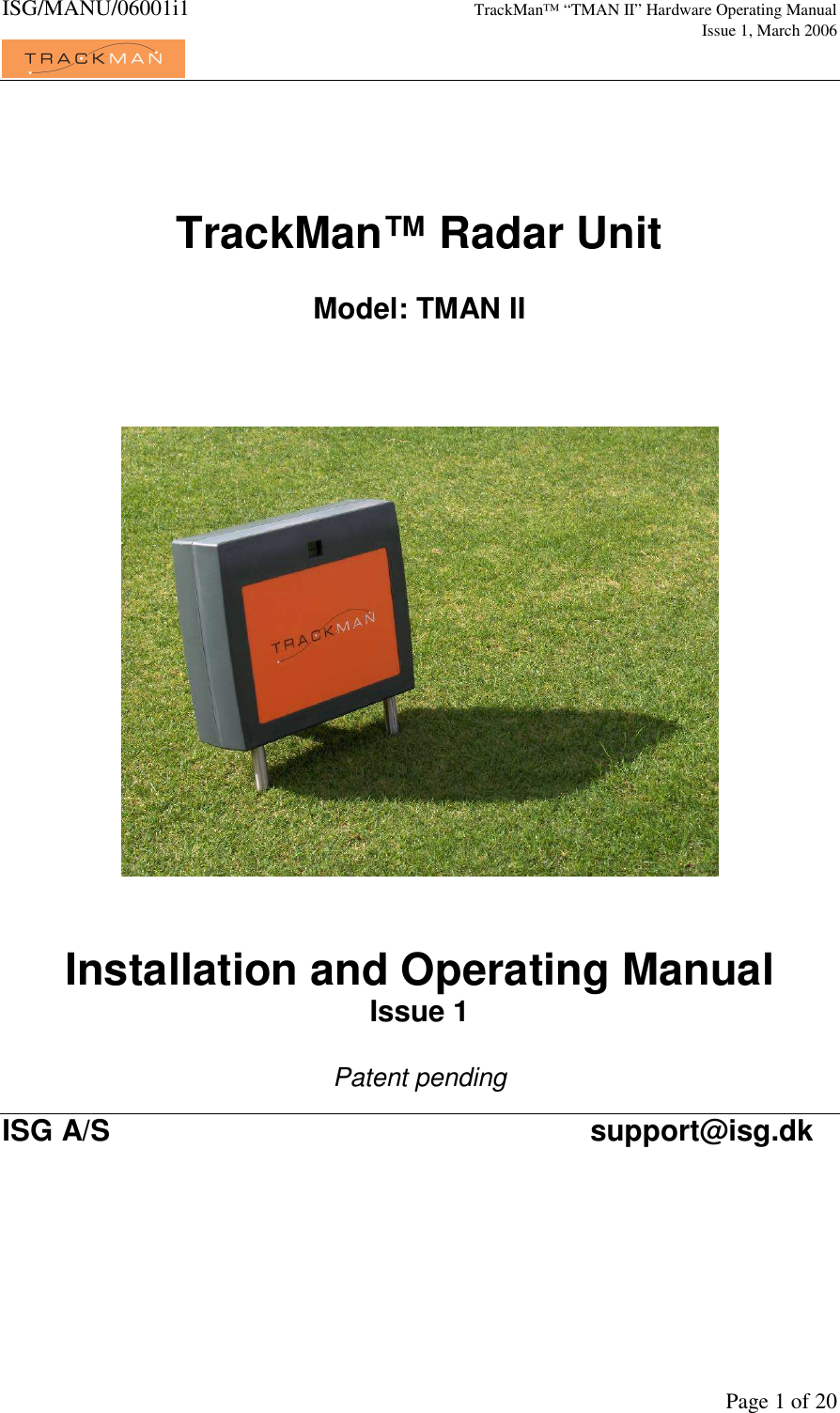
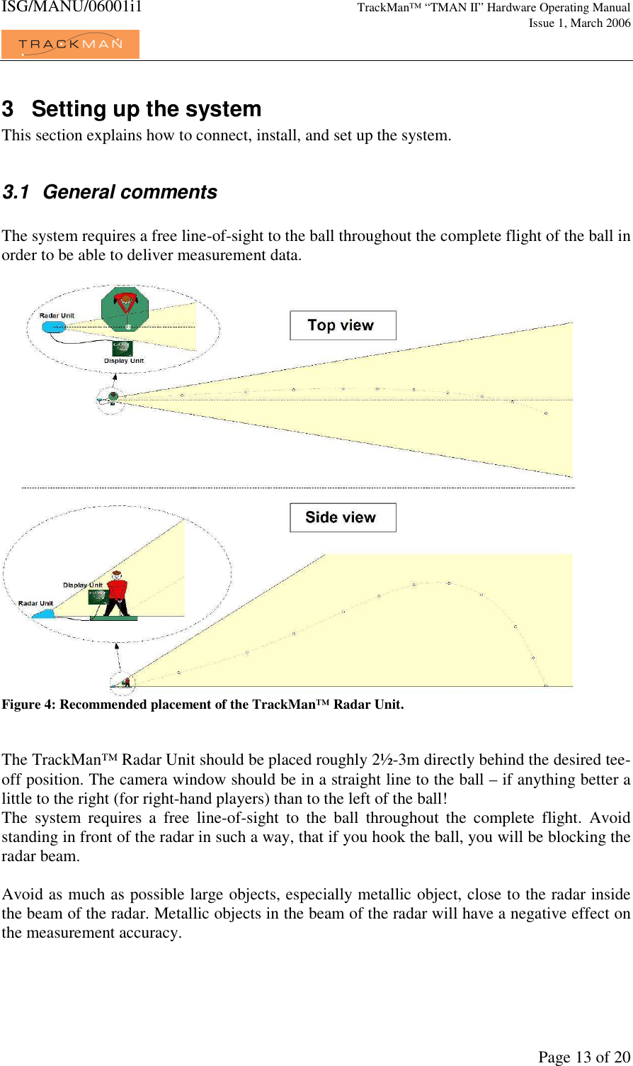
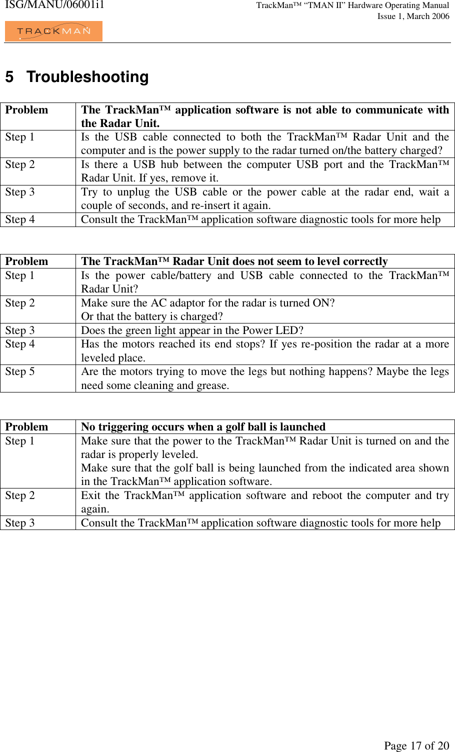
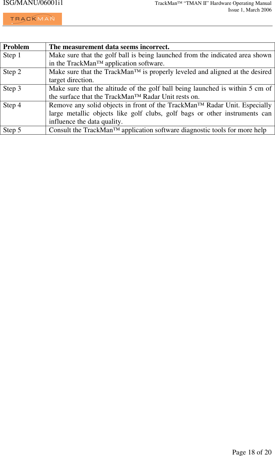
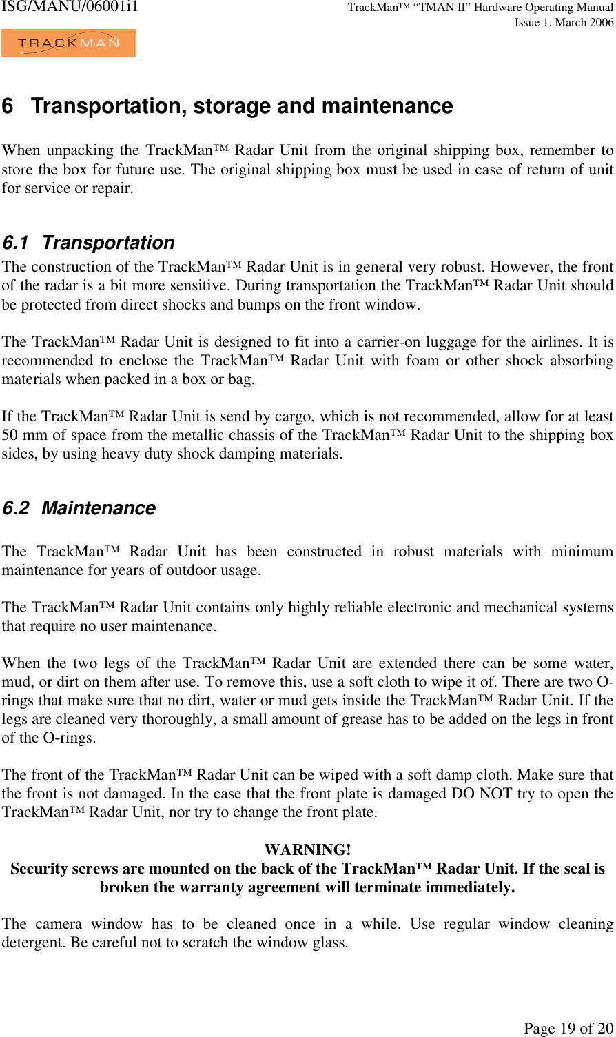
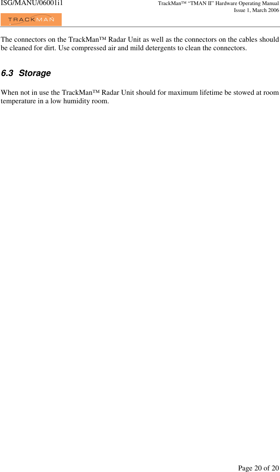
installation and operating manual
2.
Users Manual
Users Manual
Navigation menu
Upload a User Manual
Namespaces
Wiki Guide
HTML
PDF
Info
Views
User Manual
Discussion / Help
Navigation