Tradesman 55 6883 2 User Manual TABLE SAW Manuals And Guides L0904520
TRADESMAN Saw Table Manual L0904520 TRADESMAN Saw Table Owner's Manual, TRADESMAN Saw Table installation guides
User Manual: Tradesman 55-6883-2 55-6883-2 TRADESMAN TABLE SAW - Manuals and Guides View the owners manual for your TRADESMAN TABLE SAW #5568832. Home:Tool Parts:Tradesman Parts:Tradesman TABLE SAW Manual
Open the PDF directly: View PDF ![]() .
.
Page Count: 39

m m _ m m mx,mm_WJmlm
£ A S E" ill '_MMC
10" TABLE SAW WiTH LASER LiNE
55=6883=2
instruction Manual
SECTION
I.
II.
III.
IV.
V.
VI.
VII.
VIII.
IX.
X.
XI.
PAGE
Technical data ..................................................................................... 2
General safety rules ............................................................................ 3
Specific safety rules for the table saw ................................................. 5
Electrical information .......................................................................... 7
Know your table saw ........................................................................... 9
Assembly and adjustments ................................................................. 10
Operation ............................................................................................ 25
Maintenance ....................................................................................... 32
Troubleshooting guide ........................................................................ 33
Warranty ............................................................................................ 34
Replacement parts .............................................................................. 36
10" TABLE SAW WITH LASER LINE
MOTOR:
TABLE EXTENSION:
EXTENSION FENCE CAPACITY:
BLADE SIZE:
13 A, 120 V, 60 Hz, 5000 RPM (No load speed)
YES
24" Right
10"
MAXIMUM DEPTH OF CUT AT 90°: 3"
MAXIMUM DEPTH OF CUT AT 45°: 2 W'
MAXIMUM WIDTH OF DADO: W'
DADO TYPE: Stackabte only (MAX. 1/2" width)
Safety is a combination of common sense, staying alert and knowing how your table saw
works.
WARNING: TO AVOID MISTAKES THAT COULD CAUSE SERIOUS INJURY, DO
NOT PLUG IN THE TABLE SAW UNTIL THE ENTIRE INSTRUCTION MANUAL HAS
HAVE BEEN READ AND FULLY UNDERSTOOD.
1. READ and become familiar with this entire instruction manual. LEARN the tool's
applications, limitations and possible hazards.
2. AVOID DANGEROUS CONDITIONS. DO NOT use power tools in wet or damp areas or
expose them to rain. Keep work areas well-tit.
3. DO NOT use power tools in the presence of flammable liquids or gas.
4. ALWAYS keep your work area clean, uncluttered and well-tit. DO NOT work on floor
surfaces that are slippery with sawdust or wax.
5. KEEP BYSTANDERS AT A SAFE DISTANCE FROM the work area, especially when
the toot is operating. NEVER allow children near the toot.
6. DO NOT FORCE THE TOOL to do a job for which it was not designed.
7. DRESS FOR SAFETY. DO NOT wear loose clothing, gloves, neckties or jewellery
(rings, watches,) when operating the toot. They can get caught and draw you into
moving parts. ALWAYS wear non-slip footwear and tie back long hair.
8. WEAR A FACE MASK OR DUST MASK. Toot operation produces dust.
9. ALWAYS remove the power cord plug from the electrical source when making
adjustments, changing parts, cleaning or performing maintenance on the toot.
10.KEEP GUARDS IN PLACE AND IN WORKING ORDER.
11.AVOID ACCIDENTAL START-UPS. Make sure the power switch is in the OFF position
before plugging in the power cord.
12.REMOVE ADJUSTING TOOLS. ALWAYS MAKE SURE all tools are removed from the
table saw before turning it on.
SAVE THESE SAFETY INSTRUCTIONS
13. NEVER LEAVE POWER SWITCH ON WHILE UNATTENDED. Turn the power
switch to OFF. DO NOT leave the toot until it has come to a complete stop.
14. NEVER STAND ON THE TOOL. Serious injury could result if the tool tips or is
accidentally hit. DO NOT store anything above or near the tool.
15. DO NOT OVERREACH. Keep proper footing and balance at alt times. Wear oil-resistant
rubber-soled footwear. Keep the floor clear of oil, scrap and other debris.
16. MAINTAIN TOOLS PROPERLY. ALWAYS keep tools clean and in good working order.
Follow instructions for lubricating and changing accessories.
17. CHECK FOR DAMAGED PARTS. Check moving parts for alignment, jamming,
breakage, improper mounting or any other condition that may affect the tool's
operation. Any part that is damaged should be properly repaired or replaced before use.
18. MAKE THE WORKSHOP CHILDPROOF. Use padlocks, master switches and
ALWAYS remove starter keys.
19. DO NOT operate the tool if you are under the influence of drugs, alcohol or medication
that could affect your ability to use the toot properly.
20. WHEN SERVICING USE ONLY IDENTICAL REPLACEMENT PARTS.
21. DO NOT ALLOW OTHERS TO USE OR OPERATE THIS TABLE SAW UNTIL THEY
HAVE READ AND FULLY UNDERSTOOD THIS INSTRUCTION MANUAL.
WARNING: DUST GENERATED FROM CERTAIN MATERIALS CAN BE
HAZARDOUS TO YOUR HEALTH. ALWAYS OPERATE THE TABLE SAW IN A
WELL-VENTILATED AREA AND PROVIDE FOR PROPER DUST REMOVAL. USE
DUST COLLECTION SYSTEMS WHENEVER POSSIBLE.
_ PR0?'t###_
_jfh _
ALWAYS WEAR EYE PROTECTION.
A table saw can throw foreign objects into your eyes which could
CAUSE permanent eye damage.
ALWAYS wear safety goggles (not glasses). Ordinary eyeglasses
have only impact-resistant lenses...they are NOT safety goggles.
SAVE THESE SAFETY INSTRUCTIONS
BEFORE USING THE TABLE SAW WiTH LASER LiNE
WARNING: DO NOT OPERATE YOUR TABLE SAW UNTIL IT IS COMPLETELY
ASSEMBLED AND INSTALLED ACCORDING TO THE INSTRUCTIONS ]
1. ALWAYS USE THE SAW BLADE GUARD, splitter and anti-kickback pawls for every
operation for which they can be used, including through-sawing. Through-sawing
operations are those in which the blade cuts completely through the workpiece when
ripping or cross-cutting.
2. ALWAYS HOLD WORK FIRMLY against the mitre gauge or rip fence.
3. USE A PUSH STICK when required, especially when ripping narrow stock. Refer to
ripping applications in the instruction manual where the push stick is covered in detail. A
pattern for making your own push stick is included.
4. NEVER PERFORM ANY OPERATION "FREE HAND"= this means using only your
hands to support or guide the workpiece. Always use either the rip fence or the
mitre gauge to position and guide the workpiece.
WARNING: FREE HAND CUTTING IS THE MAJOR CAUSE OF KICK=BACK &
FINGER/HAND AMPUTATIONS.
5. NEVER STAND or have any part of your body in line with the path of the saw blade.
Keep your hands out of the saw blade path.
6. NEVER REACH behind or over the table saw for any reason.
7. REMOVE the rip fence when cross cutting.
8. DO NOT USE a moulding head with this saw.
9. FEED WORK iNTO THE BLADE against the direction of rotation only.
10. NEVER use the rip fence as a cut-off gauge when cross-cutting.
11. NEVER ATTEMPT TO FREE A STALLED SAW BLADE without first turning the table
saw OFF and unplugging the table saw. Immediately, turn the power switch OFF to
prevent motor damage.
12. PROVIDE ADEQUATE SUPPORT to the rear and the sides of the work table for long or
wide workpieces.
SAVE THESE SAFETY INSTRUCTIONS
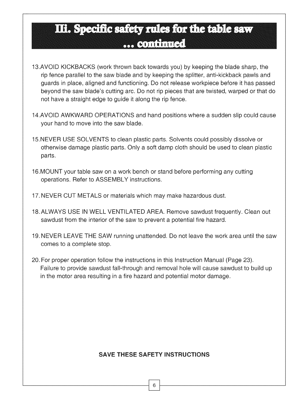
13.AVOID KICKBACKS (work thrown back towards you) by keeping the blade sharp, the
ripfence parallel to the saw blade and by keeping the splitter, anti-kickback pawls and
guards in place, aligned and functioning. Do not release workpiece before it has passed
beyond the saw blade's cutting arc. Do not rip pieces that are twisted, warped or that do
not have a straight edge to guide it along the rip fence.
14.AVOID AWKWARD OPERATIONS and hand positions where a sudden slip could cause
your hand to move into the saw blade.
15.NEVER USE SOLVENTS to clean plastic parts. Solvents could possibly dissolve or
otherwise damage plastic parts. Only a soft damp cloth should be used to clean plastic
parts.
16.MOUNT your table saw on a work bench or stand before performing any cutting
operations. Refer to ASSEMBLY instructions.
17.NEVER CUT METALS or materials which may make hazardous dust.
18.ALWAYS USE IN WELL VENTILATED AREA. Remove sawdust frequently. Clean out
sawdust from the interior of the saw to prevent a potential fire hazard.
19.NEVER LEAVE THE SAW running unattended. Do not leave the work area until the saw
comes to a complete stop.
20. For proper operation follow the instructions in this Instruction Manual (Page 23).
Failure to provide sawdust fall-through and removal hole will cause sawdust to build up
in the motor area resulting in a fire hazard and potential motor damage.
SAVE THESE SAFETY iNSTRUCTiONS
GROUNDING iNSTRUCTiONS
IN THE EVENT OF A MALFUNCTION OR BREAKDOWN, grounding provides a path
of least resistance for electric current and reduces the risk of electric shock. This toot is
equipped with an electric cord that has an equipment grounding conductor and a grounding
plug. The plug MUST be plugged into a matching outlet that is properly installed and
grounded in accordance with ALL local codes and ordinances.
DO NOT MODIFY THE PLUG PROVIDED. If it will not fit the outlet, have the proper outlet
installed by an electrician.
IMPROPER CONNECTION of the equipment grounding conductor can result in electric
shock. The conductor with the green insulation (with or without yellow stripes) is the
equipment grounding conductor. If repair or replacement of the electric cord or plug is
necessary, DO NOT connect the equipment grounding conductor to a live terminal.
CHECK with a qualified electrician or service personnel if you do not completely understand
the grounding instructions, or if you are not sure if the toot is properly grounded.
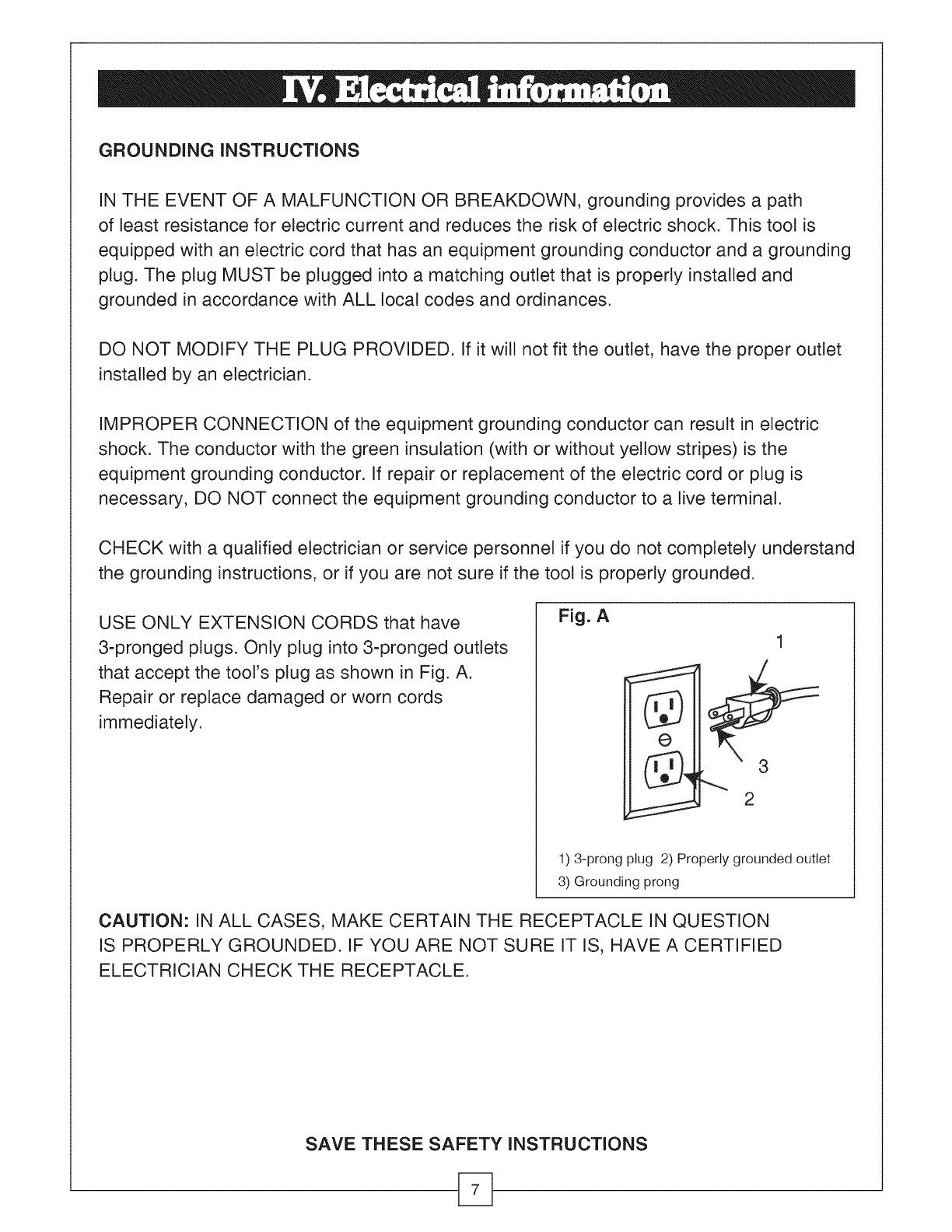
USE ONLY EXTENSION CORDS that have
3-pronged plugs. Only plug into 3-pronged outlets
that accept the tool's plug as shown in Fig. A.
Repair or replace damaged or worn cords
immediately.
Fig. A
i2
1) 3-prong plug 2) Properly grounded outlet
3) Grounding prong
CAUTION: IN ALL CASES, MAKE CERTAIN THE RECEPTACLE IN QUESTION
IS PROPERLY GROUNDED. IF YOU ARE NOT SURE IT IS, HAVE A CERTIFIED
ELECTRICIAN CHECK THE RECEPTACLE.
SAVE THESE SAFETY INSTRUCTIONS
GUIDELINES FOR USING EXTENSION CORDS
I ARNING: THIS TABLE SAW IS FOR INDOOR USE ONLY. DO NOT EXPOSE TO
RAIN OR USE IN DAMP LOCATIONS.
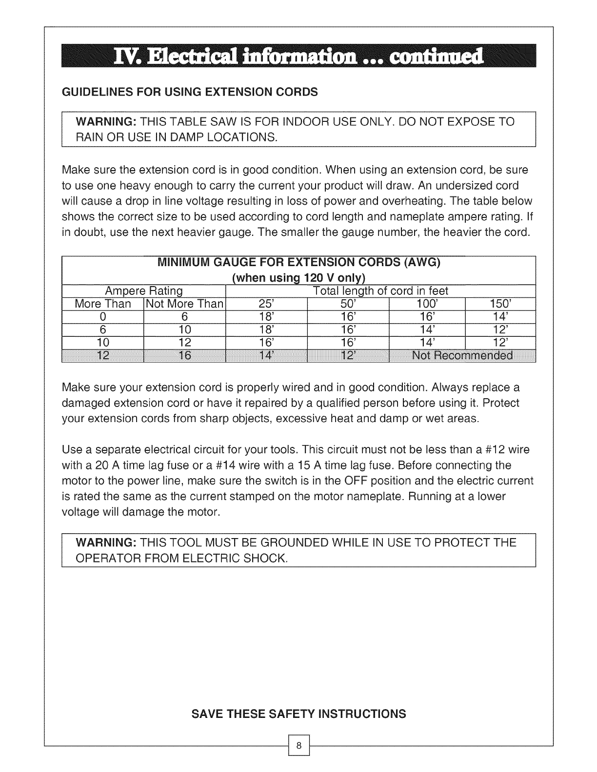
Make sure the extension cord is in good condition. When using an extension cord, be sure
to use one heavy enough to carry the current your product will draw. An undersized cord
will cause a drop in line voltage resulting in loss of power and overheating. The table below
shows the correct size to be used according to cord length and nameplate ampere rating. If
in doubt, use the next heavier gauge. The smaller the gauge number, the heavier the cord.
MINIMUM GAUGE FOR EXTENSION CORDS (AWG)
(when using 120 V only)
Ampere Rating Total length of cord in feet
More Than Not More Than 25' 50' 100' 150'
0 6 18' 16' 16' 14'
6 10 18' 16' 14' 12'
10 12 16' 16' 14' 12'
Make sure your extension cord is properly wired and in good condition. Always replace a
damaged extension cord or have it repaired by a qualified person before using it. Protect
your extension cords from sharp objects, excessive heat and damp or wet areas.
Use a separate electrical circuit for your tools. This circuit must not be tess than a #12 wire
with a 20 A time tag fuse or a #14 wire with a 15 A time lag fuse. Before connecting the
motor to the power line, make sure the switch is in the OFF position and the electric current
is rated the same as the current stamped on the motor nameplate. Running at a lower
voltage will damage the motor.
I ARNING: THIS TOOL MUST BE GROUNDED WHILE IN USE TO PROTECT THE
OPERATOR FROM ELECTRIC SHOCK.
SAVE THESE SAFETY iNSTRUCTiONS
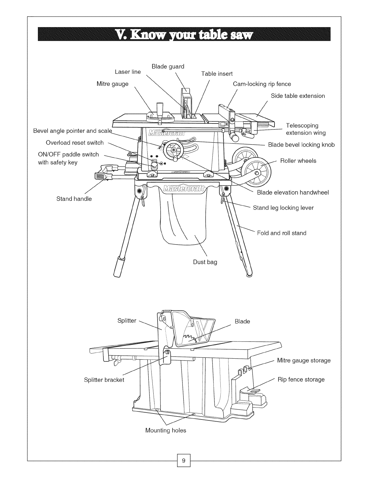
Laser line
Mitre gauge
Blade guard Table insert
Cam-locking rip fence
Side table extension
Bevel angle pointer and
Overload reset switch
ON/OFF paddle switch
with safety key
Telescoping
extension wing
Blade bevel locking knob
Roller wheels
Stand handle Blade elevation handwheel
Stand leg locking lever
Fold and roll stand
Dust bag
Splitter
Splitter bracket
_ Blade
_.1 Mitre gauge storage
Rip fence storage
Mounting holes
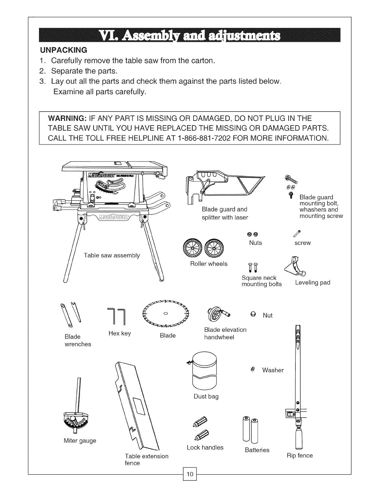
UNPACKING
1. Carefully remove the table saw from the carton.
2. Separate the parts.
3. Lay out all the parts and check them against the parts listed below.
Examine all parts carefully.
WARNING: IF ANY PART IS MISSING OR DAMAGED, DO NOT PLUG IN THE
TABLE SAW UNTIL YOU HAVE REPLACED THE MISSING OR DAMAGED PARTS.
CALL THE TOLL FREE HELPLINE AT 1-866-881-7202 FOR MORE INFORMATION.
Table saw assembly
¢p-'7
Blade guard and
splitter with laser
®®
Roller wheels
Nuts
Square neck
mounting bolts
Blade guard
mounting bolt,
whashers and
mounting screw
P
screw
Leveling pad
Blade
wrenches
qq
Hex key Blade
Miter gauge
Table extension
fence
Blade elevation
handwheel
Dust bag
Lock handles
0 Nut
Batteries
Washer
Rip fence
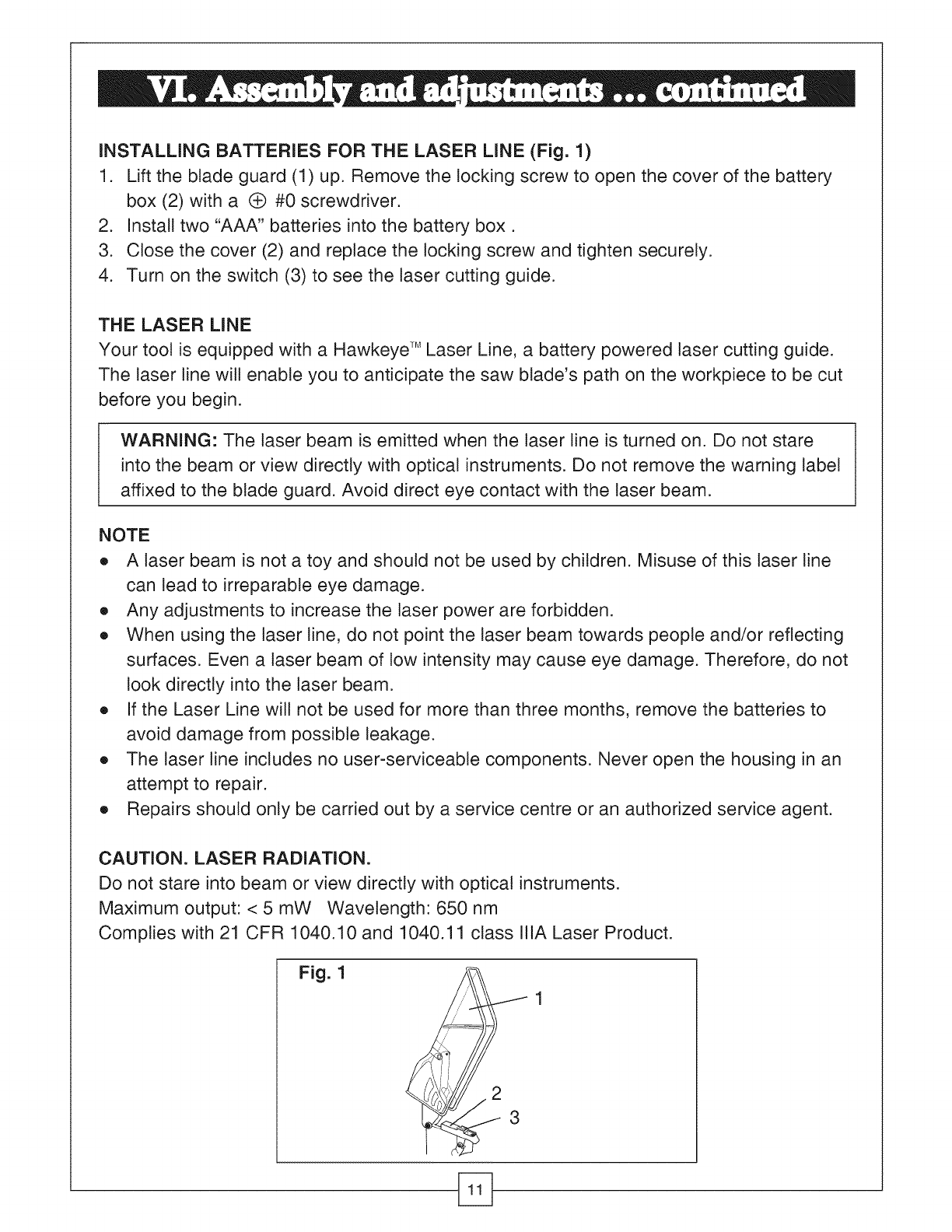
iNSTALLiNG BATTERIES FOR THE LASER LiNE (Fig. 1)
1. Lift the blade guard (1) up. Remove the locking screw to open the cover of the battery
box (2) with a (_ #0 screwdriver.
2. Install two "AAA" batteries into the battery box.
3. Close the cover (2) and replace the locking screw and tighten securely.
4. Turn on the switch (3) to see the laser cutting guide.
THE LASER LINE
Your tool is equipped with a Hawkeye TMLaser Line, a battery powered laser cutting guide.
The laser line will enable you to anticipate the saw blade's path on the workpiece to be cut
before you begin.
WARNING: The laser beam is emitted when the laser line is turned on. Do not stare
into the beam or view directly with optical instruments. Do not remove the warning label
affixed to the blade guard. Avoid direct eye contact with the laser beam.
NOTE
e A laser beam is not a toy and should not be used by children. Misuse of this laser line
can lead to irreparable eye damage.
e Any adjustments to increase the laser power are forbidden.
e When using the laser line, do not point the laser beam towards people and/or reflecting
surfaces. Even a laser beam of low intensity may cause eye damage. Therefore, do not
look directly into the laser beam.
e If the Laser Line will not be used for more than three months, remove the batteries to
avoid damage from possible leakage.
e The laser tine includes no user-serviceable components. Never open the housing in an
attempt to repair.
e Repairs should only be carried out by a service centre or an authorized service agent.
CAUTION. LASER RADIATION.
Do not stare into beam or view directly with optical instruments.
Maximum output: < 5 mW Wavelength: 650 nm
Complies with 21 CFR 1040.10 and 1040.11 class IliA Laser Product.
Fig. 1
2
3
Keeping Work Areas Clean
e Accumulated sawdust and wood chips can pose a safety hazard.
e Pick up and dispose of accumulated sawdust and debris before each cutting operation.
WARNING: ALWAYS KEEP YOUR WORK AREA CLEAN, UNCLUTTERED AND
WELL-LIT. DO NOT WORK ON FLOOR SURFACES THAT ARE SLIPPERY FROM
ACCUMULATED SAWDUST, DEBRIS OR WAX.
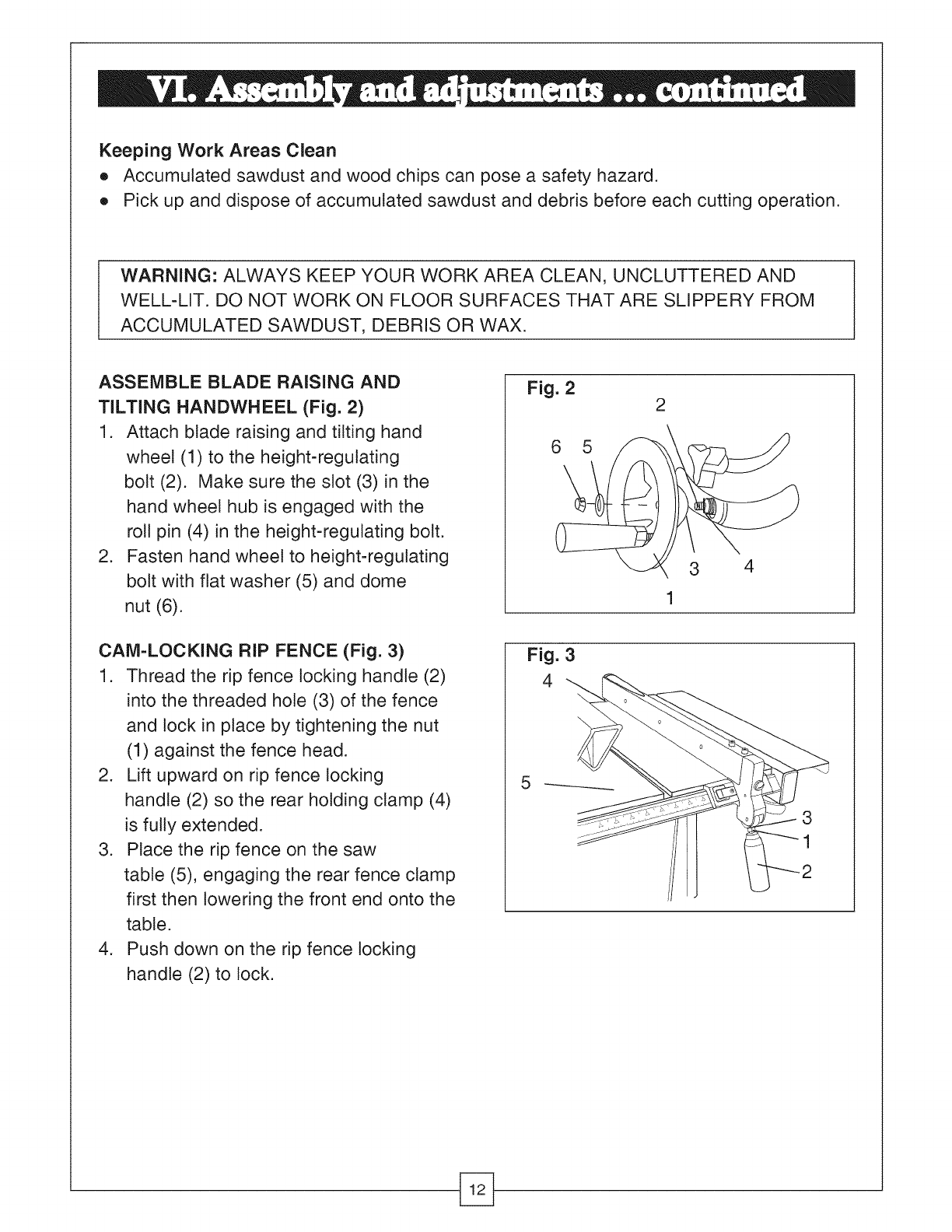
ASSEMBLE BLADE RAISING AND
TILTING HANDWHEEL (Fig. 2)
1. Attach blade raising and tilting hand
wheel (1) to the height-regulating
bolt (2). Make sure the slot (3) in the
hand wheel hub is engaged with the
roll pin (4) in the height-regulating bolt.
2. Fasten hand wheel to height-regulating
bolt with flat washer (5) and dome
nut (6).
CAM=LOCKING RIP FENCE (Fig. 3)
1. Thread the rip fence locking handle (2)
into the threaded hole (3) of the fence
and lock in place by tightening the nut
(1) against the fence head.
2. Lift upward on rip fence locking
handle (2) so the rear holding clamp (4)
is fully extended.
3. Place the rip fence on the saw
table (5), engaging the rear fence clamp
first then lowering the front end onto the
table.
4. Push down on the rip fence locking
handle (2) to lock.
Fig. 2 2
!3 4
Fig. 3
4
5
3
1
WARNING: TO AVOID INJURY FROM AN ACCIDENTAL START, MAKE SURE THE
POWER SWITCH IS IN THE "OFF" POSITION, THE REMOVABLE SAFETY KEY IS
REMOVED AND THE PLUG IS NOT CONNECTED TO THE POWER SOURCE.
TO AVOID SERIOUS INJURY, THE REAR OF THE TABLE INSERT MUST BE FLUSH
TO THE TABLE DURING ALL SAWING OPERATIONS. A RUBBER ADJUSTING
SPACER IS PROVIDED UNDER THE REAR OF THE INSERT FOR THIS PURPOSE.
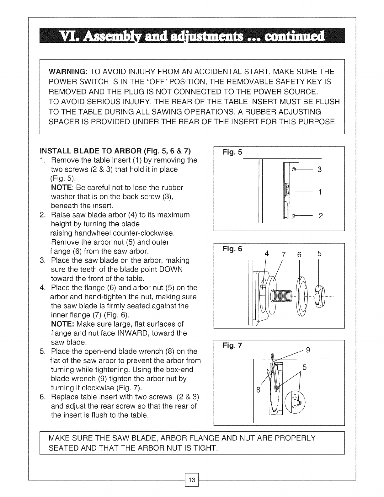
INSTALL BLADE TO ARBOR (Fig. 5, 6 & 7)
1. Remove the table insert (1) by removing the
two screws (2 & 3) that hold it in place
(Fig. 5).
NOTE: Be careful not to lose the rubber
washer that is on the back screw (3),
beneath the insert.
2. Raise saw blade arbor (4) to its maximum
height by turning the blade
raising handwheet counter-clockwise.
Remove the arbor nut (5) and outer
flange (6) from the saw arbor.
3. Place the saw blade on the arbor, making
sure the teeth of the blade point DOWN
toward the front of the table.
4. Place the flange (6) and arbor nut (5) on the
arbor and hand-tighten the nut, making sure
the saw blade is firmly seated against the
inner flange (7) (Fig. 6).
NOTE: Make sure large, flat surfaces of
flange and nut face iNWARD, toward the
saw blade.
5. Place the open-end blade wrench (8) on the
flat of the saw arbor to prevent the arbor from
turning while tightening. Using the box-end
blade wrench (9) tighten the arbor nut by
turning it clockwise (Fig. 7).
6. Replace table insert with two screws (2 & 3)
and adjust the rear screw so that the rear of
the insert is flush to the table.
Fig. 5
m
:_- 3
---- '1
e-m 2
Fig. 6 47 6 5
Fig. 7
I MAKE SURE THE SAW BLADE, ARBOR FLANGE AND NUT ARE PROPERLY
SEATED AND THAT THE ARBOR NUT IS TIGHT.
WARNING: TO AVOID INJURY FROM AN ACCIDENTAL START, MAKE SURE THE
SWITCH IS IN THE "OFF" POSITION AND THE PLUG IS NOT CONNECTED TO THE
POWER SOURCE OUTLET.
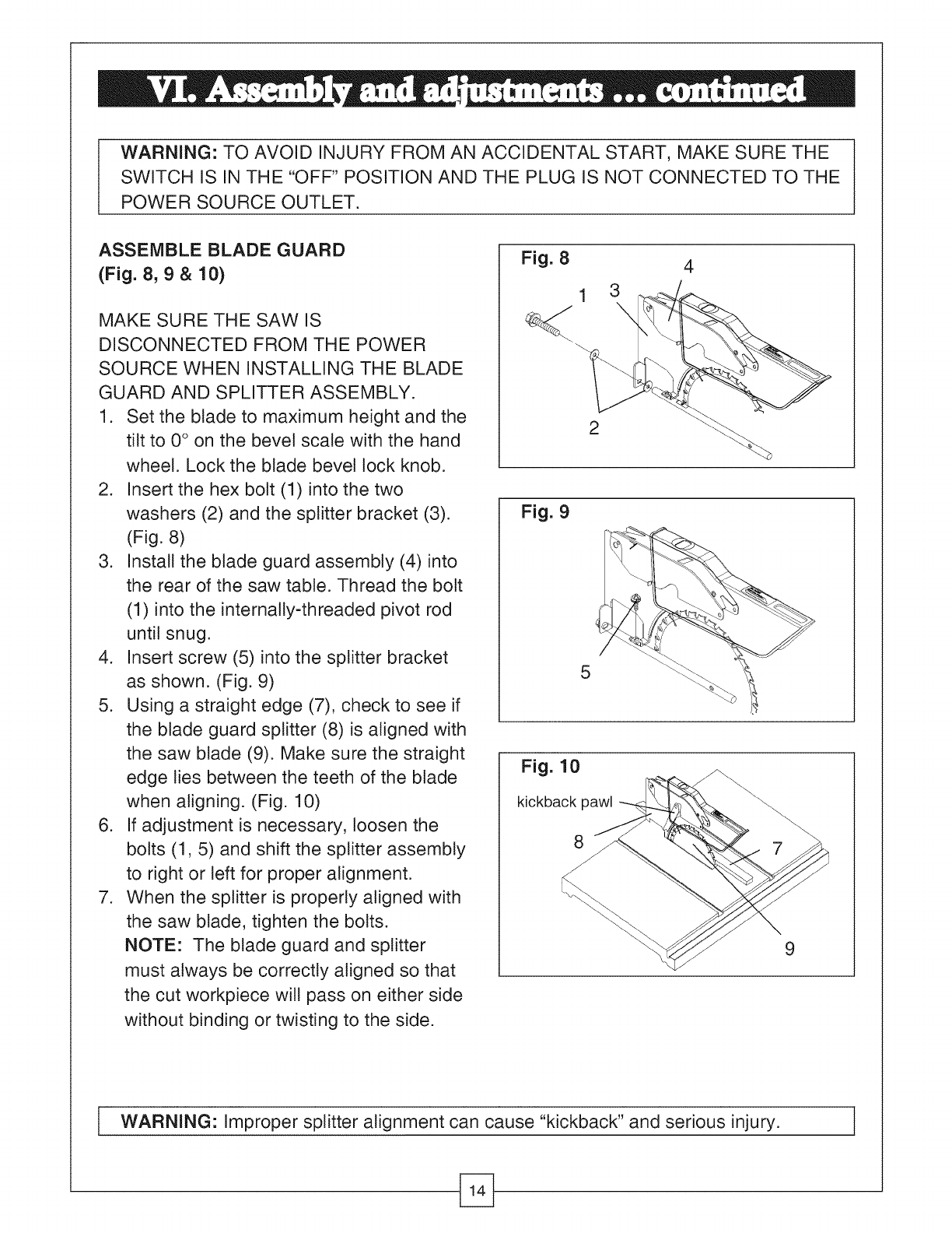
ASSEMBLE BLADE GUARD
(Fig. 8, 9 & 10)
MAKE SURE THE SAW IS
DISCONNECTED FROM THE POWER
SOURCE WHEN INSTALLING THE BLADE
GUARD AND SPLITTER ASSEMBLY.
1. Set the blade to maximum height and the
tilt to 0° on the bevel scale with the hand
wheel. Lock the blade bevel lock knob.
2. Insert the hex bolt (1) into the two
washers (2) and the splitter bracket (3).
(Fig. 8)
3. Install the blade guard assembly (4) into
the rear of the saw table. Thread the bolt
(1) into the internaNy-threaded pivot rod
until snug.
4. Insert screw (5) into the splitter bracket
as shown. (Fig. 9)
5. Using a straight edge (7), check to see if
the blade guard splitter (8) is aligned with
the saw blade (9). Make sure the straight
edge ties between the teeth of the blade
when aligning. (Fig. 10)
6. If adjustment is necessary, loosen the
bolts (1, 5) and shift the splitter assembly
to right or left for proper alignment.
7. When the splitter is properly aligned with
the saw blade, tighten the bolts.
NOTE: The blade guard and splitter
must always be correctly aligned so that
the cut workpiece will pass on either side
without binding or twisting to the side.
Fig. 8
2
4
Fig. 9
5
Fig. 10
kickback pawl
8
9
i WARNING: Improper splitter alignment can cause "kickback" and serious injury. I
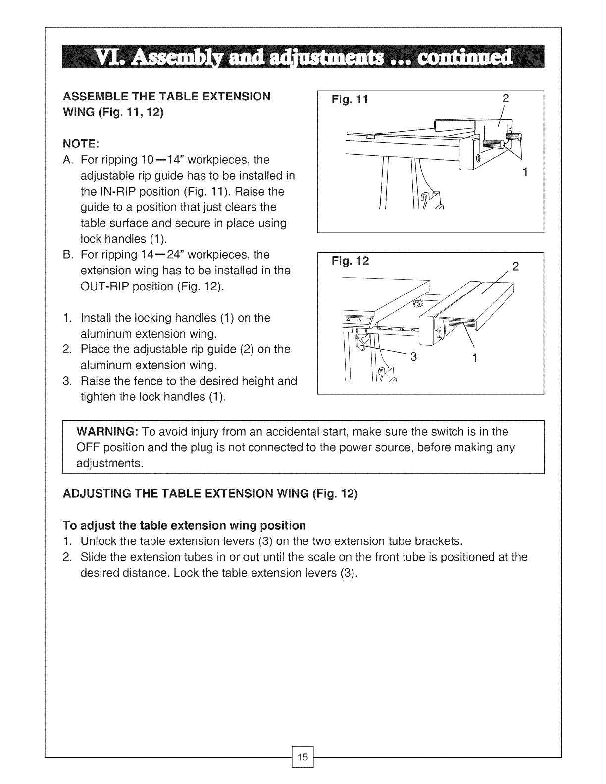
ASSEMBLE THE TABLE EXTENSION
WiNG (Fig. 11, 12)
NOTE:
A. For ripping 10 = 14" workpieces, the
adjustable rip guide has to be installed in
the IN-RIP position (Fig. 11). Raise the
guide to a position that just clears the
table surface and secure in place using
lock handles (1).
B. For ripping 14=24" workpieces, the
extension wing has to be installed in the
OUT-RIP position (Fig. 12).
1. Install the
aluminum
2. Place the
aluminum
.
locking handles (1) on the
extension wing.
adjustable rip guide (2) on the
extension wing.
Raise the fence to the desired height and
tighten the lock handles (1).
Fig. 11 2
Fig. 12 2
3 1
WARNING: To avoid injury from an accidental start, make sure the switch is in the
OFF position and the plug is not connected to the power source, before making any
adjustments.
ADJUSTING THE TABLE EXTENSION WING (Fig. 12)
To adjust the table extension wing position
1. Unlock the table extension levers (3) on the two extension tube brackets.
2. Slide the extension tubes in or out until the scale on the front tube is positioned at the
desired distance. Lock the table extension levers (3).
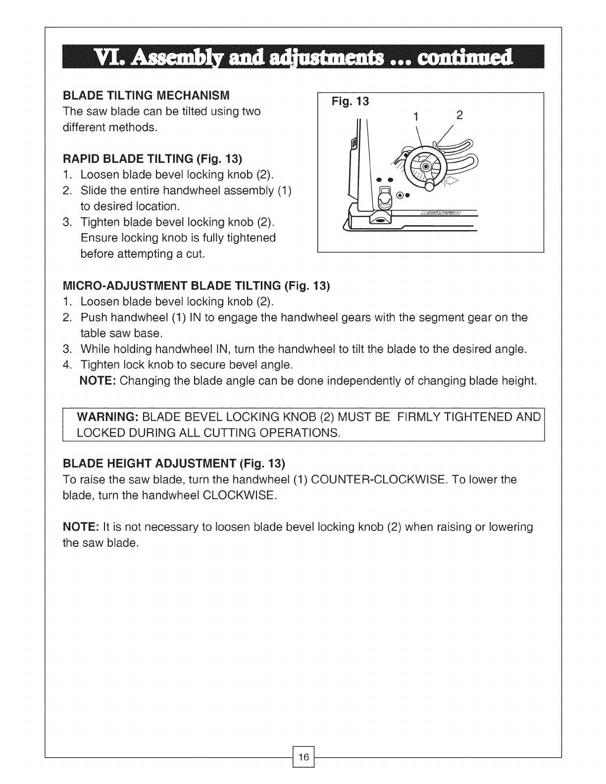
BLADE TILTING MECHANISM
The saw blade can be tilted using two
different methods.
RAPID BLADE TILTING (Fig. 13)
1. Loosen blade bevel locking knob (2).
2. Slide the entire handwheel assembly (1)
to desired location.
3. Tighten blade bevel locking knob (2).
Ensure locking knob is fully tightened
before attempting a cut.
Fig. 13
1 2
MICRO=ADJUSTMENT BLADE TILTING (Fig. 13)
1. Loosen blade bevel locking knob (2).
2. Push handwheet (1) IN to engage the handwheel gears with the segment gear on the
table saw base.
3. While holding handwheel IN, turn the handwheet to tilt the blade to the desired angle.
4. Tighten lock knob to secure bevel angle.
NOTE: Changing the blade angle can be done independently of changing blade height.
IARNING: BLADE BEVEL LOCKING KNOB (2) MUST BE FIRMLY TIGHTENED AND
LOCKED DURING ALL CUTTING OPERATIONS.
BLADE HEIGHT ADJUSTMENT (Fig. 13)
To raise the saw blade, turn the handwheel (1) COUNTER-CLOCKWISE. To lower the
blade, turn the handwheel CLOCKWISE.
NOTE: It is not necessary to loosen blade bevel locking knob (2) when raising or lowering
the saw blade.
WARNING: TO PREVENT PERSONAL INJURY:
e ALWAYS DISCONNECT THE PLUG FROM POWER SOURCE WHEN MAKING
ANY ADJUSTMENTS.
e ADJUSTMENTS MUST BE CORRECT OR KICKBACK COULD RESULT IN A
SERIOUS INJURY AND ACCURATE CUTS CANNOT BE MADE.
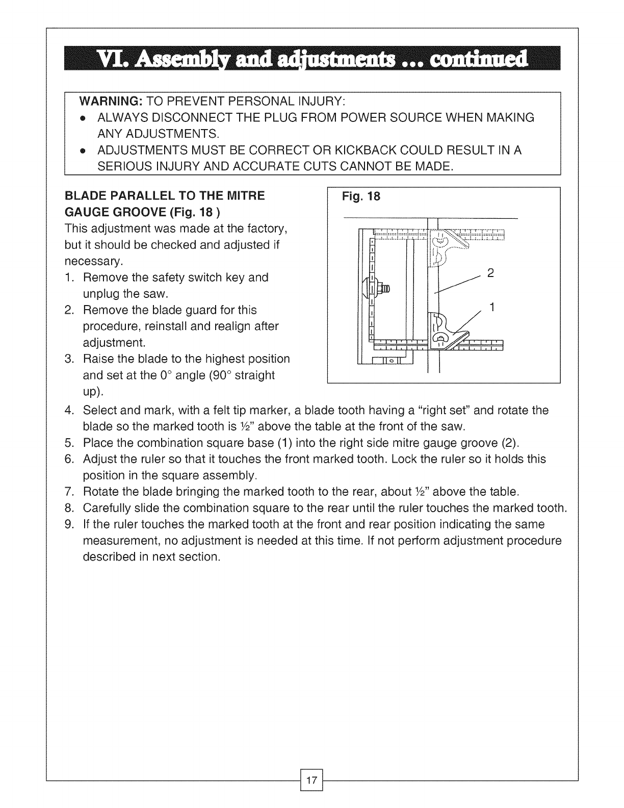
BLADE PARALLEL TO THE MITRE
GAUGE GROOVE (Fig. 18 )
This adjustment was made at the factory,
but it should be checked and adjusted if
necessary.
1.
.
.
Remove the safety switch key and
unplug the saw.
Remove the blade guard for this
procedure, reinstall and realign after
adjustment.
Raise the blade to the highest position
and set at the 0° angle (90 ° straight
up).
Fig. 18
"..=..J..=..L._.=,.L.;j
1
4. Select and mark, with a felt tip marker, a blade tooth having a "right set" and rotate the
blade so the marked tooth is W' above the table at the front of the saw.
5. Place the combination square base (1) into the right side mitre gauge groove (2).
6. Adjust the ruler so that it touches the front marked tooth. Lock the ruler so it holds this
position in the square assembly.
7. Rotate the blade bringing the marked tooth to the rear, about W' above the table.
8. Carefully slide the combination square to the rear until the ruler touches the marked tooth.
9. If the ruler touches the marked tooth at the front and rear position indicating the same
measurement, no adjustment is needed at this time. If not perform adjustment procedure
described in next section.
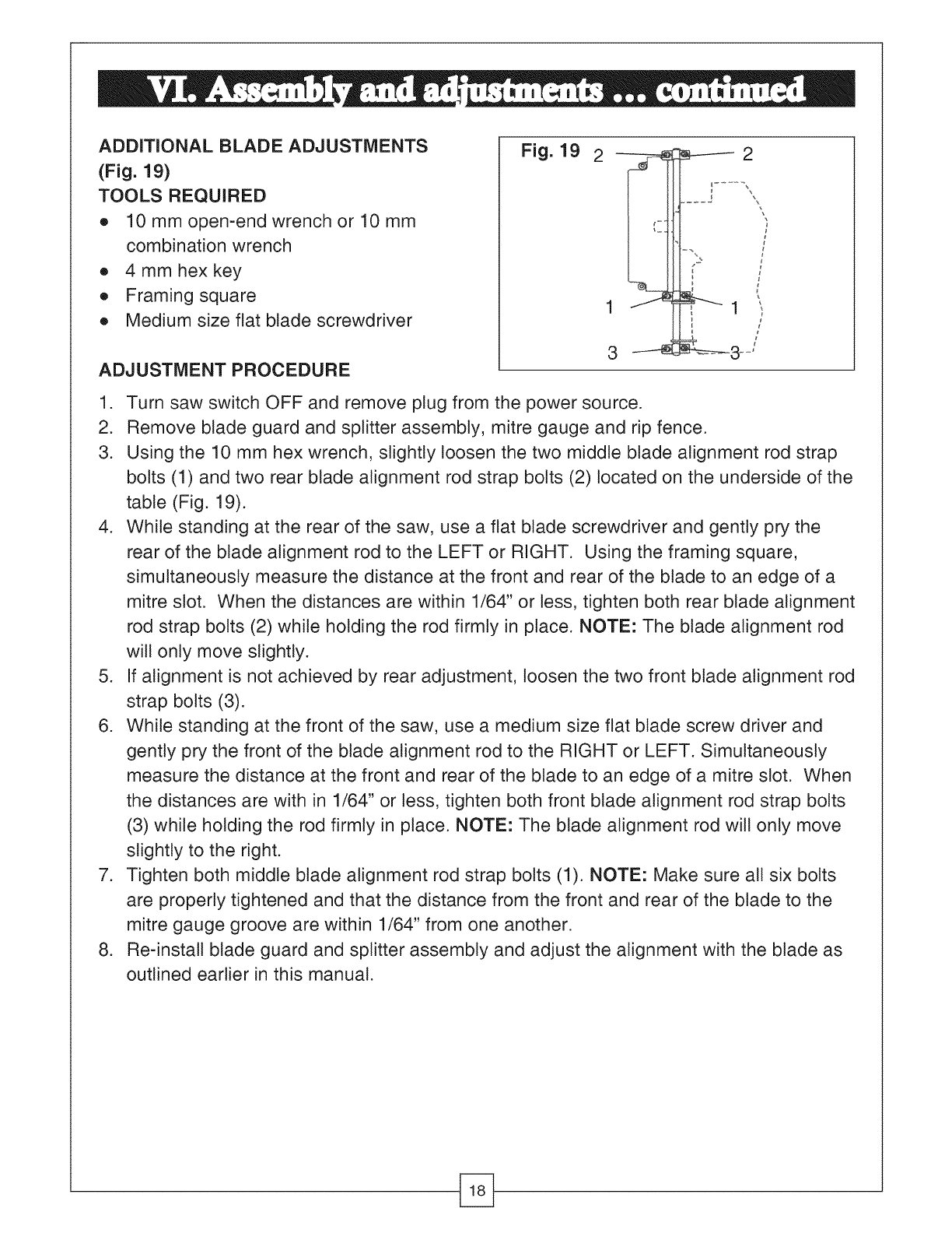
ADDITIONAL BLADE ADJUSTMENTS
(Fig. 19)
TOOLS REQUIRED
e 10 mm open-end wrench or 10 mm
combination wrench
e 4mmhexkey
e Framing square
e Medium size flat blade screwdriver
ADJUSTMENT PROCEDURE
Fig. 19 I
1 J
3
1. Turn saw switch OFF and remove plug from the power source.
2. Remove blade guard and splitter assembly, mitre gauge and rip fence.
3. Using the 10 mm hex wrench, slightly loosen the two middle blade alignment rod strap
bolts (1) and two rear blade alignment rod strap bolts (2) located on the underside of the
table (Fig. 19).
4. While standing at the rear of the saw, use a flat blade screwdriver and gently pry the
rear of the blade alignment rod to the LEFT or RIGHT. Using the framing square,
simultaneously measure the distance at the front and rear of the blade to an edge of a
mitre slot. When the distances are within 1/64" or less, tighten both rear blade alignment
rod strap bolts (2) while holding the rod firmly in place. NOTE: The blade alignment rod
will only move slightly.
5. If alignment is not achieved by rear adjustment, loosen the two front blade alignment rod
strap bolts (3).
6. While standing at the front of the saw, use a medium size flat blade screw driver and
gently pry the front of the blade alignment rod to the RIGHT or LEFT. Simultaneously
measure the distance at the front and rear of the blade to an edge of a mitre slot. When
the distances are with in 1/64" or tess, tighten both front blade alignment rod strap bolts
(3) while holding the rod firmly in place. NOTE: The blade alignment rod will only move
slightly to the right.
7. Tighten both middle blade alignment rod strap bolts (1). NOTE: Make sure all six bolts
are properly tightened and that the distance from the front and rear of the blade to the
mitre gauge groove are within 1/64" from one another.
8. Re-install blade guard and splitter assembly and adjust the alignment with the blade as
outlined earlier in this manual.
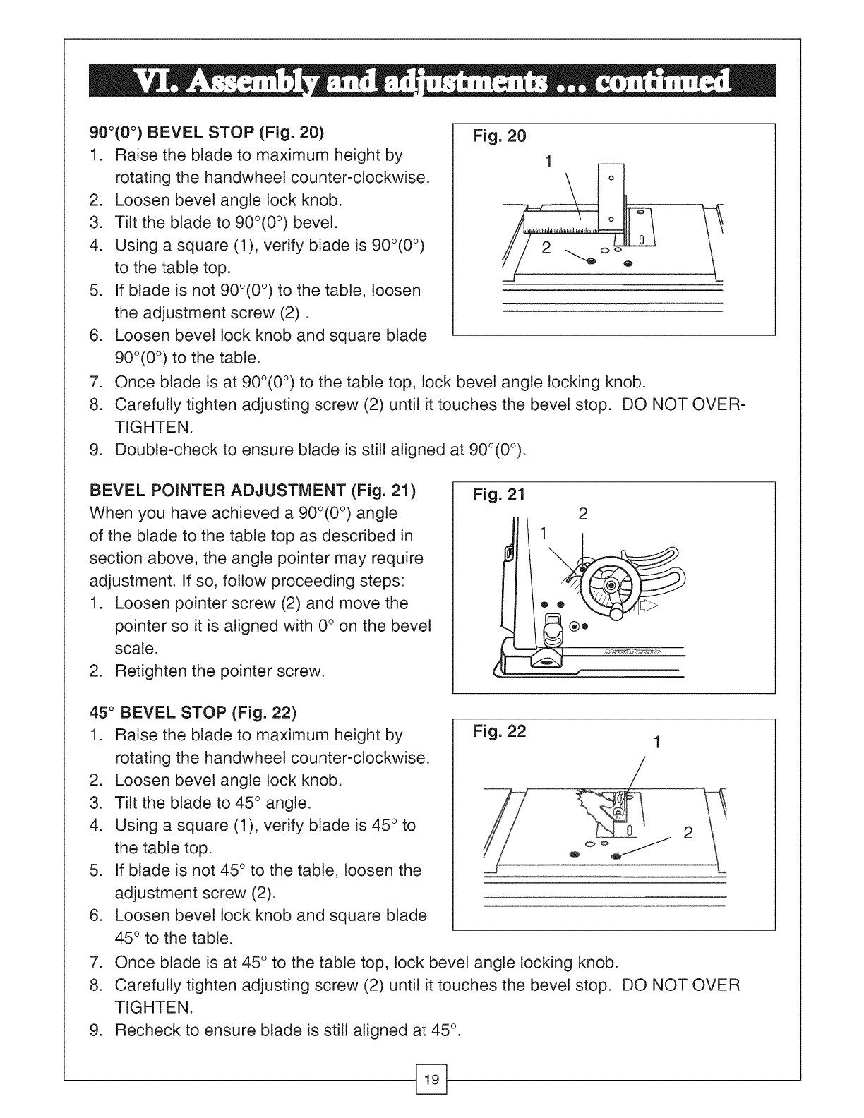
900(0°) BEVEL STOP (Fig. 20)
1. Raise the blade to maximum height by
rotating the handwheet counter-clockwise.
2. Loosen bevel angle lock knob.
3. Tilt the blade to 900(0 °) bevel.
4. Using a square (1), verify blade is 900(0 °)
to the table top.
5. If blade is not 900(0 °) to the table, loosen
the adjustment screw (2).
6. Loosen bevel tock knob and square blade
900(0 °) to the table.
Fig. 20
1
2
7. Once blade is at 90o(0 °) to the table top, tock bevel angle locking knob.
8. Carefully tighten adjusting screw (2) until it touches the bevel stop. DO NOT OVER-
TIGHTEN.
9. Double-check to ensure blade is still aligned at 90°(0°).
BEVEL POINTER ADJUSTMENT (Fig. 21)
When you have achieved a 90o(0 °) angle
of the blade to the table top as described in
section above, the angle pointer may require
adjustment. If so, follow proceeding steps:
1. Loosen pointer screw (2) and move the
pointer so it is aligned with 0 ° on the bevel
scale.
2. Retighten the pointer screw.
Fig. 21 2
45 ° BEVEL STOP (Fig. 22)
1. Raise the blade to maximum height by
rotating the handwheel counter-clockwise.
2. Loosen bevel angle lock knob.
3. Tilt the blade to 45 ° angle.
4. Using a square (1), verify blade is 45 ° to
the table top.
5. If blade is not 45 ° to the table, loosen the
adjustment screw (2).
6. Loosen bevel lock knob and square blade
45 ° to the table.
Fig. 22
2
7. Once blade is at 45 ° to the table top, lock bevel angle locking knob.
8. Carefully tighten adjusting screw (2) until it touches the bevel stop. DO NOT OVER
TIGHTEN.
9. Recheck to ensure blade is still aligned at 45 °.
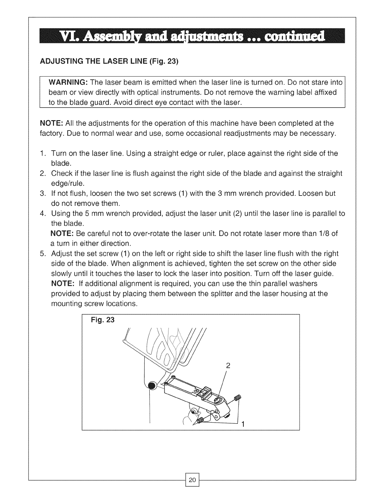
ADJUSTING THE LASER LINE (Fig. 23)
I ARNING: The laser beam is emitted when the laser line is turned on. Do not stare into
beam or view directly with optical instruments. Do not remove the warning label affixed
to the blade guard. Avoid direct eye contact with the laser.
NOTE: All the adjustments for the operation of this machine have been completed at the
factory. Due to normal wear and use, some occasional readjustments may be necessary.
1. Turn on the laser line. Using a straight edge or ruler, place against the right side of the
blade.
2. Check if the laser line is flush against the right side of the blade and against the straight
edge/rule.
3. If not flush, loosen the two set screws (1) with the 3 mm wrench provided. Loosen but
do not remove them.
4. Using the 5 mm wrench provided, adjust the laser unit (2) until the laser line is parallel to
the blade.
NOTE: Be careful not to over-rotate the laser unit. Do not rotate laser more than 1/8 of
a turn in either direction.
5. Adjust the set screw (1) on the teft or right side to shift the laser line flush with the right
side of the blade. When alignment is achieved, tighten the set screw on the other side
slowly until it touches the laser to lock the laser into position. Turn off the laser guide.
NOTE: If additional alignment is required, you can use the thin parallel washers
provided to adjust by placing them between the splitter and the laser housing at the
mounting screw locations.
Fig. 23
2
WARNING: TO AVOID INJURY FROM AN ACCIDENTAL START, MAKE SURE THE
SWITCH IS IN THE "OFF" POSITION, THE REMOVABLE KEY IS REMOVED AND
THE PLUG IS NOT CONNECTED TO THE POWER SOURCE OUTLET.
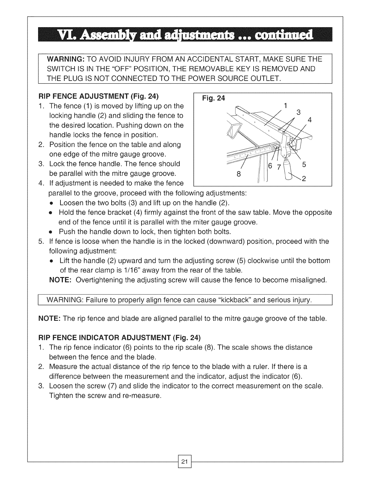
RIP FENCE ADJUSTMENT (Fig. 24)
1. The fence (1) is moved by lifting up on the
locking handle (2) and sliding the fence to
the desired location. Pushing down on the
handle locks the fence in position.
2. Position the fence on the table and along
one edge of the mitre gauge groove.
3. Lock the fence handle. The fence should
be parallel with the mitre gauge groove.
4. If adjustment is needed to make the fence
.
Fig. 24 13
4
5
2
parallel to the groove, proceed with the following adjustments:
e Loosen the two bolts (3) and lift up on the handle (2).
e Hold the fence bracket (4) firmly against the front of the saw table. Move the opposite
end of the fence until it is parallel with the miter gauge groove.
e Push the handle down to lock, then tighten both bolts.
If fence is loose when the handle is in the locked (downward) position, proceed with the
following adjustment:
e Lift the handle (2) upward and turn the adjusting screw (5) clockwise until the bottom
of the rear clamp is 1/16" away from the rear of the table.
NOTE: Overtightening the adjusting screw will cause the fence to become misaligned.
WARNING: Failure to properly align fence can cause "kickback" and serious injury. ]
NOTE: The rip fence and blade are aligned parallel to the mitre gauge groove of the table.
RIP FENCE INDICATOR ADJUSTMENT (Fig. 24)
1. The rip fence indicator (6) points to the rip scale (8). The scale shows the distance
between the fence and the blade.
2. Measure the actual distance of the rip fence to the blade with a ruler. If there is a
difference between the measurement and the indicator, adjust the indicator (6).
3. Loosen the screw (7) and slide the indicator to the correct measurement on the scale.
Tighten the screw and re-measure.
WARNING: NEVERCONNECT THE PLUG TO THE POWER SOURCE OUTLET UNTIL
ALL INSTALLATIONSAND ADJUSTMENTS ARE COMPLETED AND YOU HAVE
READ AND FULLY UNDERSTOOD THE ENTIRE MANUAL.
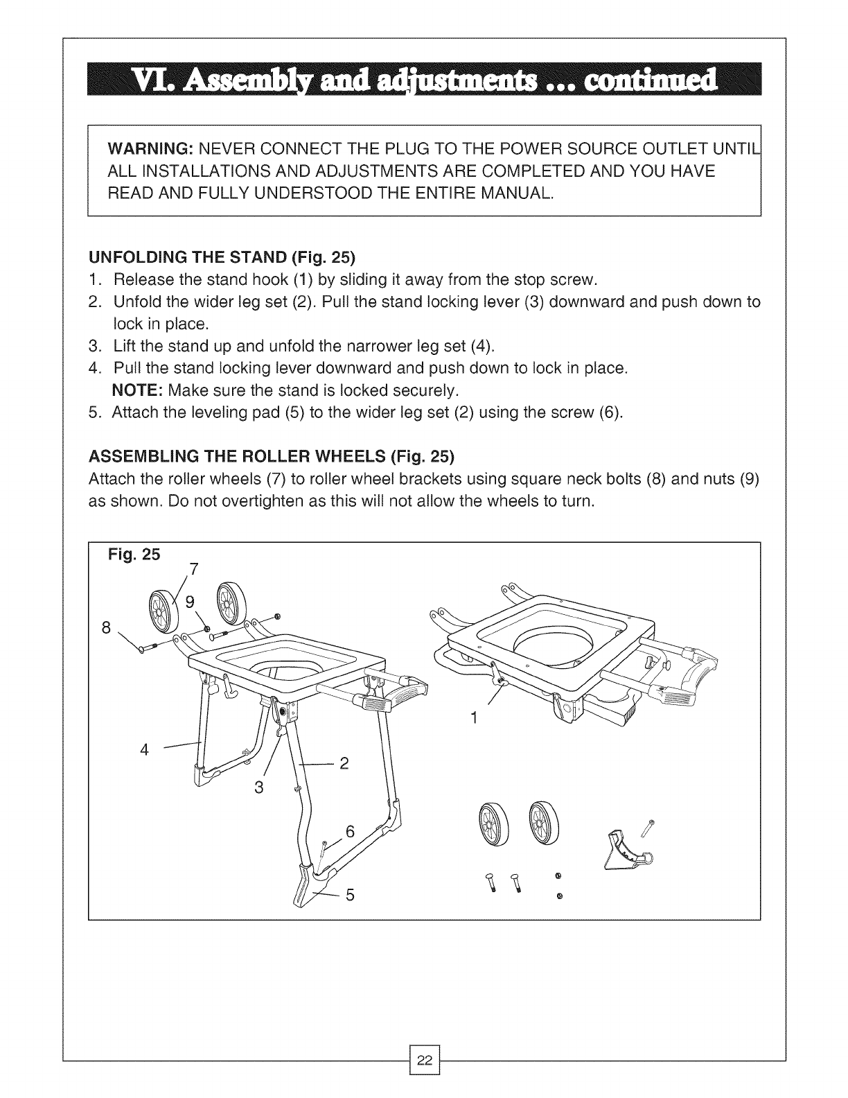
UNFOLDING THE STAND (Fig. 25)
1. Release the stand hook (1) by sliding it away from the stop screw.
2. Unfold the wider leg set (2). Pull the stand locking lever (3) downward and push down to
lock in place.
3. Lift the stand up and unfold the narrower leg set (4).
4. Pull the stand locking lever downward and push down to lock in place.
NOTE: Make sure the stand is locked securely.
5. Attach the leveling pad (5) to the wider leg set (2) using the screw (6).
ASSEMBLING THE ROLLER WHEELS (Fig. 25)
Attach the roller wheels (7) to roller wheel brackets using square neck bolts (8) and nuts (9)
as shown. Do not overtighten as this will not allow the wheels to turn.
Fig. 25 7
8
4
3
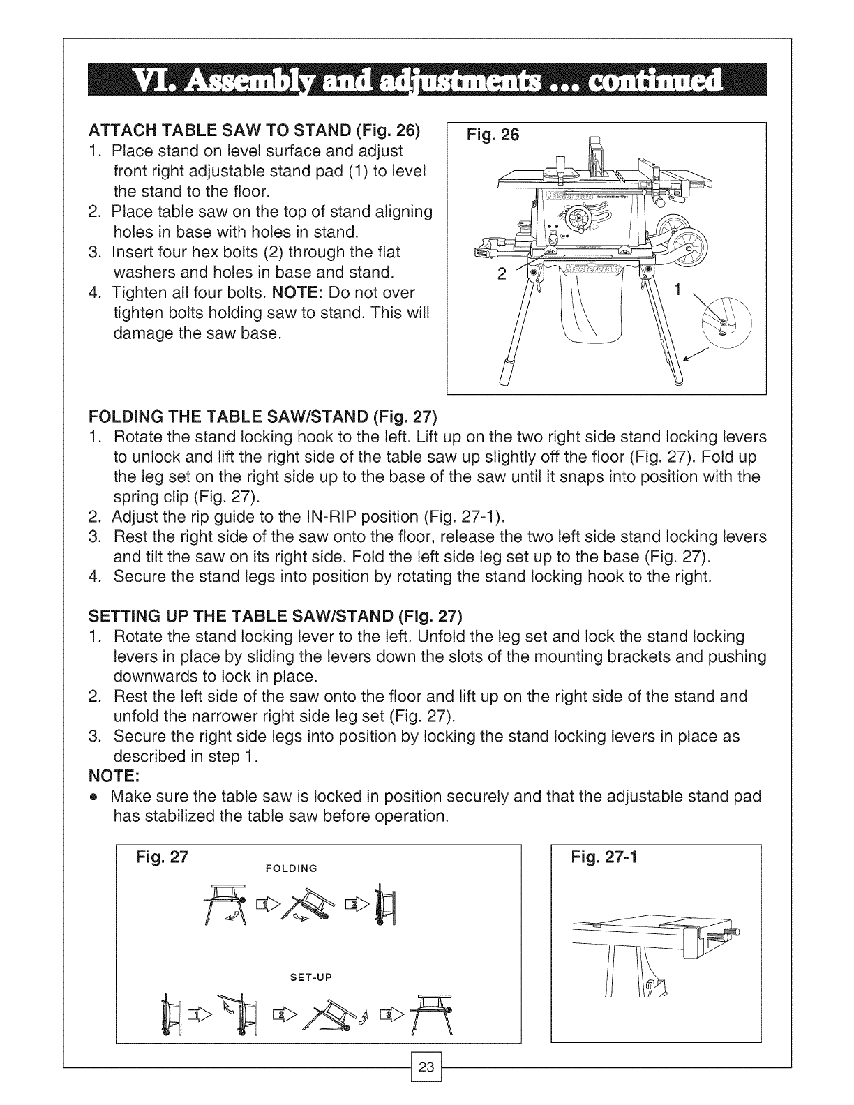
ATTACH TABLE SAW TO STAND (Fig. 26)
1. Place stand on tevelsurface and adjust
front right adjustable stand pad (1) to level
the stand to the floor.
2. Ptace table saw on the top of stand aligning
holes in base with holes in stand.
3. Insert four hex bolts (2) through the flat
washers and holes in base and stand.
4. Tighten all four bolts. NOTE: Do not over
tighten bolts holding saw to stand. This will
damage the saw base.
Fig. 26
2
FOLDING THE TABLE SAW/STAND (Fig. 27)
1. Rotate the stand locking hook to the left. Lift up on the two right side stand locking levers
to unlock and lift the right side of the table saw up slightly off the floor (Fig. 27). Fold up
the teg set on the right side up to the base of the saw until it snaps into position with the
spring clip (Fig. 27).
2. Adjust the rip guide to the IN-RIP position (Fig. 27-1).
3. Rest the right side of the saw onto the floor, release the two left side stand locking levers
and tilt the saw on its right side. Fold the left side leg set up to the base (Fig. 27).
4. Secure the stand legs into position by rotating the stand locking hook to the right.
SETTING UP THE TABLE SAW/STAND (Fig. 27)
1. Rotate the stand locking lever to the left. Unfold the teg set and tock the stand locking
levers in place by sliding the levers down the slots of the mounting brackets and pushing
downwards to lock in place.
2. Rest the left side of the saw onto the floor and lift up on the right side of the stand and
unfold the narrower right side teg set (Fig. 27).
3. Secure the right side legs into position by locking the stand locking levers in place as
described in step 1.
NOTE:
e Make sure the table saw is locked in position securely and that the adjustable stand pad
has stabilized the table saw before operation.
Fig. 27 FOLDING
SET-UP
Fig. 27-1
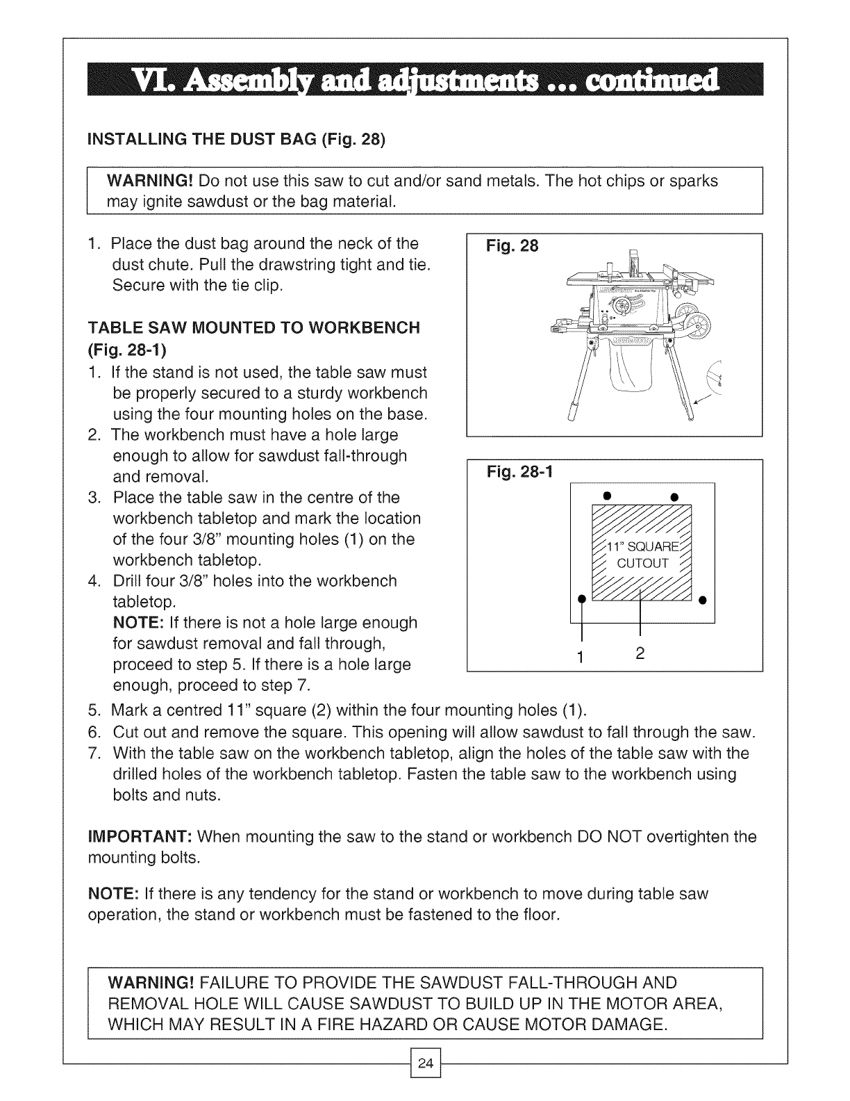
INSTALLING THE DUST BAG (Fig. 28)
WARNING! Do not use this saw to cut and/or sand metals. The hot chips or sparks
may ignite sawdust or the bag material.
1. Place the dust bag around the neck of the
dust chute. Pull the drawstring tight and tie.
Secure with the tie clip.
TABLE SAW MOUNTED TO WORKBENCH
(Fig. 284)
1. If the stand is not used, the table saw must
be properly secured to a sturdy workbench
using the four mounting holes on the base.
2. The workbench must have a hole large
enough to allow for sawdust fall-through
and removal.
3. Place the table saw in the centre of the
workbench tabletop and mark the location
of the four 3/8" mounting holes (1) on the
workbench tabletop.
4. Drill four 3/8" holes into the workbench
tabletop.
NOTE: If there is not a hole large enough
for sawdust removal and fall through,
proceed to step 5. If there is a hole large
enough, proceed to step 7.
Fig. 28
Fig. 28-1
11"SQUARF
CUTOUT /_
-4
2
5. Mark a centred 11" square (2) within the four mounting holes (1).
6. Cut out and remove the square. This opening will allow sawdust to fall through the saw.
7. With the table saw on the workbench tabletop, align the holes of the table saw with the
drilled holes of the workbench tabletop. Fasten the table saw to the workbench using
bolts and nuts.
IMPORTANT: When mounting the saw to the stand or workbench DO NOT overtighten the
mounting bolts.
NOTE: If there is any tendency for the stand or workbench to move during table saw
operation, the stand or workbench must be fastened to the floor.
WARNING! FAILURE TO PROVIDE THE SAWDUST FALL-THROUGH AND
REMOVAL HOLE WILL CAUSE SAWDUST TO BUILD UP IN THE MOTOR AREA,
WHICH MAY RESULT IN A FIRE HAZARD OR CAUSE MOTOR DAMAGE.
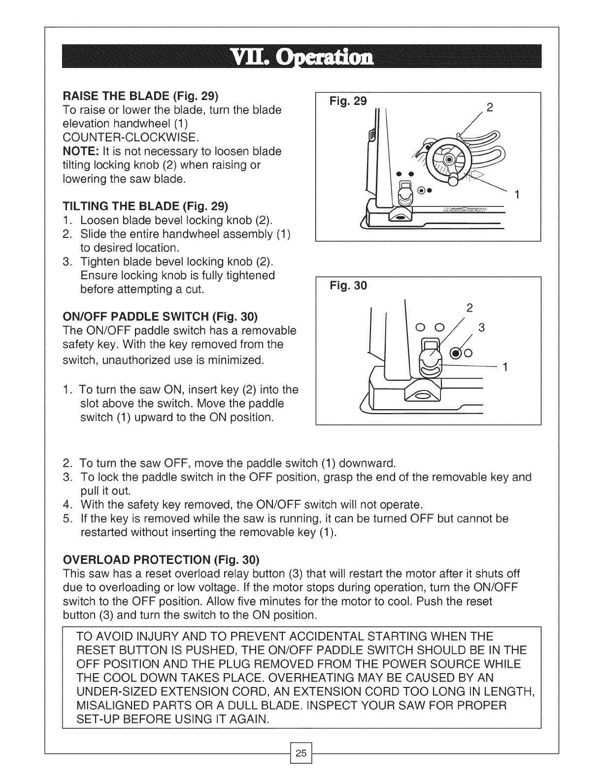
RAISE THE BLADE (Fig. 29)
To raise or lower the blade, turn the blade
elevation handwheel (1)
COUNTER-CLOCKWISE.
NOTE: It is not necessary to loosen blade
tilting locking knob (2) when raising or
lowering the saw blade.
TILTING THE BLADE (Fig. 29)
1. Loosen blade bevel locking knob (2).
2. Slide the entire handwheel assembly (1)
to desired location.
3. Tighten blade bevel locking knob (2).
Ensure locking knob is fully tightened
before attempting a cut.
ON/OFF PADDLE SWITCH (Fig. 30)
The ON/OFF paddle switch has a removable
safety key. With the key removed from the
switch, unauthorized use is minimized.
1. To turn the saw ON, insert key (2) into the
slot above the switch. Move the paddle
switch (1) upward to the ON position.
Fig. 29 2
o o
Fig. 30
2
O O 3
--1
2. To turn the saw OFF, move the paddle switch (1) downward.
3. To tock the paddle switch in the OFF position, grasp the end of the removable key and
pull it out.
4. With the safety key removed, the ON/OFF switch will not operate.
5. If the key is removed while the saw is running, it can be turned OFF but cannot be
restarted without inserting the removable key (1).
OVERLOAD PROTECTION (Fig. 30)
This saw has a reset overload relay button (3) that will restart the motor after it shuts off
due to overloading or tow voltage. If the motor stops during operation, turn the ON/OFF
switch to the OFF position. Allow five minutes for the motor to cool. Push the reset
button (3) and turn the switch to the ON position.
TO AVOID INJURY AND TO PREVENT ACCIDENTAL STARTING WHEN THE
RESET BUTTON IS PUSHED, THE ON/OFF PADDLE SWITCH SHOULD BE IN THE
OFF POSITION AND THE PLUG REMOVED FROM THE POWER SOURCE WHILE
THE COOL DOWN TAKES PLACE. OVERHEATING MAY BE CAUSED BY AN
UNDER-SIZED EXTENSION CORD, AN EXTENSION CORD TOO LONG IN LENGTH,
MISALIGNED PARTS OR A DULL BLADE. INSPECT YOUR SAW FOR PROPER
SET-UP BEFORE USING IT AGAIN.
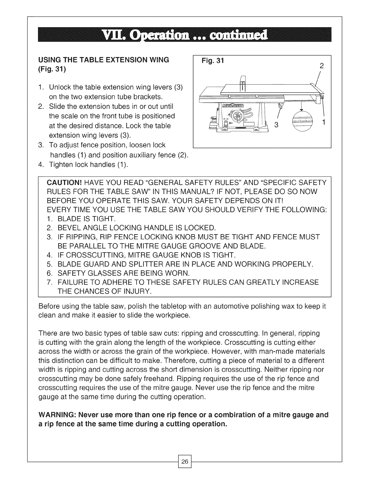
USING THE TABLE EXTENSION WING
(Fig. 31)
1. Unlock the table extension wing levers (3)
on the two extension tube brackets.
2. Slide the extension tubes in or out until
the scale on the front tube is positioned
at the desired distance. Lock the table
extension wing levers (3).
3. To adjust fence position, loosen lock
handles (1) and position auxiliary fence (2).
4. Tighten lock handles (1).
Fig. 31 2
lul
CAUTION! HAVE YOU READ "GENERAL SAFETY RULES" AND "SPECIFIC SAFETY
RULES FOR THE TABLE SAW" IN THIS MANUAL? IF NOT, PLEASE DO SO NOW
BEFORE YOU OPERATE THIS SAW. YOUR SAFETY DEPENDS ON IT!
EVERY TiME YOU USE THE TABLE SAW YOU SHOULD VERIFY THE FOLLOWING:
1. BLADE iS TIGHT.
2. BEVEL ANGLE LOCKING HANDLE iS LOCKED.
3. IF RIPPING, RIP FENCE LOCKING KNOB MUST BE TIGHT AND FENCE MUST
BE PARALLEL TO THE MITRE GAUGE GROOVE AND BLADE.
4. IF CROSSCUTTING, MITRE GAUGE KNOB IS TIGHT.
5. BLADE GUARD AND SPLITTER ARE iN PLACE AND WORKING PROPERLY.
6. SAFETY GLASSES ARE BEING WORN.
7. FAILURE TO ADHERE TO THESE SAFETY RULES CAN GREATLY iNCREASE
THE CHANCES OF iNJURY.
Before using the table saw, polish the tabletop with an automotive polishing wax to keep it
clean and make it easier to slide the workpiece.
There are two basic types of table saw cuts: ripping and crosscutting, in general, ripping
is cutting with the grain along the length of the workpiece. Crosscutting is cutting either
across the width or across the grain of the workpiece. However, with man-made materials
this distinction can be difficult to make. Therefore, cutting a piece of material to a different
width is ripping and cutting across the short dimension is crosscutting. Neither ripping nor
crosscutting may be done safely freehand. Ripping requires the use of the rip fence and
crosscutting requires the use of the mitre gauge. Never use the rip fence and the mitre
gauge at the same time during the cutting operation.
WARNING: Never use more than one rip fence or a combiration of a mitre gauge and
a rip fence at the same time during a cutting operation.
RiPPiNG
CAUTION! To prevent serious injury:
e Do not allow frequent use of your table saw to cause complacency and careless
mistakes. Remember that even a careless fraction of a second is enough to cause a
severe injury.
• Keep both hands away from the blade and the path of the blade.
• The workpiece must have a straight edge against the fence and must not be warped,
1. Remove the mitre gauge and secure the rip fence to the table.
2. Adjust the blade so it is about 1/8 in. higher than the workpiece.
3. Hold the workpiece flat on the tabletop and against the rip fence. Keep the workpiece
about 1" away from the front of the blade.
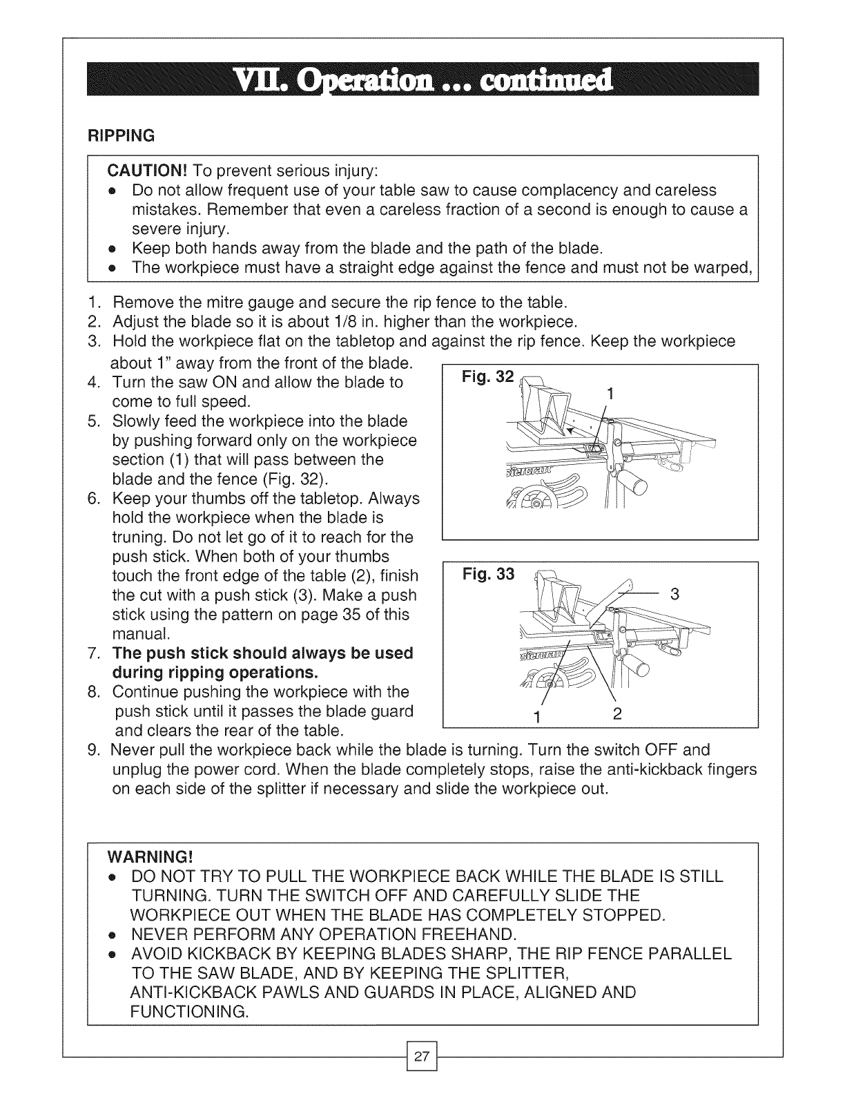
4. Turn the saw ON and allow the blade to
come to full speed.
5. Slowly feed the workpiece into the blade
by pushing forward only on the workpiece
section (1) that will pass between the
blade and the fence (Fig. 32).
6. Keep your thumbs off the tabletop. Always
hold the workpiece when the blade is
truning. Do not let go of it to reach for the
push stick. When both of your thumbs
touch the front edge of the table (2), finish
the cut with a push stick (3). Make a push
stick using the pattern on page 35 of this
manual.
7. The push stick should always be used
during ripping operations.
8. Continue pushing the workpiece with the
push stick until it passes the blade guard
and clears the rear of the table.
.
Fig. 33
1 2
Never pull the workpiece back while the blade is turning. Turn the switch OFF and
unplug the power cord. When the blade completely stops, raise the anti-kickback fingers
on each side of the splitter if necessary and slide the workpiece out.
WARNING!
e DO NOT TRY TO PULL THE WORKPIECE BACK WHILE THE BLADE IS STILL
TURNING. TURN THE SWITCH OFF AND CAREFULLY SLIDE THE
WORKPIECE OUT WHEN THE BLADE HAS COMPLETELY STOPPED.
e NEVER PERFORM ANY OPERATION FREEHAND.
e AVOID KICKBACK BY KEEPING BLADES SHARP, THE RIP FENCE PARALLEL
TO THE SAW BLADE, AND BY KEEPING THE SPLITTER,
ANTI-KICKBACK PAWLS AND GUARDS IN PLACE, ALIGNED AND
FUNCTIONING.
BEVEL RIPPING
This operation is the same as ripping except the bevel angle is set to an angle other
than 0°.
CAUTION! CUT ONLY WITH THE WORKPIECE AND THE RIP FENCE ON THE
RIGHT HAND SIDE OF THE BLADE.
RIPPING SMALL PIECES
CAUTION! AVOID INJURY RESULTING FROM BLADE CONTACT. NEVER MAKE
THROUGH-SAW CUTS NARROWER THAN W' WIDE.
1. It is unsafe to rip small pieces. It is not safe to put your hands close to the blade. To
ensure your safety, rip the small piece from a larger piece.
2. When a small width is to be ripped and the hand cannot be safely put between the
blade and the rip fence, use one or more push sticks. Use the push sticks to hold the
workpiece against the table top and fence and push the workpiece fully past the blade
(Fig. 33).
NOTE: A pattern for making your own push sticks is shown on page 35 of this manual.
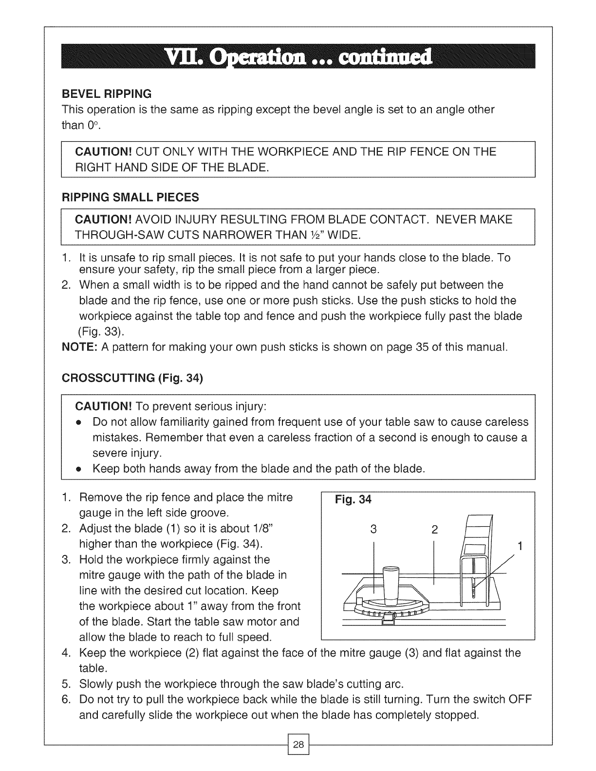
CROSSCUTTING (Fig. 34)
CAUTION! To prevent serious injury:
e Do not allow familiarity gained from frequent use of your table saw to cause careless
mistakes. Remember that even a careless fraction of a second is enough to cause a
severe injury.
• Keep both hands away from the blade and the path of the blade.
.
.
.
.
.
6.
Remove the rip fence and place the mitre Fig. 34
gauge in the left side groove.
Adjust the blade (1) so it is about 1/8" 3 2
higher than the workpiece (Fig. 34). 1
Hold the workpiece firmly against the
mitre gauge with the path of the blade in
line with the desired cut location. Keep
the workpiece about 1" away from the front
of the blade. Start the table saw motor and
allow the blade to reach to full speed.
Keep the workpiece (2) flat against the face of the mitre gauge (3) and flat against the
table.
Slowly push the workpiece through the saw blade's cutting arc.
Do not try to pull the workpiece back while the blade is still turning. Turn the switch OFF
and carefully slide the workpiece out when the blade has completely stopped.
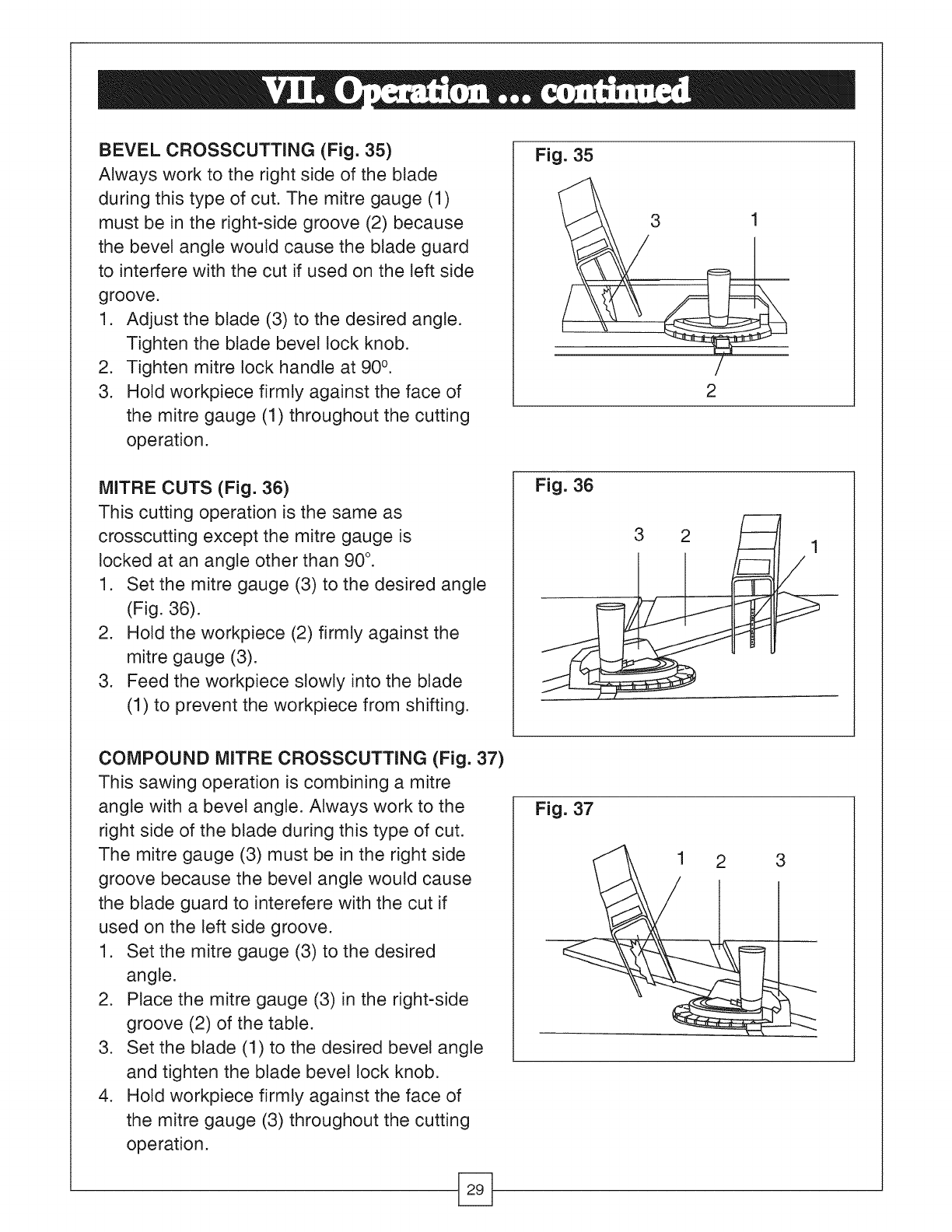
BEVEL CROSSCUTTING (Fig. 35)
Always work to the right side of the btade
during this type of cut. The mitre gauge (1)
must be in the right-side groove (2) because
the bevel angte would cause the blade guard
to interfere with the cut if used on the left side
groove.
1. Adjust the blade (3) to the desired angte.
Tighten the btade bevel lock knob.
2. Tighten mitre lock handle at 90 °.
3. Hold workpiece firmly against the face of
the mitre gauge (1) throughout the cutting
operation.
Fig. 35
3 1
2
MITRE CUTS (Fig. 36)
This cutting operation is the same as
crosscutting except the mitre gauge is
locked at an angle other than 90 °.
1. Set the mitre gauge (3) to the desired angle
(Fig. 36).
2. Hold the workpiece (2) firmly against the
mitre gauge (3).
3. Feed the workpiece slowly into the blade
(1) to prevent the workpiece from shifting.
Fig. 36
3 2
/
COMPOUND MITRE CROSSCUTTING (Fig. 37)
This sawing operation is combining a mitre
angle with a bevel angle. Always work to the
right side of the blade during this type of cut.
The mitre gauge (3) must be in the right side
groove because the bevel angle would cause
the blade guard to interefere with the cut if
used on the left side groove.
1. Set the mitre gauge (3) to the desired
angle.
2. Place the mitre gauge (3) in the right-side
groove (2) of the table.
3. Set the blade (1) to the desired bevel angle
and tighten the blade bevel lock knob.
4. Hold workpiece firmly against the face of
the mitre gauge (3) throughout the cutting
operation.
Fig. 37
1 2 3
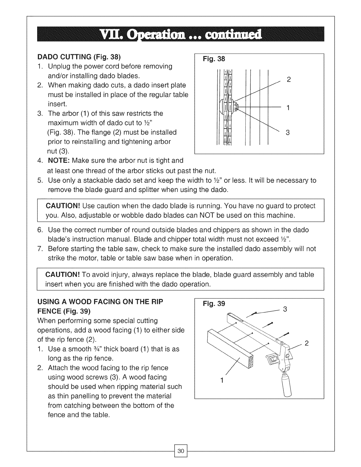
DADO CUTTING (Fig. 38)
1. Unplug the power cord before removing
and/or installing dado blades.
2. When making dado cuts, a dado insert plate
must be installed in place of the regular table
insert.
3. The arbor (1) of this saw restricts the
maximum width of dado cut to W'
(Fig. 38). The flange (2) must be installed
prior to reinstalling and tightening arbor
nut (3).
4. NOTE: Make sure the arbor nut is tight and
Fig. 38i
II
II
I I
i I'l I
jJ
_J
J2
3
.
at least one thread of the arbor sticks out past the nut.
Use only a stackabte dado set and keep the width to W' or tess. It will be necessary to
remove the blade guard and splitter when using the dado.
CAUTION! Use caution when the dado blade is running. You have no guard to protect
you. Also, adjustable or wobble dado blades can NOT be used on this machine.
6. Use the correct number of round outside blades and chippers as shown in the dado
blade's instruction manual. Blade and chipper total width must not exceed W'.
7. Before starting the table saw, check to make sure the installed dado assembly will not
strike the motor, table or table saw base when in operation.
CAUTION! To avoid injury, always replace the blade, blade guard assembly and table
insert when you are finished with the dado operation.
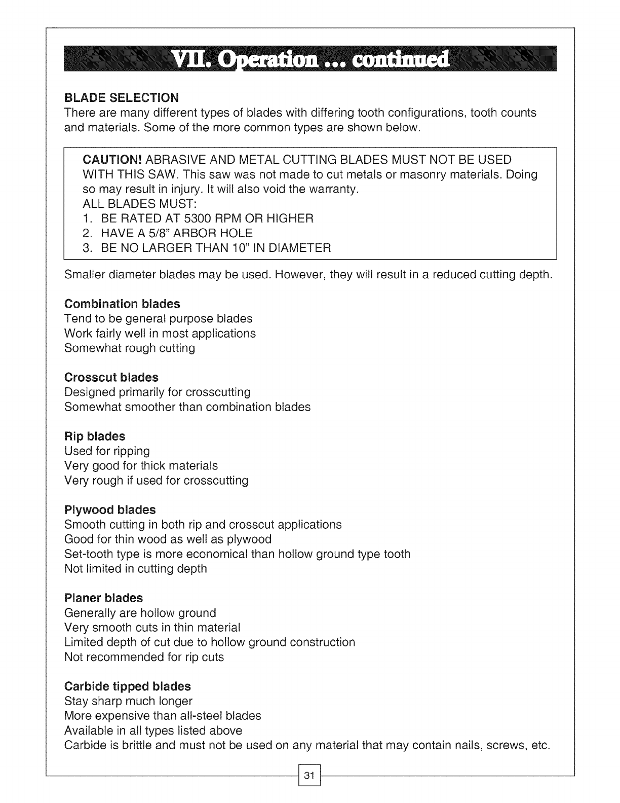
USING A WOOD FACING ON THE RIP
FENCE (Fig. 39)
When performing some special cutting
operations, add a wood facing (1) to either side
of the rip fence (2).
1. Use a smooth 3_,,thick board (1) that is as
long as the rip fence.
2. Attach the wood facing to the rip fence
using wood screws (3). A wood facing
should be used when ripping material such
as thin panelling to prevent the material
from catching between the bottom of the
fence and the table.
Fig. 39
BLADE SELECTION
There are many different types of blades with differing tooth configurations, tooth counts
and materials. Some of the more common types are shown below.
CAUTION! ABRASIVE AND METAL CUTTING BLADES MUST NOT BE USED
WITH THIS SAW. This saw was not made to cut metals or masonry materials. Doing
so may result in injury. It will also void the warranty.
ALL BLADES MUST:
1. BE RATED AT 5300 RPM OR HIGHER
2. HAVE A 5/8" ARBOR HOLE
3. BE NO LARGER THAN 10" IN DIAMETER
Smaller diameter blades may be used. However, they will result in a reduced cutting depth.
Combination blades
Tend to be general purpose blades
Work fairly well in most applications
Somewhat rough cutting
Crosscut blades
Designed primarily for crosscutting
Somewhat smoother than combination blades
Rip blades
Used for ripping
Very good for thick materials
Very rough if used for crosscutting
Plywood blades
Smooth cutting in both rip and crosscut applications
Good for thin wood as well as plywood
Set-tooth type is more economical than hollow ground type tooth
Not limited in cutting depth
Planer blades
Generally are hollow ground
Very smooth cuts in thin material
Limited depth of cut due to hollow ground construction
Not recommended for rip cuts
Carbide tipped blades
Stay sharp much longer
More expensive than all-steel blades
Available in all types listed above
Carbide is brittle and must not be used on any material that may contain nails, screws, etc.
CAUTION: For your own safety, turn the switch OFF and remove the switch key.
Remove the plug from the power source before maintaining or lubricating your saw.
GENERAL MAINTENANCE
e Frequently clean out all sawdust that has accumulated inside the saw base and around
the motor with a vacuum.
e Polish the saw table with an automotive polishing wax to keep it clean and to make it
easier to slide the workpiece.
e Clean the cutting blades with pitch and gum remover.
e Immediately replace a worn, cut or damaged power cord.
CAUTION: All electrical and mechanical repairs should be performed by a trained
repair technician. Call the Toll Free Helptine at 1-886-881-7202 for the technician
nearest you. Use only identical replacement parts. Any substitute parts may create a
hazard.
Use liquid dish washing detergent and water to clean all plastic parts. NOTE: Use of certain
cleaning chemicals may damage plastic parts.
Do not use the following cleaning chemicals or solvents on your table saw: gasoline,
carbon tetrachloride, chlorinated solvents, ammonia and household detergents containing
ammonia.
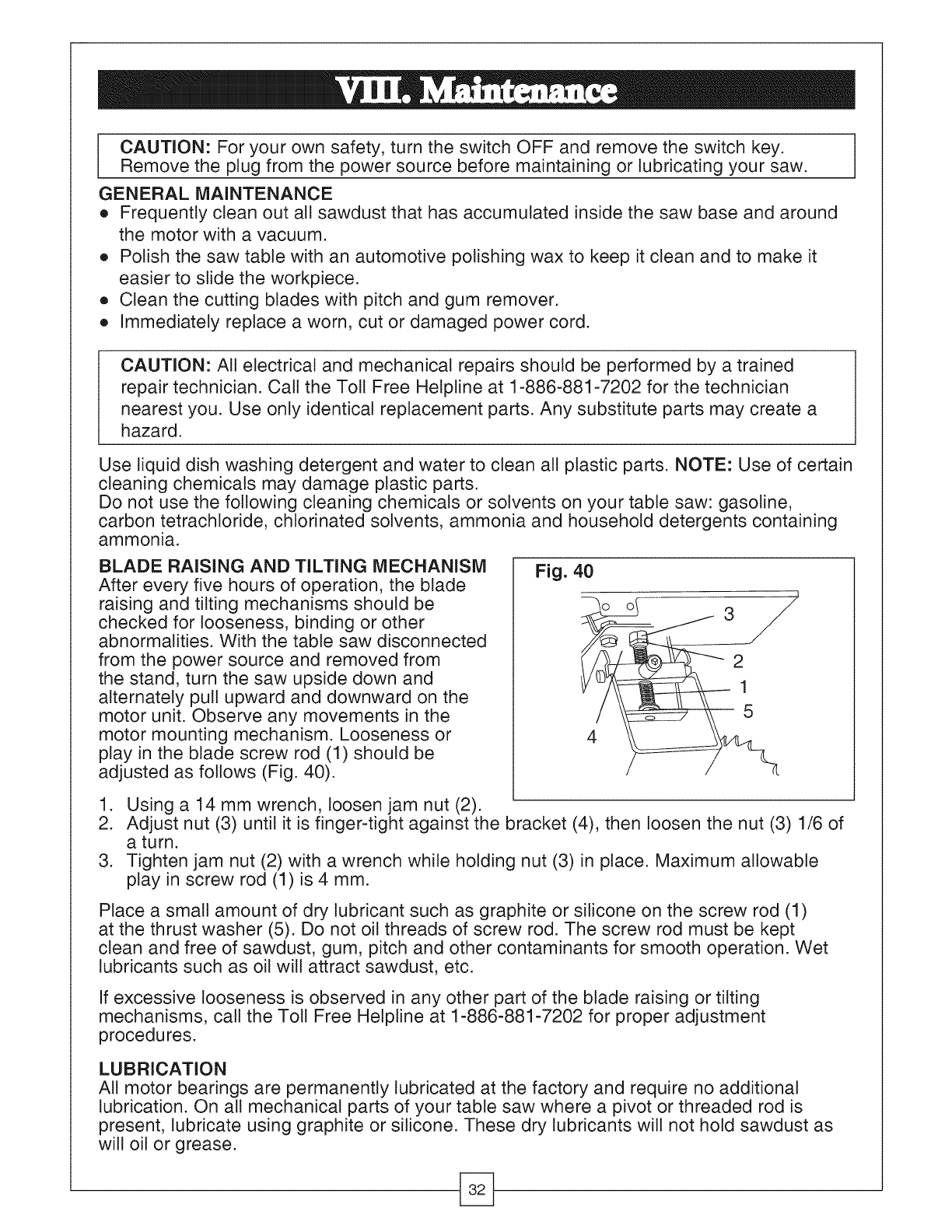
BLADE RAISING AND TILTING MECHANISM
After every five hours of operation, the blade
raising and tilting mechanisms should be
checked for looseness, binding or other
abnormalities. With the table saw disconnected
from the power source and removed from
the stand, turn the saw upside down and
alternately pull upward and downward on the
motor unit. Observe any movements in the
motor mounting mechanism. Looseness or
play in the blade screw rod (1) should be
adjusted as follows (Fig. 40).
Fig. 40
1. Using a 14 mm wrench, loosen jam nut (2).
2. Adjust nut (3) until it is finger-tight against the bracket (4), then loosen the nut (3) 1/6 of
a tu rn.
3. Tighten jam nut (2) with a wrench while holding nut (3) in place. Maximum allowable
play in screw rod (1) is 4 mm.
Place a small amount of dry lubricant such as graphite or silicone on the screw rod (1)
at the thrust washer (5). Do not oil threads of screw rod. The screw rod must be kept
clean and free of sawdust, gum, pitch and other contaminants for smooth operation. Wet
lubricants such as oil will attract sawdust, etc.
If excessive looseness is observed in any other part of the blade raising or tilting
mechanisms, call the Toll Free Helptine at 1-886-881-7202 for proper adjustment
procedures.
LUBRICATION
All motor bearings are permanently lubricated at the factory and require no additional
lubrication. On all mechanical parts of your table saw where a pivot or threaded rod is
present, lubricate using graphite or silicone. These dry lubricants will not hold sawdust as
will oil or grease.
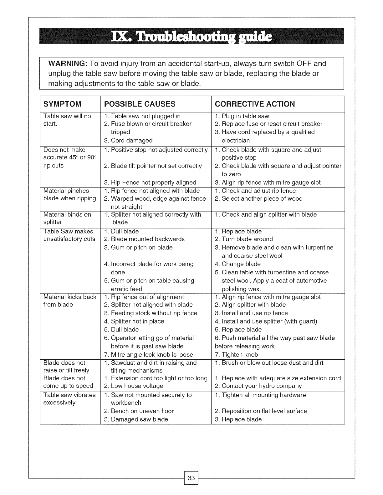
WARNING: To avoid injury from an accidental start-up, always turn switch OFF and
unplug the table saw before moving the table saw or blade, replacing the blade or
making adjustments to the table saw or blade.
SYMPTOM POSSIBLE CAUSES CORRECTIVE ACTION
Table saw will not 1. Table saw not plugged in 1.
start. 2. Fuse blown or circuit breaker 2.
tripped 3.
3. Cord damaged
1. Positive stop not adjusted correctly
Does not make
accurate 45° or 90°
rip cuts 2. Blade tilt pointer not set correctly
.
2.
3. 3.
Material pinches 1. !.
blade when ripping 2. 2.
1. 1. Check and align splitter with blade
Material binds on
splitter
Table Saw makes
unsatisfactory cuts
.
2.
3.
Rip Fence not properly aligned
Rip fence not aligned with blade
Warped wood, edge against fence
not straight
Splitter not aligned correctly with
blade
Dull blade
Blade mounted backwards
Gum or pitch on blade
.
.
.
2.
3.
4.
5.
6.
Material kicks back
from blade
Incorrect blade for work being
done
Gum or pitch on table causing
erratic feed
Rip fence out of alignment
Splitter not aligned with blade
Feeding stock without rip fence
Splitter not in place
Dull blade
Operator letting go of material
before it is past saw blade
Mitre angle lock knob is loose
Sawdust and dirt in raising and
tilting mechanisms
Extension cord too light or too long
Low house voltage
Saw not mounted securely to
workbench
Bench on uneven floor
Damaged saw blade
Plug in table saw
Replace fuse or reset circuit breaker
Have cord replaced by a qualified
electrician
Check blade with square and adjust
positive stop
Check blade with square and adjust pointer
to zero
Align rip fence with mitre gauge slot
Check and adjust rip fence
Select another piece of wood
1. Replace blade
2. Turn blade around
3. Remove blade and clean with turpentine
and coarse steel wool
4. Change blade
5. Clean table with turpentine and coarse
steel wool. Apply a coat of automotive
polishing wax.
1. Align rip fence with mitre gauge slot
2. Align splitter with blade
3. Install and use rip fence
4. Install and use splitter (with guard)
5. Replace blade
6. Push material all the way past saw blade
before releasing work
7. Tighten knob
1. Brush or blow out loose dust and dirt
.
Blade does not 1.
raise or tilt freely
Blade does not 1. 1. Replace with adequate size extension cord
come up to speed 2. 2. Contact your hydro company
Table saw vibrates 1. 1. Tighten all mounting hardware
excessively
2. 2. Reposition on flat level surface
3. 3. Replace blade

Mastercraft Canada agrees to exchange the product or refund your money within 7 days
from the date of purchase, with proof of purchase, if you are not satisfied with this product.
This Mastercraft product carries a three (3) year repair warranty against defects in
workmanship and materials. At its discretion, Mastercraft Canada agrees to have any
defective part(s) replaced free of charge, within the stated warranty period, when returned
by the original purchaser with proof of purchase. This product is not guaranteed against
wear or breakage due to misuse and/or abuse.
This product is not guaranteed if used for commercial or industrial purposes.
I I I
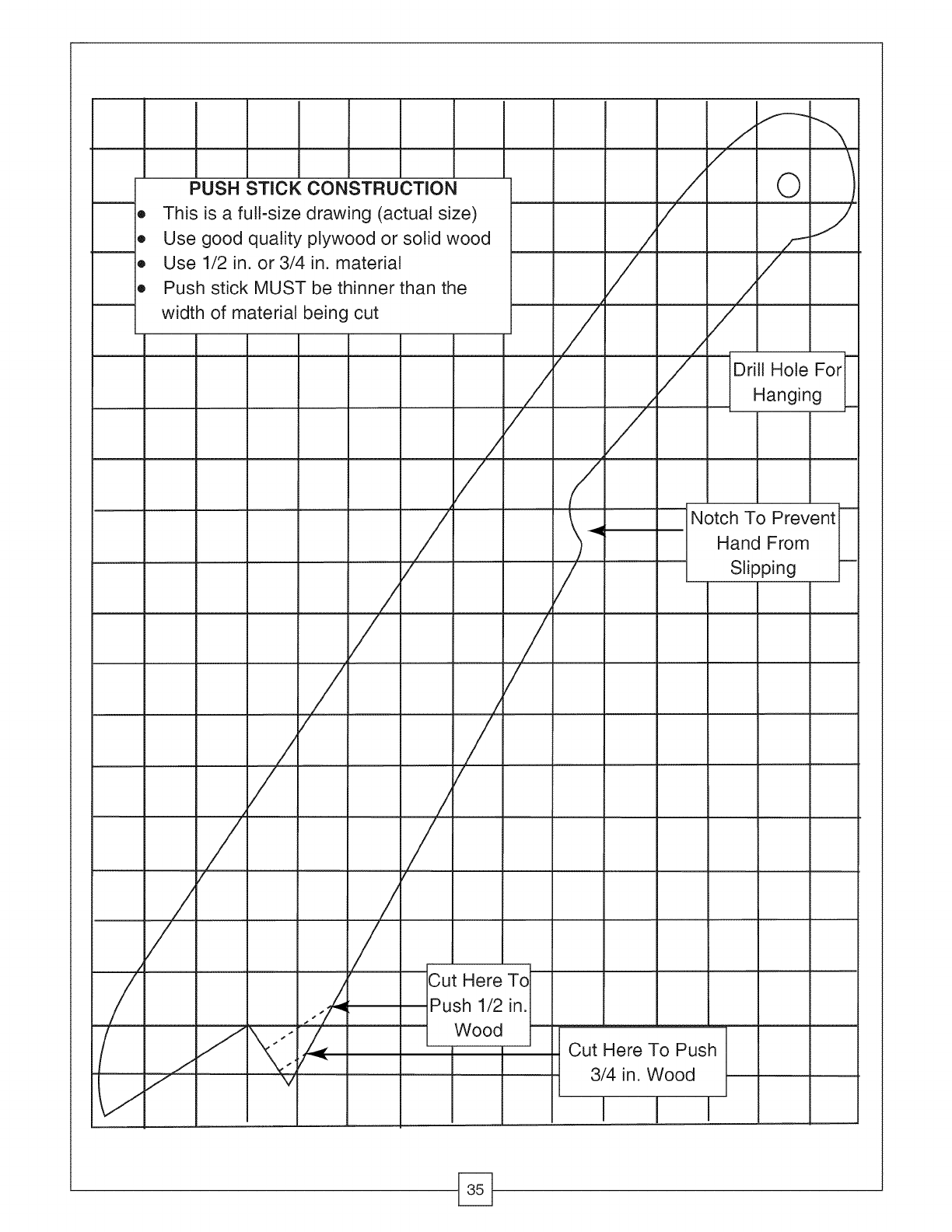
PUSH STICK CONSTRUCTION
e This is a full-size drawing (actual size)
e Use good quality plywood or solid wood
e Use 1/2 in. or 3/4 in. material
e Push stick MUST be thinner than the
width of material being cut
I
!
:
O
Drill Hole For
Hanging
mz
/Notch To Prevent
Hand From
:Slipping
=
==
#
==
=,
/I
/I
: /
Here
Push 1/2 in.
Wood
I
Cut Here To Push
3/4 in. Wood
I I I

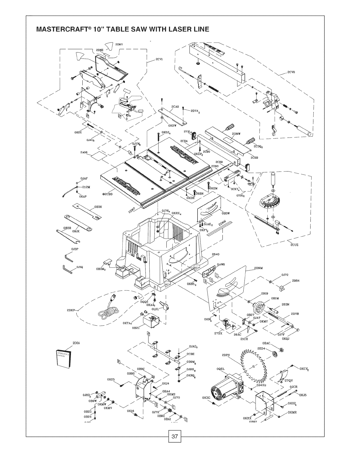
IVIASTERCRAFT ® 10" TABLE SAW WITH LASER LINE
When servicing your Mastercraft ® 10" Table Saw, use Mastercraft ® replacement parts only.
Use of any other parts may cause product damage. Any and all servicing of the table saw
should be performed by a qualified service technician. For the technician nearest you, call
1-866-881-7202.
WARNING: ANY ATTEMPT TO REPAIR OR REPLACE ELECTRICAL PARTS ON THIS
TOOL MAY CREATE A HAZARD UNLESS REPAIR IS DONE BY QUALIFIED SERVICE
TECHNICIANS.
Order by I.D. NUMBER
t.D No Descripfion Size
09JK WRENCH
OAW8 SEGMENT GEAR
OB1M WHEEL
0B23 SADDLE D=8 H=7
0B24 SPRING
0B27 POINTER BRACKET
OB2C SWITCH BOX
OB3K INSERT
OB3M CUSHION
OB3R WRENCH L=209.5
OB3W RETAINING CLIP
0B97 MOTOR BRACKET
0B99 SPACER D=IO H=69
OB9C PLUNGER HOUSING
OB9M STRAP
OB9S BRACKET
OB9W BRACKET
OB9Z COMPRESSION SPRING
OBA1 COMPRESSION SPRING
OBA4 SPACER D=IO H=8.5
OBAC SETNUT
OCKY LOCK HANDLE ASS'Y
OJ3P HEX. WRENCH
OJ3Q HEX WRENCH
OJ4F FLAT WASHER 8X16-2.5
OJ4H FLAT WASHER 10_30-0.2
OJ4U FLAT WASHER 6_18-1.5
OJ70 FLAT WASHER 1/4_3/4-7/64
0J72 FLAT WASHER 1/4_5/8-1/16
0J76 FLAT WASHER 1/4_3/4-1/16
OJ7F FLAT WASHER 5/16"7/8-5/64
OJ7K FLAT WASHER 3/8_29/32-5/64
OJ7V FLAT WASHER 5/8_1 3/8-5/64
OJ8D FLAT WASHER 3/8_3/4-5/64
OJ9H SPRING WASHER 1/4"
OJAD INTERNAL TOOTH LOCK WASHER
OJAE EXTERNALTOOTH LOCK WASHER
OJAF EXTERNAL TOOTH LOCK WASHER
OJCR SPRING PIN
OJXL HEX. SOC. SET SCREW M10_1.5-12
OJYN HEX. SOC. COUNTERSUNK HD. SCREW M6_1.0-25
OKOX HEX. HD. SCREW AND WASHER M6_1.0-16
OKOZ HEX. HD. SCREW AND WASHER M8_1.25-16
OK16 HEX. HD. SCREW AND WASHER M8_1.25-16
0K25 HEX.SOCKET HD.CAP SCREWS M5_0.8-20
OK3G CR.RE. PAN HD. SCREW & WASHER M5_0.8-12
OKSS CR. RE. COUNT HD. SCREW M6_1.0-55
0K85 CR. RE.COUNT HD. TAPPING SCREW M4X0.7-6
0K91 CR. RE. TRUSSHD. TAPPING SCREW M4_16-12
OKA4 CR.RE. PAN HD. TAPPING SCREW M4_16-16
OKAP CR.RE. PAN HD. TAPPING SCREW M5_0.8-10
OKCX CR. RE. PAN HD PLAIN WASHER TAPPING SCREW M5_0.8-10
OKDP CR. RE. PAN HD. SCREW M5_0.8-30
OKDR CR. RE. PAN HD. SCREW M5_0.8-10
Qty t.D No
OKEM
OKF7
OKJ4
OKJ5
OKMR
OKMS
OKMV
OKMW
2 OKMY
OKQJ
OKRQ
OKRX
OKSW
OKTA
6 OLSL
OQEL
OQQO
0T00
212M
2]CH
263N
2640
26AC
26BN
27QV
2 27SX
2 27XL
1 2919
1 2984
4 2A08
1 2C3Q
1 2C90
1 2CA9
2 2CB9
6 2CBA
2 2CBB
2 2CBD
1 2CBE
1 2CUZ
1 2CV0
6 2CV1
1 2DE6
4 2DKP
1 2DNM
1 2DNN
1 2DNS
4 2DNT
8 2DNW
4 2DNY
2 2DNZ
1 2DPS
2 2DV4
2 2DVB
1 2ED4
Description
CR. RE. PAN HD. SCREW
CR. RE. PAN HD. SCREW
CAP HD. SQ.NECK BOLT
CAP HD. SQ.NECK BOLT
HEX. NUT
HEX. NUT
HEX. NUT
HEX. NUT
HEX. NUT
CROWN NUT
SERRATEDTOOTHED HEXAGON FLANGE NUT
HEXAGON NUT AND FLAT WASHER
STRAIN RELIEF
STRAIN RELIEF
CIRCUIT BREAKER SWITCH
MOTOR
CLAMP-CORD
SLIDING BASE ASS'Y
LEAD WIRE ASS'Y
CR.RE. PAN HD. SCREW & WASHER
HANDLE BAR
BODY SHELL
NEEDLE POINTER
CR. RE. PAN HD. SCREW
DEFLECTOR
ROCKER SWITCH
END CAP
FLAT WASHER
LOCK KNOB
WARNING LABEL
BOLT CLAMP
EXTENTION WING
INSERT
UPPER TUBE
UPPER TUBE
ASSIST-FENCE
TABLE
ANGLE ROD
MITER GAUGE ASS'Y
RIP FENCE ASS'Y
BLADE GUARD ASS'Y
INSTRUCTIONS MANUAL
POWER CABLE ASS'Y
LABEL
TRADE-MARK LABEL
SCALE
SCALE
WARNING LABEL
CAUTION LABEL
CAUTION LABEL
BLADE
CR.RE. PAN HD. SCREW & WASHER
HEIGHT REGULATING BOLT ASS'Y
ARBOR COLLAR
Size
M6"1.0-40
M4"0.7-12
M6"1,0-35
M6X1.0-80
M5"0.8 T=4
M6"1.0 T=5
M 10_1.5 T=8
M 10_1.5 T=4
M8"1.25 T=6.5
M8"1.25 T=I 2.5
M6*l.0T=6
M6"1.0
M5"0.8-10
M6"1.0-25
@10"17-2
Ofy
1
2
1
1
2
6
5
1
2
1
1
1
2
2
1
1
1
2
2
1
1
MASTERCRAFT ® 10" TABLE SAW WITH LASER LINE
/
<
OJAF
2!2M
_OKAP @2CBD
OB3R
OJ3P
<
0J3Q OB3M 2
2640
OK9_ <
27SX
\
\
\
2DNM
0J72
_919
OB1M
21CH
263N
2DVB
<
0KQJ
OBAC
2DPS
0QEL
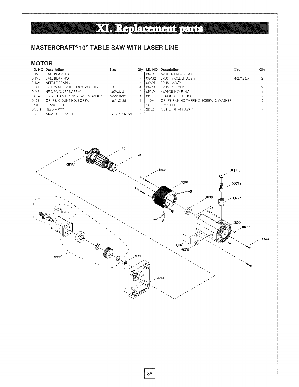
MASTERCRAFT ®10" TABLE SAW WITH LASER LINE
MOTOR
I.D. NO
OHV8
OHVU
OHX9
OJAE
OJX3
OK3A
OK5S
OKTH
OQEH
OQEJ
Description Size
BALL BEARING
BALL BEARING
NEEDLE BEARING
EXTERNAL TOOTH LOCK WASHER cp4
HEX. SOC. SETSCREW M5"0.8-8
CR.RE. PAN HD. SCREW & WASHER M5"0.8-30
CR. RE. COUNT HD. SCREW M6"1.0-55
STRAIN RELIEF
FIELD ASS'Y
ARMATURE ASS'Y 120V 60HZ 38L
Qty I.D. NO Description
1 0QEK MOTOR NAMEPLATE
1 0QM2 BRUSH HOLDER ASS'Y
1 0QQT BRUSH ASS'Y
4 0QR0 BRUSH COVER
2 0R1Q MOTOR HOUSING
4 0R1S BEARING BUSHING
4 110A CR.-RE.PAN HD.TAPPING SCREW & WASHER
1 2DE1 BRACKET
1 2DEZ CUTTERSHAFT ASS'Y
1
Qfy
1
2
2
2
1
1
2
1
1
/i
I
I
\
(0K5S_ X \
0JAE. \
2\
\
\
\
\
\
\\
2DEZ
0QEI
\
\
\
\
\
\
\
\
\
\
/
0HX9
110A2
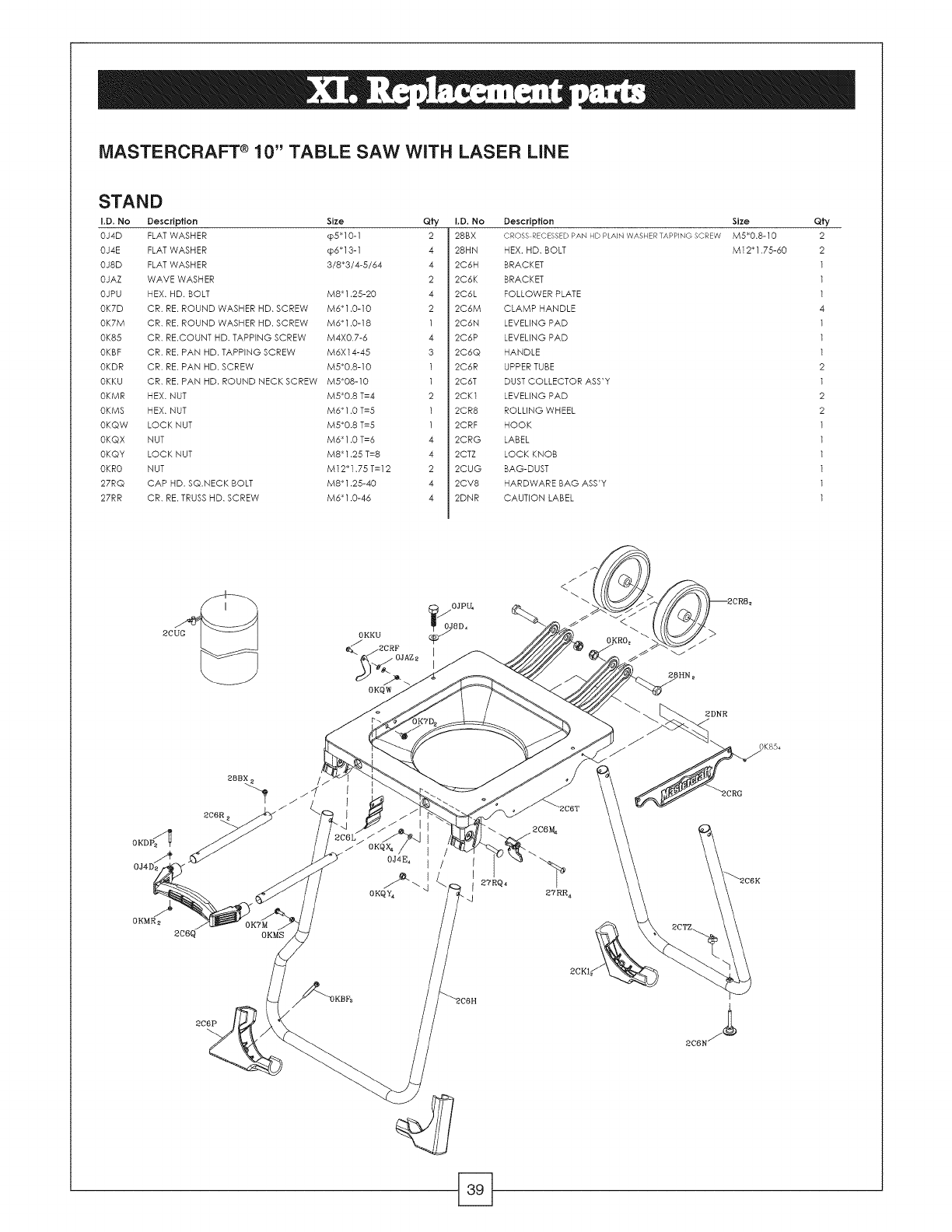
MASTERCRAFT ® 10" TABLE SAW WITH LASER LINE
STAND
I,D. No Description Size Qfy
OJ4D FLAT WASHER _p5"10-1 2
OJ4E FLAT WASHER _p6"13-1 4
OJ8D FLAT WASHER 3/8"3/4-5/64 4
OJAZ WAVE WASHER 2
OJPU HEX. HD. BOLT M8"1.25-20 4
I.D. No Description
28BX CROSS RECESSEDPANHD PLAINWASHERTAPPING SCREW
28HN HEX. HD. BOLT
2C6H BRACKET
2C6K BRACKET
2C6L FOLLOWER PLATE
OK7D
OK7M
0K85
OKBF
OKDR
OKKU
OKMR
OKMS
OKQW
OKQX
OKQY
OKR0
27RQ
27RR
CR. RE. ROUND WASHER HD. SCREW M6"1.0-10
CR. RE. ROUND WASHER HD. SCREW M6"1.0-18
CR. RE.COUNT HD. TAPPING SCREW M4XO.7-6
CR. RE. PAN HD. TAPPING SCREW M6XI4-45
CR. RE. PAN HD. SCREW M5"0.8-10
CR. RE. PAN HD. ROUND NECK SCREW M5"08-10
HEX. NUT M5"0.8 T=4
HEX. NUT M6"1.0 T=5
LOCK NUT M5"0.8 T=5
NUT M6* 1.0 T=6
LOCK NUT M8* 1.25 T=8
NUT M12"1.75 T=I 2
CAP HD. SQ.NECK BOLT M8"1.25-40
CR. RE. TRUSS HD. SCREW M6"1.0-46
2 2C6M
1 2C6N
4 2C6P
3 2C6Q
1 2C6R
1 2C6T
2 2CK1
1 2CR8
1 2CRF
4 2CRG
4 2CTZ
2 2CUG
4 2CV8
4 2DNR
CLAMP HANDLE
LEVELING PAD
LEVELING PAD
HANDLE
UPPER TUBE
DUST COLLECTOR ASS'Y
LEVELING PAD
ROLLING WHEEL
HOOK
LABEL
LOCK KNOB
BAG-DUST
HARDWARE BAG ASS'Y
CAUTION LABEL
Size
M5"0.8-10
M12* 1.75-60
Qfy
2
2
1
1
1
4
1
1
1
2
1
2
2
1
1
1
1
1
1
2CUG
0J4£
0KMR_
2c6q OKMS
0KKU
OKQW
OJ4E4 I/I
I
OKQY_
2DNR
27RR 4
0K854
2C6P
