Trakm8 T2002-GPRS Safty, Security and Tracking Device User Manual USERS MANUAL
Interactive Projects Ltd. Safty, Security and Tracking Device USERS MANUAL
Trakm8 >
USERS MANUAL
Installation &
Commissioning Notes
For Cars, Car Derived Vans,
Light Commercial Vehicles
And Heavy Goods Vehicles

Installation & Commissioning Notes
TM8_001_2_02_03 Page 1
1 Table of Contents
1 Table of Contents 1
2 Preface 2
3 Installation 3
3.1 Recommended Installation Sequence 3
3.2 SIM Card 4
3.2.1 Before fitting the SIM card 4
3.2.2 Fitting the SIM card 4
3.3 Mounting the T2002-GPRS Platform 4
3.4 T2002-GPRS Wiring and Connections 5
3.4.1 Combined GSM / GPS Antenna Installation 5
3.4.2 Power, Ignition Sense & Immobiliser connection Installation 7
3.4.3 Expansion / Serial Interface & RFID Reader Installation 7
3.4.4 Push Button Switch, Indicator LED & Telephone Handset / Hands-free Installation 8
3.5 T2002-GPRS Immobiliser Installation 8
4 Commissioning 10
5 Appendix A –T2002-GPRS Wiring diagrams 11
6 Appendix B –T2002-GPRS Records 16
7 Appendix C –T2002-GPRS Engineering Mode 18
8 Appendix D –T2002-GPRS Spare Parts & Order Numbers 20

Installation & Commissioning Notes
TM8_001_2_02_03 Page 2
2 Preface
Failure to comply with the following warnings and safety information may
invalidate warranty, certification or type approval of this product.
1. Never operate the T2002-GPRS Platform without the correct antennas, or suitable artificial
loads, connected.
2. Unauthorised modification to this equipment or associated accessories is forbidden without
the express permission and agreement from the product manufacturer.
3. This equipment should not be operated in hazardous environments i.e. areas that contain
explosive materials or flammable vapours.
4. This equipment should not be operated in aircraft or in close proximity to medical equipment.
5. Internal components containing beryllium oxide may be used in this equipment. Dust from
this material is a health hazard if inhaled or allowed to come into contact with the skin. Great
care must be taken when handling these components.
Safety Information
Please adhere to the following Safety and Installation information at all times.
Supply Voltage: +6V minimum to +32V maximum
Current consumption at: 12V <= 500mA – fit a 2A inline fuse.
24V <= 250mA – fit a 2A inline fuse.
Note: Fuses should be placed in all power lines as close as possible to the vehicle supply source.
THE RATINGS OF THESE FUSES SHOULD NOT BE EXCEEDED AT ANY TIME
WARNING!
This equipment may only be located in a position where it cannot interfere with
the normal operation of the vehicle or present a hazard to the driver or
passengers. Care must also be taken in the routing of all cables so that the
insulation does not become worn or damaged.
Installation Information
All installation and service work must be carried out in accordance with MPT 1362, MPT 1372,
RQAS, VSIB, 95/54/EC, ISO 21609 and / or any other statutory guidelines or Directives currently
in force.
Therefore it is strongly recommended that the T2002-GPRS platform is installed and
commissioned by suitably trained and qualified Installation Personnel i.e. in the UK those who are
accredited and registered by the Vehicle Systems Installation Board (www.vsib.co.uk). This is
essential in order to maximise any Insurance discounts that may apply.
Important Notes!
1. Unauthorised changes or alterations to the equipment or the installation will invalidate
certification issued by the Approved Accreditation Body and may also affect the vehicle
manufacturers warranty.
2. Under no circumstances may any part of the T2002-GPRS system be installed inside the
engine compartment area.
3. The T2002-GPRS platform contains devices which are susceptible to static damage. It is
necessary to use a proprietary anti-static (ESD) workstation prior to, and whenever the cover is
removed from the unit for service & commissioning purposes.

Installation & Commissioning Notes
TM8_001_2_02_03 Page 3
3 Installation
Before you begin installing and commissioning the system please ensure that you have read this
manual thoroughly referring to any supplementary information provided for T2002-GPRS as
required.
This document covers the T2002-GPRS platform Control Unit and its connections:
1. Combined GPS / GSM Antenna
2. Power, Ignition Sense & Immobiliser
3. Expansion / Serial Interface
i. RFID Reader
ii. RS-232 Serial Connection
4. Push Button Switch, Indicator LED & Telephone Handset
Some of the items above are optional and you may ignore sections describing features that your
T2002-GPRS does not have.
Important Notes!
When using the T2002-GPRS platform you should remember the following:
1. In order for GPS to function correctly, the GPS antenna must have a clear view of the sky in
order to receive data from the satellites. Should this view be obscured, e.g. the vehicle is
parked in a metal-clad building then the performance of the T2002-GPRS platform may be
impeded. Wherever possible it is preferable to park the vehicle in a location where the
antenna will have a clear all round view of the sky.
2. Whenever you disconnect the T2002-GPRS platform from the power supply it may lose its
stored data and so may take up to 30 minutes to obtain a GPS fix when you plug it back in.
The T2002-GPRS platform may also lose certain other information from its memory. Please
ensure that you take this into consideration when having the vehicle serviced, as the vehicle
battery connections are often removed during some service procedures. Tell the service
technician that you have a T2002-GPRS fitted and request that if possible they use a
“vehicle memory saver” plugged into the cigarette lighter socket – this device supports the
T2002-GPRS and your vehicle radio etc whilst the vehicle battery is removed.
3. It is important that any unused cable entry holes into the main control unit enclosure are
sealed with a blanking plug.
3.1 Recommended Installation Sequence
The following installation sequence is recommended. Please refer to the detailed instructions
elsewhere in this document for further details.
1. Plan the whole installation and determine suitable locations, mounting arrangements and
cable routes for all hardware items.
2. Temporarily mount the main T2002-GPRS unit and wire the Power and Ignition Sense feeds
leaving the in-line fuses out.
3. Mount the T2002-GPRS Immobiliser Unit and plug into the Control Unit (if applicable),
wire to vehicle systems as appropriate.
4. Mount the T2002-GPRS RFID Reader and plug into the Control Unit (if applicable).
5. Install the Push Button Switch & Indicator LED and plug into the Control Unit.
6. Fit SIM card (if not supplied pre-installed1).
7. Install GSM / GPS Antenna.
8. Connect internal back-up battery (see diagrams in Appendix A –T2002-GPRS Wiring
Diagrams).
1 Where a SIM card is supplied pre-installed, it is possible that the T2002-GPRS system will have been
supplied in “Shipping Mode”, with the back-up battery pre-connected. In these circumstances the system
will automatically exit Shipping Mode ready for use when power is first applied to the Ignition Sense line.

Installation & Commissioning Notes
TM8_001_2_02_03 Page 4
9. Permanently mount the main T2002-GPRS Control Unit.
10. Fit fuses for the T2002-GPRS Control Unit.
11. Commission the system.
3.2 SIM Card
3.2.1 Before fitting the SIM card
1. If you have not already registered your SIM card with the mobile network, you should do this
before proceeding. Please refer to the appropriate mobile network operator instructions on
how you do this.
2. Make a note of the number on the SIM card (ESN) as well as a note of your Voice & Data
telephone numbers. There is a convenient space in Appendix B - T2002-GPRS Records
where you can record this information.
3. Ensure that the SIM card is not protected by a PIN number. If this is the case, it must be
removed before inserting it into the T2002-GPRS platform – this can be done by inserting
the SIM into a suitable mobile telephone and then following your mobile telephone
instruction booklet.
3.2.2 Fitting the SIM card
Important Note!
When inserting or removing the SIM card from the T2002-GPRS it is necessary to take the
necessary anti-static (ESD) precautions in order to prevent damage to the unit, these precautions
should also be employed prior to removing the cover from the unit at any time for service and
commissioning purposes.
1. Using a Philips screwdriver, remove the lid of the T2002-GPRS platform Control Unit. Please
refer to the Control Unit Diagram in Appendix A.
2. Note that the T2002-GPRS platform must not be powered when fitting or removing the SIM
card. Therefore, first disconnect the main vehicle supply and then the battery back up supply
by carefully sliding out the 5 pin connector (Red, Black, Blue, Brown, Black) and then the 2
pin connector (Red, Black) and from the Printed Circuit Board (PCB) Assembly PA1005.
3. If necessary, carefully slide the PCB Assembly PA1005 out of the plastic guide slots. With
great care this can be done without removing any of the other cables connected to the PCB.
4. Carefully slide the cover of the SIM holder in the “Open” direction and hinge open the plastic
holder.
5. Insert the SIM card, so that the gold contacts on the card are down towards the PCB. Ensure
that the orientation guide of the SIM card (“missing corner”) aligns correctly with the holder.
6. Carefully hinge closed the SIM holder cover and slide the cover in the “Lock” direction.
7. Reverse steps 1 to 3 above ensuring that no cables will be trapped under the lid as it is
replaced.
3.3 Mounting the T2002-GPRS
Platform
The T2002-GPRS platform Control Unit has a LED indicator visible through a clear panel in the
label. It is preferable to install the unit so as this indicator is visible, at least whilst testing and
commissioning the system. You may choose to mount the Control Unit somewhere covertly e.g.
in the boot, under the parcel-shelf or under the dashboard. Suitable mechanical fixings must be
used (not supplied).
WARNINGS:
1. Your T2002
T2002T2002
T2002-
---GPRS
GPRS GPRS
GPRS Platform must be securely mounted in a location where it
cannot interfere with the normal operation of the vehicle. It must not be

Installation & Commissioning Notes
TM8_001_2_02_03 Page 5
located in a position where the cables or the Control Unit may become a
hazard to the driver or any passengers.
2. Under no circumstances may any part of the T2002
T2002T2002
T2002-
---GPRS
GPRSGPRS
GPRS system be installed
inside the engine compartment area.
3.4 T2002-GPRS
Wiring and Connections
Important Notes!
1. Unauthorised changes or alterations to the equipment or the installation will invalidate
certification issued by the Approved Accreditation Body and could also affect the vehicle
manufacturer’s warranty.
2. The notes below should be read in conjunction with Appendix A –T2002-GPRS Wiring
Diagrams.
3. All wiring should be safely secured to avoid damage from, or chaffing by, any hot or moving
parts.
4. Position wiring carefully to avoid the possibility of snagging or impact damage during the
normal use of the vehicle.
5. Before any holes are drilled, check that no parts, wires, pipes or tanks could be damaged at
the other side of the hole. Suitable grommets must be used where wires are routed through
body panels to prevent short circuits to the chassis.
6. Leave in-line fuses out of holders until the installation is complete.
Cable Assemblies
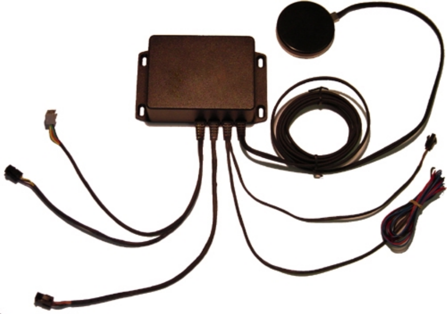
The T2002-GPRS platform has 4 cable assemblies that enter the Control Unit:
1. Combined GSM / GPS Antenna
2. Power, Ignition Sense & Immobiliser connection
3. Expansion / Serial Interface
4. Push Button Switch, Indicator LED & Telephone Handset / Hands-free
3.4.1 Combined GSM / GPS Antenna Installation
The T2002-GPRS platform is supplied with a combined GSM / GPS antenna cable assembly
fitted to the main control unit. [Order numbers: CA1003 (EGSM models) or CA1010 (GSM
models)]
The antenna should be positioned horizontally and located in a position where it will have an
unobstructed view of the sky. The ideal location in most cars is in the centre top of the
dashboard, it may also be possible to locate the antenna on the underside of the dashboard,
however, it is important to ascertain that there are no conductive materials present in the
construction of the dashboard prior to fitting the antenna.
Important Note!
The performance of the equipment may be impeded if the antenna is mounted
beneath or in very close proximity to electrically conductive materials, such as metal,
certain types of plastic, metalised film or laminate windscreens. If this applies to your
vehicle please install the antenna elsewhere.
When you commission the T2002-GPRS you will be able to carry out tests to determine
whether suitable GSM and GPS signals are being received. If in doubt about the suitability of your
planned location for the combined antenna, it is recommended that you only temporarily install
the antenna until you are able to carry out the appropriate commissioning tests. (See Section 4 –
Commissioning)

Installation & Commissioning Notes
TM8_001_2_02_03 Page 6
The antenna can be disconnected from the Control Unit by unscrewing the two in-line FME
connectors fitted between the Control Unit and the antenna itself. The GPS connectors and GSM
connectors are reversed to prevent in-correct connections being made.
Warning!
Please do not disconnect the antenna connections from the PCB inside the
Control Unit unless absolutely essential
unless absolutely essentialunless absolutely essential
unless absolutely essential. The connections are small and very
delicate so please take great care – no
liability will be accepted for any damage
caused to the system by Installation or Service personnel who aren’t suitably
qualified, or by the use of incorrect or in-appropriate tools or by the reversed
connection of the cables.
If it is absolutely essential to undertake this task then you must follow these
steps very carefully:
1. Using a Philips screwdriver, remove the lid of the T2002-GPRS platform Control Unit.
2. The antenna cables enter the enclosure through the cable entry furthest away from the PCB.
3. First remove the GPS antenna cable connection. This cable is marked with either a coloured
sleeve near the connector or a label marked GPS. It is the connector nearest the end wall of
the enclosure.
4. Using a suitable pair of long nosed pliers, gently hold the sides of the MMCX connector as
shown on the diagram below, and gently pull the connector directly upwards out of the
enclosure, taking great care not to twist the connector in the process. In the diagram shown
the connector would be pulled directly out of the page (at right angles to the page).
5. Next, using the same technique as above, remove the other antenna connector. This is the
GSM antenna connector. This cable is either unmarked or labelled GSM.
6. Carefully remove the antenna cable entry grommet by sliding it up out of the slot in the
enclosure.
7. Refit the cables, connectors and lid of the box by reversing steps 1 to 6 above.
As the antenna connectors within the Control Unit are the same it is essential
that you re-connect the cables the correct way around otherwise damage will
Hold here and pull directly
upwards out of the enclosure
The GPS antenna connector is
denoted by either:
1) a coloured sleeve
or
2) a label marked GPS

Installation & Commissioning Notes
TM8_001_2_02_03 Page 7
result. The GPS connector is identified by a coloured sleeve on the cable near
the connector or a label marked GPS.
3.4.2 Power, Ignition Sense & Immobiliser connection Installation
The second cable assembly is the Power, Ignition Sense & Immobiliser connection loom. This
cable assembly consists of 3 flying leads and wires to a 2 way Molex connector. [Order number:
CA1000]
Wire
Colour Description Notes
Red Vehicle Supply Positive (+ve) Connect to a permanent Positive supply
(6 to 32V) via a 2 amp in-line fuse.
Black Vehicle Supply Negative (-ve) Connect to permanent Negative supply
via a 5 amp in-line fuse.
Blue Ignition Sense Positive (+ve)
switched (active high) Connect to switched ignition line via a 1
amp in-line fuse.
(1) Black Signal ground for Immobiliser
(2) Brown Data control lines for Immobiliser 2 way Molex connector - plug optional
T2002-GPRS Immobiliser into this
connector.
With the exception of the Immobiliser connection, all of the above wires must be connected for
the T2002-GPRS platform to function correctly.
Please refer to Immobiliser section for wiring details relating to the Immobiliser itself.
3.4.3 Expansion / Serial Interface & RFID Reader Installation
The third cable assembly is the Expansion / Serial Interface loom. This cable assembly consists of
6 wires to a 6 way Molex connector. [Order number: CA1001]
Wire
Colour Description Notes
(1) Green RS-232 Transmit Data (TX) Serial data line (output)
(2) Blue RS-232 Ready to Send (RTS) Serial data control line (input)
(3) Pink RS-232 Receive Data (RX) Serial data line (input)
(4) Grey RS-232 Clear to Send (CTS) Serial data control line (output)
(5) Orange Auxiliary Power Supply Positive (+ve) +4 volts at 100mA max to power
Expansion modules
(6) Black Auxiliary Power Supply Negative (-ve) 0 volts to power Expansion modules
This connector allows for:
1. The attachment of a 9 Way D-Type Socket for connection to the serial port on a PC or PDA
etc. [Order number: T2002-GPRS-RS232]
2. The attachment of the RFID Reader for use in Driver ID and Asset ID applications. [Order
number: T2002-GPRS-RFID-RDR]
3. The attachment of other future Expansion Modules for the T2002-GPRS.
Where the system includes an RFID Reader, the reader should be plugged into the 6 way Molex
connector and the small module on the end of the cable should be mounted with double sided
tape or cable ties (not included) preferably within the proximity of the vehicles ignition switch,
under the plastic of the dashboard with the label on the module facing into the area in which the
RFID tag needs to be read. Note – Do not mount in a location where the RFID tag will be placed
in very close proximity to the RFID Reader. The RFID Reader is a radio receiver and it is sensitive

Installation & Commissioning Notes
TM8_001_2_02_03 Page 8
to mounting behind metallic objects etc. If problems are experienced with the RFID features
please try re-locating the reader to a different location.
3.4.4 Push Button Switch, Indicator LED & Telephone Handset / Hands-free
Installation
The fourth cable assembly is the Push Button Switch, Indicator LED & Telephone Handset
Interface loom. This cable assembly consists of 4 wires to a 4 way Molex connector and 4 wires
to a RJ9 Socket. [Order number: CA1002]
Wire
Colour Description Notes
(1) Black Microphone Positive (+ve)
(2) Red Earpiece Positive (+ve)
(3) Green Earpiece Negative (-ve)
(4) Yellow Microphone Negative (-ve)
Terminated on a standard RJ9 socket
into which a standard household
telephone handset or a suitably matched
hands-free kit can be plugged.
(Note:
not a phone instrument itself)
(1) Yellow Digital Input General purpose close to ground Digital
Input.
(2) Black Ground for Digital Input 0 volts to pair with Digital Input
(3) White Digital Output General purpose open collector Digital
Output (100mA max at 13.5 volts)
(4) Purple LED Power Current limited LED power output for use
with Digital Output
Push Button Switch & Indicator LED
The 4 way Molex connector brings out a general purpose Digital Input & Output. Although they
are general purpose, they have been optimised to work with a Push Button Switch & Indicator
LED. [Order number: T2002-GPRS-BUTTON-LED]
It is recommended that the Push Button Switch & Indicator LED, where fitted, is located within
easy reach and visibility of the vehicle driver, or where required in a covert location. Typically it
will be fitted into a blank switch position.
The functionality of this switch and LED varies depending upon the specific version of the product
purchased. Please refer to the User Manual for details.
Telephone Handset / Hands-free
The RJ9 socket will accept a standard household telephone, or equivalent, handset. This will
allow a voice call on the T2002-GPRS, where the application makes use of this capability. Note
that the T2002-GPRS does not support a telephone keypad.
It is recommended that the Telephone Handset is located in a suitable position for easy use, but
where the cable cannot get in the way of the drivers normal operation of the vehicle.
As an alternative a suitably matched Hands-free kit (amplified loud speaker and microphone) can
be plugged into the RJ9 connector.
Important Note!
The vehicle driver must not use any voice facilities unless the vehicle is stopped in a
safe location first.
3.5 T2002-GPRS
Immobiliser Installation
Important Notes!
1. Unless local law permits the T2002-GPRS Immobiliser MUST NOT be connected in such
a way such that it would be possible to disable the vehicle whilst it is under way.

Installation & Commissioning Notes
TM8_001_2_02_03 Page 9
2. Should all power (main power and battery back up if fitted) be removed from the T2002-
GPRS then the T2002-GPRS Immobiliser will default secure so as to render the vehicle
immobilised.
There are two versions of the T2002-GPRS Immobiliser available, one for 12 volt vehicles and
the other for 24 volt vehicles. [Order number: T2002-GPRS-IMMOB-12 or T2002-GPRS-IMMOB-
24]. For added security, all wiring to the Immobiliser is black in colour. The individual wires are
labelled with a number that corresponds to the table below. Please take care not to remove the
labelling before completion of the installation, testing and commissioning. The Immobiliser is
normally mounted within the passenger compartment behind the dashboard. The exact
functionality of the Immobiliser is dependant upon the configuration of the specific application
running on the T2002-GPRS platform Control Unit; please refer to the User Manual for details.
Wire
Colour Description Notes
(9) Black Data control lines for Immobiliser
(10) Black Signal ground for Immobiliser 2 way Molex connector - plug into main
T2002-GPRS platform Control Unit.
(2) Black Relay 2 - Normally Closed Contact
(rated 20 Amps)
(1) Black Relay 2 - Normally Open Contact
(rated 20 Amps)
(5) Black Relay 2 - Common Contact
(rated 20 Amps)
This relay is normally utilised for the
vehicles starter (crank) circuit. See wiring
diagrams below for details.
(8) Black Relay 1 - Normally Closed Contact
(rated 12 Amps)
(4) Black Relay 1 - Normally Open Contact
(rated 12 Amps)
(3) Black Relay 1 - Common Contact
(rated 12 Amps)
This relay is normally utilised for the
switching of auxiliary devices. See wiring
diagrams below for details.
(7) Black Vehicle Supply Positive (+ve)
(Primary connection) Connect to a permanent Positive supply
(12 volts for IMMOB-12 version or 24
volts for IMMOB-24 version).
(6) Black Vehicle Supply Negative (-ve)
(Primary connection) Connect to a permanent Negative supply.
(11) Black Vehicle Supply Positive (+ve)
(Secondary connection) Connect to a second permanent Positive
supply (12 volts for IMMOB-12 version or
24 volts for IMMOB-24 version).
(12) Black Vehicle Supply Negative (-ve)
(Secondary connection) Connect to a second permanent Negative
supply.

Installation & Commissioning Notes
TM8_001_2_02_03 Page 10
4 Commissioning
After completion of the Installation as described in Section 3, you are ready to commence
commissioning of the T2002-GPRS system.
Ensure that the SIM card
has been registered with the
mobile network and that you
are in an area with mobile
network coverage.
Note: Follow
instructions from the
mobile network
operator and ensure
that the appropriate
details are recorded in
Appendix B - T2002-
GPRS Records
Again with the vehicle
ignition off wait until the
Indicator LED is flashing
once every 2 seconds then:
Enter Engineering Mode -
"Screen 1" by pressing and
releasing the Driver interface
push button switch 10 to 12
times.
Check that the Indicator LED
is showing that the T2002-
GPRS has a GPS signal.
[2 or 3 short flashes]
(Refer to Appendix C)
Start
End
Move the vehicle to a
location where the T2002-
GPRS antenna will have a
clear view of the sky.
With the vehicle ignition off
wait until the Indicator LED
is flashing once every 2
seconds then:
"Reboot" the T2002-GPRS
by pressing and releasing
the Driver interface push
button switch 20 to 22 times.
Check that the Indicator LED
is showing GSM service.
[1, 2 or 3 long flashes]
Enter Engineering Mode
"Screen 2" by pressing and
releasing the Driver interface
push button switch once.
Check that the Indicator LED
is showing correct
connection to the vehicle
Ignition.
[Ignition on = LED on]
Enter Engineering Mode
"Screen 3" by pressing and
releasing the Driver interface
push button switch once.
Check that the Indicator LED
is showing correct
connection to the vehicle
Main Power.
[Main Power on = LED on]
Check that the Indicator LED
is showing correct operation
of Driver ID Tag Reader.
[Tag detected = blink LED]
Enter Engineering Mode
"Screen 4" by pressing and
releasing the Driver interface
push button switch once.
Check that the Indicator LED
is showing correct operation
of Tremble Sensor.
[Tamper detected = blink
LED]
Enter Engineering Mode
"Screen 5" by pressing and
releasing the Driver interface
push button switch once.
Exit Engineering Mode by
pressing and releasing the
Driver interface push button
switch 10 to 12 times.
Note: After the 20 - 22
presses wait and the
Indicator LED will blink
for 5 seconds to
confirm "Reboot"
command accepted.
Then you may need to
wait up to 3 minutes
before moving on.
Note: This will cause
the T2002-GPRS to
enter Engineering
Mode - "Screen 1" and
the Indicator LED
flashing will have
specific meaning as
shown in Appendix C -
T2002-GPRS
Engineering Mode.
Note: You may need to
wait for up to 5 minutes
but you should always
get a 3d GPS signal [3
short flashes]. If not it
is most likely there is a
problem with the
antenna location.
Note: You may need to
wait for up to 5 minutes
but you should get at
least a GSM signal [1
long flash].
Note: Ensure that the
Indicator LED is off
when the Ignition is off
and on when on.
Ensure that the LED
remains on whilst the
vehicle engine is being
started and whilst the
engine is running.
Note: Check this by
temporarily removing
the 2 amp fuse from
the Permanent +6V to
+32V supply.
Note: Skip this test if
system does not have
an RFID Tag Reader.
Check this by moving
the Driver ID Tag
around inside the
vehicle.
Note: Check this by
carefully shaking the
vehicle and / or
slamming the doors.
Note: Please ensure
Appendix B - T2002-
GPRS Records has
been filled in and hand
over this Manual to the
vehicle Owner for
future reference.
Installation & Commissioning Notes
TM8_001_2_02_03 Page 11
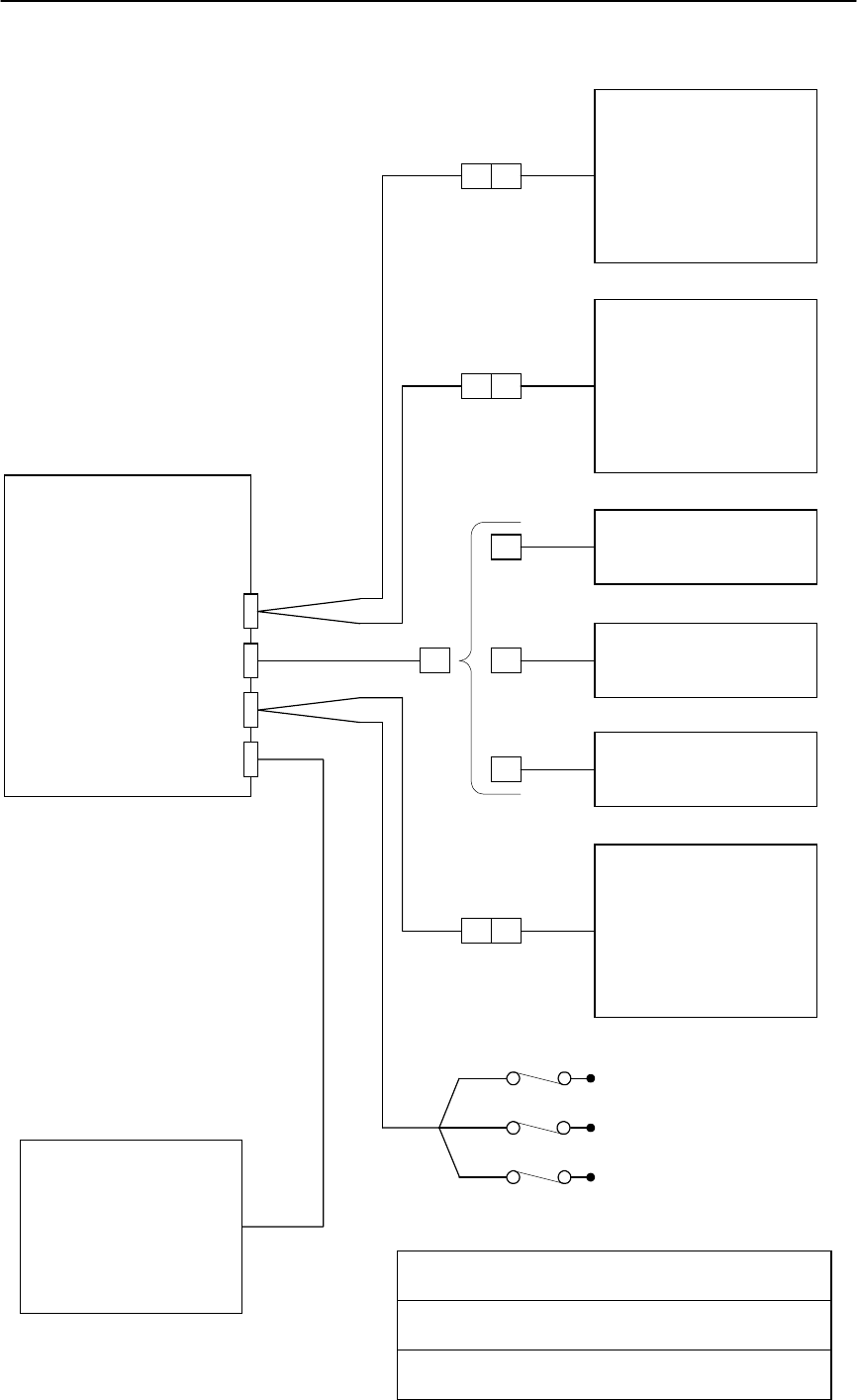
5 Appendix A –T2002-GPRS
Wiring diagrams
T2002-GPRS
APPENDIX A
BLOCK DIAGRAM
Immobiliser
[T2002-GPRS-IMMOB-12
or
T2002-GPRS-IMMOB-24]
Telephone
Handsfree or
Handset
Push Button
Switch /
Indicator LED
[T2002-GPRS-BUTTON-LED]
T2002-GPRS
Control Unit
RFID Reader
[T2002-GPRS-RFID-RDR]
GSM / GPS
Antenna
[CA1003 or CA1010]
Vehicle Ground
Black
Permanent + 6V to +32V DC
Red
Ignition Switched Supply
Blue
in-line fuses
Serial RS-232
[T2002-GPRS-RS232]
Future modules
RJ9
4 way Molex
6 way Molex
2 way Molex
2 Amp
5 Amp
1 Amp

Installation & Commissioning Notes
TM8_001_2_02_03 Page 12
T2002-GPRS
APPENDIX A
CONTROL UNIT DIAGRAM
T2002-GPRS Control Unit
1 2 1 5 1 6 1 4 1 4
Battery Pack
[GA1003]
Black
Red
Blue
Red
Brown
Black
Black
Pink
Green
Grey
Orange
Blue
Black
White
Yellow
Purple
Black
Green
Black
Yellow
Red
Back Up
Battery
Connection
GSM Antenna
Connection
PCB
Assembly
PA1005
GPS Antenna
Connection
CA1002
CA1003 or CA1010
CA1000
CA1001

Installation & Commissioning Notes
TM8_001_2_02_03 Page 13
T2002-GPRS
APPENDIX A
VOICE, BUTTON & LED DIAGRAM
RJ9 PLUG
4 - Yellow - Microphone Negative (-ve)
1 - Black - Microphone Positive (+ve)
-ve
+ve
+ve
-ve
2 - Red - Earpiece Positive (+ve)
3 - Green - Earpiece Negative (-ve)
High impedance earpiece or
matched hands free amplifier
High impedance microphone
4 way Molex
43025-0400 4 - Purple
1 - Yellow
2 - Black
3 - White
Push Button Switch / Indicator LED
[T2002-GPRS-BUTTON-LED]

Installation & Commissioning Notes
TM8_001_2_02_03 Page 14
T2002-GPRS
APPENDIX A
RFID, SERIAL & EXPANSION DIAGRAM
2 - Grey - 4
n/c - 1
n/c - 2
1 - Pink - 3
4 - Black - 6
3 - Orange - 5
RFID Tag
[T2002-GPRS-RFID-ST
or
T2002-GPRS-RFID-KT]
6 way Molex
43025-0600
4 - Grey - 4
1 - Green - 1
2 - Blue - 2
3 - Pink - 3
6 - Black - 6
5 - Orange - 5
8 - Grey - 4
2 - Green - 1
7 - Blue - 2
3 - Pink - 3
5 - Black - 6
n/c - 5
RFID Reader
6 way Molex
43025-0600
To 6 way Molex on Control Unit
OR OR
6 way Molex
43025-0600
Future
expansion
modules
RFID Reader
[T2002-GPRS-RFID-RDR] Serial RS-232
[T2002-GPRS-RS232] Future Expansion
Modules
9-Way D-Type
Installation & Commissioning Notes
TM8_001_2_02_03 Page 15
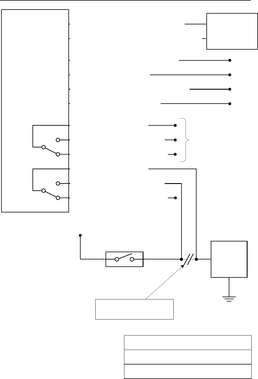
T2002-GPRS
APPENDIX A
IMMOBILISER DIAGRAM
Immobiliser
9 - Black - Data line from Control Unit - 2
NO1
NC1
C1
Relay 1
12 Amp
Contacts
NO2
NC2
C2
Relay 2
20 Amp
Contacts
10 - Black - Signal Ground from Control Unit - 1 2 way Molex
43025-0200
7 - Black - Permanent +V DC (Primary)
11 - Black - Permanent +V DC (Secondary)
6 - Black - Ground (Primary)
12 - Black - Ground (Secondary)
3 - Black - Relay 1 Common
4 - Black - Relay 1 Normally Open
8 - Black - Relay 1 Normally Closed
5 - Black - Relay 2 Common
1 - Black - Relay 2 Normally Open
2 - Black - Relay 2 Normally Closed
Vehicle
Starter
Solenoid
Ground
+V DC
Vehicle Ignition
Switch
Break Starter "Crank" circuit
here and route via Immobiliser
For
switching
of
Auxilary
devices

Installation & Commissioning Notes
TM8_001_2_02_03 Page 16
6 Appendix B –T2002-GPRS Records
Information Source Record details here
T2002-GPRS Activation
Key Issued by your T2002-GPRS
platform supplier
T2002-GPRS IMEI
number Label on bottom of Control
Unit
T2002-GPRS Mobile
Network Name SIM packaging
T2002-GPRS Mobile
number (Voice) Obtained during SIM
registration process
T2002-GPRS Mobile
number (Data) - optional Obtained during SIM
registration process
SIM Card number (ESN) Printed on SIM or on
Control Unit packaging
when supplied pre-installed
Mobile network
Customer Services
telephone number
Obtained during SIM
registration process
T2002-GPRS password Defaults to NOTACTIVE
Notes:

Installation & Commissioning Notes
TM8_001_2_02_03 Page 17
Notes:

Installation & Commissioning Notes
TM8_001_2_02_03 Page 18
7 Appendix C –T2002-GPRS
Engineering Mode
Overview
For diagnostics purposes the T2002-GPRS can be put into Engineering mode. Whilst in this
mode the Indication LED displays the results of various tests or the status of the T2002-GPRS.
Debug messages are also sent to the serial port whilst in Engineering mode.
Engineering mode has 5 different "screens", each of which, via the Indication LED conveys
information / allows diagnostic tests to be performed on the T2002-GPRS.
Activating Engineering Mode
With the vehicle ignition off wait until the Indicator LED is flashing once every 2 seconds. Press
the Driver interface button 10 times or more (but less than 20 times and with each press being
for less than 2 seconds). Wait, and the LED will come on solid for 10 seconds to confirm entry
into Engineering mode, the LED will then blink once to show that it is in "screen" 1.
Note: Please ensure that you do not keep the button pressed for more than 2 seconds on any of
the button presses; otherwise a Panic Alert will be activated.
Whilst in Engineering Mode
The 5 "screens" can be cycled through by briefly pressing and releasing the Driver interface
button. It is possible to skip more than one "screen" at a time by repeatedly pressing the button.
When a new “Screen” is entered the LED will “blink” between 1 and 5 times to confirm the
“screen” number. See the tables below for suggested usage of each “screen” and the full
meaning of the LED whilst in that “screen”.
Additionally, the T2002-GPRS platform Control Unit RS-232 Serial Port will start transmitting
coded Debug data. Where a problem is being experienced it is extremely useful if this Debug
data can be captured to a file whilst the problem is being experienced for subsequent analysis by
support staff. Microsoft®’s HyperTerminal is ideally suited for this purpose.
Suggested Usage of Engineering Mode “Screens”
“Screen” Function Suggested Usage
1 GSM / GPS
Status • Ensuring that the combined antenna is mounted in a suitable /
optimal location within the vehicle.
• Ensuring that the vehicle is in a good coverage area for GPS, GSM
and GPRS.
• Ensuring that the T2002-GPRS is correctly connecting to the
configured Instant Messaging server. (Only applicable to some
versions).
2 Ignition
Status • Ensuring that the T2002-GPRS has been connected to a suitable
Ignition feed and that the fuse has not blown.
3 External
Voltage
Detect
• Ensuring that the T2002-GPRS has been connected to a suitable
Main Power feed and that the fuse has not blown.
4 Driver ID
Tag Detect • Ensuring that the Driver ID Tag reader is installed in a suitable
location within the vehicle to detect ID Tags. (Only applicable to
some versions).
• Assisting with the setting of the RFID Tag sensitivity using the
SETRSSI command.
5 Tamper
(Trembler)
Detect
• Ensuring that the Tamper sensor is working.
• Assisting with the setting of the Tamper sensitivity using the
TREMBLELEVEL command.

Installation & Commissioning Notes
TM8_001_2_02_03 Page 19
Engineering Mode “Screen” Operation
“Screen” Function Entry
Confirmation Operation
1 GSM / GPS
Status 1 blink of LED LED will flash GPS status (short flashes)
followed by GSM status (long flashes)
No short flashes - No GPS signal
2 short flashes - 2d GPS signal
3 short flashes - 3d GPS signal
No long flashes - No GSM signal
1 long flash - GSM connected
2 long flashes - GSM & GPRS connected
3 long flashes - GSM, GPRS & Instant Messaging
client connected to server
2 Ignition
Status 2 blinks of LED LED shows status of Ignition feed to T2002-GPRS
LED on solid - Ignition detected
LED off - Ignition not detected
3 External
Voltage
Detect
3 blinks of LED LED shows status of main power feed to T2002-
GPRS
LED on solid - Voltage detected
LED off - Voltage not detected
4 Driver ID
Tag Detect 4 blinks of LED LED will blink briefly whenever a Driver ID Tag
transmission is detected
5 Tamper
(Trembler)
Detect
5 blinks of LED LED will blink briefly whenever a Tamper (Tremble) is
detected
De-activating Engineering Mode
To exit Engineering mode, press the Driver interface button 10 times or more (but less than 20
times and with each press being for less than 2 seconds). Wait, and the LED will come on solid
for 10 seconds to confirm exit from the Engineering mode. The LED will then resume its normal
operation and Debug data will be turned off.
Manually “Rebooting” the T2002-GPRS
If the T2002-GPRS has been behaving in an unpredictable or unexpected manner, it is possible
to force the system to “reboot” itself.
To activate this reboot, press the Driver interface button 20 times or more (with each press being
for less than 2 seconds). Wait, and the LED will blink for 5 seconds to confirm that the instruction
has been received. The T2002-GPRS will then reboot itself. It can take up to a few minutes for
the T2002-GPRS to start functioning normally again following the reboot.

Installation & Commissioning Notes
TM8_001_2_02_03 Page 20
8 Appendix D –T2002-GPRS
Spare Parts & Order Numbers
Order Number Description
T2002-GPRS-RS232 Serial RS-232 cable.
T2002-GPRS-IMMOB-12 2 circuit Immobiliser for the T2002-GPRS for 12V Vehicles.
T2002-GPRS-IMMOB-24 2 circuit Immobiliser for the T2002-GPRS for 24V Vehicles.
T2002-GPRS-BUTTON-LED Replacement Push Button Switch / Indicator LED with wiring
loom.
T2002-GPRS-RFID-RDR Replacement RFID Reader for the T2002-GPRS.
T2002-GPRS-RFID-ST Replacement / additional ‘credit card’ style RFID tag for use
with the T2002-GPRS. Used for Driver Identification.
T2002-GPRS-RFID-KT Key fob style RFID tag for use with the T2002-GPRS. Used for
Driver Identification.
CA1000 Replacement Power, Ignition Sense & Immobiliser connection
wiring loom. (Requires additional external items)
CA1001 Replacement Expansion / Serial Interface & RFID Reader
connection wiring loom. (Requires additional external items)
CA1002 Replacement Push Button Switch, Indicator LED & Telephone
Handset / Hands-free connection wiring loom. (Requires
additional external items)
CA1003 Replacement GSM / GPS Antenna for EGSM version of the
T2002-GPRS. (GSM frequencies 900 / 1800 MHz)
GA1003 Replacement T2002-GPRS Back-Up Battery Pack.
As we constantly strive to improve our products, all specifications are subject to change without notice. The information
provided herein is believed to be correct at time of going to press.
Copyright ® 2003 trakm8 Limited