Trakm8 T2002-GPRS Safty, Security and Tracking Device User Manual USERS MANUAL
Interactive Projects Ltd. Safty, Security and Tracking Device USERS MANUAL
UserManual.wiki
>
Trakm8
>
T2002 GPRS User Manual
USERS MANUAL
Navigation menu
Upload a User Manual
Namespaces
Wiki Guide
HTML
PDF
Info
Views
User Manual
Discussion / Help
Navigation

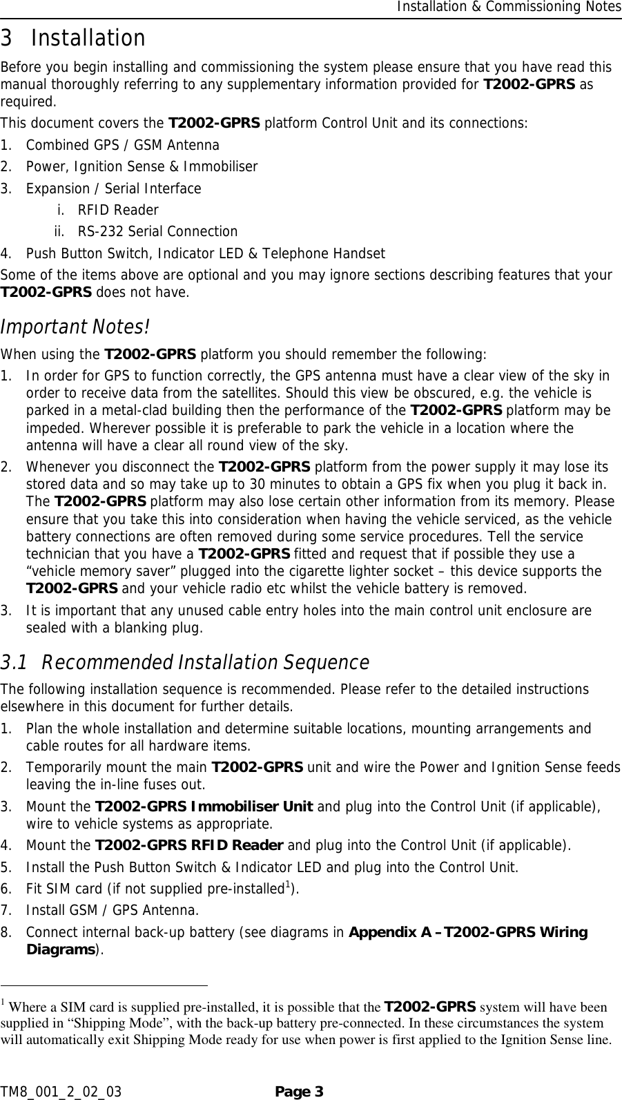
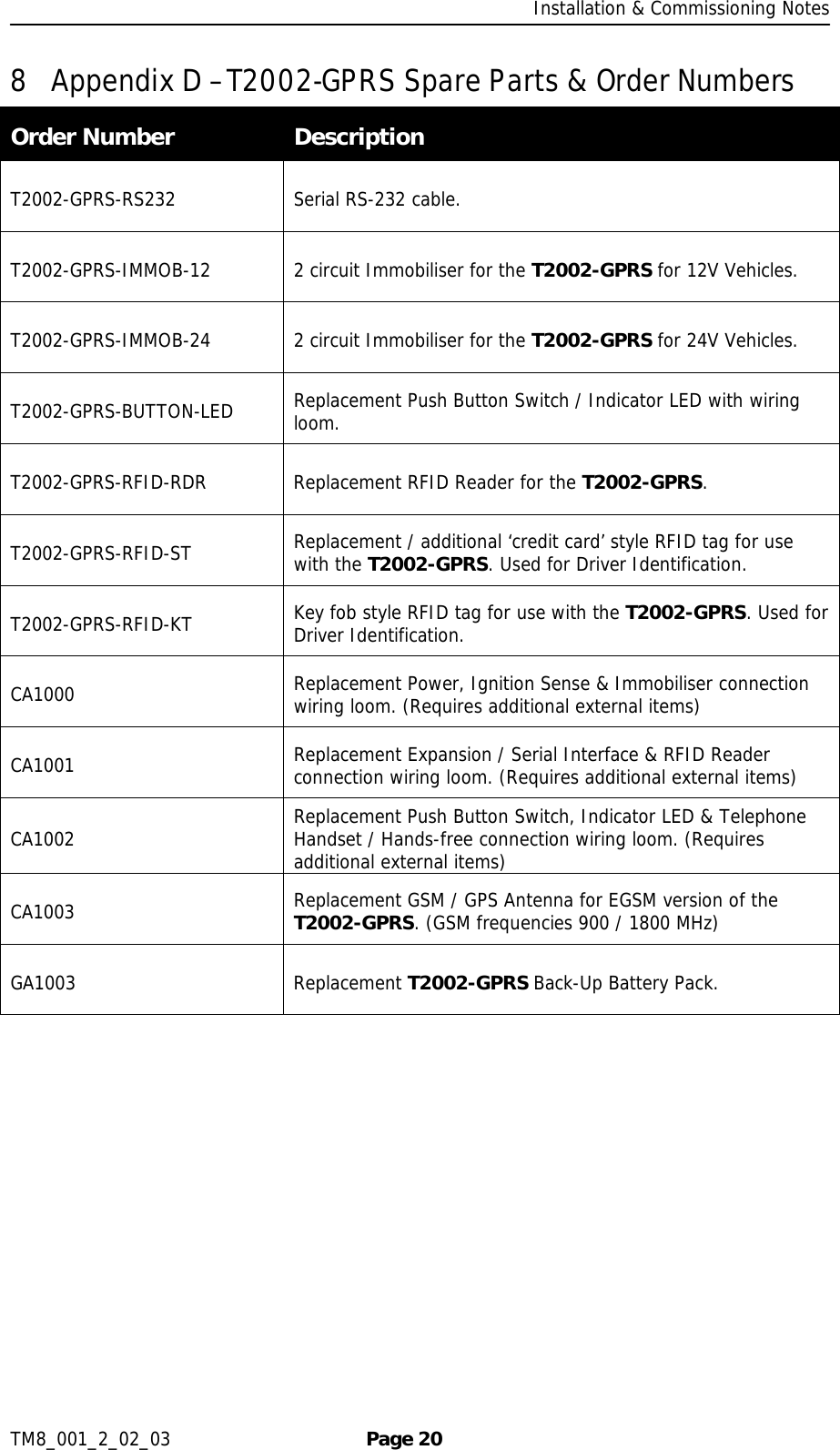
![Installation & Commissioning Notes TM8_001_2_02_03 Page 5 located in a position where the cables or the Control Unit may become a hazard to the driver or any passengers. 2. Under no circumstances may any part of the T2002T2002T2002T2002----GPRSGPRSGPRSGPRS system be installed inside the engine compartment area. 3.4 T2002-GPRS Wiring and Connections Important Notes! 1. Unauthorised changes or alterations to the equipment or the installation will invalidate certification issued by the Approved Accreditation Body and could also affect the vehicle manufacturer’s warranty. 2. The notes below should be read in conjunction with Appendix A –T2002-GPRS Wiring Diagrams. 3. All wiring should be safely secured to avoid damage from, or chaffing by, any hot or moving parts. 4. Position wiring carefully to avoid the possibility of snagging or impact damage during the normal use of the vehicle. 5. Before any holes are drilled, check that no parts, wires, pipes or tanks could be damaged at the other side of the hole. Suitable grommets must be used where wires are routed through body panels to prevent short circuits to the chassis. 6. Leave in-line fuses out of holders until the installation is complete. Cable Assemblies The T2002-GPRS platform has 4 cable assemblies that enter the Control Unit: 1. Combined GSM / GPS Antenna 2. Power, Ignition Sense & Immobiliser connection 3. Expansion / Serial Interface 4. Push Button Switch, Indicator LED & Telephone Handset / Hands-free 3.4.1 Combined GSM / GPS Antenna Installation The T2002-GPRS platform is supplied with a combined GSM / GPS antenna cable assembly fitted to the main control unit. [Order numbers: CA1003 (EGSM models) or CA1010 (GSM models)] The antenna should be positioned horizontally and located in a position where it will have an unobstructed view of the sky. The ideal location in most cars is in the centre top of the dashboard, it may also be possible to locate the antenna on the underside of the dashboard, however, it is important to ascertain that there are no conductive materials present in the construction of the dashboard prior to fitting the antenna. Important Note! The performance of the equipment may be impeded if the antenna is mounted beneath or in very close proximity to electrically conductive materials, such as metal, certain types of plastic, metalised film or laminate windscreens. If this applies to your vehicle please install the antenna elsewhere. When you commission the T2002-GPRS you will be able to carry out tests to determine whether suitable GSM and GPS signals are being received. If in doubt about the suitability of your planned location for the combined antenna, it is recommended that you only temporarily install the antenna until you are able to carry out the appropriate commissioning tests. (See Section 4 – Commissioning)](https://usermanual.wiki/Trakm8/T2002-GPRS/User-Guide-509560-Page-6.png)
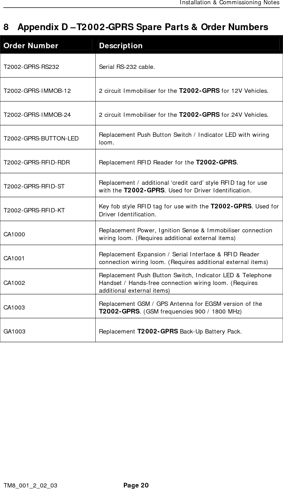
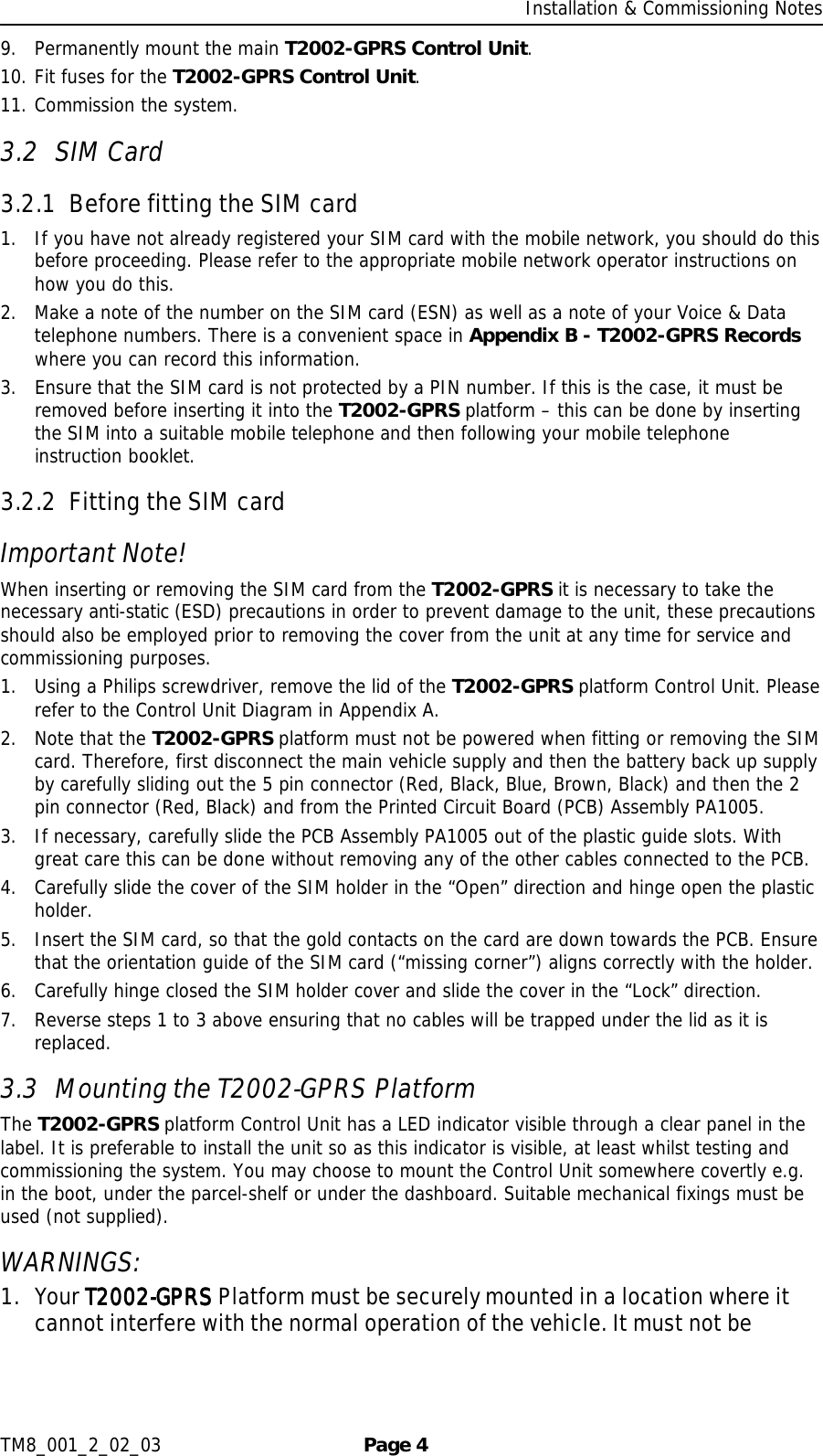
![Installation & Commissioning Notes TM8_001_2_02_03 Page 7 result. The GPS connector is identified by a coloured sleeve on the cable near the connector or a label marked GPS. 3.4.2 Power, Ignition Sense & Immobiliser connection Installation The second cable assembly is the Power, Ignition Sense & Immobiliser connection loom. This cable assembly consists of 3 flying leads and wires to a 2 way Molex connector. [Order number: CA1000] Wire Colour Description Notes Red Vehicle Supply Positive (+ve) Connect to a permanent Positive supply (6 to 32V) via a 2 amp in-line fuse. Black Vehicle Supply Negative (-ve) Connect to permanent Negative supply via a 5 amp in-line fuse. Blue Ignition Sense Positive (+ve) switched (active high) Connect to switched ignition line via a 1 amp in-line fuse. (1) Black Signal ground for Immobiliser (2) Brown Data control lines for Immobiliser 2 way Molex connector - plug optional T2002-GPRS Immobiliser into this connector. With the exception of the Immobiliser connection, all of the above wires must be connected for the T2002-GPRS platform to function correctly. Please refer to Immobiliser section for wiring details relating to the Immobiliser itself. 3.4.3 Expansion / Serial Interface & RFID Reader Installation The third cable assembly is the Expansion / Serial Interface loom. This cable assembly consists of 6 wires to a 6 way Molex connector. [Order number: CA1001] Wire Colour Description Notes (1) Green RS-232 Transmit Data (TX) Serial data line (output) (2) Blue RS-232 Ready to Send (RTS) Serial data control line (input) (3) Pink RS-232 Receive Data (RX) Serial data line (input) (4) Grey RS-232 Clear to Send (CTS) Serial data control line (output) (5) Orange Auxiliary Power Supply Positive (+ve) +4 volts at 100mA max to power Expansion modules (6) Black Auxiliary Power Supply Negative (-ve) 0 volts to power Expansion modules This connector allows for: 1. The attachment of a 9 Way D-Type Socket for connection to the serial port on a PC or PDA etc. [Order number: T2002-GPRS-RS232] 2. The attachment of the RFID Reader for use in Driver ID and Asset ID applications. [Order number: T2002-GPRS-RFID-RDR] 3. The attachment of other future Expansion Modules for the T2002-GPRS. Where the system includes an RFID Reader, the reader should be plugged into the 6 way Molex connector and the small module on the end of the cable should be mounted with double sided tape or cable ties (not included) preferably within the proximity of the vehicles ignition switch, under the plastic of the dashboard with the label on the module facing into the area in which the RFID tag needs to be read. Note – Do not mount in a location where the RFID tag will be placed in very close proximity to the RFID Reader. The RFID Reader is a radio receiver and it is sensitive](https://usermanual.wiki/Trakm8/T2002-GPRS/User-Guide-509560-Page-8.png)
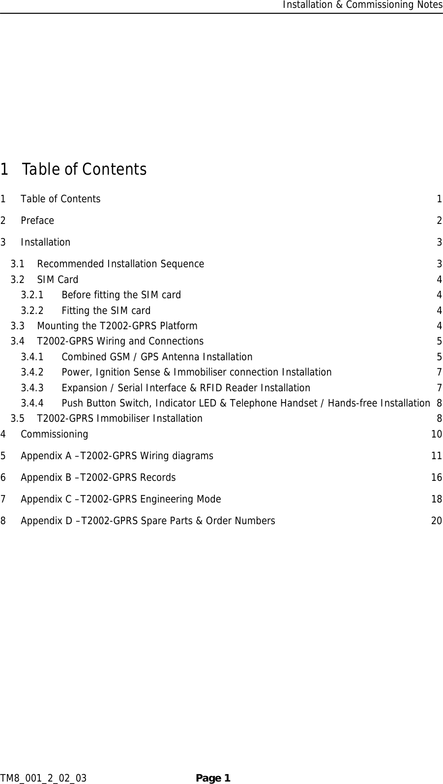
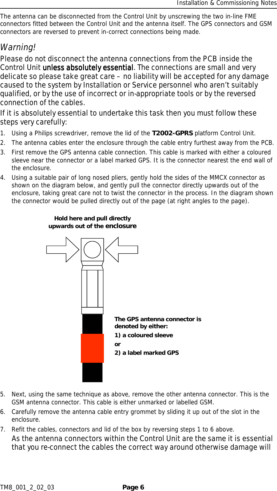
![Installation & Commissioning Notes TM8_001_2_02_03 Page 8 to mounting behind metallic objects etc. If problems are experienced with the RFID features please try re-locating the reader to a different location. 3.4.4 Push Button Switch, Indicator LED & Telephone Handset / Hands-free Installation The fourth cable assembly is the Push Button Switch, Indicator LED & Telephone Handset Interface loom. This cable assembly consists of 4 wires to a 4 way Molex connector and 4 wires to a RJ9 Socket. [Order number: CA1002] Wire Colour Description Notes (1) Black Microphone Positive (+ve) (2) Red Earpiece Positive (+ve) (3) Green Earpiece Negative (-ve) (4) Yellow Microphone Negative (-ve) Terminated on a standard RJ9 socket into which a standard household telephone handset or a suitably matched hands-free kit can be plugged. (Note: not a phone instrument itself) (1) Yellow Digital Input General purpose close to ground Digital Input. (2) Black Ground for Digital Input 0 volts to pair with Digital Input (3) White Digital Output General purpose open collector Digital Output (100mA max at 13.5 volts) (4) Purple LED Power Current limited LED power output for use with Digital Output Push Button Switch & Indicator LED The 4 way Molex connector brings out a general purpose Digital Input & Output. Although they are general purpose, they have been optimised to work with a Push Button Switch & Indicator LED. [Order number: T2002-GPRS-BUTTON-LED] It is recommended that the Push Button Switch & Indicator LED, where fitted, is located within easy reach and visibility of the vehicle driver, or where required in a covert location. Typically it will be fitted into a blank switch position. The functionality of this switch and LED varies depending upon the specific version of the product purchased. Please refer to the User Manual for details. Telephone Handset / Hands-free The RJ9 socket will accept a standard household telephone, or equivalent, handset. This will allow a voice call on the T2002-GPRS, where the application makes use of this capability. Note that the T2002-GPRS does not support a telephone keypad. It is recommended that the Telephone Handset is located in a suitable position for easy use, but where the cable cannot get in the way of the drivers normal operation of the vehicle. As an alternative a suitably matched Hands-free kit (amplified loud speaker and microphone) can be plugged into the RJ9 connector. Important Note! The vehicle driver must not use any voice facilities unless the vehicle is stopped in a safe location first. 3.5 T2002-GPRS Immobiliser Installation Important Notes! 1. Unless local law permits the T2002-GPRS Immobiliser MUST NOT be connected in such a way such that it would be possible to disable the vehicle whilst it is under way.](https://usermanual.wiki/Trakm8/T2002-GPRS/User-Guide-509560-Page-9.png)
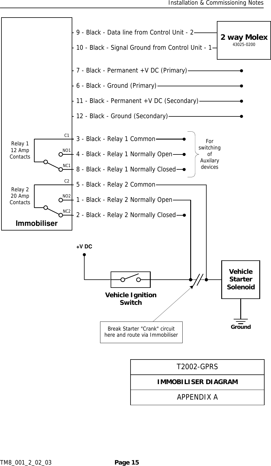
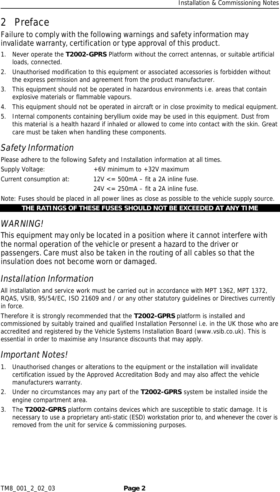
![Installation & Commissioning Notes TM8_001_2_02_03 Page 9 2. Should all power (main power and battery back up if fitted) be removed from the T2002-GPRS then the T2002-GPRS Immobiliser will default secure so as to render the vehicle immobilised. There are two versions of the T2002-GPRS Immobiliser available, one for 12 volt vehicles and the other for 24 volt vehicles. [Order number: T2002-GPRS-IMMOB-12 or T2002-GPRS-IMMOB-24]. For added security, all wiring to the Immobiliser is black in colour. The individual wires are labelled with a number that corresponds to the table below. Please take care not to remove the labelling before completion of the installation, testing and commissioning. The Immobiliser is normally mounted within the passenger compartment behind the dashboard. The exact functionality of the Immobiliser is dependant upon the configuration of the specific application running on the T2002-GPRS platform Control Unit; please refer to the User Manual for details. Wire Colour Description Notes (9) Black Data control lines for Immobiliser (10) Black Signal ground for Immobiliser 2 way Molex connector - plug into main T2002-GPRS platform Control Unit. (2) Black Relay 2 - Normally Closed Contact (rated 20 Amps) (1) Black Relay 2 - Normally Open Contact (rated 20 Amps) (5) Black Relay 2 - Common Contact (rated 20 Amps) This relay is normally utilised for the vehicles starter (crank) circuit. See wiring diagrams below for details. (8) Black Relay 1 - Normally Closed Contact (rated 12 Amps) (4) Black Relay 1 - Normally Open Contact (rated 12 Amps) (3) Black Relay 1 - Common Contact (rated 12 Amps) This relay is normally utilised for the switching of auxiliary devices. See wiring diagrams below for details. (7) Black Vehicle Supply Positive (+ve) (Primary connection) Connect to a permanent Positive supply (12 volts for IMMOB-12 version or 24 volts for IMMOB-24 version). (6) Black Vehicle Supply Negative (-ve) (Primary connection) Connect to a permanent Negative supply. (11) Black Vehicle Supply Positive (+ve) (Secondary connection) Connect to a second permanent Positive supply (12 volts for IMMOB-12 version or 24 volts for IMMOB-24 version). (12) Black Vehicle Supply Negative (-ve) (Secondary connection) Connect to a second permanent Negative supply.](https://usermanual.wiki/Trakm8/T2002-GPRS/User-Guide-509560-Page-10.png)
StartEndMove the vehicle to alocation where the T2002-GPRS antenna will have aclear view of the sky.With the vehicle ignition offwait until the Indicator LEDis flashing once every 2seconds then:"Reboot" the T2002-GPRSby pressing and releasingthe Driver interface pushbutton switch 20 to 22 times.Check that the Indicator LEDis showing GSM service.[1, 2 or 3 long flashes] Enter Engineering Mode"Screen 2" by pressing andreleasing the Driver interfacepush button switch once.Check that the Indicator LEDis showing correctconnection to the vehicleIgnition.[Ignition on = LED on] Enter Engineering Mode"Screen 3" by pressing andreleasing the Driver interfacepush button switch once.Check that the Indicator LEDis showing correctconnection to the vehicleMain Power.[Main Power on = LED on]Check that the Indicator LEDis showing correct operationof Driver ID Tag Reader.[Tag detected = blink LED] Enter Engineering Mode"Screen 4" by pressing andreleasing the Driver interfacepush button switch once.Check that the Indicator LEDis showing correct operationof Tremble Sensor.[Tamper detected = blinkLED] Enter Engineering Mode"Screen 5" by pressing andreleasing the Driver interfacepush button switch once.Exit Engineering Mode bypressing and releasing theDriver interface push buttonswitch 10 to 12 times.Note: After the 20 - 22presses wait and theIndicator LED will blinkfor 5 seconds toconfirm "Reboot"command accepted.Then you may need towait up to 3 minutesbefore moving on.Note: This will causethe T2002-GPRS toenter EngineeringMode - "Screen 1" andthe Indicator LEDflashing will havespecific meaning asshown in Appendix C -T2002-GPRSEngineering Mode.Note: You may need towait for up to 5 minutesbut you should alwaysget a 3d GPS signal [3short flashes]. If not itis most likely there is aproblem with theantenna location.Note: You may need towait for up to 5 minutesbut you should get atleast a GSM signal [1long flash].Note: Ensure that theIndicator LED is offwhen the Ignition is offand on when on.Ensure that the LEDremains on whilst thevehicle engine is beingstarted and whilst theengine is running.Note: Check this bytemporarily removingthe 2 amp fuse fromthe Permanent +6V to+32V supply.Note: Skip this test ifsystem does not havean RFID Tag Reader.Check this by movingthe Driver ID Tagaround inside thevehicle.Note: Check this bycarefully shaking thevehicle and / orslamming the doors.Note: Please ensureAppendix B - T2002-GPRS Records hasbeen filled in and handover this Manual to thevehicle Owner forfuture reference.](https://usermanual.wiki/Trakm8/T2002-GPRS/User-Guide-509560-Page-11.png)
![Installation & Commissioning Notes TM8_001_2_02_03 Page 11 5 Appendix A –T2002-GPRS Wiring diagrams T2002-GPRSAPPENDIX ABLOCK DIAGRAMImmobiliser[T2002-GPRS-IMMOB-12orT2002-GPRS-IMMOB-24]TelephoneHandsfree orHandsetPush ButtonSwitch /Indicator LED[T2002-GPRS-BUTTON-LED]T2002-GPRSControl UnitRFID Reader[T2002-GPRS-RFID-RDR]GSM / GPSAntenna[CA1003 or CA1010]Vehicle GroundBlackPermanent + 6V to +32V DCRedIgnition Switched SupplyBluein-line fusesSerial RS-232[T2002-GPRS-RS232]Future modulesRJ94 way Molex6 way Molex2 way Molex2 Amp5 Amp1 Amp](https://usermanual.wiki/Trakm8/T2002-GPRS/User-Guide-509560-Page-12.png)
![Installation & Commissioning Notes TM8_001_2_02_03 Page 12 T2002-GPRSAPPENDIX ACONTROL UNIT DIAGRAMT2002-GPRS Control Unit1 2 1 5 1 6 1 4 1 4Battery Pack[GA1003]BlackRedBlueRedBrownBlackBlackPinkGreenGreyOrangeBlueBlackWhiteYellowPurpleBlackGreenBlackYellowRedBack UpBatteryConnectionGSM AntennaConnectionPCBAssemblyPA1005GPS AntennaConnectionCA1002CA1003 or CA1010CA1000CA1001](https://usermanual.wiki/Trakm8/T2002-GPRS/User-Guide-509560-Page-13.png)
![Installation & Commissioning Notes TM8_001_2_02_03 Page 13 T2002-GPRSAPPENDIX AVOICE, BUTTON & LED DIAGRAMRJ9 PLUG 4 - Yellow - Microphone Negative (-ve) 1 - Black - Microphone Positive (+ve)-ve+ve+ve-ve 2 - Red - Earpiece Positive (+ve) 3 - Green - Earpiece Negative (-ve)High impedance earpiece ormatched hands free amplifierHigh impedance microphone4 way Molex43025-0400 4 - Purple 1 - Yellow 2 - Black 3 - WhitePush Button Switch / Indicator LED[T2002-GPRS-BUTTON-LED]](https://usermanual.wiki/Trakm8/T2002-GPRS/User-Guide-509560-Page-14.png)
![Installation & Commissioning Notes TM8_001_2_02_03 Page 14 T2002-GPRSAPPENDIX ARFID, SERIAL & EXPANSION DIAGRAM 2 - Grey - 4 n/c - 1 n/c - 2 1 - Pink - 3 4 - Black - 6 3 - Orange - 5RFID Tag[T2002-GPRS-RFID-STorT2002-GPRS-RFID-KT]6 way Molex43025-0600 4 - Grey - 4 1 - Green - 1 2 - Blue - 2 3 - Pink - 3 6 - Black - 6 5 - Orange - 5 8 - Grey - 4 2 - Green - 1 7 - Blue - 2 3 - Pink - 3 5 - Black - 6 n/c - 5RFID Reader6 way Molex43025-0600To 6 way Molex on Control UnitOR OR6 way Molex43025-0600FutureexpansionmodulesRFID Reader[T2002-GPRS-RFID-RDR] Serial RS-232[T2002-GPRS-RS232] Future ExpansionModules9-Way D-Type](https://usermanual.wiki/Trakm8/T2002-GPRS/User-Guide-509560-Page-15.png)