TranSystem 970900101 UHF Band MMDS Transceiver User Manual 1

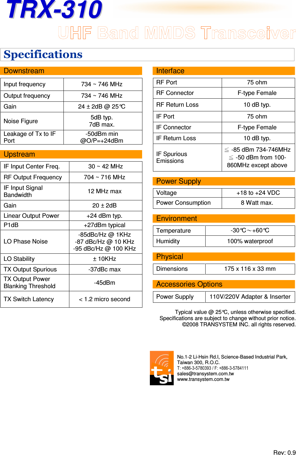
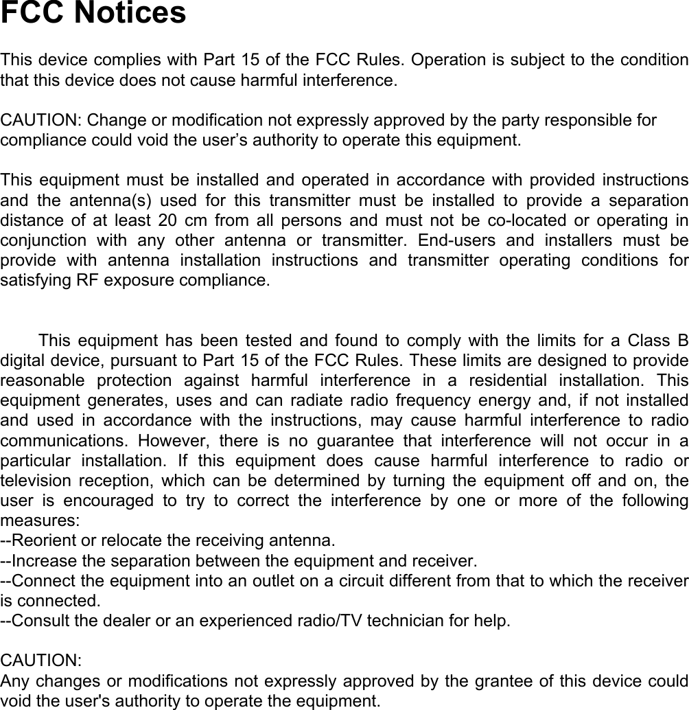
TranSystem UHF Band MMDS Transceiver 1

UserMan 1124

TTRRXX--331100      Rev: 0.9                                        Overview  TRX-310 is TSI’s latest offering for 2-way wireless broadband Internet application at UHF band. It accepts an IF signal of 30~42MHz from cable modem, upconverts the signal to 704~716MHz and transmits it back to the MMDS headend site.   With its built-in automatic on/off switch, TRX-310 will enter sleep mode to eliminate the broadband noise when there is no data packet transmission. Without exception, TRX-310 embodies the long term stability and reliability common to all TSI products.   With the integrated downconverter and upconverter, TRX-310 provides the best cost / performance solution for your 2-way MMDS operation.   Key Features • QPSK, 16 QAM Transmission Compatible • 256 QAM Reception Compatible  • Automatic On/Off switch • Up to 50Km cell coverage • Low phase noise • High frequency stability • Low power consumption • Meet FCC spectral mask requirement • Easy installation • RoHS compliant  Application • UHF Band 2 way MMDS CPE Internet access  TRANSYSTEM INC.  An A+ supplier of RF microwave & GPS products
TTRRXX--331100      Rev: 0.9   Specifications  Downstream   Input frequency  734 ~ 746 MHz Output frequency  734 ~ 746 MHz Gain  24 ± 2dB @ 25°C Noise Figure  5dB typ. 7dB max. Leakage of Tx to IF Port -50dBm min @O/P=+24dBm  Upstream  IF Input Center Freq.  30 ~ 42 MHz RF Output Frequency  704 ~ 716 MHz IF Input Signal Bandwidth  12 MHz max Gain  20 ± 2dB Linear Output Power  +24 dBm typ. P1dB  +27dBm typical LO Phase Noise -85dBc/Hz @ 1KHz -87 dBc/Hz @ 10 KHz -95 dBc/Hz @ 100 KHz LO Stability  ± 10KHz TX Output Spurious  -37dBc max TX Output Power Blanking Threshold  -45dBm TX Switch Latency  < 1.2 micro second                       Interface  RF Port  75 ohm RF Connector  F-type Female RF Return Loss  10 dB typ. IF Port  75 ohm IF Connector  F-type Female IF Return Loss  10 dB typ. IF Spurious  Emissions ≦ -85 dBm 734-746MHz ≦ -50 dBm from 100-860MHz except above  Power Supply  Voltage  +18 to +24 VDC Power Consumption  8 Watt max.  Environment  Temperature  -30°C~+60°C Humidity  100% waterproof  Physical  Dimensions  175 x 116 x 33 mm  Accessories Options  Power Supply  110V/220V Adapter & Inserter  Typical value @ 25°C, unless otherwise specified.  Specifications are subject to change without prior notice.  ©2008 TRANSYSTEM INC. all rights reserved.  No.1-2 Li-Hsin Rd.I, Science-Based Industrial Park,  Taiwan 300, R.O.C.                        T: +886-3-5780393 / F: +886-3-5784111                                    sales@transystem.com.tw                                            www.transystem.com.tw
 FCC Notices  This device complies with Part 15 of the FCC Rules. Operation is subject to the condition that this device does not cause harmful interference.  CAUTION: Change or modification not expressly approved by the party responsible for compliance could void the user’s authority to operate this equipment.  This equipment must be installed and operated in accordance with provided instructions and the antenna(s) used for this transmitter must be installed to provide a separation distance of at least 20 cm from all persons and must not be co-located or operating in conjunction with any other antenna or transmitter. End-users and installers must be provide with antenna installation instructions and transmitter operating conditions for satisfying RF exposure compliance.           This  equipment  has  been  tested  and  found to comply with the limits for a Class B digital device, pursuant to Part 15 of the FCC Rules. These limits are designed to provide reasonable protection against harmful interference in a residential installation. This equipment generates, uses and can radiate radio frequency energy and, if not installed and used in accordance with the instructions, may cause harmful interference to radio communications. However, there is no guarantee that interference will not occur in a particular installation. If this equipment does cause harmful interference to radio or television reception, which can be determined by turning the equipment off and on, the user is encouraged to try to correct the interference by one or more of the following measures: --Reorient or relocate the receiving antenna. --Increase the separation between the equipment and receiver. --Connect the equipment into an outlet on a circuit different from that to which the receiver is connected. --Consult the dealer or an experienced radio/TV technician for help.  CAUTION: Any changes or modifications not expressly approved by the grantee of this device could void the user's authority to operate the equipment.

Navigation menu