TranSystem P07-1111-02 Subscriber Unit User Manual Installation M
TranSystem Subscriber Unit Installation M
Users Manual
Installation Manual of 700MHz UHF
Transceiver
P07-1111-2-24
Nov. 2003

Transystem, Inc.
www.transystem.com.tw
1. Before you unpack the box, please check if there are one P07-
1111-2-24 transceiver and one mounting bracket inside.
2. To install the transceiver onto a mast, you will need:
a. An indoor power inserter/adapter (provided by TSI)
b. A 75 ohm coaxial cable (RG 6, RG 7 or RG 11) to run up
the mast to the transceiver
c. A 75 ohm UHF Yagi antenna of proper gain
d. A short 75 ohm (RG-59, RG 6, RG7 or RG 11) coaxial
cable to connect the transceiver with the antenna
3. Installation: (refer to Fig. 1)
a. Install the Yagi antenna onto the mast.
b. On the same mast use the included mounting bracket to
install the transceiver
c. Connect the transceiver’s antenna port to the Yagi antenna
by a short 75 ohm Male-to-male coaxial cable. Use a water-
proof tape to seal the transceiver’s F-connector port.
d. Connect the DC+IF port of the transceiver to where the
wireless modem is indoors by a long 75 ohm coaxial cable.
Also use a water-proof tape to seal the transceiver’s F-
connector port. Note that unless the modem can power the
transceiver through the coaxial cable, you will need to
install the wall mount adapter/power inserter (provided by
TSI) between the transceiver and the modem.
e. Turn on the power adapter and use either the modem’s
utility software or a CATV signal strength meter to align
the Yagi antennas’ direction toward where the headend
antenna site is to get the strongest downlink signal.
f. Fix the antenna direction. Install the necessary anti-
lightning grounding rod to protect lightning strike.
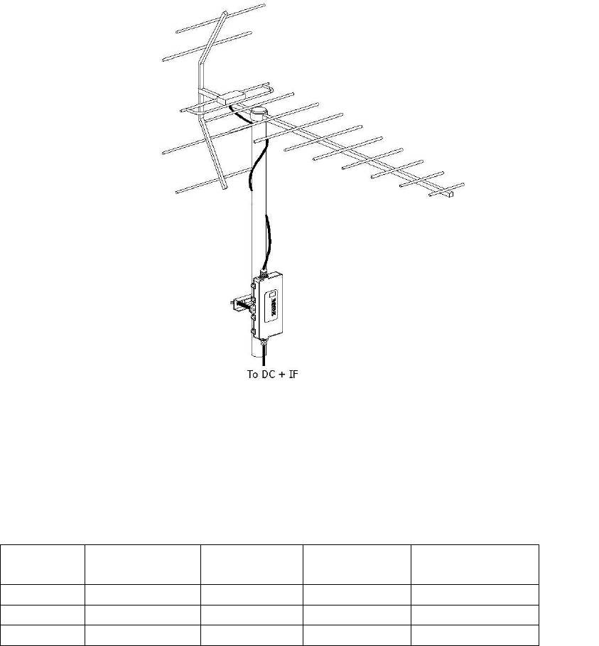
Fig. 1: Installation of transceiver with UHF Yagi antenna
NOTE: Cable modem “Channel Size” settings must be
configured so that channel center frequencies at band edge will
meet the limits in the following table:
Data rate
kSym/sec
Lowest fc
QAM
Hi ghest fc,
QAM
Low est fc,
QPSK
Hi ghest fc.,
QPSK
320 710.4 MHz 715.6MHz 710.3 MHz 715.6 MHz
640 710.7 MHz 715.4 MHz 711 MHz 715.5 MHz
1280 711.7 MHz 715.1 MHz 712 MHz 715.1 MHz
FCC RF Exposure Information:
The licensee is responsible for determining that antenna
installation will result in RF exposure levels to persons being in
compliance with the requirements of section 1.1307 of FCC
Rules.