Trane US CONT8241 Color Touchscreen Wi-Fi User Manual
Trane US, Inc. Color Touchscreen Wi-Fi
UserManual.wiki
>
Trane US
>
CONT8241 User Manual
User manual
Navigation menu
Upload a User Manual
Namespaces
Wiki Guide
HTML
PDF
Info
Views
User Manual
Discussion / Help
Navigation
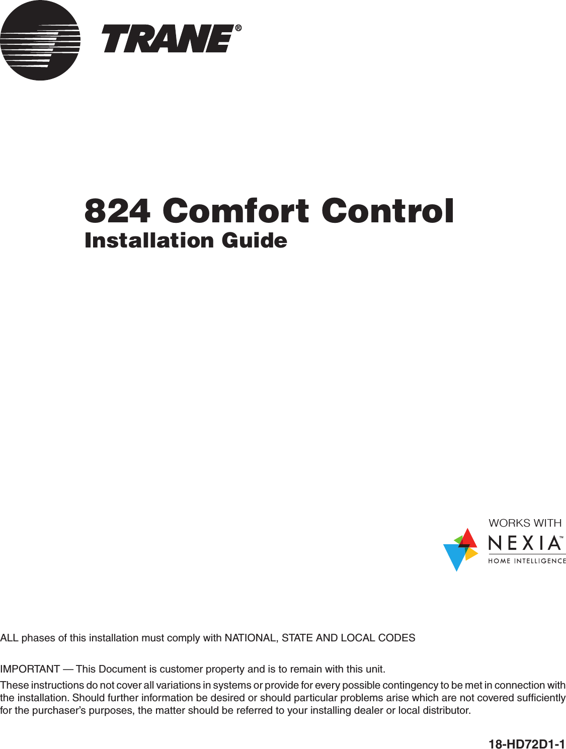
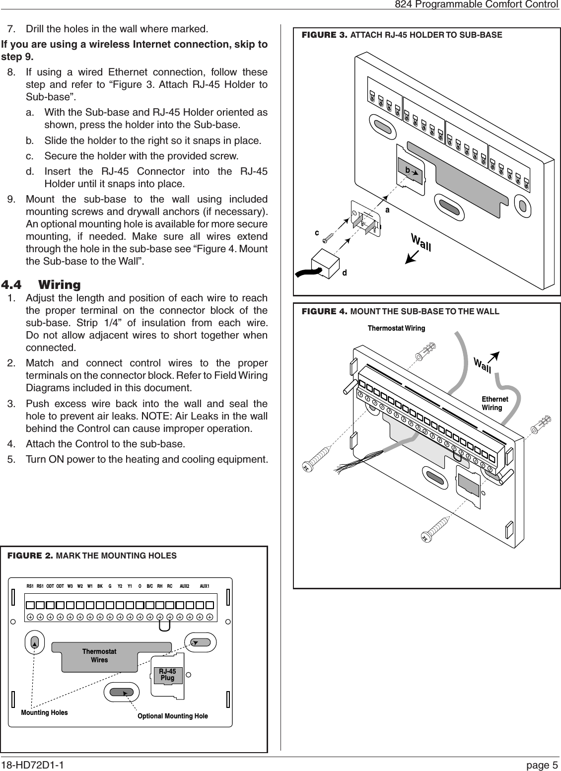
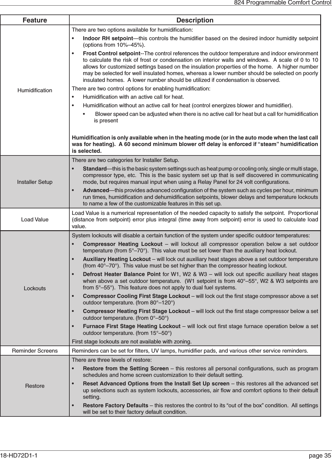
![824 Programmable Comfort Control18-HD72D1-1 page 215.2 Guided System Configuration ToolThe Guided System Configuration Tool walks you step by step through the configuration process. The Tool appears when the 824 is powered on for the first time and when the Restore Factory Defaults function is invoked. After each step, a progress screen will show what steps have been completed and which ones are still pending. MENU ITEM DESCRIPTIONTime and Date [User] Set the current time, date and time zone. Installer SetupFrom the Installer Setup screen, select a preset that matches the system’s configuration (i.e. Single Stage AC, Standard Heat Pump, Multi-Stage Heat Pump, Standard Dual fuel, etc.). Based on this selection, the 824 automatically sets a number of parameters and options. Subsequent screens provide details of the settings and allow for manual editing of each parameter.Service RemindersSet the mode and frequency of Air Filter, ERV Service and System Maintenance Reminders. When a reminder is triggered, an alert will appear on the 824 Home Screen notifying the homeowner to contact their dealer for service.Schedule [User]Guided Scheduling [User]Screen [User]Wireless Network [User]Dealer CodeRegistration [User]Weather [User][User] indicates menu items that are included in the User Setup Tool.5.3 Installer Setup5.3.1 Group 1 Standard SettingsMENU ITEM OPTIONS [DEFAULT] DESCRIPTIONOutdoor Unit Type None, [Cooling Only], HP Select the type of outdoor unit installedOutdoor Unit Stages [Single Stage], Two Stage Select the number of outdoor unit stagesCompressor Type Single Compressor Two Stage, [Two Compressor Two Stage]Select the compressor type for multi-stage outdoor unitsIndoor Unit Type [Gas/Oil], Electric, Hydronic Select the type of indoor unit installedIndoor Heat Stages [Single Stage], Two Stage, Thee Stage Select the number of indoor heat stagesIndoor Blower Type Variable, [Non - Variable] Select the indoor blower type (Constant Torque motors are considered non-variable speed)Reversing Valve](https://usermanual.wiki/Trane-US/CONT8241/User-Guide-2163312-Page-21.png)
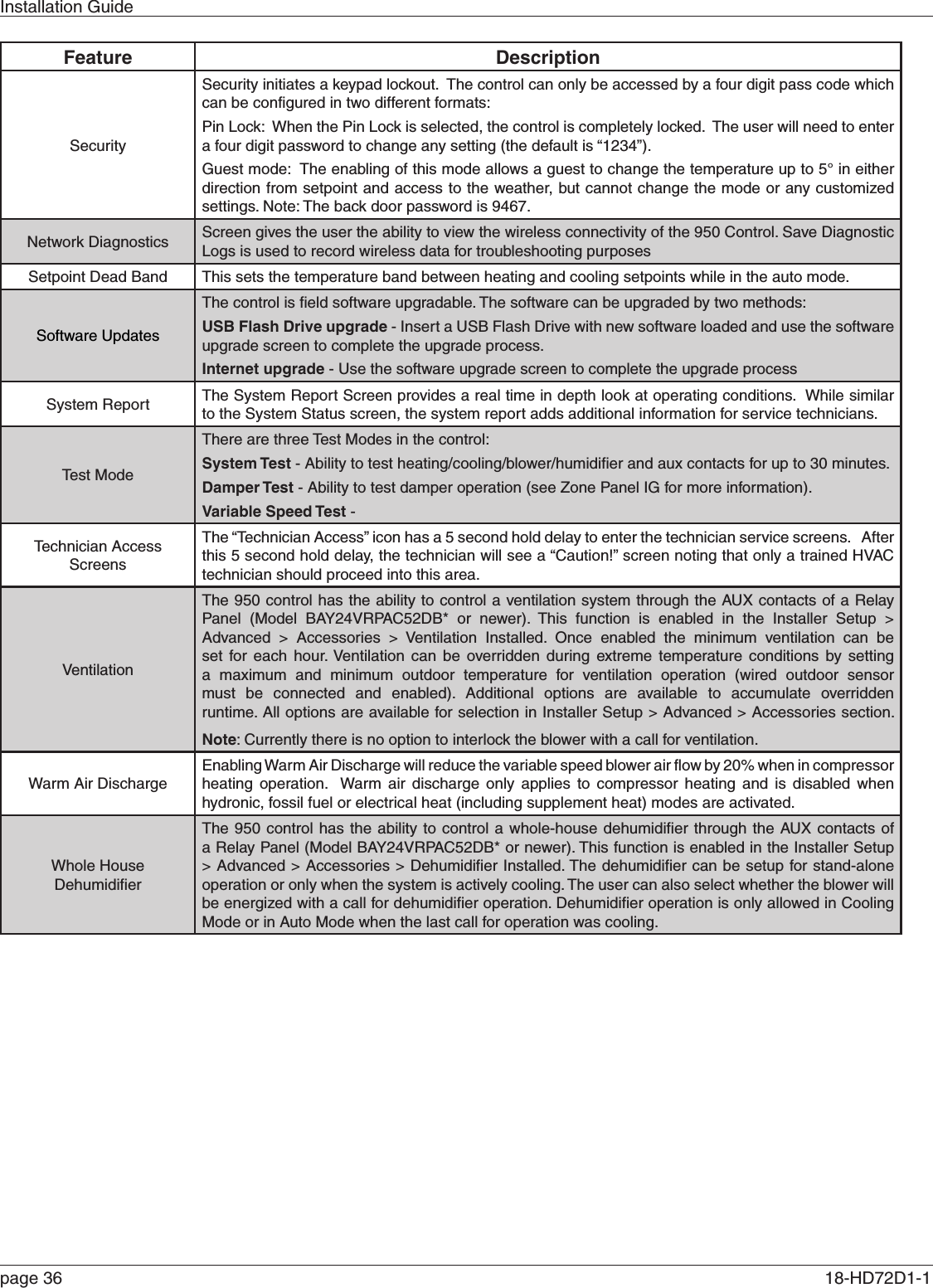
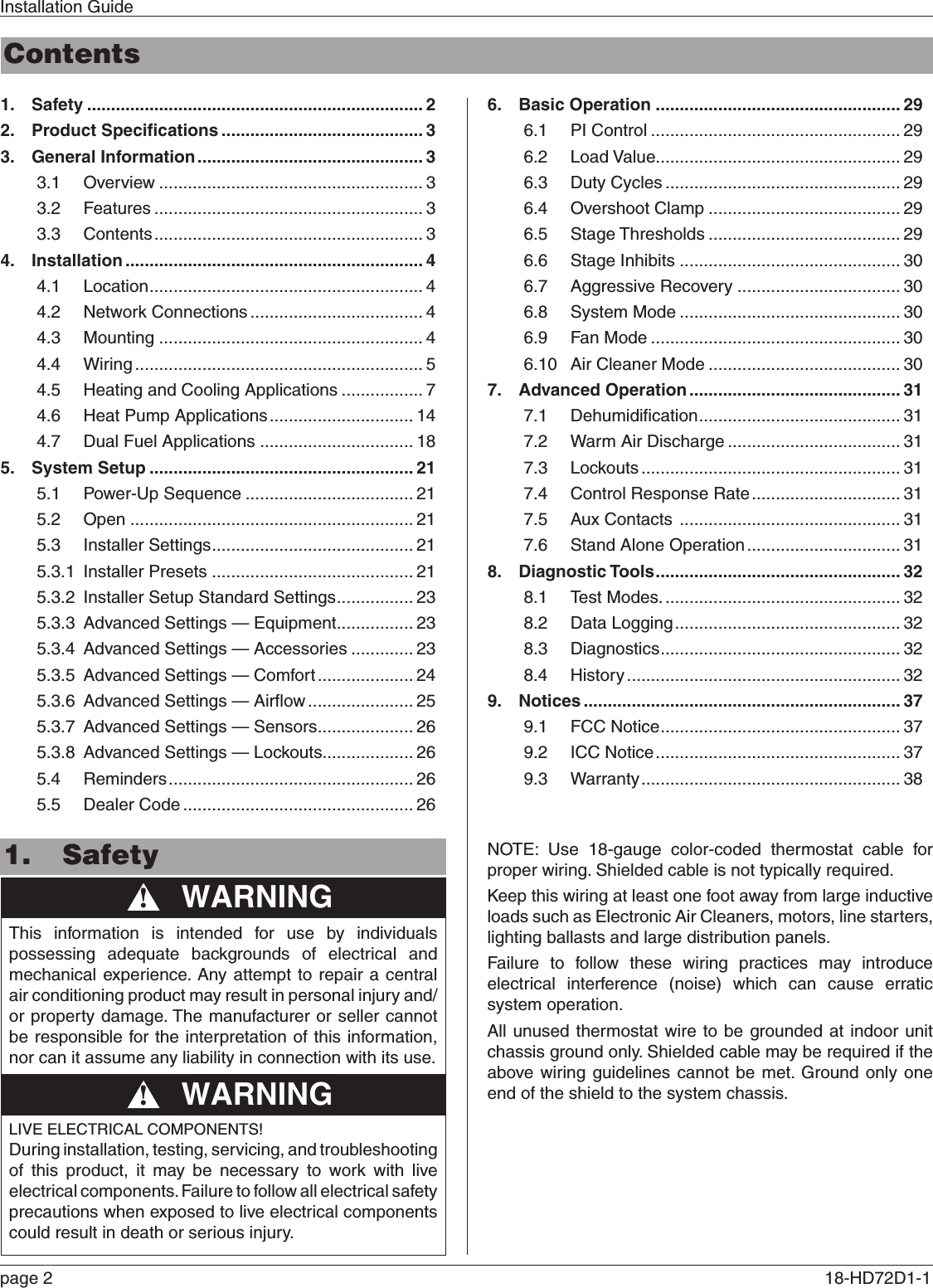
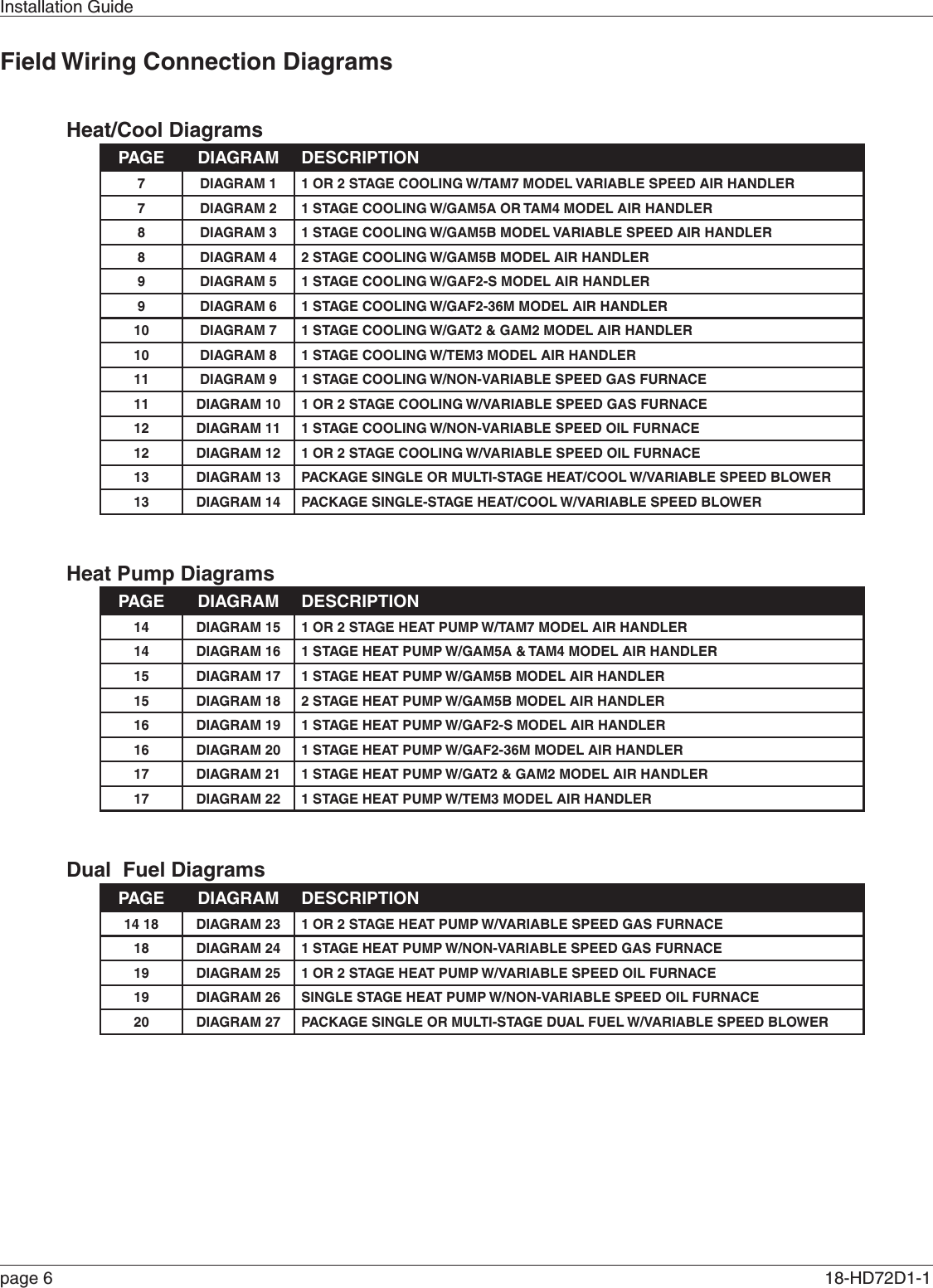
![Installation Guidepage 22 18-HD72D1-1 5.3.2 Group 2 Equipment SettingsMENU ITEM OPTIONS [DEAFULT] DESCRIPTIONCompressor Cooling Cycles Per Hour 2 - 6 [3] Select the number of cycles per hour during cooling operation1st Stage Compressor Cooling Cycles Per Hour 2 - 6 [3] Select the number of cycles per hour during 1st stage cooling operation2nd Stage Compressor Cooling Cycles Per Hour 2 - 6 [3] Select the number of cycles per hour during 2nd stage cooling operationCompressor Heating Cycles Per Hour 2 - 6 [3] Select the minimum runtime (MRT) of stage 1 indoor heat1st Stage Compressor Heating Cycles Per Hour 2 - 6 [3] Select the minimum runtime (MRT) of stage 2 indoor heat2nd Stage Compressor heating Cycles Per Hour 2 - 6 [5] Select the minimum offtime (MOT) for indoor heat operationIndoor Heater Cycles Per Hour 2 - 6 [5] Select the number of cycles per hour during indoor heat operation1st Stage Indoor Heat Cycles Per Hour 2 - 6 [5] Select the number of cycles per hour during 1st stage indoor heat operation2nd Stage Indoor Heat Cycles Per Hour 2 - 6 [5] Select the number of cycles per hour during 2nd stage indoor heat operation3rd Stage Indoor Heat Cycles Per Hour 2 - 6 [5] Select the number of cycles per hour during 3rd stage indoor heat operation5.3.3 Group 3 Sensors SettingsMENU ITEM OPTIONS [DEFAULT] DESCRIPTIONSelect Outdoor Temperature Sensor [No ODT Sensor],Thermostat ODT Sensor Select whether an outdoor temperature sensor has been connectedCalibrate Outdoor Temperature Sensor -5°F - 5°F Calibrate the outdoor temperature sensor Select Indoor Temperature Sensor [Thermostat IDT Sensor]Wired IDT SensorSelect whether the indoor temperature is being sensed by the thermostat onboard sensor or wired remote sensorCalibrate Indoor Temperature Sensor -5°F - 5°F Calibrate the indoor temperature sensor Calibrate Onboard Humidity Sensor -5% - 5% Calibrate the onboard humidity sensor Thermostat Humidity Sensor [Disable],EnableSelect whether to use the onboard humidity sensor when a wired indoor remote temperature sensor is being used](https://usermanual.wiki/Trane-US/CONT8241/User-Guide-2163312-Page-22.png)
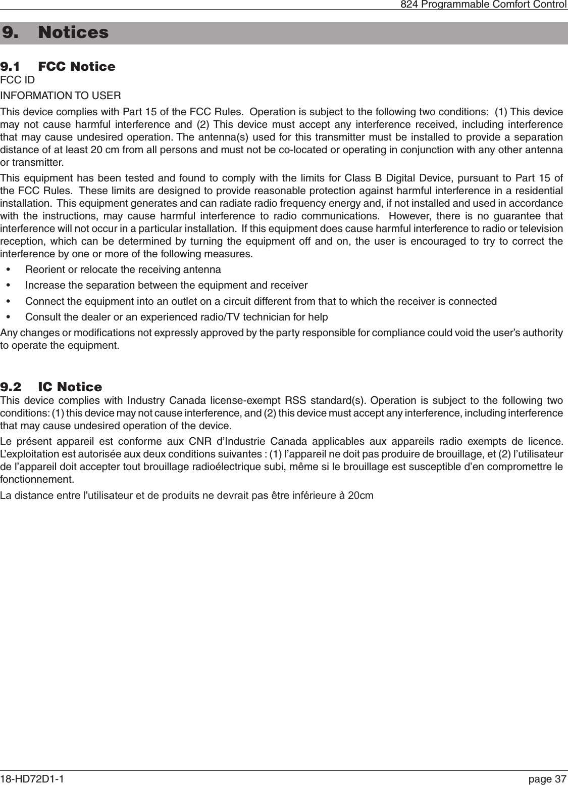
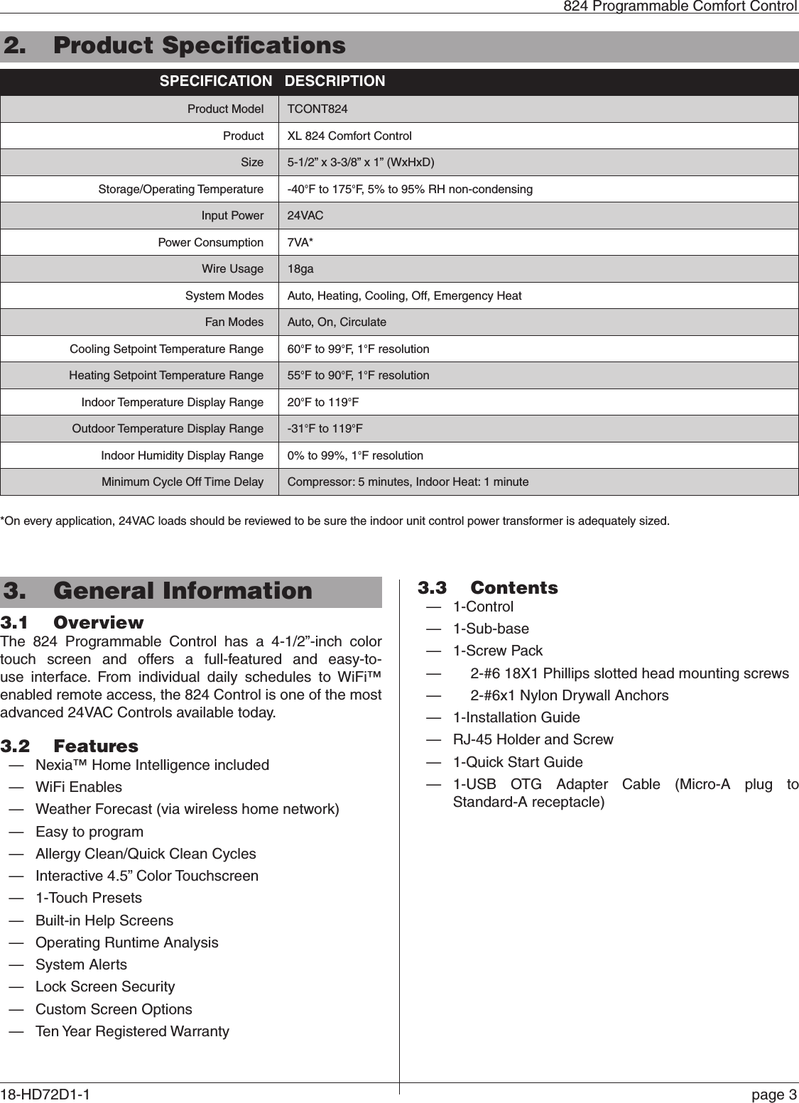
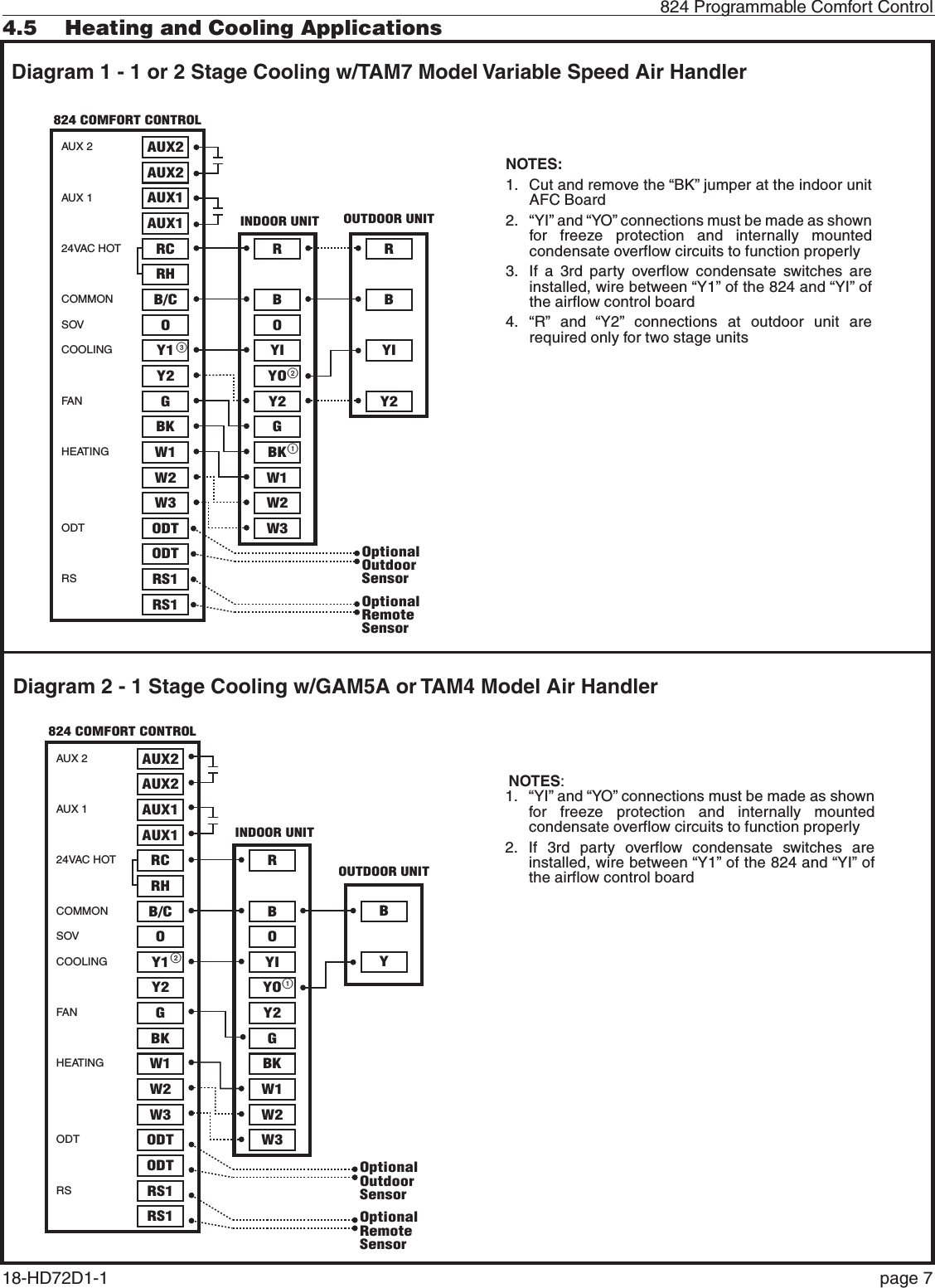
![824 Programmable Comfort Control18-HD72D1-1 page 235.3.4 Group 4 Accessories SettingsMENU ITEM OPTIONS [DEFAULT] DESCRIPTIONFiltration Type Installed Air Cleaner,[Media Filter] Select the filter type installedHumidifier Installed [None], Yes Select whether a humidifier is installedHumidifier - Select Relay Panel Aux Contact [Aux 1], Aux 2 Select which set of Aux contacts is connected to the humidifierHumidifier Type [Powered/Bypass], Steam Select what type of humidifier is installedHumidifier Control [RH Control], Frost ControlSelect how the humidifier will be controlled (Outdoor temperature sensor must be connected and enabled to allow this setting to be selected)Humidifier Fan Action[Humidify with Active Heat Call], Humidify without Active Heat CallSelect when the humidifier is allowed to operate (Humidification is disallowed during cooling mode or when the System Mode is Auto but the last call was cooling)Airflow During Humidifier Only Mode 35% - 100% [50%] Select the desired airflow when the humidifier is operating without an active call for heatUV Light Installed [None], Yes Select whether a UV Light is installedDehumidifier Installed [None], Yes Select whether a ventilation system is installedDehumidifier - Select Relay Panel Aux Contact Aux 1, [Aux 2] Select which set of aux contacts is controlling the ventilation systemDehumidifier Control Options[Stand Alone Operation], With Active Call for Cooling OnlyRun System Fan with Dehumidifier Request Yes, [No]Outdoor Temperature Ventilation Override [Disable], EnableSelect whether an outdoor temperature override is allowed (Outdoor temperature sensor must be connected and enabled to allow this setting to be selected)Ventilation - Minimum Outdoor Temperature *-10°F - 50°F [0°] Select the minimum outdoor temperature that ventilation is allowedVentilation - Maximum Outdoor Temperature 80°F - 110°F [100°F] Select the maximum outdoor temperature that ventilation is allowedMinimum Ventilation Runtime 0 - 60 Minutes [5 Minutes] Select the minimum runtime per hour for ventilation systemAcculate Overridden Runtime [No], Yes Select whether the overridden ventilation runtime will be made upAcculate Period[4 hours -recover only when outdoor conditions are favorable], 24 hours - recover only when outdoor conditions are favorable, 4 hours - recover as need to meet minimum, 24 hours - recover as needed to meet minimumSelect when to recover missed ventilation runtime due to outdoor conditions exceeding the minimum/maximum outdoor temperate for ventilation (The first two options will not meet AHRAE 62.2 standard for minimum ventilation requirements)](https://usermanual.wiki/Trane-US/CONT8241/User-Guide-2163312-Page-23.png)
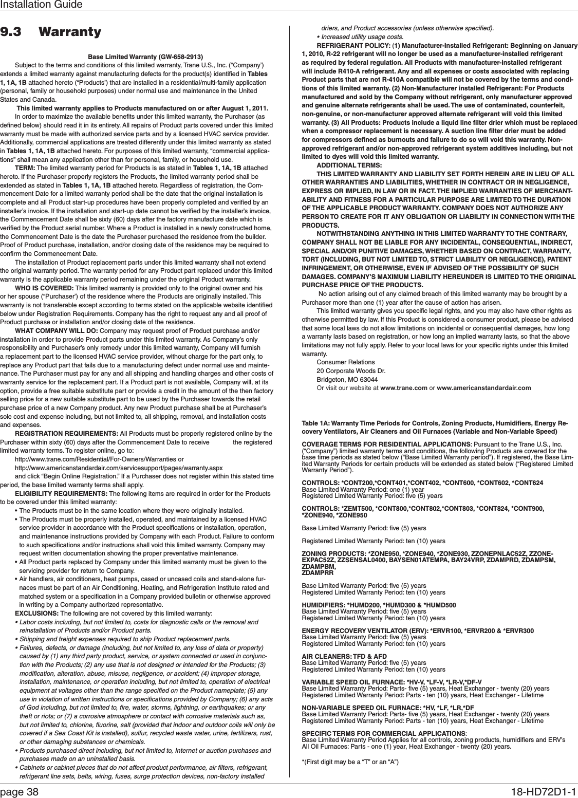
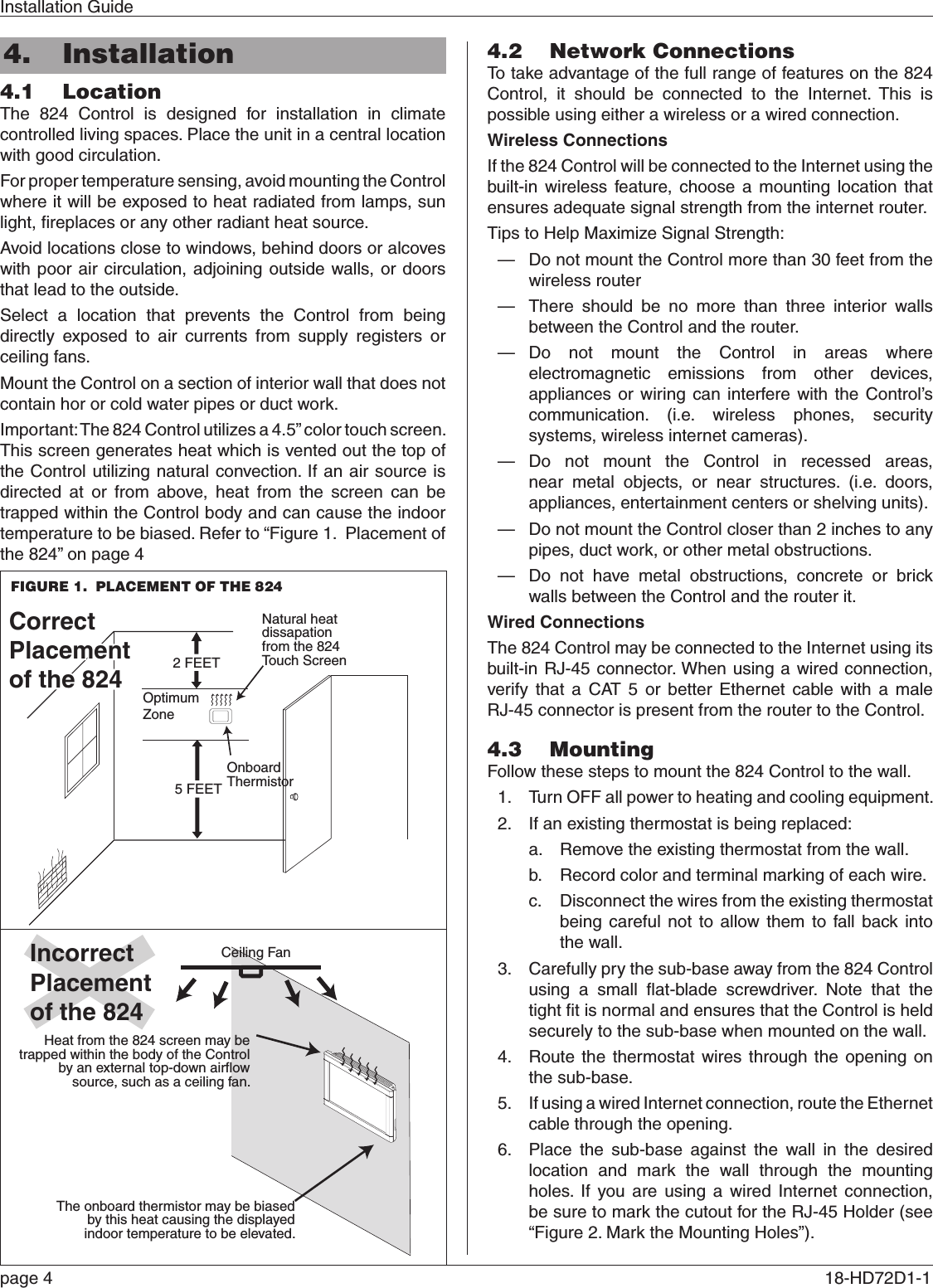
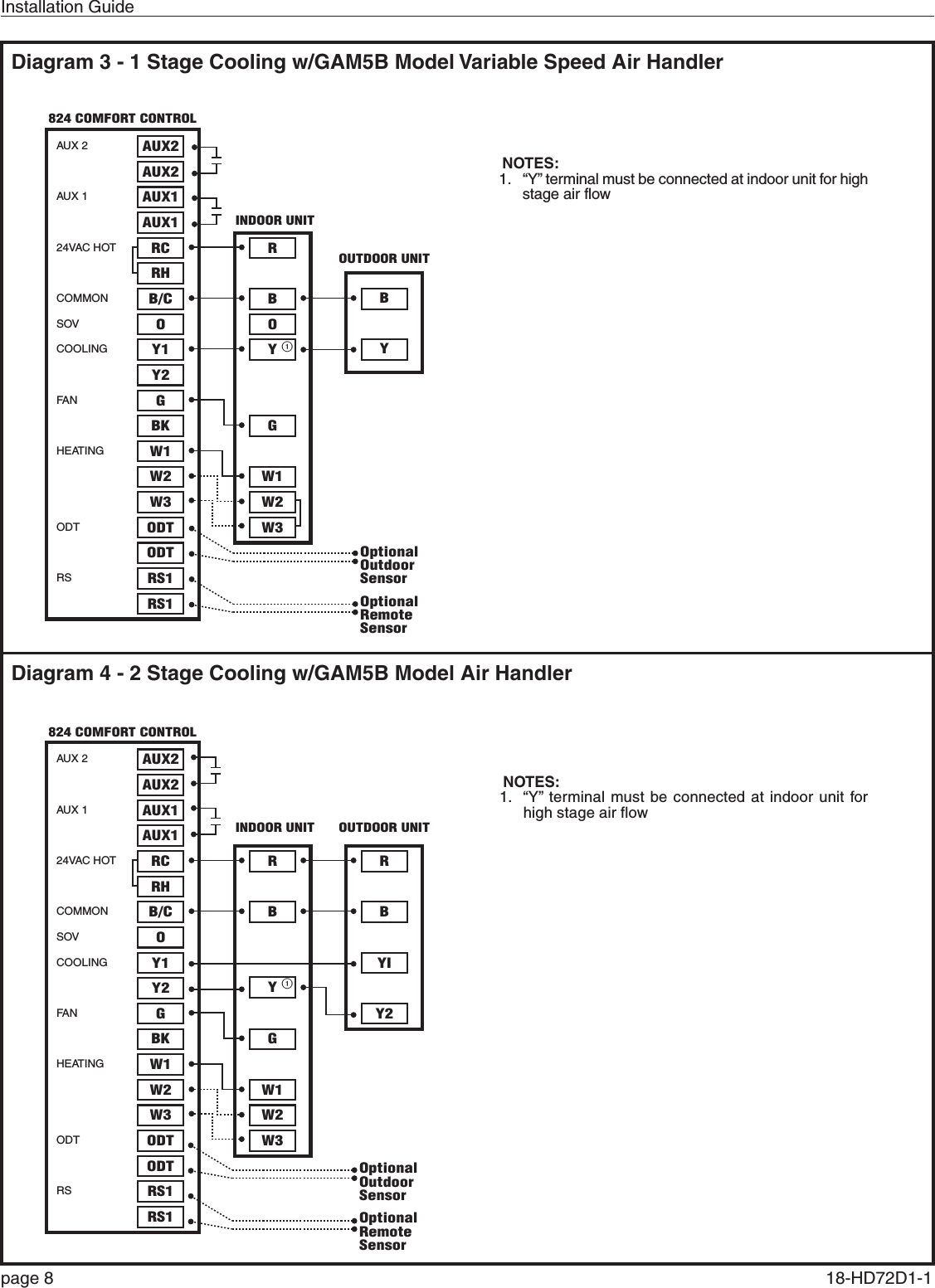
![Installation Guidepage 24 18-HD72D1-1 5.3.5 Group 5 Comfort SettingsMENU ITEM OPTIONS [DEFAULT] DESCRIPTIONEnable Dehumidification [Enable], DisableWhen dehumidification is enabled, the control will reduce system airflow by 30% (variable speed indoor units only) anytime the indoor humidity is higher than the cooling target humidity setpoint and the indoor temperature is within 2°F of cooling setpoint. All fan off delays will also be cancelled.Dehumidification Overcooling Limit - Degrees [0°] - 3°FSelect the maximum amount of overcooling allowed when the indoor humidity exceeds the cooling target humidity setpoint. To accomplish the overcooling the control will artificially create additional load by increasing the sensed indoor temperature by 1/10th of a degree for every 1% of a percent of humidity error, up to the overcooling limit selected. The displayed indoor temperature will remain the same, but the adjusted indoor temperature will control cooling operation.Control Response Rate [Normal], Fast Select how quickly the control builds load value (Selecting Fast will cause the control to build load value faster than normal operation)Aggressive Recovery > 2° Setpoint Change Enable, [Disable]Select whether the 10-minute staging inhibit is disabled (heating or cooling mode) with a setpoint change greater than 2°F (Change can be manual or scheduled)Heating Aggressive Recovery Enable, [Disable]Select whether the 10-minute staging inhibit is disabled during heating mode when the outdoor temperature falls below the selected outdoor temperature (Outdoor temperature sensor must be connected and enabled to allow this setting to be selected)Warm Air Discharge Enable, [Disable]When enabled the indoor blower speed will be limited to 80% on a call for heat pump heating. This only applies to heat pump heating with no call for aux heat (An indoor unit with variable speed blower is required)](https://usermanual.wiki/Trane-US/CONT8241/User-Guide-2163312-Page-24.png)
![824 Programmable Comfort Control18-HD72D1-1 page 255.3.6 Group 6 Airflow SettingsMENU ITEM OPTIONS [DEFAULT] DESCRIPTIONVariable Speed Blower On Delay - Cooling[No Delay],1 Minute @ 50%; 7.5 Minutes @ 80%,1 Minute @ 50%; 4 Minutes @ 80%,7.5 Minutes @ 80%,4 Minutes @ 80%,1 Minute @ 50%,30 SecondsSelect the blower on delay for cooling operationNon Variable Speed Blower On Delay - Cooling [No Delay],15 Seconds, 30 Seconds Select the blower on delay for cooling operationVariable Speed Blower Off Delay - Cooling[No Delay],1.5 Minutes @ 100%,45 Seconds @ 100%,30 Seconds % 50%,1.5 Minutes @ 50%,3 Minutes @ 50%, 30 Seconds @ 35%Select the blower off delay for cooling operationNon Variable Speed Blower Off Delay - Cooling[No Delay],30 Seconds,60 Seconds,90 SecondsSelect the blower off delay for cooling operationVariable Speed Blower On Delay - Compressor Heating[No Delay],1 Minute @ 50%; 7.5 Minutes @ 80%,1 Minute @ 50%; 4 Minutes @ 80%,7.5 Minutes @ 80%,4 Minutes @ 80%,1 Minute @ 50%,30 SecondsSelect the blower on delay for compressor heating operationNon Variable Speed Blower On Delay - Compressor Heating[No Delay],15 Seconds,30 SecondsSelect the blower on delay for compressor heating operationVariable Speed Blower Off Delay - Compressor Heating[No Delay],1.5 Minutes @ 100%,45 Seconds @ 100%,30 Seconds % 50%,1.5 Minutes @ 50%,3 Minutes @ 50%,30 Seconds @ 35%Select the blower off delay for compressor heating operationNon Variable Speed Blower Off Delay - Compressor Heating[No Delay],30 Seconds,60 Seconds,90 SecondsSelect the blower off delay for compressor heating operationHydronic Heat Blower On Delay[No Delay],30 Seconds,60 SecondsSelect the blower on delay for hydronic heating operationHydronic Heat Blower Off Delay[No Delay],30 Seconds,60 Seconds,90 SecondsSelect the blower off delay for hydronic heating operationCompressor Low Stage Air Flow% - Compressor Cooling 35% - 60% [50%] Select the 1st stage air flow for a two stage/two compressor unit in cooling modeCompressor Low Stage Air Flow% - Compressor Cooling 55% - [80%] Select the 1st stage air flow for a two stage/single compressor unit in cooling modeCompressor Low Stage Air Flow% - Compressor Heating 35% - 60% [50%] Select the 1st stage air flow for a two stage/two compressor unit in heating modeCompressor Low Stage Air Flow% - Compressor Heating 55% - [80%] Select the 1st stage air flow for a two stage/single compressor unit in heating mode](https://usermanual.wiki/Trane-US/CONT8241/User-Guide-2163312-Page-25.png)
![Installation Guidepage 26 18-HD72D1-1 5.3.7 Advanced Settings — LockoutsMENU ITEM OPTIONS [DEFAULT] DESCRIPTIONAuxiliary Heat Lockout [Disable], Enable Enable auxiliary heat lockout (10° minimum separation when enabling auxiliary heat lockout and compressor heat lockout)Auxiliary Heat Lockout 32°F - 70°F Degrees [45°] Select an outdoor temperature to prevent auxiliary heat above the selected outdoor temperatureCompressor Lockout [Disable], Enable Enable compressor heat lockout (10° minimum separation when enabling auxiliary heat lockout and compressor heat lockout)Compressor Lockout 5°F - 35°F Degrees [30] Select an outdoor temperature to prevent compressor heating below the selected outdoor temperatureDefrost Heater Balance Point (W1) [Disable], Enable Enable defrost heater balance point for W1, W2 and W3 (only applicable when indoor heat is electric or hydronic)Defrost Heater Balance Point (W1) 40°F - [55°F] Select an outdoor temperature to disallow 1st, 2nd and 3rd stage of indoor heat during defrost above this temperatureDefrost Heater Balance Point (W2) [Disable], Enable Enable defrost heater balance point for W1 and W2 (only applicable when indoor heat is electric or hydronic)Defrost Heater Balance Point (W2) 10°F - 50°F [55°F] Select an outdoor temperature to disallow 2nd and 3rd stage of indoor heat during defrost above this temperatureDefrost Heater Balance Point (W3) [Disable], Enable Enable defrost heater balance point for W3 only (only applicable when indoor heat is electric or hydronic)Defrost Heater Balance Point (W3) [5°F] - 35°F Select an outdoor temperature to disallow 3rd stage of indoor heat during defrost above this temperatureCompressor Cooling 1st Stage Lockout [Disable], Enable Enable compressor cooling 1st stage lockoutCompressor Cooling 1st Stage Lockout 80°F - [120°F] Select an outdoor temperature to force the system to 2nd stage compressor coolingCompressor Heating 1st Stage Lockout [Disable], Enable Enable compressor heating 1st stage lockoutCompressor Heating 1st Stage Lockout 0°F - [50°F] Select an outdoor temperature to force the system to 2nd stage compressor heatingFurnace Heating 1st Stage Lockout [Disable], Enable Enable furnace heating 1st stage lockoutFurnace Heating 1st Stage Lockout 0°F - [50°F] Select an outdoor temperature to force the system to 2nd stage furnace heating5.4 Reminders5.5 Dealer Code](https://usermanual.wiki/Trane-US/CONT8241/User-Guide-2163312-Page-26.png)