Trane US CONT8241 Color Touchscreen Wi-Fi User Manual
Trane US, Inc. Color Touchscreen Wi-Fi
Trane US >
User manual
824 Comfort Control
Installation Guide
18-HD72D1-1
ALL phases of this installation must comply with NATIONAL, STATE AND LOCAL CODES
IMPORTANT — This Document is customer property and is to remain with this unit.
These instructions do not cover all variations in systems or provide for every possible contingency to be met in connection with
the installation. Should further information be desired or should particular problems arise which are not covered sufficiently
for the purchaser’s purposes, the matter should be referred to your installing dealer or local distributor.
WORKS WITH
Installation Guide
page 2 18-HD72D1-1
1. Safety NOTE: Use 18-gauge color-coded thermostat cable for
proper wiring. Shielded cable is not typically required.
Keep this wiring at least one foot away from large inductive
loads such as Electronic Air Cleaners, motors, line starters,
lighting ballasts and large distribution panels.
Failure to follow these wiring practices may introduce
electrical interference (noise) which can cause erratic
system operation.
All unused thermostat wire to be grounded at indoor unit
chassis ground only. Shielded cable may be required if the
above wiring guidelines cannot be met. Ground only one
end of the shield to the system chassis.
▲WARNING
!
This information is intended for use by individuals
possessing adequate backgrounds of electrical and
mechanical experience. Any attempt to repair a central
air conditioning product may result in personal injury and/
or property damage. The manufacturer or seller cannot
be responsible for the interpretation of this information,
nor can it assume any liability in connection with its use.
▲WARNING
!
LIVE ELECTRICAL COMPONENTS!
During installation, testing, servicing, and troubleshooting
of this product, it may be necessary to work with live
electrical components. Failure to follow all electrical safety
precautions when exposed to live electrical components
could result in death or serious injury.
1. Safety ...................................................................... 2
2. Product Specifications .......................................... 3
3. General Information ............................................... 3
3.1 Overview ....................................................... 3
3.2 Features ........................................................ 3
3.3 Contents ........................................................ 3
4. Installation .............................................................. 4
4.1 Location ......................................................... 4
4.2 Network Connections .................................... 4
4.3 Mounting ....................................................... 4
4.4 Wiring ............................................................ 5
4.5 Heating and Cooling Applications ................. 7
4.6 Heat Pump Applications .............................. 14
4.7 Dual Fuel Applications ................................ 18
5. System Setup ....................................................... 21
5.1 Power-Up Sequence ................................... 21
5.2 Open ........................................................... 21
5.3 Installer Settings .......................................... 21
5.3.1 Installer Presets .......................................... 21
5.3.2 Installer Setup Standard Settings ................ 23
5.3.3 Advanced Settings — Equipment ................ 23
5.3.4 Advanced Settings — Accessories ............. 23
5.3.5 Advanced Settings — Comfort .................... 24
5.3.6 Advanced Settings — Airflow ...................... 25
5.3.7 Advanced Settings — Sensors .................... 26
5.3.8 Advanced Settings — Lockouts................... 26
5.4 Reminders ................................................... 26
5.5 Dealer Code ................................................ 26
6. Basic Operation ................................................... 29
6.1 PI Control .................................................... 29
6.2 Load Value................................................... 29
6.3 Duty Cycles ................................................. 29
6.4 Overshoot Clamp ........................................ 29
6.5 Stage Thresholds ........................................ 29
6.6 Stage Inhibits .............................................. 30
6.7 Aggressive Recovery .................................. 30
6.8 System Mode .............................................. 30
6.9 Fan Mode .................................................... 30
6.10 Air Cleaner Mode ........................................ 30
7. Advanced Operation ............................................ 31
7.1 Dehumidification .......................................... 31
7.2 Warm Air Discharge .................................... 31
7.3 Lockouts ...................................................... 31
7.4 Control Response Rate ............................... 31
7.5 Aux Contacts .............................................. 31
7.6 Stand Alone Operation ................................ 31
8. Diagnostic Tools ................................................... 32
8.1 Test Modes. ................................................. 32
8.2 Data Logging ............................................... 32
8.3 Diagnostics .................................................. 32
8.4 History ......................................................... 32
9. Notices .................................................................. 37
9.1 FCC Notice .................................................. 37
9.2 ICC Notice ................................................... 37
9.3 Warranty ...................................................... 38
Contents
824 Programmable Comfort Control
18-HD72D1-1 page 3
SPECIFICATION DESCRIPTION
Product Model TCONT824
Product XL 824 Comfort Control
Size 5-1/2” x 3-3/8” x 1” (WxHxD)
Storage/Operating Temperature -40°F to 175°F, 5% to 95% RH non-condensing
Input Power 24VAC
Power Consumption 7VA*
Wire Usage 18ga
System Modes Auto, Heating, Cooling, Off, Emergency Heat
Fan Modes Auto, On, Circulate
Cooling Setpoint Temperature Range 60°F to 99°F, 1 °F resolution
Heating Setpoint Temperature Range 55°F to 90°F, 1 °F resolution
Indoor Temperature Display Range 20°F to 119°F
Outdoor Temperature Display Range -31°F to 119°F
Indoor Humidity Display Range 0% to 99%, 1°F resolution
Minimum Cycle Off Time Delay Compressor: 5 minutes, Indoor Heat: 1 minute
*On every application, 24VAC loads should be reviewed to be sure the indoor unit control power transformer is adequately sized.
2. Product Specifications
3. General Information
3.1 Overview
The 824 Programmable Control has a 4-1/2”-inch color
touch screen and offers a full-featured and easy-to-
use interface. From individual daily schedules to WiFi™
enabled remote access, the 824 Control is one of the most
advanced 24VAC Controls available today.
3.2 Features
— Nexia™ Home Intelligence included
— WiFi Enables
— Weather Forecast (via wireless home network)
— Easy to program
— Allergy Clean/Quick Clean Cycles
— Interactive 4.5” Color Touchscreen
— 1-Touch Presets
— Built-in Help Screens
— Operating Runtime Analysis
— System Alerts
— Lock Screen Security
— Custom Screen Options
— Ten Year Registered Warranty
3.3 Contents
— 1-Control
— 1-Sub-base
— 1-Screw Pack
— 2-#6 18X1 Phillips slotted head mounting screws
— 2-#6x1 Nylon Drywall Anchors
— 1-Installation Guide
— RJ-45 Holder and Screw
— 1-Quick Start Guide
— 1-USB OTG Adapter Cable (Micro-A plug to
Standard-A receptacle)
Installation Guide
page 4 18-HD72D1-1
4. Installation
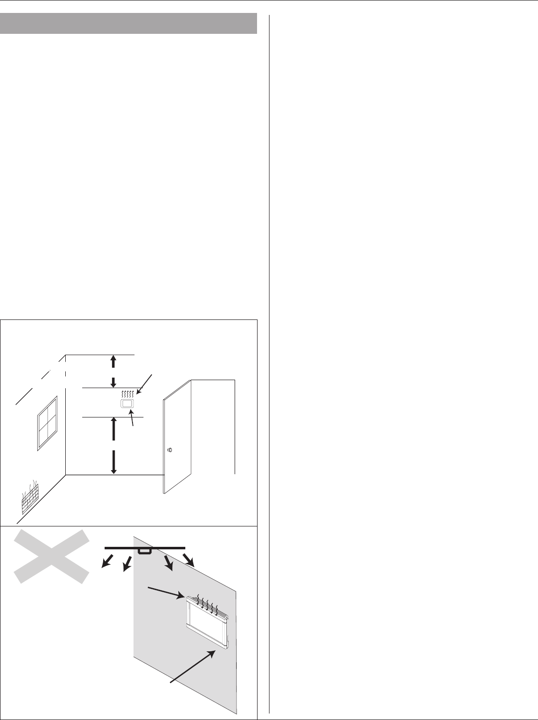
4.1 Location
The 824 Control is designed for installation in climate
controlled living spaces. Place the unit in a central location
with good circulation.
For proper temperature sensing, avoid mounting the Control
where it will be exposed to heat radiated from lamps, sun
light, fireplaces or any other radiant heat source.
Avoid locations close to windows, behind doors or alcoves
with poor air circulation, adjoining outside walls, or doors
that lead to the outside.
Select a location that prevents the Control from being
directly exposed to air currents from supply registers or
ceiling fans.
Mount the Control on a section of interior wall that does not
contain hor or cold water pipes or duct work.
Important: The 824 Control utilizes a 4.5” color touch screen.
This screen generates heat which is vented out the top of
the Control utilizing natural convection. If an air source is
directed at or from above, heat from the screen can be
trapped within the Control body and can cause the indoor
temperature to be biased. Refer to “Figure 1. Placement of
the 824” on page 4
4.2 Network Connections
To take advantage of the full range of features on the 824
Control, it should be connected to the Internet. This is
possible using either a wireless or a wired connection.
Wireless Connections
If the 824 Control will be connected to the Internet using the
built-in wireless feature, choose a mounting location that
ensures adequate signal strength from the internet router.
Tips to Help Maximize Signal Strength:
— Do not mount the Control more than 30 feet from the
wireless router
— There should be no more than three interior walls
between the Control and the router.
— Do not mount the Control in areas where
electromagnetic emissions from other devices,
appliances or wiring can interfere with the Control’s
communication. (i.e. wireless phones, security
systems, wireless internet cameras).
— Do not mount the Control in recessed areas,
near metal objects, or near structures. (i.e. doors,
appliances, entertainment centers or shelving units).
— Do not mount the Control closer than 2 inches to any
pipes, duct work, or other metal obstructions.
— Do not have metal obstructions, concrete or brick
walls between the Control and the router it.
Wired Connections
The 824 Control may be connected to the Internet using its
built-in RJ-45 connector. When using a wired connection,
verify that a CAT 5 or better Ethernet cable with a male
RJ-45 connector is present from the router to the Control.
4.3 Mounting
Follow these steps to mount the 824 Control to the wall.
1. Turn OFF all power to heating and cooling equipment.
2. If an existing thermostat is being replaced:
a. Remove the existing thermostat from the wall.
b. Record color and terminal marking of each wire.
c. Disconnect the wires from the existing thermostat
being careful not to allow them to fall back into
the wall.
3. Carefully pry the sub-base away from the 824 Control
using a small flat-blade screwdriver. Note that the
tight fit is normal and ensures that the Control is held
securely to the sub-base when mounted on the wall.
4. Route the thermostat wires through the opening on
the sub-base.
5. If using a wired Internet connection, route the Ethernet
cable through the opening.
6. Place the sub-base against the wall in the desired
location and mark the wall through the mounting
holes. If you are using a wired Internet connection,
be sure to mark the cutout for the RJ-45 Holder (see
“Figure 2. Mark the Mounting Holes”).
Incorrect
Placement
of the 824
Ceiling Fan
Natural heat
dissapation
from the 824
Touch Screen
Onboard
Thermistor
5 FEET
Optimum
Zone
2 FEET
Correct
Placement
of the 950
Correct
Placement
of the 824
Heat from the 824 screen may be
trapped within the body of the Control
by an external top-down airflow
source, such as a ceiling fan.
The onboard thermistor may be biased
by this heat causing the displayed
indoor temperature to be elevated.
FIGURE 1. PLACEMENT OF THE 824
824 Programmable Comfort Control
18-HD72D1-1 page 5
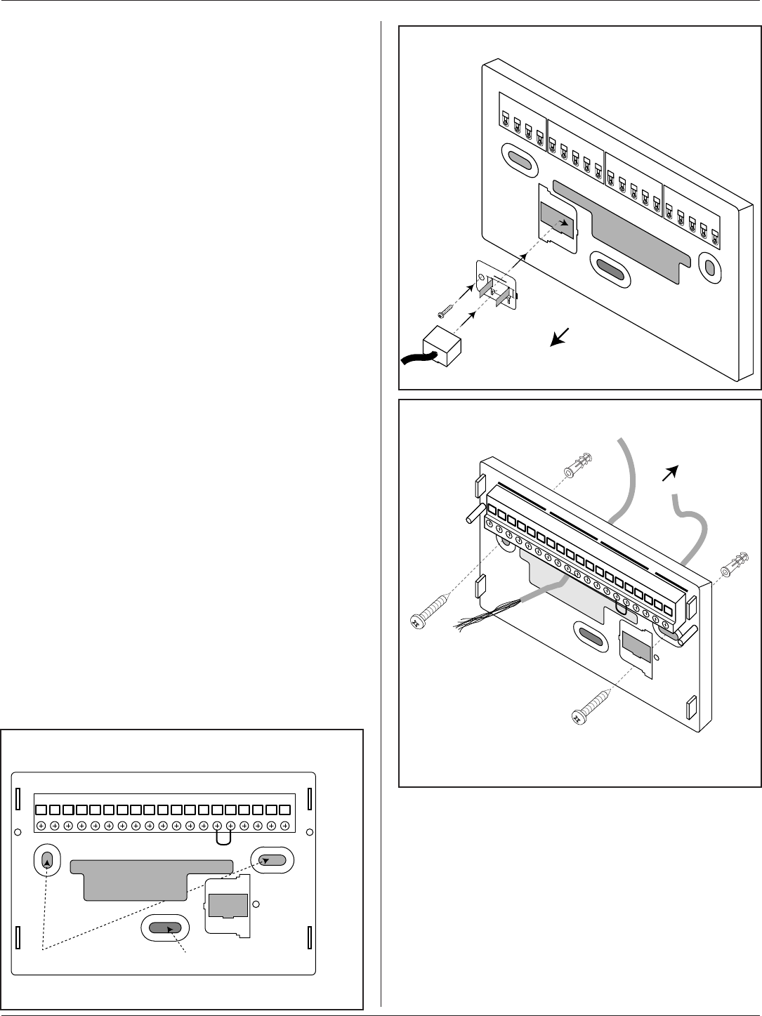
7. Drill the holes in the wall where marked.
If you are using a wireless Internet connection, skip to
step 9.
8. If using a wired Ethernet connection, follow these
step and refer to “Figure 3. Attach RJ-45 Holder to
Sub-base”.
a. With the Sub-base and RJ-45 Holder oriented as
shown, press the holder into the Sub-base.
b. Slide the holder to the right so it snaps in place.
c. Secure the holder with the provided screw.
d. Insert the RJ-45 Connector into the RJ-45
Holder until it snaps into place.
9. Mount the sub-base to the wall using included
mounting screws and drywall anchors (if necessary).
An optional mounting hole is available for more secure
mounting, if needed. Make sure all wires extend
through the hole in the sub-base see “Figure 4. Mount
the Sub-base to the Wall”.
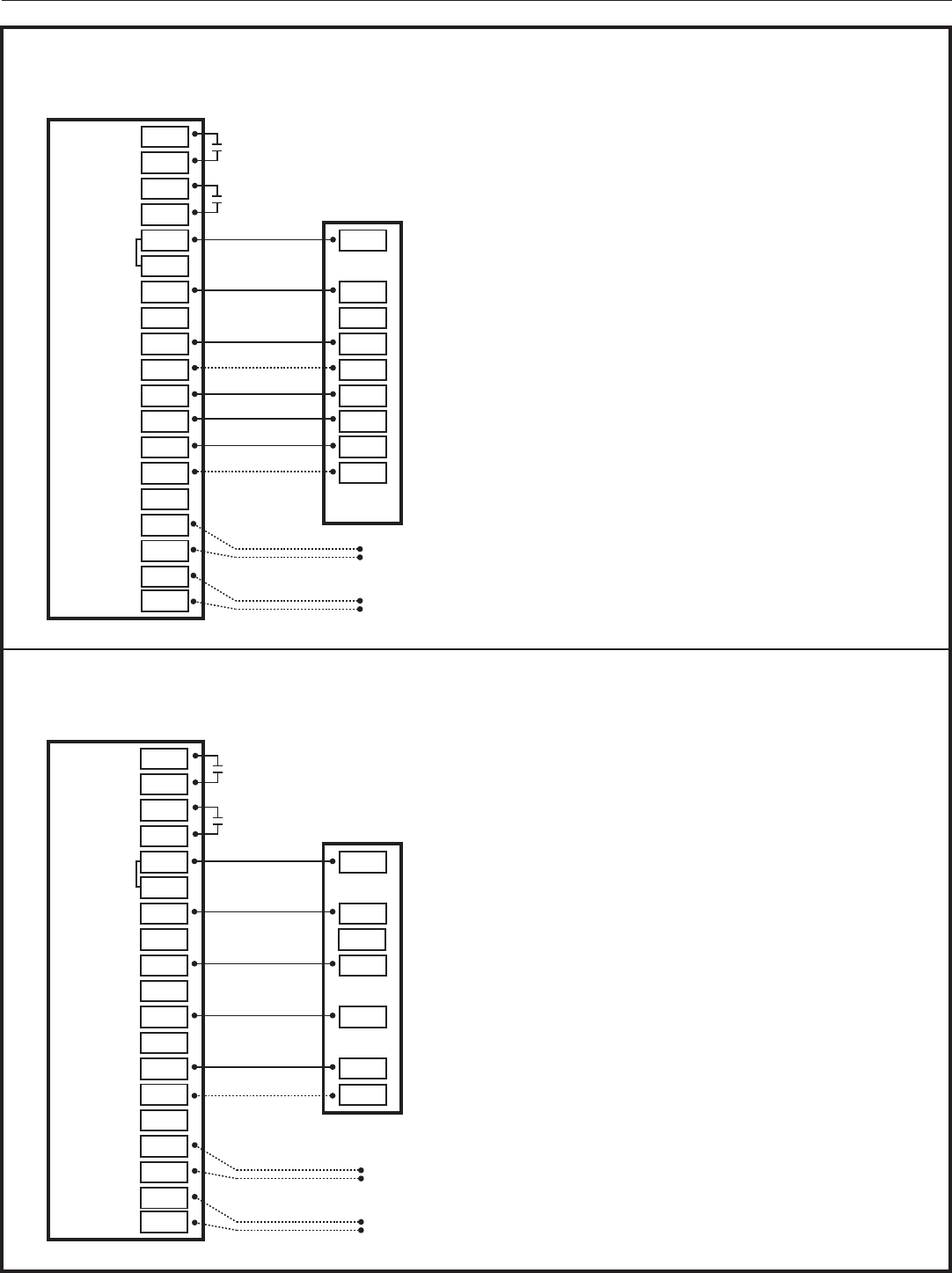
4.4 Wiring
1. Adjust the length and position of each wire to reach
the proper terminal on the connector block of the
sub-base. Strip 1/4” of insulation from each wire.
Do not allow adjacent wires to short together when
connected.
2. Match and connect control wires to the proper
terminals on the connector block. Refer to Field Wiring
Diagrams included in this document.
3. Push excess wire back into the wall and seal the
hole to prevent air leaks. NOTE: Air Leaks in the wall
behind the Control can cause improper operation.
4. Attach the Control to the sub-base.
5. Turn ON power to the heating and cooling equipment.
RS1 RS1 ODT ODT W3 W2 W1 BK G Y2 Y1 O B/C RH RC AUX2 AUX1
Mounting Holes Optional Mounting Hole
Wall
Thermostat Wiring
Ethernet
Wiring
Thermostat
Wires
RJ-45
Plug
RS1 RS1 ODT ODT W3 W2 W1 BK G Y2 Y1 O B/C RH RC AUX2 AUX1
Mounting Holes Optional Mounting Hole
Wall
Thermostat Wiring
Ethernet
Wiring
Thermostat
Wires
RJ-45
Plug
FIGURE 2. MARK THE MOUNTING HOLES
FIGURE 3. ATTACH RJ-45 HOLDER TO SUB-BASE
This side mounts to wall
Wall
a
b
c
d
FIGURE 4. MOUNT THE SUB-BASE TO THE WALL
Installation Guide
page 6 18-HD72D1-1
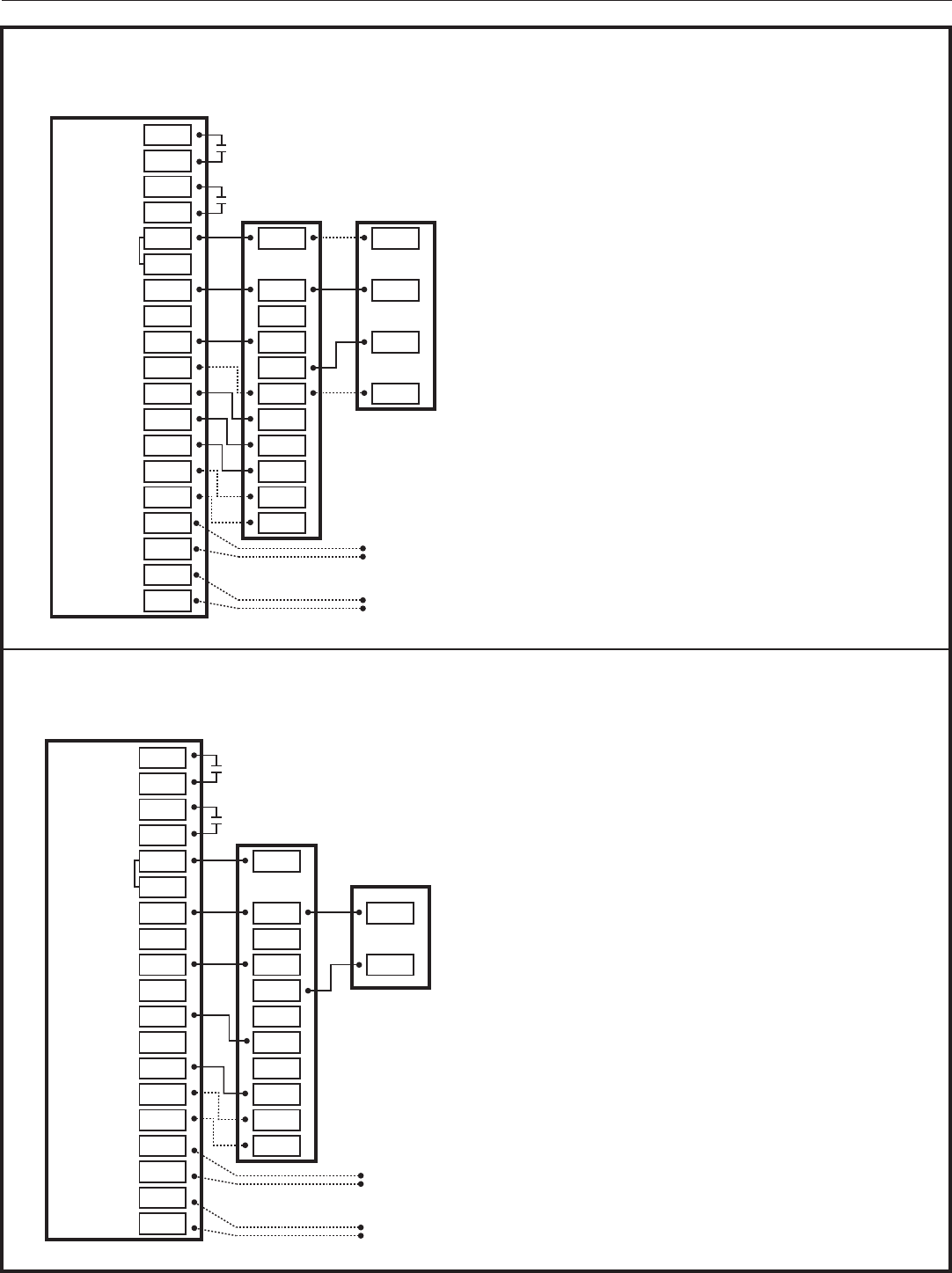
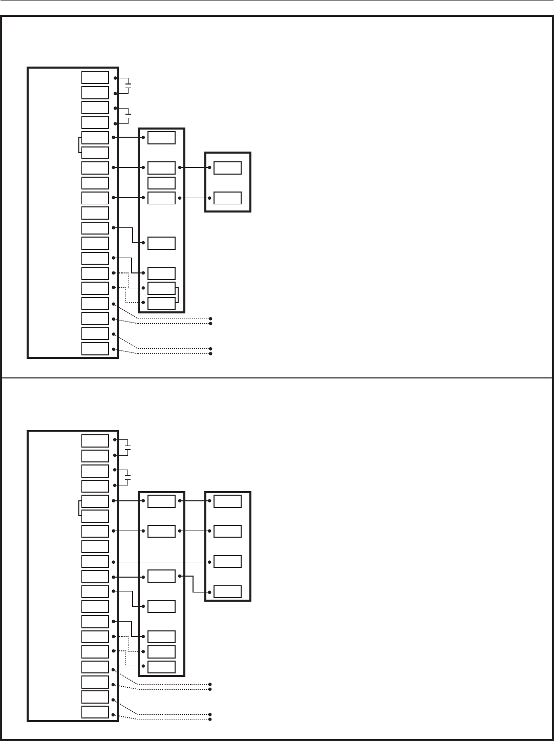
Field Wiring Connection Diagrams
Heat Pump Diagrams
Dual Fuel Diagrams
Heat/Cool Diagrams
PAG E DIAGRAM DESCRIPTION
7 DIAGRAM 1 1 OR 2 STAGE COOLING W/TAM7 MODEL VARIABLE SPEED AIR HANDLER
7 DIAGRAM 2 1 STAGE COOLING W/GAM5A OR TAM4 MODEL AIR HANDLER
8 DIAGRAM 3 1 STAGE COOLING W/GAM5B MODEL VARIABLE SPEED AIR HANDLER
8 DIAGRAM 4 2 STAGE COOLING W/GAM5B MODEL AIR HANDLER
9 DIAGRAM 5 1 STAGE COOLING W/GAF2-S MODEL AIR HANDLER
9 DIAGRAM 6 1 STAGE COOLING W/GAF2-36M MODEL AIR HANDLER
10 DIAGRAM 7 1 STAGE COOLING W/GAT2 & GAM2 MODEL AIR HANDLER
10 DIAGRAM 8 1 STAGE COOLING W/TEM3 MODEL AIR HANDLER
11 DIAGRAM 9 1 STAGE COOLING W/NON-VARIABLE SPEED GAS FURNACE
11 DIAGRAM 10 1 OR 2 STAGE COOLING W/VARIABLE SPEED GAS FURNACE
12 DIAGRAM 11 1 STAGE COOLING W/NON-VARIABLE SPEED OIL FURNACE
12 DIAGRAM 12 1 OR 2 STAGE COOLING W/VARIABLE SPEED OIL FURNACE
13 DIAGRAM 13 PACKAGE SINGLE OR MULTI-STAGE HEAT/COOL W/VARIABLE SPEED BLOWER
13 DIAGRAM 14 PACKAGE SINGLE-STAGE HEAT/COOL W/VARIABLE SPEED BLOWER
PAG E DIAGRAM DESCRIPTION
14 DIAGRAM 15 1 OR 2 STAGE HEAT PUMP W/TAM7 MODEL AIR HANDLER
14 DIAGRAM 16 1 STAGE HEAT PUMP W/GAM5A & TAM4 MODEL AIR HANDLER
15 DIAGRAM 17 1 STAGE HEAT PUMP W/GAM5B MODEL AIR HANDLER
15 DIAGRAM 18 2 STAGE HEAT PUMP W/GAM5B MODEL AIR HANDLER
16 DIAGRAM 19 1 STAGE HEAT PUMP W/GAF2-S MODEL AIR HANDLER
16 DIAGRAM 20 1 STAGE HEAT PUMP W/GAF2-36M MODEL AIR HANDLER
17 DIAGRAM 21 1 STAGE HEAT PUMP W/GAT2 & GAM2 MODEL AIR HANDLER
17 DIAGRAM 22 1 STAGE HEAT PUMP W/TEM3 MODEL AIR HANDLER
PAG E DIAGRAM DESCRIPTION
14 18 DIAGRAM 23 1 OR 2 STAGE HEAT PUMP W/VARIABLE SPEED GAS FURNACE
18 DIAGRAM 24 1 STAGE HEAT PUMP W/NON-VARIABLE SPEED GAS FURNACE
19 DIAGRAM 25 1 OR 2 STAGE HEAT PUMP W/VARIABLE SPEED OIL FURNACE
19 DIAGRAM 26 SINGLE STAGE HEAT PUMP W/NON-VARIABLE SPEED OIL FURNACE
20 DIAGRAM 27 PACKAGE SINGLE OR MULTI-STAGE DUAL FUEL W/VARIABLE SPEED BLOWER
824 Programmable Comfort Control
18-HD72D1-1 page 7
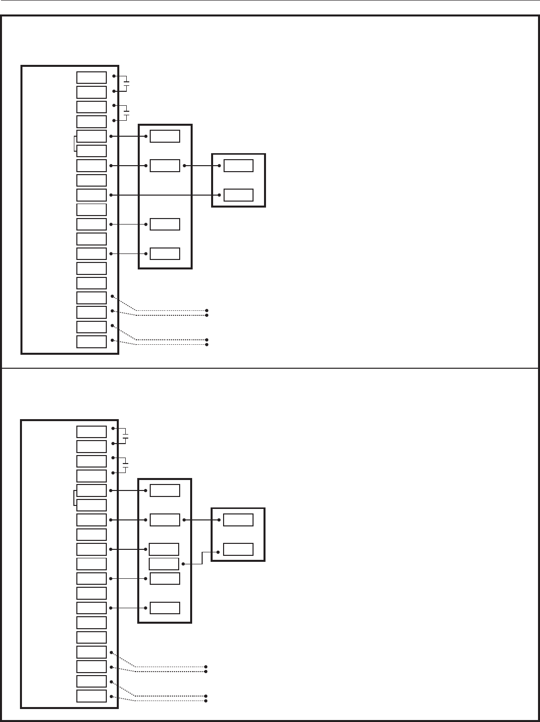
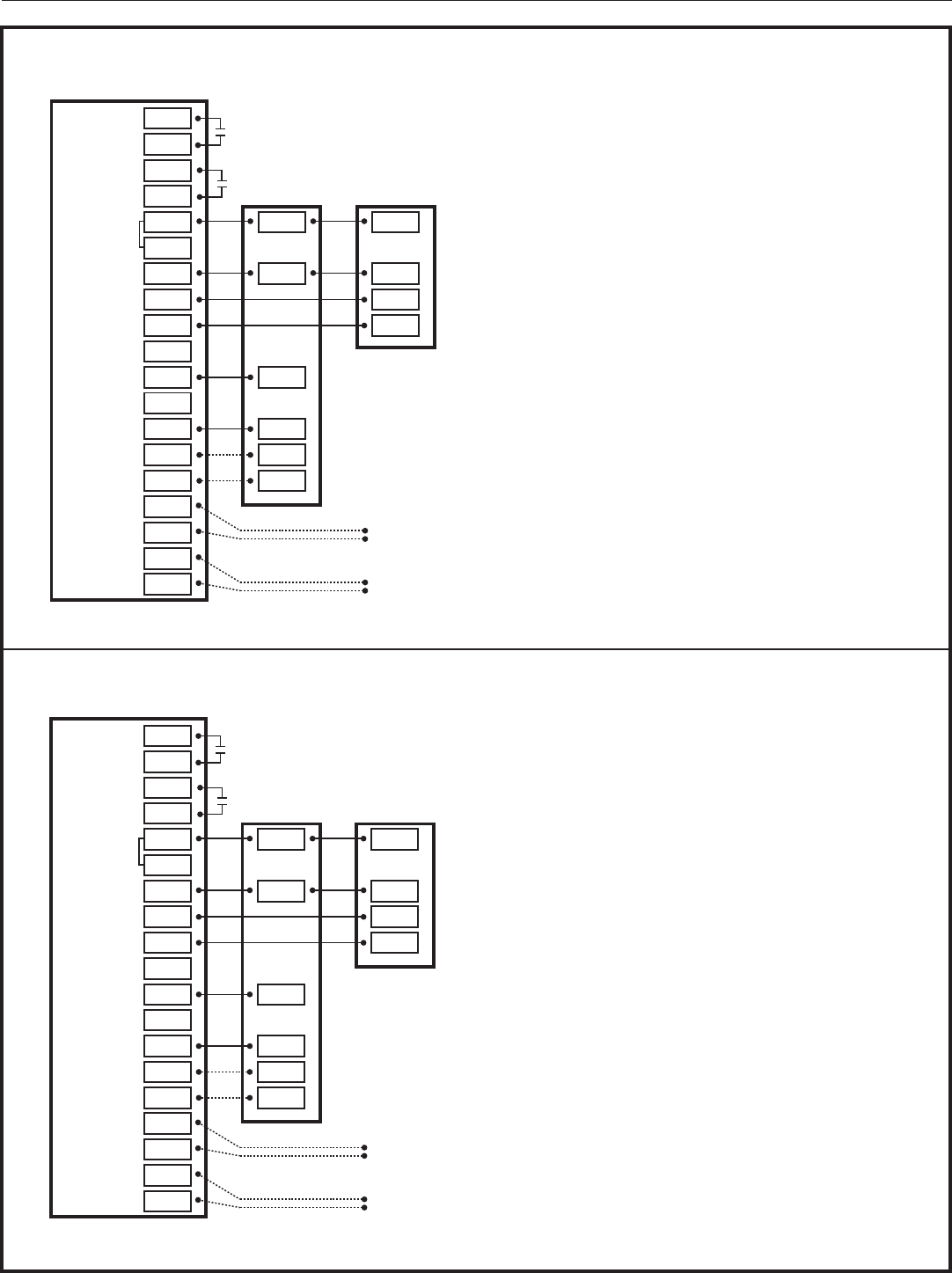
4.5 Heating and Cooling Applications
Diagram 1 - 1 or 2 Stage Cooling w/TAM7 Model Variable Speed Air Handler
Diagram 2 - 1 Stage Cooling w/GAM5A or TAM4 Model Air Handler
AUX 2
AUX 1
24VAC HOT
COMMON
SOV
COOLING
FA N
HEATING
ODT
RS
AUX2
AUX2
AUX1
AUX1
RC
RH
B/C
O
Y1
Y2
G
BK
W1
W2
W3
ODT
ODT
RS1
RS1
O
R
B
YI
YO
W3
Y2
G
BK
W1
W2
R
B
YI
Y2
Optional
Outdoor
Sensor
Optional
Remote
Sensor
3
2
1
824 COMFORT CONTROL
1- 1 or 2 Stage Cooling w/TAM7 Model Variable Speed Air Handler
INDOOR UNIT OUTDOOR UNIT
NOTES:
1. Cut and remove the “BK” jumper at the indoor unit
AFC Board
2. “YI” and “YO” connections must be made as shown
for freeze protection and internally mounted
condensate overflow circuits to function properly
3. If a 3rd party overflow condensate switches are
installed, wire between “Y1” of the 824 and “YI” of
the airflow control board
4. “R” and “Y2” connections at outdoor unit are
required only for two stage units
AUX 2
AUX 1
24VAC HOT
COMMON
SOV
COOLING
FA N
HEATING
ODT
RS
AUX2
AUX2
AUX1
AUX1
RC
RH
B/C
O
Y1
Y2
G
BK
W1
W2
W3
ODT
ODT
RS1
RS1
O
R
B
YI
YO
W3
Y2
G
BK
W1
W2
B
Y
Optional
Outdoor
Sensor
Optional
Remote
Sensor
2
1
2- 1 Stage Cooling w/GAM5A or TAM4 Model Air Handler
824 COMFORT CONTROL
INDOOR UNIT
OUTDOOR UNIT
NOTES:
1. “YI” and “YO” connections must be made as shown
for freeze protection and internally mounted
condensate overflow circuits to function properly
2. If 3rd party overflow condensate switches are
installed, wire between “Y1” of the 824 and “YI” of
the airflow control board
Installation Guide
page 8 18-HD72D1-1
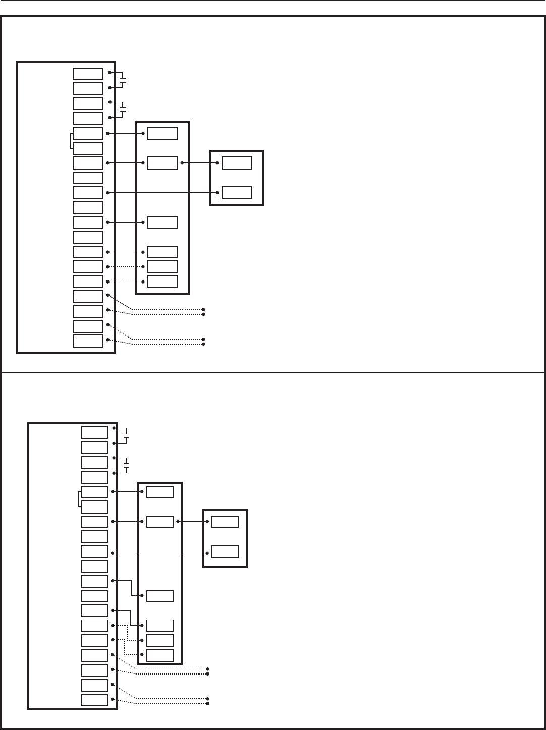
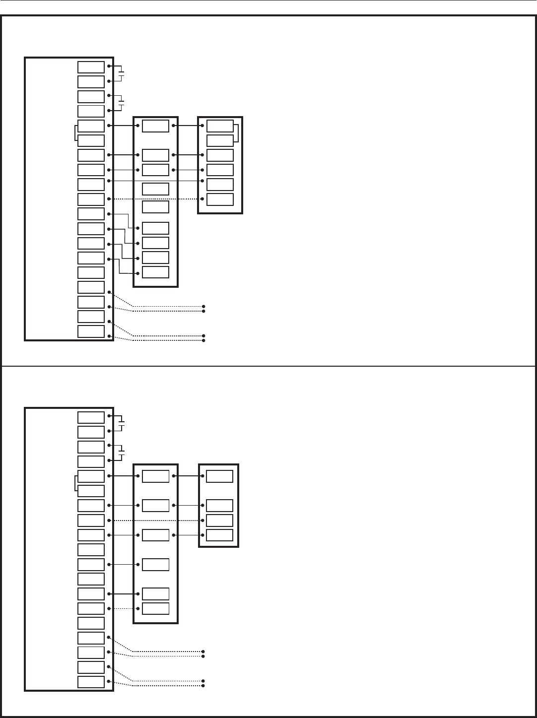
Diagram 4 - 2 Stage Cooling w/GAM5B Model Air Handler
Diagram 3 - 1 Stage Cooling w/GAM5B Model Variable Speed Air Handler
AUX 2
AUX 1
24VAC HOT
COMMON
SOV
COOLING
FA N
HEATING
ODT
RS
AUX2
AUX2
AUX1
AUX1
RC
RH
B/C
O
Y1
Y2
G
BK
W1
W2
W3
ODT
ODT
RS1
RS1
O
R
B
Y
W3
G
W1
W2
B
Y
Optional
Outdoor
Sensor
Optional
Remote
Sensor
1
3- 1 Stage Cooling w/GAM5B Model Air Handler
824 COMFORT CONTROL
INDOOR UNIT
OUTDOOR UNIT
NOTES:
1. “Y” terminal must be connected at indoor unit for high
stage air flow
AUX 2
AUX 1
24VAC HOT
COMMON
SOV
COOLING
FA N
HEATING
ODT
RS
AUX2
AUX2
AUX1
AUX1
RC
RH
B/C
O
Y1
Y2
G
BK
W1
W2
W3
ODT
ODT
RS1
RS1
Y
R
B
W3
G
W1
W2
R
B
YI
Y2
Optional
Outdoor
Sensor
Optional
Remote
Sensor
1
824 COMFORT CONTROL
4- 2 Stage Cooling w/GAM5B Model Air Handler
INDOOR UNIT OUTDOOR UNIT
NOTES:
1. “Y” terminal must be connected at indoor unit for
high stage air flow
824 Programmable Comfort Control
18-HD72D1-1 page 9
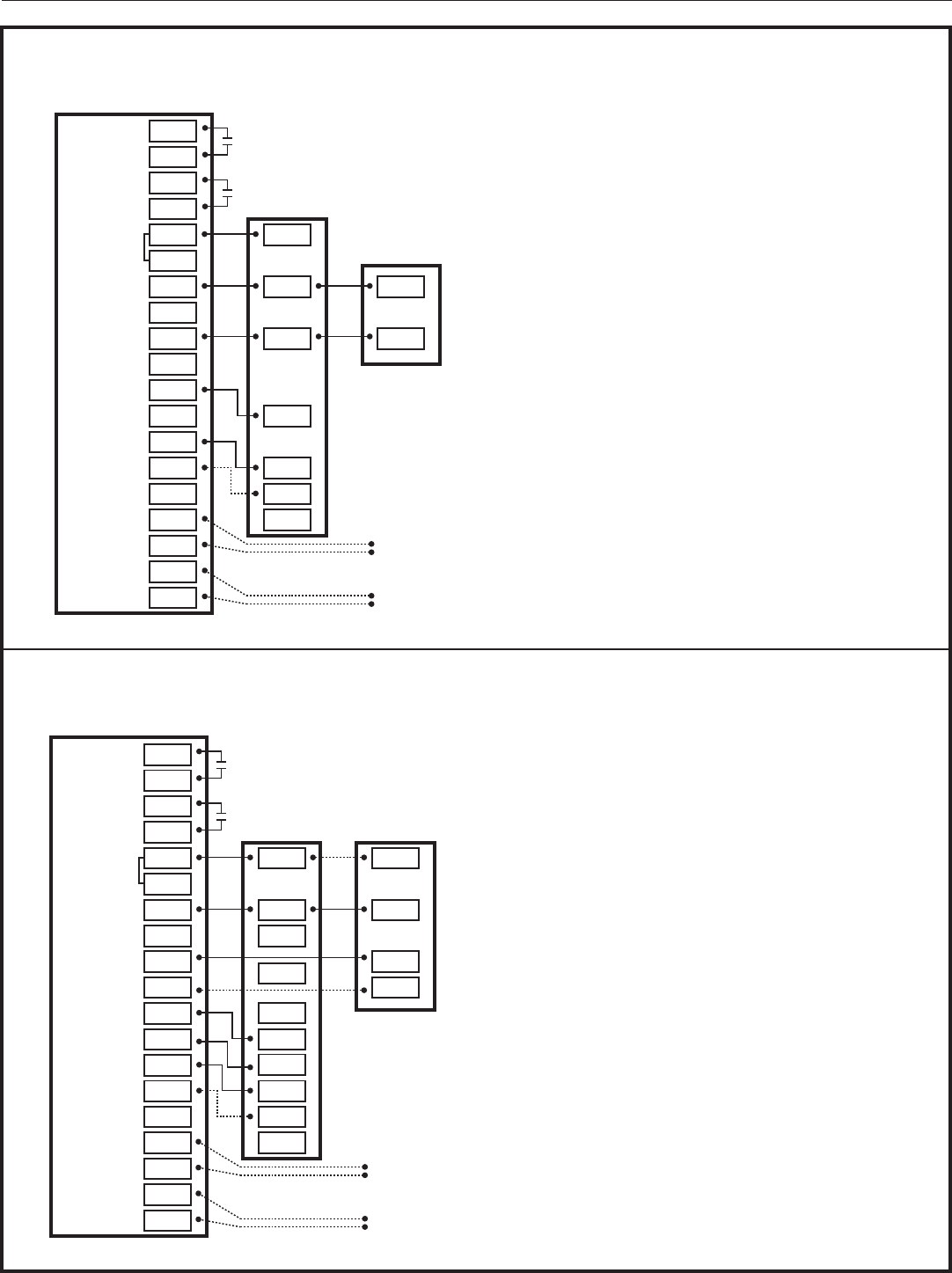
Diagram 5 - 1 Stage Cooling w/GAF2-S Model Air Handler
Diagram 6 - 1 Stage Cooling w/GAF2-36M Model Air Handler
AUX 2
AUX 1
24VAC HOT
COMMON
SOV
COOLING
FA N
HEATING
ODT
RS
AUX2
AUX2
AUX1
AUX1
RC
RH
B/C
O
Y1
Y2
G
BK
W1
W2
W3
ODT
ODT
RS1
RS1
R
B
G
W
B
Y
Optional
Outdoor
Sensor
Optional
Remote
Sensor
824 COMFORT CONTROL
5- 1 Stage Cooling w/GAF2-S Model Air Handler
INDOOR UNIT
OUTDOOR UNIT
AUX 2
AUX 1
24VAC HOT
COMMON
SOV
COOLING
FA N
HEATING
ODT
RS
AUX2
AUX2
AUX1
AUX1
RC
RH
B/C
O
Y1
Y2
YI
YO
G
BK
W1
W2
W3
ODT
ODT
RS1
RS1
R
B
G
W
B
Y
Optional
Outdoor
Sensor
Optional
Remote
Sensor
1
2
NOTES:
1. “YI” and “YO” connections must be made as shown
for freeze protection and internally mounted
condensate overflow circuits to function properly
2. If 3rd party overflow condensate switches are
installed, wire between “Y1” of the 824 and “YI” of
the airflow control board
824 COMFORT CONTROL
6- 1 Stage Cooling w/GAF2-36M Model Air Handler
INDOOR UNIT
OUTDOOR UNIT
Installation Guide
page 10 18-HD72D1-1
Diagram 8 - 1 Stage Cooling w/TEM3 Model Air Handler
Diagram 7 - 1 Stage Cooling w/GAT2 & GAM2 Model Air Handler
AUX 2
AUX 1
24VAC HOT
COMMON
SOV
COOLING
FA N
HEATING
ODT
RS
AUX2
AUX2
AUX1
AUX1
RC
RH
B/C
O
Y1
Y2
G
BK
W1
W2
W3
W2
W3
ODT
ODT
RS1
RS1
R
B
G
W1
B
Y
Optional
Outdoor
Sensor
Optional
Remote
Sensor
824 COMFORT CONTROL
7- 1 Stage w/GAT2 & GAM2 Model Air Handler
INDOOR UNIT
OUTDOOR UNIT
AUX 2
AUX 1
24VAC HOT
COMMON
SOV
COOLING
FA N
HEATING
ODT
RS
AUX2
AUX2
AUX1
AUX1
RC
RH
B/C
O
Y1
Y2
G
BK
W1
W2
W3
ODT
ODT
RS1
RS1
R
B
W3
G
W1
W2
B
Y
Optional
Outdoor
Sensor
Optional
Remote
Sensor
824 COMFORT CONTROL
8- 1 Stage w/TEM3 Model Air Handler
INDOOR UNIT
OUTDOOR UNIT
824 Programmable Comfort Control
18-HD72D1-1 page 11
Diagram 9 - 1 Stage Cooling w/Non-Variable Speed Gas Furnace
Diagram 10 - 1 or 2 Stage Cooling w/Variable Speed Gas Furnace
AUX 2
AUX 1
24VAC HOT
COMMON
SOV
COOLING
FA N
HEATING
ODT
RS
AUX2
AUX2
AUX1
AUX1
RC
RH
B/C
O
Y1 Y
Y2
G
BK
W1
W2
W3
ODT
ODT
RS1
RS1
R
B
W3
G
W1
W2
B
Y
Optional
Outdoor
Sensor
Optional
Remote
Sensor
824 COMFORT CONTROL
9- 1 Stage Cooling w/Non-Variable Speed Gas Furnace
INDOOR UNIT
OUTDOOR UNIT
AUX 2
AUX 1
24VAC HOT
COMMON
SOV
COOLING
FA N
HEATING
ODT
RS
AUX2
AUX2
AUX1
AUX1
RC
RH
B/C
O O
Y1
Y2Y2
Y1/Ylo
Y/Y2
G
BK
BK
W1
W2
W3
ODT
ODT
RS1
RS1
R R
B
W3
G
W1
W2
B
Y
Optional
Outdoor
Sensor
Optional
Remote
Sensor
NOTES:
1. Cut and remove the factory installed “BK” jumper at
the indoor unit IFC Board
2. ”R” & “Y2” connections at outdoor are only required
for two stage units
3. ”Y1/Ylo and/or Y/Y2” must be connected at indoor
for non-Trane/American Standars units
824 COMFORT CONTROL
10- 1 or 2 Stage Cooling w/Variable Speed Gas Furnace
INDOOR UNIT OUTDOOR UNIT
3
3
1
Installation Guide
page 12 18-HD72D1-1
Diagram 12 - 1 or 2 Stage Cooling w/Variable Speed Oil Furnace
Diagram 11 - 1 Stage Cooling w/Non-Variable Speed Oil Furnace
AUX 2
AUX 1
24VAC HOT
COMMON
SOV
COOLING
FA N
HEATING
ODT
RS
AUX2
AUX2
AUX1
AUX1
RC
RH
B/C
O
Y1 Y
Y2
G
BK
W1
W2
W3
ODT
ODT
RS1
RS1
R
C
G
T
T
B/C
Y
Optional
Outdoor
Sensor
Optional
Remote
Sensor
NOTES:
1. Remove factory RC/RH jumper for systems
with seperate heating and cooling low voltage
transformers
824 COMFORT CONTROL
11- 1 Stage Cooling w/Non-Variable Speed Oil Furnace
FURNACE
FAN CENTER
OIL BURNER
PRIMARY
AIR
CONDITIONER
T
T
AUX 2
AUX 1
24VAC HOT
COMMON
SOV
COOLING
FA N
HEATING
ODT
RS
AUX2
AUX2
AUX1
AUX1
RC
RH
B/C
O O
Y1
Y2Y2
G
BK
W1
W2
W3
ODT
ODT
RS1
RS1
R R
B
BK
G
W1
B
Y1
Y1/Ylo
Y/Y2
Optional Outdoor Sensor
Optional Remote Sensor
OIL BURNER
PRIMARY
NOTES:
1. “Y2” & “R” connections at outdoor unit are only
required for 2-stage heat pumps
2. Remove the factory installted jumper at “BK” on the
indoor unit
3. Remove factory RC/RH jumper for systems
with seperate heating and cooling low voltage
transformers
4. ”BK” is not connected on non-Trane/American
Standard units
5. “Y1/Ylo” and/or “Y/Y2” must be connected at the
indoor unit on non-Trane/American Standard units
824 COMFORT CONTROL
12- 1 or 2 Stage Cooling w/Variable Speed Oil Furnace
INDOOR UNIT OUTDOOR UNIT
3
5
5
2
824 Programmable Comfort Control
18-HD72D1-1 page 13
Diagram 13 - Package Single or Multi-Stage Heat/Cool w/Variable Speed Blower
Diagram 14 - Package Single-Stage Heat/Cool w/Variable Speed Blower
AUX 2
AUX 1
24VAC HOT
COMMON
SOV
COOLING
FA N
HEATING
ODT
RS
AUX2
AUX2
AUX1
AUX1
RC
RH
B/C
O O
Y1 Y1
Y2Y2
G
BK
W1
W2
W3
ODT
ODT
RS1
RS1
R
B
BK
G
W1
W2/X2
Optional
Outdoor
Sensor
Optional
Remote
Sensor
NOTES:
1. Cut and remove the factory installted jumper at “BK”
on the ECM fan control board
2. ”BK” is not connected on non-Trane/American
Standard units
824 COMFORT CONTROL
13- Package Single or Multi-stage Heat/Cool w/Variable Speed Blower
PACKAGE UNIT
1
AUX 2
AUX 1
24VAC HOT
COMMON
SOV
COOLING
FA N
HEATING
ODT
RS
AUX2
AUX2
AUX1
AUX1
RC
RH
B/C
O O
Y1 Y
Y2
G
BK
W1
W2
W3
ODT
ODT
RS1
RS1
R
B
G
W1
W2/X2
Optional
Outdoor
Sensor
Optional
Remote
Sensor
824 COMFORT CONTROL
14- Package Single-stage Heat/Cool w/Variable Speed Blower
PACKAGE UNIT
Installation Guide
page 14 18-HD72D1-1
Diagram 16 - 1 Stage Heat Pump w/GAM5A & TAM4 Model Air Handler
Diagram 15 - 1 or 2 Stage Heat Pump w/TAM7 Model Air Handler
4.6 Heat Pump Applications
AUX 2
AUX 1
24VAC HOT
COMMON
SOV
COOLING
FA N
HEATING
ODT
RS
AUX2
AUX2
AUX1
AUX1
RC
RH
B/C
O
Y1
Y2
YI
YO
G
BK
W1
W2
Y2 Y2
G
BK
W1
W3 W2
ODT W3
ODT
RS1
RS1
O
Y1
O
R
B
R
B
Optional
Outdoor
Sensor
Optional
Remote
Sensor
3 2
1
824 COMFORT CONTROL
15- 1 or 2 Stage Heat Pump w/TAM7 Model Air Handler
INDOOR UNIT OUTDOOR UNIT
NOTES:
1. Remove the factory installed “BK” jumper at the
indoor unit’s AFC Board
2. ”YI” and “YO” connections must be made as shown
for freeze protection and internally mounted
condensate overflow circuits to function properly
3. Wire 3rd party condensate overflow switches
between “Y1” of the 824 and “YI” of the airflow
control board
AUX 2
AUX 1
24VAC HOT
COMMON
SOV
COOLING
FA N
HEATING
ODT
RS
AUX2
AUX2
AUX1
AUX1
RC
RH
B/C
O
Y1
Y2
YI
YO
G
BK
W1
W2
Y2 Y2
G
W1
W3 W2
ODT W3
ODT
RS1
RS1
O
Y1
O
R
B
R
B
Optional
Outdoor
Sensor
Optional
Remote
Sensor
2
1
1
16- 1 Stage Heat Pump w/GAM5A & TAM4 Model Air Handler
824 COMFORT CONTROL
INDOOR UNIT OUTDOOR UNIT
NOTES:
1.
”YI” and “YO” connections must be made as shown
for freeze protection and internally mounted
condensate overflow circuits to function properly
2. Wire 3rd party condensate overflow switches
beteeen “Y1” of the 824 and “YI” of the airflow
control board
824 Programmable Comfort Control
18-HD72D1-1 page 15
Diagram 18 - 2 Stage Heat Pump w/GAM5B Model Air Handler
Diagram 17 - 1 Stage Heat Pump w/GAM5B Model Air Handler
AUX 2
AUX 1
24VAC HOT
COMMON
SOV
COOLING
FA N
HEATING
ODT
RS
AUX2
AUX2
AUX1
AUX1
RC
RH
B/C
O
Y1
Y2
Y
G
BK
W1
W2
G
W1
W3
W2
ODT
W3
ODT
RS1
RS1
O
Y
O
R
B
R
B
Optional
Outdoor
Sensor
Optional
Remote
Sensor
1
17- 1 Stage Heat Pump w/GAM5B Model Air Handler
824 COMFORT CONTROL
INDOOR UNIT OUTDOOR UNIT
NOTES:
1. ”Y” terminal must be connected at indoor unit for
high stage air flow
1
AUX 2
AUX 1
24VAC HOT
COMMON
SOV
COOLING
FA N
HEATING
ODT
RS
AUX2
AUX2
AUX1
AUX1
RC
RH
B/C
O
Y1
Y2 Y
G
BK
W1
W2
Y2
G
W1
W3
W2
ODT
W3
ODT
RS1
RS1
O
Y1
O
R
B
R
B
Optional
Outdoor
Sensor
Optional
Remote
Sensor
18- 2 Stage Heat Pump w/GAM5B
824 COMFORT CONTROL
INDOOR UNIT OUTDOOR UNIT
NOTES:
1. ”Y” terminal must be connected at indoor unit for
high stage air flow
Installation Guide
page 16 18-HD72D1-1
Diagram 20 - 1 Stage Heat Pump w/GAF2-36M Model Air Handler
Diagram 19 - 1 Stage Heat Pump w/GAF2-S Model Air Handler
AUX 2
AUX 1
24VAC HOT
COMMON
SOV
COOLING
FA N
HEATING
ODT
RS
AUX2
AUX2
AUX1
AUX1
RC
RH
B/C
O
Y1
Y2
G
BK
W1
W2
G
W
W3
ODT
ODT
RS1
RS1
Y
O
R
B
R
B
Optional
Outdoor
Sensor
Optional
Remote
Sensor
19- 1 Stage Heat Pump w/GAF2-S Model Air Handler
824 COMFORT CONTROL
INDOOR UNIT OUTDOOR UNIT
AUX 2
AUX 1
24VAC HOT
COMMON
SOV
COOLING
FA N
HEATING
ODT
RS
AUX2
AUX2
AUX1
AUX1
RC
RH
B/C
O
Y1
Y2
O
YI
YO Y
G
BK BK
W1
W2
G
W
W3
ODT
ODT
RS1
RS1
O
R
B
R
B
Optional
Outdoor
Sensor
Optional
Remote
Sensor
20- 1 Stage Heat Pump w/GAF2-36M Model Air Handler
824 COMFORT CONTROL
INDOOR UNIT OUTDOOR UNIT
NOTES:
1. ”YI” and “YO” connections must be made as shown
for freeze protection and internally mounted
condensate overflow circuits to function properly
2. Wire 3rd party condensate overflow switches
beteeen “Y1” of the 824 and “YI” of the airflow
control board
2 1
1
824 Programmable Comfort Control
18-HD72D1-1 page 17
Diagram 22 - 1 Stage Heat Pump w/TEM3 Model Air Handler
Diagram 21 - 1 Stage Heat Pump w/GAT2 & GAM2 Model Air Handler
AUX 2
AUX 1
24VAC HOT
COMMON
SOV
COOLING
FA N
HEATING
ODT
RS
AUX2
AUX2
AUX1
AUX1
RC
RH
B/C
O
Y1
Y2
Y
G
BK
W1
W2
G
W1
W3
W2
W3
ODT
ODT
RS1
RS1
O
R
B
R
B
Optional
Outdoor
Sensor
Optional
Remote
Sensor
21- 1 Stage Heat Pump w/GAT2 & GAM2 Model Air Handler
824 COMFORT CONTROL
INDOOR UNIT OUTDOOR UNIT
AUX 2
AUX 1
24VAC HOT
COMMON
SOV
COOLING
FA N
HEATING
ODT
RS
AUX2
AUX2
AUX1
AUX1
RC
RH
B/C
O
Y1
Y2
Y
G
BK
W1
W2
G
W1
W3
W2
W3
ODT
ODT
RS1
RS1
O
R
B
R
B
Optional
Outdoor
Sensor
Optional
Remote
Sensor
22- 1 Stage Heat Pump w/TEM3 Model Air Handler
824 COMFORT CONTROL
INDOOR UNIT OUTDOOR UNIT
Installation Guide
page 18 18-HD72D1-1
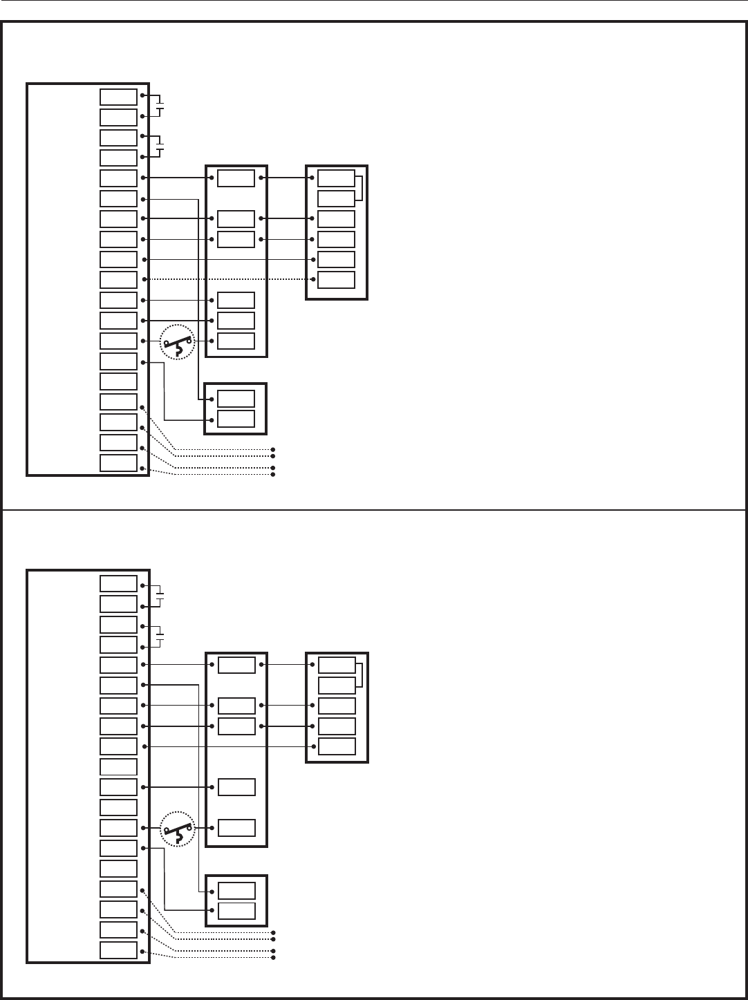
4.7 Dual Fuel Applications
Diagram 24 - 1 Stage Heat Pump w/Non-Variable Speed Gas Furnace
Diagram 23 - 1 or 2 Stage Heat Pump w/Variable Speed Gas Furnace
AUX 2
AUX 1
24VAC HOT
COMMON
SOV
COOLING
FA N
HEATING
ODT
RS
AUX2
AUX2
AUX1
AUX1
RC
RH
B/C
O
Y1
Y2
G
BK
W1
W2
G
BK
W1
W2
W3
ODT
ODT
RS1
RS1
O
Y2
O
R
B
R
F
B
YI
Y1/Ylo
Y/Y2
824 COMFORT CONTROL
23- 1 or 2 Stage Heat Pump w/Variable Speed Gas Furnace
INDOOR UNIT OUTDOOR UNIT
NOTES:
1. Cut and remove the factory installed “BK” jumper at
the indoor unit
2. ”BK” is not connected on non-Trane/American
Standard units
3. ”Y1” & “Y2” must be connected at the indoor unit on
non-Trane/American Standard units
4. For restricted mode operation, a wired ODT sensor
must be connected to the 824
Optional
Outdoor
Sensor
Optional
Remote
Sensor
4
1
3
AUX 2
AUX 1
24VAC HOT
COMMON
SOV
COOLING
FA N
HEATING
ODT
RS
AUX2
AUX2
AUX1
AUX1
RC
RH
B/C
O
Y1
Y2
G
BK
W1
W2
G
W1
W2
W3
ODT
ODT
RS1
RS1
O
R
B
Y
R
B
Y
1
24- 1 Stage Heat Pump w/Non-Variable Speed Gas Furnace
824 COMFORT CONTROL
INDOOR UNIT OUTDOOR UNIT
NOTES:
1. For restricted mode operation, a wired ODT sensor
must be connected to the 824
Optional
Outdoor
Sensor
Optional
Remote
Sensor
824 Programmable Comfort Control
18-HD72D1-1 page 19
Diagram 26 - Single Stage Heat Pump w/Non-Variable Speed Oil Furnace
Diagram 25 - 1 or 2 Stage Heat Pump w/Variable Speed Oil Furnace
6
5
AUX 2
AUX 1
24VAC HOT
COMMON
SOV
COOLING
FA N
HEATING
ODT
RS
AUX2
AUX2
AUX1
AUX1
RC
RH
B/C
O
Y1
Y2
G
BK
W1
W2
G
BK
W1
W3
ODT
ODT
RS1
RS1
O
Y2
O
R
B
R
F
B
YI
25- 1 or 2 Stage Heat Pump w/Variable Speed Oil Furnace
824 COMFORT CONTROL
INDOOR UNIT OUTDOOR UNIT
BT
NOTES:
1. Cut and remove the factory installed “BK” jumper at
the indoor unit
2. BT (Bonnet Thermostat) model THT1248
(BAYSEN03ATEMPAA) is required for dual fuel, oil
furnace applications
3. ”BK” is not connected on non-Trane/American
Standard units
4. ”Y1” & “Y2” must be connected at the indoor unit on
non-Trane/American Standard units
5. For restricted mode operation, a wired ODT sensor
must be connected to the 824
6. Remove factory RC/RH jumper for systems
with seperate heating and cooling low voltage
transformers
Optional Outdoor Sensor
Optional Remote Sensor
T
T
OIL BURNER
PRIMARY
3
2
AUX 2
AUX 1
24VAC HOT
COMMON
SOV
COOLING
FA N
HEATING
ODT
RS
AUX2
AUX2
AUX1
AUX1
RC
RH
B/C
O
Y1
Y2
G
BK
W1
W2
G
W1
W3
ODT
ODT
RS1
RS1
O O
R
B
R
F
B
Y
26- Single Stage Heat Pump w/Non-Variable Speed Oil Furnace
INDOOR UNIT OUTDOOR UNIT
BT
NOTES:
1. BT (Bonnet Thermostat) model THT1248
(BAYSEN03ATEMPAA) is required for dual fuel, oil
furnace applications
2. For restricted mode operation, a wired ODT sensor
must be connected to the 824
3. Remove factory RC/RH jumper for systems
with seperate heating and cooling low voltage
transformers
Optional Outdoor Sensor
Optional Remote Sensor
T
T
OIL BURNER
PRIMARY
Installation Guide
page 20 18-HD72D1-1
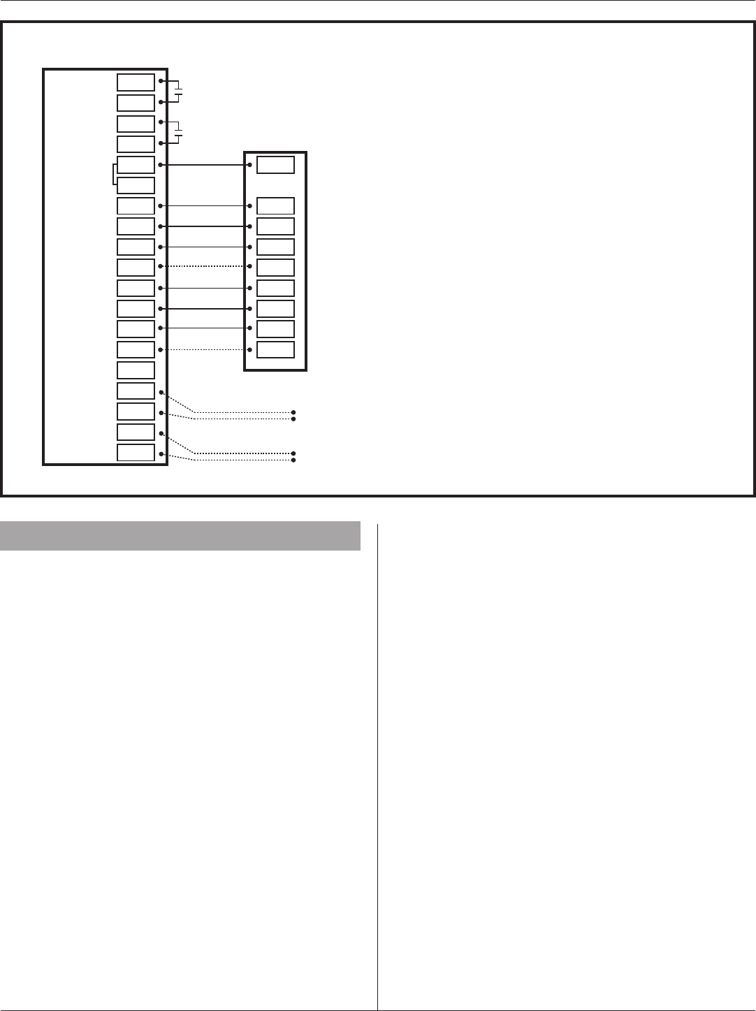
5. System Setup
5.1 Power-Up Sequence
When the 824 Control is connected to the Sub-base, the
Control will initiate a 90-120 second power-up sequence.
During the power-up sequence, the Screen Calibration
option is available for five seconds. If the screen is not
pressed within five seconds, the Control will default to
previously stored Screen Calibration settings.
Note: The 824 Control is factory calibrated and can be
recalibrated at any time by rebooting the Control and
selecting Screen Calibration option within the five seconds
following power-up.
Diagram 27 - Package Single or Multi-Stage Dual Fuel w/Variable Speed Blower
AUX 2
AUX 1
24VAC HOT
COMMON
SOV
COOLING
FA N
HEATING
ODT
RS
AUX2
AUX2
AUX1
AUX1
RC
RH
B/C
O
Y1
Y2 Y2
G
BK
W1
W2
G
BK
W1
W2/X2
W3
ODT
ODT
RS1
RS1
O
R
B
Y
27- Package Single or Multi-Stage Dual Fuel with Variable Speed Blower
OUTDOOR UNIT
NOTES:
1. Cut and remove the factory installed “BK” jumper on
them ECM fan control board
2. ”BK” is not connected on non-Trane/American
Standard units
3. For restricted mode operation, a wired ODT sensor
must be connected to the 824
Optional
Outdoor
Sensor
Optional
Remote
Sensor
1
1
824 Programmable Comfort Control
18-HD72D1-1 page 21
5.2 Guided System Configuration Tool
The Guided System Configuration Tool walks you step by step through the configuration process. The Tool appears when
the 824 is powered on for the first time and when the Restore Factory Defaults function is invoked.
After each step, a progress screen will show what steps have been completed and which ones are still pending.
MENU ITEM DESCRIPTION
Time and Date [User] Set the current time, date and time zone.
Installer Setup
From the Installer Setup screen, select a preset that matches the system’s configuration (i.e. Single Stage
AC, Standard Heat Pump, Multi-Stage Heat Pump, Standard Dual fuel, etc.). Based on this selection, the
824 automatically sets a number of parameters and options. Subsequent screens provide details of the
settings and allow for manual editing of each parameter.
Service Reminders
Set the mode and frequency of Air Filter, ERV Service and System Maintenance Reminders. When a
reminder is triggered, an alert will appear on the 824 Home Screen notifying the homeowner to contact
their dealer for service.
Schedule [User]
Guided Scheduling [User]
Screen [User]
Wireless Network [User]
Dealer Code
Registration [User]
Weather [User]
[User] indicates menu items that are included in the User Setup Tool.
5.3 Installer Setup
5.3.1 Group 1 Standard Settings
MENU ITEM OPTIONS [DEFAULT] DESCRIPTION
Outdoor Unit Type None, [Cooling Only], HP Select the type of outdoor unit installed
Outdoor Unit Stages [Single Stage], Two Stage Select the number of outdoor unit stages
Compressor Type Single Compressor Two Stage,
[Two Compressor Two Stage]
Select the compressor type for multi-stage outdoor
units
Indoor Unit Type [Gas/Oil], Electric, Hydronic Select the type of indoor unit installed
Indoor Heat Stages [Single Stage], Two Stage, Thee Stage Select the number of indoor heat stages
Indoor Blower Type Variable, [Non - Variable] Select the indoor blower type (Constant Torque motors
are considered non-variable speed)
Reversing Valve
Installation Guide
page 22 18-HD72D1-1
5.3.2 Group 2 Equipment Settings
MENU ITEM OPTIONS [DEAFULT] DESCRIPTION
Compressor Cooling Cycles Per Hour 2 - 6 [3] Select the number of cycles per hour during cooling operation
1st Stage Compressor Cooling Cycles Per Hour 2 - 6 [3] Select the number of cycles per hour during 1st stage cooling
operation
2nd Stage Compressor Cooling Cycles Per Hour 2 - 6 [3] Select the number of cycles per hour during 2nd stage cooling
operation
Compressor Heating Cycles Per Hour 2 - 6 [3] Select the minimum runtime (MRT) of stage 1 indoor heat
1st Stage Compressor Heating Cycles Per Hour 2 - 6 [3] Select the minimum runtime (MRT) of stage 2 indoor heat
2nd Stage Compressor heating Cycles Per Hour 2 - 6 [5] Select the minimum offtime (MOT) for indoor heat operation
Indoor Heater Cycles Per Hour 2 - 6 [5] Select the number of cycles per hour during indoor heat operation
1st Stage Indoor Heat Cycles Per Hour 2 - 6 [5] Select the number of cycles per hour during 1st stage indoor heat
operation
2nd Stage Indoor Heat Cycles Per Hour 2 - 6 [5] Select the number of cycles per hour during 2nd stage indoor heat
operation
3rd Stage Indoor Heat Cycles Per Hour 2 - 6 [5] Select the number of cycles per hour during 3rd stage indoor heat
operation
5.3.3 Group 3 Sensors Settings
MENU ITEM OPTIONS [DEFAULT] DESCRIPTION
Select Outdoor Temperature Sensor [No ODT Sensor],
Thermostat ODT Sensor Select whether an outdoor temperature sensor has been connected
Calibrate Outdoor Temperature Sensor -5°F - 5°F Calibrate the outdoor temperature sensor
Select Indoor Temperature Sensor [Thermostat IDT Sensor]
Wired IDT Sensor
Select whether the indoor temperature is being sensed by the thermostat
onboard sensor or wired remote sensor
Calibrate Indoor Temperature Sensor -5°F - 5°F Calibrate the indoor temperature sensor
Calibrate Onboard Humidity Sensor -5% - 5% Calibrate the onboard humidity sensor
Thermostat Humidity Sensor [Disable],
Enable
Select whether to use the onboard humidity sensor when a wired indoor
remote temperature sensor is being used

824 Programmable Comfort Control
18-HD72D1-1 page 23
5.3.4 Group 4 Accessories Settings
MENU ITEM OPTIONS [DEFAULT] DESCRIPTION
Filtration Type Installed Air Cleaner,
[Media Filter] Select the filter type installed
Humidifier Installed [None], Yes Select whether a humidifier is installed
Humidifier - Select Relay Panel Aux Contact [Aux 1], Aux 2 Select which set of Aux contacts is connected to the humidifier
Humidifier Type [Powered/Bypass], Steam Select what type of humidifier is installed
Humidifier Control [RH Control], Frost Control
Select how the humidifier will be controlled (Outdoor temperature
sensor must be connected and enabled to allow this setting to be
selected)
Humidifier Fan Action
[Humidify with Active Heat
Call], Humidify without
Active Heat Call
Select when the humidifier is allowed to operate (Humidification is
disallowed during cooling mode or when the System Mode is Auto but
the last call was cooling)
Airflow During Humidifier Only Mode 35% - 100% [50%] Select the desired airflow when the humidifier is operating without an
active call for heat
UV Light Installed [None], Yes Select whether a UV Light is installed
Dehumidifier Installed [None], Yes Select whether a ventilation system is installed
Dehumidifier - Select Relay Panel Aux
Contact Aux 1, [Aux 2] Select which set of aux contacts is controlling the ventilation system
Dehumidifier Control Options
[Stand Alone Operation],
With Active Call for Cooling
Only
Run System Fan with Dehumidifier Request Yes, [No]
Outdoor Temperature Ventilation Override [Disable], Enable
Select whether an outdoor temperature override is allowed (Outdoor
temperature sensor must be connected and enabled to allow this
setting to be selected)
Ventilation - Minimum Outdoor Temperature *-10°F - 50°F [0°] Select the minimum outdoor temperature that ventilation is allowed
Ventilation - Maximum Outdoor Temperature 80°F - 110°F [100°F] Select the maximum outdoor temperature that ventilation is allowed
Minimum Ventilation Runtime 0 - 60 Minutes [5 Minutes] Select the minimum runtime per hour for ventilation system
Acculate Overridden Runtime [No], Yes Select whether the overridden ventilation runtime will be made up
Acculate Period
[4 hours -recover
only when outdoor
conditions are favorable],
24 hours - recover
only when outdoor
conditions are favorable,
4 hours - recover as
need to meet minimum,
24 hours - recover as
needed to meet minimum
Select when to recover missed ventilation runtime due to outdoor
conditions exceeding the minimum/maximum outdoor temperate for
ventilation (The first two options will not meet AHRAE 62.2 standard for
minimum ventilation requirements)

Installation Guide
page 24 18-HD72D1-1
5.3.5 Group 5 Comfort Settings
MENU ITEM OPTIONS [DEFAULT] DESCRIPTION
Enable Dehumidification [Enable], Disable
When dehumidification is enabled, the control will reduce system
airflow by 30% (variable speed indoor units only) anytime the indoor
humidity is higher than the cooling target humidity setpoint and the
indoor temperature is within 2°F of cooling setpoint. All fan off delays
will also be cancelled.
Dehumidification Overcooling Limit - Degrees [0°] - 3°F
Select the maximum amount of overcooling allowed when the indoor
humidity exceeds the cooling target humidity setpoint. To accomplish
the overcooling the control will artificially create additional load by
increasing the sensed indoor temperature by 1/10th of a degree for
every 1% of a percent of humidity error, up to the overcooling limit
selected. The displayed indoor temperature will remain the same, but
the adjusted indoor temperature will control cooling operation.
Control Response Rate [Normal], Fast Select how quickly the control builds load value (Selecting Fast will
cause the control to build load value faster than normal operation)
Aggressive Recovery > 2° Setpoint Change Enable, [Disable]
Select whether the 10-minute staging inhibit is disabled (heating or
cooling mode) with a setpoint change greater than 2°F (Change can
be manual or scheduled)
Heating Aggressive Recovery Enable, [Disable]
Select whether the 10-minute staging inhibit is disabled during heating
mode when the outdoor temperature falls below the selected outdoor
temperature (Outdoor temperature sensor must be connected and
enabled to allow this setting to be selected)
Warm Air Discharge Enable, [Disable]
When enabled the indoor blower speed will be limited to 80% on a call
for heat pump heating. This only applies to heat pump heating with no
call for aux heat (An indoor unit with variable speed blower is required)

824 Programmable Comfort Control
18-HD72D1-1 page 25
5.3.6 Group 6 Airflow Settings
MENU ITEM OPTIONS [DEFAULT] DESCRIPTION
Variable Speed Blower On Delay - Cooling
[No Delay],
1 Minute @ 50%; 7.5 Minutes @ 80%,
1 Minute @ 50%; 4 Minutes @ 80%,
7.5 Minutes @ 80%,
4 Minutes @ 80%,
1 Minute @ 50%,
30 Seconds
Select the blower on delay for cooling operation
Non Variable Speed Blower On Delay - Cooling [No Delay],
15 Seconds, 30 Seconds Select the blower on delay for cooling operation
Variable Speed Blower Off Delay - Cooling
[No Delay],
1.5 Minutes @ 100%,
45 Seconds @ 100%,
30 Seconds % 50%,
1.5 Minutes @ 50%,
3 Minutes @ 50%,
30 Seconds @ 35%
Select the blower off delay for cooling operation
Non Variable Speed Blower Off Delay - Cooling
[No Delay],
30 Seconds,
60 Seconds,
90 Seconds
Select the blower off delay for cooling operation
Variable Speed Blower On Delay - Compressor Heating
[No Delay],
1 Minute @ 50%; 7.5 Minutes @ 80%,
1 Minute @ 50%; 4 Minutes @ 80%,
7.5 Minutes @ 80%,
4 Minutes @ 80%,
1 Minute @ 50%,
30 Seconds
Select the blower on delay for compressor
heating operation
Non Variable Speed Blower On Delay - Compressor
Heating
[No Delay],
15 Seconds,
30 Seconds
Select the blower on delay for compressor
heating operation
Variable Speed Blower Off Delay - Compressor Heating
[No Delay],
1.5 Minutes @ 100%,
45 Seconds @ 100%,
30 Seconds % 50%,
1.5 Minutes @ 50%,
3 Minutes @ 50%,
30 Seconds @ 35%
Select the blower off delay for compressor
heating operation
Non Variable Speed Blower Off Delay - Compressor
Heating
[No Delay],
30 Seconds,
60 Seconds,
90 Seconds
Select the blower off delay for compressor
heating operation
Hydronic Heat Blower On Delay
[No Delay],
30 Seconds,
60 Seconds
Select the blower on delay for hydronic heating
operation
Hydronic Heat Blower Off Delay
[No Delay],
30 Seconds,
60 Seconds,
90 Seconds
Select the blower off delay for hydronic heating
operation
Compressor Low Stage Air Flow% - Compressor Cooling 35% - 60% [50%] Select the 1st stage air flow for a two stage/two
compressor unit in cooling mode
Compressor Low Stage Air Flow% - Compressor Cooling 55% - [80%] Select the 1st stage air flow for a two stage/
single compressor unit in cooling mode
Compressor Low Stage Air Flow% - Compressor Heating 35% - 60% [50%] Select the 1st stage air flow for a two stage/two
compressor unit in heating mode
Compressor Low Stage Air Flow% - Compressor Heating 55% - [80%] Select the 1st stage air flow for a two stage/
single compressor unit in heating mode
Installation Guide
page 26 18-HD72D1-1
5.3.7 Advanced Settings — Lockouts
MENU ITEM OPTIONS [DEFAULT] DESCRIPTION
Auxiliary Heat Lockout [Disable], Enable Enable auxiliary heat lockout (10° minimum separation when enabling
auxiliary heat lockout and compressor heat lockout)
Auxiliary Heat Lockout 32°F - 70°F Degrees [45°] Select an outdoor temperature to prevent auxiliary heat above the selected
outdoor temperature
Compressor Lockout [Disable], Enable Enable compressor heat lockout (10° minimum separation when enabling
auxiliary heat lockout and compressor heat lockout)
Compressor Lockout 5°F - 35°F Degrees [30] Select an outdoor temperature to prevent compressor heating below the
selected outdoor temperature
Defrost Heater Balance Point (W1) [Disable], Enable Enable defrost heater balance point for W1, W2 and W3 (only applicable
when indoor heat is electric or hydronic)
Defrost Heater Balance Point (W1) 40°F - [55°F] Select an outdoor temperature to disallow 1st, 2nd and 3rd stage of indoor
heat during defrost above this temperature
Defrost Heater Balance Point (W2) [Disable], Enable Enable defrost heater balance point for W1 and W2 (only applicable when
indoor heat is electric or hydronic)
Defrost Heater Balance Point (W2) 10°F - 50°F [55°F] Select an outdoor temperature to disallow 2nd and 3rd stage of indoor heat
during defrost above this temperature
Defrost Heater Balance Point (W3) [Disable], Enable Enable defrost heater balance point for W3 only (only applicable when indoor
heat is electric or hydronic)
Defrost Heater Balance Point (W3) [5°F] - 35°F Select an outdoor temperature to disallow 3rd stage of indoor heat during
defrost above this temperature
Compressor Cooling 1st Stage Lockout [Disable], Enable Enable compressor cooling 1st stage lockout
Compressor Cooling 1st Stage Lockout 80°F - [120°F] Select an outdoor temperature to force the system to 2nd stage compressor
cooling
Compressor Heating 1st Stage Lockout [Disable], Enable Enable compressor heating 1st stage lockout
Compressor Heating 1st Stage Lockout 0°F - [50°F] Select an outdoor temperature to force the system to 2nd stage compressor
heating
Furnace Heating 1st Stage Lockout [Disable], Enable Enable furnace heating 1st stage lockout
Furnace Heating 1st Stage Lockout 0°F - [50°F] Select an outdoor temperature to force the system to 2nd stage furnace
heating
5.4 Reminders
5.5 Dealer Code

824 Programmable Comfort Control
18-HD72D1-1 page 27

Installation Guide
page 28 18-HD72D1-1
824 Programmable Comfort Control
18-HD72D1-1 page 29
6. Basic Operation
6.1 PI Control
The 824 Control uses Trane’s proprietary control schemes
to provide both comfort and energy efficiency. The Control
samples the indoor temperature every five seconds and
determines the capacity needed based on the following
parameters:
• Mode of operation
• Proportional Error - distance from set point
• Integral Error - Time away from set point
6.2 Load Value
The 824 uses Proportional Error plus Integral Error to
determine the amount of capacity required. The calculated
capacity is displayed as Load Value. Load Value is a
numerical representation of the needed capacity to maintain
the desired set point. The Load Value range is dependent
on the applied system.
72º
BCD
Set Point
Temperature
2 Seconds
Integral Error
Room
Temperature
A
B + C + D... = Integral Error
A = Proportional Error
6.3 Duty Cycles
Indoor temperature control is achieved by duty cycling the
equipment when the load value is less than 100% of the
current stage of operation. The duty cycle rate is dependent
on the calculated load value.
The duty cycle chart below indicates the number of cycles
at 50% load (i.e. LV = 50).
1 Hour
6 CPH
2 CPH
As with all PI-based controls the indoor temperature will
fluctuate above and below the user selected set point to
maintain comfort in the space. Adjusting the factory set
CPH (Cycles per Hour) can affect how tight the control
operates around the set point. The CPH can be adjusted
in the Installer Settings>Advanced>Equipment (2 – 6 CPH)
• Factory default for compressor operation is 3 CPH
• Factory default for indoor heat is 5 CPH
Effects of changing the cycle rates
Lower CPH results in longer run cycles with less cycling
but the indoor temperature may deviate above and below
set point.
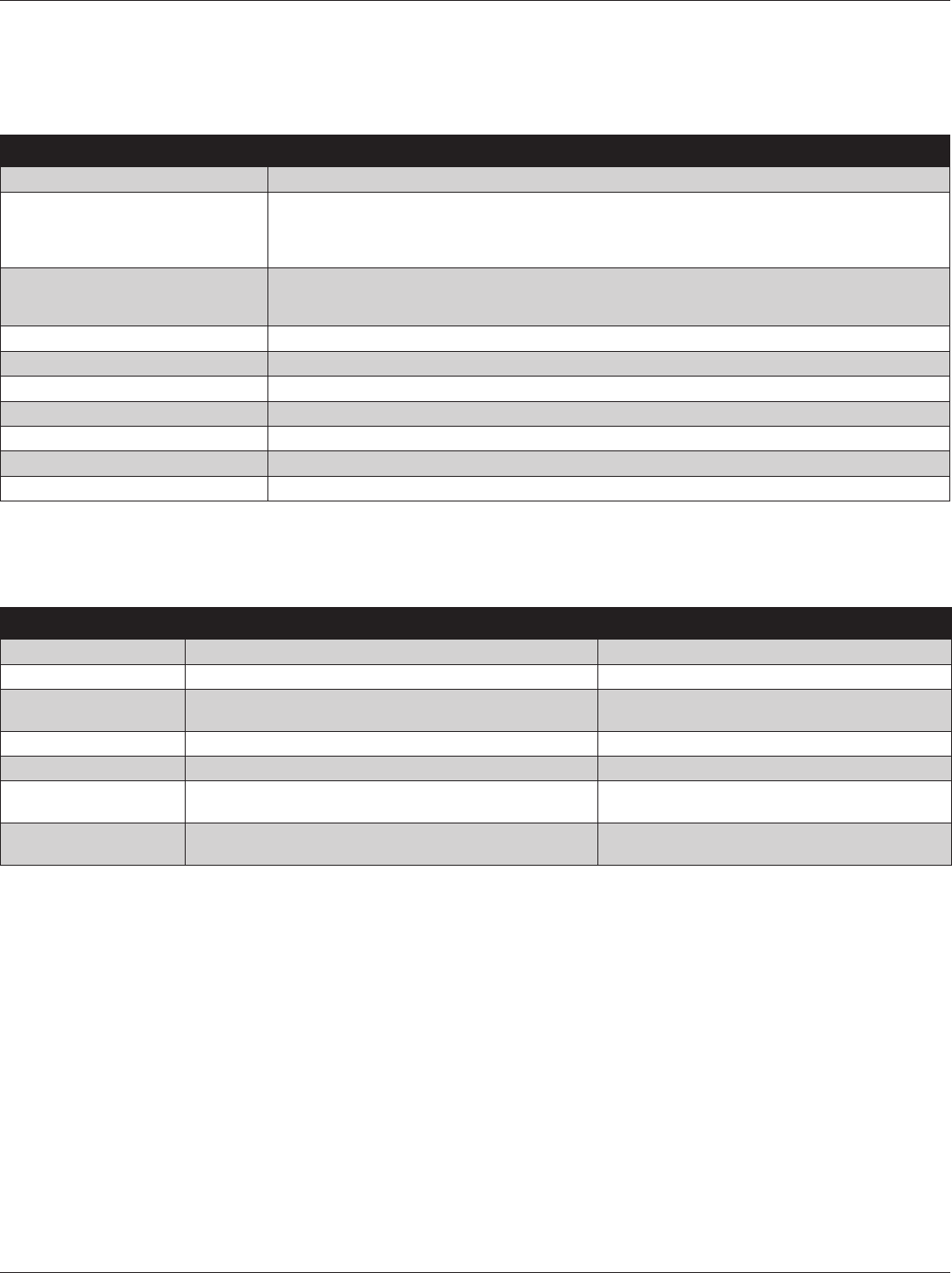
Higher CPH results in highter indoor temperature control
but shorter, more frequent cycles.
6.4 Overshoot Clamp
The 824 Control will enforce an “off cycle” anytime the
control overshoots more than 2.5°F. Once the indoor
temperature is within .75°F of set point an “on cycle” is
allowed dependent on load value and minimum off times.
Show illustration…
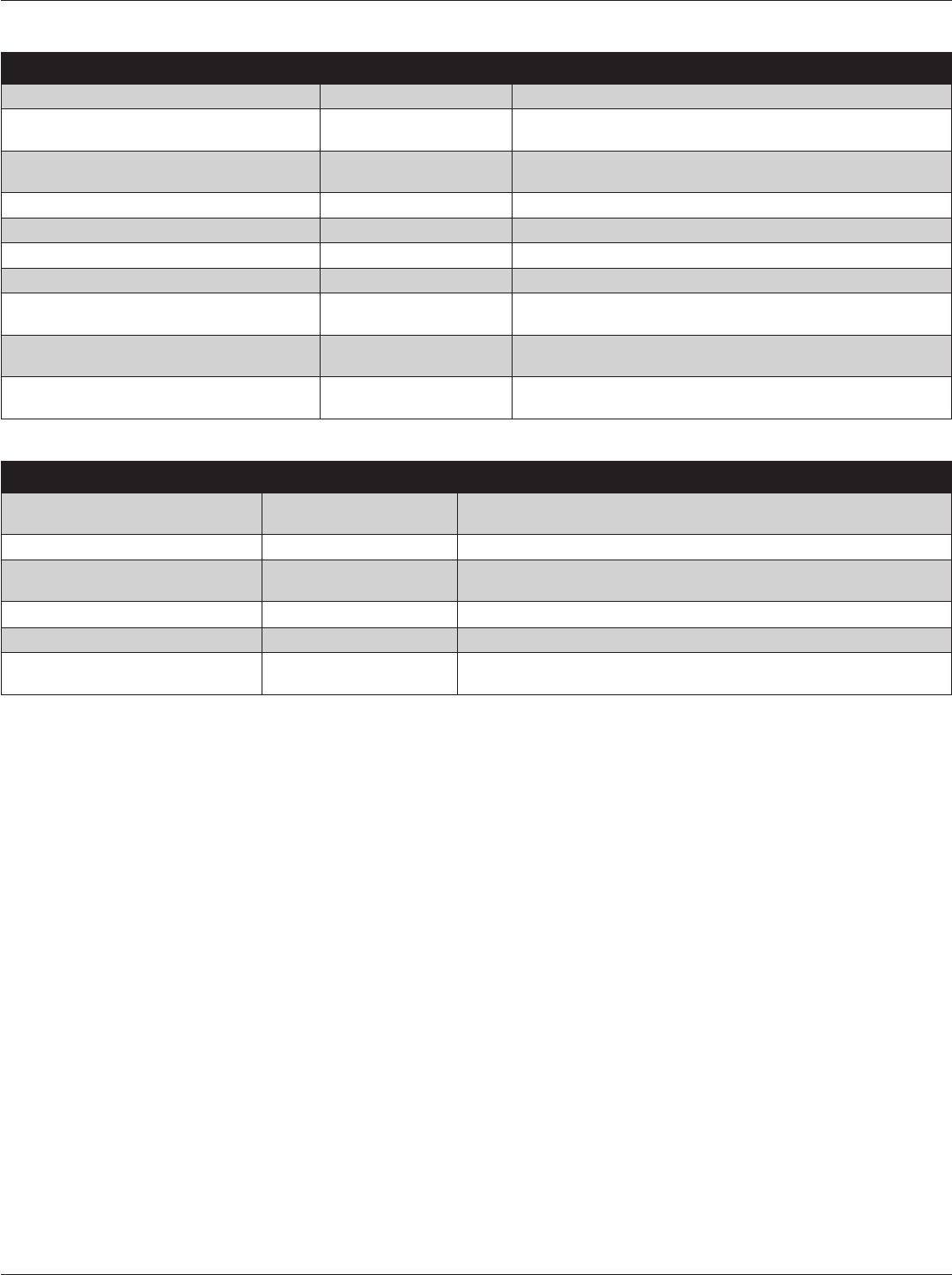
6.5 Stage Thresholds
The threshold to allow operation is a Load Value greater
than 5 and operation is always terminated with a Load
Value less than 1.
Load Value also determines when additional stages of
operation are requested. To prevent rapid cycling between
stages, a stage threshold is enforced. The stage threshold
is dependent on the applied system.
LV=100
LV=200 STAGE 3
STAGE 1
STAGE 2
COMPRESSOR STAGING THRESHOLDS
100-115
100-115
100-125
100-125
100-110
100-110
Y1 to Y2 - 100-110
Y1 to Y2 - 100-110
HP to W1 - 100-115
HP to W1 - 100-115
HP to Dual Fuel - 100-125
HP to Dual Fuel - 100-125
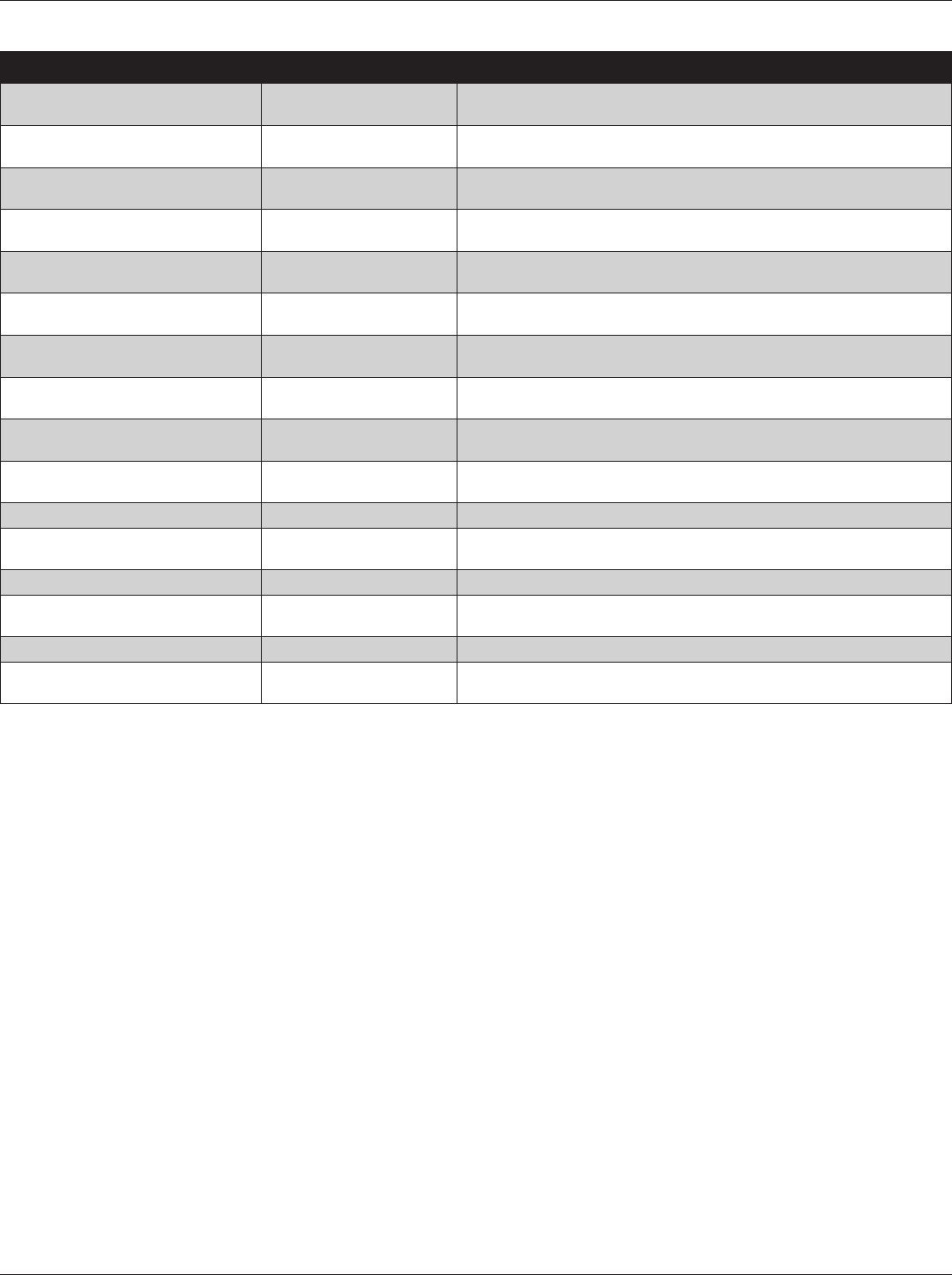
LV=100
LV=200
LV=300
LV=400 STAGE 5
STAGE 1
STAGE 2 STAGE 3 STAGE 4
AUX HEAT STAGING THRESHOLDS
100-215
100-215
100-315
100-315
100-
115
100-
115
Compressor to W1 - 100-115
Compressor to W1 - 100-115
W1 to W2 - 100-215
W1 to W2 - 100-215
W2 to W3
100-315
W2 to W3
100-315
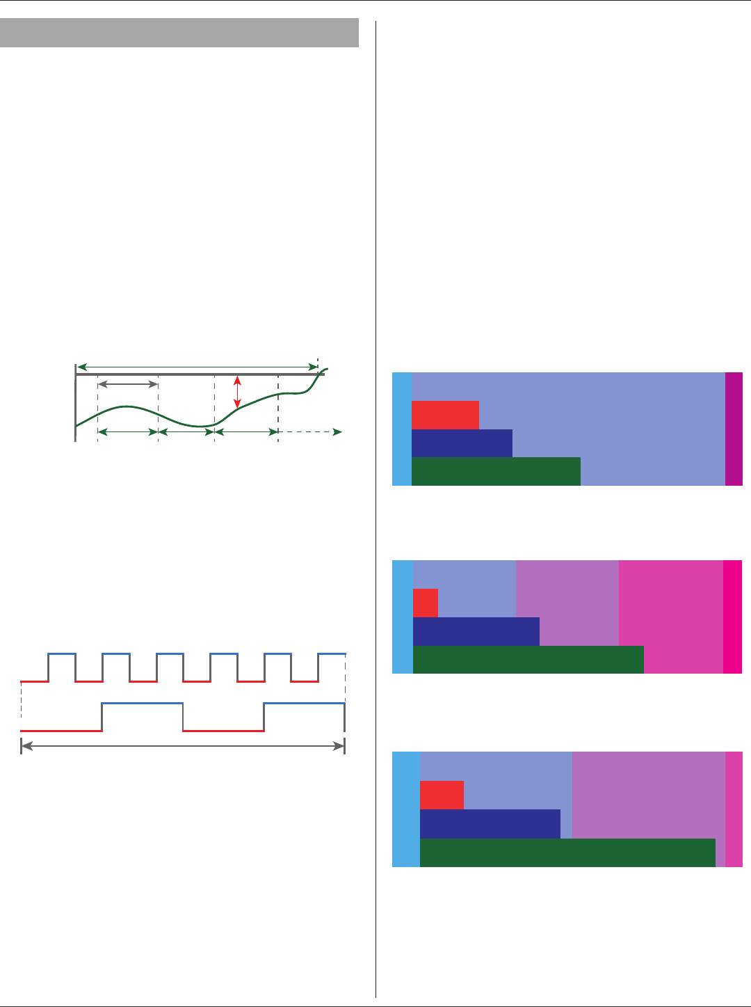
LV=100
LV=200
LV=300
STAGE 4
STAGE 1
STAGE 2 STAGE 3
FOSSIL HEAT STAGING THRESHOLDS
W1 to W2 100-190
W1 to W2 100-190
W2 to W3 100-290
W2 to W3 100-290
100-
125
100-
125
Inhibit - Compressor to W1 - 100-125
Inhibit - Compressor to W1 - 100-125
Installation Guide
page 30 18-HD72D1-1
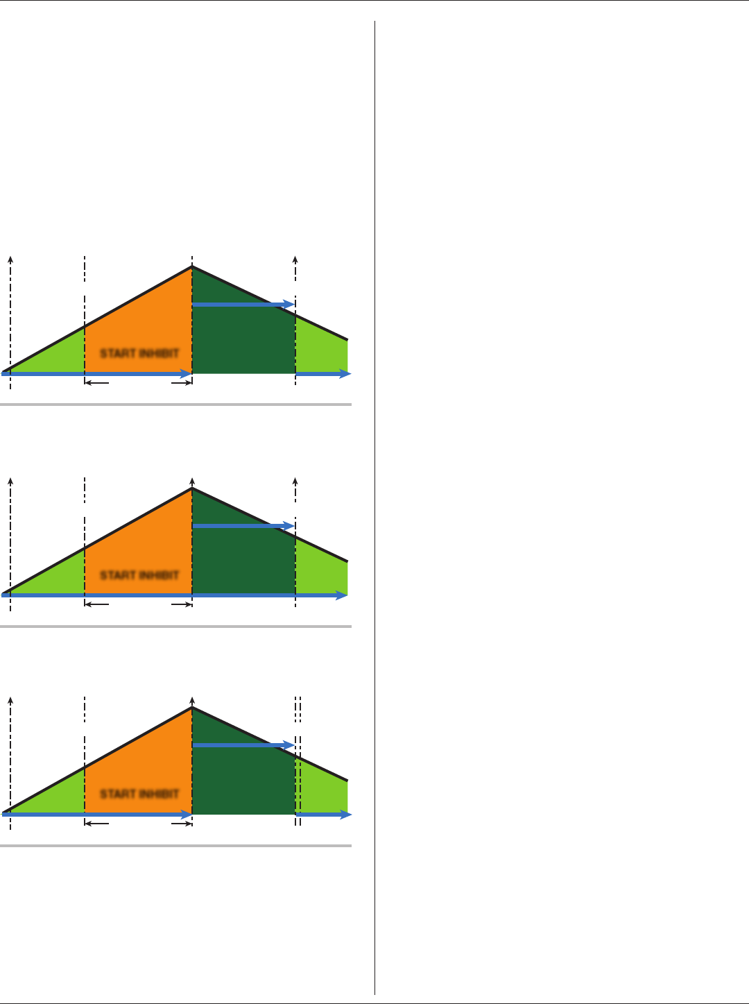
6.6 Stage Inhibits
When the stage threshold is exceeded, a stage inhibit is
applied. The stage inhibit calculates the rate of recovery
over a 10-minute period and determines if the next stage is
required to meet the current demand. If the rate of recovery
is great enough, then a new 10-minute inhibit is enabled.
The Control will not go to the next stage of operation until it
determines that the current stage cannot satisfy the current
demand. Stage inhibits only apply between compressor
stages and compressor heat to indoor heat. Stage inhibits
do not apply to indoor heat stages.
START INHIBIT
10 Minutes
Y1 “ON” Y2 “ON” Y1 “ON”
LV = 100
LOAD VALUE (LV)
LV = 110
Stage Inhibits - Compressor Staging
Stage Inhibits - Compressor to Aux Heat
START INHIBIT
10 Minutes
Y1 “ON” W1 “ON” W1 “OFF”
LV = 100
LOAD VALUE (LV)
LV = 115
START INHIBIT
10 Minutes
Y1 “ON” W1 “ON”
Y1 “ON”
45 Second
Cool Down
LV = 100
LOAD VALUE (LV)
LV = 125
Stage Inhibits - Duel Fuel
Stage inhibits can be disabled in the 824 Control Installer
Settings>Advanced>Comfort. Options are below:
6.7 Aggressive Recovery
• Disables stage inhibits in heating and cooling mode
anytime the set point is adjusted more than 2°F
• Heating Aggressive Recovery
• Disable stage inhibit in heating mode only when the
outdoor temperature falls below the selected outdoor
temperature
6.8 System Mode
• The 824 has (5) System Modes which can be
selected…Heating, Cooling, Off, Emergency Heating
and Auto.
• Heating – System will only operate in heating mode
• Cooling – System will only operate in the cooling
mode
• Off – System will not operate in heating or cooling
mode
• Emergency Heating – System will operate the indoor
heat source only (this is only available when the
outdoor unit type is a heat pump)
• Auto - The control will determine which mode of
operation by the following rules:
• Heat - Indoor temperature is equal or less than
heating set point
• Cooling – Indoor temperature is within 1°F of cooling
set point
There is minimum deadband between heating and cooling
set points of 4°F
6.9 Fan Mode
The 824 has three Fan Modes:
• Auto – Fan only runs with a call for heating or cooling
• On – Fan runs continuous
• Circ – Fan runs a user selected minimum amount of
time each hour
6.10 Air Cleaner Mode
The 824 has three Air Cleaner modes:
• Auto – Air cleaner operates only with a call for fan
operation
• Quick – Air cleaner will operate for 3-hours
• Allergy – Air cleaner will operate for 24-hours

824 Programmable Comfort Control
18-HD72D1-1 page 31
7. Advanced Operation
7.1 Dehumidification
The 824 utilizes the following methods for dehumidification:
• Air flow reduction – If the indoor unit has a variable
speed blower the 824 Control can reduce the system
air flow by 30% anytime the indoor RH is higher than
the cooling RH target. Air flow reduction is disallowed
if the indoor temperature is more than 2°F away from
the cooling set point. Dehumidification is enabled by
default and can be disabled by navigating to Installer
Settings>Advanced>Comfort settings.
• “Fan Off” delays are defeated when dehumidification
is enabled and the indoor RH exceeds the cooling RH
target.
• Cooling Overshoot - If cooling overshoot is enabled,
the Control will allow a .1°F of overcooling for each 1%
of RH error. When the system is actively overcooling,
Dehumidification will be displayed on the 824 home
screen. A maximum amount of overcooling can be
configured for 1°F, 2°F or 3°F. Overcooling is enabled
in Installer Settings>Advanced>Comfort settings.
• Smart Continuous Fan – If this option is enabled,
continuous fan operation will be interrupted when
indoor RH exceeds desired cooling RH target. A
humidity icon will be displayed along with the fan
icon to indicate that continuous fan operation has
been disabled due to high humidity conditions. Smart
Continuous Fan will not interrupt the fan circulate
mode. To enable this function press Menu>Fan>Smart
Continuous Fan settings.
7.2 Warm Air Discharge
Enabling Warm Air Discharge will reduce the variable
speed blower air flow by 20% when in compressor heating
operation. Warm air discharge only applies to compressor
heating and is disabled when hydronic, fossil fuel or
electrical heat (including supplement heat) modes are
activated. Warm Air Discharge can be enabled in Installer
Settings>Advanced>Comfort settings.
7.3 Lockouts
7.4 Control Response Rate
7.5 Aux Contacts
The 824 has two sets of dry contacts which can be
configured to control a Humidifier, Ventilation system or a
Whole-House Dehumidifier.
7.6 Stand Alone Operation
Dehumidifier can operate independent from cooling
operation as long as the control is Cooling or Auto mode
and the last call was cooling.
If Stand Alone Operation is selected, the control allows
the user to select whether the indoor fan operates with
dehumidifier request.
With Active Call for Cooling Only – Dehumidifier can only
operate during an active call for cooling.
Installation Guide
page 32 18-HD72D1-1
8. Diagnostic Tools
8.1 Test Modes.
MODE SETTINGS DESCRIPTION
Test Blower 50%, 100% Energize indoor blower at the selected speed
Test Cool Stage 1
Stage 2
Energize the selected stage of cooling operation. The indoor blower will also
operate at the speed required for the selected stage
Test Compressor Heat Stage 1
Stage 2
Energize the selected stage of compressor heating operation. The indoor blower
will also operate at the speed required for the selected stage
Test Indoor Heat
Stage 1
Stage 2
Stage 3
Modulating
Energize the selected stage of indoor heating operation. The blower operation
will be dependent on the indoor heat type:
Electric - blower energized during test mode but the blower speed is controlled
by the indoor unit
Fossil - blower is controlled independently by the indoor unit during test mode
Hydronic - blower is energized during test mode
Test Compressor and Indoor Heat
Stage 1 Indoor Heat
Stage 2 Indoor Heat
Stage 3 Indoor Heat
Energize all stages of compressor heat and selected stage of indoor electric
heat/hydronic heat. The blower is energized and runs at the higher of the
compressor heat air flow versus indoor heat air flow
More Test Humidifier
Test Aux Contact
Closes the normally open Humidifier/AUX contacts. The blower is not energized
during this test mode
8.2 Data Logging
The 824 Control has the ability to log data on USB
Flash Drive. Attach a USB Flash Drive to the Standard-A
receptacle of the included Mirco-A to Standard-A adapter
and plug the Micro-A end into the Micro-USB plug on the
824 Control and select Save Logs from the Service Menu.
The amount of data logged will be dependent on the
number of days logged and the storage capability of the
USB Flash Drive.
HOW TO END???
8.3 Diagnostics
Within the Diagnostic screen are two items related to alerts:
• Current Alerts – Alerts which are currently active
• Alert History – Alerts which have been cleared (last
30 days)
NOTE: Each alert will have a date/timestamp of when the
alert was negated.
From both screens the user can select an alert code and
get additional information on the alert as well as a list of
possible causes, similar to the Interactive Troubleshooting
Guide located on ComfortSite/ASDealernet
All alerts are categorized by severity:
• CRITICAL
— Loss of heating/cooling operation
— Service call is required
— Alert messages are displayed on the home screen
and when closed, a flashing red icon is used to
indicate alert condition.
• MAJOR
— Reduced functionality but basic/minimum operation is
possible
— Service call is not immediately required
— Alert messages are not displayed on the home screen
but a yellow icon is used to indicate alert condition.
NOTE: Critical and Major alerts can be displayed on the
home screen by pressing the alert icon on the shortcut
toolbar (top right of home screen).
• NORMAL
— Functionality may be lost but should recover
or information used for diagnostic purposes /
performance monitoring
— Service call is not required
— Normal alerts are only displayed in the Diagnostic
screen
8.4 History
The History screen allows the technician to view cycle count
and run time data for each mode and stage of operation.
This data provides a snap-shot in to how the system is
operating. The technician can also compare the current
month versus the previous month.

824 Programmable Comfort Control
18-HD72D1-1 page 33
Feature Description
1-Touch Presets
The 1-Touch Presets allows for an immediate change to the setpoint status. Set the desired temperature
for the three status modes (Home, Away & Sleep). The control will remain in the selected mode until
another mode is selected or the program reaches a new schedule period.
Aggressive Recovery
Aggressive Recovery: This option disables the 10 minute inhibit anytime the control sees more than
a 2° change (such as moving from one program time frame to another). This applies to heating &
cooling modes.
Heating Aggressive Recovery: This option disables the 10 minute inhibit based on outdoor
temperature in heating mode only. The value for outdoor temperature can be set from 0°–70°.
Heating Aggressive Recovery can only be enabled if Aggressive Recovery is disabled.
There is a 10 minute “inhibit” period between first and second stage compressor as well as compressor
heating & auxiliary heating. This 10 minute inhibit period minimizes the cycling of higher capacity
when the existing capacity is sufficient to meet the demand.
Air Cleaner Mode
There are three options when setting the Air Cleaner Mode:
Auto--the air cleaner will run whenever the blower is running.
Quick Clean--the control will energize the air cleaner at 100% output and blower at 100% air flow for
a 3-hour run cycle.
Allergy Clean--the control will energize the air cleaner at 100% output and blower at 100% air flow for
a 24-hour cycle.
Alert Indication
System alerts will be indicated on the home screen of the control with two options: “Close” or “Dealer
Contact Information”.
• Selecting “Dealer Contact Information” will display the dealer screen.
• Selecting the “Close” option will move the alert to the top right corner of the home screen. Pressing
the icon button in the top right corner of the screen will recall the alert to the home screen.
All alerts will remain until resolved.
Critical Alert – indicates the loss of heating or cooling operation. Only critical alerts will be displayed
on the home screen. These alerts will flash red when “closed” and moved to the top right corner of
the control.
Major Alerts – indicates the loss of system functionality, but the system is still operational. Major
alerts will be displayed as a solid yellow icon in the upper right corner of the control.
Blower On / Off Delays Blower on / off profiles can be set independently for heating and cooling modes. There are blower
delays specific for variable speed, non variable speed and hydronic heat applications.
Calibration
The sensors (indoor, remote and outdoor) can be individually calibrated for temperature and humidity.
The indoor sensors may be calibrated to plus or minus 5° or 5% in increments of 1 . The outdoor
sensor may be calibrated to plus or minus 10° in 1° increments.
Control Response Rate This feature changes the response rate of the control. Selecting a “faster” response rate will maintain
a tighter tolerance of indoor temperatures, but increases the cycling of the system.
Cycle Rate
The cycle rate affects the cycle time of the system. With a 50% load value, a cycle rate of 3 will allow
the system to run for 10 minutes and be off for 10 minutes; completing 3 cycles in one hour. A cycle
rate of 5 would allow the system to cycle on and off at 6 minute intervals. The higher the cycle rate,
the more often the system turns on and off.
The actual amount of time the system will be “on” or “off” will be reflective in the load value of the home.
Higher load value demands will increase system run time and decrease system off time. Lower load
value demands will decrease system run time and increase system off time.
Dealer Information
Dealer contact information, including name, address, website and multiple phone numbers may be
entered. In addition, a dealer logo (which must be named dealer.jpg) can be uploaded through the
use of an SD card. File size should not exceed 3 MB. With software version 2.1 and above, a Dealer
Code has been added. By simply typing in the dealer’s main phone number, all required fields will be
auto-populated.

Installation Guide
page 34 18-HD72D1-1
Feature Description
Duty Cycle
When the control is requesting less capacity than the system can deliver, the control will duty cycle
to meet the required demand. The length and frequency of each duty cycle is based on the cycle rate
and current load value.
Dehumidification
There are two requirements before dehumidification is enabled:
• Dehumidification must be enabled through the Installer Setup.
• The indoor relative humidity must be above the desired setpoint.
The system will take the following actions once this condition is met:
• The blower will reduce air flow proportional to the amount of RH error. The control evaluates the
percentage of humidity error and how long the error has existed to determine the amount of air
flow reduction, up to 30% reduction.
• If overcooling is enabled, the control will engage a 1 degree of overcooling for each 10% of RH
error. A maximum amount of overcooling can be configured to 1, 2 or 3 degrees.
• Fan off delays will be eliminated.
Smart Continuous Fan
Continuous fan operation will be interrupted when indoor relative humidity exceeds desired humidity
setpoint. A humidity icon will be displayed along with the fan icon to indicate that blower on options
have been disabled due to high humidity conditions. Smart Continuous Fan will not interrupt the fan
circulate mode.
Alert Code Diagnostics
Diagnostics are displayed as current alerts (what is currently happening in the system) and alert
history (what has occurred in the past, but are no longer present). The alert screen describes the alert,
when the alert happened, the severity level of the alert as well as a problem description and possible
causes to assist with troubleshooting. Up to the last 30 days are displayed.
Dual Fuel Options
The change over from heat pump to furnace can be set based on three options:
• Comfort–This is strictly based on indoor temperature demand. The furnace will take over when
the heat pump can no longer maintain the indoor heating demand.
• Operating Cost–The HSPF of the heat pump and AFUE of the furnace must be entered along
with cost of electricity and fuel. The control calculates an economic balance point for system
change over.
• Outdoor Temperature–The changeover from heat pump to furnace is based on outdoor
temperature which can be set from 0–70° (thermal balance point).
The furnace will take over anytime the HP is unable to maintain indoor temperature, regardless
of the dual fuel option chosen.
Emergency Heat The heat pump will be disabled and the furnace / heat strips are enabled any time the control is set to
Emergency Heat.
Fan Options
There are three options available for blower operation:
• Auto–the blower runs when there is a call for cooling or heating.
• On–the blower will run continually with a fan only call. The continuous fan speed for variable
speed motors can be adjusted from 35%–100%. A call for heating or cooling will supersede a fan
only call and the blower will run at a speed that matches the staging of the equipment.
• Circulate–this provides all the features of “fan on”, but the blower will only run a percentage of the
time when there is no call for heating or cooling. The blower can be set to circulate from 10–55
minutes of every hour.
History Screen
The History Screen provides system cycle information. Cycle counts and run time can be viewed for
first stage and second stage compressor operation, W1, W2 & W3 heating and defrost cycles. This
information can be viewed in a 24 hour, 1 week or 1 month period.

824 Programmable Comfort Control
18-HD72D1-1 page 35
Feature Description
Humidification
There are two options available for humidification:
• Indoor RH setpoint—this controls the humidifier based on the desired indoor humidity setpoint
(options from 10%–45%).
• Frost Control setpoint--The control references the outdoor temperature and indoor environment
to calculate the risk of frost or condensation on interior walls and windows. A scale of 0 to 10
allows for customized settings based on the insulation properties of the home. A higher number
may be selected for well insulated homes, whereas a lower number should be selected on poorly
insulated homes. A lower number should be utilized if condensation is observed.
There are two control options for enabling humidification:
• Humidification with an active call for heat.
• Humidification without an active call for heat (control energizes blower and humidifier).
• Blower speed can be adjusted when there is no active call for heat but a call for humidification
is present
Humidification is only available when in the heating mode (or in the auto mode when the last call
was for heating). A 60 second minimum blower off delay is enforced if “steam” humidification
is selected.
Installer Setup
There are two categories for Installer Setup.
• Standard—this is the basic system settings such as heat pump or cooling only, single or multi stage,
compressor type, etc. This is the basic system set up that is self discovered in communicating
mode, but requires manual input when using a Relay Panel for 24 volt configurations.
• Advanced—this provides advanced configuration of the system such as cycles per hour, minimum
run times, humidification and dehumidification setpoints, blower delays and temperature lockouts
to name a few of the customizable features in this set up.
Load Value
Load Value is a numerical representation of the needed capacity to satisfy the setpoint. Proportional
(distance from setpoint) error plus integral (time away from setpoint) error is used to calculate load
value.
Lockouts
System lockouts will disable a certain function of the system under specific outdoor temperatures:
• Compressor Heating Lockout – will lockout all compressor operation below a set outdoor
temperature (from 5°–70°). This value must be set lower than the auxiliary heat lockout.
• Auxiliary Heating Lockout – will lock out auxiliary heat stages above a set outdoor temperature
(from 40°–70°). This value must be set higher than the compressor heating lockout.
• Defrost Heater Balance Point for W1, W2 & W3 – will lock out specific auxiliary heat stages
when above a set outdoor temperature. (W1 setpoint is from 40°–55°, W2 & W3 setpoints are
from 5°–55°). This feature does not apply to dual fuel systems.
• Compressor Cooling First Stage Lockout – will lock out the first stage compressor above a set
outdoor temperature. (from 80°–120°)
• Compressor Heating First Stage Lockout – will lock out the first stage compressor below a set
outdoor temperature. (from 0°–50°)
• Furnace First Stage Heating Lockout – will lock out first stage furnace operation below a set
outdoor temperature. (from 15°–50°)
First stage lockouts are not available with zoning.
Reminder Screens Reminders can be set for filters, UV lamps, humidifier pads, and various other service reminders.
Restore
There are three levels of restore:
• Restore from the Setting Screen – this restores all personal configurations, such as program
schedules and home screen customization to their default setting.
• Reset Advanced Options from the Install Set Up screen – this restores all the advanced set
up selections such as system lockouts, accessories, air flow and comfort options to their default
setting.
• Restore Factory Defaults – this restores the control to its “out of the box” condition. All settings
will be set to their factory default condition.

Installation Guide
page 36 18-HD72D1-1
Feature Description
Security
Security initiates a keypad lockout. The control can only be accessed by a four digit pass code which
can be configured in two different formats:
Pin Lock: When the Pin Lock is selected, the control is completely locked. The user will need to enter
a four digit password to change any setting (the default is “1234”).
Guest mode: The enabling of this mode allows a guest to change the temperature up to 5° in either
direction from setpoint and access to the weather, but cannot change the mode or any customized
settings. Note: The back door password is 9467.
Network Diagnostics Screen gives the user the ability to view the wireless connectivity of the 950 Control. Save Diagnostic
Logs is used to record wireless data for troubleshooting purposes
Setpoint Dead Band This sets the temperature band between heating and cooling setpoints while in the auto mode.
Software Updates
The control is field software upgradable. The software can be upgraded by two methods:
USB Flash Drive upgrade - Insert a USB Flash Drive with new software loaded and use the software
upgrade screen to complete the upgrade process.
Internet upgrade - Use the software upgrade screen to complete the upgrade process
System Report The System Report Screen provides a real time in depth look at operating conditions. While similar
to the System Status screen, the system report adds additional information for service technicians.
Test Mode
There are three Test Modes in the control:
System Test - Ability to test heating/cooling/blower/humidifier and aux contacts for up to 30 minutes.
Damper Test - Ability to test damper operation (see Zone Panel IG for more information).
Variable Speed Test -
Technician Access
Screens
The “Technician Access” icon has a 5 second hold delay to enter the technician service screens. After
this 5 second hold delay, the technician will see a “Caution!” screen noting that only a trained HVAC
technician should proceed into this area.
Ventilation
The 950 control has the ability to control a ventilation system through the AUX contacts of a Relay
Panel (Model BAY24VRPAC52DB* or newer). This function is enabled in the Installer Setup >
Advanced > Accessories > Ventilation Installed. Once enabled the minimum ventilation can be
set for each hour. Ventilation can be overridden during extreme temperature conditions by setting
a maximum and minimum outdoor temperature for ventilation operation (wired outdoor sensor
must be connected and enabled). Additional options are available to accumulate overridden
runtime. All options are available for selection in Installer Setup > Advanced > Accessories section.
Note: Currently there is no option to interlock the blower with a call for ventilation.
Warm Air Discharge
Enabling Warm Air Discharge will reduce the variable speed blower air flow by 20% when in compressor
heating operation. Warm air discharge only applies to compressor heating and is disabled when
hydronic, fossil fuel or electrical heat (including supplement heat) modes are activated.
Whole House
Dehumidifier
The 950 control has the ability to control a whole-house dehumidifier through the AUX contacts of
a Relay Panel (Model BAY24VRPAC52DB* or newer). This function is enabled in the Installer Setup
> Advanced > Accessories > Dehumidifier Installed. The dehumidifier can be setup for stand-alone
operation or only when the system is actively cooling. The user can also select whether the blower will
be energized with a call for dehumidifier operation. Dehumidifier operation is only allowed in Cooling
Mode or in Auto Mode when the last call for operation was cooling.

824 Programmable Comfort Control
18-HD72D1-1 page 37
9.1 FCC Notice
FCC ID
INFORMATION TO USER
This device complies with Part 15 of the FCC Rules. Operation is subject to the following two conditions: (1) This device
may not cause harmful interference and (2) This device must accept any interference received, including interference
that may cause undesired operation. The antenna(s) used for this transmitter must be installed to provide a separation
distance of at least 20 cm from all persons and must not be co-located or operating in conjunction with any other antenna
or transmitter.
This equipment has been tested and found to comply with the limits for Class B Digital Device, pursuant to Part 15 of
the FCC Rules. These limits are designed to provide reasonable protection against harmful interference in a residential
installation. This equipment generates and can radiate radio frequency energy and, if not installed and used in accordance
with the instructions, may cause harmful interference to radio communications. However, there is no guarantee that
interference will not occur in a particular installation. If this equipment does cause harmful interference to radio or television
reception, which can be determined by turning the equipment off and on, the user is encouraged to try to correct the
interference by one or more of the following measures.
•Reorient or relocate the receiving antenna
•Increase the separation between the equipment and receiver
•Connect the equipment into an outlet on a circuit different from that to which the receiver is connected
•Consult the dealer or an experienced radio/TV technician for help
Any changes or modifications not expressly approved by the party responsible for compliance could void the user’s authority
to operate the equipment.
9.2 IC Notice
This device complies with Industry Canada license-exempt RSS standard(s). Operation is subject to the following two
conditions: (1) this device may not cause interference, and (2) this device must accept any interference, including interference
that may cause undesired operation of the device.
Le présent appareil est conforme aux CNR d’Industrie Canada applicables aux appareils radio exempts de licence.
L’exploitation est autorisée aux deux conditions suivantes : (1) l’appareil ne doit pas produire de brouillage, et (2) l’utilisateur
de l’appareil doit accepter tout brouillage radioélectrique subi, même si le brouillage est susceptible d’en compromettre le
fonctionnement.
9. Notices
La distance entre l'utilisateur et de produits ne devrait pas être inférieure à 20cm

Installation Guide
page 38 18-HD72D1-1
9.3 Warranty
Base Limited Warranty (GW-658-2913)
Subject to the terms and conditions of this limited warranty, Trane U.S., Inc. (“Company’)
extends a limited warranty against manufacturing defects for the product(s) identified in Tables
1, 1A, 1B attached hereto (“Products’) that are installed in a residential/multi-family application
(personal, family or household purposes) under normal use and maintenance in the United
States and Canada.
This limited warranty applies to Products manufactured on or after August 1, 2011.
In order to maximize the available benefits under this limited warranty, the Purchaser (as
defined below) should read it in its entirety. All repairs of Product parts covered under this limited
warranty must be made with authorized service parts and by a licensed HVAC service provider.
Additionally, commercial applications are treated differently under this limited warranty as stated
in Tables 1, 1A, 1B attached hereto. For purposes of this limited warranty, “commercial applica-
tions” shall mean any application other than for personal, family, or household use.
TERM: The limited warranty period for Products is as stated in Tables 1, 1A, 1B attached
hereto. If the Purchaser properly registers the Products, the limited warranty period shall be
extended as stated in Tables 1, 1A, 1B attached hereto. Regardless of registration, the Com-
mencement Date for a limited warranty period shall be the date that the original installation is
complete and all Product start-up procedures have been properly completed and verified by an
installer’s invoice. If the installation and start-up date cannot be verified by the installer’s invoice,
the Commencement Date shall be sixty (60) days after the factory manufacture date which is
verified by the Product serial number. Where a Product is installed in a newly constructed home,
the Commencement Date is the date the Purchaser purchased the residence from the builder.
Proof of Product purchase, installation, and/or closing date of the residence may be required to
confirm the Commencement Date.
The installation of Product replacement parts under this limited warranty shall not extend
the original warranty period. The warranty period for any Product part replaced under this limited
warranty is the applicable warranty period remaining under the original Product warranty.
WHO IS COVERED: This limited warranty is provided only to the original owner and his
or her spouse (“Purchaser’) of the residence where the Products are originally installed. This
warranty is not transferable except according to terms stated on the applicable website identified
below under Registration Requirements. Company has the right to request any and all proof of
Product purchase or installation and/or closing date of the residence.
WHAT COMPANY WILL DO: Company may request proof of Product purchase and/or
installation in order to provide Product parts under this limited warranty. As Company’s only
responsibility and Purchaser’s only remedy under this limited warranty, Company will furnish
a replacement part to the licensed HVAC service provider, without charge for the part only, to
replace any Product part that fails due to a manufacturing defect under normal use and mainte-
nance. The Purchaser must pay for any and all shipping and handling charges and other costs of
warranty service for the replacement part. If a Product part is not available, Company will, at its
option, provide a free suitable substitute part or provide a credit in the amount of the then factory
selling price for a new suitable substitute part to be used by the Purchaser towards the retail
purchase price of a new Company product. Any new Product purchase shall be at Purchaser’s
sole cost and expense including, but not limited to, all shipping, removal, and installation costs
and expenses.
REGISTRATION REQUIREMENTS: All Products must be properly registered online by the
Purchaser within sixty (60) days after the Commencement Date to receive the registered
limited warranty terms. To register online, go to:
http://www.trane.com/Residential/For-Owners/Warranties or
http://www.americanstandardair.com/servicesupport/pages/warranty.aspx
and click “Begin Online Registration.” If a Purchaser does not register within this stated time
period, the base limited warranty terms shall apply.
ELIGIBILITY REQUIREMENTS: The following items are required in order for the Products
to be covered under this limited warranty:
•The Products must be in the same location where they were originally installed.
•The Products must be properly installed, operated, and maintained by a licensed HVAC
service provider in accordance with the Product specifications or installation, operation,
and maintenance instructions provided by Company with each Product. Failure to conform
to such specifications and/or instructions shall void this limited warranty. Company may
request written documentation showing the proper preventative maintenance.
•All Product parts replaced by Company under this limited warranty must be given to the
servicing provider for return to Company.
•Air handlers, air conditioners, heat pumps, cased or uncased coils and stand-alone fur-
naces must be part of an Air Conditioning, Heating, and Refrigeration Institute rated and
matched system or a specification in a Company provided bulletin or otherwise approved
in writing by a Company authorized representative.
EXCLUSIONS: The following are not covered by this limited warranty:
•Labor costs including, but not limited to, costs for diagnostic calls or the removal and
reinstallation of Products and/or Product parts.
•Shipping and freight expenses required to ship Product replacement parts.
•Failures, defects, or damage (including, but not limited to, any loss of data or property)
caused by (1) any third party product, service, or system connected or used in conjunc-
tion with the Products; (2) any use that is not designed or intended for the Products; (3)
modification, alteration, abuse, misuse, negligence, or accident; (4) improper storage,
installation, maintenance, or operation including, but not limited to, operation of electrical
equipment at voltages other than the range specified on the Product nameplate; (5) any
use in violation of written instructions or specifications provided by Company; (6) any acts
of God including, but not limited to, fire, water, storms, lightning, or earthquakes; or any
theft or riots; or (7) a corrosive atmosphere or contact with corrosive materials such as,
but not limited to, chlorine, fluorine, salt (provided that indoor and outdoor coils will only be
covered if a Sea Coast Kit is installed), sulfur, recycled waste water, urine, fertilizers, rust,
or other damaging substances or chemicals.
•Products purchased direct including, but not limited to, Internet or auction purchases and
purchases made on an uninstalled basis.
•Cabinets or cabinet pieces that do not affect product performance, air filters, refrigerant,
refrigerant line sets, belts, wiring, fuses, surge protection devices, non-factory installed
driers, and Product accessories (unless otherwise specified).
•Increased utility usage costs.
REFRIGERANT POLICY: (1) Manufacturer-Installed Refrigerant: Beginning on January
1, 2010, R-22 refrigerant will no longer be used as a manufacturer-installed refrigerant
as required by federal regulation. All Products with manufacturer-installed refrigerant
will include R410-A refrigerant. Any and all expenses or costs associated with replacing
Product parts that are not R-410A compatible will not be covered by the terms and condi-
tions of this limited warranty. (2) Non-Manufacturer installed Refrigerant: For Products
manufactured and sold by the Company without refrigerant, only manufacturer approved
and genuine alternate refrigerants shall be used. The use of contaminated, counterfeit,
non-genuine, or non-manufacturer approved alternate refrigerant will void this limited
warranty. (3) All Products: Products include a liquid line filter drier which must be replaced
when a compressor replacement is necessary. A suction line filter drier must be added
for compressors defined as burnouts and failure to do so will void this warranty. Non-
approved refrigerant and/or non-approved refrigerant system additives including, but not
limited to dyes will void this limited warranty.
ADDITIONAL TERMS:
THIS LIMITED WARRANTY AND LIABILITY SET FORTH HEREIN ARE IN LIEU OF ALL
OTHER WARRANTIES AND LIABILITIES, WHETHER IN CONTRACT OR IN NEGLIGENCE,
EXPRESS OR IMPLIED, IN LAW OR IN FACT. THE IMPLIED WARRANTIES OF MERCHANT-
ABILITY AND FITNESS FOR A PARTICULAR PURPOSE ARE LIMITED TO THE DURATION
OF THE APPLICABLE PRODUCT WARRANTY. COMPANY DOES NOT AUTHORIZE ANY
PERSON TO CREATE FOR IT ANY OBLIGATION OR LIABILITY IN CONNECTION WITH THE
PRODUCTS.
NOTWITHSTANDING ANYTHING IN THIS LIMITED WARRANTY TO THE CONTRARY,
COMPANY SHALL NOT BE LIABLE FOR ANY INCIDENTAL, CONSEQUENTIAL, INDIRECT,
SPECIAL AND/OR PUNITIVE DAMAGES, WHETHER BASED ON CONTRACT, WARRANTY,
TORT (INCLUDING, BUT NOT LIMITED TO, STRICT LIABILITY OR NEGLIGENCE), PATENT
INFRINGEMENT, OR OTHERWISE, EVEN IF ADVISED OF THE POSSIBILITY OF SUCH
DAMAGES. COMPANY’S MAXIMUM LIABILITY HEREUNDER IS LIMITED TO THE ORIGINAL
PURCHASE PRICE OF THE PRODUCTS.
No action arising out of any claimed breach of this limited warranty may be brought by a
Purchaser more than one (1) year after the cause of action has arisen.
This limited warranty gives you specific legal rights, and you may also have other rights as
otherwise permitted by law. If this Product is considered a consumer product, please be advised
that some local laws do not allow limitations on incidental or consequential damages, how long
a warranty lasts based on registration, or how long an implied warranty lasts, so that the above
limitations may not fully apply. Refer to your local laws for your specific rights under this limited
warranty.
Consumer Relations
20 Corporate Woods Dr.
Bridgeton, MO 63044
Or visit our website at www.trane.com or www.americanstandardair.com
Table 1A: Warranty Time Periods for Controls, Zoning Products, Humidifiers, Energy Re-
covery Ventilators, Air Cleaners and Oil Furnaces (Variable and Non-Variable Speed)
COVERAGE TERMS FOR RESIDENTIAL APPLICATIONS: Pursuant to the Trane U.S., Inc.
(“Company”) limited warranty terms and conditions, the following Products are covered for the
base time periods as stated below (“Base Limited Warranty period”). If registered, the Base Lim-
ited Warranty Periods for certain products will be extended as stated below (“Registered Limited
Warranty Period”).
CONTROLS: *CONT200,*CONT401,*CONT402, *CONT600, *CONT602, *CONT624
Base Limited Warranty Period: one (1) year
Registered Limited Warranty Period: five (5) years
CONTROLS: *ZEMT500, *CONT800,*CONT802,*CONT803, *CONT824, *CONT900,
*ZONE940, *ZONE950
Base Limited Warranty Period: five (5) years
Registered Limited Warranty Period: ten (10) years
ZONING PRODUCTS: *ZONE950, *ZONE940, *ZONE930, ZZONEPNLAC52Z, ZZONE-
EXPAC52Z, ZZSENSAL0400, BAYSEN01ATEMPA, BAY24VRP, ZDAMPRD, ZDAMPSM,
ZDAMPBM,
ZDAMPRR
Base Limited Warranty Period: five (5) years
Registered Limited Warranty Period: ten (10) years
HUMIDIFIERS: *HUMD200, *HUMD300 & *HUMD500
Base Limited Warranty Period: five (5) years
Registered Limited Warranty Period: ten (10) years
ENERGY RECOVERY VENTILATOR (ERV): *ERVR100, *ERVR200 & *ERVR300
Base Limited Warranty Period: five (5) years
Registered Limited Warranty Period: ten (10) years
AIR CLEANERS: TFD & AFD
Base Limited Warranty Period: five (5) years
Registered Limited Warranty Period: ten (10) years
VARIABLE SPEED OIL FURNACE: *HV-V, *LF-V, *LR-V,*DF-V
Base Limited Warranty Period: Parts- five (5) years, Heat Exchanger - twenty (20) years
Registered Limited Warranty Period: Parts - ten (10) years, Heat Exchanger - Lifetime
NON-VARIABLE SPEED OIL FURNACE: *HV, *LF, *LR,*DF
Base Limited Warranty Period: Parts- five (5) years, Heat Exchanger - twenty (20) years
Registered Limited Warranty Period: Parts - ten (10) years, Heat Exchanger - Lifetime
SPECIFIC TERMS FOR COMMERCIAL APPLICATIONS:
Base Limited Warranty Period Applies for all controls, zoning products, humidifiers and ERV’s
All Oil Furnaces: Parts - one (1) year, Heat Exchanger - twenty (20) years.
*(First digit may be a “T” or an “A”)