Trane RTPRC002 EN RT PRC002 (10/04) Packaged Cooling With Electric Heat Rooftop Units Voyager™ 12 25 Tons User Manual To The 5d5a9342 4ac8 451b 8833 E34262c1ada3
User Manual: Trane RTPRC002-EN to the manual
Open the PDF directly: View PDF ![]() .
.
Page Count: 88
Packaged Cooling with
Electric Heat Rooftop Units
Voyager™
12½ - 25 Tons - 60 Hz
RT-PRC002-EN
October 2004
RT-PRC002-EN
© 2004 American Standard Inc. All rights reserved
Introduction
Packaged Rooftop
Air Conditioners
Through the years, Trane has designed
and developed the most complete line of
Packaged Rooftop products available in
the market today. Trane was the first to
introduce the Micro—microelectronic unit
controls—and has continued to improve
and revolutionalize this design concept.
The ReliaTel control platform offers the
same great features and functionality as
the original Micro, with additional benefits
for greater application flexibility.
Voyager continues to provide the highest
standards in quality and reliability,
comfort, ease of service, and the
performance of Trane light commercial
products.
Trane customers demand products that
provide exceptional reliability, meet
stringent performance requirements, and
are competitively priced. Trane delivers
with Voyager.
Voyager features cutting edge
technologies: reliable compressors, Trane
engineered ReliaTel controls, computer-
aided run testing, and Integrated
Comfort™ Systems. So, whether you’re
the contractor, the engineer, or the owner
you can be certain Voyager Products are
built to meet your needs.
It’s Hard To Stop A Trane.®

4RT-PRC002-EN
Features and
Benefits
Factory Installed Options
• Black Epoxy Pre-Coated Coils
• Dehumidification Option
• High Efficiency Motors
• High Pressure Cutout
• Hinged Access Doors
• Novar Unit Controls
• Novar Return Air Sensor
• Powered or Unpowered Convenience
Outlet
• Supply and/or Return Air Smoke
Detector
• Thermal Expansion Valve/Face-Split
Evaporator Coil Option
• Through the Base Electrical with Circuit
Breaker
• Through the Base Electrical With
Disconnect Switch
• Through the Base Utilities Access
• Two-Inch Pleated Filters
Factory or Field Installed Options
•Clogged Filter/Fan Failure Switch
•Differential Pressure Switches
•Discharge Air Sensing Kit
•Downflow – Economizer
•Electric Heaters
•Frostat
•LonTalk® Communications Interface
•Oversized Motors
•Reference or Comparative Enthalpy
•Tool-less Hail Guards
•Trane Communications Interface (TCI)
Field Installed Options
•CO2 Sensing
•Digital Display Zone Sensor
•Dual Thermistor Remote Zone Sensor
•Low Static Drive
•High Static Drive
•Manual Outside Air Damper
•Motorized Outside Air Dampers
•Powered Exhaust
•Downflow – Roof Curb
•Horizontal – Economizer
•Remote Potentiometer
•Ventilation Override Accessory
•Zone Sensors
5
RT-PRC002-EN
Features and
Benefits
Easy to Install, Service and
Maintain
Because today’s owners are very cost-
conscious when it comes to service and
maintenance, the Trane Voyager was
designed with direct input from service
contractors. This valuable information
helped to design a product that would get
the serviceman off the job quicker and
save the owner money. Voyager does
this by offering:
Quality and Reliability
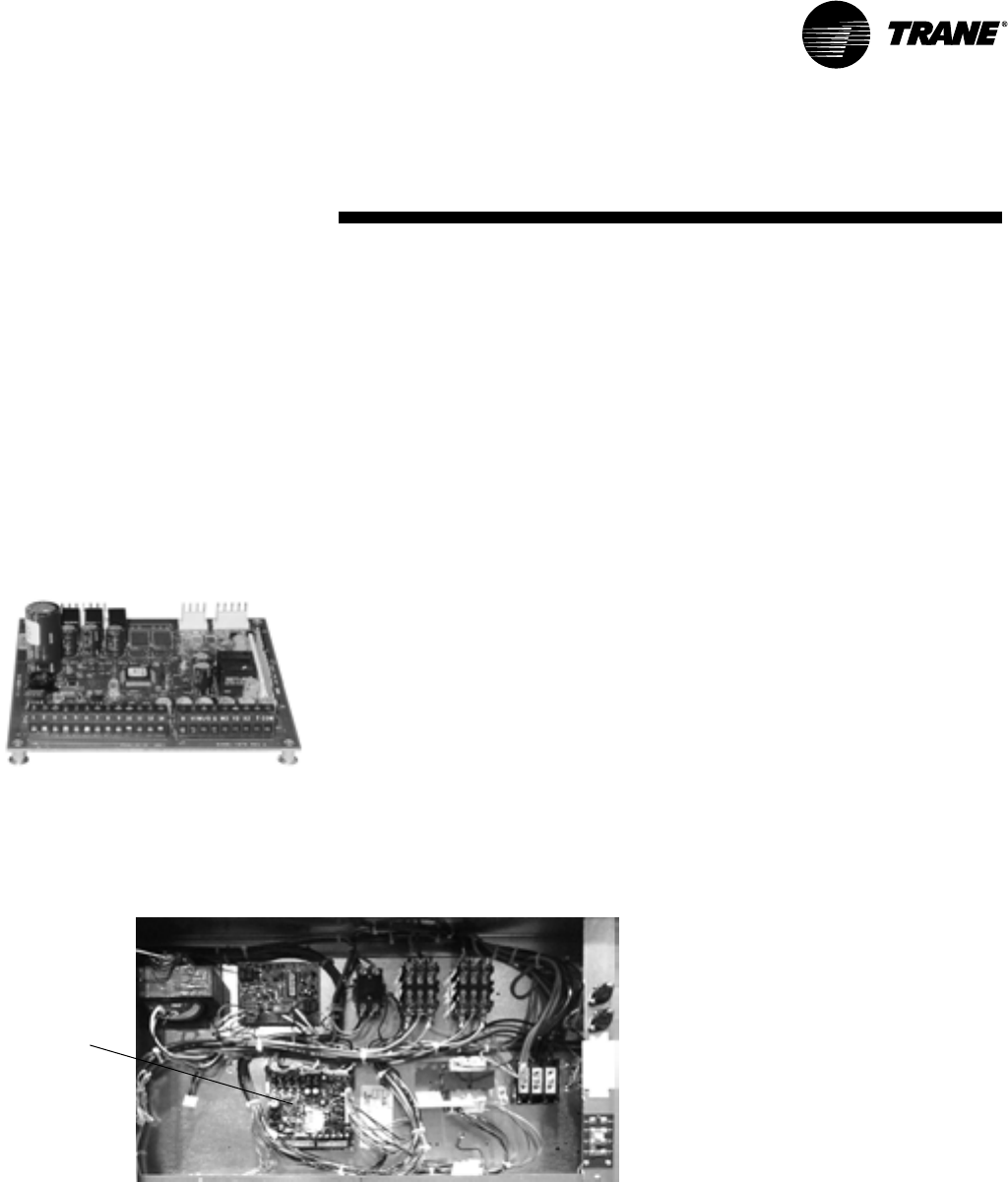
ReliaTel™ Controls (LCI-R)
ReliaTel controls provide unit control for
heating, cooling and ventilating utilizing
input from sensors that measure outdoor
and indoor temperature.
Quality and Reliability are enhanced
through ReliaTel control and logic:
—prevents the unit from short cycling,
considerably improving
compressor life.
—ensures that the compressor will run
for a specific amount of time which
allows oil to return for better
lubrication, enhancing the reliability of
the compressor.
Voyager with ReliaTel reduces the
number of components required to
operate the unit, thereby reducing
possibilities for component failure.
ReliaTel Makes Installing and
Servicing Easy
ReliaTel eliminates the need for field
installed anti-shortcycle timer and time
delay relays. ReliaTel controls provide
these functions as an integral part of the
unit. The contractor no longer has to
purchase these controls as options and
pay to install them.
The wiring of the low voltage connections
to the unit and the zone sensors is as
easy as 1-1, 2-2, and 3-3. This simplified
system makes wiring easier for the
installer.
ReliaTel Makes Testing Easy
ReliaTel requires no special tools to run
the Voyager unit through its paces.
Simply place a jumper between Test 1
and Test 2 terminals on the Low Voltage
Terminal Board and the unit will walk
through its operational steps
automatically.
— The unit automatically returns
control to the zone sensor after
stepping through the test mode a
single time, even if the jumper is
left on the unit.
As long as the unit has power and the
“system on” LED is lit, ReliaTel is
operational. The light indicates that the
controls are functioning properly.
ReliaTel features expanded diagnostic
capabilities when utilized with Trane
Integrated Comfort™ Systems.
Some zone sensor options have central
control panel lights which indicate the
mode the unit is in and possible
diagnostic information (dirty filters for
example).
Other ReliaTel Benefits
The ReliaTel built-in anti-shortcycle timer,
time delay relay and minimum “on” time
control functions are factory tested to
assure proper operation.
ReliaTel softens electrical “spikes” by
staging on fans, compressors and
heaters.
Intelligent Fallback is a benefit to the
building occupant. If a component goes
astray, the unit will continue to operate at
predetermined temperature setpoint.
Intelligent Anticipation is a standard
ReliaTel feature. It functions continuously
as ReliaTel and zone sensor(s) work
together in harmony to provide much
tighter comfort control than conventional
electro-mechanical thermostats.
The same ReliaTel Board fits all Voyager
Packaged Gas/Electrics, Cooling with
Electric Heat, and Heat Pump models.
This provides standardization of parts for
contractors. Less money is tied up in
inventory with ReliaTel.
ReliaTel™
6RT-PRC002-EN
Features and
Benefits
Black Epoxy Pre-Coated Coils
The pre-coated coils are an economical
option for protection in mildly corrosive
environments.
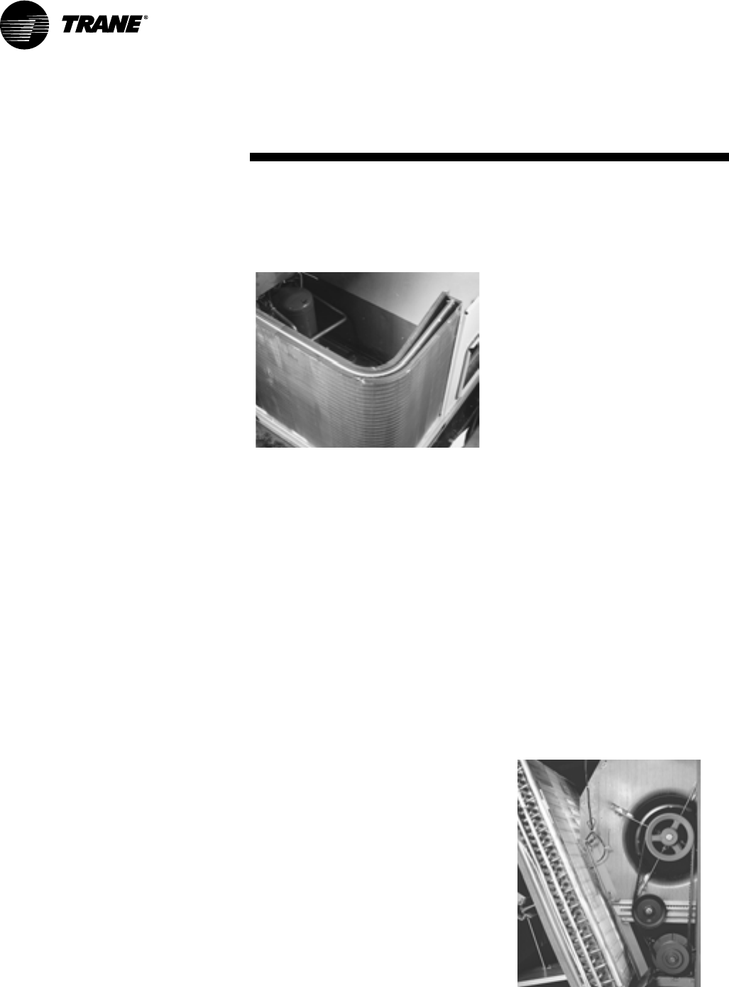
Cabinet Integrity
For added water integrity, Voyager has a
raised 11/8" lip around the supply and
return of the downflow units to prevent
water from blowing into the ductwork.
Clogged Filter/Fan Failure Switch
A dedicated differential pressure switch is
available to achieve active fan failure
indication and/or clogged filter indication.
CO2 Sensing
The CO2 sensor has the ability to monitor
space occupancy levels within the
building by measuring the parts per
million of CO2 (Carbon Dioxide) in the air.
As the CO2 levels increase, the outside air
damper modulates to meet the CO2
space ventilation requirements. The CO2
sensor kit is available as a field installed
accessory.
Colored And Numbered Wiring
Save time and money tracing wires and
diagnosing the unit.
Compressors
Voyager contains the best compressor
technology available to achieve the
highest possible performance. Dual
compressors are outstanding for
humidity control, light load cooling
conditions and system back-up
applications. Dual compressors are
available on all models.
Refrigerant Circuits
All Voyager 12½-25 ton units shall have
crankcase heaters, low and high pressure
controls as standard.
Outstanding Standard and
Optional Components
Condenser Coil
Voyager boasts a patent-pending 1+1+1
condenser coil, permanently gapped for
easy cleaning.
Digital Display Zone Sensor
The Digital LCD (Liquid Crystal Display)
zone sensor has the look and functionality
of standard zone sensors. This sensor
should be utilized with ReliaTel™ controls.
Discharge Air Sensing Kit
Provides true discharge air sensing in
heating models. The kit is functional only
with the ReliaTel Options Module.
Downflow And Horizontal Economizers
The economizers come with three control
options — dry bulb is standard, enthalpy
and differential enthalpy are optional.
Dual Thermistor Remote Zone Sensor
This sensor will reduce the total number
of remote sensors to obtain space
temperature averaging. This sensor
should be utilized with ReliaTel controls.
Factory Built Roof Curbs
Available for downflow units. Only two
roof curbs for the entire Voyager line
simplifies curb selection.
Fresh Air
0 - 25% manual or 0 - 50% motorized
outside air hoods are available.
High Static Drive Accessory
Available on many models, this high
static drive accessory extends the
capability of the standard motor. Avoid
expensive motors and operating costs by
installing this optimized sheave
accessory.
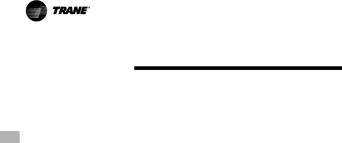
Hinged Access Doors
These doors permit easy access to the
filter, fan/heat, and compressor/control
sections. They reduce the potential roof
damage from screws or sharp access
door corners.
LonTalk® Communications Interface
The LonTalk communications interface
allows the unit to communicate as a
Tracer™LCI-V device or directly with
generic LonTalk Network Building
Automation System Controls.
Power Exhaust Option
This option is available on downflow units
and provides exhaust of the return air,
when using a downflow economizer, to
maintain proper building pressurization.
Great for relieving most building
overpressurization problems.
Quick-Access Panels
Remove three or fewer screws for
access to the standardized internal
components and wiring.
Quick-Adjust Idler Arm
With the Quick-Adjust Idler Arm, the belt
and sheaves can be quickly adjusted
without moving the mounted fan motor.
The result is a major savings in time and
money.
7
RT-PRC002-EN
Features and
Benefits
Reference or Comparative Enthalpy
Measures and communicates humidity
while maximizing comfort control.
Sloped Drain Pans
Standard on every unit.
Standardized Components
Components are placed in the same
location on all Voyager units. Familiarize
yourself with one Voyager and you are
familiar with every Voyager.
Due to standardized components
throughout the Voyager line, contractors/
owners can stock fewer parts.
Supply and/or Return Air Smoke
Detector
With this option installed, if smoke is
detected, all unit
operation will be shut
down. Reset will be
manual at the unit.
Return Air Smoke
Detectors require
minimum allowable
airflow when used
with certain models.
Tool-less Hail Guards
Tool-less, hail
protection quality coil
guards shall be either
factory or field-installed for condenser
coil protection. This option protects the
condenser coil from vandalism and/or
hail damage.
Trane Communication Interface (TCI)
Available factory or field installed. This
module when applied with the ReliaTel™
easily interfaces with Trane’s Integrated
ComfortTM System.
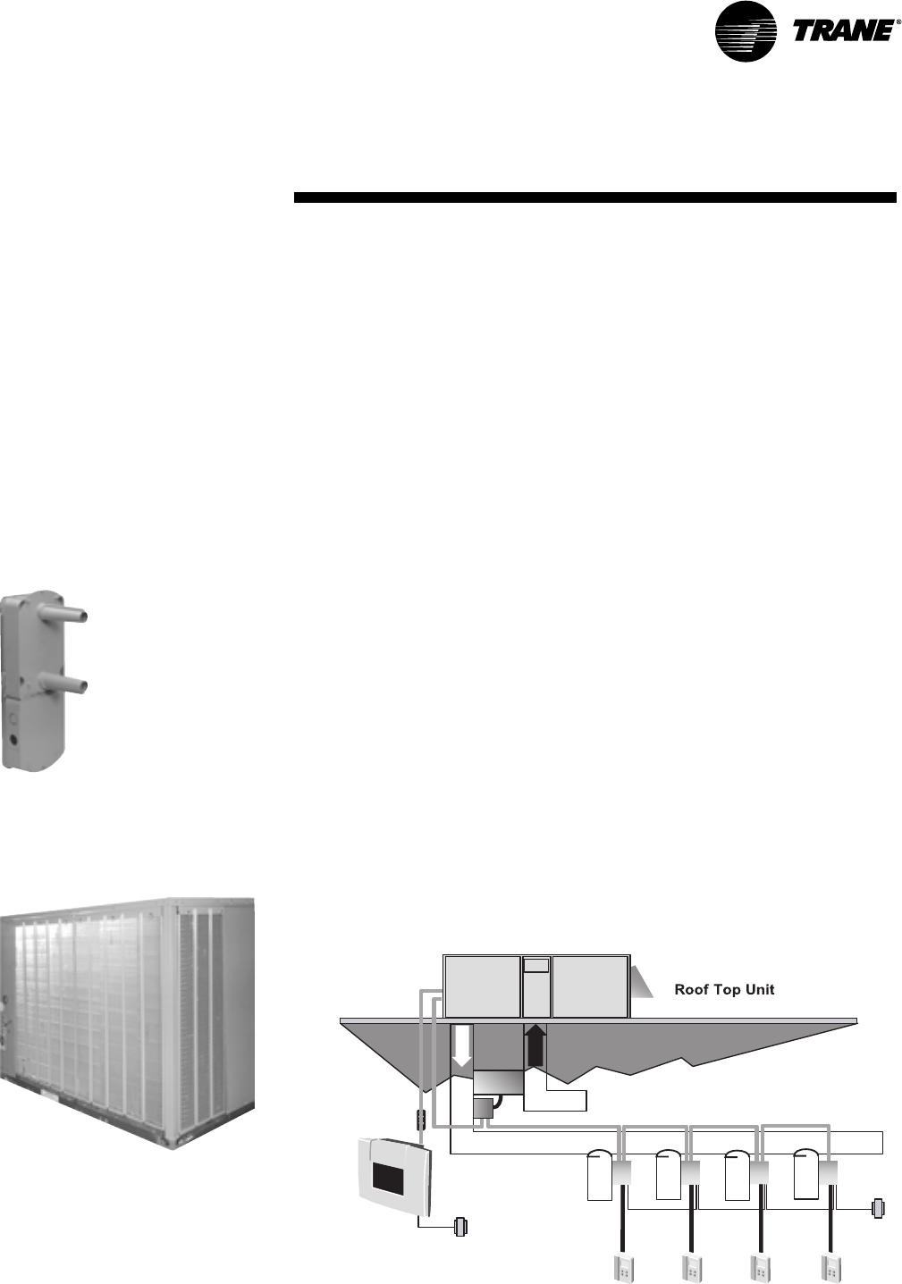
VariTrac
When Trane’s changeover VAV System
for light commercial applications is
coupled with Voyager, it provides the
latest in technological advances for
comfort management systems and can
allow thermostat control in every zone
served by VariTrac.
Ventilation Override Accessory
With the Ventilation Override Accessory
installed, the unit can be set to transition
to up to 3 different pre-programmed
sequences for Smoke Purge,
Pressurization, and Exhaust. The
transition occurs when a binary input on
the RTOM is closed (shorted). This would
typically be a hard wired relay output
from a smoke detector or fire control
panel. The ventilation override kit is
available as a field installed accessory.
Zone Sensors
Available in programmable, automatic
and manual styles.
Rigorous Testing
The fan and idler arm assembly designs
have been tested to over 300,000 cycles
each. Our combined cycle testing is now
over 7,000,000 cycles.
All of Voyager’s designs were rigorously
rain tested at the factory to ensure water
integrity.
Actual shipping tests were performed to
determine packaging requirements. Units
were test shipped around the country to
determine the best packaging. Factory
shake and drop tests were used as part
of the package design process to help
assure that the unit arrives at the job site
in top condition.
Rigging tests include lifting a unit into the
air and letting it drop one foot, assuring
that the lifting lugs and rails hold up under
stress.
We perform a 100% coil leak test at the
factory. The evaporator and condenser
coils are leak tested at 200 psig and
pressure tested to 450 psig.
All parts are inspected at the point of final
assembly. Sub-standard parts are
identified and rejected immediately.
Every unit receives a 100% unit run test
before leaving the production line to
make sure it lives up to rigorous Trane
requirements.
Voyager units incorporate either a one
piece top or the Trane-Tite-Top (T3). Each
part of the top (either two or three pieces)
overlaps in such a way that water cannot
leak into the unit. These overlapped edges
are gasketed and sealed to ensure
superior water integrity.
VariTrac™
8RT-PRC002-EN
Easy to Install and Service
Conversionless Units
The dedicated design units (either
downflow or horizontal) require no panel
removal or alteration time to convert in
the field — a major cost savings during
installation.
Horizontal units come complete with duct
flanges so the contractor doesn’t have to
field fabricate them. These duct flanges
are a time and cost saver.
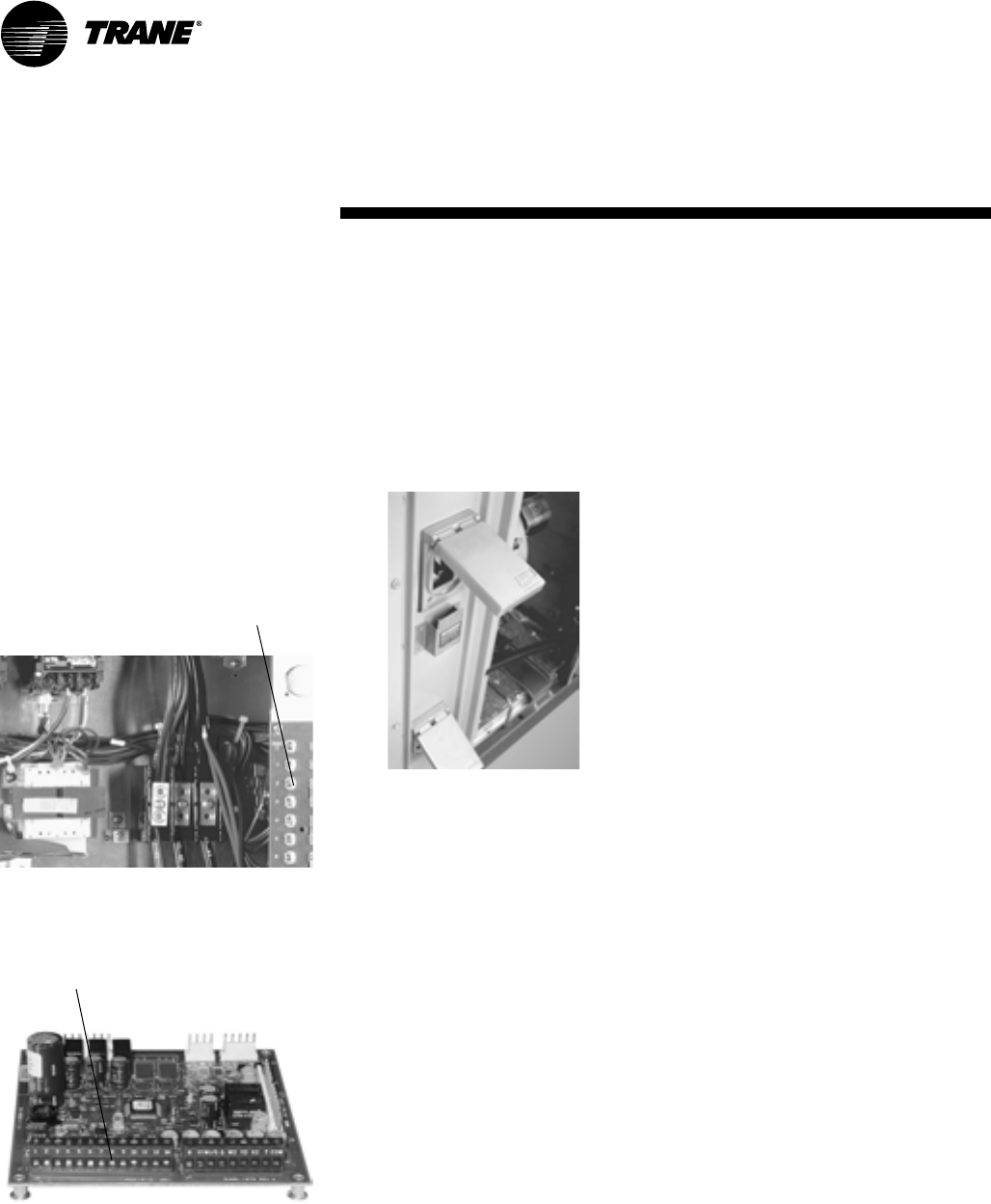
Easy Access Low Voltage Terminal Board
Voyager’s Low Voltage Terminal Board is
external to the electrical control cabinet. It
is extremely easy to locate and attach the
thermostat wire. This is another cost and
time saving installation feature.
Low Voltage Connections
The wiring of the low voltage connections
to the unit and the zone sensors is as
simple as 1-1, 2-2, and 3-3. This simplified
system makes it easy for the installer to
wire.
Electric Heaters
Electric heat modules are available within
the basic unit. If ordering the Through the
Base Electrical option with an Electrical
Heater, the heater must be factory
installed.
Powered or Unpowered Convenience
Outlet
This option is a GFCI, 120v/15amp, 2 plug,
convenience outlet, either powered or
unpowered. This option can only be
ordered when the Through the Base
Electrical with either the Disconnect
Switch, or Circuit Breaker, option is
ordered. This option is available on all
downflow models.
Single Point Power
A single electrical connection powers the
unit.
Single Side Service
Single side service is standard on all
units.
Through the Base Electrical with Circuit
Breaker
This option is a factory installed thermal
magnetic, molded case, HACR Circuit
Breaker with provisions for through the
base electrical connections. This option is
available on all downflow models.
Through the Base Electrical with
Disconnect Switch
Factory installed 3-pole, molded case,
disconnect switch with provisions for
through the base electrical connections
are available. This option is available on
all downflow models.
Through the Base Utilities Access
An electrical service entrance shall be
provided allowing electrical access for
both control and main power connections
inside the curb and through the base of
the unit. Option will allow for field
installation of liquid-tight conduit and an
external field installed disconnect switch.
Factory Installed Options
A wide variety of Factory Installed
Options (FIOPs) are available.
Added Efficiency
Airflow
Airflow is outstanding. The Voyager can
replace an older machine with old
ductwork and, in many cases, improve
the comfort through better air
distribution.
High Efficiency Motors
This option is available with efficiency
ratings from 86.5 up to 91.0. It is not
available for all models.
U-shaped Airflow
U-shaped airflow allows for improved
static capabilities.
Low Ambient Cooling
Cooling capabilities down to 0°F as
standard.
Oversized Motors
Factory or field installed oversized
motors available for high static
applications.
One of our Finest Assets:
Trane Sales Representatives are a
Support group that can assist you with:
— Product
— Application
— Service
— Training
— Special Applications
— Specifications
— Computer Programs and much more
Voyager has the features and benefits
that make it first class in the light
commercial rooftop market. Designed
with input from field contractors and
engineers, its U-shaped airflow
performance is outstanding.
Features and
Benefits

9
RT-PRC002-EN
Application of this product should be
within the cataloged airflow and cooling
considerations.
Low Ambient Cooling
This Voyager line features, as standard,
low ambient cooling down to 0°F. The
following options need to be included/
considered when low ambient
applications are required: continuous fan
operation, crankcase heaters, thermal
expansion valves, frostat. Contact your
local Trane Representative for more
assistance with low ambient cooling
applications.
Barometric Relief
This product line offers an optional
barometric relief damper included in the
downflow economizer accessory. This
accessory consists of gravity dampers
which open with increased pressure. As
the building air pressure increases, the
pressure in the unit return air section
also increases, opening the dampers and
relieving the conditioned space.
NOTE: THE EFFECTIVENESS OF
BAROMETRIC RELIEF DAMPER DURING
ECONOMIZING OPERATION IS SYSTEM
RELATED.
PRESSURE DROP OF THE RETURN AIR
SYSTEM SHOULD BE CONSIDERED TO
CONTROL BUILDING PRESSURIZATION.
Power Exhaust Accessory
The power exhaust accessory is available
on all 12½-25 ton downflow units. This
accessory can be field installed and will
assist in relieving building pressurization.
Condensate Trap
The evaporator is a draw-thru
configuration. A trap must be field
provided prior to start-up on the cooling
cycle.
Clearance Requirements
The recommended clearances identified
with unit dimensions should be
maintained to assure adequate
serviceability, maximum capacity and
peak operating efficiency. Actual
clearances which appear inadequate
should be reviewed with the local Trane
sales personnel.
Unit Pitch
These units have sloped condensate
drain pans. Units must be installed level,
any unit slope must be toward access
side of unit.
Application
Considerations
10 RT-PRC002-EN
Cooling Capacity
Step 1
Calculate the building’s total and sensible
cooling loads at design conditions. Use
the Trane calculation methods or any
other standard accepted method.
Factors used in unit selection:
A
Total Cooling Load: 180 MBh
B
Sensible Cooling Load: 129 MBh
C
Airflow: 6000 cfm
D
Electrical Characteristics: 460/60/3
E
Summer Design Conditions: Entering
Evaporator Coil: 80 DB, 67 WB Outdoor
Ambient: 95 DB
F
External Static Pressure: 0.49 in. wg
G
Rooftop - downflow configuration
H
Accessories
• Roof curb
•Economizer
•Electric Heat
I
Heating
•Capacity 115 MBh
•460 volt/3 phase Electric Heat —at 6000
cfm
Step 2
As a starting point, a rough determination
must be made of the size of the unit. The
final selection will be made after
examining the performance at the given
conditions. Divide the total cooling load by
nominal BTUH per ton (12 MBh per ton);
then round up to the nearest unit size.
180 MBh / 12 MBh = 15.0 Tons
Step 3
Table PD - 2 shows that a TCD180B4 has a
gross cooling capacity of 184 MBh and
130 MBh sensible capacity at 6000 cfm
and 95 DB outdoor ambient with 80 DB,
67 WB air entering the evaporator.
To Find Capacity at Intermediate
Conditions Not in the Table
When the design conditions are between
two numbers that are in the capacity
table, interpolation is required to
approximate the capacity. Note:
Extrapolation outside of the table
conditions is not recommended.
Step 4
In order to select the correct unit which
meets the building’s requirements, the
fan motor heat must be deducted from
the gross cooling capacity. The amount of
heat that the fan motor generates is
dependent on the effort by the motor -
cfm and static pressure. To determine the
total unit static pressure you add the
external static pressure to the additional
static related by the added features:
External Static (duct system)
0.49 wg
Standard Filter 1 in. 0.10 wg
from Table PD-35
Economizer 0.04 wg
(100% Return Air) from Table PD-35
Electric Heater Size 36 kw 0.07 wg
from Table PD-35
Total Static Pressure 0.60 wg
Note: The Evaporator Fan Performance
Table PD-18 has already accounted for
the pressure drop for standard filters and
wet coils (see note below Table PD-18).
Therefore, the actual total static pressure
is 0.60 -0.10 (from Table PD-35) = 0.50 wg.
With 6000 cfm and 0.50 wg.
Table PD-18 shows 2.56 bhp for this unit.
Note below the table gives a formula to
calculate Fan Motor Heat,
3.15 x bhp = MBH.
3.15 x 2.56 = 8.06 MBH.
Now subtract the fan motor heat from
the gross cooling capacity of the unit:
Net Total Cooling Capacity
= 184 MBH - 8.06 = 175.9 MBH.
Net Sensible Cooling Capacity
= 130 MBH - 8.06 = 121.9 MBH.
Step 5
If the performance will not meet the
required load of the building -total or
sensible cooling load, try a selection at
the next higher size unit.
Heating Capacity
Step 1
Calculate the building heating load using
the Trane calculation form or other
standard accepted method.
Step 2
Size the system heating capacity to
match the calculated building heating
load. The following are building heating
requirements:
A
Total heating load of 115.0 MBH
B
6000 cfm
C
460 volt/3 phase Power Supply
The electric heat accessory capacities are
listed in Table PD-36. From the table, a 36
kw heater will deliver 122.94 MBH at 480
volts. In order to determine capacity at
460 volts, the heater voltage correction
factor from Table PD-37 must be used.
Therefore, 122.94 MBH x .94 (voltage
correction factor) = 115.6 MBH.
Air Delivery Selection
External static pressure drop through the
air distribution system has been
calculated to be 0.50 inches of water.
From Table PD-35 static pressure drop
through the economizer is 0.04 and the
36 kw heater is 0.07 inches of water (0.49
+ 0.04 + 0.07). Enter Table PD-18 for a
TCD180B4 at 6000 cfm and 0.50 static
pressure. The standard motor at 777 rpm
will give the desired airflow at a rated bhp
of 2.71.
Selection
Procedures
11
RT-PRC002-EN
Selection
Procedure
MA'
MA'
SA'
SA'
RA'
RA'
OA
OA
OA
OA
RA'
68°F DB,
67°F WB
75°F DB,
52% RH
MA' 72.2°F DB
65°F WB
SA' 47°F DB
SA
SA
REHEAT
SA 73°F DB
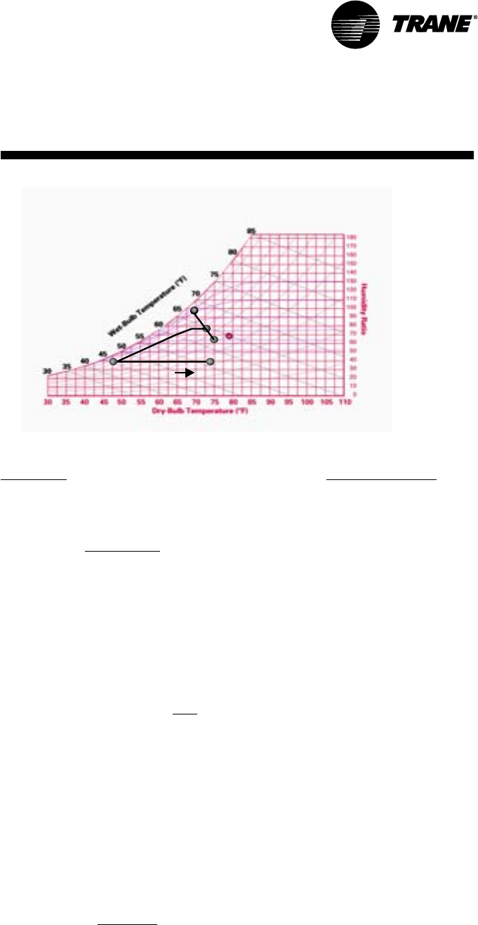
Dehumidification Selection
Determine normal unit cooling and
heating capacities as previously
described in the selection procedures on
prior page.
Typical 20 ton TFD241C
6400 cfm Total Supply airflow
2560 cfm Outside Air (40%)
3840 cfm Return Air
0.41” External Static Pressure
OA Conditions
Part load day and raining
68°F db
67°F wb
66.5 dp
95% RH
RA’ conditions
75°F db
63°F wb
52% RH
55.9 dp
Step 1: Determine the mixed/
entering air condition (MA’)
MA’ = (% outside air*outside air dry-bulb
temperature) + (% return air*return air
dry-bulb temperature)
MA’ = (0.40*68°F) + (0.60*75°F)
MA’ = 72.20°F db
Note: Repeat for wet-bulb
temperature (wb).
Plot on psychrometric chart.
MA’
72.2°F db
64.7°F wb
Step 2: Determine static pressure
drop add for reheat
Table PD-35 shows a static pressure drop
of 0.35” for the reheat coil and an
additional .04 for the mandatory 2”
pleated filters required when ordering the
dehumidification option. Total static
pressure =
1.0+0.035+0.04=1.075
(≅1.1 for manual calculations)
Do not forget to also add any additional
static from other accessories.
Table PD-29 (airflow table for 20 ton
dehumidification units) indicates that a
standard motor and drive is needed for
this airflow and static pressure range.
Step 3a: Determine leaving
evaporator temperature SA’
Leaving Unit Temperature = SA’
Utilizing the manual selection method as
previously described and the formula
∆Temp = cooling capacity in Bth
(cfm)(1.085)
or using the TOPSS™ program
determine the leaving evaporator
temperature (temperature without the
addition of fan heat).
517.74 db
51.03 wb
Step 3b: Determine leaving unit
temperature in standard cooling
mode
Find the leaving unit temperature
including fan heat as discussed in prior
selection procedures and using the
temperature formula from Step 3a or
refer to your TOPSS selection.
53.6 db
51 wb
84% RH
49% dp
Step 4: Determine reheat
temperature rise
Using the leaving evaporator temp, go to
PD-39 and find the reheat temperature
rise for that particular cfm: 17.55°F db
Note: Reheat temperature rise is based
on supply airflow and leaving
evaporator coil temperature.
Chart C-1
Step 5: Determine leaving unit
temperature with reheat active (SA)
Reheat temperature (obtained in step 3)
+ SA’ = SA
17.55°F db + 53.6°F = 71.2°F db
SA’=71.2°F
51 wb
20.8 RH
29.4 dp
Consider Chart C-1. If the space relative
humidity is equal to or above the space
relative humidity setpoint, the
Dehumidification option will:
• Energize compressor or both
compressors (2 stage compressor units).
• Hot gas reheat valve is energized and
hot gas is diverted to the reheat coil.
• Dehumidification/reheat is terminated
when space humidity is reduced to 5%
below relative humidity setpoint.
At MA’, air enters the RTU. The RTU filters,
cools, and dehumidifies the air as it
moves through the evaporator coil. Air
leaves the evaporator coil saturated at
the preset dew point condition (SA’) and
is reheated by the hot gas reheat coil to
deliver 71°F (SA) supply air to the space.
12 RT-PRC002-EN
Digit 9, 10 - Factory-Installed Options
00 = No Factory-installed Options
0A = Factory-installed Economizer
0B = Oversized Motor
0C = Downflow Economizer and
Oversized Motor
0F = Trane Communications Interface
(TCI)
0G = Downflow Economizer and TCI
0H = TXV/Face-Split Evaporator
0J = Oversized Motor and TXV/Face-Split
Evaporator
0K = Downflow Economizer, Oversized
Motor, and TXV/Face-Split Evaporator
0L = Downflow Economizer with TXV/Face-
Split Evaporator
0M = Reheat Coil
0N= Downflow Economizer and Reheat
Coil
0P = Oversized Motor and Reheat Coil
0R = Downflow Economizer, Oversized
Motor and Reheat Coil
Digit 11- Minor Design Sequence
Digit 12- Service Digit
Model
Number
Description
Digit 8 - Electrical Characteristics
3 = 208-230/60/3
4 = 460/60/3
W = 575/60/3
K = 380/60/3
Packaged Cooling with Electric Heat Unit Typical Model Nomenclature
Digits 1, 2 - Product Type
TC = Packaged Cooling, Electric
Heat
TF = With Factory Installed
Options
Digits 4, 5, 6 - Nominal Gross Cooling
Capacity (MBh)
150 = 12½ Tons Standard Efficiency
151 = 12½ Tons High Efficiency
180 = 15 Tons Standard Efficiency
181 = 15 Tons High Efficiency
210 = 17½ Tons Standard Efficiency
211 = 17½ Tons High Efficiency
240 = 20 Tons Standard Efficiency
241 = 20 Tons High Efficiency
300 = 25 Tons Standard Efficiency
301 = 25 Tons High Efficiency
Digit 7- Major Development Sequence
TC D 150 C 3 0 0 A A
12 3 456 7 8 9 10 11 12
Digit 3 - Airflow Configuration
D = Downflow
H = Horizontal
13
RT-PRC002-EN
(12½, 15 Ton)
Standard Efficiency
General
Data
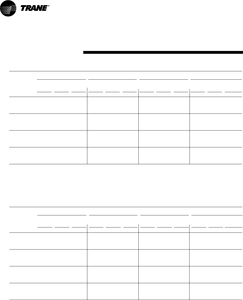
12½ Ton Downflow and Horizontal Units 15 Ton Downflow and Horizontal Units
TC*150D3, D4, DW, DK TC*180B3, B4, BW, BK
Cooling Performance1
Gross Cooling Capacity 150,000 182,000
EER29.8 9.9
Nominal CFM / ARI Rated CFM 5,000/4,400 6,000/5,300
ARI Net Cooling Capacity 142,000 174,000
Integrated Part Load Value310.5 10.2
System Power (KW) 14.49 17.57
Compressor
No./Type 2/Scrolls 2/Scrolls
Sound Rating (BELS)49.2 9.2
Outdoor Coil — Type Hi-Performance Hi-Performance
Tube Size (in.) O.D. .375 .375
Face Area (sq ft) 24.18 27.12
Rows/FPI 2/16 3/16
Indoor Coil — Type Hi-Performance Hi-Performance
Tube Size (in.) .375 .375
Face Area (sq ft) 17.5 17.5
Rows/FPI 2/15 2/15
Refrigerant Control Short Orifice Short Orifice
Drain Connection No./Size (in.) 1/1.00 NPT 1/1.00 NPT
Outdoor Fan — Type Propeller Propeller
No. Used/Diameter (in.) 2/26 2/26
Drive Type/No. Speeds Direct/1 Direct/1
CFM 10,600 10,200
No. Motors/HP 2/.50 2/.50
Motor RPM 1,100 1,100
Indoor Fan — Type FC Centrifugal FC Centrifugal
No. Used 1 1
Diameter x Width (in.) 15 x 15 15 x 15
Drive Type/No. Speeds Belt/1 Belt/1
No. Motors 1 1
Motor HP (Standard/Oversized) 3.0/5.0 3.0/5.0
Motor RPM (Standard/Oversized) 1,740/3,450 1,740/3,450
Motor Frame Size (Standard/Oversized) 145T/145T 145T/145T
Filters — Type Furnished6Throwaway Throwaway
(No.) Size Recommended (in.)
Downflow (2) 20 x 20 x 2, (4) 20 x 25 x 2 (2) 20 x 20 x 2, (4) 20 x 25 x 2
Horizontal (2) 20 x 20 x 2, (4) 20 x 25 x 2 (2) 20 x 20 x 2, (4) 20 x 25 x 2
Refrigerant Charge (Lbs of R-22)59.3/9.4/Circuit 17.5/9.5/Circuit
Notes:
1. Cooling Performance is rated at 95°F ambient, 80°F entering dry bulb, 67°F entering wet bulb. Gross capacity does not include the effect of fan motor heat. ARI capacity is net
and includes the effect of fan motor heat. Units are suitable for operation to ±20% of nominal cfm. Certified in accordance with the Unitary Large Equipment certification
program, which is based on ARI Standard 340/360-93.
2. EER is rated at ARI conditions and in accordance with ARI Standard 210/240 or 360.
3. Integrated Part Load Value is based in accordance with ARI Standard 210/240 or 360. Units are rated at 80°F ambient, 80°F entering dry bulb, and 67°F entering wet bulb at ARI
rated cfm.
4. Sound Rating shown is tested in accordance with ARI Standard 270 or 370.
5. Refrigerant charge is an approximate value. For a more precise value, see unit nameplate and service instructions.
6. Optional 2 inch pleated filters are also available.
7. For 380V/60Hz units, the oversized motor is used as the standard motor. Refer to oversized motor data.
*Indicates both downflow and horizontal units.
Table GD - 1— General Data

14 RT-PRC002-EN
(17½, 20, 25 Ton)
Standard Efficiency
General
Data
Table GD - 2 — General Data
17½ Ton 20 Ton 25 Ton
Downflow and Horizontal Units Downflow and Horizontal Units Downflow and Horizontal Units
TC*210C3, C4, CW, CK TC*240B3, B4, BW, BK TC*300B3, B4, BW, BK
Cooling Performance1
Gross Cooling Capacity 210,000 242,000 290,000
EER29.8 9.7 9.7
Nominal CFM / ARI Rated CFM 7,000/5,800 8,000/7,000 10,000/8,750
ARI Net Cooling Capacity 196,000 232,000 272,000
Integrated Part Load Value310.0 10.0 9.8
System Power (KW) 20.0 23.91 28.05
Compressor
No./Type 2/Scrolls 2/Scrolls 2/Scrolls
Sound Rating (BELS)49.4 9.4 9.4
Outdoor Coil — Type Hi-Performance Hi-Performance Hi-Performance
Tube Size (in.) O.D. .375 .375 .375
Face Area (sq ft) 27.12 35.30 36.43
Rows/FPI 3/16 3/16 2/16
Indoor Coil — Type Hi-Performance Hi-Performance Hi-Performance
Tube Size (in.) .375 .375 .375
Face Area (sq ft) 17.50 26.00 26.00
Rows/FPI 4/15 2/15 3/15
Refrigerant Control Short Orifice Short Orifice Short Orifice
Drain Connection No./Size (in.) 1/1.00 NPT 1/1.00 NPT 1/1.00 NPT
Outdoor Fan — Type Propeller Propeller Propeller
No. Used/Diameter (in.) 2/26 2/26 2/28
Drive Type/No. Speeds Direct/1 Direct/1 Direct/1
CFM 13,400 14,600 16,700
No. Motors/HP 2/1.0 2/1.0 2/1.0
Motor RPM 1,125 1,125 1,125
Indoor Fan — Type FC Centrifugal FC Centrifugal FC Centrifugal
No. Used 1 1 1
Diameter x Width (in.) 15 x 15 18 x 18 18 x 18
Drive Type/No. Speeds Belt / 1 Belt / 1 Belt / 1
No. Motors 1 1 1
Motor HP (Standard/Oversized) 5.0/7.5 5.0/7.5 7.5/NA
Motor RPM (Standard/Oversized) 3,450/3,470 3,450/3,470 3,470/NA
Motor Frame Size (Standard/Oversized) 145T/184T 145T/184T 184T/NA
Filters — Type Furnished7Throwaway Throwaway Throwaway
(No.) Size Recommended (in.)
Downflow (2) 20 x 20 x 2, (4) 20 x 25 x 2 (4) 20 x 20 x 2, (4) 20 x 25 x 2 (4) 20 x 20 x 2, (4) 20 x 25 x 2
Horizontal (2) 20 x 20 x 2, (4) 20 x 25 x 2 (8) 20 x 25 x 2 (8) 20 x 25 x 2
Refrigerant Charge (Lbs of R-22)521.0/14.3/Circuit618.9/21.0/Circuit 17.0/Circuit
Notes:
1. Cooling Performance is rated at 95°F ambient, 80°F entering dry bulb, 67°F entering wet bulb. Gross capacity does not include the effect of fan motor heat. ARI capacity is net
and includes the effect of fan motor heat. Units are suitable for operation to ±20% of nominal cfm. 17½ - 20 ton models are certified in accordance with the Unitary Large
Equipment certification program, which is based on ARI Standard 340/360-93. 25 ton model ratings shown are tested in accordance with ARI Standard 340/360-93.
2. EER is rated at ARI conditions and in accordance with ARI Standard 210/240 or 360.
3. Integrated Part Load Value is based in accordance with ARI Standard 210/240 or 360. Units are rated at 80°F ambient, 80°F entering dry bulb, and 67°F entering wet bulb at ARI
rated cfm.
4. Sound Rating shown is tested in accordance with ARI Standard 270 or 370.
5. Refrigerant charge is an approximate value. For a more precise value, see unit nameplate and service instructions.
6. Refrigerant charge for horizontal models is 21.5/14.5 per circuit.
7. Optional two inch pleated filters are also available.
8. For 380V/60Hz units, the oversized motor is used as the standard motor. Refer to oversized motor data.
*Indicates both downflow and horizontal units.

15
RT-PRC002-EN
(12½, 15 Ton)
High Efficiency
General
Data
12½ Ton 15 Ton
Downflow and Horizontal Downflow and Horizontal
TC*151C3,C4,CW TC*181C3,C4, CW
Cooling Performance1
Gross Cooling Capacity 154,000 189,000
EER211. 3 11. 5 8
Nominal CFM / ARI Rated CFM 5,000/4,400 6,000/5,300
ARI Net Cooling Capacity 146,000 180,000
Integrated Part Load Value311.5 13.3
System Power KW 12.92 15.653
Compressor
No./Type 2/Scrolls 2/Scrolls
Sound Rating (BELS)49.2 9.2
Outdoor Coil — Type Hi-Performance Hi-Performance
Tube Size (in.) O.D. 0.375 0.375
Face Area (sq ft) 27.12 35.30
Rows/FPI 3/16 3/16
Indoor Coil — Type Hi-Performance Hi-Performance
Tube Size (in.) 0.375 0.375
Face Area (sq ft) 17.50 26.00
Rows/FPI 3/15 3/15
Refrigerant Control Short Orifice9Short Orifice8
Drain Connection No./Size (in.) 1/1.0 NPT 1/1.0 NPT
Outdoor Fan — Type Propeller Propeller
No. Used/Diameter (in.) 2/26 2/26
Drive Type/No. Speeds Direct/1 Direct/1
CFM 10,400 11,000
No. Motors/HP 2/.50 2/.50
Motor RPM 1100 1100
Indoor Fan — Type FC Centrifugal FC Centrifugal
No. Used 1 1
Diameter x Width (in.) 15 x 15 18 x 18
Drive Type/No. Speeds BELT/1 BELT/1
No. Motors 1 1
Motor HP (Standard/Oversized) 3.0/5.0 3.0/5.0
Motor RPM (Standard/Oversized) 1740/3450 1740/3450
Motor Frame Size (Standard/Oversized) 145T/145T 145T/145T
Filters — Type/Furnished? Throwaway/Yes8Throwaway/Yes8
(No.) Size Recommended (in.) (2)20 x 20 x 2 (4) 20 x 20 x 2
(4)20 x 25 x 2 (4) 20 x 25 x 2
Optional Hot Gas Reheat Coil — Type Hi-Performance Hi-Performance
Tube Size (in.) OD 0.375 0.375
Face Area (sq. ft.) 17.5 26
Rows/FPI 1/16 1/16
Refrigerant Charge (Lbs of R-22) 5/Circuit
Standard 15.0/13.8925.0/13.08
Optional Hot Gas Reheat Coil 15.3/14.3 27.8/11.4
Notes:
1. Cooling Performance is rated at 95°F ambient, 80°F entering dry bulb, 67°F entering wet bulb. Gross capacity does not include the effect of fan motor heat. ARI capacity is net
and includes the effect of fan motor heat. Units are suitable for operation to ±20% of nominal cfm. Certified in accordance with the Unitary Large Equipment certification
program, which is based on ARI Standard 340/360-93.
2. EER is rated at ARI conditions and in accordance with DOE test procedures.
3. Integrated Part Load Value is based in accordance with ARI Standard 210/240 or 360. Units are rated at 80°F ambient, 80°F entering dry bulb, and 67°F entering wet bulb at ARI
rated cfm.
4. Sound Rating shown is tested in accordance with ARI Standard 270 or 370.
5. Refrigerant charge is an approximate value. For a more precise value, see unit nameplate and service instructions.
6. Face area for Indoor Coil on horizontal models is 12.36.
7. Horizontal models have 4 - 20 x 25 x 2 filters.
8. Optional two inch pleated filters are also available for 12½ ton models.
9. TXV/Face-Split Option (Downflow Only) TCD151C3,4,W (Refrigerant Control): Expansion Valve; (Refrigerant Charge): 13.4/12.0.
*Indicates both downflow and horizontal units.
Table GD - 3 — General Data

16 RT-PRC002-EN
General
Data
(17½, 20, 25 Ton)
High Efficiency
*Indicates both downflow and horizontal units.
Table GD - 4 — General Data
17½ Ton 20 Ton 25 Ton
Downflow and Horizontal Downflow and Horizontal Downflow and Horizontal
TC*211C3,C4,CW TC*241C3,C4,CW TC*301C3,C4,CW
Cooling Performance1
Gross Cooling Capacity 220,000 268,0009300,00011
EER211.0 10.6 10.411
Nominal CFM / ARI Rated CFM 7,000/6,200 8,000/7,000 10,000/8,750
ARI Net Cooling Capacity 208,000 250,0009278,000
Integrated Part Load Value312.0 11.2 11.011
System Power KW 18.91 23.58926.7311
Compressor
No./Type 2/Scrolls 2/Scrolls 2/Scrolls
Sound Rating (BELS)49.4 9.4 9.4
Outdoor Coil — Type Hi-Performance Hi-Performance Hi-Performance
Tube Size (in.) O.D. 0.375 0.375 0.375
Face Area (sq ft) 35.30 35.30
Rows/FPI 3/16 3/16 3/16
Indoor Coil — Type Hi-Performance Hi-Performance Hi-Performance
Tube Size (in.) 0.375 0.375 0.375
Face Area (sq ft) 26.000 26.00 26.00
Rows/FPI 4/15 4/15 4/15
Refrigerant Control Short Orifice Short Orifice9Short Orifice11
Drain Connection No./Size (in.) 1 /1.0 NPT 1/1.0 NPT 1/1.0 NPT
Outdoor Fan — Type Propeller Propeller Propeller
No. Used/Diameter (in.) 2/26 2/26 2/26
Drive Type/No. Speeds Direct/1 Direct/1 Direct/1
CFM 12,800 13,700 13,700
No. Motors/HP 2/1.00 2/1.00 2/1.00
Motor RPM 1125 1125 1125
Indoor Fan — Type FC Centrifugal FC Centrifugal FC Centrifugal
No. Used 1 1 1
Diameter x Width (in.) 18 x 18 18 x 18 18 x 18
Drive Type/No. Speeds BELT/1 BELT/1 BELT/1
No. Motors 1 1 1
Motor HP (Standard/Oversized) 5.0/7.5 5.0/7.5 7.5/NA
Motor RPM(Standard/Oversized) 3450/3470 3450/3470 3470/NA
Motor Frame Size (Standard/Oversized) 145T/184T 145T/184T 184T/NA
Filters — Type Furnished7Throwaway Throwaway Throwaway
(No.) Size Recommended (in.) (4/4)20 x 20 x 2/20 x 25 x 26(4/4)20 x 20 x 2/20 x 25 x 26(4/4)20 x 20 x 2/20 x 25 x 26
Optional Hot Gas Reheat Coil — Type — Hi-Performance —
Tube Size (in.) OD — 0.375 —
Face Area — 26 —
Rows/FPI — 1/16 —
Refrigerant Charge (Lbs of R-22) 5 / Circuit
Standard 25.7/12.510 21.8/21.8924.5/24.511
Optional Hot Gas Reheat Coil — 21.3/21.0 —
Notes:
1. Cooling Performance is rated at 95°F ambient, 80°F entering dry bulb, 67°F entering wet bulb. Gross capacity does not include the effect of fan motor heat. ARI capacity is net
and includes the effect of fan motor heat. 15 - 20 ton models are certified in accordance with the Unitary Large Equipment certification program, which is based on ARI
Standard 340/360-93. 25 ton model ratings shown are tested in accordance with ARI Standard 340/360-93.
2. EER is rated at ARI conditions and in accordance with DOE test procedures.
3. Integrated Part Load Value is based in accordance with ARI Standard 210/240 or 360. Units are rated at 80°F ambient, 80°F entering dry bulb, and 67°F entering wet bulb at ARI
rated cfm.
4. Sound Rating shown is tested in accordance with ARI Standard 270 or 370.
5. Refrigerant charge is an approximate value. For a more precise value, see unit nameplate and service instructions.
6. Horizontal models have 8 - 20 x 25 x 2 filters.
7. Optional two inch pleated filters are also available.
8. TXV/Face-Split Option (Downflow Only) TCD181C3,4,W (EER):11.4; (System Power kW): 15.79; (Refrigerant Control): Expansion Valve; (Refrigerant Charge): 26.0/12.0
9. TXV/Face-Split Option (Downflow Only) TCD241C3,4,W (Gross Cooling Capacity):259,000; (ARI Net Cooling Capacity): 244,000; (System Power kW): 23.02;
(Refrigerant Control): Expansion Valve; (Refrigerant Charge): 21.5/22.2
10. TXV/Face-Split Option (Downflow Only) TCD211C3,4,W Refrigerant Charge): 27.0/10.0
11. TXV/Face-Split Option (Downflow Only) TCD301C3,4,W (EER): 10; (Gross Cooling Capacity): 294,000; (ARI Net Cooling Capacity): 272,000; (IPLV): 10.6; System Power kW): 27.2;
Refrigerant Control: Expansion Valve; (Refrigerant Charge): 21.0/23.0
17
RT-PRC002-EN
Performance
Data
(12½, 15 Ton)
Standard Efficiency
*Indicates both downflow and horizontal units.
Table PD-1 — Gross Cooling Capacities (MBH) 12½ Ton Three Phase TC*150D3, D4, DW, DK
Ambient Temperature
85 95 105 115
Enter
Dry Entering Wet Bulb
CFM Bulb 61 67 73 61 67 73 61 67 73 61 67 73
Airflow (F) MBH SHC MBH SHC MBH SHC MBH SHC MBH SHC MBH SHC MBH SHC MBH SHC MBH SHC MBH SHC MBH SHC MBH SHC
75 135.0 108.0 153.0 86.0 162.0 59.3 126.0 103.0 146.0 82.0 158.0 56.7 116.0 98.2 138.0 77.7 152.0 53.8 106.0 93.1 127.0 80.0 145.0 50.5
4500 80 136.0 128.0 154.0 105.0 163.0 79.5 127.0 123.0 147.0 101.0 159.0 76.5 117.0 117.0 138.0 97.0 153.0 73.2 110.0 110.0 128.0 92.2 145.0 69.6
85 142.0 142.0 154.0 123.0 164.0 95.9 135.0 135.0 147.0 120.0 159.0 94.2 127.0 127.0 138.0 116.0 153.0 91.7 120.0 120.0 128.0 111.0 146.0 88.5
90 150.0 150.0 155.0 142.0 166.0 112.0 144.0 144.0 148.0 139.0 161.0 111.0 137.0 137.0 139.0 136.0 154.0 109.0 130.0 130.0 130.0 130.0 146.0 107.0
75 139.0 114.0 155.0 89.8 163.0 60.4 129.0 109.0 149.0 85.4 159.0 57.9 120.0 104.0 141.0 89.5 154.0 55.0 109.0 98.9 131.0 85.1 147.0 51.6
5000 80 140.0 136.0 156.0 109.0 164.0 81.3 130.0 130.0 149.0 106.0 160.0 79.1 123.0 123.0 141.0 102.0 155.0 75.8 115.0 115.0 131.0 97.5 147.0 72.2
85 147.0 147.0 157.0 129.0 166.0 98.2 141.0 141.0 150.0 126.0 161.0 96.8 133.0 133.0 141.0 123.0 155.0 94.8 125.0 125.0 131.0 118.0 148.0 91.9
90 155.0 155.0 158.0 148.0 167.0 115.0 149.0 149.0 151.0 147.0 163.0 115.0 143.0 143.0 143.0 143.0 157.0 114.0 135.0 135.0 135.0 135.0 149.0 111.0
75 142.0 120.0 157.0 91.3 164.0 61.5 132.0 115.0 151.0 88.8 160.0 59.0 122.0 110.0 143.0 84.2 155.0 56.1 112.0 104.0 133.0 89.9 148.0 52.9
5500 80 143.0 143.0 158.0 112.0 165.0 82.0 135.0 135.0 152.0 110.0 161.0 80.4 127.0 127.0 143.0 107.0 156.0 78.3 119.0 119.0 134.0 102.0 149.0 74.7
85 152.0 152.0 159.0 133.0 167.0 99.9 145.0 145.0 152.0 132.0 163.0 99.1 138.0 138.0 144.0 129.0 157.0 97.4 130.0 130.0 134.0 125.0 150.0 95.0
90 159.0 159.0 160.0 154.0 169.0 118.0 153.0 153.0 153.0 153.0 164.0 118.0 147.0 147.0 147.0 147.0 158.0 117.0 140.0 140.0 140.0 140.0 151.0 116.0
75 145.0 125.0 158.0 93.3 165.0 62.5 135.0 120.0 153.0 91.2 161.0 60.1 125.0 115.0 145.0 87.3 156.0 57.2 115.0 110.0 136.0 82.8 149.0 54.0
6000 80 147.0 147.0 159.0 115.0 166.0 82.9 140.0 140.0 153.0 114.0 162.0 81.7 132.0 132.0 145.0 111.0 157.0 79.3 123.0 123.0 136.0 107.0 150.0 76.5
85 155.0 155.0 161.0 137.0 168.0 101.1 149.0 149.0 154.0 137.0 164.0 101.0 142.0 142.0 146.0 135.0 158.0 99.8 134.0 134.0 137.0 131.0 151.0 97.8
90 161.0 161.0 162.0 159.0 170.0 120.0 156.0 156.0 156.0 156.0 166.0 121.0 150.0 150.0 150.0 150.0 160.0 121.0 143.0 143.0 143.0 143.0 152.0 119.0
Notes:
1. All capacities shown are gross and have not considered indoor fan heat. To obtain NET cooling capacity subtract indoor fan heat. For indoor fan heat formula, refer to
appropriate airflow table notes.
2. MBH = Total Gross Cooling Capacity
3. SHC = Sensible Heat Capacity
Table PD-2 — Gross Cooling Capacities (MBH) 15 Ton Three Phase TC*180B3, B4, BW, BK
Ambient Temperature
85 95 105 115
Enter.
Dry Entering Wet Bulb
CFM Bulb 61 67 73 61 67 73 61 67 73 61 67 73
Airflow (F) MBH SHC MBH SHC MBH SHC MBH SHC MBH SHC MBH SHC MBH SHC MBH SHC MBH SHC MBH SHC MBH SHC MBH SHC
75 168.0 133.0 188.0 106.0 198.0 73.0 157.0 128.0 181.0 101.0 194.0 70.4 147.0 122.0 172.0 97.0 187.0 67.3 137.0 117.0 162.0 92.1 179.0 63.2
5400 80 168.0 156.0 188.0 128.0 199.0 97.3 155.0 155.0 181.0 125.0 195.0 94.3 149.0 143.0 172.0 120.0 188.0 90.8 140.0 137.0 162.0 115.0 179.0 86.7
85 174.0 174.0 189.0 150.0 200.0 117.0 166.0 166.0 182.0 147.0 196.0 115.0 158.0 158.0 172.0 143.0 189.0 113.0 150.0 150.0 162.0 138.0 180.0 110.0
90 184.0 184.0 190.0 172.0 202.0 136.0 177.0 177.0 183.0 170.0 197.0 135.0 170.0 170.0 170.0 170.0 190.0 133.0 162.0 162.0 165.0 157.0 181.0 131.0
75 172.0 140.0 190.0 110.0 199.0 74.3 161.0 134.0 184.0 106.0 195.0 71.7 151.0 129.0 175.0 101.0 189.0 68.7 140.0 124.0 165.0 96.1 181.0 64.9
6000 80 169.0 169.0 191.0 133.0 200.0 99.4 164.0 157.0 184.0 130.0 196.0 97.2 155.0 151.0 176.0 126.0 190.0 93.8 145.0 145.0 165.0 121.0 182.0 89.9
85 181.0 181.0 192.0 156.0 202.0 119.0 173.0 173.0 185.0 154.0 198.0 118.0 165.0 165.0 176.0 151.0 191.0 116.0 157.0 157.0 166.0 146.0 183.0 113.0
90 189.0 189.0 193.0 179.0 204.0 140.0 183.0 183.0 183.0 183.0 199.0 139.0 176.0 176.0 178.0 171.0 193.0 138.0 168.0 168.0 170.0 166.0 184.0 136.0
75 176.0 147.0 192.0 112.0 200.0 75.5 165.0 141.0 186.0 110.0 196.0 73.0 154.0 136.0 178.0 105.0 190.0 69.8 144.0 130.0 168.0 99.8 182.0 66.1
6600 80 178.0 171.0 193.0 136.0 201.0 101.0 169.0 165.0 187.0 135.0 197.0 98.8 160.0 159.0 178.0 131.0 191.0 96.1 150.0 150.0 168.0 127.0 183.0 92.6
85 185.0 185.0 194.0 161.0 203.0 122.0 179.0 179.0 188.0 160.0 199.0 121.0 171.0 171.0 179.0 158.0 193.0 119.0 163.0 163.0 169.0 153.0 185.0 116.0
90 193.0 193.0 193.0 193.0 205.0 143.0 188.0 188.0 188.0 188.0 201.0 143.0 181.0 181.0 182.0 178.0 195.0 142.0 173.0 173.0 174.0 174.0 186.0 140.0
75 179.0 152.0 194.0 114.0 201.0 76.7 168.0 147.0 188.0 112.0 197.0 74.2 158.0 142.0 180.0 109.0 191.0 71.0 142.0 142.0 170.0 103.0 183.0 67.2
7200 80 182.0 177.0 195.0 140.0 202.0 103.0 173.0 172.0 189.0 139.0 198.0 100.0 164.0 164.0 181.0 136.0 192.0 97.6 155.0 155.0 171.0 132.0 184.0 94.4
85 189.0 189.0 196.0 166.0 204.0 125.0 183.0 183.0 190.0 166.0 200.0 123.0 176.0 176.0 182.0 164.0 194.0 121.0 167.0 167.0 167.0 167.0 186.0 119.0
90 197.0 197.0 197.0 197.0 206.0 146.0 192.0 192.0 193.0 187.0 202.0 146.0 185.0 185.0 186.0 184.0 196.0 146.0 177.0 177.0 177.0 177.0 188.0 144.0
Notes:
1. All capacities shown are gross and have not considered indoor fan heat. To obtain NET cooling capacity subtract indoor fan heat. For indoor fan heat formula, refer to
appropriate airflow table notes.
2. MBH = Total Gross Capacity
3. SHC = Sensible Heat Capacity
18 RT-PRC002-EN
Table PD-4 — Gross Cooling Capacities (MBH) 20 Ton Three Phase TC*240B3, B4, BW, BK
Ambient Temperature (F)
85 95 105 115
Enter.
Dry Entering Wet Bulb (F)
CFM Bulb 61 67 73 61 67 73 61 67 73 61 67 73
Airflow (F) MBH SHC MBH SHC MBH SHC MBH SHC MBH SHC MBH SHC MBH SHC MBH SHC MBH SHC MBH SHC MBH SHC MBH SHC
75 223.0 180.0 251.0 143.0 265.0 97.7 209.0 173.0 242.0 137.0 260.0 94.3 195.0 165.0 228.0 130.0 252.0 90.3 180.0 158.0 212.0 135.0 241.0 85.5
7200 80 226.0 214.0 252.0 173.0 267.0 131.0 208.0 208.0 242.0 169.0 261.0 127.0 197.0 197.0 228.0 162.0 253.0 122.0 186.0 186.0 213.0 155.0 242.0 117.0
85 235.0 235.0 253.0 204.0 268.0 158.0 224.0 224.0 242.0 200.0 262.0 156.0 213.0 213.0 229.0 194.0 253.0 153.0 201.0 201.0 214.0 188.0 242.0 149.0
90 248.0 248.0 255.0 234.0 271.0 185.0 239.0 239.0 245.0 232.0 264.0 185.0 228.0 228.0 228.0 228.0 255.0 183.0 217.0 217.0 217.0 217.0 243.0 179.0
75 229.0 190.0 255.0 148.0 267.0 99.4 215.0 183.0 246.0 142.0 262.0 96.1 200.0 175.0 233.0 136.0 254.0 92.2 185.0 168.0 218.0 129.0 244.0 87.1
8000 80 228.0 228.0 256.0 180.0 268.0 134.0 217.0 217.0 246.0 176.0 264.0 131.0 205.0 205.0 233.0 171.0 255.0 127.0 193.0 193.0 218.0 164.0 245.0 121.0
85 243.0 243.0 257.0 212.0 271.0 162.0 233.0 233.0 247.0 210.0 265.0 161.0 222.0 222.0 234.0 206.0 257.0 158.0 210.0 210.0 220.0 199.0 245.0 155.0
90 255.0 255.0 259.0 245.0 273.0 190.0 247.0 247.0 247.0 247.0 267.0 191.0 237.0 237.0 237.0 237.0 258.0 190.0 226.0 226.0 226.0 226.0 247.0 187.0
75 234.0 199.0 257.0 151.0 268.0 101.0 220.0 192.0 249.0 147.0 263.0 97.9 205.0 184.0 237.0 141.0 256.0 93.7 190.0 177.0 222.0 134.0 246.0 88.6
8800 80 236.0 236.0 259.0 185.0 270.0 136.0 224.0 224.0 249.0 183.0 265.0 134.0 212.0 212.0 237.0 178.0 257.0 130.0 200.0 200.0 222.0 172.0 247.0 126.0
85 250.0 250.0 260.0 220.0 273.0 165.0 240.0 240.0 251.0 219.0 267.0 165.0 229.0 229.0 239.0 216.0 259.0 163.0 217.0 217.0 225.0 210.0 248.0 160.0
90 260.0 260.0 263.0 254.0 275.0 194.0 253.0 253.0 253.0 253.0 270.0 196.0 244.0 244.0 244.0 244.0 261.0 196.0 233.0 233.0 233.0 233.0 250.0 194.0
75 238.0 208.0 259.0 154.0 269.0 103.0 224.0 201.0 251.0 151.0 265.0 99.6 209.0 193.0 240.0 146.0 257.0 95.1 194.0 186.0 225.0 139.0 248.0 89.2
9600 80 242.0 242.0 261.0 190.0 271.0 137.0 231.0 231.0 252.0 189.0 266.0 136.0 219.0 219.0 240.0 185.0 259.0 133.0 206.0 206.0 226.0 180.0 249.0 129.0
85 254.0 254.0 263.0 227.0 274.0 167.0 246.0 246.0 254.0 227.0 269.0 168.0 236.0 236.0 243.0 225.0 261.0 167.0 224.0 224.0 229.0 220.0 251.0 165.0
90 264.0 264.0 264.0 264.0 277.0 198.0 258.0 258.0 258.0 258.0 272.0 201.0 249.0 249.0 249.0 249.0 263.0 202.0 239.0 239.0 239.0 239.0 252.0 201.0
Notes:
1. All capacities shown are gross and have not considered indoor fan heat. To obtain NET cooling capacity subtract indoor fan heat. For indoor fan heat formula, refer to
appropriate airflow table notes.
2. MBH = Total Gross Capacity
3. SHC = Sensible Heat Capacity
Performance
Data
(17½, 20 Ton)
Standard Efficiency
*Indicates both downflow and horizontal units.
Table PD-3 — Gross Cooling Capacities (MBH) 17½ Ton Three Phase TC*210C3, C4, CW, CK
Ambient Temperature
85 95 105 115
Enter
Dry Entering Wet Bulb
CFM Bulb 61 67 73 61 67 73 61 67 73 61 67 73
Airflow (F) MBH SHC MBH SHC MBH SHC MBH SHC MBH SHC MBH SHC MBH SHC MBH SHC MBH SHC MBH SHC MBH SHC MBH SHC
75 195.0 171.0 213.0 127.0 224.0 83.3 182.0 164.0 206.0 124.0 219.0 80.1 169.0 158.0 195.0 119.0 213.0 76.1 155.0 151.0 181.0 113.0 204.0 71.8
6300 80 200.0 200.0 214.0 157.0 226.0 114.0 191.0 191.0 207.0 156.0 221.0 112.0 180.0 180.0 196.0 153.0 214.0 110.0 168.0 168.0 183.0 147.0 205.0 106.0
85 211.0 211.0 217.0 188.0 229.0 140.0 204.0 204.0 209.0 188.0 223.0 139.0 195.0 195.0 199.0 186.0 216.0 139.0 184.0 184.0 187.0 182.0 206.0 137.0
90 219.0 219.0 220.0 217.0 230.0 164.0 214.0 214.0 214.0 214.0 225.0 167.0 207.0 207.0 207.0 207.0 218.0 169.0 198.0 198.0 198.0 198.0 208.0 168.0
75 199.0 181.0 215.0 131.0 225.0 84.7 187.0 176.0 208.0 129.0 221.0 81.4 174.0 169.0 198.0 125.0 215.0 77.7 160.0 160.0 185.0 119.0 206.0 73.4
7000 80 206.0 206.0 217.0 164.0 228.0 116.0 198.0 198.0 210.0 164.0 222.0 114.0 188.0 188.0 200.0 162.0 216.0 113.0 176.0 176.0 187.0 157.0 207.0 110.0
85 216.0 216.0 220.0 197.0 230.0 144.0 210.0 210.0 213.0 198.0 225.0 144.0 202.0 202.0 204.0 198.0 218.0 145.0 192.0 192.0 192.0 192.0 209.0 144.0
90 224.0 224.0 224.0 224.0 233.0 172.0 219.0 219.0 219.0 219.0 227.0 173.0 212.0 212.0 212.0 212.0 221.0 177.0 204.0 204.0 204.0 204.0 211.0 177.0
75 203.0 191.0 217.0 135.0 226.0 86.1 192.0 187.0 211.0 138.0 222.0 82.9 178.0 178.0 201.0 131.0 216.0 79.2 165.0 165.0 188.0 126.0 208.0 75.0
7700 80 211.0 211.0 219.0 169.0 229.0 118.0 204.0 204.0 212.0 171.0 224.0 117.0 194.0 194.0 203.0 170.0 218.0 116.0 183.0 183.0 191.0 167.0 209.0 114.0
85 220.0 220.0 222.0 203.0 232.0 147.0 214.0 214.0 216.0 207.0 226.0 148.0 207.0 207.0 207.0 207.0 220.0 150.0 197.0 197.0 197.0 197.0 211.0 150.0
90 226.0 226.0 226.0 226.0 235.0 176.0 223.0 223.0 222.0 222.0 229.0 179.0 216.0 216.0 216.0 216.0 223.0 184.0 208.0 208.0 208.0 208.0 214.0 186.0
75 206.0 199.0 218.0 138.0 227.0 87.8 195.0 195.0 212.0 143.0 223.0 84.3 183.0 183.0 203.0 136.0 217.0 80.6 171.0 171.0 190.0 132.0 209.0 76.5
8400 80 214.0 214.0 221.0 174.0 230.0 120.0 208.0 208.0 214.0 178.0 226.0 120.0 199.0 199.0 205.0 178.0 219.0 119.0 188.0 188.0 194.0 176.0 211.0 117.0
85 222.0 222.0 224.0 210.0 233.0 150.0 217.0 217.0 218.0 215.0 228.0 151.0 211.0 211.0 211.0 211.0 222.0 155.0 202.0 202.0 202.0 202.0 213.0 156.0
90 229.0 229.0 229.0 229.0 236.0 181.0 225.0 225.0 225.0 225.0 231.0 184.0 220.0 220.0 219.0 219.0 225.0 190.0 212.0 212.0 212.0 212.0 216.0 193.0
Notes:
1. All capacities shown are gross and have not considered indoor fan heat. To obtain NET cooling capacity subtract indoor fan heat. For indoor fan heat formula, refer to
appropriate airflow table notes.
2. MBH = Total Gross Cooling Capacity
3. SHC = Sensible Heat Capacity

19
RT-PRC002-EN
Performance
Data
(25 Ton)
Standard Efficiency
*Indicates both downflow and horizontal units.
Table PD-5— Gross Cooling Capacities (MBH) 25 Ton Three Phase TC*300B3, B4, BW, BK
Ambient Temperature (F)
85 95 105 115
Enter.
Dry Entering Wet Bulb (F)
CFM Bulb 61 67 73 61 67 73 61 67 73 61 67 73
Airflow (F) MBH SHC MBH SHC MBH SHC MBH SHC MBH SHC MBH SHC MBH SHC MBH SHC MBH SHC MBH SHC MBH SHC MBH SHC
75 266 224 299 174 319 118 247 215 285 167 309 113 228 205 266 172 297 108 209 196 244 163 280 99.9
80 270 268 300 215 321 161 252 252 285 209 311 155 237 237 266 200 297 149 221 221 244 190 280 142
9000 85 286 286 301 255 323 196 272 272 286 250 312 194 256 256 267 242 298 189 240 240 246 233 281 183
90 301 301 304 295 326 232 289 289 289 289 314 231 275 275 275 275 300 229 259 259 259 259 282 224
75 272 237 303 180 322 120 253 227 290 174 312 115 234 218 271 165 300 109 214 208 249 156 284 102
80 277 277 304 223 324 171 262 262 290 219 314 161 246 246 271 211 301 155 229 229 249 201 284 147
10000 85 294 294 306 266 327 208 282 282 291 263 316 200 266 266 273 257 302 197 249 249 253 248 285 192
90 308 308 310 309 329 239 297 297 297 297 318 240 284 284 284 284 304 239 268 268 268 268 286 235
75 275 243 305 183 323 122 256 233 291 177 314 117 236 223 273 188 301 111 216 214 251 178 285 103
80 282 282 306 227 325 174 267 267 292 223 315 162 250 250 273 216 302 157 233 233 251 206 286 150
10500 85 298 298 308 272 328 216 286 286 294 270 317 203 270 270 276 264 304 200 253 253 256 255 286 196
90 312 312 311 311 330 256 301 301 301 301 320 244 288 288 288 288 306 244 273 273 272 272 288 241
75 278 248 306 185 324 123 258 239 293 181 315 118 239 229 275 172 302 113 217 217 253 184 286 104
80 286 286 308 231 325 160 271 271 294 228 316 163 254 254 276 221 304 160 237 237 253 212 287 153
11000 85 301 301 310 277 327 224 289 289 296 276 319 205 274 274 278 271 305 204 257 257 257 257 288 200
90 314 314 314 314 330 266 304 304 304 304 321 248 291 291 291 291 307 249 276 276 276 276 289 246
Notes:
1. All capacities shown are gross and have not considered indoor fan heat. To obtain NET cooling capacity subtract indoor fan heat. For indoor fan heat formula, refer to
appropriate airflow table notes.
2. MBH = Total Gross Capacity
3. SHC = Sensible Heat Capacity
4. Table is for 460 volt capacity. For capacity at 230 volt, multiply table capacity by 101%.

20 RT-PRC002-EN
(12½ Ton)
High Efficiency
Performance
Data
*Indicates both downflow and horizontal units.
Table PD-6 — Gross Cooling Capacities (MBH) 12½ Ton Three Phase TC*151C3, C4, CW— Standard Refrigeration System
Ambient Temperature
85 95 105 115
Enter
Dry Entering Wet Bulb
CFM Bulb 61 67 73 61 67 73 61 67 73 61 67 73
Airflow (F) MBH SHC MBH SHC MBH SHC MBH SHC MBH SHC MBH SHC MBH SHC MBH SHC MBH SHC MBH SHC MBH SHC MBH SHC
75 137.0 116.0 157.0 90.2 166.0 60.8 127.0 110.0 151.0 87.1 163.0 58.5 116.0 105.0 140.0 82.3 158.0 55.8 106.0 99.7 128.0 80.6 152.0 52.8
80 140.0 139.0 158.0 111.0 167.0 82.9 130.0 130.0 151.0 109.0 164.0 80.8 122.0 122.0 141.0 104.0 159.0 77.8 114.0 114.0 128.0 98.5 152.0 74.6
4500 85 149.0 149.0 158.0 132.0 169.0 100.0 142.0 142.0 151.0 131.0 165.0 99.4 133.0 133.0 141.0 126.0 159.0 98.2 125.0 125.0 130.0 121.0 152.0 96.0
90 158.0 158.0 160.0 153.0 170.0 118.0 152.0 152.0 154.0 152.0 166.0 118.0 145.0 145.0 145.0 145.0 160.0 118.0 137.0 137.0 137.0 137.0 153.0 117.0
75 141.0 123.0 159.0 93.4 167.0 61.6 131.0 117.0 154.0 90.9 164.0 59.4 120.0 112.0 144.0 86.6 159.0 56.8 109.0 107.0 132.0 81.0 153.0 53.7
80 145.0 145.0 160.0 116.0 168.0 84.1 136.0 136.0 154.0 114.0 165.0 82.4 128.0 128.0 144.0 110.0 161.0 80.9 119.0 119.0 132.0 105.0 154.0 77.5
5000 85 155.0 155.0 161.0 138.0 170.0 103.0 148.0 148.0 155.0 138.0 166.0 102.0 140.0 140.0 145.0 135.0 161.0 102.0 131.0 131.0 134.0 129.0 154.0 100.0
90 162.0 162.0 163.0 160.0 172.0 121.0 157.0 157.0 157.0 157.0 168.0 122.0 151.0 151.0 151.0 151.0 163.0 123.0 143.0 143.0 143.0 143.0 155.0 122.0
75 145.0 129.0 161.0 95.8 168.0 62.6 134.0 124.0 156.0 94.4 165.0 60.4 123.0 119.0 147.0 90.4 161.0 57.8 112.0 112.0 135.0 85.1 154.0 54.6
80 150.0 150.0 162.0 119.0 169.0 85.2 142.0 142.0 156.0 119.0 167.0 84.0 133.0 133.0 147.0 116.0 162.0 82.4 124.0 124.0 135.0 111.0 155.0 80.1
5500 85 158.0 158.0 163.0 143.0 172.0 104.0 153.0 153.0 157.0 144.0 168.0 104.0 146.0 146.0 149.0 143.0 163.0 105.0 137.0 137.0 137.0 137.0 156.0 104.0
90 165.0 165.0 165.0 165.0 173.0 123.0 161.0 161.0 161.0 161.0 170.0 126.0 156.0 156.0 156.0 156.0 164.0 127.0 149.0 149.0 149.0 149.0 157.0 127.0
75 148.0 136.0 162.0 97.9 168.0 63.5 137.0 131.0 157.0 97.1 166.0 61.4 126.0 125.0 150.0 94.3 162.0 58.9 116.0 116.0 138.0 89.0 155.0 55.6
80 154.0 154.0 163.0 123.0 170.0 86.2 147.0 147.0 158.0 124.0 168.0 85.8 138.0 138.0 150.0 122.0 162.0 83.3 128.0 128.0 138.0 117.0 156.0 82.2
6000 85 161.0 161.0 165.0 147.0 172.0 106.0 157.0 157.0 160.0 150.0 169.0 106.0 151.0 151.0 152.0 150.0 164.0 107.0 142.0 142.0 142.0 142.0 158.0 107.0
90 167.0 167.0 167.0 167.0 174.0 126.0 164.0 164.0 164.0 164.0 171.0 128.0 159.0 159.0 159.0 159.0 166.0 131.0 153.0 153.0 153.0 153.0 159.0 132.0
Notes:
1. All capacities shown are gross and have not considered indoor fan heat. To obtain NET cooling capacity subtract indoor fan heat. For indoor fan heat formula, refer to
appropriate airflow table notes.
2. MBH = Total Gross Cooling Capacity
3. SHC = Sensible Heat Capacity

21
RT-PRC002-EN
(12½ Ton)
High Efficiency
Performance
Data
*Indicates both downflow and horizontal units.
Table PD-7 — Gross Cooling Capacities (MBH) 12½ Ton Three Phase T*D151C3, C4, CW — Dehumidification (Hot Gas Reheat) or TXV Option
Ambient Temperature
85 95 105 115
Enter
Dry Entering Wet Bulb
CFM Bulb 61 67 73 61 67 73 61 67 73 61 67 73
Airflow (F) MBH SHC MBH SHC MBH SHC MBH SHC MBH SHC MBH SHC MBH SHC MBH SHC MBH SHC MBH SHC MBH SHC MBH SHC
75 123.8 88.0 138.9 73.4 155.2 55.8 118.2 84.4 132.8 70.1 148.6 52.6 112.1 80.7 126.2 66.6 141.5 49.2 105.6 76.8 119.1 62.8 133.8 45.6
80 123.9 100.8 139.0 85.5 155.2 69.8 118.3 97.3 132.9 82.0 148.7 66.4 112.1 93.3 126.3 78.3 141.5 62.8 105.7 89.6 119.2 74.4 133.9 59.0
2500* 85 124.0 113.6 139.1 98.3 155.3 82.5 118.5 110.1 133.0 94.7 148.8 79.1 112.5 106.3 126.4 91.0 141.6 75.4 104.3 104.3 119.3 87.1 134.0 71.6
90 126.0 124.6 139.0 110.8 155.4 95.2 120.6 120.6 133.0 107.2 148.8 91.7 115.5 115.5 126.4 103.5 141.7 88.0 110.3 110.3 119.4 99.5 134.1 84.2
75 133.0 99.5 148.7 80.0 165.5 59.1 126.7 95.9 141.9 76.4 158.2 55.7 120.0 91.9 134.7 72.5 150.4 52.2 112.8 87.8 126.9 68.5 142.0 48.5
80 133.1 115.7 148.8 96.0 165.6 76.1 126.9 112.0 142.1 92.4 158.3 72.5 120.2 108.1 134.8 88.6 150.5 68.8 113.2 104.1 127.0 84.5 142.1 64.9
3250* 85 132.7 132.7 148.8 111.9 165.7 92.0 128.6 126.0 142.1 108.2 158.4 88.4 122.5 121.6 134.8 104.3 150.6 84.7 116.2 116.2 127.1 100.4 142.3 80.7
90 139.8 139.8 148.9 127.6 165.7 107.7 134.5 134.5 142.2 124.0 158.4 104.1 128.9 128.9 135.0 120.1 150.7 100.5 122.8 122.8 127.5 116.3 142.4 96.5
75 139.3 109.8 155.4 86.2 172.5 61.7 132.6 106.1 148.2 82.5 164.7 58.3 125.4 102.0 140.4 78.6 156.4 54.7 117.8 97.8 132.2 74.5 147.6 50.9
80 139.6 128.9 155.5 105.4 172.6 81.5 133.1 125.4 148.3 101.7 164.8 77.8 126.2 121.5 140.6 97.7 156.5 74.0 119.0 115.2 132.3 93.6 147.7 70.1
4000* 85 143.2 143.2 155.5 124.1 172.8 100.5 137.6 137.6 148.3 120.4 165.0 96.8 131.5 131.5 140.7 116.6 156.7 93.0 125.0 125.0 132.4 112.5 147.8 89.0
90 151.0 151.0 156.1 143.3 172.8 119.2 145.3 145.3 149.0 139.6 165.0 115.6 139.0 139.0 141.6 136.1 156.7 111.7 132.4 132.4 134.0 129.4 147.9 107.6
75 142.5 116.0 158.8 90.2 176.0 63.3 135.6 112.2 151.3 86.4 168.0 59.8 128.2 108.3 143.3 82.4 159.5 56.2 120.4 104.1 134.9 78.2 150.4 52.4
80 143.3 137.5 158.8 111.1 176.2 84.8 135.1 135.1 151.4 107.3 168.1 81.1 130.0 127.1 143.5 103.5 159.6 77.3 122.7 122.1 135.0 99.3 150.5 73.3
4500 85 149.0 149.0 159.0 131.9 176.3 105.6 143.1 143.1 151.6 128.2 168.2 101.9 136.7 136.7 143.6 124.2 159.8 98.2 129.9 129.9 135.2 120.1 150.7 94.2
90 157.2 157.2 160.1 153.3 176.4 126.4 151.1 151.1 151.1 151.1 168.3 122.6 144.6 144.6 145.9 142.5 159.7 118.6 137.6 137.6 138.2 137.5 150.8 114.8
75 145.1 121.9 161.6 93.7 179.0 64.7 138.1 118.3 154.0 89.9 170.8 61.2 130.5 114.2 145.8 85.9 162.0 57.3 122.6 110.1 137.1 81.7 152.7 53.3
80 145.6 145.6 161.6 116.5 179.2 87.9 140.4 138.6 154.0 112.8 170.9 84.2 133.1 133.1 145.8 108.8 162.1 80.3 126.2 126.2 137.1 104.5 152.9 76.3
5000 85 154.1 154.1 162.0 139.4 179.3 110.7 147.9 147.9 154.4 135.7 171.0 106.9 141.3 141.3 146.3 131.7 162.2 103.0 134.2 134.2 137.7 127.6 153.1 99.2
90 162.6 162.6 162.5 162.5 179.5 133.2 156.3 156.3 157.1 154.9 171.2 129.5 149.5 149.5 149.4 149.4 162.4 125.5 142.2 142.2 142.2 142.2 153.1 121.5
75 147.5 127.8 164.0 97.2 181.5 66.0 140.3 124.0 156.2 93.3 173.1 62.2 132.6 119.9 147.8 89.3 164.1 58.4 124.6 116.0 138.9 85.1 154.7 54.3
80 150.2 149.4 164.1 121.8 181.7 90.9 143.5 143.5 156.2 117.9 173.2 87.1 136.8 136.8 147.9 114.0 164.3 83.2 129.7 129.7 139.0 109.8 154.8 79.2
5500 85 158.5 158.5 164.6 146.7 181.8 115.5 152.1 152.1 156.8 142.9 173.4 111.8 145.3 145.3 148.6 139.0 164.4 107.8 138.0 138.0 140.0 134.9 154.9 103.7
90 167.4 167.4 167.9 167.1 182.1 139.9 160.8 160.8 160.7 160.7 173.6 136.1 153.8 153.8 153.7 153.7 164.6 132.2 146.3 146.3 146.2 146.2 155.1 128.2
75 149.6 133.5 165.9 100.3 183.7 67.0 142.2 129.6 158.0 96.4 175.1 63.2 134.4 125.6 149.5 92.5 166.0 59.4 126.4 121.7 140.5 88.3 156.4 55.3
80 153.4 153.4 166.1 126.9 183.8 93.6 147.0 147.0 158.1 123.0 175.2 90.0 140.2 140.2 149.6 118.9 166.1 86.1 132.8 132.8 140.6 115.0 156.5 82.0
6000 85 162.5 162.5 166.9 153.7 183.9 120.1 155.9 155.9 159.1 150.0 175.3 116.3 148.8 148.8 148.7 148.7 166.2 112.5 141.3 141.3 142.4 138.6 156.6 108.4
90 171.6 171.6 171.6 171.6 184.3 146.4 164.8 164.8 164.7 164.7 175.7 142.6 157.6 157.6 157.5 157.5 166.5 138.7 149.9 149.9 149.9 149.9 157.0 134.7
Notes:
1. All capacities shown are gross and have not considered indoor fan heat. To obtain NET cooling capacity subtract indoor fan heat. For indoor fan heat formula, refer to appropriate
airflow table notes.
2. MBH = Total Gross Cooling Capacity
3. SHC = Sensible Heat Capacity
*Unit applications below 4000 CFM
• Electric heaters restricted on applications below 4000 CFM.
• Dehumidification (Hot Gas Reheat) or TXV with Frostat and Crankcase Heaters are required on applications below 4000 CFM.

22 RT-PRC002-EN
(15 Ton)
High Efficiency
*Indicates both downflow and horizontal units.
Table PD-8 — Gross Cooling Capacities (MBH) 15 Ton Three Phase TC*181C3, C4, CW— Standard Refrigeration System
Ambient Temperature
85 95 105 115
Enter.
Dry Entering Wet Bulb
CFM Bulb 61 67 73 61 67 73 61 67 73 61 67 73
Airflow (F) MBH SHC MBH SHC MBH SHC MBH SHC MBH SHC MBH SHC MBH SHC MBH SHC MBH SHC MBH SHC MBH SHC MBH SHC
75 172 144 194 112 205 75.2 159 138 185 107 200 71.9 147 131 172 101 193 68 130 130 158 97 183 63.4
80 175 169 195 138 207 103 164 162 186 134 202 99.7 153 153 173 128 194 95.4 142 142 158 122 183 90.5
5400 85 185 185 196 164 209 126 176 176 186 161 203 124 165 165 174 156 195 122 155 155 155 155 184 117
90 195 195 195 195 211 149 188 188 190 184 204 148 178 178 179 179 196 147 168 168 167 167 184 144
75 177 153 197 116 207 76 164 147 189 112 202 73.2 151 140 176 106 195 69.3 138 131 162 99.8 185 64.8
80 181 180 198 144 209 105 170 170 189 142 204 103 159 159 177 136 196 99.4 148 148 162 130 186 94.6
6000 85 192 192 199 172 211 129 183 183 190 171 206 129 173 173 173 173 197 127 162 162 162 162 186 124
90 201 201 200 200 214 153 194 194 195 194 208 155 185 185 185 185 199 154 175 175 175 175 187 152
75 181 162 198 123 208 76.6 168 155 191 117 204 74.4 152 152 180 111 197 70.6 142 139 165 105 187 66.2
80 186 186 200 151 210 107 177 177 192 148 206 105 166 166 180 144 198 102 154 154 166 137 188 98.6
6600 85 197 197 202 179 213 131 189 189 194 180 208 132 179 179 183 173 199 132 168 168 170 166 189 129
90 204 204 205 202 215 157 199 199 199 199 209 159 191 191 191 191 201 160 181 181 181 181 190 160
75 184 170 200 127 209 79.1 168 168 193 121 206 76.4 156 156 182 116 198 71.9 145 145 168 110 189 67.4
80 191 191 202 153 211 108 182 182 194 154 207 107 171 171 183 151 199 105 159 159 169 145 190 102
7200 85 200 200 204 185 214 134 194 194 194 194 209 136 185 185 187 181 201 135 174 174 174 174 191 134
90 207 207 208 207 217 160 203 203 203 203 211 163 195 195 195 195 203 166 186 186 186 186 192 167
Notes:
1. All capacities shown are gross and have not considered indoor fan heat. To obtain NET cooling capacity subtract indoor fan heat. For indoor fan heat formula, refer to
appropriate airflow table notes.
2. MBH = Total Gross Capacity
3. SHC = Sensible Heat Capacity
Performance
Data

23
RT-PRC002-EN
(15 Ton)
High Efficiency
Performance
Data
*Indicates both downflow and horizontal units.
Table PD-9 — Gross Cooling Capacities (MBH) 15 Ton Three Phase T*D181C3, C4, CW— Dehumidification (Hot Gas Reheat) or TXV Option
Ambient Temperature
85 95 105 115
Enter.
Dry Entering Wet Bulb
CFM Bulb 61 67 73 61 67 73 61 67 73 61 67 73
Airflow (F) MBH SHC MBH SHC MBH SHC MBH SHC MBH SHC MBH SHC MBH SHC MBH SHC MBH SHC MBH SHC MBH SHC MBH SHC
75 150.0 106.0 168.0 88.9 187.7 68.3 144.0 102.3 161.4 85.3 180.6 64.8 137.5 98.4 154.4 81.6 173.0 61.2 130.8 94.4 147.1 77.8 165.0 57.5
80 150.2 121.0 168.1 103.0 187.8 84.7 144.1 117.3 161.5 99.3 180.7 81.1 137.7 113.4 154.6 95.4 173.1 77.2 131.0 109.3 147.3 91.5 165.1 73.3
3000* 85 150.2 135.8 168.2 117.9 187.9 99.5 144.2 132.1 161.7 114.1 180.8 95.8 137.9 128.1 154.8 110.3 173.2 92.0 130.7 122.5 147.5 106.2 165.2 88.0
90 151.8 148.3 168.4 132.7 188.0 114.2 146.3 144.5 161.9 128.9 180.9 110.5 140.5 140.5 155.0 125.0 173.3 106.7 134.9 134.9 147.7 120.9 165.4 102.7
75 161.5 119.8 180.4 96.8 201.0 72.4 154.8 115.8 173.1 93.0 193.0 68.7 147.7 111.8 165.4 89.0 184.6 64.9 140.2 107.5 157.2 84.8 175.7 61.0
80 161.7 138.5 180.6 115.6 201.1 92.3 154.9 134.5 173.3 111.7 193.1 88.5 147.8 130.4 165.6 107.6 184.7 84.5 140.4 126.1 157.4 103.5 175.8 80.4
3900* 85 162.6 155.0 180.8 134.3 201.3 110.9 156.3 150.7 173.5 130.3 193.3 107.0 149.8 146.3 165.8 126.3 184.9 103.0 142.9 141.9 157.7 122.0 176.0 98.9
90 168.5 168.5 180.9 152.7 201.5 129.4 162.8 162.8 173.6 148.8 193.5 125.5 156.8 156.8 165.9 144.6 185.1 121.5 150.5 150.5 157.9 140.4 176.2 117.3
75 169.6 132.0 189.0 104.3 210.2 75.6 162.4 127.9 181.2 100.4 201.5 71.8 154.7 123.7 172.8 96.2 192.4 67.9 146.6 119.2 164.1 91.9 182.8 63.9
80 170.0 154.3 189.3 126.8 210.4 98.8 162.9 150.3 181.4 122.7 201.7 94.8 155.4 146.0 173.1 118.6 192.6 90.7 147.5 139.4 164.4 114.3 183.0 86.5
4800* 85 173.4 173.4 189.5 149.0 210.6 121.0 166.9 166.9 181.7 145.0 201.9 117.0 160.5 160.5 173.3 140.7 192.8 112.9 153.7 153.7 164.6 136.3 183.3 108.6
90 182.3 182.3 189.9 171.1 210.8 143.1 176.1 176.1 182.2 167.0 202.2 139.1 169.5 169.5 169.3 169.3 193.1 134.9 162.5 162.5 165.7 155.6 183.6 130.6
75 173.7 139.5 193.4 108.9 214.8 77.5 166.2 135.3 185.2 104.9 205.8 73.7 158.3 130.9 176.6 100.7 196.3 69.7 150.0 126.5 167.6 96.4 186.4 65.6
80 174.6 164.4 193.7 133.7 215.0 102.8 164.2 164.2 185.5 129.6 206.0 98.7 159.8 153.0 176.9 125.4 196.5 94.5 152.1 148.0 167.9 121.0 186.6 90.3
5400 85 180.1 180.1 193.9 158.1 215.3 127.3 173.8 173.8 185.8 154.0 206.3 123.2 167.0 167.0 177.2 149.7 196.8 119.0 159.9 159.9 168.2 145.3 186.9 114.7
90 189.8 189.8 189.8 189.8 215.5 151.6 183.3 183.3 183.3 183.3 206.6 147.6 176.4 176.4 179.1 170.7 197.1 143.4 169.1 169.1 170.7 165.6 187.2 139.0
75 177.2 146.6 197.0 113.2 218.7 79.2 169.4 142.4 188.6 109.1 209.4 75.4 161.3 138.0 179.8 104.9 199.6 71.3 152.8 133.5 170.5 100.5 189.4 67.0
80 178.8 171.0 197.4 140.3 218.9 106.5 169.8 169.8 189.0 136.2 209.6 102.4 164.0 161.4 180.1 131.9 199.8 98.2 155.8 155.8 170.9 127.5 189.6 93.9
6000 85 186.4 186.4 197.6 166.9 219.2 133.3 179.8 179.8 189.3 162.7 209.9 129.2 172.8 172.8 180.6 158.4 200.2 125.0 165.3 165.3 171.5 153.9 190.0 120.6
90 196.7 196.7 196.5 196.5 219.4 159.9 189.8 189.8 189.7 189.7 210.2 155.8 182.6 182.6 183.8 180.6 200.5 151.6 174.9 174.9 174.8 174.8 190.2 146.9
75 180.2 153.4 200.2 117.4 221.9 80.8 172.3 149.2 191.5 113.2 212.4 76.8 164.0 144.8 182.5 108.9 202.4 72.6 155.4 140.2 172.9 104.5 191.9 68.2
80 182.9 179.1 200.5 146.6 222.1 110.1 175.6 174.4 191.9 142.5 212.6 105.9 167.6 167.6 182.7 138.0 202.6 101.7 160.2 160.2 173.2 133.4 192.1 97.3
6600 85 192.0 192.0 201.0 175.4 222.5 139.1 185.1 185.1 192.5 171.2 213.0 134.9 177.8 177.8 183.6 166.9 203.0 130.7 170.1 170.1 169.9 169.9 192.5 126.2
90 202.7 202.7 204.3 199.9 222.7 167.8 195.5 195.5 196.3 195.1 213.2 163.5 188.0 188.0 187.9 187.9 203.2 159.2 180.0 180.0 179.9 179.9 192.8 154.7
75 182.8 160.1 202.8 121.3 224.7 82.1 174.8 155.8 194.0 117.1 214.9 78.0 166.4 151.4 184.7 112.8 204.7 73.7 157.7 146.8 175.0 108.4 193.9 69.4
80 186.0 186.0 203.2 152.8 224.9 113.4 179.1 179.1 194.2 148.3 215.2 109.3 171.8 171.8 185.0 143.9 205.0 105.0 164.1 164.1 175.4 139.3 194.3 100.6
7200 85 196.9 196.9 204.0 183.7 225.2 144.5 189.8 189.8 195.4 179.5 215.6 140.5 182.3 182.3 182.1 182.1 205.4 136.2 174.3 174.3 177.1 167.2 194.7 131.7
90 207.9 207.9 207.8 207.8 225.4 175.3 200.6 200.6 200.5 200.5 215.8 171.1 192.8 192.8 192.6 192.6 205.7 166.7 184.5 184.5 184.4 184.4 195.1 162.2
Notes:
1. All capacities shown are gross and have not considered indoor fan heat. To obtain NET cooling capacity subtract indoor fan heat. For indoor fan heat formula, refer to appropriate
airflow table notes.
2. MBH = Total Gross Capacity
3. SHC = Sensible Heat Capacity
*Unit applications below 4800 CFM
• Electric heaters restricted on applications below 4800 CFM.
• Dehumidification (Hot Gas Reheat) or TXV with Frostat and Crankcase Heaters are required on applications below 4800 CFM.

24 RT-PRC002-EN
Table PD-10 — Gross Cooling Capacities (MBH)17½ Ton Three Phase TC*211C3, C4, CW — Standard Refrigeration Option
Ambient Temperature
85 95 105 115
Enter
Dry Entering Wet Bulb
CFM Bulb 61 67 73 61 67 73 61 67 73 61 67 73
Airflow (F) MBH SHC MBH SHC MBH SHC MBH SHC MBH SHC MBH SHC MBH SHC MBH SHC MBH SHC MBH SHC MBH SHC MBH SHC
75 200.0 169.0 224.0 130.0 233.0 86.2 184.0 162.0 215.0 125.0 231.0 83.3 169.0 154.0 199.0 118.0 226.0 79.3 147.0 147.0 180.0 113.0 214.0 74.2
80 202.0 202.0 225.0 161.0 236.0 118.0 190.0 190.0 216.0 158.0 234.0 117.0 177.0 177.0 200.0 151.0 227.0 112.0 164.0 164.0 181.0 142.0 214.0 107.0
6300 85 216.0 216.0 227.0 191.0 239.0 143.0 206.0 206.0 217.0 190.0 236.0 146.0 193.0 193.0 202.0 184.0 228.0 144.0 180.0 180.0 185.0 176.0 215.0 139.0
90 227.0 227.0 230.0 221.0 242.0 169.0 220.0 220.0 220.0 220.0 239.0 175.0 209.0 209.0 209.0 209.0 229.0 174.0 196.0 196.0 195.0 195.0 217.0 171.0
75 205.0 180.0 226.0 134.0 234.0 87.6 190.0 172.0 219.0 131.0 233.0 84.8 174.0 164.0 204.0 124.0 228.0 80.8 155.0 155.0 184.0 116.0 218.0 76.0
80 210.0 210.0 228.0 167.0 237.0 119.0 198.0 198.0 220.0 167.0 236.0 120.0 185.0 185.0 205.0 160.0 229.0 117.0 171.0 171.0 186.0 152.0 218.0 112.0
7000 85 223.0 223.0 230.0 199.0 241.0 145.0 215.0 215.0 222.0 202.0 238.0 150.0 202.0 202.0 209.0 197.0 231.0 150.0 188.0 188.0 191.0 189.0 219.0 147.0
90 232.0 232.0 233.0 230.0 244.0 173.0 227.0 227.0 227.0 227.0 241.0 180.0 218.0 218.0 218.0 218.0 232.0 182.0 205.0 205.0 204.0 204.0 221.0 181.0
75 210.0 190.0 228.0 138.0 235.0 88.9 195.0 183.0 222.0 137.0 234.0 86.0 179.0 175.0 208.0 130.0 229.0 82.4 161.0 161.0 188.0 122.0 220.0 77.7
80 217.0 217.0 231.0 173.0 239.0 120.0 206.0 206.0 223.0 174.0 237.0 121.0 192.0 192.0 209.0 169.0 231.0 121.0 178.0 178.0 190.0 161.0 221.0 116.0
7700 85 228.0 228.0 232.0 206.0 242.0 148.0 221.0 221.0 226.0 211.0 240.0 153.0 210.0 210.0 214.0 209.0 234.0 156.0 196.0 196.0 195.0 195.0 222.0 154.0
90 235.0 235.0 235.0 235.0 245.0 176.0 232.0 232.0 232.0 232.0 243.0 185.0 224.0 224.0 224.0 224.0 235.0 189.0 213.0 213.0 212.0 212.0 224.0 191.0
75 214.0 200.0 230.0 141.0 236.0 90.3 200.0 193.0 224.0 141.0 235.0 87.4 181.0 181.0 211.0 136.0 230.0 83.8 166.0 166.0 191.0 128.0 222.0 79.2
80 222.0 222.0 232.0 177.0 239.0 133.0 213.0 213.0 226.0 181.0 238.0 123.0 199.0 199.0 213.0 178.0 233.0 124.0 184.0 184.0 194.0 170.0 223.0 121.0
8400 85 231.0 231.0 234.0 211.0 243.0 149.0 226.0 226.0 229.0 220.0 241.0 155.0 216.0 216.0 216.0 216.0 235.0 161.0 203.0 203.0 202.0 202.0 224.0 162.0
90 238.0 238.0 238.0 238.0 246.0 178.0 235.0 235.0 235.0 235.0 244.0 189.0 229.0 229.0 229.0 229.0 237.0 195.0 219.0 219.0 219.0 219.0 227.0 199.0
Notes:
1. All capacities shown are gross and have not considered indoor fan heat. To obtain NET cooling capacity subtract indoor fan heat. For indoor fan heat formula, refer to
appropriate airflow table notes.
2. MBH = Total Gross Cooling Capacity
3. SHC = Sensible Heat Capacity
Performance
Data
(17½ Ton)
High Efficiency
*Indicates both downflow and horizontal units.
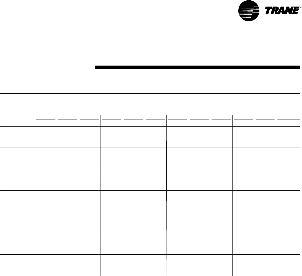
25
RT-PRC002-EN
Performance
Data
(17½ Ton)
High Efficiency
Table PD-11 — Gross Cooling Capacities (MBH)17½ Ton Three Phase T*D211C3, C4, CW— TXV Option
Ambient Temperature
85 95 105 115
Enter
Dry Entering Wet Bulb
CFM Bulb 61 67 73 61 67 73 61 67 73 61 67 73
Airflow (F) MBH SHC MBH SHC MBH SHC MBH SHC MBH SHC MBH SHC MBH SHC MBH SHC MBH SHC MBH SHC MBH SHC MBH SHC
75 178.1 125.2 199.2 102.8 222.1 78.3 170.4 120.6 190.9 98.4 213.1 74.0 162.3 115.7 182.1 93.7 203.6 69.5 153.6 110.7 172.8 88.9 193.6 64.9
80 178.3 143.9 199.4 121.1 222.2 97.7 170.6 139.3 191.1 116.5 213.3 93.4 162.4 134.5 182.3 111.8 203.8 88.8 153.8 129.5 173.1 106.8 193.7 84.0
3500* 85 178.6 163.0 199.6 139.7 222.4 116.2 171.0 158.4 191.3 135.0 213.5 111.9 163.0 153.7 182.5 130.2 204.0 107.2 151.7 151.7 173.3 125.2 194.0 102.4
90 181.8 177.2 199.8 158.2 222.6 134.6 175.2 171.7 191.5 153.5 213.7 130.2 168.1 165.8 182.7 148.7 204.2 125.5 160.6 160.1 173.5 143.8 194.2 120.6
75 190.8 142.2 212.7 113.0 236.1 82.3 182.3 137.4 203.5 108.3 226.2 78.0 173.3 132.4 193.9 103.4 215.8 73.4 163.8 127.2 183.7 98.3 204.8 68.6
80 191.2 166.4 213.0 136.6 236.3 106.8 182.8 161.6 203.8 131.8 226.5 102.3 173.9 156.6 194.1 126.9 216.0 97.5 164.7 151.5 184.0 121.8 205.1 92.6
4550* 85 193.7 186.8 213.2 160.2 236.6 130.2 186.2 180.5 204.1 155.4 226.8 125.6 178.3 173.9 194.4 150.4 216.3 120.8 169.9 167.2 184.3 145.3 205.3 115.8
90 201.2 201.2 213.6 183.9 236.9 153.5 194.2 194.2 204.7 179.3 227.0 148.9 186.6 186.6 195.2 174.4 216.6 144.0 178.5 178.5 185.2 169.3 205.6 139.0
75 199.5 157.9 221.6 122.1 245.5 85.7 190.5 153.0 212.0 117.4 234.9 81.2 180.9 147.9 201.7 112.4 223.8 76.5 171.0 142.6 190.9 107.3 212.2 71.6
80 200.9 187.5 221.9 150.5 245.8 114.8 192.2 182.6 212.3 145.8 235.3 110.1 179.9 179.9 202.0 140.8 224.1 105.2 173.8 166.9 191.2 135.6 212.5 100.2
5600 85 207.3 204.9 222.5 179.2 246.2 142.9 199.3 198.8 213.0 174.6 235.4 138.1 190.6 190.6 202.7 169.6 224.4 133.3 182.0 182.0 192.0 164.4 212.8 128.2
90 217.4 217.4 224.2 208.4 246.5 171.0 209.5 209.5 214.9 203.9 235.8 166.2 201.4 201.4 201.3 201.3 224.8 161.4 192.6 192.6 195.4 187.3 213.2 156.4
75 203.9 167.7 226.2 127.9 250.3 87.7 194.8 162.9 216.2 123.2 239.2 83.0 185.0 157.7 205.6 118.1 227.8 78.4 174.8 152.4 194.5 112.9 215.8 73.
80 202.9 202.9 226.5 159.5 250.5 119.7 195.2 195.2 216.6 154.8 239.4 114.8 188.9 182.8 206.0 149.7 228.1 110.1 179.6 175.4 194.9 144.5 216.1 105.0
6300 85 214.6 214.6 227.5 191.5 250.9 150.9 206.7 206.7 217.4 186.6 239.8 146.1 198.1 198.1 207.2 181.8 228.5 141.3 189.1 189.1 196.3 176.6 216.5 136.2
90 226.3 226.3 226.2 226.2 251.4 182.3 218.0 218.0 221.1 212.1 240.4 177.4 209.4 209.4 211.9 204.9 228.9 172.4 200.2 200.2 202.0 197.2 217.2 167.6
75 207.8 177.3 229.9 133.4 254.2 89.6 198.5 172.5 219.7 128.6 242.8 84.9 188.5 167.4 208.8 123.5 231.1 80.1 178.2 162.0 197.4 118.3 218.8 75.1
80 212.0 205.1 230.4 168.2 254.5 124.4 203.5 198.3 220.0 163.5 243.1 119.6 194.3 190.9 209.4 158.4 231.4 114.7 184.7 183.5 198.1 153.1 219.2 109.6
7000 85 221.9 221.9 231.8 203.6 254.9 158.8 213.4 213.4 221.6 198.6 243.5 153.8 204.7 204.7 211.2 193.7 231.8 149.0 195.4 195.4 200.2 188.5 219.6 143.9
90 234.1 234.1 236.8 229.0 255.6 193.4 225.4 225.4 227.5 221.6 244.3 188.5 216.5 216.5 217.7 214.0 232.5 183.4 206.9 206.9 207.6 206.7 220.6 178.6
75 211.3 186.8 233.0 138.7 257.4 91.4 201.8 181.9 222.6 133.9 245.7 86.5 191.8 176.7 211.5 128.8 233.8 81.7 181.3 171.3 199.9 123.5 221.3 76.7
80 217.2 212.9 233.7 176.7 257.8 129.0 208.4 206.0 223.3 171.9 246.1 124.1 199.0 198.7 212.3 166.8 234.2 119.3 189.0 189.0 200.8 161.5 221.7 114.1
7700 85 228.2 228.2 235.8 215.3 258.2 166.4 219.5 219.5 225.5 210.3 246.5 161.4 210.4 210.4 210.3 210.3 234.6 156.6 200.8 200.8 200.7 200.7 222.2 151.5
90 241.0 241.0 242.8 238.1 259.2 204.2 231.9 231.9 233.1 230.7 247.7 199.3 222.4 222.4 222.3 222.3 235.7 194.2 212.6 212.6 212.6 212.6 223.5 189.2
75 214.5 195.9 235.7 143.9 260.2 92.9 204.9 191.1 225.0 139.0 248.3 88.0 190.7 190.7 213.7 133.9 236.1 83.2 181.3 181.3 201.9 128.6 223.4 78.2
80 221.9 220.3 236.6 185.0 260.5 133.5 212.1 212.1 225.8 180.0 248.6 128.5 203.1 203.1 214.8 175.0 236.5 123.7 193.4 193.4 203.2 169.7 223.8 118.5
8400 85 233.9 233.9 239.5 226.8 261.0 173.9 224.8 224.8 224.7 224.7 249.2 168.9 215.5 215.5 215.4 215.4 236.9 163.8 205.5 205.5 207.7 200.6 224.4 158.9
90 247.0 247.0 248.0 246.9 262.4 214.8 237.7 237.7 237.6 237.6 250.7 209.8 227.8 227.8 227.8 227.8 238.6 204.7 217.8 217.8 217.7 217.7 226.3 199.7
Notes:
1. All capacities shown are gross and have not considered indoor fan heat. To obtain NET cooling capacity subtract indoor fan heat. For indoor fan heat formula, refer to
appropriate airflow table notes.
2. MBH = Total Gross Cooling Capacity
3. SHC = Sensible Heat Capacity
*Unit applications below 5600 CFM
• Electric heaters restricted on applications below 5600 CFM.
• Dehumidification (Hot Gas Reheat) or TXV with Frostat and Crankcase Heaters are required on applications below 5600 CFM.

26 RT-PRC002-EN
Performance
Data
Table PD-12 — Gross Cooling Capacities (MBH) 20 Ton Three Phase TC*241C3, C4, CW — Standard Refrigeration Option
Ambient Temperature (F)
85 95 105 115
Enter.
Dry Entering Wet Bulb (F)
CFM Bulb 61 67 73 61 67 73 61 67 73 61 67 73
Airflow (F) MBH SHC MBH SHC MBH SHC MBH SHC MBH SHC MBH SHC MBH SHC MBH SHC MBH SHC MBH SHC MBH SHC MBH SHC
75 246 205 273 158 284 105 228 196 263 152 280 101 208 186 246 145 273 96.5 191 176 222 136 261 91.5
7200 80 250 245 274 192 287 142 232 232 264 190 283 141 216 216 246 183 274 135 201 201 223 172 261 130
85 263 263 275 227 290 171 251 251 265 228 285 173 236 236 248 221 275 170 219 219 225 211 262 168
90 274 274 278 262 293 201 266 266 268 265 288 206 254 254 254 254 277 205 239 239 237 237 262 205
75 253 218 275 163 285 107 234 209 267 159 282 103 214 199 252 152 275 98.3 194 189 228 142 266 93.6
8000 80 257 257 277 199 289 144 243 243 268 199 285 143 227 227 252 194 277 140 210 210 228 184 266 136
85 270 270 279 236 292 174 261 261 270 240 288 177 247 247 255 237 278 177 230 230 232 226 266 177
90 280 280 282 273 295 205 274 274 274 274 291 212 264 264 264 264 280 214 250 250 248 248 267 218
75 258 230 278 167 287 109 240 221 270 164 284 105 219 211 256 159 277 100 199 199 232 149 269 95.5
8800 80 264 264 280 204 290 155 252 252 271 208 287 145 236 236 257 205 279 144 218 218 233 195 269 141
85 276 276 282 244 293 177 268 268 274 250 290 181 256 256 260 251 281 182 240 240 238 238 269 185
90 285 285 286 281 297 209 280 280 280 280 293 217 271 271 271 271 283 221 258 258 258 258 271 229
75 262 240 280 169 288 110 246 233 273 169 285 106 225 223 260 166 278 102 205 205 236 156 271 97.1
9600 80 270 270 282 209 291 161 260 260 274 215 288 147 245 245 261 215 281 147 226 226 237 205 271 146
85 280 280 284 250 295 179 274 274 277 260 291 184 263 263 265 263 282 186 248 248 246 246 272 193
90 288 288 288 288 298 212 284 284 284 284 294 222 276 276 276 276 285 228 264 264 265 265 275 240
Notes:
1. All capacities shown are gross and have not considered indoor fan heat. To obtain NET cooling capacity subtract indoor fan heat. For indoor fan heat formula, refer to
appropriate airflow table notes.
2. MBH = Total Gross Capacity
3. SHC = Sensible Heat Capacity
(20 Ton)
High Efficiency
*Indicates both downflow and horizontal units.

27
RT-PRC002-EN
Performance
Data
(20 Ton)
High Efficiency
*Indicates both downflow and horizontal units.
Table PD-13 — Gross Cooling Capacities (MBH) 20 Ton Three Phase T*D241C3, C4, CW— TXV Option
Ambient Temperature (F)
85 95 105 115
Enter.
Dry Entering Wet Bulb (F)
CFM Bulb 61 67 73 61 67 73 61 67 73 61 67 73
Airflow (F) MBH SHC MBH SHC MBH SHC MBH SHC MBH SHC MBH SHC MBH SHC MBH SHC MBH SHC MBH SHC MBH SHC MBH SHC
75 208.5 149.1 233.3 122.6 260.1 94.5 199.6 143.8 223.6 117.3 249.8 89.3 190.1 138.1 213.4 111.9 238.6 84.0 180.0 132.3 202.5 105.8 226.9 78.5
80 208.7 171.1 233.4 144.4 260.2 117.1 199.9 165.6 223.8 139.1 249.8 111.8 190.4 159.9 213.6 133.4 238.7 106.3 180.4 153.9 202.7 127.6 226.9 100.7
4000* 85 209.5 193.0 233.6 166.3 260.3 138.9 200.8 187.5 224.0 160.9 249.9 133.7 191.4 181.7 213.8 155.2 238.9 128.1 181.6 175.7 203.0 149.3 227.1 122.4
90 212.7 212.7 233.9 188.1 260.5 160.6 205.2 205.2 224.3 182.6 250.1 155.2 197.4 197.4 214.1 176.8 239.1 149.7 189.0 189.0 203.4 170.8 227.3 143.9
75 223.8 169.6 249.5 135.2 277.5 99.6 213.8 163.8 238.8 129.6 265.8 94.2 203.4 157.8 227.5 123.9 253.4 88.6 192.4 151.6 215.6 117.8 240.4 82.9
80 224.5 197.4 249.7 163.1 277.6 128.2 214.8 191.6 239.1 157.5 265.9 122.7 204.4 185.6 227.8 151.6 253.6 117.0 193.5 179.4 215.9 145.6 240.6 111.1
5200* 85 226.7 222.0 249.9 190.8 277.9 155.9 217.9 215.9 239.4 185.1 266.2 150.3 208.8 208.8 228.2 179.2 253.8 144.5 199.6 199.6 216.3 173.0 240.8 138.6
90 237.7 237.7 250.8 218.3 278.1 183.4 229.4 229.4 240.3 212.6 266.5 177.8 220.4 220.4 229.2 206.6 254.1 172.0 211.0 211.0 217.5 200.4 241.1 165.9
75 234.3 187.9 260.5 146.4 289.2 103.7 223.9 182.1 249.1 140.7 276.7 98.2 212.8 175.9 237.1 134.8 263.3 92.5 201.1 169.5 224.3 128.7 249.4 86.5
80 235.9 221.8 260.8 180.1 289.4 138.0 225.7 215.9 249.4 174.3 276.9 132.3 214.9 209.8 237.3 168.2 263.6 126.5 202.8 202.8 224.6 161.9 249.6 120.4
6400 85 243.8 243.8 261.4 213.2 289.7 171.3 234.9 234.9 250.1 207.4 277.2 165.6 225.3 225.3 238.2 201.3 264.0 159.7 215.3 215.3 225.7 195.0 250.0 153.6
90 257.1 257.1 263.2 246.7 290.1 204.5 247.9 247.9 252.1 240.8 277.5 198.6 238.1 238.1 240.6 234.8 264.3 192.6 227.7 227.7 228.5 224.2 250.4 186.3
75 239.8 199.6 266.0 153.5 295.0 106.1 229.0 193.6 254.2 147.8 282.1 100.6 217.6 187.4 241.8 141.7 268.2 94.7 205.6 180.9 228.6 138.4 253.8 88.7
80 242.3 237.5 266.3 190.6 295.3 144.0 230.8 230.8 254.6 184.7 282.3 138.3 221.3 221.1 242.2 178.6 268.6 132.4 210.7 210.7 229.2 172.3 254.2 126.2
7200 85 253.7 253.7 267.4 227.6 295.7 181.1 244.3 244.3 255.7 221.6 282.7 175.3 234.3 234.3 243.5 215.5 269.1 169.3 223.6 223.6 230.6 209.1 254.6 163.1
90 267.6 267.6 270.3 265.1 296.0 217.7 257.9 257.9 257.8 257.8 283.2 211.9 247.5 247.5 247.5 247.5 269.6 205.7 236.6 236.6 236.6 236.6 255.3 199.4
75 244.5 210.8 270.7 160.1 299.8 108.3 233.4 204.7 258.5 154.3 286.5 102.8 221.8 198.5 245.8 148.2 272.4 96.9 209.5 191.9 232.3 141.9 257.5 90.8
80 248.1 248.1 271.1 200.8 300.1 149.8 238.5 238.5 259.0 194.8 286.8 144.0 228.4 228.4 246.3 188.7 272.8 138.1 217.6 217.6 232.9 182.3 258.0 131.8
8000 85 262.5 262.5 272.6 241.6 300.5 190.5 252.6 252.6 260.7 235.6 287.3 184.7 242.1 242.1 248.1 229.3 273.3 178.7 231.0 231.0 235.0 222.9 258.3 172.1
90 277.2 277.2 277.0 277.0 301.0 230.6 266.9 266.9 266.8 266.8 288.0 224.7 256.0 256.0 256.0 256.0 274.1 218.5 244.6 244.6 244.5 244.5 259.4 212.1
75 248.5 221.7 274.6 166.6 303.7 110.4 237.3 215.6 262.1 160.6 290.2 104.8 225.4 209.3 249.0 154.6 275.8 98.9 213.0 202.7 235.3 148.3 260.6 92.7
80 255.2 255.2 275.2 210.8 304.0 155.3 245.3 245.3 262.8 204.7 290.6 149.6 234.7 234.7 249.8 198.5 276.2 143.5 223.6 223.6 236.2 192.0 261.1 137.3
8800 85 270.2 270.2 277.2 255.2 304.3 199.4 259.9 259.9 265.1 249.2 291.0 193.6 249.0 249.0 252.3 242.9 276.7 187.4 237.5 237.5 239.1 236.5 261.6 180.9
90 285.5 285.5 285.4 285.4 305.2 243.0 274.8 274.8 274.8 274.8 292.1 237.2 263.5 263.5 263.5 263.5 277.9 231.0 251.5 251.5 251.5 251.5 263.0 224.5
75 252.1 232.3 277.9 172.8 306.9 112.3 240.7 226.2 265.2 166.9 293.3 106.7 228.7 219.9 251.7 160.6 278.6 100.7 216.3 213.3 237.8 154.1 263.2 94.5
80 261.5 261.5 278.7 220.4 307.3 160.6 251.2 251.2 266.1 214.3 293.8 155.0 240.4 240.4 252.8 208.0 279.2 148.9 228.8 228.8 238.9 201.5 263.8 142.6
9600 85 277.0 277.0 281.4 268.6 307.7 208.4 266.4 266.4 269.2 262.5 294.2 202.3 255.1 255.1 254.9 254.9 279.7 196.0 243.1 243.1 243.0 243.0 264.4 189.6
90 292.8 292.8 292.8 292.8 308.7 255.2 281.8 281.8 281.8 281.8 295.6 249.4 270.1 270.1 270.1 270.1 281.3 243.2 257.7 257.7 257.7 257.7 266.2 236.7
Notes:
1. All capacities shown are gross and have not considered indoor fan heat. To obtain NET cooling capacity subtract indoor fan heat. For indoor fan heat formula, refer to
appropriate airflow table notes.
2. MBH = Total Gross Capacity
3. SHC = Sensible Heat Capacity
*Unit applications below 6400 CFM
• Electric heaters restricted on applications below 6400 CFM.
• Dehumidification (Hot Gas Reheat) or TXV with Frostat and Crankcase Heaters are required on applications below 6400 CFM.

28 RT-PRC002-EN
Performance
Data
(20 Ton)
High Efficiency
Table PD-14 — Gross Cooling Capacities (MBH) 20 Ton Three Phase T*D241C3, C4, CW— Dehumidification (Hot Gas Reheat)
Ambient Temperature (F)
85 95 105 115
Enter.
Dry Entering Wet Bulb (F)
CFM Bulb 61 67 73 61 67 73 61 67 73 61 67 73
Airflow (F) MBH SHC MBH SHC MBH SHC MBH SHC MBH SHC MBH SHC MBH SHC MBH SHC MBH SHC MBH SHC MBH SHC MBH SHC
75 197.5 138.9 222.3 116.0 249.8 89.2 188.8 133.4 213.0 110.6 239.6 83.8 179.7 127.6 203.1 105.0 228.8 78.3 170.1 121.7 192.6 99.2 217.3 72.5
80 197.7 159.2 222.6 135.8 249.8 111.4 189.0 153.7 213.3 130.3 239.6 105.8 180.0 147.9 203.4 124.6 228.8 100.1 170.4 141.9 193.0 118.7 217.4 94.2
4000* 85 198.2 179.3 222.9 156.3 250.0 132.0 189.7 173.8 213.5 150.7 239.8 126.4 180.8 168.1 203.7 145.0 229.0 120.7 171.4 162.2 193.3 139.1 217.7 114.8
90 200.5 196.8 223.1 176.7 250.3 152.5 192.8 190.9 213.7 171.0 240.1 147.0 184.8 184.8 203.8 165.2 229.3 141.2 176.9 176.9 193.5 159.3 217.9 135.3
75 213.1 158.3 239.0 127.6 267.2 94.6 203.5 152.5 228.5 121.8 255.7 88.9 193.2 146.3 217.5 115.8 243.7 83.1 182.7 140.0 206.0 109.6 231.1 77.1
80 213.5 183.8 239.3 153.7 267.4 122.1 204.0 178.0 228.9 147.9 255.9 116.3 194.0 171.9 217.9 141.9 243.9 110.3 183.5 165.7 206.4 135.7 231.3 104.1
5200* 85 215.3 209.9 239.7 179.7 267.7 148.3 204.6 204.6 229.1 173.7 256.2 142.4 197.0 194.2 218.1 167.6 244.2 136.4 187.4 187.4 206.7 161.4 231.6 130.3
90 224.3 224.3 240.1 205.2 268.0 174.4 216.2 216.2 229.8 199.4 256.6 168.6 207.6 207.6 218.9 193.3 244.5 162.5 198.7 198.7 207.6 187.1 232.0 156.4
75 223.7 175.3 250.2 138.3 279.0 98.8 213.5 169.3 239.0 132.3 266.6 93.0 202.6 163.0 227.2 126.1 253.7 87.0 191.3 156.4 214.9 119.7 240.2 80.8
80 224.9 206.3 250.6 169.7 279.2 131.4 214.8 200.3 239.4 163.6 266.8 125.3 204.2 194.1 227.7 157.5 253.9 119.2 193.2 187.7 215.2 151.0 240.5 112.9
6400 85 230.5 230.5 251.0 200.6 279.6 162.9 221.7 221.7 239.8 194.5 267.2 156.9 212.5 212.5 228.1 188.2 254.3 150.7 202.8 202.8 215.9 181.8 240.9 144.4
90 243.6 243.6 252.4 231.7 280.0 194.4 234.6 234.6 241.5 225.7 267.7 188.3 225.1 225.1 230.0 219.5 254.6 181.9 215.2 215.2 215.6 215.6 241.2 175.5
75 229.2 185.9 255.7 150.2 284.8 101.3 218.6 179.7 244.1 144.1 272.0 95.4 207.4 173.3 231.9 138.0 258.6 89.4 195.8 166.7 219.1 131.7 244.7 83.2
80 231.1 220.6 256.3 179.6 285.1 137.0 220.8 214.5 244.6 173.3 272.3 130.9 208.4 208.4 232.5 167.0 258.9 124.7 199.2 197.3 219.8 160.4 245.0 118.3
7200 85 240.3 240.3 256.9 213.7 285.5 172.0 231.1 231.1 245.4 207.5 272.7 165.9 221.4 221.4 233.3 201.2 259.4 159.7 211.2 211.2 220.8 194.7 245.5 153.3
90 254.0 254.0 259.2 248.5 286.0 206.7 244.5 244.5 248.0 242.5 273.2 200.5 234.5 234.5 235.0 235.0 259.8 194.1 224.0 224.0 225.1 224.1 246.0 187.6
75 233.9 196.0 260.5 150.9 289.7 103.6 223.0 189.8 248.6 144.8 276.5 97.7 211.5 183.3 236.1 138.4 262.7 91.4 199.6 176.7 223.0 131.9 248.4 85.0
80 234.8 234.8 261.0 188.8 290.0 142.4 225.4 225.4 249.0 182.5 276.9 136.2 215.6 215.6 236.5 176.1 263.1 129.9 205.3 205.3 223.5 169.5 248.8 123.5
8000 85 249.0 249.0 262.0 226.4 290.5 180.8 239.3 239.3 250.1 220.2 277.4 174.6 229.2 229.2 237.8 213.8 263.6 168.3 218.6 218.6 225.1 207.3 249.2 161.7
90 263.3 263.3 263.7 263.7 291.0 218.5 253.3 253.3 254.6 253.1 277.9 212.2 242.9 242.9 243.3 243.3 264.2 205.8 231.9 231.9 232.3 232.3 249.9 199.2
75 237.9 205.8 264.5 156.8 293.8 105.7 226.7 199.5 252.2 150.6 280.3 99.6 215.1 193.0 239.4 144.2 266.1 93.2 202.9 186.3 226.0 137.6 251.5 86.6
80 242.3 242.3 265.0 197.7 294.1 147.5 232.1 232.1 252.7 191.4 280.6 141.3 221.9 221.9 239.9 184.9 266.6 135.0 211.2 211.2 226.6 178.2 251.9 128.4
8800 85 256.5 256.5 266.4 238.7 294.7 189.2 246.5 246.5 254.3 232.4 281.0 182.8 235.9 235.9 241.8 226.0 267.0 176.3 224.9 224.9 228.9 219.4 252.4 169.7
90 271.4 271.4 271.8 271.8 295.2 229.9 261.0 261.0 261.4 261.4 281.8 223.6 250.1 250.1 250.5 250.5 267.9 217.2 238.7 238.7 239.1 239.1 253.4 210.5
75 241.4 215.2 267.8 162.4 297.1 107.4 230.0 208.9 255.3 156.2 283.4 101.2 218.2 202.3 242.2 149.7 269.0 94.8 205.9 195.6 228.4 143.0 254.0 88.2
80 248.0 248.0 268.4 206.4 297.6 152.5 237.9 237.9 255.9 200.0 283.8 146.2 227.5 227.5 242.8 193.4 269.5 139.8 216.4 216.4 229.3 186.7 254.6 133.2
9600 85 263.1 263.1 270.3 250.7 298.0 197.1 252.8 252.8 258.1 244.3 284.3 190.7 241.9 241.9 245.5 237.9 270.0 184.1 230.5 230.5 230.7 230.7 255.1 177.4
90 278.6 278.6 278.9 278.9 298.9 241.1 267.9 267.9 268.3 268.3 285.3 234.7 256.6 256.6 257.0 257.0 271.1 228.2 244.7 244.7 245.1 245.1 256.4 221.5
Notes:
1. All capacities shown are gross and have not considered indoor fan heat. To obtain NET cooling capacity subtract indoor fan heat. For indoor fan heat formula, refer to
appropriate airflow table notes.
2. MBH = Total Gross Capacity
3. SHC = Sensible Heat Capacity
*Unit applications below 6400 CFM
• Electric heaters restricted on applications below 6400 CFM.
• Dehumidification (Hot Gas Reheat) or TXV with Frostat and Crankcase Heaters are required on applications below 6400 CFM.
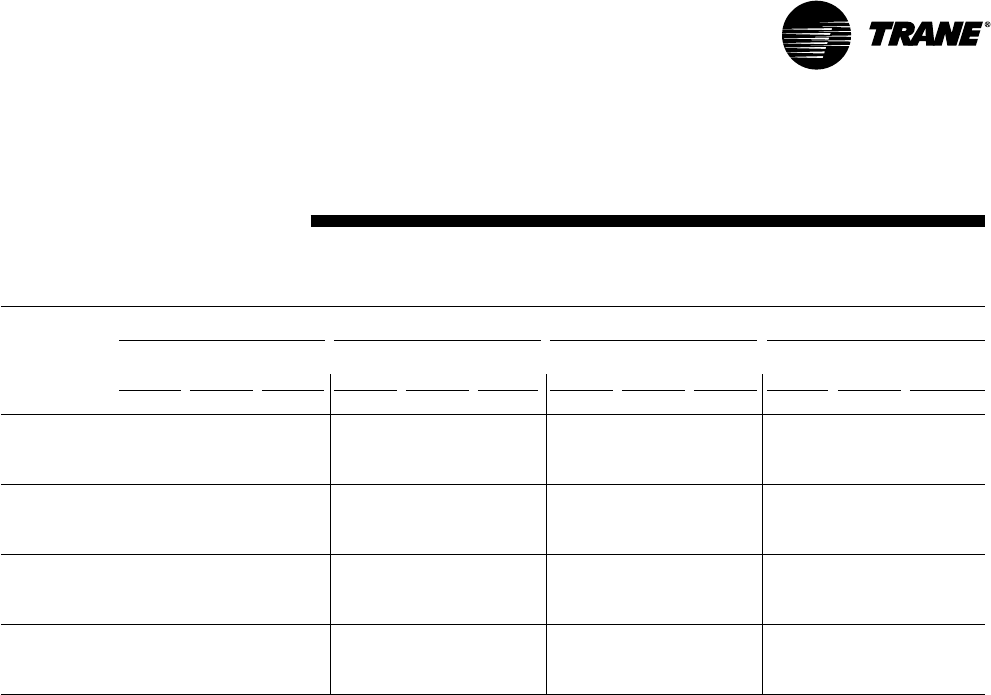
29
RT-PRC002-EN
Performance
Data
(25 Ton)
High Efficiency
Table PD-15 — Gross Cooling Capacities (MBH)25 Ton Three Phase TC*301C3, C4, CW - Standard Refrigeration System
Ambient Temperature (F)
85 95 105 115
Enter.
Dry Entering Wet Bulb (F)
CFM Bulb 61 67 73 61 67 73 61 67 73 61 67 73
Airflow (F) MBH SHC MBH SHC MBH SHC MBH SHC MBH SHC MBH SHC MBH SHC MBH SHC MBH SHC MBH SHC MBH SHC MBH SHC
75 277 243 306 187 316 117 258 234 295 178 314 115 238 224 276 169 305 110 218 214 253 163 292 104
80 284 284 307 225 321 169 269 269 295 225 317 161 252 252 277 217 307 158 235 235 254 207 293 151
9000 85 300 300 309 269 325 198 289 289 298 271 320 202 273 273 280 266 308 201 256 256 259 256 293 198
90 312 312 313 312 329 236 305 305 305 305 321 240 293 293 293 293 310 245 277 277 277 277 295 244
75 284 258 310 188 319 121 264 249 299 185 316 117 244 239 282 178 308 112 224 224 259 168 295 106
80 294 294 310 233 323 175 280 280 300 236 319 170 263 263 283 230 309 163 245 245 260 221 296 158
10000 85 307 307 313 280 327 202 298 298 303 286 322 207 284 284 287 284 312 208 267 267 267 267 297 208
90 318 318 318 318 331 241 312 312 312 312 324 248 301 301 301 301 314 255 287 287 287 287 299 257
75 286 265 311 190 320 122 267 256 300 189 316 118 247 246 284 182 309 113 228 228 261 172 296 107
80 297 297 312 237 324 178 285 285 302 241 320 174 267 267 285 237 310 165 249 249 262 227 298 162
10500 85 310 310 315 285 328 204 302 302 305 293 323 210 289 289 289 289 313 212 272 272 272 272 299 213
90 320 320 320 320 332 244 314 314 314 314 325 251 305 305 305 305 316 260 292 292 292 292 301 264
75 289 272 312 192 321 123 270 264 302 192 317 119 249 249 286 186 309 114 231 231 263 176 297 108
80 300 300 313 240 324 181 289 289 304 246 321 177 272 272 287 243 311 170 253 253 265 234 299 165
110 0 0 85 312 312 316 289 329 205 305 305 307 299 324 212 293 293 293 293 314 215 276 276 276 276 300 217
90 322 322 321 321 332 246 317 317 317 317 326 255 308 308 308 308 317 265 295 295 295 295 303 270
Notes
1. All capacities shown are gross and have not considered indoor fan heat. To obtain NET cooling capacity subtract indoor fan heat. For indoor fan heat formula, refer to
appropriate airflow table notes.
2. MBH = Total Gross Capacity
3. SHC = Sensible Heat Capacity
*Indicates both downflow and horizontal units.
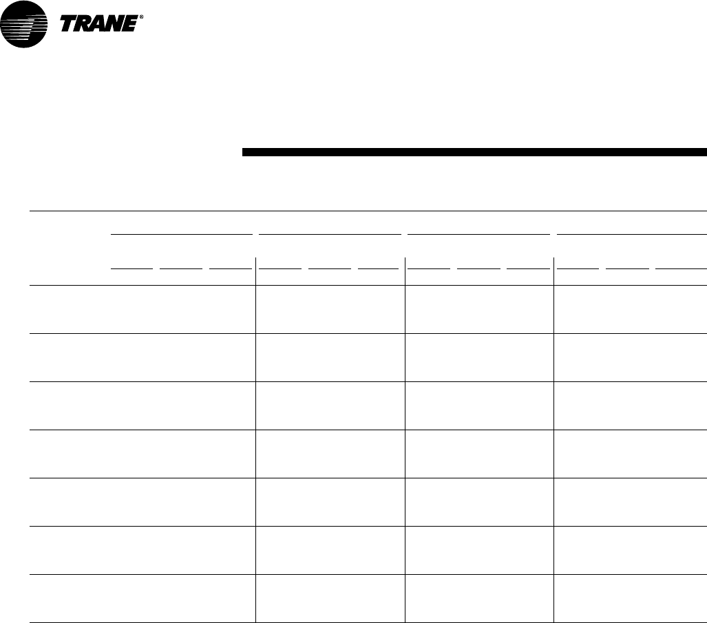
30 RT-PRC002-EN
Performance
Data
(25 Ton)
High Efficiency
Table PD-16 — Gross Cooling Capacities (MBH)25 Ton Three PhaseTC*301C3, C4, CW— TXV Option
Ambient Temperature (F)
85 95 105 115
Enter.
Dry Entering Wet Bulb (F)
CFM Bulb 61 67 73 61 67 73 61 67 73 61 67 73
Airflow (F) MBH SHC MBH SHC MBH SHC MBH SHC MBH SHC MBH SHC MBH SHC MBH SHC MBH SHC MBH SHC MBH SHC MBH SHC
75 241.0 176.5 269.7 142.7 300.9 107.2 229.7 169.7 257.6 135.9 287.8 100.8 217.8 162.6 244.9 129.0 274.0 94.1 205.5 155.3 231.6 122.0 259.8 87.3
80 241.4 204.6 269.9 170.5 300.9 135.9 230.2 197.7 257.8 163.8 287.8 129.3 218.4 190.5 245.1 156.8 274.1 122.5 206.2 183.2 231.9 149.6 259.8 115.6
5000* 85 243.0 233.0 270.1 198.3 301.1 163.7 229.2 229.2 258.1 191.5 288.1 157.0 221.3 216.5 245.4 184.5 274.4 150.1 209.9 208.3 232.2 177.3 260.1 143.1
90 251.2 251.2 270.6 226.1 301.4 191.2 241.6 241.6 258.6 219.2 288.3 184.4 231.6 231.6 246.0 212.1 274.6 177.5 221.2 221.2 233.0 204.8 260.4 170.4
75 256.8 201.4 286.5 157.9 318.8 113.1 244.6 194.3 273.3 150.9 304.2 106.4 231.8 186.9 259.5 143.8 289.2 99.5 218.4 179.4 245.1 136.5 273.6 92.5
80 258.2 237.2 286.8 193.2 318.9 149.3 246.1 230.1 273.6 186.2 304.4 142.3 233.6 222.8 259.8 179.0 289.4 135.3 220.7 215.4 245.4 171.6 273.9 128.1
6500* 85 264.6 264.6 287.3 228.5 319.2 184.3 254.2 254.2 274.1 221.4 304.7 177.3 243.2 243.2 260.4 214.1 289.7 170.2 231.7 231.7 246.2 206.6 274.1 162.9
90 279.1 279.1 288.7 263.8 319.5 219.2 268.4 268.4 275.8 256.7 305.0 212.1 257.3 257.3 262.4 249.5 290.0 205.0 245.6 245.6 245.5 245.5 274.5 197.7
75 267.9 224.2 297.7 171.5 330.7 118.0 254.9 216.9 283.7 164.4 315.3 111.1 241.5 209.3 269.2 157.1 299.2 104.0 227.5 201.6 254.0 149.6 282.7 96.8
80 268.8 268.8 298.0 214.0 330.9 161.1 259.3 255.4 284.1 206.8 315.5 154.0 246.8 246.7 269.6 199.5 299.5 146.7 234.0 234.0 254.5 191.9 283.0 139.4
8000 85 284.5 284.5 299.2 256.4 331.2 203.2 273.2 273.2 285.4 249.2 315.9 196.1 261.3 261.3 271.0 241.8 299.8 188.8 248.9 248.9 256.2 234.3 283.3 181.4
90 300.3 300.3 300.2 300.2 331.6 245.2 288.7 288.7 290.5 286.0 316.4 238.0 276.5 276.5 276.4 276.4 300.4 230.6 263.8 263.8 263.7 263.7 284.0 223.1
75 273.6 238.6 303.4 180.1 336.6 120.9 260.4 231.2 289.0 172.8 320.7 114.0 246.7 223.6 273.9 170.7 304.2 106.8 232.5 215.9 258.3 163.2 287.1 99.6
80 279.6 279.5 303.8 227.0 336.8 168.4 267.3 267.3 289.5 219.8 321.0 161.3 255.2 255.2 274.6 212.4 304.5 154.0 242.6 242.6 259.1 204.8 287.5 146.5
9000 85 295.1 295.1 305.6 274.3 337.2 215.2 283.4 283.4 291.5 267.1 321.4 208.1 271.0 271.0 276.9 259.7 304.9 200.7 258.0 258.0 261.9 252.2 287.8 193.1
90 311.9 311.9 311.8 311.8 338.0 261.8 299.6 299.6 299.6 299.6 322.2 254.5 286.9 286.9 286.8 286.8 305.9 247.1 273.5 273.5 273.5 273.5 288.9 239.4
75 278.6 252.6 308.1 188.2 341.5 123.5 265.2 245.2 293.3 180.9 325.3 116.5 251.3 237.6 278.0 173.5 308.4 109.2 234.1 234.1 262.1 165.9 290.8 101.7
80 287.6 287.6 308.7 239.7 341.8 175.5 275.5 275.5 294.0 232.5 325.6 168.3 263.1 263.1 278.8 225.0 308.7 160.9 250.0 250.0 263.1 217.3 291.2 153.4
10000 85 304.6 304.6 311.3 291.9 342.1 226.8 292.3 292.3 297.0 284.7 325.9 219.5 279.4 279.4 279.3 279.3 309.1 212.1 266.0 266.0 267.7 262.9 291.7 204.4
90 322.2 322.2 322.1 322.1 343.3 277.9 309.3 309.3 309.3 309.3 327.2 270.5 295.9 295.9 295.9 295.9 310.6 263.1 282.0 282.0 282.0 282.0 293.3 255.3
75 283.1 266.2 312.0 196.0 345.5 125.9 269.5 258.8 296.9 188.7 329.1 118.9 253.1 253.1 281.2 181.2 311.8 111.5 241.4 237.4 265.1 173.5 293.9 104.0
80 295.1 295.1 312.9 252.1 345.8 182.3 282.8 282.8 297.9 244.7 329.4 175.0 269.9 269.9 282.4 237.2 312.2 167.7 256.4 256.4 266.5 229.4 294.3 160.1
110 0 0 85 312.9 312.9 312.8 312.8 346.2 237.9 300.0 300.0 299.9 299.9 329.9 230.6 286.7 286.7 288.1 285.2 312.8 223.1 272.8 272.8 272.7 272.7 295.0 215.4
90 331.2 331.2 331.1 331.1 347.8 293.5 317.8 317.8 317.8 317.8 331.6 286.2 304.0 304.0 303.8 303.8 314.7 278.6 289.3 289.3 289.3 289.3 297.3 271.0
75 283.8 283.8 315.3 203.6 348.9 128.2 271.5 271.5 299.9 196.2 332.2 121.1 259.9 256.8 284.1 188.6 314.7 113.8 245.2 245.2 267.7 180.9 296.5 106.2
80 301.8 301.8 316.6 264.1 349.2 188.9 289.0 289.0 301.2 256.6 332.6 181.7 275.9 275.9 285.7 249.1 315.2 174.3 262.0 262.0 269.5 241.3 297.0 166.6
12000 85 320.3 320.3 322.4 316.7 349.8 248.8 307.0 307.0 308.0 306.9 333.2 241.5 293.2 293.2 293.1 293.1 315.8 233.9 278.8 278.8 278.8 278.8 297.8 226.2
90 339.1 339.1 339.0 339.0 351.7 308.8 325.4 325.4 325.3 325.3 335.6 301.5 310.9 310.9 310.9 310.9 318.5 294.0 295.9 295.9 295.9 295.9 301.0 286.4
Notes
1. All capacities shown are gross and have not considered indoor fan heat. To obtain NET cooling capacity subtract indoor fan heat. For indoor fan heat formula, refer to
appropriate airflow table notes.
2. MBH = Total Gross Capacity
3. SHC = Sensible Heat Capacity
*Unit applications below 8000 CFM
• Electric heaters restricted on applications below 8000 CFM.
• Dehumidification (Hot Gas Reheat) or TXV with Frostat and Crankcase Heaters are required on applications below 8000 CFM.
31
RT-PRC002-EN
Table PD-17 — Evaporator Fan Performance — 12½ Ton — TC*150D — Continued
External Static Pressure (Inches of Water)
1.10 1.20 1.30 1.40 1.50 1.60 1.70 1.80 1.90 2.00
CFM RPM BHP RPM BHP RPM BHP RPM BHP RPM BHP RPM BHP RPM BHP RPM BHP RPM BHP RPM BHP
3 HP Standard Motor & Sheaves 3 HP Standard Motor & High Static Drive Accessory
4000 786 1.70 813 1.81 841 1.91 867 2.02 893 2.12 919 2.22 943 2.32 966 2.41 989 2.50 1011 2.60
4500 806 2.06 834 2.19 861 2.31 886 2.43 911 2.56 935 2.67 960 2.79 983 2.90 1005 3.02 1028 3.13
5000 830 2.48 856 2.62 882 2.76 907 2.89 931 3.02 955 3.16 977 3.30 1001 3.44 1022 3.56 1045 3.70
5500 861 2.93 884 3.10 906 3.25 930 3.41 953 3.56 976 3.70 999 3.86 1021 4.00 1043 4.15 1064 4.31
6000 894 3.43 916 3.61 938 3.79 959 3.97 980 4.15 1000 4.31 1019 4.46 1040 4.62 1061 4.78 1082 4.95
5 HP Oversize Motor & Sheaves
(12½ Ton)
Standard Efficiency
Performance
Data
Factory supplied motors, in commercial equipment, are definite
purpose motors, specifically designed and tested to operate
reliably and continuously at all cataloged conditions. Using the
full horsepower range of our fan motors as shown in our
tabular data will not result in nuisance tripping or premature
motor failure. Our product’s warranty will not be affected.
5 HP Oversize Motor & Field Supplied Drive
For Standard Evaporator Fan Speed (RPM), reference Table PD-31.
For Oversized Evaporator Fan Speed (RPM), reference Table PD-33.
Fan motor heat (MBH) = 3.15 x Fan BHP
Data includes pressure drop due to wet coils and filters.
No accessories or options are included in pressure drop data.
Refer to Table PD-35 to determine add’l static pressure drop due to other options/accessories.
Notes:
1. Field Supplied Fan Sheave BK90 Required. Field Supplied Belt may be necessary.
2. 5 HP Oversized Motor with Field Supplied Motor Sheave IVL40 Required. Field Supplied Belt
may be necessary.
3. For 380V/60 Hz units, the oversized motor is used as the standard motor. Refer to “Motor &
Sheave/Fan Speed” tables to determine operating range.
Table PD-17 — Evaporator Fan Performance — 12½Ton — TC*150D
External Static Pressure (Inches of Water)
.10 .20 .30 .40 .50 .60 .70 .80 .90 1.00
CFM RPM BHP RPM BHP RPM BHP RPM BHP RPM BHP RPM BHP RPM BHP RPM BHP RPM BHP RPM BHP
3 HP Standard Motor & Field 3 HP Standard Motor & Sheaves
Supplied Low Static Drive
4000 — — — — — — 565 0.93 599 1.03 632 1.15 663 1.27 695 1.38 727 1.48 757 1.59
4500 — — — — 571 1.10 603 1.21 634 1.31 665 1.43 694 1.56 723 1.69 750 1.82 778 1.94
5000 547 1.18 581 1.30 613 1.42 643 1.54 672 1.67 700 1.78 727 1.91 755 2.05 781 2.19 806 2.34
5500 595 1.55 627 1.68 656 1.81 685 1.94 711 2.08 737 2.21 763 2.34 788 2.47 813 2.62 837 2.77
6000 643 1.99 673 2.12 701 2.26 727 2.41 752 2.56 777 2.71 801 2.85 825 2.99 848 3.13 871 3.27
32 RT-PRC002-EN
For Standard Evaporator Fan Speed (RPM), reference Table PD-31.
For Standard Motor & High Static Drive Accessory Fan Speed (RPM), reference Table PD-32.
For Oversized Evaporator Fan Speed (RPM), reference Table PD-33.
Fan motor heat (MBH) = 3.15 x Fan BHP
Data includes pressure drop due to wet coils and filters.
No accessories or options are included in pressure drop data.
Refer to Table PD-35 to determine add’l static pressure drop due to other options/accessories.
Notes:
1. Field Supplied Fan Sheave BK105 Required. Field Supplied Belt may be necessary.
2. 5 HP Oversized Motor with Field Supplied Fan Sheave BK160 Required. Field Supplied Belt may
be necessary.
3. 5 HP Oversized Motor with Field Supplied Motor Sheave IVP50 Required. Field Supplied Belt
may be necessary.
4. For 380V/60 Hz units, the oversized motor is used as the standard motor. Refer to “Motor &
Sheave/Fan Speed” tables to determine operating range.
Factory supplied motors, in commercial equipment, are
definite purpose motors, specifically designed and tested
to operate reliably and continuously at all cataloged
conditions. Using the full horsepower range of our fan
motors as shown in our tabular data will not result in
nuisance tripping or premature motor failure. Our
product’s warranty will not be affected.
Performance
Data
(15 Ton)
Standard Efficiency
Table PD-18 — Evaporator Fan Performance — 15 Ton — TC*180B
External Static Pressure (Inches of Water)
.10 .20 .30 .40 .50 .60 .70 .80 .90 1.00
CFM RPM BHP RPM BHP RPM BHP RPM BHP RPM BHP RPM BHP RPM BHP RPM BHP RPM BHP RPM BHP
3 HP Standard Motor & Field 3 HP Standard Motor & Sheaves
Supplied Low Static Drive (1)
4800 — — 563 1.17 596 1.29 626 1.41 656 1.52 685 1.63 714 1.76 742 1.90 768 2.04 794 2.18
5400 585 1.47 618 1.60 648 1.72 676 1.86 703 1.99 729 2.12 756 2.25 782 2.38 807 2.52 832 2.68
6000 643 1.99 673 2.12 701 2.26 727 2.41 752 2.56 777 2.71 801 2.85 825 2.99 848 3.13 871 3.27
6600 701 2.61 729 2.76 755 2.91 780 3.07 804 3.23 827 3.39 849 3.56 871 3.72 892 3.88 914 4.03
7200 760 3.35 786 3.52 810 3.69 834 3.85 856 4.02 878 4.20 899 4.38 919 4.56 939 4.74 959 4.91
(2) 5 HP Oversized Motor & Sheaves
Table PD-18 — Evaporator Fan Performance — 15 Ton — TC*180B — Continued
External Static Pressure (Inches of Water)
1.10 1.20 1.30 1.40 1.50 1.60 1.70 1.80 1.90 2.00
CFM RPM BHP RPM BHP RPM BHP RPM BHP RPM BHP RPM BHP RPM BHP RPM BHP RPM BHP RPM BHP
3 HP Standard Motor & Sheaves 3 HP Standard Motor & High Static Drive Accessory
4800 819 2.30 844 2.43 871 2.57 898 2.70 923 2.83 946 2.96 970 3.09 994 3.23 1018 3.39 1041 3.54
5400 855 2.84 878 3.00 901 3.15 923 3.29 945 3.43 969 3.58 993 3.73 1016 3.88 1038 4.03 1060 4.17
6000 894 3.43 916 3.61 938 3.79 959 3.97 980 4.15 1000 4.31 1019 4.46 1040 4.62 1061 4.78 1082 4.95
6600 935 4.18 956 4.34 977 4.51 997 4.70 1018 4.90 1037 5.10 1056 5.30 1075 5.49 1093 5.67 — —
7200 979 5.08 999 5.25 1018 5.41 1038 5.58 1057 5.77 — — ————————
5 HP Oversized Motor & Field Supplied Drive (3)
5 HP Oversized Motor & Sheaves
33
RT-PRC002-EN
Performance
Data
(17½Ton)
Standard Efficiency
*Indicates both downflow and horizontal units.
For Standard Evaporator Fan Speed (RPM), reference Table PD-31.
For Oversized Evaporator Fan Speed (RPM), reference Table PD-33.
For Standard Motor & Low Static Drive Accessory Fan Speed (RPM), reference Table PD-34.
Fan motor heat (MBH) = 3.15 x Fan BHP
Data includes pressure drop due to wet coils and filters.
No accessories or options are included in pressure drop data.
Refer to Table PD-35 to determine add’l static pressure drop due to other options/accessories.
Notes:
1. For 380V/60 Hz units, the oversized motor is used as the standard motor. Refer to “Motor & Sheave/
Fan Speed” tables to determine operating range.
Factory supplied motors, in commercial equipment, are
definite purpose motors, specifically designed and tested to
operate reliably and continuously at all cataloged conditions.
Using the full horsepower range of our fan motors as shown
in our tabular data will not result in nuisance tripping or
premature motor failure. Our product’s warranty will not be
affected.
Table PD-19 — Evaporator Fan Performance — 17½ Ton — TC*210C — Continued
External Static Pressure (Inches of Water)
1.10 1.20 1.30 1.40 1.50 1.60 1.70 1.80 1.90 2.00
CFM RPM BHP RPM BHP RPM BHP RPM BHP RPM BHP RPM BHP RPM BHP RPM BHP RPM BHP RPM BHP
5 HP Standard Motor & Sheaves
5600 923 3.50 946 3.68 968 3.85 989 4.03 1011 4.21 1033 4.39 1056 4.58 1078 4.77 1099 4.96 1122 5.18
6300 976 4.46 997 4.63 1019 4.82 1040 5.00 1060 5.19 1079 5.39 1100 5.60 1118 5.79 1138 6.00 1157 6.20
7000 1039 5.65 1057 5.82 1074 6.00 1092 6.19 1111 6.39 1130 6.59 1150 6.80 1168 7.01 1186 7.22 1205 7.46
7700 1104 7.06 1122 7.26 1138 7.46 1154 7.66 1170 7.84 1186 8.05 1202 8.25 1220 8.47 — — — —
8400 — — — — — — — — — — — — ————————
7.5 HP Oversive Motor & Sheaves
Table PD-19 — Evaporator Fan Performance — 17½ Ton — TC*210C
External Static Pressure (Inches of Water)
.10 .20 .30 .40 .50 .60 .70 .80 .90 1.00
CFM RPM BHP RPM BHP RPM BHP RPM BHP RPM BHP RPM BHP RPM BHP RPM BHP RPM BHP RPM BHP
5 HP Standard Motor with Low Static Drive Accessory
5600 — — — — 735 2.34 759 2.46 783 2.60 807 2.74 830 2.89 852 3.03 875 3.18 898 3.33
6300 765 2.96 788 3.10 810 3.23 831 3.36 852 3.50 874 3.65 895 3.81 917 3.97 937 4.13 956 4.29
7000 845 4.02 866 4.18 886 4.33 906 4.48 925 4.62 944 4.77 963 4.93 982 5.10 1002 5.29 1021 5.47
7700 925 5.32 944 5.49 963 5.66 982 5.82 999 5.98 1016 6.14 1033 6.30 1050 6.47 1069 6.66 1086 6.86
8400 1006 6.87 1024 7.06 1041 7.24 1058 7.42 1075 7.60 1091 7.78 1107 7.95 1122 8.13 1138 8.31 1154 8.50
7.5 HP Oversize Motor & Sheaves
5 HP Standard Motor & Sheaves
34 RT-PRC002-EN
*Indicates both downflow and horizontal units.
Performance
Data
(20 Ton)
Standard Efficiency
For Standard Evaporator Fan Speed (RPM), reference Table PD-31.
For Standard Motor & High Static Drive Accessory Fan Speed (RPM), reference Table PD-32.
For Oversized Evaporator Fan Speed (RPM), reference Table PD-33.
Fan motor heat (MBH) = 3.15 x Fan BHP
Data includes pressure drop due to wet coils and filters.
No accessories or options are included in pressure drop data.
Refer to Table PD-35 to determine add’l static pressure drop due to other options/accessories.
Notes:
1. Field Supplied Fan Sheave BK190 Required. Field Supplied Belt may be necessary.
2. 7.5 HP Standard Motor with Field Supplied Motor Sheave IVP50 Required. Field Supplied Belt
may be necessary.
3. For 380V/60 Hz units, the oversized motor is used as the standard motor. Refer to “Motor &
Sheave/Fan Speed” tables to determine operating range.
Factory supplied motors, in commercial equipment, are
definite purpose motors, specifically designed and tested to
operate reliably and continuously at all cataloged conditions.
Using the full horsepower range of our fan motors as shown
in our tabular data will not result in nuisance tripping or
premature motor failure. Our product’s warranty will not be
affected.
Table PD-20 — Evaporator Fan Performance — 20 Ton — TC*240B — Continued
External Static Pressure (Inches of Water)
1.10 1.20 1.30 1.40 1.50 1.60 1.70 1.80 1.90 2.00
CFM RPM BHP RPM BHP RPM BHP RPM BHP RPM BHP RPM BHP RPM BHP RPM BHP RPM BHP RPM BHP
5 HP Standard Motor & Sheaves 5 HP Standard Motor & High Static Drive Accessory
6400 744 3.32 768 3.52 790 3.72 811 3.91 833 4.13 855 4.36 877 4.59 897 4.82 917 5.05 936 5.29
7200 773 4.04 795 4.27 817 4.50 839 4.74 860 4.96 880 5.19 898 5.41 917 5.64 937 5.88 957 6.14
8000 811 4.96 830 5.18 848 5.40 867 5.64 887 5.90 907 6.16 927 6.42 946 6.68 964 6.93 982 7.18
8800 852 6.08 869 6.30 887 6.53 904 6.77 921 7.01 938 7.26 955 7.52 973 7.81 991 8.09 — —
9600 895 7.40 911 7.63 928 7.86 944 8.11 960 8.36 976 8.61 ————————
7.5 HP Oversized Motor & Sheaves
Table PD-20 — Evaporator Fan Performance — 20 Ton — TC*240B
External Static Pressure (Inches of Water)
.10 .20 .30 .40 .50 .60 .70 .80 .90 1.00
CFM RPM BHP RPM BHP RPM BHP RPM BHP RPM BHP RPM BHP RPM BHP RPM BHP RPM BHP RPM BHP
5 HP Standard Motor & Field Supplied 5 HP Standard Motor & Sheaves
Low Static Drive (1)
6400 — — 514 1.69 546 1.88 574 2.05 599 2.21 624 2.37 648 2.54 671 2.71 695 2.90 720 3.11
7200 527 2.08 562 2.29 592 2.50 619 2.71 644 2.91 667 3.09 689 3.26 711 3.45 732 3.64 752 3.83
8000 578 2.79 610 3.03 639 3.26 666 3.50 690 3.73 712 3.96 733 4.16 753 4.35 773 4.55 792 4.75
8800 629 3.65 659 3.93 687 4.18 712 4.43 736 4.69 758 4.96 778 5.20 797 5.43 816 5.65 834 5.86
9600 681 4.67 709 4.99 735 5.27 759 5.54 782 5.82 804 6.11 824 6.39 843 6.67 861 6.92 878 7.16
5 HP Standard Motor & Sheaves (2) 7.5 HP Oversized Motor & Sheaves

35
RT-PRC002-EN
Performance
Data
(25 Ton)
Standard Efficiency
*Indicates both downflow and horizontal units.
Table PD-21 — Evaporator Fan Performance — 25 Ton — TC*300B
External Static Pressure (Inches of Water)
.10 .20 .30 .40 .50 .60 .70 .80 .90 1.00
CFM RPM BHP RPM BHP RPM BHP RPM BHP RPM BHP RPM BHP RPM BHP RPM BHP RPM BHP RPM BHP
7.5 HP Standard Motor & Low Static Drive Accessory 7.5 HP Standard Motor & Sheaves
7000 — — — — 593 2.42 619 2.62 643 2.80 667 2.98 690 3.16 712 3.35 733 3.53 754 3.73
7500 — — 595 2.66 624 2.88 649 3.10 673 3.31 695 3.50 717 3.68 738 3.88 759 4.08 779 4.28
8000 595 2.92 627 3.16 655 3.39 679 3.63 702 3.86 724 4.07 745 4.28 766 4.48 786 4.68 805 4.90
8500 628 3.47 659 3.73 686 3.97 710 4.23 732 4.47 754 4.71 774 4.94 794 5.15 813 5.36 832 5.58
9000 661 4.08 691 4.36 717 4.62 741 4.89 763 5.15 784 5.41 803 5.66 822 5.89 841 6.12 859 6.35
9500 695 4.76 723 5.06 749 5.34 772 5.62 794 5.90 814 6.18 833 6.45 852 6.71 870 6.95 887 7.19
10000 729 5.52 755 5.84 781 6.13 804 6.42 825 6.72 844 7.01 863 7.31 881 7.59 899 7.86 916 8.11
10500 762 6.35 788 6.69 812 7.00 835 7.31 856 7.62 875 7.93 894 8.24 911 8.54 — — — —
11000 796 7.27 821 7.63 844 7.96 867 8.3 887 8.60 — — ————————
Factory supplied motors, in commercial equipment, are
definite purpose motors, specifically designed and tested
to operate reliably and continuously at all cataloged
conditions. Using the full horsepower range of our fan
motors as shown in our tabular data will not result in
nuisance tripping or premature motor failure. Our
product’s warranty will not be affected.
For Standard Evaporator Fan Speed (RPM), reference Table PD-31.
For Standard Motor & High Static Drive Accessory Fan Speed (RPM), reference Table PD-32.
For Standard Motor & Low Static Drive Accessory Fan Speed (RPM), reference Table PD-34.
Fan motor heat (MBH) = 3.15 x Fan BHP
Data includes pressure drop due to wet coils and filters.
No accessories or options are included in pressure drop
data. Refer to Table PD-35 to determine add’l static pressure drop due to other options/accessories.
Note:
1. For 380V/60 Hz units, the oversized motor is used as the standard motor. Refer to “Motor & Sheave/Fan
Speed” tables to determine operating range.
Table PD-21 — Evaporator Fan Performance — 25 Ton — TC*300B — Continued
External Static Pressure (Inches of Water)
1.10 1.20 1.30 1.40 1.50
CFM RPM BHP RPM BHP RPM BHP RPM BHP RPM BHP
7.5 HP Standard Motor & Sheaves
7000 776 3.95 798 4.18 820 4.40 841 4.62 862 4.84
7500 798 4.48 818 4.71 839 4.95 860 5.19 880 5.42
8000 824 5.11 842 5.32 860 5.55 880 5.80 899 6.06
8500 850 5.81 868 6.03 885 6.26 902 6.49 920 6.74
9000 877 6.58 894 6.81 911 7.05 928 7.29 944 7.53
9500 904 7.43 921 7.67 938 7.92 954 8.17 970 8.42
10000 933 8.36 949 8.62 — — — — — —
10500 — — — — — — — — — —
11000—— —— —— —— ——
7.5 HP Standard Motor & High Static Drive Accessory
7.5 HP Standard Motor & Sheaves
7.5 HP Standard Motor & High Static Drive Accessory
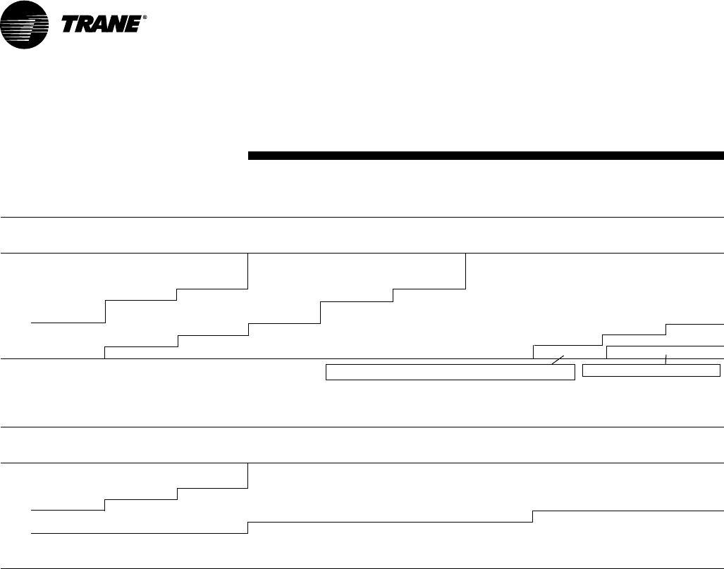
36 RT-PRC002-EN
(12½ Ton)
High Efficiency
Performance
Data
For Standard Evaporator Fan Speed (RPM), reference Table PD-31.
For Standard Motor & High Static Drive Accessory Fan Speed (RPM), reference Table PD-32.
For Oversized Evaporator Fan Speed (RPM), reference Table PD-33.
*Unit applications below 4000 CFM
• Electric heaters restricted on applications below 4000 CFM.
• Dehumidification (Hot Gas Reheat) or TXV with Frostat and Crankcase Heaters
are required on applications below 4000 CFM.
Fan motor heat (MBH) = 3.15 x Fan BHP
Data includes pressure drop due to wet coils and filters.
No accessories or options are included in pressure drop data.
Refer to Table PD-35 to determine add’l static pressure drop due to other options/accessories.
Note:
1. Field Supplied Fan Sheave BK115 Required. Field Supplied Belt may be necessary.
Factory supplied motors, in commercial equipment, are
definite purpose motors, specifically designed and tested to
operate reliably and continuously at all cataloged conditions.
Using the full horsepower range of our fan motors as shown
in our tabular data will not result in nuisance tripping or
premature motor failure. Our product’s warranty will not be
affected.
Table PD-22 — Evaporator Fan Performance — 12½Ton — TCD151C — Standard or TXV Refrigeration System
External Static Pressure (Inches of Water)
.10 .20 .30 .40 .50 .60 .70 .80 .90 1.00
CFM RPM BHP RPM BHP RPM BHP RPM BHP RPM BHP RPM BHP RPM BHP RPM BHP RPM BHP RPM BHP
3 HP Standard Motor & Field 3 HP Standard Motor & Field 3 HP Standard Motor & Drive
Supplied Low Static Drive (2) Supplied High Static Drive (2)
2500* — — 402 0.30 460 0.39 510 0.48 555 0.56 595 0.64 633 0.74 667 0.83 699 0.92 731 1.02
3250* 378 0.35 447 0.49 503 0.62 552 0.74 595 0.86 634 0.97 672 1.08 706 1.19 739 1.30 769 1.40
4000 430 0.56 495 0.74 549 0.91 596 1.07 638 1.22 677 1.37 712 1.52 747 1.66 778 1.80 809 1.94
4500 466 0.74 528 0.95 580 1.14 627 1.33 668 1.51 706 1.68 742 1.85 776 2.02 806 2.18 836 2.34
5000 503 0.96 562 1.20 612 1.42 657 1.63 699 1.84 736 2.04 771 2.23 803 2.41 835 2.61 865 2.80
5500 540 1.22 597 1.49 645 1.74 689 1.98 729 2.20 767 2.44 801 2.66 833 2.87 864 3.07 893 3.28
6000 579 1.53 633 1.82 680 2.10 722 2.37 761 2.63 797 2.87 832 3.13 864 3.38 894 3.61 922 3.83
3 HP Standard Motor & High Static Drive Accessory 5 HP Oversize Motor & Drive
Table PD-22 — Evaporator Fan Performance — 12½ Ton — TCD151C — Continued
External Static Pressure (Inches of Water)
1.10 1.20 1.30 1.40 1.50 1.60 1.70 1.80 1.90 2.00
CFM RPM BHP RPM BHP RPM BHP RPM BHP RPM BHP RPM BHP RPM BHP RPM BHP RPM BHP RPM BHP
3 HP Standard Motor & Drive 3 HP Standard Motor & High Static Drive Accessory
2500* 760 1.11 789 1.21 817 1.31 842 1.41 868 1.51 892 1.60 916 1.71 939 1.81 962 1.91 984 2.01
3250* 798 1.52 827 1.64 853 1.76 880 1.88 905 2.01 928 2.13 953 2.26 976 2.38 998 2.51 1020 2.63
4000* 839 2.07 867 2.21 893 2.33 919 2.47 943 2.59 967 2.73 991 2.88 1013 3.03 1036 3.18 1056.4 3.33
4500 865 2.50 892 2.66 919 2.81 945 2.96 970 3.11 994 3.25 1017 3.40 1039 3.55 1061 3.70 1082.3 3.85
5000 892 2.97 920 3.15 946 3.33 971 3.50 996 3.68 1020 3.85 1043 4.02 1066 4.18 1088 4.35 1109.6 4.50
5500 922 3.49 949 3.70 975 3.90 999 4.09 1023 4.28 1047 4.48 1070 4.68 1091 4.87 1114 5.06 1135.6 5.24
6000 950 4.05 977 4.29 1002 4.51 1028 4.74 1052 4.96 1074 5.16 1098 5.38 1120 5.59 — — — —
5 HP Oversized Motor & Drive
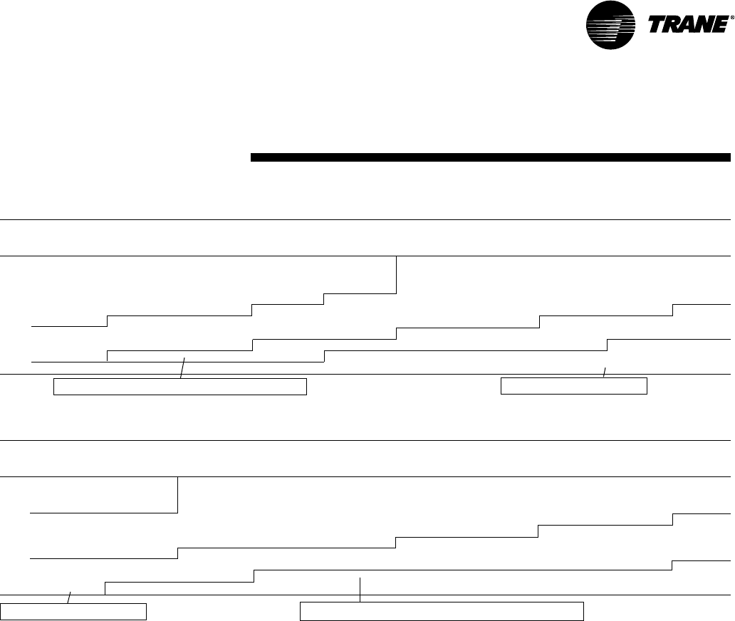
37
RT-PRC002-EN
(12½ Ton)
High Efficiency
Performance
Data
For Standard Evaporator Fan Speed (RPM), reference Table PD-31.
For Standard Motor & High Static Drive Accessory Fan Speed (RPM), reference Table PD-32.
For Oversized Evaporator Fan Speed (RPM), reference Table PD-33.
Table includes Dehumidification (Hot Gas Reheat Option).
*Unit applications below 4000 CFM
• Electric heaters restricted on applications below 4000 CFM.
• Dehumidification (Hot Gas Reheat) or TXV with Frostat and Crankcase Heaters
are required on applications below 4000 CFM.
Fan motor heat (MBH) = 3.15 x Fan BHP
Data includes pressure drop due to wet coils and filters.
No accessories or options are included in pressure drop data.
Refer to Table PD-35 to determine add’l static pressure drop due to other options/accessories.
Note:
1. Field Supplied Fan Sheave BK115 Required. Field Supplied Belt may be necessary.
Factory supplied motors, in commercial equipment, are
definite purpose motors, specifically designed and tested to
operate reliably and continuously at all cataloged conditions.
Using the full horsepower range of our fan motors as shown
in our tabular data will not result in nuisance tripping or
premature motor failure. Our product’s warranty will not be
affected.
Table PD-23 — Evaporator Fan Performance — 12½ Ton — T*D151C — Continued
External Static Pressure (Inches of Water)
1.10 1.20 1.30 1.40 1.50 1.60 1.70 1.80 1.90 2.00
CFM RPM BHP RPM BHP RPM BHP RPM BHP RPM BHP RPM BHP RPM BHP RPM BHP RPM BHP RPM BHP
3 HP Standard Motor 3 HP Standard Motor & High Static Drive Accessory
& Drive
2500* 804 1.36 832 1.48 859 1.59 883 1.71 908 1.83 931 1.95 954 2.08 977 2.21 998 2.33 1020 2.47
3000* 842 1.73 869 1.85 895 1.98 920 2.11 945 2.24 968 2.38 991 2.51 1014 2.65 1035 2.79 1057 2.94
3500* 885 2.17 910 2.31 935 2.45 959 2.59 983 2.74 1006 2.89 1029 3.04 1051 3.19 1072 3.34 1093 3.49
4000 930 2.67 956 2.85 980 3.01 1003 3.17 1026 3.34 1047 3.50 1069 3.66 1090 3.82 1110 3.99 1132 4.16
4500 978 3.25 1002 3.44 1026 3.63 1049 3.83 1071 4.02 1093 4.21 1113 4.38 1134 4.57 1154 4.75 1174 4.94
5000 1028 3.94 1051 4.14 1074 4.35 1096 4.55 1118 4.76 1140 4.98 1159 5.18 1180 5.40 1200 5.61 — —
5500 1079 4.76 1102 4.97 1123 5.17 1146 5.40 1166 5.62 — — ————————
6000 1133 5.70 — — — — — — — — — — ————————
5 HP Oversized Motor & Drive 5 HP Oversized Motor & Drive w/Field Supplied Fan Sheave
Table PD-23 — Evaporator Fan Performance — 12½Ton — T*D151C — Dehumidification (Hot Gas Reheat) Option
External Static Pressure (Inches of Water)
.10 .20 .30 .40 .50 .60 .70 .80 .90 1.00
CFM RPM BHP RPM BHP RPM BHP RPM BHP RPM BHP RPM BHP RPM BHP RPM BHP RPM BHP RPM BHP
3 HP Standard Motor & Drive w/Field 3 HP Standard Motor & Drive
Supplied Low Static Drive Fan Sheave
2500* — — — — 526 0.52 570 0.62 609 0.73 646 0.83 681 0.93 713 1.03 744 1.14 776 1.25
3000* — — 534 0.63 578 0.74 618 0.86 656 0.98 692 1.11 725 1.23 756 1.35 786 1.48 814 1.60
3500* 551 0.78 594 0.90 633 1.03 670 1.16 706 1.30 739 1.44 771 1.58 802 1.73 831 1.88 859 2.02
4000 618 1.11 656 1.26 692 1.40 727 1.55 759 1.71 791 1.86 821 2.01 850 2.17 878 2.34 905 2.50
4500 686 1.54 720 1.71 753 1.87 785 2.03 815 2.20 844 2.37 873 2.54 901 2.71 928 2.89 953 3.07
5000 755 2.07 786 2.26 816 2.44 846 2.61 874 2.79 902 2.98 928 3.17 954 3.37 979 3.56 1004 3.75
5500 824 2.71 853 2.91 881 3.13 908 3.32 935 3.51 960 3.70 985 3.91 1010 4.13 1033 4.34 1056 4.54
6000 894 3.47 921 3.70 947 3.93 972 4.15 996 4.36 1021 4.56 1044 4.78 1068 5.01 1090 5.24 1112 5.47
3 HP Standard Motor & High Static Drive Accessory 5 HP Oversized Motor & Drive

38 RT-PRC002-EN
(12½ Ton)
High Efficiency
Performance
Data
Table PD-24 — Evaporator Fan Performance — 12½Ton — TCH151C — Standard Refrigeration System
External Static Pressure (Inches of Water)
.10 .20 .30 .40 .50 .60 .70 .80 .90 1.00
CFM RPM BHP RPM BHP RPM BHP RPM BHP RPM BHP RPM BHP RPM BHP RPM BHP RPM BHP RPM BHP
3 HP Standard Motor & Field Supplied Low Static Drive (1) 3 HP Standard Motor & Drive
4000 — — — — 510 0.98 541 1.10 572 1.22 602 1.35 631 1.48 659 1.62 687 1.76 714 1.91
4500 — — 521 1.17 551 1.29 579 1.42 607 1.56 635 1.68 662 1.82 688 1.98 713 2.13 738 2.28
5000 534 1.40 566 1.54 593 1.67 620 1.81 645 1.95 671 2.11 696 2.25 720 2.40 744 2.56 767 2.73
5500 581 1.83 611 1.99 637 2.13 661 2.28 685 2.43 709 2.59 732 2.76 754 2.92 777 3.08 799 3.25
6000 628 2.34 657 2.51 682 2.68 704 2.83 727 3.00 749 3.16 770 3.33 791 3.52 812 3.70 833 3.87
5 HP Oversized Motor& Drive
For Standard Evaporator Fan Speed (RPM), reference Table PD-31.
For Standard Motor & High Static Drive Accessory Fan Speed (RPM), reference Table PD-32.
For Oversized Evaporator Fan Speed (RPM), reference Table PD-33.
Fan motor heat (MBH) = 3.15 x Fan BHP
Data includes pressure drop due to wet coils and filters.
No accessories or options are included in pressure drop data.
Refer to Table PD-35 to determine add’l static pressure drop
due to other options/accessories.
Note:
1. Field Supplied Fan Sheave BK115 Required. Field Supplied Belt may be necessary.
Factory supplied motors, in commercial equipment, are
definite purpose motors, specifically designed and tested to
operate reliably and continuously at all cataloged conditions.
Using the full horsepower range of our fan motors as shown
in our tabular data will not result in nuisance tripping or
premature motor failure. Our product’s warranty will not be
affected.
Table PD-24 — Evaporator Fan Performance — 12½ Ton — TCH151C — Continued
External Static Pressure (Inches of Water)
1.10 1.20 1.30 1.40 1.50 1.60 1.70 1.80 1.90 2.00
CFM RPM BHP RPM BHP RPM BHP RPM BHP RPM BHP RPM BHP RPM BHP RPM BHP RPM BHP RPM BHP
3 HP Standard Motor & Drive 3 HP Standard Motor & High Static
Drive Accessory
4000 740 2.07 766 2.23 791 2.38 814 2.54 838 2.70 860 2.86 883 3.02 905 3.19 926 3.37 948 3.55
4500 763 2.44 787 2.61 811 2.78 835 2.96 858 3.13 880 3.31 901 3.48 922 3.66 943 3.84 963 4.02
5000 790 2.90 812 3.07 835 3.24 857 3.42 879 3.61 901 3.81 922 4.00 942 4.20 962 4.39 982 4.59
5500 820 3.43 842 3.61 862 3.80 883 3.98 904 4.17 924 4.37 944 4.57 964 4.78 984 4.99 1003 5.20
6000 853 4.04 874 4.23 893 4.43 913 4.63 932 4.83 951 5.03 970 5.24 988 5.45 1007 5.66 — —
5 HP Oversized Motor & Drive

39
RT-PRC002-EN
Performance
Data
(15 Ton)
High Efficiency
*Indicates both downflow and horizontal units.
Factory supplied motors, in commercial equipment, are
definite purpose motors, specifically designed and tested to
operate reliably and continuously at all cataloged conditions.
Using the full horsepower range of our fan motors as shown
in our tabular data will not result in nuisance tripping or
premature motor failure. Our product’s warranty will not be
affected.
For Standard Evaporator Fan Speed (RPM), reference Table PD-31.
For Standard Motor & High Static Drive Accessory Fan Speed (RPM), reference Table PD-32.
For Oversized Evaporator Fan Speed (RPM), reference Table PD-33.
*Unit applications below 4000 CFM
• Electric heaters restricted on applications below 4000 CFM.
• Dehumidification (Hot Gas Reheat) or TXV with Frostat and Crankcase
Heaters
are required on applications below 4000 CFM.
Fan motor heat (MBH) = 3.15 x Fan BHP
Data includes pressure drop due to wet coils and filters.
No accessories or options are included in pressure drop data.
Refer to Table PD-35 to determine add’l static pressure drop due to other options/ccessories.
Note:
1. Field Supplied Fan Sheave BK120 Required. Field Supplied Belt may be necessary. Field
Supplied Belt may be necessary.
Table PD-25 — Evaporator Fan Performance — 15 Ton — TC*181C — Standard or TXV Refrigeration System
External Static Pressure (Inches of Water)
.10 .20 .30 .40 .50 .60 .70 .80 .90 1.00
CFM RPM BHP RPM BHP RPM BHP RPM BHP RPM BHP RPM BHP RPM BHP RPM BHP RPM BHP RPM BHP
3 HP Standard Motor & 3 HP Standard Motor & Field
Field Supplied Extra Supplied Low Static Drive (1)
L ow Static Drive (2)
3000* — — 337 0.32 387 0.42 432 0.53 472 0.65 511 0.77 547 0.90 580 1.03 611 1.16 640 1.29
3900* 341 0.45 384 0.55 423 0.66 462 0.78 500 0.91 536 1.05 569 1.19 600 1.35 630 1.51 660 1.67
4800 399 0.76 437 0.89 471 1.01 503 1.14 535 1.29 566 1.44 598 1.60 629 1.77 658 1.94 684 2.11
5400 445 1.04 474 1.19 506 1.33 536 1.47 564 1.62 592 1.78 621 1.95 648 2.12 676 2.30 704 2.49
6000 479 1.38 513 1.55 543 1.72 571 1.87 597 2.03 623 2.19 648 2.36 673 2.55 699 2.74 723 2.93
6600 519 1.79 552 1.98 580 2.17 606 2.35 632 2.52 656 2.69 679 2.87 702 3.05 725 3.25 748 3.46
7200 560 2.28 591 2.49 618 2.70 643 2.91 667 3.09 690 3.27 712 3.46 734 3.65 755 3.85 776 4.06
3 HP Standard Motor & Drive 5 HP Oversized Motor & Drive
Table PD-25 — Evaporator Fan Performance — 15 Ton — TC*181C — Continued
External Static Pressure (Inches of Water)
1.10 1.20 1.30 1.40 1.50 1.60 1.70 1.80 1.90 2.00
CFM RPM BHP RPM BHP RPM BHP RPM BHP RPM BHP RPM BHP RPM BHP RPM BHP RPM BHP RPM BHP
3 HP Standard Motor & Drive 3 HP Standard Motor & High
Static Drive Accessory
3000* 667 1.43 693 1.57 717 1.71 740 1.86 763 2.01 784 2.16 805 2.31 825 2.47 845 2.63 864 2.80
3900* 688 1.84 715 2.00 741 2.17 766 2.34 790 2.51 812 2.68 834 2.85 855 3.03 875 3.21 895 3.39
4800 710 2.29 735 2.48 760 2.68 785 2.88 809 3.09 832 3.29 854 3.49 876 3.69 898 3.90 919 4.10
5400 730 2.68 755 2.88 778 3.07 800 3.28 823 3.49 845 3.71 867 3.94 889 4.17 910 4.40 931 4.62
6000 749 3.13 774 3.34 798 3.56 821 3.77 842 3.99 863 4.20 884 4.43 904 4.66 924 4.90 944 5.15
6600 771 3.67 794 3.88 816 4.09 839 4.32 862 4.56 884 4.80 904 5.03 924 5.27 943 5.51 961 5.75
7200 797 4.29 818 4.51 839 4.74 860 4.96 881 5.20 902 5.45 923 5.70 — — — — — —
5 HP Oversized Motor & Drive
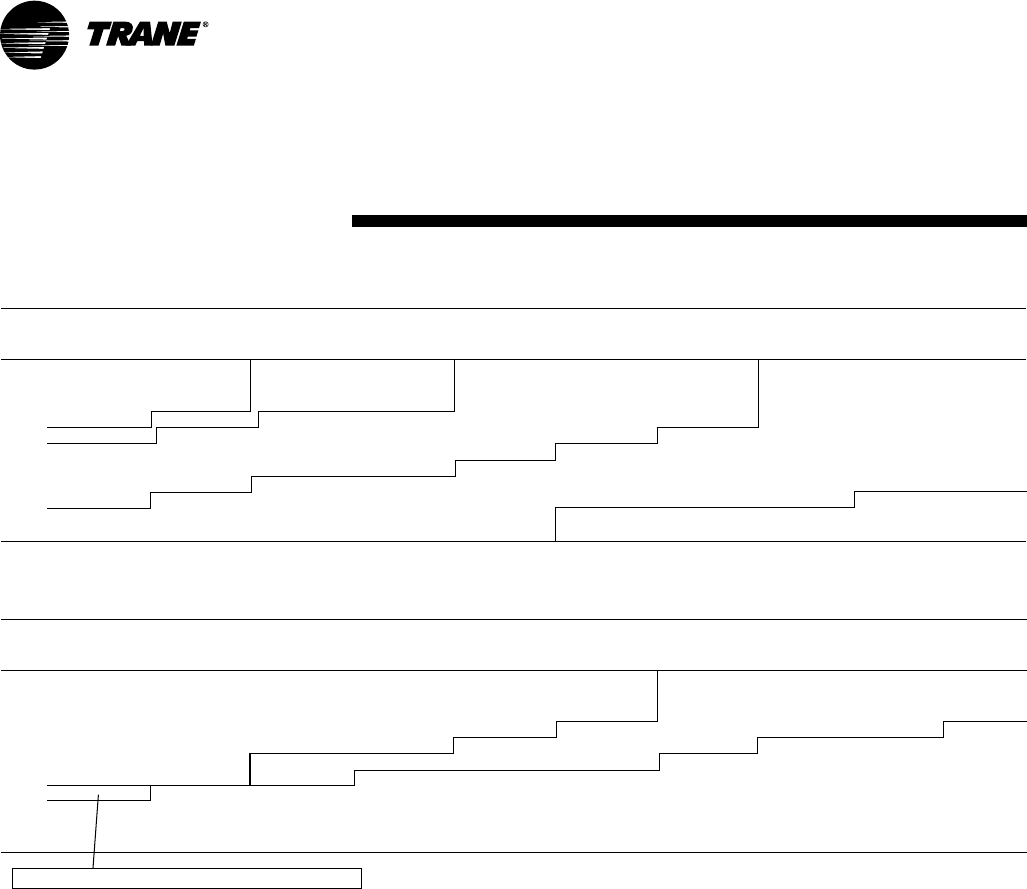
40 RT-PRC002-EN
Performance
Data
(15 Ton)
High Efficiency
Factory supplied motors, in commercial equipment, are
definite purpose motors, specifically designed and tested to
operate reliably and continuously at all cataloged conditions.
Using the full horsepower range of our fan motors as shown
in our tabular data will not result in nuisance tripping or
premature motor failure. Our product’s warranty will not be
affected.
For Standard Evaporator Fan Speed (RPM), reference Table PD-31.
For Standard Motor & High Static Drive Accessory Fan Speed (RPM), reference Table PD-32.
For Oversized Evaporator Fan Speed (RPM), reference Table PD-33.
Table includes Dehumidification (Hot Gas Reheat Option).
*Unit applications below 4800 CFM
• Electric heaters restricted on applications below 4800 CFM.
• Dehumidification (Hot Gas Reheat) or TXV with Frostat and Crankcase Heaters
are required on applications below 4800 CFM.
Fan motor heat (MBH) = 3.15 x Fan BHP
Data includes pressure drop due to wet coils and filters.
No accessories or options are included in pressure drop data.
Refer to Table PD-35 to determine add’l static pressure drop due to other options accessories.
Note:
1. Field Supplied Fan Sheave BK120 Required. Field Supplied Belt may be necessary. Field
Supplied Belt may be necessary.
2. Field Supplied Fan Sheave BK160 Required. Field Supplied Belt may be necessary. Field
Supplied Belt may be necessary.
Table PD-26 — Evaporator Fan Performance — 15 Ton — T*D181C — Continued
External Static Pressure (Inches of Water)
1.10 1.20 1.30 1.40 1.50 1.60 1.70 1.80 1.90 2.00
CFM RPM BHP RPM BHP RPM BHP RPM BHP RPM BHP RPM BHP RPM BHP RPM BHP RPM BHP RPM BHP
3 HP Standard Motor & Drive 3 HP Standard Motor &
High Static Drive Accessory
3000* 646 1.43 669 1.56 692 1.70 714 1.84 734 1.98 755 2.13 775 2.28 793 2.42 813 2.58 830 2.72
3600* 669 1.72 694 1.88 716 2.02 738 2.18 759 2.34 778 2.49 798 2.66 817 2.82 835 2.98 854 3.16
4200* 690 2.06 715 2.23 737 2.39 760 2.57 782 2.74 803 2.92 822 3.09 842 3.28 861 3.46 878 3.64
4800 711 2.44 735 2.63 758 2.81 780 3.00 802 3.19 823 3.38 843 3.58 864 3.78 882 3.97 901 4.17
5400 734 2.89 758 3.09 780 3.29 801 3.49 822 3.69 844 3.91 864 4.12 883 4.33 903 4.55 921 4.76
6000 761 3.42 782 3.63 804 3.84 824 4.05 845 4.27 865 4.49 885 4.72 904 4.95 923 5.18 941 5.41
6600 789 4.05 810 4.26 831 4.49 850 4.71 870 4.94 889 5.18 908 5.41 927 5.65 — — — —
7200 819 4.76 840 5.00 859 5.23 879 5.47 898 5.72 — — ————————
5 HP Oversized Motor & Drive
Table PD-26 — Evaporator Fan Performance — 15 Ton — T*D181C — Dehumidification (Hot Gas Reheat) Option
External Static Pressure (Inches of Water)
.10 .20 .30 .40 .50 .60 .70 .80 .90 1.00
CFM RPM BHP RPM BHP RPM BHP RPM BHP RPM BHP RPM BHP RPM BHP RPM BHP RPM BHP RPM BHP
3 HP Standard Motor w/Field 3 HP Standard Motor w/Field 3 HP Standard Motorw/Field Supplied
Supplied Motor Sheave (2) Supplied Motor Sheave (1) Low Static Drive Fan Sheave
3000* 295 0.26 346 0.35 391 0.45 432 0.56 471 0.68 506 0.80 539 0.92 569 1.04 596 1.17 622 1.30
3600* 333 0.40 379 0.51 420 0.62 458 0.74 494 0.87 527 1.00 559 1.14 589 1.28 617 1.43 644 1.57
4200* 373 0.60 415 0.72 452 0.85 487 0.98 520 1.12 551 1.26 581 1.41 610 1.57 638 1.73 664 1.89
4800 414 0.84 452 0.99 487 1.13 519 1.27 550 1.43 579 1.59 607 1.74 635 1.91 660 2.08 686 2.26
5400 455 1.14 491 1.32 524 1.48 554 1.64 582 1.80 610 1.98 637 2.15 662 2.33 687 2.51 710 2.70
6000 497 1.51 531 1.73 561 1.91 590 2.08 617 2.26 643 2.44 667 2.63 692 2.83 715 3.02 739 3.22
6600 540 1.96 572 2.20 601 2.42 628 2.61 653 2.80 678 2.99 701 3.20 724 3.41 746 3.61 768 3.83
7200 583 2.50 613 2.75 641 3.02 666 3.23 690 3.44 714 3.65 736 3.86 758 4.08 778 4.30 799 4.53
3 HP Standard Motor & Drive 5 HP Oversized Motor & Drive
3 HP Standard Motor & High Static Drive Accessory

41
RT-PRC002-EN
Performance
Data
(17½ Ton)
High Efficiency
*Indicates both downflow and horizontal units.
Table PD-27 — Evaporator Fan Performance — 17½ Ton — TC*211C — Standard or TXV Refrigeration System
External Static Pressure (Inches of Water)
.10 .20 .30 .40 .50 .60 .70 .80 .90 1.00
CFM RPM BHP RPM BHP RPM BHP RPM BHP RPM BHP RPM BHP RPM BHP RPM BHP RPM BHP RPM BHP
5 HP Standard Motor 5 HP Standard Motor &
& Field Supplied Extra Field Supplied Low Static Drive (1)
Low Static Drive (2)
3500* — — — — — — 448 0.66 488 0.78 523 0.91 557 1.05 590 1.20 622 1.35 652 1.50
4550* — — — — 457 0.90 490 1.03 524 1.17 557 1.32 590 1.48 621 1.64 649 1.80 676 1.97
5600 452 1.14 487 1.30 518 1.45 547 1.60 575 1.75 602 1.91 629 2.08 656 2.26 683 2.43 710 2.63
6300 499 1.63 532 1.76 561 1.94 588 2.10 614 2.26 639 2.43 663 2.60 687 2.79 711 2.99 735 3.19
7000 546 2.11 578 2.31 606 2.52 631 2.71 655 2.89 678 3.07 701 3.25 723 3.44 744 3.64 766 3.85
7700 594 2.75 625 2.98 651 3.21 675 3.43 698 3.64 720 3.84 741 4.03 761 4.23 782 4.44 801 4.65
8400 642 3.52 671 3.78 697 4.03 720 4.27 741 4.51 762 4.73 782 4.95 802 5.16 821 5.38 840 5.60
For Standard Evaporator Fan Speed (RPM), reference Table PD-31.
For Standard Motor & High Static Drive Accessory Fan Speed (RPM), reference Table PD-32.
For Oversized Evaporator Fan Speed (RPM), reference Table PD-33.
*Unit applications below 5600 CFM
• Electric heaters restricted on applications below 5600 CFM.
• Dehumidification (Hot Gas Reheat) or TXV with Frostat and Crankcase Heaters
are required on applications below 5600 CFM.
Fan motor heat (MBH) = 3.15 x Fan BHP
Data includes pressure drop due to wet coils and filters.
No accessories or options are included in pressure drop data.
Refer to Table PD-35 to determine add’l static pressure drop due to other options/accessories.
Note:
1. Field Supplied Fan Sheave BK190 Required. Field Supplied Belt may be necessary.
Factory supplied motors, in commercial equipment, are
definite purpose motors, specifically designed and tested to
operate reliably and continuously at all cataloged conditions.
Using the full horsepower range of our fan motors as shown
in our tabular data will not result in nuisance tripping or
premature motor failure. Our product’s warranty will not be
affected.
Table PD-27— Evaporator Fan Performance — 17½ Ton — TC*211C — Continued
External Static Pressure (Inches of Water)
1.10 1.20 1.30 1.40 1.50 1.60 1.70 1.80 1.90 2.00
CFM RPM BHP RPM BHP RPM BHP RPM BHP RPM BHP RPM BHP RPM BHP RPM BHP RPM BHP RPM BHP
5 HP Standard Motor & Drive 5 HP Standard Motor & High
Static Drive Accessory
3500* 680 1.65 707 1.80 732 1.95 756 2.11 779 2.27 801 2.43 822 2.60 843 2.77 863 2.94 882 3.11
4550* 703 2.15 729 2.34 754 2.54 779 2.73 803 2.92 827 3.11 849 3.31 871 3.50 892 3.70 913 3.89
5600 736 2.83 761 3.03 785 3.23 807 3.43 829 3.64 851 3.86 872 4.09 893 4.32 914 4.56 935 4.80
6300 759 3.38 783 3.59 807 3.82 830 4.04 853 4.27 874 4.49 894 4.72 913 4.95 933 5.19 952 5.43
7000 788 4.07 810 4.29 831 4.51 852 4.74 874 4.97 895 5.22 917 5.47 937 5.72 957 5.97 975 6.22
7700 821 4.87 841 5.10 861 5.34 881 5.59 900 5.83 919 6.07 939 6.32 958 6.58 978 6.85 997 7.12
8400 858 5.82 876 6.06 894 6.30 912 6.55 930 6.81 949 7.08 967 7.34 984 7.60 1002 7.87 — —
7.5 Oversize Motor & Drive
5 HP Standard Motor &
High Static Drive Accessory

42 RT-PRC002-EN
Performance
Data
(20 Ton)
High Efficiency
For Standard Evaporator Fan Speed (RPM), reference Table PD-31.
For Standard Motor & High Static Drive Accessory Fan Speed (RPM), reference Table PD-32.
For Oversized Evaporator Fan Speed (RPM), reference Table PD-33.
*Unit applications below 6400 CFM
• Electric heaters restricted on applications below 6400 CFM.
• Dehumidification (Hot Gas Reheat) or TXV with Frostat and Crankcase Heaters
are required on applications below 6400 CFM.
Fan motor heat (MBH) = 3.15 x Fan BHP
Data includes pressure drop due to wet coils and filters.
No accessories or options are included in pressure drop data.
Refer to Table PD-35 to determine add’l static pressure drop due to other options/accessories.
Notes:
1. Field Supplied Fan Sheave BK190 Required. Field Supplied Belt may be necessary.
2. 7.5 HP Standard Motor with Field Supplied Motor Sheave 1VP50 Required. Field Supplied Belt
may be necessary.
3. Field Supplied Fan Sheave B5V200 and Motor Sheave IVP34 required. Field Supplied Belt may
be necessary.
Factory supplied motors, in commercial equipment, are
definite purpose motors, specifically designed and tested to
operate reliably and continuously at all cataloged conditions.
Using the full horsepower range of our fan motors as shown
in our tabular data will not result in nuisance tripping or
premature motor failure. Our product’s warranty will not be
affected.
*Indicates both downflow and horizontal units.
Table PD-28 — Evaporator Fan Performance — 20 Ton — TC*241C — Standard or TXV Refrigeration System
External Static Pressure (Inches of Water)
.10 .20 .30 .40 .50 .60 .70 .80 .90 1.00
CFM RPM BHP RPM BHP RPM BHP RPM BHP RPM BHP RPM BHP RPM BHP RPM BHP RPM BHP RPM BHP
5 HP Standard Motor & Field Supplied 5 HP Standard Motor & Field
Extra Low Static Drive (3) Supplied Low Static Drive (1)
4000* — — — — 428 0.69 467 0.82 504 0.95 538 1.08 572 1.23 603 1.38 632 1.55 660 1.71
5200* 426 0.94 463 1.09 494 1.22 524 1.35 555 1.51 585 1.67 614 1.83 642 2.00 670 2.17 696 2.35
6400 506 1.64 540 1.84 570 2.03 595 2.19 620 2.34 644 2.51 669 2.69 693 2.89 717 3.09 741 3.29
7200 560 2.28 592 2.50 620 2.72 646 2.92 668 3.10 690 3.27 711 3.45 733 3.65 755 3.86 777 4.08
8000 616 3.07 645 3.31 672 3.56 696 3.80 719 4.02 739 4.22 759 4.41 778 4.60 797 4.81 817 5.03
8800 671 4.04 698 4.29 724 4.55 747 4.83 769 5.10 790 5.34 808 5.56 826 5.77 844 5.98 861 6.20
9600 728 5.19 753 5.46 776 5.74 799 6.04 820 6.34 840 6.63 859 6.90 876 7.14 893 7.37 909 7.59
5 HP Standard Motor & Drive (2) 7.5 HP Oversized Motor & Drive
Table PD-28 — Evaporator Fan Performance — 20 Ton — TC*241C — Continued
External Static Pressure (Inches of Water)
1.10 1.20 1.30 1.40 1.50 1.60 1.70 1.80 1.90 2.00
CFM RPM BHP RPM BHP RPM BHP RPM BHP RPM BHP RPM BHP RPM BHP RPM BHP RPM BHP RPM BHP
5 HP Standard Motor & Drive 5 HP Standard Motor
& High Static Drive Accessory
4000* 688 1.87 714 2.03 739 2.20 764 2.36 787 2.53 810 2.70 831 2.87 852 3.05 873 3.23 892 3.41
5200* 722 2.54 747 2.73 771 2.93 795 3.14 817 3.35 839 3.56 861 3.77 882 3.98 902 4.19 923 4.41
6400 765 3.49 788 3.70 810 3.91 832 4.12 854 4.34 875 4.57 896 4.80 916 5.04 936 5.29 955 5.54
7200 799 4.31 820 4.53 841 4.76 862 4.99 883 5.22 902 5.46 922 5.69 942 5.94 961 6.19 980 6.44
8000 837 5.26 857 5.51 876 5.76 896 6.01 915 6.26 934 6.52 953 6.77 971 7.03 989 7.29 — —
8800 879 6.43 897 6.67 915 6.93 933 7.19 951 7.46 969 7.74 986 8.01 — — — — — —
9600 925 7.83 941 8.07 958 8.32 974 8.58 — — — — — — — — — — — —
7.5 HP Oversized Motor & Drive
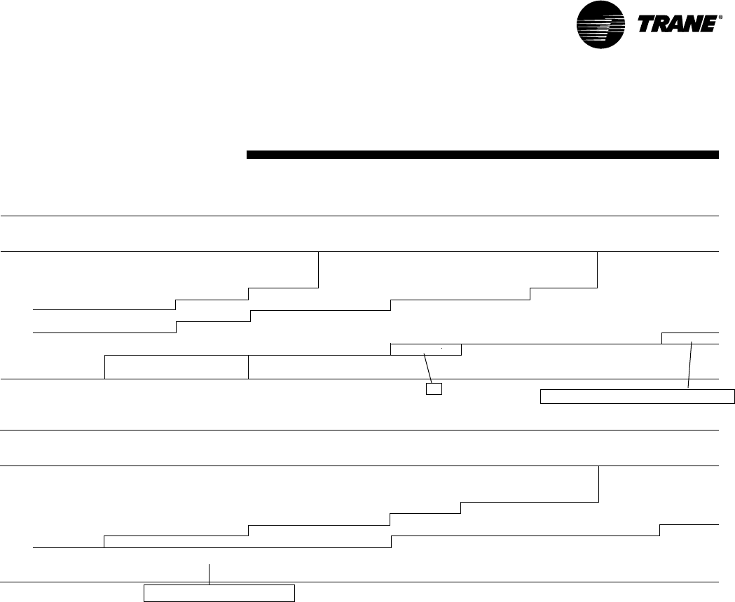
43
RT-PRC002-EN
Performance
Data
(20 Ton)
High Efficiency
For Standard Evaporator Fan Speed (RPM), reference Table PD-31.
For Standard Motor & High Static Drive Accessory Fan Speed (RPM), reference Table PD-32.
For Oversized Evaporator Fan Speed (RPM), reference Table PD-33.
Table includes Dehumidification (Hot Gas Reheat Option).
*Unit applications below 6400 CFM
• Electric heaters restricted on applications below 6400 CFM.
• Dehumidification (Hot Gas Reheat) or TXV with Frostat and Crankcase Heaters
are required on applications below 6400 CFM.
Fan motor heat (MBH) = 3.15 x Fan BHP
Data includes pressure drop due to wet coils and filters.
No accessories or options are included in pressure drop data.
Refer to Table PD-35 to determine add’l static pressure drop due to other options/accessories.
Notes:
1. Field Supplied Motor Sheave IVP34 Required. Field Supplied Belt may be necessary.
2. Field Supplied Fan Sheave BK190 Required. Field Supplied Belt may be necessary.
3. 7.5 HP Standard Motor with Field Supplied Motor Sheave 1VP50 Required. Field Supplied Belt
may be necessary.
Factory supplied motors, in commercial equipment, are
definite purpose motors, specifically designed and tested to
operate reliably and continuously at all cataloged conditions.
Using the full horsepower range of our fan motors as shown
in our tabular data will not result in nuisance tripping or
premature motor failure. Our product’s warranty will not be
affected.
Table PD-29 — Evaporator Fan Performance — 20 Ton — T*D241C — Dehumidification (Hot Gas Reheat) Option
External Static Pressure (Inches of Water)
.10 .20 .30 .40 .50 .60 .70 .80 .90 1.00
CFM RPM BHP RPM BHP RPM BHP RPM BHP RPM BHP RPM BHP RPM BHP RPM BHP RPM BHP RPM BHP
5 HP Standard Motor & Field 5 HP Standard Motor & Drive & Field Supplied 5 HP Standard
Supplied Fan Sheave (1) Low Static Fan Sheave Motor & Drive
4000* — — — — 441 0.77 477 0.90 511 1.03 543 1.17 573 1.32 603 1.47 631 1.63 658 1.78
4800* 414 0.84 452 0.99 487 1.13 519 1.27 550 1.43 579 1.59 607 1.74 635 1.91 660 2.08 686 2.26
5600* 469 1.25 504 1.45 536 1.61 566 1.78 594 1.95 620 2.12 647 2.30 672 2.49 696 2.67 720 2.87
6400 525 1.80 558 2.03 588 2.24 615 2.42 641 2.61 666 2.80 689 3.00 713 3.20 736 3.41 758 3.62
7200 583 2.50 613 2.75 641 3.02 666 3.23 690 3.44 714 3.65 736 3.86 758 4.08 778 4.30 799 4.53
8000 641 3.37 669 3.64 695 3.93 719 4.21 742 4.45 763 4.67 785 4.91 805 5.14 825 5.38 844 5.62
8800 699 4.42 725 4.72 750 5.03 773 5.35 794 5.65 815 5.91 835 6.15 854 6.41 873 6.66 892 6.93
9600 758 5.67 782 6.00 805 6.32 827 6.68 848 7.04 867 7.35 886 7.63 904 7.90 923 8.18 941 8.46
7.5 HP Oversized Motor & Drive
Table PD-29 — Evaporator Fan Performance — 20 Ton — T*D241C — Continued
External Static Pressure (Inches of Water)
1.10 1.20 1.30 1.40 1.50 1.60 1.70 1.80 1.90 2.00
CFM RPM BHP RPM BHP RPM BHP RPM BHP RPM BHP RPM BHP RPM BHP RPM BHP RPM BHP RPM BHP
5 HP Standard Motor & Drive 5 HP Standard Motor
& High Static Drive
4000* 684 1.94 708 2.10 731 2.27 753 2.43 775 2.60 795 2.77 814 2.94 834 3.12 852 3.29 870 3.47
4800* 711 2.44 735 2.63 758 2.81 780 3.00 802 3.19 823 3.38 843 3.58 864 3.78 882 3.97 901 4.17
5600* 743 3.06 765 3.26 787 3.46 809 3.67 830 3.88 850 4.09 871 4.31 890 4.53 910 4.75 929 4.98
6400 779 3.82 800 4.04 821 4.26 841 4.48 861 4.70 881 4.93 899 5.16 919 5.41 938 5.66 956 5.90
7200 819 4.76 840 5.00 859 5.23 879 5.47 898 5.72 916 5.96 933 6.19 952 6.46 968 6.70 987 6.97
8000 863 5.87 881 6.12 900 6.38 918 6.64 936 6.90 954 7.16 971 7.42 988 7.69 — — — —
8800 909 7.19 927 7.46 944 7.73 961 8.01 978 8.29 994 8.56 ————————
9600 — — — — — — — — — — — — ————————
7.5 HP Oversized Motor & Drive
(3) 5 HP Standard Motor & High StaticDrive
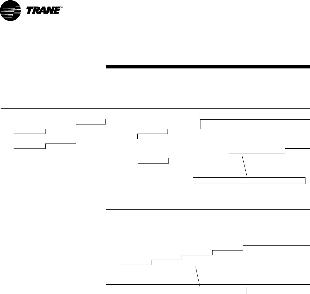
44 RT-PRC002-EN
Performance
Data
(25 Ton)
High Efficiency
*Indicates both downflow and horizontal units.
For Standard Evaporator Fan Speed (RPM), reference Table PD-31.
For Standard Motor & High Static Drive Accessory Fan Speed (RPM),
reference Table PD-32.
For Standard Motor & Low Static Drive Accessory Fan Speed (RPM),
reference Table PD-34.
Fan motor heat (MBH) = 3.15 x Fan BHP
*Unit applications below 8000 CFM
• Electric heaters restricted on applications below 8000
CFM.
• Dehumidification (Hot Gas Reheat) or TXV with Frostat
and Crankcase Heaters are required on applications
below 8000 CFM.
Notes:
Data includes pressure drop due to wet coils and filters.
No accessories or options are included in pressure drop data.
Refer to Table PD-35 to determine add’l static pressure drop due to
other options/accessories.
Factory supplied motors, in commercial
equipment, are definite purpose motors,
specifically designed and tested to operate
reliably and continuously at all cataloged
conditions. Using the full horsepower range
of our fan motors as shown in our tabular
data will not result in nuisance tripping or
premature motor failure. Our product’s
warranty will not be affected.
Table PD-30 — Evaporator Fan Performance — 25 Ton — TC*301C — Standard Refrigeraton System
External Static Pressure (Inches of Water)
.10 .20 .30 .40 .50 .60 .70 .80 .90 1.00
CFM RPM BHP RPM BHP RPM BHP RPM BHP RPM BHP RPM BHP RPM BHP RPM BHP RPM BHP RPM BHP
7.5 HP Standard Motor & Field Supplied Extra Low Static Drive (1) 7.5 HP Standard Motor & Low Static Drive Accessory
5000* — — — — — — — — — — 576 1.56 606 1.71 635 1.88 663 2.05 690 2.22
6500* — — — — 576 2.11 601 2.27 625 2.43 649 2.59 674 2.78 698 2.97 722 3.18 746 3.38
7000* — — 579 2.32 608 2.54 633 2.73 656 2.89 678 3.06 700 3.25 723 3.44 745 3.65 768 3.87
7500* 582 2.59 611 2.78 640 3.02 665 3.24 687 3.43 708 3.61 729 3.79 749 3.98 770 4.19 792 4.41
8000 616 3.07 645 3.31 672 3.56 696 3.80 719 4.02 739 4.22 759 4.41 778 4.60 797 4.81 817 5.03
8500 650 3.66 678 3.90 704 4.16 728 4.43 750 4.68 771 4.90 790 5.10 808 5.31 826 5.52 844 5.74
9000 685 4.31 712 4.56 737 4.83 760 5.12 782 5.39 802 5.65 821 5.88 839 6.09 856 6.30 873 6.53
9500 721 5.04 746 5.30 770 5.58 792 5.88 814 6.18 834 6.46 853 6.72 870 6.96 887 7.18 903 7.41
10000 756 5.85 780 6.12 803 6.41 825 6.72 846 7.04 866 7.35 884 7.64 902 7.90 918 8.14 934 8.38
10500 791 6.74 814 7.03 836 7.33 858 7.64 878 7.98 898 8.31 916 8.62 — — — — — —
11000 827 7.71 849 8.02 870 8.33 891 8.63 — — — — — — — — — — — —
7.5 HP Standard Motor & Drive
7.5 HP Standard Motor & Higher Static Drive Accessory
Table PD-30 — Evaporator Fan Performance — 25 Ton — TC*301C — Continued
External Static Pressure (Inches of Water)
1.10 1.20 1.30 1.40 1.50
CFM RPM BHP RPM BHP RPM BHP RPM BHP RPM BHP
7.5 HP Standard Motor & Drive
5000* 716 2.41 741 2.60 765 2.80 789 3.00 812 3.20
6500* 769 3.59 792 3.80 814 4.01 836 4.22 857 4.44
7000* 790 4.09 812 4.31 833 4.53 854 4.76 875 4.99
7500* 813 4.65 833 4.88 854 5.12 874 5.36 894 5.59
8000 837 5.26 857 5.51 876 5.76 896 6.01 915 6.26
8500 863 5.97 881 6.21 900 6.46 919 6.73 937 6.99
9000 890 6.76 908 7.00 925 7.25 943 7.52 961 7.79
9500 919 7.64 936 7.88 952 8.13 969 8.40 985 8.67
10000 949 8.62 — — — — — — — —
10500 — — — — — — — — — —
11000 — — — — — — — — — —
7.5 HP Standard Motor & High Static Drive Accessory

45
RT-PRC002-EN
(12½-25 Ton)
Performance
Data
*Indicates both downflow and horizontal units.
Table PD-31— Standard Motor & Drive/Fan Speed (Rpm)
Unit 6 Turns 5 Turns 4 Turns 3 Turns 2 Turns 1 Turn
Tons Model No. Open Open Open Open Open Open Closed
TC*150D3,4,W, TC*151C3,4,W 640 680 720 760 800 840 N/A
12½ TC*150DK 705 756 806 857 907 957 N/A
TC*180B3,4,W 679 721 764 806 849 891 N/A
15 TC*180BK N/A 680 733 785 837 889 941
TC*181C3,4,W 560 600 640 680 720 760 N/A
TC*210C3,4,W 869 923 978 1032 1087 1141 N/A
17½ TC*210CK 869 924 978 1032 1087 1141 N/A
TC*211C3,4,W 615 659 703 747 791 835 N/A
TC*240B3,4,W, TC*241C3,4,W 615 659 703 747 791 835 N/A
20 TC*240BK 590 627 664 701 738 775 N/A
TC*300B/301C3,4,W 705 742 779 817 854 891 N/A
25 TC*300BK 701 738 775 812 849 886 N/A
Factory set at 3 turns open.
Table PD-32— Standard Motor & High Static Drive Accessory/Fan Speed (Rpm)
Unit 6 Turns 5 Turns 4 Turns 3 Turns 2 Turns 1 Turn
Tons Model No. Open Open Open Open Open Open Closed
12½ TC*151C3,4,W 807 857 908 958 1009 1059 N/A
TC*180B3,4,W 806 849 891 934 976 1019 N/A
15 TC*181B3,4,W 640 680 720 760 800 840 N/A
17½ TC*211C3,4,W 835 879 923 967 1011 1055 N/A
20 TC*240B/241C3,4,W 835 879 923 967 1011 1055 N/A
25 TC*300B/301C3,4,W 816 853 890 928 965 1002 N/A
Table PD-33— Oversized Motor & Drive/Fan Speed (Rpm)
Unit 6 Turns 5 Turns 4 Turns 3 Turns 2 Turns 1 Turn
Tons Model No. Open Open Open Open Open Open Closed
12½ TC*150D,151C3,4,W 869 923 978 1032 1087 1141 N/A
TC*180B3,4,W 806 856 907 957 1008 1058 N/A
15 TC*181C3,4,W 705 755 806 856 907 957 N/A
TC*210C3,4,W 949 1008 1068 1127 1187 1246 N/A
17½ TC*211C3,4,W 816 853 890 928 965 1002 N/A
20 TC*240B/241C3,4,W 816 853 890 928 965 1002 N/A
Table PD-34 — Standard Motor & Low Static Fan Drive
Unit 6 Turns 5 Turns 4 Turns 3 Turns 2 Turns 1 Turn
Tons Model No. Open Open Open Open Open Open Closed
17½ TC*210C3,4,W 705 755 806 856 907 957 N/A
25 TC*300B/301C3,4,W 594 631 668 705 742 779 N/A

46 RT-PRC002-EN
(12½-25 Ton)
Performance
Data
*Indicates both downflow and horizontal units.
Table PD-35 — Static Pressure Drops Through Accessories (Inches Water Column)
Economizer with Electric Heater
Unit Standard Through 2 Inch OA/RA Dampers2Accessory (KW)3
Tons Model No. CFM Filters1Reheat Coil Pleated Filters4100% OA 100% RA 5-12 14-27 36 54 72
4000 0.05 — 0.08 0.19 0.02 — 0.03 0.03 0.04 —
5000 0.07 — 0.11 0.26 0.03 — 0.04 0.05 0.06 —
TC*150D, TCH151C 6000 0.10 — 0.15 0.33 0.04 — 0.06 0.07 0.09 —
12½ 2500 0.02 0.01 0.03 0.07 0.01 — * * * —
4000 0.05 0.03 0.08 0.19 0.02 — 0.03 0.03 0.04 —
TCD151C 5000 0.07 0.05 0.11 0.26 0.03 — 0.04 0.05 0.06 —
6000 0.10 0.06 0.15 0.33 0.04 — 0.06 0.07 0.09 —
4800 0.07 — 0.10 0.25 0.03 — 0.04 0.04 0.05 —
TC*180B 6000 0.10 — 0.15 0.33 0.04 — 0.06 0.07 0.08 —
7200 0.15 — 0.19 0.40 0.05 — 0.09 0.10 0.12 —
3000 0.02/0.01 0.01 0.03/0.02 0.07 0.03 — * * * —
4800 0.04/0.03 0.02 0.07/0.06 0.14 0.03 — 0.04 0.04 0.05 —
15 TCD181C 6000 0.06/0.05 0.03 0.10/0.09 0.20 0.04 — 0.06 0.07 0.08 —
7200 0.09/0.07 0.04 0.13/0.11 0.27 0.05 — 0.09 0.10 0.12 —
4800 0.04/0.03 — 0.07/0.06 0.14 0.03 — 0.04 0.04 0.05 —
TCH181C 6000 0.06/0.05 — 0.10/0.09 0.20 0.04 — 0.06 0.07 0.08 —
7200 0.09/0.07 — 0.13/0.11 0.27 0.05 — 0.09 0.10 0.12 —
5600 0.09 — 0.13 0.30 0.04 — — 0.06 0.07 —
TC*210C 7000 0.14 — 0.18 0.39 0.05 — — 0.10 0.11 —
8400 0.20 — 0.24 0.47 0.06 — — 0.15 0.17 —
3500 0.02/0.02 — 0.03/0.03 0.09 0.03 — — * * *
5600 0.06/0.05 — 0.09/0.08 0.18 0.04 — — 0.05 0.06 0.07
17½ TCD211C 7000 0.09/0.07 — 0.13/0.11 0.26 0.04 — — 0.08 0.09 0.11
8400 0.12/0.10 — 0.17/0.14 0.35 0.06 — — 0.12 0.13 0.16
5600 0.06/0.05 — 0.09/0.08 0.18 0.04 — — 0.05 0.06 0.07
TCH211C 7000 0.09/0.07 — 0.13/0.11 0.26 0.04 — — 0.08 0.09 0.11
8400 0.12/0.10 — 0.17/0.14 0.35 0.06 — — 0.12 0.13 0.16
6400 0.07 — 0.11 0.22 0.04 — — 0.06 0.08 0.09
TCD240B 8000 0.11 — 0.15 0.32 0.05 — — 0.10 0.12 0.14
9600 0.16 — 0.20 0.44 0.07 — — 0.14 0.17 0.20
4000 0.03 0.02 0.04 0.11 0.03 — — * * *
6400 0.07 0.04 0.11 0.22 0.04 — — 0.06 0.08 0.09
20 TCD241C 8000 0.11 0.05 0.15 0.32 0.05 — — 0.10 0.12 0.14
9600 0.16 0.07 0.20 0.44 0.07 — — 0.14 0.17 0.20
6400 0.06 — 0.10 0.22 0.04 — — 0.06 0.08 0.09
TCH240B, TCH241C 8000 0.09 — 0.13 0.32 0.05 — — 0.10 0.12 0.14
9600 0.13 — 0.17 0.44 0.07 — — 0.14 0.17 0.20
7000 0.09 — 0.13 0.26 0.04 — — 0.08 0.10 0.11
TCD300B 9000 0.14 — 0.18 0.40 0.07 — — 0.13 0.15 0.18
11000 0.21 — 0.25 0.57 0.10 — — 0.18 0.22 0.26
5000 0.04 — 0.06 0.15 0.03 — — * * *
7000 0.09 — 0.13 0.26 0.04 — — 0.08 0.10 0.11
25 TCD301C 9000 0.14 — 0.18 0.40 0.07 — — 0.13 0.15 0.18
11000 0.21 — 0.25 0.57 0.10 — — 0.18 0.22 0.26
7000 0.07 — 0.11 0.26 0.04 — — 0.08 0.10 0.11
TCH300B, TCH301C 9000 0.11 — 0.15 0.40 0.07 — — 0.13 0.15 0.18
11000 0.17 — 0.22 0.60 0.10 — — 0.18 0.22 0.26
Notes:
1. Tested with: 2” filters 12½-25 tons
2. OA = Outside Air and RA = Return Air.
3. Nominal KW ratings at 240, 480, 600 volts.
4. Difference in pressure drop should be considered when utilizing optional 2” pleated filters.
*Heaters not permitted at airflows below 320 cfm/ton.
47
RT-PRC002-EN
Table PD-36 — Auxiliary Electric Heat Capacity
Total2 Stage1 Stage 2
Unit KW MBH No. of KW MBH KW MBH
Tons Model No. Input1Output1Stages Input1Output1Input1Output1
18.00 61.47 1 18.00 61.47 — —
TC*150D3,D4,DW,DK 27.00492.15 2 9.00 30.72 18.00 61.43
12½-15 TC*180B3,B4,BW,BK 36.00 122.94 2 18.00 61.47 18.00 61.47
TC*151 or 181C3,C4,CW 54.00 184.41 2 36.00 122.94 18.00 61.47
TC*210C3,C4,CW,CK 36.00 122.94 2 18.00 61.47 18.00 61.47
17½, 20, 25 TC*240, 300B3,B4,BW,BK 54.00 184.41 2 36.00 122.94 18.00 61.47
TC*211, 241, 301C3,C4,CW 72.003245.88 2 36.00 122.94 36.00 122.94
Notes:
1. Does not include indoor fan power or heat.
2. Heaters are rated at 240v, 480v. and 600v. For other than rated voltage, CAP = x rated cap.
3. Not available on TC*210C.
4. 27KW heater can be used with TCD181C4, TCD211C4, TCD241C4 andTCD301C4 only. Cannot be used with oversized motor.
(12½-25 Ton)
Performance
Data
Table PD-37 — Electric Heater Voltage
Correction Factors (Applicable to Auxiliary
Heat Capacity)
Nominal Distribution Capacity
Voltage Voltage Multiplier
208 0.75
240 230 0.92
240 1.00
440 0.84
480 460 0.94
480 1.00
540 0.81
600 575 0.92
600 1.00
Rated Voltage
( )
Voltage
Table PD-38 — Air Temperature Rise Across Electric Heaters (Degree F)
12½ Ton 15 Ton 17½ Ton 20 Ton 25 Ton
5000 CFM 6000 CFM 7000 CFM 8000 CFM 9000 CFM
Three Phase Three Phase Three Phase Three Phase Three Phase
TC*150 TC*180 TC*210 TC*240 TC*300
KW Stages TC*151 TC*181 TC*211 TC*241 TC*301
9.00 1 —————
17.30 1 —————
18.00 1 11.4 9.5 — — —
27.00 2 — 14.2212.221 10.729.52
36.00 2 22.8 19.0 16.3 14.2 12.6
54.00 2 34.1 28.5 24.4 21.3 19.0
72.0022 — — 32.5 28.5 25.3
For minimum design airflow, see airflow performance table for each unit.
To calculate temp rise at different air flow, use following formula:
Temp. Rise across Elect. Htr = KW x 3413
1.08 x CFM
Notes:
1. Not available on TC*210 model.
2. 27KW heater can be used with TCD181C4, TCD211C4, TCD241C4 andTCD301C4 only. Cannot be used with oversized motor.
2
48 RT-PRC002-EN
Table PD-39— Hot Gas Reheat Temperature Rise
1,2,3
Leaving Evaporator Dry Bulb [F]1
Tons SCFM 35 40 45 50 55 60 65
2500 23.4 23.8 25.0 26.9 29.5 32.9 37.0
3000 21.4 21.6 22.5 24.0 26.0 28.7 31.9
3500 19.5 19.7 20.4 21.5 23.1 25.2 27.7
12½ 4000 17.8 18.1 18.6 19.6 20.9 22.5 24.5
4500 16.3 16.7 17.3 18.1 19.2 20.5 22.1
5000 14.9 15.5 16.2 17.1 18.0 19.2 20.4
5500 13.5 14.4 15.3 16.2 17.2 18.1 19.1
6000 12.1 13.4 14.6 15.7 16.7 17.6 18.3
Tons SCFM 35 40 45 50 55 60 65
3000 34.4 36.7 38.9 41.2 43.5 45.8 48.1
3600 29.3 31.2 33.1 35.0 36.9 38.8 40.8
4200 25.4 27.0 28.6 30.2 31.9 33.5 35.1
15 4800 22.3 23.7 25.1 26.5 27.9 29.3 30.7
5400 19.9 21.2 22.4 23.7 24.9 26.2 27.4
6000 18.0 19.1 20.3 21.4 22.5 23.7 24.8
6600 16.4 17.5 18.6 19.6 20.7 21.7 22.8
7200 15.1 16.1 17.1 18.1 19.1 20.1 21.1
Tons SCFM 35 40 45 50 55 60 65
4000 22.0 22.5 23.6 25.4 27.7 30.6 34.0
4800 19.1 19.8 20.9 22.3 24.0 26.1 28.5
5600 16.6 17.4 18.4 19.5 20.9 22.4 24.0
20 6400 14.7 15.5 16.3 17.2 18.2 19.3 20.6
7200 13.5 14.1 14.7 15.4 16.2 17.0 17.9
8000 12.9 13.2 13.7 14.2 14.8 15.5 16.2
8800 12.5 12.9 13.3 13.7 14.2 14.8 15.4
9600 12.4 12.8 13.1 13.5 13.9 14.5 15.0
Notes:
1. Temperature does not account for indoor fan heat.
2. 70 deg OD Ambient Temperature.
3. For units with the Dehumidification (Hot Gas Reheat) option.
Performance
Data
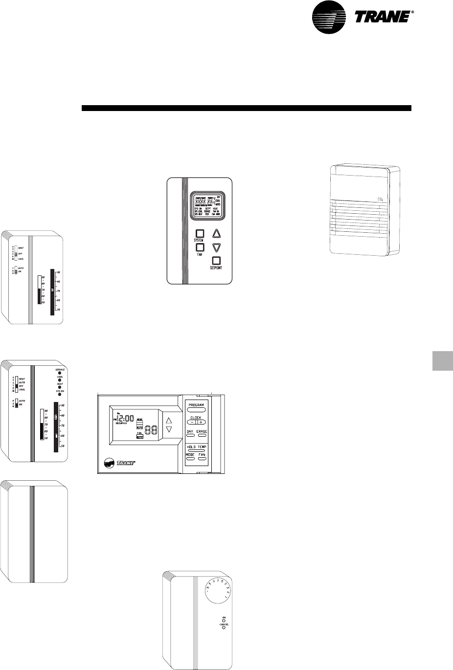
49
RT-PRC002-EN
Controls
Programmable Night Setback
Auto or manual changeover with seven-
day programming. Keyboard selection
of Heat, Cool, Fan, Auto, or On. All
programmable sensors have System On,
Heat, Cool, Service LED/indicators as
standard. Night Setback Sensors have
one (1) Occupied, one (1) Un-occupied,
and two (2) Override programs per day.
Integrated
ComfortTM
System
Sensor(s)
available with
optional
temperature
adjustment and
override buttons
to provide central
control through a
Trane Integrated
Comfort system.
Field Installed Control Options
Zone Sensors
Zone sensors are the building occupant’s
comfort control devices. They replace the
conventional electro-mechanical
thermostats. The following zone sensor
options are available for Voyager units
with the ReliaTel™ control:
Manual Changeover
Heat, Cool or Off
System Switch. Fan
Auto or Off Switch.
One temperature
setpoint lever.
Manual/Automatic Changeover
Auto, Heat, Cool or Off System Switch.
Fan Auto or Off
Switch. Two
temperature
setpoint levers.
Optional Status
Indication LED lights,
System On, Heat,
Cool, or Service.
Remote Sensor
Sensor(s) available
for all zone sensors to
provide remote
sensing capabilities.
Dual Thermistor Remote Zone Sensor
This sensor will allow the customer to
reduce the total number of remote
sensors to obtain space temperature
averaging. This sensor should be utilized
with ReliaTel controls.
Digital Display Zone Sensor
The Digital LCD (Liquid Crystal Display)
zone sensor has the look and functionality
of standard zone
sensors. This
sensor includes a
digital display of
set point
adjustment and
space temperature
in F (Fahrenheit) or
C (Celsius).
Includes FAN and
SYSTEM buttons
(supports the
service functions of
the standard
sensor). E-squared memory stores last
programmed set points. Requires 24 VAC
(Volts AC). This sensor should be utilized
with ReliaTel controls.
Economizer Controls
The standard equipment offering is a
fixed dry bulb changeover control. In
addition, there are two optional controls,
Enthalpy and Differential Enthalpy
Control.
Enthalpy Control
Replaces the dry bulb control with a wet
bulb changeover controller which has a
fully adjustable set point. Enthalpy control
offers a higher level of comfort control,
along with energy savings potential, than
the standard dry bulb control. This is due
to the additional wet bulb sensing
capability.
Differential Enthalpy
Replaces the standard dry bulb control
with two enthalpy sensors that compare
total heat content of the indoor air and
outdoor air to determine the most
efficient air source. This control option
offers the highest level of comfort control,
plus energy efficiency, available.
Remote Potentiometer
Minimum position setting of economizer
can be remotely adjusted with this
accessory.
Differential Pressure Switches
This factory or field-installed option
allows individual fan failure and dirty filter
indication. The fan failure switch will
disable all unit functions and “flash” the
Service LED on the zone sensor. The dirty
filter switch will light the Service LED on
the zone sensor and will allow continued
unit operation.
Trane Communication Interface (TCI)
This factory or field-installed micro-
processor interface allows the unit to
communicate to Trane’s Integrated
Comfort system.
CO2 Sensing The CO2 sensor has the
ability to monitor space occupancy levels
within the
building by
measuring the
parts per million
of CO2 (Carbon
Dioxide) in the air.
As the CO2 levels
increase, the
outside air
damper
modulates to
meet the CO2 space ventilation
requirements. The CO2 sensor kit is
available as a field installed accessory.
50 RT-PRC002-EN
*Indicates both downflow and horizontal units.
Electrical
Data
Table ED-1 — Unit Wiring — Standard Efficiency
Standard Indoor Fan Motor Oversize Indoor Fan Motor
Unit Minimum Maximum Fuse Minimum Maximum Fuse
Unit Operating Circuit Size or Maximum Circuit Size or Maximum
Tons Model No. Voltage Range Ampacity2Circuit Breaker1Ampacity2Circuit Breaker1
TC*150D3 187-253 63 80 69 80
12½ TC*150D4 414-506 33 40 36 40
TC*150DW 518-633 26 30 28 35
TC*150DK 342-418 43 50 – –
TC*180B3 187-253 78 90 84 100
15 TC*180B4 414-506 39 50 42 50
TC*180BW 517-633 31 40 33 40
TC*180BK 342-418 50 60 – –
TC*210C3 187-253 88 100 96 125
17½ TC*210C4 414-506 44 50 47 60
TC*210CW 517-633 35 45 38 45
TC*210CK 342-418 57 70 – –
TC*240B3 187-253 100 125 107 125
20 TC*240B4 414-506 50 60 54 60
TC*240BW 517-633 40 45 43 50
TC*240BK 342-418 65 80 – –
TC*300B3 187-253 118 150 – –
25 TC*300B4 414-506 58 70 – –
TC*300BW 517-633 46 50 – –
TC*300BK 342-418 70 80 – –
Notes:
1. HACR breaker per NEC.
2. Values do not include power exhaust accessory.
(Standard Efficiency)
51
RT-PRC002-EN
Electrical
Data
Table ED-2 — Unit Wiring With Electric Heat (Single Point Connection) — Standard Efficiency (Downflow Only)
Standard Indoor Motor Oversize Indoor Motor
To Use Heater Heater Control Max Fuse Size or Max Fuse Size or
Tons With Model No. KW Rating1Stages MCA Max Circuit MCA Max Circuit
Breaker2Breaker2
208/230 Volts Three Phase
AYDHTRF318A 13.5/18.0 1 63/68 80/80 69/76 80/80
12½ TCD150D3 AYDHTRF336A 27.0/36.0 2 108/122 110/125 115/130 125/150
AYDHTRF354A 40.5/54.0 2 154/176 175/200 162/184 175/200
AYDHTRK318A 13.5/18.0 1 78/78 100/100 84/84 100/100
15 TCD180B3 AYDHTRK336A 27.0/36.0 2 108/122 110/125 115/130 125/150
AYDHTRK354A 40.5/54.0 2 154/176 175/200 162/184 175/200
AYDHTRL336A 27.0/36.0 2 115/130 125/150 125/139 125/150
17½ TCD210C3 AYDHTRL354A 40.5/54.0 2 162/184 175/200 171/193 175/200
AYDHTRL336A 27.0/36.0 2 115/130 125/150 125/139 125/150
20 TCD240B3 AYDHTRL354A 40.5/54.0 2 162/184 175/200 171/193 175/200
AYDHTRK372A 54.0/72.0 2 209/238 225/250 218/247 225/250
AYDHTRL336A 27.0/36.0 2 125/139 150/150 — —
25 TCD300B3 AYDHTRL354A 40.5/54.0 2 171/193 175/200 — —
AYDHTRK372A 54.0/72.0 2 218/247 225/250 — —
460 Volts Three Phase
AYDHTRL418A 18.0 1 34 40 37 40
12½ TCD150D4 AYDHTRK436A 36.0 2 61 70 64 70
AYDHTRK454A 54.0 2 88 90 91 100
AYDHTRL418A 18.0 1 39 50 42 50
15 TCD180B4 AYDHTRK436A 36.0 2 61 70 64 70
AYDHTRK454A 54.0 2 88 90 91 100
AYDHTRL436A 36.0 2 64 70 68 70
17½ TCD210C4 AYDHTRL454A 54.0 2 91 100 95 100
AYDHTRL436A 36.0 2 64 70 68 70
20 TCD240B4 AYDHTRL454A 54.0 2 91 100 95 100
AYDHTRK472A 72.0 2 118 125 123 125
AYDHTRL436A 36.0 2 68 70 — —
25 TCD300B4 AYDHTRL454A 54.0 2 95 100 — —
AYDHTRK472A 72.0 2 123 125 — —
575 Volts Three Phase
AYDHTRKW18A 18.0 1 27 30 30 35
12½ TCD150DW AYDHTRMW36A 36.0 2 49 50 51 60
AYDHTRKW54A 54.0 2 70 70 73 80
AYDHTRKW18A 18.0 1 31 40 33 40
15 TCD180BW AYDHTRMW36A 36.0 2 49 50 51 60
AYDHTRKW54A 54.0 2 70 70 73 80
AYDHTRMW36A 36.0 2 51 60 55 60
17½ TCD210CW AYDHTRLW54A 54.0 2 73 80 77 80
AYDHTRMW36A 36.0 2 51 60 55 60
20 TCD240BW AYDHTRLW54A 54.0 2 73 80 77 80
AYDHTRKW72A 72.0 2 95 100 98 100
AYDHTRMW36A 36.0 2 55 60 — —
25 TCD300BW AYDHTRLW54A 54.0 2 77 80 — —
AYDHTRKW72A 72.0 2 98 100 — —
Notes:
1. Heater kw ratings are at 208/240 for 208/230V unit, 480V for 460 unit and 600V for 575 unit.
2. HACR type circuit breaker per NEC.
(Standard Efficiency)
52 RT-PRC002-EN
Table ED-2 — Unit Wiring With Electric Heat (Single Point Connection) — Standard Efficiency (Downflow Only), continued
Standard Indoor Motor Oversize Indoor Motor
To Use Heater Heater Control Max Fuse Size or Max Fuse Size or
Tons With Model No. KW Rating1Stages MCA Max Circuit MCA Max Circuit
Breaker2Breaker2
380 Volts Three Phase
AYDHTRL418A 11.3 1 43 50 — —
12½ TCD150DK AYDHTRK436A 22.6 2 55 60 — —
AYDHTRK454A 33.8 2 76 80 — —
AYDHTRL418A 11.3 1 50 60 — —
15 TCD180BK AYDHTRK436A 22.6 2 55 60 — —
AYDHTRK454A 33.8 2 76 80 — —
AYDHTRL436A 22.6 2 60 70 — —
17½ TCD210CK AYDHTRL454A 33.8 2 81 90 — —
AYDHTRL436A 22.6 2 65 80 — —
20 TCD240BK AYDHTRL454A 33.8 2 81 90 — —
AYDHTRK472A 45.1 2 103 110 — —
AYDHTRL436A 22.6 2 70 80 — —
25 TCD300BK AYDHTRL454A 33.8 2 81 90 — —
AYDHTRK472A 45.1 2 103 100 — —
Notes:
1. Heater kw ratings are at 380V for 380 unit.
2. HACR type circuit breaker per NEC.
Electrical
Data (Standard Efficiency)
53
RT-PRC002-EN
Table ED-3 — Unit Wiring With Electric Heat (Single Point Connection) — Standard Efficiency (Horizontal Only)
Standard Indoor Motor Oversize Indoor Motor
To Use Heater Heater Control Max Fuse Size or Max Fuse Size or
Tons With Model No. KW Rating1Stages MCA Max Circuit Breaker2MCA Max Circuit Breaker2
208/230 Volts Three Phase
AYHHTRN318A 13.5/18.0 1 63/68 80/80 69/76 80/80
12½ TCH150D3 AYHHTRN336A 27.0/36.0 2 108/122 110/125 115/130 125/150
AYHHTRN354A 40.5/54.0 2 154/176 175/200 162/184 175/200
AYHHTRN318A 13.5/18.0 1 78/78 100/100 84/84 100/100
15 TCH180B3 AYHHTRP336A 27.0/36.0 2 108/122 110/125 115/130 125/150
AYHHTRP354A 40.5/54.0 2 154/176 175/200 162/184 175/200
AYHHTRQ336A 27.0/36.0 2 115/130 125/150 125/139 125/150
17½ TCH210C3 AYHHTRQ354A 40.5/54.0 2 162/184 175/200 171/193 175/200
AYHHTRN336A 27.0/36.0 2 115/130 125/150 125/139 125/150
20 TCH240B3 AYHHTRN354A 40.5/54.0 2 162/184 175/200 171/193 175/200
AYHHTRN372A 54.0/72.0 2 209/238 225/250 218/247 225/250
AYHHTRN336A 27.0/36.0 2 132/139 150/150 — —
25 TCH300B3 AYHHTRN354A 40.5/54.0 2 171/193 175/200 — —
AYHHTRN372A 54.0/72.0 2 218/247 225/250 — —
460 Volts Three Phase
AYHHTRN418A 18.0 1 34 40 37 40
12½ TCH150D4 AYHHTRN436A 36.0 2 61 70 64 70
AYHHTRP454A 54.0 2 88 90 91 100
AYHHTRN418A 18.0 1 37 50 42 50
15 TCH180B4 AYHHTRP436A 36.0 2 61 70 64 70
AYHHTRP454A 54.0 2 88 90 91 100
AYHHTRQ436A 36.0 2 64 70 68 70
17½ TCH210C4 AYHHTRQ454A 54.0 2 91 100 95 100
AYHHTRN436A 36.0 2 64 70 68 70
20 TCH240B4 AYHHTRN454A 54.0 2 91 100 95 100
AYHHTRN472A 72.0 2 118 125 123 125
AYHHTRN436A 36.0 2 68 70 — —
25 TCH300B4 AYHHTRN454A 54.0 2 95 100 — —
AYHHTRN472A 72.0 2 123 125 — —
575 Volts Three Phase
AYHHTRNW18A 18.0 1 27 30 30 35
12½ TCH150DW AYHHTRPW36A 36.0 2 49 50 51 60
AYHHTRPW54A 54.0 2 70 70 73 80
AYHHTRNW18A 18.0 1 31 40 33 40
15 TCH180BW AYHHTRPW36A 36.0 2 49 50 51 60
AYHHTRPW54A 54.0 2 70 70 73 80
AYHHTRPW36A 36.0 2 51 60 55 60
17½ TCH210CW AYHHTRQW54A 54.0 2 73 80 77 80
AYHHTRMW36A 36.0 2 51 60 55 60
20 TCH240BW AYHHTRNW54A 54.0 2 73 80 77 80
AYHHTRNW72A 72.0 2 95 100 98 100
AYHHTRMW36A 36.0 2 55 60 — —
25 TCH300BW AYHHTRNW54A 54.0 2 77 80 — —
AYHHTRNW72A 72.0 2 98 100 — —
Notes:
1. Heater kw ratings are at 208/240 for 208/230V unit, 480V for 460 unit and 600V for 575 unit..
2. HACR type circuit breaker per NEC.
Electrical
Data (Standard Efficiency)

54 RT-PRC002-EN
Electrical
Data
Table ED-3 — Unit Wiring With Electric Heat (Single Point Connection) — Standard Efficiency (Horizontal Only) continued
Standard Indoor Motor Oversize Indoor Motor
To Use Heater Heater Control Max Fuse Size or Max Fuse Size or
Tons With Model No. KW Rating1Stages MCA Max Circuit MCA Max Circuit
Breaker2Breaker2
380 Volts Three Phase
AYDHTRL418A 11.3 1 43 50 — —
12½ TCD150DK AYDHTRK436A 22.6 2 55 60 — —
AYDHTRK454A 33.8 2 76 80 — —
AYDHTRL418A 11.3 1 50 60 — —
15 TCD180BK AYDHTRK436A 22.6 2 55 60 — —
AYDHTRK454A 33.8 2 76 80 — —
AYDHTRL436A 22.6 2 60 70 — —
17½ TCD210CK AYDHTRL454A 33.8 2 81 90 — —
AYDHTRL436A 22.6 2 65 80 — —
20 TCD240BK AYDHTRL454A 33.8 2 81 90 — —
AYDHTRK472A 45.1 2 103 110 — —
AYDHTRL436A 22.6 2 70 80 — —
25 TCD300BK AYDHTRL454A 33.8 2 81 90 — —
AYDHTRK472A 45.1 2 103 100 — —
Notes:
1. Heater kw ratings are at 380V for 380 unit.
2. HACR type circuit breaker per NEC.
(Standard Efficiency)
55
RT-PRC002-EN
Table ED-4— Electrical Characteristics — Compressor Motor And Condenser Motor — 60 Cycle — Standard Efficiency
Compressor Motors Condenser Fan Motors
Unit Amps1Amps1
Tons Model No. No. Volts Phase HP2RPM RLA LRA No. Phase HP FLA LRA
TC*150D3 2 208-230 3 6.00 3450 20.4 156 2 1 .50 3.2 8.8
TC*150D4 2 460 3 6.00 3450 10.8 75 2 1 .50 1.6 3.8
12½ TC*150DW 2 575 3 6.00 3450 8.3 54 2 1 .50 1.3 3.2
TC*150DK 2 380 3 6.0 3450 13.1 70 2 1 .50 1.9 5.2
TC*180B3 2 208-230 3 9.30/5.10 3450 31.9/20.7 253/128 2 1 .50 3.2 8.8
15 TC*180B4 2 460 3 9.30/5.10 3450 16.3/10.0 113/63 2 1 .50 1.6 3.8
TC*180BW 2 575 3 9.30/5.10 3450 13.1/7.4 85/49 2 1 .50 1.3 3.2
TC*180BK 2 380 3 9.3/5.1 3450 19.7/12.1 125/64 2 1 .50 1.9 5.2
TC*210C3 2 208-230 3 9.3/6.0 3450 31.5/20.8 253/156 2 1 1.00 5.5 18.3
17½ TC*210C4 2 460 3 9.3/6.0 3450 15.9/10.0 113/75 2 1 1.00 2.9 9.3
TC*210CW 2 575 3 9.3/6.0 3450 12.8/8.2 85/54 2 1 1.00 2.0 5.7
TC*210CK 2 380 3 9.3/6.0 3450 19.2/12.1 125/70 2 1 1.00 3.5 8.5
TC*240B3 2 208-230 3 9.30 3450 31.7 253 2 1 1.00 5.5 18.3
20 TC*240B4 2 460 3 9.30 3450 16.2 113 2 1 1.00 2.9 9.3
TC*240BW 2 575 3 9.30 3450 13.0 85 2 1 1.00 2.0 5.7
TC*240BK 2 380 3 9.3 3450 19.6 125 2 1 1.00 3.5 8.5
TC*300B3 2 208-230 3 10.00 3450 36.6 278 2 1 1.00 5.5 18.3
25 TC*300B4 2 460 3 10.00 3450 17.9 124 2 1 1.00 2.9 9.3
TC*300BW 2 575 3 10.00 3450 14.9 92 2 1 1.00 2.0 5.7
TC*300BK 2 380 3 10.0 3450 21.7 137 2 1 1.00 3.5 8.5
Notes:
1. Amp draw for each motor; multiply value by numbers of motors to determine total amps.
2. HP for each compressor.
Electrical
Data (Standard Efficiency)
*Indicates both downflow and horizontal units.
56 RT-PRC002-EN
Electrical
Data
Table ED-5 — Unit Wiring - High Efficiency - Standard Refrigeration System
Standard Indoor Fan Motor Oversize Indoor Fan Motor
Unit Minimum Maximum Fuse Minimum Maximum Fuse
Unit Operating Circuit Size or Maximum Circuit Size or Maximum
Tons Model No. Voltage Range Ampacity2Circuit Breaker1Ampacity2Circuit Breaker1
TC*151C3 187-253 64 80 70 90
12½ TC*151C4 414-506 31 40 34 40
TC*151CW 517-633 25 30 28 35
TC*181C3 187-253 74 90 80 100
15 TC*181C4 414-506 36 50 38 50
TC*181CW 517-633 29 40 31 40
TC*211C3 187-253 91 110 98 125
17½ TC*211C4 414-506 44 60 48 60
TC*211CW 517-633 35 45 38 50
TC*241C3 187-253 99 125 107 125
20 TC*241C4 414-506 50 60 54 60
TC*241CW 517-633 40 50 43 50
TC*301C3 187-253 120 150 N/A N/A
25 TC*301C4 414-506 58 70 N/A N/A
TC*301CW 517-633 47 60 N/A N/A
Notes:
1. HACR breaker per NEC.
2. Values do not include power exhaust accessory.
(High Efficiency)
Table ED-6— Unit Wiring - High Efficiency - TXV/Face-Split Evaporator Coil Option (Downflow Only)
Standard Indoor Fan Motor Oversize Indoor Fan Motor
Unit Minimum Maximum Fuse Minimum Maximum Fuse
Unit Operating Circuit Size or Maximum Circuit Size or Maximum
Tons Model No. Voltage Range Ampacity2Circuit Breaker1Ampacity2Circuit Breaker1
TCD151C3 187-253 59 70 65 80
12½ TCD151C4 414-506 30 35 32 40
TCD151CW 517-633 24 30 26 30
TCD181C3 187-253 74 90 80 90
15 TCD181C4 414-506 37 50 39 50
TCD181CW 517-633 30 40 32 40
TCD211C3 187-253 91 125 99 125
17½ TCD211C4 414-506 45 60 49 60
TCD211CW 517-633 36 45 39 50
TCD241C3 187-253 99 125 107 125
20 TCD241C4 414-506 51 60 54 70
TCD241CW 517-633 40 50 43 50
TCD301C3 187-253 117 150 N/A N/A
25 TCD301C4 414-506 57 70 N/A N/A
TCD301CW 517-633 46 50 N/A N/A
Notes:
1. HACR breaker per NEC.
2. Values do not include power exhaust accessory.
57
RT-PRC002-EN
Electrical
Data
Table ED-7 — Unit Wiring - High Efficiency - Dehumidification (Hot Gas Reheat) Option
(Downflow Only)
Standard Indoor Fan Motor Oversize Indoor Fan Motor
Unit Minimum Maximum Fuse Minimum Maximum Fuse
Unit Operating Circuit Size or Maximum Circuit Size or Maximum
Tons Model No. Voltage Range Ampacity2Circuit Breaker1Ampacity2Circuit Breaker1
TCD151C3 187-253 59 70 65 80
12½ TCD151C4 414-506 30 35 32 40
TCD151CW 517-633 24 30 26 30
TCD181C3 187-253 71 90 77 100
15 TCD181C4 414-506 36 45 39 50
TCD181CW 517-633 28 35 30 40
TCD241C3 187-253 98 125 105 125
20 TCD241C4 414-506 50 60 53 60
TCD241CW 517-633 39 50 42 50
Notes:
1. HACR breaker per NEC.
2. Values do not include power exhaust accessory.
(High Efficiency)

58 RT-PRC002-EN
Table ED-8 — Unit Wiring With Electric Heat (Single Point Connection) — High Efficiency, Standard Refrigeration System
(Downflow Only)
Standard Indoor Motor Oversize Indoor Motor
To Use Heater Heater Control Max Fuse Size or Max Fuse Size or
Tons With Model No. KW Rating Stages MCA Max Circuit MCA Max Circuit
Breaker1Breaker2
208/230 Volts Three Phase
AYDHTRK318A 13.5/18.0 1 64/68 80/80 70/76 90/90
12½ TCD151C3 AYDHTRK336A 27.0/36.0 2 108/122 110/125 115/130 125/150
AYDHTRK354A 40.5/54.0 2 154/176 175/200 162/184 175/200
AYDHTRK318A 13.5/18.0 1 74/74 100/100 80/80 100/100
15 TCD181C3 AYDHTRK336A 27.0/36.0 2 108/122 110/125 115/130 125/150
AYDHTRK354A 40.5/54.0 2 154/176 175/200 162/184 175/200
AYDHTRL336A 27.0/36.0 2 115/130 125/150 125/139 125/150
17½ TCD211C3 AYDHTRL354A 40.5/54.0 2 162/184 175/200 171/193 175/200
AYDHTRK372A 54.0/72.0 2 209/238 225/250 218/247 225/250
AYDHTRL336A 27.0/36.0 2 115/130 125/150 125/139 125/150
20 TCD241C3 AYDHTRL354A 40.5/54.0 2 162/184 175/200 171/193 175/200
AYDHTRK372A 54.0/72.0 2 209/238 225/250 218/247 225/250
AYDHTRL336A 27.0/36.0 2 125/139 150/150 — —
25 TCD301C3 AYDHTRL354A 40.5/54.0 2 171/193 175/200 — —
AYDHTRK372A 54.0/72.0 2 218/247 225/250 — —
460 Volts Three Phase
AYDHTRL418A 18.0 1 34 40 37 40
12½ TCD151C4 AYDHTRK436A 36.0 2 61 70 64 70
AYDHTRK454A 54.0 2 88 90 91 100
AYDHTRL418A 18.0 1 36 50 38 50
AYDHTRK427A 27.0 2 47 50 — —
15 TCD181C4 AYDHTRK436A 36.0 2 61 70 64 70
AYDHTRK454A 54.0 2 88 90 91 100
AYDHTRL427A 27.0 2 51 60 — —
AYDHTRL436A 36.0 2 64 70 68 70
17½ TCD211C4 AYDHTRL454A 54.0 2 91 100 95 100
AYDHTRK472A 72.0 2 118 125 123 125
AYDHTRL427A 27.0 2 51 60 — —
AYDHTRL436A 36.0 2 64 70 68 70
20 TCD241C4 AYDHTRL454A 54.0 2 91 100 95 100
AYDHTRK472A 72.0 2 118 125 123 125
AYDHTRL436A 36.0 2 68 70 — —
AYDHTRL427A 27.0 2 58 70 — —
25 TCD301C4 AYDHTRL454A 54.0 2 95 100 —
AYDHTRK472A 72.0 2 123 125 — —
575 Volts Three Phase
AYDHTRKW18A 18.0 1 27 30 30 35
12½ TCD151CW AYDHTRMW36A 36.0 2 49 50 51 60
AYDHTRKW54A 54.0 2 70 70 73 80
AYDHTRKW18A 18.0 1 29 40 31 40
15 TCD181CW AYDHTRMW36A 36.0 2 49 50 31 40
AYDHTRKW54A 54.0 2 70 70 73 80
AYDHTRMW36A 36.0 2 51 60 55 60
17½ TCD211CW AYDHTRLW54A 54.0 2 73 80 77 80
AYDHTRKW72A 72.0 2 95 100 98 100
AYDHTRMW36A 36.0 2 51 60 55 60
20 TCD241CW AYDHTRLW54A 54.0 2 73 80 77 80
AYDHTRKW72A 72.0 2 95 100 98 100
AYDHTRMW36A 36.0 2 55 60 — —
25 TCD301CW AYDHTRLW54A 54.0 2 77 80 — —
AYDHTRKW72A 72.0 2 98 100 — —
Notes:
1. HACR type circuit breaker per NEC.
2. Values do not include power exhaust accessory.
Electrical
Data (High Efficiency)
59
RT-PRC002-EN
Electrical
Data
Table ED-9 — Unit Wiring With Electric Heat (Single Point Connection) — High Efficiency, Standard Refrigeration System
(Horizontal Only)
Standard Indoor Motor Oversize Indoor Motor
To Use Heater Heater Control Max Fuse Size or Max Fuse Size or
Tons With Model No. KW Rating Stages MCA Max Circuit MCA Max Circuit
Breaker1Breaker2
208/230 Volts Three Phase
AYHHTRN318A 13.5/18.0 1 64/68 80/80 70/76 90/90
12½ TCH151C3 AYHHTRP336A 27.0/36.0 2 108/122 110/125 115/130 125/150
AYHHTRP354A 40.5/54.0 2 154/176 175/200 162/184 175/200
AYHHTRM318A 13.5/18.0 1 74/74 100/100 80/80 100/100
15 TCH181C3 AYHHTRM336A 27.0/36.0 2 108/122 110/125 115/130 125/150
AYHHTRM354A 40.5/54.0 2 154/176 175/200 162/184 175/200
AYHHTRN336A 27.0/36.0 2 115/130 125/150 125/139 125/150
17½ TCH211C3 AYHHTRN354A 40.5/54.0 2 162/184 175/200 171/193 175/200
AYHHTRN372A 54.0/72.0 2 209/238 225/250 218/247 225/250
AYHHTRN336A 27.0/36.0 2 115/130 125/150 125/139 125/150
20 TCH241C3 AYHHTRN354A 40.5/54.0 2 162/184 175/200 171/193 175/200
AYHHTRN372A 54.0/72.0 2 209/238 225/250 218/247 225/250
AYHHTRN336A 27.0/36.0 2 125/139 150/150 — —
25 TCH301C3 AYHHTRN354A 40.5/54.0 2 171/193 175/200 — —
AYHHTRN372A 54.0/72.0 2 218/247 225/250 — —
460 Volts Three Phase
AYHHTRN418A 18.0 1 34 40 37 40
12½ TCH151C4 AYHHTRP436A 36.0 2 61 70 64 70
AYHHTRP454A 54.0 2 88 90 91 100
AYHHTRM418A 18.0 1 36 50 38 50
15 TCH181C4 AYHHTRM436A 36.0 2 61 70 64 70
AYHHTRM454A 54.0 2 88 90 91 100
AYHHTRN436A 36.0 2 64 70 68 70
17½ TCH211C4 AYHHTRN454A 54.0 2 91 100 95 100
AYHHTRN472A 72.0 2 118 125 123 125
AYHHTRN436A 36.0 2 64 70 68 70
20 TCH241C4 AYHHTRN454A 54.0 2 91 100 95 100
AYHHTRN472A 72.0 2 118 125 123 125
AYHHTRN436A 36.0 2 68 70 — —
25 TCH301C4 AYHHTRN454A 54.0 2 95 100 — —
AYHHTRN472A 72.0 2 123 125 — —
575 Volts Three Phase
AYHHTRNW18A 18.0 1 27 30 30 35
12½ TCH151CW AYHHTRPW36A 36.0 2 49 50 51 60
AYHHTRPW54A 54.0 2 70 70 73 80
AYHHTRMW18A 18.0 1 29 40 31 40
15 TCH181CW AYHHTRMW36A 36.0 2 49 50 31 40
AYHHTRMW54A 54.0 2 70 70 73 80
AYHHTRMW36A 36.0 2 51 60 55 60
17½ TCH211CW AYHHTRNW54A 54.0 2 73 80 77 80
AYHHTRNW72A 72.0 2 95 100 98 100
AYHHTRMW36A 36.0 2 51 60 55 60
20 TCH241CW AYHHTRNW54A 54.0 2 73 80 77 80
AYHHTRNW72A 72.0 2 95 100 98 100
AYHHTRMW36A 36.0 2 55 60 — —
25 TCH301CW AYHHTRNW54A 54.0 2 77 80 — —
AYHHTRNW72A 72.0 2 98 100 — —
Notes:
1. HACR type circuit breaker per NEC.
2. Values do not include power exhaust accessory.
(High Efficiency)
60 RT-PRC002-EN
Table ED-10— Unit Wiring With Electric Heat (Single Point Connection) — High Efficiency, TXV/Face-Split Evaporator Coil and
151/181/ 241 Reheat Option(Downflow Only)
Standard Indoor Motor Oversize Indoor Motor
To Use Heater Heater Control Max Fuse Size or Max Fuse Size or
Tons With Model No. KW Rating Stages MCA Max Circuit MCA Max Circuit
Breaker2Breaker1,2
208/230 Volts Three Phase
AYDHTRK318A 13.5/18.0 1 61/68 70/70 68/76 80/80
12½ TCD151C3 AYDHTRK336A 27.0/36.0 2 108/122 110/125 115/130 125/150
AYDHTRK354A 40.5/54.0 2 154/176 175/200 162/184 175/200
AYDHTRK318A 13.5/18.0 1 74/74 100/100 80/80 90/90
TCD181C3 AYDHTRK336A 27.0/36.0 2 108/122 110/125 115/130 125/150
15 AYDHTRK354A 40.5/54.0 2 154/176 175/200 162/184 175/200
TCD181C3 *AYDHTRK318A 13.5/18.0 1 71/71 90/90 77/77 100/100
AYDHTRL336A 27.0/36.0 2 115/130 125/150 125/139 125/150
17½ TCD211C3 AYDHTRL354A 40.5/54.0 2 162/184 175/200 171/193 175/200
AYDHTRK372A 54.0/72.0 2 209/238 225/250 218/247 225/250
AYDHTRL336A 27.0/36.0 2 115/130 125/150 125/139 125/150
20 TCD241C3 AYDHTRL354A 40.5/54.0 2 162/184 175/200 171/193 175/200
AYDHTRK372A 54.0/72.0 2 209/238 225/250 218/247 225/250
AYDHTRL336A 27.0/36.0 2 125/139 150/150 — —
25 TCD301C3 AYDHTRL354A 40.5/54.0 2 171/193 175/200 — —
AYDHTRK372A 54.0/72.0 2 218/247 225/250 — —
460 Volts Three Phase
AYDHTRL418A 18.0 1 34 35 37 40
12½ TCD151C4 AYDHTRK436A 36.0 2 61 70 64 70
AYDHTRK454A 54.0 2 88 90 91 100
AYDHTRL418A 18.0 1 37 50 39 50
AYDHTRK427A327.0 2 47 50 — —
15 TCD181C4 AYDHTRK436A 36.0 2 61 70 64 70
AYDHTRK454A 54.0 2 88 90 91 100
TCD181C4 *AYDHTRL418A 18.0 1 36 45 39 50
AYDHTRL427A327.0 2 51 60 — —
AYDHTRL436A 36.0 2 64 70 68 70
17½ TCD211C4 AYDHTRL454A 54.0 2 91 100 95 100
AYDHTRK472A 72.0 2 118 125 123 125
AYDHTRL427A327.0 2 51 60 — —
AYDHTRL436A 36.0 2 64 70 68 70
20 TCD241C4 AYDHTRL454A 54.0 2 91 100 95 100
AYDHTRK472A 72.0 2 118 125 123 125
AYDHTRL427A327.0 2 57 70 — —
AYDHTRL436A 36.0 2 68 70 — —
25 TCD301C4 AYDHTRL454A 54.0 2 95 100 — —
AYDHTRK472A 72.0 2 123 125 — —
Notes:
1. HACR type circuit breaker per NEC.
2. Values do not include power exhaust accessory.
3. Do not use with oversized motor.
* Applies only to Dehumidification (Hot Gas Reheat) Models
Electrical
Data (High Efficiency)

61
RT-PRC002-EN
Electrical
Data (High Efficiency)
Table ED-10— Unit Wiring With Electric Heat (Single Point Connection) — High Efficiency, TXV/Face-Split Evaporator Coil and
151/181/ 241 Reheat Option(Downflow Only), continued
Standard Indoor Motor Oversize Indoor Motor
To Use Heater Heater Control Max Fuse Size or Max Fuse Size or
Tons With Model No. KW Rating Stages MCA Max Circuit MCA Max Circuit
Breaker2Breaker1,2
575 Volts Three Phase
AYDHTRKW18A 18.0 1 27 30 30 30
12½ TCD151CW AYDHTRMW36A 36.0 2 49 50 51 60
AYDHTRKW54A 54.0 2 70 70 73 80
AYDHTRKW18A 18.0 1 30 40 32 40
TCD181CW AYDHTRMW36A 36.0 2 49 50 51 60
15 AYDHTRKW54A 54.0 2 70 70 73 80
TCD181CW *AYDHTRKW18A 18.0 1 28 35 30 40
AYDHTRMW36A 36.0 2 51 60 55 60
17½ TCD211CW AYDHTRLW54A 54.0 2 73 80 77 80
AYDHTRKW72A 72.0 2 95 100 98 100
AYDHTRMW36A 36.0 2 51 60 55 60
20 TCD241CW AYDHTRLW54A 54.0 2 73 80 77 80
AYDHTRKW72A 72.0 2 95 100 98 100
AYDHTRMW36A 36.0 2 55 60 — —
25 TCD301CW AYDHTRLW54A 54.0 2 77 80 — —
AYDHTRKW72A 72.0 2 98 100 — —
Notes:
1. HACR type circuit breaker per NEC.
2. Values do not include power exhaust accessory.
3. Do not use with oversized motor.
* Applies only to Dehumidification (Hot Gas Reheat) Models

62 RT-PRC002-EN
Electrical
Data
*Indicates both downflow and horizontal units.
(High Efficiency)
Compressor Motors Condenser Fan Motors
Unit Amps1Amps1
Tons Model No. No. Volts Phase HP2RPM RLA LRA No. Phase HP FLA LRA
TCD151C3 2 208-230 3 5.7/5.7 3450 18.6 156 2 1 .50 3.2 8.8
12½ TCD151C4 2 460 3 5.7/5.7 3450 9.7 75 2 1 .50 1.6 3.8
TCD151CW 2 575 3 5.7/5.7 3450 7.6 54 2 1 .50 1.3 3.2
TCD181C3 2 208-230 3 8.3/5.7 3450 27.4/19.0 208/156 2 1 .50 3.2 8.8
15 TCD181C4 2 460 3 8.3/5.7 3450 13.8/10.1 100/75 2 1 .50 1.6 3.8
TCD181CW 2 575 3 8.3/5.7 3450 10.7/7.9 68/54 2 1 .50 1.3 3.2
TCD241C3 2 208-230 3 9.0/9.3 3500/3450 30.1/31.7 225/253 2 1 1.00 5.5 18.3
20 TCD241C4 2 460 3 9.0/9.3 3500/3450 15.6/16.2 114/113 2 1 1.00 2.9 9.3
TCD241CW 2 575 3 9.0/9.3 3500/3450 12.1/13.0 80/85 2 1 1.00 2.0 5.7
Notes:
1. Amp draw for each motor; multiply value by numbers of motors to determine total amps.
2. HP for each compressor.
Table ED-13 — Electrical Characteristics — Compressor Motor And Condenser Motor — 60 Cycle — Dehumidification (Hot Gas Reheat)
Option (Downflow Only)
Table ED-12 — Electrical Characteristics — Compressor Motor And Condenser Motor — 60 Cycle — High Efficiency, TXV/Face-Split
Evaporator Coil Option (Downflow Only)
Compressor Motors Condenser Fan Motors
Unit Amps1Amps1
Tons Model No. No. Volts Phase HP2RPM RLA LRA No. Phase HP FLA LRA
TCD151C3 2 208-230 3 5.7 3450 18.6 156 2 1 .50 3.2 8.8
12½ TCD151C4 2 460 3 5.7 3450 9.4 75 2 1 .50 1.6 3.8
TCD151CW 2 575 3 5.7 3450 7.4 54 2 1 .50 1.3 3.2
TCD181C3 2 208-230 3 9.30/4.50 3450 32.1/16.4 253/124 2 1 .50 3.2 8.8
15 TCD181C4 2 460 3 9.30/4.50 3450 15.6/8.7 113/59.6 2 1 .50 1.6 3.8
TCD181CW 2 575 3 9.30/4.50 3450 12.3/7.4 85/49.4 2 1 .50 1.3 3.2
TCD211C3 2 208-230 3 10.00/5.7 3450 34.8/19.5 278/156 2 1 1.00 5.5 18.3
17½ TCD211C4 2 460 3 10.00/5.7 3450 17.0/10.3 124/75 2 1 1.00 2.9 9.3
TCD211CW 2 575 3 10.00/5.7 3450 13.8/8.1 92/54 2 1 1.00 2.0 5.7
TCD241C3 2 208-230 3 9.0/9.3 3500/3450 30.4/32.6 225/253 2 1 1.00 5.5 18.3
20 TCD241C4 2 460 3 9.0/9.3 3500/3450 16.1/16.8 114/113 2 1 1.00 2.9 9.3
TCD241CW 2 575 3 9.0/9.3 3500/3450 12.5/13.4 80/85 2 1 1.00 2.0 5.7
TCD301C3 2 208-230 3 10.00 3450 36.2 278 2 1 1.00 5.5 18.3
25 TCD301C4 2 460 3 10.00 3450 17.7 124 2 1 1.00 2.9 9.3
TCD301CW 2 575 3 10.00 3450 14.3 92 2 1 1.00 2.0 5.7
Notes:
1. Amp draw for each motor; multiply value by numbers of motors to determine total amps.
2. HP for each compressor.
Table ED-11 — Electrical Characteristics — Compressor Motor And Condenser Motor — 60 Cycle — High Efficiency, Standard
Refrigeration System
Compressor Motors Condenser Fan Motors
Unit Amps1Amps1
Tons Model No. No. Volts Phase HP2RPM RLA LRA No. Phase HP FLA LRA
TC*151C3 2 208-230 3 5.70 3450 20.7 156 2 1 .50 3.2 8.8
12½ TC*151C4 2 460 3 5.70 3450 10.0 75 2 1 .50 1.6 3.8
TC*151CW 2 575 3 5.70 3450 8.2 54 2 1 .50 1.3 3.2
TC*181C3 2 208-230 3 9.30/4.50 3450 31.5/16.9 253/124 2 1 .50 3.2 8.8
15 TC*181C4 2 460 3 9.30/4.50 3450 15.1/8.2 113/59.6 2 1 .50 1.6 3.8
TC*181CW 2 575 3 9.30/4.50 3450 12.1/6.6 85/49.4 2 1 .50 1.3 3.2
TC*211C3 2 208-230 3 10.0/5.70 3450 33.3/20.7 278/156 2 1 1.00 5.5 18.3
17½ TC*211C4 2 460 3 10.0/5.70 3450 16.3/10.0 124/75 2 1 1.00 2.9 9.3
TC*211CW 2 575 3 10.0/5.70 3450 13.2/8.2 92/54 2 1 1.00 2.0 5.7
TC*241C3 2 208-230 3 9.30 3450 31.6 253 2 1 1.00 5.5 18.3
20 TC*241C4 2 460 3 9.30 3450 16.1 113 2 1 1.00 2.9 9.3
TC*241CW 2 575 3 9.30 3450 12.9 85 2 1 1.00 2.0 5.7
TC*301C3 2 208-230 3 10.00 3450 37.6 278 2 1 1.00 5.5 18.3
25 TC*301C4 2 460 3 10.00 3450 18.3 124 2 1 1.00 2.9 9.3
TC*301CW 2 575 3 10.00 3450 14.9 92 2 1 1.00 2.0 5.7
Notes:
1. Amp draw for each motor; multiply value by numbers of motors to determine total amps.
2. HP for each compressor.

63
RT-PRC002-EN
Electrical
Data
*Indicates both downflow and horizontal units.
Table ED-14 — Electrical Characteristics — Evaporator Fan Motor — 60 Cycle — Standard and Oversized
Standard Evaporator Fan Motor Oversized Evaporator Fan Motor
Unit Amps Amps
Tons Model No. No. Volts Phase HP FLA LRA No. Volts Phase HP FLA LRA
TC*150D3, TC*151C3 1 208-230 3 3.00 10.6 81.0 1 208-230 3 5.00 16.7 109.8
TC*150D4, TC*151C4 1 460 3 3.00 4.8 40.5 1 460 3 5.00 7.6 54.9
12½ TC*150DW, TC*151CW 1 575 3 3.00 3.9 31.0 1 575 3 5.00 6.1 41.6
TC*150DK 1 380 3 5.0 9.2 66.5 — — — — — —
TC*180B3, TC*181C3 1 208-230 3 3.00 10.6 81.0 1 208-230 3 5.00 16.7 109.8
TC*180B4, TC*181C4 1 460 3 3.00 4.8 40.5 1 460 3 5.00 7.6 54.9
15 TC*180BW, TC*181CW 1 575 3 3.00 3.9 31.0 1 575 3 5.00 6.1 41.6
TC*180BK 1 380 3 5.0 9.2 66.5 — — — — — —
TC*210C3, TC*211C3 1 208-230 3 5.00 16.7 109.8 1 208-230 3 7.50 24.2 120.4
TC*210C4, TC*211C4 1 460 3 5.00 7.6 54.9 1 460 3 7.50 11.0 74.0
17½ TC*210CW, TC*211CW 1 575 3 5.00 6.1 41.6 1 575 3 7.50 9.0 60.0
TC*210CK 1 380 3 7.5 13.3 83.5 — — — — — —
TC*240B3, TC*241C3 1 208-230 3 5.00 16.7 109.8 1 208-230 3 7.50 24.2 120.4
TC*240B4, TC*241C4 1 460 3 5.00 7.6 54.9 1 460 3 7.50 11.0 74.0
20 TC*240BW, TC*241CW 1 575 3 5.00 6.1 41.6 1 575 3 7.50 9.0 60.0
TC*240BK 1 380 3 7.5 13.3 83.5 — — — — — —
TC*300B3, TC*301C3 1 208-230 3 7.50 24.2 120.4 — — — — — —
TC*300B4, TC*301C4 1 460 3 7.50 11.0 74.0 — — — — — —
25 TC* 300BW, TC*301CW 1 575 3 7.50 9.0 60.0 — — — — — —
TC*300BK 1 380 3 7.5 13.3 83.5 — — — — — —
64 RT-PRC002-EN
Table ED-15 — Electrical Characteristics — Power Exhaust Accessory
Accessory
Operating \Amps
Tons Voltage Phase HP RPM FLA LRA
12½1, 2 208-230 1 3/4 1040 6.6 13.5
15, 17½ 460 1 3/4 1040 3.2 8.4
20, 25 575 1 3/4 1040 2.1 5.2
Notes:
1. 12½ Ton Standard Unit.
2. 12½ Ton High Efficiency Unit.
Electrical
Data
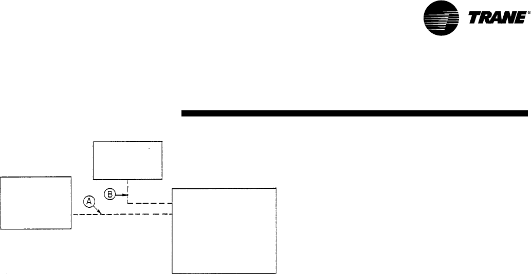
65
RT-PRC002-EN
Jobsite
Connections
For specific wiring information, see the installation instructions.
All wiring except power wires is low voltage.
All customer supplied wiring to be copper and must conform to NEC or CEC and local electrical codes. Wiring shown dotted is to be furnished and installed by the customer.
DISCONNECT
SWITCH
(BY OTHERS)
ROOFTOP
UNIT
ZONE SENSORS
Zone Sensors —Typical Number Of Wires
A— Manual Changeover ....................................... 4
Manual/Auto Changeover ............................... 5
Manual/Auto Changeover with
Status Indication LED’s ........................... 10
Programmable Night Setback with
Status Indication LED’s ............................. 7
B— 3 Power Wires + 1 Ground Wire (three phase)
2 Power Wires + 1 Ground Wire (single phase)
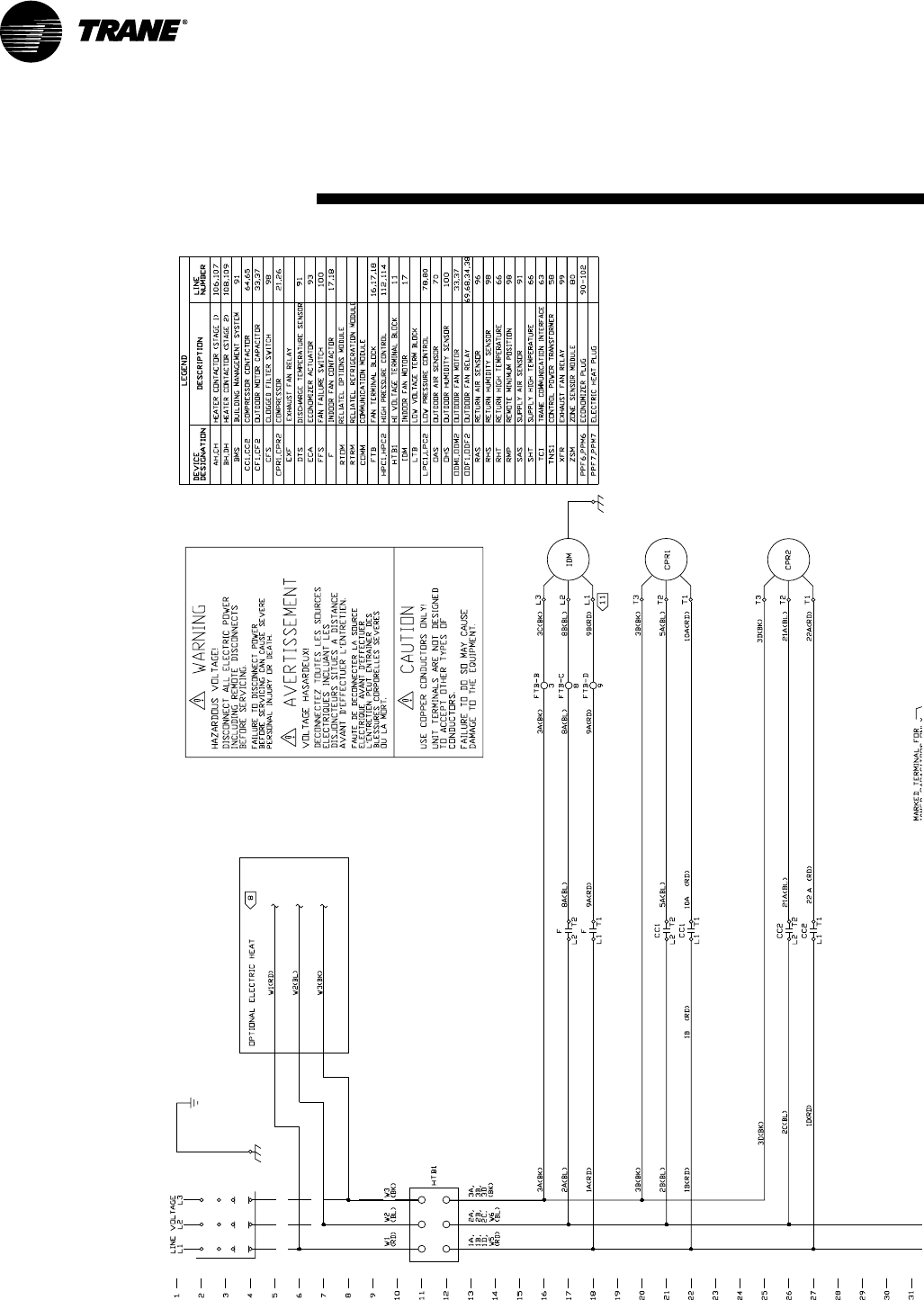
66 RT-PRC002-EN
Typical
Wiring (12½-25 Ton)
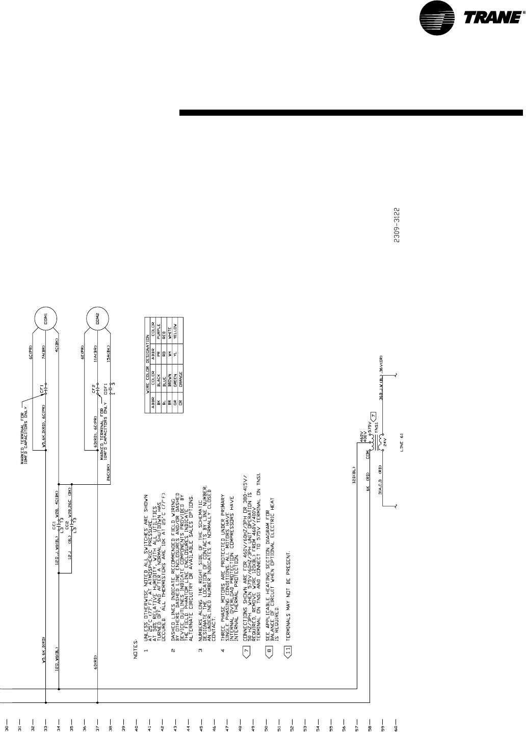
67
RT-PRC002-EN
Typical wiring diagram. For specific
wiring, see individual Service Facts.
(12½-25 Ton)
Typical
Wiring
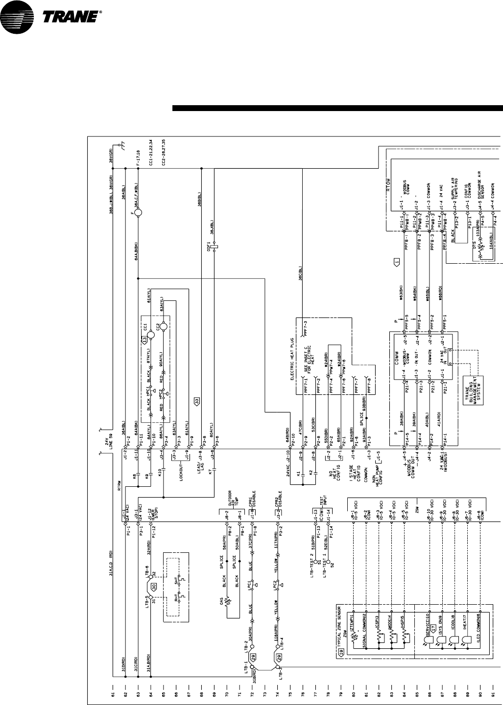
68 RT-PRC002-EN
(12½-25 Ton)
Typical
Wiring
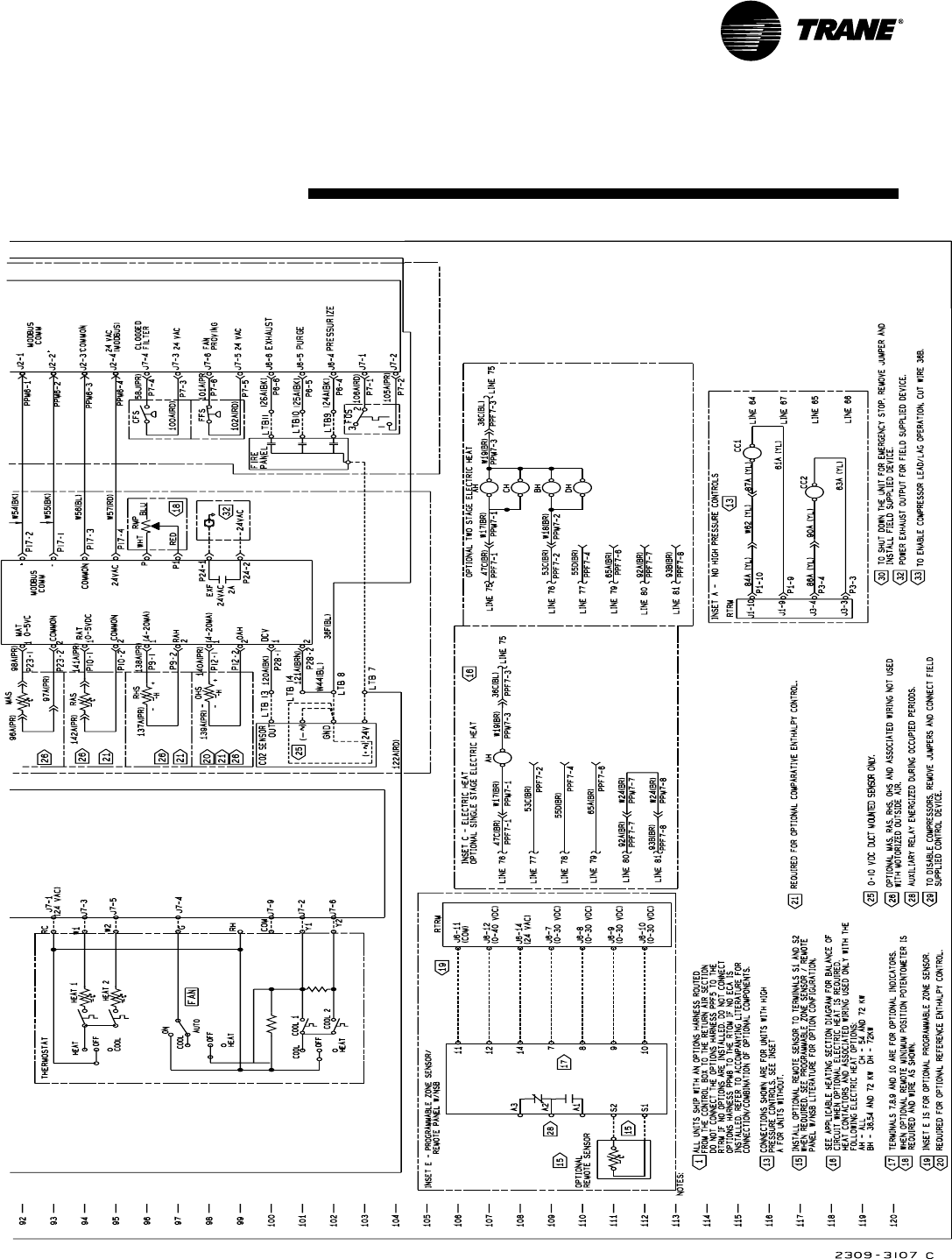
69
RT-PRC002-EN
(12½-25 Ton)
Typical
Wiring
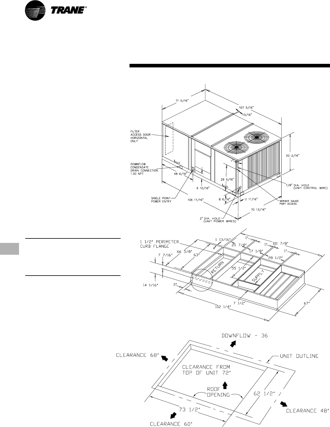
70 RT-PRC002-EN
Dimensional
Data
(12½ Ton) High Efficiency
(12½, 15, 17½ Ton)
Standard Efficiency
All dimensions are in inches.
Note: Duct flanges mount 7-7/16" down
inside the curb on the 1½" curb flanges.
See recommended duct dimensions on
the next page.
Roofcurb is intended for downflow use
only.
Downflow Unit Clearance
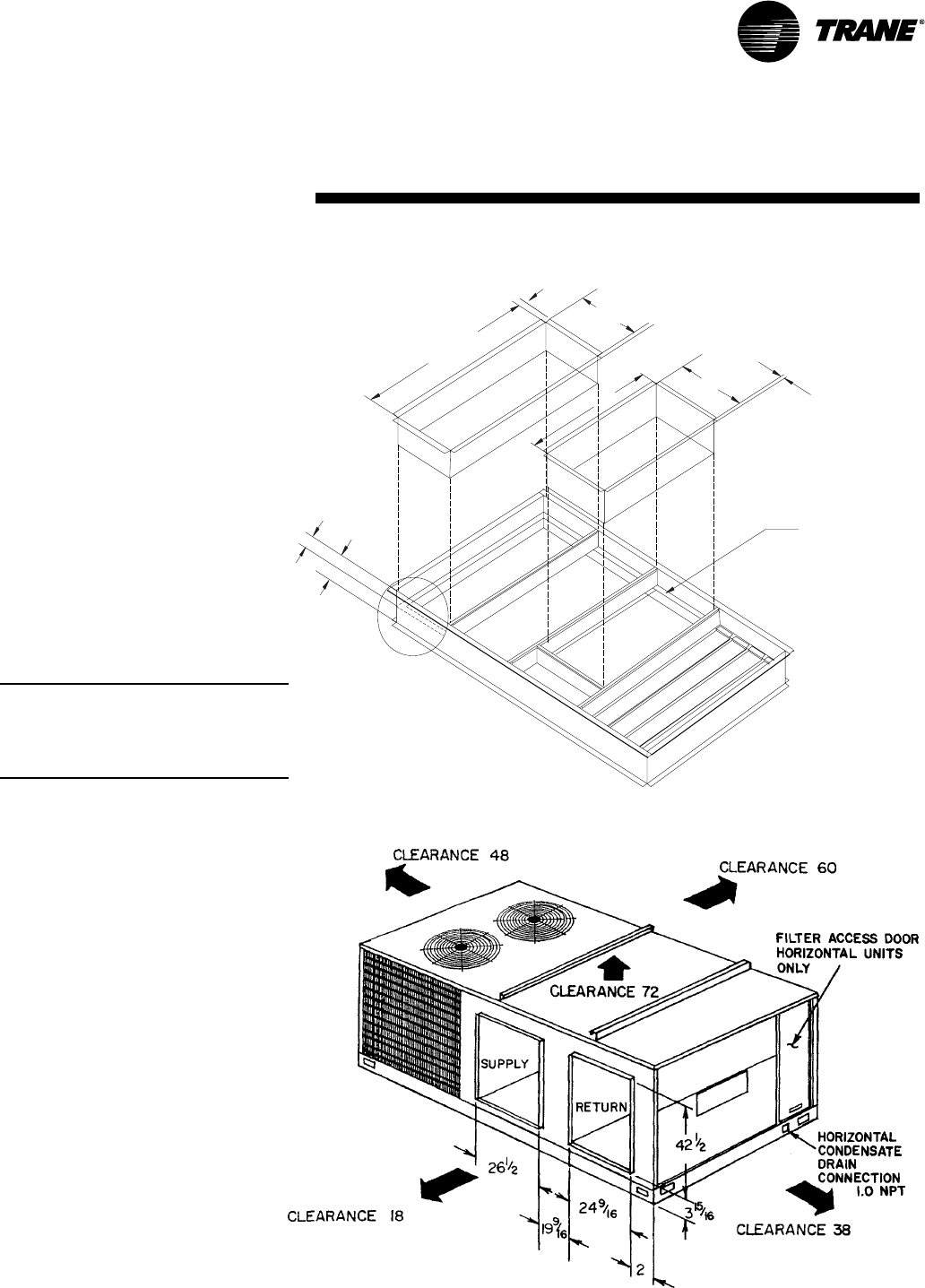
71
RT-PRC002-EN
Dimensional
Data
RETURN
SUPPLY
1 1\2"
PERIMETER
CURB FLANGE
59 7/16"
17 7/8"
26 5/16"
52 1/2" 1"
14 1/16"
7 7/16"
1"
All dimensions are in inches.
Downflow Duct Connections — Field Fabricated
Note:
Duct flanges mount 7-7/16" down inside
the curb on the 1½" curb flanges.
Roofcurb is intended for downflow use
only.
Horizontal Unit Supply/Return and Unit Clearance
(12½ Ton) High Efficiency
(12½, 15, 17½ Ton)
Standard Efficiency
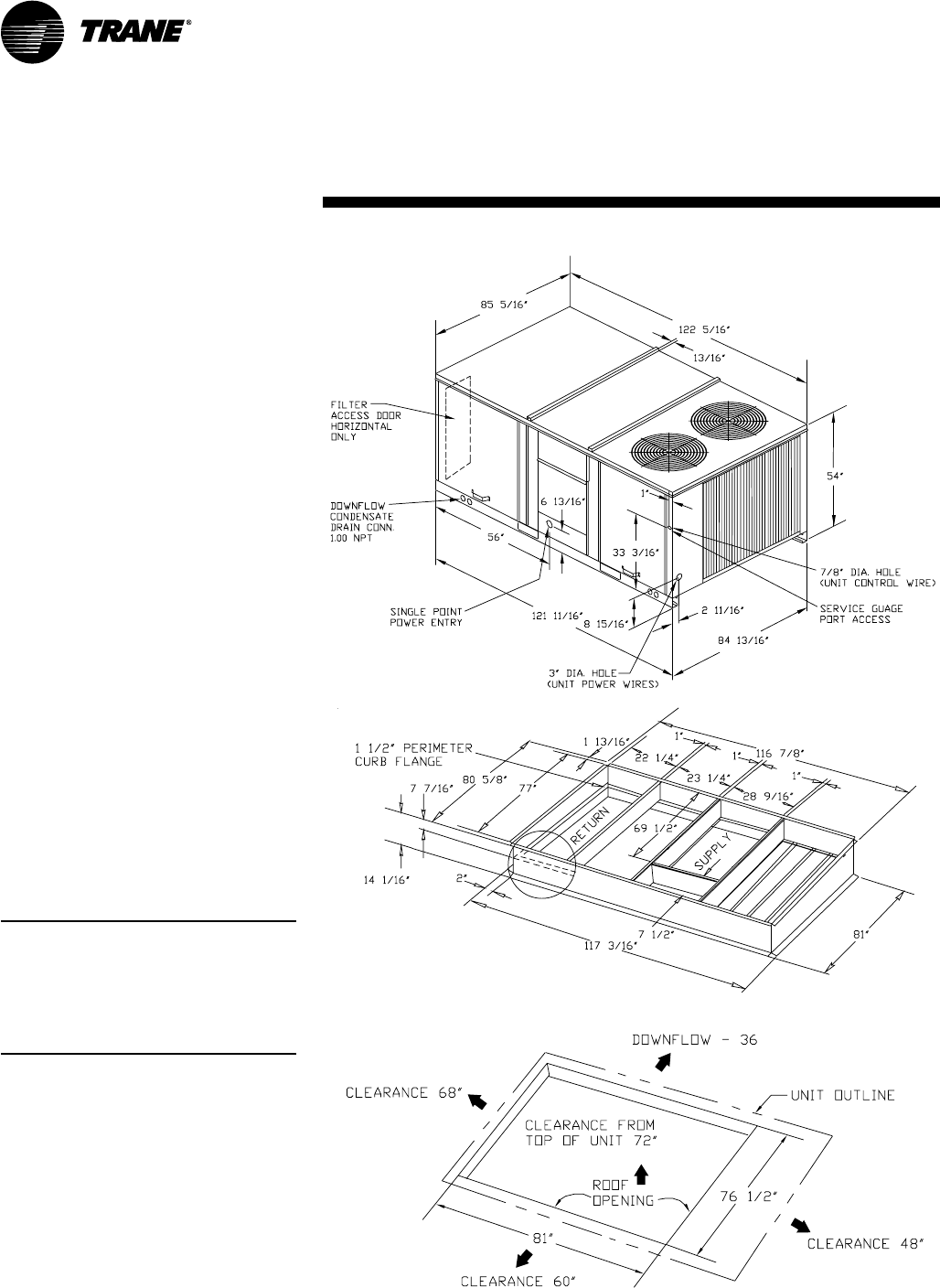
72 RT-PRC002-EN
Dimensional
Data
(15-25 Ton) High Efficiency
(20, 25 Ton)
Standard Efficiency
All dimensions are in inches.
Note:
Duct flanges mount 7-7/16" down inside
the curb on the 1½" curb flanges. See
recommended duct dimensions on the
next page.
Roofcurb is intended for downflow use
only.
Downflow Unit Clearance
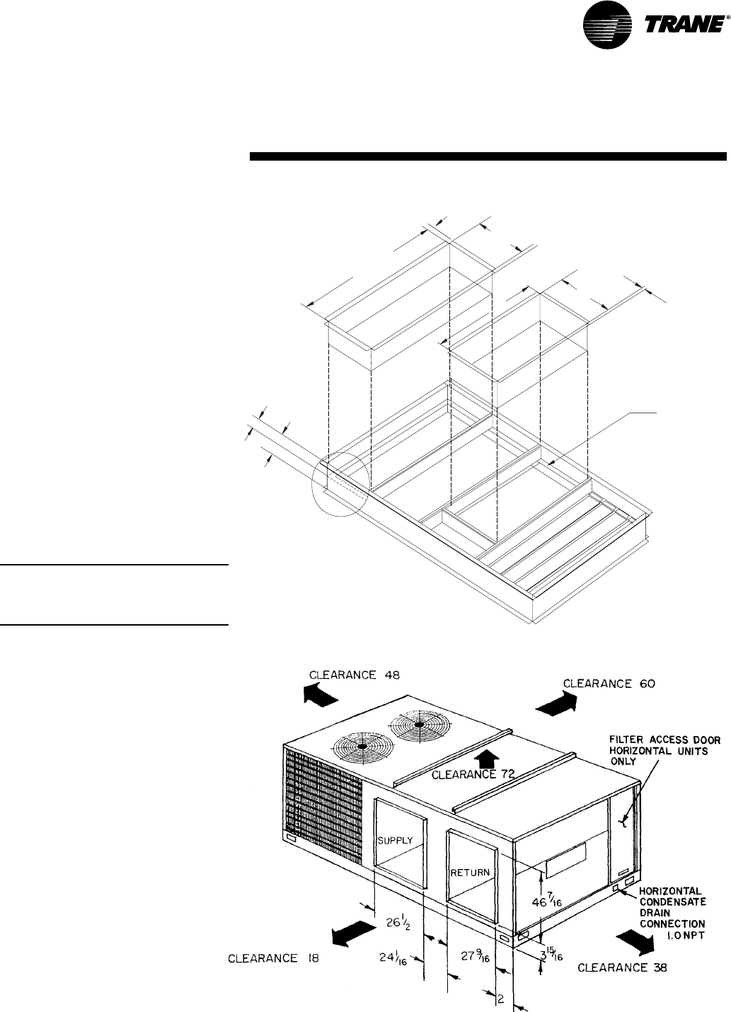
73
RT-PRC002-EN
Dimensional
Data
(15-25 Ton) High Efficiency
(20, 25 Ton)
Standard Efficiency
Downflow Duct Connections — Field Fabricated
All dimensions are in inches.
RETURN
SUPPLY
1 1\2"
PERIMETER
CURB FLANGE
73 7/16"
19 5/16"
26 5/16"
66 1/2" 1"
14 1/16"
7 7/16"
1"
Note: Duct flanges mount 7-7/16" down
inside the curb on the 1½" curb flanges.
Roofcurb is intended for downflow use
only.
Horizontal Unit Supply/Return and Unit Clearance
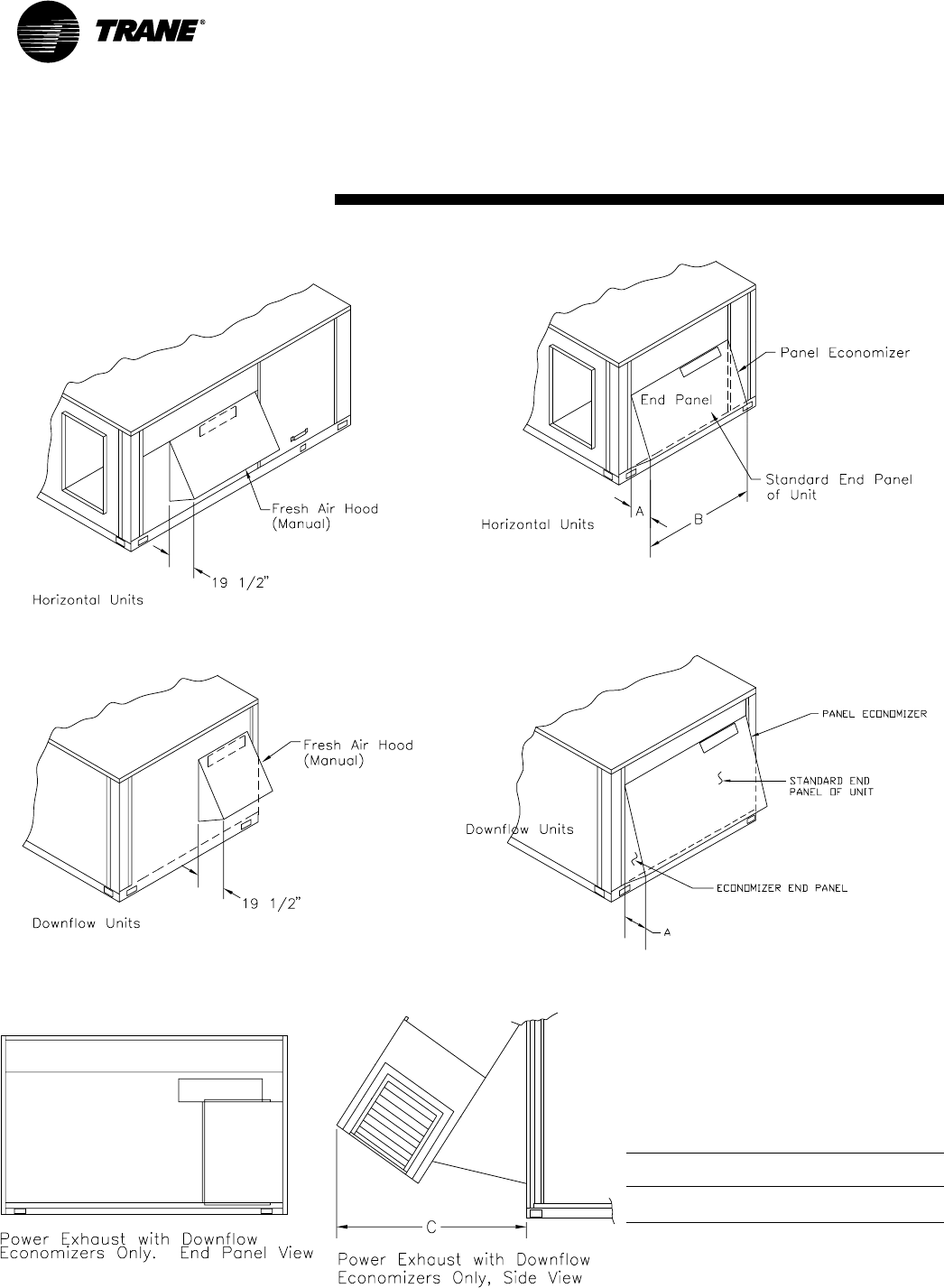
74 RT-PRC002-EN
Dimensional
Data
(12½-25 Ton)
Accessories
All dimensions are in inches.
Note:
When applying economizer to horizontal units,
connecting ductwork must be run full size to
allow proper operation of Economizer Damper.
Table DD-1
Unit
Model # A B1C2
TC*150, 151-180, 210 171/253¾ 36
TC*181, 211-301 191/264¾ 39
Notes:
1. Horizontal dimension only. Downflow economizer is width
of end panel.
2. Power exhaust is applied on downflow economizer only.
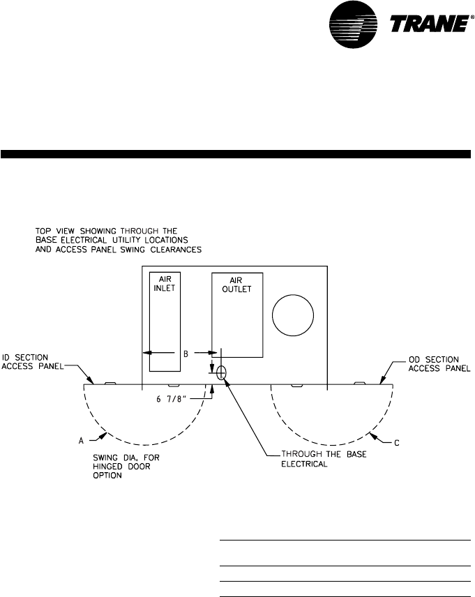
75
RT-PRC002-EN
Dimensional
Data
Factory Installed
Options (FIOPS)
All dimensions are in inches.
Table DD-2
Unit
Model # A B C
TCD150, 151, 180, 210 423/8483/831
TCD181, 211-301 291/256 381/2
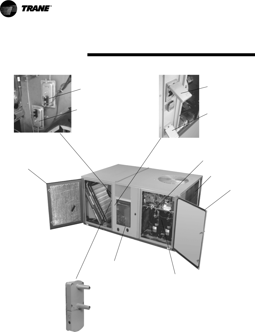
76 RT-PRC002-EN
Dimensional
Data
Factory Installed
Options (FIOPS)
Hinged Access Door
Hinged Access Door
Fan Failure Switch
Clogged Filter Switch
Black Epoxy Coated
Outdoor Coils
Powered or Unpowered
Convenience Outlet
Trane Communication Interface
Supply and/or Return Smoke Detectors
Through the Base Electrical
High Pressure Cut Out
Disconnect Switch
or Circuit Breaker
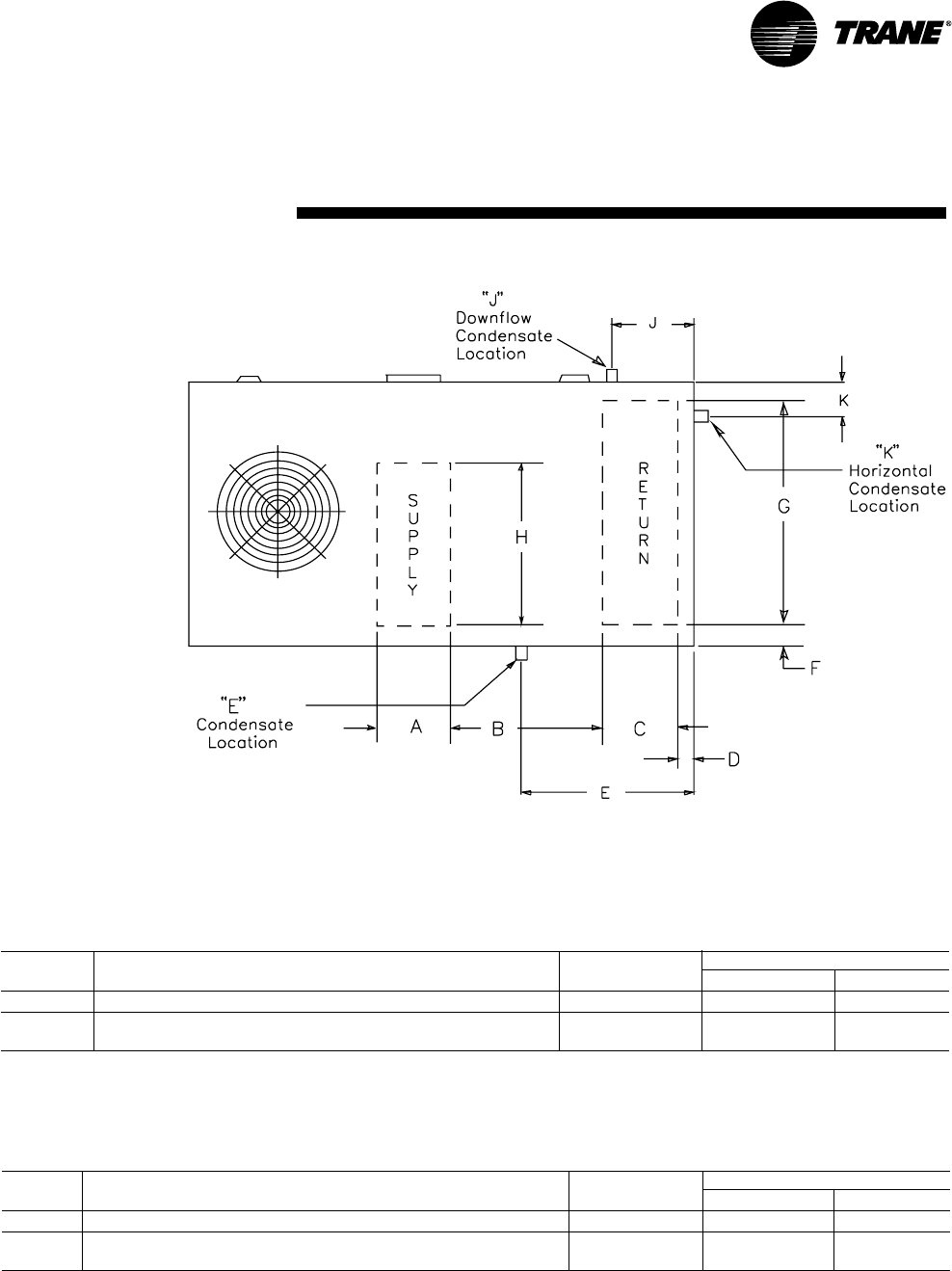
77
RT-PRC002-EN
Dimensional
Data (12½-25 Ton)
Table DD-3 — Standard Efficiency Units
Condensate Condensate Drain Location
Tons Downflow Only Drain Size Downflow Horizontal
ABCDF G H EJ EK
12½, 15, 17½ 267/16 221/21811/16 41/441/4627/16 5411/16 1 NPT — 255/8—6
20, 25 267/16 283/41915/16 41/441/4765/16 6811/16 1 NPT — 263/4—5
3/8
Table DD-4 — High Efficiency Units
Condensate Condensate Drain Location
Tons Downflow Only Drain Size Downflow Horizontal
ABCDF G H EJ EK
12½ 267/16 221/21811/16 41/441/4627/16 5411/16 1 NPT — 255/8—6
15-25 267/16 283/41915/16 41/441/4765/16 6811/16 1 NPT — 263/4—5
3/8
78 RT-PRC002-EN
Weights (12½-25 Ton)
Table W-1 — Accessory Net Weights (Lbs)
1, 7
Oversized High5Low5
Economizer Outside Air Damper Power Roof Motor Static Static
Model No. Net Manual Motorized Exhaust4Curb4Adder Drive Drive
TCD150D, 180B
TCD121,151C, TCD210C 65 32 60 95 205 5 2 2
TCD240B
TCD181,211,241C 80 32 75 95 235 5 2 —
TCD300B.301C 80 32 75 95 235 N/A N/A 2
TCH150D, 180B, 210C
TCH121,151C 50 32 60 — — 5 2 2
TCH240B
TCH181,211,241C 65 32 75 — — 5 2 —
TCH300B,301C 65 32 75 — — N/A N/A 2
Table W-1 Continued
Electric Heaters
Unit All Zone 6-23 KW 27-36 KW 54 KW 72 KW
Model No. Sensors 240/480V23 240/480V23 240/480V23 240/480V23
TCD150D, 180B, 210C 1 28/21631/27 38/32 —
TCD121,151,181C
TCD240B 1 — 33/27 40/32 43/34
TCD211,241C
TCD300B,301C 1 — 33/27 40/32 43/34
TCH150D, 180B, 210C 1 28/21631/27 38/32 —
TCH121,151,181C
TCH240B 1 — 33/27 40/32 43/34
TCH211, 241C
TCH300B, 301C 1 — 33/27 40/32 43/34
Notes:
1. Net weight should be added to unit weight when ordering factory installed accessories.
2. For 600V heaters net weights are same as 480V heaters.
3. To estimate shipping weight add 5 lbs to net weight.
4. Downflow only.
5. Not available on all models (See Fan Performance tables for specific models).
6. 9 - 23 KW Heaters not available for TC*210C.
7. TC*150-300 factory installed options for economizers, multiply net capacity x .99, EER x .97. For oversized motors, multiply net capacity x .98, EER x .93.
This is provided in compliance with ARI certification program.
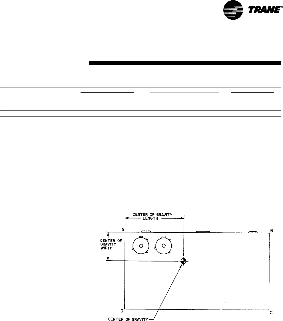
79
RT-PRC002-EN
Weights
Table W-2 — Maximum Unit And Corner Weights (Lbs) And Center Of Gravity Dimensions (In.)
Unit Maximum Weights (Lbs) Corner Weights (Lbs)1Center of Gravity (In.)
Tons Model No. Shipping2Net A B C D Length Width
12½ TC*150D/TC*151C 1687/1820 1319/1452 446/485 339/360 230/259 303/348 46/45 29/30
15 TC*180B/TC*181C 1866/2361 1498/1902 547/643 358/477 234/333 359/447 42/52 28/35
17½ TC*210C/TC*211C 2022/2380 1654/1921 565/643 425/495 285/341 378/442 46/53 29/35
20 TC*240B/TC*241C 2372/2490 1913/2031 679/697 482/528 312/348 440/458 51/53 34/34
25 TC*300B/ TC*301C 2365/2475 1906/2016 661/695 507/524 320/343 418/454 53/53 33/34
Notes:
1. Corner weights are given for information only. 12½-25 ton models must be supported continuously by a curb or equivalent frame support.
2. Weights are approximate. Horizontal and downflow unit and corner weights may vary slightly.
*Indicates both downflow and horizontal units.
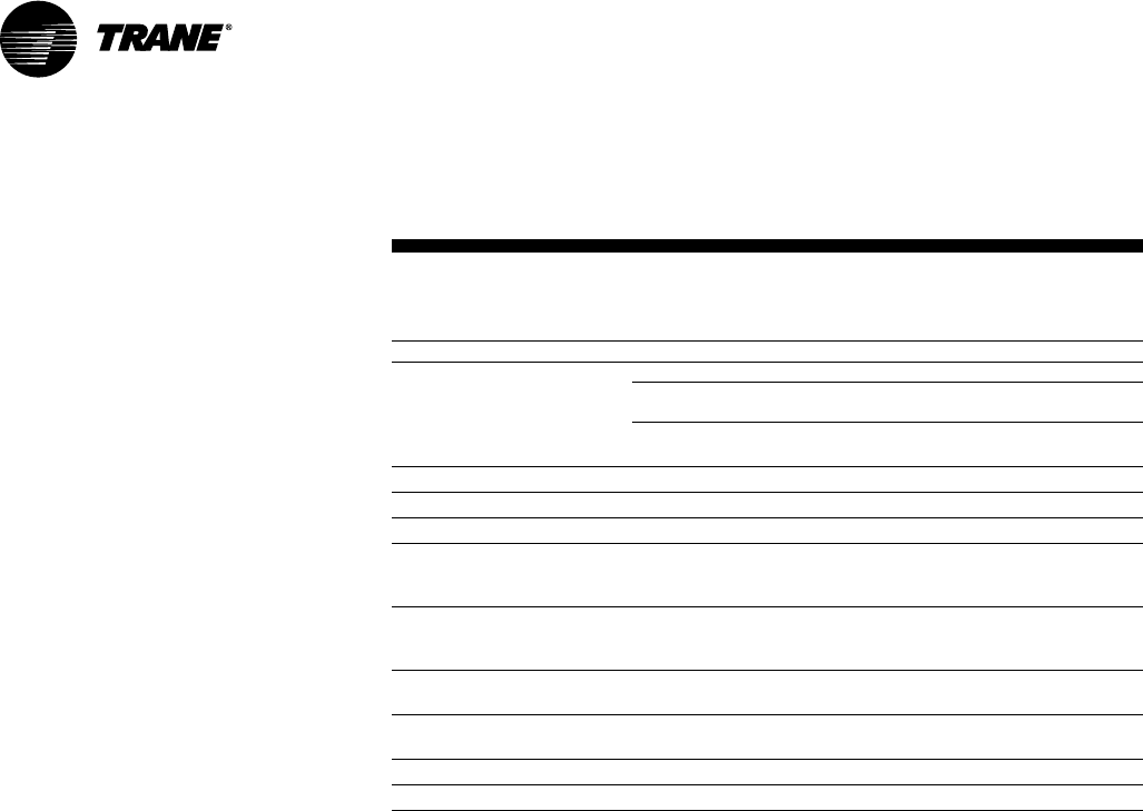
80 RT-PRC002-EN
Weights
Table W-3 — Factory Installed Options (FIOPS) Net Weights (Lbs)
1,2,3
Accessory Weight Unit Model Number
High Efficiency Motors449 TC*150-181 standard size motor
TC*210-241 standard size motor
36 TC*150-181 oversize motor
TC*210-241 oversize motor
0TC*300-301 standard size motor
Hinged Doors 27 All TC* units
Powered Convenience Outlet 38 All TC* units
Through the Base Electrical 23 All TC* units
Unit Mounted Circuit Breaker 5 All TC* units except those with 54&72 kW heaters
& 208/230V
10 All TC* units with 54&72 kW heaters & 208/230V
Unit Mounted Disconnect 5 All TC* units except those with 54&72 kW heaters
& 208/230V
10 All TC* units with 54&72 kW heaters & 208/230V
Smoke Detectors
Supply/Return 5 All TC* units
Tool-less Hail Guard 38 TC*150,151,180,210
43 TC*181,211,240,241,300,301
Novar 2024 7 All TC* units
Novar 3051 5 All TC* units
Notes:
1. Weights for FIOP accessories not listed are >5 lbs.
2. Net weight should be added to unit weight when ordering factory installed accessories.
3. See Table W-1 for standard factory installed economizer and oversized motors.
4. Standard factory installed motors are already included in unit net and shipping weights. Values shown for high
efficiency motors are in addition to the standard motor weight.

81
RT-PRC002-EN
Mechanical
Specifications
General
The units shall be dedicated downflow or
horizontal airflow. The operating range
shall be between 115°F and 0°F in cooling
as standard from the factory for all units.
Cooling performance shall be rated in
accordance with ARI testing procedures.
All units shall be factory assembled,
internally wired, fully charged with R-22,
and 100 percent run tested to check
cooling operation, fan and blower rotation
and control sequence, before leaving the
factory. Wiring internal to the unit shall be
colored and numbered for simplified
identification. Units shall be UL listed and
labeled, classified in accordance to UL
1995/CAN/CSA No. 236-M90 for Heat
Pumps. Canadian units shall be CSA
Certified.
Casing
Unit casing shall be constructed of zinc
coated, heavy gauge, galvanized steel.
Exterior surfaces shall be cleaned,
phosphatized, and finished with a
weather-resistant baked enamel finish.
Unit’s surface shall be tested 500 hours in
a salt spray test in compliance with ASTM
B117. Cabinet construction shall allow for
all maintenance on one side of the unit. In
order to ensure a water and air tight seal,
service panels shall have lifting handels
and no more thatn three screws to
remove. All exposed vertical panels and
top covers in the indoor air section shall
be insulated with a 1/2 inch, 1 pound
density foil-faced, fire-resistant,
permanent, odorless, glass fiber material.
The base of the downflow unit shall be
insulated with 1/2 inch, 1 pound density
foil-faced, closed-cell material. The
downflow unit’s base pan shall have no
penetrations within the perimeter of the
curb other than the raised 11/8 inch high
supply/return openings to provide an
added water integrity precaution, if the
condensate drain backs up. The base of
the unit shall have provisions for forklift
and crane lifting.
Unit Top
The top cover shall be one piece, or
where seams exist, double hemmed and
gasket sealed to prevent water leakage.
Filters
Two inch standard filters shall be factory
supplied on all units. Optional two inch
pleated media filters shall be available.
Compressors
All units shall have direct-drive, hermetic,
scroll type compressors with centrifugal
type oil pumps. Motor shall be suction
gas-cooled and shall have a voltage
utilization range of plus or minus 10
percent of nameplate voltage. Internal
overloads shall be provided with the
scroll compressors. All models shall have
crankcase heaters, low and high pressure
controls as standard.
Refrigerant Circuits
Each refrigerant circuit shall have
independent fixed orifice or thermostatic
expansion devices, service pressure
ports, and refrigerant line filter driers
factory installed as standard. An area
shall be provided for replacement suction
line driers.
Evaporator and Condenser Coils
Internally finned, 3/8" copper tubes
mechanically bonded to a configured
aluminum plate fin shall be standard.
Coils shall be leak tested at the factory to
ensure the pressure integrity. The
evaporator coil and condenser coil shall
be leak tested to 200 psig and pressure
tested to 450 psig. All dual compressor
units shall have intermingled evaporator
coils. Sloped condensate drain pans are
standard. Patent-pending 1+1+1
condenser coil, permanently gapped for
easy cleaning is available.
Gas Heating Section
The heating section shall have a drum
and tube heat exchanger design using
corrosion resistant steel components. A
forced combustion blower shall supply
premixed fuel to a single burner ignited
by a pilotless hot surface ignition system.
In order to provide reliable operation, a
negative pressure gas valve shall be
used that requires blower operation to
initiate gas flow. On an initial call for heat,
the combustion blower shall purge the
heat exchanger 45 seconds before
ignition. After three unsuccessful ignition
attempts, the entire heating system shall
be locked out until manually reset at the
thermostat. Units shall be suitable for use
with natural gas or propane (field
installed kit) and shall also comply with
California requirements for low NOx
emissions. The 12½-25 tons shall have
two stage heating.
Outdoor Fans
The outdoor fan shall be direct-drive,
statically and dynamically balanced,
draw-through in the vertical discharge
position. The fan motor(s) shall be
permanently lubricated and shall have
built-in thermal overload protection.
Indoor Fan
Units above shall have belt driven, FC
centrifugal fans with adjustable motor
sheaves. Units with standard motors
shall have an adjustable idler-arm
assembly for quick-adjustment of fan
belts and motor sheaves. All motors shall
be thermally protected. Oversized motors
shall be available for high static
application. All indoor fan motors meet
the U.S. Energy Policy Act of 1992
(EPACT).

82 RT-PRC002-EN
Mechanical
Specifications
Controls
Unit shall be completely factory wired
with necessary controls and contactor
pressure lugs or terminal block for power
wiring. Unit shall provide an external
location for mounting a fused disconnect
device. ReliaTel controls shall be provided
for all 24 volt control functions. The
resident control algorithms shall make all
heating, cooling, and/or ventilating
decisions in response to electronic signals
from sensors measuring indoor and
outdoor temperatures. The control
algorithm maintains accurate
temperature control, minimizes drift from
set point, and provides better building
comfort. A centralized control shall
provide anti-short cycle timing and time
delay between compressors to provide a
higher level of machine protection.
Defrost Controls
Adaptive demand defrost shall be
provided to permit defrost wherever coil
icing conditions begin to significantly
reduce unit capacity.
Factory Installed Options
Black Epoxy Coated Pre-Coated Coils
The black epoxy coils have a thermoset
vinyl coating that is bonded to the
aluminum fin stock prior to the fin-
stamping process. The pre-coated coils
are an economical option for protection in
mildly corrosive environments.
Dehumidification Option
The dehumidification (hot gas reheat)
option shall provide increased
dehumidification. The option shall consist
of a hot-gas reheat coil located on the
leaving air side of the evaporator coil
prepiped and circuited. Low pressure
switch(es) and thermostatic expansion
valve(s) TXV are standard. Frostat™,
ReliaTel options module, and 2”pleated
filters are required but not standard. They
must be ordered and configured
separately.
Hinged Access Doors
Sheet metal hinges are available on the
Filter/Evaporator Access Door and the
Compressor/Control Access Door. This
option is available on all downflow
models.
High Efficiency Motors
This option is available with efficiency
ratings from 86.5 up to 91.0. It is not
available for all models.
High Pressure Cutout
This option is offered for units that do not
have High Pressure cutout as standard.
Powered or Unpowered Convenience
Outlet
This option is a GFCI, 120v/15amp, 2 plug,
convenience outlet, either powered or
unpowered. When the convenience outlet
is powered, a service receptacle
disconnect will be available. The
convenience outlet is powered from the
line side of the disconnect or circuit
breaker, and therefore will not be
affected by the position of the disconnect
or circuit breaker. This option can only be
ordered when the Through the Base
Electrical with either the Disconnect
Switch, or Circuit Breaker, option is
ordered. This option is available on all
downflow models.
Supply and/or Return Air Smoke
Detector
With this option installed, if smoke is
detected, all unit operation will be shut
down. Reset will be manual at the unit.
Return Air Smoke Detectors require
minimum allowable airflow when used
with certain models. See the Installation,
Operation, and Maintenance (IOM)
manual for the models affected and the
minimum allowable airflow required. This
option is available on all downflow
models.
Through the Base Electrical with Circuit
Breaker
This option is a thermal magnetic, molded
case, HACR Circuit Breaker with
provisions for through the base electrical
connections. The circuit breaker will be
installed in a water tight enclosure in the
unit with access through a swinging door.
Factory wiring will be provided from the
switch to the unit high voltage terminal
block. The circuit breaker will provide
overcurrent protection, be sized per NEC
and UL guidelines, and be agency
recognized by UL/CSA. This option is
available on all downflow models.
Through the Base Electrical With
Disconnect Switch
Three-pole, molded case, disconnect
switch with provisions for through the
base electrical connections are available.
The disconnect switch will be installed in
the unit in a water tight enclosure with
access through a swinging door. Factory
wiring will be provided from the switch to
the unit high voltage terminal block. The
switch will be UL/CSA agency recognized.
Note: The disconnect switch will be sized
per NEC and UL guidelines but will not be
used in place of unit overcurrent
protection. This option is available on all
downflow models.
Through the Base Utilities Access
An electrical service entrance shall be
provided allowing electrical access for
both control and main power connections
inside the curb and through the base of
the unit. Option will allow for field
installation of liquid-tight conduit and an
external field installed disconnect switch.
Two-Inch Pleated Filters
Two inch pleated media filters shall be
available on all models.

83
RT-PRC002-EN
Mechanical
Specifications
Factory or Field Installed
Options
Clogged Filter/Fan Failure Switch
A dedicated differential pressure switch is
available to achieve active fan failure
indication and/or clogged filter indication.
These indications will be registered with
either a zone sensor with status indication
lights or an Integrated Comfort™ System.
Differential Pressure Switches
These options allow for individual fan
failure and dirty filter indication. The fan
failure switch will disable all unit functions
and “flash” the Service LED on the zone
sensor. The dirty filter switch will light the
Service LED on the zone sensor and will
allow continued unit operation.
Discharge Air Sensing Kit
This kit provides true discharge air
sensing in heating models. This sensor is
a status indicator readable through
Tracer™or Tracker™. The kit is functional
only with the ReliaTel Options Module.
Economizer - Downflow
The assembly includes fully modulating
0-100 percent motor and dampers,
barometric relief, minimum position
setting, preset linkage, wiring harness
with plug, fixed dry bulb and spring return
actuator. The barometric relief damper
shall be standard with the downflow
economizer and shall provide a pressure
operated damper that shall be gravity
closing and shall prohibit entrance of
outside air during the equipment “off”
cycle. Solid state enthalpy and differential
enthalpy control shall be field-installed
Electric Heaters
Electric heat modules shall be available
for installation within the basic unit.
Electric heater elements shall be
constructed of heavy-duty nickel
chromium elements internally delta
connected for 240 volt, wye connected
for 480 and 600 volt. Staging shall be
achieved through ReliaTel. Each heater
package shall have automatically reset
high limit control operating through
heating element contactors. All heaters
shall be individually fused from the
factory, where required, and shall meet
all NEC and CEC requirements when
properly installed. Power assemblies
shall provide single-point connection.
Electric heat modules shall be UL listed or
CSA certified. If ordering the Through the
Base Electrical option with an Electric
Heater, the heater must be factory
installed.
Frostat
This option is to be utilized as a safety
device. The Frostat opens when
temperatures on the evaporator coil fall
below 10°F. The temperature will need to
rise to 50°F before closing. This option
should be utilized in low airflow or high
outside air applications.
LonTalk® Communications Interface
The LonTalk communications interface,
when installed in a Voyager unit, allows
the unit to communicate as a Tracer™LCI-
V device or directly with generic LonTalk
Network Building Automation System
Controls.
Oversized Motors
Oversized motors shall be available for
high static applications.
Reference or Comparative Enthalpy
Reference Enthalpy is used to measure
and communicate outdoor humidity. The
unit receives and uses this information to
provide improved comfort cooling while
using the economizer. Comparative
Enthalpy measures and communicates
humidity for both outdoor and return air
conditions, and return air temperature.
The unit receives and uses this
information to maximize use of
economizer cooling, and to provide
maximum occupant comfort control.
Reference or Comparative Enthalpy
option shall be available when a factory
or field installed Downflow Economizer is
ordered. This option is available on all
downflow models.
Tool-less Hail Guards
Tool-less, hail protection quality coil
guards are available for condenser coil
protection.
Trane Communication Interface
This factory or field-installed option shall
be provided to interface ReliaTel™
controlled units with the Trane Integrated
ComfortTM systems.

84 RT-PRC002-EN
Field Installed Options
CO2 Sensing
The CO2 sensor has the ability to monitor
space occupancy levels within the
building by measuring the parts per
million of CO2 (Carbon Dioxide) in the air.
As the CO2 levels increase, the outside air
damper modulates to meet the CO2
space ventilation requirements.
Digital Display Zone Sensor
The Digital LCD (Liquid Crystal Display)
zone sensor has the look and functionality
of standard zone sensors. This sensor
includes a digital display of set point
adjustment and space temperature in F
(Fahrenheit) or C (Celsius). Includes FAN
and SYSTEM buttons (supports the
service functions of the standard sensor).
E-squared memory stores last
programmed set points. Requires 24 VAC
(Volts AC). This sensor should be utilized
with ReliaTel™ controls.
Dual Thermistor Remote Zone Sensor
This sensor will allow the customer to
reduce the total number of remote
sensors to obtain space temperature
averaging. This sensor should be utilized
with ReliaTel controls.
High Static Drive
The high static drive option shall allow the
standard motor on the 12½ and 20 ton
units to operate with improved external
static capabilities.
Manual Outside Air Damper
The rain hood and screen shall provide
up to 25 percent outside air.
Motorized Outside Air Dampers
Manually set outdoor air dampers shall
provide up to 50 percent outside air. Once
set, outdoor air dampers shall open to set
position when indoor fan starts. The
damper shall close to the full closed
position when indoor fan shuts down.
Powered Exhaust
The powered exhaust shall provide
exhaust of return air, when using an
economizer, to maintain better building
pressurization.
Roof Curb - Downflow
The roof curb shall be designed to mate
with the downflow unit and provide
support and a water tight installation
when installed properly. The roof curb
design shall allow field-fabricated
rectangular supply/return ductwork to be
connected directly to the curb. Curb
design shall comply with NRCA
requirements. Curb shall be shipped
knocked down for field assembly and
shall include wood nailer strips.
Economizer - Horizontal
The horizontal economizer shall contain
the same features as the downflow
economizer with the exception of
barometric relief.
Remote Potentiometer
The minimum position setting of the
economizer shall be adjusted with this
accessory.
Ventilation Override Accessory
With the Ventilation Override Accessory
installed, the unit can be set to transition
up to 3 different pre-programmed
sequences for Smoke Purge,
Pressurization, and Exhaust. The
transition occurs when a binary input on
the RTOM is closed (shorted). This would
typically be a hard wired relay output
from a smoke detector or fire control
panel.
Zone Sensors
This option shall be provided to interface
with the Micro equipped Voyagers and
shall be available in either manual,
automatic, programmable with night
setback, with system malfunction lights or
remote sensor options.
Mechanical
Specifications

85
RT-PRC002-EN

86 RT-PRC002-EN

87
RT-PRC002-EN

Literature Order Number
File Number
Supersedes
Stocking Location
Trane has a policy of continuous product and product data improvement and reserves the right to change design
and specifications without notice.
Trane
A business of American Standard Companies
www.trane.com
For more information contact your local dealer
(distributor), local district office, or e-mail us at
comfort@trane.com
RT-PRC002-EN
PL-UN-RT-TCD/TCH12½-25TONS-PRC002-EN-10-04
PL-UN-RT-TCD/TCH12½-25TONS-PRC002-EN-09-04
09-04 Webb/Mason 10-04 Electronic Only
