Trane TWA PRC001 EN User Manual To The 90d7d7fd C2e1 466d 8c1b 638400af9e7c
User Manual: Trane TWA-PRC001-EN to the manual
Open the PDF directly: View PDF ![]() .
.
Page Count: 60
Split System Heat Pumps
Split System Heat Pumps
7 1/2 through 20 Ton - 50 Hz
Air Handlers
5 through 20 Ton - 50 Hz
TWA-PRC001-EN
July 2000
©American Standard Inc. 2000 TWA-PRC001-EN
Introduction
Split System Heat Pumps…
Designed With Your Needs In Mind.
The Trane reputation for quality and
reliability is reflected in the Odyssey™
Commercial Split System Heat Pumps.
Trane’s focused attention on the split
system marketplace results in an
outstanding heat pump that meets job
requirements...and at a very competitive
price.
Efficiency, flexibility and installation ease,
coupled with Trane’s reputation for
quality and reliability, gives you a system
that is “ Simply the Best Value”.
TWA-PRC001-EN4
Features and
Benefits
Heat Pumps
• 3-D® Scroll compressors
• Model TWA155-200B have dual
compressors with independent
refrigerant circuits
• Compressor motor overload protection
• Control transformer
• High and low pressure cut-out
switches
• Internal pressure relief valve
• Liquid line filter drier, factory installed
• Holding charge of dry nitrogen
• Copper tube, aluminum plate fin coils
• Low ambient cooling to 35° F (1.7° C)
as manufactured
• Weather resistant baked enamel finish
• Heavy gauge steel cabinet
• Mounting/lifting rails under base
All condensing units offer these optional
accessories:
• Head Pressure Control — Low Ambient
Cooling To 0° F (-17.8° C)
• Coil Guards Kits
• Isolators both Rubber-in-Shear and
Spring Type
• Anti-Short-Cycle Kit
• Time Delay Relay
Air Handlers
• Low voltage terminal board
• Expansion valve(s)
• Convertible
• PVC double-sloped, removeable drain
pan
• Fan relay
• Efficient evaporator coil
• Baked enamel finish
• Filter access panel
• 1” (25.4 mm) throwaway filters
standard with provisions for field
supplied 2”
(50.8 mm) filters
• Adjustable belt drive motor
• Single point power entry to electric
heaters
• Refrigerant piping and/or electrical
connections provided from either side
Odyssey™ air handler versatility is further
increased by a complete line of optional
accessories designed to match and easy
to install:
• Discharge Plenum and Grille
• Return Grille
• Subbase
• Electric Heaters
• High Static Evaporator Motor
• Isolators both Rubber-in-Shear and
Spring Type
5TWA-PRC001-EN
Features and
Benefits
Heat Pump Options
The Odyssey™ split system product line
includes heat pumps in both single and
dual compressor options.
TWA075A and TWA100A single
compressor models feature single
refrigeration circuitry lowering job
installation costs by requiring only one
set of refrigerant lines. These units are
ideal for either the low cost, new
construction jobs as well as renovation
and replacement buildings.
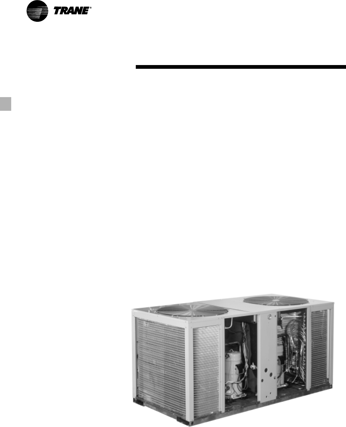
In addition, Odyssey models TWA155B
through TWA200B are dual compressor
units that give true standby protection; if
one compressor fails, the second will
automatically start-up. Also, the first
compressor can be serviced without
shutting down the unit since refrigerant
circuits are independent.
Dual compressors are not just for
protection, they also save energy costs.
Most buildings are designed for the peak
load requirements yet the building
usually operates at less than peak load.
During light load conditions only one
compressor functions to maintain the
space comfort thus reducing the need
for energy.
Low Ambient Cooling Operation
Each condensing unit can operate to
35° F (1.7° C) as standard. An accessory
Head Pressure Control gives you the
capability to operate to 0° F (-17.8° C). All
condensing units offer these accessories:
• Head Pressure Control
• Coil Guard Kits
• Isolators both Rubber-in-Shear and
Spring Type
• Anti-Short-Cycle Kit
• Time Delay Relay
Trane split systems have been specified
in thousands of applications and you’ll
find Odyssey will win you even more
jobs with it’s smaller, more manageable
cabinet.
Air Handlers Offer More Flexibility
Flexibility is a key to meeting changing
market requirements. Odyssey split
systems offer various compressor
options and convertible air handlers. The
air handlers can be installed either
vertically in a mechanical room or
horizontally above a ceiling. And it
doesn’t require any removal of panels or
reconfiguration of the drain pan to make
either airflow application work. All the air
handlers feature factory installed belt
drive and ball bearing evaporator fans
with adjustable sheaves for maximum
airflow performance. The standard motor
on the TWE100A air handler will deliver
4000 cfm (1888 l/s) at 0.8” (20.32 mm)
ESP. Plus oversized motors are available
for higher static applications.
Odyssey air handler versatility is further
increased by a complete line of
accessories designed to match and
install smoothly:
• Discharge Plenum and Grille
• Return Grille
• Subbase
• Electric Heaters
• High Static Evaporator Motor
• Isolators both Rubber-in-Shear and
Spring Type
• A Full Line of Thermostats
Odyssey™ — A Complete Split System
Odyssey delivers the flexibility to select a
complete system that meets your
particular job requirements. Air Handlers
are designed, tested and rated with
condensing units to let you select the
proper match between capacity and
load. Condensing units can also be
matched with Trane built-up air handlers.
These matched systems can be quickly
engineered for specific applications.
TWA-PRC001-EN6
Application
Considerations
Application of this product should be
within the catalogued airflow and
performance considerations. The System
Selection Program will simulate product
performance for a set of given
conditions. It is recommended that the
program should be run at the lowest
outdoor ambient and supply air flow
rates requiring cooling or heating
operation for a particular unit. For more
information on the System Selection
Program contact your local Trane
Representative.
Clearance Requirements
The recommended clearances identified
with unit dimensions should be
maintained to assure adequate
serviceability, maximum capacity and
peak operating efficiency. Actual
clearances that appear inadequate
should be reviewed with the local Trane
Representative.
Low Ambient Cooling
As manufactured, these units can
operate to 35° F (1.7° C) in the cooling
mode of operation. An accessory head
pressure control will allow operation to
0° F (-17.8° C) outdoor ambient. When
using these units with control systems
such as bypass changeover Variable Air
Volume, consider the requirement for a
head pressure control to allow low
ambient cooling.
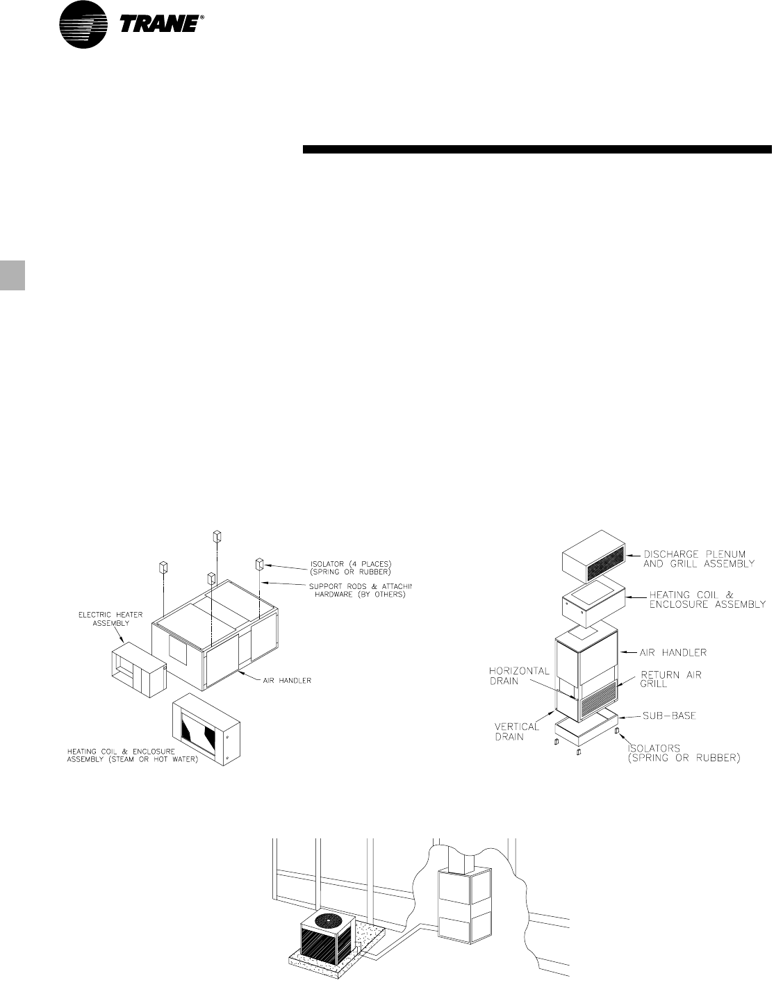
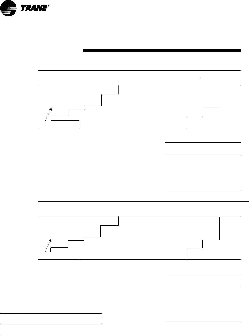
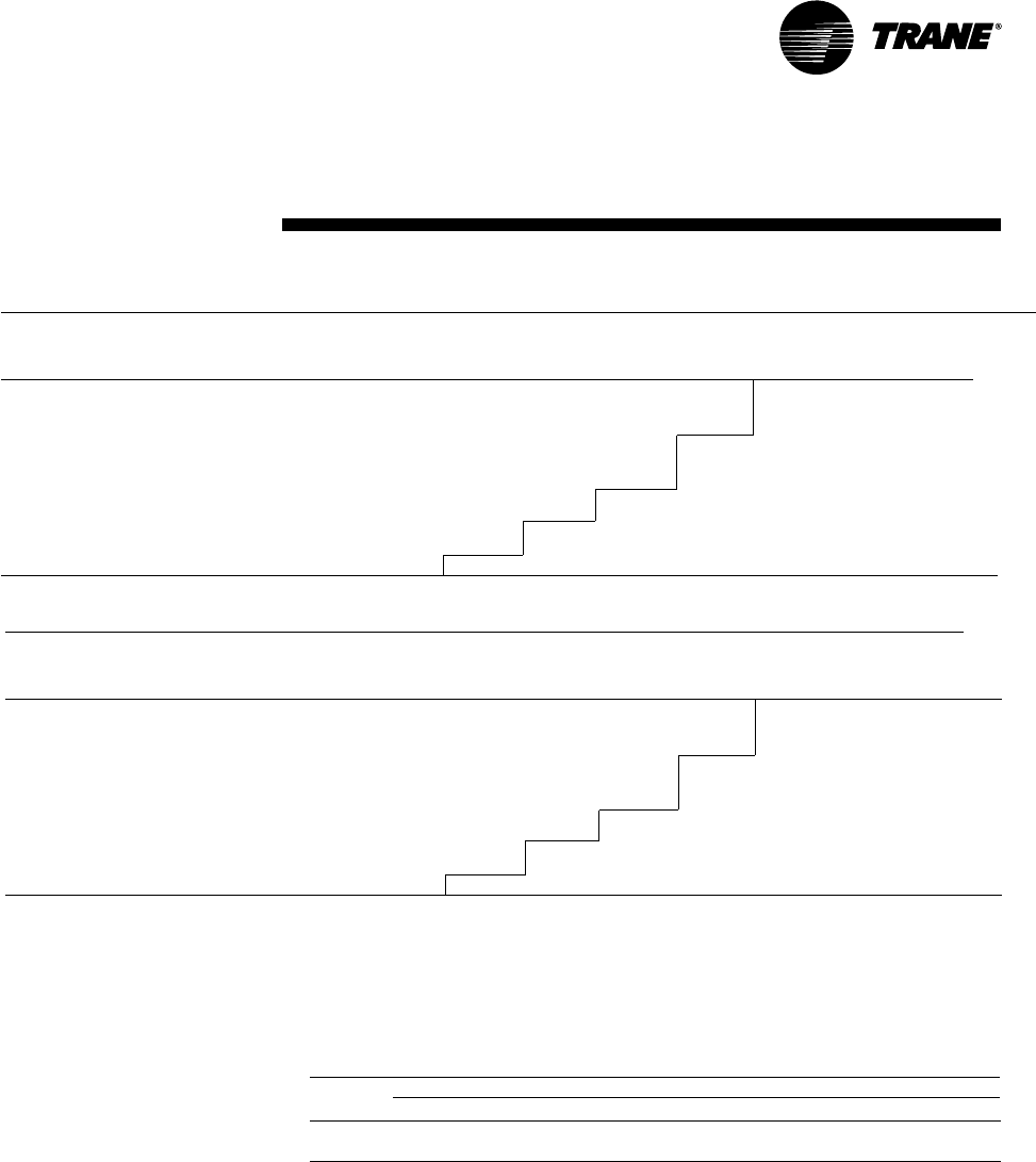
Typical Horizontal Air Handler Application Typical Vertical Air Handler Application
Typical Split System Application

7TWA-PRC001-EN
Selection
Procedure
Cooling Capacity
Step 1 — Calculate the building’s total
and sensible cooling loads at design
conditions. Use the Trane calculation
form or any other standard accepted
method.
Step 2 — Size the equipment using Table
PD-1. Match the cooling loads at design
conditions.
Example: The following are the building
cooling requirements
a
Electrical Characteristics: 380-415/50/3
b
Summer Design Conditions: Entering
Evaporator Coil: 80 DB/67 WB
(27 DB/19 WB° C)
Outdoor Ambient: 95° F (35° C)
c
Total Cooling Load: 75 MBh (22kW)
d
Sensible Cooling Load: 53 MBh
(15.5 kW)
e
Airflow: 2500 cfm (1,180 l/s)
External Static Pressure: 0.77 in.
(19.6 mm) w.g. (193 Pa)
Table PD-1 shows that a TWA075A
matched with a TWE075A has a gross
cooling capacity of 82.4 MBh (24.1 kW)
and 59.5 MBh (17.4 kW) sensible capacity
at 95 DB (35° C) ambient and 2500 cfm
(1180 l/s) and 80 DB/67 WB (27 DB/19 WB)
air entering the evaporator.
To find the net cooling capacities, fan
motor heat must be subtracted.
Determine the total unit static pressure:
External Static
0.77 in
(19.6 mm) (193 Pa)
Standard Filter
0.10 in
1 in. (25.4 mm)
(2.5 mm) (25 Pa)
Supplementary Electric Heat
0.23 in
(5.8 mm) (57 Pa)
Total Static Pressure
1.10 in
(27.9 mm) (275 Pa)
Note: The Evaporator Fan Performance
Table has included the effect of a 1 in.
(25.4 mm) filter already. Therefore, the
actual Total Static Pressure is 1.10 - 0.10 =
1.00 in. (27.9 - 2.5 = 25.4 mm)
(275 - 25 = 250 Pa)
With 2500 cfm (1180 l/s) and 1.00 inches
(250 Pa) (0.8 kW), Table 26-1 shows a 1.07
Bhp.
Note: The formula below the table can be
used to calculate Fan Motor Heat,
Constant x Motor Power =
Fan Motor Heat
3.5 x Bhp = MBh
3.5 x 1.07 = 3.75 MBh
1.375 x (kW) = kW
1.375 x 0.8 = 1.1 kW
Net Total Cooling Capacity
= 79.6 MBh – 3.75 = 75.85 MBh
= 23.3 kW - 1.1 = 22.2 kW
Net Sensible Cooling Capacity
= 57.1 MBh – 3.75 = 53.35 MBh
= 16.7 MBh - 1.1 = 15.6 kW
Heating Capacity
Step 1 — Calculate the building heating
load using the Trane calculation form or
any other standard accepted method.
Step 2 — Size the equipment using Table
PD-9 to match the heating loads at
design conditions. The following are
building heating requirements:
a
Total Heating Load: 110 MBh (32.2 kW)
b
Outdoor Ambient (Winter): 17° F
(-8.3° C) DB
c
Indoor Return Temperature: 70° F
(21.1° C) DB
d
Airflow: 2500 cfm (1180 l/s)
Table PD-9 indicates the mechanical
heating portion of the heat pump will
provide 37.5 MBh (11.0 kW) for the winter
design conditions.
Step 3 — Because 37.5 MBh (11.0 kW) is
less than the building’s required heating
capacity, a supplementary heater must
be selected. 110 - 37.5 = 72.5 MBh (32.2 -
11.0 = 21.2 kW) minimum heater capacity.
From Table PD-25, the 24.22 kW heater
has a capacity of 82,670 Btuh. From Table
34-1, the 24.22 kW heater at 400V
indicates the heater model number is
BAYHTRL435A. This heater will be
adequate to cover the residual heat
capacity needed for the application.
Air Delivery Selection
External static pressure drop through the
air distribution system has been
calculated to be 0.77 inches (19.6 mm) of
water gauge. From Table PD-24 static
pressure drop through the electric heater
is 0.12 inches (3.0 mm) of water (0.77 +
0.12 = .89 in.) (19.6 + 3.0 = 22.6 mm).
Enter Table PD-15 for TWE090A4 at 2500
cfm (1180 l/s) and .90 static pressure. The
standard motor at 790 rpm will give the
desired airflow.
TWA-PRC001-EN8
Model
Number
Description
Digit 8 - Electrical Characteristics
D = 380-415/3/50
Digit 9, 10 - Factory - Installed Options
00 = Packed Stock
0S = Black Epoxy Coated Coil
Digit 11- Minor Design Sequence
D = Fourth
Digit 12- Service Digit
A = First
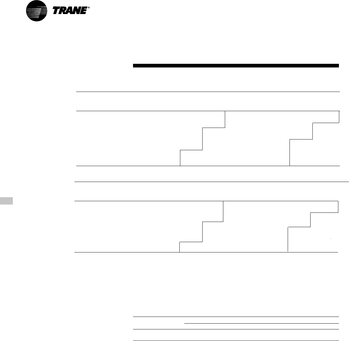
Split System Heat Pump Model Nomenclature
Digit 7- Major Development Sequence
A = Single Compressor
B = Dual Compressor
TWA075 AD0 0 DA
12 3 456 7 8 910 11 12
Air Handler Model Nomenclature
Digit 8 - Electrical Characteristics
D = 380-415/3/50
Digits 1, 2, 3 - Product Type
TWE = Cooling Convertible
Digits 4, 5, 6 - Nominal Gross Cooling
Capacity (MBh)
050 = 50
075 = 75
100 = 100
155 = 155
200 = 200
Digit 7- Refrigerant Circuit
A = Single
B = Dual
TWE 050 A D 0 0 C A
12 3 456 7 8 910 11 12
Digit 9, 10 - Factory - Installed Options
00 = Packed Stock
Digit 11- Minor Design Sequence
C = Third
Digit 12- Service Digit
A = First
Digits 4, 5, 6 - Nominal Gross Cooling Capacity
(MBh)
075 = 75
100 = 100
155 = 155
200 = 200
Digits 1, 2, 3 - Product Type
TWA = Split System Heat Pump
9TWA-PRC001-EN
General
Data (Heat Pumps)
Table GD-1 — General Data — Heat Pumps
TWA075A TWA100A
Cooling Performance1
Gross Cooling Capacity, BTUH (KW)
Matched Air Handler, BTUH (KW) 82,000 (23.97) 109,000 (31.97)
Heat Pump Only2, BTUH (KW) 82,000 (23.97) 105,000 (30.75)
ARI Net Cooling Capacity380,000 (23.35) 105,000 (30.75)
System Power KW 7.36 10.32
Heat Pump Only Power KW 6.61 9.22
Heating Performance
ARI Heating with Matched Air Handler
High Temperature Capacity, BTUH (KW) 75,000 (21.82) 106,000 (31.05)
Low Temperature Capacity, BTUH (KW) 47,000 (13.84) 69,000 (20.29)
Compressor
Number 1 1
Type 3D®Scroll 3D®Scroll
No. Speeds 1 1
No. Motors 1 1
Motor HP (KW) 6.25 (4.7) 8.33 (6.21)
Motor RPM 2875 2875
ARI Sound Rating (Bels)48.8 8.8
System Data5
No. Refrigerant Circuits 1 1
Suction Line, in. (mm) OD 1.375 (34.9) 1.375 (34.9)
Liquid Line, in. (mm) OD 0.500 (12.7) 0.500 (12.7)
Outdoor Coil — Type Plate Fin Plate Fin
Tube Size, in. (mm) OD 0.375 (9.5) 0.375 (9.5)
Face Area, sq. ft. (m2) 19.2 (1.78) 24.0 (2.23)
Rows 2 2
Fins Per Inch (Fins per mm) 18 (457) 18 (457)
Outdoor Fan Type Propeller Propeller
No. Used 1 1
Diameter, in. (mm) 26.00 (660.4) 28.00 (711)
Drive Type Direct Direct
No. Speeds 1 1
CFM6, (L/S) 4700 (2218.2) 6700 (3161.7)
No. Motors 1 1
Motor HP (KW) 0.33 (.24) 0.75 (.56)
Motor RPM 925 925
R-22 Refrigerant Charge, Lbs7 (Kg) 18.0 (8.16) 24.25 (11.0)
Notes:
1. Cooling Performance is rated at 95° F (35° C) ambient, 80° F (26.7° C) entering dry bulb, 67° F (19.4° C) entering wet
bulb and nominal cfm listed. ARI rating cfm is 350 cfm/ton for this product. Gross capacity does not include the
effect of fan motor heat. ARI capacity is net and includes the effect of fan motor heat. Units are suitable for
operation to ±20% of nominal cfm. Rated accordance with ARI Standard 210.
2. Condensing Unit Only Gross Cooling Capacity rated at 45° F (7.2° C) saturated suction temperature and at 95° F
(35° C) ambient.
3. ARI Net Cooling Capacity is calculated with matched blower coil and 25 ft. (7.2 m) of 1.375, 0.500 OD interconnect-
ing tubing. EER and/or SEER are rated at ARI conditions and in accordance with DOE test procedures. Integrated
Part Load Value is based on ARI Standard 210/240/340. Units are rated at 80° F (26.7° C) ambient, 80° F (26.7° C)
entering dry bulb, and 67° F (19.4° C) entering wet bulb at ARI rated cfm.
4. ARI Sound Rating is rated in accordance with ARI Standard 270.
5. System Data based on maximum linear length 80 ft. (26.7 m)Maximum lift: suction 60 ft. (18.3 m) liquid 60 ft. (18.3
m) For greater lengths, refer to refrigerant piping applications manual.
6. Outdoor Fan Cfm is rated with standard air-dry coil outdoor.
7. Refrigerant (operating) charge is for condensing unit (all circuits) with matching blower coils and 25 ft. (7.6 m) of
interconnecting refrigerant lines.
TWA-PRC001-EN10
General
Data (Heat Pumps)
Table GD-2 General Data — Heat Pumps
TWA155B TWA200B
Cooling Performance1
Gross Cooling Capacity, BTUH (KW)
Matched Air Handler, BTUH (KW) 166,000 (48.57) 216,000 (63.24)
Condensing Unit Only2, BTUH (KW) 161,000 (47.04) 209,000 (61.18)
ARI Net Cooling Capacity3160,000 (46.74) 196,000 (61.18)
System Power KW 14.98 20.61
Condensing Unit Power KW 13.20 18.52
Heating Performance
ARI Heating with Matched Air Handler
High Temperature Capacity, BTUH (KW) 151,000 (44.27) 206,000 (60.26)
Low Temperature Capacity, BTUH (KW) 95,000 (27.67) 135,000 (39.66)
Compressor
Number 2 2
Type 3D®Scroll 3D®Scroll
No. Speeds 1 1
No. Motors 2 2
Motor HP 6.25 (4.7) 8.33 (6.21)
Motor RPM, (KW) 2875 2875
ARI Sound Rating (Bels)48.8 8.8
System Data5
No. Refrigerant Circuits 2 2
Suction Line, in. (mm) OD 1.375 (34.9) 1.375 (34.9)
Liquid Line, in. (mm) OD 0.500 (12.7) 0.500 (12.7)
Outdoor Coil — Type Plate Fin Plate Fin
Tube Size, in. (mm) OD 0.375 (9.5) 0.375 (9.5)
Face Area, sq. ft. (m2) 38.4 (3.57) 48.0 (4.46)
Rows 2 2
Fins Per Inch(mm) 18 (457) 18 (457)
Outdoor Fan Type Propeller/Propeller Propeller/Propeller
No. Used 2 2
Diameter, in. (mm) 26.00/26.00 (660.4/660.4) 28.00/28.00 (711/711)
Drive Type Direct/Direct Direct/Direct
No. Speeds 1 1
CFM6, (L/S) 9800 (4624.6) 13400 (6323.5)
No. Motors 2 2
Motor HP, (KW) 0.33 (.24) 0.75 (.56)
Motor RPM 925 925
R-22 Refrigerant Charge, Lbs7 (Kg) 36.0 (16.32) 48.5 (22.0)
Notes:
1. Cooling Performance is rated at 95° F (35° C) ambient, 80° F (26.7° C) entering dry bulb, 67° F (19.4° C) entering
wet bulb and nominal cfm listed. ARI rating cfm is 350 cfm/ton for this product. Gross capacity does not include
the effect of fan motor heat. ARI capacity is net and includes the effect of fan motor heat. Units are suitable for
operation to ±20% of nominal cfm. Rated accordance with ARI Standard 210.
2. Condensing Unit Only Gross Cooling Capacity rated at 45° F (7.6° C) saturated suction temperature and at 95° F
(35° C) ambient.
3. ARI Net Cooling Capacity is calculated with matched blower coil and 25 ft. (7.6 m) of 1.375, 0.500 OD interconnect-
ing tubing. EER and/or SEER are rated at ARI conditions and in accordance with DOE test procedures. Integrated
Part Load Value is based on ARI Standard 210/240/340. Units are rated at 80° F (26.7° C) ambient, 80° F (26.7° C)
entering dry bulb, and 67° F (19.4° C) entering wet bulb at ARI rated cfm.
4. ARI Sound Rating is rated in accordance with ARI Standard 270.
5. System Data based on maximum linear length 80 ft. (26.7 m)Maximum lift: suction 60 ft. (18.3 m) liquid 60 ft. (18.3
m) For greater lengths, refer to refrigerant piping applications manual.
6. Outdoor Fan Cfm is rated with standard air-dry coil outdoor.
7. Refrigerant (operating) charge is for condensing unit (all circuits) with matching blower coils and 25 ft. (7.6 m) of
interconnecting refrigerant lines.

11TWA-PRC001-EN
Table GD-3 — General Data — Air Handlers
TWE050A TWE075A TWE100A TWE100B
System Data1
No. Refrigerant Circuits 1 1 1 2
Suction Line, in. (mm) OD 1.120 (28.4) 1.380 (35.0) 1.380 (35.0) 1.380 (35.0)
Liquid Line, in. (mm) OD 0.38 (9.7) 0.50 (12.7) 0.50 (12.7) 0.50 (12.7)
Indoor Coil — Type Plate Fin Plate Fin Plate Fin Plate Fin
Tube Size, in. (mm) OD 0.375 (9.5) 0.375 (9.5) 0.375 (9.5) 0.375 (9.5)
Face Area, sq. ft. (m2) 5.00 (.47) 8.07 (.75) 11.18 (1.0) 11.18 (1.0)
Rows 3 3 3 3
Fins Per Inch 12 12 12 12
Refrigerant Control Expansion Valve Expansion Valve Expansion Valve Expansion Valve
Drain Connection No. 4 4 4 4
Drain Connection Size, in. (mm) 0.75 (19.0) 0.75 (19.0) 0.75 (19.0) 0.75 (19.0)
Drain Connection Type PVC PVC PVC PVC
Indoor Fan Type FC Centrifugal FC Centrifugal FC Centrifugal FC Centrifugal
No. Used 1 1 1 1
Diameter, in. (mm) 12.0 (304.8) 15.0 (381) 15.0 (381) 15.0 (381)
Width, in. (mm) 12.0 (304.8) 15.0 (381) 15.0 (381) 15.0 (381)
Drive Type Belt Belt Belt Belt
No. Speeds 1 1 1 1
CFM, (L/S) 1670 (788.2) 2500 (1179.9) 3325 (1569.2) 3325 (1569.2)
No. Motors 1 1 1 1
Motor HP, (KW)
— Standard/Oversized 0.75/1.0 (.55/.74) 1.0/1.5 (.74/1.11) 1.5/2.0 (1.11/1.49) 1.5/2.0 (1.11/1.49)
Motor RPM (Standard) 1425 1425 1425 1425
Motor Frame Size (Standard) 56 56 56 56
Filters — Type Throwaway Throwaway Throwaway Throwaway
Furnished Yes Yes Yes Yes
No. 1/1 3 4 4
Recommended Size, in. (mm) 16x20x1/20x20x1 16x25x1 16x25x1 16x25x1
406.4x508x25. 406.4/635/25.4 406.4/635/25.4 406.4/635/25.4
4/508x508x25.4
Table GD-3 — General Data — Continued
TWE155B TWE200B
System Data
No. Refrigerant Circuits 2 2
Suction Line, in. (mm) OD 1.38 (35.0) 1.38 (35.0)
Liquid Line, in. (mm) OD 0.500 (12.7) 0.500 (12.7)
Indoor Coil — Type Plate Fin Plate Fin
Tube Size, in. (mm) OD 0.375 (9.5) 0.375 (9.5)
Face Area, sq. ft. (m2) 16.33 (1.52) 21.63 (2.01)
Rows 3 3
Fins Per Inch 12 12
Refrigerant Control Expansion Valve Expansion Valve
Drain Connection No. 4 4
Drain Connection Size, in. (mm) 1.000 (25.4) 1.000 (25.4)
Drain Connection Type PVC PVC
Indoor Fan Type FC Centrifugal FC Centrifugal
No. Used 2 2
Diameter, in. (mm) 15.0 (381) 15.0 (381)
Width, in. (mm) 15.0 (381) 15.0 (381)
Drive Type Belt Belt
No. Speeds 1 1
CFM, (L/S) 5000 (2360.0) 6650 (3138.4)
No. Motors 1 1
Motor HP, (KW)
— Standard/Oversized 2.0/3.0 (1.49/2.24) 3.0/5.0 (2.24/3.72)
Motor RPM (Standard) 1425 1425
Motor Frame Size (Standard) 145T 184T
Filters — Type Throwaway Throwaway
Furnished Yes Yes
No. 8 4/4
Recommended Size, in. (mm) 15x20x2 16x20x2/16x25x2
381x508x50.8 406.4x508x50.8/406.4x635x50.8
Notes:
1. ARI certified with various condensing units per ARI Standard 210. Refer to Performance Data section in this catalog.
General
Data (Air Handlers)
TWA-PRC001-EN12
Performance
Data (System)
Table PD-1 — Gross Cooling Capacities (MBh) TWA075A Heat Pump with TWE075A Air Handler
Ambient Temperature
85 95 105 115
Enter.
Dry Entering Wet Bulb
Bulb 61 67 73 61 67 73 61 67 73 61 67 73
CFM ID Total Sens. Total Sens. Total Sens. Total Sens. Total Sens. Total Sens. Total Sens. Total Sens. Total Sens. Total Sens. Total Sens. Total Sens.
2250 75 75.7 60.5 83.8 50.3 92.4 34.1 73.2 59.2 80.9 49.1 89.1 32.9 70.2 57.7 77.5 47.8 85.3 31.6 66.7 56.0 73.6 46.2 81.1 30.2
80 76.2 70.8 84.0 58.2 92.4 44.8 73.7 69.5 81.1 57.0 89.1 43.6 70.8 68.1 77.6 55.4 85.4 42.2 67.5 66.4 73.8 53.8 81.2 40.7
85 78.3 78.3 84.1 68.4 92.5 55.4 76.1 76.1 81.2 67.1 89.3 54.2 73.6 73.6 77.8 65.6 85.5 52.8 70.6 70.6 74.0 63.9 81.4 51.3
90 82.3 82.3 84.6 78.7 92.7 65.9 80.0 80.0 81.8 77.5 89.4 64.5 77.4 77.4 78.6 76.0 85.6 63.0 74.3 74.3 75.0 74.4 81.5 61.4
2500 75 77.2 63.4 85.3 49.5 93.9 34.7 74.6 62.1 82.3 48.2 90.5 33.6 71.4 60.5 78.8 46.8 86.6 32.2 67.8 58.8 74.8 45.2 82.2 30.6
80 77.9 74.7 85.5 61.0 93.9 46.4 75.4 73.4 82.4 59.5 90.5 45.1 72.4 72.0 78.9 58.0 86.7 43.7 68.9 68.9 75.0 56.3 82.4 42.2
85 80.9 80.9 85.6 72.0 94.1 57.9 78.6 78.6 82.6 70.7 90.7 56.7 75.9 75.9 79.2 69.2 86.8 55.3 72.8 72.8 75.3 67.5 82.6 53.7
90 85.0 85.0 86.4 83.4 94.1 69.1 82.7 82.7 83.6 82.1 90.8 67.8 79.8 79.8 79.9 79.9 87.0 66.3 76.6 76.6 76.7 76.7 82.7 64.7
2750 75 78.5 66.1 86.5 51.2 95.1 35.3 75.7 64.8 83.4 49.9 91.6 34.1 72.5 63.2 79.8 48.4 87.6 32.7 68.9 61.5 75.8 46.8 83.1 31.1
80 79.4 78.5 86.6 63.4 95.2 47.8 76.5 76.5 83.6 62.0 91.7 46.6 73.8 73.8 80.0 60.5 87.7 45.2 70.7 70.7 75.9 58.8 83.3 43.6
85 83.1 83.1 86.9 75.4 95.3 60.3 80.7 80.7 83.9 74.1 91.8 59.0 77.9 77.9 80.4 72.6 87.9 57.6 74.6 74.6 76.5 70.9 83.5 55.8
90 87.4 87.4 88.1 87.9 95.4 72.3 84.9 84.9 85.0 85.0 92.0 71.0 82.0 82.0 82.0 82.0 88.0 69.5 78.6 78.6 78.7 78.7 83.7 67.8
3000 75 79.5 68.8 87.6 52.8 96.1 35.8 76.8 67.4 84.4 51.5 92.5 34.5 73.5 65.9 80.7 50.0 88.4 33.1 69.8 64.1 76.6 48.4 83.9 31.5
80 80.7 80.7 87.7 65.8 96.2 49.2 78.3 78.3 84.6 64.4 92.6 47.9 75.4 75.4 80.9 62.8 88.6 46.5 72.2 72.2 76.8 61.1 84.1 45.0
85 85.1 85.1 88.1 78.8 96.4 62.6 82.6 82.6 85.0 77.4 92.7 61.1 79.6 79.6 81.5 75.9 88.7 59.6 76.3 76.3 77.5 74.2 84.3 58.0
90 89.5 89.5 89.6 89.6 96.5 75.4 86.9 86.9 87.0 87.0 93.0 74.1 83.8 83.8 83.9 83.9 89.0 72.5 80.4 80.4 80.5 80.5 84.6 70.9
Note: All temperatures are in degrees Fahrenheit. Airflow is in cfm.
Table PD-1 — Gross Cooling Capacities (KW) TWA075A Heat Pump with TWE075A Air Handler
Ambient Temperature
85 95 105 115
Enter.
Dry Entering Wet Bulb
Bulb 61 67 73 61 67 73 61 6 7 73 6 1 67 73
L/S ID Total Sens. Total Sens. Total Sens. Total Sens. Total Sens. Total Sens. Total Sens. Total Sens. Total Sens. Total Sens. Total Sens. Total Sens.
1062 24 22.2 17.7 24.5 14.7 27.1 10.0 21.4 17.3 23.7 14.4 26.1 9.6 20.5 16.9 22.7 14.0 25.0 9.3 19.5 16.4 21.6 13.5 23.7 8.8
27 22.3 20.7 24.6 17.0 27.1 13.1 21.6 20.4 23.7 16.7 26.1 12.8 20.7 19.9 22.7 16.2 25.0 12.4 19.8 19.5 21.6 15.7 23.8 11.9
29 22.9 22.9 24.6 20.0 27.1 16.2 22.3 22.3 23.8 19.6 26.1 15.9 21.5 21.5 22.8 19.2 25.0 15.5 20.7 20.7 21.7 18.7 23.8 15.0
32 24.1 24.1 24.8 23.1 27.1 19.3 23.4 23.4 23.9 22.7 26.2 18.9 22.7 22.7 23.0 22.3 25.1 18.5 21.8 21.8 22.0 21.8 23.9 18.0
1180 24 22.6 18.6 25.0 14.5 27.5 10.2 21.8 18.2 24.1 14.1 26.5 9.8 20.9 17.7 23.1 13.7 25.3 9.4 19.9 17.2 21.9 13.2 24.1 9.0
27 22.8 21.9 25.0 17.9 27.5 13.6 22.1 21.5 24.1 17.4 26.5 13.2 21.2 21.1 23.1 17.0 25.4 12.8 20.2 20.2 21.9 16.5 24.1 12.4
29 23.7 23.7 25.1 21.1 27.5 17.0 23.0 23.0 24.2 20.7 26.6 16.6 22.2 22.2 23.2 20.2 25.4 16.2 21.3 21.3 22.1 19.8 24.2 15.7
32 24.9 24.9 25.3 24.4 27.6 20.2 24.2 24.2 24.5 24.0 26.6 19.9 23.4 23.4 23.4 23.4 25.5 19.4 22.4 22.4 22.5 22.5 24.2 18.9
1298 24 23.0 19.4 25.3 15.0 27.8 10.3 22.2 19.0 24.4 14.6 26.8 10.0 21.2 18.5 23.4 14.2 25.6 9.6 20.2 18.0 22.2 13.7 24.3 9.1
27 23.3 23.0 25.4 18.5 27.9 14.0 22.4 22.4 24.5 18.2 26.8 13.6 21.6 21.6 23.4 17.7 25.7 13.2 20.7 20.7 22.2 17.2 24.4 12.8
29 24.3 24.3 25.4 22.1 27.9 17.6 23.6 23.6 24.6 21.7 26.9 17.3 22.8 22.8 23.5 21.3 25.7 16.9 21.9 21.9 22.4 20.8 24.4 16.3
32 25.6 25.6 25.8 25.7 27.9 21.2 24.9 24.9 24.9 24.9 26.9 20.8 24.0 24.0 24.0 24.0 25.8 20.3 23.0 23.0 23.0 23.0 24.5 19.9
1416 24 23.3 20.1 25.6 15.5 28.1 10.5 22.5 19.7 24.7 15.1 27.1 10.1 21.5 19.3 23.6 14.6 25.9 9.7 20.4 18.8 22.4 14.2 24.6 9.2
27 23.6 23.6 25.7 19.3 28.2 14.4 22.9 22.9 24.8 18.9 27.1 14.0 22.1 22.1 23.7 18.4 25.9 13.6 21.1 21.1 22.5 17.9 24.6 13.2
29 24.9 24.9 25.8 23.1 28.2 18.3 24.2 24.2 24.9 22.7 27.1 17.9 23.3 23.3 23.8 22.2 26.0 17.5 22.3 22.3 22.7 21.7 24.7 17.0
32 26.2 26.2 26.2 26.2 28.2 22.1 25.4 25.4 25.5 25.5 27.2 21.7 24.5 24.5 24.6 24.6 26.0 21.2 23.5 23.5 23.6 23.6 24.8 20.8
Note: All temperatures are in degrees Celsius. Airflow is in liters per second.

13TWA-PRC001-EN
Performance
Data (System)
Table PD-2 — Gross Cooling Capacities (MBh) TWA100A Heat Pump with TWE100A Air Handler
Ambient Temperature
85 95 105 115
Enter.
Dry Entering Wet Bulb
Bulb 61 67 73 61 67 73 61 6 7 73 6 1 67 73
CFM ID Total Sens. Total Sens. Total Sens. Total Sens. Total Sens. Total Sens. Total Sens. Total Sens. Total Sens. Total Sens. Total Sens. Total Sens.
3000 75 101.6 80.9 111.8 67.1 122.7 45.2 97.7 79.0 107.6 65.4 118.1 43.6 93.6 76.9 103.2 63.6 113.2 41.9 89.4 74.8 98.6 61.7 108.2 40.1
80 102.1 94.6 112.0 77.2 122.7 59.2 98.4 92.6 107.8 75.3 118.0 57.5 94.4 90.6 103.4 73.5 113.2 55.7 90.4 88.6 98.8 71.5 108.2 53.8
85 104.6 104.6 112.1 90.6 122.8 72.8 101.3 101.3 107.9 88.7 118.2 71.1 97.9 97.9 103.5 86.7 113.4 69.3 94.3 94.3 98.9 84.6 108.4 67.4
90 109.6 109.6 112.7 104.1 122.9 86.4 106.3 106.3 108.6 102.2 118.3 84.6 102.8 102.8 104.4 100.2 113.5 82.8 99.1 99.1 100.1 98.2 108.5 80.7
3325 75 103.4 84.5 113.7 65.6 124.6 46.0 99.4 82.5 109.4 63.8 119.8 44.4 95.2 80.5 104.8 61.9 114.8 42.7 90.9 78.3 100.1 59.9 109.6 40.8
80 104.3 99.5 113.9 80.6 124.6 61.1 100.4 97.5 109.5 78.7 119.8 59.3 96.4 95.5 104.8 76.6 114.9 57.5 92.0 92.0 100.2 74.6 109.7 55.6
85 107.8 107.8 114.0 95.0 124.7 75.9 104.4 104.4 109.6 93.1 120.0 74.1 100.8 100.8 105.2 91.1 115.0 72.3 97.0 97.0 100.6 89.0 109.9 70.4
90 113.0 113.0 114.9 109.8 124.8 90.6 109.5 109.5 110.8 107.9 120.0 88.6 105.8 105.8 106.5 105.9 115.1 86.7 102.0 102.0 101.9 101.9 110.0 84.7
3650 75 105.0 88.0 115.3 67.7 126.1 46.8 100.9 85.9 110.8 65.8 121.2 45.0 96.6 83.9 106.1 63.9 116.1 43.2 92.2 81.7 101.3 62.0 110.8 41.3
80 106.2 104.2 115.4 83.8 126.1 62.8 102.3 102.3 110.9 81.7 121.3 61.1 98.0 98.0 106.2 79.7 116.2 59.2 94.3 94.3 101.4 77.6 111.0 57.4
85 110.6 110.6 115.6 99.3 126.3 78.8 107.0 107.0 111.2 97.3 121.4 77.0 103.3 103.3 106.7 95.3 116.4 75.2 99.4 99.4 102.0 93.3 111.1 73.3
90 115.9 115.9 117.0 115.4 126.3 94.4 112.3 112.3 112.2 112.2 121.5 92.5 108.4 108.4 108.4 108.4 116.5 90.5 104.5 104.5 104.4 104.4 111.3 88.5
3975 75 106.3 91.3 116.6 69.7 127.5 47.4 102.2 89.3 112.0 67.8 122.4 45.6 97.9 87.2 107.3 65.9 117.2 43.7 93.4 85.0 102.4 63.9 111.8 41.9
80 107.4 107.4 116.7 86.6 127.5 64.5 103.9 103.9 112.1 84.7 122.5 62.7 100.1 100.1 107.4 82.6 117.3 60.9 96.2 96.2 102.5 80.5 112.0 59.0
85 113.0 113.0 117.1 103.4 127.6 81.6 109.3 109.3 112.7 101.5 122.7 79.8 105.5 105.5 108.1 99.4 117.5 78.0 101.5 101.5 103.3 97.4 112.2 76.1
90 118.5 118.5 118.4 118.4 127.7 98.2 114.8 114.8 114.7 114.7 122.8 96.3 110.8 110.8 110.7 110.7 117.6 94.3 106.6 106.6 106.6 106.6 112.4 92.3
Note: All temperatures are in degrees Fahrenheit. Airflow is in cfm.
Table PD-2 — Gross Cooling Capacities (KW) TWA100A Heat Pump with TWE100A Air Handler
Ambient Temperature
85 95 105 115
Enter.
Dry Entering Wet Bulb
Bulb 61 67 73 61 67 73 61 67 73 61 67 73
L/S ID Total Sens. Total Sens. Total Sens. Total Sens. Total Sens. Total Sens. Total Sens. Total Sens. Total Sens. Total Sens. Total Sens. Total Sens.
1416 24 29.7 23.7 32.7 19.7 35.9 13.2 28.6 23.1 31.5 19.1 34.6 12.8 27.4 22.5 30.2 18.6 33.1 12.3 26.2 21.9 28.9 18.1 31.7 11.8
27 29.9 27.7 32.8 22.6 35.9 17.3 28.8 27.1 31.6 22.1 34.6 16.8 27.6 26.5 30.3 21.5 33.2 16.3 26.5 25.9 28.9 20.9 31.7 15.8
29 30.6 30.6 32.8 26.5 35.9 21.3 29.7 29.7 31.6 26.0 34.6 20.8 28.7 28.7 30.3 25.4 33.2 20.3 27.6 27.6 29.0 24.8 31.7 19.7
32 32.1 32.1 33.0 30.5 36.0 25.3 31.1 31.1 31.8 29.9 34.6 24.8 30.1 30.1 30.6 29.3 33.2 24.2 29.0 29.0 29.3 28.8 31.8 23.6
1569 24 30.3 24.7 33.3 19.2 36.5 13.5 29.1 24.2 32.0 18.7 35.1 13.0 27.9 23.6 30.7 18.1 33.6 12.5 26.6 22.9 29.3 17.5 32.1 11.9
27 30.5 29.1 33.3 23.6 36.5 17.9 29.4 28.6 32.1 23.0 35.1 17.4 28.2 28.0 30.7 22.4 33.6 16.8 26.9 26.9 29.3 21.8 32.1 16.3
29 31.6 31.6 33.4 27.8 36.5 22.2 30.6 30.6 32.1 27.2 35.1 21.7 29.5 29.5 30.8 26.7 33.7 21.2 28.4 28.4 29.4 26.1 32.2 20.6
32 33.1 33.1 33.6 32.2 36.5 26.5 32.1 32.1 32.4 31.6 35.1 25.9 31.0 31.0 31.2 31.0 33.7 25.4 29.9 29.9 29.8 29.8 32.2 24.8
1723 24 30.7 25.8 33.8 19.8 36.9 13.7 29.5 25.2 32.4 19.3 35.5 13.2 28.3 24.6 31.1 18.7 34.0 12.7 27.0 23.9 29.7 18.1 32.5 12.1
27 31.1 30.5 33.8 24.5 36.9 18.4 30.0 29.9 32.5 23.9 35.5 17.9 28.7 28.7 31.1 23.3 34.0 17.3 27.6 27.6 29.7 22.7 32.5 16.8
29 32.4 32.4 33.8 29.1 37.0 23.1 31.3 31.3 32.6 28.5 35.6 22.6 30.2 30.2 31.2 27.9 34.1 22.0 29.1 29.1 29.9 27.3 32.5 21.5
32 33.9 33.9 34.3 33.8 37.0 27.6 32.9 32.9 32.8 32.8 35.6 27.1 31.8 31.8 31.7 31.7 34.1 26.5 30.6 30.6 30.6 30.6 32.6 25.9
1876 24 31.1 26.7 34.1 20.4 37.3 13.9 29.9 26.1 32.8 19.9 35.9 13.3 28.7 25.5 31.4 19.3 34.3 12.8 27.3 24.9 30.0 18.7 32.7 12.3
27 31.5 31.5 34.2 25.4 37.3 18.9 30.4 30.4 32.8 24.8 35.9 18.4 29.3 29.3 31.4 24.2 34.4 17.8 28.2 28.2 30.0 23.6 32.8 17.3
29 33.1 33.1 34.3 30.3 37.4 23.9 32.0 32.0 33.0 29.7 35.9 23.4 30.9 30.9 31.6 29.1 34.4 22.8 29.7 29.7 30.3 28.5 32.9 22.3
32 34.7 34.7 34.7 34.7 37.4 28.8 33.6 33.6 33.6 33.6 35.9 28.2 32.4 32.4 32.4 32.4 34.4 27.6 31.2 31.2 31.2 31.2 32.9 27.0
Note: All temperatures are in degrees Celsius. Airflow is in liters per second.
TWA-PRC001-EN14
Performance
Data (System)
Table PD-3 — Gross Cooling Capacities (MBh) TWA155A Heat Pump with TWE155A Air Handler
Ambient Temperature
85 95 105 115
Enter.
Dry Entering Wet Bulb
CFM Bulb 61 6 7 73 61 67 73 61 67 7 3 61 67 7 3
ID Total Sens. Total Sens. Total Sens. Total Sens. Total Sens. Total Sens. Total Sens. Total Sens. Total Sens. Total Sens. Total Sens. Total Sens.
4500 75 152.8 121.6169.0 101.2 186.3 68.7 147.6 119.0 163.1 98.8 179.6 66.4 141.5 116.0 156.2 96.0 171.9 63.7 134.4 112.5 148.4 92.9 163.4 60.8
80 153.5 142.2 169.3 117.1 186.4 90.4 148.5 139.6 163.5 114.7 179.7 87.9 142.6 136.6 156.4 111.4 172.1 85.0 135.8 133.3 148.7 108.0 163.7 82.0
85 157.6 157.6 169.5 137.4 186.6 111.5 153.3 153.3 163.7 134.8 180.0 109.0 148.1 148.1 156.9 131.8 172.5 106.2 142.1 142.1 149.2 128.4 164.1 103.1
90 165.7 165.7 170.4 158.1 186.8 132.2 161.1 161.1 164.8 155.5 180.2 129.6 155.7 155.7 158.2 152.6 172.7 126.6 149.6 149.6 150.9 149.3 164.3 123.4
5000 75 155.8 127.4 172.1 99.7 189.4 70.0 150.4 124.7 166.0 97.1 182.4 67.6 144.0 121.6 158.8 94.2 174.5 64.9 136.7 118.1 150.8 90.9 165.7 61.8
80 156.9 150.0 172.2 122.3 189.5 93.4 151.8 147.5 166.1 119.7 182.6 90.9 145.7 144.4 159.1 116.6 174.7 88.1 138.7 138.7 151.1 113.1 166.0 84.9
85 162.9 162.9 172.7 144.6 189.8 116.5 158.3 158.3 166.6 141.9 182.9 114.0 152.8 152.8 159.6 138.9 175.1 111.2 146.5 146.5 151.8 135.5 166.5 108.0
90 171.3 171.3 174.1 167.4 189.9 138.9 166.4 166.4 168.3 164.8 183.1 136.2 160.7 160.7 160.9 160.9 175.4 133.2 154.3 154.3 154.4 154.4 166.8 129.9
5500 75 158.3 132.9 174.6 103.0 191.8 71.3 152.8 130.2 168.3 100.5 184.7 68.7 146.2 127.0 161.0 97.5 176.5 65.9 138.8 123.5 152.7 94.2 167.5 62.7
80 160.1 157.7 174.8 127.4 192.0 96.3 154.1 154.1 168.6 124.6 184.9 93.8 148.6 148.6 161.3 121.5 176.9 90.9 142.3 142.3 153.1 118.0 168.0 87.8
85 167.4 167.4 175.3 151.5 192.3 121.3 162.6 162.6 169.2 148.8 185.3 118.8 156.8 156.8 162.0 145.7 177.1 115.4 150.3 150.3 154.0 142.3 168.3 112.1
90 176.1 176.1 177.5 176.4 192.6 145.3 171.0 171.0 171.2 171.2 185.6 142.6 165.0 165.0 165.2 165.2 177.6 139.6 158.3 158.3 158.5 158.5 168.9 136.2
6000 75 160.5 138.2 176.8 106.3 193.9 72.2 154.8 135.5 170.3 103.7 186.6 69.6 148.1 132.3 162.8 100.7 178.3 66.7 140.6 128.7 154.4 97.4 169.1 63.6
80 162.6 162.5 177.0 132.2 194.1 99.1 157.7 157.7 170.6 129.4 186.9 96.5 151.9 151.9 163.2 126.3 178.7 93.7 145.4 145.4 154.8 122.7 169.7 90.5
85 171.5 171.5 177.7 158.2 194.3 125.6 166.4 166.4 171.4 155.5 187.1 122.9 160.4 160.4 164.1 152.4 179.0 119.8 153.6 153.6 156.1 148.9 170.1 116.4
90 180.4 180.4 180.6 180.6 194.8 151.5 175.1 175.1 175.2 175.2 187.6 148.8 168.9 168.9 169.0 169.0 179.5 145.7 161.9 161.9 162.1 162.1 170.6 142.3
Note: All temperatures are in degrees Fahrenheit. Airflow is in cfm.
Table PD-3 — Gross Cooling Capacities (KW) TWA155A Heat Pump with TWE155A Air Handler
Ambient Temperature
85 95 105 115
Enter.
Dry Entering Wet Bulb
Bulb 61 67 73 61 67 7 3 61 6 7 73 61 67 73
L/S ID Total Sens. Total Sens. Total Sens. Total Sens. Total Sens. Total Sens. Total Sens. Total Sens. Total Sens. Total Sens. Total Sens. Total Sens.
2124 24 44.7 35.6 49.5 29.6 54.6 20.1 43.2 34.8 47.8 28.9 52.6 19.4 41.4 34.0 45.7 28.1 50.3 18.7 39.4 32.9 43.5 27.2 47.8 17.8
27 44.9 41.6 49.6 34.3 54.6 26.5 43.5 40.9 47.9 33.6 52.6 25.7 41.7 40.0 45.8 32.6 50.4 24.9 39.8 39.0 43.5 31.6 47.9 24.0
29 46.1 46.1 49.6 40.2 54.6 32.6 44.9 44.9 47.9 39.5 52.7 31.9 43.4 43.4 45.9 38.6 50.5 31.1 41.6 41.6 43.7 37.6 48.0 30.2
32 48.5 48.5 49.9 46.3 54.7 38.7 47.2 47.2 48.2 45.5 52.8 37.9 45.6 45.6 46.3 44.7 50.6 37.1 43.8 43.8 44.2 43.7 48.1 36.1
2360 24 45.6 37.3 50.4 29.2 55.4 20.5 44.0 36.5 48.6 28.4 53.4 19.8 42.2 35.6 46.5 27.6 51.1 19.0 40.0 34.6 44.2 26.6 48.5 18.1
27 46.0 43.9 50.4 35.8 55.5 27.4 44.4 43.2 48.6 35.0 53.5 26.6 42.7 42.3 46.6 34.1 51.2 25.8 40.6 40.6 44.2 33.1 48.6 24.9
29 47.7 47.7 50.6 42.3 55.6 34.1 46.3 46.3 48.8 41.6 53.6 33.4 44.7 44.7 46.7 40.7 51.3 32.5 42.9 42.9 44.4 39.7 48.7 31.6
32 50.1 50.1 51.0 49.0 55.6 40.7 48.7 48.7 49.3 48.3 53.6 39.9 47.1 47.1 47.1 47.1 51.3 39.0 45.2 45.2 45.2 45.2 48.8 38.0
2596 24 46.4 38.9 51.1 30.2 56.2 20.9 44.7 38.1 49.3 29.4 54.1 20.1 42.8 37.2 47.1 28.6 51.7 19.3 40.6 36.2 44.7 27.6 49.0 18.4
27 46.9 46.2 51.2 37.3 56.2 28.2 45.1 45.1 49.4 36.5 54.1 27.5 43.5 43.5 47.2 35.6 51.8 26.6 41.7 41.7 44.8 34.6 49.2 25.7
29 49.0 49.0 51.3 44.4 56.3 35.5 47.6 47.6 49.5 43.6 54.3 34.8 45.9 45.9 47.4 42.7 51.8 33.8 44.0 44.0 45.1 41.7 49.3 32.8
32 51.6 51.6 52.0 51.7 56.4 42.6 50.1 50.1 50.1 50.1 54.3 41.8 48.3 48.3 48.4 48.4 52.0 40.9 46.4 46.4 46.4 46.4 49.4 39.9
2832 24 47.0 40.5 51.8 31.1 56.8 21.1 45.3 39.7 49.9 30.4 54.6 20.4 43.4 38.7 47.7 29.5 52.2 19.5 41.2 37.7 45.2 28.5 49.5 18.6
27 47.6 47.6 51.8 38.7 56.8 29.0 46.2 46.2 50.0 37.9 54.7 28.3 44.5 44.5 47.8 37.0 52.3 27.4 42.6 42.6 45.3 35.9 49.7 26.5
29 50.2 50.2 52.0 46.3 56.9 36.8 48.7 48.7 50.2 45.5 54.8 36.0 47.0 47.0 48.1 44.6 52.4 35.1 45.0 45.0 45.7 43.6 49.8 34.1
32 52.8 52.8 52.9 52.9 57.0 44.4 51.3 51.3 51.3 51.3 54.9 43.6 49.4 49.4 49.5 49.5 52.6 42.7 47.4 47.4 47.5 47.5 50.0 41.7
Note: All temperatures are in degrees Celsius. Airflow is in liters per second.
15TWA-PRC001-EN
Performance
Data
Table PD-4 — Gross Cooling Capacities (MBh) TWA200A Heat Pump with TWE200A Air Handler
Ambient Temperature
85 95 105 115
Enter.
Dry Entering Wet Bulb
Bulb 61 67 73 61 67 7 3 61 6 7 73 61 67 73
CFM ID Total Sens. Total Sens. Total Sens. Total Sens. Total Sens. Total Sens. Total Sens. Total Sens. Total Sens. Total Sens. Total Sens. Total Sens.
6000 75 200.7 159.3220.9132.5242.6 89.4 192.9 155.4212.4129.1233.3 86.1 184.8 151.3203.6125.5223.6 82.8 176.4 147.1 194.5 121.8213.6 79.3
80 201.5 186.0 221.2 152.1 242.5 117.0 194.0 182.1 212.8 148.5 233.3 113.4 186.2 178.1 204.0 144.7 223.7 109.8 178.1 174.0 194.7 140.4 213.8 106.2
85 206.2 206.2 221.4 178.3 242.8 143.7 199.7 199.7 213.0 174.4 233.6 140.2 192.9 192.9 204.3 170.5 224.0 136.5 185.8 185.8 195.2 166.4 214.1 132.8
90 216.2 216.2 222.3 204.7 243.0 170.3 209.5 209.5 214.2 200.8 233.8 166.8 202.5 202.5 205.8 196.9 224.1 162.6 195.2 195.2 197.2 193.0 214.3 158.7
6675 75 204.4 166.6 224.8 129.6 246.5 91.1 196.4 162.6 216.1 125.9 236.9 87.8 188.1 158.5 207.0 122.1 226.9 84.3 179.4 154.2 197.6 118.3 216.6 80.6
80 205.8 195.9 225.1 159.0 246.5 120.7 198.1 192.0 216.2 154.9 236.9 117.2 190.2 188.0 207.2 151.0 227.1 113.6 181.5 181.5 197.9 146.9 216.8 109.8
85 212.7 212.7 225.3 187.3 246.7 149.9 205.9 205.9 216.7 183.3 237.2 146.3 198.8 198.8 207.7 179.3 227.4 142.7 191.4 191.4 198.6 175.3 217.2 138.9
90 223.1 223.1 226.9 216.3 246.8 178.4 216.1 216.1 218.7 212.4 237.3 174.6 208.8 208.8 210.2 208.5 227.6 170.8 201.2 201.2 201.0 201.0 217.4 166.8
7350 75 207.6 173.6 228.0 133.8 249.6 92.7 199.4 169.5 219.1 130.1 239.8 89.1 190.8 165.4 209.8 126.3 229.6 85.5 182.1 161.1 200.2 122.4 219.1 81.8
80 209.7 205.5 228.1 165.1 249.7 124.3 202.0 201.6 219.3 161.2 239.9 120.8 193.6 193.6 210.0 157.2 229.8 117.1 186.1 186.1 200.5 153.0 219.4 113.4
85 218.4 218.4 228.6 195.9 250.0 155.8 211.3 211.3 219.9 192.0 240.3 152.2 203.9 203.9 210.8 187.9 230.2 148.5 196.2 196.2 201.5 183.8 219.8 144.8
90 229.1 229.1 231.1 227.5 250.1 186.4 221.9 221.9 221.7 221.7 240.4 182.5 214.3 214.3 214.1 214.1 230.4 178.6 206.3 206.3 206.2 206.2 220.0 174.6
8025 75 210.3 180.3 230.8 137.8 252.3 93.8 202.0 176.2 221.6 134.1 242.3 90.3 193.3 172.0 212.1 130.3 231.9 86.6 184.4 167.7 202.4 126.4 221.1 82.8
80 212.4 212.4 231.0 171.2 252.4 127.7 205.3 205.3 221.9 167.2 242.5 124.2 197.8 197.8 212.5 163.1 232.1 120.5 190.1 190.1 202.8 159.0 221.5 116.7
85 223.4 223.4 231.6 204.3 252.7 161.5 216.1 216.1 222.8 200.3 242.8 157.9 208.4 208.4 213.6 196.2 232.3 153.7 200.5 200.5 204.1 192.1 221.7 149.7
90 234.5 234.5 234.3 234.3 252.9 194.0 227.0 227.0 226.8 226.8 243.1 190.1 219.0 219.0 218.9 218.9 232.8 186.2 210.8 210.8 210.7 210.7 222.2 182.1
Note: All temperatures are in degrees Fahrenheit. Airflow is in cfm.
Table PD-4 — Gross Cooling Capacities (KW) TWA200A Heat Pump with TWE200A Air Handler
Ambient Temperature
85 95 105 115
Enter.
Dry Entering Wet Bulb
Bulb 61 67 73 61 67 73 61 67 73 61 67 73
L/S ID Total Sens. Total Sens. Total Sens. Total Sens. Total Sens. Total Sens. Total Sens. Total Sens. Total Sens. Total Sens. Total Sens. Total Sens.
2832 24 58.8 46.7 64.7 38.8 71.0 26.2 56.5 45.5 62.2 37.8 68.3 25.2 54.1 44.3 59.6 36.7 65.5 24.2 51.6 43.1 57.0 35.7 62.5 23.2
27 59.0 54.5 64.8 44.5 71.0 34.2 56.8 53.3 62.3 43.5 68.3 33.2 54.5 52.1 59.7 42.4 65.5 32.2 52.1 50.9 57.0 41.1 62.6 31.1
29 60.4 60.4 64.8 52.2 71.1 42.1 58.5 58.5 62.4 51.1 68.4 41.0 56.5 56.5 59.8 49.9 65.6 40.0 54.4 54.4 57.2 48.7 62.7 38.9
32 63.3 63.3 65.1 59.9 71.2 49.9 61.3 61.3 62.7 58.8 68.5 48.8 59.3 59.3 60.3 57.7 65.6 47.6 57.2 57.2 57.7 56.5 62.7 46.5
3150 24 59.9 48.8 65.8 37.9 72.2 26.7 57.5 47.6 63.3 36.9 69.4 25.7 55.1 46.4 60.6 35.8 66.4 24.7 52.5 45.2 57.9 34.6 63.4 23.6
27 60.3 57.4 65.9 46.6 72.2 35.4 58.0 56.2 63.3 45.4 69.4 34.3 55.7 55.0 60.7 44.2 66.5 33.3 53.1 53.1 57.9 43.0 63.5 32.2
29 62.3 62.3 66.0 54.8 72.2 43.9 60.3 60.3 63.4 53.7 69.5 42.8 58.2 58.2 60.8 52.5 66.6 41.8 56.0 56.0 58.1 51.3 63.6 40.7
32 65.3 65.3 66.4 63.3 72.2 52.2 63.3 63.3 64.0 62.2 69.5 51.1 61.1 61.1 61.6 61.1 66.6 50.0 58.9 58.9 58.9 58.9 63.7 48.8
3469 24 60.8 50.8 66.8 39.2 73.1 27.1 58.4 49.6 64.1 38.1 70.2 26.1 55.9 48.4 61.4 37.0 67.2 25.0 53.3 47.2 58.6 35.8 64.1 23.9
27 61.4 60.2 66.8 48.3 73.1 36.4 59.1 59.0 64.2 47.2 70.3 35.4 56.7 56.7 61.5 46.0 67.3 34.3 54.5 54.5 58.7 44.8 64.2 33.2
29 64.0 64.0 66.9 57.4 73.2 45.6 61.9 61.9 64.4 56.2 70.3 44.6 59.7 59.7 61.7 55.0 67.4 43.5 57.5 57.5 59.0 53.8 64.4 42.4
32 67.1 67.1 67.7 66.6 73.2 54.6 65.0 65.0 64.9 64.9 70.4 53.4 62.7 62.7 62.7 62.7 67.5 52.3 60.4 60.4 60.4 60.4 64.4 51.1
3787 24 61.6 52.8 67.6 40.4 73.9 27.5 59.1 51.6 64.9 39.3 70.9 26.4 56.6 50.4 62.1 38.2 67.9 25.4 54.0 49.1 59.3 37.0 64.7 24.3
27 62.2 62.2 67.6 50.1 73.9 37.4 60.1 60.1 65.0 49.0 71.0 36.4 57.9 57.9 62.2 47.8 68.0 35.3 55.7 55.7 59.4 46.5 64.9 34.2
29 65.4 65.4 67.8 59.8 74.0 47.3 63.3 63.3 65.2 58.6 71.1 46.2 61.0 61.0 62.5 57.5 68.0 45.0 58.7 58.7 59.8 56.3 64.9 43.8
32 68.7 68.7 68.6 68.6 74.1 56.8 66.5 66.5 66.4 66.4 71.2 55.7 64.1 64.1 64.1 64.1 68.2 54.5 61.7 61.7 61.7 61.7 65.1 53.3
Note: All temperatures are in degrees Celsius. Airflow is in liters per second.
(System)

TWA-PRC001-EN16
Performance
Data (TWA075A)
Table PD-5 — Gross Cooling Performance (KW) TWA075A Heat Pump Only
OD Temp Suction Reference Temperature °C
°C -1.1 1.7 4.4 7.2 10 12.8
Head pressure (kPA) 1136 1173 1213 1255 1298 1343
18.3 Capacity (kW) 20.5 22.6 24.9 27.2 29.7 32.1
OD Unit Power (kW) 4.58 4.67 4.78 4.89 5.02 5.14
Head pressure (kPA) 1315 1355 1397 1440 1484 1531
23.9 Capacity (kW) 20.0 22.0 24.2 26.4 28.6 30.9
OD Unit Power (kW) 5.04 5.15 5.27 5.39 5.52 5.65
Head pressure (kPA) 1509 1552 1596 1642 1689 1738
29.4 Capacity (kW) 19.2 21.2 23.2 25.3 27.4 29.6
OD Unit Power (kW) 5.59 5.71 5.84 5.97 6.10 6.24
Head pressure (kPA) 1721 1766 1812 1860 1909 1959
35.0 Capacity (kW) 18.3 20.1 22.0 24.0 26.0 28.1
OD Unit Power (kW) 6.22 6.35 6.48 6.61 6.74 6.88
Head pressure (kPA) 1948 1995 2043 2093 2144 2197
40.6 Capacity (kW) 17.2 18.9 20.7 22.6 24.5 26.5
OD Unit Power (kW) 6.93 7.06 7.18 7.31 7.45 7.59
Head pressure (kPA) 2192 2240 2290 2341 2395 2450
46.1 Capacity (kW) 15.9 17.6 19.3 21.0 22.8 24.7
OD Unit Power (kW) 7.72 7.83 7.95 8.08 8.22 8.36
Head pressure (kPA) 2320 2369 2419 2471 2526 2583
48.9 Capacity (kW) 15.3 16.9 18.5 20.2 22.0 23.8
OD Unit Power (kW) 8.13 8.24 8.36 8.49 8.62 8.76
Table PD-5 — Gross Cooling Performance (MBh) TWA075A Heat Pump Only
OD Temp Suction Reference Temperature °F
°F 30 35 40 45 50 55
Head press PSIG 165 170 176 182 188 195
65 Cap. Btuh/1000 70.0 77.4 85.1 93.1 101.3 109.6
OD Unit KW 4.58 4.67 4.78 4.89 5.02 5.14
Head press PSIG 191 197 203 209 215 222
75 Cap. Btuh/1000 68.2 75.2 82.5 90.1 97.8 105.6
OD Unit KW 5.04 5.15 5.27 5.39 5.52 5.65
Head press PSIG 219 225 231 238 245 252
85 Cap. Btuh/1000 65.5 72.3 79.2 86.4 93.6 101.1
OD Unit KW 5.59 5.71 5.84 5.97 6.10 6.24
Head press PSIG 250 256 263 270 277 284
95 Cap. Btuh/1000 62.3 68.7 75.3 82.0 88.9 95.9
OD Unit KW 6.22 6.35 6.48 6.61 6.74 6.88
Head press PSIG 283 289 296 304 311 319
105 Cap. Btuh/1000 58.6 64.6 70.8 77.1 83.7 90.3
OD Unit KW 6.93 7.06 7.18 7.31 7.45 7.59
Head press PSIG 318 325 332 340 347 355
115 Cap. Btuh/1000 54.4 60.0 65.8 71.8 78.0 84.4
OD Unit KW 7.72 7.83 7.95 8.08 8.22 8.36

17TWA-PRC001-EN
Performance
Data (TWA100A)
Table PD-6— Gross Cooling Performance (MBh) TWA100A Heat Pump Only
OD Temp Suction Reference Temperature °F
°F 30 35 40 45 50 55
Head press PSIG 175 181 187 194 201 208
65 Cap. Btuh/1000 94.8 104.0 113.6 123.5 133.7 144.2
OD Unit KW 6.26 6.41 6.57 6.74 6.93 7.12
Head press PSIG 200 207 213 220 227 235
75 Cap. Btuh/1000 90.4 99.1 108.1 117.5 127.3 137.3
OD Unit KW 6.92 7.08 7.25 7.44 7.64 7.85
Head press PSIG 229 235 242 250 257 265
85 Cap. Btuh/1000 85.7 93.9 102.5 111.5 120.8 130.4
OD Unit KW 7.70 7.88 8.07 8.27 8.49 8.71
Head press PSIG 259 266 274 282 290 298
95 Cap. Btuh/1000 80.7 88.6 96.8 105.4 114.2 123.3
OD Unit KW 8.60 8.79 9.00 9.22 9.44 9.67
Head press PSIG 293 300 308 316 325 334
105 Cap. Btuh/1000 75.5 83.0 91.0 99.2 107.6 116.2
OD Unit KW 9.60 9.82 10.05 10.28 10.51 10.74
Head press PSIG 328 337 345 354 363 372
115 Cap. Btuh/1000 70.0 77.4 85.0 92.9 100.9 109.0
OD Unit KW 10.72 10.96 11.21 11.45 11.69 11.92
Table PD-6 — Gross Cooling Performance (MBh) TWA100A Heat Pump Only
OD Temp Suction Reference Temperature °F
°C -1.1 1.7 4.4 7.2 10 12.8
Head pressure (kPA) 1206 1247 1290 1336 1383 1432
18.3 Capacity (kW) 27.7 30.4 33.3 36.2 39.2 42.2
OD Unit Power (kW) 6.26 6.41 6.57 6.74 6.93 7.12
Head pressure (kPA) 1382 1425 1470 1518 1568 1621
23.9 Capacity (kW) 26.5 29.0 31.7 34.4 37.3 40.2
OD Unit Power (kW) 6.92 7.08 7.25 7.44 7.64 7.85
Head pressure (kPA) 1576 1622 1670 1721 1774 1829
29.4 Capacity (kW) 25.1 27.5 30.0 32.7 35.4 38.2
OD Unit Power (kW) 7.70 7.88 8.07 8.27 8.49 8.71
Head pressure (kPA) 1788 1837 1888 1941 1997 2055
35.0 Capacity (kW) 23.6 25.9 28.3 30.9 33.5 36.1
OD Unit Power (kW) 8.60 8.79 9.00 9.22 9.44 9.67
Head pressure (kPA) 2017 2069 2124 2181 2240 2300
40.6 Capacity (kW) 22.1 24.3 26.6 29.0 31.5 34.0
OD Unit Power (kW) 9.60 9.82 10.05 10.28 10.51 10.74
Head pressure (kPA) 2265 2321 2379 2440 2502 2565
46.1 Capacity (kW) 20.5 22.7 24.9 27.2 29.5 31.9
OD Unit Power (kW) 10.72 10.96 11.21 11.45 11.69 11.92

TWA-PRC001-EN18
Performance
Data (TWA155A)
Table PD-7 — Gross Cooling Performance (MBh) TWA155A Heat Pump Only
OD Temp Suction Reference Temperature °F
°F 30 35 40 45 50 55
Head press PSIG 165 170 176 182 188 195
65 Cap. Btuh/1000 137.2 151.6 166.8 182.4 198.5 214.9
OD Unit KW 9.13 9.33 9.54 9.77 10.02 10.27
Head press PSIG 191 197 203 209 215 222
75 Cap. Btuh/1000 133.6 147.5 161.8 176.6 191.6 207.0
OD Unit KW 10.06 10.29 10.52 10.77 11.02 11.29
Head press PSIG 219 225 232 238 245 252
85 Cap. Btuh/1000 128.5 141.7 155.4 169.3 183.6 198.1
OD Unit KW 11.16 11.40 11.65 11.91 12.18 12.46
Head press PSIG 250 256 263 270 277 284
95 Cap. Btuh/1000 122.2 134.7 147.6 160.8 174.3 188.1
OD Unit KW 12.43 12.68 12.94 13.20 13.47 13.75
Head press PSIG 283 289 296 304 311 319
105 Cap. Btuh/1000 114.9 126.7 138.8 151.2 164.0 177.1
OD Unit KW 13.85 14.10 14.35 14.61 14.89 15.17
Head press PSIG 318 325 332 340 347 355
115 Cap. Btuh/1000 106.7 117.7 129.1 140.8 152.9 165.4
OD Unit KW 15.41 15.65 15.89 16.15 16.42 16.70
Table PD-7 — Gross Cooling Performance (KW) TWA155A Heat Pump Only
OD Temp Suction Reference Temperature °C
°C -1.1 1.7 4.4 7.2 10.0 12.8
Head pressure (kPA) 1136 1174 1213 1255 1299 1343
18.3 Capacity (kW) 40.2 44.4 48.8 53.4 58.1 62.9
OD Unit Power (kW) 9.13 9.33 9.54 9.77 10.02 10.27
Head pressure (kPA) 1315 1355 1397 1440 1485 1532
23.9 Capacity (kW) 39.1 43.2 47.4 51.7 56.1 60.6
OD Unit Power (kW) 10.06 10.29 10.52 10.77 11.02 11.29
Head pressure (kPA) 1510 1552 1597 1642 1690 1738
29.4 Capacity (kW) 37.6 41.5 45.5 49.6 53.8 58.0
OD Unit Power (kW) 11.16 11.40 11.65 11.91 12.18 12.46
Head pressure (kPA) 1722 1767 1813 1860 1909 1960
35.0 Capacity (kW) 35.8 39.5 43.2 47.1 51.0 55.1
OD Unit Power (kW) 12.43 12.68 12.94 13.20 13.47 13.75
Head pressure (kPA) 1949 1996 2044 2093 2145 2197
40.6 Capacity (kW) 33.6 37.1 40.6 44.3 48.0 51.9
OD Unit Power (kW) 13.85 14.10 14.35 14.61 14.89 15.17
Head pressure (kPA) 2192 2241 2291 2342 2395 2451
46.1 Capacity (kW) 31.2 34.5 37.8 41.2 44.8 48.4
OD Unit Power (kW) 15.41 15.65 15.89 16.15 16.42 16.70

19TWA-PRC001-EN
Performance
Data (TWA200A)
Table PD-8 — Gross Cooling Performance (MBh) TWA200A Heat Pump Only
OD Temp Suction Reference Temperature °F
° F 303540455055
Head press PSIG 177 183 189 196 203 210
65 Cap. Btuh/1000 187.4 205.7 224.7 244.4 264.7 285.6
OD Unit KW 12.50 12.81 13.14 13.49 13.86 14.25
Head press PSIG 203 209 216 223 230 238
75 Cap. Btuh/1000 178.8 196.0 213.9 232.6 252.1 272.1
OD Unit KW 13.84 14.17 14.53 14.91 15.32 15.75
Head press PSIG 231 238 245 253 260 269
85 Cap. Btuh/1000 169.4 185.8 203.0 220.8 239.3 258.4
OD Unit KW 15.42 15.79 16.18 16.60 17.04 17.49
Head press PSIG 262 269 277 285 293 302
95 Cap. Btuh/1000 159.6 175.3 191.7 208.8 226.4 244.5
OD Unit KW 17.24 17.65 18.08 18.52 18.98 19.44
Head press PSIG 296 304 312 320 329 338
105 Cap. Btuh/1000 149.2 164.3 180.1 196.5 213.4 230.6
OD Unit KW 19.29 19.74 20.20 20.68 21.15 21.62
Head press PSIG 332 340 349 358 367 377
115 Cap. Btuh/1000 138.5 153.1 168.4 184.1 200.2 216.5
OD Unit KW 21.55 22.05 22.55 23.05 23.54 24.01
Table PD-8 — Gross Cooling Performance (KW) TWA200A Heat Pump Only
OD Temp Suction Reference Temperature °C
°C -1.1 1.7 4.4 7.2 10.0 12.8
Head pressure (kPA) 1219 1261 1305 1351 1399 1449
18.3 Capacity (kW) 54.9 60.2 65.8 71.5 77.5 83.6
OD Unit Power (kW) 12.50 12.81 13.14 13.49 13.86 14.25
Head pressure (kPA) 1397 1441 1487 1536 1588 1642
23.9 Capacity (kW) 52.3 57.4 62.6 68.1 73.8 79.7
OD Unit Power (kW) 13.84 14.17 14.53 14.91 15.32 15.75
Head pressure (kPA) 1593 1640 1689 1741 1796 1852
29.4 Capacity (kW) 49.6 54.4 59.4 64.7 70.1 75.7
OD Unit Power (kW) 15.42 15.79 16.18 16.60 17.04 17.49
Head pressure (kPA) 1808 1857 1910 1965 2022 2081
35.0 Capacity (kW) 46.7 51.3 56.1 61.1 66.3 71.6
OD Unit Power (kW) 17.24 17.65 18.08 18.52 18.98 19.44
Head pressure (kPA) 2040 2093 2149 2207 2268 2329
40.6 Capacity (kW) 43.7 48.1 52.7 57.5 62.5 67.5
OD Unit Power (kW) 19.29 19.74 20.20 20.68 21.15 21.62
Head pressure (kPA) 2290 2348 2408 2470 2533 2597
46.1 Capacity (kW) 40.5 44.8 49.3 53.9 58.6 63.4
OD Unit Power (kW) 21.55 22.05 22.55 23.05 23.54 24.01
TWA-PRC001-EN20
Performance
Data (System)
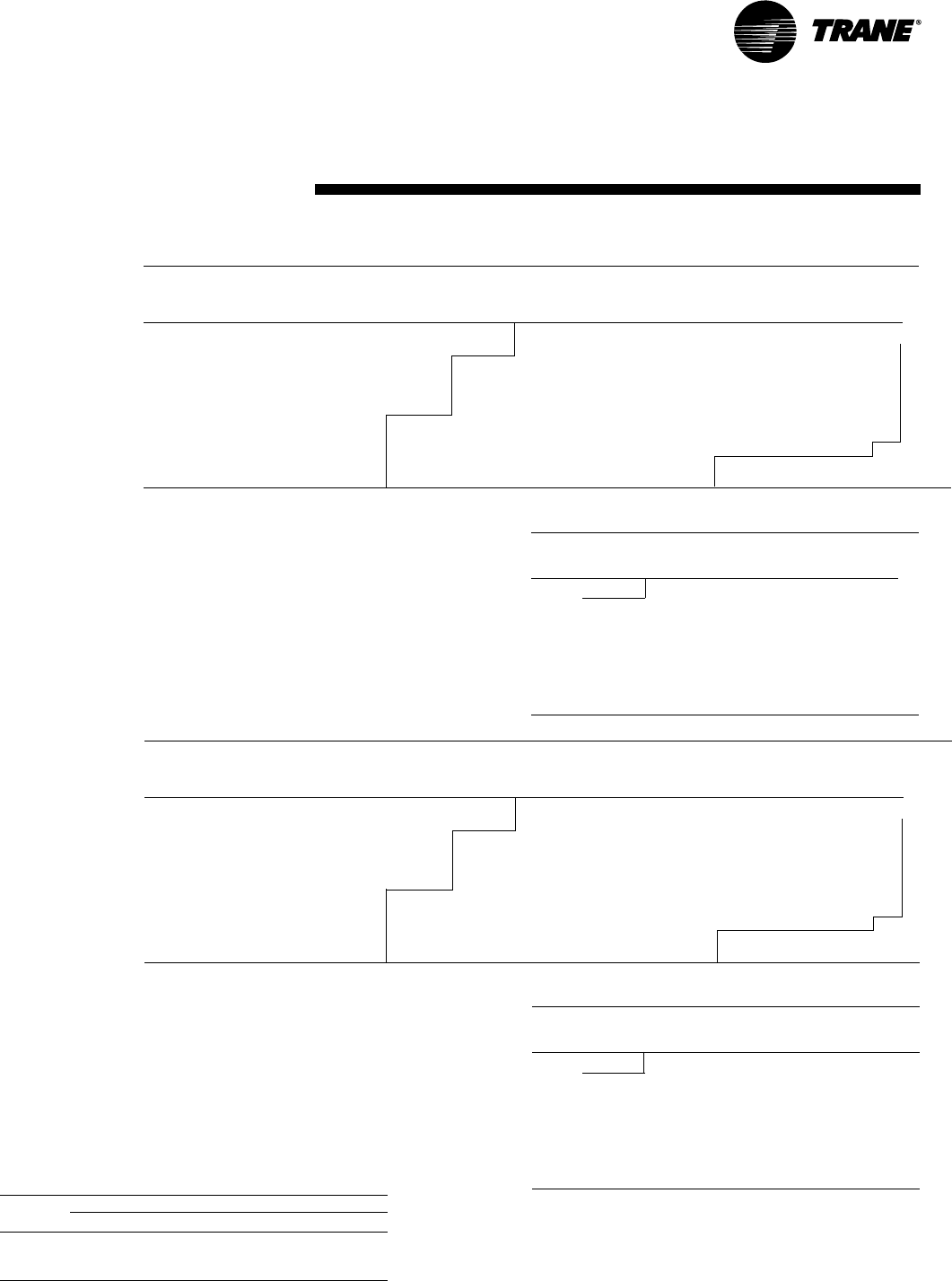
Outdoor Heating Capacity (KW) At Total Power in Kilowatts At
Temperature Indicated Indoor Dry Bulb Temperature Indicated Indoor Dry Bulb Temperature
(°C) 15.6 21.1 23.9 26.7 15.6 21.1 23.9 26.7
-27.8 10.2 8.9 8.4 7.9 5.5 6.0 6.2 6.5
-25.0 10.4 9.2 8.8 8.4 5.6 6.1 6.3 6.6
-22.2 10.7 9.7 9.3 9.0 5.7 6.2 6.5 6.7
-19.4 11.1 10.3 10.0 9.7 5.8 6.3 6.6 6.9
-16.7 11.6 11.0 10.7 10.6 5.9 6.5 6.7 7.0
-13.9 12.3 11.8 11.6 11.5 6.0 6.6 6.9 7.2
-11.1 13.1 12.7 12.6 12.6 6.2 6.7 7.0 7.4
-8.3 14.1 13.8 13.7 13.7 6.3 6.9 7.2 7.5
-5.6 15.1 15.0 14.9 14.9 6.5 7.0 7.4 7.7
-2.8 16.3 16.2 16.2 16.2 6.6 7.2 7.5 7.9
0 . 0 1 7. 7 1 7. 6 1 7. 6 1 7. 6 6 . 8 7. 4 7. 7 8 . 1
2.8 19.0 19.0 19.0 18.9 6.9 7.6 7.9 8.3
5.6 20.5 20.4 20.4 20.3 7.1 7.8 8.1 8.5
8.3 22.0 21.9 21.9 21.8 7.3 8.0 8.4 8.8
11.1 23.6 23.5 23.4 23.3 7.5 8.2 8.6 9.0
13.9 25.2 25.1 25.0 24.9 7.7 8.4 8.8 9.2
16.7 26.9 26.7 26.6 26.4 7.9 8.7 9.1 9.5
19.4 28.6 28.3 28.2 28.0 8.1 8.9 9.3 9.8
22.2 30.4 30.0 29.8 29.6 8.4 9.2 9.6 10.0
Correction Factors - Other Airflows
(Table Value x Correction Factor = Value at new airflow)
Airflow 2250 CFM 2750 CFM
1061 L/s 1297 L/s
Heating Capacity x 0.99 x 1.01
Compressor Kw x 1.02 x 0.98
Values at ARI Rating Conditions of:
70F (21.1C) and 47/43F (8.3/6.1C)(High Temp.Cond.)
70F (21.1C) and 17/15F (-8.3/-9.4C)(Low Temp. Cond)
Airflow = 2500 cfm (1179 L/s)
Heating Capacity (High Temp.) = 75,000 (21.82)
Heating Capacity (Low Temp.) = 47,000 (13.84)
Compressor Power (High Temp) = 5.41 kW
Compressor Power (Low Temp) = 4.55 kW
Coeff. Of Perf. (High Temp) = 3.2
Coeff. Of Perf. (Low Temp) = 2.3
Outdoor Fan Power = 550 watts
Indoor Fan Power = 800 watts
Note:
1. Rated with 25 feet of 1-3/8" suction and 1/2" liquid line.
Outdoor Heating Capacity (BTUH/1000) At Total Power in Kilowatts At
Temperature Indicated Indoor Dry Bulb Temperature Indicated Indoor Dry Bulb Temperature
(°F) 60 70 75 80 60 70 75 80
-18 34.9 30.4 28.5 26.9 5.5 5.6 5.7 5.8
-13 35.5 31.5 30.0 28.6 5.5 5.6 5.7 5.9
-8 36.5 33.1 31.8 30.6 5.4 5.6 5.8 5.9
-3 37.9 35.0 34.0 33.2 5.4 5.6 5.8 6.0
2 39.7 37.5 36.7 36.1 5.4 5.7 5.9 6.1
7 42.0 40.3 39.7 39.3 5.4 5.7 6.0 6.2
12 44.8 43.5 43.1 42.9 5.5 5.8 6.1 6.3
17 48.0 47.1 46.9 46.8 5.5 5.9 6.2 6.5
22 51.7 51.1 51.0 50.9 5.6 6.0 6.3 6.6
27 55.8 55.4 55.3 55.3 5.7 6.2 6.4 6.8
32 60.3 60.1 60.0 60.0 5.8 6.3 6.6 6.9
37 65.0 64.8 64.7 64.7 5.9 6.5 6.8 7.1
42 69.9 69.7 69.6 69.5 6.0 6.6 6.9 7.3
47 75.1 74.8 74.7 74.5 6.2 6.8 7.1 7.5
52 80.6 80.2 79.9 79.6 6.3 7.0 7.3 7.6
57 86.2 85.6 85.3 84.9 6.5 7.1 7.5 7.8
62 92.0 91.2 90.8 90.2 6.7 7.3 7.7 8.0
67 97.8 96.8 96.2 95.6 6.9 7.5 7.9 8.2
72 103.7 102.5 101.9 101.2 7.1 7.7 8.1 8.4
Table PD-9 — Gross Heating Capacities (MBh)
TWA075A Heat Pump with TWE075A Air Handler At 2500 CFM
Table PD-9 — Gross Heating Capacities (KW)
TWA075A Heat Pump with TWE075A Air Handler At 1180 L/S

21TWA-PRC001-EN
Performance
Data (System)
Outdoor Heating Capacity (KW) At Total Power in Kilowatts At
Temperature Indicated Indoor Dry Bulb Temperature Indicated Indoor Dry Bulb Temperature
(°C) 15.6 21.1 23.9 26.7 15.6 21.1 23.9 26.7
-27.8 6.4 11.6 12.6 13.1 5.5 6.0 6.2 6.5
-25.0 9.8 12.8 13.5 13.9 5.6 6.1 6.3 6.6
-22.2 11.9 13.9 14.4 14.7 5.7 6.2 6.5 6.7
-19.4 13.7 15.1 15.4 15.6 5.8 6.3 6.6 6.9
-16.7 15.3 16.3 16.6 16.7 5.9 6.5 6.7 7.0
-13.9 16.9 17.6 17.8 17.8 6.0 6.6 6.9 7.2
-11.1 18.5 19.0 19.1 19.1 6.2 6.7 7.0 7.4
-8.3 20.2 20.4 20.5 20.4 6.3 6.9 7.2 7.5
-5.6 21.9 22.0 22.0 21.9 6.5 7.0 7.4 7.7
-2.8 23.7 23.7 23.6 23.5 6.6 7.2 7.5 7.9
0.0 25.6 25.4 25.3 25.2 6.8 7.4 7.7 8.1
2 . 8 2 7. 4 2 7. 2 2 7. 1 2 7. 0 6 . 9 7.6 7.9 8.3
5.6 29.3 29.1 29.0 28.8 7.1 7.8 8.1 8.5
8.3 31.3 31.0 30.9 30.8 7.3 8.0 8.4 8.8
11.1 33.5 33.1 33.0 32.9 7.5 8.2 8.6 9.0
13.9 35.7 35.3 35.2 35.0 7.7 8.4 8.8 9.2
16.7 38.0 37.6 37.4 37.3 7.9 8.7 9.1 9.5
19.4 40.3 39.9 39.7 39.6 8.1 8.9 9.3 9.8
22.2 42.7 42.3 42.1 41.9 8.4 9.2 9.6 10.0
Correction Factors - Other Airflows
(Table Value x Correction Factor = Value at new airflow)
Airflow 3000 CFM 3675 CFM
1416 L/s 1734 L/s
Heating Capacity x 0.99 x 1.01
Compressor Kw x 1.02 x 0.98
Values at ARI Rating Conditions of:
70F (21.1C) and 47/43F (8.3/6.1C)(High Temp.Cond.)
70F (21.1C) and 17/15F (-8.3/-9.4C)(Low Temp. Cond)
Airflow = 3325 cfm (1569 L/s)
Heating Capacity (High Temp.) = 106,000 (31.05)
Heating Capacity (Low Temp.) = 69,000 (20.29)
Compressor Power (High Temp) = 7.61 kW
Compressor Power (Low Temp) = 6.38 kW
Coeff. Of Perf. (High Temp) = 3.30
Coeff. Of Perf. (Low Temp) = 2.4
Outdoor Fan Power = 644 watts
Indoor Fan Power = 1,170 watts
Note:
1. Rated with 25 feet of 1-3/8" suction and 1/2" liquid line.
Table PD-10 — Gross Heating Capacities (KW)
TWA100A Heat Pump with TWE100A Air Handler At 1570 L/S
Outdoor Heating Capacity (BTUH/1000) At Total Power in Kilowatts At
Temperature Indicated Indoor Dry Bulb Temperature Indicated Indoor Dry Bulb Temperature
(°F) 60 70 75 80 60 70 75 80
-18 21.9 39.6 43.0 44.8 5.6 7.3 7.9 8.4
-13 33.4 43.6 46.0 47.3 6.2 7.5 8.0 8.5
-8 40.8 47.5 49.2 50.2 6.6 7.6 8.1 8.6
-3 46.7 51.5 52.8 53.4 6.8 7.8 8.2 8.7
2 52.3 55.7 56.5 57.0 7.0 7.9 8.4 8.8
7 57.7 60.1 60.6 60.8 7.2 8.1 8.5 8.9
12 63.2 64.8 65.1 65.1 7.4 8.2 8.6 9.1
17 68.9 69.8 69.9 69.8 7.5 8.4 8.8 9.2
22 74.8 75.1 75.1 74.9 7.7 8.5 9.0 9.4
27 80.9 80.8 80.6 80.3 7.9 8.7 9.1 9.6
32 87.3 86.8 86.5 86.2 8.0 8.9 9.4 9.8
37 93.6 92.9 92.6 92.2 8.2 9.1 9.6 10.1
42 100.2 99.3 98.9 98.5 8.4 9.3 9.8 10.3
47 107.1 106.0 105.6 105.2 8.6 9.5 10.1 10.6
52 114.4 113.2 112.7 112.3 8.8 9.8 10.3 10.9
57 121.9 120.6 120.1 119.7 9.1 10.1 10.6 11.2
62 129.7 128.3 127.8 127.3 9.3 10.4 10.9 11.5
67 137.7 136.2 135.6 135.1 9.6 10.7 11.2 11.9
72 145.9 144.3 143.7 143.2 9.9 11.0 11.6 12.2
Table PD-10 — Gross Heating Capacities (MBh)
TWA100A Heat Pump with TWE100A Air Handler At 3325 CFM

TWA-PRC001-EN22
Performance
Data (System)
Table PD-11 — Gross Heating Capacities (KW)
TWA155B Heat Pump with TWE155B Air Handler At 2360 L/S
Outdoor Heating Capacity (BTUH/1000) At Total Power in Kilowatts At
Temperature Indicated Indoor Dry Bulb Temperature Indicated Indoor Dry Bulb Temperature
(°F) 60 70 75 80 60 70 75 80
-18 69.7 60.9 57.2 54.0 11.1 11.4 11.5 11.8
-13 71.1 63.2 60.2 57.4 11.0 11.3 11.6 11.8
-8 73.1 66.4 63.9 61.6 11.0 11.4 11.6 12.0
-3 76.0 70.4 68.4 66.8 10.9 11.4 11.7 12.1
2 79.8 75.4 73.9 72.7 10.9 11.5 11.9 12.3
7 84.5 81.1 80.0 79.3 11.0 11.6 12.1 12.6
12 90.2 87.7 87.0 86.6 11.1 11.8 12.3 12.8
17 96.7 95.1 94.6 94.4 11.2 12.0 12.5 13.1
22 104.2 103.2 102.9 102.8 11.3 12.2 12.8 13.4
27 112.6 111.9 111.8 111.8 11.5 12.5 13.1 13.7
32 121.8 121.4 121.3 121.3 11.7 12.8 13.4 14.1
37 131.3 131.0 130.8 130.7 12.0 13.1 13.8 14.4
42 141.4 140.9 140.7 140.5 12.3 13.4 14.1 14.8
47 151.9 151.3 151.0 150.6 12.6 13.8 14.5 15.2
52 163.0 162.2 161.6 161.0 12.9 14.1 14.8 15.6
57 174.4 173.3 172.5 171.7 13.2 14.5 15.2 15.9
62 186.2 184.6 183.6 182.6 13.6 14.9 15.6 16.3
67 198.0 196.0 194.8 193.5 14.0 15.3 16.0 16.7
72 210.0 207.6 206.2 204.8 14.4 15.7 16.4 17.1
Table PD-11 — Gross Heating Capacities (MBh)
TWA155B Heat Pump with TWE155B Air Handler At 5000 CFM
Outdoor Heating Capacity (KW) At Total Power in Kilowatts At
Temperature Indicated Indoor Dry Bulb Temperature Indicated Indoor Dry Bulb Temperature
(°C) 15.6 21.1 23.9 26.7 15.6 21.1 23.9 26.7
-27.8 20.4 17.8 16.8 15.8 5.5 6.0 6.2 6.5
-25.0 20.8 18.5 17.6 16.8 5.6 6.1 6.3 6.6
-22.2 21.4 19.4 18.7 18.0 5.7 6.2 6.5 6.7
-19.4 22.3 20.6 20.0 19.6 5.8 6.3 6.6 6.9
-16.7 23.4 22.1 21.6 21.3 5.9 6.5 6.7 7.0
-13.9 24.7 23.8 23.4 23.2 6.0 6.6 6.9 7.2
-11.1 26.4 25.7 25.5 25.3 6.2 6.7 7.0 7.4
-8.3 28.3 27.8 27.7 27.6 6.3 6.9 7.2 7.5
-5.6 30.5 30.2 30.1 30.1 6.5 7.0 7.4 7.7
-2.8 33.0 32.8 32.7 32.7 6.6 7.2 7.5 7.9
0.0 35.7 35.5 35.5 35.5 6.8 7.4 7.7 8.1
2.8 38.5 38.3 38.3 38.3 6.9 7.6 7.9 8.3
5.6 41.441.341.241.1 7.1 7.8 8.1 8.5
8.3 44.5 44.3 44.2 44.1 7.3 8.0 8.4 8.8
11.1 47.7 47.5 47.3 47.2 7.5 8.2 8.6 9.0
13.9 51.1 50.7 50.5 50.3 7.7 8.4 8.8 9.2
16.7 54.5 54.0 53.8 53.5 7.9 8.7 9.1 9.5
19.4 58.0 57.4 57.0 56.7 8.1 8.9 9.3 9.8
22.2 61.5 60.8 60.4 60.0 8.4 9.2 9.6 10.0
Correction Factors - Other Airflows“(Table Value
Correction Factor = Value at new airflow)
Airflow 4500 CFM 5500 CFM“
2124 L/s 2596 L/s
Heating Capacity x 0.99 x 1.01
Compressor Kw x 1.02 x 0.98
Values at ARI Rating Conditions of:
70F (21.1C) and 47/43F (8.3/6.1C)(High Temp.Cond.)
70F (21.1C) and 17/15F (-8.3/-9.4C)(Low Temp. Cond)
Airflow = 5000 cfm (2360 L/s)
Heating Capacity (High Temp.) = 151,000 (44.27)
Heating Capacity (Low Temp.) = 95,000 (27.67)
Compressor Power (High Temp) = 10.94 kW
Compressor Power (Low Temp) = 9.18 kW
Coeff. Of Perf. (High Temp) = 3.2
Coeff. Of Perf. (Low Temp) = 2.3
Outdoor Fan Power = 1100 watts
Indoor Fan Power = 1700 watts
Note:
1.Rated with 25 feet of 1-3/8"" suction and 1/2"" liquid line."
23TWA-PRC001-EN
Performance
Data (System)
Outdoor Heating Capacity (BTUH/1000) At Total Power in Kilowatts At
Temperature Indicated Indoor Dry Bulb Temperature Indicated Indoor Dry Bulb Temperature
(°F) 60 70 75 80 60 70 75 80
-18 43.5 80.3 85.7 88.4 10.8 14.5 15.6 16.5
-13 68.9 87.1 91.0 93.0 12.3 14.8 15.8 16.7
-8 82.3 94.2 97.0 98.4 13.0 15.1 16.0 16.8
-3 93.2 101.6 103.6 104.5 13.4 15.3 16.2 17.1
2 103.5 109.4 110.8 111.3 13.8 15.6 16.4 17.3
7 113.7 117.8 118.6 118.8 14.1 15.8 16.7 17.6
12 124.2 126.8 127.2 127.1 14.5 16.1 17.0 17.9
17 135.0 136.4 136.5 136.1 14.8 16.4 17.3 18.2
22 146.2 146.7 146.5 146.0 15.1 16.7 17.6 18.5
27 157.9 157.6 157.2 156.6 15.4 17.1 18.0 18.9
32 170.2 169.3 168.8 168.1 15.7 17.4 18.4 19.4
37 182.4 181.2 180.5 179.8 16.0 17.8 18.8 19.8
42 195.1 193.5 192.7 192.0 16.4 18.2 19.2 20.3
47 208.4 206.5 205.7 205.0 16.7 18.6 19.7 20.8
52 222.4 220.3 219.4 218.7 17.2 19.1 20.2 21.3
57 236.9 234.6 233.6 232.9 17.6 19.6 20.7 21.9
62 251.7 249.2 248.2 247.4 18.1 20.1 21.2 22.4
67 266.7 264.0 262.9 262.1 18.5 20.6 21.8 23.0
72 282.3 279.4 278.2 277.2 19.1 21.2 22.4 23.7
Table PD-12 — Gross Heating Capacities (MBh)
TWA200B Heat Pump with TWE200B Air Handler At 6675 CFM
Outdoor Heating Capacity (KW) At Total Power in Kilowatts At
Temperature Indicated Indoor Dry Bulb Temperature Indicated Indoor Dry Bulb Temperature
(°C) 15.6 21.1 23.9 26.7 15.6 21.1 23.9 26.7
27.8 12.7 23.5 25.1 25.9 5.5 6.0 6.2 6.5
-25.0 20.2 25.5 26.6 27.2 5.6 6.1 6.3 6.6
-22.2 24.1 27.6 28.4 28.8 5.7 6.2 6.5 6.7
-19.4 27.3 29.7 30.3 30.6 5.8 6.3 6.6 6.9
-16.7 30.3 32.0 32.4 32.6 5.9 6.5 6.7 7.0
-13.9 33.3 34.5 34.7 34.8 6.0 6.6 6.9 7.2
-11.1 36.4 37.1 37.2 37.2 6.2 6.7 7.0 7.4
-8.3 39.5 39.9 40.0 39.9 6.3 6.9 7.2 7.5
-5.6 42.8 42.9 42.9 42.7 6.5 7.0 7.4 7.7
-2.8 46.2 46.2 46.0 45.9 6.6 7.2 7.5 7.9
0.0 49.8 49.6 49.4 49.2 6.8 7.4 7.7 8.1
2.8 53.4 53.0 52.8 52.6 6.9 7.6 7.9 8.3
5.6 57.1 56.7 56.4 56.2 7.1 7.8 8.1 8.5
8.3 61.0 60.5 60.2 60.0 7.3 8.0 8.4 8.8
11.1 65.1 64.5 64.3 64.0 7.5 8.2 8.6 9.0
13.9 69.4 68.7 68.4 68.2 7.7 8.4 8.8 9.2
16.7 73.7 73.0 72.7 72.4 7.9 8.7 9.1 9.5
19.4 78.1 77.3 77.0 76.7 8.1 8.9 9.3 9.8
22.2 82.7 81.8 81.5 81.2 8.4 9.2 9.6 10.0
Correction Factors - Other Airflows
(Table Value x Correction Factor = Value at new airflow)
Airflow 6000 CFM 7325 CFM
2832 L/s 3457 L/s
Heating Capacity x 0.99 x 1.01
Compressor Kw x 1.02 x 0.98
Values at ARI Rating Conditions of:
70F (21.1C) and 47/43F (8.3/6.1C)(High Temp.Cond.)
70F (21.1C) and 17/15F (-8.3/-9.4C)(Low Temp. Cond)
Airflow = 6700 cfm (3162 L/s)
Heating Capacity (High Temp.) = 206,000 (60.26)
Heating Capacity (Low Temp.) = 135,000 (39.66)
Compressor Power (High Temp) = 14.92 kW
Compressor Power (Low Temp) = 12.62 kW
Coeff. Of Perf. (High Temp) = 3.2
Coeff. Of Perf. (Low Temp) = 2.4
Outdoor Fan Power = 1,100 watts
Indoor Fan Power = 2,290 watts
Note:
1. Rated with 25 feet of 1-3/8” suction and 1/2" liquid line."
Table PD-12 — Gross Heating Capacities (KW)
TWA200B Heat Pump with TWE200B Air Handler At 3150 L/S
TWA-PRC001-EN24
Performance
Data (Air Handler)
Table PD-14 — Blower Speeds
Motor DriveTurns Open
Drive 6543210
Standard N/A 590 639 688 737 786 835
High Static N/A 713 772 832 891 951 1009
Table PD-13 — Evaporator Fan Performance — TWE050A
External Static Pressure (Inches of Water Gauge)
.10" .20" .30" .40" .50" .60" .70" .80" .90" 1.00" 1.10"
CFM RPM BHP RPM BHP RPM BHP RPM BHP RPM BHP RPM BHP RPM BHP RPM BHP RPM BHP RPM BHP RPM BHP
0.75 HP Standard Motor and Drive
1400 ————6460.37 698 0.42 751 0.47 803 0.52 856 0.56 908 0.61 941 0.65 973 0.68 1006 0.71
1500 — — 607 0.36 661 0.40 713 0.45 764 0.50 816 0.54 867 0.59 919 0.64 952 0.67 984 0.71 — —
1600 — — 625 0.38 676 0.43 727 0.48 778 0.52 828 0.57 879 0.62 930 0.67 963 0.70 995 0.74 — —
1700 601 0.35 648 0.40 696 0.44 744 0.49 792 0.54 841 0.59 889 0.64 937 0.69 971 0.73 1005 0.77 — —
1800 625 0.36 671 0.41 716 0.46 762 0.51 807 0.56 853 0.61 898 0.66 944 0.71 979 0.76 ————
1900 642 0.40 687 0.45 731 0.50 776 0.55 820 0.60 865 0.66 909 0.71 951 0.75 987 0.80 ————
2000 659 0.44 703 0.49 745 0.54 790 0.60 833 0.65 877 0.70 920 0.75 957 0.80 994 0.84 ————
2100 674 0.48 722 0.54 770 0.60 817 0.65 857 0.70 897 0.75 936 0.80 973 0.85 1009 0.89 ————
1.0 HP Oversized Motor and High Static Drive
Table PD-13— Evaporator Fan Performance — TWE050A
External Static Pressure (Pascal)
25 50 75 100 125 150 174 199 224 249 274
L/S RPM KW RPM KW RPM KW RPM KW RPM KW RPM KW RPM BHP RPM BHP RPM KW RPM KW RPM KW
0.56 Standard Motor and Drive
661 646 0.28 698 0.31 751 0.35 803 0.39 856 0.42 908 0.45 941 0.48 973 0.51 1006 0.53
708 607 0.27 661 0.30 713 0.34 764 0.37 816 0.40 867 0.44 919 0.48 952 0.50 984 0.53 — —
755 625 0.28 676 0.32 727 0.36 778 0.39 828 0.43 879 0.46 930 0.50 963 0.52 995 0.55 — —
802 601 0.26 648 0.30 696 0.33 744 0.37 792 0.40 841 0.44 889 0.48 937 0.51 971 0.54 1005 0.57 — —
850 625 0.27 671 0.31 716 0.34 762 0.38 807 0.42 853 0.45 898 0.49 944 0.53 979 0.57 ————
897 642 0.30 687 0.34 731 0.37 776 0.41 820 0.45 865 0.49 909 0.53 951 0.56 987 0.60 ————
944 659 0.33 703 0.37 745 0.40 790 0.45 833 0.48 877 0.52 920 0.56 957 0.60 994 0.67 ————
991 674 0.36 722 0.40 770 0.45 817 0.48 857 0.52 897 0.56 936 0.60 973 0.63 1009 0.66 ————
0.75 KW Oversized Motor and High Static Drive
Notes:
1. Performance based on a wet coil and 1 inch (25.4 mm) throwaway filters.
2. Tabulated brake horsepower is the motor shaft output required.
3. Factory setting of motor sheave is 1.5 turns open. Adjustments are made in
0.5 turn increments.
25TWA-PRC001-EN
Performance
Data (Air Handler)
Table PD-15 — Evaporator Fan Performance TWE075A
External Static Pressure (Pascal)
25 50 75 100 125 150 174 199 224 249 274
L/S RPM KW RPM KW RPM KW RPM KW RPM KW RPM KW RPM KW RPM KW RPM KW RPM KW RPM KW
944 443 0.33 489 0.37 535 0.40 581 0.44 627 0.48 673 0.51 719 0.55 765 0.59 791 0.62 818 0.66
1003 453 0.34 499 0.39 546 0.43 592 0.47 638 0.51 684 0.55 730 0.59 771 0.63 798 0.67 825 0.72
1062 463 0.37 510 0.41 556 0.45 602 0.50 649 0.54 695 0.59 742 0.63 776 0.68 804 0.72 831 0.77
1121 473 0.38 520 0.43 567 0.48 613 0.52 660 0.57 706 0.62 753 0.67 782 0.72 810 0.77 838 0.82
1180 445 0.35 489 0.40 533 0.45 578 0.50 622 0.54 667 0.60 711 0.64 756 0.69 784 0.74 813 0.80 842 0.85
1239 464 0.37 506 0.43 548 0.47 589 0.51 631 0.57 672 0.61 714 0.66 757 0.71 786 0.75 815 0.81 844 0.87
1298 484 0.40 523 0.44 562 0.49 601 0.54 640 0.58 678 0.63 717 0.68 758 0.72 787 0.77 817 0.84 847 0.90
1357 504 0.42 540 0.46 576 0.51 612 0.55 648 0.60 684 0.65 720 0.69 759 0.74 789 0.78 819 0.86 850 0.92
1416 524 0.44 557 0.48 590 0.53 624 0.57 657 0.62 690 0.66 723 0.71 760 0.75 790 0.80 821 0.87 853 0.95
Table PD-16 — Blower Speeds
Motor Drive Turns Open
Drive 6543210
Standard N/A 600 650 700 750 800 850
Low Static N/A 428 464 499 535 571 606
High Static N/A 700 750 800 850 900 950
Table PD-15 — Evaporator Fan Performance TWE075A
External Static Pressure (In. Of Water Column)
0.10 0.20 0.30 0.40 0.50 0.60 0.70 0.80 0.90 1.00 1.10
CFM RPM BHP RPM BHP RPM BHP RPM BHP RPM BHP RPM BHP RPM BHP RPM BHP RPM BHP RPM BHP RPM BHP
2000 443 0.44 489 0.49 535 0.54 581 0.59 627 0.64 673 0.69 719 0.74 765 0.79 791 0.83 818 0.89
2125 453 0.46 499 0.52 546 0.57 592 0.63 638 0.68 684 0.74 730 0.79 771 0.85 798 0.90 825 0.96
2250 463 0.49 510 0.55 556 0.61 602 0.67 649 0.73 695 0.79 742 0.85 776 0.91 804 0.97 831 1.03
2375 473 0.51 520 0.57 567 0.64 613 0.70 660 0.77 706 0.83 753 0.90 782 0.97 810 1.03 838 1.10
2500 445 0.47 489 0.54 533 0.60 578 0.67 622 0.73 667 0.80 711 0.86 756 0.93 784 0.99 813 1.07 842 1.14
2625 464 0.50 506 0.57 548 0.63 589 0.69 631 0.76 672 0.82 714 0.88 757 0.95 786 1.01 815 1.09 844 1.17
2750 484 0.53 523 0.59 562 0.66 601 0.72 640 0.78 678 0.84 717 0.91 758 0.97 787 1.03 817 1.12 847 1.21
2875 504 0.56 540 0.62 576 0.68 612 0.74 648 0.81 684 0.87 720 0.93 759 0.99 789 1.05 819 1.15 850 1.24
3000 524 0.59 557 0.65 590 0.71 624 0.77 657 0.83 690 0.89 723 0.95 760 1.01 790 1.07 821 1.17 853 1.27
1.0 HP Standard Motor
and Low Static Drive 1.5 HP Oversized Motor
and High Static Drive
External Static Pressure (In. Of Water Column)
120 1.30 1.40 1.50 1.60
CFM RPM BHP RPM BHP RPM BHP RPM BHP RPM BHP
2000 844 0.96 871 1.02 897 1.09 924 1.15 950 1.21
2125 852 1.03 879 1.09 906 1.16 933 1.22
2250 859 1.10 886 1.17 914 1.23 942 1.30
2375 866 1.17 894 1.24 922 1.30 950 1.37
2500 870 1.21 899 1.29 928 1.36
2625 874 1.25 903 1.33 932 1.42
2750 877 1.29 907 1.38 937 1.47
2875 880 1.33 911 1.43 942 1.52
3000 884 1.37 915 1.48 946 1.58
Notes:
1. Performance based on a wet coil and 1 inch (25.4 mm) throwaway
filters.
2. Tabulated brake horsepower is the motor shaft output required.
3. Factory setting of motor sheave is 1.5 turns open. Adjustments are
made in 0.5 turn increments.
1.12 KW Oversized Motor
and High Static Drive
.75 KW Standard Motor
and High Static Drive
.75 KW Standard Motor
and High Static Drive
1.0 HP Standard Motor
and High Static Drive
External Static Pressure (Pascal)
299 324 349 374 398
L/S RPM KW RPM KW RPM KW RPM KW RPM KW
944 844 0.72 871 0.76 897 0.81 924 0.86 950 0.90
1003 852 0.77 879 0.81 906 0.87 933 0.91
1062 859 0.82 886 0.87 914 0.92 942 0.97
1121 866 0.87 894 0.92 922 0.97 950 1.02
1180 870 0,90 899 0.96 928 1.01
1239 874 0.93 903 0.99 932 1.06
1298 877 0.96 907 1.03 937 1.10
1357 880 0.99 911 1.07 942 1.13
1416 884 1.02 915 1.10 946 1.18
Table PD-15 — Continued
Table PD-15— Continued
Notes:
1. Performance based on a wet coil and 1 inch (25.4 mm) throwaway
filters.
2. Tabulated brake horsepower is the motor shaft output required.
3. Factory setting of motor sheave is 1.5 turns open. Adjustments are
made in 0.5 turn increments.
TWA-PRC001-EN26
Performance
Data (Air Handler)
Table PD-17— Evaporator Fan Performance TWE0100A, TWE100B
External Static Pressure (Pascal)
25 50 75 100 125 150 174 199 224 249 274
L/S RPM KW RPM KW RPM KW RPM KW RPM KW RPM KW RPM KW RPM KW RPM KW RPM KW RPM KW
1227 460 0.24 493 0.29 527 0.35 565 0.41 603 0.47 641 0.53 679 0.59 717 0.65 744 0.70 772 0.75 826 0.87
1310 473 0.28 576 0.34 613 0.40 649 0.45 686 0.51 723 0.57 748 0.63 775 0.69 830 0.75 884 0.80 938 0.89
1392 487 0.32 519 0.37 552 0.43 587 0.50 623 0.56 658 0.62 693 0.68 728 0.74 751 0.79 779 0.84 833 0.93
1475 501 0.37 532 0.42 565 0.48 599 0.54 632 0.60 666 0.66 700 0.72 734 0.78 755 0.83 783 0.88 737 0.97
1557 520 0.43 548 0.48 581 0.54 613 0.60 644 0.66 677 0.73 710 0.79 740 0.84 759 0.89 787 0.93 841 1.02
1640 541 0.51 568 0.57 600 0.63 631 0.69 658 0.75 691 0.80 721 0.87 746 0.90 764 0.95 793 1.00 846 1.10
1723 562 0.61 588 0.66 618 0.72 648 0.78 671 0.83 703 0.89 732 0.95 753 0.98 772 1.03 801 1.08 853 1.19
1805 582 0.72 608 0.77 637 0.83 666 0.89 685 0.94 711 0.98 739 1.03 763 1.07 787 1.13 815 1.18 862 1.30
1888 602 0.83 628 0.87 656 0.94 683 1.01 698 1.04 720 1.07 747 1.12 773 1.18 801 1.22 829 1.28 872 1.41
Table PD - 18 — Blower Speeds
Motor Sheave Turns Open
Drive 6543210
Standard N/A 587 629 671 713 755 796
Low Static N/A 453 485 518 550 583 615
High Static N/A 606 641 677 713 748 784
Table PD-17 — Evaporator Fan Performance TWE100A, TWE100B
External Static Pressure (In. Of Water Column)
0.10 0.20 0.30 0.40 0.50 0.60 0.70 0.80 0.90 1.00 1.20
CFM RPM BHP RPM BHP RPM BHP RPM BHP RPM BHP RPM BHP RPM BHP RPM BHP RPM BHP RPM BHP RPM BHP
2600 460 0.32 493 0.39 527 0.47 565 0.55 603 0.63 641 0.71 679 0.79 717 0.87 744 0.94 772 1.01 826 1.16
2775 473 0.37 506 0.45 540 0.53 576 0.61 613 0.69 649 0.77 686 0.85 723 0.93 748 1.00 775 1.07 830 1.20
2950 487 0.43 519 0.50 552 0.58 587 0.67 623 0.75 658 0.83 693 0.91 728 0.99 751 1.06 779 1.12 833 1.25
3125 501 0.49 532 0.56 565 0.64 599 0.72 632 0.81 666 0.89 700 0.97 734 1.05 755 1.11 783 1.18 737 1.30
3300 520 0.58 548 0.65 581 0.73 613 0.81 644 0.89 677 0.98 710 1.06 740 1.13 759 1.19 787 1.25 841 1.37
3475 541 0.69 568 0.76 600 0.84 631 0.93 658 1.00 691 1.08 721 1.16 746 1.21 764 1.28 793 1.34 846 1.48
3650 562 0.82 588 0.88 618 0.97 648 1.05 671 1.11 703 1.19 732 1.27 753 1.31 772 1.38 801 1.45 853 1.59
3825 582 0.96 608 1.03 637 1.11 666 1.20 685 1.26 711 1.31 739 1.38 763 1.44 787 1.51 815 1.58 862 1.74
4000 602 1.11 628 1.17 656 1.26 683 1.35 698 1.40 720 1.43 747 1.50 773 1.58 801 1.64 829 1.71 872 1.89
External Static Pressure (In. Of Water Column)
1.40 1.60
CFM RPM BHP RPM BHP
2600 881 1.30 936 1.45
2775 884 1.36 938 1.51
2960 886 1.41 939 1.57
3125 889 1.47 941 1.64
3300 892 1.54 945 1.73
3475 897 1.63 950 1.85
3650 902 1.73 955 1.99
3825 912 1.89 960 2.18
4000 922 2.04 965 2.30
Table PD-17— Continued
1.49 KW Oversized Motor
and High Static Drive
.75 KW Standard Motor
and Low Static Drive
Table PD-17— Continued
1.12 KW Standard
Motor and Drive
External Static Pressure (Pascal)
349 398
L/S RPM KW RPM KW
1227 881 0.97 936 1.08
1310 506 1.01 540 1.13
1392 886 1.05 939 1.17
1475 889 1.10 941 1.22
1557 892 1.15 945 1.29
1640 897 1.22 950 1.38
1723 902 1.29 955 1.48
1805 912 1.41 960 1.63
1888 922 1.52 965 1.72
1.5 HP Standard Motor
and Low Static Drive 2.0 HP Oversized Motor
and High Static Drive
1.5 HP Standard Motor
and Drive
Notes:
1. Performance based on a wet coil and 1 inch (25.4 mm) throwaway
filters.
2. Tabulated brake horsepower is the motor shaft output required.
3. Factory setting of motor sheave is 1.5 turns open. Adjustments are
made in 0.5 turn increments.
4. Low Static Drive must be field supplied.
Notes:
1. Performance based on a wet coil and 1 inch (25.4 mm) throwaway
filters.
2. Tabulated brake horsepower is the motor shaft output required.
3. Factory setting of motor sheave is 3.0 turns open. Adjustments are
made in 0.5 turn increments.
4. Low Static Drive must be field supplied.
27TWA-PRC001-EN
Performance
Data (Air Handler)
Table PD-20— Blower Speeds Motor Sheave Turns Open
Drive 6543210
Standard 619 648 677 705 734 763 N/A
High Static 777 806 835 863 892 921 950
Table PD-19 — Evaporator Fan Performance — TWE155B
External Static Pressure (Inches of Water Column)
.10" .20" .30" .40" .50" .60" .70" .80" .90" 1.00" 1.20" 140
CFM RPM BHP RPM BHP RPM BHP RPM BHP RPM BHP RPM BHP RPM BHP RPM BHP RPM BHP RPM BHP RPM BHP RPM BHP
2.0 HP Standard Motor and Drive 3.0 HP Oversized Motor
and High Static Drive
4000 628 1.34 653 1.38 678 1.43 692 1.48 708 1.52 723 1.57 738 1.60 749 1.61 759 1.62 795 1.66 851 1.85 907 2.03
4250 633 1.37 658 1.41 683 1.46 697 1.51 713 1.55 728 1.60 743 1.62 751 1.63 770 1.64 806 1.71 862 1.90 918 2.11
4500 637 1.40 662 1.44 687 1.49 701 1.53 717 1.58 732 1.63 747 1.64 754 1.65 782 1.67 817 1.76 873 1.96 929 2.19
4750 641 1.42 666 1.50 691 1.53 705 1.61 721 1.63 736 1.65 751 1.66 765 1.67 793 1.72 828 1.81 884 2.01 940 2.27
5000 645 1.44 670 1.52 695 1.56 710 1.65 725 1.67 739 1.68 758 1.70 777 1.74 806 1.81 839 1.91 896 2.13
5260 650 1.46 675 1.53 700 1.59 716 1.67 728 1.70 741 1.73 765 1.75 790 1.82 819 1.92 849 2.03 907 2.28
5500 652 1.47 678 1.55 703 1.63 721 1.71 734 1.75 747 1.78 775 1.83 804 1.92 832 2.03 861 2.15 920 2.44
5750 653 1.48 680 1.57 706 1.68 726 1.76 743 1.81 761 1.86 789 1.94 817 2.04 846 2.16 875 2.29 935 2.61
6000 655 1.49 681 1.59 709 1.74 731 1.80 752 1.87 774 1.94 803 2.05 831 2.17 860 2.29 889 2.44 950 2.78
Table PD-19 — Evaporator Fan Performance TWE155B
External Static Pressure (Pascal)
25 50 75 100 125 150 174 199 224 249 299 349
L/S RPM KW RPM KW RPM KW RPM KW RPM KW RPM KW RPM BHP RPM BHP RPM KW RPM KW RPM KW RPM KW
1.49 KW Standard Motor and Drive System 2.24 KW Oversized Motor
and High Static Drive System
1888 628 1.00 653 1.03 678 1.07 692 1.10 708 1.13 723 1.17 738 1.19 749 1.20 759 1.21 795 1.24 851 1.38 907 1.51
2006 633 1.02 658 1.05 683 1.09 697 1.13 713 1.16 728 1.19 743 1.21 751 1.22 770 1.22 806 1.28 862 1.42 918 1.57
2124 637 1.04 662 1.07 687 1.11 701 1.14 717 1.18 732 1.22 747 1.23 754 1.23 782 1.25 817 1.31 873 1.46 929 1.63
2242 641 1.06 666 1.12 691 1.14 705 1.20 721 1.22 736 1.23 751 1.24 765 1.25 793 1.28 828 1.35 884 1.50 940 1.69
2360 645 1.07 670 1.13 695 1.16 710 1.23 725 1.25 739 1.25 758 1.27 777 1.30 806 1.35 839 1.42 896 1.59
2482 650 1.09 675 1.14 700 1.19 716 1.25 728 1.27 741 1.29 765 1.30 790 1.36 819 1.43 849 1.51 907 1.70
2596 652 1.10 678 1.16 703 1.22 721 1.28 734 1.30 747 1.33 775 1.36 804 1.43 832 1.51 861 1.60 920 1.82
2714 653 1.10 680 1.17 706 1.25 726 1.31 743 1.30 761 1.39 789 1.45 817 1.52 846 1.61 875 1.71 935 1.95
2832 655 1.11 681 1.19 709 1.30 731 1.34 752 1.35 774 1.45 803 1.53 831 1.62 860 1.71 889 1.82 950 2.07
Notes:
1. Performance based on a wet coil and 2 inch (51 mm) throwaway filters.
2. Tabulated brake horsepower is the motor shaft output required.
3. Factory setting of motor sheave is 1.5 turns open. Adjustments are made in 0.5 turn increments.

TWA-PRC001-EN28
Performance
Data (Air Handler)
Notes:
1. Performance based on a wet coil and 2 inch (51 mm) throwaway filters.
2. Tabulated brake horsepower is the motor shaft output required.
3. Factory setting of motor sheave is 1.5 turns open. Adjustments are made in
0.5 turn increments.
Table PD-22 — Blower Speeds Motor Sheave Turns Open
Drive 6543210
Standard 706 732 758 784 811 837 863
Low Static 457 478 500 521 542 563 585
Field-Supplied Low Static 574 595 617 638 659 680 702
High Static N/A 821 862 903 945 986 1027
Table PD-21— Evaporator Fan Performance TWE200B
External Static Pressure (In. Of Water Column)
0.10 0.20 0.30 0.40 0.50 0.60 0.70 0.80 0.90 1.00 1.20 140
CFM RPM BHP RPM BHP RPM BHP RPM BHP RPM BHP RPM BHP RPM BHP RPM BHP RPM BHP RPM BHP RPM BHP RPM BHP
5200 461 0.74 503 0.91 545 1.07 587 1.03 619 1.17 685 1.40 723 1.59 750 1.74 777 1.89 851 2.19 898 2.39
5525 479 0.88 521 1.04 563 1.21 605 1.21 640 1.35 701 1.58 739 1.77 766 1.92 793 2.07 859 2.37 906 2.60
5850 497 1.01 539 1.18 581 1.34 623 1.39 661 1.53 717 1.76 755 1.95 782 2.10 809 2.25 868 2.55 915 2.81
6175 473 0.99 515 1.15 557 1.31 599 1.48 641 1.57 682 1.71 732 1.94 769 2.12 796 2.27 823 2.43 877 2.73 924 3.02
6500 492 1.12 534 1.28 576 1.45 618 1.61 660 1.75 702 1.90 748 2.12 784 2.30 811 2.45 838 2.60 886 2.91 933 3.22
6825 510 1.25 552 1.42 594 1.59 636 1.75 678 1.91 723 2.10 763 2.30 794 2.47 820 2.62 846 2.77 894 3.09 941 3.42
7150 528 1.38 570 1.56 612 1.73 654 1.90 697 2.07 744 2.30 779 2.49 804 2.64 830 2.78 855 2.94 903 3.26 950 3.62
7475 550 1.61 594 1.77 640 1.92 683 2.08 721 2.29 760 2.50 790 2.67 815 2.81 840 2.96 865 3.11 914 3.47 959 3.85
7800 572 1.83 618 1.97 668 2.10 712 2.27 746 2.52 776 2.69 802 2.84 826 2.99 851 3.13 876 3.27 926 3.67 969 4.08
3.0 Standard
Motor and
Low Static Drive 5 HP Oversized Motor
and High Static Drive
External Static Pressure (In. Of Water Column)
1.60 1.80
CFM RPM BHP RPM BHP
5200 944 2.75 989 3.12
5525 952 2.96 997 3.33
5850 961 3.17 1006 3.54
5175 970 3.38 1015 3.75
8500 978 3.59 1023 3.96
8825 986 3.80
7150 994 4.01
7475 1003 4.25
7800 1012 4.50
Table PD-21— Continued
3.0 HP Standard
Motor and Field-Supplied
Low Static Drive
Table PD-21— Evaporator Fan Performance TWE200B
External Static Pressure (Pascal)
25 50 75 100 125 150 174 199 224 249 299 349
CFM RPM BHP RPM BHP RPM BHP RPM BHP RPM BHP RPM BHP RPM BHP RPM BHP RPM BHP RPM BHP RPM BHP RPM BHP
2454 461 0.55 503 0.68 545 0.80 587 0.77 619 0.87 685 1.04 723 1.19 750 1.30 777 1.41 851 1.63 898 1.78
2608 479 0.66 521 0.78 563 0.90 605 0.90 640 1.01 701 1.18 739 1.32 766 1.43 793 1.54 859 1.77 906 1.94
2761 497 0.75 539 0.88 581 1.00 623 1.04 661 1.14 717 1.31 755 1.45 782 1.57 809 1.68 868 1.90 915 2.10
2914 473 0.74 515 0.86 557 0.98 599 1.10 641 1.17 682 1.28 732 1.45 769 1.58 796 1.69 823 1.81 877 2.04 924 2.52
3068 492 0.84 534 0.95 576 1.08 618 1.20 660 1.30 702 1.42 748 1.58 784 1.72 811 1.83 838 1.94 886 2.17 933 2.40
3221 510 0.93 552 1.06 594 1.19 636 1.30 678 1.42 723 1.57 763 1.72 794 1.84 820 1.95 846 2.07 894 2.30 941 2.55
3374 528 1.03 570 1.16 612 1.29 654 1.42 697 1.54 744 1.72 779 1.86 804 1.97 830 2.07 855 2.19 903 2.43 950 2.70
3528 550 1.20 594 1.32 640 1.43 683 1.55 721 1.71 760 1.87 790 1.99 815 2.10 840 2.21 865 2.32 914 2.59 959 2.87
3681 572 1.36 618 1.47 668 1.57 712 1.69 746 1.88 776 2.01 802 2.12 826 2.23 851 2.33 876 2.44 926 2.74 969 3.04
Standard Motor
3.0 HP and
Low Static Drive 5 HP Oversized Motor
and High Static Drive
External Static Pressure (Pascal)
398 448
CFM RPM BHP RPM BHP
2454 944 2.05 989 2.33
2608 952 2.21 997 2.48
2761 961 2.36 1006 2.64
2914 970 2.52 1015 2.80
3068 978 2.68 1023 2.95
3221 941 2.55 986 2.83
3374 994 2.99
3528 1003 3.17
3681 1012 3.36
Table PD-21— Continued
3.0 HP Standard
Motor and Field-Supplied
Low Static Drive
Notes:
1. Performance based on a wet coil and 2 inch (51 mm) throwaway filters.
2. Tabulated brake horsepower is the motor shaft output required.
3. Factory setting of motor sheave is 1.5 turns open. Adjustments are made in 0.5 turn
increments.

29TWA-PRC001-EN
Performance
Data
Table PD-23— Discharge Plenum And Grille Assembly Throw Distance — Air Handler
Unit Louver Angle Deflection Position
Model No. CFM L/S Straight 20, Ft. (m) 40, Ft. (m) 55, Ft. (m)
1400 661 38 (11.6) 24 (7.3) 22 (6.7) 18 (5.5)
1600 755 42 (12.8) 31 (9.4) 26 (7.9) 20 (6.1)
TWE050 1800 850 46 (14.0) 37 (11.3) 29 (8.8) 22 (6.7)
2000 944 48 (14.6) 43 (13.1) 33 (10.1) 24 (7.3)
2200 1038 51 (15.5) 50 (15.2) 36 (11.0) 25 (7.6)
2100 991 49 (14.9) 38 (11.6) 31 (9.4) 27 (8.2)
2400 1133 52 (15.9) 43 (13.1) 35 (10.7) 29 (8.8)
2700 1274 55 (16.8) 48 (14.6) 38 (11.6) 31 (9.4)
TWE075 3000 1416 58 (17.7) 53 (16.2) 42 (12.8) 32 (9.8)
3200 1510 56 (17.1) 46 (14.0) 38 (11.6) 30 (9.1)
3600 1699 62 (18.9) 51 (15.5) 42 (12.8) 33 (10.1)
4000 1888 66 (20.1) 57 (17.4) 47 (14.3) 35 (10.7)
4400 2077 71 (21.6) 62 (18.9) 52 (15.9) 38 (11.6)
TWE100 4800 2265 76 (23.2) 67 (20.4) 56 (17.1) 42 (12.8)
4300 2029 42 (12.8) 32 (9.8) 29 (8.8) 21 (6.4)
4900 2313 47 (14.3) 38 (11.6) 32 (9.8) 25 (7.6)
5400 2549 52 (15.9) 44 (13.4) 37 (11.3) 29 (8.8)
TWE155 6000 2832 57 (17.4) 49 (14.9) 41 (12.5) 32 (9.8)
5600 2643 50 (15.2) 40 (12.2) 33 (10.1) 27 (8.2)
6400 3020 56 (17.1) 46 (14.0) 38 (11.6) 30 (9.1)
7200 3398 62 (18.9) 51 (15.5) 42 (12.8) 33 (10.1)
TWE200 8000 3776 66 (20.1) 57 (17.4) 47 (14.3) 35 (10.7)
Throw distance values are based on a terminal velocity of 75 FPM (0.38 m/s).
Throw distance values at other terminal velocities may be established by multiplying throw distances in table above by
throw factor:
Terminal Velocity Throw Factor
50 FPM (.25 m/s) x 1.50
100 FPM (.51 m/s) x .75
150 FPM (.76 m/s) x .50
PD-24 — Static Pressure Drop Through Accessories — Air Handler
Discharge
Unit Return Grille Plenum and Grille2Electric Heaters (Kw)
Model No. CFM L/S In. W.C.1Pascal In. W.C.1Pascal 3.5-7 10-14 17-24 35
1400 661 .09 (22.4) .16 (39.8) .06 .06 .12 —
TWE050A 1600 755 .12 (29.9) .21 (52.3) 08 .08 .14 —
2000 944 .18 (44.8) .33 (82.2) .13 .13 .19 —
2100 991 .05 (12.5) .19 (47.3) .02 .03 .05 .08
TWE075A 2400 1133 .08 (19.9) .27 (67.2) .03 .06 .08 .12
3000 1416 .13 (32.4) .40 (99.6) .06 .12 .17 .23
TWE100A 2800 1321 .04 (10.0) .34 (84.7) .03 .04 .14 .20
TWE100B 3200 1510 .07 (17.4) .43 (107.1) .06 .13 .19 .26
4300 2029 .07 (17.4) .18 (44.8) .02 .02 .04 .05
4800 2265 .09 (22.4) .23 (57.3) .03 .03 .06 .08
TWE155B 6000 2832 .15 (37.4) .34 (84.7) .06 .06 .12 .17
5600 2643 .07 (17.4) .32 (79.7) .04 .04 .10 .15
TWE200B 6400 3020 .11 (27.4) .43 (107.1) .06 .0-6 .13 .19
8000 3776 .17 (42.3) .66 (164.3) .10 .10 .20 .30
1. Return air filter ESP included in Fan Performance Table data.
2. At louver opening angle of 42° F (5.5° C). For ESP at other angle openings, see accessory Installer’s Guide.
Throw distance values are based on a terminal velocity of 75 FPM (0.38 m/s).
Throw distance values at other terminal velocities may be established by multiplying throw distances in table above by
throw factor:
Terminal Velocity Throw Factor
50 FPM (.25 m/s) x 1.50
100 FPM (.51 m/s) x .75
150 FPM (.76 m/s) x .50
.

TWA-PRC001-EN30
Performance
Data
Table PD-25 — Auxiliary Electric Heat Capacity — Air Handler
No. Stage 1 Stage 2 Total
Unit Total of KW Btuh KW KW Btuh KW Btuh KW
Model No. KW Stages Input Output Output Input Output Output Output Output
TWE050, 075,100 3.47 1 3.47 11,851 3.47 — — — 11,851 3.47
6.92 1 9.92 23,606 6.92 — — — 23,606 6.92
10.39 1 10.39 35,457 10.39 — — — 35,457 10.39
17.31 2 10.39 35,457 10.39 6.92 23,606 6.92 59,063 17.31
TWE075, 100A, 100 24.22 2 13.83 47,213 13.83 10.39 35,457 10.39 82,670 24.22
TWE155, 200 6.94 1 6.94 23,701 6.94 — — — 23,701 6.94
13.83 1 13.83 47,213 13.83 — — — 47,213 13.83
20.78 2 13.83 47,213 13.83 6.94 23,701 6.94 70,915 20.78
34,62 2 20.78 70,915 20.78 13.84 47,213 13.89 118,128 34.61
*Heaters are rated at 400v. For other than rated voltage,
Capacity = Voltage 2 x Rated Capacity and KW = Voltage 2 x Rated KW.
(Rated Voltage )(
Rated Voltage )
31TWA-PRC001-EN
Electrical
Data
Table ED-1— Electrical Characteristics — Motors — Air Handler
Standard Fan Motor Oversized Fan Motor
Unit Amps Amps
Model No. Volts Phase FLA LRA Phase FLA LRA
TWE050 380/415 3 1.4 8.2 3 1.8 21.6
TWE075 380/415 3 3.2 19.7 3 4.0 25.5
TWE100 380/415 3 3.6 25.5 3 5.3 37.5
TWE155 380/415 3 4.6 37.5 3 6.9 39.2
TWE200 380/415 3 7.6 39.2 3 9.0 65.1
Table ED-2 — Unit Wiring — Air Handler
Minimum Maximum Fuse
Unit Unit Operating Circuit Size or Maximum
Model No. Voltage Range Ampacity Circuit Breaker
TWE050 380/415 2 15
TWE075 380/415 4 15
TWE100 380/415 5 15
TWE155 380/415 6 15
TWE200 380/415 10 15
Table ED-4 — Unit Wiring — Heat Pumps
Minimum Maximum Fuse
Unit Unit Operating Circuit Size or Maximum
Model No. Voltage Range Ampacity Circuit Breaker
TWA075 380/415 18.0 30
TWA100 380/415 25.6 40
TWA155 380/415 31.6 40
TWA200 380/415 45.2 60
Table ED-3— Electrical Characteristics — Motors — 60 Cycle — Heat Pumps
Compressor Motor Condenser Fan Motor
Amps Amps
Unit RLA LRA FLA LRA
Model No. No. Volts Phase (Ea.) (Ea.) No. Volts Phase (Ea.) (Ea.)
TWA075AD 1 380/415 3 11.0 90.0 1 380/415 1 1.6 3.7
TWA100AD 1 380/415 3 14.9 118.0 1 380/415 1 2.7 7.0
TWA155BD 2 380/415 3 11.0 90.0 2 380/415 1 1.6 3.7
TWA200BD 2 380/415 3 14.9 118.0 2 380/415 1 2.7 7.0
TWA-PRC001-EN32
Electrical
Data
Table ED-5— Unit Wiring With Electric Heat (Single Point Connection) — Air Handlers
Heater Heater To Use Control Minimum Maximum
Model No. KW Rating1with Unit Stages Circuit Ampacity 2Fuse Breaker Size 2
BAYHTRL405A 3.47 1 9 15
BAYHTRL410A 6.92 TWE050AD 1 17 20
BAYHTRL415A 10.39 1 24 25
BAYHTRL425A 17.31 2 39 40
BAYHTRL405A 3.47 1 11 15
BAYHTRL410A 6.92 1 18 20
BAYHTRL415A 10.39 TWE075AD 1 26 30
BAYHTRL425A 17.31 2 41 45
BAYHTRL435A 24.22 2 56 60
BAYHTRL405A 3.47 1 12 15
BAYHTRL410A 6.92 1 19 25
BAYHTRL415A 10.39 TWE10 0AD, TWE10 0BD 1 27 30
BAYHTRL425A 20.78 2 42 45
BAYHTRL435A 24.22 2 57 60
BAYHTRM410A 6.94 1 21 30
BAYHTRM420A 13.83 TWE155BD 1 36 40
BAYHTRM430A 20.78 2 51 60
BAYHTRM450A 34.62 2 81 90
BAYHTRM410A 6.94 1 25 40
BAYHTRM420A 13.83 TWE200BD 1 40 50
BAYHTRM430A 20.78 2 55 60
BAYHTRM450A 34.62 2 85 90
1. KW ratings are at 400v for 3 phase, 400v air handlers
For other than rated voltage, ampacity = Voltage 2 x Rated Capacity and KW = Voltage 2 Rated KW.
(Rated Voltage)(
Rated Voltage )
2. Any power supply and circuits must be wired and protected in accordance with local codes.
3. Field wire must be rated at least 75° C.
4. Field wire must be rated at least 90° C.
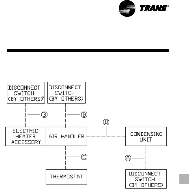
33TWA-PRC001-EN
Jobsite
Connections
Wiring shown with dashed lines is to be
furnished and installed by the customer.
All customer- supplied wiring must be
copper only and must conform to NEC
and local electrical codes. Codes may
require line of sight between disconnect
switch and unit.
NOTE:
1. When electric heater accessory is used
single point power entry or dual point
power entry is field optional. Single point
power entry option is through electric
heater only.
TWA050/TWE050
Field Wiring:
A — 3 power wires. Line voltage.
B — 3 power wires. Line voltage.
C — Heat pump thermostat: 6 wires,
24 volts.
— Electric heat: add 2 additional
wires, 24 volts.
D — 2 wires, 24 volts.
— Outdoor thermostat: add 1
additional wire per ODT, 24 volts.
— Electric heat: add 1 additional
wire, 24 volts.
(2) TWA050/TWE100B
Field Wiring:
A — 3 power wires. Line voltage.
B — 3 power wires. Line voltage.
C — Heat pump thermostat: 7 wires,
24 volts Electric Heat: add 2
additional wires, 24 volts.
D — 5 wires, 24 volts to outdoor
section ‘’A’’ 2 wires, 24 volts to
outdoor section ‘’B’’ 2 wires, 24
volts between outdoor sections
‘’A’’ ‘’B’’
— Electric heat: add 1 additional
wire, 24 volts.
— Outdoor thermostat: add 1
additional wire, 24 volt.
TWA075A/TWE075A;
TWA100A/TWE100A
Field Wiring:
A — 3 power wires, line voltage.
B — 3 power wires, line voltage.
C — Heat pump thermostat: 6 wires,
24 volts.
— Electric heat: add 2 additional
wires, 24 volts.
D — 6 wires, 24 volts.
— Outdoor thermostat: add 1
additional wire, 24 volts.
— Electric heat: add 1 additional
wire, 24 volts.
(2) TWA075A/TWE155B;
(2) TWA100A/TWE200B
Field Wiring:
A — 3 power wires, line voltage.
B — 3 power wires, line voltage.
C — Heat pump thermostat: 7 wires,
24 volts.
— Electric heat: add 2 additional
wires, 24 volts.
D — 9 wires, 24 volts.
— Electric heat: add 4 additional
wires, 24 volts.
— Outdoor thermostat: add 3
additional wires, 24 volts.
TWA155B/TWE155B;
TWA200B/TWE200B
Field Wiring:
A — 3 power wires, line voltage.
B — 3 power wires, line voltage.
C — Heat pump thermostat: 7 wires,
24 volts.
— Electric heat: add 2 additional
wires, 24 volts.
D — 7 wires, 24 volts.
— Electric heat: add 4 additional
wires, 24 volts.
— Outdoor thermostat: add 1
additional wire, 24 volts.
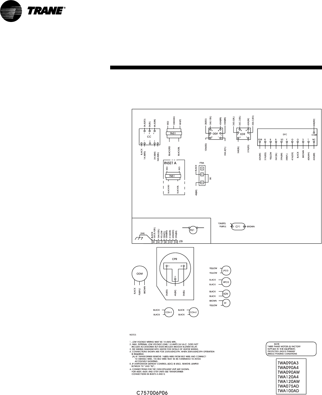
TWA-PRC001-EN34
Typical
Wiring (Heat Pump)
Heat Pump — Single Compressor
Typical unit wiring diagram. For specific
wiring, see individual Service Facts.
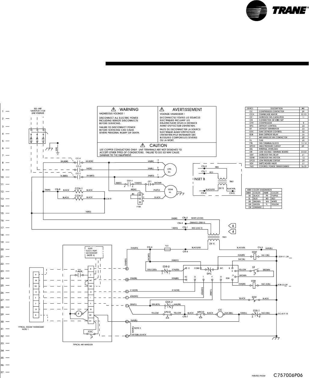
35TWA-PRC001-EN
Typical
Wiring (Heat Pump)
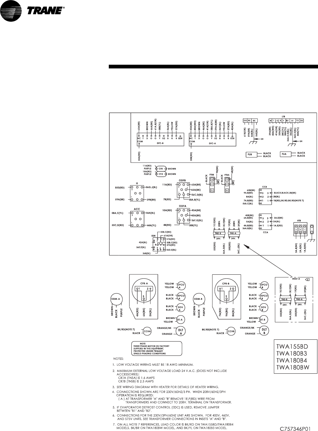
TWA-PRC001-EN36
Heat Pump — Dual Compressors
Typical unit wiring diagram. For specific
wiring, see individual Service Facts.
(Heat Pump)
Typical
Wiring
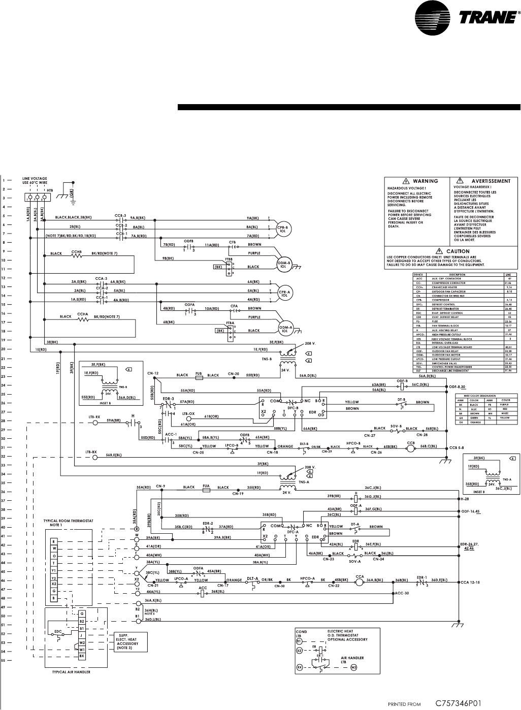
37TWA-PRC001-EN
Typical
Wiring (Heat Pump)
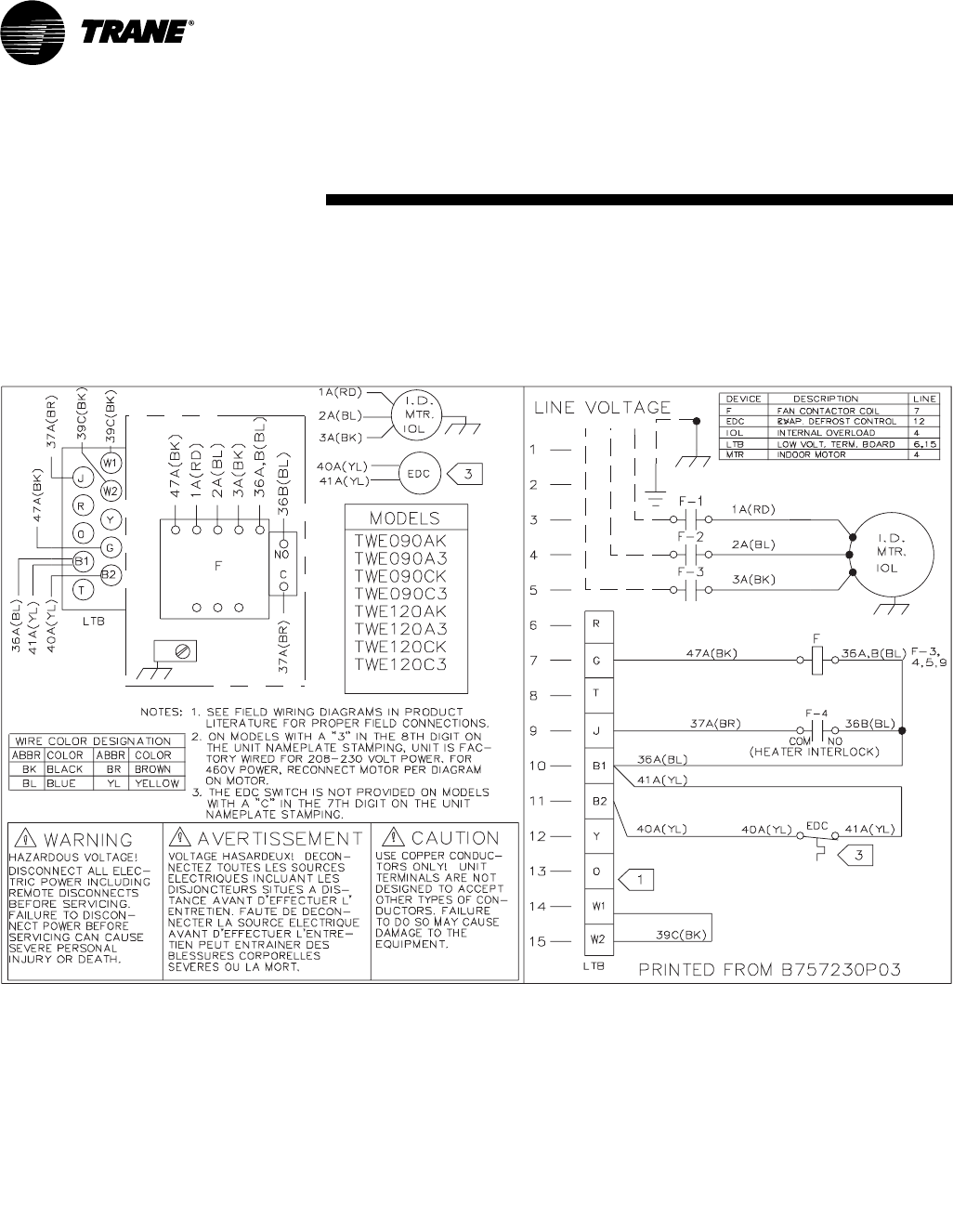
TWA-PRC001-EN38
Typical
Wiring (Air Handler)
Air Handler
Typical unit wiring diagram. For specific
wiring, see individual Service Facts.
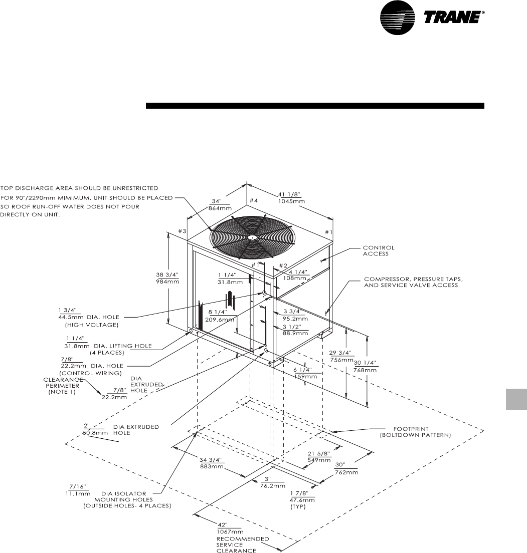
39TWA-PRC001-EN
(Heat Pump)
Dimensional
Data
Figure DD-1 — TWA075 Heat Pump
All dimensions are in inches and millimeters.
Note 1
MINIMUM CLEARANCE FOR PROPER
OPERATION IS 36 INCHES (914 MM)
FROM WALLS, SHRUBBERY, PRIVACY
FENCES, ETC. MINIMUM CLEARANCE
BETWEEN ADJACENT UNITS IS 72
INCHES (1828 MM)
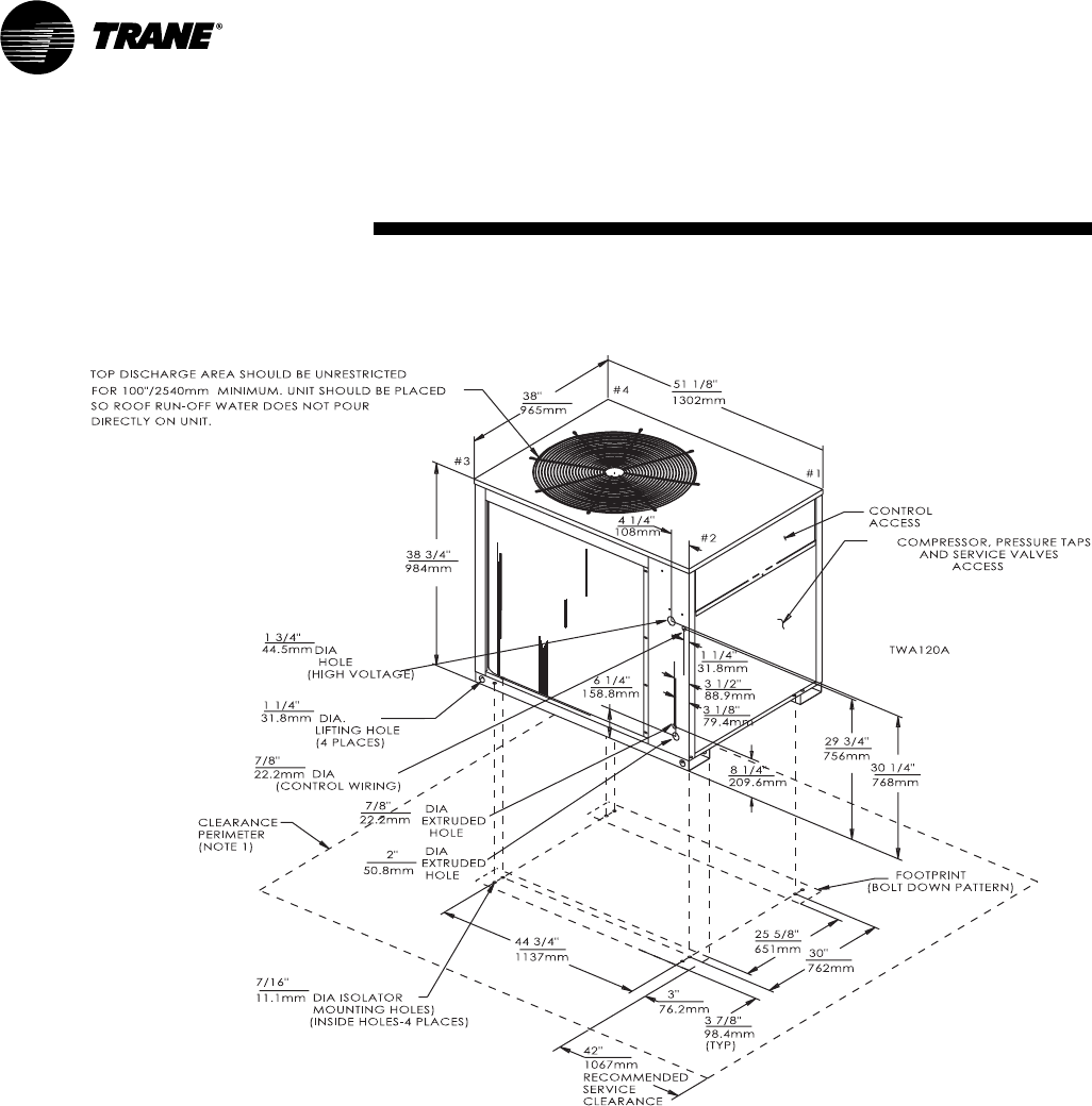
TWA-PRC001-EN40
Dimensional
Data (Heat Pump)
Figure DD-2 — 10 Ton TWA100A Heat Pump
All dimensions are in inches and millimeters.
Note 1
MINIMUM CLEARANCE FOR PROPER
OPERATION IS 36 INCHES (914 MM)
FROM WALLS, SHRUBBERY, PRIVACY
FENCES, ETC. MINIMUM CLEARANCE
BETWEEN ADJACENT UNITS IS 72
INCHES (1828 MM)
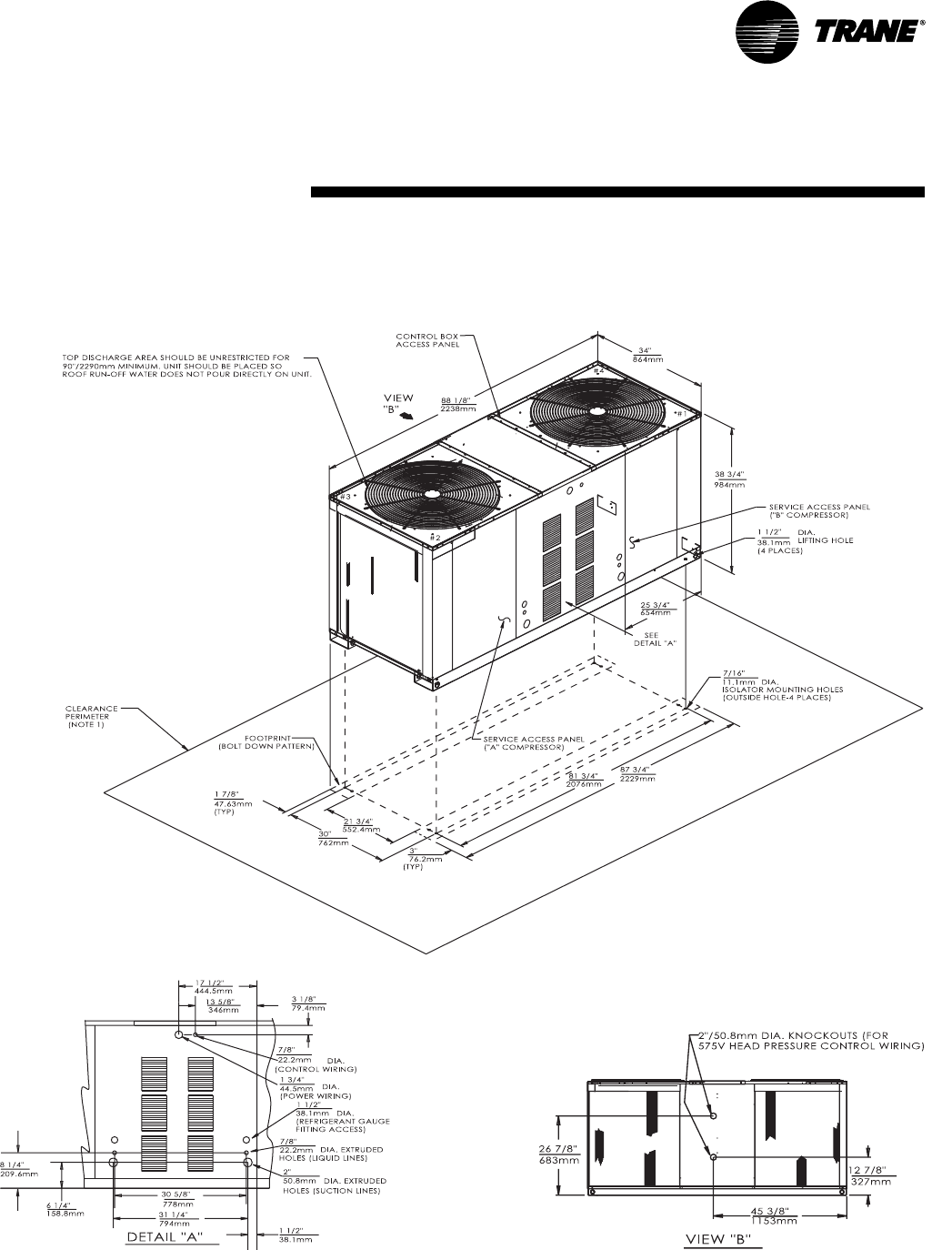
41TWA-PRC001-EN
Dimensional
Data (Heat Pump)
Figure DD-3 — TWA155B Heat Pump
All dimensions are in inches and millimeters.
Note 1
MINIMUM CLEARANCE FOR PROPER
OPERATION IS 36 INCHES (914 MM)
FROM WALLS, SHRUBBERY, PRIVACY
FENCES, ETC. MINIMUM CLEARANCE
BETWEEN ADJACENT UNITS IS 72
INCHES (1828 MM)
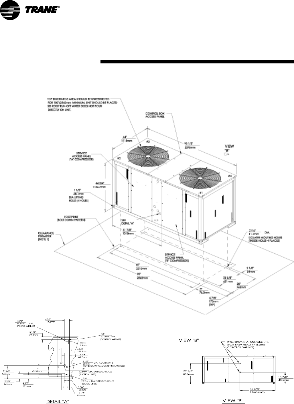
TWA-PRC001-EN42
(Heat Pump)
Dimensional
Data
Figure DD-4 — TWA200B Heat Pump
All dimensions are in inches and millimeters.
Note 1
MINIMUM CLEARANCE FOR PROPER
OPERATION IS 36 INCHES (914 MM)
FROM WALLS, SHRUBBERY, PRIVACY
FENCES, ETC. MINIMUM CLEARANCE
BETWEEN ADJACENT UNITS IS 72
INCHES (1828 MM)
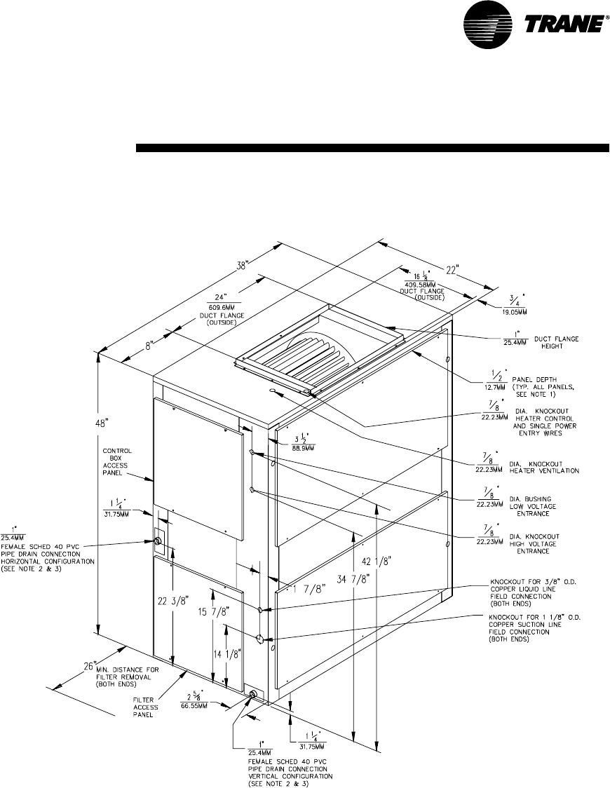
43TWA-PRC001-EN
(Air Handler)
Dimensional
Data
Figure DD-5 — TWE050A Air Handlers
All dimensions are in inches and millimeters.
Notes:
1. Length, Width, and Height Dimensions do not include 1/2”
(12.7mm) access panel depth.
2. Removable drain pan and attached drain connection may be
installed on either end of unit in either the vertical or horizontal
configuration. Plastic drain pan access plate on the end of unit
opposite drain connection must be removed to slide drain pan out
for cleaning. Access plate must be reinstalled after sliding drain
pan back into unit.
3. If periodic drain pan cleaning is required, allow room for partial
removal of pan on drain connection end of unit.
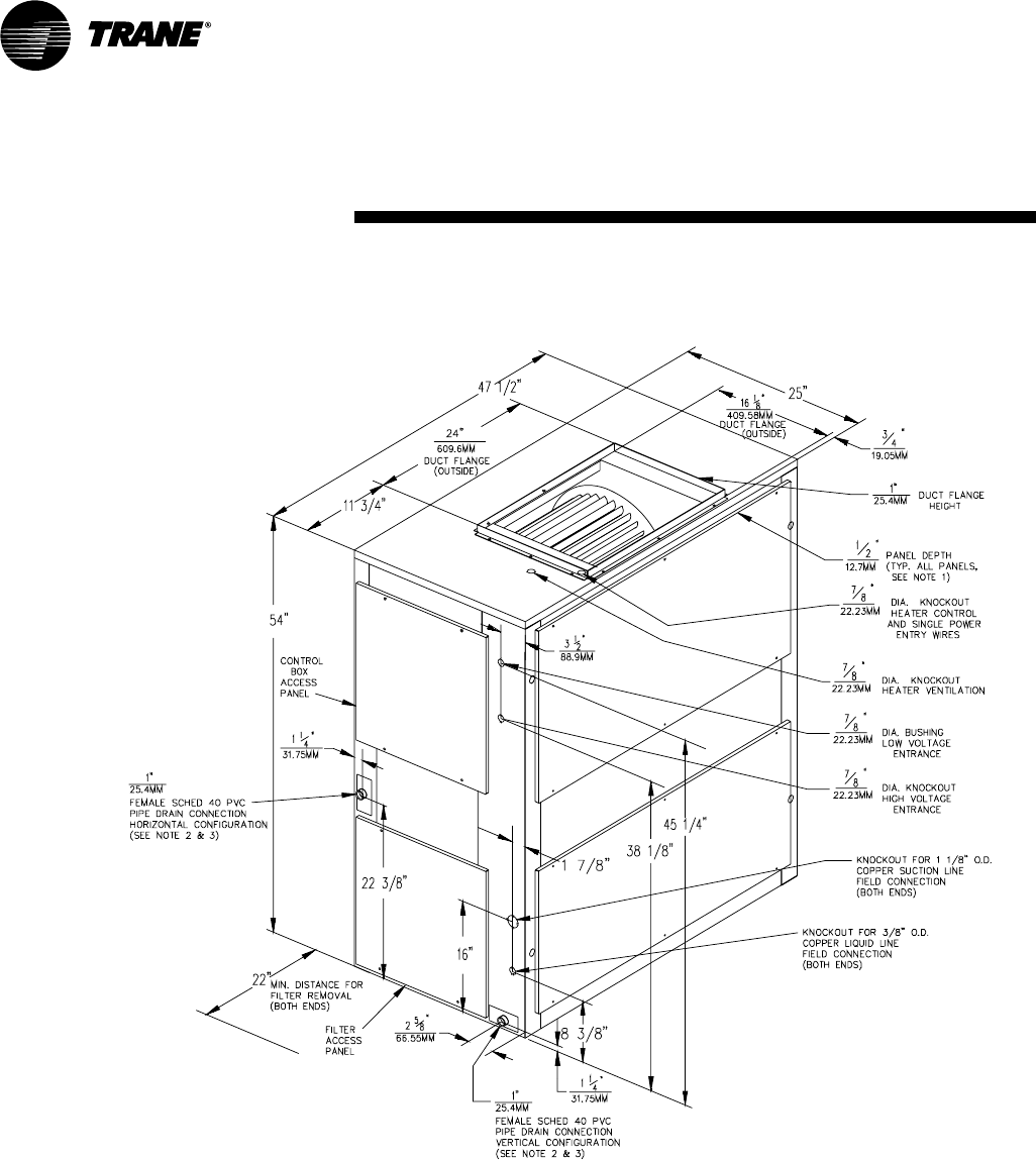
TWA-PRC001-EN44
(Air Handler)
Dimensional
Data
Figure DD-6 — TWE075A Air Handler
All dimensions are in inches and millimeters.
Notes:
1. Length, Width, and Height Dimensions do not include 1/2”
(12.7mm) access panel depth.
2. Removable drain pan and attached drain connection may be
installed on either end of unit in either the vertical or horizontal
configuration. Plastic drain pan access plate on the end of unit
opposite drain connection must be removed to slide drain pan out
for cleaning. Access plate must be reinstalled after sliding drain
pan back into unit.
3. If periodic drain pan cleaning is required, allow room for partial
removal of pan on drain connection end of unit.
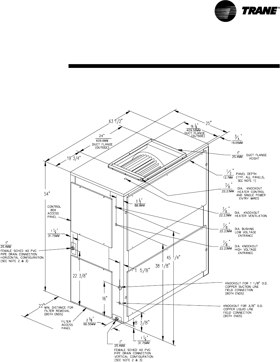
45TWA-PRC001-EN
Notes:
1. Length, Width, and Height Dimensions do not include 1/2”
(12.7mm) access panel depth.
2. Removable drain pan and attached drain connection may be
installed on either end of unit in either the vertical or horizontal
configuration. Plastic drain pan access plate on the end of unit
opposite drain connection must be removed to slide drain pan out
for cleaning. Access plate must be reinstalled after sliding drain
pan back into unit.
3. If periodic drain pan cleaning is required, allow room for partial
removal of pan on drain connection end of unit.
Figure DD-7— TWE100A Air Handler
All dimensions are in inches and millimeters.
Dimensional
Data (Air Handler)
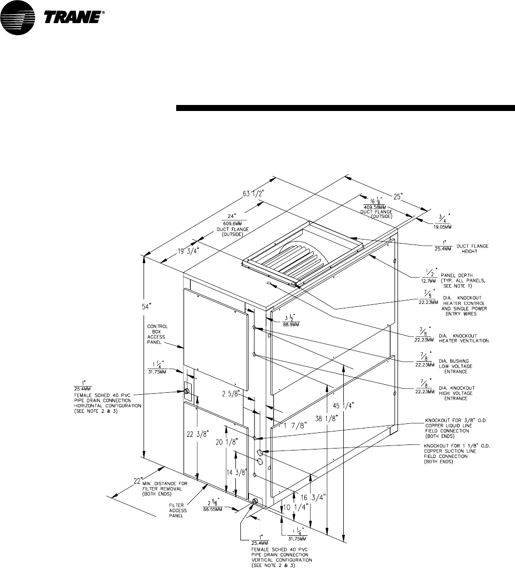
TWA-PRC001-EN46
Dimensional
Data (Air Handler)
Notes:
1. Length, Width, and Height Dimensions do not include 1/2”
(12.7mm) access panel depth.
2. Removable drain pan and attached drain connection may be
installed on either end of unit in either the vertical or horizontal
configuration. Plastic drain pan access plate on the end of unit
opposite drain connection must be removed to slide drain pan out
for cleaning. Access plate must be reinstalled after sliding drain
pan back into unit.
3. If periodic drain pan cleaning is required, allow room for partial
removal of pan on drain connection end of unit.
Figure DD-8— TWE100B Air Handler
All dimensions are in inches and millimeters.
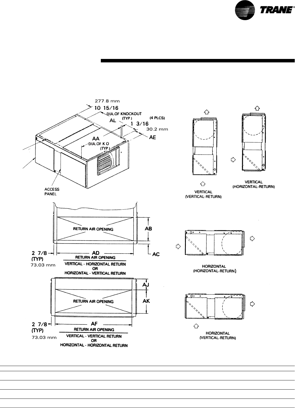
47TWA-PRC001-EN
Dimensional
Data (Air Handlers)
Table DD-1 — Air Handler Dimensions — in. (mm)
Model No. AA AB AC AD AE AF AJ AK AL
TWE050A 35 5/812 1/16 1 5/832 1/42 15/16 32 1/47 13/16 12 3/834 9/16
(905) (306.4) (41.3) (819.2) (74.6) (819.2) (198.4) (314.3) (878)
TWE075A 45 1/816 1 11 /16 41 15/16 6 5/841 3/47 16 36 7/8
(1146.2) (406.4) (42.9) (1065.2) (168.3) (1060.5) (177.8) (406.4) (936.6)
TWE100A 61 1/816 1 11/16 57 15/16 6 5/857 13/16 7 16 36 7/8
(1552.6) (406.4) (42.9) (1471.6) (168.3) (1468.4) (177.8) (406.4) (936.6)
TWE100B 61 1/816 1 11 /16 57 15/16 6 5/857 13/16 7 16 36 7/8
(1552.6) (406.4) (42.9) (1471.6) (168.3) (1468.4) (177.8) (406.4) (936.6)
Figure DD-9— TWE050A, 075A, 100A and TWE100B Air Handler
All dimensions are in inches and millimeters.
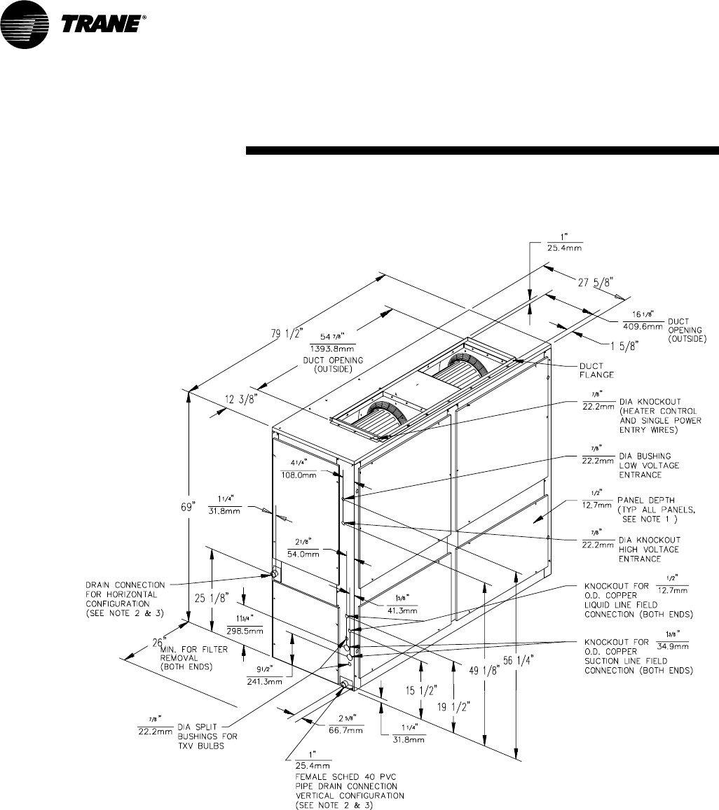
TWA-PRC001-EN48
Dimensional
Data
Figure DD-10— TWE155B Air Handler
All dimensions are in inches and millimeters.
(Air Handler)
Notes:
1. Length, Width, and Height Dimensions do not include 1/2”
(12.7mm) access panel depth.
2. Removable drain pan and attached drain connection may be
installed on either end of unit in either the vertical or horizontal
configuration. Plastic drain pan access plate on the end of unit
opposite drain connection must be removed to slide drain pan out
for cleaning. Access plate must be reinstalled after sliding drain
pan back into unit.
3. If periodic drain pan cleaning is required, allow room for partial
removal of pan on drain connection end of unit.
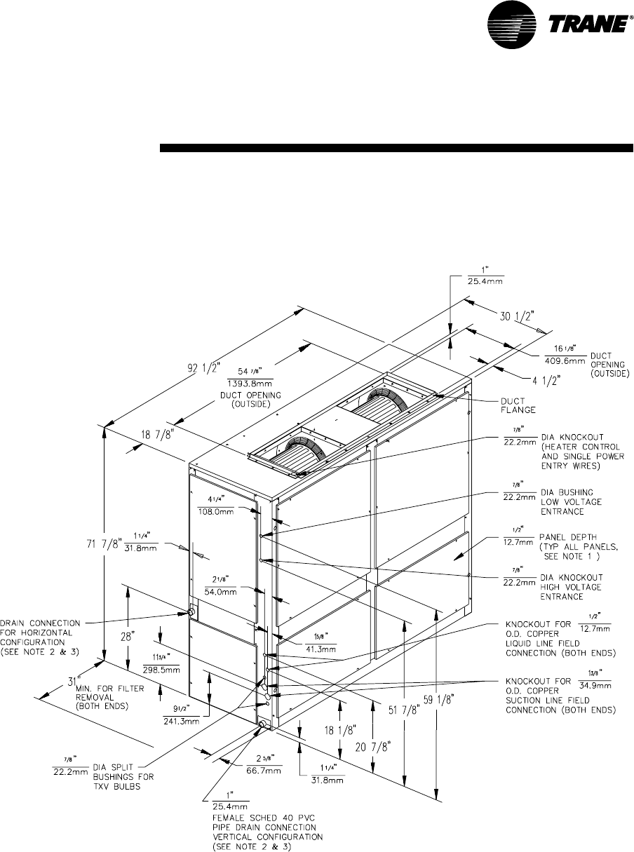
49TWA-PRC001-EN
Dimensional
Data (Air Handlers)
Figure DD-11 — TWE200B Air Handler
All dimensions are in inches and millimeters.
Notes:
1. Length, Width, and Height Dimensions do not include 1/2”
(12.7mm) access panel depth.
2. Removable drain pan and attached drain connection may be
installed on either end of unit in either the vertical or horizontal
configuration. Plastic drain pan access plate on the end of unit
opposite drain connection must be removed to slide drain pan out
for cleaning. Access plate must be reinstalled after sliding drain
pan back into unit.
3. If periodic drain pan cleaning is required, allow room for partial
removal of pan on drain connection end of unit.
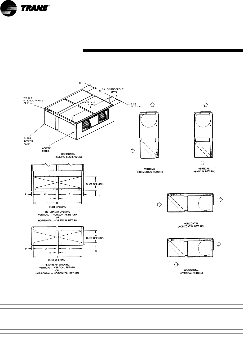
TWA-PRC001-EN50
Figure DD-12— TWE155B and 200B Air Handlers
All dimensions are in inches and millimeters.
Table DD-2 — Air Handler Dimensions — in. (mm)
Model No. A B C D E F G H J
TWE155B 77 1/4 (1962.2) 1 3/16 (30.2) 48 (1219.2) 11 7/16 (290.5) 18 (457.2) 3 3/8 (85.7) 35 1/16 (890.6) 73 7/8 (1876.4) 3 3/4 (95.3)
TWE200B 89 1/4 (2267) 1 11/16 (42.9) 50 13/16 (1290.6) 11 1/2 (292.1) 20 1/8 (511.2) 3 1/16 (77.8) 39 1/8 (993.8) 82 7/8 (2105) 4 9/16 (115.9)
Table DD-2— Air Handler Dimensions — in. (mm) (Continued)
Model No. K L M N P Q R S T
TWE155B 35 1/16 (890.6) 2 13/16 (71.4) 18 (457.2) 3 9/16 (90.5) 2 7/8 (73) 35 1/16 (890.6) 3 3/4 (95.3) 35 1/16 (890.6) 73 3/8 (1863.7)
TWE200B 39 1/8 (993.8) 4 7/8 (123.8) 20 (508) 3 (76.2) 4 13/16 (122.2) 39 1/8 (993.8) 4 9/16 (115.9) 39 1/8 (993.8) 82 7/8 (2105)
(Air Handlers)
Dimensional
Data
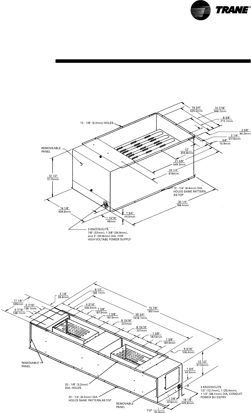
51TWA-PRC001-EN
Dimensional
Data (Accessories)
Figure DD-13— Electric Heater for TWE050, 075, 100 Air Handlers
All dimensions are in inches and millimeters.
Figure DD-14 — Electric Heater for TWE155 and 200 Air Handlers
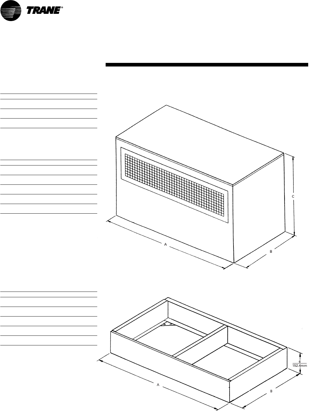
TWA-PRC001-EN52
Dimensional
Data (Accessories)
Figure DD-15 — Discharge Plenum and Grille
All dimensions are in inches and millimeters.
Figure DD-16 — Subbase
Table DD-5 — Subbase Dimensions — in.
(mm)
Model Model No. A B
TWE050 BAYBASE001 38 22
(965.2) (558.8)
TWE075 BAYBASE002 471/225
(1206.5) (635)
TWE100 BAYBASE003 631/225
(1612.9) (635)
TWE155 BAYBASE004 791/2275/8
(2019.3) (701.7)
TWE200 BAYBASE005 921/2307/16
(2349.5) (773.1)
Table DD-3 — Discharge Plenum And Grille
Dimensions — in. (mm)
Model Model No. A B C
TWE050 BAYPLNM015 3715/16 2115/16 28
(963.6) (557.2) (711.2)
TWE075 BAYPLNM016 471/225 28
(1206.5) (635) (711.2)
TWE100 BAYPLNM017 631/225 28
(1612.9) (635) (711.2)
Table DD-4 — Discharge Plenum And Grille
Dimensions — in. (mm)
For Use with Electric Heat
Model Model No. A B C
TWE050 BAYPLNM025 3715/16 2115/16 29
(963.6) (557.2) (736.6)
TWE075 BAYPLNM026 471/225 29
(1206.5) (635) (736.6)
TWE100 BAYPLNM027 631/225 29
(1612.9) (635) (736.6)
TWE155 BAYPLNM028 791/22711 /16 35
(2019.3) (703.3) (889)
TWE200 BAYPLNM029 921/2307/16 35
(2349.5) (773.1) (889)
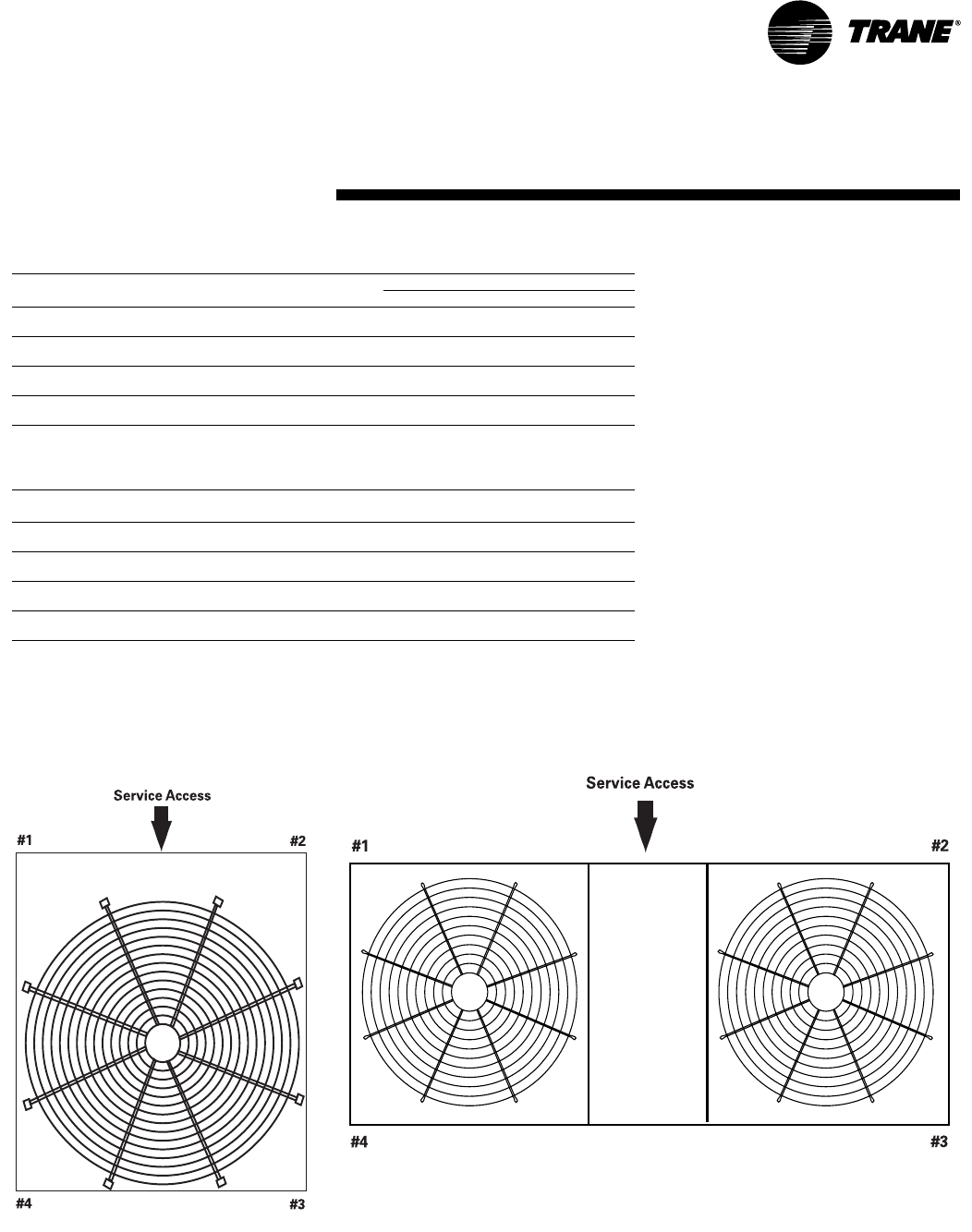
53TWA-PRC001-EN
Weights (Heat Pumps)
TWA075A, 100A
Table W-1 — Unit and Corner Weights — Lbs (Kg)
Unit Shipping Net Corner Weights
Model No. Maximum — lbs (Kg) Maximum — lbs (Kg) 1234
TWA075A 390 343 112 89 63 79
(176.9) (155.6) (50.8) (40.4) (28.6) (35.8)
TWA100A 468 414 146 106 68 94
(212.3) (187.8) (66.2) (48.1) (30.1) (42.6)
TWA155B 816 740 195 186 175 184
(370.1) (335.7) (88.5) (84.4) (79.4) (83.5)
TWA200B 970 885 253 250 190 192
(440.0) (401.4) (114.8) (113.4) (86.2) (87.1)
Table W-2 — Accessory Weights — Net Lbs (Kg)
Unit RIS Steel Spring Anti Short Coil Low
Model No. Isolators Isolators Cycle Timer Guard Thermostats Ambient
TWA075A 2 12 1 8 1 23
(.9) (5.4) (.5) (3.6) (.5) (10.4)
TWA100A 2 12 1 11 1 23
(.9) (5.4) (.5) (5) (.5) (10.4)
TWA155B212122123
(.9) (5.4) (.5) (10) (.5) (10.4)
TWA200B212134123
(.9) (5.4) (.5) (15.4) (.5) (10.4)
TWA155B, 200B
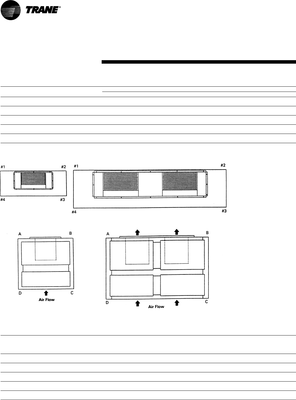
TWA-PRC001-EN54
Weights
Table W-3 — Air Handlers, Coils, And Corner Weights — Lbs (Kg)1
Unit Shipping Net Corner Weights — Vertical Corner Weights — Horizontal
Model No. Maximum (lbs) Maximum (lbs) #1 #2 #3 #4 A B C D
TWE050 298 262 59 59 59 59 54 64 64 54
(135) (118.9) (26.8) (26.8) (26.8) (26.8) (24.5) (29) (29.03) (24.5)
TWE075 388 346 79 79 79 79 77 84 81 73
(176) (157) (35.9) (35.9) (35.9) (35.9) (35) (38.1) (36.7) (33.1)
TWE100 473 419 107 107 107 107 102 113 113 102
(214.6) (190.1) (48.5) (48.5) (48.5) (48.5) (46.3) (51.3) (51.3) (46.3)
TWE125 754 690 173 173 173 173 174 156 190 170
(342) (313) (78.5) (78.5) (78.5) (78.5) (79) (70.8) (86.2) (77.1)
TWE200 886 820 204 204 204 204 185 228 221 179
(401.9) (372) (92.5) (92.5) (92.5) (92.5) (84) (103.4) (100.3) (81.2)
Note:
1. If application requires steam or hot water heating coils, field supplied isolators must be utilized.
Table W-4— Accessory Weights — Lbs (Kg)
RIS RIS Steel Spring Steel Spring
Discharge Discharge Electric Isolator Isolator Isolator Isolator
Unit Plenum Plenum Return Heat Oversized Floor Suspended Floor Suspended
Model No. And Grille1And Grill2Air Grille Min. Max. Subbase Motor Mount Mount Mount Mount
TWE050 58 93 3 32/43 14 31 2 9 12 6
(26.3) (42.2) (1.4) (14.5/19.5) (6.4) (14.1) (.9) (4) (5.4) (2.7)
TWE075 73 123 5 27/45 19 48 2 6 12 6
(33.1) (55.8) (2.3) (12.3/20.4) (8.6) (21.8) (.9) (2.7) (5.4) (2.7)
TWE100 92 156 7 27/45 23 50 2 7 12 6
(41.7) (70.8) (3.2) (12.3/20.4) (10.4) (22.7) (.9) (3.2) (5.4) (2.7)
TWE155 124 230 10 79/100 27 80 2 7 12 6
(56.3) (104.3) (4.5) (35.8/45.4) (12.3) (36.3) (.9) (3.2) (5.4) (2.7)
TWE200 145 264 12 79/100 31 88 2 9 12 6
(65.8) (119.8) (5.4) (35.8/45.4) (14.06) (40) (.9) (4) (5.4) (2.7)
Note:
1. For use when no heat is supplied.
2. For use with electric heat.
Vertical
TWE050, 075, 100
Vertical
TWE155, 200
Horizontal
TWE155, 200
Horizontal
TWE050, 075, 100
(Air Handlers)

55TWA-PRC001-EN
Mechanical
Specifications
Heat Pumps
General
Unit shall be assembled on heavy gauge
steel mounting/lifting rails and shall be
weather proofed. Unit shall include a
hermetic scroll or reciprocating
compressor(s), plate fin condenser coil,
fans and motors, controls, and holding
charge of nitrogen. Operating Range
shall be between 115° F and 35° F in
cooling as standard from factory. Unit
shall be UL 1995 listed and rated in
accordance with ARI Standard 210/240 or
340/360.
Casing
Unit casing shall be constructed of zinc
coated, heavy gauge, galvanized steel.
Exterior surfaces shall be cleaned,
phosphatized, and finished with a
weather-resistant baked enamel finish.
Unit’s surface shall be tested 500 hours
in salt spray test. Unit shall have
removable end panels which allow
access to all major components and
controls.
Refrigeration System — Single
Compressor
TWA075A, TWA100A units shall have a
single refrigeration circuit. Each
refrigeration circuit has an integral
subcooling circuit. A refrigeration filter
drier, expansion valve, and check valves
shall be provided as standard. The unit
shall have both a liquid line and suction
gas line service valve with gauge port.
Unit shall have one direct drive, Trane
hermetic scroll compressor with
centrifugal oil pump providing positive
lubrication to moving parts. Motor shall
be suction gas-cooled and shall have a
voltage utilization range of plus or minus
10 percent of nameplate voltage.
Crankcase heater, discharge line
thermostat, internal temperature, and
current-sensitive motor overloads shall
be included for maximum protection.
Scroll type compressor shall provide
inherently low vibration and noise by
having no suction and discharge valves.
External high and low pressure cutout
devices shall be provided. Evaporator
defrost control provided in indoor
blower coil unit shall prevent
compressor slugging by temporarily
interrupting compressor operation when
low evaporator coil temperatures are
encountered.
Refrigeration System — Dual
Compressor
TWA155B, TWA200B units shall have
two separate and independent
refrigeration circuits. Each refrigeration
circuit shall have an integral subcooling
circuit. A refrigeration filter drier shall be
provided as standard. Unit shall have
both a liquid line and suction gas line
service valve with gauge ports.
Unit shall have two Trane direct drive,
hermetic scroll compressors with
centrifugal oil pump and provide positive
lubrication to all moving parts. Motor
shall be suction gas-cooled and shall
have a voltage utilization range of plus or
minus 10 percent of nameplate voltage.
Crankcase heater, discharge line
thermostat, internal temperature, and
current-sensitive motor overloads shall
be included for maximum protection.
Scroll type compressor shall provide
inherently low vibration and noise by
having no suction and discharge valves.
External high and low pressure cutout
devices shall be provided. Evaporator
defrost control provided in indoor
blower coil shall prevent compressor
slugging by temporarily interrupting
compressor operation when low
evaporator coil temperatures are
encountered.
Condenser Coil
Coils shall be internally finned or smooth
bore, 3/8" (10mm) copper tubes
mechanically bonded to a configured
aluminum plate fin as standard. Coil
shall be factory pressure and leak tested
to 420 psig (2,930 kPa) air pressure.
Metal grilles with PVC coating for coil
protection is optional.
Condenser Fan And Motor(s)
Direct-drive, statically and dynamically
balanced, 26 or 28 inch (660 or 711 mm)
propeller fan(s) with aluminum blades
and electro-coated steel hubs shall be
used in draw-through vertical discharge
position. Either permanently lubricated
totally enclosed or open construction
type motors shall be provided and shall
have built-in current and thermal
overload protection. Motor(s) shall have
either ball or sleeve bearing type.
Controls
Heat pump units shall be completely
factory wired with necessary controls
and contactor pressure lugs or terminal
block for power wiring. Control wiring
shall be 24-volt control circuit which
includes fusing and control transformer.
Units shall provide external location for
mounting a fused disconnect device.
Time delay timers to prevent
compressors in dual compressor units
from simultaneous start-up and anti-
recycle timers are available as optional
accessories.
Defrost Controls
Electronic timed initiated, temperature
terminated defrost system with choice
of 50, 70, or 90 minute cycle shall be
included. Timed override limits defrost
cycle to 10 minutes.
Low Ambient Operation
Standard units shall start and operate to
approximately 35° F (1.7° C) when
matched with Trane air handlers and
coils. Optional head pressure control
accessory permits operation to 0° F
(-17.8° C).
ACCESSORIES
Low Ambient Head Pressure Control —
This accessory shall modulate the RPM
of unit outdoor fan motor in response
to outdoor ambient temperatures and
liquid line temperature. Accessory
provides unit cooling operation to
outdoor temperatures of 0° F (-17.8° C).
Vibration Isolation Packages — This
accessory shall reduce transmission of
noise and vibration to building
structures, equipment, and adjacent
spaces. Packages shall be available in
either neoprene-in-shear or spring-flex
types.
Time Delay Relay — This accessory
shall prevent compressors in dual
compressor unit from coming on line
simultaneously. Timer shall be 24-volt,
60 cycle, with four minute timing
period.
Anti-Short-Cycle Timer — This
accessory shall prevent rapid on-off
compressor cycling in light load
conditions by not allowing compressor
to operate for 5-7 minutes upon
shutdown. This accessory shall consist
of a 24-volt, 60 cycle, solid state timing
device with either 5 or 7 minute fixed-
off timing period.

TWA-PRC001-EN56
Air Handlers
General
Air handler units shall be completely
factory assembled including coil,
condensate drain pan, fan motor(s),
filters, and controls in an insulated
casing that can be applied in either
vertical or horizontal configuration. Unit
shall be rated and tested in accordance
with ARI standard 210/240 or 340/360.
Unit shall be UL listed and labeled in
accordance with UL 1995 for indoor
blower coil units.
Casing
Unit casing shall be constructed of zinc
coated, heavy gauge, galvanized steel.
Exterior surfaces shall be cleaned,
phosphatized, and finished with a
weather-resistant baked enamel finish.
Casing shall be completely insulated
with cleanable, foil faced, fire-retardant,
permanent, odorless, glass fiber
material. All insulation edges shall be
either captured or sealed. Knockouts
shall be provided for unit electrical
power and refrigerant piping
connections. Captive screws shall be
standard on all access panels.
Refrigeration System
The TWE050A, TWE075A, TWE10 0A units
shall have a single refrigeration circuit
and the TWE10 0B, TWE155B, TWE20 0B
units shall have dual refrigeration
circuits. Each refrigeration circuit is
controlled by a factory installed thermal
expansion valve.
Evaporator Coil
Configured aluminum fin surface shall
be mechanically bonded to 3/8" (10 mm)
Condenser Coil Guard — Metal grille
with PVC coating shall be provided to
alleviate coil damage.
Black Epoxy Coated Condenser Coil —
This factory installed option is designed
to provide corrosion protection of air
cooled condenser coils for seacoast
application. The black epoxy coil
protection is a factory applied thermoset
vinyl coating, bonded to normal
aluminum fin stock. The uniform
thickness of the bonded vinyl layer
exhibits excellent corrosion protection in
salt spray tests performed in accordance
with ASTM B177.
internally enhanced copper tubing and
shall be factory pressure and leak tested
at 375 psig (2586 kPa). Coil is arranged
for draw-through airflow and shall
provide a double sloped condensate
drain pan constructed of PVC plastic. The
drain pan shall be removable for
cleaning. The condensate drain pan can
be installed in any of four positions
allowing for vertical or horizontal
application and providing external
connections on either side of the unit.
Evaporator Fan
Double inlet, double width, forward
curved, centrifugal-type fan(s) with
adjustable belt drive shall be standard.
Thermal overload protection shall be
standard on motor. Fan and motor
bearings shall be permanently
lubricated. Oversized motors shall be
available as an option for high static
application. All indoor fan motors meet
the U.S. Energy Policy Act of 1992
(EPACT)
Controls
Magnetic evaporator fan contactor, low
voltage terminal strip, check valve(s), and
single point power entry shall be
included. All necessary controls shall be
factory-installed and wired. Evaporator
defrost control shall be included to
prevent compressor slugging by
temporarily interrupting compressor
operation when low evaporator coil
temperatures are encountered.
Filters
One inch, throw-away filters shall be
standard on TWE050A, TWE075A,
TWE100A and TWE120B model air
handlers. Filters shall be accessible from
the side coil access panel. Filter rack can
be field converted to two inch capability.
Two inch, throw-away filters shall be
standard on TWE155B and TWE200B
models.
ACCESSORIES
Electric Heaters — UL and CSA
approved electric heat modules shall be
available for installation directly on fan
discharge. Electric heaters shall be
available in a wide range of capacities
with one or two stage control, single-
point electric power connection, and
terminal strip connections. Electric
heater elements shall be constructed of
heavy-duty nickel chromium elements
internally wye connected on 400 volt,
three phase. Each 400 volt heater shall
have automatic line break high limit
controls.
Discharge Plenums and Grilles —
Accessory discharge plenums shall be
available for vertical, free discharge
applications. Plenums shall be
constructed of heavy-gauge, zinc coated,
galvanized steel finished with baked
enamel to match the air handler unit.
Grilles shall be satin finished aluminum
and have four-way adjustable louvers.
Return Air Grilles — Accessory return air
grille shall be provided for vertical front,
free return applications. Grilles shall be
installed in place of the front lower side
panel. Grille shall be satin finished
aluminum with non-adjustable louvers.
Mounting Subbase — The accessory
shall be available for vertical floor mount
configurations. Subbase shall be
constructed of heavy gauge, zinc coated,
galvanized steel with baked enamel
finish to match air handler unit. Subbase
is required in the vertical air flow
application for condensate drain
trapping and when isolators are
required.
Vibration Isolators — This accessory
shall reduce transmission of noise and
vibration to building structures,
equipment, and adjacent spaces.
Packages shall be available in either
neoprene-in shear or spring-flex types in
floor or suspended mountings.
Oversized Motors — Field installed
oversized motors shall be available for
high static pressure applications.
CONTROL OPTIONS
Standard Indoor Thermostats — Two
stage heating and cooling operation or
one stage heating and cooling
thermostats shall be available in either
manual or automatic changeover.
Programmable Electronic Night Setback
Thermostat — The option shall provide
heating setback and cooling setup with 7-
day programming capability.
Outdoor Thermostat — This option shall
provide staging control of electric
heaters based on a set outdoor
temperature.
Mechanical
Specifications

57TWA-PRC001-EN

TWA-PRC001-EN58

59TWA-PRC001-EN

The Trane Company
An American Standard Company
www.trane.com
For more information contact your
local distributor (dealer), local district
office, or e-mail us at
comfort@trane.com
Since The Trane Company has a policy of continuous product and product data improvement, it reserves the
right to change design and specifications without notice.
Literature Order Number
File Number
Supersedes
Stocking Location
TWA-PRC001-EN
PL-UN-TWA-PRC001-EN-07-00
TWA-PRC001-EN-05/98
Inland - LaCrosse
