Trane 4Twb4 Users Manual 22 1834 09 02/01/2012 Product Data SPLIT SYSTEM HEAT PUMP 1 1/2 ? 5 TON XB14
4TWB4 to the manual b97b3716-aff4-4515-9253-7aa5778c0cb5
2015-01-21
: Trane Trane-4Twb4-Users-Manual-236222 trane-4twb4-users-manual-236222 trane pdf
Open the PDF directly: View PDF ![]() .
.
Page Count: 16
XB14 4TWB4
1 1/2 - 5 Tons
Split System
Heat Pump
Product Data
PUB. NO. 22-1834-09

© 2012 Trane 2 22-1834-09
Features and
Benefits
• CLIMATUFF® compressor
•Efciencyupto16.0 SEER and
8.5 HSPF
•AllaluminumSPINE FIN™coil
•WEATHERGUARD™fasteners
•QUICK-SESS™cabinet,
serviceaccessandrefrigerant
connectionswithfullcoil
protection
•DURATUFF™base,fastcomplete
drain,weatherproof
•COMFORT-R™ mode approved
•Glossycorrosionresistantnish
•Internalcompressorhigh/low
pressure&temperatureprotection
•018,024,030,060&061ship
withstartkit
•CompressorSumpHeat
•Liquidlinelter/drier
•Polyslategraycabinetwith
anthracitegraybadge
•Highpressureswitch
•DemandDefrostwithDiagnostics
•R-410Arefrigerant
•S.E.E.T.designtesting
•100%lineruntest
•Lowambientcoolingto20°Fwith
AY28X084
•Lowambientcoolingto55°Fas
shipped
• Extended warranties available
22-1834-09 3
Contents
Features and Benefits 2
General Data 4
ProductSpecications 4
A-weightedSoundPowerLevel[dB(A)] 4
AccessoryDescriptionandUsage 6
AHRIStandardCapacityRatingConditions 6
Model Nomenclature 7
Electrical Data 8
Dimensions 15
Mechanical Specification Options 16
4 22-1834-09
Product Specifications
Model No. 1 4TWB4018G1 4TWB4024G1 4TWB4030G1 4TWB4036G1
Electrical Data V/Ph/Hz 2 208/230/1/60 208/230/1/60 208/230/1/60 208/230/1/60
Min Cir Ampacity 9 11 15 18
Max Fuse Size (Amps) 15 15 25 30
Compressors CLIMATUFF® CLIMATUFF® CLIMATUFF® CLIMATUFF®
RL AMPS - LR AMPS 6.4 - 38.6 8.3 - 58 11.3 - 68.2 13.2 - 63
Outdoor Fan FL Amps 0.70 0.74 0.92 1.00
Fan HP 1/8 1/8 1/5 1/5
Fan Dia (inches) 23 23 27.5 27.5
Coil Spine Fin™ Spine Fin™ Spine Fin™ Spine Fin™
Refrigerant R-410A 5/14-LB/OZ 7/02-LB/OZ 8/02-LB/OZ 7/13-LB/OZ
Line Size - (in.) O.D. Gas 3 5/8 5/8 3/4 3/4
Line Size - (in.) O.D. Liquid 3 3/8 3/8 3/8 3/8
Dimensions H x W x D (Crated) 34 x 30.1 x 33 38 x 30.1 x 33 38.4 x 35.1 x 38.7 37.9 x 35 x 37.9
Weight - Shipping 204 236 273 261
Weight - Net 176 208 239 227
Start Components YES YES YES YES
Sound Enclosure NO NO NO YES
Compressor Sump Heat NO NO NO NO
Optional Accessories: 4
Anti-short Cycle Timer TAYASCT501A TAYASCT501A TAYASCT501A TAYASCT501A
Evaporator Defrost Control A/C AY28X084 AY28X084 AY28X084 AY28X084
Rubber Isolator Kit BAYISLT101 BAYISLT101 BAYISLT101 BAYISLT101
Crankcase Heater BAYCCHT300 BAYCCHT300 BAYCCHT300 BAYCCHT300
Extreme Condition Mounting Kit BAYECMT004 BAYECMT004 BAYECMT004 BAYECMT004
Snow Leg - Base & Cap 4" High BAYLEGS002 BAYLEGS002 BAYLEGS002 BAYLEGS002
Snow Leg - 4" Extension BAYLEGS003 BAYLEGS003 BAYLEGS003 BAYLEGS003
Seacoast Kit BAYSEAC001 BAYSEAC001 BAYSEAC001 BAYSEAC001
Refrigerant Lineset 5 TAYREFLN950 TAYREFLN950 TAYREFLN7* TAYREFLN7*
1 Certified in accordance with the Air-Source Unitary Heat Pump Equipment certification program which is based on AHRI Standard 210/240.
2 Calculated in accordance with N.E.C. Only use HACR circuit breakers or fuses.
3 Standard line lengths - 80'. Standard lift - 60' Suction and Liquid line.
For Greater lengths and lifts refer to refrigerant piping software Pub# 32-3312-0†. (†denotes latest revision)
4 For accessory description and usage, see page 5.
5 * = 15, 20, 25, 30, 40 and 50 foot lineset available.
General
Data
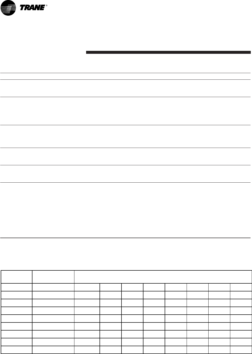
63 125 250 500 1000 2000 4000 8000
4TWB4018G 76 52.3 57.8 62.4 67.2 69.4 67.2 59.6 52.5
4TWB4024G 76 50.3 55 58.6 65.3 69.5 64.5 58.6 50.8
4TWB4030G 76 48.8 55.4 60.1 66.4 67.4 63.9 60.2 53.5
4TWB4036G 76 54.5 55.1 58.3 67 69.8 65.9 59.7 49.1
4TWB4042E 78 55.1 52 59.3 64.9 67.2 63.5 60.4 47.6
4TWB4048E 78 55.6 53.3 59.2 66.7 71.7 67.9 60.7 51.3
4TWB4049E 76 43.7 51.2 54.5 61 61.5 57.1 51.3 40.7
4TWB4060E 78 55.1 53.7 61.1 69.2 73.6 68.7 61.4 50
4TWB4061E 76 31.9 58.9 57.1 64.8 66.4 59.8 55.9 51.2
Note: Rated in accordance with AHRI Standard 270-2008.
SOUND POWER
LEVEL [dB(A)]
A-weighted Sound Power Level [dB(A)]
MODEL A-WEIGHTED FULL OCTAVE SOUND POWER LEVEL dB - [dB(A)] High Stage
22-1834-09 5
General
Data
Product Specifications
Model No. 1 4TWB4042E1 4TWB4048E1 4TWB4049E1 4TWB4060E1 4TWB4061E1
Electrical Data V/Ph/Hz 2 208/230/1/60 208/230/1/60 208/230/1/60 208/230/1/60 208/230/1/60
Min Cir Ampacity 27 29 28 35 36
Max Fuse Size (Amps) 45 50 50 60 60
Compressors
CLIMATUFF® - SCROLL CLIMATUFF® - SCROLL CLIMATUFF® - SCROL CLIMATUFF® - SCROLL CLIMATUFF® - SCROL
RL AMPS - LR AMPS 19.9 - 109 21.8 - 117 21.8 - 117 26.4 - 134 26.4 - 134
Outdoor Fan FL Amps 0.93 0.93 1.00 0.93 2.80
Fan HP 1/5 1/5 1/5 1/5 1/3
Fan Dia (inches) 27.6 27.6 27.6 27.6 27.6
Coil Spine Fin™ Spine Fin™ Spine Fin™ Spine Fin™ Spine Fin™
Refrigerant R-410A 12/1-LB/OZ 13/9-LB/OZ 13/10-LB/OZ 12/1-LB/OZ 13/12-LB/OZ
Line Size - (in.) O.D. Gas 3 3/4 7/8 7/8 7/8 1-1/8
Line Size - (in.) O.D. Liquid 3 3/8 3/8 3/8 3/8 3/8
Dimensions H x W x D (Crated)
46.4 x 35.1 x 38.7 51 x 35.1 x 38.7 51 x 35.1 x 38.7 51 x 35.1 x 38.7
51 x 35.1 x 38.7
Weight - Shipping 313 331 331 332 332
Weight - Net 277 294 294 295 295
Start Components NO NO NO YES YES
Sound Enclosure NO NO NO NO NO
Compressor Sump Heat YES YES YES YES YES
Optional Accessories: 4
Anti-short Cycle Timer TAYASCT501A TAYASCT501A TAYASCT501A TAYASCT501A TAYASCT501A
Evaporator Defrost Control A/C AY28X084 AY28X084 AY28X084 AY28X084 AY28X084
Rubber Isolator Kit BAYISLT101 BAYISLT101 BAYISLT101 BAYISLT101 BAYISLT101
Hard Start Kit Scroll BAYKSKT260 BAYKSKT260 BAYKSKT260
Extreme Condition Mounting Kit BAYECMT004 BAYECMT004 BAYECMT004 BAYECMT004 BAYECMT004
Snow Leg - Base & Cap 4" High BAYLEGS002 BAYLEGS002 BAYLEGS002 BAYLEGS002 BAYLEGS002
Snow Leg - 4" Extension BAYLEGS003 BAYLEGS003 BAYLEGS003 BAYLEGS003 BAYLEGS003
Seacoast Kit BAYSEAC001 BAYSEAC001 BAYSEAC001 BAYSEAC001 BAYSEAC001
Refrigerant Lineset 5 TAYREFLN7* TAYREFLN3* TAYREFLN3* TAYREFLN3* TAYREFLN3*
1 Certified in accordance with the Air-Source Unitary Heat Pump Equipment certification program which is based on AHRI Standard 210/240.
2 Calculated in accordance with N.E.C. Only use HACR circuit breakers or fuses.
3 Standard line lengths - 60'. Standard lift - 60' Suction and Liquid line.
For Greater lengths and lifts refer to refrigerant piping software Pub# 32-3312-0†. (†denotes latest revision)
4 For accessory description and usage, see page 5.
5 * = 15, 20, 25, 30, 40 and 50 foot lineset available.
6 22-1834-09
General
Data
AHRI Standard Capacity Rating Conditions
AHRI STANDARD 210/240 RATING CONDITIONS —
(A) Cooling80°FDB,67°FWBairenteringindoorcoil,
95°FDBairenteringoutdoorcoil.
AHRI STANDARD 270 RATING CONDITIONS —(Noise
ratingnumbersaredeterminedwiththeunitincoolingopera-
tion.)StandardNoiseRatingnumberisat95°Foutdoorair.
Accessory Description and Usage
Anti-Short Cycle Timer—Solidstatetimingdevicethat
preventscompressorrecyclinguntil5minuteshaveelapsed
aftersatisfyingcallorpowerinterruptions.Useinareawith
questionablepowerdelivery,commercialapplications,long
lineset,etc.
Evaporator Defrost Control—SPSTTemperatureactuated
switchthatcyclesthecondenseroffasindoorcoilreaches
freeze-upconditions.Usedforlowambientcoolingto30°F
withTXV.
Rubber Isolators —5largerubberdonutstoisolatecon-
densingunitfromtransmittingenergyintomountingframeor
pad.Useonanyapplicationwheresoundtransmissionneeds
tobeminimized.
Hard Start kit —Startcapacitorandrelaytoassistcompres-
sormotorstartup.Useinareaswithmarginalpowersupply,
onlonglinesets,lowambientconditions,etc.
Extreme Condition Mount Kit —Bracketkitstosecurely
mountcondensingunittoaframeorpadwithoutremoving
anypanels.Useinareaswithhighwinds,oroncommercial
rooftops,etc.
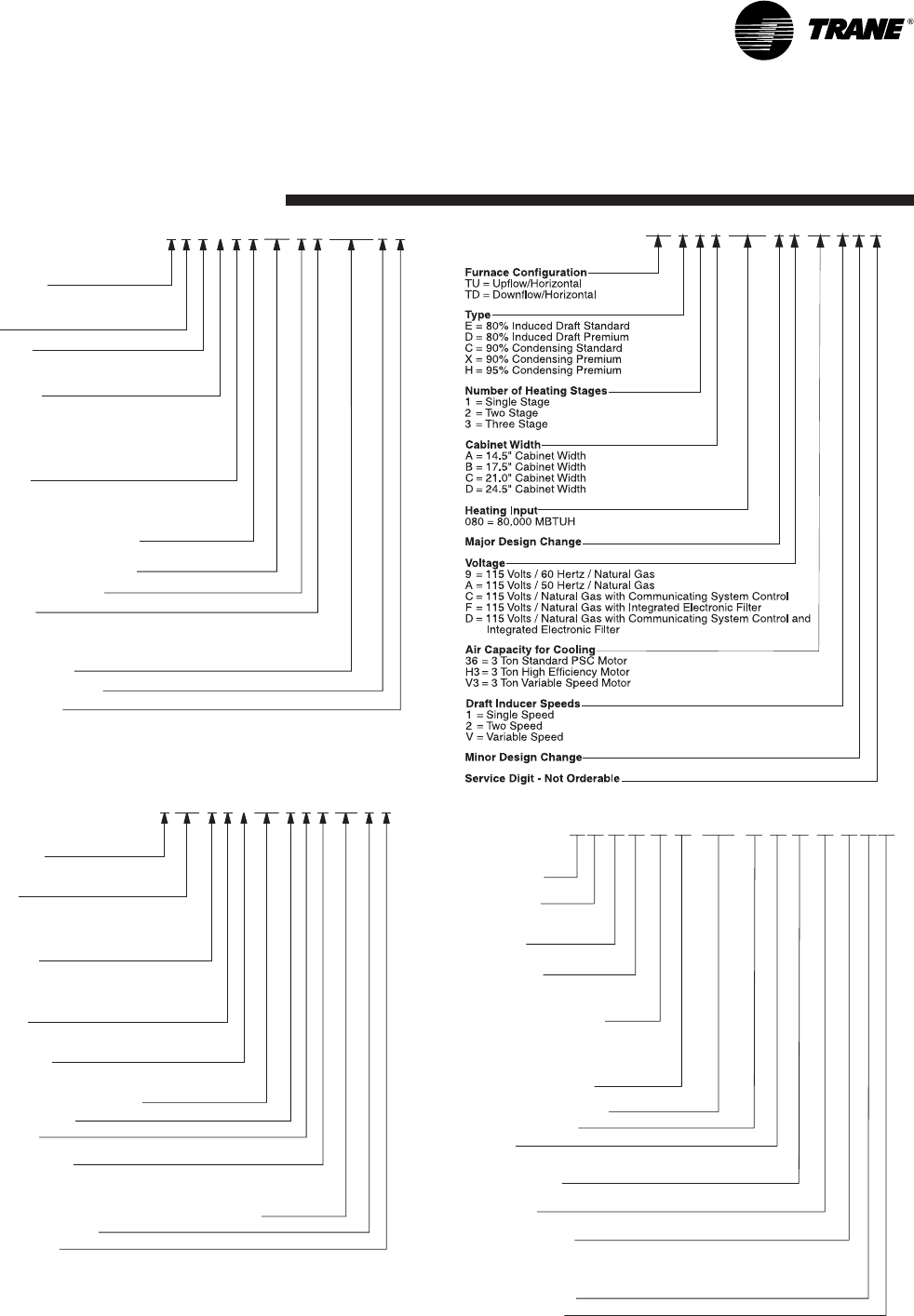
22-1834-09 7
Model
Nomenclature
Refrigerant Type
2 = R-22
4 = R-410A
TRANE
Product Type
W = Split Heat Pump
T = Split Cooling
Product Family
Z = Leadership – Two Stage
X = Leadership
R = Replacement/Retail
B = Basic
A = Light Commercial
Family SEER
0 = 10 3 = 13 6 = 16
1 = 11 4 = 14 8 = 18
2 = 12 5 = 15 9 = 19
Split System Connections 1-6 Tons
0 = Brazed
Nominal Capacity in 000s of BTUs
Major Design Modifications
Power Supply
1 = 200-230/1/60 or 208-230/1/60
3 = 200-230/3/60
4 = 460/3/60
Secondary Function
Minor Design Modifications
Unit Parts Identifier
Outdoor Units
4TWB 4036G1 000AA
Refrigerant Type
4 = R-410A
Application
TE = Fully Convertible
TG = Semi Convertible
TF = Front Return
Product Family
E = Leadership – Variable Speed
P = Leadership
C = Replacement/Retail
B = Basic
Flow Control
0 = No Flow Control
3 = Nonbleed TXV
Feature Identifier
0 = Standard Unit
F = Air-Tite™
Nominal Capacity in 1000’s (BTUH)
Major Design Change
Power Supply
1 = Single Phase
Electrical Connection
0 = Pig Tails
B = Circuit Breaker
D = Pull Disconnect
Future Option – Factory Installed Heater Nominal KW Value
Minor Design Modifications
Unit Parts Identifier
NOTE: There will be a phase-in of new model numbers for new
air handlers over next 2 years.
Air Handlers –
Residential
4TEE3F36A1 AA000
Gas Furnaces
TU D2B080AC AAV32
4TXCB001 C C3 H CAA
Refrigerant Type
4 - R410A
Product Family
T-Premium
(Heat Pump or Convertible Coil)
Coil Design
X - Direct Expansion Evaporator Coil
Product Family
C - Cased A Coil
A - Uncased A Coil
F - Cased Horizontal Flat Coil
Coil Width (Cased/Uncased)
A - 14.5" / 13.3"
B - 17.5" / 16.3"
C - 21.0" / 19.8"
D - 24.5" / 23.3"
H - 10.5"
Refrigerant Line Coupling
0 - Brazed
Model Number Distinguisher
Major Design Change
Efficiency
C - Standard
S - Hi Efficiency (Derived from 10 SEER products)
Refrigerant Control
3 - TXV - Non-Bleed
Coil Circuitry
H - Heat Pump
Airflow Configuration
A - Upflow Only
U - Upflow / Downflow
H - Horizontal Only
C - Convertible - Upflow, Downflow, Left or Right Airflow
Minor Design Change
Unit Parts Identifier
Coils –
Residential
8 22-1834-09
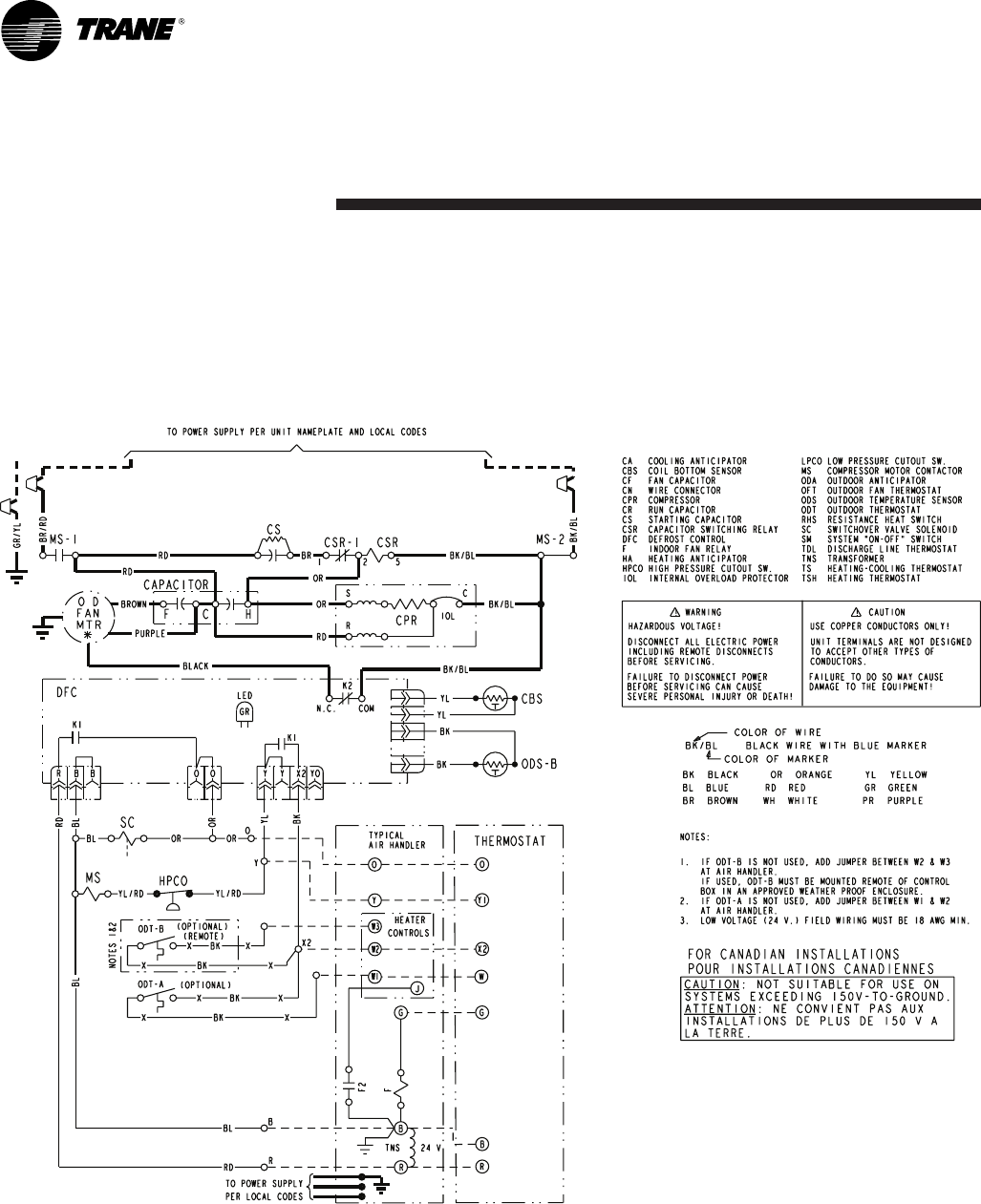
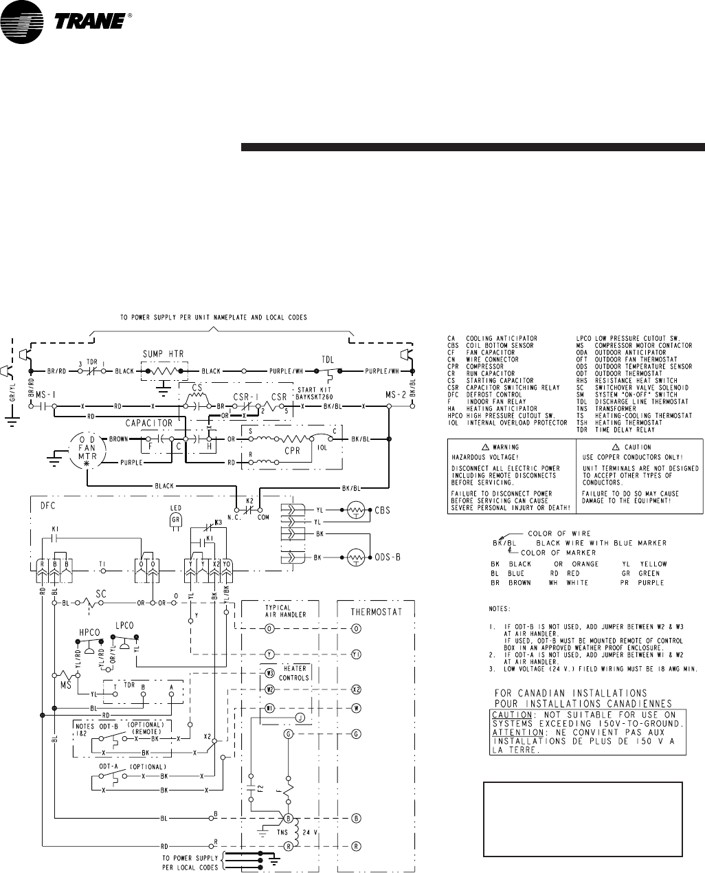
4TWB4018, 4TWB4024, 4TWB4036
Electrical
Data
Schematic Diagrams
PrintedfromD156770P01Rev00
22-1834-09 9
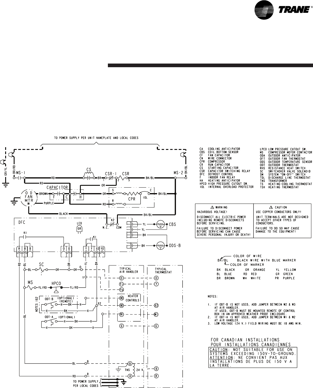
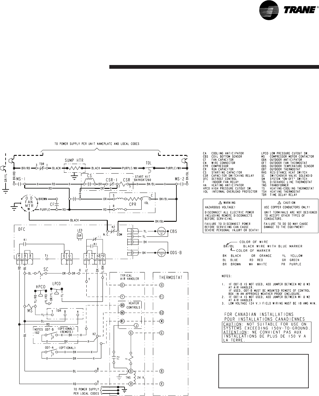
4TWB4030
Electrical
Data
Schematic Diagrams
PrintedfromD157099P01
10 22-1834-09
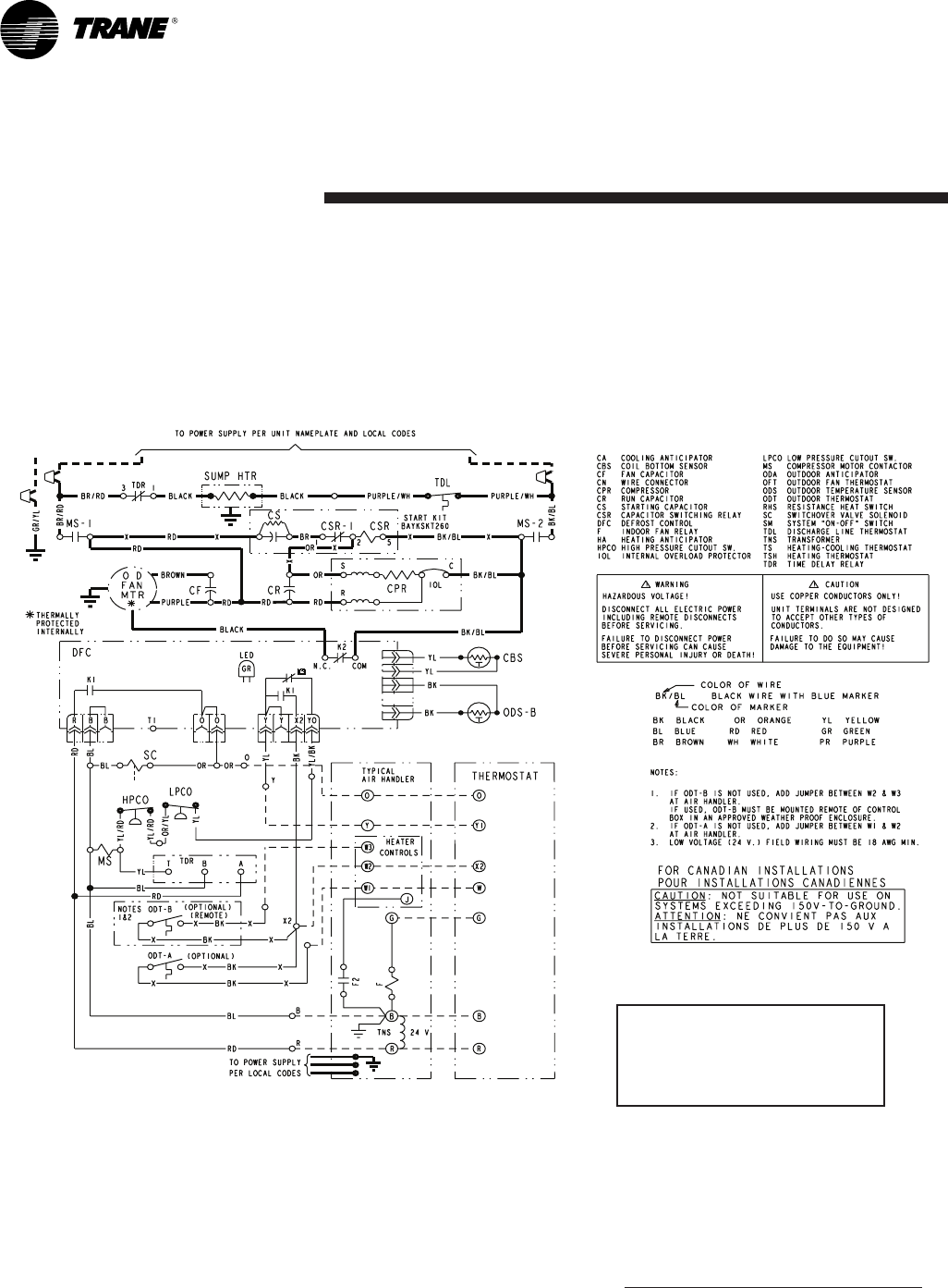
Electrical
Data
Schematic Diagrams
4TWB4042
PrintedfromD156131P02Rev00
TDRrelaycyclessumpheatoffdur-
ingcompressoroperationanddelays
energizingthesumpheatfor30mins
after“Y”callisremoved.
22-1834-09 11
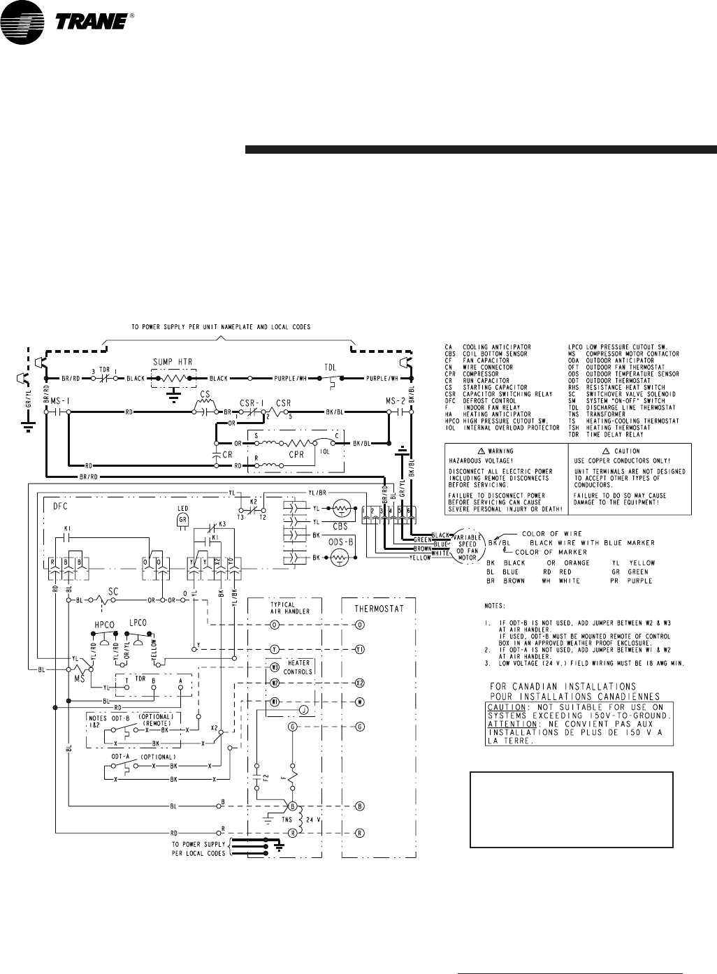
Electrical
Data
Schematic Diagrams
4TWB4048
PrintedfromD156128P02Rev00
TDRrelaycyclessumpheatoffdur-
ingcompressoroperationanddelays
energizingthesumpheatfor30mins
after“Y”callisremoved.
12 22-1834-09
Electrical
Data
Schematic Diagrams
(SEELEGEND)
4TWB4049E
PRINTED FROM D156976P01 REV. 00
TDRrelaycyclessumpheatoffdur-
ingcompressoroperationanddelays
energizingthesumpheatfor30mins
after“Y”callisremoved.

22-1834-09 13
Electrical
Data
Schematic Diagrams
4TWB4060
PrintedfromD156129P02Rev00
TDRrelaycyclessumpheatoffdur-
ingcompressoroperationanddelays
energizingthesumpheatfor30mins
after“Y”callisremoved.
14 22-1834-09
Electrical
Data
Schematic Diagrams
(SEELEGEND)
4TWB4061E
PRINTED FROM D154974P02 REV. 00
TDRrelaycyclessumpheatoffdur-
ingcompressoroperationanddelays
energizingthesumpheatfor30mins
after“Y”callisremoved.
22-1834-09 15
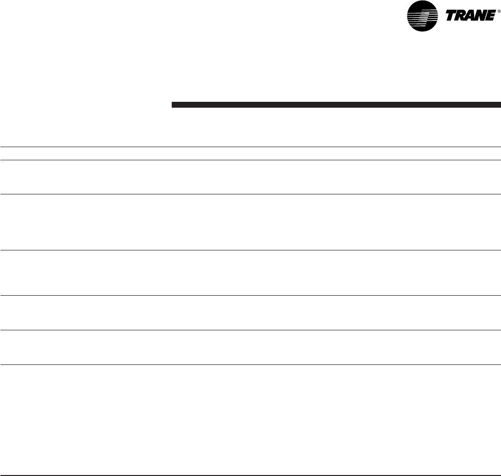
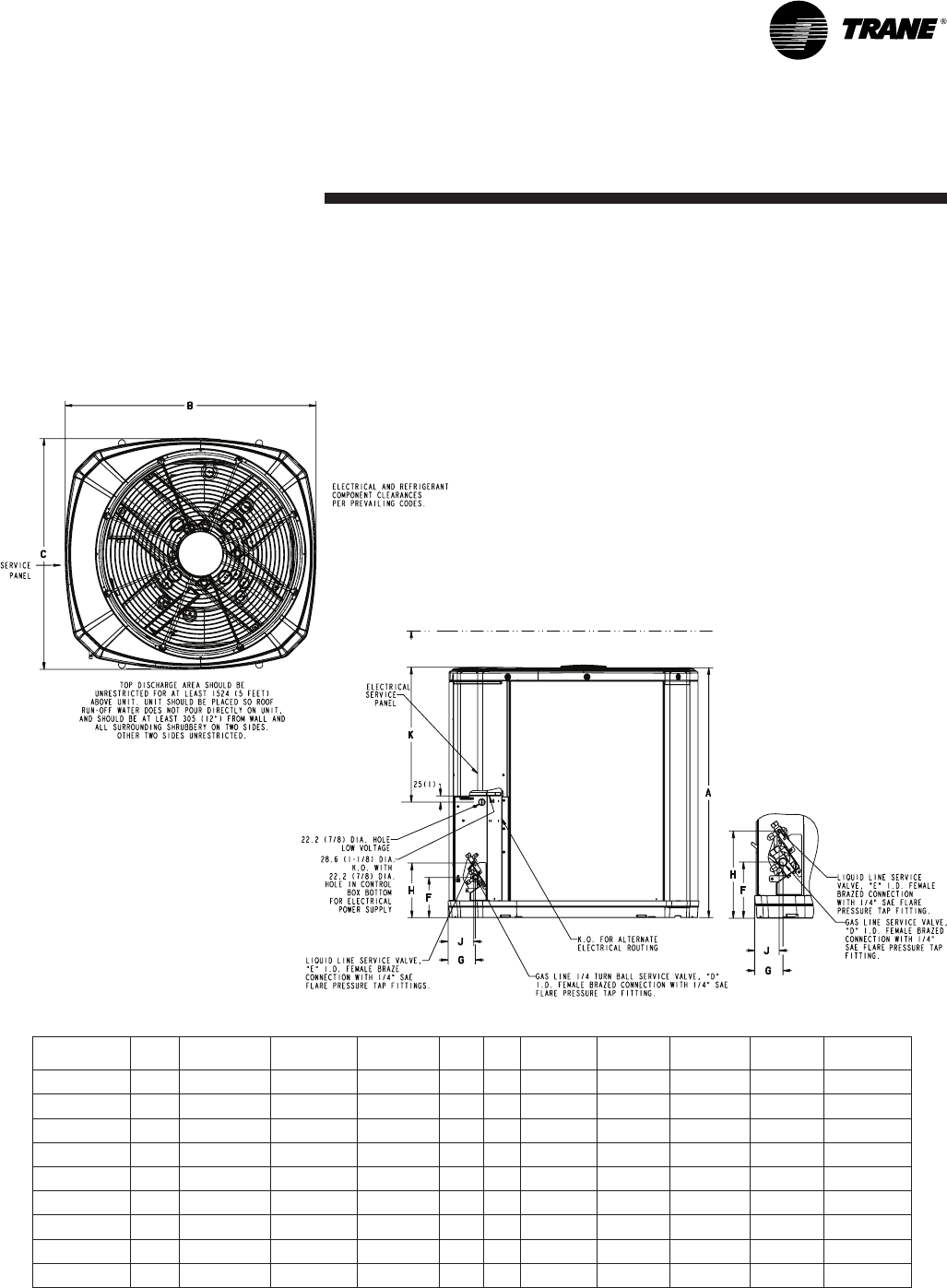
Dimensions
FromDwg.D156010
4TWB4 Outline Drawing
Note: All dimensions are in MM (Inches).
MODELS BASE A B C D E F G H J K
4TWB4018G 4730(28-3/4) 829(32-5/8) 756(29-3/4) 5/8 3/8 143(5-5/8) 92(3-5/8) 210(8-1/4) 79(3-1/8) 508(20)
4TWB4024G 3832(32-3/4) 829(32-5/8) 756(29-3/4) 5/8 3/8 143(5-5/8) 92(3-5/8) 210(8-1/4) 79(3-1/8) 508(20)
4TWB4030G 4841(33-1/8) 946(37-1/4) 870(34-1/4) 3/4 3/8 152(6) 98(3-7/8) 219(8-5/8) 86(3-3/8) 508(20)
4TWB4036G 4841(33-1/8) 946(37-1/4) 870(34-1/4) 3/4 3/8 152(6) 98(3-7/8) 219(8-5/8) 86(3-3/8) 508(20)
4TWB4042E 41045(411/8) 946(37-1/4) 870(34-1/4) 3/4 3/8 152(6) 98(3-7/8) 219(8-5/8) 86(3-3/8) 508(20)
4TWB4048E 41147(451/8) 946(37-1/4) 870(34-1/4) 7/8 3/8 152(6) 98(3-7/8) 219(8-5/8) 86(3-3/8) 508(20)
4TWB4049E 41147(451/8) 946(37-1/4) 870(34-1/4) 7/8 3/8 152(6) 98(3-7/8) 219(8-5/8) 86(3-3/8) 508(20)
4TWB4060E 41147(451/8) 946(37-1/4) 870(34-1/4) 7/8 3/8 152(6) 98(3-7/8) 219(8-5/8) 86(3-3/8) 508(20)
4TWB4061E 41147(451/8) 946(37-1/4) 870(34-1/4) 1-1/8 3/8 152(6) 98(3-7/8) 219(8-5/8) 86(3-3/8) 508(20)
Trane
www.trane.com
02/12
Trane has a policy of continuous product and product data improvement and it reserves the right to change
design and specifications without notice.
Mechanical
Specification Options
General
The4TWB4isfullychargedfromthe
factoryforupto15feetofpiping.This
unitisdesignedtooperateatoutdoor
ambienttemperaturesashighas115°F.
Coolingcapacitiesarematchedwith
awideselectionofairhandlersand
furnacecoilsthatareAHRIcertied.The
unitiscertiedtoUL1995.Exterioris
designedforoutdoorapplication.
Casing
Unitcasingisconstructedofheavy
gauge,G90galvanizedsteeland
paintedwithaweather-resistantpowder
paint
onalllouvers,panels,prepaintonall
otherpanels.Corrosionandweather-
proofCMBP-G30DuraTuff™base.
Refrigerant Controls
Refrigerationsystemcontrolsinclude
condenserfanandcompressorcontac-
tor.Highandlowpressurecontrolsare
inherenttothecompressor.Afactory
installedliquidlinedrierisstandard.
Compressor
TheClimatuff®compressorfeatures
internalovertemperatureandpressure
protectionandtotaldippedhermetic
motor.Otherfeaturesinclude:centrifugal
oilpumpandlowvibrationandnoise.
Condenser Coil
Theoutdoorcoilprovideslowairow
resistanceandefcientheattransfer.
Thecoilisprotectedonallfoursidesby
louveredpanels.
Low Ambient Cooling
Asmanufactured,thisunithasacool-
ingcapabilityto55°F.Theadditionof
anevaporatordefrostcontrolwithTXV
permitslowambientcoolingto20°F.
Accessories
Thermostats—Coolingonlyandheat/
cooling(manualandautomaticchange-
over).Sub-basetomatchthermostat
andlockingthermostatcover.
