Trane Bmtk Svn01D En Users Manual
bmtksvn01den b7f8e043-5f3f-4f72-a448-bdbbdf642529 Trane Thermostat BMTK-SVN01D-EN User Guide |
2015-01-21
: Trane Trane-Bmtk-Svn01D-En-Users-Manual-236276 trane-bmtk-svn01d-en-users-manual-236276 trane pdf
Open the PDF directly: View PDF ![]() .
.
Page Count: 88
- Contents
- Overview
- Termination module mounting
- Termination board wiring
- Main module mounting
- Display module mounting
- PC workstation wiring
- Troubleshooting
- Maintenance
- Installation checklists
- Declaration of Conformity
- Index

®
BMTK-SVN01D-EN
Hardware Installation
Tracker™ Version 12
Building Automation System

Hardware Installation
Tracker™ Version 12
Building Automation System
BMTK-SVN01D-EN
February 2004
®

BMTK-SVN01D-EN
®
Tracker Version 12 Building Automation System Hardware Installation
This guide and the information in it are the property of American Standard Inc. and may not be used or reproduced in whole or in part,
without the written permission of American Standard Inc. Since Trane has a policy of continuous product improvement, it reserves the
right to change design and specification without notice.
Use of the software contained in this package is provided under a software license agreement. Unauthorized use of the software or
related materials discussed in this guide can result in civil damages and criminal penalties. The terms of this license are included with
the compact disk. Please read them thoroughly.
Although Trane has tested the hardware and software described in this guide, no guarantee is offered that the hardware and software
are error free.
Trane reserves the right to revise this publication at any time and to make changes to its content without obligation to notify any per-
son of such revision or change.
Trane may have patents or patent applications covering items in this publication. By providing this document, Trane does not imply
giving license to these patents.
The following are trademarks or registered trademarks of Trane: Tracer, Tracker, Trane, Precedent, Rover, VariTrac, Vari-
Trane, and Voyager.
The following are trademarks or registered trademarks of their respective companies or organizations: LonMark, LonTalk,
and Neuron from Echelon Corporation; ReliaTel from Tone Software Corporation.
Printed in the U.S.A.
© 2004 American Standard Inc. All rights reserved.
™®
™®

®
BMTK-SVN01D-EN
NOTICE:
Warnings and Cautions appear at appropriate sections throughout this manual. Read these carefully:
WARNING
Indicates a potentially hazardous situation, which, if not avoided, could result in death or serious injury.
CAUTION
Indicates a potentially hazardous situation, which, if not avoided, may result in minor or moderate injury.
It may also be used to alert against unsafe practices.
CAUTION
Indicates a situation that may result in equipment or property-damage-only accidents.
The following format and symbol conventions appear at appropriate sections throughout this manual:
IMPORTANT
Alerts installer, servicer, or operator to potential actions that could cause the product or system to
operate improperly but will not likely result in potential for damage.
◆This symbol precedes a procedure that consists of only a single step.
Note:
A note may be used to make the reader aware of useful information, to clarify a point, or to describe
options or alternatives.

BMTK-SVN01D-EN i
Contents
Chapter 1 Overview . . . . . . . . . . . . . . . . . . . . . . . . . . . . . . . . . . 1
Controller components . . . . . . . . . . . . . . . . . . . . . . . . . . . . . . . . . . . . . . . 4
Termination module. . . . . . . . . . . . . . . . . . . . . . . . . . . . . . . . . . . . . . . 5
Main module. . . . . . . . . . . . . . . . . . . . . . . . . . . . . . . . . . . . . . . . . . . . . 6
Display module. . . . . . . . . . . . . . . . . . . . . . . . . . . . . . . . . . . . . . . . . . . 7
Model numbers. . . . . . . . . . . . . . . . . . . . . . . . . . . . . . . . . . . . . . . . . . . . . . 8
Tracker controller specifications . . . . . . . . . . . . . . . . . . . . . . . . . . . . . . . 9
UCM maximum capacities for Tracker models 12 and 24 . . . . . . . . . . 10
UCM maximum capacities for Tracker model WSHP . . . . . . . . . . . . . . .11
Before installation. . . . . . . . . . . . . . . . . . . . . . . . . . . . . . . . . . . . . . . . . . . 12
Verify the shipment . . . . . . . . . . . . . . . . . . . . . . . . . . . . . . . . . . . . . . 12
Inspect for shipping damage. . . . . . . . . . . . . . . . . . . . . . . . . . . . . . . 12
Store unused components until needed . . . . . . . . . . . . . . . . . . . . . 12
After installation . . . . . . . . . . . . . . . . . . . . . . . . . . . . . . . . . . . . . . . . . . . . 13
FCC compliance . . . . . . . . . . . . . . . . . . . . . . . . . . . . . . . . . . . . . . . . . . . . 14
Chapter 2 Termination module mounting . . . . . . . . . . . . . . 15
Select a location for the controller . . . . . . . . . . . . . . . . . . . . . . . . . . . . . 15
Verify location conformance to controller specifications . . . . . . . . 15
Verify location conformance to controller dimensions and
clearances . . . . . . . . . . . . . . . . . . . . . . . . . . . . . . . . . . . . . . . . . . . . 16
Verify location conformance to optimal touch screen viewing
angles . . . . . . . . . . . . . . . . . . . . . . . . . . . . . . . . . . . . . . . . . . . . . . . . 18
Mount the termination module . . . . . . . . . . . . . . . . . . . . . . . . . . . . . . . . 19
Securing the termination module to a wall . . . . . . . . . . . . . . . . . . . 20
Securing the termination module to a conduit box . . . . . . . . . . . . 20
Installing electrical conduit . . . . . . . . . . . . . . . . . . . . . . . . . . . . . . . . 21
Chapter 3 Termination board wiring . . . . . . . . . . . . . . . . . . . 23
Wire 24 Vac power . . . . . . . . . . . . . . . . . . . . . . . . . . . . . . . . . . . . . . . . . . 25
Wire optional inputs and outputs . . . . . . . . . . . . . . . . . . . . . . . . . . . . . . 26
Wire the alarm relay. . . . . . . . . . . . . . . . . . . . . . . . . . . . . . . . . . . . . . 27
Wire the priority shutdown device . . . . . . . . . . . . . . . . . . . . . . . . . . 27
Wire the utility pulse meter . . . . . . . . . . . . . . . . . . . . . . . . . . . . . . . . 28
Wire the thermistor . . . . . . . . . . . . . . . . . . . . . . . . . . . . . . . . . . . . . . 28

Contents
ii BMTK-SVN01D-EN
Wire the UCMs . . . . . . . . . . . . . . . . . . . . . . . . . . . . . . . . . . . . . . . . . . . . 29
Wire specifications . . . . . . . . . . . . . . . . . . . . . . . . . . . . . . . . . . . . . . . 29
UCM wiring configurations . . . . . . . . . . . . . . . . . . . . . . . . . . . . . . . . 32
Termination resistor placement for Comm5 links . . . . . . . . . . . . . . 34
Wire supported UCMs . . . . . . . . . . . . . . . . . . . . . . . . . . . . . . . . . . . . 37
Requirements for repeaters on Comm5 communication links . . . 37
Chapter 4 Main module mounting . . . . . . . . . . . . . . . . . . . . 41
Chapter 5 Display module mounting. . . . . . . . . . . . . . . . . . . 43
Chapter 6 PC workstation wiring. . . . . . . . . . . . . . . . . . . . . . 47
Verify PC workstation specifications . . . . . . . . . . . . . . . . . . . . . . . . . . . . 47
Direct connection to PC workstation . . . . . . . . . . . . . . . . . . . . . . . . . . . . 47
Modem connection to PC workstation . . . . . . . . . . . . . . . . . . . . . . . . . . 50
Ethernet connection to PC workstation . . . . . . . . . . . . . . . . . . . . . . . . . . 52
Connecting over an existing LAN . . . . . . . . . . . . . . . . . . . . . . . . . . . 52
Connecting through a hub . . . . . . . . . . . . . . . . . . . . . . . . . . . . . . . . . 53
Connecting with one cable. . . . . . . . . . . . . . . . . . . . . . . . . . . . . . . . . 54
Chapter 7 Troubleshooting . . . . . . . . . . . . . . . . . . . . . . . . . . . 55
Troubleshooting components . . . . . . . . . . . . . . . . . . . . . . . . . . . . . . . . . 55
LEDs . . . . . . . . . . . . . . . . . . . . . . . . . . . . . . . . . . . . . . . . . . . . . . . . . . . 55
Service pin buttons and jumper . . . . . . . . . . . . . . . . . . . . . . . . . . . . 55
Symptom/action troubleshooting . . . . . . . . . . . . . . . . . . . . . . . . . . . . . . 59
Chapter 8 Maintenance. . . . . . . . . . . . . . . . . . . . . . . . . . . . . . 63
Cleaning the touch screen . . . . . . . . . . . . . . . . . . . . . . . . . . . . . . . . . . . . 63
Calibrating the touch screen. . . . . . . . . . . . . . . . . . . . . . . . . . . . . . . . . . . 63
Appendix A Installation checklists . . . . . . . . . . . . . . . . . . . . . . 65
Appendix B Declaration of Conformity. . . . . . . . . . . . . . . . . . . 73
Index . . . . . . . . . . . . . . . . . . . . . . . . . . . . . . . . . . . . . . . . . 75
BMTK-SVN01D-EN 1
®
Chapter 1
Overview
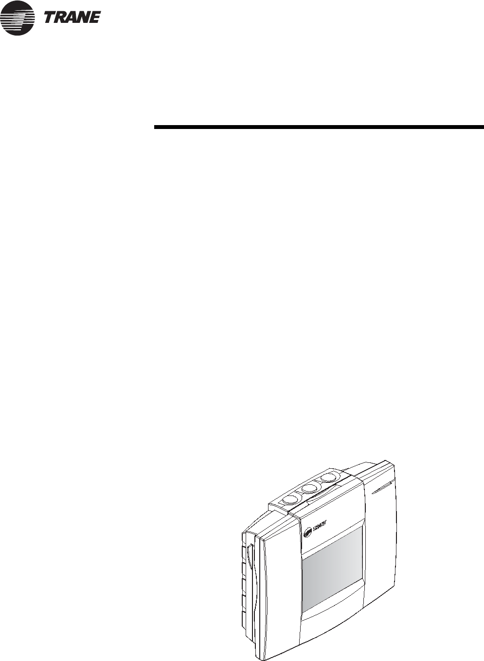
The Tracker building automation system (BAS) is an energy management
system for small- to medium-size buildings. The Tracker BAS controls
heating, ventilating, and air conditioning (HVAC) equipment. It consists
of a Tracker controller (Figure 1) and an optional PC workstation.
The Tracker BAS can be operated by using either a Tracker controller or a
PC workstation that is running Tracker PC Workstation software. A
visual interface enables an operator to set up and change HVAC
operating parameters and to collect and display building information.
The Tracker PC Workstation software allows a PC to be connected to the
Tracker controller directly with a prescribed adapter and cable, locally
over a standard Ethernet local area network (LAN) connection, or
remotely with a modem and standard phone line.
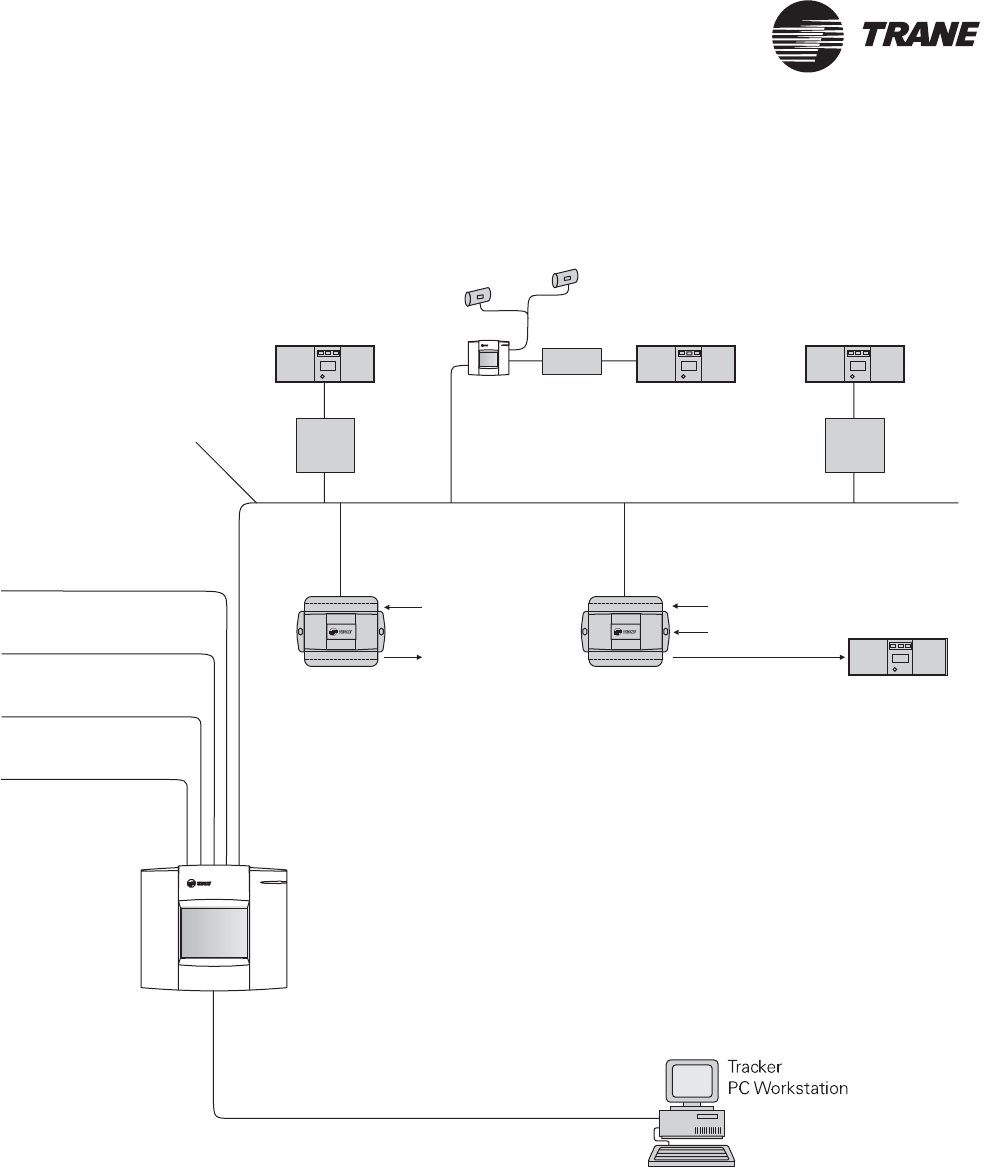
The Tracker BAS supports Comm5 communications architecture, which
is the Trane implementation of LonTalk® protocol. It resides on a network
(Figure 2 on page 2 and Figure 3 on page 3) that includes HVAC and
other comfort-related equipment, such as Trane VariTrac zoning systems;
zoning controls; unit control modules (UCMs), which control and monitor
other HVAC equipment; Tracer LCI-V (LonTalk® communication
interfaces for Voyager rooftop controls); Tracer LCI-R (LonTalk®
communication interfaces for ReliaTel rooftop controls); external input/
output (I/O) devices, which help to monitor and control specific areas or
devices; and miscellaneous equipment such as sensors, lights, and fans.
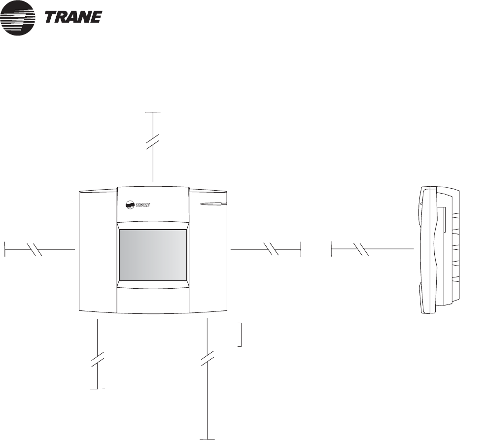
Figure 1. Tracker controller
®
Chapter 1 Overview
2BMTK-SVN01D-EN
Figure 2. Example Tracker building automation system (models 12 and 24) on a network
VariTrac central
control panel
VariTrac or VariTrane
zone dampers
Voyager rooftop
Voyager constant
volume rooftop
Precedent rooftop
with ReliaTel controls
Priority shutdown
contact input
Outdoor air
temperature sensor input
Utility pulse meter input
Tracer ZN517
unitary controller
Interconnecting wiring
(Comm5 link): single, twisted
pair, shielded wire for two-
way communication.
Universal inputs
Binary outputs
Direct, dial-in (modem),
or Ethernet connection
Alarm relay output
Tracker
controller
Generic rooftop
Tracer MP503
I/O module
Analog inputs
Binary outputs
Binary inputs
TCI-V
Tracer
LCI-V
Tracer
LCI-R
Overview
BMTK-SVN01D-EN 3
®
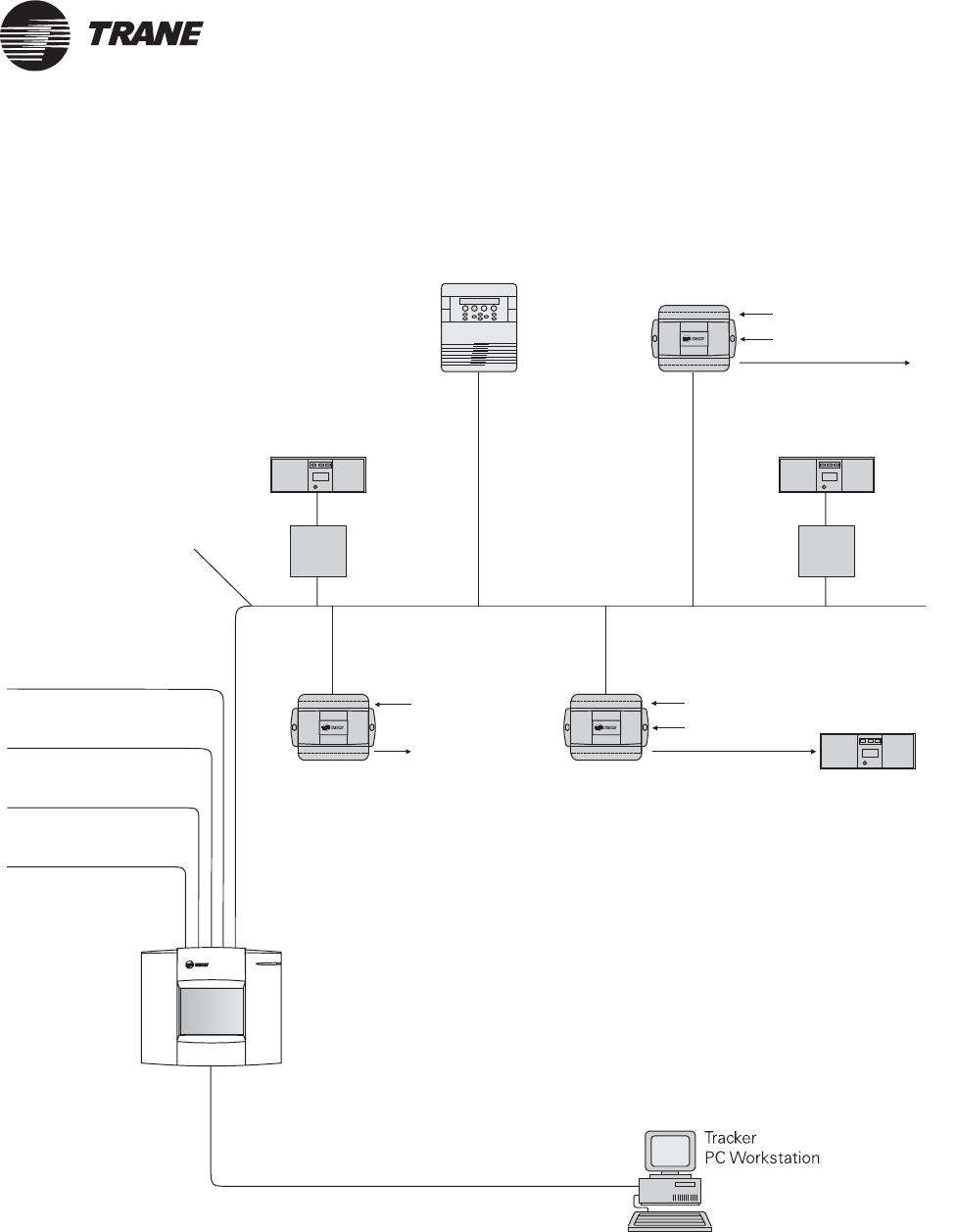
Figure 3. Example building automation system (water-source heat pump) on a network
Voyager constant
volume rooftop
Precedent rooftop
with ReliaTel controls
Priority shutdown
contact input
Outdoor air
temperature sensor input
Utility pulse meter input Analog inputs
Binary outputs
Tracer ZN517
unitary controller
Binary inputs
Interconnecting wiring
(Comm5 link): single, twisted
pair, shielded wire for two-
way communication.
Universal inputs
Binary outputs
Alarm relay output
Tracker
controller
Generic rooftop
Tracer MP503
I/O module
Analog inputs
Binary outputs
Binary inputs
Tracer ZN510, ZN511, or
ZN524 controller
Tracer loop controller
(for water-source
pump)heat
Tracer
LCI-V
Tracer
LCI-R
Direct, dial-in (modem),
or Ethernet connection
Controller components
BMTK-SVN01D-EN 5
®
Termination module
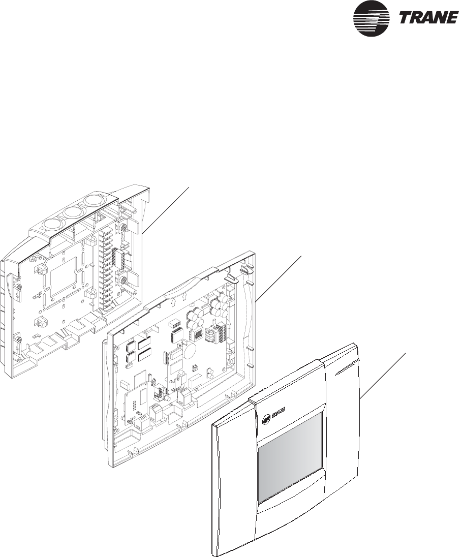
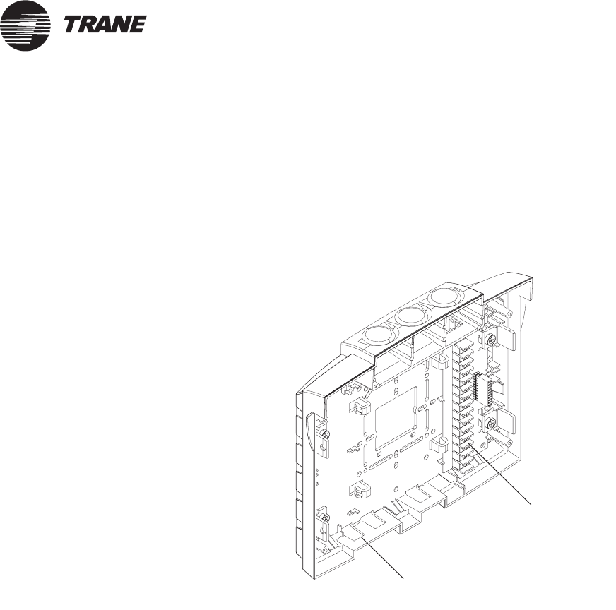
The termination module (Figure 5) is a housing that provides a
termination board and cable access for power, communications, and
system input connections. Mounting holes enable it to be mounted on a
wall or a recessed conduit box. The termination board accepts connections
for power, communications, and system inputs.
Figure 5. Termination module
Termination
board
Cable access
(three places)
®
Chapter 1 Overview
6BMTK-SVN01D-EN
Main module
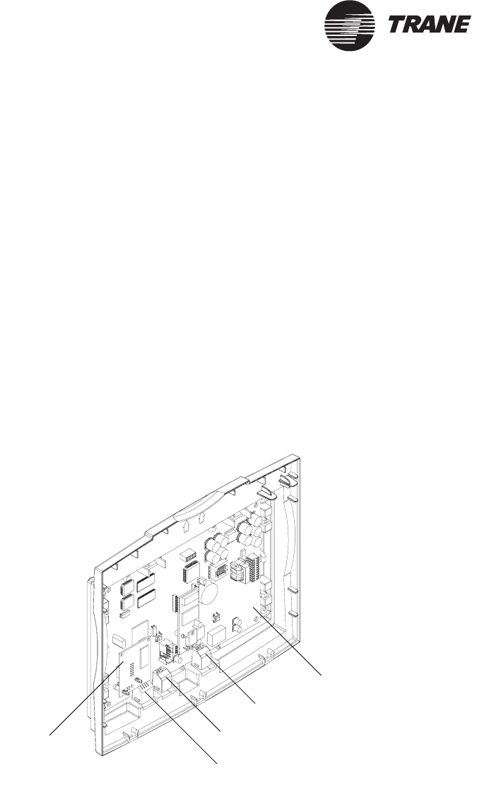
The main module (Figure 6) is a housing that contains the main logic
board and the Ethernet board. The main module can be “hot swapped”: it
can be removed and installed without removing power from the
termination module. When the main module is installed onto a powered
termination module, it receives power and begins to operate
automatically.
The main logic board provides an Ethernet LAN port, a PC interface port,
and a modem port. It provides an internal interface to termination
module I/O. It also provides Comm5 communication, 24 VAC power,
alarm, and communication indicators. It communicates and exchanges
data with the devices wired to the termination module. It also
communicates with the display module.
The Ethernet board provides two LED indicators. One shows that an
Ethernet link is detected; the other shows that there is serial traffic
between the Ethernet board and the main logic board.
Figure 6. Main module
Modem port
PC interface port
Ethernet LAN port
Main logic board
Ethernet
board
Controller components
BMTK-SVN01D-EN 7
®
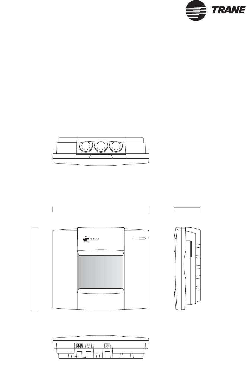
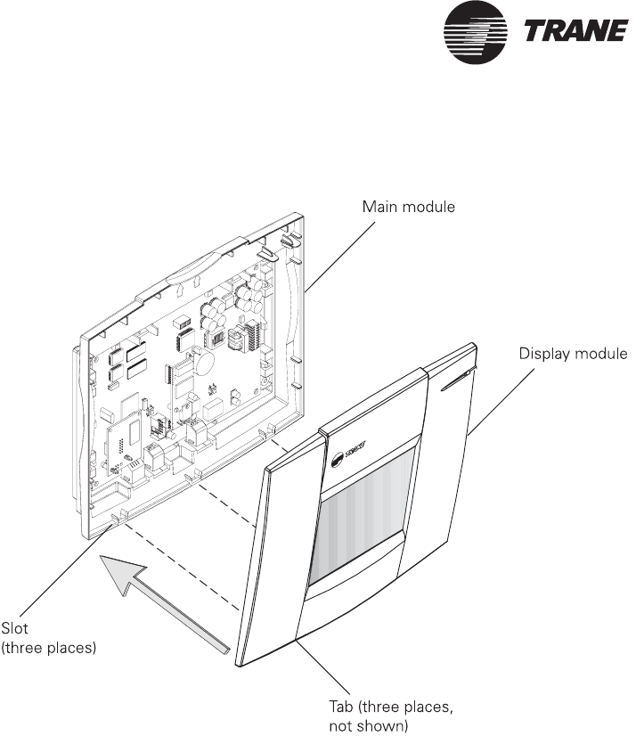
Display module
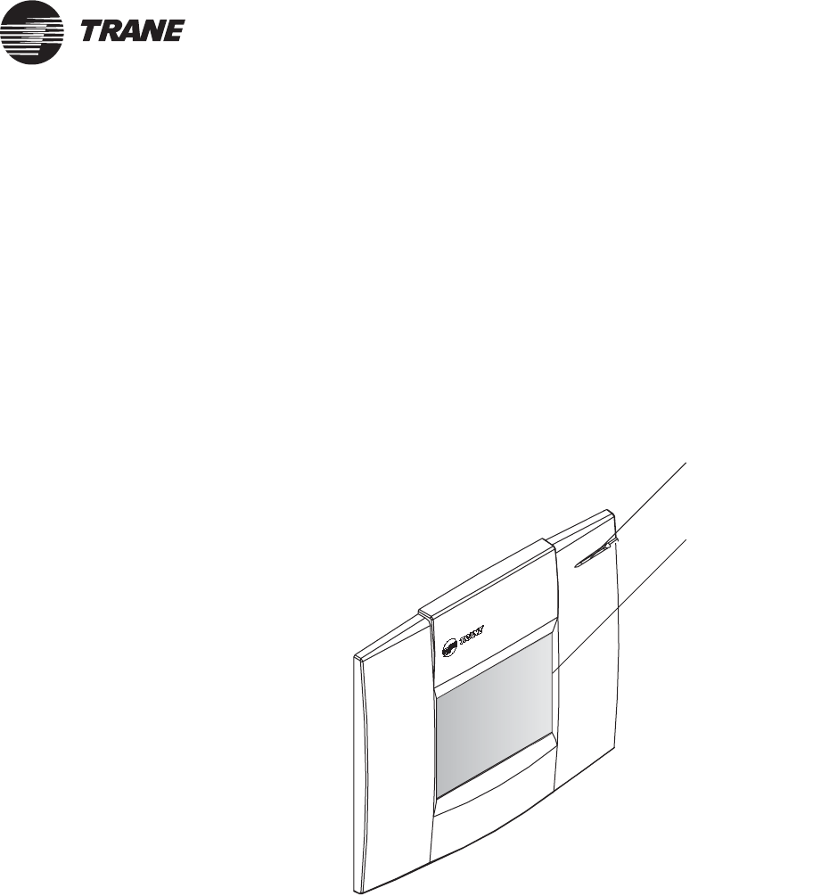
The display module (Figure 7) is a housing that contains a printed circuit
board, liquid crystal display (LCD) touch screen, and an alarm LED. The
printed circuit board supports the LCD touch screen and the alarm LED.
The touch screen provides the operator access to the user interface
program.
The display module can be “hot swapped:” it can be removed and installed
without removing power from the main module. When the display module
is installed onto a powered main module, it receives power and begins to
operate automatically.
Figure 7. Display module
LCD touch screen
Alarm LED
®
Chapter 1 Overview
8BMTK-SVN01D-EN
Model numbers
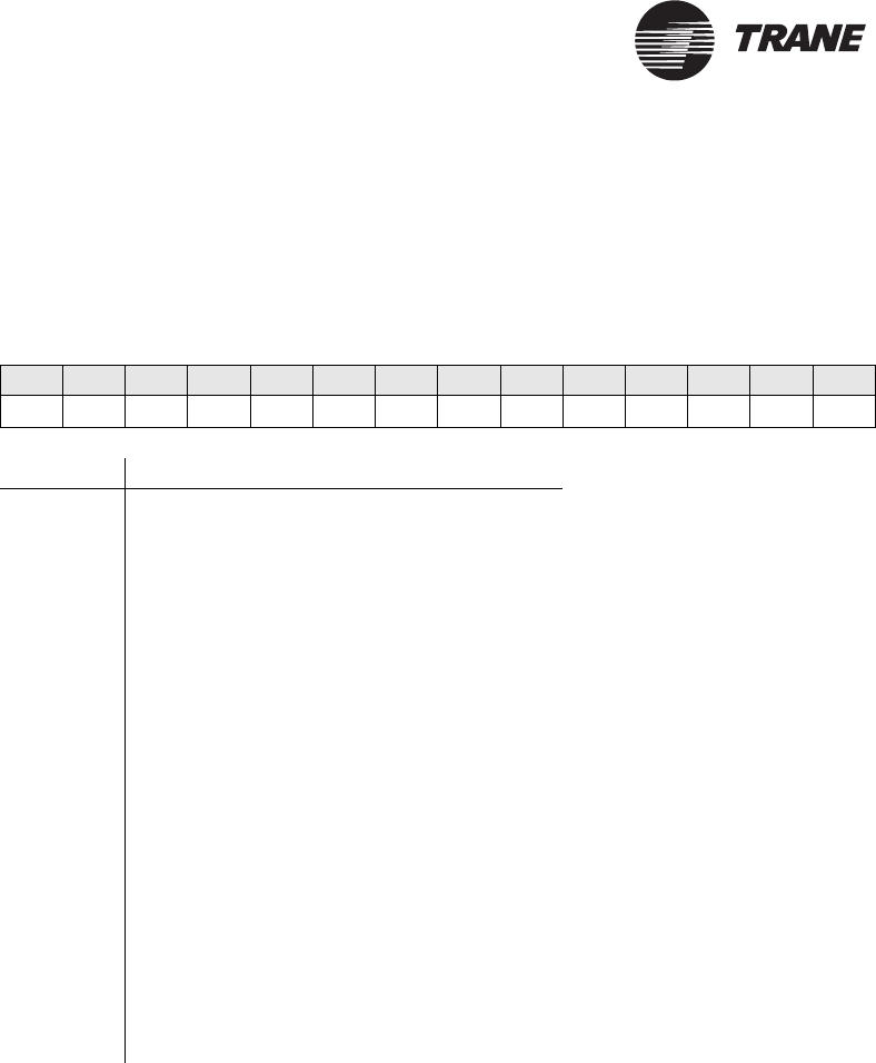
Each controller is identified by a model number that provides information
about the controller (Figure 8).
Figure 8. Model number definition
Digit number 12345678910 11 12 13 14
Model number B M T K 0 0 0 A A 0 A x 1 0
Digit Description
1–2 BM = Building management
3–4 TK = Tracker
5–7 Customer ID:
000 = Customer sales office (CSO)
KBB = Independent wholesale distributor (IWD)
8 A = 24 Vac, 50/60 Hz
9 Ethernet option
A = Modem with no Ethernet LAN option
B = Modem with Ethernet LAN option
10–11 0A = Design sequence
12 Model/software options:
1 = Model 12
2 = Model 24
3 = N/A
4 = N/A
5 = WSHP (water-source heat pump)
6 = N/A
13 Display options:
1 = LCD touch screen
14 Language options:
0 = English
Tracker controller specifications
BMTK-SVN01D-EN 9
®
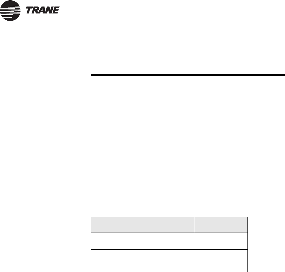
Tracker controller specifications
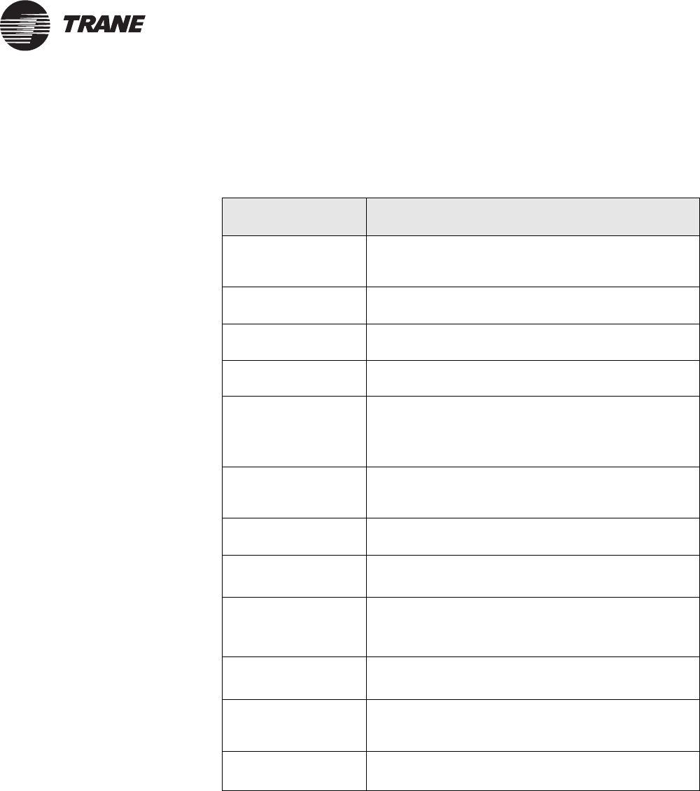
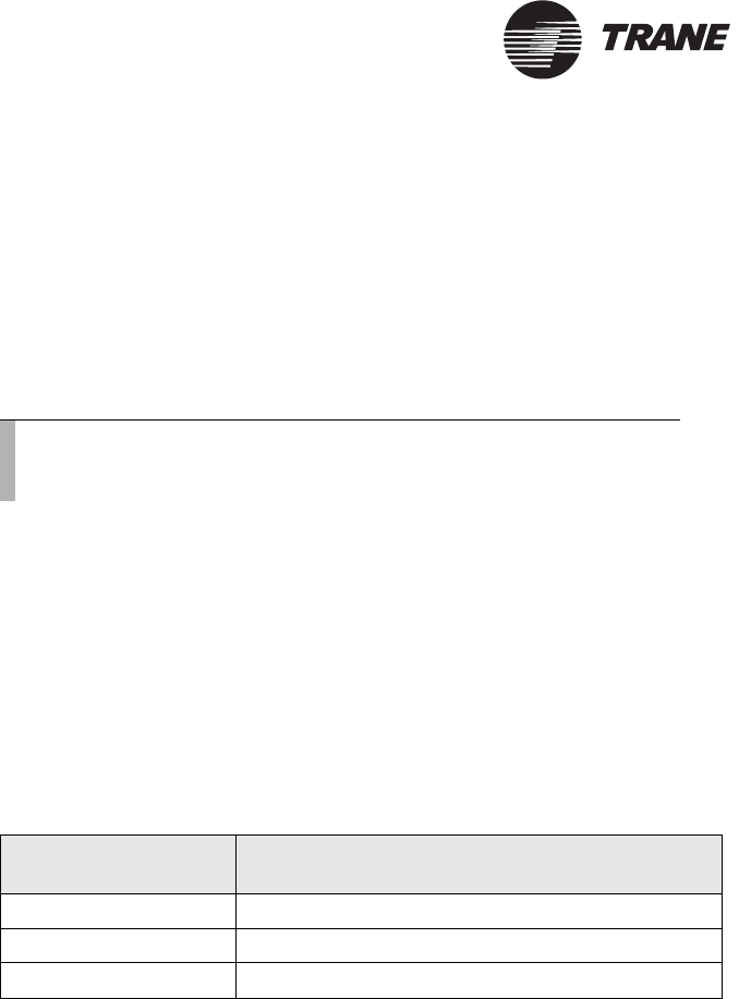
Table 1 shows the specifications for the Tracker controller.
Table 1. Tracker Controller specifications
Specification Description
Power 24 Vac nominal (19 Vac to 30 Vac),
50/60 Hz, 1 phase 40 VA minimum,
UL Class 2 transformer required
Operating environ-
ment
From 32°F to 122°F (0°C to 50°C)
10% to 90% relative humidity, non-condensing
Storage environment From –40°F to 185°F (–40°C to 85°C)
5% to 95% relative humidity, non-condensing
Cabinet NEMA 1 resin enclosure—plenum rated
Mounting Flat wall surface with one of the following recessed
conduit boxes:
2 in. × 4 in. (5.08 cm × 10.15 cm)
4 in. × 4 in. (10.15 cm × 10.15 cm)
Dimensions Height: 8.75 in. (22.38 cm)
Width: 10.25 in. (26.04 cm)
Depth: 2.75 in. (6.99 cm)
Weight 2.5 lb (1.13 kg)
Analog input
•Thermistor
10 kΩ at 77°F (25°C)
From –50°F to 200°F (–46°C to 93°C)
Binary inputs
•Utility pulse meter
•Priority shutdown
User-supplied dry contacts only. Tracker-supplied
voltage of 12 Vdc nominal (10 Vdc to 14 Vdc) at
12 mA nominal (10 mA to 14 mA).
Binary output
•Alarm relay
Tracker-supplied single-pole single-throw (SPST) dry
contact rated at 24 Vac, 0.5 A maximum
Memory backup At power loss, the system backs up memory and
stores all data for seven days. After seven days,
trends and alarms are not retained.
Approvals See Appendix B, Declaration of Conformity.
®
Chapter 1 Overview
10 BMTK-SVN01D-EN
UCM maximum capacities for Tracker
models 12 and 24
The Tracker model 12 and 24 controllers can control and monitor specific
types and numbers of Trane unit control modules (UCMs) as specified in
this topic. The supported UCMs are as follows:
•HVAC controllers that conform to the LonMark® Space Comfort Con-
troller (SCC) profile: the primary controller options are the Voyager
rooftop with a Tracer LCI-V, Precedent rooftop with ReliaTel controls
and a Tracer LCI-R, and Tracer ZN517 unitary controller. Other con-
trollers are limited to the Tracer ZN510, ZN511, and ZN524.
•VariTrac central control panels (CCPs) with a TCI-V.
•Tracer MP503 I/O module.
Table 2 shows the maximum number of each UCM type that can be linked
to each Tracker controller model. Any combination of the specified UCMs
may be used in aggregate if they do not exceed the maximum. (For
example: A fully loaded Tracker 24 controller can control 24 SCC devices,
10 VariTrac CCPs, and 4 Tracer MP503 I/O modules.)
The Trane VariTrac CCP is the main controller for either a changeover
bypass system configuration or a delivered variable air volume (VAV)
system configuration. Any combination of CCP configurations may be
used in aggregate, as long as they do not exceed the maximum.
Note:
•Each VariTrac CCP configured for changeover bypass can
control 1 HVAC device and up to 24 VAV UCMs.
•Each VariTrac CCP configured for delivered VAV can con-
trol 1 HVAC device and up to 32 VAV UCMs.
•See repeater information, “Requirements for repeaters on
Comm5 communication links” on page 37.
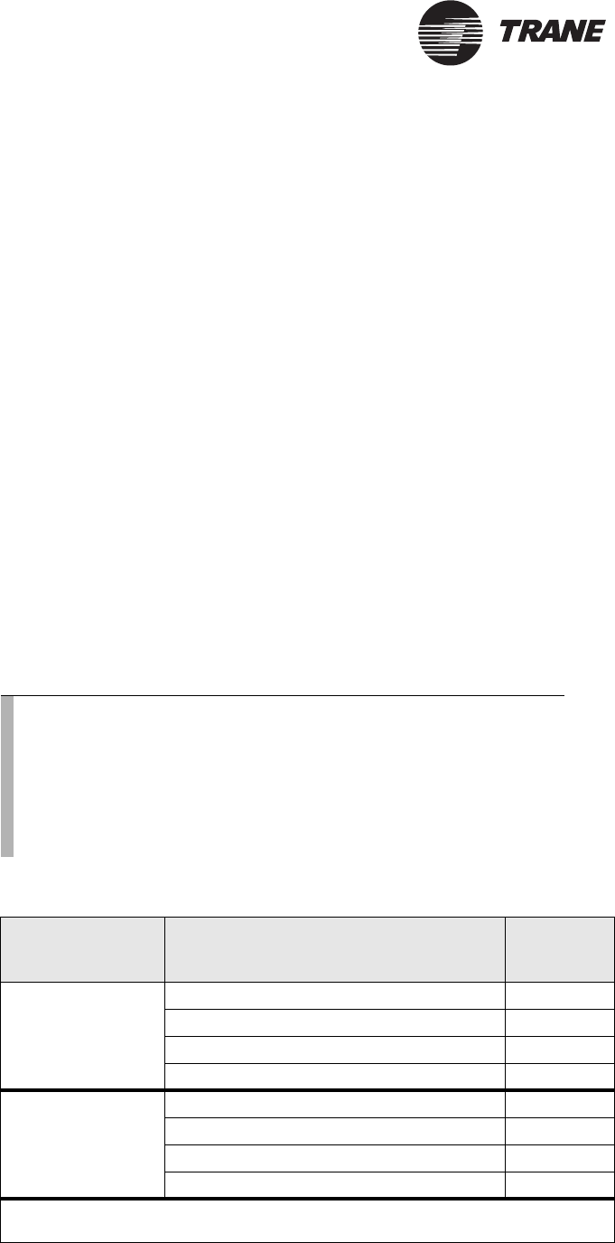
Table 2. Tracker controller models 12 and 24 UCM capacities
Tr a c k e r m o d e l UCM type Maximum
UCMs
24 SCC* 24
Trane VariTrac CCP 10
Tracer MP503 I/O module 4
To t a l maximum UCMs supported 38
12 SCC* 12
Trane VariTrac CCP 5
Tracer MP503 I/O module 4
To t a l maximum UCMs supported 21
* SCCS supported by Tracker are limited to Voyager rooftops, Precedent rooftops with
ReliaTel controls, Tracer ZN517, ZN510, ZN511, and ZN524.
UCM maximum capacities for Tracker model WSHP
BMTK-SVN01D-EN 11
®
UCM maximum capacities for Tracker
model WSHP
The Tracker model WSHP controller can control and monitor specific
types and numbers of Trane unit control modules (UCMs) as specified in
this topic. The supported UCMs are as follows:
•Space Comfort Controllers (SCCs): the primary controller options are
the Tracer ZN510, ZN511, and ZN524. Other controllers are limited
to Voyager rooftops with a Tracer LCI-V, Precedent rooftops with Reli-
aTel controls and a Tracer LCI-R, and Tracer ZN517 unitary control-
lers
•Tracer loop controller (TLC)
•Tracer MP503 I/O module
Table 3 shows the maximum number of each UCM type that can be linked
to each Tracker controller model. Any combination of the specified UCMs
may be used in aggregate if they do not exceed the maximum. (For
example: As the table shows, a fully loaded Tracker WSHP controller can
control 100 SCC devices, 1 Tracer loop controller (TLC), and 4 Tracer
MP503 I/O modules.)
IMPORTANT
SCC compressor operation will be enabled only when a TLC is commu-
nicating with the Tracker panel.
Note:
See repeater information, “Requirements for repeaters on
Comm5 communication links” on page 37.
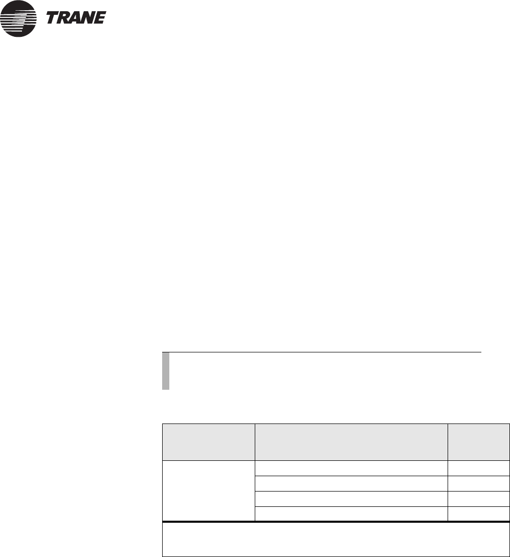
Table 3. Tracker controller model WSHP UCM capacities
Tr a c k e r m o d e l UCM type Maximum
UCMs
WSHP SCC* 100
TLC** 1
Tracer MP503 I/O module 4
To t a l maximum UCMs supported 105
* SCCS supported by Tracker are limited to Tracer ZN510, ZN511,and ZN524; Voyager
rooftops; Precedent rooftops with ReliaTel controls; and Tracer ZN517.
** The TLC is mandatory and must be present to enable SCC compressor operation.

®
Chapter 1 Overview
12 BMTK-SVN01D-EN
Before installation
Before beginning to install the Tracker controller, make sure that you
have all the necessary controller components and that they are
undamaged. Also, take steps to protect components until they are needed.
IMPORTANT
Before you install the Tracker hardware, review this guide and other
Tracker support literature and create an installation plan.
Verify the shipment
When the shipment arrives at the job site, carefully unpack the carton.
Even though outgoing orders are thoroughly reviewed before leaving the
factory, compare the items in the shipment with the shipping
authorization paper and verify that all items are present.
Verify that the controller model received is the model that you ordered
and write down the model number for use later.
Inspect for shipping damage
Inspect the items in the shipment to verify that no shipping damage or
loss occurred. If your inspection reveals damage or material shortage:
•Make the appropriate notation on the carrier delivery receipt.
•Immediately file a claim with the carrier, specifying the extent and
type of damage and/or shortage found.
•Notify the appropriate Trane representative.
Store unused components until needed
CAUTION
Avoid Equipment Damage!
Store all Tracker components off-site until most or all of the building
construction is complete. Failure to do so could result in damage to
components.
The termination module is shipped detached from the main module and
display module assembly. To protect the controller from damage, Trane
recommends storing the main module and display module assembly away
from the construction and/or installation site to prevent it from being
damaged or lost. Verify that the storage site conforms to the specifications
shown in Table 1 on page 9.
Note:
Contact your sales office to order additional Tracker literature,
if needed.

After installation
BMTK-SVN01D-EN 13
®
After installation
After installing the Tracker hardware, use the post-installation checklist
(Table 4) to verify that all installation procedures were completed.
Table 4. Tracker controller post-installation checklist
Inspect shipment upon receipt
_____ Verify that the shipment is complete.
_____ Inspect the controller and accessories to verify that
there has been no shipping damage or loss.
_____ File a damage claim with the carrier, if necessary.
_____ Verify that the controller received is the one that
was ordered.
_____ Write down the controller model number for use
later.
Verify termination module mounting
_____ Verify that the controller is in a safe indoor
environment.
_____ Verify that the location enables appropriate
personnel to access the controller.
_____ Verify that the controller is mounted securely with
recommended fasteners and screws.
_____ Verify that the installation conforms to controller
dimensions, recommended clearances, and
viewing angles.
Verify 24 Vac power wiring
_____ Verify that the power wiring complies with
applicable codes.
_____ Verify the 24 Vac power connection to the
controller termination Block TB1.
_____ Check the power wiring for shorts and improper
grounds.
_____ If using conduit connections, make sure separate
conduits are used for power and communications.
_____ Inspect the controller printed circuit card for
damage.
Verify input and output wiring
_____ Verify that wiring complies with specifications.
_____ Inspect all binary and analog terminations at TB1.
Verify communication wiring
_____ Verify that wiring complies with specifications.
_____ Inspect communication wiring between devices.
_____ Verify that all connections are properly shielded.
Verify wire terminations with a voltmeter
_____ Verify that the tests detailed in Table 18 on page 70
provide acceptable values.
Verify main module installation
_____ Verify that the main module is snapped in tightly
against the termination module.
_____ Verify that there is LED5 (HRT) activity.
Verify display module installation
_____ Verify that the display module is snapped in tightly
against the main module.
_____ Verify that the touch screen illuminates when
touched.
Verify direct and modem communication wiring
_____ Verify that the recommended cable is used for a
direct PC connection.
_____ Verify that the recommended adapter is used for
the direct connection cable.
_____ Verify that the direct connection cable is connected
to the correct Tracker port.
_____ Verify that the phone cable is connected to the
correct Tracker port.
Verify Ethernet communication wiring
_____ Verify that the recommended cable is used for the
connection.
_____ Verify that the Ethernet connection cable is
connected to the correct Tracker port.

®
Chapter 1 Overview
14 BMTK-SVN01D-EN
FCC compliance
The Tracker controller generates, uses, and radiates radio frequency
energy and if not installed and used in accordance with the instruction
manual, may cause interference to radio and television reception. The
Tracker controller has been tested and found to comply with the limits for
a Class A computing device in accordance with the specifications in
Subpart J of Part 15 of FCC rules, which are designed to provide
reasonable protection against such interference in a commercial
installation.
There is no guarantee that interference will not occur in a particular
installation. If the Tracker controller does cause interference, consult a
radio or television technician for suggestions to correct the problem. Also,
the booklet How to Identify and Resolve Radio-TV Interference Problems
is available from the U.S. Government Printing Office, Washington DC
20402. Order stock number 004-000-00345-4.

BMTK-SVN01D-EN 15
®
Chapter 2
Termination module
mounting
After unpacking and inspecting the shipment, mount the termination
module. The mounting process for the termination module consists of
selecting a location and mounting the module. This chapter provides
information and procedures that enable you to mount the termination
module.
Select a location for the controller
When selecting a location for the Tracker controller:
•Select a location that is in a clean, non-corrosive, indoor environment.
The controller is only intended for indoor installation.
•Consider both security and control wire lengths when making the
selection.
•Select a location that limits controller access to operating and service
personnel.
•Select a location that conforms to the operating environment
described in Table 1 on page 9. The recommended operating environ-
ment will extend the life of the electronic components. Verify that the
location does not subject the controller to extreme operating condi-
tions (including excessive vibration).
CAUTION
Avoid Equipment Damage!
Install the Tracker controller out of direct sunlight. Failure to do so may
cause overheating, which could result in equipment damage.
IMPORTANT
Do not install the Tracker controller near high-power radio signals, elec-
trical switching gear, power buses, large motors, or other sources of
electrical noise. The electrical interference may lead to control malfunc-
tions.
Verify location conformance to controller specifications
Verify that the selected location conforms to the applicable controller
specifications listed in Table 1 on page 9.
®
Chapter 2 Termination module mounting
16 BMTK-SVN01D-EN
Verify location conformance to controller dimensions
and clearances
Verify that the selected location provides enough space to accommodate
the controller (Figure 9) and its minimum clearances (Figure 10 on
page 17):
•The top clearance allows for ventilation and conduit entry.
•The bottom clearance allows for PC cable interface clearance.
•The front clearance allows for operation and service access.
Figure 9. Dimensions
Front view Side view
8.75 in.
(22.38 cm)
2.75 in.
(6.99 cm)
10.25 in.
(26.04 cm)
Top view
Bottom view
Select a location for the controller
BMTK-SVN01D-EN 17
®
Figure 10. Minimum clearances
36 in.
(91 cm)
12 in.
(30 cm)
12 in.
(30 cm)
12 in.
(30 cm)
12 in.
(30 cm)
54 in.
(1.4 m)
Distance
to floor
Front Back
®
Chapter 2 Termination module mounting
18 BMTK-SVN01D-EN
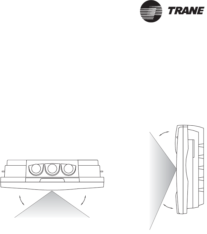
Verify location conformance to optimal touch screen
viewing angles
Verify that the height and location enable the user to view the touch
screen at the optimal viewing angles (Figure 11).
Figure 11. Optimal touch screen viewing angles
40o40o
40o
25o
Top view
Side view
Mount the termination module
BMTK-SVN01D-EN 19
®
Mount the termination module
After selecting a suitable location for the Tracker controller, mount the
termination module. Mounting consists of securing the termination
module to a wall or a 2 in. × 4 in. recessed conduit box (mounted vertically
or horizontally) or a 4 in. × 4 in. recessed conduit box (several European
electrical box sizes are also usable) and installing electrical conduit
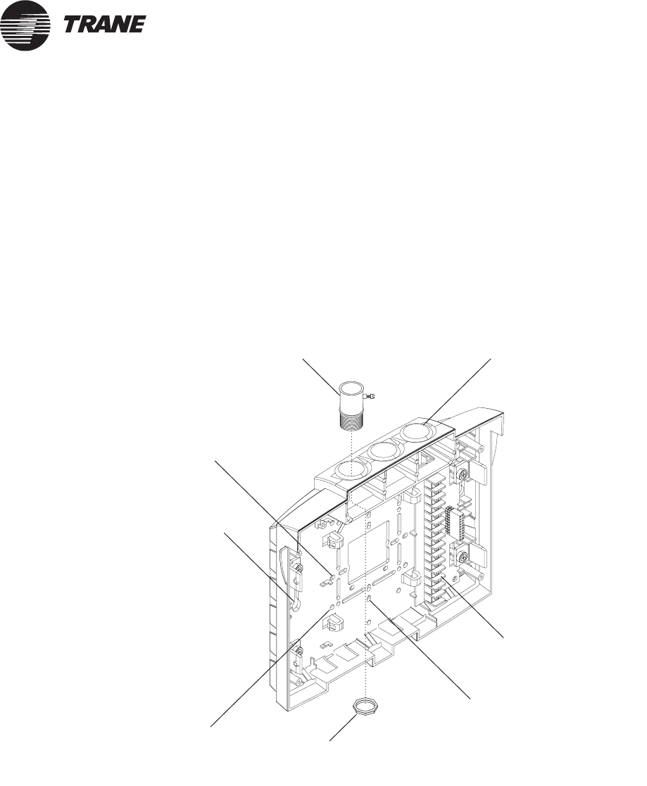
(optional). Figure 12 shows the conduit access and mounting holes on the
termination module.
Figure 12. Termination module conduit access and mounting holes
Termination board
Conduit access
(three places)
Two holes for mounting on a wall
(one on each side)
Holes for mounting on a
4 in. x 4 in. conduit box
(four corners)
Holes for mounting on a 2 in. x 4 in.
conduit box vertically
(top and bottom)
Holes for mounting on a 2 in. x 4 in.
conduit box horizontally
(left and right)
Conduit connector
Jamb nut
(attaches to
conduit connector)

®
Chapter 2 Termination module mounting
20 BMTK-SVN01D-EN
Securing the termination module to a wall
1. Mark the location of the two mounting holes on the wall.
2. Set the termination module aside and drill mounting holes.
3. Secure the termination module to the wall with the supplied hard-
ware (#10 × 1 in. screw with plastic anchor).
Securing the termination module to a conduit box
1. Remove the screws from the conduit box.
2. Line up the conduit box screw holes on the termination module
(Figure 12 on page 19) with the screw holes on the conduit box.
3. Install the screws.
Note:
When mounting the termination module to a 4 in. × 4 in.
conduit box, removing the plastic cover over the box will
provide easier access. Do not attempt to break away excess
plastic. Instead, use a hack saw blade and carefully cut away
the plastic.
Mount the termination module
BMTK-SVN01D-EN 21
®
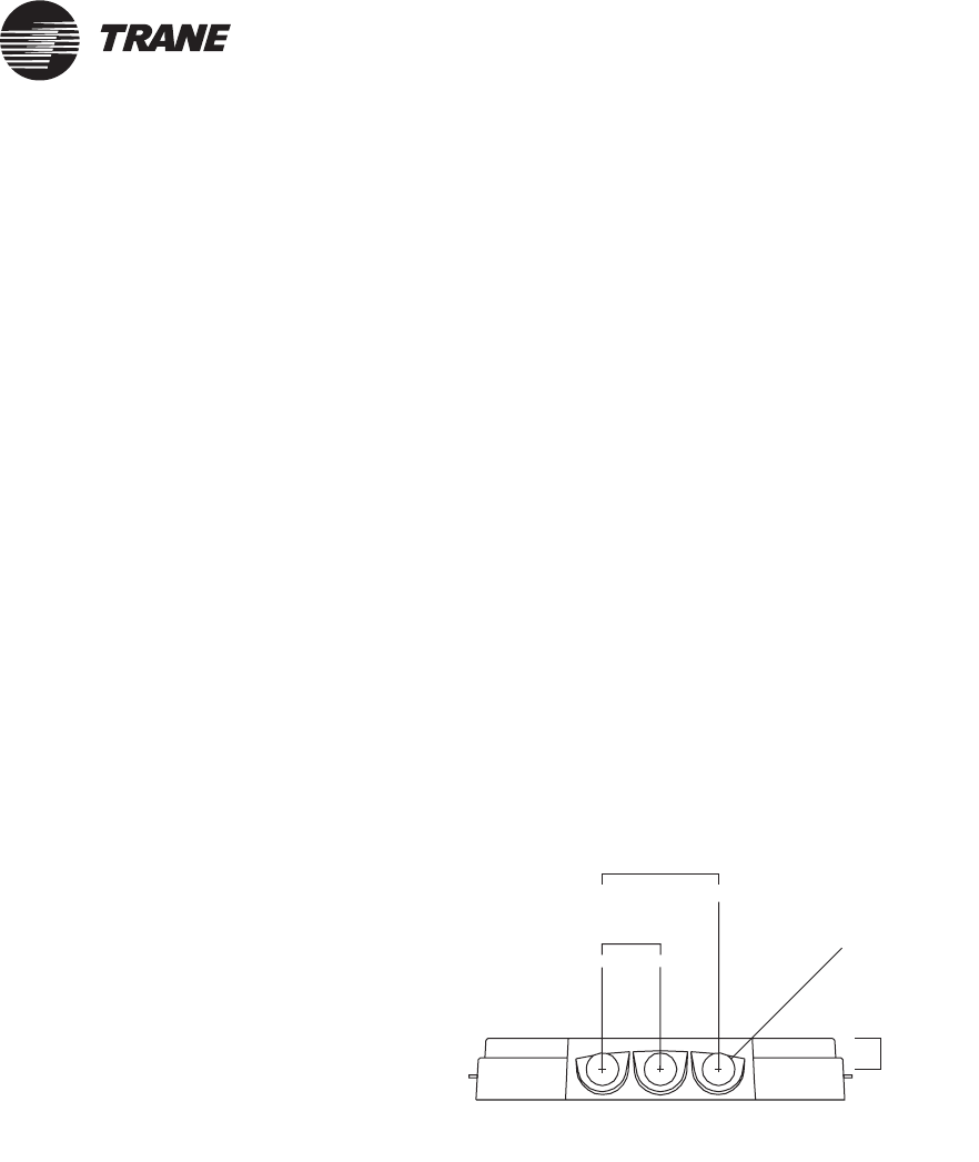
Installing electrical conduit
Use the conduit openings on the top of the Tracker termination module to
supply power or communication wires to the controller.
If the controller is mounted on a wall, you must use electrical conduit. If
the controller is mounted to a conduit box through which power, input/
output, and communications are supplied, you do not need to use
electrical conduit.
IMPORTANT
The 24 Vac wire conduit may not contain input/output or communica-
tion wires. Failure to comply will cause the Tracker controller to mal-
function due to electrical noise.
1. Remove one of the 7/8 in. (22 mm) diameter plugs at the top of the ter-
mination module (Figure 13).
2. Install 1/2 in. (12 mm) conduit connector (Figure 12 on page 19) in
opening.
3. Install the conduit jamb nut on the conduit connector threads and
tighten it to secure the connector to the Tracker panel.
Figure 13. Electrical conduit installation
Termination module top view
0.75 in.
(2.02 cm)
ø7/8 in.
(ø 22 mm)
1.5 in.
(3.81 cm)
3.0 in.
(7.62 cm)

®
Chapter 2 Termination module mounting
22 BMTK-SVN01D-EN

BMTK-SVN01D-EN 23
®
Chapter 3
Termination board wiring
After mounting the termination module, wire the termination board. The
wiring process consists of wiring the termination board to 24 Vac power,
inputs, outputs, and UCMs. This chapter provides information and
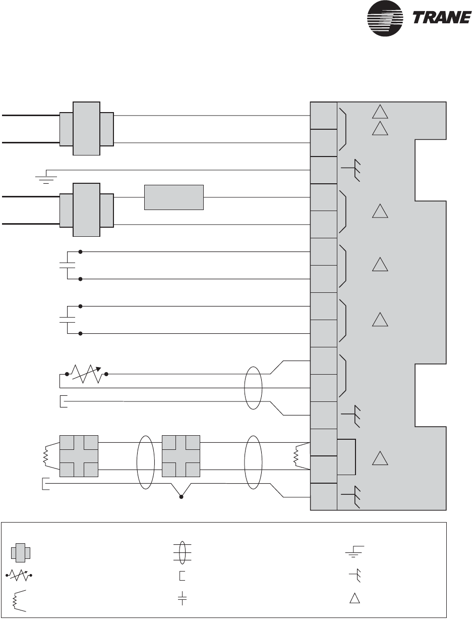
procedures that enable you to wire the termination board. Figure 14 on
page 24 shows all field wiring connections.
Refer to the required and optional supply checklists in Appendix A
(Table 15 and Table 16 on page 65) to verify that you have the materials
required to wire the Tracker controller. When termination board wiring is
complete, use the termination module post-installation checklist in
Appendix A (Table 18 on page 70) to verify the wiring.
®
Chapter 3 Termination board wiring
24 BMTK-SVN01D-EN
Figure 14. Tracker field wiring connections
24VAC
THERMISTOR
COMM
ALARM
RELAY
PRIORITY
SHUTDOWN
METER
INPUT
1
2
3
4
5
6
7
8
9
10
11
12
13
14
15
24 Vac
Line voltage
Line voltage
Comm5
link
Comm5
link
Comm5 deviceComm5 device
Splice
2
1
3
5
4
4
AA
BB
AA
BB
Legend
Twisted pair, shielded wire
per Trane specifications
Shield termination
Earth ground
Contact points
Thermistor device per
Trane specifications
Transformer
Termination resistor
Shield ground
=
=
=
=
=
=
=
=
LOAD
Figure note
=
Figure Notes:
1 All customer wiring must be in accordance with national, state, and local electrical codes.
2 Trane recommends a dedicated transformer for 24 Vac power.
3 Alarm relay circuit must not exceed 24 Vac, 1 A.
4 Do not apply voltage to the priority shutdown inputs.
5 Example of Comm5 communication link wiring. See product-specific literature for Comm5 wire connection details.
Wire 24 Vac power
BMTK-SVN01D-EN 25
®
Wire 24 Vac power
After the termination module is mounted in the selected location, wire
24 Vac power to the termination board. Table 5 shows the specifications
for power wiring.
IMPORTANT
The 24 Vac wire conduit may not contain input/output or communica-
tion wires. Failure to comply may cause the Tracker controller to mal-
function due to electrical noise.
1. Route input wires into the termination module through the conduit
box or any of the conduit access openings designated for input and
communication wiring (Figure 12 on page 19).
2. Wire the two 24 Vac power input wires and the ground wire to the
controller 24 VAC terminals (Figure 14 on page 24).
Table 5. Power wiring specifications
24 Vac power
terminals Description Wire specifications
24 Vac
TB1-1, TB1-2,
Earth ground TB1-3
Power input
24 Vac nominal (19–30 Vac), 50/60 Hz,
1 phase 40 VA minimum, class 2
transformer required
Trane recommends 18 AWG (1.02 mm2) wire and
metal conduit.
Low voltage (24 Vac) wire must comply with
National Electrical Code (NEC) and federal, state,
and local electrical codes.
®
Chapter 3 Termination board wiring
26 BMTK-SVN01D-EN
Wire optional inputs and outputs
The Tracker controller provides input and output terminals as follows:
•Input for an optional priority shutdown device
•Input for an optional utility pulse meter
•Input for an optional outdoor air temperature sensor
•Output terminal for an optional alarm relay
Refer to Table 6 for input and output wire specifications, and to the
termination board wiring diagram in Figure 14 on page 24 for wiring all
inputs and outputs.
Table 6. Input and output wire specifications
Input and output
terminals Description Wire specifications
Alarm relay output
TB1-4, TB1-5
Binary output
Dry contact
Operating range: 24 V, 1 A
maximum
Trane recommends 18 AWG (1.02 mm2) wire and metal
conduit.
Maximum length = 1000 ft (305 m) *†
Priority shutdown
device input
TB1-6, TB1-7
Binary input
Operating range:
12 Vdc nominal
(10 Vdc to 14 Vdc) at
12 mA nominal
(10 mA to 14 mA)
< 50 Ω = switch closed
> 1000 Ω = switch open
Trane recommends 18—22 AWG (1.02 mm2—0.643mm2)
wire and metal conduit.
Maximum length = 1000 ft (305 m) *‡
Utility pulse meter
input
TB1-8, TB1-9
Thermistor input
TB1-10, TB1-11,
shield ground TB1-12
Analog input for an outdoor air
temperature sensor
Operating range:
From –50ºF to 200ºF
(–46ºC to 93ºC)
Thermistor, 10 kΩ at 77°F (25°C)
Shielded wire, 18—22 AWG (1.02 mm2—0.643mm2)
twisted pair
Maximum length = 300 ft (91 m) *‡
* All field-installed binary wiring is low voltage and must comply with National Electrical Code (NEC) and federal, state, and
local electrical codes.
† Alarm relay wires and 24 Vac wires may reside in the same conduit.
‡ Do not run input wires and ac power wires together in the same conduit or wire bundle.

Wire optional inputs and outputs
BMTK-SVN01D-EN 27
®
Wire the alarm relay
Wire the alarm relay to the termination board output.
CAUTION
Avoid Equipment Damage!
Use a dedicated power transformer for this output. Failure to do so will
damage the main module, if the alarm output is powered from the
Tracker 24 Vac input (TB-1 and TB-2) and the circuit shorts to ground.
1. Route input wires into the termination module through a conduit
opening (Figure 12 on page 19) or the conduit box.
2. Connect the wires to the ALARM RELAY terminals on the termina-
tion board (Figure 14 on page 24).
3. Connect the other end of the wires to the customer-supplied power
supply and load.
Wire the priority shutdown device
Wire the priority shutdown device to the termination board input.
1. Route input wires into the termination module through a conduit
opening (Figure 12 on page 19) or the conduit box.
2. Connect the wires to the PRIORITY SHUTDOWN terminals on the
termination board (Figure 14 on page 24).
3. Connect the other end of the wires to the contacts of the priority shut-
down device.

®
Chapter 3 Termination board wiring
28 BMTK-SVN01D-EN
Wire the utility pulse meter
Wire the utility pulse meter to the termination board input.
1. Route input wires into the termination module through a conduit
opening (Figure 12 on page 19) or the conduit box.
2. Connect the wires to the METER INPUT terminals on the termina-
tion board (Figure 14 on page 24).
3. Connect the other end of the wires to the pulsed-output contacts of
the electrical meter.
Wire the thermistor
The thermistor input is for a Trane outdoor air temperature sensor only.
The input cannot be used for any other purpose. Using wire that meets
the specifications listed in Table 6 on page 26, wire the thermistor to the
termination board input.
1. Route input wires into the termination module through a conduit
opening (Figure 12 on page 19) or the conduit box.
2. Connect the wires to the THERMISTOR terminals on the termination
board (Figure 14 on page 24).
3. Connect the shield to the ground terminal.
4. Connect the other end of the wires to the thermistor device.
IMPORTANT
Tape the shield at the sensor. Any connection between the shield and
ground will cause a malfunction.
Note:
The thermistor input is not polarity sensitive.

Wire the UCMs
BMTK-SVN01D-EN 29
®
Wire the UCMs
The Comm5 communication link connects unit control modules (UCMs)
to the Tracker termination module. Each controller has one Comm5
communication link. This topic includes information and procedures for
wiring a UCM to a termination module:
Wire specifications
Tracker Comm5 communication-link and sensor wiring is low-voltage
Class 2 wire and must be field-supplied and installed in compliance with
NEC and local codes. To prevent electrical noise interference, all wiring
must comply with requirements outlined in this topic for wire selection
and link-wiring topology.
Trane recommends that you use Level 4 (Echelon) shielded cable for the
Tracker communication link wiring between the Tracker and the Comm5
UCMs to which it communicates. Trane also recommends that you use it
for communication wiring between the VariTrac CCP and its associated
VariTrac or VariTrane UCMs, and for sensor wiring to these devices.
Level 4 cable is available in shielded, plenum and non-plenum versions.
Level 4 cable is available from Trane-approved suppliers as well as other
suppliers. Table 7 on page 30 shows the Trane approved suppliers;
Table 8 on page 31 provides the specifications for Level 4 compliant
cables.
Note:
Do not exceed the maximum number of UCMs that can
communicate on a Tracker controller (see “UCM maximum
capacities for Tracker models 12 and 24” on page 10 for details).

®
Chapter 3 Termination board wiring
30 BMTK-SVN01D-EN
Table 7. Trane-approved wire suppliers
Supplier Cable type Number of
pairs Details Catalog
number
Connect-Air International
Phone: 1-800-247-1978
FAX: 1-253-813-5699
Web: www.connect-air.com
Level 4
22 AWG
(0.643mm2)
1 Shielded plenum
UL type CMP
W221P-2002
Level 4
22 AWG
(0.643mm2)
1 Shielded non-plenum
UL type CM
W221P-1003
Windy City Wire
Phone: 1-800-379-1191
FAX: 1-708-493-1380
Web: www.smartwire.com
Level 4
22 AWG
(0.643mm2)
1 Shielded plenum
UL type CMP
106500
Level 4
22 AWG
(0.643mm2)
1 Shielded non-plenum
UL type CM
10760 0
Category 4 cable is not the same as Level 4 cable and should not be used. The Echelon Level 4 cable specification was originally
defined by the National Electrical Manufacturers Association (NEMA) and differs from the Category 4 specification proposed
by the Electronic Industries Association/Telecommunications Industry Association (EIA/TIA).
Wire the UCMs
BMTK-SVN01D-EN 31
®
Table 8. Specifications for Echelon Level 4 compliant cables
Specification Value
dc resistance
(Maximum resistance of a single
copper conductor regardless of
whether or not it is solid or
stranded and regardless of
whether or not it is metal coated.)
18.0 Ω/1000 feet at 20°C
dc resistance unbalance (maxi-
mum)
5%
Mutual capacitance of a pair
(maximum)
17 pF/foot
Pair-to-ground unbalance (maxi-
mum)
1000 pF/foot/1000 feet
Characteristic impedance 772 kHz 102 Ω ± 15%
1.0 MHz 100 Ω ± 15%
4.0 MHz 100 Ω ± 15%
8.0 MHz 100 Ω ± 15%
10.0 MHz 100 Ω ± 15%
16.0 MHz 10 0 Ω ± 15%
20.0 MHz 100 Ω ± 15%
Attenuation (maximum dB/1000
feet at 20°C)
772 kHz 4.5 dB/1000 feet at 20°C
1.0 MHz 5.5 dB/1000 feet at 20°C
4.0 MHz 11.0 dB/1000 feet at 20°C
8.0 MHz 15.0 dB/1000 feet at 20°C
10.0 MHz 17.0 dB/1000 feet at 20°C
16.0 MHz 22.0 dB/1000 feet at 20°C
20.0 MHz 24.0 dB/1000 feet at 20°C
Worst-pair near-end crosstalk
(minimum)
(Values shown are for information
only. The minimum NEXT cou-
pling loss for any pair combina-
tion at room temperature is to be
greater than the value determined
using the formula NEXT
(FMHz)>NEXT(0.772)-15log10 (FMHz/
0.72) for all frequencies in the
range of 0.772 MHz–20 MHz for a
length of 1000 feet.)
772 kHz 58 dB
1.0 MHz 56 dB
4.0 MHz 47 dB
8.0 MHz 42 dB
10.0 MHz 41 dB
16.0 MHz 38 dB
20.0 MHz 36 dB
dc resistance unbalance (maxi-
mum)
5%
®
Chapter 3 Termination board wiring
32 BMTK-SVN01D-EN
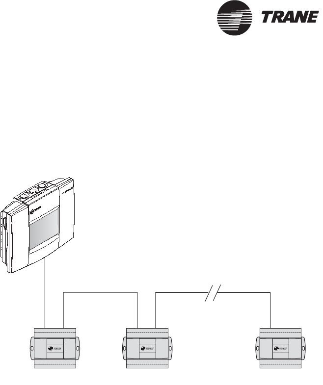
UCM wiring configurations
The Tracker UCM Comm5 communication-link wiring must be installed
in a daisy-chain configuration (Figure 15 on page 32 and Figure 16 on
page 33).
Figure 15. Daisy-chain configuration for UCM communication-link
wiring (preferred configuration)
Trane UCM Trane UCM Trane UCM
Tracker
Controller
Figure Note:
Maximum wire length for daisy-chained wiring is 4593 ft (1400 m).
Wire the UCMs
BMTK-SVN01D-EN 33
®
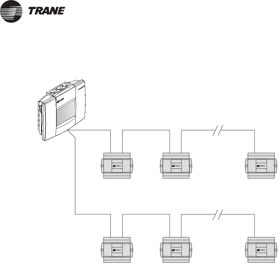
Figure 16. Daisy-chain configuration for UCM communication-link wiring with Tracker controller in
middle of link
Tracker
Controller
Trane UCM Trane UCM Trane UCM
Trane UCM Trane UCM Trane UCM
Figure Note:
•Maximum wire length for daisy-chained wiring is 4593 ft (1400 m) unless a Comm5 repeater is used.
®
Chapter 3 Termination board wiring
34 BMTK-SVN01D-EN
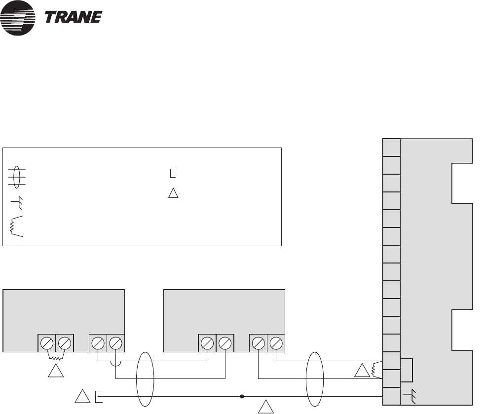
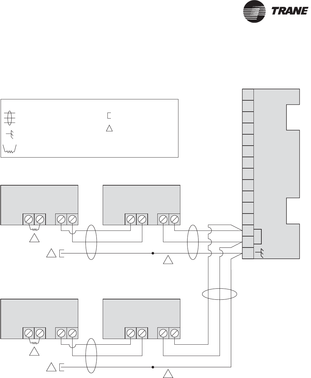
Termination resistor placement for Comm5 links
Install one 105 Ω resistor across the communication link terminals of the
device at the beginning of the daisy chain, which is typically a Tracker
controller. Then install a second 105 Ω resistor across the communication
terminals at the last UCM on each link. See Figure 17 on page 35 for an
example of a link that begins with a Tracker controller. See Figure 18 on
page 36 for an example of a link that does not begin with a Tracker
controller.
IMPORTANT
For maximum performance of the Comm5 link, use the 105 Ω resistors
that are included with the Tracker controller. If they are not available, as
a second choice, use a 100 Ω, ¼ W, 5% tolerance resistor, or as a third
choice, a 110 Ω, ¼ W, 5% tolerance resistor. Failure to comply may cause
the controller to malfunction.
The resistor value can be determined by reading its color bands. Table 9
provide the resistor color coding.
If a repeater is used, each link of the configuration that is created by the
repeater requires termination resistors (see “Requirements for repeaters
on Comm5 communication links” on page 37).
Create a set of as-built drawings or a map of the communication wire
layout during installation. Ensure that sketches of the communication
layout show the placement of the termination resistors.
Note:
If, after installation, the link is extended to add more UCMs,
the resistor must be relocated to the new last UCM on the link.
Table 9. Resistor color band table
To l e r a n c e Color sequence
105 Ω ± 1% tolerance Brown, black, green, brown
100 Ω ± 5% tolerance Brown, black, brown, gold
110 Ω ± 5% tolerance Brown, brown, brown, gold
Wire the UCMs
BMTK-SVN01D-EN 35
®
Figure 17. Daisy-chain termination resistor placement
Comm5 device
1
2
3
4
5
6
7
8
9
10
11
12
13
14
15
AAAABBBB
COMM
Comm5 device
Splice
2
1
1
3
Tracker
termination board TB1
Legend
Twisted pair, shielded wire
per Trane specifications
Shield termination
Shield ground
=
=
=
Figure note
=
Termination resistor
=
(Last device on the link)
Figure Notes:
1105 Ω termination resistor
2 Shield must be cut back and taped at last unit controller.
3 A continuous shield is required. At each unit controller, splice shield wire and tape back to prevent
grounding.
®
Chapter 3 Termination board wiring
36 BMTK-SVN01D-EN
Figure 18. Termination resistor placement with a Tracker controller in the middle of the link
Comm5 device
Comm5 device
1
2
3
4
5
6
7
8
9
10
11
12
13
14
15
A
A
A
A
A
A
A
A
B
B
B
B
B
B
B
B
COMM
Comm5 device
Splice
Splice
2
2
1
3
3
Tracker
termination boardTB1
Comm5 device
Legend
Twisted pair, shielded wire
per Trane specifications
Shield termination
Shield ground
=
=
=
Figure note
=
Termination resistor
=
1
(Last device on the link)
(Last device on the link)
Figure Notes:
1105 Ω termination resistor
2 Shield must be cut back and taped at last unit controller of each link.
3 A continuous shield is required. At each unit controller, splice shield wire and tape back to prevent
grounding.

Wire the UCMs
BMTK-SVN01D-EN 37
®
Wire supported UCMs
Wire the supported UCMs to the Tracker termination board. When
installing communication wire:
•Keep the polarity consistent throughout the site. Although Comm5 is
not polarity sensitive, consistency will improve serviceability.
•Strip away a maximum of 2 inches (50 mm) of the outer conductor
and foil shield when splicing or terminating shielded wire.
IMPORTANT
Use extreme care when stripping away the outer conductor and foil
shield. Be careful not to nick the insulating jacket of the two conduc-
tors. A nick in the insulating jacket will cause communication problems.
Wire the UCMs as follows:
1. Install termination resistors in the correct locations.
2. Route input wires into the termination module through the conduit
box or any of the conduit openings designated for input and communi-
cation wiring (Figure 12 on page 19).
3. Connect the wires to the COMM terminals on the termination board
(Figure 14 on page 24).
4. Connect the shield to the ground terminal.
5. Connect the other end of the wires to the UCMs, as necessary.
Requirements for repeaters on Comm5 communication
links
The Comm5 communication link repeater is a device that repeats and
regenerates the signal on a Comm5 link in order to enhance signal
quality or extend the length of the run. The Comm5 link goes from the
Tracker controller to the UCMs to the repeater. A second link segment
extends from the other side of the repeater to the rest of the devices. The
configuration on either side of the repeater must be a daisy-chain
configuration. Both link segments require termination.
A link repeater is required when:
•The total wire length is greater than the maximum wire run length of
4593 ft (1400 m) for a daisy-chain configuration.
•More than 60 devices are connected to a link. This total does not
include the Tracker controller, the link repeater, and the possible use
of the Rover service tool on the same link.
The link repeater has several limitations:
•Only one link repeater can be used on a link.
•The use of a repeater doubles the maximum allowable wire length.
For example, when a repeater is used with a daisy-chain configura-
tion, the total wire length can be 9186 ft (2800 m) (with half the wire
length on either side of the repeater).
®
Chapter 3 Termination board wiring
38 BMTK-SVN01D-EN
•The link repeater is limited to 60 devices on either side of the link
(120 devices total).
•The link repeater requires an earth ground. The installer should be
aware of this before making power connections.
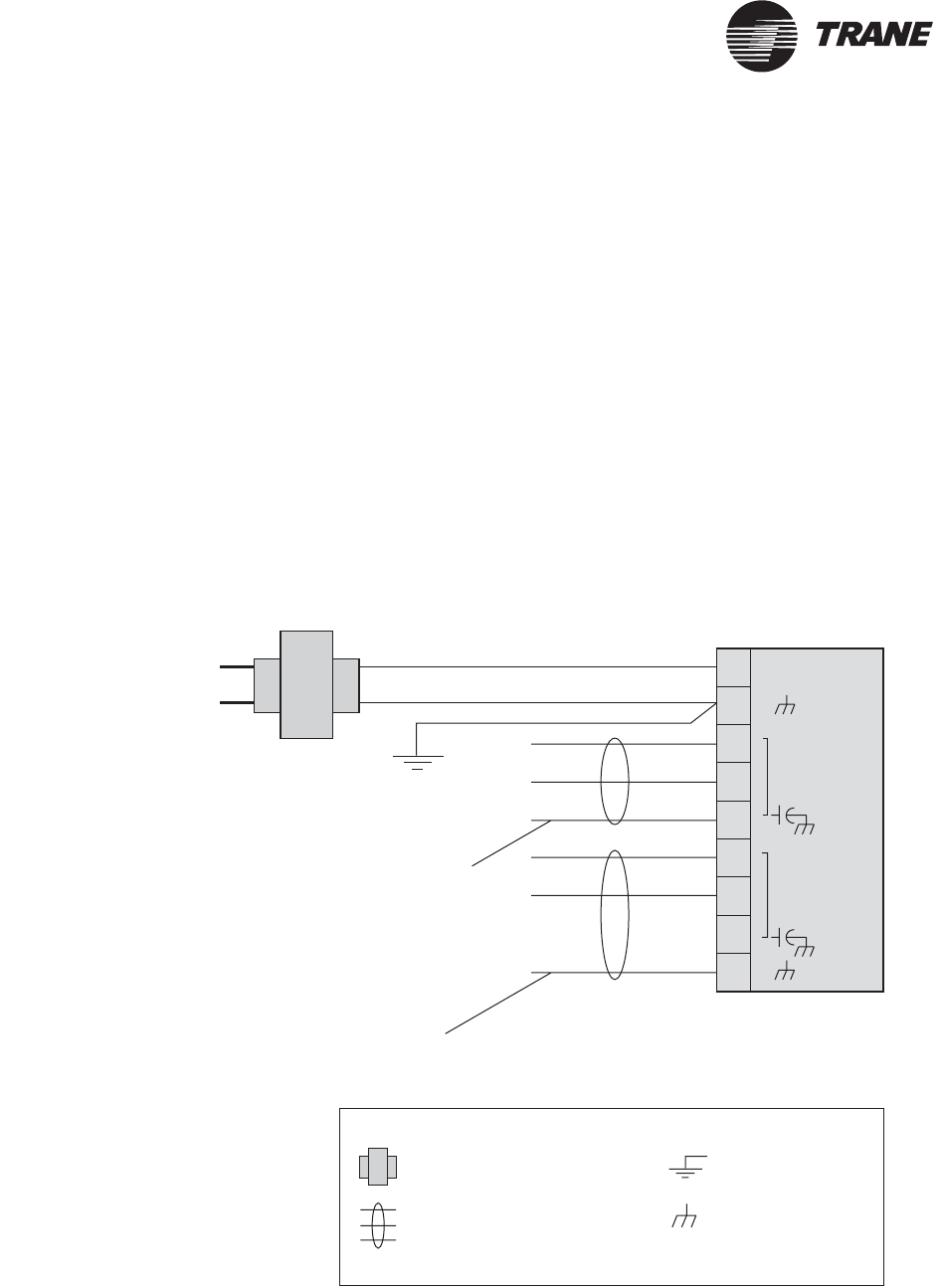
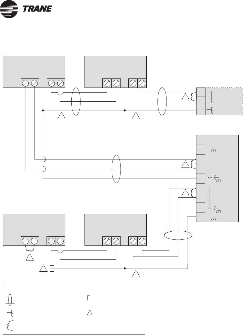
Recommended shield connections are shown in Figure 19. Figure 20 on
page 39 shows a daisy-chain repeater connection. Follow these guidelines
when using a repeater:
•Reference the installation information that comes with the link
repeater (Comm5 repeater installation, 3270 3285).
•Connect the shield-drain wires entering the repeater to a terminal
marked with a capacitor symbol. The entering shield-drain wire must
be connected to earth ground at the Tracker controller.
•Connect the shield-drain wires leaving the repeater to the repeater
terminal marked with an earth ground symbol.
Figure 19. Connecting communication link shield wiring to repeater
Comm
24 VAC
Comm
Link Repeater
24 Vac
Transformer
Earth ground
Entering shield. Continuous run, typically
starting at the Tracker controller.
Leaving shield. Must be connected to the earth ground
terminal on the repeater and terminated (insulated from
ground) at the last UCM.
Legend
Twisted pair, shielded wire
per Trane specifications
Earth ground
Transformer
Shield ground
=
=
=
=
2
3
1
4
5
6
7
8
9
Wire the UCMs
BMTK-SVN01D-EN 39
®
Figure 20. Comm5 daisy-chain repeater connection
Comm5 device
AABB
Comm5 device
AABB
Link repeater
Comm
24 VAC
Comm
COMM
13
14
15
Comm5 device
AAAABBBB
Comm5 device
Splice
SpliceSplice
2
1
1
1
1
3
33
Tracker
termination boardTB1
Legend
Twisted pair, shielded wire
per Trane specifications
Shield termination
Shield ground
=
=
=
Figure note
=
Termination resistor
=
(Last device on the link)
2
3
1
4
5
6
7
8
9
Figure Notes:
1105 Ω termination resistor
2 Shield must be cut back and taped
3 A continuous shield is required. At each
controller, splice shield wire and tape back to
prevent grounding.

®
Chapter 3 Termination board wiring
40 BMTK-SVN01D-EN

BMTK-SVN01D-EN 41
®
Chapter 4
Main module mounting
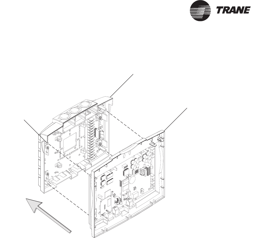
After mounting and wiring the termination module, attach the main
module to the termination module
.
This chapter provides information and
procedures that enable you to mount the main module.
1. Verify that all wires on the termination module are securely fastened
in place.
2. Carefully line up the alignment pins on the termination module with
the back side of the main module (Figure 21 on page 42).
CAUTION
Avoid Equipment Damage!
Do not use excessive force when mounting the module. If the module
does not snap easily into place, slightly reposition it on the alignment
pins. Failure to comply may cause damage to the module.
3. Firmly push the main module onto the termination module until it
snaps into place. If 24 Vac power is applied, the main module will
start. If the display module is not assembled to the main module, you
will see the LEDs on the main module flash on and off after a few sec-
onds. If the display module is assembled to the main module, it will
turn on and display information.
Note:
The Tracker controller ships with the display module
assembled to the main module. If those two modules are
assembled, performing this procedure also mounts the display
module.
Note:
It is not necessary to turn off 24 Vac power to the Tracker
controller prior to mounting or removing the main module.
®
Chapter 4 Main module mounting
42 BMTK-SVN01D-EN
Figure 21. Main module mounting
Termination module
Main module
Alignment pin
(four places)

BMTK-SVN01D-EN 43
®
Chapter 5
Display module mounting
After mounting the main module, attach the display module to the main
module
.
This chapter provides information and procedures that enable
you to mount the display module.
1. Tilt the top of the display module about 30 degrees toward you.
2. Line up the three tabs on the bottom of the display module with the
slots on the bottom of the main module (Figure 22 on page 44).
3. Starting with the center tab, insert the tabs into the slots.
CAUTION
Avoid Equipment Damage!
Do not use excessive force when mounting the module. If the module
does not snap easily into place, slightly reposition it on the alignment
pins. Failure to comply may cause damage to the module.
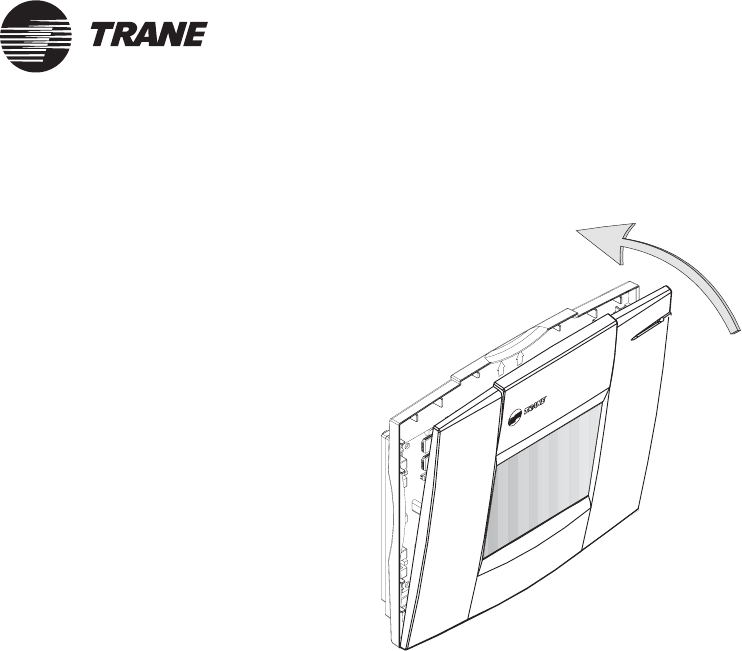
4. Push the top of the display module toward the main module until it
snaps into place while making sure that the tabs on the display mod-
ule engage the slots on the main module (Figure 23 on page 45). If 24
Vac power is applied to the Tracker controller, the display module will
turn on and display information.
Note:
The Tracker controller ships with the display module
assembled to the main module. If those two modules are
assembled, you need only to perform the main module
mounting procedure (Chapter 4, “Main module mounting”).
Note:
It is not necessary to turn off 24 Vac power to the Tracker
controller prior to mounting or removing the display module.
®
Chapter 5 Display module mounting
44 BMTK-SVN01D-EN
Figure 22. Tab and slot alignment
Display module mounting
BMTK-SVN01D-EN 45
®
Figure 23. Display module engagement

®
Chapter 5 Display module mounting
46 BMTK-SVN01D-EN
BMTK-SVN01D-EN 47
®
Chapter 6
PC workstation wiring
The Tracker controller connects to a PC workstation with a direct
connection cable, an internal modem, or an Ethernet connection.
Verify PC workstation specifications
Verify that the PC conforms to the minimum specifications listed on the
insert in the CD jewel case and that the Tracker PC workstation software
is installed.
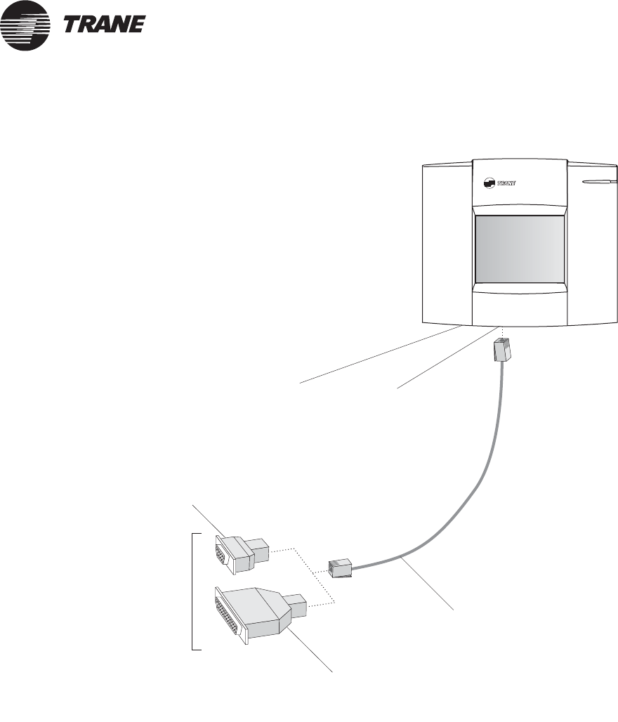
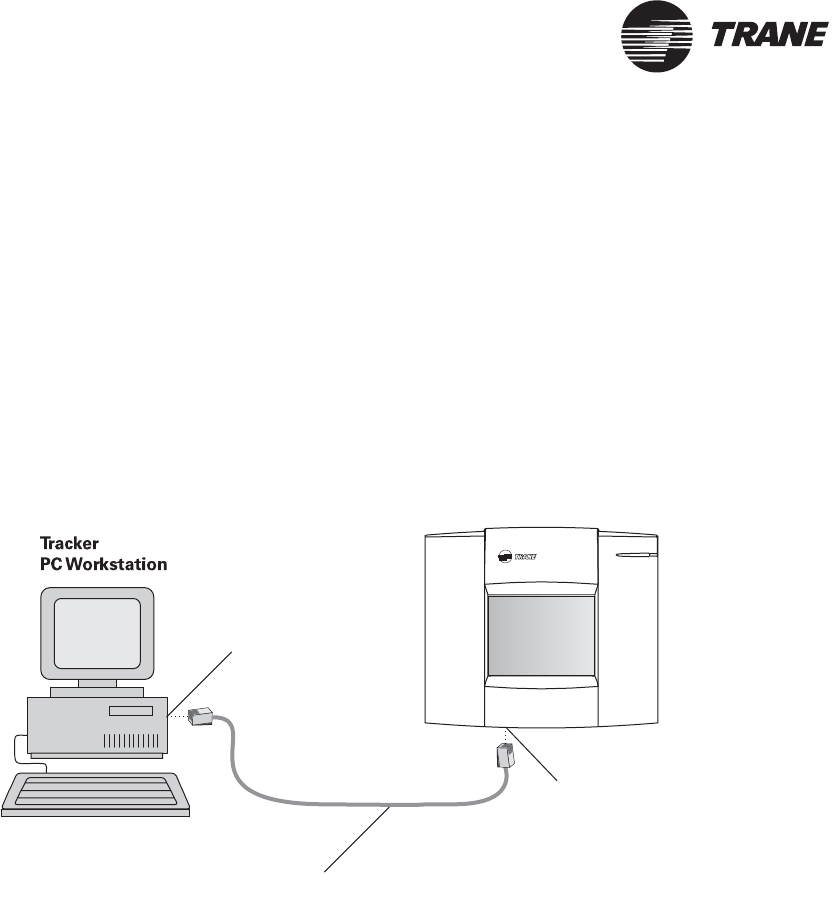
Direct connection to PC workstation
To make an EIA-232 direct connection between the controller and a PC
workstation, you need an RJ-12 cable and an adaptor matched to the
serial port connector on the PC workstation (Table 10).
Table 10. Cable and adapter specifications for direct connection
Description Trane part number
RJ-12 interface cable 3591 4260
9-pin female modular adapter 3591 4262
25-pin female modular adapter 3591 4263
The cable and adapter are not shipped with the Tracker controller and
must be purchased separately.
®
Chapter 6 PC workstation wiring
48 BMTK-SVN01D-EN
IMPORTANT
Do not use a standard phone cable for a direct connection. The RJ-12
cable is a 6-wire straight-through cable. Failure to comply will cause the
Tracker controller to malfunction.
IMPORTANT
The maximum allowable length of the RJ-12 cable is 50 ft (15 m). Failure
to comply may cause the Tracker controller to malfunction.
1. Locate the RJ-12 cable and the appropriate adapter.
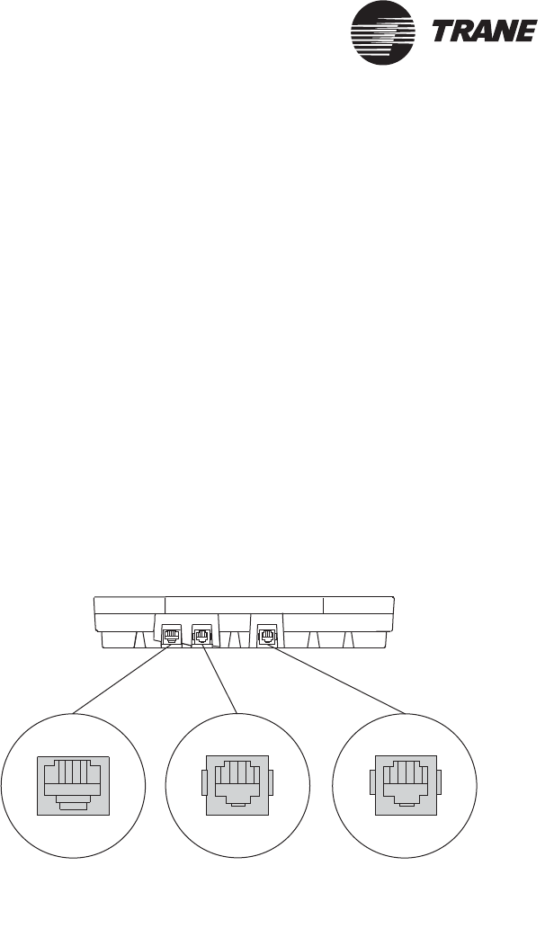
2. Connect the RJ-12 cable to the RJ-12 port on the bottom side of the
controller (Figure 24).
3. Connect the other end of the RJ-12 cable to a 9-pin or 25-pin adapter,
as appropriate (Figure 25 on page 49).
4. Connect the adaptor to the appropriate serial port on the PC worksta-
tion.
Figure 24. Tracker communication ports
LAN RJ-45 port
(Ethernet connection)
RJ-12 port
(PC direct connection)
RJ-11 port
(modem connection to
standard telephone line)
Direct connection to PC workstation
BMTK-SVN01D-EN 49
®
Figure 25. Tracker direct connection to a PC workstation
LAN port
for future Ethernet
connection
(bottom side)
RJ-45
Connect RJ-12 to
9-pin female
adapter
To PC workstation
serial port
Connect RJ-12 to
25-pin female
adapter
RJ-12 port for PC
direct connection
(bottom side)
RJ-12 cable

®
Chapter 6 PC workstation wiring
50 BMTK-SVN01D-EN
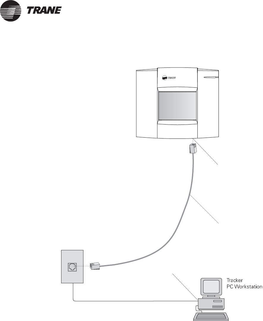
Modem connection to PC workstation
To make a modem connection between the controller and a PC
workstation, you need an RJ-11 cable (standard telephone cable).
1. Connect a RJ-11 cable (standard telephone cable) into the RJ-11 port
on the bottom side of the controller (Figure 24 on page 48).
2. Connect the other end of the cable to a phone jack, a port on an exter-
nal modem, or the PC workstation modem port (Figure 26 on
page 51). The incoming modem port is typically labeled “Line” or
“Line in.”
Note:
The Trane Company reserves the right to support only selected
modems for the Tracker PC workstation. This ensures proper
operation of the Tracker software and makes troubleshooting
easier, if a communication failure occurs.
Modem specifications are subject to change. For a current list of
specified modems, contact your local Trane office.
Note:
Use the Tracker software to set the communication port that
the modem will use.
Modem connection to PC workstation
BMTK-SVN01D-EN 51
®
Figure 26. Tracker modem connection to a PC workstation
Phone jack
RJ-11 modem
(bottom side)
port
RJ-11 cable
RJ-11 modem
(back)
port
®
Chapter 6 PC workstation wiring
52 BMTK-SVN01D-EN
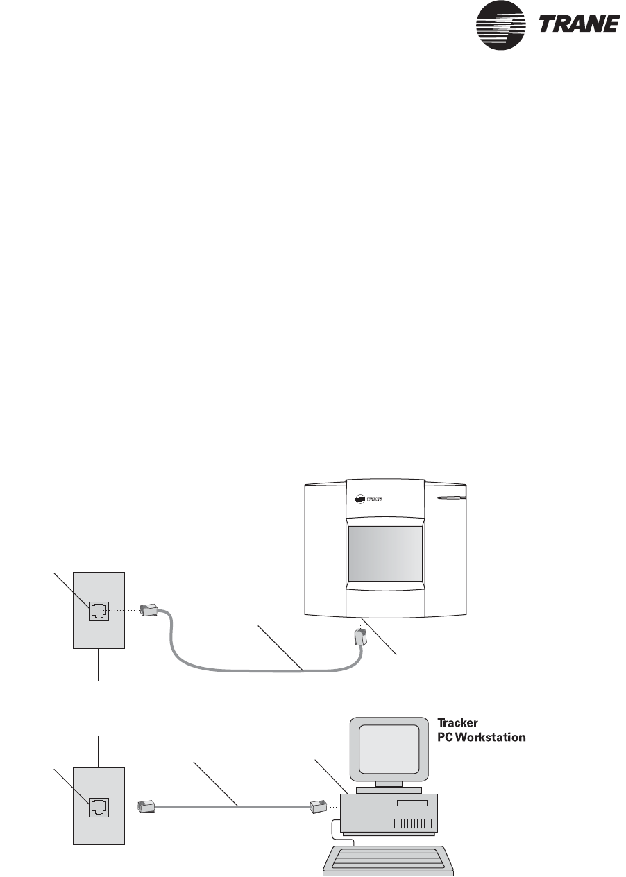
Ethernet connection to PC workstation
Connecting over an existing LAN
To make an Ethernet LAN connection between the Tracker controller and
a Tracker PC Workstation through an existing customer LAN, you need
two CAT 5 patch cables.
1. Connect one end of the first CAT 5 patch cable to the RJ-45 Ethernet
port on the bottom side of the Tracker controller (Figure 27 on
page 52).
2. Connect the other end of the cable to an RJ-45 Ethernet wall jack
near the controller.
3. Connect one end of the second CAT 5 patch cable to an RJ-45 Ether-
net wall jack near the Tracker PC Workstation.
4. Connect the other end of the cable to the RJ-45 Ethernet port on the
PC workstation.
Figure 27. Tracker Ethernet LAN connection to a PC workstation over an existing LAN
RJ-45
Ethernet
LAN jack
RJ-45 Ethernet
LAN (bottom side)port
RJ-45 Ethernet
LAN (back)port
CAT 5
patch cable
RJ-45
Ethernet
LAN jack
CAT 5
patch cable
Tracker
Controller
Existing LAN
Ethernet connection to PC workstation
BMTK-SVN01D-EN 53
®
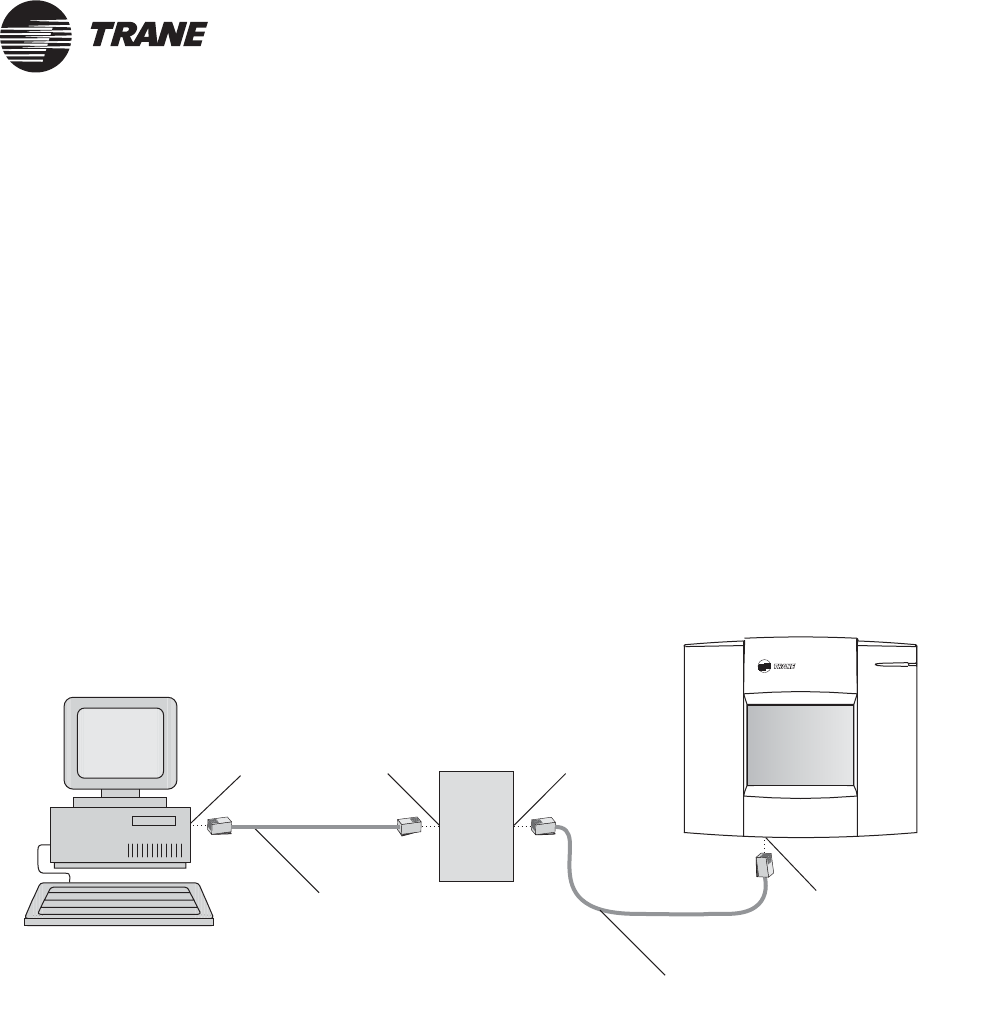
Connecting through a hub
To make an Ethernet connection between the Tracker controller and a
Tracker PC Workstation through a hub, you need two CAT 5 patch cables.
1. Connect one end of the first CAT 5 patch cable to the RJ-45 Ethernet
port on the bottom side of the Tracker controller (Figure 27 on
page 52).
2. Connect the other end of the cable to an RJ-45 Ethernet port on the
hub.
3. Connect one end of the second CAT 5 patch cable to an RJ-45 Ether-
net port on the hub.
4. Connect the other end of the cable to the RJ-45 Ethernet port on the
Tracker PC Workstation.
Figure 28. Tracker Ethernet LAN connection to a PC workstation through a hub
RJ-45
Ethernet
LAN jack
RJ-45 Ethernet
LAN (bottom side)port
RJ-45 Ethernet
LAN (back)port
CAT 5
patch cable
RJ-45
Ethernet
LAN jack
CAT 5
patch cable
Hub
Tracker
PC Workstation
Tracker
Controller
®
Chapter 6 PC workstation wiring
54 BMTK-SVN01D-EN
Connecting with one cable
To make an Ethernet connection between the Tracker controller and a
Tracker PC Workstation using one cable, you need one CAT 5 crossover
cable.
1. Connect one end of the CAT 5 crossover cable to the RJ-45 Ethernet
LAN port on the bottom side of the Tracker controller (Figure 29).
2. Connect the other end of the cable to the RJ-45 Ethernet LAN port on
the Tracker PC Workstation.
Figure 29. Tracker Ethernet LAN connection to a PC workstation with one cable
RJ-45 Ethernet
LAN (bottom side)port
RJ-45 Ethernet
LAN (back)port
Tracker
Controller
CAT 5
crossover cable

BMTK-SVN01D-EN 55
®
Chapter 7
Troubleshooting
Troubleshooting components
Light-emitting diodes (LEDs) and service pin buttons are used for
troubleshooting the Tracker system.
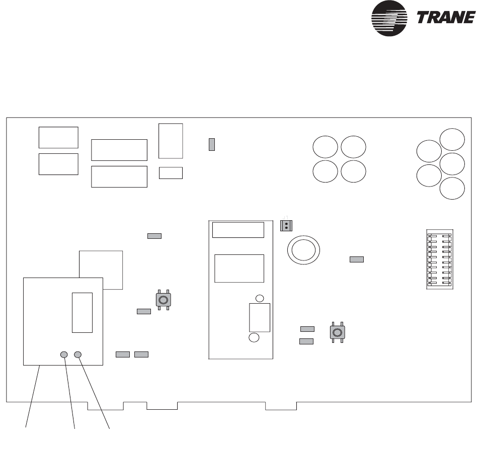
LEDs
The LEDs on the Tracker controller main logic board and display module
show central processing unit (CPU) status and traffic on the Comm5
communication link, the Ethernet module, and the EIA-232 connection.
Figure 30 shows the location of the main logic board LEDs; Table 11 on
page 57 provides a description of them. Figure 30 shows the location of
the Ethernet module LEDs; Table 11 on page 57 provides a description of
them. Figure 7 on page 7 shows the location of the alarm LED on the
display module; Table 12 on page 57 provides a description of it.
Service pin buttons and jumper
Table 13 on page 58 describes the service pin buttons that are located on
the main logic board. They are used for rebooting the controller and for
Neuron identification. The table also describes the jumper that is on the
main logic board.
®
Chapter 7 Troubleshooting
56 BMTK-SVN01D-EN
Figure 30. Tracker controller main logic board component location
HI TX
LED6
BOP
SERVICE
COMM
LED3
LED9
LED2 S2
HRT
J1
CODE
PC RX PC TX
LED5
LED4
S1
LED7 LED8
Ethernet
board
Right
LED
Left
LED
Troubleshooting components
BMTK-SVN01D-EN 57
®
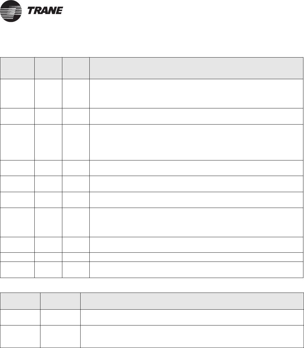
Table 11. Tracker main logic board LEDs
LED name LED
number Color Description
HI TX LED6 Green Flashes when the main module attempts to communicate with the display
module. The main module attempts to communicate with the display module
even when the display module is not installed. With no display module installed,
the LED flashes every two seconds.
HRT LED5 Green Shows the status (heart beat) of the CPU. This LED is on continuously while the
controller boots up. It flashes to show processor activity.
CODE LED4 Red Shows the status of the controller operating code. This LED is on continuously
while the controller is booting up and/or whenever the controller needs operat-
ing code.
Note: Code can be downloaded to the Tracker controller with the use of the Tracker PC software
if this LED is on.
PC RX LED7 Green Shows that EIA-232 traffic is on the PC port. This LED is normally off. Flashes
when the controller receives data from the PC.
PC TX LED8 Green Shows that EIA-232 traffic is on the PC port. This LED is normally off. Flashes
when the controller transmits data to the PC.
BOP LED3 Red Flashes when the controller binary output relay is energized and when an
appropriate alarm condition exists.
SERVICE LED9 Red Shows that Comm5 service is required. This LED is normally off. LED is on
continuously to show that controller hardware is defective. LED is on
continuously to show that the Service pin button (SW2) was pressed. Flashes to
show that the controller must be rebooted.
COMM LED2 Yellow Shows that network traffic is on the Comm5 link. Flashes when the controller
receives data from a Comm5 device.
Left LED None Green Shows that an Ethernet link is detected.
Right LED None Green Shows that there is serial traffic between the Ethernet module and the Tracker
main logic board.
Table 12. Alarm LED
State Color Description
Normal Green LED is on continuously when the controller is operating normally and has received
no alarms of the appropriate severity.
Alarm Red Flashes when the controller receives an alarm of the appropriate severity. To
acknowledge the alarm and turn off the LED, press the Alarm function button
displayed on the user interface home screen.
®
Chapter 7 Troubleshooting
58 BMTK-SVN01D-EN
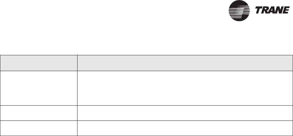
Table 13. Main logic board service pin buttons and jumper
Service pin buttons/jumper Function
S1 This service pin is the reset button. Pressing S1 reboots the controller. It starts the
same operation as does rebooting the controller from either the controller or the PC
software. All RAM data is permanently lost.
Note: Before pressing this button, attempt to restart the controller by cycling power; this method
retains the RAM image.
S2 Momentarily pressing this service pin button causes the controller to broadcast
Neuron ID and Program ID. This action also turns on LED9.
J1 This jumper is for factory use only. It must always remain in place. If removed, the
backup capacitor will not charge and data may be lost if power is lost.

Symptom/action troubleshooting
BMTK-SVN01D-EN 59
®
Symptom/action troubleshooting
Table 14 provides a list of symptoms that indicate a problem in the Tracker system.
For each symptom, the table provides one or more actions that you can perform in an
attempt to resolve the problem.
Table 14. Symptom/action troubleshooting
Symptom Action
Tracker controller does not
communicate by modem.
•Verify that the telephone cable is connected to the PC modem port (Figure 24 on
page 48).
•Verify that the phone line is an analog line (not digital).
•Perform the modem self-test procedure from the display module.
Note: The modem is an integral component of the main module and is not field replaceable.
Replacement of the modem requires replacement of the main module.
Tracker controller does not
communicate by EIA-232
port.
•Verify that the cable is connected to the PC direct connect port (Figure 24 on
page 48).
•Verify that the proper cable is used. (Refer to Table 10 on page 47.)
•Verify that the PC workstation is using the Tracker controller software; other com-
munications software will not work.
•Look for activity on the PC RX LED (Figure 30 on page 56).
Tracker controller did not
discover UCMs when ini-
tially started.
When the controller is initially powered up, it automatically discovers all communi-
cating UCMs of the proper type and installs them into its database. The discovery
process takes several minutes, depending on how many UCMs are installed on the
communication link.
After the controller has built its database after the initial power up, the controller no
longer automatically discovers UCMs. If you want to initiate the discovery process,
you must do so manually. Initiate the discovery process when a new UCM is added
to the system or an existing UCM is replaced.
•Verify proper wiring of the Comm5 communication link. (UCMs can be discov-
ered only if Comm5 communication has been established.)
•Wait at least 5 minutes for the controller to discover the UCMs.
Note: You can press the service pin button on a UCM at any time to check if it is communicating
with the controller. Pressing the service pin button causes the UCM status LED to flash on and off
(known as “winking”), if the controller is communicating with that UCM.
Touch screen beeps when
touched but does not
progress to the next screen.
Touch screen is out of calibration.
•Perform the procedures for calibrating the touch screen in Tracker Building Auto-
mation System Controller Operations guide (BMT-SVU01A-EN).
Touch-screen back light and
contrast is out of adjust-
ment.
•Perform the adjust brightness and contrast procedure from the display module.
Tracker I/O status is wrong. •Verify electrical connection using the post-installation checklist (Table 18 on
page 70).
•Verify I/O status as indicated on home display on the display module.
•Display Tracker I/O status self test from display module.

®
Chapter 7 Troubleshooting
60 BMTK-SVN01D-EN
Tracker alarm output is not
working as expected.
•Confirm proper wiring of the alarm relay output. Consult the post-installation
checklist (Table 18 on page 70) for details.
•Initiate the BOP self test from the display module.
Note: The binary output is for alarm notification only. There must be an unacknowledged alarm
present of the proper severity to actuate the alarm output.
Tracker controller will not
communicate with its
UCMs.
•Look for wiring problems (shorts or opens, for example) that develop when wire
is damaged during installation.
•Look for shorts between the two conductors resulting from nicks in the insulating
jacket. (This can be caused by improper technique when stripping away the outer
jacket and shield.)
•Look for a strong source of EMI/RFI interference nearby.
•Look for ac power disturbances from nearby transformers and electrical equip-
ment. This is especially true when running communication links in close proxim-
ity to florescent lighting ballasts.
•Verify the UCM has not failed.
•Verify proper termination resistance.
Tracker processor is locked
up.
•Cycle power to the Tracker main module by removing it from the termination
module.
•If the processor is still locked up after cycling power to the controller, perform a
reboot from the display module or the PC software (if the controller is able to
communicate).
•If the controller will not respond to the above listed methods, push the reset but-
ton (S1) on the main module (see Figure 30 on page 56).
Note: Heartbeat LED (HRT LED5) will be solid green.
Alarm LED on the display is
flashing red.
•At the Tracker controller user interface home screen, push the alarm button on
the display module to acknowledge the alarm, then take the proper corrective
action.
Note: The alarm LED flashes when the controller receives an alarm of the appropriate severity.
Pressing the Alarm button acknowledges the alarm and turns off the flashing LED (until the control-
ler receives another alarm of the appropriate severity).
Tracker controller is annun-
ciating an alarm.
•At the Tracker controller user interface home screen, push the alarm button on
the display module to acknowledge the alarm, then take the proper corrective
action.
Note: The alarm relay energizes when the controller receives an alarm of the appropriate severity.
Pressing the alarm button acknowledges the alarm and turns off the alarm relay output (until the
controller receives another alarm of the appropriate severity).
Display module is not illu-
minated.
•Press anywhere on the touch screen surface to turn the back light on. The control-
ler automatically turns off the back light during extended periods of inactivity to
conserve energy and bulb life.
•Confirm that the controller has 24 Vac power. When the display module has
power, the alarm LED will be either solid green or flashing red.
Display module does not
respond to the touch.
•Confirm that the controller has 24 Vac power. When the display module has
power, the alarm LED will be either solid green or flashing red.
•If the display module is not responding correctly when the display module is
powered up and the back light is on, initiate the touch-screen calibration proce-
dure from the display module.
Table 14. Symptom/action troubleshooting (Continued)
Symptom Action
Symptom/action troubleshooting
BMTK-SVN01D-EN 61
®
Tracker controller displays
the wrong date.
•Verify if the electrical power has been off for more than 1 week (the actual time
varies depending on storage temperature).
•Verify that jumper pin J1 on the main module is in place.
Note: The controller default date (displayed when the controller is initially powered up or whenever
the super capacitor is unable to back up the controller time) is January 1, 2000.
Outdoor air temperature is
not reading correctly.
•Measure the resistance of the outdoor air temperature thermistor (preferably at
the termination module). Check the measurement using Table 19 on page 71.
•Inspect the location of the outdoor air temperature sensor. It must not be
mounted in the sunlight or near another source of radiant heat.
Note: The outdoor air temperature sensor can be used for this purpose only.
Ethernet link is not detected
(on the Ethernet board, the
left LED is off)
•Verify that the correct type of cable is used. When communicating over a network,
use a patch cable. When communicating to an Ethernet card on a lap top com-
puter, use a crossover cable.
Table 14. Symptom/action troubleshooting (Continued)
Symptom Action

®
Chapter 7 Troubleshooting
62 BMTK-SVN01D-EN

BMTK-SVN01D-EN 63
®
Chapter 8
Maintenance
The only maintenance necessary for the controller is to occasionally clean
and calibrate the touch screen.
Cleaning the touch screen
To clean the touch screen, wipe it off with a non-abrasive cloth. For more
aggressive cleaning, use low-pressure compressed air to blow off the
surface and then wipe it off with a non-abrasive cloth.
To clean fingerprints from the touch screen, lightly spray it with a mild
glass cleaner. Immediately wipe the touch screen with an absorbent, non-
abrasive cloth.
CAUTION
Avoid Equipment Damage!
Immediately wipe moisture from the surface of the LCD touch screen.
Failure to do so will cause the operator display to malfunction.
Calibrating the touch screen
To calibrate the touch screen:
1. At the Tracker home screen, press the Advanced button. The
Advanced Selections screen displays.
2. Press the Calibrate Touch Screen button. A calibration screen dis-
plays.
CAUTION
Avoid Equipment Damage!
Do not allow the touch screen to come in contact with sharp objects.
3. Touch the target using a small, pliable, blunt object, such as a pencil
eraser. Hold until the beeping stops. A second calibration screen dis-
plays.
4. Again, touch the target with the object. Hold until the beeping stops.
The Advanced Selection screen displays.
5. To exit this procedure, press the Home button. The home screen dis-
plays.

®
Chapter 8 Maintenance
64 BMTK-SVN01D-EN
BMTK-SVN01D-EN 65
®
Appendix A
Installation checklists
Required supplies
Table 15 lists the supplies required for all Tracker installations.
Optional supplies
Table 16 lists the supplies that may or may not be necessary, depending
on the Tracker installation.
Table 15. Required supplies checklist
;Wiring installation Item
24 Vac 18 AWG (1.02 mm2) wire recommended
24 Vac, 40 VA minimum transformer
Comm Communication wire (see Table 7 on page 30
and Table 8 on page 31 for specifications)
Table 16. Optional supplies checklist
;Inputs/output
wiring installation Item
Alarm relay wiring 18 AWG (1.02 mm2) wire and metal conduit
Priority shutdown
wiring and
Meter input
18—22 AWG (1.02 mm2—0.643 mm2) wire and
metal conduit
Thermistor wire 18—22 AWG (1.02 mm2—0.643 mm2) twisted
pair, shielded wire
Alarm relay power
supply
Power supply for alarm relay output (not to
exceed 24 Vac)
Alarm relay output
load
Load for alarm relay output (not to exceed
1 amp at 24 Vac)
Thermistor Outdoor air temperature sensor
®
Appendix A Installation checklists
66 BMTK-SVN01D-EN
Comm5 UCM identification and
location
Each UCM has a unique 12-digit identifier that serves as its address. The
Tracker controller uses the address to communicate with the UCM. The
installer must know the UCM addresses when assigning names to UCMs
during setup.
Use Table 17 to record the name, location, and ID of each UCM (SCCs,
VariTrac CCPs, and I/O modules) connected to the Comm5 link. The 12-
digit identifier is on a sticker attached to the UCM. Some UCMs have
peel-away stickers that can be detached and applied to the table.
Table 17. Comm5 UCM identification and location
Space Comfort Controllers (24 maximum)
Edited name Location or area served 12 digit ID
Comm5 UCM identification and location
BMTK-SVN01D-EN 67
®
Space Comfort Controllers (continued)
Edited name Location or area served 12 digit ID
Table 17. Comm5 UCM identification and location (Continued)
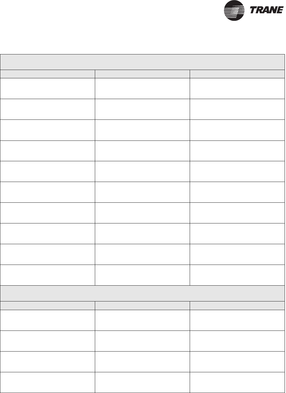
®
Appendix A Installation checklists
68 BMTK-SVN01D-EN
VariTrac central control panels (10 maximum)
Edited name Location or area served 12 digit ID
I/O modules (4 maximum)
Edited name Location or area served 12 digit ID
Table 17. Comm5 UCM identification and location (Continued)

Pre-installation wiring notes
BMTK-SVN01D-EN 69
®
Pre-installation wiring notes
The wiring for the Tracker system will have been completed prior to
Tracker installation. All Tracker wiring conforms to the following
guidelines:
•The Tracker controller receives 24 Vac from a dedicated power circuit.
If not, the Tracker controller may malfunction.
•Each UCM receives 24 Vac from a dedicated power source. If not, the
UCM may malfunction.
•Input wires and ac power wires are run in separate conduits or wire
bundles. If not, the Tracker controller may malfunction due to
induced electrical noise.
•Comm5 cable and ac power wires are run in separate conduits or wire
bundles. If not, the Tracker controller may malfunction due to
induced electrical noise.
•UCM communication cables do not run near lighting ballasts or other
transformers. If they do, the UCM may malfunction due to induced
electrical noise.
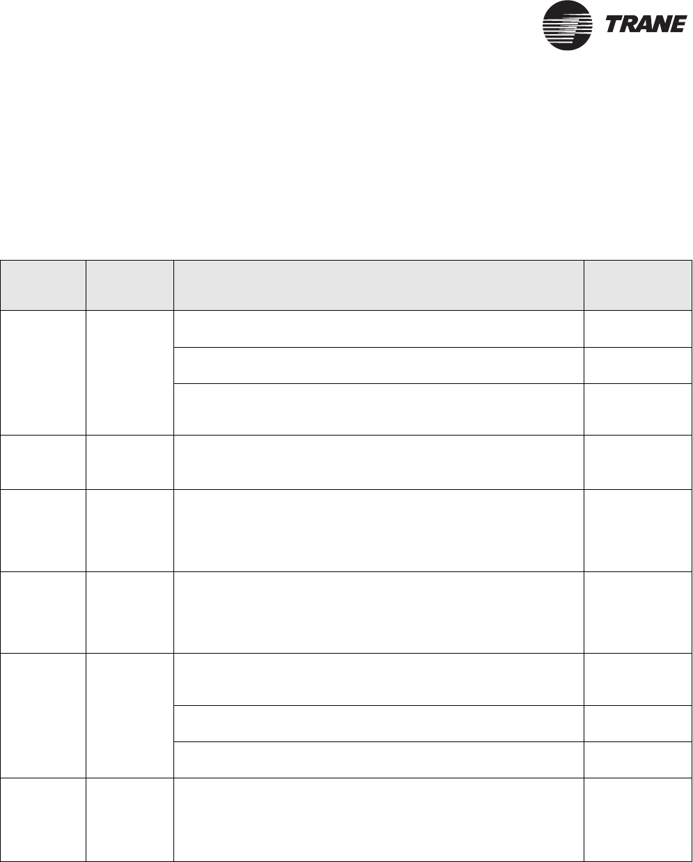
®
Appendix A Installation checklists
70 BMTK-SVN01D-EN
Termination module post-installation
checklist
Use Table 18 to verify that the circuits connected to the termination
board on the termination module are wired correctly. Record test results
in the “Actual value” column.
Table 18. Termination module post-installation checklist
Circuit Mandatory
wiring Te s t Actual value
24 Vac
TB1-1,
TB1-2,
TB1-3 9
Measure the voltage between TB1-1 and TB1-2. It must be 24 Vac
nominal (19 Vac to 30 Vac).
Measure the voltage between TB1-1 and TB1-3. It must be approxi-
mately the same voltage as measured between TB1-1 and TB1-2
The ground wire must be connected to terminal TB-3. It must be
tied to building or earth ground at nearest location. Measure the
voltage between TB1-2 and TB1-3. It must be approximately 0 V.
Alarm relay
TB1-4,
TB1-5
Measure the voltage between TB1-4 and TB1-5. It must not exceed
24 Vac. Jumper these two terminals. The user-supplied load should
now be energized and active.
Priority
shutdown
TB1-6,
TB1-7
There must be no voltage applied to these terminals. These termi-
nals must be connected to dry contacts only. Measure the resis-
tance between TB1-6 and TB1-7. It must be approximately 0 Ω with
the user-supplied contacts in the closed position, and infinity ohms
with the contacts in the open position.
Meter input
TB1-8,
TB1-9
There must be no voltage applied to these terminals. The terminals
must be connected to dry contacts only. Measure the resistance
between TB1-8 and TB1-9. It must be approximately 0 Ω with
demand meter contacts in the closed position, and infinity ohms
with the contacts in the open position.
Thermistor
TB1-10,
TB1-11,
TB1-12
There must be no voltage applied to these terminals. The cable
shield must be connected to terminal TB1-12. Measure the resis-
tance between TB1-10 and TB1-11.
Note the approximate temperature at the location of the outdoor
air temperature sensor.
Compare the resistance and temperature values to the listed val-
ues in Table 19 on page 71.
Comm
TB1-13,
TB1-14,
TB1-15
9
There must be no voltage applied to these terminals. Measure the
resistance between TB1-13 and TB1-14. The resistance must be
approximately 50 Ω with daisy-chained wiring. This test confirms
the correct usage of the termination resistors as well as the conti-
nuity of the wire.
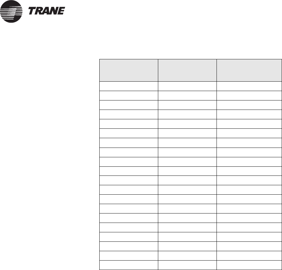
Termination module post-installation checklist
BMTK-SVN01D-EN 71
®
Table 19. Thermistor sensor electrical characteristics
Temperature (ºF)Temperature (ºC)Sensor resistance
(ohms x 1000)
–30 –34 241.1
–20 –29 170.1
–10 –23 121.4
0–18 87.6
10 –12 63.8
20 –7 46.9
30 –1 34.5
40 4 26.2
50 10 20.0
60 16 15.3
70 21 11.9
77 25 10.0
80 27 9.3
90 32 7.3
100 38 5.8
110 4 3 4 . 7
120 49 3.8
130 54 3.0
140 60 2.5
150 66 2.0

®
Appendix A Installation checklists
72 BMTK-SVN01D-EN

BMTK-SVN01D-EN 73
®
Appendix B
Declaration of Conformity
This appendix provides the Declaration of Conformity statement for the
Tracker model 12, 24, and WSHP controllers. All Tracker models are
currently CE certified.

®
Appendix B Declaration of Conformity
74 BMTK-SVN01D-EN
Declaration of Conformity
Manufacturer’s Name:
Manufacturer’s Address:
Trane
4833 White Bear Parkway
Saint Paul, Minnesota 55110
USA
The manufacturer hereby declares that the product:
Product Name:
Product Number:
Tracker model 12, 24, and water-source heat pump
(WSHP)
BMTK000AA0A110 BMTKKBBAB0A110
BMTK000AA0A210 BMTKKBBAB0A210
BMTK000AA0A510 BMTK000AB0A110
BMTKKBBAA0A110 BMTK000AB0A210
BMTKKBBAA0A210 BMTK000AB0A510
Conforms to the following standards or other normative documents:
Electromagnetic Emission:
(by Council Directive 89/336/EEC)
Electromagnetic Immunity:
UL and C-UL listing
Flammability rating
FCC
EN 50081-1:1998
Radiated EN55022: 1998 Class B limit
Conducted EN55022: 1998 Class B limit
EN61000-6-1:2001
EN61000-4-2 ±4 kV contact discharge
±8 kV air discharge
EN61000-4-3 3 V/m
EN61000-4-4 ±1 kV
EN61000-4-5 ±1 kV
EN61000-4-6 3 V
EN61000-4-11 1 cycle/100%
916, Energy management equipment
UL 94-5V (UL flammability rating for plenum use)
FCC Part 15, Class A, CFR 47
When and where issued
Electromagnetic Emission : 4/9/2003 Bounheng Saycocie
Electromagnetic Immunity: 4/10/2003 Design/Compliance Engineer
Saint Paul, Minnesota USA
Mark of Compliance European Contact
Societe Trane (Epinal, France)
1, rue des Ameriques, B.P. 6
F-88191 Golbey Cedex, France
Phone: (33) 329.31.73.00
Fax: (33) 329.81.24.98

BMTK-SVN01D-EN 75
®
Index
Numerics
24 Vac power wiring, 25
A
adapters
for direct connection to PC, 47
alarm relay
wire requirements, 26
wiring procedures, 27
analog input, 9
thermistor, general, 26
thermistor, wiring, 28
B
binary input
priority shutdown device input,
wiring, 27
priority shutdown device, general,
26
utility pulse meter, general, 26
utility pulse meter, wiring, 28
binary output
alarm relay, general, 26
alarm relay, wiring, 27
C
cabinet specifications, 9
cable
for direct connection to PC, 47
cable installation
CAT 5 crossover cable, 52
CAT 5 patch cable, 52
calibrating the touch screen, 63
capacities for UCMs, per controller,
10, 11
CAT 5 crossover cable
cable installation, 52
CAT 5 patch cable
cable installation, 52
checklist
optional supplies, 65
post-installation for termination
module, 70
post-installation, general, 13
required supplies, 65
cleaning the touch screen, 63
clearances, minimum, 17
Comm5 communication
daisy-chain repeater connection, 39
LonTalk communication interface, 1,
10, 11
repeater connection to shield
wiring, 38
repeater description, 37
requirements for repeaters, 37
status and traffic, 55
termination resistor placement, 34
Tracker BAS support, 1
wire specifications, 29
wiring procedures, 29–40
components
description, 4
display module, 7
main module, 6
shipment, 12
storage, 12
termination module, 5
conformance
to dimensions and clearances, 16
connection to PC workstation, 47
controller
dimensions, 16
figure, 1
location selection, 15
minimum clearances, 17
model number definition, 8
overview, 1
PC connection, 47
specifications, 9
D
daisy-chain configuration
repeater connection, 39
termination resistor placement, 35,
36
UCM wiring, 32, 33
dimensional specifications, 9
dimensions, 16
clearances, 16
conformance, 16
direct connection to PC, 47
diagram, 49, 51, 52, 53, 54
procedures, 48
display module
description, 7
LED, 55, 57
mounting, 43–44
tab and slot alignment, 44

Index
76 BMTK-SVN01D-EN
E
EIA-232 connection
installing, 47
LEDs, 55
electrical conduit installation, 19, 21
electrical interference, 15
Ethernet communication port, 48
Ethernet connection to PC
procedures, 52
I
I/O modules
maximum capacity per controller,
10, 11
I/O options, 26
installation
after, 13
before, 12
checklists, 65–71
direct connection to PC, 47
electrical conduit, 19, 21
Ethernet LAN connection to PC, 52
modem connection to PC, 50
J
jumper
function, 58
general, 55
L
LAN communication port, 48
LCI-R, 1, 10, 11
LCI-V, 1, 10, 11
LEDs, 57
CPU status and traffic, 55
display module, 55, 57
EIA-232 status and traffic, 55
main logic board, 55, 57
location
choosing, 15
conformance to specifications, 15,
18
controller size accommodation, 16
LonTalk see Comm5 communications
M
main logic board, 57
jumpers, 58
LEDs, 55
service pin buttons, 58
main module
description, 6
mounting, 41–42
maintenance, 63
memory backup, 9
meter, utility pulse
wire requirements, 26
wiring procedures, 28
model numbers, 8
modem connection to PC, 50
diagram, 49, 51, 52, 53, 54
procedures, 50
RJ-11 communication port, 48
mounting
display module, 43–44
main module, 41–42
specifications, 9
termination module, 15–21
MP503 I/O module, 10, 11
N
Neuron identification, 55
O
operating environment, 9
outdoor air temperature sensor
wire requirements, 26
wiring procedures, 28
overheating, 15
P
PC communication port
RJ-11, 48
RJ-12, 48
PC workstation connection
diagram, 49, 51, 52, 53, 54
direct, 47
Ethernet LAN, 52
modem, 50
wiring, 47
post-installation checklist, 13
power requirements, 9, 25
pre-installation wiring notes, 69
priority shutdown device input
wire requirements, 26
wiring procedures, 27
R
rebooting, 55
repeater
connections to Comm5 link shield
wiring, 38
daisy-chain connection, 39

Index
BMTK-SVN01D-EN 77
description, 37
limitations, 37
requirements, 37
wiring, 29
RJ-11
cable installation, 50
modem connection procedures, 50
PC communication port, 48
RJ-12
cable installation, 47
direct connection procedures, 48
parts specifications, 47
PC communication port, 48
RJ-45
Ethernet connection procedures, 52
S
SCCs
maximum capacity per controller,
10, 11
service pin buttons, 55, 58
shipment
component verification, 12
inspect for damage, 12
Space Comfort Controllers (SCCs), 10,
11
specifications
analog input, 9
binary input, 9
binary output, 9
cabinet, 9
Comm5 wire, 29
dimensions, 9
for direct connection to PC
workstation, 47
input and output wire, 26
memory backup, 9
mounting, 9
operating environment, 9
power requirements, 9
storage environment, 9
weight, 9
storage environment, 9
storage of components, 12
sunlight effects, 15
T
termination board
wiring, 23–40
termination module
description, 5
mounting, 15–21
post-installation checklist, 70
pre-installation wiring notes, 69
termination resistor
daisy-chain configuration, 35, 36
placement, 29, 34
thermistor see outdoor air
temperature sensor
touch screen
calibrating, 63
cleaning, 63
height, 18
Tracer
LCI-R, 1, 10, 11
LCI-V, 1, 10, 11
ZN510, 10, 11
ZN511, 10, 11
ZN517, 10, 11
ZN524, 10, 11
Tracer MP503 I/O module, 2, 3
Tracer ZN517 unitary controller, 2, 3
Track er BAS
controller, 1
description, 1
on network, 2, 3
software, 1
workstation, 1
troubleshooting, 55–61
components, 55
jumper, 55
service pin buttons, 55
symptom/action table, 59
U
UCMs
maximum capacities per controller,
10, 11
SCC, 10, 11
termination resistor placement, 34
Tracer MP503 I/O module, 10, 11
types, 10, 11
VariTrac CCPs, 10, 11
wire specifications, 29
wiring configurations, 29, 32, 33
wiring procedures, 37
wiring, daisy-chain configuration,
32, 33
V
VariTrac CCP, 10, 11
VariTrac CCPs
maximum capacity per controller,
10, 11
W
water-source heat pump
maximum capacities, 11
model numbers, 8
overview, 1
weight specifications, 9

Index
78 BMTK-SVN01D-EN
wire
Comm5, 29
requirements for alarm relay, 26
requirements for meter, 26
requirements for outdoor air
temperature sensor, 26
requirements for priority shutdown
device input, 26
specifications, 29
wiring
24 Vac, 25
alarm relay, 27
configurations for Comm5 UCM
communication, 32
daisy-chain configuration, 32, 33
I/O terminals, 26
outdoor air temperature sensor, 28
PC connection, 47
priority shutdown device input, 27
procedures for UCMs, 37
repeaters, 29
termination board, 23–40
UCMs, 29–40
utility pulse meter, 28
Z
ZN
ZN510, 10, 11
ZN511, 10, 11
ZN517, 10, 11
ZN524, 10, 11

®
Trane has a policy of continuous product and product data improvement and reserves the right to
change design and specifications without notice. Only qualified technicians should perform the installa-
tion and servicing of equipment referred to in this publication.
Literature Order Number BMTK-SVN01D-EN
File Number SV-ES-BAS-BMTK-SVN-01D-EN-0204
Supersedes SV-ES-BAS-BMTK-SVN-01C-EN May 2003
Stocking Location Inland
Tr a n e
A business of American Standard Companies
www.trane.com
For more information, contact your local Trane
office or e-mail us at comfort@trane.com
