Trane H V Wshp 5 To 25 Tons Installation And Maintenance Manual Axiom Horizontal/Vertical Water Source Comfort System S GEH GEV; SVX01N EN September 2014
2015-04-02
: Trane Trane-H-V-Wshp-5-To-25-Tons-Installation-And-Maintenance-Manual-684244 trane-h-v-wshp-5-to-25-tons-installation-and-maintenance-manual-684244 trane pdf
Open the PDF directly: View PDF ![]() .
.
Page Count: 132 [warning: Documents this large are best viewed by clicking the View PDF Link!]
- Introduction
- Model Number Description
- Model Number Description
- Model Number Description
- Overview of Manual
- General Information
- Pre-Installation
- Unit Dimensions and Weights
- Installation
- General Installation Checks
- Main Electrical
- Supply-Air Ductwork
- Return-Air Ductwork
- Ducted Panel
- Ducted Filter Rack
- Dual Filtration (GEH ½-5 ton and EXH ½-6 ton)
- Sound Attenuation Pad
- Hanging the Horizontal Unit
- Condensate Drain Connection
- Supply/Return Pipe Connections
- Types of Hose Connections
- Cleaning and Flushing the Water Loop
- Field Installed Power Wiring
- Main Unit Power Wiring
- Control Power Transformer
- Thermostat Location
- Controls Using 24 VAC
- Blower Motor Speed-Tap Retrofit
- Hole Plug Installation
- Air Flow Adjustment
- Waterside Economizer Installation
- Waterside Economizer Installation for GEH and GEV 6 to 25 Ton Models
- Waterside Economizer Start-Up Sequence
- Electrical Data
- Pre-Start Checklist
- Start-Up
- Maintenance
- Troubleshooting
- Wiring Diagrams
- Warranty Information
SAFETY WARNING
Only qualified personnel should install and service the equipment. The installation, starting up, and servicing
of heating, ventilating, and air-conditioning equipment can be hazardous and requires specific knowledge and
training. Improperly installed, adjusted or altered equipment by an unqualified person could result in death or
serious injury. When working on the equipment, observe all precautions in the literature and on the tags,
stickers, and labels that are attached to the equipment.
Water Source Heat Pump
Axiom™ Horizontal/Vertical
GEHE/GEVE, EXHF/EXVF
½ to 25Tons, 50/60 Hz
Installation, Operation,
and Maintenance
Model Numbers GEHE 006-060 - 50/60 Hz GEVE 006-060 - 50/60 Hz
GEHE 072-120 - 50/60 Hz GEVE 072-300 - 50/60 Hz
EXHF 006-070 - 60 Hz EXVF 006-070 - 60 Hz
WSHP-SVX01N-EN
September 2014
© 2014Trane All rights reserved WSHP-SVX01N-EN
Introduction
Read this manual thoroughly before operating or servicing
this unit.
Warnings, Cautions, and Notices
Safety advisories appear throughout this manual as
required.Your personal safety and the proper operation of
this machine depend upon the strict observance of these
precautions.
Important Environmental Concerns
Scientific research has shown that certain man-made
chemicals can affect the earth’s naturally occurring
stratospheric ozone layer when released to the
atmosphere. In particular, several of the identified
chemicals that may affect the ozone layer are refrigerants
that contain Chlorine, Fluorine and Carbon (CFCs) and
those containing Hydrogen, Chlorine, Fluorine and
Carbon (HCFCs). Not all refrigerants containing these
compounds have the same potential impact to the
environment.Trane advocates the responsible handling of
all refrigerants-including industry replacements for CFCs
such as HCFCs and HFCs.
Important Responsible Refrigerant
Practices
Trane believes that responsible refrigerant practices are
important to the environment, our customers, and the air
conditioning industry. All technicians who handle
refrigerants must be certified.The Federal Clean Air Act
(Section 608) sets forth the requirements for handling,
reclaiming, recovering and recycling of certain
refrigerants and the equipment that is used in these
service procedures. In addition, some states or
municipalities may have additional requirements that
must also be adhered to for responsible management of
refrigerants. Know the applicable laws and follow them.
The three types of advisories are defined as follows:
WARNING Indicates a potentially hazardous
situation which, if not avoided, could
result in death or serious injury.
CAUTIONsIndicates a potentially hazardous
situation which, if not avoided, could
result in minor or moderate injury. It
could also be used to alert against
unsafe practices.
NOTICE Indicates a situation that could result in
equipment or property-damage only
accidents.
WARNING
Proper Field Wiring and Grounding
Required!
Failure to follow code could result in death or serious
injury. All field wiring MUST be performed by qualified
personnel. Improperly installed and grounded field
wiring poses FIRE and ELECTROCUTION hazards.To
avoid these hazards, you MUST follow requirements for
field wiring installation and grounding as described in
NEC and your local/state electrical codes.
WARNING
Personal Protective Equipment (PPE)
Required!
Installing/servicing this unit could result in exposure to
electrical, mechanical and chemical hazards.
• Before installing/servicing this unit, technicians
MUST put on all PPE required for the work being
undertaken (Examples; cut resistant gloves/sleeves,
butyl gloves, safety glasses, hard hat/bump cap, fall
protection, electrical PPE and arc flash clothing).
ALWAYS refer to appropriate Material Safety Data
Sheets (MSDS)/Safety Data Sheets (SDS) and OSHA
guidelines for proper PPE.
• When working with or around hazardous chemicals,
ALWAYS refer to the appropriate MSDS/SDS and
OSHA/GHS (Global Harmonized System of
Classification and Labelling of Chemicals) guidelines
for information on allowable personal exposure
levels, proper respiratory protection and handling
instructions.
• If there is a risk of energized electrical contact, arc, or
flash, technicians MUST put on all PPE in accordance
with OSHA, NFPA 70E, or other country-specific
requirements for arc flash protection, PRIOR to
servicing the unit. NEVER PERFORM ANY
SWITCHING, DISCONNECTING, OR VOLTAGE
TESTING WITHOUT PROPER ELECTRICAL PPE AND
ARC FLASH CLOTHING. ENSURE ELECTRICAL
METERS AND EQUIPMENT ARE PROPERLY RATED
FOR INTENDED VOLTAGE.
Failure to follow instructions could result in death or
serious injury.

Introduction
WSHP-SVX01N-EN 3
Copyright
This document and the information in it are the property of
Trane, and may not be used or reproduced in whole or in
part without written permission.Trane reserves the right
to revise this publication at any time, and to make changes
to its content without obligation to notify any person of
such revision or change.
Trademarks
All trademarks referenced in this document are the
trademarks of their respective owners.
Axiom, ReliaTel,TOPSS,Tracer,Trane, and theTrane logo
are trademarks or registered trademarks ofTrane in the
United States and other countries.Trane is a business of
Ingersoll Rand. All trademarks referenced in this
document are the trademarks of their respective owners.
LonTalk is a registered trademark of Echelon Corporation.
BACnet is a registered trademark of ASHRAE.
Revision History
WSHP-SVX01N-EN (12 Sep 2014)
• Edited Model Number, Electrical Data, Fan
Performance - 2 speed motor change

4 WSHP-SVX01N-EN
Table of Contents
Introduction ............................. 2
Warnings, Cautions, and Notices ........ 2
Important Environmental Concerns ..... 2
Important Responsible Refrigerant Practices
2
Copyright ............................. 3
Model Number Description ............... 5
½to5Ton ............................ 5
Model Number Description ............... 6
6to25Ton ........................... 6
Model Number Description ............... 7
½to6Ton ............................ 7
Overview of Manual ..................... 8
Unit Nameplate ..................... 8
Compressor Nameplate ............... 8
Model Number Description ............ 8
General Information ..................... 9
Pre-Installation ......................... 13
Unit Inspection Checklist ............. 13
Jobsite Inspection Checklist .......... 13
Jobsite Storage .................... 13
Unit Dimensions and Weights ........... 14
GEH and EXH Clearance Dimensions . . . 14
GEV ½ to 5 tons and EXV ½ to 6 tons clear-
ance dimensions ................... 15
Weight Distribution for Hanging the GEH and
EXH Model ........................ 55
Installation ............................. 56
General Installation Checks ........... 56
Main Electrical ..................... 56
Supply-Air Ductwork ................ 57
Return-Air Ductwork ................. 57
Ducted Panel ....................... 57
Ducted Filter Rack ................... 58
Dual Filtration (GEH ½-5 ton and EXH ½-6
ton) .............................. 58
Sound Attenuation Pad .............. 59
Hanging the Horizontal Unit .......... 59
Condensate Drain Connection ......... 59
Supply/Return Pipe Connections .......60
Types of Hose Connections ............60
Cleaning and Flushing the Water Loop . .61
Field Installed Power Wiring ...........61
Main Unit Power Wiring ..............61
Control Power Transformer ...........62
Thermostat Location .................62
Controls Using 24 VAC ...............62
Blower Motor Speed-Tap Retrofit .......63
Hole Plug Installation .................64
Air Flow Adjustment .................64
Waterside Economizer Installation ......65
Waterside Economizer Installation for GEH
and GEV 6 to 25 Ton Models ...........68
Waterside Economizer Start-Up Sequence .70
Electrical Data ...........................72
Pre-Start Checklist .......................92
Start-Up ................................93
Initial Unit Start-up ....................93
Start-Up Checklist and Log ............93
Operating Pressures .................93
Water Pressure Drop ................115
Water Volume ......................117
Maintenance ...........................118
Preventive Maintenance .............118
Condensate Trap ...................118
Troubleshooting ........................119
Wiring Diagrams .......................121
Warranty Information ...................131
Standard Warranty ..................131
Extended Warranty .................131

WSHP-SVX01N-EN 5
Model Number Description
½to5Ton
Digits 1-3 — Unit Configuration
GEH = Standard Efficiency Horizontal
GEV = Standard Efficiency Vertical
Digit 4 —Development Sequence
E = R-410A
Digits 5-7 — Nominal Capacity
Digit 8 — Voltage (Volts/Hz/
Phase)
Digit 9 — Heat Exchanger
1 = Copper-Water Coil
2 = Cupro-Nickel Water Coil
7 = Insulated Copper-Water Coil
8 = Insulated Cupro-Nickel Water Coil
Digit 10 — Current Design
Sequence
Digit 11 — Refrigeration Circuit
0 = Heating and Cooling Circuit
2 = Heating and Cooling Circuit with
Hot Gas Reheat
3 = Heating and Cooling Circuit with
Waterside Economizer
Digit 12 — Blower Configuration
1 = Standard Blower Motor
2 = High Static Blower Motor
Digit 13 — Freeze Protection
A= 20°F Freezestat (extended range
geothermal)
B= 35°F Freezestat
Digit 14 —Open Digit = 0
Digit 15 — Supply-Air
Arrangement
B = Back Supply-Air Arrangement
F = Front Supply-Air Arrangement
L = Left Supply-Air Arrangement
R = Right Supply-Air Arrangement
T =Top Supply-Air Arrangement
Digit 16 — Return-Air
Arrangement
L = Left Return-Air Arrangement
R = Right Return-Air Arrangement
Digit 17 — ControlTypes
0 = Basic 24V Controls
D = Deluxe 24V Controls
B =Tracer ZN524 Controls
F = UC400
G = UC400 w/ Wireless Comm
Digit 18 — Tstat/Sensor
Location
0 = Wall Mounted Location
Digit 19 — Fault Sensors
1 = Condensate Overflow Sensor
3 = Condensate Overflow and Filter
MaintenanceTimer
6 = Condensate Overflow and Fan Status
J = Fan Status, Filter MaintenanceTimer
and Condensate Overflow Sensor
Digit 20 — Temperature Sensor
0 = None
1 = Entering Water Sensor
Digit 21 — Open
Digit 22 — Electric Heat
0 = No Electric Heat
1 = Internal Boilerless Electric Heat
4 = External Boilerless Electric Heat
Digit 23 — Open
Digit 24 — Filter Type
1 = 1"Throwaway Filter
2 = 2"Throwaway Filter
4=MERV8
5=MERV13
Digit 25 — Acoustic
Arrangement
0 = Enhanced Sound Attenuation
1 = Deluxe Sound Attenuation
Digits 26-36 — Does Not Apply
to GEH or GEV
00000000000 = Digits 26-36 are not
applicable to the GEH or GEV products
GEH E 006 11*01B0BRD01000010 0
1 2 3 4 5 6 7 8 9 10 11 12 13 14 15 16 17 18 19 20 21 22 23 24 25 26-36
006=½Ton 030=2½Ton
009=¾Ton 036=3Ton
012=1Ton 042=3½Ton
015=1¼Ton 048=4Ton
018 = 1½Ton 060= 5Ton
024=2Ton
0 = 115/60/1 5 = 575/60/3
1 = 208/60/1 6 = 220-240/50/1
2 = 230/60/1 7 = 265/60/1
3 = 208/60/3 8 = 230/60/3
4 = 460/60/3 9 = 380-415/50/3

6 WSHP-SVX01N-EN
Model Number Description
6to25Ton
Digits 1-3 - Unit Configuration
GEH = High Efficiency Horizontal
GEV = High Efficiency Vertical
Digit4-Development Sequence
E = R-410A
Digits 5-7 - Nominal Capacity
Digit 8 - Voltage (Volts/Hz/
Phase)
1 = 208/60/1
2 = 230/60/1
3 = 208/60/3
4 = 460/60/3
5 = 575/60/3
6 = 220-240/50/1
7 = 265/60/1
8 = 230/60/3
9 = 380-415/50/3
Digit 9 - Heat Exchanger
1 = Copper-Water Coil
2 = Cupro-Nickel Water Coil
7 = Insulated Copper-Water Coil
8 = Insulated Cupro-Nickel Water Coil
Digit 10 - Current Design
Sequence
Digit 11 - Refrigeration Circuit
0 = Heating and Cooling Circuit
2 = Heating and Cooling Circuit with
Hot Gas Reheat
3 = Heating and Cooling Circuit with
Waterside Economizer
4 = Heating and Cooling Circuit with
HGR and WSE
Digit 12 - Blower Configuration
A = Drive Package A (GEH/GEV)
B = Drive Package B (GEH/GEV)
C = Drive Package C (GEH/GEV)
D = Drive Package D (GEH/GEV)
E = Drive Package E (GEH/GEV)
F = Drive Package F (GEH/GEV)
G = Drive Package G (GEH/GEV)
H = Drive Package H (GEH/GEV)
J = Drive Package J (GEH/GEV)
1 = 2 Speed Drive Package A (GEH/GEV)
2 = 2 Speed Drive Package B (GEH/GEV)
3 = 2 Speed Drive Package C (GEH/GEV)
4 = 2 Speed Drive Package D (GEH/GEV)
5 = 2 Speed Drive Package E (GEH/GEV)
6 = 2 Speed Drive Package F (GEH/GEV)
7 = 2 Speed Drive Package G (GEH/GEV)
8 = 2 Speed Drive Package H (GEH/GEV)
9= 2 Speed Drive Package J (GEH/GEV)
Digit 13 - Freeze Protection
A = 20°F Freezestat
B = 35°F Freezestat
Digit 14 - Open Digit = 0
Digit 15 - Supply-Air
Arrangement
B = Back Supply-Air Arrangement
F = Front Supply-Air Arrangement
L = Left Supply-Air Arrangement
R = Right Supply-Air Arrangement
T =Top Supply-Air Arrangement
Digit 16 - Return-Air
Arrangement
B = Back Return-Air Arrangement
F = Front Return-Air Arrangement
L = Left Return-Air Arrangement
R = Right Return-Air Arrangement
Digit 17 - Control Types
D = Deluxe 24V Controls
B = Tracer ZN524 Controls
F = UC400
G = UC400 w/ Wireless Comm
Digit 18 - Open
0 = Wall Mounted Location
Digit 19 - Fault Sensors
0 = No Fault Sensor
1 = Condensate Overflow Sensor
2 = Filter MaintenanceTimer
3 = Condensate Overflow and Filter
MaintenanceTimer
4 = Fan Status Sensor
6 = Condensate Overflow and Fan
Status
H = Fan Status and Filter
MaintenanceTimer
J = Fan Status, Filter Maintenance
Timer and Condensate Overflow
Sensor
Digit 20 - Open
0 = No Additional Temperature Sensor
Digit 21 - Open
Digit 22 - Electric Heat
0 = No Electric Heat
4 = External Boilerless Electric Heat
5 = External Supplemental Electric
Heat
Digit 23 - Open
Digit 24 - Filter Type
1 = 1 in.Throwaway Filter
2 = 2 in.Throwaway Filter
Digit 25-36 - Does Not Apply to
GEH or GEV
00000000000 = Digits 25-36 are not
applicable to the GEH or GEV products
GEH E 072 11*0A00ABD0000001 0
1 2 3 4 5 6 7 8 9 10 11 12 13 14 15 16 17 18 19 20 21 22 23 24 25-36
072=6Ton 180=15Ton
090 = 7½Ton 240 = 20Ton
120=10Ton 300=25Ton
150 = 12½Ton

WSHP-SVX01N-EN 7
Model Number Description
½to6Ton
Digits 1-3 — Unit Configuration
EXH = High Efficiency Horizontal
EXV = High Efficiency Vertical
Digit 4 —Development Sequence
F
Digits 5-7 — Nominal Capacity
Digit 8 — Voltage (Volts/Hz/
Phase)
Digit 9 — Heat Exchanger
1 = Copper-Water Coil
2 = Cupro-Nickel Water Coil
7 = Insulated Copper Water
Coil/Suction Line
8 = Insulated Cupro-Nickel Water
Coil/Suction Line
Digit 10 — Current Design
Sequence
Digit 11 — Refrigeration Circuit
0 = Heating and Cooling Circuit
2 = Heating and Cooling Circuit with
Hot Gas Reheat
3 = Heating and Cooling Circuit with
Waterside Economizer
Digit 12 — Blower Configuration
3 = ECM Motor
Digit 13 - Freeze Protection
A = 20°F freezestat
B = 35°F freezestat
Digit 14 — Open Digit = 0
Digit 15 — Supply-Air
Arrangement
B = Back Supply-Air Arrangement
L = Left Supply-Air Arrangement
R = Right Supply-Air Arrangement
T =Top Supply-Air Arrangement
Digit 16 — Return-Air
Arrangement
L = Left Return-Air Arrangement
R = Right Return-Air Arrangement
Digit 17 — ControlTypes
D = Deluxe 24V Controls
B = Tracer™ ZN524 Controls
F = UC400
G = UC400 w/ Wireless Comm
Digit 18 — Tstat/Sensor
Location
0 = Wall Mounted Location
Digit 19 — Fault Sensors
1 = Condensate Overflow Sensor
3 = Condensate Overflow and Filter
MaintenanceTimer
6 = Condensate Overflow and Fan Status
J = Fan Status, Filter MaintenanceTimer
and Condensate Overflow Sensor
Digit 20 — Temperature Sensor
0 = No AdditionalTemperature Sensor
1 = Entering Water Sensor
Digit 21 — Open Digit
Digit 22 — Electric Heat
0 = No Electric Heat
1 = Internal Boilerless Electric Heat
4 = External Boilerless Electric Heat
Digit 23 — Open Digit
Digit 24 — Filter Type
1 = 1"Throwaway Filter
2 = 2"Throwaway Filter
4= MERV8
5 = MERV13
Digit 25 — Acoustic
Arrangement
0 = Enhanced Sound Attenuation
1 = Deluxe Sound Attenuation
Digits 26-36 — Does not Apply
to EXH or EXV
00000000000 Digits 26-36 are not
applicable to the EXH or EXV products
EXH F 006 11*03B0BRD01000010 0
1 2 3 4 5 6 7 8 9 10 11 12 13 14 15 16 17 18 19 20 21 22 23 24 25 26-36
006 - 1/2 ton 030 = 2½Ton
009 - 3/4 ton 036 = 3Ton
012 - 1 ton 042 = 3½Ton
015-1¼ton 048=4Ton
018 = 1½Ton 060= 5Ton
024 = 2Ton 070= 6Ton
1 = 208/60/1 4 = 460/60/3
2 = 230/60/1 7 = 265/60/1
3 = 208/60/3 8 = 230/60/3

8 WSHP-SVX01N-EN
Overview of Manual
Note: One copy of this document ships with each unit and
is customer property. It must be retained by the
unit’s maintenance personnel.
This booklet describes proper installation, operation, and
maintenance procedures for HVAC systems. By carefully
reviewing the information within this manual and
following the instructions, the risk of improper operation
and/or component damage will be minimized.
Service and maintenance work should be performed by a
qualified technician and all electrical service and
maintenance work should be performed by a qualified
licensed electrician.
Unit Nameplate
The unit nameplate is located on the outside of the control
box access panel at the front of the unit. It includes the unit
model number, serial number, electrical characteristics,
refrigerant charge, and other pertinent unit data.
Compressor Nameplate
The nameplate for the compressors are located on the
compressor shell.
Model Number Description
All products are identified by a multiple-character model
number that precisely identifies a particular type of unit. Its
use will enable the owner/operator, installing contractors,
and service engineers to define the operation, specific
components, and other options for any specific unit.
When ordering replacement parts or requesting service,
be sure to refer to the specific model number and serial
number printed on the unit nameplate.
WSHP-SVX01N-EN 9
General Information
Unit Description
Before shipment, each unit is leak tested, dehydrated,
charged with refrigerant and run tested for proper control
operation.
Air-to-Refrigerant Coil
The air-to-refrigerant coil is aluminum fin, mechanically
bonded to the copper tubing.
Water-to-Refrigerant Coil
The water-to-refrigerant coil is a copper or cupro-nickel
(option) and steel tube (tube-within-a-tube) design, leak
tested to assure there is no cross leakage between the
water tube (copper/cupro-nickel) and refrigerant gas (steel
tube).
Controls
Basic 24V control is available for the GEH/V ½ -5 ton
models and the Deluxe 24V control option is available for
all unit sizes.Tracer™ ZN524, LonTalk® certified control
option is available for all unit sizes. UC400 and UC400 with
wireless comm BACnet is available in all unit sizes.
All power wiring to the equipment is made at the unit
contactor for ½- 5 ton, 1-phase units. For 3-phase units all
power wiring to the equipment is made to the contactor or
power block. For EXH/V070 units all power wiring to the
equipment is made to the power block. For the GEH/V 6-25
tons units all power wiring is made to the high voltage
terminal block. All low-voltage wiring is made at the unit’s
low voltage terminal board. EXH and EXV 460V units
require a neutral wire.
System Input Devices and Functions
A thermostat, zone sensor, or building automation system
is required to operate the water-source heat pump.The
flexibility of having several mode capabilities depends
upon the type of sensor and/or remote panel selected.
Troubleshooting and connection diagrams for the 24V
control systems may be located in the back of this manual.
All digital control troubleshooting tips and connection
diagrams are located in WSHP-PRB002-EN (ZN524).
Basic 24V Controls
Safety devices for equipment containing the basic 24V
control option include a low-pressure switch to prevent
compressor operation during low temperature or low
suction activity.The switch is set to activate at refrigerant
pressure of 40 psig to fit most applications.
A high pressure switch prevents compressor operation
during high or excessive discharge pressures exceeding
650 psig.
The lockout relay will disable the compressor on a high or
low pressure condition. For units that contain a
condensate overflow switch option, a condensate
overflow condition will also disable the compressor
through the lockout relay.The relay may be reset at the
thermostat, or by cycling power to the unit.
General alarm is accomplished through the lockout relay.
This feature will drive dry contacts only, and cannot be
used to drive field installed control inputs.Trane provides
a 3½-minute time delay for compressor control.
Deluxe 24V Controls (option)
Units containing the Deluxe 24V control design will
incorporate a microprocessor-based control board.The
Trane® microprocessor board is factory wired to a
terminal strip to provide all necessary terminals for field
connection.The deluxe board is equipped with a random
start relay, anti-short cycle timer, brown out protection,
compressor disable, condensate overflow, unit safety
control, diagnostics, and a generic relay (which may be
available for field use). See Table 65, p. 119 for diagnostic
information and Figure 59, p. 62 and Figure 60, p. 63 for
thermostat connections.
Tracer™ UC400
TheTracer™ UC400 is a BTL Listed BACnet® controller
that can operate stand- alone or within a Building
Automations system such asTracer™ SC.
Tracer ZN524 Controls (option)
The digital ZN524 controller is designed to support the ½
to 25 ton water-source heat pumps in either a standalone,
peer-to-peer with aTracer Loop Controller, or as a full
building automation (open protocol) system.
For installation, operation and diagnostics see WSHP-
PRB002-EN (ZN524).
Pump Module (field installed accessory)
The pump module shall consist of either a single or dual 1/
6 HP bronze pump and a brass three-way shut-off valve.
Cast iron pumps are also acceptable.The pump module
kits shall contain the necessary components for the
installation, operation and maintenance of the water
circuit of a closed-loop distributed pumping application.
Table 1. High/Low pressure switch
Trip Recover Unit
LP 40 +/-4 56 +/-4 psig
HP 650 +/-10 550 +/-10 psig
General Information
10 WSHP-SVX01N-EN
Waterside Economizer (Option)
Instructions for mechanical connection of the waterside
economizer to the water-source heat pump may be found
in the dimensional section of this manual.
The waterside economizer is designed to begin
economizing mode when water temperatures fall below
the field adjustable temperature of 25, 35, 45, 55 or 60°F
(for the Deluxe control option), or below the programmed
set-point (for the ZN524 control option).
When the temperature is less than the setpoint, fluid will
flow into the economizing coil, while simultaneously
halting mechanical operation of the compressor.
Mechanical cooling will continue on a call for a second
stage from the thermostat or system control. Entering
water temperature sensor is factory provided for field
installation on the entering water side of the coil.
Boilerless Control/Electric Heat (Option)
Systems that do not contain a boiler may contain a
boilerless control with electric heat.Trane® offers both a
factory mounted electric heat option, and a field mounted
duct heater option.
If the ½-5 ton GEH, GEV and EXH/V070 unit incorporates
the factory mounted option, the unit will ship from the
factory with an internally mounted nichrome open wire
heating element, designed to start-up electric heat as the
systems primary heat in the event entering water
temperature falls below 55°F. Once the entering water
temperature rises above 60°F, the boilerless controller
returns the unit to normal compressor heating operation,
and locks out the electric heater.
For units comprised of the field installed duct heater
option, the unit will ship from the factory with controls
available to interface with the field provided electric heat
selection.
Note: For geothermal applications, the boilerless
controller has an adjustable setting of 25, 35, 45, 55,
and 60 degrees.
Supplemental or Boilerless Electric Heat
(option)
The GEH/V 6-25 ton models which contain boilerless
control electric heat or supplemental electric heat will
contain the controls interface ONLY for field provided
electric heat selection.The heater for this model shall be
external to the equipment by the contractor for ease of
installation. All power connections for the electric heater
will be completely separate from the unit for field supplied
electric heat.
Note: When the unit has boilerless control, the electric
heat is not used as supplemental electric heat, but
as a primary heat.
Hot Gas Reheat (option)
With the reheat option, the return-air from the space is
conditioned by the air-to-refrigerant coil, then reheated by
the reheat coil to control not only the space temperature,
but to also reduce the relative humidity of the space.When
operating in the reheat mode (meaning the sensible
temperature has been met in the space), the humidistat
signals the reheat relay coil to energize, allowing the high
pressure refrigerant gas to flow from the compressor
through the reheat valve, into the reversing valve, or
reheat coil.
A switching relay has been provided for the reheat
application to adjust the blower motor from normal
operation to low speed when the hot gas reheat is
energized (for ½ -5 ton and EXH/V070 equipment only).
Note: A high static blower motor is required to support
the hot gas reheat option for the GEH/V ½ -5 ton.
Note: Units containing the hot gas reheat option should
not be used as a make-up air unit.
2 Speed Blower Motor (option)
The 6-25 ton GEH/V models have indoor blowers that are
available with 2 speed motors, selectable in the model
number (Digit 12, drive packages one to nine). High speed
airflow matches the single speed motor airflow,
referenced in the Fan Performance tables. Low fan speed
airflow is approximately 50% of high fan speed airflow.
The 6-25 ton GEH/V two-speed blower motors are
available with the following options: Deluxe 24V or UC400
controls, Heat Pump (HP) or HP w/Hot Gas Reheat or HP w/
Waterside Economizer. Not available with Boilerless or
Supplemental Electric Heat.
Table 2. 6 to 25 ton GEH/V fan speed for two-speed
drive packages one to nine
RV State Fan Compresso
r 1 Compresso
r 2 Fan Speed
Heat OFF OFF OFF OFF
Heat ON OFF OFF HIGH
Heat ON ON OFF HIGH
Heat ON ON ON HIGH
Cool OFF OFF OFF OFF
Cool ON OFF OFF LOW
Cool ON ON OFF LOW
Cool ON ON ON HIGH
General Information
WSHP-SVX01N-EN 11
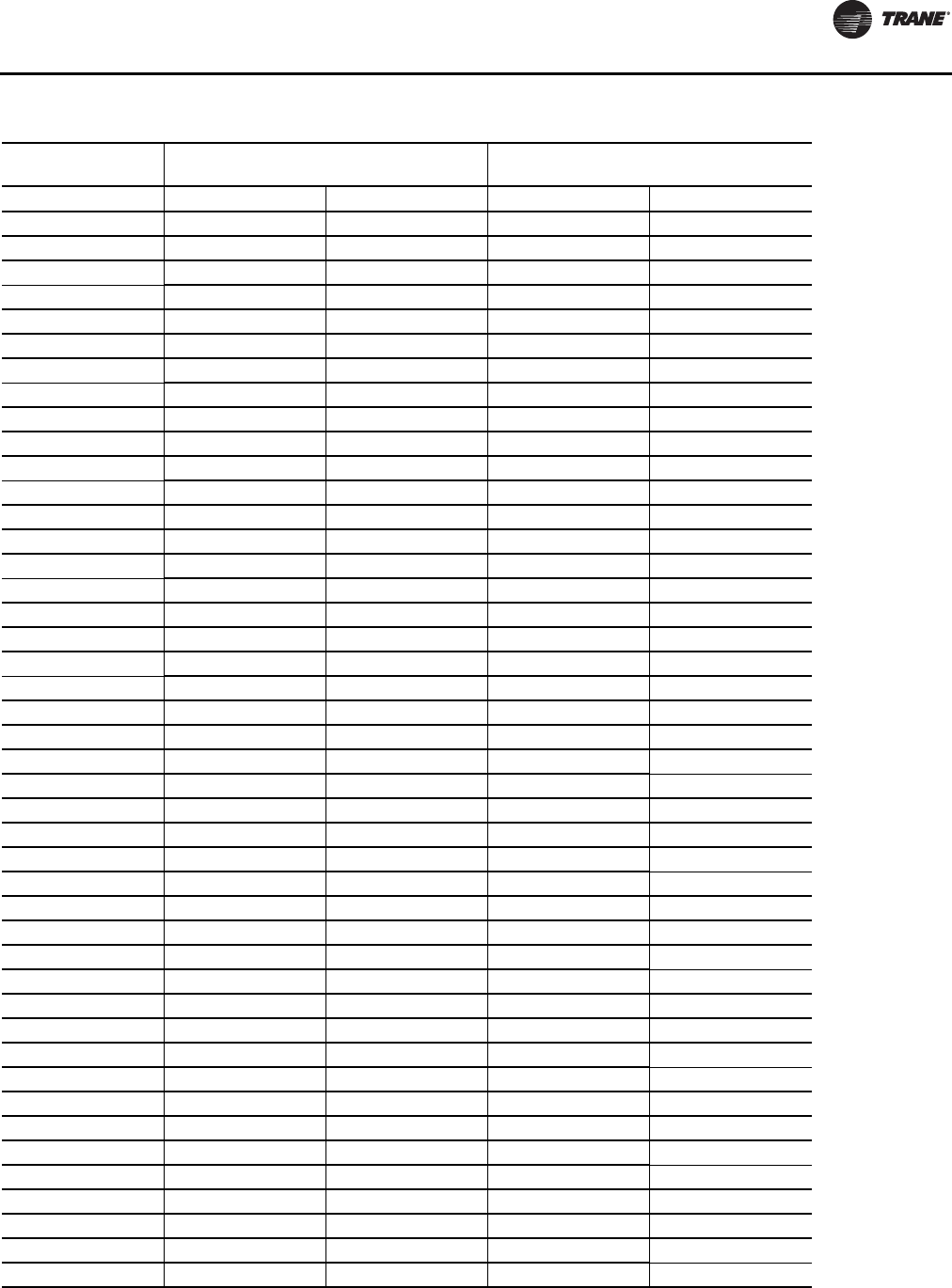
Table 3. Refrigerant charge
Model
(60 Hz) Heat Pump
(oz)/(Kg) Heat Pump w/HGR
(oz)/(Kg)
Circuit 1 Circuit 2 Circuit 1 Circuit 2
GEHE006 25.3 / .717 ----- 26.8 / .760 -----
GEHE009 26.0 / .737 ----- 27.5 / .780 -----
GEHE012 28.5 / .808 ----- 30.5 / .865 -----
GEHE015 29.0 / .822 ----- 30.5 / .865 -----
GEHE018 36.5 / 1.035 ----- 39.5 / 1.120 -----
GEHE024 39.0 / 1.106 ----- 42.0 / 1.191 -----
GEHE030 44.0 / 1.247 ----- 46.5 / 1.318 -----
GEHE036 50.0 / 1.417 ----- 53.5 / 1.517 -----
GEHE042 57.0 / 1.616 ----- 60.5 / 1.715 -----
GEHE048 61.0 / 1.729 ----- 65.5 / 1.857 -----
GEHE060 73.0 / 2.070 ----- 77.5 / 2.197 -----
GEVE006 25.7 / .789 ----- 27.2 / .771 -----
GEVE009 26.5 / .751 ----- 28.0 / .794 -----
GEVE012 29.5 / .836 ----- 31.5 / .893 -----
GEVE015 27.5 / .780 ----- 29.5 / .836 -----
GEVE018 37.0 / 1.049 ----- 40.0 / 1/134 -----
GEVE024 39.0 / 1.106 ----- 41.5 / 1.177 -----
GEVE030 44.5 / 1.262 ----- 47.0 / 1.332 -----
GEVE036 51.0 / 1.446 ----- 54.5 / 1.545 -----
GEVE042 54.0 / 1.531 ----- 57.5 / 1.630 -----
GEVE048 61.0 / 1.729 ----- 66.0 / 1.871 -----
GEVE060 74.0 / 2.098 ----- 79.5 / 2.254 -----
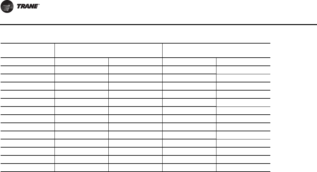
GEHE072 55 / 1.559 55 / 1.559 59 / 1.673 55 / 1.559
GEHE090 64 / 1.814 54 / 1.531 68 / 1.928 54 / 1.531
GEHE120 86 / 2.438 86 / 2.438 90 / 2.551 86 / 2.438
GEHE150 136 / 3.856 136 / 3.856 144 / 4.082 136 / 3.856
GEHE180 126 / 3.572 126 / 3.572 134 / 3.799 126 / 3.572
GEVE072 58 / 1.644 58 / 1.644 62 / 1.758 58 / 1.644
GEVE090 83 / 2.353 75 / 2.126 87 / 2.466 75 / 2.126
GEVE120 88 / 2.495 88 / 2.495 92 / 2.608 88 / 2.495
GEVE150 122 / 3.459 122 / 3.459 130 / 3.685 122 / 3.459
GEVE180 128 / 3.629 128 / 3.629 136 / 3.856 128 / 3.629
GEVE240 284 / 8.051 284 / 8.051 292 / 8.278 284 / 8.051
GEVE300 260 / 7.371 260 / 7.371 267 / 7.569 260 / 7.371
EXHF006 25.3 / 0.717 ----- 26.8 / 0.760 -----
EXHF009 26.0 / 0.737 ----- 27.5 / 0.780 -----
EXHF012 28.5 / 0.808 ----- 30.5 / 0.865 -----
EXHF015 29.0 / 0.822 ----- 30.5 / 0.865 -----
EXHF018 45.0 / 1.276 ----- 48.0 / 1.361 -----
EXHF024 50.5 / 1.432 ----- 53.0 / 1.503 -----
EXHF030 53.0 / 1.503 ----- 56.0 / 1.588 -----
EXHF036 70.0 / 1.984 ----- 73.0 / 2.070 -----
EXHF042 81.0 / 2.296 ----- 85.5 / 2.424 -----
EXHF048 83.0 / 2.353 ----- 87.5 / 2.481 -----
continued on next page
General Information
12 WSHP-SVX01N-EN
EXHF060 114.0 / 3.232 ----- 118.5 / 3.359 -----
EXHF070 122.0 / 3.459 ----- 127.0 / 3.600 -----
EXVF006 25.7 / 0.729 ----- 27.2 / 0.771 -----
EXVF009 26.5 / 0.751 ----- 28.0 / 0.794 -----
EXVF012 29.5 / 0.836 ----- 31.5 / 0.893 -----
EXVF015 30.0 / 0.850 ----- 32.0 / 0.907 -----
EXVF018 45.0 / 1.276 ----- 48.0 / 1.361 -----
EXVF024 52.0 / 1.474 ----- 54.5 / 1.545 -----
EXVF030 53.0 / 1.503 ----- 56.0 / 1.588 -----
EXVF036 70.0 / 1.984 ----- 73.0 / 2.070 -----
EXVF042 81.0 / 2.296 ----- 86.0 / 2.438 -----
EXVF048 83.0 / 2.353 ----- 88.5 / 2.509 -----
EXVF060 114.0 / 3.232 ----- 119.5 / 3.388 -----
EXVF070 122.0 / 3.459 ----- 128.0 / 3.629 -----
Table 3. Refrigerant charge (continued)
Model
(60 Hz) Heat Pump
(oz)/(Kg) Heat Pump w/HGR
(oz)/(Kg)
WSHP-SVX01N-EN 13
Pre-Installation
Unit Inspection Checklist
• Unpack all components of the kit.
• Check carefully for any shipping damage. If any
damage is found it must be reported immediately and
a claim made against the transportation company.
Important: Equipment is shipped FOB (Free on Board)
at the manufacturer.Therefore, freight
claims for damages against the carrier must
be initiated by the receiver.
• Visually inspect the components for shipping damage
as soon as possible after delivery, before it is stored.
Concealed damage must be reported within 15 days.
• If concealed damage is discovered, stop unpacking the
shipment.
• Do not remove damaged material from the receiving
location.Take photos of the damage, if possible.The
owner must provide reasonable evidence that the
damage did not occur after delivery.
• Notify the carrier’s terminal of damage immediately by
phone and by mail. Request an immediate joint
inspection of the damage by the carrier and the
consignee.
• Do not attempt to repair any damaged parts until the
parts are inspected by the carrier’s representative.
Jobsite Inspection Checklist
Always perform the following checks before
accepting a unit:
• Verify that the nameplate data matches the data on the
sales order and bill of lading (including electrical data).
• Verify that the power supply complies with the unit
nameplate specifications.
• Visually inspect the exterior of the unit, for signs of
shipping damage. Do not sign the bill of lading
accepting the unit(s) until inspection has been
completed. Check for damage promptly after the
unit(s) are unloaded. Once the bill of lading is signed at
the jobsite, the unit(s) are now the property of the
SOLDTO party and future freight claims MAY NOT be
accepted by the freight company.
Jobsite Storage
This unit is intended for indoor use only.To protect the unit
from damage due to the elements, and to prevent possible
IAQ contaminant sources from growing, the unit should be
stored indoors. If indoor storage is not possible, the
following provisions for outdoor storage must be met:
• Place the unit(s) on a dry surface or raise above the
ground to assure adequate air circulation beneath the
unit.
• Cover the unit(s) with a water proof tarp to protect
them from the elements.
• Make provisions for continuous venting of the covered
units to prevent moisture from standing on the unit(s)
surfaces. Wet interior unit insulation can become an
amplification site for microbial growth (mold) which
has been determined to be a cause of odors and
serious health related indoor air quality problems.
• Store units in the normal UP orientation to maintain oil
in the compressor.
• Horizontal units may be stacked no more than three
units high. Do not stack the vertical unit configurations.
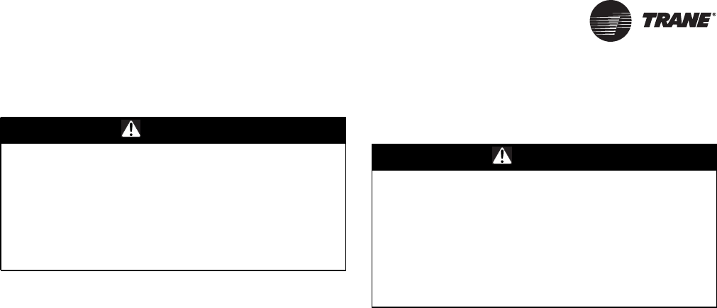
WARNING
Fiberglass Wool!
Product contains fiberglass wool. Disturbing the
insulation in this product during installation,
maintenance or repair will expose you to airborne
particles of glass wool fibers and ceramic fibers known
to the state of California to cause cancer through
inhalation. Glass wool fibers may also cause
respiratory, skin or eye irritation.
WARNING
Microbial Growth!
Wet interior unit insulation can become an amplification
site for microbial growth (mold), which may cause odors
and serious health related indoor air quality problems. If
there is evidence of microbial growth (mold) on the
interior insulation, remove or replace the insulation prior
to operating the system. Failure to remove microbial
growth could result in serious health problems.
14 WSHP-SVX01N-EN
Unit Dimensions and Weights
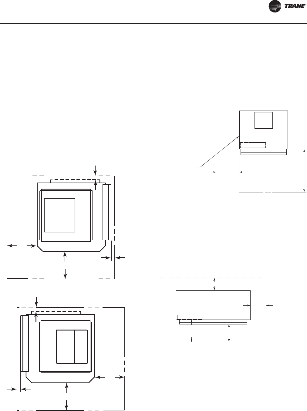
GEH and EXH Clearance Dimensions
Access to the unit for service purposes should be provided
at installation. All ½-5 tons and EXH070 configurations
(see Figure 1, p. 14) require an 18 in. (457 mm) surround
clearance from other mechanical and electrical equipment
(where shown) to enable panel removal from the unit for
service/maintenance ability. NEC requires 36 in. clearance
on the control panel side of the unit. Some local codes
require a greater service clearance than listed below.
Check all code requirements prior to unit installations.
Equipment containing a same-side supply/return
combination requires a 3 in. (229 mm) limitation on one
side. Access to theTXV may not be possible with this 3 in.
(229 mm) clearance.This configuration is typically applied
in a corridor installation, where space limitations force the
left or right side of the unit against a wall.
Service clearance dimensions for the GEH 6-15 tons
horizontal (see Figure 2, p. 14) includes a two side access
appropriate for control and blower motor/wheel access.
Some local codes require a greater service clearance than
listed below. Check all code requirements prior to unit
installations.
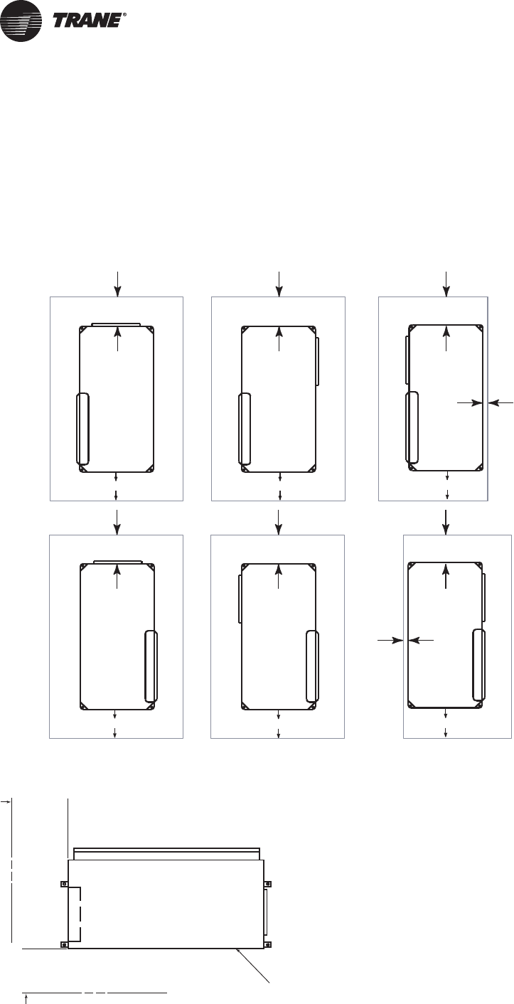
Figure 1. GEH ½ to 5 tons and EXH ½ to 6 tons clearance
LEFT RETURN
BACK SUPPLY
UNIT FRONT
LEFT RETURN
RIGHT SUPPLY LEFT RETURN
LEFT SUPPLY
UNIT FRONT UNIT FRONT
3"
(76)
18" (457)
(3-SIDES)
RIGHT RETURN
BACK SUPPLY
UNIT FRONT
RIGHT RETURN
LEFT SUPPLY RIGHT RETURN
RIGHT SUPPLY
UNIT FRONT UNIT FRONT
3"
(76)
18" (457)
(3-SIDES)
18" (457)
(3-SIDES) 18" (457)
(3-SIDES) 18" (457)
(3-SIDES)
18" (457)
(3-SIDES)
36"
(914)
36"
(914)
36"
(914)
36"
(914)
36"
(914)
36"
(914)
Figure 2. GEH 6-15 tons clearance
TOP VIEW
36"
(914)
SERVICE
CLEARANCE
20"
(508)
SERVICE
CLEARANCE BLOWER ACCESS
PANE L
CONTROL BOX
Unit Dimensions and Weights
WSHP-SVX01N-EN 15
GEV ½ to 5 tons and EXV ½ to 6 tons
clearance dimensions
Access to the unit for service purposes should be provided
at installation. A 24 in. surround clearance (see Figure 3,
p. 15) from other mechanical and electrical equipment
(where shown) is recommended for all configurations.
This will enable panel removal from the unit for service/
maintenance. Some local codes require a greater service
clearance than listed below. Check all code requirements
prior to unit installations. Units in a free return application
will require more than a 12 in. minimum clearance to
provide proper air flow to the units air-to-refrigerant coil.
Pictured in Figure 3, p. 15 minimum 1” clearance on return
side with properly attached duct work.
GEV 6–10 Tons Clearance Dimensions
A 36 in. service clearance is required for all configurations
at the unit front. It is recommended that 20 in of service
clearance for the sides (see Figure 4, p. 15) from other
mechanical and electrical equipment (where shown).The
unit may be serviced through the front access panel or
remaining open sides. Some local codes require a greater
service clearance than listed below. Check all code
requirements prior to unit installations.
GEV 12½–25 Tons Clearance Dimensions
Figure 5, p. 15 outlines service clearances. A 36 in. service
clearance is required for all configurations at the unit front.
A 24 in. service clearance (see Figure 3, p. 15) from other
mechanical and electrical equipment (where shown) is
recommended for all configurations.The unit may be
serviced through the front access panel. Some local codes
require a greater service clearance than listed below.
Check all code requirements prior to unit installations.
Figure 3. GEV ½-5 tons and EXV ½-6 tons clearance
dimensions
1"
(25.4)
36"
(914)
1"
(25.4)
24"
(610) UNIT FRONT
RIGHT RETURN
TOP/BACK SUPPLY
1"
(25.4)
36"
(914)
1"
(25.4)
24"
(610)
UNIT FRONT
LEFT RETURN
TOP/BACK SUPPLY
Figure 4. GEV 6–10 tons clearance
Figure 5. GEV 12½–25 tons clearance
ACCESS PANEL FOR
SHEAVES AND BELTS
20"
(508)
SERVICE
CLEARANCE
FRONT RETURN
TOP SUPPLY
36"
(914)
SERVICE
CLEARANC
E
CONTROL BOX UNIT FRONT
NEC REQ.
MIN. 36" (914)
C.B. TO WALL
CLEARANCE
16" (406) TO
FILTER FRAME
FOR RETURN-AIR
18" (457)
MIN. SERVICE
CLEARANCE FOR
EITHER LEFT
OR RIGHT SIDE
IS 22" (559). FOR
FAN SHAFT REMOVAL,
A 22" (559) CLEARANCE
MUST BE PROVIDED
ON EITHER THE
LEFT OR RIGHT SIDE.
FRONT RETURN-AIR
BACK SUPPLY-AIR
Unit Dimensions and Weights
16 WSHP-SVX01N-EN
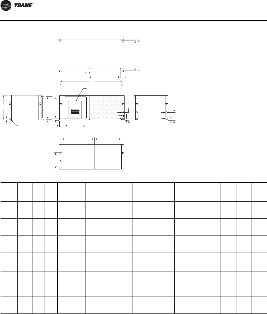
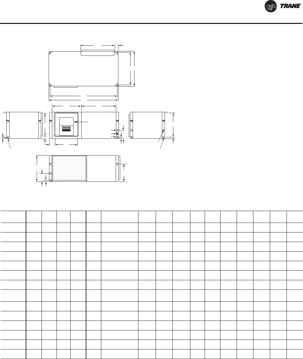
Figure 6. Left return/left supply (GEH/EXH)
TOP
BACK LEFT SIDE FRONT
RIGHT SIDE
BP
N
A
CH
H
ED
J
1" (25.4)
K
1/2"
(13)
DRAIN
3/4" (19) NPTI
BLOWER
ACCESS
PANEL
F X G
OPENING
REFRIG
AND
CONTROL
ACCESS
HI VOLT
L (W.O.)
M (W.I.)
LO VO LT
14"
(356")
Q
RS
1" (25.4)
1 3/8" (35)
6 3/4"
(171)
7"
(178)
WCI mounting location
Table 4. Left return/left supply (GEH/EXH)
GEH
Unit A B C D(a) E F x G H J K L
NPTI M
NPTI N P Q R(b) S
006, 009 40
(1016) 20
(508) 15
(381) 20
(508) 15
(381) 6-7/8 x 8
(175) x (203) 11-1/2
(292) 4-1/2
(114) 1-3/4
(45) 1/2
(13) 1/2
(13) 38-3/4
(984) 18-3/4
(476) 13-5/8
(346) 18-1/2
(470) 3-1/4
(83)
012, 015 40
(1016) 20
(508) 15
(381) 20
(508) 15
(381) 6-7/8 x 9-7/8
(175) x (251) 11-1/2
(292) 4-1/4
(108) 3/4
(19) 1/2
(13) 1/2
(13) 38-3/4
(984) 18-3/4
(476) 13-5/8
(346) 18-1/2
(470) 3-1/4
(83)
018 46
(1168) 23
(584) 18
(457) 23
(584) 18
(457) 8-1/4 x 9-3/4
(210) x (248) 13-1/2
(343) 4-3/4
(121) 1-3/8
(35) 3/4
(19) 3/4
(19) 44-3/4
(1137) 21-3/4
(552) 16-5/8
(422) 18-1/2
(470) 4-1/4
(108)
024, 030 46
(1168) 23
(584) 18
(457) 23
(584) 18
(457) 8-1/4 x 11-3/8
(210) x (289) 13-1/2
(343) 4-3/4
(121) 1-3/8
(35) 3/4
(19) 3/4
(19) 44-3/4
(1137) 21-3/4
(552) 16-5/8
(422) 18-1/2
(597) 4-1/4
(108)
036, 042 50
(1270) 25
(635) 19
(483) 25
(635) 20
(508) 10-1/2 x 13-1/2
(267) x (343) 17
(432) 4
(102) 1
(25) 3/4
(19) 3/4
(19) 48-3/4
(1238) 23-3/4
(603) 17-5/8
(448) 23-1/2
(597) 3-1/4
(83)
Std-048 58
(1473) 33
(838) 21
(533) 29-1/2
(597) 23-1/2
(749) 13-1/8 x 11-3/8
(333) x (289) 18
(457) 5-1/4
(133) 1-1/2
(38) 1
(25) 1
(25) 56-3/4
(1441) 31-3/4
(806) 19-5/8
(498) 23-1/2
(597) 5-1/2
(140)
Hi-048,
060 58
(1473) 33
(838) 21
(533) 29-1/2
(597) 23-1/2
(749) 13-7/8 x 13-7/8
(352) x (352) 18
(457) 5-1/4
(133) 1-1/2
(38) 1
(25) 1
(25) 56-3/4
(1441) 31-3/4
(806) 19-5/8
(498) 23-1/2
(597) 5-1/2
(140)
EXH
Unit A B C D(a) E F x G H J K L
NPTI M
NPTI N P Q R(b) S
006-009 40
(1016) 20
(508) 15
(381) 20
(508) 15
(381) 6-7/8 x 8
(175) x (203) 11-1/2
(292) 4-1/4
(108) 1-3/4
(45) 1/2
(13) 1/2
(13) 38-3/4
(984) 18-3/4
(476) 13-5/8
(346) 18-1/2
(470) 3-1/4
(83)
012-015 40
(1016) 20
(508) 15
(381) 20
(508) 15
(381) 8-1/4 x 9-3/4
(210) x (248) 11-1/2
(292) 4-1/4
(108) 3/4
(19) 1/2
(13) 1/2
(13) 38-3/4
(984) 18-3/4
(476) 13-5/8
(346) 18-1/2
(470) 3-1/4
(83)
018-024 46
(1168) 23
(584) 18
(457) 23
(584) 18
(457) 8-1/4 x 11-3/8
(210) x (289) 13-1/2
(343) 4-3/4
(121) 1-3/8
(35) 3/4
(19) 3/4
(19) 44-3/4
(1137) 21-3/4
(552) 16-5/8
(422) 18-1/2
(470) 4-1/4
(108)
030-036 50
(1270) 25
(635) 19
(483) 25
(635) 20
(508) 10-1/2 x 13-1/2
(267) x (343) 17
(432) 4
(102) 1
(25) 3/4
(19) 3/4
(19) 48-3/4
(1238) 23-3/4
(603) 17-5/8
(448) 23-1/2
(597) 3-1/4
(83)
042-070 58
(1473) 33
(838) 21
(533) 29-1/2
(597) 23-1/2
(749) 13-1/8 x 11-3/8
(333) x (289) 18
(457) 5-1/4
(133) 1-1/2
(38) 1
(25) 1
(25) 56-3/4
(1441) 31-3/4
(806) 19-5/8
(498) 23-1/2
(597) 5-1/2
(140)
070 58
(1473) 39
(991) 21
(533) 29-1/2
(597) 23-1/2
(749) 13-7/8 x 13-7/8
(352) x (352) 18
(457) 5-1/4
(133) 1-1/2
(38) 1
(25) 1
(25) 56-3/4
(1441) 37-3/4
(959) 19-5/8
(498) 23-1/2
(597) 5-1/2
(140)
Notes:
1. All dimensions are in inches followed by millimeters in parenthesis.
2. Access to the unit for service purposes should be provided at installation. Horizontal units require an 18 in. (457 mm) surround clearance from other
mechanical and electrical equipment to enable panel removal from the unit for service/maintenance ability. NEC requires 36 in. clearance on the
control panel side of the unit. Some local codes require a greater service clearance. Check all code requirements prior to unit installations. Installer is
responsible for following all local and NEC code requirements.
3. Equipment containing a same-side supply/return combination requires a 3 in. (229 mm) clearance on one side. Access to the TXV may not be possible
with this 3 in. (229 mm) clearance.
4. If hot gas reheat is specified for a size 018, 024, the actual cabinet size increases to an 036 cabinet.
5. When a horizontal model is ordered with the same side return and supply in a ducted application, bottom filter removal is required due to limited
access on either side of the filter.
(a) Return air opening dimension
(b) Filter rack dimension
Unit Dimensions and Weights
WSHP-SVX01N-EN 17
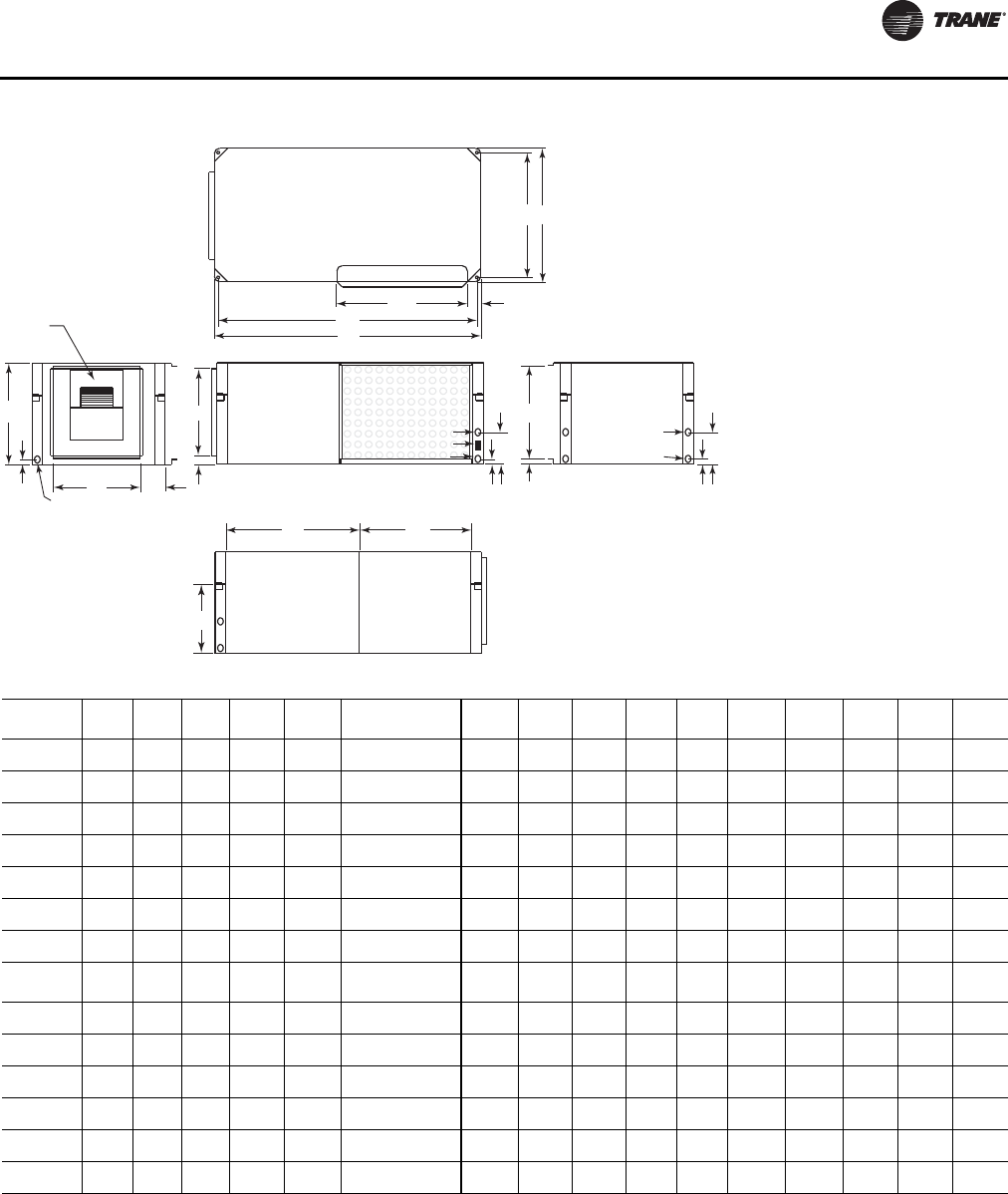
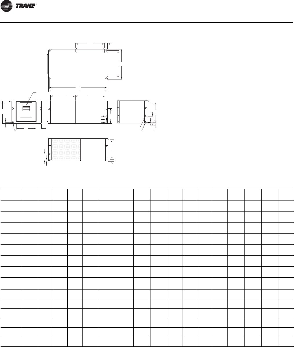
Figure 7. Left return/back supply (GEH/EXH)
TOP
BACK LEFT SIDE FRONT
RIGHT SIDE
BP
N
RS
A
CH
H
ED
14"
(356)
J
1"(25.4)
K
1" (25.4)
6 3/4"
(171)
7"
(178)
1/2"
(13)
DRAIN
3/4" (19) NPTI
BLOWER
ACCESS
PANEL
F X G
OPENING
1 3/8" (35)
REFRIG
AND
CONTROL
ACCESS
HI VOLT
L (W.O.)
Q
M (W.I.)
LO VO LT
WCI mounting location
Table 5. Left return/back supply (GEH/EXH)
GEH
Unit A B C D(a) E F x G H J K L
NPTI M
NPTI N P Q R(b) S
006, 009 40
(1016) 20
(508) 15
(381) 20
(508) 15
(381) 6-7/8 x 8
(175) x (203) 11-1/2
(292) 4-1/2
(114) 1-3/4
(45) 1/2
(13) 1/2
(13) 38-3/4
(984) 18-3/4
(476) 13-5/8
(346) 18-1/2
(470) 3-1/4
(83)
012, 015 40
(1016) 20
(508) 15
(381) 20
(508) 15
(381) 6-7/8 x 9-7/8
(175) x (251) 11-1/2
(292) 4-1/4
(108) 3/4
(19) 1/2
(13) 1/2
(13) 38-3/4
(984) 18-3/4
(476) 13-5/8
(346) 18-1/2
(470) 3-1/4
(83)
018 46
(1168) 23
(584) 18
(457) 23
(584) 18
(457) 8-1/4 x 9-3/4
(210) x (248) 13-1/2
(343) 4-3/4
(121) 1-3/8
(35) 3/4
(19) 3/4
(19) 44-3/4
(1137) 21-3/4
(552) 16-5/8
(422) 18-1/2
(470) 4-1/4
(108)
024, 030 46
(1168) 23
(584) 18
(457) 23
(584) 18
(457) 8-1/4 x 11-3/8
(210) x (289) 13-1/2
(343) 4-3/4
(121) 1-3/8
(35) 3/4
(19) 3/4
(19) 44-3/4
(1137) 21-3/4
(552) 16-5/8
(422) 18-1/2
(597) 4-1/4
(108)
036, 042 50
(1270) 25
(635) 19
(483) 25
(635) 20
(508) 10-1/2 x 13-1/2
(267) x (343) 17
(432) 4
(102) 1
(25) 3/4
(19) 3/4
(19) 48-3/4
(1238) 23-3/4
(603) 17-5/8
(448) 23-1/2
(597) 3-1/4
(83)
Std-048 58
(1473) 33
(838) 21
(533) 29-1/2
(597) 23-1/2
(749) 13-1/8 x 11-3/8
(333) x (289) 18
(457) 5-1/4
(133) 1-1/2
(38) 1
(25) 1
(25) 56-3/4
(1441) 31-3/4
(806) 19-5/8
(498) 23-1/2
(597) 5-1/2
(140)
Hi-048, 060 58
(1473) 33
(838) 21
(533) 29-1/2
(597) 23-1/2
(749) 13-7/8 x 13-7/8
(352) x (352) 18
(457) 5-1/4
(133) 1-1/2
(38) 1
(25) 1
(25) 56-3/4
(1441) 31-3/4
(806) 19-5/8
(498) 23-1/2
(597) 5-1/2
(140)
EXH Unit A B C D(a) E F x G H J K L
NPTI M
NPTI N P Q R(b) S
006-009 40
(1016) 20
(508) 15
(381) 20
(508) 15
(381) 6 -7/8 x 8
(175) x (203) 11-1/2
(292) 4-1/2
(114) 1-3/4
(45) 1/2
(13) 1/2
(13) 38-3/4
(984) 18-3/4
(476) 13-5/8
(346) 18-1/2
(470) 3-1/4
(83)
012-015 40
(1016) 20
(508) 15
(381) 20
(508) 15
(381) 8-1/4 x 9-3/4
(210) x (248) 11-1/2
(292) 4-1/4
(108) 2-3/4
(70) 1/2
(13) 1/2
(13) 38-3/4
(984) 18-3/4
(476) 13-5/8
(346) 18-1/2
(470) 3-1/4
(83)
018-024 46
(1168) 23
(584) 18
(457) 23
(584) 18
(457) 8-1/4 x 11-3/8
(210) x (289) 13-1/2
(343) 4-3/4
(121) 3-1/4
(83) 3/4
(19) 3/4
(19) 44-3/4
(1137) 21-3/4
(552) 16-5/8
(422) 18-1/2
(470) 4-1/4
(108)
030-036 50
(1270) 25
(635) 19
(483) 25
(635) 20
(508) 10-1/2 x 13-1/2
(267) x (343) 17
(432) 4
(102) 1
(25) 3/4
(19) 3/4
(19) 48-3/4
(1238) 23-3/4
(603) 17-5/8
(448) 23-1/2
(597) 3-1/4
(83)
042-070 58
(1473) 33
(838) 21
(533) 29-1/2
(597) 23-1/2
(749) 13-1/8 x 11-3/8
(333) x (289) 18
(457) 9-3/4
(248) 1-1/2
(38) 1
(25) 1
(25) 56-3/4
(1441) 31-3/4
(806) 19-5/8
(498) 23-1/2
(597) 5-1/2
(140)
070 58
(1473) 39
(991) 21
(533) 29-1/2
(597) 231/2
(749) 13-7/8 x 13-7/8
(352) x (352) 18
(457) 9-3/4
(248) 1-1/2
(38) 1
(25) 1
(25) 56-3/4
(1441) 37-3/4
(959) 19-5/8
(498) 23-1/2
(597) 5-1/2
(140)
Notes:
1. All dimensions are in inches followed by millimeters in parenthesis.
2. Access to the unit for service purposes should be provided at installation. Horizontal units require an 18 in. (457 mm) surround clearance from other
mechanical and electrical equipment to enable panel removal from the unit for service/maintenance ability. NEC requires 36 in. clearance on the
control panel side of the unit. Some local codes require a greater service clearance. Check all code requirements prior to unit installations. Installer is
responsible for following all local and NEC code requirements.
3. Equipment containing a same-side supply/return combination requires a 3 in. (229 mm) clearance on one side. Access to the TXV may not be possible
with this 3 in. (229 mm) clearance.
4. If hot gas reheat is specified for a size 018, 024, the actual cabinet size increases to an 036 cabinet.
(a) Return air opening dimension
(b) Filter rack dimension
Unit Dimensions and Weights
18 WSHP-SVX01N-EN
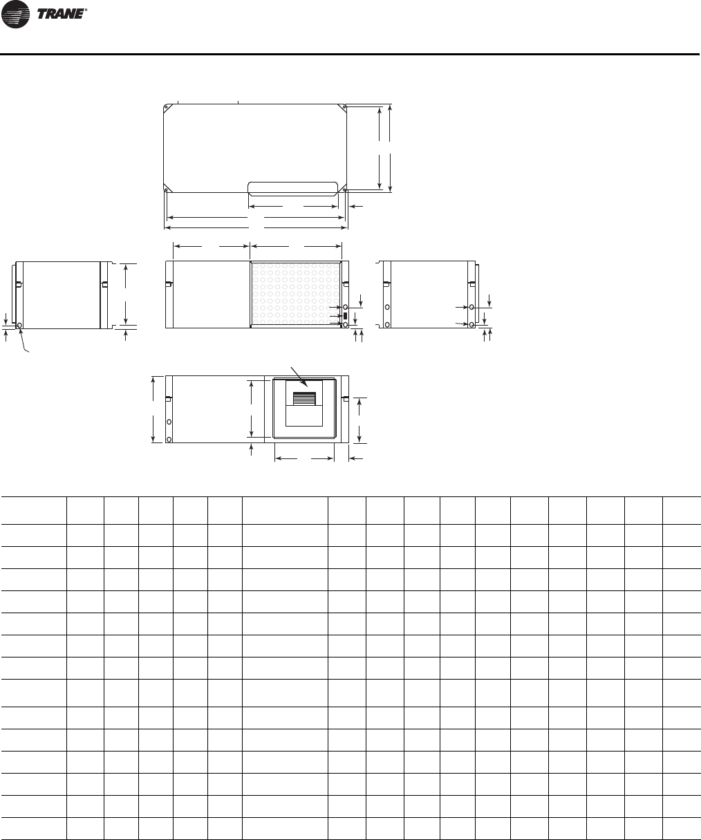
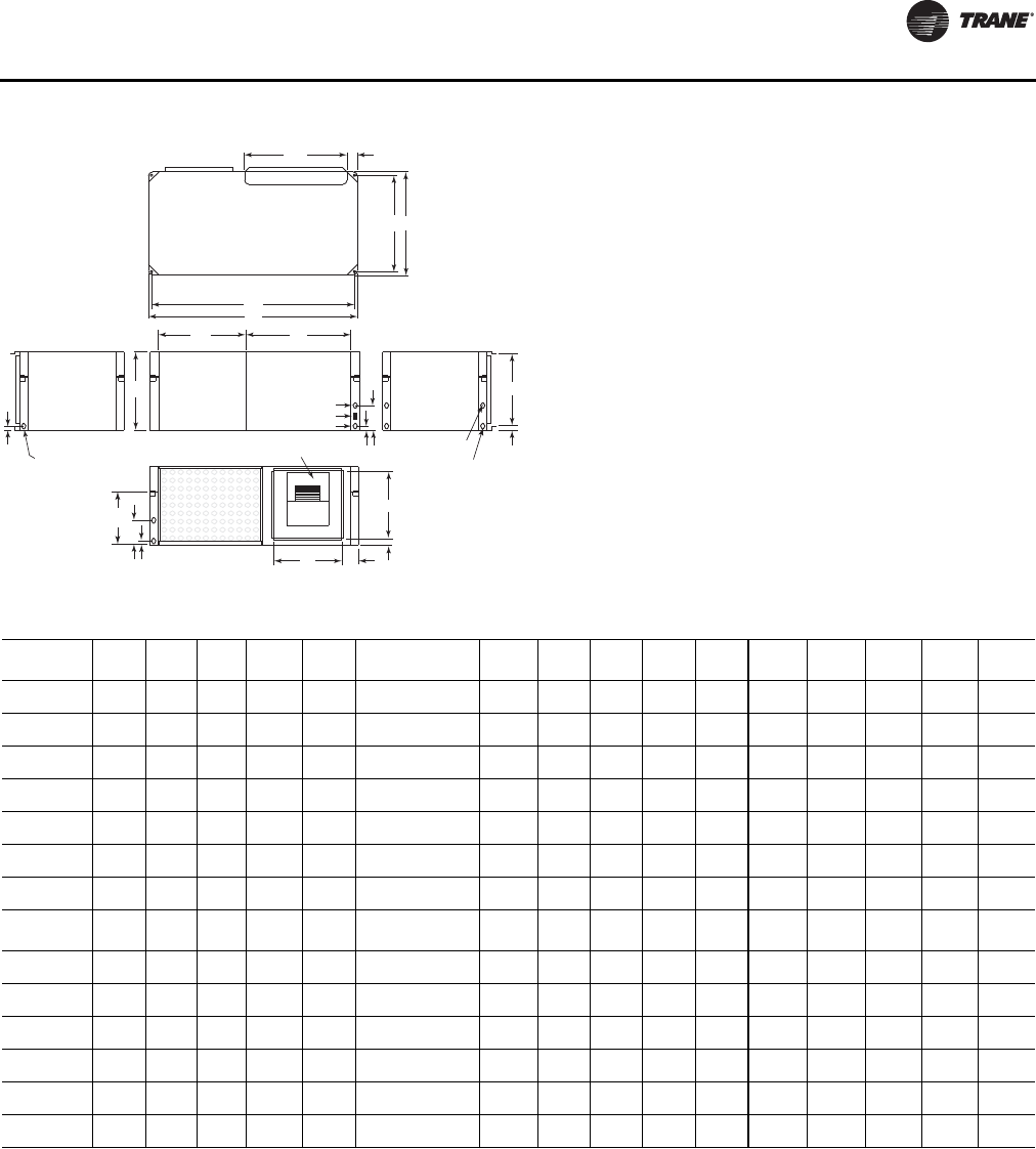
Figure 8. Left return/right supply (GEH/EXH)
TOP
BACK LEFT SIDE FRONT
RIGHT SIDE
BP
N
A
CH
H
ED
J
1" (25.4)
1/2"
(13)
K
DRAIN
3/4" (19) NPTI
BLOWER
ACCESS
PANEL
F X G
OPENING
REFRIG
AND
CONTROL
ACCESS
L (W.O.)
M (W.I.)
14"
Q
RS
1" (25.4)
1 3/8" (35)
6 3/4"
(171)
7"
(178)
HI VOLT
LO VO LT
WCI mounting location
Table 6. Left return/right supply (GEH/EXH)
GEH Unit A B C D(a) E F x G H J K L
NPTI M
NPTI N P Q R(b) S
006, 009 40
(1016) 20
(508) 15
(381) 20
(508) 15
(381) 6-7/8 x 8 (175) x
(203) 11-1/2
(292) 4-1/2
(114) 1-3/4
(45) 1/2
(13) 1/2
(13) 38-3/4
(984) 18-3/4
(476) 13-5/8
(346) 18-1/2
(470) 3-1/4
(83)
012, 015 40
(1016) 20
(508) 15
(381) 20
(508) 15
(381) 6-7/8 x 9-7/8
(175) x (251) 11-1/2
(292) 4-1/4
(108) 2-3/4
(70) 1/2
(13) 1/2
(13) 38-3/4
(984) 18-3/4
(476) 13-5/8
(346) 18-1/2
(470) 3-1/4
(83)
018 46
(1168) 23
(584) 18
(457) 23
(584) 18
(457) 8-1/4 x 9-3/4
(210) x (248) 13-1/2
(343) 4-3/4
(121) 3-1/4
(83) 3/4
(19) 3/4
(19) 44-3/4
(1137) 21-3/4
(552) 16-5/8
(422) 18-1/2
(470) 4-1/4
(108)
024, 030 46
(1168) 23
(584) 18
(457) 23
(584) 18
(457) 8-1/4 x 11-3/8
(210) x (289) 13-1/2
(343) 4-3/4
(121) 3-1/4
(83) 3/4
(19) 3/4
(19) 44-3/4
(1137) 21-3/4
(552) 16-5/8
(422) 18-1/2
(597) 4-1/4
(108)
036, 042 50
(1270) 25
(635) 19
(483) 25
(635) 20
(508) 10-1/2 x 13-1/2
(267) x (343) 17
(432) 4 (102) 1
(25) 3/4
(19) 3/4
(19) 48-3/4
(1238) 23-3/4
(603) 17-5/8
(448) 23-1/2
(597) 3-1/4
(83)
Std-048 58
(1473) 33
(838) 21
(533) 29-1/2
(597) 23-1/2
(749) 13-1/8 x 11-3/8
(333) x (289) 18
(457) 5-1/4
(133) 1-1/2
(38) 1
(25) 1
(25) 56-3/4
(1441) 31-3/4
(806) 19-5/8
(498) 23-1/2
(597) 5-1/2
(140)
Hi-048, 060 58
(1473) 33
(838) 21
(533) 29-1/2
(597) 23-1/2
(749) 13-7/8 x 13-7/8
(352) x (352) 18
(457) 5-1/4
(133) 1-1/2
(38) 1
(25) 1
(25) 56-3/4
(1441) 31-3/4
(806) 19-5/8
(498) 23-1/2
(597) 5-1/2
(140)
EXH Unit A B C D(a) E F x G H J K L
NPTI M
NPTI N P Q R(b) S
006-009 40
(1016) 20
(508) 15
(381) 20
(508) 15
(381) 6-7/8 x 8
(175) x (203) 11-1/2
(292) 4-1/2
(114) 1-3/4
(45) 1/2
(13) 1/2
(13) 38-3/4
(984) 18-3/4
(476) 13-5/8
(346) 18-1/2
(470) 3-1/4
(83)
012-015 40
(1016) 20
(508) 15
(381) 20
(508) 15
(381) 8-1/4 x 9-3/4
(210) x (248) 11-1/2
(292) 4-1/4
(108) 2-3/4
(70) 1/2
(13) 1/2
(13) 38-3/4
(984) 18-3/4
(476) 13-5/8
(346) 18-1/2
(470) 3-1/4
(83)
018-024 46
(1168) 23
(584) 18
(457) 23
(584) 18
(457) 8-1/4 x 11-3/8
(210) x (289) 13-1/2
(343) 4-3/4
(121) 3-1/4
(83) 3/4
(19) 3/4
(19) 44-3/4
(1137) 21-3/4
(552) 16-5/8
(422) 18-1/2
(470) 4-1/4
(108)
030-036 50
(1270) 25
(635) 19
(483) 25
(635) 20
(508) 10-1/2 x 13-1/2
(267) x (343) 17
(432) 4
(102) 1
(25) 3/4
(19) 3/4
(19) 48-3/4
(1238) 23-3/4
(603) 17-5/8
(448) 23-1/2
(597) 3-1/4
(83)
042-070 58
(1473) 33
(838) 21
(533) 29-1/2
(597) 23-1/2
(749) 13-1/8 x 11-3/8
(333) x (289) 18
(457) 5-1/4
(133) 1-1/2
(38) 1
(25) 1
(25) 56-3/4
(1441) 31-3/4
(806) 19-5/8
(498) 23-1/2
(597) 5-1/2
(140)
070 58
(1473) 39
(991) 21
(533) 29-1/2
(597) 23-1/2
(749) 13-7/8 x 13-7/8
(352) x (352) 18
(457) 5-1/4
(133) 1-1/2
(38) 1
(25) 1
(25) 56-3/4
(1441) 37-3/4
(959) 19-5/8
(498) 23-1/2
(597) 5-1/2
(140)
Notes:
1. All dimensions are in inches followed by millimeters in parenthesis.
2. Access to the unit for service purposes should be provided at installation. Horizontal units require an 18 in. (457 mm) surround clearance from other
mechanical and electrical equipment to enable panel removal from the unit for service/maintenance ability. NEC requires 36 in. clearance on the
control panel side of the unit. Some local codes require a greater service clearance. Check all code requirements prior to unit installations. Installer is
responsible for following all local and NEC code requirements.
3. Equipment containing a same-side supply/return combination requires a 3 in. (229 mm) clearance on one side. Access to the TXV may not be
possible with this 3 in. (229 mm) clearance.
4. If hot gas reheat is specified for a size 018, 024, the actual cabinet size increases to an 036 cabinet.
(a) Return air opening dimension
(b) Filter rack dimension
Unit Dimensions and Weights
WSHP-SVX01N-EN 19
Figure 9. Right return/left supply (GEH/EXH)
TOP
BACK LEFT SIDE FRONT
RIGHT SIDE
BP
N
A
C
H
H
ED
J
1" (25.4)
K
Q
DRAIN
3/4" (19) NPTI
BLOWER
ACCESS
PANEL
F X G
OPENING
REFRIG
AND
CONTROL
ACCESS
HI VOLT
L (W.O.)
M (W.I.)
LO VO LT
14"
(356)
RS
1"(25.4)
6 3/4"
(171)
1/2"
(13)
1 3/8"(35)
7" (178)
WCI mounting location
Table 7. Right return/left supply (GEH/EXH)
GEH Unit A B C D(a) E F x G H J K L
NPTI M
NPTI N P Q R(b) S
006, 009 40
(1016) 20
(508) 15
(381) 20
(508) 15
(381) 6-7/8 x 8
(175) x (203) 11-1/2
(292) 4-1/2
(114) 1-3/4
(45) 1/2
(13) 1/2
(13) 38-3/4
(984) 18-3/4
(476) 13-5/8
(346) 18-1/2
(470) 3-1/4
(83)
012, 015 40
(1016) 20
(508) 15
(381) 20
(508) 15
(381) 6-7/8 x 9-7/8
(175) x (251) 11-1/2
(292) 4-1/4
(108) 3/4 (19) 1/2
(13) 1/2
(13) 38-3/4
(984) 18-3/4
(476) 13-5/8
(346) 18-1/2
(470) 3-1/4
(83)
018 46
(1168) 23
(584) 18
(457) 23
(584) 18
(457) 8-1/4 x 9-3/4
(210) x (248) 13-1/2
(343) 4-3/4
(121) 1-3/8
(35) 3/4
(19) 3/4
(19) 44-3/4
(1137) 21-3/4
(552) 16-5/8
(422) 18-1/2
(470) 4-1/4
(108)
024, 030 46
(1168) 23
(584) 18
(457) 23
(584) 18
(457) 8-1/4 x 11-3/8
(210) x (289) 13-1/2
(343) 4-3/4
(121) 1-3/8
(35) 3/4
(19) 3/4
(19) 44-3/4
(1137) 21-3/4
(552) 16-5/8
(422) 18-1/2
(597) 4-1/4
(108)
036, 042 50
(1270) 25
(635) 19
(483) 25
(635) 20
(508) 10-1/2 x 13-1/2
(267) x (343) 17
(432) 4
(102) 1
(25) 3/4
(19) 3/4
(19) 48-3/4
(1238) 23-3/4
(603) 17-5/8
(448) 23-1/2
(597) 3-1/4
(83)
Std-048 58
(1473) 33
(838) 21
(533) 29-1/2
(597) 23-1/2
(749) 13-1/8 x 11-3/8
(333) x (289) 18
(457) 5-1/4
(133) 1-1/2
(38) 1
(25) 1
(25) 56-3/4
(1441) 31-3/4
(806) 19-5/8
(498) 23-1/2
(597) 5-1/2
(140)
Hi-048, 060 58
(1473) 33
(838) 21
(533) 29-1/2
(597) 23-1/2
(749) 13-7/8 x 13-7/8
(352) x (352) 18
(457) 5-1/4
(133) 1-1/2
(38) 1
(25) 1
(25) 56-3/4
(1441) 31-3/4
(806) 19-5/8
(498) 23-1/2
(597) 5-1/2
(140)
EXH Unit A B C D(a) E F x G H J K L
NPTI M
NPTI N P Q R(b) S
006-009 40
(1016) 20
(508) 15
(381) 20
(508) 15
(381) 6-7/8 x 8
(175) x (203) 11-1/2
(292) 4-1/2
(114) 1-3/4
(45) 1/2
(13) 1/2
(13) 38-3/4
(984) 18-3/4
(476) 13-5/8
(346) 18-1/2
(470) 3-1/4
(83)
012-015 40
(1016) 20
(508) 15
(381) 20
(508) 15
(381) 8-1/4 x 9-3/4
(210) x (248) 11-1/2
(292) 4-1/4
(108) 3/4
(19) 1/2
(13) 1/2
(13) 38-3/4
(984) 18-3/4
(476) 13-5/8
(346) 18-1/2
(470) 3-1/4
(83)
018-024 46
(1168) 23
(584) 18
(457) 23
(584) 18
(457) 8-1/4 x 11-3/8
(210) x (289) 13-1/2
(343) 4-3/4
(121) 1-3/8
(35) 3/4
(19) 3/4
(19) 44-3/4
(1137) 21-3/4
(552) 16-5/8
(422) 18-1/2
(470) 4-1/4
(108)
030-036 50
(1270) 25
(635) 19
(483) 25
(635) 20
(508) 10-1/2 x 13-1/2
(267) x (343) 17
(432) 4
(102) 1
(25) 3/4
(19) 3/4
(19) 48-3/4
(1238) 23-3/4
(603) 17-5/8
(448) 23-1/2
(597) 3-1/4
(83)
042-070 58
(1473) 33
(838) 21
(533) 29-1/2
(597) 23-1/2
(749) 13-1/8 x 11-3/8
(333) x (289) 18
(457) 5-1/4
(133) 1-1/2
(38) 1
(25) 1
(25) 56-3/4
(1441) 31-3/4
(806) 19-5/8
(498) 23-1/2
(597) 5-1/2
(140)
070 58
(1473) 39
(991) 21
(533) 29-1/2
(597) 23-1/2
(749) 13-7/8 x 13-7/8
(352) x (352) 18
(457) 5-1/4
(133) 1-1/2
(38) 1
(25) 1
(25) 56-3/4
(1441) 37-3/4
(959) 19-5/8
(498) 23-1/2
(597) 5-1/2
(140)
Notes:
1. All dimensions are in inches followed by millimeters in parenthesis.
2. Access to the unit for service purposes should be provided at installation. Horizontal units require an 18 in. (457 mm) surround clearance from other
mechanical and electrical equipment to enable panel removal from the unit for service/maintenance ability. NEC requires 36 in. clearance on the
control panel side of the unit. Some local codes require a greater service clearance. Check all code requirements prior to unit installations. Installer is
responsible for following all local and NEC code requirements.
3. Equipment containing a same-side supply/return combination requires a 3 in. (229 mm) clearance on one side. Access to the TXV may not be possible
with this 3 in. (229 mm) clearance.
4. If hot gas reheat is specified for a size 018, 024, the actual cabinet size increases to an 036 cabinet.
(a) Return air opening dimension
(b) Filter rack dimension
Unit Dimensions and Weights
20 WSHP-SVX01N-EN
Figure 10. Right return/back supply (GEH/EXH)
TOP
BACK LEFT SIDE FRONT
RIGHT SIDE
BP
N
A
C
H
H
ED
J
1" (25.4)
K
1 3/8" (35)
7"
(178)
DRAIN
3/4" (19) NPTI
BLOWER
ACCESS
PANEL
F X G
OPENING
REFRIG
AND
CONTROL
ACCESS
HI VOLT
L (W.O.)
M (W.I.)
LO VO LT
14"
(356)
Q
RS
1" (25.4)
1/2" (13)
6 3/4" (171)
WCI mounting location
Table 8. Right return/back supply (GEH/EXH)
GEH
Unit A B C D(a) E F x G H J K L
NPTI M
NPTI N P Q R(b) S
006,009 40
(1016) 20
(508) 15
(381) 20
(508) 15
(381) 8 x 6-3/4
(203) x (171) 11-1/2
(292) 4-1/2
(114) 1-5/8
(41) 1/2
(13) 1/2
(13) 38-3/4
(984) 18-3/4
(476) 13-5/8
(346) 18-1/2
(470) 3-1/4
(83)
012,015 40
(1016) 20
(508) 15
(381) 20
(508) 15
(381) 9-1/2 x 6-3/4
(241) x (171) 11-1/2
(292) 4-1/2
(114) 1-5/8
(41) 1/2
(13) 1/2
(13) 38-3/4
(984) 18-3/4
(476) 13-5/8
(346) 18-1/2
(470) 3-1/4
(83)
018 46
(1168) 23
(584) 18
(457) 23
(584) 18
(457) 9-1/2 x 8-1/8
(241) x (206) 13-1/2
(343) 4-3/4
(121) 3-1/4
(83) 3/4
(19) 3/4
(19) 44-3/4
(1137) 21-3/4
(552) 16-5/8
(422) 18-1/2
(470) 4-1/4
(108)
024,030 46
(1168) 23
(584) 18
(457) 23
(584) 18
(457) 11-1/4 x 8-1/4
(286) x (210) 13-1/2
(343) 4-3/4
(121) 3-1/4
(83) 3/4
(19) 3/4
(19) 44-3/4
(1137) 21-3/4
(552) 16-5/8
(422) 18-1/2
(597) 4-1/4
(108)
036,042 50
(1270) 25
(635) 19
(483) 25
(635) 20
(508) 13-1/2 x 10-1/2
(343) x (267) 17
(432) 4
(102) 1
(25) 3/4
(19) 3/4
(19) 48-3/4
(1238) 23-3/4
(603) 17-5/8
(448) 23-1/2
(597) 3-1/4
(83)
Std-048 58
(1473) 33
(838) 21
(533) 29-1/2
(597) 23-1/2
(749) 13-1/8 x 11-1/4
(333) x (286) 18
(457) 5-1/8
(130) 1-1/2
(38) 1
(25) 1
(25) 56-3/4
(1441) 31-3/4
(806) 19-5/8
(498) 23-1/2
(597) 5-1/2
(140)
Hi-048,
060 58
(1473) 33
(838) 21
(533) 29-1/2
(597) 23-1/2
(749) 13-1/2 x 13-3/4
(343) x (349) 18
(457) 5-1/8
(130) 1-1/2
(38) 1
(25) 1
(25) 56-3/4
(1441) 31-3/4
(806) 19-5/8
(498) 23-1/2
(597) 5-1/2
(140)
EXH
Unit A B C D(a) E F x G H J K L
NPTI M
NPTI N P Q R(b) S
006-009 40
(1016) 20
(508) 15
(381) 20
(508) 15
(381) 6-7/8 x 8
(175) x (203) 11-1/2
(292) 4-1/2
(114) 1-3/4
(45) 1/2
(13) 1/2
(13) 38-3/4
(984) 18-3/4
(476) 13-5/8
(346) 18-1/2
(470) 3-1/4
(83)
012-015 40
(1016) 20
(508) 15
(381) 20
(508) 15
(381) 8-1/4 x 9-3/4
(210) x (248) 11-1/2
(292) 4-1/4
(108) 2-3/4
(70) 1/2
(13) 1/2
(13) 38-3/4
(984) 18-3/4
(476) 13-5/8
(346) 18-1/2
(470) 3-1/4
(83)
018-024 46
(1168) 23
(584) 18
(457) 23
(584) 18
(457) 8-1/4 x 11-3/8
(210) x (289) 13-1/2
(343) 4-3/4
(121) 3-1/4
(83) 3/4
(19) 3/4
(19) 44-3/4
(1137) 21-3/4
(552) 16-5/8
(422) 18-1/2
(470) 4-1/4
(108)
030-036 50
(1270) 25
(635) 19
(483) 25
(635) 20
(508) 10-1/2 x 13-1/2
(267) x (343) 17
(432) 4
(102) 1
(25) 3/4
(19) 3/4
(19) 48-3/4
(1238) 23-3/4
(603) 17-5/8
(448) 23-1/2
(597) 3-1/4
(83)
042-070 58
(1473) 33
(838) 21
(533) 29-1/2
(597) 23-1/2
(749) 13-1/8 x 11-3/8
(333) x (289) 18
(457) 9-3/4
(248) 1-1/2
(38) 1
(25) 1
(25) 56-3/4
(1441) 31-3/4
(806) 19-5/8
(498) 23-1/2
(597) 5-1/2
(140)
070 58
(1473) 39
(991) 21
(533) 29-1/2
(597) 23-1/2
(749) 13-7/8 x 13-7/8
(352) x (352) 18
(457) 9-3/4
(248) 1-1/2
(38) 1
(25) 1
(25) 56-3/4
(1441) 37-3/4
(959) 19-5/8
(498) 23-1/2
(597) 5-1/2
(140)
Notes:
1. All dimensions are in inches followed by millimeters in parenthesis.
2. Access to the unit for service purposes should be provided at installation. Horizontal units require an 18 in. (457 mm) surround clearance from other
mechanical and electrical equipment to enable panel removal from the unit for service/maintenance ability. NEC requires 36 in. clearance on the
control panel side of the unit. Some local codes require a greater service clearance. Check all code requirements prior to unit installations. Installer is
responsible for following all local and NEC code requirements.
3. Equipment containing a same-side supply/return combination requires a 3 in. (229 mm) clearance on one side. Access to the TXV may not be possible
with this 3 in. (229 mm) clearance.
4. If hot gas reheat is specified for a size 018, 024, the actual cabinet size increases to an 036 cabinet.
(a) Return air opening dimension
(b) Filter rack dimension
Unit Dimensions and Weights
WSHP-SVX01N-EN 21
Figure 11. Right return/right supply (GEH/EXH)
TOP
BACK LEFT SIDE FRONT
RIGHT SIDE
BP
N
A
C
H
H
ED
J
1" (25.4)
K
DRAIN
3/4" (19) NPTI
BLOWER
ACCESS
PANEL
F X G
OPENING
REFRIG
AND
CONTROL
ACCESS
HI VOLT
LO VO LT
14"
(356)
Q
L (W.O.)
M (W.I.)
RS
1"
(25.4)
1 3/8" (35)
7" (178)
6 3/4" (171)
1/2"
(13)
WCI mounting location
Table 9. Right return/right supply (GEH/EXH)
GEH Unit A B C D(a) E F x G H J K L
NPTI M
NPTI N P Q R(b) S
006, 009 40
(1016) 20
(508) 15
(381) 20
(508) 15
(381) 6-7/8 x 8
(175) x (203) 11-1/2
(292) 4-1/2
(114) 1-3/4
(45) 1/2
(13) 1/2
(13) 38-3/4
(984) 18-3/4
(476) 13-5/8
(346) 18-1/2
(470) 3-1/4
(83)
012, 015 40
(1016) 20
(508) 15
(381) 20
(508) 15
(381) 6-7/8 x 9-7/8
(175) x (251) 11-1/2
(292) 4-1/4
(108) 2-3/4
(70) 1/2
(13) 1/2
(13) 38-3/4
(984) 18-3/4
(476) 13-5/8
(346) 18-1/2
(470) 3-1/4
(83)
018 46
(1168) 23
(584) 18
(457) 23
(584) 18
(457) 8-1/4 x 9-3/4
(210) x (248) 13-1/2
(343) 4-3/4
(121) 3-1/4
(83) 3/4
(19) 3/4
(19) 44-3/4
(1137) 21-3/4
(552) 16-5/8
(422) 18-1/2
(470) 4-1/4
(108)
024, 030 46
(1168) 23
(584) 18
(457) 23
(584) 18
(457) 8-1/4 x 11-3/8
(210) x (289) 13-1/2
(343) 4-3/4
(121) 3-1/4
(83) 3/4
(19) 3/4
(19) 44-3/4
(1137) 21-3/4
(552) 16-5/8
(422) 18-1/2
(597) 4-1/4
(108)
036, 042 50
(1270) 25
(635) 19
(483) 25
(635) 20
(508) 10-1/2 x 13-1/2
(267) x (343) 17
(432) 4 (102) 1
(25) 3/4
(19) 3/4
(19) 48-3/4
(1238) 23-3/4
(603) 17-5/8
(448) 23-1/2
(597) 3-1/4
(83)
Std-048 58
(1473) 33
(838) 21
(533) 29-1/2
(597) 23-1/2
(749) 13-1/8 x 11-3/8
(333) x (289) 18
(457) 5-1/4
(133) 1-1/2
(38) 1
(25) 1
(25) 56-3/4
(1441) 31-3/4
(806) 19-5/8
(498) 23-1/2
(597) 5-1/2
(140)
Hi-048, 060 58
(1473) 33
(838) 21
(533) 29-1/2
(597) 23-1/2
(749) 13-7/8 x 13-7/8
(352) x (352) 18
(457) 5-1/4
(133) 1-1/2
(38) 1
(25) 1
(25) 56-3/4
(1441) 31-3/4
(806) 19-5/8
(498) 23-1/2
(597) 5-1/2
(140)
EXH Unit A B C D(a) E F x G H J K L
NPTI M
NPTI N P Q R(b) S
006-009 40
(1016) 20
(508) 15
(381) 20
(508) 15
(381) 6-7/8 x 8
(175) x (203) 11-1/2
(292) 4-1/2
(114) 1-3/4
(45) 1/2
(13) 1/2
(13) 38-3/4
(984) 18-3/4
(476) 13-5/8
(346) 18-1/2
(470) 3-1/4
(83)
012-015 40
(1016) 20
(508) 15
(381) 20
(508) 15
(381) 8-1/4 x 9-3/4
(210) x (248) 11-1/2
(292) 4-1/4
(108) 2-3/4
(70) 1/2
(13) 1/2
(13) 38-3/4
(984) 18-3/4
(476) 13-5/8
(346) 18-1/2
(470) 3-1/4
(83)
018-024 46
(1168) 23
(584) 18
(457) 23
(584) 18
(457) 8-1/4 x 11-3/8
(210) x (289) 13-1/2
(343) 4-3/4
(121) 3-1/4
(83) 3/4
(19) 3/4
(19) 44-3/4
(1137) 21-3/4
(552) 16-5/8
(422) 18-1/2
(470) 4-1/4
(108)
030-036 50
(1270) 25
(635) 19
(483) 25
(635) 20
(508) 10-1/2 x 13-1/2
(267) x (343) 17
(432) 4
(102) 1
(25) 3/4
(19) 3/4
(19) 48-3/4
(1238) 23-3/4
(603) 17-5/8
(448) 23-1/2
(597) 3-1/4
(83)
042-070 58
(1473) 33
(838) 21
(533) 29-1/2
(597) 23-1/2
(749) 13-1/8 x 11-3/8
(333) x (289) 18
(457) 5-1/4
(133) 1-1/2
(38) 1
(25) 1
(25) 56-3/4
(1441) 31-3/4
(806) 19-5/8
(498) 23-1/2
(597) 5-1/2
(140)
070 58
(1473) 39
(991) 21
(533) 29-1/2
(597) 23-1/2
(749) 13-7/8 x 13-7/8
(352) x (352) 18
(457) 5-1/4
(133) 1-1/2
(38) 1
(25) 1
(25) 56-3/4
(1441) 37-3/4
(959) 19-5/8
(498) 23-1/2
(597) 5-1/2
(140)
Notes:
1. All dimensions are in inches followed by millimeters in parenthesis.
2. 2. Access to the unit for service purposes should be provided at installation. Horizontal units require an 18 in. (457 mm) surround clearance from
other mechanical and electrical equipment to enable panel removal from the unit for service/maintenance ability. NEC requires 36 in. clearance on the
control panel side of the unit Some local codes require a greater service clearance. Check all code requirements prior to unit installations. Installer is
responsible for following all local and NEC code requirements.
3. Equipment containing a same-side supply/return combination requires a 3 in. (229 mm) clearance on one side. Access to the TXV may not be possible
with this 3 in. (229 mm) clearance.
4. If hot gas reheat is specified for a size 018, 024, the actual cabinet size increases to an 036 cabinet.
5. When a horizontal model is ordered with the same side return and supply in a ducted application, bottom filter removal is required due to limited
access on either side of the filter.
(a) Return air opening dimension
(b) Filter rack dimension
Note: It is recommended to order a bottom access filter rack with right return/right supply combination due to potential
problem with return air filter removal.
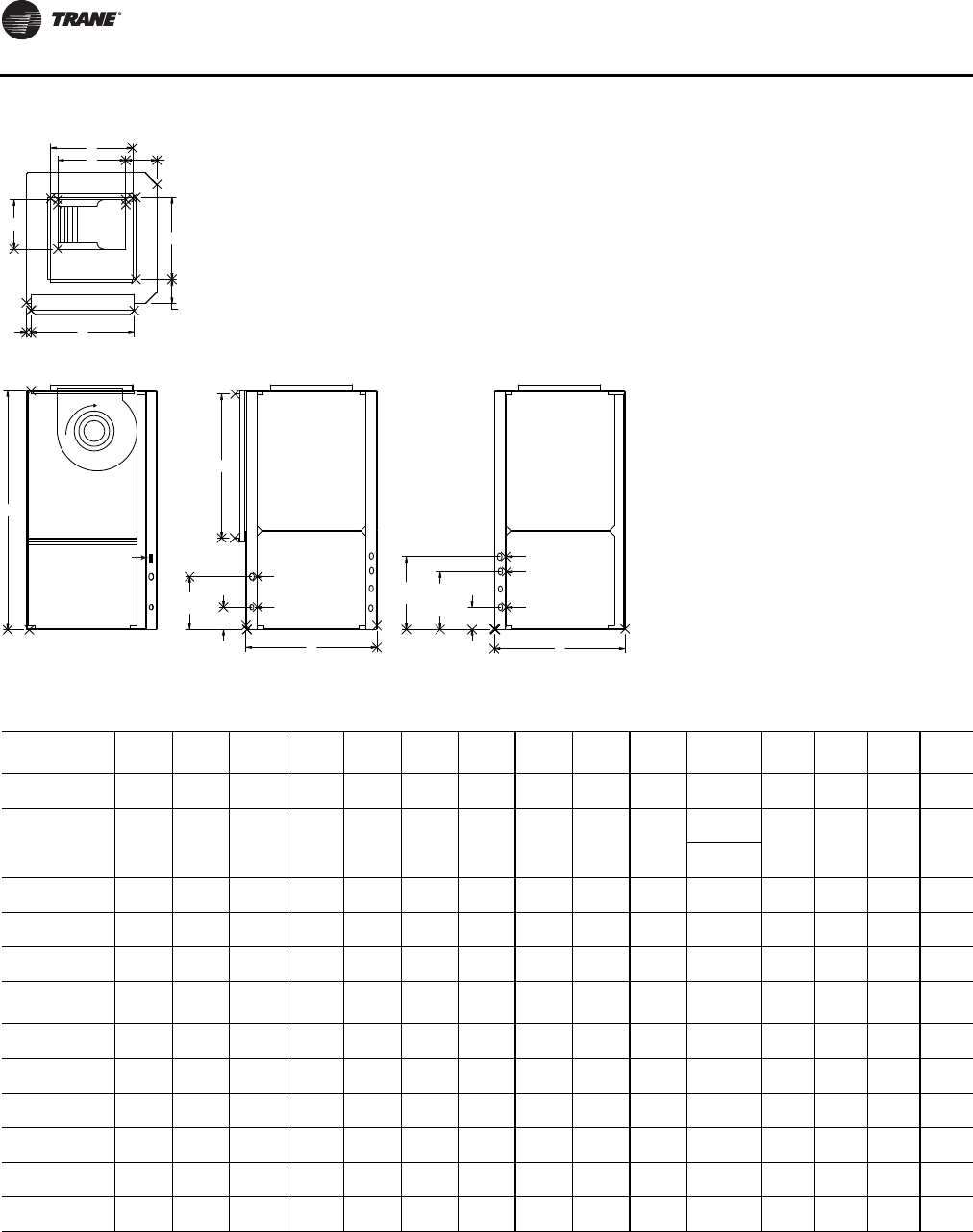
Unit Dimensions and Weights
22 WSHP-SVX01N-EN
Figure 12. Left return/top supply: GEVE—“A” and later design sequence; EXV—“A” and later design sequence
D
L
K
D
E
JM
F
B
H
3 5/8"
3 5/8"
(92)
(92)
8 3/4"
8 3/4"
(222)
(222)
A
HI VOLT
HI VOLT
LO VOLT
LO VOLT
12"
12"
(305)
(305)
9 1/2"
9 1/2"
(241)
(241)
W.O.
W.O.
DRAIN
DRAIN
W.I.
W.I.
C
3 5/8"
3 5/8"
(92)
(92)
BLOWER
BLOWER
ACCESS
ACCESS
COMP/CONTROL
COMP/CONTROL
ACCESS
ACCESS
TOP
TOP
LEFT SIDE
LEFT SIDE
FRONT
FRONT
RIGHT SIDE
RIGHT SIDE
G
WCI mounting location
Table 10. Left return/top supply: GEVE—“A” and later design sequence; EXV—“A” and later design sequence
GEV Unit A B C D E F G H J K L M W.I.
NPTI W.O.
NPTI Drain
FPT
006-015 19-1/2
(495) 31-1/4
(794) 21-1/2
(546) 11-1/2
(292) 4
(102) 5-3/4
(146) 9-1/2
(241) 15
(381) 17
(432) 6-7/8
(175) 8
(203) 3/4
(19) 1/2
(12.7) 1/2
(12.7) 3/4
(19)
018, 024, 030 21-1/2
(546) 39-1/4
(997) 21-1/2
(546) 13-1/2
(343) 4
(102) 4
(1021) 9-1/2
(241) 23-3/4
(603) 17
(432) 8-1/4
(368)
9-3/4
(248) 3/4
(19) 3/4
(19) 3/4
(19) 3/4
(19)
11-3/8
(289)
036, 042 24-1/2
(622) 41-7/8
(1064) 26-1/2
(673) 18
(457) 3-1/4
(83) 5-3/4
(146) 9-1/2
(241) 19
(483) 23
(584) 10-1/2
(267) 13-1/2
(343) 1/4
(6) 3/4
(19) 3/4
(19) 3/4
(19)
Std-048 26-1/2
(673) 46-7/8
(1191) 30-1/2
(775) 18
(457) 4-1/4
(108) 2
(51) 9-1/2
(241) 29
(737) 27-7/8
(708) 13-7/8
(352) 13-7/8
(352) 1/2
(13) 1
(25.4) 1
(25.4) 3/4
(19)
Hi-048, 060 26-1/2
(673) 46-7/8
(1191) 30-1/2
(775) 18
(457) 4-1/4
(108) 2
(51) 9-1/2
(241) 29
(737) 27-7/8
(708) 13-1/8
(333) 11-3/8
(289) 1/2
(13) 1
(25.4) 1
(25.4) 3/4
(19)
EXV Unit A B C D E F G H J K L M W.I.
NPTI W.O.
NPTI Drain
FPT
006-009 19-1/2
(495) 31-1/4
(794) 21-1/2
(546) 11-1/2
(292) 4
(102) 5-3/4
(146) 9-1/2
(241) 15
(381) 17
(432) 6-7/8
(175) 8
(203) 3/4
(19) 1/2
(13) 1/2
(13) 3/4
(19)
012-015 19-1/2
(495) 31-1/4
(794) 21-1/2
(546) 11-1/2
(292) 5-1/2
(140) 5-5/8
(142) 9-1/2
(241) 15
(381) 17
(432) 8-1/4
(210) 9-3/4
(248) 3/4
(19) 1/2
(13) 1/2
(13) 3/4
(19)
018-024 21-1/2
(546) 39-1/4
(997) 21-1/2
(546) 13-1/2
(343) 4
(102) 4
(1021) 9-1/2
(241) 23-3/4
(603) 17
(432) 8-1/4
(368) 11-3/8
(289) 3/4
(19) 3/4
(19) 3/4
(19) 3/4
(19)
030-036 24-1/2
(622) 41-7/8
(1064) 26-1/2
(673) 18
(457) 3-1/4
(83) 5-3/4
(146) 9-1/2
(241) 19
(483) 23
(584) 10-1/2
(267) 13-1/2
(343) 1/4
(6) 3/4
(19) 3/4
(19) 3/4
(19)
042-060 26-1/2
(673) 46-7/8
(1191) 30-1/2
(775) 18
(457) 4-1/4
(108) 2
(51) 9-1/2
(241) 29
(737) 27-7/8
(708) 13-7/8
(352) 11-3/8
(289) 1/2
(13) 1
(25.4) 1
(25.4) 3/4
(19)
070 26-1/2
(673) 50-7/8
(1292) 30-1/2
(775) 18
(457) 4-1/4
(108) 2
(51) 9-1/2
(241) 29
(737) 27-7/8
(708) 13-1/8
(333) 11-3/8
(289) 1/2
(13) 1
(25.4) 1
(25.4) 3/4
(19)
Notes:
1. All dimensions are in inches followed by millimeters in parenthesis.
2. Access to the unit for service purposes should be provided at installation. Vertical units require an 24 in. (610 mm) surround clearance from other
mechanical and electrical equipment to enable panel removal from the unit for service/maintenance ability. NEC requires 36 in. clearance on the
control panel side of the unit. Some local codes require a greater service clearance. Check all code requirements prior to unit installations. Installer is
responsible for following all local and NEC code requirements.
3. Units in a free return application will require more than a 1 in. (25.4 mm) clearance to provide proper air flow to the unit’s air-to-refrigerant coil.
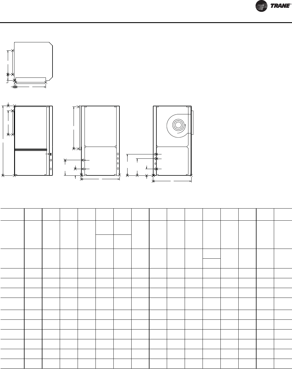
Unit Dimensions and Weights
WSHP-SVX01N-EN 23
Figure 13. Left return/back supply: GEVE—“A” and later design sequence; EXV—“A” and later design sequence
D
E
jM
D
F
B
H
8 3/4"
8 3/4"
(222)
(222)
3 5/8"
3 5/8"
(92)
(92)
LO VOLT
LO VOLT
HI VOLT
HI VOLT
W.I.
W.I.
DRAIN
DRAIN
W.O.
W.O.
A
12"
12"
(305)
(305)
3 5/8"
3 5/8"
(92)
(92)
C
BLOWER
BLOWER
ACCESS
ACCESS
COMP/CONTROL
COMP/CONTROL
ACCESS
ACCESS
9 1/2"
9 1/2"
(241)
(241)
G
LEFT SIDE
LEFT SIDE
FRONT
FRONT
RIGHT SIDE
RIGHT SIDE
TOP
TOP
WCI mounting location
Table 11. Left return/back supply: GEVE—“A” and later design sequence; EXV—“A” and later design sequence
GEV Unit A B C D E F G H J K L M W.I.
NPTI W.O.
NPTI Drain
FPT
006-015 19-1/2
(495) 31-1/4
(794) 21-1/2
(546) 11-1/2
(292)
4
(102)
006-009
1-3/4
(44)
006-009 9-1/2
(241) 15 (381) 17
(432) 6-7/8
(175) 8
(203) 3/4
(19) 1/2 (13) 1/2 (13) 3/4
(19)
4-3/4
(121)
012-015
3-3/4
(95)
012-015
018, 024,
030 21-1/2
(546) 39-1/4
(997) 21-1/2
(546) 13-1/2
(343) 4
(102) 3-7/8
(98) 9-1/2
(241) 23-3/4
(603) 17 (432) 8-1/4
(368)
9-3/4
(248) 3/4
(19) 3/4
(19) 3/4
(19) 3/4
(19)
11-3/8
(289)
036, 042 24-1/2
(622) 41-7/8
(1064) 26-1/2
(673) 18 (457) 3-1/4
(83) 1-7/8
(48) 9-1/2
(241) 19 (483) 23 (584) 10-1/2
(267) 13-1/2
(343) 1/4
(6) 3/4
(19) 3/4
(19) 3/4
(19)
Std-048 26-1/2
(673) 46-7/8
(1191) 30-1/2
(775) 18 (457) 4-1/4
(108) 2
(51) 9-1/2
(241) 29 (737) 27-7/8
(708) 13-7/8
(352) 13-7/8
(352) 1/2
(13) 1 (25.4) 1 (25.4) 3/4
(19)
Hi-048, 060 26-1/2
(673) 46-7/8
(1191) 30-1/2
(775) 18 (457) 4-1/4
(108) 2
(51) 9-1/2
(241) 29 (737) 27-7/8
(708) 13-1/8
(333) 11-3/8
(289) 1/2
(13) 1 (25.4) 1 (25.4) 3/4
(19)
EXV Unit A B C D E F G H J K L M W.I.
NPTI W.O.
NPTI Drain
FPT
006-009 19-1/2
(495) 31-1/4
(794) 21-1/2
(546) 11-1/2
(292) 4
(102) 1-3/4
(44) 9-1/2
(241) 15
(381) 17
(432) 6-7/8
(175) 8
(203) 3/4
(19) 1/2
(13) 1/2
(13) 3/4
(19)
012-015 19-1/2
(495) 31-1/4
(794) 21-1/2
(546) 11-1/2
(292) 5-1/4
(133) 3-3/4
(95) 9-1/2
(241) 15
(381) 17
(432) 8-1/4
(210) 9-3/4
(248) 3/4
(19) 1/2
(13) 1/2
(13) 3/4
(19)
018-024 21-1/2
(546) 39-1/4
(997) 21-1/2
(546) 13-1/2
(343) 4
(102) 3-7/8
(98) 9-1/2
(241) 23-3/4
(603) 17
(432) 8-1/4
(368) 11-3/8
(289) 3/4
(19) 3/4
(19) 3/4
(19) 3/4
(19)
030-036 24-1/2
(622) 41-7/8
(1064) 26-1/2
(673) 18
(457) 3-1/4
(83) 1-7/8
(48) 9-1/2
(241) 19
(483) 23
(584) 10-1/2
(267) 13-1/2
(343) 1/4
(6) 3/4
(19) 3/4
(19) 3/4
(19)
042-060 26-1/2
(673) 46-7/8
(1191) 30-1/2
(775) 18
(457) 4-1/4
(108) 2
(51) 9-1/2
(241) 29
(737) 27-7/8
(708) 13-7/8
(352) 11-3/8
(289) 1/2
(13) 1
(25.4) 1
(25.4) 3/4
(19)
070 26-1/2
(673) 50-7/8
(1292) 30-1/2
(775) 18
(457) 4-1/4
(108) 2
(51) 9-1/2
(241) 29
(737) 27-7/8
(708) 13-1/8
(333) 11-3/8
(289) 1/2
(13) 1
(25.4) 1
(25.4) 3/4
(19)
Note:
1. All dimensions are in inches followed by millimeters in parenthesis.
2. Access to the unit for service purposes should be provided at installation. Vertical units require an 24 in. (610 mm) surround clearance from other
mechanical and electrical equipment to enable panel removal from the unit for service/maintenance ability. NEC requires 36 in. clearance on the
control panel side of the unit. Some local codes require a greater service clearance. Check all code requirements prior to unit installations. Installer is
responsible for following all local and NEC code requirements.
3. Units in a free return application will require more than a 1 in. (25.4 mm) clearance to provide proper air flow to the unit’s air-to-refrigerant coil.
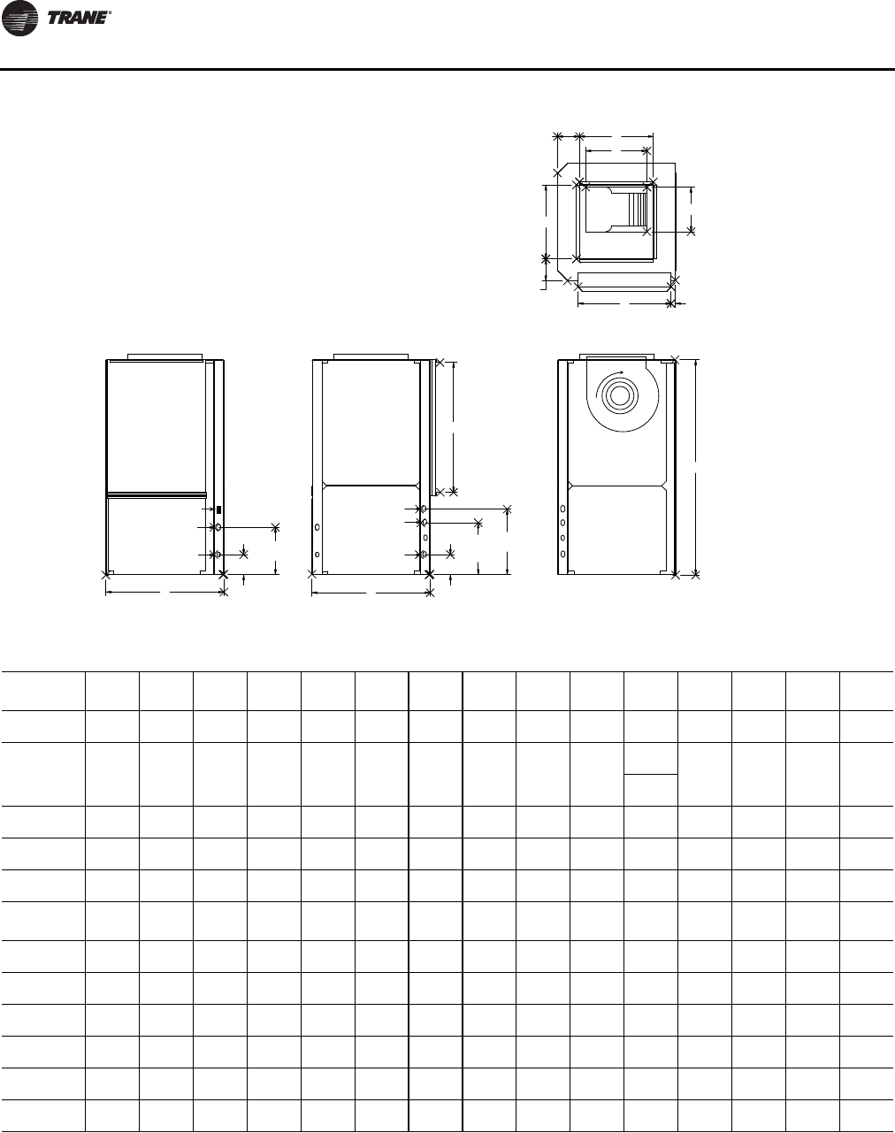
Unit Dimensions and Weights
24 WSHP-SVX01N-EN
Figure 14. Right return/top supply: GEVE—“A” and later design sequence; EXV—”A” and later design sequence)
CA
3 5/8"
3 5/8"
(92)
(92)
8 3/4"
8 3/4"
(222)
(222)
LO VOLT
LO VOLT
HI VOLT
HI VOLT
W.I.
W.I.
DRAIN
DRAIN
W.O.
W.O.
3 5/8"
3 5/8"
(92)
(92)
12"
12"
(305)
(305)
H
B
D
L
F
J M
E
D
K
9 1/2"
9 1/2"
(241)
(241)
G
FRONT
FRONT
RIGHT SIDE
RIGHT SIDE
TOP
TOP
LEFT SIDE
LEFT SIDE
BLOWER
BLOWER
ACCESS
ACCESS
COMP/CONTROL
COMP/CONTROL
ACCESS
ACCESS
WCI mounting location
Table 12. Right return/top supply: GEVE—“A” and later design sequence; EXV—“A” and later design sequence
GEV Unit A B C D E F G H J K L M W.I.
NPTI W.O.
NPTI Drain
FPT
006-015 19-1/2
(495) 31-1/4
(794) 21-1/2
(546) 11-1/2
(292) 4
(102) 5-3/4
(146) 9-1/2
(241) 15
(381) 17
(432) 6-7/8
(175) 8
(203) 3/4
(19) 1/2
(13) 1/2
(13) 3/4
(19)
018, 024, 030 21-1/2
(546) 39-1/4
(997) 21-1/2
(546) 13-1/2
(343) 4
(102) 4
(1021) 9-1/2
(241) 23-3/4
(603) 17 (432) 8-1/4
(368)
9-3/4
(248) 3/4
(19) 3/4
(19) 3/4
(19) 3/4
(19)
11-3/8
(289)
036, 042 24-1/2
(622) 41-7/8
(1064) 26-1/2
(673) 18 (457) 3-1/4
(83) 5-3/4
(146) 9-1/2
(241) 19
(483) 23 (584) 10-1/2
(267) 13-1/2
(343) 1-3/4
(19) 3/4
(19) 3/4
(19) 3/4
(19)
Std-048 26-1/2
(673) 46-7/8
(1191) 30-1/2
(775) 18 (457) 4-1/4
(108) 2
(51) 9-1/2
(241) 29
(737) 27-7/8
(708) 13-7/8
(352) 13-7/8
(352) 1/2
(13) 1
(25) 1
(25) 3/4
(19)
Hi-048, 060 26-1/2
(673) 46-7/8
(1191) 30-1/2
(775) 18 (457) 4-1/4
(108) 2
(51) 9-1/2
(241) 29
(737) 27-7/8
(708) 13-1/8
(333) 11-3/8
(289) 1/2
(13) 1
(25) 1
(25) 3/4
(19)
EXV Unit A B C D E F G H J K L M W.I.
NPTI W.O.
NPTI Drain
FPT
006-009 19-1/2
(495) 31-1/4
(794) 21-1/2
(546) 11-1/2
(292) 4
(102) 5-3/4
(146) 9-1/2
(241) 15
(381) 17
(432) 6-7/8
(175) 8
(203) 3/4
(19) 1/2
(13) 1/2
(13) 3/4
(19)
012-015 19-1/2
(495) 31-1/4
(794) 21-1/2
(546) 11-1/2
(292) 2-1/2
(64) 5-5/8
(143) 9-1/2
(241) 15
(381) 17
(432) 8-1/4
(210) 9-3/4
(248) 3/4
(19) 1/2
(13) 1/2
(13) 3/4
(19)
018-024 21-1/2
(546) 39-1/4
(997) 21-1/2
(546) 13-1/2
(343) 4
(102) 4
(102) 9-1/2
(241) 23-3/4
(603) 17
(432) 8-1/4
(368) 11-3/8
(289) 3/4
(19) 3/4
(19) 3/4
(19) 3/4
(19)
030-036 24-1/2
(622) 41-7/8
(1064) 26-1/2
(673) 18
(457) 3-1/4
(83) 5-3/4
(146) 9-1/2
(241) 19
(483) 23
(584) 10-1/2
(267) 13-1/2
(343) 3/4
(19) 3/4
(19) 3/4
(19) 3/4
(19)
042-060 26-1/2
(673) 46-7/8
(1191) 30-1/2
(775) 18
(457) 4-1/4
(108) 2
(51) 9-1/2
(241) 29
(737) 27-7/8
(708) 13-7/8
(352) 11-3/8
(289) 1/2
(13) 1
(25.4) 1
(25.4) 3/4
(19)
070 26-1/2
(673) 50-7/8
(1292) 30-1/2
(775) 18
(457) 4-1/4
(108) 2
(51) 9-1/2
(241) 29
(737) 27-7/8
(708) 13-1/8
(333) 11-3/8
(289) 1/2
(13) 1
(25.4) 1
(25.4) 3/4
(19)
Note:
1. All dimensions are in inches followed by millimeters in parenthesis.
2. Access to the unit for service purposes should be provided at installation. Vertical units require an 24 in. (610 mm) surround clearance from other
mechanical and electrical equipment to enable panel removal from the unit for service/maintenance ability. NEC requires 36 in. clearance on the
control panel side of the unit. Some local codes require a greater service clearance. Check all code requirements prior to unit installations. Installer is
responsible for following all local and NEC code requirements.
3. Units in a free return application will require more than a 1 in. (25.4 mm) clearance to provide proper air flow to the unit’s air-to-refrigerant coil.
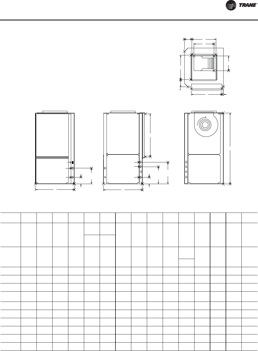
Unit Dimensions and Weights
WSHP-SVX01N-EN 25
Figure 15. Right return/back supply: GEVE—“A” and later design sequence; EXV—“A” and later design sequence
CA
3 5/8"
3 5/8"
(92)
(92)
8 3/4"
8 3/4"
(222)
(222)
LO VOLT
LO VOLT
HI VOLT
HI VOLT
W.I.
W.I.
DRAIN
DRAIN
W.O.
W.O.
3 5/8"
3 5/8"
(92)
(92)
12"
12"
(305)
(305)
H
B
D
L
F
J M
E
D
K
9 1/2"
9 1/2"
(241)
(241)
G
FRONT
FRONT
RIGHT SIDE
RIGHT SIDE
TOP
TOP
LEFT SIDE
LEFT SIDE
BLOWER
BLOWER
ACCESS
ACCESS
COMP/CONTROL
COMP/CONTROL
ACCESS
ACCESS
WCI mounting location
Table 13. Right return/back supply: GEVE—“A” and later design sequence; EXV—“A” and later design sequence
GEV Unit A B C D E F G H J K L M W.I.
NPTI W.O.
NPTI Drain
FPT
006-015 19-1/2
(495) 31-1/4
(794) 21-1/2
(546) 11-1/2
(292)
4
(102)
006-009
1-3/4
(44)
006-009 9-1/2
(241) 15 (381) 17 (432) 6-7/8
(175) 8
(203) 3/4
(19) 1/2 (13) 1/2 (13) 3/4
(19)
6
(152)
012-015
1-1/4
(32)
012-015
018, 024,
030 21-1/2
(546) 39-1/4
(997) 21-1/2
(546) 13-1/2
(343) 4
(102) 3-7/8
(98) 9-1/2
(241) 23-3/4
(603) 17 (432) 8-1/4
(368)
9-3/4
(248) 3/4
(19) 3/4
(19) 3/4
(19) 3/4
(19)
11-3/8
(289)
036, 042 24-1/2
(622) 41-7/8
(1064) 26-1/2
(673) 18 (457) 3-1/4
(83) 1-7/8
(48) 9-1/2
(241) 19
(483) 23 (584) 10-1/2
(267) 13-1/2
(343) 1-3/4
(19) 3/4
(19) 3/4
(19) 3/4
(19)
Std-048 26-1/2
(673) 46-7/8
(1191) 30-1/2
(775) 18 (457) 4-1/4
(108) 2
(51) 9-1/2
(241) 29
(737) 27-7/8
(708) 13-7/8
(352) 13-7/8
(352) 1/2
(13) 1
(25) 1
(25) 3/4
(19)
Hi-048, 060 26-1/2
(673) 46-7/8
(1191) 30-1/2
(775) 18 (457) 4-1/4
(108) 2
(51) 9-1/2
(241) 29
(737) 27-7/8
(708) 13-1/8
(333) 11-3/8
(289) 1/2
(13) 1
(25) 1
(25) 3/4
(19)
EXV Unit A B C D E F G H J K L M W.I.
NPTI W.O.
NPTI Drain
FPT
006-009 19-1/2
(495) 31-1/4
(794) 21-1/2
(546) 11-1/2
(292) 4
(102) 1-3/4
(44) 9-1/2
(241) 15
(381) 17
(432) 6-7/8
(175) 8
(203) 3/4
(19) 1/2
(13) 1/2
(13) 3/4
(19)
012-015 19-1/2
(495) 31-1/4
(794) 21-1/2
(546) 11-1/2
(292) 2
(51) 1-1/4
(32) 9-1/2
(241) 15
(381) 17
(432) 8-1/4
(210) 9-3/4
(248) 3/4
(19) 1/2
(13) 1/2
(13) 3/4
(19)
018-024 21-1/2
(546) 39-1/4
(997) 21-1/2
(546) 13-1/2
(343) 4
(102) 3-7/8
(98) 9-1/2
(241) 23-3/4
(603) 17
(432) 8-1/4
(368) 11-3/8
(289) 3/4
(19) 3/4
(19) 3/4
(19) 3/4
(19)
030-036 24-1/2
(622) 41-7/8
(1064) 26-1/2
(673) 18
(457) 3-1/4
(83) 1-7/8
(48) 9-1/2
(241) 19
(483) 23
(584) 10-1/2
(267) 13-1/2
(343) 3/4
(19) 3/4
(19) 3/4
(19) 3/4
(19)
042-060 26-1/2
(673) 46-7/8
(1191) 30-1/2
(775) 18
(457) 4-1/4
(108) 2
(51) 9-1/2
(241) 29
(737) 27-7/8
(708) 13-7/8
(352) 11-3/8
(289) 1/2
(13) 1
(25.4) 1
(25.4) 3/4
(19)
070 26-1/2
(673) 50-7/8
(1292) 30-1/2
(775) 18
(457) 4-1/4
(108) 2
(51) 9-1/2
(241) 29
(737) 27-7/8
(708) 13-1/8
(333) 11-3/8
(289) 1/2
(13) 1
(25.4) 1
(25.4) 3/4
(19)
Note: All dimensions are in inches followed by millimeters in parenthesis.
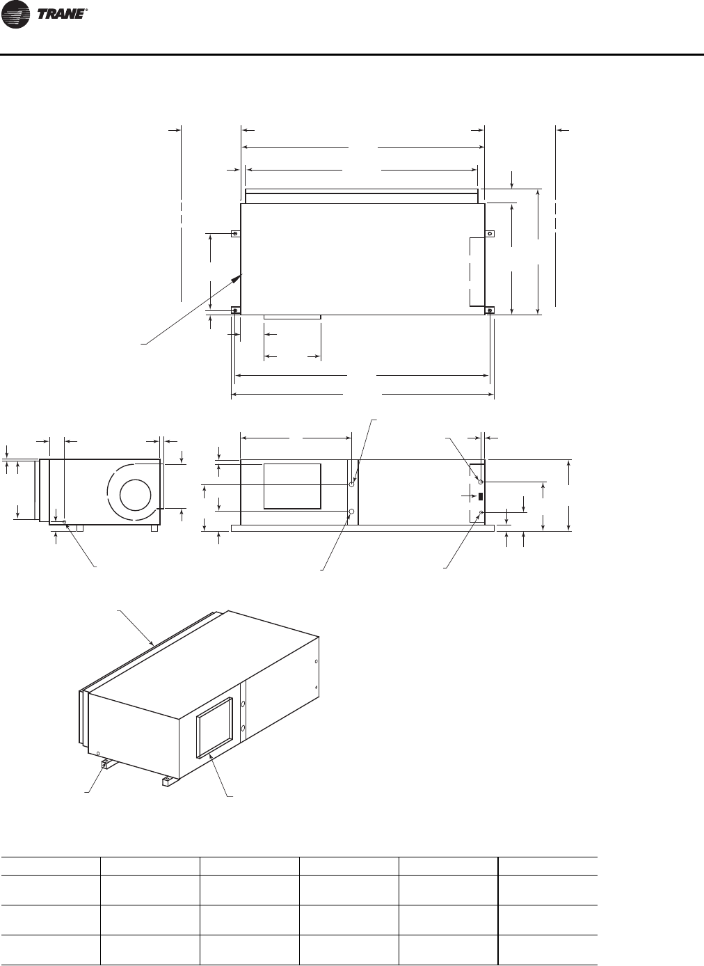
Unit Dimensions and Weights
26 WSHP-SVX01N-EN
Figure 16. GEH 6-10 tons (072-120) 60 Hz; GEH 6-7½ tons (072-090) 50 Hz—right return/left supply
WCI mounting location
20"
(508)
SERVICE
CLEARANCE 79"
(2007)
74 1/2"
(1892)
1 3/4"
(44)
36"
(914)
SERVICE
CLEARANCE
4 5/8"
(117)
36"
(914)
40 5/8"
(1032)
7 5/8"
(194)
18 3/8"
(467)
81"
(2057)
2 1/8"
(54)
23 7/8"
(606)
BLOWER ACCESS
PANEL
3 1/8"
(79)
(79 )
4 7/8"
(124)
1"
(25.4)
5/8"
(16)
18 3/4"
(476)
14 1/2"
(368)
DRAIN CONNECTION
1/2" (22) SCHEDULE 40 PVC
1 1/4"
(32)
C
B
A
W.O. "D" NPTI
W.I. "D" NPTI
24 VOLT
1 1/8" (28.6) DIA.
HIGH VOLTAGE
7/8" (22.2) DIA.
23 1/4"
(591)
16 1/2"
(419)
2 1/4"
(57)
6 1/2"
(165)
1 1/2"
(38)
RETURN AIR
OPENING
1" (25.4) DIA.
MOUNTING HOLE
4X'S SUPPLY OPENING
1" (25.4) DUCT FLANGE
TOP VIEW
BACK SIDE LEFT SIDE
85"
(2159)
Table 14. GEH 6–10 tons (072-120) 60 Hz; GEH 6–7½ tons (072-090) 50 Hz—right return/left supply
GEH (60 Hz) GEH (50 Hz) A B C D
072 — 36-1/4 in.
(921 mm) 15-5/8 in.
(397 mm) 6-5/8 in.
(168 mm) 1-1/4 in.
(32 mm)
090 072 36-1/8 in.
(917 mm) 12-3/4 in.
(324 mm) 6-3/4 in.
(171 mm) 1-1/4 in.
(32 mm)
120 090 36-1/8 in.
(917 mm) 13 in.
(330 mm) 7-1/4 in.
(184 mm) 1-1/2 in.
(38 mm)
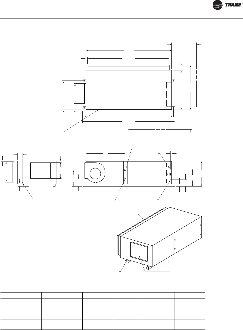
Unit Dimensions and Weights
WSHP-SVX01N-EN 27
Figure 17. GEH 6–10 tons (072–120) 60 Hz; GEH 6–7½ tons (072–090) 50 Hz—right return/back supply
79"
(2007)
74 1/2"
(1892)
36"
(914)
40 5/8"
(1032)
81"
(2057)
85"
(2159)
2 1/8"
(54)
23 7/8"
(606)
TOP VIEW
18 3/8"
(467)
6 1/8"
(156)
4 5/8"
(117)
36"
(914)
SERVICE
CLEARANCE
1 3/4"
(44)
20"
(508)
SERVICE
CLEARANCE
BLOWER ACCESS
PANEL
3 1/8"
(79)
4 7/8"
(124)
5/8"
(16)
18 3/4"
(476)
DRAIN CONNECTION
1/2" (22) SCHEDULE 40 PVC
1 1/4"
(32)
14 1/2"
(368)
C
B
A
W.O. "D" NPTI
W.I. "D" NPTI
24 VOLT
1 1/8" (28.6) DIA.
HIGH VOLTAGE
7/8" (22.2) DIA.
23 1/4"
(591)
16 1/2"
(419)
2 1/4"
(57)
6 1/2"
(165)
1 1/2"
(38)
LEFT SIDE
RETURN AIR
OPENING
1" (25.4) DIA.
MOUNTING HOLE
4X'S
SUPPLY OPENING
1" (25.4) DUCT FLANGE
WCI mounting location
Table 15. GEH 6-10 tons (072-120) 60 Hz; GEH 6-7½ tons (072-090) 50 Hz—right return/back supply
GEH (60 Hz) GEH (50 Hz) A B C D
072 — 36-1/4 in.
(921 mm) 15-5/8 in.
(397 mm) 6-5/8 in.
(168 mm) 1-1/4 in.
(32 mm)
090 072 36-1/8 in.
(917 mm) 12-3/4 in.
(324 mm) 6-3/4 in.
(171 mm) 1-1/4 in.
(32 mm)
120 090 36-1/8 in.
(917 mm) 13 in.
(330 mm) 7-1/4 in.
(184 mm) 1-1/2 in.
(38 mm)
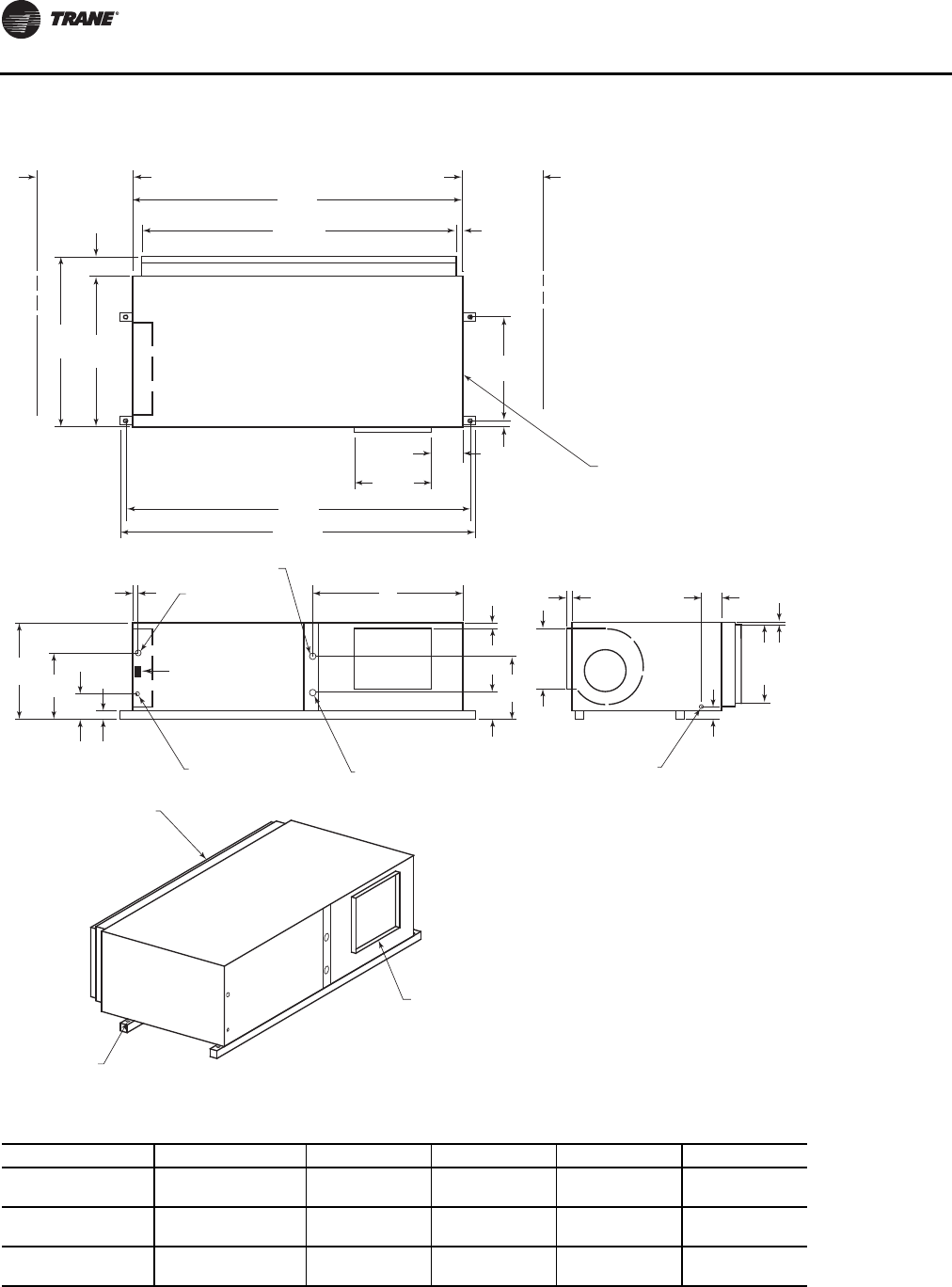
Unit Dimensions and Weights
28 WSHP-SVX01N-EN
Figure 18. GEH 6-10 tons (072-120) 60 Hz; GEH 6-7½ tons (072-090) 50 Hz - left return/right supply
20"
(508)
SERVICE
CLEARANCE
79"
(2007)
74 1/2"
(1892) 1 3/4"
(44)
36"
(914)
SERVICE
CLEARANCE
4 5/8"
(117)
36"
(914)
40 5/8"
(1032)
7 5/8"
(194)
18 3/8"
(467)
81"
(2057)
85"
(2159)
1 1/4"
(32)
24 3/4"
(629)
BLOWER ACCESS
PANEL
3 1/8"
(79)
4 7/8"
(124)
1"
(25.4)
5/8"
(16)
18 3/4"
(476)
14 1/2"
(368)
DRAIN CONNECTION
1/2" (22) SCHEDULE 40 PVC
1 1/4"
(32)
C
B
A
W.O. "D" NPTI
W.I. "D" NPTI
24 VOLT
1 1/8" (28.6) DIA.
HIGH VOLTAGE
7/8" (22.2) DIA.
23 1/4"
(591) 16 1/2"
(419)
2 1/4"
(57)
6 1/2"
(165)
1 1/2"
(38)
TOP VIEW
BACK SIDE
LEFT SIDE
RETURN AIR
OPENING
1" (25.4) DIA.
MOUNTING HOLE
4X'S
SUPPLY OPENING
1" (25.4) DUCT FLANGE
WCI mounting location
Table 16. GEH 6-10 tons (072-120) 60 Hz; GEH 6-7½ tons (072-090) 50 Hz—left return/right supply
GEH (60 Hz) GEH (50 Hz) A B C D
072 — 36-1/8 in.
(917 mm) 17 in.
(432 mm) 8 in.
(203 mm) 1-1/4 in.
(32 mm)
090 072 36-1/8 in.
(917 mm) 13-3/4 in.
(349 mm) 7-3/4 in.
(197 mm) 1-1/4 in.
(32 mm)
120 090 36-1/8 in.
(917 mm) 13 in.
(330 mm) 7-1/4 in.
(184 mm) 1-1/2 in.
(38 mm)
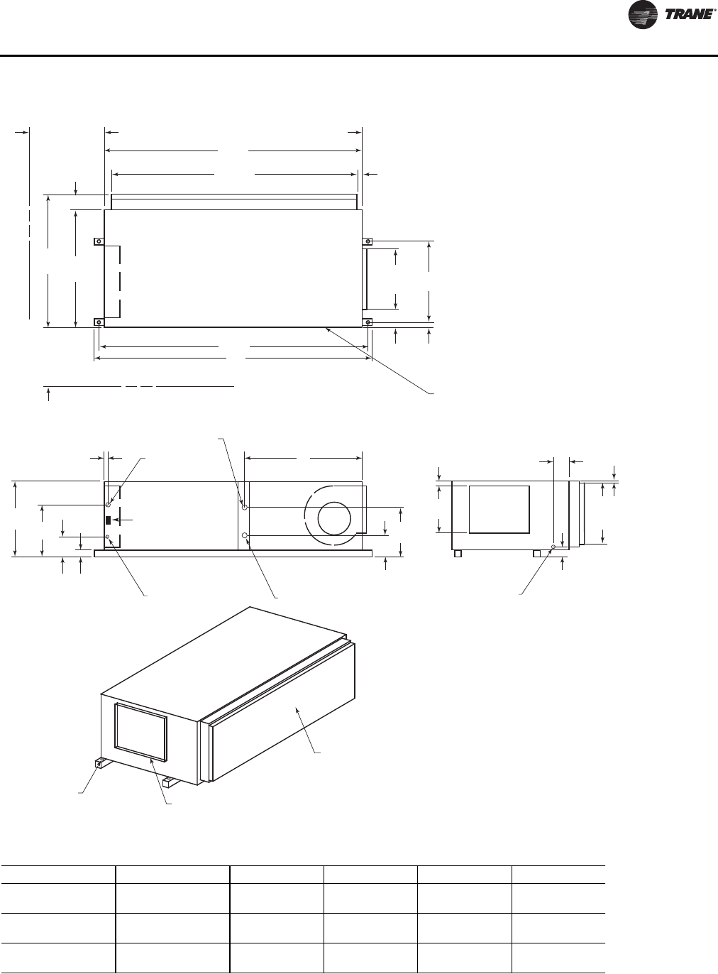
Unit Dimensions and Weights
WSHP-SVX01N-EN 29
Figure 19. GEH 6-10 tons (072-120) 60 Hz; GEH 6-7½ tons (072-090) 50 Hz—left return/back supply
79"
(2007)
74 1/2"
(1892)
36"
(914)
40 5/8"
(1032)
81"
(2057)
85"
(2159)
1 1/4"
(32)
24 3/4"
(629)
TOP VIEW
18 3/8"
(467)
6 1/8"
(156)
4 5/8"
(117)
36"
(914)
SERVICE
CLEARANCE
1 3/4"
(44)
20"
(508)
SERVICE
CLEARANCE
BLOWER ACCESS
PANEL
3 1/8"
(79)
4 7/8"
(124)
5/8"
(16)
18 3/4"
(476)
DRAIN CONNECTION
1/2" (22) SCHEDULE 40 PVC
1 1/4"
(32)
14 1/2"
(368)
C
B
A
W.O. "D" NPTI
W.I. "D" NPTI
24 VOLT
1 1/8" (28.6) DIA.
HIGH VOLTAGE
7/8" (22.2) DIA.
23 1/4"
(591) 16 1/2"
(419)
2 1/4"
(57)
6 1/2"
(159)
1 1/2"
(38)
LEFT SIDE
RETURN AIR
OPENING
1" (25.4) DIA.
MOUNTING HOLE
4X'S SUPPLY OPENING
1" (25.4) DUCT FLANGE
WCI mounting location
Table 17. GEH 6-10 tons (072-120) 60 Hz; GEH 6-7½ tons (072-090) 50 Hz—left return/back supply
GEH (60 Hz) GEH (50 Hz) A B C D
072 — 36-1/8 in.
(917 mm) 17 in.
(432 mm) 8 in.
(203 mm) 1-1/4 in.
(32 mm)
090 072 36-1/8 in.
(917 mm) 13-3/4 in.
(349 mm) 7-3/4 in.
(197 mm) 1-1/4 in.
(32 mm)
120 090 36-1/8 in.
(917 mm) 13 in.
(330 mm) 7-1/4 in.
(184 mm) 1-1/2 in.
(38 mm)
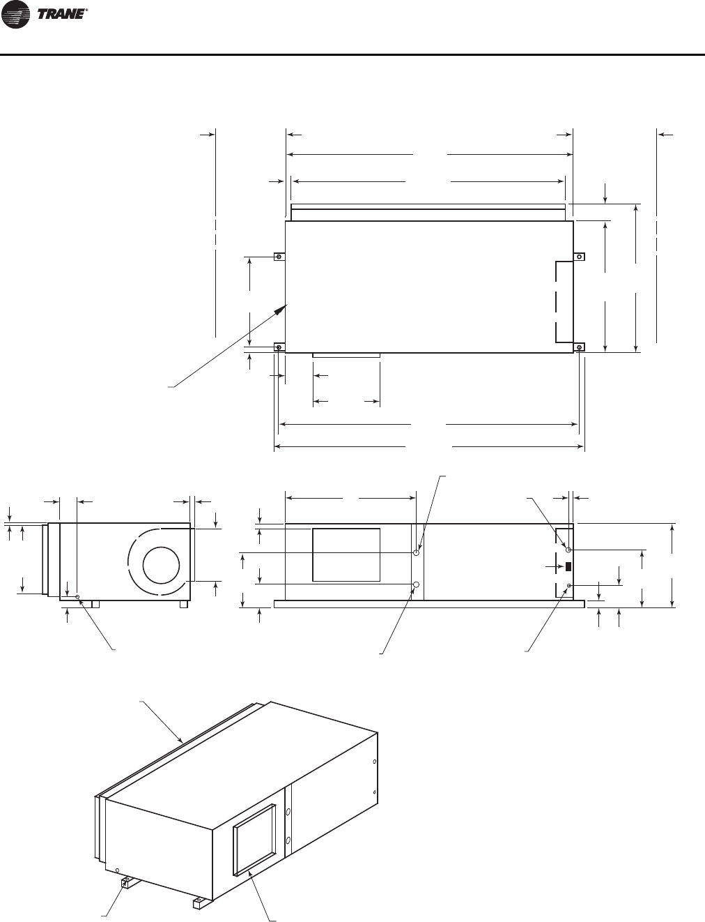
Unit Dimensions and Weights
30 WSHP-SVX01N-EN
Figure 20. GEH 12½-15 tons (150-180) 60 Hz; GEH 10-12½ tons (120-150) 50 Hz—right return/left supply
WCI mounting location
20"
(508)
SERVICE
CLEARANCE 79"
(2007)
74 1/2"
(1892)
1 3/4"
(44)
36"
(914)
SERVICE
CLEARANCE
4 5/8"
(117)
36"
(914)
40 5/8"
(1032)
7 5/8"
(194)
18 3/8"
(467)
81"
(2057)
2 1/8"
(54)
23 7/8"
(606)
BLOWER ACCESS
PANEL
3 1/8"
(79)
(79 )
4 7/8"
(124)
1"
(25.4)
5/8"
(16)
18 3/4"
(476)
14 1/2"
(368)
DRAIN CONNECTION
1/2" (22) SCHEDULE 40 PVC
1 1/4"
(32)
C
B
A
W.O. "D" NPTI
W.I. "D" NPTI
24 VOLT
1 1/8" (28.6) DIA.
HIGH VOLTAGE
7/8" (22.2) DIA.
23 1/4"
(591)
16 1/2"
(419)
2 1/4"
(57)
6 1/2"
(165)
1 1/2"
(38)
RETURN AIR
OPENING
1" (25.4) DIA.
MOUNTING HOLE
4X'S SUPPLY OPENING
1" (25.4) DUCT FLANGE
TOP VIEW
BACK SIDE LEFT SIDE
85"
(2159)
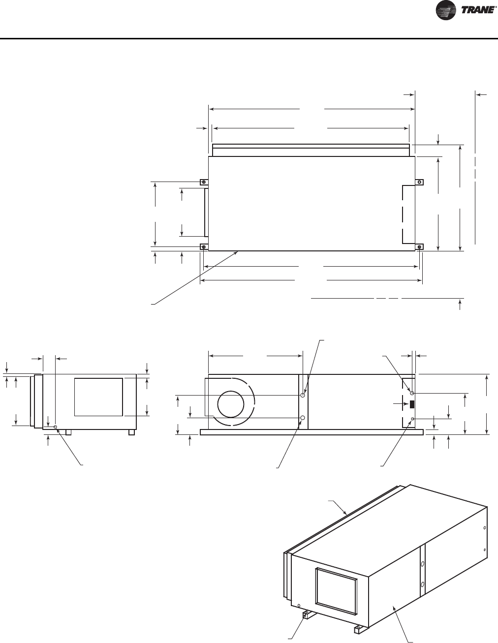
Unit Dimensions and Weights
WSHP-SVX01N-EN 31
Figure 21. GEH 12½-15 tons (150-180) 60 Hz; GEH 10-12½ tons (120-150) 50 Hz—right return/back supply
85"
(2159)
74 1/2"
(1892)
42"
(1067)
46 5/8"
(1184)
87"
(2210)
91"
(2311)
2 1/4"
(57)
29 3/4"
(756)
TOP VIEW
21 3/8"
(543)
7 1/8"
(181)
4 5/8"
(117)
36"
(914)
SERVICE
CLEARANCE
2"
(41)
20"
(508)
SERVICE
CLEARANCE
BLOWER ACCESS
PANEL
3 1/8"
(79)
4 7/8"
(124)
1 3/8"
(35)
23 3/4"
(603)
DRAIN CONNECTION
1/2" (22) SCHEDULE 40 PVC
2"
(51)
16 3/4"
(425)
5 5/8"
(143)
24 7/8"
(632)
61 1/4"
(1556)
W.O. 1 1/2" (38)
NPTI
W.I. 1 1/2" (38)
NPTI
24 VOLT
1 1/8" (28.6) DIA.
HIGH VOLTAGE
7/8" (22.2) DIA.
30 1/4"
(768)
22 3/4"
(578)
2 1/4"
(57)
9 1/8"
(232)
1 1/2"
(38)
LEFT SIDE
RETURN AIR
OPENING
1" (25.4) DIA.
MOUNTING HOLE
4X'S SUPPLY OPENING
1" (25.4) DUCT FLANGE
WCI mounting location
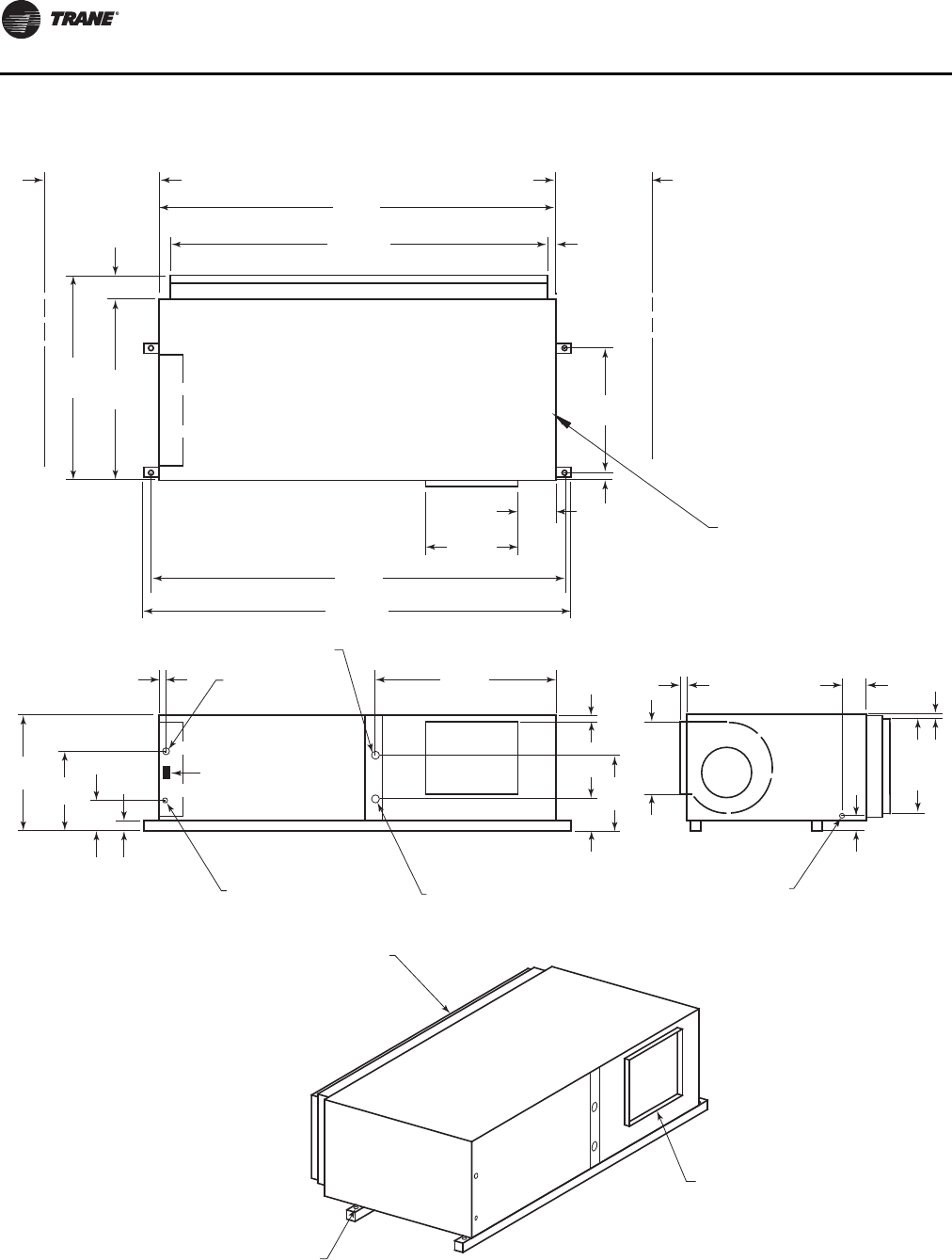
Unit Dimensions and Weights
32 WSHP-SVX01N-EN
Figure 22. GEH 12½-15 tons (150-180) 60 Hz; GEH 10-12½ tons (120-150) 50 Hz—left return/right supply
20"
(508)
SERVICE
CLEARANCE
85"
(2159)
74 1/2"
(1892) 2"
(51)
36"
(914)
SERVICE
CLEARANCE
4 5/8"
(117)
42"
(1067)
46 5/8"
(1184)
7 1/8"
(181)
21 3/8"
(543)
87"
(2210)
91"
(2311)
2 1/4"
(57)
29 3/4"
(756)
BLOWER ACCESS
PANEL
3 1/8"
(79)
4 7/8"
(124)
1"
(25.4)
1 3/8"
(35)
23 3/4"
(603)
16 3/4"
(425)
DRAIN CONNECTION
1/2" (22) SCHEDULE 40 PVC
2"
(51)
5 5/8"
(143)
24 7/8"
(632)
39 1/2"
(1003)
W.O. 1 1/2" (38)
NPTI
W.I. 1 1/2" (38)
NPTI
24 VOLT
1 1/8" (28.6) DIA.
HIGH VOLTAGE
7/8" (22.2) DIA.
30 1/4"
(768) 22 3/4"
(578)
2 1/4"
(57)
9 1/8"
(232)
2 1/8"
(54)
TOP VIEW
BACK SIDE
LEFT SIDE
RETURN AIR
OPENING
1" (25.4) DIA.
MOUNTING HOLE
4X'S
SUPPLY OPENING
1" (25.4) DUCT FLANGE
WCI mounting location
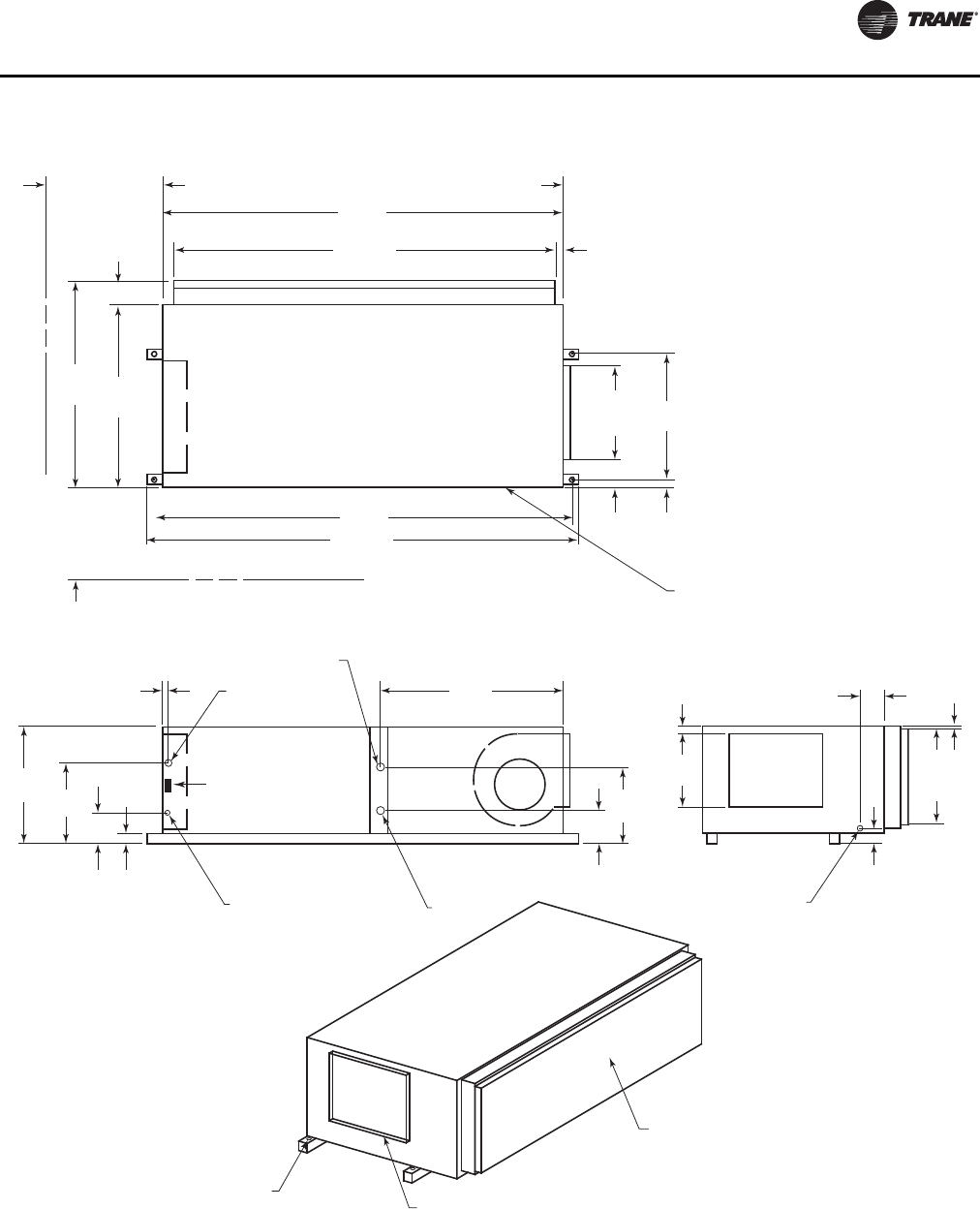
Unit Dimensions and Weights
WSHP-SVX01N-EN 33
Figure 23. GEH 12½-15 tons (150-180) 60 Hz; GEH 10-12½ tons (120-150) 50 Hz—left return/back supply
85"
(2159)
74 1/2"
(1892)
42"
(1067)
46 5/8"
(1184)
87"
(2210)
91"
(2311)
2 1/4"
(57)
29 3/4"
(756)
TOP VIEW
21 3/8"
(543)
7 1/8"
(181)
4 5/8"
(117)
36"
(914)
SERVICE
CLEARANCE
2"
(51)
20"
(508)
SERVICE
CLEARANCE
BLOWER ACCESS
PANEL
3 1/8"
(79)
4 7/8"
(124)
1 3/8"
(35)
23 3/4"
(603)
DRAIN CONNECTION
1/2" (22) SCHEDULE 40 PVC
2"
(51)
16 3/4"
(425)
5 5/8"
(143)
24 7/8"
(632)
39 1/2"
(1003)
W.O. 1 1/2" (38) NPTI
W.I. 1 1/2" (38)
NPTI
24 VOLT
1 1/8" (28.6) DIA.
HIGH VOLTAGE
7/8" (22.2) DIA.
30 1/4"
(768) 22 3/4"
(578)
2 1/4"
(57)
9 1/8"
(232)
2 1/8"
(54)
LEFT SIDE
RETURN AIR
OPENING
1" (25.4) DIA.
MOUNTING HOLE
4X'S SUPPLY OPENING
1" (25.4) DUCT FLANGE
WCI mounting location
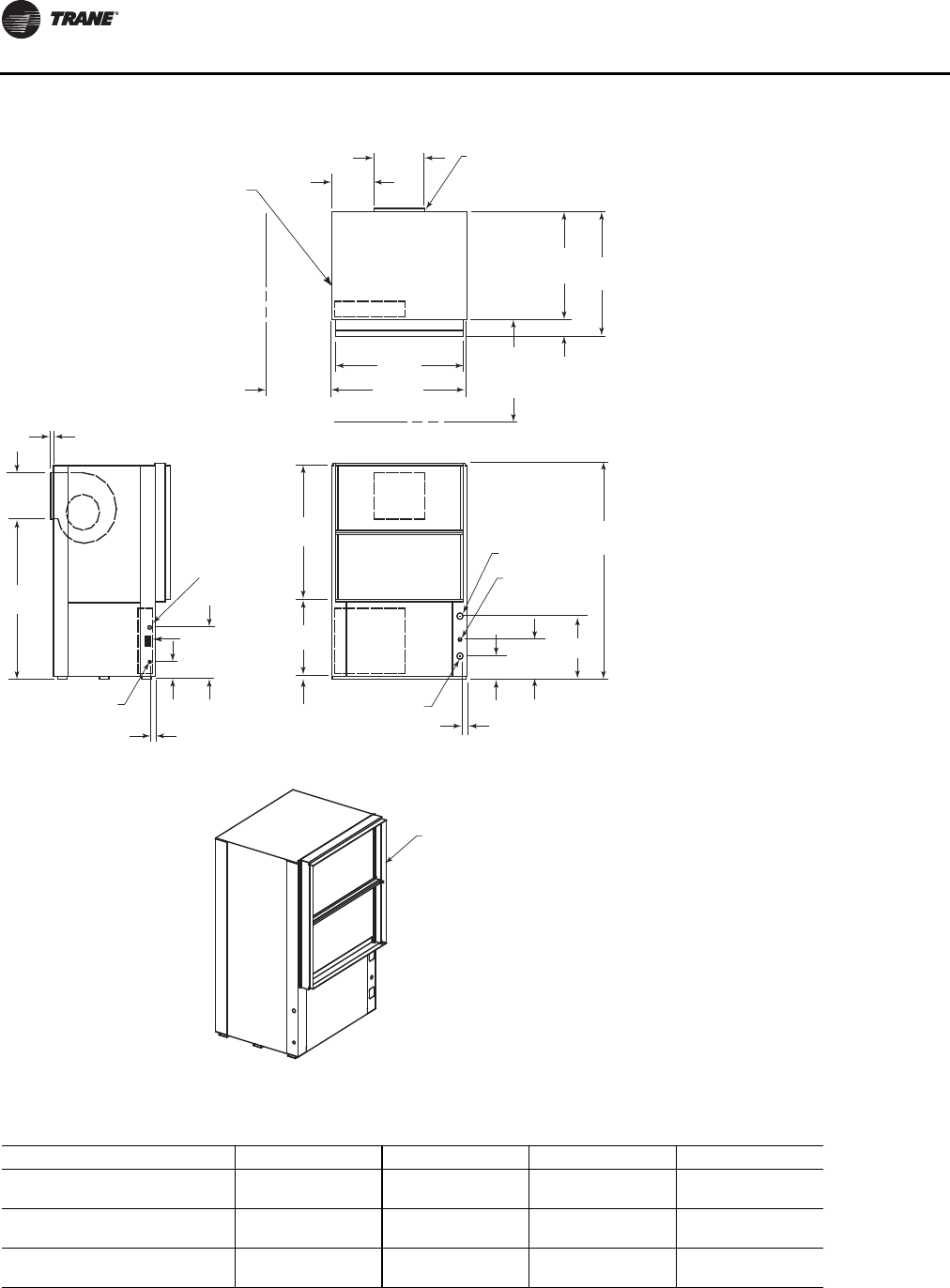
Unit Dimensions and Weights
34 WSHP-SVX01N-EN
Figure 24. GEV 6-10 tons (072-120) 60 Hz; 6 and 7½ tons (072 and 090) 50 Hz—front return/back supply(a)
(a)NEC requires that the GEV072-300 front return must be a non-ducted return.
39 5/8"
(1006)
ACCESS PANEL FOR
SHEAVES AND BELTS
13 18"
(333)
15 3/4
(400)
20"
(508)
SERVICE
CLEARANCE
42"
(1067)
4 7/8"
(124)
1
(25.4)
31 3/8"
(797) 36 1/4"
(921)
13 1/2"
(343)
46 1/2"
(1181)
36"
(914)
SERVICE
CLEARANCE
62 5/8"
(1591)
B
W.O. "C" NPTI
DRAIN 3/4" NPTI
A
11 1/2"
(292)
1 7/8"
(48)
W.I. "C" NPTI
HIGH VOLTAGE
7/8" (22.2) DIA.
1 5/8"
(41)
5"
(127)
15"
(381)
24 VOLT
1 1/8" (28.6)
22 3/8"
(568)
38 7/8"
(987)
3/4"
(19)
SUPPLY OPENING
1" (25.4) DUCT FLANGE
RETURN AIR
OPENING
WCI mounting location
Table 18. GEV 6–10 tons (072-120) 60 Hz; 6 and 7½ tons (072 and 090) 50 Hz—front return/back supply
Unit (60 Hz) Unit (50 Hz) A B C
6 ton — 6-5/8 in.
(168 mm) 18-3/8 in.
(467 mm) 1-1/4 in.
(32 mm)
7½ ton 6 ton 6-5/8 in.
(168 mm) 18-3/8 in.
(403 mm) 1-1/4 in.
(32 mm)
10 ton 7½ ton 6-1/2 in.
(165 mm) 18-1/2 in.
(470 mm) 1-1/2 in.
(38 mm)
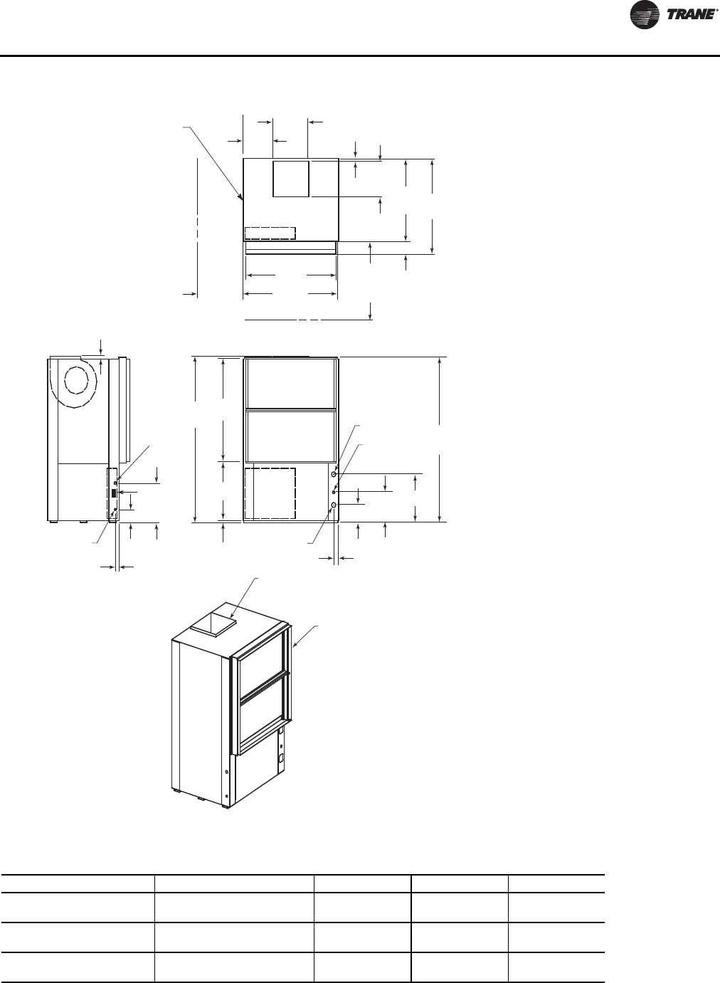
Unit Dimensions and Weights
WSHP-SVX01N-EN 35
Figure 25. GEV 6–10 tons (072–120) 60 Hz; 6 and 7½ ton (072 and 090) 50 Hz—front return/top supply(a)
(a)NEC requires that the GEV072-300 front return must be a non-ducted return.
39 5/8"
(1006)
ACCESS PANEL FOR
SHEAVES AND BELTS
13 1/4"
(337)
15 5/8
(397)
20"
(508)
SERVICE
CLEARANCE
42"
(1067)
4 7/8"
(124)
1 1/8"
(29)
31 3/8"
(797) 36 1/4"
(921)
13 3/8"
(343)
36"
(914)
SERVICE
CLEARANCE
63"
(1600)
62 5/8"
(1591)
B
W.O. "C" NPTI
DRAIN 3/4" NPTI
A
11 1/2"
(292)
1 7/8"
(48)
W.I. "C" NPTI
HIGH VOLTAGE
7/8" (22.2) DIA.
1 5/8"
(41)
5"
(127)
15"
(381)
24 VOLT
1 1/8" (28.6)
22 3/8"
(568)
38 7/8"
(987)
3/4"
(19)
1"
(25.4)
SUPPLY OPENING
1" (25.4) DUCT FLANGE
RETURN AIR
OPENING
WCI mounting location
Table 19. GEV 6–10 tons (072-120) 60 Hz; 6 and 7½ ton (072 and 090) 50 Hz—front return/top supply
Unit (60 Hz) Unit (50 Hz) A B C
6 ton — 6-5/8 in.
(168 mm) 18-3/8 in.
(467 mm) 1-1/4 in.
(32 mm)
7½ ton 6 ton 6-5/8 in.
(168 mm) 18-3/8 in.
(403 mm) 1-1/4 in.
(32 mm)
10 ton 7½ ton 6-1/2 in.
(165 mm) 18-1/2 in.
(470 mm) 1-1/2 in.
(38 mm)
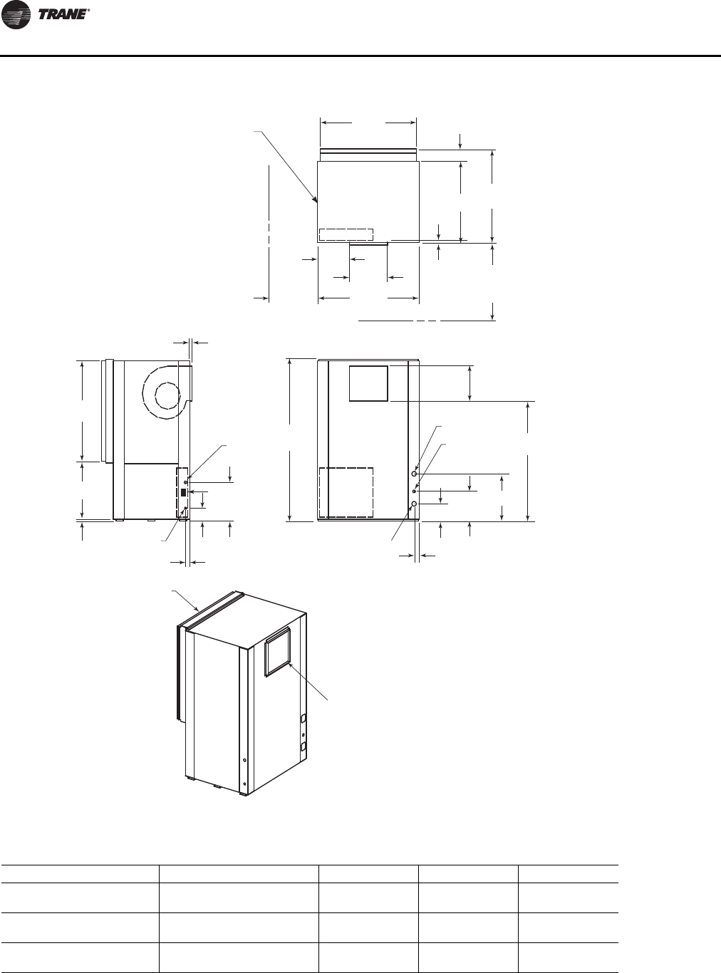
Unit Dimensions and Weights
36 WSHP-SVX01N-EN
Figure 26. GEV 6–10 tons (072-120) 60 Hz; 6 and 7½ ton (072 and 090) 50 Hz—back return/front supply(a)
(a)NEC requires that the GEV072-300 front return must be a non-ducted return.
1" (25.4)
20"
(508)
SERVICE
CLEARANCE
39 5/8"
(1006)
ACCESS PANEL FOR
SHEAVES AND BELTS
13 1/8"
(333)
15 3/4
(400)
42"
(1067)
4 7/8"
(124)
1 1/8"
(29)
36 1/4"
(921)
31 3/8"
(797)
36"
(914)
SERVICE
CLEARANCE
62 5/8"
(1591) 46 1/2"
(1181)
B
W.O. "C" NPTI
DRAIN 3/4" NPTI
A
11 1/2"
(292)
1 7/8"
(48)
W.I. "C" NPTI
HIGH VOLTAGE
7/8" (22.2) DIA.
1 5/8"
(41)
5"
(127)
15"
(381)
38 7/8"
(987)
22 3/8"
(568)
3/4"
(19)
SUPPLY OPENING
1" (25.4) DUCT FLANGE
RETURN AIR
OPENING
24 VOLT
1 1/8" (28.6)
13 1/2"
(343)
WCI mounting location
Table 20. GEV 6–10 tons (072-120) 60 Hz; 6 and 7½ ton (072 and 090) 50 Hz—back return/front supply
Unit (60 Hz) Unit (50 Hz) A B C
6 ton — 6-5/8 in.
(168 mm) 18-3/8 in.
(467 mm) 1-1/4 in.
(32 mm)
7½ ton 6 ton 6-5/8 in.
(168 mm) 18-3/8 in.
(403 mm) 1-1/4 in.
(32 mm)
10 ton 7½ ton 6-1/2 in.
(165 mm) 18-1/2 in.
(470 mm) 1-1/2 in.
(38 mm)
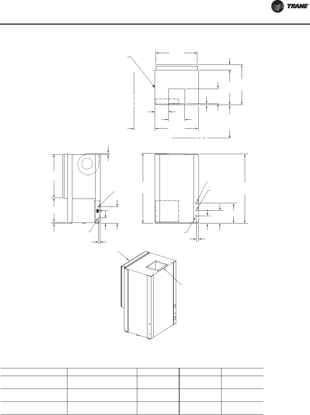
Unit Dimensions and Weights
WSHP-SVX01N-EN 37
Figure 27. GEV 6–10 tons (072-120) 60 Hz; 6 and 7½ ton (072 and 090) 50 Hz—back return/top supply(a)
(a)NEC requires that the GEV072-300 front return must be a non-ducted return.
20"
(508)
SERVICE
CLEARANCE
39 5/8"
(1006)
ACCESS PANEL FOR
SHEAVES AND BELTS
13 1/4"
(337)
15 5/8
(397)
42"
(1067)
4 7/8"
(124)
1 1/8"
(29)
31 3/8"
(797)
36 1/4"
(921)
13 1/2"
(343)
36"
(914)
SERVICE
CLEARANCE
63"
(1600) 62 5/8"
(1591)
B
W.O. "C" NPTI
DRAIN 3/4" NPTI
A
11 1/2"
(292)
1 7/8"
(48)
W.I. "C" NPTI
HIGH VOLTAGE
7/8" (22.2) DIA.
1 5/8"
(41)
5"
(127)
15"
(381)
24 VOLT
1 1/8" (28.6)
38 7/8"
(987)
22 3/8"
(568)
3/4"
(19)
1"
(25.4)
SUPPLY OPENING
1" (25.4) DUCT FLANGE
RETURN AIR
OPENING
WCI mounting location
Table 21. GEV 6–10 tons (072-120) 60 Hz; 6 and 7½ ton (072 and 090) 50 Hz—back return/top supply
Unit (60 Hz) Unit (50 Hz) A B C
6 ton — 6-5/8 in.
(168 mm) 18-3/8 in.
(467 mm) 1-1/4 in.
(32 mm)
7½ ton 6 ton 6-5/8 in.
(168 mm) 18-3/8 in.
(403 mm) 1-1/4 in.
(32 mm)
10 ton 7½ ton 6-1/2 in.
(165 mm) 18-1/2 in.
(470 mm) 1-1/2 in.
(38 mm)
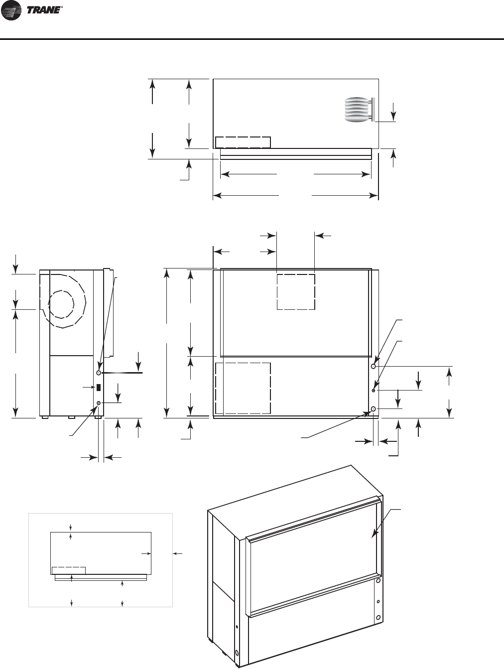
Unit Dimensions and Weights
38 WSHP-SVX01N-EN
Figure 28. GEV 12½–15 tons (150–180) 60 Hz; GEV 10 and 12½ ton (120 and 150) 50 Hz—front return/back supply(a)
(a)NEC requires that the GEV072-300 front return must be a non-ducted return.
RETURN AIR
OPENING
W.I. 1 1/2"
(38) NPTI 2 5/8"
(67)
4 1/4"
(108)
12 1/2"
(318)
23 1/2
(597)
DRAIN 3/4"
(19) NPTI
W.O. 1 1/2"
(38) NPTI
38 7/8"
(987)
27 1/8"
(537)
67 5/8"
(1718)
31 1/2"
(800)
18 5/8"
(473)
1"
(25.4)
HIGH VOLTAGE
7/8" (22) O.D.
20 1/2"
(521)
20 1
/
2"
(
521
)
6 7/8" (175)
2 3/8"
(60)
15 7/8"
(403)
49 1/8"
(1248)
24 VOLT
1 1/8" (29) O.D.
74 1/2"
(1892)
81 5/8"
(2073)
31 1/2"
(800)
36 1/4"
(921)
4 3/4"
(121)
CONTROL
BOX ACCESS
TOP VIEW
FRONT VIEW
SIDE VIEW
10"
(254)
SERVICE CLEARANCE
CONTROL BOX
UNIT FRONT
NEC REQ.
36" (914)
C.B.TO WALL
CLEARANCE
16" (406) TO
FILTER FRAME
FOR RETURN-AIR
MIN. SERVICE
CLEARANCE FOR
EITHER LEFT
OR RIGHT SIDE
IS 18" (457). FOR
FAN SHAFT REMOVAL,
A 22" (559) CLEARANCE
MUST BE PROVIDED
ON EITHER THE
LEFT OR RIGHT SIDE.
MIN. SERVICE ON BACK
FOR COMPRESSOR ACCESS IS 24”
WCI mounting
location
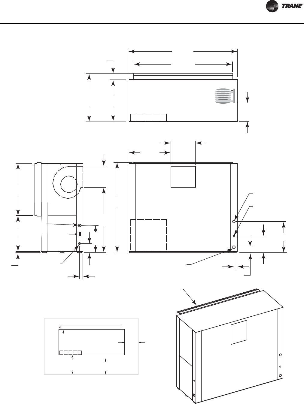
Unit Dimensions and Weights
WSHP-SVX01N-EN 39
Figure 29. GEV 12½–15 tons (150–180) 60 Hz; GEV 10 and 12½ ton (120 and 150) 50 Hz—back return/front supply(a)
(a)NEC requires that the GEV072-300 front return must be a non-ducted return.
RETURN AIR
OPENING
W.I. 1 1/2"
(38) NPTI 2 5/8"
(67)
4 1/4"
(108)
12 1/2"
(318)
10"
(254)
23 1/2
(597)
DRAIN 3/4"
(19) NPTI
W.O. 1 1/2"
(38) NPTI
38 7/8"
(987)
27 1/8"
(537)
67 5/8"
(1718)
31 1/2"
(800)
18 5/8"
(473)
1"
(25.4)
HIGH VOLTAGE
7/8" (22) O.D.
20 1/2"
(521)
2
0
2
1/2
"
(
521
)
6 7/8" (175)
2 3/8"
(60)
15 7/8"
(403)
49 1/8"
(1248)
74 1/2"
(1892)
81 5/8"
(2073)
31 1/2"
(800)
36 1/4"
(921)
4 3/4"
(121)
CONTROL
BOX ACCESS
TOP VIEW
FRONT VIEW
SIDE VIEW
SERVICE CLEARANCE
27 1/8"
(537)
24 VOLT
1 1/8"
(29) O.D.
CONTROL BOX
UNIT FRONT
NEC REQ.
36" (914)
C.B.TO WALL
CLEARANCE
16" (406) TO
FILTER FRAME
FOR RETURN-AIR
MIN. SERVICE
CLEARANCE FOR
EITHER LEFT
OR RIGHT SIDE
IS 18" (457). FOR
FAN SHAFT REMOVAL,
A 22" (559) CLEARANCE
MUST BE PROVIDED
ON EITHER THE
LEFT OR RIGHT SIDE.
MIN. SERVICE ON BACK
FOR COMPRESSOR ACCESS IS 24”
WCI mounting
location
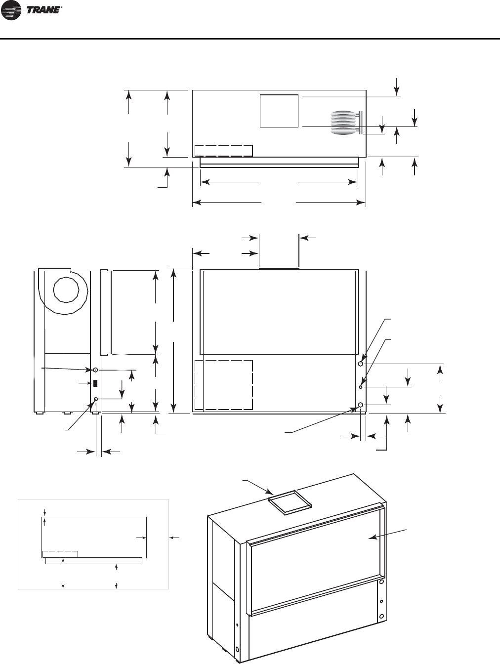
Unit Dimensions and Weights
40 WSHP-SVX01N-EN
Figure 30. GEV 12½–15 tons (150-180) 60 Hz; GEV 10 and 12½ ton (120 and 150) 50 Hz—front return/top supply(a)
(a)NEC requires that the GEV072-300 front return must be a non-ducted return.
RETURN AIR
OPENING
SUPPLY OPENING
WITH 1" (25.4) DUCT
FLANGE
W.I. 1 1/2"
(38) NPTI 2 5/8"
(67)
4 1/4"
(108)
12 1/2"
(318)
23 1/2
(597)
15 7/8"
(403)
14 3/8"
(365)
DRAIN 3/4"
(19) NPTI
W.O. 1 1/2"
(38) NPTI
38 7/8"
(987)
27 1/8"
(537)
68"
(1727)
31 1/2"
(800)
18 5/8"
(473)
1"
(25.4)
HIGH VOLTAGE
7/8" (22) O.D.
20 1/2"
(521)
2 3/8"
(60)
74 1/2"
(1892)
81 5/8"
(2073)
31 1/2"
(800)
36 1/4"
(921)
4 3/4"
(121)
(98
27 1
(53
20 1
/
2
"
(
521
)
6 7/8" (175)
10"
(254)
CONTROL
BOX ACCESS
TOP VIEW
FRONT VIEW
SIDE VIEW
24 VOLT
1 1/8"
(29) O.D.
SERVICE CLEARANCE
CONTROL BOX
UNIT FRONT
NEC REQ.
36" (914)
C.B.TO WALL
CLEARANCE
16" (406) TO
FILTER FRAME
FOR RETURN-AIR
MIN. SERVICE
CLEARANCE FOR
EITHER LEFT
OR RIGHT SIDE
IS 18" (457). FOR
FAN SHAFT REMOVAL,
A 22" (559) CLEARANCE
MUST BE PROVIDED
ON EITHER THE
LEFT OR RIGHT SIDE.
MIN. SERVICE ON BACK
FOR COMPRESSOR ACCESS IS 24”
WCI mounting
location
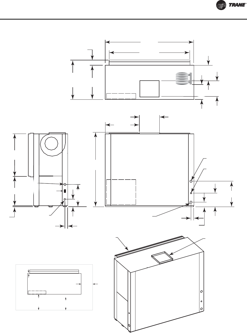
Unit Dimensions and Weights
WSHP-SVX01N-EN 41
Figure 31. GEV 12½–15 ton (150–180) 60 Hz; GEV 10 and 12½ ton (120 and 150) 50 Hz—back return/top supply(a)
(a)NEC requires that the GEV072-300 front return must be a non-ducted return.
RETURN AIR
OPENING SUPPLY OPENING
WITH 1" (25.4) DUCT
FLANGE
W.I. 1 1/2"
(38) NPTI 2 5/8"
(67)
4 1/4"
(108)
12 1/2"
(318)
23 1/2
(597)
15 7/8"
(403)
14 3/8"
(365)
DRAIN 3/4"
(19) NPTI
W.O. 1 1/2"
(38) NPTI
38 7/8"
(987)
27 1/8"
(537)
68"
(1727)
31 1/2"
(800)
18 5/8"
(473)
1"
(25.4)
HIGH VOLTAGE
7/8" (22) O.D.
20 1/2"
(521)
2
0
2
1/2
"
(521)
6 7/8" (175)
2 3/8"
(60)
74 1/2"
(1892)
81 5/8"
(2073)
31 1/2"
(800)
36 1/4"
(921)
4 3/4"
(121)
CONTROL
BOX ACCESS
TOP VIEW
FRONT VIEW
SIDE VIEW
7 1/8"
(537)
24 VOLT
1 1/8"
(29) O.D.
15 7
/8
(
40
3
10"
(254)
SERVICE CLEARANCE
CONTROL BOX
UNIT FRONT
NEC REQ.
36" (914)
C.B.TO WALL
CLEARANCE
16" (406) TO
FILTER FRAME
FOR RETURN-AIR
MIN. SERVICE
CLEARANCE FOR
EITHER LEFT
OR RIGHT SIDE
IS 18" (457). FOR
FAN SHAFT REMOVAL,
A 22" (559) CLEARANCE
MUST BE PROVIDED
ON EITHER THE
LEFT OR RIGHT SIDE.
MIN. SERVICE ON BACK
FOR COMPRESSOR ACCESS IS 24”
WCI mounting
location
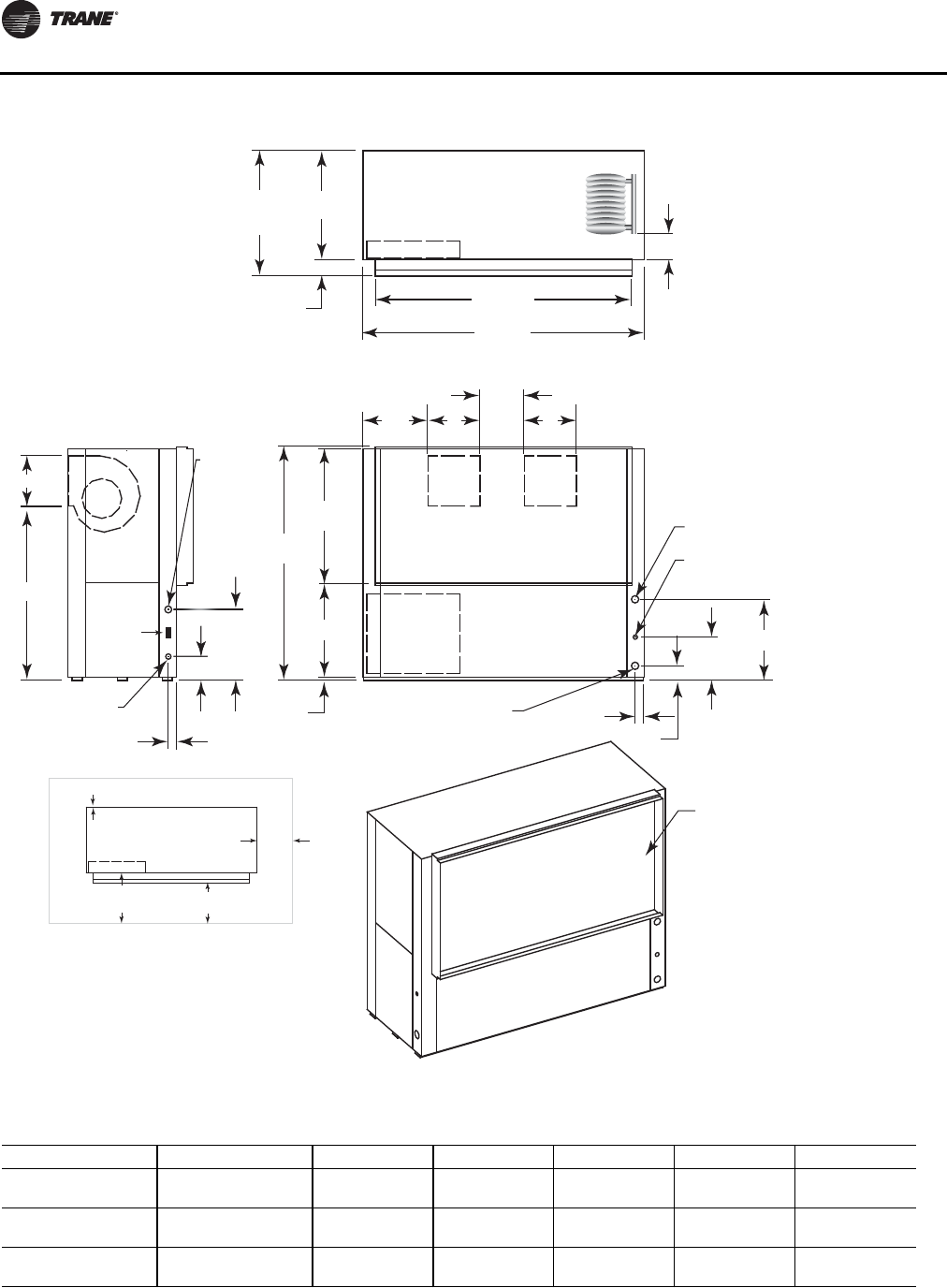
Unit Dimensions and Weights
42 WSHP-SVX01N-EN
Figure 32. GEV 20 and 25 ton (240 and 300) 60 Hz; GEV 15 and 20 ton (180 and 240) 50 Hz—front return/back supply(a)
(a)NEC requires that the GEV072-300 front return must be a non-ducted return.
RETURN AIR
OPENING
W.I. 2"
(51) NPTI 2 5/8"
(67)
4 1/4"
(108)
12 1/2"
(318)
E
DRAIN 3/4"
(19) NPTI
W.O. 2"
(51) NPTI
38 7/8"
(987)
27 1/8"
(537)
67 5/8"
(1718)
19 1/8"
(486)
AA
C
1"
(25.4)
HIGH VOLTAGE
7/8" (22) O.D.
20 1/2"
(521)
20 1
/
2
"
(521
)
6 7/8" (175)
2 3/8"
(60)
B
D
24 VOLT
1 1/8" (29) O.D.
74 1/2"
(1892)
81 5/8"
(2073)
31 1/2"
(800)
36 1/4"
(921)
4 3/4"
(121)
6 1/4"
(159)
CONTROL
BOX ACCESS
TOP VIEW
FRONT VIEW
SIDE VIEW
SERVICE CLEARANCE
CONTROL BOX
UNIT FRONT
NEC REQ.
36" (914)
C.B.TO WALL
CLEARANCE
16" (406) TO
FILTER FRAME
FOR RETURN-AIR
MIN. SERVICE
CLEARANCE FOR
EITHER LEFT
OR RIGHT SIDE
IS 18" (457). FOR
FAN SHAFT REMOVAL,
A 22" (559) CLEARANCE
MUST BE PROVIDED
ON EITHER THE
LEFT OR RIGHT SIDE.
MIN. SERVICE ON BACK
FOR COMPRESSOR ACCESS IS 24”
WCI mounting
location
Table 22. GEV 20 and 25 ton (240 and 300) 60 Hz; GEV 15 and 20 ton (180 and 240) 50 Hz—front return/back supply
Unit (60 Hz) Unit (50 Hz) A B C D E
20 ton 15 ton 15-5/8 in.
(397 mm) 13-1/2 in.
(341 mm) 12 in.
(305 mm) 51-5/8 in.
(1310 mm) 20-7/8 in.
(530 mm)
25 ton
Std Static 20 ton
Std Static 14-3/4 in.
(375 mm) 15-7/8 in.
(403 mm) 13-7/8 in.
(352 mm) 49-1/8 in.
(1248 mm) 23-1/2 in.
(597 mm)
25 ton
High Static 20 ton
High Static 15-5/8 in.
(397 mm) 13-1/2 in.
(343 mm) 12 in.
(305 mm) 51-5/8 in.
(1311 mm) 23-1/2 in.
(597 mm)
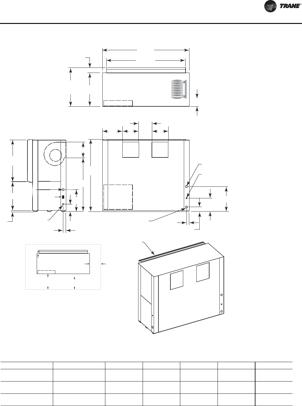
Unit Dimensions and Weights
WSHP-SVX01N-EN 43
Figure 33. GEV 20 and 25 ton (240 and 300) 60 Hz; GEV 15 and 20 ton (180 and 240) 50 Hz - back return/front supply(a)
(a)NEC requires that the GEV072-300 front return must be a non-ducted return.
W.I. 2"
(51) NPTI 2 5/8"
(67)
4 1/4"
(108)
12 1/2"
(318)
E
DRAIN 3/4"
(19) NPTI
W.O. 2"
(51) NPTI
38 7/8"
(987)
27 1/8"
(537)
67 5/8"
(1718)
19 1/8"
(486)
AA
C
1"
(25.4)
HIGH VOLTAGE
7/8" (22) O.D.
20 1/2"
(521)
6
(
20 1
/
2"
(521)
6 7/8" (175)
2 3/8"
(60)
B
D
74 1/2"
(1892)
81 5/8"
(2073)
31 1/2"
(800)
36 1/4"
(921)
4 3/4"
(121)
6 1/4"
(159)
CONTROL
BOX ACCESS
TOP VIEW
FRONT VIEW
SIDE VIEW
RETURN AIR
OPENING
1/8"
537)
24 VOLT
1 1/8"
(29) O.D.
SERVICE CLEARANCE
CONTROL BOX
UNIT FRONT
NEC REQ.
36" (914)
C.B.TO WALL
CLEARANCE
16" (406) TO
FILTER FRAME
FOR RETURN-AIR
MIN. SERVICE
CLEARANCE FOR
EITHER LEFT
OR RIGHT SIDE
IS 18" (457). FOR
FAN SHAFT REMOVAL,
A 22" (559) CLEARANCE
MUST BE PROVIDED
ON EITHER THE
LEFT OR RIGHT SIDE.
MIN. SERVICE ON BACK
FOR COMPRESSOR ACCESS IS 24”
WCI mounting
location
Table 23. GEV 20 and 25 ton (240 and 300) 60 Hz; GEV 15 and 20 ton (180 and 240) 50 Hz—back return/front supply
Unit (60 Hz) Unit (50 Hz) A B C D E
20 ton 15 ton 15-5/8 in.
(397 mm) 13-1/2 in.
(341 mm) 12 in.
(305 mm) 51-5/8 in.
(1310 mm) 20-7/8 in.
(530 mm)
25 ton
Std Static 20 ton
Std Static 14-3/4 in.
(375 mm) 15-7/8 in.
(403 mm) 13-7/8 in.
(352 mm) 49-1/8 in.
(1248 mm) 23-1/2 in.
(597 mm)
25 ton
High Static 20 ton
High Static 15-5/8 in.
(397 mm) 13-1/2 in.
(343 mm) 12 in.
(305 mm) 51-5/8 in.
(1311 mm) 23-1/2 in.
(597 mm)
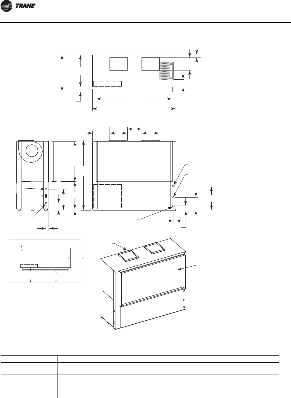
Unit Dimensions and Weights
44 WSHP-SVX01N-EN
Figure 34. GEV 20 and 25 ton (240 and 300) 60 Hz; GEV 15 and 20 ton (180 and 240) 50 Hz—front return/top supply(a)
(a)NEC requires that the GEV072-300 front return must be a non-ducted return.
RETURN AIR
OPENING
SUPPLY OPENINGS
WITH 1" (25.4) DUCT
FLANGE
W.I. 2"
(51) NPTI 2 5/8"
(67)
4 1/4"
(108)
12 1/2"
(318)
D
B
DRAIN 3/4"
(19) NPTI
W.O. 2"
(51) NPTI
38 7/8"
(987)
27 1/8"
(537)
68"
(1727)
A
C
A
1"
(25.4)
HIGH VOLTAGE
7/8" (22) O.D.
20 1/2"
(521)
2 3/8"
(60)
74 1/2"
(1892)
81 5/8"
(2073)
31 1/2"
(800)
36 1/4"
(921)
4 3/4"
(121)
(98
27 1
(53
20 1/2"
(
521
)
6 7/8" (175)
19 1/8"
(486)
1 1/4" (32)
6 1/4"
(159)
CONTROL
BOX ACCESS
TOP VIEW
FRONT VIEW
SIDE VIEW
24 VOLT
1 1/8"
(29) O.D.
SERVICE CLEARANCE
CONTROL BOX
UNIT FRONT
NEC REQ.
36" (914)
C.B.TO WALL
CLEARANCE
16" (406) TO
FILTER FRAME
FOR RETURN-AIR
MIN. SERVICE
CLEARANCE FOR
EITHER LEFT
OR RIGHT SIDE
IS 18" (457). FOR
FAN SHAFT REMOVAL,
A 22" (559) CLEARANCE
MUST BE PROVIDED
ON EITHER THE
LEFT OR RIGHT SIDE.
MIN. SERVICE ON BACK
FOR COMPRESSOR ACCESS IS 24”
WCI mounting
location
Table 24. GEV 20 and 25 ton (240 and 300) 60 Hz; GEV 15 and 20 ton (180 and 240) 50 Hz—front return/top supply
Unit (60 Hz) Unit (50 Hz) A B C D
20 ton 15 ton 15-5/8 in.
(397 mm) 13-1/2 in.
(341 mm) 12 in.
(305 mm) 20-7/8 in.
(530 mm)
25 ton
Std Static 20 ton
Std Static 14-3/4 in.
(375 mm) 15-7/8 in.
(403 mm) 13-7/8 in.
(352 mm) 23-1/2 in.
(597 mm)
25 ton
High Static 20 ton
High Static 15-5/8 in.
(397 mm) 13-1/2 in.
(343 mm) 12 in.
(305 mm) 23-1/2 in.
(597 mm)
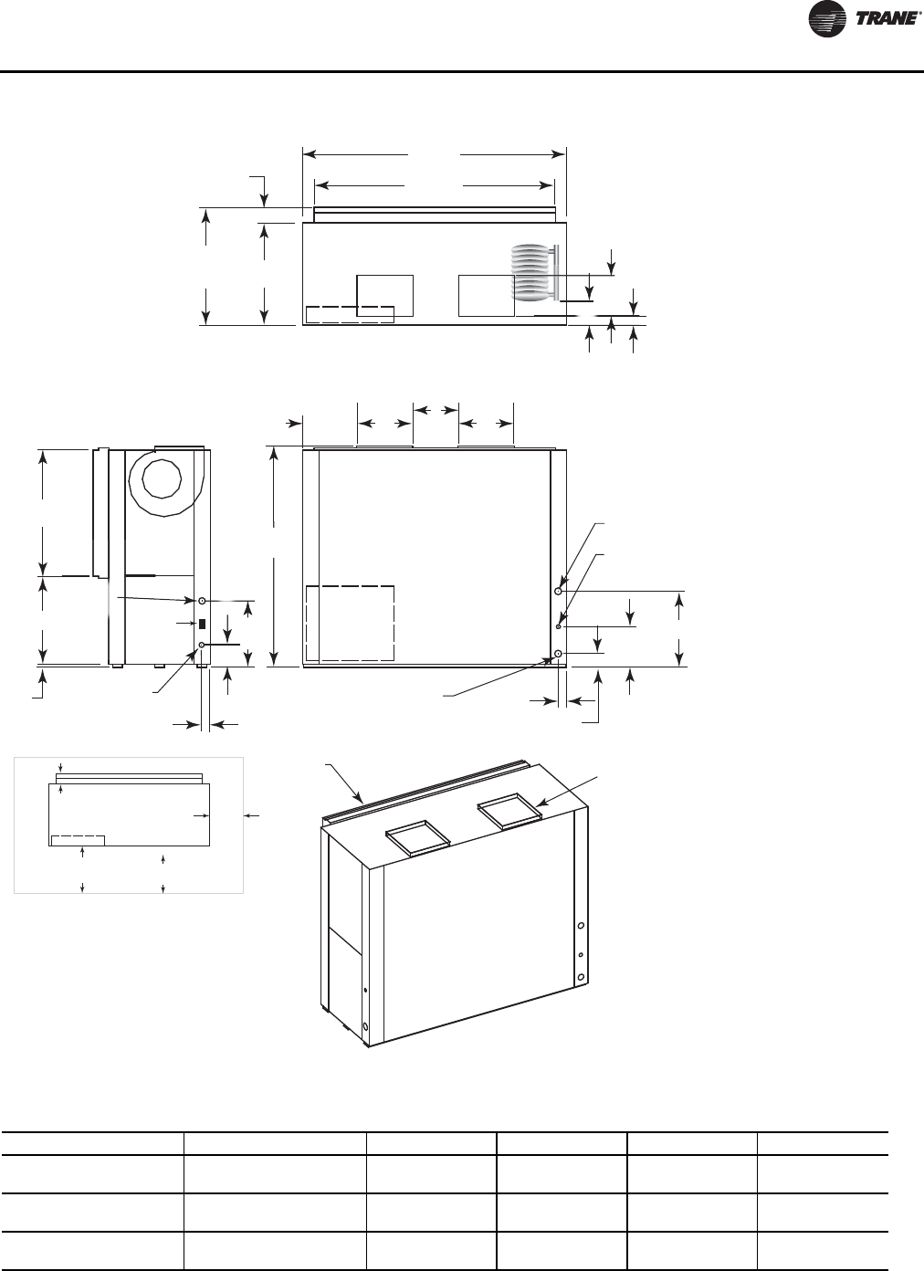
Unit Dimensions and Weights
WSHP-SVX01N-EN 45
Figure 35. GEV 20 and 25 ton (240 and 300) 60 Hz; GEV 15 and 20 ton (180 and 240) 50 Hz—back return/top supply(a)
(a)NEC requires GEV072-300 front return must be non-ducted return.
W.I. 2"
(51) NPTI 2 5/8"
(67)
4 1/4"
(108)
12 1/2"
(318)
D
B
DRAIN 3/4"
(19) NPTI
W.O. 2"
(51) NPTI
38 7/8"
(987)
27 1/8"
(537)
68"
(1727)
A
C
A
1"
(25.4)
HIGH VOLTAGE
7/8" (22) O.D.
20 1/2"
(521)
2 3/8"
(60)
74 1/2"
(1892)
81 5/8"
(2073)
31 1/2"
(800)
36 1/4"
(921)
4 3/4"
(121)
6
8
"
(17
2
2
0 1
/
2
"
(
521
)
6 7/8" (175)
19 1/8"
(486)
1 1/4" (32)
RETURN AIR
OPENING SUPPLY OPENING
WITH 1" (25.4) DUCT
FLANGE
B
1 1/
4
6 1/4"
(159)
SERVICE CLEARANCE
CONTROL BOX
UNIT FRONT
NEC REQ.
36" (914)
C.B.TO WALL
CLEARANCE
16" (406) TO
FILTER FRAME
FOR RETURN-AIR
MIN. SERVICE
CLEARANCE FOR
EITHER LEFT
OR RIGHT SIDE
IS 18" (457). FOR
FAN SHAFT REMOVAL,
A 22" (559) CLEARANCE
MUST BE PROVIDED
ON EITHER THE
LEFT OR RIGHT SIDE.
CONTROL
BOX ACCESS
TOP VIEW
FRONT VIEW
SIDE VIEW
24 VOLT
1 1/8"
(29) O.D.
MIN. SERVICE ON BACK
FOR COMPRESSOR ACCESS IS 24”
WCI mounting
location
Table 25. GEV 20 and 25 ton (240 and 300) 60 Hz; GEV 15 and 20 ton (180 and 240) 50 Hz—back return/top supply
Unit (60 Hz) Unit (50 Hz) A B C D
20 ton 15 ton 15-5/8 in.
(397 mm) 13-1/2 in.
(341 mm) 12 in.
(305 mm) 20-7/8 in.
(530 mm)
25 ton
Std Static 20 ton
Std Static 14-3/4 in.
(375 mm) 15-7/8 in.
(403 mm) 13-7/8 in.
(352 mm) 23-1/2 in.
(597 mm)
25 ton
High Static 20 ton
High Static 15-5/8 in.
(397 mm) 13-1/2 in.
(343 mm) 12 in.
(305 mm) 23-1/2 in.
(597 mm)
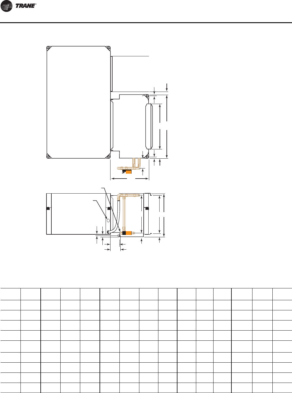
Unit Dimensions and Weights
46 WSHP-SVX01N-EN
Figure 36. GEH and EXH waterside economizer(a)
(a)Waterside economizer installation requires field piping.
H
M
5"
(127)
J
20"
(508)
N
G 1 1/2" (38)
L
K
C
D
F
2 1/2" (64)
E
TOP VIEW
FRONT VIEW
A = TO FIELD
SUPPLY PIPING
B = TO FIELD
RETURN PIPING
5/8"(16) 5/8" (16)
Table 26. GEH and EXH waterside economizer
GEH
(60 Hz) GEH
(50 Hz) A NPTI B NPTI C D E F G H J K L M N
006-015 006-012 1/2
(12.7) 1/2
(12.7) 16-1/8
(410) 13-5/8
(346) 1-1/2
(38) 10-3/4
(273) 23
(584) 2-1/4
(57) 7-1/2
(191) 1/2
(12.7) 1
(25.4) 4
(102) 18-1/2
(470)
018-030 015-024 3/4
(19) 3/4
(19) 18-1/2
(470) 15-5/8
(397) 1-1/2
(38) 13-3/4
(349) 26
(660) 3-1/4
(83) 6-7/8
(175) 1/2
(12.7) 1
(25.4) 4
(102) 18-1/2
(470)
036-042 030-036 3/4
(19) 3/4
(19) 21
(533) 17-5/8
(448) 2-1/4
(57) 16-1/2
(419) 30
(762) 3-3/4
(95) 6-1/4
(159) 1-1/4
(32) 2
(50.8) 4-1/2
(114) 23-1/2
(597)
048-060 042-060 1
(25.4) 1
(25.4) 23-1/8
(587) 19-5/8
(498) 2-1/2
(64) 19-1/2
(495) 34
(864) 5-1/4
(133) 5-7/8
(149) 1-1/4
(32) 2
(50.8) 4-1/2
(114) 23-1/2
(597)
EXH
(60 Hz) GEH
(50 Hz) A NPTI B NPTI C D E F G H J K L M N
006-015 ---- 1/2
(12.7) 1/2
(12.7) 16-1/8
(410) 13-5/8
(346) 1-1/2
(38) 10-3/4
(273) 23
(584) 2-1/4
(57) 7-1/2
(191) 1/2
(12.7) 1
(25.4) 4
(102) 18-1/2
(470)
018-024 ---- 3/4
(19) 3/4
(19) 18-1/2
(470) 15-5/8
(397) 1-1/2
(38) 13-3/4
(349) 26
(660) 3-1/4
(83) 6-7/8
(175) 1/2
(12.7) 1
(25.4) 4
(102) 18-1/2
(470)
030-036 ---- 3/4
(19) 3/4
(19) 21
(533) 17-5/8
(448) 2-1/4
(57) 16-1/2
(419) 30
(762) 3-3/4
(95) 6-1/4
(159) 1-1/4
(32) 2
(50.8) 4-1/2
(114) 23-1/2
(597)
042-070 ---- 1
(25.4) 1
(25.4) 23-1/8
(587) 19-5/8
(498) 2-1/2
(64) 19-1/2
(495) 34
(864) 5-1/4
(133) 5-7/8
(149) 1-1/4
(32) 2
(50.8) 4-1/2
(114) 23-1/2
(597)
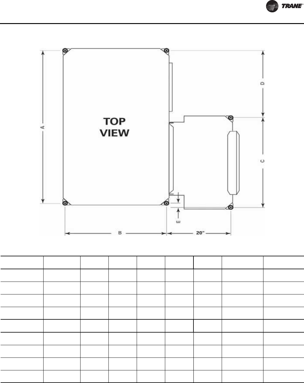
Unit Dimensions and Weights
WSHP-SVX01N-EN 47
Figure 37. GEH and EXH hanging unit waterside economizer
Table 27. GEH and EXH hanging unit waterside economizer
GEH Unit
(60 Hz) GEH Unit
(50 Hz) A B C D E Hanging
Weight Shipping
Weight
006-015 006-012 38-3/4 18-3/4 21-3/4 17 0 54 lbs 84 lbs
(984) (476) (552) (432) (0) (25 kg) (38 kg)
018-030 015-024 44-3/4 21-3/4 24-3/4 21 1 65 lbs 95 lbs
(1137) (552) (629) (553) (25) (30 kg) (43 kg)
036-042 030-036 48-3/4 23-3/4 28-3/4 21 2 76 lbs 106 lbs
(1238) (603) (730) (533) (51) (35 kg) (48 kg)
048-060 042-048 56-3/4 31-3/4 32-3/4 25 1 97 lbs 127 lbs
(1441) (806) (832) (635) (25) (44 kg) (58 kg)
EXH Unit
(60 Hz) EXH Unit
(50 Hz) A B C D E Hanging
Weight Shipping
Weight
006-015 — 38-3/4 18-3/4 21-3/4 17 0 54 lbs 84 lbs
(984) (476) (552) (432) (0) (25 kg) (38 kg)
018-024 — 44-3/4 21-3/4 24-3/4 21 1 65 lbs 95 lbs
(1137) (552) (629) (553) (25) (30 kg) (43 kg)
030-036 — 48-3/4 23-3/4 28-3/4 21 2 76 lbs 106 lbs
(1238) (603) (730) (533) (51) (35 kg) (48 kg)
042-070 — 56-3/4 31-3/4 32-3/4 25 1 97 lbs 127 lbs
(1441) (806) (832) (635) (25) (44 kg) (58 kg)
Note: All dimensions are in inches followed by millimeters in parenthesis.
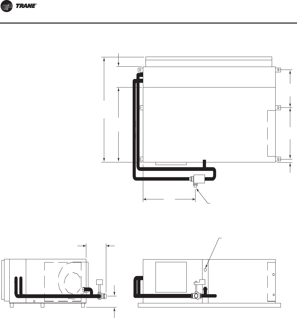
Unit Dimensions and Weights
48 WSHP-SVX01N-EN
Figure 38. GEH 6-10 tons (072-120) 60 Hz, right return; GEH 6-7½ tons (072-090) 50 Hz, right return, waterside
economizer(a)(b)
(a)Entering water is on the AB port.
(b)Field piping required on waterside economizer.
C
9 7/8"
(251)
36"
(914)
50 5/8"
(1286)
"B" OD COPPER TO
FIELD SUPPLY PIPING
18 1/2"
(470)
23 7/8"
(606)
2 1/8"
(54)
D
E
"A" NPTI FOR
FIELD RETURN PIPING
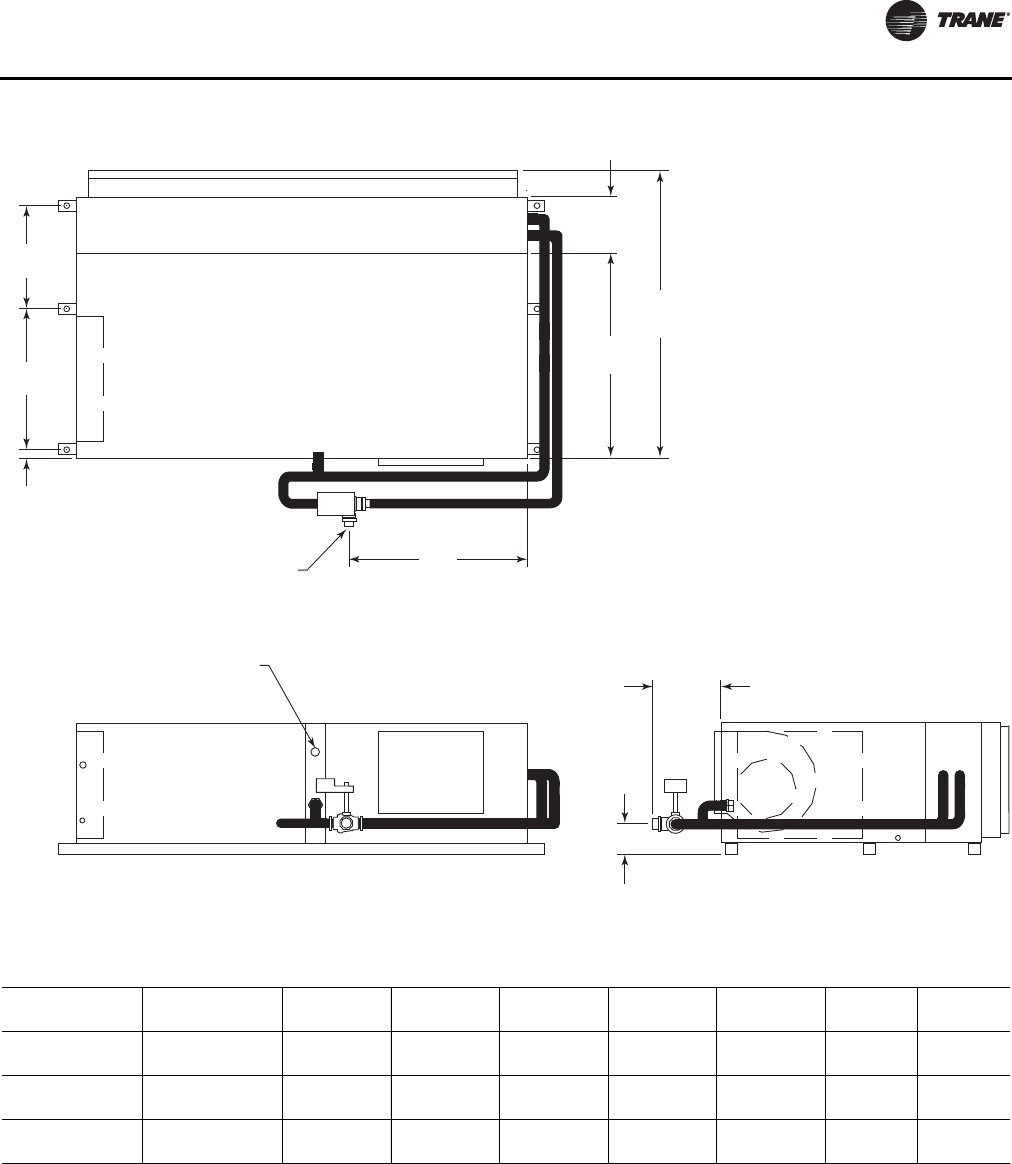
Unit Dimensions and Weights
WSHP-SVX01N-EN 49
Figure 39. GEH 6-10 tons (072-120) 60 Hz, left return; GEH 6-7½ tons (072-090) 50 Hz, left return, waterside economizer(a)(b)
(a)Entering water is on the AB port.
(b)Field piping required on waterside economizer.
C
9 7/8"
(251)
36"
(914)
50 5/8"
(1286)
"B" OD COPPER TO
FIELD SUPPLY PIPING
18 1/2"
(470)
24 3/4"
(629)
1 1/4"
(32)
D
E
"A" NPTI FOR
FIELD RETURN PIPING
Table 28. GEH 6-10 tons (072-120) 60 Hz, left return; GEH 6-7½ tons (072-090) 50 Hz, left return, waterside economizer
GEH (60 Hz) GEH (50 Hz) A B C D E Hanging
Weight Shipping
Weight
072 — 1-1/4 1-3/8 31 9-7/8 3-7/8 138 lbs 168 lbs
(32) (35) (787) (251) (98) (63 kg) (76 kg)
090 072 1-1/4 1-3/8 31 9-7/8 3-7/8 144 lbs 174 lbs
(32) (35) (787) (251) (98) (65 kg) (79 kg)
120 090 1-1/2 1-5/8 30-3/4 12-1/2 4-1/2 166 lbs 196 lbs
(38) (41) (781) (318) (114) (75 kg) (89 kg)
Note: All dimensions are in inches followed by millimeters in parenthesis.
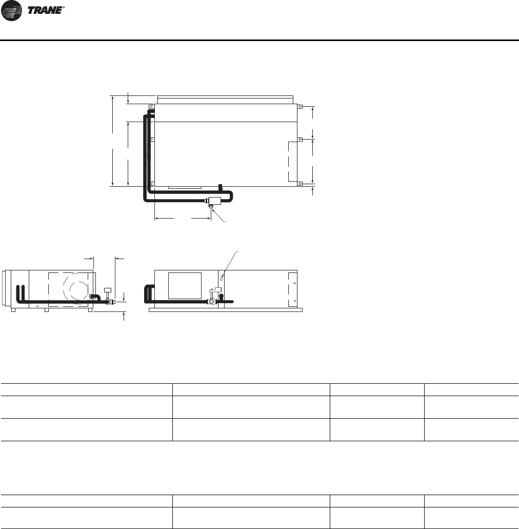
Unit Dimensions and Weights
50 WSHP-SVX01N-EN
Figure 40. GEH 12½-15 tons (150-180) 60 Hz, right return; GEH 10-12½ tons (120-150) 50 Hz, right return, waterside
economizer(a)(b)
(a)Entering water is on the AB port.
(b)Field piping required on waterside economizer.
48 3/4"
(1238)
9 7/8"
(251)
42"
(1067)
56 1/2"
(1435)
1 5/8" (42) OD COPPER TO
FIELD SUPPLY PIPING
18 1/2"
(470)
29 3/4"
(756)
2 1/4"
(57)
12"
(305)
5 3/8"
(137)
1 1/2" (38) NPTI FOR
FIELD RETURN PIPING
Table 29. GEH 12½-15 tons (150-180) 60 Hz, right return; GEH 10-12½ tons (120-150) 50 Hz, right return, waterside
economizer
GEH (60 Hz) GEH (50 Hz) Hanging Weight Shipping Weight
150 120 138 lbs 168 lbs
(63 kg) (76 kg)
180 150 144 lbs 174 lbs
(65 kg) (79 kg)
Note: All dimensions are in inches followed by millimeters in parenthesis.
Table 30. GEH 12½-15 tons (150-180) 60 Hz, right return; GEH 10-12½ tons (120-150) 50 Hz, left return, waterside
economizer
GEH (60 Hz) GEH (50 Hz) Hanging Weight Shipping Weight
150 - 180 120-150 213 lbs 243 lbs
(97 kg) (110 kg)
Note: All dimensions are in inches followed by millimeters in parenthesis.
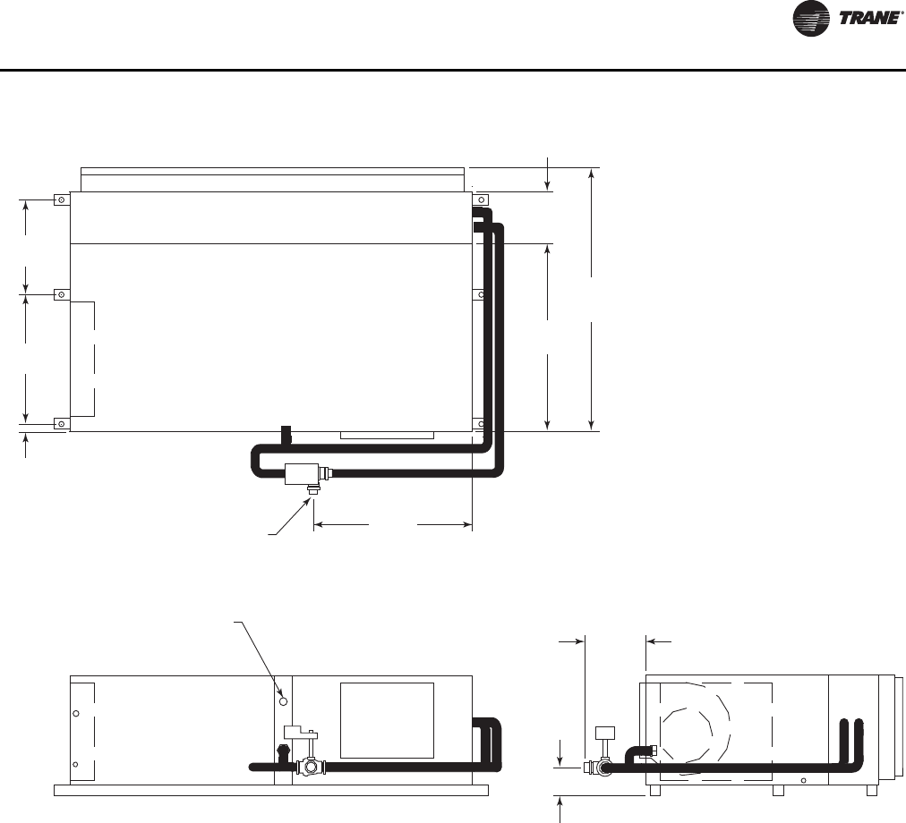
Unit Dimensions and Weights
WSHP-SVX01N-EN 51
Figure 41. GEH 12½-15 tons (150-180) 60 Hz, left return; GEH 10-12½ tons (120-150) 50 Hz, left return, waterside
economizer(a)(b)
(a)Entering water is on the AB port.
(b)Field piping required on waterside economizer.
27 1/8"
(689)
9 7/8"
(251)
42"
(1067)
56 1/2"
(1435)
1 5/8" (42) OD COPPER TO
FIELD SUPPLY PIPING
18 1/2"
(470)
29 3/4"
(756)
2 1/4"
(57)
12"
(305)
5 3/8"
(137)
1 1/2" (38) NPTI FOR
FIELD RETURN PIPING
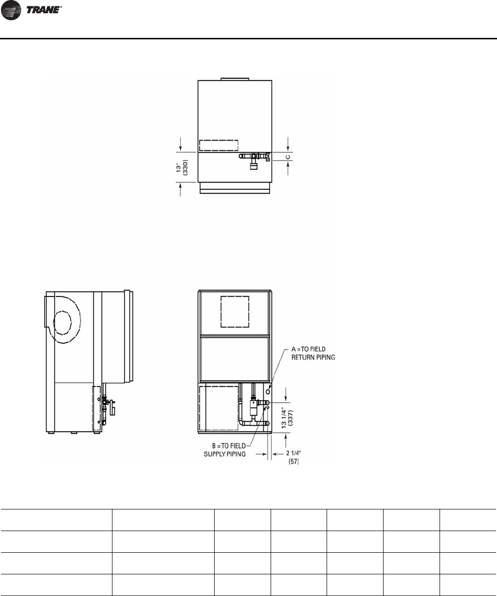
Unit Dimensions and Weights
52 WSHP-SVX01N-EN
Figure 42. GEV 6-10 tons (072-120) 60 Hz; 6 and 7½ ton (072 and 090) 50 Hz, waterside economizer(a)
(a)Entering water is on the AB port.
Table 31. GEV 6-10 tons (072-120) 60 Hz; 6 and 7½ ton (072 and 090) 50 Hz, waterside economizer
Unit (60 Hz) Unit (50 Hz) A B C Hanging
Weight Shipping
Weight
072 — 1-1/4 1-3/8 4 148 lbs 178 lbs
(32) (35) (102) (67 kg) (81 kg)
090 072 1-1/4 1-1/4 4 168 lbs 198 lbs
(32) (32) (102) (76 kg) (90 kg)
120 090 1-1/2 1-5/8 4-3/8 207 lbs 237 lbs
(38) (41) (111) (94 kg) (108 kg)
Note: All dimensions are in inches followed by millimeters in parenthesis.
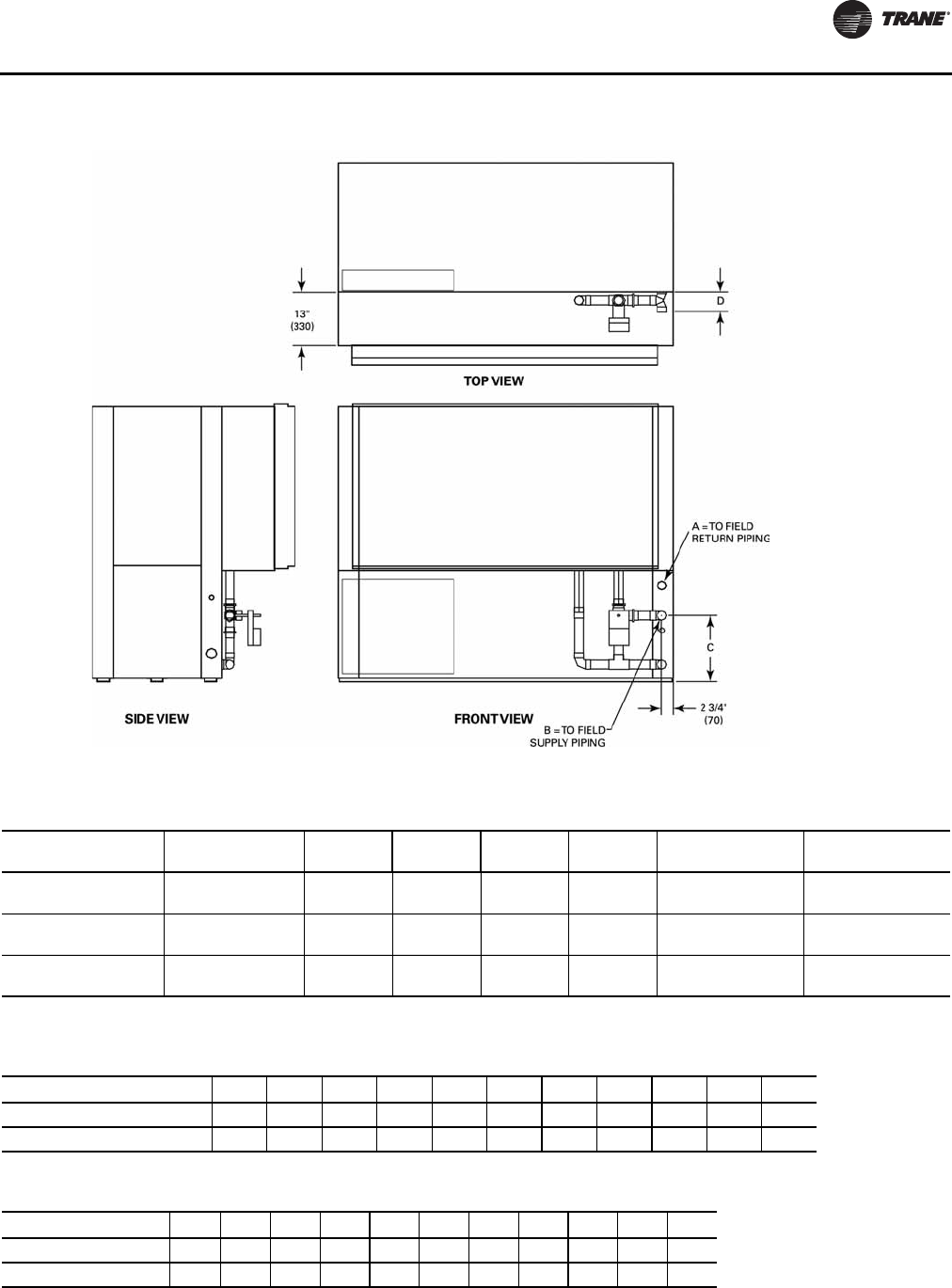
Unit Dimensions and Weights
WSHP-SVX01N-EN 53
Figure 43. GEV 12½-25 tons (150-300), waterside economizer(a)
(a)Entering water is on the AB port.
Table 32. GEV 12½-25 tons (150-300), waterside economizer
GEV (60 Hz) GEV (50 Hz) A
NPTI B
I.D. C D Hanging Weight Shipping Weight
150-180 120-150 1-1/2 1-5/8 15-7/8 4-3/8 275 lbs 305 lbs
(38) (41) (403) (111) (125 kg) (138 kg)
240 180 2 2-1/8 16-1/4 4-7/8 310 lbs 340 lbs
(51) (54) (413) (124) (141 kg) (154 kg)
300 240 2 2-1/8 16-1/4 4-7/8 395 lbs 425 lbs
(51) (54) (413) (124) (179 kg) (193 kg)
Note: All dimensions are in inches followed by millimeters in parenthesis.
Table 33. Unit weights GEH ½-5 ton (60 Hz)
GEH 006 009 012 015 018 024 030 036 042 048 060
Net Weight (lbs.) 165 165 173 173 248 253 253 288 288 398 398
Ship Weight (lbs.) 195 195 203 203 268 285 285 318 318 428 428
Table 34. Unit weights GEV ½-5 ton (60 Hz)
Model GEV 006 009 012 015 018 024 030 036 042 048 060
Net Weight (lbs.) 165 165 173 173 248 253 253 288 288 348 349
Ship Weight (lbs.) 195 195 203 203 268 285 285 308 308 396 396
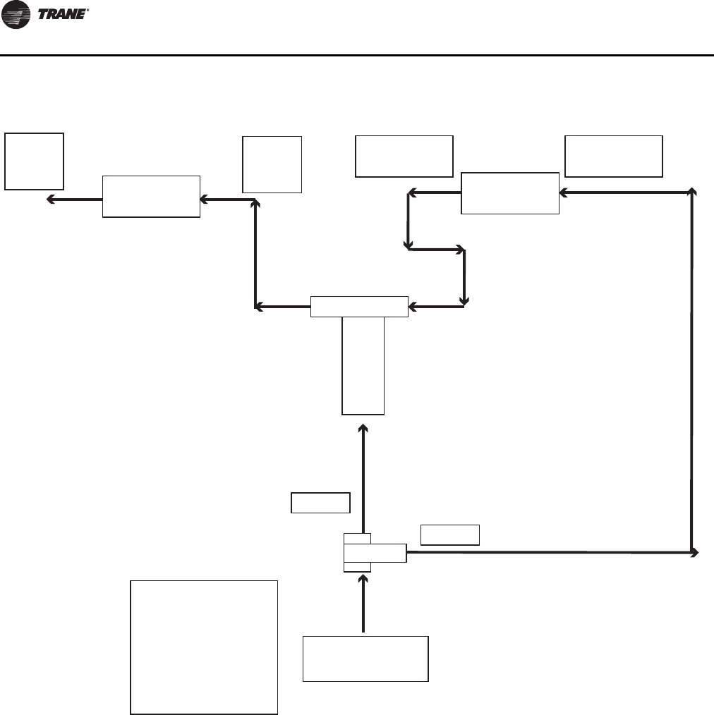
Unit Dimensions and Weights
54 WSHP-SVX01N-EN
Figure 44. Waterside economizer coil piping diagram
Note: (applicable only to 6 to 25 ton models)
Unit
Water
Outlet Unit Heat
Exchanger
Unit
Water
Inlet
TEE
WSE Coil
Outlet WSE
Coil
WSE Coil
Inlet
Port A
3 Way Valve
Port AB
Port B
Entering Water
Please match the
entering water
port marking with
the marking label
on the valve prior
to using this
diagram.
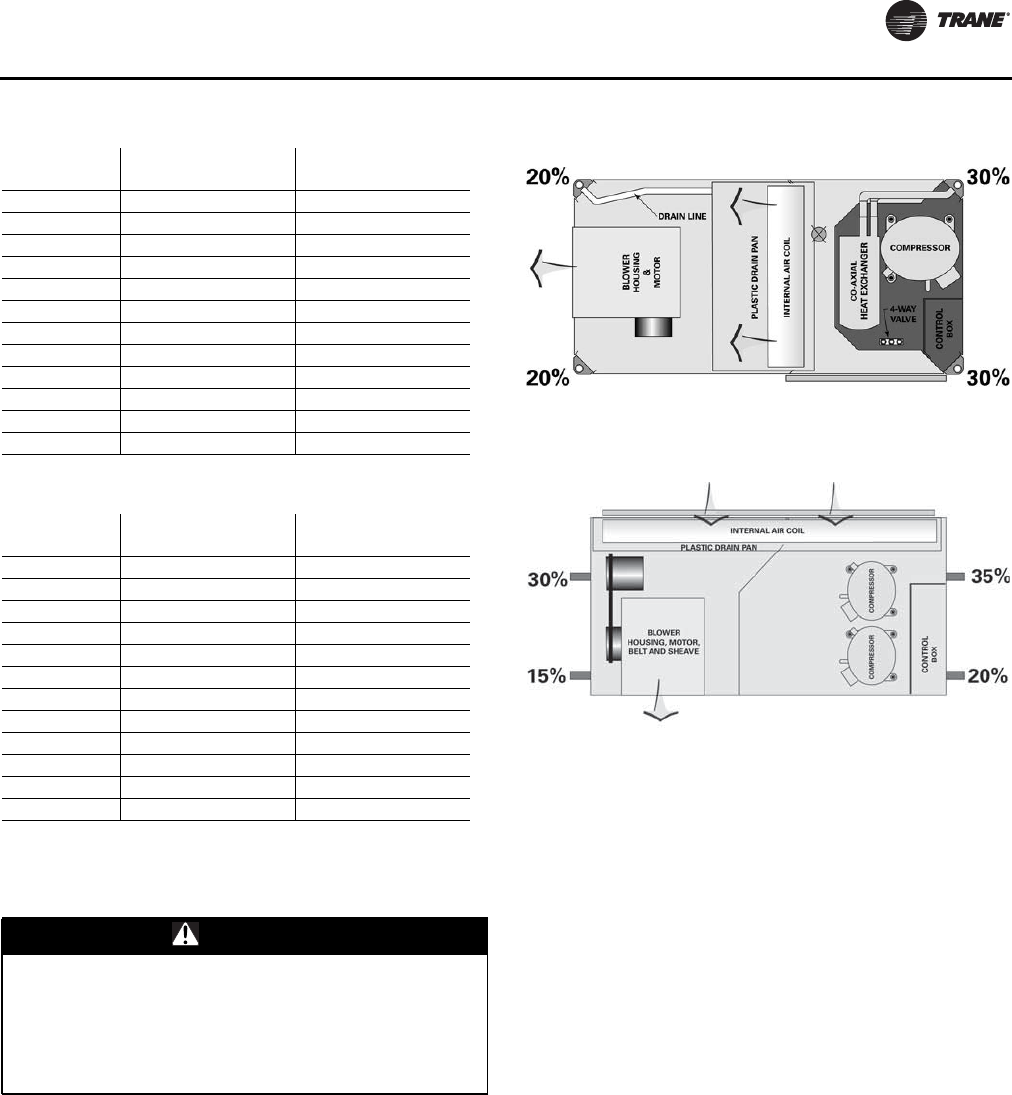
Unit Dimensions and Weights
WSHP-SVX01N-EN 55
Weight Distribution for Hanging the GEH
and EXH Model
Approximate weight distribution for proper hanging of the
GEH and EXH unit is indicated by weight distribution ½-6
ton GEH/EXH Figure 45, p. 55.
Tolerance on the weights determined are ±15%.
Total weights for each unit size are listed in Table 33,
p. 53,Table 34, p. 53 and Table 35, p. 55.
Table 35. Unit weights EXV ½-6 ton
EXV (60 Hz) Shipping Weight
with pallet (lbs) Unit Weight without
pallet (lbs)
006 195 165
009 195 165
012 203 173
015 203 173
018 284 264
024 301 269
030 319 299
036 333 313
042 402 381
048 422 374
060 442 394
070 482 434
Table 36. Unit weights EXH ½-6 ton
EXH (60 Hz) Shipping Weight
with pallet (lbs) Unit Weight without
pallet (lbs)
006 195 165
009 195 165
012 203 173
015 203 173
018 284 264
024 301 269
030 329 299
036 343 313
042 461 431
048 454 424
060 474 444
070 514 484
WARNING
Improper Unit Lift!
Test lift unit approximately 24 inches to verify proper
center of gravity lift point. To avoid dropping of unit,
reposition lifting point if unit is not level. Failure to
properly lift unit could result in death or serious injury
or possible equipment or property-only damage.
Figure 45. Weight distribution ½-6 ton GEH/EXH
Figure 46. Weight distribution GEH 6-15 ton
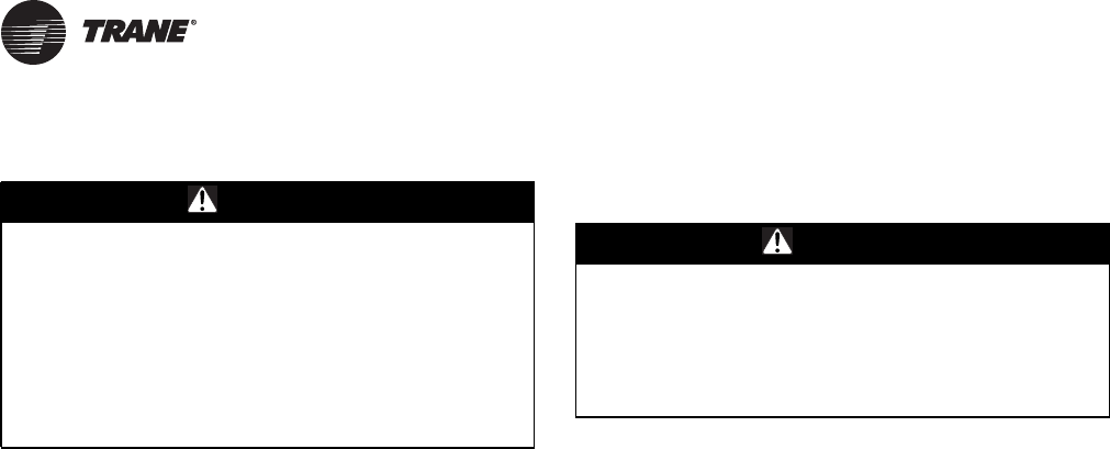
56 WSHP-SVX01N-EN
Installation
General Installation Checks
The checklist below is a summary of the steps required to
successfully install a commercial unit.This checklist is
intended to acquaint the installing personnel with what is
required in the installation process. It does not replace the
detailed instructions that are in the applicable sections of
this manual.
1. Remove packaging and inspect the unit. Check the unit
for shipping damage and material shortage; file a
freight claim and notify appropriate sales
representation.
The GEH/V ½-5 ton and EXH/V ½-6 ton units have been
anchored to the skid by (2) shipping bolts.The removal of
these bolts will require a 3/8 (9.7 mm) ratchet with a ½ (12.7
mm) socket.
The GEV 6–25 ton units have been anchored to the skid
with (4) angle brackets. Remove these brackets before
lifting unit into place.
The GEH 6–15 ton units are anchored to the cross brace of
the skid with (4) wood screws. Remove these screws prior
to lifting the unit into place.
2. Verify the correct model, options and voltage from the
unit nameplate.
3. Pull out all field attached parts (i.e. filter rack, duct
collar, filter and mounting screws) from the unit
packaging for field mounting.
4. Verify the installation location of the unit will provide
the required clearance for proper operation.
5. Remove refrigeration access panel and inspect the
unit. Be certain the refrigerant tubing has clearance
from adjacent parts.
6. Fabricate and install duct work
7. Install and connect a condensate drain line and trap to
the drain connection.
Main Electrical
1. Verify the power supply complies with the unit
nameplate specifications.
2. Inspect all control panel components; tighten any
loose connections.
3. Connect properly sized and protected power supply
wiring to a field-supplied/installed disconnect switch
and to the main compressor contactor/power block
1K1 (compressor contactor on the ½-5 ton) for GEH/V
½-5 ton and EXH/V ½-6 ton units or 1TB1 for GEH/V 6-
25 ton equipment in the unit control panel.
4. Install proper grounding wires to an earth ground. EXH
and EXV 460 V units require a neutral (a four wire
system).
Note: All field-installed wiring must comply with NEC
and applicable local codes.
Electric Heat Requirements
5. Verify that the power supply complies with the electric
heater specifications on the unit and heater nameplate.
6. Inspect the heater junction box and control panel;
tighten any loose connections.
7. Check electric heat circuits for continuity.
Low Voltage Wiring Requirements
8. Install the zone sensor or thermostat.
9. Connect properly sized control wiring to the proper
termination points between the zone sensor or
thermostat and the unit control panel.
Filter Installation
Each unit ships with 1"(25.4 mm) or 2"(50.8 mm)
throwaway filters. 2" MERV 8 or 2" MERV 13 filters are also
available options.The quantity of filters is determined by
unit size.The GEH 1/2-5 ton and EXH units require field
installation of the 1" or 2" ducted filters rack. All sheet
metal bracket, filter and hardware are in a box located on
the side of the unit within the unit packaging. All ½-25 ton
verticals and GEH 6–15 ton horizontal units ship with the
filter rack and filters factory installed.
Note: Do not operate the unit without filters.
WARNING
Proper Field Wiring and Grounding
Required!
All field wiring MUST be performed by qualified
personnel. Improperly installed and grounded field
wiring poses FIRE and ELECTROCUTION hazards.To
avoid these hazards, you MUST follow requirements for
field wiring installation and grounding as described in
NEC and your local/state electrical codes. Failure to
follow codes could result in death or serious injury.
WARNING
Hazardous Voltage!
Disconnect all electric power, including remote
disconnects before servicing. Follow proper lockout/
tagout procedures to ensure the power can not be
inadvertently energized. Failure to disconnect power
before servicing could result in death or serious injury.
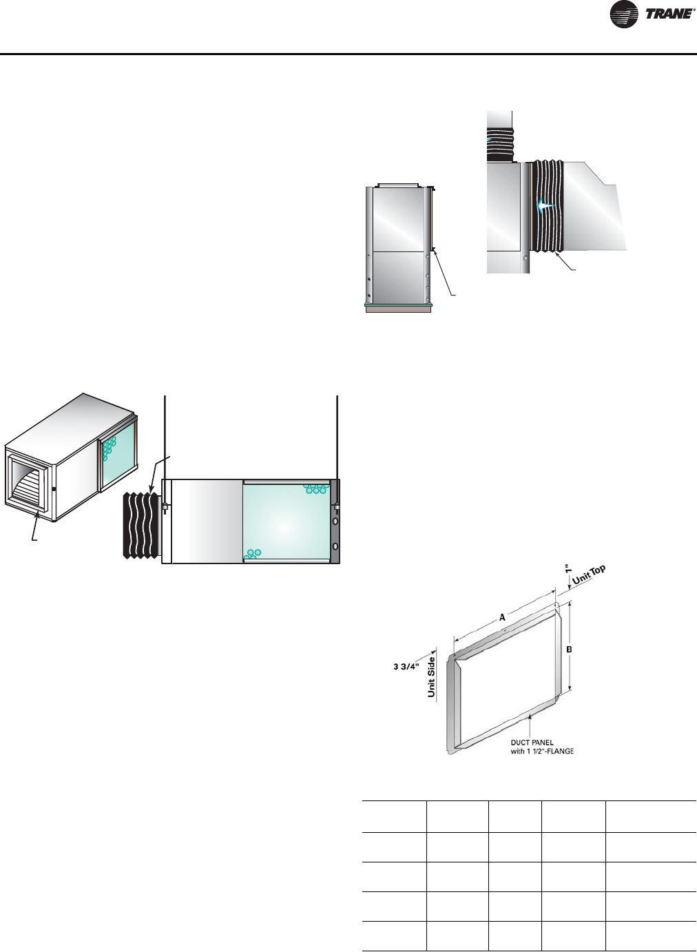
Installation
WSHP-SVX01N-EN 57
Supply-Air Ductwork
Horizontal ½-5 ton and EXHF units require duct flanges to
be field installed.The duct flange ships in a box on the side
of the unit. Install the flange with (8) 3/8 in. (213 mm)
factory supplied screws.
Install the 1 in. (25.4 mm) supply-air duct flange to the
vertical and horizontal equipment with the
(8) 5/16 in. (7.94 mm) factory-supplied screws.The duct
collar assembly for each unit is shipped with the unit in the
same box where the IOM manual is located.
When attaching the field ductwork to the unit, provide a
watertight flexible connector at the unit to prevent
operating sounds from transmitting through the
ductwork. See Figure 47, p. 57.
Elbows with turning vanes or splitters are recommended
to minimize air noise due to turbulence and to reduce static
pressure.
Return-Air Ductwork
Install the 1”-2” (25.4 mm/50.8 mm) adjustable filter rack to
the horizontal equipment only with the use of (4) 5/16 in.
(7.94 mm) factory supplied screws.The vertical equipment
factory ships with the filter rack and filter(s) installed.
When attaching the field ductwork to the unit, provide a
water-tight flexible connector at the unit to prevent
operating sounds from transmitting through the
ductwork.
Elbows with turning vanes or splitters are recommended
to minimize air noise due to turbulence and to reduce static
pressure.
Ducted Panel
The return-air arrangement may be easily converted from
a free return-air system, to a ducted return-air system with
the addition of a return-air side panel. By replacing the
filter racks with the return-air panel, a complete seal from
the duct to the unit is possible.The 1½ duct flange
facilitates ease of field connection to the duct system.This
accessory is typically used when the return-air filter is
placed in a built-in ceiling grille, or placed within a field
provided filter rack assembly.
Figure 47. Flexible supply-air connector (field provided)
1-INCH DUCT COLLAR
(FACTORY PROVIDED)
SUPPLY-AIR
BOOT (FIELD
SUPPLIED)
Figure 48. Flexible return-air connector (field provided)
Figure 49. Return-air duct panel
Table 37. Opening size and part number GEH
Unit Size
(60 Hz) Unit Size
(50 Hz) A B Duct Collar
Part Number
006-015 006-012 17½ in.
(445 mm) 13 in.
(330 mm) 4474 1133 0100
018-030 015-024 20½ in.
(521 mm) 16 in.
(406 mm) 4474 5628 0100
036-042 030-036 22½ in.
(572 mm) 17 in. (432
mm) 4474 1135 0100
048-060 042-060 26½ in.
(673 mm) 19 in. (483
mm) 4474 1136 0100
SUPPLY-AIR
RETURN
AIR
DUCT COLLAR
(FACTORY PROVIDED)
RETURN-AIR BOOT
(FIELD PROVIDED)
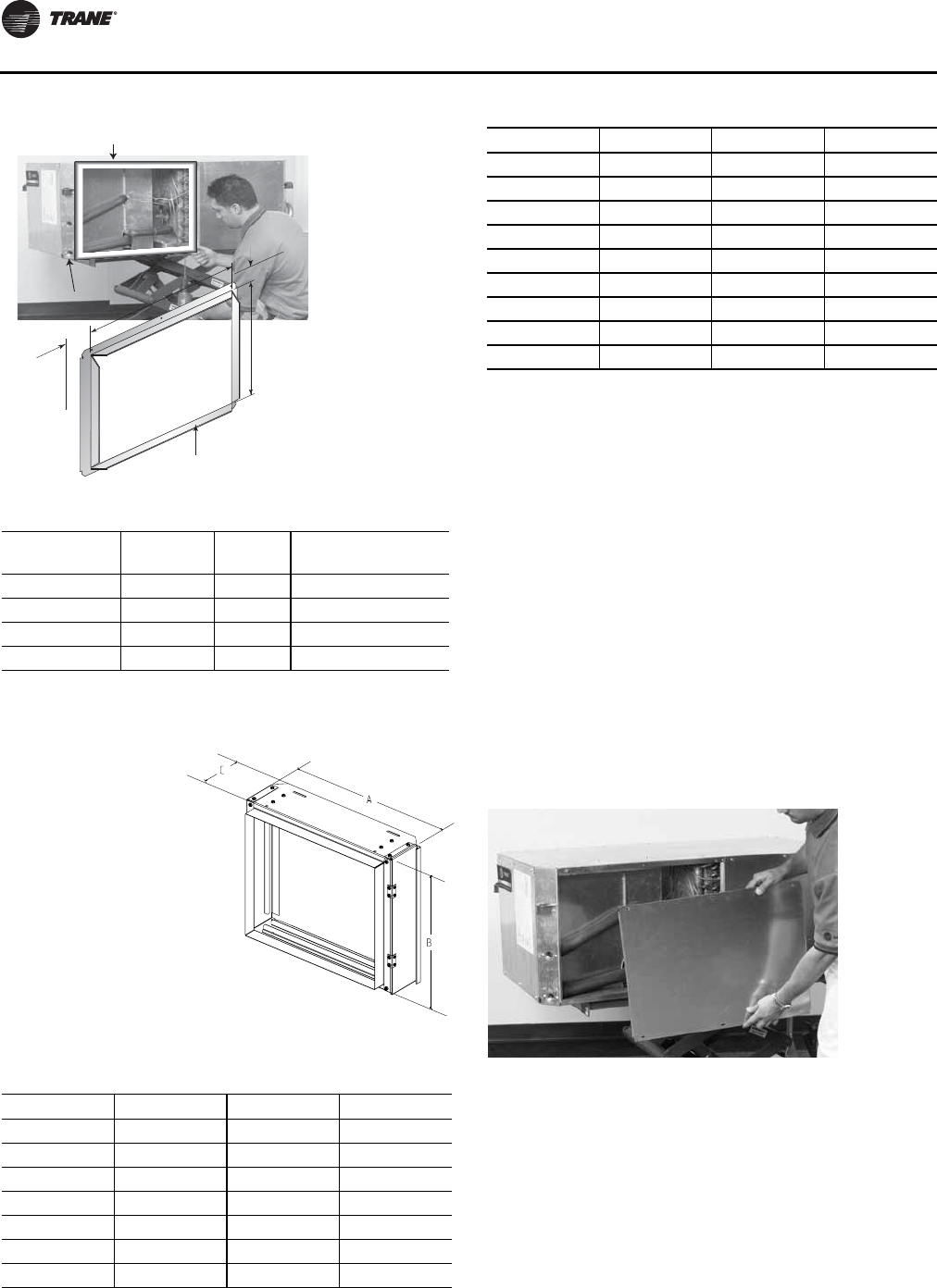
Installation
58 WSHP-SVX01N-EN
Ducted Filter Rack
Dual Filtration (GEH ½-5 ton and EXH ½-6
ton)
Note: The dual-filtration design is typically used in a free-
return application.
The horizontal, GEH and EXH model, allows the installer
flexibility in design applications such as a dual filtration
option.With the dual filtration design, the unit will contain
a lower static which translates into a decrease in filter
maintenance. For installation of a dual filtration accessory
for the GEH and EXH model, verify that an extra set of
return-air filter racks and filter have been ordered from the
factory.This accessory will be shipped separate from the
unit, and should be located in a separate box than the unit.
1. Remove the return-air side panel from the GEH and
EXH unit.This panel is held in place by screws.
2. Install the top/bottom filter rack at the new opening.
The adjustable filter rack is held in place with four
screws that once held the panel.
Figure 50. Install return-air duct panel
Install the return-
air duct panel to
the return-air
opening with the
six screws
provided for the
filter rack
assembly.
Table 38. Opening size and part number EXH
EXH (60 hz) A (in.) B (in.) Duct Collar Part
Number
006-015 17-1/2 13 447411330100
018-024 20-1/2 16 447456280100
030-036 22-1/2 17 447411350100
042-070 26-1/2 19 447411360100
When it is necessary
to have filter access at
the unit in a ducted
return, a ducted filter
rack is available.This
option allows access
to the filter at the unit.
Vertical unit filter
racks are available in
right or left access
configurations.
Horizontal units are
available in top,
bottom or side access
configurations.
Table 39. Ducted filter opening size
Unit Size A (in.) B (in.) C (in.)
GEH 006-015 21.1 15.4 5.4
GEH 018-030 24.5 18.4 5.6
GEH 036-042 26.4 19.4 5.5
GEH 048-060 30.7 21.4 5.5
GEV 006-015 20.7 17.1 5.5
GEV 018-030 20.7 23.1 5.5
GEV 036-042 25.7 22.4 4.3
DUCT PANEL
with 1 1/2"-FLANGE
A
Unit Side
Unit Side
Unit Top
Unit Top
B
1"
3 3/4
"
GEV 048-060 30.7 26.6 5.5
EXH 006-015 21.1 15.4 5.4
EXH 018-030 24.5 18.4 5.6
EXH 036-042 26.4 19.4 5.5
EXH 048-070 30.7 21.4 5.5
EXV 006-015 20.7 17.1 5.5
EXV 018-030 20.7 23.1 5.5
EXV 036-042 25.7 22.4 4.3
EXV 048-070 30.7 26.6 5.5
Note: All dimensions in inches
Figure 51. Side panel
Table 39. Ducted filter opening size
Unit Size A (in.) B (in.) C (in.)
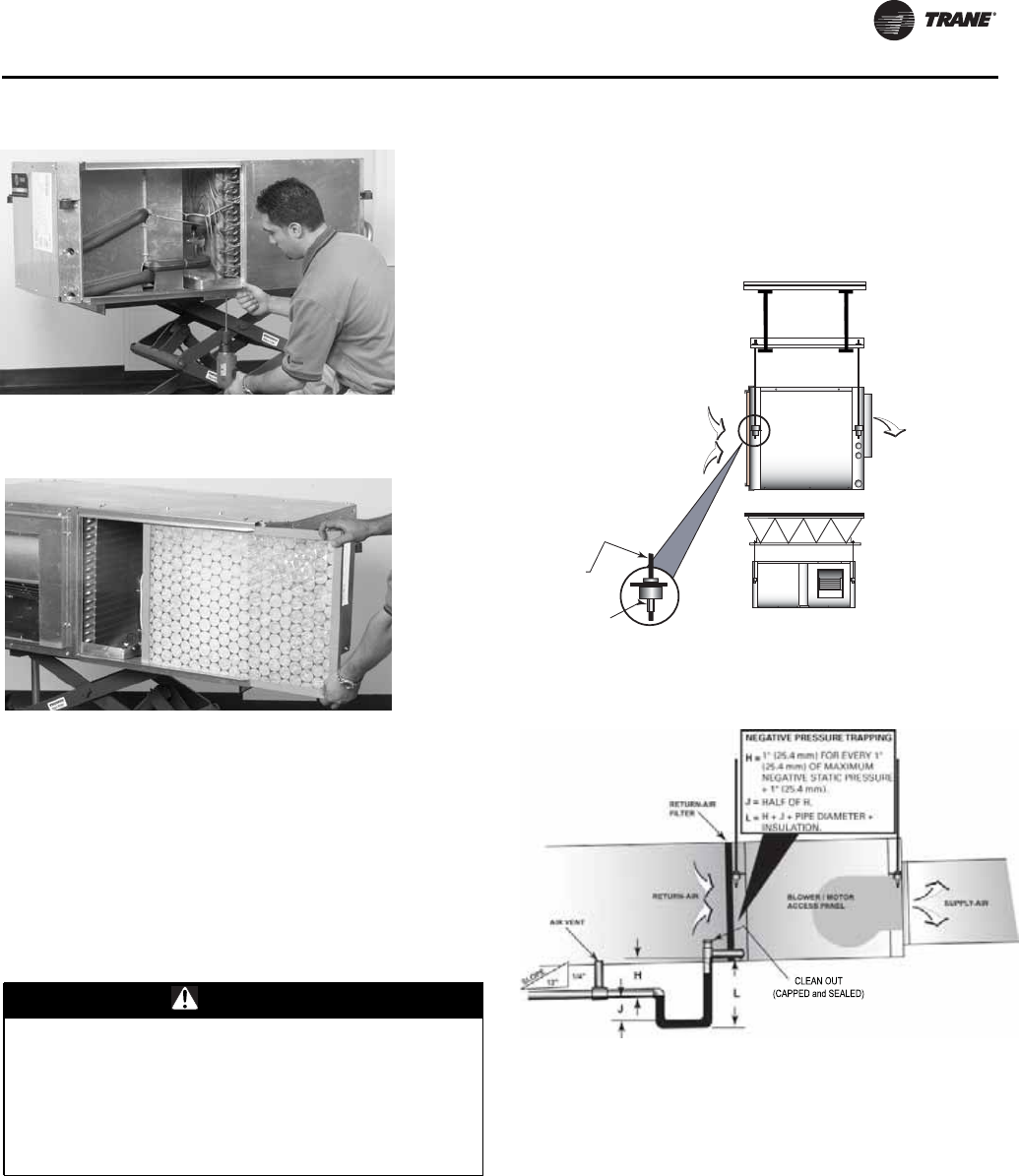
Installation
WSHP-SVX01N-EN 59
3. Install the 1”or 2”(25.4 mm/50.8 mm) filter.
Sound Attenuation Pad
For sound-sensitive installations, a vibration pad (field
provided) should be placed beneath the horizontal or
vertical equipment. For the horizontal unit, the pad should
be approximately twice the size of the unit foot print. For
the vertical unit, the pad should be ½ in. (12.7 mm) thick,
and equal to the overall unit foot print.
Hanging the Horizontal Unit
To hang the horizontal configuration (see Figure 54, p. 59):
1. Install the hanging isolators (located in the return-air
section of the unit) into the four hanging brackets.
2. Secure the equipment to a joist, concrete, etc. with the
use of 3/8 in. (9.7 mm) field provided (all-thread) rod.
Each corner should contain field provided nuts and
washers to complete the hanging installation.
3. Slope horizontal units in two directions.The unit
should contain a dual ¼-12 pitch toward the drain
connection.This will insure proper drainage of the
unit. All plumbing to the unit should conform per
national and local codes and is the responsibility of the
contractor.
Condensate Drain Connection
Install proper trapping to the equipment.The unit drain
connection is ¾ in. NPT for all GEV ½-25 ton and GEH ½-
5 ton and EXH/V ½-6 ton models. For 6-15 ton GEH models,
the drain connection is ½ in. PVC schedule 40 pipe.
When designing the condensate trap for the water-source
system, it is important to consider the unit draw-thru
design requiring negative pressure trapping.
In a properly trapped system, when condensate forms
during normal operation, the water level in the trap rises
until there is a constant flow. It is imperative to maintain
water in the trap and not allow the trap to dry out during
heating season. Keeping trap primed at all times will
enable the water to flow properly. See Figure 55, p. 59 for
Figure 52. Install top/bottom filter rack
Figure 53. Install filter
WARNING
Risk of Unit Dropping!
You MUST mount the unit to an area of the ceiling
strong enough to support the weight of that unit. If
unsure, you MUST confirm with a structural engineer.
Failure to do so could result in unit dropping from the
ceiling which could result in death or serious injury, and
equipment damage.
Figure 54. Hanging the unit
Figure 55. Negative pressure system
SUPPLY-AIR
3/8" ALL-THREAD
(BY OTHERS)
3/8" WASHER / NUT
(BY OTHERS)
RETURN-AIR
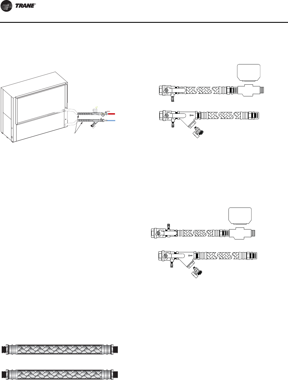
Installation
60 WSHP-SVX01N-EN
appropriate dimensions required in a negative pressure
system.
Supply/Return Pipe Connections
Connect the supply and return hoses to the water-inlet
(from supply) and water-outlet (to return) of the unit. For
vibration isolation, it is recommended that flexible steel
braided hoses be installed instead of hard piping the
equipment to the main loop system. Figure 56, p. 60
shows connection of a Hays Measurflo® balancing hose
kit to the water-in and water-out of a vertical unit.
Note: Figure 56, p. 60 example incorporates the Hays
Measurflo® balancing hose kit and a
2-position isolation valve into the system design.
An isolation valve is often used in variable speed
pumping applications.The isolation valve is
designed to stop water flow to the unit during non
operation times.This allows the loop water pumps
to run only when a requirement for pumping is
needed for greater energy efficiency of the overall
system design.
Types of Hose Connections
Whether installing the units in a central pump (main/
auxiliary pump for the entire zone) design, or as a
distributed pump (1-pump per unit) design, a shut-off
device and flexible hose is recommended to transition
from the hard piping of the closed or open loop water
system to the unit.There are multiple hose combinations
which may be used to fit the design or specification criteria
for the installation.
A steel braided hose without a shut-off device is the least
expensive means of connecting the heat pump to the
supply/return water loop.
With the addition of a shut-off device on the supply and
return of the system, the unit may be isolated during
service or maintenance situation.This system may be
installed as a wide open (full water flow to the equipment)
design, or manually balanced by utilizing the pressure/
temperature ports on the top of the ball valve/shut-off
device.
A circuit setter provides a means of manually balancing
the water flow to the heat pump.This manual in-line
balancing method is accurate up to ±20%. In order to
determine flow rate, the user must record both handle
position, and differential pressure drop.Then, the user
must consult a chart containing both pieces of information
and make the necessary adjustments to the circuit setter.
Figure 56. Supply/return pipe connections
Flexible hoses
RETURN
TO
LOOP
SUPPLY
FROM
CENTRAL
PUMP
AUTOMATIC BALANCING
HOSE KIT
WATER-IN
WATER-OUT
Supply
Return
Deluxe ball valve hose kit
Manual balance hose kit
Ball Valve w/PT
Ball Valve w/PT
Optional
Strainer/
Blowdown Valve
w/Hose Connector
Valve Body
Actuator
Actuator
Optional
Strainer/
Blowdown Valve
w/Hose Connector
Valve Body
Ball Valve w/PT
Ball Valve w/PT
Mesurmeter
w/PT’s
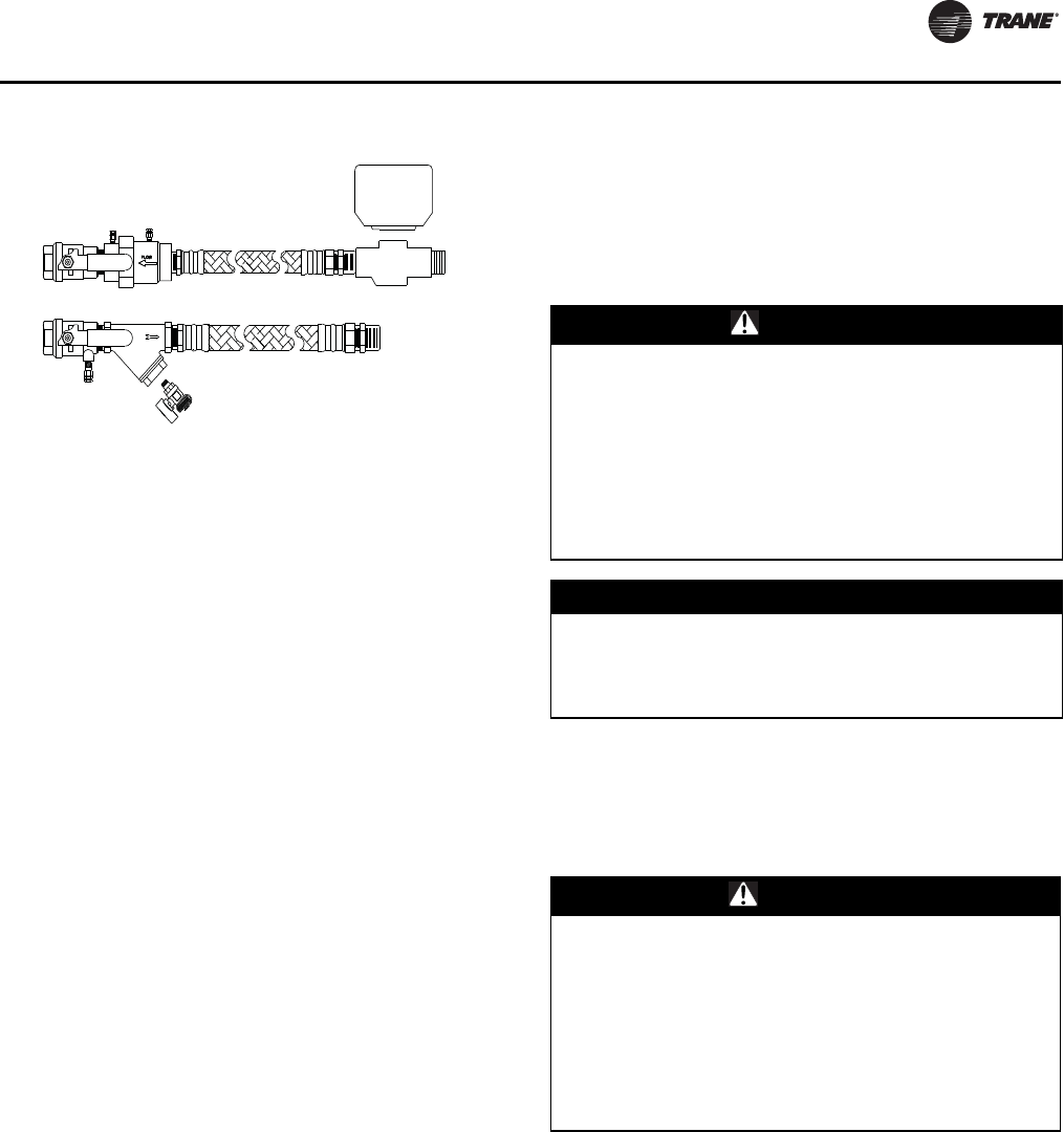
Installation
WSHP-SVX01N-EN 61
For self balancing flow control, a Hays Measurflo®
balancing hose kit provides a constant flow rate over the
pressure differential range of2–80psid. As system
pressures change (through the addition of heat pumps, for
example) each individual flow control valve will
automatically adjust to the new system conditions.
Additional accessories, such as a strainer are
recommended for use to eliminate contaminants from
entering the co-axial water-to-refrigerant heat exchanger.
Cleaning and Flushing the Water Loop
After the piping system is complete, the flexible hose
connectors should be doubled back to complete the water
circuit external to the unit (avoiding trash settle-out in the
condenser). An extra pipe may be necessary to connect
the hose kits.
1. Water circulation system should be filled with clean
water using the water make up connections.
Note: Air vents should be open during filling.
2. With the air vents closed, start the circulating pump
and then crack the air vents to bleed off the trapped air,
assuring circulation through all components of the
system.
Note: Make up water must be available to the system to
replace the volume formerly occupied by the air
that is bled off.
3. With the air vented and the water circulating, the entire
system should be checked for leaks with repairs made
as required.
4. Operate the supplementary heat system (boiler)
making checks per manufacturer’s instructions. During
this operation, visual checks should be made for leaks
that may have occurred due to increased heat. Repair
as required.
5. Open the system at the lowest point for the initial blow
down (making sure the make up water is equal to the
water being dumped). Continue blow down until the
water leaving the drain runs clear, but not less than 2
hours.
6. Shut down pumps and supplementary heat system.
Reconnect the hoses placing the water-to-refrigerant
heat exchanger in the water circulating system.
Note: Vents should be open when the pumps and
supplementary heat system are shut down.
Field Installed Power Wiring
Verify that the power supply available is compatible with
the unit’s nameplate. Use only copper conductors to
connect the power supply to the unit.
Main Unit Power Wiring
A field supplied disconnect switch must be installed at or
near the unit in accordance with the National Electric Code
(NEC latest edition).
Location of the applicable electric service entrance for
HIGH (line voltage) may be found in the Dimensions
section of this manual.
The high-voltage connection is made at the 1K1 contactor
or 1TB1 power block inside the unit control box. See
Figure 57, p. 62. Refer to the customer connection diagram
that is shipped with the unit for specific termination points.
Provide proper grounding for the unit in accordance with
the local and national codes.
Automatic balance hose kit
Actuator
Ball Valve
Ball Valve w/PT
Optional
Strainer/
Blowdown Valve
w/Hose Connector
Valve Body
Inline Mesurflo
Balance Valve
WARNING
Proper Field Wiring and Grounding
Required!
All field wiring MUST be performed by qualified
personnel. Improperly installed and grounded field
wiring poses FIRE and ELECTROCUTION hazards.To
avoid these hazards, you MUST follow requirements for
field wiring installation and grounding as described in
NEC and your local/state electrical codes. Failure to
follow codes could result in death or serious injury.
NOTICE:
Use Copper Conductors Only!
Unit terminals are not designed to accept other types of
conductors. Failure to use copper conductors could
result in equipment damage.
WARNING
Proper Field Wiring and Grounding
Required!
All field wiring MUST be performed by qualified
personnel. Improperly installed and grounded field
wiring poses FIRE and ELECTROCUTION hazards.To
avoid these hazards, you MUST follow requirements for
field wiring installation and grounding as described in
NEC and your local/state electrical codes. Failure to
follow codes could result in death or serious injury.
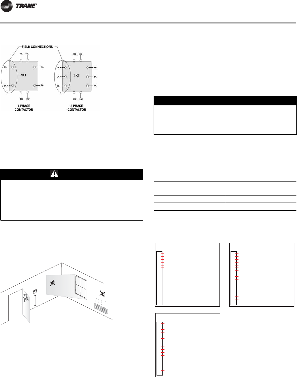
Installation
62 WSHP-SVX01N-EN
Control Power Transformer
The 24 V control power transformers are to be used only
with the accessories called out in this manual. A 50 VA
transformer is externally fused.Transformers rated
greater than 50 VA are equipped with circuit breakers. If a
circuit breaker trips, turn OFF all power to the unit before
attempting to reset it.
The transformer is located in the control panel.
Thermostat Location
Location of the thermostat or zone sensor is an important
element of effective room control.
Areas where the thermostat or zone sensor should not be
located include:
• Behind doors or corners
• Near hot or cold air ducts
• Near radiant heat (heat emitted from appliances or the
sun)
• Near concealed pipes or chimneys
• On outside walls or other non conditioned surfaces
In air-flows from adjacent zones or other units.
Controls Using 24 VAC
Before installing any wire, refer to the electrical access
locations in the “Unit Dimensions and Weights,” p. 14 of
this manual.
Ensure that the AC control wiring between the controls
and the unit termination point does not exceed 3 Ohms/
conductor for the length of the run.
Check all loads and conductors for grounds, shorts, and
mis-wiring.
Use copper conductors unless otherwise specified.
Do not run the AC low-voltage wiring in the same conduit
with the high voltage power wiring.
Low-voltage connection diagrams for basic and deluxe 24
V control packages mounted on ½-6 ton equipment sizes
are shown in Figure 59, p. 62.
Figure 57. Power wiring example
WARNING
Hazardous Voltage!
Disconnect all electric power, including remote
disconnects before servicing. Follow proper lockout/
tagout procedures to ensure the power cannot be
inadvertently energized. Failure to disconnect power
before servicing could result in death or serious injury.
Figure 58. Thermostat/sensor location
5 Feet
YES NO
NO
NO
O
NOTICE:
Component Failure!
Resistance in excess of 3 Ohms per conductor could
result in component failure due to insufficient AC
voltage supply.
Table 40. 24V AC conductors
Distance from unit to
control Recommended wire size
000-460 ft 18 gauge
461-732 ft 16 gauge
733-1000 ft 14 gauge
Figure 59. Low-voltage connection (GEH/V ½-5 ton and
EXH/V(a) ½-6 ton equipment)
(a)Basic controls not available on EXH/V units
Basic Controls Wall Mounted Thermostat
1TB1
FAN
24 VAC
REVERSING VALVE (COOL)
COMPRESSOR & VAR SPD PUMP SOLENOID
24 VAC GENERAL ALARM OUTPUT
24 VAC COMMON & VAR SPD PUMP SOLENOID
1
2
3
4
5
6
7
8
9
10
11
12
13
14
15
16
17
18
Deluxe Controls with Reheat
1TB1
1
2
3
4
5
6
7
8
9
10
11
12
13
14
15
16
17
18
24 VAC
FAN
REVERSING VALVE (COOL)
COMPRESSOR
24 VAC COMMON & VAR SPD PUMP SOLENOID
24 VAC COMPRESSOR DISABLE INPUT
24 VAC COMPRESSOR DISABLE INPUT
HUMIDISTAT
VAR SPD PUMP SOLENOID
ALARM CONTACT OUTPUT
ALARM CONTACT OUTPUT
Deluxe Controls Wall Mounted Thermostat
1TB1
1
2
3
4
5
6
7
8
9
10
11
12
13
14
15
16
17
18
24 VAC
FAN
REVERSING VALVE (COOL)
COMPRESSOR & VAR SPD PUMP SOLENOID
24 VAC COMMON & VAR SPD PUMP SOLENOID
ELECTRIC HEAT
24 VAC COMPRESSOR DISABLE INPUT
24 VAC COMPRESSOR DISABLE INPUT
ALARM CONTACT OUTPUT
ALARM CONTACT OUTPUT
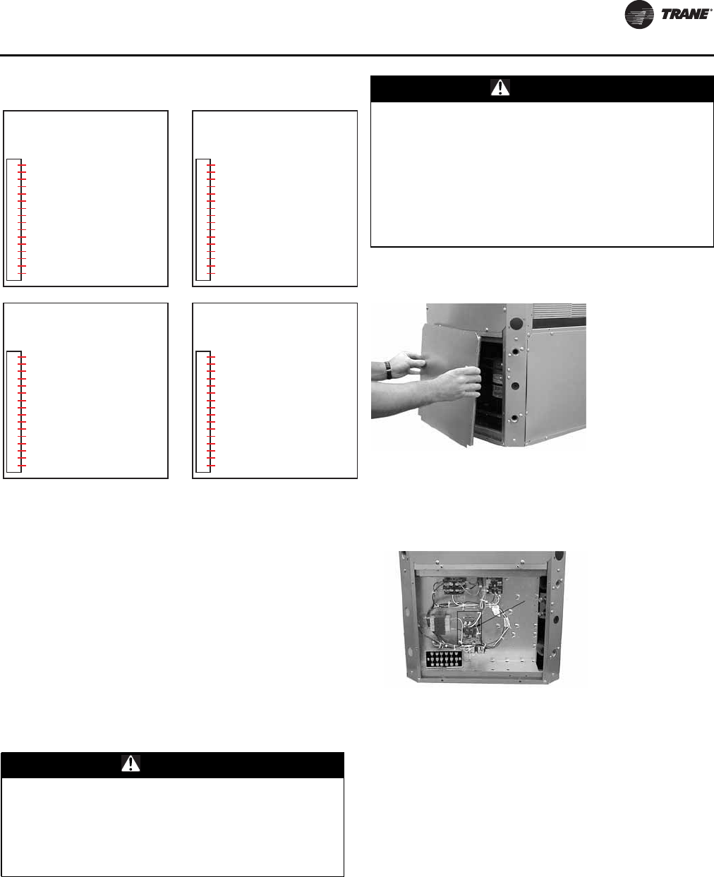
Installation
WSHP-SVX01N-EN 63
Low-voltage connection diagrams for deluxe 24V control
packages for these thermostats mounted on 6-25 ton
equipment sizes are shown in Figure 60, p. 63.
For controls using DC analog input/outputs, see
appropriate installation, operation and diagnostic
manuals for connection, WSHP-PRB002-EN (ZN524).
Blower Motor Speed-Tap Retrofit
Note: For GEH/V ½-5 ton units only.
Motors installed in the unit include 4-speed or 3-speed
configurations. All voltages include a 4-speed
configuration, with the exception of 380V, 415V, 460V
which contain a 3-speed arrangement and 575V which
contains a 2-speed arrangement.To modify the rpm of the
motor, the following steps must be followed.
1. Remove service access panel at the unit front.
2. Find the blower motor relay.The relay is located in
Figure 62, p. 63.The relay location is consistent in all
control configurations.
Removing Speed-tap Wire
3. For units w/o Hot Gas Reheat: Remove undesired
speed-tap wire from 1K4 relay at spade 3. Wire tie the
lead, to eliminate a short.
4. For units with Hot Gas Reheat: Remove undesired
speed-tap wire from 1K8 relay at spade 6. Wire tie the
lead, to eliminate a short. Hot Gas Reheat requires both
speed taps to be adjusted to enable reheat as the lower
speed tap.
Figure 60. Low-voltage connection (GEH/V 6-25 ton)
WARNING
Hazardous Voltage!
Disconnect all electric power, including remote
disconnects before servicing. Follow proper lockout/
tagout procedures to ensure the power can not be
inadvertently energized. Failure to disconnect power
before servicing could result in death or serious injury.
Deluxe Controls with
-all Heat Pump Units w/ Reheat
using X13511090010 (T8511)
1
2
3
4
5
6
7
8
9
10
11
12
13
14
15
16
1TB2
24 VAC (R)
FAN (G)
COMPRESSOR 1 (Y1)
COMPRESSOR 2 (Y2)
REVERSING VALVE (0) & HUMIDISTAT
24 VAC COMMON (C) & WATER ISOLATION VA
COMPRESSOR DISABLE
COMPRESSOR DISABLE
ALARM
ALARM
ELECTRIC HEAT
ELECTRIC HEAT
HUMIDISTAT
WATER ISOLATION VALVE
3RD STAGE HEAT (W3)
NOT USED
Deluxe Controls with
-all Heat Pump Units w/ Reheat
using X13511091010/X13511092010 (T7300)
1
2
3
4
5
6
7
8
9
10
11
12
13
14
15
16
1TB2
24 VAC (R)
FAN (G)
COMPRESSOR 1 (Y1)
COMPRESSOR 2 (Y2)
REVERSING VALVE (0) & HUMIDISTAT
24 VAC COMMON (X) & WATER ISOLATION VA
COMPRESSOR DISABLE
COMPRESSOR DISABLE
ALARM
ALARM
ELECTRIC HEAT
ELECTRIC HEAT
HUMIDISTAT
WATER ISOLATION VALVE
3RD STAGE HEAT (W1)
NOT USED
Deluxe Controls with
-all Heat Pump Units without Reheat
using X13511090010 (T8511)
1
2
3
4
5
6
7
8
9
10
11
12
13
14
15
16
1TB2
24 VAC (R)
FAN (G)
COMPRESSOR 1 (Y1) & WATER ISOLATION VA
COMPRESSOR 2 (Y2)
REVERSING VALVE (0) & HUMIDISTAT
24 VAC COMMON (C) & WATER ISOLATION VA
COMPRESSOR DISABLE
COMPRESSOR DISABLE
ALARM
ALARM
ELECTRIC HEAT
ELECTRIC HEAT
HUMIDISTAT
NOT USED
3RD STAGE HEAT (W3)
NOT USED
Deluxe Controls with
-all Heat Pump Units without Reheat
using X13511091010/X13511092010 (T7300)
1
2
3
4
5
6
7
8
9
10
11
12
13
14
15
16
1TB2
24 VAC (R)
FAN (G)
COMPRESSOR 1 (Y1) & WATER ISOLATION VA
COMPRESSOR 2 (Y2)
REVERSING VALVE (0) & HUMIDISTAT
24 VAC COMMON (X) & WATER ISOLATION VA
COMPRESSOR DISABLE
COMPRESSOR DISABLE
ALARM
ALARM
ELECTRIC HEAT
ELECTRIC HEAT
HUMIDISTAT
NOT USED
3RD STAGE HEAT (W1)
NOT USED
WARNING
Proper Field Wiring and Grounding
Required!
All field wiring MUST be performed by qualified
personnel. Improperly installed and grounded field
wiring poses FIRE and ELECTROCUTION hazards.To
avoid these hazards, you MUST follow requirements for
field wiring installation and grounding as described in
NEC and your local/state electrical codes. Failure to
follow codes could result in death or serious injury.
Figure 61. Service access panel
Figure 62. Relay location
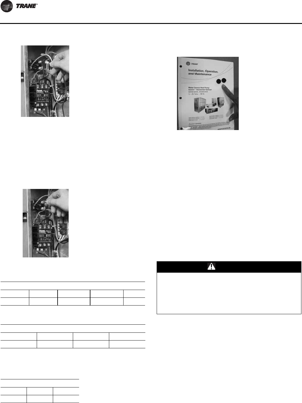
Installation
64 WSHP-SVX01N-EN
Connecting Desired Speed-tap Wire
5. For units without Hot Gas Reheat: Select desired
speed-tap wire. Connect desired speed tap wire to 1K4
relay at spade 3.
6. For units with Hot Gas Reheat Select desired
speed-tap wire. Connect desired speed tap wire to 1K8
relay at spade 6.
7. Install service front panel. Reconnect power to the unit.
Hole Plug Installation
1. Locate two Hayco plastic plugs enclosed with the
Installation, Operation, and Maintenance manual.
2. Use these plugs to plug the two shipping bolt holes in
the bottom of the GEVE/EVXVE units after shipping
bolt removal.
Air Flow Adjustment
Note: GEH/V 6-25 ton units only.
To increase cfm, loosen the turns open set screw on the
sheave, and turn the sheave clockwise.To decrease cfm,
Loosen the turns open set screw on the sheave, and turn
the sheave counterclockwise.
To increase belt tension, loosen the adjustment bolt and
pull motor mounting plate back until the belt is tight.
Tighten the adjustment bolt after the belt has reached the
desired tension.
See Figure 66, p. 65 for fan motor and sheave adjustment
Figure 63. Wiring change
Figure 64. Connecting speed-tap wire
Table 41. 4-speed motor (115, 208, 230, 265)
Lead Colors
Lead Black Blue Orange Red
Speed High Medium High Medium Low Low
Table 42. 3-speed motor (380, 415, 460)
Lead Colors
Lead Black Blue Orange
Speed High Medium Low
Note: When using the medium or low speed tap, the purple wire must be
jumpered to the high speed tap (blk).
Table 43. 2-speed motor (575)
Lead Colors
Lead Black Blue
Speed High Low
Figure 65. Hole plug installation
WARNING
Rotating Components!
Disconnect all electric power, including remote
disconnects before servicing. Follow proper lockout/
tagout procedures to ensure the power can not be
inadvertently energized. Failure to disconnect power
before servicing could result in death or serious injury.
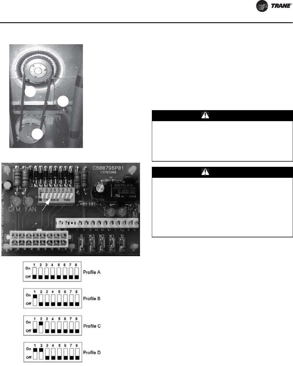
Installation
WSHP-SVX01N-EN 65
Note: EXH/V ½ -6 ton high efficiency units only:
Units are shipped from the factory on profile
setting B.
To adjust the cfm, disconnect the power to the unit. Set the
DIP switch located in the control box to the desired profile
setting. Connect the power to the unit. If the power is not
disconnected when the DIP switch is set, the motor will not
be programmed to the new setting.
Profile A = 110% of rated air flow
ProfileB=100%ofrated air flow
Profile C = 90% of rated air flow
Profile D = 80% of rated air flow
Waterside Economizer Installation
Note: GEH ½-5 and EXH ½-6 ton units.
The following steps were sequenced to aid in the
installation and mating of a water side economizer to a
water-source heat pump (GEH ½-5 ton) and (EXH 1½-6
ton).
1. Remove the control side service panel of the water-
source heat pump unit.
2. Remove rubber isolation grommets from the return-air
section. Place them in a convenient location.
3. Attach ducted panel to the water-source heat pump
unit with six factory provided screws.This panel is
shipped loose with the water-source heat pump but
must be field installed to the unit.
Figure 66. Fan motor and sheave adjustment
1.Belt
2.Adjustment Bolt and
Plate
3.Sheave
Figure 67. ECM control board and dip switch setting
2
3
1
Dip switch to
select profile
WARNING
Hazardous Voltage!
Disconnect all electric power, including remote
disconnects before servicing. Follow proper lockout/
tagout procedures to ensure the power can not be
inadvertently energized. Failure to disconnect power
before servicing could result in death or serious injury.
WARNING
Proper Field Wiring and Grounding
Required!
All field wiring MUST be performed by qualified
personnel. Improperly installed and grounded field
wiring poses FIRE and ELECTROCUTION hazards.To
avoid these hazards, you MUST follow requirements for
field wiring installation and grounding as described in
NEC and your local/state electrical codes. Failure to
follow codes could result in death or serious injury.
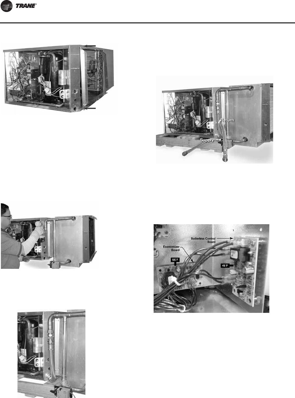
Installation
66 WSHP-SVX01N-EN
4. Attach the water side economizing unit to the ducted
panel of the water-source heat pump with 10-factory
provided screws.The economizing package fits to the
outside of the of the water-source heat pump.Trane
recommends the mating of the systems be made via 3-
screws spaced evenly across the top, 3-screws spaced
evenly across the bottom (installed immediately after
hanging the unit), and 2-screws on each side.
Note: Waterside economizer option is configured for
right return. Left return requires additional field
piping.
5. Install the 18-inch steel braided hose between the
upper most piping connection of the economizer, and
the water-in of the heat pump.The hose is shipped
loose with the water-side economizer.
6. Install the SUPPLY and RETURN hoses to the:
a. 2-position valve’s threaded connection
b. water-out threaded connection of the water-source
heat pump
7. Verify the control board for the water side economizer
is located at the back of the control box.The
temperature rating of this board is factory set to 55ºF.
For units with boilerless (electric heat) control and
water side economizer, the boilerless control board is
factory set to 45ºF.
8. Thread the bulb and wire through the low voltage hole
of the water-source heat pump. See Figure 73, p. 67.
Figure 68. Step 3
Figure 69. Step 4
Figure 70. Step 5
Figure 71. Step 6
Figure 72. Step 7
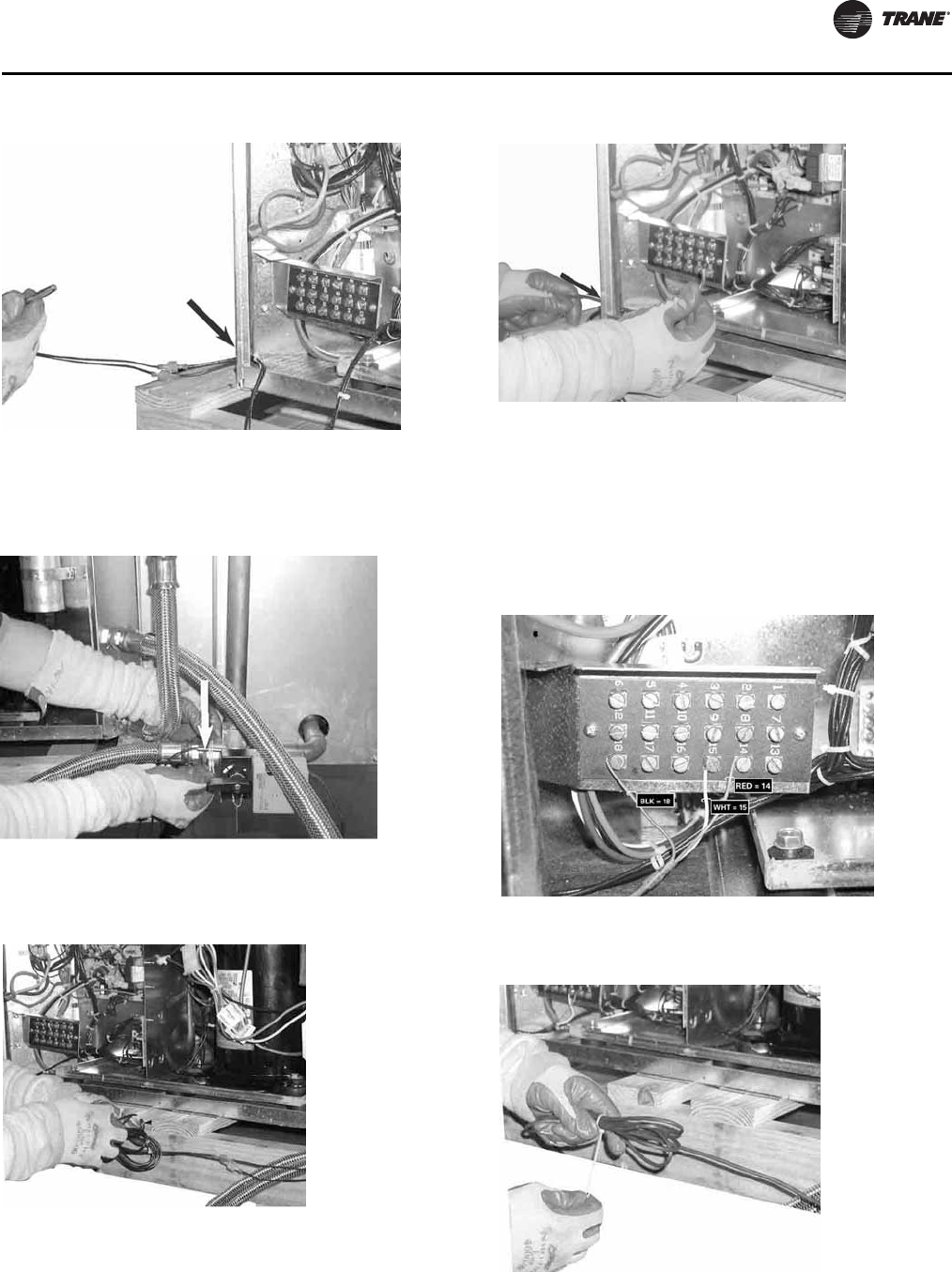
Installation
WSHP-SVX01N-EN 67
9. Wire-tie the sensor to the water SUPPLY side of the
piping (ON, or BEFORE) the 2-position valve. See
Figure 74, p. 67.
10. Bundle excess sensor wire, and wire tie the bundle
neatly. See Figure 75, p. 67.
11. Thread the valve’s wire lead through the low voltage
hole of the heat pump. See Figure 76, p. 67.
12. Wire the valve to the terminal strip according to the
unit wire diagram located on the service control panel.
RED = 1TB1-14
BLK = 1TB1-18
WHT = 1TB1-15
See Figure 77, p. 67.
13. Bundle excess valve wire, and wire tie the bundle
neatly. See Figure 78, p. 67.
14. Install control side service panel.
Figure 73. Step 8
Figure 74. Step 9
Figure 75. Step 10
Figure 76. Step 11
Figure 77. Step 12
Figure 78. Step 13
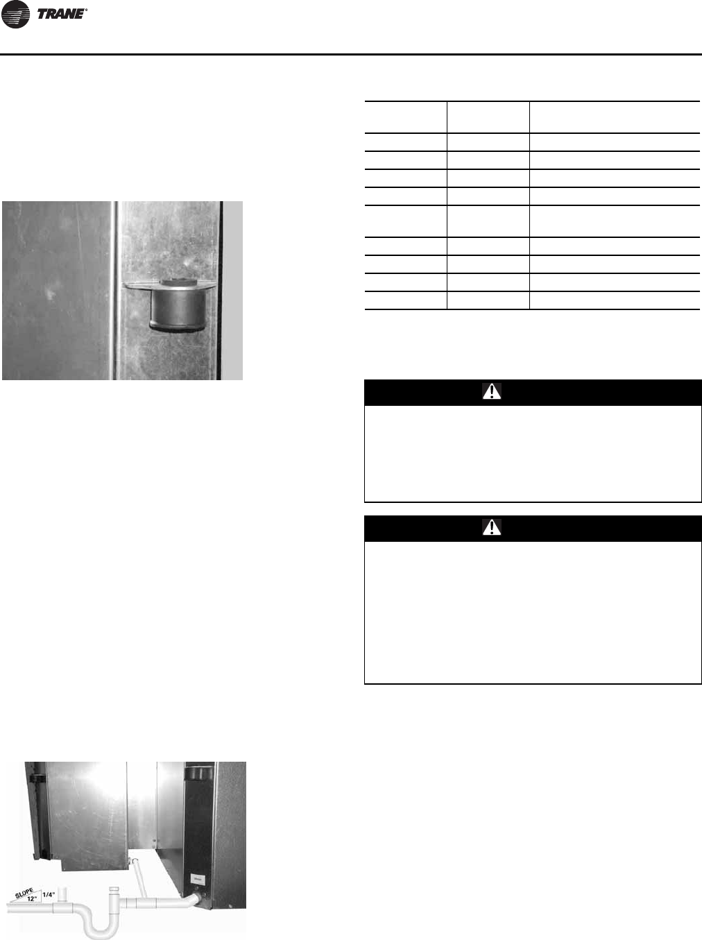
Installation
68 WSHP-SVX01N-EN
15. Install the hanging isolation grommets (see Figure 79,
p. 68) into the hanging bracketsThe unit isolators were
located in the return-air section of the unit. See Step 2.
Isolators for the economizing package are located with
the economizer.
Note: GEH ½-5 ton and EXH ½-6 ton.
16. Insulate the economizing piping package and the
supply/return/by-pass hoses (3-hoses) via field
provided pipe insulation. Insulating the piping will stop
condensation from forming on the pipe and dripping
onto the ceiling tiles.
Note: Trane does not provide insulation on the
economizing piping package.This insulation must
be field provided and field installed.
Note: Trane does not provide condensate overflow
protection of the waterside economizer.This must
be field provided and installed.
17. Install filter rack (top and bottom) to the economizing
package. The filter rack is located in the unit’s
packaging along with the filter.
18. Hang unit. See Figure 54, p. 59 for hanging of the
packaged unit. Bottom screws referenced in Step 4
must be installed at this time.
19. Field pipe the drain lines of the waterside economizer
and water-source heat pump together prior to
installing a condensate trap (see Figure 80, p. 68.See
Figure 55, p. 59 for proper trapping of condensation.
Waterside Economizer Installation for GEH
and GEV 6 to 25 Ton Models
1. Remove the filter frame from the unit.
2. Remove the waterside service panel from the unit.
3. Remove the control box service panel from the unit.
4. Remove the economizer and miscellaneous mounting
parts from it’s packaging.
5. GEV ONLY: Mount the economizer support angle (4475
1637 0100) found in the economizer packaging in the
same holes of the return air filter frame removed in
Step 1.The support angle screws into the unit roof.
6. GEV ONLY: Hang the economizer assembly from the
economizer support angle mounted in Step 5.
7. Secure the economizer to the unit using the four plates
(4475 1630 0100) found in the economizer packaging.
Two plates should be applied to each economizer side.
GEV ONLY: Secure the bracket on the bottom of the
Figure 79. Step 15
Figure 80. Step 19
Table 44. Economizer part numbers
GEH Unit 60
Hz GEH Unit 50
Hz Waterside Economizer Part
Number
006-015 006-012 4474 1690 0100
018-030 015-024 4474 7072 0100
036-042 030-036 4474 1692 0100
048-060 042-048 4474 1693 0100
EXH Unit 60
hz EXH Unit 50
Hz Waterside Economizer Part
Number
006-015 — 4474 1690 0100
018-024 — 4474 7072 0100
030-036 — 4474 1692 0100
042-070 — 4474 1639 0100
WARNING
Hazardous Voltage!
Disconnect all electric power, including remote
disconnects before servicing. Follow proper lockout/
tagout procedures to ensure the power can not be
inadvertently energized. Failure to disconnect power
before servicing could result in death or serious injury.
WARNING
Proper Field Wiring and Grounding
Required!
All field wiring MUST be performed by qualified
personnel. Improperly installed and grounded field
wiring poses FIRE and ELECTROCUTION hazards.To
avoid these hazards, you MUST follow requirements for
field wiring installation and grounding as described in
NEC and your local/state electrical codes. Failure to
follow codes could result in death or serious injury.
Installation
WSHP-SVX01N-EN 69
economizer cabinet to the unit compressor
compartment center post.
8. Install the field portion of the water piping and the 3-
way valve together.
Note: Entering water is on the AB port.
9. Verify the control board for the waterside economizer
is located at the back of the control box.The
temperature rating of this board is factory set to 55ºF.
10. Thread the economizer’s entering water temperature
sensor (4RT1) through the water-in line of the water-
source heat pump upstream from the valve.This
sensor is used by the economizer’s 3-way valve to
determine if water flow should be directed through the
waterside economizing coil.
11. Tie wrap the thermistor to the water line (supply side)
upstream of the water pipe to the economizer.The
thermistor must be situated so that the thermistor is
capable of reading the actual entering water
temperature regardless of the economizer’s on or off
situation.
12. Insulate the thermistor with tubing insulation.
13.Tie wrap each end of the tubing insulation to prevent
air filtration.The tie wraps and insulation are located in
a bag and shipped inside of the unit.
14. Thread the factory wire harness through the low
voltage hole of the heat pump to the 3-way valve’s wire
harness.
15. Connect the factory installed wire harness to the to the
wire harness supplied with the 3-way valve (see
Table 45, p. 69).
16. Bundle excess valve wire, and wire tie the bundle
neatly.
17. Install control side service panel to the heat pump.
18. Install the unit filter frame to the economizing inlet.
19. Insulate the economizing piping package with field
supplied pipe insulation. Insulating the piping will help
stop condensation from forming on the pipe.
Note: Trane does not provide insulation on the
economizing piping package.This insulation must
be field provided and field installed.
Note: Trane does not provide condensate overflow
protection of the waterside economizer.This must
be field provided and field installed.
20. Install waterside service panel to the heat pump.
21. The economizer condensate line must be trapped prior
to the unit’s drain line.This helps prevent air from
being sucked through the drain line causing
condensate to spit or build-up in the economizer or unit
drain pans. Field pipe the drain lines of the waterside
economizer and water-source heat pump together
prior to installing a condensate trap. See page
“Condensate Drain Connection,” p. 59 for proper
trapping of condensation.
Table 45. Actuator/factory harness wire table
Actuator Wire # Color Factory Harness Wire # Color
1 BLK = 25L-Black
2 WHT = 23T-White
3 WHT = 73A-White

70 WSHP-SVX01N-EN
Waterside Economizer Start-Up Sequence
1. Set the thermostat to the highest position.
2. Set the thermostat system switch to COOL with the fan
control to AUTO. The compressor should NOT run.
3. Reduce the thermostat setting until the compressor,
reversing valve, solenoid valve, and loop pump are
energized. Adjust water flow utilizing pressure/
temperature plugs and comparing to tables contained
in specification sheet data. Water leaving the heat
exchanger should be warmer than the entering water
temperature (approximately 9-12ºF); blower operation
should be smooth; compressor and blower amps
should be within data plate ratings; the suction line
should be cool with no frost observed in the refrigerant
circuit.
4. Check the cooling refrigerant pressures against values
in Table 54, p. 94.
Note: If cooling mode is activated, and the entering water
temperature of the heat pump falls below 55ºF, the
2-position, water side economizing valve will
become energized (open) and compressor
operation will halt allowing for free cooling in the
space.
5. Turn the thermostat system switch to the OFF position.
Unit should stop running and the reversing valve
should de-energize.
6. Leave unit off for approximately FIVE minutes to allow
for pressure equalization.
7. Turn the thermostat to the lowest setting.
8. Set the thermostat system switch to the HEAT position.
9. Adjust the temperature setting upward until the unit is
energized. Warm air should blow from the register. A
water temperature decrease of approximately 5-9°F
leaving the heat exchanger should be noted.The
blower and compressor operation should be smooth
with no frost observed in the refrigeration circuit.
10. Check the heating refrigerant pressures against values
in Table 54, p. 94.
Note: For units with boilerless electric heat option: In
heating mode, if the entering water temperature of
the heat pump falls below 45ºF, the electric heater
will be energized, and compressor operation will
halt. Once the entering water temperature rises
above 50ºF, the boilerless controls returns the unit
to normal operation.
11. Set the thermostat to maintain the desired space
temperature.
12. Instruct the owner on system operation.
Waterside Economizer Start-Up Sequence
WSHP-SVX01N-EN 71
Table 46. Waterside economizing three-way valve specifications
Unit Size (60 Hz) Unit Size (50 Hz) Valve Conn.
Size Valve Pres.
Rating "Valve Close-
off pressure Valve Temp.
Range Actuator
GEH006-015 GEH006-012 1/2 FPT 600 psi 200 psi "0ºF to 212ºF
-18ºC to 121ºC
Non-spring return type
24 VAC +/- 20%
135 second stroke time
10 Cv at full port
GEH018-042 GEH015-036 3/4 FPT 600 psi 200 psi "0ºF to 212ºF
-18ºC to 121ºC
Non-spring return type
24 VAC +/- 20%
135 second stroke time
30 Cv at full port
GEH048-060 GEH042-060 1 FPT 600 psi 200 psi "0ºF to 212ºF
-18ºC to 121ºC
Non-spring return type
24 VAC +/- 20%
135 second stroke time
23 Cv at full port
GEV/GEH
6-7½ Ton GEV
6 Ton 1¼ FPT 600 psi 200 psi 0ºF to 212ºF
-18ºC to 121ºC
Non-spring return type
24 VAC +/- 20%
135 second stroke time
33 Cv at full port
GEV/GEH
10-15 Ton GEV/GEH
7½-12½ Ton 1½ FPT 600 psi 200 psi 0ºF to 212ºF
-18ºC to 121ºC
Non-spring return type
24 VAC +/- 20%
135 second stroke time
37 Cv at full port
GEV
20 & 25 Ton GEV
15 & 20 Ton 2 FPT 600 psi 200 psi 0ºF to 212ºF
-18ºC to 121ºC
Non-spring return type
24 VAC +/- 20%
135 second stroke time
57 Cv at full port
EXH006-015 — 1/2 FPT 600 psi 200 psi 0ºF to 212ºF
-18ºC to 121ºC
Non-spring return type
24 VAC +/- 20%
135 second stroke time
10 Cv at full port
EXH 018-036 — 3/4 FPT 600 psi 200 psi 0°F to 212°F
-18°C to 121°C
Non-spring return type
24 VAC +/- 20%
135 second stroke time
30 Cv at full port
EXH 042-070 — 1 FPT 600 psi 200 psi 0°F to 212°F
-18°C to 121°C
Non-spring return type
24 VAC +/- 20%
135 second stroke time
23 Cv at full port
Note: The valve body is constructed from forged brass with nickel plating, with the ball and stem constructed of stainless steel. For other information
pertaining to the economizing water valve, see the valve’s data plate.

72 WSHP-SVX01N-EN
Electrical Data
Table 47. Electrical data: standard static motors, ½ to 5 tons GEH*/GEV*
Model No. Volts
Total
Unit
FLA
Comp
RLA
(ea)
Comp
LRA
(ea) No. of
Comp. Cmp
MCC
Blower
Motor
FLA
Blower
Motor
hp
Fan
Motor
Num.
Minimum
Circuit
Ampacity
Maximum
Overcurrent
Protective
Device
Electric
Heat
kW
Electric
Heat
Amps
GEH/GEV006 115/60/1 6.8 5.6 30.0 1 7.5 1.20 1/12 1 8.20 15 0.0 0.0
GEH/GEV006 208/60/1 3.9 3.3 14.0 1 4.2 0.60 1/12 1 4.73 15 0.0 0.0
GEH/GEV006 208/60/1 4.5 3.3 14.0 1 4.2 0.60 1/12 1 5.68 15 0.8 3.9
GEH/GEV006 230/60/1 3.8 3.2 15.0 1 4.2 0.60 1/12 1 4.60 15 0.0 0.0
GEH/GEV006 230/60/1 4.9 3.2 15.0 1 4.2 0.60 1/12 1 6.18 15 1.0 4.3
GEH/GEV006 220-240/50/1 3.4 2.9 17.0 1 4.0 0.52 1/12 1 4.15 15 0.0 0.0
GEH/GEV006 220-240/50/1 7.4 2.9 17.0 1 4.0 0.52 1/12 1 9.19 15 1.6 6.8
GEH/GEV006 265/60/1 3.0 2.5 11.0 1 3.5 0.52 1/12 1 3.65 15 0.0 0.0
GEH/GEV006 265/60/1 5.5 2.5 11.0 1 3.5 0.52 1/12 1 6.92 15 1.3 5.0
GEH/GEV009 115/60/1 7.6 6.4 36.0 1 8.6 1.20 1/12 1 9.20 15 0.0 0.0
GEH/GEV009 208/60/1 4.3 3.7 16.0 1 4.8 0.60 1/12 1 5.23 15 0.0 0.0
GEH/GEV009 208/60/1 6.5 3.7 16.0 1 4.8 0.60 1/12 1 8.14 15 1.2 5.9
GEH/GEV009 230/60/1 4.1 3.5 17.0 1 4.8 0.60 1/12 1 4.98 15 0.0 0.0
GEH/GEV009 230/60/1 7.1 3.5 17.0 1 4.8 0.60 1/12 1 8.90 15 1.5 6.5
GEH/GEV009 220-240/50/1 6.0 5.3 23.0 1 7.4 0.72 1/8 1 7.35 15 0.0 0.0
GEH/GEV009 220-240/50/1 9.8 5.3 23.0 1 7.4 0.72 1/8 1 12.20 15 2.2 9.0
GEH/GEV009 265/60/1 3.3 2.8 13.0 1 3.7 0.52 1/12 1 4.02 15 0.0 0.0
GEH/GEV009 265/60/1 8.1 2.8 13.0 1 3.7 0.52 1/12 1 10.08 15 2.0 7.5
GEH/GEV012 115/60/1 13.7 12.1 58.0 1 16.9 1.57 1/8 1 16.70 25 0.0 0.0
GEH/GEV012 208/60/1 7.0 6.3 30.0 1 8.8 0.70 1/8 1 8.58 15 0.0 0.0
GEH/GEV012 208/60/1 8.5 6.3 27.0 1 8.8 0.70 1/8 1 10.67 15 1.6 7.8
GEH/GEV012 230/60/1 7.0 6.3 30.0 1 8.8 0.70 1/8 1 8.58 15 0.0 0.0
GEH/GEV012 230/60/1 9.4 6.3 30.0 1 8.8 0.70 1/8 1 11.74 15 2.0 8.7
GEH/GEV012 220-240/50/1 7.4 6.7 30.0 1 9.4 0.72 1/8 1 9.10 15 0.0 0.0
GEH/GEV012 220-240/50/1 12.0 6.7 30.0 1 9.4 0.72 1/8 1 14.96 15 2.7 11.3
GEH/GEV012 265/60/1 5.7 5.0 23.0 1 7.0 0.72 1/8 1 6.97 15 0.0 0.0
GEH/GEV012 265/60/1 10.7 5.0 23.0 1 7.0 0.72 1/8 1 13.40 15 2.7 10.0
GEH/GEV015 208/60/1 8.6 7.9 36.0 1 11.1 0.70 1/8 1 10.58 15 0.0 0.0
GEH/GEV015 208/60/1 10.3 7.9 36.0 1 11.1 0.70 1/8 1 12.89 15 2.0 9.6
GEH/GEV015 230/60/1 8.6 7.9 36.0 1 11.1 0.70 1/8 1 10.58 15 0.0 0.0
GEH/GEV015 230/60/1 11.6 7.9 36.0 1 11.1 0.70 1/8 1 14.46 15 2.5 10.9
GEH/GEV015 220-240/50/1 9.0 8.2 36.0 1 11.5 0.80 1/8 1 11.05 15 0.0 0.0
GEH/GEV015 220-240/50/1 14.5 8.2 36.0 1 11.5 0.80 1/8 1 18.08 20 3.3 13.7
GEH/GEV015 265/60/1 7.1 6.4 30.0 1 9.0 0.72 1/8 1 8.72 15 0.0 0.0
GEH/GEV015 265/60/1 13.2 6.4 30.0 1 9.0 0.72 1/8 1 16.47 20 3.3 12.5
GEH/GEV018 208/60/1 10.5 9.6 42.0 1 13.4 0.90 1/8 1 12.90 20 0.0 0.0
GEH/GEV018 208/60/1 12.7 9.6 42.0 1 13.4 0.90 1/8 1 15.91 20 2.5 11.8
GEH/GEV018 230/60/1 10.5 9.6 42.0 1 13.4 0.90 1/8 1 12.90 20 0.0 0.0
GEH/GEV018 230/60/1 13.9 9.6 42.0 1 13.4 0.90 1/8 1 17.43 20 3.0 13.0
GEH/GEV018 220-240/50/1 11.1 9.6 54.0 1 15.0 1.53 1/3 1 13.53 20 0.0 0.0
GEH/GEV018 220-240/50/1 19.7 9.6 54.0 1 15.0 1.53 1/3 1 24.57 25 4.4 18.1
GEH/GEV018 265/60/1 8.5 7.7 35.0 1 10.8 0.80 1/8 1 10.43 15 0.0 0.0
continued on next page

Electrical Data
WSHP-SVX01N-EN 73
GEH/GEV018 265/60/1 15.9 7.7 35.0 1 10.8 0.80 1/8 1 19.87 20 4.0 15.1
GEH/GEV018 380-415/50/3 5.2 4.2 28.0 1 6.5 0.95 1/3 1 6.20 15 0.0 0.0
GEH/GEV018 380-415/50/3 7.0 3.6 28.0 1 5.6 0.95 1/3 1 8.75 15 4.4 6.1
GEH/GEV024 208/60/1 14.9 12.8 58.3 1 20.0 2.10 1/3 1 18.10 30 0.0 0.0
GEH/GEV024 208/60/1 17.8 12.8 58.3 1 20.0 2.10 1/3 1 22.22 30 3.3 15.7
GEH/GEV024 230/60/1 14.9 12.8 58.3 1 20.0 2.10 1/3 1 18.10 30 0.0 0.0
GEH/GEV024 230/60/1 19.5 12.8 58.3 1 20.0 2.10 1/3 1 24.36 30 4.0 17.4
GEH/GEV024 220-240/50/1 12.7 11.2 60.0 1 17.5 1.53 1/3 1 15.53 25 0.0 0.0
GEH/GEV024 220-240/50/1 24.0 11.2 60.0 1 17.5 1.53 1/3 1 30.04 35 5.4 22.5
GEH/GEV024 265/60/1 11.1 9.6 54.0 1 15.0 1.53 1/3 1 13.53 20 0.0 0.0
GEH/GEV024 265/60/1 21.5 9.6 54.0 1 15.0 1.53 1/3 1 26.91 30 5.3 20.0
GEH/GEV024 208/60/3 9.2 7.7 53.7 1 12.0 1.53 1/3 1 11.16 15 0.0 0.0
GEH/GEV024 208/60/3 10.6 7.7 53.7 1 12.0 1.53 1/3 1 13.22 15 3.3 9.0
GEH/GEV024 230/60/3 9.8 7.7 53.7 1 12.0 2.10 1/3 1 11.73 15 0.0 0.0
GEH/GEV024 230/60/3 12.1 7.7 53.7 1 12.0 2.10 1/3 1 15.18 20 4.0 10.0
GEH/GEV024 380-415/50/3 5.2 4.2 28.0 1 6.5 0.95 1/3 1 6.20 15 0.0 0.0
GEH/GEV024 380-415/50/3 8.5 4.2 28.0 1 6.5 0.95 1/3 1 10.58 15 5.4 7.5
GEH/GEV024 460/60/3 4.6 3.6 28.0 1 5.6 0.95 1/3 1 5.45 15 0.0 0.0
GEH/GEV024 460/60/3 7.6 3.6 28.0 1 5.6 0.95 1/3 1 9.50 15 5.3 6.7
GEH/GEV030 208/60/1 16.2 14.1 73.0 1 22.0 2.10 1/3 1 19.73 30 0.0 0.0
GEH/GEV030 208/60/1 21.8 14.1 73.0 1 22.0 2.10 1/3 1 27.26 30 4.1 19.7
GEH/GEV030 230/60/1 16.2 14.1 73.0 1 22.0 2.10 1/3 1 19.73 30 0.0 0.0
GEH/GEV030 230/60/1 23.8 14.1 73.0 1 22.0 2.10 1/3 1 29.80 30 5.0 21.7
GEH/GEV030 220-240/50/1 19.5 16.7 79.0 1 26.0 2.77 1/2 1 23.65 40 0.0 0.0
GEH/GEV030 220-240/50/1 29.9 13.5 72.0 1 21.0 2.77 1/2 1 37.42 40 6.5 27.2
GEH/GEV030 265/60/1 12.7 11.2 60.0 1 17.5 1.53 1/3 1 15.53 25 0.0 0.0
GEH/GEV030 265/60/1 26.4 11.2 60.0 1 17.5 1.53 1/3 1 33.04 35 6.6 24.9
GEH/GEV030 208/60/3 11.0 8.9 58.0 1 13.9 2.10 1/3 1 13.23 20 0.0 0.0
GEH/GEV030 208/60/3 13.5 8.9 58.0 1 13.9 2.10 1/3 1 16.85 20 4.1 11.4
GEH/GEV030 230/60/3 11.0 8.9 58.0 1 13.9 2.10 1/3 1 13.23 20 0.0 0.0
GEH/GEV030 230/60/3 14.7 8.9 58.0 1 13.9 2.10 1/3 1 18.31 20 5.0 12.6
GEH/GEV030 380-415/50/3 7.5 5.8 38.0 1 9.0 1.70 1/2 1 8.95 15 0.0 0.0
GEH/GEV030 380-415/50/3 10.8 5.8 38.0 1 9.0 1.70 1/2 1 13.46 15 6.5 9.1
GEH/GEV030 460/60/3 5.2 4.2 28.0 1 6.5 0.95 1/3 1 6.20 15 0.0 0.0
GEH/GEV030 460/60/3 9.2 4.2 28.0 1 6.5 0.95 1/3 1 11.54 15 6.6 8.3
GEH/GEV036 208/60/1 20.3 16.7 79.0 1 26.0 3.60 1/2 1 24.48 40 0.0 0.0
GEH/GEV036 208/60/1 27.2 16.7 79.0 1 26.0 3.60 1/2 1 33.95 40 4.9 23.6
GEH/GEV036 230/60/1 20.3 16.7 79.0 1 26.0 3.60 1/2 1 24.48 40 0.0 0.0
GEH/GEV036 230/60/1 29.7 16.7 79.0 1 26.0 3.60 1/2 1 37.11 40 6.0 26.1
GEH/GEV036 265/60/1 16.3 13.5 72.0 1 21.0 2.77 1/2 1 19.65 30 0.0 0.0
GEH/GEV036 265/60/1 32.8 13.5 72.0 1 21.0 2.77 1/2 1 40.96 45 8.0 30.0
GEH/GEV036 208/60/3 14.0 10.4 73.0 1 16.3 3.60 1/2 1 16.60 25 0.0 0.0
GEH/GEV036 208/60/3 17.2 10.4 73.0 1 16.3 3.60 1/2 1 21.50 25 4.9 13.6
GEH/GEV036 230/60/3 14.0 10.4 73.0 1 16.3 3.60 1/2 1 16.60 25 0.0 0.0
continued on next page
Table 47. Electrical data: standard static motors, ½ to 5 tons (continued)GEH*/GEV*
Model No. Volts
Total
Unit
FLA
Comp
RLA
(ea)
Comp
LRA
(ea) No. of
Comp. Cmp
MCC
Blower
Motor
FLA
Blower
Motor
hp
Fan
Motor
Num.
Minimum
Circuit
Ampacity
Maximum
Overcurrent
Protective
Device
Electric
Heat
kW
Electric
Heat
Amps

Electrical Data
74 WSHP-SVX01N-EN
GEH/GEV036 230/60/3 18.7 10.4 73.0 1 16.3 3.60 1/2 1 23.33 25 6.0 15.1
GEH/GEV036 380-415/50/3 7.7 6.0 44.0 1 9.3 1.70 1/2 1 9.20 15 0.0 0.0
GEH/GEV036 380-415/50/3 11.6 6.0 44.0 1 9.3 1.70 1/2 1 14.56 15 7.2 9.9
GEH/GEV036 460/60/3 7.5 5.8 38.0 1 9.0 1.70 1/2 1 8.95 15 0.0 0.0
GEH/GEV036 460/60/3 11.7 5.8 38.0 1 9.0 1.70 1/2 1 14.60 15 8.0 10.0
GEH/GEV042 208/60/1 21.5 17.9 112.0 1 28.0 3.60 1/2 1 25.98 40 0.0 0.0
GEH/GEV042 208/60/1 31.0 17.9 112.0 1 28.0 3.60 1/2 1 38.75 40 5.7 27.4
GEH/GEV042 230/60/1 21.5 17.9 112.0 1 28.0 3.60 1/2 1 25.98 40 0.0 0.0
GEH/GEV042 230/60/1 34.0 17.9 112.0 1 28.0 3.60 1/2 1 42.54 45 7.0 30.4
GEH/GEV042 208/60/3 17.1 13.5 88.0 1 21.1 3.60 1/2 1 20.48 30 0.0 0.0
GEH/GEV042 208/60/3 19.4 13.5 88.0 1 21.1 3.60 1/2 1 24.28 30 5.7 15.8
GEH/GEV042 230/60/3 17.1 13.5 88.0 1 21.1 3.60 1/2 1 20.48 30 0.0 0.0
GEH/GEV042 230/60/3 21.2 13.5 88.0 1 21.1 3.60 1/2 1 26.46 30 7.0 17.6
GEH/GEV042 380-415/50/3 7.7 6.3 55.0 1 9.9 1.40 1/2 1 9.28 15 0.0 0.0
GEH/GEV042 380-415/50/3 13.4 6.3 55.0 1 9.9 1.40 1/2 1 16.71 20 8.6 12.0
GEH/GEV042 460/60/3 7.7 6.0 44.0 1 9.3 1.70 1/2 1 9.20 15 0.0 0.0
GEH/GEV042 460/60/3 13.4 6.0 44.0 1 9.3 1.70 1/2 1 16.72 20 9.3 11.7
GEH/GEV042 575/60/3 6.2 4.9 34.0 1 7.7 1.31 1/2 1 7.44 15 0.0 0.0
GEH/GEV048 208/60/1 24.2 21.4 135.0 1 33.4 2.80 1/2 1 29.55 50 0.0 0.0
GEH/GEV048 208/60/1 34.1 21.4 135.0 1 33.4 2.80 1/2 1 42.56 50 6.5 31.3
GEH/GEV048 230/60/1 24.2 21.4 135.0 1 33.4 2.80 1/2 1 29.55 50 0.0 0.0
GEH/GEV048 230/60/1 37.6 21.4 135.0 1 33.4 2.80 1/2 1 46.98 50 8.0 34.8
GEH/GEV048 208/60/3 17.3 14.5 98.0 1 22.6 2.80 1/2 1 20.93 35 0.0 0.0
GEH/GEV048 208/60/3 20.8 14.5 98.0 1 22.6 2.80 1/2 1 26.05 35 6.5 18.0
GEH/GEV048 230/60/3 17.3 14.5 98.0 1 22.6 2.80 1/2 1 20.93 35 0.0 0.0
GEH/GEV048 230/60/3 22.9 14.5 98.0 1 22.6 2.80 1/2 1 28.60 35 8.0 20.1
GEH/GEV048 380-415/50/3 10.5 7.8 52.0 1 12.1 2.70 1 1 12.45 20 0.0 0.0
GEH/GEV048 380-415/50/3 14.7 7.8 52.0 1 12.1 2.70 1 1 18.33 20 8.6 12.0
GEH/GEV048 460/60/3 7.7 6.3 55.0 1 9.9 1.40 1/2 1 9.28 15 0.0 0.0
GEH/GEV048 460/60/3 14.7 6.3 55.0 1 9.9 1.40 1/2 1 18.38 20 10.6 13.3
GEH/GEV048 575/60/3 7.4 6.0 41.0 1 9.4 1.40 1/2 1 8.90 15 0.0 0.0
GEH/GEV060 208/60/1 31.7 26.3 134.0 1 41.0 5.40 1 1 38.28 60 0.0 0.0
GEH/GEV060 208/60/1 36.7 26.3 134.0 1 41.0 5.40 1 1 45.81 60 6.5 31.3
GEH/GEV060 230/60/1 31.7 26.3 134.0 1 41.0 5.40 1 1 38.28 60 0.0 0.0
GEH/GEV060 230/60/1 40.2 26.3 134.0 1 41.0 5.40 1 1 50.23 60 8.0 34.8
GEH/GEV060 208/60/3 21.0 15.6 110.0 1 24.4 5.40 1 1 24.90 40 0.0 0.0
GEH/GEV060 208/60/3 23.4 15.6 110.0 1 24.4 5.40 1 1 29.30 40 6.5 18.0
GEH/GEV060 230/60/3 21.0 15.6 110.0 1 24.4 5.40 1 1 24.90 40 0.0 0.0
GEH/GEV060 230/60/3 25.5 15.6 110.0 1 24.4 5.40 1 1 31.85 40 8.0 20.1
GEH/GEV060 380-415/50/3 12.3 9.6 75.0 1 15.0 2.70 1 1 14.70 20 0.0 0.0
GEH/GEV060 380-415/50/3 14.7 9.6 75.0 1 15.0 2.70 1 1 18.33 20 8.6 12.0
GEH/GEV060 460/60/3 10.5 7.8 52.0 1 12.1 2.70 1 1 12.45 20 0.0 0.0
GEH/GEV060 460/60/3 16.0 7.8 52.0 1 12.1 2.70 1 1 20.01 25 10.6 13.3
GEH/GEV060 575/60/3 8.0 5.8 38.9 1 9.1 2.20 1 1 9.45 15 0.0 0.0
Table 47. Electrical data: standard static motors, ½ to 5 tons (continued)GEH*/GEV*
Model No. Volts
Total
Unit
FLA
Comp
RLA
(ea)
Comp
LRA
(ea) No. of
Comp. Cmp
MCC
Blower
Motor
FLA
Blower
Motor
hp
Fan
Motor
Num.
Minimum
Circuit
Ampacity
Maximum
Overcurrent
Protective
Device
Electric
Heat
kW
Electric
Heat
Amps

Electrical Data
WSHP-SVX01N-EN 75
Table 48. Electrical data - high static motors-½to5tonsGEH*/GEV*
Model No. Volts
Total
Unit
FLA
Comp
RLA
(ea)
Comp
LRA
(ea) No. of
Comp. Cmp
MCC
Blower
Motor
FLA
Blower
Motor
hp
Fan
Motor
Num.
Minimum
Circuit
Ampacity
Maximum
Overcurrent
Protective
Device
Electric
Heat
kW
Electric
Heat
Amps
GEHE/GEVE
GEH/GEV006 115/60/1 6.8 5.6 30.0 1 7.5 1.20 1/12 1 8.20 15 0.0 0.0
GEH/GEV006 208/60/1 3.9 3.3 14.0 1 4.2 0.60 1/12 1 4.73 15 0.0 0.0
GEH/GEV006 208/60/1 4.5 3.3 14.0 1 4.2 0.60 1/12 1 5.68 15 0.8 3.9
GEH/GEV006 230/60/1 3.8 3.2 15.0 1 4.2 0.60 1/12 1 4.60 15 0.0 0.0
GEH/GEV006 230/60/1 4.9 3.2 15.0 1 4.2 0.60 1/12 1 6.18 15 1.0 4.3
GEH/GEV006 220-240/50/1 3.4 2.9 17.0 1 4.0 0.52 1/12 1 4.15 15 0.0 0.0
GEH/GEV006 220-240/50/1 7.4 2.9 17.0 1 4.0 0.52 1/12 1 9.19 15 1.6 6.8
GEH/GEV006 265/60/1 3.0 2.5 11.0 1 3.5 0.52 1/12 1 3.65 15 0.0 0.0
GEH/GEV006 265/60/1 5.5 2.5 11.0 1 3.5 0.52 1/12 1 6.92 15 1.3 5.0
GEH/GEV009 115/60/1 7.6 6.4 36.0 1 8.6 1.20 1/12 1 9.20 15 0.0 0.0
GEH/GEV009 208/60/1 4.3 3.7 16.0 1 4.8 0.60 1/12 1 5.23 15 0.0 0.0
GEH/GEV009 208/60/1 6.5 3.7 16.0 1 4.8 0.60 1/12 1 8.14 15 1.2 5.9
GEH/GEV009 230/60/1 4.1 3.5 17.0 1 4.8 0.60 1/12 1 4.98 15 0.0 0.0
GEH/GEV009 230/60/1 7.1 3.5 17.0 1 4.8 0.60 1/12 1 8.90 15 1.5 6.5
GEH/GEV009 220-240/50/1 6.0 5.3 23.0 1 7.4 0.72 1/8 1 7.35 15 0.0 0.0
GEH/GEV009 220-240/50/1 9.8 5.3 23.0 1 7.4 0.72 1/8 1 12.20 15 2.2 9.0
GEH/GEV009 265/60/1 3.3 2.8 13.0 1 3.7 0.52 1/12 1 4.02 15 0.0 0.0
GEH/GEV009 265/60/1 8.1 2.8 13.0 1 3.7 0.52 1/12 1 10.08 15 2.0 7.5
GEH/GEV012 115/60/1 13.7 12.1 58.0 1 16.9 1.57 1/8 1 16.70 25 0.0 0.0
GEH/GEV012 208/60/1 7.0 6.3 30.0 1 8.8 0.70 1/8 1 8.58 15 0.0 0.0
GEH/GEV012 208/60/1 8.5 6.3 27.0 1 8.8 0.70 1/8 1 10.67 15 1.6 7.8
GEH/GEV012 230/60/1 7.0 6.3 30.0 1 8.8 0.70 1/8 1 8.58 15 0.0 0.0
GEH/GEV012 230/60/1 9.4 6.3 30.0 1 8.8 0.70 1/8 1 11.74 15 2.0 8.7
GEH/GEV012 220-240/50/1 7.4 6.7 30.0 1 9.4 0.72 1/8 1 9.10 15 0.0 0.0
GEH/GEV012 220-240/50/1 12.0 6.7 30.0 1 9.4 0.72 1/8 1 14.96 15 2.7 11.3
GEH/GEV012 265/60/1 5.7 5.0 23.0 1 7.0 0.72 1/8 1 6.97 15 0.0 0.0
GEH/GEV012 265/60/1 10.7 5.0 23.0 1 7.0 0.72 1/8 1 13.40 15 2.7 10.0
GEH/GEV015 208/60/1 8.6 7.9 36.0 1 11.1 0.70 1/8 1 10.58 15 0.0 0.0
GEH/GEV015 208/60/1 10.3 7.9 36.0 1 11.1 0.70 1/8 1 12.89 15 2.0 9.6
GEH/GEV015 230/60/1 8.6 7.9 36.0 1 11.1 0.70 1/8 1 10.58 15 0.0 0.0
GEH/GEV015 230/60/1 11.6 7.9 36.0 1 11.1 0.70 1/8 1 14.46 15 2.5 10.9
GEH/GEV015 220-240/50/1 9.7 8.2 36.0 1 11.5 1.53 1/3 1 11.78 15 0.0 0.0
GEH/GEV015 220-240/50/1 15.2 8.2 36.0 1 11.5 1.53 1/3 1 19.00 20 3.3 13.7
GEH/GEV015 265/60/1 7.1 6.4 30.0 1 9.0 0.72 1/8 1 8.72 15 0.0 0.0
GEH/GEV015 265/60/1 13.2 6.4 30.0 1 9.0 0.72 1/8 1 16.47 20 3.3 12.5
GEH/GEV018 208/60/1 11.7 9.6 42.0 1 13.4 2.10 1/3 1 14.10 20 0.0 0.0
GEH/GEV018 208/60/1 13.9 9.6 42.0 1 13.4 2.10 1/3 1 17.41 20 2.5 11.8
GEH/GEV018 230/60/1 11.7 9.6 42.0 1 13.4 2.10 1/3 1 14.10 20 0.0 0.0
GEH/GEV018 230/60/1 15.1 9.6 42.0 1 13.4 2.10 1/3 1 18.93 20 3.0 13.0
GEH/GEV018 220-240/50/1 11.1 9.6 54.0 1 15.0 1.53 1/3 1 13.53 20 0.0 0.0
GEH/GEV018 220-240/50/1 19.7 9.6 54.0 1 15.0 1.53 1/3 1 24.57 25 4.4 18.1
GEH/GEV018 265/60/1 9.2 7.7 35.0 1 10.8 1.53 1/3 1 11.16 15 0.0 0.0
continued on next page

Electrical Data
76 WSHP-SVX01N-EN
GEH/GEV018 265/60/1 16.6 7.7 35.0 1 10.8 1.53 1/3 1 20.78 25 4.0 15.1
GEH/GEV018 380-415/50/3 5.2 4.2 28.0 1 6.5 0.95 1/3 1 6.20 15 0.0 0.0
GEH/GEV018 380-415/50/3 7.0 3.6 28.0 1 5.6 0.95 1/3 1 8.75 15 4.4 6.1
GEH/GEV024 208/60/1 14.9 12.8 58.3 1 20.0 2.10 1/3 1 18.10 30 0.0 0.0
GEH/GEV024 208/60/1 17.8 12.8 58.3 1 20.0 2.10 1/3 1 22.22 30 3.3 15.7
GEH/GEV024 230/60/1 14.9 12.8 58.3 1 20.0 2.10 1/3 1 18.10 30 0.0 0.0
GEH/GEV024 230/60/1 19.5 12.8 58.3 1 20.0 2.10 1/3 1 24.36 30 4.0 17.4
GEH/GEV024 220-240/50/1 12.7 11.2 60.0 1 17.5 1.53 1/3 1 15.53 25 0.0 0.0
GEH/GEV024 220-240/50/1 24.0 11.2 60.0 1 17.5 1.53 1/3 1 30.04 35 5.4 22.5
GEH/GEV024 265/60/1 11.1 9.6 54.0 1 15.0 1.53 1/3 1 13.53 20 0.0 0.0
GEH/GEV024 265/60/1 21.5 9.6 54.0 1 15.0 1.53 1/3 1 26.91 30 5.3 20.0
GEH/GEV024 208/60/3 9.2 7.7 53.7 1 12.0 1.53 1/3 1 11.16 15 0.0 0.0
GEH/GEV024 208/60/3 10.6 7.7 53.7 1 12.0 1.53 1/3 1 13.22 15 3.3 9.0
GEH/GEV024 230/60/3 9.8 7.7 53.7 1 12.0 2.10 1/3 1 11.73 15 0.0 0.0
GEH/GEV024 230/60/3 12.1 7.7 53.7 1 12.0 2.10 1/3 1 15.18 20 4.0 10.0
GEH/GEV024 380-415/50/3 5.2 4.2 28.0 1 6.5 0.95 1/3 1 6.20 15 0.0 0.0
GEH/GEV024 380-415/50/3 8.5 4.2 28.0 1 6.5 0.95 1/3 1 10.58 15 5.4 7.5
GEH/GEV024 460/60/3 4.6 3.6 28.0 1 5.6 0.95 1/3 1 5.45 15 0.0 0.0
GEH/GEV024 460/60/3 7.6 3.6 28.0 1 5.6 0.95 1/3 1 9.50 15 5.3 6.7
GEH/GEV030 208/60/1 16.2 14.1 73.0 1 22.0 2.10 1/3 1 19.73 30 0.0 0.0
GEH/GEV030 208/60/1 21.8 14.1 73.0 1 22.0 2.10 1/3 1 27.26 30 4.1 19.7
GEH/GEV030 230/60/1 16.2 14.1 73.0 1 22.0 2.10 1/3 1 19.73 30 0.0 0.0
GEH/GEV030 230/60/1 23.8 14.1 73.0 1 22.0 2.10 1/3 1 29.80 30 5.0 21.7
GEH/GEV030 220-240/50/1 19.5 16.7 79.0 1 26.0 2.77 1/2 1 23.65 40 0.0 0.0
GEH/GEV030 220-240/50/1 29.9 13.5 72.0 1 21.0 2.77 1/2 1 37.42 40 6.5 27.2
GEH/GEV030 265/60/1 12.7 11.2 60.0 1 17.5 1.53 1/3 1 15.53 25 0.0 0.0
GEH/GEV030 265/60/1 26.4 11.2 60.0 1 17.5 1.53 1/3 1 33.04 35 6.6 24.9
GEH/GEV030 208/60/3 11.0 8.9 58.0 1 13.9 2.10 1/3 1 13.23 20 0.0 0.0
GEH/GEV030 208/60/3 13.5 8.9 58.0 1 13.9 2.10 1/3 1 16.85 20 4.1 11.4
GEH/GEV030 230/60/3 11.0 8.9 58.0 1 13.9 2.10 1/3 1 13.23 20 0.0 0.0
GEH/GEV030 230/60/3 14.7 8.9 58.0 1 13.9 2.10 1/3 1 18.31 20 5.0 12.6
GEH/GEV030 380-415/50/3 7.5 5.8 38.0 1 9.0 1.70 1/2 1 8.95 15 0.0 0.0
GEH/GEV030 380-415/50/3 10.8 5.8 38.0 1 9.0 1.70 1/2 1 13.46 15 6.5 9.1
GEH/GEV030 460/60/3 5.2 4.2 28.0 1 6.5 0.95 1/3 1 6.20 15 0.0 0.0
GEH/GEV030 460/60/3 9.2 4.2 28.0 1 6.5 0.95 1/3 1 11.54 15 6.6 8.3
GEH/GEV036 208/60/1 20.3 16.7 79.0 1 26.0 3.60 1/2 1 24.48 40 0.0 0.0
GEH/GEV036 208/60/1 27.2 16.7 79.0 1 26.0 3.60 1/2 1 33.95 40 4.9 23.6
GEH/GEV036 230/60/1 20.3 16.7 79.0 1 26.0 3.60 1/2 1 24.48 40 0.0 0.0
GEH/GEV036 230/60/1 29.7 16.7 79.0 1 26.0 3.60 1/2 1 37.11 40 6.0 26.1
GEH/GEV036 265/60/1 16.3 13.5 72.0 1 21.0 2.77 1/2 1 19.65 30 0.0 0.0
GEH/GEV036 265/60/1 32.8 13.5 72.0 1 21.0 2.77 1/2 1 40.96 45 8.0 30.0
GEH/GEV036 208/60/3 14.0 10.4 73.0 1 16.3 3.60 1/2 1 16.60 25 0.0 0.0
GEH/GEV036 208/60/3 17.2 10.4 73.0 1 16.3 3.60 1/2 1 21.50 25 4.9 13.6
GEH/GEV036 230/60/3 14.0 10.4 73.0 1 16.3 3.60 1/2 1 16.60 25 0.0 0.0
continued on next page
Table 48. Electrical data - high static motors-½to5tonsGEH*/GEV* (continued)
Model No. Volts
Total
Unit
FLA
Comp
RLA
(ea)
Comp
LRA
(ea) No. of
Comp. Cmp
MCC
Blower
Motor
FLA
Blower
Motor
hp
Fan
Motor
Num.
Minimum
Circuit
Ampacity
Maximum
Overcurrent
Protective
Device
Electric
Heat
kW
Electric
Heat
Amps

Electrical Data
WSHP-SVX01N-EN 77
GEH/GEV036 230/60/3 18.7 10.4 73.0 1 16.3 3.60 1/2 1 23.33 25 6.0 15.1
GEH/GEV036 380-415/50/3 7.7 6.0 44.0 1 9.3 1.70 1/2 1 9.20 15 0.0 0.0
GEH/GEV036 380-415/50/3 11.6 6.0 44.0 1 9.3 1.70 1/2 1 14.56 15 7.2 9.9
GEH/GEV036 460/60/3 7.5 5.8 38.0 1 9.0 1.70 1/2 1 8.95 15 0.0 0.0
GEH/GEV036 460/60/3 11.7 5.8 38.0 1 9.0 1.70 1/2 1 14.60 15 8.0 10.0
GEH/GEV042 208/60/1 21.5 17.9 112.0 1 28.0 3.60 1/2 1 25.98 40 0.0 0.0
GEH/GEV042 208/60/1 31.0 17.9 112.0 1 28.0 3.60 1/2 1 38.75 40 5.7 27.4
GEH/GEV042 230/60/1 21.5 17.9 112.0 1 28.0 3.60 1/2 1 25.98 40 0.0 0.0
GEH/GEV042 230/60/1 34.0 17.9 112.0 1 28.0 3.60 1/2 1 42.54 45 7.0 30.4
GEH/GEV042 208/60/3 17.1 13.5 88.0 1 21.1 3.60 1/2 1 20.48 30 0.0 0.0
GEH/GEV042 208/60/3 19.4 13.5 88.0 1 21.1 3.60 1/2 1 24.28 30 5.7 15.8
GEH/GEV042 230/60/3 17.1 13.5 88.0 1 21.1 3.60 1/2 1 20.48 30 0.0 0.0
GEH/GEV042 230/60/3 21.2 13.5 88.0 1 21.1 3.60 1/2 1 26.46 30 7.0 17.6
GEH/GEV042 380-415/50/3 9.0 6.3 55.0 1 9.9 2.70 1 1 10.58 15 0.0 0.0
GEH/GEV042 380-415/50/3 14.7 6.3 55.0 1 9.9 2.70 1 1 18.33 20 8.6 12.0
GEH/GEV042 460/60/3 7.7 6.0 44.0 1 9.3 1.70 1/2 1 9.20 15 0.0 0.0
GEH/GEV042 460/60/3 13.4 6.0 44.0 1 9.3 1.70 1/2 1 16.72 20 9.3 11.7
GEH/GEV042 575/60/3 6.2 4.9 34.0 1 7.7 1.31 1/2 1 7.44 15 0.0 0.0
GEH/GEV048 208/60/1 26.8 21.4 135.0 1 33.4 5.40 1 1 32.15 50 0.0 0.0
GEH/GEV048 208/60/1 36.7 21.4 135.0 1 33.4 5.40 1 1 45.81 50 6.5 31.3
GEH/GEV048 230/60/1 26.8 21.4 135.0 1 33.4 5.40 1 1 32.15 50 0.0 0.0
GEH/GEV048 230/60/1 40.2 21.4 135.0 1 33.4 5.40 1 1 50.23 60 8.0 34.8
GEH/GEV048 208/60/3 19.9 14.5 98.0 1 22.6 5.40 1 1 23.53 35 0.0 0.0
GEH/GEV048 208/60/3 23.4 14.5 98.0 1 22.6 5.40 1 1 29.30 35 6.5 18.0
GEH/GEV048 230/60/3 19.9 14.5 98.0 1 22.6 5.40 1 1 23.53 35 0.0 0.0
GEH/GEV048 230/60/3 25.5 14.5 98.0 1 22.6 5.40 1 1 31.85 35 8.0 20.1
GEH/GEV048 380-415/50/3 10.5 7.8 52.0 1 12.1 2.70 1 1 12.45 20 0.0 0.0
GEH/GEV048 380-415/50/3 14.7 7.8 52.0 1 12.1 2.70 1 1 18.33 20 8.6 12.0
GEH/GEV048 460/60/3 9.0 6.3 55.0 1 9.9 2.70 1 1 10.58 15 0.0 0.0
GEH/GEV048 460/60/3 16.0 6.3 55.0 1 9.9 2.70 1 1 20.01 25 10.6 13.3
GEH/GEV048 575/60/3 8.2 6.0 41.0 1 9.4 2.20 1 1 9.70 15 0.0 0.0
GEH/GEV060 208/60/1 31.7 26.3 134.0 1 41.0 5.40 1 1 38.28 60 0.0 0.0
GEH/GEV060 208/60/1 36.7 26.3 134.0 1 41.0 5.40 1 1 45.81 60 6.5 31.3
GEH/GEV060 230/60/1 31.7 26.3 134.0 1 41.0 5.40 1 1 38.28 60 0.0 0.0
GEH/GEV060 230/60/1 40.2 26.3 134.0 1 41.0 5.40 1 1 50.23 60 8.0 34.8
GEH/GEV060 208/60/3 21.0 15.6 110.0 1 24.4 5.40 1 1 24.90 40 0.0 0.0
GEH/GEV060 208/60/3 23.4 15.6 110.0 1 24.4 5.40 1 1 29.30 40 6.5 18.0
GEH/GEV060 230/60/3 21.0 15.6 110.0 1 24.4 5.40 1 1 24.90 40 0.0 0.0
GEH/GEV060 230/60/3 25.5 15.6 110.0 1 24.4 5.40 1 1 31.85 40 8.0 20.1
GEH/GEV060 380-415/50/3 12.3 9.6 75.0 1 15.0 2.70 1 1 14.70 20 0.0 0.0
GEH/GEV060 380-415/50/3 14.7 9.6 75.0 1 15.0 2.70 1 1 18.33 20 8.6 12.0
GEH/GEV060 460/60/3 10.5 7.8 52.0 1 12.1 2.70 1 1 12.45 20 0.0 0.0
GEH/GEV060 460/60/3 16.0 7.8 52.0 1 12.1 2.70 1 1 20.01 25 10.6 13.3
GEH/GEV060 575/60/3 8.0 5.8 38.9 1 9.1 2.20 1 1 9.45 15 0.0 0.0
Table 48. Electrical data - high static motors-½to5tonsGEH*/GEV* (continued)
Model No. Volts
Total
Unit
FLA
Comp
RLA
(ea)
Comp
LRA
(ea) No. of
Comp. Cmp
MCC
Blower
Motor
FLA
Blower
Motor
hp
Fan
Motor
Num.
Minimum
Circuit
Ampacity
Maximum
Overcurrent
Protective
Device
Electric
Heat
kW
Electric
Heat
Amps

Electrical Data
78 WSHP-SVX01N-EN
Table 49. Electrical data - ECM motors-½to6tonsEXH*/EXV*
Model
No. Volts
Total
Unit
FLA
Comp
RLA
(ea)
Comp
LRA
(ea)
Blower
Motor
FLA
Blower
Motor
hp
Minimum
Circuit
Ampacity
Maximum
Overcurrent
Protective
Device Electric
Heat kW Electric
Heat Amps
EXH - Horizontal Units
EXH006 208/60/1 3.70 3.3 14.0 0.40 1/3 4.53 15 0.0 0.0
EXH006 208/60/1 4.34 3.3 14.0 0.40 1/3 5.43 15 0.8 3.9
EXH006 230/60/1 3.60 3.2 15.0 0.40 1/3 4.40 15 0.0 0.0
EXH006 230/60/1 4.75 3.2 15.0 0.40 1/3 5.93 15 1.0 4.3
EXH006 265/60/1 2.90 2.5 11.0 0.40 1/3 3.53 15 0.0 0.0
EXH006 265/60/1 5.42 2.5 11.0 0.40 1/3 6.77 15 1.3 5.0
EXH009 208/60/1 4.30 3.7 16.0 0.60 1/3 5.23 15 0.0 0.0
EXH009 208/60/1 6.51 3.7 16.0 0.60 1/3 8.14 15 1.2 5.9
EXH009 230/60/1 4.10 3.5 17.0 0.60 1/3 4.98 15 0.0 0.0
EXH009 230/60/1 7.12 3.5 17.0 0.60 1/3 8.90 15 1.5 6.5
EXH009 265/60/1 3.40 2.8 13.0 0.60 1/3 4.10 15 0.0 0.0
EXH009 265/60/1 8.15 2.8 13.0 0.60 1/3 10.18 15 2.0 7.5
EXH012 208/60/1 7.02 6.3 30.0 0.72 1/3 8.60 15 0.0 0.0
EXH012 208/60/1 8.56 6.3 27.0 0.72 1/3 10.70 15 1.6 7.8
EXH012 230/60/1 7.02 6.3 30.0 0.72 1/3 8.60 15 0.0 0.0
EXH012 230/60/1 9.42 6.3 30.0 0.72 1/3 11.77 15 2.0 8.7
EXH012 265/60/1 5.72 5.0 23.0 0.72 1/3 6.97 15 0.0 0.0
EXH012 265/60/1 10.72 5.0 23.0 0.72 1/3 13.40 15 2.7 10.0
EXH015 208/60/1 8.79 7.9 36.0 0.89 1/3 10.77 15 0.0 0.0
EXH015 208/60/1 10.51 7.9 36.0 0.89 1/3 13.13 15 2.0 9.6
EXH015 230/60/1 8.79 7.9 36.0 0.89 1/3 10.77 15 0.0 0.0
EXH015 230/60/1 11.76 7.9 36.0 0.89 1/3 14.70 15 2.5 10.9
EXH015 265/60/1 7.29 6.4 30.0 0.89 1/3 8.89 15 0.0 0.0
EXH015 265/60/1 13.34 6.4 30.0 0.89 1/3 16.68 20 3.3 12.5
EXH018 208/60/1 11.10 9.6 42.0 1.50 1/2 13.50 20 0.0 0.0
EXH018 208/60/1 13.33 9.6 42.0 1.50 1/2 16.66 20 2.5 11.8
EXH018 230/60/1 11.10 9.6 42.0 1.50 1/2 13.50 20 0.0 0.0
EXH018 230/60/1 14.54 9.6 42.0 1.50 1/2 18.18 20 3.0 13.0
EXH018 265/60/1 9.00 7.7 35.0 1.30 1/2 10.93 15 0.0 0.0
EXH018 265/60/1 16.39 7.7 35.0 1.30 1/2 20.49 25 4.0 15.1
EXH024 208/60/1 15.70 13.5 58.3 2.20 1/2 19.08 30 0.0 0.0
EXH024 208/60/1 17.87 13.5 58.3 2.20 1/2 22.34 30 3.3 15.7
EXH024 230/60/1 15.70 13.5 58.3 2.20 1/2 19.08 30 0.0 0.0
EXH024 230/60/1 19.59 13.5 58.3 2.20 1/2 24.49 30 4.0 17.4
EXH024 265/60/1 10.10 9.0 54.0 1.10 1/2 12.35 20 0.0 0.0
EXH024 265/60/1 21.10 9.0 54.0 1.10 1/2 26.38 30 5.3 20.0
EXH030 208/60/1 17.30 14.1 77.0 3.20 1/2 20.83 30 0.0 0.0
EXH030 208/60/1 26.76 14.1 77.0 3.20 1/2 33.45 35 4.9 23.6
EXH030 230/60/1 17.30 14.1 77.0 3.20 1/2 20.83 30 0.0 0.0
EXH030 230/60/1 29.29 14.1 77.0 3.20 1/2 36.61 40 6.0 26.1
EXH030 265/60/1 13.70 10.9 60.0 2.80 1/2 16.43 25 0.0 0.0
EXH030 265/60/1 32.80 10.9 60.0 2.80 1/2 41.00 45 8.0 30.0
continued on next page

Electrical Data
WSHP-SVX01N-EN 79
EXH - Horizontal Units
EXH036 208/60/1 18.10 14.1 77.0 4.00 3/4 21.63 35 0.0 0.0
EXH036 208/60/1 27.56 14.1 77.0 4.00 3/4 34.45 35 4.9 23.6
EXH036 230/60/1 18.10 14.1 77.0 4.00 3/4 21.63 35 0.0 0.0
EXH036 230/60/1 30.09 14.1 77.0 4.00 3/4 37.61 40 6.0 26.1
EXH036 265/60/1 15.70 12.2 72.0 3.50 3/4 18.75 30 0.0 0.0
EXH036 265/60/1 33.50 12.2 72.0 3.50 3/4 41.88 45 8.0 30.0
EXH036 208/60/3 13.00 9.0 71.0 4.00 3/4 15.25 20 0.0 0.0
EXH036 208/60/3 17.60 9.0 71.0 4.00 3/4 22.00 25 4.9 13.6
EXH036 230/60/3 13.00 9.0 71.0 4.00 3/4 15.25 20 0.0 0.0
EXH036 230/60/3 19.06 9.0 71.0 4.00 3/4 23.83 25 6.0 15.1
EXH036 460/60/3 9.10 5.6 38.0 3.50 3/4 10.50 15 0.0 0.0
EXH036 460/60/3 13.48 5.6 38.0 3.50 3/4 16.85 20 8.0 10.0
EXH042 208/60/1 22.30 17.9 112.0 4.40 3/4 26.78 40 0.0 0.0
EXH042 208/60/1 35.65 17.9 112.0 4.40 3/4 44.56 45 6.5 31.3
EXH042 230/60/1 22.30 17.9 112.0 4.40 3/4 26.78 40 0.0 0.0
EXH042 230/60/1 39.18 17.9 112.0 4.40 3/4 48.98 50 8.0 34.8
EXH042 208/60/3 17.60 13.2 88.0 4.40 3/4 20.90 30 0.0 0.0
EXH042 208/60/3 22.44 13.2 88.0 4.40 3/4 28.05 30 6.5 18.0
EXH042 230/60/3 17.60 13.2 88.0 4.40 3/4 20.90 30 0.0 0.0
EXH042 230/60/3 24.48 13.2 88.0 4.40 3/4 30.60 35 8.0 20.1
EXH042 460/60/3 9.80 6.0 44.0 3.80 3/4 11.30 15 0.0 0.0
EXH042 460/60/3 17.10 6.0 44.0 3.80 3/4 21.38 25 10.6 13.3
EXH048 208/60/1 25.00 19.9 109.0 5.10 3/4 29.98 45 0.0 0.0
EXH048 208/60/1 36.35 19.9 109.0 5.10 3/4 45.44 50 6.5 31.3
EXH048 230/60/1 25.00 19.9 109.0 5.10 3/4 29.98 45 0.0 0.0
EXH048 230/60/1 39.88 19.9 109.0 5.10 3/4 49.85 50 8.0 34.8
EXH048 208/60/3 18.20 13.1 83.1 5.10 3/4 21.48 30 0.0 0.0
EXH048 208/60/3 23.14 13.1 83.1 5.10 3/4 28.93 30 6.5 18.0
EXH048 230/60/3 18.20 13.1 83.1 5.10 3/4 21.48 30 0.0 0.0
EXH048 230/60/3 25.18 13.1 83.1 5.10 3/4 31.48 35 8.0 20.1
EXH048 460/60/3 10.50 6.1 41.0 4.40 3/4 12.03 15 0.0 0.0
EXH048 460/60/3 17.70 6.1 41.0 4.40 3/4 22.13 25 10.6 13.3
EXH060 208/60/1 34.40 26.4 134.0 8.00 1 41.00 60 0.0 0.0
EXH060 208/60/1 39.25 26.4 134.0 8.00 1 49.06 60 6.5 31.3
EXH060 230/60/1 34.40 26.4 134.0 8.00 1 41.00 60 0.0 0.0
EXH060 230/60/1 42.78 26.4 134.0 8.00 1 53.48 60 8.0 34.8
EXH060 208/60/3 24.00 16.0 110.0 8.00 1 28.00 40 0.0 0.0
EXH060 208/60/3 26.04 16.0 110.0 8.00 1 32.55 40 6.5 18.0
EXH060 230/60/3 24.00 16.0 110.0 8.00 1 28.00 40 0.0 0.0
EXH060 230/60/3 28.08 16.0 110.0 8.00 1 35.10 40 8.0 20.1
EXH060 460/60/3 14.70 7.8 52.0 6.90 1 16.65 20 0.0 0.0
EXH060 460/60/3 20.20 7.8 52.0 6.90 1 25.26 30 10.6 13.3
EXH070 208/60/1 37.10 30.1 158.0 7.00 1 44.63 70 0.0 0.0
continued on next page
Table 49. Electrical data - ECM motors-½to6tonsEXH*/EXV* (continued)
Model
No. Volts
Total
Unit
FLA
Comp
RLA
(ea)
Comp
LRA
(ea)
Blower
Motor
FLA
Blower
Motor
hp
Minimum
Circuit
Ampacity
Maximum
Overcurrent
Protective
Device Electric
Heat kW Electric
Heat Amps

Electrical Data
80 WSHP-SVX01N-EN
EXH - Horizontal Units
EXH070 208/60/1 38.25 30.1 158.0 7.00 1 47.81 70 6.5 31.3
EXH070 230/60/1 37.10 30.1 158.0 7.00 1 44.63 70 0.0 0.0
EXH070 230/60/1 41.78 30.1 158.0 7.00 1 52.23 70 8.0 34.8
EXH070 208/60/3 27.50 20.5 155.0 7.00 1 32.63 50 0.0 0.0
EXH070 208/60/3 27.50 20.5 155.0 7.00 1 32.63 50 6.5 18.0
EXH070 230/60/3 27.50 20.5 155.0 7.00 1 32.63 50 0.0 0.0
EXH070 230/60/3 27.50 20.5 155.0 7.00 1 33.85 50 8.0 20.1
EXH070 460/60/3 15.70 9.6 75.0 6.10 1 18.10 25 0.0 0.0
EXH070 460/60/3 19.40 9.6 75.0 6.10 1 24.26 25 10.6 13.3
EXV - Vertical Units
EXV006 208/60/1 3.76 3.3 14.0 0.46 1/3 4.59 15 0.0 0.0
EXV006 208/60/1 4.40 3.3 14.0 0.46 1/3 5.50 15 0.8 3.9
EXV006 230/60/1 3.66 3.2 15.0 0.46 1/3 4.46 15 0.0 0.0
EXV006 230/60/1 4.81 3.2 15.0 0.46 1/3 6.01 15 1.0 4.3
EXV006 265/60/1 2.96 2.5 11.0 0.46 1/3 3.59 15 0.0 0.0
EXV006 265/60/1 5.48 2.5 11.0 0.46 1/3 6.85 15 1.3 5.0
EXV009 208/60/1 4.31 3.7 16.0 0.61 1/3 5.24 15 0.0 0.0
EXV009 208/60/1 6.52 3.7 16.0 0.61 1/3 8.15 15 1.2 5.9
EXV009 230/60/1 4.11 3.5 17.0 0.61 1/3 4.99 15 0.0 0.0
EXV009 230/60/1 7.13 3.5 17.0 0.61 1/3 8.91 15 1.5 6.5
EXV009 265/60/1 3.41 2.8 13.0 0.61 1/3 4.11 15 0.0 0.0
EXV009 265/60/1 8.16 2.8 13.0 0.61 1/3 10.20 15 2.0 7.5
EXV012 208/60/1 6.91 6.3 30.0 0.61 1/3 8.49 15 0.0 0.0
EXV012 208/60/1 8.45 6.3 27.0 0.61 1/3 10.56 15 1.6 7.8
EXV012 230/60/1 6.91 6.3 30.0 0.61 1/3 8.49 15 0.0 0.0
EXV012 230/60/1 9.31 6.3 30.0 0.61 1/3 11.63 15 2.0 8.7
EXV012 265/60/1 5.61 5.0 23.0 0.61 1/3 6.86 15 0.0 0.0
EXV012 265/60/1 10.61 5.0 23.0 0.61 1/3 13.26 15 2.7 10.0
EXV015 208/60/1 8.73 7.9 36.0 0.83 1/3 10.71 15 0.0 0.0
EXV015 208/60/1 10.45 7.9 36.0 0.83 1/3 13.06 15 2.0 9.6
EXV015 230/60/1 8.73 7.9 36.0 0.83 1/3 10.71 15 0.0 0.0
EXV015 230/60/1 11.70 7.9 36.0 0.83 1/3 14.62 15 2.5 10.9
EXV015 265/60/1 7.23 6.4 30.0 0.83 1/3 8.83 15 0.0 0.0
EXV015 265/60/1 13.28 6.4 30.0 0.83 1/3 16.60 20 3.3 12.5
EXV018 208/60/1 11.10 9.6 42.0 1.50 1/2 13.50 20 0.0 0.0
EXV018 208/60/1 13.33 9.6 42.0 1.50 1/2 16.66 20 2.5 11.8
EXV018 230/60/1 11.10 9.6 42.0 1.50 1/2 13.50 20 0.0 0.0
EXV018 230/60/1 14.54 9.6 42.0 1.50 1/2 18.18 20 3.0 13.0
EXV018 265/60/1 9.00 7.7 35.0 1.30 1/2 10.93 15 0.0 0.0
EXV018 265/60/1 16.39 7.7 35.0 1.30 1/2 20.49 25 4.0 15.1
EXV024 208/60/1 15.70 13.5 58.3 2.20 1/2 19.08 30 0.0 0.0
EXV024 208/60/1 17.87 13.5 58.3 2.20 1/2 22.34 30 3.3 15.7
EXV024 230/60/1 15.70 13.5 58.3 2.20 1/2 19.08 30 0.0 0.0
continued on next page
Table 49. Electrical data - ECM motors-½to6tonsEXH*/EXV* (continued)
Model
No. Volts
Total
Unit
FLA
Comp
RLA
(ea)
Comp
LRA
(ea)
Blower
Motor
FLA
Blower
Motor
hp
Minimum
Circuit
Ampacity
Maximum
Overcurrent
Protective
Device Electric
Heat kW Electric
Heat Amps

Electrical Data
WSHP-SVX01N-EN 81
EXV - Vertical Units
EXV024 230/60/1 19.59 13.5 58.3 2.20 1/2 24.49 30 4.0 17.4
EXV024 265/60/1 10.10 9.0 54.0 1.10 1/2 12.35 20 0.0 0.0
EXV024 265/60/1 21.10 9.0 54.0 1.10 1/2 26.38 30 5.3 20.0
EXV030 208/60/1 17.30 14.1 77.0 3.20 1/2 20.83 30 0.0 0.0
EXV030 208/60/1 26.76 14.1 77.0 3.20 1/2 33.45 35 4.9 23.6
EXV030 230/60/1 17.30 14.1 77.0 3.20 1/2 20.83 30 0.0 0.0
EXV030 230/60/1 29.29 14.1 77.0 3.20 1/2 36.61 40 6.0 26.1
EXV030 265/60/1 13.70 10.9 60.0 2.80 1/2 16.43 25 0.0 0.0
EXV030 265/60/1 32.80 10.9 60.0 2.80 1/2 41.00 45 8.0 30.0
EXV036 208/60/1 18.10 14.1 77.0 4.00 3/4 21.63 35 0.0 0.0
EXV036 208/60/1 27.56 14.1 77.0 4.00 3/4 34.45 35 4.9 23.6
EXV036 230/60/1 18.10 14.1 77.0 4.00 3/4 21.63 35 0.0 0.0
EXV036 230/60/1 30.09 14.1 77.0 4.00 3/4 37.61 40 6.0 26.1
EXV036 265/60/1 15.70 12.2 72.0 3.50 3/4 18.75 30 0.0 0.0
EXV036 265/60/1 33.50 12.2 72.0 3.50 3/4 41.88 45 8.0 30.0
EXV036 208/60/3 13.00 9.0 71.0 4.00 3/4 15.25 20 0.0 0.0
EXV036 208/60/3 17.60 9.0 71.0 4.00 3/4 22.00 25 4.9 13.6
EXV036 230/60/3 13.00 9.0 71.0 4.00 3/4 15.25 20 0.0 0.0
EXV036 230/60/3 19.06 9.0 71.0 4.00 3/4 23.83 25 6.0 15.1
EXV036 460/60/3 9.10 5.6 38.0 3.50 3/4 10.50 15 0.0 0.0
EXV036 460/60/3 13.48 5.6 38.0 3.50 3/4 16.85 20 8.0 10.0
EXV042 208/60/1 22.30 17.9 112.0 4.40 3/4 26.78 40 0.0 0.0
EXV042 208/60/1 35.65 17.9 112.0 4.40 3/4 44.56 45 6.5 31.3
EXV042 230/60/1 22.30 17.9 112.0 4.40 3/4 26.78 40 0.0 0.0
EXV042 230/60/1 39.18 17.9 112.0 4.40 3/4 48.98 50 8.0 34.8
EXV042 208/60/3 17.60 13.2 88.0 4.40 3/4 20.90 30 0.0 0.0
EXV042 208/60/3 22.44 13.2 88.0 4.40 3/4 28.05 30 6.5 18.0
EXV042 230/60/3 17.60 13.2 88.0 4.40 3/4 20.90 30 0.0 0.0
EXV042 230/60/3 24.48 13.2 88.0 4.40 3/4 30.60 35 8.0 20.1
EXV042 460/60/3 9.80 6.0 44.0 3.80 3/4 11.30 15 0.0 0.0
EXV042 460/60/3 17.10 6.0 44.0 3.80 3/4 21.38 25 10.6 13.3
EXV048 208/60/1 25.00 19.9 109.0 5.10 3/4 29.98 45 0.0 0.0
EXV048 208/60/1 36.35 19.9 109.0 5.10 3/4 45.44 50 6.5 31.3
EXV048 230/60/1 25.00 19.9 109.0 5.10 3/4 29.98 45 0.0 0.0
EXV048 230/60/1 39.88 19.9 109.0 5.10 3/4 49.85 50 8.0 34.8
EXV048 208/60/3 18.20 13.1 83.1 5.10 3/4 21.48 30 0.0 0.0
EXV048 208/60/3 23.14 13.1 83.1 5.10 3/4 28.93 30 6.5 18.0
EXV048 230/60/3 18.20 13.1 83.1 5.10 3/4 21.48 30 0.0 0.0
EXV048 230/60/3 25.18 13.1 83.1 5.10 3/4 31.48 35 8.0 20.1
EXV048 460/60/3 10.50 6.1 41.0 4.40 3/4 12.03 15 0.0 0.0
EXV048 460/60/3 17.70 6.1 41.0 4.40 3/4 22.13 25 10.6 13.3
EXV060 208/60/1 34.40 26.4 134.0 8.00 1 41.00 60 0.0 0.0
EXV060 208/60/1 39.25 26.4 134.0 8.00 1 49.06 60 6.5 31.3
continued on next page
Table 49. Electrical data - ECM motors-½to6tonsEXH*/EXV* (continued)
Model
No. Volts
Total
Unit
FLA
Comp
RLA
(ea)
Comp
LRA
(ea)
Blower
Motor
FLA
Blower
Motor
hp
Minimum
Circuit
Ampacity
Maximum
Overcurrent
Protective
Device Electric
Heat kW Electric
Heat Amps
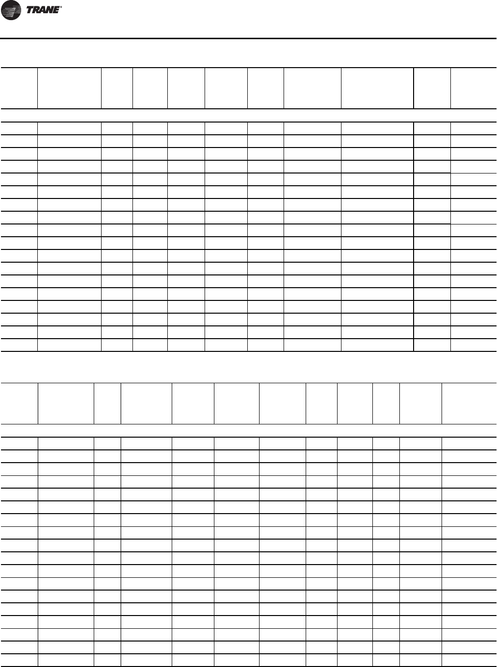
Electrical Data
82 WSHP-SVX01N-EN
EXV - Vertical Units
EXV060 230/60/1 34.40 26.4 134.0 8.00 1 41.00 60 0.0 0.0
EXV060 230/60/1 42.78 26.4 134.0 8.00 1 53.48 60 8.0 34.8
EXV060 208/60/3 24.00 16.0 110.0 8.00 1 28.00 40 0.0 0.0
EXV060 208/60/3 26.04 16.0 110.0 8.00 1 32.55 40 6.5 18.0
EXV060 230/60/3 24.00 16.0 110.0 8.00 1 28.00 40 0.0 0.0
EXV060 230/60/3 28.08 16.0 110.0 8.00 1 35.10 40 8.0 20.1
EXV060 460/60/3 14.70 7.8 52.0 6.90 1 16.65 20 0.0 0.0
EXV060 460/60/3 20.20 7.8 52.0 6.90 1 25.26 30 10.6 13.3
EXV070 208/60/1 37.10 30.1 158.0 7.00 1 44.63 70 0.0 0.0
EXV070 208/60/1 38.25 30.1 158.0 7.00 1 47.81 70 6.5 31.3
EXV070 230/60/1 37.10 30.1 158.0 7.00 1 44.63 70 0.0 0.0
EXV070 230/60/1 41.78 30.1 158.0 7.00 1 52.23 70 8.0 34.8
EXV070 208/60/3 27.50 20.5 155.0 7.00 1 32.63 50 0.0 0.0
EXV070 208/60/3 27.50 20.5 155.0 7.00 1 32.63 50 6.5 18.0
EXV070 230/60/3 27.50 20.5 155.0 7.00 1 32.63 50 0.0 0.0
EXV070 230/60/3 27.50 20.5 155.0 7.00 1 33.85 50 8.0 20.1
EXV070 460/60/3 15.70 9.6 75.0 6.10 1 18.10 25 0.0 0.0
EXV070 460/60/3 19.40 9.6 75.0 6.10 1 24.26 25 10.6 13.3
Table 49. Electrical data - ECM motors-½to6tonsEXH*/EXV* (continued)
Model
No. Volts
Total
Unit
FLA
Comp
RLA
(ea)
Comp
LRA
(ea)
Blower
Motor
FLA
Blower
Motor
hp
Minimum
Circuit
Ampacity
Maximum
Overcurrent
Protective
Device Electric
Heat kW Electric
Heat Amps
Table 50. Electrical data: 6 to 25 tons - single speed blower motor
Model
No. Volts Total
FLA Comp RLA
(ea)
Comp
LRA
(ea) No. of
Comp. Cmp MCC
Blower
Motor
FLA
Blower
Motor
HP
Fan
Motor
No.
Minimum
Circuit
Ampacity
Maximum
Overcurrent
Protective
Device
GEH - Horizontal Units
GEH072 208/60/1 39.9 16.7 79 2 26 6.5 1.0 1 44.08 60
GEH072 230/60/1 39.9 16.7 79 2 26 6.5 1.0 1 44.08 60
GEH072 208/60/1 42.7 16.7 79 2 26 9.3 1.5 1 46.88 60
GEH072 230/60/1 42.3 16.7 79 2 26 8.9 1.5 1 46.48 60
GEH072 208/60/1 44.6 16.7 79 2 26 11.2 2.0 1 48.78 60
GEH072 230/60/1 43.6 16.7 79 2 26 10.2 2.0 1 47.78 60
GEH072 380-415/50/3 13.9 7.1/5.1 48/35 2 11/8 1.7 0.75 1 15.68 20
GEH072 208/60/3 24.3 10.4 73 2 16.3 3.5 1.0 1 26.90 35
GEH072 230/60/3 24.6 10.4 73 2 16.3 3.8 1.0 1 27.20 35
GEH072 460/60/3 13.4 5.8 38 2 9 1.8 1.0 1 14.85 20
GEH072 380-415/50/3 14.3 7.1/5.1 48/35 2 11/8 2.1 1.0 1 16.08 20
GEH072 208/60/3 26.4 10.4 73 2 16.3 5.6 1.5 1 29.00 35
GEH072 230/60/3 25.6 10.4 73 2 16.3 4.8 1.5 1 28.20 35
GEH072 380-415/50/3 15.2 7.1/5.1 48/35 2 11/8 3.0 1.5 1 16.98 20
GEH072 460/60/3 14.0 5.8 38 2 9 2.4 1.5 1 15.45 20
GEH072 208/60/3 27.9 10.4 73 2 16.3 7.1 2.0 1 30.50 40
GEH072 230/60/3 27.0 10.4 73 2 16.3 6.2 2.0 1 29.60 40
GEH072 380-415/50/3 15.6 7.1/5.1 48/35 2 11/8 3.4 2.0 1 17.38 20
continued on next page

Electrical Data
WSHP-SVX01N-EN 83
GEH - Horizontal Units
GEH072 460/60/3 14.7 5.8 38 2 9 3.1 2.0 1 16.15 20
GEH072 380-415/50/3 17.4 7.1/5.1 48/35 2 11/8 5.2 3.0 1 19.18 25
GEH090 208/60/3 28.4 14.5/10.4 98/73 2 22.6/16.3 3.5 1.0 1 32.03 45
GEH090 230/60/3 28.7 14.5/10.4 98/73 2 22.6/16.3 3.8 1.0 1 32.33 45
GEH090 460/60/3 13.9 6.3/5.8 55/38 2 9.9/9 1.8 1.0 1 15.48 20
GEH090 208/60/3 30.5 14.5/10.4 98/73 2 22.6/16.3 5.6 1.5 1 34.13 45
GEH090 230/60/3 29.7 14.5/10.4 98/73 2 22.6/16.3 4.8 1.5 1 33.33 45
GEH090 380-415/50/3 22.2 9.6 64 2 15 3.0 1.5 1 24.60 30
GEH090 460/60/3 14.5 6.3/5.8 55/38 2 9.9/9 2.4 1.5 1 16.08 20
GEH090 208/60/3 32.0 14.5/10.4 98/73 2 22.6/16.3 7.1 2.0 1 35.63 50
GEH090 230/60/3 31.1 14.5/10.4 98/73 2 22.6/16.3 6.2 2.0 1 34.73 45
GEH090 380-415/50/3 22.6 9.6 64 2 15 3.4 2.0 1 25.00 30
GEH090 460/60/3 15.2 6.3/5.8 55/38 2 9.9/9 3.1 2.0 1 16.78 20
GEH090 575/60/3 12.1 6/3.8 41/36.5 2 9.4/5.9 2.3 2.0 1 13.60 15
GEH090 208/60/3 34.3 14.5/10.4 98/73 2 22.6/16.3 9.4 3.0 1 37.93 50
GEH090 230/60/3 33.1 14.5/10.4 98/73 2 22.6/16.3 8.2 3.0 1 36.73 50
GEH090 380-415/50/3 24.4 9.6 64 2 15 5.2 3.0 1 26.80 35
GEH090 460/60/3 16.7 6.3 55 2 9.9 4.1 3.0 1 18.28 20
GEH090 575/60/3 13.1 6/3.8 41/36.5 2 9.4/5.9 3.3 3.0 1 14.60 20
GEH120 380-415/50/3 23.3 10.6 74 2 16.5 2.1 1.0 1 25.95 35
GEH120 208/60/3 37.6 16 110 2 24.9 5.6 1.5 1 41.60 50
GEH120 230/60/3 36.8 16 110 2 24.9 4.8 1.5 1 40.80 50
GEH120 380-415/50/3 24.2 10.6 74 2 16.5 3.0 1.5 1 26.85 35
GEH120 460/60/3 18.0 7.8 52 2 12.1 2.4 1.5 1 19.95 25
GEH120 208/60/3 39.1 16 110 2 24.9 7.1 2.0 1 43.10 50
GEH120 230/60/3 38.2 16 110 2 24.9 6.2 2.0 1 42.20 50
GEH120 380-415/50/3 24.6 10.6 74 2 16.5 3.4 2.0 1 27.25 35
GEH120 460/60/3 18.7 7.8 52 2 12.1 3.1 2.0 1 20.65 25
GEH120 575/60/3 13.7 5.7 38.9 2 8.9 2.3 2.0 1 15.13 20
GEH120 208/60/3 41.4 16 110 2 24.9 9.4 3.0 1 45.40 60
GEH120 230/60/3 40.2 16 110 2 24.9 8.2 3.0 1 44.20 60
GEH120 380-415/50/3 26.4 10.6 74 2 16.5 5.2 3.0 1 29.05 35
GEH120 460/60/3 19.7 7.8 52 2 12.1 4.1 3.0 1 21.65 25
GEH120 575/60/3 14.7 5.7 38.9 2 8.9 3.3 3.0 1 16.13 20
GEH120 208/60/3 46.0 16 110 2 24.9 14.0 5.0 1 50.00 60
GEH120 230/60/3 45.0 16 110 2 24.9 13.0 5.0 1 49.00 60
GEH120 460/60/3 22.1 7.8 52 2 12.1 6.5 5.0 1 24.05 30
GEH120 575/60/3 16.7 5.7 38.9 2 8.9 5.3 5.0 1 18.13 20
GEH150 208/60/3 50.4 22.4 149 2 35 5.6 1.5 1 56.00 70
GEH150 230/60/3 49.6 22.4 149 2 35 4.8 1.5 1 55.20 70
GEH150 380-415/50/3 27.4 12.2 101 2 19 3.0 1.5 1 30.45 40
GEH150 460/60/3 23.6 10.6 75 2 16.5 2.4 1.5 1 26.25 35
GEH150 575/60/3 17.3 7.7 54 2 12 1.9 1.5 1 19.23 25
continued on next page
Table 50. Electrical data: 6 to 25 tons - single speed blower motor (continued)
Model
No. Volts Total
FLA Comp RLA
(ea)
Comp
LRA
(ea) No. of
Comp. Cmp MCC
Blower
Motor
FLA
Blower
Motor
HP
Fan
Motor
No.
Minimum
Circuit
Ampacity
Maximum
Overcurrent
Protective
Device

Electrical Data
84 WSHP-SVX01N-EN
GEH - Horizontal Units
GEH150 208/60/3 51.9 22.4 149 2 35 7.1 2.0 1 57.50 70
GEH150 230/60/3 51.0 22.4 149 2 35 6.2 2.0 1 56.60 70
GEH150 380-415/50/3 27.8 12.2 101 2 19 3.4 2.0 1 30.85 40
GEH150 460/60/3 24.3 10.6 75 2 16.5 3.1 2.0 1 26.96 35
GEH150 575/60/3 17.7 7.7 54 2 12 2.3 2.0 1 19.63 25
GEH150 208/60/3 54.2 22.4 149 2 35 9.4 3.0 1 59.80 80
GEH150 230/60/3 53.0 22.4 149 2 35 8.2 3.0 1 58.60 80
GEH150 380-415/50/3 29.6 12.2 101 2 19 5.2 3.0 1 32.65 40
GEH150 460/60/3 25.3 10.6 75 2 16.5 4.1 3.0 1 27.95 35
GEH150 575/60/3 18.7 7.7 54 2 12 3.3 3.0 1 20.63 25
GEH150 208/60/3 58.8 22.4 149 2 35 14.0 5.0 1 64.40 80
GEH150 230/60/3 57.8 22.4 149 2 35 13.0 5.0 1 63.40 80
GEH150 380-415/50/3 32.6 12.2 101 2 19 8.2 5.0 1 35.65 45
GEH150 460/60/3 27.7 10.6 75 2 16.5 6.5 5.0 1 30.35 40
GEH150 575/60/3 20.7 7.7 54 2 12 5.3 5.0 1 22.63 30
GEH180 208/60/3 57.1 25 164 2 39 7.1 2.0 1 63.35 80
GEH180 230/60/3 56.2 25 164 2 39 6.2 2.0 1 62.45 80
GEH180 460/60/3 27.5 12.2 100 2 19 3.1 2.0 1 30.56 40
GEH180 575/60/3 20.3 9 78 2 14 2.3 2.0 1 22.55 30
GEH180 208/60/3 59.4 25 164 2 39 9.4 3.0 1 65.65 90
GEH180 230/60/3 58.2 25 164 2 39 8.2 3.0 1 64.45 80
GEH180 460/60/3 28.5 12.2 100 2 19 4.1 3.0 1 31.55 40
GEH180 575/60/3 21.3 9 78 2 14 3.3 3.0 1 23.55 30
GEH180 208/60/3 64.0 25 164 2 39 14.0 5.0 1 70.25 90
GEH180 230/60/3 63.0 25 164 2 39 13.0 5.0 1 69.25 90
GEH180 460/60/3 30.9 12.2 100 2 19 6.5 5.0 1 33.95 45
GEH180 575/60/3 23.3 9 78 2 14 5.3 5.0 1 25.55 30
GEH180 208/60/3 70.0 25 164 2 39 20.0 7.5 1 76.25 100
GEH180 230/60/3 69.4 25 164 2 39 19.4 7.5 1 75.65 100
GEH180 460/60/3 34.1 12.2 100 2 19 9.7 7.5 1 37.15 45
GEH180 575/60/3 26.0 9 78 2 14 8.0 7.5 1 28.25 35
GEV - Vertical Units
GEV072 208/60/1 40.0 16.7 79 2 26 6.6 1.0 1 44.13 60
GEV072 230/60/1 39.9 16.7 79 2 26 6.5 1.0 1 44.08 60
GEV072 208/60/1 42.7 16.7 79 2 26 9.3 1.5 1 46.88 60
GEV072 230/60/1 42.3 16.7 79 2 26 8.9 1.5 1 46.48 60
GEV072 208/60/1 44.6 16.7 79 2 26 11.2 2.0 1 48.78 60
GEV072 230/60/1 43.6 16.7 79 2 26 10.2 2.0 1 47.81 60
GEV072 380-415/50/3 13.9 7.1/5.1 48/35 2 11/8 1.7 0.75 1 15.68 20
GEV072 208/60/3 24.3 10.4 73 2 16.3 3.5 1.0 1 26.90 35
GEV072 230/60/3 24.6 10.4 73 2 16.3 3.8 1.0 1 27.20 35
GEV072 460/60/3 13.4 5.8 38 2 9 1.8 1.0 1 14.85 20
GEV072 380-415/50/3 14.3 7.1/5.1 48/35 2 11/8 2.1 1.0 1 16.08 20
continued on next page
Table 50. Electrical data: 6 to 25 tons - single speed blower motor (continued)
Model
No. Volts Total
FLA Comp RLA
(ea)
Comp
LRA
(ea) No. of
Comp. Cmp MCC
Blower
Motor
FLA
Blower
Motor
HP
Fan
Motor
No.
Minimum
Circuit
Ampacity
Maximum
Overcurrent
Protective
Device

Electrical Data
WSHP-SVX01N-EN 85
GEV - Vertical Units
GEV072 208/60/3 26.4 10.4 73 2 16.3 5.6 1.5 1 29.00 35
GEV072 230/60/3 25.6 10.4 73 2 16.3 4.8 1.5 1 28.20 35
GEV072 380-415/50/3 15.2 7.1/5.1 48/35 2 11/8 3.0 1.5 1 16.98 20
GEV072 460/60/3 14.0 5.8 38 2 9 2.4 1.5 1 15.45 20
GEV072 208/60/3 27.9 10.4 73 2 16.3 7.1 2.0 1 30.50 40
GEV072 230/60/3 27.0 10.4 73 2 16.3 6.2 2.0 1 29.60 40
GEV072 380-415/50/3 15.6 7.1/5.1 48/35 2 11/8 3.4 2.0 1 17.38 20
GEV072 460/60/3 14.7 5.8 38 2 9 3.1 2.0 1 16.16 20
GEV072 380-415/50/3 17.7 7.1/5.1 48/35 2 11/8 5.5 3.0 1 19.48 25
GEVE090 380-415/50/3 21.3 9.6 64 2 15 2.1 1.0 1 23.70 30
GEV090 208/60/3 28.4 14.5/10.4 98/73 2 22.6/16.3 3.5 1.0 1 32.03 45
GEV090 230/60/3 28.7 14.5/10.4 98/73 2 22.6/16.3 3.8 1.0 1 32.33 45
GEV090 460/60/3 13.9 6.3/5.8 55/38 2 9.9/9 1.8 1.0 1 15.48 20
GEV090 208/60/3 30.5 14.5/10.4 98/73 2 22.6/16.3 5.6 1.5 1 34.13 45
GEV090 230/60/3 29.7 14.5/10.4 98/73 2 22.6/16.3 4.8 1.5 1 33.33 45
GEV090 380-415/50/3 22.2 9.6 64 2 15 3.0 1.5 1 24.60 30
GEV090 460/60/3 14.5 6.3/5.8 55/38 2 9.9/9 2.4 1.5 1 16.08 20
GEV090 208/60/3 32.0 14.5/10.4 98/73 2 22.6/16.3 7.1 2.0 1 35.63 50
GEV090 230/60/3 31.1 14.5/10.4 98/73 2 22.6/16.3 6.2 2.0 1 34.73 45
GEV090 380-415/50/3 22.6 9.6 64 2 15 3.4 2.0 1 25.00 30
GEV090 460/60/3 15.2 6.3/5.8 55/38 2 9.9/9 3.1 2.0 1 16.79 20
GEV090 575/60/3 12.1 6/3.8 41/36.5 2 9.4/5.9 2.3 2.0 1 13.60 15
GEV090 208/60/3 34.3 14.5/10.4 98/73 2 22.6/16.3 9.4 3.0 1 37.93 50
GEV090 230/60/3 33.1 14.5/10.4 98/73 2 22.6/16.3 8.2 3.0 1 36.73 50
GEV090 380-415/50/3 24.4 9.6 64 2 15 5.2 3.0 1 26.80 35
GEV090 460/60/3 16.2 6.3/5.8 55/38 2 9.9/9 4.1 3.0 1 17.78 20
GEV090 575/60/3 13.1 6/3.8 41/36.5 2 9.4/5.9 3.3 3.0 1 14.60 20
GEV120 208/60/3 37.6 16 110 2 24.9 5.6 1.5 1 41.60 50
GEV120 230/60/3 36.8 16 110 2 24.9 4.8 1.5 1 40.80 50
GEV120 460/60/3 18.0 7.8 52 2 12.1 2.4 1.5 1 19.95 25
GEV120 208/60/3 39.1 16 110 2 24.9 7.1 2.0 1 43.10 50
GEV120 230/60/3 38.2 16 110 2 24.9 6.2 2.0 1 42.20 50
GEV120 460/60/3 18.7 7.8 52 2 12.1 3.1 2.0 1 20.66 25
GEV120 575/60/3 13.7 5.7 38.9 2 8.9 2.3 2.0 1 15.13 20
GEV120 208/60/3 41.4 16 110 2 24.9 9.4 3.0 1 45.40 60
GEV120 230/60/3 40.2 16 110 2 24.9 8.2 3.0 1 44.20 60
GEV120 460/60/3 19.7 7.8 52 2 12.1 4.1 3.0 1 21.65 25
GEV120 575/60/3 14.7 5.7 38.9 2 8.9 3.3 3.0 1 16.13 20
GEV120 208/60/3 46.0 16 110 2 24.9 14.0 5.0 1 50.00 60
GEV120 230/60/3 45.0 16 110 2 24.9 13.0 5.0 1 49.00 60
GEV120 460/60/3 22.1 7.8 52 2 12.1 6.5 5.0 1 24.05 30
GEV120 575/60/3 16.7 5.7 38.9 2 8.9 5.3 5.0 1 18.13 20
GEV120 380-415/50/3 24.2 10.6 74 2 16.5 3.0 1.5 1 26.85 35
continued on next page
Table 50. Electrical data: 6 to 25 tons - single speed blower motor (continued)
Model
No. Volts Total
FLA Comp RLA
(ea)
Comp
LRA
(ea) No. of
Comp. Cmp MCC
Blower
Motor
FLA
Blower
Motor
HP
Fan
Motor
No.
Minimum
Circuit
Ampacity
Maximum
Overcurrent
Protective
Device

Electrical Data
86 WSHP-SVX01N-EN
GEV - Vertical Units
GEV120 380-415/50/3 24.6 10.6 74 2 16.5 3.4 2.0 1 27.25 35
GEV120 380-415/50/3 26.4 10.6 74 2 16.5 5.2 3.0 1 29.05 35
GEV150 208/60/3 51.9 22.4 149 2 35 7.1 2.0 1 57.50 70
GEV150 230/60/3 51.0 22.4 149 2 35 6.2 2.0 1 56.60 70
GEV150 380-415/50/3 27.8 12.2 101 2 19 3.4 2.0 1 30.85 40
GEV150 460/60/3 24.3 10.6 75 2 16.5 3.1 2.0 1 26.96 35
GEV150 575/60/3 17.7 7.7 54 2 12 2.3 2.0 1 19.63 25
GEV150 208/60/3 54.2 22.4 149 2 35 9.4 3.0 1 59.80 80
GEV150 230/60/3 53.0 22.4 149 2 35 8.2 3.0 1 58.60 80
GEV150 380-415/50/3 29.6 12.2 101 2 19 5.2 3.0 1 32.65 40
GEV150 460/60/3 25.3 10.6 75 2 16.5 4.1 3.0 1 27.95 35
GEV150 575/60/3 18.7 7.7 54 2 12 3.3 3.0 1 20.63 25
GEV150 208/60/3 58.8 22.4 149 2 35 14.0 5.0 1 64.40 80
GEV150 230/60/3 57.8 22.4 149 2 35 13.0 5.0 1 63.40 80
GEV150 380-415/50/3 32.6 12.2 101 2 19 8.2 5.0 1 35.65 45
GEV150 460/60/3 27.7 10.6 75 2 16.5 6.5 5.0 1 30.35 40
GEV150 575/60/3 20.7 7.7 54 2 12 5.3 5.0 1 22.63 30
GEV180 208/60/3 59.4 25 164 2 39 9.4 3.0 1 65.65 90
GEV180 230/60/3 58.2 25 164 2 39 8.2 3.0 1 64.45 80
GEV180 380-415/50/3 38.6 16.7 111 2 26 5.2 3.0 1 42.78 50
GEV180 460/60/3 28.5 12.2 100 2 19 4.1 3.0 1 31.55 40
GEV180 575/60/3 21.3 9 78 2 14 3.3 3.0 1 23.55 30
GEV180 208/60/3 64.0 25 164 2 39 14.0 5.0 1 70.25 90
GEV180 230/60/3 63.0 25 164 2 39 13.0 5.0 1 69.25 90
GEV180 380-415/50/3 41.6 16.7 111 2 26 8.2 5.0 1 45.78 60
GEV180 460/60/3 30.9 12.2 100 2 19 6.5 5.0 1 33.95 45
GEV180 575/60/3 23.3 9 78 2 14 5.3 5.0 1 25.55 30
GEV180 208/60/3 70.0 25 164 2 39 20.0 7.5 1 76.25 100
GEV180 230/60/3 69.4 25 164 2 39 19.4 7.5 1 75.65 100
GEV180 380-415/50/3 44.9 16.7 111 2 26 11.5 7.5 1 49.08 60
GEV180 460/60/3 34.1 12.2 100 2 19 9.7 7.5 1 37.15 45
GEV180 575/60/3 26.0 9 78 2 14 8.0 7.5 1 28.25 35
GEV240 380-415/50/3 42.4 18.6 118 2 29 5.2 3.0 1 47.05 60
GEV240 208/60/3 74.2 30.1 225 2 47 14.0 5.0 1 81.73 110
GEV240 230/60/3 73.2 30.1 225 2 47 13.0 5.0 1 80.73 110
GEV240 380-415/50/3 45.4 18.6 118 2 29 8.2 5.0 1 50.05 60
GEV240 460/60/3 39.9 16.7 114 2 26 6.5 5.0 1 44.08 60
GEV240 575/60/3 29.7 12.2 80 2 19 5.3 5.0 1 32.75 40
GEV240 208/60/3 80.2 30.1 225 2 47 20.0 7.5 1 87.73 110
GEV240 230/60/3 79.6 30.1 225 2 47 19.4 7.5 1 87.13 110
GEV240 380-415/50/3 48.7 18.6 118 2 29 11.5 7.5 1 53.35 70
GEV240 460/60/3 43.1 16.7 114 2 26 9.7 7.5 1 47.28 60
GEV240 575/60/3 32.4 12.2 80 2 19 8.0 7.5 1 35.45 45
continued on next page
Table 50. Electrical data: 6 to 25 tons - single speed blower motor (continued)
Model
No. Volts Total
FLA Comp RLA
(ea)
Comp
LRA
(ea) No. of
Comp. Cmp MCC
Blower
Motor
FLA
Blower
Motor
HP
Fan
Motor
No.
Minimum
Circuit
Ampacity
Maximum
Overcurrent
Protective
Device

Electrical Data
WSHP-SVX01N-EN 87
GEV - Vertical Units
GEV240 208/60/3 86.2 30.1 225 2 47 26.0 10.0 1 93.73 110
GEV240 230/60/3 85.2 30.1 225 2 47 25.0 10.0 1 92.73 110
GEV240 460/60/3 45.9 16.7 114 2 26 12.5 10.0 1 50.08 60
GEV240 575/60/3 34.4 12.2 80 2 19 10.0 10.0 1 37.45 45
GEV240 208/60/3 97.2 30.1 225 2 47 37.0 15.0 1 106.45 125
GEV240 230/60/3 96.2 30.1 225 2 47 36.0 15.0 1 105.20 125
GEV240 380-415/50/3 52.2 18.6 118 2 29 15.0 10.0 1 56.85 70
GEV240 460/60/3 51.4 16.7 114 2 26 18.0 15.0 1 55.90 70
GEV240 575/60/3 38.5 12.2 80 2 19 14.1 15.0 1 42.03 50
GEV300 208/60/3 110.2 48.1 245 2 75 14.0 5.0 1 122.23 150
GEV300 230/60/3 109.2 48.1 245 2 75 13.0 5.0 1 121.23 150
GEV300 460/60/3 43.7 18.6 125 2 29 6.5 5.0 1 48.35 60
GEV300 575/60/3 34.7 14.7 100 2 23 5.3 5.0 1 38.38 50
GEV300 208/60/3 116.2 48.1 245 2 75 20.0 7.5 1 128.23 175
GEV300 230/60/3 115.6 48.1 245 2 75 19.4 7.5 1 127.63 175
GEV300 460/60/3 46.9 18.6 125 2 29 9.7 7.5 1 51.55 70
GEV300 575/60/3 37.4 14.7 100 2 23 8.0 7.5 1 41.08 50
GEV300 208/60/3 122.2 48.1 245 2 75 26.0 10.0 1 134.23 175
GEV300 230/60/3 121.2 48.1 245 2 75 25.0 10.0 1 133.23 175
GEV300 460/60/3 49.7 18.6 125 2 29 12.5 10.0 1 54.35 70
GEV300 575/60/3 39.4 14.7 100 2 23 10.0 10.0 1 43.08 50
GEV300 208/60/3 133.2 48.1 245 2 75 37.0 15.0 1 145.23 175
GEV300 230/60/3 132.2 48.1 245 2 75 36.0 15.0 1 144.23 175
GEV300 460/60/3 55.2 18.6 125 2 29 18.0 15.0 1 59.85 70
GEV300 575/60/3 43.5 14.7 100 2 23 14.1 15.0 1 47.18 60
Table 50. Electrical data: 6 to 25 tons - single speed blower motor (continued)
Model
No. Volts Total
FLA Comp RLA
(ea)
Comp
LRA
(ea) No. of
Comp. Cmp MCC
Blower
Motor
FLA
Blower
Motor
HP
Fan
Motor
No.
Minimum
Circuit
Ampacity
Maximum
Overcurrent
Protective
Device
Table 51. Electrical data: 6 to 25 tons - two speed blower motor
Model
No. Volts Total
FLA Comp RLA
(ea)
Comp
LRA
(ea) No. of
Comp. Cmp MCC
Blower
Motor
FLA
Blower
Motor
HP
Fan
Motor
No.
Minimum
Circuit
Ampacity
Maximum
Overcurrent
Protective
Device
GEH - Horizontal Units
GEH072 208/60/3 24.1 10.4 73 2 16.3 3.3 1.0 1 26.70 35
GEH072 230/60/3 23.8 10.4 73 2 16.3 3.0 1.0 1 26.40 35
GEH072 460/60/3 13.1 5.8 38 2 9 1.5 1.0 1 14.55 20
GEH072 208/60/3 25.7 10.4 73 2 16.3 4.9 1.5 1 28.30 35
GEH072 230/60/3 25.2 10.4 73 2 16.3 4.4 1.5 1 27.80 35
GEH072 460/60/3 13.8 5.8 38 2 9 2.2 1.5 1 15.25 20
GEH072 208/60/3 27.5 10.4 73 2 16.3 6.7 2.0 1 30.10 40
GEH072 230/60/3 26.9 10.4 73 2 16.3 6.1 2.0 1 29.50 35
GEH072 460/60/3 14.7 5.8 38 2 9 3.1 2.0 1 16.15 20
GEH090 208/60/3 28.2 14.5/10.4 98/73 2 22.6/16.3 3.3 1.0 1 31.83 45
GEH090 230/60/3 27.9 14.5/10.4 98/73 2 22.6/16.3 3.0 1.0 1 31.53 45
continued on next page

Electrical Data
88 WSHP-SVX01N-EN
GEH - Horizontal Units
GEH090 460/60/3 13.6 6.3/5.8 55/38 2 9.9/9 1.5 1.0 1 15.18 20
GEH090 208/60/3 29.8 14.5/10.4 98/73 2 22.6/16.3 4.9 1.5 1 33.43 45
GEH090 230/60/3 29.3 14.5/10.4 98/73 2 22.6/16.3 4.4 1.5 1 32.93 45
GEH090 460/60/3 14.3 6.3/5.8 55/38 2 9.9/9 2.2 1.5 1 15.88 20
GEH090 208/60/3 31.6 14.5/10.4 98/73 2 22.6/16.3 6.7 2.0 1 35.23 45
GEH090 230/60/3 31.0 14.5/10.4 98/73 2 22.6/16.3 6.1 2.0 1 34.63 45
GEH090 460/60/3 15.2 6.3/5.8 55/38 2 9.9/9 3.1 2.0 1 16.78 20
GEH090 208/60/3 33.7 14.5/10.4 98/73 2 22.6/16.3 8.8 3.0 1 37.33 50
GEH090 230/60/3 32.9 14.5/10.4 98/73 2 22.6/16.3 8.0 3.0 1 36.53 50
GEH090 460/60/3 16.6 6.3 55 2 9.9 4.0 3.0 1 18.18 20
GEH120 208/60/3 36.9 16 110 2 24.9 4.9 1.5 1 40.90 50
GEH120 230/60/3 36.4 16 110 2 24.9 4.4 1.5 1 40.40 50
GEH120 460/60/3 17.8 7.8 52 2 12.1 2.2 1.5 1 19.75 25
GEH120 208/60/3 38.7 16 110 2 24.9 6.7 2.0 1 42.70 50
GEH120 230/60/3 38.1 16 110 2 24.9 6.1 2.0 1 42.10 50
GEH120 460/60/3 18.7 7.8 52 2 12.1 3.1 2.0 1 20.65 25
GEH120 208/60/3 40.8 16 110 2 24.9 8.8 3.0 1 44.80 60
GEH120 230/60/3 40.0 16 110 2 24.9 8.0 3.0 1 44.00 60
GEH120 460/60/3 19.6 7.8 52 2 12.1 4.0 3.0 1 21.55 25
GEH120 208/60/3 46.6 16 110 2 24.9 14.6 5.0 1 50.60 60
GEH120 230/60/3 45.2 16 110 2 24.9 13.2 5.0 1 49.20 60
GEH120 460/60/3 22.2 7.8 52 2 12.1 6.6 5.0 1 24.15 30
GEH150 208/60/3 49.7 22.4 149 2 35 4.9 1.5 1 55.30 70
GEH150 230/60/3 49.2 22.4 149 2 35 4.4 1.5 1 54.80 70
GEH150 460/60/3 23.4 10.6 75 2 16.5 2.2 1.5 1 26.05 35
GEH150 208/60/3 51.5 22.4 149 2 35 6.7 2.0 1 57.10 70
GEH150 230/60/3 50.9 22.4 149 2 35 6.1 2.0 1 56.50 70
GEH150 460/60/3 24.3 10.6 75 2 16.5 3.1 2.0 1 26.95 35
GEH150 208/60/3 53.6 22.4 149 2 35 8.8 3.0 1 59.20 80
GEH150 230/60/3 52.8 22.4 149 2 35 8.0 3.0 1 58.40 80
GEH150 460/60/3 25.2 10.6 75 2 16.5 4.0 3.0 1 27.85 35
GEH150 208/60/3 59.4 22.4 149 2 35 14.6 5.0 1 65.00 80
GEH150 230/60/3 58.0 22.4 149 2 35 13.2 5.0 1 63.60 80
GEH150 460/60/3 27.8 10.6 75 2 16.5 6.6 5.0 1 30.45 40
GEH180 208/60/3 56.7 25 164 2 39 6.7 2.0 1 62.95 80
GEH180 230/60/3 56.1 25 164 2 39 6.1 2.0 1 62.35 80
GEH180 460/60/3 27.5 12.2 100 2 19 3.1 2.0 1 30.55 40
GEH180 208/60/3 58.8 25 164 2 39 8.8 3.0 1 65.05 90
GEH180 230/60/3 58.0 25 164 2 39 8.0 3.0 1 64.25 80
GEH180 460/60/3 28.4 12.2 100 2 19 4.0 3.0 1 31.45 40
GEH180 208/60/3 64.6 25 164 2 39 14.6 5.0 1 70.85 90
GEH180 230/60/3 63.2 25 164 2 39 13.2 5.0 1 69.45 90
GEH180 460/60/3 31.0 12.2 100 2 19 6.6 5.0 1 34.05 45
continued on next page
Table 51. Electrical data: 6 to 25 tons - two speed blower motor (continued)
Model
No. Volts Total
FLA Comp RLA
(ea)
Comp
LRA
(ea) No. of
Comp. Cmp MCC
Blower
Motor
FLA
Blower
Motor
HP
Fan
Motor
No.
Minimum
Circuit
Ampacity
Maximum
Overcurrent
Protective
Device

Electrical Data
WSHP-SVX01N-EN 89
GEH - Horizontal Units
GEH180 208/60/3 72.1 25 164 2 39 22.1 7.5 1 78.35 100
GEH180 230/60/3 70.0 25 164 2 39 20.0 7.5 1 76.25 100
GEH180 460/60/3 34.4 12.2 100 2 19 10.0 7.5 1 37.45 45
GEV - Vertical Units
GEV072 208/60/3 24.1 10.4 73 2 16.3 3.3 1.0 1 26.70 35
GEV072 230/60/3 23.8 10.4 73 2 16.3 3.0 1.0 1 26.40 35
GEV072 460/60/3 13.1 5.8 38 2 9 1.5 1.0 1 14.55 20
GEV072 208/60/3 25.7 10.4 73 2 16.3 4.9 1.5 1 28.30 35
GEV072 230/60/3 25.2 10.4 73 2 16.3 4.4 1.5 1 27.80 35
GEV072 460/60/3 13.8 5.8 38 2 9 2.2 1.5 1 15.25 20
GEV072 208/60/3 27.5 10.4 73 2 16.3 6.7 2.0 1 30.10 40
GEV072 230/60/3 26.9 10.4 73 2 16.3 6.1 2.0 1 29.50 35
GEV072 460/60/3 14.7 5.8 38 2 9 3.1 2.0 1 16.15 20
GEV090 208/60/3 28.2 14.5/10.4 98/73 2 22.6/16.3 3.3 1.0 1 31.83 45
GEV090 230/60/3 27.9 14.5/10.4 98/73 2 22.6/16.3 3.0 1.0 1 31.53 45
GEV090 460/60/3 13.6 6.3/5.8 55/38 2 9.9/9 1.5 1.0 1 15.18 20
GEV090 208/60/3 29.8 14.5/10.4 98/73 2 22.6/16.3 4.9 1.5 1 33.43 45
GEV090 230/60/3 29.3 14.5/10.4 98/73 2 22.6/16.3 4.4 1.5 1 32.93 45
GEV090 460/60/3 14.3 6.3/5.8 55/38 2 9.9/9 2.2 1.5 1 15.88 20
GEV090 208/60/3 31.6 14.5/10.4 98/73 2 22.6/16.3 6.7 2.0 1 35.23 45
GEV090 230/60/3 31.0 14.5/10.4 98/73 2 22.6/16.3 6.1 2.0 1 34.63 45
GEV090 460/60/3 15.2 6.3/5.8 55/38 2 9.9/9 3.1 2.0 1 16.78 20
GEV090 208/60/3 33.7 14.5/10.4 98/73 2 22.6/16.3 8.8 3.0 1 37.33 50
GEV090 230/60/3 32.9 14.5/10.4 98/73 2 22.6/16.3 8.0 3.0 1 36.53 50
GEV090 460/60/3 16.1 6.3/5.8 55/38 2 9.9/9 4.0 3.0 1 17.68 20
GEV120 208/60/3 36.9 16 110 2 24.9 4.9 1.5 1 40.90 50
GEV120 230/60/3 36.4 16 110 2 24.9 4.4 1.5 1 40.40 50
GEV120 460/60/3 17.8 7.8 52 2 12.1 2.2 1.5 1 19.75 25
GEV120 208/60/3 38.7 16 110 2 24.9 6.7 2.0 1 42.70 50
GEV120 230/60/3 38.1 16 110 2 24.9 6.1 2.0 1 42.10 50
GEV120 460/60/3 18.7 7.8 52 2 12.1 3.1 2.0 1 20.65 25
GEV120 208/60/3 40.8 16 110 2 24.9 8.8 3.0 1 44.80 60
GEV120 230/60/3 40.0 16 110 2 24.9 8.0 3.0 1 44.00 60
GEV120 460/60/3 19.6 7.8 52 2 12.1 4.0 3.0 1 21.55 25
GEV120 208/60/3 46.6 16 110 2 24.9 14.6 5.0 1 50.60 60
GEV120 230/60/3 45.2 16 110 2 24.9 13.2 5.0 1 49.20 60
GEV120 460/60/3 22.2 7.8 52 2 12.1 6.6 5.0 1 24.15 30
GEV150 208/60/3 51.5 22.4 149 2 35 6.7 2.0 1 57.10 70
GEV150 230/60/3 50.9 22.4 149 2 35 6.1 2.0 1 56.50 70
GEV150 460/60/3 24.3 10.6 75 2 16.5 3.1 2.0 1 26.95 35
GEV150 208/60/3 53.6 22.4 149 2 35 8.8 3.0 1 59.20 80
GEV150 230/60/3 52.8 22.4 149 2 35 8.0 3.0 1 58.40 80
GEV150 460/60/3 25.2 10.6 75 2 16.5 4.0 3.0 1 27.85 35
continued on next page
Table 51. Electrical data: 6 to 25 tons - two speed blower motor (continued)
Model
No. Volts Total
FLA Comp RLA
(ea)
Comp
LRA
(ea) No. of
Comp. Cmp MCC
Blower
Motor
FLA
Blower
Motor
HP
Fan
Motor
No.
Minimum
Circuit
Ampacity
Maximum
Overcurrent
Protective
Device

Electrical Data
90 WSHP-SVX01N-EN
GEV - Vertical Units
GEV150 208/60/3 59.4 22.4 149 2 35 14.6 5.0 1 65.00 80
GEV150 230/60/3 58.0 22.4 149 2 35 13.2 5.0 1 63.60 80
GEV150 460/60/3 27.8 10.6 75 2 16.5 6.6 5.0 1 30.45 40
GEV180 208/60/3 58.8 25 164 2 39 8.8 3.0 1 65.05 90
GEV180 230/60/3 58.0 25 164 2 39 8.0 3.0 1 64.25 80
GEV180 460/60/3 28.4 12.2 100 2 19 4.0 3.0 1 31.45 40
GEV180 208/60/3 64.6 25 164 2 39 14.6 5.0 1 70.85 90
GEV180 230/60/3 63.2 25 164 2 39 13.2 5.0 1 69.45 90
GEV180 460/60/3 31.0 12.2 100 2 19 6.6 5.0 1 34.05 45
GEV180 208/60/3 72.1 25 164 2 39 22.1 7.5 1 78.35 100
GEV180 230/60/3 70.0 25 164 2 39 20.0 7.5 1 76.25 100
GEV180 460/60/3 34.4 12.2 100 2 19 10.0 7.5 1 37.45 45
GEV240 208/60/3 74.8 30.1 225 2 47 14.6 5.0 1 82.33 110
GEV240 230/60/3 73.4 30.1 225 2 47 13.2 5.0 1 80.93 110
GEV240 460/60/3 40.0 16.7 114 2 26 6.6 5.0 1 44.18 60
GEV240 208/60/3 82.3 30.1 225 2 47 22.1 7.5 1 89.83 110
GEV240 230/60/3 80.2 30.1 225 2 47 20.0 7.5 1 87.73 110
GEV240 460/60/3 43.4 16.7 114 2 26 10.0 7.5 1 47.58 60
GEV240 208/60/3 87.8 30.1 225 2 47 27.6 10.0 1 95.33 125
GEV240 230/60/3 85.2 30.1 225 2 47 25.0 10.0 1 92.73 110
GEV240 460/60/3 46.4 16.7 114 2 26 13.0 10.0 1 50.58 60
GEV240 460/60/3 53.4 16.7 114 2 26 20.0 15.0 1 58.40 70
GEV300 208/60/3 110.8 48.1 245 2 75 14.6 5.0 1 122.83 150
GEV300 230/60/3 109.4 48.1 245 2 75 13.2 5.0 1 121.43 150
GEV300 460/60/3 43.8 18.6 125 2 29 6.6 5.0 1 48.45 60
GEV300 208/60/3 118.3 48.1 245 2 75 22.1 7.5 1 130.33 175
GEV300 230/60/3 116.2 48.1 245 2 75 20.0 7.5 1 128.23 175
GEV300 460/60/3 47.2 18.6 125 2 29 10.0 7.5 1 51.85 70
GEV300 208/60/3 123.8 48.1 245 2 75 27.6 10.0 1 135.83 175
GEV300 230/60/3 121.2 48.1 245 2 75 25.0 10.0 1 133.23 175
GEV300 460/60/3 50.2 18.6 125 2 29 13.0 10.0 1 54.85 70
GEV300 460/60/3 57.2 18.6 125 2 29 20.0 15.0 1 62.20 80
Table 51. Electrical data: 6 to 25 tons - two speed blower motor (continued)
Model
No. Volts Total
FLA Comp RLA
(ea)
Comp
LRA
(ea) No. of
Comp. Cmp MCC
Blower
Motor
FLA
Blower
Motor
HP
Fan
Motor
No.
Minimum
Circuit
Ampacity
Maximum
Overcurrent
Protective
Device
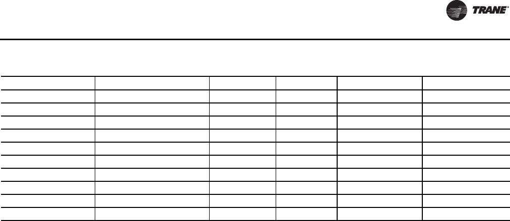
Electrical Data
WSHP-SVX01N-EN 91
Table 52. Electrical minimum and maximum
Digit 8 Rated Voltage Hz Ph Min Utiliz. Volts Max Utiliz. Volts
0 115 60 1 104 126
1 208 60 1 197 229
2 230 60 1 207 253
3 208 60 3 187 229
4 460 60 3 414 506
5 575 60 3 518 633
6 220-240 50 1 198 264
7 265 60 1 239 292
8 230 60 3 207 253
9 380-415 50 3 342 456

92 WSHP-SVX01N-EN
Pre-Start Checklist
Before energizing the unit, the following system devices
must be checked:
• Is the high voltage power supply correct and in
accordance with the nameplate ratings?
• Is phasing of the unit correct per compressor rotation
(scroll compressor only)?
• Is the field wiring and circuit protection the correct
size?
• Is the low voltage control circuit wiring correct per the
unit wiring diagram?
• Is the piping system clean/complete and correct? (A
recommendation of all system flushing of debris from
the water-to-refrigerant heat exchanger, along with air
purging from the water-to-refrigerant heat exchanger
be done in accordance with the Closed-Loop/Ground
Source Heat Pump Systems Installation Guide).
• Is vibration isolation provided? (i.e. unit isolation pad,
hose kits)
• Is unit serviceable? (See clearance specifications in
“Unit Dimensions and Weights,” p. 14).
• Are the low/high-side pressure temperature caps
secure and in place?
• Are all the unit access panels secure and in place?
• Is the thermostat in the OFF position?
• Is the water flow established and circulating through
all the units?
• Is the duct work correctly sized, run, taped, insulated
and weather proofed with proper unit arrangement?
• Is the condensate line properly sized, run, trapped,
pitched and primed?
• Is the zone sensor correctly wired and in a good
location?
• Does the indoor blower turn freely without rubbing?
• Has all work been done in accordance with applicable
local and national codes?
Has heat transfer fluid been added in the proper mix to
prevent freezing in closed system application?
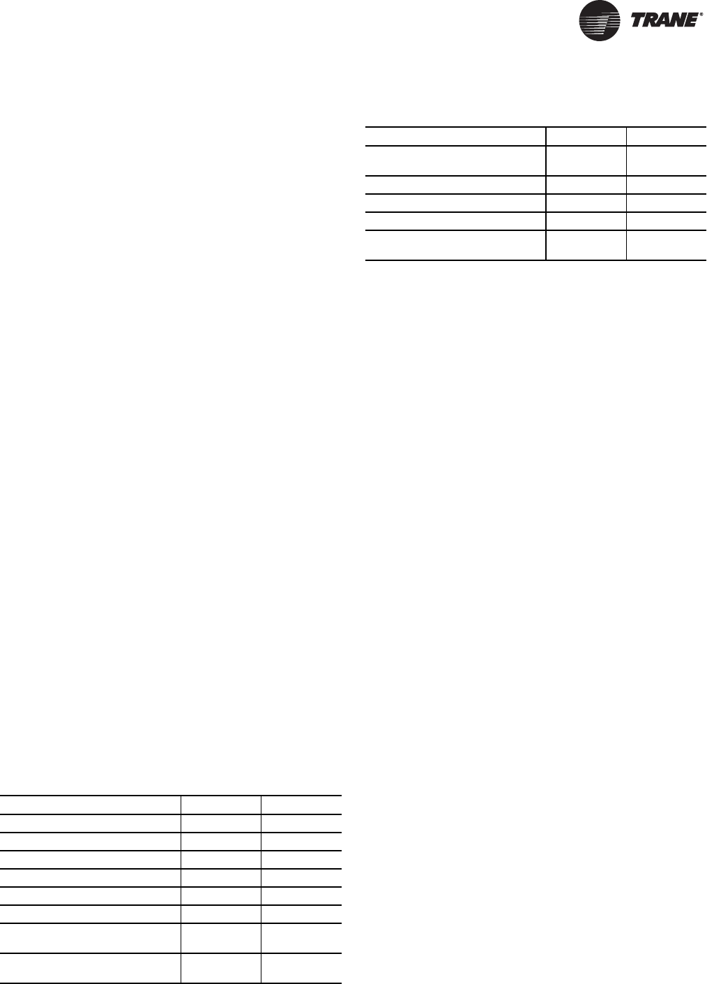
WSHP-SVX01N-EN 93
Start-Up
Initial Unit Start-up
Note: Start-up with the heat pump thermostat is included
below:
1. Set the thermostat to the highest position.
2. Set the thermostat system switch to COOL with the fan
control to AUTO. The compressor should NOT run.
3. Reduce the thermostat setting until the compressor,
reversing valve, solenoid valve, and loop pump are
energized. Adjust water flow utilizing pressure/
temperature plugs and comparing to tables contained
in specification sheet data.
Water leaving the heat exchanger should be warmer
than the entering water temperature (approximately 9-
12ºF); blower operation should be smooth;
compressor and blower amps should be within data
plate ratings; the suction line should be cool with no
frost observed in the refrigerant circuit.
4. Check the cooling refrigerant pressures against values
in Table 54, p. 94.
5. Turn the thermostat system switch to the OFF position.
Unit should stop running and the reversing valve
should de-energize.
6. Leave unit off for approximately FIVE minutes to allow
for pressure equalization.
7. Turn the thermostat to the lowest setting.
8. Set the thermostat system switch to the HEAT position.
9. Adjust the temperature setting upward until the unit is
energized. Warm air should blow from the register. A
water temperature decrease of approximately 5-9ºF
leaving the heat exchanger should be noted.The
blower and compressor operation should be smooth
with no frost observed in the refrigeration circuit.
10. Check the heating refrigerant pressures against values
in Table 54, p. 94.
11. Set the thermostat to maintain the desired space
temperature.
12. Instruct the owner on system operation.
Start-Up Checklist and Log
Installing Contractor: Use this checklist to thoroughly
check-out the system and units before and during start-up.
(This form need not be returned to the factory unless
requested during technical service support).
Job Name:________________________
Model Number:____________________
Date:______________________________
Serial Number:_____________________
In order to minimize troubleshooting and costly system
failures, complete the following checks and data entries
before the system is put into full operation.
Operating Pressures
There are many variables (airflow, air temperatures) in an
air conditioning system that will affect operating
refrigerant pressures and temperatures.The charts below
shows approximate conditions and is based on air flow at
the rated SCFM, entering air at 80.6°F(DB), 66.2°F(WB) in
cooling, 68°F(DB) in heating. (+)Heating data with 35°F
EWT is based on the use of an anti-freeze solution having
a freezing point 20°F lower than the minimum expected
entering temperature.
Table 53. Checklist
MODE Heat Cool
Entering fluid temperature _______F _______F
Leaving fluid temperature _______F _______F
Temperature differential _______F _______F
Return-air temperature DB/WB _______F _______F
Supply-air temperature DB/WB _______F _______F
Temperature differential _______F _______F
Water coil heat exchanger (Water
Pressure IN) ________PSIG ________PSIG
Water coil heat exchanger (Water
Pressure OUT) ________PSIG ________PSIG
Pressure Differential _________PSI
G_________PSI
G
COMPRESSOR
Amps
Volts
Discharge line temperature (after 10
minutes) _______F _______F
Table 53. Checklist
MODE Heat Cool
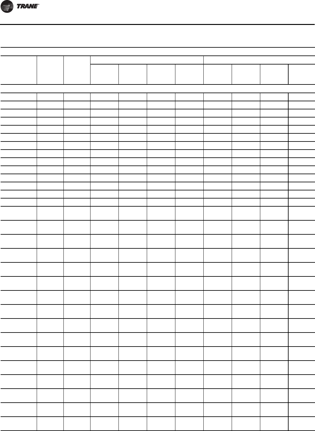
Start-Up
94 WSHP-SVX01N-EN
Table 54. Operating pressures in cooling/heating for GE* units
Operating Data
Model No.
Entering
Water
Temp
(°F)
Water
Flow
(GPM)
Cooling Heating
Suction
Pressure
(psig)
Discharge
Pressure
(psig)
Water
Temp Rise
(°F)
Air Temp
Drop
(°F DB)
Suction
Pressure
(psig)
Discharge
Pressure
(psig)
Water
Temp
Drop (°F)
Air Temp
Rise
(°F DB)
GEH*/GEV*
006 (60 Hz) 35 1.4 — — — — 94-108 279-355 6-8 23-29
006 (60 Hz) 35 1.7 — — — — 96-110 281-357 5-6 23-29
006 (60 Hz) 45 1.4 143-165 190-243 13-16 24-30 110-127 297-377 7-9 26-34
006 (60 Hz) 45 1.7 143-164 184-235 11-13 24-31 113-130 300-382 6-8 27-34
006 (60 Hz) 55 1.4 145-167 217-277 13-16 23-30 128-147 317-404 8-10 30-39
006 (60 Hz) 55 1.7 144-166 210-268 11-13 24-30 131-151 320-407 7-9 31-39
006 (60 Hz) 68 1.4 148-171 254-324 12-15 23-29 154-177 345-439 10-12 35-45
006 (60 Hz) 68 1.7 147-170 244-312 10-13 23-29 158-182 349-444 8-10 36-45
006 (60 Hz) 75 1.4 148-171 281-358 12-15 23-29 169-195 361-459 10-13 38-48
006 (60 Hz) 75 1.7 148-170 273-348 10-13 23-29 175-201 366-466 9-11 38-48
006 (60 Hz) 86 1.4 149-172 328-418 12-15 22-28 197-226 388-494 11-15 41-52
006 (60 Hz) 86 1.7 149-172 320-407 10-13 23-29 203-234 395-502 10-12 41-52
006 (60 Hz) 95 1.4 151-173 373-474 12-15 22-28 — — — —
006 (60 Hz) 95 1.7 150-173 363-462 10-13 22-28 — — — —
009 (60Hz)
006 (50 Hz) 35 1.7 — — — — 93-107 272-346 6-7 20-26
009 (60Hz)
006 (50 Hz) 35 2.1 — — — — 95-110 274-348 5-6 21-27
009 (60Hz)
006 (50 Hz) 45 1.7 142-164 187-238 13-16 22-28 109-126 288-366 7-9 24-30
009 (60Hz)
006 (50 Hz) 45 2.1 142-164 181-230 11-14 22-27 112-129 291-370 6-7 24-31
009 (60Hz)
006 (50 Hz) 55 1.7 144-166 214-272 12-15 21-27 127-146 305-388 8-10 27-34
009 (60Hz)
006 (50 Hz) 55 2.1 144-166 207-263 10-13 21-27 130-150 309-393 7-8 27-35
009 (60Hz)
006 (50 Hz) 68 1.7 146-168 258-328 12-15 20-26 153-176 330-420 9-12 31-39
009 (60Hz)
006 (50 Hz) 68 2.1 146-168 250-318 10-12 21-26 157-181 335-427 8-10 32-40
009 (60Hz)
006 (50 Hz) 75 1.7 147-169 286-363 12-15 20-25 168-193 345-439 10-13 33-42
009 (60Hz)
006 (50 Hz) 75 2.1 147-169 277-352 9-12 20-26 174-200 350-446 8-11 34-43
009 (60Hz)
006 (50 Hz) 86 1.7 149-171 336-427 12-15 19-25 195-224 370-471 11-14 36-46
009 (60Hz)
006 (50 Hz) 86 2.1 148-171 326-415 9-12 20-25 202-232 375-477 9-12 37-47
009 (60Hz)
006 (50 Hz) 95 1.7 149-172 386-491 12-15 19-24 — — — —
009 (60Hz)
006 (50 Hz) 95 2.1 149-172 375-477 9-12 19-24 — — — —
012 (60Hz)
009 (50 Hz) 35 2.2 — — — — 92-106 288-367 10-13 21-27
012 (60Hz)
009 (50 Hz) 35 2.8 — — — — 95-109 290-370 8-11 21-27

Start-Up
WSHP-SVX01N-EN 95
GEH*/GEV*
012 (60Hz)
009 (50 Hz) 45 2.2 142-163 183-233 12-15 22-28 108-125 304-387 12-15 24-30
012 (60Hz)
009 (50 Hz) 45 2.8 142-163 175-223 9-12 23-29 111-128 307-391 9-12 24-31
012 (60Hz)
009 (50 Hz) 55 2.2 143-164 212-270 12-15 21-27 126-145 322-410 13-16 26-33
012 (60Hz)
009 (50 Hz) 55 2.8 143-164 204-260 9-12 22-27 130-149 325-413 10-13 27-34
012 (60Hz)
009 (50 Hz) 68 2.2 144-166 257-327 12-15 21-26 152-174 346-441 14-18 29-37
012 (60Hz)
009 (50 Hz) 68 2.8 144-166 248-316 9-12 21-26 157-180 352-448 11-15 29-37
012 (60Hz)
009 (50 Hz) 75 2.2 145-167 284-361 12-15 20-26 167-192 361-460 15-19 30-38
012 (60Hz)
009 (50 Hz) 75 2.8 145-167 274-349 9-12 20-26 173-199 366-466 12-15 30-39
012 (60Hz)
009 (50 Hz) 86 2.2 146-168 332-422 12-15 19-25 194-223 384-489 16-21 32-40
012 (60Hz)
009 (50 Hz) 86 2.8 146-168 321-409 9-12 20-25 201-231 390-497 13-17 32-41
012 (60Hz)
009 (50 Hz) 95 2.2 147-170 376-478 12-15 19-24 — — — —
012 (60Hz)
009 (50 Hz) 95 2.8 147-170 365-465 9-12 19-24 — — — —
015 (60Hz)
012 (50 Hz) 35 2.8 — — — — 91-105 296-377 6-7 20-25
015 (60Hz)
012 (50 Hz) 35 3.5 — — — — 93-107 299-380 5-6 20-26
015 (60Hz)
012 (50 Hz) 45 2.8 138-159 180-230 11-14 22-28 107-123 313-398 7-8 23-29
015 (60Hz)
012 (50 Hz) 45 3.5 138-158 174-221 9-11 22-27 109-126 316-402 5-7 23-30
015 (60Hz)
012 (50 Hz) 55 2.8 139-159 210-267 11-14 21-27 124-143 332-423 8-10 26-33
015 (60Hz)
012 (50 Hz) 55 3.5 138-159 203-258 9-11 21-27 128-147 336-427 6-8 27-34
015 (60Hz)
012 (50 Hz) 68 2.8 140-161 254-324 11-14 20-26 150-172 358-456 9-11 30-38
015 (60Hz)
012 (50 Hz) 68 3.5 140-161 246-313 9-11 21-26 154-178 364-463 7-9 30-39
015 (60Hz)
012 (50 Hz) 75 2.8 141-162 281-358 11-14 20-25 165-190 373-475 10-12 32-40
015 (60Hz)
012 (50 Hz) 75 3.5 140-162 272-347 9-11 20-26 171-196 379-483 8-10 32-41
015 (60Hz)
012 (50 Hz) 86 2.8 142-163 328-417 11-14 19-25 191-220 399-508 11-14 34-43
015 (60Hz)
012 (50 Hz) 86 3.5 142-163 318-405 9-11 20-25 198-228 405-515 9-11 34-44
Table 54. Operating pressures in cooling/heating for GE* units (continued)
Operating Data
Model No.
Entering
Water
Temp
(°F)
Water
Flow
(GPM)
Cooling Heating
Suction
Pressure
(psig)
Discharge
Pressure
(psig)
Water
Temp Rise
(°F)
Air Temp
Drop
(°F DB)
Suction
Pressure
(psig)
Discharge
Pressure
(psig)
Water
Temp
Drop (°F)
Air Temp
Rise
(°F DB)

Start-Up
96 WSHP-SVX01N-EN
GEH*/GEV*
015 (60Hz)
012 (50 Hz) 95 2.8 143-165 371-472 11-14 19-24 — — — —
015 (60Hz)
012 (50 Hz) 95 3.5 143-165 361-459 9-11 19-24 — — — —
018 (60Hz)
015 (50 Hz) 35 3.3 — — — — 89-102 276-351 6-7 21-26
018 (60Hz)
015 (50 Hz) 35 4.2 — — — — 91-105 279-354 5-6 21-27
018 (60Hz)
015 (50 Hz) 45 3.3 142-163 186-237 12-15 23-29 104-120 292-372 7-9 24-30
018 (60Hz)
015 (50 Hz) 45 4.2 142-163 179-227 9-12 23-29 107-123 295-376 5-7 24-31
018 (60Hz)
015 (50 Hz) 55 3.3 142-163 216-275 12-15 23-29 121-139 310-395 8-10 27-34
018 (60Hz)
015 (50 Hz) 55 4.2 142-163 207-264 9-12 23-29 125-143 313-399 6-8 27-35
018 (60Hz)
015 (50 Hz) 68 3.3 142-163 262-333 12-15 22-28 146-168 334-425 9-12 31-39
018 (60Hz)
015 (50 Hz) 68 4.2 142-163 252-321 9-12 22-28 151-174 338-430 7-9 32-40
018 (60Hz)
015 (50 Hz) 75 3.3 142-164 289-368 12-15 21-27 161-185 347-441 10-13 33-42
018 (60Hz)
015 (50 Hz) 75 4.2 142-164 280-356 9-12 21-27 167-192 351-447 8-10 34-43
018 (60Hz)
015 (50 Hz) 86 3.3 143-165 338-430 12-15 20-26 188-216 365-464 11-14 36-46
018 (60Hz)
015 (50 Hz) 86 4.2 143-165 327-416 9-12 20-26 195-225 370-471 9-11 37-47
018 (60Hz)
015 (50 Hz) 95 3.3 144-166 383-488 12-15 19-24 — — — —
018 (60Hz)
015 (50 Hz) 95 4.2 144-166 372-473 9-12 19-25 — — — —
GEH*024
024 (60Hz)
018 (50Hz) 35 — — — — — 76-88 279-355 6-7 21-30
024 (60Hz)
018 (50Hz) 35 — — — — — 78-89 280-357 5-6 21-31
024 (60Hz)
018 (50Hz) 45 4.5 114-131 172-219 12-16 20-26 89-103 290-369 7-9 24-34
024 (60Hz)
018 (50Hz) 45 5.6 114-131 165-211 10-13 20-26 91-105 292-371 6-7 24-34
024 (60Hz)
018 (50Hz) 55 4.5 115-132 200-255 12-15 20-26 106-122 307-390 8-10 27-37
024 (60Hz)
018 (50Hz) 55 5.6 115-132 193-246 10-12 20-26 108-125 309-394 6-8 28-38
024 (60Hz)
018 (50Hz) 68 4.5 120-139 239-304 12-15 19-25 124-143 326-415 9-12 31-42
024 (60Hz)
018 (50Hz) 68 5.6 120-138 231-294 10-12 20-25 129-148 330-420 7-9 32-43
Table 54. Operating pressures in cooling/heating for GE* units (continued)
Operating Data
Model No.
Entering
Water
Temp
(°F)
Water
Flow
(GPM)
Cooling Heating
Suction
Pressure
(psig)
Discharge
Pressure
(psig)
Water
Temp Rise
(°F)
Air Temp
Drop
(°F DB)
Suction
Pressure
(psig)
Discharge
Pressure
(psig)
Water
Temp
Drop (°F)
Air Temp
Rise
(°F DB)
Start-Up
WSHP-SVX01N-EN 97
GEH*024
024 (60Hz)
018 (50Hz) 75 4.5 121-140 264-336 12-15 19-25 139-159 340-432 10-13 34-44
024 (60Hz)
018 (50Hz) 75 5.6 121-139 256-325 9-12 19-25 143-165 343-437 8-10 34-45
024 (60Hz)
018 (50Hz) 86 4.5 124-143 305-389 12-15 18-24 163-188 363-462 11-14 38-49
024 (60Hz)
018 (50Hz) 86 5.6 124-143 297-378 9-12 19-24 169-195 368-468 9-12 39-50
024 (60Hz)
018 (50Hz) 95 4.5 126-145 344-437 12-15 18-24 — — — —
024 (60Hz)
018 (50Hz) 95 5.6 126-145 335-426 9-12 18-24 — — — —
GEV*024
024 (60Hz)
018 (50Hz) 35 — — — — — 76-87 270-344 6-7 21-30
024 (60Hz)
018 (50Hz) 35 — — — — — 78-89 272-346 5-6 21-31
024 (60Hz)
018 (50Hz) 45 4.5 114-132 173-221 12-16 20-26 88-102 283-360 7-9 24-34
024 (60Hz)
018 (50Hz) 45 5.6 114-131 167-212 10-12 20-26 90-104 285-362 6-7 24-34
024 (60Hz)
018 (50Hz) 55 4.5 116-133 202-258 12-15 20-25 105-121 299-381 8-10 27-37
024 (60Hz)
018 (50Hz) 55 5.6 116-133 195-249 10-12 20-26 107-124 301-384 6-8 28-38
024 (60Hz)
018 (50Hz) 68 4.5 122-140 242-308 12-15 20-26 123-141 315-401 9-12 31-41
024 (60Hz)
018 (50Hz) 68 5.6 122-140 234-298 10-12 20-26 127-146 318-405 7-9 32-42
024 (60Hz)
018 (50Hz) 75 4.5 123-141 268-341 12-15 19-25 137-158 327-417 10-13 34-44
024 (60Hz)
018 (50Hz) 75 5.6 123-141 259-330 10-12 20-25 142-163 331-421 8-10 34-45
024 (60Hz)
018 (50Hz) 86 4.5 126-145 310-394 12-15 19-25 161-186 349-444 11-14 38-49
024 (60Hz)
018 (50Hz) 86 5.6 125-144 301-383 9-12 19-25 167-193 353-449 9-12 39-50
024 (60Hz)
018 (50Hz) 95 4.5 127-146 349-445 12-15 19-25 — — — —
024 (60Hz)
018 (50Hz) 95 5.6 127-146 340-433 9-12 19-25 — — — —
GEH*030
030 (60 Hz)
024 (50 Hz) 35 — — — — — 77-89 276-351 6-7 21-30
030 (60 Hz)
024 (50 Hz) 35 — — — — — 79-90 277-352 4-6 21-30
030 (60 Hz)
024 (50 Hz) 45 5.6 120-138 171-218 12-15 22-27 91-104 290-369 7-8 24-34
030 (60 Hz)
024 (50 Hz) 45 7.0 120-138 165-210 10-12 22-28 93-107 292-371 5-7 24-34
Table 54. Operating pressures in cooling/heating for GE* units (continued)
Operating Data
Model No.
Entering
Water
Temp
(°F)
Water
Flow
(GPM)
Cooling Heating
Suction
Pressure
(psig)
Discharge
Pressure
(psig)
Water
Temp Rise
(°F)
Air Temp
Drop
(°F DB)
Suction
Pressure
(psig)
Discharge
Pressure
(psig)
Water
Temp
Drop (°F)
Air Temp
Rise
(°F DB)

Start-Up
98 WSHP-SVX01N-EN
GEH*030
030 (60 Hz)
024 (50 Hz) 55 5.6 121-140 200-254 12-15 21-27 108-124 307-390 8-10 27-37
030 (60 Hz)
024 (50 Hz) 55 7.0 121-139 193-245 9-12 22-27 111-127 309-393 6-8 28-38
030 (60 Hz)
024 (50 Hz) 68 5.6 122-140 249-317 12-15 20-26 128-148 329-419 9-11 32-42
030 (60 Hz)
024 (50 Hz) 68 7.0 122-140 241-306 9-12 20-26 133-152 333-423 7-9 32-43
030 (60 Hz)
024 (50 Hz) 75 5.6 123-141 275-350 12-15 20-26 143-164 342-436 10-12 34-45
030 (60 Hz)
024 (50 Hz) 75 7.0 123-141 267-340 9-12 20-26 148-170 346-440 8-10 35-46
030 (60 Hz)
024 (50 Hz) 86 5.6 126-146 310-395 11-14 20-26 168-193 365-465 11-14 38-49
030 (60 Hz)
024 (50 Hz) 86 7.0 126-145 302-384 9-11 20-26 174-200 370-470 9-11 39-50
030 (60 Hz)
024 (50 Hz) 95 5.6 128-148 350-446 11-14 19-25 — — — —
030 (60 Hz)
024 (50 Hz) 95 7.0 128-147 341-434 9-11 19-25 — — — —
GEV*030
030 (60 Hz)
024 (50 Hz) 35 — — — — — 76-88 266-338 6-7 21-30
030 (60 Hz)
024 (50 Hz) 35 — — — — — 78-90 268-341 5-6 22-31
030 (60 Hz)
024 (50 Hz) 45 5.6 115-132 172-218 12-15 21-27 87-100 275-351 6-8 24-33
030 (60 Hz)
024 (50 Hz) 45 7.0 115-132 165-210 9-12 21-27 90-103 278-354 5-7 24-34
030 (60 Hz)
024 (50 Hz) 55 5.6 116-134 201-256 12-15 20-26 104-119 292-371 8-10 27-37
030 (60 Hz)
024 (50 Hz) 55 7.0 116-134 194-247 9-12 21-26 107-123 295-375 6-8 28-38
030 (60 Hz)
024 (50 Hz) 68 5.6 121-139 242-308 11-15 20-26 122-141 311-396 9-11 31-41
030 (60 Hz)
024 (50 Hz) 68 7.0 120-138 234-298 9-12 20-26 126-145 314-400 7-9 32-42
030 (60 Hz)
024 (50 Hz) 75 5.6 122-140 268-341 11-14 20-26 136-157 324-412 9-12 34-44
030 (60 Hz)
024 (50 Hz) 75 7.0 122-140 260-331 9-12 20-26 141-162 328-418 8-10 34-45
030 (60 Hz)
024 (50 Hz) 86 5.6 124-142 311-396 11-14 19-25 161-185 345-439 11-14 38-49
030 (60 Hz)
024 (50 Hz) 86 7.0 123-142 303-385 9-11 19-25 167-192 350-445 9-11 39-50
030 (60 Hz)
024 (50 Hz) 95 5.6 125-144 351-447 11-14 19-25 — — — —
030 (60 Hz)
024 (50 Hz) 95 7.0 125-144 342-436 9-11 19-25 — — — —
Table 54. Operating pressures in cooling/heating for GE* units (continued)
Operating Data
Model No.
Entering
Water
Temp
(°F)
Water
Flow
(GPM)
Cooling Heating
Suction
Pressure
(psig)
Discharge
Pressure
(psig)
Water
Temp Rise
(°F)
Air Temp
Drop
(°F DB)
Suction
Pressure
(psig)
Discharge
Pressure
(psig)
Water
Temp
Drop (°F)
Air Temp
Rise
(°F DB)

Start-Up
WSHP-SVX01N-EN 99
GEH*036
036 (60 Hz)
030 (50 Hz) 35 — — — — — 76-88 294-375 6-8 21-30
036 (60 Hz)
030 (50 Hz) 45 6.7 115-132 174-222 12-15 20-26 89-102 306-390 7-9 24-34
036 (60 Hz)
030 (50 Hz) 45 8.4 115-132 168-214 9-12 20-26 91-105 309-394 6-7 24-34
036 (60 Hz)
030 (50 Hz) 55 6.7 117-134 203-259 11-15 19-25 106-122 327-416 8-11 27-37
036 (60 Hz)
030 (50 Hz) 55 8.4 116-134 196-250 9-12 20-25 108-125 329-419 7-9 28-38
036 (60 Hz)
030 (50 Hz) 68 6.7 120-138 244-311 11-14 19-25 126-145 351-446 10-12 32-42
036 (60 Hz)
030 (50 Hz) 68 8.4 119-137 237-301 9-11 19-25 130-150 354-450 8-10 32-43
036 (60 Hz)
030 (50 Hz) 75 6.7 121-139 270-343 11-14 19-25 141-162 367-468 10-13 34-45
036 (60 Hz)
030 (50 Hz) 75 8.4 121-139 262-333 9-11 19-25 145-167 372-473 9-11 35-46
036 (60 Hz)
030 (50 Hz) 86 6.7 124-142 312-397 11-14 18-24 165-190 395-503 12-15 39-50
036 (60 Hz)
030 (50 Hz) 86 8.4 124-142 303-386 9-11 19-24 172-197 399-508 10-12 40-51
036 (60 Hz)
030 (50 Hz) 95 6.7 126-145 351-447 11-14 18-24 — — — —
036 (60 Hz)
030 (50 Hz) 95 8.4 126-144 342-435 9-11 18-24 — — — —
GEV*036
036 (60 Hz)
030 (50 Hz) 35 — — — — — 77-88 286-364 6-8 22-31
036 (60 Hz)
030 (50 Hz) 35 — — — — — 78-90 288-366 5-6 22-31
036 (60 Hz)
030 (50 Hz) 45 6.7 116-134 169-215 12-15 20-26 89-103 296-377 7-9 25-34
036 (60 Hz)
030 (50 Hz) 45 8.4 116-134 163-208 10-12 21-26 91-105 298-380 6-7 25-35
036 (60 Hz)
030 (50 Hz) 55 6.7 118-136 198-251 12-15 20-26 106-122 315-401 8-10 28-38
036 (60 Hz)
030 (50 Hz) 55 8.4 118-135 191-243 10-12 20-26 109-125 318-404 7-8 29-39
036 (60 Hz)
030 (50 Hz) 68 6.7 121-139 238-303 12-15 20-25 128-147 341-434 10-12 33-43
036 (60 Hz)
030 (50 Hz) 68 8.4 121-139 231-294 10-12 20-26 132-151 344-437 8-10 33-44
036 (60 Hz)
030 (50 Hz) 75 6.7 122-141 263-335 12-15 19-25 143-164 357-454 10-13 36-46
036 (60 Hz)
030 (50 Hz) 75 8.4 122-140 255-325 9-12 19-25 147-169 360-458 9-11 36-47
036 (60 Hz)
030 (50 Hz) 86 6.7 125-144 304-387 12-15 19-25 168-193 383-488 12-15 40-51
Table 54. Operating pressures in cooling/heating for GE* units (continued)
Operating Data
Model No.
Entering
Water
Temp
(°F)
Water
Flow
(GPM)
Cooling Heating
Suction
Pressure
(psig)
Discharge
Pressure
(psig)
Water
Temp Rise
(°F)
Air Temp
Drop
(°F DB)
Suction
Pressure
(psig)
Discharge
Pressure
(psig)
Water
Temp
Drop (°F)
Air Temp
Rise
(°F DB)
Start-Up
100 WSHP-SVX01N-EN
GEV*036
036 (60 Hz)
030 (50 Hz) 86 8.4 125-143 296-377 9-12 19-25 174-200 387-492 10-12 41-52
036 (60 Hz)
030 (50 Hz) 95 6.7 127-146 342-436 11-15 19-24 — — — —
036 (60 Hz)
030 (50 Hz) 95 8.4 127-146 334-425 9-12 19-25 — — — —
GEH*042
042 (60 Hz)
036 (50 Hz) 35 — — — — — 74-86 269-342 6-7 20-30
042 (60 Hz)
036 (50 Hz) 35 — — — — — 76-87 270-344 5-6 21-30
042 (60 Hz)
036 (50 Hz) 45 7.8 116-134 173-220 12-16 21-27 86-99 281-358 7-8 23-33
042 (60 Hz)
036 (50 Hz) 45 9.8 116-134 167-212 10-13 21-27 88-101 283-360 5-7 24-33
042 (60 Hz)
036 (50 Hz) 55 7.8 118-135 201-256 12-15 21-26 102-118 298-379 8-10 27-36
042 (60 Hz)
036 (50 Hz) 55 9.8 118-135 194-247 10-12 21-26 105-121 300-382 6-8 27-37
042 (60 Hz)
036 (50 Hz) 68 7.8 122-140 242-308 12-15 20-26 121-140 317-403 9-11 31-41
042 (60 Hz)
036 (50 Hz) 68 9.8 121-140 235-299 10-12 21-26 125-144 321-408 7-9 31-42
042 (60 Hz)
036 (50 Hz) 75 7.8 123-141 267-340 12-15 20-26 135-156 331-422 10-12 33-44
042 (60 Hz)
036 (50 Hz) 75 9.8 123-141 259-330 9-12 20-26 140-161 336-427 8-10 34-45
042 (60 Hz)
036 (50 Hz) 86 7.8 125-144 308-392 12-15 20-25 159-183 355-451 11-14 38-49
042 (60 Hz)
036 (50 Hz) 86 9.8 125-144 300-382 9-12 20-26 165-190 359-457 9-12 39-50
042 (60 Hz)
036 (50 Hz) 95 7.8 127-146 346-441 11-15 19-25 — — — —
042 (60 Hz)
036 (50 Hz) 95 9.8 127-146 338-430 9-12 19-25 — — — —
GEV*042
042 (60 Hz)
036 (50 Hz) 35 — — — — — 75-86 268-341 6-7 20-30
042 (60 Hz)
036 (50 Hz) 35 — — — — — 76-87 268-341 5-6 21-30
042 (60 Hz)
036 (50 Hz) 45 7.8 116-133 173-220 12-16 21-26 86-99 283-360 7-9 23-33
042 (60 Hz)
036 (50 Hz) 45 9.8 116-133 167-212 10-12 21-27 88-102 283-360 6-7 24-33
042 (60 Hz)
036 (50 Hz) 55 7.8 117-135 201-256 12-15 20-26 103-118 298-380 8-10 27-37
042 (60 Hz)
036 (50 Hz) 55 9.8 117-135 194-247 10-12 20-26 105-121 301-383 6-8 27-37
Table 54. Operating pressures in cooling/heating for GE* units (continued)
Operating Data
Model No.
Entering
Water
Temp
(°F)
Water
Flow
(GPM)
Cooling Heating
Suction
Pressure
(psig)
Discharge
Pressure
(psig)
Water
Temp Rise
(°F)
Air Temp
Drop
(°F DB)
Suction
Pressure
(psig)
Discharge
Pressure
(psig)
Water
Temp
Drop (°F)
Air Temp
Rise
(°F DB)

Start-Up
WSHP-SVX01N-EN 101
GEV*042
042 (60 Hz)
036 (50 Hz) 68 7.8 122-140 242-308 12-15 20-26 122-140 318-404 9-12 31-41
042 (60 Hz)
036 (50 Hz) 68 9.8 121-140 234-298 9-12 20-26 126-144 321-409 7-9 31-42
042 (60 Hz)
036 (50 Hz) 75 7.8 123-141 267-340 12-15 20-25 136-156 331-422 10-13 33-44
042 (60 Hz)
036 (50 Hz) 75 9.8 122-141 259-330 9-12 20-26 140-161 336-427 8-10 34-45
042 (60 Hz)
036 (50 Hz) 86 7.8 126-144 307-390 11-15 19-25 160-184 355-452 11-14 38-49
042 (60 Hz)
036 (50 Hz) 86 9.8 125-144 299-380 9-12 19-25 166-190 359-457 9-12 39-50
042 (60 Hz)
036 (50 Hz) 95 7.8 127-147 345-439 11-14 18-24 — — — —
042 (60 Hz)
036 (50 Hz) 95 9.8 127-146 337-428 9-11 18-24 — — — —
GEH*048
048 (60 Hz)
042 (50 Hz) 35 — — — — — 74-85 263-334 6-8 20-29
048 (60 Hz)
042 (50 Hz) 35 — — — — — 76-87 265-337 5-6 20-29
048 (60 Hz)
042 (50 Hz) 45 9.0 120-138 184-234 13-16 23-29 85-98 273-348 7-9 23-32
048 (60 Hz)
042 (50 Hz) 45 11.2 120-138 176-225 10-13 23-29 87-100 275-350 6-7 23-33
048 (60 Hz)
042 (50 Hz) 55 9.0 121-140 214-273 13-16 23-28 101-117 289-368 8-10 26-36
048 (60 Hz)
042 (50 Hz) 55 11.2 121-139 206-262 10-13 23-28 104-120 292-372 6-8 26-36
048 (60 Hz)
042 (50 Hz) 68 9.0 125-144 256-326 13-16 22-28 117-135 305-388 9-12 30-40
048 (60 Hz)
042 (50 Hz) 68 11.2 125-144 247-315 10-13 23-28 122-140 310-394 7-10 30-41
048 (60 Hz)
042 (50 Hz) 75 9.0 126-146 282-359 12-16 22-28 131-151 318-405 10-13 32-43
048 (60 Hz)
042 (50 Hz) 75 11.2 126-145 273-348 10-13 22-28 136-156 322-410 8-10 33-44
048 (60 Hz)
042 (50 Hz) 86 9.0 129-148 324-412 12-15 21-27 154-177 339-431 11-14 36-47
048 (60 Hz)
042 (50 Hz) 86 11.2 128-147 314-400 10-12 22-27 160-184 344-437 9-12 37-48
048 (60 Hz)
042 (50 Hz) 95 9.0 130-150 364-463 12-15 21-27 — — — —
048 (60 Hz)
042 (50 Hz) 95 11.2 130-149 354-451 10-12 21-27 — — — —
Table 54. Operating pressures in cooling/heating for GE* units (continued)
Operating Data
Model No.
Entering
Water
Temp
(°F)
Water
Flow
(GPM)
Cooling Heating
Suction
Pressure
(psig)
Discharge
Pressure
(psig)
Water
Temp Rise
(°F)
Air Temp
Drop
(°F DB)
Suction
Pressure
(psig)
Discharge
Pressure
(psig)
Water
Temp
Drop (°F)
Air Temp
Rise
(°F DB)

Start-Up
102 WSHP-SVX01N-EN
GEV*048
048 (60 Hz)
042 (50 Hz) 35 — — — — — 63-73 248-315 5-7 19-28
048 (60 Hz)
042 (50 Hz) 35 — — — — — 64-74 249-316 4-5 19-28
048 (60 Hz)
042 (50 Hz) 45 9.0 120-138 184-234 13-16 22-28 72-82 257-327 6-8 21-30
048 (60 Hz)
042 (50 Hz) 45 11.2 119-137 177-225 10-13 22-28 73-84 259-329 5-6 21-30
048 (60 Hz)
042 (50 Hz) 55 9.0 121-139 214-272 13-16 22-27 86-99 270-344 7-9 24-33
048 (60 Hz)
042 (50 Hz) 55 11.2 121-139 206-262 10-13 22-27 88-101 272-347 6-7 24-34
048 (60 Hz)
042 (50 Hz) 68 9.0 125-144 255-325 12-16 21-27 102-118 287-366 8-10 27-37
048 (60 Hz)
042 (50 Hz) 68 11.2 125-144 246-314 10-13 21-27 105-120 290-369 7-8 28-38
048 (60 Hz)
042 (50 Hz) 75 9.0 126-145 281-358 12-16 21-27 114-131 299-381 9-11 30-40
048 (60 Hz)
042 (50 Hz) 75 11.2 126-145 272-346 10-13 21-27 117-135 302-384 7-9 30-41
048 (60 Hz)
042 (50 Hz) 86 9.0 129-149 323-412 12-16 20-26 136-156 318-405 10-13 34-44
048 (60 Hz)
042 (50 Hz) 86 11.2 129-148 314-399 10-12 21-26 140-161 321-409 8-10 34-45
048 (60 Hz)
042 (50 Hz) 95 9.0 131-151 363-462 12-15 20-26 — — — —
048 (60 Hz)
042 (50 Hz) 95 11.2 131-150 353-449 10-12 20-26 — — — —
GEH*060
060(60 Hz)
048 (50 Hz) 35 — — — — — 69-79 265-337 6-7 20-30
060(60 Hz)
048 (50 Hz) 35 — — — — — 70-81 267-339 5-6 21-30
060(60 Hz)
048 (50 Hz) 45 11.2 111-128 176-225 13-16 21-26 79-91 274-348 6-8 23-32
060(60 Hz)
048 (50 Hz) 45 14.0 108-124 170-217 10-13 21-27 81-93 275-350 5-7 23-32
060(60 Hz)
048 (50 Hz) 55 11.2 113-129 205-261 12-16 20-26 95-109 290-369 7-9 26-36
060(60 Hz)
048 (50 Hz) 55 14.0 112-129 198-252 10-13 20-26 97-111 291-371 6-8 26-36
060(60 Hz)
048 (50 Hz) 68 11.2 117-135 243-309 12-16 20-26 115-132 311-396 9-11 30-40
060(60 Hz)
048 (50 Hz) 68 14.0 117-134 235-300 10-12 20-26 118-136 314-399 7-9 31-41
060(60 Hz)
048 (50 Hz) 75 11.2 118-136 268-342 12-15 20-25 128-147 324-412 10-12 33-43
060(60 Hz)
048 (50 Hz) 75 14.0 118-136 260-331 10-12 20-26 132-152 327-416 8-10 33-44
Table 54. Operating pressures in cooling/heating for GE* units (continued)
Operating Data
Model No.
Entering
Water
Temp
(°F)
Water
Flow
(GPM)
Cooling Heating
Suction
Pressure
(psig)
Discharge
Pressure
(psig)
Water
Temp Rise
(°F)
Air Temp
Drop
(°F DB)
Suction
Pressure
(psig)
Discharge
Pressure
(psig)
Water
Temp
Drop (°F)
Air Temp
Rise
(°F DB)
Start-Up
WSHP-SVX01N-EN 103
GEH*060
060(60 Hz)
048 (50 Hz) 86 11.2 121-139 309-393 12-15 19-25 151-174 347-442 11-14 37-48
060(60 Hz)
048 (50 Hz) 86 14.0 121-139 301-383 10-12 19-25 157-180 351-447 9-11 38-49
060(60 Hz)
048 (50 Hz) 95 11.2 123-141 348-442 12-15 19-25 — — — —
060(60 Hz)
048 (50 Hz) 95 14.0 122-141 339-431 9-12 19-25 — — — —
GEV*060
060(60 Hz)
048 (50 Hz) 35 — — — — — 70-81 261-332 6-7 20-30
060(60 Hz)
048 (50 Hz) 35 — — — — — 72-82 262-333 5-6 20-30
060(60 Hz)
048 (50 Hz) 45 11.2 115-133 178-227 13-16 21-27 80-92 269-342 6-8 23-32
060(60 Hz)
048 (50 Hz) 45 14.0 115-132 172-219 10-13 21-27 82-94 270-344 5-7 23-32
060(60 Hz)
048 (50 Hz) 55 11.2 117-134 207-264 12-16 20-26 95-110 284-362 7-10 26-36
060(60 Hz)
042 (50 Hz) 55 14.0 117-134 200-255 10-13 21-26 97-112 286-364 6-8 26-36
060(60 Hz)
048 (50 Hz) 68 11.2 122-140 248-315 12-16 20-26 116-134 304-387 9-11 31-41
060(60 Hz)
048 (50 Hz) 68 14.0 121-140 240-305 10-13 21-26 120-138 308-392 7-9 31-42
060(60 Hz)
048 (50 Hz) 75 11.2 123-141 273-347 12-16 20-26 129-149 318-404 10-12 33-44
060(60 Hz)
048 (50 Hz) 75 14.0 123-141 265-337 10-12 20-26 134-154 321-408 8-10 34-45
060(60 Hz)
048 (50 Hz) 86 11.2 125-144 313-399 12-15 20-25 153-176 341-434 11-14 38-49
060(60 Hz)
048 (50 Hz) 86 14.0 125-144 305-388 10-12 20-25 158-182 344-438 9-12 38-50
060(60 Hz)
048 (50 Hz) 95 11.2 127-146 352-447 12-15 19-25 — — — —
060(60 Hz)
048 (50 Hz) 95 14.0 127-146 343-436 9-12 19-25 — — — —
GEH*/GEV*
072 (60 Hz) 32 12 — — — — 67 - 77 250 - 319 6 - 8 20 - 24
072 (60 Hz) 32 18 — — — — 70 - 80 253 - 322 4 - 5 20 - 25
072 (60 Hz) 45 12 129 - 148 176 - 224 15 - 18 25 - 30 85 - 97 266 - 338 8 - 10 24 - 29
072 (60 Hz) 45 18 128 - 148 163 - 208 10 - 12 25 - 31 89 - 103 269 - 342 5 - 7 25 - 30
072 (60 Hz) 55 12 130 - 150 205 - 260 14 - 18 24 - 30 102 - 117 281 - 357 8 - 11 28 - 35
072 (60 Hz) 55 18 130 - 149 191 - 243 10 - 12 24 - 30 107 - 123 285 - 362 6 - 7 29 - 35
072 (60 Hz) 68 12 133 - 153 247 - 314 14 - 18 23 - 29 125 - 144 300 - 382 10 - 13 34 - 42
072 (60 Hz) 68 18 132 - 152 232 - 296 9 - 12 24 - 29 133 - 153 305 - 388 7 - 9 35 - 43
072 (60 Hz) 77 12 134 - 155 286 - 363 15 - 18 23 - 28 139 - 160 311 - 396 11 - 14 37 - 45
Table 54. Operating pressures in cooling/heating for GE* units (continued)
Operating Data
Model No.
Entering
Water
Temp
(°F)
Water
Flow
(GPM)
Cooling Heating
Suction
Pressure
(psig)
Discharge
Pressure
(psig)
Water
Temp Rise
(°F)
Air Temp
Drop
(°F DB)
Suction
Pressure
(psig)
Discharge
Pressure
(psig)
Water
Temp
Drop (°F)
Air Temp
Rise
(°F DB)

Start-Up
104 WSHP-SVX01N-EN
GEH*/GEV*
072 (60 Hz) 77 18 134 - 154 268 - 341 10 - 12 23 - 29 148 - 170 317 - 403 8 - 10 38 - 47
072 (60 Hz) 86 12 136 - 156 317 - 403 14 - 17 22 - 28 163 - 188 329 - 419 13 - 16 41 - 50
072 (60 Hz) 86 18 135 - 155 300 - 382 9 - 12 23 - 28 175 - 201 335 - 427 9 - 11 43 - 53
072 (60 Hz) 95 12 137 - 158 356 - 453 13 - 17 22 - 27 — — — —
072 (60 Hz) 95 18 137 - 157 340 - 432 9 - 11 22 - 27 — — — —
090 (60 Hz)
072 (50 Hz) 32 15 — — — — 65 - 75 245 - 312 6 - 8 22 - 27
090 (60 Hz)
072 (50 Hz) 32 22.5 — — — — 68 - 78 248 - 316 4 - 5 23 - 28
090 (60 Hz)
072 (50 Hz) 45 15 125 - 144 183 - 233 15 - 19 24 - 30 83 - 95 260 - 331 8 - 10 26 - 31
090 (60 Hz)
072 (50 Hz) 45 22.5 124 - 143 170 - 216 10 - 12 24 - 30 87 - 101 263 - 335 5 - 7 26 - 32
090 (60 Hz)
072 (50 Hz) 55 15 126 - 145 213 - 271 14 - 18 24 - 29 100 - 115 274 - 348 8 - 11 29 - 36
090 (60 Hz)
072 (50 Hz) 55 22.5 126 - 145 198 - 252 10 - 12 24 - 29 105 - 121 277 - 353 6 - 7 30 - 37
090 (60 Hz)
072 (50 Hz) 68 15 128 - 148 257 - 327 14 - 18 23 - 28 123 - 142 291 - 370 10 - 13 34 - 42
090 (60 Hz)
072 (50 Hz) 68 22.5 128 - 147 241 - 307 9 - 12 23 - 29 131 - 150 296 - 376 7 - 9 35 - 43
090 (60 Hz)
072 (50 Hz) 77 15 130 - 150 298 - 379 15 - 19 23 - 28 137 - 158 301 - 383 11 - 14 37 - 45
090 (60 Hz)
072 (50 Hz) 77 22.5 130 - 149 279 - 355 10 - 12 23 - 28 146 - 168 306 - 390 8 - 10 38 - 47
090 (60 Hz)
072 (50 Hz) 86 15 131 - 151 328 - 418 14 - 17 22 - 27 161 - 185 317 - 403 13 - 16 40 - 50
090 (60 Hz)
072 (50 Hz) 86 22.5 131 - 151 311 - 396 9 - 12 22 - 28 173 - 199 324 - 412 9 - 11 42 - 52
090 (60 Hz)
072 (50 Hz) 95 15 133 - 153 370 - 471 13 - 17 22 - 27 — — — —
090 (60 Hz)
072 (50 Hz) 95 22.5 133 - 153 352 - 448 9 - 11 22 - 27 — — — —
120 (60 Hz)
090 (50 Hz) 32 20 — — — — 65 - 75 246 - 313 6 - 7 25 - 30
120 (60 Hz)
090 (50 Hz) 32 30 — — — — 68 - 79 248 - 316 4 - 5 25 - 31
120 (60 Hz)
090 (50 Hz) 45 20 124 - 143 174 - 221 14 - 18 23 - 29 84 - 96 259 - 330 7 - 9 28 - 34
120 (60 Hz)
090 (50 Hz) 45 30 123 - 142 162 - 206 9 - 12 23 - 29 88 - 101 263 - 335 5 - 6 28 - 34
120 (60 Hz)
090 (50 Hz) 55 20 125 - 144 202 - 258 14 - 18 23 - 29 101 - 116 274 - 349 8 - 10 30 - 37
120 (60 Hz)
090 (50 Hz) 55 30 125 - 144 189 - 241 9 - 12 23 - 29 106 - 122 279 - 355 6 - 7 31 - 38
120 (60 Hz)
090 (50 Hz) 68 20 127 - 146 244 - 311 13 - 17 23 - 28 124 - 143 292 - 372 10 - 12 34 - 42
120 (60 Hz)
090 (50 Hz) 68 30 127 - 146 230 - 293 9 - 11 23 - 28 132 - 152 297 - 378 7 - 8 35 - 43
120 (60 Hz)
090 (50 Hz) 77 20 129 - 148 281 - 358 14 - 18 23 - 28 139 - 159 303 - 385 10 - 13 37 - 45
Table 54. Operating pressures in cooling/heating for GE* units (continued)
Operating Data
Model No.
Entering
Water
Temp
(°F)
Water
Flow
(GPM)
Cooling Heating
Suction
Pressure
(psig)
Discharge
Pressure
(psig)
Water
Temp Rise
(°F)
Air Temp
Drop
(°F DB)
Suction
Pressure
(psig)
Discharge
Pressure
(psig)
Water
Temp
Drop (°F)
Air Temp
Rise
(°F DB)

Start-Up
WSHP-SVX01N-EN 105
GEH*/GEV*
120 (60 Hz)
090 (50 Hz) 77 30 128 - 148 265 - 337 9 - 12 23 - 28 147 - 170 308 - 392 7 - 9 37 - 46
120 (60 Hz)
090 (50 Hz) 86 20 130 - 150 311 - 396 13 - 16 22 - 27 163 - 187 320 - 407 12 - 15 40 - 50
120 (60 Hz)
090 (50 Hz) 86 30 130 - 150 296 - 376 9 - 11 22 - 27 174 - 200 326 - 415 8 - 11 41 - 51
120 (60 Hz)
090 (50 Hz) 95 20 132 - 152 348 - 443 13 - 16 22 - 27 — — — —
120 (60 Hz)
090 (50 Hz) 95 30 132 - 152 333 - 423 8 - 11 22 - 27 — — — —
150 (60 Hz)
120 (50 Hz) 32 25 — — — — 66 - 75 256 - 326 7 - 8 23 - 29
150 (60 Hz)
120 (50 Hz) 32 37.5 — — — — 69 - 79 258 - 329 5 - 6 24 - 30
150 (60 Hz)
120 (50 Hz) 45 25 120 - 138 187 - 238 15 - 19 22 - 29 84 - 96 272 - 346 8 - 10 26 - 32
150 (60 Hz)
120 (50 Hz) 45 37.5 120 - 138 172 - 219 10 - 12 22 - 29 88 - 102 275 - 350 6 - 7 26 - 32
150 (60 Hz)
120 (50 Hz) 55 25 122 - 140 216 - 275 14 - 18 22 - 28 101 - 116 290 - 369 9 - 11 28 - 35
150 (60 Hz)
120 (50 Hz) 55 37.5 121 - 140 200 - 255 10 - 12 22 - 28 107 - 123 293 - 372 6 - 8 29 - 37
150 (60 Hz)
120 (50 Hz) 68 25 124 - 143 259 - 329 14 - 18 22 - 28 124 - 143 310 - 395 11 - 14 32 - 40
150 (60 Hz)
120 (50 Hz) 68 37.5 124 - 142 242 - 308 9 - 12 22 - 28 132 - 152 315 - 401 7 - 9 33 - 42
150 (60 Hz)
120 (50 Hz) 77 25 126 - 145 300 - 382 14 - 18 22 - 28 138 - 159 323 - 411 12 - 15 34 - 43
150 (60 Hz)
120 (50 Hz) 77 37.5 125 - 144 280 - 356 10 - 12 22 - 28 148 - 170 328 - 418 8 - 10 36 - 45
150 (60 Hz)
120 (50 Hz) 86 25 128 - 147 328 - 417 13 - 17 21 - 27 162 - 187 344 - 438 13 - 17 37 - 47
150 (60 Hz)
120 (50 Hz) 86 37.5 127 - 146 309 - 393 9 - 11 22 - 27 174 - 201 351 - 446 9 - 12 39 - 49
150 (60 Hz)
120 (50 Hz) 95 25 129 - 149 366 - 466 13 - 17 21 - 27 — — — —
150 (60 Hz)
120 (50 Hz) 95 37.5 129 - 148 348 - 442 9 - 11 21 - 27 — — — —
180 (60 Hz)
150 (50 Hz) 32 30 — — — — 62 - 71 260 - 331 7 - 9 23 - 29
180 (60 Hz)
150 (50 Hz) 32 45 — — — — 65 - 75 263 - 334 5 - 6 24 - 30
180 (60 Hz)
150 (50 Hz) 45 30 119 - 136 189 - 240 15 - 19 22 - 29 79 - 91 277 - 352 8 - 10 26 - 32
180 (60 Hz)
150 (50 Hz) 45 45 118 - 136 172 - 219 10 - 13 22 - 29 84 - 97 280 - 356 6 - 7 27 - 33
180 (60 Hz)
150 (50 Hz) 55 30 120 - 138 220 - 280 15 - 19 22 - 28 96 - 111 294 - 375 9 - 11 29 - 36
180 (60 Hz)
150 (50 Hz) 55 45 120 - 138 205 - 261 10 - 12 22 - 28 102 - 117 297 - 378 6 - 8 30 - 37
180 (60 Hz)
150 (50 Hz) 68 30 122 - 140 266 - 338 14 - 18 22 - 28 119 - 137 316 - 402 11 - 14 32 - 41
Table 54. Operating pressures in cooling/heating for GE* units (continued)
Operating Data
Model No.
Entering
Water
Temp
(°F)
Water
Flow
(GPM)
Cooling Heating
Suction
Pressure
(psig)
Discharge
Pressure
(psig)
Water
Temp Rise
(°F)
Air Temp
Drop
(°F DB)
Suction
Pressure
(psig)
Discharge
Pressure
(psig)
Water
Temp
Drop (°F)
Air Temp
Rise
(°F DB)

Start-Up
106 WSHP-SVX01N-EN
GEH*/GEV*
180 (60 Hz)
150 (50 Hz) 68 45 121 - 140 249 - 317 10 - 12 22 - 28 127 - 146 320 - 407 7 - 9 34 - 43
180 (60 Hz)
150 (50 Hz) 77 30 123 - 142 308 - 392 15 - 19 22 - 28 133 - 153 329 - 419 12 - 15 35 - 43
180 (60 Hz)
150 (50 Hz) 77 45 123 - 141 288 - 367 10 - 13 22 - 28 142 - 163 334 - 425 8 - 10 36 - 46
180 (60 Hz)
150 (50 Hz) 86 30 124 - 143 340 - 432 14 - 18 21 - 27 156 - 179 351 - 447 13 - 17 38 - 48
180 (60 Hz)
150 (50 Hz) 86 45 124 - 143 321 - 409 9 - 12 21 - 27 167 - 192 357 - 455 9 - 12 40 - 50
180 (60 Hz)
150 (50 Hz) 95 30 126 - 145 381 - 485 14 - 17 21 - 27 — — — —
180 (60 Hz)
150 (50 Hz) 95 45 126 - 145 363 - 461 9 - 12 21 - 27 — — — —
240 (60 Hz)
180 (50 Hz) 32 40 — — — — 64 - 73 256 - 326 6 - 8 25 - 31
240 (60 Hz)
180 (50 Hz) 32 60 — — — — 67 - 77 259 - 329 4 - 5 26 - 32
240 (60 Hz)
180 (50 Hz) 45 40 126 - 145 178 - 226 15 - 19 23 - 29 82 - 94 270 - 344 7 - 9 27 - 34
240 (60 Hz)
180 (50 Hz) 45 60 125 - 144 165 - 210 10 - 12 23 - 29 86 - 99 274 - 349 5 - 7 28 - 35
240 (60 Hz)
180 (50 Hz) 55 40 127 - 146 208 - 265 14 - 18 23 - 29 99 - 113 285 - 362 8 - 10 29 - 37
240 (60 Hz)
180 (50 Hz) 55 60 127 - 146 194 - 247 10 - 12 23 - 29 104 - 120 289 - 368 6 - 7 30 - 38
240 (60 Hz)
180 (50 Hz) 68 40 129 - 148 253 - 321 14 - 18 22 - 29 122 - 140 303 - 386 10 - 13 33 - 41
240 (60 Hz)
180 (50 Hz) 68 60 129 - 148 237 - 301 9 - 12 23 - 29 129 - 149 309 - 394 7 - 9 34 - 42
240 (60 Hz)
180 (50 Hz) 77 40 131 - 150 294 - 374 15 - 19 22 - 28 135 - 156 315 - 400 11 - 14 34 - 43
240 (60 Hz)
180 (50 Hz) 77 60 130 - 150 275 - 350 10 - 12 22 - 28 144 - 166 322 - 409 8 - 10 36 - 45
240 (60 Hz)
180 (50 Hz) 86 40 132 - 152 325 - 414 14 - 17 22 - 28 159 - 183 334 - 425 12 - 16 37 - 47
240 (60 Hz)
180 (50 Hz) 86 60 132 - 152 308 - 392 9 - 12 22 - 28 170 - 196 342 - 436 9 - 11 39 - 49
240 (60 Hz)
180 (50 Hz) 95 40 134 - 154 367 - 467 13 - 17 22 - 27 — — — —
240 (60 Hz)
180 (50 Hz) 95 60 134 - 154 349 - 444 9 - 11 22 - 28 — — — —
300 (60 Hz)
240 (50 Hz) 32 50 — — — — 62 - 71 275 - 350 6 - 8 24 - 30
300 (60 Hz)
240 (50 Hz) 32 75 — — — — 65 - 75 279 - 355 4 - 6 25 - 31
300 (60 Hz)
240 (50 Hz) 45 50 120 - 138 181 - 231 15 - 19 22 - 28 80 - 92 291 - 370 8 - 10 26 - 33
300 (60 Hz)
240 (50 Hz) 45 75 119 - 137 169 - 215 10 - 13 22 - 28 84 - 97 295 - 376 5 - 7 27 - 34
300 (60 Hz)
240 (50 Hz) 55 50 121 - 140 209 - 267 14 - 18 22 - 28 96 - 111 309 - 394 8 - 11 29 - 36
Table 54. Operating pressures in cooling/heating for GE* units (continued)
Operating Data
Model No.
Entering
Water
Temp
(°F)
Water
Flow
(GPM)
Cooling Heating
Suction
Pressure
(psig)
Discharge
Pressure
(psig)
Water
Temp Rise
(°F)
Air Temp
Drop
(°F DB)
Suction
Pressure
(psig)
Discharge
Pressure
(psig)
Water
Temp
Drop (°F)
Air Temp
Rise
(°F DB)
Start-Up
WSHP-SVX01N-EN 107
GEH*/GEV*
300 (60 Hz)
240 (50 Hz) 55 75 121 - 139 196 - 249 10 - 12 22 - 28 102 - 117 314 - 399 6 - 8 30 - 37
300 (60 Hz)
240 (50 Hz) 68 50 124 - 142 251 - 320 14 - 18 22 - 27 119 - 137 330 - 420 10 - 13 32 - 40
300 (60 Hz)
240 (50 Hz) 68 75 123 - 142 236 - 301 9 - 12 22 - 27 127 - 146 335 - 427 7 - 9 33 - 42
300 (60 Hz)
240 (50 Hz) 77 50 126 - 145 289 - 368 15 - 18 21 - 27 133 - 153 342 - 435 11 - 14 34 - 43
300 (60 Hz)
240 (50 Hz) 77 75 125 - 144 272 - 346 10 - 12 21 - 27 142 - 163 348 - 443 8 - 10 35 - 45
300 (60 Hz)
240 (50 Hz) 86 50 127 - 147 319 - 406 13 - 17 21 - 27 156 - 180 362 - 461 13 - 16 37 - 46
300 (60 Hz)
240 (50 Hz) 86 75 127 - 146 302 - 385 9 - 11 21 - 27 168 - 193 371 - 472 9 - 11 39 - 49
300 (60 Hz)
240 (50 Hz) 95 50 130 - 149 357 - 454 13 - 17 21 - 26 — — — —
300 (60 Hz)
240 (50 Hz) 95 75 129 - 148 340 - 433 9 - 11 21 - 26 — — — —
Table 54. Operating pressures in cooling/heating for GE* units (continued)
Operating Data
Model No.
Entering
Water
Temp
(°F)
Water
Flow
(GPM)
Cooling Heating
Suction
Pressure
(psig)
Discharge
Pressure
(psig)
Water
Temp Rise
(°F)
Air Temp
Drop
(°F DB)
Suction
Pressure
(psig)
Discharge
Pressure
(psig)
Water
Temp
Drop (°F)
Air Temp
Rise
(°F DB)
Table 55. Operating pressures in cooling/heating for EX* units
Operating Data
Cooling Heating
Model
Entering
water
temp (ºF)
Water
flow
(GPM)
Suction
pressure
(psig)
Discharge
pressure
(psig)
Water
temp rise
(ºF)
Air temp
drop
(ºF DB)
Suction
pressure
(psig)
Discharge
pressure
(psig)
Water
Temp drop
(ºF)
Air temp
rise
(ºF DB)
EXH*006
(60 Hz)
35 1.4 — — — — 94-108 279-355 6-8 23-29
35 1.7 — — — — 96-110 281-357 5-6 23-29
45 1.4 143-165 190-243 13-16 24-30 110-127 297-377 7-9 26-34
45 1.7 143-164 184-235 11-13 24-31 113-130 300-382 6-8 27-34
55 1.4 145-167 217-277 13-16 23-30 128-147 317-404 8-10 30-39
55 1.7 144-166 210-268 11-13 24-30 131-151 320-407 7-9 31-39
68 1.4 148-171 254-324 12-15 23-29 154-177 345-439 10-12 35-45
68 1.7 147-170 244-312 10-13 23-29 158-182 349-444 8-10 36-45
75 1.4 148-171 281-358 12-15 23-29 169-195 361-459 10-13 38-48
75 1.7 148-170 273-348 10-13 23-29 175-201 366-466 9-11 38-48
86 1.4 149-172 328-418 12-15 22-28 197-226 388-494 11-15 41-52
86 1.7 149-172 320-407 10-13 23-29 203-234 395-502 10-12 41-52
95 1.4 151-173 373-474 12-15 22-28 — — — —
95 1.7 150-173 363-462 10-13 22-28 — — — —
35 1.7 — — — — 93-107 272-346 6-7 20-26

Start-Up
108 WSHP-SVX01N-EN
EXH*009
(60 Hz)
35 2.1 — — — — 95-110 274-348 5-6 21-27
45 1.7 142-164 187-238 13-16 22-28 109-126 288-366 7-9 24-30
45 2.1 142-164 181-230 11-14 22-27 112-129 291-370 6-7 24-31
55 1.7 144-166 214-272 12-15 21-27 127-146 305-388 8-10 27-34
55 2.1 144-166 207-263 10-13 21-27 130-150 309-393 7-8 27-35
68 1.7 146-168 258-328 12-15 20-26 153-176 330-420 9-12 31-39
68 2.1 146-168 250-318 10-12 21-26 157-181 335-427 8-10 32-40
75 1.7 147-169 286-363 12-15 20-25 168-193 345-439 10-13 33-42
75 2.1 147-169 277-352 9-12 20-26 174-200 350-446 8-11 34-43
86 1.7 149-171 336-427 12-15 19-25 195-224 370-471 11-14 36-46
86 2.1 148-171 326-415 9-12 20-25 202-232 375-477 9-12 37-47
95 1.7 149-172 386-491 12-15 19-24 — — — —
95 2.1 149-172 375-477 9-12 19-24 — — — —
EXH*012
(60 Hz)
35 2.2 — — — — 92-106 288-367 10-13 21-27
35 2.8 — — — — 95-109 290-370 8-11 21-27
45 2.2 142-163 183-233 12-15 22-28 108-125 304-387 12-15 24-30
45 2.8 142-163 175-223 9-12 23-29 111-128 307-391 9-12 24-31
55 2.2 143-164 212-270 12-15 21-27 126-145 322-410 13-16 26-33
55 2.8 143-164 204-260 9-12 22-27 130-149 325-413 10-13 27-34
68 2.2 144-166 257-327 12-15 21-26 152-174 346-441 14-18 29-37
68 2.8 144-166 248-316 9-12 21-26 157-180 352-448 11-15 29-37
75 2.2 145-167 284-361 12-15 20-26 167-192 361-460 15-19 30-38
75 2.8 145-167 274-349 9-12 20-26 173-199 366-466 12-15 30-39
86 2.2 146-168 332-422 12-15 19-25 194-223 384-489 16-21 32-40
86 2.8 146-168 321-409 9-12 20-25 201-231 390-497 13-17 32-41
95 2.2 147-170 376-478 12-15 19-24 — — — —
95 2.8 147-170 365-465 9-12 19-24 — — — —
EXH*015
(60 Hz)
35 2.8 — — — — 91-105 296-377 6-7 20-25
35 3.5 — — — — 93-107 299-380 5-6 20-26
45 2.8 138-159 180-230 11-14 22-28 107-123 313-398 7-8 23-29
45 3.5 138-158 174-221 9-11 22-27 109-126 316-402 5-7 23-30
55 2.8 139-159 210-267 11-14 21-27 124-143 332-423 8-10 26-33
55 3.5 138-159 203-258 9-11 21-27 128-147 336-427 6-8 27-34
68 2.8 140-161 254-324 11-14 20-26 150-172 358-456 9-11 30-38
68 3.5 140-161 246-313 9-11 21-26 154-178 364-463 7-9 30-39
75 2.8 141-162 281-358 11-14 20-25 165-190 373-475 10-12 32-40
75 3.5 140-162 272-347 9-11 20-26 171-196 379-483 8-10 32-41
86 2.8 142-163 328-417 11-14 19-25 191-220 399-508 11-14 34-43
86 3.5 142-163 318-405 9-11 20-25 198-228 405-515 9-11 34-44
95 2.8 143-165 371-472 11-14 19-24 — — — —
95 3.5 143-165 361-459 9-11 19-24 — — — —
Table 55. Operating pressures in cooling/heating for EX* units (continued)
Operating Data
Cooling Heating
Model
Entering
water
temp (ºF)
Water
flow
(GPM)
Suction
pressure
(psig)
Discharge
pressure
(psig)
Water
temp rise
(ºF)
Air temp
drop
(ºF DB)
Suction
pressure
(psig)
Discharge
pressure
(psig)
Water
Temp drop
(ºF)
Air temp
rise
(ºF DB)

Start-Up
WSHP-SVX01N-EN 109
EXH*018
(60 Hz)
35 3.3 — — — — 91-104 282-357 6-7 21-26
35 4.2 — — — — 93-107 285-360 5-6 21-27
45 3.3 143-164 158-206 12-15 23-29 106-122 306-385 7-9 24-30
45 4.2 142-164 151-197 9-12 23-29 109-125 309-388 5-7 24-31
55 3.3 142-164 186-242 12-15 23-29 123-141 323-407 8-10 27-34
55 4.2 143-164 179-233 9-12 23-29 127-146 326-411 6-8 27-35
68 3.3 143-164 226-294 12-15 22-28 148-171 357-447 9-12 31-39
68 4.2 142-164 218-283 9-12 22-28 153-176 361-452 8-10 32-40
75 3.3 143-164 252-326 12-15 21-27 164-188 370-464 10-13 33-42
75 4.2 143-164 243-315 9-12 21-27 169-195 375-470 8-10 34-43
86 3.3 143-165 295-382 12-15 20-26 191-219 389-488 11-14 36-46
86 4.2 143-165 286-370 9-12 20-26 198-228 392-492 9-11 37-47
95 3.3 144-166 336-433 12-15 19-24 — — — —
95 4.2 144-166 326-421 9-12 19-25 — — — —
EXH*024
(60 Hz)
35 4.4 — — — — 84-97 276-348 5-7 21-27
35 5.6 — — — — 86-99 278-350 4-5 22-28
45 4.4 134-154 164-214 12-15 23-30 99-114 296-372 6-8 25-32
45 5.6 132-152 157-205 9-12 23-30 101-116 298-375 5-6 26-32
55 4.4 134-154 191-249 12-15 22-28 115-132 311-391 7-9 29-36
55 5.6 134-154 184-239 9-12 22-29 118-136 314-395 6-7 29-37
68 4.4 135-156 231-300 12-15 21-27 139-160 342-428 9-11 33-42
68 5.6 135-155 224-290 9-12 22-28 143-165 346-433 7-9 33-42
75 4.4 136-157 256-331 12-15 21-27 153-176 355-444 9-12 35-44
75 5.6 136-156 248-321 9-12 21-27 159-182 360-450 8-10 35-45
86 4.4 137-158 298-385 11-14 20-26 178-205 376-471 11-13 37-47
86 5.6 137-158 289-374 9-11 20-26 185-213 380-476 9-11 38-48
95 4.4 139-160 336-434 11-14 19-25 — — — —
95 5.6 138-159 328-422 9-11 20-25 — — — —
EXH*030
(60 Hz)
35 5.5 — — — — 88-102 269-342 5-7 20-25
35 7.0 — — — — 91-105 271-344 4-6 20-26
45 5.5 138-159 164-214 12-15 22-28 104-120 287-364 7-8 23-29
45 7.0 140-161 157-205 10-12 22-27 107-123 290-367 5-7 23-30
55 5.5 142-164 191-249 12-15 21-27 121-139 303-384 8-10 26-33
55 7.0 142-163 184-240 9-12 21-27 125-144 307-388 6-8 27-34
68 5.5 144-165 230-299 12-15 20-26 146-168 333-420 9-11 30-38
68 7.0 143-165 222-289 9-12 21-26 151-174 337-426 7-9 30-39
75 5.5 144-166 255-331 12-15 20-25 161-185 347-438 10-13 32-40
75 7.0 143-165 248-322 9-12 20-26 167-192 352-444 8-10 32-41
86 5.5 146-168 297-384 11-15 19-25 187-215 368-465 11-14 34-43
86 7.0 145-167 288-373 9-11 20-25 194-223 374-473 9-11 34-44
95 5.5 147-169 336-434 11-14 19-24 — — — —
95 7.0 146-169 327-423 9-11 19-24 — — — —
Table 55. Operating pressures in cooling/heating for EX* units (continued)
Operating Data
Cooling Heating
Model
Entering
water
temp (ºF)
Water
flow
(GPM)
Suction
pressure
(psig)
Discharge
pressure
(psig)
Water
temp rise
(ºF)
Air temp
drop
(ºF DB)
Suction
pressure
(psig)
Discharge
pressure
(psig)
Water
Temp drop
(ºF)
Air temp
rise
(ºF DB)
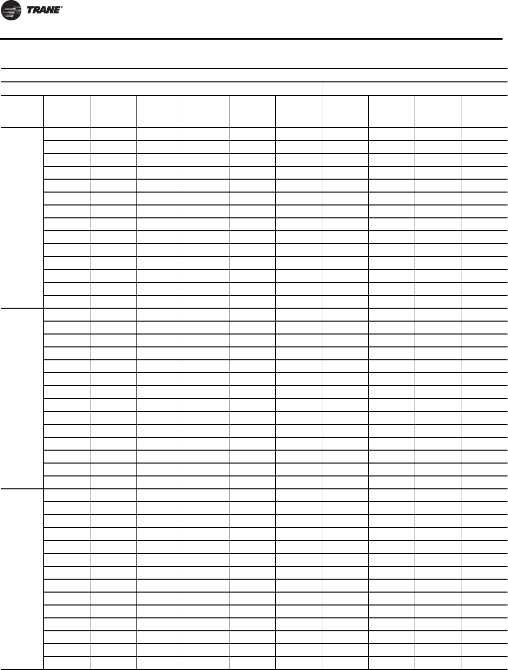
Start-Up
110 WSHP-SVX01N-EN
EXH*036
(60 Hz)
35 6.6 — — — — 88-102 289-364 6-7 19-24
35 8.4 — — — — 90-104 291-366 5-6 19-24
45 6.6 135-156 168-217 12-15 21-26 103-119 307-386 7-8 23-29
45 8.4 135-155 161-209 9-12 21-26 106-122 309-388 5-7 23-29
55 6.6 136-157 196-252 12-15 20-26 120-139 324-408 8-10 26-33
55 8.4 136-157 189-244 9-12 21-26 124-143 327-411 6-8 26-34
68 6.6 138-159 234-302 12-15 20-25 145-167 359-450 9-12 30-39
68 8.4 138-159 226-292 9-12 20-26 150-173 363-454 7-9 31-39
75 6.6 140-161 259-333 11-15 20-25 160-184 373-468 10-13 33-42
75 8.4 139-160 251-323 9-11 20-26 166-191 377-472 8-10 33-42
86 6.6 141-163 300-386 11-14 20-25 185-213 398-499 11-14 35-45
86 8.4 141-162 292-375 9-11 20-26 193-222 402-505 9-12 36-45
95 6.6 143-164 338-434 11-14 20-25 — — — —
95 8.4 143-164 329-423 9-11 20-26 — — — —
EXH*042
(60 Hz)
35 7.8 — — — — 86-99 281-353 6-7 22-27
35 9.8 — — — — 88-101 282-354 4-6 22-28
45 7.8 138-159 161-212 12-15 21-27 101-116 297-372 7-8 25-31
45 9.8 138-159 155-204 10-12 21-27 103-119 299-375 5-7 25-32
55 7.8 139-160 190-249 12-15 21-27 117-135 312-392 8-10 28-35
55 9.8 139-160 183-240 10-12 21-27 120-139 314-395 6-8 29-35
68 7.8 140-161 230-300 12-15 21-26 142-163 348-434 9-11 32-40
68 9.8 140-161 222-290 9-12 21-26 146-168 351-438 7-9 33-41
75 7.8 141-162 255-332 12-15 20-26 156-180 361-450 10-12 35-43
75 9.8 141-162 247-322 9-12 20-26 161-186 365-456 8-10 35-44
86 7.8 143-164 298-387 11-14 19-25 181-209 384-480 11-14 37-46
86 9.8 142-164 290-376 9-12 19-25 188-216 388-485 9-11 37-47
95 7.8 144-166 337-437 11-14 19-24 — — — —
95 9.8 144-165 329-426 9-11 19-24 — — — —
EXH*048
(60 Hz)
35 8.8 — — — — 88-101 287-362 6-7 20-25
35 11.2 — — — — 90-103 289-364 5-6 20-26
45 8.8 136-156 173-224 12-15 21-27 103-118 303-382 7-9 23-29
45 11.2 136-156 167-215 10-12 22-28 106-122 305-385 5-7 23-30
55 8.8 137-158 202-261 12-15 21-27 120-138 319-402 8-10 26-33
55 11.2 137-158 195-251 9-12 21-27 123-142 323-407 6-8 27-34
68 8.8 139-160 245-315 12-15 20-26 145-166 353-443 9-12 30-38
68 11.2 139-160 237-305 9-12 21-26 150-172 357-448 7-9 31-39
75 8.8 140-161 270-347 12-15 20-25 159-183 367-461 10-13 32-40
75 11.2 140-161 262-337 9-12 20-26 165-190 371-466 8-10 32-41
86 8.8 142-163 312-401 11-14 19-25 185-213 392-492 11-14 33-42
86 11.2 142-163 303-390 9-11 19-25 192-221 398-500 9-12 34-43
95 8.8 144-165 351-451 11-14 19-24 — — — —
95 11.2 143-165 342-440 9-11 19-24 — — — —
Table 55. Operating pressures in cooling/heating for EX* units (continued)
Operating Data
Cooling Heating
Model
Entering
water
temp (ºF)
Water
flow
(GPM)
Suction
pressure
(psig)
Discharge
pressure
(psig)
Water
temp rise
(ºF)
Air temp
drop
(ºF DB)
Suction
pressure
(psig)
Discharge
pressure
(psig)
Water
Temp drop
(ºF)
Air temp
rise
(ºF DB)
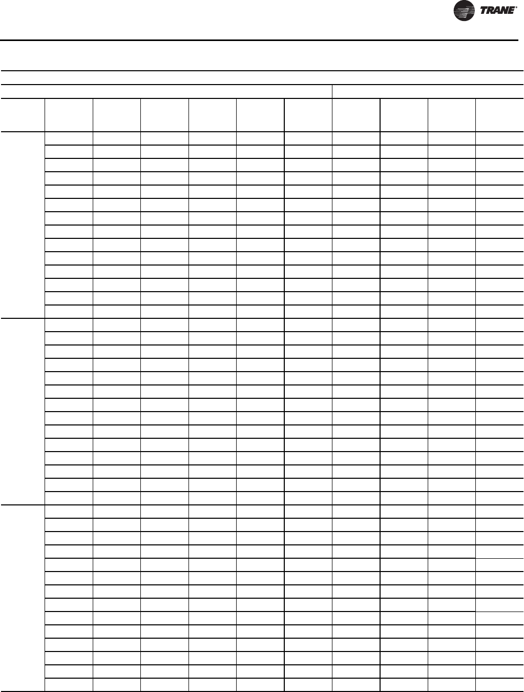
Start-Up
WSHP-SVX01N-EN 111
EXH*060
(60 Hz)
35 11.6 — — — — 88-102 314-395 6-7 21-27
35 14.0 — — — — 90-103 315-397 5-6 21-27
45 11.6 130-150 171-221 12-15 21-27 103-119 340-426 7-8 24-31
45 14.0 130-150 166-214 10-13 21-26 106-122 341-428 6-7 24-31
55 11.6 132-152 199-256 12-15 20-26 121-139 360-452 8-10 27-35
55 14.0 132-151 193-249 10-12 21-26 123-142 364-457 6-8 28-35
68 11.6 134-154 237-306 11-15 20-26 146-168 398-499 9-12 31-40
68 14.0 134-154 231-298 9-12 20-26 150-172 402-503 8-10 32-40
75 11.6 135-155 262-337 11-14 20-25 161-185 416-521 10-12 33-42
75 14.0 135-155 256-330 9-12 20-26 165-190 421-528 8-11 34-43
86 11.6 137-157 304-391 11-14 20-25 186-214 449-564 11-14 36-45
86 14.0 137-157 298-383 9-12 20-25 192-221 454-570 9-12 36-46
95 11.6 138-159 342-440 11-14 19-24 — — — —
95 14.0 138-159 335-431 9-11 19-25 — — — —
EXH*070
(60 Hz)
35 12.3 — — — — 85-98 296-373 6-7 20-25
35 15.4 — — — — 87-100 298-375 5-6 20-26
45 12.3 132-151 167-216 12-16 22-28 100-115 322-403 7-8 23-29
45 15.4 132-151 161-209 10-12 22-28 103-118 324-406 5-7 23-30
55 12.3 132-152 195-252 12-15 21-27 117-134 341-427 8-10 26-33
55 15.4 132-152 188-244 10-12 21-27 120-138 343-431 6-8 26-34
68 12.3 134-154 235-304 12-15 21-27 141-162 374-468 9-12 30-39
68 15.4 134-154 228-294 10-12 21-27 145-167 378-473 8-10 31-39
75 12.3 135-155 259-335 12-15 21-26 155-179 390-488 10-13 33-42
75 15.4 135-155 252-325 9-12 21-26 160-185 395-494 8-10 34-43
86 12.3 136-157 297-384 12-15 20-26 180-207 418-524 11-15 37-47
86 15.4 136-157 289-374 9-12 20-26 186-215 423-530 9-12 38-48
95 12.3 138-159 334-431 11-15 20-25 — — — —
95 15.4 138-159 326-421 9-12 20-25 — — — —
EXV*006
(60 Hz)
35 1.4 — — — — 94-108 279-355 6-8 23-29
35 1.7 — — — — 96-110 281-357 5-6 23-29
45 1.4 143-165 190-243 13-16 24-30 110-127 297-377 7-9 26-34
45 1.7 143-164 184-235 11-13 24-31 113-130 300-382 6-8 27-34
55 1.4 145-167 217-277 13-16 23-30 128-147 317-404 8-10 30-39
55 1.7 144-166 210-268 11-13 24-30 131-151 320-407 7-9 31-39
68 1.4 148-171 254-324 12-15 23-29 154-177 345-439 10-12 35-45
68 1.7 147-170 244-312 10-13 23-29 158-182 349-444 8-10 36-45
75 1.4 148-171 281-358 12-15 23-29 169-195 361-459 10-13 38-48
75 1.7 148-170 273-348 10-13 23-29 175-201 366-466 9-11 38-48
86 1.4 149-172 328-418 12-15 22-28 197-226 388-494 11-15 41-52
86 1.7 149-172 320-407 10-13 23-29 203-234 395-502 10-12 41-52
95 1.4 151-173 373-474 12-15 22-28 — — — —
95 1.7 150-173 363-462 10-13 22-28 — — — —
Table 55. Operating pressures in cooling/heating for EX* units (continued)
Operating Data
Cooling Heating
Model
Entering
water
temp (ºF)
Water
flow
(GPM)
Suction
pressure
(psig)
Discharge
pressure
(psig)
Water
temp rise
(ºF)
Air temp
drop
(ºF DB)
Suction
pressure
(psig)
Discharge
pressure
(psig)
Water
Temp drop
(ºF)
Air temp
rise
(ºF DB)

Start-Up
11 2 WSHP-SVX01N-EN
EXV*009
(60 Hz)
35 1.7 — — — — 93-107 272-346 6-7 20-26
35 2.1 — — — — 95-110 274-348 5-6 21-27
45 1.7 142-164 187-238 13-16 22-28 109-126 288-366 7-9 24-30
45 2.1 142-164 181-230 11-14 22-27 112-129 291-370 6-7 24-31
55 1.7 144-166 214-272 12-15 21-27 127-146 305-388 8-10 27-34
55 2.1 144-166 207-263 10-13 21-27 130-150 309-393 7-8 27-35
68 1.7 146-168 258-328 12-15 20-26 153-176 330-420 9-12 31-39
68 2.1 146-168 250-318 10-12 21-26 157-181 335-427 8-10 32-40
75 1.7 147-169 286-363 12-15 20-25 168-193 345-439 10-13 33-42
75 2.1 147-169 277-352 9-12 20-26 174-200 350-446 8-11 34-43
86 1.7 149-171 336-427 12-15 19-25 195-224 370-471 11-14 36-46
86 2.1 148-171 326-415 9-12 20-25 202-232 375-477 9-12 37-47
95 1.7 149-172 386-491 12-15 19-24 — — — —
95 2.1 149-172 375-477 9-12 19-24 — — — —
EXV*012
60 Hz)
35 2.2 — — — — 92-106 288-367 10-13 21-27
35 2.8 — — — — 95-109 290-370 8-11 21-27
45 2.2 142-163 183-233 12-15 22-28 108-125 304-387 12-15 24-30
45 2.8 142-163 175-223 9-12 23-29 111-128 307-391 9-12 24-31
55 2.2 143-164 212-270 12-15 21-27 126-145 322-410 13-16 26-33
55 2.8 143-164 204-260 9-12 22-27 130-149 325-413 10-13 27-34
68 2.2 144-166 257-327 12-15 21-26 152-174 346-441 14-18 29-37
68 2.8 144-166 248-316 9-12 21-26 157-180 352-448 11-15 29-37
75 2.2 145-167 284-361 12-15 20-26 167-192 361-460 15-19 30-38
75 2.8 145-167 274-349 9-12 20-26 173-199 366-466 12-15 30-39
86 2.2 146-168 332-422 12-15 19-25 194-223 384-489 16-21 32-40
86 2.8 146-168 321-409 9-12 20-25 201-231 390-497 13-17 32-41
95 2.2 147-170 376-478 12-15 19-24 — — — —
95 2.8 147-170 365-465 9-12 19-24 — — — —
EXV*015
(60 Hz)
35 2.8 — — — — 91-105 296-377 6-7 20-25
35 3.5 — — — — 93-107 299-380 5-6 20-26
45 2.8 138-159 180-230 11-14 22-28 107-123 313-398 7-8 23-29
45 3.5 138-158 174-221 9-11 22-27 109-126 316-402 5-7 23-30
55 2.8 139-159 210-267 11-14 21-27 124-143 332-423 8-10 26-33
55 3.5 138-159 203-258 9-11 21-27 128-147 336-427 6-8 27-34
68 2.8 140-161 254-324 11-14 20-26 150-172 358-456 9-11 30-38
68 3.5 140-161 246-313 9-11 21-26 154-178 364-463 7-9 30-39
75 2.8 141-162 281-358 11-14 20-25 165-190 373-475 10-12 32-40
75 3.5 140-162 272-347 9-11 20-26 171-196 379-483 8-10 32-41
86 2.8 142-163 328-417 11-14 19-25 191-220 399-508 11-14 34-43
86 3.5 142-163 318-405 9-11 20-25 198-228 405-515 9-11 34-44
95 2.8 143-165 371-472 11-14 19-24 — — — —
95 3.5 143-165 361-459 9-11 19-24 — — — —
Table 55. Operating pressures in cooling/heating for EX* units (continued)
Operating Data
Cooling Heating
Model
Entering
water
temp (ºF)
Water
flow
(GPM)
Suction
pressure
(psig)
Discharge
pressure
(psig)
Water
temp rise
(ºF)
Air temp
drop
(ºF DB)
Suction
pressure
(psig)
Discharge
pressure
(psig)
Water
Temp drop
(ºF)
Air temp
rise
(ºF DB)
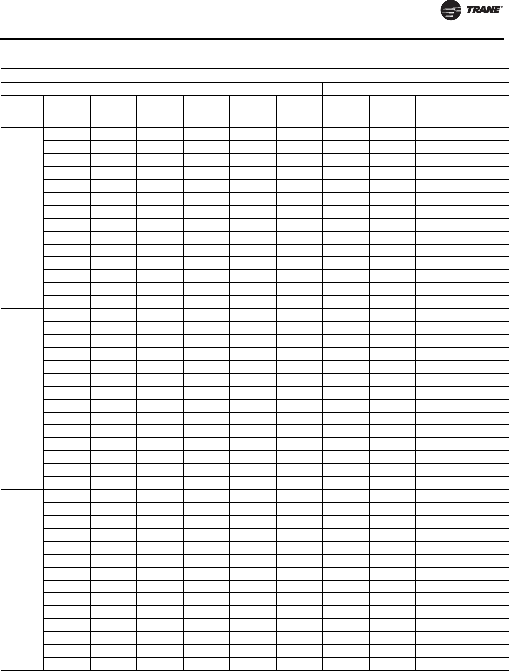
Start-Up
WSHP-SVX01N-EN 11 3
EXV*018
(60 Hz)
35 3.3 — — — — 91-104 280-353 6-8 21-26
35 4.2 — — — — 92-106 281-355 5-6 21-27
45 3.3 142-163 158-206 11-15 23-29 106-122 301-379 7-9 24-30
45 4.2 141-163 151-197 9-11 23-29 108-125 304-383 6-7 24-31
55 3.3 141-162 187-243 12-15 23-29 123-142 319-401 8-10 27-34
55 4.2 141-162 179-233 9-12 23-29 126-145 322-405 6-8 27-35
68 3.3 141-163 227-295 12-15 22-28 149-171 352-441 10-12 31-39
68 4.2 141-163 219-284 9-12 22-28 153-176 356-446 8-10 32-40
75 3.3 142-163 253-328 12-15 21-27 165-189 364-456 10-13 33-42
75 4.2 142-163 245-317 9-12 21-27 170-196 368-461 8-10 34-43
86 3.3 143-165 298-385 12-15 20-26 192-221 383-480 11-14 36-46
86 4.2 143-164 288-372 9-12 20-26 199-229 386-484 9-11 37-47
95 3.3 144-166 339-437 12-15 19-24 — — — —
95 4.2 144-166 329-424 9-12 19-25 — — — —
EXV*024
(60 Hz)
35 4.4 — — — — 85-98 278-351 6-7 21-27
35 5.6 — — — — 87-100 280-353 4-6 22-28
45 4.4 136-156 165-215 12-15 23-30 100-115 299-375 7-8 25-32
45 5.6 135-156 158-206 10-12 23-30 103-118 301-378 5-7 26-32
55 4.4 137-158 193-251 12-15 22-28 117-134 314-395 8-10 29-36
55 5.6 137-157 186-241 9-12 22-29 120-138 318-399 6-8 29-37
68 4.4 138-159 234-304 12-15 21-27 141-162 346-433 9-11 33-42
68 5.6 138-159 226-293 9-12 22-28 145-167 350-438 7-9 33-42
75 4.4 139-160 260-336 12-15 21-27 155-179 358-449 10-12 35-44
75 5.6 139-160 251-325 9-12 21-27 161-185 363-454 8-10 35-45
86 4.4 141-162 303-391 12-15 20-26 180-207 380-476 11-14 37-47
86 5.6 141-162 294-379 9-12 20-26 187-215 385-482 9-11 38-48
95 4.4 142-164 343-442 11-15 19-25 — — — —
95 5.6 142-163 334-430 9-11 20-25 — — — —
EXV*030
(60 Hz)
35 5.5 — — — — 87-101 266-337 6-7 20-25
35 7.0 — — — — 89-103 267-340 4-6 20-26
45 5.5 137-158 164-214 12-15 22-28 102-118 284-359 7-8 23-29
45 7.0 137-157 158-206 9-12 22-27 105-121 286-362 5-7 23-30
55 5.5 138-159 192-250 12-15 21-27 119-137 299-379 8-10 26-33
55 7.0 138-159 185-241 9-12 21-27 122-141 302-382 6-8 27-34
68 5.5 140-161 231-301 11-15 20-26 143-165 328-413 9-12 30-38
68 7.0 140-161 223-291 9-11 21-26 148-170 332-419 7-9 30-39
75 5.5 141-162 257-334 11-14 20-25 158-182 341-430 10-13 32-40
75 7.0 141-162 249-323 9-11 20-26 164-188 346-436 8-10 32-41
86 5.5 143-164 300-388 11-14 19-25 183-211 364-460 11-14 34-43
86 7.0 142-164 291-377 9-11 20-25 190-219 368-465 9-11 34-44
95 5.5 144-165 340-440 11-14 19-24 — — — —
95 7.0 144-165 331-428 9-11 19-24 — — — —
Table 55. Operating pressures in cooling/heating for EX* units (continued)
Operating Data
Cooling Heating
Model
Entering
water
temp (ºF)
Water
flow
(GPM)
Suction
pressure
(psig)
Discharge
pressure
(psig)
Water
temp rise
(ºF)
Air temp
drop
(ºF DB)
Suction
pressure
(psig)
Discharge
pressure
(psig)
Water
Temp drop
(ºF)
Air temp
rise
(ºF DB)

Start-Up
114 WSHP-SVX01N-EN
EXV*036
(60 Hz)
35 6.6 — — — — 88-101 292-368 6-7 19-24
35 8.4 — — — — 89-103 293-369 5-6 19-24
45 6.6 133-153 169-218 12-15 20-26 103-118 310-390 7-8 23-29
45 8.4 132-152 162-210 9-12 21-26 105-121 311-392 5-7 23-29
55 6.6 134-154 197-254 12-15 20-26 119-137 327-412 8-10 26-33
55 8.4 134-154 190-245 9-12 20-26 122-141 330-415 6-8 26-34
68 6.6 136-156 236-304 12-15 20-25 144-166 362-454 9-12 30-39
68 8.4 136-156 228-295 9-12 20-25 148-171 365-457 7-9 31-39
75 6.6 137-158 261-336 11-14 20-25 159-183 378-474 10-13 33-42
75 8.4 137-158 253-326 9-11 20-25 164-189 382-479 8-10 33-42
86 6.6 139-160 303-390 11-14 19-24 184-212 403-506 11-15 35-45
86 8.4 139-160 295-379 9-11 19-24 191-219 409-514 9-12 36-45
95 6.6 141-162 342-439 11-14 19-24 — — — —
95 8.4 141-162 333-428 9-11 19-24 — — — —
EXV*042
(60 Hz)
35 7.8 — — — — 84-97 285-358 5-7 19-24
35 9.8 — — — — 86-99 286-359 4-6 19-25
45 7.8 134-155 160-210 12-15 21-27 99-114 300-377 6-8 22-28
45 9.8 134-154 153-202 10-12 21-27 101-116 302-379 5-7 22-29
55 7.8 135-156 189-247 12-15 21-27 115-132 315-396 7-9 25-32
55 9.8 135-156 182-238 9-12 21-27 118-136 319-400 6-8 26-32
68 7.8 137-158 229-299 12-15 21-26 139-160 352-438 9-11 29-37
68 9.8 137-158 221-289 9-12 21-26 143-165 354-442 7-9 30-38
75 7.8 138-159 255-332 12-15 20-26 154-177 365-456 10-12 32-40
75 9.8 138-159 247-322 9-12 20-26 158-182 369-460 8-10 32-41
86 7.8 140-161 299-389 11-15 19-25 179-205 388-485 11-14 34-43
86 9.8 140-161 291-379 9-12 19-25 184-212 392-490 9-11 34-44
95 7.8 142-163 341-442 11-14 19-24 — — — —
95 9.8 142-163 332-430 9-11 19-24 — — — —
EXV*048
(60 Hz)
35 8.8 — — — — 87-101 285-359 6-7 20-25
35 11.2 — — — — 90-103 287-362 5-6 20-26
45 8.8 135-156 172-222 12-15 21-27 103-118 300-378 7-8 23-29
45 11.2 135-155 165-214 9-12 22-28 105-121 303-382 5-7 23-30
55 8.8 136-157 201-259 12-15 21-27 120-138 316-398 8-10 26-33
55 11.2 136-157 193-249 9-12 21-27 123-142 320-403 6-8 27-34
68 8.8 138-159 243-313 12-15 20-26 144-166 348-437 9-12 30-38
68 11.2 138-159 235-303 9-12 21-26 149-171 352-442 7-9 31-39
75 8.8 139-160 269-345 11-15 20-25 159-183 363-455 10-13 32-40
75 11.2 139-160 260-334 9-11 20-26 165-189 367-461 8-10 32-41
86 8.8 141-162 310-399 11-14 19-25 184-212 386-485 11-14 33-42
86 11.2 141-162 301-387 9-11 19-25 191-220 392-493 9-12 34-43
95 8.8 143-164 349-448 11-14 19-24 — — — —
95 11.2 143-164 340-437 9-11 19-24 — — — —
Table 55. Operating pressures in cooling/heating for EX* units (continued)
Operating Data
Cooling Heating
Model
Entering
water
temp (ºF)
Water
flow
(GPM)
Suction
pressure
(psig)
Discharge
pressure
(psig)
Water
temp rise
(ºF)
Air temp
drop
(ºF DB)
Suction
pressure
(psig)
Discharge
pressure
(psig)
Water
Temp drop
(ºF)
Air temp
rise
(ºF DB)
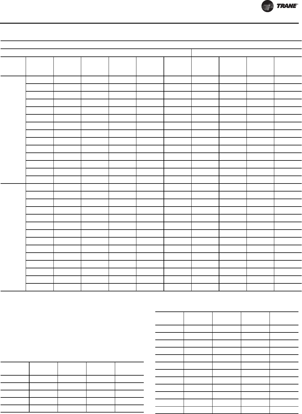
Start-Up
WSHP-SVX01N-EN 11 5
Water Pressure Drop
Table 56, p. 115 should be used to define feet of head/
pressure drop. Please note the feet of pressure (ft/head)
provided is at ARI/ISO standard.
To calculate feet of head, when using gauges that read in
PSIG, multiply PSI by 2.31.
EXV*060
(60 Hz)
35 11.6 — — — — 89-102 300-377 6-7 21-27
35 14.0 — — — — 90-104 301-379 5-6 21-27
45 11.6 132-152 169-219 12-15 21-27 104-120 324-406 7-9 24-31
45 14.0 132-152 164-212 10-13 21-26 106-122 325-407 6-7 24-31
55 11.6 133-153 197-254 12-15 20-26 121-139 343-430 8-10 27-35
55 14.0 133-153 192-247 10-12 21-26 124-142 344-432 7-8 28-35
68 11.6 135-156 235-303 12-15 20-26 146-168 377-472 9-12 31-40
68 14.0 135-156 229-296 10-12 20-26 150-172 380-476 8-10 32-40
75 11.6 136-157 260-335 11-14 20-25 161-185 394-493 10-13 33-42
75 14.0 136-157 253-326 9-12 20-26 165-190 398-499 9-11 34-43
86 11.6 138-159 302-388 11-14 20-25 186-214 424-532 12-15 36-45
86 14.0 138-159 295-379 9-12 20-25 192-221 429-538 10-12 36-46
95 11.6 140-161 339-436 11-14 19-24 — — — —
95 14.0 140-161 332-427 9-12 19-25 — — — —
EXV*070
(60 Hz)
35 12.32 — — — — 86-100 294-371 6-7 20-26
35 15.4 — — — — 88-102 296-373 5-6 21-26
45 12.32 131-150 166-216 12-15 21-27 101-117 320-401 7-9 23-29
45 15.4 131-150 160-208 10-12 21-27 104-119 322-404 6-7 24-30
55 12.32 131-151 194-252 12-15 21-27 118-136 338-424 8-10 26-33
55 15.4 131-151 188-243 10-12 21-27 121-139 340-427 6-8 27-34
68 12.32 133-153 235-303 12-15 20-26 142-164 374-467 9-12 31-39
68 15.4 133-153 228-294 9-12 21-26 146-168 376-470 8-10 31-40
75 12.32 134-154 259-335 12-15 20-26 157-180 389-487 10-13 33-42
75 15.4 134-154 252-325 9-12 20-26 162-186 393-492 8-11 34-43
86 12.32 136-156 297-384 11-15 20-25 181-209 417-523 12-15 37-47
86 15.4 136-156 289-374 9-12 20-25 188-216 422-529 9-12 38-48
95 12.32 137-158 335-432 11-14 19-25 — — — —
95 15.4 137-158 327-422 9-12 19-25 — — — —
Table 55. Operating pressures in cooling/heating for EX* units (continued)
Operating Data
Cooling Heating
Model
Entering
water
temp (ºF)
Water
flow
(GPM)
Suction
pressure
(psig)
Discharge
pressure
(psig)
Water
temp rise
(ºF)
Air temp
drop
(ºF DB)
Suction
pressure
(psig)
Discharge
pressure
(psig)
Water
Temp drop
(ºF)
Air temp
rise
(ºF DB)
Table 56. Cooling water pressure drops (WPD) in feet of
head for GE* units - ½- 6 ton
Unit Size
(60 Hz) Unit Size
(50 Hz) EWT °F GPM Ft.
Pressure
GEH006 — 86 1.8 3.9
GEH009 GEH006 86 2.1 3.7
GEH012 GEH009 86 2.8 3.8
GEH015 GEH012 86 3.5 5.4
GEH018 GEH015 86 4.2 6.8
GEH024 GEH018 86 5.6 13.2
GEH030 GEH024 86 7.0 11.1
GEH036 GEH030 86 8.4 11.5
GEH042 GEH036 86 9.8 13.6
GEH048 GEH042 86 11.2 6.8
GEH060 GEH048 86 14.0 12.3
— GEH060 86 14.0 11.4
GEH072 — 86 18.0 12.0
GEH090 GEH072 86 22.5 13.8
GEH120 GEH090 86 30.0 14.1
GEH150 GEH120 86 37.5 13.4
GEH180 GEH150 86 45.0 18.2
Table 56. Cooling water pressure drops (WPD) in feet of
head for GE* units - ½- 6 ton (continued)
Unit Size
(60 Hz) Unit Size
(50 Hz) EWT °F GPM Ft.
Pressure
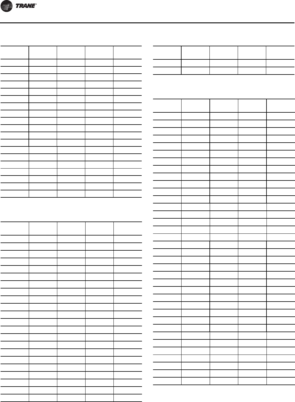
Start-Up
11 6 WSHP-SVX01N-EN
GEV006 — 86 1.8 3.0
GEV009 GEV006 86 2.1 3.9
GEV012 GEV009 86 2.8 3.8
GEV015 GEV012 86 3.5 5.3
GEV018 GEV015 86 4.2 6.3
GEV024 GEV018 86 5.6 12.9
GEV030 GEV024 86 7.0 12.2
GEV036 GEV030 86 8.4 12.5
GEV042 GEV036 86 9.8 14.5
GEV048 GEV042 86 11.2 5.7
GEV060 GEV048 86 14.0 12.0
— GEV060 86 14.0 10.8
GEV072 — 86 18.0 12.0
GEV090 GEV072 86 22.5 13.4
GEV120 GEV090 86 30.0 14.1
GEV150 GEV120 86 37.5 13.4
GEV180 GEV150 86 45.0 18.2
GEV240 GEV180 86 60.0 14.0
GEV300 GEV240 86 75.0 13.2
Table 57. Cooling water pressure drops (WPD) in feet of
head for EX* units
Unit Size
(60 Hz) Unit Size
(50 Hz) EWT °F GPM Ft.
Pressure
EXH006 — 86 1.8 3.9
EXH009 — 86 2.1 3.7
EXH012 — 86 2.8 3.8
EXH015 — 86 3.5 5.4
EXH018 — 86 4.2 4.1
EXH024 — 86 5.6 6.1
EXH030 — 86 7 9.2
EXH036 — 86 8.4 5.5
EXH042 — 86 9.8 7.8
EXH048 — 86 11.2 8.2
EXH060 — 86 14 7.2
EXH070 — 86 15.4 6.3
EXV006 — 86 1.8 3.0
EXV009 — 86 2.1 3.9
EXV012 — 86 2.8 3.8
EXV015 — 86 3.5 5.3
EXV018 — 86 4.2 3.7
EXV024 — 86 5.6 6.5
EXV030 — 86 7 8.5
EXV036 — 86 8.4 6.3
EXV042 — 86 9.8 8.5
EXV048 — 86 11.2 7.9
Table 56. Cooling water pressure drops (WPD) in feet of
head for GE* units - ½- 6 ton (continued)
Unit Size
(60 Hz) Unit Size
(50 Hz) EWT °F GPM Ft.
Pressure
EXV060 — 86 14 7.4
EXV070 — 86 15.4 6.6
Table 58. Heating water pressure drops (WPD) in feet of
head for GE* units
Unit Size
(60 Hz) Unit Size
(50 Hz) EWT °F GPM Ft.
Pressure
GEH006 — 68 1.8 4.2
GEH009 GEH006 68 2.1 3.9
GEH012 GEH009 68 2.8 4.1
GEH015 GEH012 68 3.5 5.7
GEH018 GEH015 68 4.2 7.2
GEH024 GEH018 68 5.6 14
GEH030 GEH024 68 7.0 11.8
GEH036 GEH030 68 8.4 12.1
GEH042 GEH036 68 9.8 14.5
GEH048 GEH042 68 11.2 7.2
GEH060 GEH048 68 14.0 13.1
— GEH060 68 14.0 12.1
GEH072 — 68 18.0 13.9
GEH090 GEH072 68 22.5 15.7
GEH120 GEH090 68 30.0 16.0
GEH150 GEH120 68 37.5 14.8
GEH180 GEH150 68 45.0 20.3
GEV006 — 68 1.8 3.2
GEV009 GEV006 68 2.1 4.2
GEV012 GEV009 68 2.8 4.1
GEV015 GEV012 68 3.5 5.6
GEV018 GEV015 68 4.2 6.7
GEV024 GEV018 68 5.6 13.7
GEV030 GEV024 68 7.0 12.9
GEV036 GEV030 68 8.4 13.2
GEV042 GEV036 68 9.8 15.4
GEV048 GEV042 68 11.2 6.1
GEV060 GEV048 68 14.0 12.7
— GEV060 68 14.0 11.5
GEV072 — 68 18.0 13.9
GEV090 GEV072 68 22.5 15.3
GEV120 GEV090 68 30.0 16.0
GEV150 GEV120 68 37.5 14.8
GEV180 GEV150 68 45.0 20.3
GEV240 GEV180 68 60.0 16.0
GEV300 GEV240 68 75.0 14.8
Table 57. Cooling water pressure drops (WPD) in feet of
head for EX* units (continued)
Unit Size
(60 Hz) Unit Size
(50 Hz) EWT °F GPM Ft.
Pressure
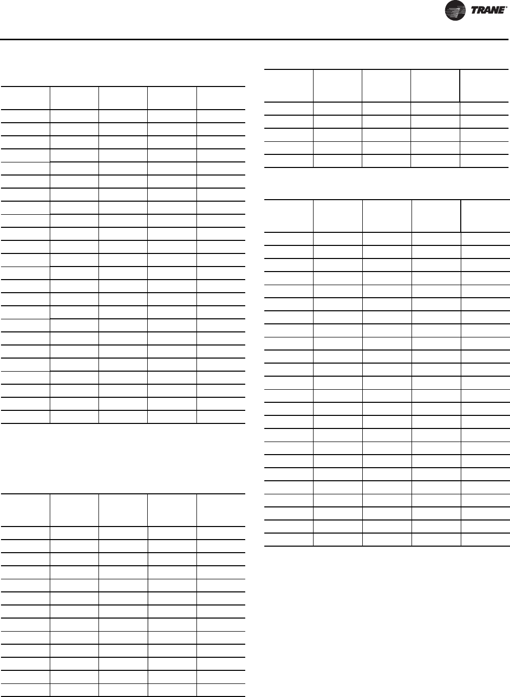
Start-Up
WSHP-SVX01N-EN 11 7
Water Volume
Table 60, p. 117 is provided for use in calculating glycol
requirements for the unit.
Table 59. Heating water pressure drops (WPD) in feet of
head for EX* units
Unit Size
(60 Hz) Unit Size
(50 Hz) EWT °F GPM Ft.
Pressure
EXH006 — 68 1.8 4.2
EXH009 — 68 2.1 3.9
EXH012 — 68 2.8 4.1
EXH015 — 68 3.5 5.7
EXH018 — 68 4.2 5.0
EXH024 — 68 5.6 7.9
EXH030 — 68 7.0 11.2
EXH036 — 68 8.4 6.5
EXH042 — 68 9.8 9.4
EXH048 — 68 11.2 9.4
EXH060 — 68 14.0 7.1
EXH070 — 68 15.4 7.2
EXV006 — 68 1.8 4.2
EXV009 — 68 2.1 3.9
EXV012 — 68 2.8 4.1
EXV015 — 68 3.5 5.7
EXV018 — 68 4.2 4.5
EXV024 — 68 5.6 8.2
EXV030 — 68 7.0 10.2
EXV036 — 68 8.4 7.5
EXV042 — 68 9.8 9.8
EXV048 — 68 11.2 9.1
EXV060 — 68 14.0 7.2
EXV070 — 68 15.4 7.6
Table 60. Water volume for GE* units
Unit Size
(60 Hz) Unit Size
(50 Hz)
Water Side
Volume
(in3)
Water Side
Volume
(ft3)
Water Side
Volume
(gallons)
006 — 13.6 0.008 0.059
009 006 13.6 0.008 0.059
012 009 28.2 0.016 0.122
015 012 36.0 0.021 0.156
018 015 28.2 0.016 0.122
024 018 37.8 0.022 0.164
030 024 49.1 0.028 0.213
036 030 70.4 0.041 0.305
042 036 79.0 0.046 0.342
048 042 71.7 0.041 0.310
060 048 91.8 0.053 0.397
— 060 91.8 0.053 0.397
072 — 181 0.105 0.783
090 072 214 0.125 0.927
120 090 390 0.227 1.690
150, 180 120, 150 508 0.296 2.201
240 180 779 0.453 3.374
300 240 1057 0.615 4.576
Table 61. Water volume for EX* units
Unit Size
(60 Hz) Unit Size
(50 Hz)
Water Side
Volume
(in3)
Water Side
Volume
(ft3)
Water Side
Volume
(gallons)
EXH006 — 13.6 0.008 0.059
EXH009 — 13.6 0.008 0.059
EXH012 — 28.4 0.016 0.123
EXH015 — 36.0 0.021 0.156
EXH018 — 89.8 0.052 0.389
EXH024 — 89.8 0.052 0.389
EXH030 — 89.8 0.052 0.389
EXH036 — 171.2 0.099 0.741
EXH042 — 200.8 0.116 0.869
EXH048 — 200.8 0.116 0.869
EXH060 — 331.2 0.192 1.434
EXH070 — 331.2 0.192 1.434
EXV006 — 13.6 0.008 0.059
EXV009 — 13.6 0.008 0.059
EXV012 — 28.4 0.016 0.123
EXV015 — 36.0 0.021 0.156
EXV018 — 89.8 0.052 0.389
EXV024 — 89.8 0.052 0.389
EXV030 — 89.8 0.052 0.389
EXV036 — 171.2 0.099 0.741
EXV042 — 200.8 0.116 0.869
EXV048 — 200.8 0.116 0.869
EXV060 — 331.2 0.192 1.434
EXV070 — 331.2 0.192 1.434
Table 60. Water volume for GE* units (continued)
Unit Size
(60 Hz) Unit Size
(50 Hz)
Water Side
Volume
(in3)
Water Side
Volume
(ft3)
Water Side
Volume
(gallons)
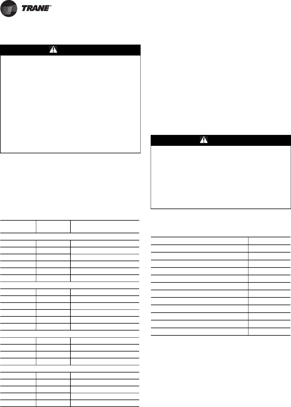
11 8 WSHP-SVX01N-EN
Maintenance
Preventive Maintenance
Maintenance on the unit is simplified with the following
preventive suggestions:
Filter maintenance must be performed to assure proper
operation of the equipment. Filters should be inspected at
least every three months, and replaced when it is evident
they are dirty. Filter sizing is shown in Table 62, p. 118:
Check the contactors and relays within the control panel at
least once a year. It is good practice to check the tightness
of the various wiring connections within the control panel.
A strainer (60 mesh or greater) must be used on an open
loop system to keep debris from entering the unit heat
exchanger and to ensure a clean system.
For units on well water, it is important to check the
cleanliness of the water-to-refrigerant heat exchanger.
Should it become contaminated with dirt and scaling as a
result of bad water, the heat exchanger will have to be back
flushed and cleaned with a chemical that will remove the
scale.This service should be performed by an experienced
service person.
It should be noted that the water quality should be checked
periodically. See Table 63, p. 118.
Condensate Trap
For units incorporating a negative trap design, ensure that
the condensate system is primed with water at all times.
Allowing a negative, pressure condensate system to run
dry could cause a break in the condensate seal allowing
the fan to draw water from the condensate line to spray
moisture into the mechanical system. By maintaining a
primed condensate trap, a seal will be created and will
help prevent these complications.
WARNING
Hazardous Service Procedures!
The maintenance and trouble shooting procedures
recommended in this section of the manual could result
in exposure to electrical, mechanical or other potential
safety hazards. Always refer to the safety warnings
provided throughout this manual concerning these
procedures. When possible, disconnect all electrical
power including remote disconnects before servicing.
Follow proper lockout/tagout procedures to ensure the
power can not be inadvertently energized. When
necessary to work with live electrical components, have
a qualified licensed electrician or other individual who
has been trained in handling live electrical components
per these tasks. Failure to follow all of the
recommended safety warnings provided, could result in
death or serious injury.
Table 62. Filter sizing
Size (60 Hz) Size (50 Hz) Filter Size (Actual)
inches (mm)
GEH
006-015 006-012 14 5/8 x 20 1/4 (371 x 514)
018-030 015-024 17 7/8 x 23 7/8 (454 x 607)
036-042 030-036 18 5/8 x 25 3/8 (473 x 645)
048-060 042-060 20 5/8 x 29 3/4 (524 x 755)
072-120 072-090 20 x 25 (3) (508 x 508)
150-180 120-150 25 x 25 (3) (635 x 635)
GEV
006-015 006-012 15 7/8 x 19 7/8 (403 x 504)
018-030 015-024 19 7/8 x 19 7/8 (505 x 505)
036-042 030-036 19 7/8 x 24 7/8 (504 x 632)
048-060 042-060 23 7/8 x 29 7/8 (606 x 759)
GEV 072-120 090 20 x 20 (4) (508 x 508)
150-300 120-240 19 5/8 x 24 5/8 (6) (498 x 625)‘
EXH
006-015 — 14 5/8 x 20 1/4 (371 x 514)
018-024 — 17 7/8 X 23 7/8 (454 X 607)
030-036 — 18 5/8 x 25 3/8 (473 x 645)
042-070 — 20 5/8 x 29 3/4 (524 x 755)
EXV
006-015 — 15 7/8 x 19 7/8 (403 x 504)
018-024 — 19 7/8 x 19 7/8 (505 x 505)
030-036 — 19 7/8 x 24 7/8 (504 x 632)
042-060 — 23 7/8 x 29 7/8 (606 x 759)
070 — 27 7/8 x 29 7/8 (708 x 759)
WARNING
Hazardous Chemicals!
Cleaning agents can be either acidic or highly alkaline.
Handle chemical carefully. Proper handling should
include goggles or face shield, chemical resistant
gloves, boots, apron or suit as required. For personal
safety, refer to the cleaning agent manufacturers
Materials Safety Data Sheet and follow all
recommended safe handling practices. Failure to follow
all safety instructions could result in death or serious
injury.
Table 63. Water quality
Scaling Amount
Calcium and magnesium (total hardness) Less than 350 ppm
Corrosion
pH 7-9.5
Hydrogen Sulfide Less than 1 ppm
Sulfates Less than 25 ppm
Chlorides Less than 125 ppm
Carbon Dioxide Less than 75 ppm
Total dissolved solids (TDS) Less than 1000 ppm
Biological Growth
Iron Bacteria Low
Erosion
Suspended Solids Low
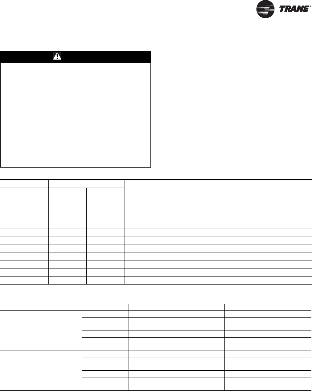
WSHP-SVX01N-EN 119
Troubleshooting
Deluxe Controls
Troubleshooting units which contain the deluxe control
option may be made easy by using the three LEDs (light
emitting diodes).These LEDs are provided for indicating
the operating mode of the controller.The LEDs are
intended to aid in troubleshooting.The LEDs are labeled
on the circuit board with numbers as referenced in
Table 64, p. 119.
WARNING
Hazardous Service Procedures!
The maintenance and trouble shooting procedures
recommended in this section of the manual could result
in exposure to electrical, mechanical or other potential
safety hazards. Always refer to the safety warnings
provided throughout this manual concerning these
procedures. When possible, disconnect all electrical
power including remote disconnects before servicing.
Follow proper lockout/tagout procedures to ensure the
power can not be inadvertently energized. When
necessary to work with live electrical components, have
a qualified licensed electrician or other individual who
has been trained in handling live electrical components
per these tasks. Failure to follow all of the
recommended safety warnings provided, could result in
death or serious injury.
Table 64. Diagnostic LEDs
Color: Green Color: Red Controller
Mode
LED1 LED2 LED3
OFF OFF OFF Control OFF
ON OFF OFF Normal/Compressor OFF
ON OFF FLASH Anti-short cycle
ON OFF ON Normal/Compressor ON
FLASH ON OFF Brownout Condition
ON FLASH ON Soft Lockout (low pressure)
ON FLASH FLASH Soft Lockout (high pressure)
ON ON ON Manual Lockout (low pressure)
ON ON FLASH Manual Lockout (high pressure)
ON FLASH OFF Manual Lockout (condensate overflow)
ON ON OFF Compressor Disable
Table 65. Troubleshooting table
Problem Heating Cooling Cause Correction
No response to any
thermostat setting X X Main power off Check fuses
X X Defective control transformer Replace
X X Broken or loose connection Repair
X X Defective thermostat Replace
X X Transformer Reset Transformer
Unit short cycles X X Thermostat or sensor improperly located Relocate
Blower runs, but compressor
does not X X Defective compressor overload Replace (if external)
X X Defective compressor contactor Replace
X X Supply Voltage too low Correct
X X Defective compressor capacitor Replace
X X Defective windings Replace
X X Limit switches open Check cause/Replace or repair
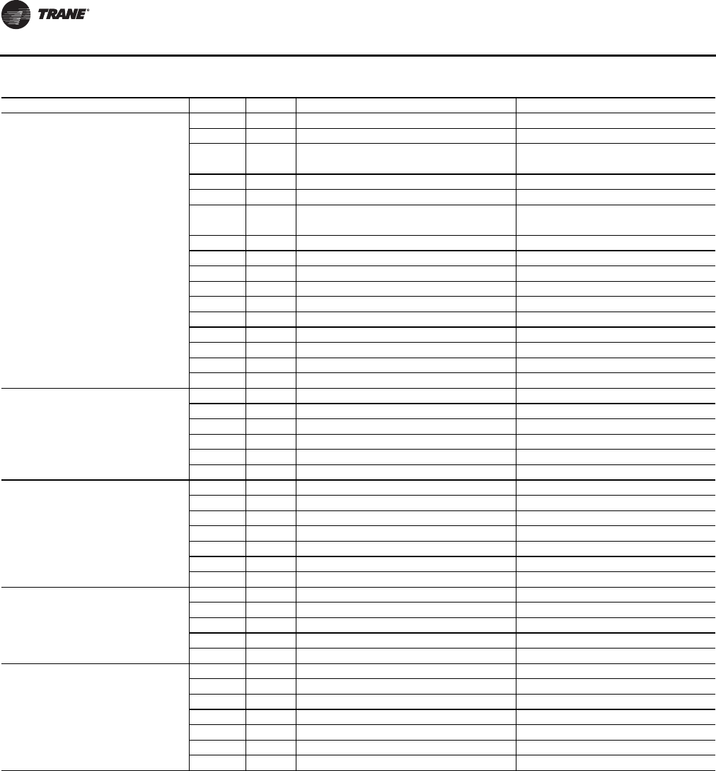
Troubleshooting
120 WSHP-SVX01N-EN
Insufficient capacity X X Dirty filter Replace/clean
X X Blower RPM too low Correct
XX
Loss of conditioned air due to leaks in
ductwork Repair leaks
X Introduction of excessively hot return-air Correct
X Introduction of excessively cold return-air Correct
X X Low on refrigerant charge Locate leak, repair and recharge by
weight (not by superheat)
X X Restricted thermal expansion valve Replace
X X Defective reversing valve See WSHP-IOM-# for touch test chart
X X Thermostat improperly located Relocate
X X Unit undersized Recalculate heat gains/losses
X X Inadequate water flow Increase GPM
X X Scaling in heat exchanger Clean or replace
X Water too hot Decrease temperature
X Water too cold Increase temperature
X X Filter drier blocked Replace
X X Defective reversing valve Check or replace
High pressure switch open X Inadequate GPM Increase water flow to unit
X Water too hot Decrease temperature
X Inadequate air flow Check, clean blower and coil
X Dirty filter Clean/replace
X X Overcharged with refrigerant Decrease charge
X X Defective pressure switch Check or replace
High head pressure X Trash in heat exchanger Backflush
X Low water flow Increase GPM
X X Overcharge of refrigerant Decrease charge
X X Non-condensable in system Evacuate and recharge by weight
X X Water too hot Decrease temperature
X Dirty filter Clean / replace
X Inadequate air flow Check, clean blower and coil
Low suction pressure X X Undercharged Locate leak, repair and recharge
X X Restricted thermal expansion valve Repair / replace
X Inadequate air flow Check, clean blower and coil
X Dirty filter Clean/replace
X Inadequate GPM Increase GPM
Low pressure switch open X Inadequate GPM Increase GPM
X Water too cold Increase temperature
X Inadequate air flow Increase CFM
X Dirty filter Clean/replace
X X Undercharged with refrigerant Increase charge
X X Defective pressure switch Replace
X X Heat transfer fluid too cold Raise water temperature
Table 65. Troubleshooting table (continued)
Problem Heating Cooling Cause Correction
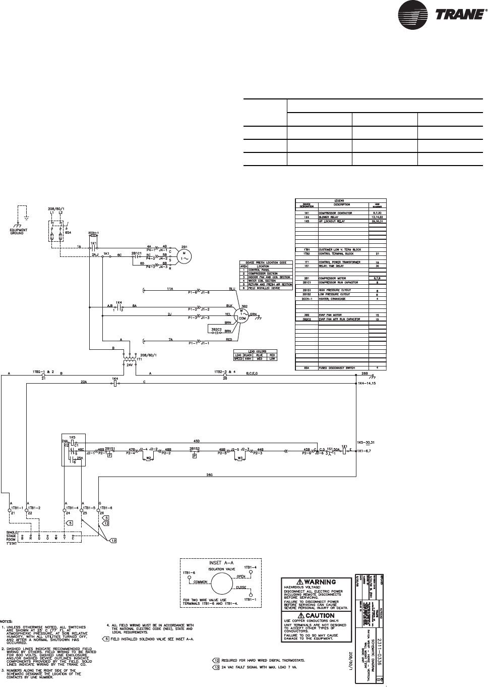
WSHP-SVX01N-EN 121
Wiring Diagrams
This section contains wiring diagrams (Figure 81, p. 121–
Figure 87, p. 127) and isolation valve wiring connections
(Table 66, p. 121).
Table 66. Isolation valve wiring
Control
type
3-wire Honeywell isolation valve connections
Blue Brown Black
Basic 24V 1TB1-6 1TB1-1 1TB1-4
Deluxe 24V 1TB1-6 1TB1-1 1TB1-4
ZN524 1TB1-18 1TB2-3 1TB1-16
Figure 81. GEH_V (½-5 tons) - basic-208V - 60 Hz-1ph
(a)
(a)Wiring diagrams provided in the catalog are generic. A unit specific As Built wiring diagram is located on the unit control panel.
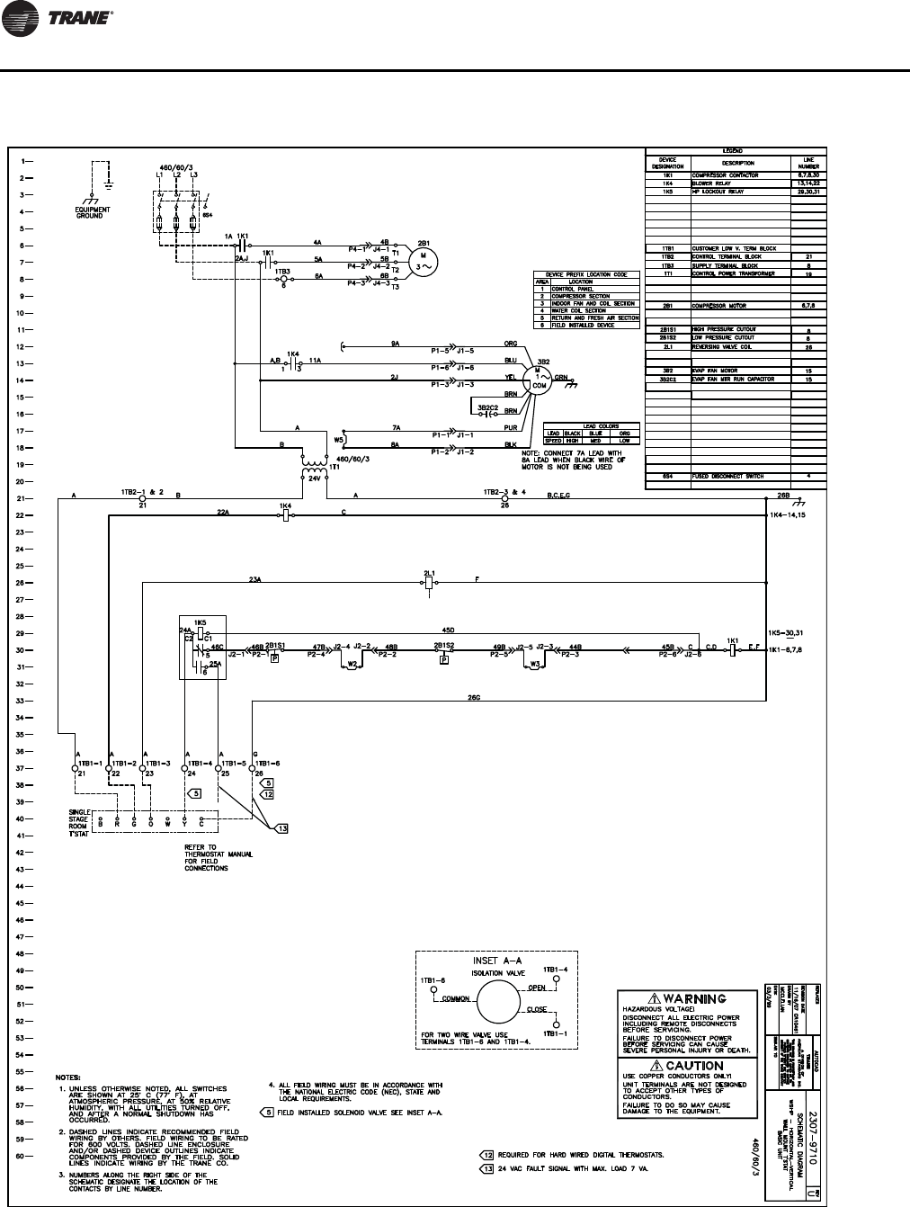
Wiring Diagrams
122 WSHP-SVX01N-EN
Figure 82. GEH_V (½-5 tons) - basic 24V - 460V-60 Hz-3ph
(a)
(a)Wiring diagrams provided in the catalog are generic. A unit specific As Built wiring diagram is located on the unit control panel.
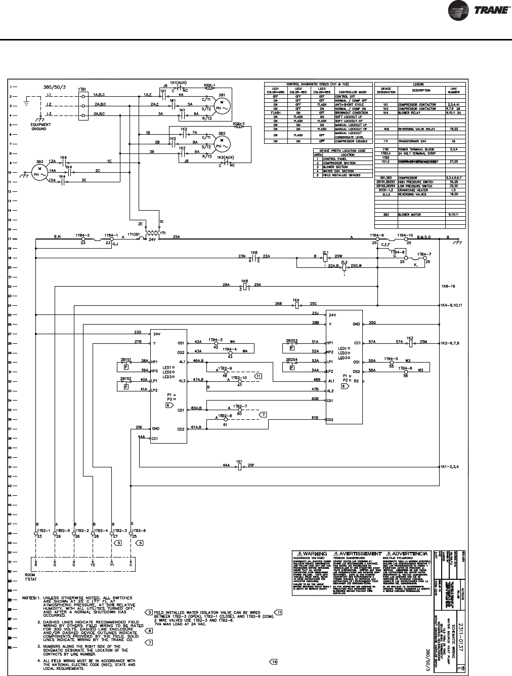
Wiring Diagrams
WSHP-SVX01N-EN 123
Figure 83. GEH_V (6-25 tons) - deluxe-380-420V - 50 Hz-3ph
(a)
(a)Wiring diagrams provided in the catalog are generic. A unit specific As Built wiring diagram is located on the unit control panel.
1U1
1U2
CONNECTION FOR 24VAC CLASS 2 COMPRESSOR DISABLE
VERIFY TEST JUMPER HAS BEEN REMOVED TO PREVENT
INP UT. TERM INAL 1 TB2- 7 AND 1TB2-8
CONTROL TIMING ER RORS.
CONTACTS RATED FOR CLASS 2 24V. TER MINAL 1TB2-9 AND 10.
ISOLATED GENERAL ALARM CONTACTS. CONTACTS CLOSE
WHEN CONTROL 1U1 AND 1U2 GOES INTO MANUAL LOCKOUT MODE.
CONNECTTERMINAL11TO1TB2-1&2ANDTERMINAL10TO1TB2-3&4
IF USING ZONE SENSOR X13790886010.
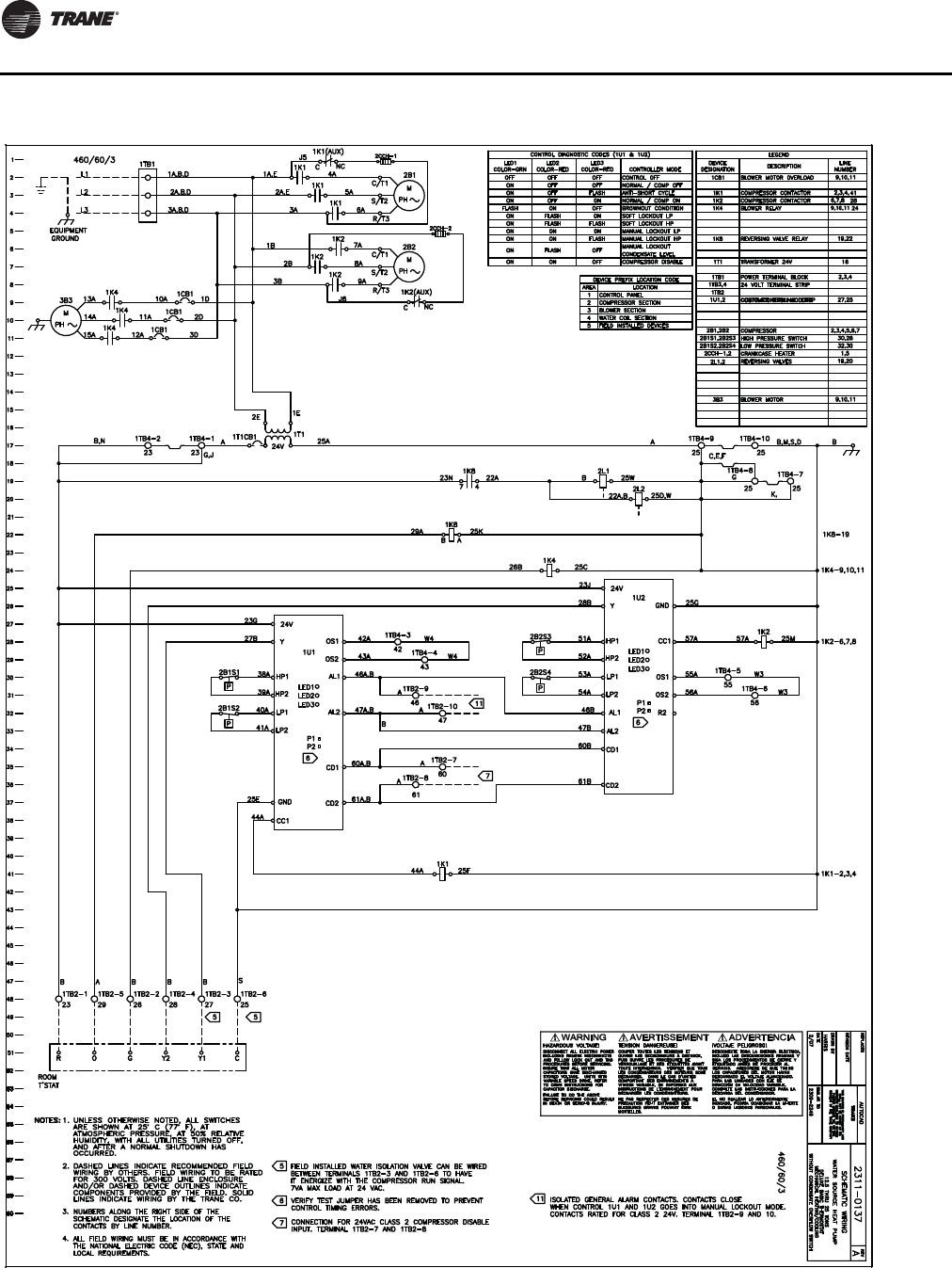
Wiring Diagrams
124 WSHP-SVX01N-EN
Figure 84. GEH_V (6-25 tons) - deluxe 24V - 460V-60 Hz-3ph
(a)
(a)Wiring diagrams provided in the catalog are generic. A unit specific As Built wiring diagram is located on the unit control panel.
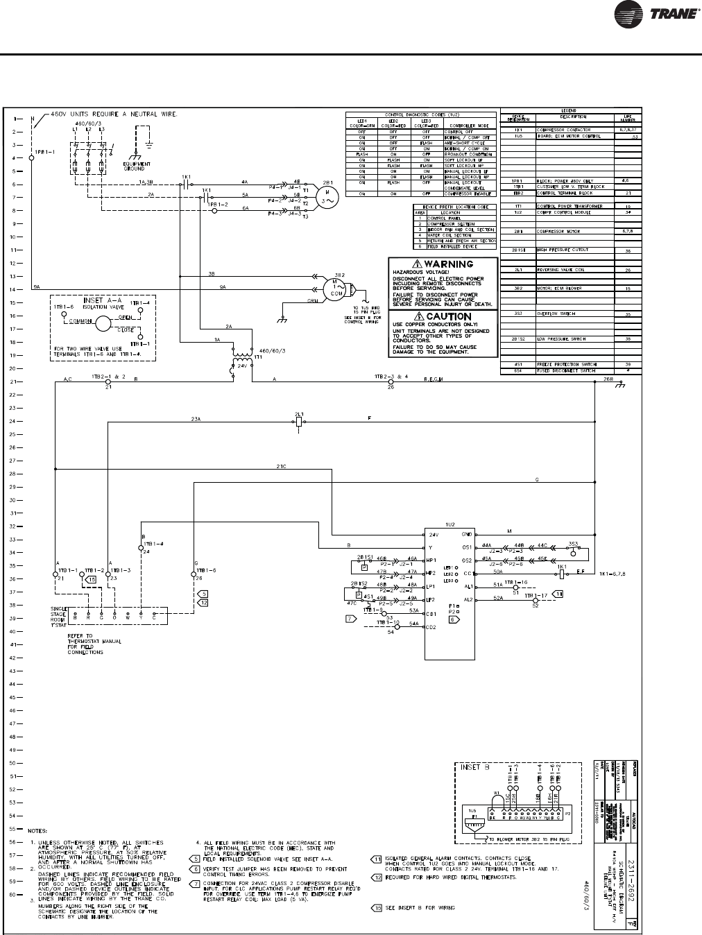
Wiring Diagrams
WSHP-SVX01N-EN 125
Figure 85. EXH/EXV - deluxe 24V - 460V-60 Hz-3ph
(a) - (ECM motor wiring diagram)
(a)Wiring diagrams provided in the catalog are generic. A unit specific As Built wiring diagram is located on the unit control panel.
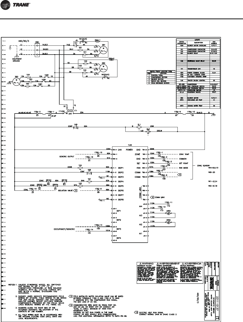
Wiring Diagrams
126 WSHP-SVX01N-EN
Figure 86. GEH_V (6-25 tons) - Tracer™ ZN524-460V - 60 Hz-3ph
(a)
(a)Wiring diagrams provided in the catalog are generic. A unit specific As Built wiring diagram is located on the unit control panel.
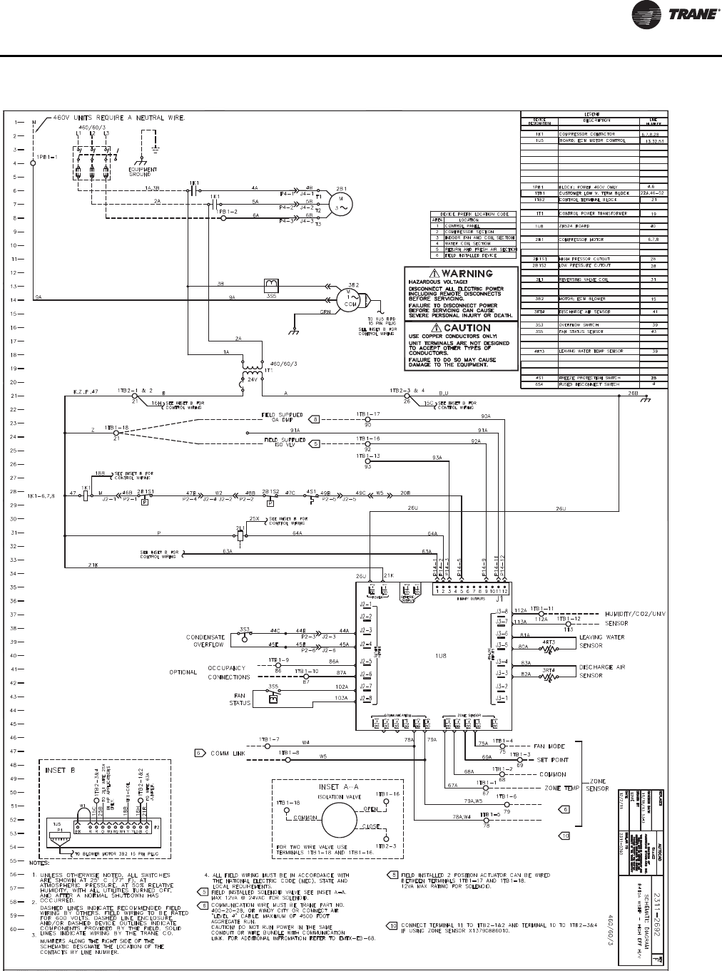
Wiring Diagrams
WSHP-SVX01N-EN 127
Figure 87. EXH_V -Tracer™ ZN524 460V-60 Hz-3ph
(a) - (ECM motor wiring diagram)
(a)Wiring diagrams provided in the catalog are generic. A unit specific As Built wiring diagram is located on the unit control panel.
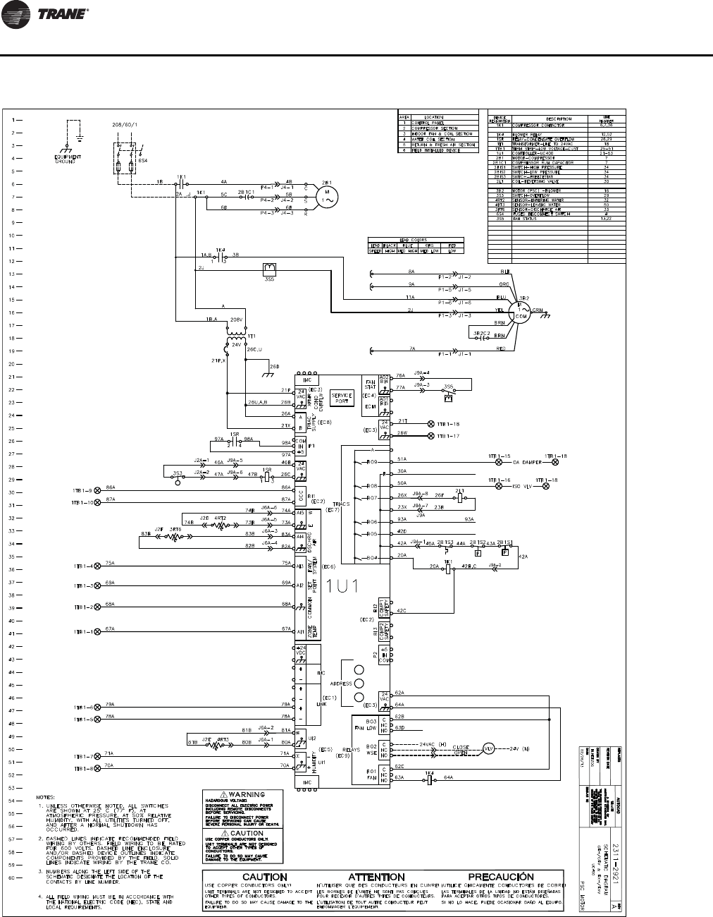
Wiring Diagrams
128 WSHP-SVX01N-EN
Figure 88. GEH_V (½-5) tons - UC400(a)
(a)Wiring diagrams provided in the catalog are generic. A unit specific As Built wiring diagram is located on the unit control panel.
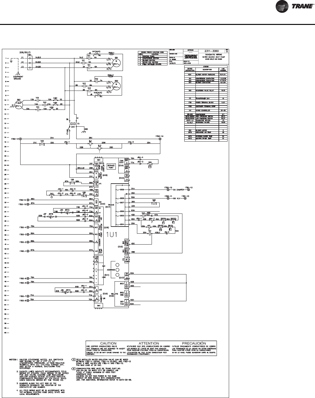
Wiring Diagrams
WSHP-SVX01N-EN 129
Figure 89. GEH_V (6-25 tons) - UC400(a)
(a)Wiring diagrams provided in the catalog are generic. A unit specific As Built wiring diagram is located on the unit control panel.

Wiring Diagrams
130 WSHP-SVX01N-EN

131 WSHP-SVX01N-EN
Warranty Information
Standard Warranty
The standard water-source heat pump warranty isTrane’s
parts-only warranty, running 12 months from startup, not
to exceed 18-months from shipment.
Extended Warranty
The optional extended warranty is a second through fifth
year warranty.The time starts at the end of the standard 1
year coverage through the fifth year.
These extended warranties apply only to new equipment
installed in domesticTrane Commercial Systems Group
sales territories and must be ordered prior to start-up.

Trane optimizes the performance of homes and buildings around the world. A business of Ingersoll Rand, the leader in
creating and sustaining safe, comfortable and energy efficient environments,Trane offers a broad portfolio of advanced
controls and HVAC systems, comprehensive building services, and parts. For more information, visit www.Trane.com.
Trane has a policy of continuous product and product data improvement and reserves the right to change design and specifications without notice.
We are committed to using environmentally
conscious print practices that reduce waste.
© 2014Trane All rights reserved
WSHP-SVX01N-EN 12 Sep 2014
Supersedes WSHP-SVX01M-EN (15 Dec 2013)
