Trane Odyssey 6 To 25 Tons Installation And Maintenance Manual Air Handlers
2015-04-02
: Trane Trane-Odyssey-6-To-25-Tons-Installation-And-Maintenance-Manual-684225 trane-odyssey-6-to-25-tons-installation-and-maintenance-manual-684225 trane pdf
Open the PDF directly: View PDF ![]() .
.
Page Count: 48
- Model Number Description
- General Information
- Pre-Installation
- Dimensional Data
- Weights
- Installation
- Electrical Data
- Start-Up
- Maintenance
- Wiring Diagram Matrix
SSAAFFEETTYY WWAARRNNIINNGG
Only qualified personnel should install and service the equipment. The installation, starting up, and servicing of heating, ventilating, and
air-conditioning equipment can be hazardous and requires specific knowledge and training. Improperly installed, adjusted or altered
equipment by an unqualified person could result in death or serious injury. When working on the equipment, observe all precautions in the
literature and on the tags, stickers, and labels that are attached to the equipment.
March 2015 SSA-SVX06E-EN
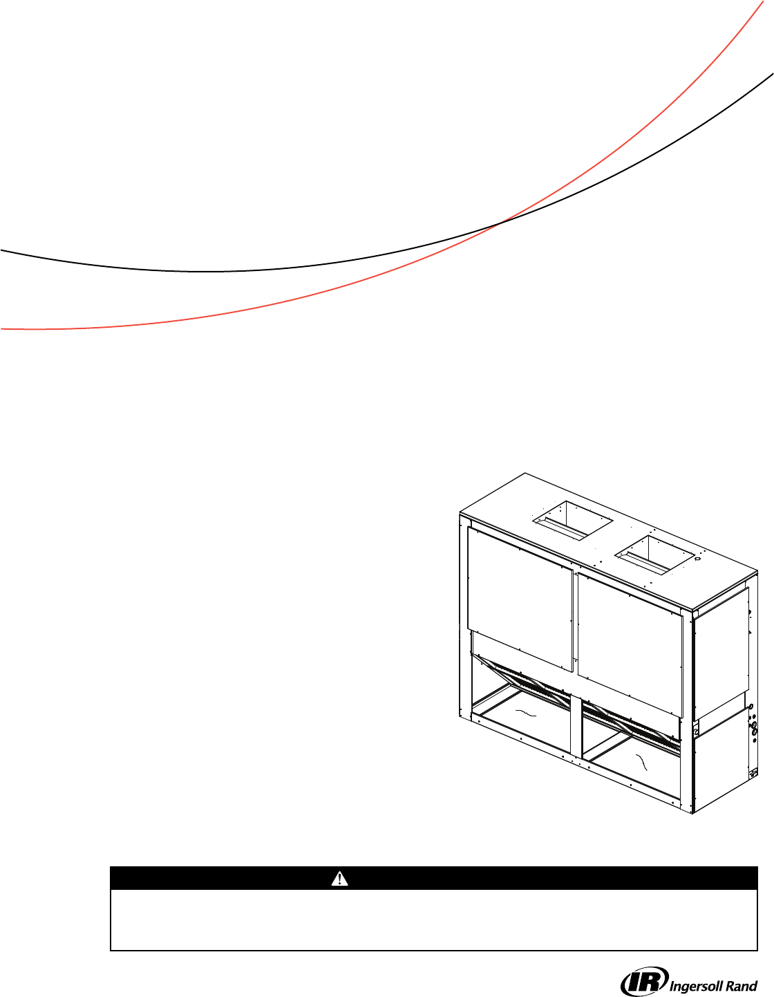
Split System Air Conditioners
Odyssey™™
Air Handler — 5 to 25 Tons
MMooddeell ((6600 HHzz))
TWE061D/E***A
TWE090D/E**BA
TWE120D/E**BA
TWE150E**BA
TWE180E**BA
TWE240E**BA
TWE300E**BA
MMooddeell ((5500 HHzz))
TWE051D***A
TWE076D/E***A
TWE101D/E***A
TWE126E***A
TWE156E***A
TWE201E***A
TWE251E***A
Installation, Operation,
and Maintenance
©2015 Trane All rights reserved SSA-SVX06E-EN
Introduction
Read this manual thoroughly before operating or
servicing this unit.
Warnings, Cautions, and Notices
Safety advisories appear throughout this manual as
required. Your personal safety and the proper
operation of this machine depend upon the strict
observance of these precautions.
The three types of advisories are defined as follows:
WARNING
Indicates a potentially hazardous situation
which, if not avoided, could result in death or
serious injury.
CAU
TION
Indicates a potentially hazardous situation
which, if not avoided, could result in minor or
moderate injury. It could also be used to alert
against unsafe practices.
NOTICE
Indicates a situation that could result in
equipment or property-damage only
accidents.
Important Environmental Concerns
Scientific research has shown that certain man-made
chemicals can affect the earth’s naturally occurring
stratospheric ozone layer when released to the
atmosphere. In particular, several of the identified
chemicals that may affect the ozone layer are
refrigerants that contain Chlorine, Fluorine and Carbon
(CFCs) and those containing Hydrogen, Chlorine,
Fluorine and Carbon (HCFCs). Not all refrigerants
containing these compounds have the same potential
impact to the environment. Trane advocates the
responsible handling of all refrigerants-including
industry replacements for CFCs such as HCFCs and
HFCs.
Important Responsible Refrigerant
Practices
Trane believes that responsible refrigerant practices are
important to the environment, our customers, and the
air conditioning industry. All technicians who handle
refrigerants must be certified. The Federal Clean Air Act
(Section 608) sets forth the requirements for handling,
reclaiming, recovering and recycling of certain
refrigerants and the equipment that is used in these
service procedures. In addition, some states or
municipalities may have additional requirements that
must also be adhered to for responsible management
of refrigerants. Know the applicable laws and follow
them.
WWAARRNNIINNGG
PPrrooppeerr FFiieelldd WWiirriinngg aanndd GGrroouunnddiinngg
RReeqquuiirreedd!!
AAllll ffiieelldd wwiirriinngg MMUUSSTT bbee ppeerrffoorrmmeedd bbyy qquuaalliiffiieedd
ppeerrssoonnnneell.. IImmpprrooppeerrllyy iinnssttaalllleedd aanndd ggrroouunnddeedd
ffiieelldd wwiirriinngg ppoosseess FFIIRREE aanndd EELLEECCTTRROOCCUUTTIIOONN
hhaazzaarrddss.. TToo aavvooiidd tthheessee hhaazzaarrddss,, yyoouu MMUUSSTT ffoollllooww
rreeqquuiirreemmeennttss ffoorr ffiieelldd wwiirriinngg iinnssttaallllaattiioonn aanndd
ggrroouunnddiinngg aass ddeessccrriibbeedd iinn NNEECC aanndd yyoouurr llooccaall//
ssttaattee eelleeccttrriiccaall ccooddeess..
WWAARRNNIINNGG
PPeerrssoonnaall PPrrootteeccttiivvee EEqquuiippmmeenntt ((PPPPEE))
RReeqquuiirreedd!!
TTeecchhnniicciiaannss,, iinn oorrddeerr ttoo pprrootteecctt tthheemmsseellvveess ffrroomm
ppootteennttiiaall eelleeccttrriiccaall,, mmeecchhaanniiccaall,, aanndd cchheemmiiccaall
hhaazzaarrddss,, MMUUSSTT ffoollllooww pprreeccaauuttiioonnss iinn tthhiiss mmaannuuaall
aanndd oonn tthhee ttaaggss,, ssttiicckkeerrss,, aanndd llaabbeellss,, aass wweellll aass tthhee
iinnssttrruuccttiioonnss bbeellooww::
•• BBeeffoorree iinnssttaalllliinngg//sseerrvviicciinngg tthhiiss uunniitt,,
tteecchhnniicciiaannss MMUUSSTT ppuutt oonn aallll PPPPEE rreeqquuiirreedd ffoorr
tthhee wwoorrkk bbeeiinngg uunnddeerrttaakkeenn ((EExxaammpplleess;; ccuutt
rreessiissttaanntt gglloovveess//sslleeeevveess,, bbuuttyyll gglloovveess,, ssaaffeettyy
ggllaasssseess,, hhaarrdd hhaatt//bbuummpp ccaapp,, ffaallll pprrootteeccttiioonn,,
eelleeccttrriiccaall PPPPEE aanndd aarrcc ffllaasshh ccllootthhiinngg))..
AALLWWAAYYSS rreeffeerr ttoo aapppprroopprriiaattee MMaatteerriiaall SSaaffeettyy
DDaattaa SShheeeettss ((MMSSDDSS))//SSaaffeettyy DDaattaa SShheeeettss
((SSDDSS)) aanndd OOSSHHAA gguuiiddeelliinneess ffoorr pprrooppeerr PPPPEE..
•• WWhheenn wwoorrkkiinngg wwiitthh oorr aarroouunndd hhaazzaarrddoouuss
cchheemmiiccaallss,, AALLWWAAYYSS rreeffeerr ttoo tthhee aapppprroopprriiaattee
MMSSDDSS//SSDDSS aanndd OOSSHHAA//GGHHSS ((GGlloobbaall
HHaarrmmoonniizzeedd SSyysstteemm ooff CCllaassssiiffiiccaattiioonn aanndd
LLaabbeelllliinngg ooff CChheemmiiccaallss)) gguuiiddeelliinneess ffoorr
iinnffoorrmmaattiioonn oonn aalllloowwaabbllee ppeerrssoonnaall eexxppoossuurree
lleevveellss,, pprrooppeerr rreessppiirraattoorryy pprrootteeccttiioonn aanndd
hhaannddlliinngg iinnssttrruuccttiioonnss..
•• IIff tthheerree iiss aa rriisskk ooff eenneerrggiizzeedd eelleeccttrriiccaall
ccoonnttaacctt,, aarrcc,, oorr ffllaasshh,, tteecchhnniicciiaannss MMUUSSTT ppuutt
oonn aallll PPPPEE iinn aaccccoorrddaannccee wwiitthh OOSSHHAA,, NNFFPPAA
7700EE,, oorr ootthheerr ccoouunnttrryy--ssppeecciiffiicc rreeqquuiirreemmeennttss
ffoorr aarrcc ffllaasshh pprrootteeccttiioonn,, PPRRIIOORR ttoo sseerrvviicciinngg
tthhee uunniitt.. NNEEVVEERR PPEERRFFOORRMM AANNYY SSWWIITTCCHHIINNGG,,
DDIISSCCOONNNNEECCTTIINNGG,, OORR VVOOLLTTAAGGEE TTEESSTTIINNGG
WWIITTHHOOUUTT PPRROOPPEERR EELLEECCTTRRIICCAALL PPPPEE AANNDD
AARRCC FFLLAASSHH CCLLOOTTHHIINNGG.. EENNSSUURREE
EELLEECCTTRRIICCAALL MMEETTEERRSS AANNDD EEQQUUIIPPMMEENNTT AARREE
PPRROOPPEERRLLYY RRAATTEEDD FFOORR IINNTTEENNDDEEDD VVOOLLTTAAGGEE..
SSA-SVX06E-EN 3
WWAARRNNIINNGG
RReeffrriiggeerraanntt uunnddeerr HHiigghh PPrreessssuurree!!
SSyysstteemm ccoonnttaaiinnss ooiill aanndd rreeffrriiggeerraanntt uunnddeerr hhiigghh
pprreessssuurree.. RReeccoovveerr rreeffrriiggeerraanntt ttoo rreelliieevvee pprreessssuurree
bbeeffoorree ooppeenniinngg tthhee ssyysstteemm.. SSeeee uunniitt nnaammeeppllaattee ffoorr
rreeffrriiggeerraanntt ttyyppee.. DDoo nnoott uussee nnoonn--aapppprroovveedd
rreeffrriiggeerraannttss,, rreeffrriiggeerraanntt ssuubbssttiittuutteess,, oorr rreeffrriiggeerraanntt
aaddddiittiivveess..
WWAARRNNIINNGG
RR--441100AA RReeffrriiggeerraanntt uunnddeerr HHiigghheerr
PPrreessssuurree tthhaann RR--2222!!
TThhee uunniittss ddeessccrriibbeedd iinn tthhiiss mmaannuuaall uussee RR--441100AA
rreeffrriiggeerraanntt wwhhiicchh ooppeerraatteess aatt hhiigghheerr pprreessssuurreess
tthhaann RR--2222.. UUssee OONNLLYY RR--441100AA rraatteedd sseerrvviiccee
eeqquuiippmmeenntt oorr ccoommppoonneennttss wwiitthh tthheessee uunniittss.. FFoorr
ssppeecciiffiicc hhaannddlliinngg ccoonncceerrnnss wwiitthh RR--441100AA,, pplleeaassee
ccoonnttaacctt yyoouurr llooccaall TTrraannee rreepprreesseennttaattiivvee..
Copyright
This document and the information in it are the
property of Trane, and may not be used or reproduced
in whole or in part without written permission. Trane
reserves the right to revise this publication at any time,
and to make changes to its content without obligation
to notify any person of such revision or change.
Trademarks
All trademarks referenced in this document are the
trademarks of their respective owners.
Revision History
• With the change to Microchannel, the Odyssey split
system now offers a 50Hz, 6.25 standard air handler
(TWE076E) and a 60Hz, 7.5 ton standard/SZVAV/2-
Speed VFD air handler (TWE090E). See
performance data for additional details on this new
split system.
• Odyssey air handlers now have the ability to
convert from Single Zone VAV to 2–Speed Fan
control in order to comply with certain sections of
California Title 24 and ASHRAE 90.1. See
“Installation, 2-Speed VFD Units,” p. 25 for
configuration details.
IInnttrroodduuccttiioonn
4SSA-SVX06E-EN
Model Number Description. . . . . . . . . . . . . . . . . 5
Air Handler. . . . . . . . . . . . . . . . . . . . . . . . . . . . . . . 5
General Information . . . . . . . . . . . . . . . . . . . . . . . . 6
Unit Description . . . . . . . . . . . . . . . . . . . . . . . . . . 6
Pre-Installation . . . . . . . . . . . . . . . . . . . . . . . . . . . . . 7
Unit Inspection . . . . . . . . . . . . . . . . . . . . . . . . . . . 7
Inspection Checklist . . . . . . . . . . . . . . . . . . . 7
Testing for Leaks. . . . . . . . . . . . . . . . . . . . . . . . . . 7
Lifting Recommendations . . . . . . . . . . . . . . . . . 7
Repositioning Drain Pan. . . . . . . . . . . . . . . . . . . 7
Field Conversion to 460 Volt . . . . . . . . . . . . . . . 9
Converting Motor to 460 Volt. . . . . . . . . . . 9
Refrigerant Piping . . . . . . . . . . . . . . . . . . . . . . . . 9
Reorienting Evaporator Coil
(TWE126/150 and 156/180) . . . . . . . . . . . . . 9
Preparation for Refrigerant
Piping. . . . . . . . . . . . . . . . . . . . . . . . . . . . . . . 10
Installations, Limitations and
Recommendations. . . . . . . . . . . . . . . . . . . . . . . 10
Dimensional Data . . . . . . . . . . . . . . . . . . . . . . . . . 11
Weights . . . . . . . . . . . . . . . . . . . . . . . . . . . . . . . . . . . 20
Air Handler. . . . . . . . . . . . . . . . . . . . . . . . . . . . . . 20
Installation . . . . . . . . . . . . . . . . . . . . . . . . . . . . . . . . 22
Horizontal Suspension . . . . . . . . . . . . . . . . . . . 22
Leveling. . . . . . . . . . . . . . . . . . . . . . . . . . . . . 22
Auxiliary Drain Pan. . . . . . . . . . . . . . . . . . . 22
Refrigerant Piping . . . . . . . . . . . . . . . . . . . . . . . 22
Condensate Piping. . . . . . . . . . . . . . . . . . . . . . . 23
Filter Replacement. . . . . . . . . . . . . . . . . . . . . . . 23
Duct Connections. . . . . . . . . . . . . . . . . . . . . . . . 24
Air Flow Settings . . . . . . . . . . . . . . . . . . . . . . . . 24
Standard Units. . . . . . . . . . . . . . . . . . . . . . . 24
SZVAV Units . . . . . . . . . . . . . . . . . . . . . . . . . 24
2-Speed VFD Units . . . . . . . . . . . . . . . . . . . 25
Minimum Supply Fan Output . . . . . . . . . 25
Electrical Connections . . . . . . . . . . . . . . . . . . . 26
Setpoints . . . . . . . . . . . . . . . . . . . . . . . . . . . . . . . 26
EDC Switch Wiring . . . . . . . . . . . . . . . . . . . 27
Heating and Cooling Setpoint
Arbitration . . . . . . . . . . . . . . . . . . . . . . . . . . 27
Checkout Procedure . . . . . . . . . . . . . . . . . . . . . 28
Installation Checklist . . . . . . . . . . . . . . . . . . . . . 28
Thermostat and Control
Connections. . . . . . . . . . . . . . . . . . . . . . . . . . . . . 29
Electromechanical Controls . . . . . . . . . . . 29
ReliaTel Controls . . . . . . . . . . . . . . . . . . . . . 29
Electrical Data . . . . . . . . . . . . . . . . . . . . . . . . . . . . . 31
60 Hz Models . . . . . . . . . . . . . . . . . . . . . . . . . . . . 31
50 Hz Models . . . . . . . . . . . . . . . . . . . . . . . . . . . . 40
Start-Up . . . . . . . . . . . . . . . . . . . . . . . . . . . . . . . . . . . 42
Sequence of Operation. . . . . . . . . . . . . . . . . . . 42
Variable Air Volume Applications
(SZVAV) . . . . . . . . . . . . . . . . . . . . . . . . . . . . . 42
2–Speed VFD Applications . . . . . . . . . . . . 43
Maintenance . . . . . . . . . . . . . . . . . . . . . . . . . . . . . . 44
Fan Belt Adjustment . . . . . . . . . . . . . . . . . . . . . 44
Monthly . . . . . . . . . . . . . . . . . . . . . . . . . . . . . . . . 44
Annually (Cooling Season) . . . . . . . . . . . . . . . 45
Coil Cleaning . . . . . . . . . . . . . . . . . . . . . . . . . . . . 45
Maintenance Log . . . . . . . . . . . . . . . . . . . . . . . . 46
Wiring Diagram Matrix . . . . . . . . . . . . . . . . . . . . 47
Table of Contents

SSA-SVX06E-EN 5
Model Number Description
Air Handler
T WE 2 40 E D 0 0 * *
1 2 3 4 5 6 7 8 9 10 11 12
T WE 201 E D 0 0 * *
1 2 3 4 5 6 7 8 9 10 11 12
NNoottee:: When ordering replacement parts or requesting
service, be sure to refer to the specific model
number, serial number, and DL number (if
applicable) stamped on the unit nameplate.
DDIIGGIITTSS 11 -- 33:: PPrroodduucctt TTyyppee
TWE = Split System Heat Pump/Cooling Air Handler
DDIIGGIITTSS 44 -- 66:: NNoommiinnaall GGrroossss CCoooolliinngg CCaappaacciittyy
((MMBBhh))
061 = 5 Tons (60 Hz)
090 = 7.5 Tons (60 Hz)
120 = 10 Tons (60 Hz)
150 = 12.5 Tons (60 Hz)
180 = 15 Tons (60 Hz)
240 = 20 Tons (60 Hz)
300 = 25 Tons (60 Hz)
051 = 4.6 Tons (50 Hz)
076 = 6.25 Tons (50 Hz)
101 = 8.33 Tons (50 Hz)
126 = 10.4 Tons (50 Hz)
156 = 13.0 Tons (50 Hz)
201 = 16.7 Tons (50 Hz)
251 = 20.9 Tons (50 Hz)
DDIIGGIITT 77:: MMaajjoorr DDeevveellooppmmeenntt SSeeqquueennccee
D = Single Refrigeration Circuit
E = Dual Refrigeration Circuit
DDIIGGIITT 88:: EElleeccttrriiccaall CChhaarraacctteerriissttiiccss
3 = 208–230/60/3
4 = 460/60/3
W = 575/60/3
D = 380-415/50/3
K = 380/60/3
DDIIGGIITTSS 99 -- 1100:: FFaaccttoorryy IInnssttaalllleedd OOppttiioonnss
00 = Packed Stock (Standard)
03 = 2-Speed Variable Frequency Drive (VFD) standard
motor (electromechanical condenser only)
04 = 2-Speed Variable Frequency Drive (VFD) oversized
motor (electromechanical condenser only)
R3 = Single Zone Variable Air Volume (VFD) standard
motor - (ReliaTel condenser only)
R4 = Single Zone Variable Air Volume (VFD) oversized
motor - (ReliaTel condenser only)
DDIIGGIITTSS 1111:: MMiinnoorr DDeessiiggnn SSeeqquueennccee
* = Current Design Sequence1
DDIIGGIITTSS 1122:: SSeerrvviiccee DDiiggiitt
* = Current Design Sequence1
1. * = sequential alpha character
6SSA-SVX06E-EN
General Information
This manual describes proper installation, operation,
and maintenance procedures for air cooled systems. By
carefully reviewing the information within this manual
and following the instructions, the risk of improper
operation and/or component damage will be
minimized. It is important that periodic maintenance be
performed to help assure trouble free operation.
Should equipment failure occur, contact a qualified
service organization with qualified, experienced HVAC
technicians to properly diagnose and repair this
equipment.
IImmppoorrttaanntt:: All phases of this installation must comply
with the NATIONAL, STATE & LOCAL
CODES. In addition to local codes, the
installation must conform with National
Electric Code -ANSI/NFPA NO. 70 LATEST
REVISION.
Any individual installing, maintaining, or servicing this
equipment must be properly trained, licensed and
qualified.
IImmppoorrttaanntt:: Do not remove the VFD without first
contacting technical support! For
performance-related questions and
diagnostic support in North America call 1-
877-872-6363. Any return requires a claim
number FIRST. Removal of the VFD prior to
this step will void the unit’s warranties.
Installation procedures should be performed in the
sequence that they appear in this manual. Do not
destroy or remove the manual from the unit. The
manual should remain weather-protected with the unit
until all installation procedures are complete.
NNoottee:: It is not the intention of this manual to cover all
possible variations in systems that may occur or
to provide comprehensive information
concerning every possible contingency that may
be encountered during an installation. If
additional information is required or if specific
problems arise that are not fully discussed in this
manual, contact your local sales office.
Use the installation checklist provided In this manual to
verify that all necessary installation procedures have
been completed. Do not use the checklist as a
substitute for reading the information contained in the
manual. Read the entire manual before beginning
installation procedures.
Unit Description
These air handler models incorporate a single slab coil
assembly, improved application flexibility, servicing,
maintenance accessibility and an improved accessory
line. They are fully convertible, (vertical to horizontal
discharge) without field removal of the coil assembly.
They are shipped ready for horizontal installation.
All units have one drain pan that can be installed in any
one of four positions. This allows for vertical or
horizontal applications and right or left exit.
IImmppoorrttaanntt:: All dual circuit (digit 7 = E) have an
intertwined coil, except for the 25 ton,
TWE251 and TWE300 units.
SSA-SVX06E-EN 7
Pre-Installation
The final position for the air handler must be dictated
by required service access to it, weight distribution
over structural supports, and by the locations of
electrical, refrigerant and condensate drainage
connections. After this is determined, the following
preparations should be made.
Unit Inspection
Inspect material carefully for any shipping damage. If
damaged, it must be reported to, and claims made
against the transportation company. Compare the
information that appears on the unit nameplate with
ordering and submittal data to ensure the proper unit
was shipped. Available power supply must be
compatible with electrical characteristics specified on
component nameplates. Replace damaged parts with
authorized parts only.
Inspection Checklist
To protect against loss due to damage incurred in
transit, complete the following checklist upon receipt of
the unit.
Inspect individual pieces of the shipment before
accepting the unit. Check for obvious damage to the
unit or packing material.
Inspect the unit for concealed damage before it is
stored and as soon as possible after delivery.
Concealed damage must be reported within 15
days. If concealed damage is discovered, stop
unpacking the shipment. Do not remove damaged
material from the receiving location. Take photos of
the damage if possible. The owner must provide
reasonable evidence that the damage did not occur
after delivery.
Notify the carrier’s terminal of damage immediately
by phone and by mail. Request an immediate joint
inspection of the damage by the carrier and the
consignee.
Notify the sales representative and arrange for
repair. Do not repair the unit until the damage is
inspected by the carrier’s representative.
Testing for Leaks
All TWE units are shipped with a holding charge of
nitrogen in each circuit and should be leak tested
before installation.
1. Remove the access panel.
2. Locate the liquid line or suction line access valve for
each circuit.
3. Install gauges to determine if the circuits are still
pressurized. If not, the charge has escaped and
should be repaired as required to obtain a leak-free
circuit.
Lifting Recommendations
WWAARRNNIINNGG
IImmpprrooppeerr UUnniitt LLiifftt!!
TTeesstt lliifftt uunniitt aapppprrooxxiimmaatteellyy 2244 iinncchheess ttoo vveerriiffyy
pprrooppeerr cceenntteerr ooff ggrraavviittyy lliifftt ppooiinntt.. TToo aavvooiidd
ddrrooppppiinngg ooff uunniitt,, rreeppoossiittiioonn lliiffttiinngg ppooiinntt iiff uunniitt iiss
nnoott lleevveell..
NNOOTTIICCEE
EEqquuiippmmeenntt DDaammaaggee!!
UUssee sspprreeaaddeerr bbaarrss ttoo pprreevveenntt ssttrraappss ffrroomm
ddaammaaggiinngg tthhee uunniitt.. IInnssttaallll tthhee bbaarrss bbeettwweeeenn lliiffttiinngg
ssttrraappss,, bbootthh uunnddeerrnneeaatthh tthhee uunniitt aanndd aabboovvee tthhee
uunniitt ttoo pprreevveenntt tthhee ssttrraappss ffrroomm ccrruusshhiinngg tthhee uunniitt
ccaabbiinneett oorr ddaammaaggiinngg tthhee ffiinniisshh..
Before preparing the unit for lifting, estimate the
approximate center of gravity for lifting safety. Because
of placement of internal components, the unit weight
may be unevenly distributed. See “Weights,” p. 20 for
approximate unit weights.
The crated unit can be moved using a forklift of suitable
capacity. For lifting the unit into an elevated mounting
position, run lifting straps or slings under the unit and
attach securely to the lifting device.
Repositioning Drain Pan
Air handlers come with one drain pan that can be
installed in any one of four positions; this allows for
vertical or horizontal application and right or left
condensate line connection.
NNoottee:: Important! All air handlers are shipped with the
drain pan installed in the horizontal position and
the connection on the left side (as shown in
Figure 1, p. 8. If an alternate position is required,
the drain pan should be repositioned before
setting the air handler.
1. Remove the access plate at the opposite end of the
drain connection. This plate secures and lifts the
back end of the drain pan for sloping. It must be
removed before the drain pan can be removed. This
is done as follows:
a. Remove the screw
b. Lift the access plate up
c. Pull the plate out. If the drain pan is to be moved
to the vertical position also remove the other
two access plates.
2. Remove the screw securing the drain pan.
a. Lift the pan up
b. Slide the pan out
3. Install the drain pan into the new position.
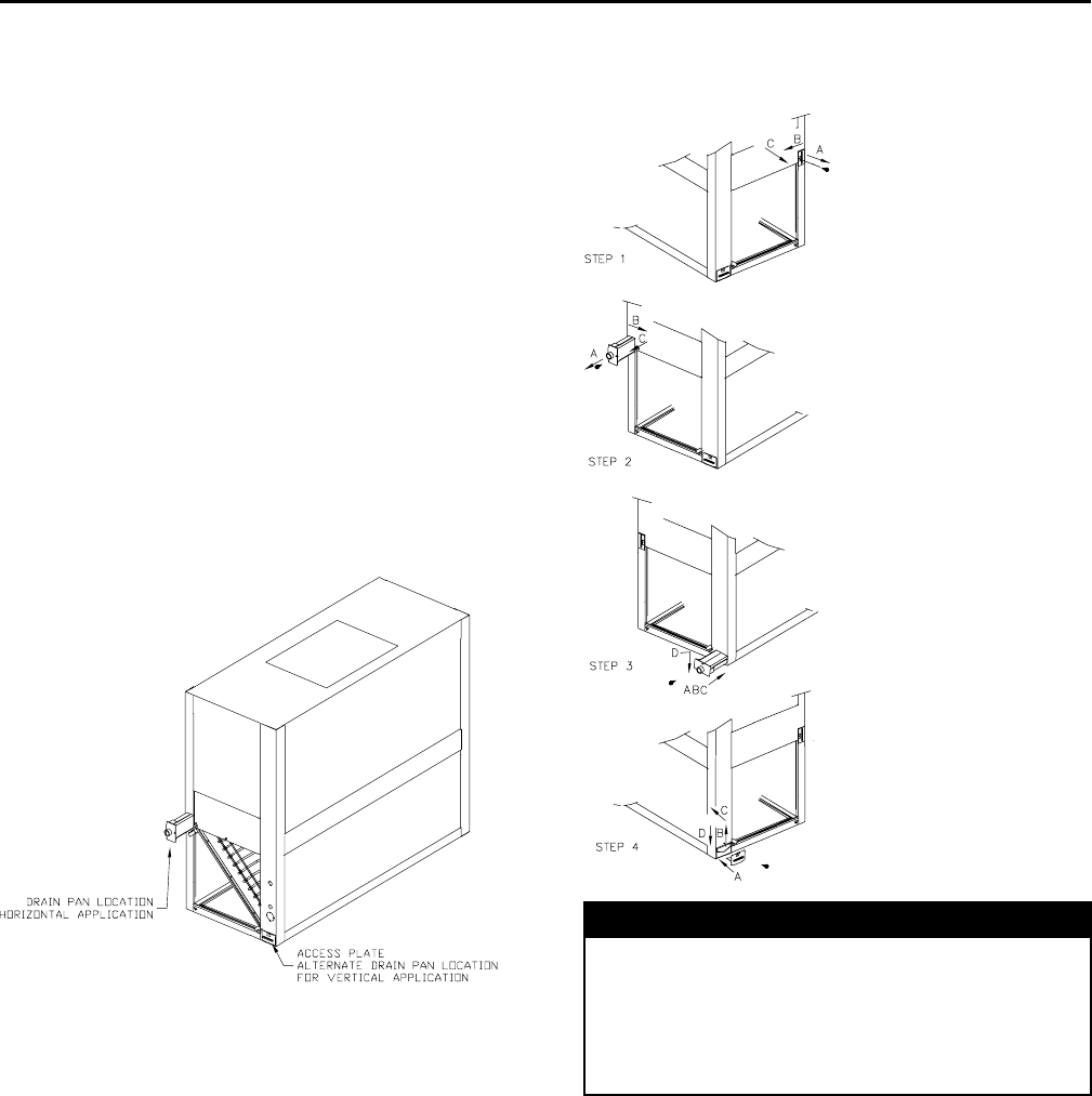
8SSA-SVX06E-EN
a. Slide the drain pan into the opening
b. Lift the drain pan up
c. Push it in all the way
d. Drop it down over the lip of the opening, secure
with screw
4. Install the access plate on the opposite end of the
drain pain.
a. Slide the edge of the access plate under the
drain pan
b. Lift the access plate and drain pan up
c. Push the access plate in
d. Drop the access plate down over the lip of the
opening, secure with screw
NNoottee:: If the drain pan is being moved to the vertical
position, install the other access plates over
the horizontal position opening
Figure 1. Drain pan location
Figure 2. Drain pan relocation
NNOOTTIICCEE
SSyysstteemm CCoommppoonneenntt DDaammaaggee!!
TThheessee aaiirr hhaannddlleerrss aarree sshhiippppeedd wwiitthh aa ddrryy nniittrrooggeenn
hhoollddiinngg cchhaarrggee iinn tthhee ccooiill.. DDeepprreessss oorr rreemmoovvee tthhee
aacccceessss vvaallvvee ccoonnee ttoo bblleeeedd ooffff tthhee nniittrrooggeenn pprriioorr ttoo
bbrraazziinngg.. TTeemmppoorraarriillyy ccaapp ooffff ttuubbeess iiff tthhee
rreeffrriiggeerraanntt lliinnee ccoonnnneeccttiioonnss aarree ttoo bbee mmaaddee llaatteerr..
PPrree--IInnssttaallllaattiioonn
SSA-SVX06E-EN 9
Field Conversion to 460 Volt
WWAARRNNIINNGG
HHaazzaarrddoouuss VVoollttaaggee ww//CCaappaacciittoorrss!!
DDiissccoonnnneecctt aallll eelleeccttrriicc ppoowweerr,, iinncclluuddiinngg rreemmoottee
ddiissccoonnnneeccttss aanndd ddiisscchhaarrggee aallll mmoottoorr ssttaarrtt//rruunn
ccaappaacciittoorrss bbeeffoorree sseerrvviicciinngg.. FFoollllooww pprrooppeerr lloocckkoouutt//
ttaaggoouutt pprroocceedduurreess ttoo eennssuurree tthhee ppoowweerr ccaannnnoott bbee
iinnaaddvveerrtteennttllyy eenneerrggiizzeedd.. FFoorr vvaarriiaabbllee ffrreeqquueennccyy
ddrriivveess oorr ootthheerr eenneerrggyy ssttoorriinngg ccoommppoonneennttss
pprroovviiddeedd bbyy TTrraannee oorr ootthheerrss,, rreeffeerr ttoo tthhee
aapppprroopprriiaattee mmaannuuffaaccttuurreerr’’ss lliitteerraattuurree ffoorr
aalllloowwaabbllee wwaaiittiinngg ppeerriiooddss ffoorr ddiisscchhaarrggee ooff
ccaappaacciittoorrss.. VVeerriiffyy wwiitthh aann aapppprroopprriiaattee vvoollttmmeetteerr
tthhaatt aallll ccaappaacciittoorrss hhaavvee ddiisscchhaarrggeedd..
FFoorr aaddddiittiioonnaall iinnffoorrmmaattiioonn rreeggaarrddiinngg tthhee ssaaffee
ddiisscchhaarrggee ooff ccaappaacciittoorrss,, sseeee PPRROODD--SSVVBB0066AA--EENN..
WWAARRNNIINNGG
PPrrooppeerr FFiieelldd WWiirriinngg aanndd GGrroouunnddiinngg
RReeqquuiirreedd!!
AAllll ffiieelldd wwiirriinngg MMUUSSTT bbee ppeerrffoorrmmeedd bbyy qquuaalliiffiieedd
ppeerrssoonnnneell.. IImmpprrooppeerrllyy iinnssttaalllleedd aanndd ggrroouunnddeedd
ffiieelldd wwiirriinngg ppoosseess FFIIRREE aanndd EELLEECCTTRROOCCUUTTIIOONN
hhaazzaarrddss.. TToo aavvooiidd tthheessee hhaazzaarrddss,, yyoouu MMUUSSTT ffoollllooww
rreeqquuiirreemmeennttss ffoorr ffiieelldd wwiirriinngg iinnssttaallllaattiioonn aanndd
ggrroouunnddiinngg aass ddeessccrriibbeedd iinn NNEECC aanndd yyoouurr llooccaall//
ssttaattee eelleeccttrriiccaall ccooddeess..
• Available power supply must agree with electrical
data on component nameplate.
• Some standard air handlers are shipped wired for
208-230 volt applications and can be converted for
460 volt by rewiring the blower motor. (This
includes models TWE090D3, TWE090E3,
TWE120D3, TWE120E3, TWE150E3 and TWE180E3).
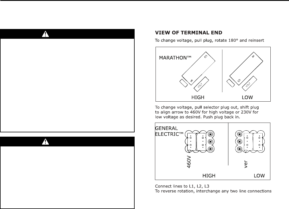
Converting Motor to 460 Volt
1. Ensure power is disconnected to unit by following
the warning above.
2. Remove unit access panels closest to motor.
3. Open terminal cover on lead end of motor.
4. Pull voltage selector plug from low voltage
selection (see Figure 3, p. 9).
5. Shift the plug (or rotate 180°) to align plug for high
voltage selection and re-insert plug.
IImmppoorrttaanntt:: When re-inserting voltage selection
plug, ensure it is fully seated.
6. Replace terminal cover on lead end of motor.
7. Replace unit access panels.
Figure 3. Voltage change plug
To change volta g e , pull plug, rotate 180° and reinse rt
VIE W OF TERMI NAL END
GENERAL
ELECTRIC™
MARATHON™
HIGH LOW
HIGH LOW
To ch a n ge volta ge , pu ll sele ctor plug out, shift plug
to a lign a rrow to 4 60V for h igh volta ge or 23 0 V for
low volta ge as de sire d. Push plu g ba ck in.
460V
ve r
Con n e ct line s to L1, L2, L3
To re ve rs e rota tion, inte rch a nge a ny two line conne ction s
Refrigerant Piping
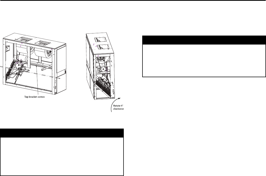
Reorienting Evaporator Coil (TWE126/
150 and 156/180)
IImmppoorrttaanntt:: Applies to TWE126/150 and 156/180 when
positioned for vertical upflow. Unit is
shipped in the horizontal position. If
installing in the vveerrttiiccaall ppoossiittiioonn, the coil
mmuusstt bbee reoriented by rotating the coil 4
degrees (control box side) from the
shipped position.
1. Remove screws from top evaporator coil bracket
(bracket that attaches coil to cabinet and runs the
length of the unit).
2. Rotate evaporator coil approximately 4 degrees
clockwise - looking from the control box end. When
the evaporator coil is rotated, the lower set of
evaporator coil bracket holes will align with the
support bracket (from which it was originally
fastened).
3. Reinsert screws in evaporator coil bracket.
PPrree--IInnssttaallllaattiioonn
10 SSA-SVX06E-EN
Figure 4. Evaporator coil reorientation for TWE126,
150, 156, 180
Top bracket screws
Rotate 4°
clockwise
Preparation for Refrigerant Piping
NNOOTTIICCEE
EEqquuiippmmeenntt DDaammaaggee!!
DDoo nnoott aappppllyy hheeaatt ttoo rreemmoovvee sseeaall ccaappss uunnttiill tthhee
ggaauuggee ppoorrtt ccoorreess hhaavvee bbeeeenn rreemmoovveedd.. IIff sseeaall ccaappss
aarree iinnttaacctt,, aapppplliiccaattiioonn ooff hheeaatt mmaayy ggeenneerraattee
eexxcceessssiivvee pprreessssuurree iinn tthhee uunniitt aanndd rreessuulltt iinn
ddaammaaggee ttoo tthhee ccooiill oorr eexxppaannssiioonn vvaallvvee..
The air handler is designed so that refrigerant piping
can enter from either the right or left hand side. It is
shipped with the intent that the refrigerant lines will
enter from the left hand side. To convert to right hand
entry, unbraze the elbow on the suction line and rotate
180° and rebraze.
IImmppoorrttaanntt:: Access to refrigerant lines is limited in all
horizontal and some vertical applications.
Therefore, refrigerant lines should be
stubbed out and temporarily capped prior
to setting the air handler. Protect adjacent
surfaces from heat damage when brazing
in and around the air handler.
Installations, Limitations and
Recommendations
NNOOTTIICCEE
SSyysstteemm CCoommppoonneenntt DDaammaaggee!!
PPrrooppeerrllyy iinnssuullaattee aallll rreeffrriiggeerraanntt ggaass ppiippiinngg ttoo
pprreevveenntt ppoossssiibbllee wwaatteerr ddaammaaggee dduuee ttoo
ccoonnddeennssaattiioonn aanndd ttoo pprreevveenntt ccaappaacciittyy lloossss aanndd
ppoossssiibbllee ccoommpprreessssoorr ddaammaaggee..
The general location of the air handler is normally
selected by the architect, contractor and/or buyer. For
proper installation, the following items must be
considered:
• Available power supply must agree with electrical
data on component nameplate.
• If external accessories are installed on the unit,
additional clearances must be provided.
• All duct work should be properly insulated to
prevent condensation and heat loss.
• Refrigerant gas piping must be insulated.
It is recommended that the outline drawings in the
Dimensional Data section be studied and dimensions
properly noted and checked against the selected
installation site. By noting in advance which features
are to be used, proper clearance allowances can be
made for installation and possible future service.
IImmppoorrttaanntt:: When installing these units “free standing”
with discharge grills and isolators, a top
support with isolator should be added to
prevent tipping. Support and isolator can
be attached to a wall or other appropriate
structure.
If adding external accessories to the unit,
additional clearances must be considered
for the overall space needed.
For installation of accessories available for this air
handler, follow the installation instructions that are
shipped with each accessory.
PPrree--IInnssttaallllaattiioonn
SSA-SVX06E-EN 11
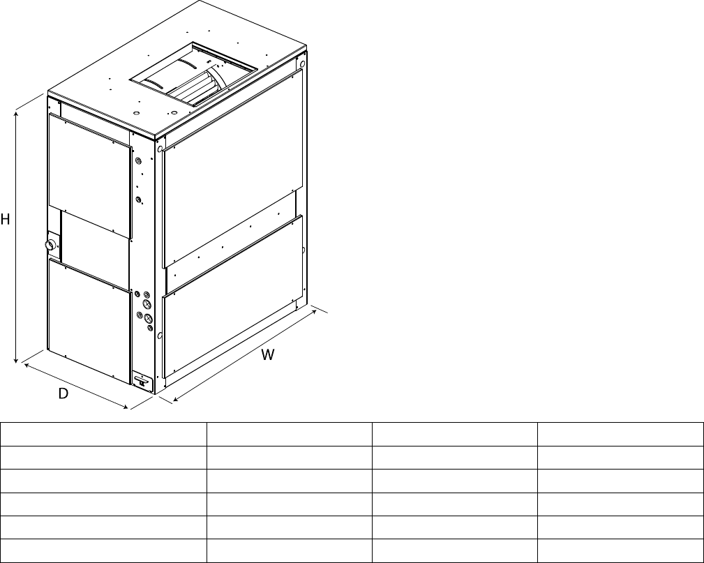
Dimensional Data
Figure 5. Height, width and depth measurements
H
D
W
Model Number H - in. (mm) W - in. (mm) D - in. (mm)
TWE051, 061 48-1/8 (1222.4) 39-5/8 (1006.5) 23-5/8 (600.0)
TWE076, 090 54-1/8 (1374.8) 49-1/8 (1247.8) 26-1/2 (673.1)
TWE101, 120 54-1/8 (1374.8) 65-1/8 (1654.2) 26-1/2 (673.1)
TWE126, 150, 156, 180 69-1/8 (1756.0) 81-1/4 (2063.7) 30 (762.0)
TWE201, 240, 251, 300 71-7/8 (1806.6) 94-1/4 (2394.0) 32-1/8 (816.0)
Note: Full dimensional data is available on the following pages.
12 SSA-SVX06E-EN
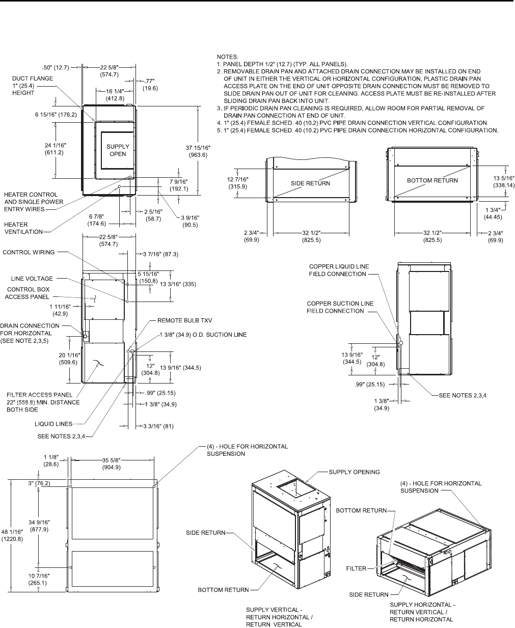
Figure 6. 4.6, 5 ton air handler, single circuit
3" (76.2)
48 1/16"
(1220. 8)
10 7/16"
(265. 1)
34 9/16"
(877. 9)
35 5/8"
(904. 9)
1 1/8"
(28.6)
12"
(304. 8)13 9/16" (344.5)
20 1/16"
(509. 6)
1 11/16"
(42.9)
5 15/16"
(150. 8) 13 3/16" (335)
12"
(304.8)
13 9/16"
(344.5)
13 5/16"
(338.14)
1 3/4"
(44.45)
2 3/4"
(69.9)
DRAIN CONNECTION
FOR HORIZONTAL
(SEE NOTE 2,3,5)
32 1/2"
(825.5)
12 7/16"
(315.9)
1 3/8"
(34.9)
.99" (25.15)
.99" (25.15)
1 3/8" (34.9)
3 3/16" (81)
3 7/16" (87.3)
22 5/8"
(574.7)
22 5/8"
(574.7)
16 1/4"
(412.8)
.77"
(19.6)
.50" (12.7)
3 9/16"
(90.5)
7 9/16"
(192.1)
37 15/16"
(963.6)
24 1/16"
(611.2)
2 5/16"
(58.7)
6 7/8"
(174.6)
6 15/16" (176.2)
BOTTOM RETURN
SIDE RETURN
CONTROL BOX
ACCESS PANEL
NOTES:
1. PANEL DEPTH 1/2" (12.7) (TYP. ALL PANELS).
2. REMOVABLE DRAIN PAN AND ATTACHED DRAIN CONNECTION MAY BE INSTALLED ON END
OF UNIT IN EITHER THE VERTICAL OR HORIZONTAL CONFIGURATION, PLASTIC DRAIN PAN
ACCESS PLATE ON THE END OF UNIT OPPOSITE DRAIN CONNECTION MUST BE REMOVED TO
SLIDE DRAIN PAN OUT OF UNIT FOR CLEANING. ACCESS PLATE MUST BE RE-INSTALLED AFTER
SLIDING DRAIN PAN BACK INTO UNIT.
3. IF PERIODIC DRAIN PAN CLEANING IS REQUIRED, ALLOW ROOM FOR PARTIAL REMOVAL OF
DRAIN PAN CONNECTION AT END OF UNIT.
4. 1" (25.4) FEMALE SCHED. 40 (10.2) PVC PIPE DRAIN CONNECTION VERTICAL CONFIGURATION.
5. 1" (25.4) FEMALE SCHED. 40 (10.2) PVC PIPE DRAIN CONNECTION HORIZONTAL CONFIGURATION.
SEE NOTES 2,3,4
SEE NOTES 2,3,4
(4) - HOLE FOR HORIZONTAL
SUSPENSION
COPPER LIQUID LINE
FIELD CONNECTION
COPPER SUCTION LINE
FIELD CONNECTION
LIQUID LINES
1 3/8" (34.9) O.D. SUCTION LINE
REMOTE BULB TXV
FILTER ACCESS PANEL
22" (558.8) MIN. DISTANCE
BOTH SIDE
FILTER
SUPPLY OPENING
BOTTOM RETURN
SIDE RETURN
BOTTOM RETURN
SUPPLY VERTICAL -
RETURN HORIZONTAL /
RETURN VERTICAL
SUPPLY HORIZONTAL -
RETURN VERTICAL /
RETURN HORIZONTAL
(4) - HOLE FOR HORIZONTAL
SUSPENSION
SIDE RETURN
CONTROL WIRING
LINE VOLTAGE
DUCT FLANGE
1" (25.4)
HEIGHT
SUPPLY
OPEN
HEATER
VENTILATION
HEATER CONTROL
AND SINGLE POWER
ENTRY WIRES
32 1/2"
(825.5)
2 3/4"
(69.9)
DDiimmeennssiioonnaall DDaattaa
SSA-SVX06E-EN 13
Figure 7. 5 ton air handler, dual circuit
3" (76.2)
48 1/16"
(1220. 8)
10 7/16"
(265. 1)
34 9/16"
(877. 9)
35 5/8"
(904. 9)
1 1/8"
(28.6)
12"
(304. 8)
13 9/16"
(344. 5)
20 1/16"
(509. 6)
1 11/16"
(42.9)
5 15/16"
(150. 8) 13 3/16" (335)
16 1/8"
(409. 6)
17 5/16"
(439. 7)
17 7/8"
(454) 12"
(304.8)
13 9/16"
(344.5)
16 1/8"
(409.6)
17 5/16"
(439.7)
1
3 5/16"
(338.14)
1 3/4"
(44.45)
2 3/4"
(69.8)
32 1/2"
(825.5)
DRAIN CONNECTION
FOR HORIZONTAL
(SEE NOTE 2,3,5)
12 7/16"
(315. 9)
3 11/16" (93.7)
1 11/16" (42.9)
1 3/8" (34.9)
.99" (25.15)
.99" (25.15)
1 3/8" (34.9)
1 11/16" (42.9)
3 3/16" (81)
3 11/16" (93.7)
3 7/16" (87.3)
22 5/8"
(574. 7)
1 13/16"
(46.04)
22 5/8"
(574. 7)
16 1/4"
(412. 8)
.77" (19.6)
.50" (12.7)
3 9/16"
(90.5)
7 9/16"
(192. 1)
37 15/16"
(963. 6)
24 1/16"
(611. 2)
2 5/16"
(58.7)
6 7/8"
(174. 6)
6 15/16"
(176. 2)
BOTTOM RETURN
SIDE RETURN
DUCT FLANGE
1" (25.4) HEIGHT
SUPPLY
OPEN
CONTROL WIRING
LINE VOLTAGE
CONTROL BOX
ACCESS PANEL
NOTES:
1. PANEL DEP TH 1/2" (12.7) (TYP. ALL PANELS).
2. REMOVABLE DRAIN PAN AND ATTACHED DRAIN CONNECTION MAY BE INSTALLED ON END
OF UNIT IN EITHER THE VERTICAL OR HORIZONTAL CONFIGURATION, PLASTIC DRAIN PAN
ACCESS PLATE ON THE END OF UNIT OPPOSITE DRAIN CONNECTION MUST BE REMOVED TO
SLIDE DRAIN PAN OUT OF UNIT FOR CLEANING. ACCESS PLATE MUST BE RE-INSTALLED AFTER
SLIDING DRAIN PAN BACK INTO UNIT.
3. IF PERIODIC DRAIN PAN CLEANING IS REQUIRED, ALLOW ROOM FOR PARTIAL REMOVAL OF
DRAIN CONNECTION AT END OF UNIT.
4. 1" (25.4) FEMALE SCHED. 40 (10.2) P VC PIPE DRAIN CONNECTION VERTICAL CONFIGURATION.
5. 1" (25.4) FEMALE SCHED. 40 (10.2) PVC PIP E DRAIN CONNECTION HORIZONTAL CONFIGURATION.
SEE NOTES 2,3,4
SEE NOTES 2,3,4
SUPPLY VERTICAL -
RETURN HORIZONTAL /
RETURN VERTICAL
SUPPLY HORIZONTAL -
RETURN VERTICAL /
RETURN HORIZONTAL
(4) - HOLE FOR HORIZONTAL
SUSPENSION
COPPER LIQUID LINE
FIELD CONNECTION
COPPER SUCTION LINE
FIELD CONNECTION
LIQUID LINES
(2) REMOTE BULB TXV
FILTER ACCESS PANEL
22" (558.8) MIN. DISTANCE
BOTH SIDE
SIDE RETURN
SIDE RETURN
BOTTOM RETURN
BOTTOM RETURN
SUPPLY OPENING
FILTER
(4) HOLE FOR
HORIZONTAL
SUSPENSION
DRAIN CONNECTION
SUCTION LINE
COPPER LIQUID LINE
FIELD CONNECTION
HEATER
VENTILATION
HEATER CONTROL
AND SINGLE POWER
ENTRY WIRES
32 1/2"
(825.5)
2 3/4"
(69.8)
DDiimmeennssiioonnaall DDaattaa
14 SSA-SVX06E-EN
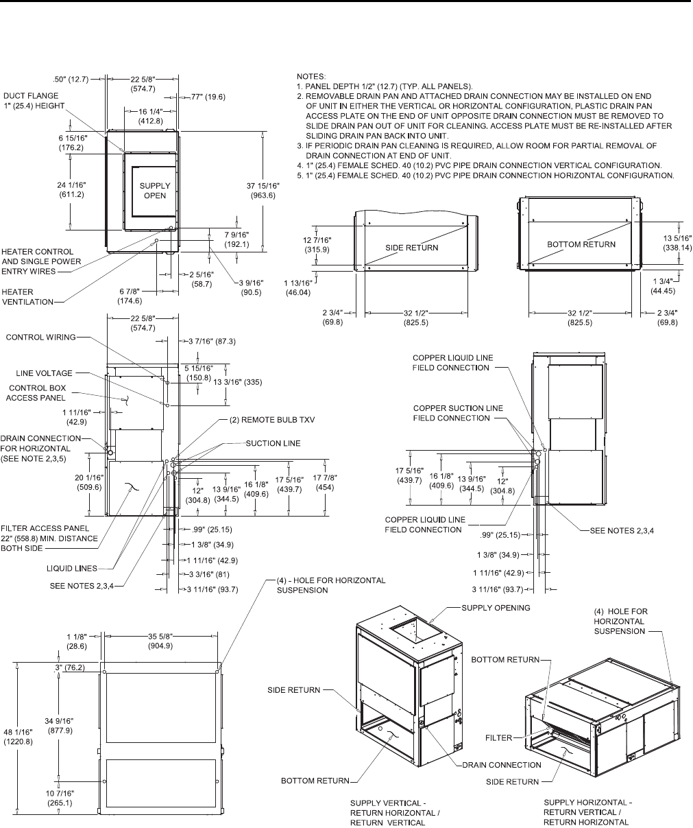
Figure 8. 6.25, 7.5 ton air handler, single circuit
16 7/8"
(428.6)
1 13/16"
(46)
2 3/4"
(69.85)
42"
(1066.8)
1 9/16"
(39.7)
16 1/16"
(408)
16"
(406. 4)
8 13/16" (223.8)
3 1/2" (88.9)
1 3/16" (30.2)
22 7/8"
(581)
45 1/8"
(1146. 2)
6 3/4"
(171. 45)
36 7/8"
(936. 6)
10 7/16"
(265. 1)
54 1/16"
(1373. 2)
1 3/16" (30.16)
16 11/16"
(423. 9)
17 7/16"
(442. 9)
20"
(508)
3 5/8" (92.1)
1 11/16" (42.9)
16 11/16"
(423.9)
17 3/8"
(441.3)
1 9/16" (39.7)
3 1/2" (88.9)
25 1/2"
(647. 7)
16 1/4"
(412. 8) .70"
(17.8)
25 1/2"
(647. 7)
24 1/16"
(611. 2)
11 11/16"
(296. 8)
47 1/2"
(1206. 5)
8 5/16"
(211. 1)
12 5/16"
(312. 7)
2 1/4" (57.15)
6 13/16"
(173)
BOTTOM RETURN
SIDE RETURN
CONTROL BOX
ACCESS PANEL
NOTES:
1. PANEL DEPTH 1/2" (12.7) (TYP. ALL PANELS).
2. REMOVABLE DRAIN PAN AND ATTACHED DRAIN CONNECTION MAY BE INSTALLED ON END
OF UNIT IN EITHER THE VERTICAL OR HORIZONTAL CONFIGURATION, PLASTIC DRAIN PAN
ACCESS PLATE ON THE END OF UNIT OPPOSITE DRAIN CONNECTION MUST BE REMOVED TO
SLIDE DRAIN PAN OUT OF UNIT FOR CLEANING. ACCESS PLATE MUST BE RE-INSTALLED AFTER
SLIDING DRAIN PAN BACK INTO UNIT.
3. IF PERIODIC DRAIN PAN CLEANING IS REQUIRED, ALLOW ROOM FOR PARTIAL REMOVAL OF
DRAIN PAN CONNECTION AT END OF UNIT.
4. 1" (25.4) FEMALE SCHED. 40 (10.2) PVC PIPE DRAIN CONNECTION VERTICAL CONFIGURATION.
5. 1" (25.4) FEMALE SCHED. 40 (10.2) PVC PIPE DRAIN CONNECTION HORIZONTAL CONFIGURATION.
SEE NOTES 2,3,4
SEE NOTES 2,3,4
(4) - HOLE FOR
HORIZONTAL SUSPENSION
COPPER LIQUID LINE
FIELD CONNECTION
COPPER SUCTION LINE
FIELD CONNECTION
LIQUID LINES
SUCTION LINE
REMOTE BULB TXV
FILTER ACCESS PANEL
22" (558.8) MIN. DISTANCE
BOTH SIDE
DRAIN CONNECTION
FOR HORIZONTAL
(SEE NOTE 2,3,5)
FILTER
BOTTOM RETURN
SUPPLY VERTICAL -
RETURN HORIZONTAL /
RETURN VERTICAL
SUPPLY HORIZONTAL -
RETURN VERTICAL /
RETURN HORIZONTAL
(4) HOLE FOR
HORIZONTAL
SUSPENSION
SIDE RETURN
BOTTOM RETURN SIDE RETURN
SUPPLY OP ENING
CONTROL WIRING
LINE VOLTAGE
DUCT FLANGE
1" (25.4)
HEIGHT
SUPPLY
OPEN
HEATER
VENTILATION
HEATER CONTROL
AND SINGLE POWER
ENTRY WIRES
42"
(1066.8)
2 3/4"
(69.85)
DDiimmeennssiioonnaall DDaattaa
SSA-SVX06E-EN 15
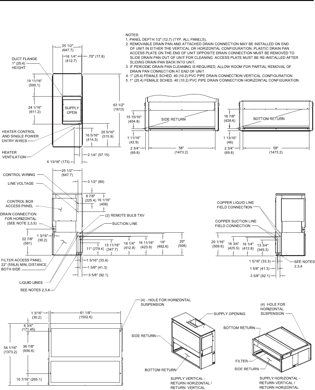
Figure 9. 6.25, 7.5 ton air handler, dual circuit
16 7/8"
(406.4)
1 13/16"
(46)
2 3/4"
(69.9)
42"
(1066.8)
1 9/16"
(39.7)
16 1/16"
(408)
20 1/16"
(509.6) 16 3/4"
(425.5) 16 1/4"
(412.8) 13 3/4"
(349.3)
3 5/8" (92.1)
1 5/8" (41.3)
1 5/16" (33.3)
11 1/16"
(281)
13 3/4"
(349. 2)
16 1/4"
(412. 8) 16 3/4"
(425. 5)
19 1/16"
(484. 2)
20 1/16"
(509.6)
3 5/8" (92.1)
1 5/8" (41.3)
1 5/16" (33.3)
16"
(406. 4)
8 13/16" (223.8)
3 1/2" (88.9)
1 3/16" (30.2)
22 7/8"
(581)
45 1/8"
(1146. 2)
6 3/4"
(171. 5)
36 7/8"
(936. 6)
10 7/16"
(265. 1)
54 1/16"
(1373. 2)
1 3/16" (30.2)
25 1/2"
(647. 7)
16 1/4"
(412. 8) .70"
(17.78)
25 1/2"
(647. 7)
24 1/16"
(611. 2)
11 11/16"
(296. 9)
47 1/2"
(1206. 5)
8 5/16"
(211. 1)
12 5/16"
(312. 7)
2 1/4" (57.15)
6 13/16" (173)
BOTTOM RETURN
SIDE RETURN
CONTROL WIRING
LINE VOLTAGE
CONTROL BOX
ACCESS PANEL
NOTES:
1. PANEL DEPTH 1/2" (12.7) (TYP. ALL PANELS).
2. REMOVABLE DRAIN PAN AND ATTACHED DRAIN CONNECTION MAY BE INSTALLED ON END
OF UNIT IN EITHER THE VERTICAL OR HORIZONTAL CONFIGURATION, PLASTIC DRAIN PAN
ACCESS PLATE ON THE END OF UNIT OPPOSITE DRAIN CONNECTION MUST BE REMOVED TO
SLIDE DRAIN PAN OUT OF UNIT FOR CLEANING. ACCESS PLATE MUST BE RE-INSTALLED AFTER
SLIDING DRAIN PAN BACK INTO UNIT.
3. IF PERIODIC DRAIN PAN CLEANING IS REQUIRED, ALLOW ROOM FOR P ARTIAL REMOVAL OF
DRAIN PAN CONNECTION AT END OF UNIT.
4. 1" (25.4) FEMALE SCHED. 40 (10.2) PVC PIPE DRAIN CONNECTION VERTICAL CONFIGURATION.
5. 1" (25.4) FEMALE SCHED. 40 (10.2) PVC PIPE DRAIN CONNECTION HORIZONTAL CONFIGURATION.
SEE NOTES 2,3,4
SEE NOTES 2,3,4 (4) - HOLE FOR HORIZONTAL
SUSPENSION
COPPER LIQUID LINE
FIELD CONNECTION
COPPER SUCTION LINE
FIELD CONNECTION
LIQUID LINES
SUCTION LINE
(2) REMOTE BULB TXV
FILTER ACCESS PANEL
22" (559) MIN. DISTANCE
BOTH SIDE
DRAIN CONNECTION
FOR HORIZONTAL
(SEE NOTE 2,3,5)
FILTER
SUPPLY OPENING
BOTTOM RETURN
SIDE RETURN
BOTTOM RETURN
SUPPLY VERTICAL -
RETURN HORIZONTAL /
RETURN VERTICAL
SUPPLY HORIZONTAL -
RETURN VERTICAL /
RETURN HORIZONTAL
(4) HOLE FOR
HORIZONTAL
SUSPENSION
SIDE RETURN
DUCT FLANGE
1" (25.4)
HEIGHT
SUPPLY
OPEN
HEATER
VENTILATION
HEATER CONTROL
AND SINGLE POWER
ENTRY WIRES
42"
(1066.8)
2 3/4"
(69.9)
DDiimmeennssiioonnaall DDaattaa
16 SSA-SVX06E-EN
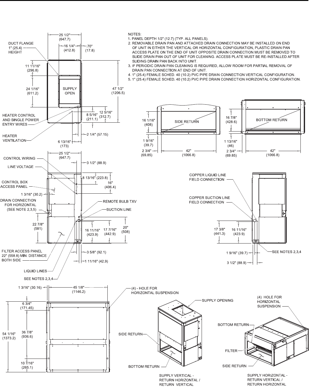
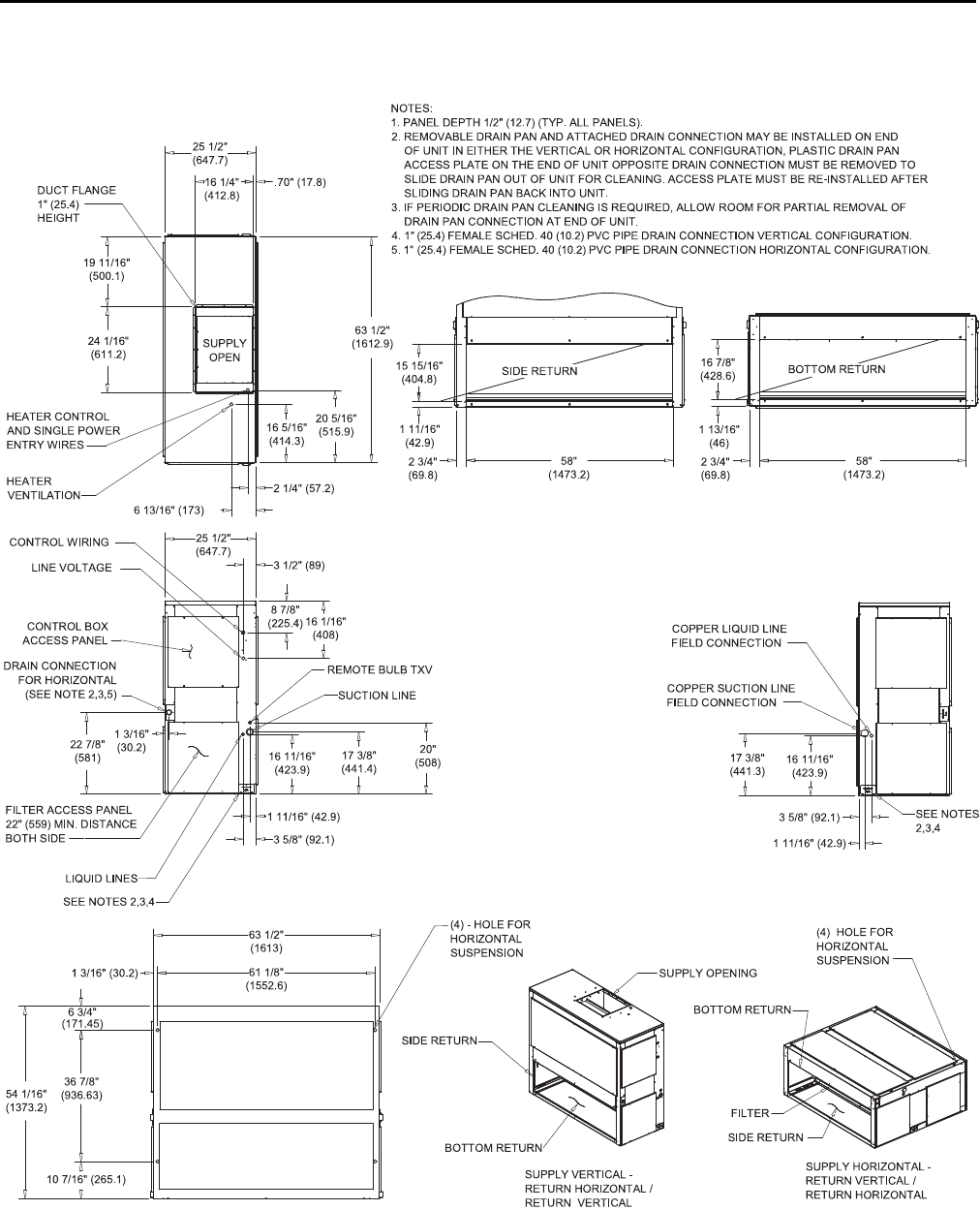
Figure 10. 8.33, 10 ton air handler, single circuit
3 1/2" (89)
8 7/8"
(225. 4) 16 1/16"
(408)
1 3/16"
(30.2)
22 7/8"
(581)
61 1/8"
(1552. 6)
6 3/4"
(171. 45)
36 7/8"
(936. 63)
10 7/16" (265.1)
54 1/16"
(1373. 2)
58"
(1473.2)
2 3/4"
(69.8)
1 13/16"
(46)
16 7/8"
(428.6)
15 15/16"
(404. 8)
1 11/16"
(42.9)
16 11/16"
(423. 9)
17 3/8"
(441. 4)
20"
(508)
1 11/16" (42.9)
3 5/8" (92.1)
16 11/16"
(423.9)
17 3/8"
(441.3)
1 11/16" (42.9)
3 5/8" (92.1)
63 1/2"
(1613)
1 3/16" (30.2)
16 1/4"
(412. 8) .70" (17.8)
25 1/2"
(647. 7)
19 11/16"
(500. 1)
24 1/16"
(611. 2)
63 1/2"
(1612. 9)
20 5/16"
(515. 9)
16 5/16"
(414. 3)
2 1/4" (57.2)
6 13/16" (173)
BOTTOM RETURN
SIDE RETURN
CONTROL BOX
ACCESS PANEL
NOTES:
1. PANEL DEP TH 1/2" (12.7) (TYP. ALL PANELS).
2. REMOVABLE DRAIN PAN AND ATTACHED DRAIN CONNECTION MAY BE INSTALLED ON END
OF UNIT IN EITHER THE VERTICAL OR HORIZONTAL CONFIGURATION, PLASTIC DRAIN PAN
ACCESS PLATE ON THE END OF UNIT OPPOSITE DRAIN CONNECTION MUST BE REMOVED TO
SLIDE DRAIN PAN OUT OF UNIT FOR CLEANING. ACCESS PLATE MUST BE RE-INSTALLED AFTER
SLIDING DRAIN PAN BACK INTO UNIT.
3. IF PERIODIC DRAIN PAN CLEANING IS REQUIRED, ALLOW ROOM FOR PARTIAL REMOVAL OF
DRAIN PAN CONNECTION AT END OF UNIT.
4. 1" (25.4) FEMALE SCHED. 40 (10.2) PVC PIPE DRAIN CONNECTION VERTICAL CONFIGURATION.
5. 1" (25.4) FEMALE SCHED. 40 (10.2) PVC PIPE DRAIN CONNECTION HORIZONTAL CONFIGURATION.
SEE NOTES
2,3,4
SEE NOTES 2,3,4
COPPER LIQUID LINE
FIELD CONNECTION
COPPER SUCTION LINE
FIELD CONNECTION
LIQUID LINES
SUCTION LINE
REMOTE BULB TXV
FILTER ACCESS PANEL
22" (559) MIN. DISTANCE
BOTH SIDE
DRAIN CONNECTION
FOR HORIZONTAL
(SEE NOTE 2,3,5)
BOTTOM RETURN
SUPPLY VERTICAL -
RETURN HORIZONTAL /
RETURN VERTICAL
SUPPLY OPENING
SIDE RETURN
(4) - HOLE FOR
HORIZONTAL
SUSPENSION
CONTROL WIRING
LINE VOLTAGE
DUCT FLANGE
1" (25.4)
HEIGHT
SUPPLY
OPEN
HEATER
VENTILATION
HEATER CONTROL
AND SINGLE POWER
ENTRY WIRES
25 1/2"
(647. 7)
58"
(1473.2)
2 3/4"
(69.8)
BOTTOM RETURN
SIDE RETURN
(4) HOLE FOR
HORIZONTAL
SUSPENSION
FILTER
SUPPLY HORIZONTAL -
RETURN VERTICAL /
RETURN HORIZONTAL
DDiimmeennssiioonnaall DDaattaa
SSA-SVX06E-EN 17
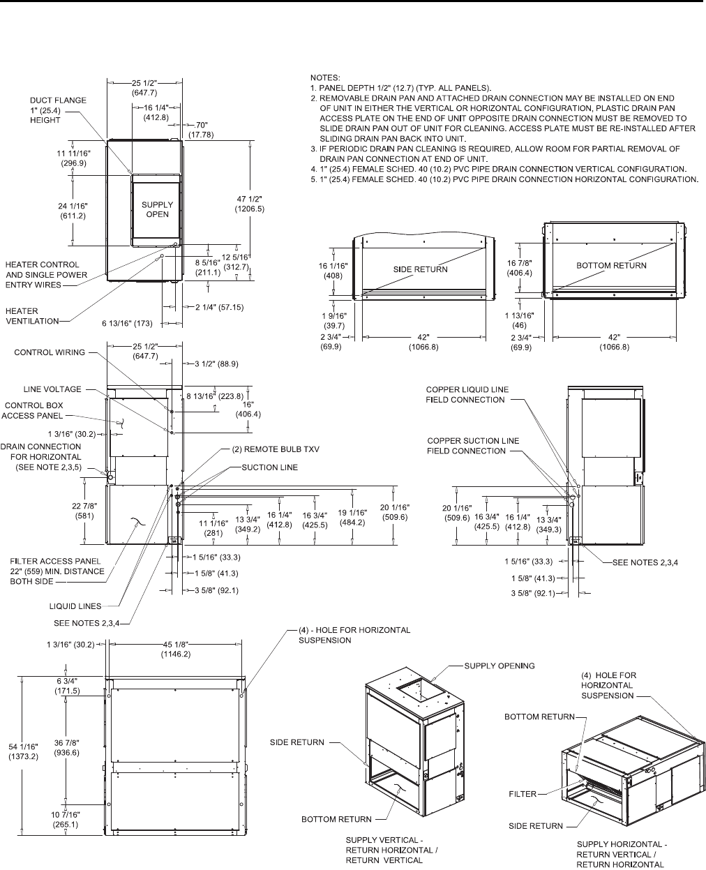
Figure 11. 8.33, 10 ton air handler, dual circuit
3 1/2" (89)
8 7/8"
(225. 4) 16 1/16"
(408)
1 3/16"
(30.2)
22 7/8"
(581)
61 1/8"
(1552. 6)
6 3/4"
(171. 45)
36 7/8"
(936. 6)
10 7/16" (265.1)
54 1/16"
(1373. 2)
11" (279.4) 13 11/16"
(347. 7)
16 1/4"
(412. 8)
16 11/16"
(423. 9)
19"
(482 .6)
20"
(508)
1 5/16" (33.4)
1 5/8" (41.3)
3 5/8" (92.1) 3 5/8" (92.1)
1 5/8" (41.3)
1 5/16" (33.3)
13 3/4"
(349.3)
16 1/4"
(412.8)
16 3/4"
(425.5)
20 1/16"
(509.6)
58"
(1473.2)
2 3/4"
(69.8)
1 13/16"
(46)
16 7/8"
(428.6)
15 15/16"
(404. 8)
1 11/16"
(42.9)
1 3/16"
(30.2)
25 1/2"
(647. 7)
16 1/4"
(412. 7)
.70" (17.8)
25 1/2"
(647. 7)
19 11/16"
(500. 1)
24 1/16"
(611. 2)
63 1/2"
(1613)
20 5/16"
(515. 9)
16 5/16"
(414. 3)
2 1/4" (57.15)
6 13/16" (173)
BOTTOM RETURN
SIDE RETURN
CONTROL BOX
ACCESS PANEL
NOTES:
1. PANEL DEP TH 1/2" (12.7) (TYP. ALL PANELS).
2. REMOVABLE DRAIN PAN AND ATTACHED DRAIN CONNECTION MAY BE INSTALLED ON END
OF UNIT IN EITHER THE VERTICAL OR HORIZONTAL CONFIGURATION, PLASTIC DRAIN PAN
ACCESS PLATE ON THE END OF UNIT OPPOSITE DRAIN CONNECTION MUST BE REMOVED TO
SLIDE DRAIN PAN OUT OF UNIT FOR CLEANING. ACCESS PLATE MUST BE RE-INSTALLED AFTER
SLIDING DRAIN PAN BACK INTO UNIT.
3. IF PERIODIC DRAIN PAN CLEANING IS REQUIRED, ALLOW ROOM FOR PARTIAL REMOVAL OF
DRAIN PAN CONNECTION AT END OF UNIT.
4. 1" (25.4) FEMALE SCHED. 40 (10.2) PVC PIPE DRAIN CONNECTION VERTICAL CONFIGURATION.
5. 1" (25.4) FEMALE SCHED. 40 (10.2) PVC PIPE DRAIN CONNECTION HORIZONTAL CONFIGURATION.
SEE NOTES
2,3,4
SEE NOTES 2,3,4
(4) - HOLE FOR HORIZONTAL
SUSPENSION
COPPER LIQUID LINE
FIELD CONNECTION
COPPER SUCTION LINE
FIELD CONNECTION
SUCTION LINE
(2) REMOTE BULB TXV
FILTER ACCESS PANEL
22" (558.8) MIN. DISTANCE
BOTH SIDE
DRAIN CONNECTION
FOR HORIZONTAL
(SEE NOTE 2,3,5)
LIQUID LINES
FILTER
BOTTOM RETURN
SIDE RETURN
BOTTOM RETURN
SUPPLY VERTICAL -
RETURN HORIZONTAL /
RETURN VERTICAL
SUPPLY HORIZONTAL -
RETURN VERTICAL /
RETURN HORIZONTAL
SIDE RETURN
SUPPLY OPENING
(4) HOLE FOR
HORIZONTAL
SUSPENSION
CONTROL WIRING
LINE VOLTAGE
DUCT FLANGE
1" (25.4)
HEIGHT
SUPPLY
OPEN
HEATER
VENTILATION
HEATER CONTROL
AND SINGLE POWER
ENTRY WIRES
58"
(1473.2)
2 3/4"
(69.8)
DDiimmeennssiioonnaall DDaattaa
18 SSA-SVX06E-EN
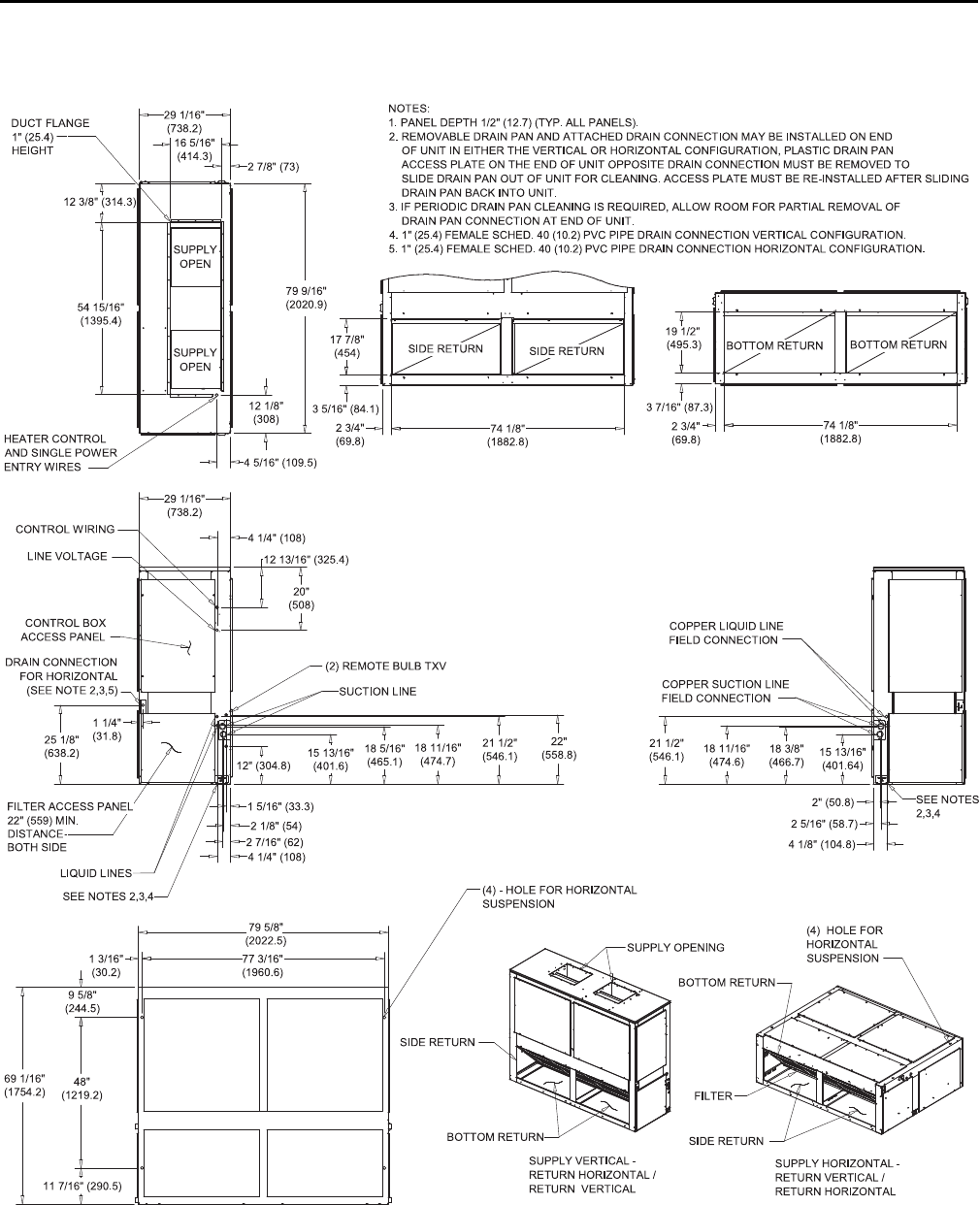
Figure 12. 10.4, 13, 12.5, 15 ton air handler, dual circuit
19 1/2"
(495.3)
74 1/8"
(1882.8)
3 7/16" (87.3)
2 3/4"
(69.8)
17 7/8"
(454)
3 5/16" (84.1)
4 1/4" (108)
20"
(508)
12 13/16" (325.4)
22"
(558.8)
21 1/2"
(546. 1)
18 11/16"
(474. 7)
18 5/16"
(465. 1)
15 13/16"
(401. 6)
12" (304.8)
21 1/2"
(546.1)
1 5/16" (33.3)
2 1/8" (54)
2 7/16" (62)
4 1/4" (108)
25 1/8"
(638. 2) 18 11/16"
(474.6) 18 3/8"
(466.7) 15 13/16"
(401.64)
4 1/8" (104.8)
2 5/16" (58.7)
2" (50.8)
9 5/8"
(244. 5)
48"
(1219. 2)
11 7/16" (290.5)
1 3/16"
(30.2)
69 1/16"
(1754. 2)
79 5/8"
(2022. 5)
1 1/4"
(31.8)
77 3/16"
(1960. 6)
29 1/16"
(738. 2)
2 7/8" (73)
16 5/16"
(414. 3)
29 1/16"
(738. 2)
4 5/16" (109.5)
12 1/8"
(308)
79 9/16"
(2020. 9)
54 15/16"
(1395. 4)
12 3/8" (314.3)
BOTTOM RETURN
SIDE RETURN
CONTROL BOX
ACCESS PANEL
NOTES:
1. PANEL DEP TH 1/2" (12.7) (TYP. ALL PANELS).
2. REMOVABLE DRAIN PAN AND ATTACHED DRAIN CONNECTION MAY BE INSTALLED ON END
OF UNIT IN EITHER THE VERTICAL OR HORIZONTAL CONFIGURATION, PLASTIC DRAIN PAN
ACCESS PLATE ON THE END OF UNIT OPPOSITE DRAIN CONNECTION MUST BE REMOVED TO
SLIDE DRAIN PAN OUT OF UNIT FOR CLEANING. ACCESS PLATE MUST BE RE-INSTALLED AFTER SLIDING
DRAIN PAN BACK INTO UNIT.
3. IF PERIODIC DRAIN PAN CLEANING IS REQUIRED, ALLOW ROOM FOR PARTIAL REMOVAL OF
DRAIN PAN CONNECTION AT END OF UNIT.
4. 1" (25.4) FEMALE SCHED. 40 (10.2) PVC P IPE DRAIN CONNECTION VERTICAL CONFIGURATION.
5. 1" (25.4) FEMALE SCHED. 40 (10.2) PVC PIPE DRAIN CONNECTION HORIZONTAL CONFIGURATION.
SEE NOTES
2,3,4
SEE NOTES 2,3,4 (4) - HOLE FOR HORIZONTAL
SUSPENSION
COPPER LIQUID LINE
FIELD CONNECTION
COPPER SUCTION LINE
FIELD CONNECTION
LIQUID LINES
SUCTION LINE
(2) REMOTE BULB TXV
FILTER ACCESS PANEL
22" (559) MIN.
DISTANCE
BOTH SIDE
DRAIN CONNECTION
FOR HORIZONTAL
(SEE NOTE 2,3,5)
SIDE RETURN BOTTOM RETURN
FILTER
SUPPLY OPENING
BOTTOM RETURN
SIDE RETURN
BOTTOM RETURN
SUPPLY VERTICAL -
RETURN HORIZONTAL /
RETURN VERTICAL
SUPPLY HORIZONTAL -
RETURN VERTICAL /
RETURN HORIZONTAL
(4) HOLE FOR
HORIZONTAL
SUSPENSION
SIDE RETURN
CONTROL WIRING
LINE VOLTAGE
DUCT FLANGE
1" (25.4)
HEIGHT
SUPPLY
OPEN
HEATER CONTROL
AND SINGLE POWER
ENTRY WIRES
74 1/8"
(1882.8)
2 3/4"
(69.8)
SUPPLY
OPEN
DDiimmeennssiioonnaall DDaattaa
SSA-SVX06E-EN 19
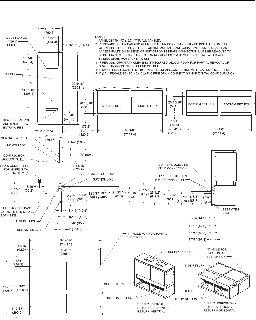
Figure 13. 16.7, 20.9, 20, 25 ton air handler, dual circuit
20 15/16"
(531.8)
2 15/16"
(74.6)
4 3/4"
(120.6) 83 1/8"
(2111.4)
3"
(76.2)
20 15/16"
(531.8)
20" (508)
12 13/16"
(325. 4)
25 1/2"
(647.7)
21 13/16"
(554)
21 3/8"
(542. 9)
19 1/8"
(485. 8)
18 3/8"
(466.7)
15 7/8"
(403. 2)
12 7/8"
(327)
25 1/2"
(647.7)
11 7/16"
(290.5)
50 13/16"
(1290.6)
9 5/8"
(244.5)
71 7/8"
(1825.6)
1 11/16"
(42.9) 89 3/16"
(2265.4)
92 9/16"
(2351.1)
4" (101.6)
3 3/8" (85.7)
1 15/16" (49.2)
1 11/16" (42.9)
3 7/8" (98.4)
3 1/4" (82.5)
1 7/8" (47.6)
1 9/16" (39.7)
28 1/2"
(724)
1 3/16"
(30.2)
31 1/8"
(790.6) 4 1/4" (108)
16 5/16"
(414.3)
31 1/8"
(790.6)
4 15/16" (125.4)
92 9/16"
(2351.1)
18 5/8"
(473.1)
6 7/16" (163.5)
18 7/8"
(479.4)
54 15/16"
(1395.4)
BOTTOM RETURN
SIDE RETURN
CONTROL BOX
ACCESS PANEL
NOTES:
1. PANEL DEPTH 1/2" (12.7) (TYP. ALL PANELS).
2. REMOVABLE DRAIN PAN AND ATTACHED DRAIN CONNECTION MAY BE INSTALLED ON END
OF UNIT IN EITHER THE VERTICAL OR HORIZONTAL CONFIGURATION, PLASTIC DRAIN PAN
ACCESS PLATE ON THE END OF UNIT OPPOSITE DRAIN CONNECTION MUST BE REMOVED TO
SLIDE DRAIN PAN OUT OF UNIT CLEANING. ACCESS PLATE MUST BE RE-INSTALLED AFTER
SLIDING DRAIN PAN BACK INTO UNIT.
3. IF PERIODIC DRAIN PAN CLEANING IS REQUIRED, ALLOW ROOM FOR PARTIAL REMOVAL OF
DRAIN PAN CONNECTION AT END OF UNIT.
4. 1" (25.4) FEMALE SCHED .40 (10.2) PVC PIPE DRAIN CONNECTION VERTICAL CONFIGURATION.
5. 1" (25.4) FEMALE SCHED .40 (10.2) PVC PIPE DRAIN CONNECTION HORIZONTAL CONFIGURATION.
SEE NOTES
2,3,4
SEE NOTES 2,3,4
(4) - HOLE FOR HORIZONTAL
SUSPENSION
COPPER LIQUID LINE
FIELD CONNECTION
COPPER SUCTION LINE
FIELD CONNECTION
SUCTION LINE
REMOTE BULB TXV
FILTER ACCESS PANEL
22" (559) MIN. DISTANCE
BOTH SIDE
DRAIN CONNECTION
FOR HORIZONTAL
(SEE NOTE 2,3,5)
SIDE RETURN BOTTOM RETURN
LIQUID LINES
(4) HOLE FOR
HORIZONTAL
SUSPENSION
SUPPLY HORIZONTAL -
RETURN VERTICAL /
RETURN HORIZONTAL
SUPPLY VERTICAL -
RETURN HORIZONTAL /
RETURN VERTICAL
BOTTOM RETURN
SIDE RETURN
FILTER
SUPPLY OPENING
BOTTOM RETURN
SIDE RETURN
CONTROL WIRING
LINE VOLTAGE
DUCT FLANGE
1" (25.4)
HEIGHT
SUPPLY
OPEN
HEATER CONTROL
AND SINGLE POWER
ENTRY WIRES
21 13/16"
(554) 19 1/8"
(485.8)
18 3/8"
(466.7) 15 7/8"
(403.2)
83 1/8"
(2111.4)
4 3/4"
(120.6)
DDiimmeennssiioonnaall DDaattaa
20 SSA-SVX06E-EN
Weights
Air Handler
Table 1. Standard air handler (TWE) — unit and corner weights - (60 Hz)
Tons Model
Number
Shipping
Max (lbs)
Net Max
(lbs)
Corner Weights - Vertical Corner Weights - Horizontal
1 2 3 4 1 2 3 4
5TWE061D/E 263 232 55 71 51 55 54 67 50 61
7.5 TWE090D/E 360 323 67 99 75 82 56 92 87 88
10 TWE120D/E 429 393 77 121 110 85 79 118 77 119
12.5 TWE150E 730 676 168 192 181 135 196 164 145 171
15 TWE180E 729 675 167 192 181 135 196 163 145 171
20 TWE240E 891 818 258 168 161 231 256 181 146 235
25 TWE300E 972 899 211 229 184 275 272 176 228 223
Table 2. SZVAV and 2-Speed VFD air handler (TWE) — unit and corner weights - (60 Hz)
Tons Model
Number
Shipping
Max (lbs)
Net Max
(lbs)
Corner Weights - Vertical Corner Weights - Horizontal
1 2 3 4 1 2 3 4
7.5 TWE090E 360 323 67 99 75 82 56 92 87 88
10 TWE120D/E 429 393 77 121 110 85 79 118 77 119
12.5 TWE150E 730 676 168 192 181 135 196 164 145 171
15 TWE180E 729 675 167 192 181 135 196 163 145 171
20 TWE240E 891 818 258 168 161 231 256 181 146 235
25 TWE300E 972 899 211 229 184 275 272 176 228 223
Table 3. Standard air handler (TWE) — unit and corner weights - (50 Hz)
Tons Model
Number
Shipping
Max (lbs)
Net Max
(lbs)
Corner Weights - Vertical Corner Weights - Horizontal
1 2 3 4 1 2 3 4
4.6 TWE051D 263 232 55 71 51 55 54 67 50 61
6.25 TWE076D/E 360 323 67 99 75 82 56 92 87 88
8.33 TWE101D/E 429 393 77 121 110 85 79 118 77 119
10.4 TWE126E 730 676 168 192 181 135 196 164 145 171
13 TWE156E 729 675 167 192 181 135 196 163 145 171
16.7 TWE201E 891 818 258 168 161 231 256 181 146 235
20.9 TWE251E 972 899 211 229 184 275 272 176 228 223
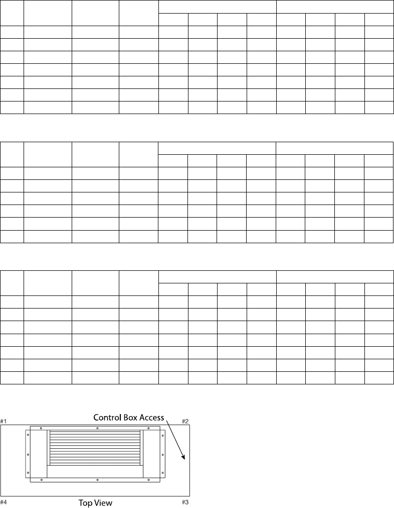
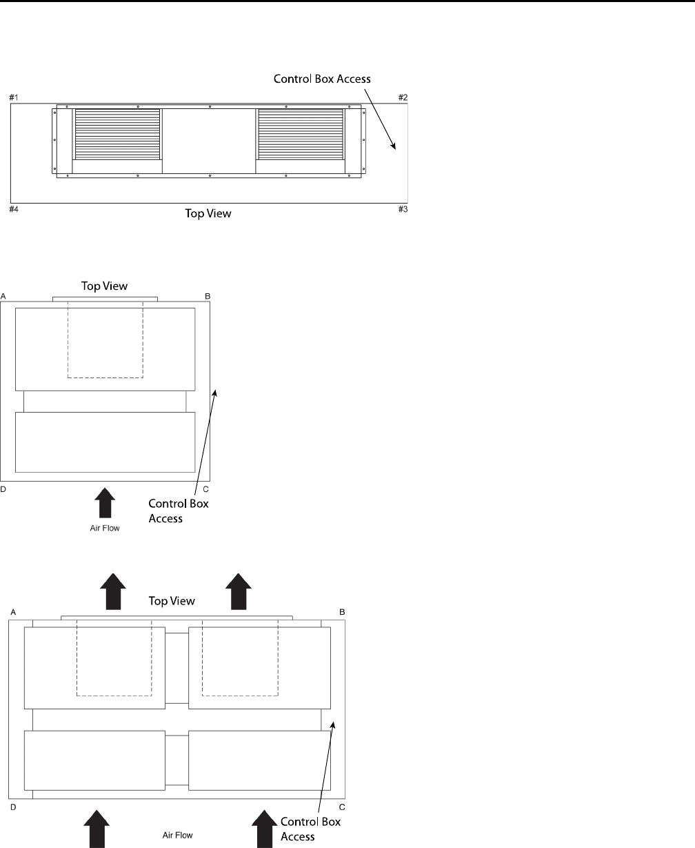
Figure 14. Vertical — TWE051, 076, 101, 061, 090, 120
T
op View
Control Box Access

22 SSA-SVX06E-EN
Installation
Horizontal Suspension
If the air handler will be suspended, use a suspension
mounting kit to isolate the unit from the structure. This
is usually accomplished with spring or rubber isolators,
which are offered as an accessory.
Mounting rods must be field supplied. Isolator
selection is dependent upon total unit weight including
accessories — see “Weights,” p. 20 for approximate
unit weights.
NNOOTTIICCEE
EEqquuiippmmeenntt DDaammaaggee!!
BBeeffoorree hhaannggiinngg tthhee uunniitt oonn ssuussppeennssiioonn rrooddss,,
rreeiinnffoorrccee tthhee ccaabbiinneett aarroouunndd tthhee ssuussppeennssiioonn hhoolleess
bbyy uussiinngg aa llaarrggee wwaasshheerr iinnssiiddee tthhee ccaabbiinneett..
WWaasshheerrss sshhoouulldd bbee bbeettwweeeenn tthhee sskkiinn ooff tthhee aaiirr
hhaannddlleerr aanndd tthhee nnuutt oonn tthhee ssuussppeennssiioonn rroodd..
Align holes in the cabinet with structural supports and
secure suspension rods to the structure, then to the air
handler cabinet. If hole locations do not permit proper
alignment with existing structure, it may be necessary
to field fabricate cross members on existing structural
beams.
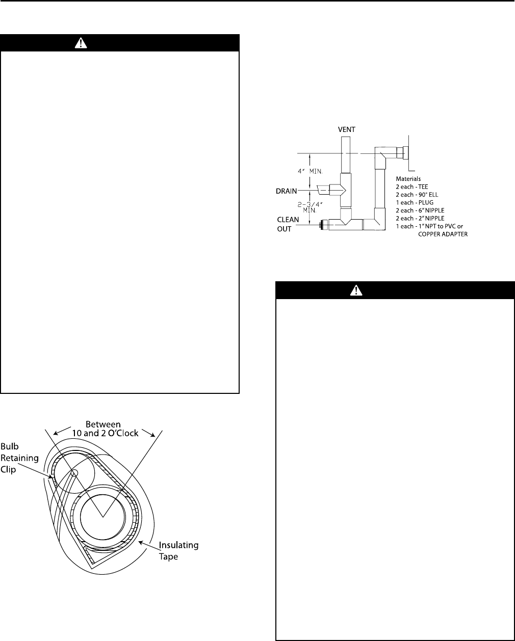
NNoottee:: When other than bottom return is to be used,
side panel removal for return duct installation
must be secured over the bottom opening.
Leveling
This air handler has a double sloped drain pan. In order
to assure proper drainage along the length of the drain
pan, it is important to have the unit properly leveled. Be
sure the air handler is level.
Auxiliary Drain Pan
A field fabricated, auxiliary drain pan should be
installed under the unit for all horizontal applications
and when air handlers are installed above ceilings or in
other locations where condensate overflow may cause
damage.
This drain pan will eliminate any excess condensation
that may be due to extreme humidity or an obstructed
drain in the primary drain pan. Drain lines from this
pan must be installed, but should not be connected to
the primary drain line from the unit. Isolate the
auxiliary drain pan from both the air handler and the
structure.
Refrigerant Piping
Installation, brazing, leak testing and evacuation of
refrigerant lines are covered in the installation
instructions that shipped with the outdoor unit. Read
the instructions before beginning installation of
refrigerant lines.
NNOOTTIICCEE
EEqquuiippmmeenntt DDaammaaggee!!
EEnnssuurree tthhaatt tthhee rreeffrriiggeerraanntt lliinneess ppaassssiinngg tthhrroouugghh
tthhee ccaabbiinneett aarree nnoott rreessttiinngg oonn sshhaarrpp sshheeeett mmeettaall
eeddggeess aanndd tthhaatt tthhee bbuullbb((ss)) aarree aattttaacchheedd ttoo tthhee
ssuuccttiioonn lliinnee ooff tthhee ssaammee cciirrccuuiitt..
1. Locate cloth bag(s) attached to the refrigerant tube
of the coil that contains a stainless steel clamp and
insulation material (approximately 9” long by 4”
wide) for each refrigerant circuit. This is for
attaching and insulating the expansion valve bulb(s)
to the suction line(s).
2. Attach the expansion valve bulb(s)
oonn aaiirr hhaannddlleerrss tthhaatt wwiillll hhaavvee rreeffrriiggeerraanntt lliinneess
eenntteerriinngg tthhee ccaabbiinneett ffrroomm tthhee lleefftt ssiiddee::
a. Remove the split rubber grommet from the
knockout in the end of the air handler. Uncoil the
cap tube with the bulb attached at the expansion
valve and place the grommet on the cap tube.
b. With the grommet around the tube, push the
bulb through the hole and position the grommet
back into its original position (one bulb and cap
tube on single circuit units, and two bulbs and
cap tubes on dual circuit units).
oonn aaiirr hhaannddlleerrss tthhaatt wwiillll hhaavvee rreeffrriiggeerraanntt lliinneess
eenntteerriinngg tthhee ccaabbiinneett ffrroomm tthhee rriigghhtt ssiiddee::
a. Attach the bulb(s) to the suction tube(s) inside
the cabinet, approximately 10” from the right
end of the unit.
3. Attach the bulb(s) on a horizontal section of tube
where the entire length of the bulb is in contact with
the tube (see Figure 18, p. 23), approximately 45
degrees off vertical (a 10 or 2 o’clock position).
4. After attaching to the suction line(s), either inside or
outside of the cabinet, wrap the insulation around
the bulb(s) and suction tube(s).
NNoottee:: Suction piping should be insulated.
SSA-SVX06E-EN 23
WWAARRNNIINNGG
FFiibbeerrggllaassss WWooooll!!
YYoouu MMUUSSTT wweeaarr aallll nneecceessssaarryy PPeerrssoonnaall PPrrootteeccttiivvee
EEqquuiippmmeenntt ((PPPPEE)) iinncclluuddiinngg gglloovveess,, eeyyee pprrootteeccttiioonn,,
aa NNIIOOSSHH aapppprroovveedd dduusstt//mmiisstt rreessppiirraattoorr,, lloonngg
sslleeeevveess aanndd ppaannttss wwhheenn wwoorrkkiinngg wwiitthh pprroodduuccttss
ccoonnttaaiinniinngg ffiibbeerrggllaassss wwooooll..
PPrreeccaauuttiioonnaarryy MMeeaassuurreess::
•• AAvvooiidd bbrreeaatthhiinngg ffiibbeerrggllaassss dduusstt..
•• UUssee aa NNIIOOSSHH aapppprroovveedd dduusstt//mmiisstt rreessppiirraattoorr..
•• AAvvooiidd ccoonnttaacctt wwiitthh tthhee sskkiinn oorr eeyyeess.. WWeeaarr
lloonngg--sslleeeevveedd,, lloooossee--ffiittttiinngg ccllootthhiinngg,, gglloovveess,,
aanndd eeyyee pprrootteeccttiioonn..
•• WWaasshh ccllootthheess sseeppaarraatteellyy ffrroomm ootthheerr ccllootthhiinngg;;
rriinnssee wwaasshheerr tthhoorroouugghhllyy..
•• OOppeerraattiioonnss ssuucchh aass ssaawwiinngg,, bblloowwiinngg,, tteeaarr--
oouutt,, aanndd sspprraayyiinngg mmaayy ggeenneerraattee ffiibbeerr
ccoonncceennttrraattiioonnss rreeqquuiirriinngg aaddddiittiioonnaall
rreessppiirraattoorryy pprrootteeccttiioonn.. UUssee tthhee aapppprroopprriiaattee
NNIIOOSSHH aapppprroovveedd rreessppiirraattoorr..
FFiirrsstt AAiidd MMeeaassuurreess::
•• EEyyee CCoonnttaacctt -- FFlluusshh eeyyeess wwiitthh wwaatteerr ttoo
rreemmoovvee dduusstt.. IIff ssyymmppttoommss ppeerrssiisstt,, sseeeekk
mmeeddiiccaall aatttteennttiioonn..
•• SSkkiinn CCoonnttaacctt -- WWaasshh aaffffeecctteedd aarreeaass ggeennttllyy
wwiitthh ssooaapp aanndd wwaarrmm wwaatteerr aafftteerr hhaannddlliinngg..
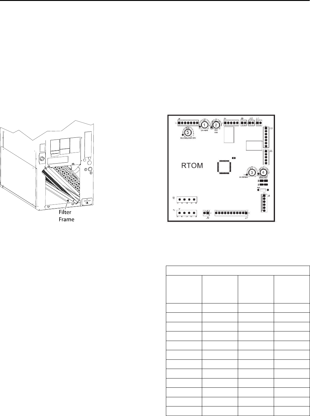
Figure 18. Remote bulb installation
000
000
000
000
000
000
000
Between
10 and 2 O’Clock
Bulb
Retaining
Clip
Insulating
Tape
Condensate Piping
The drain pan condensate connection is a female slip
joint type for 1” Schedule 40 PVC pipe. Use PVC cement
and tubing as required (field supplied) to construct a
trap. A union or flexible tubing and clamps may be
installed if the drain pan is to be removed periodically
for cleaning.
NNoottee:: When air handler is installed in the vertical
position and close proximity trapping of
condensate is required, use of a subbase
accessory to raise the air handler for clearance of
the drain trap is recommended. See Figure 19, p.
23 for a typical drain trap assembly.
Figure 19. Typical drain trap assembly
V
ENT
DRAIN
CLEAN
OUT
Materials
2 each - TEE
2 each - 90° ELL
1 each - PLUG
2 each - 6” NIPPLE
2 each - 2” NIPPLE
1 each - 1” NPT to PVC or
COPPER ADAPTER
Filter Replacement
WWAARRNNIINNGG
FFiibbeerrggllaassss WWooooll!!
YYoouu MMUUSSTT wweeaarr aallll nneecceessssaarryy PPeerrssoonnaall PPrrootteeccttiivvee
EEqquuiippmmeenntt ((PPPPEE)) iinncclluuddiinngg gglloovveess,, eeyyee pprrootteeccttiioonn,,
aa NNIIOOSSHH aapppprroovveedd dduusstt//mmiisstt rreessppiirraattoorr,, lloonngg
sslleeeevveess aanndd ppaannttss wwhheenn wwoorrkkiinngg wwiitthh pprroodduuccttss
ccoonnttaaiinniinngg ffiibbeerrggllaassss wwooooll..
PPrreeccaauuttiioonnaarryy MMeeaassuurreess::
•• AAvvooiidd bbrreeaatthhiinngg ffiibbeerrggllaassss dduusstt..
•• UUssee aa NNIIOOSSHH aapppprroovveedd dduusstt//mmiisstt rreessppiirraattoorr..
•• AAvvooiidd ccoonnttaacctt wwiitthh tthhee sskkiinn oorr eeyyeess.. WWeeaarr
lloonngg--sslleeeevveedd,, lloooossee--ffiittttiinngg ccllootthhiinngg,, gglloovveess,,
aanndd eeyyee pprrootteeccttiioonn..
•• WWaasshh ccllootthheess sseeppaarraatteellyy ffrroomm ootthheerr ccllootthhiinngg;;
rriinnssee wwaasshheerr tthhoorroouugghhllyy..
•• OOppeerraattiioonnss ssuucchh aass ssaawwiinngg,, bblloowwiinngg,, tteeaarr--
oouutt,, aanndd sspprraayyiinngg mmaayy ggeenneerraattee ffiibbeerr
ccoonncceennttrraattiioonnss rreeqquuiirriinngg aaddddiittiioonnaall
rreessppiirraattoorryy pprrootteeccttiioonn.. UUssee tthhee aapppprroopprriiaattee
NNIIOOSSHH aapppprroovveedd rreessppiirraattoorr..
FFiirrsstt AAiidd MMeeaassuurreess::
•• EEyyee CCoonnttaacctt -- FFlluusshh eeyyeess wwiitthh wwaatteerr ttoo
rreemmoovvee dduusstt.. IIff ssyymmppttoommss ppeerrssiisstt,, sseeeekk
mmeeddiiccaall aatttteennttiioonn..
•• SSkkiinn CCoonnttaacctt -- WWaasshh aaffffeecctteedd aarreeaass ggeennttllyy
wwiitthh ssooaapp aanndd wwaarrmm wwaatteerr aafftteerr hhaannddlliinngg..
Air handlers are shipped with throwaway filters
installed. For replacement filters consult the air handler
service facts for correct size and number.
IInnssttaallllaattiioonn
24 SSA-SVX06E-EN
To replace filters from the end of the unit, remove lower
access panel (either end) and slide old filters out and
replace with new ones.
To replace from the front of the unit, remove one “L”
shaped angle. Remove and replace filters and reinstall
“L” shaped angle. See Figure 20, p. 24.
To convert from 1” filter to a 2” filter on units so
equipped, remove lower access panels from both ends
of the air handler. Remove screws and rotate the “L”
shaped angles from both the top and bottom of the
filter track 180° to increase the width of the filter
opening.
Figure 20. Filter location
Filter
Frame
Duct Connections
The supply and return ducts should be connected to
the unit with flame retardant duct connectors to reduce
vibration transmission. The return duct should be sized
to the same dimensions as the return inlet of the unit.
IImmppoorrttaanntt:: Duct flanges are provided for attachment of
the duct work and are packaged on the
outside of the cabinet for TWE150, 180, 240,
300 and TWE126, 156, 201, 251. The duct
flanges are fastened to the pallet below the
coil (bottom return) on the TWE051, 061,
076, 090, 101 and 120 models.
Air Flow Settings
Standard Units
Unit is shipped for nominal airflow with nominal static
pressure. Please refer to the fan performance table in
either the product catalog or unit service facts and
select the proper drive package for each application.
Failure to do so could result in improper airflow
causing coil frosting or condensate management
problems. Condensate management problems such as
water blow off could be the result of too great of air
face velocity across the coil. To ensure proper
operation refer to “Fan Belt Adjustment,” p. 44.
SZVAV Units
For SZVAV units, air flow is set by using potentiometer
R-136 on the ReliaTel options module found in the air
handler control box, see Figure 21, p. 24. The
potentiometer will adjust the maximum air flow
between the range of 60 Hz to 44.50 Hz. If the desired
maximum operating point from the catalog fan table is
lower than 44.50 Hz, parameter 6-15 on the VFD must
be reprogrammed to 50 Hz. The VFD is preset from the
factory to a default of 25 Hz for the lower limit and does
not need to be reprogrammed.
Figure 21. ReliaTel options module
Measure the voltage between TP1 on the RTOM and
ground. Use Table 4, p. 24 to set the desired maximum
operating supply fan speed.
Table 4. SZVAV air handler speed to voltage
Parameter 6-15 Set to 60 Hz
High Speed
(Hz)
TP1
(RTOM)
Voltage
(Vdc)
High Speed
(Hz)
TP1
(RTOM)
Voltage
(Vdc)
38.00 <0.10 44.00 1.65
38.40 0.20 44.40 1.70
38.80 0.30 44.80 1.75
39.20 0.45 45.20 1.83
39.60 0.55 45.60 1.90
40.00 0.70 46.00 1.95
40.40 0.80 46.40 2.00
40.80 0.95 46.80 2.05
41.20 1.05 47.20 2.10
41.60 1.15 47.60 2.13
42.00 1.25 48.00 2.17
42.40 1.30 48.40 2.21
IInnssttaallllaattiioonn
SSA-SVX06E-EN 25
Table 4. SZVAV air handler speed to voltage
(continued)
Parameter 6-15 Set to 60 Hz
High Speed
(Hz)
TP1
(RTOM)
Voltage
(Vdc)
High Speed
(Hz)
TP1
(RTOM)
Voltage
(Vdc)
42.80 1.35 48.80 2.27
43.20 1.45 49.20 2.30
43.60 1.55 49.60 2.35
— — 50.00 >2.40
44.50 <0.10 52.25 1.65
45.02 0.20 52.77 1.70
45.53 0.30 53.28 1.75
46.05 0.45 53.80 1.83
46.57 0.55 54.32 1.90
47.08 0.70 54.83 1.95
47.60 0.80 55.35 2.00
48.12 0.95 55.87 2.05
48.63 1.05 56.38 2.10
49.15 1.15 56.90 2.13
49.67 1.25 57.42 2.17
50.18 1.30 57.93 2.21
50.70 1.35 58.45 2.27
51.22 1.45 58.97 2.30
51.73 1.55 59.48 2.35
— — 60.00 >2.40
2-Speed VFD Units
To configure units with an RTOM for 2-speed operation
move plug PPM 10 from PPF 10 to TP. Refer to “Heating
and Cooling Setpoint Arbitration,” p. 27 for setpoint
connection. Complete the configuration by
reprogramming VFD parameter 6-10 to 5.00 V and
parameter 6-11 to 7.60 V. For 2-Speed VFD controlled
units the desired maximum air flow (High Speed) is set
by reprogramming parameter 6-15 on the VFD to the
frequency value that best meets the RPM requirement
as shown in the catalog fan tables.
The minimum air flow (Low Speed) is set by
reprogramming parameter 6-14 on the VFD. Refer to
Table 5, p. 25 to see the allowed Low Speed range for a
given High Speed. Use the Menu button and up and
down arrows on the keypad to access the parameters.
Table 5. 2-Speed VFD programming speeds
High
Speed
(Hz)
Low Speed
(Hz)
Ranges
High Speed
(Hz)
Low Speed
(Hz)
Ranges
60.00 25.00 - 39.60 48.00 25 - 31.68
59.00 25.00 - 38.94 47.00 25 - 31.02
58.00 25.00 - 38.28 46.00 25 - 30.36
57.00 25.00 - 37.62 45.00 25 - 29.70
56.00 25.00 - 36.96 44.00 25 - 29.04
55.00 25.00 - 36.30 43.00 25 - 28.38
54.00 25.00 - 35.64 42.00 25 - 27.72
53.00 25.00 - 34.98 41.00 25 - 27.06
52.00 25.00 - 34.32 40.00 25 - 26.40
51.00 25.00 - 33.66 39.00 25 - 25.74
50.00 25.00 - 33.00 38.00 25 - 25.08
49.00 25.00 - 32.34 — —
Minimum Supply Fan Output
Refer to Table 6, p. 25 for details on minimum supply
fan output signals associated with each unit function.
Note that each value represents the actual Fan Output
% based on 100% being the customers selected
maximum operating speed.
Table 6. Minimum supply fan speeds for SZVAV units
VFD Parameter 6-15 Set to 60 Hz
Function
Minimum
Fan Output %
Ventilation Only 58%
Cool 1 (C1 or C2) 58%
Cool 2 (C1 + C2 Energized) 80%
CV Staged Heat 100%
VFD Parameter 6-15 Set to 50 Hz
Function
Minimum
Fan Output %
Ventilation Only 64%
Cool 1 (C1 or C2) 64%
Cool 2 (C1 + C2 Energized) 83%
CV Staged Heat 100%
Table 7. Minimum supply fan speeds for 2-Speed units
Function Fan Output %
Ventilation Only 42 - 66% (a)
Cool 1 (C1) 42 - 66% (a)
IInnssttaallllaattiioonn
26 SSA-SVX06E-EN
Table 7. Minimum supply fan speeds for 2-Speed units
(continued)
Function Fan Output %
Cool 2 (C1 + C2 Energized) 100%
CV Staged Heat 100%
(a) Fan Output percentage is based on the customer chosen upper and
lower speed settings.
IImmppoorrttaanntt:: Do not remove the VFD without first
contacting technical support! For
performance-related questions and
diagnostic support in North America call 1-
877-872-6363. Any return requires a claim
number FIRST. Removal of the VFD prior to
this step will void the unit warranty.
Electrical Connections
WWAARRNNIINNGG
HHaazzaarrddoouuss VVoollttaaggee ww//CCaappaacciittoorrss!!
DDiissccoonnnneecctt aallll eelleeccttrriicc ppoowweerr,, iinncclluuddiinngg rreemmoottee
ddiissccoonnnneeccttss aanndd ddiisscchhaarrggee aallll mmoottoorr ssttaarrtt//rruunn
ccaappaacciittoorrss bbeeffoorree sseerrvviicciinngg.. FFoollllooww pprrooppeerr lloocckkoouutt//
ttaaggoouutt pprroocceedduurreess ttoo eennssuurree tthhee ppoowweerr ccaannnnoott bbee
iinnaaddvveerrtteennttllyy eenneerrggiizzeedd.. FFoorr vvaarriiaabbllee ffrreeqquueennccyy
ddrriivveess oorr ootthheerr eenneerrggyy ssttoorriinngg ccoommppoonneennttss
pprroovviiddeedd bbyy TTrraannee oorr ootthheerrss,, rreeffeerr ttoo tthhee
aapppprroopprriiaattee mmaannuuffaaccttuurreerr’’ss lliitteerraattuurree ffoorr
aalllloowwaabbllee wwaaiittiinngg ppeerriiooddss ffoorr ddiisscchhaarrggee ooff
ccaappaacciittoorrss.. VVeerriiffyy wwiitthh aann aapppprroopprriiaattee vvoollttmmeetteerr
tthhaatt aallll ccaappaacciittoorrss hhaavvee ddiisscchhaarrggeedd..
FFoorr aaddddiittiioonnaall iinnffoorrmmaattiioonn rreeggaarrddiinngg tthhee ssaaffee
ddiisscchhaarrggee ooff ccaappaacciittoorrss,, sseeee PPRROODD--SSVVBB0066AA--EENN..
WWAARRNNIINNGG
PPrrooppeerr FFiieelldd WWiirriinngg aanndd GGrroouunnddiinngg
RReeqquuiirreedd!!
AAllll ffiieelldd wwiirriinngg MMUUSSTT bbee ppeerrffoorrmmeedd bbyy qquuaalliiffiieedd
ppeerrssoonnnneell.. IImmpprrooppeerrllyy iinnssttaalllleedd aanndd ggrroouunnddeedd
ffiieelldd wwiirriinngg ppoosseess FFIIRREE aanndd EELLEECCTTRROOCCUUTTIIOONN
hhaazzaarrddss.. TToo aavvooiidd tthheessee hhaazzaarrddss,, yyoouu MMUUSSTT ffoollllooww
rreeqquuiirreemmeennttss ffoorr ffiieelldd wwiirriinngg iinnssttaallllaattiioonn aanndd
ggrroouunnddiinngg aass ddeessccrriibbeedd iinn NNEECC aanndd yyoouurr llooccaall//
ssttaattee eelleeccttrriiccaall ccooddeess..
1. All electrical lines, sizing, protection, and grounding
must be in accordance with the National Electric
Code and local codes.
2. Isolate conduit whenever vibration transmission
may cause a noise problem within the building
structure.
3. Ensure all connections are tight and no wires
exposed.
4. All accessories must be installed and wired
according to the instructions packaged with that
accessory.
For air handler power entry only, or for dual power
entry (power entry for air handler and power entry
for electric heats), the electrical connections are
made in the fan control box located in the right side
of the air handler and electric heater respectively.
Wiring entrance is through holes provided in the
end of the air handler cabinet, Figure 22, p. 26.
Breaker or fuse size can be selected using the
nameplates attached to the unit and electric heater.
Figure 22. Electrical entries
Heater Control
Single Point Power
Line Voltage Entrance
Control Wiring
Table 8. Recommended thermostat wire size
Wire Size Maximum Wire Length
(Gauge) Physical distance between Unit & T’stat
22 30 Feet
20 50 Feet
18 75 Feet
16 125 Feet
14 200 Feet
Setpoints
IInnssttaallllaattiioonn
SSA-SVX06E-EN 27
EDC Switch Wiring
EElleeccttrroommeecchhaanniiccaall UUnniittss: To enable the Evaporator
Defrost Control Switch remove the "W3" jumper
between LTB1-B1 and LTB1-B2 at the Outdoor
Condenser Section.
RReelliiaaTTeell UUnniittss: To enable the Evaporator Defrost
Control Switch move wire "W11" from LTB2-B2 to LTB2-
R, and move wire "W12" from LTB2-B1 to LTB2-CD at
the Indoor Air Handler Section.
NNoottee:: Refer to wiring schematics for more detail.
Heating and Cooling Setpoint Arbitration
Figure 23. Discharge air cooling setpoint
Single Zone VAV units will require traditional Zone
Heating (if Heat installed) and Cooling Setpoints that
are used on constant volume units in addition to two
new setpoints: Discharge Air Cool (Externally Mounted
Potentiometer in Control Box) and Discharge Air Heat
(DA Heat R-42) Setpoint limits. The Zone Heating and
Cooling Setpoints will be selectable via the existing
RTRM customer connections for a Zone Sensor panel
and the DA Heat and Cool Setpoints will be customer
selectable via an onboard potentiometer on the RTOM,
and an off board potentiometer mounted inside the
control box with ranges 50-150°F and 40-90°F
respectively.
The setpoint tables should be used as a reference when
setting the DA Heat (R–42) and Discharge Air Cool
(Control Box Mounted Potentiometer) setpoints. Note
that the recommended settings for these setpoints are
100°F for the DA Heat Setpoint, and 50°F for the DA
Cool Setpoint.
Table 9. DA heat setpoint
Voltage
(Vdc)
Setpoint
(ºF)
Voltage
(Vdc)
Setpoint
(ºF)
Voltage
(Vdc)
Setpoint
(ºF)
Voltage
(Vdc)
Setpoint
(ºF)
0.00 50 0.98 75 1.61 100 2.06 125
0.09 51 1.00 76 1.63 101 2.08 126
0.13 52 1.03 77 1.66 102 2.09 127
0.16 53 1.06 78 1.69 103 2.11 128
0.20 54 1.08 79 1.71 104 2.12 129
0.24 55 1.11 80 1.72 105 2.13 130
0.28 56 1.13 81 1.74 106 2.13 131
0.31 57 1.16 82 1.76 107 2.14 132
0.35 58 1.18 83 1.78 108 2.16 133
0.39 59 1.21 84 1.79 109 2.17 134
0.42 60 1.23 85 1.81 110 2.19 135
0.46 61 1.26 86 1.83 111 2.20 136
0.50 62 1.28 87 1.84 112 2.21 137
0.53 63 1.31 88 1.86 113 2.23 138
0.57 64 1.33 89 1.88 114 2.24 139
0.61 65 1.36 90 1.89 115 2.25 140
IInnssttaallllaattiioonn
28 SSA-SVX06E-EN
Table 9. DA heat setpoint (continued)
Voltage
(Vdc)
Setpoint
(ºF)
Voltage
(Vdc)
Setpoint
(ºF)
Voltage
(Vdc)
Setpoint
(ºF)
Voltage
(Vdc)
Setpoint
(ºF)
0.65 66 1.38 91 1.91 116 2.26 141
0.68 67 1.41 92 1.93 117 2.28 142
0.72 68 1.43 93 1.95 118 2.29 143
0.76 69 1.46 94 1.96 119 2.30 144
0.79 70 1.48 95 1.98 120 2.32 145
0.83 71 1.51 96 2.00 121 2.33 146
0.87 72 1.53 97 2.01 122 2.34 147
0.90 73 1.56 98 2.03 123 2.36 148
0.94 74 1.58 99 2.05 124 2.37 149
— — — — — — 2.40 150
Table 10. DA cool setpoint (mounted above keyboard)
Setpoint (°F) Voltage (Vdc) Setpoint (°F) Voltage (Vdc) Setpoint (°F) Voltage (Vdc)
40 <0.10 51 1.30 61 2.00
41 0.20 52 1.35 62 2.05
42 0.30 53 1.45 63 2.10
43 0.45 54 1.55 64 2.13
44 0.55 55 1.65 65 2.17
45 0.70 56 1.70 66 2.21
46 0.80 57 1.75 67 2.27
47 0.95 58 1.83 68 2.30
48 1.05 59 1.90 69 2.35
49 1.15 60 1.95 70 >2.40
50 1.25
Note: The potentiometer voltage readings can be verified via the provided test points located next to each potentiometer. Use a DC voltmeter to the Vdc
reading between those points and common.
Checkout Procedure
Complete the “Installation Checklist,” p. 28 once
installation of field wiring connections is complete. All
operational checks (unit running) must be made after
the outdoor unit is installed and system
interconnection is complete.
Installation Checklist
WWAARRNNIINNGG
HHaazzaarrddoouuss VVoollttaaggee!!
DDiissccoonnnneecctt aallll eelleeccttrriicc ppoowweerr,, iinncclluuddiinngg rreemmoottee
ddiissccoonnnneeccttss bbeeffoorree sseerrvviicciinngg.. FFoollllooww pprrooppeerr
lloocckkoouutt//ttaaggoouutt pprroocceedduurreess ttoo eennssuurree tthhee ppoowweerr
ccaann nnoott bbee iinnaaddvveerrtteennttllyy eenneerrggiizzeedd..
Complete this checklist once the unit is installed to
verify that all recommended procedures have been
accomplished before the system is started. Operational
checks cannot be performed until the outdoor unit is
installed and system interconnection is complete.
Verify that the unit electrical power is disconnected.
Inspect all field wiring connections. All connections
should be clean and tight.
Inspect unit ground connection(s). Ground must
comply with all applicable codes.
Inspect unit suspension arrangement (if used). Unit
position must be secure. Remove any tools or
debris found in or near the unit.
Inspect duct outlets. Outlets must be open and
unrestricted.
Inspect unit drain lines. Pipe connections must be
tight and drain line unrestricted.
IInnssttaallllaattiioonn
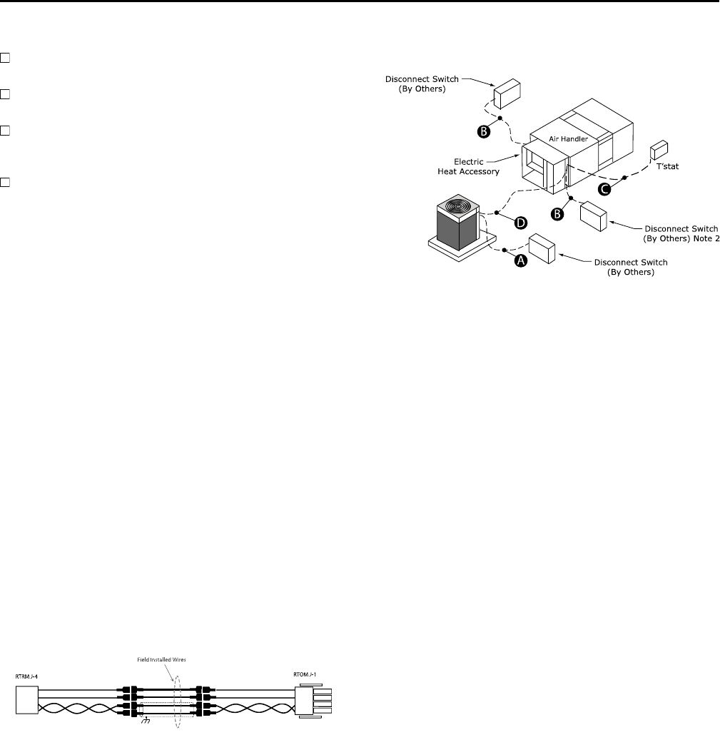
SSA-SVX06E-EN 29
Inspect fan assembly to insure all moving parts
move freely.
If unit is horizontally mounted, make sure
secondary drain pan has been installed.
Inspect unit for proper filters, securely installed and
not touching the coil surface. All cabinet panels
must be secure.
Instruct owner/operator on proper system
operating and maintenance procedure.
Thermostat and Control
Connections
Wiring shown with dashed lines is to be furnished and
installed by the customer. All customer-supplied wiring
must be copper only and must conform to NEC and
local electrical codes. Codes may require line of sight
between disconnect switch and unit.
1. Observe all notes on the wiring diagrams.
2. Mount the thermostat or zone sensor in the desired
location.
3. Install color coded low voltage cables between
outdoor unit, indoor unit and thermostat. For
SZVAV units, install low voltage and
communication wires between the RTRM in the
condenser and the RTOM in the air handler. See
schematic and connection print for more detail.
4. Connect low voltage control wiring to the low
voltage terminal board located at the control box
per the typical interconnecting wiring diagrams. For
SZVAV units, connect the ReliaTel harness (supplied
with the air handler), between the RTRM and RTOM.
See Figure 24, p. 29.
Figure 24. RTOM to RTRM harness
RTRMJ-4 RTOMJ-1
Field Installed Wires
Electromechanical Controls
Wiring shown with dashed lines is to be furnished and
installed by the customer. All customer supplied wiring
must be copper only and must conform to NEC and
local electrical codes. Codes may require line of sight
between disconnect switch and unit.
NNoottee:: When electric heater accessory is used, single
point power entry or dual point power entry is
field optional. Single point power entry option is
through electric heater only.
Figure 25. Electromechanical jobsite connections
T’s t a t
Air Handler
Disconnect S witch
(By Others)
Disconnect S witch
(By Others) Note 2
Electric
Heat Accessory
Disconnect S witch
(By Others)
B
A
B
D
C
A. 3 power wires, line voltage for 3 phase, (2 power wires for
single phase)
B. 3 power wires, line voltage for 3 phase, (2 power wires for
single phase)
C. Cooling only thermostat: 3 to 7 wires depending on stages of
electric heat
D. 3 to 7 wires depending on type of outdoor unit(s)
ReliaTel Controls
Wiring shown with dashed lines is to be furnished and
installed by the customer. All customer supplied wiring
must be copper only and must conform to NEC and
local electrical codes. Codes may require line of sight
between disconnect switch and unit.
NNootteess::
1. When electric heater accessory is used,
single point power entry or dual point power
entry is field optional. Single point power
entry option is through electric heater only.
2. ***Choose only one of the following;
Thermostat, Zone Sensor, or NSB Panel.
IInnssttaallllaattiioonn
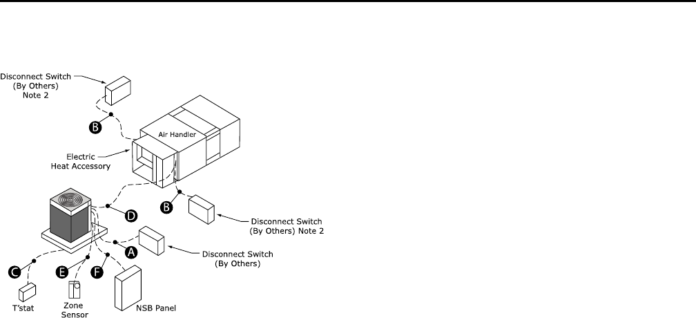
30 SSA-SVX06E-EN
Figure 26. ReliaTel jobsite connections
NSB P anel
Zo ne
Sensor
T’s t a t
Air Handler
Disconnect S witch
(By Others)
Disconnect S witch
(By Others) Note 2
Electric
Heat Accessory
Disconnect S witch
(By Others)
Note 2
B
A
B
D
F
EC
A. 3 power wires, line voltage for 3 phase, (2 power wires for
single phase)
B. 3 power wires, line voltage for 3 phase, (2 power wires for
single phase)
C. Cooling only thermostat: 3 to 7 wires depending on stages of
electric heat
C. Heat Pump thermostat: 5 to 8 wires depending on stages of
electric heat
D. 3 to 7 wires depending on type of outdoor unit(s)
E. Zone Sensor: 4 to 10 wires depending on zone sensor model(a)
F. Night Setback Panel: 7 wires
(a) For SZVAV air handlers: 4 additional wires are required (2 of which
require twisted pair or shielded wire) in order to make connections
between ReliaTel boards in the condenser and air handler.
IInnssttaallllaattiioonn
SSA-SVX06E-EN 31
Electrical Data
60 Hz Models
Includes Standard, SZVAV and 2–Speed VFD air
handlers.
Table 11. Voltage operating range (all air handlers)
Model Number:
Digit 8
Electrical
Characteristics
Unit Operating
Voltage Range
1208-230/60/1 187-253
3208-230/60/3 187-253
4460/60/3 414-506
K380/60/3 342-418
W575/60/3 518-632
Table 12. Electrical characteristics — standard and low static motors — 60 Hz standard air handler
Tons Unit
Model Number
Standard Evaporator Fan Motor Low Static Evaporator Fan Motor
No. Volts Phase Hp Amps MCA MFS No. Volts Phase Hp Amps MCA MFS
FLA LRA FLA LRA
5
TWE061D1, E1 1 208 1 0.75 6.0 41.0 7.5 15 N/A N/A N/A N/A N/A N/A N/A N/A
TWE061D1, E1 1 230 1 0.75 5.9 45.0 7.4 15 N/A N/A N/A N/A N/A N/A N/A N/A
TWE061D3, E3 1 208 3 0.75 2.5 16.4 3.1 15 N/A N/A N/A N/A N/A N/A N/A N/A
TWE061D3, E3 1 230 3 0.75 2.4 16.4 3.0 15 N/A N/A N/A N/A N/A N/A N/A N/A
TWE061D4, E4 1 460 3 0.75 1.2 8.2 1.5 15 N/A N/A N/A N/A N/A N/A N/A N/A
TWE061DW 1 575 3 0.75 1.3 6.1 1.6 15 N/A N/A N/A N/A N/A N/A N/A N/A
7.5
TWE090D1, E1 1 208 1 1.5 6.8 31.5 8.5 20 N/A N/A N/A N/A N/A N/A N/A N/A
TWE090D1, E1 1 230 1 1.5 6.2 31.5 7.8 15 N/A N/A N/A N/A N/A N/A N/A N/A
TWE090D3, E3 1 208 3 1.5 5.3 34.3 6.6 15 N/A N/A N/A N/A N/A N/A N/A N/A
TWE090D3, E3 1 230 3 1.5 5.0 34.3 6.3 15 N/A N/A N/A N/A N/A N/A N/A N/A
TWE090DK, EK 1 380 3 1.5 3.0 20.2 3.8 15 N/A N/A N/A N/A N/A N/A N/A N/A
TWE090D3, E3 1 460 3 1.5 2.5 17.0 3.1 15 N/A N/A N/A N/A N/A N/A N/A N/A
TWE090DW, EW 1 575 3 1.5 1.8 13.6 2.3 15 N/A N/A N/A N/A N/A N/A N/A N/A
10
TWE120D1, E1 1 208 1 2 8.5 57.4 10.6 20 N/A N/A N/A N/A N/A N/A N/A N/A
TWE120D1, E1 1 230 1 2 7.7 57.4 9.6 20 N/A N/A N/A N/A N/A N/A N/A N/A
TWE120D3, E3 1 208 3 2 7.0 33.9 7.8 15 N/A N/A N/A N/A N/A N/A N/A N/A
TWE120D3, E3 1 230 3 2 6.6 33.9 7.3 15 N/A N/A N/A N/A N/A N/A N/A N/A
TWE120DK, EK 1 380 3 2 3.3 28.0 4.1 15 N/A N/A N/A N/A N/A N/A N/A N/A
TWE120D3, E3(a) 1 460 3 2 3.3 19.0 3.6 15 N/A N/A N/A N/A N/A N/A N/A N/A
TWE120DW, EW 1 575 3 2 2.3 15.6 4.0 15 N/A N/A N/A N/A N/A N/A N/A N/A
12.5
TWE150E3 1 208 3 2 6.0 23.0 7.4 15 N/A N/A N/A N/A N/A N/A N/A N/A
TWE150E3 1 230 3 2 5.5 23.0 6.9 15 N/A N/A N/A N/A N/A N/A N/A N/A
TWE150EK 1 380 3 2 3.3 28.0 4.1 15 N/A N/A N/A N/A N/A N/A N/A N/A
TWE150E3(a) 1 460 3 2 2.8 23.0 3.4 15 N/A N/A N/A N/A N/A N/A N/A N/A
TWE150EW 1 575 3 2 2.2 18.0 2.8 15 N/A N/A N/A N/A N/A N/A N/A N/A
15
TWE180E3 1 208 3 3 9.4 74.9 11.8 20 N/A N/A N/A N/A N/A N/A N/A N/A
TWE180E3 1 230 3 3 9.2 74.9 11.5 20 N/A N/A N/A N/A N/A N/A N/A N/A
TWE180EK 1 380 3 5 8.1 63.5 10.1 15 N/A N/A N/A N/A N/A N/A N/A N/A
TWE180E3(a) 1 460 3 3 4.6 39.3 5.8 15 N/A N/A N/A N/A N/A N/A N/A N/A
TWE180EW 1 575 3 3 3.4 24.6 4.3 15 N/A N/A N/A N/A N/A N/A N/A N/A
32 SSA-SVX06E-EN
Table 12. Electrical characteristics — standard and low static motors — 60 Hz standard air handler (continued)
Tons Unit
Model Number
Standard Evaporator Fan Motor Low Static Evaporator Fan Motor
No. Volts Phase Hp Amps MCA MFS No. Volts Phase Hp Amps MCA MFS
FLA LRA FLA LRA
20
TWE240E3 1 208 3 5 14.0 90.8 17.5 30 1 208 3 3 9.4 74.9 11.8 25
TWE240E3 1 230 3 5 13.6 103.0 17.0 30 1 230 3 3 9.2 74.9 11.5 25
TWE240EK 1 380 3 5 8.1 63.5 10.1 15 N/A N/A N/A N/A N/A N/A N/A N/A
TWE240E4 1 460 3 5 6.6 44.8 9.0 15 1 460 3 3 4.6 39.3 5.8 15
TWE240EW 1 575 3 5 5.3 36.2 6.6 15 1 575 3 3 3.4 24.6 4.3 15
25
TWE300E3 1 208 3 7.5 19.6 150.0 25.0 40 1 208 3 7.5 19.6 150 25 40
TWE300E3 1 230 3 7.5 17.8 150.0 25.0 40 1 230 3 7.5 17.8 150 25 40
TWE300EK 1 380 3 7.5 10.9 72.9 13.6 20 N/A N/A N/A N/A N/A N/A N/A N/A
TWE300E4 1 460 3 7.5 8.9 75.0 12.0 20 1 460 3 7.5 8.9 75 12 20
TWE300EW 1 575 3 7.5 7.1 60.0 9.0 15 1 575 3 7.5 7.1 60 9 15
Note: For additional information contact product support.
(a) Field wired for 460V.
Table 13. Electrical characteristics — high and ultra-high static motors — 60 Hz standard air handler
Tons Unit
Model Number
High Static Evaporator Fan Motor Ultra-High Static Evaporator Fan Motor
No. Volts Phase Hp Amps MCA MFS No. Volts Phase Hp Amps MCA MFS
FLA LRA FLA LRA
5
TWE061D1, E1 1 208 1 1.5 6.8 31.5 8.5 20 N/A N/A N/A N/A N/A N/A N/A N/A
TWE061D1, E1 1 230 1 1.5 6.2 31.5 7.8 15 N/A N/A N/A N/A N/A N/A N/A N/A
TWE061D3, E3 1 208 3 1.5 5.3 34.3 6.6 15 N/A N/A N/A N/A N/A N/A N/A N/A
TWE061D3, E3 1 230 3 1.5 5 34.3 6.3 15 N/A N/A N/A N/A N/A N/A N/A N/A
TWE061D4, E4 1 460 3 1.5 2.5 17 3.1 15 N/A N/A N/A N/A N/A N/A N/A N/A
TWE061DW 1 575 3 1.5 1.8 13.6 2.3 15 N/A N/A N/A N/A N/A N/A N/A N/A
7.5
TWE090D1, E1 1 208 1 2 8.5 57.4 10.6 20 N/A N/A N/A N/A N/A N/A N/A N/A
TWE090D1, E1 1 230 1 2 7.7 57.4 9.6 20 N/A N/A N/A N/A N/A N/A N/A N/A
TWE090D3, E3 1 208 3 2 7 33.9 7.8 15 1 208 3 3 9.4 74.9 11.8 25
TWE090D3, E3 1 230 3 2 6.6 33.9 7.3 15 1 230 3 3 9.2 74.9 11.5 25
TWE090D3, E3(a) 1 460 3 2 3.3 19 3.6 15 1 460 3 3 4.6 39.3 5.8 15
TWE090DW, EW 1 575 3 2 2.3 15.6 4 15 1 575 3 3 3.4 24.6 4.3 15
10
TWE120D1, E1 N/A N/A N/A N/A N/A N/A N/A N/A N/A N/A N/A N/A N/A N/A N/A N/A
TWE120D1, E1 N/A N/A N/A N/A N/A N/A N/A N/A N/A N/A N/A N/A N/A N/A N/A N/A
TWE120D3, E3 1 208 3 3 9.4 74.9 11.8 25 N/A N/A N/A N/A N/A N/A N/A N/A
TWE120D3, E3 1 230 3 3 9.2 74.9 11.5 25 N/A N/A N/A N/A N/A N/A N/A N/A
TWE120D3, E3(a) 1 460 3 3 4.6 39.3 5.8 15 N/A N/A N/A N/A N/A N/A N/A N/A
TWE120DW, EW 1 575 3 3 3.4 24.6 4.3 15 N/A N/A N/A N/A N/A N/A N/A N/A
12.5
TWE150E3 1 208 3 3 9.4 74.9 11.8 25 1 208 3 5 14 98 17.5 35
TWE150E3 1 230 3 3 9.2 74.9 11.5 25 1 230 3 5 13.6 103 17 35
TWE150E3(a) 1 460 3 3 4.6 39.3 5.8 15 1 460 3 5 6.6 44.8 8.3 20
TWE150EW 1 575 3 3 3.4 24.6 4.3 15 1 575 3 5 5.2 36.2 6.5 15
15
TWE180E3 1 208 3 5 14 98 17.5 30 N/A N/A N/A N/A N/A N/A N/A N/A
TWE180E3 1 230 3 5 13.6 103 17 30 N/A N/A N/A N/A N/A N/A N/A N/A
TWE180E3(a) 1 460 3 5 6.6 44.8 8.3 15 N/A N/A N/A N/A N/A N/A N/A N/A
TWE180EW 1 575 3 5 5.2 36.2 6.5 15 N/A N/A N/A N/A N/A N/A N/A N/A
20
TWE240E3 N/A N/A N/A N/A N/A N/A N/A N/A 1 208 3 7.5 19.6 114 25 45
TWE240E3 N/A N/A N/A N/A N/A N/A N/A N/A 1 230 3 7.5 17.6 126 22 40
TWE240E4 N/A N/A N/A N/A N/A N/A N/A N/A 1 460 3 7.5 9 61.4 11.3 25
TWE240EW N/A N/A N/A N/A N/A N/A N/A N/A 1 575 3 7.5 7.2 49.8 9 20
EElleeccttrriiccaall DDaattaa
SSA-SVX06E-EN 33
Table 13. Electrical characteristics — high and ultra-high static motors — 60 Hz standard air handler (continued)
Tons Unit
Model Number
High Static Evaporator Fan Motor Ultra-High Static Evaporator Fan Motor
No. Volts Phase Hp Amps MCA MFS No. Volts Phase Hp Amps MCA MFS
FLA LRA FLA LRA
25
TWE300E3 1 208 3 7.5 19.6 150 25 40 N/A N/A N/A N/A N/A N/A N/A N/A
TWE300E3 1 230 3 7.5 17.8 150 25 40 N/A N/A N/A N/A N/A N/A N/A N/A
TWE300E4 1 460 3 7.5 8.9 75 12 20 N/A N/A N/A N/A N/A N/A N/A N/A
TWE300EW 1 575 3 7.5 7.1 60 9 15 N/A N/A N/A N/A N/A N/A N/A N/A
Note: For additional information contact product support.
(a) Field wired for 460V.
Table 14. Electrical characteristics — standard and oversized motors — 60 Hz SZVAV and 2-Speed VFD air handler
Tons Unit
Model Number
Standard Evaporator Fan Motor High Static Evaporator Fan Motor
No. Volts Phase Hp Amps MCA MFS No. Volts Phase Hp Amps MCA MFS
FLA LRA FLA LRA
7.5
TWE090E4 1 208 3 2 6.2 43.4 8 15 1 208 3 3 9.4 71 12 20
TWE090E3 1 230 3 2 5.8 48 8 15 1 230 3 3 9.2 64 12 20
TWE090E4 1 460 3 2 2.9 24 4 15 1 460 3 3 4.6 35.5 6 15
TWE090E4 1 575 3 2 2.2 20.6 3 15 1 575 3 3 3.7 28.4 5 15
10
TWE120D3, E3 1 208 3 2 6.2 43.4 8 15 1 208 3 3 9.4 71 12 20
TWE120D3, E3 1 230 3 2 5.8 48 8 15 1 230 3 3 9.2 64 12 20
TWE120D4, E4 1 460 3 2 2.9 24 4 15 1 460 3 3 4.6 35.5 6 15
TWE120DW, EW 1 575 3 2 2.2 20.6 3 15 1 575 3 3 3.7 28.4 5 15
12.5
TWE150E3 1 208 3 2 6.2 43.4 8 15 1 208 3 5 13.4 99.5 17 30
TWE150E3 1 230 3 2 5.8 48 8 15 1 230 3 5 12.6 110 17 30
TWE150E4 1 460 3 2 2.9 24 4 15 1 460 3 5 6.3 55 8 15
TWE150EW 1 575 3 2 2.2 20.6 3 15 1 575 3 5 5.1 44 7 15
15
TWE180E3 1 208 3 3 9.4 71 12 20 1 208 3 5 13.4 99.5 17 30
TWE180E3 1 230 3 3 9.2 64 12 20 1 230 3 5 12.6 110 17 30
TWE180E4 1 460 3 3 4.6 35.5 6 15 1 460 3 5 6.3 55 8 15
TWE180EW 1 575 3 3 3.7 28.4 5 15 1 575 3 5 5.1 44 7 15
20
TWE240E3 1 208 3 5 13.4 99.5 17 30 1 208 3 7.5 19.6 113.4 25 45
TWE240E3 1 230 3 5 12.6 110 17 30 1 230 3 7.5 17.6 124 25 45
TWE240E4 1 460 3 5 6.3 55 8 15 1 460 3 7.5 8.8 63 11 15
TWE240EW 1 575 3 5 5.1 44 7 15 1 575 3 7.5 7.1 50.4 9 15
25
TWE300E3 1 208 3 7.5 19.6 113.4 25 45 N/A N/A N/A N/A N/A N/A N/A N/A
TWE300E3 1 230 3 7.5 17.6 124 25 45 N/A N/A N/A N/A N/A N/A N/A N/A
TWE300E4 1 460 3 7.5 8.8 63 12 20 N/A N/A N/A N/A N/A N/A N/A N/A
TWE300EW 1 575 3 7.5 7.1 50.4 9 15 N/A N/A N/A N/A N/A N/A N/A N/A
Notes:
1. For additional information contact product support.
2. Not available with 380/60 Hz models.
EElleeccttrriiccaall DDaattaa

34 SSA-SVX06E-EN
Table 15. Unit wiring with electric heat (single point connection) — 5-25 ton standard air handlers — 60 Hz
Tons Used With Heater Model
Number
Heater kW
Rating
Unit Power
Supply
Control
Stages
Minimum Circuit
Ampacity
Maximum Fuse
or HACR Circuit
Breaker Size
5TWE061D1,
TWE061E1
BAYHTRL106* 4.33/5.76
208-230/1/60
133.5/37.4 35.0/40.0
BAYHTRL112* 8.65/11.52 159.5/67.4 60.0/70.0
BAYHTRL117* 12.98/17.28 185.5/97.4 90.0/100.0
BAYHTRL123* 17.31/23.04 2111.5/127.4(a) 125.0/150.0
5TWE061D3,
TWE061E3
BAYHTRL305* 3.76/5.00
208-230/3/60
116.1/18.0 20.0/20.0
BAYHTRL310* 7.48/9.96 129.0/33.0 30.0/35.0
BAYHTRL315* 11.24/14.96 142.2/48.0 45.0/50.0
BAYHTRL325* 18.72/24.92 268.0/77.9(a) 70.0/80.0
5TWE061D4,
TWE061E4
BAYHTRL405* 5.00
460/3/60
1 10.0 15.0
BAYHTRL410* 9.96 1 17.0 20.0
BAYHTRL415* 14.96 1 25.0 25.0
BAYHTRL425* 24.92 2 40.0 40.0
5 TWE061DW
BAYHTRLW05* 5.00
575/3/60
1 8.0 15.0
BAYHTRLW10* 9.96 1 15.0 15.0
BAYHTRLW15* 14.96 1 21.0 20.0
BAYHTRLW25* 24.92 2 33.0 35.0
7.5 TWE090D1,
TWE090E1
BAYHTRL106* 4.33/5.76
208-230/1/60
134.5/37.8 40.0/40.0
BAYHTRL112* 8.65/11.52 160.5/67.8(a) 70.0/70.0
BAYHTRL117* 12.98/17.28 186.5/97.8 90.0/100.0
BAYHTRL123* 17.31/23.04 2112.5/127.8(a) 125.0/150.0
BAYHTRL129* 21.63/28.80 2138.6/157.8(a) 150.0/175.0
7.5 TWE090D3,
TWE090E3
BAYHTRL305* 3.76/5.00
208-230/3/60
119.6/21.3 25.0/25.0
BAYHTRL310* 7.48/9.96 132.5/36.2 35.0/40.0
BAYHTRL315* 11.24/14.96 145.7/51.2 50.0/60.0
BAYHTRL325* 18.72/24.92 271.5/82.0(a) 80.0/90.0
BAYHTRL335* 26.20/34.88 298.7/112(b) 100.0/125.0
7.5 TWE090D3,
TWE090E3(c)
BAYHTRL405* 5.00
460/3/60
1 11.0 15.0
BAYHTRL410* 9.96 1 19.0 20.0
BAYHTRL415* 14.96 1 26.0 30.0
BAYHTRL425* 24.92 2 41.0 45.0
BAYHTRL435* 34.88 2 56.0 60.0
7.5 TWE090DW,
TWE090EW
BAYHTRLW05* 5.00
575/3/60
1 11.0 15.0
BAYHTRLW10* 9.96 1 17.0 15.0
BAYHTRLW15* 14.96 1 23.0 25.0
BAYHTRLW25* 24.92 2 36.0 35.0
BAYHTRLW35* 34.88 2 48.0 45.0
10 TWE120D1,
TWE120E1
BAYHTRL106* 4.33/5.76
208-230/1/60
136.6/39.6 40.0/45.0
BAYHTRL112* 8.65/11.52 162.6/69.6(a) 70.0/70.0
BAYHTRL117* 12.98/17.28 188.6/99.6 90.0/100.0
BAYHTRL123* 17.31/23.04 2114.6/129.6(a) 125.0/150.0
BAYHTRL129* 21.63/28.80 2140.7/159.6(a) 150.0/175.0
10 TWE120D3,
TWE120E3
BAYHTRL305* 3.76/5.00
208-230/3/60
121.0/23.0 25.0/30.0
BAYHTRL310* 7.48/9.96 134.0/38.0 35.0/40.0
BAYHTRL315* 11.24/14.96 147.0/53.0 50.0/60.0
BAYHTRL325* 18.72/24.92 273.0/83.0(a) 80.0/90.0
BAYHTRL335* 26.20/34.88 298.7/113.0(b) 100.0/125.0
EElleeccttrriiccaall DDaattaa

SSA-SVX06E-EN 35
Table 15. Unit wiring with electric heat (single point connection) — 5-25 ton standard air handlers — 60 Hz
(continued)
Tons Used With Heater Model
Number
Heater kW
Rating
Unit Power
Supply
Control
Stages
Minimum Circuit
Ampacity
Maximum Fuse
or HACR Circuit
Breaker Size
10 TWE120D3(c) ,
TWE120E3(c)
BAYHTRL405* 5.00
460/3/60
1 12.0 15.0
BAYHTRL410* 9.96 1 20.0 20.0
BAYHTRL415* 14.96 1 27.0 30.0
BAYHTRL425* 24.92 2 42.0 45.0
BAYHTRL435* 34.88 2 57.0 60.0
10 TWE120DW,
TWE120EW
BAYHTRLW05* 5.00
575/3/60
1 10.0 15.0
BAYHTRLW10* 9.96 1 16.0 15.0
BAYHTRLW15* 14.96 1 22.0 25.0
BAYHTRLW25* 24.92 2 35.0 35.0
BAYHTRLW35* 34.88 2 47.0 45.0
12.5 TWE150E3
BAYHTRM310A 7.51/10.00
208-230/3/60
133.5/36.9 35/40
BAYHTRM320A 14.96/19.92 159.3/66.8 60/70
BAYHTRM330A 22.47/29.92 285.5/96.8 90/100
BAYHTRM350A 37.44/49.84 2137.3/156.7 150/175
12.5 TWE150E3(c)
BAYHTRM410* 10.00
460/3/60
1 19.0 20.0
BAYHTRM420* 19.92 1 34.0 35.0
BAYHTRM430* 29.92 2 49.0 50.0
BAYHTRM450* 49.84 2 79.0 80.0
12.5 TWE150EW
BAYHTRMW10* 10.00
575/3/60
1 15.0 15.0
BAYHTRMW20* 19.92 1 27.0 30.0
BAYHTRMW30* 29.92 2 39.0 40.0
BAYHTRMW50* 49.84 2 63.0 70.0
15 TWE180E3
BAYHTRM310* 7.51/10.00
208-230/3/60
137.8/41.6 45.0/45.0
BAYHTRM320* 14.96/19.92 163.7/71.4 70.0/80.0
BAYHTRM330* 22.47/29.92 289.8/101.5 90.0/110.0
BAYHTRM350* 37.44/49.84 2141.6/161.4(b) 150.0/175.0
15 TWE180E3(c)
BAYHTRM410* 10.00
460/3/60
1 21.0 25.0
BAYHTRM42* 19.92 1 36.0 40.0
BAYHTRM430* 29.92 2 51.0 60.0
BAYHTRM450* 49.84 2 81.0 90.0
15 TWE180EW
BAYHTRMW10* 10.00
575/3/60
1 17.0 20.0
BAYHTRMW20* 19.92 1 30.0 30.0
BAYHTRMW30* 29.92 2 42.0 45.0
BAYHTRMW50* 49.84 2 67.0 70.0
20 TWE240E3
BAYHTRM310* 7.51/10.00
208-230/3/60
144.1/49.0 60.0/60.0
BAYHTRM320* 14.96/19.92 171.0/79.0 80.0/90.0
BAYHTRM330* 22.47/29.92 297.0/109.0 100.0/110.0
BAYHTRM350* 37.44/49.84 2149.0/169.0(b) 150.0/175.0
20 TWE240E4
BAYHTRM410* 10.00
460/3/60
1 24.0 30.0
BAYHTRM420* 19.92 1 39.0 40.0
BAYHTRM430* 29.92 2 54.0 60.0
BAYHTRM450* 49.84 2 84.0 90.0
20 TWE240EW
BAYHTRMW10* 10.00
575/3/60
1 20.0 25.0
BAYHTRMW20* 19.92 1 32.0 35.0
BAYHTRMW30* 29.92 2 45.0 45.0
BAYHTRMW50* 49.84 2 70.0 70.0
EElleeccttrriiccaall DDaattaa
36 SSA-SVX06E-EN
Table 15. Unit wiring with electric heat (single point connection) — 5-25 ton standard air handlers — 60 Hz
(continued)
Tons Used With Heater Model
Number
Heater kW
Rating
Unit Power
Supply
Control
Stages
Minimum Circuit
Ampacity
Maximum Fuse
or HACR Circuit
Breaker Size
25 TWE300E3
BAYHTRM310* 7.51/10
208-230/3/60
151.0/53.0 60.0/90.0
BAYHTRM320* 14.96/19.92 177.0/83.0 85.0/90.0
BAYHTRM330* 22.47/29.92 2103.0/113.0 110.0/125.0
BAYHTRM350* 37.44/49.84 2155.0/173.0 175.0/175.0
25 TWE300E4
BAYHTRM410* 10.00
460/3/60
1 27.0 30.0
BAYHTRM420* 19.92 1 42.0 45.0
BAYHTRM430* 29.92 2 57.0 60.0
BAYHTRM450* 49.84 2 87.0 90.0
25 TWE300EW
BAYHTRMW10* 10.00
575/3/60
1 22.0 25.0
BAYHTRMW20* 19.92 1 34.0 35.0
BAYHTRMW30* 29.92 2 47.0 50.0
BAYHTRMW50* 49.84 2 72.0 80.0
Notes:
1. kW ratings are at: 208/240V for 208-230V air handlers; 480V for 460V air handlers; 600V for 575V air handlers. For other than
rated voltage, capacity = (voltage/rated voltage)2x rated capacity.
2. Any power supply and circuits must be wired and protected in accordance with local codes.
3. Electric heat not available with 380/60 Hz models.
4. The HACR circuit breaker is for U.S.A. installations only.
(a) Field wire must be rated at least 75°C.
(b) Field wire must be rated at least 90°C.
(c) With motor field wired for 460V.
Table 16. Unit wiring with electric heat (single point connection) — 7.5-25 ton SZVAV and 2-Speed VFD air handlers —
60 Hz
Tons Used With Heater Model
Number
Heater KW
Rating
Unit Power
Supply
Control
Stages
Minimum
Circuit
Ampacity
Maximum Fuse or
HACR Circuit
Breaker Size
7.5 TWE090E3*3
BAYHTRL305* 3.76/5.00
208-230/3/60
121/23 25/25
BAYHTRL310* 7.48/9.96 134/38 35/40
BAYHTRL315* 11.24/14.96 147/53 50/60
BAYHTRL325* 18.72/24.92 273/83 80/90
BAYHTRL335* 26.20/34.88 299/113 100/125
7.5 TWE090E4*4
BAYHTRL305* 5.00
460/3/60
1 12 15
BAYHTRL310* 9.96 1 19 20
BAYHTRL315* 14.96 1 27 30
BAYHTRL325* 24.92 2 42 45
BAYHTRL335* 34.88 2 57 60
7.5 TWE090EW*3
BAYHTRLW05* 5.00
575/3/60
1 9 15
BAYHTRLW10* 9.96 1 16 20
BAYHTRLW15* 14.96 1 22 25
BAYHTRLW25* 24.92 2 34 35
BAYHTRLW35* 34.88 2 47 50
10 TWE120D3*3, E3*3
BAYHTRL305* 3.76/5.00
208-230/3/60
121/23 25/25
BAYHTRL310* 7.48/9.96 134/38 35/40
BAYHTRL315* 11.24/14.96 147/53 50/60
BAYHTRL325* 18.72/24.92 273/83 80/90
BAYHTRL335* 26.20/34.88 299/113 100/125
EElleeccttrriiccaall DDaattaa

SSA-SVX06E-EN 37
Table 16. Unit wiring with electric heat (single point connection) — 7.5-25 ton SZVAV and 2-Speed VFD air handlers —
60 Hz (continued)
Tons Used With Heater Model
Number
Heater KW
Rating
Unit Power
Supply
Control
Stages
Minimum
Circuit
Ampacity
Maximum Fuse or
HACR Circuit
Breaker Size
10 TWE120D3*4, E3*4
BAYHTRL305* 3.76/5.00
208-230/3/60
125/27 30/30
BAYHTRL310* 7.48/9.96 138/42 40/45
BAYHTRL315* 11.24/14.96 138/57 40/60
BAYHTRL325* 18.72/24.92 277/87 80/90
BAYHTRL335* 26.20/34.88 2103/117 110/125
10 TWE120D4*3, E4*3
BAYHTRL405* 5.00
460/3/60
1 12 15
BAYHTRL410* 9.96 1 19 20
BAYHTRL415* 14.96 1 27 30
BAYHTRL425* 24.92 2 42 45
BAYHTRL435* 34.88 2 57 60
10 TWE120D4*4, E4*4
BAYHTRL405* 5.00
460/3/60
1 14 15
BAYHTRL410* 9.96 1 21 25
BAYHTRL415* 14.96 1 29 30
BAYHTRL425* 24.92 2 44 45
BAYHTRL435* 34.88 2 59 60
10 TWE120DW*3, EW*3
BAYHTRLW05* 5.00
575/3/60
1 9 15
BAYHTRLW10* 9.96 1 16 20
BAYHTRLW15* 14.96 1 22 25
BAYHTRLW25* 24.92 2 34 35
BAYHTRLW35* 34.88 2 47 50
10 TWE120DW*4, EW*4
BAYHTRLW05* 5.00
575/3/60
1 11 15
BAYHTRLW10* 9.96 1 18 20
BAYHTRLW15* 14.96 1 24 25
BAYHTRLW25* 24.92 2 36 40
BAYHTRLW35* 34.88 2 49 50
12.5 TWE150E3*3
BAYHTRM310* 7.51/10.00
208-230/3/60
134/38 35/40
BAYHTRM320* 14.96/19.92 160/68 60/70
BAYHTRM330* 22.47/29.92 286/98 90/100
BAYHTRM350* 37.44/49.84 2138/158 150/175
12.5 TWE150E3*4
BAYHTRM310* 7.51/10.00
208-230/3/60
143/47 45/50
BAYHTRM320* 14.96/19.92 169/77 70/80
BAYHTRM330* 22.47/29.92 295/107 100/110
BAYHTRM350* 37.44/49.84 2147/167 150/175
12.5 TWE150E4*3
BAYHTRM410* 10.00
460/3/60
1 19 20
BAYHTRM420* 19.92 1 34 35
BAYHTRM430* 29.92 2 49 50
BAYHTRM450* 49.84 2 79 80
12.5 TWE150E4*4
BAYHTRM410* 10.00
460/3/60
1 23 25
BAYHTRM420* 19.92 1 38 40
BAYHTRM430* 29.92 2 53 60
BAYHTRM450* 49.84 2 83 90
12.5 TWE150EW*3
BAYHTRMW10* 10.00
575/3/60
1 16 20
BAYHTRMW20* 19.92 1 28 30
BAYHTRMW30* 29.92 2 41 45
BAYHTRMW50* 49.84 2 66 70
EElleeccttrriiccaall DDaattaa

38 SSA-SVX06E-EN
Table 16. Unit wiring with electric heat (single point connection) — 7.5-25 ton SZVAV and 2-Speed VFD air handlers —
60 Hz (continued)
Tons Used With Heater Model
Number
Heater KW
Rating
Unit Power
Supply
Control
Stages
Minimum
Circuit
Ampacity
Maximum Fuse or
HACR Circuit
Breaker Size
12.5 TWE150EW*4
BAYHTRMW10* 10.00
575/3/60
1 19 20
BAYHTRMW20* 19.92 1 32 35
BAYHTRMW30* 29.92 2 44 45
BAYHTRMW50* 49.84 2 69 70
15 TWE180E3*3
BAYHTRM310* 7.51/10.00
208-230/3/60
138/42 40/45
BAYHTRM320* 14.96/19.92 164/72 70/80
BAYHTRM330* 22.47/29.92 290/102 90/110
BAYHTRM350* 37.44/49.84 2142/162 150/175
15 TWE180E3*4
BAYHTRM310* 7.51/10.00
208-230/3/60
143/47 45/50
BAYHTRM320* 14.96/19.92 169/77 70/80
BAYHTRM330* 22.47/29.92 295/107 100/110
BAYHTRM350* 37.44/49.84 2147/167 150/175
15 TWE180E4*3
BAYHTRM410* 10.00
460/3/60
1 21 25
BAYHTRM420* 19.92 1 36 40
BAYHTRM430* 29.92 2 51 60
BAYHTRM450* 49.84 2 81 90
15 TWE180E4*4
BAYHTRM410* 10.00
460/3/60
1 23 25
BAYHTRM420* 19.92 1 38 40
BAYHTRM430* 29.92 2 53 60
BAYHTRM450* 49.84 2 83 90
15 TWE180EW*3
BAYHTRMW10* 10.00
575/3/60
1 18 20
BAYHTRMW20* 19.92 1 30 30
BAYHTRMW30* 29.92 2 43 45
BAYHTRMW50* 49.84 2 68 70
15 TWE180EW*4
BAYHTRMW10* 10.00
575/3/60
1 19 20
BAYHTRMW20* 19.92 1 32 35
BAYHTRMW30* 29.92 2 44 45
BAYHTRMW50* 49.84 2 69 70
20 TWE240E3*3
BAYHTRM310* 7.51/10.00
208-230/3/60
143/47 45/50
BAYHTRM320* 14.96/19.92 169/77 70/80
BAYHTRM330* 22.47/29.92 295/107 100/110
BAYHTRM350* 37.44/49.84 2147/167 150/175
20 TWE240E3*4
BAYHTRM310* 7.51/10.00
208-230/3/60
151/55 60/60
BAYHTRM320* 14.96/19.92 177/85 80/90
BAYHTRM330* 22.47/29.92 2103/115 110/125
BAYHTRM350* 37.44/49.84 2155/175 175/175
20 TWE240E4*3
BAYHTRM410* 10.00
460/3/60
1 23 25
BAYHTRM420* 19.92 1 38 40
BAYHTRM430* 29.92 2 53 60
BAYHTRM450* 49.84 2 83 90
20 TWE240E4*4
BAYHTRM410* 10.00
460/3/60
1 26 30
BAYHTRM420* 19.92 1 41 45
BAYHTRM430* 29.92 2 56 60
BAYHTRM450* 49.84 2 86 90
EElleeccttrriiccaall DDaattaa

SSA-SVX06E-EN 39
Table 16. Unit wiring with electric heat (single point connection) — 7.5-25 ton SZVAV and 2-Speed VFD air handlers —
60 Hz (continued)
Tons Used With Heater Model
Number
Heater KW
Rating
Unit Power
Supply
Control
Stages
Minimum
Circuit
Ampacity
Maximum Fuse or
HACR Circuit
Breaker Size
20 TWE240EW*3
BAYHTRMW10* 10.00
575/3/60
1 19 20
BAYHTRMW20* 19.92 1 32 35
BAYHTRMW30* 29.92 2 44 45
BAYHTRMW50* 49.84 2 69 70
20 TWE240EW*4
BAYHTRMW10* 10.00
575/3/60
1 22 25
BAYHTRMW20* 19.92 1 34 35
BAYHTRMW30* 29.92 2 47 50
BAYHTRMW50* 49.84 2 72 80
25 TWE300E3*3
BAYHTRM310* 7.51/10.00
208-230/3/60
151/55 60/60
BAYHTRM320* 14.96/19.92 177/85 80/90
BAYHTRM330* 22.47/29.92 2103/115 110/125
BAYHTRM350* 37.44/49.84 2155/175 175/175
25 TWE300E4*3
BAYHTRM410* 10.00
460/3/60
1 26 30
BAYHTRM420* 19.92 1 41 45
BAYHTRM430* 29.92 2 56 60
BAYHTRM450* 49.84 2 86 90
25 TWE300EW*3
BAYHTRMW10* 10.00
575/3/60
1 22 25
BAYHTRMW20* 19.92 1 34 35
BAYHTRMW30* 29.92 2 47 50
BAYHTRMW50* 49.84 2 72 80
Notes:
1. kW ratings are at: 208/240V for 208-230V air handlers; 480V for 460V air handlers; 600V for 575V air handlers. For other than rated
voltage, capacity = (voltage/rated voltage)2x rated capacity.
2. Any power supply and circuits must be wired and protected in accordance with local codes.
3. Electric heat not available with 380/60 Hz models.
4. The HACR circuit breaker is for U.S.A. installations only.
EElleeccttrriiccaall DDaattaa
40 SSA-SVX06E-EN
50 Hz Models
Includes standard air handlers
Table 17. Electrical characteristics — standard motor — 50 Hz air handler
Tons Unit Model Number
Standard Evaporator Fan Motor
No. Volts Phase
Amps
FLA LRA
4.6 TWE051DD 1 380 3 1.4 8.0
1 415 3 1.0 8.4
6.25 TWE076DD, ED 1 380 3 3.1 17.0
1 415 3 3.2 16.8
8.33 TWE101DD, ED 1 380 3 3.4 17.3
1 415 3 3.2 19.0
10.4 TWE126ED 1 380 3 3.2 35.0
1 415 3 3.1 35.0
13 TWE156ED 1 380 3 4.0 33.1
1 415 3 4.0 36.1
16.7 TWE201ED 1 380 3 8.0 43.2
1 415 3 8.0 48.6
20.9 TWE251ED 1 380 3 7.5 71.0
1 415 3 7.2 77.0
Table 18. Unit wiring — air handler — 50 Hz
Tons Unit Model
Number
Minimum Unit Operating
Voltage Range
Maximum Fuse
Circuit Ampacity
Ampacity
Size or Maximum
Circuit Breaker
4.6 TWE051DD 380/415 4 15
6.25 TWE076DD, ED 380/415 5 15
8.33 TWE101DD, ED 380/415 5 15
10.4 TWE126ED 380/415 5 15
13 TWE156ED 380/415 6 15
16.7 TWE201ED 380/415 10 15
20.9 TWE251ED 380/415 10 15
Table 19. Unit wiring with electric heat (single point connection) — air handlers
Heater
Model No.
Heater
kW Rating
To Use
with Unit
Control
Stages
Minimum
Circuit
Ampacity
Maximum
Fuse Breaker
Size
BAYHTRL405* 5
TWE051DD
1 13 15
BAYHTRL410* 9.96 1 22 25
BAYHTRL415* 14.96 1 31 35
BAYHTRL425* 24.92 2 49 50
BAYHTRL405* 5
TWE076DD, ED
1 14 15
BAYHTRL410* 9.96 1 23 25
BAYHTRL415* 14.96 1 32 35
BAYHTRL425* 24.92 2 50 50
BAYHTRL435* 34.88 2 68 70
EElleeccttrriiccaall DDaattaa

SSA-SVX06E-EN 41
Table 19. Unit wiring with electric heat (single point connection) — air handlers (continued)
BAYHTRL405* 5
TWE101DD,
TWE101ED
1 14 15
BAYHTRL410* 9.96 1 23 25
BAYHTRL415* 14.96 1 32 35
BAYHTRL425* 24.92 2 50 50
BAYHTRL435* 34.88 2 68 70
BAYHTRM410* 10
TWE126ED
1 19 20
BAYHTRM420* 19.92 1 41 45
BAYHTRM430* 29.92 2 59 60
BAYHTRM450* 49.84 2 94 100
BAYHTRM410* 10
TWE156ED
1 23 25
BAYHTRM420* 19.92 1 41 45
BAYHTRM430* 29.92 2 59 60
BAYHTRM450* 49.84 2 95 100
BAYHTRM410* 10
TWE201ED
1 29 30
BAYHTRM420* 19.92 1 46 50
BAYHTRM430* 29.92 2 65 70
BAYHTRM450* 49.84 2 100 100
BAYHTRM410* 10
TWE251ED
1 29 30
BAYHTRM420* 19.92 1 46 50
BAYHTRM430* 29.92 2 65 70
BAYHTRM450* 49.84 2 100 100
Notes:
1. Field wire must be rated at least 167°F (75°C).
2. Field wire must be rated at least 194°F (90°C).
3. Heater kW ratings are at 400v for 3 phase, 400v air handlers.
4. For other than rated voltage, capacity = (voltage/rated voltage)2 x rated capacity and kW = (voltage/rated voltage)
2 rated kW.
5. Any power supply and circuits must be wired and protected in accordance with local codes.
6. MCA and Maximum Fuse Size is based on 400V.
EElleeccttrriiccaall DDaattaa

42 SSA-SVX06E-EN
Start-Up
Sequence of Operation
NNOOTTIICCEE
EEqquuiippmmeenntt DDaammaaggee!!
EEnnssuurree tthhee ddiissccoonnnneecctt ffoorr tthhee iinnddoooorr aaiirr hhaannddlleerr iiss
cclloosseedd bbeeffoorree ooppeerraattiinngg tthhee ssyysstteemm.. OOppeerraattiinngg tthhee
oouuttddoooorr uunniitt wwiitthhoouutt tthhee iinnddoooorr ffaann eenneerrggiizzeedd ccaann
ccaauussee uunniitt ttrriipp--oouutt oonn hhiigghh pprreessssuurree ccoonnttrrooll aanndd//oorr
lliiqquuiidd fflloooodd bbaacckk ttoo tthhee ccoommpprreessssoorr..
Variable Air Volume Applications
(SZVAV)
Supply Fan Mode Operation
Units configured for SZVAV control will utilize Supply
Fan Mode selection as is currently implemented into
ReliaTel controls for normal Zone Control and will be
selectable between AAUUTTOO and OONN via a connected
Zone Sensor module or through BAS/Network
controllers.
Supply Fan Mode Auto Operation
For active Cooling, and Heating operation the Supply
Fan will be commanded OONN and will ramp up to the
appropriate minimum speed once the unit determines
that there is a request for capacity control. Once the
active request is cleared and all capacity is de-
energized normal supply fan off delays as implemented
on constant volume units will be in effect. During the
Supply Fan Off-Delay, the supply fan will remain
energized for the predetermined time at the previous
unit function's minimum speed. All other cases which
would bring the Supply Fan OONN will function as on
non-SZVAV units.
Supply Fan Mode ON Operation
For active unit control with the Supply Fan Mode set to
OONN, the unit will energize the Supply Fan and hold the
Fan Speed output at minimum speed until there is a
request for the fan speed to increase. This will hold true
for all cases except during Unoccupied periods in
which the Supply Fan Mode is forced to AAUUTTOO and will
operate the Supply Fan as described above for all
Cooling, and Heating requests.
Supply Air Temperature Control - Cooling
For Cooling operation the unit will control the active
capacity outputs to meet a varying, calculated
Discharge Air Setpoint that is calculated based on zone
conditions in order to maintain the Zone Temperature
to the active Zone Setpoint. Note that this setpoint will
be clamped between the user selected DA Heat and DA
Cool setpoints for compressor control. In general, as
the zone temperature rises above the ZCSP, the Active
Discharge Air Setpoint will be calculated down. This
calculated setpoint is a direct indication of space
demand and is also used to determine the proper
supply fan speed to meet the space requirements.
During active capacity control, the unit will utilize a +/-
3.5°F deadband around the active Discharge Air
Setpoint to determine when to request additional
cooling capacity. If the unit is maintaining the discharge
air temperature within the +/- 3.5°F deadband around
the calculated discharge air setpoint requirements, no
additional capacity will be requested.
Occupied Cooling Operation
For normal Cooling operation, available Cooling
capacity will be staged or modulated in order to meet
the calculated discharge air setpoint between the user
selected upper and lower limits. If the current active
cooling capacity is controlling the discharge air within
the deadband no additional Cooling capacity change
will be requested. As the Discharge Air Temperature
rises above the deadband the control will request
additional capacity as required (additional compressor
operation). As the Discharge Air Temperature falls
below the deadband the algorithm will request a
reduction in active capacity.
Compressor Cooling
Compressor output control and protection schemes
will function similar to non-SZVAV units. Normal
compressor HPC and LPC control will remain in effect
as well as normal 3-minute minimum on, off, and inter-
stage timers. Also, the condenser fans will be
controlled similar to non-SZVAV units.
Cooling Sequence
If the control determines that there is a need for
compressor stages in order to meet the discharge air
requirements, once supply fan proving has been made,
the unit will begin to stage compressors accordingly.
Note that a 5 second delay will be enforced between
the command for supply fan output operation and the
command for compressor output operation. This delay
is enforced to ensure that the supply fan is energized
and ramping up to operating speed prior to energizing
compressors.
As the zone cooling demand continues to increase, if
additional capacity is required, the supply fan output
will be modulated above minimum speed in order to
meet the zone requirements. Note that the supply fan
speed will remain at the compressor stage's associated
minimum value until the control requires additional
capacity to meet the zone demand.
As the cooling load in the zone decreases the control
will reduce the speed of the fan down to minimum per
compressor stage and control the compressor outputs
accordingly. As the compressors begin to de-energize,
the Supply Fan speed will fall back to the Cooling
Stage's associated minimum fan speed but not below.
As the load in the zone continues to drop, cooling

SSA-SVX06E-EN 43
capacity will be reduced in order to maintain the
calculated discharge air setpoint.
Cooling Stages Minimum Fan Speed
As the unit begins to stage compressors to meet the
cooling demand, the following minimum Supply Fan
Speeds will be utilized for each corresponding Cooling
Stage. Note that the Supply Fan Speed will be allowed
to ramp up beyond the minimum speed in order to
meet the zone cooling demand. The minimum fan
speed for units with 2 stages of DX Cooling will be 58%
of the unit's full airflow capacity. At Stage 1 of DX
Cooling the Fan Speed will be at a minimum of 58%
and at Stage 2 of DX Cooling the Fan Speed will be at a
minimum of 80%.
Occupied Heating Operation
Occupied Heating operation on units configured with
SZVAV control will utilize two separate control
methodologies based on heating configurations. For all
"Staged" Heating types (Electric and Gas), the unit will
utilize 100% full airflow during all active heating
periods like traditional Constant Volume units. For
Modulating Gas heat units, the unit will have the ability
to control the discharge air temperature to the
calculated discharge air heating setpoint in order to
maintain the Zone Temperature to the Zone Heating
setpoint.
Staged Heating Operation
For units configured with Mechanical or Auxiliary Heat
once the control determines that there is an active
heating capacity request, the unit will energize the
Supply Fan and ramp up to full speed. The control
methodology during Active Heating will be identical to
traditional Constant Volume units; heating stages will
be energized/de-energized to meet the Zone Heating
demand. Note that all Electric staging sequences will
be identical to Constant Volume units.
Unoccupied Cooling and Heating Operation
For SZVAV units, the unit will control Heating and
Cooling, as during Occupied periods using the normal
heating and cooling SZVAV algorithms. In Unoccupied
periods the unit will utilize setback setpoints, and Auto
fan mode operation as on normal Constant Volume
units.
Failure and Overriding Conditions
Certain failure and overriding conditions require
special handling of the Supply Fan Speed on units
configured with SZVAV. See below for a list of these
conditions:
1. SSuuppppllyy FFaann PPrroovviinngg FFaaiilluurree - If a Supply Fan
Proving failure is detected the Supply Fan will be
de-energized after 40s of run time and the Fan
Speed output will go to the corresponding
minimum speed voltage.
2. ZZoonnee TTeemmppeerraattuurree SSeennssoorr FFaaiilluurree - If the Active
Zone Temperature input goes out of range, the unit
will discontinue all Heating, Cooling, and
Dehumidification operation.
3. SSuuppppllyy AAiirr TTeemmppeerraattuurree SSeennssoorr FFaaiilluurree - If the
Supply Air Temperature input goes out of range,
the unit will revert back to Full Airflow, Traditional
CV control. The unit will call out a Supply Air
Temperature Sensor Failure Alarm, the RTRM
System LED will flash the 2-blink error code, and
Cool LEDs will flash.
2–Speed VFD Applications
General Description of Functionality
Cooling Operation (DX Cooling)
Units with a 2-Speed VFD control scheme will utilize a
thermostat's heating and cooling outputs to
differentiate between high and low speed. When the
unit receives a G or Y1 call from the thermostat the
supply fan will run at the user selected low speed. Once
the zone load demands the second stage of cooling,
and the unit receives the Y2 call from the thermostat
the supply fan will be signaled to run at the user
selected high speed. All other compressor staging will
be handled the same as all standard thermostat
controlled units.
Heating Operation
Units with 2-Speed VFD controls will utilize traditional
CV Heating control schemes with full airflow provided
based on the customer selected VFD controlled
maximum speed. When the unit receives the W1 call
from the thermostat a relay will signal the supply fan to
run at high speed. All the electric heaters that can be
outfitted in the field are wired up to interlock W1 and
W2 so the supply fan will always run at the user
selected high speed during heat modes.
SSttaarrtt--UUpp
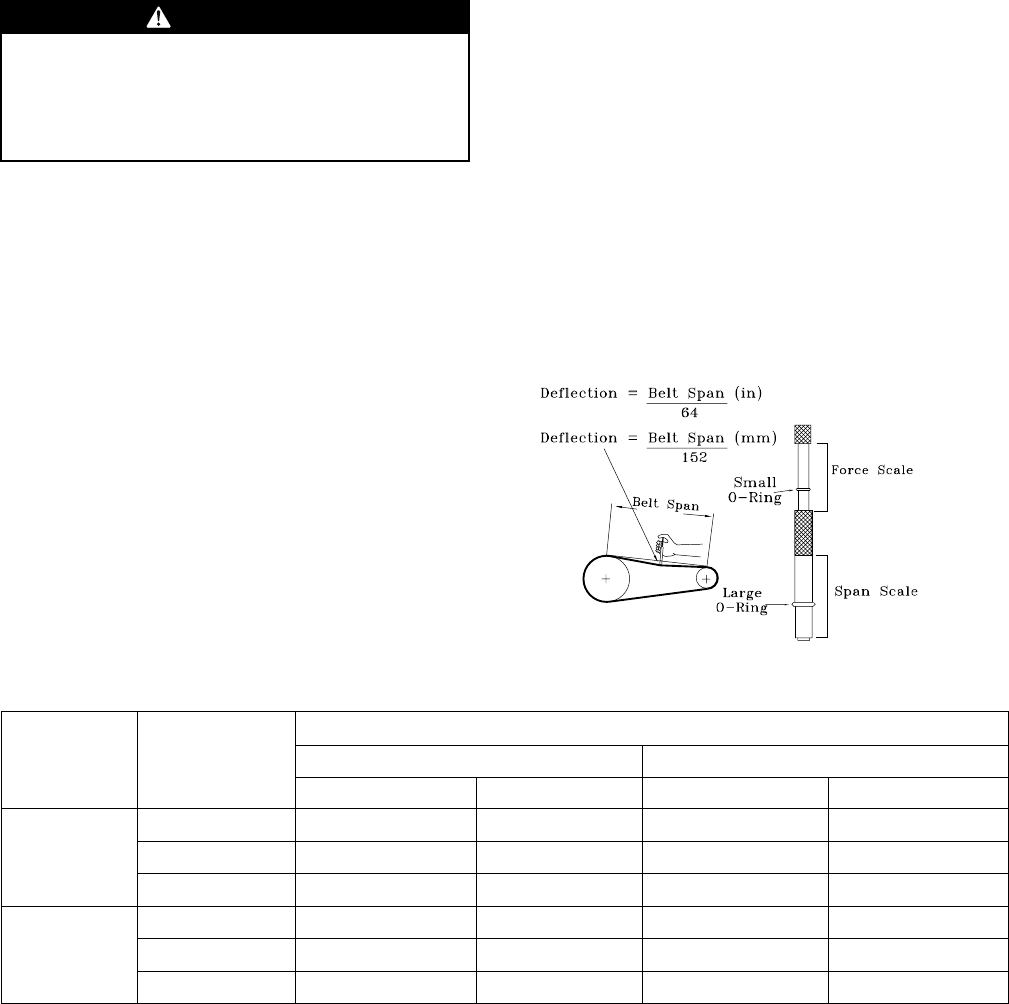
44 SSA-SVX06E-EN
Maintenance
Perform all of the indicated maintenance procedures at
the intervals scheduled. This will prolong the life of the
unit and reduce the possibility of costly equipment
failure.
Fan Belt Adjustment
WWAARRNNIINNGG
RRoottaattiinngg CCoommppoonneennttss!!
DDiissccoonnnneecctt aallll eelleeccttrriicc ppoowweerr,, iinncclluuddiinngg rreemmoottee
ddiissccoonnnneeccttss bbeeffoorree sseerrvviicciinngg.. FFoollllooww pprrooppeerr
lloocckkoouutt//ttaaggoouutt pprroocceedduurreess ttoo eennssuurree tthhee ppoowweerr
ccaann nnoott bbee iinnaaddvveerrtteennttllyy eenneerrggiizzeedd..
The fan belts must be inspected periodically to assure
proper unit operation. Replacement is necessary if the
belts appear frayed or worn.
When removing or installing the new belts, do not
stretch them over the sheaves. Loosen the belts using
the belt tension adjustment bolts on the motor
mounting base.
Once the new belts are installed, using a Browning or
Gates tension gauge (or equivalent), adjust the belt
tension as follows:
1. To determine the appropriate belt deflection:
a. Measure the center-to-center shaft distance (in
inches) between the fan and motor sheaves.
b. Divide the distance measured in Step 1a by 64;
the resulting value represents the amount of
belt deflection that corresponds to the proper
belt tension.
2. Set the large O-ring on the belt tension gauge at the
deflection value determined in Step 1b.
3. Set the small O-ring at zero on the force scale of the
gauge plunger.
4. Place the large end of the gauge at the center of the
belt span; then depress the gauge plunger until the
large O-ring is even with the top of the next belt or
even with a straightedge placed across the fan and
motor sheaves.
5. Remove the belt tension gauge. The small
O-ring now indicates a number other than zero on
the plunger’s force scale. This number represents
the force (in pounds) required to give the needed
deflection.
6. Compare the “force” scale reading (Step 5) with the
appropriate “force” value listed in the Belt tension
table. If the “force” reading is outside the range,
readjust the belt tension.
NNoottee:: Actual belt deflection “force” must not
exceed the maximum “force” value shown in
Figure 27, p. 44.
Recheck the belt tension at least twice during the
first 2 to 3 days of operation. Belt tension may
decrease until the new belts are “run in”.
Figure 27. Belt tension gauge
Table 20. Belt tension measurement and deflection
Belts Cross
Section
Small Pitch
Diameter Range
Deflection Force (Lbs.)
Standard V-Belt V-Belt with Molded Notches
Min. Max. Min. Max.
A
3.0 - 3.6 3 4-1/2 3-7/8 5-1/2
3.8 - 4.8 3-1/2 54-1/2 6-1/4
5.0 - 7.0 4 5-1/2 56-7/8
B
3.4 - 4.2 4 5-1/2 5-3/4 8
4.4 - 5.6 5-1/8 7-1/8 6-1/2 9-1/8
5.8 - 8.8 6-3/8 8-3/4 7-3/8 10-1/8
Monthly
The following warning complies with State of
California law, Proposition 65.
SSA-SVX06E-EN 45
WWAARRNNIINNGG
HHaazzaarrddoouuss VVoollttaaggee ww//CCaappaacciittoorrss!!
DDiissccoonnnneecctt aallll eelleeccttrriicc ppoowweerr,, iinncclluuddiinngg rreemmoottee
ddiissccoonnnneeccttss aanndd ddiisscchhaarrggee aallll mmoottoorr ssttaarrtt//rruunn
ccaappaacciittoorrss bbeeffoorree sseerrvviicciinngg.. FFoollllooww pprrooppeerr lloocckkoouutt//
ttaaggoouutt pprroocceedduurreess ttoo eennssuurree tthhee ppoowweerr ccaannnnoott bbee
iinnaaddvveerrtteennttllyy eenneerrggiizzeedd.. FFoorr vvaarriiaabbllee ffrreeqquueennccyy
ddrriivveess oorr ootthheerr eenneerrggyy ssttoorriinngg ccoommppoonneennttss
pprroovviiddeedd bbyy TTrraannee oorr ootthheerrss,, rreeffeerr ttoo tthhee
aapppprroopprriiaattee mmaannuuffaaccttuurreerr’’ss lliitteerraattuurree ffoorr
aalllloowwaabbllee wwaaiittiinngg ppeerriiooddss ffoorr ddiisscchhaarrggee ooff
ccaappaacciittoorrss.. VVeerriiffyy wwiitthh aann aapppprroopprriiaattee vvoollttmmeetteerr
tthhaatt aallll ccaappaacciittoorrss hhaavvee ddiisscchhaarrggeedd..
FFoorr aaddddiittiioonnaall iinnffoorrmmaattiioonn rreeggaarrddiinngg tthhee ssaaffee
ddiisscchhaarrggee ooff ccaappaacciittoorrss,, sseeee PPRROODD--SSVVBB0066AA--EENN..
NNOOTTIICCEE
OOppeerraattiinngg UUnnddeerr VVaaccuuuumm!!
DDoo nnoott ooppeerraattee oorr aappppllyy ppoowweerr ttoo tthhee ccoommpprreessssoorr
wwhhiillee uunnddeerr aa vvaaccuuuumm..
WWAARRNNIINNGG
FFiibbeerrggllaassss WWooooll!!
YYoouu MMUUSSTT wweeaarr aallll nneecceessssaarryy PPeerrssoonnaall PPrrootteeccttiivvee
EEqquuiippmmeenntt ((PPPPEE)) iinncclluuddiinngg gglloovveess,, eeyyee pprrootteeccttiioonn,,
aa NNIIOOSSHH aapppprroovveedd dduusstt//mmiisstt rreessppiirraattoorr,, lloonngg
sslleeeevveess aanndd ppaannttss wwhheenn wwoorrkkiinngg wwiitthh pprroodduuccttss
ccoonnttaaiinniinngg ffiibbeerrggllaassss wwooooll..
PPrreeccaauuttiioonnaarryy MMeeaassuurreess::
•• AAvvooiidd bbrreeaatthhiinngg ffiibbeerrggllaassss dduusstt..
•• UUssee aa NNIIOOSSHH aapppprroovveedd dduusstt//mmiisstt rreessppiirraattoorr..
•• AAvvooiidd ccoonnttaacctt wwiitthh tthhee sskkiinn oorr eeyyeess.. WWeeaarr
lloonngg--sslleeeevveedd,, lloooossee--ffiittttiinngg ccllootthhiinngg,, gglloovveess,,
aanndd eeyyee pprrootteeccttiioonn..
•• WWaasshh ccllootthheess sseeppaarraatteellyy ffrroomm ootthheerr ccllootthhiinngg;;
rriinnssee wwaasshheerr tthhoorroouugghhllyy..
•• OOppeerraattiioonnss ssuucchh aass ssaawwiinngg,, bblloowwiinngg,, tteeaarr--
oouutt,, aanndd sspprraayyiinngg mmaayy ggeenneerraattee ffiibbeerr
ccoonncceennttrraattiioonnss rreeqquuiirriinngg aaddddiittiioonnaall
rreessppiirraattoorryy pprrootteeccttiioonn.. UUssee tthhee aapppprroopprriiaattee
NNIIOOSSHH aapppprroovveedd rreessppiirraattoorr..
FFiirrsstt AAiidd MMeeaassuurreess::
•• EEyyee CCoonnttaacctt -- FFlluusshh eeyyeess wwiitthh wwaatteerr ttoo
rreemmoovvee dduusstt.. IIff ssyymmppttoommss ppeerrssiisstt,, sseeeekk
mmeeddiiccaall aatttteennttiioonn..
•• SSkkiinn CCoonnttaacctt -- WWaasshh aaffffeecctteedd aarreeaass ggeennttllyy
wwiitthh ssooaapp aanndd wwaarrmm wwaatteerr aafftteerr hhaannddlliinngg..
Conduct the following maintenance inspections once
per month:
Inspect air filters and clean (or replace) if necessary.
Check unit wiring to ensure all connections are tight
and that the wiring insulation is intact.
Check drain pans and condensate piping to insure
they are free of obstacles.
Manually rotate the indoor fan to ensure proper
operation.
Inspect the evaporator coils for dirt and debris. If
the coils appear dirty, clean them.
Observe indoor fan operation and correct any
unusual or excessive vibration. Clean blower
wheels as needed.
Annually (Cooling Season)
The following maintenance procedures must be
performed at the beginning of each cooling season to
ensure efficient unit operation:
Perform all of the monthly maintenance
inspections.
With the unit operating, check unit superheat and
record the reading in the “Maintenance Log,” p. 46
Remove any accumulation of dust and/or dirt from
the unit casing.
Remove corrosion from any surface and repaint.
Check the gasket around the control panel door to
ensure it fits correctly and is in good condition to
prevent water leakage.
Inspect the evaporator fan belt. If it is worn or
frayed, replace it.
Inspect the control panel wiring to ensure that all
connections are tight and that the insulation is
intact.
Check refrigerant piping and fittings for leaks.
Inspect the evaporator coils for dirt and debris. If
the coils appear dirty, clean them.
Coil Cleaning
Regular coil maintenance, including annual cleaning-
enhances the unit's operating efficiency by minimizing:
• compressor head pressure and amperage draw
• water carryover
• fan brake horsepower
• static pressure losses
At least once each year — or more often if the unit is
located in a “dirty” environment — clean the coil using
the instructions outlined below. Be sure to follow these
instructions as closely as possible to avoid damaging
the coils.
MMaaiinntteennaannccee

46 SSA-SVX06E-EN
Maintenance Log
Date
Ambient
Temp.
(°F)
Evaporator Entering Air Compressor
Superheat (°F)
(at compressor)
Subcooling (°F)
(at service valve)
Dry
Bulb
Wet
Bulb
Suction Pressure Discharge Pressure
Circuit #1 Circuit #2 Circuit #1 Circuit #2
(C1) (C2) (C1) (C2)
Note: Perform each inspection once per month (during cooling season) while unit is operating
MMaaiinntteennaannccee

SSA-SVX06E-EN 47
Wiring Diagram Matrix
Table 21. Wiring schematics for TWE air handlers
Electromechanical
(Sd)
Electromechanical
(2 speed) Reliatel
Model No. Ton Circuit Volts Hz Ph Schematic/
Connection Schematic Connection Schematic Connection
TWE051DD 4.6 Single 380-415 50 3 2313-0401 N/A N/A N/A N/A
TWE061D3 5 Single 208-230 60 3 2313-0401 N/A N/A N/A N/A
TWE061D4 5 Single 460 60 3 2313-0401 N/A N/A N/A N/A
TWE061DW 5 Single 575 60 3 2313-0401 N/A N/A N/A N/A
TWE061DK 5 Single 380 60 3 2313-0401 N/A N/A N/A N/A
TTA076DD 6.25 Single 380-415 50 3 2313-0401 N/A N/A N/A N/A
TWE061D1 5 Single 208-230 60 1 2313-0402 N/A N/A N/A N/A
TWE090D1 7.5 Single 208-230 60 1 2313-0402 N/A N/A N/A N/A
TWE120D1 10 Single 208-230 60 1 2313-0402 N/A N/A N/A N/A
TWE061E3 5 Dual 208-230 60 3 2313-0431 N/A N/A N/A N/A
TWE061E4 5 Dual 460 60 3 2313-0431 N/A N/A N/A N/A
TWE061EW 5 Dual 575 60 3 2313-0431 N/A N/A N/A N/A
TWE061EK 5 Dual 380 60 3 2313-0431 N/A N/A N/A N/A
TWE061E1 5 Dual 208-230 60 1 2313-0432 N/A N/A N/A N/A
TWE090E1 7.5 Dual 208-230 60 1 2313-0432 N/A N/A N/A N/A
TWE120E1 10 Dual 208-230 60 1 2313-0432 N/A N/A N/A N/A
TWE090D3 7.5 Single 208-230 60 3 2313-0401 2313-0451 2313-0453 1213-1400 1213-1401
TWE090D4 7.5 Single 460 60 3 2313-0401 2313-0451 2313-0453 1213-1400 1213-1401
TWE090DW 7.5 Single 575 60 3 2313-0401 2313-0451 2313-0453 1213-1400 1213-1401
TWE090DK 7.5 Single 380 60 3 2313-0401 N/A N/A N/A N/A
TWE090E3 7.5 Dual 208-230 60 3 2313-0431 2313-0451 2313-0453 1213-1400 1213-1401
TWE090E4 7.5 Dual 460 60 3 2313-0431 2313-0451 2313-0453 1213-1400 1213-1401
TWE090EW 7.5 Dual 575 60 3 2313-0431 2313-0451 2313-0453 1213-1400 1213-1401
TWE090EK 7.5 Dual 380 60 3 2313-0431 N/A N/A N/A N/A
TWE101DD 8.33 Single 380-415 50 3 2313-0401 N/A N/A N/A N/A
TWE101ED 8.33 Dual 380-415 50 3 2313-0431 N/A N/A N/A N/A
TWE120D3 10 Single 208-230 60 3 2313-0401 2313-0451 2313-0453 1213-1400 1213-1401
TWE120DW 10 Single 575 60 3 2313-0401 2313-0451 2313-0453 1213-1400 1213-1401
TWE120DK 10 Single 380 60 3 2313-0401 N/A N/A N/A N/A
TWE120E3 10 Dual 208-230 60 3 2313-0431 2313-0451 2313-0453 1213-1400 1213-1401
TWE120EW 10 Dual 575 60 3 2313-0431 2313-0451 2313-0453 1213-1400 1213-1401
TWE120EK 10 Dual 380 60 3 2313-0431 N/A N/A N/A N/A
TWE126ED 10.4 Dual 380-415 50 3 2313-0431 N/A N/A N/A N/A
TWE150E3 12.5 Dual 208-230 60 3 2313-0431 2313-0451 2313-0453 1213-1400 1213-1401
TWE150EW 12.5 Dual 575 60 3 2313-0431 2313-0451 2313-0453 1213-1400 1213-1401
TWE150EK 12.5 Dual 380 60 3 2313-0431 N/A N/A N/A N/A
TWE156ED 13 Dual 380-415 50 3 2313-0431 N/A N/A N/A N/A
TWE180E3 15 Dual 208-230 60 3 2313-0431 2313-0451 2313-0453 1213-1400 1213-1401
TWE180EW 15 Dual 575 60 3 2313-0431 2313-0451 2313-0453 1213-1400 1213-1401
TWE180EK 15 Dual 380 60 3 2313-0431 N/A N/A N/A N/A
TWE201ED 16.7 Dual 380-415 50 3 2313-0431 N/A N/A N/A N/A
TWE240E3 20 Dual 208-230 60 3 2313-0431 2313-0451 2313-0453 1213-1400 1213-1401
TWE240E4 20 Dual 380-415 60 3 2313-0431 2313-0451 2313-0453 1213-1400 1213-1401
TWE240EW 20 Dual 575 60 3 2313-0431 2313-0451 2313-0453 1213-1400 1213-1401
TWE240EK 20 Dual 380 60 3 2313-0431 N/A N/A N/A N/A
TWE251ED 20.9 Dual 380-415 50 3 2313-0431 N/A N/A N/A N/A
Table 21. Wiring schematics for TWE air handlers (continued)
Electromechanical
(Sd)
Electromechanical
(2 speed) Reliatel
Model No. Ton Circuit Volts Hz Ph Schematic/
Connection Schematic Connection Schematic Connection
TWE300E3 25 Dual 208-230 60 3 2313-0431 2313-0451 2313-0453 1213-1400 1213-1401
TWE300E4 25 Dual 380-415 50 3 2313-0431 2313-0451 2313-0453 1213-1400 1213-1401
TWE300EW 25 Dual 575 60 3 2313-0431 2313-0451 2313-0453 1213-1400 1213-1401
TWE300EK 25 Dual 380 60 3 2313-0431 N/A N/A N/A N/A
Note: Wiring diagrams are available through e-Library or by contacting your local sales office.
WWiirriinngg DDiiaaggrraamm MMaattrriixx
The manufacturer optimizes the performance of homes and buildings around the world. A business of Ingersoll Rand,
the leader in creating and sustaining safe, comfortable and energy efficient environments, the manufacturer offers a
broad portfolio of advanced controls and HVAC systems, comprehensive building services, and parts. For more
information, visit www.IRCO.com.
The manufacturer has a policy of continuous product and product data improvements and reserves the right to change design and specifications without notice.
©2015 Trane All rights reserved
SSA-SVX06E-EN 02 Mar 2015
Supersedes SSA-SVX06D-EN (January 2014)
We are committed to using environmentally
conscious print practices that reduce waste.
