Trane Performance Air Handlers Catalogue
2015-04-02
: Trane Trane-Performance-Air-Handlers-Catalogue-684265 trane-performance-air-handlers-catalogue-684265 trane pdf
Open the PDF directly: View PDF ![]() .
.
Page Count: 216 [warning: Documents this large are best viewed by clicking the View PDF Link!]

Performance Climate Changer™ Air Handlers
Sizes 3-120
Indoor and Outdoor Units
Application and Performance Information
September 2013 CLCH-PRC022A-EN
Catalog

© 2013 Trane All rights reserved CLCH-PRC022A-EN
Introduction
Performance Climate Changer air handlers combine the Trane tradition of engineering excellence
with the latest in manufacturing technology to give you an energy efficient air handler with superior
performance, the highest quality and reliability, and the lowest installed cost in the industry. This
air handler was designed to incorporate such features as component flexibility, integrated control
options, and proven performance to give you the optimal system to clean, filter, dehumidify, heat,
and cool your building.
Superior Performance
• ASHRAE 111 Class 6 low-leak casing design achieving less than 1.0 percent leakage rate at
+/- 8 inches w.g.
• Less than L/240 @ +/- 8 inches w.g. panel and door deflection
• 2-inch R13 foam-insulated, mid-span thermal break panels and thermal break doors
• Casing thermal resistance ratio TR-value of 0.6
• New filter technology that exceeds LEED requirements and reduces filter pressure drops up to
50 percent versus previous designs
Industry-Leading Energy Efficiency
• AMCA 611-certified Traq airflow monitoring station
• Total energy-recovery wheels
• Cool Dry Quiet (CDQ™) desiccant dehumidification wheels
• Discharge plenums and plenum fan sections available with variable size, type, and location of
openings to reduce static pressure loss and lower energy consumption
• 50,000 hour LED service lights
• Low-leak, high thermal performance casing design
• All airfoil-bladed dampers and Traq dampers meet ASHRAE 90.1 lowest specified leakage
requirements
• High-efficiency coil fins deliver superior heat transfer while allowing face velocities in excess
of 625 fpm without moisture carryover
System Optimization
• Optimal design to meet the Trane EarthWise™ design philosophy incorporating high-efficiency
air handlers and water chillers with low flow rates and low temperatures.
• Factory-engineered, -mounted, and -tested control packages with properly sealed casing
openings.
• Variety of coil types with high-efficiency coil fins allow lower coil approach temperature and
reduce chance of moisture carryover
• Ability to choose the exact number of fins per foot of coil surface to enhance heat transfer and
air pressure performance
• Wide array of fan options, including direct-drive plenum fans, belt-drive plenum fans, and
housed fans
• Control options to easily incorporate fan pressurization and demand control ventilation
strategies.
• Design and analysis tools provide whole building analysis, acoustical design guidance,
equipment performance data, and suggested control strategies to help achieve optimum
system design with tailored energy, IAQ, and project budget solutions.

CLCH-PRC022A-EN 3
Introduction
Highest Quality
• UL/CUL listed
• AHRI Standard 430-certified air-handling unit
• AHRI Standard 410-certified coils are all factory tested
• AHRI Standard 1060-certified energy wheels
• All fans are dynamically balanced in the horizontal and vertical planes.
• All fans with VFDs undergo inverter balancing
• Formulated panels and integral base frame minimize seams that could introduce air leak paths
• Integrated raceway for wiring protection
• Integrated, fully-enclosed control panel for starters, VFDs, and unit-mounted controllers
• Pre-engineered, factory-mounted controls, including end devices, motor controllers, VFDs,
unit-mounted DDC controllers, Traq™ damper ventilation control section, UL-listed turnkey
control packages
Lowest Installed Cost
• Lifting lugs included on the integral base frame
• Indoor units ship with skid designed for forklift transport
• Variable height, size, type, and location of openings on discharge plenums minimize duct
transitions
• Factory-installed interoperable controls shorten construction cycles, simplify job-site
coordination, reduce installation time and expense, and provide single-source responsibility
for warranty and service issues
• Single-point power is available with high-voltage distribution block and external main unit
disconnect with lockout/tagout capabilities.
• External service module with 15 amp GFCI receptacle, light switch, and controller display and
communications port
• Quick-connect wiring minimizes installation costs and provides wiring integrity between
sections
• Factory-installed conduit connectors eliminate penetrations in the wrong location
• Motor leads can be run through flexible metal conduits to NEMA 4 external motor junction box
• Building Information Modeling (BIM) drawings to minimize jobsite ductwork, electrical, piping
and structural interference
• Duct supports designed into factory roof curbs for pre-connection of ductwork
For dimensional information on Performance Climate Changer air handlers see Trane catalog
CLCH-PRC023-EN.

4 CLCH-PRC022A-EN
Table of Contents
Introduction . . . . . . . . . . . . . . . . . . . . . . . . . . . . . . . . . . . . . . . . . . . . . . . . . . . . . . 2
Superior Performance . . . . . . . . . . . . . . . . . . . . . . . . . . . . . . . . . . . . . . . . . . 2
Industry-Leading Energy Efficiency . . . . . . . . . . . . . . . . . . . . . . . . . . . . . . . 2
System Optimization . . . . . . . . . . . . . . . . . . . . . . . . . . . . . . . . . . . . . . . . . . . 2
Highest Quality . . . . . . . . . . . . . . . . . . . . . . . . . . . . . . . . . . . . . . . . . . . . . . . 3
Lowest Installed Cost . . . . . . . . . . . . . . . . . . . . . . . . . . . . . . . . . . . . . . . . . . 3
Features and Benefits - Unit . . . . . . . . . . . . . . . . . . . . . . . . . . . . . . . . . . . . . . . . 11
Form, Function and Flexibility . . . . . . . . . . . . . . . . . . . . . . . . . . . . . . . . . . . . 11
Reduces Footprint when Stacked . . . . . . . . . . . . . . . . . . . . . . . . . . . . . . . . 11
Eases Retrofit, Renovation, and Replacement . . . . . . . . . . . . . . . . . . . . . 11
Airside Options . . . . . . . . . . . . . . . . . . . . . . . . . . . . . . . . . . . . . . . . . . . . . . 12
Construction and Integrity . . . . . . . . . . . . . . . . . . . . . . . . . . . . . . . . . . . . . . . 12
Engineered for Good IAQ . . . . . . . . . . . . . . . . . . . . . . . . . . . . . . . . . . . . . . . . 12
Sound-Sensitive Solutions . . . . . . . . . . . . . . . . . . . . . . . . . . . . . . . . . . . . . . . 13
Provide Accurate, Tested Sound Data . . . . . . . . . . . . . . . . . . . . . . . . . . . . 13
Minimize Sound Source . . . . . . . . . . . . . . . . . . . . . . . . . . . . . . . . . . . . . . . 14
Increase Operating Efficiency . . . . . . . . . . . . . . . . . . . . . . . . . . . . . . . . . . . . . 14
Turnkey Control Solutions . . . . . . . . . . . . . . . . . . . . . . . . . . . . . . . . . . . . . . . 14
Single-Source Responsibility . . . . . . . . . . . . . . . . . . . . . . . . . . . . . . . . . . . 15
Single-Point Power . . . . . . . . . . . . . . . . . . . . . . . . . . . . . . . . . . . . . . . . . . . 16
Reduced Installation Costs . . . . . . . . . . . . . . . . . . . . . . . . . . . . . . . . . . . . . 16
Reliable Operation . . . . . . . . . . . . . . . . . . . . . . . . . . . . . . . . . . . . . . . . . . . . 16
Open Protocol . . . . . . . . . . . . . . . . . . . . . . . . . . . . . . . . . . . . . . . . . . . . . . . 17
Service Module . . . . . . . . . . . . . . . . . . . . . . . . . . . . . . . . . . . . . . . . . . . . . . 17
Proven Performance . . . . . . . . . . . . . . . . . . . . . . . . . . . . . . . . . . . . . . . . . . . . 17
AHRI Standards . . . . . . . . . . . . . . . . . . . . . . . . . . . . . . . . . . . . . . . . . . . . . . 17
Miami/Dade County Notice of Compliance (NOA) . . . . . . . . . . . . . . . . . . 18
UL Listing . . . . . . . . . . . . . . . . . . . . . . . . . . . . . . . . . . . . . . . . . . . . . . . . . . . 18
IBC Seismic Certification . . . . . . . . . . . . . . . . . . . . . . . . . . . . . . . . . . . . . . . 18
AMCA Certification . . . . . . . . . . . . . . . . . . . . . . . . . . . . . . . . . . . . . . . . . . . 18
Canadian Registration Number (CRN) . . . . . . . . . . . . . . . . . . . . . . . . . . . . 18
ISO Certification . . . . . . . . . . . . . . . . . . . . . . . . . . . . . . . . . . . . . . . . . . . . . 18
HVAC Design Fundamentals . . . . . . . . . . . . . . . . . . . . . . . . . . . . . . . . . . . . . . . . 19
Provide Proper Ventilation . . . . . . . . . . . . . . . . . . . . . . . . . . . . . . . . . . . . . . . 19
Maintain Building Pressure . . . . . . . . . . . . . . . . . . . . . . . . . . . . . . . . . . . . . . 19
Protect Coils from Freezing . . . . . . . . . . . . . . . . . . . . . . . . . . . . . . . . . . . . . . 20
Filter Contaminants . . . . . . . . . . . . . . . . . . . . . . . . . . . . . . . . . . . . . . . . . . . . . 21
Particulate Filter Guidelines . . . . . . . . . . . . . . . . . . . . . . . . . . . . . . . . . . . . 21
Gases and Vapors . . . . . . . . . . . . . . . . . . . . . . . . . . . . . . . . . . . . . . . . . . . . 22
Minimize Microbial Growth . . . . . . . . . . . . . . . . . . . . . . . . . . . . . . . . . . . . . . 23
Water Management . . . . . . . . . . . . . . . . . . . . . . . . . . . . . . . . . . . . . . . . . . . 23
Dehumidification . . . . . . . . . . . . . . . . . . . . . . . . . . . . . . . . . . . . . . . . . . . . . 24

CLCH-PRC022A-EN 5
Humidification . . . . . . . . . . . . . . . . . . . . . . . . . . . . . . . . . . . . . . . . . . . . . . . 25
Provide Quiet Comfort . . . . . . . . . . . . . . . . . . . . . . . . . . . . . . . . . . . . . . . . . . 25
Application Considerations . . . . . . . . . . . . . . . . . . . . . . . . . . . . . . . . . . . . . . . . . 27
Air Handler Design . . . . . . . . . . . . . . . . . . . . . . . . . . . . . . . . . . . . . . . . . . . . . 27
Single-Path Design . . . . . . . . . . . . . . . . . . . . . . . . . . . . . . . . . . . . . . . . . . . 27
Dual-Path Design . . . . . . . . . . . . . . . . . . . . . . . . . . . . . . . . . . . . . . . . . . . . . 28
Standard AHU Arrangements . . . . . . . . . . . . . . . . . . . . . . . . . . . . . . . . . . . . 29
Draw-Thru Arrangements . . . . . . . . . . . . . . . . . . . . . . . . . . . . . . . . . . . . . . 29
Blow-Thru Arrangements . . . . . . . . . . . . . . . . . . . . . . . . . . . . . . . . . . . . . . 29
Stacked Units . . . . . . . . . . . . . . . . . . . . . . . . . . . . . . . . . . . . . . . . . . . . . . . . 30
Arrangements for Specific Applications . . . . . . . . . . . . . . . . . . . . . . . . . . . . 30
Building Pressurization . . . . . . . . . . . . . . . . . . . . . . . . . . . . . . . . . . . . . . . . 30
Building Pressurization with Return Fan and Economizer . . . . . . . . . . . . 30
Building Pressurization with Exhaust Fan and Economizer . . . . . . . . . . . 31
Building Pressurization with Barometric Relief Economizer . . . . . . . . . . 32
Dehumidification . . . . . . . . . . . . . . . . . . . . . . . . . . . . . . . . . . . . . . . . . . . . . 32
Dehumidification with CDQ™ (Cool, Dry, Quiet) Desiccant Wheels . . . . 33
Dehumidification with Coil Runaround Loops . . . . . . . . . . . . . . . . . . . . . 33
Dehumidification with a Split Dehumidification Unit (SDU) . . . . . . . . . . 34
Dehumidification with Hot-Water Heat-Recovery Coils . . . . . . . . . . . . . . 37
Energy Recovery . . . . . . . . . . . . . . . . . . . . . . . . . . . . . . . . . . . . . . . . . . . . . . . 37
Energy Recovery with a Total Energy Wheel . . . . . . . . . . . . . . . . . . . . . . 37
Energy Recovery with Coil Runaround Loops . . . . . . . . . . . . . . . . . . . . . 39
Energy Recovery with Air-to-Air Plate Frame Heat Exchangers . . . . . . . 40
Acoustics . . . . . . . . . . . . . . . . . . . . . . . . . . . . . . . . . . . . . . . . . . . . . . . . . . . . . 41
Components and Options . . . . . . . . . . . . . . . . . . . . . . . . . . . . . . . . . . . . . . . . . . 42
Access/Blank and Turning Section . . . . . . . . . . . . . . . . . . . . . . . . . . . . . . . . 42
Blender . . . . . . . . . . . . . . . . . . . . . . . . . . . . . . . . . . . . . . . . . . . . . . . . . . . . . . . 42
CDQ™ Desiccant Dehumidification Wheel . . . . . . . . . . . . . . . . . . . . . . . . . . 43
Coils . . . . . . . . . . . . . . . . . . . . . . . . . . . . . . . . . . . . . . . . . . . . . . . . . . . . . . . . . 44
Coil Optimization . . . . . . . . . . . . . . . . . . . . . . . . . . . . . . . . . . . . . . . . . . . . . 44
Drain Pans . . . . . . . . . . . . . . . . . . . . . . . . . . . . . . . . . . . . . . . . . . . . . . . . . . 45
Electric Heat . . . . . . . . . . . . . . . . . . . . . . . . . . . . . . . . . . . . . . . . . . . . . . . . . 45
Integral Face-and-Bypass Coil . . . . . . . . . . . . . . . . . . . . . . . . . . . . . . . . . . 45
Dampers . . . . . . . . . . . . . . . . . . . . . . . . . . . . . . . . . . . . . . . . . . . . . . . . . . . . . . 46
Face-and-Bypass Dampers . . . . . . . . . . . . . . . . . . . . . . . . . . . . . . . . . . . . . 46
Traq™ Dampers and Low Flow Traq Dampers . . . . . . . . . . . . . . . . . . . . . 49
. . . . . . . . . . . . . . . . . . . . . . . . . . . . . . . . . . . . . . . . . . . . . . . . . . . . . . . . . . . 49
Diffuser . . . . . . . . . . . . . . . . . . . . . . . . . . . . . . . . . . . . . . . . . . . . . . . . . . . . . . . 49
Discharge Plenum . . . . . . . . . . . . . . . . . . . . . . . . . . . . . . . . . . . . . . . . . . . . . . 50
Economizer . . . . . . . . . . . . . . . . . . . . . . . . . . . . . . . . . . . . . . . . . . . . . . . . . . . 50
Energy Recovery . . . . . . . . . . . . . . . . . . . . . . . . . . . . . . . . . . . . . . . . . . . . . . . 50

6 CLCH-PRC022A-EN
Energy Wheels . . . . . . . . . . . . . . . . . . . . . . . . . . . . . . . . . . . . . . . . . . . . . . . 51
Coil Runaround Loop . . . . . . . . . . . . . . . . . . . . . . . . . . . . . . . . . . . . . . . . . 51
Air-to-Air Plate Frame Heat Exchanger . . . . . . . . . . . . . . . . . . . . . . . . . . . 52
Fans . . . . . . . . . . . . . . . . . . . . . . . . . . . . . . . . . . . . . . . . . . . . . . . . . . . . . . . . . 52
Fan Choices . . . . . . . . . . . . . . . . . . . . . . . . . . . . . . . . . . . . . . . . . . . . . . . . . 52
Constant Volume vs. VAV Systems . . . . . . . . . . . . . . . . . . . . . . . . . . . . . . 53
Airflow Measuring Systems . . . . . . . . . . . . . . . . . . . . . . . . . . . . . . . . . . . . 54
Filtration and Air Cleaning . . . . . . . . . . . . . . . . . . . . . . . . . . . . . . . . . . . . . . . 54
Filtration Options . . . . . . . . . . . . . . . . . . . . . . . . . . . . . . . . . . . . . . . . . . . . . 54
Air Cleaning Options . . . . . . . . . . . . . . . . . . . . . . . . . . . . . . . . . . . . . . . . . . 55
Gas Heat . . . . . . . . . . . . . . . . . . . . . . . . . . . . . . . . . . . . . . . . . . . . . . . . . . . . . . 56
Humidifier . . . . . . . . . . . . . . . . . . . . . . . . . . . . . . . . . . . . . . . . . . . . . . . . . . . . 56
Inlet Hood . . . . . . . . . . . . . . . . . . . . . . . . . . . . . . . . . . . . . . . . . . . . . . . . . . . . . 57
Mixing Box and Economizer . . . . . . . . . . . . . . . . . . . . . . . . . . . . . . . . . . . . . 57
Multizone . . . . . . . . . . . . . . . . . . . . . . . . . . . . . . . . . . . . . . . . . . . . . . . . . . . . . 58
Silencers . . . . . . . . . . . . . . . . . . . . . . . . . . . . . . . . . . . . . . . . . . . . . . . . . . . . . . 58
General Data . . . . . . . . . . . . . . . . . . . . . . . . . . . . . . . . . . . . . . . . . . . . . . . . . . . . . 59
Unit Size 3 . . . . . . . . . . . . . . . . . . . . . . . . . . . . . . . . . . . . . . . . . . . . . . . . . . . . 59
Unit Size 4 . . . . . . . . . . . . . . . . . . . . . . . . . . . . . . . . . . . . . . . . . . . . . . . . . . . . 62
Unit Size 6 . . . . . . . . . . . . . . . . . . . . . . . . . . . . . . . . . . . . . . . . . . . . . . . . . . . . 66
Unit Size 8 . . . . . . . . . . . . . . . . . . . . . . . . . . . . . . . . . . . . . . . . . . . . . . . . . . . . 70
Unit Size 10 . . . . . . . . . . . . . . . . . . . . . . . . . . . . . . . . . . . . . . . . . . . . . . . . . . . 74
Unit Size 12 . . . . . . . . . . . . . . . . . . . . . . . . . . . . . . . . . . . . . . . . . . . . . . . . . . . 78
Unit Size 14 . . . . . . . . . . . . . . . . . . . . . . . . . . . . . . . . . . . . . . . . . . . . . . . . . . . 82
Unit Size 17 . . . . . . . . . . . . . . . . . . . . . . . . . . . . . . . . . . . . . . . . . . . . . . . . . . . 86
Unit Size 21 . . . . . . . . . . . . . . . . . . . . . . . . . . . . . . . . . . . . . . . . . . . . . . . . . . . 90
Unit Size 22 . . . . . . . . . . . . . . . . . . . . . . . . . . . . . . . . . . . . . . . . . . . . . . . . . . . 94
Unit Size 25 . . . . . . . . . . . . . . . . . . . . . . . . . . . . . . . . . . . . . . . . . . . . . . . . . . . 97
Unit Size 26 . . . . . . . . . . . . . . . . . . . . . . . . . . . . . . . . . . . . . . . . . . . . . . . . . . 101
Unit Size 30 . . . . . . . . . . . . . . . . . . . . . . . . . . . . . . . . . . . . . . . . . . . . . . . . . . 104
Unit Size 31 . . . . . . . . . . . . . . . . . . . . . . . . . . . . . . . . . . . . . . . . . . . . . . . . . . 108
Unit Size 35 . . . . . . . . . . . . . . . . . . . . . . . . . . . . . . . . . . . . . . . . . . . . . . . . . . 111
Unit Size 36 . . . . . . . . . . . . . . . . . . . . . . . . . . . . . . . . . . . . . . . . . . . . . . . . . . 115
Unit Size 40 . . . . . . . . . . . . . . . . . . . . . . . . . . . . . . . . . . . . . . . . . . . . . . . . . . 118
Unit Size 41 . . . . . . . . . . . . . . . . . . . . . . . . . . . . . . . . . . . . . . . . . . . . . . . . . . 122
Unit Size 50 . . . . . . . . . . . . . . . . . . . . . . . . . . . . . . . . . . . . . . . . . . . . . . . . . . 125
Unit Size 51 . . . . . . . . . . . . . . . . . . . . . . . . . . . . . . . . . . . . . . . . . . . . . . . . . . 129
Unit Size 57 . . . . . . . . . . . . . . . . . . . . . . . . . . . . . . . . . . . . . . . . . . . . . . . . . . 132

CLCH-PRC022A-EN 7
Unit Size 58 . . . . . . . . . . . . . . . . . . . . . . . . . . . . . . . . . . . . . . . . . . . . . . . . . . 136
Unit Size 66 . . . . . . . . . . . . . . . . . . . . . . . . . . . . . . . . . . . . . . . . . . . . . . . . . . 139
Unit Size 80 . . . . . . . . . . . . . . . . . . . . . . . . . . . . . . . . . . . . . . . . . . . . . . . . . . 143
Unit Size 100 . . . . . . . . . . . . . . . . . . . . . . . . . . . . . . . . . . . . . . . . . . . . . . . . . 147
Unit Size 120 . . . . . . . . . . . . . . . . . . . . . . . . . . . . . . . . . . . . . . . . . . . . . . . . . 151
Coils . . . . . . . . . . . . . . . . . . . . . . . . . . . . . . . . . . . . . . . . . . . . . . . . . . . . . . . . . . 155
Drain Pans . . . . . . . . . . . . . . . . . . . . . . . . . . . . . . . . . . . . . . . . . . . . . . . . . . . 155
Coil Connections . . . . . . . . . . . . . . . . . . . . . . . . . . . . . . . . . . . . . . . . . . . . . . 155
Hydronic and Steam Coil Connections . . . . . . . . . . . . . . . . . . . . . . . . . . 155
Refrigerant Coil Connections . . . . . . . . . . . . . . . . . . . . . . . . . . . . . . . . . . 156
Coil Circuiting . . . . . . . . . . . . . . . . . . . . . . . . . . . . . . . . . . . . . . . . . . . . . . . . 160
Distributor Arrangement . . . . . . . . . . . . . . . . . . . . . . . . . . . . . . . . . . . . . . 160
Distributor Circuiting . . . . . . . . . . . . . . . . . . . . . . . . . . . . . . . . . . . . . . . . . 160
Face-Velocity Limits for Moisture Carryover . . . . . . . . . . . . . . . . . . . . . . . 165
Performance Data . . . . . . . . . . . . . . . . . . . . . . . . . . . . . . . . . . . . . . . . . . . . . . . 170
Air-to-Air Plate Heat Exchangers . . . . . . . . . . . . . . . . . . . . . . . . . . . . . . . . . 170
Blenders . . . . . . . . . . . . . . . . . . . . . . . . . . . . . . . . . . . . . . . . . . . . . . . . . . . 171
Dampers . . . . . . . . . . . . . . . . . . . . . . . . . . . . . . . . . . . . . . . . . . . . . . . . . . . . . 172
Energy Wheel Dampers . . . . . . . . . . . . . . . . . . . . . . . . . . . . . . . . . . . . . . 172
Mixing Box Dampers . . . . . . . . . . . . . . . . . . . . . . . . . . . . . . . . . . . . . . . . . . 174
Mixing box with airfoil blade dampers . . . . . . . . . . . . . . . . . . . . . . . . . . 174
Mixing box with Traq dampers . . . . . . . . . . . . . . . . . . . . . . . . . . . . . . . . 176
AMCA 610 Test Performance for Traq Damper . . . . . . . . . . . . . . . . . . . 178
Multizone Dampers . . . . . . . . . . . . . . . . . . . . . . . . . . . . . . . . . . . . . . . . . . . . 178
Diffuser . . . . . . . . . . . . . . . . . . . . . . . . . . . . . . . . . . . . . . . . . . . . . . . . . . . . . . 179
Discharge Plenums . . . . . . . . . . . . . . . . . . . . . . . . . . . . . . . . . . . . . . . . . . . . 180
Horizontal or Vertical Discharge Plenum with Factory Openings . . . . . 180
Economizer for Outdoor Units . . . . . . . . . . . . . . . . . . . . . . . . . . . . . . . . . . . 182
Electric Heat . . . . . . . . . . . . . . . . . . . . . . . . . . . . . . . . . . . . . . . . . . . . . . . . . . 183
Filters . . . . . . . . . . . . . . . . . . . . . . . . . . . . . . . . . . . . . . . . . . . . . . . . . . . . . . . 184
Gas Heat . . . . . . . . . . . . . . . . . . . . . . . . . . . . . . . . . . . . . . . . . . . . . . . . . . . . . 187
Hoods . . . . . . . . . . . . . . . . . . . . . . . . . . . . . . . . . . . . . . . . . . . . . . . . . . . . . . . 187
Humidifiers . . . . . . . . . . . . . . . . . . . . . . . . . . . . . . . . . . . . . . . . . . . . . . . . . . 188
Multizone . . . . . . . . . . . . . . . . . . . . . . . . . . . . . . . . . . . . . . . . . . . . . . . . . . . . 190
Silencers . . . . . . . . . . . . . . . . . . . . . . . . . . . . . . . . . . . . . . . . . . . . . . . . . . . . . 190
Trane Catalytic Air Cleaning Systems (TCACS . . . . . . . . . . . . . . . . . . . . . . 191
Electrical Data . . . . . . . . . . . . . . . . . . . . . . . . . . . . . . . . . . . . . . . . . . . . . . . . 191
Mechanical Specifications . . . . . . . . . . . . . . . . . . . . . . . . . . . . . . . . . . . . . . . . . 192

8 CLCH-PRC022A-EN
Seismic Certification . . . . . . . . . . . . . . . . . . . . . . . . . . . . . . . . . . . . . . . . . . . 192
Unit Construction . . . . . . . . . . . . . . . . . . . . . . . . . . . . . . . . . . . . . . . . . . . . . 193
Casing Construction . . . . . . . . . . . . . . . . . . . . . . . . . . . . . . . . . . . . . . . . . 193
Unit Flooring . . . . . . . . . . . . . . . . . . . . . . . . . . . . . . . . . . . . . . . . . . . . . . . 193
Casing Leakage . . . . . . . . . . . . . . . . . . . . . . . . . . . . . . . . . . . . . . . . . . . . . 193
Insulation . . . . . . . . . . . . . . . . . . . . . . . . . . . . . . . . . . . . . . . . . . . . . . . . . . . . 193
Drain Pans . . . . . . . . . . . . . . . . . . . . . . . . . . . . . . . . . . . . . . . . . . . . . . . . . . . 193
Access Doors . . . . . . . . . . . . . . . . . . . . . . . . . . . . . . . . . . . . . . . . . . . . . . . . 194
View Windows . . . . . . . . . . . . . . . . . . . . . . . . . . . . . . . . . . . . . . . . . . . . . . 194
Marine Lights . . . . . . . . . . . . . . . . . . . . . . . . . . . . . . . . . . . . . . . . . . . . . . . . . 194
Fans . . . . . . . . . . . . . . . . . . . . . . . . . . . . . . . . . . . . . . . . . . . . . . . . . . . . . . . . 194
FC Fan . . . . . . . . . . . . . . . . . . . . . . . . . . . . . . . . . . . . . . . . . . . . . . . . . . . . . 195
BC Fan . . . . . . . . . . . . . . . . . . . . . . . . . . . . . . . . . . . . . . . . . . . . . . . . . . . . 195
AF Fan . . . . . . . . . . . . . . . . . . . . . . . . . . . . . . . . . . . . . . . . . . . . . . . . . . . . 195
Belt-Drive Plenum Fan . . . . . . . . . . . . . . . . . . . . . . . . . . . . . . . . . . . . . . . 195
Direct-Drive Plenum Fan . . . . . . . . . . . . . . . . . . . . . . . . . . . . . . . . . . . . . . 195
Fan Isolation . . . . . . . . . . . . . . . . . . . . . . . . . . . . . . . . . . . . . . . . . . . . . . . . . 195
1-Inch, Seismic Spring Isolators . . . . . . . . . . . . . . . . . . . . . . . . . . . . . . . . 195
2-Inch, Seismic Spring Isolators . . . . . . . . . . . . . . . . . . . . . . . . . . . . . . . . 195
Fan Drives . . . . . . . . . . . . . . . . . . . . . . . . . . . . . . . . . . . . . . . . . . . . . . . . . . . 195
Fan Motors . . . . . . . . . . . . . . . . . . . . . . . . . . . . . . . . . . . . . . . . . . . . . . . . . . . 196
Motor Options . . . . . . . . . . . . . . . . . . . . . . . . . . . . . . . . . . . . . . . . . . . . . . 196
Grease Lines . . . . . . . . . . . . . . . . . . . . . . . . . . . . . . . . . . . . . . . . . . . . . . . 196
Fan Section Options . . . . . . . . . . . . . . . . . . . . . . . . . . . . . . . . . . . . . . . . . . . 196
Multiple Belt Drive . . . . . . . . . . . . . . . . . . . . . . . . . . . . . . . . . . . . . . . . . . . 196
External Motor Junction Box . . . . . . . . . . . . . . . . . . . . . . . . . . . . . . . . . . 196
Motor wiring conduit . . . . . . . . . . . . . . . . . . . . . . . . . . . . . . . . . . . . . . . . 196
Flow Meter . . . . . . . . . . . . . . . . . . . . . . . . . . . . . . . . . . . . . . . . . . . . . . . . . 196
Belt Guard . . . . . . . . . . . . . . . . . . . . . . . . . . . . . . . . . . . . . . . . . . . . . . . . . 197
Door Guard . . . . . . . . . . . . . . . . . . . . . . . . . . . . . . . . . . . . . . . . . . . . . . . . 197
Fan Modulation . . . . . . . . . . . . . . . . . . . . . . . . . . . . . . . . . . . . . . . . . . . . . . . 197
Variable-Frequency Drives (VFDs) . . . . . . . . . . . . . . . . . . . . . . . . . . . . . . 197
Inverter Test . . . . . . . . . . . . . . . . . . . . . . . . . . . . . . . . . . . . . . . . . . . . . . . . 197
Coils . . . . . . . . . . . . . . . . . . . . . . . . . . . . . . . . . . . . . . . . . . . . . . . . . . . . . . . . 197
Horizontal and Vertical Coil Sections . . . . . . . . . . . . . . . . . . . . . . . . . . . . 197
Inspection Section . . . . . . . . . . . . . . . . . . . . . . . . . . . . . . . . . . . . . . . . . . . 197
Water Coils (UW, UU, W, 5W, 5A, WD, 5D, D1, D2, P, or TT) . . . . . . . . 197
Refrigerant Cooling Coils (UF, FD) . . . . . . . . . . . . . . . . . . . . . . . . . . . . . 198
Steam Heating Coil (NS) . . . . . . . . . . . . . . . . . . . . . . . . . . . . . . . . . . . . . 198
Coil Coating . . . . . . . . . . . . . . . . . . . . . . . . . . . . . . . . . . . . . . . . . . . . . . . . 198
Electric Heat Coil Section . . . . . . . . . . . . . . . . . . . . . . . . . . . . . . . . . . . . . 199
Integral Face-and-Bypass Coils . . . . . . . . . . . . . . . . . . . . . . . . . . . . . . . . 199
Dampers . . . . . . . . . . . . . . . . . . . . . . . . . . . . . . . . . . . . . . . . . . . . . . . . . . . . . 200

CLCH-PRC022A-EN 9
Barometric Relief Dampers . . . . . . . . . . . . . . . . . . . . . . . . . . . . . . . . . . . . 200
Energy Recovery Wheel Section . . . . . . . . . . . . . . . . . . . . . . . . . . . . . . . . . 200
Performance and Certification . . . . . . . . . . . . . . . . . . . . . . . . . . . . . . . . . 200
Wheel Construction . . . . . . . . . . . . . . . . . . . . . . . . . . . . . . . . . . . . . . . . . . 200
Wheel Motor . . . . . . . . . . . . . . . . . . . . . . . . . . . . . . . . . . . . . . . . . . . . . . . 201
Maintenance and Access . . . . . . . . . . . . . . . . . . . . . . . . . . . . . . . . . . . . . 201
Wheel Control . . . . . . . . . . . . . . . . . . . . . . . . . . . . . . . . . . . . . . . . . . . . . . 201
Frost Control . . . . . . . . . . . . . . . . . . . . . . . . . . . . . . . . . . . . . . . . . . . . . . . 201
Wheel Warranty . . . . . . . . . . . . . . . . . . . . . . . . . . . . . . . . . . . . . . . . . . . . . 201
Cool Dry Quiet (CDQ™) Desiccant Wheel . . . . . . . . . . . . . . . . . . . . . . . . . . 201
Wheel Construction . . . . . . . . . . . . . . . . . . . . . . . . . . . . . . . . . . . . . . . . . . 201
CDQ Wheel Drive System . . . . . . . . . . . . . . . . . . . . . . . . . . . . . . . . . . . . . 201
Maintenance and Access Doors . . . . . . . . . . . . . . . . . . . . . . . . . . . . . . . . 202
Humidifiers . . . . . . . . . . . . . . . . . . . . . . . . . . . . . . . . . . . . . . . . . . . . . . . . . . 202
Direct Steam . . . . . . . . . . . . . . . . . . . . . . . . . . . . . . . . . . . . . . . . . . . . . . . 202
Atmospheric steam . . . . . . . . . . . . . . . . . . . . . . . . . . . . . . . . . . . . . . . . . . 202
Filters and Air Cleaners . . . . . . . . . . . . . . . . . . . . . . . . . . . . . . . . . . . . . . . . . 202
Permanent Filters . . . . . . . . . . . . . . . . . . . . . . . . . . . . . . . . . . . . . . . . . . . 202
Throwaway Filters . . . . . . . . . . . . . . . . . . . . . . . . . . . . . . . . . . . . . . . . . . . 202
Pleated Media Filters . . . . . . . . . . . . . . . . . . . . . . . . . . . . . . . . . . . . . . . . . 202
Bag Filters . . . . . . . . . . . . . . . . . . . . . . . . . . . . . . . . . . . . . . . . . . . . . . . . . 202
Cartridge Filters . . . . . . . . . . . . . . . . . . . . . . . . . . . . . . . . . . . . . . . . . . . . . 203
4-Inch High-Efficiency Filters . . . . . . . . . . . . . . . . . . . . . . . . . . . . . . . . . . 203
HEPA Filters . . . . . . . . . . . . . . . . . . . . . . . . . . . . . . . . . . . . . . . . . . . . . . . . 203
Ultraviolet (UVc) Lights . . . . . . . . . . . . . . . . . . . . . . . . . . . . . . . . . . . . . . . 203
Air Cleaning Systems . . . . . . . . . . . . . . . . . . . . . . . . . . . . . . . . . . . . . . . . 204
Filter Section Options . . . . . . . . . . . . . . . . . . . . . . . . . . . . . . . . . . . . . . . . . . 205
Differential Pressure Gage . . . . . . . . . . . . . . . . . . . . . . . . . . . . . . . . . . . . 205
Mixing Section . . . . . . . . . . . . . . . . . . . . . . . . . . . . . . . . . . . . . . . . . . . . . . . . 205
Mixing Section, Filter Mixing Section, Airflow Measurement Station
(Traq™ Dampers), and Economizer Sections . . . . . . . . . . . . . . . . . . . . . 205
Dampers . . . . . . . . . . . . . . . . . . . . . . . . . . . . . . . . . . . . . . . . . . . . . . . . . . 205
Airflow Measurement Station (Traq Dampers) . . . . . . . . . . . . . . . . . . . . 205
Internal and External Face-and-Bypass Damper Section . . . . . . . . . . . . 206
Internal Face Damper Section . . . . . . . . . . . . . . . . . . . . . . . . . . . . . . . . . 206
Gas Heat Section . . . . . . . . . . . . . . . . . . . . . . . . . . . . . . . . . . . . . . . . . . . . . . 206
Air-to-Air Plate Frame Heat Exchanger . . . . . . . . . . . . . . . . . . . . . . . . . . . . 206
Construction . . . . . . . . . . . . . . . . . . . . . . . . . . . . . . . . . . . . . . . . . . . . . . . 206
Performance . . . . . . . . . . . . . . . . . . . . . . . . . . . . . . . . . . . . . . . . . . . . . . . 206
Corrosion Coating (Optional) . . . . . . . . . . . . . . . . . . . . . . . . . . . . . . . . . . 207
Frost Damper (Optional) . . . . . . . . . . . . . . . . . . . . . . . . . . . . . . . . . . . . . . 207
Bypass Dampers (Optional) . . . . . . . . . . . . . . . . . . . . . . . . . . . . . . . . . . . 207
Multizone Sections . . . . . . . . . . . . . . . . . . . . . . . . . . . . . . . . . . . . . . . . . . . . 207
Two-Deck Multizone . . . . . . . . . . . . . . . . . . . . . . . . . . . . . . . . . . . . . . . . . 207
Three-Deck Multizone . . . . . . . . . . . . . . . . . . . . . . . . . . . . . . . . . . . . . . . . 207

10 CLCH-PRC022A-EN
Double-Duct Section . . . . . . . . . . . . . . . . . . . . . . . . . . . . . . . . . . . . . . . . . 207
Triple-Duct Section . . . . . . . . . . . . . . . . . . . . . . . . . . . . . . . . . . . . . . . . . . 207
Paint Options . . . . . . . . . . . . . . . . . . . . . . . . . . . . . . . . . . . . . . . . . . . . . . . . . 208
Outdoor Unit Paint . . . . . . . . . . . . . . . . . . . . . . . . . . . . . . . . . . . . . . . . . . 208
Optional Indoor Unit Paint . . . . . . . . . . . . . . . . . . . . . . . . . . . . . . . . . . . . 208
Pipe Cabinet . . . . . . . . . . . . . . . . . . . . . . . . . . . . . . . . . . . . . . . . . . . . . . . . . . 208
Outdoor Unit Roof . . . . . . . . . . . . . . . . . . . . . . . . . . . . . . . . . . . . . . . . . . . . . 208
Silencers . . . . . . . . . . . . . . . . . . . . . . . . . . . . . . . . . . . . . . . . . . . . . . . . . . . . . 208
Other Sections and Options . . . . . . . . . . . . . . . . . . . . . . . . . . . . . . . . . . . . . 208
Access/Inspection Sections . . . . . . . . . . . . . . . . . . . . . . . . . . . . . . . . . . . 208
Blender Section . . . . . . . . . . . . . . . . . . . . . . . . . . . . . . . . . . . . . . . . . . . . . 208
Diffuser Section . . . . . . . . . . . . . . . . . . . . . . . . . . . . . . . . . . . . . . . . . . . . 209
Turning and Discharge Plenum Sections . . . . . . . . . . . . . . . . . . . . . . . . 209
Plenum Attenuation Panels . . . . . . . . . . . . . . . . . . . . . . . . . . . . . . . . . . . 209
Controls . . . . . . . . . . . . . . . . . . . . . . . . . . . . . . . . . . . . . . . . . . . . . . . . . . . . . 209
Combination Starter–Disconnects . . . . . . . . . . . . . . . . . . . . . . . . . . . . . 209
Combination VFD and Disconnects . . . . . . . . . . . . . . . . . . . . . . . . . . . . 209
Starter/Disconnect or VFD Enclosure Options . . . . . . . . . . . . . . . . . . . . 210
Factory-Mounted DDC System . . . . . . . . . . . . . . . . . . . . . . . . . . . . . . . . . 210
Direct Digital Controller . . . . . . . . . . . . . . . . . . . . . . . . . . . . . . . . . . . . . . 210
Factory-Mounted Control Options—Electronic End Devices . . . . . . . . . 210
Field-Mounted Control Options . . . . . . . . . . . . . . . . . . . . . . . . . . . . . . . . 212
CLCH-PRC022A-EN 11
Features and Benefits - Unit
Form, Function and Flexibility
Flexibility and versatility are standard in the Performance air handler. As a customizable cataloged
air handler, standard components can be arranged to meet most commercial, institutional and
industrial applications for the indoor air handler market. Pre-engineered custom options expand
that flexibility while ensuring proven, tested performance and dependability, and reducing the
costs and long lead times associated with most custom units. Some projects call for an air handler
that incorporates new, emerging technologies or a job-specific requirement. Trane’s experienced
team of professionals can tailor the Performance air handler to meet these requirements.
The Performance air handler design adopts a “building-block” approach that allows you to design
a unit specifically for your project. Choose the “blocks” you need from the wide range of standard
and custom-engineered sections, and arrange them to satisfy the air-handling requirements of the
application.
Reduces Footprint when Stacked
The Performance unit’s design makes it easy to stack sections - even coil sections. Reducing the unit
footprint is very advantageous, especially in tight mechanical rooms or limited roof space. The
structural integrity remains intact, even when panels are removed for service or maintenance
activities.
Eases Retrofit, Renovation, and Replacement
Buildings age, usage changes, loads change, new technology emerges, codes and standards are
revised. Change is inevitable. The Performance air handler readily lends itself to the special needs
of the renovation, retrofit, and replacement markets. The Performance air handler can be shipped
in small segments that can easily be moved into tight spaces of existing buildings.
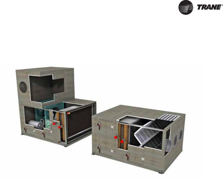
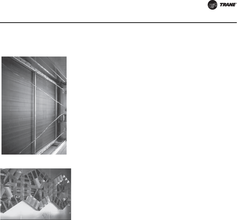
Figure 1. Trane Performance Climate Changer™ air handler

12 CLCH-PRC022A-EN
Features and Benefits - Unit
Airside Options
Many standard options are available for specific applications, including:
Construction and Integrity
Trane engineered panels and doors incorporate mid-span, internal thermal breaks to eliminate
thermal conduction paths from the interior of the air handler to the exterior. Likewise, door frames
also feature thermal breaks to minimizing heat transfer.
The panels and doors are designed to provide extraordinary insulating capabilities for efficient and
cost effective performance. Panels are formulated with interlocking seam features and integral
gasket seals optimized to drive down casing air leakage. The Performance air handler design is
capable of meeting an ASHARE 111 Class 6 leakage level, better than most custom designs, up to
+/-8 inches w.g. Standard double-wall panels and doors include two-inch closed cell foam
insulation providing a minimum R-value of 13, in addition to unsurpassed panel strength and L/240
deflection at +/- 8 inches w.g.
The no-through-metal design and low casing air leakage delivers thermal performance that
assures condensation will not form on the casing exterior even under 55°F supply air temperature
and design conditions on the unit exterior of 81°F dry bulb and 73°F wet bulb. In addition to the low
air leakage, these standard features prevent equipment from unnecessarily creating slip hazards
in the mechanical equipment room or premature corrosion of the casing. With this level of casing
performance and thorough testing of Trane engineers, Trane is able to deliver predictable thermal
performance and key guidance to consulting engineers.
Heavy-duty door handles and hinges are surface-mounted, eliminating a potential leakage path
since they do not pierce the casing. A removable hinge pin allows for easy door removal; the
symmetrical handle and hinge mounting allows for easy field modification if it becomes necessary
to change from a left-hand to a right-hand door.
Engineered for Good IAQ
The building industry is continuously evolving and the rate of change is accelerating. The
Performance air handler is engineered to address today’s multifaceted design issues required to
provide good indoor air quality (IAQ). Building owners must give particular attention to
maintaining and documenting IAQ to ensure occupant comfort and to meet industry and
government regulatory standards.
In Standard 62.1, the American Society of Heating, Refrigerating, and Air Conditioning Engineers
(ASHRAE) provides guidance regarding suitable outside air volume to be brought into the building,
recommended air filtration, and design recommendations and procedures to control microbial
growth. However, applying these principles may lead to greater energy consumption, larger and
noisier units, and increased risk of coil freeze-up. The flexibility of the Performance air handler
enables you to configure a unique, IAQ-ready air-handling system that can address all of these
concerns.
• Exhaust or return fan economizers • Variable height vertical discharge plenums
• Direct space pressurization control • Variable length horizontal discharge plenums
• Thermal break double-wall access doors • Positional controls section
• Thermal break casing • Multiple base frame heights/multiple curb heights
• Factory-mounted and run-tested controls • Single-handle, multiple latch doors
• Versatile access section lengths to meet specific needs • External motor junction box
• Multiple belt drives • Low-flow Traq dampers
• Full array of pre- and final filter sections • Silencers
• Extended grease lines • Gas heat
• Single-point power • Flush-mounted dial-type filter gauge
• LED service lights • Stainless steel inner liners
• Variable sizes, types and opening locations for discharge
plenums, plenum fans, and mixing boxes • Treadplate floor
CLCH-PRC022A-EN 13
Features and Benefits - Unit
Serviceability/Cleanability
Sound-Sensitive Solutions
Provide Accurate, Tested Sound Data
Traditionally, ASHRAE algorithms have been used to predict the sound power levels of air-handling
units. Although this method is easy to do, it can be inaccurate. It can produce results that deviate
from tested data by as much as ±15 dB. For more accurate sound data, AHRI has established
Standard 260, which is a method of rating sound data for ducted air-handling equipment. It is
intended to be a guide for the industry, including HVAC manufacturers, engineers, installers,
contractors, and consumers. AHRI Standard 260:
• Strengthens testing and calibration procedures
• Provides repeatable results
• Uses a reverberant-room approach, a mapped sound-rating concept, and reference sound-
source calibration
• Is application driven
• Includes ducted outlet, ducted inlet, and casing (radiated) test configurations
It is important to note that sound data for Trane air handlers is taken per AHRI Standard 260. This
sound power standard covers eight octave bands (63–8000 Hz) and is unweighted (no dB
corrections). AHRI Standard 260-tested sound data can be found in TOPSS.
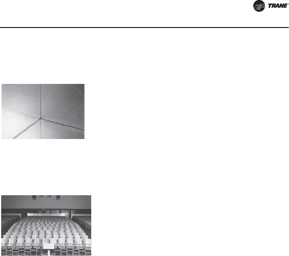
Figure 2. Smooth, interior surfaces
make cleaning easy • Full-size access doors and access sections are available for easy cleaning of
internal components
• Fully removable coil and access panels
• Smooth, cleanable interior double-wall surfaces help improve indoor air
quality.
• Coils are raised up out of the drain pan to make all coils removable from the
side and provide easier access to the drain pan for cleaning.
• Optional antimicrobial treatments for drain pans and filters.
Figure 3. Schools and auditoriums
are low noise criterion
(NC) applications
Acceptable space sound levels enhance occupant comfort and productivity.
However, system designs that promote good IAQ can adversely affect acoustics:
unlined ductwork, air handlers with solid double-wall construction, and increased
fan static pressures (resulting from the addition of energy recovery and increased
filtration) can magnify the building’s background noise.
Trane air handlers have unique product flexibility that allow designers to use them
in many low-NC (noise criteria) applications.
NC curves define not-to-exceed limits for a noise source to achieve a level of
occupant acceptance. (See applications engineering manual FND-AM-5,
“Acoustics in Air Conditioning,” for more information about NC levels.)
Performance air handlers can be used successfully in NC 35 offices and schools.
14 CLCH-PRC022A-EN
Features and Benefits - Unit
Minimize Sound Source
Trane air handlers have many features to optimize the source sound level for job requirements
while minimizing the cost of the air handler including:
For more information on how to apply these options in your air handler, contact your local Trane
sales representative.
Increase Operating Efficiency
The Trane EarthWise™ system is a design philosophy that uses low flow rate and low temperature
on both the waterside and airside, along with high-efficiency equipment. Along with reducing
emissions, it also reduces first cost, lowers operating costs, and improves the acoustical
characteristics and comfort of the HVAC system. Low-temperature, low-flow systems can challenge
conventional cataloged air-handling units. The flexibility of the Performance air handler makes it
ideally suited for low temperature applications. In addition:
• Trane has developed a unique high-efficiency fin surface that allows face velocities in excess
of 625 fpm without moisture carryover. The fins have been engineered and tested to meet these
higher face velocities at a given set of design conditions. This allows you to utilize the latest in
airside heat transfer to further improve the efficiency of the overall system by lowering the coil
approach temperature.
• The ability to choose the exact number of fins per foot of coil surface allows heat transfer and
air-pressure-drop performance to be tuned to specifically meet project needs.
• The wide array of fan options lets you choose the right fan for the application.
• Factory-engineered, -mounted, and -tested controls provide the added insurance that the
airflow sensors and sequences meet your requirements.
• Further system enhancements can be made by taking advantage of the latest controls
technology with fan pressurization control (required in most variable-air-volume systems per
ASHRAE Standard 90.1) and/or ventilation reset of the outside air damper based upon
occupancy levels in the space.
Turnkey Control Solutions
Trane air handlers offer one of the most comprehensive factory-packaged controls systems
available, from end devices to total system integration, with industry-standard open protocols. An
air handler turnkey control package can be used in a stand-alone operation, or it can be fully
integrated into a comprehensive control system. Trane’s Integrated Comfort™ system (ICS)
incorporates the benefits of factory-installed controls and links the air handler to the Tracer
Summit™ building management system.
Figure 4. Plenum fans help reduce
noise levels • A variety of fan types to minimize the sound generated by the fan and to
optimize cost no matter the application.
• Double-wall perforated insulation helps attenuate high-frequency noise.
• Two-inch discharge plenums reduce turbulence and create an end reflection
that dampens low-frequency sound. The 2-inch perforated liner option
attenuates higher frequency sound.
• Turning modules used to turn the air and reduce turbulence work as effective,
low-cost silencers.
• Silencers for horizontal or vertical discharge in the plenum fan section come in
3-ft. and 5-ft lengths. They are dissipative or film-lined for hospital and clean-
room applications.
CLCH-PRC022A-EN 15
Features and Benefits - Unit
These options are designed to lower installation costs and risk while dramatically improving the
quality of the application and the performance of the air handler. The entire air handler control
system is engineered, mounted, wired, and tested before leaving the factory. As a result of strict
quality manufacturing methods, Tracer control options bring consistency and reliability to the
control-system package and provide single-source responsibility.
Single-Source Responsibility
Equipment and interoperable controls, engineered and provided by a single manufacturer, provide
faster construction cycles and simplify job-site coordination efforts. This simplification reduces
installation time, expense, and risk.Trane equipment and controls package provides the optimal
performance when integrated with a Tracer building management system, forming a Trane
Integrated Comfort™ system (ICS). ICS is a powerful system architecture that unifies Trane HVAC
equipment, direct digital control, and building management into a cohesive whole with an assured
source of support. This system is managed with the Tracer Summit building management system.
The Tracer Summit building management system is based on ASHRAE and American National
Standards Institute (ANSI) BACnet Standard 135.
The following control devices are available as standard
mounted on fan sections or within the positional controls
section:
The following end devices are also available:
• Combination starters and disconnects • Valves
– International Electrotechnical Commission (IEC)
standards • Electronic damper actuators
• Variable-frequency drives (VFDs) • Temperature and pressure sensors
– Drive/OFF/Bypass selector switch – Available in multiple temperature sensor materials
– Digital manual speed control • Averaging temperature sensors
– Three-year parts and labor warranty – Available in multiple temperature sensor materials
– Open drive to provide easy serviceability • Fan and filter status switches
• Unit-mounted direct digital controllers (DDCs). • Low-limit switches (see Figure 6)
– A factory-wired and mounted Tracer programmable
controller is available. – Double pole, single throw, manual reset
– Available wired to low voltage and high voltage
• Condensate overflow switches
• Humidity sensors
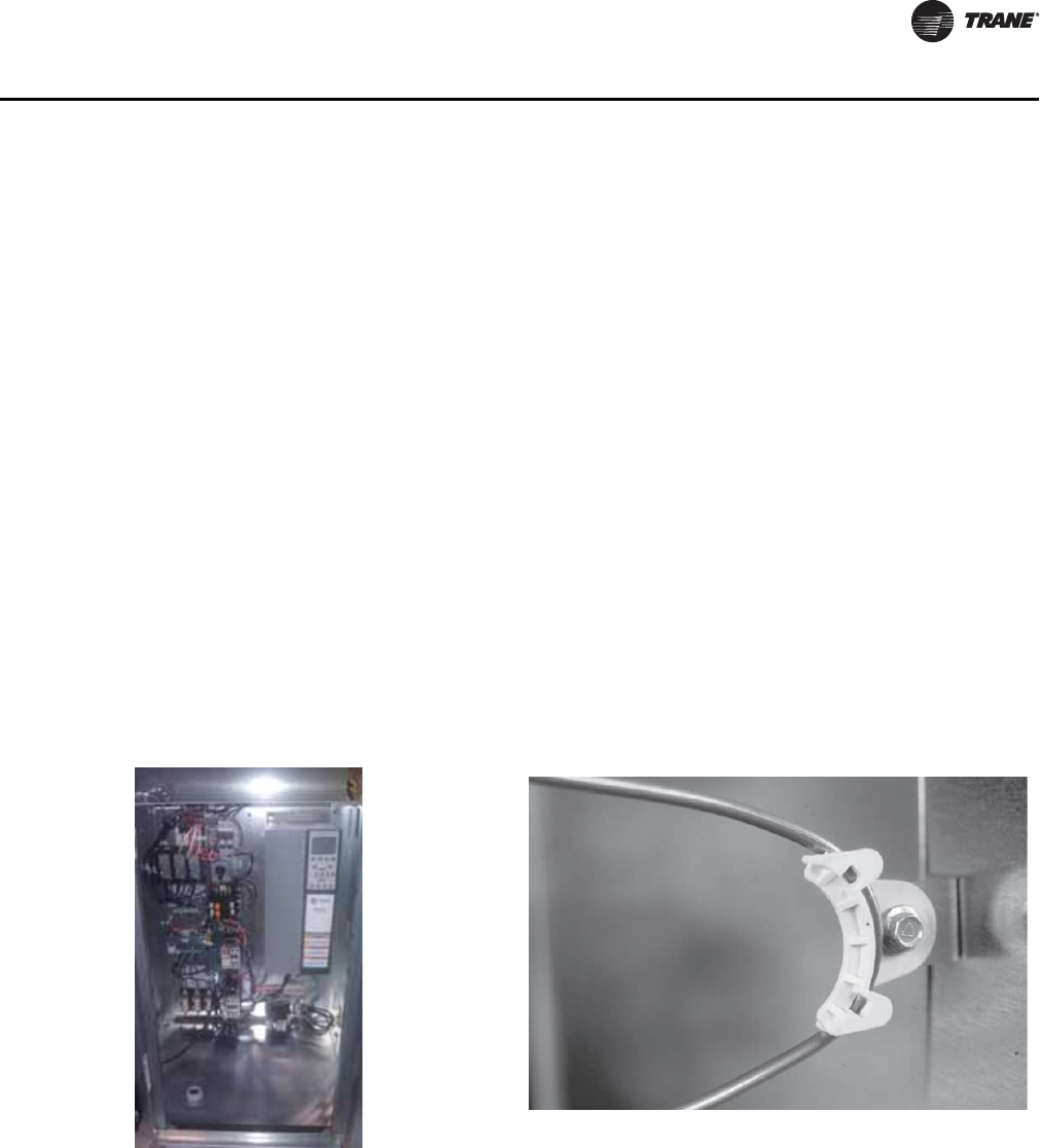
Figure 5. Integral controls cabinet for starters, variable
frequency drives, and unit controllers Figure 6. Factory-mounting ensures quality installation,
as shown with the low-limit radius bend
16 CLCH-PRC022A-EN
Features and Benefits - Unit
Single-Point Power
For air-handling units requiring a supply fan with a return/exhaust fan, electric heat, gas heat or
CDQ, we can supply single-point power. Single-point power wiring includes a high voltage
distribution block and main unit disconnect with lockout/tagout capabilities. From a single line
voltage connection, power is provided to all components including controls and service lights.
Single-point power wiring does not compromise the UL or ETL certification of the unit.
Reduced Installation Costs
After installation, Tracer controllers enable information-sharing and complex control strategies,
such as ventilation reset, throughout the HVAC system. They also ensure that each subsystem
operates in the most efficient manner possible while continuing to satisfy current loads. The result
is reduced building energy consumption through effective operation of the entire HVAC system at
part-load conditions.
Trane ICS incorporates the latest energy-saving concepts to produce comfort at the lowest possible
cost. In addition, it offers sophisticated building management features, such as after-hours billing,
for commercial properties. This revenue opportunity enables developers and owners to accurately
monitor and bill the cost incurred by a single tenant in after-hours usage of a facility. An optional
DDC variable-air-volume (VAV) capability helps to accurately control each tenant space so that only
an individual tenant’s HVAC systems are activated. This helps minimize operating costs while
providing flexible work hours.
Reliable Operation
Controller end devices, such as low-limit switches and averaging temperature sensors, are
properly sized, selected, laboratory-tested, and mounted for optimal system performance. Trane
engineers its unit-mounted controllers to provide the highest level of useful information possible.
A computer-based test station tests low-voltage end-device functionality and surveys the input
devices. This procedure ensures trouble-free installation and reliable operation when the
Performance air handler reaches the job site. This feature can limit the number of call-backs and
punch-list tasks.
Incorporating a Performance air handler with Trane ICS provides an engineered system of proven
components and comfort concepts that is both state-of-the-art and reliable. Standard components
are used to aid in serviceability and uniformity from building to building. These components, when
tied to a Tracer Summit system, provide a powerful tool for scheduling preventive maintenance,
reducing equipment downtime, and controlling service expense.
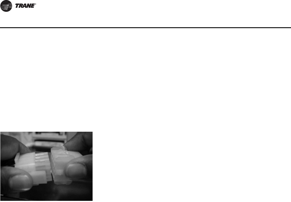
Figure 7. Quick-connect wiring While the air-handling system is in the factory, trained technicians install the
control end devices and controllers using state-of-the-art equipment and agency-
approved wiring practices. The system is pre-designed, pre-engineered, and
checked out, making jobsite installation and commissioning fast and easy.
While many of these tasks and procedures could be done in the field, it is beneficial
to do them in the factory due to time and accessibility constraints. As a result, field
expenses for installation costs of conduit and wire are minimized, additional lead-
time is alleviated, and jobsite coordination is simplified. Casing integrity is also
maintained by minimized penetrations.
Factory wiring minimizes installation costs, too. Quick-connect wiring (see
Figure 7) ensures integrity between sections without having to identify or check
continuity.
CLCH-PRC022A-EN 17
Features and Benefits - Unit
Open Protocol
Trane Tracer™ controllers bring open communication protocols to the product offering. For
building-level and unit level communications, Tracer controllers use BACnet®. BACnet is a
standard, open communications protocol that allows integration and interoperability
,
enabling the
controllers to not only tie into a Tracer Summit system, but also other building automation
systems.
At the unit level, Trane can also use LonTalk® for peer-to-peer communication between Trane
controllers and other approved LonTalk controllers. Trane can provide a factory-wired terminal
strip that can be wired into a field-mounted controller. The programmable controller (MP581)
follows the certified Space Comfort Controller (SCC) profile for constant-volume systems and the
Discharge Air Controller (DAC) profile for constant-volume or VAV systems. Adherence of this
controller to these standardized, certified profiles enables it to communicate with other controllers
that use the same certified LonTalk profiles. Go to www.lonmark.org for more information.
Service Module
Proven Performance
AHRI Standards
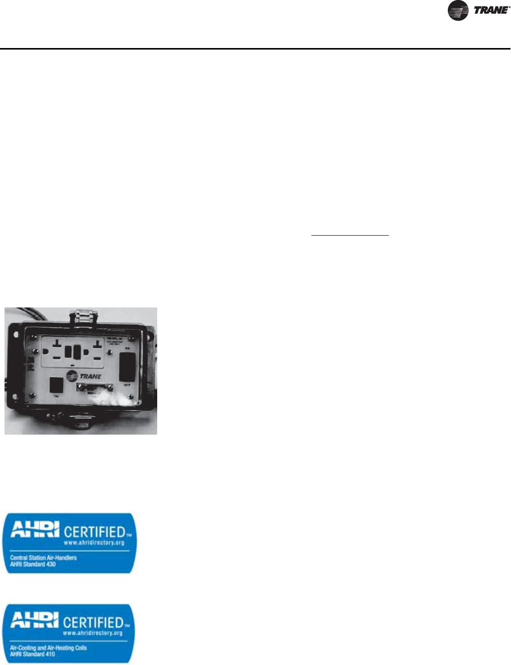
Figure 8. The service module can
include a 15-amp GFCI. Performance air handlers can be equipped with an easy access Service Module
when a Trane programmable controller and/or service lights are factory mounted.
All service lights are wired to a common switch within the Service Module, located
either on the fan section or the controller cabinet. The Service Module can also
include a 15-amp ground-fault circuit interrupter (GFCI) receptacle separate from
the load side of the equipment, a National Electrical Code (NEC) requirement.
When an MP580 controller is factory mounted, the Service Module will have
communications and portable display ports allowing service personnel to perform
diagnostics without opening the unit or controller panel.
Figure 9. AHRI Standard 430 Trane combines comprehensive performance certification by AHRI with thorough
laboratory testing and advanced manufacturing methods. Together, these elements help
assure that each Trane air handler operates predictably and reliably throughout the life
of the unit.
Unlike other rating methods that check fan performance alone, Trane units are
performance-tested in accordance with AHRI Standard 430. This certification process
evaluates the air handler on the basis of airflow, static pressure, fan speed, and brake
horsepower.
Heating and cooling coils are rigorously tested and certified with AHRI Standard 410 to
assure that they, too, deliver published performance.
AHRI Standard 260 is the first ducted-air-handler sound rating procedure. It is intended
to provide engineers with better, more accurate, ducted sound power levels so that they
can design quieter and more cost-effective comfort systems. Sound ratings for Trane air
handlers have been developed from extensive AHRI Standard 260 testing and laboratory
data.
Figure 10. AHRI Standard 410
18 CLCH-PRC022A-EN
Features and Benefits - Unit
Miami/Dade County Notice of Compliance (NOA)
Performance Climate Changer air handlers size 3-30 are approved and have has been designed to comply with the High
Velocity Hurricane Zone of the Florida Building Code. Each qualified unit shall bear a permanent label with the Trane name
and logo and the statement “Miami-Dade County Product Control Approved”. Notice of compliance and additional product
construction details can be found at the Miami-Dade County, Building Code Compliance Office Web site, under NOA No.
11-0926.08). Testing is currently underway for unit sizes 35-120.
UL Listing
Trane air handlers are UL-listed to U.S. and Canadian safety standards.
IBC Seismic Certification
Air handling equipment manufactured by Trane is capable of structurally and operationally withstanding the seismic
response criteria as required by the International Building Codes (IBC) 2000,2003, 2006, 2009. Trane has third-party
certification for IBC compliance for seismic applications for unit sizes 3-30. Certification for larger sizes is in process.
AMCA Certification
Trane utilizes AMCA certification for airflow measuring stations. Trane certifies that the TraqTM
damper shown herein is licensed to bear the AMCA Seal. The ratings shown are based on tests and
procedures performed in accordance with AMCA Publication 611 and comply with the requirements
of the AMCA Certified Ratings Program.
This certification program provides the engineer and owner assurance that manufacturer-published
performance ratings for airflow measurement stations are accurate and repeatable. Trane Traq
dampers are certified with the integral ventilation control module (VCM) which converts differential
pressure to an electronic signal for control.
Canadian Registration Number (CRN)
The Canadian Registration Number, or CRN, is given to companies that comply with Canada’s
Technical Safety Standards Act concerning pressure vessel safety. In Trane air-handling systems,
the CRN applies to coils classified as Category H fittings. Most government and industrial
customers require the HVAC supplier to have a CRN. Trane has earned a CRN for all steam and water
coils. used in the Performance air handler.
ISO Certification
Certification by the International Standardization Organization (ISO) ensures that an organization
can consistently deliver a product or service that meets the customer’s contractual requirements by
following documented processes. The ISO 9001 quality assurance model establishes the
requirements for an organization whose business processes range from design and development
to production. Having the quality management system of our manufacturing plants ISO 9001-
certified directly benefits Trane customers because our continuous process improvements can
reduce business costs, improve product quality, and enable faster ship cycles

CLCH-PRC022A-EN 19
HVAC Design Fundamentals
In essence, an air-handling unit, or AHU, is exactly what its name implies: a device that “handles”
(moves and/or conditions) air. It accomplishes this based on the functions required by a given
application, as well as the arrangement of components necessary for those functions.
Trane air handlers can accommodate an extraordinary degree of design versatility, but in order to
apply that versatility to each unique application, an HVAC designer must:
• Design the air handler in a manner consistent with good HVAC design practices.
• Understand the impact of ASHRAE Standard 62.1, Ventilation for Acceptable Indoor Air Quality,
and ASHRAE Standard 90.1, Energy Standard for Buildings Except Low-Rise Residential
Buildings, on AHU functions and design.
• Know how specific components can address application requirements, with arrangements
optimized for job requirements, thermal performance, and acoustical performance.
• Deliver the performance you have designed with a well-functioning control system.
Provide Proper Ventilation
Ventilation is the process of diluting the build-up of contaminants by introducing clean, fresh
outdoor air into buildings. The lack of proper ventilation is identified as a leading cause of poor
indoor air quality (IAQ) problems. ASHRAE Standard 62.1 sets the minimum ventilation rates and
specifies basic HVAC equipment and system requirements to provide “acceptable indoor air
quality.” ASHRAE Standard 62.1 is considered the standard of care for designers to assure good IAQ
in commercial buildings.
Assuring proper ventilation levels at all operating conditions can be challenging for a designer.
Fixed outdoor-air damper arrangements on variable-air-volume systems can result in severe under-
ventilation of the occupied spaces at part-load conditions. The Performance air handler is available
with the patented Traq™ outdoor airflow measurement and control damper, which can precisely
control the volume of ventilation air entering the system and even dynamically vary the amount
in response to specific operating conditions. With the Traq damper, the amount of outdoor air can
be continuously logged using a Tracer Summit™ building automation system to document proper
ventilation.
Maintain Building Pressure
An important aspect of establishing outdoor-air requirements is equalizing outdoor-air and
exhaust-air volumes to maintain proper building pressurization (see Figure 11). Building
pressurization describes an air-handling strategy that regulates pressure differences across the
building envelope and between zones or rooms by adjusting the amount of air that is supplied and
removed. The goals of this strategy are to:
• Assure proper distribution of conditioned and ventilation air throughout the occupied space
• Avoid discomfort due to temperature stratification and drafts
• Prevent infiltration of unconditioned air
• Confine odors and contaminants to specific areas within the building
20 CLCH-PRC022A-EN
HVAC Design Fundamentals
Building-envelope pressurization is typically achieved by incorporating either an exhaust fan and
economizer or a return fan and economizer in the air handler design. Careful analysis is required
to determine which approach best suits the unique requirements of each application. To better
understand the differences between exhaust-fan and return-fan systems, consult your local Trane
sales representative or refer to applications engineering manual, Building Pressurization Control
(AM-CON-17).
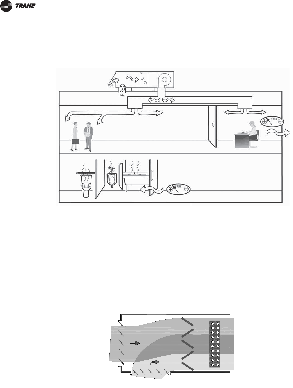
Protect Coils from Freezing
Figure 11. Maintain proper building pressurization
Figure 12. Protect coils from freezing by addressing air stratification
Outside
Air
Cold Air
Warm Air
Mixed Air
Return Air
CLCH-PRC022A-EN 21
HVAC Design Fundamentals
Filter Contaminants
Particulate Filter Guidelines
The Environmental Protection Agency (EPA) and ASHRAE recommend that the concentration of
particulates in the air not exceed 0.05 mg/m3 (measured as an annual mean). This guideline is
established in an EPA PM-10 standard which focuses on smaller particulates (<10 microns) that are
likely responsible for adverse health effects because of their ability to reach the lower regions of
the respiratory tract.
ASHRAE Standard 62.1 and the U.S. Green Building Council LEED rating system emphasize the
importance of including appropriate filters in the air handling system to effectively control
particulate contaminants. Both establish minimum requirements for filter performance applied
within a commercial building based on ASHRAE Standard 52.2, Method of Testing General
Ventilation Air-Cleaning Devices for Removal Efficiency by Particle Size. This standard establishes
a test procedure for evaluating the performance of air-cleaning devices as a function of particle size
(0.3 to 10 microns). A minimum efficiency reporting value (MERV) is assigned to a filter based on
its efficiency in three different particle-size ranges (0.3 to 1 microns, 1 to 3 microns, and 3 to 10
microns). A higher MERV rating indicates a greater ability to remove high quantities of small
particles from air.
Figure 13. Low-limit sensor When bringing more outdoor air into the air handler to satisfy the ventilation
requirements of ASHRAE Standard 62.1, it increases the likelihood of air
stratification (see Figure 12). If a layer of freezing air moves through the air handler,
it can damage unprotected, hydronic cooling and heating coils. Traditional freeze
protection includes a low-limit thermostat (see Figure 13) (installed on the face of
the cooling coil) that trips when it detects a dangerously low air temperature. When
this happens, it stops the supply fan, closes the outdoor air damper, and ultimately
degrades the building IAQ.
It is important to design the air handler so that it effectively treats the required
amount of outdoor air—regardless of temperature—without risking coil damage,
tripping the low-limit thermostat, or compromising indoor air quality. Trane has
several means of providing coil protection. Choose the technique that best suits
the application requirements.
•Drain the coils. This approach necessitates vent and drain connections on
every coil, plus shutoff valves to isolate them from the chiller(s).
•Add glycol and an inhibitor to the cooling system water. The glycol lowers the
water freezing point, and the inhibitor helps to resist corrosion.
•Introduce ventilation air downstream of the cooling coil with dual-path or
bypass techniques.
•Preheat the outdoor air stream. Use a traditional or integral face-and-bypass
steam coil or a hot hydronic coil to raise the air-stream temperature above
freezing.
• Use a blender section (see Figure 14). This approach mixes the outdoor and
recirculated air streams to address air stratification.
Figure 14. Blender
22 CLCH-PRC022A-EN
HVAC Design Fundamentals
ASHRAE Standard 62.1 recommends a minimum MERV 6 filter, while the USGBC LEED rating
system recommends a minimum MERV 8 during the construction cycle and MERV 13 during
normal operation. National, state, or local codes established by government bodies or
occupational groups may dictate more specific or stringent filtration requirements.
Selecting the appropriate filter relies on understanding the particles that need to be filtered and
their size. Table 1 provides design guidance for which filter option should be applied in your air
handler.
Table 1. MERV ratings versus particle size efficiencies
MERV Value
Group 1
Avg. Eff.%
0.3 to 1.0 microns
Group 2
Avg. Eff.%
1.0 to 3.0 microns
Group 3
Avg. Eff.%
3.0 to 10.0 microns General Applications
1n/a n/a E3<20
Residential
Light Commercial
2n/a n/a E3<20
3n/a n/a E3<20
4n/a n/a E3<20
5 n/a n/a 20<35 Commercial
Industrial
Better Residential
6n/a n/a 35<50
7 n/a n/a 50<70
8n/a n/a 70
9n/a E2<50 85
Commercial
Telecommunications
Industrial
10 n/a 50<65 85
11 n/a 65<80 85
12 n/a 80 90
13 E1<75 90 90 Superior Commercial
Health Care
Hospitals
General Surgery
14 75<85 90 90
15 85<95 90 90
16 95 95 95
17 99.7 Surgery, pharmaceutical
manufacturing
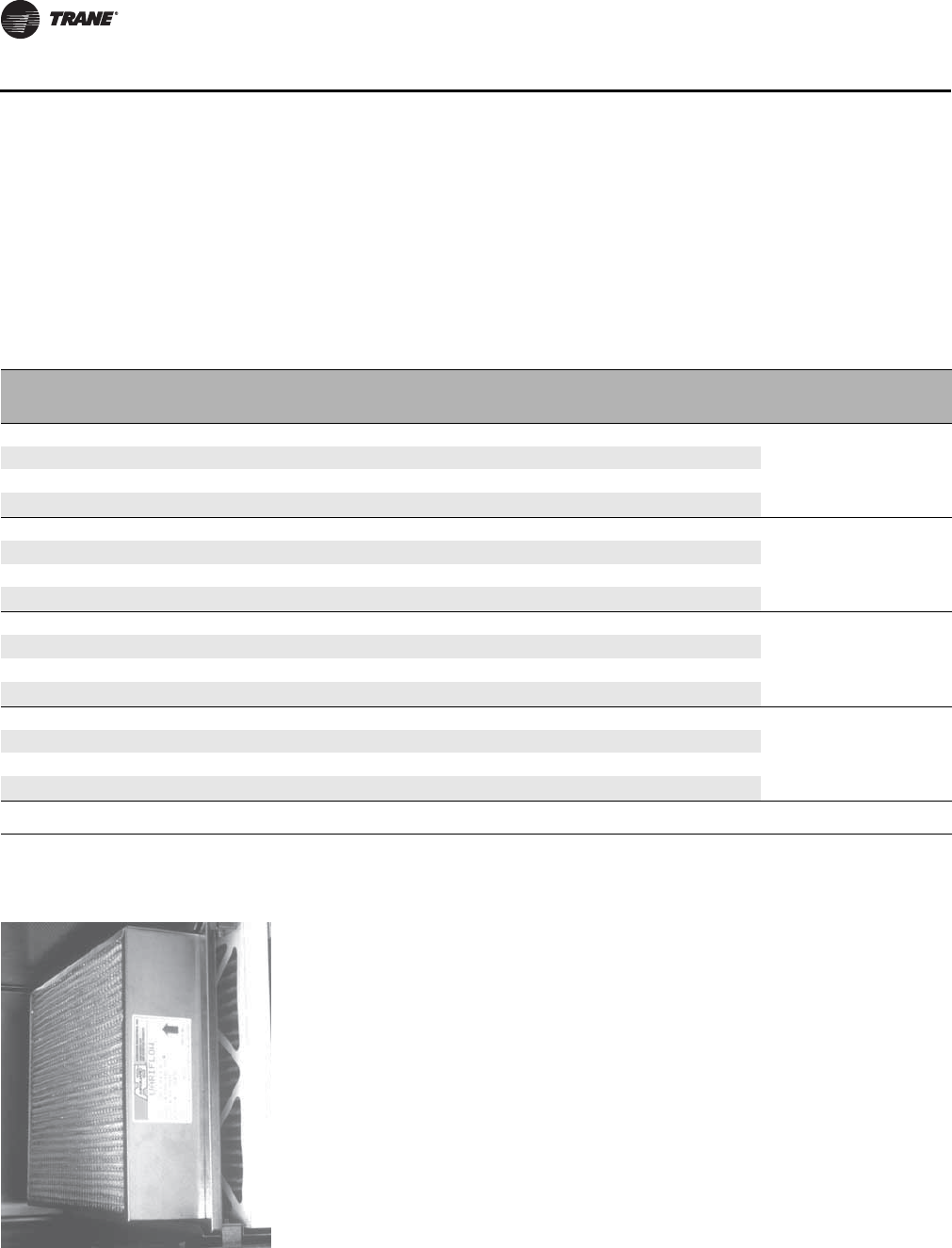
Figure 15. Use proper filtration
Gases and Vapors
The presence of various undesirable gases and vapors (particularly formaldehyde,
radon, oxidants, and volatile organic compounds, or VOCs) indoors can be
detrimental to building occupants, materials, and contents. Controlling VOC
concentrations is particularly challenging—hundreds of them are present, few are
unique to any one source, and there are many potential sources, some of which
emit several VOCs.
A common way to control gaseous contaminants is to dilute them with outdoor
air. This approach is appealing because many VOCs defy individual treatment.
However, it is only practical if the quality of the outdoor air is suitable and if the
resulting supply airflow is consistent and appropriate and if it mixes effectively
with the air in the occupied space.
Another approach is to neutralize the contaminants in the air. This can be done
through air cleaning mechanisms UVc/PCO technology to reduce volatile organic
compounds (VOC’s) through photocatalytic oxidation without the creation of
ozone or by-products.
CLCH-PRC022A-EN 23
HVAC Design Fundamentals
Minimize Microbial Growth
Water Management
Cooling coils collect water from the passing air stream as they cool and dehumidify it. If not
properly addressed, this condensed moisture encourages mold, mildew, and other
microorganisms to colonize and breed. To reduce the likelihood of microbial growth:
• Reduce moisture carryover by sizing the cooling coils for proper airflow velocities. Trane coils
can be sized for velocities in excess of 625 fpm without moisture carryover, depending on air
conditions, coil size, and coil-fin type and spacing. Refer to “Coils” section on page 155 for the
moisture-carryover curves and details about allowable velocities.
• Specify drain pans sloped in two planes to eliminate stagnant water conditions and to promote
positive drainage.
• Locate coils on the second level of a stacked air handler to provide adequate trapping height.
• Properly size condensate traps to ensure proper drainage. See Figure 17.
• Promote cleanability by providing adequate space around the unit, easily removable access
panels, and a solid steel liner to isolate insulation from the air stream and to facilitate cleaning.
Also, provide extended drain pans to allow for periodic cleaning.
• Condition the mechanical equipment room to prevent condensation on piping, ductwork,
mechanical equipment, and other surfaces.
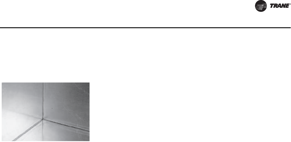
Figure 16. Keep surfaces clean Although filtration effectively removes a number of common particulate and
gaseous contaminants from the building environment, microbiological, or
microbial, contaminants such as fungi (mold and mildew) and bacteria are
sometimes too small to be filtered entirely from the air stream. To help control
microbial growth, design the air handler to include:
• Non-porous, cleanable interior wet surfaces
• Easy access to all areas of the air handler for inspection, service, and cleaning.
• Use of ultraviolet (UV) germicidal irradiation lights
Regular cleaning and disinfecting with nonpolluting cleansers and antimicrobial
coatings also helps, but none of these measures totally eliminates the growth of
ever-present microorganisms. Consequently, moisture control becomes another
important means of combating microbial contaminants.
24 CLCH-PRC022A-EN
HVAC Design Fundamentals
Dehumidification
ASHRAE Standard 62.1 observes that “high humidities can support the growth of pathogenic or
allergenic organisms” and suggests that the relative humidity of the occupied space not exceed
60 percent. Higher humidities also require lower supply-air temperatures for thermal comfort.
Most climates require dehumidification to achieve this design goal. Dehumidification can be
accomplished by removing moisture from the air, that is, condensing the water vapor on cooling
coils.
However, cooling coils can over cool the occupied space when dehumidifying at sensible part-load
conditions. There are several ways to control to both humidity and temperature at part load
conditions.
• Use a VAV air handler versus a constant volume air handler. This can improve part load
dehumidification.
• Use desiccant dehumidification systems to dehumidify and control humidity to very tight
tolerances.
• Use a split dehumidification unit (SDU) to improve dehumidification by treating the ventilation
air separately.
• Use a s Dedicated Outside Air Unit, DOAS, to dehumidify the ventilation air.
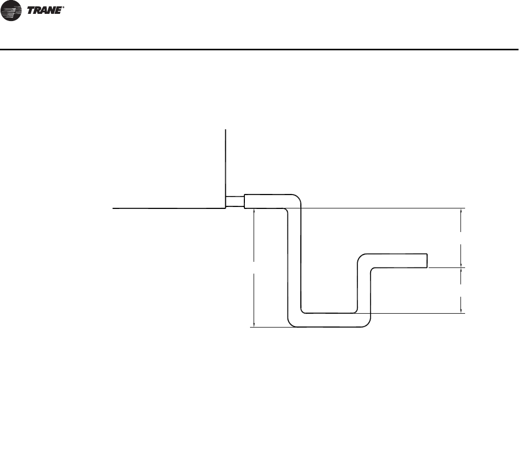
Figure 17. Drain pan trapping for positive and negative pressure applications
H
J
L
Drain pan trapping for section
under negative pressure
L = H + J + pipe diameter where:
H = 1 inch for each inch of negative
pressure plus 1 inch
J = 1/2 H
Drain pan trapping for section
under positive pressure
L = H + J + pipe diameter where:
H = 1/2 inch (minimum)
J = 1/2 inch plus the unit positive static
pressure at coil discharge
(loaded filters)
CLCH-PRC022A-EN 25
HVAC Design Fundamentals
• Use a reheat coil, which can be accomplished using recovered condenser heat energy or with
standard electric or hot water coils.
Humidification
Low relative humidity - below 30 percent - in an occupied space is also undesirable because it
requires higher supply-air temperatures for thermal comfort and promotes static electricity.
Raising the space humidity to an appropriate level requires a humidifier to inject water particles
into the passing air stream. To avoid promoting microbial growth, the unit design must assure that
the injected water is fully absorbed within the air handler without collecting on its walls or
components.
Three types of commercial humidifiers are generally used in central-station air-handling systems:
wetted media, atomized water, and steam. Of these types, ASHRAE Standard 62.1 prefers steam
“as the moisture source for humidifiers.” The temperature and pressure properties of steam make
it easy to introduce directly into the passing air stream and encourages complete absorption in a
short distance. Trane standard humidifier sections incorporate all the distance required for
absorption to occur.
Application Considerations:
• Never position the humidification section immediately downstream of a housed fan or blow-
thru coil section.
• Extra dispersion distance may be needed if the humidification section is placed upstream of a
final filter or electric heat coil.
• Vertical airflow turns immediately upstream and downstream of the humidification section
necessitate a large section.
Provide Quiet Comfort
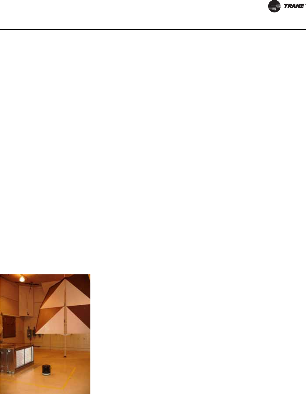
Trane sound power ratings cover eight octave bands (63–8000 Hz). Data is collected in one of
Trane’s ANSI 12.32-qualified reverberant rooms.
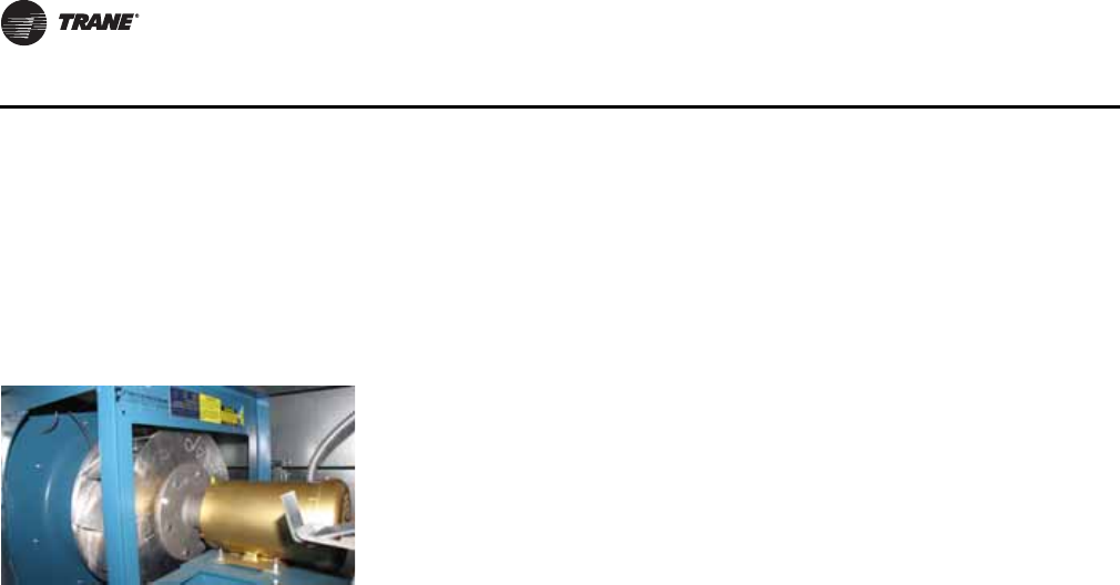
Figure 18. Trane acousticians
collect and test sound
data
Acceptable sound levels inside a building can improve occupant comfort and
productivity. In fact, achieving an acceptable acoustical environment today is
almost as important as simply conditioning it. To meet space sound levels, be sure
to optimize the noise source (the air handler) using path attenuation (ducts, wall,
and room carpeting).
The sound source can be projected using Trane TOPSS selection program or with
the Trane CLCHLw program. The sound path can be projected using the Trane
Acoustical Program (TAP). Compare the resulting NC projection with the designed
value. If the NC projection is too high, the air handler can be made quieter with a
selection focused on acoustics, or the path attenuation can be increased—or both
strategies can be combined. In the end, the projection should meet the NC
requirements for your job.
Creating quiet spaces is increasingly difficult because of the trend toward “IAQ-
hardened” systems. “IAQ hardening” involves removing fiberglass insulation,
which acts as a sound absorber, from inside the ducts and even the units. Without
this insulation, the air handler makes too much noise.
With Trane’s acoustic options and the TOPSS selection program, you can create the
unit you need for your quiet application. With these options, you can select an air
handler that is more than 20 dB quieter than a conventional unit. The starting point
is the Trane AHRI Standard 260 sound database.
26 CLCH-PRC022A-EN
HVAC Design Fundamentals
To determine the most cost-effective acoustical solution for a given application, follow these steps:
Select the unit and predict the unit sound power using the TOPSS selection program.
Project the sound to the space using TAP.
Optimize the unit sound (fan, plenums) with the path attenuation (ductwork and ceiling) for the
lowest first cost that meets the sound requirements.
Table 2 summarizes the noise reduction ideas accumulated by Trane engineers during four
decades of experience with central-station air handlers. Use the TOPSS program to predict the
effect of each idea.
However, for acoustically sensitive applications, we strongly recommend that you work with your
local Trane sales representative to find the most cost-effective solution that meets your job
requirements.
Table 2. Noise reduction suggestions
Targeted Sound Suggestions
Overall unit sound power (L
w
)
• In VAV systems, use variable-frequency drives for fan modulation.
• Change fan types.
• Increase the fan size.
• Use a central exhaust fan rather than a return fan.
Discharge sound power
• Use discharge plenums.
• Use outlet silencers.
• Use perforated walls.
• Use multiple-discharge plenum outlet ducts.
• Use discharge plenums with side openings.
Inlet sound power • Use a large inlet plenum.
• Use inlet silencers.
• Stack the inlet sections.
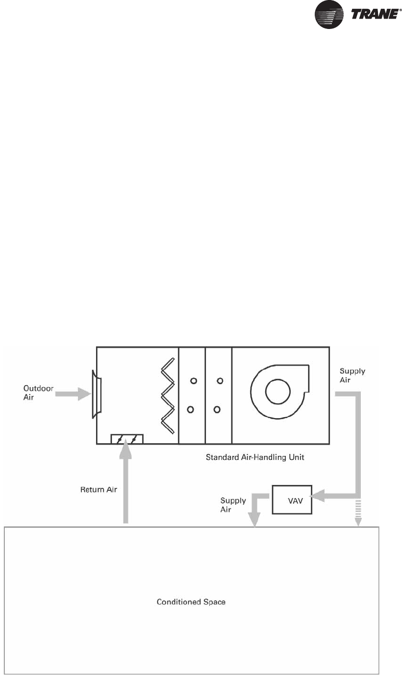
CLCH-PRC022A-EN 27
Application Considerations
The first things to consider when selecting an air handler for any given application include:
•Design. Which overall system design best suits the required function?
•Arrangements. What is the best section arrangement for the specified function and layout?
•Components. Which components should be selected to support the function, layout, and
arrangement of the application?
Air Handler Design
Which design best suites the application? After determining the required airflows and functions for
a particular application, the HVAC designer must determine which one of two path layouts for
outdoor air best serves the application: single-path or dual-path.
Single-Path Design
Single-path AHUs (see Figure 19) rely on one outdoor air path. Depending on application
requirements, that path may provide ventilation air only or both ventilation air and economizing
air for natural, non-mechanical cooling. Components for filtering and tempering the air are
arranged in series. The single-path layout can accommodate passive or powered return- and/or
exhaust-air paths as well as energy recovery.
Figure 19. Single-path design
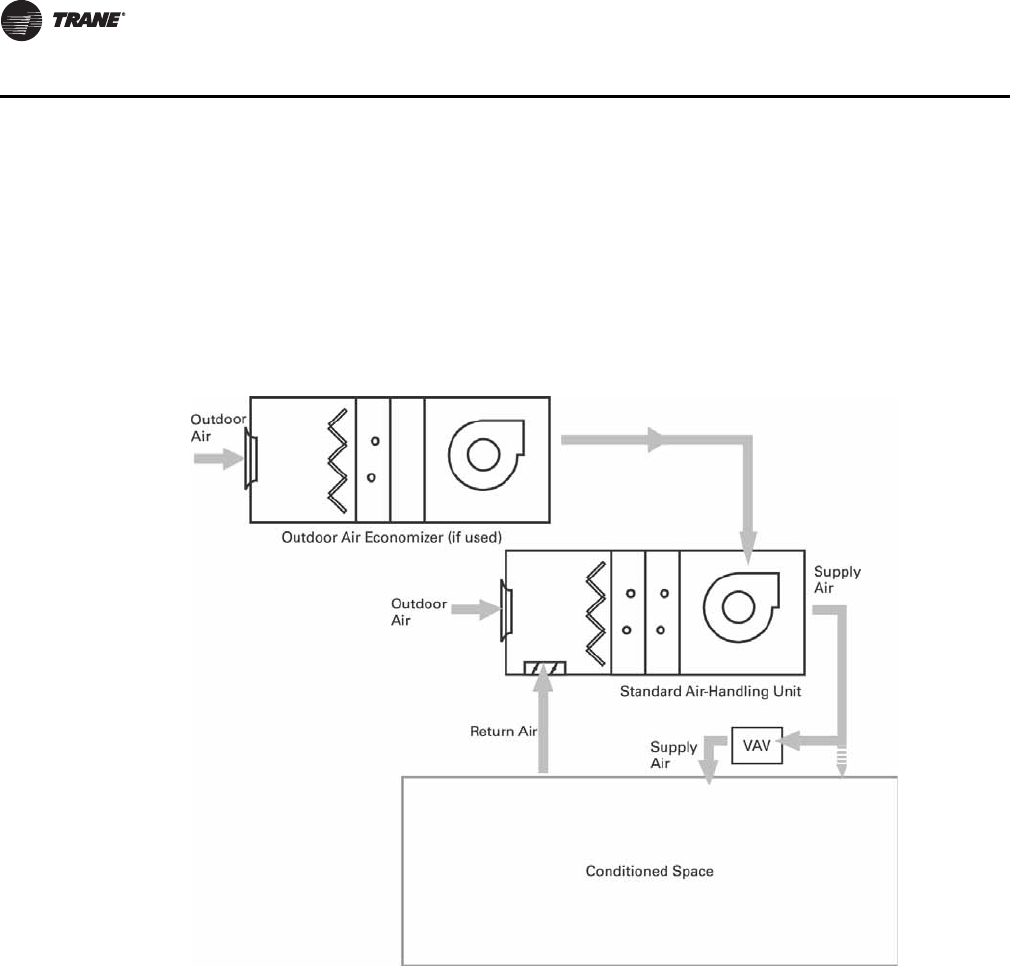
28 CLCH-PRC022A-EN
Application Considerations
Dual-Path Design
Dual-path AHU (see Figure 20) layouts provide two air paths. Like a single-path design, dual-path
designs can incorporate basic outdoor air, recirculation, exhaust-air, and energy-recovery
functions. However, one path is dedicated to handling ventilation air to specifically address
ASHRAE Standard 62.1 requirements. Each path is provided with its own air treatment components
such as filters and heating and cooling coils.
Application considerations:
• Reduces or eliminates reheat requirements, while providing an effective means of
dehumidification for loads with low sensible-heat ratios (high latent cooling requirements)
• Avoids increasing supply-fan static pressure due to high pressure drop components in the
ventilation air stream (increases latent cooling and filtration capacity without increasing fan
size)
• Permits downsizing of the ventilation-path components
• Enables compliance with the ASHRAE Standard 62.1 requirement for measuring outdoor
airflow without significantly increasing the first cost of the air handler
• Provides a cost-effective means to increase ventilation airflow in an existing system
• Reduces cost by reducing the number of units (dedicated outdoor-air units can be eliminated).
Figure 20 represents a sample dual path configuration. For more design options, see Trane
Application Engineering Manual for Dehumidification in HVAC systems (SYS-APM004-EN).
Figure 20. Dual-path design
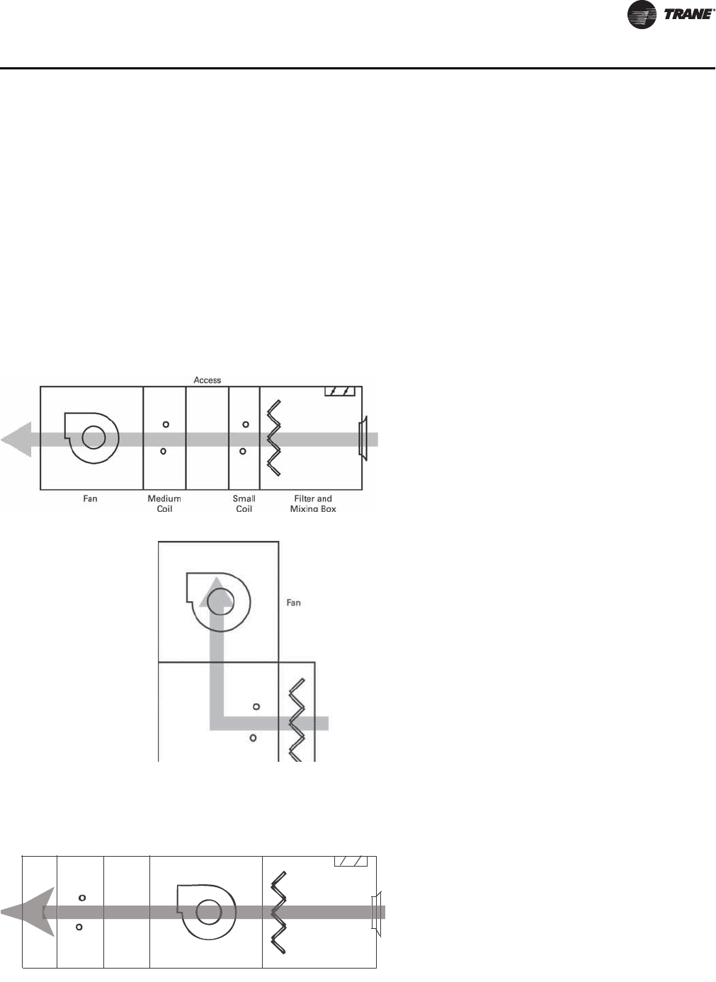
CLCH-PRC022A-EN 29
Application Considerations
Standard AHU Arrangements
To complete the air-handling system, the sections must be physically arranged in a way that fits the
available space. Conventional descriptions of air handler arrangements, draw-thru and blow-thru,
reflect the means of establishing airflow through the coil based on the position of the coil relative
to the fan: the fan either draws air through a coil located upstream or blows air through a
downstream coil.
Trane adds another dimension to air handler arrangements, letting you combine sections by
stacking them on top of each other in space-saving configurations, by coupling them together with
transition panels, or by combining both techniques. Careful evaluation of the merits of each
arrangement is a critical part of the design process.
Draw-Thru Arrangements
Blow-Thru Arrangements
A draw-thru AHU arrangement places the coils and filters upstream of a ducted supply fan. It can be single- or dual-path.
Horizontal Draw-Thru
Accepted system design practices are generally the only
restrictions in a horizontal draw-thru application.
However, certain application rules must be followed to
promote proper airflow through filters and coils.
Vertical Draw-Thru
Trane air handlers in a vertical draw-thru arrangement
typically result in a shorter footprint than horizontal
draw-thru units. This arrangement stacks a fan on top of
a vertical coil section. When designing an air handler in
this configuration:
• The bottom deck must be equal to or longer than the
fan section to avoid creating a “cantilever” effect.
• A vertical draw-thru fan performance curve should
be used to account for the airflow impingement by a
coil installed in a vertical coil section.
This type of AHU arrangement places the cooling coil downstream of the supply fan.
Single-Zone Blow-Thru
This type of arrangement can provide only one supply-
air temperature from the unit. To promote proper air
distribution through each section and to reduce the risk
of moisture carryover, certain application considerations
apply based on the fan type.
Medium coil
Access
Access Fan Filter and mixing box
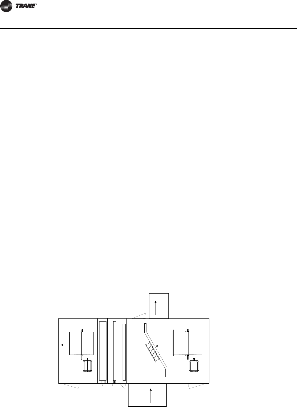
30 CLCH-PRC022A-EN
Application Considerations
Stacked Units
A stacked AHU arrangement can be either draw-thru or blow-thru. It places the air handler sections
on top of each other. This strategy can significantly reduce the length of the unit and provide better
acoustical performance, yet has very little effect on unit static pressure drops.
Application considerations:
• Stacked section weight must not exceed the maximum stacking weight of the casing.
• Ductwork and dampers must not interfere with stacked sections.
• “Upper-deck” sections cannot overhang lower sections.
• Intermediate support brackets should be used if the width of the upper deck is less than that of
the bottom deck.
Arrangements for Specific Applications
Draw-thru and blow-thru arrangements for Trane air handlers can be engineered for specific
applications, including those to maintain proper building pressure, dehumidify, and recover
energy.
Building Pressurization
Return fans and exhaust fans are used to maintain building pressurization. A Trane air handler can
include either of these components. To better understand the differences between exhaust-fan and
return-fan systems, consult your local Trane sales engineer or refer to the Trane applications
engineering manual, Building Pressurization Control (AM-CON-17).
Building Pressurization with Return Fan and Economizer
Figure 21 depicts a standard air handler with a return fan and an economizer for outdoor air. The
return fan typically runs continuously to balance the amount of air supplied to and removed from
the occupied space. Although this approach makes precise space pressurization control more
difficult, it is better suited to applications with high return static pressures than the exhaust-fan
alternative. If the supply fan is unable to handle system static pressure, the return fan is sized to
overcome the external static pressure of the return duct. Of course, the larger size and constant
operation of the return fan also means higher first and operating costs.
Figure 21. Return fan and economizer arrangement for outdoor units
Supply fan
Coil Filter
Economizer
Return fan
Airflow
Airflow
Airflow
Airflow
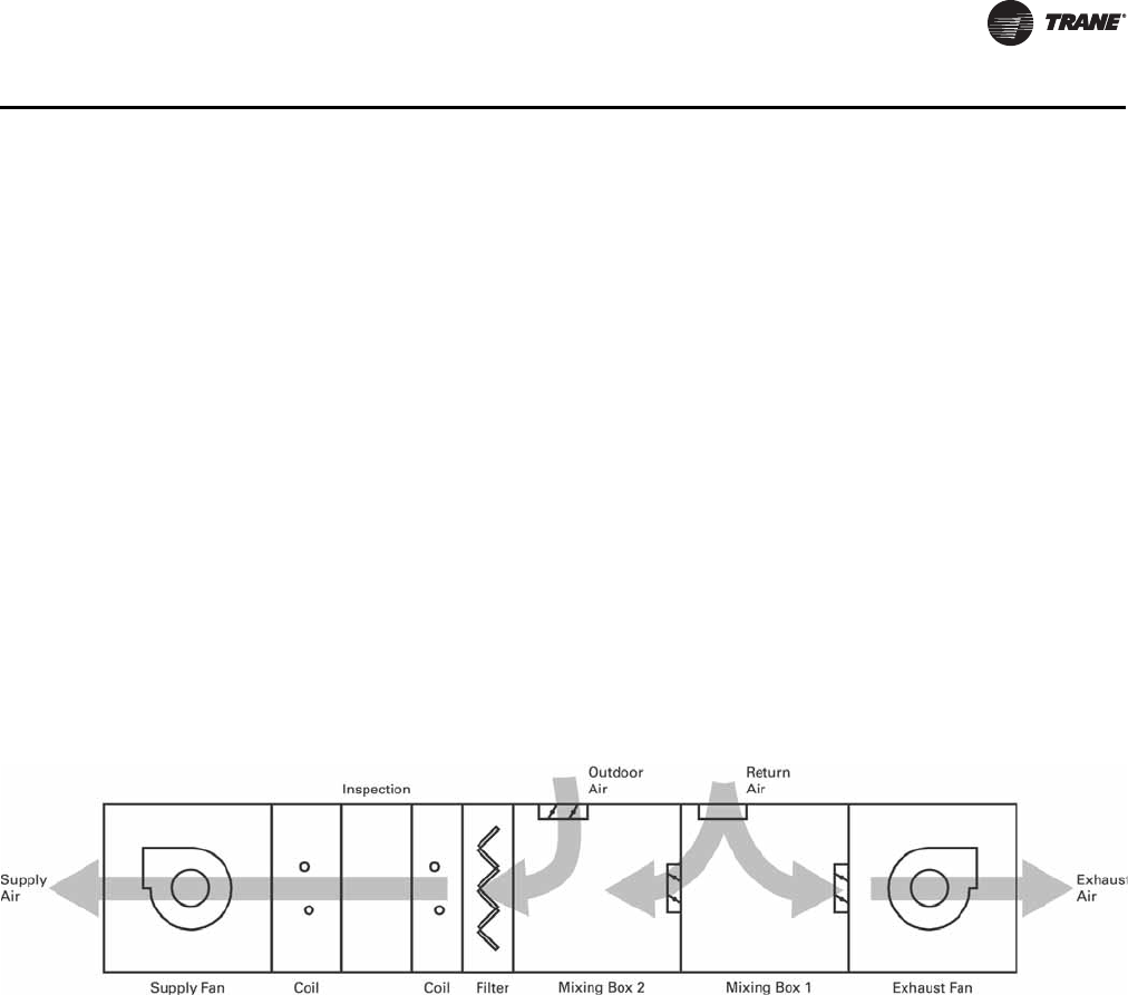
CLCH-PRC022A-EN 31
Application Considerations
Application considerations:
•Size the supply fan to handle the static pressure requirements of a 100-percent economizer
operation, including outdoor-air ductwork, dampers, filters, coils, other accessories in the
outdoor air stream, and supply-duct static pressure.
•Size the return fan to handle the static pressure requirements of a 100-percent return air
operation, including return duct, exhaust duct, and exhaust damper.
• Control the return fan to keep the outdoor/indoor static-pressure differential within design
limits.
• Control the mixing box dampers to prevent all of them from closing simultaneously; otherwise,
serious equipment damage could result.
Building Pressurization with Exhaust Fan and Economizer
Figure 22 depicts a standard air handler with an exhaust fan and an economizer for outdoor air. To
balance the amount of air exhausted from the building with the amount of air brought into the
building, the exhaust fan modulates, running at full capacity only when the economizer brings in
100 percent outdoor air. When the economizer is at minimum and the exhaust fan is idle, dampers
on the mixing box close to prevent outdoor air from being drawn into the air handler through the
exhaust section.
The exhaust-fan-and-economizer combination provides strict space pressurization control,
provided that the supply fan is sized to handle total system static pressure. Its first cost and
operating cost are usually lower than the return-fan-and-economizer alternative, too. (An exhaust
fan requires less capacity than a return fan and runs less often.)
Application considerations:
•Size the supply fan to handle the static pressure requirements of the higher of either a 100-
percent economizer operation or 100-percent return-air operation.
•Size the exhaust fan to handle the static pressure requirements of a 100-percent return-air
operation, including return duct, exhaust duct, and shutoff damper, when the unit is in full
economizer mode.
• Control exhaust airflow to keep the outdoor/indoor static-pressure differential within design
limits.
• Control the mixing box dampers to prevent all of them from closing simultaneously; otherwise,
serious equipment damage could result.
Figure 22. Exhaust fan and economizer arrangement
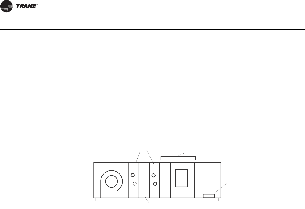
32 CLCH-PRC022A-EN
Application Considerations
Building Pressurization with Barometric Relief Economizer
Figure 23 depicts a typical air handler with a barometric relief economizer. Barometric relief offers
some positive space pressure control. The equipment consists of an economizer section with a
damper in the return air path that opens upon an increase in pressure difference between the space
and the outside.
The supply fan must over-pressurize the space to allow for proper operation of the barometric
damper. It should only be used in systems that have extremely low return air static requirements.
In other systems, it is recommended that a powered system such as return fan or exhaust fan
economizer be used instead of barometric relief.
Application Considerations:
• Size the supply fan to handle 100 percent outside air operation (i.e. OA hood, OA dampers,
filters, coil(s) and other accessories, plus supply air ductwork).
• Set up system for maximum delivery at 100 percent OA economizer mode. Turn on all remote
exhaust fans. Measure the space static pressure, and adjust barometric relief damper to
produce a slight positive space pressure.
• Only when the unit is at or near 100 percent OA (return air damper is closed) will the exhaust
section become sufficiently pressurized to open the barometric damper.
Dehumidification
Excessive humidity in buildings can encourage mold and mildew growth and thermal discomfort.
To cost effectively address these issues, first isolate the conditioned space from the unconditioned
space. (See Trane applications engineering manual, Managing Building Moisture, SYS-AM-15.)
Next, remove the humidity.
The two primary humidity sources in most buildings are people and outdoor air. In any coil-based
HVAC system, it is the cooling coil that dehumidifies the air. This coil must be on and air must pass
through it for dehumidification to occur. In Trane air handler enhanced dehumidification units, the
priority for the cooling coil is humidity control. Temperature control is secondary and is generally
provided by a separate reheat source.
Dehumidification can be obtained using:
• CDQ™ (Cool, Dry, Quiet) units with desiccant dehumidification wheels
• Series, coil run-around loops
• Split dehumidification units (SDU)
Free reheat options with dehumidification include:
• Hot water heat-recovery coils
• Refrigerant heat-recovery H coils
Figure 23. Building pressurization with a barometric relief economizer arrangement
Supply fan
Coils Barometric
relief economizer
Mixing section
(Return air opening)
Access
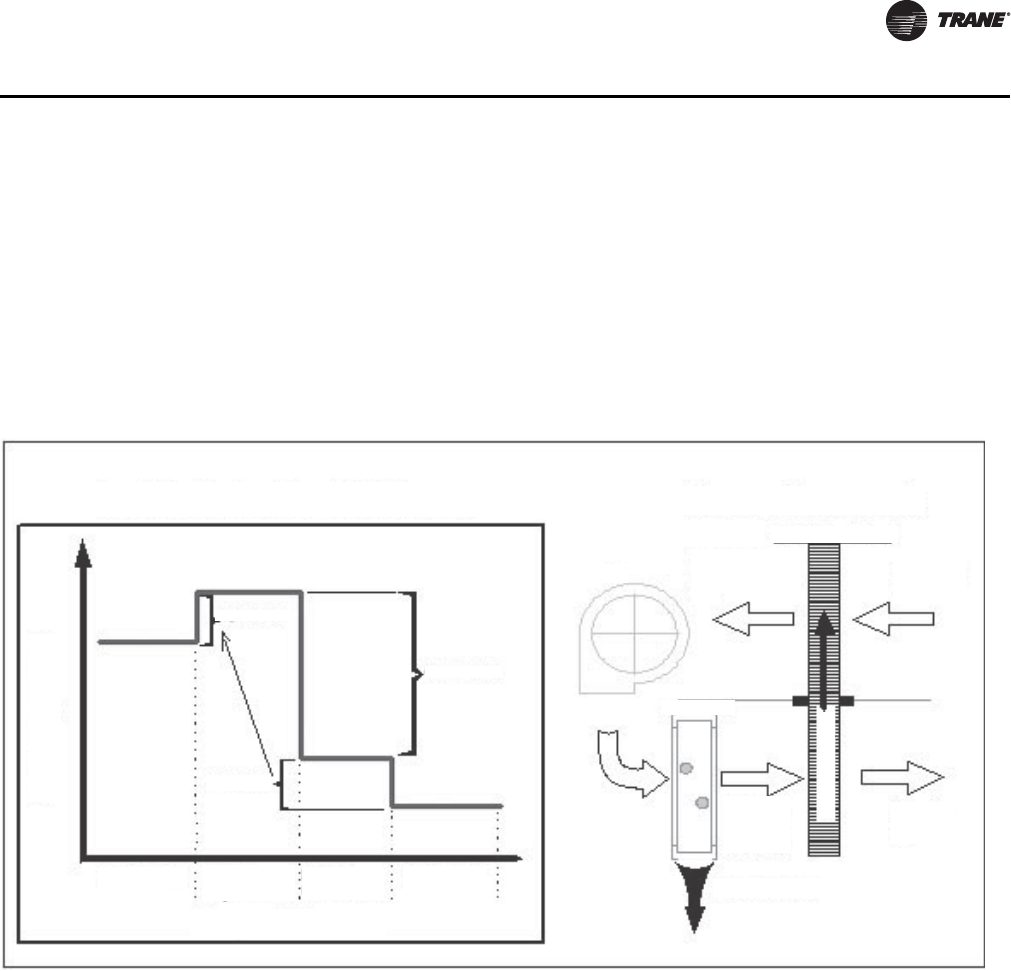
CLCH-PRC022A-EN 33
Application Considerations
Dehumidification with CDQ™ (Cool, Dry, Quiet) Desiccant Wheels
The addition of the CDQ desiccant wheel to the system enhances the dehumidification
performance of the traditional cooling coil (see Figure 24). The CDQ wheel transfers water vapor
and the cooling coil does all the dehumidification work in the system. The latent capacity of the
cooling coil increases without increasing its total cooling capacity. The system can achieve a lower
supply air dew point without lowering the coil temperature. Unlike a system with a cooling coil
alone, the dew point of the air leaving the coil can be lower than the dry bulb temperature leaving
the coil.
Application Considerations:
• Increased cooling coil latent (dehumidification) capacity
• Lower achievable supply-air dew points.
• Decreased need for reheat
• Lower unit cooling sensible heat ratios.
• Warmer required chilled water temperatures.
• Improved energy efficiency for dehumidification.
• Decreased required cooling capacity when dehumidifying.
• Eliminates exhaust air as a requirement
For application guidelines concerning CDQ, refer to Trane engineering bulletin CLCH-PRB020-EN.
Dehumidification with Coil Runaround Loops
Series, coil run-around loops (see Figure 25) consist of finned-tube water coils connected in a
closed loop that is “wrapped” around an active cooling coil. Operation is psychrometrically similar
Figure 24. Dehumidification with CDQ (Cool, Dry, Quiet) desiccant dehumidification units
Water vapor
Humidy during the CDQ process
Humidity level
Regeneration
Condensation
Entering air
Stage of process
Leaving
regeneration
Leaving
cooling coil
Leaving air
Adsorption
Process components
Fan Entering
air
Leaving
regeneration
air
CDQ desiccant wheel
Leaving
air
Leaving
cooling
coil air
Cooling coil
Condensate
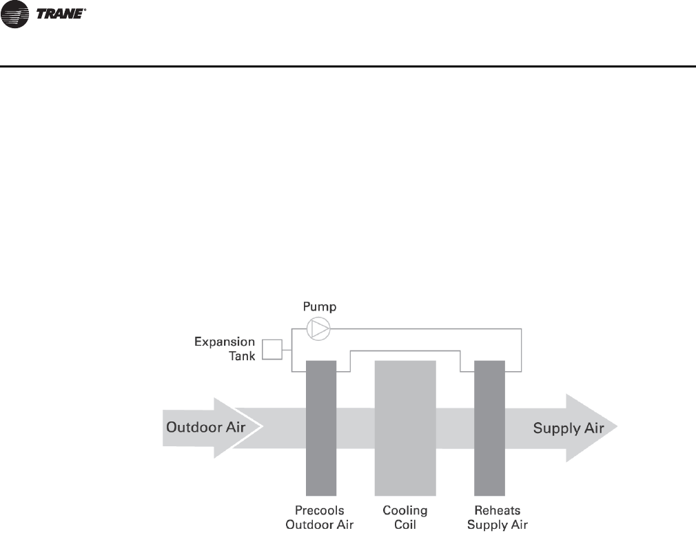
34 CLCH-PRC022A-EN
Application Considerations
to the air-to-air, fixed-plate heat exchanger. The first coil in the loop precools the incoming outdoor
air. The active cooling coil absorbs more heat from the air stream and further dehumidifies the air
to the design point. The second coil in the loop is placed after the active cooling coil and reheats
the air with the heat absorbed by the first coil. Loop components include a pump to move the fluid
within the loop and an expansion tank.
Series, coil runaround loops occupy little space and have a relatively low first cost. Like the series
air-to-air, fixed-plate heat exchangers, series coil loops are only effective during the cooling season.
Additional heating may be required on cool, humid or cold days.
Application Considerations:
• Provide free reheat at design conditions
• Allow downsizing of new energy cooling and reheat coils
• Add a minimal pressure drop through each coil (only 0.3 to 0.6 in. wg)
• Are available in all Trane units
• Can be fully modulated by varying water flow
Dehumidification with a Split Dehumidification Unit (SDU)
The SDU is a dual-path, return-air-bypass air handler. It consists of two units that are stacked
together in a draw-thru arrangement that share one supply fan (see Figure 26). All of the ventilation
(outdoor) air is ducted to the upper unit where it is dehumidified, typically down to 50ºF or lower.
The lower unit is sized to handle the return air needed to achieve the desired air-change rate in the
space. The warmer return air in the lower unit mixes with the cooler, drier air from the upper unit.
The resulting mixed air provides humidity control by achieving a sensible heat ratio (SHR) of down
to 0.4, but also provides sensible reheat without using any new energy.
A vertical unit stacks the supply fan on top of a vertical coil module; the outdoor air enters the back
of the fan module. This unit is shorter than the horizontal SDU.
Outdoor air economizers can also be used with an SDU. Simply add a mixing module to the return-
air unit and bring outdoor air into this mixing module when conditions permit economizing.
This configuration, sometimes called a “winterizer,” uses a combination of two different-sized air-
handling units configured to allow the outdoor air to be introduced downstream of the cooling coil
Figure 25. Series dehumidification with coil run-around loops
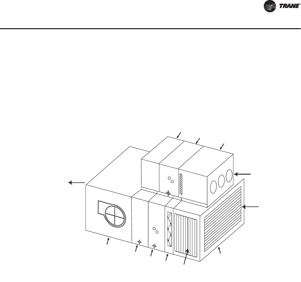
CLCH-PRC022A-EN 35
Application Considerations
whenever the outdoor air is colder than 32°F (0°C). The smaller air-handling unit, sized for the
minimum required ventilation airflow, contains filters and possibly a small preheat coil.
This “winterizer” configuration removes the length and pressure drop associated with a preheat
coil from the main air path, resulting in a shorter air-handling unit than if a conventional preheat
coil, air-mixing baffles, or an energy-recovery device is used. And, since it adds no static pressure
drop to the design of the supply fan, it has less impact on fan energy than these other approaches.
However, the cost of the second, smaller air-handling unit is typically higher than an air-mixing
baffles, and it requires a second, smaller set of filters that need to be replaced periodically.
Application Considerations:
• Provides excellent humidity control in recirculating units, achieving SHR down to 0.4 without
using new energy for reheat.
• Can offer significantly lower operating costs and a low first cost.
• Can be used in retrofits.
• Uses standard components.
• Does not require field-installed structural bracing.
• Has a small foot print.
• Is available in sizes 3-50, with the upper unit being sized between 20 to 50 percent of the lower
unit.
Dehumidifying with outdoor units can be achieved with an outdoor air pretreating SDU or by using
two units. See Figure 27 and Figure 28.
Figure 26. Horizontal split dehumidification indoor unit (SDU)
Supply
air
Ventilation
outdoor air
Return
air
Medium
blank Outdoor air
cooling coil Traq damper, filter
mixing box
Fan
Medium
blank Return air
cooling
coil
Filter
Economizing
outdoor air
Mixing
box
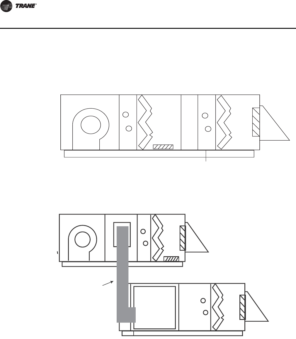
36 CLCH-PRC022A-EN
Application Considerations
Figure 27. Outdoor air pre-treating split dehumidification unit
Figure 28. Split dehumidification with outdoor units
CoilSupply fan
Filter
mixing
section
Filter mixing section
(outdoor air only)
Pre-treating coil
Access
Supply fan Coil
Filter mixing
section
Mixing
section
Field-supplied
ductwork
Discharge
plenum Coil
Filter mixing
section

CLCH-PRC022A-EN 37
Application Considerations
Dehumidification with Hot-Water Heat-Recovery Coils
Using waste condenser heat from the chiller or compressor is a simple way to provide
dehumidification reheat. With this dehumidification strategy, a hot-water coil is installed after the
active cooling coil. Hot water from the chiller—or from an auxiliary condenser on the chiller—is
piped to this coil. Free reheat is available any time the chiller is on.
Application Considerations:
• Work with recirculating or 100-percent makeup-air units.
• Provide excellent humidity control at any sensible-heat-ratio condition without using new-
energy reheat.
• Can reduce operating costs significantly.
• Can be used in retrofits.
• Use standard Trane components.
• Provide proven, low-cost technology.
Energy Recovery
Trane air handlers offer high-performance solutions for airside energy recovery:
• Total energy recovery wheels
• Run-around coil loops
• Air-to-Air plate frame heat exchangers
These technologies transfer energy between the exhaust and outdoor air streams. Total energy
recovery wheels transfer both sensible and latent energy between the air streams, while the coil
loop transfers sensible energy.
Energy-recovery arrangements:
• Reduce operating costs.
• Can reduce first cost by allowing downsizing of chillers and boilers.
Energy-recovery systems can offer excellent energy savings when properly applied. Economic
considerations must be carefully evaluated to determine the payback period of any energy-
recovery system.
For more information, refer to Trane applications engineering manual Air-to-Air Energy Recovery
in HVAC Systems SYS-APM003-EN.
Energy Recovery with a Total Energy Wheel
This type of application is used to recover energy and moisture from the exhaust air stream. The
wheel preheats and humidifies the supply air during the winter season and precools and
dehumidifies the supply air during the summer season. Figure 29 and Figure 30 show an air
handler arrangement with an exhaust fan, an economizer, and a total-energy wheel.
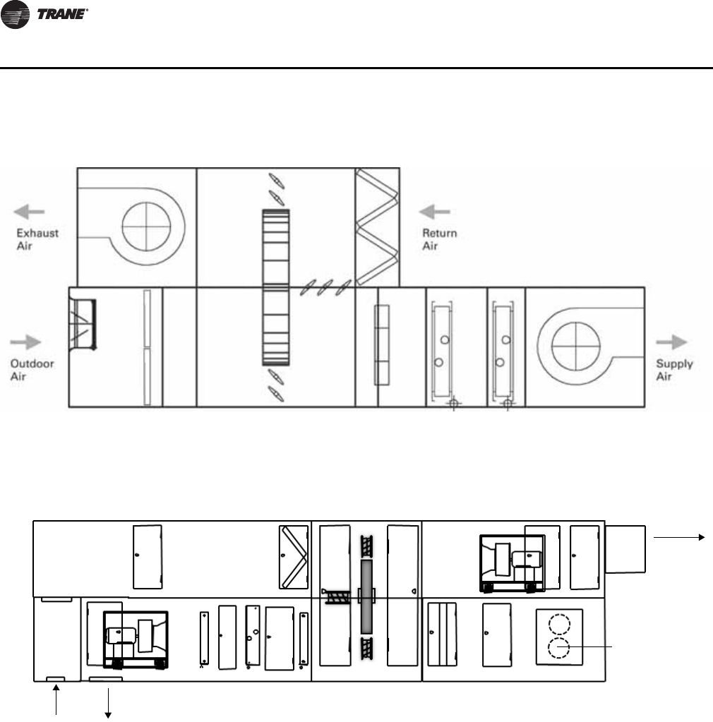
38 CLCH-PRC022A-EN
Application Considerations
As the return air enters the unit, a portion is recirculated through the return-air damper and the
remainder goes through the wheel and is exhausted to maintain the required building pressure.
Outdoor air enters an outdoor-air damper, then goes through the wheel and mixes with return air.
During the economizing mode, the energy wheel is not used, and both wheel bypass dampers are
open to allow up to 100-percent outdoor and exhaust airflow.
If the energy wheel module is used in a VAV system or in a unit that supplies cold supply air,
modulating the exhaust-air bypass damper at the wheel can prevent the air from overheating
during onset of the heating mode. If frosting conditions exist, modulating the outdoor-air bypass
damper at the wheel can prevent vapor in the exhaust air from freezing on the wheel. If bypass frost
control is used as freeze protection for the wheel, add a blender module to adequately mix the
outdoor and exhaust air streams. If bypass frost control is not used, add outdoor-air preheat or
return-air reheat.
Figure 29. Energy-recovery with a total energy wheel in indoor unit
Figure 30. Energy-recovery with a total energy wheel in outdoor unit
Exhaust
air
Outdoor
air
Supply
air
Return
air
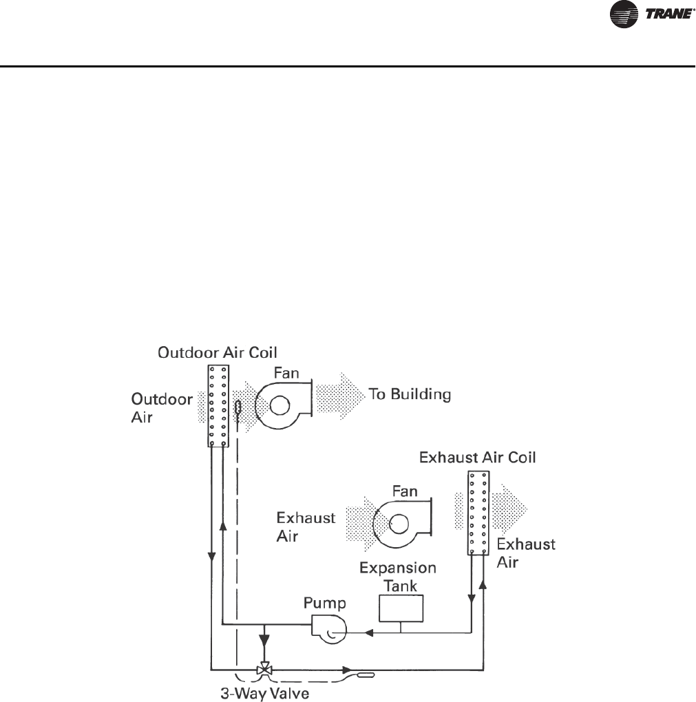
CLCH-PRC022A-EN 39
Application Considerations
Energy Recovery with Coil Runaround Loops
Outdoor-air and exhaust-air coil runaround loops recover energy that would normally be
exhausted. They precool the outdoor air during the cooling season and preheat the outdoor air
during the heating season. With coil loops, the outdoor and exhaust air streams do not need to be
adjacent. This provides design flexibility for building renovations and new construction—at a first
cost that is often lower than other methods of energy recovery.
Multiple exhaust and outdoor-air coils can be piped together with relative ease. Coil runaround
loops use finned-tube hydronic coils in a closed loop to transfer energy. A typical runaround system
is shown in Figure 31. The heat-transfer fluid pumped within the loop is usually an inhibited
solution of ethylene glycol and water to avoid freeze up.
Application considerations:
• Typical coil-loop effectiveness ranges from 45 to 65 percent with equal airflow and no
condensation. Adhere to standard guidelines regarding coil construction, based on conditions.
(See Trane catalog COIL-DS-1 and engineering bulletin COIL-EB-19 for more information.)
• Coil performance and airside pressure drops can be determined using Trane selection tools.
Coil loops offer complete separation of the air streams, thus eliminating any risk of cross-
contamination. Loop components include the coils, a pump, expansion tank, and a three-way valve
or variable-frequency drive (VFD). The expansion tank accommodates expansion and contraction
of the internal fluid. The three-way valve or VFD modulates coil capacity. To prevent moisture in
the exhaust air from freezing on the exhaust coil, the three-way valve can divert the warm fluid
returning from the exhaust coil to the supply side of the coil.
Figure 31. Energy recovery with a runaround coil loop
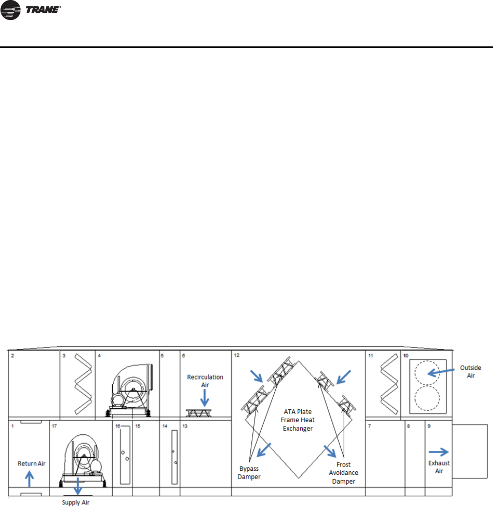
40 CLCH-PRC022A-EN
Application Considerations
Energy Recovery with Air-to-Air Plate Frame Heat Exchangers
This type of application is used to recover energy from the exhaust air stream using cross-flow
aluminum plates. The air-to-air (ATA) plate frame heat exchanger preheats the supply air during the
winter season and precools the supply air during the summer season. Figure 32 shows an air
handler arrangement with an exhaust fan, economizer and ATA heat exchanger.
As the return air enters the unit, a portion is recirculated through the return-air damper in the
mixing box and the remainder goes through the air-to-air plate frame heat exchanger and is
exhausted to maintain the required building pressure. Outdoor air enters an outdoor-air damper,
then goes through the ATA heat exchanger and mixes with return air. During the economizing
mode, the ATA heat exchanger is not used, and bypass dampers are open to allow up to 100-percent
outdoor and exhaust airflow. The center bypass dampers can be selected for either the outside air
or exhaust air path, but not both.
If the ATA heat exchanger is used in a VAV system or in a unit that supplies cold supply air,
modulating the exhaust-air bypass damper at the ATA heat exchanger can prevent the air from
overheating during onset of the heating mode. If frosting conditions exist, frost avoidance dampers
that block part of the outdoor air face of the exchangers close to minimize frosting potential. Frost
control can also be achieved by modulating bypass dampers placed on the outside air side versus
the exhaust side. If outside air bypass is used, freeze protection needs to be applied to any
downstream hydronic coils.
Figure 32. Energy recovery with air-to-air plate from heat exchanger
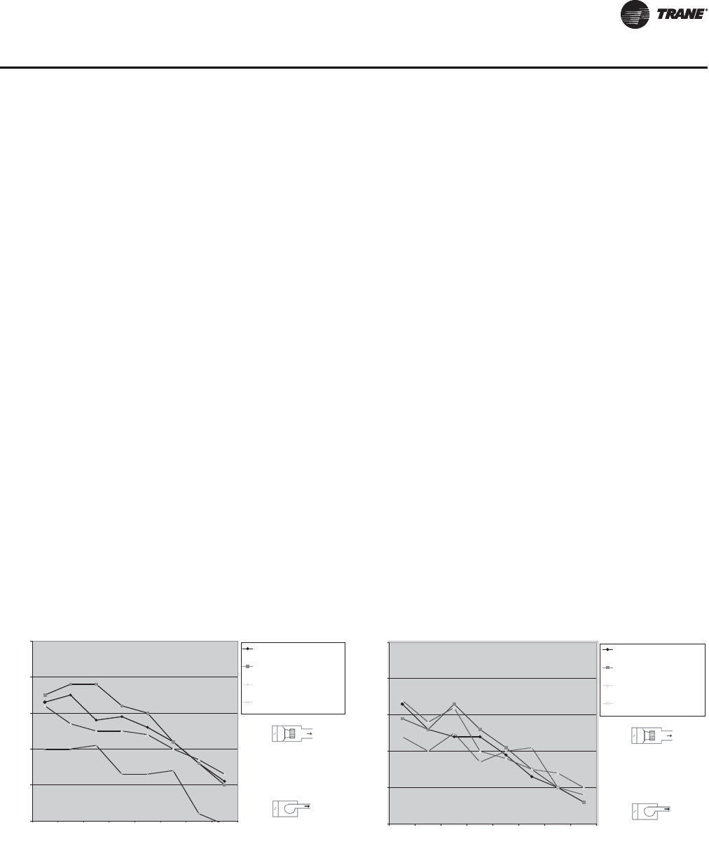
CLCH-PRC022A-EN 41
Application Considerations
Acoustics
Designers are often challenged to select and arrange the air handler components so that the inlet,
discharge and casing-radiated fan generated sound power levels help create a quiet space. To
accomplish this, the designer must choose the right fan and determine whether additional unit
attenuation is necessary.
Choosing the Right Fan
Obviously, the quieter the noise source (in this case, the fan), the less attenuation is needed along
sound transmission paths. Selecting a quieter fan often increases the initial cost of the air handler,
but can be a cost-effective system solution because it:
• Reduces the need for path attenuation (e.g., silencers) by diminishing the sound level along all
transmission paths
• Reduces energy consumption (i.e., a fan is normally quietest when running at the most efficient
point on its operating curve), providing operating cost savings to offset the initial cost.
Trane acoustical tests have shown that a fan’s sound power (Lw) level depends on three factors:
• Type/design
• Operating point on the fan curve
• Application requirements (e.g., critical octave band frequency)
Figure 33 and Figure 34 compare the inlet and outlet sound power levels of four different fans.
Together, these charts demonstrate that fan inlet sound is not equivalent to fan outlet sound. More
importantly, they underscore the need to obtain accurate, AHRI 260 tested sound data from the
manufacturer so that appropriate source and/or path attenuation methods can be applied.
Trane gives designers a choice of many different fan types. See “Fans” section on page 52 for a
summary of different fan application considerations and acoustical characteristics.
Figure 33. Comparison of discharge sound power by fan
type Figure 34. Comparison of inlet plus casing sound power
by fan type
Ducted Discharge
60
70
80
90
100
110
63 125 250 500 1K 2K 4K 8K
Frequency, Hz
Sound Power (Lw), dB
22.375" Housed FC (898 RPM, 10.9
BHP)
22" Housed AF (1642 RPM, 10.9
BHP)
32" Belt-Drive Plenum (1190 RPM,
12.1 BHP)
30" Direct-Drive Plenum (1282
RPM, 11.72 BHP)
NOTE: 3.4 plus a 0.6 duct discharge loss = 4.0 TSP.
NOTE: Sound power data is
based on a draw-thru unit, front
discharge, and 2 in. double wall
perforated liner in the fan
section. Fan delivery is 12,500
CFM at 4 in. wg Plenum Fan
TSP.
Inlet+Casing
60
70
80
90
100
110
63 125 250 500 1K 2K 4K 8K
Frequency, Hz
Sound Power (Lw), dB
22.375" Housed FC (898 RPM, 10.9
BHP)
22" Housed AF (1642 RPM, 10.9
BHP)
32" Belt-Drive Plenum (1190 RPM,
12.1 BHP)
30" Direct-Drive Plenum (1282
RPM, 11.72 BHP)
NOTE: 3.4 plus a 0.6 duct discharge loss = 4.0 TSP.
NOTE: Sound power data is
based on a draw-thru unit, front
discharge, and 2 in. double wall
perforated liner in the fan
section. Fan delivery is 12,500
CFM at 4 in. wg Plenum Fan
TSP.
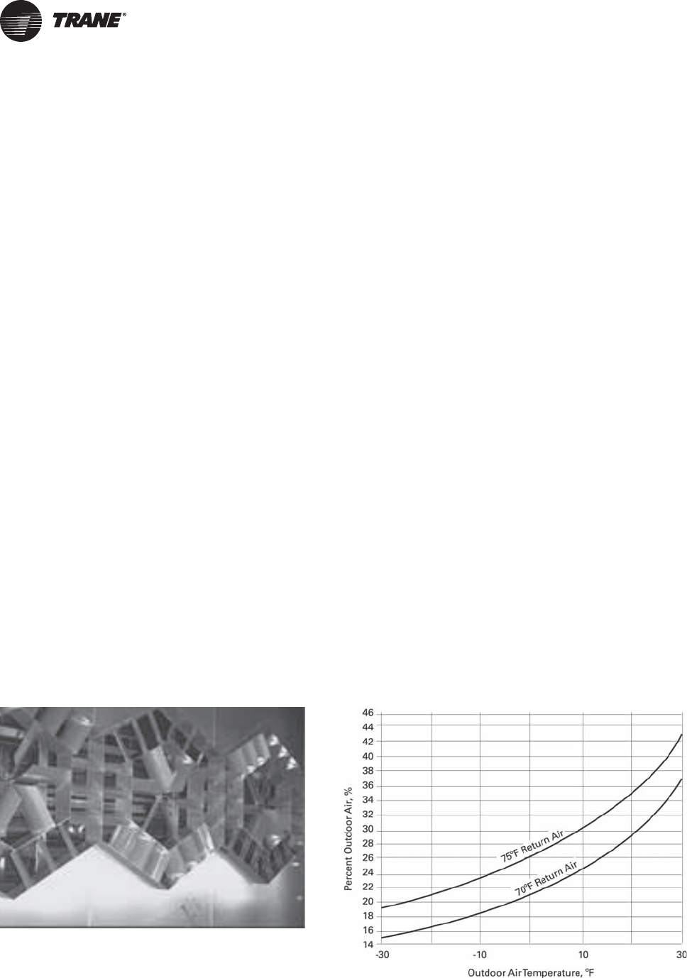
42 CLCH-PRC022A-EN
Components and Options
Performance air handlers adopt a ‘building-block’ approach to air-handling design. Each ‘building
block’ or section contains one or more components that serve a specific purpose unique to each
application. The required function, layout, and arrangement of the air-handling system determines
which sections must be included for a particular application.
Access/Blank and Turning Section
Access or blank sections can provide access to internal components for cleaning, maintenance, and
service or to promote proper airflow through the unit.
A turning section is a blank section that alters the direction of airflow and reduces turbulence. It
can also serve as an effective sound attenuator. When compared to a field-mounted, rectangular
duct silencer, the turning section is less expensive to install, has a lower pressure drop, and
provides more predictable performance. Perforated lining in the turning module attenuates mid-
to high-frequency sound.
Note: Only large and extra-large blank sections can be selected as turning sections.
Blender
Blender sections contain air-mixing baffles, or blenders, that rotate the passing air streams,
boosting their velocity for improved mixing. It is usually placed immediately downstream of a
mixing box section, and should always be positioned upstream of filters and coils. Figure 36
documents blender performance at a downstream coil entering air temperature of 55ºF and return-
air temperatures of 70ºF and 75ºF.
Application considerations:
• Blender face velocity should be in the range of 500 to 2000 fpm for proper mixing.
• When operated at temperatures within its design range, a blender may eliminate the need for
preheat.
• Space is required both upstream and downstream of the blender to allow complete air mixing.
The standard design of the blender section satisfies these spacial requirements.
• Select the mixing box such that the dampers are positioned at the top, back, or bottom when
used with a blender.
Figure 35. Use blenders for coil protection Figure 36. Blender performance with 55ºF leaving air temperature
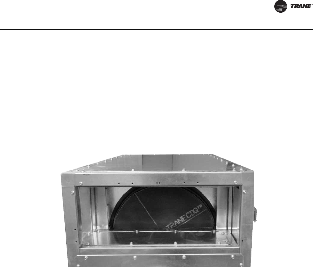
CLCH-PRC022A-EN 43
Components and Options
CDQ™ Desiccant Dehumidification Wheel
The CDQ wheel section (see Figure 37) is a used to enhance the dehumidification performance of
a traditional cooling coil. It utilizes a Type III desiccant (activated alumina) chosen specifically for
air-handling applications. The wheel is configured in series with a cooling coil, and requires only
one air stream. The CDQ wheel rotates between the entering and leaving sides of the cooling coil.
CDQ wheels are sized based on supply fan airflow. Unlike conventional equipment, the dew point
of the supply air is not equal to the dew point of the air leaving the cooling coil. The required cooling
coil capacity and air temperature leaving the coil are determined by the CDQ wheel performance.
For more application information, refer to engineering bulletin CLCH-PRB020-EN.
Application Considerations:
• Available in 14 unit sizes, ranging from 1000 to 25,000 cfm
• Single wheel for unit sizes 3 to 50 with up to two wheels available per unit size
• Can be applied in mixed air and dedicated outdoor air systems
• Required cooling coil capacity is decreased when dehumidifying
• Entering water temperatures to the coil can be increased
• Section includes required space upstream and downstream of the wheel
• Required access and doors in section
• Variable effectiveness control using bypass dampers
Additional dehumidification options
• Dual-path split dehumidification units (SDUs)
• Low sensible-heat ratio coil selections
• Series recovery supply air tempering 100 percent outdoor air units in conjunction with other
Trane airside products
Figure 37. CDQ wheel
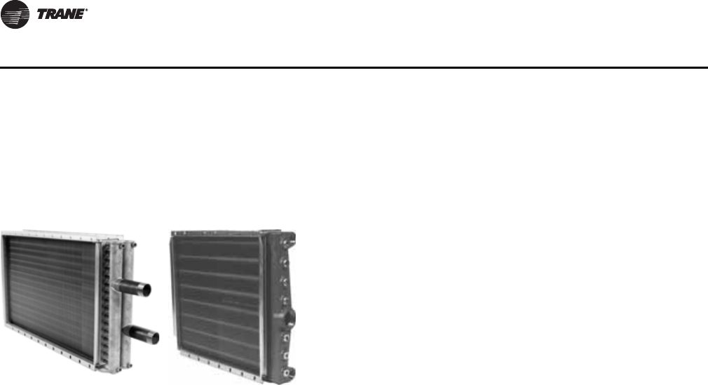
44 CLCH-PRC022A-EN
Components and Options
Coils
Coil options include but are not limited to the following:
• Two- to eight-row, 1/2-inch OD (outside diameter) chilled water or refrigerant coils
• Two- to 10-row, 5/8-inch OD chilled water or refrigerant coils
• One- or two-row 5/8-inch OD hot water coils
• Two-row, 1/2-inch OD hot water coils
• One-row, 1-inch OD distributing-type steam coils
• Half, full, and dual-serpentine, circuited water coils
• Full face, split face, and intertwined circuited refrigerant coils
A variety of fin surfaces are also available, with the following options:
• Variable fin spacing on all fin types to fine-tune coil capacity and air-pressure drop
• Aluminum Delta-Flo™ H and Prima-Flo™ H fins that maximize the heat transfer and moisture
carryover limits of the coils
• Aluminum Delta-Flo E and Prima-Flo E fins that minimize the coil air-pressure drop
• Copper Prima-Flo™ fins for corrosion protection
For additional information on coils, see Air Heating and Cooling Coils Quick Select
COIL-PRC002-EN.
Figure 38. Coil with
copper
header
Figure 39. Coil with
cast iron
header
Coil Optimization
The variety of Trane coil types, sizes, arrangements, and materials
allows you to select a coil that is optimized for pressure drop and
capacity requirements. Published coil performance is certified in
accordance with AHRI Standard 410 and meets CRN (Canadian
Registration Number) standards.
Trane is at the leading edge of coil technology. Through extensive
laboratory testing and numerous job-site installations, Trane has
developed unique fin surfaces for its coil offerings. These enhanced
fin surfaces have superior heat transfer characteristics and allow
greater velocities of air to move through the cooling coil without
causing moisture carryover.
The industry is familiar with the 500-fpm limit through a cooling coil as a “rule of thumb” to safeguard against moisture
carryover. However, some applications have tight dimensional constraints that require high coil face velocities. Trane fin
designs extend this limit in excess of 625 fpm, depending upon air conditions, coil size, and coil-fin type, and spacing.
Tested data for moisture carryover is incorporated in the Trane Official Product Selection System (TOPSS™). In cases
where moisture carryover is possible, the TOPSS program alerts you to this fact with a moisture carryover warning. See
“Face-Velocity Limits for Moisture Carryover,” p. 165 for moisture carryover curves.
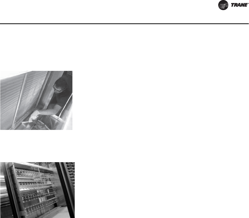
CLCH-PRC022A-EN 45
Components and Options
Drain Pans
Electric Heat
Integral Face-and-Bypass Coil
Conventional preheat systems are subject to coil freeze-up, stratification, and air-volume variation.
An integral face-and-bypass (IFB) coil is specifically designed to minimize these problems,
alternating heating and bypass channels with face-and-bypass dampers before and after the coil.
If heat is needed, both dampers modulate open; otherwise, they remain closed to prevent “coil
wiping” on the leaving side of the coil and to avoid unwanted heat pickup. This design effectively
provides good freeze protection, constant airflow, and uniformly mixed and unstratified air. The IFB
coil comes as a complete package (including heating coil, linkage, and dampers), thus assuring
maximum system reliability. The section uses horizontal coil-tube arrangements in unit sizes 6 to
40 and vertical coil-tube arrangements in unit sizes 50 to 100.
These coils are capable of maintaining a constant heating discharge air temperature regardless of
variations in entering air temperatures, with full steam pressure of hot water flow on the coils at
all times. IFB coils consist of rectangular aluminum fin (.010-inch thick) elements, with 5/8-inch
O.D..035 thick copper tubes completely enclosed in a 14-gauge galvanized steel casing, with 16-
gauge dampers. Dampers are arranged to completely enclose and isolate the heating coil elements
when no temperature rise is required. Holes in the unit casing for supply and return connections
are factory provided to facilitate field piping of the coils. Factory-mounted electronic actuators are
available when specified.
Figure 3 and Figure 4 list the sections required to house the integral face-and-bypass coil, and the
downstream section required for proper air mixing space. External piping cabinets are required on
Figure 40. Extended drain pans for
easy cleaning • Galvanized or stainless steel drain pans sloped in two directions to assure
positive drainage helps prevent corrosion.
• Drain pans that can extend beyond the cooling coil (see Figure 40) for periodic
cleaning are standard options.
• A variety of cooling coil fin options, including the high-efficiency H-fin design,
are available. These fins allow for coil selections with face velocities in excess
of 625 fpm without moisture carryover.
• UV-C lights help preventing mold, bacteria and viruses from reproducing and
also maintains or improve the system efficiency. Factory engineering and
UV-C lights installation allows us to maximize the benefits of UV technology
without jeopardizing the expected reliability and safety of the equipment.
Figure 41. Typical 1-inch steam coil An electric heat coil is a relatively inexpensive first cost heating option
compared to central plant boiler systems. Electric heat is a factory-installed, UL-
listed option for unit sizes 3-66 draw-thru arrangements and 3-30 blow-thru
arrangements in constant-volume or VAV applications.
Application considerations:
• Blow-thru arrangements require a minimum of a medium blank section
between the supply fan and the electric heat section to ensure even air
distribution across the electric heater.
• A large access or discharge plenum section with a door for field-wiring
access is required downstream of the electric heat section in a blow-thru
arrangement.
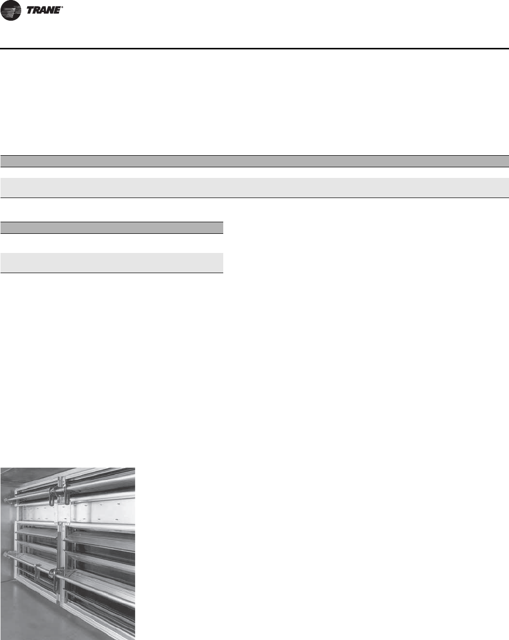
46 CLCH-PRC022A-EN
Components and Options
both sections. An optional access door can be added to the downstream section on units with an
integral face-and-bypass coil. On units with a vertical integral face-and-bypass coil, an access door
must be included in the downstream section, on the opposite side of the coil connection, to
facilitate field piping of the supply and return connections on the coil.
External piping cabinets are required on both the IFB coil and the section immediately downstream
of the coil. An optional access door can be added to the downstream section. On units with vertical
IFB coils, an access door must be included in the downstream section to facilitate field piping of
the supply and return connections on the coil.
It is recommended that a factory selection of a coil be made based on scheduled performance prior
to configuring a unit with an IFB coil, so as to determine whether the unit should be configured
around an integral face-and-bypass coil or a vertical integral face-and-bypass coils.
Dampers
Face-and-Bypass Dampers
Table 3. Requirements for horizontal IFB coils
Unit size 3 6 8 10 12 14 17 21 25 30 35 40
IFB section n/a Large Large Large Large Large Large Large Large Large Med-Large Med-Large
Downstream
section n/a Medium Medium Medium Medium Medium Medium Medium Medium Medium Medium Medium
Table 4. Requirements for vertical IFB Coils
Unit size 50 57 66 80 100
IFB section Med-
Large Med-
Large Med-
Large Med-
Large Med-
Large
Downstream
section Medium Medium Medium Medium Medium
Figure 42. Internal face-and-bypass
damper Designed to divert airflow around a coil, the face-and-bypass damper can be used
to control humidity or provide freeze protection for hydronic coils. Face-and-
bypass dampers are available in two module configurations, internal and external.
Internal Face-and-Bypass Dampers
Typically used immediately upstream of a modified-size (less than 100-percent
airflow) coil, this arrangement enables temperature control while operating the
preheat coil at full flow. The dampers modulate to bypass air around the heating
coil when the outdoor air temperature is warm enough to preclude freezing. See
Figure 42.
Application considerations:
• To ensure full airflow coverage across downstream coil banks, provide extra
distance after the modified-size coil section (see Table 5).
• Consider the effect of reduced bypass area, higher velocities, and higher
pressure drops when designing internal face-and-bypass configurations that
require 100-percent bypass. External face-and-bypass dampers may be better
suited for these configurations.
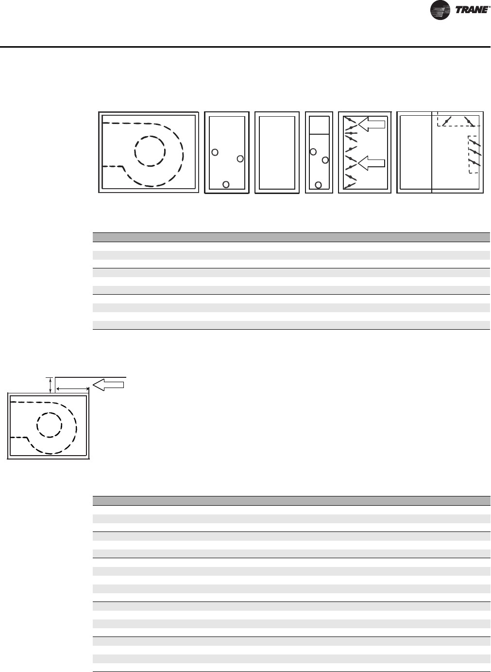
CLCH-PRC022A-EN 47
Components and Options
Figure 43. Internal face-and-bypass configuration
Table 5. Recommended distance between coils to ensure full airflow coverage
Unit size Distance between coils (inches)
3, 6 12.00
8, 10 18.00
12, 14 24.00
17 30.00
21 33.00
25-40 36.00
50 48.00
57, 66 57.00
80 69.00
100, 120 78.00
Fan Filter mixing boxInternal face-and-bypassAccess or blankMedium coil
Figure 44. External bypass
External Face-and-Bypass Dampers
External face-and-bypass dampers perform the same function as their internal
counterpart. However, they are used upstream of a full-face coil, and they route air
around the coil through an external bypass duct. See Table 6 for recommended
duct sizes that permit 100-percent bypass. Duct placement varies with each air
handler arrangement. Ensure that the external bypass duct does not interfere with
stacked modules. Use Table 6 in conjunction with Figure 44.
Fan L
H
Bypass
airflow
Table 6. Recommended bypass duct sizes (inches)
Unit size H W L
3 16.00 20.00 14.00
418.00 33.00 16.00
6 18.00 33.00 16.00
818.00 39.00 16.00
10 18.00 50.00 16.00
12 22.00 55.00 20.00
14 22.00 61.00 20.00
17 22.00 61.00 20.00
21 28.00 69.00 26.00
25 28.00 69.00 26.00
30 28.00 82.00 26.00
35 45.00 80.00 36.00
40 45.00 93.00 36.00
50 45.00 106.00 36.00
57 47.00 106.00 40.00
66 48.00 121.00 40.00
80 56.00 121.00 48.00
100 56.00 135.00 48.00
120 56.00 162.00 48.00
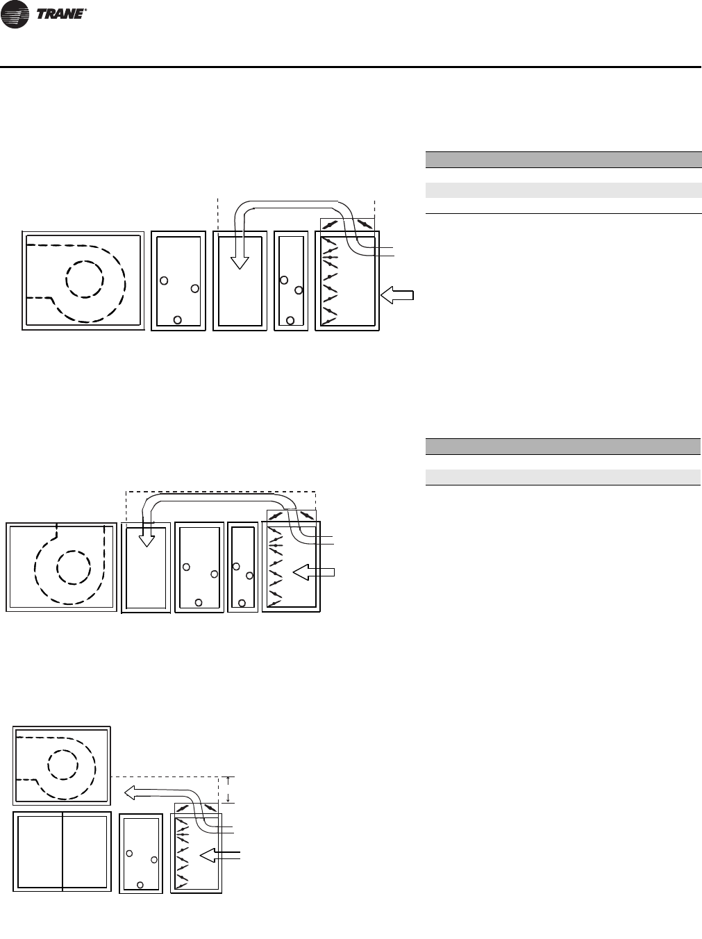
48 CLCH-PRC022A-EN
Components and Options
Figure 45. Configuration A Table 7. Table for Configuration A
Unit Size Blank Size
3-12 Extended Medium
14-17 Medium- Large
21-120 Large
Fan Small
coil
Access
or blank
Medium
coil
External face-and-bypass
with bypass between two coils
External
face-and-
bypass
Figure 46. Configuration B Table 8. Table for Configuration B
Unit Size Blank Size
3-57 Extended Medium
66-120 Large
Fan Small
coil
Access
or blank
Medium
coil
External face-and-bypass with
bypass between a coil and a top-discharge
housed fan or a plenum fan
External
face-and-
bypass
Figure 47. Configuration C Area of opening in fan module should be equal
to “H” and “W” dimensions from Table 6.
Fan
External
face-and-
bypass
CoilVertical coil module
H
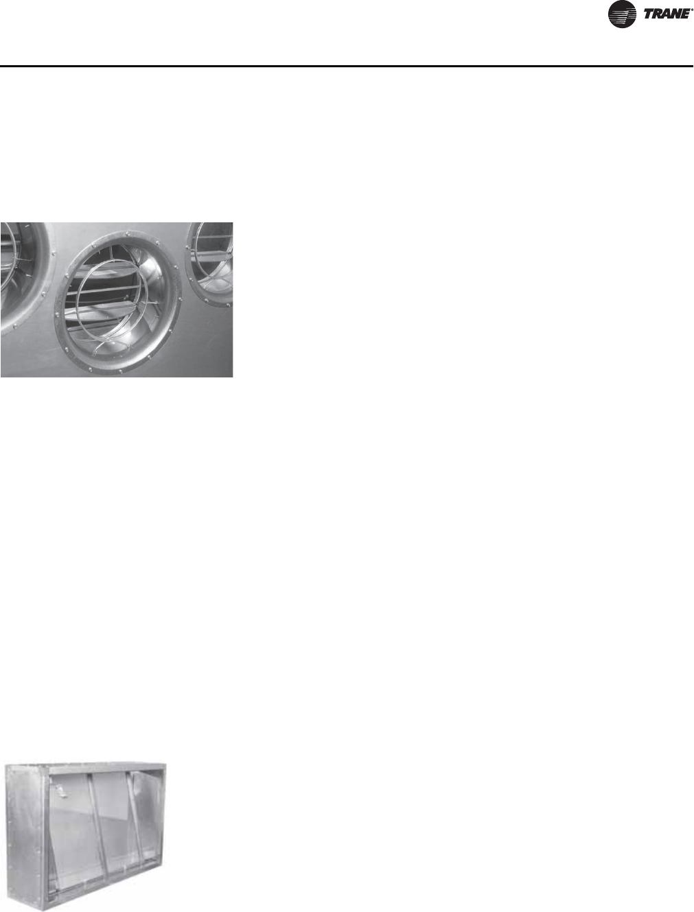
CLCH-PRC022A-EN 49
Components and Options
Traq™ Dampers and Low Flow Traq Dampers
The bell-mouth inlet of each damper guides air uniformly through a flow-sensing ring that
accurately measures total and static pressure from 100 percent of nominal airflow down to 300 fpm
through the damper. The damper assembly’s ventilation control module (VCM) produces a
2-to-10-Vdc signal that is proportional to airflow, recalibrates itself once every 60 seconds, and
automatically adjusts for temperature variations. Depending on unit size and controls
configurations Traq dampers can measure from 100 percent of design CFM, down to five percent
design CFM.
Application considerations:
• The Traq damper mixing box requires only one duct diameter of straight inlet duct (as much as
80 percent less than other airflow monitoring techniques).
• Connecting a Traq-damper-equipped air handler to a building automation system, such as a
Tracer building management system, permits:
– Dynamic calculation of the outdoor air needed to adequately ventilate a multispace VAV
system and reset the outdoor-air setpoint accordingly to save energy.
– Trend logs and custom reports to document compliance with ASHRAE Standard 62.1.
Figure 48. Traq dampers measure and
control ventilation airflow. The Trane AMCA 611-certified Traq™ airflow-monitoring solution
(seeFigure 48), allows direct measurement and control of outdoor and/or return
airflow and is rated for a maximum leakage rate of 4 cfm/ft2 at 1 inch w.g.
complying with ASHRAE Standard 90.1 maximum damper leakage. The low-
flow Traq option can be used as a key part of a demand control ventilation
strategy to help drive down energy costs. When applied as part of an Integrated
Comfort™ system (ICS) with the Tracer Summit™ building automation system,
ventilation airflow can be controlled dynamically and documented to verify
compliance with ASHRAE Standard 62.1. (See Trane product catalog BAS-
PRC001-EN for more information on Tracer Summit systems.) Factory-mounted
and tested to reduce installation and startup costs, the Traq damper also
requires significantly less straight duct than traditional airflow-monitoring
stations and does not require upstream straightening vanes for proper
operation that could become clogged with debris.
Diffuser
Figure 49. Diffusers provide even
airflow. A diffuser consists of pressure-equalizing baffles that are designed to provide
even airflow across components downstream of a fan. The diffuser section is
typically used immediately downstream of a centrifugal fan in a blow-thru filter,
coil application.
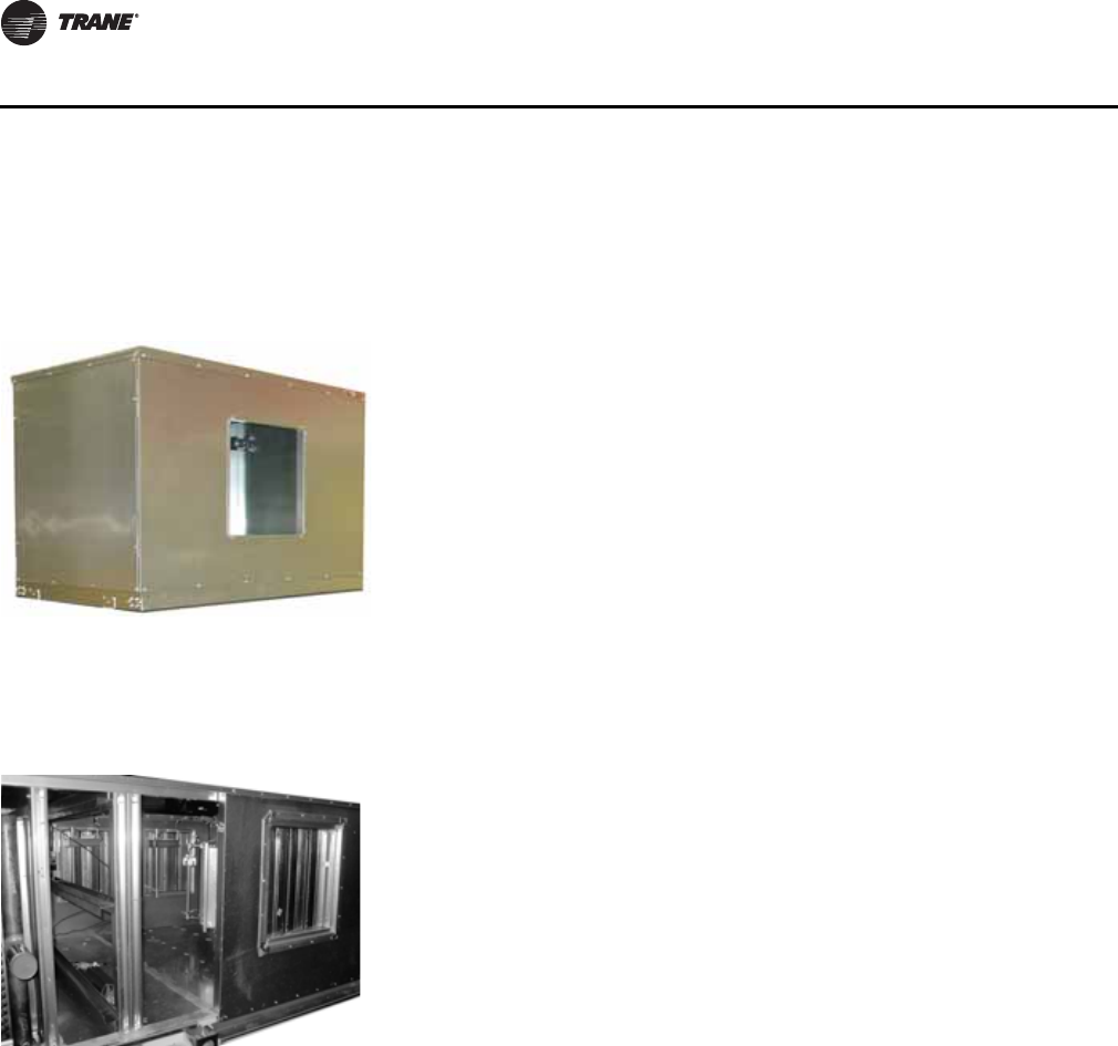
50 CLCH-PRC022A-EN
Components and Options
Economizer
Energy Recovery
Increased ventilation airflow requires more energy to heat or cool and can significantly affect
operating costs. Bringing in more fresh air when it is cold outside also increases the risk of coil
freeze-up. Trane airside energy-recovery solutions address both energy consumption and coil
protection by recovering heat from the exhaust air stream to pre-condition outdoor air entering the
building.Trane has many factory-packaged energy-recovery solutions including:
• Total energy recovery wheels to recover both sensible and latent energy. See Figure 52.
• Coil-runaround loops to recover sensible energy (see Figure 53).
• Air-to-air plate frame heat exchangers recover sensible energy.
Discharge Plenum
Figure 50. Discharge plenums can
lessen low-frequency
sound.
Before leaving the air handler, supply air can be ducted to a discharge plenum
section. The rapid air-stream expansion as it passes into the plenum reduces
turbulence and creates an acoustical end reflection that dampens low-frequency
sound. Perforated panels can be selected as an additional attenuation option.
Two configurations enable supply-duct connections from any side:
•Vertical-mounted plenum sections mount atop an adjacent section and can
be increased 1.5 times or reduced 0.5 times to standard height minimizing
field duct transitions. Openings can be factory- or field-cut.
•Horizontal-mounted plenum sections mount on the front of an adjacent
section. Openings can be factory- or field-cut.
Vertical and horizontal discharge plenum openings can be tailored to the size,
type and location to best fit the velocity and static pressure requirements,
improving energy efficiency and sound. Round, rectangular, and bell mouth
openings are all available.
Figure 51. Outdoor economizer section
An economizer section, for outdoor use only, provides an exhaust path for return
air, allowing the system to provide natural, non-mechanical cooling when outdoor
air conditions are suitable.
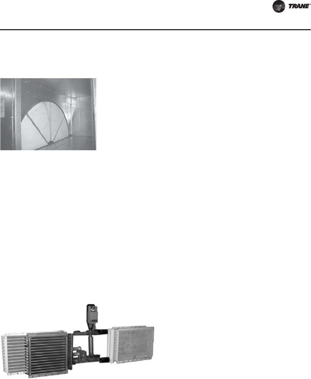
CLCH-PRC022A-EN 51
Components and Options
Energy Wheels
Application considerations:
• Certified in accordance to AHRI Standard 1060
• Available in 18 sizes, depending on ventilation requirements ranging from 900 to 25,000 cfm
• Single wheels for sizes 3-50 with up to seven wheels available per unit size
• Greater than 70 percent total effectiveness at a pressure drop of 1 to 1.15 in. w.g. and nominal
airflow through the wheel
• Bypass dampers are standard for partial-flow energy wheel sections
• Standard, built-in return damper for partial-flow, recirculating wheels for sizes 6-50
• Section includes required space upstream and downstream of the wheel
• Required access and doors in the section
• Variable effectiveness control using air bypass
• Frost protection using an air bypass damper or a separate pre-heat module
Coil Runaround Loop
Application Considerations:
• Recovery is limited to sensible energy with effectiveness that typically ranges from 60-65
percent.
Figure 52. Energy wheel The energy wheel section is a total-energy-recovery device; it recovers both
sensible and latent energy. It consists of a rotating wheel that contains heat
exchange media surfaces. A desiccant material specifically designed for
adsorption and desorption of water vapor is permanently bonded into the heat
exchanger matrix. The wheel rotates between the outdoor- and return-air paths,
whose air streams are counter-flow.
Energy wheels are sized based on the ventilation air requirement and can be
applied in a 100-percent-outdoor-air unit or a recirculation unit. Internal wheel-
bypass dampers vary the effectiveness of the wheel.
For more application information on energy recovery, refer to these Trane
applications manual SYS-APM003-EN.
Figure 53. Coil-runaround loops recover sensible energy A runaround loop, used to recover sensible energy,
consists of two finned-tube coils (air-to-water heat
exchangers) piped together; one coil resides in the outdoor
airstream and the other in the exhaust airstream. An
expansion tank, pump, three-way temperature control
valve and working fluid (usually an inhibited solution of
ethylene glycol and water) complete the recovery system.
Since the outdoor and exhaust airstreams need not be
adjacent, the runaround loop provides design versatility
well-suited to building renovations – at a lower first cost
than other methods of energy recovery. Complete
separation of the airstreams also eliminates the risk of
cross-contamination.
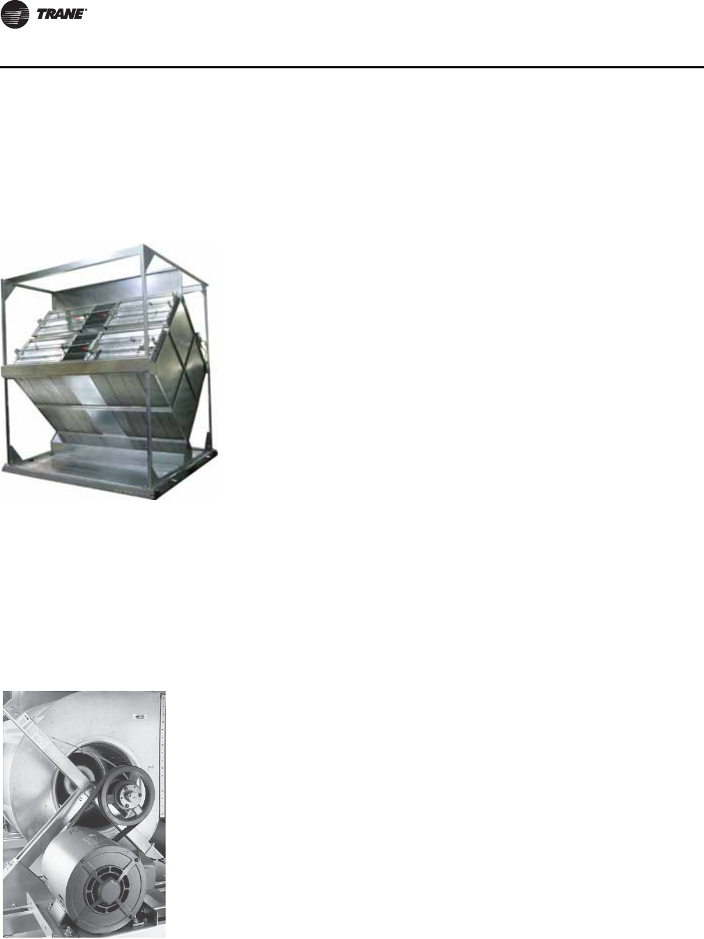
52 CLCH-PRC022A-EN
Components and Options
• Together, the two finned-tube coils may contribute approximately 0.3 to 0.6 in. wg to system
static pressure.
Air-to-Air Plate Frame Heat Exchanger
Fans
Fan Choices
An extensive array of fan types and options, including variable-frequency drives (VFDs) for
modulation in variable-air-volume systems, lets you optimize the fan to best fit not only the airflow
and static pressure requirements, but also the acoustical, efficiency, and discharge requirements.
Figure 54. Air-to-air plate frame heat
exchanger Air-to-air plate frame heat exchangers is a sensible-energy-recovery device.
The
exchanger consists of aluminum plates that are stamped into a dimpled or
channeled shape. The plates are stacked on each other with the alternate
edges crimped and sealed to prevent cross leakage.
These can handle high pressure differentials, some up to 10 inches between
the exhaust and outdoor air side. They also can handle higher temperatures
and can be coated for corrosion protection.
Application Considerations:
• Certified in accordance to AHRI Standard 1060.
• Three plate spacings available.
• Bypass options available for variable effectiveness and frost prevention.
• Up to 70 percent total effectiveness with close spacing.
• Drain pans always required.
• Can be used in a series arrangement for dehumidification.
Figure 55. Trane offers a wide variety
of fan choices Fan types include:
• Double-width/double-inlet (DWDI) centrifugal fans with front, top, or bottom
discharges in the following available types:
– Forward-curved (FC)
– Backward-curved (BC)
– Airfoil (AF)
• Single-width/single-inlet (SWSI) plenum fans with multiple or single
discharges on the front, top, bottom, or sides of the section
– Direct-drive plenum fans
– Belt-drive plenum fans
Plenum fan openings can be tailored to the size, type and location to best fit your
velocity and static pressure requirements improving energy and sound. Round,
rectangular, and bell mouth openings are all available.
Each fan is rated in accordance with Standard 430 of the Air Conditioning Heating
and Refrigeration Institute (AHRI) and all DWDI fans are AHRI Standard 430-
certified to assure published performance.
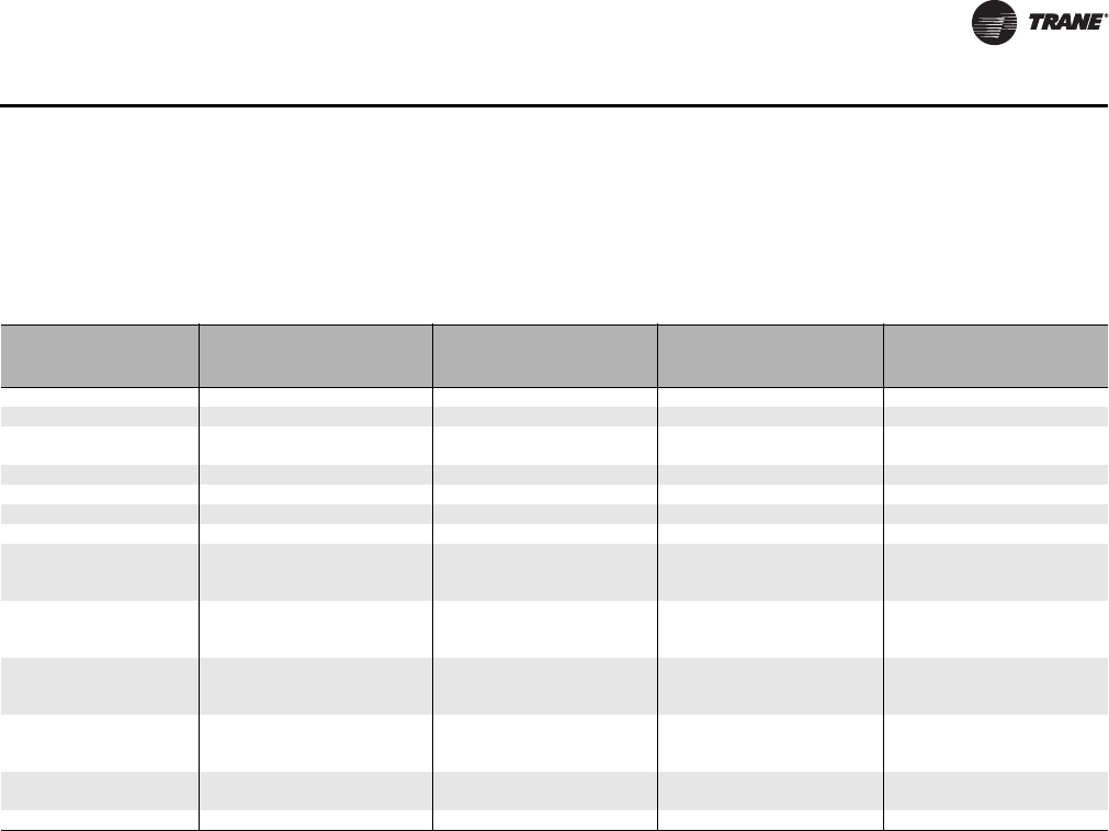
CLCH-PRC022A-EN 53
Components and Options
Table 9 summarizes and compares the characteristics and application considerations of these fans.
When evaluating the merits of each fan type for a given application, consider the volumetric rate
of airflow, static pressure, required sound characteristics, and space.
To verify that fan performance will satisfy design requirements, use the TOPSS selection program.
The AHRI Standard 430-certified fan curves include the fan section casing effect. TOPSS also takes
into account ductwork connections, air density, fan and motor heat, drive losses, and use of high-
performance (MERV 11 and higher) filters affect fan performance.
Constant Volume vs. VAV Systems
Depending on the fan-control method used, the fan can provide either a constant or variable
volume of supply air. In a constant-volume system, the fan delivers a consistent amount of air and
cooling and heating devices adjust the air temperature for occupant comfort. Because the fan runs
at constant horsepower under all load conditions, system operating costs are higher than those of
a VAV system.
A VAV system provides occupant comfort by delivering a modulated amount of constant-
temperature air. Usually, supply-duct static pressure determines how much air the fan provides.
Varying fan horsepower with building load can offer substantial energy savings and do a better job
of controlling space humidity.
Fan modulation is accomplished with a variable-frequency drive (VFD) that adjusts fan speed and
airflow by varying motor speed. VFD modulation is quiet and energy efficient; it can also prolong
the life of the fan motor by “soft starting” it.
Table 9. Fan summary information
Fan type FC Fan Backward-curved
(BC) Fan AF Fan Plenum Fan
Centrifugal, housed Centrifugal, housed Centrifugal, housed Unhoused
Inlet Double Double Double Single
Airflow direction Radial Radial Radial Pressurized, all directions
Optimal pressure range Low to medium
(0 to 5 in. wg) High (4 to 8 in. wg) High (4 to 8 in. wg) Medium to high
(2 to 8 in. wg)
First cost (relative) Low Medium Medium High
Operating cost (relative) Medium Medium-high Medium-high Medium
Typical speed range 400–1,600 rpm 1,000–2,600 rpm 1,000–2,600 rpm 600–1,600 rpm
Blade shape Curved Curved Airfoil Airfoil
Acoustical characteristics Significant air turbulence that
quickly abates; little blade-
tone noise
Significant air turbulence;
strong blade tones in 250-Hz
octave band
Significant air turbulence;
strong blade tones in 250-Hz
octave band
Discharge sound but higher
inlet noise
1
Suggested source
attenuation Add a discharge plenum Avoid using inlet vanes; use
discharge plenums and/or
silencers
Avoid using inlet vanes; use
discharge plenums and/or
silencers
Add a discharge plenum or
outlet/inlet silencer
Direct upstream space
required in draw-thru
arrangements None None None Medium module
Direct downstream space
required in blow-thru
arrangements
Medium blank or diffuser
module Medium blank or diffuser
module Medium blank or diffuser
module Medium blank module
When to use? Low-pressure applications High-pressure applications High-pressure applications Multiple-duct arrangement,
blow-thru applications
2
K
t
loss, abrupt discharge
3
1.80 1.00 1.00 n/a
Note: 1. Add duct takeoff losses from the plenum fan module to external static pressure; see Trane fan performance catalog CLCH-PRC008-EN for details.
2. Same as Note 1; the uniform discharge velocity of the plenum fan may eliminate the need for turns in supply-air ductwork and diffusers, suiting
it for installations with limited equipment room space. 3. In draw-thru applications, fan curves assume three diameters of straight duct downstream
of the fan. Refer to AMCA 201-02, Fans and Systems, for more information when this assumption is not valid.
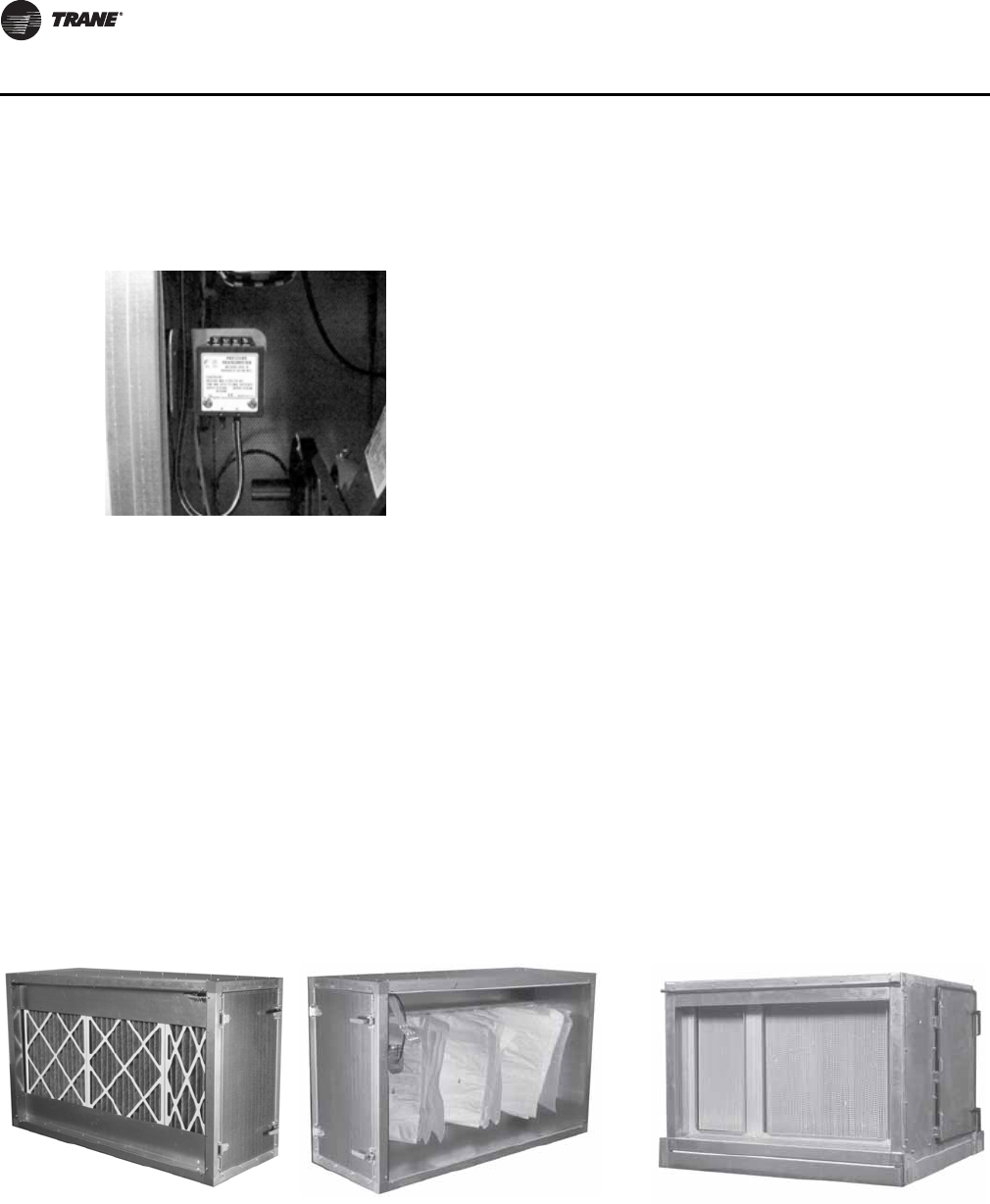
54 CLCH-PRC022A-EN
Components and Options
Airflow Measuring Systems
Filtration and Air Cleaning
Effectively controlling particulate and gaseous contaminants by reducing their concentrations or
removing them from the air stream altogether is key to good IAQ. That necessitates proper filter
selection. Filtration and cleaning options include:
• Pleated media (MERV 8 to 14 based on ASHRAE Standard 52.2)
• Bag or cartridge filters (MERV 11 to 15 based on ASHRAE Standard 52.2)
• HEPA filters (MERV 17 based on ASHRAE Standard 52.2)
• Trane Catalytic Air Cleaners (TCACS) reduce microorganisms to a non-viable state
• Antimicrobial treatments for filters inhibiting microbial growth (MERV 7 based on ASHRAE
Standard 52.2)
Filtration Options
Air handlers can be equipped with a variety of filtration options, all tested in accordance with
ASHRAE Standard 52.2. The continuous operating range of both the high-efficiency filters and the
disposable prefilter is typically 0ºF to 150ºF, but can be as high as 200ºF. Available filters and
minimum efficiency reporting values (MERV) are:
Figure 56. Piezometer ring measures inlet air flow.
A fan inlet airflow measuring system with a piezometer ring
is also available on many centrifugal and plenum fans. Each
system comes with a differential pressure transmitter (see
Figure 56). The piezometer ring is connected to the LO port
of the transmitter and the reference pressure point is
connected to the HI port of the transmitter.
Figure 57. Bag filter section-
entering side Figure 58. Bag filter section -
leaving side Figure 59. HEPA filter section
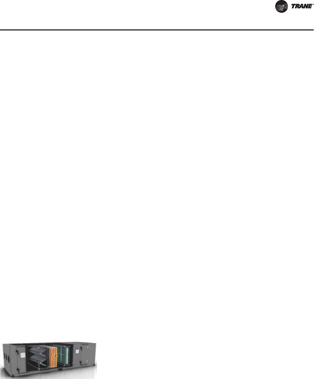
CLCH-PRC022A-EN 55
Components and Options
• Two-inch permanent-MERV 2
• Two-inch disposable-MERV 5
• Two-inch and four-inch pleated media-MERV 8-14
• Eighteen-inch and 30-inch bag or 12-inch cartridge filters-MERV 11-15
• Two-inch and four-inch antimicrobial-treated filters-MERV 7
•HEPA
• Multiple side-loading and front-loading filter options
Application considerations:
• Higher filter efficiencies cost more, but provide cleaner air and better system performance.
National, state, and local codes may also specify filter performance.
• Operating resistance to airflow (i.e. pressure drops). Filter resistance and first cost may increase
with efficiency.
• High filtration efficiencies sometimes require more space, which lowers velocity, and may
enlarge the air handler footprint.
• A high degree of filtration can lower cleaning costs in the occupied space.
• Exceeding the face velocity limit of the filter increases its resistance (as well as fan energy
consumption) and necessitates more frequent maintenance or replacement.
• Exercise special care to avoid moisture carryover whenever final filters are used. Never place
a blow-thru final filter section directly downstream of a cooling coil without providing an
intervening source of reheat (such as fan motor). Tests have shown that certain entering-coil
conditions can create water vapor that will collect on the final filter. The only known solution
for this intermittent application issue is two degrees of reheat.
• Treating filter media with an antimicrobial coating can reduce the likelihood of microbial
contamination. Trane coated pleated media filters can be treated with an antimicrobial coating.
• Install bag filters with the pleats vertical to the floor of the unit.
• Provide easy access to encourage regular filter maintenance.
• High-efficiency filters and disposable pre-filters may be operated near 100 percent relative
humidity; however, they may not come in direct contact with water droplets.
• Keep filters dry.
Air Cleaning Options
Figure 60. TCACS uses three air
cleaning technologies. The Trane Catalytic Air Cleaning System (TCACS) is a factory engineered and
installed combination of three air cleaning technologies: MERV 13 particle
collection, high-intensity UVc light, and photo-catalytic oxidation (PCO). The high
efficiency MERV 13 filters are very good at removing small, respirable particles
from the airstream. The UVc/PCO combination reduces volatile organic
compounds (VOC’s) through photocatalytic oxidation without the creation of
ozone or by-products. The combination of the three technologies also has a
signification capability to reduce the spread of airborne biological containments
including viruses, bacteria and fungi/mold.
The UV energy in the TCACS creates hydroxyl radicals on the surface of the
titanium dioxide which oxidizes contaminants that they contact. All reactions occur
within the air cleaner and no by-products leave the unit. The factory installed
system comes complete with appropriate safety mechanisms protecting the
owners and operators of the system. These safeties include an external disconnect
with lock-out/tag-out capabilities, door interlock switches, and UVc viewport.
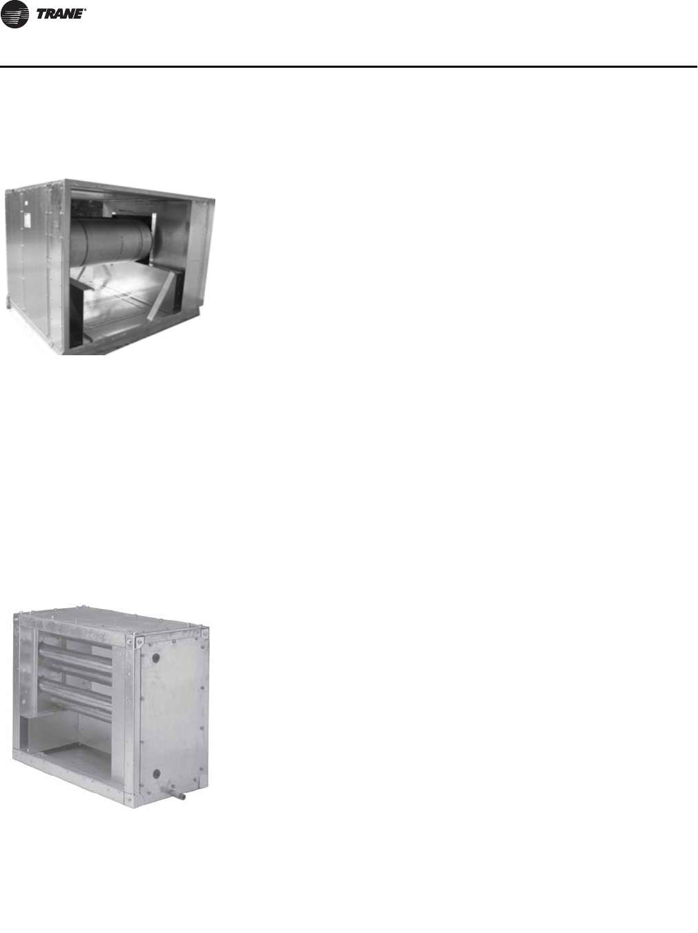
56 CLCH-PRC022A-EN
Components and Options
Gas Heat
Application considerations:
• Gas heater must be applied in a blow-thru configuration to insure that combustion gases will
not enter the airstream due to the positive static pressure.
• Maximum discharge air temperature is 101° F.
• When reducing airflow, the control system should not allow the temperature rise through the
gas heat section to exceed the nominal at full airflow.
• On high altitude applications, derate the heating capacity (MBh) by 4 percent for every 1,000
feet over 2,000 feet.
Humidifier
Figure 61. Gas heat module
Gas heat can be an economical source of heat when compared to traditional heat
sources such as central plant boilers with hot water or steam coils installed inside
air handlers, or electric resistance heating installed inside air handlers.
Gas heat can be a good heating option for any of the following applications:
• Climates and applications with large heat loads
• Applications with high outside air requirements to comply with ASHRAE
Standard 62
• Buildings without a central boiler plant
• Remote locations where boiler capacity or water piping expense is prohibitive
• Areas with relatively inexpensive natural gas or expensive electricity
Figure 62. Humidifier section ASHRAE Standard 62.1 suggests maintaining a relative humidity of no less than
30 percent to provide a comfortable, healthy indoor environment. The humidifier
uses low-pressure steam distributors to add moisture to the air. This can be
accomplished by using either building stream or an atmospheric steam
generator. It includes accessories such as valves, strainers, and traps. Factory
mounting within the air handler lowers the installed cost of the humidifier and
keeps moisture out of the supply duct.
Application considerations:
• Airflow through the humidifier must be horizontal and of relatively uniform
velocity (400 to 700 fpm).
• Do not locate the humidifier upstream of filters, gas heat, electric heat, or active
cooling coils.
• Blow-thru applications with housed fans require at least a four-row coil between
the fan and humidifier modules. The diffuser alone is unacceptable.
• To prevent condensate formation, the relative humidity leaving the humidifier
should not exceed 83 percent. Contact your local Trane sales engineer for
application-specific guidance.
• The required dispersion distance is designed into the humidifier section.
• Vertical airflow turning immediately upstream and downstream of the
humidifier section requires a large turning section.
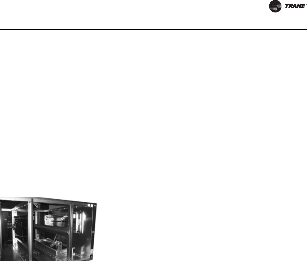
CLCH-PRC022A-EN 57
Components and Options
Inlet Hood
Inlet hoods include a moisture eliminator. Eliminator face velocities below 950 fpm will avoid
pulling water through the eliminator fins and into the unit. It is possible for the moisture to be
carried over into the unit when elimination face velocities are above 950 fpm.
OA Inlet Hood Requirements
Many specification require that there be a minimum distance between the point that outside air
enters an air handler and the roof of a building. This distance is to minimize the possible
introduction of contaminants into the conditioned air.
ASHRAE 62 recommends that there be at least 9 inches (or 8 inches above maximum snow depth)
separation from the roof to the outside air intake, however, some specifications, specifically for
units in the health care industry require at least 36 inches of separation distance. When configuring
and air handler, ensure that the unit in conjunction with a roof curb will meet the specifications
requirements on separation distance.
Mixing Box and Economizer
– Dynamic calculation of the outdoor air needed to adequately ventilate a multispace VAV
system and reset the outdoor-air setpoint accordingly to save energy.
– Trend logs and custom reports to document compliance with ASHRAE Standard 62.1.
• For indoor units, an additional mixing box can be used as an economizer to provide an exhaust
path for return air, allowing the main mixing box to provide natural, non-mechanical cooling
when outdoor air conditions are suitable.
• For outdoor units, and economizer section can be used to provide a path for outside air, return
air and exhaust air in a single section.
• Use freeze protection for coils downstream of the mixing box when incoming outdoor air is
below 35ºF (see “Protect Coils from Freezing,” p. 20).
Figure 63. Mixing Box A mixing box section typically combines the incoming outdoor air with
recirculated return air collected from the occupied space. It is commonly included
in an air handler design to control this mixture. When equipped with an optional
Traq damper, the mixing box module permits direct measurement of outdoor
airflow to assure compliance with ASHRAE Standard 62.1.
Application considerations:
• The Traq damper mixing box requires only one duct diameter of straight inlet
duct (as much as 80 percent less than other airflow monitoring techniques).
• Connecting a Traq-damper-equipped air handler to a building automation
system, such as a Tracer building management system, permits:
58 CLCH-PRC022A-EN
Components and Options
Multizone
The multizone module consists of a cooling coil, heating coil, and dampers with multiple zones. It
can be split into either two decks or three decks, each with a separate air stream. The “cold” deck
cools one air stream and the “hot” deck heats another air stream. A third deck can be used for
bypass air. The damper then mixes these air streams to achieve a certain mixed-air temperature.
The damper is divided into segments so that one AHU can deliver multiple supply air temperatures.
Baffles ensure equal pressure drops through each deck of the unit.
The multizone module is always used in a blow-thru arrangement and is typically placed directly
downstream of the supply fan.
Note: The number of zones that one multizone AHU can supply varies by unit size. Be aware that
ASHRAE Standard 90.1 does not allow for multizone configurations without bypass for new
construction.
Silencers
Figure 64. Sound attenuators used
in low NC level
applications
Controlling noise at its source is the most cost-effective solution for providing
quiet comfort in the space. Source attenuation can eliminate the need for duct-
mounted silencers and thereby lower fan operating costs. The key to a quiet
design is to know which options and layouts have a sound source that achieves
the target noise criterion (NC) level when reduced by space attenuation. It all starts
with accurate, tested sound data, and Trane has the most complete sound power
data in the industry.
The design process involves predicting the unit sound power and projecting it into
the space, then optimizing the path attenuation (ductwork, ceilings) and the unit
sound (fans, plenums) to get the lowest cost system that meets the requirements.
Designing the right unit is a matter of experience and solid acoustical data.
Obviously, the quieter the sound source, the less path attenuation is needed in the
sound paths. Minimizing the sound source, using a quieter fan, or using more
source attenuation increases the initial cost of the air handler, but is generally
offset by significant path-reduction cost savings.
CLCH-PRC022A-EN 59
General Data
This section includes summary information per unit size, including section dimensions and
weights, coil availability, filter areas and sizes, fan section weights and application data, and
damper areas.
Note: For specific dimensional and weight information, refer to the unit submittals. The
dimensions and weights in this manual are approximate. Trane has a policy of continuous
product and product data improvement and reserves the right to change design and
specifications without notice.
Unit Size 3
Table 10. Section dimensions (inches) and weights (pounds) - unit size 3
Nominal airflow
1500
Airflow at 625 fpm
2169
Height - indoor unit (in.)
29.00
Width (in.)
31.50
Height - outdoor unit (in.) includes base drip lip
36.25
Weight add for outdoor unit (lbs./in. of unit length)
1.66
Section type Length (in.) Weight (lb.)
Access or blank
-Small horizontal 10.00 48.05
-Medium horizontal 14.00 59.91
-Extended-medium horizontal 19.00 74.73
-Medium-large horizontal 24.50 121.60
-Large horizontal or turning 34.00 137.75
-Extra-large horizontal or turning 36.00 143.68
-Ducted inlet or ducted outlet section
10.00 48.10
Blender
19.00 94.86
Cool Dry Quiet (CDQ) Desiccant Dehumidification Section
52.00 495.00
Coils
-Small horizontal (with 4-row UW) 10.00 116.10
-Medium horizontal (with 8-row UW) 14.00 168.65
-Extended-medium horizontal (with 8-row UW) 19.00 185.58
-Medium-large horizontal (with 10-row W) 24.50 270.61
-Large horizontal or vertical (with 10-row W) 34.00 302.77
-Electric Heat Coil
36.00 295.00
-Integral-face-and-bypass (IFB) coil
n/a n/a
Controls section (includes largest available VFD)
28.50 184.00
Diffuser
10.00 45.70
Discharge plenum
-Horizontal 34.00 135.40
-Vertical 36.00 159.90
Energy Wheel
n/a n/a
Face-and-Bypass Dampers
-Face-and-bypass 19.00 105.60
-External face-and-bypass 19.00 122.68
-Internal face-and-bypass or face damper only 19.00 107.95

60 CLCH-PRC022A-EN
General Data
Fan Length (in.) Weight (lb.)
-Belt-drive plenum (BDP) fan with motor 36.00 397.87
-Housed fan FC with motor 36.00 368.77
-Housed AF/BC fans with motor 36.00 378.87
-Direct-drive plenum fan with motor 36.00 373.16
Filters
-Side load 2-in. angled 24.50 134.55
-Side load 4-in. angled 24.50 141.89
-Side load cartridge 12-in. or short bag 18-in. 24.50 125.03
-Side load 2-in. flat 14.00 70.27
-Side load 4-in. flat 14.00 81.56
Filters
-Side load 2-in. and 4-in. combination flat 19.00 100.62
-Long bag 30-in. 36.00 159.54
-Front-load HEPA 40.00 240.36
-Front-load cartridge, 2-inch and 4-inch 40.00 215.15
-Front-load short bag 45.00 222.35
Gas heat
n/a n/a
Humidifier
-Building Steam 14.00 125.00
-Atmospheric 14.00 127.00
Mixing box
-with angled filters 34.00 137.75
-with front/back Traq and top Traq dampers 36.00 191.06
- reduced length mixing box with side/top/back/bottom airfoil damper 23.40 131.80
Multizone
n/a n/a
Silencer
-3 feet 38.00 198.00
-5 feet 62.00 308.00
Trane Catalytic Air Cleaning System (TCACS)
36.00 334.73
UV light
14.00 76.02
SECTIONS BELOW ARE FOR OUTDOOR UNITS ONLY
Diagonal economizer
-with airfoil dampers 46.00 187.00
-with airfoil damper and one side Traq damper 46.00 204.00
Exhaust damper section
19.00 93.30
Hoods
- Back inlet hood - airfoil and Traq 22.25 22.00
- Side inlet hood - airfoil and Traq 20.00 17.00
- Exhaust hood - airfoil 20.00 12.00
- Economizer inlet hood 45.50 41.00
Pipe Cabinets
15 in. long - 24-in. depth 15.00 77.00
15 in. long - 36-in. depth 15.00 104.00
15 in. long - 48-in. depth 15.00 132.00
24 in. long - 24-in. depth 24.00 91.00
24 in. long - 36-in. depth 24.00 122.00
24 in. long - 48-in. depth 24.00 153.00
Table 10. Section dimensions (inches) and weights (pounds) - unit size 3
CLCH-PRC022A-EN 61
General Data
Pipe Cabinets Length (in.) Weight (lb.)
48 in. long - 24-in. depth 48.00 130.00
48 in. long - 36-in. depth 48.00 169.00
48 in. long - 48-in. depth 48.00 208.00
96 in. long - 24-in. depth 96.00 207.00
96 in. long - 36-in. depth 96.00 263.00
96 in. long - 48-in. depth 96.00 319.00
Table 11. Filter data for unit size 3
Filter Type Area ft² Qty–Size (in.)
Flat (2-in., 4-in., and 2-in/4-in high efficiency) pleated, permanent,
throwaway media 3.47 1 - 20x25
Angled (2-in. or 4-in.) Pleated, permanent, throwaway media 5.56 2 - 16x25
Side load bag or cartridge 3.33 1 - 20x24
Front load bag or cartridge 2.00 1 - 12x24
Front load HEPA 2.00 1 - 12x24
Note: 2-inch filters available in permanent, throwaway, or pleated media; 4-inch filters available in pleated media, 65%, 85%,
or 95% efficiency; Bag or cartridge filters available in 65%, 85%, or 95% efficiency.
Table 12. Coil availability - unit size 3
Section Type 1/2-in Unit Coils 5/8-in Unit Coils,
1/2-in and 5/8-in Modified Coils
Small 2-4 rows 1-2 rows
Medium 2–8 rows 1–4 rows
Extended-medium 2–8 rows 1–8 rows
Medium-large 2-8 rows 1-10 rows
-with access 2–6 rows 1–3 rows
Large horizontal 2–8 rows 1–10 rows
-with access 2–8 rows 1–6 rows
Large vertical 2-8 rows 1–6 rows
-with access 2–8 rows 1–4 rows
Table 13. Coil data for unit size 3
Coil Type Rows Fin Type Area ft² Qty–Size (in.)
1/2-inch unit coils
-UA,UW, UF 2, 4, 6, 8 Aluminum 2.92 1–20 × 21
5/8-inch unit coils
-W, 5A, 5W, D1, TT, P2, P4, P8 1, 2, 3, 4, 6, 8, 10 Aluminum or Copper 2.50 1–18 × 20
-WD, D2 6, 8, 10 Aluminum or Copper 2.38 1–18 × 19
1-inch unit coil
-NS 1Aluminum or Copper 2.50 1–18 × 20
1/2-inch modified coil
-WL 2, 4, 6, 8 Aluminum 1.74 1–12.50 × 20
5/8-inch modified coils
-W, 5A, 5W, D1, TT, P2, P4 1, 2, 3, 4, 6, 8, 10 Aluminum or Copper 1.67 1–12 × 20
1-inch modified coil
-NS 1Aluminum or Copper 1.67 1–12 × 20
Table 10. Section dimensions (inches) and weights (pounds) - unit size 3
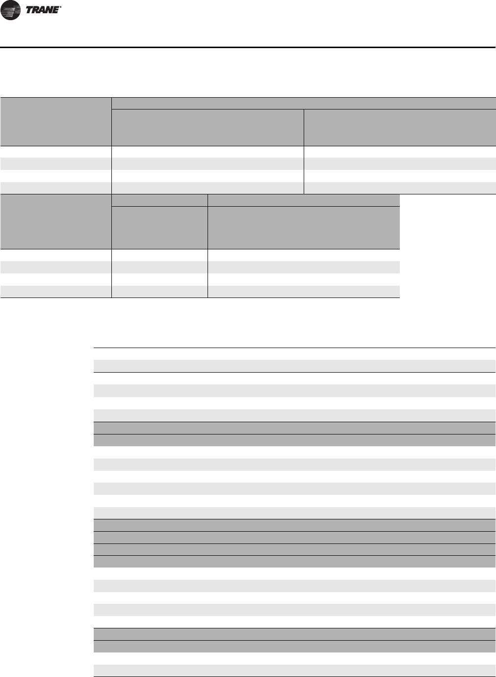
62 CLCH-PRC022A-EN
General Data
Unit Size 4
Table 14. Fan data for unit size 3
Housed Fans
Low Pressure High Pressure
Size/type 9-in FC 9-6-in FC 9-4-in FC 9-in BC 9-in FC 9-6-in FC 9-4-in FC 9-in BC
Fan name 9FA 5FA 4FA 9BA 9FB 5FB 4FB 9BB
Max TSP/rpm 4/2250 4.5/2250 4.5/2250 6.5/4375 5/2900 6.5/2900 7/2900 8/5000
ODP NEMA Prem motor hp range 0.75-3 0.75-3 0.75-3 0.75-3 0.75-3 0.75-3 0.75-3 0.75-5
Outlet area (ft²) 0.85 0.60 0.50 0.85 0.85 0.60 0.50 0.85
Bearing/Shaft size (in.) 0.75 0.75 0.75 0.75 0.75 0.75 0.75 0.75
Belt-drive Plenum Fans Direct-Drive Plenum Fans
High Pressure High Pressure
Size/type 11-in BC 10-in BC 10.5-in. AF
Nominal Width 10.5-in. AF
Extended Width
Fan name 11PB 10PB 10NF 10NW
Max TSP/rpm 9/4735 8/5200 5195 5195
ODP NEMA Prem motor hp range 0.75-5 0.75-3 1-5 1.5-5
Outlet area (ft²) n/a n/a
Bearing/Shaft size (in.) n/a n/a
Table 15. Section dimensions (inches) and weights (pounds) - unit size 4
Nominal airflow
2000
Airflow at 625 fpm
3475
Height - indoor unit (in.)
29.00
Width (in.)
44.00
Height - outdoor unit (in.) includes base drip lip
36.38
Weight add for outdoor unit (lbs./in. of unit length)
1.91
Section type Length (in.) Weight (lb.)
Access or blank
-Small horizontal 10.00 57.43
-Medium horizontal 14.00 71.18
-Extended-medium horizontal 19.00 88.37
-Medium-large horizontal 24.50 107.28
-Large horizontal or turning 34.00 164.85
-Extra-large horizontal or turning 41.00 188.92
-Ducted inlet or ducted outlet section
10.00 57.40
Blender
24.50 132.71
Cool Dry Quiet (CDQ) Desiccant Dehumidification Section
52.00 651.00
Coils
-Small horizontal (with 4-row UW) 10.00 148.55
-Medium horizontal (with 8-row UW) 14.00 220.23
-Extended-medium horizontal (with 8-row UW) 19.00 239.53
-Medium-large horizontal (with 10-row W) 24.50 359.79
-Large horizontal or vertical (with 10-row W) 34.00 396.45
-Electric Heat Coil
41.00 364.00
-Integral-face-and-bypass (IFB) coil
--
Less than 4 rows 26.50 355.20
--4 rows 43.00 543.54
CLCH-PRC022A-EN 63
General Data
Section type Length (in.) Weight (lb.)
Controls section (includes largest available VFD)
28.50 208.00
Diffuser
10.00 55.08
Discharge plenum
-Horizontal 34.00 162.50
-Vertical 41.00 211.48
Energy Wheel
52.00 609.00
Face-and-Bypass Dampers
-Face-and-bypass 19.00 129.06
-External face-and-bypass 19.00 155.15
-Internal face-and-bypass or face damper only 19.00 140.46
Fan
-Belt-drive plenum (BDP) fan with motor 41.00 538.34
-Housed fan FC with motor 41.00 449.75
-Housed AF/BC fans with motor 41.00 467.35
-Direct-drive plenum fan with motor 41.00 516.35
Filters
-Side load 2-in. angled 24.50 163.83
-Side load 4-in. angled 24.50 176.87
-Side load cartridge 12-in. or short bag 18-in. 24.50 159.79
Filters
-Side load 2-in. flat 14.00 86.53
-Side load 4-in. flat 14.00 104.62
-Side load 2-in. and 4-in. combination flat 19.00 128.19
-Long bag 30-in. 41.00 203.31
-Front-load HEPA 40.00 262.50
-Front-load cartridge 40.00 237.79
-Front-load short bag 45.00 246.75
Gas heat
n/a n/a
Humidifier
-Building Steam 14.00 146.00
-Atmospheric 14.00 168.00
Mixing box
-with angled filters 34.00 164.85
-with front/back Traq and top Traq dampers 41.00 247.07
- reduced length mixing box with side/top/back/bottom airfoil damper 23.40 158.30
Multizone
n/a n/a
Silencer
-3 feet 38.00 256.00
-5 feet 62.00 391.00
Trane Catalytic Air Cleaning System (TCACS)
36.00 367.14
UV light
14.00 93.64
SECTIONS BELOW ARE FOR OUTDOOR UNITS ONLY
Diagonal economizer
-with airfoil dampers 49.00 231.00
-with airfoil damper and one side Traq damper 49.00 247.00
Exhaust damper section
19.00 113.30
Table 15. Section dimensions (inches) and weights (pounds) - unit size 4
64 CLCH-PRC022A-EN
General Data
Hoods Length (in.) Weight (lb.)
- Back inlet hood - airfoil and Traq 44.00 45.00
- Side inlet hood - airfoil and Traq 20.00 17.00
- Exhaust hood - airfoil 20.00 12.00
- Economizer inlet hood 49.00 37.00
Pipe Cabinets
15 in. long - 24-in. depth 15.00 77.00
15 in. long - 36-in. depth 15.00 104.00
15 in. long - 48-in. depth 15.00 132.00
24 in. long - 24-in. depth 24.00 91.00
24 in. long - 36-in. depth 24.00 122.00
24 in. long - 48-in. depth 24.00 153.00
48 in. long - 24-in. depth 48.00 130.00
48 in. long - 36-in. depth 48.00 169.00
48 in. long - 48-in. depth 48.00 208.00
96 in. long - 24-in. depth 96.00 207.00
96 in. long - 36-in. depth 96.00 263.00
96 in. long - 48-in. depth 96.00 319.00
Table 16. Filter data for unit size 4
Filter Type Area ft² Qty–Size (in.)
Flat (2-in., 4-in., and 2-in/4-in high efficiency) pleated, permanent,
throwaway media 5.56 2 - 20x20
Angled (2-in. or 4-in.) pleated, permanent, throwaway media 8.89 4 - 16x20
Side load bag or cartridge 5.56 2 - 20x20
Front load bag or cartridge 2.00 1 - 12x24
Front load HEPA 2.00 1 - 12x24
Note: 2-inch filters available in permanent, throwaway, or pleated media; 4-inch filters available in pleated media, 65%, 85%,
or 95% efficiency; Bag or cartridge filters available in 65%, 85%, or 95% efficiency.
Table 17. Coil availability - unit size 4
Section Type 1/2-in Unit Coils 5/8-in Unit Coils,
1/2-in and 5/8-in Modified Coils
Small 2-4 rows 1-2 rows
Medium 2–8 rows 1–4 rows
Extended-medium 2–8 rows 1–8 rows
Medium-large 2-8 rows 1-10 rows
-with access 2–6 rows 1–3 rows
Large horizontal 2–8 rows 1–10 rows
-with access 2–8 rows 1–6 rows
Large vertical 2-8 rows 1–6 rows
-with access 2–8 rows 1–4 rows
Table 15. Section dimensions (inches) and weights (pounds) - unit size 4
CLCH-PRC022A-EN 65
General Data
Table 18. Coil data for unit size 4
Coil Type Rows Fin Type Area ft² Qty–Size (in.)
1/2-inch unit coils
-UA, UW, UF 1, 2, 4, 6, 8 Aluminum 4.51 1–20 × 32.50
5/8-inch unit coils
-W, 5A, 5W, D1, TT, P2, P4, P8 1, 2, 3, 4, 6, 8, 10 Aluminum or Copper 4.00 1–18 × 32
-WD, D2 6, 8, 10 Aluminum or Copper 3.88 1–18 × 31
1-inch unit coil
-NS 1Aluminum or Copper 4.00 1–18 × 32
1/2-inch modified coil
-WL 1, 2, 4, 6, 8 Aluminum 2.78 1–12.50 × 32
5/8-inch modified coils
-W, 5A, 5W, D1, TT, P2, P4 1, 2, 3, 4, 6, 8, 10 Aluminum or Copper 2.67 1–12 × 32
1-inch modified coil
-NS 1Aluminum or Copper 2.67 1–12 × 32
Table 19. Fan data for unit size 4
Housed Fans
Low Pressure High Pressure
Size/type 10-in. FC 9-in. FC 9-6-in. FC 10-in. BC 9-in. BC 10-in. FC 9-in. FC 9-6 in. FC10-in. BC 9-in. BC
Fan name 10FA 9FA 5FA 10BA 9BA 10FB 9FB 5FB 10BB 9BB
Max TSP/rpm 4.5/2100 4/2250 4.5/2250 5/4070 6/4375 6/2525 6/2900 6.5/2900 8/4650 8/5000
ODP NEMA Premium motor
hp range 0.75-5 0.75-3 0.75-3 0.75-3 0.75-3 0.75-5 0.75-5 0.75-5 0.75-5 0.75-5
Outlet area (ft²) 1.04 0.84 0.60 1.04 0.85 1.04 0.84 0.60 1.03 0.85
Bearing/Shaft size (in.) 0.75 0.75 0.75 0.75 0.75 0.75 0.75 0.75 0.75 0.75
Belt-drive Plenum Fans Direct-Drive Plenum Fans
Low Pressure High Pressure High Pressure
Size/type 12-in. AF 12-in. AF 11-in. BC 13.5-in AF
Reduced Width 13.5-in AF
Nominal Width
Fan name 12PA 12PB 11PB 13NR 13NF
Max TSP/rpm 7/4130 7.5/4500 9/4735 4038 4038
ODP NEMA Premium motor
hp range 0.75-5 0.75-7.5 0.75-5 1.5-7.5 1.5-7.5
Outlet area (ft²) n/a n/a n/a n/a n/a
Bearing/Shaft size (in.) 1.00 1.19 0.75 n/a n/a
66 CLCH-PRC022A-EN
General Data
Unit Size 6
Table 20. Section dimensions (inches) and weights (pounds) - unit size 6
Nominal airflow
3000
Airflow at 625 fpm
4338
Height - indoor unit (in.)
35.25
Width (in.)
44.00
Height - outdoor unit (in.) includes base drip lip
42.63
Weight add for outdoor unit (lbs./in. of unit length)
1.91
Section type Length (in.) Weight (lb.)
Access or blank
5
-Small horizontal 10.00 60.55
-Medium horizontal 14.00 75.25
-Extended-medium horizontal 19.00 93.62
-Medium-large horizontal 24.50 113.84
-Large horizontal or turning 34.00 179.46
-Extra-large horizontal or turning 41.00 205.18
-Ducted inlet or ducted outlet section
10.00 60.50
Blender
24.50 146.30
Cool Dry Quiet (CDQ) Desiccant Dehumidification Section
52.00 694.00
Coils
-Small horizontal (with 4-row UW) 10.00 174.35
-Medium horizontal (with 8-row UW) 14.00 265.58
-Extended-medium horizontal (with 8-row UW) 19.00 286.06
-Medium-large horizontal (with 10-row W) 24.50 433.08
-Large horizontal or vertical (with 10-row W) 34.00 471.99
-Electric Heat Coil
41.00 413.00
-Integral-face-and-bypass (IFB) coil
--
Less than 4 rows 26.50 367.21
--4 rows 43.00 560.74
Controls section (includes largest available VFD)
28.50 253.00
Diffuser
10.00 58.20
Discharge plenum
-Horizontal 34.00 177.11
-Vertical 41.00 233.54
Energy Wheel
52.00 663.00
Face-and-Bypass Dampers
-Face-and-bypass 19.00 141.70
-External face-and-bypass 19.00 167.79
-Internal face-and-bypass or face damper only 19.00 149.91
Fan
-Belt-drive plenum (BDP) fan with motor 41.00 631.36
-Housed fan FC with motor 41.00 544.28
-Housed AF/BC fans with motor 41.00 574.68
-Direct-drive plenum fan with motor 41.00 535.05
CLCH-PRC022A-EN 67
General Data
Filters Length (in.) Weight (lb.)
-Side load 2-in. angled 24.50 175.66
-Side load 4-in. angled 24.50 192.86
-Side load cartridge 12-in. or short bag 18-in. 24.50 176.46
-Side load 2-in. flat 14.00 91.98
-Side load 4-in. flat 14.00 114.08
-Side load 2-in. and 4-in. combination flat 19.00 139.09
-Long bag 30-in. 41.00 224.00
-Front-load HEPA 40.00 346.00
-Front-load cartridge 40.00 286.00
-Front-load short bag 45.00 280.00
Gas heat
- 200 MBH 57.00 752.90
- 300 MBH 73.00 901.30
Humidifier
-Building Steam 14.00 165.00
-Atmospheric 14.00 178.00
Mixing box
-with angled filters 34.00 179.46
-with front/back Traq and top Traq dampers 41.00 272.06
- reduced length mixing box with side/top/back/bottom airfoil damper 23.40 177.90
Multizone
- 3-deck vertical discharge 61.00 1125.00
- 2-deck vertical discharge 61.00 763.00
- 3-deck horizontal discharge 52.00 1031.00
- 2-deck horizontal discharge 52.00 701.00
Silencer
-3 feet 38.00 286.00
-5 feet 62.00 436.00
Trane Catalytic Air Cleaning System (TCACS)
36.00 389.00
UV light
14.00 98.69
SECTIONS BELOW ARE FOR OUTDOOR UNITS ONLY
Diagonal economizer
-with airfoil dampers 50.00 256.00
-with airfoil damper and one side Traq damper 50.00 271.00
Exhaust damper section
19.00 124.30
Hoods
- Back inlet hood - airfoil and Traq 44.00 47.00
- Side inlet hood - airfoil and Traq 20.00 22.00
- Exhaust hood - airfoil 20.00 16.00
- Economizer inlet hood 49.50 45.00
Pipe Cabinets
15 in. long - 24-in. depth
15 in. long - 36-in. depth 15.00 116.00
15 in. long - 48-in. depth 15.00 146.00
24 in. long - 24-in. depth 24.00 101.00
24 in. long - 36-in. depth 24.00 135.00
24 in. long - 48-in. depth 24.00 168.00
Table 20. Section dimensions (inches) and weights (pounds) - unit size 6
68 CLCH-PRC022A-EN
General Data
Pipe Cabinets Length (in.) Weight (lb.)
48 in. long - 24-in. depth 48.00 142.00
48 in. long - 36-in. depth 48.00 184.00
48 in. long - 48-in. depth 48.00 226.00
96 in. long - 24-in. depth 96.00 226.00
96 in. long - 36-in. depth 96.00 284.00
96 in. long - 48-in. depth 96.00 343.00
Table 21. Filter data for unit size 6
Filter Type Area ft² Qty–Size (in.)
Flat (2-in., 4-in., and 2-in/4-in high efficiency) pleated, permanent,
throwaway media 5.56 2 - 20x25
Angled (2-in. or 4-in.) Pleated, permanent, throwaway media 8.89 4 - 16x20
Side load bag or cartridge 6.67 2 - 24x20
Front load bag or cartridge 6.00 1 - 24x24
1 - 24x12
Front load HEPA 6.00 1 - 24x24
1 - 24x12
Note: 2-inch filters available in permanent, throwaway, or pleated media; 4-inch filters available in pleated media, 65%, 85%,
or 95% efficiency; Bag or cartridge filters available in 65%, 85%, or 95% efficiency.
Table 22. Coil availability - unit size 6
Section Type 1/2-in Unit Coils 5/8-in Unit Coils,
1/2-in and 5/8-in Modified Coils
Small 2-4 rows 1-2 rows
Medium 2–8 rows 1–4 rows
Extended-medium 2–8 rows 1–8 rows
Medium-large 2-8 rows 1-10 rows
-with access 2–6 rows 1–3 rows
Large horizontal 2–8 rows 1–10 rows
-with access 2–8 rows 1–6 rows
Large vertical 2-8 rows 1–6 rows
-with access 2–8 rows 1–4 rows
Table 23. Coil data for unit size 6
Coil Type Rows Fin Type Area ft² Qty–Size (in.)
1/2-inch unit coils
-UA,UW, UF 1, 2, 4, 6, 8 Aluminum 6.11 1–26.25 x 33.50
5/8-inch unit coils
-W, 5A, 5W, D1, TT, P2, P4, P8 1, 2, 3, 4, 6, 8, 10 Aluminum or Copper 5.33 1–24 × 32
-WD, D2 6, 8, 10 Aluminum or Copper 5.17 1–24 × 31
1-inch unit coil
-NS 1Aluminum or Copper 5.33 1–24 × 32
1/2-inch modified coil
-WL 1, 2, 4, 6, 8 Aluminum 2.78 1–12.50 × 32
5/8-inch modified coils
-W, 5A, 5W, D1, TT, P2, P4 1, 2, 3, 4, 6, 8, 10 Aluminum or Copper 2.67 1–12 × 32
Table 20. Section dimensions (inches) and weights (pounds) - unit size 6
CLCH-PRC022A-EN 69
General Data
Coil Type Rows Fin Type Area ft² Qty–Size (in.)
1-inch modified coil
-NS 1Aluminum or Copper 2.67 1–12 × 32
Multizone coils
-5A, 5W, NS, TT 1, 2 Aluminium or Copper 2.67 1-12 x 32
-WL 2 Aluminum 2.67 1-12 x 32
Table 23. Coil data for unit size 6
Table 24. Fan data for unit size 6
Housed Fans - Low Pressure
Size/Type 12-in. FC 10-in. FC 9-in. FC 12-in. AF 10-in. BC 9-in. BC
Fan Name 12FA 10FA 9FA 12AA 10BA 9BA
Max rpm 1900 2100 2250 3700 4070 4375
ODP NEMA Premium motor hp range 0.75-5 0.75-5 0.75-3 0.75-7.5 0.75-3 0.75-3
Outlet area (ft²) 1.46 1.03 0.84 1.46 1.03 0.84
Bearing/Shaft size (in.) 1.00 0.75 0.75 1.00 0.75 0.75
Housed Fans - High Pressure
Size/Type 12-in. FC 10-in. FC 9-in. FC 12-in. AF 10-in. BC 9-in. BC
Fan name 12FB 10FB 9FB 12AB 10BB 9BB
Max rpm 2115 2525 2900 4350 4650 5000
ODP NEMA Premium motor hp range 0.75-7.5 0.75-7.5 0.75-5 0.75-7.5 0.75-5 0.75-5
Outlet area (ft²) 1.46 1.03 0.84 1.46 1.03 0.84
Bearing/Shaft size (in.) 1.19 0.75 0.75 1.44 0.75 0.75
Belt-drive Plenum Fans Direct-Drive Plenum Fans
Low Pressure High Pressure High Pressure
Size/Type 16-in. AF 14-in. AF 16-in. AF 14-in. AF 15-in. AF
Reduced Width 15-in. AF
Nominal Width
Fan name 16PA 14PA 16PB 14PB 15NR 15NF
Max rpm 3300 3670 3700 4000 3650 3650
ODP NEMA Premium motor hp range 0.75-10 0.75-7.5 0.75-10 0.75-10 1.5-10 1.5-10
Outlet area (ft²) n/a n/a n/a n/a n/a n/a
Bearing/Shaft size (in.) 1.19 1.00 1.4 1.19 n/a n/a

70 CLCH-PRC022A-EN
General Data
Unit Size 8
Table 25. Section dimensions (inches) and weights (pounds) - unit size 8
Nominal airflow
4000
Airflow at 625 fpm
4581
Height - indoor unit (in.)
3
37.75
Width (in.)
50.50
Height - outdoor unit (in.)
4
includes base drip lip
45.13
Weight add for outdoor unit (lbs./in. of unit length)
2.04
Section type Length (in.) Weight (lb.)
Access or blank
5
-Small horizontal 10.00 66.67
-Medium horizontal 14.00 82.74
-Extended-medium horizontal 19.00 102.82
-Medium-large horizontal 26.50 132.94
-Large horizontal or turning 36.00 208.50
-Extra-large horizontal or turning 44.00 240.63
-Ducted inlet or ducted outlet section
10.00 66.70
Blender
26.50 173.34
Cool Dry Quiet (CDQ) Desiccant Dehumidification Section
52.00 792.00
Coils
-Small horizontal (with 4-row UW) 10.00 205.79
-Medium horizontal (with 8-row UW) 14.00 318.97
-Extended-medium horizontal (with 8-row UW) 19.00 341.16
-Medium-large horizontal (with 10-row W) 26.50 554.88
-Large horizontal or vertical (with 10-row W) 36.00 597.03
-Electric Heat Coil
44.00 480.00
-Integral-face-and-bypass (IFB) coil
--
Less than 4 rows 26.50 470.21
--4 rows 43.00 725.48
Controls section (includes largest available VFD)
28.50 272.00
Diffuser
14.00 80.39
Discharge plenum
-Horizontal 36.00 206.15
-Vertical 44.00 275.69
Energy Wheel
52.00 765.00
Face-and-Bypass Dampers
-Face-and-bypass 19.00 157.63
-External face-and-bypass 19.00 190.70
-Internal face-and-bypass or face damper only 19.00 174.82
Fan
-Belt-drive plenum (BDP) fan with motor 44.00 682.55
-Housed fan FC with motor 44.00 589.00
-Housed AF/BC fans with motor 44.00 649.40
-Direct-drive plenum fan with motor 44.00 692.86

CLCH-PRC022A-EN 71
General Data
Filters Length (in.) Weight (lb.)
-Side load 2-in. angled 26.50 202.44
-Side load 4-in. angled 26.50 209.64
-Side load cartridge 12-in. or short bag 18-in. 26.50 220.46
-Side load 2-in. flat 14.00 103.59
-Side load 4-in. flat 14.00 117.09
-Side load 2-in. and 4-in. combination flat 19.00 144.56
-Long bag 30-in. 44.00 269.00
-Front-load HEPA 40.00 368.00
-Front-load cartridge 40.00 310.00
-Front-load short bag 45.00 306.00
Gas heat
- 200 MBH 57.00 797.90
- 300 MBH 73.00 953.50
Humidifier
-Building Steam 14.00 184.00
-Atmospheric 14.00 203.00
Mixing box
-with angled filters 36.00 208.50
-with front/back Traq and top Traq dampers 44.00 321.58
- reduced length mixing box with side/top/back/bottom airfoil damper 23.40 202.80
Multizone
- 3-deck vertical discharge 61.00 1313.00
- 2-deck vertical discharge 61.00 899.00
- 3-deck horizontal discharge 52.00 1219.00
- 2-deck horizontal discharge 52.00 832.00
Silencer
-3 feet 38.00 376.00
-5 feet 62.00 483.00
Trane Catalytic Air Cleaning System (TCACS)
36.00 435.00
UV light
14.00 120.26
SECTIONS BELOW ARE FOR OUTDOOR UNITS ONLY
Diagonal economizer
-with airfoil dampers 48.00 276.00
-with airfoil damper and one side Traq damper 48.00 290.00
Exhaust damper section
19.00 140.20
Hoods
- Back inlet hood - airfoil and Traq 50.38 47.00
- Side inlet hood - airfoil and Traq 20.00 22.00
- Exhaust hood - airfoil 20.00 16.00
- Economizer inlet hood 48.00 61.00
Pipe Cabinets
15 in. long - 24-in. depth 15.00 89.00
15 in. long - 36-in. depth 15.00 120.00
15 in. long - 48-in. depth 15.00 152.00
24 in. long - 24-in. depth 24.00 105.00
24 in. long - 36-in. depth 24.00 140.00
24 in. long - 48-in. depth 24.00 174.00
Table 25. Section dimensions (inches) and weights (pounds) - unit size 8
72 CLCH-PRC022A-EN
General Data
Pipe Cabinets Length (in.) Weight (lb.)
48 in. long - 24-in. depth 48.00 148.00
48 in. long - 36-in. depth 48.00 191.00
48 in. long - 48-in. depth 48.00 234.00
96 in. long - 24-in. depth 96.00 233.00
96 in. long - 36-in. depth 96.00 293.00
96 in. long - 48-in. depth 96.00 352.00
Table 26. Filter data for unit size 8
Filter Type Area ft² Qty–Size (in.)
Flat (2-in., 4-in., and 2-in/4-in high efficiency) pleated, permanent,
throwaway media 7.33 1 - 24x20
1 - 24x24
Angled (2-in. or 4-in.) Pleated, permanent, throwaway media 11.11 4 - 20x20
Side load bag or cartridge 8.00 4 - 24x12
Front load bag or cartridge 6.00 1 - 24x24
1 - 24x12
Front load HEPA 7.00 1 - 24x30
1 - 24x12
Note: 2-inch filters available in permanent, throwaway, or pleated media; 4-inch filters available in pleated media, 65%, 85%,
or 95% efficiency; Bag or cartridge filters available in 65%, 85%, or 95% efficiency
Table 27. Coil availability - unit size 8
Section Type 1/2-in Unit Coils 5/8-in Unit Coils,
1/2-in and 5/8-in Modified Coils
Small 2-4 rows 1-2 rows
Medium 2–8 rows 1–4 rows
Extended-medium 2–8 rows 1–8 rows
Medium-large 2-8 rows 1-10 rows
-with access 2–6 rows 1–3 rows
Large horizontal 2–8 rows 1–10 rows
-with access 2–8 rows 1–6 rows
Large vertical 2-8 rows 1–6 rows
-with access 2–8 rows 1–6 rows
Table 28. Coil data for unit size 8
Coil Type Rows Fin Type Area ft² Qty–Size (in.)
1/2-inch unit coils
-UA, UW, UF 1, 2, 4, 6, 8 Aluminum 7.99 1–28.75 × 40
5/8-inch unit coils
-W, 5A, 5W, D1 1, 2, 3, 4, 6, 8,10 Aluminum or Copper 7.31 1–27 × 39
-WD, D2 6, 8, 10 Aluminum or Copper 7.13 1–27 × 38
-TT, P2, P4, P8 1, 2, 4, 6, 8 Aluminum or Copper 6.50 1–24 × 39
1-inch unit coil
-NS 1Aluminum or Copper 6.50 1–24 × 39
1/2-inch modified coils
-WL, LL, FD 2, 4, 6, 8 Aluminum 4.95 1–18.75 × 38
Table 25. Section dimensions (inches) and weights (pounds) - unit size 8
CLCH-PRC022A-EN 73
General Data
Coil Type Rows Fin Type Area ft² Qty–Size (in.)
5/8-inch modified coils
-W, 5A, 5W, D1, TT, P2, P4, P8 1, 2, 3, 4, 6, 8,10 Aluminum or Copper 4.88 1–18 × 39
-WD, D2 6, 8, 10 Aluminum or Copper 4.75 1–18 × 38
1-inch modified coil
-NS 1Aluminum or Copper 4.88 1–18 × 39
Multizone coils
-5A, 5W, NS, TT 1, 2 Aluminium or Copper 3.25 1-12 x 39
-WL 2 Aluminum 3.25 1-12 x 39
Table 28. Coil data for unit size 8
Table 29. Fan data for unit size 8
Housed Fans - Low Pressure
Size/Type 12-in. FC 10-in. FC 9-in. FC 12n. AF 10-in. BC 9-in. BC
Fan name 12FA 10FA 9FA 12AA 10BA 9BA
Max rpm 1900 2100 2250 3700 4070 4375
ODP NEMA Premium motor hp range 1-5 1-5 1-3 1-7.5 1-3 1-3
Outlet area (ft²) 1.46 1.03 0.84 1.46 1.03 0.84
Bearing/Shaft size (in.) 1.00 0.75 0.75 1.00 0.75 0.75
Housed Fans - High Pressure
Size/Type 12-in. FC 10-in. FC 9-in. FC 12-in. AF 10-in. BC 9-in. BC
Fan name 12FB 10FB 9FB 12AB 10BB 9BB
Max rpm 2115 2525 2900 4350 4650 5000
ODP NEMA Premium motor hp range 1-7.5 1-7.5 1-5 1-10 1-5 1-5
Outlet area (ft²) 1.46 1.03 0.84 1.46 1.03 0.84
Bearing/Shaft size (in.) 1.19 0.75 0.75 1.44 0.75 0.75
Belt-drive Plenum Fans Direct-Drive Plenum Fans
Low Pressure High Pressure High Pressure
Size/Type 16-in. AF 14-in. AF 16-in. AF 14-in. AF 1 8 -in . AF
Reduced Width 1 8 -in . AF
Nominal Width
Fan name 16PA 14PA 16PB 14PB 18NR 18NF
Max rpm 3300 3670 3700 4000 2979 2979
ODP NEMA Premium motor hp range 1-10 1-7.5 1-10 1-10 2-15 3-15
Outlet area (ft²) n/a n/a n/a n/a n/a n/a
Bearing/Shaft size (in.) 1.19 1.00 1.34 1.19 n/a n/a
74 CLCH-PRC022A-EN
General Data
Unit Size 10
Table 30. Section dimensions (inches) and weights (pounds) - unit size 10
Nominal airflow
5000
Airflow at 625 fpm
6075
Height - indoor unit (in.)
37.75
Width (in.)
61.50
Height - outdoor unit (in.) includes base drip lip
45.13
Weight add for outdoor unit (lbs./in. of unit length)
2.27
Section type Length (in.) Weight (lb.)
Access or blank
-Small horizontal 10.00 74.92
-Medium horizontal 14.00 92.66
-Extended-medium horizontal 19.00 114.83
-Medium-large horizontal 26.50 148.08
-Large horizontal or turning 36.00 235.01
-Extra-large horizontal or turning 42.50 263.83
-Ducted inlet or ducted outlet section
10.00 74.90
Blender
36.00 238.64
Cool Dry Quiet (CDQ) Desiccant Dehumidification Section
55.00 1011.00
Coils
-Small horizontal (with 4-row UW) 10.00 244.49
-Medium horizontal (with 8-row UW) 14.00 382.53
-Extended-medium horizontal (with 8-row UW) 19.00 406.80
-Medium-large horizontal (with 10-row W) 26.50 656.63
-Large horizontal or vertical (with 10-row W) 36.00 702.74
-Electric Heat Coil
42.50 563.00
-Integral-face-and-bypass (IFB) coil
--
Less than 4 rows 26.50 541.93
--4 rows 43.00 835.34
Controls section (includes largest available VFD)
28.50 295.00
Diffuser
14.00 90.31
Discharge plenum
-Horizontal 36.00 232.66
-Vertical 42.50 306.29
Energy Wheel
55.00 911.00
Face-and-Bypass Dampers
-Face-and-bypass 19.00 178.68
-External face-and-bypass 19.00 219.68
-Internal face-and-bypass or face damper only 19.00 203.43
Fan
-Belt-drive plenum (BDP) fan with motor 42.50 875.00
-Housed fan FC with motor 42.50 721.69
-Housed AF/BC fans with motor 42.50 849.71
-Direct-drive plenum fan with motor 46.75 795.54
CLCH-PRC022A-EN 75
General Data
Filters Length (in.) Weight (lb.)
-Side load 2-in. angled 26.50 225.96
-Side load 4-in. angled 26.50 247.16
-Side load cartridge 12-in. or short bag 18-in. 26.50 234.88
-Side load 2-in. flat 14.00 117.74
-Side load 4-in. flat 14.00 143.40
-Side load 2-in. and 4-in. combination flat 19.00 174.73
-Long bag 30-in. 42.50 289.00
-Front-load HEPA 40.00 408.00
-Front-load cartridge 40.00 341.00
-Front-load short bag 45.00 335.00
Gas heat
- 200 MBH 59.00 852.50
- 300 MBH n/a n/a
- 360 MBH 77.00 1093.20
Humidifier
-Building Steam 14.00 226.00
-Atmospheric 14.00 252.00
Mixing box
-with angled filters 36.00 235.01
-with front/back Traq and top Traq dampers 42.50 356.08
- reduced length mixing box with side/top/back/bottom airfoil damper 23.40 231.60
Multizone
- 3-deck vertical discharge 66.00 1671.00
- 2-deck vertical discharge 66.00 1099.00
- 3-deck horizontal discharge 52.00 1511.00
- 2-deck horizontal discharge 52.00 982.00
Silencer
-3 feet 38.00 359.00
-5 feet 62.00 541.00
Trane Catalytic Air Cleaning System (TCACS)
36.00 470.00
UV light
14.00 135.22
SECTIONS BELOW ARE FOR OUTDOOR UNITS ONLY
Diagonal economizer
-with airfoil dampers 53.00 334.00
-with airfoil damper and one side Traq damper 53.00 349.00
Exhaust damper section
19.00 159.60
Hoods
- Back inlet hood - airfoil and Traq 61.50 52.00
- Side inlet hood - airfoil and Traq 22.88 31.00
- Exhaust hood - airfoil 22.88 21.00
- Economizer inlet hood 53.00 68.00
Pipe Cabinets
15 in. long - 24-in. depth 15.00 89.00
15 in. long - 36-in. depth 15.00 120.00
15 in. long - 48-in. depth 15.00 152.00
Table 30. Section dimensions (inches) and weights (pounds) - unit size 10
76 CLCH-PRC022A-EN
General Data
Pipe Cabinets Length (in.) Weight (lb.)
24 in. long - 24-in. depth 24.00 105.00
24 in. long - 36-in. depth 24.00 140.00
24 in. long - 48-in. depth 24.00 174.00
48 in. long - 24-in. depth 48.00 148.00
48 in. long - 36-in. depth 48.00 191.00
48 in. long - 48-in. depth 48.00 234.00
96 in. long - 24-in. depth 96.00 233.00
96 in. long - 36-in. depth 96.00 293.00
96 in. long - 48-in. depth 96.00 352.00
Table 31. Filter data for unit size 10
Filter Type Area ft² Qty–Size (in.)
Flat (2-in., 4-in., and 2-in/4-in high efficiency) pleated, permanent,
throwaway media 9.72 2 - 20x25
1 - 16x25
Angled (2-in. or 4-in.) pleated, permanent, throwaway media 13.89 4 - 25x20
Side load bag or cartridge 8.67 2 - 24x20
1 - 24x12
Front load bag or cartridge 8.00 2 - 24x24
Front load HEPA 9.00 1 - 24x30
1 - 24x24
Note: 2-inch filters available in permanent, throwaway, or pleated media; 4-inch filters available in pleated media, 65%, 85%,
or 95% efficiency; Bag or cartridge filters available in 65%, 85%, or 95% efficiency.
Table 32. Coil availability-size 10
Section Type 1/2-in Unit Coils 5/8-in Unit Coils,
1/2-in and 5/8-in Modified Coils
Small 2-4 rows 1 - 2 rows
Medium 2–8 rows 1–4 rows
Extended-medium 2–8 rows 1–8 rows
Medium-large 2-8 rows 1-10 rows
-with access 2–6 rows 1–3 rows
Large horizontal 2–8 rows 1–10 rows
-with access 2–8 rows 1–6 rows
Large vertical 2-8 rows 1–6 rows
-with access 2–8 rows 1–6 rows
Table 33. Coil data for unit size 10
Coil Type Rows Fin Type Area ft² Qty–Size (in.)
1/2-inch unit coils
-UA, UW, UF 1, 2, 4, 6, 8 Aluminum 9.98 1–28.75 × 50
5/8-inch unit coils
-W, WD, 5A, 5W, D1, D2 1, 2, 3, 4, 6, 8, 10 Aluminum or Copper 9.19 1-27 x 49
-TT, P2, P4, P8 1, 2, 4, 6, 8 Aluminum or Copper 8.17 1-24 x 49
1-inch unit coil
-NS 1Aluminum or Copper 8.17 1–24 × 49
Table 30. Section dimensions (inches) and weights (pounds) - unit size 10

CLCH-PRC022A-EN 77
General Data
Coil Type Rows Fin Type Area ft² Qty–Size (in.)
1/2-inch modified coils
-WL, LL, FD 2, 4, 6, 8 Aluminum 6.38 1–18.75 × 49
5/8-inch modified coils
-W, 5A, 5W, WD, D1, D2, TT,
P2, P4, P8 1, 2, 3, 4, 6, 8, 10 Aluminum or Copper 6.13 1–18 × 49
1-inch modified coil
-NS 1Aluminum or Copper 6.13 1–18 × 49
Multizone coils
-5A, 5W, NS, TT 1, 2 Aluminium or Copper 6.13 1-18 x 49
-WL 2 Aluminum 6.13 1-18 x 49
Table 33. Coil data for unit size 10
Table 34. Fan data for unit size 10
Housed Fans - Low Pressure
Size/Type 15-in. FC 12-in. FC 10-in. FC 15-in. AF 12-in. AF 10-in. BC
Fan name 15FA 12FA 10FA 15AA 12AA 10BA
Max rpm 1600 1900 2100 2900 3700 4070
ODP NEMA Premium motor hp range 1-7.5 1-5 1-5 1-10 1-7.5 1-3
Outlet area (ft²) 2.05 1.46 1.03 2.05 1.46 1.03
Bearing/Shaft size (in.) 1.00 1.00 0.75 1.19 1.00 0.75
Housed Fans - High Pressure
Size/Type 15-in. FC 12-in. FC 10-in. FC 15-in. AF 12-in. AF 10-in. BC
Fan name 15FB 12FB 10FB 15AB 12AB 10BB
Max rpm 1720 2115 2525 3500 4350 4650
ODP NEMA Premium motor hp range 1-10 1-10 1-7.5 1-15 1-10 1-5
Outlet area (ft²) 2.05 1.46 1.03 2.05 1.46 1.03
Bearing/Shaft size (in.) 1.19 1.19 0.75 1.44 1.44 1.00
Belt-drive Plenum Fans Direct-Drive Plenum Fans
Low Pressure High Pressure High Pressure
Size/Type 18-in. AF 16-in. AF 18-in. AF 16-in. AF 2 0 - i n . A F
Reduced Width 2 0 - i n . A F
Nominal Width
Fan name 18PA 16PA 18PB 16PB 20NR 20NF
Max rpm 3000 3300 3300 3700 2771 2771
ODP NEMA Premium motor hp range 1-10 1-10 1-15 1-10 3-15 3-15
Outlet area (ft²) n/a n/a n/a n/a n/a n/a
Bearing/Shaft size (in.) 1.19 1.19 1.50 1.34 n/a n/a

78 CLCH-PRC022A-EN
General Data
Unit Size 12
Table 35. Section dimensions (inches) and weights (pounds) - unit sizes 12
Nominal airflow
6000
Airflow at 625 fpm
8331
Height - indoor unit (in.)
41.50
Width (in.)
66.50
Height - outdoor unit (in.) includes base drip lip
49.25
Weight add for outdoor unit (lbs./in. of unit length)
2.40
Section type Length (in.) Weight (lb.)
Access or blank
-Small horizontal 10.00 80.55
-Medium horizontal 14.00 99.61
-Extended-medium horizontal 19.00 123.43
-Medium-large horizontal 26.50 159.18
-Large horizontal or turning 36.00 257.70
-Extra-large horizontal or turning 42.50 288.68
-Ducted inlet or ducted outlet section
10.00 80.50
Blender
36.00 264.12
Cool Dry Quiet (CDQ) Desiccant Dehumidification Section
58.00 1165.00
Coils
-Small horizontal (with 4-row UW) 10.00 285.13
-Medium horizontal (with 8-row UW) 14.00 450.07
-Extended-medium horizontal (with 8-row UW) 19.00 476.00
-Medium-large horizontal (with 10-row W) 26.50 777.26
-Large horizontal or vertical (with 10-row W) 36.00 826.53
-Electric Heat Coil
42.50 622.00
-Integral-face-and-bypass (IFB) coil
--
Less than 4 rows 26.50 585.86
--4 rows 43.00 901.70
Controls section (includes largest available VFD)
28.50 315.00
Diffuser
14.00 97.26
Discharge plenum
-Horizontal 36.00 255.35
-Vertical 42.50 339.58
Energy Wheel
58.00 1085.00
Face-and-Bypass Dampers
-Face-and-bypass 19.00 199.15
-External face-and-bypass 19.00 241.45
-Internal face-and-bypass or face damper only 19.00 227.60
Fan
-Belt-drive plenum (BDP) fan with motor 42.50 951.91
-Housed fan FC with motor 42.50 882.15
-Housed AF/BC fans with motor 42.50 920.08
-Direct-drive plenum fan with motor 48.50 912.52
CLCH-PRC022A-EN 79
General Data
Filters Length (in.) Weight (lb.)
-Side load 2-in. angled 26.50 251.82
-Side load 4-in. angled 26.50 254.22
-Side load cartridge 12-in. or short bag 18-in. 26.50 284.12
-Side load 2-in. flat 14.00 133.81
-Side load 4-in. flat 14.00 142.66
-Side load 2-in. and 4-in. combination flat 19.00 185.69
-Long bag 30-in. 42.50 331.00
-Front-load HEPA 40.00 440.00
-Front-load cartridge 40.00 386.00
-Front-load short bag 45.00 370.00
Gas heat
- 200 MBH 57.00 912.60
- 300 MBH n/a n/a
- 360 MBH 73.00 1131.40
- 560 MBH n/a n/a
Humidifier
-Building Steam 14.00 269.00
-Atmospheric 14.00 276.00
Mixing box
-with angled filters 36.00 257.70
-with front/back Traq and top Traq dampers 42.50 396.49
- reduced length mixing box with side/top/back/bottom airfoil damper 23.40 257.60
Multizone
- 3-deck vertical discharge 71.00 1899.00
- 2-deck vertical discharge 71.00 1266.00
- 3-deck horizontal discharge 57.00 1729.00
- 2-deck horizontal discharge 57.00 1145.00
Silencer
-3 feet 38.00 442.00
-5 feet 62.00 678.00
Trane Catalytic Air Cleaning System (TCACS)
36.00 498.00
UV light
14.00 146.68
SECTIONS BELOW ARE FOR OUTDOOR UNITS ONLY
Diagonal economizer
-with airfoil dampers 53.00 365.00
-with airfoil damper and one side Traq damper 53.00 378.00
Exhaust damper section
19.00 176.70
Hoods
- Back inlet hood - airfoil and Traq 66.38 69.00
- Side inlet hood - airfoil and Traq 22.88 42.00
- Exhaust hood - airfoil 22.88 29.00
- Economizer inlet hood 53.00 76.00
Table 35. Section dimensions (inches) and weights (pounds) - unit sizes 12
80 CLCH-PRC022A-EN
General Data
Pipe Cabinets Length (in.) Weight (lb.)
15 in. long - 24-in. depth 15.00 94.00
15 in. long - 36-in. depth 15.00 127.00
15 in. long - 48-in. depth 15.00 161.00
24 in. long - 24-in. depth 24.00 111.00
24 in. long - 36-in. depth 24.00 147.00
24 in. long - 48-in. depth 24.00 184.00
48 in. long - 24-in. depth 48.00 155.00
48 in. long - 36-in. depth 48.00 200.00
48 in. long - 48-in. depth 48.00 245.00
96 in. long - 24-in. depth 96.00 244.00
96 in. long - 36-in. depth 96.00 305.00
96 in. long - 48-in. depth 96.00 367.00
Table 36. Filter data for unit size 12
Filter Type Area ft² Qty–Size (in.)
Flat (2-in., 4-in., and 2-in/4-in high efficiency) pleated, permanent,
throwaway media 13.33 3 - 16x20
3 - 16x20
Angled (2-in. or 4-in.) pleated, permanent, throwaway media 16.67 6 - 20x20
Side load bag or cartridge 12.33 3 - 20x20
2 - 12x24
Front load bag or cartridge 10.00 1 -12x24
2 - 24x24
Front load HEPA 10.00 2 - 30x24
Table 37. Coil availability - size 12
Section Type 1/2-in Unit Coils 5/8-in Unit Coils,
1/2-in and 5/8-in Modified Coils
Small 2-4 rows 1-2 rows
Medium 2–8 rows 1–4 rows
Extended-medium 2–8 rows 1–8 rows
Medium-large 2-8 rows 1-10 rows
-with access 2–6 rows 1–3 rows
Large horizontal 2–8 rows 1–10 rows
-with access 2–8 rows 1–6 rows
Large vertical 2-8 rows 1–6 rows
-with access 2–8 rows 1–6 rows
Table 35. Section dimensions (inches) and weights (pounds) - unit sizes 12
CLCH-PRC022A-EN 81
General Data
Table 38. Coil data for unit size 12
Coil Type Rows Fin Type Area ft² Qty–Size (in.)
1/2-inch unit coils
-UA, UW, UF, UU 1, 2, 4, 6, 8 Aluminum 12.30 1–32.50 x 54.50
5/8-inch unit coils
-W, WD, D1, D2 4, 6, 8, 10 Aluminum or Copper 11.81 1–31.50 × 54
-W, 5A, 5W, D1, TT, P2, P4, P8 1, 2, 3, 4, 6, 8 Aluminum or Copper 11.25 1 - 30 x 54
1-inch unit coil
-NS 1Aluminum or Copper 11.25 1–30 × 54
1/2-inch modified coils
-WL, LL, FD 2, 4, 6, 8 Aluminum 9.38 1-25 × 54
5/8-inch modified coils
-W, WD, 5A, 5W, D1, D2, TT,
P2, P4, P8 1, 2, 3, 4,6, 8, 10 Aluminum or Copper 9.00 1–24 × 54
1-inch modified coil
-NS 1Aluminum or Copper 9.00 1–24 × 54
Multizone coils
-5A, 5W, NS, TT 1, 2 Aluminium or Copper 6.75 1-18 x 54
-WL 2 Aluminum 6.75 1-18 x 54
Table 39. Fan data for unit size 12
Housed Fans - Low Pressure
Size/Type 18-in FC 15-in FC 12-in FC 18-in AF 15-in AF 12-in AF
Fan name 18FA 15FA 12FA 18AA 15AA 12AA
Max rpm 1215 1600 1900 2450 2900 3700
ODP NEMA Premium motor hp range 1-7.5 1-7.5 1-5 1-10 1-10 1-7.5
Outlet area (ft²) 2.88 2.05 1.46 2.88 2.05 1.46
Bearing/Shaft size (in.) 1.00 1.00 1.00 1.19 1.19 1.00
Housed Fans - High Pressure
Size/Type 18-in FC 15-in FC 12-in FC 18-in AF 15-in AF 12-in AF
Fan name 18FB 15FB 12FB 18AB 15AB 12AB
Max rpm 1500 1720 2115 3100 3500 4350
ODP NEMA Premium motor hp range 1-15 1-10 1-10 1-15 1-15 1-10
Outlet area (ft²) 2.88 2.05 1.46 2.88 2.05 1.46
Bearing/Shaft size (in.) 1.44 1.19 1.19 1.50 1.44 1.44
Belt-drive Plenum Fans Direct-Drive Plenum Fans
Low Pressure High Pressure High Pressure
Size/Type 20-in AF 18-in AF 20-in AF 18-in AF 22 - i n . A F
Reduced Width 2 2 - i n . A F
Nominal Width
Fan name 20PA 18PA 20PB 18PB 22NR 22NF
Max rpm 2650 3000 2850 3300 2454 2454
ODP NEMA Premium motor hp range 1-15 1-10 1-15 1-15 3-15 5-20
Outlet area (ft²) n/a n/a n/a n/a n/a n/a
Bearing/Shaft size (in.) 1.50 1.19 1.69 1.50 n/a n/a

82 CLCH-PRC022A-EN
General Data
Unit Size 14
Table 40. Section dimensions (inches) and weights (pounds) - unit size 14
Nominal airflow
7000
Airflow at 625 fpm
9025
Height - indoor unit (in.)
41.50
Width (in.)
72.00
Height - outdoor unit (in.) includes base drip lip
49.25
Weight add for outdoor unit (lbs./in. of unit length)
2.51
Section type Length (in.) Weight (lb.)
Access or blank
-Small horizontal 10.00 84.67
-Medium horizontal 14.00 104.57
-Extended-medium horizontal 19.00 129.44
-Medium-large horizontal 26.50 166.74
-Large horizontal or turning 36.00 271.35
-Extra-large horizontal or turning 42.50 303.68
-Ducted inlet or ducted outlet section
10.00 84.70
Blender
36.00 276.73
Cool Dry Quiet (CDQ) Desiccant Dehumidification Section
58.00 1326.00
Coils
-Small horizontal (with 4-row UW) 10.00 307.44
-Medium horizontal (with 8-row UW) 14.00 488.32
-Extended-medium horizontal (with 8-row UW) 19.00 516.35
-Medium-large horizontal (with 10-row W) 26.50 884.93
-Large horizontal or vertical (with 10-row W) 36.00 938.18
-Electric Heat Coil
42.50 666.00
-Integral-face-and-bypass (IFB) coil
--
Less than 4 rows 26.50 619.66
--4 rows 43.00 950.23
Controls section (includes largest available VFD)
28.50 327.00
Diffuser
14.00 102.22
Discharge plenum
-Horizontal 36.00 269.00
-Vertical 42.50 358.68
Energy Wheel
58.00 1208.00
Face-and-Bypass Dampers
-Face-and-bypass 19.00 209.53
-External face-and-bypass 19.00 255.80
-Internal face-and-bypass or face damper only 19.00 241.91
Fan
-Belt-drive plenum (BDP) fan with motor 42.50 1069.39
-Housed fan FC with motor 42.50 904.21
-Housed AF/BC fans with motor 42.50 942.14
-Direct-drive plenum fan with motor 48.50 936.26
CLCH-PRC022A-EN 83
General Data
Filters Length (in.) Weight (lb.)
-Side load 2-in. angled 26.50 265.94
-Side load 4-in. angled 26.50 273.54
-Side load cartridge 12-in. or short bag 18-in. 26.50 303.60
-Side load 2-in. flat 14.00 141.07
-Side load 4-in. flat 14.00 154.67
-Side load 2-in. and 4-in. combination flat 19.00 201.97
-Long bag 30-in. 42.50 349.00
-Front-load HEPA 40.00 453.00
-Front-load cartridge 40.00 399.00
-Front-load short bag 45.00 384.00
Gas heat
- 200 MBH 57.00 937.10
- 300 MBH n/a n/a
- 360 MBH 68.00 1127.90
- 560 MBH n/a n/a
Humidifier
-Building Steam 14.00 286.00
-Atmospheric 14.00 312.00
Mixing box
-with angled filters 36.00 271.35
-with front/back Traq and top Traq dampers 42.50 418.78
- reduced length mixing box with side/top/back/bottom airfoil damper 28.40 298.40
Multizone
- 3-deck vertical discharge 71.00 2063.00
- 2-deck vertical discharge 71.00 1380.00
- 3-deck horizontal discharge 57.00 1892.00
- 2-deck horizontal discharge 57.00 1253.00
Silencer
-3 feet 38.00 461.00
-5 feet 62.00 704.00
Trane Catalytic Air Cleaning System (TCACS)
36.00 514.00
UV light
14.00 155.07
SECTIONS BELOW ARE FOR OUTDOOR UNITS ONLY
Diagonal economizer
-with airfoil dampers 57.00 407.00
-with airfoil damper and one side Traq damper 57.00 426.00
Exhaust damper section
19.00 186.80
Hoods
- Back inlet hood - airfoil and Traq 71.88 74.00
- Side inlet hood - airfoil and Traq 31.38 50.00
- Exhaust hood - airfoil 31.38 30.00
- Economizer inlet hood 56.50 137.00
Pipe Cabinets
15 in. long - 24-in. depth 15.00 94.00
15 in. long - 36-in. depth 15.00 127.00
15 in. long - 48-in. depth 15.00 161.00
Table 40. Section dimensions (inches) and weights (pounds) - unit size 14
84 CLCH-PRC022A-EN
General Data
Pipe Cabinets Length (in.) Weight (lb.)
24 in. long - 24-in. depth 24.00 111.00
24 in. long - 36-in. depth 24.00 147.00
24 in. long - 48-in. depth 24.00 184.00
48 in. long - 24-in. depth 48.00 155.00
48 in. long - 36-in. depth 48.00 200.00
48 in. long - 48-in. depth 48.00 245.00
96 in. long - 24-in. depth 96.00 244.00
96 in. long - 36-in. depth 96.00 305.00
96 in. long - 48-in. depth 96.00 367.00
Table 41. Filter data for unit size 14
Filter Type Area ft² Qty–Size (in.)
Flat (2-in., 4-in., and 2-in/4-in high efficiency) pleated, permanent,
throwaway media 14.44 4 - 16x20
2 - 16x25
Angled (2-in. or 4-in.) pleated, permanent, throwaway media 18.06 2 - 20x25
4 - 20x20
Side load bag or cartridge 13.44 2 - 20x24
1 - 20x20
2 - 12x24
Front load bag or cartridge 10.00 1 - 12x24
2 - 24x24
Front load HEPA 10.00 2 - 30x24
Note: 2-inch filters available in permanent, throwaway, or pleated media; 4-inch filters available in pleated media, 65%, 85%,
or 95% efficiency; Bag or cartridge filters available in 65%, 85%, or 95% efficiency.
Table 42. Coil availability - size 14
Section Type 1/2-in Unit Coils 5/8-in Unit Coils,
1/2-in and 5/8-in Modified Coils
Small 2-4 rows 1-2 rows
Medium 2–8 rows 1–4 rows
Extended-medium 2–8 rows 1–8 rows
Medium-large 2-8 rows 1-10 rows
-with access 2–6 rows 1–3 rows
Large horizontal 2–8 rows 1–10 rows
-with access 2–8 rows 1–6 rows
Large vertical 2-8 rows 1–6 rows
-with access 2–8 rows 1–6 rows
Table 40. Section dimensions (inches) and weights (pounds) - unit size 14
CLCH-PRC022A-EN 85
General Data
Table 43. Coil data for unit size 14
Coil Type Rows Fin Type Area ft² Qty–Size (in.)
1/2-inch unit coils
-UA, UW, UF, UU 1, 2, 4, 6, 8 Aluminum 13.65 1-32.50 x 60.50
5/8-inch unit coils
-W, D1 4, 6, 8, 10 Aluminum or Copper 13.13 1-31.50 x 60
W, 5A, 5W, D1, TT, P2, P4, P8 1, 2, 3, 4, 6, 8 Aluminum or Copper 12.50 1-30 x 60
-WD, D2 6, 8, 10 Aluminum or Copper 12.91 1-31.50 x 59
1-inch unit coil
-NS 1Aluminum or Copper 12.50 1–30 × 60
1/2-inch modified coils
-WL, LL, FD 2, 4, 6, 8 Aluminum 10.42 1-25 x 60
5/8-inch modified coils
-W, 5A, 5W, D1, TT, P2, P4, P8 1, 2, 3, 4, 6, 8, 10 Aluminum or Copper 10.00 1-24 x 60
-WD, D2 6, 8, 10 Aluminum or Copper 9.83 1-24 x 59
-WD 6, 8 Copper 9.83 1-24 x 59
1-inch modified coil
-NS 1Aluminum or Copper 10.00 1-24 x 60
Multizone coils
-5A, 5W, NS, TT 1, 2 Aluminium or Copper 7.50 1-18 x 60
-WL 2 Aluminum 7.50 1-18 x 60
Table 44. Fan data for unit size 14
Housed Fans - Low Pressure
Size/Type 18-in FC 15-in FC 12-in FC 18-in AF 15-in AF 12-in AF
Fan name 18FA 15FA 12FA 18AA 15AA 12AA
Max rpm 1215 1600 1900 2450 2900 3700
ODP NEMA Premium motor hp range 1-7.5 1-7.5 1-5 1-10 1-7.5 1-7.5
Outlet area (ft²) 2.88 2.05 1.46 2.88 2.05 1.46
Bearing/Shaft size (in.) 1.00 1.00 1.00 1.19 1.19 1.00
Housed Fans - High Pressure
Size/Type 18-in FC 15-in FC 12-in FC 18-in AF 15-in AF 12-in AF
Fan name 18FB 15FB 12FB 18AB 15AB 12AB
Max rpm 1500 1720 2115 3100 3500 4350
ODP NEMA Premium motor hp range 1-10 1-10 1-10 1-15 1-15 1-10
Outlet area (ft²) 2.88 2.05 1.46 2.88 2.05 1.46
Bearing/Shaft size (in.) 1.44 1.19 1.19 1.50 1.44 1.44
Belt-drive Plenum Fans Direct-Drive Plenum Fans
Low Pressure High Pressure High Pressure
Size/Type 22-in AF 20-in AF 22-in AF 20-in AF 22 - in . AF
Nominal Width 22-in. AF
Extended Width
Fan name 22PA 20PA 22PB 20PB 22NF 22NW
Max rpm 2320 2650 2650 2850 2454 2454
ODP NEMA Premium motor hp range 1-15 1-15 1-20 1-20 5-20 5-20
Outlet area (ft²) n/a n/a n/a n/a n/a n/a
Bearing/Shaft size (in.) 1.50 1.50 1.69 1.69 n/a n/a
86 CLCH-PRC022A-EN
General Data
Unit Size 17
Table 45. Section dimensions (inches) and weights (pounds) - unit size 17
Nominal airflow
8500
Airflow at 625 fpm
11,806
Height - indoor unit (in.)
49.00
Width (in.)
72.00
Height - outdoor unit (in.) includes base drip lip
56.75
Weight add for outdoor unit (lbs./in. of unit length)
2.51
Section type Length (in.) Weight (lb.)
Access or blank
-Small horizontal 10.00 88.41
-Medium horizontal 14.00 109.45
-Extended-medium horizontal 19.00 135.74
-Medium-large horizontal 24.50 164.66
-Large horizontal or turning 36.00 293.42
-Extra-large horizontal or turning 44.00 335.49
-Ducted inlet or ducted outlet section
10.00 88.40
Blender
36.00 303.71
Cool Dry Quiet (CDQ) Desiccant Dehumidification Section
58.00 1390.00
Coils
-Small horizontal (with 4-row UW) 10.00 352.47
-Medium horizontal (with 8-row UW) 14.00 569.79
-Extended-medium horizontal (with 8-row UW) 19.00 599.24
-Medium-large horizontal (with 10-row W) 24.50 1013.57
-Large horizontal or vertical (with 10-row W) 36.00 1081.30
-Electric Heat Coil
44.00 731.00
-Integral-face-and-bypass (IFB) coil
--
Less than 4 rows 26.50 733.14
--4 rows 43.00 1131.90
Controls section (includes largest available VFD)
28.50 350.00
Diffuser
14.00 107.10
Discharge plenum
-Horizontal 36.00 291.07
-Vertical 44.00 401.43
Energy Wheel
58.00 1269.00
Face-and-Bypass Dampers
-Face-and-bypass 19.00 224.50
-External face-and-bypass 19.00 270.77
-Internal face-and-bypass or face damper only 19.00 255.18
Fan
-Belt-drive plenum (BDP) fan with motor 44.00 1239.89
-Housed fan FC with motor 44.00 1054.64
-Housed AF/BC fans with motor 44.00 1098.21
-Direct-drive plenum fan with motor 50.00 991.99
Filters
-Side load 2-in. angled 24.50 314.12
-Side load 4-in. angled 24.50 352.07
-Side load cartridge 12-in. or short bag 18-in. 24.50 335.02
CLCH-PRC022A-EN 87
General Data
Filters Length (in.) Weight (lb.)
-Side load 2-in. flat 14.00 148.02
-Side load 4-in. flat 14.00 202.82
-Side load 2-in. and 4-in. combination flat 19.00 252.57
-Long bag 30-in. 44.00 383.00
-Front-load HEPA 40.00 569.00
-Front-load cartridge 40.00 470.00
-Front-load short bag 45.00 432.00
Gas heat
- 200 MBH 60.00 1011.80
- 300 MBH n/a n/a
- 360 MBH 71.00 1211.10
- 560 MBH 71.00 1192.00
Humidifier
-Building Steam 14.00 324.00
-Atmospheric 14.00 339.00
Mixing box
-with angled filters 36.00 293.42
-with front/back Traq and top Traq dampers 44.00 463.57
- reduced length mixing box with side/top/back/bottom airfoil damper 28.40 328.40
Multizone
- 3-deck vertical discharge 71.00 2211.00
- 2-deck vertical discharge 71.00 1526.00
- 3-deck horizontal discharge 57.00 2034.00
- 2-deck horizontal discharge 57.00 1396.00
Silencer
-3 feet 38.00 512.00
-5 feet 62.00 780.00
Trane Catalytic Air Cleaning System (TCACS)
36.00 544.00
UV light
14.00 162.95
SECTIONS BELOW ARE FOR OUTDOOR UNITS ONLY
Diagonal economizer
-with airfoil dampers 52.00 414.00
-with airfoil damper and one side Traq damper 52.00 431.00
Exhaust damper section
19.00 204.00
Hoods
- Back inlet hood - airfoil and Traq 72.00 74.00
- Side inlet hood - airfoil and Traq 25.75 50.00
- Exhaust hood - airfoil 25.75 30.00
- Economizer inlet hood 52.00 174.00
Pipe Cabinets
15 in. long - 24-in. depth 15.00 105.00
15 in. long - 36-in. depth 15.00 141.00
15 in. long - 48-in. depth 15.00 178.00
Pipe Cabinets
24 in. long - 24-in. depth 24.00 122.00
24 in. long - 36-in. depth 24.00 162.00
24 in. long - 48-in. depth 24.00 202.00
Table 45. Section dimensions (inches) and weights (pounds) - unit size 17
88 CLCH-PRC022A-EN
General Data
Pipe Cabinets Length (in.) Weight (lb.)
48 in. long - 24-in. depth 48.00 170.00
48 in. long - 36-in. depth 48.00 218.00
48 in. long - 48-in. depth 48.00 267.00
96 in. long - 24-in. depth 96.00 266.00
96 in. long - 36-in. depth 96.00 331.00
96 in. long - 48-in. depth 96.00 396.00
Table 46. Filter data for unit size 17
Filter Type Area ft² Qty–Size (in.)
Flat (2-in., 4-in., and 2-in/4-in high efficiency) pleated,
permanent, throwaway media 18.89 4 - 20x24
2 - 20x20
Angled (2-in. or 4-in.) Pleated, permanent, throwaway media 28.89 4 - 16x25
8 - 16x20
Side load bag or cartridge 18.89 4 - 20x24
2 - 20x20
Front load bag or cartridge 14.00 3 - 12x24
2 - 24x24
Front load HEPA 14.00 2 - 24x30
2 - 12x24
Note: 2-inch filters available in permanent, throwaway, or pleated media; 4-inch filters available in pleated media, 65%, 85%,
or 95% efficiency; Bag or cartridge filters available in 65%, 85%, or 95% efficiency.
Table 47. Coil availability - size 17
Section Type 1/2-in Unit Coils 5/8-in Unit Coils, 1/2-in and 5/8-in, Modified Coils
Small 2-4 rows 1-2 rows
Medium 2–8 rows 1–4 rows
Extended-medium 2–8 rows 1–8 rows
Medium-large 2-8 rows 1-10 rows
-with access 2–6 rows 1–3 rows
Large horizontal 2–8 rows 1–10 rows
-with access 2–8 rows 1–6 rows
Large vertical 2-8 rows 1–6 rows
-with access 2–8 rows 1–6 rows
Table 48. Coil data for unit size 17
Coil Type Rows Fin Type Area ft² Qty–Size (in.)
1/2-inch unit coils
-UA, UW, UF, UU 1, 2, 4, 6, 8 Aluminum 16.81 1–40 × 60.50
5/8-inch unit coils
-D1 4, 6, 8 Aluminum or Copper 15.63 1-37.50 x 60
-W, D1 4, 6, 8, 10 Aluminum 15.63 1-37.50 x 60
-W, D1 4, 6, 8 Copper 15.63 1-37.50 x 60
-WD, D2 6, 8 Aluminum or Copper 15.36 1-37.50 x 59
-WD, D2 10 Aluminum 15.36 1-37.50 x 59
-WD, D2 8 Copper 15.36 1-37.50 x 59
-W, 5A, 5W, D1 1, 2, 3 Aluminum or Copper 15.00 1-36 x 60
-TT 2 Aluminum or Copper 13.75 1-33 x 60
1-inch unit coil
-NS 1Aluminum or Copper 13.75 1–33 × 60
Table 45. Section dimensions (inches) and weights (pounds) - unit size 17
CLCH-PRC022A-EN 89
General Data
Coil Type Rows Fin Type Area ft² Qty–Size (in.)
1/2-inch modified coils
-WL, LL, FD 2, 4, 6, 8 Aluminum 13.02 1-31.25 x 60
5/8-inch modified coils
-W, 5A, 5W, D1, TT, P2, P4, P8 1, 2, 3, 4, 6, 8, 10 Aluminum or Copper 12.50 1-30 x 60
-WD, D2 6, 8, 10 Aluminum or Copper 12.29 1-30 X 59
1-inch modified coil
-NS 1Aluminum or Copper 12.50 1-30 x 60
Multizone coils
-5A, 5W, NS, TT 1, 2 Aluminium or Copper 7.50 1-18 x 60
-WL 2 Aluminum 7.50 1-18 x 60
Table 48. Coil data for unit size 17
Table 49. Fan data for unit size 17
Size/Type
Housed Fans - Low Pressure
20-in FC 18-in FC 15-in FC 20-in AF 18-in AF 15-in AF
Fan name 20FA 18FA 15FA 20AA 18AA 15AA
Max rpm 1050 1215 1600 2300 2450 2900
ODP NEMA Premium motor hp range 1.5-20 1.5-7.5 1.5-7.5 1.5-15 1.5-10 1.5-10
Outlet area (ft²) 4.38 2.88 2.05 4.38 2.88 2.05
Bearing/Shaft size (in.) 1.50 1.00 1.00 1.50 1.19 1.19
Size/Type
Housed Fans - High Pressure
20-in FC 18-in FC 15-in FC 20-in AF 18-in AF 15-in AF
Fan name 20FB 18FB 15FB 20AB 18AB 15AB
Max rpm 1330 1500 1720 2750 3100 3500
ODP NEMA Premium motor hp range 1.5-20 1.5-15 1.5-10 1.5-20 1.5-20 1.5-15
Outlet area (ft²) 4.38 2.88 2.05 4.38 2.88 2.05
Bearing/Shaft size (in.) 1.69 1.44 1.188 1.69 1.50 1.44
Size/Type
Belt - Drive Plenum Fans Direct - Drive Plenum Fans
Low Pressure High Pressure High Pressure
25-in AF 22-in AF 25-in AF 22-in AF 24.5-in. AF
Reduced Width 24.5-in. AF
Nominal Width
Fan name 25PA 22PA 25PB 22PB 24NR 24NF
Max rpm 2070 2320 2350 2650 2269 2269
ODP NEMA Premium motor hp range 1.5-20 1.5-15 1.5-25 1.5-20 5-20 5-20
Outlet area (ft²) n/a n/a n/a n/a n/a n/a
Bearing/Shaft size (in.) 1.69 1.50 1.69 1.69 n/a n/a

90 CLCH-PRC022A-EN
General Data
Unit Size 21
Table 50. Section dimensions (inches) and weights (pounds) - unit sizes 21
Nominal airflow
10,500
Airflow at 625 fpm
13,456
Height - indoor unit (in.)
52.75
Width (in.)
80.00
Height - outdoor unit (in.) includes base drip lip
60.50
Weight add for outdoor unit (lbs./in. of unit length)
2.68
Section type Length (in.) Weight (lb.)
Access or blank
-Small horizontal 10.00 96.28
-Medium horizontal 14.00 119.10
-Extended-medium horizontal 19.00 147.62
-Medium-large horizontal 24.50 178.99
-Large horizontal or turning 34.00 314.60
-Extra-large horizontal or turning 50.25 407.29
-Ducted inlet or ducted outlet section
10.00 96.30
Blender
34.00 323.59
Cool Dry Quiet (CDQ) Desiccant Dehumidification Section
56.00 1793.00
Coils
-Small horizontal (with 4-row UW) 10.00 433.37
-Medium horizontal (with 8-row UW) 14.00 700.27
-Extended-medium horizontal (with 8-row UW) 19.00 737.96
-Medium-large horizontal (with 10-row W) 24.50 1262.10
-Large horizontal or vertical (with 10-row W) 34.00 1333.70
-Electric Heat Coil
50.30 876.00
-Integral-face-and-bypass (IFB) coil
--
Less than 4 rows 26.50 792.88
--4 rows 43.00 1216.48
Controls section (includes largest available VFD)
28.50 428.00
Diffuser
14.00 116.75
Discharge plenum
-Horizontal 34.00 312.25
-Vertical 50.25 486.37
Energy Wheel
56.00 1484.00
Face-and-Bypass Dampers
-Face-and-bypass 19.00 248.05
-External face-and-bypass 19.00 300.08
-Internal face-and-bypass or face damper only 19.00 291.55
Fan
-Belt-drive plenum (BDP) fan with motor 50.25 1443.26
-Housed fan FC with motor 50.25 1329.38
-Housed AF/BC fans with motor 50.25 1432.10
-Direct-drive plenum fan with motor 50.25 1380.92
Filters
-Side load 2-in. angled 24.50 347.50
-Side load 4-in. angled 24.50 379.13
-Side load cartridge 12-in. or short bag 18-in. 24.50 365.40
CLCH-PRC022A-EN 91
General Data
Filters Length (in.) Weight (lb.)
-Side load 2-in. flat 14.00 165.52
-Side load 4-in. flat 14.00 213.64
-Side load 2-in. and 4-in. combination flat 19.00 268.17
-Long bag 30-in. 50.25 462.00
-Front-load HEPA 40.00 692.00
-Front-load cartridge 40.00 526.00
-Front-load short bag 45.00 474.00
Gas heat
- 200 MBH 60.00 1074.90
- 300 MBH n/a n/a
- 360 MBH 69.00 1264.50
- 560 MBH 69.00 1246.60
- 700 MBH 75.00 1503.40
- 860 MBH 81.00 1606.40
- 1000 MBH 87.00 1364.20
- 1250-1750 MBH 87.00 1364.20
Humidifier
-Building Steam 14.00 354.00
-Atmospheric 14.00 396.00
Mixing box
-with angled filters 34.00 314.60
-with front/back Traq and top Traq dampers 50.25 555.65
- reduced length mixing box with side/top/back/bottom airfoil damper 28.40 370.10
Multizone
- 3-deck vertical discharge 82.00 2757.00
- 2-deck vertical discharge 82.00 1882.00
- 3-deck horizontal discharge 72.00 2603.00
- 2-deck horizontal discharge 72.00 1755.00
Silencer
-3 feet 38.00 573.00
-5 feet 62.00 873.00
Trane Catalytic Air Cleaning System (TCACS)
36.00 599.00
UV light
14.00 1779.84
SECTIONS BELOW ARE FOR OUTDOOR UNITS ONLY
Diagonal economizer
-with airfoil dampers 63.00 534.00
-with airfoil damper and one side Traq damper 63.00 555.00
Exhaust damper section
19.00 229.10
Hoods
- Back inlet hood - airfoil and Traq 79.88 74.00
- Side inlet hood - airfoil and Traq 29.13 50.00
- Exhaust hood - airfoil 29.13 30.00
- Economizer inlet hood 62.50 179.00
Pipe Cabinets
15 in. long - 24-in. depth 15.00 110.00
15 in. long - 36-in. depth 15.00 148.00
15 in. long - 48-in. depth 15.00 187.00
Table 50. Section dimensions (inches) and weights (pounds) - unit sizes 21
92 CLCH-PRC022A-EN
General Data
Pipe Cabinets Length (in.) Weight (lb.)
24 in. long - 24-in. depth 24.00 128.00
24 in. long - 36-in. depth 24.00 170.00
24 in. long - 48-in. depth 24.00 211.00
48 in. long - 24-in. depth 48.00 178.00
48 in. long - 36-in. depth 48.00 228.00
48 in. long - 48-in. depth 48.00 278.00
96 in. long - 24-in. depth 96.00 277.00
96 in. long - 36-in. depth 96.00 343.00
96 in. long - 48-in. depth 96.00 410.00
Table 51. Filter data for unit size 21
Filter Type Area ft² Qty–Size (in.)
Flat (2-in., 4-in., and 2-in/4-in high efficiency) pleated, permanent,
throwaway media 21.53 3 - 25x20
1 - 25x16
3 - 16x25
Angled (2-in. or 4-in.) Pleated, permanent, throwaway media 33.33 12 - 25x16
Side load bag or cartridge 22.00 3 - 24x24
3 - 20x24
Front load bag or cartridge 18.00 3 - 12x24
3 - 24x24
Front load HEPA 21.00 3 - 30x24
3 - 12x24
Note: 2-inch filters available in permanent, throwaway, or pleated media; 4-inch filters available in pleated media, 65%, 85%,
or 95% efficiency; Bag or cartridge filters available in 65%, 85%, or 95% efficiency.
Table 52. Coil availability - size 21
Section Type 1/2-in Unit Coils 5/8-in Unit Coils,
1/2-in and 5/8-in Modified Coils
Small 2-4 rows 1-2 rows
Medium 2–8 rows 1–4 rows
Extended-medium 2–8 rows 1–8
1
rows
Medium-large 2-8 rows 1-10 rows
-with access 2–6 rows 1–4 rows
Large horizontal 2–8 rows 1–10 rows
-with access 2–8 rows 1–6 rows
Large vertical 2-8 rows 1–6 rows
-with access 2–8 rows 1–4 rows
Note:
1
6-row maximum for stacked coils.
Table 53. Coil data for unit size 21
Coil Type Rows Fin Type Area ft² Qty–Size (in.)
1/2-inch unit coils
-UA, UW, UF, UU 1, 2, 4, 6, 8 Aluminum 20.81 1–43.75 × 68.50
5/8-inch unit coils
-W, 5A, 5W, D1, D2 1, 2, 3, 4, 6, 8 Aluminum or Copper 19.83 1-42 x 68
-W, D1 4, 6, 8, 10 Aluminum 19.83 1-42 x 68
-W, WD, D1, D2 4, 6, 8 Copper 19.83 1-42 x 68
-WD, D2 6, 8 Aluminum or Copper 19.54 1-42 x 67
-D2, WD 10 Aluminum 19.54 1-42 x 67
-TT, P2, P4, P8 (stacked) 1, 2, 4, 6, 8 Aluminum or Copper 17.00 2-18 x 68
Table 50. Section dimensions (inches) and weights (pounds) - unit sizes 21
CLCH-PRC022A-EN 93
General Data
Coil Type Rows Fin Type Area ft² Qty–Size (in.)
1-inch unit coil
-NS (stacked) 1Aluminum or Copper 17.00 2–18 × 68
1/2-inch modified coils
-WL, LL, FD 2, 4, 6, 8 Aluminum 15.94 1-33.75 x 68
5/8-inch modified coils
-W, 5A, 5W, D1, TT 1, 2, 3, 4, 6, 8, 10
1
Aluminum or Copper 15.58 1-33 x 68
-D2 6, 8, 10
1
Aluminum or Copper 15.35 1-33 x 67
-WD 6, 8, 10 Aluminum 15.35 1-33 x 67
-WD 6, 8 Copper 15.35 1-33 x 67
1-inch modified coil
-NS 1Aluminum or Copper 15.58 1-33 x 68
Multizone coils
-5A, 5W, NS, TT 1, 2 Aluminium or Copper 11.33 1-24 x 68
-WL 2 Aluminum 11.33 1-24 x 68
Note:
1
Copper not available for 10 row
Table 53. Coil data for unit size 21
Table 54. Fan data for unit size 21
Size/Type
Housed Fans-Low Pressure
22-in FC 20-in FC 18-in FC 22-in AF 20-in AF 18-in AF
Fan name 22FA 20FA 18FA 22AA 20AA 18AA
Max rpm 950 1050 1215 1900 2300 2450
ODP NEMA Premium motor hp range 2-20 2-20 2-7.5 2-15 2-15 2-10
Outlet area (ft²) 5.54 4.38 2.88 5.54 4.38 2.88
Bearing/Shaft size (in.) 1.5 1.5 11.5 1.5 1.19
Size/Type
Housed Fans-High Pressure
22-in FC 20-in FC 18-in FC 22-in AF 20-in AF 18-in AF
Fan name 22FB 20FB 18FB 22AB 20AB 18AB
Max rpm 1200 1330 1500 2500 2750 3100
ODP NEMA Premium motor hp range 2-20 2-20 2-15 2-25 2-25 2-20
Outlet area (ft²) 5.54 4.38 2.88 5.54 4.38 2.88
Bearing/Shaft size (in.) 2.00 1.69 1.44 2.00 1.69 1.50
Size/Type
Belt-drive Plenum Fans Direct-Drive Plenum Fans
Low Pressure High Pressure High Pressure
28-in AF 25-in AF 28-in AF 25-in AF 2-20-in AF
Reduced Width 2-20-in AF
Nominal Width
Fan name 28PA 25PA 28PB 25PB 20NR 20NF
Max rpm 1850 2070 2100 2350 2771 2771
ODP NEMA Premium motor hp range 2-25 2-20 2-30 2-30 3-15 3-15
Outlet area (ft²) n/a n/a n/a n/a n/a n/a
Bearing/Shaft size (in.) 2.00 1.69 1.69 1.69 n/a n/a

94 CLCH-PRC022A-EN
General Data
Unit Size 22
Table 55. Section dimensions (inches) and weights (pounds) - unit size 22
Nominal airflow
11,000
Airflow at 625 fpm
13,194
Height - indoor unit (in.)
67.25
Width (in.)
61.50
Height - outdoor unit (in.) includes base drip lip
Available for indoor use only
Weight add for outdoor unit (lbs./in. of unit length)
n/a n/a
Section type Length (in.) Weight (lb.)
Access or blank
-Small horizontal 10.00 89.63
-Medium horizontal 14.00 111.84
-Extended-medium horizontal 19.00 139.60
-Medium-large horizontal 26.50 170.14
-Large horizontal or turning 36.00 315.97
-Extra-large horizontal or turning n/a n/a
-Ducted inlet or ducted outlet section
10.00 89.60
Blender
30.50 300.15
Cool Dry Quiet (CDQ) Desiccant Dehumidification Section
n/a n/a
Coils
-Small horizontal (with 4-row UW) 10.00 433.22
-Medium horizontal (with 8-row UW) 14.00 690.67
-Extended-medium horizontal (with 8-row UW) 19.00 721.58
-Medium-large horizontal (with 10-row W) 26.50 1175.58
-Large horizontal or vertical (with 10-row W) 36.00 1234.32
-Electric Heat Coil
n/a n/a
-Integral-face-and-bypass (IFB) coil
--
Less than 4 rows 26.50 858.31
--4 rows 43.00 1313.83
Controls section (includes largest available VFD)
28.50 419.00
Diffuser
14.00 109.49
Discharge plenum
-Horizontal 36.00 313.62
-Vertical n/a n/a
Energy Wheel
n/a n/a
Face-and-Bypass Dampers
-Face-and-bypass 19.00 137.25
-External face-and-bypass 22.00 153.91
-Internal face-and-bypass or face damper only 19.00 137.25
Fan
-Belt-drive plenum (BDP) fan with motor n/a n/a
-Housed fan FC with motor 69.00 1399.90
-Housed AF/BC fans with motor 69.00 1548.63
-Direct-drive plenum fan with motor 69.00 1237.09
Filters
-Side load 2-in. angled 24.50 348.70
-Side load 4-in. angled 24.50 361.27
-Side load cartridge 12-in. or short bag 18-in. 24.50 342.50
CLCH-PRC022A-EN 95
General Data
Filters Length (in.) Weight (lb.)
-Side load 2-in. flat 14.00 160.19
-Side load 4-in. flat 14.00 189.17
-Side load 2-in. and 4-in. combination flat 19.00 252.01
-Long bag 30-in. 50.25 396.00
-Front-load HEPA 40.00 595.00
-Front-load cartridge 40.00 468.00
-Front-load short bag 45.00 488.00
Gas heat
n/a n/a
Humidifier
-Building Steam 14.00 368.00
-Atmospheric 14.00 344.00
Mixing box
-with angled filters 36.00 315.97
-with front/back Traq and top Traq dampers 51.00 549.18
- reduced length mixing box with side/top/back/bottom airfoil damper n/a n/a
Multizone
n/a n/a
Silencer
-3 feet 38.00 562.00
-5 feet 62.00 858.00
Trane Catalytic Air Cleaning System (TCACS)
36.00 691.00
UV light
n/a n/a
Table 56. Filter data for unit size 22
Filter Type Area (ft²) Qty–Size (in.)
Flat (2-in., 4-in., and 2-in/4-in high efficiency) pleated, permanent,
throwaway media 21.53 3 - 25x20
1 - 25x16
3 - 16x25
Angled (2-in. or 4-in.) Pleated, permanent, throwaway media 33.33 12 - 25x16
Side load bag or cartridge 22.00 3 - 24x24
3 - 20x24
Front load bag or cartridge 18.00 3 - 12x24
3 - 24x24
Front load HEPA 21.00 3 - 30x24
3 - 12x24
Note: 2-inch filters available in permanent, throwaway, or pleated media; 4-inch filters available in pleated media, 65%, 85%,
or 95% efficiency; Bag or cartridge filters available in 65%, 85%, or 95% efficiency.
Table 57. Coil availability - size 22
Section Type 1/2-in Unit Coils 5/8-in Unit Coils
1/2-in and 5/8-in Modified Coils
Small 2-4 rows 1-2 rows
Medium 2–8 rows 1–4 rows
Extended-medium 2–8 rows 1–8 rows
Medium-large 2-8 rows 1-10 rows
-with access 2–6 rows 1–4 rows
Large horizontal 2–8 rows 1–10 rows
-with access 2–8 rows 1–6 rows
Large vertical n/a n/a
-with access n/a n/a
Table 55. Section dimensions (inches) and weights (pounds) - unit size 22
96 CLCH-PRC022A-EN
General Data
Table 58. Coil data for unit size 22
Coil Type Rows Fin Type Area ft² Qty–Size (in.)
1/2-inch unit coils
-UA, UW, UF, UU 2, 4, 6, 8 Aluminum 19.97 1–57.50 × 50
5/8-inch unit coils
-W, WD, D1, D2 4, 6, 8 Aluminum or Copper 18.89 1-55.50 x 49
-W, WD, 5D, D1, D2 6, 8, 10 Aluminum or Copper 18.89 1- 55.50 x 49
-W, 5A, 5W, D1 1, 2, 3 Aluminum or Copper 18.38 1-54 x 49
1-inch unit coil
-NS (stacked) 1Aluminum or Copper 17.35 1 - 33 x 49
1 - 18 x 49
1/2-inch modified coils
-WL, LL, FD 2, 4, 6, 8 Aluminum 12.34 1-36.25 x 49
5/8-inch modified coils
-W, WD, 5A, 5W, D1, D2 1, 2, 3, 4, 6, 8 Aluminum or Copper 12.25 1-36 x 49
W, WD, D1, D2 10 Aluminum 12.25 1-36 x 49
1-inch modified coil
-NS (stacked) 1Aluminum or Copper 12.25 2-18 x 49
Multizone coils n/a n/a
Table 59. Fan data for unit size 22
Housed Fans - Low Pressure
Size/Type 22-in FC 20-in FC 18-in FC 22-in AF 20-in AF 18-in AF
Fan name 22FA 20FA 18FA 22AA 20AA 18AA
Max rpm 950 1050 1215 1900 2300 2450
ODP NEMA Premium motor hp range 2-20 2-20 2-7.5 2-15 2-15 2-10
Outlet area (ft²) 5.54 4.38 2.88 5.54 4.38 2.88
Bearing/Shaft size (in.) 1.50 1.50 1.00 1.50 1.50 1.19
Housed Fans - High Pressure
Size/Type 22-in FC 20-in FC 18-in FC 22-in AF 20-in AF 18-in AF
Fan name 22FB 20FB 18FB 22AB 20AB 18AB
Max rpm 1200 1330 1500 2500 2750 3100
ODP NEMA Premium motor hp range 2-20 2-20 2-15 2-25 2-25 2-20
Outlet area (ft²) 5.54 4.38 2.88 5.54 4.38 2.88
Bearing/Shaft size (in.) 2.00 1.69 1.44 2.00 1.69 1.50
Size/Type
Belt-drive Plenum Fans Direct-Drive Plenum Fans
Low Pressure High Pressure High Pressure
28-in AF 25-in AF 28-in AF 25-in AF 27-in AF
Reduced Width 27-in AF
Nominal Width
Fan name 28PA 25PA 28PB 25PB 27NR 27NF
Max rpm 1850 2070 2100 2350 2035 2035
ODP NEMA Premium motor hp range 2-25 2-20 2-30 2-30 5-25 7.5-25
Outlet area (ft²) n/a n/a n/a n/a n/a n/a
Bearing/Shaft size (in.) 2.00 1.69 1.69 1.69 n/a n/a
CLCH-PRC022A-EN 97
General Data
Unit Size 25
Table 60. Section dimensions (inches) and weights (pounds) - unit size 25
Nominal airflow
12,500
Airflow at 625 fpm
16,944
Height - indoor unit (in.)
61.50
Width (in.)
80.00
Height - outdoor unit (in.) includes base drip lip
69.25
Weight add for outdoor unit (lbs./in. of unit length)
2.68
Section type Length (in.) Weight (lb.)
Access or blank
-Small horizontal 10.00 100.65
-Medium horizontal 14.00 124.79
-Extended-medium horizontal 19.00 154.97
-Medium-large horizontal 24.50 188.17
-Large horizontal or turning 46.00 413.45
-Extra-large horizontal or turning 56.50 476.83
-Ducted inlet or ducted outlet section
10.00 100.60
Blender
46.00 427.13
Cool Dry Quiet (CDQ) Desiccant Dehumidification Section
56.00 1876.00
Coils
-Small horizontal (with 4-row UW) 10.00 502.46
-Medium horizontal (with 8-row UW) 14.00 817.63
-Extended-medium horizontal (with 8-row UW) 19.00 858.03
-Medium-large horizontal (with 10-row W) 24.50 1478.66
-Large horizontal or vertical (with 10-row W) 46.00 1652.36
-Electric Heat Coil
46.00 1012.00
-Integral-face-and-bypass (IFB) coil
--
Less than 4 rows 26.50 805.52
--4 rows 43.00 1399.66
Controls section (includes largest available VFD)
28.50 453.00
Diffuser
19.00 152.62
Discharge plenum
-Horizontal 46.00 411.10
-Vertical 56.50 570.00
Energy Wheel
56.00 1595.00
Face-and-Bypass Dampers
-Face-and-bypass 19.00 265.62
-External face-and-bypass 19.00 317.53
-Internal face-and-bypass or face damper only 19.00 306.62
Fan
-Belt-drive plenum (BDP) fan with motor 50.25 1494.52
-Housed fan FC with motor 56.50 1487.55
-Housed AF/BC fans with motor 56.50 1572.28
-Direct-drive plenum fan with motor 56.50 1541.05
Filters
-Side load 2-in. angled 24.50 403.70
-Side load 4-in. angled 24.50 409.37
-Side load cartridge 12-in. or short bag 18-in. 24.50 439.69
98 CLCH-PRC022A-EN
General Data
Filters Length (in.) Weight (lb.)
-Side load 2-in. flat 14.00 182.07
-Side load 4-in. flat 14.00 217.75
-Side load 2-in. and 4-in. combination flat 19.00 288.98
-Long bag 30-in. 46.00 489.00
-Front-load HEPA 40.00 750.00
-Front-load cartridge 40.00 580.00
-Front-load short bag 45.00 518.00
Gas heat
- 200 MBH n/a n/a
- 300 MBH n/a n/a
- 360 MBH 69.00 1348.00
- 560 MBH 65.00 1307.50
- 700 MBH 75.00 1599.40
- 860 MBH 81.00 1711.20
- 1000 MBH 90.00 1497.30
Humidifier
-Building Steam 14.00 398.00
-Atmospheric 14.00 432.00
Mixing box
-with angled filters 46.00 413.45
-with front/back Traq and top Traq dampers 56.50 646.61
- reduced length mixing box with side/top/back/bottom airfoil damper 28.40 408.10
Multizone
- 3-deck vertical discharge 82.00 2991.00
- 2-deck vertical discharge 82.00 2108.00
- 3-deck horizontal discharge 72.00 2829.00
- 2-deck horizontal discharge 72.00 1975.00
Silencer
-3 feet 38.00 699.00
-5 feet 62.00 1073.00
Trane Catalytic Air Cleaning System (TCACS)
36.00 665.00
UV light
14.00 188.71
SECTIONS BELOW ARE FOR OUTDOOR UNITS ONLY
Diagonal economizer
-with airfoil dampers 57.00 548.00
-with airfoil damper and one side Traq damper 57.00 565.00
Exhaust damper section
19.00 250.50
Hoods
- Back inlet hood - airfoil and Traq 79.88 128.00
- Side inlet hood - airfoil and Traq 25.75 84.00
- Exhaust hood - airfoil 25.75 59.00
- Economizer inlet hood 57.00 214.00
Pipe Cabinets
15 in. long - 24-in. depth 15.00 122.00
15 in. long - 36-in. depth 15.00 164.00
15 in. long - 48-in. depth 15.00 207.00
Table 60. Section dimensions (inches) and weights (pounds) - unit size 25
CLCH-PRC022A-EN 99
General Data
Pipe Cabinets Length (in.) Weight (lb.)
24 in. long - 24-in. depth 24.00 142.00
24 in. long - 36-in. depth 24.00 187.00
24 in. long - 48-in. depth 24.00 233.00
48 in. long - 24-in. depth 48.00 195.00
48 in. long - 36-in. depth 48.00 249.00
48 in. long - 48-in. depth 48.00 303.00
96 in. long - 24-in. depth 96.00 302.00
96 in. long - 36-in. depth 96.00 373.00
96 in. long - 48-in. depth 96.00 443.00
Table 61. Filter data for unit size 25
Filter Type Area ft² Qty–Size (in.)
Flat (2-in., 4-in., and 2-in/4-in high efficiency) pleated, permanent,
throwaway media 27.11 6 - 20x20
2 - 20x16
3 - 12x24
Angled (2-in. or 4-in.) Pleated, permanent, throwaway media 50.00 18 - 25x16
Side load bag or cartridge 26.00 6 - 20x24
3 - 12x24
Front load bag or cartridge 24.00 6 - 24x24
Front load HEPA 24.00
2 - 24x30
1 - 24x12
2 - 24x30
1 - 24x12
Note: 2-inch filters available in permanent, throwaway, or pleated media; 4-inch filters available in pleated media, 65%, 85%,
or 95% efficiency; Bag or cartridge filters available in 65%, 85%, or 95% efficiency.
Table 62. Coil availability - size 25
Section Type 1/2-in Unit Coils 5/8-in Unit Coils
1/2-in and 5/8-in Modified Coils
Small 2-4 rows 1-2 rows
Medium 2–8 rows 1–4 rows
Extended-medium 2–8 rows 1–8
1
rows
Medium-large 2-8 rows 1-10
1
rows
-with access 2–6 rows 1–3 rows
Large horizontal 2–8 rows 1–10 rows
-with access 2–8 rows 1–10 rows
Large vertical 2-8 rows 1–10 rows
-with access 2–8 rows 1–10 rows
Note:
1
6-row maximum for stacked coils.
Table 63. Coil data for unit size 25
Coil Type Rows Fin Type Area ft² Qty–Size (in.)
1/2-inch unit coils
-UA, UW, UF, UU 1, 2, 4, 6, 8 Aluminum 24.97 1–52.50 ×68.50
5/8-inch unit coils
-W, 5A, 5W, D1 1, 2, 3, 4, 6, 8 Aluminum or Copper 24.08 1-51 x 68
-W, D1 4, 6, 8, 10 Aluminum 24.08 1-51 x 68
-W, WD, 5D, D1, D2 4, 6, 8 Copper 24.08 1-51 x 68
WD, 5D, D2 6, 8, 10 Aluminum or Copper 23.73 1-51 x 67
-TT, P2, P4, P8 (stacked) 1, 2, 4, 6, 8 Aluminum or Copper 22.67 2-24 x 68
Table 60. Section dimensions (inches) and weights (pounds) - unit size 25
100 CLCH-PRC022A-EN
General Data
Coil Type Rows Fin Type Area ft² Qty–Size (in.)
1-inch unit coil
-NS (stacked) 1Aluminum or Copper 22.67 2–24 × 68
1/2-inch modified coils
-WL, LL, FD 2, 4, 6, 8 Aluminum 17.12 1-36.25 x 68
5/8-inch modified coils
-W, 5A, 5W, D1 1, 2, 3, 4, 6, 8 Aluminum or Copper 17.00 1-36 x 68
-W, D1 10 Aluminum 17.00 1-36 x 68
-W, WD, D1, D2 8Copper 17.00 1-36 x 68
-D2 6, 8 Aluminum or Copper 16.75 1-36 x 67
-D2, WD 6, 8, 10 Aluminum 16.75 1-36 x 67
-WD 6, 8 Copper 16.75 1-36 x 67
-TT, P2, P4, P8 (stacked) 1, 2, 4, 6, 8 Aluminum or Copper 17.00 2-18 x 68
1-inch modified coil
-NS (stacked) 1Aluminum or Copper 17.00 2-18 x 68
Multizone coils
-5A, 5W, NS, TT 1, 2 Aluminium or Copper 11.00 1-24 x 68
-WL 2 Aluminum 11.33 1-24 x 68
Table 63. Coil data for unit size 25
Table 64. Fan data for unit size 25
Housed Fans - Low Pressure
Size/Type 22-in FC 20-in FC 18-in FC 22-in AF 20-in AF 18-in AF
Fan name 22FA 20FA 18FA 22AA 20AA 18AA
Max rpm 950 1050 1215 1900 2300 2450
ODP NEMA Premium motor hp range 3-20 3-20 3-7.5 3-15 3-15 3-10
Outlet area (ft²) 5.54 4.38 2.88 5.54 4.38 2.88
Bearing/Shaft size (in.) 1.50 1.50 1.00 1.50 1.50 1.1875
Housed Fans - High Pressure
Size/Type 22-in FC 20-in FC 18-in FC 22-in AF 20-in AF 18-in AF
Fan name 22FB 20FB 18FB 22AB 20AB 18AB
Max rpm 1200 1330 1500 2500 2750 3100
ODP NEMA Premium motor hp range 3-25 3-25 3-15 3-30 3-30 3-20
Outlet area (ft²) 5.54 4.38 2.88 5.54 4.38 2.88
Bearing/Shaft size (in.) 2.00 1.69 1.44 2.00 1.69 1.50
Belt-drive Plenum Fans Direct-Drive Plenum Fans
Low Pressure High Pressure High Pressure
Size/Type 28-in AF 25-in AF 28-in AF 25-in AF 2 - 2 2 - i n A F
Reduced Width 2 - 2 2 - i n A F
Nominal Width
Fan name 28PA 25PA 28PB 25PB 22NR 22NF
Max rpm 1850 2070 2100 2350 2454 2454
ODP NEMA Premium motor hp range 3-25 3-20 3-30 3-30 3-15 5-20
Outlet area (ft²) n/a n/a n/a n/a n/a n/a
Bearing/Shaft size (in.) 2.00 1.69 1.69 1.69 n/a n/a

CLCH-PRC022A-EN 101
General Data
Unit Size 26
Table 65. Section dimensions (inches) and weights (pounds) - unit size 26
Nominal airflow
13,000
Airflow at 625 fpm
18,231
Height - indoor unit (in.)
85.50
Width (in.)
61.50
Height - outdoor unit (in.) includes base drip lip
Available for indoor use only
Weight add for outdoor unit (lbs./in. of unit length)
n/a n/a
Section type Length (in.) Weight (lb.)
Access or blank
-Small horizontal 10.00 98.73
-Medium horizontal 14.00 123.71
-Extended-medium horizontal 19.00 154.93
-Medium-large horizontal 26.50 189.27
-Large horizontal or turning 46.00 428.50
-Extra-large horizontal or turning n/a n/a
-Ducted inlet or ducted outlet section
10.00 98.70
Blender
36.00 385.06
Cool Dry Quiet (CDQ) Desiccant Dehumidification Section
n/a n/a
Coils
-Small horizontal (with 4-row UW) 10.00 523.01
-Medium horizontal (with 8-row UW) 14.00 840.58
-Extended-medium horizontal (with 8-row UW) 19.00 878.74
-Medium-large horizontal (with 10-row W) 26.50 1503.93
-Large horizontal or vertical (with 10-row W) 46.00 1652.73
-Electric Heat Coil
n/a n/a
-Integral-face-and-bypass (IFB) coil
--
Less than 4 rows 26.50 1047.84
--4 rows 43.00 1613.03
Controls section (includes largest available VFD)
28.50 464.00
Diffuser
19.00 152.58
Discharge plenum
-Horizontal 46.00 426.15
-Vertical n/a n/a
Energy Wheel
n/a n/a
Face-and-Bypass Dampers
-Face-and-bypass 19.00 152.58
-External face-and-bypass 27.75 207.22
-Internal face-and-bypass or face damper only 19.00 152.58
Fan
-Belt-drive plenum (BDP) fan with motor n/ n/a
-Housed fan FC with motor 69.00 1589.43
-Housed AF/BC fans with motor 69.00 1687.15
-Direct-drive plenum fan with motor 69.00 1600.04
Filters
-Side load 2-in. angled 24.50 418.53
-Side load 4-in. angled 24.50 470.37
-Side load cartridge 12-in. or short bag 18-in. 24.50 440.65
102 CLCH-PRC022A-EN
General Data
Filters Length (in.) Weight (lb.)
-Side load 2-in. flat 14.00 177.12
-Side load 4-in. flat 14.00 254.10
-Side load 2-in. and 4-in. combination flat 19.00 326.16
-Long bag 30-in. 37.25 462.00
-Front-load HEPA 40.00 837.00
-Front-load cartridge 40.00 553.00
-Front-load short bag 45.00 574.00
Gas heat
n/a n/a
Humidifier
-Building Steam 14.00 500.00
-Atmospheric 14.00 396.00
Mixing box
-with angled filters 46.00 428.50
-with front/back Traq and top Traq dampers n/a n/a
- reduced length mixing box with side/top/back/bottom airfoil damper n/a n/a
Multizone
n/a n/a
Silencer
-3 feet 38.00 659.00
-5 feet 62.00 1005.00
Trane Catalytic Air Cleaning System (TCACS)
36.00 778.00
UV light
n/a n/a
Table 66. Filter data for unit size 26
Filter Type Area (ft²) Qty–Size (in.)
Flat (2-in., 4-in., and 2-in/4-in high efficiency) pleated, permanent,
throwaway media 27.11 6 - 20x20
2 - 20x16
3 - 12x24
Angled (2-in. or 4-in.) Pleated, permanent, throwaway media 50.00 18 - 25x16
Side load bag or cartridge 26.00 6 - 20x24
3 - 12x24
Front load bag or cartridge 24.00 6 - 24x24
Front load HEPA 24.00
2 - 24x30
1 - 24x12
2 - 24x30
1 - 24x12
Note: 2-inch filters available in permanent, throwaway, or pleated media; 4-inch filters available in pleated media, 65%, 85%,
or 95% efficiency; Bag or cartridge filters available in 65%, 85%, or 95% efficiency.
Table 65. Section dimensions (inches) and weights (pounds) - unit size 26
Table 67. Coil availability - size 26
Section Type 1/2-in Unit Coils 5/8-in Unit Coils
1/2-in and 5/8-in Modified Coils
Small 2-4 rows unstacked, 2 row stacked 1-2 rows
Medium 2–8 rows unstacked, 2-6 rows stacked w/out IDP,
2-4 rows with IDP 1–4 rows
Extended-medium 2–8 rows 1–8 rows w/out IDP, 1-6 rows w/ IDP
Medium-large 2-8 rows 1-10 rows
-with access 2-6 rows unstacked, 2-4 stacked without IDP,
2 row stacked with IDP 1–4 rows unstacked, 1-3 rows stacked w/out IDP,
1-2 rows stacked w/ IDP
Large horizontal 2–8 rows 1–10 rows
-with access 2–8 rows 1–10 rows
Large vertical n/a n/a
Note: IDP = intermediate drain pan
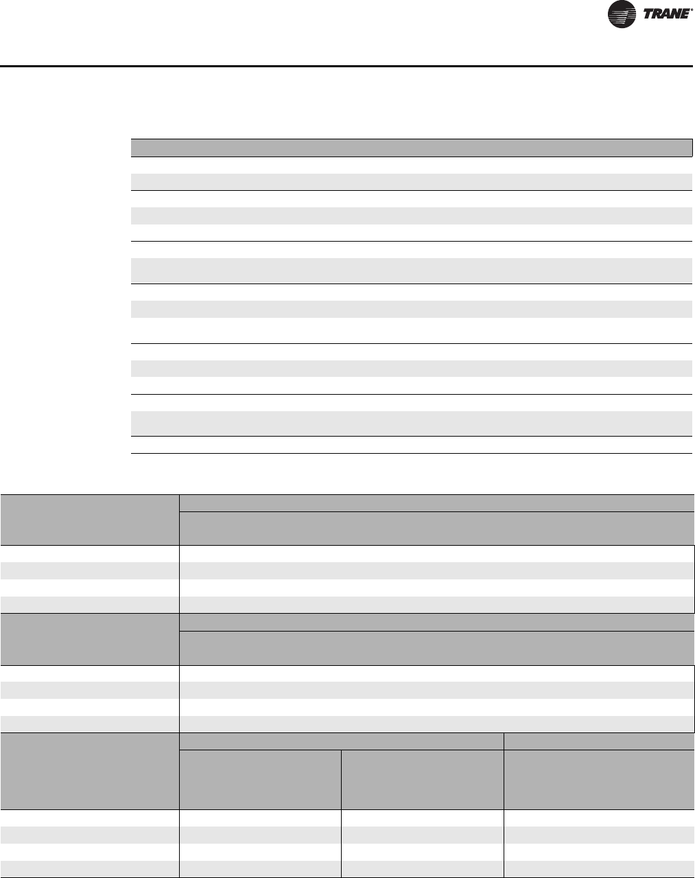
CLCH-PRC022A-EN 103
General Data
Table 68. Coil data for unit size 26
Coil Type Rows Fin Type Area (ft²) Qty–Size (in.)
1/2-inch unit coils
-UA, UW, UF, UU (stacked) 2, 4, 6, 8 Aluminum 24.67 2–36.25 × 49
5/8-inch unit coils
-W, WD, 5A, 5W, D1, D2 (stacked) 1, 2, 3, 4, 6, 8 Aluminum or Copper 24.50 2-36 x 49
W, WD, D1, D2 (stacked) 4, 6, 8, 10 Aluminum 24.50 2-36 x 49
1-inch unit coil
-NS (stacked) 1Aluminum or Copper 22.46 1 - 30 x 49
2 - 18 x 49
1/2-inch modified coils
-WL, LL 2, 4, 6, 8 Aluminum 18.72 1-55 x 49
-FD (stacked) 4, 6 Aluminum 19.14 1-31.25 x 49
1-25 x 49
5/8-inch modified coils
-W, WD, 5A, 5W, D1, D2 1, 2, 3, 4, 6, 8 Aluminum or Copper 18.38 1-54 x 49
-WD, D1, D2 4, 6, 8, 10 Aluminum 18.38 1-54 x 49
1-inch modified coil
-NS (stacked) 1Aluminum or Copper 18.38 1-30 x 49
1-24 x 49
Multizone coils n/a n/a
Table 69. Fan data for unit size 26
Housed Fans - Low Pressure
Size/Type 22-in FC 20-in FC 18-in FC 22-in AF 20-in AF 18-in AF
Fan name 22FA 20FA 18FA 22AA 20AA 18AA
Max rpm 950 1050 1215 1900 2300 2450
ODP NEMA Premium motor hp range 3-20 3-20 3-7.5 3-15 3-15 3-10
Outlet area (ft²) 5.54 4.38 2.88 5.54 4.38 2.88
Bearing/Shaft size (in.) 1.50 1.50 1.00 1.50 1.50 1.19
Housed Fans - High Pressure
Size/Type 22-in FC 20-in FC 18-in FC 22-in AF 20-in AF 18-in AF
Fan name 22FB 20FB 18FB 22AB 20AB 18AB
Max rpm 1200 1330 1500 2500 2750 3100
ODP NEMA Premium motor hp range 3-25 3-25 3-15 3-30 3-30 3-20
Outlet area (ft²) 5.54 4.38 2.88 5.54 4.38 2.88
Bearing/Shaft size (in.) 2.00 1.69 1.44 2.00 1.69 1.50
Belt-drive Plenum Fans Direct-Drive Plenum Fans
Low Pressure High Pressure High Pressure
Size/Type 28-in AF 25-in AF 28-in AF 25-in AF 30-in AF
Reduced Width 30-in AF
Nominal Width
Fan name 28PA 25PA 28PB 25PB 30NR 30NF
Max rpm 1850 2070 2100 2350 1851 1851
ODP NEMA Premium motor hp range 3-25 3-20 3-30 3-30 7.5-25 10-40
Outlet area (ft²) n/a n/a n/a n/a n/a n/a
Bearing/Shaft size (in.) 2.00 1.69 1.69 1.69 n/a n/a

104 CLCH-PRC022A-EN
General Data
Unit Size 30
Table 70. Section dimensions (inches) and weights (pounds) - unit size 30
Nominal airflow
15,000
Airflow at 625 fpm
19,025
Height - indoor unit (in.)
61.50
Width (in.)
93.50
Height - outdoor unit (in.) includes base drip lip
69.25
Weight add for outdoor unit (lbs./in. of unit length)
2.94
Section type Length (in.) Weight (lb.)
Access or blank
-Small horizontal 10.00 110.78
-Medium horizontal 14.00 136.97
-Extended-medium horizontal 19.00 169.71
-Medium-large horizontal 24.50 205.72
-Large horizontal or turning 46.00 457.18
-Extra-large horizontal or turning 56.50 525.93
-Ducted inlet or ducted outlet section
10.00 110.80
Blender
46.00 470.25
Cool Dry Quiet (CDQ) Desiccant Dehumidification Section
58.00 2029.00
Coils
-Small horizontal (with 4-row UW) 10.00 572.50
-Medium horizontal (with 8-row UW) 14.00 941.48
-Extended-medium horizontal (with 8-row UW) 19.00 985.30
-Medium-large horizontal (with 10-row W) 24.50 1701.77
-Large horizontal or vertical (with 10-row W) 46.00 1890.19
-Electric Heat Coil
56.50 1244.00
-Integral-face-and-bypass (IFB) coil
--
Less than 4 rows 26.50 940.46
--4 rows 43.00 1439.40
Controls section (includes largest available VFD)
28.50 487.00
Diffuser
19.00 167.36
Discharge plenum
-Horizontal 46.00 454.83
-Vertical 56.50 634.27
Energy Wheel
58.00 1868.00
Face-and-Bypass Dampers
-Face-and-bypass 19.00 291.36
-External face-and-bypass 19.00 353.22
-Internal face-and-bypass or face damper only 19.00 341.36
Fan
-Belt-drive plenum (BDP) fan with motor 52.50 1751.34
-Housed fan FC with motor 56.50 1710.85
-Housed AF/BC fans with motor 56.50 1797.21
-Direct-drive plenum fan with motor 56.50 1652.91
CLCH-PRC022A-EN 105
General Data
Filters Length (in.) Weight (lb.)
-Side load 2-in. angled 24.50 454.19
-Side load 4-in. angled 24.50 465.65
-Side load cartridge 12-in. or short bag 18-in. 24.50 479.36
-Side load 2-in. flat 14.00 198.93
-Side load 4-in. flat 14.00 249.73
-Side load 2-in. and 4-in. combination flat 19.00 326.58
-Long bag 30-in. 46.00 523.00
-Front-load HEPA 40.00 822.00
-Front-load cartridge 40.00 651.00
-Front-load short bag 45.00 567.00
Gas heat
- 200 MBH n/a n/a
- 300 MBH n/a n/a
- 360 MBH 66.00 1298.90
- 560 MBH 66.00 1441.80
- 700 MBH 76.00 1745.60
- 860 MBH 76.00 1804.80
- 1000 MBH 85.00 1560.00
Humidifier
-Building Steam 14.00 452.00
-Atmospheric 19.00 528.00
Mixing box
-with angled filters 46.00 457.18
-with front/back Traq and top Traq dampers 56.50 715.15
- reduced length mixing box with side/top/back/bottom airfoil damper 32.50 485.80
Multizone
- 3-deck vertical discharge 82.00 3425.00
- 2-deck vertical discharge 82.00 2413.00
- 3-deck horizontal discharge 72.00 3267.00
- 2-deck horizontal discharge 72.00 2264.00
Silencer
-3 feet 38.00 800.00
-5 feet 62.00 1215.00
Trane Catalytic Air Cleaning System (TCACS)
36.00 711.00
UV light
14.00 218.33
SECTIONS BELOW ARE FOR OUTDOOR UNITS ONLY
Diagonal economizer
-with airfoil dampers 63.00 649.00
-with airfoil damper and one side Traq damper 63.00 689.00
Exhaust damper section
19.00 280.40
Hoods Length (in.) Weight (lb.)
- Back inlet hood - airfoil and Traq 93.38 166.00
- Side inlet hood - airfoil and Traq 27.88 96.00
- Exhaust hood - airfoil 27.88 67.00
- Economizer inlet hood 62.50 224.00
Table 70. Section dimensions (inches) and weights (pounds) - unit size 30
106 CLCH-PRC022A-EN
General Data
Pipe Cabinets
15 in. long - 24-in. depth 15.00 122.00
15 in. long - 36-in. depth 15.00 164.00
15 in. long - 48-in. depth 15.00 207.00
24 in. long - 24-in. depth 24.00 142.00
24 in. long - 36-in. depth 24.00 187.00
24 in. long - 48-in. depth 24.00 233.00
48 in. long - 24-in. depth 48.00 195.00
48 in. long - 36-in. depth 48.00 249.00
48 in. long - 48-in. depth 48.00 303.00
96 in. long - 24-in. depth 96.00 302.00
96 in. long - 36-in. depth 96.00 373.00
96 in. long - 48-in. depth 96.00 443.00
Table 71. Filter data for unit size 30
Filter Type Area (ft²) Qty–Size (in.)
Flat (2-in., 4-in., and 2-in/4-in high efficiency) pleated, permanent,
throwaway media 30.44 6 - 20x24
2 - 20x16
3 - 12x24
Angled (2-in. or 4-in.) Pleated, permanent, throwaway media 56.67 6 - 16x25
18 - 16x20
Side load bag or cartridge 28.22 8 - 20x20
3 - 12x24
Front load bag or cartridge 28.00 6 - 24x24
2 - 12x24
Front load HEPA 28.00
2 - 24x30
1 - 24x24
2 - 24x30
1 - 24x24
Note: 2-inch filters available in permanent, throwaway, or pleated media; 4-inch filters available in pleated media, 65%, 85%,
or 95% efficiency; Bag or cartridge filters available in 65%, 85%, or 95% efficiency.
Table 72. Coil availability - size 30
Section Type 1/2-in Unit Coils 5/8-in Unit Coils,
1/2-in and 5/8-in Modified Coils
Small 2-4 rows 1-2 rows
Medium 2–8 rows 1–4 rows
Extended-medium 2–8 rows 1–8
1
rows
Medium-large 2-8 rows 1-10
1
rows
-with access 2–6 rows 1–3 rows
Large horizontal 2–8 rows 1–10 rows
-with access 2–8 rows 1–10
1
rows
Large vertical 2-8 rows 1–10 rows
-with access 2–8 rows 1–10 rows
Note:
1
6-row maximum for stacked coils.
Table 70. Section dimensions (inches) and weights (pounds) - unit size 30
CLCH-PRC022A-EN 107
General Data
Table 73. Coil data for unit size 30
Coil Type Rows Fin Type Area ft² Qty–Size (in.)
1/2-inch unit coils
-UA, UW, UF, UU 1, 2, 4, 6, 8 Aluminum 29.90 1–52.50 × 82
5/8-inch unit coils
-W, WD, 5D, 5A, 5W, D1, D2 1, 2, 3, 4, 6, 8 Aluminum or Copper 28.69 1-51 x 81
-W, WD, 5D, D1, D2 4, 6, 8, 10 Aluminum 28.69 1-51 x 81
-W, WD, 5D, D1, D2 4, 6, 8 Copper 28.69 1-51 x 81
-TT, P2, P4, P8 (stacked) 1, 2, 4, 6, 8 Aluminum or Copper 27.00 2-24 x 81
1-inch unit coil
-NS (stacked) 1Aluminum or Copper 27.00 2–24 x 81
1/2-inch modified coils
-WL, LL, FD 2, 4, 6, 8 Aluminum 20.39 1-36.25 x 81
5/8-inch modified coils
-W, 5A, 5W, D1, D2 1, 2, 3, 4, 6, 8 Aluminum or Copper 20.25 1-36 x 81
-W, WD, D1, D2 6, 8, 10 Aluminum 20.25 1-36 x 81
-W, WD, D1, D2 8Copper 20.25 1-36 x 81
-TT, P2, P4, P8 (stacked) 1, 2, 4, 6, 8 Aluminum or Copper 20.25 2-18 x 81
1-inch modified coil
-NS (stacked) 1Aluminum or Copper 20.25 2-18 x 81
Multizone coils
-5A, 5W, NS, TT 1, 2 Aluminium or Copper 13.50 1-24 x 81
-WL 2 Aluminum 13.50 1-24 x 81
Table 74. Fan data for unit size 30
Housed Fans - Low Pressure
Size/Type 25-in FC 22-in FC 20-in FC 25-in AF 22-in AF 20-in AF
Fan name 25FA 22FA 20FA 25AA 22AA 20AA
Max rpm 850 950 1050 1650 1900 2300
ODP NEMA Premium motor hp range 3-20 3-20 3-20 3-20 3-15 3-15
Outlet area (ft²) 6.94 5.54 4.38 6.94 5.54 4.38
Bearing/Shaft size (in.) 1.69 1.50 1.50 1.69 1.50 1.50
Housed Fans - High Pressure
Size/Type 25-in FC 22-in FC 20-in FC 25-in AF 22-in AF 20-in AF
Fan name 25FB 22FB 20FB 25AB 22AB 20AB
Max rpm 1025 1200 1330 2200 2500 2750
ODP NEMA Premium motor hp range 3-30 3-30 3-25 3-40 3-30 3-30
Outlet area (ft²) 6.94 5.54 4.38 6.94 5.54 4.38
Bearing/Shaft size (in.) 2.44 2.00 1.69 2.00 2.00 1.69
Belt-drive Plenum Fans Direct-Drive Plenum Fans
Low Pressure High Pressure High Pressure
Size/Type 32-in AF 28-in AF 32-in AF 28-in AF 2-24.5-in AF
Reduced Width 2-24.5-in AF
Nominal Width
Fan name 32PA 28PA 32PB 28PB 24NR 24NF
Max rpm 1600 1850 1800 2100 2269 2269
ODP NEMA Premium motor hp range 3-25 3-25 3-40 3-40 5-20 5-20
Outlet area (ft²) n/a n/a n/a n/a n/a n/a
Bearing/Shaft size (in.) 2.00 2.00 1.69 1.69 n/a n/a
108 CLCH-PRC022A-EN
General Data
Unit Size 31
Table 75. Section dimensions (inches) and weights (pounds) - unit size 31
Nominal airflow
15,500
Airflow at 625 fpm
22,138
Height - indoor unit (in.)
85.50
Width (in.)
72.00
Height - outdoor unit (in.) includes base drip lip
Available for indoor use only
Weight add for outdoor unit (lbs./in. of unit length)
n/a n/a
Section type Length (in.) Weight (lb.)
Access or blank
-Small horizontal 10.00 106.61
-Medium horizontal 14.00 133.18
-Extended-medium horizontal 19.00 166.39
-Medium-large horizontal 26.50 202.93
-Large horizontal or turning 46.00 467.28
-Extra-large horizontal or turning n/a n/a
-Ducted inlet or ducted outlet section
10.00 106.60
Blender
40.00 449.80
Cool Dry Quiet (CDQ) Desiccant Dehumidification Section
n/a n/a
Coils
-Small horizontal (with 4-row UW) 10.00 594.43
-Medium horizontal (with 8-row UW) 14.00 968.56
-Extended-medium horizontal (with 8-row UW) 19.00 1009.31
-Medium-large horizontal (with 10-row W) 26.50 1737.73
-Large horizontal or vertical (with 10-row W) 46.00 1896.66
-Electric Heat Coil
n/a n/a
-Integral-face-and-bypass (IFB) coil
--
Less than 4 rows 26.50 1190.19
--4 rows 43.00 1836.97
Controls section (includes largest available VFD)
28.50 496.00
Diffuser
19.00 164.04
Discharge plenum
-Horizontal 46.00 464.93
-Vertical n/a n/a
Energy Wheel
n/a n/a
Face-and-Bypass Dampers
-Face-and-bypass 19.00 164.04
-External face-and-bypass 27.75 222.16
-Internal face-and-bypass or face damper only 19.00 164.04
Fan
-Belt-drive plenum (BDP) fan with motor n/a n/a
-Housed fan FC with motor 73.25 1832.18
-Housed AF/BC fans with motor 73.25 1979.55
-Direct-drive plenum fan with motor 73.25 1673.71
Filters
-Side load 2-in. angled 24.50 469.97
-Side load 4-in. angled 24.50 477.66
-Side load cartridge 12-in. or short bag 18-in. 24.50 487.55
CLCH-PRC022A-EN 109
General Data
Filters Length (in.) Weight (lb.)
-Side load 2-in. flat 14.00 198.17
-Side load 4-in. flat 14.00 241.97
-Side load 2-in. and 4-in. combination flat 19.00 322.00
-Long bag 30-in. 37.25 506.00
-Front-load HEPA 40.00 874.00
-Front-load cartridge 40.00 637.00
-Front-load short bag 45.00 623.00
Gas heat
n/a n/a
Humidifier
-Building Steam 14.00 561.00
-Atmospheric 19.00 471.00
Mixing box
-with angled filters 46.00 467.28
-with front/back Traq and top Traq dampers n/a n/a
- reduced length mixing box with side/top/back/bottom airfoil damper n/a n/a
Multizone
n/a n/a
Silencer
-3 feet 38.00 826.00
-5 feet 62.00 1272.00
Trane Catalytic Air Cleaning System (TCACS)
36.00 826.00
UV light
n/a n/a
Table 76. Filter data for unit size 31
Filter Type Area (ft²) Qty–Size (in.)
Flat (2-in., 4-in., and 2-in/4-in high efficiency) pleated, permanent,
throwaway media 30.44 6 - 20x24
2 - 20x16
3 - 12x24
Angled (2-in. or 4-in.) Pleated, permanent, throwaway media 56.67 6 - 16x25
18 - 16x20
Side load bag or cartridge 28.22 8 - 20x20
3 - 12x24
Front load bag or cartridge 28.00 6 - 24x24
2 - 12x24
Front load HEPA 28.00
2 - 24x30
1 - 24x24
2 - 24x30
1 - 24x24
Note: 2-inch filters available in permanent, throwaway, or pleated media; 4-inch filters available in pleated media, 65%, 85%,
or 95% efficiency; Bag or cartridge filters available in 65%, 85%, or 95% efficiency.
Table 75. Section dimensions (inches) and weights (pounds) - unit size 31
Table 77. Coil availability - size 31
Section Type 1/2-in Unit Coils 5/8-in Unit Coils,
1/2-in and 5/8-in Modified Coils
Small 2-4 rows unstacked, 2 rows stacked 1-2 rows
Medium 2–8 rows unstacked, 2-6 rows stacked without IDP, 2-4 rows
stacked with IDP 1–4 rows
Extended-medium 2–8 rows 1–8 without IDP
1-6 rows with IDP
Medium-large 2-8 rows 1-10 rows
-with access 2–6 rows unstacked, 2-4 rows stacked without IDP 1–4 rows unstacked, 1-3 rows stacked without IDP,
1-2 rows stacked with IDP
Large horizontal 2–8 rows 1–10 rows
-with access 2–8 rows 1–10 rows
Large vertical n/a n/a

110 CLCH-PRC022A-EN
General Data
Table 78. Coil data for unit size 31
Coil Type Rows Fin Type Area (ft²) Qty–Size (in.)
1/2-inch unit coils
-UA, UW, UF, UU (stacked) 2, 4, 6, 8 Aluminum 29.96 1–36.25 x 59.50
5/8-inch unit coils
-W, WD, 5A, 5W, D1, D2 (stacked) 1, 2, 3, 5, 6, 8 Aluminum or Copper 29.50 1-36 x 59
-W, WD, D1, D2 (stacked) 10 Aluminum 29.50 2-36 x 59
1-inch unit coil
-NS (stacked) 1Aluminum or Copper 27.04 1-30 x 59
2-18 x 59
1/2-inch modified coils
-WL, LL 2, 4, 6, 8 Aluminum 22.53 1-55 x 59
-FD (stacked) 4, 6 Aluminum 23.05 1-31.25 x 59
1-25 x 59
5/8-inch modified coils
-W, WD, 5A, 5W, D1, D2 1, 2, 3, 4, 6, 8 Aluminum or Copper 22.13 1-54 x 59
W, WD, D1, D2 4, 6, 8, 10 Aluminum 22.13 1-54 x 59
1-inch modified coil
-NS (stacked) 1Aluminum or Copper 22.13 1-30 x 59
1-24 x 59
Multizone coils n/a n/a
Table 79. Fan data for unit size 31
Housed Fans - Low Pressure
Size/Type 25-in FC 22-in FC 20-in FC 25-in AF 22-in AF 20-in AF
Fan name 25FA 22FA 20FA 25AA 22AA 20AA
Max rpm 850 950 1050 1650 1900 2300
ODP NEMA Premium motor hp range 3-20 3-20 3-20 3-20 3-15 3-15
Outlet area (ft²) 6.945.544.386.94 5.54 4.38
Bearing/Shaft size (in.) 1.69 1.50 1.50 1.69 1.50 1.50
Housed Fans - High Pressure
Size/Type 25-in FC 22-in FC 20-in FC 25-in AF 22-in AF 20-in AF
Fan name 25FB 22FB 20FB 25AB 22AB 20AB
Max rpm 1025 1200 1330 2200 2500 2750
ODP NEMA Premium motor hp range 3-30 3-30 3-25 3-40 3-30 3-30
Outlet area (ft²) 6.945.544.386.94 5.54 4.38
Bearing/Shaft size (in.) 2.44 2.00 1.69 2.00 2.00 1.69
Belt-drive Plenum Fans Direct-Drive Plenum Fans
Low Pressure High Pressure High Pressure
Size/Type n/a n/a n/a n/a 2-24.5-in AF
Reduced Width 2-24.5-in AF
Nominal Width
Fan name 24NR 24NF
Max rpm 2269 2269
ODP NEMA Premium motor hp range 5-20 5-20
Outlet area (ft²) n/a n/a
Bearing/Shaft size (in.) n/a n/a

CLCH-PRC022A-EN 111
General Data
Unit Size 35
Table 80. Section dimensions (inches) and weights (pounds) - unit size 35
Nominal airflow
17,500
Airflow at 625 fpm
23,263
Height - indoor unit (in.)
67.25
Width (in.)
100.00
Height - outdoor unit (in.) includes base drip lip
75.00
Weight add for outdoor unit (lbs./in. of unit length)
3.02
Section type Length (in.) Weight (lb.)
Access or blank
-Small horizontal 10.00 211.11
-Medium horizontal 14.00 241.53
-Extended-medium horizontal 19.00 279.57
-Medium-large horizontal 24.50 321.40
-Large horizontal or turning 48.00 514.42
-Extra-large horizontal or turning 63.75 624.86
-Ducted inlet or ducted outlet section
10.00 211.10
Blender
48.00 540.76
Cool Dry Quiet (CDQ) Desiccant Dehumidification Section
56.00 2914.00
Coils
-Small horizontal (with 4-row UW) 10.00 690.59
-Medium horizontal (with 8-row UW) 14.00 1094.27
-Extended-medium horizontal (with 8-row UW) 19.00 1148.70
-Medium-large horizontal (with 10-row W) 24.50 1955.08
-Large horizontal or vertical (with 10-row W) 48.00 2131.70
-Electric Heat Coil
63.80 1666.00
-Integral-face-and-bypass (IFB) coil
-
Less than 4 rows 29.50 1129.66
--4 rows 43.00 1677.52
Controls section (includes largest available VFD)
28.50 637.00
Diffuser
24.50 319.05
Discharge plenum
-Horizontal 48.00 627.24
-Vertical 63.75 876.48
Energy Wheel
61.00 2403.00
Face-and-Bypass Dampers
-Face-and-bypass 19.00 473.39
-External face-and-bypass 22.00 566.46
-Internal face-and-bypass or face damper only 19.00 502.53
Fan
-Belt-drive plenum (BDP) fan with motor 53.50 2368.54
-Housed fan FC with motor 63.75 2400.18
-Housed AF/BC fans with motor 63.75 2429.71
-Direct-drive plenum fan with motor 63.75 2057.87
Filters
-Side load 2-in. angled 24.50 593.86
-Side load 4-in. angled 24.50 594.02
-Side load cartridge 12-in. or short bag 18-in. 24.50 681.24

112 CLCH-PRC022A-EN
General Data
Filters Length (in.) Weight (lb.)
-Side load 2-in. flat 14.00 319.66
-Side load 4-in. flat 14.00 359.20
-Side load 2-in. and 4-in. combination flat 19.00 476.00
-Long bag 30-in. 37.25 657.00
-Front-load HEPA 40.00 986.00
-Front-load cartridge 40.00 868.00
-Front-load short bag 45.00 751.00
Gas heat
- 200 MBH n/a n/a
- 300 MBH n/a n/a
- 360 MBH 66.00 1402.10
- 560 MBH 66.00 1594.60
- 700 MBH 73.00 1895.20
- 860 MBH 80.00 2046.30
- 1000 MBH 80.00 1723.70
- 1250-1750 MBH 101.00 2540.80
- 2000 MBH n/a n/a
- 2400 MBH n/a n/a
Humidifier
-Building Steam 14.00 544.00
-Atmospheric 19.00 581.00
Mixing box
-with angled filters 48.00 519.12
-with front/back Traq and top Traq dampers 63.75 966.49
- reduced length mixing box with side/top/back/bottom airfoil damper 35.50 708.50
Multizone
- 3-deck vertical discharge 92.00 4263.00
- 2-deck vertical discharge 92.00 2965.00
- 3-deck horizontal discharge 78.00 4020.00
- 2-deck horizontal discharge 78.00 2725.00
Silencer
-3 feet 38.00 918.00
-5 feet 62.00 1335.00
Trane Catalytic Air Cleaning System (TCACS)
36.00 882.00
UV light
14.00 325.48
SECTIONS BELOW ARE FOR OUTDOOR UNITS ONLY
Diagonal economizer
-with airfoil dampers 75.00 931.00
-with airfoil damper and one side Traq damper 75.00 973.00
Exhaust damper section
24.50 450.80
Hoods
- Back inlet hood - airfoil and Traq 99.88 176.00
- Side inlet hood - airfoil and Traq 40.88 122.00
- Exhaust hood - airfoil 40.88 73.00
- Economizer inlet hood 75.00 195.00
Table 80. Section dimensions (inches) and weights (pounds) - unit size 35
CLCH-PRC022A-EN 113
General Data
Pipe Cabinets Length (in.) Weight (lb.)
15 in. long - 24-in. depth 15.00 130.00
15 in. long - 36-in. depth 15.00 175.00
15 in. long - 48-in. depth 15.00 220.00
24 in. long - 24-in. depth 24.00 151.00
24 in. long - 36-in. depth 24.00 199.00
24 in. long - 48-in. depth 24.00 247.00
48 in. long - 24-in. depth 48.00 207.00
48 in. long - 36-in. depth 48.00 263.00
48 in. long - 48-in. depth 48.00 320.00
96 in. long - 24-in. depth 96.00 319.00
96 in. long - 36-in. depth 96.00 392.00
96 in. long - 48-in. depth 96.00 466.00
Table 81. Filter data for unit size 35
Filter Type Area (ft²) Qty–Size (in.)
Flat (2-in., 4-in., and 2-in/4-in high efficiency) pleated, permanent,
throwaway media 37.22 8 - 20x24
3 - 16x25
1 - 16x20
Angled (2-in. or 4-in.) Pleated, permanent, throwaway media 63.33 18 - 16x25
6 - 16x20
Side load bag or cartridge 34.67 8 - 20x24
4 - 12x24
Front load bag or cartridge 34.00 5 - 12x24
6 - 24x24
Front load HEPA 30.00 3 - 24x30
3 - 30x24
Note: 2-inch filters available in permanent, throwaway, or pleated media; 4-inch filters available in pleated media, 65%, 85%,
or 95% efficiency; Bag or cartridge filters available in 65%, 85%, or 95% efficiency.
Table 82. Coil availability - size 35
Section Type 1/2-in Unit Coils 5/8-in Unit Coils,
1/2-in and 5/8-in Modified Coils
Small 2-4 rows 1-2 rows
Medium 2–8 rows 1–4 rows
Extended-medium 2–8 rows 1–8 rows
1
Medium-large 2-8 rows 1-10 rows
-with access 2–4 rows 1–3 rows
Large horizontal 2–8 rows 1–10 rows
-with access 2–8 rows 1–10 rows
Large vertical 2-8 rows 1–6 rows
-with access 2–8 rows 1–6 rows
Note:
1
6-row maximum for stacked coils.
Table 80. Section dimensions (inches) and weights (pounds) - unit size 35
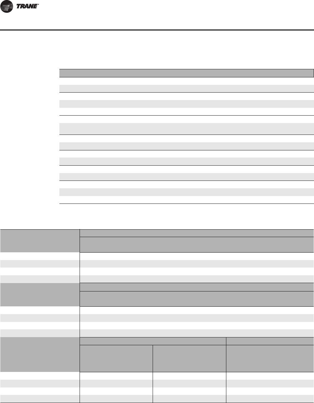
114 CLCH-PRC022A-EN
General Data
Table 83. Coil data for unit size 35
Coil Type Rows Fin Type Area ft² Qty–Size (in.)
1/2-inch unit coils
-UA, UW, UF, UU 2, 4, 6, 8 Aluminum 34.94 1–57.50 × 87.50
5/8-inch unit coils
-W, WD, 5D, D1, D2 4, 6, 8, 10 Aluminum or Copper 33.53 1-55.50 x 87
- W, 5A, 5W, D1 1, 2, 3 Aluminum or Copper 32.63 1-54 x 87
1-inch unit coil
-NS (stacked) 1Aluminum or Copper 30.81 1-33 x 87
1-18 x 87
1/2-inch modified coils
-WL, LL, FD 2, 4, 6, 8 Aluminum 21.90 1-36.25 x 87
5/8-inch modified coils
-W, WD, 5A, 5W, D1, D2 1, 2, 3, 4, 6, 8, 10 Aluminum or Copper 21.75 1-36 x 87
1-inch modified coil
-NS (stacked) 1Aluminum or Copper 21.75 2-18 x 87
Multizone coils
-5A, 5W, NS 1, 2 Aluminium or Copper 18.13 1-30 x 87
-WL 2 Aluminum 18.13 1-30 x 87
Table 84. Fan data for unit size 35
Housed Fans - Low Pressure
Size/Type 25-in. FC 22-in. FC 20-in. FC 25-in. AF 22-in. AF 20-in. AF
Fan name 25FA 22FA 20FA 25AA 22AA 20AA
Max rpm 850 950 1050 1650 1900 2300
ODP NEMA Premium motor hp range 7.5-20 7.5-20 7.5-20 7.5-20 7.5-15 7.5-15
Outlet area (ft²) 6.95 5.54 4.38 6.95 5.54 4.38
Bearing/Shaft size (in.) 1.69 1.50 1.50 1.69 1.50 1.50
Housed Fans - High Pressure
Size/Type 25-in. FC 22-in. FC 20-in. FC 25-in. AF 22-in. AF 20-in. AF
Fan name 25FB 22FB 20FB 25AB 22AB 20AB
Max rpm 1025 1200 1330 2200 2500 2750
ODP NEMA Premium motor hp range 7.5-40 7.5-30 7.5-25 7.5-40 7.5-40 7.5-30
Outlet area (ft²) 6.95 5.54 4.38 6.95 5.54 4.38
Bearing/Shaft size (in.) 2.44 2.00 1.69 2.00 2.00 1.69
Belt-drive Plenum Fans Direct-Drive Plenum Fans
Low Pressure High Pressure High Pressure
Size/Type 36-in. AF 32-in. AF 36-in. AF 32-in. AF 2- 24.5-in AF
Nominal Width 2-24.5-in AF
Extended Width
Fan name 36PA 32PA 36PB 32PB 24NF 24NW
Max rpm 1350 1600 1600 1800 2269 2269
ODP NEMA Premium motor hp range 7.5-30 7.5-25 7.5-50 7.5-50 5-20 5-20
Outlet area (ft²) n/a n/a n/a n/a n/a n/a
Bearing/Shaft size (in.) 2.44 2.00 2.19 1.69 n/a n/a

CLCH-PRC022A-EN 115
General Data
Unit Size 36
Table 85. Section dimensions (inches) and weights (pounds) - unit size 36
Nominal airflow
18,000
Airflow at 625 fpm
25,000
Height - indoor unit (in.)
89.00
Width (in.)
80.00
Height - outdoor unit (in.) includes base drip lip
Available for indoor use only
Weight add for outdoor unit (lbs./in. of unit length)
n/a n/a
Section type Length (in.) Weight (lb.)
Access or blank
-Small horizontal 10.00 207.98
-Medium horizontal 14.00 238.68
-Extended-medium horizontal 19.00 277.04
-Medium-large horizontal 29.50 319.24
-Large horizontal or turning 46.00 509.00
-Extra-large horizontal or turning n/a n/a
-Ducted inlet or ducted outlet section
10.00 208.00
Blender
40.00 495.07
Cool Dry Quiet (CDQ) Desiccant Dehumidification Section
n/a n/a
Coils
-Small horizontal (with 4-row UW) 10.00 675.23
-Medium horizontal (with 8-row UW) 14.00 1095.29
-Extended-medium horizontal (with 8-row UW) 19.00 1138.74
-Medium-large horizontal (with 10-row W) 29.50 2017.86
-Large horizontal or vertical (with 10-row W) 46.00 2161.23
-Electric Heat Coil
n/a n/a
-Integral-face-and-bypass (IFB) coil
--
Less than 4 rows 29.50 1407.86
--4 rows 43.00 2148.28
Controls section (includes largest available VFD)
28.50 649.00
Diffuser
24.50 316.89
Discharge plenum
-Horizontal 46.00 621.68
-Vertical n/a n/a
Energy Wheel
n/a n/a
Face-and-Bypass Dampers
-Face-and-bypass 19.00 274.69
-External face-and-bypass 27.75 341.83
-Internal face-and-bypass or face damper only 19.00 274.69
Fan
-Belt-drive plenum (BDP) fan with motor n/a n/a
-Housed fan FC with motor 80.50 2423.46
-Housed AF/BC fans with motor 80.50 2568.99
-Direct-drive plenum fan with motor 80.50 2804.47
Filters
-Side load 2-in. angled 24.50 562.37
-Side load 4-in. angled 24.50 567.56
-Side load cartridge 12-in. or short bag 18-in. 24.50 637.25
116 CLCH-PRC022A-EN
General Data
Filters Length (in.) Weight (lb.)
-Side load 2-in. flat 14.00 322.85
-Side load 4-in. flat 14.00 350.39
-Side load 2-in. and 4-in. combination flat 19.00 484.13
-Long bag 30-in. 37.25 701.00
-Front-load HEPA 40.00 1176.00
-Front-load cartridge 40.00 797.00
-Front-load short bag 45.00 778.00
Gas heat
n/a n/a
Humidifier
-Building Steam 14.00 622.00
-Atmospheric 19.00 508.00
Mixing box
-with angled filters 46.00 513.70
-with front/back Traq and top Traq dampers n/a n/a
- reduced length mixing box with side/top/back/bottom airfoil damper n/a n/a
Multizone
n/a n/a
Silencer
-3 feet 38.00 951.00
-5 feet 62.00 1478.00
Trane Catalytic Air Cleaning System (TCACS)
36.00 916.00
UV light
n/a n/a
Table 86. Filter data for unit size 36
Filter Type Area (ft²) Qty–Size (in.)
Flat (2-in., 4-in., and 2-in/4-in high efficiency) pleated, permanent,
throwaway media 37.22 8 - 20x24
3 - 16x25
1 - 16x20
Angled (2-in. or 4-in.) Pleated, permanent, throwaway media 63.33 18 - 16x25
6 - 16x20
Side load bag or cartridge 34.67 8 - 20x24
4 - 12x24
Front load bag or cartridge 34.00 5 - 12x24
6 - 24x24
Front load HEPA 30.00 3 - 24x30
3 - 30x24
Note: 2-inch filters available in permanent, throwaway, or pleated media; 4-inch filters available in pleated media, 65%, 85%,
or 95% efficiency; Bag or cartridge filters available in 65%, 85%, or 95% efficiency.
Table 87. Coil availability - size 36
Section Type 1/2-in Unit Coils 5/8-in Unit Coils,
1/2-in and 5/8-in Modified Coils
Small 2 rows 1-2 rows
Medium 2–6 rows
(4 row cooling) 1–4 rows without IDP
Extended-medium 2–8 rows 1-8 rows without IDP
Medium-large 2-8 rows 1-10 rows
-with access 2–8 rows 1–6 rows
Large horizontal 2–8 rows 1–10 rows
-with access 2–8 rows 1–10 rows
Large vertical n/a n/a
-with access n/a n/a
Table 85. Section dimensions (inches) and weights (pounds) - unit size 36
CLCH-PRC022A-EN 117
General Data
Table 88. Coil data for unit size 36
Coil Type Rows Fin Type Area ft² Qty–Size (in.)
1/2-inch unit coils
-UW, UA, UF, UU (stacked) 2, 4, 6, 8 Aluminum 34.11 1–37.50 × 65.50
5/8-inch unit coils
-W, WD, 5A, 5W, D1, D2 (stacked) 1, 2, 3, 4, 6, 8 Aluminum or Copper 34.38 2-37.50 x 66
- W, WD, D1, D2 (stacked) 10 Aluminum 34.38 2-37.50 x 66
1-inch unit coil
-NS (stacked) 1Aluminum or Copper 31.63 1-33 x 66
2-18 x 66
1/2-inch modified coils
-WL, LL, FD (stacked) 2, 4, 6, 8 Aluminum 26.93 1-33.75 x 66
1-25 x 66
5/8-inch modified coils
-W, 5A, 5W, D1, D2 (stacked) 1, 2, 3, 4, 6, 8 Aluminum or Copper 26.13 1-33 x 66
1-24 x 66
-W, WD, D1, D2 (stacked) 4, 6, 8, 10 Aluminum 26.13 1-33 x 66
1-24 x 66
1-inch modified coil
-NS (stacked) 1Aluminum or Copper 26.13 1-33 x 66
1- 24 x 66
Multizone coils n/a n/a
Table 89. Fan data for unit size 36
Housed Fans - Low Pressure
Size/Type 25-in. FC 22-in. FC 20-in. FC 25-in. AF 22-in. AF 20-in. AF
Fan name 25FA 22FA 20FA 25AA 22AA 20AA
Max rpm 850 950 1050 1650 1900 2300
ODP NEMA Premium motor hp range 7.5-20 7.5-20 7.5-20 7.5-20 7.5-15 7.5-15
Outlet area (ft²) 6.95 5.54 4.38 6.95 5.54 4.38
Bearing/Shaft size (in.) 1.69 1.50 1.50 1.69 1.50 1.50
Housed Fans - High Pressure
Size/Type 25-in. FC 22-in. FC 20-in. FC 25-in. AF 22-in. AF 20-in. AF
Fan name 25FB 22FB 20FB 25AB 22AB 20AB
Max rpm 1025 1200 1330 2200 2500 2750
ODP NEMA Premium motor hp range 7.5-40 7.5-30 7.5-25 7.5-40 7.5-40 7.5-30
Outlet area (ft²) 6.95 5.54 4.38 6.95 5.54 4.38
Bearing/Shaft size (in.) 2.44 2.00 1.69 2.00 2.00 1.69
Belt-drive Plenum Fans Direct-Drive Plenum Fans
Low Pressure High Pressure High Pressure
Size/Type n/a n/a n/a n/a 2 - 2 2 - i n A F
Nominal Width 2 - 2 2 - i n A F
Extended Width
Fan name 22SF 22SW
Max rpm 2675 2675
ODP NEMA Premium motor hp range 5-25 5-25
Outlet area (ft²) n/a n/a
Bearing/Shaft size (in.) n/a n/a

118 CLCH-PRC022A-EN
General Data
Unit Size 40
Table 90. Section dimensions (inches) and weights (pounds) - unit size 40
Nominal airflow
20,000
Airflow at 625 fpm
25,519
Height - indoor unit (in.)
67.25
Width (in.)
112.50
Height - outdoor unit (in.) includes base drip lip
75.00
Weight add for outdoor unit (lbs./in. of unit length)
3.28
Section type Length (in.) Weight (lb.)
Access or blank
-Small horizontal 10.00 227.92
-Medium horizontal 14.00 260.24
-Extended-medium horizontal 19.00 300.64
-Medium-large horizontal 24.50 345.09
-Large horizontal or turning 48.00 557.22
-Extra-large horizontal or turning 63.75 675.12
-Ducted inlet or ducted outlet section
10.00 227.90
Blender
48.00 593.46
Cool Dry Quiet (CDQ) Desiccant Dehumidification Section
56.00 3122.00
Coils
-Small horizontal (with 4-row UW) 10.00 754.61
-Medium horizontal (with 8-row UW) 14.00 1219.78
-Extended-medium horizontal (with 8-row UW) 19.00 1279.06
-Medium-large horizontal (with 10-row W) 24.50 2216.68
-Large horizontal or vertical (with 10-row W) 48.00 2401.84
-Electric Heat Coil
63.80 1825.00
-Integral-face-and-bypass (IFB) coil
--
Less than 4 rows 29.50 1168.40
--4 rows 43.00 1720.20
Controls section (includes largest available VFD)
28.50 674.00
Diffuser
24.50 342.74
Discharge plenum
-Horizontal 48.00 677.47
-Vertical 63.75 949.58
Energy Wheel
65.00 2742.00
Face-and-Bypass Dampers
-Face-and-bypass 19.00 556.23
-External face-and-bypass 22.00 660.36
-Internal face-and-bypass or face damper only 19.00 575.62
Fan
-Belt-drive plenum (BDP) fan with motor 53.50 2740.37
-Housed fan FC with motor 63.75 2603.08
-Housed AF/BC fans with motor 63.75 2695.61
-Direct-drive plenum fan with motor 63.75 2406.73
Filters
-Side load 2-in. angled 24.50 649.06
-Side load 4-in. angled 24.50 631.64
-Side load cartridge 12-in. or short bag 18-in. 24.50 668.25

CLCH-PRC022A-EN 119
General Data
Filters Length (in.) Weight (lb.)
-Side load 2-in. flat 14.00 358.18
-Side load 4-in. flat 14.00 375.13
-Side load 2-in. and 4-in. combination flat 19.00 504.37
-Long bag 30-in. 37.25 716.00
-Front-load HEPA 40.00 1128.00
-Front-load cartridge 40.00 923.00
-Front-load short bag 45.00 800.00
Gas heat
- 200 MBH n/a n/a
- 300 MBH n/a n/a
- 360 MBH n/a n/a
- 560 MBH 64.00 1468.10
- 700 MBH 75.00 1804.10
- 860 MBH 75.00 2098.70
- 1000 MBH 81.00 1844.70
- 1250-1750 MBH 105.00 2717.90
Humidifier
-Building Steam 14.00 599.00
-Atmospheric 19.00 665.00
Mixing box
-with angled filters 48.00 561.92
-with front/back Traq and top Traq dampers 63.75 1073.80
- reduced length mixing box with side/top/back/bottom airfoil damper 38.50 795.10
Multizone
- 3-deck vertical discharge 92.00 4732.00
- 2-deck vertical discharge 92.00 3267.00
- 3-deck horizontal discharge 78.00 4471.00
- 2-deck horizontal discharge 78.00 3006.00
Silencer
-3 feet 38.00 974.00
-5 feet 62.00 1439.00
Trane Catalytic Air Cleaning System (TCACS)
36.00 935.00
UV light
14.00 352.71
SECTIONS BELOW ARE FOR OUTDOOR UNITS ONLY
Diagonal economizer
-with airfoil dampers 83.00 1062.00
-with airfoil damper and one side Traq damper 83.00 1101.00
Exhaust damper section
24.50 489.90
Hoods
- Back inlet hood - airfoil and Traq 112.38 195.00
- Side inlet hood - airfoil and Traq 40.88 128.00
- Exhaust hood - airfoil 40.88 77.00
- Economizer inlet hood 83.00 275.00
Pipe Cabinets
15 in. long - 24-in. depth 15.00 130.00
15 in. long - 36-in. depth 15.00 175.00
15 in. long - 48-in. depth 15.00 220.00
Table 90. Section dimensions (inches) and weights (pounds) - unit size 40
120 CLCH-PRC022A-EN
General Data
Pipe Cabinets Length (in.) Weight (lb.)
24 in. long - 24-in. depth 24.00 151.00
24 in. long - 36-in. depth 24.00 199.00
24 in. long - 48-in. depth 24.00 247.00
48 in. long - 24-in. depth 48.00 207.00
48 in. long - 36-in. depth 48.00 263.00
48 in. long - 48-in. depth 48.00 320.00
96 in. long - 24-in. depth 96.00 319.00
96 in. long - 36-in. depth 96.00 392.00
96 in. long - 48-in. depth 96.00 466.00
Table 91. Filter data for unit size 40
Filter Type Area ft² Qty–Size (in.)
Flat (2-in., 4-in., and 2-in/4-in high efficiency) pleated, permanent,
throwaway media 40.83
8 - 20x20
2 - 20x25
4 - 16x20
1 - 16x25
Angled (2-in. or 4-in.) Pleated, permanent, throwaway media 70.00 6 - 16x25
24 - 16x20
Side load bag or cartridge 36.00 8 - 24x24
2 - 24x12
Front load bag or cartridge 40.00 4 - 12x24
8 - 24x24
Front load HEPA 37.00 3 - 24x30
1 - 24x12
4 - 30x24
Note: 2-inch filters available in permanent, throwaway, or pleated media; 4-inch filters available in pleated media, 65%, 85%,
or 95% efficiency; Bag or cartridge filters available in 65%, 85%, or 95% efficiency.
Table 92. Coil availability - size 40
Section Type 1/2-in Unit Coils 5/8-in Unit Coils,
1/2-in and 5/8-in Modified Coils
Small 2-4 rows 1-2 rows
Medium 2–8 rows 1–4 rows
Extended-medium 2–8 rows 1–8
1
rows
Medium-large 2-8 rows 1-10 rows
-with access 2–4 rows 1–3 rows
Large horizontal 2–8 rows 1–10 rows
-with access 2–8 rows 1–10 rows
Large vertical 2-8 rows 1–6 rows
-with access 2–8 rows 1–6 rows
Note:
1
6-row maximum for stacked coils.
Table 90. Section dimensions (inches) and weights (pounds) - unit size 40
CLCH-PRC022A-EN 121
General Data
Table 93. Coil data for unit size 40
Coil Type Rows Fin Type Area ft² Qty–Size (in.)
1/2-inch unit coils
-UA, UW, UF, UU 2, 4, 6, 8 Aluminum 39.93 1–57.50 × 100
5/8-inch unit coils
-W, WD, D1, D2 4, 6, 8 Aluminum or Copper 38.54 1-55.50 x 100
-W, WD, 5D, D1, D2 6, 8, 10 Aluminum 38.54 1-55.50 x 100
-W, 5A, 5W, D1 1, 2, 3 Aluminum or Copper 37.50 1-54 x 100
1-inch unit coil
-NS (stacked) 1Aluminum or Copper 35.42 1-33 x 100
1-18 x 100
1/2-inch modified coils
-WL, LL, FD 2, 4, 6, 8 Aluminum 25.17 1-36.25 x 100
5/8-inch modified coils
-W, WD, 5A, 5W, D1, D2 1, 2, 3, 4, 6, 8 Aluminum or Copper 25.00 1-36 x 100
-W, WD, D1, D2 10 Aluminum 25.00 1-36 x 100
1-inch modified coil
-NS (stacked) 1Aluminum or Copper 25.00 2-18 x 100
Multizone coils
-5A, 5W, NS 1, 2 Aluminium or Copper 20.83 1-30 x 100
-WL 2 Aluminum 20.83 1-30 x 100
Table 94. Fan data for unit size 40
Housed Fans - Low Pressure
Size/Type 28-in. FC 25-in. FC 22-in. FC 28-in. AF 25-in. AF 22-in. AF
Fan name 28FA 25FA 22FA 28AA 25AA 22AA
Max rpm 750 850 950 1500 1650 1900
ODP NEMA Premium motor hp range 7.5-25 7.5-20 7.5-20 7.5-20 7.5-20 7.5-15
Outlet area (ft²) 8.81 6.95 5.54 8.81 6.95 5.54
Bearing/Shaft size (in.) 1.94 1.69 1.50 1.94 1.69 1.50
High Pressure - High Pressure
Size/Type 28-in. FC 25-in. FC 22-in. FC 28-in. AF 25-in. AF 22-in. AF
Fan name 28FB 25FB 22FB 28AB 25AB 22AB
Max rpm 860 1025 1200 2050 2200 2500
ODP NEMA Premium motor hp range 7.5-40 7.5-40 7.5-30 7.5-50 7.5-50 7.5-50
Outlet area (ft²) 8.81 6.95 5.54 8.81 6.95 5.54
Bearing/Shaft size (in.) 2.44 2.44 2.00 2.19 2.00 2.00
Belt-drive Plenum Fans Direct-Drive Plenum Fans
Low Pressure High Pressure High Pressure
Size/Type 40-in. AF 36-in. AF 40-in. AF 36-in. AF 2 - 2 7 - i n A F
Reduced Width 2 - 2 7 - i n A F
Nominal Width
Fan name 40PA 36PA 40PB 36PB 27NR 27NF
Max rpm 1150 1350 1400 1600 2035 2035
ODP NEMA Premium motor hp range 7.5-30 7.5-30 7.5-50 7.5-50 5-20 7.5-25
Outlet area (ft²) n/a n/a n/a n/a n/a n/a
Bearing/Shaft size (in.) 2.44 2.44 2.19 2.19 n/a n/a

122 CLCH-PRC022A-EN
General Data
Unit Size 41
Table 95. Section dimensions (inches) and weights (pounds) - unit size 41
Nominal airflow
20,500
Airflow at 625 fpm
30,138
Height - indoor unit (in.)
104.00
Width (in.)
80.00
Height - outdoor unit (in.) includes base drip lip
Available for indoor use only
Weight add for outdoor unit (lbs./in. of unit length)
n/a n/a
Section type Length (in.) Weight (lb.)
Access or blank
-Small horizontal 10.00 224.38
-Medium horizontal 14.00 257.35
-Extended-medium horizontal 19.00 298.56
-Medium-large horizontal 29.50 343.89
-Large horizontal or turning 46.00 561.11
-Extra-large horizontal or turning n/a n/a
-Ducted inlet or ducted outlet section
10.00 224.40
Blender
48.00 616.31
Cool Dry Quiet (CDQ) Desiccant Dehumidification Section
n/a n/a
Coils
-Small horizontal (with 4-row UW) 10.00 792.51
-Medium horizontal (with 8-row UW) 14.00 1290.73
-Extended-medium horizontal (with 8-row UW) 19.00 1337.01
-Medium-large horizontal (with 10-row W) 29.50 2355.51
-Large horizontal or vertical (with 10-row W) 46.00 2508.26
-Electric Heat Coil
n/a n/a
-Integral-face-and-bypass (IFB) coil
--
Less than 4 rows 29.50 1449.00
--4 rows 43.00 2196.84
Controls section (includes largest available VFD)
28.50 698.00
Diffuser
24.50 341.54
Discharge plenum
-Horizontal 46.00 682.71
-Vertical n/a n/a
Energy Wheel
n/a n/a
Face-and-Bypass Dampers
-Face-and-bypass 19.00 296.21
-External face-and-bypass 27.75 368.32
-Internal face-and-bypass or face damper only 19.00 296.21
Fan
-Belt-drive plenum (BDP) fan with motor n/a n/a
-Housed fan FC with motor 80.50 2771.01
-Housed AF/BC fans with motor 80.50 2863.54
-Direct-drive plenum fan with motor 80.50 3039.54
Filters
-Side load 2-in. angled 24.50 652.32
-Side load 4-in. angled 24.50 663.25
-Side load cartridge 12-in. or short bag 18-in. 24.50 762.69
CLCH-PRC022A-EN 123
General Data
Filters Length (in.) Weight (lb.)
-Side load 2-in. flat 14.00 358.29
-Side load 4-in. flat 14.00 404.69
-Side load 2-in. and 4-in. combination flat 19.00 570.61
-Long bag 30-in. 37.25 803.00
-Front-load HEPA 40.00 1268.00
-Front-load cartridge 40.00 931.00
-Front-load short bag 45.00 885.00
Gas heat
n/a n/a
Humidifier
-Building Steam 14.00 684.00
-Atmospheric 19.00 570.00
Mixing box
-with angled filters 46.00 565.81
-with front/back Traq and top Traq dampers n/a n/a
- reduced length mixing box with side/top/back/bottom airfoil damper n/a n/a
Multizone
n/a n/a
Silencer
-3 feet 38.00 1013.00
-5 feet 62.00 1558.00
Trane Catalytic Air Cleaning System (TCACS)
36.00 946.00
UV light
n/a n/a
Table 96. Filter data for unit size 41
Filter Type Area ft² Qty–Size (in.)
Flat (2-in., 4-in., and 2-in/4-in high efficiency) pleated, permanent,
throwaway media 40.83
8 - 20x20
2 - 20x25
4 - 16x20
1 - 16x25
Angled (2-in. or 4-in.) Pleated, permanent, throwaway media 70.00 6 - 16x25
24 - 16x20
Side load bag or cartridge 36.00 8 - 24x24
2 - 24x12
Front load bag or cartridge 40.00 4 - 12x24
8 - 24x24
Front load HEPA 37.00 3 - 24x30
1 - 24x12
4 - 30x24
Note: 2-inch filters available in permanent, throwaway, or pleated media; 4-inch filters available in pleated media, 65%, 85%,
or 95% efficiency; Bag or cartridge filters available in 65%, 85%, or 95% efficiency.
Table 97. Coil availability - size 41
Section Type 1/2-in Unit Coils 5/8-in Unit Coils,
1/2-in and 5/8-in Modified Coils
Small 2 rows 1-2 rows
Medium 2–6 rows (4 row cooling) 1–4 rows without IDP
Extended-medium 2–8 rows 1–8 rows without IDP
Medium-large 2-8 rows 1-10 rows
-with access 2–8 rows 1–6 rows
Large horizontal 2–8 rows 1–10 rows
-with access 2–8 rows 1–10 rows
Large vertical n/a n/a
-with access n/a n/a
Table 95. Section dimensions (inches) and weights (pounds) - unit size 41
124 CLCH-PRC022A-EN
General Data
Table 98. Coil data for unit size 41
Coil Type Rows Fin Type Area ft² Qty–Size (in.)
1/2-inch unit coils
-UA, UW, UF, UU (stacked) 2, 4, 6, 8 Aluminum 40.94 2–45 x 65.50
5/8-inch unit coils
-W, WD, 5A, 5W, D1, D2 (stacked) 1, 2, 3, 4, 6, 8, 10 Aluminum or Copper 41.25 2-45 x 66
-W, 5D (stacked) 6, 8, 10 Aluminum 41.25 2-45 x 66
1-inch unit coil
-NS (stacked) 1Aluminum or Copper 38.50 2-30 x 66
1-24 x 66
1/2-inch modified coils
-WL, LL, FD (stacked) 2, 4, 6, 8 Aluminum 33.23 2-36.25 x 66
5/8-inch modified coils
-W, WD, 5A, 5W, D1, D2 1, 2, 3, 4, 6, 8 Aluminum or Copper 33.00 2-36 x 66
-W, WD, D1, D2 10 Aluminum 33.00 2-36 x 66
1-inch modified coil
-NS (stacked) 1Aluminum or Copper 23.38 2-18 x 66
1-33 x 66
Multizone coils n/a n/a
Table 99. Fan data for unit size 41
Housed Fans - Low Pressure
Size/Type 28-in. FC 25-in. FC 22-in. FC 28-in. AF 25-in. AF 22-in. AF
Fan name 28FA 25FA 22FA 28AA 25AA 22AA
Max rpm 750 850 950 1500 1650 1900
ODP NEMA Premium motor hp range 7.5-25 7.5-20 7.5-20 7.5-20 7.5-20 7.5-15
Outlet area (ft²) 8.81 6.95 5.54 8.81 6.95 5.54
Bearing/Shaft size (in.) 1.94 1.69 1.50 1.94 1.69 1.50
Housed Fans - High Pressure
Size/Type 28-in. FC 25-in. FC 22-in. FC 28-in. AF 25-in. AF 22-in. AF
Fan name 28FB 25FB 22FB 28AB 25AB 22AB
Max rpm 860 1025 1200 2050 2200 2500
ODP NEMA Premium motor hp range 7.5-40 7.5-40 7.5-30 7.5-50 7.5-50 7.5-50
Outlet area (ft²) 8.81 6.95 5.54 8.81 6.95 5.54
Bearing/Shaft size (in.) 2.44 2.44 2.00 2.19 2.00 2.00
Belt-drive Plenum Fans Direct-Drive Plenum Fans
Low Pressure High Pressure High Pressure
Size/Type n/a n/a n/a n/a 2-24-in AF
Nominal Width 2-24.5-in AF
Extended Width
Fan name 24SF 24SW
Max rpm 2365 2365
ODP NEMA Premium motor hp range 5-25 5-25
Outlet area (ft²) n/a n/a
Bearing/Shaft size (in.) n/a n/a

CLCH-PRC022A-EN 125
General Data
Unit Size 50
Table 100. Section dimensions (inches) and weights (pounds) - unit size 50
Nominal airflow
25,000
Airflow at 625 fpm
34,375
Height - indoor unit (in.)
75.75
Width (in.)
125.50
Height - outdoor unit (in.) includes base drip lip
84.38
Weight add for outdoor unit (lbs./in. of unit length)
3.73
Section type Length (in.) Weight (lb.)
Access or blank
-Small horizontal 10.00 254.69
-Medium horizontal 14.00 290.28
-Extended-medium horizontal 19.00 334.76
-Medium-large horizontal 24.50 410.37
-Large horizontal or turning 48.00 639.24
-Extra-large horizontal or turning 68.50 809.42
-Ducted inlet or ducted outlet section
10.00 254.70
Blender
48.00 675.51
Cool Dry Quiet (CDQ) Desiccant Dehumidification Section
59.00 4224.00
Coils
-Small horizontal (with 4-row UW) 10.00 934.27
-Medium horizontal (with 8-row UW) 14.00 1561.92
-Extended-medium horizontal (with 8-row UW) 19.00 1613.56
-Medium-large horizontal (with 10-row W) 24.50 2754.49
-Large horizontal or vertical (with 10-row W) 48.00 2985.19
-Electric Heat Coil
68.50 2267.00
-Integral-face-and-bypass (IFB) coil
--
Less than 4 rows 29.50 1793.80
--4 rows n/a n/a
Controls section (includes largest available VFD)
28.50 745.00
Diffuser
24.50 381.33
Discharge plenum
-Horizontal 48.00 772.27
-Vertical 68.50 1136.53
Energy Wheel
65.00 3111.00
Face-and-Bypass Dampers
-Face-and-bypass 19.00 630.10
-External face-and-bypass 22.00 740.29
-Internal face-and-bypass or face damper only 19.00 678.20
Fan
-Belt-drive plenum (BDP) fan with motor 57.50 3263.68
-Housed fan FC with motor 68.50 3151.89
-Housed AF/BC fans with motor 68.50 3221.42
-Direct-drive plenum fan with motor 68.50 3469.95
Filters
-Side load 2-in. angled 27.50 770.02
-Side load 4-in. angled 27.50 768.20
-Side load cartridge 12-in. or short bag 18-in. 27.50 878.57
126 CLCH-PRC022A-EN
General Data
Filters Length (in.) Weight (lb.)
-Side load 2-in. flat 14.00 408.69
-Side load 4-in. flat 14.00 451.33
-Side load 2-in. and 4-in. combination flat 19.00 600.40
-Long bag 30-in. 37.25 827.00
-Front-load HEPA 40.00 1397.00
-Front-load cartridge 40.00 1093.00
-Front-load short bag 45.00 917.00
Gas heat
- 200 MBH n/a n/a
- 300 MBH n/a n/a
- 360 MBH n/a n/a
- 560 MBH 64.00 1853.50
- 700 MBH 74.00 2190.50
- 860 MBH 74.00 2280.50
- 1000 MBH 77.00 2325.60
- 1250-1750 MBH 106.00 3264.80
- 2000 MBH 114.00 3758.70
Humidifier
-Building Steam 14.00 782.00
-Atmospheric 19.00 724.00
Mixing box
-with angled filters 48.00 653.36
-with front/back Traq and top Traq dampers 68.50 1261.78
-reduced length mixing box with side/top/back/bottom airfoil damper 41.50 947.60
Multizone
- 3-deck vertical discharge 96.00 5739.00
- 2-deck vertical discharge 96.00 3986.00
- 3-deck horizontal discharge 78.00 5276.00
- 2-deck horizontal discharge 78.00 3633.00
Silencer
-3 feet 38.00 1226.00
-5 feet 62.00 1795.00
Trane Catalytic Air Cleaning System (TCACS)
36.00 1044.00
UV light
14.00 394.34
SECTIONS BELOW ARE FOR OUTDOOR UNITS ONLY
Diagonal economizer
-with airfoil dampers 72.00 1120.00
-with airfoil damper and one side Traq damper 72.00 1169.00
Exhaust damper section
24.50 565.60
Hoods
- Back inlet hood - airfoil and Traq 125.38 230.00
- Side inlet hood - airfoil and Traq 44.75 161.00
- Exhaust hood - airfoil 39.63 93.00
- Economizer inlet hood 72.00 358.00
Table 100. Section dimensions (inches) and weights (pounds) - unit size 50
CLCH-PRC022A-EN 127
General Data
Pipe Cabinets Length (in.) Weight (lb.)
15 in. long - 24-in. depth 15.00 142.00
15 in. long - 36-in. depth 15.00 191.00
15 in. long - 48-in. depth 15.00 239.00
24 in. long - 24-in. depth 24.00 164.00
24 in. long - 36-in. depth 24.00 216.00
24 in. long - 48-in. depth 24.00 268.00
48 in. long - 24-in. depth 48.00 224.00
48 in. long - 36-in. depth 48.00 284.00
48 in. long - 48-in. depth 48.00 345.00
96 in. long - 24-in. depth 96.00 344.00
96 in. long - 36-in. depth 96.00 421.00
96 in. long - 48-in. depth 96.00 498.00
Table 101.Filter data for unit size 50
Filter Type Area (ft²) Qty–Size (in.)
Flat (2-in., 4-in., and 2-in/4-in high efficiency) pleated, permanent,
throwaway media 55.00 12 - 25x20
4 - 16x25
1 - 16x20
Angled (2-in. or 4-in.) Pleated, permanent, throwaway media 100.00 36 - 20x20
Side load bag or cartridge 50.00 10 - 24x24
5 - 12x24
Front load bag or cartridge 50.00 5 - 12x24
10 - 24x24
Front load HEPA 46.00
3 - 24x30
1 - 24x24
3 - 24x30
1 - 24x24
4 - 12x24
Note: 2-inch filters available in permanent, throwaway, or pleated media; 4-inch filters available in pleated media, 65%, 85%,
or 95% efficiency; Bag or cartridge filters available in 65%, 85%, or 95% efficiency.
Table 102.Coil availability - size 50
Section Type 1/2-in Unit Coils 5/8-in Unit Coils,
1/2-in and 5/8-in Modified Coils
Small 2 rows 1-2 rows
Medium 2–4 rows 1–3 rows
Extended-medium 2–8 rows 1-6 rows
Medium-large 2-8 rows 1-8 rows
-with access 2-4 rows n/a
Large horizontal 2–8 rows 1–8 rows
-with access 2–8 rows 1–10 rows
Large vertical 2-8 rows 1–6 rows
-with access 2–8 rows 1–6 rows
Table 100. Section dimensions (inches) and weights (pounds) - unit size 50

128 CLCH-PRC022A-EN
General Data
Table 103.Coil data for unit size 50
Coil Type Rows Fin Type Area ft² Qty–Size (in.)
1/2-inch unit coils
-UA, UW, UF, UU (stacked) 2, 4, 6, 8 Aluminum 49.05 2-31.25 x 113
5/8-inch unit coils
-W, WD, D1, D2 (stacked) 4, 6, 8, 10 Aluminum 48.26 1-27 x 113
1-34.50 x 113
-W, WD, D1, D2 (stacked) 4, 6, 8 Copper 48.26 1-27 x 113
1-34.50 x 113
-W, 5A, 5W, D1 (stacked) 1, 2, 3 Aluminum or Copper 47.08 1-27 x 113
1-33 x 113
1-inch unit coil
-NS (stacked) 1Aluminum or Copper 47.08 2-30 x 113
1/2-inch modified coils
-WL, LL, FD 2, 4, 6, 8 Aluminum 33.35 1-42.50 x 113
5/8-inch modified coils
-W, WD, 5A, 5W, D1, D2 1, 2, 3, 4, 6, 8, 10 Aluminum or Copper 35.31 1-45 x 113
1-inch modified coil
-NS (stacked) 1Aluminum or Copper 32.96 1-24 x 113
1-18 x 113
Multizone coils
-5A, 5W, NS 1, 2 Aluminium or Copper 25.90 1-33 x 113
-WL 2 Aluminum 25.90 1-33 x 113
Table 104.Fan data for unit size 50
Housed Fans - Low Pressure
Size/Type 32-in. FC 28-in. FC 25-in. FC 32-in. AF 28-in. AF 25-in. AF
Fan name 32FA 28FA 25FA 32AA 28AA 25AA
Max rpm 675 750 850 1300 1500 1650
ODP NEMA Premium motor hp range 7.5-30 7.5-25 7.5-20 7.5-30 7.5-20 7.5-20
Outlet area (ft²) 11.11 8.81 6.95 11.11 8.81 6.95
Bearing/Shaft size (in.) 2.19 1.94 1.69 2.19 1.94 1.69
Housed Fans - High Pressure
Size/Type 32-in. FC 28-in. FC 25-in. FC 32-in. AF 28-in. AF 25-in. AF
Fan name 32FB 28FB 25FB 32AB 28AB 25AB
Max rpm 760 860 1025 1700 2050 2200
ODP NEMA Premium motor hp range 7.5-50 7.5-40 7.5-40 7.5-60 7.5-60 7.5-50
Outlet area (ft²) 11.11 8.81 6.95 11.11 8.81 6.95
Bearing/Shaft size (in.) 2.19 2.44 2.44 2.19 2.19 2.00
Belt-drive Plenum Fans Direct-Drive Plenum Fans
Low Pressure High Pressure High Pressure
Size/Type 40-in. AF 36-in. AF 40-in. AF 36-in. AF 2 - 3 0 - i n A F
Reduced Width 2-30-in AF
Nominal Width
Fan name 40PA 36PA 40PB 36PB 30NR 30NF
Max rpm 1150 1350 1400 1600 1851 1851
ODP NEMA Premium motor hp range 7.5-30 7.5-30 7.5-75 7.5-60 10-30 10-30
Outlet area (ft²) n/a n/a n/a n/a n/a n/a
Bearing/Shaft size (in.) 2.44 2.44 2.19 2.19 n/a n/a

CLCH-PRC022A-EN 129
General Data
Unit Size 51
Table 105. Section dimensions (inches) and weights (pounds) - unit size 51
Nominal airflow
25,500
Airflow at 625 fpm
34,306
Height - indoor unit (in.)
104.00
Width (in.)
93.50
Height - outdoor unit (in.) includes base drip lip
Available for indoor use only
Weight add for outdoor unit (lbs./in. of unit length)
n/a n/a
Section type Length (in.) Weight (lb.)
Access or blank
-Small horizontal 10.00 242.54
-Medium horizontal 14.00 277.55
-Extended-medium horizontal 19.00 321.32
-Medium-large horizontal 29.50 369.46
-Large horizontal or turning 46.00 615.72
-Extra-large horizontal or turning n/a n/a
-Ducted inlet or ducted outlet section
10.00 242.50
Blender
48.00 656.33
Cool Dry Quiet (CDQ) Desiccant Dehumidification Section
n/a n/a
Coils
-Small horizontal (with 4-row UW) 10.00 922.65
-Medium horizontal (with 8-row UW) 14.00 1523.08
-Extended-medium horizontal (with 8-row UW) 19.00 1572.75
-Medium-large horizontal (with 10-row W) 29.50 2791.28
-Large horizontal or vertical (with 10-row W) 46.00 2955.21
-Electric Heat Coil
n/a n/a
-Integral-face-and-bypass (IFB) coil
--
Less than 4 rows 29.50 1640.15
--4 rows n/a n/a
Controls section (includes largest available VFD)
28.50 747.00
Diffuser
24.50 367.11
Discharge plenum
-Horizontal 46.00 745.34
-Vertical n/a n/a
Energy Wheel
n/a n/a
Face-and-Bypass Dampers
-Face-and-bypass 19.00 318.97
-External face-and-bypass 27.75 395.56
-Internal face-and-bypass or face damper only 19.00 318.97
Fan
-Belt-drive plenum (BDP) fan with motor n/a n/a
-Housed fan FC with motor 88.00 3312.75
-Housed AF/BC fans with motor 88.00 3382.28
-Direct-drive plenum fan with motor 88.00 4268.88
Filters
-Side load 2-in. angled 24.50 688.86
-Side load 4-in. angled 24.50 747.25
-Side load cartridge 12-in. or short bag 18-in. 24.50 874.81
130 CLCH-PRC022A-EN
General Data
Filters Length (in.) Weight (lb.)
-Side load 2-in. flat 14.00 392.33
-Side load 4-in. flat 14.00 461.82
-Side load 2-in. and 4-in. combination flat 19.00 646.20
-Long bag 30-in. 37.25 883.00
-Front-load HEPA 40.00 1450.00
-Front-load cartridge 40.00 1062.00
-Front-load short bag 45.00 969.00
Gas heat
n/a n/a
Humidifier
-Building Steam 14.00 773.00
-Atmospheric 19.00 683.00
Mixing box
-with angled filters 46.00 629.45
-with front/back Traq and top Traq dampers n/a n/a
- reduced length mixing box with side/top/back/bottom airfoil damper n/a n/a
Multizone
n/a n/a
Silencer
-3 feet 38.00 1142.00
-5 feet 62.00 1759.00
Trane Catalytic Air Cleaning System (TCACS)
36.00 1044.00
UV light
n/a n/a
Table 106.Filter data for unit size 51
Filter Type Area ft² Qty–Size (in.)
Flat (2-in., 4-in., and 2-in/4-in high efficiency) pleated, permanent,
throwaway media 55.00 12 - 25x20
4 - 16x25
1 - 16x20
Angled (2-in. or 4-in.) Pleated, permanent, throwaway media 100.00 36 - 20x20
Side load bag or cartridge 50.00 10 - 24x24
5 - 12x24
Front load bag or cartridge 50.00 5 - 12x24
10 - 24x24
Front load HEPA 46.00
3 - 24x30
1 - 24x24
3 - 24x30
1 - 24x24
4 - 12x24
Note: 2-inch filters available in permanent, throwaway, or pleated media; 4-inch filters available in pleated media, 65%, 85%,
or 95% efficiency; Bag or cartridge filters available in 65%, 85%, or 95% efficiency.
Table 107. Coil availability - size 51
Section Type 1/2-in Unit Coils 5/8-in Unit Coils,
1/2-in and 5/8-in Modified Coils
Small 2 rows 1-2 rows
Medium 2–6 rows (4 row cooling) 1–4 rows without IDP
Extended-medium 2–8 rows 1-8 rows without IDP
Medium-large 2-8 rows 1-10 rows
-with access 2-8 rows 1-6 rows
Large horizontal 2–8 rows 1–10 rows
-with access 2–8 rows 1–10 rows
Large vertical n/a n/a
Table 105. Section dimensions (inches) and weights (pounds) - unit size 51
CLCH-PRC022A-EN 131
General Data
Table 108.Coil data for unit size 51
Coil Type Rows Fin Type Area ft² Qty–Size (in.)
1/2-inch unit coils
-UA, UW, UF, UU (stacked) 2, 4, 6, 8 Aluminum 50.00 2-45 x 80
5/8-inch unit coils
-W, WD, 5A, 5W, D1, D2 (stacked) 1, 2, 3, 4, 6, 8, 10 Aluminum or Copper 50.00 2-45 x 80
-W, WD, 5D, D1, D2 (stacked) 6, 8, 10 Aluminum 50.00 2-45 x 80
1-inch unit coil
-NS (stacked) 1Aluminum or Copper 46.67 2-30 x 80
1-24 x 80
1/2-inch modified coils
-WL, LL, FD (stacked) 2, 4, 6, 8 Aluminum 40.28 2-36.25 x 80
5/8-inch modified coils
-W, WD, 5A, 5W, D1, D2 (stacked) 1, 2, 3, 4, 6, 8 Aluminum or Copper 40.00 2-36 x 80
-W, WD, D1, D2 (stacked) 10 Aluminum 40.00 2-36 x 80
1-inch modified coil
-NS (stacked) 1Aluminum or Copper 38.33 2-18 x 80
1-33 x 80
Multizone coils n/a n/a
Table 109.Fan data for unit size 51
Housed Fans - Low Pressure
Size/Type 32-in. FC 28-in. FC 25-in. FC 32-in. AF 28-in. AF 25-in. AF
Fan name 32FA 28FA 25FA 32AA 28AA 25AA
Max rpm 675 750 850 1300 1500 1650
ODP NEMA Premium motor hp range 7.5-30 7.5-25 7.5-20 7.5-30 7.5-20 7.5-20
Outlet area (ft²) 11.11 8.81 6.95 11.11 8.81 6.95
Bearing/Shaft size (in.) 2.19 1.94 1.69 2.19 1.94 1.69
Housed Fans - High Pressure
Size/Type 32-in. FC 28-in. FC 25-in. FC 32-in. AF 28-in. AF 25-in. AF
Fan name 32FB 28FB 25FB 32AB 28AB 25AB
Max rpm 760 860 1025 1700 2050 2200
ODP NEMA Premium motor hp range 7.5-50 7.5-40 7.5-40 7.5-60 7.5-60 7.5-50
Outlet area (ft²) 11.11 8.81 6.95 11.11 8.81 6.95
Bearing/Shaft size (in.) 2.19 2.44 2.44 2.19 2.19 2.00
Belt-drive Plenum Fans Direct-Drive Plenum Fans
Low Pressure High Pressure High Pressure
Size/Type n/a n/a n/a n/a 4 - 2 2 - i n A F
Reduced Width 4 - 2 2 - i n A F
Nominal Width
Fan name 22SR 22SF
Max rpm 2675 2675
ODP NEMA Premium motor hp range 3-20 3-20
Outlet area (ft²) n/a n/a
Bearing/Shaft size (in.) n/a n/a

132 CLCH-PRC022A-EN
General Data
Unit Size 57
Table 110. Section dimensions (inches) and weights (pounds) - unit size 57
Nominal airflow
28,500
Airflow at 625 fpm
39,581
Height - indoor unit (in.)
85.50
Width (in.)
125.50
Height - outdoor unit (in.) includes base drip lip
94.13
Weight add for outdoor unit (lbs./in. of unit length)
6.12
Section type Length (in.) Weight (lb.)
Access or blank
-Small horizontal 10.00 265.35
-Medium horizontal 14.00 302.41
-Extended-medium horizontal 19.00 348.74
-Medium-large horizontal 24.50 427.50
-Large horizontal or turning 48.00 682.26
-Extra-large horizontal or turning n/a n/a
-Ducted inlet or ducted outlet section
10.00 265.30
Blender
48.00 731.75
Cool Dry Quiet (CDQ) Desiccant Dehumidification Section
n/a n/a
Coils
-Small horizontal (with 4-row UW) 10.00 1044.33
-Medium horizontal (with 8-row UW) 14.00 1759.58
-Extended-medium horizontal (with 8-row UW) 19.00 1813.06
-Medium-large horizontal (with 10-row W) 24.50 3215.01
-Large horizontal or vertical (with 10-row W) 48.00 3454.40
-Electric Heat Coil
48.00 2297.00
-Integral-face-and-bypass (IFB) coil
--
Less than 4 rows 29.50 1956.80
--4 rows n/a n/a
Controls section (includes largest available VFD)
28.50 787.00
Diffuser
24.50 397.35
Discharge plenum
-Horizontal 48.00 821.10
-Vertical n/a n/a
Energy Wheel
n/a n/a
Face-and-Bypass Dampers
-Face-and-bypass 19.00 714.61
-External face-and-bypass 22.00 831.66
-Internal face-and-bypass or face damper only 19.00 714.61
Fan
-Belt-drive plenum (BDP) fan with motor 59.50 3599.82
-Housed fan FC with motor 68.50 3235.63
-Housed AF/BC fans with motor 68.50 3305.16
-Direct-drive plenum fan with motor 68.50 3545.86
Filters
-Side load 2-in. angled 27.50 797.89
-Side load 4-in. angled 27.50 805.97
-Side load cartridge 12-in. or short bag 18-in. 27.50 934.14
CLCH-PRC022A-EN 133
General Data
Filters Length (in.) Weight (lb.)
-Side load 2-in. flat 14.00 438.52
-Side load 4-in. flat 14.00 498.71
-Side load 2-in. and 4-in. combination flat 19.00 671.64
-Long bag 30-in. 37.25 907.00
-Front-load HEPA 40.00 1520.00
-Front-load cartridge 40.00 1174.00
-Front-load short bag 45.00 980.00
Gas heat
- 200 MBH n/a n/a
- 300 MBH n/a n/a
- 360 MBH n/a n/a
- 560 MBH 64.00 1900.50
- 700 MBH 74.00 2241.90
- 860 MBH 74.00 2331.90
- 1000 MBH 77.00 2082.90
- 1250-1750 MBH 106.00 2942.80
- 2000 MBH 114.00 3430.30
Humidifier
-Building Steam 14.00 897.00
-Atmospheric 19.00 803.00
Mixing box
-with angled filters 48.00 653.36
-with front/back Traq and top Traq dampers 68.50 1365.59
- reduced length mixing box with side/top/back/bottom airfoil damper 41.50 1022.70
Multizone
n/a n/a
Silencer
-3 feet 38.00 1332.00
-5 feet 62.00 1945.00
Trane Catalytic Air Cleaning System (TCACS)
36.00 1148.00
UV light
14.00 419.43
SECTIONS BELOW ARE FOR OUTDOOR UNITS ONLY
Diagonal economizer
-with airfoil dampers 76.00 1223.00
-with airfoil damper and one side Traq damper 76.00 1266.00
Exhaust damper section
22.40 586.60
Hoods
- Back inlet hood - airfoil and Traq 125.38 270.00
- Side inlet hood - airfoil and Traq 37.25 174.00
- Exhaust hood - airfoil 37.25 114.00
- Economizer inlet hood 75.50 345.00
Pipe Cabinets
15 in. long - 24-in. depth 15.00 155.00
15 in. long - 36-in. depth 15.00 209.00
15 in. long - 48-in. depth 15.00 262.00
24 in. long - 24-in. depth 24.00 179.00
24 in. long - 36-in. depth 24.00 236.00
24 in. long - 48-in. depth 24.00 292.00
Table 110. Section dimensions (inches) and weights (pounds) - unit size 57
134 CLCH-PRC022A-EN
General Data
Pipe Cabinets Length (in.) Weight (lb.)
48 in. long - 24-in. depth 48.00 244.00
48 in. long - 36-in. depth 48.00 309.00
48 in. long - 48-in. depth 48.00 373.00
96 in. long - 24-in. depth 96.00 373.00
96 in. long - 36-in. depth 96.00 454.00
96 in. long - 48-in. depth 96.00 536.00
Table 111. Filter data for unit size 57
Filter Type Area ft² Qty–Size (in.)
Flat (2-in., 4-in., and 2-in/4-in high efficiency) pleated, permanent,
throwaway media 63.33
12 - 20x25
3 - 20x20
4 - 16x25
1 - 16x20
Angled (2-in. or 4-in.) Pleated, permanent, throwaway media 100.00 36 - 20x20
Side load bag or cartridge 60.00 15 - 24x24
Front load bag or cartridge 60.00 15 - 24x24
Front load HEPA 57.00
3 - 24x30
1 - 24x24
3 - 24x30
1 - 24x24
3 - 24x30
1 - 24x24
Note: 2-inch filters available in permanent, throwaway, or pleated media; 4-inch filters available in pleated media, 65%, 85%,
or 95% efficiency; Bag or cartridge filters available in 65%, 85%, or 95% efficiency.
Table 112.Coil availability - size 57
Section Type 1/2-in Unit Coils 5/8-in Unit Coils,
1/2-in and 5/8-in Modified Coils
Small 2 rows 1-2 rows
Medium 2–4 rows 1–3 rows
Extended-medium 2–8 rows 1-6 rows
Medium-large 2-8 rows 1-8 rows
-with access 2-4 rows n/a
Large horizontal 2–8 rows 1–8 rows
-with access 2–8 rows 1–10 rows
Table 110. Section dimensions (inches) and weights (pounds) - unit size 57
CLCH-PRC022A-EN 135
General Data
Table 113.Coil data for unit size 57
Coil Type Rows Fin Type Area ft² Qty–Size (in.)
1/2-inch unit coils
-UA, UW, UF, UU (stacked) 2, 4, 6, 8 Aluminum 56.89 2-36.25 x 113
5/8-inch unit coils
-W, WD, 5A, 5W, D1, D2 (stacked) 1, 2, 3, 4, 6, 8 Aluminum or Copper 56.50 2-36 x 113
-W, WD, D1, D2 (stacked) 10 Aluminum 56.50 2-36 x 113
1-inch unit coil
-NS (stacked) 1Aluminum or Copper 51.79 1-30 x 113
2-18 x 113
1/2-inch modified coils
-WL, LL 2, 4, 6, 8 Aluminum 43.16 1-55 x 113
-FD (stacked) 4 to 6 Aluminum 44.14 1-31.25 x 113
1-25 x 113
5/8-inch modified coils
-W, WD, 5A, 5W, D1, D2 1, 2, 3, 4, 6, 8 Aluminum or Copper 42.38 1-54 x 113
-W, WD, D1, D2 10 Aluminum 42.38 1-54 x 113
1-inch modified coil
-NS (stacked) 1Aluminum or Copper 42.38 1-30 x 113
1-24 x 113
Multizone coils n/a n/a
Table 114.Fan data for unit size 57
Housed Fans -Low Pressure
Size/Type 32-in. FC 28-in. FC 25-in. FC 32-in. AF 28-in. AF 25-in. AF
Fan name 32FA 28FA 25FA 32AA 28AA 25AA
Max rpm 675 750 850 1300 1500 1650
ODP NEMA Premium motor hp
range 7.5-30 7.5-25 7.5-20 7.5-30 7.5-20 7.5-20
Outlet area (ft²) 11.11 8.81 6.95 11.11 8.81 6.95
Bearing/Shaft size (in.) 2.19 1.94 1.69 2.19 1.94 1.69
Housed Fans - High Pressure
Size/Type 32-in. FC 28-in. FC 25-in. FC 32-in. AF 28-in. AF 25-in. AF
Fan name 32FB 28FB 25FB 32AB 28AB 25AB
Max rpm 760 860 1025 1700 2050 2200
ODP NEMA Premium motor hp
range 7.5-60 7.5-40 7.5-40 7.5-60 7.5-60 7.5-50
Outlet area (ft²) 11.11 8.81 6.95 11.11 8.81 6.95
Bearing/Shaft size (in.) 2.19 2.44 2.44 2.19 2.19 2.00
Belt-drive Plenum Fans Direct-Drive Plenum Fans
Low Pressure High Pressure High Pressure
Size/Type 44-in. AF 40-in. AF 44-in. AF 40-in. AF 2 - 3 0 - i n A F
Reduced Width 2 - 3 0 - i n A F
Nominal Width
Fan name 44PA 40PA 44PB 40PB 30NR 30NF
Max rpm 1100 1150 1200 1400 1851 1851
ODP NEMA Premium motor hp
range 7.5-60 7.5-30 7.5-75 7.5-75 10-30 10-30
Outlet area (ft²) n/a n/a n/a n/a n/a n/a
Bearing/Shaft size (in.) 2.19 2.44 2.44 2.19 n/a n/a

136 CLCH-PRC022A-EN
General Data
Unit Size 58
Table 115. Section dimensions (inches) and weights (pounds) - unit size 58
Nominal airflow
29,000
Airflow at 625 fpm
38,194
Height - indoor unit (in.)
116.25
Width (in.)
93.50
Height - outdoor unit (in.) includes base drip lip
Available for indoor use only
Weight add for outdoor unit (lbs./in. of unit length)
n/a n/a
Section type Length (in.) Weight (lb.)
Access or blank
-Small horizontal 10.00 255.92
-Medium horizontal 14.00 292.80
-Extended-medium horizontal 19.00 338.89
-Medium-large horizontal 29.50 389.59
-Large horizontal or turning 46.00 661.42
-Extra-large horizontal or turning n/a n/a
-Ducted inlet or ducted outlet section
10.00 255.90
Blender
48.00 718.81
Cool Dry Quiet (CDQ) Desiccant Dehumidification Section
n/a n/a
Coils
-Small horizontal (with 4-row UW) 10.00 1014.74
-Medium horizontal (with 8-row UW) 14.00 1686.19
-Extended-medium horizontal (with 8-row UW) 19.00 1738.19
-Medium-large horizontal (with 10-row W) 29.50 3116.00
-Large horizontal or vertical (with 10-row W) 46.00 3287.59
-Electric Heat Coil
n/a n/a
-Integral-face-and-bypass (IFB) coil
--
Less than 4 rows 29.50 1817.25
--4 rows n/a n/a
Controls section (includes largest available VFD)
28.50 790.00
Diffuser
24.50 387.24
Discharge plenum
-Horizontal 46.00 798.32
-Vertical n/a n/a
Energy Wheel
n/a n/a
Face-and-Bypass Dampers
-Face-and-bypass 19.00 336.54
-External face-and-bypass 27.75 417.20
-Internal face-and-bypass or face damper only 19.00 336.54
Fan
-Belt-drive plenum (BDP) fan with motor n/a n/a
-Housed fan FC with motor 88.00 3414.05
-Housed AF/BC fans with motor 88.00 3483.58
-Direct-drive plenum fan with motor 88.00 4349.06
Filters
-Side load 2-in. angled 24.50 777.14
-Side load 4-in. angled 24.50 778.73
-Side load cartridge 12-in. or short bag 18-in. 24.50 980.36
CLCH-PRC022A-EN 137
General Data
Filters Length (in.) Weight (lb.)
-Side load 2-in. flat 14.00 426.12
-Side load 4-in. flat 14.00 476.21
-Side load 2-in. and 4-in. combination flat 19.00 667.97
-Long bag 30-in. 37.25 945.00
-Front-load HEPA 40.00 1561.00
-Front-load cartridge 40.00 1169.00
-Front-load short bag 45.00 1049.00
Gas heat
n/a n/a
Humidifier
-Building Steam 14.00 807.00
-Atmospheric 19.00 742.00
Mixing box
-with angled filters 46.00 675.14
-with front/back Traq and top Traq dampers n/a n/a
- reduced length mixing box with side/top/back/bottom airfoil damper n/a n/a
Multizone
n/a n/a
Silencer
-3 feet 38.00 1312.00
-5 feet 62.00 2030.00
Trane Catalytic Air Cleaning System (TCACS)
36.00 1132.00
UV light
n/a n/a
Table 116.Filter data for unit size 58
Filter Type Area ft² Qty–Size (in.)
Flat (2-in., 4-in., and 2-in/4-in high efficiency) pleated, permanent,
throwaway media 63.33
12 - 20x25
3 - 20x20
4 - 16x25
1 - 16x20
Angled (2-in. or 4-in.) Pleated, permanent, throwaway media 100.00 36 - 20x20
Side load bag or cartridge 60.00 15 - 24x24
Front load bag or cartridge 60.00 15 - 24x24
Front load HEPA 57.00
3 - 24x30
1 - 24x24
3 - 24x30
1 - 24x24
3 - 24x30
1 - 24x24
Note: 2-inch filters available in permanent, throwaway, or pleated media; 4-inch filters available in pleated media, 65%, 85%,
or 95% efficiency; Bag or cartridge filters available in 65%, 85%, or 95% efficiency.
Table 117. Coil availability - size 58
Section Type 1/2-in Unit Coils 5/8-in Unit Coils, 1/2-in and 5/8-in Modified Coils
Small 2 rows 1-2 rows
Medium 2–6 rows (4 row cooling) 1–4 rows without IDP
1-3 rows with IDP
Extended-medium 2–8 rows 1-8 rows without IDP
1-6 rows with IDP
Medium-large 2-8 rows 1-10 rows
-with access 2-8 rows 1-6 rows
Large horizontal 2–8 rows 1–10 rows
-with access 2–8 rows 1–10 rows
Large vertical n/a n/a
Table 115. Section dimensions (inches) and weights (pounds) - unit size 58

138 CLCH-PRC022A-EN
General Data
Table 118.Coil data for unit size 58
Coil Type Rows Fin Type Area ft² Qty–Size (in.)
1/2-inch unit coils
-UA, UW, UF, UU (stacked) 2, 4, 6, 8 Aluminum 56.89 1-57.50 x80
1-43.75 x 80
5/8-inch unit coils
-W, WD, 5A, 5W, D1, D2 (stacked) 1, 2, 3, 4, 6, 8, 10 Aluminum or Copper 56.67 2-51 x 80
-W, WD, 5D 6, 8, 10 Aluminum 56.67 2-51 x 80
1-inch unit coil
-NS (stacked) 1Aluminum or Copper 53.33 2-33 x 80
1-30 x 80
1/2-inch modified coils
-WL, LL, FD (stacked) 2, 4, 6, 8 Aluminum 43.75 1-42.50 x 80
1-36.25 x 80
5/8-inch modified coils
W, WD, 5A, 5W, D1, D2 (stacked) 1, 2, 3, 4, 6, 8 Aluminum or Copper 42.33 1-42 x 80
1-36 x 80
-W, WD, D1, D2 (stacked) 10 Aluminum 43.33 1-42 x 80
1-36 x 80
1-inch modified coil
-NS (stacked) 1Aluminum or Copper 43.33 1-30 x 80
2-24 x 80
Multizone coils n/a n/a
Table 119.Fan data for unit size 58
Housed Fans - Low Pressure
Size/Type 32-in. FC 28-in. FC 25-in. FC 32-in. AF 28-in. AF 25-in. AF
Fan name 32FA 28FA 25FA 32AA 28AA 25AA
Max rpm 675 750 850 1300 1500 1650
ODP NEMA Premium motor hp range 7.5-30 7.5-25 7.5-20 7.5-30 7.5-20 7.5-20
Outlet area (ft²) 11.11 8.81 6.95 11.11 8.81 6.95
Bearing/Shaft size (in.) 2.19 1.94 1.69 2.19 1.94 1.69
Housed Fans - High Pressure
Size/Type 32-in. FC 28-in. FC 25-in. FC 32-in. AF 28-in. AF 25-in. AF
Fan name 32FB 28FB 25FB 32AB 28AB 25AB
Max rpm 760 860 1025 1700 2050 2200
ODP NEMA Premium motor hp range 7.5-60 7.5-40 7.5-40 7.5-60 7.5-60 7.5-50
Outlet area (ft²) 11.11 8.81 6.95 11.11 8.81 6.95
Bearing/Shaft size (in.) 2.19 2.44 2.44 2.19 2.19 2.00
Belt-drive Plenum Fans Direct-Drive Plenum Fans
Low Pressure High Pressure High Pressure
Size/Type n/a n/a n/a n/a 4 - 2 2 - i n A F
Reduced Width 4 - 2 2 - i n A F
Nominal Width
Fan name 22SR 22SF
Max rpm 2675 2675
ODP NEMA Premium motor hp range 3-20 3-20
Outlet area (ft²) n/a n/a
Bearing/Shaft size (in.) n/a n/a
CLCH-PRC022A-EN 139
General Data
Unit Size 66
Table 120. Section dimensions (inches) and weights (pounds) - unit size 66
Nominal airflow
33,000
Airflow at 625 fpm
47,225
Height - indoor unit (in.)
92.50
Width (in.)
140.50
Height - outdoor unit (in.) includes base drip lip
97.63
Weight add for outdoor unit (lbs./in. of unit length)
2.57
Section type Length (in.) Weight (lb.)
Access or blank
-Small horizontal 10.00 289.35
-Medium horizontal 15.00 430.36
-Extended-medium horizontal 19.00 476.36
-Medium-large horizontal 24.50 574.11
-Large horizontal or turning 49.00 907.93
-Extra-large horizontal or turning n/a n/a
-Ducted inlet or ducted outlet section
10.00 372.90
Blender
49.00 970.30
Cool Dry Quiet (CDQ) Desiccant Dehumidification Section
n/a n/a
Coils
-Small horizontal (with 4-row UW) n/a n/a
-Medium horizontal (with 8-row UW) 15.00 2220.94
-Extended-medium horizontal (with 8-row UW) 19.00 2275.46
-Medium-large horizontal (with 10-row W) 24.50 3876.05
-Large horizontal or vertical (with 10-row W) n/a n/a
-Electric Heat Coil
49.00 2857.00
-Integral-face-and-bypass (IFB) coil
--
Less than 4 rows 29.50 2322.61
--4 rows n/a n/a
Controls section (includes largest available VFD)
28.50 964.00
Diffuser
27.50 571.76
Discharge plenum
-Horizontal 49.00 1058.35
-Vertical n/a n/a
Energy Wheel
n/a n/a
Face-and-Bypass Dampers
-Face-and-bypass 19.00 888.33
-External face-and-bypass 39.00 1256.07
-Internal face-and-bypass or face damper only 19.00 888.33
Fan
-Belt-drive plenum (BDP) fan with motor 61.00 4062.62
-Housed fan FC with motor 84.00 4201.67
-Housed AF/BC fans with motor 84.00 4311.38
-Direct-drive plenum fan with motor 84.00 4903.24
Filters
-Side load 2-in. angled 27.50 989.00
-Side load 4-in. angled 27.50 999.89
-Side load cartridge 12-in. or short bag 18-in. 27.50 1239.99
140 CLCH-PRC022A-EN
General Data
Filters Length (in.) Weight (lb.)
-Side load 2-in. flat 15.00 598.12
-Side load 4-in. flat 15.00 657.87
-Side load 2-in. and 4-in. combination flat 19.00 853.08
-Long bag 30-in. 37.25 1095.00
-Front-load HEPA 40.00 1846.00
-Front-load cartridge 40.00 1449.00
-Front-load short bag 45.00 1231.000
Gas heat
- 200 MBH n/a n/a
- 300 MBH n/a n/a
- 360 MBH n/a n/a
- 560 MBH n/a n/a
- 700 MBH 74.00 2490.60
- 860 MBH 74.00 2580.60
- 1000 MBH 74.00 2300.60
- 1250-1750 MBH 109.00 3309.40
- 2000 MBH 112.00 3688.30
- 2400 MBH 118.00 3890.30
Humidifier
-Building Steam 15.00 1123.00
-Atmospheric 19.00 977.00
Mixing box
-with angled filters 49.00 946.02
-with front/back Traq and top Traq dampers 84.00 1907.28
- reduced length mixing box with side/top/back/bottom airfoil damper 41.50 1328.50
Multizone
n/a n/a
Silencer
-3 feet 38.00 1573.00
-5 feet 62.00 2313.00
Trane Catalytic Air Cleaning System (TCACS)
36.00 1362.00
UV light
15.00 574.52
SECTIONS BELOW ARE FOR OUTDOOR UNITS ONLY
Diagonal economizer
-with airfoil dampers 83.00 1680.00
-with airfoil damper and one side Traq damper 83.00 1722.00
Exhaust damper section
22.40 755.30
Hoods
- Back inlet hood - airfoil and Traq 126.00 317.00
- Side inlet hood - airfoil and Traq 37.25 189.00
- Exhaust hood - airfoil 37.25 129.00
- Economizer inlet hood 83.00 418.00
Pipe Cabinets
15 in. long - 24-in. depth 15.00 160.00
15 in. long - 36-in. depth 15.00 215.00
15 in. long - 48-in. depth 15.00 270.00
Table 120. Section dimensions (inches) and weights (pounds) - unit size 66
CLCH-PRC022A-EN 141
General Data
Pipe Cabinets Length (in.) Weight (lb.)
24 in. long - 24-in. depth 24.00 185.00
24 in. long - 36-in. depth 24.00 243.00
24 in. long - 48-in. depth 24.00 301.00
48 in. long - 24-in. depth 48.00 251.00
48 in. long - 36-in. depth 48.00 317.00
48 in. long - 48-in. depth 48.00 384.00
96 in. long - 24-in. depth 96.00 383.00
96 in. long - 36-in. depth 96.00 466.00
96 in. long - 48-in. depth 96.00 549.00
Table 121.Filter data for unit size 66
Filter Type Area ft² Qty–Size (in.)
Flat (2-in., 4-in., and 2-in/4-in high efficiency) pleated, permanent,
throwaway media 75.56 20 - 20x24
4 - 20x16
Angled (2-in. or 4-in.) Pleated, permanent, throwaway media 113.33 36 - 20x20
6 - 16x20
Side load bag or cartridge 66.67 20 - 20x24
Front load bag or cartridge 66.00 3 - 12x24
15 - 24x24
Front load HEPA 66.00
4 - 24x30
1 - 24x12
4 - 24x30
1 - 24x12
4 - 24x30
1 - 24x12
Note: 2-inch filters available in permanent, throwaway, or pleated media; 4-inch filters available in pleated media, 65%, 85%,
or 95% efficiency; Bag or cartridge filters available in 65%, 85%, or 95% efficiency.
Table 122.Coil availability - size 66
Section Type 1/2-in Unit Coils 5/8-in Unit Coils
1/2-in and 5/8-in Modified Coils
Small n/a n/a
Medium 2–4 rows 1–3 rows
Extended-medium 2–8 rows 1-6 rows
Medium-large 2-8 rows 1-10 rows
-with access n/a n/a
Large horizontal n/a n/a
-with access n/a n/a
Large vertical n/a n/a
-with access n/a n/a
Table 120. Section dimensions (inches) and weights (pounds) - unit size 66
142 CLCH-PRC022A-EN
General Data
Table 123.Coil data for unit size 66
Coil Type Rows Fin Type Area ft² Qty–Size (in.)
1/2-inch unit coils
-UA, UW, UF, UU (stacked) 2, 4, 6, 8 Aluminum 65.63 2-37.50 x 126
5/8-inch unit coils
-W, WD, D1, D (stacked0 4, 6, 8 Aluminum or Copper 65.63 2-37.50 x 126
-W, WD, D1, D2 (stacked) 10 Aluminum 65.63 2-37.50 x 126
-W, 5A, 5W, D1 (stacked) 1, 2, 3 Aluminum or Copper 65.63 1-42 x 126
1-33 x 126
1-inch unit coil
-NS (stacked) 1Aluminum or Copper 60.38 1-33 x 126
2-18 x 126
1/2-inch modified coils
-WL, LL, FD (stacked) 2, 4, 6, 8 Aluminum 51.41 1-33.75 x 126
1-25 x 126
5/8-inch modified coils
-W, WD, 5A, 5W, D1, D2 (stacked) 1, 2, 3, 4, 6, 8 Aluminum or Copper 49.88 1-33 x 126
1-24 x 126
W, WD, D1, D2 (stacked) 10 Aluminum 49.88 1-33 x 126
1-24 x 126
1-inch modified coil
-NS (stacked) 1Aluminum or Copper 49.88 1-33 x 126
1-24 x 126
Multizone coils n/a n/a
Table 124.Fan data for unit size 66
Housed Fans - Low Pressure
Size/Type 36-in. FC 32-in. FC 28-in. FC 36-in. AF 32-in. AF 28-in. AF
Fan name 36FA 32FA 28FA 36AA 32AA 28AA
Max rpm 600 675 750 1250 1300 1500
ODP NEMA Premium motor hp
range 10-40 10-30 10-25 10-30 10-30 10-20
Outlet area (ft²) 13.91 11.11 8.81 13.91 11.11 8.81
Bearing/Shaft size (in.) 2.44 2.19 1.94 2.44 2.19 1.94
Housed Fans - High Pressure
Size/Type 36-in. FC 32-in. FC 28-in. FC 36-in. AF 32-in. AF 28-in. AF
Fan name 36FB 32FB 28FB 36AB 32AB 28AB
Max rpm 665 760 860 1550 1700 2050
ODP NEMA Premium motor hp
range 10-60 10-60 10-40 10-75 10-60 10-60
Outlet area (ft²) 13.91 11.11 8.81 13.91 11.11 8.81
Bearing/Shaft size (in.) 2.44 2.19 2.44 2.44 2.19 2.19
Belt-drive Plenum Fans Direct-Drive Plenum Fans
Low Pressure High Pressure High Pressure
Size/Type 44-in. AF 40-in. AF 44-in. AF 40-in. AF 4 - 2 2 - i n A F
Nominal Width 4- 22 -in AF
Extended Width
Fan name 44PA 40PA 44PB 40PB 22SF 22SW
Max rpm 1100 1150 1200 1400 2613 2613
ODP NEMA Premium motor hp
range 10-60 10-30 10-75 10-75 5-25 7.5-25
Outlet area (ft²) n/a n/a n/a n/a n/a n/a
Bearing/Shaft size (in.) 2.19 2.44 2.44 2.19 n/a n/a

CLCH-PRC022A-EN 143
General Data
Unit Size 80
Table 125. Section dimensions (inches) and weights (pounds) - unit size 80
Nominal airflow
40,000
Airflow at 625 fpm
53,475
Height - indoor unit (in.)
107.50
Width (in.)
140.50
Height - outdoor unit (in.) includes base drip lip
112.63
Weight add for outdoor unit (lbs./in. of unit length)
2.57
Section type Length (in.) Weight (lb.)
Access or blank
-Small horizontal 10.00 305.74
-Medium horizontal 15.00 449.60
-Extended-medium horizontal 19.00 497.88
-Medium-large horizontal 24.50 600.46
-Large horizontal or turning 54.00 1036.33
-Extra-large horizontal or turning n/a n/a
-Ducted inlet or ducted outlet section
10.00 389.30
Blender
54.00 1112.23
Cool Dry Quiet (CDQ) Desiccant Dehumidification Section
n/a n/a
Coils
-Small horizontal (with 4-row UW) n/a n/a
-Medium horizontal (with 8-row UW) 15.00 2558.94
-Extended-medium horizontal (with 8-row UW) 19.00 2615.73
-Medium-large horizontal (with 10-row W) 24.50 4488.82
-Large horizontal or vertical (with 10-row W) n/a n/a
-Electric Heat Coil
n/a n/a
-Integral-face-and-bypass (IFB) coil
--
Less than 4 rows 29.50 2378.60
--4 rows n/a n/a
Controls section (includes largest available VFD)
28.50 1031.00
Diffuser
37.25 715.78
Discharge plenum
-Horizontal 54.00 1198.64
-Vertical n/a n/a
Energy Wheel
n/a n/a
Face-and-Bypass Dampers
-Face-and-bypass 19.00 973.60
-External face-and-bypass 39.00 1348.84
-Internal face-and-bypass or face damper only 19.00 954.26
Fan
-Belt-drive plenum (BDP) fan with motor 63.00 4745.62
-Housed fan FC with motor 92.00 4922.58
-Housed AF/BC fans with motor 92.00 5101.29
-Direct-drive plenum fan with motor 92.00 5456.86
Filters
-Side load 2-in. angled 27.50 1088.02
-Side load 4-in. angled 27.50 1105.14
-Side load cartridge 12-in. or short bag 18-in. 27.50 1364.91
144 CLCH-PRC022A-EN
General Data
Filters Length (in.) Weight (lb.)
-Side load 2-in. flat 15.00 637.02
-Side load 4-in. flat 15.00 729.15
-Side load 2-in. and 4-in. combination flat 19.00 981.02
-Long bag 30-in. 37.25 1271.00
-Front-load HEPA 40.00 2141.00
-Front-load cartridge 40.00 1671.00
-Front-load short bag 45.00 1365.00
Gas heat
n/a n/a
Humidifier
-Building Steam 15.00 1215.00
-Atmospheric 19.00 1078.00
Mixing box
-with angled filters 54.00 1077.83
-with front/back Traq and top Traq dampers 92.00 2151.42
- reduced length mixing box with side/top/back/bottom airfoil damper 41.50 1453.60
Multizone
n/a n/a
Silencer
-3 feet 38.00 1741.00
-5 feet 62.00 2555.00
Trane Catalytic Air Cleaning System (TCACS)
36.00 1451.00
UV light
15.00 604.11
SECTIONS BELOW ARE FOR OUTDOOR UNITS ONLY
Diagonal economizer
-with airfoil dampers 86.00 1851.00
-with airfoil damper and one side Traq damper 86.00 1920.00
Exhaust damper section
22.40 820.10
Hoods
- Back inlet hood - airfoil and Traq 140.00 344.00
- Side inlet hood - airfoil and Traq 37.25 258.00
- Exhaust hood - airfoil 37.25 174.00
- Economizer inlet hood 86.00 522.00
Pipe Cabinets
15 in. long - 24-in. depth 15.00 181.00
15 in. long - 36-in. depth 15.00 243.00
15 in. long - 48-in. depth 15.00 304.00
24 in. long - 24-in. depth 24.00 208.00
24 in. long - 36-in. depth 24.00 273.00
24 in. long - 48-in. depth 24.00 338.00
48 in. long - 24-in. depth 48.00 281.00
48 in. long - 36-in. depth 48.00 354.00
48 in. long - 48-in. depth 48.00 427.00
96 in. long - 24-in. depth 96.00 427.00
96 in. long - 36-in. depth 96.00 517.00
96 in. long - 48-in. depth 96.00 606.00
Table 125. Section dimensions (inches) and weights (pounds) - unit size 80
CLCH-PRC022A-EN 145
General Data
Table 126.Filter data for unit size 80
Filter Type Area ft² Qty–Size (in.)
Flat (2-in., 4-in., and 2-in/4-in high efficiency) pleated, permanent,
throwaway media 85.56 20 - 20x24
4 - 20x16
5 - 12x24
Angled (2-in. or 4-in.) Pleated, permanent, throwaway media 151.11 48 - 20x20
8 - 16x20
Side load bag or cartridge 88.00 20 - 24x24
4 - 24x12
Front load bag or cartridge 86.00 1 - 12x24
19 - 24x24
4 - 24x12
Front load HEPA 76.00
4 - 24x30
1 - 24x12
4 - 24x30
1 - 24x12
4 - 24x30
1 - 24x12
5 - 12x24
Note: 2-inch filters available in permanent, throwaway, or pleated media; 4-inch filters available in pleated media, 65%, 85%,
or 95% efficiency; Bag or cartridge filters available in 65%, 85%, or 95% efficiency.
Table 127.Coil availability - size 80
Section Type 1/2-in Unit Coils 5/8-in Unit Coils,
1/2-in and 5/8-in Modified Coils
Small n/a n/a
Medium 2–4 rows 1–3 rows
Extended-medium 2–8 rows 1-6 rows
Medium-large 2-8 rows 1-10 rows
-with access n/a n/a
Large horizontal n/a n/a
-with access n/a n/a
Large vertical n/a n/a
-with access n/a n/a
Table 128.Coil data for unit size 80
Coil Type Rows Fin Type Area ft² Qty–Size (in.)
1/2-inch unit coils
-UA, UW, UF, UU (stacked) 2, 4, 6, 8 Aluminum 78.75 2-45 x 126
5/8-inch unit coils
-W, WD, 5D, 5A, 5W, D1, D2
(stacked) 1, 2, 3, 4, 6, 8 Aluminum or Copper 78.75 2-45 x 126
-W, WD, 5D, D1, D2 (stacked) 10 Aluminum 78.75 2-45 x 126
1-inch unit coil
-NS (stacked) 1Aluminum or Copper 73.50 2-30 x 126
1-24 x 126
1/2-inch modified coils
-WL, LL, FD (stacked) 2, 4, 6, 8 Aluminum 63.44 2-36.25 x 126
5/8-inch modified coils
-W, WD, 5A 5W, D1, D2 1, 2, 3, 4, 6, 8 Aluminum or Copper 63.00 2-36 x 126
-W, WD, D1, D2 10 Aluminum 63.00 2-36 x 126
1-inch modified coil
-NS (stacked) 1Aluminum or Copper 60.38 2-18 x 126
1-33 x 126
Multizone coils n/a n/a
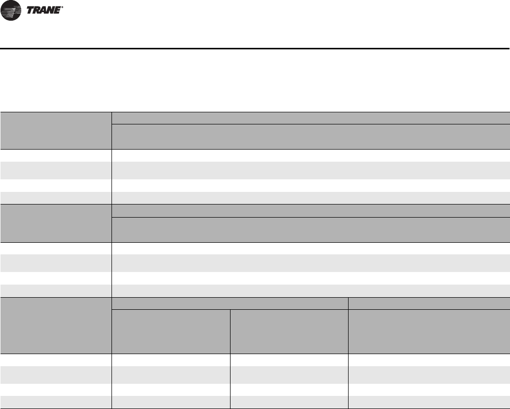
146 CLCH-PRC022A-EN
General Data
Table 129.Fan data for unit size 80
Housed Fans - Low Pressure
Size/Type 36-in. FC 32-in. FC 28-in. FC 36-in. AF 32-in. AF 28-in. AF
Fan name 36FA 32FA 28FA 36AA 32AA 28AA
Max rpm 600 675 750 1250 1300 1500
ODP NEMA Premium motor hp
range 10-40 10-30 10-25 10-30 10-30 10-20
Outlet area (ft²) 13.91 11.11 8.81 13.91 11.11 8.81
Bearing/Shaft size (in.) 2.4375 2.1875 1.9375 2.4375 2.1875 1.9375
Housed Fans - High Pressure
Size/Type 36-in. FC 32-in. FC 28-in. FC 36-in. AF 32-in. AF 28-in. AF
Fan name 36FB 32FB 28FB 36AB 32AB 28AB
Max rpm 665 760 860 1550 1700 2050
ODP NEMA Premium motor hp
range 10-60 10-60 10-40 10-75 10-60 10-60
Outlet area (ft²) 13.91 11.11 8.81 13.91 11.11 8.81
Bearing/Shaft size (in.) 2.4375 2.1875 2.4375 2.4375 2.1875 2.1875
Belt-drive Plenum Fans Direct-Drive Plenum Fans
Low Pressure High Pressure High Pressure
Size/Type 44-in. AF 40-in. AF 44-in. AF 40-in. AF ( 4 ) 2 2 - i n . A F
Nominal Width ( 4 ) 2 2- i n . A F
Extended Width
Fan name 44PA 40PA 44PB 40PB 22SF 22SW
Max rpm 1100 1150 1200 1400 2613 2613
ODP NEMA Premium motor hp
range 10-60 10-30 10-75 10-75 5-25 7.5-25
Outlet area (ft²) n/a n/a n/a n/a n/a n/a
Bearing/Shaft size (in.) 2.1875 2.4375 2.4375 2.1875 n/a n/a

CLCH-PRC022A-EN 147
General Data
Unit Size 100
Table 130. Section dimensions (inches) and weights (pounds) - unit size 100
Nominal airflow
50,000
Airflow at 625 fpm
65,106
Height - indoor unit (in.)
119.75
Width (in.)
154.50
Height - outdoor unit (in.) includes base drip lip
124.88
Weight add for outdoor unit (lbs./in. of unit length)
2.80
Section type Length (in.) Weight (lb.)
Access or blank
-Small horizontal 10.00 337.96
-Medium horizontal 15.00 493.59
-Extended-medium horizontal 19.00 545.85
-Medium-large horizontal 24.50 656.89
-Large horizontal or turning 60.00 1242.40
-Extra-large horizontal or turning n/a n/a
-Ducted inlet or ducted outlet section
10.00 428.30
Blender
60.00 1345.03
Cool Dry Quiet (CDQ) Desiccant Dehumidification Section
n/a n/a
Coils
-Small horizontal (with 4-row UW) n/a n/a
-Medium horizontal (with 8-row UW) 15.00 3094.04
-Extended-medium horizontal (with 8-row UW) 19.00 3163.21
-Medium-large horizontal (with 10-row W) 24.50 5499.42
-Large horizontal or vertical (with 10-row W) n/a n/a
-Electric Heat Coil
n/a n/a
-Integral-face-and-bypass (IFB) coil
--
Less than 4 rows 29.50 2865.77
--4 rows n/a n/a
Controls section (includes largest available VFD)
28.50 1146.00
Diffuser
37.25 781.92
Discharge plenum
-Horizontal 60.00 1423.88
-Vertical n/a n/a
Energy Wheel
n/a n/a
Face-and-Bypass Dampers
-Face-and-bypass 19.00 1093.88
-External face-and-bypass 39.00 1498.11
-Internal face-and-bypass or face damper only 19.00 1082.84
Fan
-Belt-drive plenum (BDP) fan with motor 73.75 6223.51
-Housed fan FC with motor 96.00 5297.62
-Housed AF/BC fans with motor 96.00 6025.44
-Direct-drive plenum fan with motor 96.00 7176.65
Filters
-Side load 2-in. angled 27.50 1157.16
-Side load 4-in. angled 27.50 1201.91
-Side load cartridge 12-in. or short bag 18-in. 27.50 1746.31
148 CLCH-PRC022A-EN
General Data
Filters Length (in.) Weight (lb.)
-Side load 2-in. flat 15.00 716.56
-Side load 4-in. flat 15.00 803.46
-Side load 2-in. and 4-in. combination flat 19.00 1078.09
-Long bag 30-in. 37.25 1393.00
-Front-load HEPA 40.00 2554.00
-Front-load cartridge 40.00 1923.00
-Front-load short bag 45.00 1539.00
Gas heat
- 860 MBH n/a n/a
- 1000 MBH 84.00 3156.00
- 1250-1750 MBH 92.00 3878.50
- 2000 MBH 109.00 4503.50
- 2400 MBH 121.00 4715.90
Humidifier
-Building Steam 15.00 1363.00
-Atmospheric 19.00 1265.00
Mixing box
-with angled filters 60.00 1287.99
-with front/back Traq and top Traq dampers 96.00 2473.12
- reduced length mixing box with side/top/back/bottom airfoil damper 47.00 1731.30
Multizone
n/a n/a
Silencer
-3 feet 38.00 2196.00
-5 feet 62.00 3230.00
Trane Catalytic Air Cleaning System (TCACS)
36.00 1707.00
UV light
15.00 667.60
SECTIONS BELOW ARE FOR OUTDOOR UNITS ONLY
Diagonal economizer
-with airfoil dampers 93.00 2173.00
-with airfoil damper and one side Traq damper 93.00 2290.00
Exhaust damper section
22.40 935.50
Hoods
- Back inlet hood - airfoil and Traq 140.00 491.00
- Side inlet hood - airfoil and Traq 43.00 412.00
- Exhaust hood - airfoil 43.00 206.00
- Economizer inlet hood 93.00 629.00
Pipe Cabinets
15 in. long - 24-in. depth 15.00 198.00
15 in. long - 36-in. depth 15.00 265.00
15 in. long - 48-in. depth 15.00 333.00
24 in. long - 24-in. depth 24.00 227.00
24 in. long - 36-in. depth 24.00 298.00
24 in. long - 48-in. depth 24.00 368.00
48 in. long - 24-in. depth 48.00 306.00
48 in. long - 36-in. depth 48.00 385.00
48 in. long - 48-in. depth 48.00 463.00
Table 130. Section dimensions (inches) and weights (pounds) - unit size 100
CLCH-PRC022A-EN 149
General Data
Pipe Cabinets Length (in.) Weight (lb.)
96 in. long - 24-in. depth 96.00 462.00
96 in. long - 36-in. depth 96.00 558.00
96 in. long - 48-in. depth 96.00 653.00
Table 131.Filter data for unit size 100
Filter Type Area ft² Qty–Size (in.)
Flat (2-in., 4-in., and 2-in/4-in high efficiency) pleated, permanent,
throwaway media 104.17 30 - 20x25
Angled (2-in. or 4-in.) Pleated, permanent, throwaway media 166.67 48 - 20x25
Side load bag or cartridge 113.33 28 - 24x20
4 - 24x12
6 - 12x24
Front load bag or cartridge 108.00 6 - 12x24
24 - 24x24
Front load HEPA 102.00
6 - 30x24
6 - 30x24
6 - 30x24
6 - 12x24
Note: 2-inch filters available in permanent, throwaway, or pleated media; 4-inch filters available in pleated media, 65%, 85%,
or 95% efficiency; Bag or cartridge filters available in 65%, 85%, or 95% efficiency.
Table 132.Coil availability - size 100
Section Type 1/2-in Unit Coils 5/8-in Unit Coils,
1/2-in and 5/8-in Modified Coils
Small n/a n/a
Medium 2–4 rows 1–3 rows
Extended-medium 2–8 rows 1-6 rows
Medium-large 2-8 rows 1-10 rows
-with access n/a n/a
Large horizontal n/a n/a
-with access n/a n/a
Large vertical n/a n/a
-with access n/a n/a
Table 133.Coil data for unit size 100
Coil Type Rows Fin Type Area ft² Qty–Size (in.)
1/2-inch unit coils
-UA, UW, UF, UU (stacked) 2, 4, 6, 8 Aluminum 99.14 1-57.50 x 141
1-43.75 x 141
5/8-inch unit coils
-W, WD, 5D, 5A 5W, D1, D2 (stacked) 1, 2, 3, 4, 6, 8 Aluminum or Copper 99.88 2-51 x 141
W, WD, 5D, D1, D2 (stacked) 10 Aluminum 99.88 2-51 x 141
1-inch unit coil
-NS (stacked) 1Aluminum or Copper 94.00 2-33 x 141
1-30 x 141
1/2-inch modified coils
-WL, LL, FD (stacked) 2, 4, 6, 8 Aluminum 77.11 1-42.50 x 141
1-36.25 x 141
Table 130. Section dimensions (inches) and weights (pounds) - unit size 100
150 CLCH-PRC022A-EN
General Data
Coil Type Rows Fin Type Area ft² Qty–Size (in.)
5/8-inch modified coils
-W, WD, 5A 5W, D1, D2 (stacked) 1, 2, 3, 4, 6, 8 Aluminum or Copper 76.38 1-42 x 141
1-36 x 141
W, WD, D1, D2 (stacked) 10 Aluminum 76.38 1-42 x 141
1-36 x 141
1-inch modified coil
-NS 1Aluminum or Copper 76.38 1-30 x 141
2-24 x 141
Multizone coils n/a n/a
Table 133.Coil data for unit size 100
Table 134.Fan data for unit size 100
Housed Fans - Low Pressure
Size/Type 40-in. FC 36-in. FC 32-in. FC 44-in. AF 40-in. AF 36-in. AF 32-in. AF
Fan name 40FA 36FA 32FA 44AA 40AA 36AA 32AA
Max rpm 550 600 675 850 1200 1250 1300
ODP NEMA Premium motor hp range 15-40 15-40 15-30 15-40 15-60 15-30 15-30
Outlet area (ft²) 17.45 13.91 11.11 21.88 17.45 13.91 11.11
Bearing/Shaft size (in.) 2.44 2.44 2.19 2.94 2.19 2.44 2.19
Housed Fans - High Pressure
Size/Type 40-in. FC 36-in. FC 32-in. FC 44-in. AF 40-in. AF 36-in. AF 32-in. AF
Fan name 40FB 36FB 32FB 44AB 40AB 36AB 32AB
Max rpm 600 665 760 1150 1350 1550 1700
ODP NEMA Premium motor hp range 15-75 15-75 15-60 15-100 15-100 15-75 15-60
Outlet area (ft²) 17.45 13.91 11.11 21.88 17.45 13.91 11.11
Bearing/Shaft size (in.) 2.44 2.44 2.19 2.94 2.44 2.44 2.19
Belt-drive Plenum Fans Direct-Drive Plenum Fans
Low Pressure High Pressure High Pressure
Size/Type 55-in. AF 49-in. AF 55-in. AF 49-in. AF 6-24.5-in AF
Nominal Width 6 -24.5-in AF
Extended Width
Fan name 55PA 49PA 55PB 49PB 24SF 24SW
Max rpm 850 950 975 1100 2344 2344
ODP NEMA Premium motor hp range 15-75 15-60 15-125 15-100 5-20 5-20
Outlet area (ft²) n/a n/a n/a n/a n/a n/a
Bearing/Shaft size (in.) 2.44 2.19 2.94 2.44 n/a n/a

CLCH-PRC022A-EN 151
General Data
Unit Size 120
Table 135. Section dimensions (inches) and weights (pounds) - unit size 120
Nominal airflow
60,000
Airflow at 625 fpm
76,388
Height - indoor unit (in.)
119.75
Width (in.)
182.00
Height - outdoor unit (in.) includes base drip lip
124.88
Weight add for outdoor unit (lbs./in. of unit length)
3.24
Section type Length (in.) Weight (lb.)
Access or blank
-Small horizontal 10.00 374.94
-Medium horizontal 15.00 549.13
-Extended-medium horizontal 19.00 605.56
-Medium-large horizontal 24.50 725.47
-Large horizontal or turning 60.00 1387.96
-Extra-large horizontal or turning n/a n/a
-Ducted inlet or ducted outlet section
10.00 478.60
Blender
60.00 1567.62
Cool Dry Quiet (CDQ) Desiccant Dehumidification Section
n/a n/a
Coils
-Small horizontal (with 4-row UW) n/a n/a
-Medium horizontal (with 8-row UW) 15.00 3638.44
-Extended-medium horizontal (with 8-row UW) 19.00 3712.02
-Medium-large horizontal (with 10-row W) 24.50 6713.50
-Large horizontal or vertical (with 10-row W) n/a n/a
-Electric Heat Coil
n/a n/a
-Integral-face-and-bypass (IFB) coil
-
Less than 4 rows 29.50 2936.42
--4 rows n/a n/a
Controls section (includes largest available VFD)
28.50 1266.00
Diffuser
37.25 860.66
Discharge plenum
-Horizontal 60.00 1585.80
-Vertical n/a n/a
Energy Wheel
n/a n/a
Face-and-Bypass Dampers
-Face-and-bypass 19.00 1205.53
-External face-and-bypass 39.00 1643.69
-Internal face-and-bypass or face damper only 19.00 1194.50
Fan
-Belt-drive plenum (BDP) fan with motor 82.25 7341.11
-Housed fan FC with motor 96.00 5600.08
-Housed AF/BC fans with motor 96.00 6891.90
-Direct-drive plenum fan with motor 96.00 7382.51
Filters
-Side load 2-in. angled 27.50 1282.20
-Side load 4-in. angled 27.50 1338.65
-Side load cartridge 12-in. or short bag 18-in. 27.50 1903.54
152 CLCH-PRC022A-EN
General Data
Filters Length (in.) Weight (lb.)
-Side load 2-in. flat 15.00 817.63
-Side load 4-in. flat 15.00 913.90
-Side load 2-in. and 4-in. combination flat 19.00 1165.92
-Long bag 30-in. 37.25 1550.00
-Front-load HEPA 40.00 2925.00
-Front-load cartridge 40.00 2156.00
-Front-load short bag 45.00 1696.00
Gas heat
- 860 MBH n/a n/a
- 1000 MBH 92.00 3125.30
- 1250-1750 MBH 102.00 3886.60
- 2000 MBH 109.00 4391.20
- 2400 MBH 119.00 4668.50
Humidifier
-Building Steam 15.00 1551.00
-Atmospheric 19.00 1492.00
Mixing box
-with angled filters 60.00 1433.55
-with front/back Traq and top Traq dampers 96.00 2790.48
- reduced length mixing box with side/top/back/bottom airfoil damper 53.00 2025.40
Multizone
n/a n/a
Silencer
-3 feet 38.00 2555.00
-5 feet 62.00 3786.00
Trane Catalytic Air Cleaning System (TCACS)
36.00 1881.00
UV light
15.00 758.72
SECTIONS BELOW ARE FOR OUTDOOR UNITS ONLY
Diagonal economizer
-with airfoil dampers 93.00 2396.00
-with airfoil damper and one side Traq damper 93.00 2494.00
Exhaust damper section
22.40 1058.30
Hoods
- Back inlet hood - airfoil and Traq 167.25 566.00
- Side inlet hood - airfoil and Traq 48.75 415.00
- Exhaust hood - airfoil 48.75 221.00
- Economizer inlet hood 93.00 778.00
Pipe Cabinets
15 in. long - 24-in. depth 15.00 198.00
15 in. long - 36-in. depth 15.00 265.00
15 in. long - 48-in. depth 15.00 333.00
24 in. long - 24-in. depth 24.00 227.00
24 in. long - 36-in. depth 24.00 298.00
24 in. long - 48-in. depth 24.00 368.00
48 in. long - 24-in. depth 48.00 306.00
48 in. long - 36-in. depth 48.00 385.00
48 in. long - 48-in. depth 48.00 463.00
Table 135. Section dimensions (inches) and weights (pounds) - unit size 120
CLCH-PRC022A-EN 153
General Data
Pipe Cabinets Length (in.) Weight (lb.)
96 in. long - 24-in. depth 96.00 462.00
96 in. long - 36-in. depth 96.00 558.00
96 in. long - 48-in. depth 96.00 653.00
Table 136.Filter data for unit size 120
Filter Type Area ft² Qty–Size (in.)
Flat (2-in., 4-in., and 2-in/4-in high efficiency) pleated, permanent,
throwaway media 122.22 32 - 25x20
4 - 25x16
Angled (2-in. or 4-in.) Pleated, permanent, throwaway media 194.44 56 - 25x20
Side load bag or cartridge 134.00 28 - 24x24
4 - 24x12
7 - 12x24
Front load bag or cartridge 126.00 7 - 12x24
28 - 24x24
Front load HEPA 119.00
7 - 30x24
7 - 30x24
7 - 30x24
7 - 12x24
Note: 2-inch filters available in permanent, throwaway, or pleated media; 4-inch filters available in pleated media, 65%, 85%,
or 95% efficiency; Bag or cartridge filters available in 65%, 85%, or 95% efficiency.
Table 137.Coil availability - size 120
Section Type 1/2-in Unit Coils 5/8-in Unit Coils,
1/2-in and 5/8-in Modified Coils
Small n/a n/a
Medium 2–4 rows 1–3 rows
Extended-medium 2–8 rows 1-6 rows
Medium-large 2-8 rows 1-10 rows
-with access n/a n/a
Large horizontal n/a n/a
-with access n/a n/a
Large vertical n/a n/a
-with access n/a n/a
Table 138.Coil data for unit size 120
Coil Type Rows Fin Type Area ft² Qty–Size (in.)
1/2-inch unit coils
-UA, UW, UF, UU (stacked) 2, 4, 6, 8 Aluminum 118.13 1-57.50 x 168
1-43.75 x 168
5/8-inch unit coils
-W, WD, 5D, 5A, 5W, D1, D2 (stacked) 1, 2, 3, 4, 6, 8 Aluminum or Copper 119.00 2-51 x 168
-W, WD, D1, D2 (stacked) 10 Aluminum 115.50 3-33 x 168
1-inch unit coil
-NS (stacked) 1Aluminum or Copper 96.00 2-33 x 144
1-30 x 144
1/2-inch modified coils
-WL, LL, FD (stacked) 2, 4, 6, 8 Aluminum 91.88 1-42.50 x 168
1-36.25 x 168
Table 135. Section dimensions (inches) and weights (pounds) - unit size 120
154 CLCH-PRC022A-EN
General Data
Coil Type Rows Fin Type Area ft² Qty–Size (in.)
5/8-inch modified coils
-W, WD, 5A, 5W, D1, D2 (stacked) 1, 2, 3, 4, 6, 8 Aluminum or Copper 91.00 1-42 x 168
1-36 x 168
-W, WD, D1, D2 (stacked) 10 Aluminum 91.00 1-30 x 168
2-24 x 168
1-inch modified coil
-NS (stacked) 1Aluminum or Copper 78.00 1-30 x 144
2-24 x 144
Multizone coils n/a n/a
Table 138.Coil data for unit size 120
Table 139.Fan data for unit size 120
Housed Fans - Low Pressure
Size/Type 40-in. FC 36-in. FC 32-in. FC 49-in. AF 44-in. AF 40-in. AF 36-in. AF
Fan name 40FA 36FA 32FA 49AA 44AA 40AA 36AA
Max rpm 550 600 675 800 850 1200 1250
ODP NEMA Premium motor hp range 30-40 30-40 30 30-100 30-40 30-60 30
Outlet area (ft²) 17.45 13.91 11.11 27.45 21.88 17.45 13.91
Bearing/Shaft size (in.) 2.44 2.44 2.19 2.75 2.94 2.19 2.44
Housed Fans - High Pressure
Size/Type 40-in. FC 36-in. FC 32-in. FC 49-in. AF 44-in. AF 40-in. AF 36-in. AF
Fan name 40FB 36FB 32FB 49AB 44AB 40AB 36AB
Max rpm 600 665 760 1100 1150 1350 1550
ODP NEMA Premium motor hp range 30-75 30-75 30-60 30-125 30-125 30-100 30-75
Outlet area (ft²) 17.45 13.91 11.11 27.45 21.88 17.45 13.91
Bearing/Shaft size (in.) 2.44 2.44 2.19 2.94 2.94 2.44 2.44
Belt-drive Plenum Fans Direct-Drive Plenum Fans
Low Pressure High Pressure High Pressure
Size/Type 63-in. AF 55-in. AF 63-in. AF 55-in. AF 6-24.5-in AF
Nominal Width 6-24.5-in AF
Extended Width
Fan name 63PA 55PA 63PB 55PB 24SF 24SW
Max rpm 750 850 850 975 2344 2344
ODP NEMA Premium motor hp range 30-100 30-75 30-125 30-125 5-20 5-20
Outlet area (ft²) n/a n/a n/a n/a n/a n/a
Bearing/Shaft size (in.) 2.94 2.44 3.19 2.94 n/a n/a
CLCH-PRC022A-EN 155
Coils
Drain Pans
Coil Connections
Hydronic and Steam Coil Connections
Table 140.Coil depth by rows (inches)
Tube Diameter Unit Size
Coil Rows
12346810
1/2 inch (unit height) 3-40, 22 n/a 6.55 n/a 6.55 8.72 10.88 n/a
1/2 inch (unit height) 50-120, 26, 31, 36,
41,51, 58 n/a 5.72 n/a 7.88 10.05 12.21 n/a
1/2 inch (modified height)
1
All sizes n/a 6.50 n/a 9/50 12.50 15.50 n/a
5/8 inch All sizes 4.00 6.50 8.00 9.50 12.50 15.50 18.50
1 inch All sizes 5.25 n/a n/a n/a n/a n/a n/a
Note:
1
Modified coils include WL, LL, FD.
2
Unit coils include UF, UW, UU. Example: Size 30 with a 4-row UW coil in an extended-
medium coil section, there would be 10.82 inches of drain pan exposed beyond the coil casing for cleaning access.
Table 141.Water coils with 1/2-inch tubes connection diameter
Coil Type Rows Unit Sizes Quantity
Connection Diameter (inches)
Supply Return Drain/Vent
UW 2, 4, 6, 8
3-6 1 1.50 1.50 0.38
8-14, 50-66 1 2.00 2.00 0.38
17-40, 80-120 1 2.50 2.50 0.38
UA 23-14, 50-57 11.50 1.50 0.38
17-40, 66-120 12.00 2.00 0.38
UU 4, 8 12-120 1 2.50 2.50 0.38
LL 4, 6, 8 8-120 1 2.50 2.50 0.38
WL 2, 4, 6, 8
3-10 11.50 1.50 0.38
12-21, 66 12.00 2.00 0.38
25-57, 80-120 12.50 2.50 0.38
Note: All connections have external threads.
Table 142.Water coils with 5/8-inch tubes connection diameter
Coil Type Rows Header Height (in.) Connection Diameter (inches)
Supply Return Drain/Vent
5A 212-27 2.00 2.00 0.38
30-54 2.50 2.50 0.38
5D 6, 8, 10 45-55 2.50 2.50 0.38
5W
112-18 1.25 1.25 0.38
24-54 1.50 1.50 0.38
212-27 2.00 2.00 0.38
30-54 2.50 2.50 0.38
D1 3, 4, 6, 8, 10 12-27 2.00 2.00 0.38
30-55 2.50 2.50 0.38
D2 6, 8, 10 18-55 2.50 2.50 0.38
P2 2, 6 12-30 0.75 0.75 0.50
412-30 1.00 1.00 0.50
P4 2, 4, 6, 8 12-30 1.00 1.00 0.50
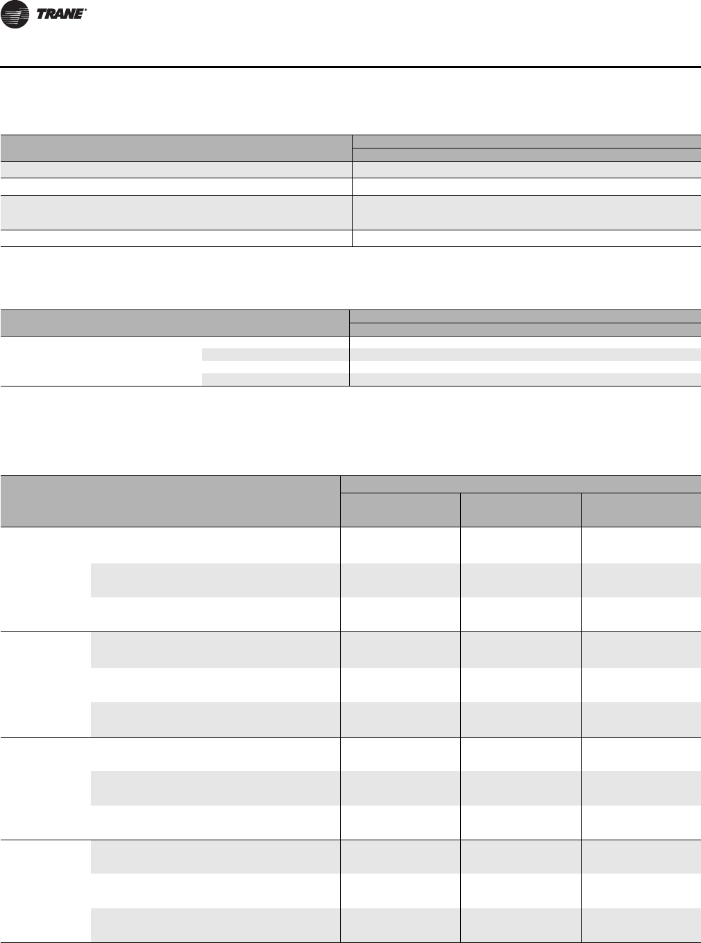
156 CLCH-PRC022A-EN
Coils
Refrigerant Coil Connections
Coil Type Rows Header Height (in.) Connection Diameter (inches)
Supply Return Drain/Vent
P8 4, 8 18-30 1.25 1.25 0.50
TT 1, 2 12-33 0.75 0.75 n/a
W3, 4, 6, 8, 10 12-27 2.00 2.00 0.38
24, 30-51 2.50 2.50 0.38
WD 6, 8, 10 18-55 2.50 2.50 0.38
Note: 5A, 5W, W (4–10 row), D1, D2, WD, and 5D connections have external threads; P2, P4, P8, and TT connections have internal threads.
Table 142.Water coils with 5/8-inch tubes connection diameter
Table 143.Steam coils with 1-inch tubes connection diameter
Coil Type Rows Header Height (in.) Connection Diameter (inches)
Supply Return Drain/Vent
NS 1
12 1.50 1.00 1.00
18 2.00 1.00 1.00
24 2.50 1.25 1.25
30–33 3.00 1.25 1.25
Note: All connections have internal threads.
Table 144.Type UF refrigerant coil connection sizes for unit sizes 3 to 30
Unit
Size
Header
Height
(inches) Rows Distributor
Tube Number
of Circuits Circuiting
Connection Diameter (inches)
1 Distributor 2 Distributor 4 Distributor
Liquid Suction Liquid Suction Liquid Suction
3, 4 20
4, 6, 8 0.25 15 Full n/a n/a 1.13 Note
1
n/a n/a
0.19 15 Full n/a n/a Note
2
Note
1
n/a n/a
4, 6 0.25 7Half 1.13 1.38 0.88 1.38 n/a n/a
0.19 7Half 0.88 1.38 0.63 1.38 n/a n/a
40.25 3 Quarter 0.88 1.38 n/a n/a n/a n/a
0.19 3 Quarter 0.63 1.38 n/a n/a n/a n/a
626
4, 6, 8 0.25 20 Full n/a n/a 1.13 1.63 n/a n/a
0.19 20 Full n/a n/a 1.13 1.63 n/a n/a
4, 6 0.25 10 Half 1.13 1.63 0.88 1.38 n/a n/a
0.19 10 Half 1.13 1.63 0.88 1.38 n/a n/a
40.25 5Quarter 0.88 1.38 0.88 1.38 n/a n/a
0.19 5Quarter 0.88 1.38 0.63 1.38 n/a n/a
8, 10 28
4, 6, 8 0.25 22 Full n/a n/a 1.38 1.63 n/a n/a
0.19 22 Full n/a n/a 1.13 1.63 n/a n/a
4, 6 0.25 11 Half 1.38 1.63 0.88 1.38 n/a n/a
0.19 11 Half 1.13 1.63 0.88 1.38 n/a n/a
40.25 4 Quarter 0.88 1.38 0.88 1.38 n/a n/a
0.19 4 Quarter 0.63 1.38 0.63 1.38 n/a n/a
12, 14 32
4, 6, 8 0.25 25 Full n/a n/a 1.38 1.63 n/a n/a
0.19 25 Full n/a n/a 1.13 1.63 n/a n/a
4, 6 0.25 12 Half 1.38 1.63 1.13 1.38 n/a n/a
0.19 12 Half 1.13 1.63 0.88 1.38 n/a n/a
40.25 6Quarter 1.13 1.38 0.88 1.38 n/a n/a
0.19 6Quarter 0.88 1.38 0.63 1.38 n/a n/a
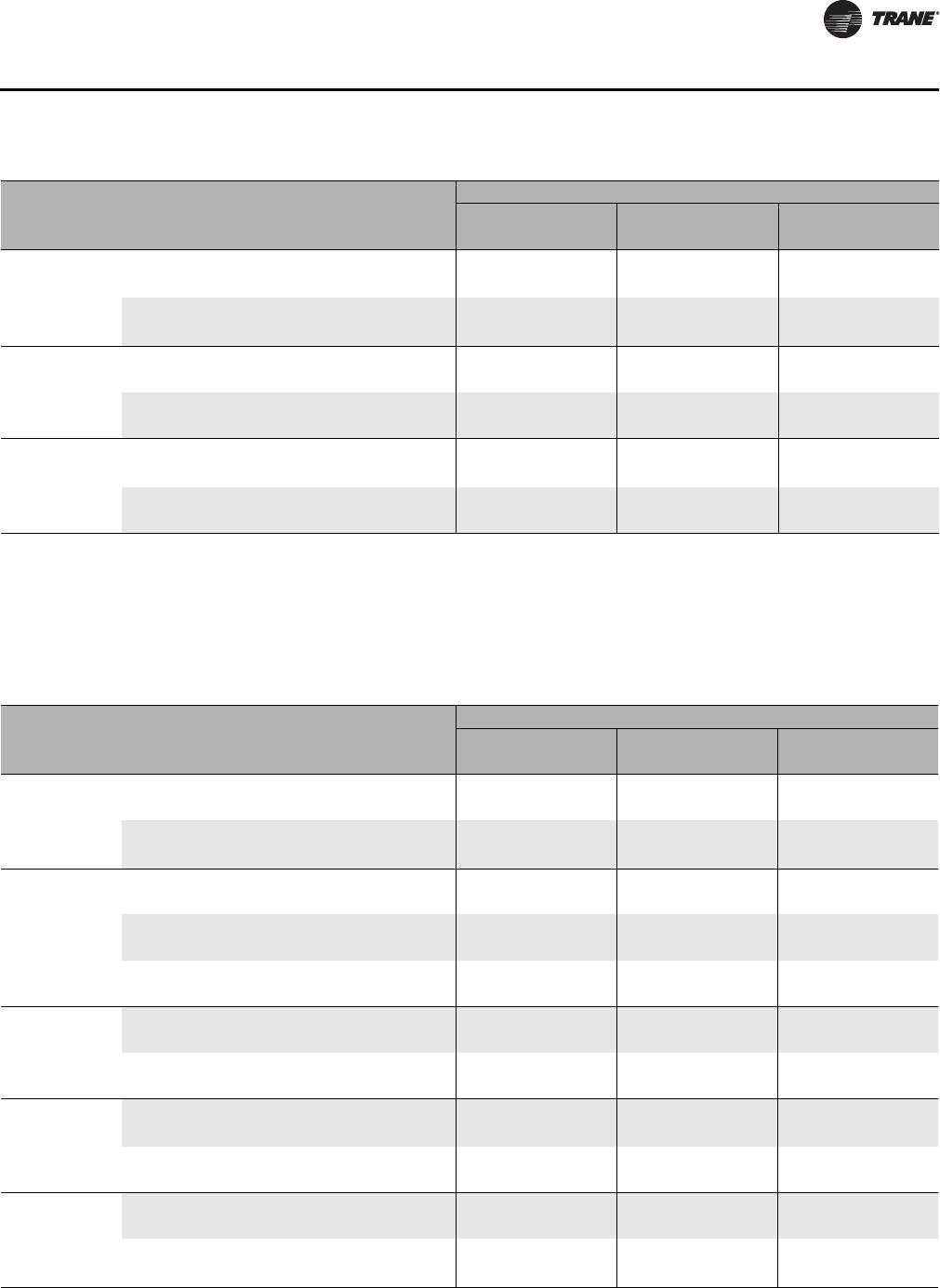
CLCH-PRC022A-EN 157
Coils
Unit
Size
Header
Height
(inches) Rows Distributor
Tube Number
of Circuits Circuiting
Connection Diameter (inches)
1 Distributor 2 Distributor 4 Distributor
Liquid Suction Liquid Suction Liquid Suction
17 40
4, 6, 8 0.25 31 Full n/a n/a n/a n/a 1.13 Note
5
0.19 31 Full n/a n/a n/a n/a Note
4
Note
5
4, 6 0.25 15 Half n/a n/a 1.13 Note
7
0.88 1.38
0.19 15 Half n/a n/a Note
6
Note
7
0.63 1.38
21 43
4, 6, 8 0.25 34 Full n/a n/a n/a n/a 1.13 1.63
0.19 34 Full n/a n/a n/a n/a 1.13 1.63
4, 6 0.25 17 Half n/a n/a 1.13 1.63 0.88 1.38
0.19 17 Half n/a n/a 1.13 1.63 Note
8
1.38
25, 30 52
4, 6, 8 0.25 41 Full n/a n/a n/a n/a 1.38 1.63
0.19 41 Full n/a n/a n/a n/a 1.13 1.63
4, 6 0.25 20 Half n/a n/a 1.13 1.63 0.88 1.38
0.19 20 Half n/a n/a 1.13 1.63 0.88 1.38
Notes:
1
Bottom suction connection is 1.63 inches and top suction connection is 1.38 inch.
2
Bottom liquid connection is 1.13 inches and top liquid
connection is 0.88 inch.
3
Connections are 1.13 for intertwined and 1.38 inches for horizontal split.
4
Three connections are 1.13 inches and one is
0.88 inch.
5
Three connections are 1.63 inches and one is 1.38 inches.
6
One connection is 0.88 inch and one is 1.13 inches.
7
One connection is
1.38 inches and one is 1.63 inches.
8
Three connection are 0.63 inch and one is 0.88 inch.
9
Liquid connections are 0.88 inch for intertwined and
1.13 inches for horizontal split.
10
Suction connections are 1.38 inches for intertwined and 1.63 inches for horizontal split.
11
Three suction
connections are 1.38 inches and one is 1.63 inches.
12
Three liquid connections are 0.88 inches and one is 1.13 inches.
13
Three connections are
0.63 inches and one connection is 0.88 inches.
Table 144.Type UF refrigerant coil connection sizes for unit sizes 3 to 30
Table 145.Type UF refrigerant coil connection sizes for unit sizes 35 to 120
Unit
Size
Header
Height
(inches) Rows Distributor
Tube Number
of Circuits Circuiting
Connection Diameter (inches)
1 Distributor 2 Distributor 4 Distributor
Liquid Suction Liquid Suction Liquid Suction
35, 40 57
4, 6, 8 0.25 45 Full n/a n/a n/a n/a 1.38 1.63
0.19 45 Full n/a n/a n/a n/a 1.13 1.63
4, 6 0.25 22 Half n/a n/a 1.38 1.63 1.38 1.63
0.19 22 Half n/a n/a 1.13 1.63 Note
9
Note
10
50 31
4, 6, 8 0.25 24 Full n/a n/a 1.38 1.63 n/a n/a
0.19 24 Full n/a n/a 1.13 1.63 n/a n/a
4, 6 0.25 12 Half 1.38 1.63 1.13 1.38 n/a n/a
0.19 12 Half 1.13 1.63 0.88 1.38 n/a n/a
40.25 6 Quarter 1.13 1.38 0.88 1.38 n/a n/a
0.19 6 Quarter 0.88 1.38 0.63 1.38 n/a n/a
57 36
4, 6, 8 0.25 28 Full n/a n/a n/a n/a 1.13 1.38
0.19 28 Full n/a n/a n/a n/a 0.88 1.38
4, 6 0.25 14 Half n/a n/a 1.13 1.38 n/a n/a
0.19 14 Half n/a n/a 0.88 1.38 n/a n/a
66 37
4, 6, 8 0.25 29 Full n/a n/a n/a n/a 1.13 Note
11
0.19 29 Full n/a n/a n/a n/a Note
12
Note
11
4, 6 0.25 14 Half n/a n/a 1.13 1.38 n/a n/a
0.19 14 Half n/a n/a 0.88 1.38 n/a n/a
80 45
4, 6, 8 0.25 35 Full n/a n/a n/a n/a 1.13 1.63
0.19 35 Full n/a n/a n/a n/a 1.13 1.63
4, 6 0.25 17 Half n/a n/a 1.13 1.63 0.88 1.38
0.19 17 Half n/a n/a 1.13 1.63 Note
13
1.38
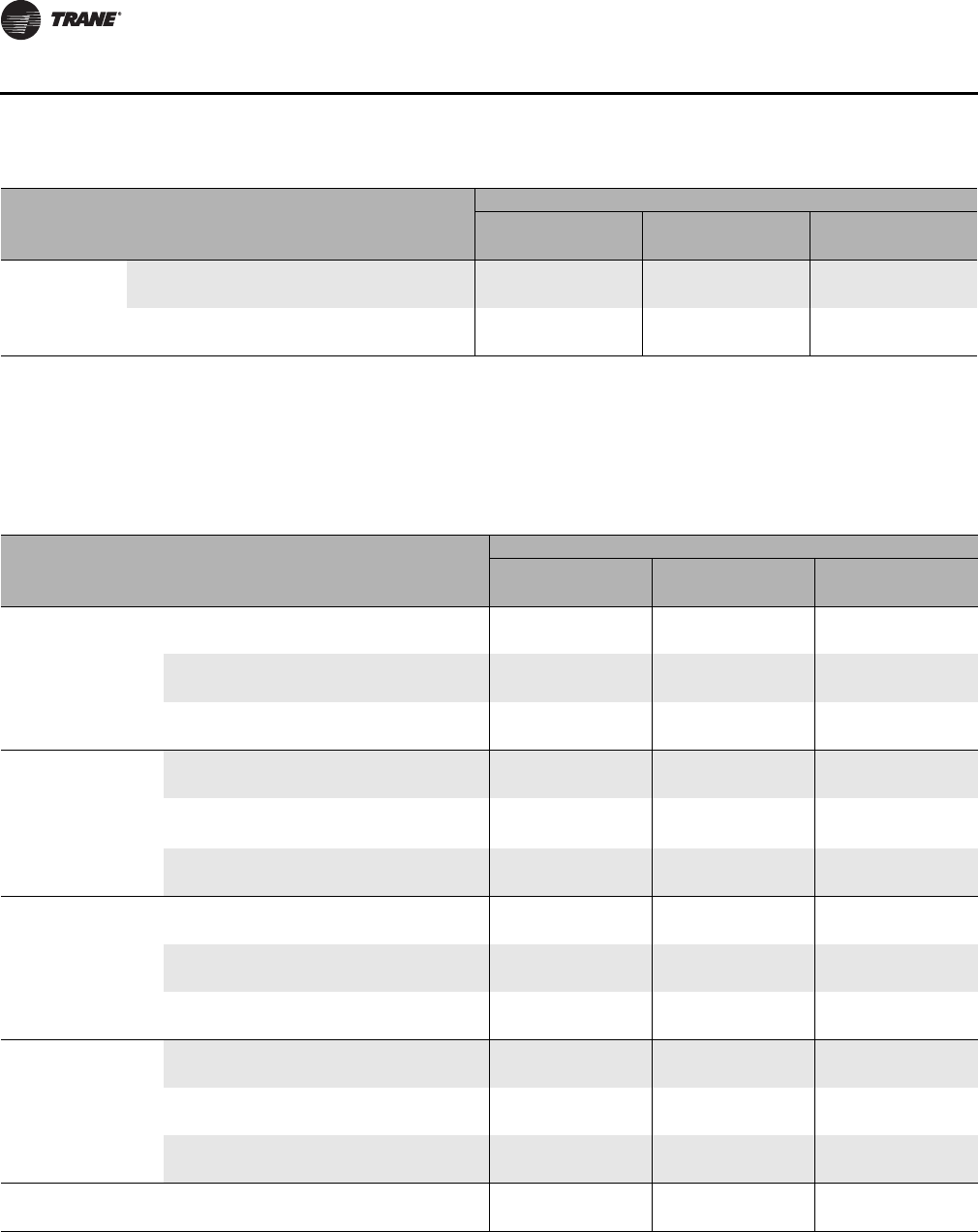
158 CLCH-PRC022A-EN
Coils
Unit
Size
Header
Height
(inches) Rows Distributor
Tube Number
of Circuits Circuiting
Connection Diameter (inches)
1 Distributor 2 Distributor 4 Distributor
Liquid Suction Liquid Suction Liquid Suction
100,
120 51
4, 6, 8 0.25 40 Full n/a n/a n/a n/a 1.13 1.63
0.19 40 Full n/a n/a n/a n/a 1.13 1.63
4, 6 0.25 20 Half n/a n/a 1.13 1.63 0.88 1.38
0.19 20 Half n/a n/a 1.13 1.63 0.88 1.38
Notes:
1
Bottom suction connection is 1.63 inches and top suction connection is 1.38 inch.
2
Bottom liquid connection is 1.13 inches and top liquid
connection is 0.88 inch.
3
Connections are 1.13 for intertwined and 1.38 inches for horizontal split.
4
Three connections are 1.13 inches and one is
0.88 inch.
5
Three connections are 1.63 inches and one is 1.38 inches.
6
One connection is 0.88 inch and one is 1.13 inches.
7
One connection is
1.38 inches and one is 1.63 inches.
8
Three connection are 0.63 inch and one is 0.88 inch.
9
Liquid connections are 0.88 inch for intertwined and
1.13 inches for horizontal split.
10
Suction connections are 1.38 inches for intertwined and 1.63 inches for horizontal split.
11
Three suction
connections are 1.38 inches and one is 1.63 inches.
12
Three liquid connections are 0.88 inches and one is 1.13 inches.
13
Three connections are
0.63 inches and one connection is 0.88 inches.
Table 145.Type UF refrigerant coil connection sizes for unit sizes 35 to 120
Table 146.Type FD refrigerant coil connection sizes for unit sizes 3 to 40
Unit Size
Header
Height
(inches) Rows Distribut
or Tube
Number
of
Circuits Circuiting
Connection Diameter (inches)
1 Distributor 2 Distributor 4 Distributor
Liquid Suction Liquid Suction Liquid Suction
8, 10 18
4, 6 0.25 14 Full n/a n/a 1.13 1.38 n/a n/a
0.19 14 Full n/a n/a 0.88 1.38 n/a n/a
4, 6 0.25 7Half 1.13 1.38 0.88 1.38 n/a n/a
0.19 7Half 0.88 1.38 0.63 1.38 n/a n/a
40.25 4 Quarter 0.88 1.38 0.88 1.38 n/a n/a
0.19 4 Quarter 0.63 1.38 0.63 1.38 n/a n/a
12, 14 24
4, 6 0.25 19 Full n/a n/a 1.13 1.63 n/a n/a
0.19 19 Full n/a n/a 1.13 1.63 n/a n/a
4, 6 0.25 9 Half1.131.630.881.63 n/a n/a
0.19 9 Half 1.13 1.63 Note
1
1.63 n/a n/a
40.25 4Quarter 0.88 1.38 0.88 1.38 n/a n/a
0.19 4Quarter 0.63 1.38 0.63 1.38 n/a n/a
17 30
4, 6 0.25 24 Full n/a n/a 1.38 1.63 n/a n/a
0.19 24 Full n/a n/a 1.13 1.63 n/a n/a
4, 6 0.25 12 Half 1.38 1.63 1.13 1.63 n/a n/a
0.19 12 Half 1.13 1.63 0.88 1.63 n/a n/a
40.25 6 Quarter 1.13 1.63 0.88 1.63 n/a n/a
0.19 6 Quarter 0.88 1.63 0.63 1.63 n/a n/a
21 33
4, 6 0.25 26 Full n/a n/a 1.38 1.63 n/a n/a
0.19 26 Full n/a n/a 1.13 1.63 n/a n/a
4, 6 0.25 13 Half 1.38 1.63 1.13 1.63 n/a n/a
0.19 13 Half 1.13 1.63 0.88 1.63 n/a n/a
40.25 6Quarter 1.13 1.63 0.88 1.63 n/a n/a
0.19 6Quarter 0.88 1.63 0.63 1.63 n/a n/a
25, 30, 35,
40 36 4, 6 0.25 28 Full n/a n/a n/a n/a 1.13 1.38
0.19 28 Full n/a n/a n/a n/a 0.88 1.38
Notes:
1
On a 4 row intertwined the liquid connection is 0.88 inch downstream and 0.63 inch upstream. On a 6 row intertwined the liquid connection is
0.64 inch downstream and 0.88 upstream.
2
For 4-row intertwined, the upstream liquid connection is 0.63 inches and the downstream liquid
connection is 0.88 inches. For 6-row intertwined, the upstream liquid connection is 0.88 inches and the downstream liquid connection is 0.63
inches.
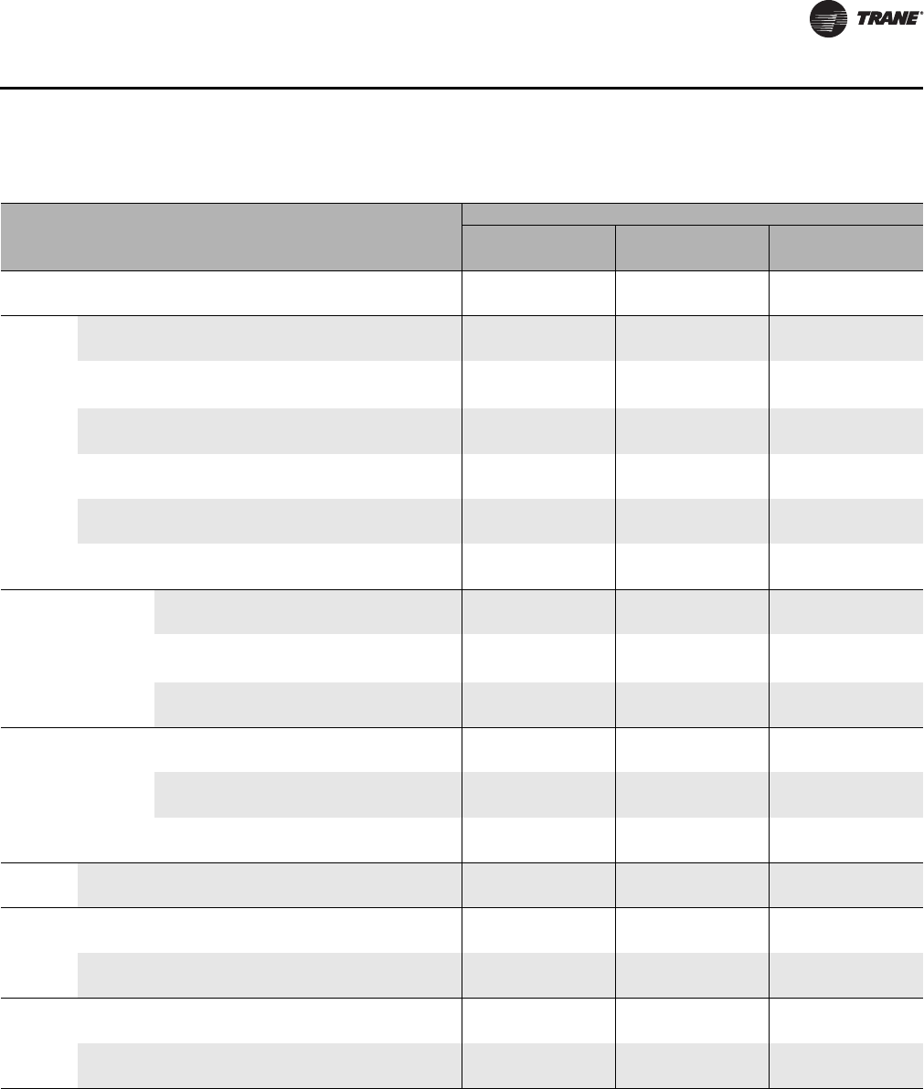
CLCH-PRC022A-EN 159
Coils
Table 147.Type FD refrigerant coil connection sizes for unit sizes 50-120
Unit Size
Header
Height
(inches) Rows Distribut
or Tube
Number
of
Circuits Circuiting
Connection Diameter (inches)
1 Distributor 2 Distributor 4 Distributor
Liquid Suction Liquid Suction Liquid Suction
50 42 4, 6 0.25 33 Full n/a n/a n/a n/a 1.13 1.63
0.19 33 Full n/a n/a n/a n/a 1.13 1.63
57
24 4, 6 0.25 19 Full n/a n/a 1.13 1.63 n/a n/a
0.19 19 Full n/a n/a 1.13 1.63 n/a n/a
24 4, 6 0.25 9 Half1.131.630.881.63 n/a n/a
0.19 9 Half 1.13 1.63 Note
2
1.63 n/a n/a
24 40.25 4Quarter 0.88 1.38 0.88 1.38 n/a n/a
0.19 4Quarter 0.63 1.38 0.63 1.38 n/a n/a
30 4, 6 0.25 24 Full n/a n/a 1.38 1.63 n/a n/a
0.19 24 Full n/a n/a 1.13 1.63 n/a n/a
30 4, 6 0.25 12 Half 1.38 1.63 1.13 1.63 n/a n/a
0.19 12 Half 1.13 1.63 0.88 1.63 n/a n/a
30 4 0.25 6 Quarter 1.13 1.63 0.88 1.63 n/a n/a
0.19 6 Quarter 0.88 1.63 0.63 1.63 n/a n/a
66 24
4, 6 0.25 19 Full n/a n/a 1.13 1.63 n/a n/a
0.19 19 Full n/a n/a 1.13 1.63 n/a n/a
4, 6 0.25 9 Half1.131.630.881.63 n/a n/a
0.19 9 Half 1.13 1.63 Note
2
1.63 n/a n/a
40.25 4Quarter 0.88 1.38 0.88 1.38 n/a n/a
0.19 4Quarter 0.63 1.38 0.63 1.38 n/a n/a
66 33
4, 6 0.25 26 Full n/a n/a 1.38 1.63 n/a n/a
0.19 26 Full n/a n/a 1.13 1.63 n/a n/a
4, 6 0.25 13 Half 1.38 1.63 1.13 1.63 n/a n/a
0.19 13 Half 1.13 1.63 0.88 1.63 n/a n/a
40.25 6 Quarter 1.13 1.63 0.88 1.63 n/a n/a
0.19 6 Quarter 0.88 1.63 0.63 1.63 n/a n/a
80 36 4, 6 0.25 28 Full n/a n/a n/a n/a 1.13 1.38
0.19 28 Full n/a n/a n/a n/a 0.88 1.38
100
36 4, 6 0.25 28 Full n/a n/a n/a n/a 1.13 1.38
0.19 28 Full n/a n/a n/a n/a 0.88 1.38
42 4, 6 0.25 33 Full n/a n/a n/a n/a 1.13 1.63
0.19 33 Full n/a n/a n/a n/a 1.13 1.63
120
36 4, 6 0.25 28 Full n/a n/a n/a n/a 1.13 1.38
0.19 28 Full n/a n/a n/a n/a 0.88 1.38
42 4, 6 0.25 33 Full n/a n/a n/a n/a 1.13 1.63
0.19 33 Full n/a n/a n/a n/a 1.13 1.63
Notes:
1
On a 4 row intertwined the liquid connection is 0.88 inch downstream and 0.63 inch upstream. On a 6 row intertwined the liquid connection is
0.64 inch downstream and 0.88 upstream.
2
For 4-row intertwined, the upstream liquid connection is 0.63 inches and the downstream liquid
connection is 0.88 inches. For 6-row intertwined, the upstream liquid connection is 0.88 inches and the downstream liquid connection is 0.63
inches.
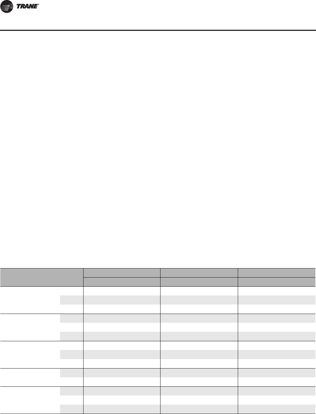
160 CLCH-PRC022A-EN
Coils
Coil Circuiting
Refrigerant coil circuiting is first defined by how the distributors are arranged on the coil and then
by the number of tubes on the coil being fed refrigerant.
Distributor Arrangement
The term standard circuiting means the number of distributors used on a coil is the minimum
required to meet capacity. If more than one distributor is required, then the coil is horizontally split
so sections of the coil can be de-energized to unload the coil.
The term horizontally split circuiting means that at a minimum, each coil (or each coil in a bank)
will have two or more distributors per coil. As each coil is horizontally split, sections of the coil can
be de-energized to unload the coil.
The term intertwined circuiting means that at a minimum each coil (or each coil in a bank) will have
two or more distributors per coil. Since each distributor is circuited from the top to the bottom of
the coil, the full face of the coil remains energized even if a circuit is de-energized to unload the coil.
If four distributors are used on a coil, then the coil is first horizontally split, with the top half of the
coil intertwined using two distributors, and the bottom half of the coil intertwined using the other
two distributors.
Distributor Circuiting
The terms full, half, and quarter refer to the number of coil tubes being fed refrigerant by each
distributor of that coil. For example, full means that each tube in one row of the coil is being fed
refrigerant from the distributor(s), while half means every other tube in a row is being fed.
Circuiting Example.
Table 148 lists standard distributor arrangements (minimum number or
distributors) for UF coils. On a size 12 unit, 6-row coil with half circuiting (every other tube in a row
being fed), there is one distributor, with 12 tubes in one row of the coil being fed refrigerant.
Circuiting data is show by unit size and coil rows.
Table 148.Type UF coil standard circuiting
Unit
size Header height
(inches) Coil
rows
Full Half Quarter
Dist qty Circuits per dist Dist qty Circuits per dist Dist qty Circuits per dist
3,4 20
427,81713
6 2 7,8 1 7 n/a n/a
8 2 7,8 n/a n/a n/a n/a
626
4 2 10,10 110 1 5
6 2 10,10 1 10 n/a n/a
8 2 10,10 n/a n/a n/a n/a
8,10 28
4 2 11,11 1 11 1 4
6 2 11,11 111 n/a n/a
8 2 11,11 n/a n/a n/a n/a
12,14 32 4 2 12,13 112 1 6
6 2 12,13 1 12 n/a n/a
17 40
4 4 7,8,8,8 27,8 n/a n/a
6 4 7,8,8,8 2 7,8 n/a n/a
8 4 7,8,8,8 n/a n/a n/a n/a
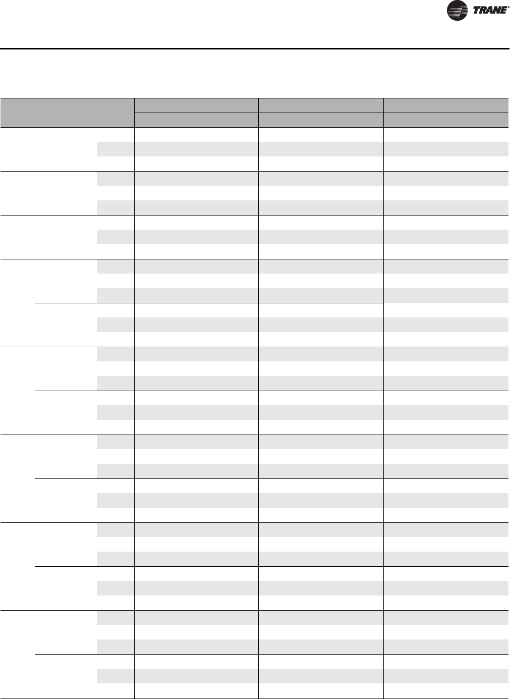
CLCH-PRC022A-EN 161
Coils
Unit
size Header height
(inches) Coil
rows
Full Half Quarter
Dist qty Circuits per dist Dist qty Circuits per dist Dist qty Circuits per dist
21 43
4 4 8,8,9,9 2 8,9 n/a n/a
6 4 8,8,9,9 28,9 n/a n/a
8 4 8,8,9,9 n/a n/a n/a n/a
25,30 52
4 4 10,10,10,11 210,10 n/a n/a
6 4 10,10,10,11 2 10,10 n/a n/a
8 4 10,10,10,11 n/a n/a n/a n/a
35,40 57
4 4 11,11,11,12 2 11,11 n/a n/a
6 4 11,11,11,12 211,11 n/a n/a
8 4 11,11,11,12 n/a n/a n/a n/a
50
(Stacked)
31
4 2 12,12 112 1 6
6 2 12,12 1 12 n/a n/a
8 2 12,12 n/a n/a n/a n/a
31
4 2 12,12 1 12 1 6
6 2 12,12 112 n/a n/a
8 2 12,12 n/a n/a n/a n/a
57
(Stacked)
36
4 4 7,7,7,7 27,7 n/a n/a
6 4 7,7,7,7 2 7,7 n/a n/a
8 4 7,7,7,7 n/a n/a n/a n/a
36
4 4 7,7,7,7 2 7,7 n/a n/a
6 4 7,7,7,7 27,7 n/a n/a
8 4 7,7,7,7 n/a n/a n/a n/a
66
(Stacked)
37
4 4 7,7,7,8 27,7 n/a n/a
6 4 7,7,7,8 2 7,7 n/a n/a
8 4 7,7,7,8 n/a n/a n/a n/a
37
4 4 7,7,7,8 2 7,7 n/a n/a
6 4 7,7,7,8 27,7 n/a n/a
8 4 7,7,7,8 n/a n/a n/a n/a
80
(Stacked)
45
4 4 8,9,9,9 28,9 n/a n/a
6 4 8,9,9,9 2 8,9 n/a n/a
8 4 8,9,9,9 n/a n/a n/a n/a
45
4 4 8,9,9,9 2 8,9 n/a n/a
6 4 8,9,9,9 28,9 n/a n/a
8 4 8,9,9,9 n/a n/a n/a n/a
100, 120
(Stacked)
51
4 4 10,10,10,10 210,10 n/a n/a
6 4 10,10,10,10 2 10,10 n/a n/a
8 4 10,10,10,10 n/a n/a n/a n/a
51
4 4 10,10,10,10 2 10,10 n/a n/a
6 4 10,10,10,10 210,10 n/a n/a
8 4 10,10,10,10 n/a n/a n/a n/a
Table 148.Type UF coil standard circuiting
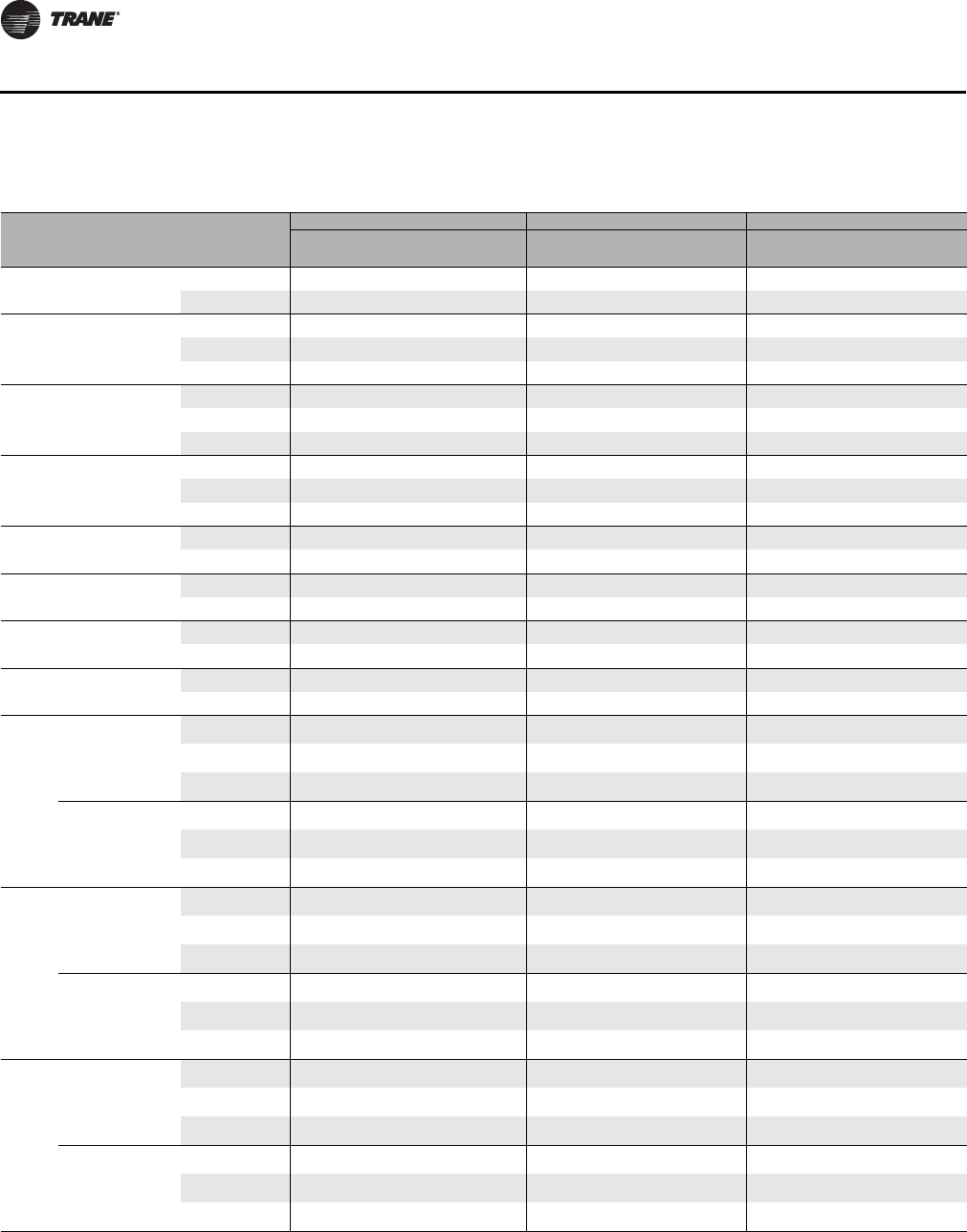
162 CLCH-PRC022A-EN
Coils
Table 149.Type UF coil intertwined circuiting
Unit
Size Header Height
(inches) Coil Rows
Full Half Quarter
Dist Qty Circuits per
Dist Dist Qty Circuits per
Dist Dist Qty Circuits per
Dist
3, 4 20 4, 6 2 7, 8 2 3, 4 n/a n/a
8 2 7, 8 n/a n/a n/a n/a
626
4 2 10, 10 2 5, 5 2 2, 3
6 2 10, 10 25, 5 n/a n/a
8 2 10, 10 n/a n/a n/a n/a
8, 10 28
4 2 11, 11 25, 6 22, 2
6 2 11, 11 2 5, 6 n/a n/a
8 2 11, 11 n/a n/a n/a n/a
12, 14 32
4 2 12, 13 2 6, 6 2 3, 3
6 2 12, 13 26, 6 n/a n/a
8 2 12, 13 n/a n/a n/a n/a
17 40 4, 6 48, 7, 8, 8 44, 3, 4, 4 n/a n/a
8 4 8, 7, 8, 8 n/a n/a n/a n/a
21 43 4, 6 48, 8, 9, 9 44, 4, 4, 5 n/a n/a
8 4 8, 8, 9, 9 n/a n/a n/a n/a
25, 30 52 4, 6 410, 10, 10, 11 45, 5, 5, 5 n/a n/a
8 4 10, 10, 10, 11 n/a n/a n/a n/a
35, 40 57 4, 6 411, 11, 11, 12 45, 6, 5, 6 n/a n/a
8 4 11, 11, 11, 12 n/a n/a n/a n/a
50
(Stacked)
31
4 2 12,12 26,6 23,3
6212,1226,6n/an/a
8 2 12,12 n/a n/a n/a n/a
31
4 2 12,12 2 6,6 2 3,3
6 2 12,12 26,6 n/a n/a
8 2 12,12 n/a n/a n/a n/a
57
(Stacked)
36
4 4 7,7,7,7 27,7 n/a n/a
6 4 7,7,7,7 2 7,7 n/a n/a
8 4 7,7,7,7 n/a n/a n/a n/a
36
4 4 7,7,7,7 2 7,7 n/a n/a
6 4 7,7,7,7 27,7 n/a n/a
8 4 7,7,7,7 n/a n/a n/a n/a
66
(Stacked)
37
4 4 7,7,7,8 27,7 n/a n/a
6 4 7,7,7,8 2 7,7 n/a n/a
8 4 7,7,7,8 n/a n/a n/a n/a
37
4 4 7,7,7,8 2 7,7 n/a n/a
6 4 7,7,7,8 27,7 n/a n/a
8 4 7,7,7,8 n/a n/a n/a n/a
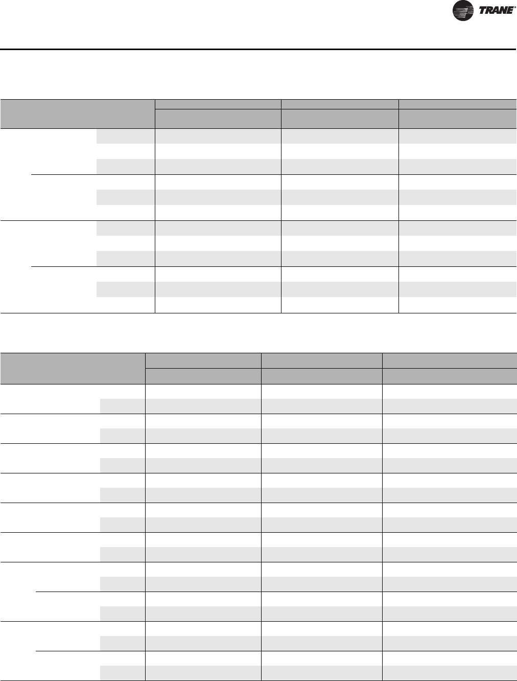
CLCH-PRC022A-EN 163
Coils
Unit
Size Header Height
(inches) Coil Rows
Full Half Quarter
Dist Qty Circuits per
Dist Dist Qty Circuits per
Dist Dist Qty Circuits per
Dist
80
(Stacked)
45
4 4 8,9,9,9 44,4,4,5 n/a n/a
6 4 8,9,9,9 4 4,4,4,5 n/a n/a
8 4 8,9,9,9 n/a n/a n/a n/a
45
4 4 8,9,9,9 4 4,4,4,5 n/a n/a
6 4 8,9,9,9 44,4,4,5 n/a n/a
8 4 8,9,9,9 n/a n/a n/a n/a
100,
120
(Stacked)
51
4 4 10,10,10,10 45,5,5,5 n/a n/a
6 4 10,10,10,10 4 5,5,5,5 n/a n/a
8 4 10,10,10,10 n/a n/a n/a n/a
51
4 4 10,10,10,10 4 5,5,5,5 n/a n/a
6 4 10,10,10,10 45,5,5,5 n/a n/a
8 4 10,10,10,10 n/a n/a n/a n/a
Table 149.Type UF coil intertwined circuiting
Table 150. Type FD coil standard circuiting
Unit
Size Header height
(inches) Coil rows
Full Half Quarter
Dist qty Circuits per dist Dist qty Circuits per dist Dist qty Circuits per dist
8,10 18 42 7,7 1 7 1 4
6 2 7,7 1 7 n/a n/a
12,14 24 4 2 9,10 1 9 1 4
6 2 9,10 1 9 n/a n/a
17 30 4 2 12,12 1 12 1 6
6 2 12,12 112 n/a n/a
21 33 4 2 13,13 1 13 1 6
6 2 13,13 113 n/a n/a
25, 30,
35, 40 36 4 4 7,7,7,7 n/a n/a n/a n/a
6 4 7,7,7,7 n/a n/a n/a n/a
50 42 4 4 8,8,8,9 n/a n/a n/a n/a
6 4 8,8,8,9 n/a n/a n/a n/a
57
(Stacked)
24 4 2 9,10 1 9 1 4
6 2 9,10 1 9 n/a n/a
30 4 2 12,12 1 12 1 6
6 2 12,12 112 n/a n/a
66
(Stacked)
24 4 2 9,10 1 9 1 4
6 2 9,10 1 9 n/a n/a
33 4 2 13,13 1 13 1 6
6 2 13,13 113 n/a n/a
164 CLCH-PRC022A-EN
Coils
Unit
Size Header height
(inches) Coil rows
Full Half Quarter
Dist qty Circuits per dist Dist qty Circuits per dist Dist qty Circuits per dist
80
(Stacked)
36 4 4 7,7,7,7 n/a n/a n/a n/a
6 4 7,7,7,7 n/a n/a n/a n/a
36 4 4 7,7,7,7 n/a n/a n/a n/a
6 4 7,7,7,7 n/a n/a n/a n/a
100, 120
(Stacked)
36 4 4 7,7,7,7 n/a n/a n/a n/a
6 4 7,7,7,7 n/a n/a n/a n/a
42 4 4 8,8,8,9 n/a n/a n/a n/a
6 4 8,8,8,9 n/a n/a n/a n/a
Table 150. Type FD coil standard circuiting
Table 151.Type FD coil intertwined circuiting
Unit Size
Header
Height
(inches) Coil Rows
Full Half Quarter
Dist Qty Circuits per
Dist Dist Qty Circuits per
Dist Dist Qty Circuits per
Dist
8, 10 18 4 2 7, 7 23, 422, 2
6 2 7, 7 23, 4 n/a n/a
12, 14 24 4 2 10, 9 2 4, 5 2 2, 2
6 2 10, 9 24, 5 n/a n/a
17 30 4 2 12, 12 2 6, 6 2 3, 3
6 2 12, 12 26, 6 n/a n/a
21 33 4 2 13, 13 2 6, 7 2 3, 3
6 2 13, 13 26, 7 n/a n/a
25, 30, 35, 40 36 4 4 7, 7, 7, 7 n/a n/a n/a n/a
6 4 7, 7, 7, 7 n/a n/a n/a n/a
50 42 4 4 8, 9, 8, 8 n/a n/a n/a n/a
6 4 8, 9, 8, 8 n/a n/a n/a n/a
57
(Stacked)
24 4 2 10, 9 2 4, 5 2 2, 2
6 2 10, 9 24, 5 n/a n/a
30 4 2 12, 12 2 6, 6 2 3, 3
6 2 12, 12 26, 6 n/a n/a
66
(Stacked)
24 4 2 10, 9 2 4, 5 2 2, 2
6 2 10, 9 24, 5 n/a n/a
33 4 2 13, 13 2 6, 7 2 3, 3
6 2 13, 13 26, 7 n/a n/a
80
(Stacked)
36 4 4 7, 7, 7, 7 n/a n/a n/a n/a
6 4 7, 7, 7, 7 n/a n/a n/a n/a
36 4 4 7, 7, 7, 7 n/a n/a n/a n/a
6 4 7, 7, 7, 7 n/a n/a n/a n/a
100, 120
(Stacked)
36 4 4 7, 7, 7, 7 n/a n/a n/a n/a
6 4 7, 7, 7, 7 n/a n/a n/a n/a
42 4 4 8, 9, 8, 8 n/a n/a n/a n/a
6 4 8, 9, 8, 8 n/a n/a n/a n/a
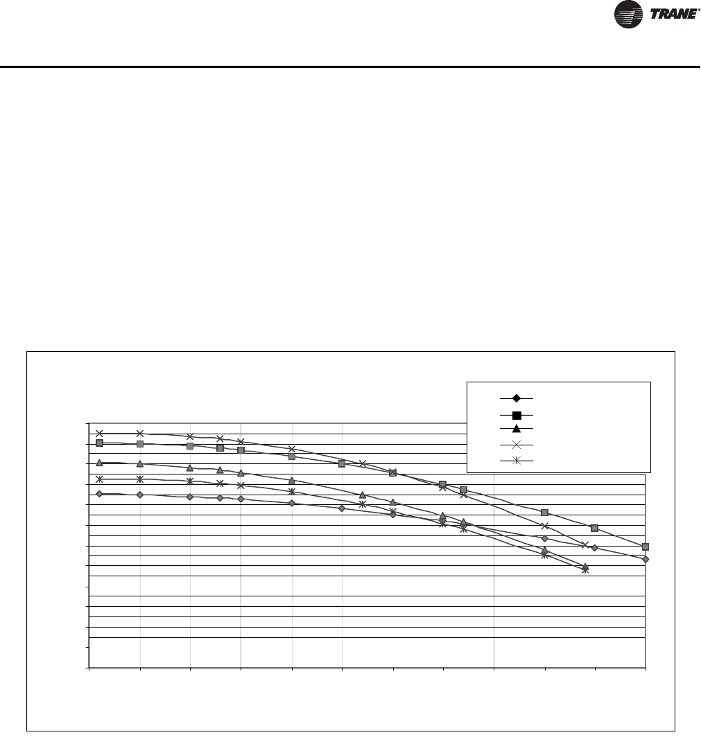
CLCH-PRC022A-EN 165
Coils
Face-Velocity Limits for Moisture Carryover
Cooling coils are available with a wide variety of fin types and materials, including the following,
to help optimize their performance:
• 1/2-inch: Delta-Flo™ E and Delta-Flo H aluminum fins
• 5/8-inch: Prima-Flo™ E and Prima-Flo H aluminum fins, and Prima-Flo™ copper fins
All of these fins are available with variable fin spacing (that is, the spacing can increment by as little
as one fin per foot). Also, Delta-Flo H and Prima-Flo H fins are specifically designed to help
maximize heat transfer while minimizing moisture carryover.
Figure 65 through Figure 72 detail the moisture carryover limits for each of these fin types. Refer
to TOPSS selection program for availability.
Figure 65. Face-velocity limits for moisture carryover with uncoated coils in unit sizes 3 to 10
200
250
300
350
400
450
500
550
600
650
700
750
800
70 80 90 100 110 120 130 140 150 160 170 180
Fin Series (fins/ft)
Face Velocity (sfpm)
Delta-Flo E
Delta-Flo H
Prima-Flo E
Prima-Flo H
Prima-Flo Cu
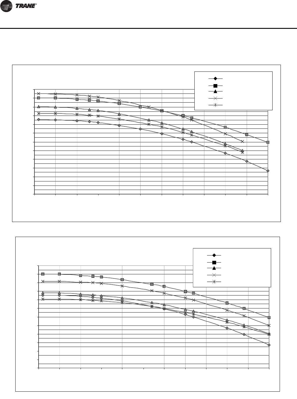
166 CLCH-PRC022A-EN
Coils
Figure 66. Face-velocity limits for moisture carryover with uncoated coils in unit size 12
200
250
300
350
400
450
500
550
600
650
700
750
800
70 80 90 100 110 120 130 140 150 160 170 180
Fin Series (fins/ft)
Face Velocity (sfpm)
Delta-Flo E
Delta-Flo H
Prima-Flo E
Prima-Flo H
Prima-Flo Cu
Figure 67. Face velocity limits for moisture carryover with uncoated coils in unit sizes 14 to 17
200
250
300
350
400
450
500
550
600
650
700
750
800
70 80 90 100 110 120 130 140 150 160 170 180
Fin Series (fins/ft)
Face Velocity (sfpm)
Delta-Flo E
Delta-Flo H
Prima-Flo E
Prima-Flo H
Prima-Flo Cu
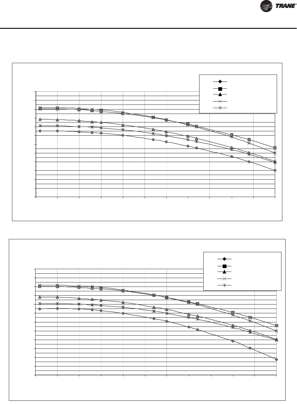
CLCH-PRC022A-EN 167
Coils
Figure 68. Face velocity limits for moisture carryover with uncoated coils in unit sizes 21 to 30
200
250
300
350
400
450
500
550
600
650
700
750
800
70 80 90 100 110 120 130 140 150 160 170 180
Fin Series (fins/ft)
Face Velocity (sfpm)
Delta-Flo E
Delta-Flo H
Prima-Flo E
Prima-Flo H
Prima-Flo Cu
Figure 69. Face velocity limits for moisture carryover with uncoated coils in unit sizes 35 and 40
200
250
300
350
400
450
500
550
600
650
700
750
800
70 80 90 100 110 120 130 140 150 160 170 180
Fin Series (fins/ft)
Face Velocity (sfpm)
Delta-Flo E
Delta-Flo H
Prima-Flo E
Prima-Flo H
Prima-Flo Cu
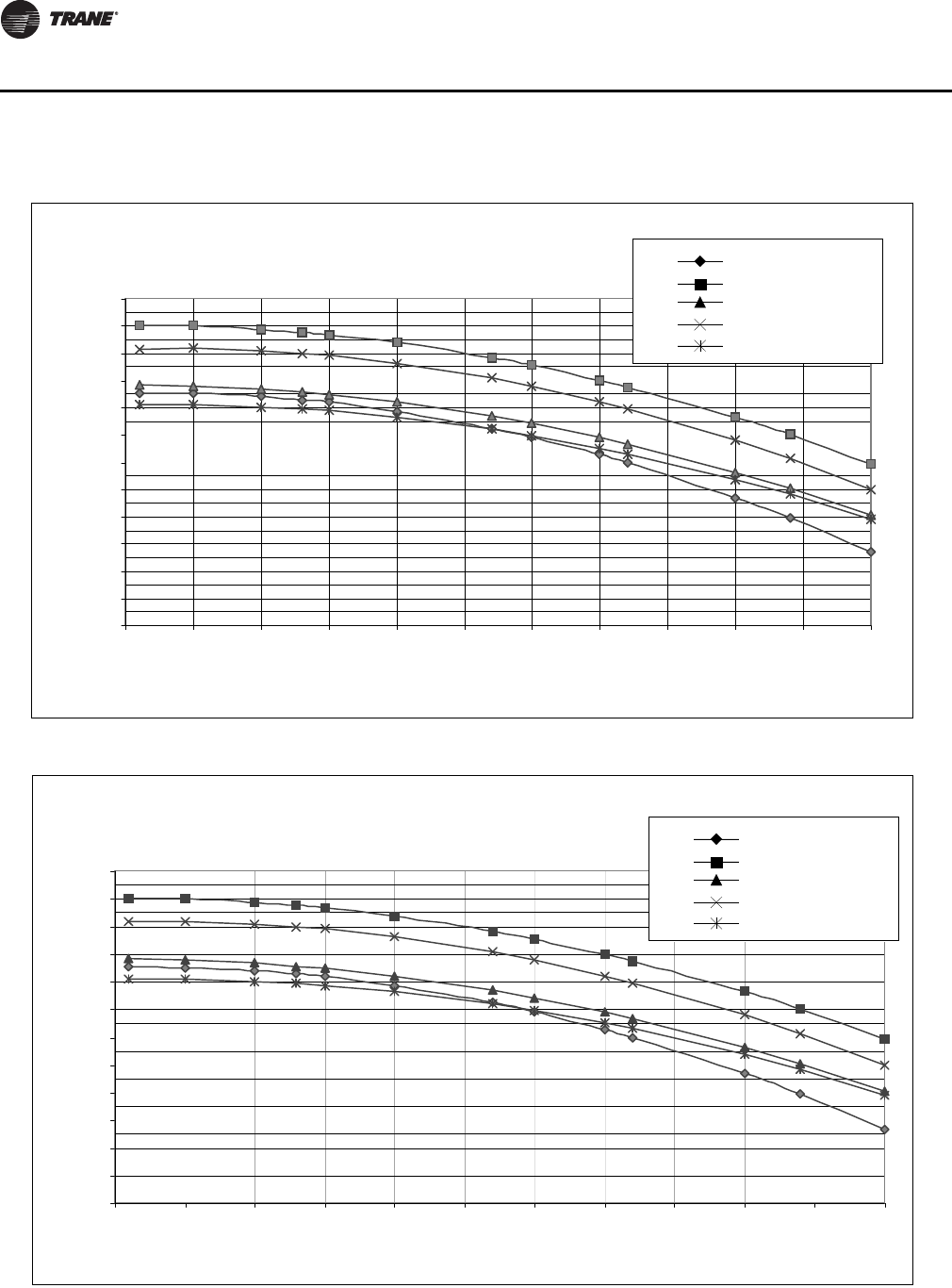
168 CLCH-PRC022A-EN
Coils
Figure 70. Face velocity limits for moisture carryover with uncoated coils in unit sizes 50 to 57
200
250
300
350
400
450
500
550
600
650
700
750
800
70 80 90 100 110 120 130 140 150 160 170 180
Fin Series (fins/ft)
Face Velocity (sfpm)
Delta-Flo E
Delta-Flo H
Prima-Flo E
Prima-Flo H
Prima-Flo Cu
Figure 71. Face velocity limits for moisture carryover with uncoated coils in unit size 66
200
250
300
350
400
450
500
550
600
650
700
750
800
70 80 90 100 110 120 130 140 150 160 170 180
Fin Series (fins/ft)
Face Velocity (sfpm)
Delta-Flo E
Delta-Flo H
Prima-Flo E
Prima-Flo H
Prima-Flo Cu
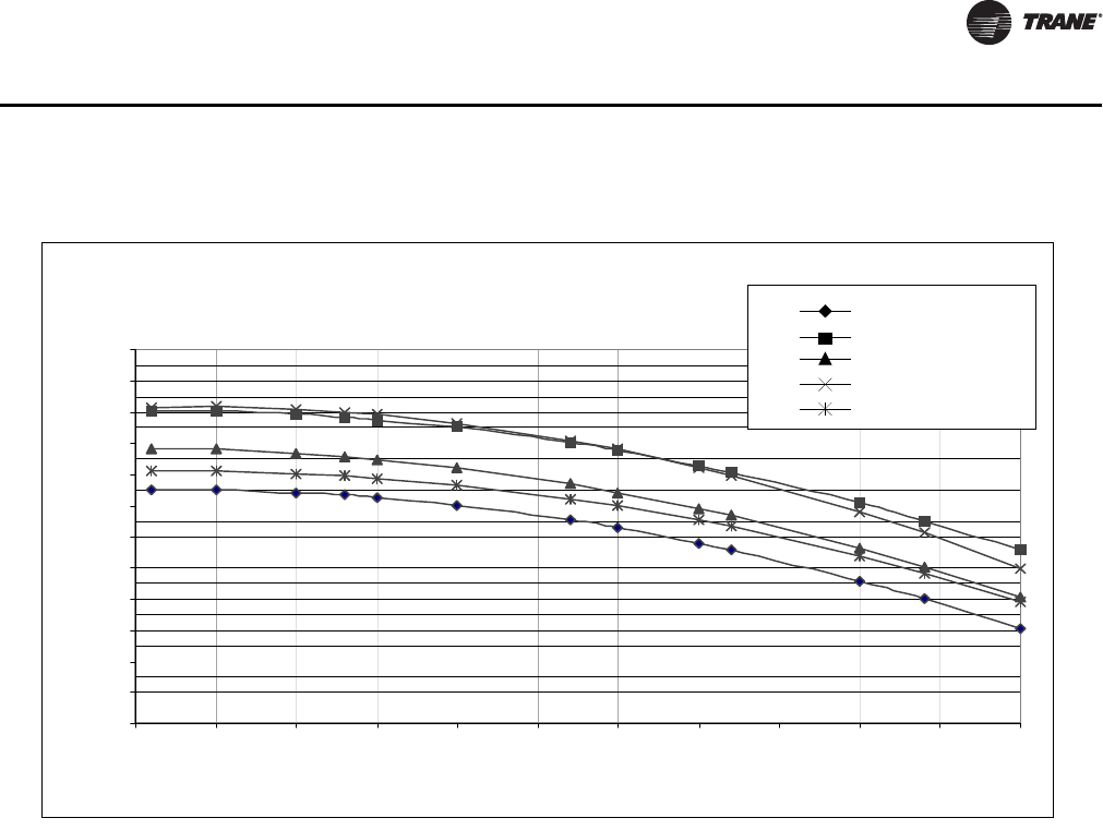
CLCH-PRC022A-EN 169
Coils
Figure 72. Face velocity limits for moisture carryover with uncoated coils in unit sizes 80 to 120
200
250
300
350
400
450
500
550
600
650
700
750
800
70 80 90 100 110 120 130 140 150 160 170 180
Fin Series (fins/ft)
Face Velocity (sfpm)
Delta-Flo E
Delta-Flo H
Prima-Flo E
Prima-Flo H
Prima-Flo Cu
170 CLCH-PRC022A-EN
Performance Data
Air-to-Air Plate Heat Exchangers
Table 152. Air-to-air plate heat exchanger performance data
Unit
size Nominal
airflow* cfm Plate
spacing
Bypass exchanger High efficiency exchanger Low efficiency exchanger
% sensible
effectiveness Pressure drop
(in w.g.) % sensible
effectiveness Pressure drop
(in w.g.) % sensible
effectiveness Pressure drop
(in w.g.)
3 1500
Wide 50 0.35 56 0.24 n/a n/a
Medium 58 0.59 60 0.32 n/a n/a
Close651.21660.67n/an/a
42000
Wide 52 0.26 57 0.18 n/a n/a
Medium 59 0.40 60 0.25 n/a n/a
Close 66 0.83 66 0.54 n/a n/a
6 3000
Wide 53 0.42 55 0.23 n/a n/a
Medium 60 0.58 65 0.43 n/a n/a
Close640.76690.89n/an/a
84000
Wide 53 0.48 54 0.29 n/a n/a
Medium 60 0.66 64 0.54 n/a n/a
Close 63 0.87 69 1.10 n/a n/a
10 5000
Wide 58 0.37 59 0.22 49 0.39
Medium 61 0.52 62 0.33 54 0.52
Close660.87670.56580.66
12 6000
Wide 57 0.44 59 0.27 54 0.35
Medium 61 0.62 62 0.39 61 0.49
Close 66 1.01 67 0.66 64 0.64
14 7000
Wide 57 0.49 58 0.31 54 0.39
Medium 60 0.69 62 0.44 60 0.55
Close661.12670.74640.72
17 8500
Wide 63 0.65 64 0.42 57 0.45
Medium 67 0.87 68 0.56 61 0.63
Close 69 1.13 70 0.75 66 1.03
21 10500
Wide 63 0.73 64 0.50 61 0.43
Medium 64 0.86 68 0.66 64 0.53
Close670.97700.88680.73
25 12500
Wide 59 0.78 60 0.50 63 0.68
Medium 66 0.84 67 0.54 65 0.81
Close 69 0.99 70 0.63 67 0.91
30 15000
Wide 59 0.78 60 0.51 63 0.70
Medium 66 0.84 67 0.55 65 0.82
Close690.98700.65670.93
35 17500
Wide 59 0.87 60 0.59 n/a n/a
Medium 66 0.94 67 0.64 n/a n/a
Close 69 1.09 69 0.75 n/a n/a
40 20000
Wide 59 0.87 60 0.60 n/a n/a
Medium 66 0.94 67 0.65 n/a n/a
Close691.10690.76n/an/a
50 25000
Wide n/a n/a n/a n/a 59 0.72
Medium n/a n/a n/a n/a 66 0.78
Close n/a n/a n/a n/a 69 0.92
Note: *Stated performance is based on a dry exchanger with the exhaust and ventilation airflow rate equal to the nominal airflow. Performance will vary
based on airflow conditions, utilize TOPSS for application specific performance.
CLCH-PRC022A-EN 171
Performance Data
Blenders
Table 153. Air-to-air plate heat exchanger bypass damper performance data
Unit size Face Area
(ft
2
)
Static Pressure Drop (inches w.g.) by face velocity (fpm)
800 1000 1200 1400 1600 1800 2000 2200 2400 2600
3 1.17 0.23 0.36 0.52 0.71 0.93 1.18
41.34 0.23 0.36 0.52 0.71 0.93 1.18
6 2.07 0.17 0.26 0.38 0.52 0.67 0.85 1.05 1.27
82.07 0.17 0.26 0.38 0.52 0.67 0.85 1.05 1.27
10 2.96 0.15 0.23 0.33 0.45 0.59 0.75 0.92 1.12 1.33
12 3.21 0.14 0.22 0.32 0.44 0.57 0.72 0.89 1.08 1.28
14 3.45 0.14 0.22 0.31 0.42 0.55 0.70 0.86 1.05 1.25
17 4.43 0.13 0.21 0.30 0.41 0.53 0.67 0.83 1.00 1.19
21 4.43 0.13 0.21 0.30 0.41 0.53 0.67 0.83 1.00 1.19
25 6.34 0.12 0.19 0.28 0.38 0.49 0.62 0.77 0.93 1.11 1.30
30 7.14 0.12 0.19 0.27 0.36 0.47 0.60 0.74 0.90 1.07 1.25
35 7.14 0.12 0.19 0.27 0.36 0.47 0.60 0.74 0.90 1.07 1.25
40 7.93 0.12 0.18 0.26 0.35 0.46 0.58 0.72 0.87 1.04 1.22
Table 154. Blender performance data
Unit size Area (ft
2
)
Static Pressure Drop (inches w.g.) by Plenum Face Velocity (fpm)
200 250 300 350 400 450 500 550 600
3 1.90 0.03 0.04 0.06 0.08 0.10 0.13 0.16 0.20 0.24
42.30 0.04 0.07 0.10 0.13 0.17 0.21 0.27 0.32 0.38
6 3.30 0.03 0.05 0.07 0.10 0.13 0.16 0.20 0.24 0.28
83.90 0.04 0.06 0.08 0.11 0.15 0.19 0.23 0.28 0.34
10 4.50 0.04 0.07 0.10 0.14 0.18 0.23 0.28 0.34 0.40
12 5.90 0.04 0.06 0.08 0.11 0.15 0.19 0.23 0.28 0.33
14 5.80 0.05 0.08 0.11 0.15 0.19 0.24 0.30 0.36 0.43
17 9.00 0.03 0.04 0.06 0.08 0.10 0.13 0.16 0.19 0.23
21 10.40 0.03 0.05 0.06 0.09 0.12 0.15 0.18 0.22 0.26
22 9.20 0.04 0.06 0.09 0.12 0.16 0.20 0.24 0.30 0.35
25 11.80 0.03 0.05 0.07 0.10 0.13 0.17 0.20 0.25 0.29
26 11.10 0.05 0.07 0.11 0.15 0.19 0.24 0.30 0.36 0.43
30 15.00 0.03 0.04 0.06 0.08 0.11 0.14 0.17 0.20 0.24
31 13.25 0.05 0.07 0.10 0.14 0.19 0.24 0.29 0.35 0.42
35 15.00 0.04 0.07 0.09 0.13 0.17 0.21 0.26 0.32 0.38
36 15.60 0.05 0.07 0.10 0.14 0.18 0.23 0.28 0.34 0.41
40 17.70 0.04 0.06 0.08 0.11 0.15 0.19 0.23 0.28 0.33
41 18.00 0.05 0.08 0.11 0.15 0.19 0.25 0.30 0.37 0.44
50 22.50 0.04 0.06 0.08 0.12 0.15 0.19 0.24 0.28 0.34
51 25.10 0.03 0.05 0.07 0.10 0.12 0.16 0.19 0.23 0.28
57 24.90 0.04 0.06 0.09 0.12 0.16 0.21 0.25 0.31 0.37
172 CLCH-PRC022A-EN
Performance Data
Dampers
Energy Wheel Dampers
Unit size Area (ft
2
)
Static Pressure Drop (inches w.g.) by Plenum Face Velocity (fpm)
200 250 300 350 400 450 500 550 600
58 25.10 0.04 0.07 0.10 0.13 0.17 0.21 0.27 0.32 0.38
66 27.60 0.05 0.07 0.11 0.15 0.19 0.24 0.30 0.36 0.43
80 30.30 0.06 0.09 0.13 0.18 0.23 0.29 0.36 0.43 0.52
100 39.90 0.05 0.08 0.11 0.15 0.20 0.25 0.31 0.37 0.44
120 54.00 0.03 0.05 0.08 0.11 0.14 0.17 0.22 0.26 0.31
Table 154. Blender performance data
Table 155. Energy wheel recirculation damper performance data
Unit
size Area
(ft
2
)
Unducted Pressure Drop
400 500 600 700 800 900 1000 1100 1200 1400 1600 1800 2000 2200 2400 2600
3 2.21 0.040.060.090.120.160.200.250.300.360.480.630.800.991.201.421.67
42.76 0.04 0.06 0.08 0.12 0.15 0.19 0.24 0.29 0.34 0.46 0.60 0.76 0.94 1.14 1.36 1.59
6 2.76 0.040.060.080.120.150.190.240.290.340.460.600.760.941.141.361.59
83.40 0.04 0.06 0.08 0.11 0.15 0.18 0.23 0.28 0.33 0.45 0.58 0.74 0.91 1.10 1.31 1.54
10 4.46 0.04 0.06 0.08 0.11 0.14 0.18 0.22 0.27 0.32 0.43 0.56 0.71 0.88 1.07 1.27 1.49
12 4.95 0.03 0.05 0.08 0.11 0.14 0.18 0.22 0.26 0.31 0.43 0.56 0.71 0.87 1.06 1.26 1.47
14 5.48 0.03 0.05 0.08 0.11 0.14 0.17 0.22 0.26 0.31 0.42 0.55 0.70 0.86 1.05 1.24 1.46
17 5.48 0.03 0.05 0.08 0.11 0.14 0.17 0.22 0.26 0.31 0.42 0.55 0.70 0.86 1.05 1.24 1.46
21 6.26 0.04 0.06 0.09 0.12 0.16 0.20 0.25 0.30 0.35 0.48 0.63 0.79 0.98 1.19 1.41 1.66
25 6.26 0.04 0.06 0.09 0.12 0.16 0.20 0.25 0.30 0.35 0.48 0.63 0.79 0.98 1.19 1.41 1.66
30 7.57 0.04 0.06 0.08 0.12 0.15 0.19 0.24 0.29 0.34 0.46 0.60 0.76 0.94 1.14 1.36 1.59
35 8.20 0.04 0.06 0.08 0.11 0.15 0.19 0.23 0.28 0.34 0.46 0.60 0.75 0.93 1.13 1.34 1.57
40 9.41 0.04 0.06 0.08 0.11 0.15 0.18 0.23 0.28 0.33 0.45 0.58 0.74 0.91 1.10 1.31 1.54
50 10.67 0.04 0.06 0.08 0.11 0.14 0.18 0.22 0.27 0.32 0.44 0.57 0.73 0.90 1.08 1.29 1.51
Table 156. Energy wheel bypass damper performance data
Unit
size
Wheel
nominal
cfm Area
(ft
2
)
Unducted Pressure Drop
400 500 600 700 800 900 1000 1100 1200 1400 1600 1800 2000 2200 2400 2600
4 900 1.03 0.04 0.07 0.09 0.13 0.17 0.21 0.26 0.32 0.38 0.51 0.67 0.85 1.05 1.27 1.51 1.77
41500 1.03 0.04 0.07 0.09 0.13 0.17 0.21 0.26 0.32 0.38 0.51 0.67 0.85 1.05 1.27 1.51 1.77
4 2200 1.03 0.04 0.07 0.09 0.13 0.17 0.21 0.26 0.32 0.38 0.51 0.67 0.85 1.05 1.27 1.51 1.77
6900 1.03 0.04 0.07 0.09 0.13 0.17 0.21 0.26 0.32 0.38 0.51 0.67 0.85 1.05 1.27 1.51 1.77
6 1500 1.03 0.04 0.07 0.09 0.13 0.17 0.21 0.26 0.32 0.38 0.51 0.67 0.85 1.05 1.27 1.51 1.77
62200 1.03 0.04 0.07 0.09 0.13 0.17 0.21 0.26 0.32 0.38 0.51 0.67 0.85 1.05 1.27 1.51 1.77
8 1500 1.83 0.04 0.06 0.08 0.11 0.15 0.19 0.23 0.28 0.33 0.45 0.59 0.75 0.92 1.12 1.33 1.56
82200 1.03 0.04 0.07 0.09 0.13 0.17 0.21 0.26 0.32 0.38 0.51 0.67 0.85 1.05 1.27 1.51 1.77
8 3000 1.83 0.04 0.06 0.08 0.11 0.15 0.19 0.23 0.28 0.33 0.45 0.59 0.75 0.92 1.12 1.33 1.56
CLCH-PRC022A-EN 173
Performance Data
Unit
size
Wheel
nominal
cfm Area
(ft
2
)
Unducted Pressure Drop
400 500 600 700 800 900 1000 1100 1200 1400 1600 1800 2000 2200 2400 2600
10 2200 1.83 0.04 0.06 0.08 0.11 0.15 0.19 0.23 0.28 0.33 0.45 0.59 0.75 0.92 1.12 1.33 1.56
10 3000 1.83 0.04 0.06 0.08 0.11 0.15 0.19 0.23 0.28 0.33 0.45 0.59 0.75 0.92 1.12 1.33 1.56
10 4000 2.38 0.04 0.06 0.08 0.11 0.14 0.18 0.22 0.27 0.32 0.44 0.57 0.72 0.89 1.08 1.28 1.50
10 5000 2.38 0.04 0.06 0.08 0.11 0.14 0.18 0.22 0.27 0.32 0.44 0.57 0.72 0.89 1.08 1.28 1.50
12 2200 1.83 0.04 0.06 0.08 0.11 0.15 0.19 0.23 0.28 0.33 0.45 0.59 0.75 0.92 1.12 1.33 1.56
12 3000 1.83 0.04 0.06 0.08 0.11 0.15 0.19 0.23 0.28 0.33 0.45 0.59 0.75 0.92 1.12 1.33 1.56
12 4000 2.38 0.04 0.06 0.08 0.11 0.14 0.18 0.22 0.27 0.32 0.44 0.57 0.72 0.89 1.08 1.28 1.50
12 5000 3.05 0.03 0.05 0.08 0.11 0.14 0.18 0.22 0.26 0.31 0.42 0.55 0.70 0.87 1.05 1.25 1.46
12 6000 3.05 0.03 0.05 0.08 0.11 0.14 0.18 0.22 0.26 0.31 0.42 0.55 0.70 0.87 1.05 1.25 1.46
14 2200 2.38 0.04 0.06 0.08 0.11 0.14 0.18 0.22 0.27 0.32 0.44 0.57 0.72 0.89 1.08 1.28 1.50
14 3000 1.83 0.04 0.06 0.08 0.11 0.15 0.19 0.23 0.28 0.33 0.45 0.59 0.75 0.92 1.12 1.33 1.56
14 4000 2.38 0.04 0.06 0.08 0.11 0.14 0.18 0.22 0.27 0.32 0.44 0.57 0.72 0.89 1.08 1.28 1.50
14 5000 3.05 0.03 0.05 0.08 0.11 0.14 0.18 0.22 0.26 0.31 0.42 0.55 0.70 0.87 1.05 1.25 1.46
14 6000 3.05 0.03 0.05 0.08 0.11 0.14 0.18 0.22 0.26 0.31 0.42 0.55 0.70 0.87 1.05 1.25 1.46
14 7000 3.05 0.03 0.05 0.08 0.11 0.14 0.18 0.22 0.26 0.31 0.42 0.55 0.70 0.87 1.05 1.25 1.46
17 3000 3.05 0.03 0.05 0.08 0.11 0.14 0.18 0.22 0.26 0.31 0.42 0.55 0.70 0.87 1.05 1.25 1.46
17 4000 2.38 0.04 0.06 0.08 0.11 0.14 0.18 0.22 0.27 0.32 0.44 0.57 0.72 0.89 1.08 1.28 1.50
17 5000 3.05 0.03 0.05 0.08 0.11 0.14 0.18 0.22 0.26 0.31 0.42 0.55 0.70 0.87 1.05 1.25 1.46
17 6000 3.51 0.03 0.05 0.08 0.10 0.14 0.17 0.21 0.26 0.31 0.42 0.55 0.69 0.86 1.04 1.23 1.45
17 7000 3.51 0.03 0.05 0.08 0.10 0.14 0.17 0.21 0.26 0.31 0.42 0.55 0.69 0.86 1.04 1.23 1.45
21 3000 3.05 0.03 0.05 0.08 0.11 0.14 0.18 0.22 0.26 0.31 0.42 0.55 0.70 0.87 1.05 1.25 1.46
21 4000 5.09 0.02 0.04 0.05 0.07 0.10 0.12 0.15 0.18 0.22 0.29 0.38 0.48 0.60 0.72 0.86 1.01
21 5000 3.05 0.03 0.05 0.08 0.11 0.14 0.18 0.22 0.26 0.31 0.42 0.55 0.70 0.87 1.05 1.25 1.46
21 6000 3.51 0.03 0.05 0.08 0.10 0.14 0.17 0.21 0.26 0.31 0.42 0.55 0.69 0.86 1.04 1.23 1.45
21 7000 3.77 0.03 0.05 0.08 0.10 0.14 0.17 0.21 0.26 0.31 0.42 0.54 0.69 0.85 1.03 1.23 1.44
21 8500 4.00 0.04 0.06 0.09 0.12 0.15 0.19 0.24 0.29 0.35 0.47 0.62 0.78 0.96 1.16 1.38 1.62
25 4000 5.09 0.02 0.04 0.05 0.07 0.10 0.12 0.15 0.18 0.22 0.29 0.38 0.48 0.60 0.72 0.86 1.01
25 5000 5.09 0.02 0.04 0.05 0.07 0.10 0.12 0.15 0.18 0.22 0.29 0.38 0.48 0.60 0.72 0.86 1.01
25 6000 5.09 0.02 0.04 0.05 0.07 0.10 0.12 0.15 0.18 0.22 0.29 0.38 0.48 0.60 0.72 0.86 1.01
25 7000 3.77 0.03 0.05 0.08 0.10 0.14 0.17 0.21 0.26 0.31 0.42 0.54 0.69 0.85 1.03 1.23 1.44
25 8500 6.31 0.03 0.04 0.06 0.08 0.11 0.14 0.17 0.20 0.24 0.33 0.43 0.55 0.67 0.81 0.97 1.14
30 4000 5.09 0.02 0.04 0.05 0.07 0.10 0.12 0.15 0.18 0.22 0.29 0.38 0.48 0.60 0.72 0.86 1.01
30 5000 5.09 0.02 0.04 0.05 0.07 0.10 0.12 0.15 0.18 0.22 0.29 0.38 0.48 0.60 0.72 0.86 1.01
30 6000 5.09 0.02 0.04 0.05 0.07 0.10 0.12 0.15 0.18 0.22 0.29 0.38 0.48 0.60 0.72 0.86 1.01
30 7000 3.77 0.03 0.05 0.08 0.10 0.14 0.17 0.21 0.26 0.31 0.42 0.54 0.69 0.85 1.03 1.23 1.44
30 8500 6.31 0.03 0.04 0.06 0.08 0.11 0.14 0.17 0.20 0.24 0.33 0.43 0.55 0.67 0.81 0.97 1.14
30 10500 5.09 0.02 0.04 0.05 0.07 0.10 0.12 0.15 0.18 0.22 0.29 0.38 0.48 0.60 0.72 0.86 1.01
30 12500 6.31 0.03 0.04 0.06 0.08 0.11 0.14 0.17 0.20 0.24 0.33 0.43 0.55 0.67 0.81 0.97 1.14
Table 156. Energy wheel bypass damper performance data
174 CLCH-PRC022A-EN
Performance Data
Mixing Box Dampers
Mixing box with airfoil blade dampers
Unit
size
Wheel
nominal
cfm Area
(ft
2
)
Unducted Pressure Drop
400 500 600 700 800 900 1000 1100 1200 1400 1600 1800 2000 2200 2400 2600
35 5000 5.09 0.02 0.04 0.05 0.07 0.10 0.12 0.15 0.18 0.22 0.29 0.38 0.48 0.60 0.72 0.86 1.01
35 6000 5.09 0.02 0.04 0.05 0.07 0.10 0.12 0.15 0.18 0.22 0.29 0.38 0.48 0.60 0.72 0.86 1.01
35 7000 5.09 0.02 0.04 0.05 0.07 0.10 0.12 0.15 0.18 0.22 0.29 0.38 0.48 0.60 0.72 0.86 1.01
35 8500 6.31 0.03 0.04 0.06 0.08 0.11 0.14 0.17 0.20 0.24 0.33 0.43 0.55 0.67 0.81 0.97 1.14
35 10500 5.09 0.02 0.04 0.05 0.07 0.10 0.12 0.15 0.18 0.22 0.29 0.38 0.48 0.60 0.72 0.86 1.01
35 12500 6.31 0.03 0.04 0.06 0.08 0.11 0.14 0.17 0.20 0.24 0.33 0.43 0.55 0.67 0.81 0.97 1.14
35 15000 7.28 0.03 0.04 0.06 0.08 0.10 0.13 0.16 0.20 0.24 0.32 0.42 0.53 0.65 0.79 0.94 1.10
35 17500 8.20 0.03 0.04 0.06 0.08 0.10 0.13 0.16 0.19 0.23 0.31 0.41 0.52 0.64 0.77 0.92 1.08
40 5000 5.09 0.02 0.04 0.05 0.07 0.10 0.12 0.15 0.18 0.22 0.29 0.38 0.48 0.60 0.72 0.86 1.01
40 6000 5.09 0.02 0.04 0.05 0.07 0.10 0.12 0.15 0.18 0.22 0.29 0.38 0.48 0.60 0.72 0.86 1.01
40 7000 5.09 0.02 0.04 0.05 0.07 0.10 0.12 0.15 0.18 0.22 0.29 0.38 0.48 0.60 0.72 0.86 1.01
40 8500 6.31 0.03 0.04 0.06 0.08 0.11 0.14 0.17 0.20 0.24 0.33 0.43 0.55 0.67 0.81 0.97 1.14
40 10500 5.09 0.02 0.04 0.05 0.07 0.10 0.12 0.15 0.18 0.22 0.29 0.38 0.48 0.60 0.72 0.86 1.01
40 12500 6.31 0.03 0.04 0.06 0.08 0.11 0.14 0.17 0.20 0.24 0.33 0.43 0.55 0.67 0.81 0.97 1.14
40 15000 7.28 0.03 0.04 0.06 0.08 0.10 0.13 0.16 0.20 0.24 0.32 0.42 0.53 0.65 0.79 0.94 1.10
40 17500 8.20 0.03 0.04 0.06 0.08 0.10 0.13 0.16 0.19 0.23 0.31 0.41 0.52 0.64 0.77 0.92 1.08
40 20000 9.90 0.02 0.04 0.06 0.08 0.10 0.13 0.16 0.19 0.22 0.30 0.40 0.50 0.62 0.75 0.90 1.05
50 7000 6.31 0.03 0.04 0.06 0.08 0.11 0.14 0.17 0.20 0.24 0.33 0.43 0.55 0.67 0.81 0.97 1.14
50 8500 6.31 0.03 0.04 0.06 0.08 0.11 0.14 0.17 0.20 0.24 0.33 0.43 0.55 0.67 0.81 0.97 1.14
50 10500 5.09 0.02 0.04 0.05 0.07 0.10 0.12 0.15 0.18 0.22 0.29 0.38 0.48 0.60 0.72 0.86 1.01
50 12500 6.31 0.03 0.04 0.06 0.08 0.11 0.14 0.17 0.20 0.24 0.33 0.43 0.55 0.67 0.81 0.97 1.14
50 15000 7.28 0.03 0.04 0.06 0.08 0.10 0.13 0.16 0.20 0.24 0.32 0.42 0.53 0.65 0.79 0.94 1.10
50 17500 8.20 0.03 0.04 0.06 0.08 0.10 0.13 0.16 0.19 0.23 0.31 0.41 0.52 0.64 0.77 0.92 1.08
50 20000 9.90 0.02 0.04 0.06 0.08 0.10 0.13 0.16 0.19 0.22 0.30 0.40 0.50 0.62 0.75 0.90 1.05
50 25000 10.96 0.02 0.04 0.06 0.08 0.10 0.12 0.15 0.19 0.22 0.30 0.39 0.50 0.61 0.74 0.88 1.04
Table 156. Energy wheel bypass damper performance data
Table 157. Mixing box with front, back, top, and bottom airfoil blade dampers (unducted)
Unit
Size Area
(ft
2
)
Static Pressure Drop (inches wg) by Damper Face Velocity
400 500 600 700 800 900 1000 1100 1200 1400 1600 1800 2000 2200 2400 2600
3 1.29 0.05 0.07 0.11 0.14 0.19 0.24 0.29 0.36 0.42 0.58 0.75 0.95 1.17 1.42 1.69 1.99
41.87 0.04 0.06 0.09 0.13 0.16 0.21 0.26 0.31 0.37 0.50 0.66 0.83 1.03 1.25 1.48 1.74
6 2.45 0.04 0.06 0.09 0.12 0.15 0.20 0.24 0.29 0.35 0.47 0.62 0.78 0.96 1.17 1.39 1.63
83.33 0.04 0.06 0.08 0.11 0.15 0.19 0.23 0.28 0.33 0.45 0.58 0.74 0.91 1.11 1.32 1.54
10 4.16 0.04 0.06 0.08 0.11 0.14 0.18 0.22 0.27 0.32 0.43 0.57 0.72 0.89 1.07 1.28 1.50
12 5.10 0.03 0.05 0.08 0.11 0.14 0.18 0.22 0.26 0.31 0.43 0.56 0.70 0.87 1.05 1.25 1.47
14 5.66 0.03 0.05 0.07 0.10 0.12 0.16 0.19 0.24 0.28 0.38 0.50 0.63 0.78 0.94 1.12 1.31
17 6.99 0.03 0.05 0.07 0.09 0.12 0.15 0.19 0.23 0.27 0.37 0.49 0.62 0.76 0.92 1.09 1.28
CLCH-PRC022A-EN 175
Performance Data
Unit
Size Area
(ft
2
)
Static Pressure Drop (inches wg) by Damper Face Velocity
400 500 600 700 800 900 1000 1100 1200 1400 1600 1800 2000 2200 2400 2600
21 8.64 0.03 0.05 0.07 0.09 0.12 0.15 0.19 0.23 0.27 0.37 0.48 0.60 0.75 0.90 1.07 1.26
22 7.26 0.03 0.05 0.07 0.09 0.12 0.15 0.18 0.22 0.26 0.36 0.46 0.59 0.73 0.88 1.04 1.23
25 10.36 0.03 0.04 0.06 0.09 0.11 0.14 0.17 0.21 0.25 0.34 0.45 0.57 0.70 0.85 1.01 1.18
26 10.53 0.03 0.04 0.06 0.08 0.11 0.14 0.17 0.20 0.24 0.33 0.43 0.55 0.67 0.82 0.97 1.14
30 12.04 0.03 0.04 0.06 0.08 0.11 0.14 0.17 0.21 0.25 0.34 0.44 0.56 0.69 0.84 0.99 1.17
31 11.07 0.03 0.04 0.06 0.08 0.11 0.14 0.17 0.20 0.24 0.33 0.43 0.55 0.68 0.82 0.98 1.15
35 14.32 0.03 0.04 0.06 0.09 0.11 0.14 0.18 0.22 0.26 0.35 0.46 0.58 0.72 0.87 1.03 1.21
36 10.01 0.03 0.04 0.06 0.09 0.11 0.14 0.18 0.21 0.25 0.34 0.45 0.57 0.70 0.85 1.01 1.18
40 16.29 0.03 0.04 0.06 0.09 0.11 0.14 0.18 0.22 0.26 0.35 0.46 0.58 0.72 0.87 1.03 1.21
41 12.32 0.03 0.05 0.07 0.09 0.12 0.15 0.18 0.22 0.26 0.36 0.47 0.59 0.73 0.89 1.06 1.24
50 18.59 0.03 0.04 0.06 0.09 0.11 0.14 0.18 0.21 0.25 0.35 0.45 0.57 0.71 0.85 1.02 1.19
51 17.47 0.03 0.04 0.06 0.08 0.10 0.13 0.16 0.19 0.23 0.31 0.41 0.52 0.64 0.78 0.92 1.09
57 22.79 0.03 0.04 0.06 0.08 0.11 0.14 0.17 0.20 0.24 0.33 0.43 0.55 0.68 0.82 0.97 1.14
58 19.45 0.03 0.04 0.06 0.08 0.10 0.13 0.16 0.19 0.23 0.31 0.40 0.51 0.63 0.76 0.91 1.07
66 26.04 0.03 0.04 0.06 0.08 0.11 0.14 0.17 0.20 0.24 0.33 0.43 0.54 0.67 0.81 0.96 1.13
80 30.83 0.03 0.04 0.06 0.08 0.10 0.13 0.16 0.20 0.23 0.32 0.42 0.53 0.65 0.78 0.93 1.10
100 39.78 0.03 0.04 0.06 0.08 0.10 0.13 0.16 0.19 0.23 0.31 0.40 0.51 0.63 0.76 0.91 1.06
120 47.87 0.03 0.04 0.06 0.08 0.10 0.13 0.16 0.19 0.23 0.31 0.41 0.52 0.64 0.78 0.92 1.08
Table 157. Mixing box with front, back, top, and bottom airfoil blade dampers (unducted)
Table 158. Mixing box with front, back, top, and bottom airfoil blade dampers (ducted)
Unit
Size Area
(ft
2
)
Static Pressure Drop (inches w.g.) by Damper Face Velocity
400 500 600 700 800 900 1000 1100 1200 1400 1600 1800 2000 2200 2400 2600
3 1.290.070.100.150.200.260.330.410.490.590.801.041.321.631.982.352.76
41.87 0.05 0.07 0.11 0.15 0.19 0.24 0.30 0.36 0.43 0.59 0.77 0.97 1.20 1.45 1.72 2.02
6 2.450.040.060.090.120.160.200.250.300.360.490.640.811.001.211.441.69
83.33 0.03 0.05 0.08 0.10 0.14 0.17 0.21 0.26 0.31 0.42 0.55 0.69 0.86 1.04 1.23 1.45
10 4.16 0.03 0.05 0.07 0.10 0.12 0.16 0.19 0.24 0.28 0.38 0.50 0.63 0.78 0.94 1.12 1.32
12 5.10 0.03 0.05 0.07 0.09 0.12 0.15 0.18 0.22 0.26 0.36 0.46 0.59 0.73 0.88 1.04 1.23
14 5.66 0.02 0.03 0.05 0.06 0.08 0.10 0.13 0.16 0.19 0.25 0.33 0.42 0.52 0.62 0.74 0.87
17 6.99 0.02 0.03 0.04 0.06 0.08 0.10 0.12 0.14 0.17 0.23 0.30 0.38 0.47 0.57 0.68 0.79
21 8.64 0.02 0.03 0.04 0.05 0.07 0.09 0.11 0.13 0.16 0.21 0.28 0.35 0.43 0.53 0.63 0.73
22 7.26 0.02 0.02 0.04 0.05 0.06 0.08 0.10 0.12 0.14 0.19 0.25 0.32 0.40 0.48 0.57 0.67
25 10.36 0.01 0.02 0.03 0.04 0.05 0.07 0.08 0.10 0.12 0.16 0.21 0.27 0.33 0.40 0.48 0.56
26 10.53 0.01 0.02 0.03 0.04 0.05 0.06 0.07 0.09 0.10 0.14 0.18 0.23 0.29 0.35 0.41 0.48
30 12.04 0.01 0.02 0.03 0.04 0.05 0.06 0.08 0.10 0.11 0.15 0.20 0.26 0.32 0.38 0.45 0.53
31 11.07 0.01 0.02 0.03 0.04 0.05 0.06 0.07 0.09 0.11 0.14 0.19 0.24 0.29 0.35 0.42 0.49
35 14.32 0.01 0.02 0.03 0.04 0.05 0.07 0.08 0.10 0.12 0.16 0.21 0.26 0.33 0.39 0.47 0.55
36 10.01 0.01 0.02 0.03 0.04 0.05 0.07 0.08 0.10 0.12 0.17 0.22 0.27 0.34 0.41 0.49 0.57
40 16.29 0.01 0.02 0.03 0.04 0.05 0.07 0.08 0.10 0.12 0.16 0.21 0.27 0.33 0.40 0.48 0.56
41 12.32 0.01 0.02 0.03 0.04 0.06 0.07 0.09 0.11 0.13 0.18 0.23 0.29 0.36 0.43 0.52 0.61
50 18.59 0.01 0.02 0.03 0.04 0.05 0.06 0.08 0.10 0.11 0.16 0.20 0.26 0.32 0.38 0.46 0.54
51 17.47 0.01 0.01 0.02 0.03 0.04 0.04 0.05 0.07 0.08 0.11 0.14 0.18 0.22 0.27 0.32 0.37
57 22.79 0.01 0.02 0.02 0.03 0.04 0.05 0.06 0.08 0.09 0.13 0.16 0.21 0.26 0.31 0.37 0.43
58 19.45 0.01 0.01 0.02 0.02 0.03 0.04 0.05 0.06 0.07 0.10 0.13 0.16 0.20 0.24 0.28 0.33
176 CLCH-PRC022A-EN
Performance Data
Mixing box with Traq dampers
Unit
Size Area
(ft
2
)
Static Pressure Drop (inches w.g.) by Damper Face Velocity
400 500 600 700 800 900 1000 1100 1200 1400 1600 1800 2000 2200 2400 2600
66 26.04 0.01 0.02 0.02 0.03 0.04 0.05 0.06 0.07 0.09 0.12 0.16 0.20 0.24 0.29 0.35 0.41
80 30.83 0.01 0.01 0.02 0.03 0.03 0.04 0.05 0.06 0.07 0.10 0.13 0.17 0.21 0.25 0.30 0.35
100 39.78 0.01 0.01 0.02 0.02 0.03 0.04 0.04 0.05 0.06 0.09 0.11 0.14 0.17 0.21 0.25 0.30
120 47.87 0.01 0.01 0.02 0.02 0.03 0.04 0.05 0.06 0.07 0.09 0.12 0.15 0.18 0.22 0.26 0.31
Table 158. Mixing box with front, back, top, and bottom airfoil blade dampers (ducted)
Table 159. Mixing box with front/back/top standard and low-flow Traq dampers
Unit
Size Damper
Size (in) Damper
Quantity Area
(sq ft)
Traq Damper Velocity (fpm) vs. Delta P (w.g.)
800 900 1000 1100 1200 1300 1400 1500 1600
3 13 1 0.92 0.06 0.07 0.09 0.11 0.13 0.15 0.17 0.20 0.23
413 21.84 0.06 0.07 0.09 0.11 0.13 0.15 0.17 0.20 0.23
6 13 2 1.84 0.06 0.07 0.09 0.11 0.13 0.15 0.17 0.20 0.23
813 32.77 0.06 0.07 0.09 0.11 0.13 0.15 0.17 0.20 0.23
10 13 3 2.77 0.06 0.07 0.09 0.11 0.13 0.15 0.17 0.20 0.23
12 16 34.19 0.06 0.07 0.09 0.11 0.13 0.15 0.17 0.20 0.23
14 16 3 4.19 0.06 0.07 0.09 0.11 0.13 0.15 0.17 0.20 0.23
17 16 34.19 0.06 0.07 0.09 0.11 0.13 0.15 0.17 0.20 0.23
21 20 3 6.54 0.06 0.07 0.09 0.10 0.12 0.14 0.17 0.19 0.21
22 16 45.59 0.06 0.07 0.09 0.11 0.13 0.15 0.17 0.20 0.23
25 20 3 6.54 0.06 0.07 0.09 0.10 0.12 0.14 0.17 0.19 0.21
26 16 45.59 0.06 0.07 0.09 0.11 0.13 0.15 0.17 0.20 0.23
30 24 3 9.42 0.06 0.07 0.09 0.10 0.12 0.14 0.17 0.19 0.21
31 20 48.73 0.06 0.07 0.09 0.10 0.12 0.14 0.17 0.19 0.21
35 24 3 9.42 0.06 0.07 0.09 0.10 0.12 0.14 0.17 0.19 0.21
36 24 39.42 0.06 0.07 0.09 0.10 0.12 0.14 0.17 0.19 0.21
40 24 3 9.42 0.06 0.07 0.09 0.10 0.12 0.14 0.17 0.19 0.21
41 24 39.42 0.06 0.07 0.09 0.10 0.12 0.14 0.17 0.19 0.21
50 28 3 12.83 0.06 0.07 0.09 0.10 0.12 0.14 0.17 0.19 0.21
51 28 312.83 0.06 0.07 0.09 0.10 0.12 0.14 0.17 0.19 0.21
57 28 3 12.83 0.06 0.07 0.09 0.10 0.12 0.14 0.17 0.19 0.21
58 28 312.83 0.06 0.07 0.09 0.10 0.12 0.14 0.17 0.19 0.21
66 28 4 17.10 0.06 0.07 0.09 0.10 0.12 0.14 0.17 0.19 0.21
80 28 521.38 0.06 0.07 0.09 0.10 0.12 0.14 0.17 0.19 0.21
100 28 6 25.66 0.06 0.07 0.09 0.10 0.12 0.14 0.17 0.19 0.21
120 28 625.66 0.06 0.07 0.09 0.10 0.12 0.14 0.17 0.19 0.21
Notes: 1. Data a standard air density. 2. Traq damper airflow measurement station (AMS) ratings are based on AMCA Standard 610 Test Setup Figure 4 using
differential pressure measurement with voltage signals from a Trane ventilation control module (VCM). 3. Performance of Traq dampers will be +/- 5 percent
of data shown for AMCA 610 Test Setup Figure 4. 4. Sizes and shapes tested include 16-inch and 28-inch diameter circular. Rated sizes are from 13 inches to
24 inches diameter circular. 5. Low-flow Traq option includes one damper for minimum outside air and remaining dampers are for economizing.
CLCH-PRC022A-EN 177
Performance Data
.
Table 160. Mixing box with front/back/top standard and low-flow Traq dampers
Unit
Size
Traq
Damper
Size (in)
Traq
Damper
Quantity
Damper
Area
(sq ft)
Traq Damper Velocity (fpm) vs. Delta P (w.g.)
1700 1800 1900 2000 2100 2200 2300 2400 2500
3 13 1 0.92 0.26 0.29 0.32 0.35 0.39 0.43 0.47 0.51 0.56
413 21.84 0.26 0.29 0.32 0.35 0.39 0.43 0.47 0.51 0.56
6 13 2 1.84 0.26 0.29 0.32 0.35 0.39 0.43 0.47 0.51 0.56
813 32.77 0.26 0.29 0.32 0.35 0.39 0.43 0.47 0.51 0.56
10 13 3 2.77 0.260.290.320.350.390.430.470.510.56
12 16 34.19 0.26 0.29 0.32 0.35 0.39 0.43 0.47 0.51 0.56
14 16 3 4.19 0.260.290.320.350.390.430.470.510.56
17 16 34.19 0.26 0.29 0.32 0.35 0.39 0.43 0.47 0.51 0.56
21 20 3 6.54 0.240.270.300.330.370.400.440.480.52
22 16 45.59 0.26 0.29 0.32 0.35 0.39 0.43 0.47 0.51 0.56
25 20 3 6.54 0.240.270.300.330.370.400.440.480.52
26 16 45.59 0.26 0.29 0.32 0.35 0.39 0.43 0.47 0.51 0.56
30 24 3 9.42 0.240.270.300.330.370.400.440.480.52
31 20 48.73 0.24 0.27 0.30 0.33 0.37 0.40 0.44 0.48 0.52
35 24 3 9.42 0.240.270.300.330.370.400.440.480.52
36 24 39.42 0.24 0.27 0.30 0.33 0.37 0.40 0.44 0.48 0.52
40 24 3 9.42 0.240.270.300.330.370.400.440.480.52
41 24 39.42 0.24 0.27 0.30 0.33 0.37 0.40 0.44 0.48 0.52
50 28 3 12.83 0.24 0.27 0.30 0.33 0.37 0.40 0.44 0.48 0.52
51 28 312.83 0.24 0.27 0.30 0.33 0.37 0.40 0.44 0.48 0.52
57 28 3 12.83 0.24 0.27 0.30 0.33 0.37 0.40 0.44 0.48 0.52
58 28 312.83 0.24 0.27 0.30 0.33 0.37 0.40 0.44 0.48 0.52
66 28 4 17.10 0.24 0.27 0.30 0.33 0.37 0.40 0.44 0.48 0.52
80 28 521.38 0.24 0.27 0.30 0.33 0.37 0.40 0.44 0.48 0.52
100 28 6 25.66 0.24 0.27 0.30 0.33 0.37 0.40 0.44 0.48 0.52
120 28 625.66 0.24 0.27 0.30 0.33 0.37 0.40 0.44 0.48 0.52
Notes: 1. Data a standard air density. 2. Traq damper airflow measurement station (AMS) ratings are based on AMCA Standard 610 Test Setup Figure 4 using
differential pressure measurement with voltage signals from a Trane ventilation control module (VCM). 3. Performance of Traq dampers will be +/- 5 percent
of data shown for AMCA 610 Test Setup Figure 4. 4. Sizes and shapes tested include 16-inch and 28-inch diameter circular. Rated sizes are from 13 inches to
24 inches diameter circular. 5. Low-flow Traq option includes one damper for minimum outside air and remaining dampers are for economizing.
Trane certifies that the Traq damper shown herein is licensed to bear the
AMCA seal - Airflow Measurement Station Performance. The rating shown
is based on tests and procedures performed in accordance with AMCA
Publication 611 and complies with the requirements of the AMCA Certified
Ratings Program.
178 CLCH-PRC022A-EN
Performance Data
AMCA 610 Test Performance for Traq Damper
Corresponding conversion formulas:
Traq 16-inch AMS: Airflow = ((Volts-2)/8)*2475*Total Area (applicable for unit sizes 3-17).
Traq 28-inch AMS: Airflow = ((Volts-2)/8)*2600*Total Area (applicable for units sizes 21-30).
Refer to the Performance Climate Changer air handler installation operation manual (CLCH-
SVX07A-EN) for Traq damper installation details.
Multizone Dampers
Table 161. Air Performance Table 162. Airflow Resistance
Test
Run Reference
Volume (cfm) Indicated Volume
(cfm) Difference
(percent) Test
Run Pressure Drop
(in. w.g.) Volume
(cfm) Velocity
(fpm)
Traq 16-inch damper AMS Traq 16-inch damper AMS
13470 3351 -3.41 10.561 3469.70 2485.40
2 2882 2773 -3.80 2 0.389 2895.70 2074.30
32264 2211 -2.35 30.239 2276.30 1630.60
4 1703 1676 -1.62 4 0.135 1710.20 1225.10
51032 1019 -1.25 50.052 1035.00 741.40
6 506 505 -0.18 6 0.010 507.00 363.20
Traq 28-inch damper AMS Traq 28-inch damper AMS
110714 10548 -1.55 10.515 10738.60 2511.40
2 8817 8644 -1.96 2 0.352 8856.50 2071.20
36997 6851 -2.09 30.228 7029.20 1643.90
4 5063 4961 -2.00 4 0.114 5085.50 1189.30
53126 3071 -1.76 50.041 3134.60 733.10
6 1363 1362 -0.06 6 0.010 1364.40 319.10
Table 163. Multizone damper - 2-deck with single actuator
Unit
size Area
ft
2
Static Pressure Drop (inches w.g.) by Damper Face Velocity (fpm)
400 500 600 700 800 900 1000 1100 1200 1400 1600 1800 2000 2200 2400 2600
6 2.890.050.070.100.140.180.230.290.350.410.560.730.931.151.391.651.94
83.48 0.05 0.07 0.10 0.14 0.18 0.23 0.29 0.35 0.41 0.56 0.74 0.93 1.15 1.39 1.66 1.95
10 5.50 0.05 0.08 0.12 0.16 0.21 0.26 0.32 0.39 0.46 0.63 0.82 1.04 1.29 1.56 1.86 2.18
12 6.06 0.05 0.07 0.11 0.15 0.19 0.24 0.30 0.36 0.43 0.59 0.77 0.97 1.20 1.45 1.72 2.02
14 6.67 0.05 0.07 0.10 0.14 0.18 0.23 0.29 0.35 0.41 0.56 0.73 0.93 1.15 1.39 1.65 1.94
17 6.67 0.05 0.07 0.10 0.14 0.18 0.23 0.29 0.35 0.41 0.56 0.73 0.93 1.15 1.39 1.65 1.94
21 8.97 0.04 0.06 0.08 0.11 0.15 0.19 0.23 0.28 0.34 0.46 0.60 0.76 0.93 1.13 1.34 1.58
25 8.97 0.04 0.06 0.08 0.11 0.15 0.19 0.23 0.28 0.34 0.46 0.60 0.76 0.93 1.13 1.34 1.58
30 10.75 0.04 0.06 0.09 0.12 0.15 0.19 0.24 0.29 0.35 0.47 0.61 0.78 0.96 1.16 1.38 1.62
35 14.06 0.04 0.06 0.08 0.11 0.15 0.19 0.23 0.28 0.33 0.45 0.59 0.74 0.92 1.11 1.32 1.55
40 16.05 0.04 0.06 0.08 0.11 0.15 0.19 0.23 0.28 0.33 0.45 0.59 0.74 0.92 1.11 1.32 1.55
50 18.13 0.04 0.06 0.08 0.11 0.15 0.19 0.23 0.28 0.33 0.45 0.59 0.75 0.92 1.12 1.33 1.56
CLCH-PRC022A-EN 179
Performance Data
Diffuser
Table 164. Multizone damper - 3-deck with single actuator
Unit
size Area
ft
2
Static Pressure Drop (inches w.g.) by Damper Face Velocity (fpm)
400 500 600 700 800 900 1000 1100 1200 1400 1600 1800 2000 2200 2400 2600
6 2.720.050.080.110.160.200.260.320.380.460.620.811.031.271.531.822.14
83.28 0.04 0.07 0.09 0.13 0.17 0.21 0.26 0.32 0.38 0.51 0.67 0.85 1.05 1.27 1.51 1.78
10 5.24 0.04 0.06 0.09 0.13 0.16 0.21 0.26 0.31 0.37 0.50 0.66 0.83 1.03 1.24 1.48 1.73
12 5.77 0.04 0.06 0.09 0.13 0.17 0.21 0.26 0.31 0.37 0.51 0.66 0.84 1.03 1.25 1.49 1.74
14 6.35 0.04 0.06 0.08 0.11 0.14 0.18 0.23 0.27 0.32 0.44 0.58 0.73 0.90 1.09 1.30 1.52
17 6.35 0.04 0.06 0.08 0.11 0.14 0.18 0.23 0.27 0.32 0.44 0.58 0.73 0.90 1.09 1.30 1.52
21 8.62 0.03 0.05 0.07 0.10 0.13 0.17 0.21 0.25 0.30 0.40 0.53 0.67 0.82 1.00 1.19 1.39
25 8.62 0.03 0.05 0.07 0.10 0.13 0.17 0.21 0.25 0.30 0.40 0.53 0.67 0.82 1.00 1.19 1.39
30 10.33 0.03 0.05 0.07 0.10 0.13 0.17 0.21 0.25 0.30 0.40 0.53 0.67 0.83 1.00 1.19 1.40
35 13.75 0.03 0.05 0.07 0.10 0.13 0.17 0.20 0.25 0.29 0.40 0.52 0.66 0.82 0.99 1.18 1.38
40 15.70 0.03 0.05 0.07 0.10 0.13 0.16 0.20 0.24 0.29 0.39 0.51 0.65 0.80 0.97 1.15 1.35
50 17.73 0.03 0.05 0.07 0.10 0.13 0.16 0.20 0.24 0.28 0.39 0.51 0.64 0.79 0.96 1.14 1.34
Table 165. Multizone damper - 3-deck with dual actuator
Unit
size Area
ft
2
Static Pressure Drop (inches w.g.) by Damper Face Velocity (fpm)
400 500 600 700 800 900 1000 1100 1200 1400 1600 1800 2000 2200 2400 2600
6 2.720.030.050.070.100.130.160.200.250.290.400.520.660.810.991.171.38
83.28 0.03 0.05 0.07 0.10 0.13 0.17 0.20 0.25 0.29 0.40 0.52 0.66 0.82 0.99 1.18 1.38
10 5.24 0.03 0.05 0.07 0.09 0.12 0.15 0.19 0.23 0.27 0.37 0.48 0.61 0.75 0.91 1.08 1.27
12 5.77 0.03 0.05 0.06 0.09 0.12 0.15 0.18 0.22 0.26 0.35 0.46 0.58 0.72 0.87 1.04 1.22
14 6.35 0.03 0.04 0.06 0.09 0.11 0.14 0.18 0.21 0.25 0.35 0.45 0.57 0.71 0.86 1.02 1.20
17 6.35 0.03 0.04 0.06 0.09 0.11 0.14 0.18 0.21 0.25 0.35 0.45 0.57 0.71 0.86 1.02 1.20
21 8.62 0.03 0.05 0.07 0.09 0.12 0.15 0.19 0.23 0.27 0.36 0.48 0.60 0.74 0.90 1.07 1.26
25 8.62 0.03 0.05 0.07 0.09 0.12 0.15 0.19 0.23 0.27 0.36 0.48 0.60 0.74 0.90 1.07 1.26
30 10.33 0.03 0.05 0.07 0.09 0.12 0.16 0.19 0.23 0.28 0.38 0.49 0.62 0.77 0.93 1.10 1.29
35 13.75 0.03 0.05 0.07 0.09 0.12 0.15 0.19 0.23 0.27 0.37 0.49 0.62 0.76 0.92 1.10 1.29
40 15.70 0.03 0.05 0.07 0.09 0.12 0.15 0.19 0.23 0.27 0.37 0.49 0.62 0.76 0.92 1.10 1.29
50 17.73 0.03 0.05 0.07 0.09 0.12 0.16 0.19 0.23 0.28 0.38 0.49 0.62 0.77 0.93 1.11 1.30
Table 166. Diffuser pressure drop
Unit Size
Static Pressure Drop (inches wg) by Face Velocity (fpm)
500 700 900 1100 1300 1500 1700 1900 2100
3-120 0.01 0.02 0.04 0.06 0.08 0.10 0.13 0.17 0.20
Table 167. Diffuser face area
Unit Size 346810 12 14 17 21 22 25 26 30
Area (ft
2
)
1.53 1.53 3.36 3.74 3.74 4.32 4.32 7.94 8.78 11.71 10.72 15.77 10.72
Unit Size 31 35 36 40 41 50 51 57 58 66 80 100 120
Area (ft
2
)
15.77 23.42 33.09 23.42 39.76 27.21 39.76 31.53 45.20 33.09 39.76 45.20 45.20
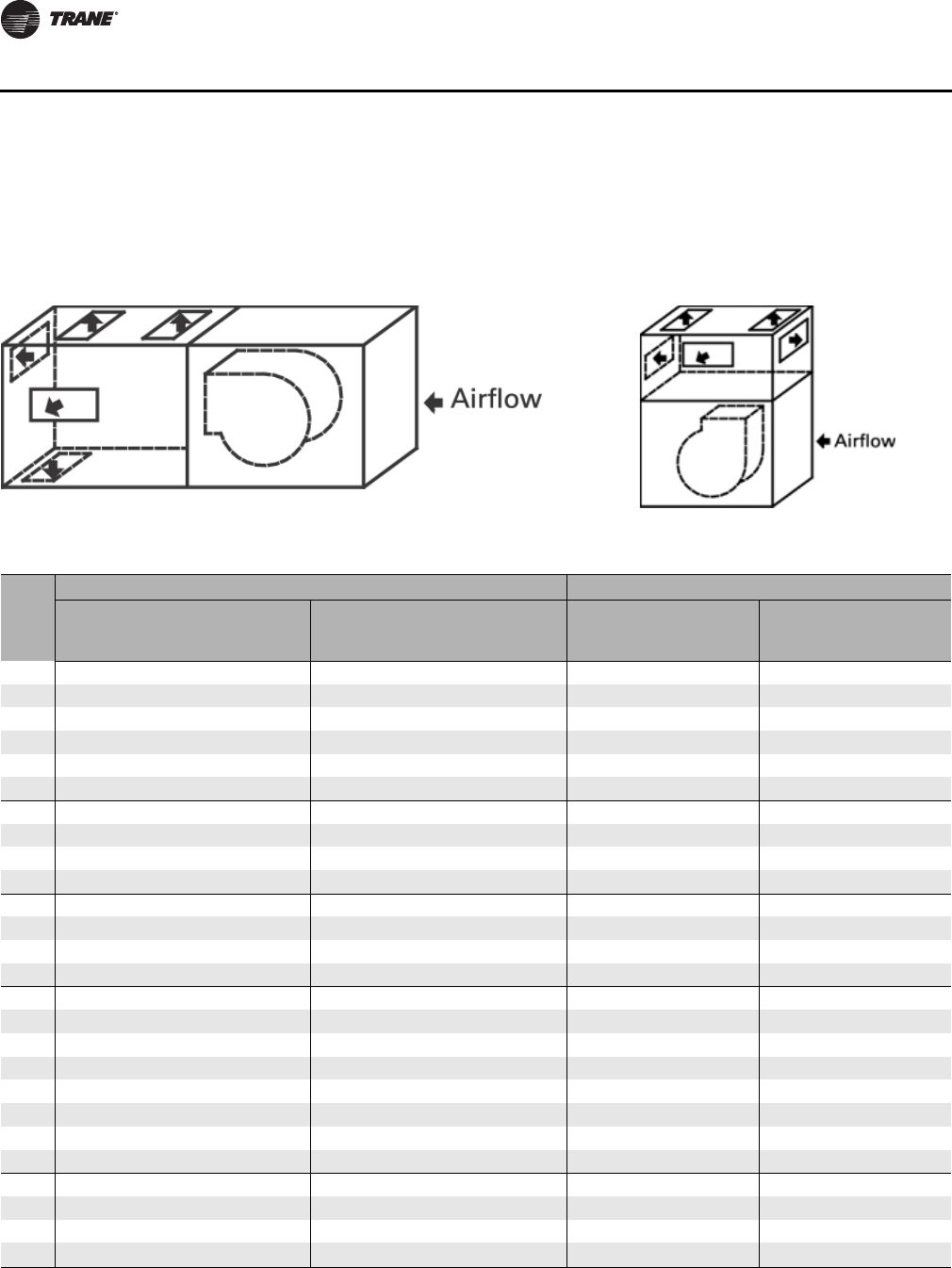
180 CLCH-PRC022A-EN
Performance Data
Discharge Plenums
Horizontal or Vertical Discharge Plenum with Factory Openings
Figure 73. Horizontal plenum Figure 74. Vertical plenum
Table 168. Discharge plenums - default factory outlet areas (ft2)
Unit
Size
Horizontal Plenum Vertical Plenum
Rectangular Openings Round Openings Rectangular Openings Round Openings
Front Top Bottom Side Front Top Bottom Side Front/
Back Top Side Front/
Back Top Side
3 1.071.071.071.070.920.920.920.921.071.071.070.920.920.92
41.53 1.53 1.53 1.25 1.40 1.40 1.40 1.40 1.53 1.53 1.25 1.40 1.40 1.40
6 2.192.192.192.132.182.182.182.182.192.192.132.182.182.18
82.67 2.67 2.67 2.51 2.64 2.64 2.64 2.64 2.67 2.67 2.51 2.64 2.64 2.64
10 3.33 3.33 3.33 3.36 3.14 3.14 3.14 3.14 3.33 3.33 3.36 3.14 3.14 3.14
12 4.00 4.00 4.00 3.99 3.69 3.69 3.69 4.28 4.00 4.00 3.99 4.28 4.28 4.28
14 4.88 4.88 4.88 4.69 3.69 3.69 3.69 4.28 4.88 4.88 4.69 4.91 4.91 4.91
17 5.91 5.91 5.91 5.56 3.69 3.69 3.69 4.28 5.91 5.91 5.56 5.59 5.59 5.59
21 7.12 7.12 7.12 7.04 3.14 3.14 3.14 3.69 7.12 7.12 7.04 6.31 6.31 6.31
22 6.88 7.17 7.12 7.26 6.31 5.77 5.77 5.71 n/a n/a n/a n/a n/a n/a
25 8.54 8.54 8.54 8.13 7.07 7.07 7.07 7.88 8.54 8.54 8.13 7.88 7.88 7.88
26 11.39 8.54 8.54 8.13 7.88 7.47 6.49 11.17 n/a n/a n/a n/a n/a n/a
30 10.21 10.21 10.21 10.15 7.07 7.07 7.07 7.88 10.21 10.21 10.15 9.62 9.62 9.62
31 13.10 10.21 10.21 10.07 9.62 8.55 8.71 11.17 n/a n/a n/a n/a n/a n/a
35 13.56 13.09 11.67 11.25 11.54 11.17 11.17 5.52 13.56 13.09 11.25 11.54 11.17 11.54
36 14.93 11.25 11.67 11.25 15.9066 11.17 11.35 12.43 n/a n/a n/a n/a n/a n/a
40 14.89 14.70 13.42 12.67 12.57 12.61 12.61 5.52 14.89 14.70 12.67 12.57 12.61 12.57
41 17.36 13.75 11.67 13.33 15.90 11.17 11.35 14.53 n/a n/a n/a n/a n/a n/a
50 19.27 18.30 16.67 15.04 15.75 14.53 14.53 7.95 19.27 18.30 15.04 15.75 14.53 12.57
51 20.19 17.24 16.67 15.93 25.22 14.93 12.98 14.53 n/a n/a n/a n/a n/a n/a
57 21.88 20.63 18.89 17.94 18.34 16.76 16.76 11.17 n/a n/a n/a n/a n/a n/a
58 23.36 17.24 16.67 18.08 25.22 14.93 12.98 14.53 n/a n/a n/a n/a n/a n/a
66 25.36 23.61 20.40 19.23 21.12 18.92 18.92 12.43 n/a n/a n/a n/a n/a n/a
80 29.97 28.71 23.49 25.06 25.13 21.21 21.21 18.56 n/a n/a n/a n/a n/a n/a
100 37.28 34.53 30.04 32.29 31.50 26.84 26.84 24.35 n/a n/a n/a n/a n/a n/a
120 43.43 41.25 35.58 34.03 38.48 33.13 33.13 24.35 n/a n/a n/a n/a n/a n/a
Note: 1. Openings can be varied in number, size, and location within the TOPSS Selection Software. 2. Sizes 35-120 have default multiple round openings
as standard. 3. Bell mouth openings are available within the TOPSS Selection Software.
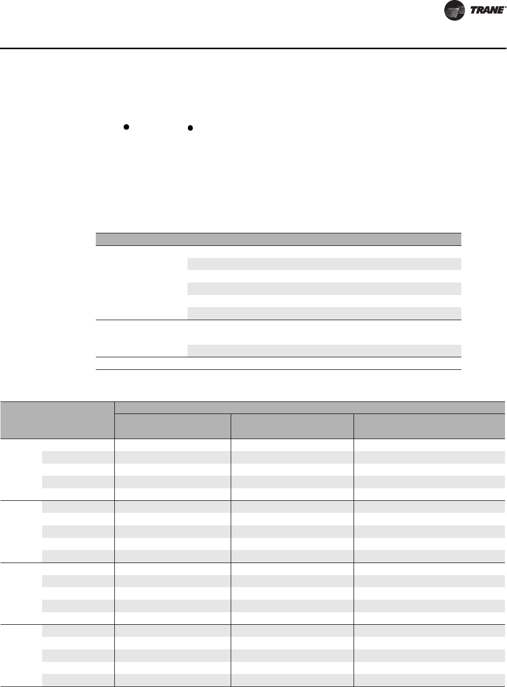
CLCH-PRC022A-EN 181
Performance Data
Formulas
For all plenum openings, use:
SP =
Where:
SP = static pressure drop
Kt = value from Table 169
OVF = FM/OAF
OVP = CFM/OAP
OVF = fan outlet velocity
OAF = fan outlet area (see “General Data,” p. 59)
OVP = plenum opening outlet velocity
OAP = plenum opening area (see Table 168)
Table 169. Discharge Plenums - Kt values for factory openings for plenum fans
Unit size Discharge Location Discharge
3-120
Rectangular Radial 2.00
Rectangular Axial Discharge 2.50
Round Radial 2.00
Round Axial Discharge 2.50
Bell mouth Radial 1.60
Bell mouth Axial Discharge 1.80
Discharge Plenum Loss
Rectangular Discharge 0.50
Round Discharge 0.50
Housed Exhaust Fans
Exhaust Damper Section Discharge 0.45
K
t
OV
F
4005
---------------
2
²0.5
OV
P
4005
---------------
2
²+
Table 170. Discharge Plenums - Kt values for factory openings for housed fans
Size Discharge
Location
Plenum location and Fan Discharge
Top Mounted Horizontally Mounted Horizontally Mounted
Fan Top-frontFan Top-back Fan Front-top Fan Back-top Fan Front-bottom Fan Back-bottom
3-8 FC
Front-top 1.67 0.98 0.98 n/a 0.98 n/a
Back-top 0.98 1.67 n/a 0.98 n/a 0.98
Top-front/back 0.98 0.98 1.67 1.67 0.98 0.98
Side-top 1.5 1.5 1.5 1.5 1.5 1.5
Bottom-front/back n/a n/a 0.98 0.98 1.67 1.67
3-8 BC or
AF
Front-top 1.14 0.68 0.68 n/a 0.68 n/a
Back-top 0.68 1.14 n/a 0.68 n/a 0.68
Top-front/back 0.68 0.68 1.33 1.33 0.78 0.78
Side-top 1.29 1.29 1.34 1.34 1.34 1.34
Bottom-front/back n/a n/a 0.78 0.78 1.33 1.33
10-17 FC
Front-top 2.59 1.68 1.68 n/a 1.68 n/a
Back-top 1.68 2.59 n/a 1.68 n/a 1.68
Top-front/back 1.68 1.68 2.59 2.59 1.68 1.68
Side-top 2.37 2.37 2.37 2.37 2.37 2.37
Bottom-front/back n/a n/a 1.68 1.68 2.59 2.59
10-17 AF
Front-top 1.67 1.15 1.15 n/a 1.15 n/a
Back-top 1.15 1.67 n/a 1.15 n/a 1.15
Top-front/back 1.15 1.15 1.83 1.83 1.23 1.23
Side-top 1.85 1.85 1.85 1.85 1.85 1.85
Bottom-front/back n/a n/a 1.23 1.23 1.83 1.83
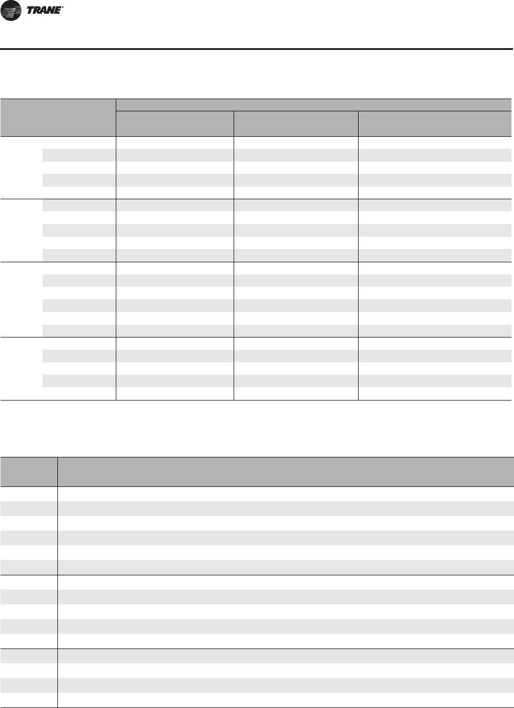
182 CLCH-PRC022A-EN
Performance Data
Economizer for Outdoor Units
Size Discharge
Location
Plenum location and Fan Discharge
Top Mounted Horizontally Mounted Horizontally Mounted
Fan Top-frontFan Top-back Fan Front-top Fan Back-top Fan Front-bottom Fan Back-bottom
21-31FC
Front-top 1.68 0.96 0.96 n/a 0.96 n/a
Back-top 0.96 1.68 n/a 0.96 n/a 0.96
Top-front/back 0.96 0.96 1.68 1.68 0.96 0.96
Side-top 1.5 1.5 1.5 1.5 1.5 1.5
Bottom-front/back n/a n/a 0.96 0.96 1.68 1.68
21-58 AF
Front-top 1.45 0.93 0.93 n/a 0.93 n/a
Back-top 0.93 1.45 n/a 0.93 n/a 0.93
Top-front/back 0.93 0.93 1.81 1.81 1.13 1.13
Side-top 1.68 1.68 1.68 1.68 1.68 1.68
Bottom-front/back n/a n/a 1.13 1.13 1.81 1.81
35-120 FC
Front-top 1.44 0.83 0.83 n/a 0.83 n/a
Back-top 0.83 1.44 n/a 0.83 n/a 0.83
Top-front/back 0.83 0.83 1.44 1.44 0.83 0.83
Side-top 1.25 1.25 1.25 1.25 1.25 1.25
Bottom-front/back n/a n/a 0.83 0.83 1.44 1.44
Full bottom n/a n/a 0.73 0.73 0.73 0.73
66 -120 AF
Front-top n/a n/a 1.34 n/a 1.34 n/a
Back-top n/a n/a n/a 1.34 n/a 1.34
Top-front/back n/a n/a 2.14 2.14 1.34 1.34
Side-top n/a n/a 2.11 2.11 2.11 2.11
Bottom-front/back n/a n/a 1.34 1.34 2.14 2.14
Table 170. Discharge Plenums - Kt values for factory openings for housed fans
Table 171. Economizer - exhaust damper performance data
Unit
size Area
(ft
2
)
Static Pressure Drop (inches w.g.) by Damper Face Velocity (fpm)
400 500 600 700 800 900 1000 1100 1200 1400 1600 1800 2000 2200 2400 2600
3 1.09 0.05 0.08 0.11 0.16 0.20 0.26 0.32 0.380.460.620.811.031.271.541.832.15
41.09 0.05 0.08 0.11 0.16 0.20 0.26 0.32 0.38 0.46 0.62 0.81 1.03 1.27 1.54 1.83 2.15
6 1.53 0.04 0.07 0.10 0.13 0.18 0.22 0.27 0.330.400.540.700.891.101.331.581.85
81.97 0.04 0.06 0.09 0.12 0.16 0.21 0.25 0.31 0.37 0.50 0.65 0.82 1.02 1.23 1.46 1.72
10 2.29 0.04 0.06 0.09 0.13 0.16 0.21 0.26 0.31 0.37 0.50 0.65 0.83 1.02 1.24 1.47 1.72
12 3.05 0.04 0.06 0.09 0.12 0.15 0.19 0.24 0.29 0.34 0.47 0.61 0.77 0.96 1.16 1.38 1.62
14 3.19 0.03 0.05 0.08 0.10 0.14 0.17 0.21 0.26 0.31 0.42 0.55 0.69 0.86 1.04 1.23 1.45
17 4.18 0.03 0.05 0.07 0.10 0.13 0.16 0.20 0.25 0.29 0.40 0.52 0.66 0.81 0.98 1.17 1.37
21 5.04 0.03 0.05 0.07 0.10 0.13 0.16 0.20 0.24 0.28 0.39 0.51 0.64 0.79 0.96 1.14 1.33
25 6.27 0.03 0.05 0.07 0.09 0.12 0.16 0.19 0.23 0.28 0.38 0.49 0.62 0.77 0.93 1.11 1.30
30 6.65 0.03 0.05 0.07 0.09 0.12 0.15 0.19 0.23 0.27 0.37 0.49 0.62 0.76 0.92 1.10 1.29
35 8.06 0.03 0.04 0.06 0.09 0.11 0.15 0.18 0.22 0.26 0.35 0.46 0.58 0.72 0.87 1.03 1.21
40 9.42 0.03 0.04 0.06 0.09 0.11 0.15 0.18 0.22 0.26 0.35 0.46 0.58 0.72 0.87 1.03 1.21
50 12.32 0.03 0.05 0.07 0.09 0.12 0.15 0.18 0.22 0.26 0.36 0.47 0.59 0.73 0.89 1.06 1.24
57 14.27 0.03 0.04 0.06 0.09 0.11 0.14 0.18 0.22 0.26 0.35 0.46 0.58 0.72 0.87 1.03 1.21
CLCH-PRC022A-EN 183
Performance Data
Electric Heat
Unit
size Area
(ft
2
)
Static Pressure Drop (inches w.g.) by Damper Face Velocity (fpm)
400 500 600 700 800 900 1000 1100 1200 1400 1600 1800 2000 2200 2400 2600
66 15.30 0.03 0.04 0.06 0.09 0.11 0.14 0.18 0.21 0.25 0.35 0.45 0.57 0.71 0.86 1.02 1.20
80 18.45 0.03 0.04 0.06 0.08 0.11 0.14 0.17 0.21 0.25 0.34 0.44 0.56 0.69 0.84 1.00 1.17
100 24.41 0.03 0.04 0.06 0.08 0.11 0.13 0.17 0.20 0.24 0.32 0.42 0.54 0.66 0.80 0.95 1.12
120 28.50 0.03 0.04 0.06 0.08 0.10 0.13 0.16 0.20 0.23 0.32 0.41 0.52 0.65 0.78 0.93 1.10
Table 171. Economizer - exhaust damper performance data
Table 172. Economizer - outside air/return damper
Unit
size Area
(ft
2
)
Static Pressure Drop (inches w.g.) by Damper Face Velocity (fpm)
400 500 600 700 800 900 1000 1100 1200 1400 1600 1800 2000 2200 2400 2600
3 1.220.050.080.110.150.190.240.300.360.430.590.770.981.211.461.742.04
41.89 0.04 0.06 0.09 0.12 0.16 0.20 0.25 0.31 0.36 0.49 0.65 0.82 1.01 1.22 1.45 1.71
6 2.570.040.060.080.110.140.180.230.270.330.440.580.730.911.101.301.53
83.33 0.03 0.05 0.08 0.10 0.14 0.17 0.21 0.26 0.31 0.42 0.54 0.69 0.85 1.03 1.22 1.43
10 4.16 0.03 0.05 0.07 0.10 0.13 0.16 0.20 0.24 0.29 0.39 0.51 0.64 0.80 0.96 1.15 1.35
12 5.14 0.03 0.05 0.07 0.09 0.12 0.15 0.19 0.23 0.27 0.37 0.49 0.62 0.76 0.92 1.10 1.29
14 5.64 0.03 0.04 0.06 0.09 0.11 0.14 0.18 0.21 0.25 0.35 0.45 0.57 0.71 0.86 1.02 1.20
17 6.94 0.03 0.04 0.06 0.08 0.11 0.14 0.17 0.21 0.25 0.33 0.44 0.55 0.68 0.82 0.98 1.15
21 8.68 0.03 0.04 0.06 0.09 0.11 0.14 0.17 0.21 0.25 0.34 0.45 0.56 0.70 0.84 1.00 1.18
25 10.42 0.03 0.04 0.06 0.08 0.11 0.14 0.17 0.21 0.25 0.33 0.44 0.55 0.68 0.83 0.98 1.15
30 12.08 0.03 0.04 0.06 0.08 0.11 0.13 0.17 0.20 0.24 0.33 0.42 0.54 0.66 0.80 0.96 1.12
35 14.25 0.03 0.04 0.06 0.08 0.10 0.13 0.16 0.20 0.23 0.32 0.41 0.52 0.65 0.78 0.93 1.10
40 16.17 0.03 0.04 0.06 0.08 0.10 0.13 0.16 0.19 0.23 0.31 0.41 0.52 0.64 0.77 0.92 1.08
50 19.45 0.03 0.04 0.06 0.08 0.11 0.14 0.17 0.21 0.25 0.34 0.44 0.55 0.68 0.83 0.99 1.16
57 22.73 0.03 0.04 0.06 0.08 0.11 0.14 0.17 0.20 0.24 0.33 0.43 0.54 0.67 0.81 0.96 1.13
66 27.27 0.03 0.05 0.07 0.09 0.12 0.15 0.19 0.23 0.27 0.37 0.48 0.61 0.75 0.90 1.08 1.26
80 32.57 0.03 0.05 0.07 0.09 0.12 0.15 0.18 0.22 0.26 0.36 0.47 0.59 0.73 0.88 1.05 1.23
100 41.34 0.03 0.04 0.06 0.08 0.11 0.14 0.17 0.21 0.25 0.33 0.44 0.55 0.68 0.83 0.98 1.15
120 48.82 0.03 0.04 0.06 0.08 0.11 0.13 0.17 0.20 0.24 0.32 0.42 0.54 0.66 0.80 0.95 1.12
Table 173. Electric heat pressure drop
Static Pressure Drop (inches w.g.) by Face Velocity (fpm)
Face Velocity 350 400 450 500 550 600 650 700
Pressure Drop
0.06 0.08 0.1 0.12 0.15 0.17 0.2 0.24
Table 174. Electric heat face area
Unit size 3 4 6 8 10 12 14 17 21 22 25 26
Area (ft
2
)
2.18 3.79 4.73 6.43 8.52 10.54 11.70 14.58 17.57 17.48 21.13 21.60
Unit size 30 31 35 36 40 41 50 51 57 58 66
Area (ft
2
)
25.52 26.72 30.97 32.29 34.98 37.81 45.17 45.56 52.25 51.73 62.65
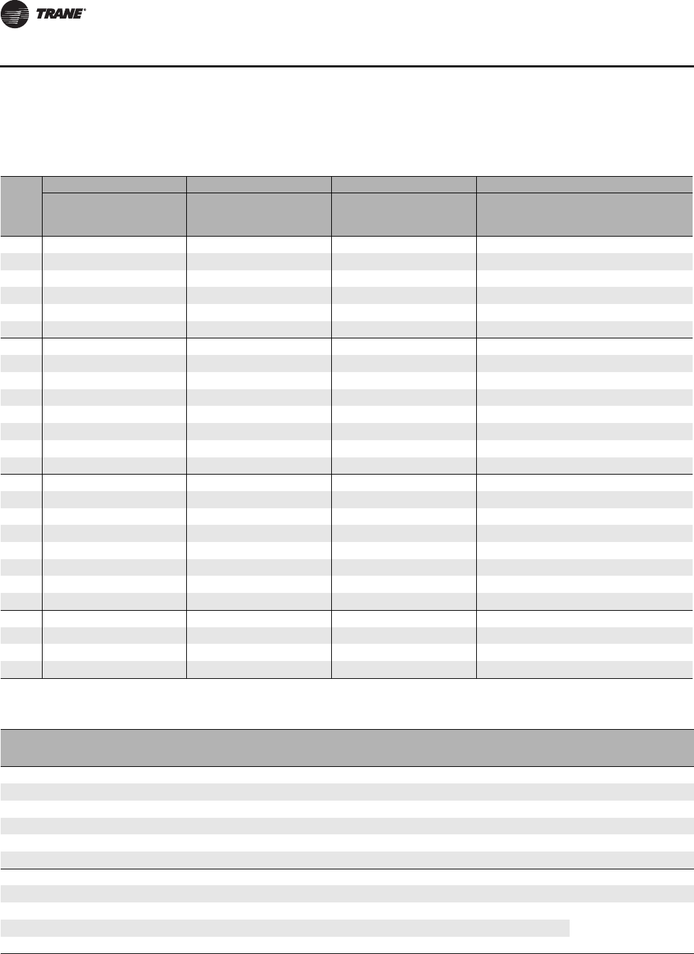
184 CLCH-PRC022A-EN
Performance Data
Filters
Table 175.Maximum CFM for filters
Unit
Size
Pleated Media Permanent Throwaway High Efficiency
2-in. and
4-in. Flat 2-in. or
4-in. Angled 2-in. and
4-in. Flat 2-in. or 4-in.
Angled 2-in. and
4-in. Flat 2-in. or 4-in.
Angled Long
Cartridge/Bag HEPA 4-in. High
Efficiency
625 625 800 800 500 500 625 600 625
3 2169 3475 2776 4448 1735 2780 2081 1200 2169
43475 5556 4448 7112 2780 4445 3475 1200 3475
6 4338 5556 5552 7112 3470 4445 4169 3600 4338
84581 6944 5864 8888 3665 5555 5000 4200 4581
10 6075 8681 7776 11,112 4860 6945 5419 5400 6075
12 8331 10,419 10,664 13,336 6665 8335 7706 6000 8331
14 9025 11,288 11,552 14,448 7220 9030 8400 6000 9025
17 11,806 18,056 15,112 23,112 9445 14,445 11,806 8400 11,806
21 13,456 20,831 17,224 26,664 10,765 16,665 13,750 12,600 13,456
22 13,194 20,831 16,888 26,664 10,555 16,665 10,831 11,400 13,194
25 16,944 31,250 21,688 40,000 13,555 25,000 16,250 14,400 16,944
26 18,231 27,775 23,336 35,552 14,585 22,220 16,250 16,200 18,231
30 19,025 35,419 24,352 45,336 15,220 28,335 17,638 16,800 19,025
31 22,138 36,113 28,336 46,224 17,710 28,890 21,250 18,000 22,138
35 23,263 39,581 29,776 50,664 18,610 31,665 21,669 18,000 23,263
36 25,000 39,063 32,000 50,000 20,000 31,250 22,500 21,600 25,000
40 25,519 43,750 32,664 56,000 20,415 35,000 22,500 22,200 25,519
41 30,138 41,669 38,576 53,336 24,110 33,335 30,000 27,000 30,138
50 34,375 62,500 44,000 80,000 27,500 50,000 31,250 27,600 34,375
51 34,306 59,025 43,912 75,552 27,445 47,220 35,000 28,800 34,306
57 39,581 62,500 50,664 80,000 31,665 50,000 37,500 34,200 39,581
58 38,194 61,806 48,888 79,112 30,555 49,445 38,750 33,600 38,194
66 47,225 70,831 60,448 90,664 37,780 56,665 41,669 39,600 47,225
80 53,475 94,444 68,448 120,888 42,780 75,555 55,000 45,600 53,475
100 65,106 104,169 83,336 133,336 52,085 83,335 70,831 61,200 65,106
120 76,388 121,525 97,776 155,552 61,110 97,220 83,750 71,400 76,388
Table 176.Filter area (ft.2)
Unit Size Side-load
2-in. and 4-in. Flat Side-load
2-in. and 4-in. Angled Side-load
Bag/Cartridge Front-Load Bag/
Cartridge Filter Front-load
HEPA
3 3.47 5.56 3.33 2.00 2.00
45.56 8.89 5.56 2.00 2.00
6 6.94 8.89 6.67 6.00 6.00
87.33 11.11 8.00 6.00 7.00
10 9.72 13.89 8.67 8.00 9.00
12 13.33 16.67 12.33 10.00 10.00
14 14.44 18.06 13.44 10.00 10.00
17 18.89 28.89 18.89 14.00 14.00
21 21.53 33.33 22.00 18.00 21.00
22 21.11 33.33 17.33 18.00 19.00
25 27.11 50.00 26.00 24.00 24.00
CLCH-PRC022A-EN 185
Performance Data
Unit Size Side-load
2-in. and 4-in. Flat Side-load
2-in. and 4-in. Angled Side-load
Bag/Cartridge Front-Load Bag/
Cartridge Filter Front-load
HEPA
26 29.17 44.44 26.00 24.00 27.00
30 30.44 56.67 28.22 28.00 28.00
31 35.42 57.78 34.00 30.00 30.00
35 37.22 63.33 34.67 34.00 30.00
36 40.00 32.50 36.00 36.00 36.00
40 40.83 70.00 36.00 38.00 37.00
41 48.22 66.67 48.00 46.00 45.00
50 55.00 100.00 50.00 50.00 46.00
51 54.89 94.44 56.00 54.00 48.00
57 63.33 100.00 60.00 60.00 57.00
58 61.11 98.89 62.00 62.00 56.00
66 75.56 113.33 66.67 66.00 66.00
80 85.56 151.11 88.00 86.00 76.00
100 104.17 166.67 113.33 106.00 102.00
120 122.22 194.44 134.00 124.00 119.00
Table 176.Filter area (ft.2)
Table 177. Filters (clean) performance data
Filter Type
Static Pressure Drop (inches wg) by Filter Face Velocity (fpm)
200 250 300 350 400 450 500 550 600
2-inch permanent – MERV 2 0.01 0.02 0.03 0.04 0.05 0.06 0.07 0.09 0.11
2-inch disposable (TA) – MERV 5 0.04 0.06 0.08 0.10 0.13 0.15 0.18 n/a n/a
2-inch pleated media – MERV 8 0.080.110.140.180.220.260.300.340.39
2-inch pleated media – coated – MERV 7 0.08 0.11 0.14 0.18 0.21 0.26 0.30 0.35 0.40
4-inch pleated media – MERV 8 0.040.060.080.110.130.160.190.220.25
4-inch pleated media – coated – MERV 7 0.04 0.06 0.09 0.12 0.16 0.20 0.25 0.30 0.36
4-inch high efficient – 65% efficient – MERV 11 0.07 0.10 0.12 0.15 0.18 0.21 0.24 0.27 0.30
4-inch high efficient – 95% efficient – MERV 14 0.16 0.20 0.25 0.29 0.34 0.39 0.44 0.49 0.54
12-inch cartridge – 65% efficient – MERV 11 0.06 0.09 0.12 0.15 0.19 0.23 0.27 0.31 0.36
12-inch cartridge – 95% efficient – MERV 14 0.11 0.14 0.18 0.22 0.26 0.30 0.35 0.39 0.44
18-inch bag – 65% efficient – MERV 12 0.18 0.22 0.27 0.31 0.35 0.39 0.44 0.48 0.52
18-inch bag – 85% efficient – MERV 13 0.20 0.25 0.30 0.35 0.41 0.46 0.51 0.56 0.61
18-inch bag – 95% efficient – MERV 14 0.23 0.28 0.34 0.39 0.45 0.50 0.56 0.61 0.66
30-inch bag – 65% efficient – MERV 12 0.07 0.10 0.13 0.17 0.21 0.26 0.31 0.36 0.42
30-inch bag – 85% efficient – MERV 13 0.09 0.11 0.15 0.18 0.22 0.26 0.31 0.35 0.40
30-inch bag – 95% efficient – MERV 14 0.17 0.22 0.27 0.32 0.37 0.42 0.47 0.52 0.58
HEPA - 99.97% efficient - DOP 0.470.600.740.891.041.201.371.541.72
186 CLCH-PRC022A-EN
Performance Data
Table 178. Filters (mid-life) performance data
Filter Type
Static Pressure Drop (inches wg) by Filter Face Velocity (fpm)
200 250 300 350 400 450 500 550 600
2-inch permanent – MERV 2 0.510.510.520.520.530.530.540.550.55
2-inch disposable (TA) – MERV 5 0.52 0.53 0.54 0.55 0.57 0.58 0.59 n/a n/a
2-inch pleated media – MERV 8 0.540.560.570.590.610.630.650.670.69
2-inch pleated media – coated – MERV 7 0.54 0.56 0.57 0.59 0.61 0.63 0.65 0.67 0.70
4-inch pleated media – MERV 8 0.520.530.540.560.570.580.590.610.62
4-inch pleated media – coated – MERV 7 0.52 0.53 0.55 0.57 0.59 0.61 0.63 0.65 0.67
4-inch high efficient – 65% efficient – MERV 11 0.64 0.65 0.66 0.68 0.69 0.70 0.72 0.73 0.75
4-inch high efficient – 95% efficient – MERV 14 0.68 0.70 0.72 0.75 0.77 0.79 0.82 0.84 0.87
12-inch cartridge – 65% efficient – MERV 11 0.63 0.65 0.66 0.68 0.70 0.72 0.74 0.76 0.78
12-inch cartridge – 95% efficient – MERV 14 0.65 0.67 0.69 0.71 0.73 0.75 0.77 0.80 0.82
18-inch bag – 65% efficient – MERV 12 0.69 0.71 0.73 0.75 0.77 0.80 0.82 0.84 0.86
18-inch bag – 85% efficient – MERV 13 0.70 0.73 0.75 0.78 0.80 0.83 0.85 0.88 0.90
18-inch bag – 95% efficient – MERV 14 0.71 0.74 0.77 0.80 0.82 0.85 0.88 0.90 0.93
30-inch bag – 65% efficient – MERV 12 0.63 0.65 0.67 0.69 0.71 0.73 0.76 0.78 0.80
30-inch bag – 85% efficient – MERV 13 0.64 0.66 0.68 0.70 0.71 0.73 0.76 0.78 0.80
30-inch bag – 95% efficient – MERV 14 0.69 0.71 0.73 0.76 0.78 0.81 0.83 0.86 0.89
HEPA - 99.97% efficient - DOP 1.231.301.371.441.521.601.681.771.86
Table 179. Filters (dirty) performance data
Filter Type
Static Pressure Drop (inches wg) by Filter Face Velocity (fpm)
200 250 300 350 400 450 500 550 600
2-inch permanent – MERV 2 1.00 1.00 1.00 1.00 1.00 1.00 1.00 1.00 1.00
2-inch disposable (TA) – MERV 5 1.00 1.00 1.00 1.00 1.00 1.00 1.00 n/a n/a
2-inch pleated media – MERV 8 1.001.001.001.001.001.001.001.001.00
2-inch pleated media – coated – MERV 7 1.00 1.00 1.00 1.00 1.00 1.00 1.00 1.00 1.00
4-inch pleated media – MERV 8 1.001.001.001.001.001.001.001.001.00
4-inch pleated media – coated – MERV 7 1.00 1.00 1.00 1.00 1.00 1.00 1.00 1.00 1.00
4-inch high efficient – 65% efficient – MERV 11 1.20 1.20 1.20 1.20 1.20 1.20 1.20 1.20 1.20
4-inch high efficient – 95% efficient – MERV 14 1.20 1.20 1.20 1.20 1.20 1.20 1.20 1.20 1.20
12-inch cartridge – 65% efficient – MERV 11 1.20 1.20 1.20 1.20 1.20 1.20 1.20 1.20 1.20
12-inch cartridge – 95% efficient – MERV 14 1.20 1.20 1.20 1.20 1.20 1.20 1.20 1.20 1.20
18-inch bag – 65% efficient – MERV 12 1.20 1.20 1.20 1.20 1.20 1.20 1.20 1.20 1.20
18-inch bag – 85% efficient – MERV 13 1.20 1.20 1.20 1.20 1.20 1.20 1.20 1.20 1.20
18-inch bag – 95% efficient – MERV 14 1.20 1.20 1.20 1.20 1.20 1.20 1.20 1.20 1.20
30-inch bag – 65% efficient – MERV 12 1.20 1.20 1.20 1.20 1.20 1.20 1.20 1.20 1.20
30-inch bag – 85% efficient – MERV 13 1.20 1.20 1.20 1.20 1.20 1.20 1.20 1.20 1.20
30-inch bag – 95% efficient – MERV 14 1.20 1.20 1.20 1.20 1.20 1.20 1.20 1.20 1.20
HEPA - 99.97% efficient - DOP 2.002.002.002.002.002.002.002.002.00

CLCH-PRC022A-EN 187
Performance Data
Gas Heat
Hoods
Table 180. Gas heat pressure drop
Unit Size
Static Pressure Drop (inches w.g.) by Face Velocity (range = 750 - 2000)
Full Face Discharge Horizontal Discharge Vertical Discharge
6 0.32 0.42 0.65
80.38 0.48 0.78
10 0.42 0.52 0.85
12 0.46 0.56 0.88
14 0.49 0.59 0.89
17 0.51 0.61 0.90
21 0.53 0.63 0.94
25 0.55 0.65 1.00
30 0.60 0.70 0.99
35 0.42 0.52 0.84
40 0.47 0.57 0.91
50 0.49 0.59 0.91
57 0.58 0.68 1.02
66 0.52 0.62 0.91
80 0.54 0.64 0.99
100 0.62 0.72 1.10
120 0.54 0.64 1.00
Table 181. Exhaust hood performance data
Static Pressure Drop (inches wg) by Face Velocity (fpm)
Face Velocity (FPM) 700 800 900 1000 1100 1200 1300 1400 1500 1600
Pressure drop
0.03 0.04 0.05 0.06 0.07 0.09 0.10 0.12 0.13 0.15
Table 182. Exhaust hood face area
Unit Size 346810 12 14 17 21 25 30 35 40 50 57
Area (ft
2
)
1.25 1.25 1.49 1.78 2.00 2.52 3.21 3.17 4.07 4.36 5.28 7.69 7.94 8.67 9.23
Table 183. Inlet hood performance data
Static Pressure Drop (inches wg) by Face Velocity (fpm)
Face Velocity (FPM) 300 400 500 600 700 800 900 950
Pressure drop
0.04 0.06 0.10 0.15 0.20 0.26 0.33 0.37
188 CLCH-PRC022A-EN
Performance Data
Each air handler has a rated nominal airflow (for example, 1500 cfm for a size 3). This nominal
airflow is a quick guide to figure unit size requirements. Although this is the nominal airflow of a
given unit, each unit is capable of producing more, until something limits the ability of the unit to
meet this higher airflow requirement such as coil face velocity, filter face velocity, or the outside
air inlet hood eliminator velocity.
The eliminator in the inlet hood is rated to a maximum of 800 feet per minute. Above this limit, there
is a high probability of bringing rain, water or snow into the unit, which could migrate to the
conditioned space below. When selecting units for your application, remember not to undersize a
unit to the point that the inlet hood eliminators can not handle the outside air cfm requirements.
Table 184 shows the maximum airflow for inlet hoods.
Humidifiers
Table 184. Inlet hood airflow limitations (cfm)
Unit size
Mixing Section Economizer Section
Back hood
area (ft
2
)Back inlet
hood 1 Side hood
area (ft
2
)1 side inlet
hood 2 side hood
area (ft
2
)2 side inlet
hoods Inlet hood
area (ft
2)
Single inlet
hood
3 2.82 2257 2.23 1781 4.46 3563 1.88 1504
46.96 5567 2.23 1781 4.46 3563 3.65 2917
6 7.52 6016 2.72 2179 5.44 4358 4.53 3625
811.06 8847 3.29 2634 6.58 5268 5.79 4628
10 8.81 7050 3.81 3050 7.62 6100 6.57 5257
12 11.74 9393 4.80 3841 9.60 7681 7.74 6190
14 12.73 10,185 6.98 5582 13.96 11,163 10.31 8248
17 14.74 11,789 6.09 4870 12.18 9741 12.45 9960
21 18.39 14,716 8.15 6524 16.30 13,047 14.91 11,928
25 21.32 17,054 8.65 6917 17.30 13,834 17.48 13,984
30 28.37 22,694 9.68 7742 19.36 15,483 19.69 15,752
35 30.39 24,316 15.25 12,199 30.50 24,397 22.78 18,222
40 34.29 27,434 15.80 12,640 31.60 25,280 27.86 22,288
50 40.87 32,700 19.76 15,808 39.52 31,617 32.46 25,968
57 47.10 37,677 18.67 14,933 37.34 29,865 33.89 27,112
66 64.99 51,988 18.80 15,039 37.60 30,077 42.51 34,008
80 69.42 55,539 22.43 17,943 44.86 35,887 51.03 40,824
80 Traq n/a n/a 24.54 19,633 49.08 39,265 n/a n/a
100 81.29 65,029 29.05 23,239 58.10 46,477 63.15 50,520
100 Traq n/a n/a 51.83 41,463 103.66 82,926 n/a n/a
120 97.40 77,916 33.50 26,797 67.00 53,595 72.80 58,240
120 Traq n/a n/a 50.29 40,231 100.58 80,462 n/a n/a
Table 185. Humidifier pressure drop
Static Pressure Drop (inches w.g.) by Face Velocity (fpm)
Face Velocity 400 450 500 550 600 650 700 750 800 850 900
Pressure drop
0.02 0.02 0.03 0.03 0.04 0.05 0.05 0.06 0.07 0.08 0.09
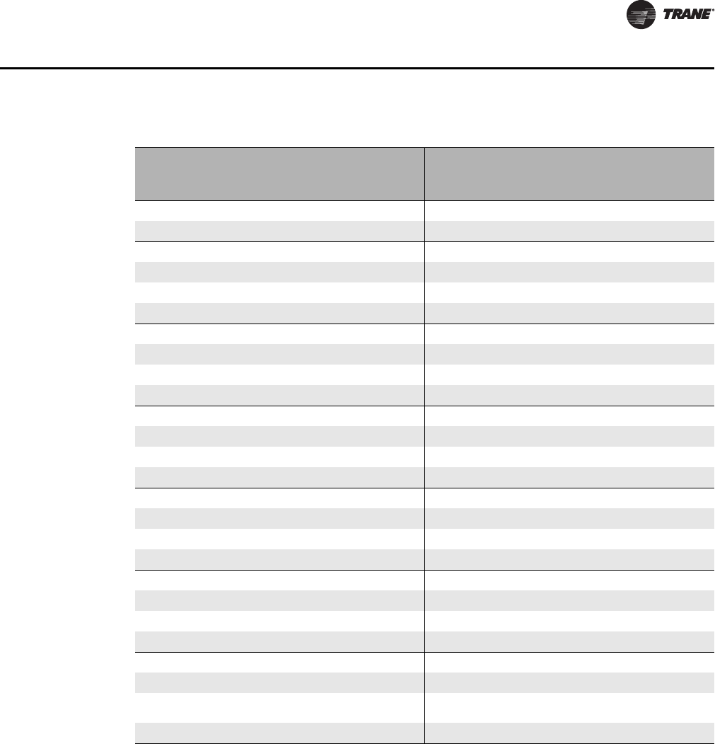
CLCH-PRC022A-EN 189
Performance Data
Table 186. Face area for building steam and atmospheric steam sources
Building Steam Source Atmospheric Steam Source
Unit Size Area (ft.
2)
Unit Size Area (ft.
2)
3 1.22 3 1.42
42.43 42.29
6 3.47 6 3.72
84.59 85.14
10 6.20 10 6.58
12 7.59 12 8.67
14 8.47 14 9.53
17 11.04 17 12.71
21 12.71 21 16.17
22 12.99 22 16.92
25 16.52 25 20.36
26 18.59 26 23.32
30 20.18 30 21.40
31 23.19 31 28.17
35 24.96 35 26.73
36 27.96 36 33.54
40 28.57 40 30.45
41 30.50 41 34.50
50 39.20 50 41.05
51 37.25 51 41.38
57 46.59 57 48.56
58 37.25 58 41.38
66 55.69 66 58.19
80 60.75 80 63.00
100 67.75 100 70.00
120 72.00 120 74.00
190 CLCH-PRC022A-EN
Performance Data
Multizone
Silencers
Table 187. Baffle assembly pressure drop (inches w.g.)
Unit size Air flow
(cfm)
Baffle Assembly Pressure Drop (inches w.g.)
70 60 6070 6060 40 4070 4060 4040
6 3000 0.10 0.19 0.29 0.38 0.67 0.77 0.86 1.33
84000 0.12 0.23 0.36 0.47 0.81 0.93 1.04 1.62
10 5000 0.07 0.14 0.21 0.27 0.47 0.54 0.61 0.94
12 6000 0.09 0.16 0.25 0.32 0.56 0.64 0.72 1.12
14 7000 0.10 0.18 0.28 0.36 0.62 0.72 0.80 1.25
17 8500 0.14 0.27 0.41 0.53 0.92 1.06 1.19 1.84
21 10,500 0.11 0.22 0.33 0.43 0.74 0.86 0.96 1.49
25 12,500 0.16 0.30 0.47 0.61 1.06 1.22 1.36 2.11
30 15,000 0.16 0.30 0.46 0.61 1.05 1.21 1.36 2.10
35 17,500 0.12 0.23 0.35 0.46 0.79 0.91 1.02 1.58
40 20,000 0.12 0.23 0.35 0.46 0.79 0.91 1.02 1.58
50 25,000 0.15 0.28 0.43 0.56 0.97 1.11 1.24 1.93
Table 188. Silencer performance data
Length Model Unit Sizes
Pressure Drop (in. H
2
O) by Face Velocity (fpm)
250 500 750 1000 1250 1500 1750
3 ft.
RD-ULV-F2 10 0.03 0.11 0.26 0.45 0.70 1.01 1.37
RD-ULV-F3 3, 21, 22, 25, 26, 40, 66, 80 0.03 0.11 0.25 0.45 0.70 1.00 1.36
RD-ULV-F4 41, 50, 57, 100, 120 0.03 0.11 0.25 0.44 0.68 0.98 1.32
RD-ULV-F5 8, 14, 17, 30, 35, 51, 58 0.03 0.12 0.27 0.47 0.73 1.05 1.43
RD-ULV-F6 4, 6,12, 31 0.03 0.12 0.28 0.50 0.78 1.13 1.54
RD-ULV-F7 36 0.03 0.13 0.29 0.53 0.83 1.20 1.65
5 ft.
RD-ULV-F2 10 0.04 0.15 0.34 0.61 0.94 1.36 1.84
RD-ULV-F3 3, 21, 22, 25, 26, 40, 66, 80 0.04 0.15 0.34 0.59 0.92 1.31 1.78
RD-ULV-F4 41, 50, 57, 100, 120 0.04 0.15 0.33 0.57 0.89 1.27 1.71
RD-ULV-F5 8, 14, 17, 30, 35, 51, 58 0.04 0.15 0.34 0.61 0.94 1.35 1.83
RD-ULV-F6 4, 6,12, 31 0.04 0.16 0.36 0.64 0.99 1.43 1.94
RD-ULV-F7 36 0.04 0.17 0.38 0.67 1.05 1.52 2.07
Table 189. Silencer face area
Unit Size 346810 12 14 17 21 22 25 26 30
Area (ft
2
)
4.30 6.25 7.99 10.09 12.48 15.19 16.53 20.07 24.41 24.26 29.03 31.55 34.18
Unit Size 31 35 36 40 41 50 51 57 58 66 80 100 120
Area (ft
2
)
37.31 40.50 43.54 45.77 51.46 58.43 60.60 66.66 68.21 78.20 92.42 114.70 135.66
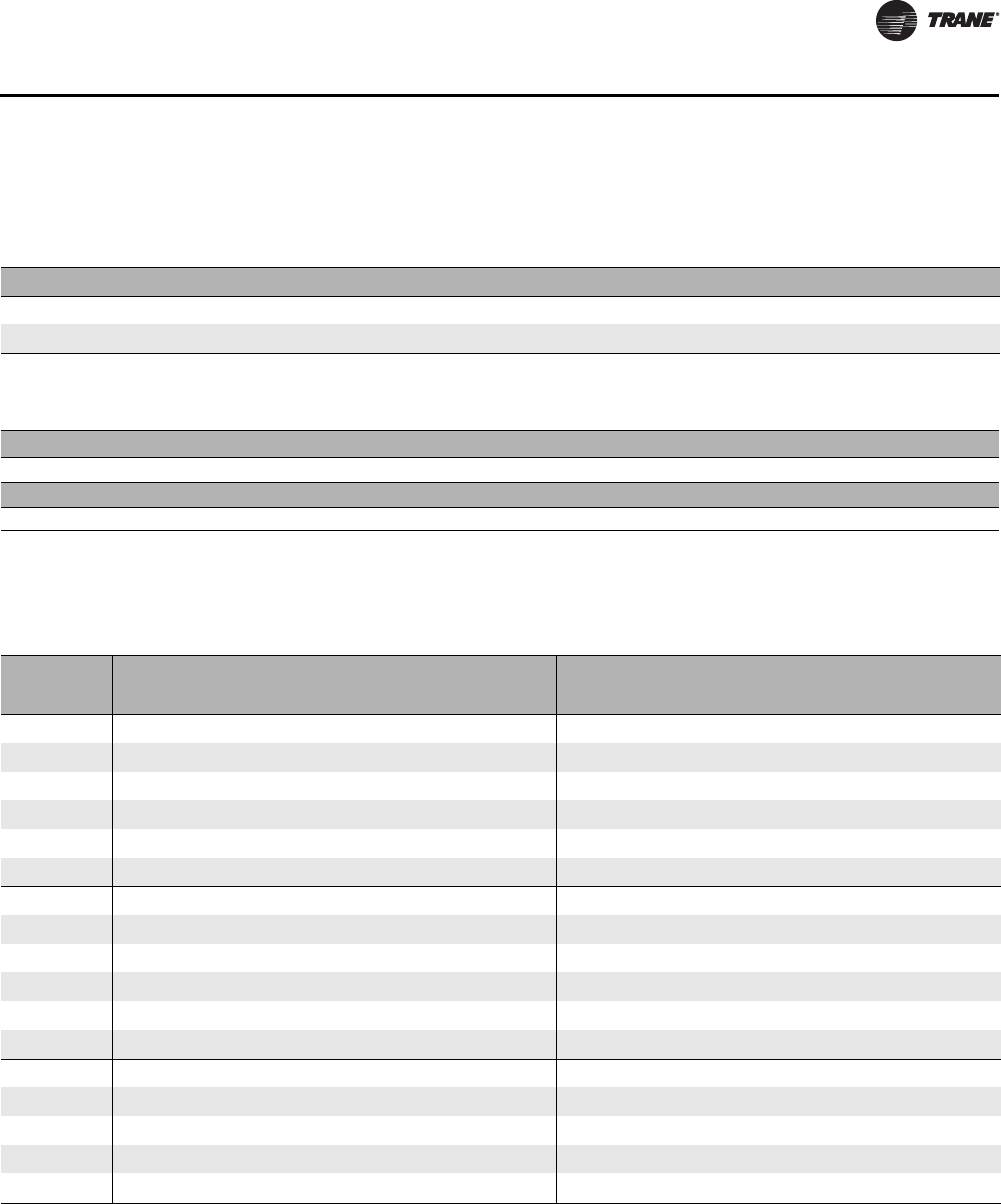
CLCH-PRC022A-EN 191
Performance Data
Trane Catalytic Air Cleaning Systems (TCACS
Electrical Data
Table 190. TCACS pressure drop
Static Pressure Drop (inches w.g.) by Face Velocity (fpm)
Face Velocity 200 250 300 350 400 450 500 550 600
Pressure drop
0.010 0.014 0.017 0.022 0.026 0.030 0.035 0.040 0.045
Table 191. TCACS face area
Unit Size 346810 12 14 17 21 22 25 26 30
Area (ft
2
)
2.92 5.14 6.17 7.97 10.31 13.33 13.78 17.22 21.08 20.61 24.92 27.97 29.97
Unit Size 31 35 36 40 41 50 51 57 58 66 80 100 120
Area (ft
2
)
32.72 35.00 38.89 39.67 39.61 51.11 53.03 60.69 62.25 68.89 79.22 107.25 126.00
Table 192. Current requirements - full load amps
HP
VFD Starter
200 230 460 575 200 230 460 575
1 6.306.302.502.304.804.202.101.70
1.5 6.30 6.30 2.50 2.30 6.90 6.00 3.00 2.40
2 7.307.303.402.607.806.803.402.70
310.40 10.40 4.80 3.80 11.00 9.60 4.80 3.90
5 16.80 16.80 8.30 5.90 17.50 15.20 7.60 6.10
7.5 23.80 23.80 10.60 9.20 25.30 22.00 11.00 9.00
10 32.20 32.20 14.20 11.10 32.20 28.00 14.00 11.00
15 48.30 48.30 21.00 16.60 48.30 42.00 21.00 17.00
20 61.90 61.90 27.60 21.40 62.10 54.00 27.00 22.00
25 78.20 78.20 34.00 26.30 78.20 68.00 34.00 27.00
30 92.00 92.00 41.00 31.20 92.00 80.00 40.00 32.00
40 117.00 101.30 53.00 39.90 120.00 104.00 52.00 41.00
50 n/a 126.60 64.00 50.60 n/a 130.00 65.00 52.00
60 n/a n/a 77.00 60.40 n/a n/a 77.00 62.00
75 n/a n/a 104.00 75.00 n/a n/a 96.00 77.00
100 n/a n/a 128.00 92.40 n/a n/a 124.00 99.00
125 n/a n/a 157.00 n/a n/a n/a 156.00 n/a

192 CLCH-PRC022A-EN
Mechanical Specifications
Performance Climate ChangerTM air handlers must be rigged, lifted, and installed in strict
accordance with the Installation, Operation, and Maintenance manual (CLCH-SVX07A-EN) for
Performance air handlers. The units are also to be installed in strict accordance with the
specifications.
All units will be shipped with an integral base frame designed with the necessary number of lift
points for safe installation. The lift points will be designed to accept standard rigging devices and
be removable after installation. Units shipped in sections will have a minimum of four points of lift.
Sizes 3-30 will also be shipped with a shipping skid designed for forklift transport.
Units will be shipped with a shipping skid designed for forklift transport and the integral base will
be designed with the necessary number of lift points for safe installation. The lift points will be
designed to accept standard rigging devices and removable after installation. Units shipped in
sections will have a minimum of four points of lift.
Per ASHRAE 62.1 recommendation, units will be shipped stretch-wrapped to protect unit from in-
transit rain and debris. Installing contractor is responsible for long-term storage in accordance with
the Installation, Operation, and Maintenance manual (CLCH-SVX07A-EN).
Unit shall be UL and C-UL Listed.
Air-handling performance data shall be certified in accordance with AHRI Standard 430. Unit sound
performance data shall be provided using AHRI Standard 260 test methods and reported as sound
power. Coil performance shall be certified in accordance with AHRI Standard 410.
Seismic Certification
Trane has qualified listed air-handling unit sizes 3-30 as certified for seismic applications in
accordance with the following International Building Code (IBC) releases: IBC 2000, 2003, 2006,
2009.
Seismic Qualification Testing and structural analysis shall be conducted in accordance with and
strict adherence to the standards set forth within ASCE 7 by an independent approval agency with
a complete list of certified models, options, and installation methods provided in an approved
detailed report. The above referenced equipment shall be approved for seismic applications when
properly installed and used as intended.
The basis of the certification shall be obtained through a combination of testing of the active and
energized components per AC156, and analysis of the main force resisting members of the unit.
Additional calculations shall be conducted to ensure components, accessories, and options
remained intact and attached to the unit under seismic load conditions.
The certification shall be based on a maximum Design Structural Response Acceleration at Short
Period (Sds) value of 1.85 g's for IBC 2006 and 2009, and 1.93 for IBC 2000 and 2003. This is obtained
from the Maximum Considered Earthquake Short Period Spectral Response Acceleration, Ss, of
2.78 g's or 2.90 g's as determined by the ASCE 7 seismic maps for Soil Site Class B with 5 percent
damping. When the site soil properties or final equipment installation location are not known, the
soil site coefficient, Fa, defaults to the Soil Site Class D coefficient. Occupancy Category IV and
Seismic Design Category C shall be covered under this certification, limited by the Sds value stated
above. A seismic importance factor, Ip, of 1.5 shall apply to the certification to include essential
facility requirements and life safety applications for post event functionality.
IBC 2000, 2003 FP/WP = 0.4 x 2/3(Ss=2.90) x (FA=1) x (IP=1.5) x (aP/RP=0.40) x (1+2(z/h=1.0)) = 1.39 g's
IBC 2006, 2009 FP/WP = 0.4 x 2/3(Ss=2.78) x (FA=1) x (IP=1.5) x (aP/RP=0.42) x (1+2(z/h=1.0)) = 1.39 g's
Structural floors, housekeeping pads, supporting curbs, and supporting steel must be seismically
designed and approved by the project or building Structural Engineer of Record to withstand the
seismic anchor loads. Installation details such as special inspection, attachment to a curb, or
attachment to a non-building structure must be outlined and approved by the Engineer of Record
for the project or building. The installing contractor shall be responsible for the proper installation

CLCH-PRC022A-EN 193
Mechanical Specifications
of the equipment and must observe the seismic installation requirements set forth by the Engineer
of Record.
Unit Construction
Casing Construction
All unit panels shall be 2-inch solid, double-wall construction to facilitate cleaning of unit interior.
Unit panels shall be provided with a mid-span, no through metal, internal thermal break. Casing
thermal performance shall be such that under 55°F supply air temperature and design conditions
on the exterior of the unit of 81°F dry bulb and 73°F wet bulb, condensation shall not form on the
casing exterior.
All exterior and interior AHU panels will be made of galvanized steel. Optionally, all interior AHU
casing panels will be made of stainless steel.
The casing shall be able to withstand up to 8 inches w.g. positive or negative static pressure. The
casing shall not exceed 0.0042 inch deflection per inch of panel span at 1.5 times design static
pressure up to a maximum of +8 inches w.g. in all positive pressure sections and -8 inches w.g. in
all negative pressure sections.
Unit Flooring
The unit floor shall be of sufficient strength to support a 300-lb. load during maintenance activities
and shall deflect no more than 0.0042 inch per inch of panel span.
Casing Leakage
The casing air leakage shall not exceed leak class 9 (CL = 9) per ASHRAE 111 at 1.25 times maximum
casing static pressure (P in inches w.g.), up to a maximum of +8 inches w.g. in all positive pressure
sections and -8 inches w.g. in all negative pressure sections, where maximum casing leakage (cfm/
100 ft2 of casing surface area) = CL x P0.65.
Optionally, the casing air leakage shall not exceed leak class 6 (CL = 6) per ASHRAE 111 at 1.25 times
maximum casing static pressure (P in inches w.g.), up to a maximum of + 8 inches w.g. in all positive
pressure sections and -8 inches w.g. in all negative pressure sections, where maximum casing
leakage (cfm/100 ft2 of casing surface area) = CL x P0.65.
Insulation
Panel insulation shall provide a minimum thermal resistance (R) value of 13 ft²•h•ºF/Btu throughout
the entire unit. Insulation shall completely fill the panel cavities in all directions so that no voids
exist and settling of insulation is prevented. Panel insulation shall comply with NFPA 90A.
Drain Pans
All cooling coil sections shall be provided with an insulated, double-wall, galvanized or stainless
steel drain pan. To address indoor air quality (IAQ), the drain pan shall be designed in accordance
with ASHRAE 62.1 being of sufficient size to collect all condensation produced from the coil and
sloped in two planes promoting positive drainage to eliminate stagnant water conditions. The
outlet shall be located at the lowest point of the pan and shall be sufficient diameter to preclude
drain pan overflow under any normally expected operating condition. All drain pan threaded
connections shall be visible external to the unit. Drain connections shall be of the same material
as the primary drain pan and shall extend a minimum of 2 1/2 inches beyond the base to ensure
adequate room for field piping of condensate drain traps. Coil support members inside the drain
pan shall be of the same material as the drain pan and coil casing. Heating coil, access, and mixing
sections may be provided with an optional IAQ drain pan.

194 CLCH-PRC022A-EN
Mechanical Specifications
Access Doors
Access doors shall be 2-inch double-wall construction. Interior and exterior door panels shall be
of the same construction as the interior and exterior wall panels, respectively. All doors
downstream of cooling coils shall be provided with a thermal break construction of door panel and
door frame. Gasketing shall be provided around the full perimeter of the doors to prevent air
leakage.
Surface-mounted handles shall be provided to allow quick access to the interior of the functional
section and to prevent through-cabinet penetrations that could likely weaken the casing leakage
and thermal performance. Handle hardware shall be designed to prevent unintended closure.
Access doors shall be hinged and removable for quick, easy access. Hinges shall be
interchangeable with the door handle hardware to allow for alternating door swing in the field to
minimize access interference due to unforeseen job site obstructions. Door handle hardware shall
be adjustable and visually indicate locking position of door latch external to the section.
All doors shall be a minimum of 60 inches high when sufficient height is available, or the maximum
height allowed by the unit height.
Door handles will be provided for each latching point of the door necessary to maintain the
specified air leakage integrity of the unit. Optionally, a single-handle door shall be provided for all
outward swinging doors linked to multiple latching points necessary to maintain the specified air
leakage integrity of the unit.
View Windows
An optional shatterproof window for viewing, capable of withstanding unit operating pressures,
shall be provided in the door.
Marine Lights
A factory-mounted, weather-resistant (enclosed and gasketed to prevent water and dust intrusion),
light emitting diode (LED) fixture shall be provided in sections of the unit as specified for
maintenance and service visibility. Fixture shall be complete with aluminum die cast housing,
polycarbonate lens designed for maximum light output, and LEDs wired to a single switch within
a factory-provided service module. LED lighting shall provide instant-on white light and have a
minimum 50,000 hour life. Fixtures shall be designed for flexible positioning during maintenance
and service activities for optimal location.
All lights within the unit shall be wired to a single switch within the factory provided service
module. The service module shall include a GFCI receptacle separate from the load side of the
equipment. Electrical contractor shall be required to provide a 120V supply to the factory-mounted
service module for the marine light circuit (unless single-point power is provided) and always for
the GFCI receptacle circuit per NEC.
The service module shall be provided on the fan section, unless a controls section is provided. In
which case, the service module will be provided on the controls section.
Fans
The fan type shall be provided as required for stable operation and optimum energy efficiency. The
fan shall be statically and dynamically balanced at the factory as a complete fan assembly (fan
wheel, motor, drive, and belts). The fan shaft shall not exceed 75 percent of its first critical speed
at any cataloged speed. Fan wheels shall be keyed to the fan shaft to prevent slipping. The fan shafts
shall be solid steel. The fan section shall be provided with an access door on the drive side of the
fan.

CLCH-PRC022A-EN 195
Mechanical Specifications
FC Fan
The fan shall be a double-width, double-inlet, multi-blade-type, forward-curved (FC) fan. The fan
shall be equipped with self-aligning, antifriction bearings with an L-50 life of 200,000 hours as
calculated per ANSI/AFBMA Standard 9. Fan performance shall be certified as complying with AHRI
Standard 430.
BC Fan
The fan shall be a double-width, double-inlet, multi-blade-type backward-curved (BC) fan. The fan
shall be equipped with self-aligning, antifriction bearings with an L-50 life of 200,000 hours as
calculated per ANSI/AFBMA Standard 9. Fan performance shall be certified as complying with AHRI
Standard 430.
AF Fan
The fan shall be a double-width, double-inlet, multi-blade-type, airfoil (AF) fan. The fan shall be
equipped with self-aligning, antifriction bearings with an L-50 life of 200,000 hours, as calculated
per ANSI/AFBMA Standard 9. Fan performance shall be certified as complying with AHRI Standard
430.
Belt-Drive Plenum Fan
The fan shall be a single-width, single-inlet, multi-blade-type, plenum fan. The fan blades shall be
backward-inclined airfoil. Belt-drive plenum fans shall be equipped with self-aligning, antifriction,
pillow-block bearings with an L-50 life of 200,000 hours as calculated per ANSI/AFBMA Standard 9.
Direct-Drive Plenum Fan
The fan shall be a single-width, single-inlet, 9-blade or 12-blade plenum fan. The fan blades shall
be aluminum backward-inclined airfoil. Plenum fan shall be direct-driven.
Fan sections containing multiple fans shall be controlled using a common control signal, such as
the duct static control signal, to modulate the fan speed.
Fan Isolation
All fans, including direct-drive plenum fans, shall be mounted on isolation bases and isolated from
the unit casing by a flexible connection.
1-Inch, Seismic Spring Isolators
The fan and motor assembly (on sizes 3 to 8) shall be internally isolated from the unit casing with
1-inch (25.3-mm) deflection spring isolators, furnished and installed by the unit manufacturer. The
isolation system shall be designed to resist loads produced by external forces, such as
earthquakes, and conform to the current IBC seismic requirements.
2-Inch, Seismic Spring Isolators
The fan and motor assembly (on sizes 10 to 120) shall be internally isolated from the unit casing
with 2-inch (50.8-mm) deflection spring isolators, furnished and installed by the unit manufacturer.
The isolation system shall be designed to resist loads produced by external forces, such as
earthquakes, and conform to the current IBC seismic requirements.
Fan Drives
•Variable Pitch. The drives shall be variable pitch, suitable for adjustment within five percent of
the specified speed.
•Fixed Pitch. The drives shall be constant speed with fixed-pitch sheaves.

196 CLCH-PRC022A-EN
Mechanical Specifications
•1.2 Service Factor. The drives shall be selected at a minimum 20 percent larger than the motor
horsepower.
•1.5 Service Factor. The drives shall be selected at a minimum 50 percent larger than the motor
horsepower.
Fan Motors
The motor shall be integrally mounted to an isolated fan assembly furnished by the unit
manufacturer. The motor shall be mounted inside the unit casing on an adjustable base to permit
adjustment of drive-belt tension. The motor shall meet or exceed all NEMA Standards Publication
MG1 requirements and comply with NEMA premium efficiency levels when applicable. The motor
shall have T-frame, squirrel cage with size, type, and electrical characteristics as shown on the
equipment schedule.
•Open Drip-Proof. The motor shall be open and drip-proof.
•Totally Enclosed Fan-Cooled (TEFC). The motor shall be totally enclosed and fan-cooled.
Motor Options
• 200 volt, 3-phase, 60 Hz
• 230 volt, 3-phase, 60 Hz
• 460 volt, 3-phase, 60 Hz
• 575 volt, 3-phase, 60 Hz
• 115 volt, single-phase, 60 Hz
• 230 volt, single-phase, 60 Hz
Grease Lines
Bearings are selectable with life-time lubrication or with relubrication required. For any bearing
requiring relubrication, the grease line shall be extended to the fan-support bracket on the drive
side of the fan.
Fan Section Options
Multiple Belt Drive
The fan section with a belt-driven fan shall be provided with a multiple belt drive.
External Motor Junction Box
The fan section shall have motor leads extended to a factory-installed NEMA 4 external junction
box to facilitate motor wiring and to maintain air leakage integrity of the casing.
Motor wiring conduit
The fan motor wiring shall be factory-wired to the unit-mounted starter/disconnect, variable
frequency drive (VFD), or external motor junction box within flexible metal conduit of adequate
length so that the fan vibration isolation will not be restricted.
Flow Meter
The fan shall have an airflow measurement system to measure fan airflow directly or to measure
differential pressure that can be used to calculate fan airflow. The system shall predict airflow
within +/-5 percent total accuracy (device and transmitter) when operating within the stable
operating region of the fan curve. The submitted fan airflow performance and noise levels shall not
be affected by the installation of the device. Any device that provides an obstruction to the fan inlet
will not be accepted.

CLCH-PRC022A-EN 197
Mechanical Specifications
Belt Guard
Fan sections with centrifugal housed fans shall be provided with a corrosion-proof, wire mesh belt
guard to deter incidental contact with rotating sheaves and belts.
Door Guard
Fans sections with plenum fans shall be provided with an expanded-metal guard screen for the
access door, mounted on the door opening, to deter unauthorized entry and incidental contact with
rotating components.
Fan Modulation
Variable-Frequency Drives (VFDs)
For variable-air-volume applications, airflow shall be modulated by a VFD that controls fan speed.
Inverter Test
Inverter test shall be performed to check vibration at unloaded conditions. Fan vibration levels shall
be checked from 100 percent to 30 percent of required operating rpm.
Coils
Coils shall be manufactured by the supplier of the air handling unit and installed such that headers
and return bends are enclosed by unit casing. Coils shall be removable by unbolting the wall panels
in the coil section. Coil connections shall be clearly labeled on unit exterior. Fin surfaces shall be
cleaned prior to installation in the unit to remove any oil or dirt that may have accumulated on the
fin surfaces during manufacturing of the coil.
Horizontal and Vertical Coil Sections
The coil section shall be provided complete with coil and coil holding frame. Coil section side
panels shall be easily removable to allow for removal and replacement of coils without impacting
the structural integrity of the unit. The coils shall be installed such that headers and return bends
are enclosed by unit casings. If two or more cooling coils are stacked in the unit, an intermediate
drain pan shall be installed between each coil. Like the primary drain pan, the intermediate drain
pan shall be designed being of sufficient size to collect all condensation produced from the coil and
sloped to promote positive drainage to eliminate stagnant water conditions. The intermediate pan
shall begin at the leading face of the water-producing device and be of sufficient length extending
downstream to prevent condensate from passing through the air stream of the lower coil.
Intermediate drain pan shall include downspouts to direct condensate to the primary drain pan.
The outlet shall be located at the lowest point of the pan and shall be sufficient diameter to preclude
drain pan overflow under any normally expected operating condition.
Inspection Section
The coil section shall include an inspection section complete with a double-wall, removable door
downstream of the coil for inspection, cleaning, and maintenance. Interior and exterior door panels
shall be of the same construction as the interior and exterior wall panels, respectively. All doors
downstream of cooling coils shall be provided with a thermal break construction of door panel and
door frame.
Water Coils (UW, UU, W, 5W, 5A, WD, 5D, D1, D2, P, or TT)
The coils shall have aluminum fins and seamless copper tubes. Copper fins may be applied to coils
with 5/8-inch tubes. Fins shall have collars drawn, belled, and firmly bonded to tubes by mechanical
expansion of the tubes. The coil casing may be galvanized or stainless steel. The coils shall be
proof-tested to 300 psig and leak-tested under water to 200 psig. Coil performance data and coils

198 CLCH-PRC022A-EN
Mechanical Specifications
containing water or ethylene glycol shall be certified in accordance with AHRI Standard 410.
Propylene glycol and calcium chloride, or mixtures thereof, are outside the scope of AHRI Standard
410 and, therefore, do not require AHRI 410 rating or certification.
Headers are to be constructed of round copper pipe or cast iron.
• Tubes shall be 1/2-inch OD, 0.016-inch copper.
• Tubes shall be 1/2-inch OD, 0.025-inch copper.
• Tubes shall be 5/8-inch OD, 0.020-inch copper.
• Tubes shall be 5/8-inch OD, 0.024-inch copper.
• Tubes shall be 5/8-inch OD, 0.035-inch copper.
Hydronic coils may be supplied with factory installed drain and vent piping to unit casing exterior.
Refrigerant Cooling Coils (UF, FD)
The coils shall have aluminum fins and seamless copper tubes. The fins shall have collars drawn,
belled, and firmly bonded to tubes by mechanical expansion of the tubes. The coil casing may be
galvanized or stainless steel. Suction and liquid line connections shall extend to the unit exterior.
The coils shall be proof-tested to 450 psig and leak-tested to 300 psig air pressure under water. After
testing, the inside of the coils shall be dried, all connections shall be sealed, and the coil shall be
shipped with a charge of dry nitrogen.
Suction headers shall be constructed of copper tubing with connections penetrating unit casings
to permit sweat connections to refrigerant lines. The coils shall have equalizing vertical distributors
sized according to the capacities of the coils. Coil performance data shall be certified in accordance
with AHRI Standard 410.
• Tubes shall be 1/2-inch OD, 0.016-inch copper.
• Tubes shall be 1/2-inch OD, 0.025-inch copper.
Steam Heating Coil (NS)
The coils shall have aluminum fins and seamless copper tubes. Copper fins may be applied to coils
with 1-inch tubes. The fins shall have collars drawn, belled, and firmly bonded to tubes by
mechanical expansion of the tubes. The coil casing may be galvanized or stainless steel. Non-
freeze, steam-distributing-type coils shall be provided. Steam coils shall be pitched in the unit for
proper drainage of steam condensate from coils. The coils shall be proof-tested to 300 psig and
leak-tested to 200 psig air pressure under water. Headers are to be constructed of cast iron. Inner
tubes shall have orifices that ensure even steam distribution throughout the full length of the outer
tube. Orifices shall be directed toward the return connections to ensure that the steam condensate
is adequately removed from the coil. Coil performance data shall be certified in accordance with
AHRI Standard 410.
• Tube construction shall be a 11/16-inch OD, 0.031-inch copper inner tube with a 1-inch OD, 0.031
copper outer tube.
• Tube construction shall be a 11/16-inch OD, 0.031-inch copper inner tube with a 1-inch OD,
0.049-inch red brass outer tube.
Coil Coating
The coil shall have a flexible epoxy polymer e-coat uniformly applied to all coil surface areas
without material bridging between fins. Coating process shall ensure complete coil encapsulation
and a uniform dry film thickness from 0.8 - 1.2 mil on all surface areas including fin edges. Superior
hardness characteristics of 2H per ASTM D3363-92A and a cross-hatch adhesion of 4B-5B per ASTM
B3359-93. Impact resistance shall be up to 160 in/lb. per ASTM D2794-93. Humidity and water
immersion resistance shall be up to a minimum 1000 and 260 hours respectively (ASTM D2247-92
and ASTM D870-02). Corrosion durability shall be confirmed through testing to no less than 5,000
hours salt spray per ASTM B117-90 using scribed aluminum test coupons.

CLCH-PRC022A-EN 199
Mechanical Specifications
Electric Heat Coil Section
A UL-recognized electric heater shall be factory-installed in the air handler. The heater shall be an
open-coil configuration with Type A wire (80% nickel and 20% chromium) derated to a maximum
watt density of 45 watts per square inch. Safeties shall include three-pole, disconnecting-type
contactors, airflow switches, automatic-reset functional limits, automatic-reset high-temperature
limits, and manual-reset high-temperature limits. The contactors for energizing the electric heater
shall be magnetic contactors. Electric heaters above 48 amps shall be fused into circuits not to
exceed 48 amps as required by UL and NEC. Kilowatt output shall be selected to the nearest 0.1 kW
of scheduled kilowatt.
Power options:
•208 V, 3 ph
•240 V, 3 ph
•480 V, 3 ph
•600 V, 3 ph
Control options:
• Basic External Relay Control
– The electric heater shall use standard contactors with one side of the holding coil that may
be connected to the thermostat or controller for staging purposes.
• Step Controller (0-10 VDC)
– The electric heater shall be factory-wired to an electronic step controller relay bank. This type
of control may be connected to a 0-10VDC or 4-20mA signal from a standalone thermostat
or building automation system, which is converted to stages of heat.
• SSR-Full Modulating Control (0-10 VDC)
– The electric heater shall be factory-wired to accommodate SSR-Full Modulating control. The
SSR control can receive a 0-10VDC or 4-20mA signal from a standalone thermostat or
building automation system providing full modulating control of the heater.
• SSR-Vernier Proportional Control (0-10 VDC)
– The electric heater shall be factory-wired to accommodate SSR-Vernier control. The SSR
control can receive a 0-10VDC or 4-20mA signal from a standalone thermostat or building
automation system providing full modulating control of the first increment of heat, which
is rated at 200% of all other chosen heat increments. There are a minimum of 3 and a
maximum of 6 increments of heat stages. These stage increments are turned on and off by
a step controller. As each stage is required to fulfill the demand for heat, the SSR increment
is used as fully modulating between stages.
Integral Face-and-Bypass Coils
A section consisting of a horizontal or vertical-tube, integral face-and-bypass coil shall be provided.
The coils shall be installed such that the headers and return bends are enclosed by the unit casings.
The coils shall be sized as required to meet the scheduled capacity using steam or hot water, as
specified. The integral face-and-bypass coils shall consist of a built-in series of finned heating
elements and bypasses with interlocked dampers. Coil performance shall be certified in
accordance with ARI Standard 410. Integral face-and-bypass coils shall be provided with a factory-
mounted damper actuator when specified.

200 CLCH-PRC022A-EN
Mechanical Specifications
Dampers
Barometric Relief Dampers
The frame shall be 20 gage roll formed galvanized steel. Blades shall be 28 gage roll formed
galvanized steel. Blade seals shall be extruded vinyl, mechanically attached to the blade edge.
Damper sections up to 24 inches wide shall be galvanized steel single tie bar linkage. Damper
sections larger than 24 inches wide shall be stainless steel double tie bar linkage. Damper sections
up to 42 inches wide shall be Zytel® synthetic axle assembly mechanically locked onto the blade
edge. Damper sections larger than 42 inches wide shall be stainless steel axle and blade bracket
assembly.
Damper Performance and Operating Conditions
The operating temperature range is -40F to 200F. Manufacturer must be able to demonstrate
structural capacity of damper to withstand maximum system air velocity of 3,000 fpm when fully
open. Manufacturer must be able to demonstrate structural capacity of damper to withstand
maximum system back pressure of 6 inches w.g. in the closed position. Pressure drop shall be
maximum 0.1 inch w.g. at 1,000 fpm across a fully open 24 inch x 24 inch damper. Damper pressure
drop ratings shall be in accordance with Air Movement and Control Association (AMCA) 500.
Dimensions and Tolerances - In addition to the dimensions and tolerances shown on the applicable
drawing, the following dimension tolerance criteria must be met:
• Mounting flange slot tolerance: -0/+0.031
• All sheet metal brake angles: +/- 3 degrees
• Overall frame size: +0/-0.125
• Mounting flange flatness:
• Overall dimension 48 inches and under: 0.062:/ft
• Over 48 inches: within 0.25 inch overall
• Frame squareness*: +/- 0.125 inch diagonal corner to corner
*Squareness is defined as the difference between two diagonal measurements.
Packing and Shipping - Dampers shall be prepared for shipment in accordance with commercial
practice to assure carrier acceptance and safe transportation to the point of delivery. Packaging
shall conform to carrier rules and regulations applicable to the mode of transportation.
Energy Recovery Wheel Section
The air-handling unit shall have a total energy recovery wheel sized per the ventilation requirement
of the unit. Mixed air units with economizing shall be constructed with internal bypass dampers
such that the pressure drop across the wheel does not increase during economizing.
Performance and Certification
The energy recovery wheel shall be ARI 1060-certified. The air-handling unit nameplate shall bear
the ARI 1060 certification label. The energy recovery cassette shall be an Underwriters Laboratories
(UL) Recognized Component certified for mechanical, electrical, and fire safety in accordance with
UL Standard 1812. The calculated total net effectiveness of the recovery device shall be not less
than 70 percent when the specified ventilation flow rate equals the exhaust flow rate.
Wheel Construction
The energy recovery wheel cassette shall incorporate a rotary wheel with all necessary seals, drive
motor, and drive belts. The total energy recovery wheel shall incorporate a desiccant without the
use of binders or adhesives. Coated segments shall be washable using standard detergent or
alkaline-based coil cleaners. The desiccant shall not dissolve in the presence of water or high

CLCH-PRC022A-EN 201
Mechanical Specifications
humidity. The rim shall be of continuous rolled stainless steel and forms an even concentric circle,
preventing leakage around the rim and minimizing the wear of components. All diameter and
perimeter seals shall be provided as part of the cassette assembly. Perimeter seals shall be self-
adjusting; diameter seals are adjustable. Seals shall be factory set. Wheel bearings shall be
permanently sealed and lubricated and have a minimum L-10 life of 400,000 hours.
Wheel Motor
The wheel drive motor shall be mounted in the cassette frame. The wheel drive motor shall be
thermally protected and UL Component Recognized. Drive belts shall not require belt tensioners.
Maintenance and Access
Energy recovery wheel shall be provided in the form of removable segments. The segments shall
be removable without the use of tools to facilitate maintenance and cleaning as required. The
cassette shall be removable through the energy recovery section side panel. Access doors shall be
provided immediately upstream and downstream of the energy recovery wheel cassette. Adequate
space shall be provided for cleaning, service, and maintenance of the wheel, motor, bearing, and
belt.
Wheel Control
The energy recovery wheel section shall incorporate a variable effectiveness damper to control the
energy wheel recovery capacity. The variable effectiveness control shall have the ability to
modulate the total energy recovery effectiveness to 40 percent of the initial total recovery capacity.
Variable frequency speed control is not an acceptable method for controlling capacity.
Frost Control
Frost control prevention shall be achieved by either outside air bypass, or return air preheat. Frost
setpoint temperatures based on scheduled design air conditions shall be provided by the air
handling manufacturer. Winter design supply and exhaust air conditions leaving the energy wheel
provided by the unit manufacturer shall include any derate in performance due to frost protection
measures.
Wheel Warranty
In conjunction with the air handler manufacturer ‘s standard unit warranty, the energy recovery
wheel shall be warranted for a period of five years. Warranty applies to all parts and components
of the energy recovery cassette with the exception of the motor.
Cool Dry Quiet (CDQ™) Desiccant Wheel
The air handling unit shall be provided with a CDQ desiccant wheel to control space humidity based
on specified requirements. The wheel media shall meet the flammability requirements governing
this class of products and shall be a UL-recognized component in accordance with UL 1812 and
UL1995.
Wheel Construction
The CDQ desiccant wheel shall be constructed of a synthetic matrix with a type III desiccant. The
wheel shall be structurally reinforced with a spoke system to minimize wheel deflection. All
diameter and perimeter seals shall be provided as part of the cassette assembly. The drive system
shall consist of a heavy-duty fractional horsepower A/C gear motor mounted in the cassette.
CDQ Wheel Drive System
The motor shall have permanently lubricated bearings. The bearings, which support rotation of the
wheel around a center shaft, shall be provided with grease fittings for periodic lubrication.

202 CLCH-PRC022A-EN
Mechanical Specifications
Maintenance and Access Doors
The wheel matrix shall be cleanable. The desiccant shall not dissolve in the presence of water or
high humidity. Access doors shall be provided immediately upstream and downstream of the CDQ
wheel cassette. Adequate space shall be provided for cleaning, service, and maintenance of the
wheel, motor, bearing, and belt.
Humidifiers
Direct Steam
Humidifier section shall be provided with a humidifier panel designed for building steam.
Humidifier panel shall include stainless steel construction of all wetted parts including the header/
separator and multiple tube dispersion assembly. Tube-to-header joints shall consist of welded
stainless steel. Humidifier shall provide a uniform steam discharge. Humidifiers shall be provided
with a steam separator, control valve, inverted bucket steam trap, wye strainer, and two float and
thermostatic steam traps shipped loose for field installation. All pipe connections shall be made
from one side of the air handler.
Atmospheric steam
Humidifier section shall be provided with a humidifier panel designed for atmospheric steam.
Humidifier panel shall include stainless steel construction of all wetted parts including the header/
separator and multiple tube dispersion assembly. Tube-to-header joints shall consist of welded
stainless steel. Humidifier shall provide a uniform steam discharge. All pipe connections shall be
made from one side of the air handler.
Filters and Air Cleaners
Filter sections shall have filter racks, at least one access door for filter removal, and filter block-offs
to prevent air bypass around filters. The filter sections shall be supplied with 2-inch or 4-inch flat,
or 2-inch or 4-inch angled, bag, or cartridge filters.
Permanent Filters
The filters shall be 2-inch, all-metal, viscous-imprisonment type, capable of operating up to
625-fpm face velocity without loss of filter efficiency and holding capacity. The filter media shall be
layers of cleanable wire mesh. The filter frame shall be constructed of galvanized steel. The filters
shall have a MERV 2 rating when tested in accordance with the ANSI/ASHRAE Standard 52.2.
Throwaway Filters
The filters shall be throwaway-type and shall have 2-inch fiberglass media contained in a rigid
frame. Filters shall be capable of operating up to 500-fpm face velocity without loss of filter
efficiency and holding capacity. Filters shall have a rigid supporting mesh across the leaving face
of the media. The filters shall have a MERV 5 rating when tested in accordance with the ANSI/
ASHRAE Standard 52.2.
Pleated Media Filters
The filters shall be 2-inch or 4 inch, made with 100 percent synthetic fibers that are continuously
laminated to a supported steel-wire grid with water repellent adhesive. Filters shall be capable of
operating up to 625-fpm face velocity without loss of filter efficiency and holding capacity. The
filters shall have a MERV 8 rating when tested in accordance with the ANSI/ASHRAE Standard 52.2.
Bag Filters
The filters shall be fine-fiber, all-glass media with spun backing to keep glass fibers from eroding
downstream. The stitching method shall permit the bag to retain its pleated shape without the use

CLCH-PRC022A-EN 203
Mechanical Specifications
of a wire-basket support. The filters shall be capable of operating up to 625-fpm face velocity
without loss of filter efficiency and holding capacity.
The filters shall be sealed into a metal header. A gasket material shall be installed on the metal
header of the filter to prevent filter bypass where the metal headers meet the side-access racks. All
bag filters shall be furnished with a 2-inch pleated media MERV 8 prefilter to extend bag filter life.
The manufacturer shall supply a side-access filter rack capable of holding bag filters and prefilters.
The filters shall have a MERV 12 to 14 rating when tested in accordance with the ANSI/ASHRAE
Standard 52.2.
Cartridge Filters
The filters shall be constructed with a continuous sheet of fine-fiber media made into closely
spaced pleats. The filters shall be capable of operating up to 625-fpm face velocity for 12-inch deep
filters without loss of filter efficiency and holding capacity.
The filters shall be sealed into a metal frame assembled in a rigid manner. A gasket material shall
be installed on the metal header of the filter to prevent filter bypass where the metal headers meet
on the side-access racks.
All cartridge filters shall be furnished with a 2-inch pleated media MERV 8 prefilter to provide
extended cartridge life. The manufacturer shall supply a side-access filter rack capable of holding
cartridge filters and prefilters. Cartridge filters shall have a MERV 11 to 15 rating when tested in
accordance with the ANSI/ASHRAE Standard 52.2.
4-Inch High-Efficiency Filters
The filters shall be constructed with a fine fiber media made into closely spaced pleats. The filters
shall be capable of operating up to 625-fpm face velocity without loss of filter efficiency and holding
capacity. The filter media shall be sealed into a frame assembled in a rigid manner. All 4-inch high-
efficiency filters shall be furnished with a 2-inch prefilter to provide extended filter life. The
manufacturer shall supply a side-access filter rack capable of holding 4-inch high-efficiency filters
and prefilters. The filters shall have a MERV 11 to 14 rating when tested in accordance with the
ANSI/ASHRAE Standard 52.2.
HEPA Filters
The HEPA filter cells shall be enclosed in a galvanized steel frame with neoprene rubber applied
to the leaving-air side of the filter cell to reduce air leakage. Continuously welded, front-load filter
frames with filter holding clips shall be mounted inside the section casing and shall be gasketed
to prevent leakage or air bypass. Filter clips shall require tooling in order to tighten and hold filter
cells to frame. Filter media shall be produced from glass waterproof microfiber with a continuous
pleat and aluminum separates between pleat folds. Filters shall be capable of operating up to 500-
fpm face velocity without loss of filter efficiency and holding capacity. HEPA filter efficiency shall
be not less than 99.97 percent when tested in accordance with ASHRAE 52.1 atmospheric dust spot
method. Although not covered by MERV ratings, HEPA filters shall be not less than an equivalent
17 when tested in accordance with ASHRAE 52.2.
Ultraviolet (UVc) Lights
UV-C light fixtures and lamps shall be provided by the air handler manufacturer. The UV-C fixtures
shall be factory-assembled and tested in the air handler. Lamp life shall be 9,000 hours minimum
with no more than a 20% loss of output after two years of continuous use. The UV-C fixtures and
lamps shall be coupled end-to-end and mounted on a slide-out rack to enable complete
replacement and/or maintenance of the bulbs from the unit exterior. Fixtures shall meet the UL
drip-proof design criteria. Fixtures shall be constructed of stainless steel to resist corrosion.
Fixtures shall have been tested and recognized by UL/C-UL under Category Code ABQK
(Accessories, Air Duct Mounted), UL Standards 153, 1598 & 1995.

204 CLCH-PRC022A-EN
Mechanical Specifications
All polymeric materials that come into direct or indirect (reflected) contact with UV-C light shall be
UV-C resistant or shielded from the UV-C light using a certified UV-C tolerant material such as metal.
Access doors shall be provided at the location of each UV-C light as indicated on the plans and
schedule. A view port with cover shall be provided to allow viewing of the UV-C light array to
confirm operation. The view port and other AHU windows shall be treated to assure the UV-C
energy emitted through it is below the threshold limits specified by NIOSH and ACGIH.
All sections of the handler with access doors where the UV-C lights may pose a risk for direct
exposure shall have a mechanical interlock switch that disconnects power to the lights when the
door is opened. Each UV section shall also be equipped with an externally mounted on-off/
disconnect/shut off switch that disconnects power to the UV-C lights. The switch shall be equipped
with a lock-out/tag-out to prevent unwanted operation of the UV-C lights.
Air Cleaning Systems
The Trane Catalytic Air Cleaner System (TCACS) shall be factory-engineered and factory-installed
as a three-part integral assembly for treatment of air by:
1. High Efficiency Particle Filtration
2. Ultraviolet Germicidal Irradiation (UVGI) using UV-C lamps and fixtures
3. Photocatalytic Oxidation (PCO) catalyst media using titanium dioxide (TiO2)
High efficiency particle filters shall be rated MERV 13 or higher. Filters are positioned upstream of
the PCO media. UV-C lamps and ballasts designed specifically to provide type-C ultraviolet light
with a wavelength at or near 253.7 Angstroms and shall not produce any ozone. Lamps shall be
imbedded in the center of the catalyst media bank, spaced no further than six inches apart, and shall
achieve a minimum coverage of five milliwatts per square inch of UVC light across all exposed
surfaces of the PCO media. The catalyst media shall consist of six-inch deep (direction of airflow)
grid with face area to match casing opening, one pleat per inch (nominal), and coated with 40-200
nanometer TiO2. The complete PCO media bank assembly shall be housed in a galvanized or
stainless steel casing and placed in the air handler perpendicular to the airflow. All UV lamps and
PCO media shall be removable from outside the AHU casing through a side access door for
maintenance purposes. An air flow switch shall be wired into the control circuit to disable the UV
lights when the AHU fan is not running.
Power options:
• 120V/1 phase/60 hz
• 200-208V/3ph/60hz
• 230V/3ph/60hz
• 460V/3ph/60hz
• 575V/3ph/60hz
All 120V/1ph./60hz systems shall have an independent single point external power connection.
Three phase systems shall be either independent single point power or integral with the AHU main
power as shown on the drawings. All necessary main fusing shall be included.
Electrical fixtures shall meet the UL drip proof design criteria. Component enclosures shall be
constructed of galvanized steel or stainless steel to resist corrosion. Fixtures shall have been tested
and recognized by UL/C-UL under Category Code ABQK (Accessories, Air Duct Mounted), UL
Standards 1995. For Line Voltage options, the TCACS shall be provided with a UL 508 listed panel
for power distribution and over-current protection.
TCACS assemble shall be capable of withstanding 750 fpm face velocity with no structural damage
All polymeric materials that come into direct or indirect (reflected) contact with UV-C light shall be
tested and certified as UV-C tolerant. Any non-conforming construction materials or components
within the exposure zone shall be completely shielded from the UV-C light using a certified UV-C

CLCH-PRC022A-EN 205
Mechanical Specifications
tolerant material. UV-C tolerance is defined as being capable of performing its intended duty for
a minimum of 20 years.
Access doors or panels shall be provided at the location of each Trane Catalytic Air Cleaner System
as indicated on the plans and schedule. All access doors/panels shall have a mechanical safety
interlock switch that disconnects the TCACS power upon opening. Each TCACS shall be equipped
with an externally mounted electrical disconnect switch, with lock-out capability to prevent
unwanted operation for maintenance purposes. A window shall be provided on each air handler
to allow visual inspection of the Trane Catalytic Air Cleaner System during operation. The viewing
window shall be guaranteed to block UV-C light emissions below the threshold limits specified by
NIOSH and/or ACGIH. Units shall have a safety warning label applied to the exterior of each section
containing UV-C lights. Complete safety, maintenance and servicing instructions for the Trane
Catalytic Air Cleaner System shall be incorporated into the air handler manufacturer’s standard
installation, operating and maintenance manuals.
Filter Section Options
Differential Pressure Gage
A factory-installed dial type differential pressure gage shall be piped to both sides of the filter to
indicate status. Gage shall maintain a +/- 5 percent accuracy within operating temperature limits
of -20°F to 120°F. Gage shall be flush mounted with casing outer wall. Filter sections consisting of
pre- and post-filters shall have a gage for each.
Mixing Section
Mixing Section, Filter Mixing Section, Airflow Measurement Station (Traq™ Dampers),
and Economizer Sections
A functional section shall be provided to support the damper assembly for outdoor, return, and/
or exhaust air.
Dampers
Dampers shall modulate the volume of outdoor, return, or exhaust air. The dampers shall be of
double-skin airfoil design with metal, compressible jamb seals and extruded-vinyl blade-edge
seals on all blades. The blades shall rotate on stainless-steel sleeve bearings. The dampers shall
be rated for a maximum leakage rate of 3 cfm/ft² at 1 in. w.g. complying with ASHRAE 90.1
maximum damper leakage. All leakage testing and pressure ratings shall be based on AMCA
Standard 500-D. Dampers may be arranged in a parallel or opposed-blade configuration.
Airflow Measurement Station (Traq Dampers)
A factory-mounted airflow measurement station tested in accordance with AMCA Standard 611
and bearing the AMCA Ratings Seal for Airflow Measurement Performance shall be provided in the
outdoor and/or return air opening to measure airflow. The damper blades shall be galvanized steel,
housed in a galvanized steel frame and mechanically fastened to a rotating axle rod. The dampers
shall be rated for a maximum leakage rate of 4 cfm/ft² at 1 in. w.g. complying with ASHRAE 90.1
maximum damper leakage. The standard Traq airflow measurement station shall be capable of
measuring from 15 percent to 100 percent of unit nominal airflow. Optionally, a low-flow Traq
airflow measurement station shall be capable of measuring from 7.5 percent to 100 percent (sizes
6-30) of unit nominal airflow. The airflow measurement station shall adjust for temperature
variations and provide a 2 to 10 Vdc signal that corresponds to actual airflow for controlling and
documenting airflow. The accuracy of the airflow measurement station shall be ±5 percent.

206 CLCH-PRC022A-EN
Mechanical Specifications
Internal and External Face-and-Bypass Damper Section
Dampers shall be provided as scheduled to divert airflow around the coil. Dampers shall be of
double-skin airfoil design with metal, compressible jamb seals and extruded-vinyl blade-edge
seals on all blades. The blades shall rotate on stainless-steel sleeve bearings. Dampers are
arranged in an opposed-blade configuration and mechanically linked with jackshafts. The dampers
shall be rated for a maximum leakage rate of 5 cfm/ft² at 1 in. w.g. All leakage testing and pressure
ratings shall be based on AMCA Standard 500-D.
Internal Face Damper Section
Dampers shall be provided as scheduled within the air handler. Dampers shall be of double-skin
airfoil design with metal, compressible jamb seals and extruded-vinyl blade-edge seals on all
blades. The blades shall rotate on stainless-steel sleeve bearings. Dampers are arranged in an
opposed-blade configuration and mechanically linked with jackshafts. The dampers shall be rated
for a maximum leakage rate of 5 cfm/ft² at 1 in. w.g. All leakage testing and pressure ratings shall
be based on AMCA Standard 500-D.
Gas Heat Section
Indirect-fired gas heaters shall be completely factory assembled, piped, and operationally fire
tested at the factory prior to shipment. The heat exchanger primary drum and secondary tubes
shall constructed from 14-gauge, 409 stainless steel. The industrial/commercial burner shall be UL
listed, forced draft, and fully modulating. The control panel shall be equipped with Honeywell®
RM7800 flame management controls and appropriate safeties. The gas heat section construction
shall match the rest of the air handling unit and be an integral part of the unit. All burner and control
components shall be housed in a burner vestibule with a large access door. The entire section shall
bear a UL or CUL label for Commercial-Industrial Gas Heating Equipment (ANSI / UL Standard 795)
and Industrial Gas-Fired Package Furnaces (CGA Standard 3.2-1976).
Air-to-Air Plate Frame Heat Exchanger
Construction
Air-to-air, fixed-plate heat exchangers shall be provided as indicated on the schedule and drawings.
Exchangers shall be a cross flow, plate-type with no moving parts or secondary heat transfer
surfaces. Plates shall be a minimum 99.5% aluminum and formed with a plate profile for maximum
efficiency and cleanability, and minimizes pressure loss. The connecting plate edges shall be
double-folded and internally sealed with a silicone free elastic resin to minimize leakage. The
corners of assembled exchanger packages shall also be sealed to minimize leakage. The
connecting plate edges shall be double-folded and internally sealed with a silicone free elastic resin
to minimize leakage. The corners of assembled exchanger packages shall also be sealed to
minimize leakage. Heat exchanger assemblies shall be able to withstand temperatures of 212F.
Access to all four faces of exchangers shall be provided for cleaning and inspection. Drain pans
shall be provided under each the supply and exhaust sides of the exchanger, with drain connections
extending to the exterior of the unit base. Drain pans shall be either galvanized or stainless steel
of the same construction as provided in other unit sections.
Performance
The heat exchanger shall be certified to ANSI/AHRI Standard 1060 and bear the AHRI 1060 label.
Performance characteristics of the heat exchanger shall be provided as defined by AHRI 1060
definitions. The heat exchangers EATR shall be less than 1% as shown by AHRI certification. Heat
exchanger face velocity shall not exceed 500fpm and not exceed specified pressure drop.
Performance shall match or exceed specified effectiveness. Condensate volume at design
conditions shall be predicted by the air handling unit manufacturer.

CLCH-PRC022A-EN 207
Mechanical Specifications
Corrosion Coating (Optional)
To provide protection for installations in mildly corrosive environments the air-to-air plate
exchanger plates shall have an Epoxy-phenol lacquer applied coating. The extrusions, end plates
and all sheet metal surfaces of the plate exchanger are to be epoxy coated.
Frost Damper (Optional)
Heat exchangers shall meet the leaving air temperature (LAT) as shown on the schedule while
operating at the specified conditions and while operating in frost prevention mode. Frost
prevention systems shall provide continuous output temperatures. Defrost systems with
temperature swings due to defrost cycles will not be acceptable. Frost systems shall incorporate
a partial face damper factory installed on the outside air side of the exchanger.
Bypass Dampers (Optional)
Opposed blade face and bypass dampers shall be provided as indicated on the schedule and
drawings to modulate the plate exchanger effectiveness. Dampers shall have the same
construction as the double-skin airfoil design specified in mixing sections. Bypass shall be through
the center of the exchanger and shall be capable of 100% bypass. Static pressure drop through the
bypass shall be calculated at the maximum economizing airflow and shall not exceed the schedule
values.
Multizone Sections
Two-Deck Multizone
Multizone section shall be provided with a cooling coil in the lower deck and a heating coil in the
upper deck. Pressure drop equalization baffles shall be provided, as required, to balance air
pressure drop through each deck. Multizone dampers for controlling airflow through the upper and
lower decks shall be double-skin airfoil design with metal compressible jamb seals and extruded
vinyl blade edge seals on all blades. Blades shall rotate on stainless steel sleeve bearings. The
dampers are rated for a maximum leakage rate of 11 (cfm)/(foot squared) at 1 inch wg.
Three-Deck Multizone
Multizone section shall be provided with a cooling coil in the lower deck, a heating coil in the upper
deck, and a bypass (neutral) center deck. Pressure drop equalization baffles shall be provided, as
required, to balance air pressure drop through each deck. Multizone dampers for controlling
airflow through the three decks shall be double-skin airfoil design with metal compressible jamb
seals and extruded vinyl blade edge seals on all blades. Blades shall rotate on stainless steel sleeve
bearings. The dampers are rated for a maximum leakage rate of 11 (cfm)/(foot squared) at 1 inch wg.
Double-Duct Section
Double duct section shall be provided with a cooling coil in the lower deck and a heating coil in the
upper deck. Pressure drop equalization baffles shall be provided, as required, to balance air
pressure drop through each deck.
Triple-Duct Section
Triple duct section shall be provided with a cooling coil in the lower deck, a heating coil in the upper
deck, and a bypass (neutral) center deck. Pressure drop equalization baffles shall be provided, as
required, to balance air pressure drop through each deck.

208 CLCH-PRC022A-EN
Mechanical Specifications
Paint Options
Outdoor Unit Paint
External surface of unit casing shall be prepared and coated with a minimum 1.5 mil enamel finish
or equal. Units supplied with casing exterior factory-painted shall be able to withstand a salt spray
test in accordance with ASTM B117 for a minimum of 500 consecutive hours. Unit casing exterior
will be provided with manufacturer’s standard color, or alternative color when required.
Optional Indoor Unit Paint
In indoor units all exterior AHU panels will be made of galvanized steel. As an option, the external
surface of the unit casing can be painted upon request. Units supplied with factory-painted exterior
casing shall be able to withstand a salt spray test in accordance with ASTM B117 for a minimum
of 500 consecutive hours. Unit casing exterior will be provided with manufacturer’s standard color,
or alternative color when required.
Pipe Cabinet
For outdoor units, piping cabinet shall be supplied by the manufacturer (factory-assembled) and
shall be of the same construction as the main unit casing. Piping cabinet shall be mounted external
to the unit and shipped separate to be field-installed.
Outdoor Unit Roof
Trane engineered inner roofs incorporate mid-span, internal thermal breaks to eliminate thermal
conduction paths from the interior of the air handler to the exterior (2-inch R13 foam-insulated).
Inner/ Indoor/ roof will be installed in such a manner as to prevent air bypass between internal
components. A single layer Outer/Outdoor roof is utilized above the inner roof and will be sloped
at a minimum 0.125inches per foot either from one side of unit to other, or from center to sides of
the unit. Roof assembly will overhang all walls of units by a 1.5-inch minimum.
Silencers
A rectangular silencer shall be provided to reduce airborne sound transmitted through the air
handler. The silencer ratings for dynamic insertion loss and pressure drop shall be in accordance
with ASTM E-477 for forward flow (air and noise in the same direction) or reverse flow (air and noise
in the opposite direction) per the project's requirements. Acoustical performance within the air
handler unit assembly shall be in accordance with AHRI 260.
Other Sections and Options
Access/Inspection Sections
A section shall be provided to allow additional access/inspection of unit components and space for
field-installed components as needed. The section length shall be variable to accommodate
specific access, spacing, or dimensional requirements. An access door shall be provided for easy
access. All access sections shall be complete with a double-wall, removable door downstream for
inspection, cleaning, and maintenance. Interior and exterior door panels shall be of the same
construction as the interior and exterior wall panels, respectively. All doors downstream of cooling
coils shall be provided with a thermal break construction of door panel and door frame.
Blender Section
An air blender section shall be provided to mix outside and return air, minimize stratification, and
reduce the risk of frozen coils. The blender size, space upstream, and space downstream shall be
factory engineered for proper performance.

CLCH-PRC022A-EN 209
Mechanical Specifications
Diffuser Section
A diffuser section shall be provided immediately downstream of the fan section. The diffuser shall
provide equal air distribution to blow-thru components immediately downstream of the diffuser.
Turning and Discharge Plenum Sections
Plenums shall be provided to efficiently turn air and provide sound attenuation. Discharge plenum
opening types and sizes shall be scaled to meet engineering requirements. The vertical discharge
plenum height may be scaled to accommodate the appropriate discharge duct height. The
horizontal discharge plenum length may be scaled to accommodate necessary dimensional
constraints.
Plenum Attenuation Panels
Discharge plenum panels shall include an acoustical liner. The liner shall be fabricated from
stainless steel perforated material to prevent corrosion and designed to completely encapsulate
fiberglass insulation. The perforation spacing and hole size shall be such as to prevent insulation
breakaway, flake off, or delamination when tested at 9,000 fpm, in accordance with UL
Specification 181.
Controls
Combination Starter–Disconnects
An IEC combination starter/disconnect shall be provided for each fan motor. Each starter /
disconnect shall be properly sized, factory mounted in a full metal enclosure, and wired to the fan
motor to facilitate temporary heating, cooling, ventilation, and/or timely completion of the project.
Starter / disconnects shall include a circuit breaker disconnect with a through-the-door interlocking
handle (external-mounted starters - sizes 3-120) or a beside-the-door interlocking handle (internal-
mounted starters - sizes 3-120) spring loaded and designed to rest only in the full ON or OFF state
and shall be lockable in these states. A concealed defeater mechanism shall allow entry into the
enclosure when the handle is in the ON position. The starter package shall also include:
• Hand-Off-Auto (H-O-A) selector switch
• Two N.O. auxiliary contacts
• Overload heaters
• Manual reset overloads
• 120V control transformer with fusing and secondary grounding
Units with factory-mounted controls shall also include power wiring from the starter control
transformer to the secondary control system transformers, and start-stop wiring from the direct
digital controller start-stop relay to the starter H-O-A switch.
Combination VFD and Disconnects
A combination VFD/disconnect shall be provided for each fan motor. Each VFD/disconnect shall be
properly sized, factory mounted in a full metal enclosure, wired to the fan motor, and
commissioned to facilitate temporary heating, cooling, ventilation, and/or timely completion of the
project. VFD/disconnects shall include a circuit breaker disconnect with a through-the-door
interlocking handle (external-mounted starters - sizes 3-120) or a beside-the-door interlocking
handle (internal-mounted starters - sizes 3-120) spring loaded and designed to rest only in the full
ON or OFF state and shall be lockable in these states. A concealed defeater mechanism shall allow
entry into the enclosure when the handle is in the ON position. The VFD package shall also include:
• Electronic manual speed control
• Hand-Off-Auto (H-O-A) selector switch
• Inlet fuses to provide maximum protection against inlet short circuit

210 CLCH-PRC022A-EN
Mechanical Specifications
• Current limited stall prevention
• Auto restart after momentary power loss
• Speed search for starting into rotating motor
• Anti-windmill with DC injection before start
• Phase-to-phase short circuit protection
• Ground fault protection
Units with factory-mounted controls shall include a control transformer with sufficient capacity to
support both the VFD and controls requirements, binary output on/off wiring, analog output-speed-
signal wiring, and all interfacing wiring between the VFD and the direct digital controller.
The VFD shall be UL508C listed and CSA certified and conform to applicable NEMA, ICS, NFPA, and
IEC standards.
Optional Bypass
Bypass relays and bypass circuitry with a VFD/OFF/Bypass selector switch shall be provided.
Starter/Disconnect or VFD Enclosure Options
Starter or VFD shall be mounted externally on the fan section in a NEMA Type 1 enclosure (unit sizes
3-120) or internally in a NEMA Type 4 equivalent unit casing (unit sizes 3-120) within a dedicated
controls section or housed fan section. The internal enclosure shall be an integral part of the unit
casing to allow for thermal venting to casing interior, but shall be accessible from unit exterior
through access door. Internally mounted starters/VFDs shall have doors with the same
construction as other doors on unit. An external disconnect shall be mounted beside the access
door to the starter or VFD to disconnect full power from starter/VFD, lights, or control power.
Factory-Mounted DDC System
Factory-mounted direct-digital control (DDC) system shall be engineered, mounted, wired, and
tested by the air handler manufacturer to reduce installed costs, improve reliability, and save time
at unit startup. Each control system shall be fully functional in a stand-alone mode or may be tied
to a building automation system with a single pair of twisted wires. All factory-mounted controls
shall be covered by the air handler manufacturer’s standard warranty.
Direct Digital Controller
Field-Programmable Controller
A dedicated, programmable, direct digital-controller with the appropriate point capabilities shall
be unit-mounted on each air-handling unit. A portable screen and keypad shall be provided to
facilitate local monitoring, troubleshooting, and changing of setpoints. The touch pad shall be able
to quickly plug into other factory-configured controllers by the same manufacturer.
Factory-Mounted Control Options—Electronic End Devices
All factory-mounted control devices shall be provided to accommodate integration into existing
building systems. Devices provided shall be wired to standard point locations of a unit-mounted
direct digital controller or terminal block for a remote controller.
Mixing Section Damper Actuators
Spring return actuators shall be mounted with the outdoor air damper linked as normally closed
and the return-air damper linked as normally open.
Airflow Measuring Stations (Traq Dampers)
Airflow monitoring stations shall provide a 2 to 10 Vdc signal, which corresponds to cfm, for
controlling and documenting airflow.

CLCH-PRC022A-EN 211
Mechanical Specifications
Temperature Sensors
Unit-mounted temperature sensor material shall be selected for ease of integration into existing
BAS control systems. Temperature sensor material types include:
• 1k ohm RTD, Platinum 385
•1k ohm RTD, Nickel
• 10k ohm, Type II Thermistor
• 10k ohm, Type III Thermistor
• 20k ohm, Type IV Thermistor
• 100k ohm, Type II Thermistor
Fan Discharge Temperature Sensors
A button or probe temperature sensor shall be mounted in the fan discharge. The sensor material
shall be selected for ease of BAS integration.
Averaging Temperature Sensors
An averaging temperature sensor shall be serpentined across the functional section. Bends of the
capillaries shall be curved and fastened with capillary clips to prevent crimping and minimize wear.
The sensor material shall be selected for ease of BAS integration.
Low-Limit Switches
A double-pole low limit switch shall be wired to a momentary push-button reset circuit. Capillaries
are serpentined across the entering side of the coil. The bends of the capillaries shall be curved and
fastened with capillary clips to prevent crimping and minimize wear. A separate low limit shall be
provided for each coil in a coil stack.
Airflow Switches
A differential pressure switch piped to the discharge and suction sides of the fan shall indicate fan
status.
Dirty Filter Switches
A differential pressure switch piped to both sides of the filter shall indicate filter status.
Condensate Overflow Switches
A float switch conforming to UL 508 shall be factory-installed in the drain pan that will detect a high
condensate water level and be used to shut off the air handler in the event that the primary drain
is blocked to comply with IMC 2006. The float switch shall be located at a point higher than the
primary drain line connection and below the overflow rim of the drain pan.
Customer Interface Relays
Five-amp double-pole, double-throw relays shall be provided as required for each binary output
of the controller for customer interface to:
• Motor starters of supply, return, and exhaust fans
• Relief dampers
• Pumps
• Condensing units

212 CLCH-PRC022A-EN
Mechanical Specifications
Field-Mounted Control Options
Control Valves
Control valves shall be provided by the air-handling unit (AHU) manufacturer and field-piped by the
piping contractor. Power and signal wiring shall be extended to a factory-installed external junction
box to facilitate field-wiring and to maintain air leakage integrity of the casing.
Space Temperature Sensors
Thermistor-type sensors shall be provided by the air-handling unit (AHU) manufacturer as required
for field wiring.
Outdoor Air Sensors
Thermistor-type sensors shall be provided by the air-handling unit (AHU) manufacturer as required
for field wiring.

CLCH-PRC022A-EN 213
NOTES
NOTES

214 CLCH-PRC022A-EN
NOTES

CLCH-PRC022A-EN 215
NOTES
Trane optimizes the performance of homes and buildings around the world. A business of Ingersoll Rand, the leader in
creating and sustaining safe, comfortable and energy efficient environments, Trane offers a broad portfolio of advanced
controls and HVAC systems, comprehensive building services, and parts. For more information, visit www.Trane.com.
Trane has a policy of continuous product and product data improvement and reserves the right to change design and specifications without notice.
We are committed to using environmentally
conscious print practices that reduce waste.
© 2013 Trane All rights reserved
CLCH-PRC022A-EN 10 Sep 2013
Supersedes CLCH-PRC015-EN (12 Dec 2012)
