Trane Rtac 140 400 Users Manual SVX01F EN 01/01/2006 IOM Series R Air Cooled Helical Rotary Liquid Chiller. S 500 Ton Units (60 Hz), 1
RTAC 140-400 ton units (50 HZ) to the manual bfc813a7-ad9a-4d5f-9d7a-e7cd3f62b36c
2015-01-21
: Trane Trane-Rtac-140-400-Users-Manual-236136 trane-rtac-140-400-users-manual-236136 trane pdf
Open the PDF directly: View PDF ![]() .
.
Page Count: 252 [warning: Documents this large are best viewed by clicking the View PDF Link!]
- Literature History
- Unit Identification - Nameplates
- Unit Inspection
- Inspection Checklist
- Loose Parts Inventory
- Unit Description
- Figure 2 Typical RTAC Unit
- Figure 3 Unit Dimensions 185-200 Ton Standard Efficiency, 60 Hz and 155, 170 Ton, High Efficiency, 50 and 60 Hz
- Figure 4 Unit Dimensions 225-250 Ton Standard Efficiency, 60 Hz and 185-200 Ton, High Efficiency, 50 and 60 Hz
- Figure 5 Unit Dimensions 225-250 Ton High Efficiency, 60 Hz
- Figure 6 Unit Dimensions 250-275 Ton Standard Efficiency, 50 Hz and 250 Ton High Efficiency, 50 Hz and 275 Ton Standard Efficiency, 60 Hz
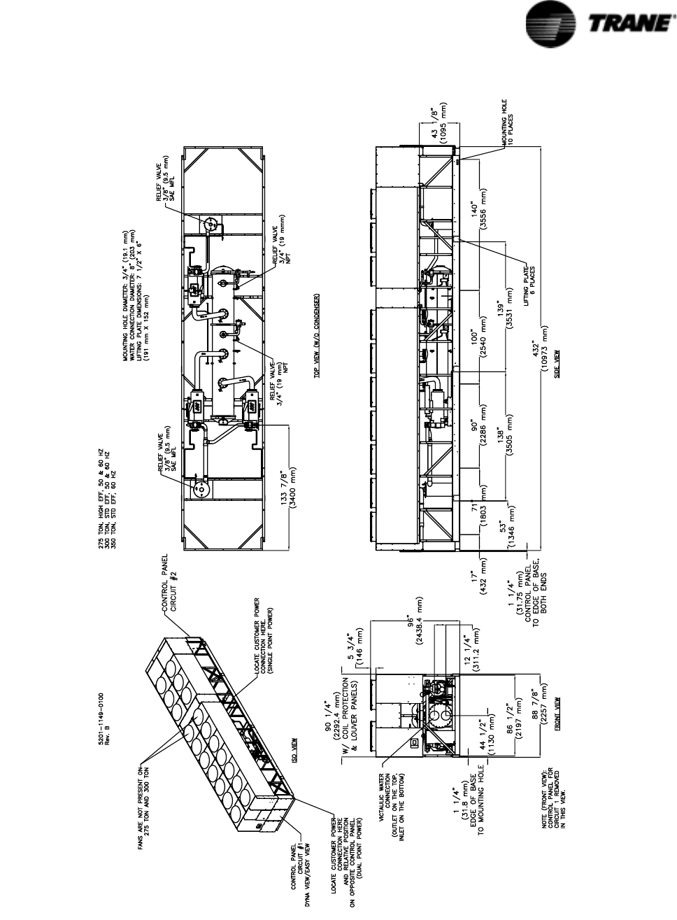
- Figure 7 Unit Dimensions 275 Ton High Efficiency, 50 and 60 Hz; 300 Ton, Standard Efficiency, 50 and 60 Hz and 350 Ton, Standard Efficiency 60 Hz
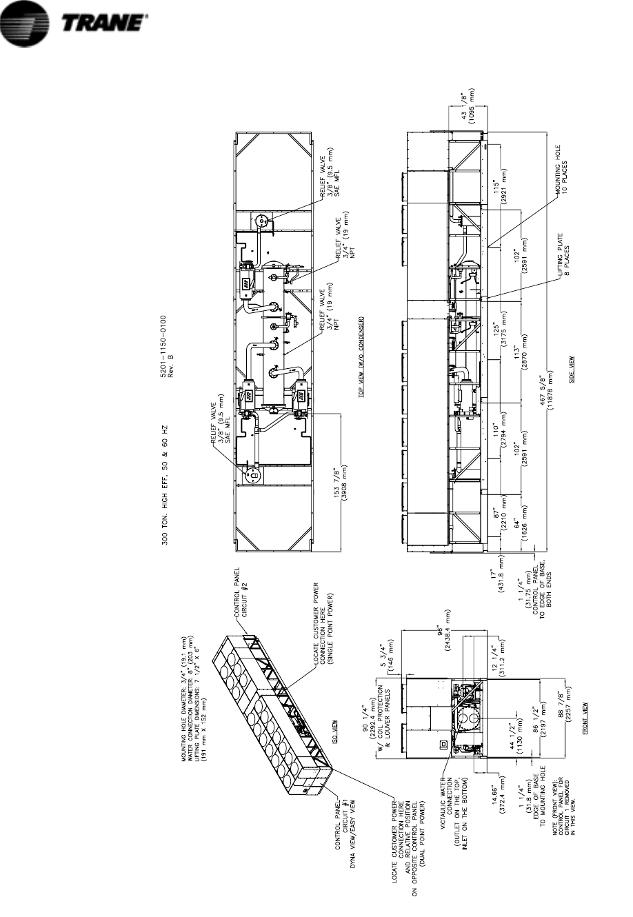
- Figure 8 Unit Dimensions 300 Ton High Efficiency, 50 and 60 Hz
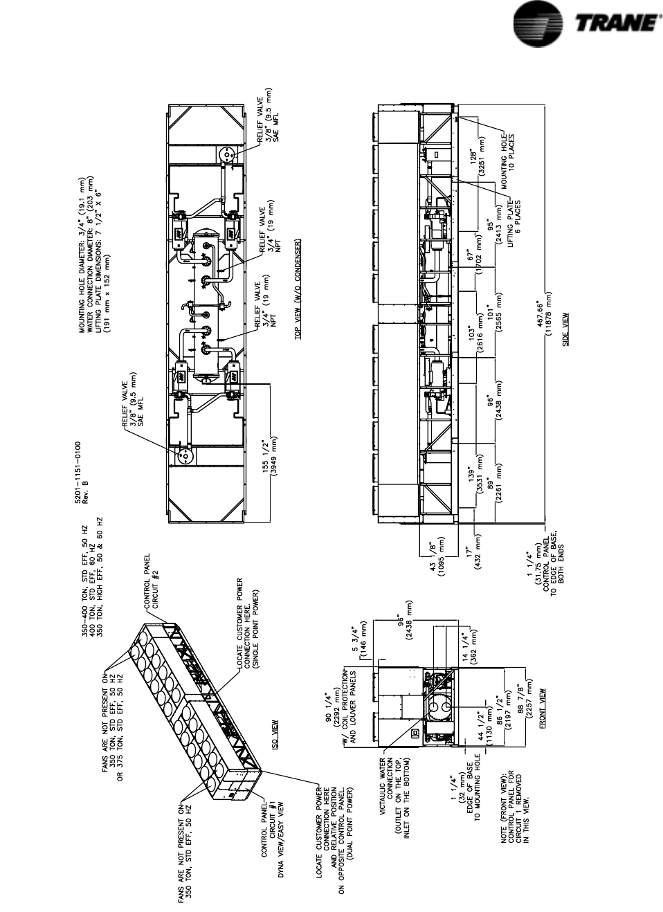
- Figure 9 Unit Dimensions 350-400 Ton Standard Efficiency, Hz and 400 Ton, Standard Efficiency, 60 Hz and 350 Ton High Efficiency, 50 and 60Hz
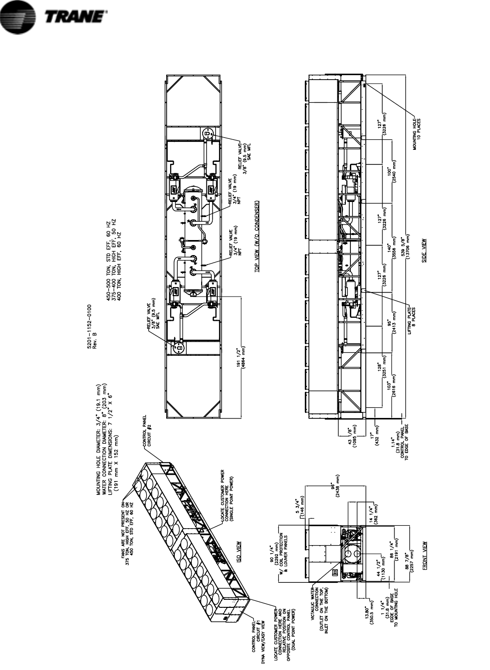
- Figure 10 Unit Dimensions 450-500 Ton Standard Efficiency, 60 Hz and 375-400 Ton, High Efficiency, 50 Hz and 400 Ton High Efficiency, 60 Hz
- Figure 11 Unit Dimensions of Condenser/Compressor Unit for Remote Evaporator Option
- Figure 12 Unit Dimensions for Remote Evaporator 140-170 Ton Standard Efficiency and 140 Ton High Efficiency
- Figure 13 Unit Dimensions for Remote Evaporator185-250 Ton Standard Efficiency and 155-200 Ton High Efficiency
- Installation Responsibilities
- Nameplates
- Outdoor Unit Nameplate
- Compressor Nameplate
- Setting the Unit
- Neoprene Isolator Installation
- Entering Chilled Water Piping
- Leaving Chilled Water Piping
- Evaporator Drain
- Evaporator Flow Switch
- Procedure
- Important
- Specials
- Liquid Line Sizing Steps
- Example Liquid Line Sizing
- Suction Line Sizing Steps
- Example Suction Line Sizing
- Example of Suction Accumulator Line Sizing
- Refrigerant Charge Determination
- Oil Charge Determination
- Power Supply Wiring
- Heater Power Supply and Convenience Outlet (Packaged Units Only)
- Chilled Water Flow (Pump) Interlock
- Chilled Water Pump Control
- Alarm and Status Relay Outputs (Programmable Relays)
- Relay Assignments Using TechView
- Emergency Stop
- External Auto/Stop
- External Circuit Lockout - Circuit #1 and Circuit #2
- Ice Building Option
- External Chilled Water Setpoint (ECWS) Option
- External Current Limit Setpoint (ECLS) Option
- Chilled Water Reset (CWR)
- Optional Tracer Communications Interface
- LonTalk Communications Interface for Chillers (LCI-C)
- Refrigeration Cycle
- Key Functions
- Radio Buttons
- Spin Value Buttons
- Action Buttons
- Hot Links
- File Folder Tabs
- Basic Screen Format
- Diagnostic Screen
- Units
- Languages
- Replacing or Adding Devices
- Instructions for First Time TechView Users
- Legend to Diagnostics Table
- Receiving
- Unit Location and Mounting
- Unit Piping
- Electrical Wiring
- General
- Unit Voltage Power Supply
- Unit Voltage Imbalance
- Unit Voltage Phasing
- Water System Flow Rates
- Water System Pressure Drop
- CH530 Set-Up
- Daily Unit Start-Up
- General
- Seasonal Unit Start-Up Procedure
- System Restart After Extended Shutdown
- Temporary Shutdown And Restart
- Extended Shutdown Procedure
- Weekly Maintenance
- R134a Field Charging Procedure
- Factory (initial) Refrigerant Charging Procedure
- Field Refrigerant Charging Procedure
- Adding charge:
- High side charge isolation procedure:
- Returning unit to running condition:
- Low side charge isolation procedure:
- Factory (initial) Oil Charging Procedure
January 2006 RTAC-SVX01F-EN
Installation
Operation
Maintenance
Preliminary
© American Standard Inc. 2006
Series R Air-Cooled Helical Rotary
Liquid Chillers
Models
RTAC 140-500 ton units (60 Hz)
RTAC 140-400 ton units (50 Hz)

2RTAC-SVX01F-EN
NOTICE: Warnings and Cautions appear at appropriate sections through-
out this literature. Read these carefully.
WARNING: Indicates a potentially hazardous situation which, if not
avoided, could result in death or serious injury.
CAUTION: Indicates a potentially hazardous situation which, if not
avoided, may result in minor or moderate injury. It may also be used to
alert against unsafe practices.
CAUTION: Indicates a situation that may result in equipment or property-
damage only accidents.
Important
Environmental Concerns!
Scientific research has shown that certain man-made chemicals can
affect the earth’s naturally occurring stratospheric ozone layer when
released to the atmosphere. In particular, several of the identified
chemicals that may affect the ozone layer are refrigerants that contain
Chlorine, Fluorine and Carbon (CFCs) and those containing Hydrogen,
Chlorine, Fluorine and Carbon (HCFCs). Not all refrigerants containing
these compounds have the same potential impact to the environment.
Trane advocates the responsible handling of all refrigerants—including
industry replacements for CFCs such as and HCFCs and HFCs.
Responsible Refrigerant Practices!
Trane believes that responsible refrigerant practices are important to the
environment, our customers, and the air conditioning industry. All
technicians who handle refrigerants must be certified. The Federal Clean
Air Act (Section 608) sets forth the requirements for handling,
reclaiming, recovering and recycling of certain refrigerants and the
equipment that is used in these service procedures. In addition, some
states or municipalities may have additional requirements that must
also be adhered to for responsible management of refrigerants. Know
the applicable laws and follow them.
WARNING
Contains Refrigerant!
System contains oil and refrigerant under high pressure. Recover
refrigerant to relieve pressure before opening the system. See unit
nameplate for refrigerant type. Do not use non-approved refrigerants,
refrigerant substitutes, or refrigerant additives.
Failure to follow proper procedures or the use of non-approved
refrigerants, refrigerant substitutes, or refrigerant additives could result
in death or serious injury or equipment damage.

RTAC-SVX01F-EN 3
Table of Contents
General Information............................................................................................. 7
Literature History.................................................................................................... 7
Unit Identification - Nameplates ............................................................................. 7
Unit Inspection ....................................................................................................... 8
Inspection Checklist ............................................................................................... 8
Loose Parts Inventory ............................................................................................ 8
Unit Description...................................................................................................... 8
Installation - Mechanical..................................................................................... 28
Installation Responsibilities ................................................................................... 28
Nameplates ........................................................................................................... 28
Outdoor Unit Nameplate ....................................................................................... 28
Compressor Nameplate ........................................................................................ 28
Storage .................................................................................................................. 29
General .................................................................................................................. 29
Location Requirements ......................................................................................... 29
Setting the Unit ..................................................................................................... 29
Isolation and Sound Emission ............................................................................... 36
Noise Considerations ............................................................................................ 37
Foundation............................................................................................................. 38
Clearances ............................................................................................................. 38
Unit Isolation and Leveling .................................................................................... 41
Neoprene Isolator Installation................................................................................ 41
Drainage ................................................................................................................ 41
Evaporator Water Piping........................................................................................ 41
Evaporator Piping .................................................................................................. 41
Entering Chilled Water Piping................................................................................ 42
Leaving Chilled Water Piping................................................................................. 42
Evaporator Drain.................................................................................................... 42
Evaporator Flow Switch......................................................................................... 42
Evaporator Water Pressure Drop RTAC 140 - 250 Ton ......................................... 43
Evaporator Water Pressure Drop RTAC 250 - 500 Ton ......................................... 44
Water Pressure Gauges ........................................................................................ 45
Water Pressure Relief Valves ................................................................................ 46
Freeze Protection .................................................................................................. 46
Low Evaporator Refrigerant Cutout and % Glycol Recommendations ................. 46
Procedure .............................................................................................................. 46
Important ............................................................................................................... 47
Specials ................................................................................................................. 47
Installation - Mechanical
Remote Evaporator Option ................................................................................ 49
Line Sizing ............................................................................................................. 53
Liquid Line Sizing Steps ........................................................................................ 54
Example Liquid Line Sizing.................................................................................... 55
Suction Line Sizing Steps ...................................................................................... 56
Example Suction Line Sizing.................................................................................. 56
Suction Accumulator Sizing................................................................................... 57
Example of Suction Accumulator Line Sizing ........................................................ 57
Piping Installation Procedures ............................................................................... 57
Refrigerant Sensors............................................................................................... 58
Refrigerant Pressure Relief Valve Venting............................................................. 58

4RTAC-SVX01F-EN
Table of Contents
Leak Test and Evacuation..................................................................................... 58
Refrigerant and Additional Oil Charge .................................................................. 60
Refrigerant Charge Determination........................................................................ 60
Oil Charge Determination ..................................................................................... 61
Installation - Electrical........................................................................................ 62
General Recommendations .................................................................................. 62
Installer-Supplied Components............................................................................. 75
Power Supply Wiring ............................................................................................ 75
Control Power Supply........................................................................................... 76
Heater Power Supply and Convenience Outlet (Packaged Units Only)................ 76
Water Pump Power Supply .................................................................................. 77
Interconnecting Wiring ......................................................................................... 77
Chilled Water Flow (Pump) Interlock .................................................................... 77
Chilled Water Pump Control ................................................................................. 77
Alarm and Status Relay Outputs (Programmable Relays)..................................... 78
Relay Assignments Using TechView.................................................................... 79
Low Voltage Wiring .............................................................................................. 79
Emergency Stop ................................................................................................... 79
External Auto/Stop................................................................................................ 80
External Circuit Lockout – Circuit #1 and Circuit #2.............................................. 80
Ice Building Option ............................................................................................... 80
External Chilled Water Setpoint (ECWS) Option................................................... 81
External Current Limit Setpoint (ECLS) Option..................................................... 81
Chilled Water Reset (CWR) .................................................................................. 82
Communications Interface options....................................................................... 84
Optional Tracer Communications Interface .......................................................... 84
LonTalk Communications Interface for Chillers (LCI-C) ........................................ 84
Operating Principles........................................................................................... 86
Refrigeration Cycle ............................................................................................... 86
Refrigerant R134a................................................................................................. 88
Compressor .......................................................................................................... 88
Condenser and Subcooler .................................................................................... 88
Expansion Valve.................................................................................................... 89
Evaporator ............................................................................................................ 89
Oil System ............................................................................................................ 89
Controls Interface ............................................................................................... 91
CH530 Communications Overview ...................................................................... 91
Controls Interface ................................................................................................. 91
DynaView Interface .............................................................................................. 91
Key Functions ....................................................................................................... 92
Radio Buttons ....................................................................................................... 92
Spin Value Buttons ............................................................................................... 92
Action Buttons...................................................................................................... 92
Hot Links .............................................................................................................. 92
File Folder Tabs .................................................................................................... 92
Display Screens .................................................................................................... 93
Basic Screen Format ............................................................................................ 93
Front Panel Lockout Feature ................................................................................ 94
Front Panel Display During Cold Ambients........................................................... 94

RTAC-SVX01F-EN 5
Table of Contents
Modes Screen ....................................................................................................... 95
Chiller Screen ....................................................................................................... 101
Compressor Screen.............................................................................................. 101
Refrigerant Screen ............................................................................................... 102
Setpoint Screen.................................................................................................... 103
Diagnostic Screen ................................................................................................ 104
Power-Up ............................................................................................................. 105
Display Formats.................................................................................................... 105
Units ..................................................................................................................... 105
Languages ............................................................................................................ 105
TechView ............................................................................................................ 106
Minimum PC requirements to install and operate TechView ............................... 107
Unit View .............................................................................................................. 107
Compressor Service View .................................................................................... 109
Status View .......................................................................................................... 110
Setpoint View ....................................................................................................... 113
Diagnostics View.................................................................................................. 117
Software View ...................................................................................................... 122
Binding View ........................................................................................................ 123
Replacing or Adding Devices................................................................................ 124
Software Download.............................................................................................. 124
Instructions for First Time TechView Users ......................................................... 124
Diagnostics ......................................................................................................... 126
Legend to Diagnostics Table ................................................................................ 126
Pre-Start Checkout ............................................................................................. 137
Installation Checklist............................................................................................. 137
Receiving .............................................................................................................. 137
Unit Location and Mounting ................................................................................. 137
Unit Piping ............................................................................................................ 137
Electrical Wiring.................................................................................................... 138
General ................................................................................................................. 139
Unit Voltage Power Supply................................................................................... 140
Unit Voltage Imbalance ........................................................................................ 141
Unit Voltage Phasing ............................................................................................ 141
Water System Flow Rates.................................................................................... 142
Water System Pressure Drop............................................................................... 142
CH530 Set-Up ...................................................................................................... 143
Unit Start-Up Procedures .................................................................................. 144
Daily Unit Start-Up................................................................................................ 144
General ................................................................................................................. 144
Seasonal Unit Start-Up Procedure........................................................................ 145
System Restart After Extended Shutdown .......................................................... 146
Unit Shutdown Procedures ............................................................................... 147
Temporary Shutdown And Restart....................................................................... 147
Extended Shutdown Procedure ........................................................................... 147

6RTAC-SVX01F-EN
Table of Contents
Periodic Maintenance........................................................................................ 149
Weekly Maintenance........................................................................................... 149
Maintenance Procedures .................................................................................. 155
Refrigerant and Oil Charge Management ............................................................ 155
R134a Field Charging Procedure ......................................................................... 156
Factory (initial) Refrigerant Charging Procedure .................................................. 156
Field Refrigerant Charging Procedure.................................................................. 156
Adding charge:..................................................................................................... 157
Charge Isolation in the high or low side of system.............................................. 157
High side charge isolation procedure: ................................................................. 157
Returning unit to running condition: .................................................................... 158
Low side charge isolation procedure: .................................................................. 158
Refrigerant Filter Replacement Procedure .......................................................... 159
Lubrication System.............................................................................................. 159
Oil Charging Procedure........................................................................................ 159
Factory (initial) Oil Charging Procedure................................................................ 161
Evaporator tube replacement .............................................................................. 163
Compressor Replacement ................................................................................... 163
Unit Wiring ......................................................................................................... 165
RTAC-SVX01F-EN 7
General Information
Literature History
RTAC-SVX001-EN (December 2000)
New manual.
RTAC-SVX01B-EN (September 2001)
New manual describes installation, operation, and maintenance of RTAC units and the
remote evaporator option.
RTAC-SVX01C-EN (February 2002)
Revised manual includes additional RTAC units to size 500 tons, new installation and
maintenance material, and expanded CH530 diagnostics.
RTAC-SVX01D-EN (July 2003)
Revised manual for new evaporator design for 2 compressor units. Design Sequence
H0 and later.
RTAC-SVX01E-EN (July 2004)
Revised manual for new evaporator design for 3 and 4 compressor units. Design
Sequence J0 and later.
RTAC-SVX01F-EN (January 2006)
Revised manual for new control panel design.
Unit Identification - Nameplates
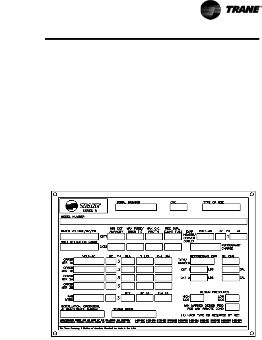
When the unit arrives, compare all nameplate data with ordering, submittal, and ship-
ping information. A typical unit nameplate is shown in Figure 1.
Figure 1 Typical Unit Nameplate

8RTAC-SVX01F-EN
General information
Unit Inspection
When the unit is delivered, verify that it is the correct unit and that it is properly
equipped. Compare the information which appears on the unit nameplate with the
ordering and submittal information.
Inspect all exterior components for visible damage. Report any apparent damage or
material shortage to the carrier and make a “unit damage” notation on the carrier’s
delivery receipt. Specify the extent and type of damage found and notify the appropri-
ate Trane Sales Office. Do not proceed with installation of a damaged unit without
sales office approval.
Inspection Checklist
To protect against loss due to damage incurred in transit, complete the following
checklist upon receipt of the unit.
• Inspect the individual pieces of the shipment before accepting the unit. Check for
obvious damage to the unit or packing material.
• Inspect the unit for concealed damage as soon as possible after delivery and
before it is stored. Concealed damage must be reported within 15 days.
• If concealed damage is discovered, stop unpacking the shipment. Do not remove
damaged material from the receiving location. Take photos of the damage, if pos-
sible. The owner must provide reasonable evidence that the damage did not
occur after delivery.
• Notify the carrier’s terminal of the damage immediately, by phone and by mail.
Request an immediate, joint inspection of the damage with the carrier and the
consignee.
• Notify the Trane sales representative and arrange for repair. Do not repair the unit,
however, until damage is inspected by the carrier’s representative.
Loose Parts Inventory
Check all the accessories and loose parts which are shipped with the unit against the
shipping list. Included in these items will be water vessel drain plugs, rigging and
electrical diagrams, and service literature, which are placed inside the control panel
and/or starter panel for shipment.
Unit Description
The 140 - 500 ton Model RTAC units are helical-rotary type, air-cooled liquid chillers
designed for installation outdoors. The compressor circuits are completely assem-
bled, hermetic packages that are factory-piped, wired, leak-tested, dehydrated, and
tested for proper control operation before shipment.
NOTE: Packaged units are factory charged with refrigerant and oil.
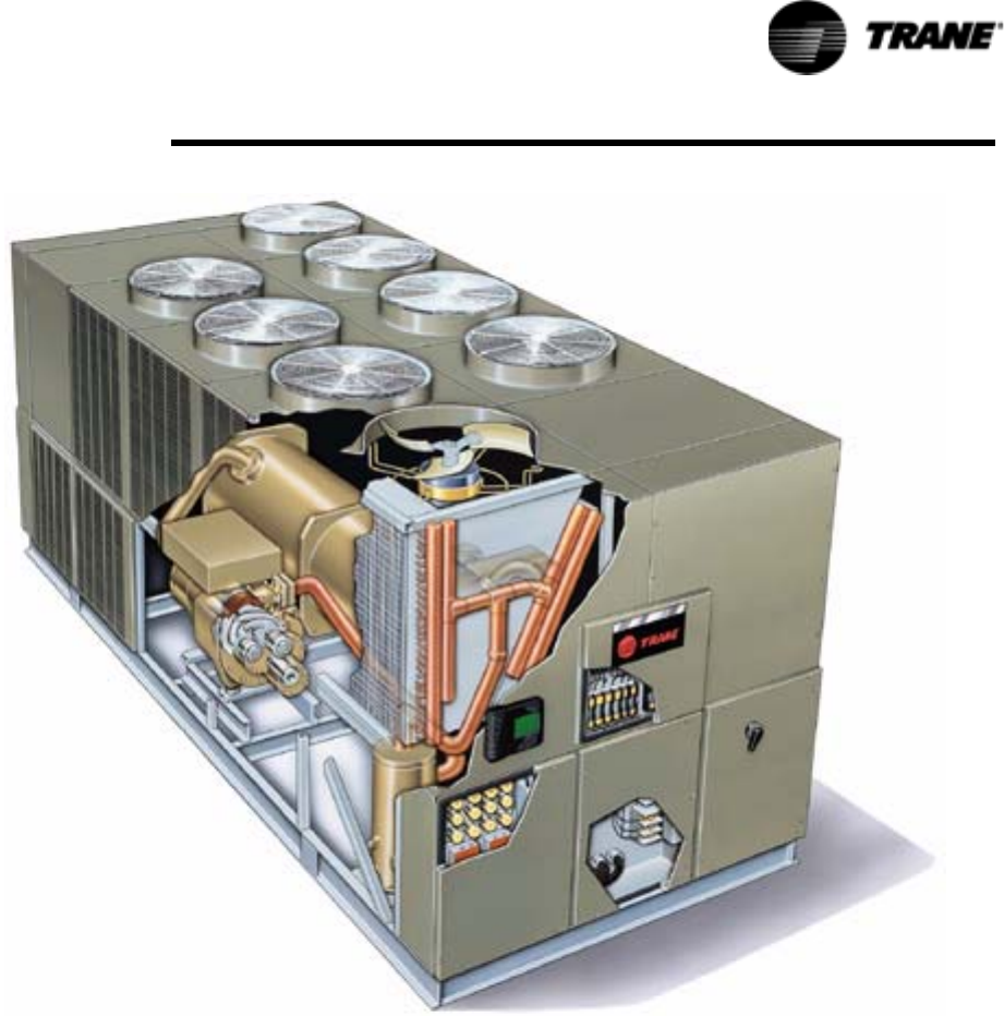
Figure 2 shows a typical RTAC packaged unit and its components.
Table 1 through Table 5 contain general RTAC mechanical specifications for all unit
sizes.
RTAC-SVX01F-EN 9
General Information
.
Chilled water inlet and outlet openings are covered for shipment. Each compressor
has a separate compressor motor starter. The RTAC series features Trane’s exclusive
Adaptive Control ™ logic, which monitors the control variables that govern the opera-
tion of the chiller unit. Adaptive Control logic can adjust capacity variables to avoid
chiller shutdown when necessary, and keep producing chilled water. The units feature
two independent refrigerant circuits. Compressor unloaders are solenoid actuated
and oil pressure operated. Each refrigerant circuit is provided with filter, sight glass,
electronic expansion valve, and charging valves. The shell-and-tube type evaporator is
manufactured in accordance with ASME standards or other international codes. Each
evaporator is fully insulated and is equipped with water drain and vent connections.
Packaged units have heat tape protection to - 20°F (-28.9°C) as standard. As an
option, a convenience outlet can be supplied.
Figure 2 Typical RTAC Unit

10 RTAC-SVX01F-EN
General information
Table 1 General Data — 140-250 Ton 60 Hz Units - Standard Efficiency
Size 140 155 170 185 200 225 250
Type STD STD STD STD STD STD STD
Compressor
Quantity 2 2 2 2 2 2 2
Nominal
Size
(tons) 70/70 85/70 85/85 100/85 100/100 120/100 120/120
Evaporator
Water Storage (gallons) 29 32 33 35 39 38 42
(liters) 111 121 127 134 146 145 158
Min. Flow (gpm) 193 214 202 217 241 217 241
(l/sec) 12 14 13 14 15 14 15
Max. Flow (gpm) 709 785 741 796 883 796 883
(l/sec) 45 50 47 50 56 50 56
Condenser
Quantity of Coils 4 4 4 4 4 4 4
Coil Length (inches) 156/156 180/156 180/180 216/180 216/216 252/216 252/252
(mm) 3962/3962 4572/3962 4572/4572 5486/4572 5486/5486 6401/5486 6401/6401
Coil Height (inches) 42 42 42 42 42 42 42
(mm) 1067 1067 1067 1067 1067 1067 1067
Fins/Ft 192 192 192 192 192 192 192
Number of Rows 3 3 3 3 3 3 3
Condenser Fans
Quantity 4/4 5/4 5/5 6/5 6/6 7/6 7/7
Diameter (inches) 30 30 30 30 30 30 30
(mm) 762 762 762 762 762 762 762
Total Airflow (cfm) 77000 84542 92087 101296 110506 119725 128946
(m3/hr) 130811 143623 156441 172086 187732 203394 219059
Nominal Fan
Speed
(rpm) 1140 1140 1140 1140 1140 1140 1140
(rps) 19 19 19 19 19 19 19
Tip Speed (ft/min) 8954 8954 8954 8954 8954 8954 8954
(m/s) 45 45 45 45 45 45 45
Min Starting/Operating Ambient
Std Unit (Deg F) 25 25 25 25 25 25 25
(Deg C) -3.9 -3.9 -3.9 -3.9 -3.9 -3.9 -3.9
Low Ambient (Deg F) 0.0 0.0 0.0 0.0 0,0 0.0 0.0
(Deg C) -17.8 -17.8 -17.8 -17.8 -17.8 -17.8 -17.8
General Unit
Refrigerant HFC-134a HFC-134a HFC-134a HFC-134a HFC-134a HFC-134a HFC-134a
No. of Independent
Refrigerant Circuits
22 22222
% Min. load 15 15 15 15 15 15 15
Refrigerant
Charge
(lb) 165/165 175/165 175/175 215/210 215/215 225/215 225/225
(kg) 75/75 79/75 79/79 98/95 98/98 102/98 102/102
Oil Charge (gallons) 1.5/1.5 1.5/1.5 1.5/1.5 2.1/1.5 2.1/2.1 2.1/2.1 2.1/2.1
(liters) 6/6 6/6 6/6 8/6 8/8 8/8 8/8
Base Length (feet) 15 15 15 18 18 21 21
1. Data containing information on two circuits shown as follows: CKT1/CKT 2.
2. Minimum start-up/operating ambient based on a 5 mph wind across the condenser.

RTAC-SVX01F-EN 11
General Information
Table 2 General Data — 275- 500 Ton 60 Hz Units - Standard Efficiency
Size 275 300 350 400 450 500
Type STD STD STD STD STD STD
Compressor
Quantity 3 3 3 4 4 4
Nominal
Size
(tons) 85/85
100
100/100
100
120/120
100
100/100
100/100
120/120
100/100
120/120
120/120
Evaporator
Water Storage (gallons) 60 65 70 81 84 89
(liters) 229 245 264 306 316 337
Min. Flow (gpm) 309 339 375 404 422 461
(l/sec) 20 21 24 26 27 29
Max. Flow (gpm) 1134 1243 1374 1483 1548 1690
(l/sec) 72 78 87 94 98 107
Condenser
Quantity of Coils 8 8 8 8 8 8
Coil Length (inches) 180/108 216/108 252/108 216/216 252/216 252/252
(mm) 4572/2743 5486/2743 6401/4572 5486/5486 6401/5486 6401/6401
Coil Height (inches) 42 42 42 42 42 42
(mm) 1067 1067 1067 1067 1067 1067
Fins/Ft 192 192 192 192 192 192
Number of Rows 3 3 3 3 3 3
Condenser Fans
Quantity 10/6 12/6 14/6 12/12 14/12 14/14
Diameter (inches) 30 30 30 30 30 30
(mm) 762 762 762 762 762 762
Total Airflow (cfm) 147340 165766 184151 221016 239456 257991
(m3/hr) 250307 281610 312843 375471 406797 438285
Nominal Fan Speed (rpm) 1140 1140 1140 1140 1140 1140
(rps) 19 19 19 19 19 19
Tip Speed (ft/min) 8954 8954 8954 8954 8954 8954
(m/s) 45 45 45 45 45 45
Min Starting/Oper Ambient
Std Unit (Deg F) 25 25 25 25 25 25
(Deg C) -3.9 -3.9 -3.9 -3.9 -3.9 -3.9
Low Ambient (Deg F) 0.0 0.0 0.0 0.0 0.0 0.0
(Deg C) -17.8 -17.8 -17.8 -17.8 -17.8 -17.8
General Unit
Refrigerant HFC-134a HFC-134a HFC-134a HFC-134a HFC-134a HFC-134a
No. of Independent
Refrigerant Circuits
222222
% Min. load 15 15 15 15 15 15
Refrigerant Charge (lb) 365/200 415/200 460/200 415/415 460/415 460/460
(kg) 166/91 188/91 209/91 188/188 209/188 209/209
Oil Charge (gallons) 4.6/2.1 5.0/2.1 5.0/2.1 5.0/5.0 5.0/5.0 5.0/5.0
(liters) 17.4/8 19/8 19/8 19/19 19/19 19/19
Base Length (feet) 30 36 36 39 45 45
1. Data containing information on two circuits shown as follows: CKT1/CKT 2.
2. Minimum start-up/operating ambient based on a 5 mph wind across the condenser.

12 RTAC-SVX01F-EN
General information
Table 3 General Data — 140-400 Ton 60 Hz Units - High Efficiency
Size 140 155 170 185 200 225 250 275 300 350 400
Type HIGH HIGH HIGH HIGH HIGH HIGH HIGH HIGH HIGH HIGH HIGH
Compressor
Quantity 22222223344
Nominal
Size
(tons) 70/70 85/70 85/85 100/85 100/100 120/100 120/120 85/85
100
100/100
100
85/85
85/85
100/100
100/100
Evaporator
Water
Storage
(gallons)3335393842424270708189
(liters) 127 134 146 145 158 158 158 264 264 306 337
Min. Flow (gpm) 202 217 241 217 241 241 241 375 375 404 461
(l/sec)1314151415151524242629
Max. Flow (gpm) 741 796 883 796 883 883 883 1374 1374 1483 1690
(l/sec) 47 50 56 50 56 56 56 87 87 94 107
Condenser
Quantity of
Coils
44444888888
Coil Length (inches) 180/180 216/180 216/216 252/216 252//252 144/144 180/108 216/144 252/144 216/216 252/252
(mm) 4572/
4572
5486/
4572
5486/
5486
6401/
5486
6401/
6401
3658/
3658
4572/
2743
5486/
3658
6401/
3658
5486/
5486
6401/
6401
Coil Height (inches)4242424242424242424242
(mm) 1067 1067 1067 1067 1067 1067 1067 1067 1067 1067 1067
Fins/Ft 192 192 192 192 192 192 192 192 192 192 192
Number of Rows33333333333
Condenser Fans
Quantity 5/5 6/5 6/6 7/6 7/7 8/6 8/8 12/6 14/6 12/12 14/14
Diameter (inches)3030303030303030303030
(mm) 762 762 762 762 762 762 762 762 762 762 762
Tot al
Airflow
(cfm) 91993 101190 110387 119598 128812 136958 147242 173733 192098 220778 257626
(m3/hr) 156281 171906 187530 203178 218831 232670 250141 295145 326344 375066 437665
Nominal
Fan Speed
(rpm) 1140 1140 1140 1140 1140 1140 1140 1140 1140 1140 1140
(rps)1919191919191919191919
Tip Speed (ft/min) 8954 8954 8954 8954 8954 8954 8954 8954 8954 8954 8954
(m/s)4545454545454545454545
Min Starting/Oper Ambient
Std Unit (Deg F) 25 25 25 25 25 25 25 25 25 25 25
(Deg C) -3.9 -3.9 -3.9 -3.9 -3.9 -3.9 -3.9 -3.9 -3.9 -3.9 -3.9
Low
Ambient
(Deg F) 0.0 0.0 0.0 0.0 0.0 0.0 0.0 0.0 0.0 0.0 0.0
(Deg C) -17.8 -17.8 -17.8 -17.8 -17.8 -17.8 -17.8 -17.8 -17.8 -17.8 -17.8
General Unit
Refrigerant HFC-134a HFC-134a HFC-134a HFC-134a HFC-134a HFC-134a HFC-134a HFC-134a HFC-134a HFC-134a HFC-134a
No. of Independent
Refrigerant Circuits
22222222222
% Min. load 15 15 15 15 15 15 15 15 15 15 15
Refrigerant
Charge
(lb) 175/175 215/205 215/215 225/215 225/225 235/235 235/235 415/200 460/200 415/415 460/460
(kg) 79/79 98/93 98/98 102/98 102/102 107/107 107/107 188/91 209/91 188/188 209/209
Oil Charge (gallons) 1.5/1.5 1.5/1.5 1.5/1.5 2.1/1.5 2.1/2.1 2.1/2.1 2.1/2.1 4.6/2.2 5.0/2.2 4.6/4.6 5.0/5.0
(liters) 6/6 6/6 6/6 8/6 8/8 8/8 8/8 17/8 19/8 17/17 19/19
Base
Length
(feet) 15 18 18 21 21 30 30 36 39 39 45
1. Data containing information on two circuits shown as follows: CKT 1/CKT 2
2. Minimum start-up/operating ambient based on a 5 mph wind across the condenser

RTAC-SVX01F-EN 13
General Information
Table 4 General Data - 120-400 Ton 50 Hz Units-Standard Efficiency
Size 140 155 170 185 200 250 275 300 350 375 400
Type STD STD STD STD STD STD STD STD STD STD STD
Compressor
Quantity 22222333444
Nominal
Size
(tons) 70/70 85/70 85/85 100/85 100/100 70-70/100 85-85/100 100-100/
100
85-85/85-
85
100-100/
85-85
100-100/
100-100
Evaporator
Water
Storage
(gallons)29 32 33 35 38 546064737780
(liters) 110 120 126 133 145 203 227 243 275 291 304
Min. Flow (gpm) 192 221 200 215 239 262 307 336 384 377 401
(l/sec)1213131415171921222425
Max. Flow (gpm) 702 778 735 789 875 962 1124 1232 1275 1383 1470
(l/sec) 44 49 46 50 55 61 72 78 80 87 93
Condenser
Quantity of
Coils
44444888888
Coil Length (inches) 156/156 180/156 180/180 216/180 216/216 156/108 180/108 216/108 180/180 216/180 252/216
(mm) 3962/
3962
4512/
3962
4572/
4512
5486/
4572
5486/
5486
3962/
4512
4572/
2743
5486/
2743
4572/
4572
5486/
4572
6401/
5486
Coil Height (inches) 42 42 42 42 42 42 42 42 42 42 42
(mm) 1067 1067 1067 1067 1067 1067 1067 1067 1067 1067 1067
Fins/Ft 192 192 192 192 192 192 192 192 192 192 192
Number of Rows33333333333
Condenser Fans
Quantity 4/4 5/4 5/5 6/5 6/6 8/6 10/6 12/6 10/10 12/10 12/12
Diameter (inches) 30 30 30 30 30 30 30 30 30 30 30
(mm) 762 762 762 762 762 762 762 762 762 762 762
To t al
Airflow
(cfm) 63346 69507 75671 83236 90803 108698 121056 136210 151332 166467 181611
(m3/hr) 107615 118081 128553 141405 154260 184661 205655 231399 257089 282801 308528
Nominal
Fan Speed
(rpm) 950 950 950 950 950 950 950 950 950 950 950
(rps) 15.8 15.8 15.8 15.8 15.8 15.8 15.8 15.8 15.8 15.8 15.8
Tip Speed (ft/min) 7461 7461 7461 7461 7461 7461 7461 7451 7461 7461 7461
(m/s)38 38 38 38 38 383838383838
Min Starting/Oper Ambient
Std Unit (Deg F) 25 25 25 25 25 25 25 25 25 25 25
(Deg C) -3.9 -3.9 -3.9 -3.9 -3.9 -3.9 -3.9 -3.9 -3.9 -3.9 -3.9
Low
Ambient
(Deg F)00000000000
(Deg C) -17.8 -17.8 -17.8 -17.8 -17.8 -17.8 -17.8 -17.8 -17.8 -17.8 -17.8
General Unit
Refrigerant HFC-134a HFC-134a HFC-134a HFC-134a HFC-134a HFC-134a HFC-134a HFC-134a HFC-134a HFC-134a HFC-134a
No. of Independent
Refrigerant Circuits
22222222222
% Min. load 15 15 15 15 15 15 15 15 15 15 15
Refrigerant
Charge
(lb) 165/165 175/165 175/175 215/210 215/215 335/200 365/200 415/200 365/365 415/365 415/415
(kg) 75/75 79/75 79/79 98/95 98/98 152/91 166/91 188/91 166/166 188/166 188/188
Oil
Charge
(gallons) 1.5/1.5 1.5/1.5 1.5/1.5 2.1/1.5 2.1/2.1 4.6/2.1 4.6/2.1 5.0/2.1 4.6/4.6 5.0/4.6 5.0/5.0
(liters) 6/6 6/6 6/6 8/6 8/8 17.4/8 17.4/8 19.0/8 17.4/17.4 19.0/17.4 19.0/19.0
Base
Length
(feet)15 15 15 18 18 303036393939
1. Data containing information on two circuits shown as follows: CKT 1/CKT 2
2. Minimum start-up/operating ambient based on a 5 mph wind across the condenser
14 RTAC-SVX01F-EN
General information
Table 5 General Data - 120-400 Ton 50 Hz Units-High Efficiency
Size 140 155 170 185 200 250 275 300 350 375 400
Type HIGH HIGH HIGH HIGH HIGH HIGH HIGH HIGH HIGH HIGH HIGH
Compressor
Quantity 2 2 2 2 2 3 3 3 4 4 4
Nominal Size (tons) 70/70 85/70 85/85 100/85 100/100 70-70/
100
85-85/
100
100-100/
100
85-85/
85-85
100-100/
85-85
100-100/
100-100
Evaporator
Water
Storage
(gallons)33 353838416469 6980 83 89
(liters) 126 133 145 145 157 243 262 262 304 314 335
Min. Flow (gpm) 200 215 239 215 239 336 371 371 401 419 457
(l/sec) 13 14 15 14 15 21 23 23 25 26 29
Max. Flow (gpm) 735 789 875 789 875 1232 1362 1362 1470 1535 1675
(l/sec) 46 50 55 50 55 78 86 86 93 97 106
Condenser
Qty of Coils 4 444488 88 8 8
Coil Length (inches) 180/180 216/180 216/216 252/216 252/252 180/108 216/144 252/144 216/216 252/216 252/252
(mm) 4572/
4572
5486/
4572
5486/
5486
6401/
5486
6401/
6401
4572/
2743
5486/3658 6401/
3658
5486/5486 6401/5486 6401/
6401
Coil Height (inches) 42 42 42 42 42 42 42 42 42 42 42
(mm) 1067 1067 1067 1067 1067 1067 1067 1067 1067 1067 1067
Fins/Ft 192 192 192 192 192 192 192 192 192 192 192
Number of Rows 3 3 3 3 3 3 3 3 3 3 3
Condenser Fans
Quantity 5/5 6/5 6/6 7/6 7/7 10/6 12/6 14/6 12/12 14/12 14/14
Diameter in. (mm) 30 (762) 30 (762) 30 (762) 30 (762) 30 (762) 30 (762) 30 (762) 30 (762) 30 (762) 30 (762) 30 (762)
Total Airflow (cfm) 75575 83130 90687 98256 105826 120971 142969 158112 181371 194731 211648
(m3/hr) 128390 141225 154063 166921 179781 205510 242881 268607 308120 330817 359556
Nominal Fan
Speed
(rpm) 950 950 950 950 950 950 950 950 950 950 950
(rps) 15.8 15.8 15.8 15.8 15.8 15.8 15.8 15.8 15.8 15.8 15.8
Tip Speed (ft/min) 7461 7461 7461 7461 7461 7461 7461 7461 7461 7461 7461
(m/s) 38 38 38 38 38 38 38 38 38 38 38
Min Starting/Oper Ambient
Std Unit Deg F
(C)
25 (-3.9) 25 (-3.9) 25 (-3.9) 25 (-3.9) 25 (-3.9) 25 (-3.9) 25 (-3.9) 25 (-3.9) 25 (-3.9) 25 (-3.9) 25 (-3.9)
Low
Ambient
Deg F
(C)
0 (-17.8) 0 (-17.8) 0 (-17.8) 0 (-17.8) 0 (-17.8) 0 (-17.8) 0 (-17.8) 0 (-17.8) 0 (-17.8) 0 (-17.8) 0 (-17.8)
General Unit
Refrigerant HFC-134a HFC-134a HFC-134a HFC-134a HFC-134a HFC-134a HFC-134a HFC-134a HFC-134a HFC-134a HFC-134a
No. of Independent
Refrigerant Circuits
22222222222
% Min. load 15 15 15 15 15 15 15 15 15 15 15
Refrigerant
Charge
(lb) 175/175 215/205 215/215 225/215 225/225 365/200 415/200 460/200 415/415 460/415 460/460
(kg) 79/79 98/93 98/98 102/98 102/102 166/91 188/91 209/91 188/188 209/188 209/209
Oil Charge (gallons) 1.5/1.5 1.5/1.5 1.5/1.5 2.1/1.5 2.1/2.1 4.6/2.1 4.6/2.1 5.0/2.1 4.6/4.6 5.0/5.0 5.0/5.0
(liters) 6/6 6/6 6/6 8/6 8/8 17.4/8 17.4/8 19.0/8 17.4/17.4 19.0/19.0 19.0/19.0
Base Length (feet) 15 18 18 21 21 30 36 39 39 45 45
1. Data containing information on two circuits shown as follows CKT 1/CKT 2
2. Minimum start-up/operating ambient based on a 5 mph wind across the condenser
RTAC-SVX01F-EN 15
General Information
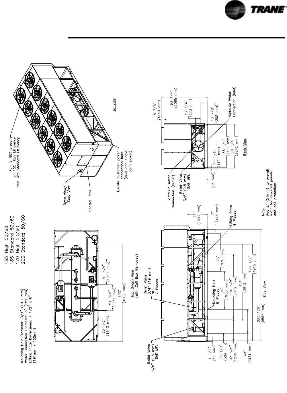
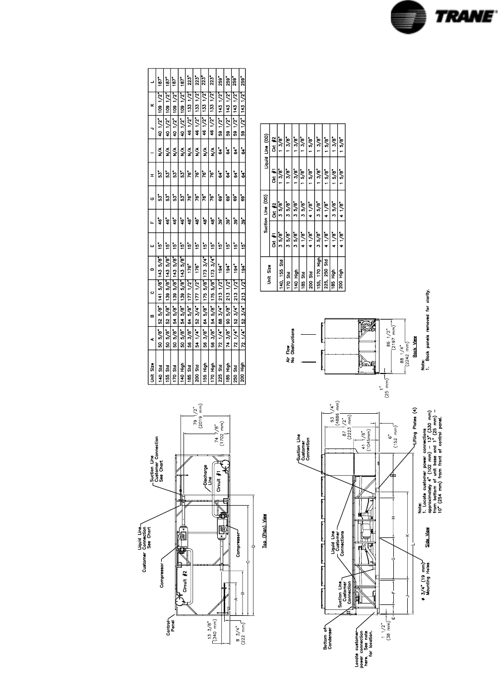
Figure 3 Unit Dimensions 185-200 Ton Standard Efficiency, 60 Hz and 155, 170 Ton, High Efficiency, 50 and 60 Hz
16 RTAC-SVX01F-EN
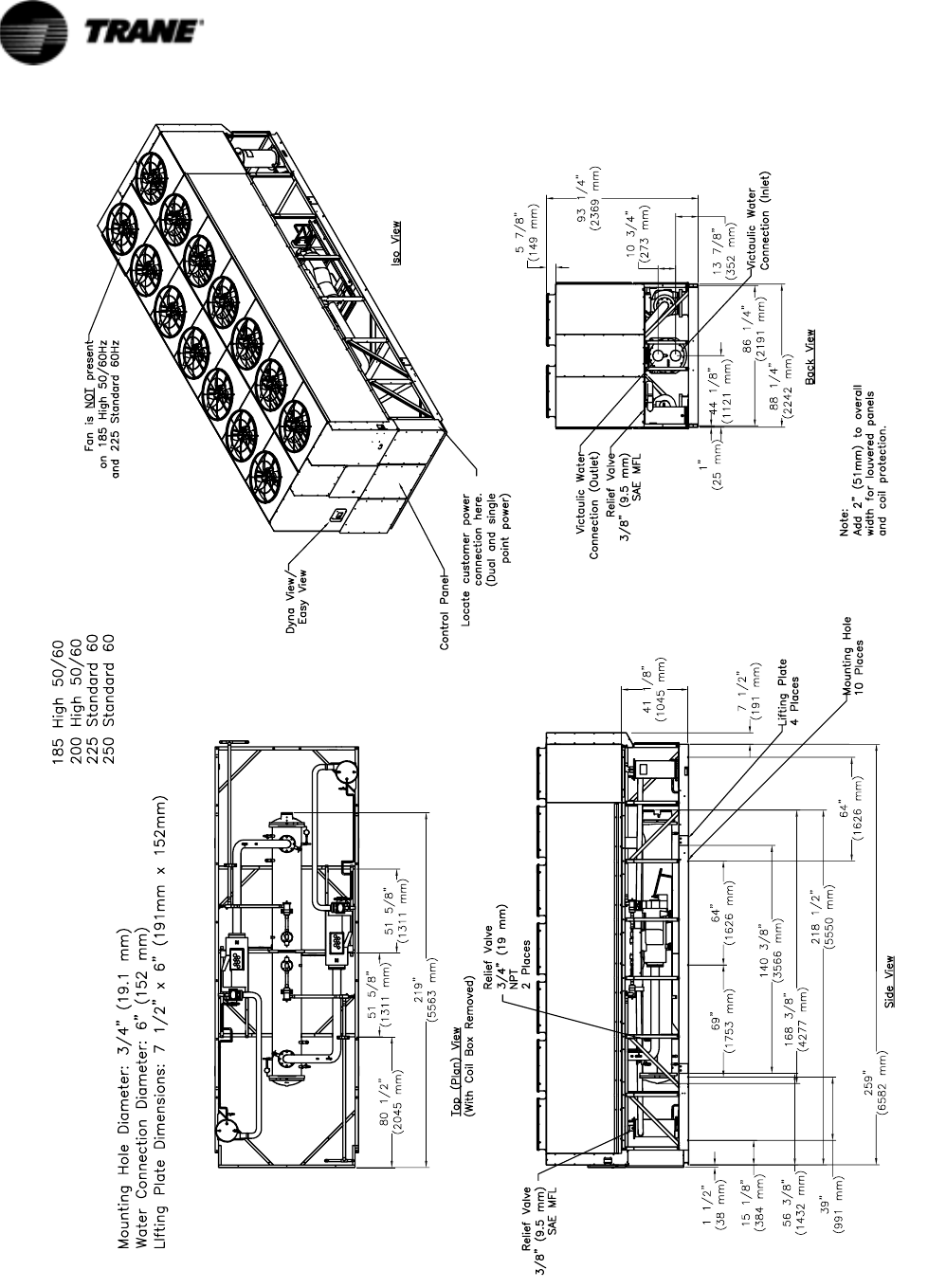
Figure 4 Unit Dimensions 225-250 Ton Standard Efficiency, 60 Hz and 185-200 Ton, High Efficiency, 50 and 60 Hz
RTAC-SVX01F-EN 17
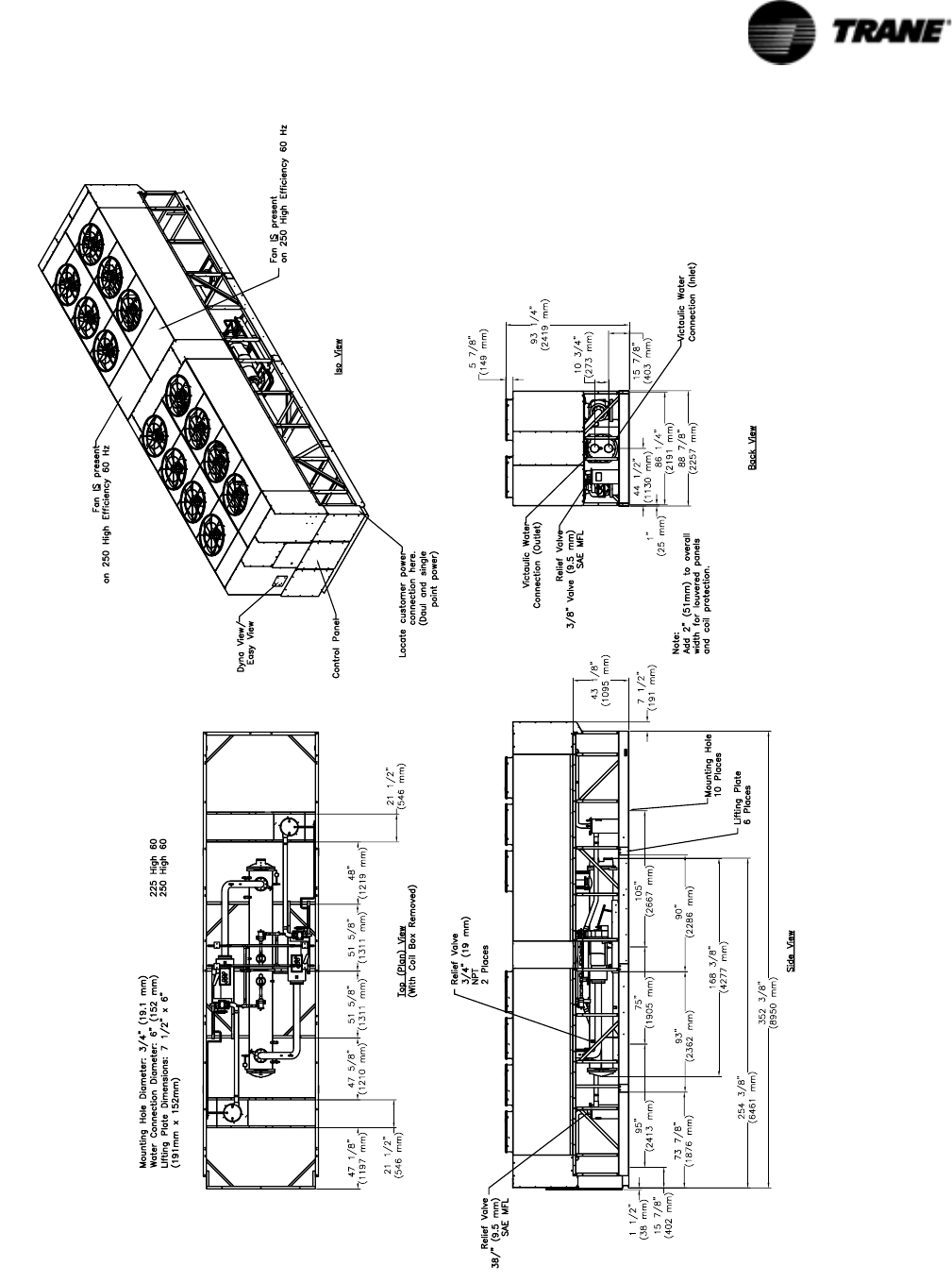
Figure 5 Unit Dimensions 225-250 Ton High Efficiency, 60 Hz
18 RTAC-SVX01F-EN
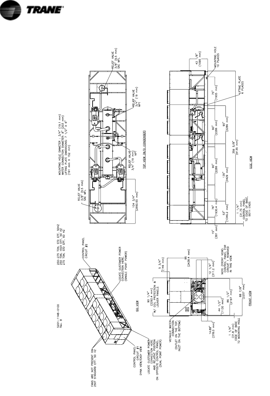
Figure 6 Unit Dimensions 250-275 Ton Standard Efficiency, 50 Hz and 250 Ton High Efficiency, 50 Hz and 275 Ton
Standard Efficiency, 60 Hz
RTAC-SVX01F-EN 19
Figure 7 Unit Dimensions 275 Ton High Efficiency, 50 and 60 Hz; 300 Ton, Standard Efficiency, 50 and 60 Hz and 350
Ton, Standard Efficiency 60 Hz
20 RTAC-SVX01F-EN
Figure 8 Unit Dimensions 300 Ton High Efficiency, 50 and 60 Hz
RTAC-SVX01F-EN 21
Figure 9 Unit Dimensions 350-400 Ton Standard Efficiency, Hz and 400 Ton, Standard Efficiency, 60 Hz and 350 Ton
High Efficiency, 50 and 60Hz
22 RTAC-SVX01F-EN
Figure 10 Unit Dimensions 450-500 Ton Standard Efficiency, 60 Hz and 375-400 Ton, High Efficiency, 50 Hz and 400 Ton
High Efficiency, 60 Hz
RTAC-SVX01F-EN 23
Figure 11 Unit Dimensions of Condenser/Compressor Unit for Remote Evaporator Option
24 RTAC-SVX01F-EN
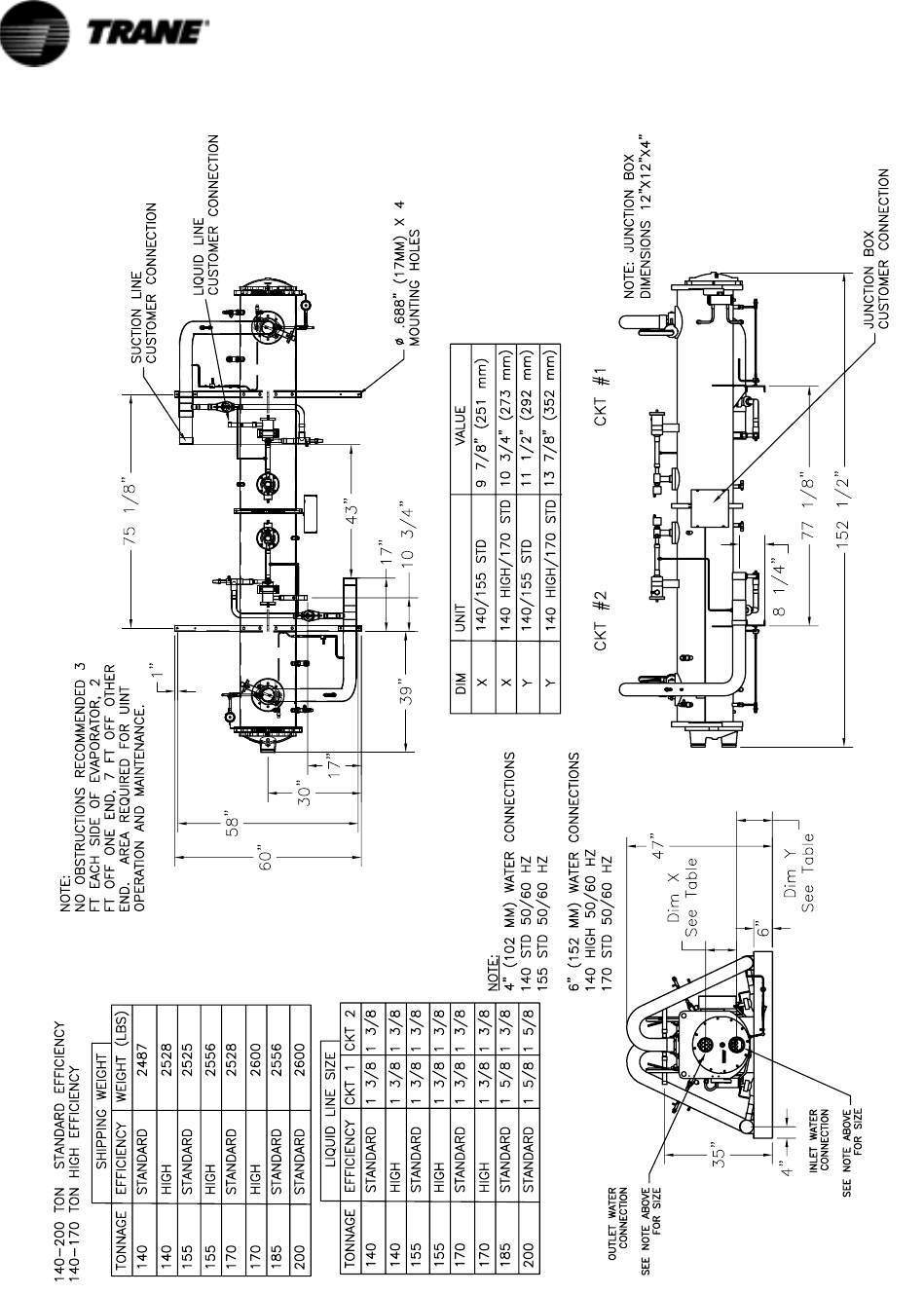
Figure 12 Unit Dimensions for Remote Evaporator 140-170 Ton Standard Efficiency and 140 Ton High Efficiency
RTAC-SVX01F-EN 25
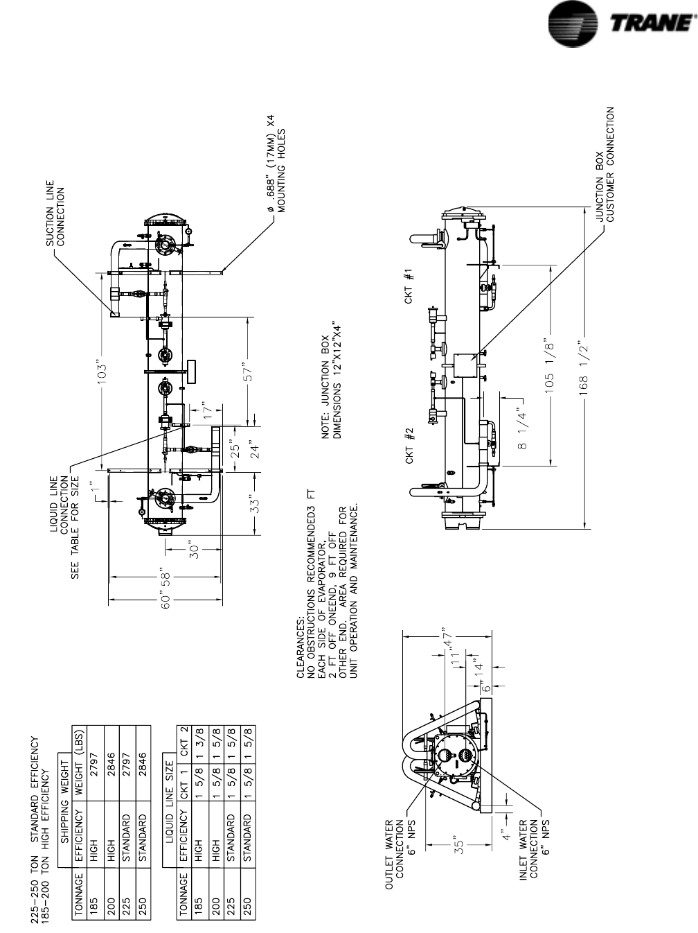
Figure 13 Unit Dimensions for Remote Evaporator185-250 Ton Standard Efficiency and 155-200 Ton High Efficiency

26 RTAC-SVX01F-EN
Model Number Coding System
The model numbers for the unit and the starter are composed of numbers and letters
that represent features of the equipment. Shown in the following table is a sample of
typical unit model number and the coding system for each.
Each position, or group of positions, in the model number is used to represent a fea-
ture. For example, in the first table, position 08 of the unit model number, Unit Volt-
age, contains the number “4”. A 4 in this position means that the unit voltage is 460/
60/3.
Unit Model Number
An example of a typical unit model number (M/N) is:
RTAC 350A UA0N NAFN N1NX 1TEN NN0N N01N
Model number digits are selected and assigned in accordance with the following defi-
nitions using the model number example shown above.

RTAC-SVX01F-EN 27
Digit 1-4
Unit Model
RTAC Air Cooled Series R® chiller
Digit 5-7
Unit Nominal Capacity
140 140 Nominal Tons
155 155 Nominal Tons
170 170 Nominal Tons
185185 Nominal Tons
200 200 Nominal Tons
225 225 Nominal Tons
250 250 Nominal Tons
275 275 Nominal Tons
300 300 Nominal Tons
350 350 Nominal Tons
375 375 Nominal Tons
400 400 Nominal Tons
450 450 Nominal Tons
500 500 Nominal Tons
Digit 8
Unit Voltage
A 200V/60Hz/3Ph power
K 220V/50Hz/3 Ph power
C 230V/60Hz/3Ph power
J380V/60Hz/3Ph power
D 400V/50Hz/3Ph power
4 460V/60Hz/3Ph power
5 575V/60Hz/3Ph power
Digit 9
Manufacturing Location
U Pueblo
ECharmes
Digit 10-11
Design Sequence
XX Factory/ABU Assigned
Digit 12
Unit Type
N Std. Efficiency/Performance
H High Efficiency/Performance
Digit 13
Agency Listing
N No agency listing
U C/UL listing
Digit 14
Pressure Vessel Code
A ASME pressure vessel code
C Canadian code
D Australian code
L Chinese code
R Vietanamese code
S Special
Digit 15
Evaporator Temperature Range &
Application Type
F Standard Temp. with Frz Prot
RRem Evap, Std. Temp, No Frz
Prot
G Low Temp, with Frz Prot
Digit 16
Evaporator Configuration
N Standard pass arrangement,
insulated
Digit 17
Condenser Temperature Range
N Standard ambient range
25-115 deg F
H High ambient capability
25-125 deg F
LLow ambient capability
0-115 deg F
WWide ambient capability
0-125 deg F
Digit 18
Condenser Fin Material
1 Standard aluminum slit fins
2 Copper fins, non-slit fins
4Complete Coat aluminum fins
Digit 19
Condenser Fan/Motor Configuration
N Condenser fans with ODP
motors
WLow Noise fans
T Condenser fans with TEAO
motors
Digit 20
Compressor Motor Starter Type
X Across-the-line starters
YWye-delta closed transition
starters
Digit 21
Incoming Power Line Connection
1 Single point power connection
2 Dual point power connection (1/
ckt)
Digit 22
Power Line Connection Type
TTerminals only
D Non-fused disconnect
switch(es)
C Circuit Breaker(s), HACR-rated
Digit 23
Unit Operator Interface
E Easy-View operator interface
D Dyna-View operator interface
Digit 24
Remote Interface
N No remote interface
C Tracer Comm 3 interface
LLon Talk Communication interface
(LCI)
Digit 25
Control Input Accessories/Options
N No remote input
RRemote leaving water temp stpt
CRemote current limit setpoint
BRemote lvg. temp.setpoint and
remote current limit setpoint
Digit 26
COOP 26
Control Output Accessories/Options
N No output options
AAlarm relay
CIcemaking
DIcemaking and alarm relay
Digit 27
Short Circuit Rating
0 No short circuit withstand rating
5 10000A SCR
4 35000A SCR
6 65000A SCR
Digit 28
Electrical Accessories and Export
Packing
N No flow switches
F NEMA-1 flow switch - 150 psi
E Vapor Proof FS - 150 psi
Digit 29
Control Panel Accessories
N No convenience outlet
A 15A 115V convenience outlet
(60HZ)
Digit 30
Refrigerant Service Valves
1 Suction service valves
Digit 31
Compressor Sound Attenuator
Option
0 No sound attenuator
1 Factory installed sound attenuator
Digit 32
Appearance Options
N No appearance options
A Architectural louvered panels
CHalf Louvers
G Access guards
B Access guards and half louvers
P Painted unit
L Painted unit with full louvered
panels
H Painted unit with half louvered
panels
K Painted unit with access guards
WPainted w/access guards and half
louvers
Digit33
Installation Accessories
N No installation accessories
R Neoprene isolators
F Flanged water connection kit
G Neoprene isolators and flange
wtr conn kit
Digit 34
Factory Test
0 No factory run test
P Performance test
WWitness test
Digit 35
Label, and Literature Language
EEnglish
G Chinese
Digit 36
Special Order
X Standard catalog configuration
S Unit has special order feature
Digit 37
Safety Devices
N None
X Standard

28 RTAC-SVX01F-EN
Installation - Mechanical
Installation Responsibilities
Generally, the contractor must do the following when installing an RTAC unit:
• Install unit on a flat foundation, level (within 1/4” [6 mm] across the length and
width of the unit), and strong enough to support unit loading.
• Install unit per the instructions contained in the Installation-Mechanical and
Installation-Electrical sections of this manual.
• Install any optional sensors and make electrical connections at the CH530.
• Where specified, provide and install valves in water piping upstream and
downstream of evaporator water connections to isolate the evaporator for
maintenance, and to balance/trim system.
• Furnish and install flow switch to prove chilled water flow.
• Furnish and install pressure gauges in inlet and outlet piping of the evaporator.
• Furnish and install a drain valve to the bottom of the evaporator waterbox.
• Supply and install a vent cock to the top of the evaporator waterbox.
• Furnish and install strainers ahead of all pumps and automatic modulating valves,
and at inlet of evaporator.
• Provide and install field wiring.
• Install heat tape and insulate the chilled water lines and any other portions of the
system, as required, to prevent sweating under normal operating conditions or
freezing during low ambient temperature conditions.
• Install evaporator drain plug. The plug ships in unit control panel.
• Start unit under supervision of a qualified service technician.
Nameplates
The RTAC outdoor unit nameplates (Figure 1) are applied to the exterior of the Control
Panel. A compressor nameplate is located on each compressor.
Outdoor Unit Nameplate
The outdoor unit nameplate provides the following information:
– Unit model and size description.
– Unit serial number.
– Identifies unit electrical requirements.
– Lists correct operating charges of R-134a and refrigerant oil (Trane OIL00048).
– Lists unit test pressures.
– Identifies installation, operation and maintenance and service data literature
(Pueblo).
– Lists drawing numbers for unit wiring diagrams (Pueblo).
Compressor Nameplate
The compressor nameplate provides following information:
– Compressor model number.
– Compressor serial number.
– Compressor electrical characteristics.
– Utilization range.
– Recommended refrigerant.
RTAC-SVX01F-EN 29
Installation - Mechanical
Storage
Extended storage of the outdoor unit prior to installation requires the following pre-
cautionary measures:
1. Store the outdoor unit in a secure area.
2. At least every three months (quarterly), check the pressure in the refrigerant cir-
cuits to verify that the refrigerant charge is intact. If it is not, contact a qualified
service organization and the appropriate Trane sales office.
3. Close the discharge and liquid line isolation valves.
General
Report any damage incurred during handling or installation to the Trane sales office
immediately.
Location Requirements
Setting the Unit
A base or foundation is not required if the selected unit location is level and strong
enough to support the unit’s operating weight as listed in Table 1 through Table 5 in
the General Information section.
See Table 6 for lifting weights and center of gravity (CG) dimensions.
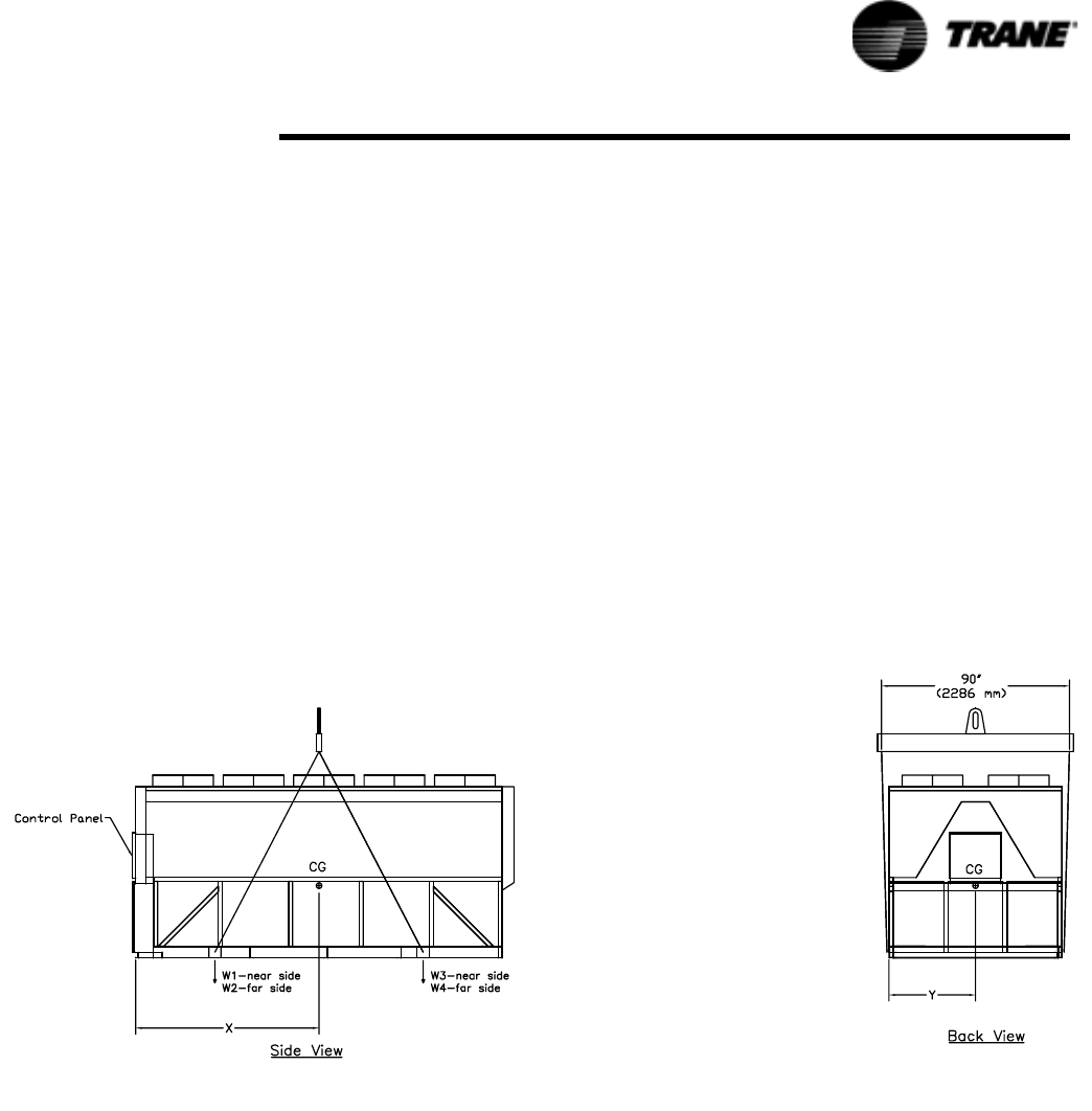
Figure 14 Lifting the Unit (Package and Remote) 15-21-foot Base
1. Lifting chains/cables will not
be the same length. Adjust to keep unit level while lifting.
2. Do not fork lift unit.
3. Weights are typical for units with R-134a charge.
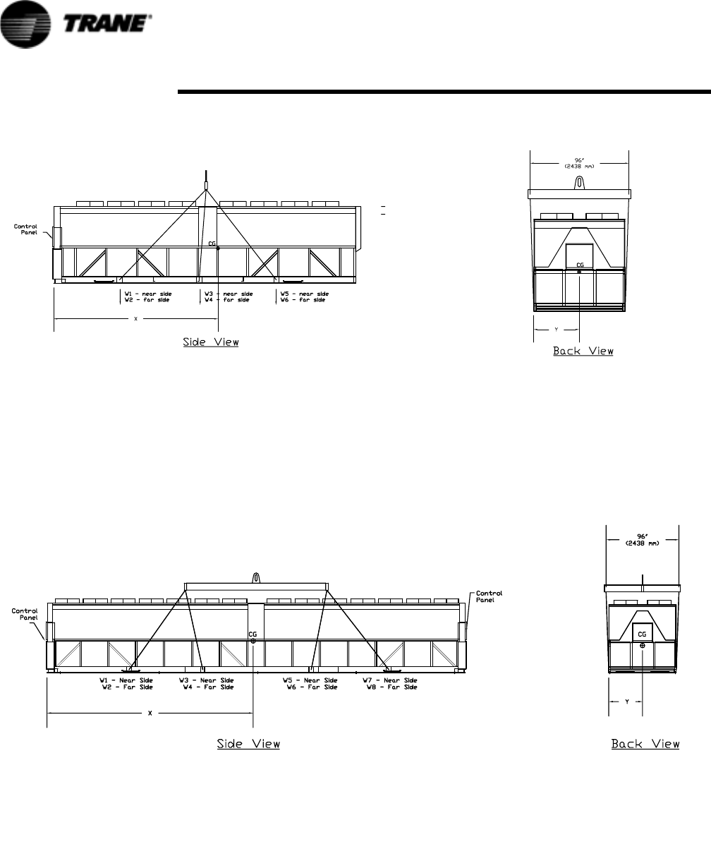
Figure 15 Lifting the Unit (Package and Remote) 30-36-foot Base
Figure 16 Lifting the Unit 39-45-foot Base
30 RTAC-SVX01F-EN
Installation - Mechanical
1. Lifting chains/cables will not be the same length. Adjust to
keep unit level while lifting.
2. Do not fork lift unit.
3. Weights are typical for units with R-134a charge.
1. Lifting chains/cables will not be the same length. Adjust to
keep unit level while lifting.
2. Do not fork lift unit.
3. Weights are typical for units with R-134a charge.

RTAC-SVX01F-EN 31
Installation - Mechanical
:
Table 6 Lifting Weights and CG Dimensions (Refer to Figure 14 - Figure 15)
Unit
W1 W2 W3 W4 W5 W6 W7 W8 Shipping
Weight
Xcg Ycg
lbs
kg
lbs
kg
lbs
kg
lbs
kg
lbs
kg
lbs
kg
lbs
kg
lbs
kg
lbs
kg
in
mm
in
mm
Aluminum Fins
140 Ton 50 Hz High Eff 2499 2874 2686 3019 NA NA NA NA 11077 88 45
1134 1303 1218 1369 5025 2245 1140
140 Ton 50 Hz Std Eff 2488 2859 2668 3000 NA NA NA NA 11015 88 45
1128 1297 1210 1361 4996 2245 1140
140 Ton 60 Hz High Eff 2495 2869 2680 3013 NA NA NA NA 11057 88 45
1132 1301 1216 1367 5015 2245 1140
140 Ton 60 Hz Std Eff 2484 2855 2662 2994 NA NA NA NA 10995 88 45
1127 1295 1208 1358 4987 2243 1140
155 Ton 50 Hz High Eff 3281 3588 2747 3055 NA NA NA NA 12671 106 44
1488 1628 1246 1386 5748 2695 1123
155 Ton 50 Hz Std Eff 2601 2882 2794 3033 NA NA NA NA 11309 88 44
1180 1307 1267 1376 5130 2243 1120
155 Ton 60 Hz High Eff 3168 3562 2604 2998 NA NA NA NA 12332 106 45
1437 1616 1181 1360 5594 2682 1140
155 Ton 60 Hz Std Eff 2493 2862 2675 3004 NA NA NA NA 11034 88 45
1131 1298 1213 1362 5005 2245 1138
170 Ton 50 Hz High Eff 3308 3721 2760 3173 NA NA NA NA 12962 106 45
1501 1688 1252 1439 5880 2695 1140
170 Ton 50 Hz Std Eff 2598 2990 2838 3177 NA NA NA NA 11603 89 45
1179 1356 1287 1441 5263 2256 1138
170Ton 60 Hz High Eff 3186 3586 2623 3024 NA NA NA NA 12418 106 45
1445 1627 1190 1371 5633 2685 1140
170 Ton 60 Hz Std Eff 2498 2873 2684 3018 NA NA NA NA 11073 88 45
1133 1303 1218 1369 5023 2245 1140
185 Ton 50 Hz High Eff 3650 4199 3113 3662 NA NA NA NA 14624 124 45
1655 1905 1412 1661 6633 3160 1153
185 Ton 50 Hz Std Eff 3342 3763 2745 3166 NA NA NA NA 13015 106 45
1516 1707 1245 1436 5904 2682 1140
185 Ton 60 Hz High Eff 3526 4117 2990 3581 NA NA NA NA 14214 124 46
1600 1867 1356 1624 6447 3157 1161
185 Ton 60 Hz Std Eff 3296 3635 2707 3047 NA NA NA NA 12685 106 44
1495 1649 1228 1382 5754 2680 1128
200 Ton 50 Hz High Eff 3778 4252 3175 3649 NA NA NA NA 14853 124 45
1714 1928 1440 1655 6737 3147 1140
200 Ton 50 Hz Std Eff 3370 3789 2828 3247 NA NA NA NA 13234 106 45
1529 1719 1283 1473 6003 2697 1138
200 Ton 60 Hz High Eff 3719 4187 3110 3578 NA NA NA NA 14593 124 45
1687 1899 1411 1623 6619 3142 1140
200 Ton 60 Hz Std Eff 3340 3756 2796 3212 NA NA NA NA 13104 106 45
1515 1704 1268 1457 5944 2697 1138
225 Ton 60 Hz Std Eff 3711 4229 3114 3632 NA NA NA NA 14687 124 45
1683 1918 1413 1648 6662 3147 1148
250 Ton 60 Hz Std Eff 3778 4252 3175 3649 NA NA NA NA 14853 124 45
1714 1928 1440 1655 6737 3147 1140
250 Ton 50 Hz High Eff 3360 2930 3390 2959 3430 3000 NA NA 19069 177 41
1526 1330 1539 1344 1557 1362 8657 4483 1052
250 Ton 50 Hz Std Eff 2951 2522 3238 2809 3430 3000 NA NA 17949 182 41
1340 1145 1470 1275 1557 1362 8149 4623 1046
275 Ton 50 Hz High Eff 3403 2997 3689 3283 3977 3571 NA NA 20920 202 42
1545 1361 1675 1491 1805 1621 9498 5128 1064

32 RTAC-SVX01F-EN
Installation - Mechanical
275 Ton 50 Hz Std Eff 3668 3194 3478 3004 3356 2877 NA NA 19577 172 41
1665 1450 1579 1364 1524 1306 NA NA 8888 4376 1046
275 Ton 60 Hz High Eff 3251 2863 3571 3183 3894 3505 NA NA 20266 203 42
1476 1300 1621 1445 1768 1591 9201 5159 1064
275 Ton 60 Hz Std Eff 3345 2936 3351 2942 3356 2947 NA NA 18876 176 42
1518 1333 1521 1336 1523 1338 8570 4473 1057
300 Ton 50 Hz High Eff 2955 2628 2892 2565 2822 2495 2759 2432 21548 222 42
1342 1193 1313 1164 1281 1133 1253 1104 9783 5644 1059
300 Ton 50 Hz Std Eff 3328 2917 3564 3153 3802 3393 NA NA 20314 201 42
1511 1394 1618 1431 1726 1540 9222 5100 1059
300 Ton 60 Hz High Eff 2955 2628 2892 2565 2782 2495 2759 2432 21508 222 42
1342 1193 1313 1165 1263 1133 1253 1104 9765 5641 1062
300 Ton 60 Hz Std Eff 3456 3074 3615 3233 3774 3393 NA NA 19572 199 42
1569 1396 1641 1468 1713 1540 8886 5044 1067
350 Ton 50 Hz High Eff 3278 3258 3179 3159 3075 3055 2977 2957 24936 234 44
1488 1479 1443 1434 1396 1387 1352 1342 11321 5951 1125
350 Ton 50 Hz Std Eff 3018 2998 2933 2914 2844 2824 2760 2740 23031 235 44
1370 1361 1332 1323 1291 1282 1253 1244 10456 5956 1125
350 Ton 60 Hz High Eff 3140 3123 3038 3020 2930 2912 2828 2811 23803 234 44
1426 1418 1379 1371 1330 1322 1284 1276 10806 5941 1125
350 Ton 60 Hz Std Eff 3374 2998 3772 3367 4172 3767 NA NA 21450 205 42
1532 1361 1712 1529 1894 1710 9738 5197 1064
375 Ton 50 Hz High Eff 3393 3372 3278 3257 3108 3086 2986 2965 25444 266 44
1541 1531 1488 1478 1411 1401 1356 1346 11552 6754 1125
375 Ton 50 Hz Std Eff 3328 3296 3116 3083 2892 2859 2681 2649 23903 229 44
1511 1496 1414 1400 1313 1298 1217 1202 10852 5827 1123
400 Ton 50 Hz High Eff 3345 3271 3377 3303 3425 3350 3458 3384 26912 274 44
1519 1485 1533 1499 1555 1521 1570 1536 12218 6957 1115
400 Ton 50 Hz Std Eff 3299 3279 3201 3180 3098 3077 3001 2939 25073 234 44
1498 1488 1453 1444 1406 1397 1362 1334 11383 5951 1125
400 Ton 60 Hz High Eff 3345 3271 3377 3303 3425 3350 3458 3384 26913 274 44
1519 1485 1533 1500 1555 1521 1570 1536 12219 6955 1118
400 Ton 60 Hz Std Eff 3299 3279 3201 3180 3098 3077 3001 2939 25074 234 44
1498 1489 1453 1444 1406 1397 1362 1334 11383 5951 1125
450 Ton 60 Hz Std Eff 3423 3402 3307 3286 3137 3116 3015 2994 25678 266 44
1554 1544 1501 1492 1424 1414 1369 1359 11658 6754 1125
500 Ton 60 Hz Std Eff 3363 3289 3395 3321 3442 3368 3476 3402 27056 274 44
1527 1493 1541 1508 1563 1529 1578 1544 12283 6955 1115
Copper Fins
140 Ton 50 Hz High Eff 2972 3464 3410 3805 NA NA NA NA 13651 90 45
1348 1571 1547 1726 6192 2289 1140
140 Ton 50 Hz Std Eff 2961 3450 3392 3786 NA NA NA NA 13589 90 45
1343 1565 1539 1717 6164 2286 1140
140 Ton 60 Hz High Eff 2969 3460 3404 3799 NA NA NA NA 13631 90 45
1347 1569 1544 1723 6183 2289 1140
140 Ton 60 Hz Std Eff 2957 3445 3386 3780 NA NA NA NA 13569 90 45
1341 1563 1536 1715 6155 2286 1140
155 Ton 50 Hz High Eff 4027 4454 3591 4018 NA NA NA NA 16091 108 44
1827 2020 1629 1823 7299 2743 1128
155 Ton 50 Hz Std Eff 3074 3472 3518 3819 NA NA NA NA 13883 90 44
1394 1575 1596 1732 6297 2286 1125
155 Ton 60 Hz High Eff 3915 4428 3448 3961 NA NA NA NA 15752 108 45
1776 2009 1564 1797 7145 2736 1140
Table 6 Lifting Weights and CG Dimensions (Refer to Figure 14 - Figure 15)
Unit
W1 W2 W3 W4 W5 W6 W7 W8 Shipping
Weight
Xcg Ycg
lbs
kg
lbs
kg
lbs
kg
lbs
kg
lbs
kg
lbs
kg
lbs
kg
lbs
kg
lbs
kg
in
mm
in
mm

RTAC-SVX01F-EN 33
Installation - Mechanical
155 Ton 60 Hz Std Eff 2967 3453 3399 3790 NA NA NA NA 13608 90 45
1346 1566 1542 1719 6173 2286 1140
170 Ton 50 Hz High Eff 4055 4587 3604 4136 NA NA NA NA 16382 108 45
1839 2081 1635 1876 7431 2743 1140
170 Ton 50 Hz Std Eff 3071 3581 3562 3963 NA NA NA NA 14177 90 45
1393 1624 1616 1798 6431 2296 1140
170Ton 60 Hz High Eff 3932 4452 3467 3987 NA NA NA NA 15838 108 45
1784 2019 1573 1808 7184 2738 1140
170 Ton 60 Hz Std Eff 2972 3463 3409 3804 NA NA NA NA 13647 90 45
1348 1571 1546 1725 6190 2289 1140
185 Ton 50 Hz High Eff 4585 5283 4161 4860 NA NA NA NA 18889 126 45
2080 2396 1888 2204 8568 3211 1151
185 Ton 50 Hz Std Eff 4088 4629 3589 4129 NA NA NA NA 16435 108 45
1854 2100 1628 1873 7455 2733 1140
185 Ton 60 Hz High Eff 4462 5201 4039 4778 NA NA NA NA 18479 126 46
2024 2359 1832 2167 8382 3211 1158
185 Ton 60 Hz Std Eff 4042 4501 3551 4010 NA NA NA NA 16105 108 45
1834 2042 1611 1819 7305 2733 1133
200 Ton 50 Hz High Eff 4713 5336 4223 4846 NA NA NA NA 19118 126 45
2138 2420 1916 2198 8672 3200 1140
200 Ton 50 Hz Std Eff 4116 4654 3672 4211 NA NA NA NA 16654 108 45
1867 2111 1666 1910 7554 2746 1140
200 Ton 60 Hz High Eff 4654 5271 4158 4775 NA NA NA NA 18858 126 45
2111 2391 1886 2166 8554 3198 1140
200 Ton 60 Hz Std Eff 4087 4622 3640 4175 NA NA NA NA 16524 108 45
1854 2097 1651 1894 7495 2746 1140
225 Ton 60 Hz Std Eff 4646 5313 4163 4830 NA NA NA NA 18952 126 45
2108 2410 1888 2191 8597 3200 1146
250 Ton 60 Hz Std Eff 4713 5336 4223 4846 NA NA NA NA 19118 126 45
2138 2420 1916 2198 8672 3200 1140
250 Ton 50 Hz High Eff 4303 3872 4188 3756 4111 3679 NA NA 23909 174 42
1954 1758 1901 1705 1866 1670 10855 4422 1067
250 Ton 50 Hz Std Eff 3534 3104 3918 3488 4174 3744 NA NA 21962 183 42
1605 1409 1779 1583 1895 1700 9971 4638 1062
275 Ton 50 Hz High Eff 4366 3959 4618 4211 4872 4465 NA NA 26492 200 42
1982 1797 2097 1912 2212 2027 12027 5070 1077
275 Ton 50 Hz Std Eff 4611 4136 4276 3801 4057 3577 NA NA 24458 171 42
2093 1878 1941 1725 1842 1624 11104 4338 1062
275 Ton 60 Hz High Eff 4214 3877 4501 4111 4789 4399 NA NA 25891 201 42
1913 1760 2043 1866 2174 1997 11754 5093 1077
275 Ton 60 Hz Std Eff 4287 3877 4149 3739 4057 3647 NA NA 23758 174 42
1946 1760 1884 1698 1842 1656 10786 4415 1069
300 Ton 50 Hz High Eff 3836 3508 3689 3360 3526 3197 3379 3050 27544 220 42
1742 1592 1675 1526 1601 1451 1534 1385 12505 5575 1074
300 Ton 50 Hz Std Eff 4360 3948 4476 4064 4593 4182 NA NA 25623 197 42
1980 1792 2032 1845 2085 1899 11633 4999 1074
300 Ton 60 Hz High Eff 3799 3508 3689 3360 3526 3197 3379 3050 27508 219 42
1725 1593 1675 1525 1601 1451 1534 1385 12489 5573 1074
300 Ton 60 Hz Std Eff 4488 4105 4527 4144 4593 4182 NA NA 26039 195 43
2038 1864 2055 1881 2085 1899 11822 4956 1080
350 Ton 50 Hz High Eff 4173 4152 4053 4032 3927 3905 3808 3787 31836 235 44
1895 1885 1840 1830 1783 1773 1729 1719 14453 5956 1125
Table 6 Lifting Weights and CG Dimensions (Refer to Figure 14 - Figure 15)
Unit
W1 W2 W3 W4 W5 W6 W7 W8 Shipping
Weight
Xcg Ycg
lbs
kg
lbs
kg
lbs
kg
lbs
kg
lbs
kg
lbs
kg
lbs
kg
lbs
kg
lbs
kg
in
mm
in
mm

34 RTAC-SVX01F-EN
Installation - Mechanical
350 Ton 50 Hz Std Eff 3778 3757 3675 3654 3566 3545 3465 3444 28882 235 44
1715 1705 1668 1659 1619 1610 1573 1563 13113 5961 1125
350 Ton 60 Hz High Eff 4036 4017 3912 3893 3782 3763 3660 3641 30703 234 44
1832 1824 1776 1767 1717 1708 1661 1653 13939 5949 1125
350 Ton 60 Hz Std Eff 4283 3877 4754 4348 5229 4823 NA NA 27315 204 43
1944 1760 2158 1974 2374 2190 12401 5179 1080
375 Ton 50 Hz High Eff 4502 4479 4244 4221 3863 3841 3592 3569 32311 261 44
2044 2034 1927 1916 1754 1744 1631 1620 14669 6632 1125
375 Ton 50 Hz Std Eff 4332 4298 3984 3950 3618 3584 3274 3240 30279 227 44
1967 1951 1809 1793 1643 1627 1486 1471 13747 5761 1123
400 Ton 50 Hz High Eff 4341 4265 4367 4291 4406 4330 4433 4357 34791 273 44
1971 1936 1983 1948 2000 1966 2013 1978 15795 6939 1118
400 Ton 50 Hz Std Eff 4195 4173 4075 4053 3950 3928 3832 3810 32014 235 44
1904 1894 1850 1840 1793 1783 1740 1730 14534 5956 1125
400 Ton 60 Hz High Eff 4341 4265 4367 4291 4406 4330 4433 4357 34790 273 44
1971 1936 1983 1948 2000 1966 2013 1978 15795 6939 1120
400 Ton 60 Hz Std Eff 4195 4173 4075 4053 3950 3928 3832 3810 32016 234 44
1905 1895 1850 1840 1793 1783 1740 1730 14535 5954 1125
450 Ton 60 Hz Std Eff 4532 4509 4273 4251 3892 3870 3621 3598 32545 261 44
2057 2047 1940 1930 1767 1757 1644 1633 14775 6634 1125
500 Ton 60 Hz Std Eff 4359 4283 4385 4309 4424 4348 4451 4375 34935 273 44
1979 1945 1991 1956 2008 1974 2021 1986 15860 6939 1118
Remote Evaporator Aluminum Fins
140 Ton 50 Hz High Eff 2033 2292 1972 2244 NA NA NA NA 8542 86 45
922 1040 895 1018 3875 2179 1138
140 Ton 50 Hz Std Eff 2030 2287 1967 2238 NA NA NA NA 8522 86 45
921 1038 892 1015 3866 2177 1138
140 Ton 60 Hz High Eff 2030 2288 1967 2238 NA NA NA NA 8522 86 45
921 1038 892 1015 3866 2177 1138
140 Ton 60 Hz Std Eff 2026 2283 1961 2232 NA NA NA NA 8502 86 45
919 1036 889 1013 3857 2177 1138
155 Ton 50 Hz High Eff 2725 2944 2119 2337 NA NA NA NA 10125 104 44
1236 1335 961 1060 4593 2637 1115
155 Ton 50 Hz Std Eff 2139 2305 2087 2265 NA NA NA NA 8795 86 44
970 1046 947 1027 3989 2177 1113
155 Ton 60 Hz High Eff 2612 2918 1975 2281 NA NA NA NA 9786 103 45
1185 1323 896 1034 4439 2619 1138
155 Ton 60 Hz Std Eff 2031 2285 1968 2236 NA NA NA NA 8520 86 45
921 1037 893 1014 3865 2177 1135
170 Ton 50 Hz High Eff 2749 3073 2128 2451 NA NA NA NA 10400 104 45
1247 1394 965 1112 4717 2637 1138
170 Ton 50 Hz Std Eff 2138 2415 2133 2411 NA NA NA NA 9097 87 45
970 1096 967 1094 4126 2197 1135
170Ton 60 Hz High Eff 2626 2938 1990 2302 NA NA NA NA 9856 103 45
1191 1332 903 1044 4471 2621 1138
170 Ton 60 Hz Std Eff 2033 2291 1971 2243 NA NA NA NA 8538 86 45
922 1039 894 1018 3873 2179 1138
185 Ton 50 Hz High Eff 3034 3485 2423 2875 NA NA NA NA 11817 122 45
1376 1581 1099 1304 5360 3106 1153
185 Ton 50 Hz Std Eff 2786 3118 2116 2449 NA NA NA NA 10469 103 45
12 6 4 14 14 9 6 0 1111 474 9 2621 1138
185 Ton 60 Hz High Eff 2911 3403 2300 2793 NA NA NA NA 11407 122 46
1320 1544 1043 1267 5174 3101 1166
Table 6 Lifting Weights and CG Dimensions (Refer to Figure 14 - Figure 15)
Unit
W1 W2 W3 W4 W5 W6 W7 W8 Shipping
Weight
Xcg Ycg
lbs
kg
lbs
kg
lbs
kg
lbs
kg
lbs
kg
lbs
kg
lbs
kg
lbs
kg
lbs
kg
in
mm
in
mm

RTAC-SVX01F-EN 35
Installation - Mechanical
185 Ton 60 Hz Std Eff 2740 2991 2079 2329 NA NA NA NA 10139 103 44
1243 1357 943 1057 4599 2619 1123
200 Ton 50 Hz High Eff 3156 3531 2478 2853 NA NA NA NA 12019 122 45
1432 1602 1124 1294 5452 3091 1138
200 Ton 50 Hz Std Eff 2811 3140 2196 2525 NA NA NA NA 10672 104 45
1275 1424 996 1146 4841 2644 1138
200 Ton 60 Hz High Eff 3097 3466 2413 2782 NA NA NA NA 11759 121 45
1405 1572 1095 1262 5334 3084 1138
200 Ton 60 Hz Std Eff 2781 3108 2163 2490 NA NA NA NA 10542 104 45
1262 1410 981 1129 4782 2639 1138
225 Ton 60 Hz Std Eff 3096 3516 2425 2845 NA NA NA NA 11880 122 45
1404 1595 1100 1290 5389 3091 1148
250 Ton 60 Hz Std Eff 3156 3531 2478 2853 NA NA NA NA 12019 122 45
1432 1602 1124 1294 5452 3091 1138
Remote Evaporator Copper Fins
140 Ton 50 Hz High Eff 2506 2883 2697 3031 NA NA NA NA 11116 88 45
1137 1308 1223 1375 5042 2245 1140
140 Ton 50 Hz Std Eff 2503 2878 2691 3025 NA NA NA NA 11096 88 45
1135 1305 1221 1372 5033 2245 1140
140 Ton 60 Hz High Eff 2503 2878 2691 3025 NA NA NA NA 11096 88 45
1135 1306 1221 1372 5033 2245 1140
140 Ton 60 Hz Std Eff 2499 2874 2685 3019 NA NA NA NA 11076 88 45
1134 1303 1218 1369 5024 2245 1140
155 Ton 50 Hz High Eff 3472 3810 2963 3301 NA NA NA NA 13545 107 44
1575 1728 1344 1497 6144 2710 1123
155 Ton 50 Hz Std Eff 2612 2896 2811 3051 NA NA NA NA 11369 88 44
1185 1313 1275 1384 5157 2243 1120
155 Ton 60 Hz High Eff 3359 3783 2819 3244 NA NA NA NA 13206 106 45
1524 1716 1279 1471 5990 2700 1140
155 Ton 60 Hz Std Eff 2505 2876 2692 3022 NA NA NA NA 11094 88 45
1136 1305 1221 1371 5032 2245 1138
170 Ton 50 Hz High Eff 3496 3938 2972 3414 NA NA NA NA 13820 107 45
1586 1786 1348 1549 6269 2708 1140
170 Ton 50 Hz Std Eff 2611 3006 2857 3198 NA NA NA NA 11671 89 45
1184 1363 1296 1450 5294 2258 1138
170Ton 60 Hz High Eff 3373 3803 2834 3265 NA NA NA NA 13276 106 45
1530 1725 1286 1481 6022 2700 1140
170 Ton 60 Hz Std Eff 2506 2882 2695 3030 NA NA NA NA 11112 88 45
1137 1307 1223 1374 5040 2245 1140
185 Ton 50 Hz High Eff 3969 4570 3471 4072 NA NA NA NA 16082 125 45
1800 2073 1575 1847 7295 3180 1151
185 Ton 50 Hz Std Eff 3532 3984 2960 3412 NA NA NA NA 13889 106 45
1602 1807 1343 1548 6300 2697 1140
185 Ton 60 Hz High Eff 3846 4487 3349 3990 NA NA NA NA 15672 125 46
1745 2035 1519 1810 7109 3178 1161
185 Ton 60 Hz Std Eff 3487 3857 2923 3293 NA NA NA NA 13559 106 45
1581 1749 1326 1494 6150 2697 1130
200 Ton 50 Hz High Eff 4092 4615 3527 4050 NA NA NA NA 16284 125 45
1856 2094 1600 1837 7386 3167 1140
200 Ton 50 Hz Std Eff 3557 4006 3040 3489 NA NA NA NA 14092 107 45
1613 1817 1379 1583 6392 2713 1140
200 Ton 60 Hz High Eff 4033 4551 3462 3979 NA NA NA NA 16024 125 45
1829 2064 1570 1805 7269 3165 1140
Table 6 Lifting Weights and CG Dimensions (Refer to Figure 14 - Figure 15)
Unit
W1 W2 W3 W4 W5 W6 W7 W8 Shipping
Weight
Xcg Ycg
lbs
kg
lbs
kg
lbs
kg
lbs
kg
lbs
kg
lbs
kg
lbs
kg
lbs
kg
lbs
kg
in
mm
in
mm
Standard Eff Premium Eff
To n n a ge
lbs
Kg
36 RTAC-SVX01F-EN
Installation - Mechanical
Isolation and Sound Emission
The most effective form of isolation is to locate the unit away from any sound sensi-
tive area. Structurally transmitted sound can be reduced by elastomeric vibration elim-
inators. Spring isolators are not recommended. Consult an acoustical engineer in
critical sound applications.
For maximum isolation effect, isolate water lines and electrical conduit. Wall sleeves
and rubber isolated piping hangers can be used to reduce the sound transmitted
through water piping. To reduce the sound transmitted through electrical conduit, use
flexible electrical conduit.
State and local codes on sound emissions should always be considered. Since the
environment in which a sound source is located affects sound pressure, unit place-
ment must be carefully evaluated. Sound power levels for Trane air-cooled Series R®
chillers are available on request.
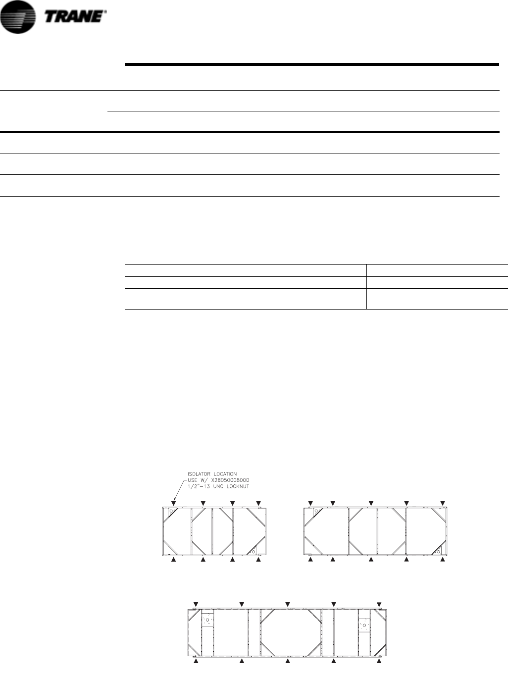
Figure 17 Unit Isolator Locations
200 Ton 60 Hz Std Eff 3528 3974 3007 3453 NA NA NA NA 13962 107 45
1600 1802 1364 1566 6333 2710 1140
225 Ton 60 Hz Std Eff 4031 4600 3473 4042 NA NA NA NA 16145 125 45
1828 2086 1575 1833 7323 3167 1148
250 Ton 60 Hz Std Eff 4092 4615 3527 4050 NA NA NA NA 16284 125 45
1856 2094 1600 1837 7386 3167 1140
Table 6 Lifting Weights and CG Dimensions (Refer to Figure 14 - Figure 15)
Unit
W1 W2 W3 W4 W5 W6 W7 W8 Shipping
Weight
Xcg Ycg
lbs
kg
lbs
kg
lbs
kg
lbs
kg
lbs
kg
lbs
kg
lbs
kg
lbs
kg
lbs
kg
in
mm
in
mm
Table 7 Remote Evaporator Lifting Weights
140 155 170 185 200 225 250 140 155 170 185 200
2487
112 8
2525
114 5
2528
114 6
2556
115 9
2600
1179
2797
1268
2846
1291
2528
114 6
2556
115 9
2600
1179
2797
1268
2846
1291
5NITSWITHORMORE#OMPRESSORS
5NITSWITH#OMPRESSORS
RTAC-SVX01F-EN 37
Installation - Mechanical
Noise Considerations
Locate the outdoor unit away from sound sensitive areas. If required, install rubber
vibration isolators in all water piping and use flexible electrical conduit. Consult an
acoustical engineer for critical applications. Also refer to Trane Engineering Bulletins
for application information on RTAC chillers.
Table 8 Unit Isolators
Tonnage Efficiency Frequency Unit Type Condenser
Fin Material
Isolator Part
Number
Quantity
140 Std/High 50/60 Packaged AL X10140305620 8
140 Std/High 50/60 Remote AL X10140305610 8
140 Std/High 50/60 Packaged/Remote Cu X10140305620 8
155 Std/High 50/60 Packaged AL X10140305620 8
155 Std/High 50/60 Remote AL X10140305610 8
155 Std/High 50/60 Packaged/Remote Cu X10140305620 8
170 Std/High 50/60 Packaged AL X10140305620 8
170 Std/High 50/60 Remote AL X10140305610 8
170 Std/High 50/60 Packaged/Remote Cu X10140305620 8
185 Std 50/60 Packaged AL X10140305620 8
185 High 50/60 Packaged AL X10140305620 10
185 Std 50/60 Remote AL X10140305610 8
185 High 50/60 Remote AL X10140305610 10
185 Std 50/60 Packaged Cu X10140305620 8
185 High 50/60 Packaged Cu X10140305620 10
185 Std 50/60 Remote Cu X10140305620 8
185 High 50/60 Remote Cu X10140305620 10
200 Std 50/60 Packaged AL X10140305620 8
200 High 50/60 Packaged AL X10140305620 10
200 Std 50/60 Remote AL X10140305610 8
200 High 50/60 Remote AL X10140305610 10
200 Std 50/60 Packaged Cu X10140305620 8
200 High 50/60 Packaged Cu X10140305620 10
200 Std 50/60 Remote Cu X10140305620 8
200 High 50/60 Remote Cu X10140305620 10
225 Std 50/60 Packaged AL X10140305620 10
225 Std 50/60 Remote AL X10140305610 10
225 Std 50/60 Packaged/Remote Cu X10140305620 10
225 High 60 Packaged Al/Cu X10140305620 10
250 Std 50/60 Packaged AL X10140305620 10
250 Std 50/60 Remote AL X10140305610 10
250 Std 50/60 Packaged/Remote Cu X10140305620 10
250 High 60 Packaged Al/Cu X10140305620 10
250 Std 50 Packaged Al/Cu X10140305630 10
250 High 50 Packaged Al/Cu X10140305640 10
275 Std/High 50/60 Packaged Al/Cu X10140305640 10
300 Std/High 50/60 Packaged Al/Cu X10140305640 10
350 Std 60 Packaged Al/Cu X10140305640 10
350 Std 50 Packaged Al/Cu X10140305640 10
350 High 50/60 Packaged Al/Cu X10140305640 10
375 Std/High 50 Packaged Al/Cu X10140305640 10
400 Std/High 50/60 Packaged Al/Cu X10140305640 10
450 Std/High 60 Packaged Al/Cu X10140305640 10
500 Std 60 Packaged Al/Cu X10140305640 10
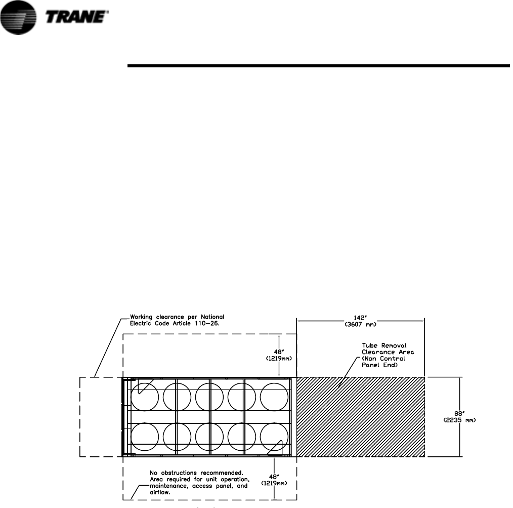
38 RTAC-SVX01F-EN
Installation - Mechanical
Foundation
Provide rigid, non-warping mounting pads or a concrete foundation of sufficient
strength and mass to support the outdoor unit operating weight (i.e., including com-
pleted piping, and full operating charges of refrigerant, oil and water). Refer to Ta ble 1
though Table 5 in the General Information section for unit operating weights. Once in
place, the outdoor unit must be level within 1/ 4" (6 mm) over its length and width.
The Trane Company is not responsible for equipment problems resulting from an
improperly designed or constructed foundation.
NOTE: To allow for cleaning under the condensing coil, it is recommended that an
opening be left between the unit base and the concrete pad.
Clearances
Provide enough space around the outdoor unit to allow the installation and mainte-
nance personnel unrestricted access to all service points. Refer to submittal drawings
for the unit dimensions. A minimum of 4 feet (1.2 m) is recommended for compressor
service. Provide sufficient clearance for the opening of control panel doors. Refer to
Figure 18 through Figure 19 for minimum clearances. In all cases, local codes which
require additional clearances will take precedence over these recommendations.
Figure 18 Recommended Unit Clearances 15-foot bases
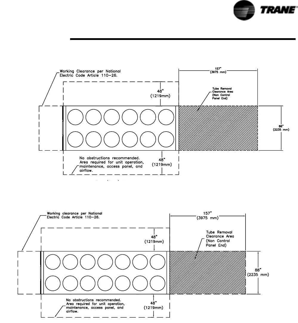
Figure 19 Recommended Unit Clearances 18-21 foot bases
Figure 20 Recommended Unit Clearances 30-45 foot bases
RTAC-SVX01F-EN 39
Installation - Mechanical
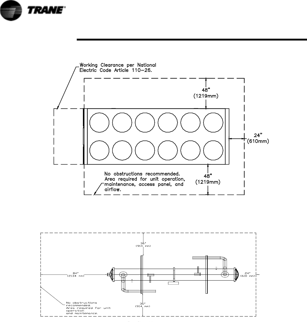
Figure 21 Recommended Remote Evaporator Unit Clearances 15-30 foot bases
40 RTAC-SVX01F-EN
Installation - Mechanical
Unobstructed flow of condenser air is essential to maintain chiller capacity and oper-
ating efficiency. When determining unit placement, give careful consideration to
assuring a sufficient flow of air across the condenser heat transfer surface. Two detri-
mental conditions are possible and must be avoided if optimum performance is to be
achieved: warm air recirculation and coil starvation.
Warm air recirculation occurs when discharge air from the condenser fans is recycled
back to the condenser coil inlet. Coil starvation occurs when free airflow to (or from)
the condenser is restricted.
Both warm air recirculation and coil starvation cause reduction in unit efficiency and
capacity due to the increased head pressures.
Figure 22 Recommended Evaporator Clearance

RTAC-SVX01F-EN 41
Installation - Mechanical
Debris, trash, supplies etc. should not be allowed to accumulate in the vicinity of the
unit. Supply air movement may draw debris into the condenser coil, blocking spaces
between coil fins and causing coil starvation. Special consideration should be given to
low ambient units. Condenser coils and fan discharge must be kept free of snow or
other obstructions to permit adequate airflow for satisfactory unit operation.
In situations where equipment must be installed with less clearance than recom-
mended, such as frequently occurs in retrofit and rooftop applications, restricted air-
flow is common. The Main Processor will direct the unit to make as much chilled
water as possible given the actual installed conditions. Consult your Trane sales engi-
neer for more details.
NOTE: If the outdoor unit configuration requires a variance to the clearance dimen-
sions, contact your Trane Sales Office Representative. Also refer to Trane Engineering
Bulletins for application information on RTAC chillers.
Unit Isolation and Leveling
For additional reduction of sound and vibration, install the optional neoprene isolators.
Construct an isolated concrete pad for the unit or provide concrete footings at the unit
mounting points. Mount the unit directly to the concrete pads or footings.
Level the unit using the base rail as a reference. The unit must be level within 1/4-in (6
mm) over the entire length and width. Use shims as necessary to level the unit.
Neoprene Isolator Installation
1. Secure the isolators to the mounting surface using the mounting slots in the iso-
lator base plate. Do not fully tighten the isolator mounting bolts at this time.
2. Align the mounting holes in the base of the unit with the threaded positioning
pins on the top of the isolators.
3. Lower the unit onto the isolators and secure the isolator to the unit with a nut.
Maximum isolator deflection should be 1/4 inch (6 mm).
4. Level the unit carefully. Fully tighten the isolator mounting bolts.
Drainage
Provide a large capacity drain for water vessel drain-down during shutdown or repair.
The evaporator is provided with a drain connection. All local and national codes apply.
The vent on the top of the evaporator waterbox is provided to prevent a vacuum by
allowing air into the evaporator for complete drainage.
Evaporator Water Piping
Thoroughly flush all water piping to the unit before making the final piping connec-
tions to the unit.
Evaporator Piping
Components and layout will vary slightly, depending on the location of connections
and the water source.
CAUTION
Evaporator Damage!
The chilled water connections to the evaporator are to be “victaulic”
type connections. Do not attempt to weld these connections, as the
heat generated from welding can cause microscopic and macroscopic
fractures on the cast iron waterboxes that can lead to premature failure
of the waterbox. To prevent damage to chilled water components, do
not allow evaporator pressure (maximum working pressure) to exceed
150 psig (10.5 bar).

42 RTAC-SVX01F-EN
Installation - Mechanical
Provide shutoff valves in lines to the gauges to isolate them from the system when
they are not in use. Use rubber vibration eliminators to prevent vibration transmission
through the water lines. If desired, install thermometers in the lines to monitor enter-
ing and leaving water temperatures. Install a balancing valve in the leaving water line
to control water flow balance. Install shutoff valves on both the entering and leaving
water lines so that the evaporator can be isolated for service.
CAUTION
Use Piping Strainers!
To prevent evaporator damage, pipe strainers must be installed in the
water supplies to protect components from water born debris. Trane is
not responsible for equipment-only-damage caused by water born
debris.
“Piping components” include all devices and controls used to provide proper water
system operation and unit operating safety. These components and their general loca-
tions are given below.
Entering Chilled Water Piping
• Air vents (to bleed air from system).
• Water pressure gauges with shutoff valves.
• Vibration eliminators.
• Shutoff (isolation) valves. Thermometers (if desired).
• Clean-out tees.
• Pipe strainer.
Leaving Chilled Water Piping
• Air vents (to bleed air from system).
• Water pressure gauges with shutoff valves. Vibration eliminators.
• Shutoff (isolation) valves.
• Thermometers.
• Clean-out tees.
• Balancing valve.
• Flow Switch
Evaporator Drain
A1/2 inch drain connection is located under the outlet end of the evaporator waterbox.
This may be connected to a suitable drain to permit evaporator drainage during unit
servicing. A shutoff valve must be installed on the drain line.
Evaporator Flow Switch
Specific connection and schematic wiring diagrams are shipped with the unit. Some
piping and control schemes, particularly those using a single water pump for both
chilled and hot water, must be analyzed to determine how and or if a flow sensing
device will provide desired operation.
Follow the manufacturer’s recommendations for selection and installation proce-
dures. General guidelines for flow switch installation are outlined below
1. Mount the switch upright, with a minimum of 5 pipe diameters of straight hori-
zontal run on each side. Do not install close to elbows, orifices or valves.
NOTE: The arrow on the switch must point in the direction of flow.
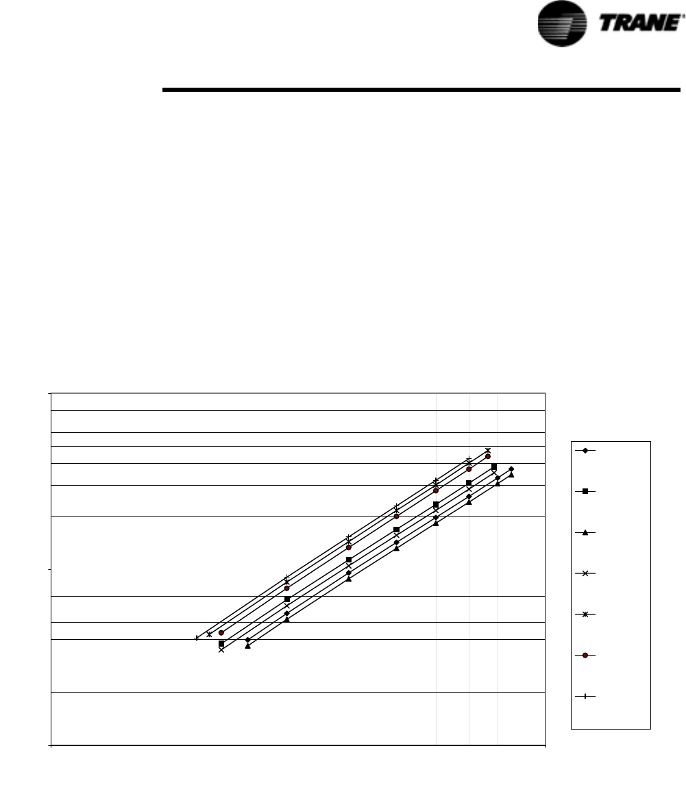
RTAC-SVX01F-EN 43
Installation - Mechanical
2. To prevent switch fluttering, remove all air from the water system.
NOTE: The CH530 provides a 6-second time delay after a “loss-of-flow” diagnostic
before shutting the unit down. Contact a qualified service representative if nuisance
machine shutdowns persist.
3. Adjust the switch to open when water flow falls below the minimum flow rate.
Evaporator data is given in the General Information section. Flow switch contacts
are closed on proof of water flow.
4. Install a pipe strainer in the entering evaporator water line to protect components
from waterborne debris.
Evaporator Water Pressure Drop RTAC 140 - 250 Ton
Figure 23 Evaporator Water Pressure Drop
Evaporator Water Pressure Drop
1
10
100
100 1000
Flow Rate (GPM)
Pressure Drop (ft H2O)
250S, 200H,
225H, 250H
(60Hz)
225S, 185H
200S, 170H
185S, 155H
170S, 140H
155S
140S
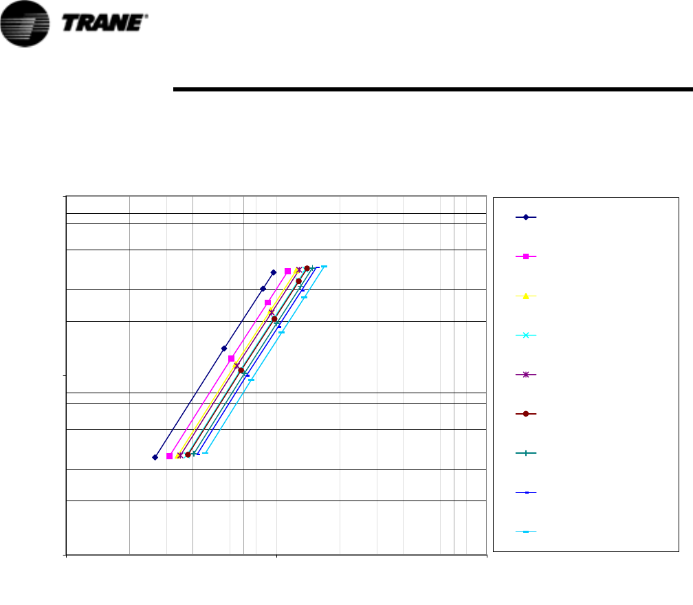
44 RTAC-SVX01F-EN
Installation - Mechanical
Evaporator Water Pressure Drop RTAC 250 - 500 Ton
Figure 24 Evaporator Water Pressure Drop
CAUTION
Proper Water Treatment!
The use of untreated or improperly treated water in a unit may result in
scaling, erosion, corrosion, algae or slime. It is recommended that the
services of a qualified water treatment specialist be engaged to
determine what water treatment, if any, is required. Trane assumes no
responsibility for equipment failures which result from untreated or
improperly treated water, or saline or brackish water.
If using an acidic commercial flushing solution, construct a temporary
bypass around the unit to prevent damage to internal components of the
evaporator.
Dirt, scale, products of corrosion and other foreign material will adversely affect heat
transfer between the water and system components. Foreign matter in the chilled
water system can also increase pressure drop and, consequently, reduce water flow.
Proper water treatment must be determined locally, depending on the type of system
and local water characteristics.
Water-Side Pressure Drop vs Flow Rate
1.0
10.0
100.0
100 1000 10000
Flow Rate (GPM)
Pressure Drop (ft H2O)
250S (50Hz)
275S
300S, 250H (50Hz)
350S (60 Hz), 275H, 300H
350S (50Hz)
375S (50Hz)
400S, 350H
450S (60Hz), 375H (50Hz)
500S (60Hz), 400H
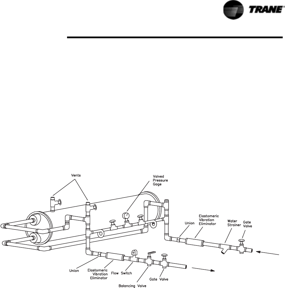
RTAC-SVX01F-EN 45
Installation - Mechanical
Neither salt nor brackish water is recommended for use in Trane air-cooled Series R®
chillers. Use of either will lead to a shortened life to an indeterminable degree. The
Trane Company encourages the employment of a reputable water treatment special-
ist, familiar with local water conditions, to assist in this determination and in the
establishment of a proper water treatment program.
Using untreated or improperly treated water in these units may result in inefficient
operation and possible tube damage. Consult a qualified water treatment specialist to
determine whether treatment is needed. The following disclamatory label is provided
on each RTAC unit:
NOTE: The use of improperly treated or untreated water in this equipment may
result in scaling, erosion, corrosion, algae or slime. The services of a qualified water
treatment specialist should be engaged to determine what treatment, if any, is
advisable. The Trane Company warranty specifically excludes liability for corrosion,
erosion or deterioration of Trane equipment.
Water Pressure Gauges
Install field-supplied pressure components as shown in Figure 25. Locate pressure
gauges or taps in a straight run of pipe; avoid placement near elbows, etc. Be sure to
install the gauges at the same elevation on each shell if the shells have opposite-end
water connections.
Figure 25 Suggested Piping for Typical RTAC Evaporator
NOTE: Once the unit is installed at a site, one vertical or one diagonal unit support
can be permanently removed if it creates an obstruction for water piping.
To read manifolded pressure gauges, open one valve and close the other (depending
upon the reading desired). This eliminates errors resulting from differently calibrated
gauges installed at unmatched elevations.

46 RTAC-SVX01F-EN
Installation - Mechanical
Water Pressure Relief Valves
CAUTION
Shell Damage!
To prevent shell damage, install pressure relief valves in the evaporator
water system.
Install a water pressure relief valve in the evaporator inlet piping between the evapo-
rator and the inlet shutoff valve, as shown in Figure 25. Water vessels with close-cou-
pled shutoff valves have a high potential for hydrostatic pressure buildup on a water
temperature increase. Refer to applicable codes for relief valve installation guidelines.
Freeze Protection
If the unit will remain operational at subfreezing ambient temperatures, the chilled
water system must be protected from freezing. Heaters are factory-installed on the
packaged unit evaporator and will help protect it from freezing in ambient tempera-
tures down to -20°F (-29°C).
Install heat tape on all water piping, pumps, water box nozzles and other components
that may be damaged if exposed to freezing temperatures. Heat tape must be
designed for low ambient temperature applications. Heat tape selection should be
based on the lowest expected ambient temperature.
Add a non-freezing, low temperature, corrosion inhibiting, heat transfer fluid may also
be added to the chilled water system. The solution must be strong enough to provide
protection against ice formation at the lowest anticipated ambient temperature. Refer
to Table 1 through Tab l e 5 in the General Information section for evaporator water
storage capacities.
NOTE: Use of glycol type antifreeze reduces the cooling capacity of the unit and
must be considered in the design of the system specifications.
CAUTION
Evaporator Damage!
ALL unit chilled water pumps must be controlled by the Trane CH530 to
avoid catastrophic damage to the evaporator due to freezing. Refer to
RLC-PRB012-EN.
Low Evaporator Refrigerant Cutout and % Glycol
Recommendations
1. Solution freeze point is 4 deg F below operating point saturation temperature.
2. LRTC is 4 deg F below freeze point.
Procedure
1. Is operating condition contained within Tab l e 9 ? If no see “Special” below.
2. For leaving fluid temperatures greater than 40 deg F, use settings for 40 deg F.
3. Select operating conditions from Tabl e 9.
4. Read off recommended % glycol.
5. Go to Table 10. From the % glycol.

RTAC-SVX01F-EN 47
Installation - Mechanical
Important
1. Additional glycol beyond the recommendations will adversely effect unit perfor-
mance. The unit efficiency will be reduced and the saturated evaporator tempera-
ture will be reduced. For some operating conditions this effect can be significant.
2. If additional glycol is used, then use the actual % glycol to establish the low
refrigerant cutout setpoint.
3. The minimum low refrigerant cutout setpoint allowed is -5 deg F. The minimum is
established by the solubility limits of the oil in the refrigerant.
Specials
The following constitute a special that must be calculated by engineering:
1. Freeze inhibitor other than Ethylene Glycol or Propylene Glycol.
2. Fluid delta T outside the range 4 to 16 deg F.
3. Unit configuration other than Standard, Standard with extra pass, and Premium.
4. % Glycol greater than maximum in column in Table 10.
Special should all be calculated by engineering. The purpose of calculating is to make
sure that design saturation temperature is greater than 3 deg F. Additionally, the calcu-
lation must verify that the fluid freeze point is a minimum of 4 deg. F lower that the
design saturation temperature. The low evaporator temperature cutout will be 4 deg F
below the freeze point or -5 deg F, whichever is greater.
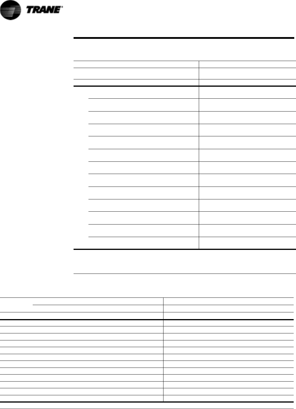
Ethylene Glycol Propylene Glycol
DT
[F]
46810 12 14 16 46810 12 14 16
[C] -15 -14 -13 -12 -11 -10 -9 -15 -14 -13 -12 -11 -10 -9
Leaving Water Temperature (F/C)
% Glycol
Ethylene Glycol Propylene Glycol
Low Refrig. Temp Cutout Solution Freeze Point Low Refrig. Temp Cutout Solution Freeze Point
°F °C °F °C °F °C °F °C
48 RTAC-SVX01F-EN
Installation - Mechanical
Table 9 Glycol Recommendations
38 --55556----66778--
3
34 -- 11 11 11 12 -- -- -- 13 13 15 17 -- --
1
30 -- 15 16 17 18 -- -- -- 19 21 -- -- -- --
-1
28 -- 18 18 19 -- -- -- -- 22 -- -- -- -- --
-2
26 -- 20 21 22 -- -- -- -- 25 -- -- -- -- --
-3
24 -- 22 23 26 -- -- -- -- -- -- -- -- -- --
-4
22 -- 24 26 -- -- -- -- -- -- -- -- -- -- --
-6
20 -- 26 30 -- -- -- -- -- -- -- -- -- -- --
-7
18 -- 29 -- -- -- -- -- -- -- -- -- -- -- --
-8
16 -- 31 -- -- -- -- -- -- -- -- -- -- -- --
-9
14 30 -- -- -- -- -- -- -- -- -- -- -- -- --
-10
12 32 -- -- -- -- -- -- -- -- -- -- -- -- --
-11
10.4 34 -- -- -- -- -- -- -- -- -- -- -- -- --
-12
These tables represent the MINIMUM RECOMMENDED glycol percentages for each operating condition
Operation is not recommended at certain operating conditions as some chillers may not satisfy maximum or
minimum velocity requirements or minimum performance requirements. Contact Trane Sales Representative
for more information regarding the operating limits of a particular chiller.
Table 10 Recommended Low Evaporator Refrigerant Cutout and % Glycol
0 28.0 -2.2 32 0 28.0 -2.2 32.0 0
5 25.0 -3.9 29 -1.7 25.3 -3.7 29.3 -1.5
10 21.5 -5.8 25.5 -3.6 22.4 -5.3 26.4 -3.1
15 17.5 -8.1 21.5 -5.8 19.1 -7.2 23.1 -4.9
20 12.8 -10.7 16.8 -8.4 15.3 -9.3 19.3 -7.1
25 7.4 -13.7 11.4 -11.4 10.8 -11.8 14.8 -9.6
30 1.1 -17.2 5.1 -15.0 5.3 -14.8 9.3 -12.6
35 -5.0 -20.6 -2.3 -19.1 -1.3 -19.5 2.7 -16.3
40 -5.0 -20.6 -10.8 -23.8 -5.0 -20.6 -5.2 -20.7
45 -5.0 -20.6 -20.7 -29.3 -5.0 -20.6 -14.6 -25.9
50 -5.0 -20.6 -32.1 -35.6 -5.0 -20.6 -25.8 -32.1
54 -5.0 -20.6 -42.3 -41.3 -5.0 -20.6 -36.1 -37.8
Chilled Water Temperature Cutout should be set to 5°F below the lowest allowable Chilled Water Set Point bases on the %Glycol.
RTAC-SVX01F-EN 49
Installation - Mechanical
Remote Evaporator Option
The RTAC 140-250 ton outdoor unit with the Remote Evaporator option is shipped as two
pieces: the outdoor unit (condensing) and the evaporator. Short suction line connections
are provided with the outdoor condensing unit. The remote evaporator is shipped com-
plete, with factory-mounted electronic expansion valves, water temperature sensors, suc-
tion pressure transducers, liquid level control sensors, all factory wired to a ribbon cable.
Solenoid valves and drain valves are wired to a relay board in the terminal box. The install-
ing contractor is required to provide and install the following:
• 2-wire, twisted shielded communication line between the remote evaporator terminal
box and the Condensing Unit’s control panel
• 115 VAC single phase power supply to the remote evaporator terminal box
• 2 liquid lines
• 2 suction lines
• Suction accumulator as specified
NOTE: A unit ordered as a remote evaporator must also be ordered with either the wide
or low ambient option. The fan inverters are necessary for proper control.
System Configuration and Interconnecting Refrigerant Piping
The system may be configured in any of the four arrangements shown in Figure 26. The
configurations and their associated elevations, along with the total distance between the
remote evaporator and the compressor/condenser section, play a critical role in determin-
ing suction and liquid line sizes. This will also affect field refrigerant and oil charges. Conse-
quently, there are physical limits which must not be violated if the system is to operate as
designed. Please note the following requirements for field installation:
1. The remote evaporator MUST be matched with its respective outdoor condensing unit.
2. The circuit number on the outdoor condensing unit must match the circuit number on
the evaporator, i.e. circuit #1 on the outdoor condensing unit must be connected with
circuit # 1 on the remote evaporator and likewise for circuit #2. RTAC Circuit Capacities
are shown in General Data Tables.
CAUTION
Equipment Damage!
If the circuits are crossed, serious equipment damage may occur.
3. Piping between the evaporator and outdoor unit can not exceed 200 actual feet and/or
an equivalent length of 300 feet.
NOTE: The latter includes the equivalent length of all associated field installed fittings,
valves, accessories and straight lengths of interconnecting piping.
4. Horizontal portions of suction lines must be downward sloping toward the compressor
at least 1/2 inch for each 10 feet run. This promotes the movement of oil in the direc-
tion of gas flow.
5. Suction lines must be insulated.
6. The line sizes defined are to be used only for 40-60 F leaving water temperature and/or
full load ice-making applications.

50 RTAC-SVX01F-EN
Installation - Mechanical
Remote Evaporator Option
7. Figure 26, drawing 1 depicts an installation where the remote evaporator eleva-
tion is the same as that of the outdoor condensing unit. The suction and liquid
lines are horizontal or down flowing only.
The suction and liquid lines can be put under ground or in a trench. The
temperature of the suction lines must never exceed the temperature of the
compressor. The line can be below the compressors a maximum of 15 ft.
8. Figure 26, drawing 2 shows a variation to drawing 1. The remote evaporator and
outdoor condensing unit are at the same elevation but interconnecting piping may
be installed up to 15 feet above the base elevation. Refer to Ta ble 13 to determine
the required length of the suction accumulator line. A full size suction accumula-
tor is required at the evaporator and 50% of the value is required at the condens-
ing unit.
9. A refrigerant drain valve is installed at the bottom of the evaporator for freeze pro-
tection. This drain valve is a normally open, pilot operated valve which remains
closed unless there is a potential freezing situation detected via low evap temper-
atures or low water temperatures or a power failure. If the drain valve is opened
the installed suction accumulator must be capable of holding the entire evapora-
tor charge. Refer to Table 13 for sizing.
10. For installations where the remote evaporator is at a lower elevation than the out-
door condensing unit as shown in Figure 26, drawing 3, the elevation difference is
not to exceed 100 feet. An inverted liquid line trap at the condensing unit is
required to prevent unwanted free cooling. The apex of the liquid line trap should
be at a height above the condenser coils. A suction accumulator must be installed
at the evaporator. Refer to Table 13 for sizing.
11. When the elevation of the remote evaporator exceeds that of the outdoor con-
densing unit as shown in Figure 26, drawing 4, the elevation difference is deter-
mined by Table 11. The suction accumulator line must be installed according to
Table 13. It is very important, for proper control and operation of the chiller, that
the elevation requirements given in Table 11 are not exceeded. It should also be
noted that in this configuration the suction accumulator is installed at the con-
densing section.
Note: The height is limited by the available subcooling.
12. Compressor & oil separator heaters must be on at least 24 hours prior to com-
pressor start.
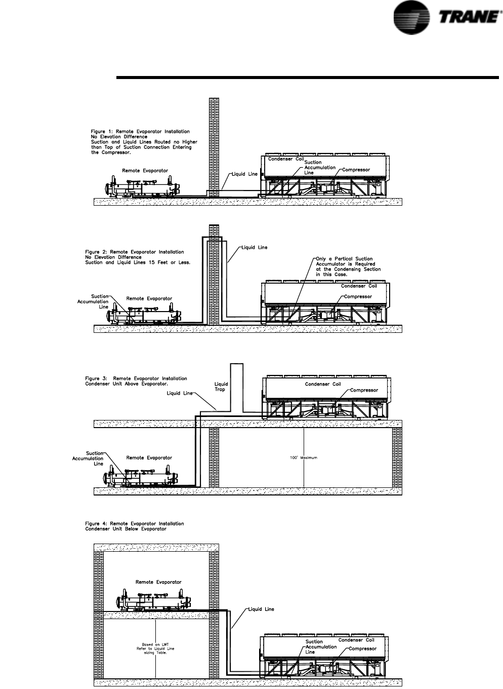
RTAC-SVX01F-EN 51
Installation - Mechanical
Remote Evaporator Option
Figure 26 Remote Evaporator Installations
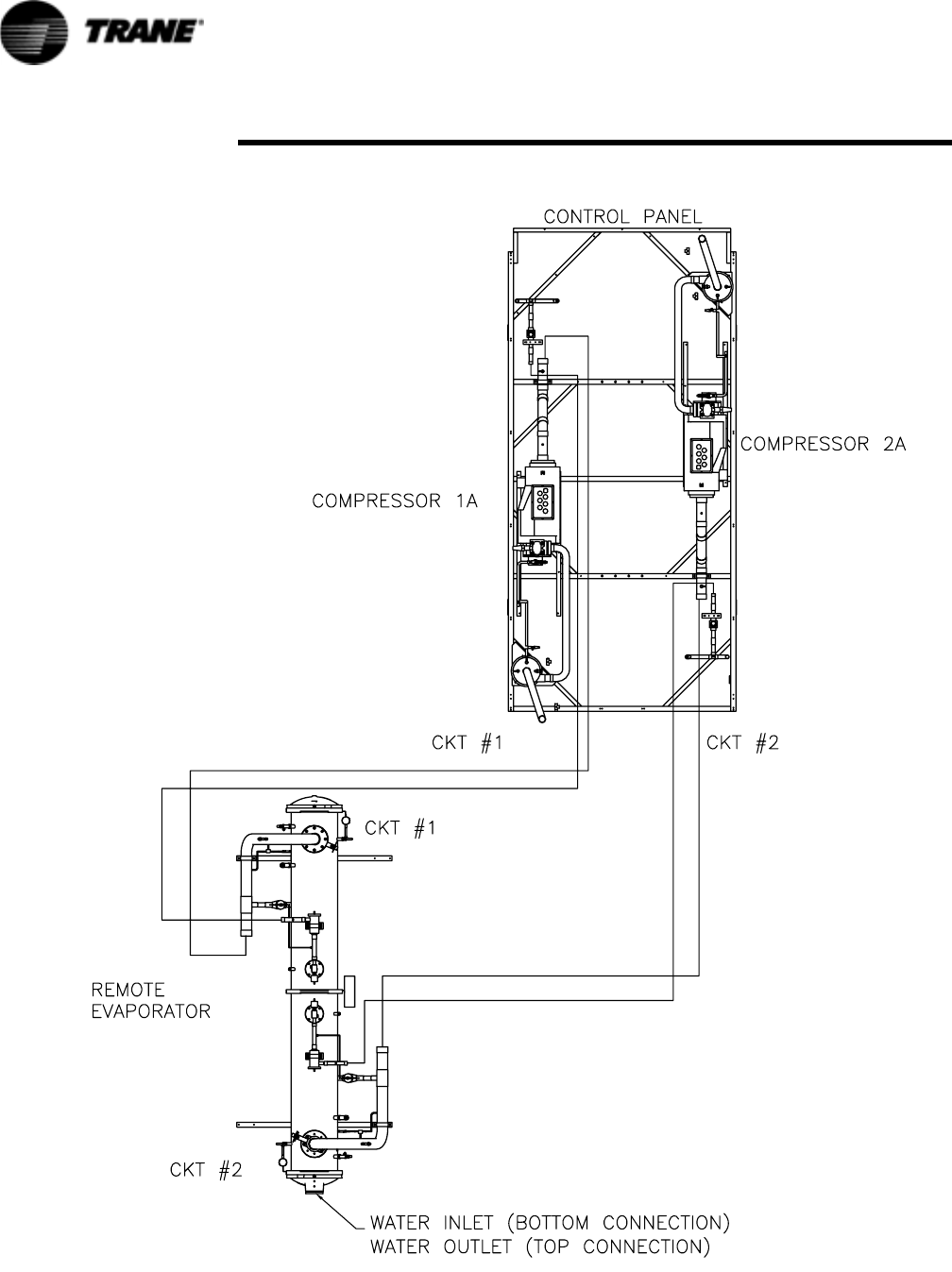
52 RTAC-SVX01F-EN
Installation - Mechanical
Remote Evaporator Option
Figure 27 Circuit Identification
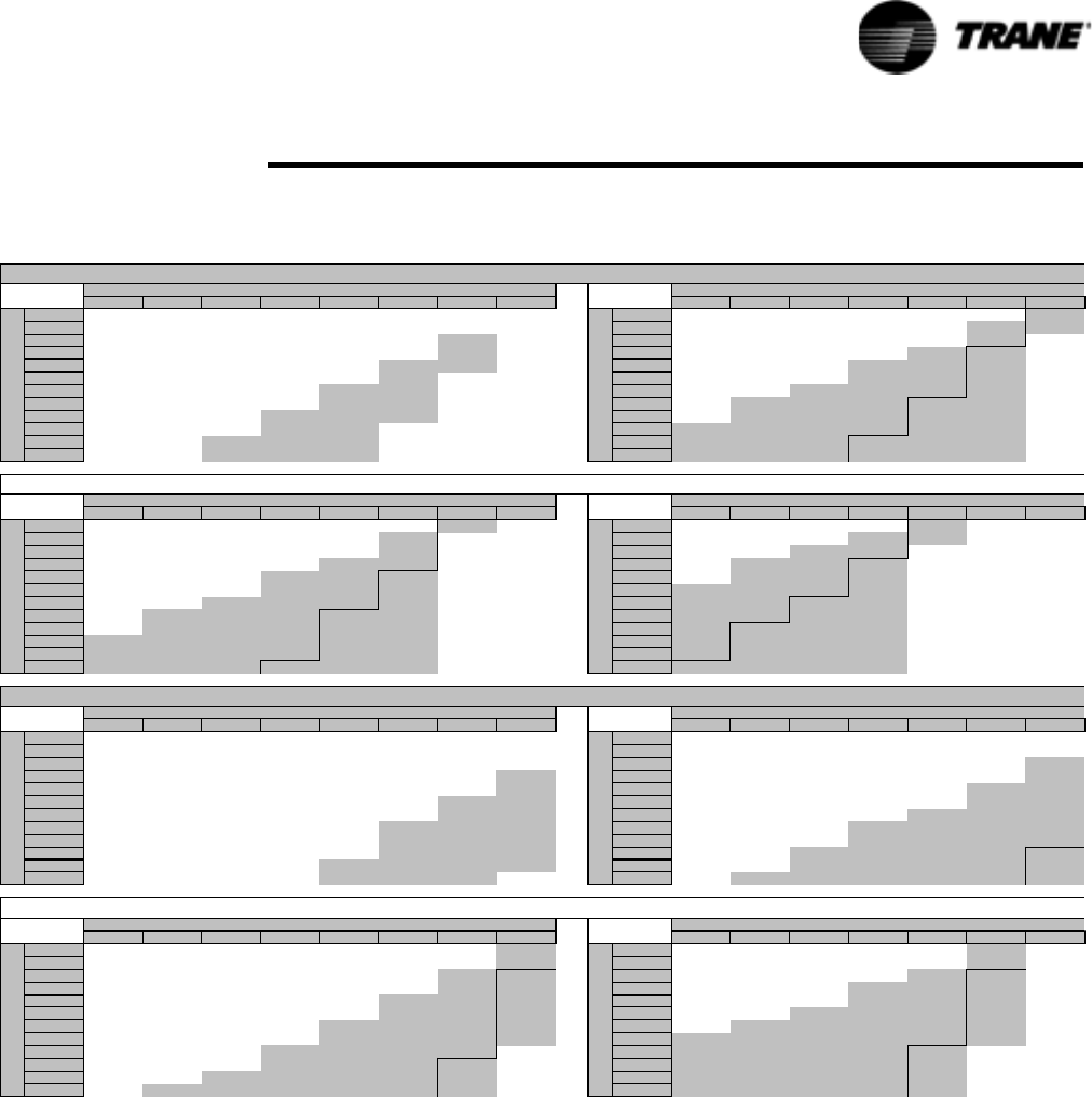
RTAC-SVX01F-EN 53
Installation - Mechanical
Remote Evaporator Option
Line Sizing
To determine the appropriate outside diameter for field installed liquid and suction
lines, it is first necessary to establish the equivalent length of pipe for each line. It is
also necessary to know the capacity (tons) of each circuit. Circuit capacities for each
RTAC unit are listed in the General Data Tables in Section1.
Table 11 Liquid Line Sizes for Remote Evaporators (typical type L copper O.D.)
RTAC 140-250 Ton Remote Evaporator
Liquid Line Sizes
0 1 to 5 6 to 10 11 to 15 16 to 20 21 to 25 26 to 30 31 to 35 0 1 to 5 6 to 10 11 to 15 16 to 20 21 to 25 26 to 30
25 1.375 1.375 1.375 1.375 1.375 1.375 1.375 N/A 25 1.375 1.375 1.375 1.375 1.375 1.375 2.125
50 1.375 1.375 1.375 1.375 1.375 1.375 1.375 N/A 50 1.375 1.375 1.375 1.375 1.375 1.625 2.125
75 1.375 1.375 1.375 1.375 1.375 1.375 1.625 N/A 75 1.375 1.375 1.375 1.375 1.375 1.625 N/A
100 1.375 1.375 1.375 1.375 1.375 1.375 1.625 N/A 100 1.375 1.375 1.375 1.375 1.625 2.125 N/A
125 1.375 1.375 1.375 1.375 1.375 1.625 1.625 N/A 125 1.375 1.375 1.375 1.625 1.625 2.125 N/A
150 1.375 1.375 1.375 1.375 1.375 1.625 N/A N/A 150 1.375 1.375 1.375 1.625 1.625 2.125 N/A
175 1.375 1.375 1.375 1.375 1.625 1.625 N/A N/A 175 1.375 1.375 1.625 1.625 1.625 2.125 N/A
200 1.375 1.375 1.375 1.375 1.625 1.625 N/A N/A 200 1.375 1.625 1.625 1.625 2.125 2.125 N/A
225 1.375 1.375 1.375 1.625 1.625 1.625 N/A N/A 225 1.375 1.625 1.625 1.625 2.125 2.125 N/A
250 1.375 1.375 1.375 1.625 1.625 N/A N/A N/A 250 1.625 1.625 1.625 1.625 2.125 2.125 N/A
275 1.375 1.375 1.625 1.625 1.625 N/A N/A N/A 275 1.625 1.625 1.625 2.125 2.125 2.125 N/A
300 1.375 1.375 1.625 1.625 1.625 N/A N/A N/A 300 1.625 1.625 1.625 2.125 2.125 2.125 N/A
0 1 to 5 6 to 10 11 to 15 16 to 20 21 to 25 26 to 30 31 to 35 0 1 to 5 6 to 10 11 to 15 16 to 20 21 to 25 26 to 30
25 1.375 1.375 1.375 1.375 1.375 1.375 2.125 N/A 25 1.375 1.375 1.375 1.375 2.125 N/A N/A
50 1.375 1.375 1.375 1.375 1.375 1.625 N/A N/A 50 1.375 1.375 1.375 1.625 2.125 N/A N/A
75 1.375 1.375 1.375 1.375 1.375 1.625 N/A N/A 75 1.375 1.375 1.625 1.625 N/A N/A N/A
100 1.375 1.375 1.375 1.375 1.625 1.625 N/A N/A 100 1.375 1.625 1.625 2.125 N/A N/A N/A
125 1.375 1.375 1.375 1.625 1.625 2.125 N/A N/A 125 1.375 1.625 1.625 2.125 N/A N/A N/A
150 1.375 1.375 1.375 1.625 1.625 2.125 N/A N/A 150 1.625 1.625 1.625 2.125 N/A N/A N/A
175 1.375 1.375 1.625 1.625 1.625 2.125 N/A N/A 175 1.625 1.625 2.125 2.125 N/A N/A N/A
200 1.375 1.625 1.625 1.625 2.125 2.125 N/A N/A 200 1.625 1.625 2.125 2.125 N/A N/A N/A
225 1.375 1.625 1.625 1.625 2.125 2.125 N/A N/A 225 1.625 2.125 2.125 2.125 N/A N/A N/A
250 1.625 1.625 1.625 1.625 2.125 2.125 N/A N/A 250 1.625 2.125 2.125 2.125 N/A N/A N/A
275 1.625 1.625 1.625 1.625 2.125 2.125 N/A N/A 275 1.625 2.125 2.125 2.125 N/A N/A N/A
300 1.625 1.625 1.625 2.125 2.125 2.125 N/A N/A 300 2.125 2.125 2.125 2.125 N/A N/A N/A
0 1 to 5 6 to 10 11 to 15 16 to 20 21 to 25 26 to 30 31 to 35 0 1 to 5 6 to 10 11 to 15 16 to 20 21 to 25 26 to 30
25 1.625 1.625 1.625 1.625 1.625 1.625 1.625 1.625 25 1.625 1.625 1.625 1.625 1.625 1.625 1.625
50 1.625 1.625 1.625 1.625 1.625 1.625 1.625 1.625 50 1.625 1.625 1.625 1.625 1.625 1.625 1.625
75 1.625 1.625 1.625 1.625 1.625 1.625 1.625 1.625 75 1.625 1.625 1.625 1.625 1.625 1.625 2.125
100 1.625 1.625 1.625 1.625 1.625 1.625 1.625 2.125 100 1.625 1.625 1.625 1.625 1.625 1.625 2.125
125 1.625 1.625 1.625 1.625 1.625 1.625 1.625 2.125 125 1.625 1.625 1.625 1.625 1.625 2.125 2.125
150 1.625 1.625 1.625 1.625 1.625 1.625 2.125 2.125 150 1.625 1.625 1.625 1.625 1.625 2.125 2.125
175 1.625 1.625 1.625 1.625 1.625 1.625 2.125 2.125 175 1.625 1.625 1.625 1.625 2.125 2.125 2.125
200 1.625 1.625 1.625 1.625 1.625 2.125 2.125 2.125 200 1.625 1.625 1.625 2.125 2.125 2.125 2.125
225 1.625 1.625 1.625 1.625 1.625 2.125 2.125 2.125 225 1.625 1.625 1.625 2.125 2.125 2.125 2.125
250 1.625 1.625 1.625 1.625 1.625 2.125 2.125 2.125 250 1.625 1.625 2.125 2.125 2.125 2.125 2.625
275 1.625 1.625 1.625 1.625 2.125 2.125 2.125 2.125 275 1.625 1.625 2.125 2.125 2.125 2.125 2.625
300 1.625 1.625 1.625 1.625 2.125 2.125 2.125 N/A 300 1.625 2.125 2.125 2.125 2.125 2.125 2.625
0 1 to 5 6 to 10 11 to 15 16 to 20 21 to 25 26 to 30 31 to 35 0 1 to 5 6 to 10 11 to 15 16 to 20 21 to 25 26 to 30
25 1.625 1.625 1.625 1.625 1.625 1.625 1.625 2.125 25 1.625 1.625 1.625 1.625 1.625 2.125 N/A
50 1.625 1.625 1.625 1.625 1.625 1.625 1.625 2.125 50 1.625 1.625 1.625 1.625 1.625 2.125 N/A
75 1.625 1.625 1.625 1.625 1.625 1.625 2.125 2.625 75 1.625 1.625 1.625 1.625 2.125 2.625 N/A
100 1.625 1.625 1.625 1.625 1.625 1.625 2.125 2.625 100 1.625 1.625 1.625 2.125 2.125 2.625 N/A
125 1.625 1.625 1.625 1.625 1.625 2.125 2.125 2.625 125 1.625 1.625 1.625 2.125 2.125 2.625 N/A
150 1.625 1.625 1.625 1.625 1.625 2.125 2.125 2.625 150 1.625 1.625 2.125 2.125 2.125 2.625 N/A
175 1.625 1.625 1.625 1.625 2.125 2.125 2.125 2.625 175 1.625 2.125 2.125 2.125 2.125 2.625 N/A
200 1.625 1.625 1.625 1.625 2.125 2.125 2.125 2.625 200 2.125 2.125 2.125 2.125 2.125 2.625 N/A
225 1.625 1.625 1.625 2.125 2.125 2.125 2.125 N/A 225 2.125 2.125 2.125 2.125 2.625 N/A N/A
250 1.625 1.625 1.625 2.125 2.125 2.125 2.625 N/A 250 2.125 2.125 2.125 2.125 2.625 N/A N/A
275 1.625 1.625 2.125 2.125 2.125 2.125 2.625 N/A 275 2.125 2.125 2.125 2.125 2.625 N/A N/A
300 1.625 2.125 2.125 2.125 2.125 2.125 2.625 N/A 300 2.125 2.125 2.125 2.125 2.625 N/A N/A
70-ton Circuit
100-ton Circuit
40
-
50F
Lvg. Water
50
-
60F
Lvg. Water
Height (ft) Height (ft)
85-ton Circuit
40
-
50F
Lvg. Water
Total Equiv. Length (ft)
Total Equiv. Length (ft)
40
-
50F
Lvg. Water
50
-
60F
Lvg. Water
Height (ft) Height (ft)
Total Equiv. Length (ft)
120-ton Circuit
Total Equiv. Length (ft)
Total Equiv. Length (ft)
40
-
50F
Lvg. Water
50
-
60F
Lvg. Water
Height (ft)
Total Equiv. Length (ft)
Height (ft)
Height (ft)
50
-
60F
Lvg. Water
Total Equiv. Length (ft)
Total Equiv. Length (ft)
Height (ft)
54 RTAC-SVX01F-EN
Installation - Mechanical
Remote Evaporator Option
Liquid Line Sizing Steps
The steps to compute liquid line size are as follows:
1. Compute the actual length of field installed piping.
2. Multiply the length from step # 1 by 1.5 to estimate the equivalent length.
3. Refer to Table 11 to determine the outside diameter that corresponds to the
equivalent length computed in step # 2 for the height and leaving water tempera-
ture of interest.
Note: If the condenser is at the same elevation or above the evap, use the 0 ft.
column.
4. With the outside diameter found in step # 3, use Table 12 to determine the equiv-
alent lengths of each fitting in the field installed piping.
5. Sum the equivalent lengths of all the field installed elbows and valves.
6. Add the length found in step # 5 to the actual length from step # 1. This is your
new equivalent line length.
7. U s i n g Table 11 again, find the outside diameter that corresponds to the new
equivalent line length from step # 6. If it is the same as step #3, this is the final
equivalent length. Otherwise, proceed to the next step.
8. Using Table 12 and the new outside diameter found in step # 7, find the equivalent
line length of each valve and fitting, and sum them.
9. Add the length found in step # 8 to the actual length from step # 1. This is the new
equivalent line length.
10. With the equivalent line length found in step # 9, use Table 11 to select the proper
outside diameter for the liquid lines. If the same as in step #7, this is your final
equivalent line length. Otherwise, repeat step #7.
Table 12 Equivalent Lengths of Non-Ferrous Valves and Fittings (feet)
Line Size Inches
OD
Globe Valve Short Angle
Valve
Short Radius
ELL
Long Radius
ELL
1-1/887292.71.9
1-3/8 102 33 3.2 2.2
1-5/8 115 34 3.8 2.6
2-1/8 141 39 5.2 3.4
2-5/8 159 44 6.5 4.2
3-1/8 185 53 8 5.1
3-5/8 216 66 10 6.3
4-1/8 248 76 12 7.3
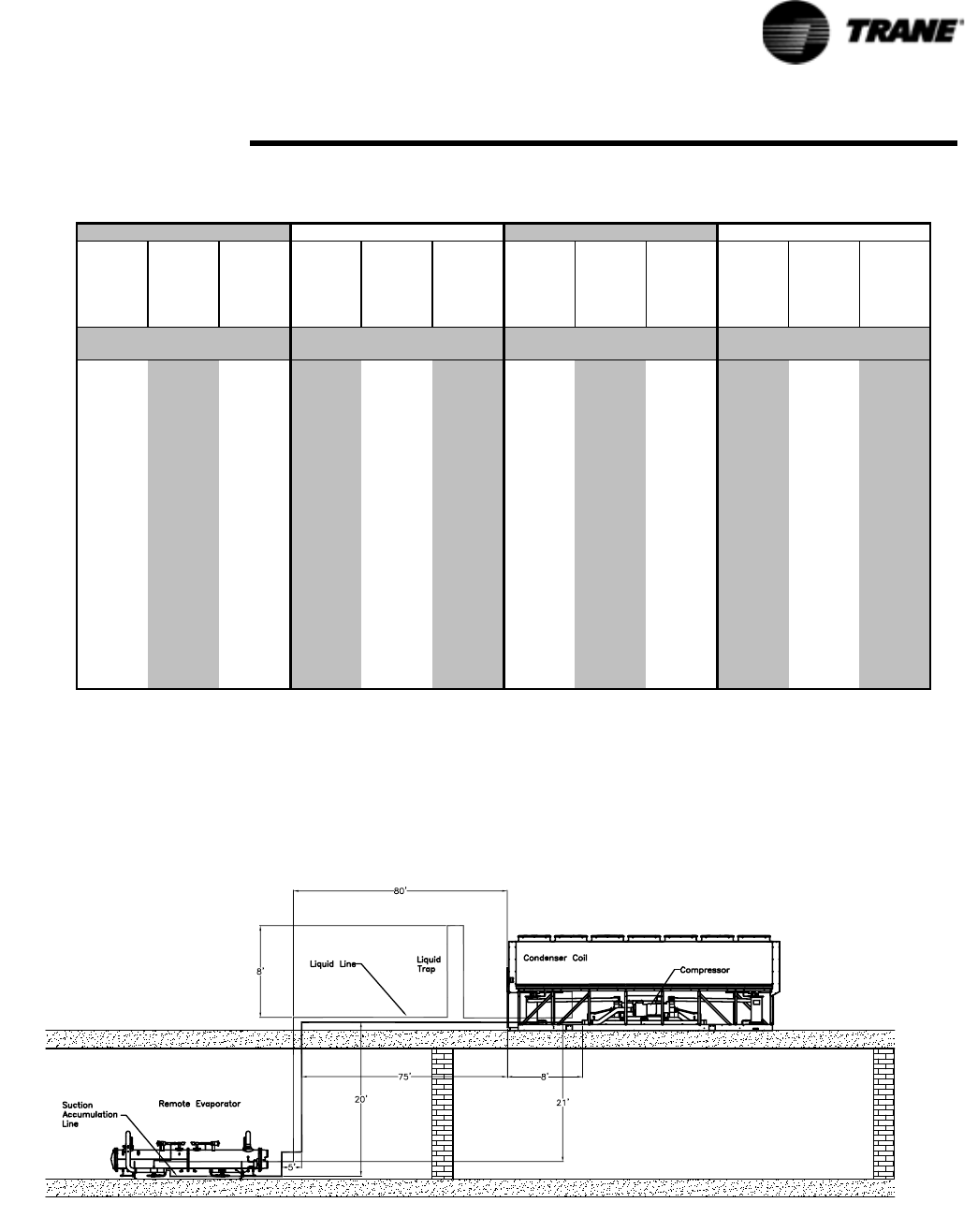
RTAC-SVX01F-EN 55
Installation - Mechanical
Remote Evaporator Option
NOTE: Location and quantity of suction accumulator is dependent upon the unit
configuration.
Example Liquid Line Sizing
Table 13 Required Length of Field Installed Suction Accumulator
1 3/8" O.D.
Field
Installed
Liquid Line
1 5/8" O.D.
Field
Installed
Liquid Line
2 1/8" O.D.
Field
Installed
Liquid Line
1 3/8" O.D.
Field
Installed
Liquid Line
1 5/8" O.D.
Field
Installed
Liquid Line
2 1/8" O.D.
Field
Installed
Liquid Line
1 5/8" O.D.
Field
Installed
Liquid Line
2 1/8" O.D.
Field
Installed
Liquid Line
2 5/8" O.D.
Field
Installed
Liquid Line
1 5/8" O.D.
Field
Installed
Liquid Line
2 1/8" O.D.
Field
Installed
Liquid Line
2 5/8" O.D.
Field
Installed
Liquid Line
10 43 44 45 52 52 53 43 44 46 52 53 54
20 45 46 49 53 54 57 45 47 50 53 55 58
30 46 48 52 54 56 60 46 49 53 55 58 62
40 48 50 55 56 58 63 48 52 57 56 60 66
50 49 52 59 57 60 67 49 55 61 58 63 70
60 51 54 62 59 62 70 51 57 65 59 66 74
70 52 56 65 60 64 73 53 60 69 61 68 78
80 53 58 69 62 66 77 54 62 73 62 71 81
90 55 60 72 63 68 80 56 65 77 64 73 85
100 56 62 75 64 70 83 57 68 81 66 76 89
110 58 64 79 66 72 87 59 70 85 67 79 93
120 59 66 82 67 74 90 60 73 89 69 81 97
130 61 68 85 69 76 93 62 75 93 70 84 101
140 62 70 89 70 78 97 63 78 97 72 86 105
150 64 72 92 72 80 100 65 81 101 73 89 109
160 65 74 95 73 82 103 67 83 105 75 92 113
170 66 76 99 75 84 107 68 86 108 76 94 117
180 68 78 102 76 86 110 70 88 112 78 97 121
190 69 79 105 77 88 113 71 91 116 80 99 125
200 71 81 109 79 90 117 73 94 120 81 102 129
(1) Note: Circuit 2 (M1) of 155 Ton Premium Unit requires an additional 10 feet of Suction Accumulator length.
Actual ft
of field
installed
liquid line
120 Ton Circuit100 Ton Circuit70 Ton Circuit (1) 85 Ton Circuit
Required Length in Feet of Field Installed Suction Line Accumulator
Length of 3 5/8"
Suction Accumulator
Length of 3 5/8"
Suction Accumulator
Length of 4 1/8"
Suction Accumulator
Length of 4 1/8"
Suction Accumulator
Figure 28 Liquid Line Sizing Example
56 RTAC-SVX01F-EN
Installation - Mechanical
Remote Evaporator Option
For this example, refer to Table 11, Table 12 and Figure 28. Assume a 70 ton circuit
and a leaving water temperature of 49 degrees F.
1. Fr o m Figure 28, the actual length of field installed piping is:
80 + 8 + 8 + 21 = 117 feet
2. Estimate equivalent line length:
117 feet x 1.5 = 175 feet
3. From Table 11 for a 70 ton circuit, for 175 equivalent feet the OD is 1.375 inches.
Note: use the 0 ft. column since the condenser is above the evap
4. In Figure 28 there are six long-radius elbows. From Table 12, for 1.375 inch
elbows, the equivalent feet is:
6 elbows x 2.2 feet = 13.2 feet
5. Adding equivalent feet from step #4 to step #1 gives:
13.2 feet + 117 feet = 130.2 feet
6. From Table 11, for a 70 ton circuit, for 125 equivalent feet (nearest to 130.2), the
O.D. is 1- 3/8 inches.
Liquid Line size = 1-3/8 inches
Suction Line Sizing Steps
The steps to compute suction line size are as follows:
1. Break the suction line into it's Vertical/Upflow and Horizontal/Downflow compo-
nents.
2. From Table 14, select the appropriate Vertical/Upflow suction line outside diame-
ter according to the circuit tonnage. This is the diameter of the upflow suction line
and any fittings in the upflow line.
3. From Table 14, select the appropriate Horizontal/Downflow suction line outside
diameter according to the circuit tonnage. This is the diameter of the upflow suc-
tion line and any fittings in the upflow line.
NOTE: The diameters of the upflow, and horizontal or downflow portions of the
suction line may differ depending on the application.
Example Suction Line Sizing
For this example, refer to Tab le 14 and Figure 28 assume a 70 ton circuit and a leaving
water temperature of 49 degrees F.
1. Fr o m Table 14, the vertical/upflow suction line is: 3 5/8” O.D.
2. From Table 14, the horizontal/downflow line is: 3 5/8” O.D.
NOTE: In this example, the horizontal line is pitched downward in the direction of
flow.
Table 14 Suction Line Sizes
Vertical/Upflow and Horizontal/Downflow Suction Lines O.D. (Type L Copper)
LWT (F) 70 ton circuit 85ton circuit 100 ton circuit 120 ton circuit
40 - 60 3 5/8” 3 5/8” 4 1/8” 4 1/8”
RTAC-SVX01F-EN 57
Installation - Mechanical
Remote Evaporator Option
Suction Accumulator Sizing
Use Table 13 to calculate length and size of the required suction accumulator(s).
Example of Suction Accumulator Line Sizing
Use Figure 28 and the same assumptions from the liquid line sizing example to calcu-
late the suction accumulator line size and length.
In this case the accumulator is installed at the evaporator.
1. Use the 70 ton circuit column.
2. From the liquid line sizing example, use a field installed liquid line of:
1.375 (1 3/8”) inches
3. The actual feet of liquid line installed is: 117 feet
4. The size of the suction accumulator is: 3 5/8 inches
5. The length of the suction line accumulator is: 59 feet
Piping Installation Procedures
The outdoor unit and the evaporator are shipped with a 25 psig holding pressure of
dry nitrogen. Do not relieve this pressure until field installation of the refrigerant pip-
ing is to be accomplished. This will require the removal of the temporary pipe caps.
NOTE: Use Type L refrigerant-grade copper tubing only.
The refrigerant lines must be isolated to prevent line vibration from being transferred
to the building. Do not secure the lines rigidly to the building at any point.
All horizontal suction lines should be pitched downward, in the direction of flow, at a
slope of 1/2 inch per 10 feet of run.
Do not use a saw to remove end caps, as this may allow copper chips to contaminate
the system. Use a tubing cutter or heat to remove the end caps.
When sweating copper joints, flow dry nitrogen through the system. This prevents
scale formation and the possible formation of an explosive mixture of R-134a and air.
This will also prevent the formation of toxic phosgene gas, which occurs when refrig-
erant is exposed to open flame.
WARNING
Hazardous Gas!
To prevent injury or death, due to explosion and/or inhalation of
phosgene gas, purge the system thoroughly with dry nitrogen while
sweating connections. Use a pressure regulator in the line between the
unit and the high pressure nitrogen cylinder to avoid over-pressurization
and possible explosion.Failure to use a nitrogen purge and pressure
regulator could result in death or serious injury or equipment damage.

58 RTAC-SVX01F-EN
Installation - Mechanical
Remote Evaporator Option
Refrigerant Sensors
All necessary refrigerant devices, transducers and solenoids are factory installed and
wired to the evaporator terminal box.
Refrigerant Pressure Relief Valve Venting
WARNING
Hazardous Gases!
Consult local regulations for any special relief line requirements.
Refrigerant vented into a confined equipment room could displace
available oxygen to breathe, causing possible asphyxiation or other
serious health risks. Failure to follow these recommendations could
result in death or serious injury.
Vent pipe size must conform to the ANSI/ASHRAE Standard 15 for vent pipe sizing. All
federal, state, and local codes take precedence over any suggestions stated in this
manual.
All relief valve venting is the responsibility of the installing contractor.
All RTAC remote evaporator units use evaporator pressure relief valves (Figure 29)
that must be vented to the outside of the building.
Relief valve connection sizes and locations are shown in the unit submittals. Refer to
local codes for relief valve vent line sizing information.
Caution
Equipment Damage!
Do not exceed vent piping code specifications. Failure to comply with
specifications may result in capacity reduction, unit damage and/or relief
valve damage.
Relief valve discharge setpoints and capacities rates are given in Table 12. Once the
relief valve has opened, it will re-close when pressure is reduced to a safe level.
Once opened, relief valves may have a tendency to leak and must be replaced.
Pressure relief valve discharge capacities will vary with shell diameter and length and
also compressor displacement. Discharge venting capacity should be calculated as
required by ASHRAE Standard 15-94. Do not adjust relief valve setting in the field.
Valve Location Discharge
Setpoint
(psi)
Number of
Valves
Rated Capacity
per Relief Valve
(lba/min.)
Field Connection
Pipe Size (in NPT)
Factory
Shell Side
Connection (in)
Leak Test and Evacuation
After installation of the refrigerant piping, thoroughly test the system for leaks. Pres-
sure test the system at pressures required by local codes.
Table 15 Pressure Relief Valve Data
Evap 200 2 28.9 3/4 7/8 - 14
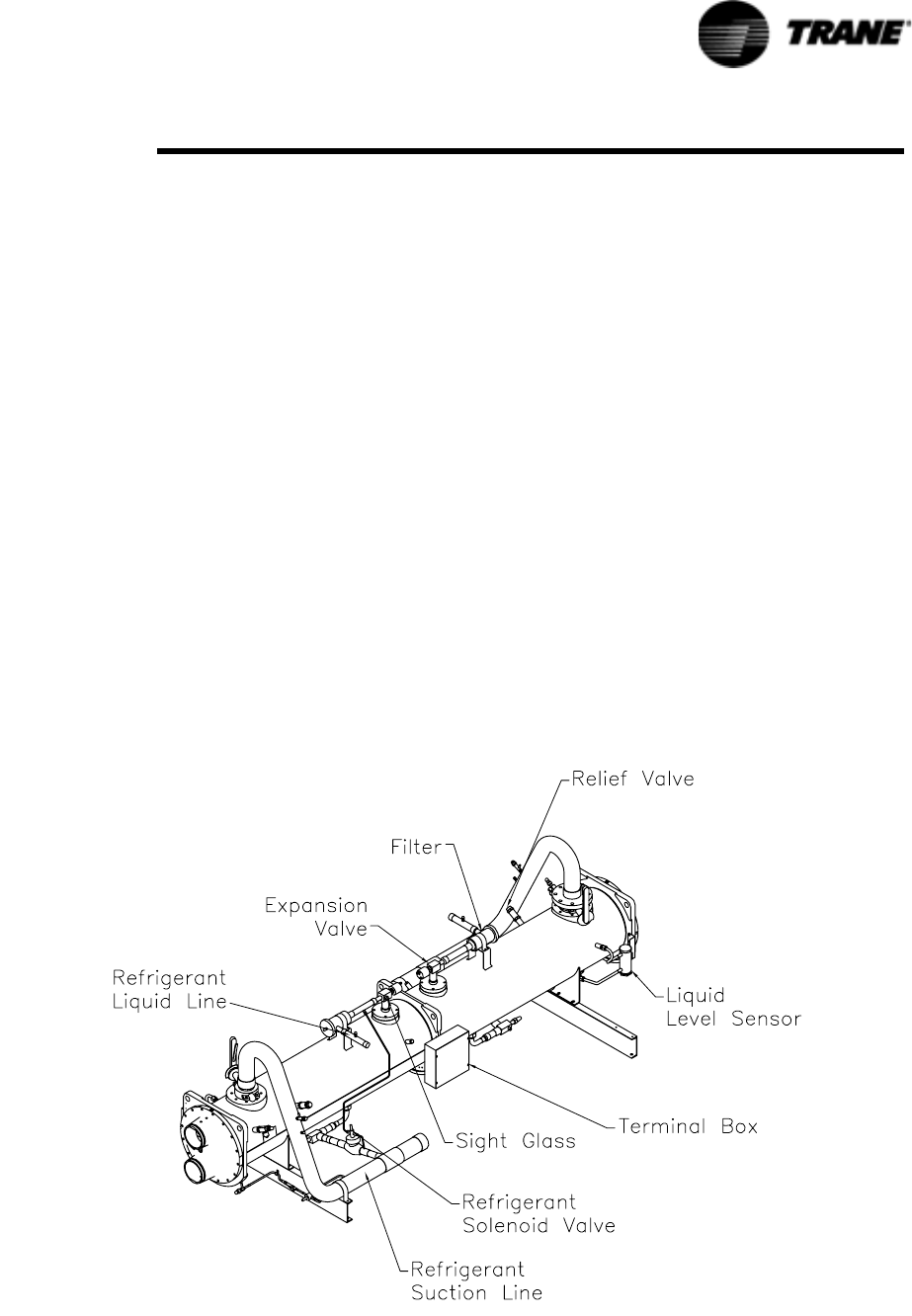
RTAC-SVX01F-EN 59
Installation - Mechanical
Remote Evaporator Option
WARNING
Hazard of Explosion!
Use only dry nitrogen with a pressure regulator for pressurizing unit. Do
not use acetylene, oxygen or compressed air or mixtures containing
them for pressure testing. Do not use mixtures of a hydrogen containing
refrigerant and air above atmospheric pressure for pressure testing as
they may become flammable and could result in an explosion.
Refrigerant, when used as a trace gas should only be mixed with dry
nitrogen for pressurizing units. Failure to follow these recommendations
could result in death or serious injury or equipment or property-only
damage.
For field evacuation, use a rotary-type vacuum pump capable of pulling a vacuum of
500 microns or less. Follow the pump manufacturer's instructions for proper use of
the pump. The line used to connect the pump to the system should be copper and be
the largest diameter that can be practically used. A larger line size with minimum flow
resistance can significantly reduce evacuation time.
Use the ports on the suction service valves and the liquid line shutoff valves for
access to the system for evacuation. Ensure that the suction service valve, the liquid
line shutoff valve, the oil line shutoff valve and any field installed valves are open in
the proper position before evacuating.
Insulate the entire suction line and the suction accumulator line. Where the line is
exposed to the weather, wrap it with weatherproof tape and seal with weatherproof
compound.
Figure 29 Remote Evaporator
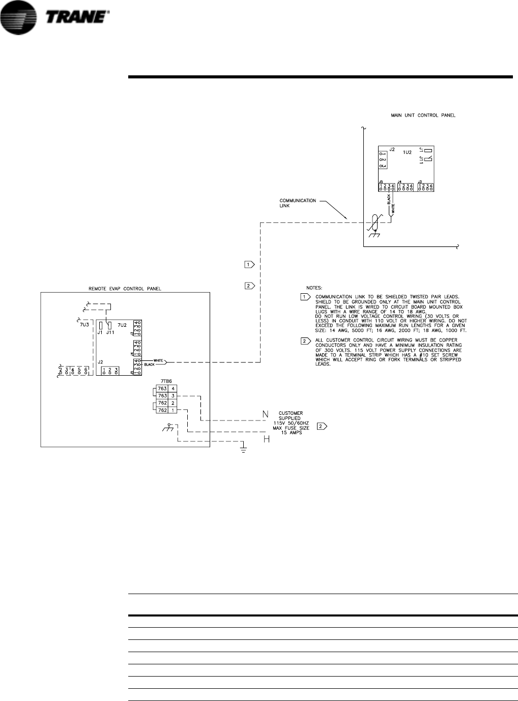
Figure 30 Field Wiring between Remote Evaporator and Condensing Unit
60 RTAC-SVX01F-EN
Installation - Mechanical
Remote Evaporator Option
Refrigerant and Additional Oil Charge
Refrigerant Charge Determination
The approximate amount of refrigerant charge required by the system must be deter-
mined by referring to Table 16 and must be verified by running the system and check-
ing subcooling.
Pipe O.D. (in)
Suction Line
lbs of R134a per 100ft
Liquid Line
lbs of R134a per 100ft
Table 16 Field Installed Piping Charge
1-3/8 N/A 62.4
1-5/8 N/A 88.3
2-1/8 N/A 153.6
2-5/8 N/A 236.9
3-1/8 5.0 N/A
3-5/8 6.8 N/A
4-1/8 8.8 N/A

RTAC-SVX01F-EN 61
Installation - Mechanical
Remote Evaporator Option
1. To determine the appropriate charge, first refer to the General Data Tables in Sec-
tion 1 to establish the required charge without the field-installed piping.
2. Next, determine the charge required for the field-installed piping by referring to
Table 16.
3. Sum the values of step 1 and step 2 to determine the circuit charge.
NOTE: The amounts of refrigerant listed in Table 16 are per 100 feet of pipe.
Requirements will be in direct proportion to the actual length of piping.
Oil Charge Determination
The unit is factory charged with the amount of oil required by the system, without the
field-installed piping. The amount of the additional oil required is dependent upon the
amount of refrigerant that is added to the system for the field installed piping.
Use the following formula to calculate the amount of oil to be added:
Pints of Oil = [lbs of R-134a added for field-installed piping]/100

62 RTAC-SVX01F-EN
Installation - Electrical
General Recommendations
All wiring must comply with local codes and the National Electric Code. Typical field
wiring diagrams are included at the end of the manual. Minimum circuit ampacities
and other unit electrical data are on the unit nameplate and in Tabl e 17 though Table
19. See the unit order specifications for actual electrical data. Specific electrical
schematics and connection diagrams are shipped with the unit.
WARNING
Hazardous Voltage w/Capacitors!
Disconnect all electric power, including remote disconnects before
servicing. Follow proper lockout/tagout procedures to ensure the power
cannot be inadvertently energized. For variable frequency drives or other
energy storing components provided by Trane or others, refer to the
appropriate manufacturer’s literature for allowable waiting periods for
discharge of capacitors. Verify with an appropriate voltmeter that all
capacitors have discharged. Failure to disconnect power and discharge
capacitors before servicing could result in death or serious injury.
Note: For additional information regarding the safe discharge of
capacitors, see PROD-SVB06A-EN or PROD-SVB06A-FR
CAUTION
Use Copper Conductors Only!
Unit terminals are not designed to accept other types of conductors.
Failure to use copper conductors may result in equipment damage.
Important!
Do not allow conduit to interfere with other components, structural members or
equipment. Control voltage (115V) wiring in conduit must be separate from
conduit carrying low voltage (<30V) wiring.
Caution: To prevent control malfunctions, do not run low voltage wiring (<30V)
in conduit with conductors carrying more than 30 volts.

RTAC-SVX01F-EN 63
Installation - Electrical
Table 17 Unit Electrical Data for Std. Efficiency at All Ambient Operation
Unit
Size
Rated
Voltage
Unit Wiring Motor Data
# of
Power
Conns
(1)
MCA (3)
Ckt1/Ckt2
Max. Fuse,
HACR
Breaker or
MOP (11)
Ckt1/Ckt2
Rec. Time
Delay or
RDE (4)
Ckt1/Ckt2
Compressor (Each) Fans (Each)
Qty
RLA (5)
Ckt1/Ckt2
XLRA (8)
Ckt1/Ckt2
YLRA (8)
Ckt1/Ckt2
Qty.
Ckt1/Ckt2 kW FLA
Control
VA ( 7)
RTAC
140
200/60/3 1 660 800 800 2 270-270 1498-1498 487-487 8 1.5 6.5 0.83
200/60/3 2 364/364 600/600 450/450 2 270/270 1498/1498 487/487 4/4 1.5 6.5 0.83
230/60/3 1 581 800 700 2 235-235 1314-1314 427-427 8 1.5 6.5 0.83
230/60/3 2 320/320 500/500 400/400 2 235/235 1314/1314 427/427 4/4 1.5 6.5 0.83
380/60/3 1 348 450 400 2 142-142 801-801 260-260 8 1.5 3.5 0.83
380/60/3 2 192/192 300/300 250/250 2 142/142 801/801 260/260 4/4 1.5 3.5 0.83
460/60/3 1 290 400 350 2 118-118 652-652 212-212 8 1.5 3.0 0.83
460/60/3 2 160/160 250/250 200/200 2 118/118 652/652 212/212 4/4 1.5 3.0 0.83
575/60/3 1 232 300 300 2 94-94 520-520 172-172 8 1.5 2.5 0.83
575/60/3 2 128/128 200/200 175/175 2 94/94 520/520 172/172 4/4 1.5 2.5 0.83
400/50/3 1 333 450 400 2 138-138 774-774 259-259 8 0.9 2.8 0.83
400/50/3 2 184/184 300/300 250/250 2 138/138 774/774 259/259 4/4 0.9 2.8 0.83
RTAC
155
200/60/3 1 730 1000 1000 2 320-270 1845-1498 600-701 9 1.5 6.5 0.83
200/60/3 2 433/364 700/600 600/450 2 320/270 1845/1498 600/701 5/4 1.5 6.5 0.83
230/60/3 1 641 800 800 2 278-235 1556-1314 506-571 9 1.5 6.5 0.83
230/60/3 2 380/320 600/500 450/400 2 278/235 1556/1314 506/571 5/4 1.5 6.5 0.83
380/60/3 1 380 500 450 2 168-142 973-801 316-260 9 1.5 3.5 0.83
380/60/3 2 228/192 350/300 300/250 2 168/142 973/801 316/260 5/4 1.5 3.5 0.83
460/60/3 1 319 450 400 2 139-118 774-652 252-212 9 1.5 3.0 0.83
460/60/3 2 189/160 300/250 225/200 2 139/118 774/652 252/212 5/4 1.5 3.0 0.83
575/60/3 1 255 350 300 2 111-94 631-528 205-172 9 1.5 2.5 0.83
575/60/3 2 152/128 250/200 200/175 2 111/94 631/528 205/172 5/4 1.5 2.5 0.83
400/50/3 1 373 500 450 2 168-138 896-796 291-259 9 0.9 2.8 0.83
400/50/3 2 224/184 350/300 300/250 2 168/138 896/796 291/259 5/4 0.9 2.8 0.83
RTAC
170
200/60/3 1 785 1000 1000 2 320-320 1845-1845 600-600 10 1.5 6.5 0.83
200/60/3 2 433/433 700/700 600/600 2 320/320 1845/1845 600/600 5/5 1.5 6.5 0.83
230/60/3 1 691 800 800 2 278-278 1556-1556 506-506 10 1.5 6.5 0.83
230/60/3 2 380/380 600/600 450/450 2 278/278 1556/1556 506/506 5/5 1.5 6.5 0.83
380/60/3 1 413 500 500 2 168-168 973-973 316-316 10 1.5 3.5 0.83
380/60/3 2 228/228 350/350 300/300 2 168/168 973/973 316/316 5/5 1.5 3.5 0.83
460/60/3 1 343 450 400 2 139-139 774-774 252-252 10 1.5 3.0 0.83
460/60/3 2 189/189 300/300 225/225 2 139/139 774/774 252/252 5/5 1.5 3.0 0.83
575/60/3 1 275 350 350 2 111-111 631-631 205-205 10 1.5 2.5 0.83
575/60/3 2 152/152 250/250 200/200 2 111/111 631/631 205/205 5/5 1.5 2.5 0.83
400/50/3 1 406 500 450 2 168-168 896-896 291-291 10 0.9 2.8 0.83
400/50/3 2 224/224 350/350 300/300 2 168/168 896/896 291/291 5/5 0.9 2.8 0.83
RTAC
185
200/60/3 1 874 1200 1000 2 386-320 2156-1845 701-600 11 1.5 6.5 0.83
200/60/3 2 522/433 800/700 700/600 2 386/320 2156/1845 701/600 6/5 1.5 6.5 0.83
230/60/3 1 770 1000 1000 2 336-278 1756-1556 571-506 11 1.5 6.5 0.83
230/60/3 2 459/380 700/600 600/450 2 336/278 1756/1556 571/506 6/5 1.5 6.5 0.83
380/60/3 1 460 600 600 2 203-168 1060-973 345-316 11 1.5 3.5 0.83
380/60/3 2 275/228 450/350 350/300 2 203/168 1060/973 345/316 6/5 1.5 3.5 0.83
460/60/3 1 382 500 450 2 168-139 878-774 285-252 11 1.5 3.0 0.83
460/60/3 2 228/189 350/300 300/225 2 168/139 878/774 285/252 6/5 1.5 3.0 0.83
575/60/3 1 306 400 350 2 134-111 705-631 229-205 11 1.5 2.5 0.83
575/60/3 2 183/152 300/250 225/200 2 134/111 705/631 229/205 6/5 1.5 2.5 0.83
400/50/3 1 446 600 500 2 198-168 1089-896 354-291 11 0.9 2.8 0.83
400/50/3 2 264/224 450/350 350/300 2 198/168 1089/896 354/291 6/5 0.9 2.8 0.83

64 RTAC-SVX01F-EN
Installation - Electrical
RTAC
200
200/60/3 1 947 1200 1200 2 386-386 2156-2156 701-701 12 1.5 6.5 0.83
200/60/3 2 522/522 800/800 700/700 2 386/386 2156/2156 701/701 6/6 1.5 6.5 0.83
230/60/3 1 834 1000 1000 2 336-336 1756-1756 571-571 12 1.5 6.5 0.83
230/60/3 2 459/459 700/700 600/600 2 336/336 1756/1756 571/571 6/6 1.5 6.5 0.83
380/60/3 1 499 700 600 2 203-203 1060-1060 345-345 12 1.5 3.5 0.83
380/60/3 2 275/275 450/450 350/350 2 203/203 1060/1060 345/345 6/6 1.5 3.5 0.83
460/60/3 1 414 500 500 2 168-168 878-878 285-285 12 1.5 3.0 0.83
460/60/3 2 228/228 350/350 300/300 2 168/168 878/878 285/285 6/6 1.5 3.0 0.83
575/60/3 1 323 450 400 2 134-134 705-705 229-229 12 1.5 2.5 0.83
575/60/3 2 183/183 300/300 225/225 2 134/134 705/705 229/229 6/6 1.5 2.5 0.83
400/50/3 1 479 600 600 2 198-198 1089-1089 354-354 12 0.9 2.8 0.83
400/50/3 2 264/264 450/450 350/350 2 198/198 1089/1089 354/354 6/6 0.9 2.8 0.83
RTAC
225
200/60/3 1 1045 1200 1200 2 459-386 2525-2156 821-701 13 1.5 6.5 0.83
200/60/3 2 620/522 1000/800 800/700 2 459/386 2525/2156 821/701 7/6 1.5 6.5 0.83
230/60/3 1 920 1200 1200 2 399-336 2126-1756 691-571 13 1.5 6.5 0.83
230/60/3 2 545/459 800/700 700/600 2 399/336 2126/1756 691/571 7/6 1.5 6.5 0.83
380/60/3 1 551 700 700 2 242-203 1306-1060 424-345 13 1.5 3.5 0.83
380/60/3 2 327/275 500/450 400/350 2 242/203 1306/1060 424/345 7/6 1.5 3.5 0.83
460/60/3 1 457 600 600 2 200-168 1065-878 346-285 13 1.5 3.0 0.83
460/60/3 2 271/228 450/350 350/300 2 200/168 1065/878 346/285 7/6 1.5 3.0 0.83
575/60/3 1 367 500 450 2 160-134 853-705 277-229 13 1.5 2.5 0.83
575/60/3 2 218/183 350/300 300/225 2 160/134 853/705 277/229 7/6 1.5 2.5 0.83
RTAC
250
200/60/3 1 1124 1200 1200 2 459-459 2525-2525 821-821 14 1.5 6.5 0.83
200/60/3 2 620/620 1000/1000 800/800 2 459/459 2525/2525 821/821 7/7 1.5 6.5 0.83
230/60/3 1 989 1200 1200 2 399-399 2126-2126 691-691 14 1.5 6.5 0.83
230/60/3 2 545/545 800/800 700/700 2 399/399 2126/2126 691/691 7/7 1.5 6.5 0.83
380/60/3 1 594 800 700 2 242-242 1306-1306 424-424 14 1.5 3.5 0.83
380/60/3 2 327/327 500/500 400/400 2 242/242 1306/1306 424/424 7/7 1.5 3.5 0.83
460/60/3 1 492 600 600 2 200-200 1065-1065 346-346 14 1.5 3.0 0.83
460/60/3 2 271/271 450/450 350/350 2 200/200 1065/1065 346/346 7/7 1.5 3.0 0.83
575/60/3 1 395 500 500 2 160-160 853-853 277-277 14 1.5 2.5 0.83
575/60/3 2 218/218 350/350 300/300 2 160/160 853/853 277/277 7/7 1.5 2.5 0.83
400/50/3 1 563 700 700 3 138-138-198 796-796-1089 259-259-354 14 0.9 2.8 1.2
400/50/3 2 333/265 450/450 400/350 3 138/138/198 796/796/1089 259/259/354 8/6 0.9 2.8 1.2
RTAC
275
200/60/3 1 NA
200/60/3 2 785/522 1000/800 1000/700 3 320/320/386 1845/1845/2156 600/600/701 10/6 1.5 6.5 1.2
230/60/3 1 NA
230/60/3 2 681/459 800/700 800/600 3 278/278/336 1556/1556/1756 506/506/571 10/6 1.5 6.5 1.2
380/60/3 1 NA
380/60/3 2 413/275 500/450 500/350 3 168/168/203 973/973/1060 316/316/345 10/6 1.5 3.5 1.2
460/60/3 1 536 700 600 3 139-139-168 774-774-878 252-252-285 16 1.5 3.0 1.2
460/60/3 2 343/228 450/350 400/300 3 139/139/168 774/774/878 252/252/285 10/6 1.5 3.0 1.2
575/60/3 1 430 500 500 3 111-111-134 631-631-705 205-205-229 16 1.5 2.5 1.2
575/60/3 2 275/183 350/300 350/225 3 111-111/134 631/631/705 205/205/229 10/6 1.5 2.5 1.2
400/50/3 1 629 800 700 3 168-168-198 896-896-1089 291-291-354 16 0.9 2.8 1.2
400/50/3 2 406/265 500/450 450/350 3 168/168/198 896/896/1089 291/291/254 10/6 0.9 2.8 1.2
Table 17 Unit Electrical Data for Std. Efficiency at All Ambient Operation
Unit
Size
Rated
Volta ge
Unit Wiring Motor Data
# of
Power
Conns
(1)
MCA (3)
Ckt1/Ckt2
Max. Fuse,
HACR
Breaker or
MOP (11)
Ckt1/Ckt2
Rec. Time
Delay or
RDE (4)
Ckt1/Ckt2
Compressor (Each) Fans (Each)
Qty
RLA (5)
Ckt1/Ckt2
XLRA (8)
Ckt1/Ckt2
YLRA (8)
Ckt1/Ckt2
Qty.
Ckt1/Ckt2 kW FLA
Control
VA (7)

RTAC-SVX01F-EN 65
Installation - Electrical
RTAC
300
200/60/3 1 NA
200/60/3 2 947/522 1200/800 1200/700 3 386/386/386 2156/2156/2156 701/701/701 12/6 1.5 6.5 1.2
230/60/3 1 NA
230/60/3 2 834/459 1000/700 1000/600 3 336/336/336 1756/1756/1756 571/571/571 12/6 1.5 6.5 1.2
380/60/3 1 NA
380/60/3 2 499/275 700/450 600/350 3 203/203/203 1060/1060/1060 345/345/345 12/6 1.5 3.5 1.2
460/60/3 1 600 700 700 3 168-168-168 878-878-878 285-285-285 18 1.5 3.0 1.2
460/60/3 2 414/228 500/350 500/300 3 168/168/168 878/878/878 285/285/285 12/6 1.5 3.0 1.2
575/60/3 1 481 600 600 3 134-134-134 705-705-705 229-229-229 18 1.5 2.5 1.2
575/60/3 2 332/183 450/300 400/225 3 134/134/134 705/705/705 229/229/229 12/6 1.5 2.5 1.2
400/50/3 1 694 800 800 3 198-198-198 1089-1089-1089 354-354-354 18 0.9 2.8 1.2
400/50/3 2 480/265 600/450 600/350 3 198/198/198 1089/1089/1089 354/354/354 12/6 0.9 2.8 1.2
RTAC
350
200/60/3 1 NA
200/60/3 2 1124/522 1200/800 1200/700 3 459/459/386 1845/1845/1845/
1845
821/821/701 14/6 1.5 6.5 1.2
230/60/3 1 NA
230/60/3 2 989/459 1200/700 1200/600 3 399/399/336 1556/1556/1556/
1556
691/691/571 14/6 1.5 6.5 1.2
380/60/3 1 NA
380/60/3 2 594/275 800/450 700/350 3 242/242/203 973/973/973/973 424/424/345 14/6 1.5 3.5 1.2
460/60/3 1 678 800 800 3 200-200-168 774-774-774-774 346-346-285 20 1.5 3.0 1.2
460/60/3 2 492/228 600/350 600/300 3 200/200/168 774/774/774/774 346/346/285 14/6 1.5 3.0 1.2
575/60/3 1 544 700 600 3 160-160-134 631-631-631-631 277-277-229 20 1.5 2.5 1.2
575/60/3 2 395/183 500/300 450/225 3 160/160/134 631/631/631/631 277/277/229 14/6 1.5 2.5 1.2
400/50/3 1 770 800 800 4 168-168-168-
168
896-896-896-896 291-291-291-
291
20 0.9 2.8 1.59
400/50/3 2 406/406 500/500 450/450 4 168/168/168/
168
896/896/896/896 291/291/291/
291
10/10 0.9 2.8 1.59
RTAC
375
400/50/3 1 844 1000 1000 4 198-198-168-
168
1089-1089-896-896 354-354-291-
291
22 0.9 2.8 1.59
400/50/3 2 480/406 600/500 600/450 4 198/198/168/
168
1089/1089/896/896 354/354/291/
291
12/10 0.9 2.8 1.59
RTAC
400
200/60/3 1 NA
200/60/3 2 947/947 1200/1200 1200/1200 4 386/386/386/
386
2156/2156/2156/
2156
701/701/701/
701
14/14 1.5 6.5 1.59
230/60/3 1 NA
230/60/3 2 834/834 1000/1000 1000/1000 4 336/336/336/
336
1756/1756/1756/
1756
571/571/571/
571
14/14 1.5 6.5 1.59
380/60/3 1 NA
380/60/3 2 499/499 700/700 600/600 4 203/203/203/
203
1060/1060/1060/
1060
345/345/345/
345
14/14 1.5 3.5 1.59
460/60/3 1 786 800 800 4 168-168-168-
168
878-878-878-878 285-285-285-
285
2 8 1. 5 3 . 0 1. 5 9
460/60/3 2 414/414 500/500 500/500 4 168/168/168/
168
878/878/878/878 285/285/285/
285
14/14 1.5 3.0 1.59
575/60/3 1 630 700 700 4 134-134-134-
134
705-705-705-705 229-229-229-
229
2 8 1. 5 2 . 5 1. 5 9
575/60/3 2 332/332 450/450 400/400 4 134/134/134/
134
705/705/705/705 229/229/229/
229
14/14 1.5 2.5 1.59
400/50/3 1 909 1000 1000 4 198-198-198-
198
1089-1089-1089-
1089
354-354-354-
354
28 0.9 2.8 1.59
400/50/3 2 480/480 600/600 600/600 4 198/198/198/
198
1089/1089/1089/
1089
354/354/354/
354
14/14 0.9 2.8 1.59
Table 17 Unit Electrical Data for Std. Efficiency at All Ambient Operation
Unit
Size
Rated
Voltage
Unit Wiring Motor Data
# of
Power
Conns
(1)
MCA (3)
Ckt1/Ckt2
Max. Fuse,
HACR
Breaker or
MOP (11)
Ckt1/Ckt2
Rec. Time
Delay or
RDE (4)
Ckt1/Ckt2
Compressor (Each) Fans (Each)
Qty
RLA (5)
Ckt1/Ckt2
XLRA (8)
Ckt1/Ckt2
YLRA (8)
Ckt1/Ckt2
Qty.
Ckt1/Ckt2 kW FLA
Control
VA ( 7)

66 RTAC-SVX01F-EN
Installation - Electrical
RTAC
450
200/60/3 1 NA
200/60/3 2 1124/947 1200/1200 1200/1200 4 459/459/386/
386
2525/2525/2156/
2156
821/821/701/
701
14/12 1.5 6.5 1.59
230/60/3 1 NA
230/60/3 2 989/834 1200/1000 1200/1000 4 399/399/336/
336
2126/2126/1756/
1756
691/691/571/
571
14/12 1.5 6.5 1.59
380/60/3 1 NA
380/60/3 2 594/499 800/700 700/600 4 242/242/203/
203
1306/1306/1060/
1060
424/424/345/
345
14/12 1.5 3.5 1.59
460/60/3 1 864 1000 1000 4 200-200-168-
168
1065-1065-878-878 346-346-285-
285
26 1.5 3.0 1.59
460/60/3 2 492/414 600/500 600/500 4 200/200/168/
168
1065/1065/878/878 346/346/285/
285
14/12 1.5 3.0 1.59
575/60/3 1 693 800 800 4 160-160-134-
134
853-853-705-705 277-277-229-
229
26 1.5 2.5 1.59
575/60/3 2 395/332 500/450 450/400 4 160/160/134/
134
853/853/705/705 277/277/229/
229
14/12 1.5 2.5 1.59
RTAC
500
200/60/3 1 NA
200/60/3 2 1124/1124 1200/1200 1200/1200 4 459/459/459/
459
2525/2525/2525/
2525
821/821/821/
821
14/14 1.5 6.5 1.59
230/60/3 1 NA
230/60/3 2 989/989 1200/1200 1200/1200 4 399/399/399/
399
2126/2126/2126/
2126
691/691/691/
691
14/14 1.5 6.5 1.59
380/60/3 1 NA
380/60/3 2 594/594 800/800 700/700 4 242/242/242/
242
1306/1306/1306/
1306
424/424/424/
424
14/14 1.5 3.5 1.59
460/60/3 1 929 1000 1000 4 200-200-200-
200
1065-1065-1065-
1065
346-346-346-
346
28 1.5 3.0 1.59
460/60/3 2 490/490 600/600 600/600 4 200/200/200/
200
1065/1065/1065/
1065
346/346/346/
346
14/14 1.5 3.0 1.59
575/60/3 1 745 800 800 4 160-160-160-
160
853-853-853-853 277-277-277-
277
28 1.5 2.5 1.59
575/60/3 2 393/393 500/500 450/450 4 160/160/160/
160
853/853/853/853 277/277/277/
277
14/14 1.5 2.5 1.59
Notes:
1. As standard, 140-250 ton (60 Hz) units and 140-200 ton (50Hz) units have a single point power connection. Optional dual point power connections
are available. As standard, 275-500 ton (60Hz) units and 250-400 ton (50Hz) units have dual point power connections. Optional single point power
connections are available on 380V, 460V 575V/50 Hz and 400V/50 Hz units.
2. Max Fuse or HACR type breaker = 225 percent of the largest compressor RLA plus 100 percent of the second compressor RLA, plus the sum of the
condenser fan FLA per NEC 440-22. (Use FLA per circuit, NOT FLA for the entire unit).
3. MCA - Minimum Circuit Ampacity - 125 percent of largest compressor RLA plus 100 percent of the second compressor RLA plus the sum of the
condenser fans FLAs per NEC 440-33.
4. RECOMMENDED TIME DELAY OR DUAL ELEMENT (RDE) FUSE SIZE: 150 percent of the largest compressor RLA plus 100 percent of the second
compressor RLA and the sum of the condenser fan FLAs.
5. RLA - Rated Load Amps - rated in accordance with UL Standard 1995.
6. Local codes may take precedence.
7. Control VA includes operational controls only. Does not include evaporator heaters.
8. XLRA - Locked Rotor Amps - based on full winding (x-line) start units. YLRA for wye-delta starters is ~1/3 of LRA of x-line units.
9. Voltage Utilization Range:
Rated Voltage 200/60/3 230/60/3 380/60/3 460/60/3 575/60/3 400/50/3
Use Range 180-220 208-254 342-418 414-506 516-633 360-440
10. A separate 115/60/1, 20 amp or 220/50/1, 15 amp customer provided power connection is required to power the evaporator heaters (1640 watts).
11. If factory circuit breakers are supplied with the chiller, then these values represent Maximum Overcurrent Protection (MOP).
Table 17 Unit Electrical Data for Std. Efficiency at All Ambient Operation
Unit
Size
Rated
Volta ge
Unit Wiring Motor Data
# of
Power
Conns
(1)
MCA (3)
Ckt1/Ckt2
Max. Fuse,
HACR
Breaker or
MOP (11)
Ckt1/Ckt2
Rec. Time
Delay or
RDE (4)
Ckt1/Ckt2
Compressor (Each) Fans (Each)
Qty
RLA (5)
Ckt1/Ckt2
XLRA (8)
Ckt1/Ckt2
YLRA (8)
Ckt1/Ckt2
Qty.
Ckt1/Ckt2 kW FLA
Control
VA (7)

RTAC-SVX01F-EN 67
Installation - Electrical
Table 18 Unit Electrical Data for High Efficiency at Std. Ambient Operation
Unit
Size
Rated
Volta ge
Unit Wiring Motor Data
# of
Power
Conns
(1)
MCA (3)
Ckt1/
Ckt2
Max. Fuse,
HACR
Breaker or
MOP (11)
Ckt1/Ckt2
Rec. Time
Delay or
RDE (4)
Ckt1/Ckt 2
Compressor (Each) Fans (Each)
Qty
RLA (5)
Ckt1/Ckt2
XLRA (8)
Ckt1/Ckt2
YLRA (8)
Ckt1/Ckt2
Qty.
Ckt1/Ckt2 kW FLA
Control
VA ( 7)
RTAC
140
200/60/3 1 648 800 800 2 259-259 1498-1498 487-487 10 1.5 6.5 0.83
200/60/3 2 356/356 600/600 450/450 2 259/259 1498/1498 487/487 5/5 1.5 6.5 0.83
230/60/3 1 572 700 700 2 225-225 1314-1314 427-427 10 1.5 6.5 0.83
230/60/3 2 314/314 500/500 400/400 2 225/225 1314/1314 427/427 5/5 1.5 6.5 0.83
380/60/3 1 341 450 400 2 136-136 801-801 260-260 10 1.5 3.5 0.83
380/60/3 2 188/188 300/300 225/225 2 136/136 801/801 260/260 5/5 1.5 3.5 0.83
460/60/3 1 285 350 350 2 113-113 652-652 212-212 10 1.5 3.0 0.83
460/60/3 2 157/157 250/250 200/200 2 113/113 652/652 212/212 5/5 1.5 3.0 0.83
575/60/3 1 228 300 250 2 90-90 520-520 172-172 10 1.5 2.5 0.83
575/60/3 2 125/125 200/200 150/150 2 90/90 520/520 172/172 5/5 1.5 2.5 0.83
400/50/3 1 325 450 400 2 132-132 774-774 259-259 10 0.9 2.8 0.83
400/50/3 2 179/179 300/300 225/225 2 132/132 774/774 259/259 5/5 0.9 2.8 0.83
RTAC
155
200/60/3 1 712 1000 800 2 305-259 1845-1498 600-487 11 1.5 6.5 0.83
200/60/3 2 421/356 700/600 500/450 2 305/259 1845/1498 600/487 6/5 1.5 6.5 0.83
230/60/3 1 628 800 700 2 265-225 1556-1314 506-427 11 1.5 6.5 0.83
230/60/3 2 371/314 600/500 450/400 2 265/225 1556/1314 506/427 6/5 1.5 6.5 0.83
380/60/3 1 376 500 416 2 161-136 973-801 316-260 11 1.5 3.5 0.83
380/60/3 2 222/188 350/300 300/225 2 161/136 973/801 316/260 6/5 1.5 3.5 0.83
460/60/3 1 313 400 350 2 133-113 774-652 252-212 11 1.5 3.0 0.83
460/60/3 2 185/157 300/250 225/200 2 133/113 774/652 252/212 6/5 1.5 3.0 0.83
575/60/3 1 250 350 300 2 106-90 631-528 205-172 11 1.5 2.5 0.83
575/60/3 2 148/125 250/200 175/150 2 106/90 631/528 205/172 6/5 1.5 2.5 0.83
400/50/3 1 363 500 450 2 160-132 896-796 291-259 11 0.9 2.8 0.83
400/50/3 2 217/179 350/300 300/225 2 160/132 896/796 291/259 6/5 0.9 2.8 0.83
RTAC
170
200/60/3 1 765 1000 1000 2 305-305 1845-1845 600-600 12 1.5 6.5 0.83
200/60/3 2 421/421 700/700 500/500 2 305/305 1845/1845 600/600 6/6 1.5 6.5 0.83
230/60/3 1 675 800 800 2 265-265 1556-1556 506-506 12 1.5 6.5 0.83
230/60/3 2 371/371 600/600 450/450 2 265/265 1556/1556 506/506 6/6 1.5 6.5 0.83
380/60/3 1 404 500 450 2 161-161 973-973 316-316 12 1.5 3.5 0.83
380/60/3 2 222/222 350/350 300/300 2 161/161 973/973 316/316 6/6 1.5 3.5 0.83
460/60/3 1 336 450 400 2 133-133 774-774 252-252 12 1.5 3.0 0.83
460/60/3 2 185/185 300/300 225/225 2 133/133 774/774 252/252 6/6 1.5 3.0 0.83
575/60/3 1 269 350 300 2 106-106 631-631 205-205 12 1.5 2.5 0.83
575/60/3 2 148/148 250/250 175/175 2 106/106 631/631 205/205 6/6 1.5 2.5 0.83
400/50/3 1 394 500 450 2 160-160 896-896 291-291 12 0.9 2.8 0.83
400/50/3 2 217/217 350/350 300/300 2 160/160 896/896 291/291 6/6 0.9 2.8 0.83
RTAC
185
200/60/3 1 856 1200 1000 2 373-305 2156-1845 701-600 13 1.5 6.5 0.83
200/60/3 2 512/421 800/700 700/500 2 373/305 2156/1845 701/600 7/6 1.5 6.5 0.83
230/60/3 1 755 1000 1000 2 324-265 1756-1556 571-506 13 1.5 6.5 0.83
230/60/3 2 451/371 700/600 600/450 2 324/265 1756/1556 571/506 7/6 1.5 6.5 0.83
380/60/3 1 452 600 500 2 196-161 1060-973 345-316 13 1.5 3.5 0.83
380/60/3 2 270/222 450/350 350/300 2 196/161 1060/973 345/316 7/6 1.5 3.5 0.83
460/60/3 1 375 500 450 2 162-133 878-774 285-252 13 1.5 3.0 0.83
460/60/3 2 224/185 350/300 300/225 2 162/133 878/774 285/252 7/6 1.5 3.0 0.83
575/60/3 1 301 400 350 2 130-106 705-631 229-205 13 1.5 2.5 0.83
575/60/3 2 180/148 300/250 225/175 2 130/106 705/631 229/205 7/6 1.5 2.5 0.83
400/50/3 1 433 600 500 2 189-160 1089-896 354-291 13 0.9 2.8 0.83
400/50/3 2 256/217 400/350 350/300 2 189/160 1089/896 354/291 7/6 0.9 2.8 0.83

68 RTAC-SVX01F-EN
Installation - Electrical
RTAC
200
200/60/3 1 931 1200 1200 2 373-373 2156-2156 701-701 14 1.5 6.5 0.83
200/60/3 2 512/512 800/800 700/700 2 373/373 2156/2156 701/701 7/7 1.5 6.5 0.83
230/60/3 1 820 1000 1000 2 324-324 1756-1756 571-571 14 1.5 6.5 0.83
230/60/3 2 451/451 700/700 600/600 2 324/324 1756/1756 571/571 7/7 1.5 6.5 0.83
380/60/3 1 490 600 600 2 196-196 1060-1060 345-345 14 1.5 3.5 0.83
380/60/3 2 270/270 450/450 350/350 2 196/196 1060/1060 345/345 7/7 1.5 3.5 0.83
460/60/3 1 407 500 450 2 162-162 878-878 285-285 14 1.5 3.0 0.83
460/60/3 2 224/224 350/350 300/300 2 162/162 878/878 285/285 7/7 1.5 3.0 0.83
575/60/3 1 328 450 400 2 130-130 705-705 229-229 14 1.5 2.5 0.83
575/60/3 2 180/180 300/300 225/225 2 130/130 705/705 229/229 7/7 1.5 2.5 0.83
400/50/3 1 464 600 600 2 189-189 1089-1089 354-354 14 0.9 2.8 0.83
400/50/3 2 256/256 400/400 350/350 2 189/189 1089/1089 354/354 7/7 0.9 2.8 0.83
RTAC
225
200/60/3 1 1023 1200 1200 2 447-373 2525-2156 821-701 14 1.5 6.5 0.83
200/60/3 2 611/506 1000/800 800/600 2 447/373 2525/2156 821/701 8/6 1.5 6.5 0.83
230/60/3 1 900 1200 1000 2 388-224 2126-1756 691-571 14 1.5 6.5 0.83
230/60/3 2 537/544 800/700 700/600 2 388/324 2126/1756 691/571 8/6 1.5 6.5 0.83
380/60/3 1 539 700 600 2 235-196 1306-1060 424-345 14 1.5 3.5 0.83
380/60/3 2 322/266 500/450 400/350 2 235/196 1306/1060 424/345 8/6 1.5 3.5 0.83
460/60/3 1 447 600 500 2 194-162 1065-878 346-285 14 1.5 3.0 0.83
460/60/3 2 267/221 450/350 350/300 2 194/162 1065/878 346/285 8/6 1.5 3.0 0.83
575/60/3 1 359 500 400 2 155-130 853-705 277-229 14 1.5 2.5 0.83
575/60/3 2 214/178 350/300 300/225 2 155/130 853/705 277/229 8/6 1.5 2.5 0.83
RTAC
250
200/60/3 1 1110 1200 1200 2 447-447 2525-2525 821-821 16 1.5 6.5 0.83
200/60/3 2 611/611 1000/1000 800/800 2 447/447 2525/2525 821/821 8/8 1.5 6.5 0.83
230/60/3 1 977 1200 1200 2 388-388 2126-2126 691-691 16 1.5 6.5 0.83
230/60/3 2 537/537 800/800 700/700 2 388/388 2126/2126 691/691 8/8 1.5 6.5 0.83
380/60/3 1 585 800 700 2 235-235 1306-1306 424-424 16 1.5 3.5 0.83
380/60/3 2 322/322 500/500 400/400 2 235/235 1306/1306 424/424 8/8 1.5 3.5 0.83
460/60/3 1 485 600 600 2 194/-194 1065-1065 346-346 16 1.5 3.0 0.83
460/60/3 2 267/267 450/450 350/350 2 194/194 1065/1065 346/346 8/8 1.5 3.0 0.83
575/60/3 1 389 500 450 2 155-155 853-853 277-277 7/4 1.5 2.5 0.83
575/60/3 2 214/214 350/350 300/300 2 155/155 853/853 277/277 8/8 1.5 2.5 0.83
400/50/3 1 546 700 600 3 132-132-189 796-796-1089 259-259-354 16 0.9 2.8 1.2
400/50/3 2 325/254 450/400 400/350 3 132/132/189 796/796/1089 259/259/354 10/6 0.9 2.8 1.2
RTAC
275
200/60/3 1 NA
200/60/3 2 765/506 1000/800 1000/600 3 305/305/373 1845/1845/2156 600/600/701 12/6 1.5 6.5 1.2
230/60/3 1 NA
230/60/3 2 675/444 800/700 800/600 3 265/265/324 1556/1556/1756 506/506/571 12/6 1.5 6.5 1.2
380/60/3 1 NA
380/60/3 2 405/266 500/450 450/350 3 161/161/196 973/973/1060 316/316/345 12/6 1.5 3.5 1.2
460/60/3 1 523 600 600 3 133-133-162 774-774-878 252-252-285 18 1.5 3.0 1.2
460/60/3 2 336/221 450/350 400/300 3 133/133/162 77/-774/878 252/252/285 12/6 1.5 3.0 1.2
575/60/3 1 420 500 450 3 106-106-130 631-631-705 205-205-229 18 1.5 2.5 1.2
575/60/3 2 269/178 350/300 300/225 3 106/106/130 631/631/705 205/205/229 12/6 1.5 2.5 1.2
400/50/3 1 607 700 700 3 160-160-189 896-896-1089 291-291-354 18 0.9 2.8 1.2
400/50/3 2 394/254 500/400 450/350 3 160/160/189 896/896/1089 291/291/254 12/6 0.9 2.8 1.2
Table 18 Unit Electrical Data for High Efficiency at Std. Ambient Operation
Unit
Size
Rated
Volta ge
Unit Wiring Motor Data
# of
Power
Conns
(1)
MCA (3)
Ckt1/
Ckt2
Max. Fuse,
HACR
Breaker or
MOP (11)
Ckt1/Ckt2
Rec. Time
Delay or
RDE (4)
Ckt1/Ckt 2
Compressor (Each) Fans (Each)
Qty
RLA (5)
Ckt1/Ckt2
XLRA (8)
Ckt1/Ckt2
YLRA (8)
Ckt1/Ckt2
Qty.
Ckt1/Ckt2 kW FLA
Control
VA (7)

RTAC-SVX01F-EN 69
Installation - Electrical
RTAC
300
200/60/3 1 NA
200/60/3 2 931/506 1200/800 1200/600 3 373/373/373 2156/2156/2156 701/701/701 14/6 1.5 6.5 1.2
230/60/3 1 NA
230/60/3 2 820/444 1000/700 1000/600 3 324/324/324 1756/1756/1756 571/571/571 14/6 1.5 6.5 1.2
380/60/3 1 NA
380/60/3 2 490/266 600/450 600/350 3 196/196/196 1060/1060/1060 345/345/345 14/6 1.5 3.5 1.2
460/60/3 1 587 700 700 3 162-162 - 162 878-878-878 285-285-285 20 1.5 3.0 1.2
460/60/3 2 407/221 500/350 450/300 3 162/162/162 878/878/878 285/285/285 14/6 1.5 3.0 1.2
575/60/3 1 473 500 500 3 130-130-130 705-705-705 229-229-229 20 1.5 2.5 1.2
575/60/3 2 328/178 450/300 400/225 3 130/130/130 705/705/705 229/229/229 14/6 1.5 2.5 1.2
400/50/3 1 671 800 800 3 189-189-189 1089-1089-1089 354-354-354 20 0.9 2.8 1.2
400/50/3 2 465/254 600/400 600/350 3 189/189/189 1089/1089/1089 354/354/354 14/6 0.9 2.8 1.2
RTAC
350
200/60/3 1 NA
200/60/3 2 765/765 1000/1000 1000/1000 4 305/305/305/
305
1845/1845/
1845/1845
600/600/
600/600
12/12 1.5 6.5 1.2
230/60/3 1 NA
230/60/3 2 675/675 800/800 800800 4 265/265/265/
265
1556/1556/
1556/1556
506/506/506/
506
12/12 1.5 6.5 1.2
380/60/3 1 NA
380/60/3 2 405/405 500/500 450/450 4 161/161/161/
161
973/973/973/
973
316/316/316/
316
12/12 1.5 3.5 1.2
460/60/3 1 638 700 700 4 133-133-133-
133
774-774-774-774 252-252-252-
252
24 1.5 3.0 1.2
460/60/3 2 336/336 450/450 400/400 4 133/133/133/
133
774/774/774/774 252/252/252/
252
12/12 1.5 3.0 1.2
575/60/3 1 511 600 600 4 106-106-
106-106
631-631-631-
631
205-205-
205-205
24 1. 5 2 . 5 1. 2
575/60/3 2 269/269 350/350 300/300 4 106/106/
106/106
631/631/631/
631
205/205/
205/205
12/12 1. 5 2 . 5 1. 2
400/50/3 1 748 800 800 4 160-160-
160-160
896-896-896-
896
291-291-
291-291
24 0.9 2.8 1. 5 9
400/50/3 2 394/394 500/500 450/450 4 160/160/
160/160
896/896/896/
896
291/291/
291/291
12/12 0.9 2.8 1. 5 9
RTAC
375 400/50/3 1 819 1000 1000 4 189-189-
160-160
1089-1089-
896-896
354-354-
291-291
26 0.9 2.8 1. 5 9
400/50/3 2 465/394 600/500 600/450 4 189/189/
160/160
1089/1089/
896/896
254/254/
291/291
14/12 0.9 2.8 1. 5 9
Table 18 Unit Electrical Data for High Efficiency at Std. Ambient Operation
Unit
Size
Rated
Volta ge
Unit Wiring Motor Data
# of
Power
Conns
(1)
MCA (3)
Ckt1/
Ckt2
Max. Fuse,
HACR
Breaker or
MOP (11)
Ckt1/Ckt2
Rec. Time
Delay or
RDE (4)
Ckt1/Ckt 2
Compressor (Each) Fans (Each)
Qty
RLA (5)
Ckt1/Ckt2
XLRA (8)
Ckt1/Ckt2
YLRA (8)
Ckt1/Ckt2
Qty.
Ckt1/Ckt2 kW FLA
Control
VA ( 7)

70 RTAC-SVX01F-EN
Installation - Electrical
RTAC
400 200/60/3 1 NA
200/60/3 2 931/931 1200/1200 1200/1200 4 373/373/
373/373
2156/2156/
2156/2156
701/701/
701/701
14/14 1. 5 6 . 5 1. 5 9
230/60/3 1 NA
230/60/3 2 820/820 1000/1000 1000/1000 4 324/324/
324/324
1756/1756/
1756/1756
571/571/
571/571
14/14 1. 5 6 . 5 1. 5 9
380/60/3 1 NA
380/60/3 2 490/490 600/600 600/600 4 196/196/
196/196
1060/1060/
1060/1060
345/345/
345/345
14/14 1. 5 3 . 5 1. 5 9
460/60/3 1 773 800 800 4 162-162-
162-162
878-878-878-
878
285-285-
285-285
28 1. 5 3 . 0 1. 5 9
460/60/3 2 407/407 500/500 450/450 4 162/162/
162/162
878/878/878/
878
285/285/
285/285
14/14 1. 5 3 . 0 1. 5 9
575/60/3 1 623 700 700 4 130-130-
130-130
705-705-705-
705
229-229-
229-229
28 1. 5 2 . 5 1. 5 9
575/60/3 2 328/328 450/450 400/400 4 130/130/
130/130
705/705/705/
705
229/229/
229/229
14/14 1. 5 2 . 5 1. 5 9
400/50/3 1 882 1000 1000 4 189-189-
189-189
1089-1089-
1089-1089
354-354-
354-354
28 0.9 2.8 1. 5 9
400/50/3 2 465/465 600/600 600/600 4 189/189/
189/189
1089/1089/
1089/1089
354/354/
354/354
14/14 0.9 2.8 1. 5 9
Notes:
1. As standard, 140-250 ton (60 Hz) units and 140-200 ton (50Hz) units have a single point power connection. Optional dual point power connections
are available. As standard, 275-500 ton (60Hz) units and 250-400 ton (50Hz) units have dual point power connections. Optional single point power
connections are available on 380V, 460V 575V/50 Hz and 400V/50 Hz units.
2. Max Fuse or HACR type breaker = 225 percent of the largest compressor RLA plus 100 percent of the second compressor RLA, plus the sum of the
condenser fan FLA per NEC 440-22. (Use FLA per circuit, NOT FLA for the entire unit).
3. MCA - Minimum Circuit Ampacity - 125 percent of largest compressor RLA plus 100 percent of the second compressor RLA plus the sum of the
condenser fans FLAs per NEC 440-33.
4. RECOMMENDED TIME DELAY OR DUAL ELEMENT (RDE) FUSE SIZE: 150 percent of the largest compressor RLA plus 100 percent of the second
compressor RLA and the sum of the condenser fan FLAs.
5. RLA - Rated Load Amps - rated in accordance with UL Standard 1995.
6. Local codes may take precedence.
7. Control VA includes operational controls only. Does not include evaporator heaters.
8. XLRA - Locked Rotor Amps - based on full winding (x-line) start units. YLRA for wye-delta starters is ~1/3 of LRA of x-line units.
9. Voltage Utilization Range:
Rated Voltage 200/60/3 230/60/3 380/60/3 460/60/3 575/60/3 400/50/3
Use Range 180-220 208-254 342-418 414-506 516-633 360-440
10. A separate 115/60/1, 20 amp or 220/50/1, 15 amp customer provided power connection is required to power the evaporator heaters (1640 watts).
11. If factory circuit breakers are supplied with the chiller, then these values represent Maximum Overcurrent Protection (MOP).
Table 18 Unit Electrical Data for High Efficiency at Std. Ambient Operation
Unit
Size
Rated
Volta ge
Unit Wiring Motor Data
# of
Power
Conns
(1)
MCA (3)
Ckt1/
Ckt2
Max. Fuse,
HACR
Breaker or
MOP (11)
Ckt1/Ckt2
Rec. Time
Delay or
RDE (4)
Ckt1/Ckt 2
Compressor (Each) Fans (Each)
Qty
RLA (5)
Ckt1/Ckt2
XLRA (8)
Ckt1/Ckt2
YLRA (8)
Ckt1/Ckt2
Qty.
Ckt1/Ckt2 kW FLA
Control
VA (7)

RTAC-SVX01F-EN 71
Installation - Electrical
Table 19 Unit Electrical Data for High Efficiency at High Ambient Operation
Unit
Size
Rated
Voltage
Unit Wiring Motor Data
# of
Power
Conns
(1)
MCA (3)
Ckt1/Ckt2
Max. Fuse,
HACR
Breaker or
MOP (11)
Ckt1/Ckt2
Rec. Time
Delay or RDE
(4)
Ckt1/Ckt 2
Compressor (Each) Fans (Each)
Qty
RLA (5)
Ckt1/Ckt2
XLRA (8)
Ckt1/Ckt2
YLRA (8)
Ckt1/Ckt2
Qty.
Ckt1/Ckt2 kW FLA
Control
VA (7)
RTAC
140
200/60/3 1 673 800 800 2 270-270 1498-1498 487-487 10 1.5 6.5 0.83
200/60/3 2 370/370 600/600 450/450 2 270/270 1498/1498 487/487 5/5 1.5 6.5 0.83
230/60/3 1 594 700 700 2 235-235 1314-1314 427-427 10 1.5 6.5 0.83
230/60/3 2 327/327 500/500 400/400 2 235/235 1314/1314 427/427 5/5 1.5 6.5 0.83
380/60/3 1 355 400 400 2 142-142 801-801 260-260 10 1.5 3.5 0.83
380/60/3 2 195/195 300/300 250/250 2 142/142 801/801 260/260 5/5 1.5 3.5 0.83
460/60/3 1 296 400 350 2 118-118 652-652 212-212 10 1.5 3.0 0.83
460/60/3 2 163/163 250/250 200/200 2 118/118 652/652 212/212 5/5 1.5 3.0 0.83
575/60/3 1 237 300 300 2 94-94 520-520 172-172 10 1.5 2.5 0.83
575/60/3 2 130/130 200/200 175/175 2 94/94 520/520 172/172 5/5 1.5 2.5 0.83
400/50/3 1 339 450 400 2 138-138 774-774 259-259 10 0.9 2.8 0.83
400/50/3 2 187/187 300/300 225/225 2 138/138 774/774 259/259 5/5 0.9 2.8 0.83
RTAC
155
200/60/3 1 742 1000 1000 2 320-270 1845-1498 600-487 11 1.5 6.5 0.83
200/60/3 2 439/370 700/600 600/450 2 320/270 1845/1498 600/487 6/5 1.5 6.5 0.83
230/60/3 1 654 800 800 2 278-235 1556-1314 506-427 11 1.5 6.5 0.83
230/60/3 2 387/327 600/500 500/400 2 278/235 1556/1314 506/427 6/5 1.5 6.5 0.83
380/60/3 1 391 500 450 2 168-142 973-801 316-260 11 1.5 3.5 0.83
380/60/3 2 231/195 350/300 300/250 2 168/142 973/801 316/260 6/5 1.5 3.5 0.83
460/60/3 1 325 450 400 2 139-118 774-652 252-212 11 1.5 3.0 0.83
460/60/3 2 192/163 300/250 225/200 2 139/118 774/652 252/212 6/5 1.5 3.0 0.83
575/60/3 1 261 350 300 2 111-94 631-528 205-172 11 1.5 2.5 0.83
575/60/3 2 154/130 250/200 200/175 2 111/94 631/528 205/172 6/5 1.5 2.5 0.83
400/50/3 1 379 500 450 2 168-138 896-796 291-259 11 0.9 2.8 0.83
400/50/3 2 227/187 350/300 300/225 2 168/138 896/796 291/259 6/5 0.9 2.8 0.83
RTAC
170
200/60/3 1 798 1000 1000 2 320-320 1845-1845 600-600 12 1.5 6.5 0.83
200/60/3 2 439/439 700/700 600/600 2 320/320 1845/1845 600/600 6/6 1.5 6.5 0.83
230/60/3 1 704 800 800 2 278-278 1556-1556 506-506 12 1.5 6.5 0.83
230/60/3 2 387/387 600/600 500/500 2 278/278 1556/1556 506/506 6/6 1.5 6.5 0.83
380/60/3 1 420 500 500 2 168-168 973-973 316-316 12 1.5 3.5 0.83
380/60/3 2 231/231 350/350 300/300 2 168/168 973/973 316/316 6/6 1.5 3.5 0.83
460/60/3 1 349 450 400 2 139-139 774-774 252-252 12 1.5 3.0 0.83
460/60/3 2 192/192 300/300 225/225 2 139/139 774/774 252/252 6/6 1.5 3.0 0.83
575/60/3 1 280 350 350 2 111-111 631-631 205-205 12 1.5 2.5 0.83
575/60/3 2 154/154 250/250 200/200 2 111/111 631/631 205/205 6/6 1.5 2.5 0.83
400/50/3 1 412 500 500 2 168-168 896-896 291-291 12 0.9 2.8 0.83
400/50/3 2 227/227 350/350 300/300 2 168/168 896/896 291/291 6/6 0.9 2.8 0.83
RTAC
185
200/60/3 1 887 1200 1000 2 386-320 2156-1845 701-600 13 1.5 6.5 0.83
200/60/3 2 528/439 800/700 700/600 2 386/320 2156/1845 701/600 7/6 1.5 6.5 0.83
230/60/3 1 783 1000 1000 2 336-278 1756-1556 571-506 13 1.5 6.5 0.83
230/60/3 2 466/387 800/600 600/500 2 336/278 1756/1556 571/506 7/6 1.5 6.5 0.83
380/60/3 1 467 600 600 2 203-168 1060-973 345-316 13 1.5 3.5 0.83
380/60/3 2 278/231 450/350 350/300 2 203/168 1060/973 345/316 7/6 1.5 3.5 0.83
460/60/3 1 388 500 450 2 168-139 878-774 285-252 13 1.5 3.0 0.83
460/60/3 2 231/192 350/300 300/225 2 168/139 878/774 285/252 7/6 1.5 3.0 0.83
575/60/3 1 311 450 350 2 134-111 705-631 229-205 13 1.5 2.5 0.83
575/60/3 2 185/154 300/250 225/200 2 134/111 705/631 229/205 7/6 1.5 2.5 0.83
400/50/3 1 445 600 500 2 198-168 1089-896 354-291 13 0.9 2.8 0.83
400/50/3 2 267/227 450/350 350/300 2 198/168 1089/896 354/291 7/6 0.9 2.8 0.83

72 RTAC-SVX01F-EN
Installation - Electrical
RTAC
200
200/60/3 1 960 1200 1200 2 386-386 2156-2156 701-701 14 1.5 6.5 0.83
200/60/3 2 528/528 800/800 700/700 2 386/386 2156/2156 701/701 7/7 1.5 6.5 0.83
230/60/3 1 847 1000 1000 2 336-336 1756-1756 571-571 14 1.5 6.5 0.83
230/60/3 2 466/466 800/800 600/600 2 336/336 1756/1756 571/571 7/7 1.5 6.5 0.83
380/60/3 1 506 700 600 2 203-203 1060-1060 345-345 14 1.5 3.5 0.83
380/60/3 2 278/278 450/450 350/350 2 203/203 1060/1060 345/345 7/7 1.5 3.5 0.83
460/60/3 1 420 500 500 2 168-168 878-878 285-285 14 1.5 3.0 0.83
460/60/3 2 231/231 350/350 300/300 2 168/168 878/878 285/285 7/7 1.5 3.0 0.83
575/60/3 1 337 450 400 2 134-134 705-705 229-229 14 1.5 2.5 0.83
575/60/3 2 185/185 300/300 225/225 2 134/134 705/705 229/229 7/7 1.5 2.5 0.83
400/50/3 1 485 600 600 2 198-198 1089-1089 354-354 14 0.9 2.8 0.83
400/50/3 2 267/267 450/450 350/350 2 198/198 1089/1089 354/354 7/7 0.9 2.8 0.83
RTAC
225
200/60/3 1 1051 1200 1200 2 459-358 2525-2156 821-701 14 1.5 6.5 0.83
200/60/3 2 626/522 1000/800 800/700 2 459/358 2525/2156 821/701 8/6 1.5 6.5 0.83
230/60/3 1 926 1200 1200 2 399-336 2126-1756 691-571 14 1.5 6.5 0.83
230/60/3 2 551/459 800/700 700/600 2 399/336 2126/1756 691/571 8/6 1.5 6.5 0.83
380/60/3 1 555 700 700 2 242-203 1306-1060 424-345 14 1.5 3.5 0.83
380/60/3 2 331/275 500/450 400/350 2 242/203 1306/1060 424/345 8/6 1.5 3.5 0.83
460/60/3 1 460 600 600 2 200-168 1065-878 346-285 14 1.5 3.0 0.83
460/60/3 2 274/228 450/350 350/300 2 200/168 1065/878 346/285 8/6 1.5 3.0 0.83
575/60/3 1 369 500 450 2 160-134 853-705 277-229 14 1.5 2.5 0.83
575/60/3 2 220/183 350/300 300/225 2 160/134 853/705 277/229 8/6 1.5 2.5 0.83
RTAC
250
200/60/3 1 1137 1200 1200 2 459-459 2525-2525 821-821 16 1.5 6.5 0.83
200/60/3 2 626/626 1000/1000 800/800 2 459/459 2525/2525 821/821 8/8 1.5 6.5 0.83
230/60/3 1 1002 1200 1200 2 399-399 2126-2126 691-691 16 1.5 6.5 0.83
230/60/3 2 551/551 800/800 700/700 2 399/399 2126/2126 691/691 8/8 1.5 6.5 0.83
380/60/3 1 601 800 700 2 242-242 1306-1306 424-424 16 1.5 3.5 0.83
380/60/3 2 331/331 500/500 400/400 2 242/242 1306/1306 424/424 8/8 1.5 3.5 0.83
460/60/3 1 498 600 600 2 200-200 1065-1065 346-346 16 1.5 3.0 0.83
460/60/3 2 274/274 450/450 350/350 2 200/200 1065/1065 346/346 8/8 1.5 3.0 0.83
575/60/3 1 400 500 450 2 160-160 853-853 277-277 16 1.5 2.5 0.83
575/60/3 2 220/220 350/350 300/300 2 160/160 853/853 277/277 8/8 1.5 2.5 0.83
400/50/3 1 569 700 700 3 138-138-198 796-796-1089 259-259-354 16 0.9 2.8 1.2
400/50/3 2 339/265 450/450 400/350 3 138/138/198 796/796/1089 259/259/354 10/6 0.9 2.8 1.2
RTAC
275
200/60/3 1 NA
200/60/3 2 798/522 1000/800 1000/700 3 320/320/386 1845/1845/
2156
600/600/701 12/6 1.5 6.5 1.2
230/60/3 1 NA
230/60/3 2 704/459 800/700 800/600 3 278/278/336 1556/1556/
1756
506/506/571 12/6 1.5 6.5 1.2
380/60/3 1 NA
380/60/3 2 420/275 500/450 500/350 3 168/168/203 973/973/1060 316/316/345 12/6 1.5 3.5 1.2
460/60/3 1 542 700 600 3 139-139-168 774-774-878 252-252-285 18 1.5 3.0 1.2
460/60/3 2 349/228 450/350 400/300 3 139/139/168 774/774/878 252/252/285 12/6 1.5 3.0 1.2
575/60/3 1 435 500 500 3 111-111-134 631-631-705 205-205-229 18 1.5 2.5 1.2
575/60/3 2 280/183 350/300 350/225 3 111/111/134 631/631/705 205/205/229 12/6 1.5 2.5 1.2
400/50/3 1 634 800 700 3 168-168-168 896-896-1089 291-291-354 18 0.9 2.8 1.2
400/50/3 2 412/265 500/450 500/350 3 168/168/168 896/896/1089 291/291/254 12/6 0.9 2.8 1.2
Table 19 Unit Electrical Data for High Efficiency at High Ambient Operation
Unit
Size
Rated
Volta ge
Unit Wiring Motor Data
# of
Power
Conns
(1)
MCA (3)
Ckt1/Ckt2
Max. Fuse,
HACR
Breaker or
MOP (11)
Ckt1/Ckt2
Rec. Time
Delay or RDE
(4)
Ckt1/Ckt 2
Compressor (Each) Fans (Each)
Qty
RLA (5)
Ckt1/Ckt2
XLRA (8)
Ckt1/Ckt2
YLRA (8)
Ckt1/Ckt2
Qty.
Ckt1/Ckt2 kW FLA
Control
VA (7)
RTAC-SVX01F-EN 73
Installation - Electrical
RTAC
300
200/60/3 1 NA
200/60/3 2 960522 1200/800 1200/700 3 386/386/386 2156/2156/
2156
701/701/701 14/6 1.5 6.5 1.2
230/60/3 1 NA
230/60/3 2 847/459 1000/700 1000/600 3 336/336/336 1756/1756/
1756
571/571/571 14/6 1.5 6.5 1.2
380/60/3 1 NA
380/60/3 2 506/275 700/450 600/350 3 203/203/203 1060/1060/
1060
345/345/345 14/6 1.5 3.5 1.2
460/60/3 1 606 700 700 3 168-168-168 878-878-878 285-285-285 20 1.5 3.0 1.2
460/60/3 2 420/228 500/350 500/300 3 168/168/168 878/878/87/ 285/285/285 14/6 1.5 3.0 1.2
575/60/3 1 486 600 600 3 134-134-134 705-705-705 229-229-229 20 1.5 2.5 1.2
575/60/3 2 337/183 450/300 400/225 3 134/134/134 705/705/705 229/229/229 14/6 1.5 2.5 1.2
400/50/3 1 700 800 800 3 198-198-198 1089-1089-
1089
354-354-354 20 0.9 2.8 1.2
400/50/3 2 485/265 600/450 600/350 3 198/198/198 1089/1089/
1089
354/354/354 14/6 0.9 2.8 1.2
RTAC
350
200/60/3 1 NA
200/60/3 2 798/798 10001000 10001000 4 320/320/320/
320
1845/1845/
1845/1845
600/600/600/
600
12/12 1.5 6.5 1.2
230/60/3 1 NA
230/60/3 2 704/704 800/800 800/800 4 278/278/278/
278
1556/1556/
1556/1556
506/506/506/
506
12/12 1.5 6.5 1.2
380/60/3 1 NA
380/60/3 2 420/420 500/500 500/500 4 168/168/168/
168
973/973/973/
973
316/316/316/
316
12/12 1.5 3.5 1.2
460/60/3 1 663 700 700 4 139-139-139-
139
774-774-774-
774
252-252-252-
252
2 4 1. 5 3 . 0 1. 2
460/60/3 2 349/349 450/450 400/400 4 139/139/139/
139
774/774/774/
774
252/252/252/
252
12/12 1.5 3.0 1.2
575/60/3 1 532 600 600 4 111-111-111-
111
631-631-631-
631
205-205-205-
205
2 4 1. 5 2 . 5 1. 2
575/60/3 2 280/280 350/350 350/350 4 111/111/111/
111
631/631/631/
631
205/205/205/
205
12/12 1.5 2.5 1.2
400/50/3 1 782 800 800 4 168-168-168-
168
896-896-896-
896
291-291-291-
291
24 0.9 2.8 1.59
400/50/3 2 412/412 500/500 500/500 4 168/168/168/
168
896/896/896/
896
291/291/291/
291
12/12 0.9 2.8 1.59
RTAC
375
400/50/3 1 855 1000 1000 4 198-198-168-
168
1089-1089-
896-896
354-354-291-
291
26 0.9 2.8 1.59
400/50/3 2 485/412 600/500 600/500 4 198/198/168/
168
1089/1089/
896/896
254/254/291/
291
14/12 0.9 2.8 1.59
Table 19 Unit Electrical Data for High Efficiency at High Ambient Operation
Unit
Size
Rated
Voltage
Unit Wiring Motor Data
# of
Power
Conns
(1)
MCA (3)
Ckt1/Ckt2
Max. Fuse,
HACR
Breaker or
MOP (11)
Ckt1/Ckt2
Rec. Time
Delay or RDE
(4)
Ckt1/Ckt 2
Compressor (Each) Fans (Each)
Qty
RLA (5)
Ckt1/Ckt2
XLRA (8)
Ckt1/Ckt2
YLRA (8)
Ckt1/Ckt2
Qty.
Ckt1/Ckt2 kW FLA
Control
VA (7)

74 RTAC-SVX01F-EN
Installation - Electrical
RTAC
400
200/60/3 1 NA
200/60/3 2 960/960 1200/1200 12001200 4 386/386/386/
386
2156/2156/
2156/2156
701/701/701/
701
14/14 1.5 6.5 1.59
230/60/3 1 NA
230/60/3 2 847/847 1000/1000 1000/1000 4 336/336/336/
336
1756/1756/
1756/1756
571/571/571/
571
14/14 1.5 6.5 1.59
380/60/3 1 NA
380/60/3 2 505/506 700/700 600/600 4 203/203/203/
203
1060/1060/
1060/1060
345/345/345/
345
14/14 1.5 3.5 1.59
460/60/3 1 798 800 800 4 168-168-168-
168
878-878-878-
878
285-285-285-
285
2 8 1. 5 3 . 0 1. 5 9
460/60/3 2 420/420 500/500 500/500 4 168/168/168/
16/
878/878/878/
878
285/285/285/
285
14/14 1.5 3.0 1.59
575/60/3 1 640 700 700 4 134-134-134-
134
705-705-705-
705
229-229-229-
229
2 8 1. 5 2 . 5 1. 5 9
575/60/3 2 337/337 450/450 400/400 4 134/134/134/
134/
705/705/705/
705
229/229/229/
229
14/14 1.5 2.5 1.59
400/50/3 1 920 1000 1000 4 198-198-198-
198
1089-1089-
1089-1089
354-354-354-
354
28 0.9 2.8 1.59
400/50/3 2 485/485 600/600 600/600 4 198/198/198/
198
1089/1089/
1089
354/354/354/
354
14/14 0.9 2.8 1.59
Notes:
1. As standard, 140-250 ton (60 Hz) units and 140-200 ton (50Hz) units have a single point power connection. Optional dual point power connections are
available. As standard, 275-500 ton (60Hz) units and 250-400 ton (50Hz) units have dual point power connections. Optional single point power con-
nections are available on 380V, 460V 575V/50 Hz and 400V/50 Hz units.
2. Max Fuse or HACR type breaker = 225 percent of the largest compressor RLA plus 100 percent of the second compressor RLA, plus the sum of the
condenser fan FLA per NEC 440-22. (Use FLA per circuit, NOT FLA for the entire unit).
3. MCA - Minimum Circuit Ampacity - 125 percent of largest compressor RLA plus 100 percent of the second compressor RLA plus the sum of the
condenser fans FLAs per NEC 440-33.
4. RECOMMENDED TIME DELAY OR DUAL ELEMENT (RDE) FUSE SIZE: 150 percent of the largest compressor RLA plus 100 percent of the second
compressor RLA and the sum of the condenser fan FLAs.
5. RLA - Rated Load Amps - rated in accordance with UL Standard 1995.
6. Local codes may take precedence.
7. Control VA includes operational controls only. Does not include evaporator heaters.
8. XLRA - Locked Rotor Amps - based on full winding (x-line) start units. YLRA for wye-delta starters is ~1/3 of LRA of x-line units.
Voltage Utilization Range:
Rated Voltage 200/60/3 230/60/3 380/60/3 460/60/3 575/60/3 400/50/3
Use Range 180-220 208-254 342-418 414-506 516-633 360-440
9. A separate 115/60/1, 20 amp or 220/50/1, 15 amp customer provided power connection is required to power the evaporator heaters (1640 watts).
10. If factory circuit breakers are supplied with the chiller, then these values represent Maximum Overcurrent Protection (MOP).
Table 19 Unit Electrical Data for High Efficiency at High Ambient Operation
Unit
Size
Rated
Volta ge
Unit Wiring Motor Data
# of
Power
Conns
(1)
MCA (3)
Ckt1/Ckt2
Max. Fuse,
HACR
Breaker or
MOP (11)
Ckt1/Ckt2
Rec. Time
Delay or RDE
(4)
Ckt1/Ckt 2
Compressor (Each) Fans (Each)
Qty
RLA (5)
Ckt1/Ckt2
XLRA (8)
Ckt1/Ckt2
YLRA (8)
Ckt1/Ckt2
Qty.
Ckt1/Ckt2 kW FLA
Control
VA (7)

RTAC-SVX01F-EN 75
Installation - Electrical
Installer-Supplied Components
Customer wiring interface connections are shown in the electrical schematics and
connection diagrams that are shipped with the unit. The installer must provide the
following components if not ordered with the unit:
• Power supply wiring (in conduit) for all field-wired connections.
• All control (interconnecting) wiring (in conduit) for field supplied devices.
• Fused-disconnect switches or circuit breakers.
• Power factor correction capacitors. (optional)
Power Supply Wiring
All power supply wiring must be sized and selected accordingly by the project
engineer in accordance with NEC Table 310-16.
WARNING
Hazardous Voltage w/Capacitors!
Disconnect all electric power, including remote disconnects before
servicing. Follow proper lockout/tagout procedures to ensure the power
cannot be inadvertently energized. For variable frequency drives or other
energy storing components provided by Trane or others, refer to the
appropriate manufacturer’s literature for allowable waiting periods for
discharge of capacitors. Verify with an appropriate voltmeter that all
capacitors have discharged. Failure to disconnect power and discharge
capacitors before servicing could result in death or serious injury.
Note: For additional information regarding the safe discharge of
capacitors, see PROD-SVB06A-EN or PROD-SVB06A-FR
All wiring must comply with local codes and the National Electrical Code. The
installing (or electrical) contractor must provide and install the system interconnecting
wiring, as well as the power supply wiring. It must be properly sized and equipped
with the appropriate fused disconnect switches.
The type and installation location(s) of the fused disconnects must comply with all
applicable codes.
CAUTION
Use Copper Conductors Only!
Unit terminals are not designed to accept other types of conductors.
Failure to use copper conductors may result in equipment damage.
Cut holes into the sides of the control panel for the appropriately-sized power wiring
conduits. The wiring is passed through these conduits and connected to the terminal
blocks, optional unit-mounted disconnects, or HACR type breakers. Refer to Figure
31.
To provide proper phasing of 3-phase input, make connections as shown in field
wiring diagrams and as stated on the WARNING label in the starter panel. For
additional information on proper phasing, refer to “Unit Voltage Phasing.” Proper
equipment ground must be provided to each ground connection in the panel (one for
each customer-supplied conductor per phase).
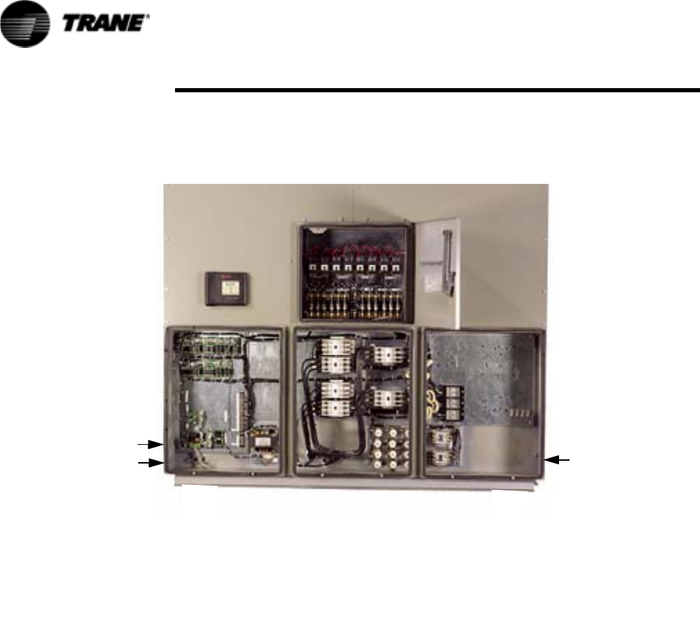
76 RTAC-SVX01F-EN
Installation - Electrical
115 volt field-provided connections (either control or power) are made through
knockouts on the lower left side of the panel (Figure 31). Additional grounds may be
required for each 115 volt power supply to the unit. Green lugs are provided for 115V
customer wiring.
Control Power Supply
The unit is equipped with a control power transformer; it is not necessary to provide
additional control power voltage to the unit.
All units are factory-connected for appropriate labeled voltages except for the 400V/
50Hz units which need the control power transformer (1T1) reconnected as noted
below.
NOTE: Important! As shipped, a normal 400 volt unit control power transformer is
wired on the 400 volt tap (H3). Reconnect the appropriate transformer wire lead 126A
to the tap (H2) for 380V/50Hz power supply or lead 126A to the tap H4 for the 415V/
50 Hz power supply. It is also necessary to adjust the “unit voltage” setting using
TechView (Configuration-Custom Tab).
Heater Power Supply and Convenience Outlet (Packaged Units Only)
The evaporator shell is insulated from ambient air and protected from freezing
temperatures by two thermostatically-controlled immersion heaters and two strip
heaters. Whenever the water temperature drops to approximately 37°F (2.8°C), the
thermostat energizes the heaters. The heaters will provide protection from ambient
temperatures down to -20°F (-29°C).
It is required to provide an independent power source (115V 60Hz-20 amp, 220V
50Hz-15 amp), with a fused-disconnect. The heaters are factory-wired back to the unit
control panel.
Figure 31 Starter Panel
Knockouts for 30 volt
115 volt
field wiring
Cut holes for power
wiring THIS AREA

RTAC-SVX01F-EN 77
Installation - Electrical
CAUTION
Heat Tape!
Control panel main processor does not check for loss of power to the
heat tape nor does it verify thermostat operation. A qualified technician
must verify power to the heat tape and confirm operation of the heat
tape thermostat to avoid catastrophic damage to the evaporator.
A convenience outlet is also optional, which shares the same power supply as the
heaters on 140-250 ton units. Be aware that when the heater is operating, the
convenience outlet amperage draw will be reduced accordingly.
NOTE: The convenience outlet is optional. The heaters are required.
Interconnecting Wiring
Chilled Water Flow (Pump) Interlock
The Model RTAC Series R® chiller requires a field-supplied control voltage contact
input through a flow proving switch 5S1 and an auxiliary contact 5K1 AUX. Connect
the proving switch and auxiliary contact to 1TB5-8 and 1U11 J3-2. Refer to the field
wiring for details. The auxiliary contact can be BAS signal, starter contactor auxiliary.
or any signal which indicates the pump is running. A flow switch is still required and
cannot be omitted.
Chilled Water Pump Control
An evaporator water pump output relay closes when the chiller is given a signal to go
into the Auto mode of operation from any source. The contact is opened to turn off
the pump in the event of most machine level diagnostics to prevent the build up of
pump heat.
CAUTION
Evaporator Damage!
IMPORTANT: ALL unit chilled water pumps must be controlled by the
Trane CH530 to avoid catastrophic damage to the evaporator due to
freezing. Refer to RLC-PRB012-EN.
The relay output from 1U10 is required to operate the Evaporator Water Pump (EWP)
contactor. Contacts should be compatible with 115/240 VAC control circuit. The EWP
relay operates in different modes depending on CH530 or Tracer commands, if
available, or service pumpdown (See maintenance section). Normally, the EWP relay
follows the AUTO mode of the chiller. Whenever the chiller has no diagnostics and is
in the AUTO mode, regardless of where the auto command is coming from, the
normally open relay is energized. When the chiller exits the AUTO mode, the relay is
timed open for an adjustable (using TechView) 0 to 30 minutes. The non-AUTO modes
in which the pump is stopped, include Reset (88), Stop (00), External Stop (100),
Remote Display Stop (600), Stopped by Tracer (300), Low Ambient Run Inhibit (200),
and Ice Building complete (101).
Regardless of whether the chiller is allowed to control the pump on a full-time basis, if
the MP calls for a pump to start and water does not flow, the evaporator may be
damaged catastrophically. It is the responsibility of the installing contractor and/or
the customer to ensure that a pump will start when called upon by the chiller
controls.
78 RTAC-SVX01F-EN
Installation - Electrical
NOTE: Exceptions are listed below.
When going from Stop to Auto, the EWP relay is energized immediately. If evaporator
water flow is not established in 4 minutes and 15 sec., the CH530 de-energizes the
EWP relay and generates a non-latching diagnostic. If flow returns (e.g. someone else
is controlling the pump), the diagnostic is cleared, the EWP is re-energized, and
normal control resumed.
If evaporator water flow is lost once it had been established, the EWP relay remains
energized and a non-latching diagnostic is generated. If flow returns, the diagnostic is
cleared and the chiller returns to normal operation.
In general, when there is either a non-latching or latching diagnostic, the EWP relay is
turned off as though there was a zero time delay. Exceptions (see above table)
whereby the relay continues to be energized occur with:
A Low Chilled Water Temp. diagnostic (non-latching) (unless also accompanied by an
Evap Leaving Water Temperature Sensor Diagnostic)
or
A starter contactor interrupt failure diagnostic, in which a compressor continues to
draw current even after commanded to have shutdown
or
A Loss of Evaporator Water Flow diagnostic (non-latching) and the unit is in the AUTO
mode, after initially having proven evaporator water flow.
Alarm and Status Relay Outputs (Programmable Relays)
A programmable relay concept provides for enunciation of certain events or states of
the chiller, selected from a list of likely needs, while only using four physical output
relays, as shown in the field wiring diagram. The four relays are provided (generally
with a Quad Relay Output LLID) as part of the Alarm Relay Output Option. The relay’s
contacts are isolated Form C (SPDT), suitable for use with 120 VAC circuits drawing
up to 2.8 amps inductive, 7.2 amps resistive, or 1/3 HP and for 240 VAC circuits
drawing up to 0.5 amp resistive.
The list of events/states that can be assigned to the programmable relays can be
found in Table 21. The relay will be energized when the event/state occurs.
Table 20 Pump Relay Operation
Chiller Mode Relay Operation
Auto Instant close
Ice Building Instant close
Tracer Override Close
Stop TImed Open
Ice Complete Instant Open
Diagnostics Instant Open
Table 21 Alarm and Status Relay Output Configuration Table
Description
Alarm - Latching This output is true whenever there is any active diagnostic that requires a manual reset to clear, that
affects either the Chiller, the Circuit, or any of the Compressors on a circuit. This classification does not
include informational diagnostics.
Alarm - Auto Reset This output is true whenever there is any active diagnostic that could automatically clear, that affects
either the Chiller, the Circuit, or any of the Compressors on a circuit. This classification does not include
informational diagnostics.
Alarm This output is true whenever there is any diagnostic affecting any component, whether latching or auto-
matically clearing. This classification does not include informational diagnostics
RTAC-SVX01F-EN 79
Installation - Electrical
Relay Assignments Using TechView
CH530 Service Tool (TechView) is used to install the Alarm and Status Relay Option
package and assign any of the above list of events or status to each of the four relays
provided with the option. The relays to be programmed are referred to by the relay’s
terminal numbers on the LLID board 1U12.
The default assignments for the four available relays of the RTAC Alarm and Status
Package Option are:
If any of the Alarm/Status relays are used, provide electrical power, 115 VAC with
fused-disconnect to the panel and wire through the appropriate relays (terminals on
1U12 (EUR=A4-5)). Provide wiring (switched hot, neutral, and ground connections) to
the remote annunciation devices. Do not use power from the chiller’s control panel
transformer to power these remote devices. Refer to the field diagrams which are
shipped with the unit.
Low Voltage Wiring
The remote devices described below require low voltage wiring. All wiring to and
from these remote input devices to the Control Panel must be made with shielded,
twisted pair conductors. Be sure to ground the shielding only at the panel.
To prevent control malfunctions, do not run low voltage wiring (<30 V) in
conduit with conductors carrying more than 30 volts.
Emergency Stop
CH530 provides auxiliary control for a customer specified/installed latching trip out.
When this customer-furnished remote contact 5K14 is provided, the chiller will run
normally when the contact is closed. When the contact opens, the unit will trip on a
manually resettable diagnostic. This condition requires manual reset at the chiller
switch on the front of the control panel.
Connect low voltage leads to terminal strip locations on 1U4. Refer to the field
diagrams that are shipped with the unit.
Alarm Ckt 1 This output is true whenever there is any diagnostic effecting Refrigerant Circuit 1, whether latching or
automatically clearing, including diagnostics affecting the entire chiller. This classification does not
include informational diagnostics.
Alarm Ckt 2 This output is true whenever there is any diagnostic affecting Refrigerant Circuit 2 whether latching or
automatically clearing, including diagnostics effecting the entire chiller. This classification does not
include informational diagnostics.
Chiller Limit Mode
(with a 20 minute fil-
ter)
This output is true whenever the chiller has been running in one of the Unloading types of limit modes
(Condenser, Evaporator, Current Limit or Phase Imbalance Limit) continuously for the last 20 minutes.
Circuit 1 Running This output is true whenever any compressors are running (or commanded to be running) on Refrigerant
Circuit 1, and false when no compressors are commanded to be running on that circuit.
Circuit 2 Running This output is true whenever any compressors are running (or commanded to be running) on Refrigerant
Circuit 2, and false when no compressors are commanded to be running on that circuit.
Chiller Running This output is true whenever any compressors are running (or commanded to be running) on the chiller
and false when no compressors are commanded to be running on the chiller.
Maximum Capacity
(software 18.0 or
later)
This output is true whenever the chiller has reached maximum capacity or had reached its maximum
capacity and since that time has not fallen below 70% average current relative to the rated ARI current
for the chiller. The output is false when the chiller falls below 70% average current and, since that time,
had not reestablished maximum capacity.
Table 21 Alarm and Status Relay Output Configuration Table
Description
Table 22 Default Assignments
Relay
Relay 1 Terminals J2 -12,11,10: Alarm
Relay 2 Terminals J2 - 9,8,7: Chiller Running
Relay 3 Terminals J2-6,5,4: Maximum Capacity (software 18.0 or later)
Relay 4 Terminals J2-3,2,1: Chiller Limit

80 RTAC-SVX01F-EN
Installation - Electrical
Silver or gold-plated contacts are recommended. These customer-furnished contacts
must be compatible with 24 VDC, 12 mA resistive load.
External Auto/Stop
If the unit requires the external Auto/Stop function, the installer must provide leads
from the remote contacts 5K15 to the proper terminals of the LLID 1U4 on the control
panel.
The chiller will run normally when the contacts are closed. When either contact
opens, the compressor(s), if operating, will go to the RUN:UNLOAD operating mode
and cycle off. Unit operation will be inhibited. Closure of the contacts will permit the
unit to return to normal operation.
Field-supplied contacts for all low voltage connections must be compatible with dry
circuit 24 VDC for a 12 mA resistive load. Refer to the field diagrams that are shipped
with the unit.
External Circuit Lockout – Circuit #1 and Circuit #2
CH530 provides auxiliary control of a customer specified or installed contact closure,
for individual operation of either Circuit #1 or #2. If the contact is closed, the
refrigerant circuit will not operate 1K15 and 1K16.
Upon contact opening, the refrigerant circuit will run normally. This feature is used to
restrict total chiller operation, e.g. during emergency generator operations.
Connections to 1U5 are shown in the field diagrams that are shipped with the unit.
These customer-supplied contact closures must be compatible with 24 VDC, 12 mA
resistive load. Silver or gold plated contacts are recommended.
Ice Building Option
CH530 provides auxiliary control for a customer specified/installed contact closure for
ice building if so configured and enabled. This output is known as the Ice Building
Status Relay. The normally open contact will be closed when ice building is in
progress and open when ice building has been normally terminated either through Ice
Termination setpoint being reached or removal of the Ice Building command. This
output is for use with the ice storage system equipment or controls (provided by
others) to signal the system changes required as the chiller mode changes from “ice
building” to “ice complete”. When contact 5K18 is provided, the chiller will run
normally when the contact is open.
CH530 will accept either an isolated contact closure (External Ice Building command)
or a Remote Communicated input (Tracer) to initiate and command the Ice Building
mode.
CH530 also provides a “Front Panel Ice Termination Setpoint”, settable through
TechView, and adjustable from 20 to 31°F (-6.7 to -0.5°C) in at least 1°F (1°C)
increments.
NOTE: When in the Ice Building mode, and the evaporator entering water temper-
ature drops below the ice termination setpoint, the chiller terminates the Ice Building
mode and changes to the Ice Building Complete Mode.
CAUTION
Evaporator Damage!
Freeze inhibitor must be adequate for the leaving water temperature.
Failure to do so will result in damage to system components.
Techview must also be used to enable or disable Ice Machine Control. This setting
does not prevent the Tracer from commanding Ice Building mode.
Upon contact closure, the CH530 will initiate an ice building mode, in which the unit
runs fully loaded at all times. Ice building shall be terminated either by opening the
contact or based on the entering evaporator water temperature. CH530 will not

RTAC-SVX01F-EN 81
Installation - Electrical
permit the ice building mode to be reentered until the unit has been switched out of
ice building mode (open 5K18 contacts) and then switched back into ice building
mode (close 5K18 contacts.)
In ice building, all limits (freeze avoidance, evaporator, condenser, current) will be
ignored. All safeties will be enforced.
If, while in ice building mode, the unit gets down to the freeze stat setting (water or
refrigerant), the unit will shut down on a manually resettable diagnostic, just as in
normal operation.
Connect leads from 5K18 to the proper terminals of 1U7. Refer to the field diagrams
which are shipped with the unit.
Silver or gold-plated contacts are recommended. These customer furnished contacts
must be compatible with 24 VDC, 12 mA resistive load.
External Chilled Water Setpoint (ECWS) Option
The CH530 provides inputs that accept either 4-20 mA or 2-10 VDC signals to set the
external chilled water setpoint (ECWS). This is not a reset function. The input defines
the set point. This input is primarily used with generic BAS (building automation
systems). The chilled water setpoint set via the DynaView or through digital
communication with Tracer (Comm3). The arbitration of the various chilled water
setpoint sources is described in the flow charts at the end of the section.
The chilled water setpoint may be changed from a remote location by sending either a
2-10 VDC or 4-20 mA signal to the 1U6, terminals 5 and 6 LLID. 2-10 VDC and 4-20
mA each correspond to a 10 to 65°F (-12 to 18°C) external chilled water setpoint.
The following equations apply:
If the ECWS input develops an open or short, the LLID will report either a very high or
very low value back to the main processor. This will generate an informational
diagnostic and the unit will default to using the Front Panel (DynaView) Chilled Water
Setpoint.
TechView Service Tool is used to set the input signal type from the factory default of
2-10 VDC to that of 4-20 mA. TechView is also used to install or remove the External
Chilled Water Setpoint option as well as a means to enable and disable ECWS.
External Current Limit Setpoint (ECLS) Option
Similar to the above, the CH530 also provides for an optional External Current Limit
Setpoint that will accept either a 2-10 VDC (default) or a 4-20 mA signal. The Current
Limit Setting can also be set via the DynaView or through digital communication with
Tracer (Comm 3). The arbitration of the various sources of current limit is described in
the flow charts at the end of this section. The External Current Limit Setpoint may be
changed from a remote location by hooking up the analog input signal to the 1 U6
LLID terminals 2 and 3. Refer to the following paragraph on Analog Input Signal
Wiring Details. The following equations apply for ECLS:
Voltage Signal Current Signal
As generated from external
source
VDC=0.1455*(ECWS)+0.5454 mA=0.2909(ECWS)+1.0909
As processed by CH530 ECWS=6.875*(VDC)-3.75 ECWS=3.4375(mA)-3.75
Voltage Signal Current Signal
As generated from external
source
VDC+0.133*(%)-6.0 mA=0.266*(%)-12.0
As processed by UCM %=7.5*(VDC)+45.0 %=3.75*(mA)+45.0
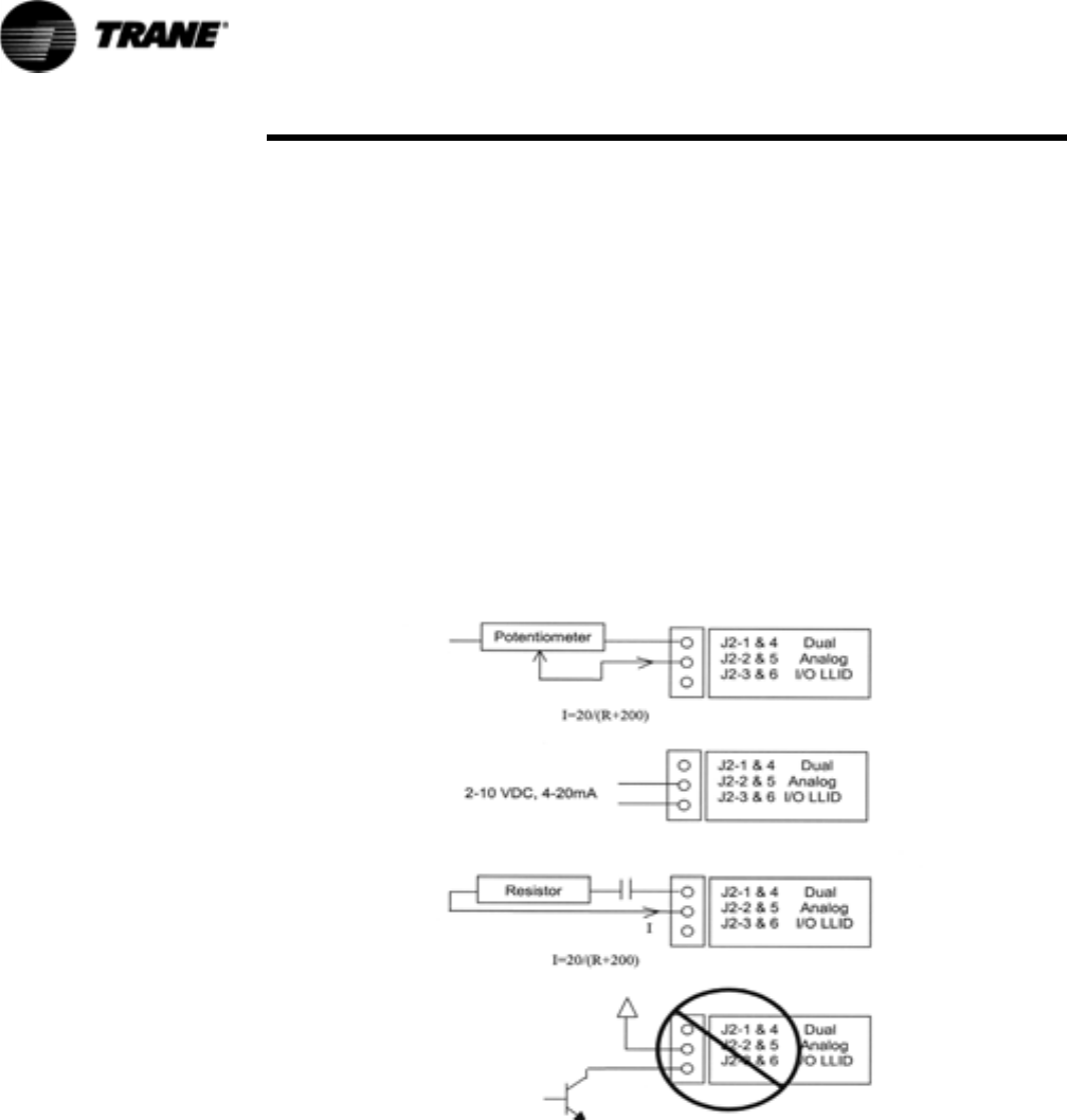
82 RTAC-SVX01F-EN
Installation - Electrical
If the ECLS input develops an open or short, the LLID will report either a very high or
very low value back to the man processor. This will generate an informational
diagnostic and the unit will default to using the Front Panel (DynaView) Current Limit
Setpoint.
The TechView Service Tool must be used to set the input signal type from the factory
default of 2-10 VDC to that of 4-20 mA current. TechView must be also be used to
install or remove the External Current Limit Setpoint Option for field installation, or
can be used to enable or disable the feature (if installed).
ECLS and ECWS Analog Input Signal Wiring Details:
Both the ECWS and ECLS can be connected and setup as either a 2-10 VDC (factory
default), 4-20 mA, or resistance input (also a form of 4-2OmA) as indicated below.
Depending on the type to be used, the TechView Service Tool must be used to
configure the LLID and the MP for the proper input type that is being used. This is
accomplished by a setting change on the Custom Tab of the Configuration View
within TechView.
The J2-3 and J2-6 terminal is chassis grounded and terminal J2- 1 and J2-4 can be
used to source 12 VDC. The ECLS uses terminals J2-2 and J2-3. ECWS uses
terminals J2-5 and J2-6. Both inputs are only compatible with high-side current
sources.
Figure 32 Wiring Examples for ECLS and ECWS
Chilled Water Reset (CWR)
CH530 resets the chilled water temperature set point based on either return water
temperature, or outdoor air temperature. Return Reset is standard, Outdoor Reset is
optional.
The following shall be selectable:
• One of three Reset Types: None, Return Water Temperature Reset, Outdoor Air
Temperature Reset, or Constant Return Water Temperature Reset.
• Reset Ratio Set Points.
For outdoor air temperature reset there shall be both positive and negative reset
ratio's.

RTAC-SVX01F-EN 83
Installation - Electrical
• Start Reset Set Points.
• Maximum Reset Set Points.
The equations for each type of reset are as follows:
Return
CWS' = CWS + RATIO (START RESET - (TWE - TWL))
and CWS' > or = CWS
and CWS' - CWS < or = Maximum Reset
Outdoor
CWS' = CWS + RATIO * (START RESET - TOD)
and CWS' > or = CWS
and CWS' - CWS < or = Maximum Reset
where
CWS' is the new chilled water set point or the "reset CWS"
CWS is the active chilled water set point before any reset has occurred, e.g. normally
Front Panel, Tracer, or ECWS
RESET RATIO is a user adjustable gain
START RESET is a user adjustable reference
TOD is the outdoor temperature
TWE is entering evap. water temperature
TWL is leaving evap. water temperature
MAXIMUM RESET is a user adjustable limit providing the maximum amount of reset.
For all types of reset, CWS' - CWS < or = Maximum Reset.
In addition to Return and Outdoor Reset, the MP provides a menu item for the
operator to select a Constant Return Reset. Constant Return Reset will reset the
leaving water temperature set point so as to provide a constant entering water
temperature. The Constant Return Reset equation is the same as the Return Reset
equation except on selection of Constant Return Reset, the MP will automatically set
Ratio, Start Reset, and Maximum Reset to the following.
RATIO = 100%
START RESET = Design Delta Temp.
MAXIMUM RESET = Design Delta Temp.
The equation for Constant Return is then as follows:
CWS' = CWS + 100% (Design Delta Temp. - (TWE - TWL))
and CWS' > or = CWS
and CWS' - CWS < or = Maximum Reset
When any type of CWR is enabled, the MP will step the Active CWS toward the
desired CWS' (based on the above equations and setup parameters) at a rate of 1
degree F every 5 minutes until the Active CWS equals the desired CWS'. This
applies when the chiller is running.
Reset Type Reset Ratio
Range
Start Reset
Range
Maximum Reset
Range
Increment
English Units
Increment
SI Units
Factory Default
Valu e
Return: 10 to 120% 4 to 30 F 0 to 20 F 1% 1% 50%
(2.2 to 16.7 C) (0.0 to 11.1 C)
Outdoor 80 to -80% 50 to 130 F 0 to 20 F 1% 1% 10%
(10 to 54.4 C) (0.0 to 11.1 C)
84 RTAC-SVX01F-EN
Installation - Electrical
When the chiller is not running the CWS is reset immediately (within one minute) for
Return Reset and at a rate of 1 degree F every 5 minutes for Outdoor Reset. The
chiller will start at the Differential to Start value above a fully reset CWS or CWS' for
both Return and Outdoor Reset.
Communications Interface options
Optional Tracer Communications Interface
This option allows the Tracer CH530 controller to exchange information (e.g. operating
setpoints and Auto/Standby commands) with a higher-level control device, such as a
Tracer Summit or a multiple-machine controller. A shielded, twisted pair connection
establishes the bi-directional communications link between the Tracer CH530 and the
building automation system.
To prevent control malfunctions, do not run low voltage wiring (<30 V) in
conduit with conductors carrying more than 30 volts.
Field wiring for the communication link must meet the following requirements:
• All wiring must be in accordance with the NEC and local codes.
• Communication link wiring must be shielded, twisted pair wiring (Belden 8760 or
equivalent). See the table below for wire size selection:
Wire Size Maximum Length of Communication Wire
• The communication link cannot pass between buildings.
• All units on the communication link can be connected in a “daisy chain”
configuration.
LonTalk Communications Interface for Chillers (LCI-C)
CH530 provides an optional LonTalk Communication Interface (LCI-C) between the
chiller and a Building Automation System (BAS). An LCI-C LLID shall be used to
provide "gateway" functionality between a LonTalk compatible device and the Chiller.
The inputs/outputs include both mandatory and optional network variables as
established by the LonMark Functional Chiller Profile 8040.
Installation Recommendations
• 22 AWG Level 4 unshielded communication wire recommended for most LCI-C
installations
• LCI-C link limits: 4500 feet, 60 devices
• Termination resistors are required
– 105 ohms at each end for Level 4 wire
– 82 ohms at each end for Trane "purple" wire
• LCI-C topology should be daisy chain
• Zone sensor communication stubs limited to 8 per link, 50 feet each (maximum)
• One repeater can be used for an additional 4500 feet, 60 devices, 8
communication stubs
Table 23 Wire Size
14 AWG (2.5 mm2) 5,000 FT (1525 m)
16 AWG (1.5 mm2) 2,000 FT (610 m)
18 AWG (1.0 mm2) 1,000 FT (305 m)
RTAC-SVX01F-EN 85
Installation - Electrical
Table 24 LonTalk Points List
LonTalk Communications Interface
Inputs Variable type SNVT_Type
Chiller Enable/Disable binary start(1)/stop(0) SNVT_switch
Chilled Water Setpoint analog temperature SNVT_temp_p
Current Limit Setpoint analog % current SNVT_lev_percent
Chiller Mode Note 1 SNVT_hvac_mode
Outputs Variable type SNVT_Type
Outputs Variable type SNVT_Type
Chiller On/Off binary on(1)/off(0) SNVT_switch
Active Chilled Water Setpoint analog temperature SNVT_temp_p
Percent RLA analog % current SNVT_lev_percent
Active Current Limit Setpoint analog % current SNVT_lev_percent
Leaving Chilled Water Temperature analog temperature SNVT_temp_p
Entering Chilled Water Temperature analog temperature SNVT_temp_p
Entering Condenser Water Temperature analog temperature SNVT_temp_p
Leaving Condenser Water Temperature analog temperature SNVT_temp_p
Alarm Description Note 2 SNVT_str_asc
Chiller Status Note 3 SNVT_chlr_status
Note 1: Chiller Mode is used to place the chiller into an alternate mode; Cool or Ice Build
Note 2: Alarm Description denotes alarm severity and target.
Severity: no alarm, warning, normal shutdown, immediate shutdown
Target: Chiller, Platform, Ice Building (Chiller is refrigerant circuit and Platform is control circuit)
Note 3: Chiller Status describes Chiller Run Mode and Chiller Operating Mode.
Run Modes: Off, Starting, Running, Shutting Down
Operating Modes: Cool, Ice Build
States: Alarm, Run Enabled, Local Control, Limited, CHW Flow, Cond Flow
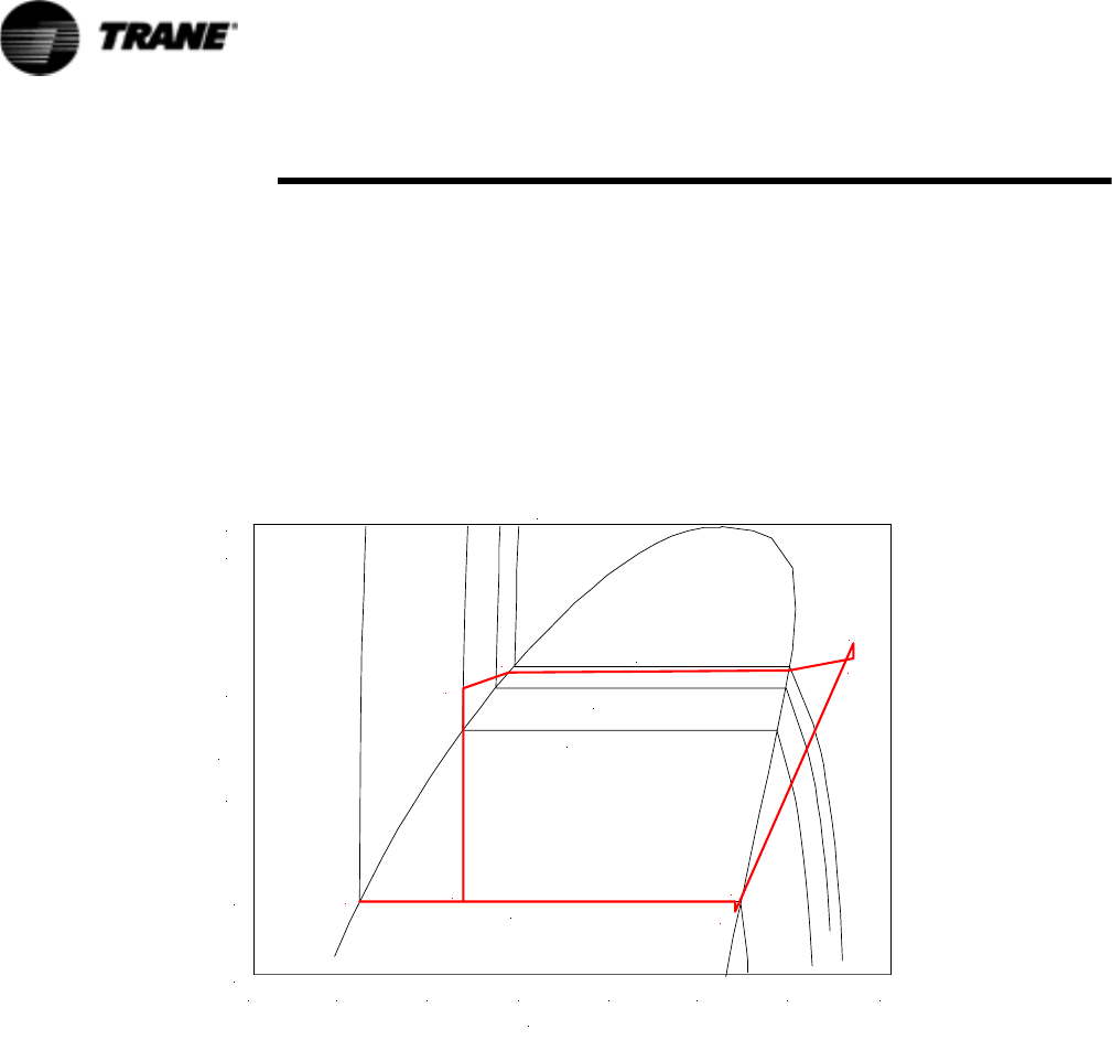
86 RTAC-SVX01F-EN
Operating Principles
This section contains an overview of the operation and maintenance of RTAC units
equipped with CH530 control systems. It describes the overall operating principles of
the RTAC design.
Refrigeration Cycle
The refrigeration cycle of the RTAC chiller is similar to that of the RTAA air cooled
water chiller. The exception is that the evaporating and condensing temperatures have
been increased to allow for optimization of the chiller and reduced foot print. The
refrigeration cycle is represented in the pressure enthalpy diagram in Figure 33. Key
state points are indicated on the figure. The cycle for the full load ARI design point is
represented in the plot.
Figure 33 Pressure Enthalpy (P-h) diagram of RTAC chiller
020 40 60 80 100 120 140
P (psia)
137 F
126 F
106 F
39 F
R134a
30
50
100
200
500
600
h (btu/lb)
1
1b
2
2b
3
3b
4
4b
(58 C)
(52 C)
(41 C)
(4 C)
The RTAC chiller uses a shell and tube evaporator design with refrigerant evaporating
on the shell side and water flowing inside tubes having enhanced surfaces (states 4
to 1). The suction lines and bolt pads are designed to minimize pressure drop.(states
1 to 1b). The compressor is a twin-rotor helical rotary compressor designed similarly
to the compressors offered in other Trane Screw Compressor Based Chillers (states
1b to 2). The discharge lines include a highly efficient oil separation system that
virtually removes all oil from the refrigerant stream going to the heat exchangers
(states 2 to 2b). De-superheating, condensing and sub-cooling is accomplished in a fin
and tube air cooled heat exchanger where refrigerant is condensed in the tube (states
2b to 3b). Refrigerant flow through the system is balanced by an electronic expansion
valve (states 3b to 4).
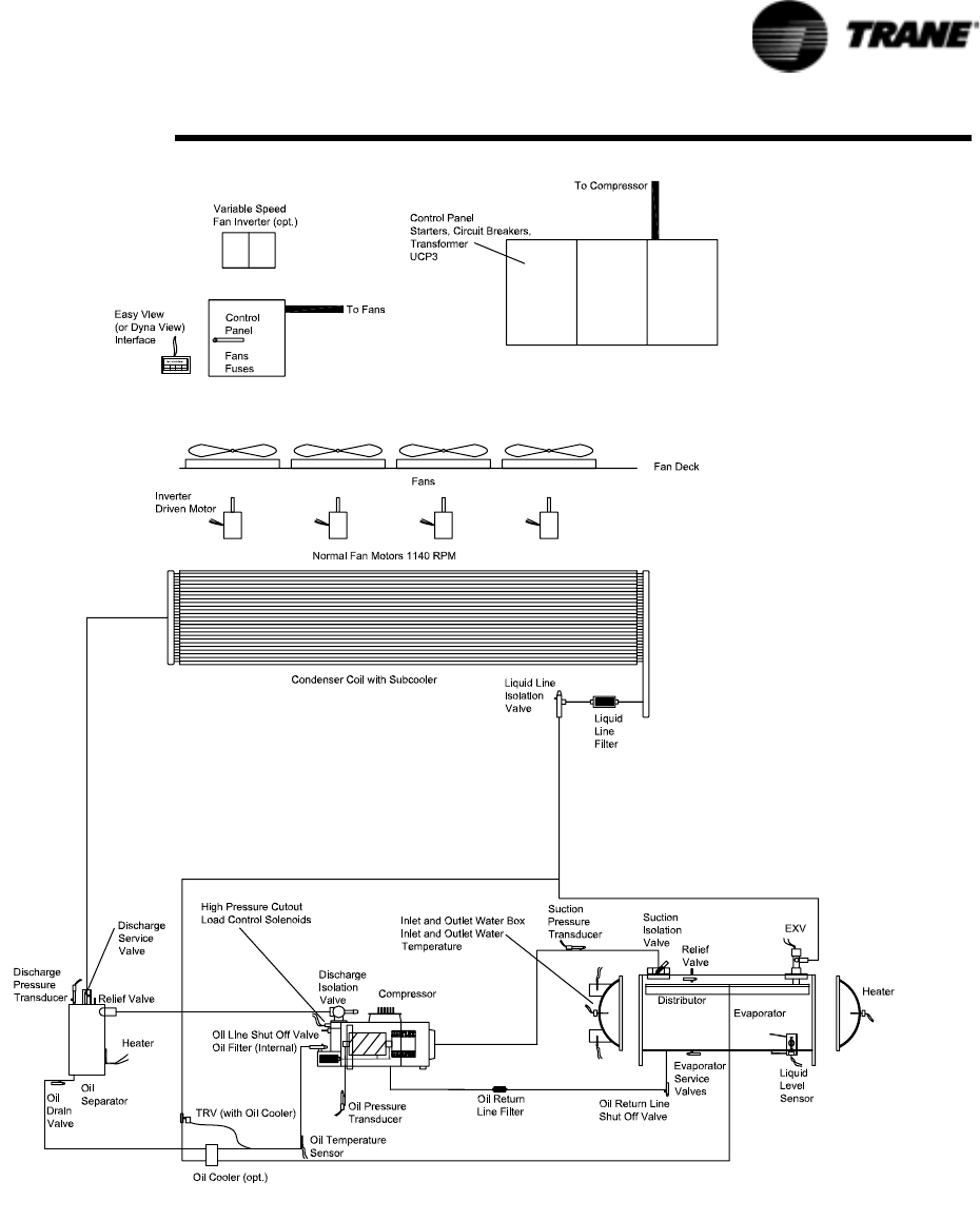
RTAC-SVX01F-EN 87
Operating Principles
Figure 34 System Schematic

88 RTAC-SVX01F-EN
Operating Principles
Refrigerant R134a
The RTAC chiller uses environmentally friendly R134a. Trane believes that responsible
refrigerant practices are important to the environment, our customers, and the air
conditioning industry. All technicians who handle refrigerants must be certified. The
Federal Clean Air Act (Section 608) sets forth the requirements for handling,
reclaiming, recovering and recycling of certain refrigerants and the equipment that is
used in these service procedures. In addition, some states or municipalities may have
additional requirements that must also be adhered to for responsible management of
refrigerants. Know the applicable laws and follow them.
R134a is a medium pressure refrigerant. It may not be used in any condition that
would cause the chiller to operate in a vacuum without a purge system. RTAC is not
equipped with a purge system. Therefore, the RTAC chiller may not be operated in a
condition that would result in a saturated condition in the chiller of –15°F (-26°C) or
lower.
R134a requires the use of specific POE oils as designated on the unit nameplate.
Important! The RTAC units must only operate with R-134a and Trane Oil 00048.
Compressor
The compressor is a semi-hermetic, direct-drive rotary type compressor. Each
compressor has only four moving parts: two rotors that provide compression and
male and female load-control valves. The male rotor is attached to the motor and the
female rotor is driven by the male rotor. The rotors and motor are supported by
bearings.
The helical rotary compressor is a positive displacement device. Refrigerant vapor
from the evaporator is drawn into the suction opening of the compressor (state 1b),
through a suction strainer screen across the motor (which provides motor cooling)
and into the intake of the compressor rotors. The gas is then compressed and
discharged through a check valve and into the discharge line (state 2).
There is no physical contact between the rotors and the compressor housing. The
rotors contact each other at the point where the driving action between the male and
female rotors occurs. Oil is injected into the rotors of the compressor, coating the
rotors and the compressor housing interior. Although this oil does provide rotor
lubrication, its primary purpose is to seal the clearance spaces between the rotors
and compressor housing. A positive seal between these internal parts enhances
compressor efficiency by limiting leakage between the high pressure and low
pressure cavities.
Capacity control is accomplished by means of a female step load-control valve and a
male control valve. The female step valve is the first stage of loading after the
compressor starts and the last stage of unloading before the compressor shuts
down. The male control valve is positioned by a piston cylinder along the length of the
male rotor. Compressor capacity is dictated by the position of the loading valve
relative to the rotors. When the valve slides toward the discharge end of the rotors
compressor capacity is reduced.
Condenser and Subcooler
The condenser and subcooler are similar to the condenser used in RTAA chillers. The
heat exchanger consists of 3/8” tubes that contain the refrigerant, large fins that are
in the air flow and fans that draw air through the fins. Heat is transferred from the
refrigerant through the tubes and fins to the air.
High pressure gas from the compressor enters the tubes of the condenser through a
distribution header (state 2b). As refrigerant flows through the tubes, the heat of
compression and cooling load are rejected to the air. In this process the refrigerant is
de-superheated, condensed (states 2b to 3) and finally subcooled (states 3 to 3b) to a
temperature slightly above the ambient air temperature. The subcooled liquid
refrigerant is collected in the leaving header where it is transferred to the liquid line
(state 3b).
A controls algorithm always runs as many fans as possible without reducing the
differential pressure (discharge minus suction) below the setpoint (60 psid or 4.2 bar).
If a warm enough ambient is sensed, all the fans will run. If the ambient is cooler,

RTAC-SVX01F-EN 89
Operating Principles
some fans are shut off to maintain the pressure differential. Fan staging depends on
the chiller load, evaporator pressure, condenser effectiveness, ambient temperature,
and numbers and sizes of fans installed on the circuit.
The algorithm pre-starts fans (based on ambient and water temperatures) when a
circuit starts the compressor. (For rare conditions such as during some pull-downs, a
steady fan state would either violate the 60 psid (4.2 bar) setpoint or cause a high
pressure cut-out; in those conditions a fan will cycle on and off.)
For up to two minutes after chiller start-up, the setpoint is 35 psi (2.45 bar) difference,
and then before the controls adjust gradually over half a minute up to 60 psi (4.2 bar).
Expansion Valve
Pressure drop occurs in an electronic expansion valve. The unit controller (CH530)
uses the valve to regulate the flow through the liquid line to match the flow produced
by the compressor. The valve has a variable orifice that is modulated by a stepper
motor.
High pressure, subcooled liquid refrigerant enters the expansion valve from the liquid
line. As refrigerant passes through the valve the pressure is dropped substantially,
which results in vaporization of some of the refrigerant. The heat of vaporization is
supplied by the two phase mixture resulting in low temperature low pressure
refrigerant which is supplied to the evaporator (state 4) to provide cooling.
Evaporator
The evaporator is composed of a liquid-vapor distributor and falling film evaporator.
A liquid-vapor refrigerant mixture enters the distributor (state 4). The mixture is
distributed over the length of the evaporator tubes (state 4b). Liquid is evenly
distributed over the length of the evaporator tubes by the two-phase distribution
system. A portion of the liquid boils as it falls by gravity from tube to tube, wetting all
the tubes of the evaporator. To ensure that the tubes at the bottom of the evaporator
do not experience “dry out,” a liquid pool is maintained in the bottom few inches of
the bundle. Tubes located in the bottom of the evaporator will evaporate the liquid
refrigerant by boiling (pool boiling).
Heat is transferred from the water or glycol inside the tubes to the liquid refrigerant
as the film of refrigerant evaporates on the surface of the tube. Thin film heat transfer
requires a smaller temperature difference for a given amount of heat transfer than
nucleate boiling, which is the heat transfer process used in flooded evaporators.
Hence, efficiency is enhanced by the use of falling film evaporation. Additionally, the
evaporator requires less refrigerant than a comparable flooded evaporator and the
evaporator boils the entire refrigerant supply at constant pressure. Refrigerant vapor
exits the evaporator through the suction line (state 1).
Oil System
Screw compressors require large quantities of oil for lubricating and sealing the rotors
and lubricating the bearings. This oil is mixed with refrigerant at the discharge of the
compressor. To enhance the performance of the heat exchanger surfaces an oil
separation system is placed into the discharge line. The oil separator is located
between the compressor and the condenser. It separates oil using highly efficient
centrifugal force. Approximately 99.5% of the oil is removed from the refrigerant in
the separator.
Oil that is removed from the refrigerant falls by gravity into the oil sump. This oil is
directed back to the compressor through the oil lines. Internal to the compressor is a
high efficiency filter to clean the oil before it is delivered to the rotors and bearings.
Once oil is injected into the compressor rotors it mixes with the refrigerant again and
is delivered back to the discharge line.
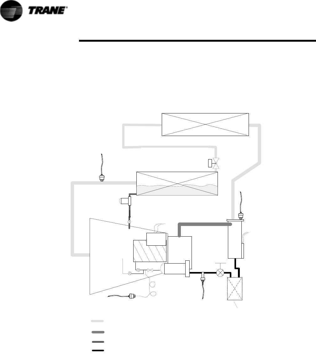
90 RTAC-SVX01F-EN
Operating Principles
Oil that gets past the oil separators flows through the condenser, subcooler and
expansion valve into the evaporator. This oil is collected in the pool of refrigerant that
is maintained in the bottom of the evaporator. A small amount of oil and refrigerant
from this pool (state 4b) is returned through a line that is connected to the
compressor down stream of the motor. This oil and refrigerant mixes with the
refrigerant vapor that was drawn out of the evaporator, prior to injection into the
compressor rotors.
Figure 35 RTAC Oil System
E X V
E v a p o r a t o r
M a n u a l
S e r v i c e
V a l v e
O p t i o n a l O i l
C o o l e r
C o m p r e s s o r O i l
S e p a r a t o r
E v a p o r a t o r
O i l R e t u r n L i n e F i l t e r
B e a r i n g a n d R o t o r
R e s t r i c t o r s a n d
O i l i n j e c t i o n
C o n d e n s e r
C ondenser
R e f r i g e r a n t
P r e s s u r e
T r a n s d u c e r
P
C
I n t e r m e d i a t e
O i l P r e s s u r e
T r a n s d u c e r
P
I
E v a p o r a t o r
R e f r i g e r a n t
P r e s s u r e
T r a n s d u c e r
P
E
P r i m a r y O i l S y s t e m
R e f r i g e r a n t & O i l M i x t u r e
( r e f r i g e r a n t v a p o r a n d o i l )
O i l R e c o v e r y S y s t e m
( l i q u i d r e f r i g e r a n t a n d o i l )
R e f r i g e r a n t w i t h
s m a l l a m o u n t o f O i l
K E Y
C o m p r e s s o r O i l
T e m p e r a t u r e S e n s o r
I n t e r n a l
C o m p r e s s o r
O i l F i l t e r
O i l S e p a r a t o r
S u m p H e a t e r
C o m p r e s s o r
H e a t e r

RTAC-SVX01F-EN 91
Controls Interface
CH530 Communications Overview
The Trane CH530 control system that runs the chiller consists of several elements:
• The main processor collects data, status, and diagnostic information and commu-
nicates commands to the starter module and the LLID (for Low Level Intelligent
Device) bus. The main processor has an integral display (DynaView).
• Higher level modules (e.g. starter) exist only as necessary to support system level
control and communications. The starter module provides control of the starter
when starting, running, and stopping the chiller motor. It also processes its own
diagnostics and provides motor and compressor protection.
• Low level intelligent device (LLID) bus. The main processor communicates to
each input and output device (e.g. temperature and pressure sensors, low voltage
binary inputs, analog input/output) all connected to a four-wire bus, rather than
the conventional control architecture of signal wires for each device.
• The communication interface to a building automation system (BAS).
• A service tool to provide all service/maintenance capabilities.
Main processor and service tool (TechView) software is downloadable from
www.Trane.com. The process is discussed later in this section under TechView Inter-
face.
DynaView provides bus management. It has the task of restarting the link, or filling in
for what it sees as “missing” devices when normal communications has been
degraded. Use of TechView may be required.
The CH530 uses the IPC3 protocol based on RS485 signal technology and communi-
cating at 19.2 Kbaud to allow 3 rounds of data per second on a 64-device network. A
typical four-compressor RTAC will have around 50 devices.
Most diagnostics are handled by the DynaView. If a temperature or pressure is
reported out of range by a LLID, the DynaView processes this information and calls
out the diagnostic. The individual LLIDs are not responsible for any diagnostic func-
tions. The only exception to this is the Starter module.
NOTE: It is imperative that the CH530 Service Tool (TechView) be used to facilitate
the replacement of any LLID or reconfigure any chiller component. TechView is
discussed later in this section.
Controls Interface
Each chiller is equipped with a DynaView interface. The DynaView has the capability
to display information to the operator including the ability to adjust settings. Multiple
screens are available and text is presented in multiple languages as factory-ordered or
can be easily downloaded from www.trane.com.
TechView can be connected to either the DynaView module and provides further data,
adjustment capabilities, diagnostics information using downloadable software.
DynaView Interface
The DynaView share the same enclosure design: weatherproof and durable plastic for
use as a stand-alone device on the outside of the unit or mounted nearby.
The display on DynaView is a 1/4 VGA display with a resistive touch screen and an
LED backlight. The display area is approximately 4 inches wide by 3 inches high
(102mm x 60mm).

92 RTAC-SVX01F-EN
Controls Interface
Key Functions
In this touch screen application, key functions are determined completely by software
and change depending upon the subject matter currently being displayed. The basic
touch screen functions are outlined below.
Radio Buttons
Radio buttons show one menu choice among two or more alternatives, all visible. (It is
the AUTO button in Figure 36.) The radio button model mimics the buttons used on
old-fashioned radios to select stations. When one is pressed, the one that was previ-
ously pressed “pops out” and the new station is selected. In the DynaView model
the possible selections are each associated with a button. The selected button is dark-
ened, presented in reverse video to indicate it is the selected choice. The full range of
possible choices as well as the current choice is always in view.
Spin Value Buttons
Spin values are used to allow a variable setpoint to be changed, such as leaving water
setpoint. The value increases or decreases by touching the increment (+) or decre-
ment (-) arrows.
Action Buttons
Action buttons appear temporarily and provide the user with a choice such as Enter or
Cancel.
Hot Links
Hot links are used to navigate from one view to another view.
File Folder Tabs
File folder tabs are used to select a screen of data. Just like tabs in a file folder, these
serve to title the folder/screen selected, as well as provide navigation to other
screens. In DynaView, the tabs are in one row across the top of the display. The folder
tabs are separated from the rest of the display by a horizontal line. Vertical lines sepa-
rate the tabs from each other. The folder that is selected has no horizontal line under
Figure 36 DynaView
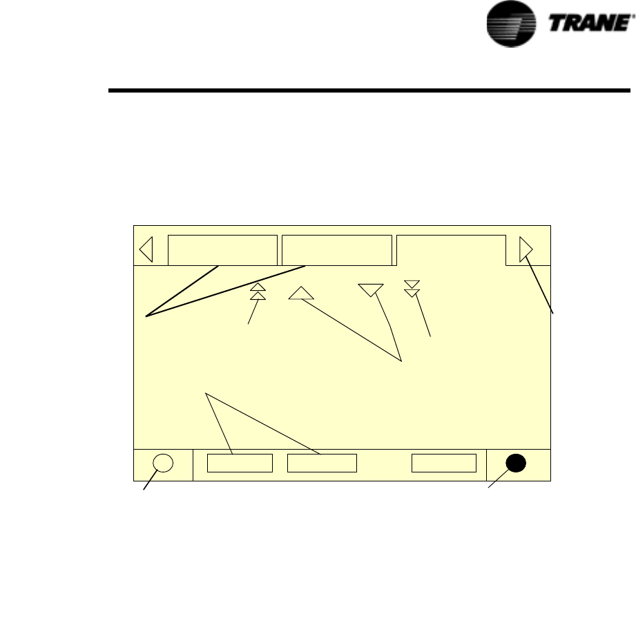
RTAC-SVX01F-EN 93
Controls Interface
its tab, thereby making it look like a part of the current folder (as would an open folder
in a file cabinet). The user selects a screen of information by touching the appropriate
tab.
Display Screens
Basic Screen Format
The basic screen format appears as
Auto Stop Alarms
Contrast control (lighter)
Tab navigator
Tabs
File folder
Radio buttons
Line scroll
Page scroll
(up/down)
Contrast control (darker)
Page scroll
(down)
(up)
:
The file folder tabs across the top of the screen are used to select the various display
screens.
Scroll arrows are added if more file tabs (choices) are available. When the tabs are at
the left most position, the left navigator will not show and only navigation to the right
will be possible. Likewise when the right most screen is selected, only left navigation
will be possible.
The main body of the screen is used for description text, data, setpoints, or keys
(touch sensitive areas). The Chiller Mode is displayed here.
The double up arrows cause a page-by-page scroll either up or down. The single
arrow causes a line by line scroll to occur. At the end of the page, the appropriate
scroll bar will disappear.
A double arrow pointing to the right indicates more information is available about the
specific item on that same line. Pressing it will bring you to a subscreen that will
present the information or allow changes to settings.
The bottom of the screen (Fixed Display) is present in all screens and contains the fol-
lowing functions. The left circular area is used to reduce the contrast/viewing angle
of the display. The right circular area is used to increase the contrast/viewing angle
of the display. The contrast may require re-adjustment at ambient temperatures sig-
nificantly different from those present at last adjustment.
The other functions are critical to machine operation. The AUTO and STOP keys are
used to enable or disable the chiller. The key selected is in black (reverse video). The
chiller will stop when the STOP key is touched and after completing the Run Unload
mode.
Touching the AUTO key will enable the chiller for active cooling if no diagnostic is
present. (A separate action must be taken to clear active diagnostics.)
The AUTO and STOP keys, take precedence over the Enter and Cancel keys. (While a
setting is being changed, AUTO and STOP keys are recognized even if Enter or Cancel
has not been pressed.)
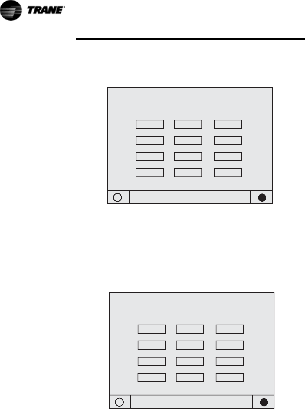
94 RTAC-SVX01F-EN
Controls Interface
The ALARMS button appears only when an alarm is present, and blinks (by alternating
between normal and reverse video) to draw attention to a diagnostic condition. Press-
ing the ALARMS button takes you to the corresponding tab for additional information.
Front Panel Lockout Feature
Display and Touch Screen are Locked
Enter Password to Unlock
1
4
78
5
2
6
3
9
Enter 0 Cancel
NOTE: The DynaView display and Touch Screen Lock screen is shown below. This
screen is used if the Display and touch screen and lock feature is enabled. Thirty
minutes after the last keystroke, this screen is displayed and the Display and Touch
Screen is locked out until the sequence “159 <ENTER>” is pressed.
Until the proper password is entered, there will be no access to the DynaView
screens including all reports, setpoints, and Auto/Stop/Alarms/Interlocks.
The password “159” is not programmable from either DynaView or TechView.
Front Panel Display During Cold Ambients
Display and Touch Screen are Locked
Enter 159 to Unlock
1
4
78
5
2
6
3
9
Enter 0 Cancel
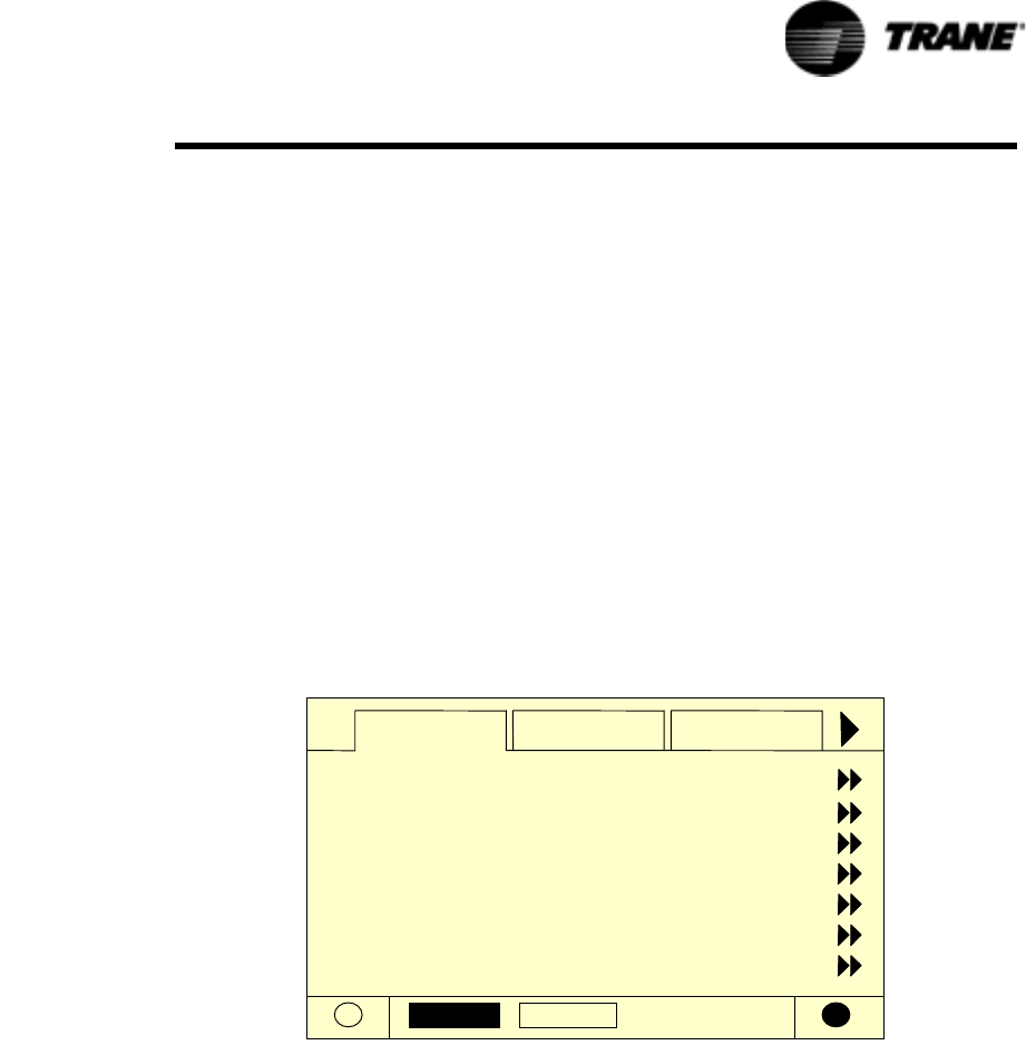
RTAC-SVX01F-EN 95
Controls Interface
If the Display and Touch Screen Lock feature is disabled, the following screen is auto-
matically displayed if the DynaView Temperature is below freezing and has been 30
minutes after the last keystroke. Note: This feature is provided to avoid unintended
actuations of the keypad, which can occur due to ice build-up on the DynaView’s exte-
rior surfaces. Also be aware that at extremes of temperatures, the LCD display
screen will change its contrast from the optimal adjustment made at more normal
temperatures. It can appear washed out or blacked out. Simply pressing the lower
right contrast control on the screen will return the display to readable condition.
NOTE: All screens shown in this section are typical. Some screens show all display
options available, only one of which may appear on a line.
Modes Screen
The Mode Screen is only found on software revisions 18 and later. This screen pro-
vides a display for the top level operating mode for each of the components and sub-
components of the chiller (i.e. Chiller, Circuits, and Compressors) that exist on the
Chiller as it is configured. The modes are displayed as text only without the hex
codes.
In software revisions 17.0 and earlier, the top level mode and the sub mode for each
component was displayed on the respective component tab on the first two lines.
The mode display of the first three lines of the Compressor and Chiller Screen tabs is
eliminated with the addition of the Mode Screen
Auto Stop
Modes Chiller Compressor
Chiller Mode:
Circuit 1 Mode:
Cprsr 1A Mode:
Cprsr 1B Mode:
Circuit 2 Mode:
Cprsr 2A Mode:
Cprsr 2B Mode:
Running
Stopped
Stopped
Run Inhibit
Running
Running
Running - Limit
96 RTAC-SVX01F-EN
Controls Interface
Table 25 Chiller Modes
Chiller Modes Description
Top Level Mode
Sub-modes
Stopped The chiller is not running and cannot run without inter-
vention. Further information is provided by the sub-
mode:
Local Stop Chiller is stopped by DynaView Stop button command-
cannot be remotely overridden.
Panic Stop Chiller is stopped by the DynaView Panic Stop (by
pressing Stop button twice in succession) - previous
shutdown was manually commanded to shutdown
immediately without a run-unload or pumpdown cycle -
cannot be remotely overridden.
Diagnostic Shutdown - Manual Reset The chiller is stopped by a diagnostic that requires
manual intervention to reset.
Other sub-modes are possible in conjunction with at least
one of the above modes - See items below for their
descriptions:
Diagnostic Shutdown - Auto Reset
Start Inhibited by Low Cond Temp
Start Inhibited by Low Ambient Temp
Start Inhibited by External Source
Start Inhibited by BAS
Waiting for BAS Communications
Ice Building to Normal Transition
Ice Building is Complete
Design Note: Maximum Capacity was eliminated as a
annunciated mode prior to any release
Run Inhibit The chiller is currently being inhibited from starting (and
running), but may be allowed to start if the inhibiting or
diagnostic condition is cleared. Further information is
provided by the sub-mode:
Diagnostic Shutdown - Auto Reset The entire chiller is stopped by a diagnostic that may
automatically clear.
Start Inhibited by Low Cond Temp The chiller is inhibited from starting by Low Condenser
Temperature- Inhibit is active below either 25°F (can be
disabled with proper freeze protection) or 0°F (limit set by
design, cannot be disabled). As an exception, this will not
stop a chiller already running.
Start Inhibited by Low Ambient Temp The chiller is inhibited from starting (and running) by an
outdoor air ambient temperature lower than a specified
temperature - per user adjustable settings and can be
disabled.
Start Inhibited by External Source The chiller is inhibited from starting (and running) by the
"external stop" hardwired input.
RTAC-SVX01F-EN 97
Controls Interface
Start Inhibited by BAS The chiller is inhibited from starting (and running) by
command from a Building Automation System via the
digital communication link (com 3 or com 5).
Waiting for BAS Communications This is a transient mode - 15-min. max, and is only
possible if the chiller is in the Auto - Remote command
mode. After a power up reset, it is necessary to wait for
valid communication from a Building Automation System
(Tracer) to know whether to run or stay inhibited. Either
valid communication will be received from the Building
Automation System (e.g. Tracer), or a communication
diagnostic ultimately will result. In the latter case the
chiller will revert to Local control.
Ice Building to Normal Transition The chiller is inhibited from running for a brief period of
time if it is commanded from active ice building mode
into normal cooling mode via the ice building hardwired
input or Tracer. This allows time for the external system
load to "switchover" from an ice bank to the chilled water
loop, and provides for a controlled pull down of the
loop's warmer temperature. This mode is not seen if the
ice making is automatically terminated on return brine
temperature per the mode below.
Ice Building is Complete The chiller is inhibited from running as the Ice Building
process has been normally terminated on the return brine
temperature. The chiller will not start unless the ice
building command (hardwired input or Building
Automation System command) is removed or cycled.
Auto The chiller is not currently running but can be expected to
start at any moment given that the proper conditions and
interlocks are satisfied. Further information is provided
by the sub-mode:
Waiting For Evap Water Flow The chiller will wait up to 4 minutes in this mode for
evaporator water flow to be established per the flow
switch hardwired input.
Waiting for Need to Cool The chiller will wait indefinitely in this mode, for an
evaporator leaving water temperature higher than the
Chilled Water Setpoint plus the Differential to Start.
Starting The chiller is going through the necessary steps to allow
the lead circuit and lead compressor to start.
No Sub Modes
Running At least one circuit and one compressor on the chiller are
currently running. Further information is provided by the
sub-mode:
Table 25 Chiller Modes
Chiller Modes Description
Top Level Mode
Sub-modes
98 RTAC-SVX01F-EN
Controls Interface
Unit is Building Ice The chiller is running in the Ice Building Mode, and either
at or moving towards full capacity available. Ice mode is
terminated either with the removal of the ice mode
command or with the return brine temperature falling
below the Ice Termination Setpoint.
Running - Limited At least one circuit and one compressor on the chiller are
currently running, but the operation of the chiller as a
whole is being actively limited by the controls.
Capacity Limited by
High Evap Water Temp
This mode will occur if both the OA temperature is above
40°F and the Evap Leaving Water Temperature is above
75°F as is often the case in a high temperature pull-down.
While in this mode, no compressors will be allowed to
load past their minimum load capacity step, but it will not
inhibit compressor staging. This mode is necessary to
prevent nuisance trips due to Compressor Overcurrent or
High Pressure Cutout. Reasonable pull-down rates can
still be expected despite this limit.
Table 25 Chiller Modes
Chiller Modes Description
Top Level Mode
Sub-modes
Table 26 Circuit Modes
Circuit Modes Description
Top Level Mode
Sub-modes
Stopped The given circuit is not running and cannot run without intervention.
Further information is provided by the sub-mode:
Front Panel Lockout The circuit is manually locked out by the circuit lockout setting - the
nonvolatile lockout setting is accessible through either the Dyna-
View or TechView.
Diagnostic Shutdown - Manual Reset The circuit has been shutdown on a latching diagnostic.
Other sub-modes are possible in conjunction with at least one of
the above modes - See items below for their descriptions:
Diagnostic Shutdown - Auto Reset
Start Inhibited by External Source
Start Inhibited by BAS
Run Inhibit The given circuit is currently being inhibited from starting (and run-
ning), but may be allowed to start if the inhibiting or diagnostic con-
dition is cleared. Further information is provided by the sub-mode:
Diagnostic Shutdown - Auto Reset The circuit has been shutdown on a diagnostic that may clear auto-
matically.
Start Inhibited by External Source The circuit is inhibited from starting (and running) by its "external cir-
cuit lockout" hardwired input.
Start Inhibited by BAS The circuit is inhibited from starting (and running) by command
from a Building Automation System via the digital communication
link (com 3 or com 5).
RTAC-SVX01F-EN 99
Controls Interface
Auto The given circuit is not currently running but can be expected to
start at any moment given that the proper conditions and interlocks
are satisfied.
No Sub Modes
Starting The given circuit is going through the necessary steps to allow the
lead compressor on that circuit to start.
No Sub Modes
Running At least one compressor on the given circuit is currently running.
Further information is provided by the sub-mode:
Establishing Min. Cap - Low Diff pressure The circuit is experiencing low system differential pressure and is
being force loaded, irregardless Chilled Water Temperature Control,
to develop pressure sooner.
Running - Limited At least one compressor on the given circuit is currently running,
but the capacity of the circuit is being actively limited by the con-
trols. Further information is provided by the sub-mode:
Capacity Limited by High Cond Press The circuit is experiencing condenser pressures at or near the con-
denser limit setting. Compressors on the circuit will be unloaded to
prevent exceeding the limits.
Capacity Limited by Low Evap Rfgt Temp The circuit is experiencing saturated evaporator temperatures at or
near the Low Refrigerant Temperature Cutout setting. Compres-
sors on the circuit will be unloaded to prevent tripping.
Capacity Limited by Low Liquid Level The circuit is experiencing low refrigerant liquid levels and the EXV
is at or near full open. The compressors on the circuit will be
unloaded to prevent tripping.
Shutting Down The given circuit is still running but shutdown is imminent. The cir-
cuit is going through either a compressor run-unload mode or a cir-
cuit operational pumpdown to dry out the evaporator (cold OA
ambient only). Shutdown is necessary due to one (or more) of the
following sub-modes:
Operational Pumpdown The circuit is in the process shutting down by performing an opera-
tional pumpdown just prior to stopping the last running compres-
sor. The EXV is commanded closed. Pumpdown will terminate
when both the liquid level and the evap pressure
Front Panel Lockout The circuit has been manually locked out by the circuit lockout set-
ting and is in the process of shutting down - the nonvolatile lockout
setting is accessible through either the DynaView or TechView.
Diagnostic Shutdown - Manual Reset The circuit is in the process of shutdown due to a latching diagnos-
tic.
Diagnostic Shutdown - Auto Reset The circuit is in the process of shutdown due to a diagnostic that
may automatically clear.
Start Inhibited by External Source The circuit is in the process of shutdown due to a command from
the external circuit lockout hardwired input.
Start Inhibited by BAS The circuit is in the process of shutdown due to a command from
the Building Automation System (e.g. Tracer)
Service Override The given circuit is in a Service Override mode
Service Pumpdown The circuit is running with fan control, via a manual command to
perform a Service Pumpdown. Its respective EXV is being held
wide open, but the manual liquid line service valve should be
closed.
Table 26 Circuit Modes
Circuit Modes Description
Top Level Mode
Sub-modes
100 RTAC-SVX01F-EN
Controls Interface
Table 27 Compressor Modes
Compressor Modes Description
Top Level Mode
Sub-modes
Stopped The given compressor is not running and cannot run without inter-
vention. Further information is provided by the sub-mode:
Diagnostic Shutdown - Manual Reset The compressor has been shutdown on a latching diagnostic.
Service Tool Lockout The compressor has been shutdown due to a command from the
TechView Service Tool to be "locked out" and inoperative. This set-
ting is nonvolatile and operation can only be restored by using Tech-
View to "unlock" it.
Other sub-modes are possible in conjunction with at least one of
the above modes - See items below for their descriptions:
Diagnostic Shutdown - Auto Reset
Restart Inhibit
Run Inhibit The given compressor is currently being inhibited from starting (and
running*), but may be allowed to start if the inhibiting or diagnostic
condition is cleared. Further information is provided by the sub-
mode:
Diagnostic Shutdown - Auto Reset The compressor has been shutdown on a diagnostic that may clear
automatically.
Restart Inhibit The compressor is currently unable to start due to its restart inhibit
timer. A given compressor is not allowed to start until 5 minutes
has expired since its last start.
Auto The given compressor is not currently running but can be expected
to start at any moment given that the proper conditions occur.
No Sub Modes
Starting The given compressor is going through the necessary steps to
allow it to start. (This mode is short and transitory)
No Sub Modes
Running The given compressor is currently running. Further information is
provided by the sub-mode:
Establishing Min. Capacity - High Oil Temp The compressor is running and is being forced loaded to its step
load point, without regard to the leaving water temperature control,
to prevent tripping on high oil temperature.
Running - Limited The given compressor is currently running, but its capacity is being
actively limited by the controls. Further information is provided by
the sub-mode:
Capacity Limited by High Current The compressor is running and its capacity is being limited by high
currents. The current limit setting is 120% RLA (to avoid overcur-
rent trips) or lower as set by the compressor's "share" of the active
current limit (demand limit) setting for the entire chiller.
Capacity Limited by Phase Unbalance The compressor is running and its capacity is being limited by
excessive phase current unbalance.
Shutting Down The given compressor is still running but shutdown is imminent.
The compressor is going through either a run-unload mode or is the
active compressor in the operational pumpdown cycle for its circuit.
Shutdown is either normal (no sub-mode displayed) or due the fol-
lowing sub-modes:
Diagnostic Shutdown - Manual Reset The compressor is in the process of shutdown due to a latching
diagnostic.
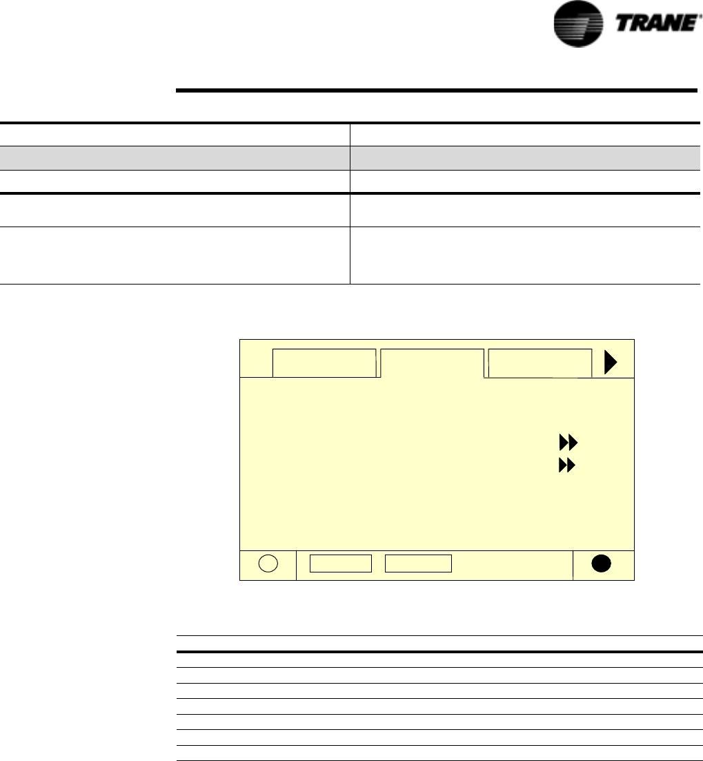
RTAC-SVX01F-EN 101
Controls Interface
Chiller Screen
The chiller screen is a summary of the chiller activity.
A
uto Stop
Chiller Compressor
Evap Leaving Water Temperature:
Evap Entering Water Temperature:
A
ctive Chilled Water Setpoint:
44.0 F
54.0 F
44.0 F
A
ctive Current Limit Setpoint: 100 %
Outdoor Air Temperature: 72.0 F
Modes
Software Version: 18.0
Compressor Screen
The compressor screen displays information for the one, two, three, or four compres-
sors in the format shown. The top line of radio buttons allows you to select the com-
pressor of interest. The next three lines show the compressor operating mode. The
compressor radio buttons and the compressor operating mode lines don’t change as
you scroll down in the menu.
The top screen has no upward scroll keys. The single arrow down scrolls the screen
one line at a time. As soon as the display is one line away from the top, the upward
pointing arrow appears.
The last screen has a single arrow to scroll upward one line at a time. When in the last
position, the single down arrow disappears.
Diagnostic Shutdown - Auto Reset The compressor is in the process of shutdown due to a diagnostic
that may clear automatically.
Service Tool Lockout The compressor is in the process of shutdown due to a command
from the TechView Service Tool to be "locked out" and inoperative.
This setting is nonvolatile and operation can only be restored by
using TechView to "unlock" it.
Table 27 Compressor Modes
Compressor Modes Description
Top Level Mode
Sub-modes
Table 28 Chiller Screen
Description Resolution Units
Evap Leaving Water Temperature X.X F / C
Evap Entering Water Temperature X.X F / C
Active Chilled Water Setpoint X.X F / C
Active Current Limit Setpoint X % RLA
Out Door Temperature X.X F / C
Software Type RTA Text
Software Version X.XX Text
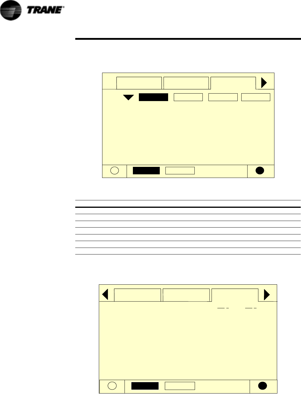
102 RTAC-SVX01F-EN
Controls Interface
Each compressor has its own screen depending on which radio key is pressed. When
toggling between compressor screens, say to compare starts and run time, the same
lines can be seen without additional key strokes. For example, toggling from the bot-
tom of the compressor 1A menu accesses the top of the compressor 2A menu.
A
uto Stop
Chiller Compressor
2B2A1B1A
A
mps L1 L2 L3:
% RLA:
Unit Volts:
55.0 56.2 54.3
460
86.0 88.4 84.3
Oil Temperature:
Intermediate Oil Pressure:
95.0 F
Suction Pressure:
102.9 psig
32.6 psig
Modes
Refrigerant Screen
The refrigerant screen displays those aspects of the chiller related to the refrigerant
circuits.
Auto Stop
Chiller Compressor Rfgt.
Cond Rfgt Pressure:
Sat Cond Rfgt Temp:
Evap Rfgt Pressure:
185.0 psig
125.0 F
30.0 psig
Ckt 1Ckt 2
185.0
125.0
30.0
Sat Evap Rfgt Temp: 34.0 F34.0
Evap Approach Temp: 4.0 F4.0
Rfgt Liquid Level: 0.1 -0.1 in
Table 29 Compressor Screen
Description Resolution Units
Amps L1 L2 L3 XXX Amps
% RLA L1 L2 L3 X.X % RLA
Unit Volts XXX Volts
Oil Temperature X.X F / C
Intermediate Oil Pressure X.X Pressure
Suction Pressure X.X Pressure
Starts/ Run Hours X, XX:XX hr:min
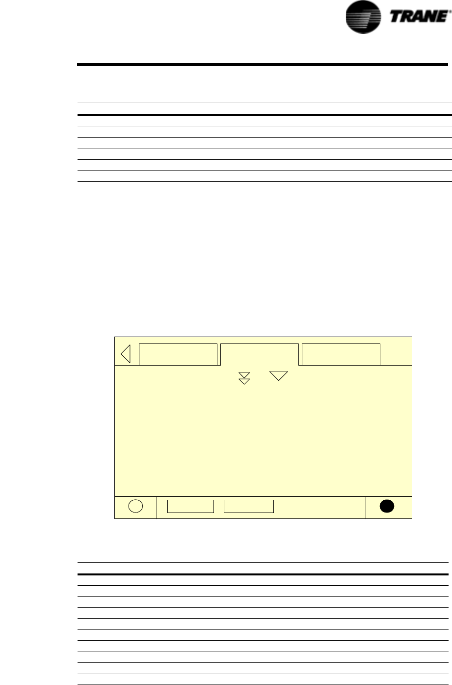
RTAC-SVX01F-EN 103
Controls Interface
Setpoint Screen
The setpoint screen is a two-part screen. Screen 1 lists all setpoints available to
change along with their current value. The operator selects a setpoint to change by
touching either the verbal description or setpoint value. Doing this causes the screen
to switch to Screen 2.
In Screen 1 the language setpoint will always be the last setpoint in the list. This will
facilitate language changes by placing that control in a standard position across all
CH.530 product lines.
Screen 2 displays the current value of the chosen setpoint in the upper ½ of the dis-
play. It is displayed in a changeable format consistent with its type. Binary setpoints
are considered to be simple two state enumeration and will use radio buttons. Ana-
log setpoints are displayed as spin buttons. The lower half of the screen is reserved
for help screens.
Auto Stop
Rfgt Setpoint Diagnostic
Auto Local or Remote:
Front Panel Chilled Water Setpoint:
Local
Condenser Limit Setpt: XXX % HPC
Front Panel Current Limit Setpoint:
Low Ambient Lockout Setpt: 35.0 F
Low Ambient Lockout: Enable
44.0 F
100 %
Table 30 Refrigerant Screen
Description Resolution Units
Cond Rfgt Pressure Ckt1/Ckt2 X.X Pressure
Sat Cond Rfgt Temp Ckt1/Ckt2 X.X F / C
Evap Rfgt Pressure Ckt1/Ckt2 X.X Pressure
Sat Evap Rfgt Temp Ckt1/Ckt2 X.X F / C
Evap Approach Temp Ckt1/Ckt2 X.X F / C
Rfgt Liquid Level Ckt1/Ckt2 X.X Height
Table 31 Setpoint Screen
Description Resolution or Text Units
Auto Local or Remote Remote/Local Text
Front Panel Chilled Water Setpoint X.X F / C
Front Panel Current Limit Setpoint XXX % RLA
Differential to Start X.X Temperature
Differential to Stop X.X Temperature
Condenser Limit Setpoint Enable/Disable Text
Low Ambient Lockout Setpoint X.X Temperature
Low Ambient Lockout Enable/Disable Text
Ice Build Enable/Disable Text
Front Panel Ice Termination Setpoint X.X Temperature
104 RTAC-SVX01F-EN
Controls Interface
Diagnostic Screen
The diagnostic screen (shown following) is accessible by either pressing the blinking
ALARMS key or by pressing the Diagnostic tab on the screen tab selection.
A hex code and a verbal description appears on the display as shown typically above.
This is the last active diagnostic. Pressing the “Reset All Active Diagnostics” will
reset all active diagnostics regardless of type, machine or refrigerant circuit. Compres-
sor diagnostics, which hold off only one compressor, are treated as circuit diagnos-
Comp 1A Pumpdown Pumpdown/Abort Text
Comp 1B Pumpdown Pumpdown/Abort Text
Comp 2A Pumpdown Pumpdown/Abort Text
Comp 2B Pumpdown Pumpdown/Abort Text
EXV Ckt 1 Open Auto/Open Text
EXV Ckt 2 Open Auto/Open Text
Front Panel Ckt 1 Lockout Locked Out/Not Locked Out Text
Front Panel Ckt 2 Lockout Locked Out/Not Locked Out Text
Ext Chilled Water Setpoint X.X F / C
Ext Current Limit Setpoint XXX % RLA
Date Format mmm dd yyyy, dd mm yyyy Text
Date Tex t
Time Format 12 hr, 24 hr Text
Time of Day Tex t
Keypad/Display Lockout Enable/Disable Text
Display Units SI, English Text
Pressure Units Absolute, Gauge Text
Language Selection Downloaded from TechView Text
Table 31 Setpoint Screen
Description Resolution or Text Units
Table 32 Setpoint Options/Conditions Displayed
Option Condition(s) Explanation
Ice Building Enable/Disable If feature is installed, operation can be initiated or stopped
Cprsr Pumpdown1Avail Pumpdown is allowed: only with unit in Stop or when circuit is locked out
Not Avail Pumpdown is not allowed because unit is operating or pumpdown has been com-
pleted
Pumpdown State is displayed while pumpdown is in progress
EXV Ckt Open
(For Authorized Service Use
Only2)
Avail Indicates EXV is closed but can be opened manually since unit is in Stop or circuit
is locked out
Not Avail EXV is closed but cannot be opened manually since unit is operating
Open State is displayed when EXV is open. Unit will not start with EXV manually set
open, but will initiate valve closure first.
Ckt Lockout Locked Out Circuit is locked out at Front Panel; other circuit may be available to run
Not Locked Out Circuit is not locked out and is available to run
Ext. Chilled Water Setpt Enable/Disable Allows unit to control setpoint; otherwise another loop controller in line will con-
trol, as optionally wired.
Ext. Current Limit Setpt Enable/Disable Allows unit to control setpoint; otherwise another loop controller in line will con-
trol, as optionally wired.
Notes:
1 Pumpdown procedure are discussed in Maintenance section 10.
2 Used for liquid level control or to recover from pumpdown
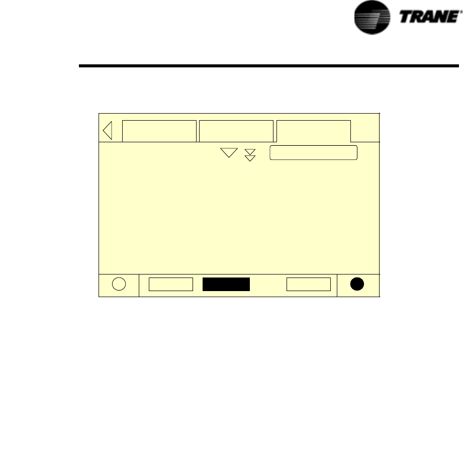
RTAC-SVX01F-EN 105
Controls Interface
tics, consistent with the circuit to which they belong. One circuit not operating will
not shut the chiller down. Viewing the “Compressor” screen will indicate whether a
circuit is not operating and for what reason.
Auto Stop Alarms
DiagnosticSetpointRfgt
[01] 10:59 AM Nov 26, 2001
Evaporator Water Flow Overdue
[02] 10:56 AM Nov 26, 2001
Low Chilled Water Temp: Unit Off
[03] 10:55 AM Nov 26, 2001
Low Evaorator Temp: Unit Off
Reset Diags
A complete listing of diagnostics and codes is included in the Diagnostic Section.
Power-Up
On Power-Up, DynaView will progress through three screens:
First Screen, Version # of the Boot, full version # displayed.
This screen will display for 5 seconds and move on to the second screen. The con-
trast will also be adjustable from this screen.
Second Screen, Application or No Application.
This screen will display for 5 seconds “A Valid Application Is Present” or “A Valid
Application Is Not Present” and move on to the third screen.
Third Screen, First screen of the Application, the Chiller Tab.
Display Formats
Units
Temperature settings are in °F or °C, depending on Display Units settings. Settings
can be entered in tenths or whole degrees depending on a menu setting at the Tech-
View.
Dashes (“-----”) appearing in a temperature or pressure report, indicates that the value
is invalid or not applicable.
Languages
English plus two alternate languages may be installed with DynaView and will reside
in the main processor. English will always be available. Alternate languages must be
installed using TechView, Software Download View.
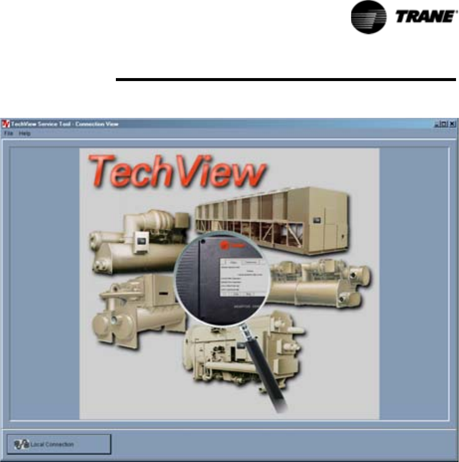
RTAC-SVX01F-EN 106
Te ch Vi ew
TechView is the PC (laptop) based tool used for servicing Tracer CH530.
Technicians that make any chiller control modification or service any
diagnostic with Tracer CH530 must use a laptop running the software
application “TechView.” TechView is a Trane application developed to minimize
chiller downtime and aid the technicians understanding of chiller operation
and service requirements.
NOTE: Important: Performing any Tracer CH530 service functions should be
done only by a properly trained service technician. Please contact your local
Trane service agency for assistance with any service requirements.
TechView software is available via Trane.com.
(http://www.trane.com/commercial/software/tracerch530/)
This download site provides a user the TechView installation software and
CH530 main processor software that must be loaded onto your PC in order to
service a CH530 main processor. The TechView service tool is used to load
software into the Tracer CH530 main processor.
Figure 37 TechView
RTAC-SVX01F-EN 107
TechVi ew
Minimum PC requirements to install and operate TechView
• Pentium II or higher processor
• 128Mb RAM
• 1024 x 768 resolution of display
• 56K modem
• 9-pin RS-232 serial connection
• Operating system - Windows 2000
• Microsoft Office (MS Word, MS Access, MS Excel)
• Parallel Port (25-pin) or USB Port
NOTE: TechView was designed for the preceding listed laptop configuration.
Any variation will have unknown results. Therefore, support for TechView is
limited to only those operating systems that meet the specific configuration
listed here. Only computers with a Pentium II class processor or better are
supported; Intel Celeron, AMD, or Cyrix processors have not been tested.
TechView is also used to perform any CH530 service or maintenance
function. Servicing a CH530 main processor includes:
• Updating main processor software
• Monitoring chiller operation
• Viewing and resetting chiller diagnostics
• Low Level Intelligent Device (LLID) replacement and binding
• Main processor replacement and configuration modifications
• Setpoint modifications
• Service overrides
Unit View
Unit view is a summary for the system organized by chiller subsystem. This
provides an overall view of chiller operating parameters and gives you an "at-a-
glance" assessment of chiller operation.
The Control Panel tab displays important operating information for the unit
and allows you to change several key operating parameters. The panel is
divided into four or more sub-panels (depending on the number of circuits in
the unit).
The Operating Mode tab displays the unit, circuit and compressor top level
operating modes.
The Hours and Starts tab displays the number a hours (total) a compressor
has run and the number of times the compressor has started. This window
plays a key role in evaluating maintenance requirements.
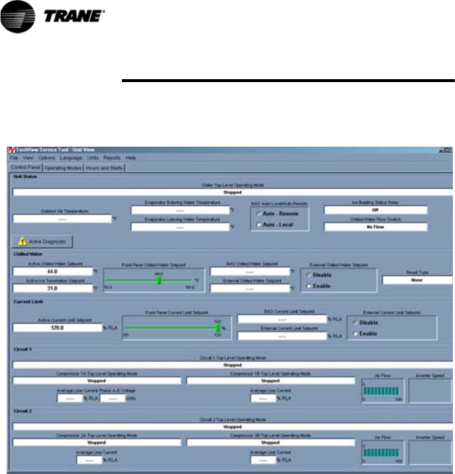
108 RTAC-SVX01F-EN
TechVi ew
Upon successful Local Connect Tech View will display UNIT VIEW.
RTAC Unit View is shown below
Figure 38 Unit View
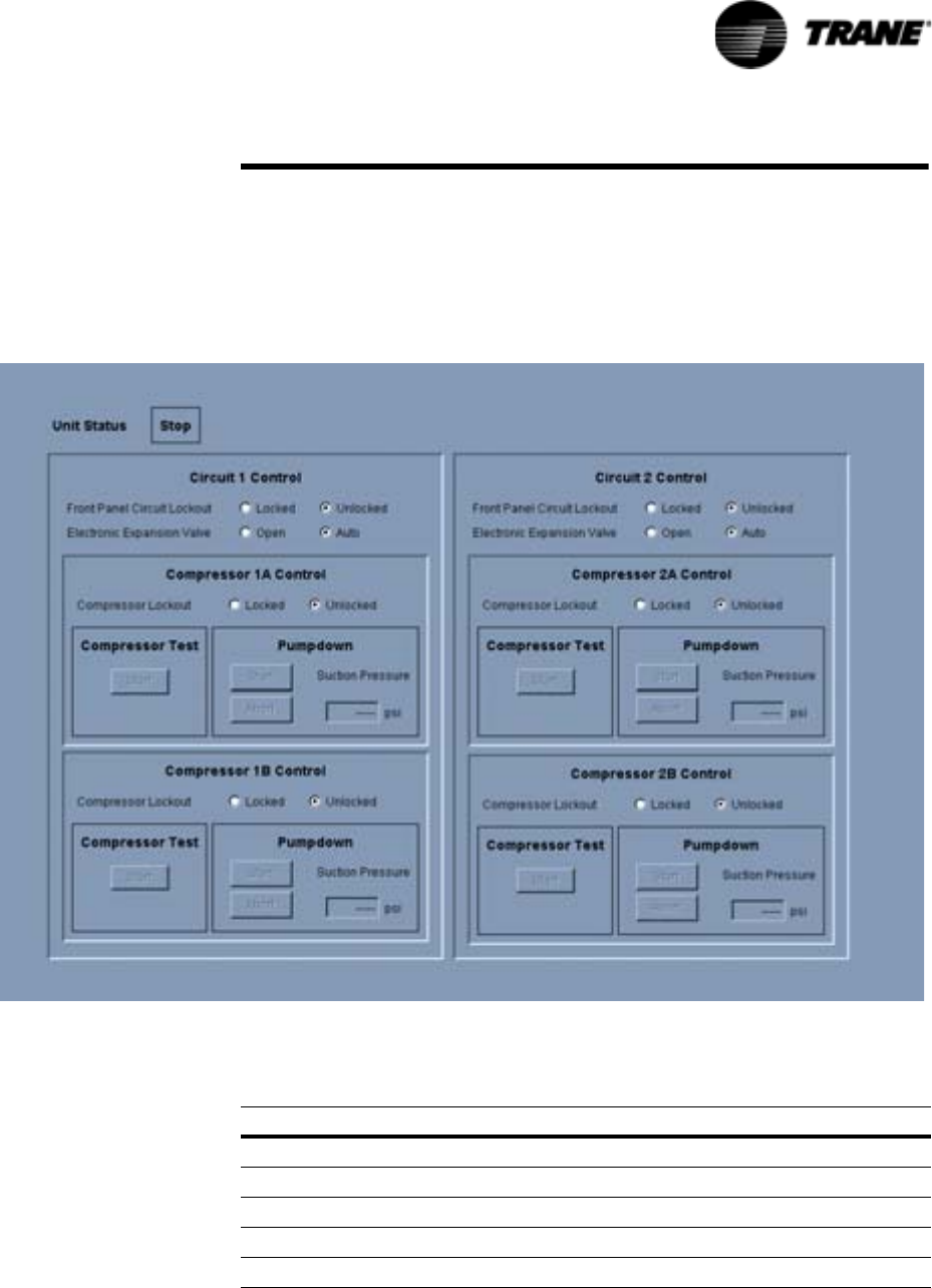
RTAC-SVX01F-EN 109
TechVi ew
Compressor Service View
The Compressor View provides convenient access to service functions for
pumping down circuits and test starting compressors. Various operational
lockouts allow operation of the rest of the chiller while some parts are
awaiting repair.
Figure 39 Compressor Service View
Table 33 Compressor Service View Items
Description Settings
Front Panel Circuit Lock Out Locked/Unlocked
Electronic Expansion Valve Open/Auto
Compressor Lockout Locked/Unlocked
Compressor test Start
Pumpdown (suction pressure is displayed) Start/Abort
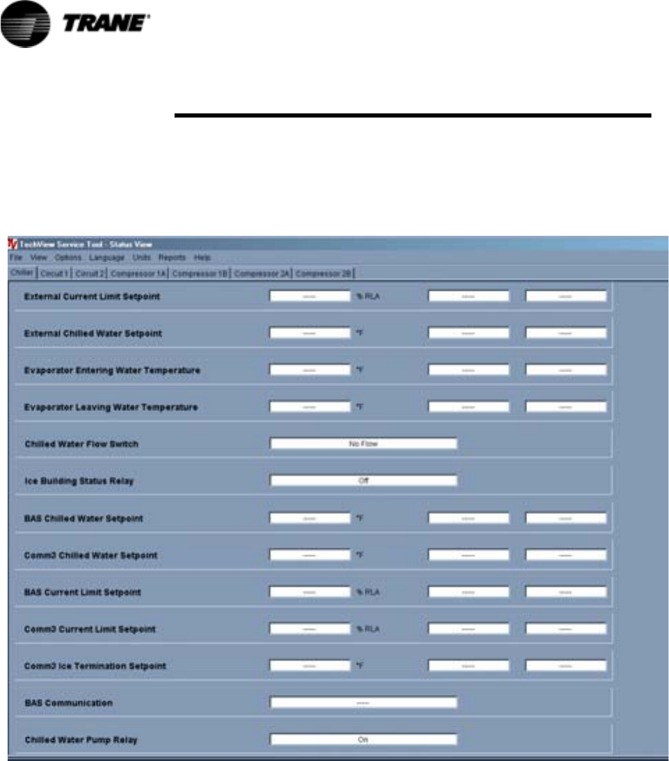
110 RTAC-SVX01F-EN
TechVi ew
Status View
Status View displays, in real time, all non-setpoint data organized by
subsystem tabs. As data changes on the chiller it is automatically updated in
Status View.
Figure 40 Status View

RTAC-SVX01F-EN 111
TechVi ew
Table 34 Status View Items
Ta b Te x t U n i t s
Chiller Chiller Top Level Operating Mode Text
Chiller Sub Operating Mode Text
Operating Mode Text
Chiller Sub Operating Mode Text
Front Panel Auto/Stop Text
Outdoor Air Temperature Temperature
External Auto/Stop Auto/Stop
External Emergency Stop Auto/Stop
Active Chilled Water Setpoint Temperature
Active Current Limit Setpoint Temperature
Active Ice Termination Setpoint Temperature
External Current Limit Setpoint % RLA
External Chilled Water Setpoint Temperature
Evaporator Entering Water Temperature Temperature
Evaporator Leaving Water Temperature Temperature
Chilled Water Flow Switch Flow/NoFlow
Ice Building Status Relay Ice Build/Normal
Comm3 Chilled Water Setpoint Temperature
BAS Chilled Water Setpoint Temperature
BAS Current Limit Setpoint % RLA
Comm3 Current Limit Setpoint % RLA
Comm3 Ice Termination Setpoint Temperature
BAS Communication Text
Chilled Water Pump Relay on/off
Compressor Compressor 1 Operating Mode Text
Compressor 1 Sub Mode Text
Compressor 1 Top Level Operating Mode Text
Run Hours Integer
Starts Integer
Phase A-B Voltage Volts
Average Line Current Amps
Line 1 Current Amps
Line 2 Current Amps
Line 3 Current Amps
Line 1 Current % RLA
Line 2 Current % RLA
112 RTAC-SVX01F-EN
TechVi ew
Compressor Line 3 Current % RLA
Maximum Line Current Amps
Supply Oil Temperature Temperature
Intermediate Oil Pressure Pressure
Female Step Loader Loaded/Unloaded
High Pressure Cutout Switch Tripped/Not Tripped
Circuit Circuit Sub Mode Text
Circuit Top Level Operating Mode Text
External Hardwired Lockout Locked/Not locked
Front Panel Lockout Locked/Not locked
Air Flow %
Inverter Speed % Full Speed
Condenser Refrigerant Pressure Pressure
Saturated Condenser Refrigerant
Temperature
Temperature
Differential Refrigerant Pressure Pressure
Evaporator Refrigerant Pressure Pressure
Saturated Evaporator Refrigerant
Temperature
Temperature
EXV Position % Open
Evaporator Refrigerant Liquid Level in
Table 34 Status View Items
Ta b Te x t U n i t s
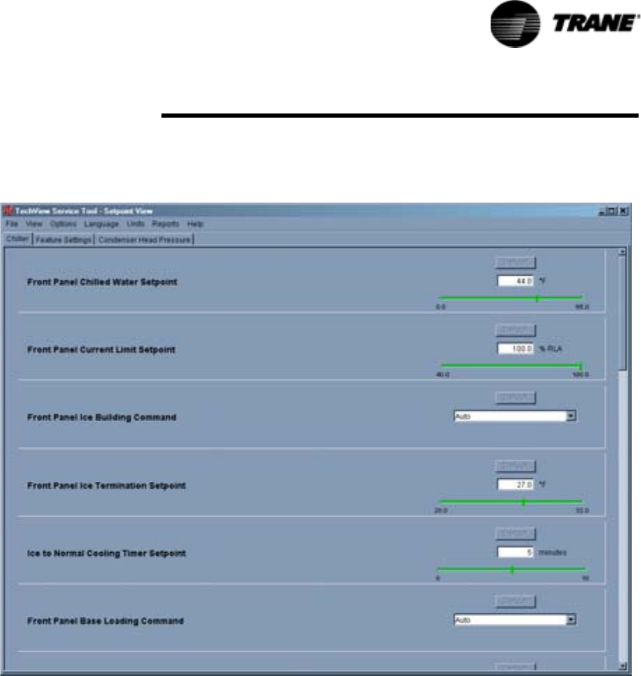
RTAC-SVX01F-EN 113
TechVi ew
Setpoint View
Setpoint view displays the active setpoints and allows you to make changes.
Figure 41 Setpoint View
Setpoint List
The center of the window displays the scrollable list of setpoint panels.
Setpoint Enumeration Panel
A setpoint numeric panel contains a label with the setpoint description and a
pull-down list showing the active value and the other selections. The Default
button returns the setpoint to the product's factory setting. The text field is
updated when the change is complete.
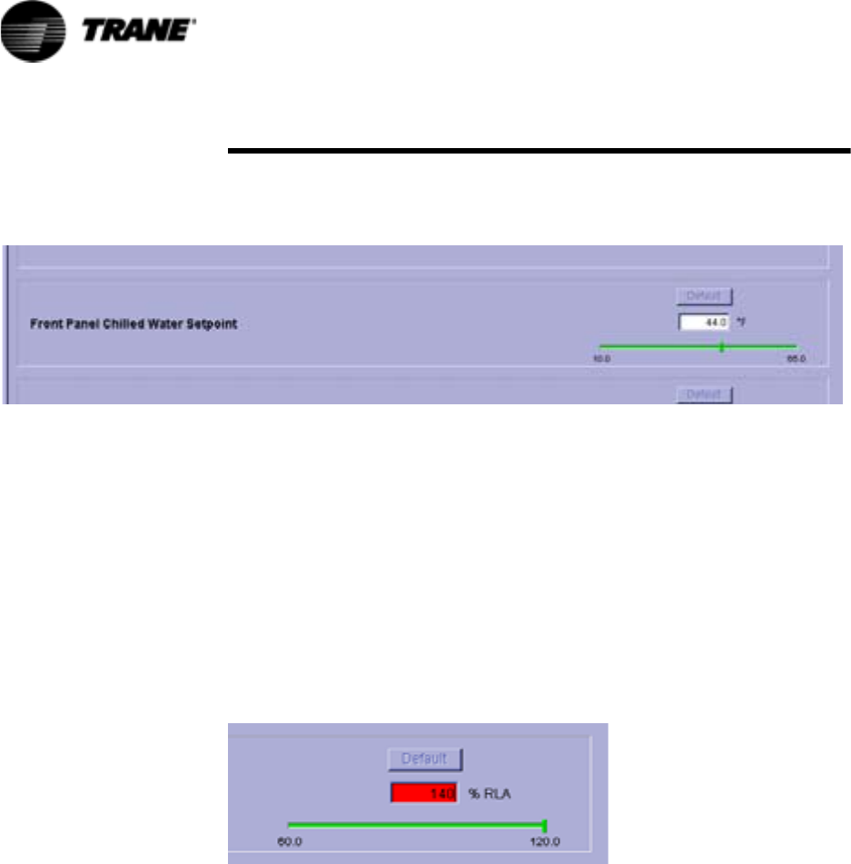
114 RTAC-SVX01F-EN
TechVi ew
Setpoint Numeric Panel
A setpoint numeric panel contains a label with the setpoint description, a
Default button, a text field with a unit label, and a slider.
The Default button changes the setpoint to the product's factory setting. The
text field and slider are updated when the change is complete.
You can change a setpoint with the text field or with the slider. When you click
on the entry field, the change setpoint dialog displays to coordinate the
setpoint change.
You can change the display units for a setpoint by clicking on the unit label
next to the entry field.
Change Setpoint
The change setpoint window allows you to enter a new value for the setpoint
into a text field. If the entered value is outside the given range, the
background turns red.

RTAC-SVX01F-EN 115
TechVi ew
Table 35 Setpoints View Items
Tab Tex t
Min
Value
Max
Value
Default
Value Unit Type
Chiller Front Panel Display Units English, SI English Display Units
Chiller Front Panel Chilled Water
Setpoint
10
(-12.22)
65
(18.33)
44
(6.67)
Tem p D e g F( C )
Chiller Front Panel Current Limit
Setpoint
60 120 120 Percent
Chiller Differential to Stop 0.5
(0.2777)
2.5
(1.388)
2.0
( 1. 111 )
Differential
Tem p D e g F( C )
Chiller Differential to Start 1.0
(0.555)
30
(16.666)
2
( 1. 111 )
Differential
Tem p D e g F( C )
Chiller Leaving Water Temp Cutout 0.0
(-17.78)
36.0
(2.22)
36.0
(2.22)
Tem p D e g F( C )
Chiller Low Refrigerant Temp Cutout -5.0
(-20.56)
36.0
(2.22)
28.0
(-2.22)
Tem p D e g F( C )
Chiller Front Panel Condenser Limit
Setpoint
80 120 90 Percent
Chiller Low Ambient Lockout Setpoint -10
(-23.333)
70
( 2 1. 111 )
25
(-3.89)
Tem p D e g F( C )
Chiller Low Ambient Lockout Enable, Disable Enable Enabled /
Disabled
Chiller Front Panel Ice Termination
Setpoint
20
(-6.67)
31
(-0.56)
31
(-0.56)
Tem p D e g F( C )
Chiller External Ice Building Input Enable, Disable Disable Enabled /
Disabled
Chiller Under/Over Voltage Protection Enable, Disable Disable Enabled /
Disabled
Chiller Local Atmospheric Pressure 9.93
(68.5)
16.0
(110.3)
14.7
(101.3)
Absolute
Pressure
psia(Kpa)
Chiller Design Delta Temperature 4
(2.22)
30
(16.666)
10
(5.6)
Differential
Tem p D e g F( C )
Chiller Reset Type None, Return, Outdoor,
Constant Return
None RstTyp
Chiller Return Reset Ratio 10 120 50 Percent
Chiller Return Start Reset 4.0
(2.22)
30.0
(16.666)
10.0
(5.56)
Differential
Tem p D e g F( C )
Chiller Return Maximum Reset 0 20
(11.11)
5.0
(2.78)
Differential
Tem p D e g F( C )
Chiller Outdoor Reset Ratio -80 80 10 Percent
Chiller Outdoor Start Reset 50
(10)
130
(54.44)
90
(32.22)
Tem p D e g F( C )
116 RTAC-SVX01F-EN
TechVi ew
Chiller Outdoor Maximum Reset 0 20
(11.11)
5
(2.78)
Differential
Tem p D e g F( C )
Chiller External Chilled Water Setpoint Enable, Disable Disable Enabled /
Disabled
Chiller External Current Limit Setpoint Enable, Disable Disable Enabled /
Disabled
Chiller Evaporator Water Pump Off
Delay
0301 Minutes
Chiller Chilled Water Setpoint Filter
Settling Time
30 1800 200 Seconds
Chiller Compressor Staging Deadband 0.4
(0.222)
4.0
(2.222)
0.05
(0.2778)
Differential
Tem p D e g F( C )
Table 35 Setpoints View Items
Tab Tex t
Min
Value
Max
Value
Default
Value Unit Type
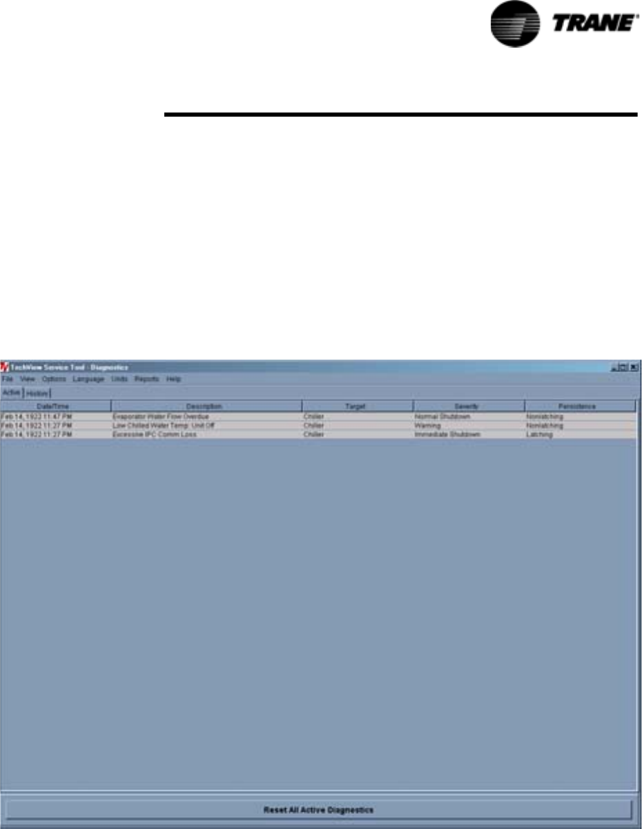
RTAC-SVX01F-EN 117
TechVi ew
Diagnostics View
This window lists the active and inactive (history) diagnostics. There can be
up to 60 diagnostics, both active and historic. For example, if there were 5
active diagnostics, the possible number of historic diagnostics would be 55.
You can also reset active diagnostics here, (i.e., transfer active diagnostics to
history and allow the chiller to regenerate any active diagnostics).
Resetting the active diagnostics may cause the chiller to resume operation.
The Active and History diagnostics have separate tabs. A button to reset the
active diagnostics displays when either tab is selected
.
Figure 42 Diagnostic View
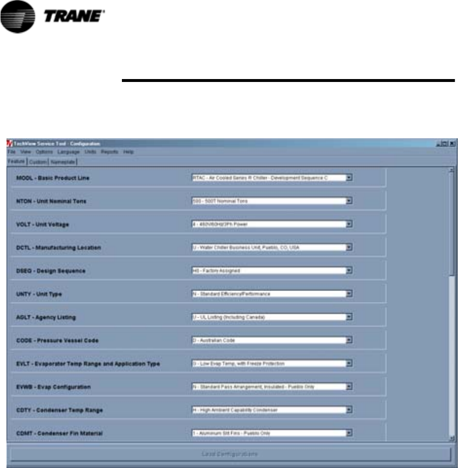
118 RTAC-SVX01F-EN
TechVi ew
Configuration View
This view displays the active configuration and allows you to make changes.
Figure 43 Configuration View
Configuration View allows you to define the chiller's components, ratings, and
configuration settings. These are all values that determine the required
installed devices, and how the chiller application is run in the main processor.
For example, a user may set an option to be installed with Configuration View,
which will require devices to be bound using Binding View. And when the
main processor runs the chiller application, the appropriate steps are taken to
monitor required inputs and control necessary outputs.
Any changes made in the Configuration View, on any of the tabs, will modify
the chiller configuration when you click on the Load Configuration button
(located at the base of the window). The Load Configuration button uploads
the new configuration settings into the main processor.
Any changes made to the configuration will change the unit model number
number and the confirmation code (CRC). If changes are made to the unit
configuration the new model number and CRC should be recorded.

RTAC-SVX01F-EN 119
TechVi ew
Selecting the Undo All button will undo any configuration setting changes
made during the present TechView connection and since the last time the
Load Configuration button was selected. .
Table 36 Configuration View Items
Tab Item Default Description
Feature Basic Product Line RTAC - Air Cooled Series R Chiller
Unit Nominal Capacity 140 Nominal Tons
155 Nominal Tons
170 Nominal Tons
185 Nominal Tons
200 Nominal Tons
225 Nominal Tons
250 Nominal Tons
275 Nominal Tons
300 Nominal Tons
350 Nominal Tons
375 Nominal Tons
400 Nominal Tons
450 Nominal Tons
500 Nominal Tons
Unit Voltage A - 200V/60Hz/3Ph power
K - 220V/50Hz/3 Ph power
C - 230V/60Hz/3Ph power
J - 380V/60Hz/3Ph power
D - 400V/50Hz/3Ph power
4 - 460V/60Hz/3Ph power
5 - 575V/60Hz/3Ph power
Manufacturing Location U - Water Chiller Business Unit - Pueblo
E - Epinal Business Unit -Charmes
Design Sequence XX - Factory/ABU Assigned
Unit Type N - Standard Efficiency/Performance
H - High Efficiency/Performance
Agency Listing N - No agency listing
U - C/UL listing
Pressure Vessel Code A - ASME pressure vessel code
C - Canadian code
D - Australian code
L - Chinese code
R - Vietanamese code
S - Special
Evaporator Temperature Range & Application
Type
F - Standard Temp. with Frz Prot
R - Rem Evap, Std Temp, No Frz Prot
G - Low Temp, with Frz Prot
Evaporator Configuration N - Standard pass arrangement, insulated
Condenser Temperature Range N - Standard ambient range 25-115 deg F
H - High ambient capability 25-125 deg F
L - Low ambient capability 0-115 deg F
W - Wide ambient capability 0-125 deg F
Condenser Fin Material 1 - Standard aluminum slit fins
2 - Copper fins, non-slit fins
4 - Complete Coat aluminum fins
120 RTAC-SVX01F-EN
TechVi ew
Feature Condenser Fan/Motor Configuration N - Condenser fans with ODP motors
W - Low Noise fans
T - Condenser fans with TEAO motors
Compressor Motor Starter Type X - Across-the-line starters
Y - Wye-delta closed transition starters
Incoming Power Line Connection 1 - Single point power connection
2 - Dual point power connection (1/ckt)
Power Line Connection Type T - Terminals only
D - Non-fused disconnect switch(es)
C - Circuit Breaker(s), HACR-rated
Unit Operator Interface E - Easy-View operator interface
D -Dyna-View operator interface
Remote Interface N - No remote interface
C - Tracer Comm 3 interface
L -Lon Talk Communication interface (LCI)
Control Input Accessories/Options N -No remote input
R -Remote leaving water temp stpt
C -Remote current limit setpoint
B -Remote lvg. temp.setpoint and remote current
limit setpoint
Control Output Accessories/Options N -No output options
A -Alarm relay
C -Icemaking
D -Icemaking and alarm relay
Short Circuit Rating 0 - No short circuit withstand rating
5 -10000A SCR
4 -35000A SCR
6 -65000A SCR
Electrical Accessories and Export Packing N - No flow switches
F - NEMA-1 flow switch - 150 psi
E - Vapor Proof FS - 150 psi
Control Panel Accessories N - No convenience outlet
A - 15A 115V convenience outlet (60HZ)
Refrigerant Service Valves 0 - No suction services valves
1 - Suction service valves
Compressor Sound Attenuator Option 0 - No sound attenuator
1 - Factory installed sound attenuator
Appearance Options N - No appearance options
A - Architectural louvered panels
C - Half Louvers
G - Access guards
B - Access guards and half louvers
P - Painted unit
L - Painted unit with full louvered panels
H - Painted unit with half louvered panels
K - Painted unit with access guards
W - Painted w/access guards and half louvers
Table 36 Configuration View Items
Tab Item Default Description
RTAC-SVX01F-EN 121
TechVi ew
Features Installation Accessories N - No installation accessories
R - Neoprene Isolators
F - Flanged water connection kit
G - Neoprene isolators and flange wtr conn kit
Factory Test 0 - No factory run test
Control, Label, and
Literature Language
E - English
G - Chinese
Special Order X - Standard catalog configuration
S - Unit has special order feature
Custom Comm 3 ICD address 55 1-64
REM = C
Status Relay #1 J2-10,11,12 Alarm - Latching None, Alarm - Latching (Active diagnostic
persistence latching), Alarm - Auto reset (Active
diagnostic persistence non-latching), Alarm
(Active diagnostic persistence latching or non-
latching), Alarm Ckt1 (Active diagnostic
persistence latching or non-latching), Alarm Ckt2
(Active diagnostic persistence latching or non-
latching), Chiller Limit Mode (With 20 minute
filter), Circuit 1 Running, Circuit 2 Running,
Maximum Capacity
COOP = A, D or X
Status Relay #2 J2-7,8,9 Chiller Running
Status Relay #3 J2-4,5,6 Maximum Capacity
Status Relay #4 J2-1,2,3 Chiller Limit Mode
Phase Unbalance Trip 30 10-50%
Phase Unbalance Grace
Period
90 30-255 Sec
Maximum Acceleration
Time
31-255 Sec
Starter Feature All Enabled Contactor Integrity Test, Phase Reversal Detect,
Phase Unbalance Detect
External Chilled Water
Setpoint Detection
2-10 VDC 2-10 VDC, 4-20 mA
CIOP = C or B
External Current Limit Water
Setpoint Detection
2-10 VDC 2-10 VDC, 4-20 mA
CIOP = C or B
Custom Unit Voltage 400 380,400,415
VOLT = D
Nameplate The Model Number field contains the model number stored in the EasyView or DynaView.
The Confirm Code field contains the confirm code stored in the EasyView or DynaView. The
confirm code is a four-digit hex value that is a mathematical calculation of the model number. This
number has one to one correlation to a specific model number and is used to verify that the model
number was entered properly.
The Serial Number field contains the serial number stored in the EasyView or DynaView.
This model number and confirmation code must be know when the main processor requires
replacement.
Table 36 Configuration View Items
Tab Item Default Description
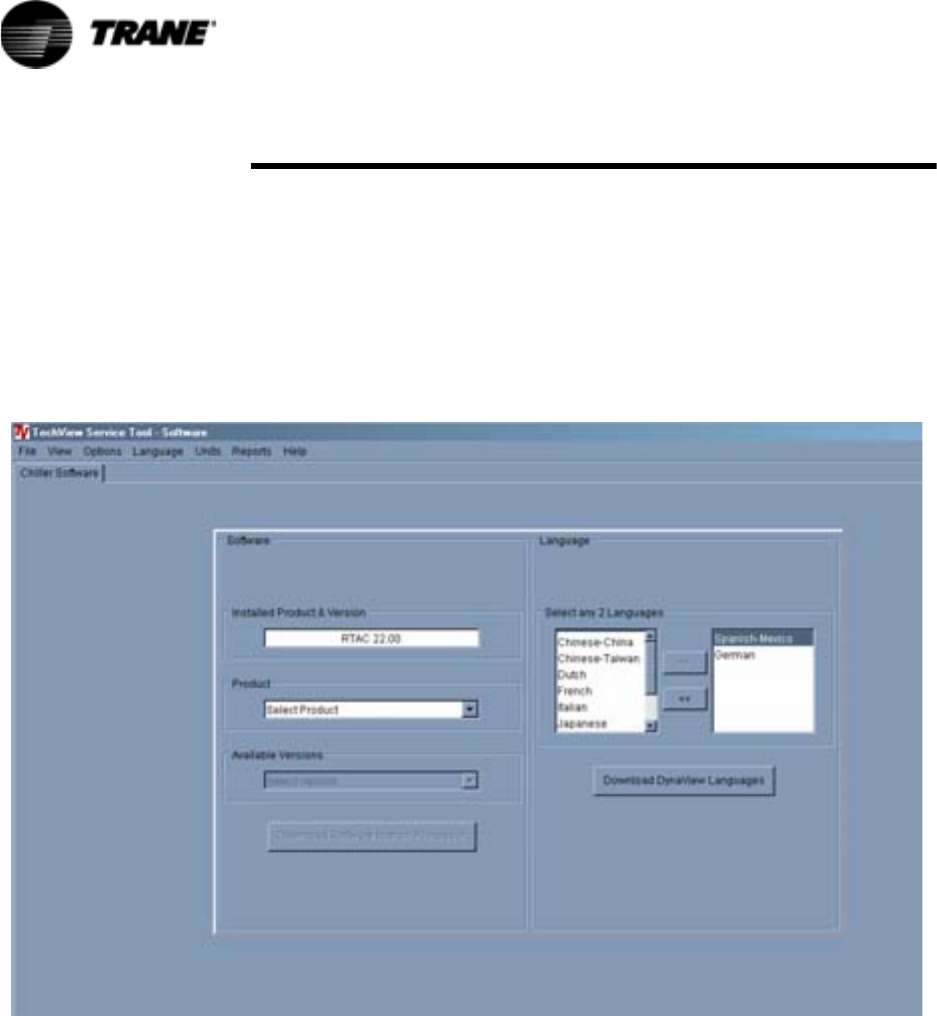
122 RTAC-SVX01F-EN
TechVi ew
Software View
Software view allows you to verify the version of chiller software currently
running on the EasyView or DynaView and download a new version of chiller
software to the EasyView or DynaView.
You can also add up to two available languages to load into the DynaView.
Loading an alternate language file allows the DynaView to display its text in
the selected alternate language, English will always be available.
Figure 44 Software View
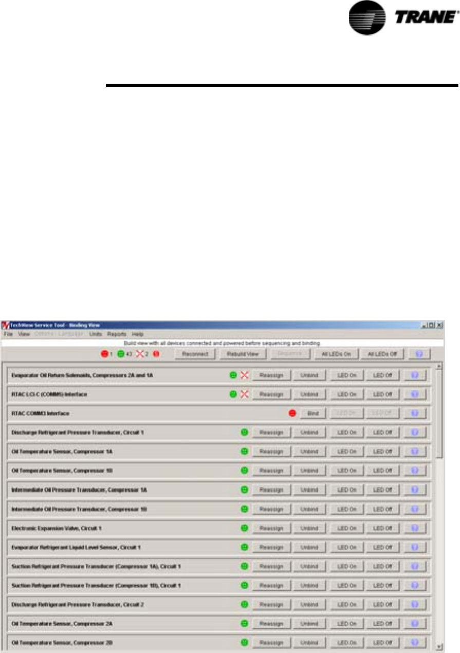
RTAC-SVX01F-EN 123
TechVi ew
Binding View
Binding View allows you to assess the status of the network and all the
devices connected as a whole, or the status of individual devices by using
status icons and function buttons.
Binding View is essentially a table depicting what devices and options are
actually discovered on the network bus (and their communication status)
versus what is required to support the configuration defined by the feature
codes and categories. Binding View allows you to add, remove, modify, verify,
and reassign devices and options in order to match the configuration
requirements.
Whenever a device is installed, it must be correctly configured to
communicate and to function as intended. This process is called binding.
Some features of Binding View are intended to serve a second purpose; that
is diagnosing problems with communication among the devices.
Figure 45 Binding View
124 RTAC-SVX01F-EN
TechVi ew
Replacing or Adding Devices
If a device is communicating but incorrectly configured, it might not be
necessary to replace it. If the problem with the device is related to
communication, attempt to rebind it, and if the device becomes correctly
configured, it will then communicate properly.
If a device that needs to be replaced is still communicating, it should be
unbound. Otherwise, it will be necessary to rebuild the CH530 network
image for Binding View to discover that it has been removed. An unbound
device stops communicating and allows a new device to be bound in its
place.
It is good practice to turn the power off while detaching and attaching devices
to the CH530 network. Be sure to keep power on the service tool computer.
After power is restored to the CH530 network, the reconnect function in
Binding View restores communication with the network. If the service tool
computer is turned off, you must restart TechView and Binding View.
If a device is not communicating, the binding function displays a window to
request manual selection of the device to be bound. Previously-selected
devices are deselected when the function starts. When manual selection is
confirmed, exactly one device must be selected; if it is the correct type, it is
bound. If the desired device cannot be selected or if multiple devices are
accidentally selected, you can close the manual selection window by clicking
on No and repeat the bind function.
Software Download
Instructions for First Time TechView Users
This information can also be found at http://www.trane.com/commercial/
software/tracerch530/.
1. Create a folder called “CH530” on your C:\ drive. You will select and use
this folder in subsequent steps so that downloaded files are easy to
locate.
2. Download the Java Runtime installation utility file onto your PC in the
CH530 folder (please note that this does not install Java Runtime, it only
downloads the installation utility).
– Click on the latest version of Java Runtime shown in the TechView
Download table.
– Select “Save this program to disk” while downloading the files (do not
select “Run this program from its current location”).
3. Download the TechView installation utility file onto your PC in the CH530
folder (please note that this does not install TechView, it only downloads
the installation utility).
– Click on the latest version of TechView shown in the TechView
Download table.
– Select “Save this program to disk” while downloading the files (do not
select “Run this program from its current location”).
4. Remember where you downloaded the files (the “CH530” folder). You
will need to locate them to finish the installation process.

RTAC-SVX01F-EN 125
TechVi ew
5. Proceed to “Main Processor Software Download” page and read the
instructions to download the latest version of main processor installation
files.
Note: you will first select the chiller type to obtain the available file ver-
sions.
6. Select the product family. A table with the download link will appear for
that product family.
7. Download the main processor software onto your PC in the CH530 folder
(please note that this does not install the main processor, it only down-
loads the installation utility).
– To do this, click on the latest version of the main processor.
– Select “Save this program to disk” while downloading the files (do not
select “Run this program from its current location”).
8. Remember where you downloaded the files (the “CH530” folder). You
will need to locate them to finish the installation process.
9. To complete the installation process, locate the installation utilities you
downloaded into the CH530 folder. If necessary, use your PC’s file man-
ager to locate the downloaded files.
10. Install the applications in the following order by double-clicking on the
install program and following the installation prompts:
– Java Runtime Environment (JRE_VXXX.exe)
Note: During the Java Runtime Environment installation, you may be
prompted to “select the default Java Runtime for the system browsers...”.
Do not select any system browsers at this step. There should be no
default browsers selected for proper operation.
– TechView (6200-0347-VXXX.exe)
– The main processor (6200-XXXX-XX-XX.exe).
– The main processor program will self extract to the proper folder within
the TechView program directory, provided the TechView program is
properly installed on the C:\ drive.
11. Connect your PC to the CH530 main processor using a standard 9-pin
male/9-pin female RS-232 cable.
12. Run the TechView software by selecting the TechView icon placed on
your desktop during the installation process. The “Help...About” menu
can be viewed to confirm proper installation of latest versions.
126 RTAC-SVX01F-EN
Diagnostics
The following Diagnostic Table contains all diagnostics possible arranged
alphabetically by the name assigned to each diagnostic. Not all diagnostics are
available unless TechView is installed.
Legend to Diagnostics Table
Hex Code: 3-digit code used to uniquely identify diagnostics.
Diagnostic Name: Name of the diagnostic as it appears at DynaView and/or
TechView displays.
Severity: Defines the action of the above effect. Immediate means an instantaneous
shutdown of the affected portion. Normal means routine or friendly shutdown of the
affected portion. Special Mode means a particular mode of operation is invoked, but
without shutdown, and Info means an Informational Note or Warning is generated.
Persistence: Defines whether or not the diagnostic and its effects are to be manually
reset (Latched), or can be either manually or automatically reset (Nonlatched).
Criteria: Quantitatively defines the criteria used in generating the diagnostic and, if
nonlatching, the criteria for auto reset.
Reset Level: Defines the lowest level of manual diagnostic reset command which can
clear the diagnostic. The manual diagnostic reset levels in decreasing order of priority
are: Local, Remote and Info. For example, a diagnostic that has a reset level of
Remote, can be reset by either a remote diagnostic reset command or by a local
diagnostic reset command, but not by the lower priority Info Reset command.
Hex
Code
Diagnostic Name
and Source
Severity Persis-
tence
Criteria Reset
Level
398 BAS Communication Lost Special NonLatch The BAS was setup as "installed" at the MP and the Comm 3 LLID lost
communications with the BAS for 15 contiguous minutes after it had
been established. Refer to Section on Setpoint Arbitration to determine
how setpoints and operating modes may be effected by the comm
loss. The chiller follows the value of the Tracer Default Run Command
which can be previously written by Tracer and stored nonvolatilely by
the MP (either use local or shutdown).
Remote
390 BAS Failed to Establish
Communication
Special NonLatch The BAS was setup as "installed" and the BAS did not communicate
with the MP within 15 minutes after power-up. Refer to Section on
Setpoint Arbitration to determine how setpoints and operating modes
may be effected. Note: The original requirement for this was 2
minutes, but was implemented at 15 minutes for RTAC.
Remote
2E6 Check Clock Info Latch The real time clock had detected loss of its oscillator at some time in
the past. This diagnostic can be effectively cleared only by writing a
new value to the chiller's time clock using the TechView or DynaView's
"set chiller time" functions.
Remote
8A Chilled Water Flow (Entering
Water Temperature)
Info NonLatch The entering evaporator water temp fell below the leaving evaporator
water temp. by more than 2°F for 100 °F-sec. For RTAC this diagnostic
cannot reliably indicate loss of flow, but can warn of improper flow
direction through the evaporator, misbound temperature sensors, or
other system problems
Remote
5EF Comm Loss: Chilled Water
Flow Switch
Immediate Latch Continual loss of communication between the MP and the Functional
ID has occurred for a 30 second period.
Remote
5F2 Comm Loss: Cond Rfgt
Pressure, Circuit #1
Immediate Latch Same as Comm Loss: Chilled Water Flow Switch Remote
5F3 Comm Loss: Cond Rfgt
Pressure, Circuit #2
Immediate Latch Same as Comm Loss: Chilled Water Flow Switch Remote
694 Comm Loss: Electronic
Expansion Valve, Circuit #1
Normal Latch Same as Comm Loss: Chilled Water Flow Switch Remote
695 Comm Loss: Electronic
Expansion Valve, Circuit #2
Normal Latch Same as Comm Loss: Chilled Water Flow Switch Remote
5DE Comm Loss: Emergency
Stop
Normal Latch Same as Comm Loss: Chilled Water Flow Switch Remote
68E Comm Loss: Evap Oil Return
Valve, Cprsr 1A
Normal Latch Same as Comm Loss: Chilled Water Flow Switch Remote
69E Comm Loss: Evap Oil Return
Valve, Cprsr 1B
Normal Latch Same as Comm Loss: Chilled Water Flow Switch Remote
68F Comm Loss: Evap Oil Return
Valve, Cprsr 2A
Normal Latch Same as Comm Loss: Chilled Water Flow Switch Remote

RTAC-SVX01F-EN 127
Diagnostics
69F Comm Loss: Evap Oil Return
Valve, Cprsr 2B
Normal Latch Same as Comm Loss: Chilled Water Flow Switch Remote
5E4 Comm Loss: Evaporator
Entering Water Temperature
Special
Mode
Latch Same as Comm Loss: Chilled Water Flow Switch Remote
5E3 Comm Loss: Evaporator
Leaving Water Temperature
Normal Latch Same as Comm Loss: Chilled Water Flow Switch Remote
6BB Comm Loss: Evaporator Rfgt
Drain Valve - Ckt 1
Normal Latch Same as Comm Loss: Chilled Water Flow Switch Remote
6BC Comm Loss: Evaporator Rfgt
Drain Valve - Ckt 2
Normal Latch Same as Comm Loss: Chilled Water Flow Switch Remote
688 Comm Loss: Evaporator Rfgt
Liquid Level, Circuit #1
Immediate Latch Same as Comm Loss: Chilled Water Flow Switch Remote
689 Comm Loss: Evaporator Rfgt
Liquid Level, Circuit #2
Immediate Latch Same as Comm Loss: Chilled Water Flow Switch Remote
5F0 Comm Loss: Evaporator Rfgt
Pressure, Circuit #1
Immediate Latch Continual loss of communication between the MP and the Functional
ID has occurred for a 30 second period. Note: This diagnostic is
replaced by diagnostic 5FB below with Rev 15.0
Remote
5F1 Comm Loss: Evaporator Rfgt
Pressure, Circuit #2
Immediate Latch Continual loss of communication between the MP and the Functional
ID has occurred for a 30 second period. Note: This diagnostic is
replaced by diagnostic 5FD below with Rev 15.0
Remote
5F8 Comm Loss: Evaporator
Water Pump Control
Normal Latch Same as Comm Loss: Chilled Water Flow Switch Remote
5DD Comm Loss: External Auto/
Stop
Normal Latch Same as Comm Loss: Chilled Water Flow Switch Remote
5E9 Comm Loss: External Chilled
Water Setpoint
Special
Mode
NonLatch Continual loss of communication between the MP and the Functional
ID has occurred for a 30 second period. Chiller shall discontinue use of
the External Chilled Water Setpoint source and revert to the next higher
priority for setpoint arbitration
Remote
5DF Comm Loss: External Circuit
Lockout, Circuit #1
Special
Mode
Latch Continual loss of communication between the MP and the Functional
ID has occurred for a 30 second period. MP will nonvolatily hold the
lockout state (enabled or disabled) that was in effect at the time of
comm loss.
Remote
5E0 Comm Loss: External Circuit
Lockout, Circuit #2
Special
Mode
Latch Same as Comm Loss: External Circuit Lockout, Circuit #1 Remote
5EA Comm Loss: External Current
Limit Setpoint
Special
Mode
NonLatch Continual loss of communication between the MP and the Functional
ID has occurred for a 30 second period. Chiller shall discontinue use of
the External Current limit setpoint and revert to the next higher priority
for Current Limit setpoint arbitration
Remote
680 Comm Loss: Fan Control
Circuit #1, Stage #1
Normal Latch Same as Comm Loss: Chilled Water Flow Switch Remote
681 Comm Loss: Fan Control
Circuit #1, Stage #2
Normal Latch Same as Comm Loss: Chilled Water Flow Switch Remote
682 Comm Loss: Fan Control
Circuit #1, Stage #3
Normal Latch Same as Comm Loss: Chilled Water Flow Switch Remote
683 Comm Loss: Fan Control
Circuit #1, Stage #4
Normal Latch Same as Comm Loss: Chilled Water Flow Switch Remote
684 Comm Loss: Fan Control
Circuit #2, Stage #1
Normal Latch Same as Comm Loss: Chilled Water Flow Switch Remote
685 Comm Loss: Fan Control
Circuit #2, Stage #2
Normal Latch Same as Comm Loss: Chilled Water Flow Switch Remote
686 Comm Loss: Fan Control
Circuit #2, Stage #3
Normal Latch Same as Comm Loss: Chilled Water Flow Switch Remote
687 Comm Loss: Fan Control
Circuit #2, Stage #4
Normal Latch Same as Comm Loss: Chilled Water Flow Switch Remote
68C Comm Loss: Fan Inverter
Fault, Circuit #1 or Circuit #1,
Drive 1
Special
Mode
Latch Continual loss of communication between the MP and the Functional
ID has occurred for a 30 second period. Operate the remaining fans as
fixed speed fan deck.
Remote
68D Comm Loss: Fan Inverter
Fault, Circuit #1, Drive 2
Special
Mode
Latch Same as Comm Loss: Fan Inverter Fault, Circuit #1 or Circuit #1,
Drive 1
Remote
69A Comm Loss: Fan Inverter
Fault, Circuit #2 or Circuit #2,
Drive 1
Special
Mode
Latch Same as Comm Loss: Fan Inverter Fault, Circuit #1 or Circuit #1,
Drive 1
Remote
69B Comm Loss: Fan Inverter
Fault, Circuit #2, Drive 2
Special
Mode
Latch Same as Comm Loss: Fan Inverter Fault, Circuit #1 or Circuit #1,
Drive 1
Remote
68A Comm Loss: Fan Inverter
Power, Circuit #1 or Circuit #1
Drive 1 and 2
Normal Latch Same as Comm Loss: Fan Inverter Fault, Circuit #1 or Circuit #1,
Drive 1
Remote
Hex
Code
Diagnostic Name
and Source
Severity Persis-
tence
Criteria Reset
Level
128 RTAC-SVX01F-EN
Diagnostics
698 Comm Loss: Fan Inverter
Power, Circuit #2 or Circuit #2
Drive 1 and 2
Normal Latch Same as Comm Loss: Fan Inverter Fault, Circuit #1 or Circuit #1,
Drive 1
Remote
68B Comm Loss: Fan Inverter
Speed Command, Circuit #1
or Circuit #1 Drive 1 and 2
Special
Mode
Latch Same as Comm Loss: Fan Inverter Fault, Circuit #1 or Circuit #1,
Drive 1
Remote
699 Comm Loss: Fan Inverter
Speed Command, Circuit #2
or Circuit #2 Drive 1 and 2
Special
Mode
Latch Same as Comm Loss: Fan Inverter Fault, Circuit #1 or Circuit #1,
Drive 1
Remote
5D9 Comm Loss: Female Step
Load Compressor 1A
Normal Latch Same as Comm Loss: Chilled Water Flow Switch Remote
5DA Comm Loss: Female Step
Load Compressor 1B
Normal Latch Same as Comm Loss: Chilled Water Flow Switch Remote
5DB Comm Loss: Female Step
Load Compressor 2A
Normal Latch Same as Comm Loss: Chilled Water Flow Switch Remote
5DC Comm Loss: Female Step
Load Compressor 2B
Normal Latch Same as Comm Loss: Chilled Water Flow Switch Remote
5EB Comm Loss: High Pressure
Cutout Switch, Cprsr 1A
Immediate Latch Same as Comm Loss: Chilled Water Flow Switch Remote
5EC Comm Loss: High Pressure
Cutout Switch, Cprsr 1B
Immediate Latch Same as Comm Loss: Chilled Water Flow Switch Remote
5ED Comm Loss: High Pressure
Cutout Switch, Cprsr 2A
Immediate Latch Same as Comm Loss: Chilled Water Flow Switch Remote
5EE Comm Loss: High Pressure
Cutout Switch, Cprsr 2B
Immediate Latch Same as Comm Loss: Chilled Water Flow Switch Remote
5E1 Comm Loss: Ice-Machine
Control
Special
Mode
Latch Continual loss of communication between the MP and the Functional
ID has occurred for a 30 second period. Chiller shall revert to normal
(non-ice building) mode regardless of last state.
Remote
5FA Comm Loss: Ice-Making
Status
Special
Mode
Latch Same as Comm Loss: Ice-Machine Control Remote
5F4 Comm Loss: Intermediate Oil
Pressure, Cprsr 1A
Immediate Latch Same as Comm Loss: Chilled Water Flow Switch Remote
5F5 Comm Loss: Intermediate Oil
Pressure, Cprsr 1B
Immediate Latch Same as Comm Loss: Chilled Water Flow Switch Remote
5F6 Comm Loss: Intermediate Oil
Pressure, Cprsr 2A
Immediate Latch Same as Comm Loss: Chilled Water Flow Switch Remote
5F7 Comm Loss: Intermediate Oil
Pressure, Cprsr 2B
Immediate Latch Same as Comm Loss: Chilled Water Flow Switch Remote
69D Comm Loss: Local BAS
Interface
Special
Mode
Latch Same as Comm Loss: Chilled Water Flow Switch Remote
5D2 Comm Loss: Male Port Load
Compressor 1A
Normal Latch Same as Comm Loss: Chilled Water Flow Switch Remote
5D4 Comm Loss: Male Port Load
Compressor 1B
Normal Latch Same as Comm Loss: Chilled Water Flow Switch Remote
5D6 Comm Loss: Male Port Load
Compressor 2A
Normal Latch Same as Comm Loss: Chilled Water Flow Switch Remote
5D8 Comm Loss: Male Port Load
Compressor 2B
Normal Latch Same as Comm Loss: Chilled Water Flow Switch Remote
5D1 Comm Loss: Male Port
Unload Compressor 1A
Normal Latch Same as Comm Loss: Chilled Water Flow Switch Remote
5D3 Comm Loss: Male Port
Unload Compressor 1B
Normal Latch Same as Comm Loss: Chilled Water Flow Switch Remote
5D5 Comm Loss: Male Port
Unload Compressor 2A
Normal Latch Same as Comm Loss: Chilled Water Flow Switch Remote
5D7 Comm Loss: Male Port
Unload Compressor 2B
Normal Latch Same as Comm Loss: Chilled Water Flow Switch Remote
5E5 Comm Loss: Oil
Temperature, Circuit #1 or
Cprsr 1A
Normal Latch Same as Comm Loss: Chilled Water Flow Switch Remote
5E6 Comm Loss: Oil
Temperature, Circuit #2 or
Cprsr 2A
Normal Latch Same as Comm Loss: Chilled Water Flow Switch Remote
696 Comm Loss: Oil
Temperature, Cprsr 1B
Normal Latch Same as Comm Loss: Chilled Water Flow Switch Remote
697 Comm Loss: Oil
Temperature, Cprsr 2B
Normal Latch Same as Comm Loss: Chilled Water Flow Switch Remote
Hex
Code
Diagnostic Name
and Source
Severity Persis-
tence
Criteria Reset
Level

RTAC-SVX01F-EN 129
Diagnostics
5E2 Comm Loss: Outdoor Air
Temperature
Normal Latch Continual loss of communication between the MP and the Functional
ID has occurred for a 30 second period. Note that if this diagnostic
occurs, operational pumpdown will be performed regardless of the last
valid temperature
Remote
690 Comm Loss: Starter 1A Immediate Latch Same as Comm Loss: Chilled Water Flow Switch Local
691 Comm Loss: Starter 1B Immediate Latch Same as Comm Loss: Chilled Water Flow Switch Local
692 Comm Loss: Starter 2A Immediate Latch Same as Comm Loss: Chilled Water Flow Switch Local
693 Comm Loss: Starter 2B Immediate Latch Same as Comm Loss: Chilled Water Flow Switch Local
6AC Comm Loss: Starter Panel
High Temperature Limit -
Panel 1, Cprsr 1B
Info Latch Same as Comm Loss: Chilled Water Flow Switch Local
6AB Comm Loss: Starter Panel
High Temperature Limit -
Panel 1, Cprsr 2A
Info Latch Same as Comm Loss: Chilled Water Flow Switch Local
6AD Comm Loss: Starter Panel
High Temperature Limit -
Panel 2, Cprsr 2B
Info Latch Same as Comm Loss: Chilled Water Flow Switch Local
6A0 Comm Loss: Status/
Annunciation Relays
Info Latch Same as Comm Loss: Chilled Water Flow Switch Remote
5FB Comm Loss: Suction
Pressure Cprsr 1A
Immediate Latch Continual loss of communication between the MP and the Functional
ID has occurred for a 30 second period. Circuit target if no isolation
valves, Compressor target if isolation valves or simplex. Design Note:
In the case of manifolded compressors w/o isolation valves, the
occurrence of this diagnostic will also generate a comm loss with the
nonexistent Suction Press Cprsr 2B in order to accomplish circuit
shutdown.
Remote
5FC Comm Loss: Suction
Pressure Cprsr 1B
Immediate Latch Continual loss of communication between the MP and the Functional
ID has occurred for a 30 second period. Design Note: For circuits with
manifolded compressors w/o isolation valve option, this diagnostic will
occur with the preceding diagnostic, even though this transducer is not
required or installed.
Remote
5FD Comm Loss: Suction
Pressure Cprsr 2A
Immediate Latch Same as Comm Loss: Suction Pressure Cprsr 1A Remote
5FE Comm Loss: Suction
Pressure Cprsr 2B
Immediate Latch Same as Comm Loss: Suction Pressure Cprsr 1B Remote
2A1 Condenser Fan Variable
Speed Drive Fault - Circuit 1
(Drive 1)
Special
Mode
Latch The MP has received a fault signal from the respective condenser fan
Variable Speed Inverter Drive, and unsuccessfully attempted (5 times
within 1 minute of each other) to clear the fault. The 4th attempt
removes power from the inverter to create a power up reset. If the
fault does not clear, the MP will revert to constant speed operation
without the use of the inverter's fan. The inverter must be manually
bypassed, and fan outputs rebound, for full fixed speed fan operation.
Remote
5B4 Condenser Fan Variable
Speed Drive Fault - Circuit 1
Drive 2
Special
Mode
Latch Same as Condenser Fan Variable Speed Drive Fault -
Circuit 1 (Drive 1)
Remote
2A2 Condenser Fan Variable
Speed Drive Fault - Circuit 2
(Drive 1)
Special
Mode
Latch Same as Condenser Fan Variable Speed Drive Fault -
Circuit 1 (Drive 1)
Remote
5B5 Condenser Fan Variable
Speed Drive Fault - Circuit 2
(Drive 2)
Special
Mode
Latch Same as Condenser Fan Variable Speed Drive Fault -
Circuit 1 (Drive 1)
Remote
5B8 Condenser Refrigerant
Pressure Transducer -
Circuit 1
Immediate Latch Bad Sensor or LLID Remote
5B9 Condenser Refrigerant
Pressure Transducer -
Circuit 2
Immediate Latch Bad Sensor or LLID Remote
FD Emergency Stop Immediate Latch EMERGENCY STOP input is open. An external interlock has tripped.
Time to trip from input opening to unit stop shall be 0.1 to 1.0 seconds.
Local
8E Evaporator Entering Water
Temperature Sensor
Info Latch Bad Sensor or LLID a. Normal operation, no effects on control.
b. Chiller shall remove any Return or Constant Return Chilled Water
Reset, if it was in effect. Apply slew rates per Chilled Water Reset
spec.
Remote
AB Evaporator Leaving Water
Temperature Sensor
Normal Latch Bad Sensor or LLID Remote
27D Evaporator Liquid Level
Sensor - Circuit 1
Immediate Latch Bad Sensor or LLID Remote
3F9 Evaporator Liquid Level
Sensor - Circuit 2
Immediate Latch Bad Sensor or LLID Remote
Hex
Code
Diagnostic Name
and Source
Severity Persis-
tence
Criteria Reset
Level

130 RTAC-SVX01F-EN
Diagnostics
6B9 Evaporator Rfgt Drain -
Circuit 1
NA Latch This diagnostic is effective only with Remote Evap units. The liquid
level of the respective evaporator was not seen to be below the level of
-21.2 mm (0.83 in) within 5 minutes of the commanded opening of its
Drain Valve Solenoid. The diagnostic will not be active if the drain valve
is commanded closed.
Remote
6BA Evaporator Rfgt Drain -
Circuit 2
NA Latch Same as Evaporator Rfgt Drain - Circuit 1 Remote
ED Evaporator Water Flow Lost Immediate NonLatch a. The chilled water flow switch input was open for more than 6-10
contiguous seconds. b. This diagnostic does not de-energize the evap
pump output c. 6-10 seconds of contiguous flow shall clear this
diagnostic. d. Even though the pump times out in the STOP modes, this
diagnostic shall not be called out in the STOP modes. Note that this
diagnostic will not light the red diagnostic light on the Easy View
display.
Remote
384 Evaporator Water Flow
Overdue
Normal NonLatch Evaporator water flow was not proven within 4.25 minutes (RTAC Rev
20 and earlier) or 20 minutes (RTAC Rev 21) of the Chilled water pump
relay being energized. With SW Rev 17.0 and earlier, the diagnostic will
de-energize the Chilled Water Pump output. It will be re-energized if the
diagnostic clears with the return of flow and the chiller will be allowed
to restart normally (to accommodate external control of pump) With
SW Rev 18.0 and later, the pump command status will not be effected.
Note that this diagnostic will not light the red diagnostic light on the
EasyView display.
Remote
5C4 Excessive Loss of Comm Immediate Latch Loss of comm with 75% or more of the LLIDs configured for the
system has been detected. This diagnostic will suppress the callout of
all subsequent comm loss diagnostics. Check power supply(s) and
power disconnects - troubleshoot LLIDS buss using TechView
Remote
87 External Chilled Water
Setpoint
Info NonLatch a. Function Not "Enabled": no diagnostics. b. "Enabled ": Out-Of-Range
Low or Hi or bad LLID, set diagnostic, default CWS to next level of
priority (e.g. Front Panel SetPoint). This Info diagnostic will
automatically reset if the input returns to the normal range.
Remote
89 External Current Limit
Setpoint
Info NonLatch Same as External Chilled Water Setpoint Remote
1C6 High Differential Refrigerant
Pressure - Circuit 1
Normal Latch The system differential pressure for the respective circuit was above
275 Psid for 2 consecutive samples or more than 10 seconds.
Remote
1C7 High Differential Refrigerant
Pressure - Circuit 2
Normal Latch Same as High Differential Refrigerant Pressure - Circuit 1 Remote
584 High Evaporator Liquid Level -
Circuit 1
Normal Latch The liquid level sensor is seen to be at or near its high end of range for
80 contiguous minutes while the compressor is running. (The
diagnostic timer will hold, but not clear when the circuit is off). Design:
80% or more of bit count corresponding to +21.2 mm or more liquid
level for 80 minutes)
Remote
5B7 High Evaporator Liquid Level -
Circuit 2
Normal Latch Same as High Evaporator Liquid Level - Circuit 1 .
Remote
6B8 High Evaporator Refrigerant
Pressure
Immediate NonLatch The evaporator refrigerant pressure of either circuit has risen above 190
psig. The evaporator water pump relay will be de-energized to stop the
pump regardless of why the pump is running. The diagnostic will auto
reset and the pump will return to normal control when all of the
evaporator pressures fall below 185 psig. This diagnostic has severity
of Immediate because if an evaporator pressure reads high without
being invalid, the pump would be shut off but the chiller could keep
running. Evap water flow diagnostics are not active if the pump is
commanded off, only if the pump is commanded on but flow does not
occur as expected.
Remote
1DE High Oil Temperature -
Compressor 1A
Immediate Latch The respective oil temperature as supplied to the compressor,
exceeded 200°F for 2 consecutive samples or for over 10 seconds.
Note: As part of the Compressor High Temperature Limit Mode (aka
Minimum Limit), the running compressor's female load step will be
forced loaded when its oil temperature exceeds 190F and returned to
normal control when the oil temperature falls below 170°F.
Remote
1E0 High Oil Temperature -
Compressor 1B
Immediate Latch Same as High Oil Temperature - Compressor 1A Remote
1DD High Oil Temperature -
Compressor 2A
Immediate Latch Same as High Oil Temperature - Compressor 1A Remote
1DF High Oil Temperature -
Compressor 2B
Immediate Latch Same as High Oil Temperature - Compressor 1A Remote
F5 High Pressure Cutout -
Compressor 1A
Immediate Latch A high pressure cutout was detected on Compressor 1A; trip at 315 ± 5
PSIG. Note: Other diagnostics that may occur as an expected
consequence of the HPC trip will be suppressed from annunciation.
These include Phase Loss, Power Loss, and Transition Complete Input
Open.
Local
F6 High Pressure Cutout -
Compressor 1B
Immediate Latch Same as High Pressure Cutout - Compressor 1A Local
Hex
Code
Diagnostic Name
and Source
Severity Persis-
tence
Criteria Reset
Level
RTAC-SVX01F-EN 131
Diagnostics
BE High Pressure Cutout -
Compressor 2A
Immediate Latch Same as High Pressure Cutout - Compressor 1A Local
BF High Pressure Cutout -
Compressor 2B
Immediate Latch Same as High Pressure Cutout - Compressor 1A Local
5BE Intermediate Oil Pressure
Transducer - Compressor 1A
Immediate Latch Bad Sensor or LLID Remote
5BF Intermediate Oil Pressure
Transducer - Compressor 1B
Immediate Latch Bad Sensor or LLID Remote
5C0 Intermediate Oil Pressure
Transducer - Compressor 2A
Immediate Latch Bad Sensor or LLID Remote
5C1 Intermediate Oil Pressure
Transducer - Compressor 2B
Immediate Latch Bad Sensor or LLID Remote
C5 Low Chilled Water Temp: Unit
Off
Special
Mode
NonLatch The leaving chilled water temp. fell below the leaving water temp
cutout setting for 30 degree F seconds while the Chiller is in the Stop
mode, or in Auto mode with no compressors running. Energize Evap
Water pump Relay until diagnostic auto resets, then return to normal
evap pump control. Automatic reset occurs when the temp rises 2°F
(1.1°C) above the cutout setting for 30 minutes.
Remote
C6 Low Chilled Water Temp: Unit
On
Immediate
and Special
Mode
NonLatch The chilled water temp. fell below the cutout setpoint for 30 degree F
Seconds while the compressor was running. Automatic reset occurs
when the temperature rises 2 °F (1.1°C) above the cutout setting for 2
minutes. This diagnostic shall not de-energize the Evaporator Water
Pump Output.
Remote
1AE Low Differential Refrigerant
Pressure - Circuit 1
Immediate Latch The system differential pressure for the respective circuit was below 35
Psid for more than 2000 Psid-sec with either a 1 minute (single cprsr
circuit) or 2.5 minute (manifolded cprsr circuit) ignore time from the
start of the circuit.
Remote
1AF Low Differential Refrigerant
Pressure - Circuit 2
Immediate Latch Same as Low Differential Refrigerant Pressure - Circuit 1 Remote
583 Low Evaporator Liquid Level -
Circuit 1
Info NonLatch The liquid level sensor is seen to be at or near its low end of range for
80 contiguous minutes while the compressor is running. Design: 20%
or less of bit count corresponding to -21.2 mm or less liquid level for 80
minutes)
Remote
5B6 Low Evaporator Liquid Level -
Circuit 2
Info NonLatch Same as Low Evaporator Liquid Level - Circuit 1 Remote
194 Low Evaporator Refrigerant
Temperature - Circuit 1
Immediate Latch a. The inferred Saturated Evap Refrigerant Temperature (calculated from
suction pressure transducer(s)) dropped below the Low Refrigerant
Temperature Cutout Setpoint for 120°F-sec (8°F-sec max rate) while the
circuit was running after the ignore period had expired. The integral is
held at zero for the ignore time (which is a function of outdoor air temp)
following the circuit startup and the integral will be limited to never trip
in less than 15 seconds, i.e. the error term shall be clamped to 8°F. The
minimum LRTC setpoint is -5°F (18.7 Psia) the point at which oil
separates from the refrigerant. b. During the timeout of the trip
integral, the unload solenoid(s) of the running compressors on the
circuit, shall be energized continuously. Normal load/unload operation
will be resumed if the trip integral is reset by return to temps above the
cutout setpoint.
Remote
195 Low Evaporator Refrigerant
Temperature - Circuit 2
Immediate Latch Same as Low Evaporator Refrigerant Temperature - Circuit 1 Remote
6B3 Low Evaporator Temp -
Ckt 1: Unit Off
Special
Mode
NonLatch Any of the evap sat temps fell below the water temp cutout setting
while the respective evap liquid level was greater than -21.2mm for 30
degree F seconds while Chiller is in the Stop mode, or in Auto mode
with no compressors running. Energize Evap Water pump Relay until
diagnostic auto resets, then return to normal evap pump control.
Automatic reset occurs when either the evap temp rises 2°F (1.1°C)
above the cutout setting or the liquid level falls below -21.2mm for 30
minutes
Remote
6B3 Low Evaporator Temp -
Ckt 2: Unit Off
Special
Mode
NonLatch Same as Low Evaporator Temp - Ckt 1: Unit Off Remote
198 Low Oil Flow -
Compressor 1A
Immediate Latch The intermediate oil pressure transducer for this compressor was out
of the acceptable pressure range for 15 seconds, while the Delta
Pressure was greater than 35 Psid.: Acceptable range is 0.50 > (PC-PI)
/ (PC-PE) for the first 2.5 minutes of operation, and 0.25 > (PC-PI) / (PC-
PE) thereafter,
Local
199 Low Oil Flow -
Compressor 1B
Immediate Latch Same as Low Oil Flow - Compressor 1A Local
19A Low Oil Flow -
Compressor 2A
Immediate Latch Same as Low Oil Flow - Compressor 1A Local
19B Low Oil Flow -
Compressor 2B
Immediate Latch Same as Low Oil Flow - Compressor 1A Local
Hex
Code
Diagnostic Name
and Source
Severity Persis-
tence
Criteria Reset
Level

132 RTAC-SVX01F-EN
Diagnostics
B5 Low Suction Refrigerant
Pressure - Circuit 1
Immediate Latch a. The Suction Refrigerant Pressure (or either of the compressor
suction pressures) dropped below 10 Psia just prior to compressor start
(after EXV preposition). b. The pressure fell below 16 Psia while
running after the ignore time had expired, or fell below 10 Psia (or 5 Psia
in software prior to Oct'02) before the ignore time had expired. The
ignore time is function of outdoor air temperature. Note: Part b. is
identical to Low Evaporator Refrigerant Temperature diagnostic except
for the trip integral and trip point settings.
Local
B6 Low Suction Refrigerant
Pressure - Circuit 2
Immediate Latch Same as Low Suction Refrigerant Pressure - Circuit 1 Local
B7 Low Suction Refrigerant
Pressure - Cprsr 1B
Immediate Latch Same as Low Suction Refrigerant Pressure - Circuit 1 Local
B8 Low Suction Refrigerant
Pressure - Cprsr 2B
Immediate Latch Same as Low Suction Refrigerant Pressure - Circuit 1 Local
BA Motor Current Overload -
Compressor 1A
Immediate Latch Compressor current exceeded overload time vs. trip characteristic. For
A/C products Must trip = 140% RLA, Must hold=125%, nominal trip
132.5% in 30 seconds
Local
BB Motor Current Overload -
Compressor 1B
Immediate Latch Same as Motor Current Overload - Compressor 1A Local
BC Motor Current Overload -
Compressor 2A
Immediate Latch Same as Motor Current Overload - Compressor 1A Local
BD Motor Current Overload -
Compressor 2B
Immediate Latch Same as Motor Current Overload - Compressor 1A Local
1AD MP Application Memory CRC
Error
Immediate Latch Memory error criteria TBD Remote
6A1 MP: Could not Store Starts
and Hours
Info Latch MP has determined there was an error with the previous power down
store. Starts and Hours may have been lost for the last 24 hours.
Remote
5FF MP: Invalid Configuration Immediate Latch MP has an invalid configuration based on the current software installed Remote
6A2 MP: Non-Volatile Block Test
Error
Info Latch MP has determined there was an error with a block in the Non-Volatile
memory. Check settings.
Remote
69C MP: Non-Volatile Memory
Reformat
Info Latch MP has determined there was an error in a sector of the Non-Volatile
memory and it was reformatted. Check settings.
Remote
D9 MP: Reset Has Occurred Info NonLatch The main processor has successfully come out of a reset and built its
application. A reset may have been due to a power up, installing new
software or configuration. This diagnostic is immediately and
automatically cleared and thus can only be seen in the Historic
Diagnostic List in TechView
Remote
1E1 Oil Flow Fault -
Compressor 1A
Immediate Latch The Intermediate Oil Pressure Transducer for this cprsr is reading a
pressure either above its respective circuit's Condenser Pressure by 15
Psia or more, , or below its respective Suction Pressure 10 Psia or more
for 30 seconds continuously.
Local
1E2 Oil Flow Fault -
Compressor 1B
Immediate Latch Same as Oil Flow Fault - Compressor 1A Local
5A0 Oil Flow Fault -
Compressor 2A
Immediate Latch Same as Oil Flow Fault - Compressor 1A Local
5A1 Oil Flow Fault -
Compressor 2B
Immediate Latch Same as Oil Flow Fault - Compressor 1A Local
1E6 Oil Temperature
Sensor - Cprsr 1B
Normal Latch Bad Sensor or LLID Remote
1E8 Oil Temperature
Sensor - Cprsr 2B
Normal Latch Bad Sensor or LLID Remote
1E5 Oil Temperature
Sensor -Cprsr 1A
Normal Latch Bad Sensor or LLID Remote
1E7 Oil Temperature
Sensor -Cprsr 2A
Normal Latch Bad Sensor or LLID Remote
A1 Outdoor Air Temperature
Sensor
Normal Latch Bad Sensor or LLID. Note that if this diagnostic occurs, operational
pumpdown will be performed regardless of the last valid temperature
Remote
D7 Over Voltage Normal NonLatch a. Line voltage above + 10% of nominal. [Must hold = + 10 % of
nominal. Must trip = + 15 % of nominal. Reset differential = min. of
2% and max. of 4%. Time to trip = minimum of 1 min. and maximum
of 5 min.) Design: Nom. trip: 60 seconds at greater than 112.5%, + or
- 2.5%, Auto Reset at 109% or less.
Remote
19C Phase Loss - Compressor 1A Immediate Latch a) No current was sensed on one or two of the current transformer
inputs while running or starting (See Nonlatching Power Loss
Diagnostic for all three phases lost while running). Must hold = 20%
RLA. Must trip = 5% RLA. Time to trip shall be longer than guaranteed
reset on Starter Module at a minimum, 3 seconds maximum. Actual
design trippoint is 10%. The actual design trip time is 2.64 seconds. b)
If Phase reversal protection is enabled and current is not sensed on one
or more current xformer inputs. Logic will detect and trip in a maximum
of 0.3 second from compressor start.
Local
Hex
Code
Diagnostic Name
and Source
Severity Persis-
tence
Criteria Reset
Level

RTAC-SVX01F-EN 133
Diagnostics
19D Phase Loss - Compressor 1B Immediate Latch Same as Phase Loss - Compressor 1A Local
19E Phase Loss - Compressor 2A Immediate Latch Same as Phase Loss - Compressor 1A Local
19F Phase Loss - Compressor 2B Immediate Latch Same as Phase Loss - Compressor 1A Local
184 Phase Reversal -
Compressor 1A
Immediate Latch A phase reversal was detected on the incoming current. On a
compressor startup the phase reversal logic must detect and trip in a
maximum of .3 second from compressor start.
Local
185 Phase Reversal -
Compressor 1B
Immediate Latch Same as Phase Reversal - Compressor 1A Local
186 Phase Reversal -
Compressor 2A
Immediate Latch Same as Phase Reversal - Compressor 1A Local
187 Phase Reversal -
Compressor 2B
Immediate Latch Same as Phase Reversal - Compressor 1A Local
1A0 Power Loss - Compressor 1A Immediate NonLatch The compressor had previously established currents while running and
then all three phases of current were lost. Design: Less than 10% RLA,
trip in 2.64 seconds. This diagnostic will preclude the Phase Loss
Diagnostic and the Transition Complete Input Opened Diagnostic from
being called out. To prevent this diagnostic from occurring with the
intended disconnect of main power, the minimum time to trip must be
greater than the guaranteed reset time of the Starter module. Note:
This diagnostic prevents nuisance latching diagnostics due to a
momentary power loss - It does not protect motor/compressor from
uncontrolled power reapplication. See Momentary Power Loss
Diagnostic for this protection. This diagnostic is not active during the
start mode before the transition complete input is proven. Thus a
random power loss during a start would result in either a "Starter Fault
Type 3" or a "Starter Did Not Transition" latching diagnostic.
Remote
1A1 Power Loss - Compressor 1B Immediate NonLatch Same as Power Loss - Compressor 1A Remote
1A2 Power Loss - Compressor 2A Immediate NonLatch Same as Power Loss - Compressor 1A Remote
1A3 Power Loss - Compressor 2B Immediate NonLatch Same as Power Loss - Compressor 1A Remote
8C Pumpdown Terminated -
Circuit 1
Info NonLatch The pumpdown cycle for this circuit was terminated abnormally due to
excessive time or due to a specific set of diagnostic criteria - but w/o
associated latching diagnostics
Remote
8D Pumpdown Terminated -
Circuit 2
Info NonLatch Same as Pumpdown Terminated - Circuit 1 Remote
1B2 Severe Current Imbalance -
Compressor 1A
Immediate Latch A 30% Current Imbalance has been detected on one phase relative to
the average of all 3 phases for 90 continuous seconds.
Local
1B3 Severe Current Imbalance -
Compressor 1B
Immediate Latch Same as Severe Current Imbalance - Compressor 1A Local
1B4 Severe Current Imbalance -
Compressor 2A
Immediate Latch Same as Severe Current Imbalance - Compressor 1A Local
1B5 Severe Current Imbalance -
Compressor 2B
Immediate Latch Same as Severe Current Imbalance - Compressor 1A Local
5CD Starter 1A Comm Loss: MP Immediate Latch Starter has had a loss of communication with the MP for a 15 second
period.
Local
6A7 Starter 1A Dry Run Test Immediate Latch While in the Starter Dry Run Mode either 50 % Line Voltage was
sensed at the Potential Transformers or 10 % RLA Current was sensed
at the Current Transformers.
Local
5CE Starter 1B Comm Loss: MP Immediate Latch Starter has had a loss of communication with the MP for a 15 second
period.
Local
6A8 Starter 1B Dry Run Test Immediate Latch While in the Starter Dry Run Mode either 50 % Line Voltage was
sensed at the Potential Transformers or 10 % RLA Current was sensed
at the Current Transformers.
Local
5CF Starter 2A Comm Loss: MP Immediate Latch Starter has had a loss of communication with the MP for a 15 second
period.
Local
6A9 Starter 2A Dry Run Test Immediate Latch While in the Starter Dry Run Mode either 50 % Line Voltage was
sensed at the Potential Transformers or 10 % RLA Current was sensed
at the Current Transformers.
Local
5D0 Starter 2B Comm Loss: MP Immediate Latch Starter has had a loss of communication with the MP for a 15 second
period.
Local
6AA Starter 2B Dry Run Test Immediate Latch While in the Starter Dry Run Mode either 50 % Line Voltage was
sensed at the Potential Transformers or 10 % RLA Current was sensed
at the Current Transformers.
Local
Hex
Code
Diagnostic Name
and Source
Severity Persis-
tence
Criteria Reset
Level

134 RTAC-SVX01F-EN
Diagnostics
CC Starter Contactor Interrupt
Failure - Compressor 2A
Special
Mode
Latch Detected compressor currents greater than 10% RLA on any or all
phases when the compressor was commanded off. Detection time
shall be 5 second minimum and 10 seconds maximum. On detection
and until the controller is manually reset: generate diagnostic, energize
the appropriate alarm relay, continue to energize the Evap Pump
Output, continue to command the affected compressor off, fully unload
the effected compressor and command a normal stop to all other
compressors. For as long as current continues, perform liquid level and
fan control on the circuit effected.
Local
CA Starter Contactor Interrupt
Failure - Compressor 1A
Special
Mode
Latch Same as Starter Contactor Interrupt Failure - Compressor 2A Local
CB Starter Contactor Interrupt
Failure - Compressor 1B
Special
Mode
Latch Same as Starter Contactor Interrupt Failure - Compressor 2A Local
CD Starter Contactor Interrupt
Failure - Compressor 2B
Special
Mode
Latch Same as Starter Contactor Interrupt Failure - Compressor 2A Local
180 Starter Did Not Transition -
Compressor 1A
Immediate Latch The Starter Module did not receive a transition complete signal in the
designated time from its command to transition. The must hold time
from the Starter Module transition command is 1 second. The Must trip
time from the transition command is 6 seconds. Actual design is 2.5
seconds. This diagnostic is active only for Y-Delta, Auto-Transformer,
Primary Reactor, and X-Line Starters.
Local
181 Starter Did Not Transition -
Compressor 1B
Immediate Latch Same as Starter Did Not Transition - Compressor 1A Local
182 Starter Did Not Transition -
Compressor 2A
Immediate Latch Same as Starter Did Not Transition - Compressor 1A Local
183 Starter Did Not Transition -
Compressor 2B
Immediate Latch Same as Starter Did Not Transition - Compressor 1A Local
6A3 Starter Failed to Arm/Start -
Cprsr 1A
Info Latch Starter failed to arm or start within the allotted time (15 seconds). Local
6A4 Starter Failed to Arm/Start -
Cprsr 1B
Info Latch Same as Starter Failed to Arm/Start - Cprsr 1A Local
6A5 Starter Failed to Arm/Start -
Cprsr 2A
Info Latch Same as Starter Failed to Arm/Start - Cprsr 1A Local
6A6 Starter Failed to Arm/Start -
Cprsr 2B
Info Latch Same as Starter Failed to Arm/Start - Cprsr 1A Local
1E9 Starter Fault Type I -
Compressor 1A
Immediate Latch This is a specific starter test where 1M(1K1) is closed first and a check
is made to ensure that there are no currents detected by the CT's. If
currents are detected when only 1M is closed first at start, then one of
the other contactors is shorted.
Local
1EA Starter Fault Type I -
Compressor 1B
Immediate Latch Same as Starter Fault Type I - Compressor 1A Local
1EB Starter Fault Type I -
Compressor 2A
Immediate Latch Same as Starter Fault Type I - Compressor 1A Local
1EC Starter Fault Type I -
Compressor 2B
Immediate Latch Same as Starter Fault Type I - Compressor 1A Local
1ED Starter Fault Type II -
Compressor 1A
Immediate Latch a. This is a specific starter test where the Shorting Contactor (1K3) is
individually energized and a check is made to ensure that there are no
currents detected by the CT's. If current is detected when only S is
energized at Start, then 1M is shorted. b. This test in a. above applies
to all forms of starters (Note: It is understood that many starters do not
connect to the Shorting Contactor.).
Local
1EE Starter Fault Type II -
Compressor 1B
Immediate Latch Same as Starter Fault Type II - Compressor 1A Local
1EF Starter Fault Type II -
Compressor 2A
Immediate Latch Same as Starter Fault Type II - Compressor 1A Local
1F0 Starter Fault Type II -
Compressor 2B
Immediate Latch Same as Starter Fault Type II - Compressor 1A Local
1F1 Starter Fault Type III -
Compressor 1A
Immediate Latch As part of the normal start sequence to apply power to the compressor,
the Shorting Contactor (1K3) and then the Main Contactor (1K1) were
energized. 1.6 seconds later there were no currents detected by the
CT's for the last 1.2 Seconds on all three phases. The test above applies
to all forms of starters except Adaptive Frequency Drives.
Local
1F2 Starter Fault Type III -
Compressor 1B
Immediate Latch Same as Starter Fault Type III - Compressor 1A Local
1F3 Starter Fault Type III -
Compressor 2A
Immediate Latch Same as Starter Fault Type III - Compressor 1A Local
1F4 Starter Fault Type III -
Compressor 2B
Immediate Latch Same as Starter Fault Type III - Compressor 1A Local
5C7 Starter Module Memory Error
Type 1 - Starter 2A
Info Latch Checksum on RAM copy of the Starter LLID configuration failed.
Configuration recalled from EEPROM.
Local
Hex
Code
Diagnostic Name
and Source
Severity Persis-
tence
Criteria Reset
Level

RTAC-SVX01F-EN 135
Diagnostics
5C8 Starter Module Memory Error
Type 1 - Starter 2B
Info Latch Same as Starter Module Memory Error Type 1 - Starter 2A Local
5C5 Starter Module Memory Error
Type 1Starter 1A
Info Latch Same as Starter Module Memory Error Type 1 - Starter 2A Local
5C6 Starter Module Memory Error
Type 1-Starter 1B
Info Latch Same as Starter Module Memory Error Type 1 - Starter 2A Local
5C9 Starter Module Memory Error
Type 2 - Starter 1A
Immediate Latch Same as Starter Module Memory Error Type 1 - Starter 2A Local
5CA Starter Module Memory Error
Type 2 - Starter 1B
Immediate Latch Same as Starter Module Memory Error Type 1 - Starter 2A Local
5CB Starter Module Memory Error
Type 2 - Starter 2A
Immediate Latch Same as Starter Module Memory Error Type 1 - Starter 2A Local
5CC Starter Module Memory Error
Type 2 - Starter 2B
Immediate Latch Same as Starter Module Memory Error Type 1 - Starter 2A Local
6B1 Starter Panel High
Temperature Limit - Panel 1,
Cprsr 1B
Special
Mode
NonLatch Starter Panel High Limit Thermostat (170°F) trip was detected. Note:
Other diagnostics that may occur as an expected consequence of the
Panel High Temp Limit trip will be suppressed from annunciation.
These include Phase Loss, Power Loss, and Transition Complete Input
Open for Cprsr 1B
Local
6B0 Starter Panel High
Temperature Limit - Panel 1,
Cprsr 2A
Special
Mode
NonLatch Same as Starter Panel High Temperature Limit - Panel 1, Cprsr 1B Local
6B2 Starter Panel High
Temperature Limit - Panel 2,
Cprsr 2B
Special
Mode
NonLatch Same as Starter Panel High Temperature Limit - Panel 1, Cprsr 1B Local
5BA Suction Refrigerant Pressure
Transducer - Circuit 1,
Compressor 1A
Immediate Latch Bad Sensor or LLID Circuit target if no isolation valves, Compressor
target if isolation valves. Design Note: In the case of manifolded
compressors w/o isolation valves, the occurrence of this diagnostic will
also generate a comm loss with the nonexistent Suction Press Cprsr
1B in order to accomplish circuit shutdown.
Remote
5BB Suction Refrigerant Pressure
Transducer - Circuit 1,
Compressor 1B
Immediate Latch Same as Suction Refrigerant Pressure Transducer - Circuit 1,
Compressor 1A
Remote
5BC Suction Refrigerant Pressure
Transducer - Circuit 2,
Compressor 2A
Immediate Latch Same as Suction Refrigerant Pressure Transducer - Circuit 1,
Compressor 1A
Remote
5BD Suction Refrigerant Pressure
Transducer - Circuit 2,
Compressor 2B
Immediate Latch Same as Suction Refrigerant Pressure Transducer - Circuit 1,
Compressor 1A
Remote
5B0 Transition Complete Input
Opened - Compressor 1A
Immediate Latch The Transition Complete input was found to be opened with the
compressor motor running after a successful completion of transition.
This is active only for Y-Delta, Auto-Transformer, Primary Reactor, and X-
Line Starters. To prevent this diagnostic from occurring as the result of
a power loss to the contactors, the minimum time to trip must be
greater than the trip time for the power loss diagnostic.
Local
5B1 Transition Complete Input
Opened - Compressor 1B
Immediate Latch Same as Transition Complete Input Opened - Compressor 1A Local
5B2 Transition Complete Input
Opened - Compressor 2A
Immediate Latch Same as Transition Complete Input Opened - Compressor 1A Local
5B3 Transition Complete Input
Opened - Compressor 2B
Immediate Latch Same as Transition Complete Input Opened - Compressor 1A Local
5AC Transition Complete Input
Shorted - Compressor 1A
Immediate Latch The Transition Complete input was found to be shorted before the
compressor was started. This is active for all electromechanical
starters.
Local
5AD Transition Complete Input
Shorted - Compressor 1B
Immediate Latch Same as Transition Complete Input Opened - Compressor 2B Local
5AE Transition Complete Input
Shorted - Compressor 2A
Immediate Latch Same as Transition Complete Input Opened - Compressor 2B Local
5AF Transition Complete Input
Shorted - Compressor 2B
Immediate Latch Same as Transition Complete Input Opened - Compressor 2B Local
Hex
Code
Diagnostic Name
and Source
Severity Persis-
tence
Criteria Reset
Level

136 RTAC-SVX01F-EN
Diagnostics
D8 Under Voltage Normal NonLatch a. Line voltage below - 10% of nominal or the Under/Overvoltage
transformer is not connected. [Must hold = - 10 % of nominal. Must
trip = - 15 % of nominal. Reset differential = min. of 2% and max. of
4%. Time to trip = min. of 1 min. and max. of 5 min.) Design: Nom.
trip: 60 seconds at less than 87.5%, + or - 2.8% at 200V or + or - 1.8%
at 575V, Auto Reset at 90% or greater.
Remote
771 Very Low Evaporator
Refrigerant Pressure -
Circuit 1
Immediate Latch The evaporator pressure dropped below 10 psia (or 5 psia in software
prior to Oct '02)regardless of whether or not compressors are running
on that circuit. This diagnostic was created to prevent compressor
failures due to crossbinding by forcing an entire chiller shutdown. If a
given compressor or circuit is locked out, the suction pressure
transducer(s)associated with it, will be excluded from causing this
diagnostic.
Local
772 Very Low Evaporator
Refrigerant Pressure -
Circuit 2
Immediate Latch Same as Very Low Evaporator Refrigerant Pressure - Circuit 1 Local
Hex
Code
Diagnostic Name
and Source
Severity Persis-
tence
Criteria Reset
Level

RTAC-SVX01F-EN 137
Pre-Start Checkout
Installation Checklist
Complete this checklist as the unit is installed and verify that all recommended proce-
dures are accomplished before the unit is started. This checklist does not replace the
detailed instructions given in the “Installation -Mechanical” and “Installation -Electri-
cal” sections of this manual. Read both sections completely, to become familiar with
the installation procedures, prior to beginning the work.
Receiving
• Verify that the unit nameplate data corresponds to the ordering information.
• Inspect the unit for shipping damage and any shortages of materials. Report any
damage or shortage to the carrier.
Unit Location and Mounting
• Inspect the location desired for installation and verify adequate service access
clearances.
• Provide drainage for evaporator water.
• Remove and discard all shipping materials (cartons, etc.)
• Install optional rubber isolators, if required.
• Level the unit and secure it to the mounting surface.
Unit Piping
• Flush all water piping before making final connections to the unit.
CAUTION
Proper Water Treatment!
The use of untreated or improperly treated water in the Unit may result
in scaling, erosion, corrosion, algae or slime. It is recommended that the
services of a qualified water treatment specialist be engaged to
determine what water treatment, if any, is required. Trane assumes no
responsibility for equipment failures which result from untreated or
improperly treated water, or saline or brackish water.
If using an acidic commercial flushing solution, construct a temporary
bypass around the unit to prevent damage to internal components of the
evaporator.
• Connect the chilled water piping to the evaporator.
• Install pressure gauges and shutoff valves on the chilled water inlet and outlet to
the evaporator.
• Install a water strainer in the entering chilled water line.
• Install a balancing valve and flow switch (recommended) in the leaving chilled
water line.
• Install a drain with shutoff valve or a drain plug on the evaporator waterbox.
• Vent the chilled water system at high points in the system piping.
• Apply heat tape and insulation, as necessary, to protect all exposed piping from
freeze-up.

138 RTAC-SVX01F-EN
Pre-Start Checkout
Electrical Wiring
WARNING
Hazardous Voltage w/Capacitors!
Disconnect all electric power, including remote disconnects before
servicing. Follow proper lockout/tagout procedures to ensure the power
cannot be inadvertently energized. For variable frequency drives or other
energy storing components provided by Trane or others, refer to the
appropriate manufacturer’s literature for allowable waiting periods for
discharge of capacitors. Verify with an appropriate voltmeter that all
capacitors have discharged. Failure to disconnect power and discharge
capacitors before servicing could result in death or serious injury.
Note: For additional information regarding the safe discharge of
capacitors, see PROD-SVB06A-EN or PROD-SVB06A-FR
Live Electrical Components!
During installation, testing, servicing and troubleshooting of this
product, it may be necessary to work with live electrical components.
Have a qualified licensed electrician or other individual who has been
properly trained in handling live electrical components perform these
tasks. Failure to follow all electrical safety precautions when exposed to
live electrical components could result in death or serious injury.
CAUTION
Use Copper Conductors Only!
Unit terminals are not designed to accept other types of conductors.
Failure to use copper conductors may result in equipment damage.
• Connect the unit power supply wiring with fused-disconnect to the terminal block
or lugs (or unit-mounted disconnect) in the power section of the control panel.
• Connect power supply wiring to the evaporator heaters.
• Connect power supply wiring to the chilled water pump.
• Connect power supply wiring to any auxiliary heat tapes.
• Connect the flow switch and then connect to the proper terminals.
• Connect the chilled water pump to the proper terminals.
• For the External Auto/Stop function, install wiring from remote contacts (5K14,
5K15) to the proper terminals on the circuit board.
• Connect the power supply for the convenience outlet, if it is separate from the
evaporator heater.
CAUTION
Information in Interconnecting Wiring!
Chilled Water Pump Interlock and External Auto/Stop must be adhered
to or equipment damage may occur.

RTAC-SVX01F-EN 139
Pre-Start Checkout
• If alarm and status relay outputs are used, install leads from the panel to the
proper terminals on circuit board.
• If the emergency stop function is used, install low voltage leads to terminals on
circuit board.
• Connect separate power for the External Emergency Stop option, if applicable.
• If the ice making-option is used, install leads on 5K18 to the proper terminals on
1U7.
• Connect separate power supply for ice making status circuit, if applicable.
General
When installation is complete, but prior to putting the unit into service, the following
pre-start procedures must be reviewed and verified correct:
WARNING
Hazardous Voltage w/Capacitors!
Disconnect all electric power, including remote disconnects before
servicing. Follow proper lockout/tagout procedures to ensure the power
cannot be inadvertently energized. For variable frequency drives or other
energy storing components provided by Trane or others, refer to the
appropriate manufacturer’s literature for allowable waiting periods for
discharge of capacitors. Verify with an appropriate voltmeter that all
capacitors have discharged. Failure to disconnect power and discharge
capacitors before servicing could result in death or serious injury.
Note: For additional information regarding the safe discharge of
capacitors, see PROD-SVB06A-EN or PROD-SVB06A-FR
1. Inspect all wiring connections in the compressor power circuits (disconnects, ter-
minal block, contactors, compressor junction box terminals, etc.). to be sure they
are clean and tight.
CAUTION
Connections!
Verify all connections are made. Loose connections can cause
overheating and undervoltage conditions at the compressor motor.
2. Open all refrigerant valves in the discharge, liquid, suction, oil and oil return lines.
CAUTION
Compressor Damage!
Catastrophic damage to the compressor will occur if the oil line shut off
valve or the isolation valves are left closed on unit start-up.
3. Check the power supply voltage to the unit at the main power fused-disconnect
switch. Voltage must be within the voltage utilization range and also stamped on
the unit nameplate. Voltage imbalance must not exceed 3%.
4. Check the unit power phasing L1-L2-L3 in the starter to be sure that it has been
installed in an “ABC” phase sequence.
140 RTAC-SVX01F-EN
Pre-Start Checkout
CAUTION
Compressor Damage!
It is imperative that L1, L2, L3 in the starter be connected in the A-B-C
phase sequence to prevent equipment damage due to reverse rotation.
5. Fill the evaporator chilled water circuit. Vent the system while it is being filled.
Open the vents on the top of the evaporator waterbox while filling and close
when filling is completed.
CAUTION
Proper Water Treatment!
The use of untreated or improperly treated water in the unit may result
in scaling, erosion, corrosion, algae or slime. It is recommended that the
services of a qualified water treatment specialist be engaged to
determine what water treatment, if any, is required. Trane assumes no
responsibility for equipment failures which result from untreated or
improperly treated water, or saline or brackish water.
CAUTION
Use Piping Strainers!
To prevent evaporator damage, pipe strainers must be installed in the
water supplies to protect components from water born debris. Trane is
not responsible for equipment-only-damage caused by water born
debris.
6. Close the fused-disconnect switch(es) that supplies power to the chilled water
pump starter.
7. Start the chilled water pump to begin circulation of the water. Inspect all piping for
leakage and make any necessary repairs.
8. With water circulating through the system, adjust water flow and check water
pressure drop through the evaporator.
9. Adjust the chilled water flow switch for proper operation.
10. Reapply power to complete procedures.
11. Prove all Interlock and Interconnecting Wiring Interlock and External as described
in the Electrical Installation section.
12. Check and set, as required, all CH530 menu items.
13. Stop the chilled water pump.
14. Energize compressor and oil separator heaters 24 hours prior to unit start-up.
Unit Voltage Power Supply
Voltage to the unit must meet the criteria given in the Installation-Electrical Section.
Measure each leg of the supply voltage at the unit's main power fused- disconnect. If
the measured voltage on any leg is not within specified range, notify the supplier of
the power and correct the situation before operating the unit.

RTAC-SVX01F-EN 141
Pre-Start Checkout
CAUTION
Equipment Damage!
Provide adequate voltage to the unit. Failure to do so can cause control
components to malfunction and shorten the life of relay contact,
compressor motors and contactors.
Unit Voltage Imbalance
Excessive voltage imbalance between the phases of three-phase system can cause
motors to overheat and eventually fail. The maximum allowable imbalance is 3%. Volt-
age imbalance is determined using the following calculations:
% Imbalance = [(Vx - V ave) x 100]/Vave
V ave = (V1 + V2 + V3)/3
Vx = phase with the greatest difference from V ave (without regard to the sign)
For example, if the three measured voltages are 221, 230, and 227 volts, the average
would be:
(221+230+227)/3 = 226
The percentage of the imbalance is then:
[100(221-226)]/226 = 2.2%
This exceeds the maximum allowable (2%) by 0.2 percent.
Unit Voltage Phasing
CAUTION
Compressor Damage!
It is imperative that L1, L2, L3 in the starter be connected in the A-B-C
phase sequence to prevent equipment damage due to reverse rotation.
It is important that proper rotation of the compressors be established before the unit
is started. Proper motor rotation requires confirmation of the electrical phase
sequence of the power supply. The motor is internally connected for clockwise rota-
tion with the incoming power supply phased A, B, C.
Basically, voltages generated in each phase of a polyphase alternator or circuit are
called phase voltages. In a three-phase circuit, three sine wave voltages are gener-
ated, differing in phase by 120 electrical degrees. The order in which the three volt-
ages of a three-phase system succeed one another is called phase sequence or
phase rotation. This is determined by the direction of rotation of the alternator. When
rotation is clockwise, phase sequence is usually called "ABC," when counterclock-
wise, "CBA.”
This direction may be reversed outside the alternator by interchanging any two of the
line wires. It is this possible interchange of wiring that makes a phase sequence indi-
cator necessary if the operator is to quickly determine the phase rotation of the
motor.
Proper compressor motor electrical phasing can be quickly determined and corrected
before starting the unit. Use a quality instrument, such as the Associated Research
Model 45 Phase Sequence Indicator, and follow this procedure.
1. Press the STOP key on the CH530.
2. Open the electrical disconnect or circuit protection switch that provides line
power to the line power terminal block(s) in the starter panel (or to the unit-
mounted disconnect).

142 RTAC-SVX01F-EN
Pre-Start Checkout
WARNING
Hazardous Voltage w/Capacitors!
Disconnect all electric power, including remote disconnects before
servicing. Follow proper lockout/tagout procedures to ensure the power
cannot be inadvertently energized. For variable frequency drives or other
energy storing components provided by Trane or others, refer to the
appropriate manufacturer’s literature for allowable waiting periods for
discharge of capacitors. Verify with an appropriate voltmeter that all
capacitors have discharged. Failure to disconnect power and discharge
capacitors before servicing could result in death or serious injury.
Note: For additional information regarding the safe discharge of
capacitors, see PROD-SVB06A-EN or PROD-SVB06A-FR
3. Connect the phase sequence indicator leads to the line Power terminal block, as
follows:
4. Turn power on by closing the unit supply power fused-disconnect switch.
5. Read the phase sequence on the indicator. The “ABC” LED on the face of the
phase indicator will glow if phase is “ABC.”
6. If the “CBA” indicator glows instead, open the unit main power disconnect and
switch two line leads on the line power terminal block(s) (or the unit mounted dis-
connect). Re-close the main power disconnect and recheck the phasing.
CAUTION
Compressor Damage!
Do not interchange any load leads that are from the unit contactors or
the motor terminals. Doing so may damage the equipment.
7. Reopen the unit disconnect and disconnect the phase indicator.
Water System Flow Rates
Establish a balanced chilled water flow through the evaporator. The flow rates should
fall between the minimum and maximum values given on the pressure drop curves.
Chilled water flow rates below the minimum values will result in laminar flow, which
reduces heat transfer and causes either loss of EXV control or repeated nuisance, low
temperature, cutouts. Flow rates that are too high can cause tube erosion in the evap-
orator.
Water System Pressure Drop
Measure water pressure drop through the evaporator at the field-installed pressure
taps on the system water piping. Use the same gauge for each measurement. Do not
include valves, strainers fittings in the pressure drop readings.
Pressure drop readings should be approximately those shown in the Pressure Drop
Charts in the Mechanical Installation section.
Phase Seq. Lead Terminal
Black (Phase A) L1
Red (Phase B) L2
Yellow (Phase C) L3

RTAC-SVX01F-EN 143
Pre-Start Checkout
CH530 Set-Up
Use of TechView service tool is required to view and adjust most settings. Refer to
the Controls Interface section for instruction on adjustment of the settings.
144 RTAC-SVX01F-EN
Unit Start-Up Procedures
Daily Unit Start-Up
The time line for sequence of operation is shown at the end of this section and
depicts the nominal delays and sequences that a chiller would experience during a
typical operational cycle. The time line begins with a power up of the main power to
the chiller. The sequence assumes a 2 circuit, 2 compressor air-cooled RTAC chiller
with no diagnostics or malfunctioning components. External events such as the oper-
ator placing the chiller in Auto or Stop, chilled water flow through the evaporator, and
application of load to the chilled water loop causing loop water temperature increases
are depicted and the chillers responses to those events are shown, with appropriate
delays noted. The effects of diagnostics, and other external interlocks other than evap-
orator water flow proving, are not considered. The response of the EasyView Display
is also depicted on the time line.
NOTE: Unless the CH530 TechView and building automation system are controlling
the chilled water pump, the manual unit start sequence is as follows. Operator
actions are noted.
CAUTION
Compressor Damage!
Ensure that the compressor and oil separator heaters have been
operating for a minimum of 24 hours before starting. Failure to do so
may result in equipment damage.
General
If the pre-start checkout, has been completed, the unit is ready to start.
1. Press the STOP key on the CH530.
2. As necessary, adjust the setpoint values in the CH530 menus using TechView.
3. Close the fused-disconnect switch for the chilled water pump. Energize the
pump(s) to start water circulation.
4. Check the service valves on the discharge line, suction line, oil line and liquid line
for each circuit. These valves must be open (backseated) before starting the com-
pressors.
CAUTION
Compressor Damage!
Catastrophic damage to the compressor will occur if the oil line shut off
valve or the isolation valves are left closed on unit start-up.
5. Press the AUTO key. If the chiller control calls for cooling and all safety interlocks
are closed, the unit will start. The compressor(s) will load and unload in response
to the leaving chilled water temperature.
6. Verify that the chilled water pump runs for at least one minute after the chiller is
commanded to stop (for normal chilled water systems).

RTAC-SVX01F-EN 145
Unit Start-Up Procedures
Once the system has been operating for approximately 30 minutes and has become
stabilized, complete the remaining start-up procedures, as follows:
1. Check the evaporator refrigerant pressure and the condenser refrigerant pressure
under Refrigerant Report on the CH530 TechView. The pressures are referenced
to sea level (14.6960 psia).
2. Check the EXV sight glasses after sufficient time has elapsed to stabilize the
chiller. The refrigerant flow past the sight glasses should be clear. Bubbles in the
refrigerant indicate either low refrigerant charge or excessive pressure drop in the
liquid line or a stuck open expansion valve. A restriction in the line can sometimes
be identified by a noticeable temperature differential between the two sides of
the restriction. Frost will often form on the line at this point. Proper refrigerant
charges are shown in the General Information Section.
NOTE: Important! A clear sight glass alone does not mean that the system is
properly charged. Also check system subcooling, liquid level control and unit
operating pressures.
3. Measure the system subcooling.
4. A shortage of refrigerant is indicated if operating pressures are low and subcool-
ing is also low. If the operating pressures, sight glass, superheat and subcooling
readings indicate a refrigerant shortage, gas-charge refrigerant into each circuit,
as required. With the unit running, add refrigerant vapor by connecting the charg-
ing line to the suction service valve and charging through the backseat port until
operating conditions become normal.
CAUTION
Refrigerant!
If both suction and discharge pressures are low but sub-cooling is
normal, a problem other than refrigerant shortage exists. Do not add
refrigerant, as this may result in overcharging the circuit.
Use only refrigerants specified on the unit nameplate (HFC 134a) and
Trane OIL00048. Failure to do so may cause compressor damage and
improper unit operation.
Seasonal Unit Start-Up Procedure
1. Close all valves and re-install the drain plugs in the evaporator.
2. Service the auxiliary equipment according to the start-up/maintenance instruc-
tions provided by the respective equipment manufacturers.
3. Close the vents in the evaporator chilled water circuits.
4. Open all the valves in the evaporator chilled water circuits.
5. Open all refrigerant valves to verify they are in the open condition.
6. If the evaporator was previously drained, vent and fill the evaporator and chilled
water circuit. When all air is removed from the system (including each pass),
install the vent plugs in the evaporator water boxes.
7. Check the adjustment and operation of each safety and operating control.
8. Close all disconnect switches.
9. Refer to the sequence for daily unit startup for the remainder of the seasonal star-
tup.

146 RTAC-SVX01F-EN
Unit Start-Up Procedures
System Restart After Extended Shutdown
Follow the procedures below to restart the unit after extended shutdown:
1. Verify that the liquid line service valves, oil line, compressor discharge service
valves and suction service valves are open (backseated).
CAUTION
Compressor Damage!
Catastrophic damage to the compressor will occur if the oil line shut off
valve or the isolation valves are left closed on unit start-up.
2. Check the oil separator oil level (see Maintenance Procedures section).
3. Fill the evaporator water circuit. Vent the system while it is being filled. Open the
vent on the top of the evaporator and condenser while filling and close when fill-
ing is completed.
CAUTION
Proper Water Treatment!
The use of untreated or improperly treated water in the unit may result
in scaling, erosion, corrosion, algae or slime. It is recommended that the
services of a qualified water treatment specialist be engaged to
determine what water treatment, if any, is required. Trane assumes no
responsibility for equipment failures which result from untreated or
improperly treated water, or saline or brackish water.
4. Close the fused-disconnect switches that provides power to the chilled water
pump.
5. Start the evaporator water pump and, while water is circulating, inspect all piping
for leakage. Make any necessary repairs before starting the unit.
6. While the water is circulating, adjust the water flows and check the water pres-
sure drops through the evaporator. Refer to “Water System Flow Rates” and
“Water System Pressure Drop”.
7. Adjust the flow switch on the evaporator piping for proper operation.
8. Stop the water pump. The unit is now ready for start-up as described in “Start-Up
Procedures”.
RTAC-SVX01F-EN 147
Unit Shutdown Procedures
Temporary Shutdown And Restart
To shut the unit down for a short time, use the following procedure:
1. Press the STOP key on the CH530. The compressors will continue to operate
and, after an unloading period (which may be followed by pumpdown cycle in out-
door ambients below 50oF), will stop when the compressor contactors de-ener-
gize.
2. CH530 pump control will turn off the pump (after a minimum 1 min. delay) when
the STOP key is pressed and automatically restart the pump when the unit starts
normally.
3. The unit will start normally, provided the following conditions exist:
– The CH530 receives a call for cooling and the differential-to-start is above the
setpoint.
– All system operating interlocks and safety circuits are satisfied.
Extended Shutdown Procedure
The following procedure is to be followed if the system is to be taken out of service
for an extended period of time, e.g. seasonal shutdown:
1. Test the unit for refrigerant leaks and repair as necessary.
2. Open the electrical disconnect switches for the chilled water pump. Lock the
switches in the “OPEN” position.
CAUTION
Chilled Water Pump!
Lock the chilled water pump disconnects open, to prevent pump
damage.
3. Close all chilled water supply valves. Drain the water from the evaporator.
4. With the water drained from evaporator, the "customer provided" power for the
120-volt evaporator heaters (terminated at 1TB4...terminals 1 & 2) must be must
disconnect.
These heaters consist of 1 well heater in each evaporator end (or water box), and
the heat tape, which is wrapped around the bundle itself. They are energized by a
klixon temperature control mounted on the side of the evaporator, which
energizes at or below 37oF. outside air temp. If there is no liquid in the evaporator
and the temp drops below 37 degrees, both of the well heaters will burn up
because they have no liquid to transfer their heat into.
5. Open the unit main electrical disconnect and unit-mounted disconnect (if
installed) and lock on the “OPEN” position. If the optional control power trans-
former is not installed, open and lock the 115V disconnect.

148 RTAC-SVX01F-EN
Unit Shutdown Procedure
CAUTION
Disconnect Power!
Lock the disconnects in the “OPEN” position to prevent accidental start-
up and damage to the system when it has been setup for extended
shutdown.
6. At least every three months (quarterly), check the refrigerant pressure in the unit
to verify that the refrigerant charge is intact.

RTAC-SVX01F-EN 149
Periodic Maintenance
Perform all maintenance procedures and inspections at the recommended intervals.
This will prolong the life of the chiller and minimize the possibility of costly failures.
Use an “Operator’s Log”, such as that shown at the end of the section, to record an
operating history for the unit. The log serves as a valuable diagnostic tool for service
personnel. By observing trends in operating conditions, an operator can anticipate and
prevent problem situations before they occur. If the unit does not operate properly
during maintenance inspections, refer to “Diagnostics and Troubleshooting”.
After the unit has been operating for approximately 30 minutes and the system has
stabilized, check the operating conditions and complete the procedures below:
Weekly Maintenance
While unit is running in stable conditions.
1. Check MP pressure for evaporator, condenser and intermediate oil.
2. Observe liquid line sight glass on EXV.
3. If liquid line sight glass has bubbles measure the subcooling entering the EXV.
The subcooling should never be less than 4 °F under any circumstances.
A clear sightglass alone does not mean that the system is properly charged.
Also check the rest of the system operating conditions.
4. Inspect the entire system for unusual conditions and inspect the condenser coils
for dirt and debris. If the coils are dirty, refer to coil cleaning.
Monthly Maintenance
1. Perform all weekly maintenance procedures.
2. Record the system subcooling.
3. Make any repairs necessary.
Annual Maintenance
1. Perform all weekly and monthly procedures.
2. Check oil sump oil level while unit is off.
NOTE: Routine changing of the oil is not required. Use an oil analysis to determine
the condition of the oil.
3. Have a qualified laboratory perform a compressor oil analysis to determine sys-
tem moisture content and acid level. This analysis is a valuable diagnostic tool.
4. Contact a qualified service organization to leak test the chiller, to check operating
and safety controls, and to inspect electrical components for deficiencies.
5. Inspect all piping components for leakage and damage. Clean out any inline
strainers.
6. Clean and repaint any areas that show signs of corrosion.
7. Clean the condenser coils.

150 RTAC-SVX01F-EN
Periodic Maintenance
WARNING
Hazardous Voltage w/Capacitors!
Disconnect all electric power, including remote disconnects before
servicing. Follow proper lockout/tagout procedures to ensure the power
cannot be inadvertently energized. For variable frequency drives or other
energy storing components provided by Trane or others, refer to the
appropriate manufacturer’s literature for allowable waiting periods for
discharge of capacitors. Verify with an appropriate voltmeter that all
capacitors have discharged. Failure to disconnect power and discharge
capacitors before servicing could result in death or serious injury.
Note: For additional information regarding the safe discharge of
capacitors, see PROD-SVB06A-EN or PROD-SVB06A-FR
8. Check and tighten all electrical connections as necessary.
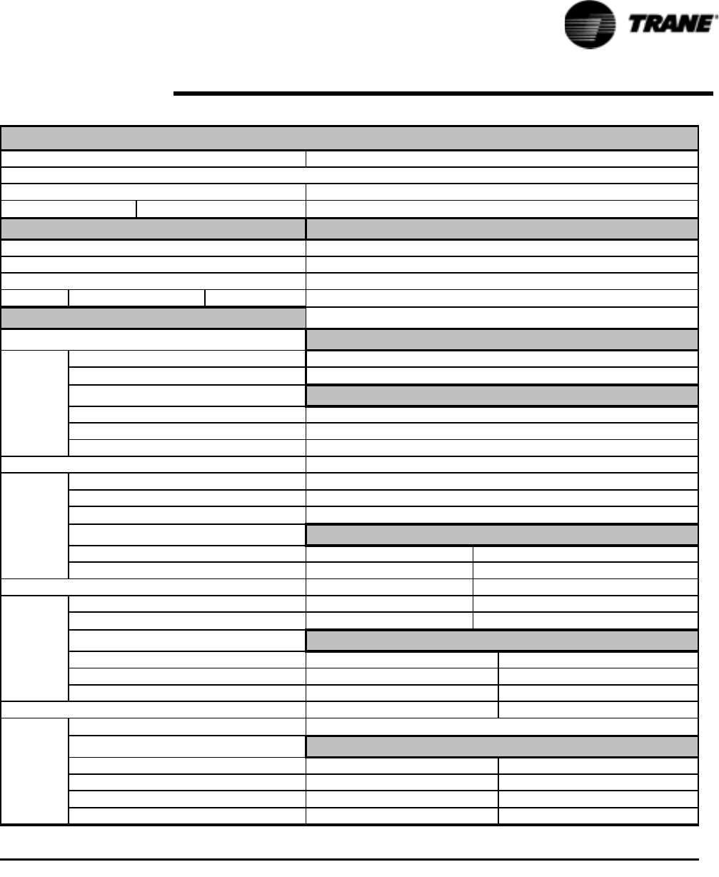
RTAC-SVX01F-EN 151
Periodic Maintenance
Sales Order # Job Elevation (ft. above sea level)
Chiller Appearance on arrival:
ckt1/ckt2
ckt1/ckt2
Volts Hz lbs
gal
Vacuum after leak test= mm
Standing Vacuum test= mm rise in hrs
Part number ("X" code and 2-digit extension)
Y N
Y N
Y N
Y N
Y N
PSID
Leaving Water:
PSID
Leaving Water:
RTAC Start-u
p
Test Lo
g
Job Name Job Location
Serial #
Shi
p
Date
Starter Data: Start-u
p
Onl
y
Manufacturer
Type: (wye-delta or x-line)
Vendor ID #/ Model #:
Am
p
s
Com
p
ressor Data:
Com
p
ressor A: Pressure Test
(
if re
q
uired
)
Model #:
Serial #
RLA Current Transformers
KW
Volts X
HZ X
Compressor B: X
Model #: X
Serial # X
RLA X
KW Summar
y
of O
p
tions Installed
Volts Tracer Communications Interface
HZ Ice Making
Compressor C: Other
Model #: Other
Serial # Other
RLA Eva
p
Desi
g
n Conditions
Compressor D:
Model #:
Serial #
KW
Volts
HZ
KW
Volts % Glycol:
Entering Water:
HZ
Owner Witness Si
g
nature:
CRC #
Model #
Eva
p
Actual Conditions
Entering Water:
Type of Glycol:
GPMRLA
T
yp
e of Gl
y
col:
Machine gauge pressure:
Machine CH.530 pressure
Unit oil char
g
e
(
OIL00048
)
Unit R-134a Char
g
e
GPM
% Glycol:
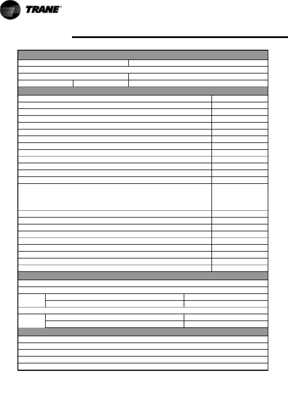
152 RTAC-SVX01F-EN
Periodic Maintenance
RTAC Unit Configuration
Job Name Job Location
Serial # CRC#
Sales Order # Ship Date Job Elevation (ft. above sea level)
Setpoint View *
Front Panel Degree Units (circle one) F or C
Front Panel Chilled Water Setpoint
Front Panel Current Limit
Differential to Stop
Differential to Start
Leaving Water Temperature Cutout
Low Refrigerant Temperature Cutout
Condenser Limit
Low Ambient Lockout Setpoint
Low Ambient Lockout (circle one) Enable or Disable
Under/Over Voltage Protection Enable or Disable
Local Atmospheric Pressure psi
Design Delta T F or C
Reset Type (circle one) None
Return Reset Type
Outdoor Air Temp.
Constant Return
Return Reset Ratio %
Return Start Reset
Return Max Reset
Outdoor Reset Ratio %
Outdoor Start Reset
Outdoor Max Reset
Chilled Water Pump Delay Time minutes
Chilled Water Setpoint Filtering Settling Time sec
Compressor Staging Deadband
Compressor Service View **
Unit Status:
Circuit 1 Control
Front Panel Circuit Lockout (circle one) Locked or Unlocked
Electronic Expansion Valve (circle one) Open or Auto
Circuit 2 Control
Front Panel Circuit Lockout (circle one) Locked or Unlocked
Electronic Expansion Valve (circle one) Open or Auto
Configuration ***
Nameplate
Model #
Confirm Code
Serial Number
Note:
* Using Techview, click on "View" and then click "Setpoint View" Log accordingly.
** Using Techview, click on "View" and then click "Compressor Service View" Log accordingly.
*** Using Techview, click on "View" and then click "Configuration" (Nameplate Tab) Log accordingly.
Model #
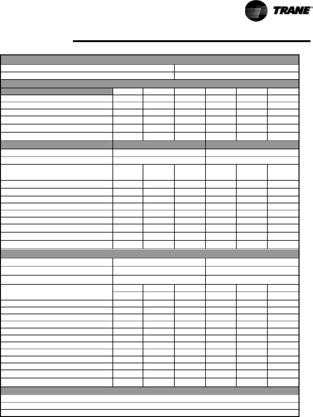
RTAC-SVX01F-EN 153
Periodic Maintenance
RTAC Chiller Log
Job Name Job Location
Model # Serial #
Status View: *
Chiller Tab: 15 min 30 min 45 min 15 min 30 min 45 min
Operating Mode
Outdoor Air Temperature F or C
Active Chill Water Setpoint F or C
Active Current Limit Setpoint
Evaporator Entering Water Temp. F or C
Evaporator Leaving Water Temp. F or C
Circuit 1 Tab Circuit 2 Tab
External Hardwired Lockout Not Locked out/ Locked out Not Locked out/ Locked out
Front Panel Lockout Not Locked out/ Locked out Not Locked out/ Locked out
15 min 30 min 45 min 15 min 30 min 45 min
AirFlow %
Inverter Speed %
Condenser Refrigerant Pressure psig/kPa
Saturated Condenser Rfgt. Temp. F or C
Differential Refrigerant Pressure psid/kPA
Evaporator Refrigerant Pressure psig/kPa
Saturated Evaporator Rfgt.Temp. F or C
EXV Position %
Evaporator Rfgt Liquid Level inches/mm
Compressor 1A Tab Compressor 1B Tab
Operating Mode
Hours Hrs/mins Hrs/mins
Starts
15 min 30 min 45 min 15 min 30 min 45 min
Phase A - B Voltage volts
Average Line Current %RLA
Line 1 current amps
Line 2 current amps
Line 3 current amps
Line 1 current %RLA
Line 2 current %RLA
Line 3 current %RLA
Evaporator Oil Return Solenoid open / closed open / closed open / closed open / closed open / closed open / closed
Supply Oil Temperature F or C
Intermediate Oil Pressure psig/kPa
Female Step solenoid load / unload load / unload load / unload load / unload load / unload load / unload
High Pressure Cutout switch Good / Tripped Good / Tripped Good / Tripped Good / Tripped Good / Tripped Good / Tripped
Comments:
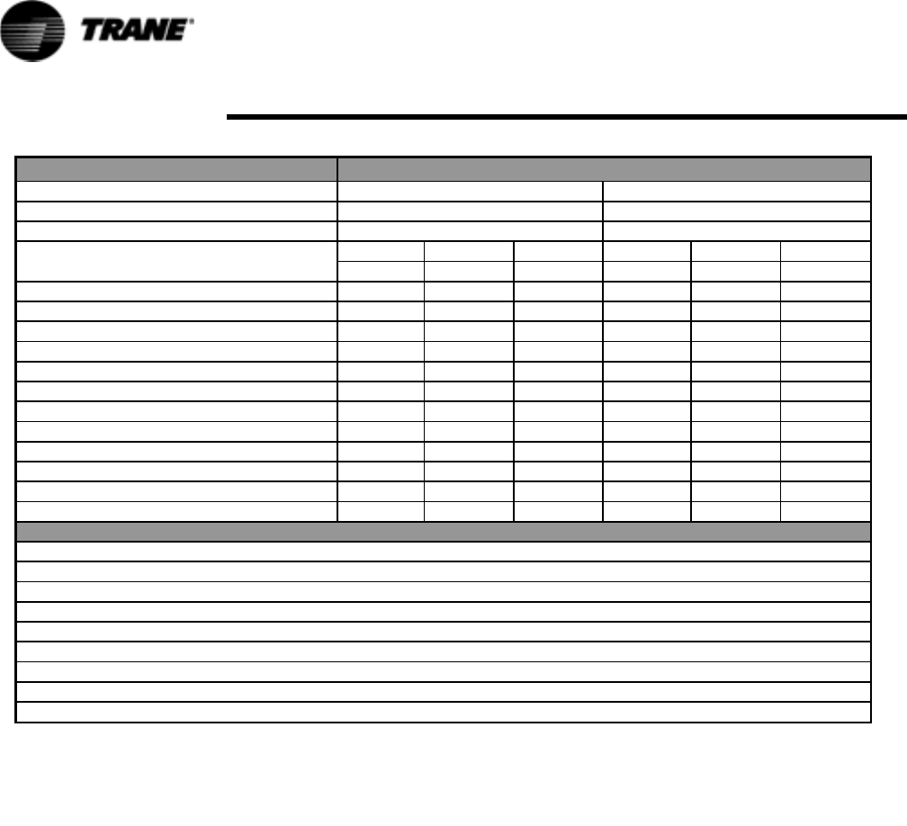
154 RTAC-SVX01F-EN
Periodic Maintenance
Compressor 2A Tab Compressor 2B Tab
Operating Mode
Hours Hrs/mins Hrs/mins
Starts
15 min 30 min 45 min 15 min 30 min 45 min
Phase A - B Voltage volts
Average Line Current %RLA
Line 1 current amps
Line 2 current amps
Line 3 current amps
Line 1 current %RLA
Line 2 current %RLA
Line 3 current %RLA
Evaporator Oil Return Solenoid open / closed open / closed open / closed open / closed open / closed open / closed
Supply Oil Temperature F or C
Intermediate Oil Pressure psig/kPa
Female Step solenoid load / unload load / unload load / unload load / unload load / unload load / unload
High Pressure Cutout switch Good / Tripped Good / Tripped Good / Tripped Good / Tripped Good / Tripped Good / Tripped
Comments:

RTAC-SVX01F-EN 155
Maintenance Procedures
Refrigerant and Oil Charge Management
Proper oil and refrigerant charge is essential for proper unit operation, unit perfor-
mance, and environmental protection. Only trained and licensed service personnal
should service the chiller.
Some symptoms of a refrigerant under-charged unit:
• Low subcooling
• Higher than normal discharge superheat
• Bubbles in EXV sight glass
• Low liquid level diagnostic
• Larger than normal evaporator approach temperatures (leaving water temperature
- saturated evaporator temperature)
• Low evaporator refrigerant temperature limit
• Low refrigerant temperature cutout diagnostic
• Fully open expansion valve
• Possible whistling sound coming from liquid line (due to high vapor velocity)
• High condenser + subcooler pressure drop
Some symptoms of a refrigerant over-charged unit:
• High subcooling
• Evaporator liquid level higher than centerline after shut down
• Larger than normal condenser approach temperatures (entering condenser satu-
rated temperature – entering air temperature)
• Condenser pressure limit
• High pressure cutout diagnostic
• More than normal number of fans running
• Erratic fan control
• Higher than normal compressor power
• Very low discharge superheat at startup
• Compressor rattle or grinding sound at startup
Some symptoms of an oil over-charged unit:
• Larger than normal evaporator approach temperatures (leaving water temperature
- saturated evaporator temperature)
• Low evaporator refrigerant temperature limit
• Erratic liquid level control
• Low unit capacity
• Low discharge superheat (especially at high loads)
• Low liquid level diagnostics
• High oil sump level after normal shut down
Some symptoms of an oil under-charged unit:
• Compressor rattle or grinding sound
• Lower than normal pressure drop through oil system
• Seized or welded compressors

156 RTAC-SVX01F-EN
Maintenance Procedures
• Low oil sump level after normal shut down
• Lower than normal oil concentrations in evaporator
R134a Field Charging Procedure
Be certain that the electrical power to the unit is disconnected before performing this
procedure.
WARNING
Hazardous Voltage w/Capacitors!
Disconnect all electric power, including remote disconnects before
servicing. Follow proper lockout/tagout procedures to ensure the power
cannot be inadvertently energized. For variable frequency drives or other
energy storing components provided by Trane or others, refer to the
appropriate manufacturer’s literature for allowable waiting periods for
discharge of capacitors. Verify with an appropriate voltmeter that all
capacitors have discharged. Failure to disconnect power and discharge
capacitors before servicing could result in death or serious injury.
Note: For additional information regarding the safe discharge of
capacitors, see PROD-SVB06A-EN or PROD-SVB06A-FR
Factory (initial) Refrigerant Charging Procedure
The initial charging procedure should be followed the first time the unit is charged in
the factory, as well as for charging any time after the charge has been completely
removed from the entire system in the event of repair.
1. As part of automatic vacuum/charge procedure, verify that the EXVs are OPEN.
2. Attach vacuum hoses to evaporator service valves (one per circuit). Open service
valves.
3. Attach charging hoses to the charging port on the liquid line filter (one per circuit).
The filters contain a port with a ¼” (6mm) flare.
4. Begin semi-automatic vacuum procedure.
5. When vacuum is complete (indicated), manually isolate the unit from vacuum.
6. Charge unit through the filter housing port per Table 1 - Table 5.
7. When charging is complete, shut evaporator service valve and disconnect
vacuum and charging hoses.
Field Refrigerant Charging Procedure
Follow this procedure when the unit is empty of all refrigerant and under a vacuum.
Add the charge through the evaporator service valve.
CAUTION
Evaporator Damage!
Water must be flowing through the evaporator during the entire
charging process to avoid freezing and rupturing of the evaporator tubes.
Charge first with vapor to avoid freezing tubes.
1. Note the weight of the amount of charge removed. Compare it to Table 1 - Table
5. A difference in charge may indicate a leak.

RTAC-SVX01F-EN 157
Maintenance Procedures
2. Attach charging hose to evaporator service valve (3/8” (9mm) flare). Open service
valve.
3. Add charge to evaporator to bring total circuit charge up to the level indicated in
the above chart.
4. Close service valve and disconnect charging hose.
Adding charge:
This procedure should be followed when adding charge to an undercharged unit.
When low charge is indicated by low subcooling in the liquid line, charge should be
added until sufficient subcooling is achieved.
1. Attach charging hose to evaporator service valve (3/8” (9mm) flare). Open service
valve.
2. Add 10 pounds of refrigerant (R-134a) charge.
3. Close valve, remove charging hose and start unit. Monitor subcooling.
4. If subcooling is still insufficient, return to step #1.
NOTE: Proper subcooling can be determined from run log history, service
experience, or by contacting Trane technical service.
Charge Isolation in the high or low side of system
All the refrigerant may be trapped into the high side (condenser) of the unit for main-
tenance on the compressor or low side. With the suction line service valve option,
charge may also be isolated in the evaporator for maintenance on the compressor or
the high side. It is preferable to isolate the charge in the evaporator, if this option is
available.
High side charge isolation procedure:
1. Make sure circuit is off.
2. Shut liquid line service valve.
3. Shut oil return line service valve.
4. Start circuit with the service tool in charge isolation mode:
– All fans will turn on
– EXV will open 100%
– Oil return line solenoid (if included) will open
– Unit will start at minimum load
– Unit will run until it cuts out on low pressure (~6 psia) (0.41 bar)
– Monitor pressure with a suction gauge
5. When unit trips, the discharge check valve will close.
6. Close discharge isolation valve.
7. Close oil line shut off valve.
8. Remove the remainder of the charge with transfer pump.
NOTE: Recommendation: Do not pump remaining charge into high side. This may
introduce non condensable gasses and other contaminants into the unit.
9. The low side and compressor may be serviced at this time.
158 RTAC-SVX01F-EN
Maintenance Procedures
NOTE: Units with a design sequence of A0 did not have enough capacity in the
condenser to hold the entire charge. Table 37 lists the amount of charge that would
flood the oil separator if the charge was isolated in the high side. For this reason,
when getting the unit back to running condition, care must be taken to drive the refrig-
erant out of the oil separator using the oil separator heaters.
Returning unit to running condition:
1. Open all valves.
2. Manually open EXV for 15 minutes to allow refrigerant to drain to evaporator by
gravity (ensure water is flowing in the evaporator prior to opening the EXV).
3. Let unit sit with heaters on to drive refrigerant out of oil and warm up compressor
bearings. Depending upon ambient conditions, this may take up to 24
hours.Ensure the UCM is powered so the pump may be energized if it detects a
freeze condition.
4. Once the oil level has returned to normal, the unit can be put back into operation.
Low side charge isolation procedure:
After normal shut down under some conditions most of the charge resides in the
evaporator. Running cold water through the evaporator may also drive much of the
refrigerant to the evaporator.
1. Make sure circuit is off.
2. Close suction line isolation valve.
3. Close oil return line service valve.
4. Close liquid line service valve.
5. Manually open EXV.
6. Use a liquid pump or vacuum pump to move refrigerant from the condenser to
evaporator. The liquid pump will only be effective if there is a lot of charge in the
condenser. It may be connected to the condenser drain port on the liquid line
isolation valve.
NOTE: If a pump is to be used, connect it before closing this valve. This port is only
isolated when the valve is back seated.
If a vacuum pump is used, then connect it to the discharge line service valve near the
oil separator.
A vacuum pump will be required for part of the procedure.
Table 37 Charge Holding Capabilities on High Side
Nominal Circuit
Capacity
Nominal Circuit
Charge
lb
Condenser Charge
Holding Capacity
@ 60% full
90o ambient
lb
Charge in Oil
Separator
lb
% Oil Separator
Level
70 165 118.1 46.9 97.7
85 175 134.3 40.7 86.0
100 215 163.7 51.3 56.0
1 2 0 2 2 5 1 8 7. 9 3 7. 1 4 1. 2
170 365 203.4 161.6 100.0%
200 415 282.0 133 86.1 %
240 460 325.6 134.4 86.9 %
Circuit varies slightly with efficiency and unit configuration

RTAC-SVX01F-EN 159
Maintenance Procedures
The evaporator is large enough to hold all the charge for any unit to below the center-
line of the shell. Therefore, no special precautions are required to restart the unit after
isolating the charge in the evaporator.
Refrigerant Filter Replacement Procedure
A dirty filter is indicated by a temperature gradient across the filter, corresponding to a
pressure drop. If the temperature downstream of the filter is 8°F (4.4°C) lower than
the upstream temperature, the filter should be replaced. A temperature drop can also
indicate that the unit is undercharged. Ensure proper subcooling before taking tem-
perature readings.
1. With the unit off, verify that the EXV is closed. Close liquid line isolation valve. On
units with remote evaporators or oil cooling circuits, close ball valve on oil cooler
liquid line.
2. Attach hose to service port on liquid line filter flange.
3. Evacuate refrigerant from liquid line and store.
4. Remove hose.
5. Depress schrader valve to equalize pressure in liquid line with atmospheric
pressure.
6. Remove bolts that retain filter flange.
7. Remove old filter element.
8. Inspect replacement filter element and lubricate o-ring with Trane OIL00048.
NOTE: Do not use mineral oil. It will contaminate the system.
9. Install new filter element in filter housing.
10. Inspect flange gasket and replace if damaged.
11. Install flange and torque bolts to 14-16 lb-ft (19-22 n-m).
12. Attach vacuum hose and evacuate liquid line.
13. Remove vacuum hose from liquid line and attach charging hose.
14. Replace stored charge in liquid line.
15. Remove charging hose.
16. Open liquid line isolation valve. On units with remote evaporators or oil cooler
circuits, open oil cooler liquid line ball valve.
Lubrication System
The lubrication system has been designed to keep most of the oil lines filled with oil
as long as there is a proper oil level in the oil sump.
The total oil charge can be removed by draining the oil system, oil return line from the
evaporator, the evaporator, and the compressor. Very small quantities of oil may be
found in other components.
Like many machines, an excessive oil charge can cause operational problems. Spe-
cial care should always be taken to avoid adding extra oil.
Units that exhibit the symptoms of an oil overcharge at high loads may still run fine at
light loads. An oil overcharged unit may result in an evaporator limit warning or even a
low liquid level or low evap temp (LRTC) diagnostic. An oil overcharged unit may
exhibit increased approach temperatures and decreased overall unit efficiency.
Oil Charging Procedure
Proper charging of the oil system is critical to the reliability of the compressor and
chiller. Too little oil can cause the compressor to run hot and inefficient. When taken
to an extreme, low oil level may result in instant failure of the compressor. Too much
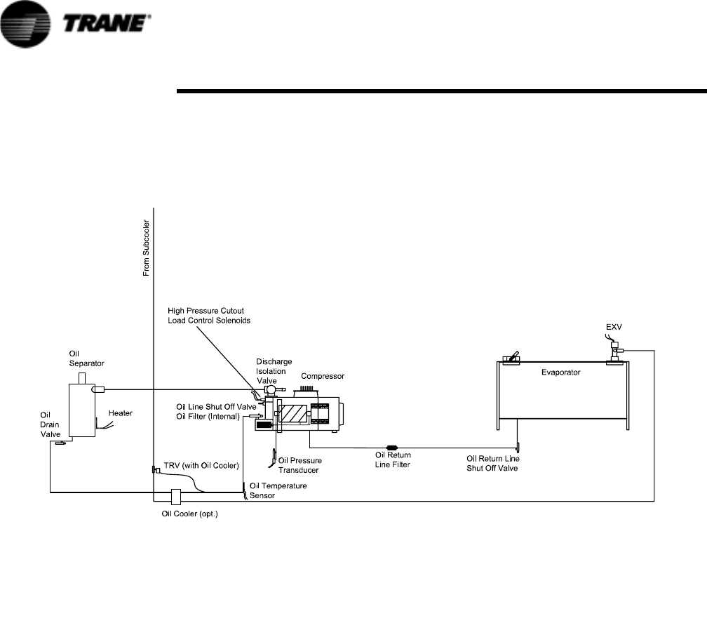
160 RTAC-SVX01F-EN
Maintenance Procedures
oil will result in high oil circulation rates which will foul the condenser and evaporator
performance. This will result in inefficient operation of the chiller. Taken to an
extreme, high oil levels may result in erratic expansion valve control or shut down of
the chiller due to low evaporator refrigerant temperature. Too much oil may contribute
to long term bearing wear. Additionally, excessive compressor wear is probable when
the compressor is started with the oil lines dry.
Figure 46 Oil System Schematic
Oil system consists of the following components:
• Compressor
• Oil separator
• Discharge line with service valve
• Oil line from separator to compressor
• Oil line drain (lowest point in system)
• Oil cooler - optional
• Oil temperature sensor
• Oil line shut off valve with flare service connection
• Oil filter (internal to compressor) with flare fitting service connection and schrader
valve
• Oil flow control valve (internal to the compressor after the filter)
• Oil return line from evaporator with shut off valve and strainer
Refer to Table 1 - Table 5 for the standard oil charge for each circuit.
NOTE: Recommendation: check the oil level in the sump using a sight glass or a
manometer, attached to charging hoses.

RTAC-SVX01F-EN 161
Maintenance Procedures
1. To measure oil level, use the oil drain valve on the oil line and a service valve on
the discharge line. This measurement can only be made when the circuit is not
running.
Note: The level is measured from the bottom of the separator and 1” must be
subtracted for the thickness of the bottom plate.
2. The initial oil charge should be approximately at the level in the above chart. This
is the approximate oil level if all the oil is in the oil lines, filter and oil sump and the
unit is in vacuum so that there is no refrigerant dissolved in the oil.
3. After the unit has run for a while, the oil level in the sump can vary greatly.
However, if the unit has run “normal” conditions for a long time the level should
resemble the level in the above chart. (+1” to – 4” (25 to -101mm) is acceptable.)
The field charging procedure depends on the circumstances that resulted in the need
for oil charge.
1. Some service procedures may result in loss of small quantities of oil which must
be replaced (oil analysis, filter replacement, re-tubing the evaporator, etc.).
2. Additionally, some maintenance procedures may result in virtually all of the oil
being removed (compressor motor burn or total removal of the charge to trouble
shoot a unit).
3. Finally, leaks may result in a loss of oil that must be replaced.
Factory (initial) Oil Charging Procedure
The initial charging procedure should be followed any time the unit is new or has had
all of the oil removed.
4. If the isolation valves is closed, then the charge may be trapped in the evaporator.
In either case, the high side of the system should not be pressurized.
5. The oil line shut off valve must be open to allow the oil to pass into the oil lines
and the oil separator.
6. The oil charging port is a ¼” (6mm) flare fitting with a schrader valve that is on the
side of the oil filter housing. This is the port that must be used to add oil into the
compressor so that the filter and lines are full at the first start of the compressor.
7. On single compressor circuits all the oil should be put into the circuit through the
oil charging port on the compressor filter housing. On two compressor circuits
put approximately ½ of the oil into the unit through each of the two oil charging
ports on the two compressors.
8. Oil may be put into the unit using either of two methods:
Table 38 Oil Charging Data
Circuit
(Tons)
Approximate sump oil level after
running “normal” conditions
(in)
Normal quantity of oil in refrigera-
tion system (evaporator/condenser)
lb (gal)
70 7 1.1 (0.14)
85 6 1.1 (0.14)
100 7 1.8 (0.23)
120 7 1.8 (0.23)
170 8 3.5 (0.44)
200 8 3.5 (0.44)
240 8 3.5 (0.44)

162 RTAC-SVX01F-EN
Maintenance Procedures
CAUTION
Equipment Damage!
Use only Trane OIL00048 in the RTAC units to avoid any catastrophic
damage to the compressor or unit.
• Have the unit in vacuum. Note that the vacuum connection should be made on
the unit at the service valve that is on the discharge line. Hook up the oil charging
hose to the oil charging fitting and submerse the other end into the oil container.
Let the vacuum draw the required amount of oil into the unit.
• Have the unit at the same pressure as the oil. Hook up the oil charging hose to
the oil charging fitting and the other end to an oil pump. Use the pump to draw oil
out of the oil container and push the required amount of oil into the unit.
NOTE: The compressor filter has an internal shut off valve that will prevent oil from
entering the compressor while the compressor is not running. Therefore, there is no
concern about flooding the compressor with oil.
Field Oil Charging Procedure
Use the initial charging procedure under the following circumstances:
• When virtually all of the oil has been removed.
• If the oil charge is removed from the compressor and oil system only but the unit
has been run for less than 15 minutes.
• If the oil charge is removed from the compressor and oil system only and the unit
has been run for more than 15 minutes. However, reduce the amount of oil added
to the unit by the normal quantity of oil in refrigeration system.
NOTE: This procedure can be followed even with the refrigerant charge isolated in
the evaporating section of the unit.
If small quantities of oil were removed to service refrigeration components, such
as the evaporator, simply replace the oil that was removed into the serviced compo-
nent prior to vacuum and recharge of the refrigerant.
If oil was removed from the compressor only to service a compressor or change
the oil filter follow this procedure:
1. If the compressor is a new compressor or has been removed from the system
and reworked, add 1 quart (2 lb.) oil to the motor cavity prior to installing the com-
pressor into the chiller.
2. Install the compressor in the system. Make sure that the filter shut off valve is
closed. Other compressor isolation valves may also be closed depending upon
the service that was completed. For example, changing the oil filter would require
the compressor to be isolated and pulled into vacuum.
NOTE: Make sure that compressor is not pressurized.
3. Open the flare fitting on the oil line shut off valve.
4. Open the flare fitting on the filter housing. This is the port that must be used to
put oil into the compressor.
5. Install charging hose on oil charging port (with schrader valve) and the other on
the oil canister.
6. Lift the oil canister, or use a pump, to pour oil into the filter housing.
RTAC-SVX01F-EN 163
Maintenance Procedures
7. When oil comes out of the flare fitting on the oil line shut off valve the filter is full.
Stop adding oil.
8. Put the cap on the flare on the oil line shut off valve, remove the charging hose
and put the cap back on the flare on the filter housing.
9. Vacuum the compressor (low side) and prepare it for inclusion in the system.
There is a service valve on the suction line and on the evaporator. Use these
valves to vacuum the compressor.
10. Open the oil line shut off valve. Severe damage to the compressor can result if
the oil line shut off valve is closed when the compressor is started.
CAUTION
Compressor Damage!
Catastrophic damage to the compressor will occur if the oil line shut off
valve or the isolation valves are left closed on unit start-up.
11. Open the other compressor isolation valves.
NOTE: This procedure assumes that the oil that is put into the filter housing does
not have contaminants such as non-condensable gases. The oil forces these gases
out of the filter and oil line shut off valve without the need to pull a vacuum on this
small volume. If the oil has been in an open container or is otherwise contaminated,
then this small volume must be subject to vacuum as well. However, the filter cavity
is full of oil. Therefore, be sure to use a flash tank in line with the vacuum pump to
make sure that oil, that is pulled out of the filter cavity, does not slug the vacuum
pump.
Evaporator tube replacement
The units were designed for installation of the tubes from the end of the evaporator
opposite the control panel end.
The following units will need to have the circuit 2 control panel removed to replace
tubes in the evaporator.
• 30' Base - 3 compressor units
• 36' Base - 3 compressor units
CAUTION
Evaporator Damage!
The tubes are rolled at both ends and in the center. When replacing
tubes, take care to ensure that the tube is removed and rolled into the
center tube sheet properly. Failure to do so could result in damage to the
tubes and improper operation of the system.
Compressor Replacement
If a compressor needs to be replaced follow the procedures listed below.
1. Isolate the refrigerant charge outside of the compressor and close all four valves
leading to the compressor. This includes the oil line service valve located on the
oil filter cover of the compressor, the valve on the oil return line from the evapora-
tor, the discharge service valve, and the suction service valve. In the event that
the optional suction service valve was not ordered with the unit, insure that the
liquid line service valve is closed.

164 RTAC-SVX01F-EN
Maintenance Procedures
2. Disconnect power to the chiller. Remove the electrical junction box cover and
disconnect the wires.
WARNING
Hazardous Voltage!
Disconnect all electric power, including remote disconnects before
servicing. Follow proper lockout/tagout procedures to ensure the power
can not be inadvertently energized. Failure to disconnect power before
servicing could result in death or serious injury.
3. Evacuate the compressor through the service fitting provided. If the unit does not
have suction service valves, this will include evacuating the low side of the
system as well. Disconnect all four lines attached to the compressor, as well as
the junction box. Remove three screws from the bottom of the compressor.
4. Remove the compressor by sliding it out of the chiller onto a well supported skid
or other platform. The compressor is very heavy, so insure that the support is
sturdy. A piece of 1x4 lumber placed between the isolators works well to support
the compressor feet as it is pulled from the chiller.
5. Install the new compressor. Reinstall all lines, wires, and screws. Open the
service valves, and trim charge as required.

RTAC-SVX01F-EN 165
Unit Wiring
This section provides field wiring diagrams, electrical schematics and connection dia-
grams for 140-500 ton RTAC units.
Page
Drawing Number Description
2309-2227 Schematic, M&L, X-L, Ckt 1 166
2309-2228 Schematic, M&L, X-L, Ckt 2 168
2309-2229 Schematic, M&L, Y-D, Ckt 1 170
2309-2230 Schematic, M&L, Y-D, Ckt 2 172
2309-1988 Schematic, 3&4 Comp, Comp 1A, X-L 174
2309-1989 Schematic, 3&4 Comp, Comp 1B, X-L 176
2309-1990 Schematic, 3&4 Comp, Comp 1A, Y-D 178
2309-1991 Schematic, 3&4 Comp, Comp 1B, Y-D 180
2309-1996 Schematic, 3 Comp, Comp 2A, X-L 182
2309-1997 Schematic, 3 Comp, Comp 2A, Y-D 184
2309-1999 Schematic, Fans, 3 Comp, Ckt2 186
2309-2201 Schematic, 4 Comp, Comp 2A, X-L 188
2309-2202 Schematic, 4 Comp, Comp 2B, X-L 190
2309-2203 Schematic, 4 Comp, Comp 2A, Y-D 192
2309-2204 Schematic, 4 Comp, Comp 2B, Y-D 194
2309-2241 Schematic, Fans, Medium, 140&155 Std 196
2309-2242 Schematic, Fans, Medium, all others 198
2309-2231 Schematic, Fans, Large (225&250 Prem) 200
2309-4876 Schematic, Fans, 3&4 Comp, Ckt1, Low Volt 202
2309-1992 Schematic, Fans, 3&4 Comp, Ckt1, High Volt 204
2309-2217 Schematic, Fans, 3 Comp, Ckt1, 250T, 50Hz, Std 206
2309-4877 Schematic, Fans, 4 Comp, Ckt2, Low Volts 208
2309-2205 Schematic, Fans, 4 Comp, Ckt2, High Volt 210
2309-1352 Schematic, Control, M&L 212
2309-4880 Schematic, Controls, 3&4 Comp, Ckt1 214
2309-4882 Schematic, Controls/Legend/Bus, 3 Comp, Ckt2 216
2309-4883 Schematic, Controls, 4 Compressor, Ckt2 218
2309-1353 Schematic, Legend/LLID Bus, M&L 220
2309-4881 Schematic, Legend/LLID Bus, 3&4 Comp, Ckt1 222
2309-4884 Schematic, Legend/LLID Bus, 4 Comp, Ckt2 224
2309-2243 Schematic, Fans, M&L, Inverters 226
2309-4899 Schematic; Remote Evap 228
2309-4871 Component Location, 2 Comp 230
2309-4874 Component Location, 3 Comp 232
2309-4873 Component Location, 4 Comp 234
2309-2219 Schematic, 3&4 Comp, Single Source Panel 236
2309-2222 Field Wiring, 3&4 Comp, Dual Source Pwr 238
2309-2248 Field Layout, All 240
2309-2239 Field Layout, 3&4 Comp 242
2309-2208 Field Wiring, All 244
2309-2246 Customer Lug Size 245
2309-2223 Field Wiring, 3&4 Comp, Single Source Pwr 246
2309-4872 Component Location, Remte Evap 248
2309-1974 Field Wiring, Remote Evap 250
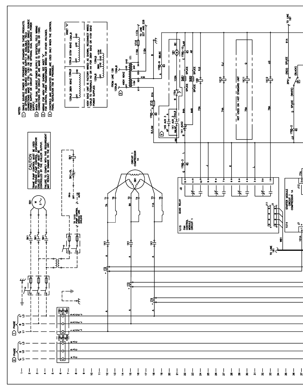
166 RTAC-SVX01F-EN
2227
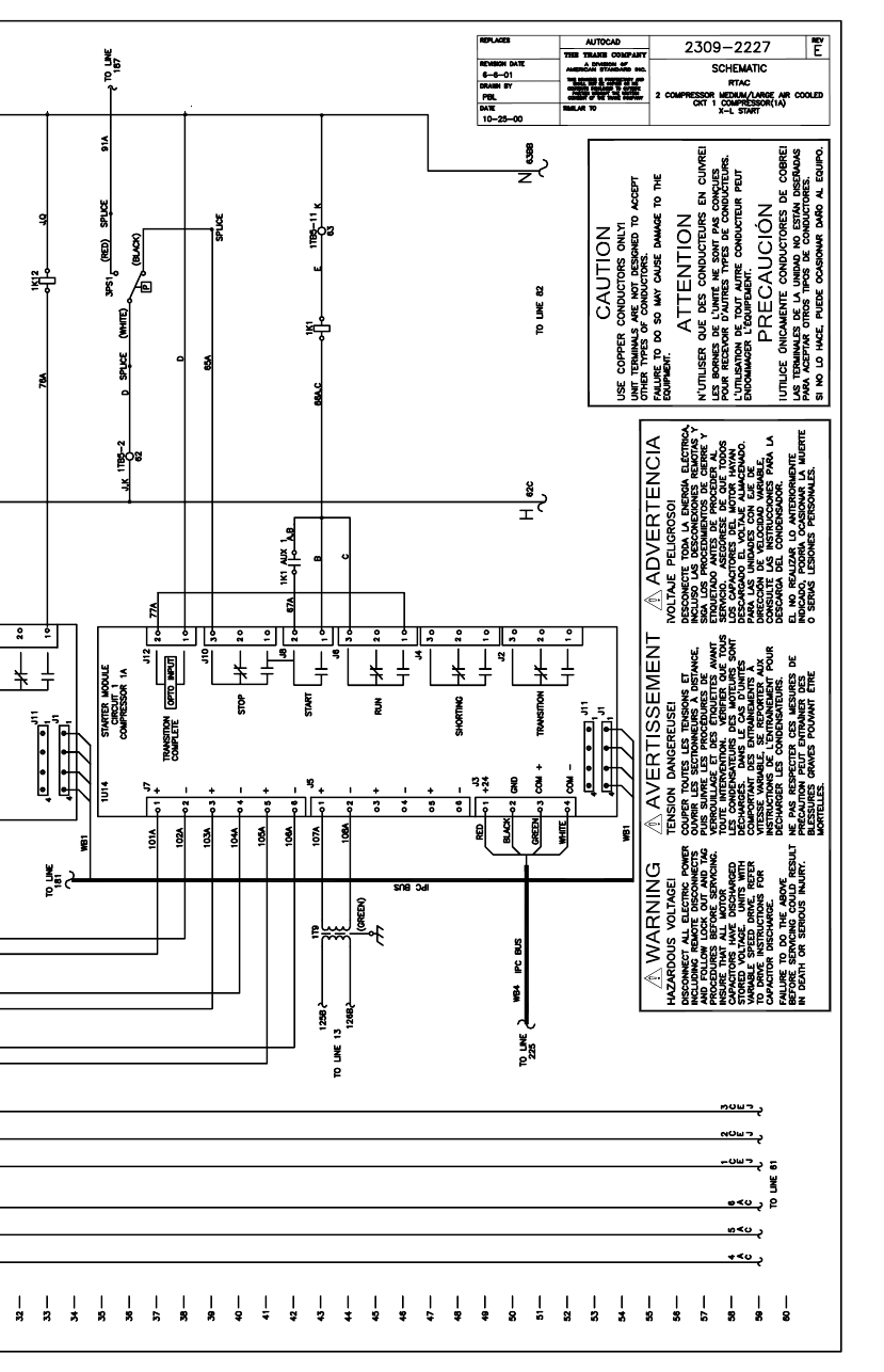
RTAC-SVX01F-EN 167
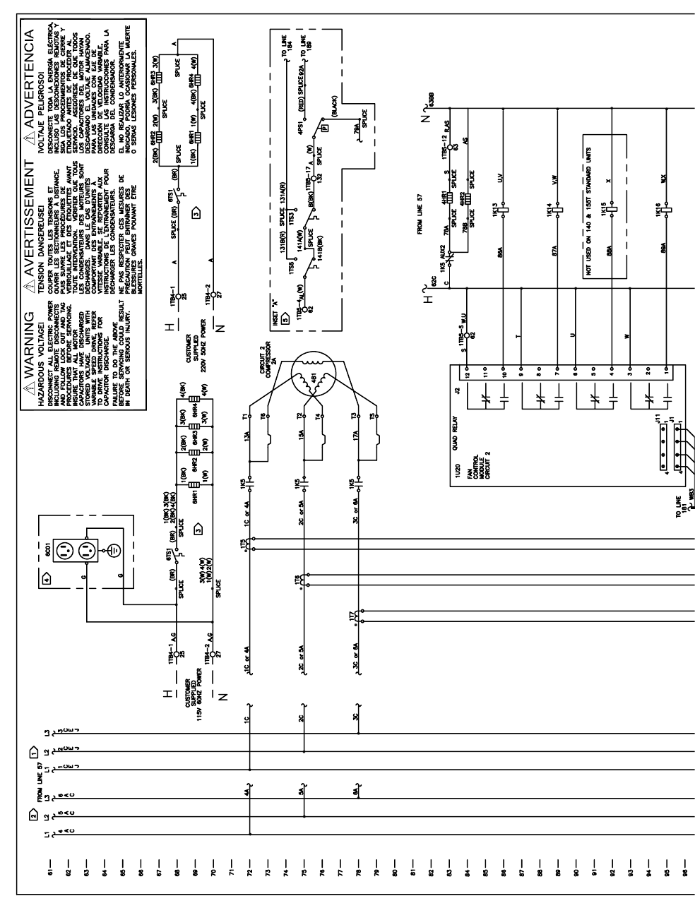
168 RTAC-SVX01F-EN
2228
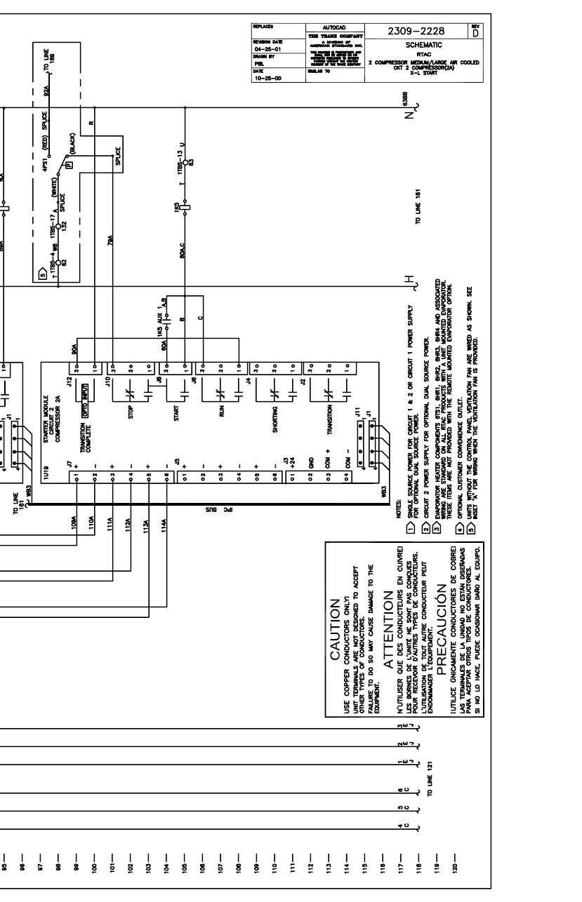
RTAC-SVX01F-EN 169
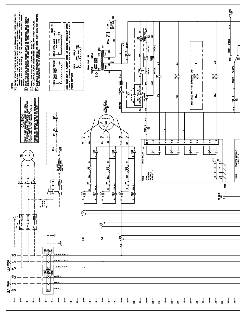
170 RTAC-SVX01F-EN
2229

RTAC-SVX01F-EN 171
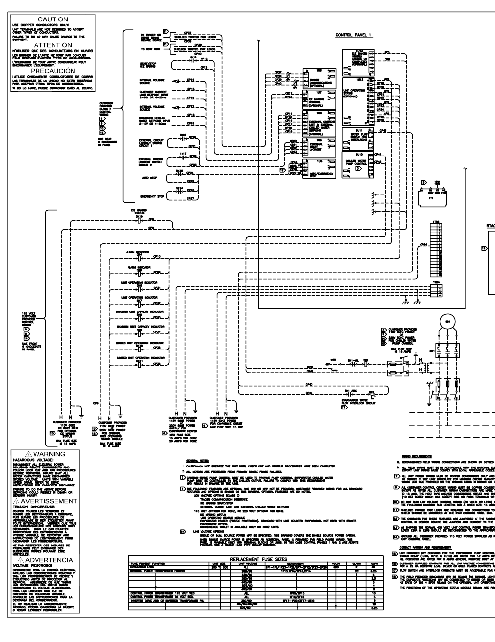
172 RTAC-SVX01F-EN
2230
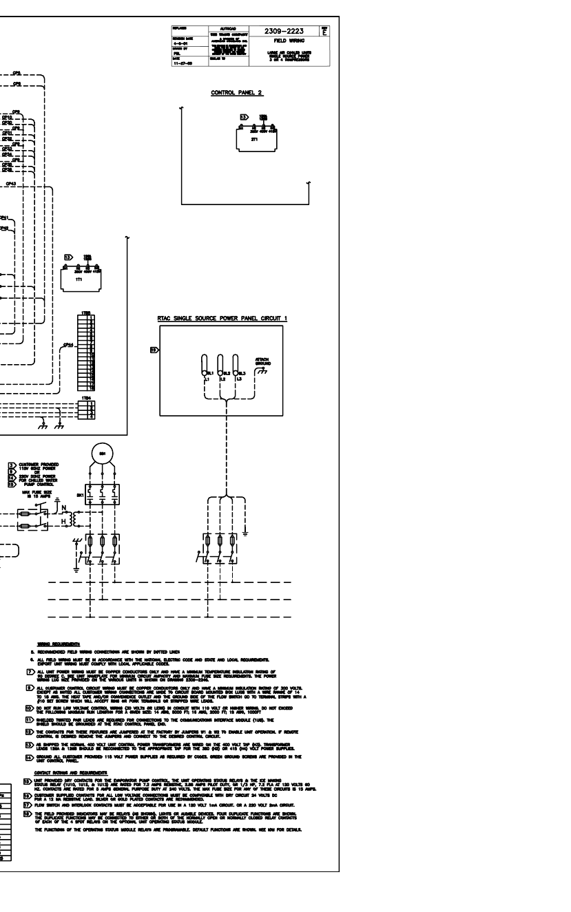
RTAC-SVX01F-EN 173
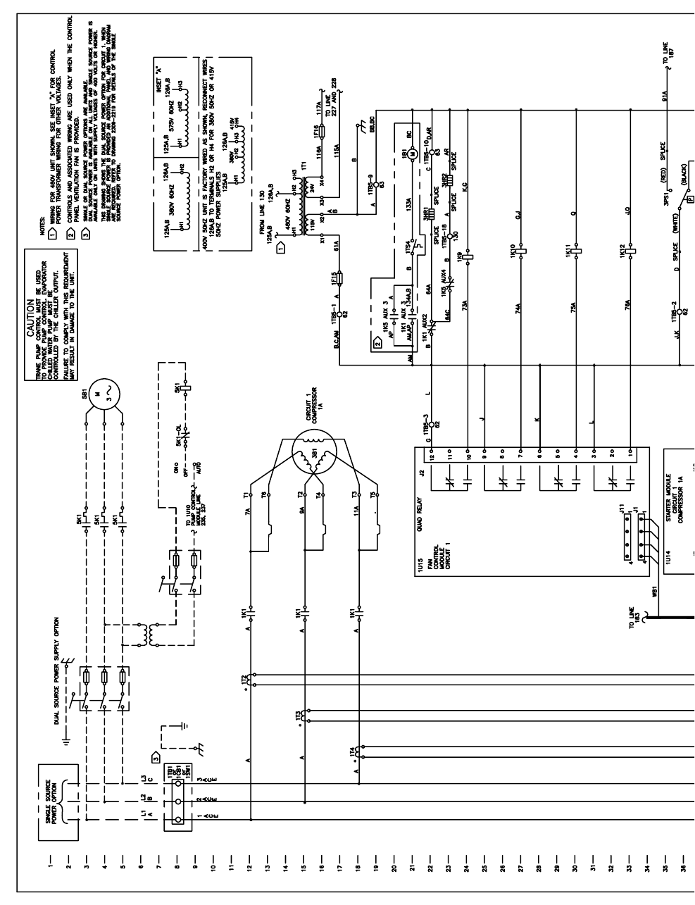
174 RTAC-SVX01F-EN
1988
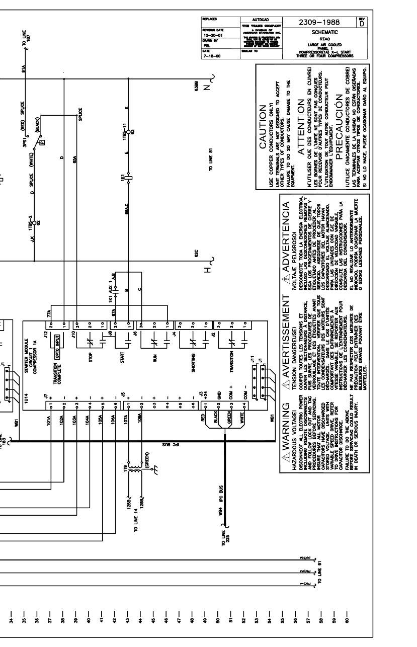
RTAC-SVX01F-EN 175
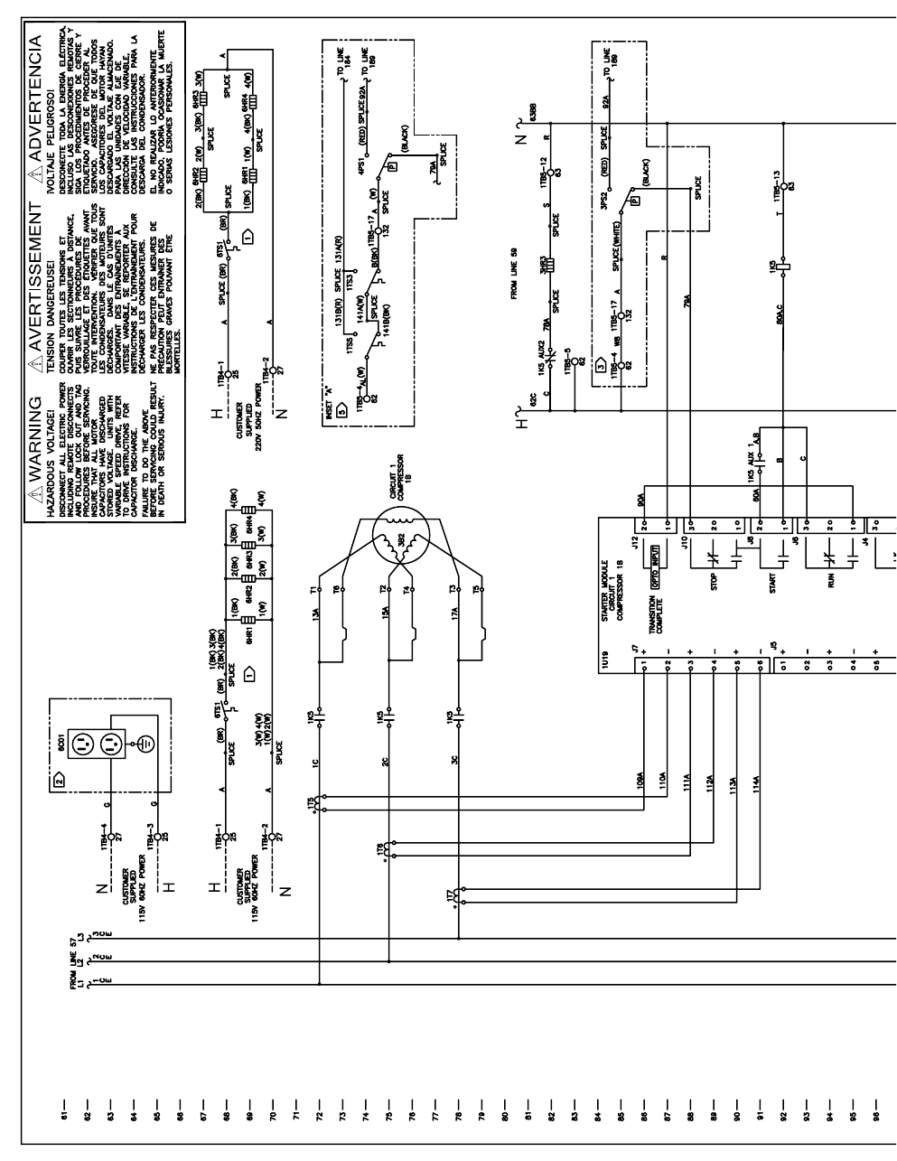
176 RTAC-SVX01F-EN
1989
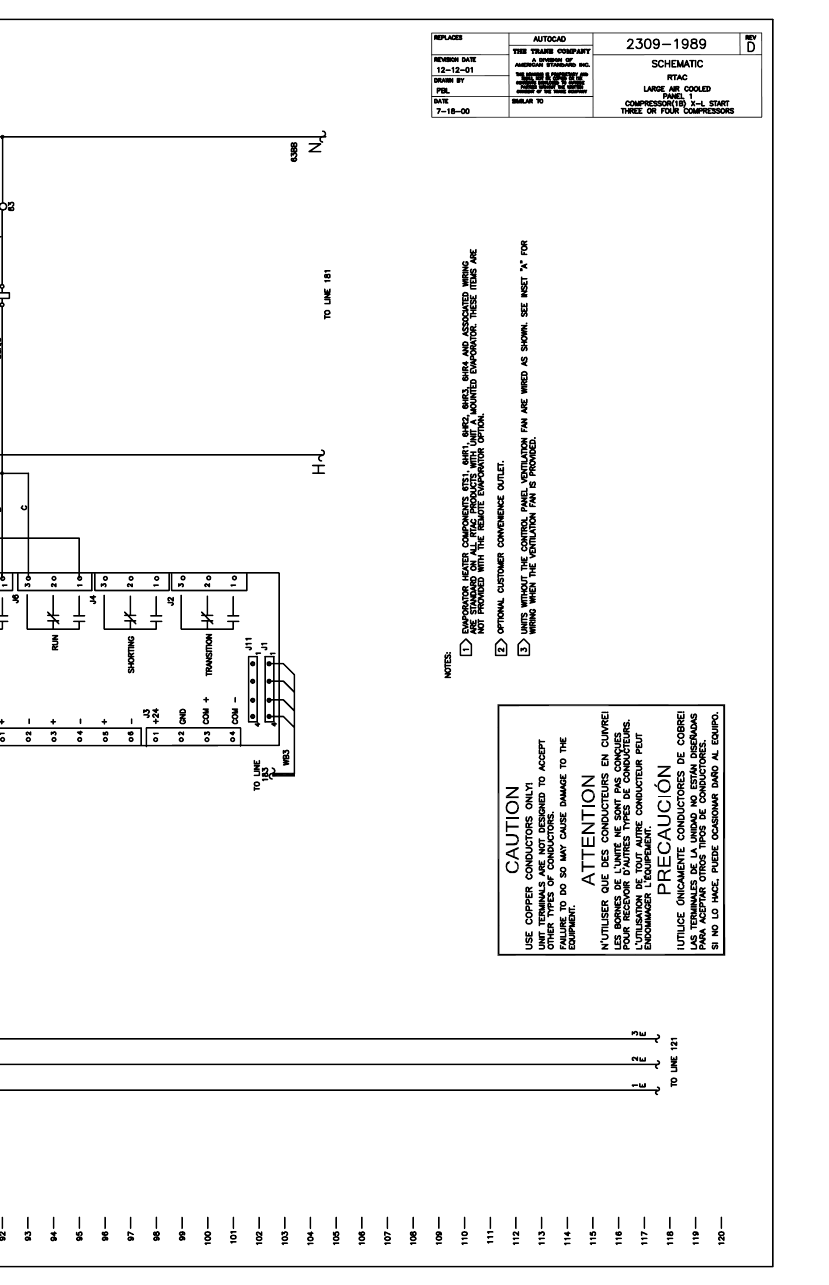
RTAC-SVX01F-EN 177
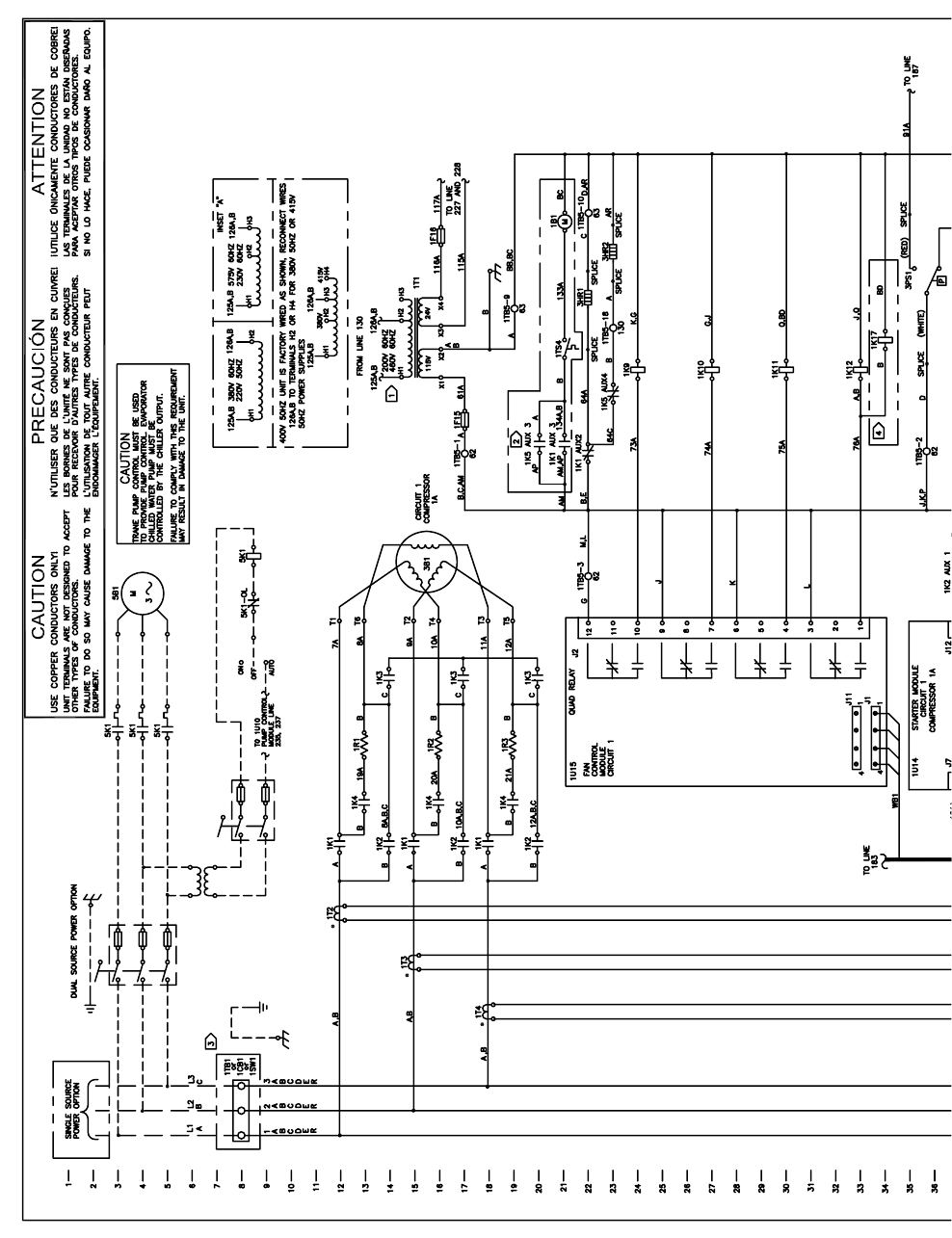
178 RTAC-SVX01F-EN
1990
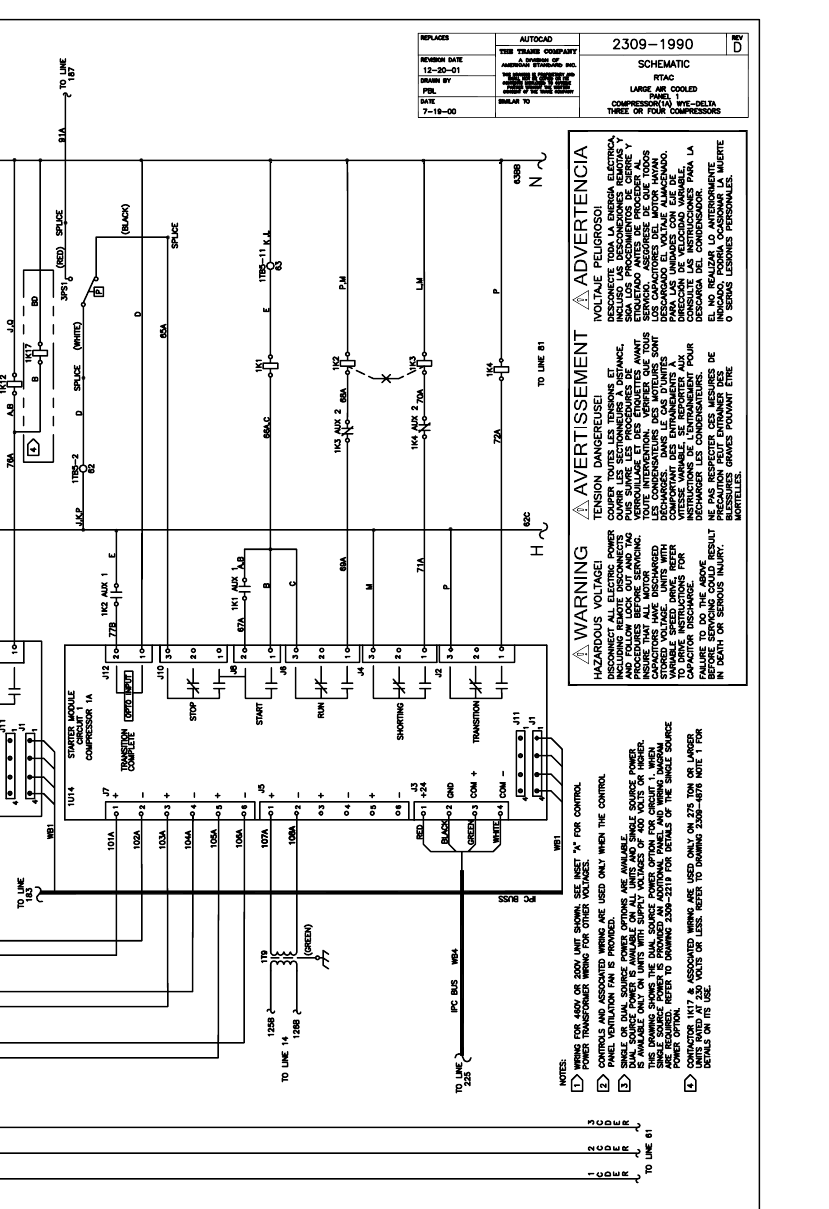
RTAC-SVX01F-EN 179
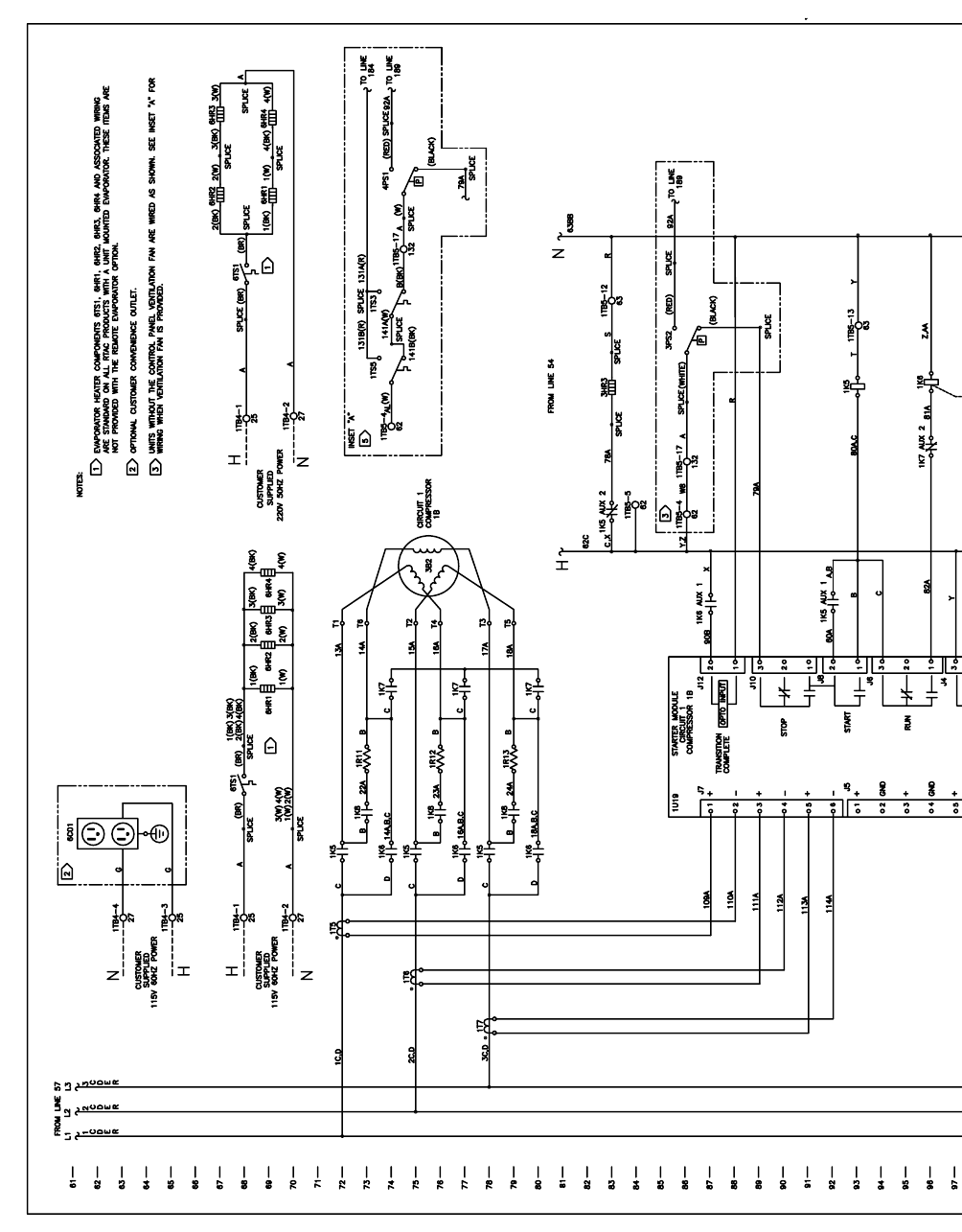
180 RTAC-SVX01F-EN
1991
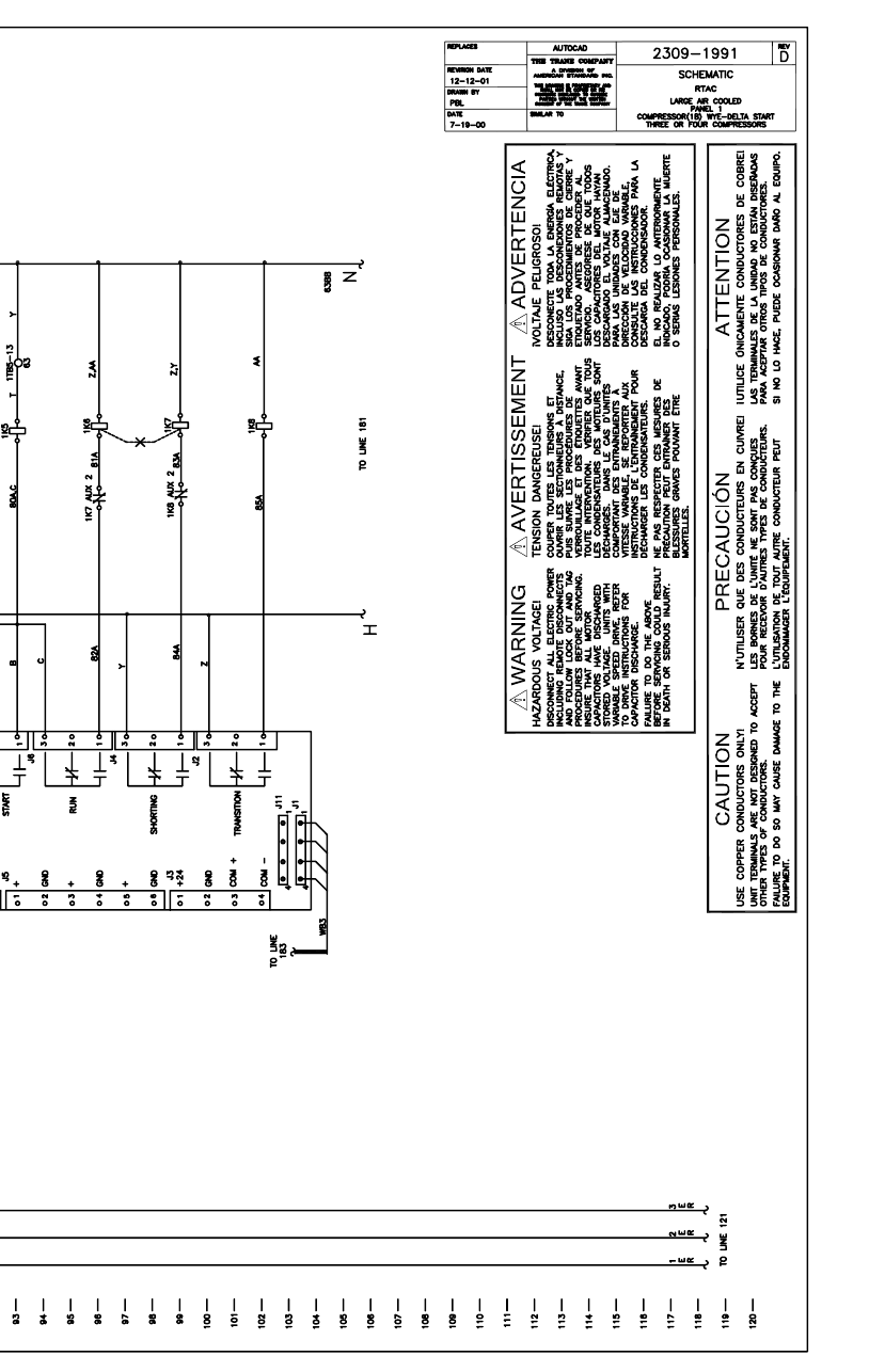
RTAC-SVX01F-EN 181
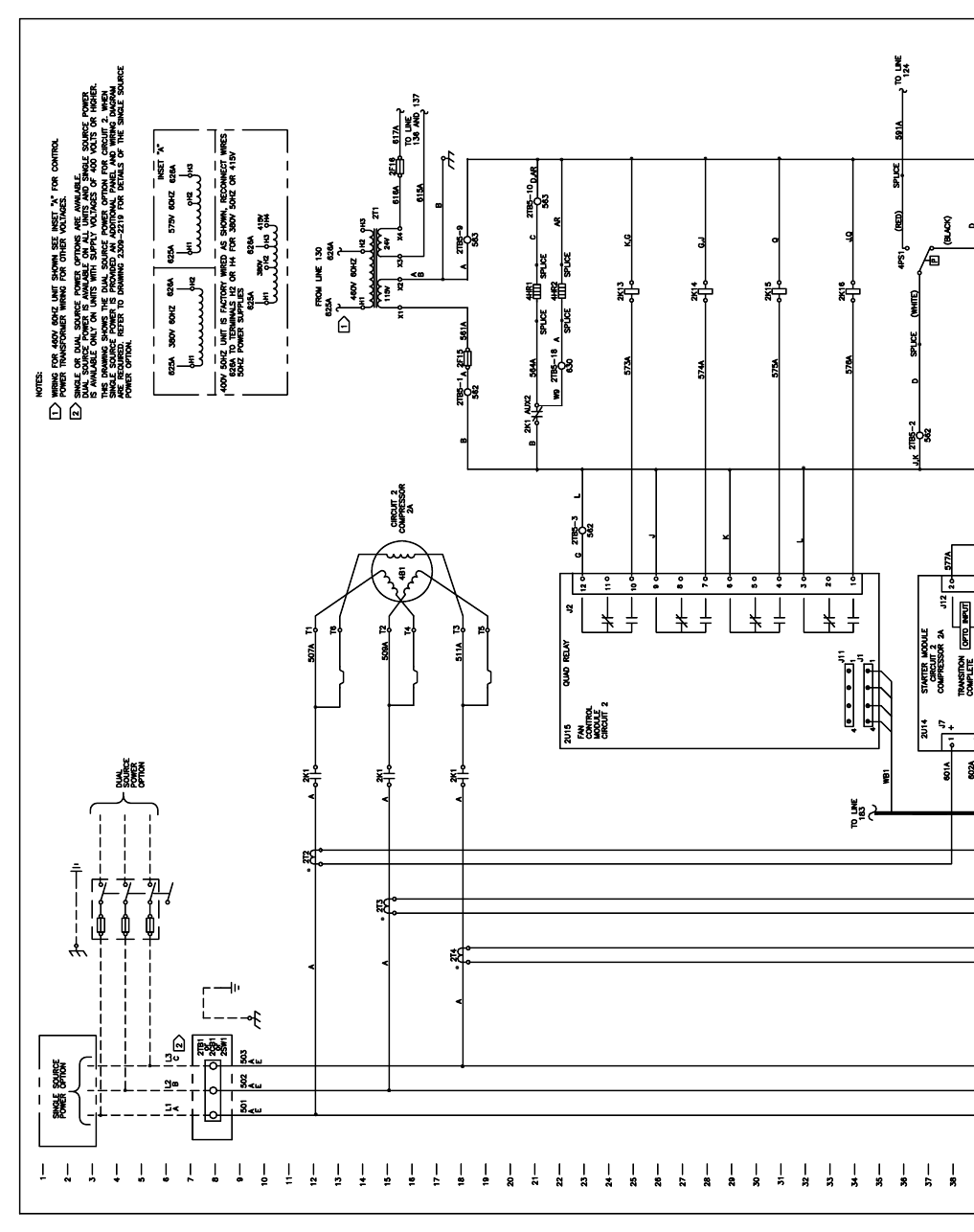
182 RTAC-SVX01F-EN
1996
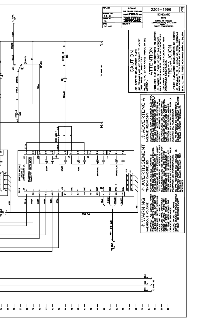
RTAC-SVX01F-EN 183
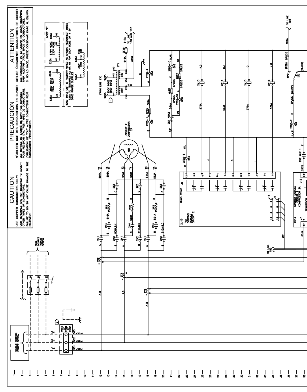
184 RTAC-SVX01F-EN
1997
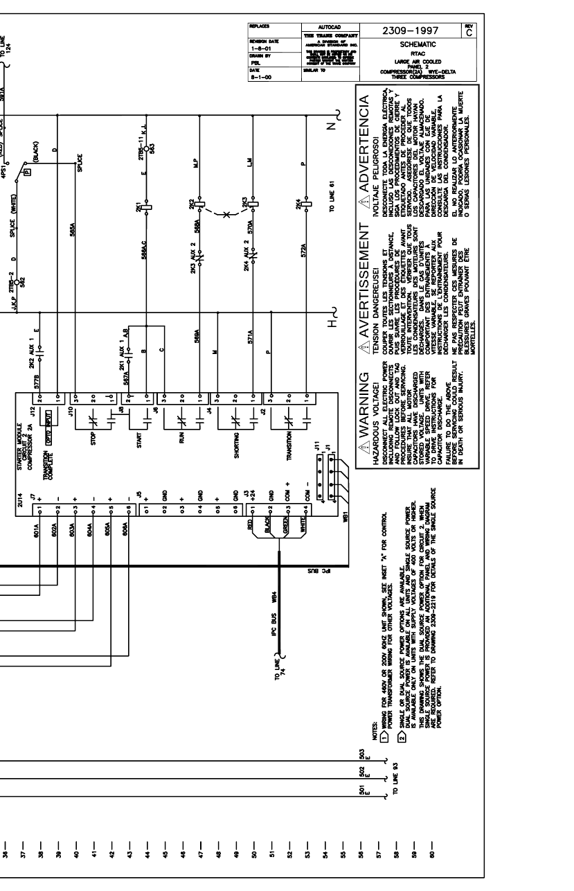
RTAC-SVX01F-EN 185
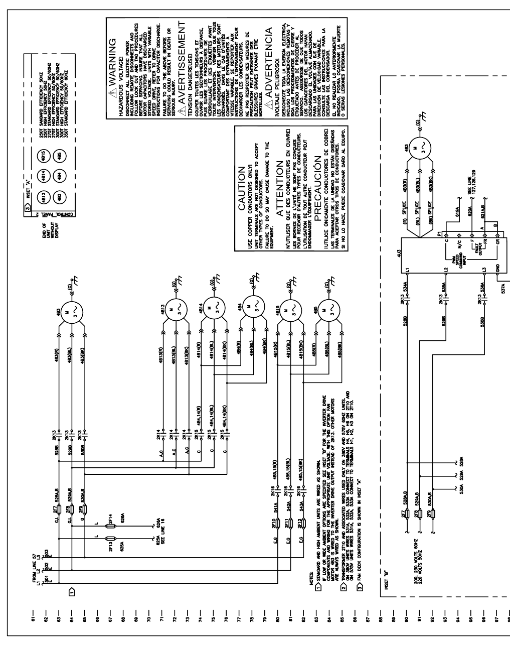
186 RTAC-SVX01F-EN
1999
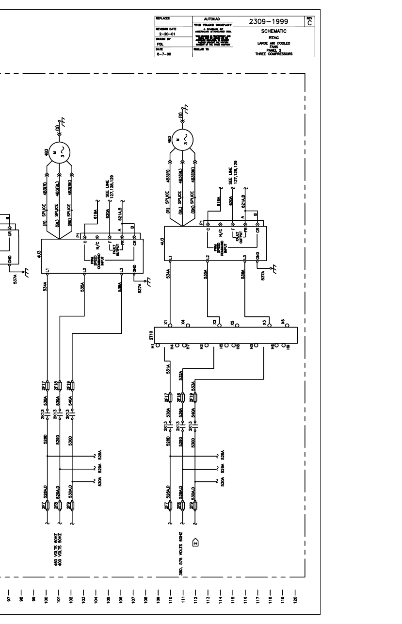
RTAC-SVX01F-EN 187

188 RTAC-SVX01F-EN
2201
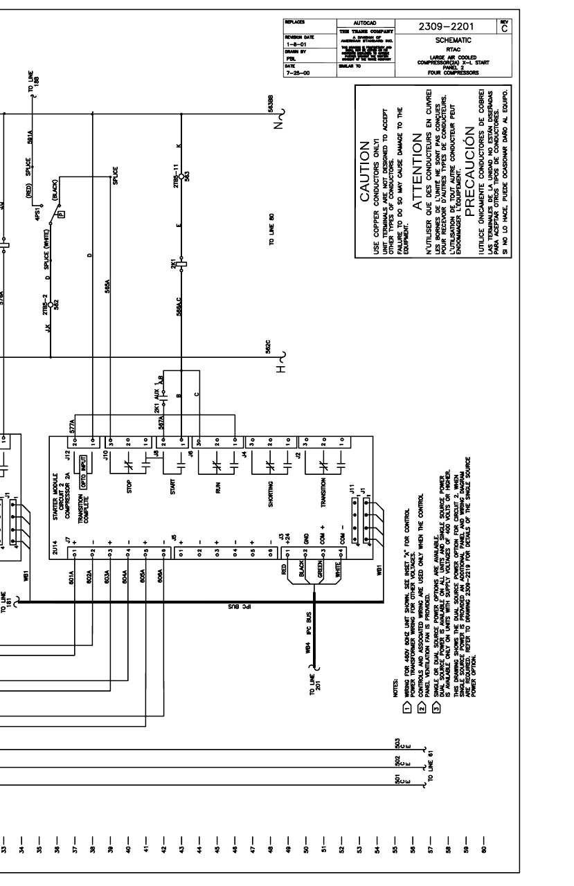
RTAC-SVX01F-EN 189
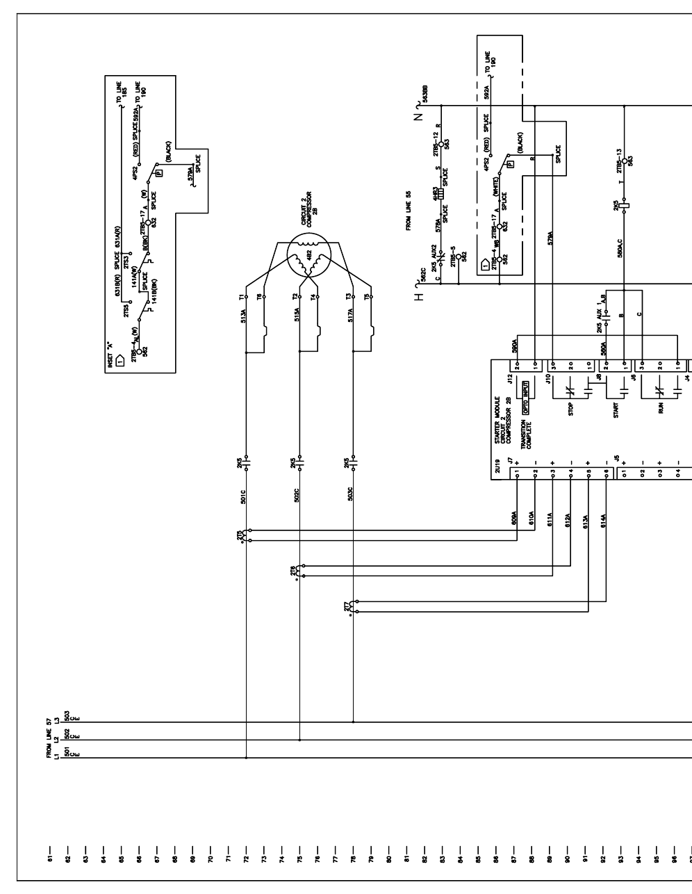
190 RTAC-SVX01F-EN
2202
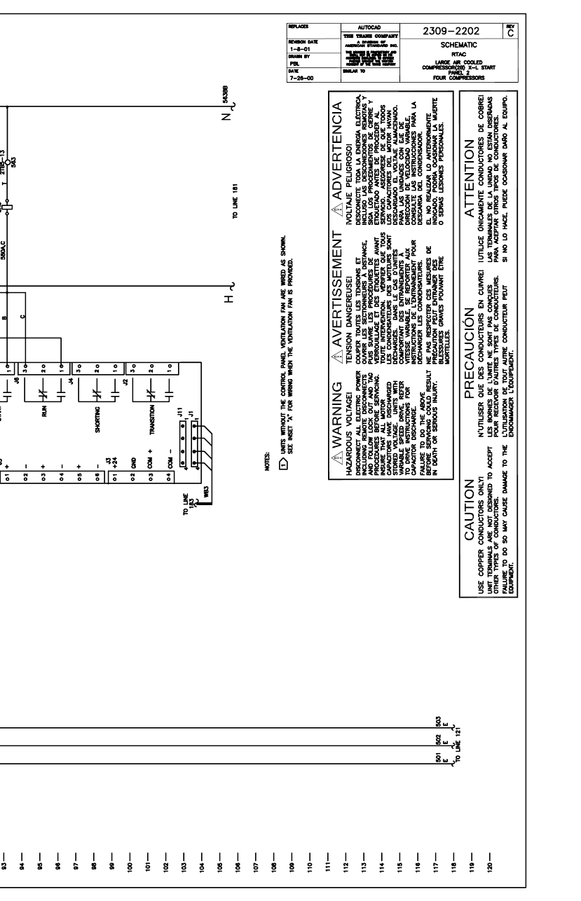
RTAC-SVX01F-EN 191
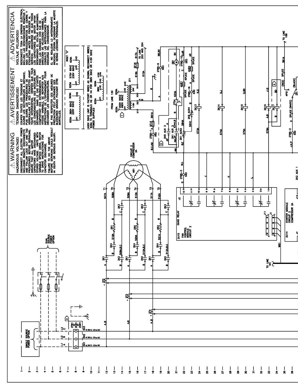
192 RTAC-SVX01F-EN
2203
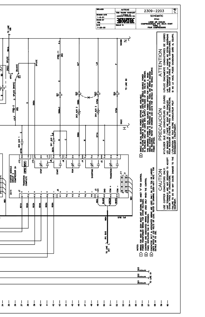
RTAC-SVX01F-EN 193
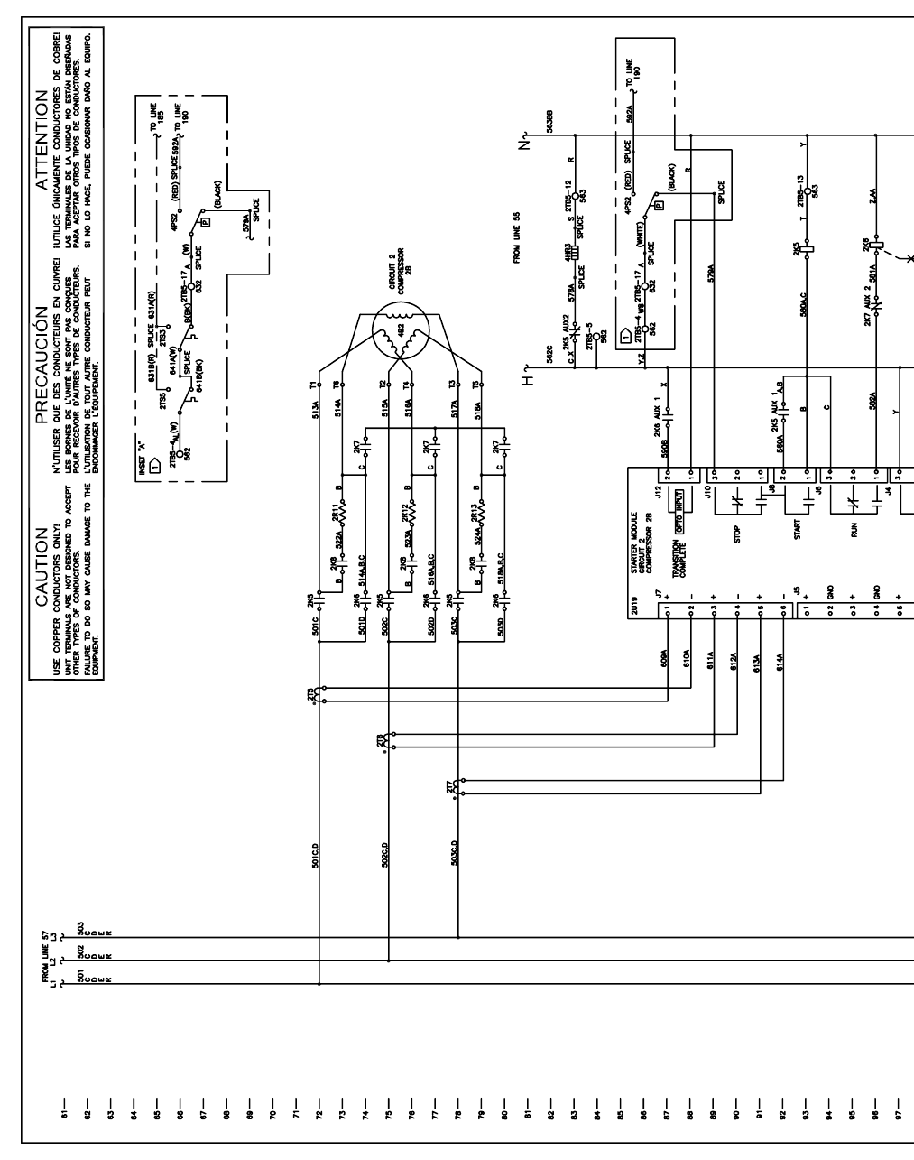
194 RTAC-SVX01F-EN
2204
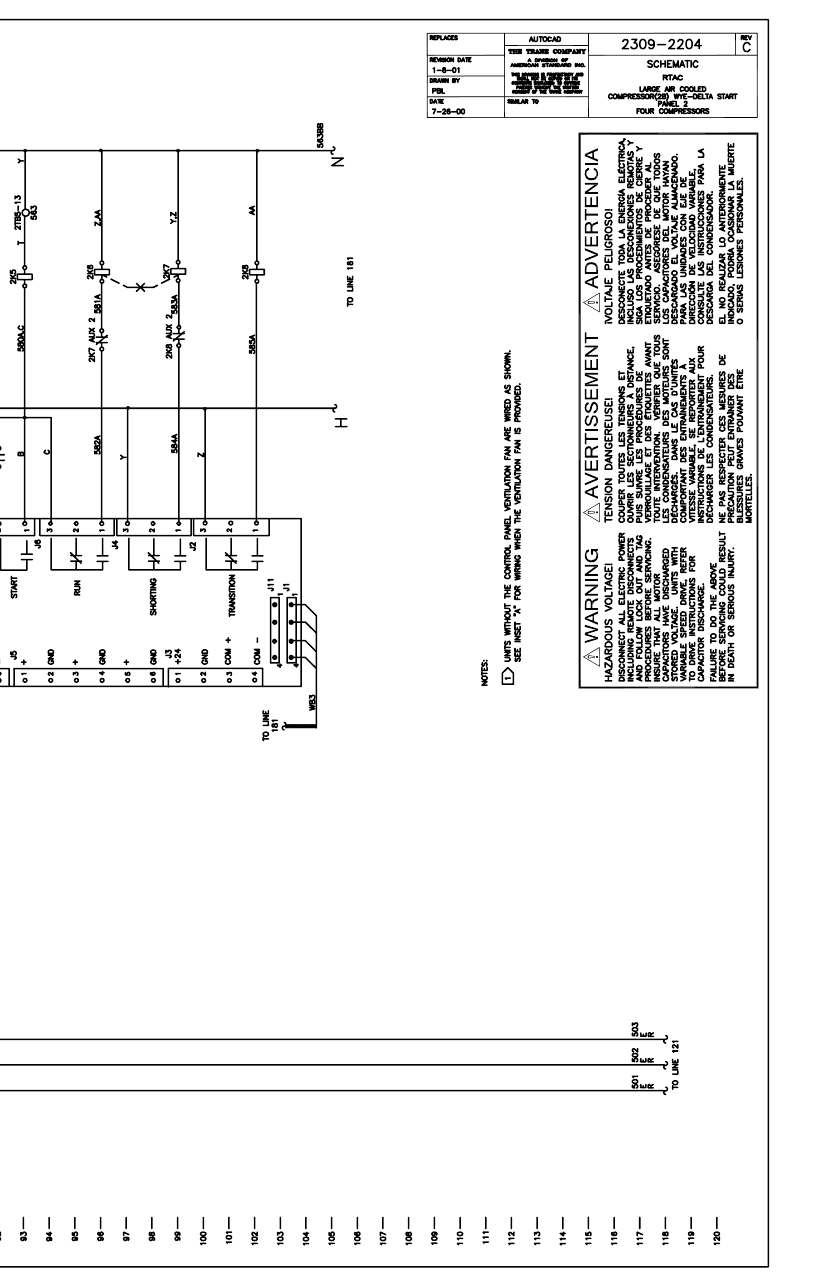
RTAC-SVX01F-EN 195
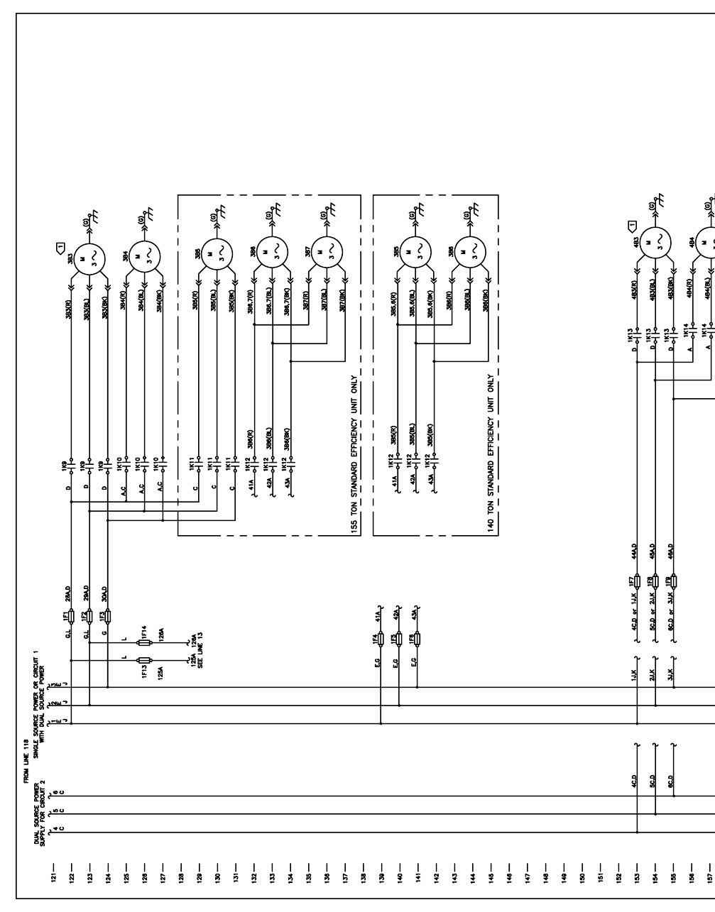
196 RTAC-SVX01F-EN
2241
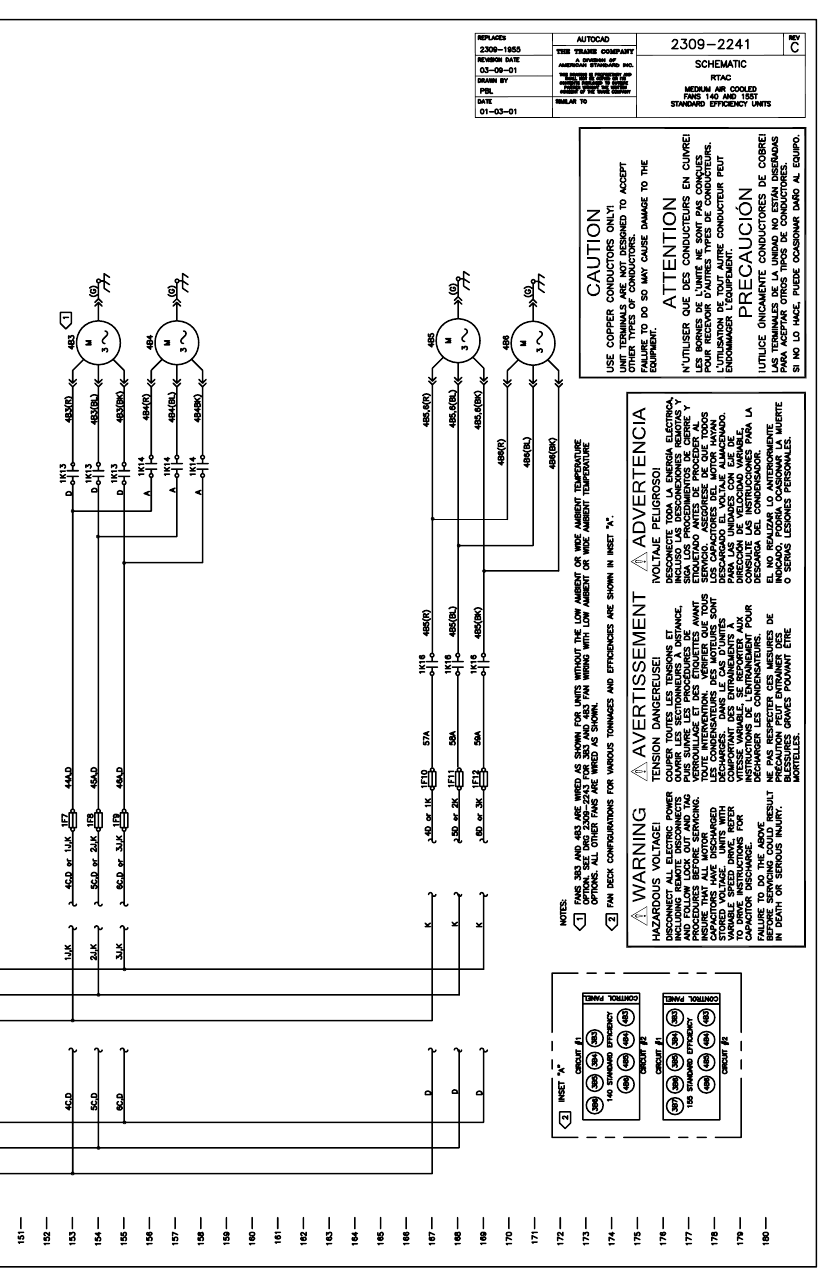
RTAC-SVX01F-EN 197
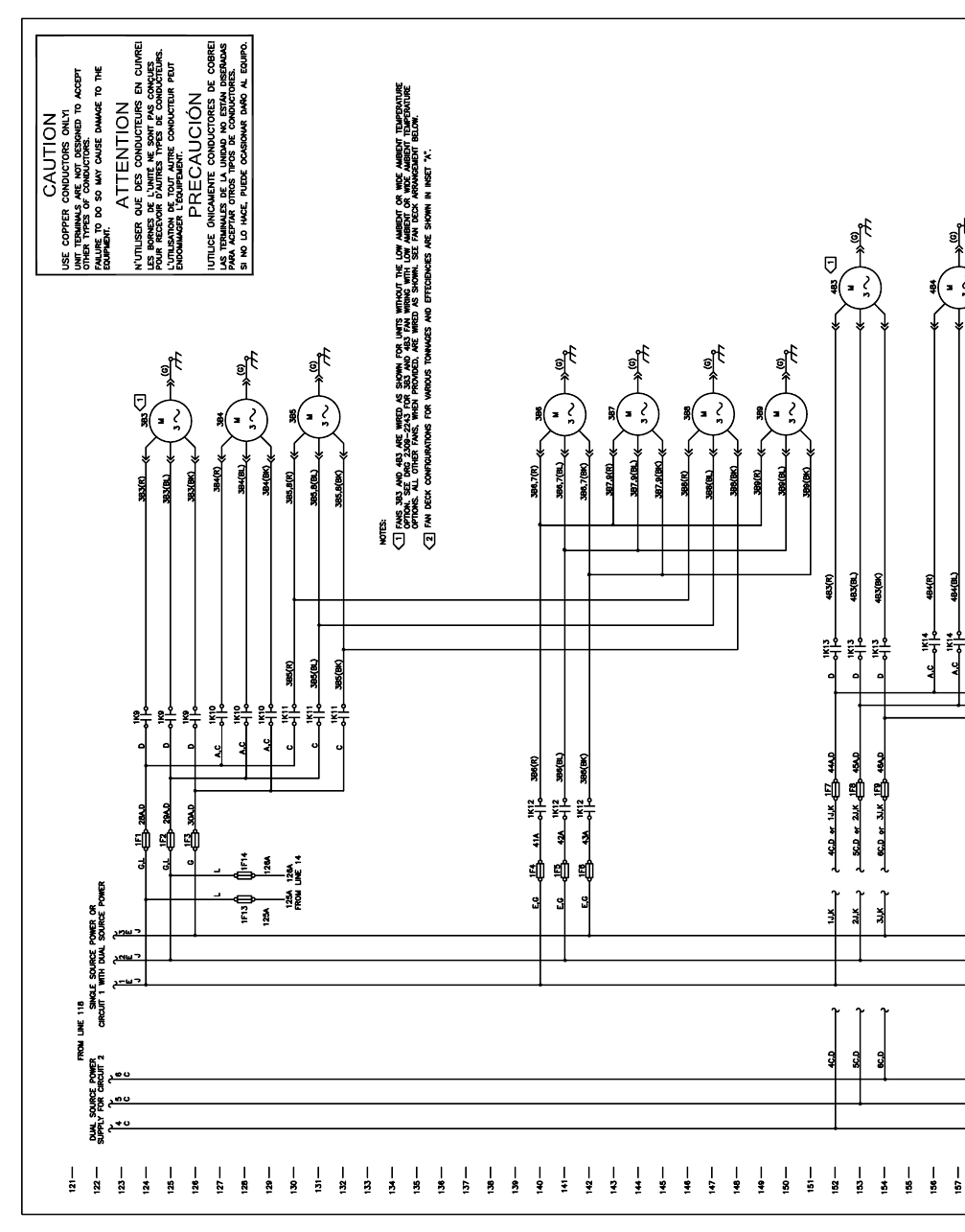
198 RTAC-SVX01F-EN
2242
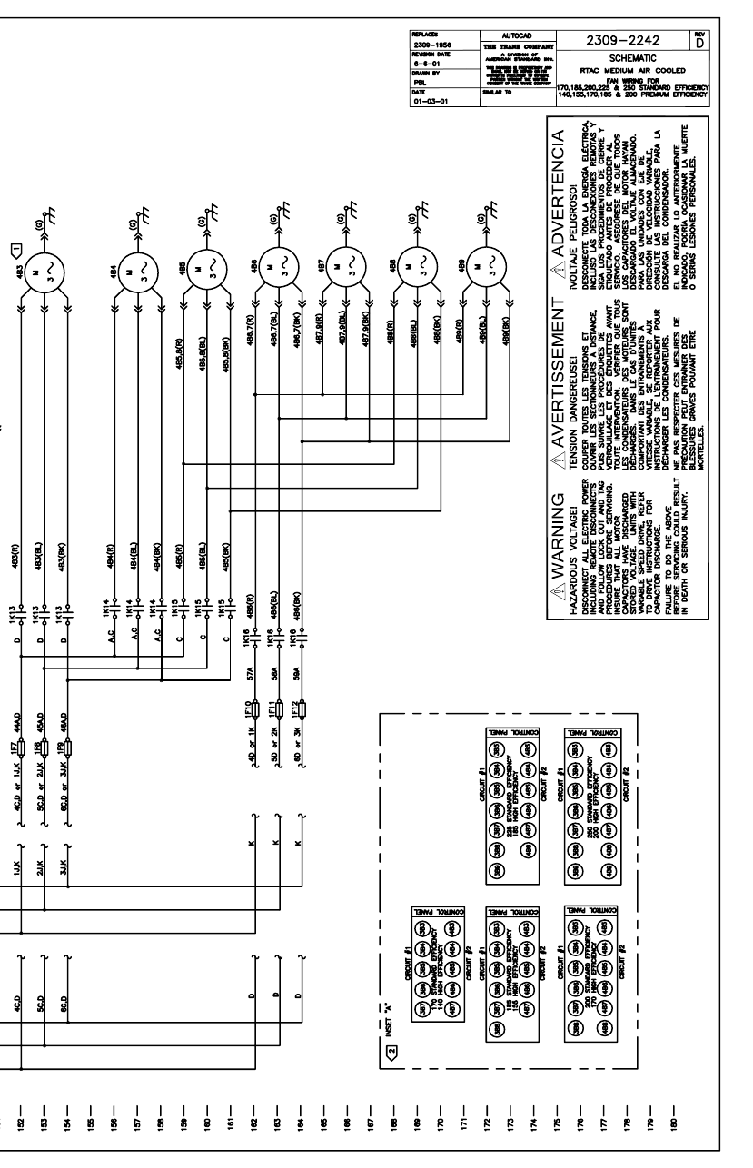
RTAC-SVX01F-EN 199
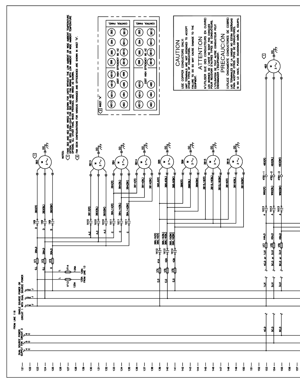
200 RTAC-SVX01F-EN
2231
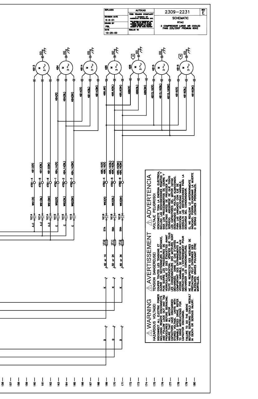
RTAC-SVX01F-EN 201
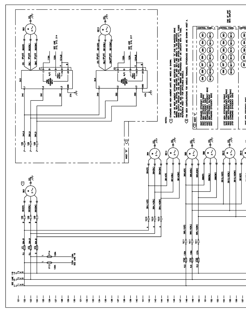
202 RTAC-SVX01F-EN
4876
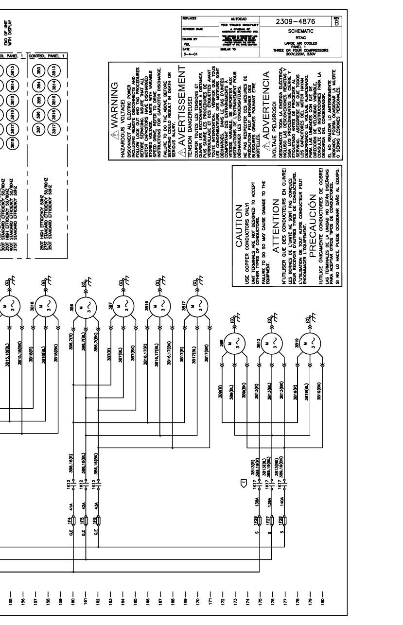
RTAC-SVX01F-EN 203
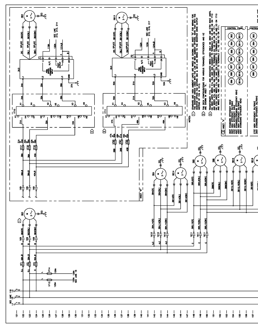
204 RTAC-SVX01F-EN
1992
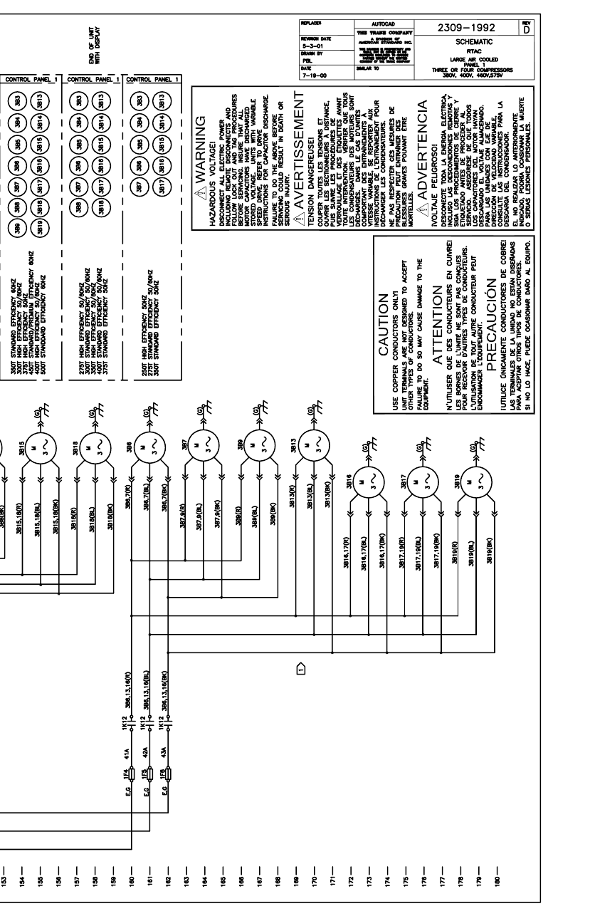
RTAC-SVX01F-EN 205
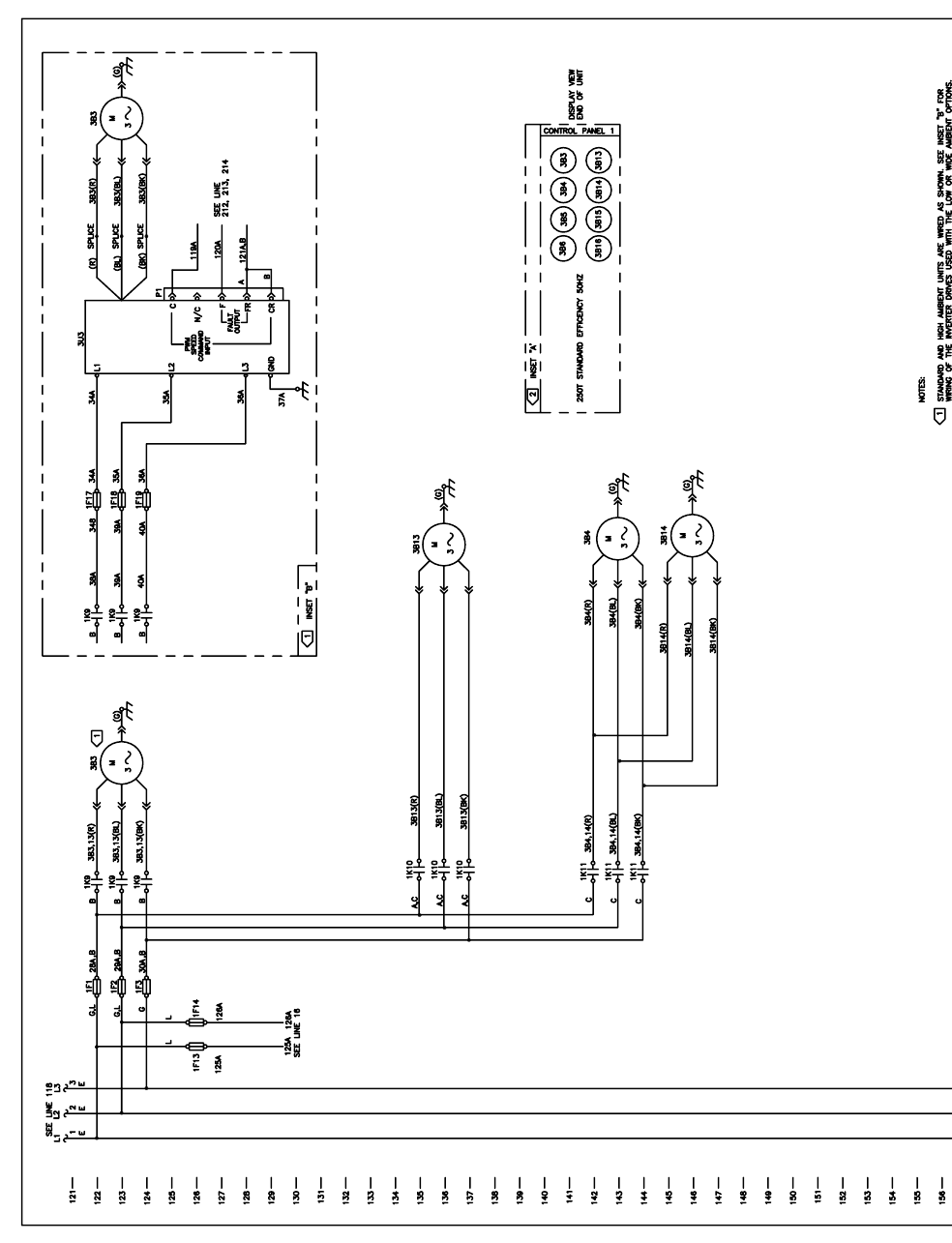
206 RTAC-SVX01F-EN
2217
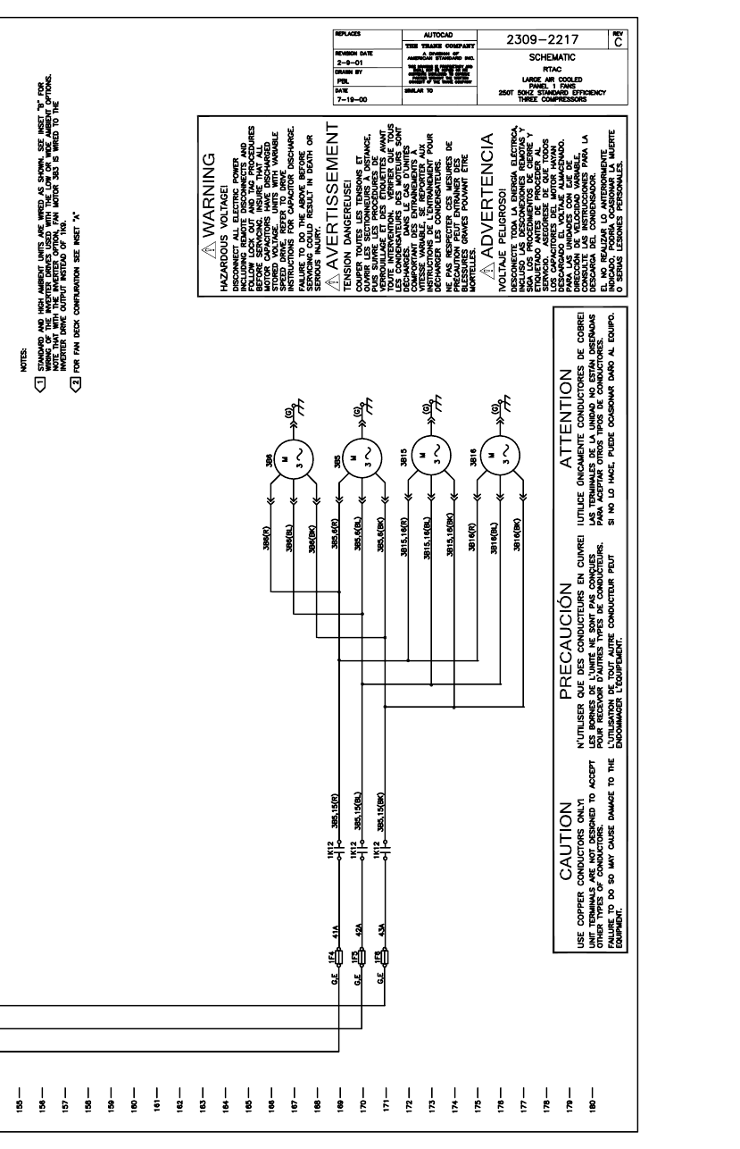
RTAC-SVX01F-EN 207
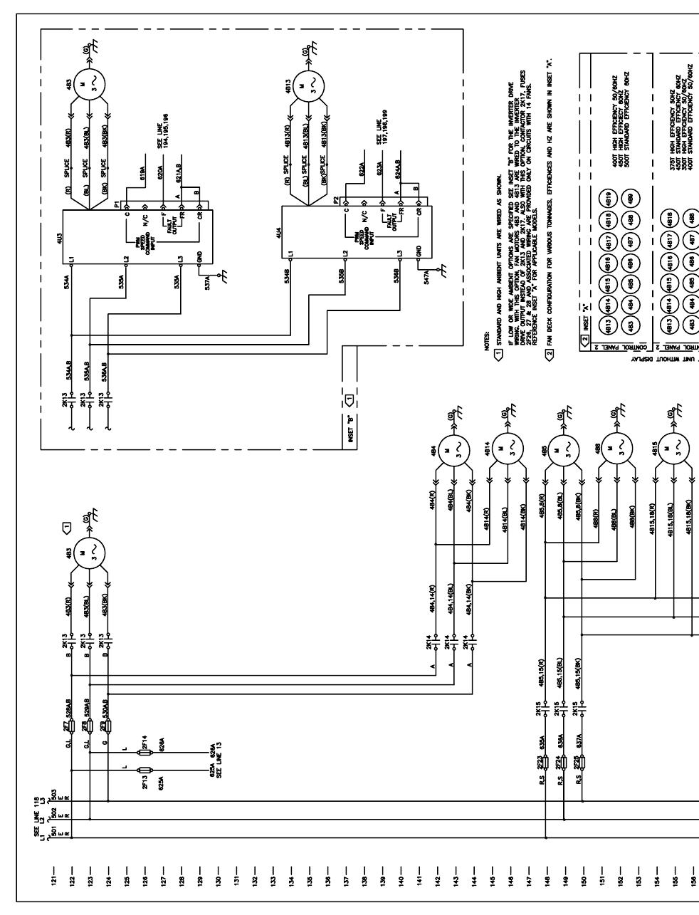
208 RTAC-SVX01F-EN
4877
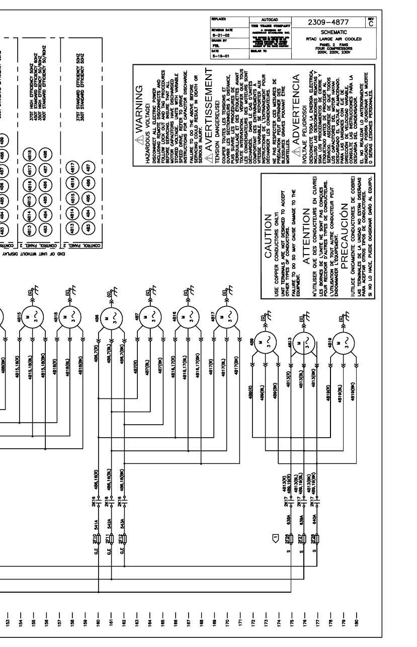
RTAC-SVX01F-EN 209
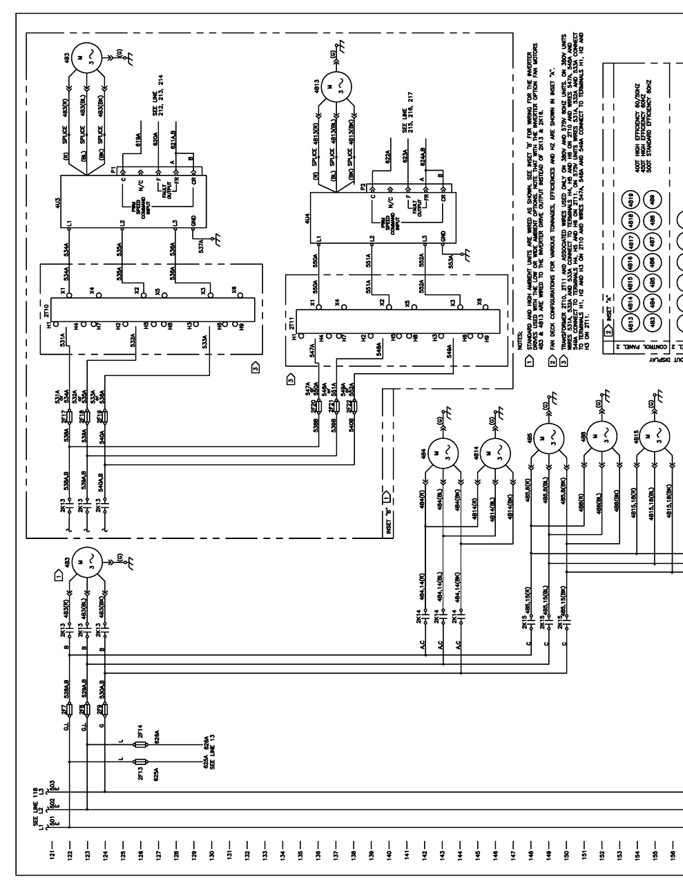
210 RTAC-SVX01F-EN
2205
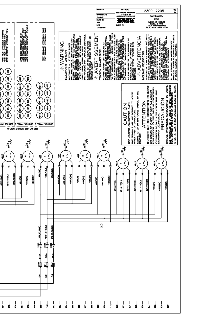
RTAC-SVX01F-EN 211
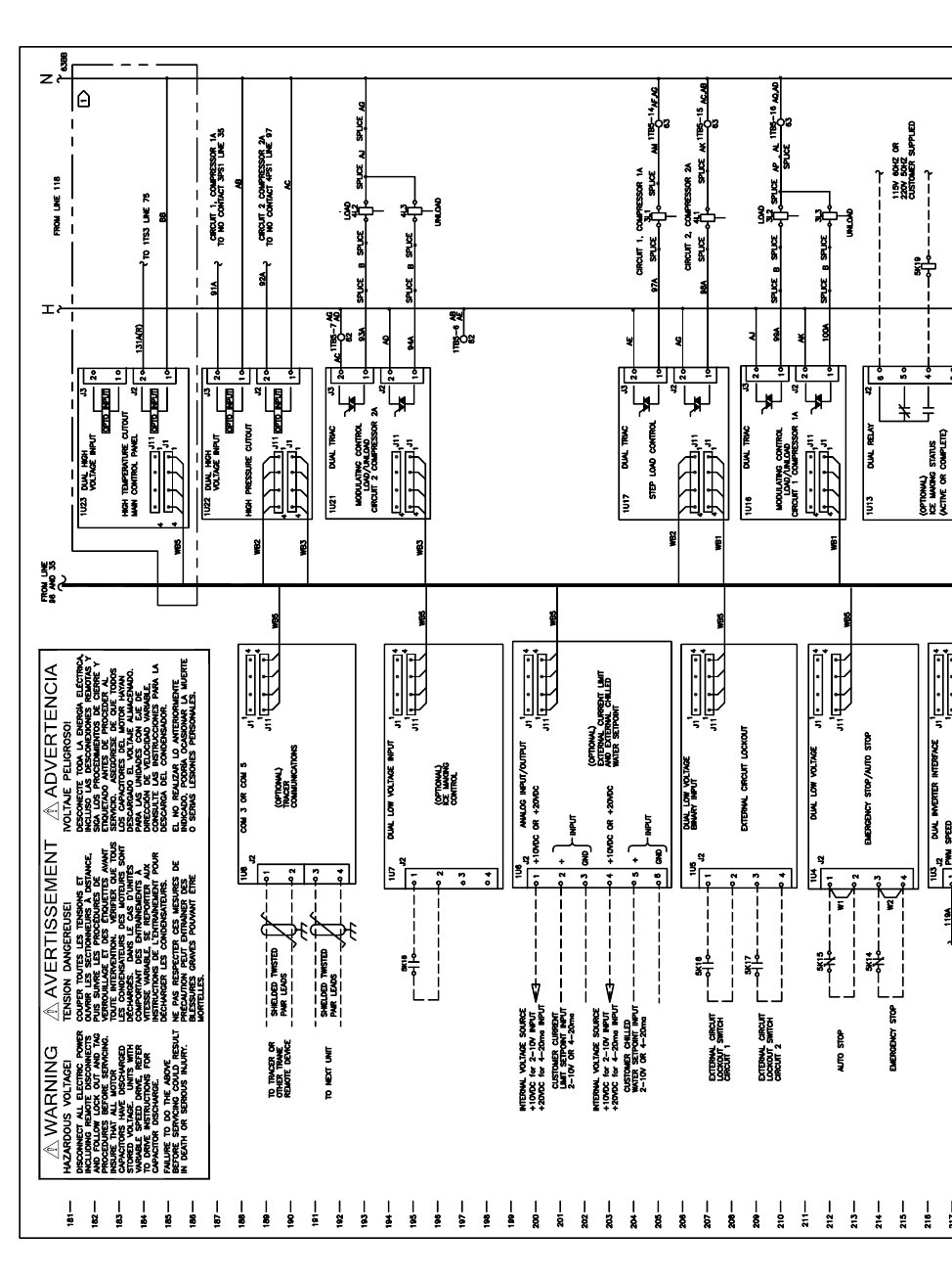
212 RTAC-SVX01F-EN
1352
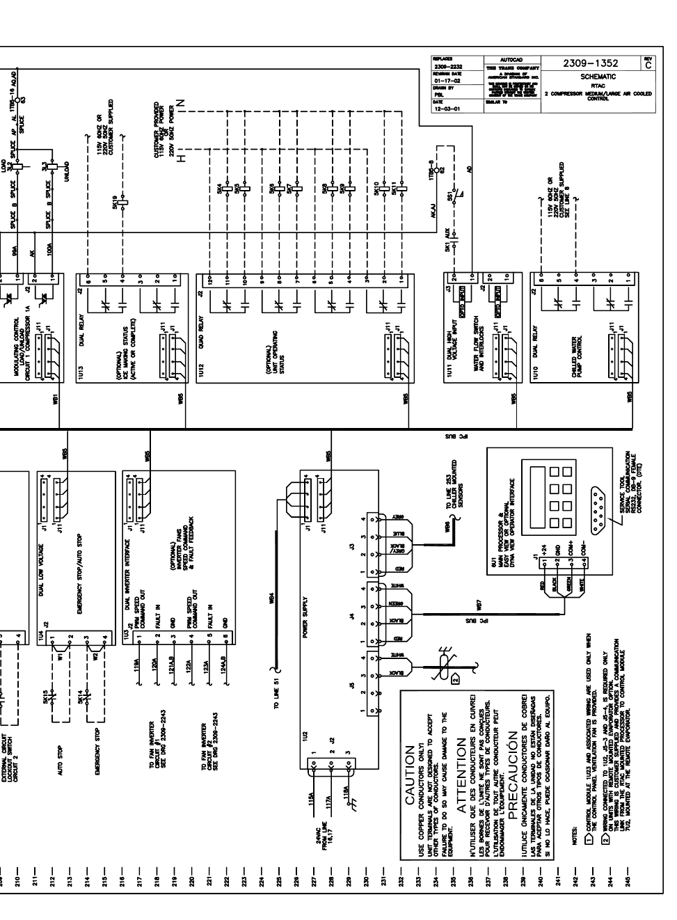
RTAC-SVX01F-EN 213
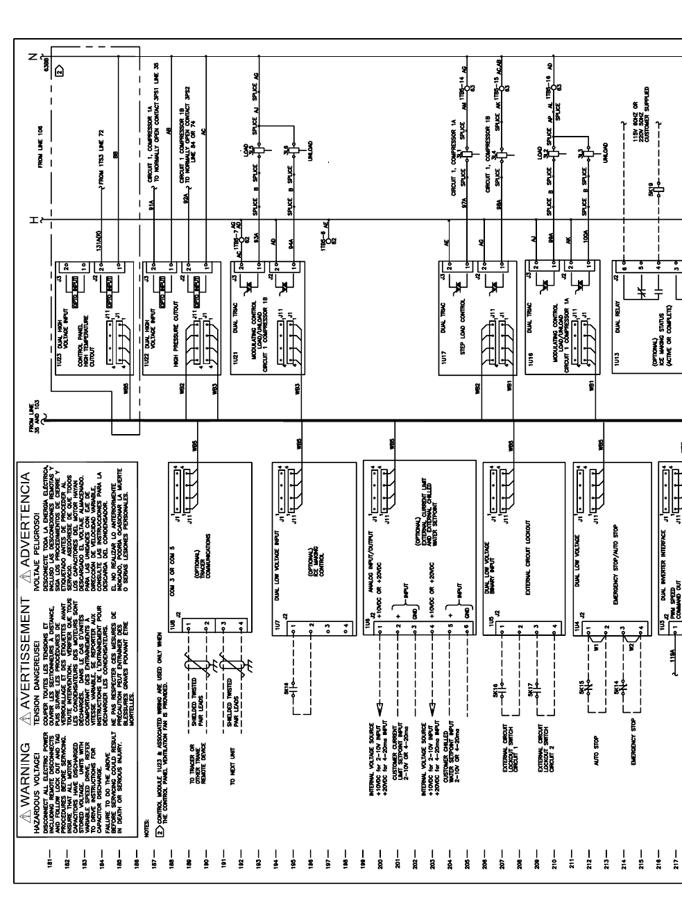
214 RTAC-SVX01F-EN
4880
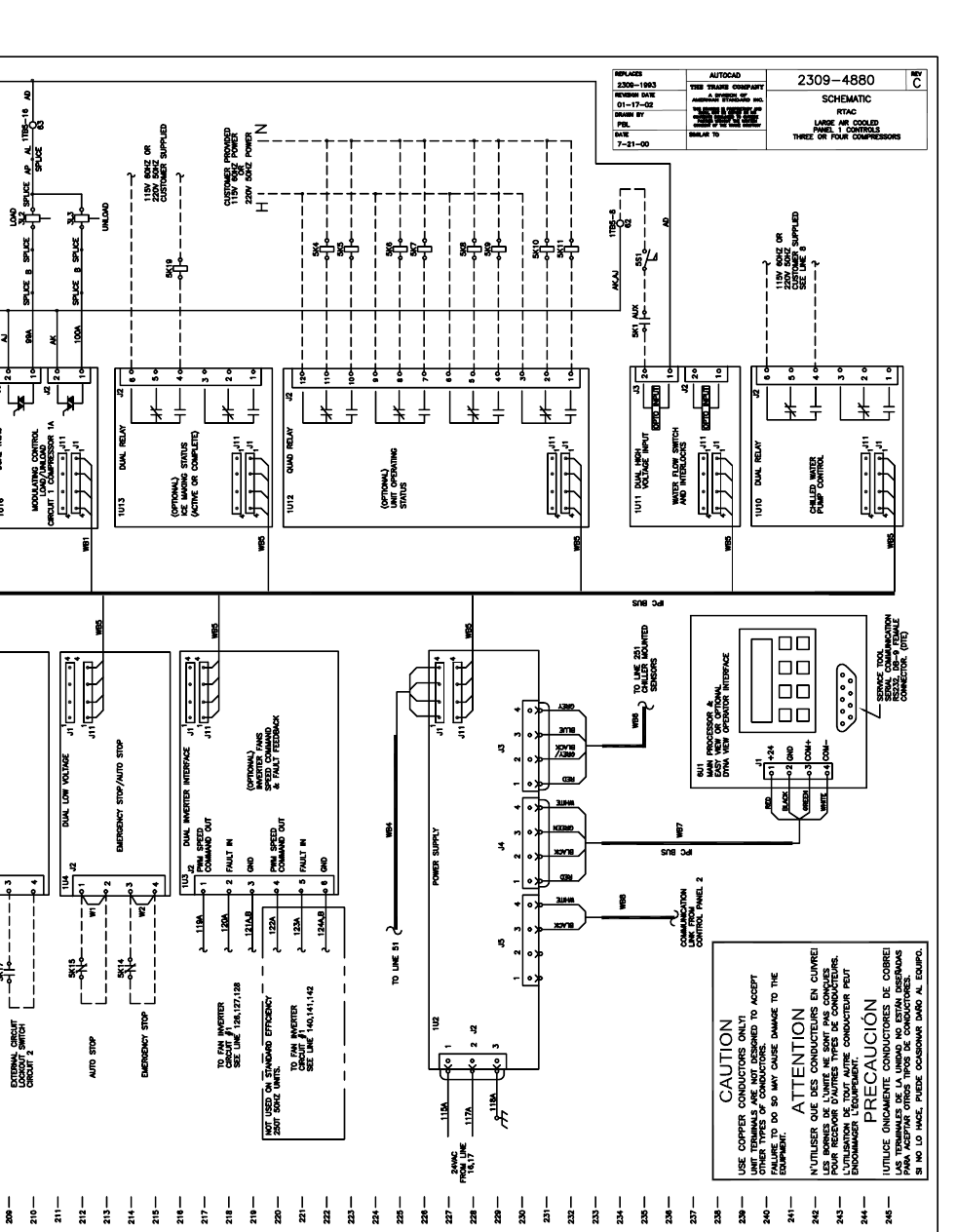
RTAC-SVX01F-EN 215
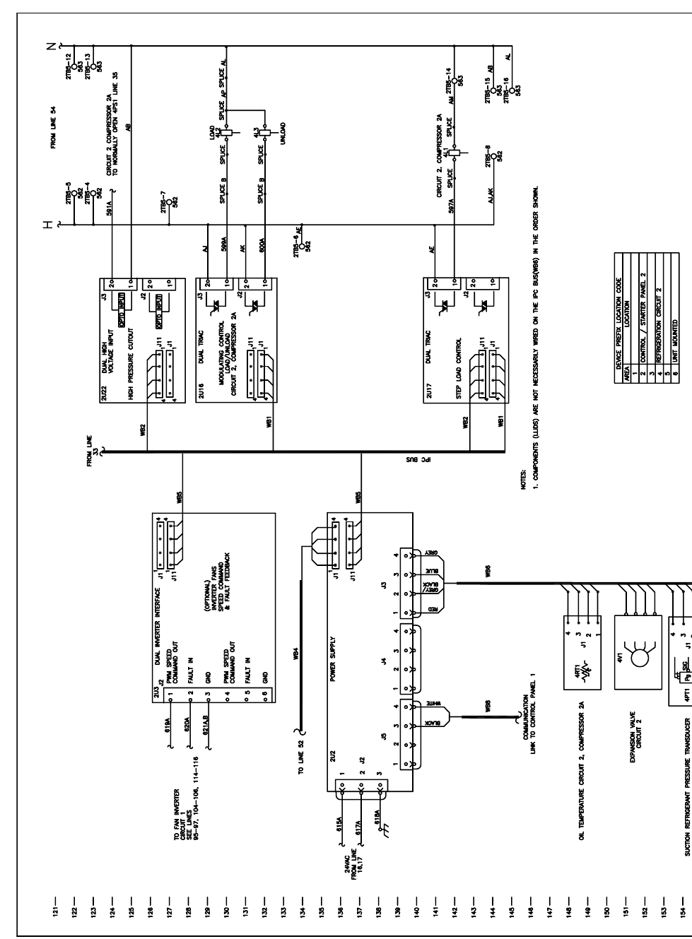
216 RTAC-SVX01F-EN
4882
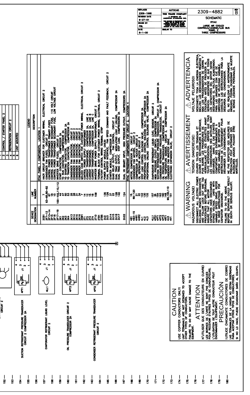
RTAC-SVX01F-EN 217
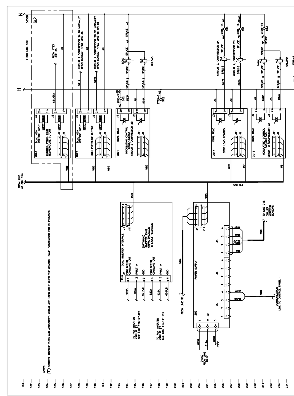
218 RTAC-SVX01F-EN
4883
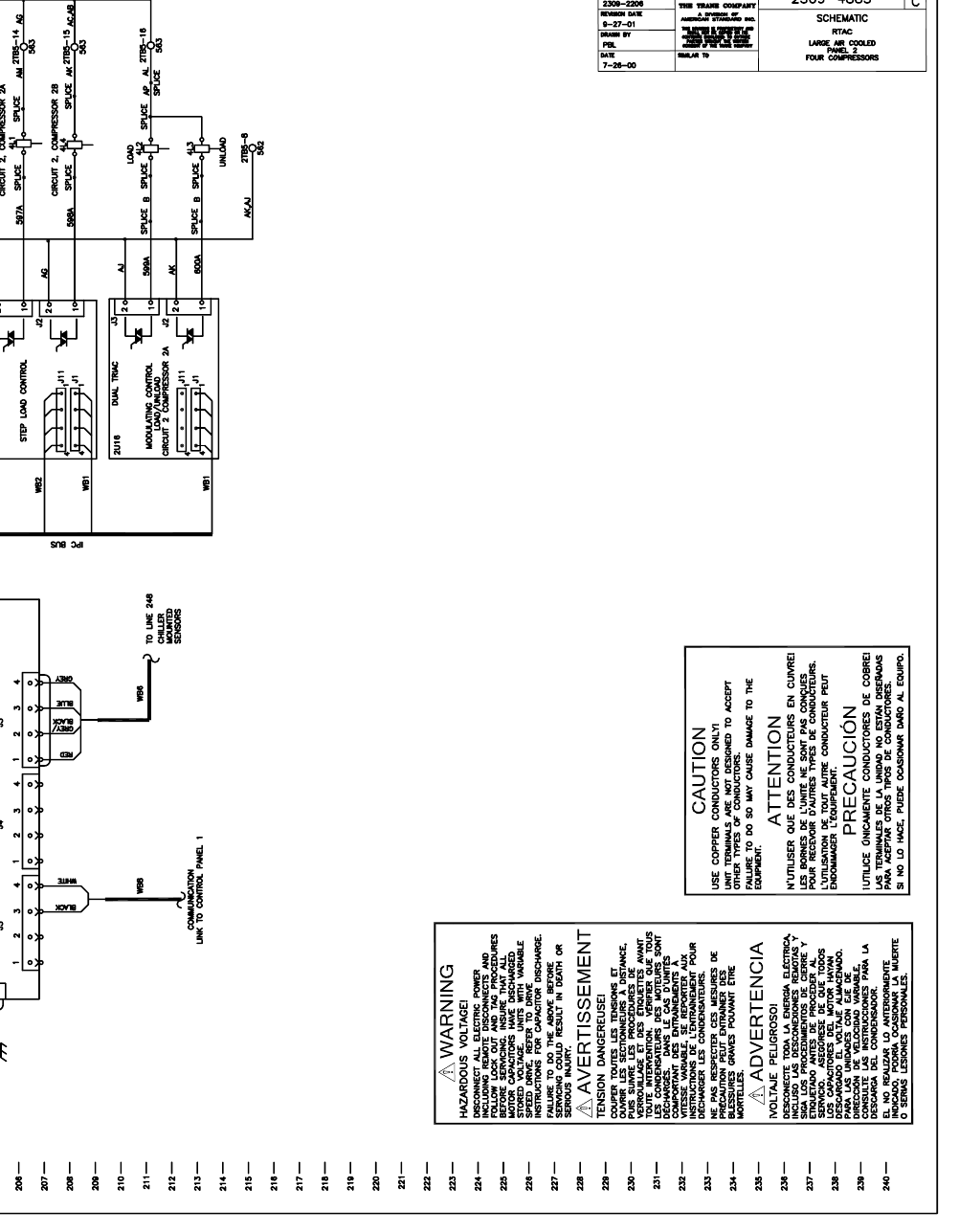
RTAC-SVX01F-EN 219
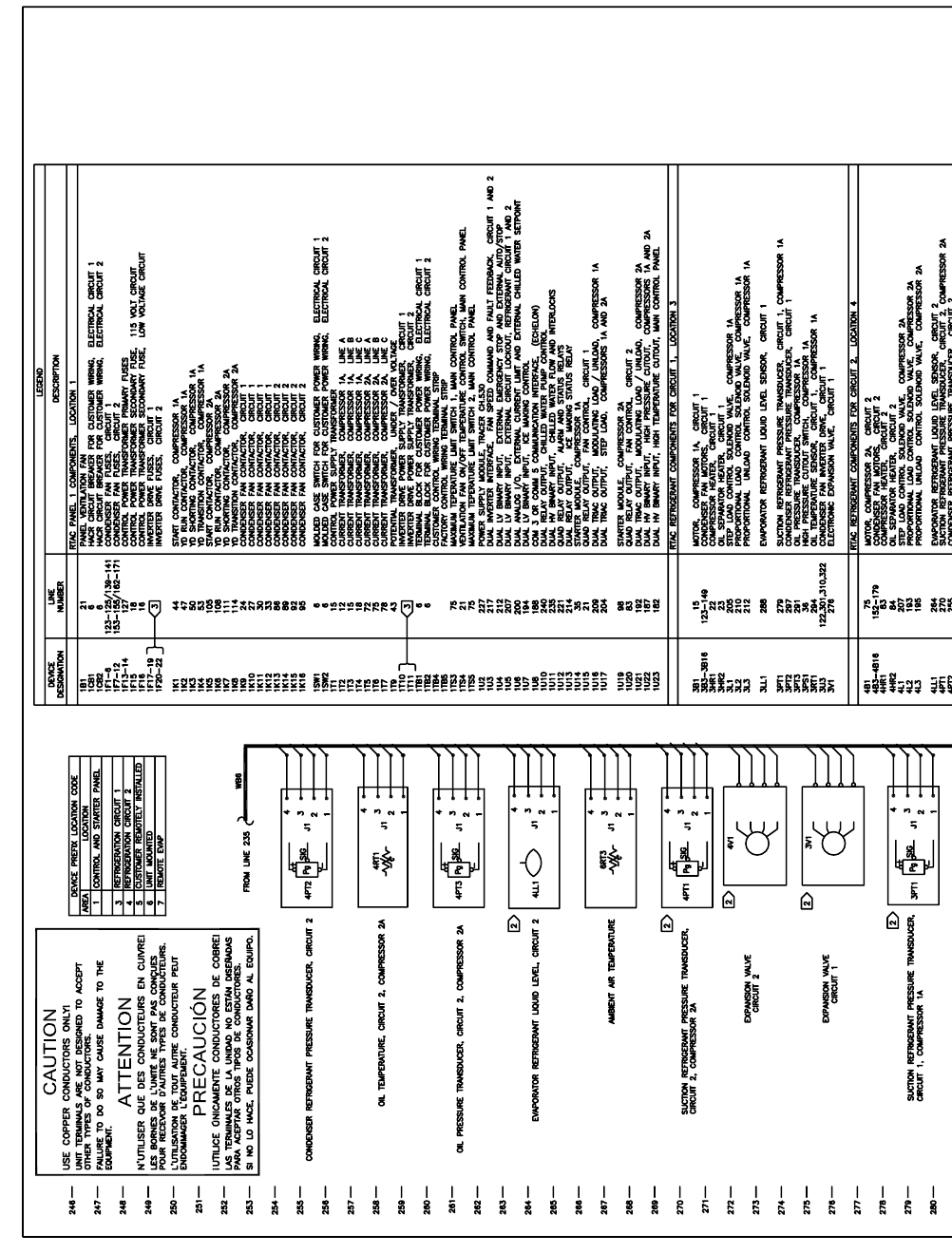
220 RTAC-SVX01F-EN
1353
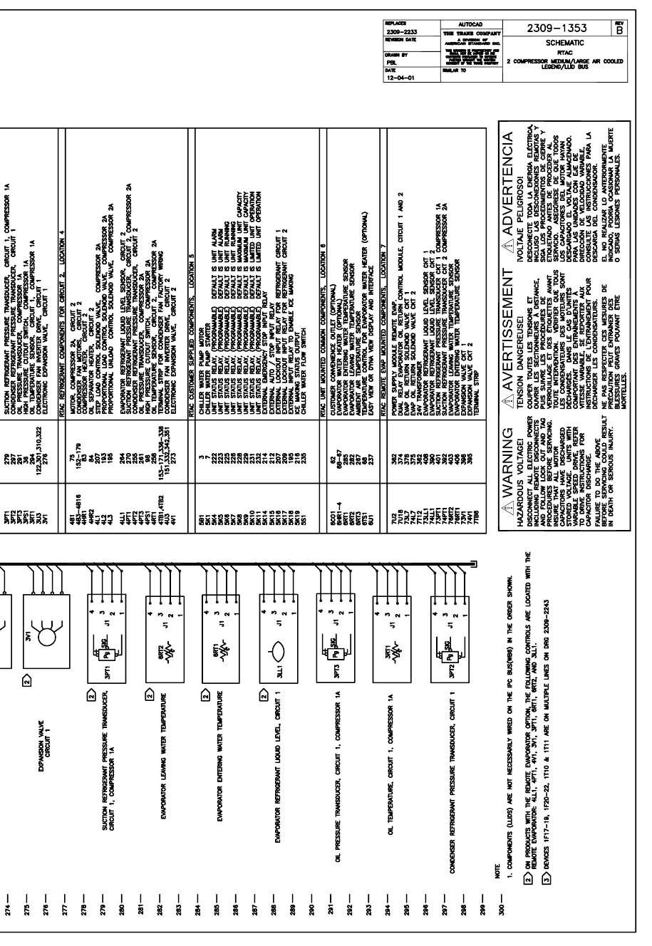
RTAC-SVX01F-EN 221
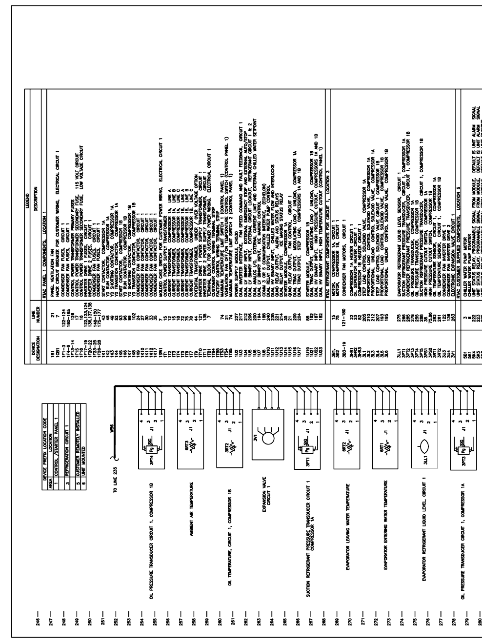
222 RTAC-SVX01F-EN
4881
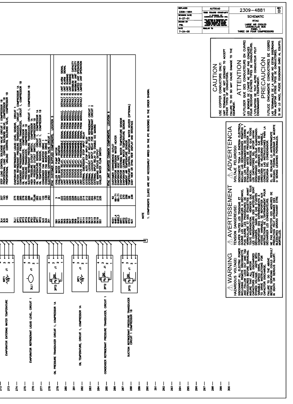
RTAC-SVX01F-EN 223
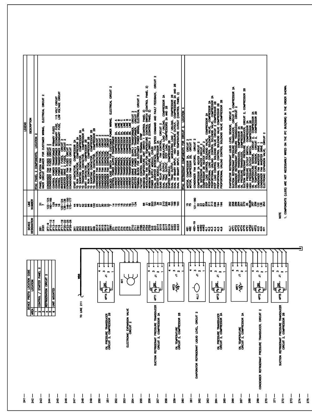
224 RTAC-SVX01F-EN
4884
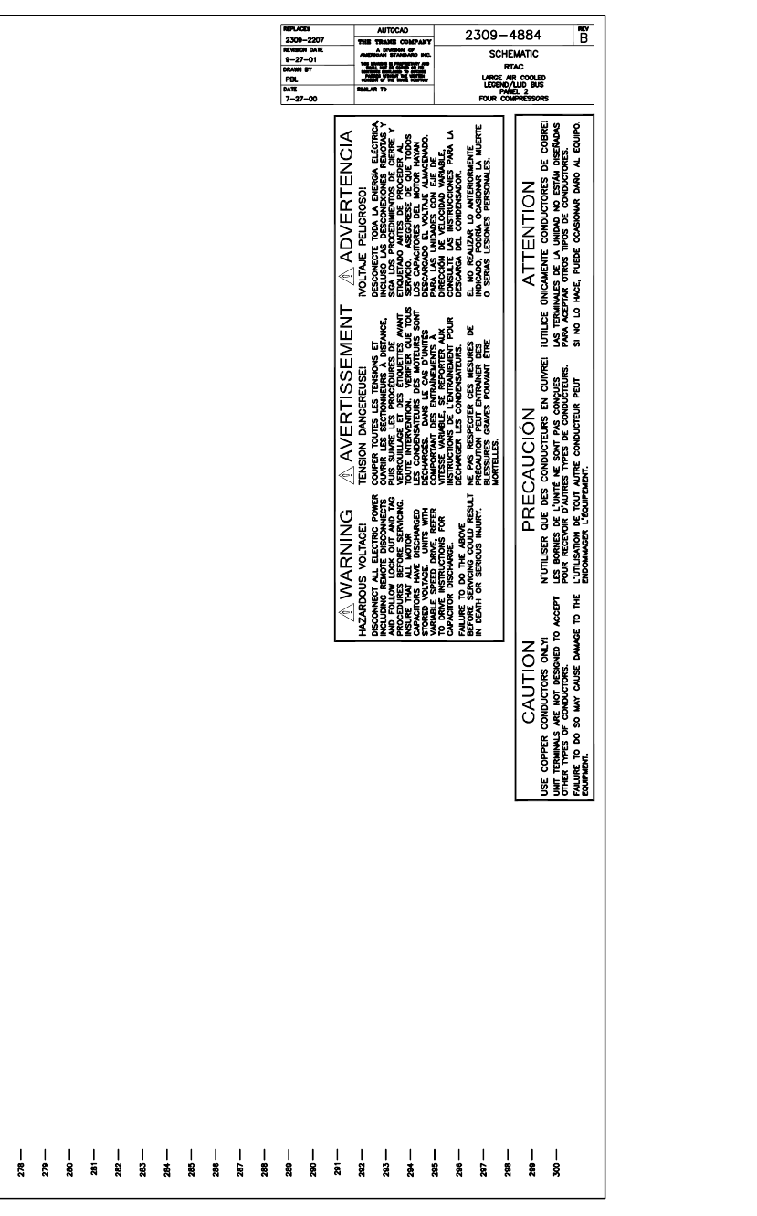
RTAC-SVX01F-EN 225
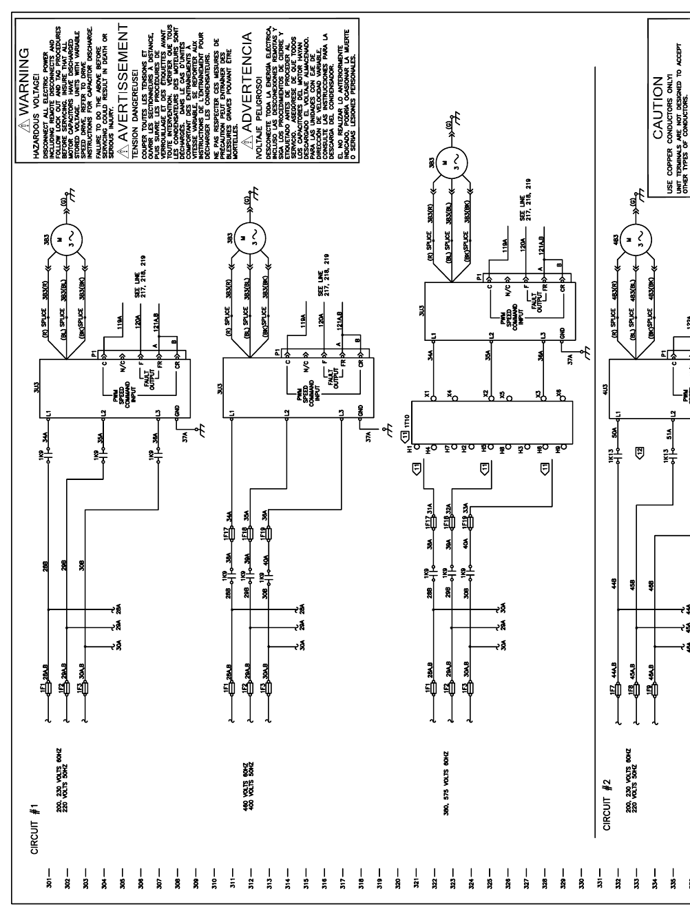
226 RTAC-SVX01F-EN
2243
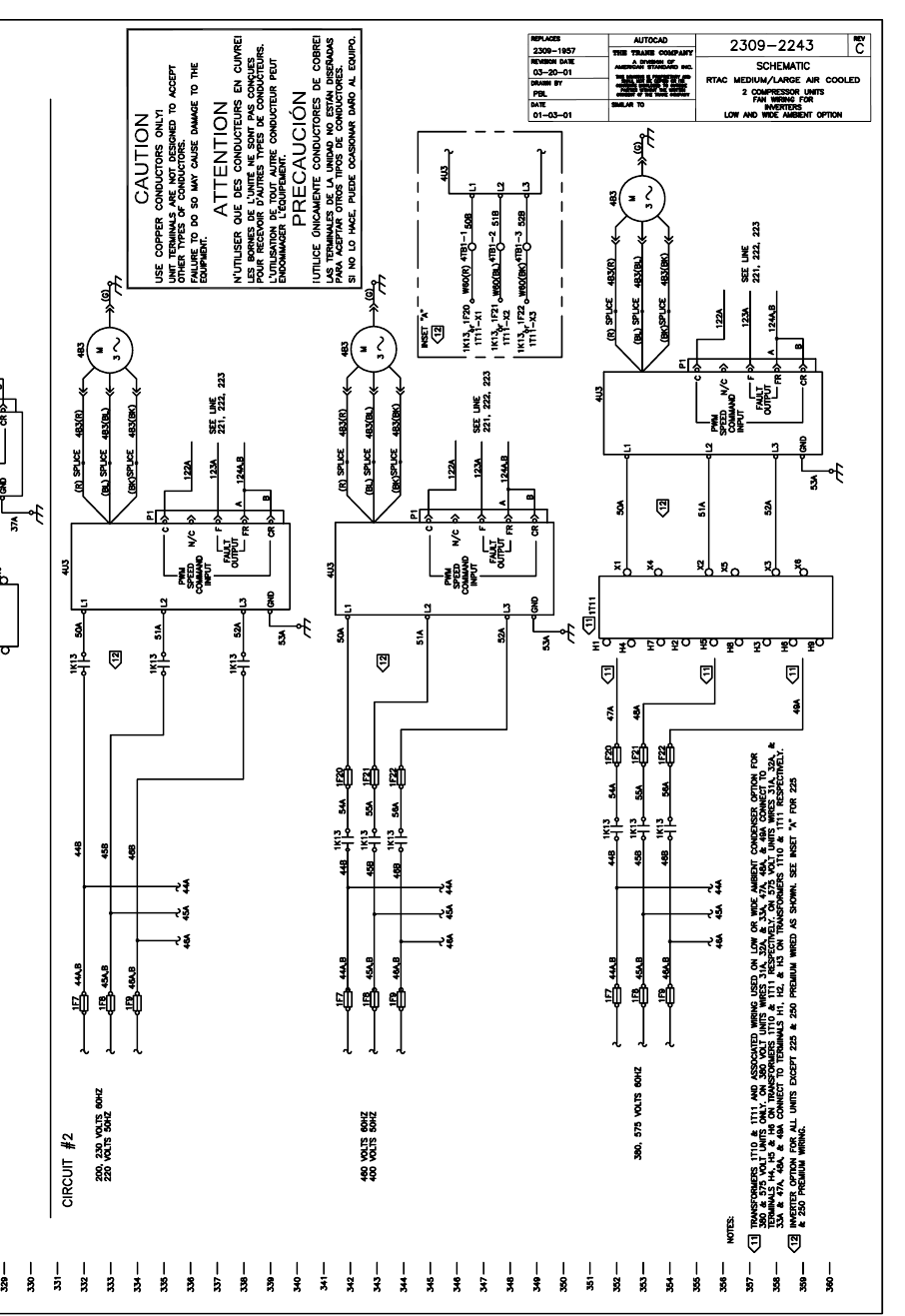
RTAC-SVX01F-EN 227
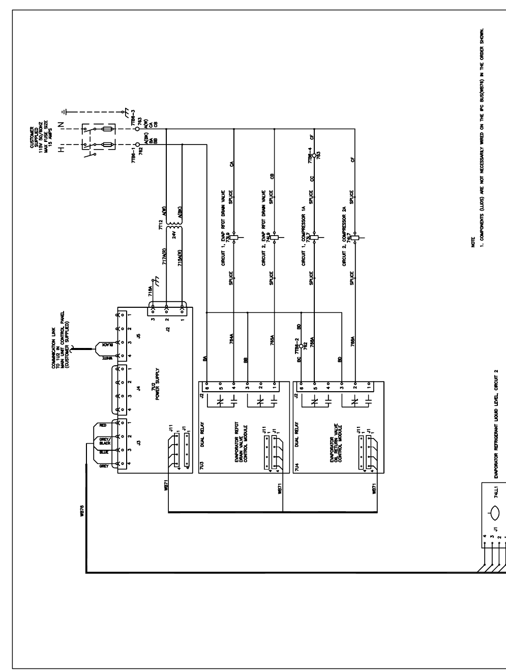
228 RTAC-SVX01F-EN
4899
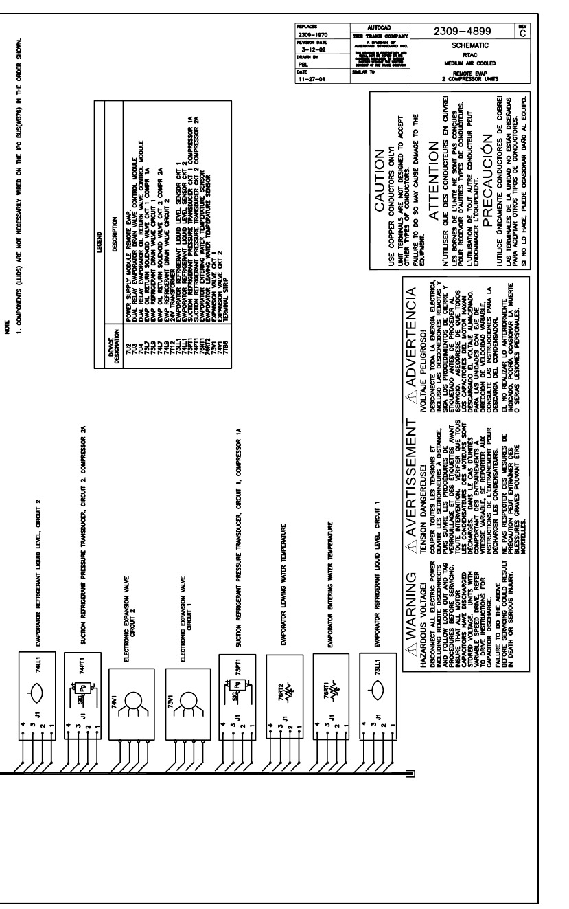
RTAC-SVX01F-EN 229
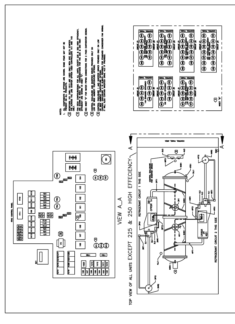
230 RTAC-SVX01F-EN
4871
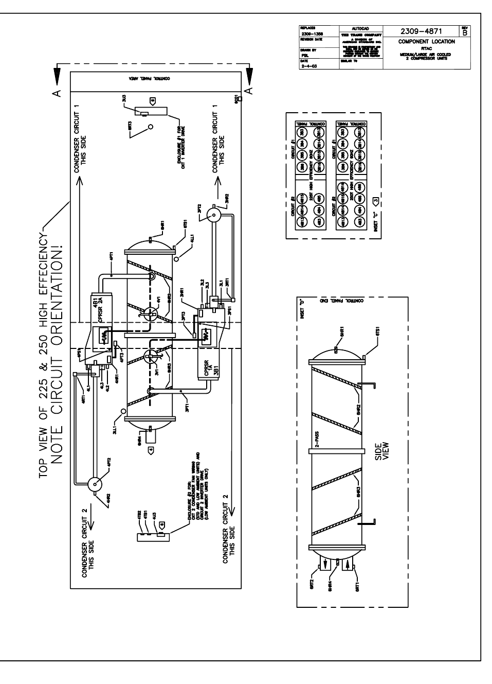
RTAC-SVX01F-EN 231
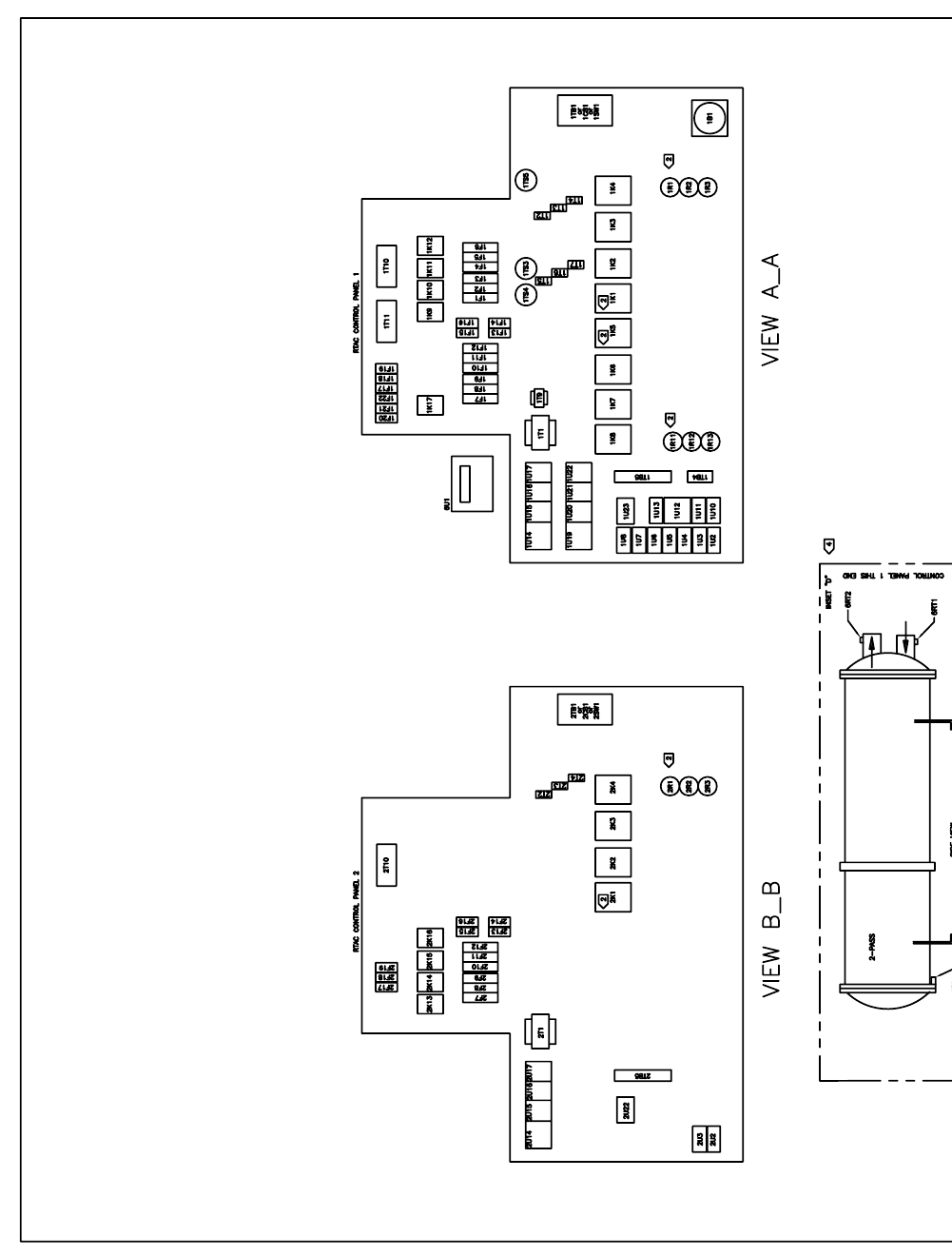
232 RTAC-SVX01F-EN
4874
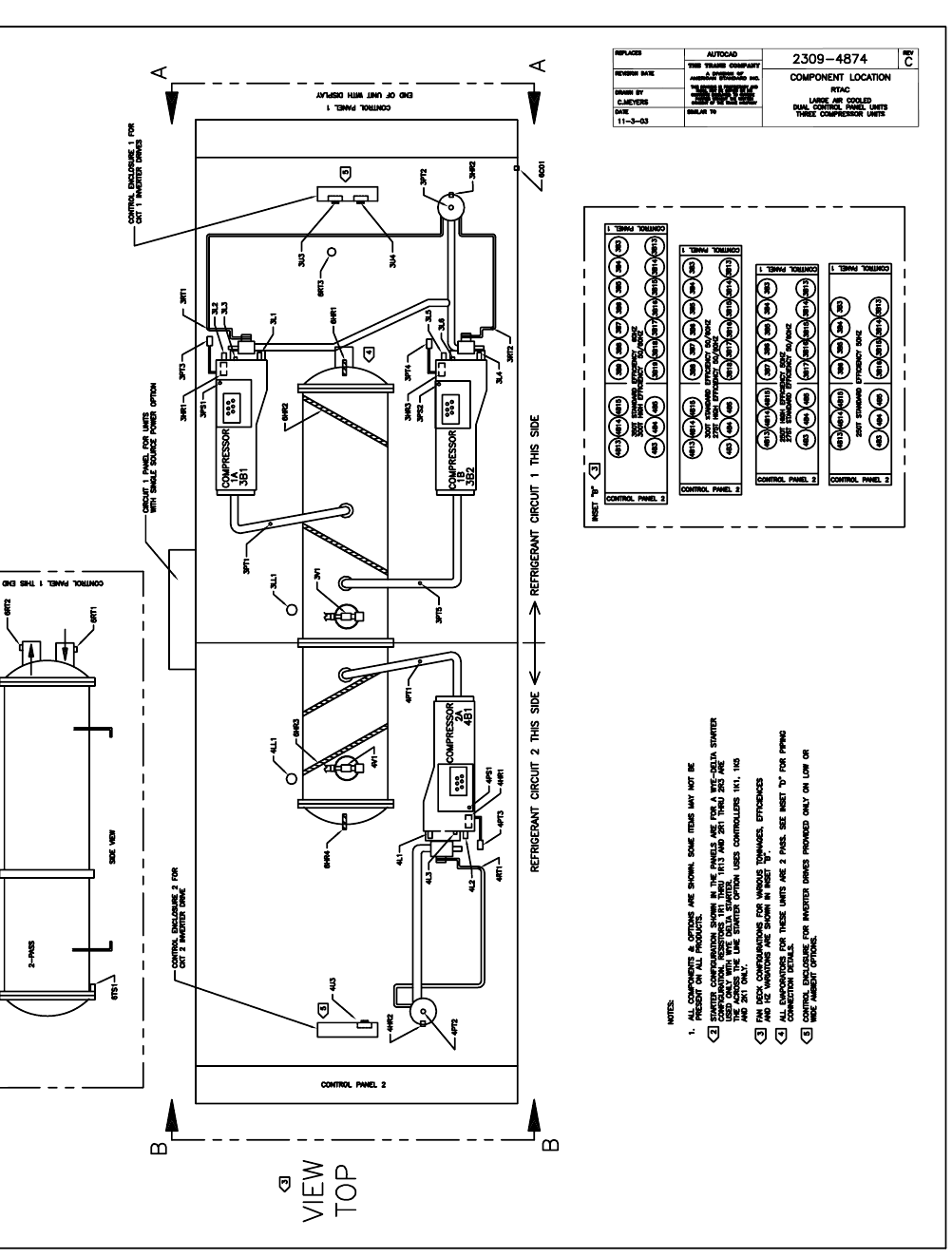
RTAC-SVX01F-EN 233
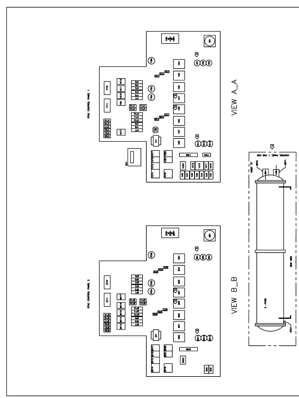
234 RTAC-SVX01F-EN
4873
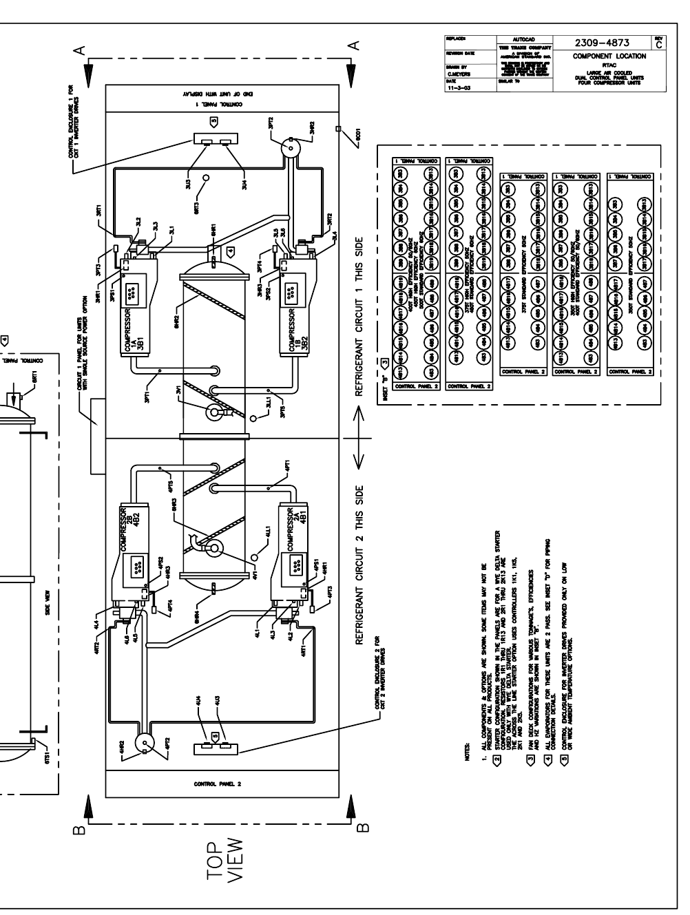
RTAC-SVX01F-EN 235
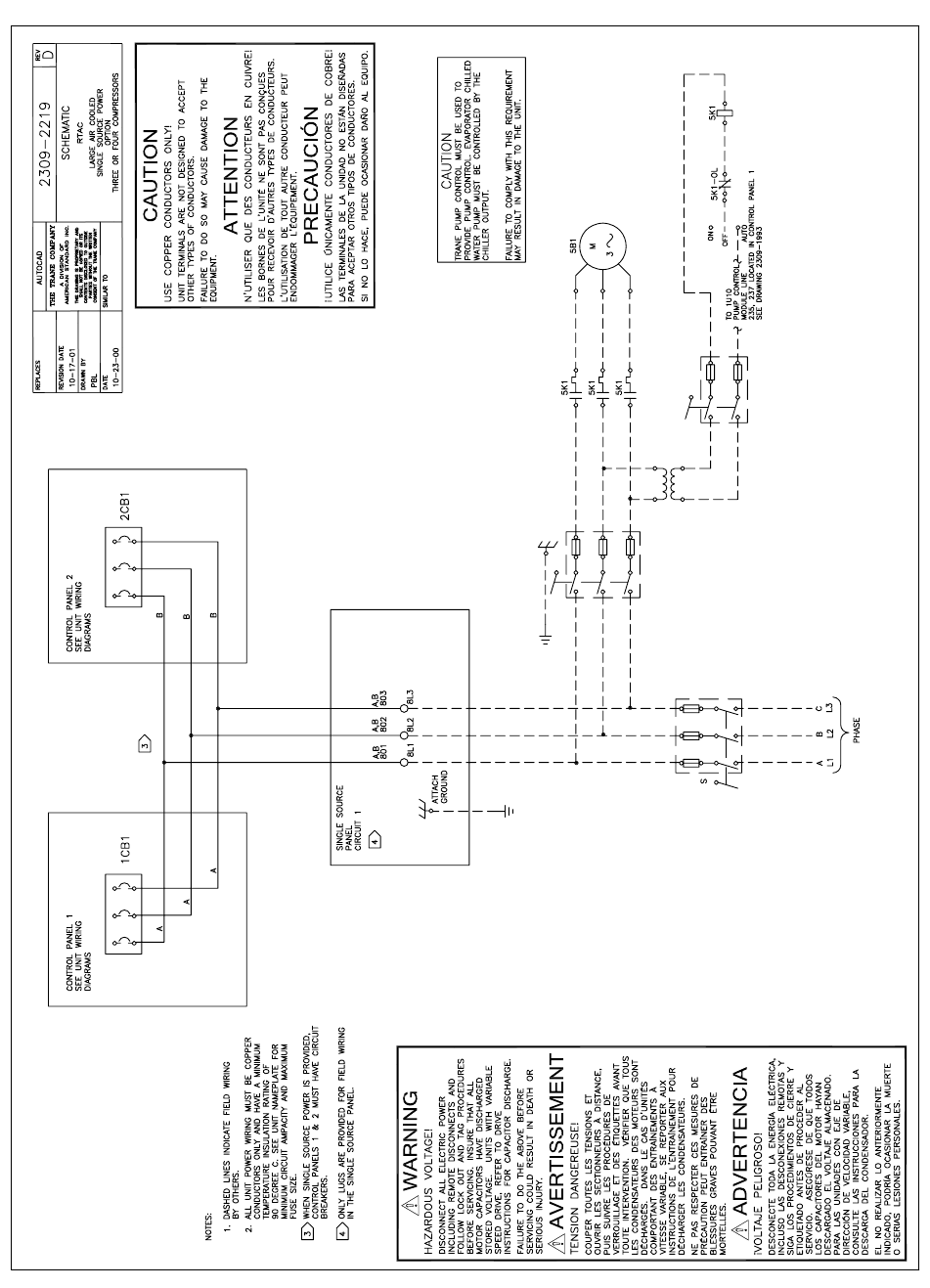
236 RTAC-SVX01F-EN
2219
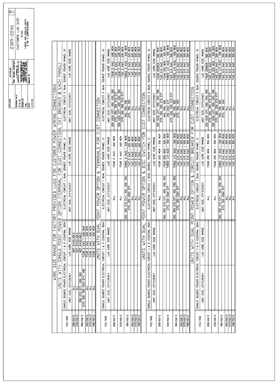
RTAC-SVX01F-EN 237
2247
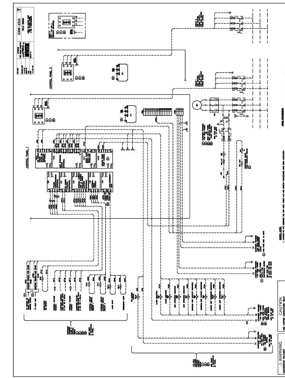
238 RTAC-SVX01F-EN
2222
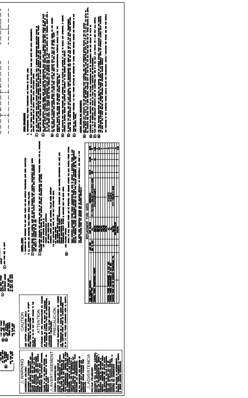
RTAC-SVX01F-EN 239
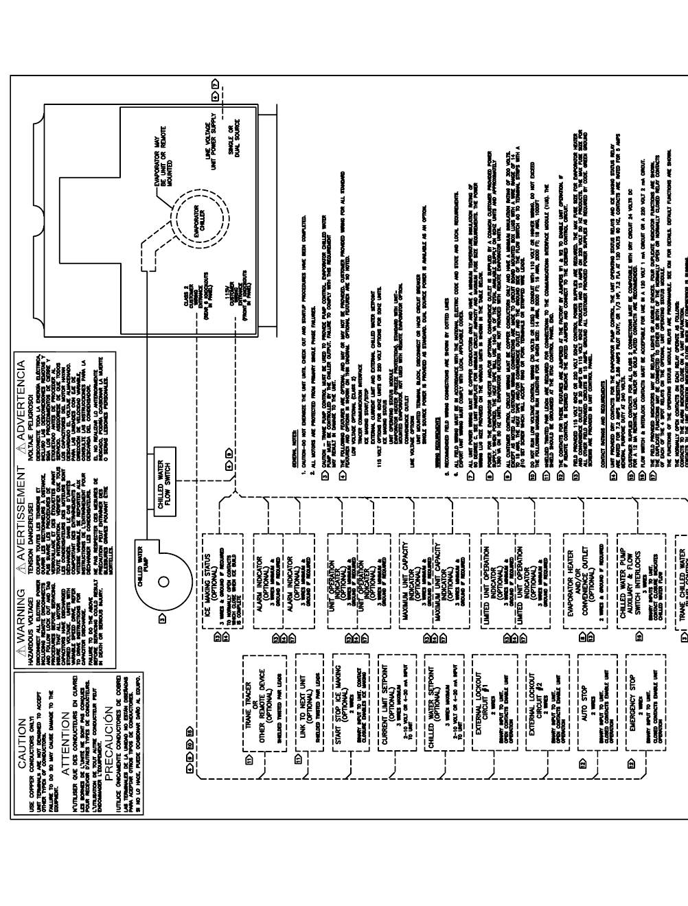
240 RTAC-SVX01F-EN
2248
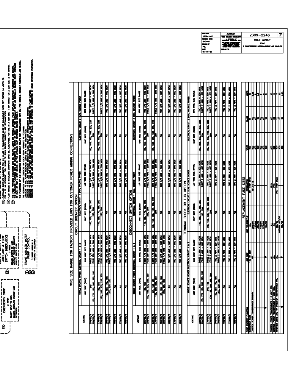
RTAC-SVX01F-EN 241
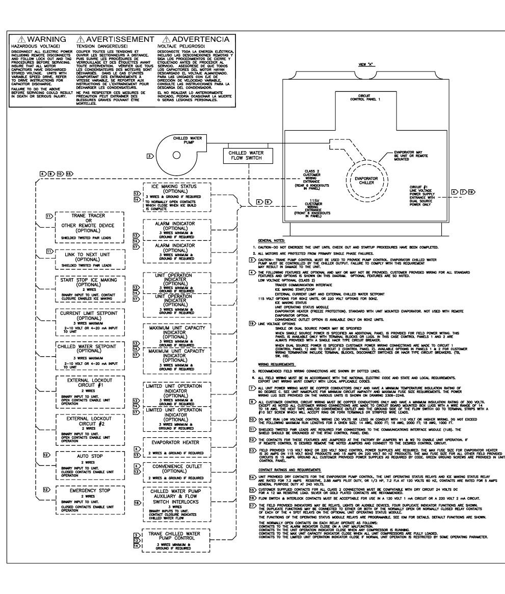
242 RTAC-SVX01F-EN
2239
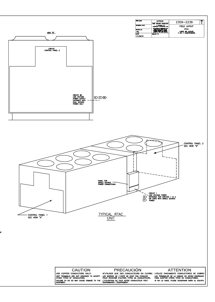
RTAC-SVX01F-EN 243
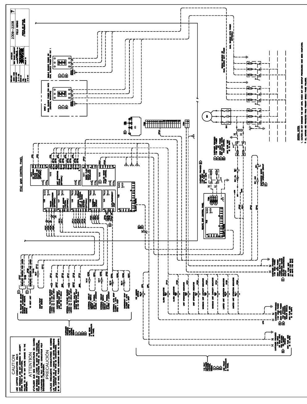
244 RTAC-SVX01F-EN
2208
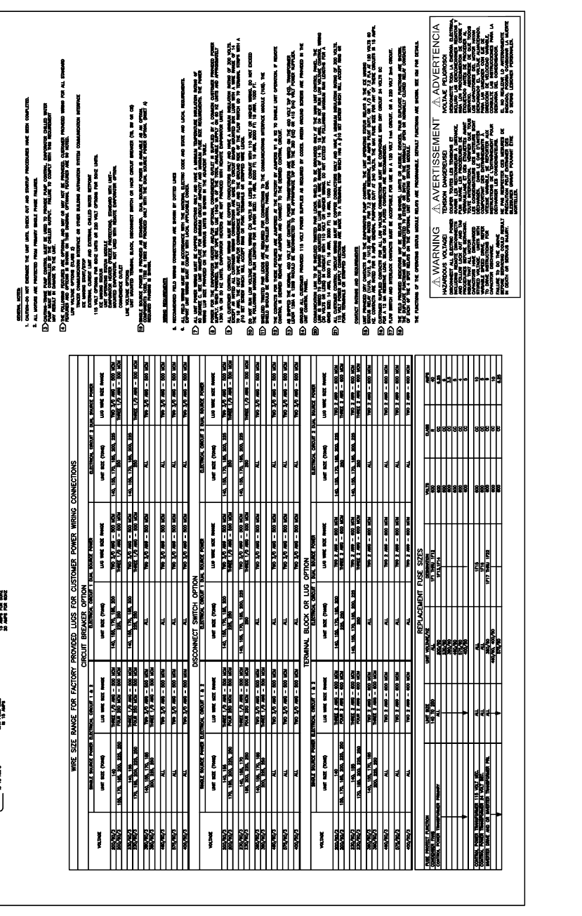
RTAC-SVX01F-EN 245
2246
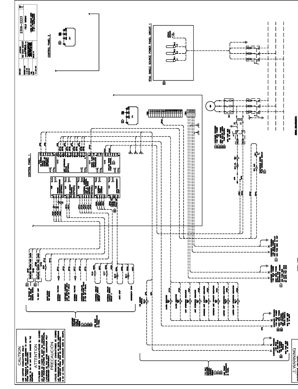
246 RTAC-SVX01F-EN
2223
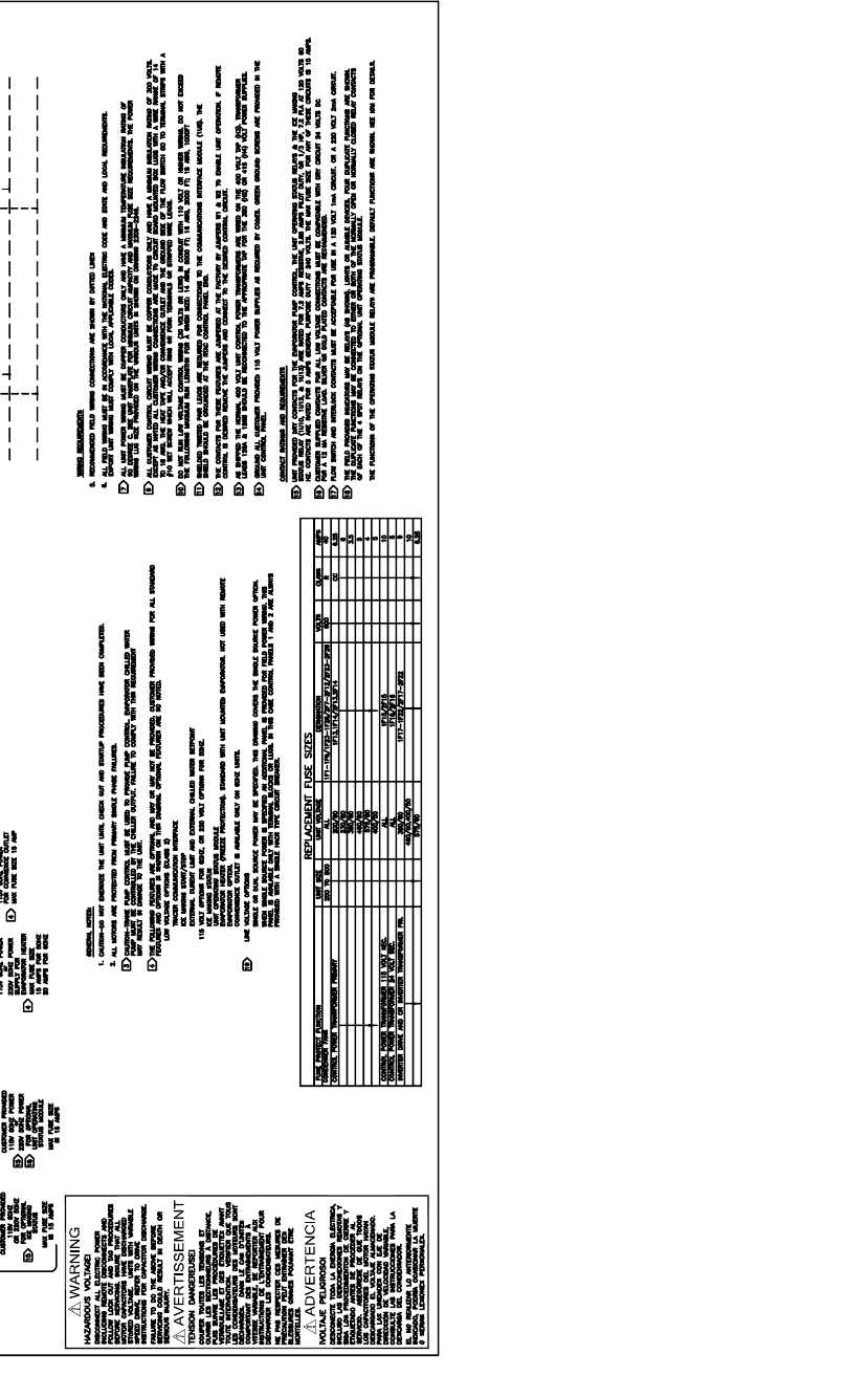
RTAC-SVX01F-EN 247
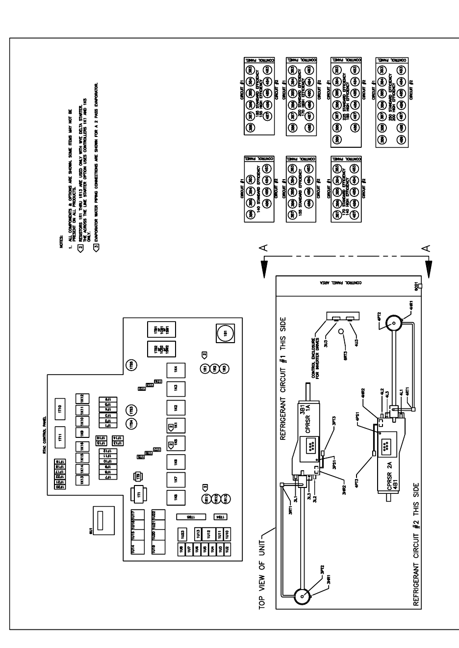
248 RTAC-SVX01F-EN
4872
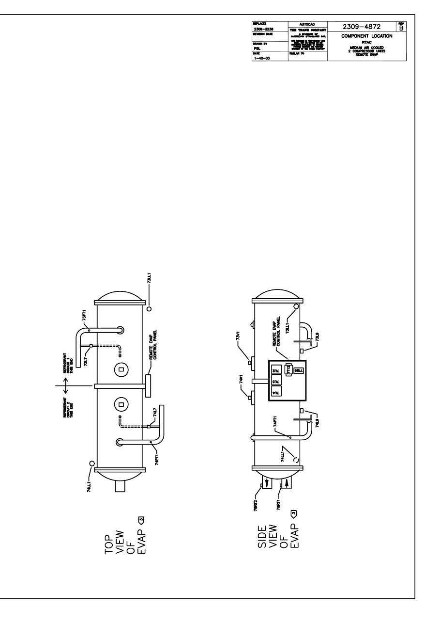
RTAC-SVX01F-EN 249
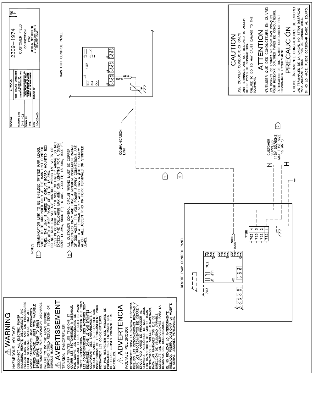
250 RTAC-SVX01F-EN
1974

Trane has a policy of continuous product data and product improvement and reserves
the right to change design and specifications without notice. Only qualified technicians
should perform the installation and servicing of equipment referred to in this bulletin.
Literature Order Number RTAC-SVX01F-EN
File Number SV-RF-RTAC-SVX01F-EN-0106
Supersedes RTAC-SVX01E-EN
Stocking Location Inland
Trane
A business of American Standard Companies
www.trane.com
For more information contact your local district
office or e-mail us at comfort@trane.com
