Trane Series R Rtud Installation And Maintenance Manual RLC SVX09H EN (10/12)
2015-04-02
: Trane Trane-Series-R--Rtud-Installation-And-Maintenance-Manual-684184 trane-series-r--rtud-installation-and-maintenance-manual-684184 trane pdf
Open the PDF directly: View PDF ![]() .
.
Page Count: 216 [warning: Documents this large are best viewed by clicking the View PDF Link!]
- Warnings, Cautions and Notices
- Model Number Description
- General Information
- Pre-Installation
- Unit Dimensions/Weights
- Installation - Mechanical
- Location Requirements
- Rigging
- Evaporator Piping
- Condenser Water Piping (RTWD Units Only)
- Refrigerant Relief Valve Venting
- RTUD Installation
- System Configuration
- Equivalent Line Length
- Liquid Line Sizing
- Discharge (Hot Gas) Line Sizing
- Example
- Refrigerant Charge Determination
- RTUD Chilled Water Flow Control
- Oil Charge Determination
- Outdoor Air Temperature Sensor Installation Requirements
- Fan Control for the Remote Air Cooled Condenser
- RTUD Condenser Elevation Setting
- Shipping Spacers
- Installation - Electrical
- RTWD/RTUD Operating Principles
- Controls Interface
- Pre-Start Checkout
- Unit Start-Up Procedures
- Unit Shutdown
- Service and Maintenance
- Diagnostics
- Wiring Schematics
SAFETY WARNING
Only qualified personnel should install and service the equipment. The installation, starting up, and
servicing of heating, ventilating, and air-conditioning equipment can be hazardous and requires specific
knowledge and training. Improperly installed, adjusted or altered equipment by an unqualified person could
result in death or serious injury. When working on the equipment, observe all precautions in the literature
and on the tags, stickers, and labels that are attached to the equipment.
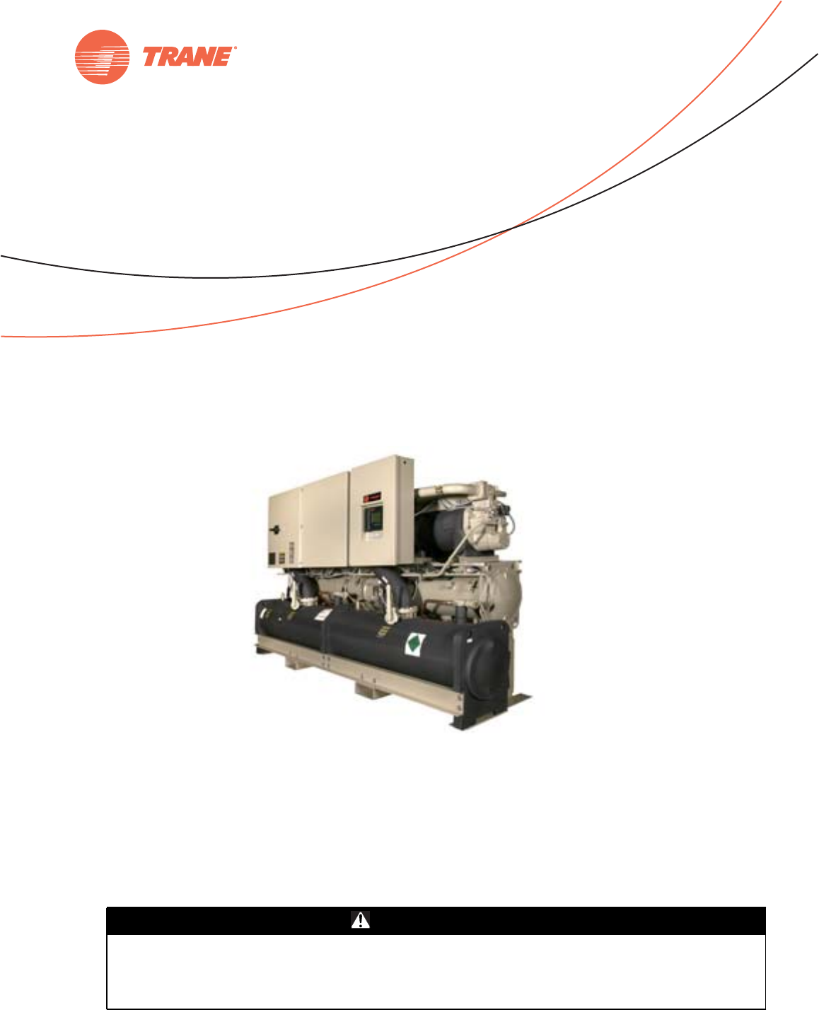
Series R®Rotary Liquid Chillers
Water-Cooled and Compressor-Chillers
October 2012 RLC-SVX09H-EN
Installation, Operation,
and Maintenance
RTWD 60 RTWD 90 RTWD 120 RTWD 150 RTWD 200
RTWD 70 RTWD 100 RTWD 130 RTWD 160 RTWD 220
RTWD 80 RTWD 110 RTWD 140 RTWD 180 RTWD 250
RTUD 80 RTUD 110 RTUD 150 RTUD 200
RTUD 90 RTUD 120 RTUD 160 RTUD 220
RTUD 100 RTUD 130 RTUD 180 RTUD 250
© 2012Trane All rights reserved RLC-SVX09H-EN
Warnings, Cautions and Notices
Warnings, Cautions and Notices. Note that warnings,
cautions and notices appear at appropriate intervals
throughout this manual. Warnings are provide to alert
installing contractors to potential hazards that could result
in death or personal injury. Cautions are designed to alert
personnel to hazardous situations that could result in
personal injury, while notices indicate a situation that
could result in equipment or property-damage-only
accidents.
Your personal safety and the proper operation of this
machine depend upon the strict observance of these
precautions.
Read this manual thoroughly before operating or servicing
this unit.
Important
Environmental Concerns!
Scientific research has shown that certain man-made
chemicals can affect the earth’s naturally occurring
stratospheric ozone layer when released to the
atmosphere. In particular, several of the identified
chemicals that may affect the ozone layer are refrigerants
that contain Chlorine, Fluorine and Carbon (CFCs) and
those containing Hydrogen, Chlorine, Fluorine and
Carbon (HCFCs). Not all refrigerants containing these
compounds have the same potential impact to the
environment.Trane advocates the responsible handling of
all refrigerants-including industry replacements for CFCs
such as HCFCs and HFCs.
Responsible Refrigerant Practices!
Trane believes that responsible refrigerant practices are
important to the environment, our customers, and the air
conditioning industry. All technicians who handle
refrigerants must be certified.The Federal Clean Air Act
(Section 608) sets forth the requirements for handling,
reclaiming, recovering and recycling of certain
refrigerants and the equipment that is used in these
service procedures. In addition, some states or
municipalities may have additional requirements that
must also be adhered to for responsible management of
refrigerants. Know the applicable laws and follow them.
ATTENTION: Warnings, Cautions and Notices appear at
appropriate sections throughout this literature. Read
these carefully:
WARNING Indicates a potentially hazardous
situation which, if not avoided, could
result in death or serious injury.
CAUTIONsIndicates a potentially hazardous
situation which, if not avoided, could
result in minor or moderate injury. It
could also be used to alert against
unsafe practices.
NOTICE: Indicates a situation that could result in
equipment or property-damage only
WARNING
Refrigerant under High Pressure!
System contains oil and refrigerant under high
pressure. Recover refrigerant to relieve pressure before
opening the system. See unit nameplate for refrigerant
type. Do not use non-approved refrigerants, refrigerant
substitutes, or refrigerant additives. Failure to recover
refrigerant to relieve pressure or the use of non-
approved refrigerants, refrigerant substitutes, or
refrigerant additives could result in an explosion which
could result in death or serious injury or equipment
damage.
WARNING
Proper Field Wiring and Grounding
Required!
All field wiring MUST be performed by qualified
personnel. Improperly installed and grounded field
wiring poses FIRE and ELECTROCUTION hazards. To
avoid these hazards, you MUST follow requirements for
field wiring installation and grounding as described in
NEC and your local/state electrical codes. Failure to
follow code could result in death or serious injury.
WARNING
Personal Protective Equipment (PPE)
Required!
Installing/servicing this unit could result in exposure to
electrical, mechanical and chemical hazards.
• Before installing/servicing this unit, technicians
MUST put on all Personal Protective Equipment (PPE)
recommended for the work being undertaken.
ALWAYS refer to appropriate MSDS sheets and OSHA
guidelines for proper PPE.
• When working with or around hazardous chemicals,
ALWAYS refer to the appropriate MSDS sheets and
OSHA guidelines for information on allowable
personal exposure levels, proper respiratory
protection and handling recommendations.
• If there is a risk of arc or flash, technicians MUST put
on all Personal Protective Equipment (PPE) in
accordance with NFPA 70E or other country-specific
requirements for arc flash protection, PRIOR to
servicing the unit.
Failure to follow recommendations could result in death
or serious injury.

Warnings, Cautions and Notices
RLC-SVX09H-EN 3
Factory Warranty Information
Compliance with the following is required to preserve the
factory warranty:
All Unit Installations
Startup MUST be performed byTrane, or an authorized
agent ofTrane, to VALIDATE this WARRANTY. Contractor
must provide a two-week startup notification toTrane (or
an agent ofTrane specifically authorized to perform
startup).
Additional Requirements for Units Requiring
Disassembly
When a new fully assembled chiller is shipped and
received from ourTrane manufacturing location, and, for
any reason, it requires disassembly or partial disassembly
— which could include but is not limited to the evaporator,
condenser, control panel, compressor/motor, factory-
mounted starter or any other components originally
attached to the fully assembled unit — compliance with the
following is required to preserve the factory warranty:
• Trane, or an agent ofTrane specifically authorized to
perform startup and warranty ofTrane®products, will
perform or have direct onsite technical supervision of
the disassembly and reassembly work.
• The installing contractor must notifyTrane — or an
agent ofTrane specifically authorized to perform
startup and warrant ofTrane®products — two weeks in
advance of the scheduled disassembly work to
coordinate the disassembly and reassembly work.
• Startup must be performed byTrane or an agent of
Trane specifically authorized to perform startup and
warranty ofTrane®products as noted above.
Trane, or an agent ofTrane specifically authorized to
perform startup and warranty ofTrane®products, will
provide qualified personnel and standard hand tools to
perform the disassembly work at a location specified by
the contractor. The contractor shall provide the rigging
equipment such as chain falls, gantries, cranes, forklifts,
etc. necessary for the disassembly and reassembly work
and the required qualified personnel to operate the
necessary rigging equipment.
Introduction
This manual covers the installation, operation and
maintenance of RTWD and RTUD units.
Revision Summary
RLC-SVX09H-EN
The following points describe the changes to this revision
of the manual:
• Added factory warranty information.
• Corrections to Model Number descriptions.
• Updated unit dimensions and weights.
• Added Recommended Glycol information.
• Clarified requirements for liquid line service valves on
RTUD units.
• Corrections to electrical data.
• Updated Customer Wire Selection tables.
• Corrected refrigeration circuit graphic in Operating
Principals chapter.
• Updated Compressor Loading Sequence information.
• Updated Diagnostics lists.
• Removed electrical wiring diagrams, and added
reference to new wiring diagram document.
• Miscellaneous minor corrections
Trademarks
Trane, Series R and theTrane logo are trademarks ofTrane
in the United States and other countries. All trademarks
referenced in this document are the trademarks of their
respective owners.

4 RLC-SVX09H-EN
Table of Contents
Model Number Description ............... 6
Nameplates ........................... 6
Unit Nameplate ..................... 6
Compressor Nameplate ............... 6
Model Number Coding System ......... 6
ASME Nameplate .................... 6
Model Number Descriptions ............ 7
RTWD Model Number ................ 7
Compressor Model Number ........... 8
General Information ..................... 9
Unit Description ....................... 9
Accessory (Options Information ......... 9
General Data .......................... 9
Pre-Installation ......................... 17
Inspection Checklist ................... 17
Unit Storage ......................... 17
Installation requirements and Contractor
responsibilities ....................... 17
Unit Dimensions/Weights ............... 18
Service Clearances and Dimension ..... 18
Weights ............................. 28
Installation - Mechanical ................ 31
Location Requirements ................ 31
Noise Considerations ................ 31
Foundation ........................ 31
Clearances ......................... 31
Rigging .............................. 31
Lifting Procedure ................... 31
Unit Isolation and Leveling ........... 32
Center of Gravity ................... 38
Evaporator Piping .................... 40
Low Evap Refrigerant Cutout/Percent
Glycol Recommendations ............ 55
Condenser Water Piping (RTWD Only) ... 56
Refrigerant Relief Valve Venting ........ 57
RTUD Installation ..................... 58
Application examples ............... 58
Remote Air-Cooled Condenser
Interconnection Refrigerant Piping ..... 60
Condenser by Others
Requirement for Stable fan operation
at low ambient temperatures ..........61
System Configuration ..................62
Equivalent Line Length ...............62
Liquid Line Sizing ....................62
Discharge (Hot Gas) Line Sizing ........67
Example ...........................70
Refrigerant Charge Determination ......71
RTUD Chilled Water Flow Control ......72
Oil Charge Determination .............72
Outdoor Air Temperature Sensor
Installation Requirements .............72
Fan Control for the Remote Air Cooled Con-
denser .............................72
RTUD Condenser Elevation Setting .....73
Shipping Spacers ......................74
Installation - Electrical ....................75
General Recommendations .............75
Installer-Supplied Components .........105
Power Supply Wiring ................106
Interconnecting Wiring ................107
Outdoor Air Temperature Sensor
Installation Requirements ............112
Remote Air Cooled Condenser ........112
Fan Control for the Remote Air Cooled
Condenser .........................112
Communications Interface .............112
RTWD/RTUD Operating Principles ........125
General .............................125
RTWD ............................125
RTUD .............................125
Refrigeration (Cooling) Cycle ...........126
Overview ..........................126
Cycle Description ...................126
Oil System Operation (RTWD/RTUD) ....129
Overview ..........................129
Compressor Motor ..................129
Compressor Rotors .................129
Oil Filter ...........................130

RLC-SVX09H-EN 5
Compressor Rotor Oil Supply ........ 130
Compressor Bearing Oil Supply ...... 130
Oil Separator ...................... 130
Compressor Loading Sequence ...... 130
Controls Interface ...................... 131
CH530 Communications Overview ..... 131
Controls Interface .................... 131
DynaView ........................ 131
Display Screens ................... 132
Main Screen ...................... 133
Chiller Operating Mode ............. 133
Settings Screen ................... 138
Lockout Screen ...................... 143
Power Up and Self Tests .............. 144
TechView ........................... 145
Fan Configurations ................. 163
A/C Fan Controls ................... 163
Low Ambient Fan Control Type ...... 164
Fan Deck Arrangement Circuit 1 ...... 165
Fan Deck Arrangement Circuit 2 ...... 166
Example for Fan Configurations ...... 166
A/C Fan Controls (ACFC) ............ 166
Pre-Start Checkout ..................... 168
Unit Voltage Power Supply ........... 169
Unit Voltage Imbalance ............. 169
Unit Voltage Phasing ............... 169
Water System Flow Rates ........... 170
Water System Pressure Drop ........ 170
Unit Start-Up Procedures ............... 171
Sequence of Operation ............... 171
PowerUp ........................ 171
Stopped to Starting: ................ 173
Start-up ............................ 177
Seasonal Unit Start-Up Procedure ..... 177
Unit Shutdown ........................ 179
Normal Shutdown to Stopped ......... 179
Seasonal Unit Shutdown ............. 180
Service and Maintenance ............... 181
Overview ........................... 181
Maintenance .........................181
Weekly Maintenance and Checks ......181
Monthly Maintenance and Checks .....181
Annual Maintenance ................181
Scheduling Other Maintenance .......182
Operating Log ........................182
Service Procedures ...................185
Cleaning the Condense (RTWD Only) . .185
RTUD Air Cooled Condenser Applications -
High Condenser Pressure Limit and High
Pressure Cutout Diagnostics ..........188
Cleaning the Evaporator .............189
Compressor Oil ....................189
Refrigerant Charge ..................191
Freeze Protection .....................192
Diagnostics ............................193
Starter Diagnostics ...................194
Main Processor Diagnostics ............197
Communication Diagnostics ...........208
Limit Conditions ......................214
Wiring Schematics ......................215
Unit Electrical Data ...................215
6 RLC-SVX09H-EN
Model Number Description
Nameplates
The RTWD/RTUD unit nameplates are applied to the
exterior surface of the control panel door.
A compressor nameplate is located on each compressor.
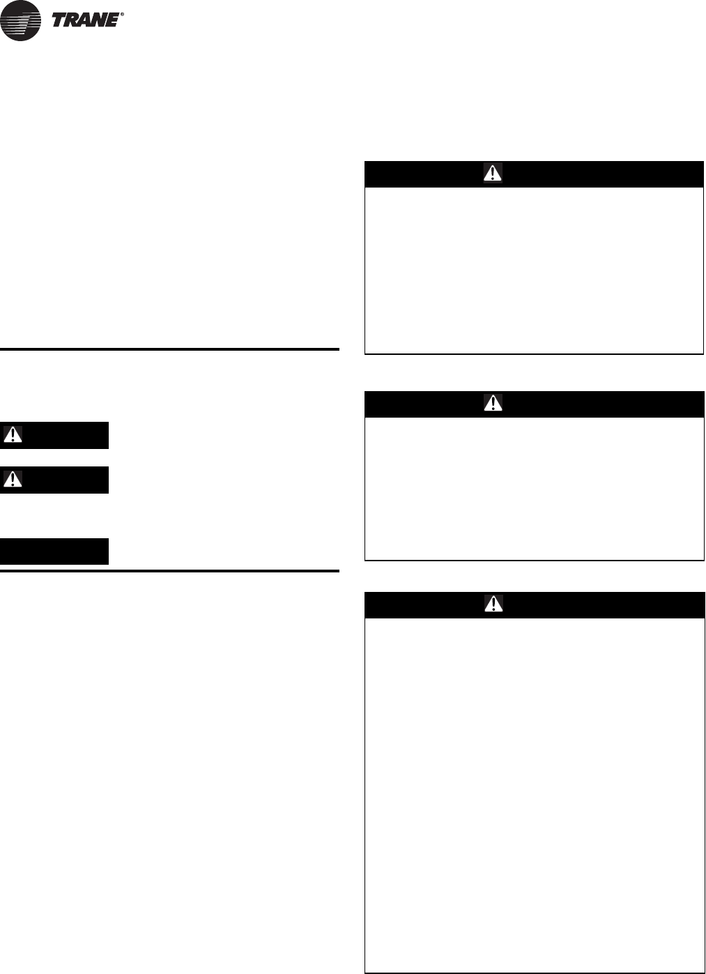
Unit Nameplate
See Figure 1. Unit nameplate includes the following:
• Unit model and size descriptor.
• Unit serial number.
• Identifies unit electrical requirements.
• Lists correct operating charges of R-134a and Oil 48.
• Lists unit test pressures
• Identifies installation, operation and maintenance and
service data literature.
• Lists drawing numbers for unit wiring diagrams.
Compressor Nameplate
Compressor nameplate includes the following:
• Compressor model number.
• Compressor serial number.
• Compressor electrical characteristics.
• Utilization Range.
• Recommended refrigerant.
Model Number Coding System
Model numbers for unit and compressors are comprised
of numbers and letter which represent equipment
features.
See “RTWD Model Number,” p. 7 and “Compressor Model
Number,” p. 8 for details.
Each position, or group of positions, in a number or letter
is used to represent a feature. For example, from the chart,
we can determine that “F” in digit 8 of unit model number
indicates unit voltage is 460/60/3.
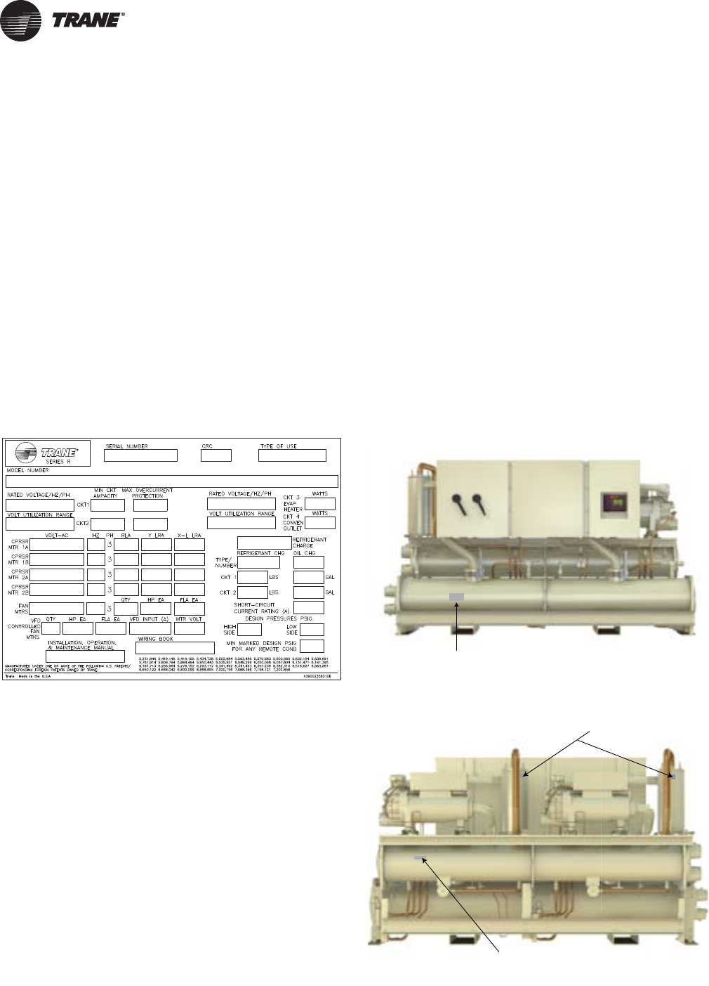
ASME Nameplate
The ASME nameplate is different for the evaporators,
condensers (RTWD only) and oil separators.The
evaporator nameplate is located on the left portion of the
shell.The insulation over the nameplate is intentionally
left unglued, for ease in viewing the nameplate.
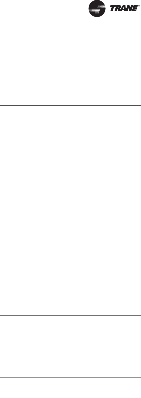
The condenser nameplate is on the backside of the
condenser below circuit 2 compressor.
Figure 1. Unit nameplate
Figure 2. Location of ASME unit nameplate - front
Figure 3. Location of ASME unit nameplates - back
%VAPORATOR
!3-% L
Evaporator ASME Nameplate
/IL3EPARATOR
!3-%NAMEPLATES
#ONDENSER
!3-%NAMEPLATES
Condenser
ASME nameplates (RTWD only)
Oil Separator
SME Nameplates
Condenser ASME Nameplate
(RTWD only)

RLC-SVX09H-EN 7
Model Number Descriptions
RTWD Model Number
Digits 1-4— Chiller Model
RTWD= Water Cooled Chiller - Series R®
RTUD= Compressor Series R®Chiller
Digits 5-7— Unit Nominal
Tonnage
060 = 60 Nominal Tons
070 = 70 Nominal Tons
080 = 80 Nominal Tons
090 = 90 Nominal Tons
100 = 100 NominalTons
110 = 110 NominalTons
120 = 120 NominalTons
130 = 130 NominalTons
140 = 140 Nominal Tons
150 = 150 NominalTons
160 = 160 NominalTons
180 = 180 NominalTons
200 = 200 NominalTons
220 = 220 Nominal Tons
250 = 250 Nominal Tons
Digit 8— Unit Voltage
A = 200/60/3
B = 230/60/3
D = 380/60/3
E = 400/50/3
F = 460/60/3
G = 575/60/3
Digit 9— Manufacturing Plant
2 = Pueblo, USA
Digits 10, 11— Design Sequence
XX = Factory Assigned
Digit 12— UnitType
1 = Standard efficiency/performance
2 = High efficiency/performance
3 = Premium efficiency/performance
Digit 13— Agency Listing
0 = No agency listing
A = UL listed to US and Canadian
safety standards
D = IBC Seismically Rated Unit
E = UL/Canadian and IBC
F = OSHPD Seismically Rated Unit
G = UL/Canadian and OSHPD
Digit 14— Pressure Vessel Code
1 = ASME pressure vessel code
3 = Chinese code-imported pressure
vessel
S = Special
Digit 15— Unit Application
A = Standard condenser
(< 95°F/35°C entering water)
B = High temperature condenser
(>95°F/35°C entering water)
C = Water-to-water heat pump
D = Remote condenser byTrane
E = Remote condenser by others
Digit 16— Pressure Relief Valve
1 = Single relief valve
2 = Dual relief valve with 3-way
isolation valve
Digit 17— Water Connection
Type
A = Grooved pipe connection
Digit 18— EvaporatorTubes
A = Internal and External enhanced
Digit 19— Number of
Evaporator Passes
2 = 2-pass evaporator
3 = 3-pass evaporator
Digit 20— Evaporator Water
Side Pressure
A = 150 psi/10.5 bar evaporator
water pressure
Digit 21— Evaporator
Application
1 = Standard cooling
2 = Low temperature
3 = Ice-making
Digit 22— CondenserTubes
X = Remote condenser
A = Enhanced fin - copper
B = Internally enhanced 90/10 CuNi
fin
Digit 23— Condenser Water
Side Pressure
0 = Remote condenser
1 = 150 psi/10.5 bar condenser water
pressure
Digit 24— Compressor Starter
Type
Y = Wye-delta closed transition
starter
X = Across-the-line starter
Digit 25— Incoming Power Line
Connection
1 = Single point power connection
2 = Double point power connection
Digit 26— Power Line
ConnectionType
A = Terminal block
B = Mechanical disconnect switch
D = Circuit breaker
E = High fault rated panel with circuit
breaker
Digit 27— Under/Over Voltage
Protection
0 = No under/over voltage
protection
1 = Under/over voltage protection
Digit 28— Unit Operator
Interface
A = Dyna-View/English
B = Dyna-View/Spanish
C = Dyna-View/Spanish-Mexico
D = Dyna-View/French
E = Dyna-View/German
F = Dyna-View/Dutch
G = Dyna-View/Italian
H = Dyna-View/Japanese
J = Dyna-View/Portuguese-Portugal
K = Dyna-View/Portuguese-Brazil
L = Dyna-View/Korean
M = Dyna-View/Thai
N = Dyna-View/Simplified Chinese
P = Dyna-View/Traditional Chinese
R = Dyna-View/Russian
T = Dyna-View/Polish
U = Dyna-View/Czech
V = Dyna-View/Hungarian
W = Dyna-View/Greek
X = Dyna-View/Romanian
Y = Dyna-View/Swedish
Digit 29— Remote Interface
(Digital Comm)
0 = No remote digital
communication
A = LonTalk/Tracer Summit™
interface
B = Time of day scheduling
4 = Unit Level BACnet
Digit 30— External Water and
Current Limit Setpoint
0 = No external water and current
limit setpoint
A = External water and current limit
setpoint 4-20 mA
B = External water and current limit
setpoint 2-10 Vdc
Digit 31— Ice Making
0 = No ice making
A = Ice making with relay
B = Ice making without relay
Digit 32— Programmable Relays
0 = No programmable relays
A = Programmable relays
Digit 33— Condenser
Refrigerant Pressure Output
Option
0 = No condenser refrigerant output
1 = Condenser water control output
2 = Condenser pressure (%HPC)
output
3 = Differential pressure output
Digit 34— Outdoor AirTemp
Sensor
0 = No outdoor air temp sensor
A = Outdoor air temp sensor - CWR
(low ambient

8 RLC-SVX09H-EN
Digit 35— Condenser Leaving
Hot Water Temp Control
0 = No condenser leaving hot water
temperature control
1 = Condenser leaving hot water
temperature control
Digit 36— Power Meter
0 = No power meter
P = Power meter
Digit 37— Motor Current Analog
Output (%RLA)
0 = No motor current analog output
1 = Motor current analog output
Digit 38— A/C Fan Control
0 = No fan controls (RTWD)
A = Fan control by others
B = Integral fan controls
Digit 39— Low Ambient Fan
ControlType
0 = No low ambient fan control type
(RTWD)
1 = Two speed fan
2 = Variable speed fan with analog
interface
3 = Variable speed fan with PWM
interface
Digit 40— Installation
Accessories
0 = No installation accessories
(shipped with elastomeric pad)
A = Elastomeric (neoprene) isolators
B = Flanged water connection kit
C = Isolators and flanged water
connection kit
Digit 41— Flow Switch
0 = No flow switch
1 = 150 psi NEMA 1; flow switch x 1
2 = 150 psi NEMA 1; flow switch x 2
3 = 150 psi NEMA 4; flow switch x 1
4 = 150 psi NEMA 4; flow switch x 2
7 = Factory installed proof of
evaporator and condenser
8 = Factory installed proof of
evaporator
9 = Factory installed proof of
condenser
Digit 42— 2-Way Water
Regulating Valve
0 = No 2-way water regulating valve
A = 3” 150psi/88.9mm 10.5 bar 115V
B = 3” 150psi/88.9mm 10.5 bar 220V
C = 3” 150psi/114.3mm 10.5bar 115V
D = 3” 150psi/114.3mm 10.5bar 220V
Digit 43— Sound Reduction
Package
0 = No sound reduction package
A = Sound reduction - factory
installed
Digit 44— Insulation
0 = No insulation
1 = Factory insulation, all cold parts
2 = Insulation for high humidity
Digit 45— Factory Charge
0 = Full factory refrigerant charge
(R-134a)
1 = Nitrogen charge
Digit 46— Base Rail Forklifting
0 = No base rail forklifting
B = Base rail forklifting
Digit 47— Label and Literature
Language
B = Spanish
D = English
E = French
G = Chinese - traditional
Digit 48— Special
0 = None
A = Special
Digits 49-55
0 = None (not used)
Digit 56— Shipping Package
0 = No skid (standard)
1 = Skid
2 = Shrink wrap
3 = Skid and shrink wrap
Digits 57-58
x = Factory assigned
Digit 59— PerformanceTest
Options
0 = No performance test
C = 1 point test with report
D = 2 point test with report
E = 3 point test with report
F = 4 point test with report
G = Witness 1 point test with report
H = Witness 2 point test with report
J = Witness 3 point test with report
K = Witness 4 point test with report
Digit 60— Evaporator FluidType
0 = Water
1 = Calcium chloride
2 = Ethylene glycol
3 = Propylene glycol
4 = Methanol
Compressor Model
Number
Digits 1-4— Compressor Model
CHHN= Positive displacement,
helical rotary (twin screw)
hermetic compressor
Digits 5-7— Size
0N2= 120Tons
0N1= 100Tons
0M2= 85Tons
0M1= 70Tons
0L2 = 60Tons
0L1 = 50Tons
0K2= 40Tons
0K1= 35Tons
Digit 8— Unit Voltage
A = 200/60/3
R = 220/50/3
C = 230/60/3
D = 380/60/3
H = 575/60/3
T = 460/60/3 or 400/50/3
Digit 9— Internal Relief
K = 450 psid
Digits 10, 11— Design Sequence
XX = Factory Assigned
Digit 12— Capacity Limit
N = Standard capacity controls
(no capacity limit
Digits 13-15— Motor kW Rating
134 = 134 kW (N2/60Hz)
112 = 112 kW (N2/50Hz)
092 = 092 kW (M2/60Hz)
077 = 077 kW (M2/50Hz)
069 = 069 kW (L2/60Hz)
058 = 058 kW (L2/50Hz)
050 = 050 kW (K2/60Hz)
041 = 041 kW (K2/50Hz)
112 = 112 kW (N1/60Hz)
093 = 093 kW (N1/50Hz)
077 = 077 kW (M1/60Hz)
065 = 065 kW (M1/50Hz)
057 = 057 kW (L1/60Hz)
048 = 048 kW (L1/60Hz)
043 = 043 kW (K1/60Hz)
036 = 036 kW (K1/60Hz)
Digit 16— Volume Ratio
A = High volume ratio
N = Low volume ratio
RLC-SVX09H-EN 9
General Information
Unit Description
The RTWD units are helical-rotary type, water-cooled,
liquid chillers, designed for installation indoors.The units
have 2 independent refrigerant circuits, with one
compressor per circuit.The RTWD units are packaged with
an evaporator and condenser.
Note: Each RTWD unit is a completely assembled,
hermetic package that is factory-piped, wired, leak-
tested, dehydrated, charged and tested for proper
control operations prior to shipment.The chilled
water inlet and outlet openings are covered for
shipment.
The RTWD series featuresTrane's exclusive Adaptive
Control logic with CH530 controls. It monitors the control
variables that govern the operation of the chiller unit.
Adaptive Control logic can correct these variables, when
necessary, to optimize operational efficiencies, avoid
chiller shutdown, and keep producing chilled water.
Compressor unloaders are solenoid actuated. Each
refrigerant circuit is provided with filter, sight glass,
electronic expansion valve, and charging valves on the
RTWD.
The evaporator and condenser are manufactured in
accordance with ASME standards.The evaporator is fully
insulated. Both evaporator and condenser are equipped
with water drain and vent connections.
The RTUD units are helical-rotary type compressor
chillers, designed to be most effective when used with the
Levitor II air-cooled condenser.The RTUD unit consists of
an evaporator, two helical rotary compressors (one per
circuit), oil separators, oil coolers, liquid line service
valves, sightglasses, electronic expansion valves and
filter. The discharge line leaving the oil separator and
liquid line entering the filters are capped and brazed. The
unit ships with a full charge of oil and a nitrogen holding
charge.
Accessory/Options Information
Check all the accessories and loose parts which are
shipped with the unit against the original order. Included
in these items will be water vessel drain plugs, rigging
diagrams, electrical diagrams, and service literature,
which are placed inside the control panel and/or starter
panel for shipment. Also check for optional components,
such as flow switches and isolators.
General Data
Table 1. General Data - RTWD - 60 Hz - premium
efficiency
Size 150 160 180 200
Compressor L2/M1 M1/M1 M1/M2 M2/M2
Quantity 2 2 2 2
Nominal Size 65/70 70/70 70/85 85/85
Evaporator
2 Pass Arrangement
Water Conn.
Size
NPS 6 6 6 6
mm 150 150 150 150
Water Storage (gal) 27.8 27.8 29.3 31.3
(L) 105.1 105.1 110.9 118.3
Minimum Flow (gpm) 174 174 186 202
(L/s) 11.0 11.0 11.8 12.7
Maximum
Flow
(gpm) 639 639 683 739
(L/s) 40.3 40.3 43.1 46.7
3 Pass Arrangement
Water Conn.
Size
NPS 4 4 4 4
mm 100 100 100 100
Water Storage (gal) 27.1 27.1 28.6 30.6
(L) 102.4 102.4 108.3 115.7
Minimum Flow (gpm) 116 116 124 134
(L/s) 7.3 7.3 7.8 8.5
Maximum
Flow
(gpm) 426 426 456 493
(L/s) 26.9 26.9 28.7 31.1
Condenser
Water Conn.
Size
NPS 6 6 6 6
mm 150 150 150 150
Water Storage (gal) 30.0 30.0 32.9 32.9
(L) 113.4 113.4 124.4 124.4
Minimum Flow (gpm) 206 206 231 231
(L/s) 13 13 14.6 14.6
Maximum
Flow
(gpm) 755 755 845 845
(L/s) 47.6 47.6 53.3 53.3
General Unit
Refrig Type R-134a R-134a R-134a R-134a
# Refrig
Circuits 2222
Refrigerant
Charge
(lb) 174.2/
183.0
183.0/
183.0
180.8/
180.8
178.6/
178.6
(kg) 79/83 83/83 82/82 81/81
Oil Charge (qts) 10.5/12.4 12.4/12.4 12.4/12.4 12.4/12.4
(L) 9.9/11.7 11.7/11.7 11.7/11.7 11.7/11.7
Notes:
1. Data containing information on two circuits is shown as circuit 1/
circuit 2.
2. Flow limits are for water only.

General Information
10 RLC-SVX09H-EN
Table 2. General Data - RTWD - 60 Hz - standard efficiency
Size 80 90 100 110 120 130 140
Compressor K1/K1 K2/K2 K2/L1 L1/L1 L1/L2 L2/L2 L2/M1
Quantity 2 2 2 2222
Nominal Size 40/40 45/45 45/55 55/55 55/65 65/65 65/70
Evaporator
2 Pass Arrangement
Water Conn. Size NPS 4 4 4 4555
mm 100 100 100 100 125 125 125
Water Storage (gal) 11.2 11.2 12.6 14 15.2 16.2 17.7
(L) 42.2 42.2 47.6 53.0 57.4 61.5 66.8
Minimum Flow (gpm) 77 77 89 101 101 110 122
(L/s) 4.9 4.9 5.6 6.4 6.4 6.9 7.7
Maximum Flow (gpm) 281 281 325 368 368 400 444
(L/s) 17.7 17.7 20.5 23.2 23.2 25.2 28
3 Pass Arrangement
Water Conn. Size NPS 3 3 3 3444
mm 80 80 80 80 100 100 100
Water Storage (gal) 11.2 11.2 12.6 14 15.2 16.2 17.7
(L) 42.2 42.2 47.6 53.0 57.4 61.5 66.8
Minimum Flow (gpm) 52 52 59 67 67 73 81
(L/s) 3.3 3.3 3.8 4.3 4.3 4.6 5.1
Maximum Flow (gpm) 187 187 216 244 244 266 295
(L/s) 11.8 11.8 13.6 15.4 15.4 16.8 18.6
Condenser
Water Conn. Size NPS 5 5 5 5555
mm 125 125 125 125 125 125 125
Water Storage (gal) 12.4 14.2 16.0 16.9 18.5 18.5 20.9
(L) 46.8 53.6 60.4 63.8 70.1 70.1 79.2
Minimum Flow (gpm) 83 99 115 124 135 135 156
(L/s) 5.2 6.3 7.3 7.8 8.5 8.5 9.9
Maximum Flow (gpm) 301 361 421 451 491 491 572
(L/s) 18.9 22.7 26.5 28.4 31.0 31.0 36.0
General Unit
Refrigerant Type R-134a R-134a R-134a R-134a R-134a R-134a R-134a
# Refrig Circuits 2 2 2 2222
Refrigerant Charge (lb) 114.6/114.6 114.6/114.6 112.4/114.6 112.4/112.4 132.3/132.3 130.1/130.1 127.9/132.3
(kg) 52/52 52/52 51/52 51/51 60/60 59/59 58/60
Oil Charge (quarts) 7.2/7.2 7.2/7.2 7.2/10.5 10.5/10.5 10.5/10.5 10.5/10.5 10.5/10.5
(L) 6.8/6.8 6.8/6.8 6.8/9.9 9.9/9.9 9.9/9.9 9.9/9.9 9.9/9.9
Notes:
1. Data containing information on two circuits is shown as circuit 1/circuit 2.
2. Flow limits are for water only.

General Information
RLC-SVX09H-EN 11
Table 3. General Data - RTWD - 60 Hz - high efficiency
Size 80 90 100 110 120 130 150 160 180 200 220 250
Compressor K1/K1 K2/K2 K2/L1 L1/L1 L1/L2 L2/L2 L2/M1 M1/M1 M1/M2 M2/M2 M2/N1 N1/N1
Quantity 222222222222
Nominal Size 40/40 45/45 45/55 55/55 55/65 65/65 65/70 70/70 70/85 85/85 85/100 100/100
Evaporator
2 Pass Arrangement
Water Conn.
Size
NPS445555555566
mm 100 100 100 125 125 125 125 125 125 125 150 150
Water Storage (gal) 9.8 11.9 12.8 15.3 16.4 17.3 19.2 20.3 22.3 24.2 28.6 31.8
(L) 37.0 45.2 48.3 57.9 62.3 65.4 72.6 77.0 84.5 91. 108.3 120.3
Minimum Flow (gpm) 72 92 100 112 123 130 141 151 170 186 211 240
(L/s) 4.6 5.8 6.3 7.1 7.8 8.2 8.9 9.5 10.7 11.8 13.3 15.1
Maximum Flow (gpm) 263 336 364 409 448 476 515 555 622 683 773 879
(L/s) 16.6 21.2 22.9 25.8 28.2 30.0 32.5 35.0 39.2 43.1 48.8 55.5
3 Pass Arrangement
Water Conn.
Size NPS334444444444
mm 80 80 80 100 100 100 100 100 100 100 100 100
Water Storage (gal) 9.8 11.9 12.8 15.3 16.4 17.3 18.8 20.0 22.0 23.8 27.9 31.0
(L) 37.0 45.2 48.3 57.9 62.3 65.4 71.2 75.6 83.2 90.1 105.5 117.5
Minimum Flow (gpm) 48 61 67 75 82 87 94 101 113 124 141 160
(L/s) 3.1 3.9 4.2 4.7 5.2 5.5 5.9 6.4 7.1 7.8 8.9 10.1
Maximum Flow (gpm) 175 223 242 271 298 316 344 370 415 456 515 586
(L/s) 11.0 14.1 15.2 17.1 18.8 19.9 21.7 23.3 26.2 28.7 32.5 37.0
Condenser
Water Conn.
Size NPS555555666666
mm 125 125 125 125 125 125 150 150 150 150 150 150
Water Storage (gal) 11.9 12.7 14.9 16.6 17.2 18.0 21.6 22.9 24.6 26.2 31.1 39.2
(L) 45.1 48.1 56.3 62.7 65.2 68.3 81.7 86.8 93.0 99.2 117.8 148.3
Minimum Flow (gpm) 87 95 117 130 136 145 159 173 189 206 244 325
(L/s) 5.5 6.0 7.4 8.2 8.6 9.1 10.1 10.9 12.0 13.0 15.4 20.5
Maximum Flow (gpm) 317 347 427 473 498 528 584 634 695 755 896 1193
(L/s) 20.0 21.9 26.9 29.8 31.4 33.3 36.8 40.0 43.8 47.6 56.5 75.3
General Unit
Refrigerant Type R-134a R-134a R-134a R-134a R-134a R-134a R-134a R-134a R-134a R-134a R-134a R-134a
# Refrig Circuits 222222222222
Refrigerant
Charge (lb) 99.2/
99.2 97/97 123.5/
125.7
123.5/
123.5
121.3/
121.3
119/
119
134.5/
143.3
141.1/
141.1
138.9/
138.9
136.7/
136.7
178.6/
185.2
180.8/
180.8
(kg) 45/45 44/44 56/57 56/56 55/55 54/54 61/65 64/64 63/63 62/62 81/84 82/82
Oil Charge (qt) 7.2/7.2 7.2/7.2 7.2/10.5 10.5/
10.5
10.5/
10.5
10.5/
10.5
10.5/
12.4
12.4/
12.4
12.4/
12.4
12.4/
12.4
12.4/
12.4
12.4/
12.4
(L) 6.8/6.8 6.8/6.8 6.8/9.9 9.9/9.9 9.9/9.9 9.9/9.9 9.9/11.7 11.7/
11.7
11.7/
11.7
11.7/
11.7
11.7/
11.7
11.7/
11.7
Notes:
1. Data containing information on two circuits is shown as circuit 1/circuit 2.
2. 2. Flow limits are for water only.

General Information
12 RLC-SVX09H-EN
Table 4. General Data – RTUD – 60 Hz
Size 80 90 100 110 120 130 150 160 180 200 220 250
Compressor K1/K1 K2/K2 K2/L1 L1/L1 L1/L2 L2/L2 L2/M1 M1/M1 M1/M2 M2/M2 M2/N1 N1/N1
Quantity 222222222222
Nominal Size 40/40 45/45 45/55 55/55 55/65 65/65 65/70 70/70 70/85 85/85 85/100 100/100
Evaporator
2 Pass Arrangement
Water Conn.
Size NPS444555555555
mm 100 100 100 125 125 125 125 125 125 125 125 125
Water Storage (gal) 9.8 10.6 12.0 14.0 15.3 15.3 16.5 19.2 19.2 20.3 22.3 24.2
(L) 37.1 40.2 45.3 53.0 58.0 58.0 62.4 72.6 72.6 77.0 84.5 91.5
Minimum Flow (gpm) 77 79 91 99 111 111 122 140 140 151 169 186
(L/s) 4.9 5.0 5.7 6.2 7.0 7.0 7.7 8.8 8.8 9.5 10.7 11.7
Maximum Flow (gpm) 281 291 335 363 408 408 447 514 514 553 620 681
(L/s) 17.7 21.2 23.0 25.8 28.3 30.0 28.2 32.4 32.4 34.9 39.1 43.0
3 Pass Arrangement
Water Conn.
Size NPS333444444444
mm 80 80 80 100 100 100 100 100 100 100 100 100
Water Storage (gal) 9.5 10.3 11.6 13.7 15.1 15.1 16.1 18.8 18.8 20.0 22.0 23.8
(L) 36.0 39.0 44.0 52.0 57.0 57.0 61.0 71.2 71.2 75.6 83.2 90.1
Minimum Flow (gpm) 51 53 61 66 74 74 81 94 94 100 112 124
(L/s) 3.2 3.3 3.8 4.2 4.7 4.7 5.1 5.9 5.9 6.3 7.1 7.8
Maximum Flow (gpm) 187 194 224 242 272 272 298 343 343 368 413 454
(L/s) 11.8 12.2 14.1 15.3 17.2 17.2 18.8 21.6 21.6 23.2 26.1 28.6
General Unit
Refrigerant Type R-134a R-134a R-134a R-134a R-134a R-134a R-134a R-134a R-134a R-134a R-134a R-134a
# Refrig Circuits 222222222222
Refrigerant
Charge (lb) 50/50 49/49 47/47 65/65 64/64 64/64 62/62 66/66 66/66 66/66 63/63 61/61
(kg) 22.7/
22.7
22.2/
22.2
21.3/
21.3
29.5/
29.5
29.0/
29.0
29.0/
29.0
28.1/
28.1
29.9/
29.9
29.9/
29.9
29.9/
29.9
28.6/
28.6
27.7/
27.7
Oil Charge (qt) 7.2/7.2 7.2/7.2 7.2/10.5 10.5/
10.5
10.5/
10.5
10.5/
10.5
10.5/
10.5
10.5/
10.5
10.5/
12.4
12.4/
12.4
12.4/
12.4
12.4/
12.4
(L) 6.8/6.8 6.8/6.8 6.8/9.9 9.9/9.9 9.9/9.9 9.9/9.9 9.9/9.9 9.9/9.9 9.9/11.7 11.7/
11.7
11.7/
11.7
11.7/
11.7
Discharge
Connection
Diameter
(inch) 2.1 2.1 2.1 2.6 2.6 2.6 2.6 3.1 3.1 3.1 3.1 3.1
Liquid
Connection
Diameter
(inch) 1.1 1.1 1.1 1.4 1.4 1.4 1.4 1.4 1.4 1.4 1.4 1.6
Notes:
1. Data containing information on two circuits is shown as circuit 1/circuit 2.
2. 2. Flow limits are for water only.
General Information
RLC-SVX09H-EN 13
Table 5. General Data – Condenser by Trane – 60 Hz
Size 80 90 100 110 120 130 150 160 180 200 220 250
Condenser
Condenser
Quantity 111111222222
Fins/Inch 12 10 10 12 8 10 8/12 12/12 12/8 8/8 8/10 10/10
Coil Length (in) 162 216 216 216 270 270 162/162 162/162 162/216 216/216 216/216 216/216
(mm) 4115 5486 5486 5486 6858 6858 4115/
4115
4115/
4115
4115/
5486
5486/
5486
5486/
5486
5486/
5486
Coil Width (in) 85 85 85 85 85 85 85/85 85/85 85/85 85/85 85/85 85/85
(mm) 2159 2159 2159 2159 2159 2159 2159/
2159
2159/
2159
2159/
2159
2159/
2159
2159/
2159
2159/
2159
Number of Rows 3 3 4 4 4 4 3/3 3/3 3/3 3/3 3/4 4/4
Condenser Fans
Fan Quantity 6 8 8 8 10 10 6/6 6/6 6/8 8/8 8/8 8/8
Diameter (in) 30 30 30 30 30 30 30 30 30 30 30 30
(mm) 762 762 762 762 762 762 762 762 762 762 762 762
Nominal RPM (rpm) 850 850 850 850 850 850 850 850 850 850 850 850
Air Flow (cfm) 56,646 78,280 72,248 69,280 94,490 90,310 60,954/
56,646
56,646/
56,646
56,646/
81,272
81,272/
81,272
81,272/
72,248
72,248/
72,248
Tip Speed (fpm) 6676 6676 6676 6676 6676 6676 6676 6676 6676 6676 6676 6676
Motor HP (hp) 1.5 1.5 1.5 1.5 1.5 1.5 1.5 1.5 1.5 1.5 1.5 1.5
General
Recommended
Refrigerant
Charge¹
(lbs) 55/55 92/92 97/97 97/97 98/98 122/122 109/109 109/109 109/146 146/146 146/195 195/195
(kg) 24.9/
24.9
41.7/
41.7
44.0/
44.0
44.0/
44.0
44.5/
44.5
55.3/
55.3
49.4/
49.4
49.4/
49.4
49.4/
66.2
66.2/
66.2
66.2/
88.5
88.5/
88.5
Discharge/Liquid
Connection
Diameters
(in) 2.1 2.1 2.1 2.1 2.1 2.1 2.125 2.125 2.125 2.125 2.125 2.125
(mm) 54 54 54 54 54 54 54 54 54 54 54 54
Notes:
1. Data containing information on two condensers is shown as cond 1/cond 2.
2. Data containing information on two circuits is shown as circuit 1/circuit 2.
3. Condenser is not factory charged, the refrigerant must be purchased and charged in
the field.

General Information
14 RLC-SVX09H-EN
Table 6. General Data - RTWD 50 Hz - standard efficiency
Size 70 80 90 100 110 120 130 140 150
Compressor K2/K2 K2/L1 L1/L1 L1/L2 L2/L2 L2/M1 M1/M1 M1/M2 M2/M2
Quantity 2 2 2 222222
Nominal Size 45/45 45/55 55/55 55/65 65/65 65/70 70/70 70/85 85/85
Evaporator
2 Pass Arrangement
Water Conn. Size NPS 4 4 4 445555
mm 100 100 100 100 100 125 125 125 125
Water Storage (gal) 11.2 12.6 14.0 14.0 14.0 16.2 17.7 17.7 19.1
(L) 42.2 47.6 53.0 53.0 53.0 61.5 66.8 66.8 72.2
Minimum Flow (gpm) 77 89 101 101 101 110 122 122 133
(L/s) 4.9 5.6 6.3 6.3 6.3 6.9 7.7 7.7 8.4
Maximum Flow (gpm) 281 324 368 368 368 400 444 444 487
(L/s) 17.7 20.5 23.2 23.2 23.2 25.2 28.0 28.0 30.7
3 Pass Arrangement
Water Conn. Size NPS 3 3 3 334444
mm 80 80 80 80 80 100 100 100 100
Water Storage (gal) 11.2 12.6 14.0 14.0 14.0 16.2 17.7 17.7 19.1
(L) 42.2 47.6 53.0 53.0 53.0 61.5 66.8 66.8 72.2
Minimum Flow (gpm) 52 59 67 67 67 73 81 81 89
(L/s) 3.3 3.8 4.3 4.3 4.3 4.6 5.1 5.1 5.6
Maximum Flow (gpm) 187 216 244 244 244 266 295 295 324
(L/s) 11.8 13.6 15.4 15.4 15.4 16.8 18.6 18.6 20.4
Condenser
Water Conn. Size NPS 5 5 5 555555
mm 125 125 125 125 125 125 125 125 125
Water Storage (gal) 12.4 14.2 16.0 16.9 16.9 18.5 20.9 20.9 22.4
(L) 46.8 53.6 60.4 63.8 63.8 70.1 79.2 79.2 84.8
Minimum Flow (gpm) 83 99 115 124 124 135 156 156 170
(L/s) 5.2 6.3 7.3 7.8 7.8 8.5 9.9 9.9 10.8
Maximum Flow (gpm) 301 361 421 451 451 491 571 571 622
(L/s) 18.9 22.7 26.5 28.4 28.4 31.0 36.0 36.0 39.2
General Unit
Refrigerant Type R134a R134a R134a R134a R134a R134a R134a R134a R134a
# Refrig Circuits 2 2 2 222222
Refrigerant Charge (lb) 114.6/
114.6
112.4/
112.4
110.2/
110.2
110.2/
112.4
112.4/
112.4
130.1/
130.1
127.9/
127.9
127.9/
132.3
130.1/
130.1
(kg) 52/52 51/51 50/50 50/51 51/51 59/59 58/58 58/60 59/59
Oil Charge (quarts) 7.2/7.2 7.2/7.2 7.2/7.2 7.2/10.5 10.5/10.5 10.5/10.5 10.5/10.5 10.5/10.5 10.5/10.5
(L) 6.8/6.8 6.8/6.8 6.8/6.8 6.8/9.9 9.9/9.9 9.9/9.9 9.9/9.9 9.9/9.9 9.9/9.9
Notes:
1. Data containing information on two circuits is shown as circuit 1/circuit 2.
2. Flow limits are for water only.

General Information
RLC-SVX09H-EN 15
Table 7. General Data - RTWD 50 Hz - high efficiency
Size 60 70 80 90 100 110 120 130 140 160 180 200 220 250
Compressor K1/K1 K2/K2 K2/L1 L1/L1 L1/L2 L2/L2 L2/M1 M1/M1 M1/M2 M2/M2 M2/N1 N1/N1 N1/N2 N2/N2
Quantity 22222222222222
Nominal Size 40/40 45/45 45/55 55/55 55/65 65/65 65/70 70/70 70/85 85/85 85/100 100/
100
100/
120
120/
120
Evaporator
2 Pass Arrangement
Water
Conn. Size
NPS44455555555666
mm 100 100 100 125 125 125 125 125 125 125 125 150 150 150
Water
Storage
(gal) 9.8 10.6 11.9 15.3 15.3 16.4 17.3 19.2 20.3 22.3 24.2 28.6 29.9 31.8
(L) 37.0 40.2 45.2 57.9 57.9 62.3 65.4 72.6 77.0 84.5 91.5 108.3 113.3 120.3
Minimum
Flow
(gpm) 72 80 92 112 112 123 130 141 151 170 186 211 223 240
(L/s) 4.6 5.1 5.8 7.1 7.1 7.8 8.2 8.9 9.5 10.7 11.8 13.3 14.1 15.1
Maximum
Flow
(gpm) 263 291 336 408 408 448 476 515 555 622 683 773 818 879
(L/s) 16.6 18.3 21.2 25.8 25.8 28.2 30.0 32.5 35.0 39.2 43.1 48.8 51.6 55.5
3 Pass Arrangement
Water
Conn. Size
NPS33344444444444
mm 80 80 80 100 100 100 100 100 100 100 100 100 100 100
Water
Storage
(gal) 9.8 10.6 11.9 15.3 15.3 16.4 17.3 18.8 20.0 22.0 23.8 27.9 29.2 31.0
(L) 37.0 40.2 45.2 57.9 57.9 62.3 65.4 71.2 75.6 83.2 90.1 105.5 110.5 117.5
Minimum
Flow
(gpm) 48 53 61 75 75 82 86 94 101 113 124 141 149 160
(L/s) 3.1 3.4 3.9 4.7 4.7 5.2 5.5 5.9 6.4 7.1 7.8 8.9 9.4 10.1
Maximum
Flow
(gpm) 175 193 223 271 271 298 316 344 370 415 456 515 545 586
(L/s) 11.0 12.2 14.1 17.1 17.1 18.8 19.9 21.7 23.3 26.2 28.7 32.5 34.4 37.0
Condenser
Water
Conn. Size
NPS55555556666666
mm 125 125 125 125 125 125 125 150 150 150 150 150 150 150
Water
Storage
(gal) 11.9 11.9 13.8 15.3 16.6 16.6 18.0 21.6 22.9 24.6 26.2 31.1 31.1 35.2
(L) 45.1 45.1 52.2 58.1 62.7 62.7 68.3 81.7 86.8 93.0 99.2 117.8 117.8 133.3
Minimum
Flow
(gpm) 87 87 106 117 130 130 145 159 173 189 206 244 244 286
(L/s) 5.5 5.5 6.7 7.4 8.2 8.2 9.1 10.0 10.9 11.9 13.0 15.4 15.4 18.0
Maximum
Flow
(gpm) 317 317 387 427 473 473 528 584 634 695 755 896 896 1047
(L/s) 20.0 20.0 24.4 26.9 29.8 29.8 33.3 36.8 40.0 43.8 47.6 56.5 56.5 66.1
General Unit
Refrig Type R-134a R-134a R-134a R-134a R-134a R-134a R134a R-134a R-134a R-134a R134a R-134a R-134a R-134a
# Refrig
Circuits 22222222222222
Refrigerant
Charge
(lb) 99.2/
99.2
99.2/
99.2 97/97 121.3/
121.3
121.3/
123.5
121.3/
121.3
119/
119
134.5/
134.5
132.3/
136.7
134.5/
134.5
132.3/
136.7
178.6/
178.6
176.4/
183.0
180.8/
180.8
(kg) 45/45 45/45 44/44 55/55 55/56 55/55 54/54 61/61 60/62 61/61 60/62 81/81 80/83 82/82
Oil Charge
(qts) 7.2/
7.2
7.2/
7.2
7.2/
7.2
7.2/
7.2
7.2/
10.5
10.5/
10.5
10.5/
10.5
10.5/
10.5
10.5/
10.5
10.5/
10.5
10.5/
12.4
12.4/
12.4
12.4/
12.4
12.4/
12.4
(L) 6.8/
6.8
6.8/
6.8
6.8/
6.8
6.8/
6.8
6.8/
9.9
9.9/
9.9
9.9/
9.9
9.9/
9.9
9.9/
9.9
9.9/
9.9
9.9/
11.7
11.7/
11.7
11.7/
11.7
11.7/
11.7
Notes:
1. Data containing information on two circuits is shown as circuit 1/circuit 2.
2. Flow limits are for water only.

General Information
16 RLC-SVX09H-EN
Table 8. General Data - RTWD 50 Hz - premium efficiency
Size 160 180 200
Compressor M2/M2 M2/N1 N1/N1
Quantity 2 2 2
Nominal Size 85/85 85/100 100/100
Evaporator
2 Pass Arrangement
Water Conn. Size NPS 6 6 6
mm 150 150 150
Water Storage (gal) 29.3 31.3 31.8
(L) 110.9 118.3 120.3
Minimum Flow (gpm) 186 202 240
(L/s) 11.8 12.7 15.1
Maximum Flow (gpm) 683 739 879
(L/s) 43.1 46.7 55.5
3 Pass Arrangement
Water Conn. Size NPS 4 4 4
mm 100 100 100
Water Storage (gal) 28.6 30.6 31.0
(L) 108.3 115.7 117.5
Minimum Flow (gpm) 124 134 160
(L/s) 7.8 8.5 10.1
Maximum Flow (gpm) 456 493 586
(L/s) 28.7 31.1 37.0
Condenser
Water Conn. Size NPS 6 6 6
mm 150 150 150
Water Storage (gal) 30.0 34.5 39.2
(L) 113.4 130.6 148.3
Minimum Flow (gpm) 206 244 325
(L/s) 13.0 15.4 20.5
Maximum Flow (gpm) 755 896 1193
(L/s) 47.6 56.5 75.3
General Unit
Refrigerant Type R-134a R-134a R-134a
# Refrig Circuits 2 2 2
Refrigerant Charge (lb) 176.4/176.4 176.6/178.6 176.4/174.2
(kg) 80/80 79/81 80/79
Oil Charge (qts) 10.5/10.5 10.5/12.4 12.4/12.4
(L) 9.9/9.9 9.9/11.7 11.7/11.7
1. Data containing information on two circuits is shown as circuit 1/circuit 2.
2. Flow limits are for water only.
RLC-SVX09H-EN 17
Pre-Installation
Inspection Checklist
When the unit is delivered, verify that it is the correct unit
and that it is properly equipped. Compare the information
which appears on the unit nameplate with the ordering
and submittal information. See “Model Number
Descriptions,” p. 7.
Inspect all exterior components for visible damage. Report
any apparent damage or material shortage to the carrier
and make a “unit damage” notation on the carrier's
delivery receipt. Specify the extent and type of damage
found and notify the appropriateTrane Sales Office.
Important: Do not proceed with installation of a
damaged unit without sales office approval.
To protect against loss due to damage incurred in transit,
complete the following checklist upon receipt of the unit.
• Inspect the individual pieces of the shipment before
accepting the unit. Check for obvious damage to the
unit or packing material.
• Inspect the unit for concealed damage as soon as
possible after delivery and before it is stored.
Concealed damage must be reported within 15 days.
• If concealed damage is discovered, stop unpacking the
shipment. Do not remove damaged material from the
receiving location.Take photos of the damage, if
possible.The owner must provide reasonable
evidence that the damage did not occur after delivery.
• Notify the carrier's terminal of the damage
immediately, by phone and by mail. Request an
immediate, joint inspection of the damage with the
carrier and the consignee.
• Notify theTrane sales representative and arrange for
repair. Do not repair the unit, however, until damage is
inspected by the carrier's representative.
Unit Storage
If the chiller is to be stored for more than one month prior
to installation, observe the following precautions:
• Do not remove the protective coverings from the
electrical panel.
• Store the chiller in a dry, vibration-free, secure area.
• At least every three months, attach a gauge and
manually check the pressure in the refrigerant circuit.
If the refrigerant pressure is below 71 psig at 70 F (or 46
psig at 50 F), call a qualified service organization and
the appropriateTrane sales office.
Note: Pressure will be approximately 20 psig if shipped
with the optional nitrogen charge.
Installation requirements and
Contractor responsibilities
A list of the contractor responsibilities typically associated
with the unit installation process is provided in Table 9.
Note: Unit Start-up must be completed by a qualified
Trane service technician.
Table 9. Installation requirements
Type of
Rqmt
Trane Supplied
Field Supplied
Field InstalledTrane Installed
Field
Installed
Foundation • Meet foundation
requirements
Rigging • Safety chains
Clevis connectors
Lifting beam
Isolation • Isolation
pads or
neoprene
isolators
(opt)
• Isolation pads or neoprene
isolators (optional)
Electrical • Circuit
breakers or
fusible
disconnects
(optional)
• Unit mounted
starter
• Flow
switches
(may be
field
supplied)
• Water
regulating
valve
(optional)
• Circuit breakers or fusible
disconnects (opt)
• Electrical connections to unit
mounted starter (opt)
• Electrical connections to
remote mounted starter
(opt)
• Wiring sizes per submittal
and NEC
• Terminal lugs
• Ground connection(s)
• BAS wiring (opt)
• Control voltage wiring
• Chilled water pump
contactor and wiring
including interlock
• Condenser water pump
contactor and wiring
including interlock
• Option relays and wiring
Water
piping
• Flow
switches
(optional)
• Flow
switches
(may be
field
supplied)
• Water
regulating
valve
(optional)
• Taps for thermometers and
gauges
• Thermometers
• Strainers (as required)
• Water flow pressure gauges
• Isolation and balancing
valves in water piping
• Vents and drain on waterbox
valves
• Pressure relief valves (for
waterboxes as required)
Relief • Single relief
valve
• Dual relief
valves (opt)
• Vent line and flexible
connector and vent line from
relief valve to atmosphere
Insulation • Insulation
• High humidity
insulation (opt)
• Insulation
Water
Piping
Connection
Componen
ts
• Grooved pipe
• Grooved pipe
to flanged
connection
(opt)
Other
Materials
• R-134a refrigerant (1 lb.
max per machine as needed)
• Dry nitrogen (20 psig max
per machine as needed)
18 RLC-SVX09H-EN
Unit Dimensions/Weights
Service Clearances and Dimension
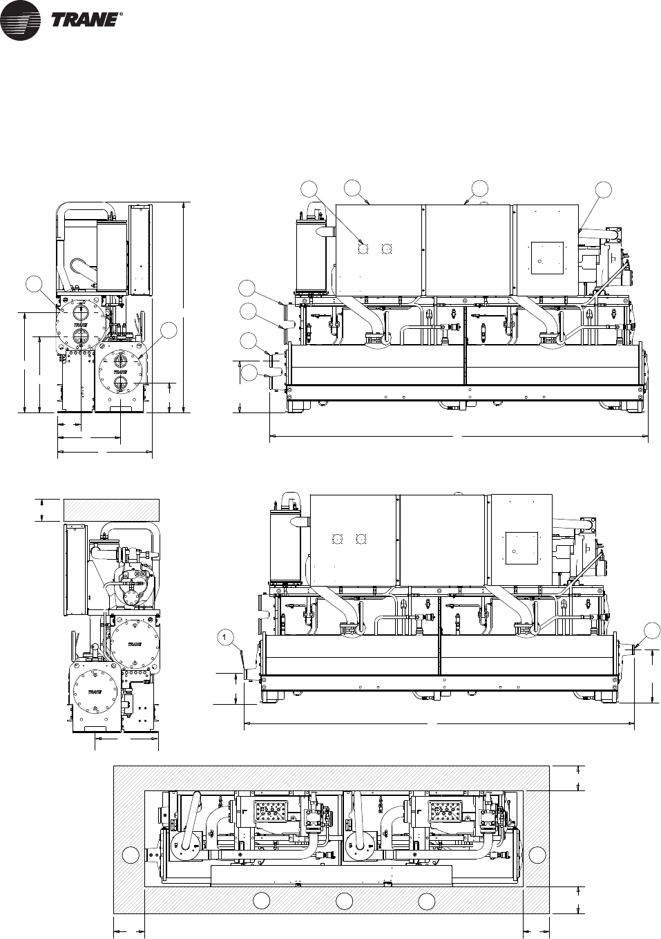
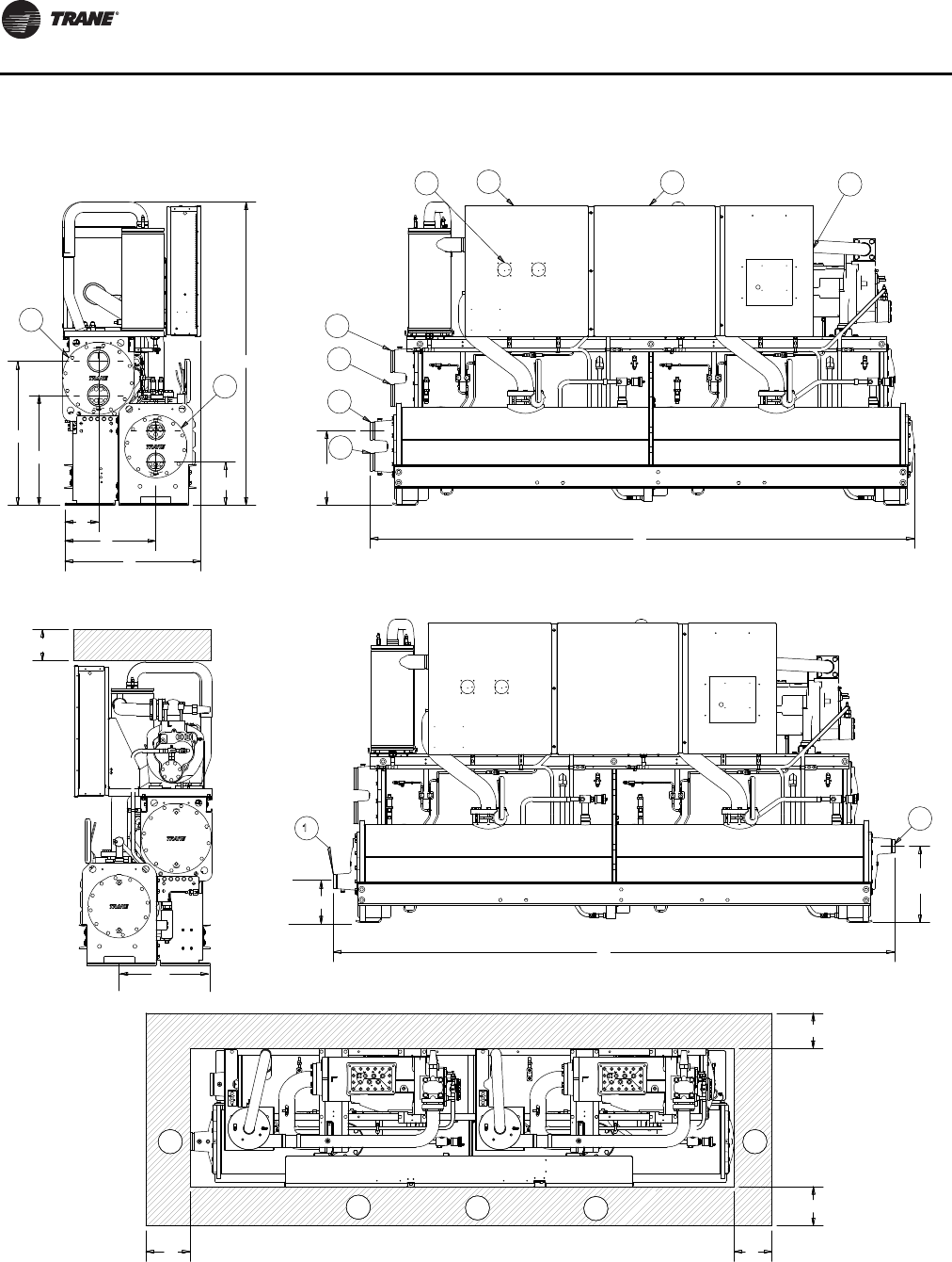
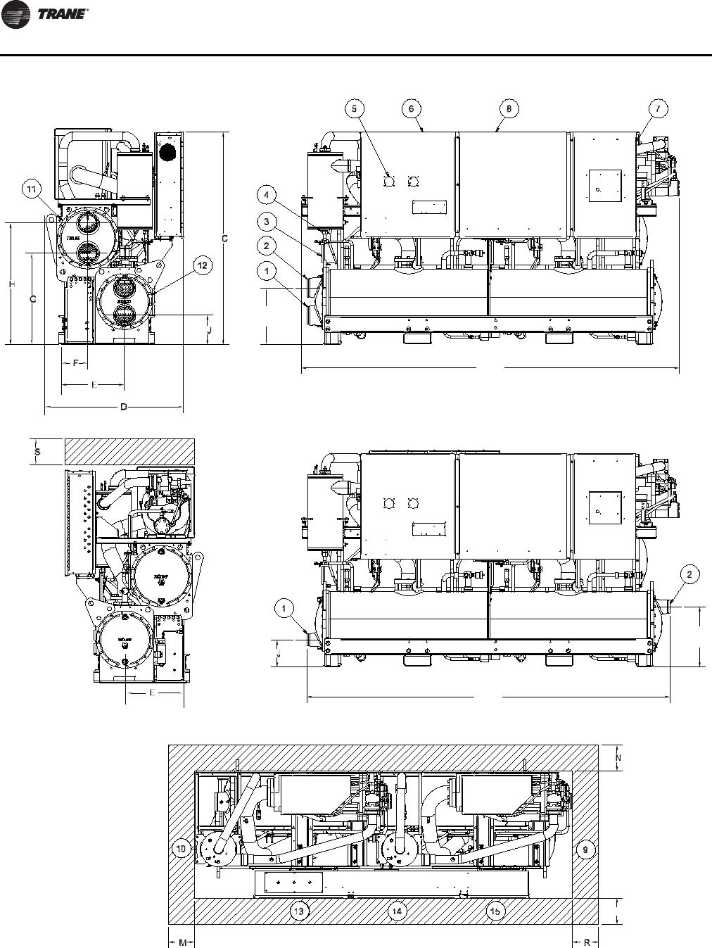
Figure 4. RTWD/RTUD – 60 Hz dimensions – 80-140 ton
10 9
13 14 15
2
1
3
4
11
5687
1
2
12
A
G
H
C
D
E
F
N
R
M
B
J
L
K
N
J
S
E
( 3 pass evap )
2 pass evap
3 pass evap
( 3 pass evap )
(3 pass evap)
( 2 pass evap )
(2 pass evap)

Unit Dimensions/Weights
RLC-SVX09H-EN 19
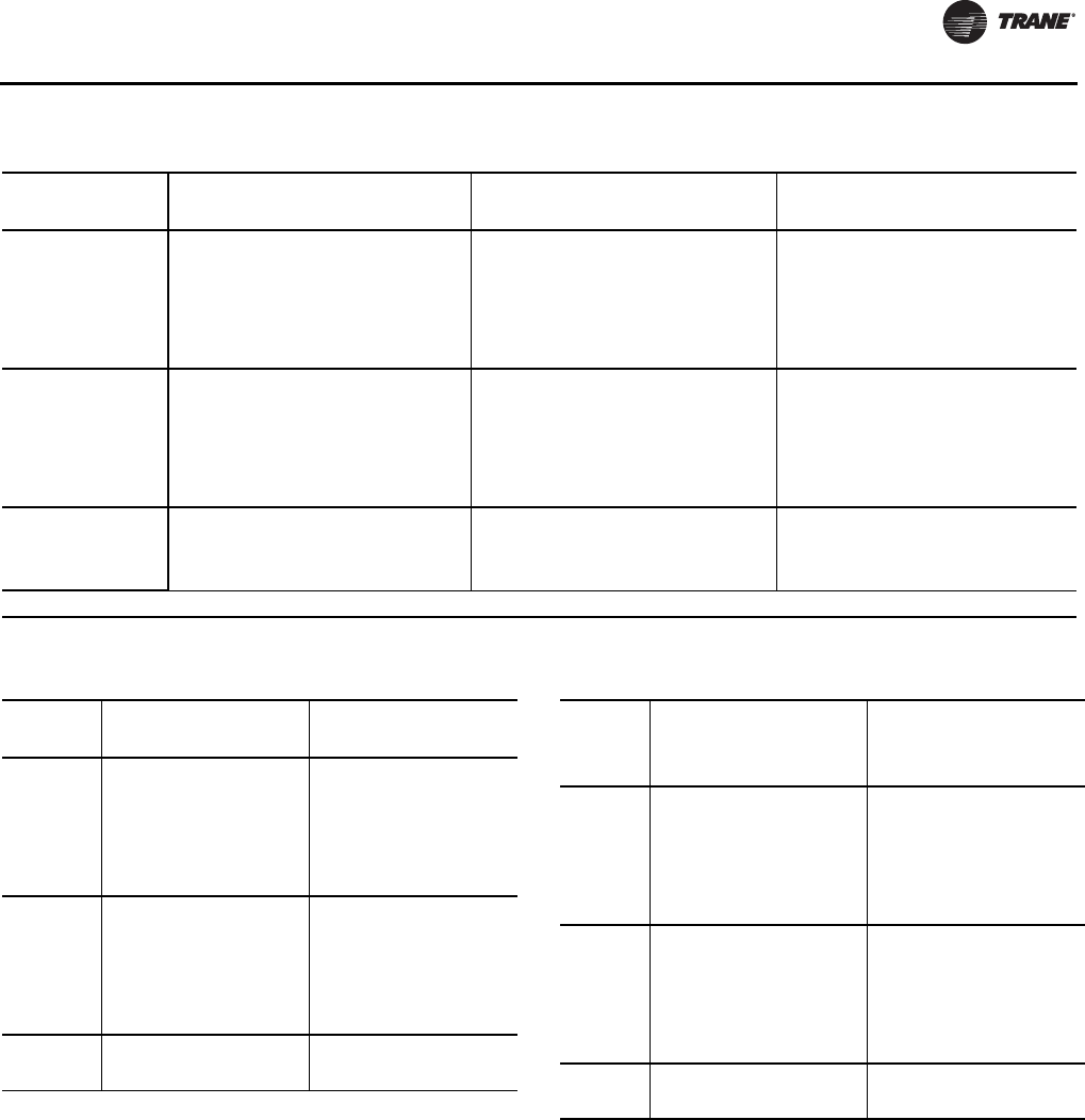
Table 10. RTWD/RTUD – 60 Hz dimensions – 80-140 ton
Standard Efficiency RTWD/RTUD - High Efficiency
80,90
inch (mm)
100,110
inch (mm)
120,130,140
inch (mm)
80,90
inch (mm)
100,110,120,130
inch (mm)
A (2 pass evap) 138.2 (3510) 138.2 (3510) 138.8 (3525) 126.4 (3210) 126.9 (3225)
B (3 pass evap) 142.6 (3621) 142.6 (3621) 142.6 (3621) 130.8 (3321) 130.7 (3320)
C75.9 (1929) 76.9 (1955) 76.9 (1955) 76.1 (1933) 76.9 (1955)
D34.3 (871) 34.3 (871) 34.8 (884) 35.1 (890) 35.1 (890)
E23.6 (600) 23.6 (600) 23.6 (600) 23.6 (600) 23.6 (600)
F9.1 (231) 9.1 (231) 9.1 (231) 9.1 (231) 9.1 (231)
G27.9 (709) 27.9 (709) 27.9 (709) 27.9 (709) 27.9 (709)
H36.6 (929) 36.6 (929) 36.6 (929) 36.6 (929) 36.6 (929)
J (2 pass evap) 11.0 (280) 11.0 (280) 10.6 (268) 10.8 (273) 11.8 (299)
J (3 pass evap) 10.4 (265) 10.4 (265) 10.1 (256) 10.2 (258) 11.3 (287)
K (2 pass evap) 18.9 (479) 18.9 (479) 19.2 (487) 18.6 (472) 20.4 (519)
L (3 pass evap) 19.5 (495) 19.5 (495) 19.5 (496) 19.2 (488) 19.2 (487)
M36 (914) 36 (914) 36 (914) 36 (914) 36 (914)
N* 36 (914)* 36 (914)* 36 (914)* 36 (914)* 36 (914)*
R127 (3226) 127 (3226) 127 (3226) 115 (2921) 115 (2921)
S36 (914) 36 (914) 36 (914) 36 (914) 36 (914)
Reference
1Evaporator Water Inlet
2Evaporator Water Outlet
3Condenser Water Inlet (RTWD only)
4Condenser Water Outlet (RTWD only)
5Power Disconnect
6Power Wire
7Control Wire
8Control Panel
9Condenser Return Waterbox End (RTWD only) - minimum clearance (for tube removal)
10 Condenser Supply Waterbox End (RTWD only) - minimum clearance (for maintenance)
11 Condenser (RTWD only)
12 Evaporator
13 Panel Power Section - door swing 31.3 inch (796.9 mm)
14 Panel Power Section - door swing 31.1 inch (790.1 mm)
15 Panel Control Section - door swing 22.4 inch (568.14 mm)
*
42 inch (1067 mm) clearance required to other ground parts, two units with panels facing each other or other live parts
require a clearance of 48 inch (1220 mm)
** Sound attenuator may increase the footprint - submittal should be used.
Unit Dimensions/Weights
20 RLC-SVX09H-EN
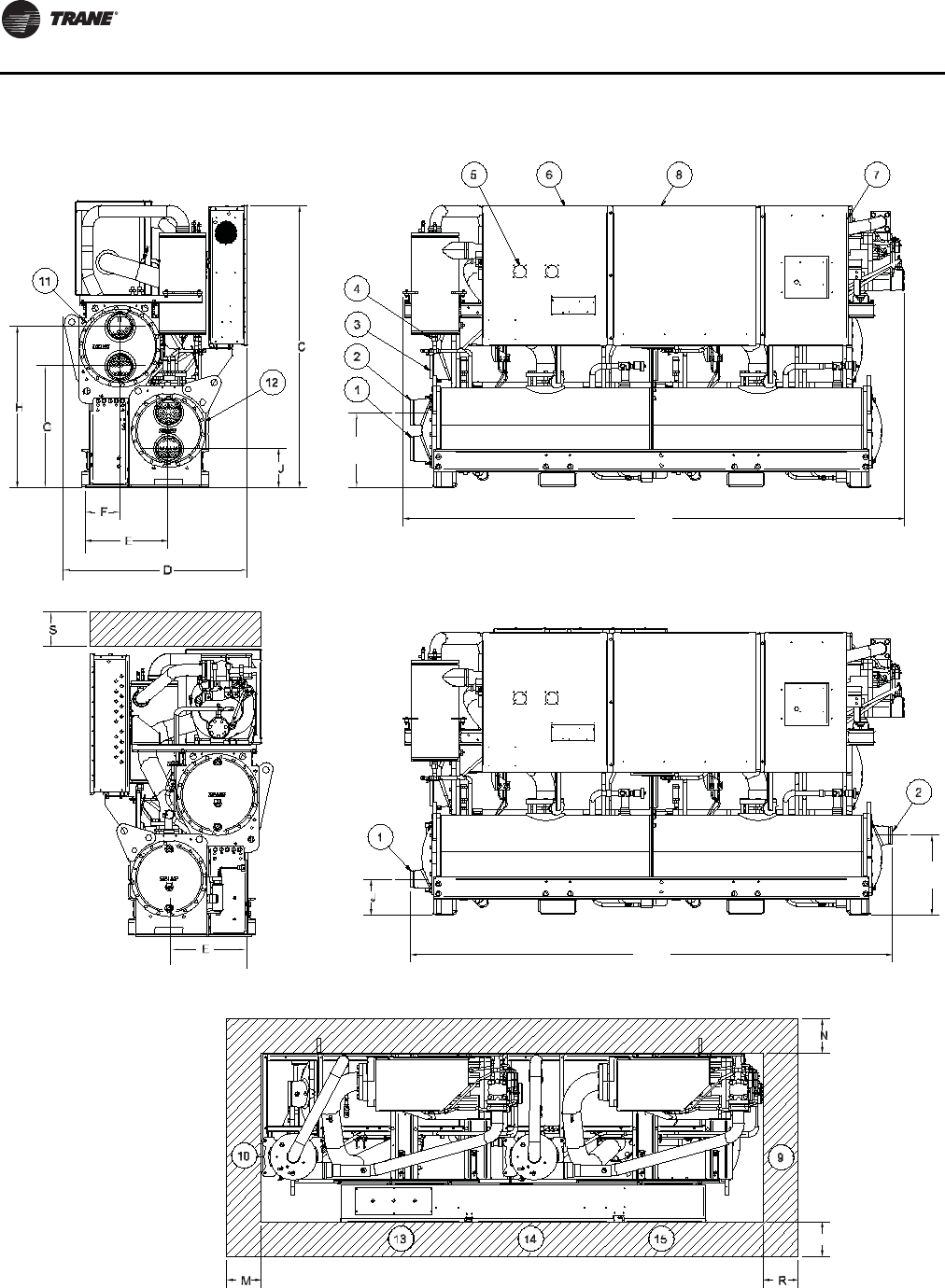
Figure 5. RTWD/RTUD – 60 Hz dimensions – 150-250 tons
A
K
B
L
P
3 pass evap
2 pass evap
( 3 pass evap )
(3 pass evap)
( 2 pass evap )
(2 pass evap)
(3 pass evap)
Unit Dimensions/Weights
RLC-SVX09H-EN 21
Table 11. RTWD/RTUD – 60 Hz dimensions – 150-250 tons
RTWD RTUD
High Efficiency Prem Efficiency
150-200
inch (mm)
220, 250
inch (mm)
150-200
inch (mm)
150
inch (mm)
160-200
inch (mm)
220,250
inch (mm)
A (2 pass evap) 132.3 (3360) 136.1 (3456) 147.9 (3755) 126.9 (3225) 132.3 (3360) 132.3 (3360)
B (3 pass evap) 132.8 (3371) 136.1 (3456) 150.9 (3831) 130.8 (3321) 132.8 (3371) 132.9 (3376)
C75.6 (1920) 76.9 (1955) 76.8 (1950) 76.9 (1955) 75.6 (1920) 76.7 (1949)
D47.3 (1202) 47.8 (1213) 47.3 (1202) 37.9 (962) 47.4 (1203) 47.4 (1203)
E24.6 (624) 24.8 (630) 24.6 (624) 23.5 (599) 24.5 (624) 24.6 (624)
F11.1 (282) 11.2 (295) 11.1 (282) - - -
G32.7 (830) 33.1 (840) 33.8 (860) - - -
H42.4 (1078) 43.9 (1115) 43.6 (1108) - - -
J (2 pass evap) 10.1 (256) 10.6 (270) 10.6 (270) 10.2/259 10.1 (256) 11.3 (263)
J (3 pass evap) 9.5 (241) 9.7 (247) 9.7 (247) 9.8/247 9.5 (241) 8.8 (223)
K (2 pass evap) 19.3 (490) 20.6 (524) 20.6 (524) 18.9/479 19.3 (490) 19.9 (483)
L (3 pass evap) 19.9 (505) 21.6 (549) 21.6 (549) 19.8/501 19.9 (505) 20.7 (526)
M36.0 (914) 36.0 (914) 36.0 (914) 36.0 (914) 36.0 (914) 36.0 (914)
N36.0 (914) 36.0 (914) 36.0 (914) 36.0 (914) 36.0 (914) 36.0 (914)
P* 40 (1016)* 40 (1016)* 40 (1016)* 40 (1016)* 40 (1016)* 40 (1016)*
R114.8 (2916) 114.8 (2916) 134.5 (3416) 114.8 (2916) 114.8 (2916) 114.8 (2916)
S36.0 (914) 36.0 (914) 36.0 (914) 36.0 (914) 36.0 (914) 36.0 (914)
Reference
1Evaporator Water Inlet
2Evaporator Water Outlet
3Condenser Water Inlet (RTWD only)
4Condenser Water Outlet (RTWD only)
5Power Disconnect
6Power Wire
7Control Wire
8Control Panel
9Condenser Return Waterbox End (RTWD only) - minimum clearance (for tube removal)
10 Condenser Supply Waterbox End (RTWD only) - minimum clearance (for maintenance)
11 Condenser (RTWD only)
12 Evaporator
13 Panel Power Section - door swing 31.3 inch (796.9 mm)
14 Panel Power Section - door swing 31.1 inch (790.1 mm)
15 Panel Control Section - door swing 22.4 inch (568.14 mm)
*
Control panel clearance is 36 or 40 inch (914 or 1016 mm) depending on voltages, starter type, unit application
and local code; 42 inch (1067 mm) clearance required to other grounded parts; two units with panels facing
each other or other live parts require a clearance of 48 inch (1220 mm).
** Sound attenuator may increase the footprint - submittal should be used.
Unit Dimensions/Weights
22 RLC-SVX09H-EN
Figure 6. RTWD - 50 Hz dimensions - 70-150 ton SE, 60-120 ton HE
10 9
13 14 15
2
1
3
4
11
5687
1
2
12
A
G
H
C
D
E
F
N
R
M
B
J
L
K
N
J
S
E
( 3 pass evap )
2 pass evap
3 pass evap
( 3 pass evap )
(3 pass e
v
( 2 pass evap )
(2 pass evap)
Unit Dimensions/Weights
RLC-SVX09H-EN 23
Table 12. RTWD – 50 Hz – 70-150 ton SE, 60-120 ton HE
RTWD Standard Efficiency High Efficiency
70,80,90,100,110
inch (mm)
120,130,140,150
inch (mm)
60,70,80
inch (mm)
90
inch (mm)
100,110,120
inch (mm)
A (2 pass evap) 138.2 (3510) 138.8 (3525) 126.4 (3210) 127.0 (3225) 127.0 (3225)
B (3 pass evap) 142.6 (3621) 145.6 (3621) 130.8 (3321) 130.7 (3320) 130.7 (3320)
C75.9 (1929) 76.9 (1955) 76.1 (1933) 76.1 (1933) 76.9 (1955)
D34.3 (871) 34.8 (884) 35.1 (890) 35.1 (890) 35.1 (890)
E 23.6 (600) 23.6 (600) 23.6 (600) 23.6 (600) 23.6 (600)
F9.1 (231) 9.1 (231) 9.1 (231) 9.1 (231) 9.1 (231)
G27.9 (709) 27.9 (709) 27.9 (709) 27.9 (709) 27.9 (709)
H36.6 (929) 36.6 (929) 36.6 (929) 36.6 (929) 36.6 (929)
J (2 pass evap) 11.0 (280) 10.6 (268) 10.8 (273) 11.8 (299) 11.8 (299)
J (3 pass evap) 10.4 (265) 10.1 (256) 10.2 (258) 11.3 (287) 11.3 (287)
K (2 pass evap) 18.9 (479) 19.2 (487) 18.6 (472) 20.4 (519) 20.4 (519)
L (3 pass evap) 19.5 (495) 19.5 (496) 19.2 (488) 19.2 (487) 19.2 (487)
M36 (914) 36 (914) 36 (914) 36 (914) 36 (914)
N* 36 (914)* 36 (914)* 36 (914)* 36 (914)* 36 (914)*
R127 (3226) 127 (3226) 115 (2921) 115 (2921) 115 (2921)
S36 (914) 36 (914) 36 (914) 36 (914) 36 (914)
Reference
1Evaporator Water Inlet
2Evaporator Water Outlet
3Condenser Water Inlet
4Condenser Water Outlet
5Power Disconnect
6Power Wire
7Control Wire
8Control Panel
9Condenser Return Waterbox End - minimum clearance (for tube removal)
10 Condenser Supply Waterbox End - minimum clearance (for maintenance)
11 Condenser
12 Evaporator
13 Panel Power Section - door swing 31.3 inch (796.9 mm)
14 Panel Power Section - door swing 31.1 inch (790.1 mm)
15 Panel Control Section - door swing 22.4 inch (568.14 mm)
*
42 inch (1067 mm) clearance required to other ground parts, two units with panels facing each other or other live parts
require a clearance of 48 inch (1220 mm)
** Sound attenuator may increase the footprint - submittal should be used.
Unit Dimensions/Weights
24 RLC-SVX09H-EN
Figure 7. RTWD - 50 Hz dimensions - 130-250 ton HE, 160-200 ton PE
A
K
B
L
P
3 pass evap
2 pass evap
( 3 pass evap )
(3 pass evap)
( 2 pass evap )
(2 pass evap)
(3 pass evap)
Unit Dimensions/Weights
RLC-SVX09H-EN 25
Table 13. RTWD – 50 Hz dimensions – 130-250 ton HE, 160-200 ton PE
RTWD High Efficiency Premium Efficiency
130, 140, 160, 180
inch (mm)
200, 220, 250
inch (mm)
160, 180
inch (mm)
200
inch (mm)
A (2 pass evap) 132.3 (3360) 136.1 (3456) 147.9 (3755) 136.1 (3456)
B (3 pass evap) 132.8 (3371) 136.1 (3456) 150.8 (3831) 136.1 (3456)
C75.6 (1920) 76.8 (1949) 76.8 (1950) 76.9 (1955)
D47.3 (1202) 47.8 (1213) 47.3 (1202) 47.8 (1213)
E 24.6 (624) 24.8 (630) 24.6 (624) 24.8 (630)
F11.1 (282) 11.6 (295) 11.1 (282) 11.6 (295)
G32.7 (830) 33.1 (840) 33.8 (860) 33.1 (840)
H42.4 (1078) 43.9 (1115) 43.6 (1108) 43.9 (1115)
J (2 pass evap) 10.1 (256) 10.6 (270) 10.6 (270) 10.6 (270)
J (3 pass evap) 9.5 (241) 9.7 (247) 9.7 (247) 9.7 (247)
K (2 pass evap) 19.3 (490) 20.6 (524) 20.6 (524) 20.6 (524)
L (3 pass evap) 19.9 (505) 21.6 (549) 21.6 (550) 21.6 (549)
M36.0 (914) 36.0 (914) 36.0 (914) 36.0 (914)
N36.0 (914) 36.0 (914) 36.0 (914) 36.0 (914)
P* 40 (1016)* 40 (1016)* 40 (1016)* 40 (1016)*
R114.8 (2916) 114.8 (2916) 134.5 (3416) 134.5 (3416)
S36.0 (914) 36.0 (914) 36.0 (914) 36.0 (914)
Reference
1Evaporator Water Inlet
2Evaporator Water Outlet
3Condenser Water Inlet
4Condenser Water Outlet
5Power Disconnect
6Power Wire
7Control Wire
8Control Panel
9Condenser Return Waterbox End - minimum clearance (for tube removal)
10 Condenser Supply Waterbox End - minimum clearance (for maintenance)
11 Condenser
12 Evaporator
13 Panel Power Section - door swing 31.3 inch (796.9 mm)
14 Panel Power Section - door swing 31.1 inch (790.1 mm)
15 Panel Control Section - door swing 22.4 inch (568.14 mm)
*
Control panel clearance is 36 or 40 inch (914 or 1016 mm) depending on voltages, starter type, unit application and
local code; 42 inch (1067 mm) clearance required to other grounded parts; two units with panels facing each other
or other live parts require a clearance of 48 inch (1220 mm).
** Sound attenuator may increase the footprint - submittal should be used.
Unit Dimensions/Weights
26 RLC-SVX09H-EN
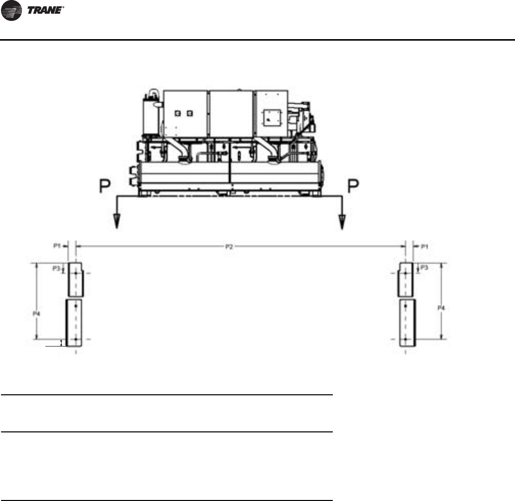
Figure 8. RTWD/RTUD Unit footprint
P5
Table 14. RTWD/RTUD – unit footprint – all sizes
Standard Efficiency High Efficiency
200 PE (50 Hz) Premium Efficiency
inch (mm) inch (mm) inch (mm)
P1 3.68 (93.5) 3.68 (93.5) 3.68 (93.5)
P2 123.78 (3144) 111.97 (2844) 131.65 (3344)
P3 2.43 (61.8) 4.30 (109.3) 4.30 (109.3)
P4 24.93 (633.2) 24.93 (633.2) 24.93 (633.2)
P5 2.5 (64) 2.5 (64) 2.5 (64)
Note: Base hole diameters all 0.63 inch (16 mm).
Unit Dimensions/Weights
RLC-SVX09H-EN 27
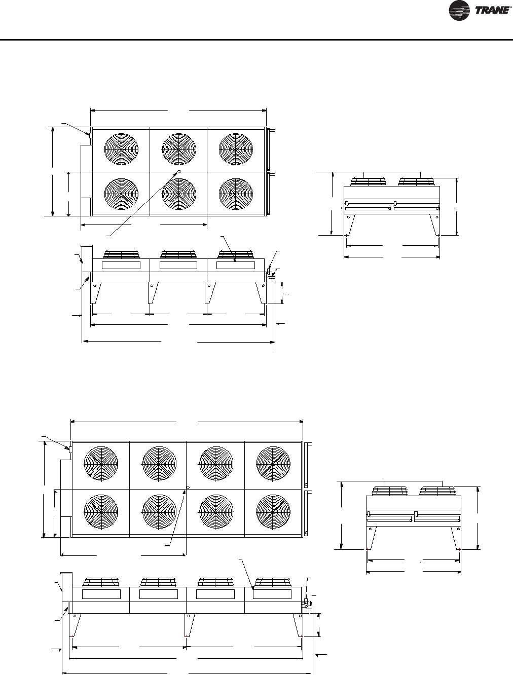
Figure 9. Trane air-cooled condenser -
80T, 150T (cond 1 & 2), 160T (cond 1 & 2), 180T (cond 1)
Approx. center of gravity
Disconnect switch
Service panel
Electrical box
split controls
Return bend cover
Inlet connection
Outlet connection
166.0‚
90.5‚
45.25‚
93.0‚
54.0‚ 54.0‚ 54.0‚
166.0‚
22.0‚
90.5‚
86.5‚
58.5‚
184.0‚
64.0‚
8.0‚
10.0‚
0.75 inch anchor holes
Figure 10. Trane air-cooled condenser -
90T, 100T, 110T, 180T (cond 2), 200T (cond 1 & 2), 220T (cond 1 & 2), 250T (cond1&2)
Return bend cover
Electrical box
split controls Outlet connection
Inlet connection
Service panel
Disconnect switch
220.0‚
90.5‚
45.25‚
120.0‚
Approx. center of gravity
108.0‚ 108.0‚
220.0‚
238.0‚
22.0‚
64.0‚ 58.5‚
86.5‚
90.5‚
10.0‚
8.0‚
0.75 inch anchor holes

Unit Dimensions/Weights
28 RLC-SVX09H-EN
Weights
Figure 11. Trane air-cooled condenser - 120T, 130T
274.0‚
45.25‚
90.5‚
145.0‚
Approx. center of gravity
64.0‚
86.5‚
90.5‚
Disconnect
switch
Electrical box
split controls
Return
bend cover
10.0‚ 108.0‚ 54.0‚ 108.0‚
22.0‚
8.0‚
274.0‚
292.0‚
Inlet connection
Outlet connection
58.5‚
Table 15. Weights - RTWD 60 Hz - IP units
Standard Efficiency High Efficiency Premium Efficiency
Model Operating (lb) Shipping (lb) Operating (lb) Shipping (lb) Operating (lb) Shipping (lb)
80 5900 5703 5732 5551 - -
90 5933 5721 5792 5587 - -
100 6140 5902 6255 6025 - -
110 6332 6074 6475 6208 - -
120 6530 6248 6510 6230 - -
130 6535 6244 6543 6248 - -
140 6971 6649 - - - -
150 - - 7884 7544 8724 8243
160 - - 8395 8036 9171 8691
180 - - 8490 8098 9290 8772
200 - - 8578 8157 9337 8803
220 - - 9493 8995 - -
250 - - 10071 9478 - -
Note: Weights include optional base rail forklifting. Subtract 300 lbs if this option is not selected.
Unit Dimensions/Weights
RLC-SVX09H-EN 29
Table 16. Weights - RTWD 60 Hz - SI units
Standard Efficiency High Efficiency Premium Efficiency
Model Operating (kg) Shipping (kg) Operating (kg) Shipping (kg) Operating (kg) Shipping (kg)
80 2676 2587 2600 2518 - -
90 2691 2595 2627 2534 - -
100 2785 2677 2837 2733 - -
110 2872 2755 2937 2816 - -
120 2962 2834 2953 2826 - -
130 2964 2832 2968 2834 - -
140 3162 3016 - - - -
150 - - 3576 3422 3957 3739
160 - - 3808 3645 4160 3942
180 - - 3851 3673 4214 3979
200 - - 3891 3700 4235 3993
220 - - 4306 4080 - -
250 - - 4568 4299 - -
Note: Weights include optional base rail forklifting. Subtract 136.1 kg if this option is not selected.
Table 17. Weights - RTUD - 60 Hz
IP units (lbs) SI units (kg)
Model Operating Shipping Operating Shipping
80 4874 4793 2211 2174
90 4892 4804 2219 2179
100 5073 4974 2301 2256
110 5326 5221 2416 2368
120 5322 5194 2414 2356
130 5322 5194 2414 2356
150 5917 5781 2684 2622
160 6804 6643 3086 3013
180 6876 6715 3119 3046
200 6980 6810 3166 3089
220 7300 7112 3311 3226
250 7602 7401 3448 3357
Note: Weights include optional base rail fork lifting. Subtract 300 lbs if this
option is not selected.
Table 18. Air-Cooled Condenser Weights
RTUD
Tonnage
I-P Units (lbs) SI Units (kg)
Shipping Weight Shipping Weight
Cond 1 Cond 2 Cond 1 Cond 2
80 2100 - 953 -
90 2651 - 1202 -
100 2884 - 1308 -
110 2950 - 1338 -
120 4005 - 1817 -
130 4046 - 1835 -
150 2044 2100 927 953
160 2100 2100 953 953
180 2100 2526 953 1146
200 2526 2526 1146 1146
220 2526 2884 1146 1308
250 2884 2884 1308 1308
Unit Dimensions/Weights
30 RLC-SVX09H-EN
Table 19. Weights - RTWD 50 Hz - IP units
Standard Efficiency High Efficiency Premium Efficiency
Model Operating (lb) Shipping (lb) Operating (lb) Shipping (lb) Operating (lb) Shipping (lb)
60 - - 5706 5525 - -
70 5874 5677 5724 5534 - -
80 6030 5807 5893 5680 - -
90 6187 5938 6319 6063 - -
100 6268 6010 6412 6145 - -
110 6332 6014 6495 6220 - -
120 6903 6614 6914 6619 - -
130 7337 7016 8177 7837 - -
140 7342 7020 8245 7884 - -
150 7395 7049 N/A N/A - -
160 - - 8342 7950 9061 8565
180 - - 8770 8351 9579 9030
200 - - 9758 9259 10060 9467
220 - - 9793 9284 - -
250 - - 9958 9398 - -
Note: All weights +/-3%. Weights include optional base rail forklifting. Subtract 300 lbs if this option is not selected.
Table 20. Weights - RTWD 50 Hz - SI units
Standard Efficiency High Efficiency Premium Efficiency
Model Operating (kg) Shipping (kg) Operating (kg) Shipping (kg) Operating (kg) Shipping (kg)
60 - - 2588 2506 - -
70 2664 2575 2596 2510 - -
80 2735 2634 2673 2576 - -
90 2806 2693 2866 2750 - -
100 2843 2726 2908 2787 - -
110 2872 2755 2946 2821 - -
120 3131 3000 3136 3002 - -
130 3328 3182 3709 3555 - -
140 3330 3184 3740 3576 - -
150 3354 3197 - - - -
160 - - 3784 3606 4110 3885
180 - - 3979 3788 4345 4096
200 - - 4426 4200 4563 4294
220 - - 4442 4211 - -
250 - - 4517 4263 - -
Note: Weights include optional base rail forklifting. Subtract 136.1 kg if this option is not selected.

RLC-SVX09H-EN 31
Installation - Mechanical
Location Requirements
Noise Considerations
• Refer toTrane Engineering Bulletin -Series RChiller
Sound Ratings and Installation Guide for sound
consideration applications.
• Locate the unit away from sound-sensitive areas.
• Install the isolation pads under the unit. Refer to “Unit
Isolation.”
• Install rubber vibration isolators in all water piping.
• Seal all wall penetrations.
Note: Consult an acoustical engineer for critical
applications.
Foundation
Provide rigid, non-warping mounting pads or a concrete
foundation of sufficient strength and mass to support the
applicable operating weight (i.e., including completed
piping, and full operating charges of refrigerant, oil and
water). See “Unit Dimensions/Weights” chapter for unit
operating weights. Once in place, the unit must be level
within 1/4” (6.4 mm) over its length and width.TheTrane
Company is not responsible for equipment problems
resulting from an improperly designed or constructed
foundation.
Clearances
Provide enough space around the unit to allow the
installation and maintenance personnel unrestricted
access to all service points. Refer to submittal drawings for
the unit dimensions, to provide sufficient clearance for the
opening of control panel doors and unit service. Refer to
the chapter on “Unit Dimensions/Weights” for minimum
clearances. In all cases, local codes which require
additional clearances will take precedence over these
recommendations.
Note: Required vertical clearance above the unit is 36”
(914.4 mm).There should be no piping or conduit
located over the compressor motor. If the unit
configuration requires a variance to the clearance
dimensions, contact yourTrane Sales Office
Representative. Also refer toTrane Engineering
Bulletins for application information on RTWD/
RTUD chillers.
Rigging
The Model RTWD/RTUD chiller should be moved by lifting,
unless the unit is ordered with the “Base Rail Forklifting”
option. Refer to the unit model number, digit 46, for more
details.
Refer to Table 15, p. 28 thru Table 20, p. 30 for typical unit
lifting weights and Table 30, p. 39 thru Table 35, p. 40 for
center of gravity dimensions. Refer to the rigging label
attached to the unit for further details.\
Lifting Procedure
Attach chains or cables to lifting beam, as shown in
Figure .Lifting beam crossbars MUST be positioned so
lifting cables do not contact the sides of the unit.Attach the
anti-rolling cable to the circuit 2 compressor suction pipe.
Adjust as necessary for even level lift.
WARNING
Heavy Objects!
• Ensure that all the lifting equipment used is properly
rated for the weight of the unit being lifted. Each of
the cables (chains or slings), hooks, and shackles
used to lift the unit must be capable of supporting the
entire weight of the unit.
• Lifting cables (chains or slings) may not be of the
same length. Adjust as necessary for even unit lift.
• The high center of gravity on this unit requires the use
of an anti-rolling cable (chain or sling).To prevent unit
from rolling, attach cable (chain or sling) with no
tension and minimal slack around compressor
suction pipe as shown.
• Do not use fork lift to move or lift unit unless unit has
lifting base with locations marked by caution labels
installed.
Other lifting arrangements could cause equipment or
property damage. Failure to follow instructions above
or properly lift unit could result in unit dropping and
possibly crushing operator/technician which could
result in death or serious injury.
WARNING
Improper Unit Lift!
Test lift unit approximately 24 inches to verify proper
center of gravity lift point. To avoid dropping of unit,
reposition lifting point if unit is not level. Failure to
properly lift unit could result in unit dropping and
possibly crushing operator/technician which could
result in death or serious injury and possible equipment
or property-only damage.
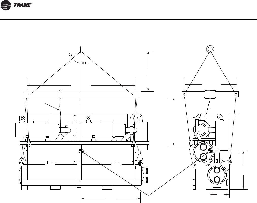
Installation - Mechanical
32 RLC-SVX09H-EN
Unit Isolation and Leveling
Mounting
Construct an isolated concrete pad for the unit or provide
concrete footings at each of the four unit mounting points.
Mount the unit directly to the concrete pads or footings.
Level the unit using the base rail as a reference.The unit
must be level within 1/4” over the entire length and width.
Use shims as necessary to level the unit.
Isolation Pads
Note: The elastomeric pads shipped (as standard) are
adequate for most installations. For additional
details on isolation practices, refer toTrane
Engineering Bulletin -Series R®Chiller Sound
Ratings and Installation Guide, or consult an
acoustical engineer for sound-sensitive
installations.
During final positioning of the unit, place the isolation
pads under the evaporator and condenser tube sheet
supports as shown in Figure 13, p. 33. Level the unit as
described in the next main paragraph.
Neoprene Isolator Installation (optional)
Install the optional neoprene isolators at each mounting
location. Isolators are identified by part number and color.
Refer to submittal drawing for correct isolators.
1. Secure the isolators to the mounting surface, using the
mounting slots in the isolator base plate, as shown in
Figure . Do not fully tighten the isolator mounting bolts
at this time.
2. Align the mounting holes in the base of the unit, with
the threaded
positioning pins on the top of the isolators.
3. Lower the unit on to the isolators and secure the
isolator to the unit with a nut.
4. Level the unit carefully. Refer to “Leveling”. Fully
tighten the isolator mounting bolts.
Figure 12. RTWD/RTUD rigging
CG CG
60 Deg. MAX
48” MIN
40” MIN
Approximate location
of center of gravity
X
Y
110” MIN
ANTI-ROLLING CABLE
Z
48” MIN
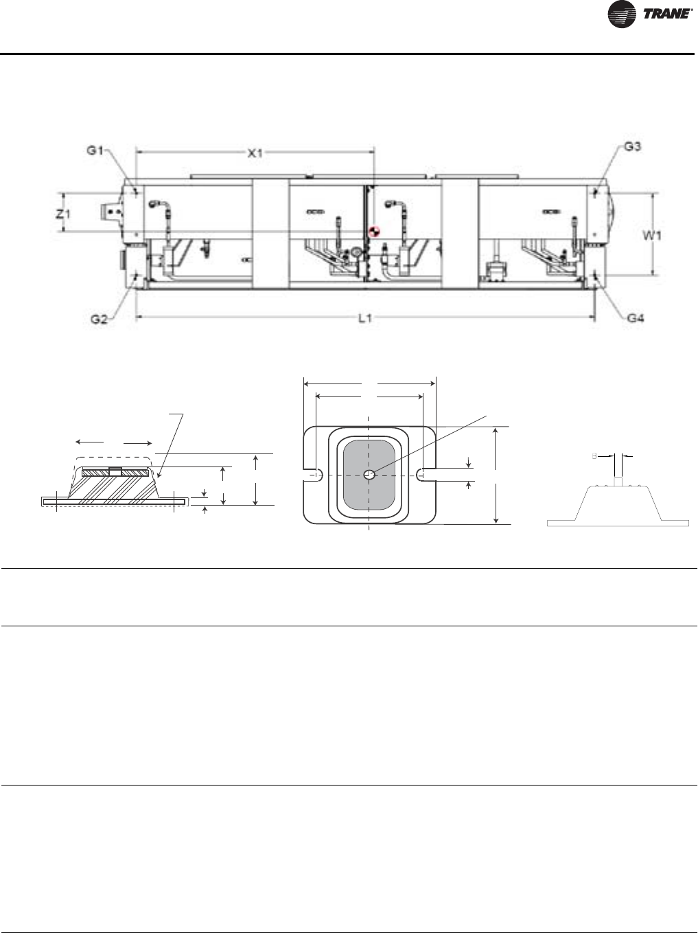
Installation - Mechanical
RLC-SVX09H-EN 33
Figure 13. Isolator pad placement
Figure 14. RTWD/RTUD neoprene isolator
Table 21. Isolator part numbers and dimensions(a)
Isolator Type
Color [Ext](b)
Max Load-
lbs (kg)
Maximum Dimension - in (mm)
Model Size Hz Effic. Deflection (in) A B C D E H L W
RTWD 80, 90, 100, 110,
120, 130, 140 60 STD
RDP-4
Red [62]
2250 (1021)
0.50 3.0
(76.2)
0.50
(12.7)
5.00
(127.0)
0.56
(14.2)
0.38
(9.7)
2.75
(69.8)
6.25
(158.8)
4.63
(117.6)
RTWD 80, 90, 100, 110,
120, 130 60 HIGH
RTWD
70, 80, 90, 100,
110, 120, 130,
140, 150
50 STD
RTWD 60,70,80, 90,
100, 110, 120 50 HIGH
RTUD 80, 90, 100, 110,
120, 130 60 HIGH
RTWD 150, 160, 180,
200, 220, 250 60 HIGH
RDP-4
Green [63]
3000 (1361)
0.50 3.0
(76.2)
0.50
(12.7)
5.00
(127.0)
0.56
(14.2)
0.38
(9.7)
2.75
(69.8)
6.25
(158.8)
4.63
(117.6)
RTWD 150, 160,
180, 200 60 PREM
RTWD
130, 140, 160,
180, 200, 220,
250
50 HIGH
RTWD 160, 180, 200 50 PREM
RTUD 150, 160, 180,
200, 220, 250 60 HIGH
(a) See submittal drawing to verify correct isolators.
(b) Part number is X10140305-xx
Note: Level unit to 1/4” (6.35 mm) across
width and length
Note: Level unit to 1/4” (6.35 mm) across
width and length
L
C
D
1/2-13NC-2B
W
Mounting molded in Neoprene
H (RD)
H (R)
E
A

Installation - Mechanical
34 RLC-SVX09H-EN
Figure 15. Mounting point locations and weights
RTWD - Std efficiency (all)
RTWD - High efficiency, 80-120T (60 Hz), 60-120T (50 Hz)
RTUD - 80-130T
Figure 16. Mounting point locations and weights
RTWD - High efficiency, 150-250T (60Hz), 130-250T (50Hz)
RTWD - Premium efficiency (all)
RTUD - 150-250T
Without panel
With panel

Installation - Mechanical
RLC-SVX09H-EN 35
Important: Isolators need to be placed under G1, G2, G3 and G4.
Table 22. RTWD Corner weights, 60 Hz - Figure 15 -lb(kg)
Corner Weights - lb (kg)
Operating Weight-lb (kg)Unit G1 G2 G3 G4
Standard Efficiency
80 1566 (710) 1566 (710) 1385 (628) 1385 (628) 5902 (2676)
90 1571 (713) 1577 (715) 1390 (630) 1396 (633) 5934 (2691)
100 1599 (725) 1617 (733) 1454 (660) 1471 (667) 6141 (2785)
110 1662 (754) 1690 (767) 1477 (670) 1503 (681) 6332 (2872)
120 1689 (766) 1795 (814) 1477 (670) 1569 (712) 6530 (2962)
130 1688 (765) 1797 (815) 1478 (670) 1573 (713) 6536 (2964)
140 1654 (750) 1905 (864) 1586 (719) 1827 (829) 6972 (3162)
High Efficiency
80 1465 (664) 1595 (724) 1279 (580) 1393 (632) 5732 (2600)
90 1479 (671) 1610 (730) 1294 (587) 1409 (639) 5792 (2627)
100 1602 (726) 1704 (773) 1429 (648) 1521 (690) 6256 (2837)
110 1673 (759) 1789 (811) 1457 (661) 1557 (706) 6476 (2937)
120 1680 (762) 1798 (816) 1465 (664) 1569 (711) 6512 (2953)
130 1685 (764) 1808 (820) 1472 (668) 1580 (716) 6545 (2968)
Table 23. RTWD Corner weights, 50 Hz - Figure 15 -lb(kg)
Corner Weights - lb (kg)
Operating Weight-lb (kg)Unit G1 G2 G3 G4
Standard Efficiency
70 1555 (705) 1563 (709) 1375 (624) 1382 (627) 5875 (2664)
80 1560 (708) 1595 (723) 1422 (645) 1454 (659) 6031 (2735)
90 1592 (722) 1655 (751) 1442 (654) 1498 (680) 6187 (2806)
100 1621 (735) 1668 (756) 1468 (666) 1511 (685) 6268 (2843)
110 1662 (754) 1690 (766) 1477 (670) 1503 (681) 6332 (2872)
120 1634 (741) 1872 (852) 1578 (716) 1814 (823) 6905 (3131)
130 1692 (767) 2091 (948) 1590 (721) 1965 (891) 7338 (3328)
140 1696 (769) 2092 (949) 1591 (722) 1964 (891) 7343 (3330)
150 1707 (774) 2107 (956) 1603 (727) 1978 (897) 7395 (3354)
High Efficiency
60 1455 (660) 1592 (722) 1270 (576) 1389 (630) 5706 (2588)
70 1461 (663) 1595 (723) 1275 (578) 1392 (631) 5723 (2596)
80 1468 (666) 1632 (740) 1324 (600) 1471 (667) 5894 (2673)
90 1600 (726) 1747 (792) 1421 (645) 1551 (704) 6320 (2866)
100 1631 (740) 1765 (800) 1448 (657) 1567 (711) 6412 (2908)
110 1678 (761) 1793 (813) 1463 (663) 1563 (709) 6497 (2946)
120 1635 (741) 1894 (859) 1569 (711) 1817 (824) 6914 (3136)

Installation - Mechanical
36 RLC-SVX09H-EN
Table 24. RTWD Corner weights, 60 Hz - Figure 16 -lb(kg)
Corner Weights - lb (kg)
Operating Weight-lb (kg)Unit G1 G2 G3 G4
High Efficiency, No Panel
150 1425 (646) 2102 (953) 1482 (672) 2185 (991) 7194 (3262)
160 1524 (691) 2361 (1071) 1498 (680) 2322 (1053) 7706 (3495)
180 1539 (698) 2385 (1081) 1520 (689) 2356 (1068) 7798 (3537)
200 1556 (706) 2410 (1093) 1538 (698) 2383 (1081) 7887 (3577)
220 1712 (777) 2611 (1184) 1769 (802) 2697 (1223) 8789 (3986)
250 1793 (813) 2826 (1282) 1837 (833) 2895 (1313) 9352 (4241)
Premium Efficiency, No Panel
150 1638 (743) 2299 (1043) 1704 (773) 2393 (1085) 8033 (3643)
160 1716 (778) 2525 (1145) 1715 (778) 2524 (1145) 8481 (3846)
180 1736 (787) 2564 (1163) 1737 (788) 2564 (1163) 8601 (3901)
200 1749 (793) 2572 (1166) 1751 (794) 2575 (1168) 8647 (3921)
Table 25. RTWD Corner weights, 60 Hz- Figure 16 -lb(kg)
Corner Weights - lb (kg)
Operating Weight-lb (kg)Unit G1 G2 G3 G4
High Efficiency, With Panel
150 1181 (853) 2010 (911) 1937 (878) 2070 (939) 7897 (3581)
160 1987 (901) 2261 (1025) 1946 (883) 2215 (1004) 8409 (3814)
180 2002 (908) 2284 (1036) 1969 (893) 2246 (1019) 8502 (3856)
200 2020 (916) 2309 (1047) 1989 (902) 2273 (1031) 8590 (3896)
220 2171 (985) 2515 (1141) 2226 (1010) 2579 (1170) 9492 (4305)
250 2256 (1023) 2728 (1237) 2296 (1041) 2776 (1259) 10056 (4560)
Premium Efficiency, With Panel
150 2089 (947) 2195 (996) 2171 (985) 2281 (1035) 8737 (3962)
160 2173 (985) 2416 (1096) 2176 (987) 2420 (1097) 9184 (4165)
180 2194 (995) 2454 (1113) 2198 (997) 2458 (1115) 9304 (4220)
200 2207 (1001) 2461 (1116) 2213 (1004) 2468 (1119) 9350 (4240)
Table 26. RTWD Corner weights, 50 Hz- Figure 16 -lb(kg)
Corner Weights - lb (kg)
Operating Weight-lb (kg)Unit G1 G2 G3 G4
High Efficiency, No Panel
130 1429 (648) 2307 (1046) 1434 (650) 2316 (1050) 7486 (3395)
140 1443 (654) 2328 (1056) 1448 (657) 2336 (1059) 7555 (3426)
160 1465 (664) 2355 (1068) 1469 (666) 2362 (1071) 8069 (3470)
180 1480 (671) 2401 (1089) 1597 (724) 2592 (1175) 8069 (3660)
200 1735 (787) 2724 (1235) 1782 (808) 2798 (1269) 9039 (4099)
220 1748 (793) 2731 (1238) 1794 (814) 2803 (1271) 9075 (4116)
250 1779 (807) 2784 (1263) 1824 (827) 2854 (1294) 9240 (4191)
Premium Efficiency, No Panel
160 1651 (749) 2504 (1136) 1675 (759) 2540 (1152) 8370 (3796)
180 1679 (762) 2590 (1174) 1813 (822) 2796 (1268) 8877 (4026)
200 1785 (809) 2823 (1280) 1833 (831) 2900 (1315) 9341 (4236)

Installation - Mechanical
RLC-SVX09H-EN 37
Table 27. RTWD Corner weights, 50 Hz - Figure 16 -lb(kg)
Corner Weights - lb (kg)
Operating Weight-lb (kg)Unit G1 G2 G3 G4
High Efficiency, With Panel
130 1889 (857) 2211 (1003) 1884 (855) 2205 (1000) 8190 (3714)
140 1904 (863) 2231 (1012) 1899 (861) 2225 (1009) 8258 (3745)
160 1927 (874) 2257 (1023) 1921 (871) 2250 (1020) 8355 (3789)
180 1931 (876) 2314 (1049) 2060 (934) 2468 (1119) 8773 (3979)
200 2195 (995) 2628 (1192) 2239 (1015) 2681 (1216) 9743 (4418)
220 2208 (1001) 2635 (1195) 2250 (1021) 2686 (1218) 9779 (4435)
250 2241 (1016) 2686 (1218) 2281 (1035) 2735 (1240) 9943 (4510)
Premium Efficiency, With Panel
160 2106 (955) 2396 (1087) 2138 (970) 2433 (1103) 9073 (4115)
180 2127 (964) 5491 (1130) 2286 (1037) 2677 (1214) 9580 (4345)
200 2245 (1018) 2723 (1235) 2291 (1039) 2778 (1260) 10045 (4555)
Table 28. RTUD Corner weights, 60 Hz - Figure 15 -lb(kg)
Corner Weights - lb (kg)
Operating Weight-lb (kg)Unit G1 G2 G3 G4
High Efficiency
80 1331 (605) 1254 (570) 1173 (533) 1104 (502) 4874 (2211)
90 1338 (608) 1258 (572) 1179 (536) 1109 (504) 4892 (2219)
100 1357 (617) 1280 (582) 1247 (567) 1177 (535) 5073 (2301)
110 1454 (661) 1357 (617) 1296 (589) 1210 (550) 5326 (2416)
120 1468 (666) 1367 (620) 1310 (594) 1219 (553) 5366 (2434)
130 1468 (666) 1367 (620) 1310 (594) 1219 (553) 5366 (2434)
Table 29. RTUD Corner weights, 60 Hz - Figure 16 -lb(kg)
Corner Weights - lb (kg)
Operating Weight-lb (kg)Unit G1 G2 G3 G4
High Efficiency, No Panel
150 964 (438) 1399 (636) 1168 (531) 1698 (772) 5240 (2377)
160 1087 (494) 1775 (807) 1221 (555) 1995 (907) 6089 (2762)
180 1111 (505) 1780 (809) 1252 (569) 2992 (910) 6158 (2793)
200 1162 (528) 1813 (824) 1276 (580) 1991 (905) 6257 (2838)
220 1148 (522) 1837 (835) 1377 (626) 2200 (1000) 6576 (2983)
250 1192 (542) 1956 (889) 1406 (639) 2308 (1049) 6878 (3120)
High Efficiency, With Panel
150 1242 (564) 1549 (704) 1386 (630) 1729 (786) 5917 (2684)
160 1522 (692) 1709 (777) 1676 (762) 1881 (855) 6803 (3086)
180 1549 (704) 1714 (779) 1707 (776) 1890 (859) 6876 (3119)
200 1606 (730) 1745 (793) 1731 (787) 1881 (855) 6980 (3166)
220 1582 (719) 1782 (810) 1844 (838) 2077 (944) 7300 (3311)
250 1628 (740) 1901 (864) 1872 (851) 2185 (993) 7602 (3448)
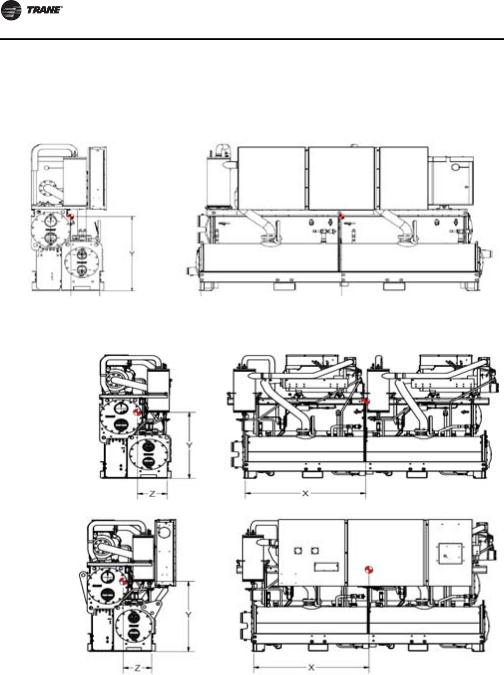
Installation - Mechanical
38 RLC-SVX09H-EN
Center of Gravity
Figure 17. Center of gravity
RTWD - Std efficiency (all)
RTWD - High efficiency, 80-120T (60 Hz), 60-120T (50 Hz)
RTUD - 80-130T
Figure 18. Center of gravity
RTWD - High efficiency, 150-250T (60Hz), 130-250T (50Hz)
RTWD - Premium efficiency (all)
RTUD - 150-250T
Without panel
With panel
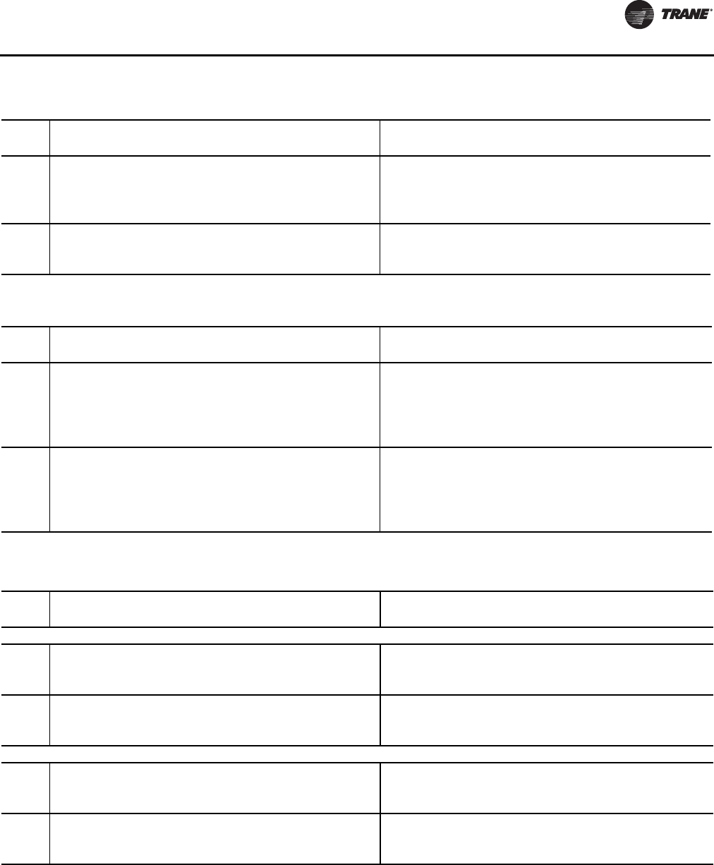
Installation - Mechanical
RLC-SVX09H-EN 39
Table 30. RTWD Center of gravity, 60Hz - Figure 17 - in (mm)
Standard Efficiency High Efficiency
Unit X Y Z X Y Z
80 61 (1543) 34 (868) 15 (381) 55 (1393) 35 (879) 16 (394)
90 61 (1544) 34 (868) 15 (381) 55 (1395) 35 (877) 16 (394)
100 62 (1566) 35 (879) 15 (382) 55 (1409) 34 (869) 15 (390)
110 61 (1547) 35 (891) 15 (383) 55 (1391) 35 (880) 15 (391)
120 60 (1534) 34 (876) 15 (390) 55 (1393) 35 (879) 15 (391)
130 60 (1535) 35 (876) 15 (391) 55 (1394) 35 (879) 15 (392)
140 63 (1607) 36 (903) 16 (403) - - -
Table 31. RTWD Center of gravity, 50Hz - Figure 17 - in (mm)
Standard Efficiency High Efficiency
Unit X Y Z X Y Z
60 - - - 55 (1393) 35 (879) 16 (395)
70 61 (1543) 34 (868) 15 (381) 55 (1393) 35 (878) 16 (395)
80 62 (1567) 34 (875) 15 (384) 56 (1416) 35 (885) 16 (397)
90 61 (1562) 35 (882) 15 (387) 55 (1405) 34 (871) 16 (395)
100 61 (1562) 35 (886) 15 (385) 55 (1405) 34 (876) 15 (393)
110 61 (1547) 35 (891) 15 (383) 55 (1393) 35 (879) 15 (391)
120 63 (1612) 36 (905) 16 (403) 57 (1460) 36 (907) 16 (404)
130 63 (1591) 37 (929) 16 (414) 55 (1393) 35 (879) 16 (395)
140 63 (1590) 37 (929) 16 (414) - - -
150 63 (1590) 37 (927) 16 (414) - - -
Table 32. RTWD Center of gravity, 60Hz - Figure 18 - in (mm)
High Efficiency Premium Efficiency
Unit X Y Z X Y Z
No Panel
150 60 (1518) 38 (959) 17 (441) 70 (1773) 37 (949) 17 (434)
160 58 (1478) 39 (989) 18 (449) 68 (1740) 39 (980) 17 (441)
180 58 (1481) 39 (987) 18 (449) 68 (1740) 38 (978) 17 (442)
200 58 (1482) 39 (985) 18 (449) 68 (1741) 38 (977) 17 (441)
220 60 (1513) 40 (1006) 18 (446) - - -
250 59 (1507) 40 (1019) 18 (451) - - -
With Panel
150 59 (1511) 39 (995) 15 (391) 70 (1772) 39 (986) 15 (388)
160 58 (1475) 40 (1020) 16 (401) 68 (1741) 40 (1012) 16 (397)
180 58 (1478) 40 (1018) 16 (401) 69 (1742) 40 (1010) 16 (398)
200 58 (1479) 40 (1016) 16 (402) 69 (1742) 40 (1008) 16 (398)
220 59 (1508) 41 (1035) 16 (404) - - -
250 59 (1502) 41 (1046) 16 (411) - - -
Installation - Mechanical
40 RLC-SVX09H-EN
Evaporator Piping
Thoroughly flush all water piping to the unit before making
the final piping connections to the unit.
Components and layout will vary slightly, depending on
the location of connections and the water source.
Table 33. RTWD Center of gravity, 50Hz - Figure 18 - in (mm)
High Efficiency Premium Efficiency
Unit X Y Z X Y Z
No Panel
120 59 (1493) 39 (988) 18 (455) - - -
140 59 (1492) 39 (986) 18 (455) - - -
160 59 (1492) 39 (983) 18 (454) 69 (1752) 38 (974) 17 (446)
180 61 (1544) 39 (1002) 18 (456) 71 (1804) 39 (993) 18 (448)
200 59 (1509) 40 (1025) 18 (451) 59 (1509) 40 (1021) 18 (452)
220 59 (1509) 40 (1023) 18 (450) - - -
250 59 (1508) 40 (1020) 18 (450) - - -
With Panel
120 59 (1488) 40 (1020) 16 (405) - - -
140 59 (1488) 40 (1018) 16 (406) - - -
160 59 (1488) 40 (1015) 16 (406) 69 (1752) 40 (1007) 16 (401)
180 60 (1536) 41 (1031) 16 (409) 71 (1800) 40 (1023) 16 (406)
200 59 (1504) 41 (1052) 16 (409) 59 (1504) 41 (1047) 16 (411)
220 59 (1504) 41 (1050) 16 (409) - - -
250 59 (1503) 41 (1047) 16 (409) - - -
Table 34. RTUD Center of gravity, 60Hz- Figure 17-in
(mm)
High Efficiency
Unit X Y Z
80 55 (1400) 35 (895) 15 (371)
90 55 (1400) 35 (894) 15 (371)
100 56 (1430) 36 (906) 15 (372)
110 55 (1408) 36 (909) 15 (370)
120 55 (1408) 36 (908) 15 (369)
130 55 (1408) 36 (908) 15 (369)
Table 35. RTUD Center of gravity, 60Hz- Figure 18-in
(mm)
High Efficiency
Unit X Y Z
No Panel
150 64 (1627) 38 (959) 17 (439)
160 62 (1573) 41 (1034) 18 (457)
180 62 (1574) 41 (1037) 18 (454)
200 61 (1557) 41 (1037) 18 (450)
220 64 (1618) 42 (1055) 18 (454)
250 63 (1607) 42 (1070) 18 (457)
With Panel
150 62 (1568) 38 (973) 16 (416)
160 61 (1558) 42 (1067) 16 (399)
180 61 (1559) 42 (1069) 16 (397)
200 61 (1543) 42 (1069) 16 (394)
220 63 (1599) 43 (1084) 16 (399)
250 63 (1589) 43 (1097) 16 (405)
NOTICE:
Evaporator Damage!
The chilled water connections to the evaporator are to
be grooved-pipe type connections. Do not attempt to
weld these connections, as the heat generated from
welding can cause microscopic and macroscopic
fractures on the cast iron waterboxes that can lead to
premature failure of the waterbox. To prevent damage
to chilled water components, do not allow evaporator
pressure (maximum working pressure) to exceed 150
psig (10.5 bar).
NOTICE:
Equipment Damage!
If using an acidic commercial flushing solution when
flushing the water piping, construct a temporary
bypass around the unit to prevent damage to internal
components of the evaporator.
NOTICE:
Equipment Damage!
To prevent evaporator or condenser damage, pipe
strainers must be installed in the water supplies to
protect components from water born debris. Trane is
not responsible for equipment-only-damage caused by
water born debris.
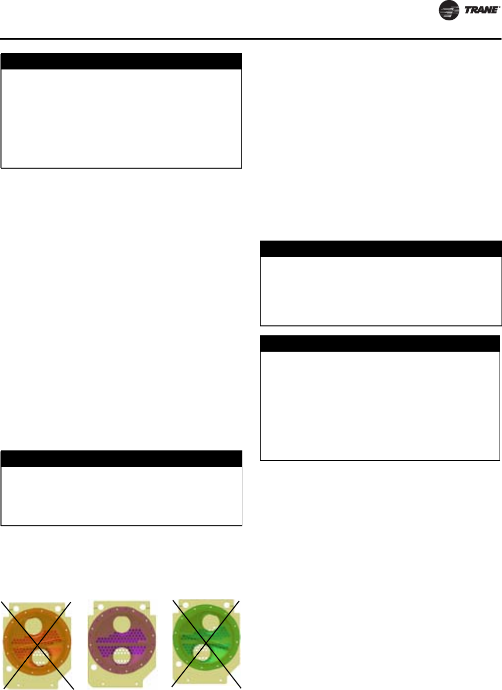
Installation - Mechanical
RLC-SVX09H-EN 41
Drainage
Locate the unit near a large capacity drain for water vessel
drain-down during shutdown or repair. Condensers and
evaporators are provided with drain connections. Refer to
“Water Piping.” All local and national codes apply.
A vent is provided on the top of the evaporator at the
return end. Be sure to provide additional vents at high
points in the piping to bleed air from the chilled water
system. Install necessary pressure gauges to monitor the
entering and leaving chilled water pressures.
Provide shutoff valves in lines to the gauges to isolate
them from the system when they are not in use. Use
rubber vibration eliminators to prevent vibration
transmission through the water lines.
If desired, install thermometers in lines to monitor
entering and leaving water temperatures. Install a
balancing valve in leaving water line to control water flow
balance. Install shutoff valves on both entering and
leaving water lines to isolate evaporator for service.
A pipe strainer must be installed in entering water line to
prevent water-borne debris from entering the evaporator.
Reversing Water Boxes
Water boxes on evaporator and condenser can NOT be
rotated or swapped end for end. Altering water boxes will
lead to poor efficiency, poor oil management and possible
freeze-up of evaporator.
Evaporator Piping Components
“Piping components” include all devices and controls
used to provide proper water system operation and unit
operating safety. These components and their general
locations are given below.
Entering Chilled Water Piping - Field Installed
• Air vents (to bleed air from system)
• Water pressure gauges with shutoff valves
• Vibration eliminators
• Shutoff (isolation) valves
• Thermometers (if desired)
• Cleanout tees
• Relief valve
• Pipe strainer
Leaving Chilled Water Piping - Field Installed
• Air vents (to bleed air from system)
• Water pressure gauges with shutoff valves
• Vibration eliminators
• Shutoff (isolation) valves
• Thermometers
• Cleanout tees
• Balancing valve
• Flow Switch (not required if factory installed flow
switch option is selected)
Evaporator Flow Switch (Optional)
If factory installed flow switch option is selected, switch is
programmed based on the operating conditions
submitted with the order.The leaving evaporator
temperature, fluid type and fluid concentration affect the
selected flow switch. If the operating conditions on the job
site change, the flow switch may need to be replaced.
NOTICE:
Proper Water Treatment!
The use of untreated or improperly treated water could
result in scaling, erosion, corrosion, algae or slime. It is
recommended that the services of a qualified water
treatment specialist be engaged to determine what
water treatment, if any, is required. Trane assumes no
responsibility for equipment failures which result from
untreated or improperly treated water, or saline or
brackish water.
NOTICE:
Equipment Damage!
Do NOT rotate or swap evaporator or condenser water
boxes end-for-end. Altering water boxes can affect
equipment operation and can cause equipment
damage.
Figure 19. RTWD water boxes
NOTICE:
Water Born Debris!
To prevent evaporator or condenser damage, pipe
strainers must be installed in the water supplies to
protect components from water born debris. Trane is
not responsible for equipment-only-damage caused by
water born debris.
NOTICE:
Evaporator Damage!
The chilled water connections to the evaporator are to
be grooved-pipe type connections. Do not attempt to
weld these connections, as the heat generated from
welding can cause microscopic and macroscopic
fractures on the cast iron waterboxes that can lead to
premature failure of the waterbox. To prevent damage
to chilled water components, do not allow evaporator
pressure (maximum working pressure) to exceed 150
psig (10.5 bar).

Installation - Mechanical
42 RLC-SVX09H-EN
The sensor head includes 3 LEDs, two yellow and one
green.Wait 15 seconds after power is applied to the sensor
before evaluating LEDs for flow status. When wired
correctly and flow is established, only the green LED
should be lit. Following are the LED indicators:
• Green ON, both yellow OFF — Flow
• Green and outside yellow ON — No Flow
• Center yellow ON continuously — Miswire
Important: If using an acidic commercial flushing
solution, construct a temporary bypass
around the unit to prevent damage to
internal components of the evaporator.
Dirt, scale, products of corrosion and other foreign
material will adversely affect heat transfer between the
water and system components. Foreign matter in the
chilled water system can also increase pressure drop and,
consequently, reduce water flow. Proper water treatment
must be determined locally, depending on the type of
system and local water characteristics.
Neither salt nor brackish water is recommended for use in
Trane air-cooled Series R®chillers. Use of either will lead
to a shortened life to an indeterminable degree.TheTrane
Company encourages the employment of a reputable
water treatment specialist, familiar with local water
conditions, to assist in this determination and in the
establishment of a proper water treatment program.
Using untreated or improperly treated water in these units
may result in inefficient operation and possible tube
damage. Consult a qualified water treatment specialist to
determine whether treatment is needed.
Indexing Flow Switch
To properly index the flow switch, the following
requirements must be met:
• Dot must be at a position no greater than 90° off Index.
• Torque must be between 22 ft-lb min and 74 ft-lb max.
• A minimum distance of 5x pipe diameter must be
maintained between flow switch and any bends,
valves, changes in cross sections, etc.
Flow Proving Devices
Important: If factory installed flow switch option is not
selected, installer must provide flow
switches or differential pressure switches
with pump interlocks to prove water flow.
To provide chiller protection, install and wire flow switches
in series with the water pump interlocks, for both chilled
water and condenser water circuits (see “Installation -
Electrical” chapter). Specific connections and schematic
wiring diagrams are shipped with the unit.
Flow switches must prevent or stop compressor operation
if either system water flow drops off below the required
minimum shown on the pressure drop curves. Follow the
manufacturer’s recommendations for selection and
installation procedures. General guidelines for flow switch
installation are outlined below.
• Mount the switch upright, with a minimum of 5 pipe
diameters straight, horizontal run on each side.
• Do not install close to elbows, orifices or valves.
Note: The arrow on switch must point in direction of
water flow.
• To prevent switch fluttering, remove all air from water
system.
Note: CH530 provides a 6-sec time delay on flow switch
input before shutting down unit on loss-of-flow
diagnostic. Contact a qualified service organization
if nuisance machine shutdowns persist.
• Adjust switch to open when water flow falls below
minimum. See General Data tables for minimum flow
recommendations. Flow switch is closed on proof of
water flow.
NOTICE:
Proper Water Treatment!
The use of untreated or improperly treated water in this
equipment could result in scaling, erosion, corrosion,
algae or slime. It is recommended that the services of a
qualified water treatment specialist be engaged to
determine what water treatment, if any, is required.
Trane assumes no responsibility for equipment failures
which result from untreated or improperly treated
water, or saline or brackish water.
Figure 20. Proper flow switch indexing
NOTICE:
Evaporator Damage!
For all RTUD units, chilled water pumps MUST be
controlled by the Trane CH530 to avoid catastrophic
damage to the evaporator due to freezing.
NOTICE:
Evaporator Damage!
To prevent evaporator damage, do not use water flow
switch to cycle the system.
Flow
Top View
Index
The flow switch must have the dot in the shaded area
to the left of this line for proper indexing (±90° off Index)
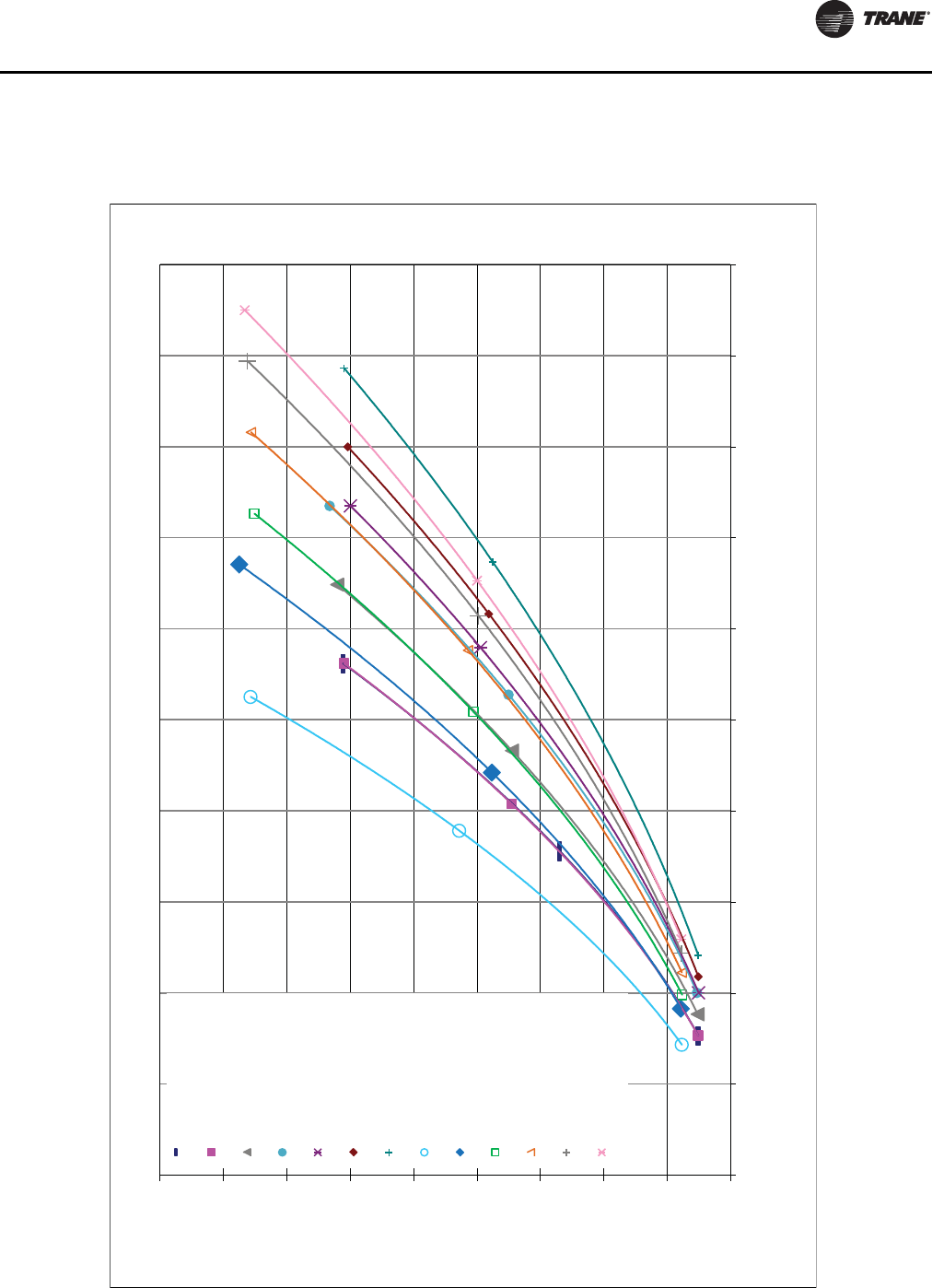
Installation - Mechanical
RLC-SVX09H-EN 43
Pressure Drop Curves
For overlapping pressure drop curves, see General Data tables in section “General Information,” p. 9 for limit values.
Figure 21. Evaporator pressure drop curves - 2 pass, 60 Hz - RTWD, RTUD
0.0
5.0
10.0
15.0
20.0
25.0
30.0
35.0
40.0
45.0
0.0 50.0 100.0 150.0 200.0 250.0 300.0 350.0 400.0 450.0 500.0
Pressure Drop (ft. H2O)
Water Flow (GPM)
Waterside Pressure Drop - 60 Hz Units - 2 Pass Evaporator
RTWD080 Std
RTWD090 Std
RTWD100 Std
RTWD110 Std
RTWD120 Std
RTWD130 Std
RTWD140 Std
RTWD80 High
RTWD90 High
RTWD100 High &
RTUD110 High
RTWD110 High &
RTUD120, 130 High
RTWD120 High &
RTUD150 High
RTWD130 High
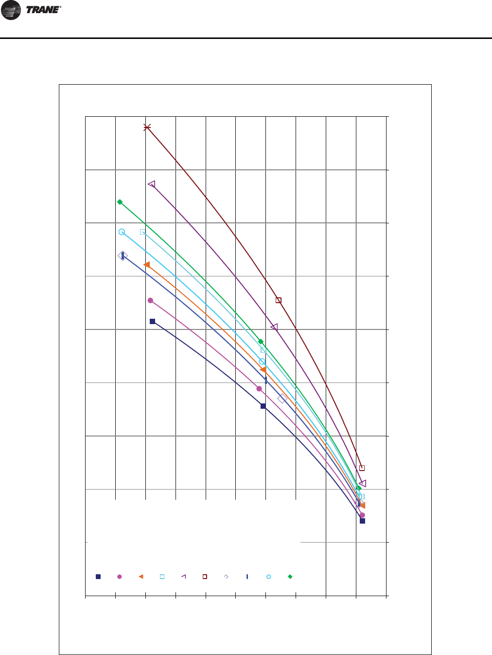
Installation - Mechanical
44 RLC-SVX09H-EN
Figure 22. Evaporator pressure drop curves - 2 pass, 60 Hz - RTWD, RTUD
0.0
5.0
10.0
15.0
20.0
25.0
30.0
35.0
40.0
45.0
50.0
0.0 100.0 200.0 300.0 400.0 500.0 600.0 700.0 800.0 900.0
Pressure Drop (ft. H2O)
Water Flow (GPM)
Waterside Pressure Drop - 60 Hz Units - 2 Pass Evaporator
RTWD150 High
RTWD160 High
RTWD180 High
RTWD200 High
RTWD220 High
RTWD250 High
RTWD150 Prem
RTWD160 Prem
RTWD180 Prem
RTWD200 Prem
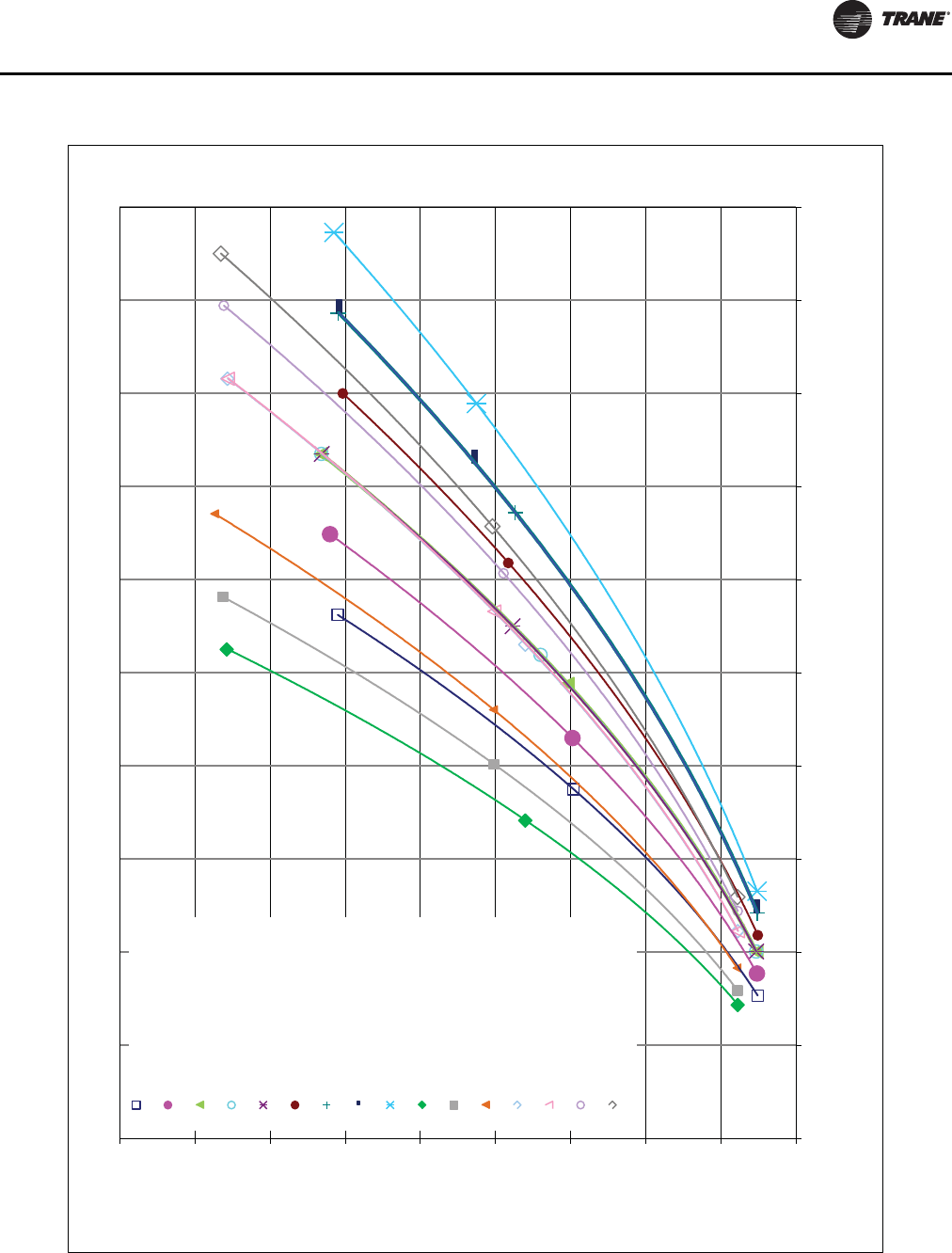
Installation - Mechanical
RLC-SVX09H-EN 45
Figure 23. Evaporator pressure drop curves - 2 pass - RTWD 50 Hz, RTUD 60 Hz
0.0
5.0
10.0
15.0
20.0
25.0
30.0
35.0
40.0
45.0
0.0 50.0 100.0 150.0 200.0 250.0 300.0 350.0 400.0 450.0 500.0
Pressure Drop (ft. H2O)
Water Flow (GPM)
Waterside Pressure Drop - RTWD 50Hz/RTUD 60Hz Units - 2 Pass Evaporator
RTWD70 Std 50Hz
RTWD80 Std 50Hz
RTWD90 Std 50Hz
RTWD100 Std 50Hz
RTWD110 Std 50Hz
RTWD120 Std 50Hz
RTWD130 Std 50Hz
RTWD140 Std 50Hz
RTWD150 Std 50Hz
RTWD60 High 50Hz &
RTUD80 High 60Hz
RTWD70 High 50Hz &
RTUD90 High 60Hz
RTWD80 High 50Hz &
RTUD100 High 60Hz
RTWD90 High 50Hz
RTWD100 High 50Hz
RTWD110 High 50Hz
RTWD120 High 50Hz
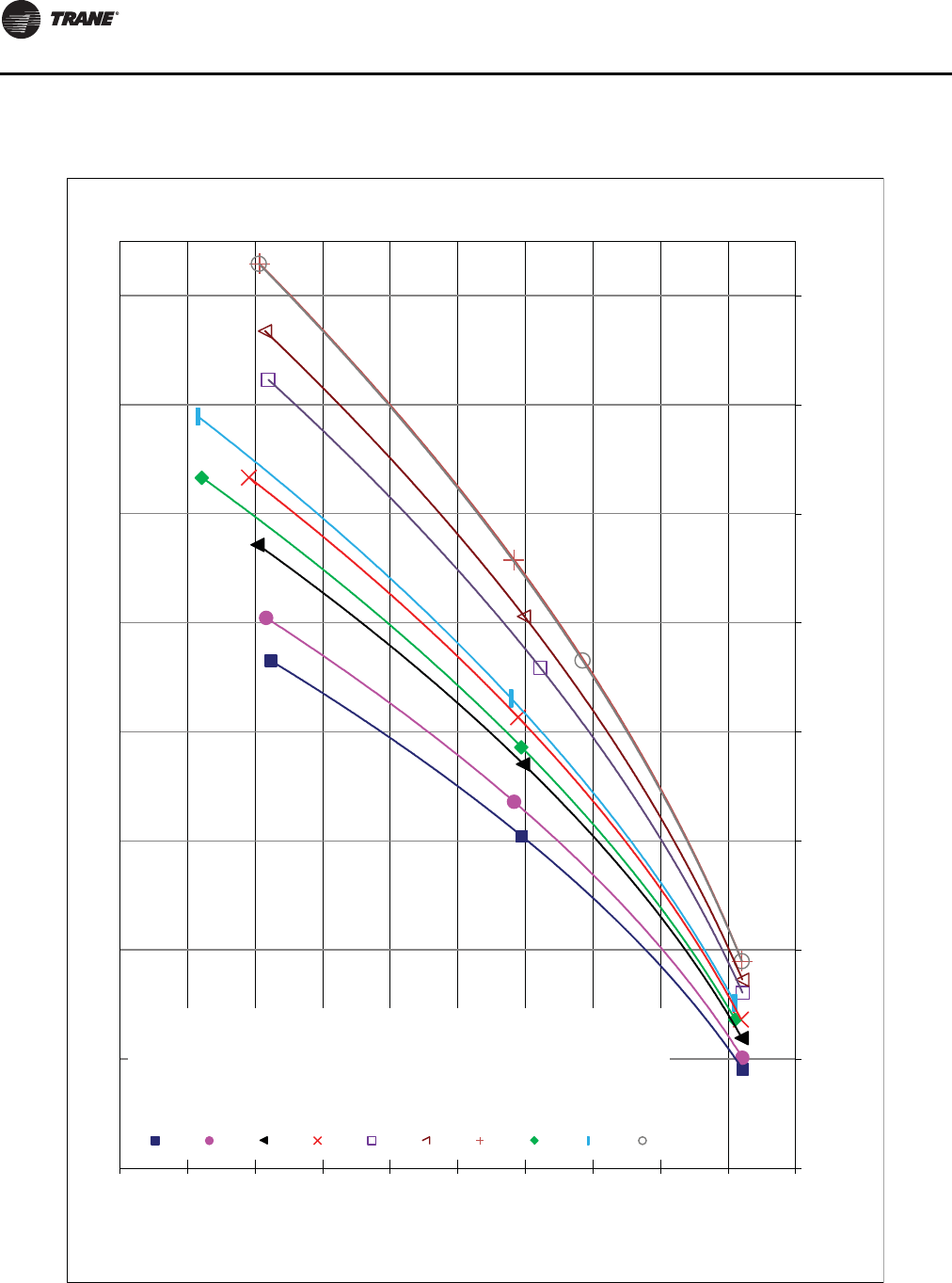
Installation - Mechanical
46 RLC-SVX09H-EN
Figure 24. Evaporator pressure drop curves - 2 pass, 50 hz - RTWD
0.0
5.0
10.0
15.0
20.0
25.0
30.0
35.0
40.0
45.0
50.0
50.0 150.0 250.0 350.0 450.0 550.0 650.0 750.0 850.0
Pressure Drop (ft. H2O)
Water Flow (GPM)
Waterside Pressure Drop - 50 Hz Units - 2 Pass Evaporator
RTWD130 High
RTWD140 High
RTWD160 High
RTWD180 High
RTWD200 High
RTWD220 High
RTWD250 High
RTWD160 Prem
RTWD180 Prem
RTWD200 Prem
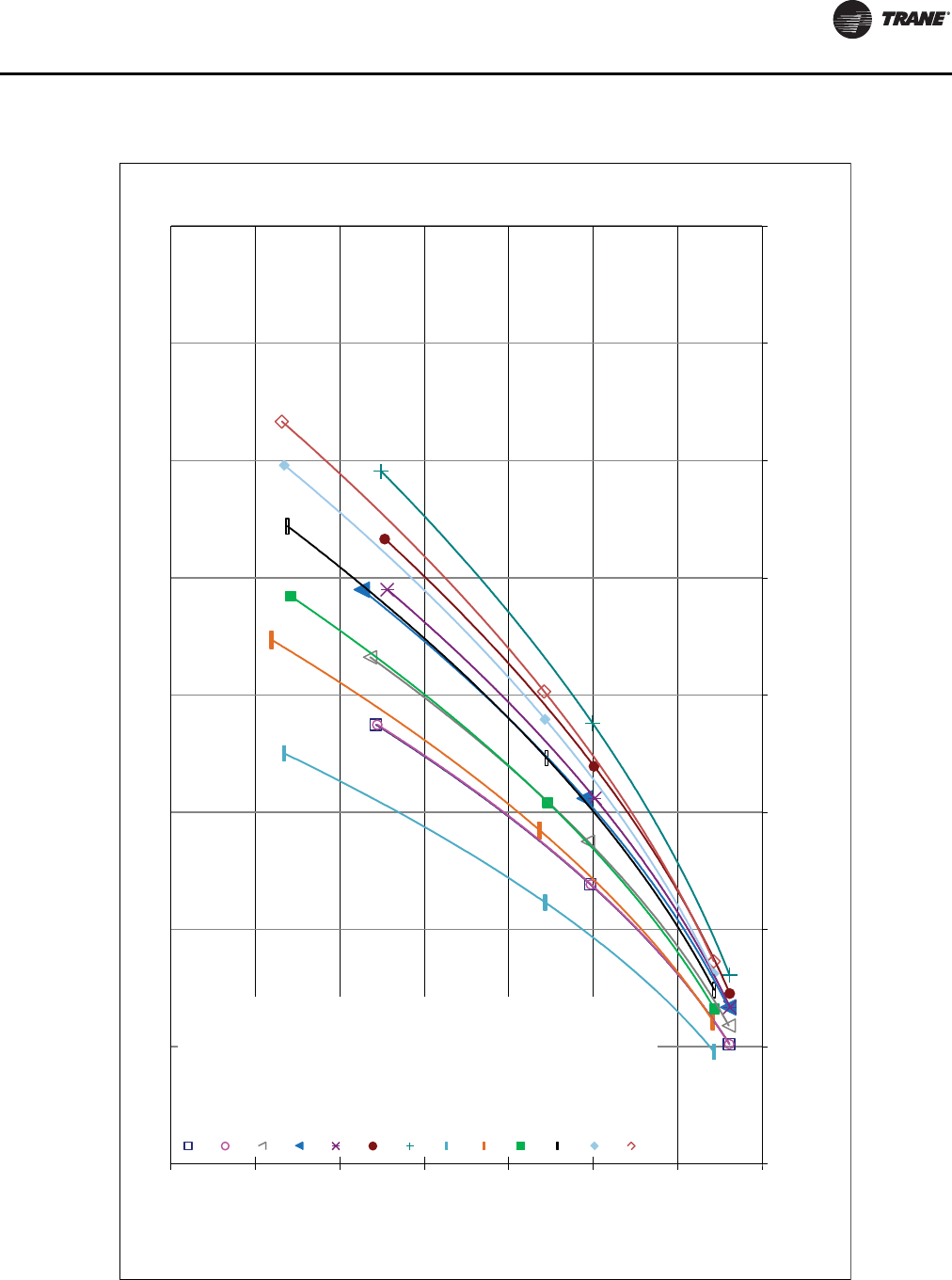
Installation - Mechanical
RLC-SVX09H-EN 47
Figure 25. Evaporator pressure drop curves - 3 pass, 60 hz - RTWD, RTUD
0.0
10.0
20.0
30.0
40.0
50.0
60.0
70.0
0.0 50.0 100.0 150.0 200.0 250.0 300.0 350.0 400.0
Pressure Drop (ft. H2O)
Water Flow (GPM)
Waterside Pressure Drop - 60 Hz Units - 3 Pass Evaporator
RTWD080 Std
RTWD090 Std
RTWD100 Std
RTWD110 Std
RTWD120 Std
RTWD130 Std
RTWD140 Std
RTWD80 High
RTWD90 High
RTWD100 High &
RTUD110 High
RTWD110 High &
RTUD120, 130 High
RTWD120 High &
RTUD150 High
RTWD130 High
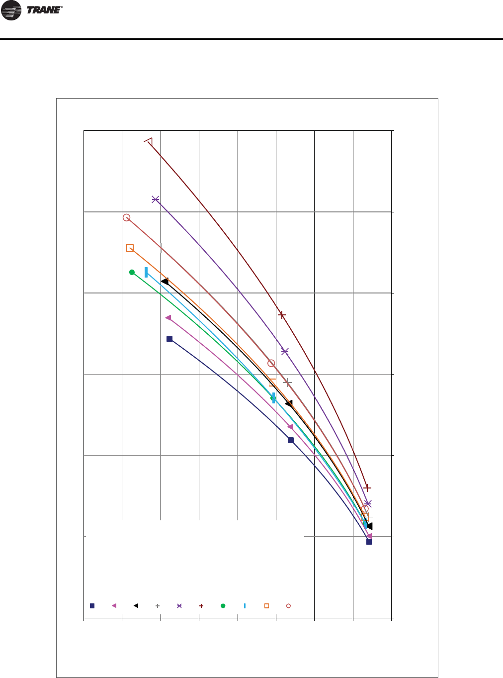
Installation - Mechanical
48 RLC-SVX09H-EN
Figure 26. Evaporator pressure drop curves - 3 pass, 60 hz - RTWD, RTUD
0.0
10.0
20.0
30.0
40.0
50.0
60.0
70.0
80.0
0.0 100.0 200.0 300.0 400.0 500.0 600.0
Pressure Drop (ft. H2O)
Water Flow (GPM)
Waterside Pressure Drop - 60 Hz Units - 3 Pass Evaporator
RTWD150 High &
RTUD160, 180 High
RTWD160 High &
RTUD200 High
RTWD180 High &
RTUD 220 High
RTWD200 High &
RTUD 250 High
RTWD220 High
RTWD250 High
RTWD150 Prem
RTWD160 Prem
RTWD180 Prem
RTWD200 Prem
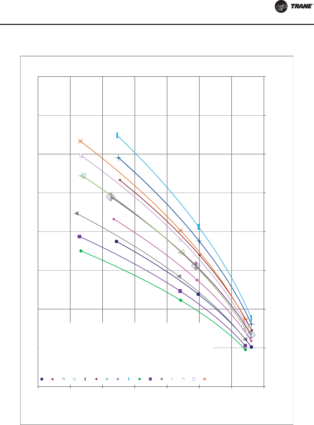
Installation - Mechanical
RLC-SVX09H-EN 49
Figure 27. Evaporator pressure drop curves - 3 pass - RTWD 50 Hz, RTUD 60 Hz
0.0
10.0
20.0
30.0
40.0
50.0
60.0
70.0
0.0 50.0 100.0 150.0 200.0 250.0 300.0 350.0 400.0
Pressure Drop (ft. H2O)
Water Flow (GPM)
Waterside Pressure Drop - RTWD 50Hz/RTUD 60 Hz Units - 3 Pass Evaporator
RTWD70 Std 50Hz
RTWD80 Std 50Hz
RTWD90 Std 50Hz
RTWD100 Std 50Hz
RTWD110 Std 50Hz
RTWD120 Std 50Hz
RTWD130 Std 50Hz
RTWD140 Std 50Hz
RTWD150 Std 50Hz
RTWD60 High 50Hz &
RTUD80 High 60Hz
RTWD70 High 50Hz &
RTUD90 High 60Hz
RTWD80 High 50Hz &
RTUD100 High 60Hz
RTWD90 High 50Hz
RTWD100 High 50Hz
RTWD110 High 50Hz
RTWD120 High 50Hz
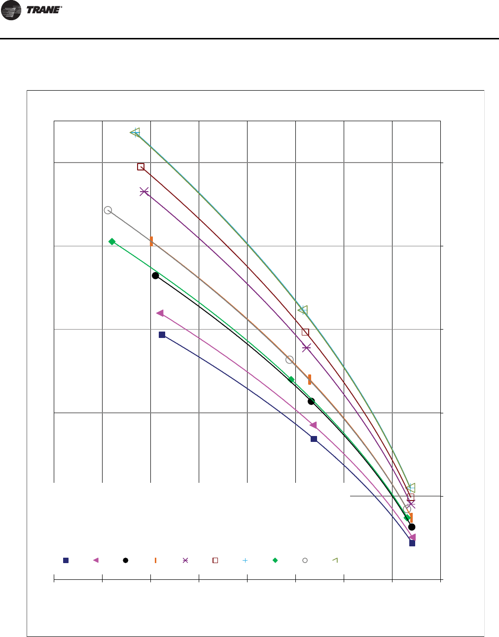
Installation - Mechanical
50 RLC-SVX09H-EN
Figure 28. Evaporator pressure drop curves - 3 pass, 50 Hz - RTWD
0.0
10.0
20.0
30.0
40.0
50.0
60.0
70.0
80.0
50.0 150.0 250.0 350.0 450.0 550.0
Pressure Drop (ft. H2O)
Water Flow (GPM)
Waterside Pressure Drop - 50 Hz Units - 3 Pass Evaporator
RTWD130 High
RTWD140 High
RTWD160 High
RTWD180 High
RTWD200 High
RTWD220 High
RTWD250 High
RTWD160 Prem
RTWD180 Prem
RTWD200 Prem
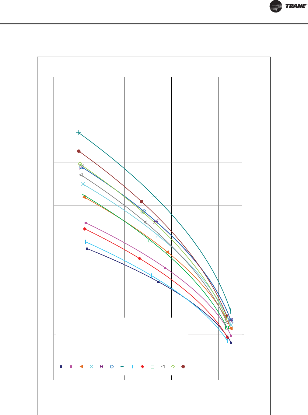
Installation - Mechanical
RLC-SVX09H-EN 51
Figure 29. Condenser pressure drop curves - RTWD 60 Hz
0.0
5.0
10.0
15.0
20.0
25.0
30.0
35.0
40.0
0.0 100.0 200.0 300.0 400.0 500.0 600.0 700.0
Pressure Drop (ft. H2O)
Water Flow (GPM)
Waterside Pressure Drop - 60 Hz Units - Condenser
RTWD080 Std
RTWD090 Std
RTWD100 Std
RTWD110 Std
RTWD120 Std
RTWD130 Std
RTWD140 Std
RTWD80 High
RTWD90 High
RTWD100 High
RTWD110 High
RTWD120 High
RTWD130 High
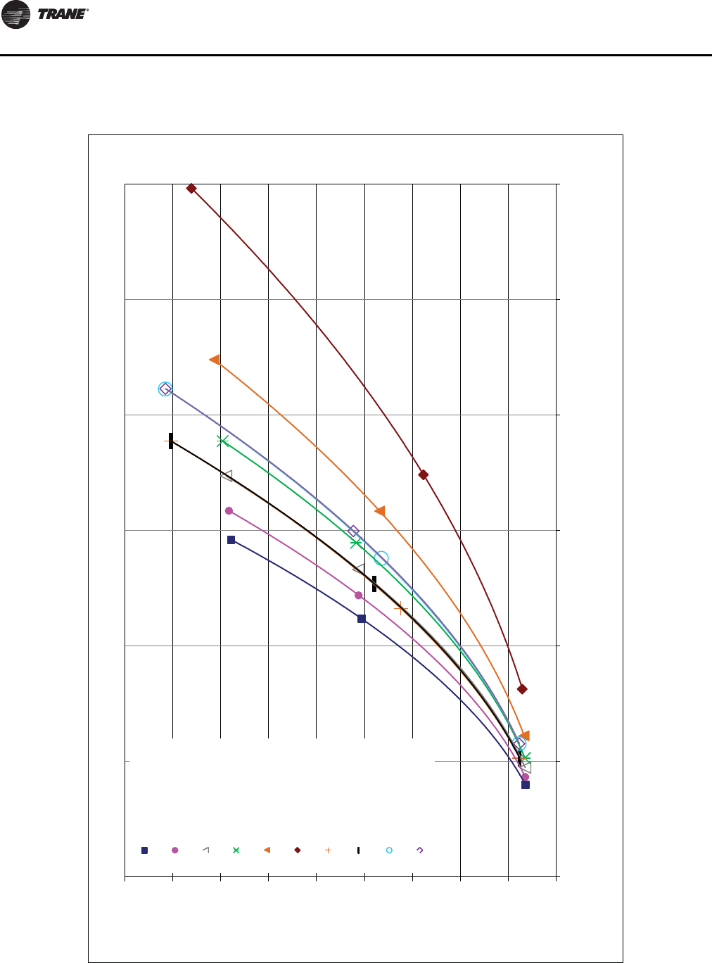
Installation - Mechanical
52 RLC-SVX09H-EN
Figure 30. Condenser pressure drop curves - RTWD 60 Hz
0.0
5.0
10.0
15.0
20.0
25.0
30.0
35.0
40.0
45.0
0.0 200.0 400.0 600.0 800.0 1000.0 1200.0
Pressure Drop (ft. H2O)
Water Flow (GPM)
Waterside Pressure Drop - 60 Hz Units - Condenser
RTWD150 High
RTWD160 High
RTWD180 High
RTWD200 High
RTWD220 High
RTWD250 High
RTWD150 Prem
RTWD160 Prem
RTWD180 Prem
RTWD200 Prem
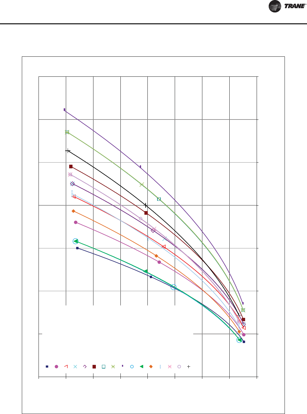
Installation - Mechanical
RLC-SVX09H-EN 53
Figure 31. Condenser pressure drop curves - RTWD 50 Hz
0.0
5.0
10.0
15.0
20.0
25.0
30.0
35.0
40.0
0.0 100.0 200.0 300.0 400.0 500.0 600.0 700.0
Pressure Drop (ft. H2O)
Water Flow (GPM)
Waterside Pressure Drop - 50 Hz Units - Condenser
RTWD70 Std 50Hz
RTWD80 Std 50Hz
RTWD90 Std 50Hz
RTWD100 Std 50Hz
RTWD110 Std 50Hz
RTWD120 Std 50Hz
RTWD130 Std 50Hz
RTWD140 Std 50Hz
RTWD150 Std 50Hz
RTWD60 High 50Hz
RTWD70 High 50Hz
RTWD80 High 50Hz
RTWD90 High 50Hz
RTWD100 High 50Hz
RTWD110 High 50Hz
RTWD120 High 50Hz
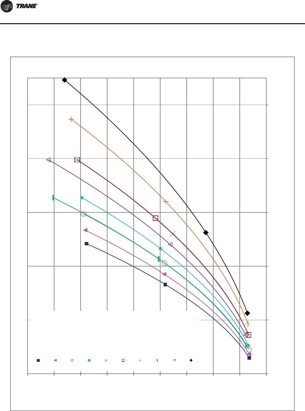
Installation - Mechanical
54 RLC-SVX09H-EN
Figure 32. Condenser pressure drop curves - RTWD 50 Hz
0.0
5.0
10.0
15.0
20.0
25.0
30.0
35.0
40.0
45.0
100.0 300.0 500.0 700.0 900.0 1100.0
Pressure Drop (ft. H2O)
Water Flow (GPM)
Waterside Pressure Drop - 50 Hz Units - Condenser
RTWD130 High
RTWD140 High
RTWD160 High
RTWD180 High
RTWD200 High
RTWD220 High
RTWD250 High
RTWD160 Prem
RTWD180 Prem
RTWD200 Prem
Installation - Mechanical
RLC-SVX09H-EN 55
Low Evap Refrigerant Cutout/Percent Glycol Recommendations
The table below shows the low evaporator temperature
cutout for different glycol levels.
Additional glycol beyond the recommendations will
adversely effect unit performance.The unit efficiency will
be reduced and the saturated evaporator temperature will
be reduced. For some operating conditions this effect can
be significant.
If additional glycol is used, then use the actual percent
glycol to establish the low refrigerant cutout setpoint.
Table 36. Low evaporator refrigerant temperature cutout (LRTC) and low water temperature cutout (LWTC)
Ethylene Glycol Propylene Glycol
Glycol
Percentage
(%)
Solution
Freeze Point
(°F)
Minimum
Recommended
LRTC (°F)
Minimum
Recommended
LWTC (°F)
Glycol
Percentage
(%)
Solution
Freeze Point
(°F)
Minimum
Recommended
LRTC (°F)
Minimum
Recommended
LWTC (°F)
0 32.0 28.6 35.0 0 32.0 28.6 35.0
2 31.0 27.6 34.0 2 31.0 27.6 34.0
4 29.7 26.3 32.7 4 29.9 26.5 32.9
5 29.0 25.6 32.0 5 29.3 25.9 32.3
6 28.3 24.9 31.3 6 28.7 25.3 31.7
8 26.9 23.5 29.9 8 27.6 24.2 30.6
10 25.5 22.1 28.5 10 26.4 23.0 29.4
12 23.9 20.5 26.9 12 25.1 21.7 28.1
14 22.3 18.9 25.3 14 23.8 20.4 26.8
15 21.5 18.1 24.5 15 23.1 19.7 26.1
16 20.6 17.2 23.6 16 22.4 19.0 25.4
18 18.7 15.3 21.7 18 20.9 17.5 23.9
20 16.8 13.4 19.8 20 19.3 15.9 22.3
22 14.7 11.3 17.7 22 17.6 14.2 20.6
24 12.5 9.1 15.5 24 15.7 12.3 18.7
25 11.4 8.0 14.4 25 14.8 11.4 17.8
26 10.2 6.8 13.2 26 13.8 10.4 16.8
28 7.7 4.3 10.7 28 11.6 8.2 14.6
30 5.1 1.7 8.1 30 9.3 5.9 12.3
32 2.3 -1.1 5.3 32 6.8 3.4 9.8
34 -0.7 -4.1 5.0 34 4.1 0.7 7.1
35 -2.3 -5.0 5.0 35 2.7 -0.7 5.7
36 -3.9 -5.0 5.0 36 1.3 -2.1 5.0
38 -7.3 -5.0 5.0 38 -1.8 -5.0 5.0
40 -10.8 -5.0 5.0 40 -5.2 -5.0 5.0
42 -14.6 -5.0 5.0 42 -8.8 -5.0 5.0
44 -18.6 -5.0 5.0 44 -12.6 -5.0 5.0
45 -20.7 -5.0 5.0 45 -14.6 -5.0 5.0
46 -22.9 -5.0 5.0 46 -16.7 -5.0 5.0
48 -27.3 -5.0 5.0 48 -21.1 -5.0 5.0
50 -32.1 -5.0 5.0 50 -25.8 -5.0 5.0

Installation - Mechanical
56 RLC-SVX09H-EN
Condenser Water Piping (RTWD Units Only)
Condenser water inlet and outlet types, sizes and locations
are given in the Unit Dimensions and Weights. Condenser
pressure drops are shown inFigure 29, p. 51 thru
Figure 32, p. 54.
Condenser Piping Components
Condenser piping components and layout vary,
depending on location of connections and water source.
Condenser piping components generally function
identically to those in the evaporator piping system, as
described in "Evaporator Piping" on Page 40. In addition,
cooling tower systems should include a manual or
automatic bypass valve that can alter the water flow rate,
to maintain condensing pressure. Well water (or city
water) condensing systems should include a pressure
reducing valve and a water regulating valve.
Pressure reducing valve should be installed to reduce
water pressure entering the condenser.This is required
only if the water pressure exceeds 150 psig.This is
necessary to prevent damage to the disc and seat of the
water regulating valve that can be caused by excessive
pressure drop through the valve and also due to the design
of the condenser. Condenser waterside is rated at 150 psi.
Water Regulating Valve (RTWD Only)
The Condenser Head Pressure Control Option provides for
a 0-10V (maximum range - a smaller range is adjustable)
output interface to the customer’s condenser water flow
device. Refer to RLC-PRB021-EN for further details
regarding condenser water temperature control.
The following guidelines must be met in order to ensure
adequate oil circulation throughout the system.
• The RTWD requires a minimum pressure differential of
25 psid (172.1 kPA) at all load conditions in order to
ensure adequate oil circulation.
• The entering condenser water temperature must be
above 55°F (12.8°C), or between 45°F (7.2°C) and 55°F
(12.8°C) with a 1°F (0.6°C) temperature rise per minute
up to 55°F (12.8°C).
• The leaving condenser water temperature must be
17°F (9.4°C) degrees higher than leaving evaporator
water temperature within 2 minutes of startup. A 25°F
(13.9°C) temperature differential must be maintained
thereafter. (This differential requirement is lessened by
0.25°F [0.14°C] for every 1°F [0.6°C] that the leaving
condenser water temperature is above 55°F [12.8°C].)
If the above guidelines cannot be met, then some form of
condenser water temperature control must be used.
Note: Plugged tees are installed to provide access for
chemical cleaning of the condenser tubes.
Condenser piping must be in accordance with all
applicable local and national codes.
Condenser Drains
The condenser shells can be drained by removing the
drain plugs from the bottom of the condenser heads. Also,
remove the vent plugs at the top of the condenser heads
to facilitate complete drainage.
When the unit is shipped, the drain plugs are removed
from the condenser and placed in a plastic bag in the
control panel, along with the evaporator drain plug.The
condenser drains may be connected to suitable drains to
permit drainage during unit servicing. If they are not, the
drain plugs must be installed.
Water Treatment
Using untreated or improperly treated water in these units
may result in inefficient operation and possible tube
damage. Consult a qualified water treatment specialist to
determine whether treatment is needed.The following
disclamatory label is provided on each RTWD unit:
Water Pressure Gauges
Install field-supplied pressure gauges (with manifolds,
when practical) on the RTWD units. Locate pressure
gauges or taps in a straight run of pipe; avoid placement
near elbows, etc. Install gauges at the same elevation.
To read manifolded pressure gauges, open one valve and
close the other (depending upon the reading desired).This
eliminates errors resulting from differently calibrated
gauges installed at unmatched elevations.
Water Pressure Relief Valves
Install a water pressure relief valve in the condenser and
evaporator leaving chilled water piping. Water vessels
with close coupled shutoff valves have a high potential for
hydrostatic pressure buildup on a water temperature
increase. Refer to applicable codes for relief valve
installation guidelines.
NOTICE:
Equipment Damage!
To prevent damage to the condenser or regulating
valve, the condenser water pressure should not exceed
150 psig.
NOTICE:
Proper Water Treatment!
The use of untreated or improperly treated water could
result in scaling, erosion, corrosion, algae or slime. It is
recommended that the services of a qualified water
treatment specialist be engaged to determine what
water treatment, if any, is required. Trane assumes no
responsibility for equipment failures which result from
untreated or improperly treated water, or saline or
brackish water.
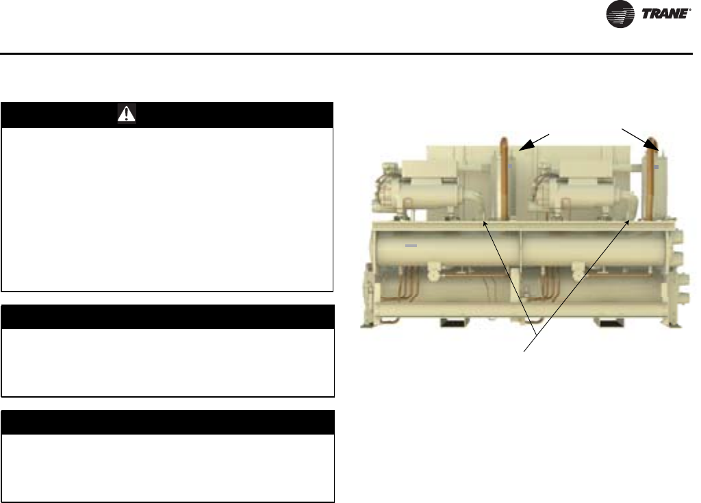
Installation - Mechanical
RLC-SVX09H-EN 57
Refrigerant Relief Valve Venting
High Pressure Side Relief Valve Venting
(RTWD-Condenser, RTUD-Oil Separator)
All RTWD units utilize a refrigerant-pressure relief valve for
each circuit which must be vented to the outdoor
atmosphere.The valves are located at the top of the
condenser. Relief valve connections are 5/8” MFL. See
Figure 33. Refer to local codes for relief valve vent line
sizing requirements.
All RTUD units utilize a refrigerant-pressure relief valve for
each circuit which must be vented to the outdoor
atmosphere.The valves are located at the top of the oil
separator. Relief valve connections are 3/8” MFL. Refer to
local codes for relief valve vent line sizing requirements.
High side relief valve discharge setpoints are 300 psig for
RTWD, and 350 psig for RTUD units. Once the relief valve
has opened, it will reclose when pressure is reduced to a
safe level.
Note: Vent line length must not exceed code
recommendations. If the line length will exceed
code recommendations for the outlet size of the
valve, install a vent line of the next larger pipe size.
Pipe each relief valve on the unit into a common vent line.
Provide access valve located at the low point of the vent
piping, to enable draining of any condensate that may
accumulate in the piping.
If multiple chillers are installed, each unit may have a
separate venting for its relief valves. If multiple relief
valves are vented together, see ASHRAE 15, and/or local
codes for sizing requirements.
Note: RTWD units can be ordered with “Dual Relief
Valve” options. Model number digit 16 is a “2”.
Units with this option will have two valves on each
circuit for a total of four on the condenser. Only two
valves would release at the same time - never all
four.
Low Pressure Side Relief Valve Venting
(Evaporator)
Low-side refrigerant-pressure relief valves are located on
the top of the evaporator shell, one per circuit. Each must
be vented to the outdoor atmosphere. Relief valve
connections are 3/4” NPTFI.
Note: RTWD units can be ordered with “Dual Relief
Valve” option. Model number digit 16 is a “2”. Units
with this option will have two valves on each circuit
for a total of four on the evaporator. Only two
valves would release at the same time - never all
four.
See Figure 33, p. 57 and Table 37, p. 58. Refer to local
codes for relief valve vent line sizing requirements.
WARNING
Refrigerant under High Pressure!
System contains oil and refrigerant under high
pressure. Recover refrigerant to relieve pressure before
opening the system. See unit nameplate for refrigerant
type. Do not use non-approved refrigerants, refrigerant
substitutes, or refrigerant additives. Failure to recover
refrigerant to relieve pressure or the use of non-
approved refrigerants, refrigerant substitutes, or
refrigerant additives could result in an explosion which
could result in death or serious injury or equipment
damage.
NOTICE:
Equipment Damage!
To prevent shell damage, install pressure relief
valves in both the evaporator and condenser
water systems.
NOTICE:
Equipment Damage!
To prevent capacity reduction and relief valve
damage, do not exceed vent piping code
specifications.
Figure 33. High pressure side relief valves
#ONDENSER
2ELIEF6ALVES
Condenser Relief Valves (RTWD only)
Oil Separator Relief Valves (RTUD only)
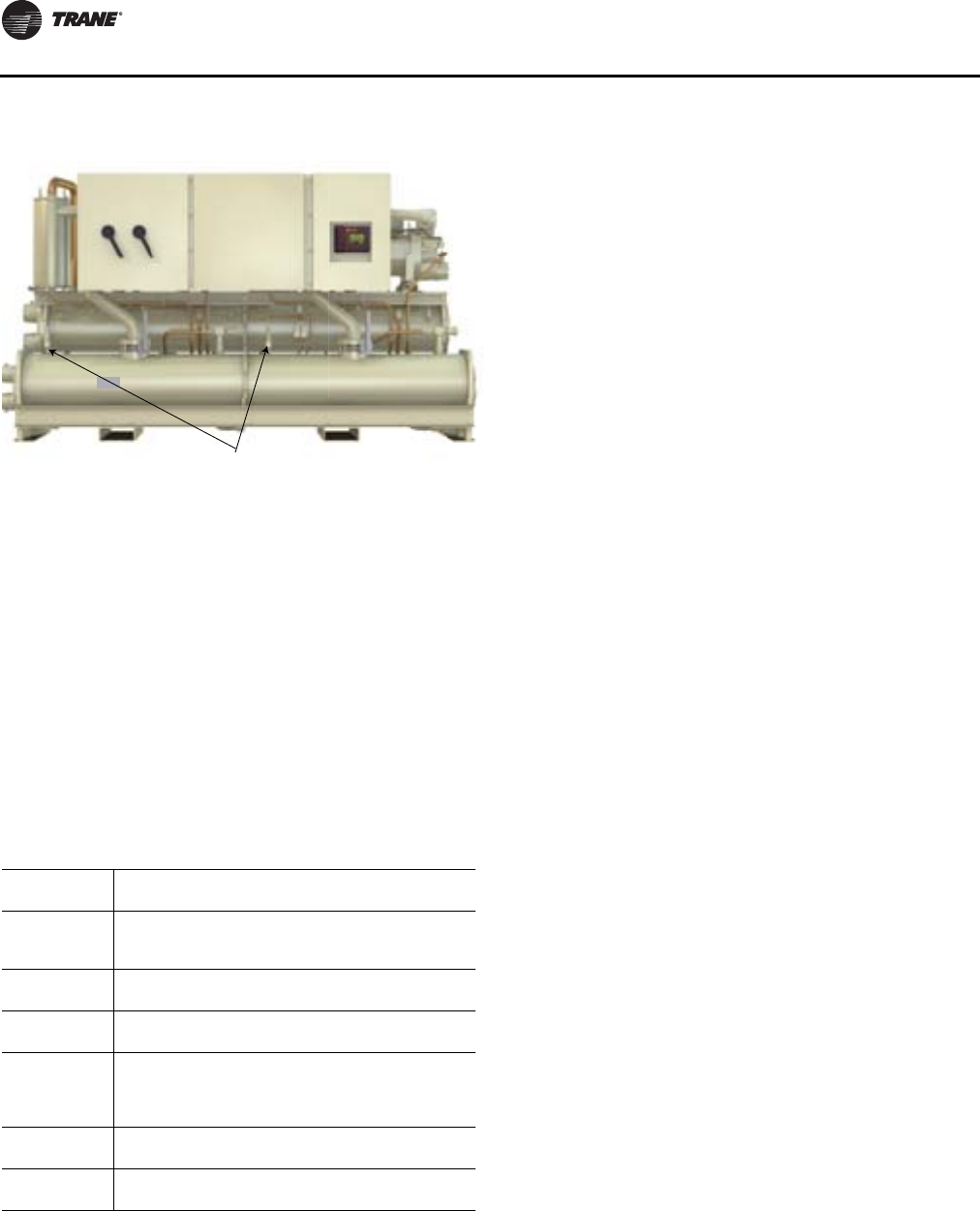
Installation - Mechanical
58 RLC-SVX09H-EN
Note: Vent line length must not exceed code
recommendations. If the line length will exceed
code recommendations for the outlet size of the
valve, install a vent line of the next larger pipe size.
Low side relief valve discharge setpoints are 200 psig.
Once the relief valve has opened, it will reclose when
pressure is reduced to a safe level.
Pipe each relief valve on the unit into a common vent line.
Provide an access valve located at the low point of the vent
piping, to enable draining of any condensate that may
accumulate in the piping.
Summary or Relief Valves - RTWD, RTUD
RTUD Installation
The installation of a split system offers a good economic
alternative to satisfy the chilled water demand for cooling
a building, particularly in the case of new construction.
The choice of a completeTrane system, including the
compressor chiller and the condenser offers the designer,
installer and owner the advantages of an optimized
selection and undivided responsibility for the design, the
quality and the operation of the complete system.
Application examples
No Elevation Difference
See Figure 35, p. 59.
Restrictions
• Total distance between components should not
exceed 200 ft (actual) or 300 ft (equivalent).
• Elevation rise of the liquid line must not be more than
15 ft above the base of the air-cooled condenser.
• Discharge line trap is recommended leaving the oil
separator if the discharge piping runs for more than 10
(actual) feet horizontally above the RTUD unit.
Condenser Installed Above Compressor Chiller
See Figure 36, p. 59.
Restrictions
• Total distance between components should not
exceed 200 ft (actual) or 300 ft (equivalent).
• Elevation difference greater than 100 ft (actual) will
result in at least a 2% efficiency decrease.
Condenser Installed Below Compressor Chiller
See Figure 37, p. 60.
Restrictions
• Total distance between components should not
exceed 200 ft (actual) or 300 ft (equivalent).
• Elevation rise of the liquid line must not be more than
15 ft above the base of the air-cooled condenser.
Figure 34. Evaporator relief valves
Table 37. Relief valve descriptions
Condenser Evaporator Oil Separator
Units
RTWD
High Pressure
Side
RTWD, RTUD
Low Pressure Side
RTUD
High Pressure
Side
Relief Setpoint 300 psig 200 psig 350 psig
Quantity
(standard) 1 per ckt 1 per ckt 1 per ckt
Quantity
(Dual Relief
Valves option -
RTWD only)
2 per ckt RTWD - 2 per ckt
(n/a - RTUD units) n/a
Relief Rate
(lb/min) 25.4 28.9 13.3
Field
Connection Size 5/8” MFL 3/4” NPTFI 3/8” MFL
%VAPORATOR
2ELEIF6ALVES
Evaporator Relief Valves

Installation - Mechanical
RLC-SVX09H-EN 59
Figure 35. Condenser installed at same elevation as compressor chiller
Figure 36. Condenser above the compressor chiller
Inverted Trap
Height equal to
top of Condenser
Trap
Liquid Line
Discharge Line
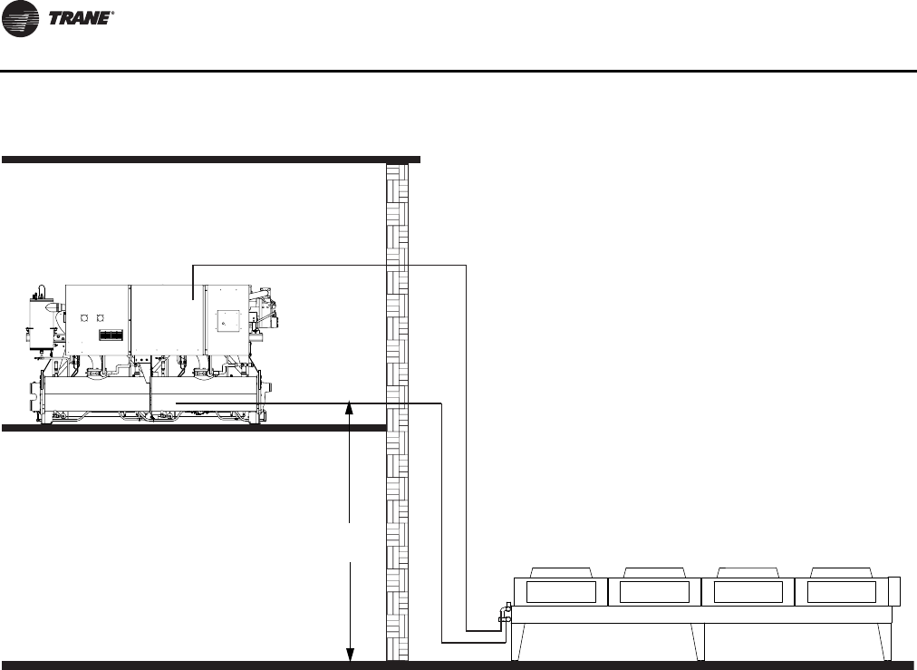
Installation - Mechanical
60 RLC-SVX09H-EN
Remote Air-Cooled Condenser Interconnection Refrigerant Piping
The RTUD compressor chiller is shipped with a full charge
of oil and a nitrogen holding charge.The Levitor II unit is
an air-cooled condenser that is designed for use with the
RTUD unit.The RTUD unit is designed to be most effective
when used with the Levitor II aircooled condenser. Other
air-cooled condensers can be used in place of the Levitor
II condenser, but the overall performance of the system
may be different from that published in the catalogs.The
following section covers the required piping between the
RTUD unit and the appropriate air-cooled condenser.
The RTUD unit consists of an evaporator, two helical rotor
compressors (one per circuit), oil separators, oil coolers,
liquid line service valves (NOT isolation valves), sight
glasses, electronic expansion valves and filter. The
discharge line leaving the oil separator and liquid line
entering the filters are capped and brazed.The installing
contractor need only provide the interconnecting piping,
including liquid line isolation valves, between the RTUD
and the air-cooled condenser.
Important: RTUD units are not shipped with factory
installed liquid line isolation valves. Liquid
line isolation valves must be field installed.
Trane does not approve the use of underground
refrigerant piping. Potential problems include dirt and
moisture in the lines during assembly, condensation of
refrigerant in the lines during off-cycle, which creates
liquid slugs and potential damage to parts or
controllability issues, and vibration/corrosion damage.
For best reliability and performance, the RTUD should be
matched withTrane Levitor II. If a non-Levitor II condenser
is used, overall performance and reliability of the RTUD
may be affected. Depending on the customer's fan control,
nuisance trips may occur on the RTUD unit, due to head
pressure instability.
If a non-Levitor II condenser is a supplied, it must be
capable of providing a minimum of 5 F subcooling at the
EXV.The RTUD requires subcooled liquid at the expansion
valves. Without a minimum of 5 F subcooling, the RTUD
will not operate as designed.
Piping should be sized and laid out according to the job
plans and specifications.This design should be completed
during system component selection.
Note: UseType L refrigerant-grade copper tubing only.
The refrigerant lines must be isolated to prevent line
vibration from being transferred to the building. Do not
secure the lines rigidly to the building at any point.
Important: Relieve nitrogen pressure before removing
end caps.
Figure 37. Condenser below the compressor chiller
Trap
Liquid Line
Discharge Line
15 ft
max

Installation - Mechanical
RLC-SVX09H-EN 61
Do not use a saw to remove end caps, as this may allow
copper chips to contaminate the system. Use a tubing
cutter or heat to remove end caps.
See Table 38, p. 61 for the Levitor condenser model
number. Units 150 tons and above will have one
condenser per circuit.The manifold piping for these
condensers is field supplied.
On units with two separateTrane-supplied condensers
(150-250Ton), a field installed tee is required at the
condenser connections to combine the two internal halves
into a single circuit. See Figure 39, p. 61. In this case, each
separate condenser would be a single circuit. If non-Trane
condensers with multiple circuits are used, a field installed
tee may be required to provide two individual circuits.
Important: To prevent excessive pressure drop in tee,
connection for the combined stream should
not be any smaller than the field run piping.
Condenser by Others
Requirement for Stable fan operation at
low ambient temperatures
Each circuit of the RTUD chiller is capable of unloading to
approximately 30% of its full load capability at any given
operating point.To guarantee no fan cycling at the
minimum compressor load and an ambient temperature
of 32º, the condenser will require the ability to reduce its
minimum capacity with one fan running to roughly ½ of
that 30%, which implies at least 6 fans minimum. Some
amount of slow fan cycling is acceptable depending on the
application. Operating with fewer fans at low ambient
temperatures and minimum loads may cause fast and
prolonged fan cycling and may result in large excursions
in condenser pressure and differential pressures and may
lead to either poor leaving water temperature
performance or nuisance tripping. To avoid this problem
in certain low ambient temperature applications, it may be
necessary to provide that one fan be a variable speed fan
to improve stability and minimal cycling.
WARNING
Hazard of Explosion!
When sweating line connections, always provide
a sufficient purge of dry nitrogen through the
tubing to prevent the formation of oxides/scaling
caused by high temperature from brazing. Use a
pressure regulator in the line between the unit
and the high pressure nitrogen cylinder to avoid
over-pressurization and possible explosion. If any
refrigerant or refrigerant vapors are present a
thorough purge with dry nitrogen will prevent the
possible formation of toxic phosgene gas. Failure
to follow these recommendations could result in
death or serious injury.
Table 38. Levitor Model Numbers
RTUD Size Circuit (s) Levitor Model No.
80 Ton Ckt 1 & 2 LAVC23312
90 Ton Ckt 1 & 2 LAVC24310
100 Ton Ckt 1 & 2 LAVC24410
110 Ton Ckt 1 & 2 LAVC24412
120 Ton Ckt 1 & 2 LAVC25408
130 Ton Ckt 1 & 2 LAVC25410
150 Ton Ckt 1 LAVC23308
150 Ton Ckt 2 LAVC23312
160 Ton Ckt 1 LAVC23312
160 Ton Ckt 2 LAVC23312
180 Ton Ckt 1 LAVC23312
180 Ton Ckt 2 LAVC24308
200 Ton Ckt 1 LAVC24308
200 Ton Ckt 2 LAVC24308
220 Ton Ckt 1 LAVC24308
220 Ton Ckt 2 LAVC24410
250 Ton Ckt 1 LAVC24410
250 Ton Ckt 2 LAVC24410
Figure 38. Condenser manifolding, 80-130Ton
Figure 39. Condenser manifolding, 150-250Ton
Ckt 1
Ckt 2
Discharge
Liquid
Local code
dictates
control panel
clearance
(36” min)
48” min clearance
for airflow
48” min clearance
for airflow
24”min clearance
for servcie
Control Panel
Ckt 1
Ckt 2
Discharge
Liquid
Field piping
requires a tee
Control Panel
48” min clearance
for airflow
Control Panel
24”min clearance
for servcie
48” min clearance
for airflow
48” min clearance
for airflow
Local code
dictates
control pane
clearance
(36” min)
Installation - Mechanical
62 RLC-SVX09H-EN
System Configuration
The system can be configured in any of the primary
arrangements as shown in Figure 35, p. 59,Figure 36,
p. 59 and Figure 37, p. 60.The configuration and its
associated elevation, along with the total distance
between the RTUD and the air-cooled condenser, plays a
critical role in determining the liquid line and discharge
line sizes.This will also affect the field refrigerant and oil
charges. Consequently, there are physical limits which
must not be violated if the system is to operate as
designed. Please note the following restrictions:
1. The discharge line sizing is different for different
leaving evaporator water temperatures.
2. The total distance between the RTUD and the air-
cooled condenser must not exceed 200 actual feet or
300 equivalent feet.
3. When the air-cooled condenser is installed at the same
level or below the compressor-chiller, liquid line risers
must not be more than 15 ft above the base of the
condenser.
4. Discharge line risers cannot exceed an elevation
difference greater than 100 actual feet without a
minimum of 2% efficiency decrease.
5. See Figure 35,Figure 36 and Figure 37. for location of
recommended traps.
6. Circuit #1 on the condenser must be connected to
Circuit#1ontheRTUDunit.
Equivalent Line Length
To determine the appropriate size for field installed liquid
and discharge lines, it is first necessary to establish the
equivalent length of pipe for each line, including the added
flow resistance of elbows, valves, etc. An initial
approximation can be made by assuming that the
equivalent length of pipe is 1.5 times the actual pipe
length.
Note: Table 39, p. 62 states the equivalent length, in feet,
for various non-ferrous valves and fittings. When
calculating the equivalent length, do not include
piping of the unit. Only field piping must be
considered.
Liquid Line Sizing
Trane recommends that the liquid line diameter be as
small as possible, while maintaining acceptable pressure
drop.This is necessary to minimize refrigerant charge.The
total length between the components must not exceed 200
actual feet or 300 equivalent feet.
The liquid line risers must not exceed 15 feet from the base
of the air-cooled condenser.The liquid line does not have
to be pitched. Liquid line sizing for these units when
installed with aTrane Levitor II air-cooled condenser are
shown in Table 40, p. 63 through Table 51, p. 66. Line
sizing for other condensers must be done manually not to
violate the 5°F subcooling requirement at the EXV.
Liquid lines are not typically insulated. However, if the
lines run through an area of high ambient temperature (eg.
boiler room), subcooling may drop below required levels.
In these situations, insulate the liquid lines.
Use of a liquid line receiver is not recommended because
it adds to the overall refrigerant volume of the circuit.
Note: In case of power failure to the expansion valve, the
amount of liquid refrigerant contained in the
refrigerant system must not exceed the holding
capacity of the evaporator. See Table 64, p. 71 for
the maximum allowable charge in each circuit.
Note: Height in Table 40 through Table 51 is the raise in
elevation of the RTUD unit above the condensing
unit.
NOTICE:
Equipment Damage!
If circuits are crossed, serious equipment damage
may occur.
Table 39. Equivalent lengths of non-ferrous valves and
fittings
Line Size
OD (in)
Globe
Valve (ft)
Angle
Valve (ft)
Short
Radius
Elbow (ft)
Long
Radius
Elbow (ft)
1 1/8 87 29 2.7 1.9
1 3/8 102 33 3.2 2.2
1 5/8 115 34 3.8 2.6
2 1/8 141 39 5.2 3.4
2 5/8 159 44 6.5 4.2
3 1/8 185 53 8 5.1
3 5/8 216 66 10 6.3
4 1/8 248 76 12 7.3
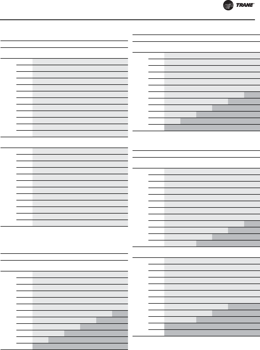
Installation - Mechanical
RLC-SVX09H-EN 63
Table 40. Liquid line sizing RTUD 80 ton
Height (ft)
Ckt 1
Line < 0 3 6 9 12 15
Total
Equiv.
Length
(ft)
25 1.125 1.125 1.125 1.125 1.125 1.125
50 1.125 1.125 1.125 1.125 1.125 1.125
75 1.125 1.125 1.125 1.125 1.125 1.125
100 1.125 1.125 1.125 1.125 1.125 1.125
125 1.125 1.125 1.125 1.125 1.125 1.125
150 1.125 1.125 1.125 1.125 1.125 1.125
175 1.125 1.125 1.125 1.125 1.125 1.125
200 1.125 1.125 1.125 1.125 1.125 1.125
225 1.125 1.125 1.125 1.125 1.125 1.125
250 1.125 1.125 1.125 1.125 1.125 1.125
275 1.125 1.125 1.125 1.125 1.125 1.125
300 1.125 1.125 1.125 1.125 1.125 1.125
Ckt 2
Line < 0 3 6 9 12 15
Total
Equiv.
Length
(ft)
25 1.125 1.125 1.125 1.125 1.125 1.125
50 1.125 1.125 1.125 1.125 1.125 1.125
75 1.125 1.125 1.125 1.125 1.125 1.125
100 1.125 1.125 1.125 1.125 1.125 1.125
125 1.125 1.125 1.125 1.125 1.125 1.125
150 1.125 1.125 1.125 1.125 1.125 1.125
175 1.125 1.125 1.125 1.125 1.125 1.125
200 1.125 1.125 1.125 1.125 1.125 1.125
225 1.125 1.125 1.125 1.125 1.125 1.125
250 1.125 1.125 1.125 1.125 1.125 1.125
275 1.125 1.125 1.125 1.125 1.125 1.125
300 1.125 1.125 1.125 1.125 1.125 1.125
Table 41. Liquid line sizing RTUD 90 ton
Height (ft)
Ckt 1
Line < 0 3 6 9 12 15
Total
Equiv.
Length
(ft)
25 1.125 1.125 1.125 1.125 1.125 1.125
50 1.125 1.125 1.125 1.125 1.125 1.125
75 1.125 1.125 1.125 1.125 1.125 1.125
100 1.125 1.125 1.125 1.125 1.125 1.125
125 1.125 1.125 1.125 1.125 1.125 1.125
150 1.125 1.125 1.125 1.125 1.125 1.125
175 1.125 1.125 1.125 1.125 1.125 1.375
200 1.125 1.125 1.125 1.125 1.375 1.375
225 1.125 1.125 1.125 1.375 1.375 1.375
250 1.125 1.125 1.375 1.375 1.375 1.375
275 1.125 1.375 1.375 1.375 1.375 1.375
300 1.375 1.375 1.375 1.375 1.375 1.375
Ckt 2
Line < 0 3 6 9 12 15
Total
Equiv.
Length
(ft)
25 1.125 1.125 1.125 1.125 1.125 1.125
50 1.125 1.125 1.125 1.125 1.125 1.125
75 1.125 1.125 1.125 1.125 1.125 1.125
100 1.125 1.125 1.125 1.125 1.125 1.125
125 1.125 1.125 1.125 1.125 1.125 1.125
150 1.125 1.125 1.125 1.125 1.125 1.125
175 1.125 1.125 1.125 1.125 1.125 1.375
200 1.125 1.125 1.125 1.125 1.375 1.375
225 1.125 1.125 1.125 1.375 1.375 1.375
250 1.125 1.125 1.375 1.375 1.375 1.375
275 1.125 1.375 1.375 1.375 1.375 1.375
300 1.375 1.375 1.375 1.375 1.375 1.375
Table 42. Liquid line sizing RTUD 100 ton
Height (ft)
Ckt 1
Line < 0 3 6 9 12 15
Total
Equiv.
Length
(ft)
25 1.125 1.125 1.125 1.125 1.125 1.125
50 1.125 1.125 1.125 1.125 1.125 1.125
75 1.125 1.125 1.125 1.125 1.125 1.125
100 1.125 1.125 1.125 1.125 1.125 1.125
125 1.125 1.125 1.125 1.125 1.125 1.125
150 1.125 1.125 1.125 1.125 1.125 1.125
175 1.125 1.125 1.125 1.125 1.125 1.125
200 1.125 1.125 1.125 1.125 1.125 1.125
225 1.125 1.125 1.125 1.125 1.125 1.375
250 1.125 1.125 1.125 1.125 1.375 1.375
275 1.125 1.125 1.125 1.375 1.375 1.375
300 1.125 1.125 1.375 1.375 1.375 1.375
Ckt 2
Line < 0 3 6 9 12 15
Total
Equiv.
Length
(ft)
25 1.125 1.125 1.125 1.125 1.125 1.125
50 1.125 1.125 1.125 1.125 1.125 1.125
75 1.125 1.125 1.125 1.125 1.125 1.125
100 1.125 1.125 1.125 1.125 1.125 1.125
125 1.125 1.125 1.125 1.125 1.125 1.125
150 1.125 1.125 1.125 1.125 1.125 1.125
175 1.125 1.125 1.125 1.125 1.125 1.125
200 1.125 1.125 1.125 1.125 1.375 1.375
225 1.125 1.125 1.125 1.375 1.375 1.375
250 1.125 1.125 1.375 1.375 1.375 1.375
275 1.375 1.375 1.375 1.375 1.375 1.375
300 1.375 1.375 1.375 1.375 1.375 1.375
Table 41. Liquid line sizing RTUD 90 ton (continued)
Height (ft)
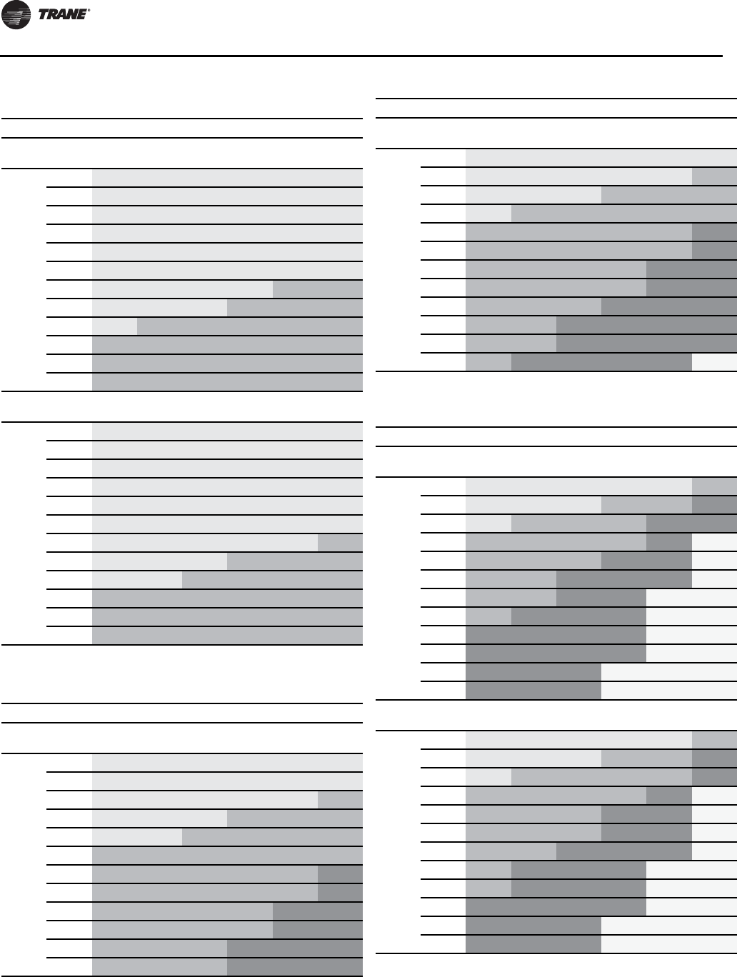
Installation - Mechanical
64 RLC-SVX09H-EN
Table 43. Liquid line sizing RTUD 110 ton
Height (ft)
Ckt 1
Line < 0 3 6 9 12 15
Total
Equiv.
Length
(ft)
25 1.125 1.125 1.125 1.125 1.125 1.125
50 1.125 1.125 1.125 1.125 1.125 1.125
75 1.125 1.125 1.125 1.125 1.125 1.125
100 1.125 1.125 1.125 1.125 1.125 1.125
125 1.125 1.125 1.125 1.125 1.125 1.125
150 1.125 1.125 1.125 1.125 1.125 1.125
175 1.125 1.125 1.125 1.125 1.375 1.375
200 1.125 1.125 1.125 1.375 1.375 1.375
225 1.125 1.375 1.375 1.375 1.375 1.375
250 1.375 1.375 1.375 1.375 1.375 1.375
275 1.375 1.375 1.375 1.375 1.375 1.375
300 1.375 1.375 1.375 1.375 1.375 1.375
Ckt 2
Line < 0 3 6 9 12 15
Total
Equiv.
Length
(ft)
25 1.125 1.125 1.125 1.125 1.125 1.125
50 1.125 1.125 1.125 1.125 1.125 1.125
75 1.125 1.125 1.125 1.125 1.125 1.125
100 1.125 1.125 1.125 1.125 1.125 1.125
125 1.125 1.125 1.125 1.125 1.125 1.125
150 1.125 1.125 1.125 1.125 1.125 1.125
175 1.125 1.125 1.125 1.125 1.125 1.375
200 1.125 1.125 1.125 1.375 1.375 1.375
225 1.125 1.125 1.375 1.375 1.375 1.375
250 1.375 1.375 1.375 1.375 1.375 1.375
275 1.375 1.375 1.375 1.375 1.375 1.375
300 1.375 1.375 1.375 1.375 1.375 1.375
Table 44. Liquid line sizing RTUD 120 ton
Height (ft)
Ckt 1
Line < 0 3 6 9 12 15
Total
Equiv.
Length
(ft)
25 1.125 1.125 1.125 1.125 1.125 1.125
50 1.125 1.125 1.125 1.125 1.125 1.125
75 1.125 1.125 1.125 1.125 1.125 1.375
100 1.125 1.125 1.125 1.375 1.375 1.375
125 1.125 1.125 1.375 1.375 1.375 1.375
150 1.375 1.375 1.375 1.375 1.375 1.375
175 1.375 1.375 1.375 1.375 1.375 1.625
200 1.375 1.375 1.375 1.375 1.375 1.625
225 1.375 1.375 1.375 1.375 1.625 1.625
250 1.375 1.375 1.375 1.375 1.625 1.625
275 1.375 1.375 1.375 1.625 1.625 1.625
300 1.375 1.375 1.375 1.625 1.625 1.625
Ckt 2
Line < 0 3 6 9 12 15
Total
Equiv.
Length
(ft)
25 1.125 1.125 1.125 1.125 1.125 1.125
50 1.125 1.125 1.125 1.125 1.125 1.375
75 1.125 1.125 1.125 1.375 1.375 1.375
100 1.125 1.375 1.375 1.375 1.375 1.375
125 1.375 1.375 1.375 1.375 1.375 1.625
150 1.375 1.375 1.375 1.375 1.375 1.625
175 1.375 1.375 1.375 1.375 1.625 1.625
200 1.375 1.375 1.375 1.375 1.625 1.625
225 1.375 1.375 1.375 1.625 1.625 1.625
250 1.375 1.375 1.625 1.625 1.625 1.625
275 1.375 1.375 1.625 1.625 1.625 1.625
300 1.375 1.625 1.625 1.625 1.625 2.125
Table 45. Liquid line sizing RTUD 130 ton
Height (ft)
Ckt 1
Line < 0 3 6 9 12 15
Total
Equiv.
Length
(ft)
25 1.125 1.125 1.125 1.125 1.125 1.375
50 1.125 1.125 1.125 1.375 1.375 1.625
75 1.125 1.375 1.375 1.375 1.625 1.625
100 1.375 1.375 1.375 1.375 1.625 2.125
125 1.375 1.375 1.375 1.625 1.625 2.125
150 1.375 1.375 1.625 1.625 1.625 2.125
175 1.375 1.375 1.625 1.625 2.125 2.125
200 1.375 1.625 1.625 1.625 2.125 2.125
225 1.625 1.625 1.625 1.625 2.125 2.125
250 1.625 1.625 1.625 1.625 2.125 2.125
275 1.625 1.625 1.625 2.125 2.125 2.125
300 1.625 1.625 1.625 2.125 2.125 2.125
Ckt 2
Line < 0 3 6 9 12 15
Total
Equiv.
Length
(ft)
25 1.125 1.125 1.125 1.125 1.125 1.375
50 1.125 1.125 1.125 1.375 1.375 1.625
75 1.125 1.375 1.375 1.375 1.375 1.625
100 1.375 1.375 1.375 1.375 1.625 2.125
125 1.375 1.375 1.375 1.625 1.625 2.125
150 1.375 1.375 1.375 1.625 1.625 2.125
175 1.375 1.375 1.625 1.625 1.625 2.125
200 1.375 1.625 1.625 1.625 2.125 2.125
225 1.375 1.625 1.625 1.625 2.125 2.125
250 1.625 1.625 1.625 1.625 2.125 2.125
275 1.625 1.625 1.625 2.125 2.125 2.125
300 1.625 1.625 1.625 2.125 2.125 2.125
Table 44. Liquid line sizing RTUD 120 ton (continued)
Height (ft)
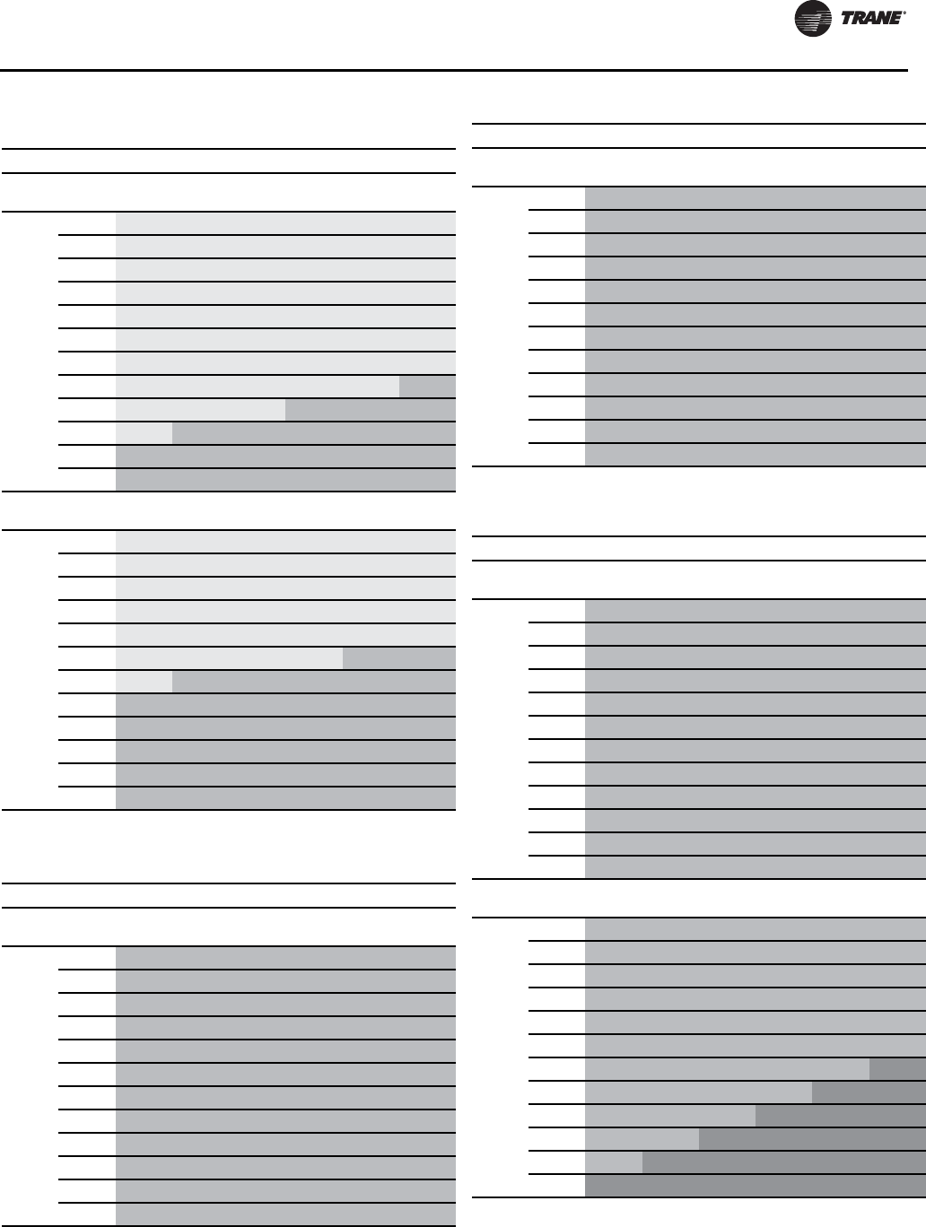
Installation - Mechanical
RLC-SVX09H-EN 65
Table 46. Liquid line sizing RTUD 150 ton
Height (ft)
Ckt 1
Line < 0 3 6 9 12 15
Total
Equiv.
Length
(ft)
25 1.125 1.125 1.125 1.125 1.125 1.125
50 1.125 1.125 1.125 1.125 1.125 1.125
75 1.125 1.125 1.125 1.125 1.125 1.125
100 1.125 1.125 1.125 1.125 1.125 1.125
125 1.125 1.125 1.125 1.125 1.125 1.125
150 1.125 1.125 1.125 1.125 1.125 1.125
175 1.125 1.125 1.125 1.125 1.125 1.125
200 1.125 1.125 1.125 1.125 1.125 1.375
225 1.125 1.125 1.125 1.375 1.375 1.375
250 1.125 1.375 1.375 1.375 1.375 1.375
275 1.375 1.375 1.375 1.375 1.375 1.375
300 1.375 1.375 1.375 1.375 1.375 1.375
Ckt 2
Line < 0 3 6 9 12 15
Total
Equiv.
Length
(ft)
25 1.125 1.125 1.125 1.125 1.125 1.125
50 1.125 1.125 1.125 1.125 1.125 1.125
75 1.125 1.125 1.125 1.125 1.125 1.125
100 1.125 1.125 1.125 1.125 1.125 1.125
125 1.125 1.125 1.125 1.125 1.125 1.125
150 1.125 1.125 1.125 1.125 1.375 1.375
175 1.125 1.375 1.375 1.375 1.375 1.375
200 1.375 1.375 1.375 1.375 1.375 1.375
225 1.375 1.375 1.375 1.375 1.375 1.375
250 1.375 1.375 1.375 1.375 1.375 1.375
275 1.375 1.375 1.375 1.375 1.375 1.375
300 1.375 1.375 1.375 1.375 1.375 1.375
Table 47. Liquid line sizing RTUD 160 ton
Height (ft)
Ckt 1
Line < 0 3 6 9 12 15
Total
Equiv.
Length
(ft)
25 1.375 1.375 1.375 1.375 1.375 1.375
50 1.375 1.375 1.375 1.375 1.375 1.375
75 1.375 1.375 1.375 1.375 1.375 1.375
100 1.375 1.375 1.375 1.375 1.375 1.375
125 1.375 1.375 1.375 1.375 1.375 1.375
150 1.375 1.375 1.375 1.375 1.375 1.375
175 1.375 1.375 1.375 1.375 1.375 1.375
200 1.375 1.375 1.375 1.375 1.375 1.375
225 1.375 1.375 1.375 1.375 1.375 1.375
250 1.375 1.375 1.375 1.375 1.375 1.375
275 1.375 1.375 1.375 1.375 1.375 1.375
300 1.375 1.375 1.375 1.375 1.375 1.375
Ckt 2
Line < 0 3 6 9 12 15
Total
Equiv.
Length
(ft)
25 1.375 1.375 1.375 1.375 1.375 1.375
50 1.375 1.375 1.375 1.375 1.375 1.375
75 1.375 1.375 1.375 1.375 1.375 1.375
100 1.375 1.375 1.375 1.375 1.375 1.375
125 1.375 1.375 1.375 1.375 1.375 1.375
150 1.375 1.375 1.375 1.375 1.375 1.375
175 1.375 1.375 1.375 1.375 1.375 1.375
200 1.375 1.375 1.375 1.375 1.375 1.375
225 1.375 1.375 1.375 1.375 1.375 1.375
250 1.375 1.375 1.375 1.375 1.375 1.375
275 1.375 1.375 1.375 1.375 1.375 1.375
300 1.375 1.375 1.375 1.375 1.375 1.375
Table 48. Liquid line sizing RTUD 180 ton
Height (ft)
Ckt 1
Line < 0 3 6 9 12 15
Total
Equiv.
Length
(ft)
25 1.375 1.375 1.375 1.375 1.375 1.375
50 1.375 1.375 1.375 1.375 1.375 1.375
75 1.375 1.375 1.375 1.375 1.375 1.375
100 1.375 1.375 1.375 1.375 1.375 1.375
125 1.375 1.375 1.375 1.375 1.375 1.375
150 1.375 1.375 1.375 1.375 1.375 1.375
175 1.375 1.375 1.375 1.375 1.375 1.375
200 1.375 1.375 1.375 1.375 1.375 1.375
225 1.375 1.375 1.375 1.375 1.375 1.375
250 1.375 1.375 1.375 1.375 1.375 1.375
275 1.375 1.375 1.375 1.375 1.375 1.375
300 1.375 1.375 1.375 1.375 1.375 1.375
Ckt 2
Line < 0 3 6 9 12 15
Total
Equiv.
Length
(ft)
25 1.375 1.375 1.375 1.375 1.375 1.375
50 1.375 1.375 1.375 1.375 1.375 1.375
75 1.375 1.375 1.375 1.375 1.375 1.375
100 1.375 1.375 1.375 1.375 1.375 1.375
125 1.375 1.375 1.375 1.375 1.375 1.375
150 1.375 1.375 1.375 1.375 1.375 1.375
175 1.375 1.375 1.375 1.375 1.375 1.625
200 1.375 1.375 1.375 1.375 1.625 1.625
225 1.375 1.375 1.375 1.625 1.625 1.625
250 1.375 1.375 1.625 1.625 1.625 1.625
275 1.375 1.625 1.625 1.625 1.625 1.625
300 1.625 1.625 1.625 1.625 1.625 1.625
Table 47. Liquid line sizing RTUD 160 ton (continued)
Height (ft)
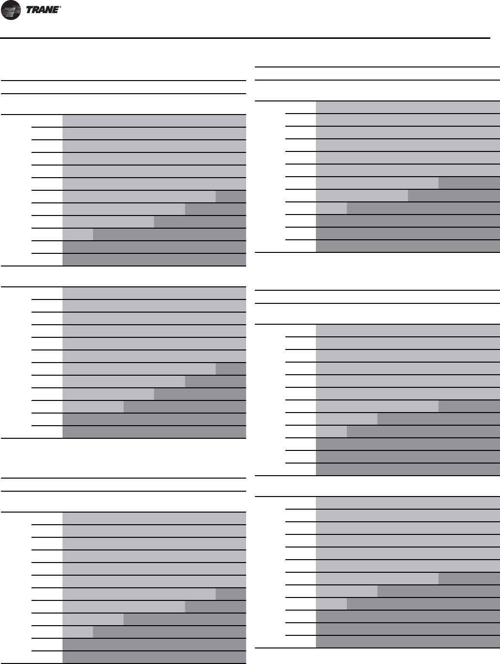
Installation - Mechanical
66 RLC-SVX09H-EN
Table 49. Liquid line sizing RTUD 200 ton
Height (ft)
Ckt 1
Line < 0 3 6 9 12 15
Total
Equiv.
Length
(ft)
25 1.375 1.375 1.375 1.375 1.375 1.375
50 1.375 1.375 1.375 1.375 1.375 1.375
75 1.375 1.375 1.375 1.375 1.375 1.375
100 1.375 1.375 1.375 1.375 1.375 1.375
125 1.375 1.375 1.375 1.375 1.375 1.375
150 1.375 1.375 1.375 1.375 1.375 1.375
175 1.375 1.375 1.375 1.375 1.375 1.625
200 1.375 1.375 1.375 1.375 1.625 1.625
225 1.375 1.375 1.375 1.625 1.625 1.625
250 1.375 1.625 1.625 1.625 1.625 1.625
275 1.625 1.625 1.625 1.625 1.625 1.625
300 1.625 1.625 1.625 1.625 1.625 1.625
Ckt 2
Line < 0 3 6 9 12 15
Total
Equiv.
Length
(ft)
25 1.375 1.375 1.375 1.375 1.375 1.375
50 1.375 1.375 1.375 1.375 1.375 1.375
75 1.375 1.375 1.375 1.375 1.375 1.375
100 1.375 1.375 1.375 1.375 1.375 1.375
125 1.375 1.375 1.375 1.375 1.375 1.375
150 1.375 1.375 1.375 1.375 1.375 1.375
175 1.375 1.375 1.375 1.375 1.375 1.625
200 1.375 1.375 1.375 1.375 1.625 1.625
225 1.375 1.375 1.375 1.625 1.625 1.625
250 1.375 1.375 1.625 1.625 1.625 1.625
275 1.625 1.625 1.625 1.625 1.625 1.625
300 1.625 1.625 1.625 1.625 1.625 1.625
Table 50. Liquid line sizing RTUD 220 ton
Height (ft)
Ckt 1
Line < 0 3 6 9 12 15
Total
Equiv.
Length
(ft)
25 1.375 1.375 1.375 1.375 1.375 1.375
50 1.375 1.375 1.375 1.375 1.375 1.375
75 1.375 1.375 1.375 1.375 1.375 1.375
100 1.375 1.375 1.375 1.375 1.375 1.375
125 1.375 1.375 1.375 1.375 1.375 1.375
150 1.375 1.375 1.375 1.375 1.375 1.375
175 1.375 1.375 1.375 1.375 1.375 1.625
200 1.375 1.375 1.375 1.375 1.625 1.625
225 1.375 1.375 1.625 1.625 1.625 1.625
250 1.375 1.625 1.625 1.625 1.625 1.625
275 1.625 1.625 1.625 1.625 1.625 1.625
300 1.625 1.625 1.625 1.625 1.625 1.625
Ckt 2
Line < 0 3 6 9 12 15
Total
Equiv.
Length
(ft)
25 1.375 1.375 1.375 1.375 1.375 1.375
50 1.375 1.375 1.375 1.375 1.375 1.375
75 1.375 1.375 1.375 1.375 1.375 1.375
100 1.375 1.375 1.375 1.375 1.375 1.375
125 1.375 1.375 1.375 1.375 1.375 1.375
150 1.375 1.375 1.375 1.375 1.375 1.375
175 1.375 1.375 1.375 1.375 1.625 1.625
200 1.375 1.375 1.375 1.625 1.625 1.625
225 1.375 1.625 1.625 1.625 1.625 1.625
250 1.625 1.625 1.625 1.625 1.625 1.625
275 1.625 1.625 1.625 1.625 1.625 1.625
300 1.625 1.625 1.625 1.625 1.625 1.625
Table 51. Liquid line sizing RTUD 250 ton
Height (ft)
Ckt 1
Line < 0 3 6 9 12 15
Total
Equiv.
Length
(ft)
25 1.375 1.375 1.375 1.375 1.375 1.375
50 1.375 1.375 1.375 1.375 1.375 1.375
75 1.375 1.375 1.375 1.375 1.375 1.375
100 1.375 1.375 1.375 1.375 1.375 1.375
125 1.375 1.375 1.375 1.375 1.375 1.375
150 1.375 1.375 1.375 1.375 1.375 1.375
175 1.375 1.375 1.375 1.375 1.625 1.625
200 1.375 1.375 1.625 1.625 1.625 1.625
225 1.375 1.625 1.625 1.625 1.625 1.625
250 1.625 1.625 1.625 1.625 1.625 1.625
275 1.625 1.625 1.625 1.625 1.625 1.625
300 1.625 1.625 1.625 1.625 1.625 1.625
Ckt 2
Line < 0 3 6 9 12 15
Total
Equiv.
Length
(ft)
25 1.375 1.375 1.375 1.375 1.375 1.375
50 1.375 1.375 1.375 1.375 1.375 1.375
75 1.375 1.375 1.375 1.375 1.375 1.375
100 1.375 1.375 1.375 1.375 1.375 1.375
125 1.375 1.375 1.375 1.375 1.375 1.375
150 1.375 1.375 1.375 1.375 1.375 1.375
175 1.375 1.375 1.375 1.375 1.625 1.625
200 1.375 1.375 1.625 1.625 1.625 1.625
225 1.375 1.625 1.625 1.625 1.625 1.625
250 1.625 1.625 1.625 1.625 1.625 1.625
275 1.625 1.625 1.625 1.625 1.625 1.625
300 1.625 1.625 1.625 1.625 1.625 1.625
Table 50. Liquid line sizing RTUD 220 ton (continued)
Height (ft)
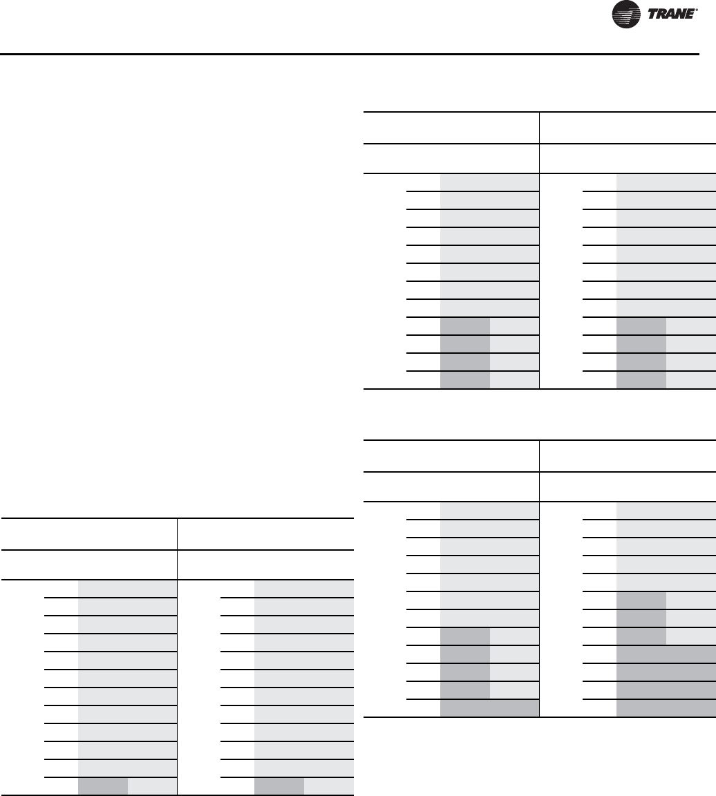
Installation - Mechanical
RLC-SVX09H-EN 67
Discharge (Hot Gas) Line Sizing
The discharge lines should pitch downward, in the
direction of the hot gas flow, at the rate of 1/2 inch per each
10 feet of horizontal run.
Discharge line size is based on the velocity needed to
obtain sufficient oil return. Basic discharge line sizing is
shown in Table 52, p. 67 throughTable 63, p. 70,
depending on the unit configuration.
Discharge lines are not typically insulated. If insulation is
required, it should be approved for use at temperatures up
to 230°F (max discharge temp).
Note: The proper column for leaving evaporator water
temperature must be used to avoid catastrophic
damage to the unit. Column for 10 °F to 37°F can
only be used on units designed for low
temperature applications. Refer to the design
conditions of the unit to determine the correct
column that must be used.
Note: The discharge line should drop well below the
compressor discharge outlet before beginning its
vertical rise.This prevents possible refrigerant
drainage back to the compressor and oil separator
during the unit STOP cycle. See Figure 35, p. 59,
Figure 36, p. 59 and Figure 37, p. 60 for details.
Table 52. Discharge (hot gas) line sizing RTUD 80 ton
Leaving Water
Temperature
Leaving Water
Temperature
Ckt 1
Line
38-65
°F
10-37
°F
Ckt 2
Line
38-65
°F
10-37
°F
Total
Equiv.
Length
(ft)
25 2.125 2.125
Total
Equiv.
Length
(ft)
25 2.125 2.125
50 2.125 2.125 50 2.125 2.125
75 2.125 2.125 75 2.125 2.125
100 2.125 2.125 100 2.125 2.125
125 2.125 2.125 125 2.125 2.125
150 2.125 2.125 150 2.125 2.125
175 2.125 2.125 175 2.125 2.125
200 2.125 2.125 200 2.125 2.125
225 2.125 2.125 225 2.125 2.125
250 2.125 2.125 250 2.125 2.125
275 2.125 2.125 275 2.125 2.125
300 2.625 2.125 300 2.625 2.125
Table 53. Discharge (hot gas) line sizing RTUD 90 ton
Leaving Water
Temperature
Leaving Water
Temperature
Ckt 1
Line
38-65
°F
10-37
°F
Ckt 2
Line
38-65
°F
10-37
°F
Total
Equiv.
Length
(ft)
25 2.125 2.125
Total
Equiv.
Length
(ft)
25 2.125 2.125
50 2.125 2.125 50 2.125 2.125
75 2.125 2.125 75 2.125 2.125
100 2.125 2.125 100 2.125 2.125
125 2.125 2.125 125 2.125 2.125
150 2.125 2.125 150 2.125 2.125
175 2.125 2.125 175 2.125 2.125
200 2.125 2.125 200 2.125 2.125
225 2.625 2.125 225 2.625 2.125
250 2.625 2.125 250 2.625 2.125
275 2.625 2.125 275 2.625 2.125
300 2.625 2.125 300 2.625 2.125
Table 54. Discharge (hot gas) line sizing RTUD 100 ton
Leaving Water
Temperature
Leaving Water
Temperature
Ckt 1
Line
38-65
°F
10-37
°F
Ckt 2
Line
38-65
°F
10-37
°F
Total
Equiv.
Length
(ft)
25 2.125 2.125
Total
Equiv.
Length
(ft)
25 2.125 2.125
50 2.125 2.125 50 2.125 2.125
75 2.125 2.125 75 2.125 2.125
100 2.125 2.125 100 2.125 2.125
125 2.125 2.125 125 2.125 2.125
150 2.125 2.125 150 2.625 2.125
175 2.125 2.125 175 2.625 2.125
200 2.625 2.125 200 2.625 2.125
225 2.625 2.125 225 2.625 2.625
250 2.625 2.125 250 2.625 2.625
275 2.625 2.125 275 2.625 2.625
300 2.625 2.625 300 2.625 2.625
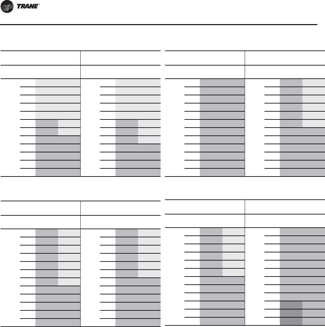
Installation - Mechanical
68 RLC-SVX09H-EN
Table 55. Discharge (hot gas) line sizing RTUD 110 ton
Leaving Water
Temperature
Leaving Water
Temperature
Ckt 1
Line
38-65
°F
10-37
°F
Ckt 2
Line
38-65
°F
10-37
°F
Total
Equiv.
Length
(ft)
25 2.125 2.125
Total
Equiv.
Length
(ft)
25 2.125 2.125
50 2.125 2.125 50 2.125 2.125
75 2.125 2.125 75 2.125 2.125
100 2.125 2.125 100 2.125 2.125
125 2.125 2.125 125 2.125 2.125
150 2.625 2.125 150 2.625 2.125
175 2.625 2.125 175 2.625 2.125
200 2.625 2.625 200 2.625 2.125
225 2.625 2.625 225 2.625 2.625
250 2.625 2.625 250 2.625 2.625
275 2.625 2.625 275 2.625 2.625
300 2.625 2.625 300 2.625 2.625
Table 56. Discharge (hot gas) line sizing RTUD 120 ton
Leaving Water
Temperature
Leaving Water
Temperature
Ckt 1
Line
38-65
°F
10-37
°F
Ckt 2
Line
38-65
°F
10-37
°F
Total
Equiv.
Length
(ft)
25 2.625 2.125
Total
Equiv.
Length
(ft)
25 2.625 2.125
50 2.625 2.125 50 2.625 2.125
75 2.625 2.125 75 2.625 2.125
100 2.625 2.125 100 2.625 2.125
125 2.625 2.125 125 2.625 2.125
150 2.625 2.125 150 2.625 2.125
175 2.625 2.125 175 2.625 2.625
200 2.625 2.625 200 2.625 2.625
225 2.625 2.625 225 2.625 2.625
250 2.625 2.625 250 2.625 2.625
275 2.625 2.625 275 2.625 2.625
300 2.625 2.625 300 2.625 2.625
Table 57. Discharge (hot gas) line sizing RTUD 130 ton
Leaving Water
Temperature
Leaving Water
Temperature
Ckt 1
Line
38-65
°F
10-37
°F
Ckt 2
Line
38-65
°F
10-37
°F
Total
Equiv.
Length
(ft)
25 2.625 2.625
Total
Equiv.
Length
(ft)
25 2.625 2.125
50 2.625 2.625 50 2.625 2.125
75 2.625 2.625 75 2.625 2.125
100 2.625 2.625 100 2.625 2.125
125 2.625 2.625 125 2.625 2.125
150 2.625 2.625 150 2.625 2.125
175 2.625 2.625 175 2.625 2.625
200 2.625 2.625 200 2.625 2.625
225 2.625 2.625 225 2.625 2.625
250 2.625 2.625 250 2.625 2.625
275 2.625 2.625 275 2.625 2.625
300 2.625 2.625 300 2.625 2.625
Table 58. Discharge (hot gas) line sizing RTUD 150 ton
Leaving Water
Temperature
Leaving Water
Temperature
Ckt 1
Line
38-65
°F
10-37
°F
Ckt 2
Line
38-65
°F
10-37
°F
Total
Equiv.
Length
(ft)
25 2.625 2.125
Total
Equiv.
Length
(ft)
25 2.625 2.625
50 2.625 2.125 50 2.625 2.625
75 2.625 2.125 75 2.625 2.625
100 2.625 2.125 100 2.625 2.625
125 2.625 2.125 125 2.625 2.625
150 2.625 2.125 150 2.625 2.625
175 2.625 2.625 175 2.625 2.625
200 2.625 2.625 200 2.625 2.625
225 2.625 2.625 225 2.625 2.625
250 2.625 2.625 250 3.125 2.625
275 2.625 2.625 275 3.125 2.625
300 2.625 2.625 300 3.125 2.625
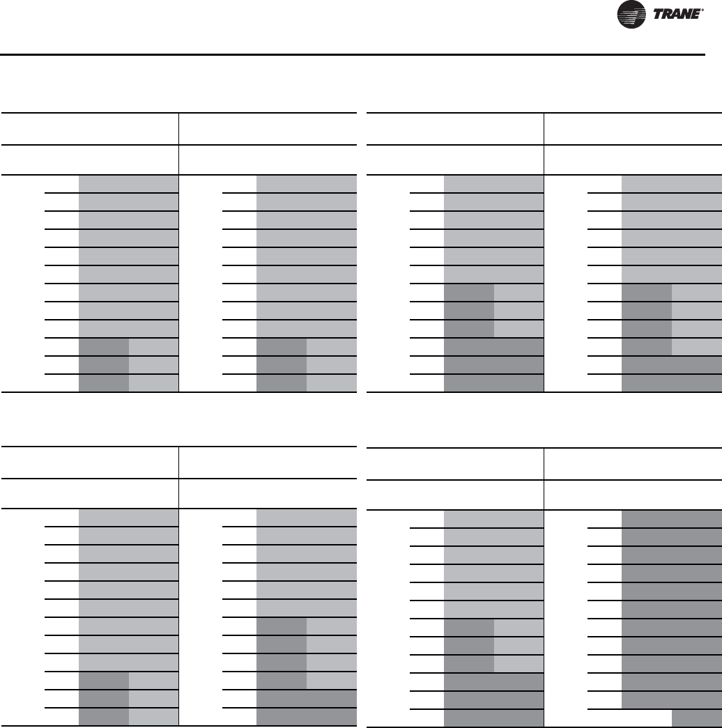
Installation - Mechanical
RLC-SVX09H-EN 69
Table 59. Discharge (hot gas) line sizing RTUD 160 ton
Leaving Water
Temperature
Leaving Water
Temperature
Ckt 1
Line
38-65
°F
10-37
°F
Ckt 2
Line
38-65
°F
10-37
°F
Total
Equiv.
Length
(ft)
25 2.625 2.625
Total
Equiv.
Length
(ft)
25 2.625 2.625
50 2.625 2.625 50 2.625 2.625
75 2.625 2.625 75 2.625 2.625
100 2.625 2.625 100 2.625 2.625
125 2.625 2.625 125 2.625 2.625
150 2.625 2.625 150 2.625 2.625
175 2.625 2.625 175 2.625 2.625
200 2.625 2.625 200 2.625 2.625
225 2.625 2.625 225 2.625 2.625
250 3.125 2.625 250 3.125 2.625
275 3.125 2.625 275 3.125 2.625
300 3.125 2.625 300 3.125 2.625
Table 60. Discharge (hot gas) line sizing RTUD 180 ton
Leaving Water
Temperature
Leaving Water
Temperature
Ckt 1
Line
38-65
°F
10-37
°F
Ckt 2
Line
38-65
°F
10-37
°F
Total
Equiv.
Length
(ft)
25 2.625 2.625
Total
Equiv.
Length
(ft)
25 2.625 2.625
50 2.625 2.625 50 2.625 2.625
75 2.625 2.625 75 2.625 2.625
100 2.625 2.625 100 2.625 2.625
125 2.625 2.625 125 2.625 2.625
150 2.625 2.625 150 2.625 2.625
175 2.625 2.625 175 3.125 2.625
200 2.625 2.625 200 3.125 2.625
225 2.625 2.625 225 3.125 2.625
250 3.125 2.625 250 3.125 2.625
275 3.125 2.625 275 3.125 3.125
300 3.125 2.625 300 3.125 3.125
Table 61. Discharge (hot gas) line sizing RTUD 200 ton
Leaving Water
Temperature
Leaving Water
Temperature
Ckt 1
Line
38-65
°F
10-37
°F
Ckt 2
Line
38-65
°F
10-37
°F
Total
Equiv.
Length
(ft)
25 2.625 2.625
Total
Equiv.
Length
(ft)
25 2.625 2.625
50 2.625 2.625 50 2.625 2.625
75 2.625 2.625 75 2.625 2.625
100 2.625 2.625 100 2.625 2.625
125 2.625 2.625 125 2.625 2.625
150 2.625 2.625 150 2.625 2.625
175 3.125 2.625 175 3.125 2.625
200 3.125 2.625 200 3.125 2.625
225 3.125 2.625 225 3.125 2.625
250 3.125 3.125 250 3.125 2.625
275 3.125 3.125 275 3.125 3.125
300 3.125 3.125 300 3.125 3.125
Table 62. Discharge (hot gas) line sizing RTUD 220 ton
Leaving Water
Temperature
Leaving Water
Temperature
Ckt 1
Line
38-65
°F
10-37
°F
Ckt 2
Line
38-65
°F
10-37
°F
Total
Equiv.
Length
(ft)
25 2.625 2.625
Total
Equiv.
Length
(ft)
25 3.125 3.125
50 2.625 2.625 50 3.125 3.125
75 2.625 2.625 75 3.125 3.125
100 2.625 2.625 100 3.125 3.125
125 2.625 2.625 125 3.125 3.125
150 2.625 2.625 150 3.125 3.125
175 3.125 2.625 175 3.125 3.125
200 3.125 2.625 200 3.125 3.125
225 3.125 2.625 225 3.125 3.125
250 3.125 3.125 250 3.125 3.125
275 3.125 3.125 275 3.125 3.125
300 3.125 3.125 300 3.625 3.125

Installation - Mechanical
70 RLC-SVX09H-EN
Example
Table 63. Discharge (hot gas) line sizing RTUD 250 ton
Leaving Water
Temperature
Leaving Water
Temperature
Ckt 1
Line
38-65
°F
10-37
°F
Ckt 2
Line
38-65
°F
10-37
°F
Total
Equiv.
Length
(ft)
25 3.125 3.125
Total
Equiv.
Length
(ft)
25 3.125 3.125
50 3.125 3.125 50 3.125 3.125
75 3.125 3.125 75 3.125 3.125
100 3.125 3.125 100 3.125 3.125
125 3.125 3.125 125 3.125 3.125
150 3.125 3.125 150 3.125 3.125
175 3.125 3.125 175 3.125 3.125
200 3.125 3.125 200 3.125 3.125
225 3.125 3.125 225 3.125 3.125
250 3.125 3.125 250 3.125 3.125
275 3.125 3.125 275 3.125 3.125
300 3.625 3.125 300 3.625 3.125
Figure 40. Example configuration
Inverted Trap
Height equal to
top of Condenser
Trap
Liquid Line
Discharge Line
20’
15.5’
5’
71’
2’ 2’

Installation - Mechanical
RLC-SVX09H-EN 71
Shown in Figure 40, p. 70 are RTUD 100 ton andTrane
Levitor II condenser designed for a leaving evaporator
water temperature of 42°F.This example will show how to
calculate the line sizes for both the liquid and discharge
lines.The discharge line consists of one long radius elbow
and 4 short radius elbows.The liquid line also consists of
one long radius elbow and 4 short radius elbows.
Discharge Line
Actual length of lines=2+5+71+15.5+5 = 98.5 ft.
Total equivalent length = 1.5 x 98.5= 147.75 ft.
Approximate line size for discharge lines
Table 54, p. 67 = 2 1/8”
Equivalent length of one long radius elbow at 2 1/8”
Table 39 = 3.4 ft.
Equivalent length of 4 short radius elbows at 2 1/8”
Table 39 = 4 x 5.2 ft. = 20.8 ft.
Total equivalent length = 98.5+ 3.4 + 20.8 = 122.7 ft.
New line size for discharge lines remains
Table 54
Ckt 1= 2 1/8”
Ckt 2= 2 1/8”
ALL DISCHARGE LINE SIZES ARE = 2 1/8”
Liquid Lines
Actual length of liquid lines=8+75+20+8=111ft.
Total equivalent length = 1.5 X 111 =166.5 ft.
Approximate liquid line size
Table 42, p. 63 = 1 1/8”
Equiv. length of one long radius elbow at 1 1/8”
Table 39=1.9
Equiv. length of 4 short radius elbows at 1 1/8”
Table 39= 4 x 2.7 ft. =10.8 ft.
Total equivalent length = 111 + 1.9 + 10.8 =123.7 ft.
Table 42
Ckt 1= 1 1/8”
Ckt 2= 1 1/8”
ALL LIQUID LINE SIZES ARE = 1 1/8”
Refrigerant Charge Determination
The approximate amount of the refrigerant charge
required by the system must be determined by referring to
Table 64 and must be verified by running the system and
checking the liquid line sightglasses.
Note: The maximum charge can reduce the maximum
length of the piping. Due to maximum allowable
refrigerant charge not all units can have 200 feet of
piping.
To determine the approximate charge, first refer to
Table 64 and establish the required charge without the
field-installed piping.Then refer toTable 65, to determine
the charge required for the field-installed piping.The
approximate charge is therefore the sum of the values
from Table 64 and Table 65.
Note: The amounts of refrigerant listed in Table 65 are
based on 100 feet of pipe. Actual requirements will
be in direct proportion to the actual length of the
piping.
Note: Table 65 assumes: LiquidTemperature = 105°F;
Saturated DischargeTemperature = 125°F;
Discharge Superheat = 30°F.
Table 64. System refrigerant charge - lbs
Condenser RTUD Max. Unit Charge
Ton Ckt 1 Ckt 2 Ckt 1 Ckt 2 Ckt 1 Ckt 2
80 40 40 50 50 318 318
90 52 52 49 49 308 308
100 68 68 47 47 308 308
110 68 68 65 65 359 359
120 85 85 64 64 352 352
130 85 85 64 64 352 352
150 76 76 62 62 347 347
160 76 76 66 66 396 396
180 76 101 66 66 396 396
200 101 101 66 66 391 391
220 101 134 63 63 382 382
250 134 134 61 61 373 373
Table 65. Field-installed piping charge
Pipe O.D.
Discharge Line
(lbs) Liquid Line (lbs)
1 1/8 - 41
1 3/8 - 62
1 5/8 - 88
2 1/8 8 154
2 5/8 13 -
3 1/8 18 -
4 1/8 32 -

Installation - Mechanical
72 RLC-SVX09H-EN
RTUD Chilled Water Flow Control
Oil Charge Determination
The RTUD unit is factory charged with the amount of oil
required by the system. No additional oil is required for
field installed piping.
Outdoor Air Temperature Sensor
Installation Requirements
The outdoor air temperature sensor is optional for the
RTWD water cooled units, but is a required sensor for the
RTUD compressor chiller units.The sensor is required as
an important input to the condenser fan control algorithm
as well as for the low outdoor air ambient lockout feature.
The temperature sensor probe is shipped separately
inside the control panel.
It is necessary for the chiller installer to locate and install
the separate outdoor air sensor probe at the remote air
cooled condenser at a location to sense the coil’s entering
air temperature, while avoiding direct sunlight. It should
be located at least 2” from the coil face and somewhere
“in-between” the two refrigerant circuits. Where the
condenser installation is such that the two refrigerant
circuit’s condensers are physically separate from each
other, or one circuit is more likely to see re-circulated
warmer air, an attempt should be made to locate the probe
to see an average temperature of the two separate
condensers.
Important: The probe provided must not be substituted
with another probe, as the probe and the
electronics are“matched / calibrated” at the
factory for accuracy.
A twisted pair sheathed cable shall be run and connected
between the probe at the remote condenser and its LLID
module in the chiller control panel.The sensor’s circuit is
a class II power limited analog circuit and therefore the
wire should not be run in close proximity to any power or
line voltage wiring.The splices at the condenser end,
should be made to be water tight.The wire run should be
physically supported at equal intervals with consideration
for safety and reliability/durability with wire ties or similar
to meet local codes.
Fan Control for the Remote Air Cooled
Condenser
The CH530 Controls for the RTUD compressor chiller
provide as an option, the flexible and full control of 2-
circuit remote air cooled condenser fans. In addition to the
option for controlling between 2 to 8 fixed speed fans per
circuit (or multiples thereof), a separate additional option
includes the ability to control either two speed fans or
variable speed fan/drive combinations in conjunction with
other fixed speed fans, to provide low ambient outdoor air
temperature capability. The controls will also provide an
option for a simple per circuit interlock output (in lieu of
actual fan control) to use in the scenario in which
independent fan head pressure or differential pressure
controls (by others) is applied. See "Fan Control By Others"
on Page 164 for more information. It is recommended
however, that for the best overall unit performance, the
integral fan control option is selected.
The controls support control of a remote, air cooled
condenser fan deck, from 2 to 8 fans per circuit (1-8 fans for
variable speed). It supports options to control the
following types of standard ambient outdoor air
temperature fan decks: 1) all fans fixed speed, and 2) all
fans two speed. It will also support the following low
ambient outdoor air temperature fan decks 1) one fan per
circuit isTwo-Speed, (remaining fans fixed speed), and 2)
One fan per circuit is variable speed i.e. variable frequency
drive (VFD), (remaining fans fixed speed). In the variable
fan low ambient outdoor air option the VFD fan and fixed
speed fans are sequenced accordingly to provide
continuous control from 0-100% air flow per circuit. Fan
staging provides the correct combination of fixed speed
fan relay, VFD relay (to enable operation of the VFD), and
speed outputs to provide air flow control commanded by
the fan algorithm running inside the CH530 Main
Processor.The fan deck arrangement is independently
configurable per circuit.
Since the condenser is provided separately from the RTUD
compressor chiller, the RTUD electrical panel design does
not provide for condensing unit’s control power
requirements. The chiller’s control power transformer is
not sized to provide the control power for the additional
fan contactor loads. The CH530 controls, when properly
optioned, will provide for pilot duty rated relays, low
voltage binary inputs, and low voltage analog outputs to
control the remote contactors and inverters provided by
others.The CH530 fan control relays located in the chiller
control panel, are intended to control the fan contactors
that are located in the remote air cooled condenser panel.
The Fan Control Relays are rated for up to 7.2 Amps
resistive, 2.88 Amps pilot duty 1/3 HP, 7.2 FLA at 120 VAC,
and up to 5 Amps general purpose at 240 VAC. All wiring
NOTICE:
Equipment Damage!
Add initial field refrigerant charge only through the
service valve on the liquid line, not the service valves on
the evaporator, and insure that water is flowing through
the evaporator during the charging process. Failure to
do the above could result in equipment damage.
NOTICE:
Equipment Damage!
ALL RTUD unit chilled water pumps MUST be
controlled by the Trane CH530 to avoid catastrophic
damage to the evaporator due to freezing
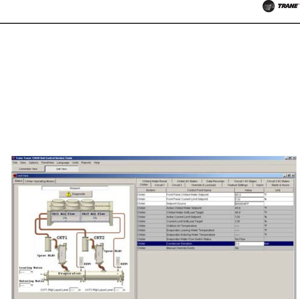
Installation - Mechanical
RLC-SVX09H-EN 73
for the field connections to the condenser, will have screw
terminals for termination in the RTUD control panel with
the exception of the outdoor air temperature sensor
(addressed above). Refer to the wiring diagrams.
Separate fan control algorithms are used for fixed speed
and variable speed systems. For the variable speed fan
deck option, the fan control reverts to fixed speed control
if an inverter drive fault is detected through a binary input
interface with the drive. An informational diagnostic is
also provided to indicate the issue.
For more fan control information, see chapter sections
beginning with "Fan Configurations" on Page 163.
RTUD Condenser Elevation Setting
Condenser elevation setting is a require input during
startup of an RTUD chiller, and is accessible inTechView,
on the Unit View Screen. Go to the Unit View/ChillerTab,
select Condenser Elevation setting and enter condenser
elevation in appropriate units. See Figure 41.The shipped
default of this setting is 0 and it represents the distance of
the bottom of the condenser, relative to the top of the
evaporator. Use a positive value for the condenser above
the evaporator and a negative value for the condenser
below the evaporator. An estimate to within +/- 3 feet is
required.
Condenser elevation setting allows proper EXV operation.
Failure to properly set the elevation can result in low
pressure cutout trips, or low differential pressure trips
during startup or large load transients, as well as poor EXV
liquid level control during operation.
Figure 41. RTUD Condenser elevation setting
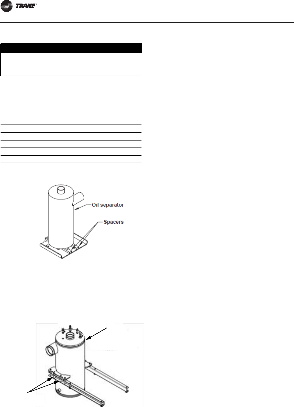
Installation - Mechanical
74 RLC-SVX09H-EN
Shipping Spacers
For RTWD units listed in table below, and all RTUD 80-130
ton units, remove and discard the two shipping spacers
with four bolts, located underneath the oil separator, as
shown in Figure 42, p. 74 before starting unit.
For RTUD 150-250 ton units, remove and discard the four
sets of shipping spacers (each including two spacers and
one bolt), located within the oil separator mounting
brackets, as shown in Figure , p. 74 before starting unit.
Failure to remove the spacers could result in excessive
noise and vibration transmission into the building
NOTICE:
Excessive Noise and Vibration!
Failure to remove the spacers could result in excessive
noise and vibration transmission into the building
Table 66. RTWD Units that require oil sep spacer removal
Size Hz Efficiency
80, 90, 100, 110, 120, 130, 140 60 STD
80, 90, 100, 110, 120, 130 60 HIGH
70, 80, 90, 100, 110, 120, 130, 140, 150 50 STD
60, 70, 80, 90, 100, 110, 120 50 HIGH
Figure 42. Oil separator spacer removal -
RTWD and RTUD 80-130T
Figure 43. Oil sep spacer removal - RTUD 150-250T
Oil Separator
Spacers
RLC-SVX09H-EN 75
Installation - Electrical
General Recommendations
All wiring must comply with local codes and the National
Electric Code.Typical field wiring diagrams are included at
the end of the manual. Minimum circuit ampacities and
other unit electrical data are on the unit nameplate and in
Table 67. See the unit order specifications for actual
electrical data. Specific electrical schematics and
connection diagrams are shipped with the unit. Important: Do not allow conduit to interfere with other
components, structural members or
equipment. Control voltage (115V) wiring in
conduit must be separate from conduit
carrying low voltage (<30V) wiring.To
prevent control malfunctions, do not run
low voltage wiring (<30V) in conduit with
conductors carrying more than 30 volts.
NOTICE: WARNING
Hazardous Voltage!
Disconnect all electric power, including remote
disconnects before servicing. Follow proper lockout/
tagout procedures to ensure the power can not be
inadvertently energized. Failure to disconnect power
before servicing could result in death or serious injury.
NOTICE:
Use Copper Conductors Only!
Unit terminals are not designed to accept other types
of conductors. Failure to use copper conductors could
result in equipment damage.
Table 67. Electrical Data - RTWD - 60 Hz - standard efficiency - standard condensing temperature
Unit
Size
Rated
Voltage
Unit Wiring
Single Point Power -
1 Power Connection
Dual Point Power -
2 Power Connections Motor Data
MCA MOP MCA MOP RLA LRA YD LRA XL
80
200/60/3 216 300 122/118 200/200 94/94 276/276 912/912
230/60/3 188 250 106/103 175/175 82/82 238/238 786/786
380/60/3 115 150 65/63 110/110 50/50 138/138 456/456
460/60/3 94 125 53/51 90/90 41/41 114/114 376/376
575/60/3 76 100 43/41 70/70 33/33 93/93 308/308
90
200/60/3 249 350 140/136 225/225 109/109 304/304 1003/1003
230/60/3 217 300 122/119 200/200 95/95 262/262 866/866
380/60/3 130 175 73/71 125/125 57/57 161/161 530/530
460/60/3 110 150 62/60 100/100 48/48 131/131 433/433
575/60/3 87 110 49/48 80/80 38/38 105/105 346/346
100
200/60/3 291 400 140/178 225/300 109/142 304/355 1003/1137
230/60/3 252 350 122/154 200/250 95/123 262/294 866/942
380/60/3 153 225 73/94 125/150 57/75 161/177 530/566
460/60/3 127 175 62/78 100/125 48/62 131/147 433/471
575/60/3 102 150 49/63 80/110 38/50 105/118 346/377
110
200/60/3 324 450 182/178 300/300 142/142 355/355 1137/1137
230/60/3 280 400 157/154 250/250 123/123 294/294 942/942
380/60/3 171 225 96/94 150/150 75/75 177/177 566/566
460/60/3 141 200 80/78 125/125 62/62 147/147 471/471
575/60/3 114 150 64/63 110/110 50/50 118/118 377/377
120
200/60/3 356 500 182/210 300/350 142/168 355/419 1137/1368
230/60/3 309 450 157/183 250/300 123/146 294/367 942/1200
380/60/3 187 250 96/110 150/175 75/88 177/229 566/747
460/60/3 155 225 79/91 125/150 62/73 147/184 471/600
575/60/3 125 175 64/74 110/125 50/59 118/148 377/483

Installation - Electrical
76 RLC-SVX09H-EN
130
200/60/3 382 500 214/210 350/350 168/168 419/419 1368/1368
230/60/3 332 450 186/183 300/300 146/146 367/367 1200/1200
380/60/3 200 250 112/110 200/175 88/88 229/229 747/747
460/60/3 166 225 93/91 150/150 73/73 184/184 600/600
575/60/3 134 175 75/74 125/125 59/59 148/148 483/483
140
200/60/3 425 600 214/253 350/450 168/202 419/487 1368/1498
230/60/3 368 500 186/219 300/350 146/175 367/427 1200/1314
380/60/3 223 300 112/133 200/225 88/106 229/260 747/801
460/60/3 185 250 93/110 150/175 73/88 184/212 600/652
575/60/3 148 200 75/88 125/150 59/70 148/172 483/528
Notes:
1. Voltage Utilization Range: +/- 10% of rated voltage
Rated voltage (use range): 208/60/3 (187.2-228.8), 230/60/3(208-254), 380/60/3 (342-418), 460/60/3 (414-506), 575/60/3 (516-633)
2. MCA–minimum circuit ampacity
3. MOP–maximum overcurrent protection
4. RLA–rated load amps are rated in accordance with UL Standard 1995.
5. LRA–locked rotor amps are based on full winding starts.
6. LRA YD–Locked Rotor Amps in Wye configuration. LRA XL–Locked Rotor Amps in the Delta configuration.
7. Local codes may take precedence.
8. Data containing information on two circuits shown as follows: circuit 1/circuit 2.
9. Standard condensing temperature option refers to entering condenser water temperatures 95°F (35°C) and below.
Table 67. Electrical Data - RTWD - 60 Hz - standard efficiency - standard condensing temperature (continued)
Unit
Size
Rated
Voltage
Unit Wiring
Single Point Power -
1 Power Connection
Dual Point Power -
2 Power Connections Motor Data
MCA MOP MCA MOP RLA LRA YD LRA XL
Table 68. Electrical Data - RTWD - 60 Hz - high efficiency - standard condensing temperature
Unit
Size
Rated
Voltage
Unit Wiring
Single Point Power -
1 Power Connection
Dual Point Power -
2 Power Connections Motor Data
MCA MOP MCA MOP RLA LRA YD LRA XL
80
200/60/3 211 300 119/115 200/200 92/92 276/276 912/912
230/60/3 184 250 104/100 175/175 80/80 238/238 786/786
380/60/3 112 150 63/61 110/110 49/49 138/138 456/456
460/60/3 92 125 52/50 90/90 40/40 114/114 376/376
575/60/3 73 100 32/32 93/93 32/32 93/93 308/308
90
200/60/3 245 350 138/134 225/225 107/107 304/304 1003/1003
230/60/3 213 300 120/116 200/200 93/93 262/262 866/866
380/60/3 128 175 72/70 125/125 56/56 161/161 530/530
460/60/3 108 150 61/59 100/100 47/47 131/131 433/433
575/60/3 85 110 48/46 80/80 37/37 105/105 346/346
100
200/60/3 284 400 138/173 225/300 107/138 304/355 1003/1137
230/60/3 247 350 120/150 200/250 93/120 262/294 866/942
380/60/3 149 200 72/91 125/150 56/73 161/177 530/566
460/60/3 124 175 61/75 100/125 47/60 131/147 433/471
575/60/3 98 125 48/60 80/100 37/48 105/118 346/377
110
200/60/3 315 450 177/173 300/300 138/138 355/355 1137/1137
230/60/3 274 350 154/150 250/250 120/120 294/294 942/942
380/60/3 166 225 93/91 150/150 73/73 177/177 566/566
460/60/3 137 175 77/75 125/125 60/60 147/147 471/471
575/60/3 109 150 61/60 100/100 48/48 118/118 377/377

Installation - Electrical
RLC-SVX09H-EN 77
120
200/60/3 347 500 177/205 300/350 138/164 355/419 1137/1368
230/60/3 302 400 154/179 250/300 120/143 294/367 942/1200
380/60/3 184 250 93/109 150/175 73/87 177/229 566/747
460/60/3 152 200 77/90 125/150 60/72 147/184 471/600
575/60/3 121 175 61/71 100/125 48/57 118/148 377/483
130
200/60/3 373 500 209/205 350/350 164/164 419/419 1368/1368
230/60/3 325 450 182/179 300/300 143/143 367/367 1200/1200
380/60/3 198 250 111/109 175/175 87/87 229/229 747/747
460/60/3 164 225 92/90 150/150 72/72 184/184 600/600
575/60/3 130 175 73/71 125/125 57/57 148/148 483/483
150
200/60/3 414 600 210/245 350/400 164/196 419/487 1368/1498
230/60/3 361 500 183/214 300/350 143/171 367/427 1200/1314
380/60/3 218 300 111/129 175/225 87/103 229/260 747/801
460/60/3 182 250 92/108 150/175 72/86 184/212 600/652
575/60/3 145 200 73/87 125/150 57/69 148/172 483/528
160
200/60/3 446 600 250/245 400/400 196/196 487/487 1498/1498
230/60/3 389 500 218/214 350/350 171/171 427/427 1314/1314
380/60/3 234 300 131/129 225/225 103/103 260/260 801/801
460/60/3 196 250 110/108 175/175 86/86 212/212 652/652
575/60/3 157 225 88/87 150/150 69/69 172/172 528/528
180
200/60/3 484 700 250/284 400/500 196/227 487/600 1498/1845
230/60/3 421 600 218/247 350/400 171/197 427/506 1314/1556
380/60/3 256 350 131/150 225/250 103/120 260/316 801/973
460/60/3 213 300 110/125 175/225 86/100 212/252 652/774
575/60/3 171 250 88/100 150/175 69/80 172/205 528/631
200
200/60/3 515 700 288/284 500/500 227/227 600/600 1845/1845
230/60/3 447 600 250/247 400/400 197/197 506/506 1556/1556
380/60/3 273 350 153/150 250/250 120/120 316/316 973/973
460/60/3 227 300 127/125 225/225 100/100 252/252 774/774
575/60/3 182 250 102/100 175/175 80/80 205/205 631/631
220
200/60/3 583 800 288/352 500/600 227/281 600/701 1845/2156
230/60/3 509 700 250/308 400/500 197/246 506/571 1556/1756
380/60/3 309 450 153/187 250/300 120/149 316/345 973/1060
460/60/3 256 350 127/154 225/250 100/123 252/285 774/878
575/60/3 204 300 102/123 175/200 80/98 205/229 631/705
250
200/60/3 637 800 356/352 600/600 281/281 701/701 2156/2156
230/60/3 558 800 312/308 500/500 246/246 571/571 1756/1756
380/60/3 338 450 189/187 300/300 149/149 345/345 1060/1060
460/60/3 279 700 156/154 250/250 123/123 285/285 878/878
575/60/3 222 300 124/123 200/200 98/98 229/229 705/705
Notes:
1. Voltage Utilization Range: +/- 10% of rated voltage
Rated voltage (use range): 208/60/3 (187.2-228.8), 230/60/3(208-254), 380/60/3 (342-418), 460/60/3 (414-506), 575/60/3 (516-633)
2. MCA–minimum circuit ampacity
3. MOP–maximum overcurrent protection
4. RLA–rated load amps are rated in accordance with UL Standard 1995.
5. LRA–locked rotor amps are based on full winding starts.
6. LRA YD–Locked Rotor Amps in Wye configuration. LRA XL–Locked Rotor Amps in the Delta configuration.
7. Local codes may take precedence.
8. Data containing information on two circuits shown as follows: circuit 1/circuit 2.
9. Standard condensing temperature option refers to entering condenser water temperatures 95°F/35°C) and below.
Table 68. Electrical Data - RTWD - 60 Hz - high efficiency - standard condensing temperature (continued)
Unit
Size
Rated
Voltage
Unit Wiring
Single Point Power -
1 Power Connection
Dual Point Power -
2 Power Connections Motor Data
MCA MOP MCA MOP RLA LRA YD LRA XL

Installation - Electrical
78 RLC-SVX09H-EN
Table 69. Electrical Data - RTWD - 60 Hz - premium efficiency - standard condensing temperature
Unit
Size
Rated
Voltage
Unit Wiring
Single Point Power -
1 Power Connection
Dual Point Power -
2 Power Connections Motor Data
MCA MOP MCA MOP RLA LRA YD LRA XL
150
200/60/3 410 600 208/243 350/400 163/194 419/487 1368/1498
230/60/3 360 500 183/213 300/350 143/170 367/427 1200/1314
380/60/3 277 300 110/129 175/225 86/103 229/260 747/801
460/60/3 180 250 91/107 150/175 71/85 184/212 600/652
575/60/3 145 200 74/85 125/150 58/68 148/172 483/528
160
200/60/3 441 600 247/243 400/400 194/194 487/487 1498/1498
230/60/3 387 500 217/213 350/350 170/170 427/427 1314/1314
380/60/3 234 300 131/129 225/225 103/103 260/260 801/801
460/60/3 194 250 109/107 175/175 85/85 212/212 652/652
575/60/3 155 200 87/85 150/150 68/68 172/172 528/528
180
200/60/3 481 700 247/283 400/500 194/226 487/600 1498/1845
230/60/3 420 600 217/247 350/400 170/197 427/506 1314/1556
380/60/3 256 350 131/150 225/250 103/120 260/316 801/973
460/60/3 212 300 109/125 175/225 85/100 212/252 652/774
575/60/3 171 250 87/102 150/175 68/81 172/205 528/631
200
200/60/3 513 700 287/283 500/500 226/226 600/600 1845/1845
230/60/3 447 600 250/247 400/400 197/197 506/506 1556/1556
380/60/3 275 350 153/150 250/250 120/120 316/316 973/973
460/60/3 277 300 127/125 225/225 100/100 252/252 774/774
575/60/3 184 250 103/102 175/175 81/81 205/205 631/631
Notes:
1. Voltage Utilization Range: +/- 10% of rated voltage
Rated voltage (use range): 208/60/3 (187.2-228.8), 230/60/3(208-254), 380/60/3 (342-418), 460/60/3 (414-506), 575/60/3 (516-633)
2. MCA–minimum circuit ampacity
3. MOP–maximum overcurrent protection
4. RLA–rated load amps are rated in accordance with UL Standard 1995.
5. LRA–locked rotor amps are based on full winding starts.
6. LRA YD–Locked Rotor Amps in Wye configuration. LRA XL–Locked Rotor Amps in the Delta configuration.
7. Local codes may take precedence.
8. Data containing information on two circuits shown as follows: circuit 1/circuit 2.
9. Standard condensing temperature option refers to entering condenser water temperatures 95°F (35°C) and below.
Table 70. Electrical Data - RTWD - 60 Hz - high efficiency - high condensing temperature
Unit
Size
Rated
Voltage
Unit Wiring
Single Point Power -
1 Power Connection
Dual Point Power -
2 Power Connections Motor Data
MCA MOP MCA MOP RLA LRA YD LRA XL
80
200/60/3 263 350 148/144 250/250 115/115 276/276 912/912
230/60/3 229 300 129/125 225/225 100/100 238/238 786/786
380/60/3 139 200 78/76 125/125 61/61 138/138 456/456
460/60/3 114 150 64/63 110/110 50/50 114/114 376/376
575/60/3 91 125 51/50 90/90 40/40 93/93 308/308
90
200/60/3 319 450 179/175 300/300 140/140 304/304 1003/1003
230/60/3 278 400 156/153 250/250 122/122 262/262 866/866
380/60/3 169 225 95/92 150/150 74/74 161/161 530/530
460/60/3 139 200 78/76 125/125 61/61 131/131 433/433
575/60/3 112 150 63/61 110/110 49/49 105/105 346/346

Installation - Electrical
RLC-SVX09H-EN 79
100
200/60/3 364 500 179/220 300/350 140/176 304/355 1003/1137
230/60/3 317 450 156/191 250/300 122/153 262/294 866/942
380/60/3 192 250 95/116 150/200 74/93 161/177 530/566
460/60/3 159 225 78/96 125/150 61/77 131/147 433/471
575/60/3 127 175 63/76 110/125 49/61 105/118 346/377
110
200/60/3 400 500 224/220 400/350 176/176 355/355 1137/1137
230/60/3 348 500 195/191 300/300 153/153 294/294 942/942
380/60/3 211 300 118/116 200/200 93/93 177/177 566/566
460/60/3 175 250 98/96 175/150 77/77 147/147 471/471
575/60/3 139 175 78/76 125/125 61/61 118/118 377/377
120
200/60/3 436 600 224/256 400/450 176/205 355/419 1137/1368
230/60/3 380 500 195/224 300/400 153/179 294/367 942/1200
380/60/3 230 300 118/135 200/225 93/108 177/229 566/747
460/60/3 191 250 98/113 175/200 77/90 147/184 471/600
575/60/3 152 200 78/90 125/150 61/72 118/148 377/483
130
200/60/3 N/A N/A 260/256 450/450 205/205 419/419 1368/1368
230/60/3 406 500 227/224 400/400 179/179 367/367 1200/1200
380/60/3 245 350 137/135 225/225 108/108 229/229 747/747
460/60/3 204 250 114/113 200/200 90/90 184/184 600/600
575/60/3 163 225 91/90 150/150 72/72 148/148 483/483
150
200/60/3 502 700 261/293 450/500 205/234 419/487 1368/1498
230/60/3 438 600 228/255 400/450 179/204 367/427 1200/1314
380/60/3 267 350 138/157 225/250 108/125 229/260 747/801
460/60/3 220 300 115/128 200/225 90/102 184/212 600/652
575/60/3 179 250 92/105 150/175 72/84 148/172 483/528
160
200/60/3 531 700 297/293 500/500 234/234 487/487 1498/1498
230/60/3 463 600 259/255 450/450 204/204 427/427 1314/1314
380/60/3 284 400 159/157 250/250 125/125 260/260 801/801
460/60/3 232 300 130/128 225/225 102/102 212/212 652/652
575/60/3 191 250 107/105 175/175 84/84 172/172 528/528
180
200/60/3 591 800 297/353 500/600 234/282 487/600 1498/1845
230/60/3 512 700 259/304 450/500 204/243 427/506 1314/1556
380/60/3 309 450 159/182 250/300 125/145 260/316 801/973
460/60/3 253 350 130/149 225/250 102/119 212/252 652/774
575/60/3 207 300 107/122 175/200 84/97 172/205 528/631
200
200/60/3 621 800 347/343 600/600 274/274 600/600 1845/1845
230/60/3 551 700 308/304 500/500 243/243 506/506 1556/1556
380/60/3 327 450 183/180 300/300 144/144 316/316 973/973
460/60/3 270 350 151/149 250/250 119/119 252/252 774/774
575/60/3 220 300 123/122 200/200 97/97 205/205 631/631
220
200/60/3 702 1000 357/415 600/700 282/332 600/701 1845/2156
230/60/3 608 800 308/362 500/600 243/289 506/571 1556/1756
380/60/3 373 500 184/225 300/400 145/180 316/345 973/1060
460/60/3 303 400 151/182 250/300 119/145 252/285 774/878
575/60/3 244 350 123/145 200/250 97/116 205/229 631/705
Table 70. Electrical Data - RTWD - 60 Hz - high efficiency - high condensing temperature (continued)
Unit
Size
Rated
Voltage
Unit Wiring
Single Point Power -
1 Power Connection
Dual Point Power -
2 Power Connections Motor Data
MCA MOP MCA MOP RLA LRA YD LRA XL
Installation - Electrical
80 RLC-SVX09H-EN
250
200/60/3 752 1000 420/415 700/700 332/332 701/701 2156/2156
230/60/3 654 800 365/362 600/600 289/289 571/571 1756/1756
380/60/3 408 500 228/225 400/400 180/180 345/345 1060/1060
460/60/3 329 450 184/182 300/300 145/145 285/285 878/878
575/60/3 263 350 147/145 250/250 116/116 229/229 705/705
Notes:
1. Voltage Utilization Range: +/- 10% of rated voltage
Rated voltage (use range): 208/60/3 (187.2-228.8), 230/60/3(208-254), 380/60/3 (342-418), 460/60/3 (414-506), 575/60/3 (516-633)MCA–
minimum circuit ampacity
2. MOP–maximum overcurrent protection
3. RLA–rated load amps are rated in accordance with UL Standard 1995.
4. LRA–locked rotor amps are based on full winding starts.
5. LRA YD–Locked Rotor Amps in Wye configuration. LRA XL–Locked Rotor Amps in the Delta configuration.
6. Local codes may take precedence.
7. Data containing information on two circuits shown as follows: circuit 1/circuit 2.
8. High condensing temperature option refers to entering condenser water temperatures above 95°F (35°C).
Table 70. Electrical Data - RTWD - 60 Hz - high efficiency - high condensing temperature (continued)
Unit
Size
Rated
Voltage
Unit Wiring
Single Point Power -
1 Power Connection
Dual Point Power -
2 Power Connections Motor Data
MCA MOP MCA MOP RLA LRA YD LRA XL
Table 71. Electrical Data - RTWD - 60 Hz - premium efficiency - high condensing temperature
Unit
Size
Rated
Voltage
Unit Wiring
Single Point Power -
1 Power Connection
Dual Point Power -
2 Power Connections Motor Data
MCA MOP MCA MOP RLA LRA YD LRA XL
150
200/60/3 498 700 252/295 400/500 198/236 419/487 1368/1498
230/60/3 430 600 219/254 350/450 172/203 367/427 1200/1314
380/60/3 266 350 138/155 225/250 108/124 229/260 747/801
460/60/3 218 300 112/128 175/225 88/102 184/212 600/652
575/60/3 178 250 91/105 150/175 71/84 148/172 483/528
160
200/60/3 536 700 300/295 500/500 236/236 487/487 1498
230/60/3 461 600 258/254 450/450 203/203 427/427 1314/1314
380/60/3 282 400 158/155 250/250 124/124 260/260 801/801
460/60/3 232 300 130/128 225/225 102/102 212/212 652/652
575/60/3 191 250 107/105 175/175 84/84 172/172 528/528
180
200/60/3 583 800 300/343 500/600 236/274 487/600 1498/1845
230/60/3 511 700 258/304 450/500 203/243 427/506 1314/1556
380/60/3 307 450 158/180 250/300 124/144 260/316 801/973
460/60/3 253 350 130/149 225/250 102/119 212/252 652/774
575/60/3 207 300 107/122 175/200 84/97 172/205 528/631
200
200/60/3 621 800 347/343 600/600 274/274 600/600 1845/1845
230/60/3 551 700 308/304 500/500 243/243 506/506 1556/1556
380/60/3 327 450 183/180 300/300 144/144 316/316 973/973
460/60/3 270 350 151/149 250/250 119/119 252/252 774/774
575/60/3 220 300 123/122 200/200 97/97 205/205 631/631
Notes:
1. Voltage Utilization Range: +/- 10% of rated voltage
Rated voltage (use range): 208/60/3 (187.2-228.8), 230/60/3(208-254), 380/60/3 (342-418), 460/60/3 (414-506), 575/60/3 (516-633)
2. MCA–minimum circuit ampacity
3. MOP–maximum overcurrent protection
4. RLA–rated load amps are rated in accordance with UL Standard 1995.
5. LRA–locked rotor amps are based on full winding starts.
6. LRA YD–Locked Rotor Amps in Wye configuration. LRA XL–Locked Rotor Amps in the Delta configuration.
7. Local codes may take precedence.
8. Data containing information on two circuits shown as follows: circuit 1/circuit 2.
9. High condensing temperature option refers to entering condenser water temperatures above 95°F (35°C).

Installation - Electrical
RLC-SVX09H-EN 81
Table 72. Electrical Data - RTUD - 60 Hz
Unit
Size
Rated
Voltage
Unit Wiring
Single Point Power -
1 Power Connection
Dual Point Power -
2 Power Connections Motor Data
MCA MOP MCA MOP RLA LRA YD LRA XL
80
200/60/3 297 400 167/163 250/250 130/130 276/276 912/912
230/60/3 261 350 147/143 250/250 114/114 238/238 786/786
380/60/3 158 225 89/87 150/150 69/69 138/138 456/456
460/60/3 131 175 74/72 125/125 57/57 114/114 376/376
575/60/3 105 150 59/58 100/100 46/46 93/93 308/308
90
200/60/3 353 500 198/194 350/300 155/155 304/304 1003/1003
230/60/3 299 400 168/164 250/250 131/131 262/262 866/866
380/60/3 185 250 104/102 175/175 81/81 161/161 530/530
460/60/3 153 200 86/84 150/150 67/67 131/131 433/433
575/60/3 123 175 69/68 110/110 54/54 105/105 346/346
100
200/60/3 400 500 198/240 350/400 155/192 304/355 1003/1137
230/60/3 344 500 168/209 250/350 131/167 262/294 866/942
380/60/3 210 300 104/127 175/225 81/101 161/177 530/566
460/60/3 174 250 86/105 150/175 67/84 131/147 433/471
575/60/3 140 200 69/84 110/150 54/67 105/118 346/377
110
200/60/3 437 600 245/240 400/400 192/192 355/355 1137/1137
230/60/3 380 500 213/209 350/350 167/167 294/294 942/942
380/60/3 230 300 129/127 225/225 101/101 177/177 566/566
460/60/3 191 250 107/105 175/175 84/84 147/147 471/471
575/60/3 153 200 86/84 150/150 67/67 118/118 377/377
120
200/60/3 447 600 245/250 400/450 192/200 355/419 1137/1368
230/60/3 421 600 213/250 350/450 167/200 294/367 942/1200
380/60/3 255 350 129/152 225/250 101/121 177/229 566/747
460/60/3 211 300 107/125 175/225 84/100 147/184 471/600
575/60/3 169 225 86/100 150/175 67/80 118/148 377/483
130
200/60/3 455 600 255/250 450/450 200/200 419/419 1368/1368
230/60/3 454 600 254/250 450/450 200/200 367/367 1200/1200
380/60/3 275 350 154/152 250/250 121/121 229/229 747/747
460/60/3 227 300 127/125 225/225 100/100 184/184 600/600
575/60/3 182 250 102/100 175/175 80/80 148/148 483/483
150
200/60/3 542 800 255/338 450/600 200/270 419/487 1368/1498
230/60/3 498 700 254/294 450/500 200/235 367/427 1200/1314
380/60/3 301 400 154/178 250/300 121/142 229/260 747/801
460/60/3 250 350 127/148 225/250 100/118 184/212 600/652
575/60/3 199 250 102/118 175/200 80/84 148/172 483/528
160
200/60/3 612 800 342/338 600/600 270/270 487/487 1498/1498
230/60/3 553 700 298/294 500/500 235/235 427/427 1314/1314
380/60/3 322 450 180/178 300/300 142/142 260/260 801/801
460/60/3 268 350 150/148 250/250 118/118 212/212 652/652
575/60/3 213 300 119/118 200/200 94/94 172/172 528/528
180
200/60/3 675 800 342/400 600/700 270/320 487/600 1498/1845
230/60/3 587 800 298/348 500/600 235/278 427/506 1314/1556
380/60/3 355 500 180/210 300/350 142/168 260/316 801/973
460/60/3 284 400 150/164 250/250 118/131 212/252 652/774
575/60/3 235 300 119/139 200/225 94/111 172/205 528/631
Installation - Electrical
82 RLC-SVX09H-EN
200
200/60/3 725 1000 405/400 700/700 320/320 600/600 1845/1845
230/60/3 630 800 352/345 600/600 278/278 506/506 1556/1556
380/60/3 381 500 213/210 350/350 168/168 316/316 973/973
460/60/3 297 400 166/164 250/250 131/131 252/252 774/774
575/60/3 252 350 141/139 250/225 111/111 205/205 631/631
220
200/60/3 743 1000 405/419 700/700 320/335 600/701 1845/2156
230/60/3 701 1000 352/419 600/700 278/335 506/571 1556/1756
380/60/3 424 600 213/254 350/450 168/203 316/345 973/1060
460/60/3 343 500 166/210 250/350 131/168 252/285 774/878
575/60/3 277 400 141/164 250/250 111/131 205/229 631/705
250
200/60/3 758 1000 423/419 700/700 335/335 701/701 2156/2156
230/60/3 758 1000 423/419 700/700 335/335 571/571 1756/1756
380/60/3 459 600 256/254 450/450 203/203 345/345 1060/1060
460/60/3 380 500 212/210 350/350 168/168 285/285 878/878
575/60/3 297 400 166/164 250/250 131/131 229/229 705/705
Notes:
1. Voltage Utilization Range: +/- 10% of rated voltage
Rated voltage (use range): 208/60/3 (187.2-228.8), 230/60/3(208-254), 380/60/3 (342-418), 460/60/3 (414-506), 575/60/3 (516-633)MCA–
minimum circuit ampacity
2. MOP–maximum overcurrent protection
3. RLA–rated load amps are rated in accordance with UL Standard 1995.
4. LRA–locked rotor amps are based on full winding starts.
5. LRA YD–Locked Rotor Amps in Wye configuration. LRA XL–Locked Rotor Amps in the Delta configuration.
6. Local codes may take precedence.
7. Data containing information on two circuits shown as follows: circuit 1/circuit 2.
8. Standard condensing temperature option refers to entering condenser water temperatures 95°F (35°C) and below.
Table 72. Electrical Data - RTUD - 60 Hz (continued)
Unit
Size
Rated
Voltage
Unit Wiring
Single Point Power -
1 Power Connection
Dual Point Power -
2 Power Connections Motor Data
MCA MOP MCA MOP RLA LRA YD LRA XL
Table 73. Electrical Data –Trane Air-Cooled Condenser – 60 Hz
Unit Wiring
Standard Ambient Low Ambient
Unit Size Rated Voltage Fan FLA Fan MCA Fan MOP Fan FLA Fan MCA Fan MOP
RTUD 80
208-230/60/3 6 37.5 40 6 37.5 40
460/60/3 3 18.8 20 3 18.8 20
575/60/3 2.5 15.6 15 2.5 16.8 15
RTUD 90
208-230/60/3 6 49.5 50 6 49.5 50
460/60/3 3 24.8 25 3 24.8 25
575/60/3 2.5 20.6 20 2.5 21.8 20
RTUD 100
208-230/60/3 6 49.5 50 6 49.5 50
460/60/3 3 24.8 25 3 24.8 25
575/60/3 2.5 20.6 20 2.5 21.8 20
RTUD 110
208-230/60/3 6 49.5 50 6 49.5 50
460/60/3 3 24.8 25 3 24.8 25
575/60/3 2.5 20.6 20 2.5 21.8 20
RTUD 120
208-230/60/3 6 61.5 60 6 61.5 60
460/60/3 3 30.8 30 3 30.8 30
575/60/3 2.5 18.8 25 2.5 24.8 25
RTUD 130
208-230/60/3 6 61.5 60 6 61.5 60
460/60/3 3 30.8 30 3 30.8 30
575/60/3 2.5 18.8 25 2.5 24.8 25
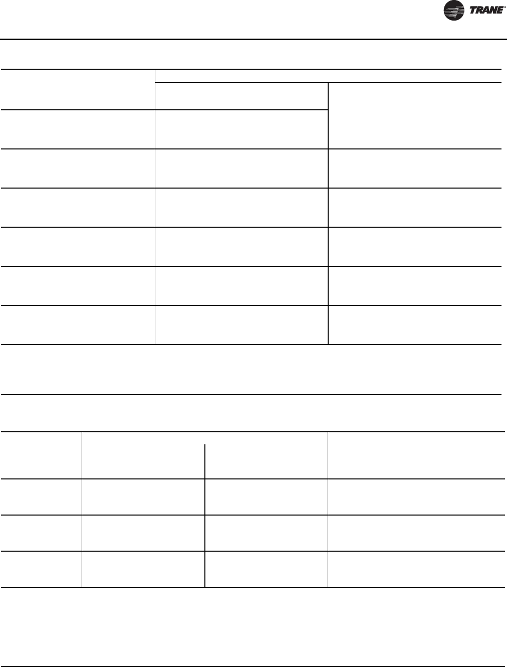
Installation - Electrical
RLC-SVX09H-EN 83
RTUD 150
208-230/60/3 6 37.5 40 6 37.5 40
460/60/3 3 18.8 20 3 18.8 20
575/60/3 2.5 15.6 15 2.5 16.8 15
RTUD 160
208-230/60/3 6 37.5 40 6 37.5 40
460/60/3 3 18.8 20 3 18.8 20
575/60/3 2.5 15.6 15 2.5 16.8 15
RTUD 180
208-230/60/3 6 37.5/49.5 40/50 6 37.5/49.5 40/50
460/60/3 3 18.8/24.8 20/25 3 18.8/24.8 20/25
575/60/3 2.5 15.6/20.6 15/20 2.5 16.8/21.8 15/20
RTUD 200
208-230/60/3 6 49.5 50 6 49.5 50
460/60/3 3 24.8 25 3 24.8 25
575/60/3 2.5 20.6 20 2.5 21.8 20
RTUD 220
208-230/60/3 6 49.5 50 6 49.5 50
460/60/3 3 24.8 25 3 24.8 25
575/60/3 2.5 20.6 20 2.5 21.8 20
RTUD 250
208-230/60/3 6 49.5 50 6 49.5 50
460/60/3 3 24.8 25 3 24.8 25
575/60/3 2.5 20.6 20 2.5 21.8 20
Notes:
1. MCA–minimum circuit ampacity
2. MOP–maximum overcurrent protection
3. FLA–fan rated load amps
4. Local codes may take precedence.
5. Information is the same for both circuits unless it is shown as: circuit 1/circuit 2.
Table 73. Electrical Data –Trane Air-Cooled Condenser – 60 Hz (continued)
Unit Wiring
Standard Ambient Low Ambient
Unit Size Rated Voltage Fan FLA Fan MCA Fan MOP Fan FLA Fan MCA Fan MOP
Table 74. Electrical Data - RTWD - 50 Hz - standard efficiency - standard condensing temperature
Unit
Size
Rated
Voltage
Unit Wiring
Single Point Power -
1 Power Connection
Dual Point Power -
2 Power Connections Motor Data
MCA MOP MCA MOP RLA LRA YD LRA XL
70 400/50/3 106 150 60/58 100/100 46/46 129/129 427/427
80 400/50/3 123 175 60/75 100/125 46/60 129/144 427/462
90 400/50/3 137 175 77/75 125/125 60/60 144/144 462/462
100 400/50/3 152 200 77/90 125/150 60/72 144/180 462/589
110 400/50/3 164 225 92/90 150/150 72/72 180/180 589/589
120 400/50/3 180 250 92/106 150/175 72/85 180/217 589/668
130 400/50/3 193 250 108/106 175/175 85/85 217/217 668/668
140 400/50/3 211 300 108/124 175/200 85/99 217/259 668/796
150 400/50/3 225 300 126/124 200/200 99/99 259/259 796/796
Notes:
1. Voltage Utilization Range: +/- 10% of rated voltage
Rated voltage (use range): 400/50/3 (360-440)
2. MOP–maximum overcurrent protection
3. RLA–rated load amps are rated in accordance with UL Standard 1995.
4. LRA–locked rotor amps are based on full winding starts.
5. LRA YD–Locked Rotor Amps in Wye configuration. LRA XL–Locked Rotor Amps in the Delta configuration.
6. Local codes may take precedence.
7. Data containing information on two circuits shown as follows: circuit 1/circuit 2.
8. Standard condensing temperature option refers to entering condenser water temperatures 95°F (35°C) or below.

Installation - Electrical
84 RLC-SVX09H-EN
Table 75. Electrical Data - RTWD - 50 Hz - high efficiency - standard condensing temperature
Unit
Size
Rated
Voltage
Unit Wiring
Single Point Power -
1 Power Connection
Dual Point Power -
2 Power Connections Motor Data
MCA MOP MCA MOP RLA LRA YD LRA XL
60 400/50/3 88 125 50/48 80/80 38/38 112/112 370/370
70 400/50/3 103 125 58/56 100/100 45/45 129/129 427/427
80 400/50/3 121 175 58/74 100/125 45/59 129/144 427/462
90 400/50/3 135 175 76/74 125/125 59/59 144/144 462/462
100 400/50/3 150 200 76/89 125/150 59/71 144/180 462/589
110 400/50/3 162 225 91/89 150/150 71/71 180/180 589/589
120 400/50/3 178 250 91/105 150/175 71/84 180/217 589/668
130 400/50/3 192 250 108/105 175/175 84/84 217/217 668/668
140 400/50/3 209 300 108/123 175/200 84/98 217/259 668/796
160 400/50/3 223 300 125/123 200/200 98/98 259/259 796/796
180 400/50/3 247 350 125/147 200/250 98/117 259/291 796/896
200 400/50/3 266 350 149/147 250/250 117/117 291/291 896/896
220 400/50/3 296 400 149/177 250/300 117/141 291/354 896/1089
250 400/50/3 320 450 179/177 300/300 141/141 354/354 1089/1089
Notes:
1. Voltage Utilization Range: +/- 10% of rated voltage. Rated voltage (use range): 400/50/3 (360-440)
2. MCA–minimum circuit ampacity
3. MOP–maximum overcurrent protection
4. RLA–rated load amps are rated in accordance with UL Standard 1995.
5. LRA–locked rotor amps are based on full winding starts.
6. LRA YD–Locked Rotor Amps in Wye configuration. LRA XL–Locked Rotor Amps in the Delta configuration.
7. Local codes may take precedence.
8. Data containing information on two circuits shown as follows: circuit 1/circuit 2.
9. Standard condensing temperature option refers to entering condenser water temperatures 95°F (35°C) or below.
Table 76. Electrical Data - RTWD - 50 Hz - high efficiency - high condensing temperature
Unit
Size
Rated
Voltage
Unit Wiring
Single Point Power -
1 Power Connection
Dual Point Power -
2 Power Connections Motor Data
MCA MOP MCA MOP RLA LRA YD LRA XL
60 400/50/3 110 150 62/60 110/100 48/48 112/112 370/370
70 400/50/3 133 175 75/73 125/125 58/58 129/129 427/427
80 400/50/3 153 225 75/93 125/150 58/74 129/144 427/462
90 400/50/3 169 225 95/93 150/150 74/74 144/144 462/462
100 400/50/3 186 250 95/110 150/175 74/88 144/180 462/589
110 400/50/3 200 250 112/110 200/175 88/88 180/180 589/589
120 400/50/3 215 300 112/125 200/225 88/100 180/217 589/668
130 400/50/3 226 300 128/123 225/200 100/98 217/217 668/668
150 400/50/3 250 350 128/148 225/250 100/118 217/259 668/796
160 400/50/3 268 350 150/148 250/250 118/118 259/259 796/796
180 400/50/3 297 400 150/177 250/300 118/141 259/291 796/896
200 400/50/3 320 450 179/177 300/300 141/141 291/291 896/896
220 400/50/3 352 500 179/209 300/350 141/167 291/354 896/1089
250 400/50/3 378 500 211/209 350/350 167/167 354/354 1089/1089
Notes:
1. Voltage Utilization Range: +/- 10% of rated voltage. Rated voltage (use range): 400/50/3 (360-440)
2. MCA–minimum circuit ampacity
3. MOP–maximum overcurrent protection
4. RLA–rated load amps are rated in accordance with UL Standard 1995.
5. LRA–locked rotor amps are based on full winding starts.
6. LRA YD–Locked Rotor Amps in Wye configuration. LRA XL–Locked Rotor Amps in the Delta configuration.
7. Local codes may take precedence.
8. Data containing information on two circuits shown as follows: circuit 1/circuit 2.
9. High condensing temperature option refers to entering condenser water temperatures above 95°F (35°C).
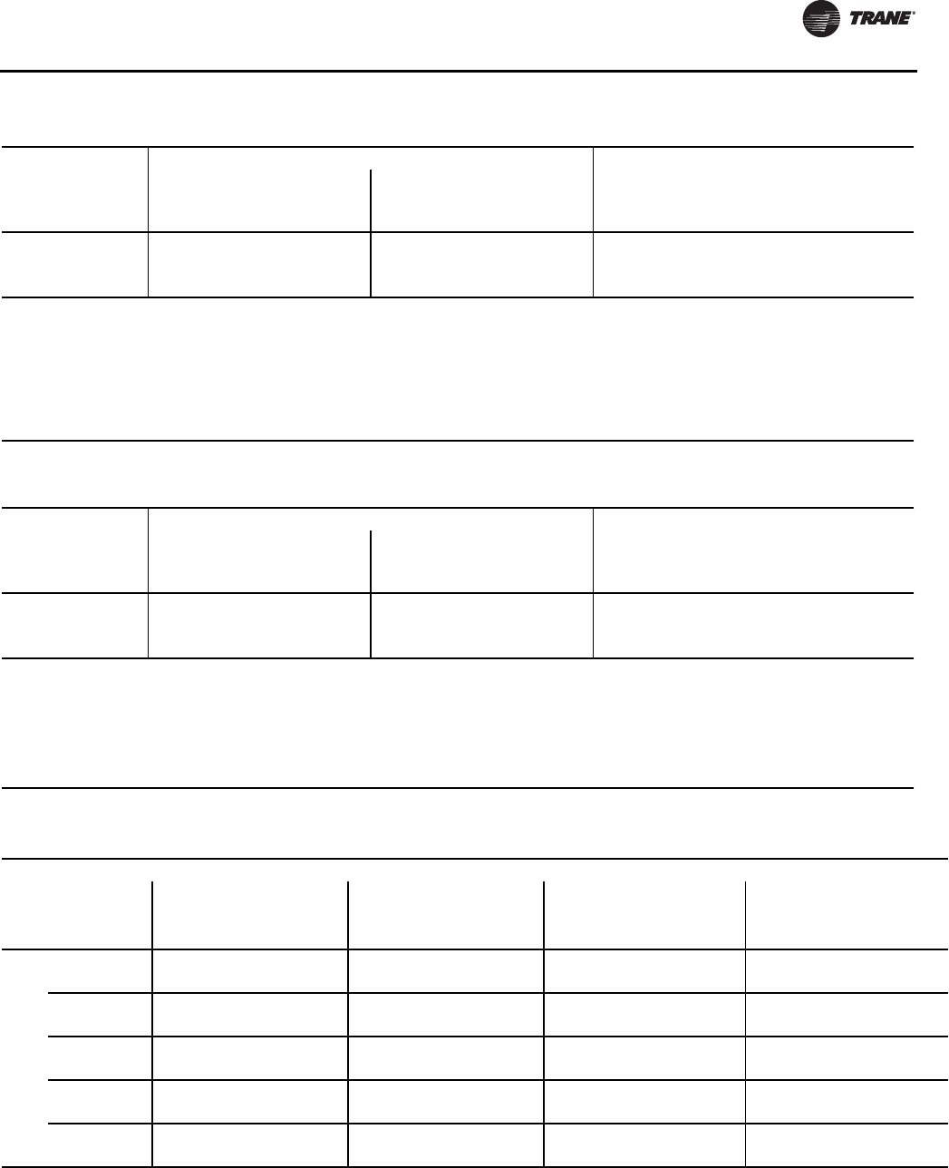
Installation - Electrical
RLC-SVX09H-EN 85
Table 77. Electrical Data - RTWD - 50 Hz - premium efficiency - standard condensing temperature
Unit
Size
Rated
Voltage
Unit Wiring
Single Point Power -
1 Power Connection
Dual Point Power -
2 Power Connections Motor Data
MCA MOP MCA MOP RLA LRA YD LRA XL
160 400/50/3 221 300 124/122 200/200 97/97 259/259 796/796
180 400/50/3 246 350 124/147 200/250 97/117 259/291 796/896
200 400/50/3 266 350 149/147 250/250 117/117 291/291 896/896
Notes:
1. Voltage Utilization Range: +/- 10% of rated voltage. Rated voltage (use range): 400/50/3 (360-440)
2. MCA–minimum circuit ampacity
3. MOP–maximum overcurrent protection
4. RLA–rated load amps are rated in accordance with UL Standard 1995.
5. LRA–locked rotor amps are based on full winding starts.
6. LRA YD–Locked Rotor Amps in Wye configuration. LRA XL–Locked Rotor Amps in the Delta configuration.
7. Local codes may take precedence.
8. Data containing information on two circuits shown as follows: circuit 1/circuit 2.
9. Standard condensing temperature option refers to entering condenser water temperatures 95°F (35°C) or below.
Table 78. Electrical Data - RTWD - 50 Hz - premium efficiency - high condensing temperature
Unit
Size
Rated
Voltage
Unit Wiring
Single Point Power -
1 Power Connection
Dual Point Power -
2 Power Connections Motor Data
MCA MOP MCA MOP RLA LRA YD LRA XL
160 400/50/3 268 350 150/148 250/250 118/118 259/259 796/796
180 400/50/3 297 400 150/177 250/300 118/141 259/291 796/896
200 400/50/3 320 450 179/177 300/300 141/141 291/291 896/896
Notes:
1. MCA–minimum circuit ampacity
2. MOP–maximum overcurrent protection
3. RLA–rated load amps are rated in accordance with UL Standard 1995.
4. LRA–locked rotor amps are based on full winding starts.
5. LRA YD–Locked Rotor Amps in Wye configuration. LRA XL–Locked Rotor Amps in the Delta configuration.
6. Local codes may take precedence.
7. Data containing information on two circuits shown as follows: circuit 1/circuit 2.
8. High condensing temperature option refers to entering condenser water temperatures above 95°F (35°C).
Table 79. Customer Wire Selection - RTWD - 60 Hz - standard efficiency - standard condensing temperature
Size
Rated
Voltage
#
Conn
Wire Selection
Main Terminal Block Disconnect Circuit Breaker Hi-Fault Panel Ckt Brkr
Size Wire Range Size Wire Range Size Wire Range Size Wire Range
Amp XL YD Amp XL YD Amp XL YD Amp XL YD
80
200 1 380 N/A #4-500 250 N/A #6-350 300 N/A 3/0-500(a) 300 N/A 3/0-500(a)
2 175 N/A #14-2/0 250 N/A #6-350 200 N/A #6-350 200 N/A #6-350
230 1 380 N/A #4-500 250 N/A #6-350 250 N/A #6-350 250 N/A #6-350
2 175 N/A #14-2/0 100 N/A #10–1/0 175 N/A #6-350 175 N/A #6-350
380 1 380 #4-500 #4-500 250 #6-350 #6-350 150 #6-350 #6-350 150 #6-350 #6-350
2 175 #14-2/0 #14-2/0 100 #10-1/0 #10-1/0 110 #6-350 #6-350 110 #6-350 #6-350
460 1 380 #4-500 #4-500 100 #10-1/0 #10-1/0 125 #6-350 #6-350 125 #6-350 #6-350
2 175 #14-2/0 #14-2/0 100 #10-1/0 #10-1/0 90 #6-350 #6-350 90 #6-350 #6-350
575 1 380 #4-500 #4-500 100 #10-1/0 #10-1/0 100 #6-350 #6-350 N/A N/A N/A
2 175 #14-2/0 #14-2/0 100 #10-1/0 #10-1/0 70 #6-350 #6-350 N/A N/A N/A
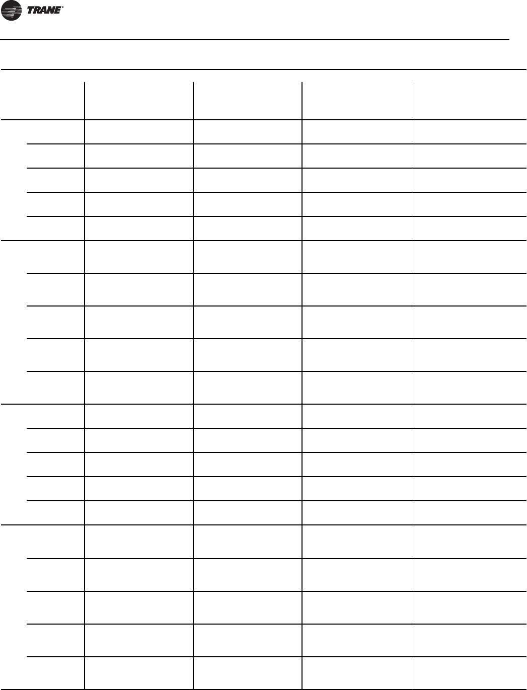
Installation - Electrical
86 RLC-SVX09H-EN
90
200 1 380 N/A #4-500 400 N/A 3/0-500(a) 350 N/A 3/0-500(a) 350 N/A 3/0-500(a)
2 175 N/A #14-2/0 250 N/A #6-350 225 N/A #6-350 225 N/A #6-350
230 1 380 N/A #4-500 250 N/A #6-350 300 N/A 3/0-500(a) 300 N/A 3/0-500(a)
2 175 N/A #14-2/0 250 N/A #6-350 200 N/A #6-350 200 N/A #6-350
380 1 380 #4-500 #4-500 250 #6-350 #6-350 175 #6-350 #6-350 175 #6-350 #6-350
2 175 #14-2/0 #14-2/0 100 #10-1/0 #10-1/0 125 #6-350 #6-350 125 #6-350 #6-350
460 1 380 #4-500 #4-500 250 #6-350 #6-350 150 #6-350 #6-350 150 #6-350 #6-350
2 175 #14-2/0 #14-2/0 100 #10-1/0 #10-1/0 100 #6-350 #6-350 100 #6-350 #6-350
575 1 380 #4-500 #4-500 100 #10-1/0 #10-1/0 110 #6-350 #6-350 N/A N/A N/A
2 175 #14-2/0 #14-2/0 100 #10-1/0 #10-1/0 80 #6-350 #6-350 N/A N/A N/A
100
200
1 380 N/A #4-500 400 N/A 3/0-500(a) 400 N/A 3/0-500(a) 400 N/A 3/0-500(a)
2175
380 N/A #14-2/0
#4-500 250 N/A #6-350 225
300 N/A #6-350
3/0-500(a)
225
300 N/A #6-350
3/0-500(a)
230
1 380 N/A #4-500 400 N/A 3/0-500(a) 350 N/A 3/0-500(a) 350 N/A 3/0-500(a)
2 175 N/A #14-2/0 250 N/A #6-350 200
250 N/A #6-350 200
250 N/A #6-350
380
1 380 #4-500 #4-500 250 #6-350 #6-350 225 #6-350 #6-350 225 #6-350 #6-350
2 175 #14-2/0 #14-2/0 100 #10-1/0 #10-1/0 125
150 #6-350 #6-350 125
150 #6-350 #6-350
460
1 380 #4-500 #4-500 250 #6-350 #6-350 175 #6-350 #6-350 175 #6-350 #6-350
2 175 #14-2/0 #14-2/0 100 #10-1/0 #10-1/0 100
125 #6-350 #6-350 100
125 #6-350 #6-350
575
1 380 #4-500 #4-500 250 #6-350 #6-350 150 #6-350 #6-350 N/A N/A N/A
2 175 #14-2/0 #14-2/0 100 #10-1/0 #10-1/0 80
110 #6-350 #6-350 N/A N/A N/A
110
200 1 380 N/A #4-500 400 N/A 3/0-500(a) 450 N/A 3/0-500(a) 450 N/A 3/0-500(a)
2 380 N/A #4-500 250 N/A #6-350 300 N/A 3/0-500(a) 300 N/A 3/0-500(a)
230 1 380 N/A #4-500 400 N/A 3/0-500(a) 400 N/A 3/0-500(a) 400 N/A 3/0-500(a)
2 175 N/A #14-2/0 250 N/A #6-350 250 N/A #6-350 250 N/A #6-350
380 1 380 #4-500 #4-500 250 #6-350 #6-350 225 #6-350 #6-350 225 #6-350 #6-350
2 175 #14-2/0 #14-2/0 100 #10-1/0 #10-1/0 150 #6-350 #6-350 150 #6-350 #6-350
460 1 380 #4-500 #4-500 250 #6-350 #6-350 200 #6-350 #6-350 200 #6-350 #6-350
2 175 #14-2/0 #14-2/0 100 #10-1/0 #10-1/0 125 #6-350 #6-350 125 #6-350 #6-350
575 1 380 #4-500 #4-500 250 #6-350 #6-350 150 #6-350 #6-350 N/A N/A N/A
2 175 #14-2/0 #14-2/0 100 #10-1/0 #10-1/0 110 #6-350 #6-350 N/A N/A N/A
120
200
1 380 N/A #4-500 400 N/A 3/0-500(a) 500 N/A 3/0-500(a) 500 N/A 3/0-500(a)
2 380 N/A #4-500 250 N/A #6-350 300
350 N/A 3/0-500(a) 300
350 N/A 3/0-500(a)
230
1 380 N/A #4-500 400 N/A 3/0-500(a) 450 N/A 3/0-500(a) 450 N/A 3/0-500(a)
2175
380 N/A #14-2/0
#4-500 250 N/A #6-350 250
300 N/A #6-350
3/0-500(a)
250
300 N/A #6-350
3/0-500(a)
380
1 380 #4-500 #4-500 250 #6-350 #6-350 250 #6-350 #6-350 250 #6-350 #6-350
2 175 #14-2/0 #14-2/0 100
250
#10-1/0
#6-350
#10-1/0
#6-350
150
175 #6-350 #6-350 150
175 #6-350 #6-350
460
1 380 #4-500 #4-500 250 #6-350 #6-350 225 #6-350 #6-350 225 #6-350 #6-350
2 175 #14-2/0 #14-2/0 100 #10-1/0 #10-1/0 125
150 #6-350 #6-350 125
150 #6-350 #6-350
575
1 380 #4-500 #4-500 250 #6-350 #6-350 175 #6-350 #6-350 N/A N/A N/A
2 175 #14-2/0 #14-2/0 100 #10-1/0 #10-1/0 110
125 #6-350 #6-350 N/A N/A N/A
Table 79. CustomerWire Selection - RTWD - 60 Hz - standard efficiency - standard condensing temperature (continued)
Size
Rated
Voltage
#
Conn
Wire Selection
Main Terminal Block Disconnect Circuit Breaker Hi-Fault Panel Ckt Brkr
Size Wire Range Size Wire Range Size Wire Range Size Wire Range
Amp XL YD Amp XL YD Amp XL YD Amp XL YD
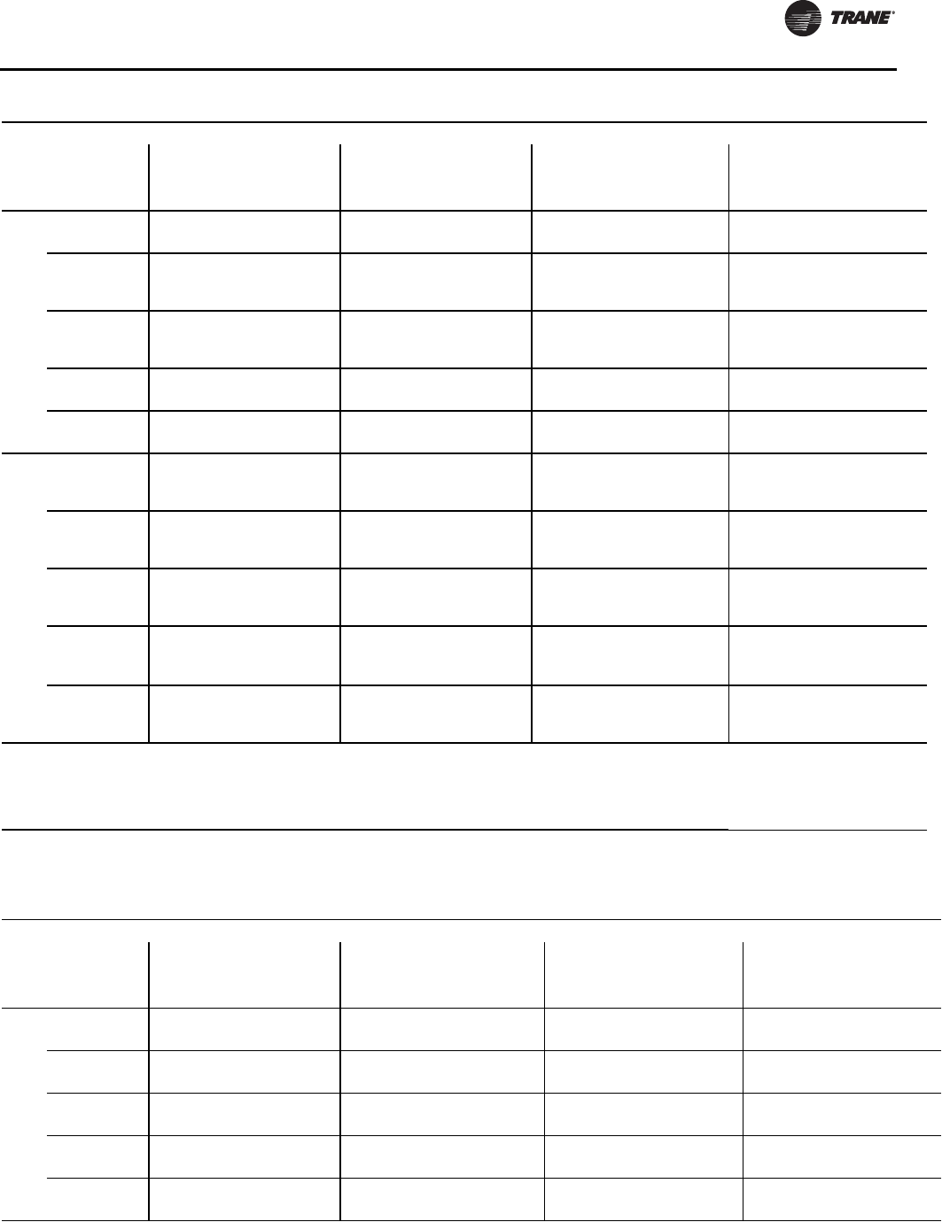
Installation - Electrical
RLC-SVX09H-EN 87
130
200 1 380 N/A #4-500 400 N/A 3/0-500(a) 500 N/A 3/0-500(a) 500 N/A 3/0-500(a)
2 380 N/A #4-500 250 N/A #6-350 350 N/A 3/0-500(a) 350 N/A 3/0-500(a)
230
1 380 N/A #4-500 400 N/A 3/0-500(a) 450 N/A 3/0-500(a) 450 N/A 3/0-500(a)
2175
380 N/A #14-2/0
#4-500 250 N/A #6-350 300 N/A 3/0-500(a) 300 N/A 3/0-500(a)
380
1 380 #4-500 #4-500 250 #6-350 #6-350 250 #6-350 #6-350 250 #6-350 #6-350
2 175 #14-2/0 #14-2/0 250 #6-350 #6-350 200
175 #6-350 #6-350 200
175 #6-350 #6-350
460 1 380 #4-500 #4-500 250 #6-350 #6-350 225 #6-350 #6-350 225 #6-350 #6-350
2 175 #14-2/0 #14-2/0 100 #10-1/0 #10-1/0 150 #6-350 #6-350 150 #6-350 #6-350
575 1 380 #4-500 #4-500 250 #6-350 #6-350 175 #6-350 #6-350 N/A N/A N/A
2 175 #14-2/0 #14-2/0 100 #10-1/0 #10-1/0 125 #6-350 #6-350 N/A N/A N/A
140
200
1 760 N/A #4-500(a) 600 N/A 3/0-500(a) 600 N/A 3/0-500(a) 600 N/A 3/0-500(a)
2 380 N/A #4-500 250 N/A #6-350 350
450 N/A 3/0-500(a) 350
450 N/A 3/0-500(a)
230
1 380 N/A #4-500 400 N/A 3/0-500(a) 500 N/A 3/0-500(a) 500 N/A 3/0-500(a)
2 380 N/A #4-500 250 N/A #6-350 300
350 N/A 3/0-500(a) 300
350 N/A 3/0-500(a)
380
1 380 #4-500 #4-500 250 #6-350 #6-350 300 3/0-500(a) 3/0-500(a) 300 3/0-500(a) 3/0-500(a)
2 175 #14-2/0 #14-2/0 250 #6-350 #6-350 200
225 #6-350 #6-350 200
225 #6-350 #6-350
460
1 380 #4-500 #4-500 250 #6-350 #6-350 250 #6-350 #6-350 250 #6-350 #6-350
2 175 #14-2/0 #14-2/0 100
250
#10-1/0
#6-350
#10-1/0
#6-350
150
175 #6-350 #6-350 150
175 #6-350 #6-350
575
1 380 #4-500 #4-500 250 #6-350 #6-350 200 #6-350 #6-350 N/A N/A N/A
2 175 #14-2/0 #14-2/0 100 #10-1/0 #10-1/0 125
150 #6-350 #6-350 N/A N/A N/A
Notes:
1. Optional non-fused disconnect and circuit breaker.
2. Copper wire only, based on nameplate minimum circuit ampacity (MCA).
3. Standard condensing temperature option refers to entering condenser water temperatures 95°F (35°C) and below.
4. Circuit two information is the same as circuit one unless listed on a separate line below circuit one values.
5. XL - across-the-line starter and YD - wye-delta starter.
(a) Will accept 2 conduits per phase in this size.
Table 79. CustomerWire Selection - RTWD - 60 Hz - standard efficiency - standard condensing temperature (continued)
Size
Rated
Voltage
#
Conn
Wire Selection
Main Terminal Block Disconnect Circuit Breaker Hi-Fault Panel Ckt Brkr
Size Wire Range Size Wire Range Size Wire Range Size Wire Range
Amp XL YD Amp XL YD Amp XL YD Amp XL YD
Table 80. Customer Wire Selection - RTWD - 60 Hz - high efficiency - standard condensing temperature
Size
Rated
Voltage
#
Conn
Wire Selection
Main Terminal Block Disconnect Circuit Breaker Hi-Fault Panel Ckt Brkr
Size Wire Range Size Wire Range Size Wire Range Size Wire Range
Amp XL YD Amp XL YD Amp XL YD Amp XL YD
80
200 1 380 N/A #4-500 250 N/A #6-350 300 N/A 3/0-500(a) 300 N/A 3/0-500(a)
2 175 N/A #14-2/0 250 N/A #6-350 200 N/A #6-350 200 N/A #6-350
230 1 380 N/A #4-500 250 N/A #6-350 250 N/A #6-350 250 N/A #6-350
2 175 N/A #14-2/0 100 N/A #10-1/0 175 N/A #6-350 175 N/A #6-350
380 1 380 #4-500 #4-500 250 #6-350 #6-350 150 #6-350 #6-350 150 #6-350 #6-350
2 175 #14-2/0 #14-2/0 100 #10-1/0 #10-1/0 110 #6-350 #6-350 110 #6-350 #6-350
460 1 380 #4-500 #4-500 100 #10-1/0 #10-1/0 125 #6-350 #6-350 125 #6-350 #6-350
2 175 #14-2/0 #14-2/0 100 #10-1/0 #10-1/0 90 #6-350 #6-350 90 #6-350 #6-350
575 1 380 #4-500 #4-500 100 #10-1/0 #10-1/0 100 #6-350 #6-350 N/A N/A N/A
2 175 #14-2/0 #14-2/0 100 #10-1/0 #10-1/0 70 #6-350 #6-350 N/A N/A N/A
Installation - Electrical
88 RLC-SVX09H-EN
90
200 1 380 N/A #4-500 250 N/A #6-350 350 N/A 3/0-500(a) 350 N/A 3/0-500(a)
2 175 N/A #14-2/0 250 N/A #6-350 225 N/A #6-350 225 N/A #6-350
230 1 380 N/A #4-500 250 N/A #6-350 300 N/A 3/0-500(a) 300 N/A 3/0-500(a)
2 175 N/A #14-2/0 250 N/A #6-350 200 N/A #6-350 200 N/A #6-350
380 1 380 #4-500 #4-500 250 #6-350 #6-350 175 #6-350 #6-350 175 #6-350 #6-350
2 175 #14-2/0 #14-2/0 100 #10-1/0 #10-1/0 125 #6-350 #6-350 125 #6-350 #6-350
460 1 380 #4-500 #4-500 250 #6-350 #6-350 150 #6-350 #6-350 150 #6-350 #6-350
2 175 #14-2/0 #14-2/0 100 #10-1/0 #10-1/0 100 #6-350 #6-350 100 #6-350 #6-350
575 1 380 #4-500 #4-500 100 #10-1/0 #10-1/0 110 #6-350 #6-350 N/A N/A N/A
2 175 #14-2/0 #14-2/0 100 #10-1/0 #10-1/0 80 #6-350 #6-350 N/A N/A N/A
100
200
1 380 N/A #4-500 400 N/A 3/0-500(a) 400 N/A 3/0-500(a) 400 N/A 3/0-500(a)
2 175 N/A #14-2/0 250 N/A #6-350 225
300 N/A #6-350
3/0-500(a)
225
300 N/A #6-350
3/0-500(a)
230
1 380 N/A #4-500 250 N/A #6-350 350 N/A 3/0-500(a) 350 N/A 3/0-500(a)
2 175 N/A #14-2/0 250 N/A #6-350 200
250 N/A #6-350 200
250 N/A #6-350
380
1 380 #4-500 #4-500 250 #6-350 #6-350 200 #6-350 #6-350 200 #6-350 #6-350
2 175 #14-2/0 #14-2/0 100 #10-1/0 #10-1/0 125
150 #6-350 #6-350 125
150 #6-350 #6-350
460
1 380 #4-500 #4-500 250 #6-350 #6-350 175 #6-350 #6-350 175 #6-350 #6-350
2 175 #14-2/0 #14-2/0 100 #10-1/0 #10-1/0 100
125 #6-350 #6-350 100
125 #6-350 #6-350
575
1 380 #4-500 #4-500 100 #10-1/0 #10-1/0 125 #6-350 #6-350 N/A N/A N/A
2 175 #14-2/0 #14-2/0 100 #10-1/0 #10-1/0 80
100 #6-350 #6-350 N/A N/A N/A
110
200
1 380 N/A #4-500 400 N/A 3/0-500(a) 450 N/A 3/0-500(a) 450 N/A 3/0-500(a)
2380
175 N/A #4-500
#14-2/0 250 N/A #6-350 300 N/A 3/0-500(a) 300 N/A 3/0-500(a)
230 1 380 N/A #4-500 400 N/A 3/0-500(a) 350 N/A 3/0-500(a) 350 N/A 3/0-500(a)
2 175 N/A #14-2/0 250 N/A #6-350 250 N/A #6-350 250 N/A #6-350
380 1 380 #4-500 #4-500 250 #6-350 #6-350 225 #6-350 #6-350 225 #6-350 #6-350
2 175 #14-2/0 #14-2/0 100 #10-1/0 #10-1/0 150 #6-350 #6-350 150 #6-350 #6-350
460 1 380 #4-500 #4-500 250 #6-350 #6-350 175 #6-350 #6-350 175 #6-350 #6-350
2 175 #14-2/0 #14-2/0 100 #10-1/0 #10-1/0 125 #6-350 #6-350 125 #6-350 #6-350
575 1 380 #4-500 #4-500 250 #6-350 #6-350 150 #6-350 #6-350 N/A N/A N/A
2 175 #14-2/0 #14-2/0 100 #10-1/0 #10-1/0 100 #6-350 #6-350 N/A N/A N/A
120
200
1 760 N/A #4-500(a) 400 N/A 3/0-500(a) 500 N/A 3/0-500(a) 500 N/A 3/0-500(a)
2 380 N/A #4-500 250 N/A #6-350 300
350 N/A 3/0-500(a) 300
350 N/A 3/0-500(a)
230
1 380 N/A #4-500 400 N/A 3/0-500(a) 400 N/A 3/0-500(a) 400 N/A 3/0-500(a)
2 380 N/A #4-500 250 N/A #6-350 250
300 N/A #6-350
3/0-500(a)
250
300 N/A #6-350
3/0-500(a)
380
1 380 #4-500 #4-500 250 #6-350 #6-350 250 #6-350 #6-350 250 #6-350 #6-350
2 175 #14-2/0 #14-2/0 100
250
#10-1/0
#6-350
#10-1/0
#6-350
150
175 #6-350 #6-350 150
175 #6-350 #6-350
460
1 380 #4-500 #4-500 250 #6-350 #6-350 200 #6-350 #6-350 200 #6-350 #6-350
2 175 #14-2/0 #14-2/0 100 #10-1/0 #10-1/0 125
150 #6-350 #6-350 125
150 #6-350 #6-350
575
1 380 #4-500 #4-500 250 #6-350 #6-350 175 #6-350 #6-350 N/A N/A N/A
2 175 #14-2/0 #14-2/0 100 #10-1/0 #10-1/0 100
125 #6-350 #6-350 N/A N/A N/A
Table 80. Customer Wire Selection - RTWD - 60 Hz - high efficiency - standard condensing temperature (continued)
Size
Rated
Voltage
#
Conn
Wire Selection
Main Terminal Block Disconnect Circuit Breaker Hi-Fault Panel Ckt Brkr
Size Wire Range Size Wire Range Size Wire Range Size Wire Range
Amp XL YD Amp XL YD Amp XL YD Amp XL YD
Installation - Electrical
RLC-SVX09H-EN 89
130
200 1 380 N/A #4-500 400 N/A 3/0-500(a) 500 N/A 3/0-500(a) 500 N/A 3/0-500(a)
2 380 N/A #4-500 250 N/A #6-350 350 N/A 3/0-500(a) 350 N/A 3/0-500(a)
230 1 380 N/A #4-500 400 N/A 3/0-500(a) 450 N/A 3/0-500(a) 450 N/A 3/0-500(a)
2 380 N/A #4-500 250 N/A #6-350 300 N/A 3/0-500(a) 300 N/A 3/0-500(a)
380 1 380 #4-500 #4-500 250 #6-350 #6-350 250 #6-350 #6-350 250 #6-350 #6-350
2 175 #14-2/0 #14-2/0 250 #6-350 #6-350 175 #6-350 #6-350 175 #6-350 #6-350
460 1 380 #4-500 #4-500 250 #6-350 #6-350 225 #6-350 #6-350 225 #6-350 #6-350
2 175 #14-2/0 #14-2/0 100 #10-1/0 #10-1/0 150 #6-350 #6-350 150 #6-350 #6-350
575 1 380 #4-500 #4-500 250 #6-350 #6-350 175 #6-350 #6-350 N/A N/A N/A
2 175 #14-2/0 #14-2/0 100 #10-1/0 #10-1/0 125 #6-350 #6-350 N/A N/A N/A
150
200
1 760 N/A #4–500(a) 600 N/A 3/0-500(a) 600 N/A 3/0-500(a) 600 N/A 3/0-500(a)
2 380 N/A #4–500 250 N/A #6-350 350
400 N/A 3/0-500(a) 350
400 N/A 3/0-500(a)
230
1 380 N/A #4–500 400 N/A 3/0-500(a) 500 N/A 3/0-500(a) 500 N/A 3/0-500(a)
2 380 N/A #4–500 250 N/A #6-350 300
350 N/A 3/0-500(a) 300
350 N/A 3/0-500(a)
380
1 380 #4-500 #4–500 250 #6-350 #6-350 300 3/0-500 3/0-500(a) 300 3/0-500 3/0-500(a)
2 175 #14-2/0 #14-2/0 250 #6-350 #6-350 175
225 #6-350 #6-350 175
225 #6-350 #6-350
460
1 380 #4-500 #4–500 250 #6-350 #6-350 250 3/0-500(a) 3/0-500(a) 250 3/0-500(a) 3/0-500(a)
2 175 #14-2/0 #14-2/0 100 #10-1/0 #10-1/0 150
175 #6-350 #6-350 150
175 #6-350 #6-350
575
1 175 #14-2/0 #14-2/0 250 #6-350 #6-350 200 #6-350 #6-350 N/A N/A N/A
2 175 #14-2/0 #14-2/0 100 #10-1/0 #10-1/0 125
150 #6-350 #6-350 N/A N/A N/A
160
200 1 760 N/A #4-500(a) 600 N/A 3/0-500(a) 600 N/A 3/0-500(a) 600 N/A 3/0-500(a)
2 380 N/A #4-500 250 N/A #6-350 400 N/A 3/0-500(a) 400 N/A 3/0-500(a)
230 1 760 N/A #4-500(a) 400 N/A 3/0-500(a) 500 N/A 3/0-500(a) 500 N/A 3/0-500(a)
2 380 N/A #4-500 250 N/A #6-350 350 N/A 3/0-500(a) 350 N/A 3/0-500(a)
380 1 380 #4-500 #4-500 250 #6-350 #6-350 300 3/0-500(a) 3/0-500(a) 300 3/0-500(a) 3/0-500(a)
2 175 #14-2/0 #14-2/0 250 #6-350 #6-350 225 #6-350 #6-350 225 #6-350 #6-350
460
1 380 #4-500 #4-500 250 #6-350 #6-350 250 3/0-500(a) 3/0-500(a) 250 3/0-500(a) 3/0-500(a)
2 175 #14-2/0 #14-2/0 250
100
#6-350
#10-1/0
#6-350
#10-1/0 175 #6-350 #6-350 175 #6-350 #6-350
575 1 175 #14-2/0 #14-2/0 250 #6-350 #6-350 225 #6-350 #6-350 N/A N/A N/A
2 175 #14-2/0 #14-2/0 100 #10-1/0 #10-1/0 150 #6-350 #6-350 N/A N/A N/A
180
200
1 760 N/A #4-500(a) 600 N/A 3/0-500(a) 700 N/A #1-500(b) 700 N/A #1-500(b)
2 380 N/A #4-500 250
400 N/A #6-350
3/0-500(a)
400
500 N/A 3/0-500(a) 400
500 N/A 3/0-500(a)
230
1 760 N/A #4-500(a) 600 N/A 3/0-500(a) 600 N/A 3/0-500(a) 600 N/A 3/0-500(a)
2 380 N/A #4-500 250 N/A #6-350 350
400 N/A 3/0-500(a) 350
400 N/A 3/0-500(a)
380
1 380 #4-500 #4-500 400 3/0-500(a) 3/0-500(a) 350 3/0-500(a) 3/0-500(a) 350 3/0-500(a) 3/0-500(a)
2
XL 175/
380
YD 175
#14-2/0
#4-500 #14-2/0 250 #6-350 #6-350 225
250 #6-350 #6-350 225
250 #6-350 #6-350
460
1 380 #4-500 #4-500 250 #6-350 #6-350 300 3/0-500(a) 3/0-500(a) 300 3/0-500(a) 3/0-500(a)
2 175 #14-2/0 #14-2/0 250 #6-350 #6-350 175
225 #6-350 #6-350 175
225 #6-350 #6-350
575
1 175 #14-2/0 #14-2/0 250 #6-350 #6-350 250 #6-350 #6-350 N/A N/A N/A
2 175 #14-2/0 #14-2/0 100 #10-1/0 #10-1/0 150
175 #6-350 #6-350 N/A N/A N/A
Table 80. Customer Wire Selection - RTWD - 60 Hz - high efficiency - standard condensing temperature (continued)
Size
Rated
Voltage
#
Conn
Wire Selection
Main Terminal Block Disconnect Circuit Breaker Hi-Fault Panel Ckt Brkr
Size Wire Range Size Wire Range Size Wire Range Size Wire Range
Amp XL YD Amp XL YD Amp XL YD Amp XL YD
Installation - Electrical
90 RLC-SVX09H-EN
200
200 1 760 N/A #4-500(a) 600 N/A 3/0-500(a) 700 N/A #1-500 700 N/A #1-500
2 380 N/A #4-500 400 N/A 3/0-500(a) 500 N/A 3/0-500(a) 500 N/A 3/0-500(a)
230 1 760 N/A #4-500(a) 600 N/A 3/0-500(a) 600 N/A 3/0-500(a) 600 N/A 3/0-500(a)
2 380 N/A #4-500 250 N/A #6-350 400 N/A 3/0-500(a) 400 N/A 3/0-500(a)
380
1 380 #4-500 #4-500 400 3/0-500(a) 3/0-500(a) 350 3/0-500(a) 3/0-500(a) 350 3/0-500(a) 3/0-500(a)
2XL 380
YD 175 #4-500 #14-2/0 250 #6-350 #6-350 250 #6-350 #6-350 250 #6-350 #6-350
460 1 380 #4-500 #4-500 250 #6-350 #6-350 300 3/0-500(a) 3/0-500(a) 300 3/0-500(a) 3/0-500(a)
2 175 #14-2/0 #14-2/0 250 #6-350 #6-350 225 #6-350 #6-350 225 #6-350 #6-350
575 1 380 #4-500 #4-500 250 #6-350 #6-350 250 3/0-500(a) 3/0-500(a) N/A N/A N/A
2 175 #14-2/0 #14-2/0 100 #10-1/0 #10-1/0 175 #6-350 #6-350 N/A N/A N/A
220
200
1 760 N/A #4-500(a) 600 N/A 3/0-500(a) 800 N/A #1-500(b) 800 N/A #1-500(b)
2 380 N/A #4-500 400 N/A 3/0-500(a) 500
600 N/A 3/0-500(a) 500
600 N/A 3/0-500(a)
230
1 760 N/A #4-500(a) 600 N/A 3/0-500(a) 700 N/A #1-500(b) 700 N/A #1-500(b)
2 380 N/A #4-500 250
400 N/A #6-350
3/0-500(a)
400
500 N/A 3/0-500(a) 400
500 N/A 3/0-500(a)
380
1 380 #4-500 #4-500 400 3/0-500(a) 3/0-500(a) 450 3/0-500(a) 3/0-500(a) 450 3/0-500(a) 3/0-500(a)
2
XL 380
YD 175
380
#4-500 #14-2/0
#4-500 250 #6-350 #6-350 250
300
#6-350
3/0-500(a)
#6-350
3/0-500(a)
250
300
#6-350
3/0-500(a)
#6-350
3/0-500(a)
460
1 380 #4-500 #4-500 400 3/0-500(a) 3/0-500(a) 350 3/0-500(a) 3/0-500(a) 350 3/0-500(a) 3/0-500(a)
2
XL 175
380
YD 175
#14-2/0
#4-500
#14-2/0
#14-2/0 250 #6-350 #6-350 225
250 #6-350 #6-350 225
250 #6-350 #6-350
575
1 380 #4-500 #4-500 250 #6-350 #6-350 300 3/0-500(a) 3/0-500(a) N/A N/A N/A
2 175 #14-2/0 #14-2/0 100
250
#10-1/0
#6-350
#10-1/0
#6-350
175
200 #6-350 #6-350 N/A N/A N/A
250
200 1 760 N/A #4-500(a) 700 N/A #1-500(b) 800 N/A #1-500(b) 800 N/A #1-500(b)
2 380 N/A #4-500 400 N/A 3/0-500(a) 600 N/A 3/0-500(a) 600 N/A 3/0-500(a)
230 1 760 N/A #4-500(a) 600 N/A 3/0-500(b) 800 N/A #1-500(b) 800 N/A #1-500(a)
2 380 N/A #4-500 400 N/A 3/0-500(a) 500 N/A 3/0-500(a) 500 N/A 3/0-500(a)
380 1 380 #4-500 #4-500 400 3/0-500(a) 3/0-500(a) 450 3/0-500(a) 3/0-500(a) 450 3/0-500(a) 3/0-500(a)
2 380 #4-500 #4-500 250 #6-350 #6-350 300 3/0-500(a) 3/0-500(a) 300 3/0-500(a) 3/0-500(a)
460
1 380 #4-500 #4-500 400 3/0-500(a) 3/0-500(a) 400 3/0-500(a) 3/0-500(a) 400 3/0-500(a) 3/0-500(a)
2XL 380
YD 175 #4-500 #14-2/0 250 #6-350 #6-350 250 #6-350 #6-350 250 #6-350 #6-350
575 1 380 #4-500 #4-500 250 #6-350 #6-350 300 3/0-500(a) 3/0-500(a) N/A N/A N/A
2 175 #14-2/0 #14-2/0 250 #6-350 #6-350 200 #6-350 #6-350 N/A N/A N/A
Notes:
1. Optional non-fused disconnect and circuit breaker.
2. Copper wire only, based on nameplate minimum circuit ampacity (MCA).
3. Standard condensing temperature option refers to entering condenser water temperatures 95°F (35°C) and below.
4. Circuit two information is the same as circuit one unless listed on a separate line below circuit one values.
5. XL - across-the-line starter and YD - wye-delta starter.
(a) Will accept 2 conduits per phase in this size.
(b) Will accept 3 conduits per phase in this size.
Table 80. Customer Wire Selection - RTWD - 60 Hz - high efficiency - standard condensing temperature (continued)
Size
Rated
Voltage
#
Conn
Wire Selection
Main Terminal Block Disconnect Circuit Breaker Hi-Fault Panel Ckt Brkr
Size Wire Range Size Wire Range Size Wire Range Size Wire Range
Amp XL YD Amp XL YD Amp XL YD Amp XL YD

Installation - Electrical
RLC-SVX09H-EN 91
Table 81. Customer Wire Selection - RTWD - 60 Hz - premium efficiency - standard condensing temperature
Size
Rated
Voltage
#
Conn
Wire Selection
Main Terminal Block Disconnect Circuit Breaker Hi-Fault Panel Ckt Brkr
Size Wire Range Size Wire Range Size Wire Range Size Wire Range
Amp XL YD Amp XL YD Amp XL YD Amp XL YD
150
200
1 760 N/A #4-500(a) 600 N/A 3/0-
#500(a) 600 N/A 3/0-500(a) 600 N/A 3/0-500(a)
2 380 N/A #4-500 250 N/A #6-350 350
400 N/A 3/0-500(a) 350
400 N/A 3/0-500(a)
230
1 380 N/A #4-500 400 N/A 3/0-
#500(a) 500 N/A 3/0-500(a) 500 N/A 3/0-500(a)
2 380 N/A #4-500 250 N/A #6-350 300
350 N/A 3/0-500(a) 300
350 N/A 3/0-500(a)
380
1 380 #4-500 #4-500 250 #6-350 #6-350 300 3/0-500(a) 3/0-500(a) 300 3/0-500(a) 3/0-500(a)
2 175 #14-2/0 #14-2/0 250 #6-350 #6-350 175
225 #6-350 #6-350 175
225 #6-350 #6-350
460
1 380 #4-500 #4-500 250 #6-350 #6-350 250 #6-350 #6-350 250 #6-350 #6-350
2 175 #14-2/0 #14-2/0 100 #10-1/0 #10-1/0 150
175 #6-350 #6-350 150
175 #6-350 #6-350
575
1 175 #14-2/0 #14-2/0 250 #6-350 #6-350 200 #6-350 #6-350 N/A N/A N/A
2 175 #14-2/0 #14-2/0 100 #10-1/0 #10-1/0 125
150 #6-350 #6-350 N/A N/A N/A
160
200 1 760 N/A #4-500(a) 600 N/A 3/0-500(a) 600 N/A 3/0-500(a) 600 N/A 3/0-500(a)
2 380 N/A #4-500 250 N/A #6-350 400 N/A 3/0-500(a) 400 N/A 3/0-500(a)
230 1 760 N/A #4-500(a) 400 N/A 3/0-500(a) 500 N/A 3/0-500(a) 500 N/A 3/0-500(a)
2 380 N/A #4-500 250 N/A #6-350 350 N/A 3/0-500(a) 350 N/A 3/0-500(a)
380 1 380 #4-500 #4-500 250 #6-350 #6-350 300 3/0-500(a) 3/0-500(a) 300 3/0-500(a) 3/0-500(a)
2 175 #14-2/0 #14-2/0 250 #6-350 #6-350 225 #6-350 #6-350 225 #6-350 #6-350
460 1 380 #4-500 #4-500 250 #6-350 #6-350 250 3/0-500(a) 3/0-500(a) 250 3/0-500(a) 3/0-500(a)
2 175 #14-2/0 #14-2/0 100 #10-1/0 #10-1/0 175 #6-350 #6-350 175 #6-350 #6-350
575 1 175 #14-2/0 #14-2/0 250 #6-350 #6-350 200 #6-350 #6-350 N/A N/A N/A
2 175 #14-2/0 #14-2/0 100 #10-1/0 #10-1/0 150 #6-350 #6-350 N/A N/A N/A
180
200
1 760 N/A #4-500(a) 600 N/A 3/0-500(a) 700 N/A #1-500(b) 700 N/A #1-500(b)
2 380 N/A #4-500 250
400 N/A #6-350
3/0-500(a)
400
500 N/A 3/0-500(a) 400
500 N/A 3/0-500(a)
230
1 760 N/A #4-500(a) 600 N/A 3/0-500(a) 600 N/A 3/0-500(a) 600 N/A 3/0-500(a)
2 380 N/A #4-500 250 N/A #6-350 350
400 N/A 3/0-500(a) 350
400 N/A 3/0-500(a)
380
1 380 #4-500 #4-500 400 3/0-500(a) 3/0-500(a) 350 3/0-500(a) 3/0-500(a) 350 3/0-500(a) 3/0-500(a)
2
XL 175/
380
YD 175
#14-2/0
#4-500 #14-2/0 250 #6-350 #6-350 225
250 #6-350 #6-350 225
250 #6-350 #6-350
460
1 380 #4-500 #4-500 250 #6-350 #6-350 300 3/0-500(a) 3/0-500(a) 300 3/0-500(a) 3/0-500(a)
2 175 #14-2/0 #14-2/0 100
250
#10-1/0
#6-350
#10-1/0
#6-350
175
225 #6-350 #6-350 175
225 #6-350 #6-350
575
1 175 #14-2/0 #14-2/0 250 #6-350 #6-350 250 #6-350 #6-350 N/A N/A N/A
2 175 #14-2/0 #14-2/0 100 #10-1/0 #10-1/0 150
175 #6-350 #6-350 N/A N/A N/A
Installation - Electrical
92 RLC-SVX09H-EN
200
200 1 760 N/A #4-500(a) 600 N/A 3/0-500(a) 700 N/A #1-500(b) 700 N/A #1-500(b)
2 380 N/A #4-500 400 N/A 3/0-500(a) 500 N/A 3/0-500(a) 500 N/A 3/0-500(a)
230 1 760 N/A #4-500(a) 600 N/A 3/0-500(a) 600 N/A 3/0-500(a) 600 N/A 3/0-500(a)
2 380 N/A #4-500 250 N/A #6-350 400 N/A 3/0-500(a) 400 N/A 3/0-500(a)
380
1 380 #4-500 #4-500 400 3/0-500(a) 3/0-500(a) 350 3/0-500(a) 3/0-500(a) 350 3/0-500(a) 3/0-500(a)
2XL 380
YD 175 #4-500 #14-2/0 250 #6-350 #6-350 250 #6-350 #6-350 250 #6-350 #6-350
460 1 380 #4-500 #4-500 250 #6-350 #6-350 300 3/0-500(a) 3/0-500(a) 300 3/0-500(a) 3/0-500(a)
2 175 #14-2/0 #14-2/0 250 #6-350 #6-350 225 #6-350 #6-350 225 #6-350 #6-350
575 1 380 #4-500 #4-500 250 #6-350 #6-350 250 3/0-500(a) 3/0-500(a) N/A N/A N/A
2 175 #14-2/0 #14-2/0 100 #10-1/0 #10-1/0 175 #6-350 #6-350 N/A N/A N/A
Notes:
1. Optional non-fused disconnect and circuit breaker.
2. Copper wire only, based on nameplate minimum circuit ampacity (MCA).
3. Standard condensing temperature option refers to entering condenser water temperatures 95°F (35°C) and below.
4. Circuit two information is the same as circuit one unless listed on a separate line below circuit one values.
5. XL - across-the-line starter and YD - wye-delta starter.
(a) Will accept 2 conduits per phase in this size.
(b) Will accept 3 conduits per phase in this size.
Table 81. CustomerWire Selection - RTWD - 60 Hz - premium efficiency - standard condensing temperature (continued)
Size
Rated
Voltage
#
Conn
Wire Selection
Main Terminal Block Disconnect Circuit Breaker Hi-Fault Panel Ckt Brkr
Size Wire Range Size Wire Range Size Wire Range Size Wire Range
Amp XL YD Amp XL YD Amp XL YD Amp XL YD
Table 82. Customer Wire Selection - RTWD - 60 Hz - high efficiency - high condensing temperature
Size
Rated
Voltage
#
Conn
Wire Selection
Main Terminal Block Disconnect Circuit Breaker Hi-Fault Panel Ckt Brkr
Size Wire Range Size Wire Range Size Wire Range Size Wire Range
Amp XL YD Amp XL YD Amp XL YD Amp XL YD
80
200 1 380 N/A #4-500 400 N/A 3/0-500(a) 350 N/A 3/0-500(a) 350 N/A 3/0-500(a)
2 175 N/A #14-2/0 250 N/A #6-350 250 N/A #6-350 250 N/A #6-350
230 1 380 N/A #4-500 250 N/A #6-350 300 N/A 3/0-500(a) 300 N/A 3/0-500(a)
2 175 N/A #14-2/0 250 N/A #6-350 225 N/A #6-350 225 N/A #6-350
380 1 380 #4-500 #4-500 250 #6-350 #6-350 200 #6-350 #6-350 200 #6-350 #6-350
2 175 #14-2/0 #14-2/0 100 #10-1/0 #10-1/0 125 #6-350 #6-350 125 #6-350 #6-350
460 1 380 #4-500 #4-500 250 #6-350 #6-350 N/A N/A N/A N/A N/A N/A
2 175 #14-2/0 #14-2/0 100 #10-1/0 #10-1/0 110 #6-350 #6-350 110 #6-350 #6-350
575 1 380 #4-500 #4-500 100 #10-1/0 #10-1/0 125 #6-350 #6-350 N/A N/A N/A
2 175 #14-2/0 #14-2/0 100 #10-1/0 #10-1/0 90 #6-350 #6-350 N/A N/A N/A
90
200
1 380 N/A #4-500 400 N/A 3/0-500(a) 450 N/A 3/0-500(a) 450 N/A 3/0-500(a)
2380
175 N/A #4-500
#14-2/0 250 N/A #6-350 300 N/A 3/0-500(a) 300 N/A 3/0-500(a)
230 1 380 N/A #4-500 400 N/A 3/0-500(a) 400 N/A 3/0-500(a) 400 N/A 3/0-500(a)
2 175 N/A #14-2/0 250 N/A #6-350 250 N/A #6-350 250 N/A #6-350
380 1 380 #4-500 #4-500 250 #6-350 #6-350 225 #6-350 #6-350 225 #6-350 #6-350
2 175 #14-2/0 #14-2/0 100 #10-1/0 #10-1/0 150 #6-350 #6-350 150 #6-350 #6-350
460 1 380 #4-500 #4-500 250 #6-350 #6-350 200 #6-350 #6-350 200 #6-350 #6-350
2 175 #14-2/0 #14-2/0 100 #10-1/0 #10-1/0 125 #6-350 #6-350 125 #6-350 #6-350
575 1 380 #4-500 #4-500 250 #6-350 #6-350 150 #6-350 #6-350 N/A N/A N/A
2 175 #14-2/0 #14-2/0 100 #10-1/0 #10-1/0 110 #6-350 #6-350 N/A N/A N/A
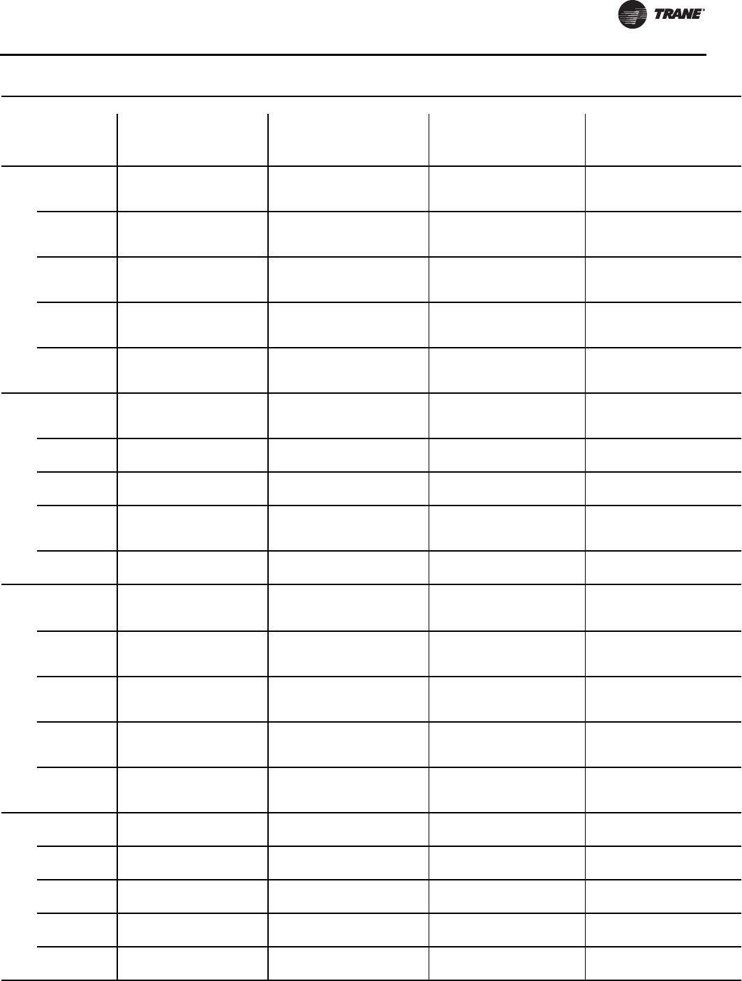
Installation - Electrical
RLC-SVX09H-EN 93
100
200
1 380 N/A #4-500 400 N/A 3/0-500(a) 500 N/A 3/0-500(a) 500 N/A 3/0-500(a)
2 380 N/A #4-500 250 N/A #6-350 300
350 N/A 3/0-500(a) 300
350 N/A 3/0-500(a)
230
1 380 N/A #4-500 400 N/A 3/0-500(a) 450 N/A 3/0-500(a) 450 N/A 3/0-500(a)
2175
380 N/A #14-2/0
#4-500 250 N/A #6-350 250
300 N/A #6-350
3/0-500(a)
250
300 N/A #6-350
3/0-500(a)
380
1 380 #4-500 #4-500 250 #6-350 #6-350 250 3/0-500(a) 3/0-500(a) 250 3/0-500(a) 3/0-500(a)
2 175 #14-2/0 #14-2/0 100
250
#10-1/0
#6-350
#10-1/0
#6-350
150
200 #6-350 #6-350 150
200 #6-350 #6-350
460
1 380 #4-500 #4-500 250 #6-350 #6-350 225 #6-350 #6-350 225 #6-350 #6-350
2 175 #14-2/0 #14-2/0 100 #10-1/0 #10-1/0 125
150 #6-350 #6-350 125
150 #6-350 #6-350
575
1 380 #4-500 #4-500 250 #6-350 #6-350 175 #6-350 #6-350 N/A N/A N/A
2 175 #14-2/0 #14-2/0 100 #10-1/0 #10-1/0 110
125 #6-350 #6-350 N/A N/A N/A
110
200
1 760 N/A #4-500(a) 600 N/A 3/0-500(a) 500 N/A 3/0-500(a) 500 N/A 3/0-500(a)
2 380 N/A #4-500 250 N/A #6-350 400
350 N/A 3/0-500(a) 400
350 N/A 3/0-500(a)
230 1 380 N/A #4-500 400 N/A 3/0-500(a) 500 N/A 3/0-500(a) 500 N/A 3/0-500(a)
2 380 N/A #4-500 250 N/A #6-350 300 N/A 3/0-500(a) 300 N/A 3/0-500(a)
380 1 380 #4-500 #4-500 250 #6-350 #6-350 300 3/0-500(a) 3/0-500(a) 300 3/0-500(a) 3/0-500(a)
2 175 #14-2/0 #14-2/0 250 #6-350 #6-350 200 #6-350 #6-350 200 #6-350 #6-350
460
1 380 #4-500 #4-500 250 #6-350 #6-350 250 #6-350 #6-350 250 #6-350 #6-350
2 175 #14-2/0 #14-2/0 100 #10-1/0 #10-1/0 175
150 #6-350 #6-350 175
150 #6-350 #6-350
575 1 380 #4-500 #4-500 250 #6-350 #6-350 N/A N/A N/A N/A N/A N/A
2 175 #14-2/0 #14-2/0 100 #10-1/0 #10-1/0 125 #6-350 #6-350 N/A N/A N/A
120
200
1 760 N/A #4-500(a) 600 N/A 3/0-500(a) 600 N/A 3/0-500(a) 600 N/A 3/0-500(a)
2 380 N/A #4-500 250 N/A #6-350 400
450 N/A 3/0-500(a) 400
450 N/A 3/0-500(a)
230
1 760 N/A #4-500(a) 600 N/A 3/0-500(a) 500 N/A 3/0-500(a) 500 N/A 3/0-500(a)
2 380 N/A #4-500 250 N/A #6-350 300
400 N/A 3/0-500(a) 300
400 N/A 3/0-500(a)
380
1 380 #4-500 #4-500 250 #6-350 #6-350 300 3/0-500(a) 3/0-500(a) 300 3/0-500(a) 3/0-500(a)
2 175 #14-2/0 #14-2/0 250 #6-350 #6-350 200
225 #6-350 #6-350 200
225 #6-350 #6-350
460
1 380 #4-500 #4-500 250 #6-350 #6-350 250 3/0-500(a) 3/0-500(a) 250 3/0-500(a) 3/0-500(a)
2 175 #14-2/0 #14-2/0 100
250
#10-1/0
#6-350
#10-1/0
#6-350
175
200 #6-350 #6-350 175
200 #6-350 #6-350
575
1 380 #4-500 #4-500 250 #6-350 #6-350 200 3/0-500(a) 3/0-500(a) N/A N/A N/A
2 175 #14-2/0 #14-2/0 100 #10-1/0 #10-1/0 125
150 #6-350 #6-350 N/A N/A N/A
130
200 1 N/A N/A N/A N/A N/A N/A N/A N/A N/A N/A N/A N/A
2 380 N/A #4-500 250 N/A #6-350 450 N/A 3/0-500(a) 450 N/A 3/0-500(a)
230 1 760 N/A #4-500(a) 600 N/A 3/0-500(a) 500 N/A 3/0-500(a) 500 N/A 3/0-500(a)
2 380 N/A #4-500 250 N/A #6-350 400 N/A 3/0-500(a) 400 N/A 3/0-500(a)
380 1 380 #4-500 #4-500 400 3/0-500(a) 3/0-500(a) 350 3/0-500(a) 3/0-500(a) 350 3/0-500(a) 3/0-500(a)
2 175 #14-2/0 #14-2/0 250 #6-350 #6-350 225 #6-350 #6-350 225 #6-350 #6-350
460 1 380 #4-500 #4-500 250 #6-350 #6-350 250 3/0-500(a) 3/0-500(a) 250 3/0-500(a) 3/0-500(a)
2 175 #14-2/0 #14-2/0 250 #6-350 #6-350 200 #6-350 #6-350 200 #6-350 #6-350
575 1 380 #4-500 #4-500 250 #6-350 #6-350 225 #6-350 #6-350 N/A N/A N/A
2 175 #14-2/0 #14-2/0 100 #10-1/0 #10-1/0 150 #6-350 #6-350 N/A N/A N/A
Table 82. Customer Wire Selection - RTWD - 60 Hz - high efficiency - high condensing temperature (continued)
Size
Rated
Voltage
#
Conn
Wire Selection
Main Terminal Block Disconnect Circuit Breaker Hi-Fault Panel Ckt Brkr
Size Wire Range Size Wire Range Size Wire Range Size Wire Range
Amp XL YD Amp XL YD Amp XL YD Amp XL YD

Installation - Electrical
94 RLC-SVX09H-EN
150
200
1 760 N/A #4-500(a) 600 N/A 3/0-500(a) 700 N/A #1-500(b) 700 N/A #1-500(b)
2 380 N/A #4-500 250
400 N/A #6-350
3/0-500(a)
450
500 N/A 3/0-500(a) 450
500 N/A 3/0-500(a)
230
1 760 N/A #4-500(a) 600 N/A 3/0-500(a) 600 N/A 3/0-500(a) 600 N/A 3/0-500(a)
2 380 N/A #4-500 250
400 N/A #6-350
3/0-500(a)
400
450 N/A 3/0-500(a) 400
450 N/A 3/0-500(a)
380
1 380 #4-500 #4-500 400 3/0-500(a) 3/0-500(a) 350 3/0-500(a) 3/0-500(a) 350 3/0-500(a) 3/0-500(a)
2
XL 175/
380
YD 175
#14-2/0
#4-500 #14-2/0 250 #6-350 #6-350 225
250 #6-350 #6-350 225
250 #6-350 #6-350
460
1 380 #4-500 #4-500 250 #6-350 #6-350 300 3/0-500(a) 3/0-500(a) 300 3/0-500(a) 3/0-500(a)
2 175 #14-2/0 #14-2/0 250 #6-350 #6-350 200
225 #6-350 #6-350 200
225 #6-350 #6-350
575
1 380 #4-500 #4-500 250 #6-350 #6-350 200 #6-350 #6-350 N/A N/A N/A
2 175 #14-2/0 #14-2/0 100
250
#10-1/0
#6-350
#10-1/0
#6-350
150
175 #6-350 #6-350 N/A N/A N/A
160
200 1 760 N/A #4-500(a) 600 N/A 3/0-500(a) 700 N/A #1-500(b) 700 N/A #1-500(b)
2 380 N/A #4-500 400 N/A 3/0-500(a) 500 N/A 3/0-500(a) 500 N/A 3/0-500(a)
230 1 760 N/A #4-500(a) 600 N/A 3/0-500(a) 600 N/A 3/0-500(a) 600 N/A 3/0-500(a)
2 380 N/A #4-500 400 N/A 3/0-500(a) 450 N/A 3/0-500(a) 450 N/A 3/0-500(a)
380
1 380 #4-500 #4-500 400 3/0-500(a) 3/0-500(a) 400 3/0-500(a) 3/0-500(a) 400 3/0-500(a) 3/0-500(a)
2XL 380
YD 175 #4-500 #14-2/0 250 #6-350 #6-350 250 #6-350 #6-350 250 #6-350 #6-350
460 1 380 #4-500 #4-500 400 3/0-500(a) 3/0-500(a) 300 3/0-500(a) 3/0-500(a) 300 3/0-500(a) 3/0-500(a)
2 175 #14-2/0 #14-2/0 250 #6-350 #6-350 225 #6-350 #6-350 225 #6-350 #6-350
575 1 380 #4-500 #4-500 250 #6-350 #6-350 250 3/0-500(a) 3/0-500(a) N/A N/A N/A
2 175 #14-2/0 #14-2/0 250 #6-350 #6-350 175 #6-350 #6-350 N/A N/A N/A
180
200
1 760 N/A #4-500(a) 700 N/A #1-500(b) 800 N/A #1-500(b) 800 N/A #1-500(b)
2 380 N/A #4-500 400 N/A 3/0-500(a) 500
600 N/A 3/0-500(a) 500
600 N/A 3/0-500(a)
230
1 760 N/A #4-500(a) 600 N/A 3/0-500(a) 700 N/A #1-500(b) 700 N/A #1-500(b)
2 380 N/A #4-500 400 N/A 3/0-500(a) 450
500 N/A 3/0-500(a) 450
500 N/A 3/0-500(a)
380
1 380 #4-500 #4-500 400 3/0-500(a) 3/0-500(a) 450 3/0-500 3/0-500(a) 450 3/0-500 3/0-500(a)
2
XL 380
YD
175/
380
#4-500 #14-2/0
#4-500 250 #6-350 #6-350 250
300
#6-350
3/0-500(a)
#6-350
3/0-500(a)
250
300
#6-350
3/0-500(a)
#6-350
3/0-500(a)
460
1 380 #4-500 #4-500 400 3/0-500(a) 3/0-500(a) 350 3/0-500(a) 3/0-500(a) 350 3/0-500(a) 3/0-500(a)
2
XL 175/
380
YD 175
#14-2/0
#4-500 #14-2/0 250 #6-350 #6-350 225
250 #6-350 #6-350 225
250 #6-350 #6-350
575
1 380 #4-500 #4-500 250 #6-350 #6-350 300 3/0-500(a) 3/0-500(a) N/A N/A N/A
2 175 #14-2/0 #14-2/0 250 #6-350 #6-350 175
200 #6-350 #6-350 N/A N/A N/A
Table 82. Customer Wire Selection - RTWD - 60 Hz - high efficiency - high condensing temperature (continued)
Size
Rated
Voltage
#
Conn
Wire Selection
Main Terminal Block Disconnect Circuit Breaker Hi-Fault Panel Ckt Brkr
Size Wire Range Size Wire Range Size Wire Range Size Wire Range
Amp XL YD Amp XL YD Amp XL YD Amp XL YD
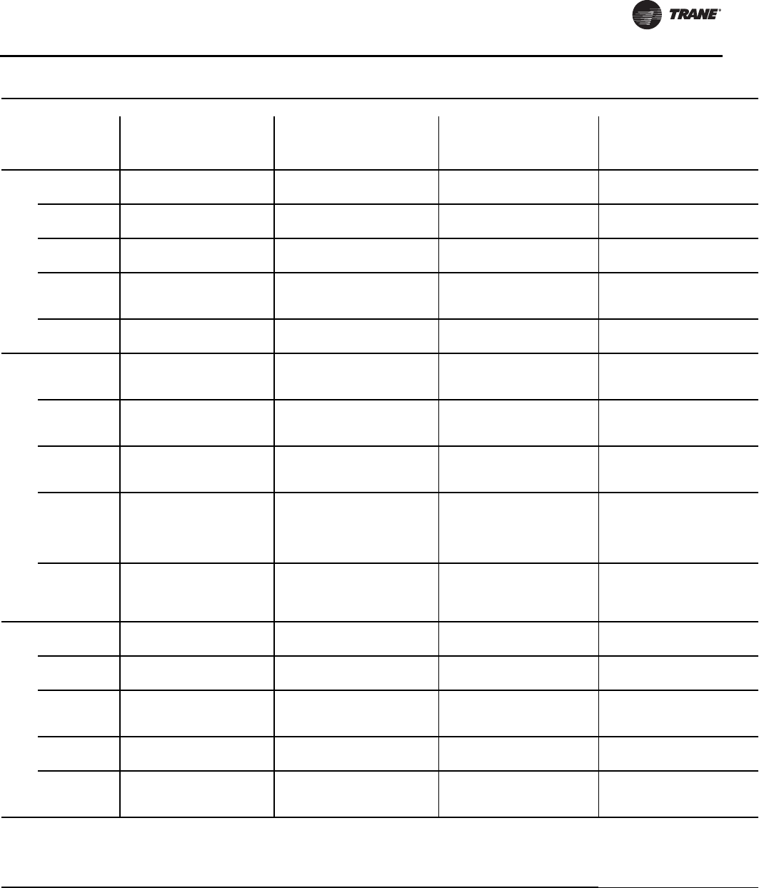
Installation - Electrical
RLC-SVX09H-EN 95
200
200 1 760 N/A #4-500(a) 700 N/A #1-500(b) 800 N/A #1-500(b) 800 N/A #1-500(b)
2 380 N/A #4-500 400 N/A 3/0-500(a) 600 N/A 3/0-500(a) 600 N/A 3/0-500(a)
230 1 760 N/A #4-500(a) 600 N/A 3/0-500(a) 700 N/A #1-500(b) 700 N/A #1-500(b)
2 380 N/A #4-500 400 N/A 3/0-500(a) 500 N/A 3/0-500(a) 500 N/A 3/0-500(a)
380 1 380 #4-500 #4-500 400 3/0-500(a) 3/0-500(a) 450 3/0-500(a) 3/0-500(a) 450 3/0-500(a) 3/0-500(a)
2 380 #4-500 #4-500 250 #6-350 #6-350 300 3/0-500(a) 3/0-500(a) 300 3/0-500(a) 3/0-500(a)
460
1 380 #4-500 #4-500 400 3/0-500(a) 3/0-500(a) 350 3/0-500(a) 3/0-500(a) 350 3/0-500(a) 3/0-500(a)
2XL 380
YD 175 #4-500 #14-2/0 250 #6-350 #6-350 250 #6-350 #6-350 250 #6-350 #6-350
575 1 380 #4-500 #4-500 250 #6-350 #6-350 300 3/0-500(a) 3/0-500(a) N/A N/A N/A
2 175 #14-2/0 #14-2/0 250 #6-350 #6-350 200 #6-350 #6-350 N/A N/A N/A
220
200
1 760 N/A #4-500(a) 800 N/A #1-500(b) 1000 N/A 250-500(c) 1000 N/A 250-500(c)
2380
760 N/A #4-500
#4-500(a)
400
600 N/A 3/0-500(a) 600
700 N/A 3/0-500(a)
#1-500(b)
600
700 N/A 3/0-500(a)
#1-500(b)
230
1 760 N/A #4-500(a) 700 N/A #1-500(b) 800 N/A #1-500(b) 800 N/A #1-500(b)
2 380 N/A #4-500 400 N/A 3/0-500(a) 500
600 N/A 3/0-500(a) 500
600 N/A 3/0-500(a)
380
1 380 #4-500 #4-500 400 3/0-500(a) 3/0-500(a) 500 3/0-500(a) 3/0-500(a) 500 3/0-500(a) 3/0-500(a)
2 380 #4-500 #4-500 250 #6-350 #6-350 300
400 3/0-500(a) 3/0-500(a) 300
400 3/0-500(a) 3/0-500(a)
460
1 380 #4-500 #4-500 400 3/0-500(a) 3/0-
(2)500(a) 400 3/0-500(a) 3/0-500(a) 400 3/0-500(a) 3/0-500(a)
2
XL 380
YD175/
380
#4-500 #14-2/0
#4-500 250 #6-350 #6-350 250
300
#6-350
3/0-500(a)
#6-350
3/0-500(a)
250
300
#6-350
3/0-500(a)
#6-350
3/0-500(a)
575
1 380 #4-500 #4-500 400 3/0-500(a) 3/0-500(a) 350 3/0-500(a) 3/0-500(a) N/A N/A N/A
2
XL 175/
380
YD 175
#14-2/0
#4-500 #14-2/0 250 #6-350 #6-350 200
250 #6-350 #6-350 N/A N/A N/A
250
200 1 760 N/A #4-500(a) 800 N/A #1-500(b) 1000 N/A 250-500(c) 1000 N/A 250-500(c)
2 760 N/A #4-500(a) 600 N/A 3/0-500(a) 700 N/A #1-500(b) 700 N/A #1-500(b)
230 1 760 N/A #4-500(a) 800 N/A #1-500(b) 800 N/A #1-500(b) 800 N/A #1-500(b)
2 380 N/A #4-500 400 N/A 3/0-500(a) 600 N/A 3/0-500(a) 600 N/A 3/0-500(a)
380 1 760 #4-
500(a) #4-500(a) 600 3/0-500(a) 3/0-500(a) 500 3/0-500(a) 3/0-500(a) 500 3/0-500(a) 3/0-500(a)
2 380 #4-500 #4-500 250 #6-350 #6-350 400 3/0-500(a) 3/0-500(a) 400 3/0-500(a) 3/0-500(a)
460 1 380 #4-500 #4-500 400 3/0-500(a) 3/0-500(a) 450 3/0-500(a) 3/0-500(a) 450 3/0-500(a) 3/0-500(a)
2 380 #4-500 #4-500 250 #6-350 #6-350 300 3/0-500(a) 3/0-500(a) 300 3/0-500(a) 3/0-500(a)
575
1 380 #4-500 #4-500 400 3/0-500(a) 3/0-500(a) 350 3/0-500(a) 3/0-500(a) N/A N/A N/A
2XL 380
YD 175 #4-500 #14-2/0 250 #6-350 #6-350 250 #6-350 #6-350 N/A N/A N/A
Notes:
1. Optional non-fused disconnect and circuit breaker.
2. Copper wire only, based on nameplate minimum circuit ampacity (MCA).
3. Standard condensing temperature option refers to entering condenser water temperatures 95°F (35°C) and below.
4. Circuit two information is the same as circuit one unless listed on a separate line below circuit one values.
5. XL - across-the-line starter and YD - wye-delta starter.
(a) Will accept 2 conduits per phase in this size.
(b) Will accept 3 conduits per phase in this size.
(c) Will accept 4 conduits per phase in this size.
Table 82. Customer Wire Selection - RTWD - 60 Hz - high efficiency - high condensing temperature (continued)
Size
Rated
Voltage
#
Conn
Wire Selection
Main Terminal Block Disconnect Circuit Breaker Hi-Fault Panel Ckt Brkr
Size Wire Range Size Wire Range Size Wire Range Size Wire Range
Amp XL YD Amp XL YD Amp XL YD Amp XL YD

Installation - Electrical
96 RLC-SVX09H-EN
Table 83. Customer Wire Selection - RTWD - 60 Hz - premium efficiency - high condensing temperature
Size
Rated
Voltage
#
Conn
Wire Selection
Main Terminal Block Disconnect Circuit Breaker Hi-Fault Panel Ckt Brkr
Size Wire Range Size Wire Range Size Wire Range Size Wire Range
Amp XL YD Amp XL YD Amp XL YD Amp XL YD
150
200
1 760 N/A #4-500(a) 600 N/A 3/0-500(a) 700 N/A #1-500(b) 700 N/A #1-500(c)
2 380 N/A #4-500 250
400 N/A #6-350
3/0-500(a)
400
500 N/A 3/0-500(a) 400
500 N/A 3/0-500(a)
230
1 760 N/A #4-500(a) 600 N/A 3/0-500(a) 600 N/A 3/0-500(a) 600 N/A 3/0-500(a)
2 380 N/A #4-500 250
400 N/A #6-350
3/0-500(a)
350
450 N/A 3/0-500(a) 350
450 N/A 3/0-500(a)
380
1 380 #4-500 #4-500 400 3/0-500(a) 3/0-500(a) 350 3/0-500 3/0-500(a) 350 3/0-500 3/0-500(a)
2
XL 175/
380
YD 175
#14-2/0
#4-500 #14-2/0 250 #6-350 #6-350 225
250 #6-350 #6-350 225
250 #6-350 #6-350
460
1 380 #4-500 #4-500 250 #6-350 #6-350 300 3/0-500(a) 3/0-500(a) 300 3/0-500(a) 3/0-500(a)
2 175 #14-2/0 #14-2/0 250 #6-350 #6-350 175
225 #6-350 #6-350 175
225 #6-350 #6-350
575
1 380 #4-500 #4-500 250 #6-350 #6-350 250 #6-350 #6-350 N/A N/A N/A
2 175 #14-2/0 #14-2/0 100
250
#10-1/0
#6-350
#10-1/0
#6-350
150
175 #6-350 #6-350 N/A N/A N/A
160
200 1 760 N/A #4-500(a) 600 N/A 3/0-500(a) 700 N/A #1-500(b) 700 N/A #1-500(b)
2 380 N/A #4-500 400 N/A 3/0-500(a) 500 N/A 3/0-500(a) 500 N/A 3/0-500(a)
230 1 760 N/A #4-500(a) 600 N/A 3/0-500(a) 600 N/A 3/0-500(a) 600 N/A 3/0-500(a)
2 380 N/A #4-500 400 N/A 3/0-500(a) 450 N/A 3/0-500(a) 450 N/A 3/0-500(a)
380
1 380 #4-500 #4-500 400 3/0-500(a) 3/0-500(a) 400 3/0-500(a) 3/0-500(a) 400 3/0-500(a) 3/0-500(a)
2XL 380
YD 175 #4-500 #14-2/0 250 #6-350 #6-350 250 #6-350 #6-350 250 #6-350 #6-350
460 1 380 #4-500 #4-500 400 3/0-500(a) 3/0-500(a) 300 3/0-500(a) 3/0-500(a) 300 3/0-500(a) 3/0-500(a)
2 175 #14-2/0 #14-2/0 250 #6-350 #6-350 225 #6-350 #6-350 225 #6-350 #6-350
575 1 380 #4-500 #4-500 250 #6-350 #6-350 250 3/0-500(a) 3/0-500(a) N/A N/A N/A
2 175 #14-2/0 #14-2/0 250 #6-350 #6-350 175 #6-350 #6-350 N/A N/A N/A
180
200
1 760 N/A #4-500(a) 700 N/A #1-500(b) 800 N/A #1-500(b) 800 N/A #1-500(b)
2 380 N/A #4-500 400 N/A 3/0-500(a) 500
600 N/A 3/0-500(a) 500
600 N/A 3/0-500(a)
230
1 760 N/A #4-500(a) 600 N/A 3/0-500(a) 700 N/A #1-500(b) 700 N/A #1-500(b)
2 380 N/A #4-500 400 N/A 3/0-500(a) 450
500 N/A 3/0-500(a) 450
500 N/A 3/0-500(a)
380
1 380 #4-500 #4-500 400 3/0-500(a) 3/0-500(a) 450 3/0-500 3/0-500(a) 450 3/0-500 3/0-500(a)
2
XL 380
YD
175/
380
#4-500 #14-2/0
#4-500 250 #6-350 #6-350 250
300
#6-350
3/0-500(a)
#6-350
3/0-500(a)
250
300
#6-350
3/0-500(a)
#6-350
3/0-500(a)
460
1 380 #4-500 #4-500 400 3/0-500(a) 3/0-500(a) 350 3/0-500(a) 3/0-500(a) 350 3/0-500(a) 3/0-500(a)
2
XL 175/
380
YD 175
#14-2/0
#4-500 #14-2/0 250 #6-350 #6-350 225
250 #6-350 #6-350 225
250 #6-350 #6-350
575
1 380 #4-500 #4-500 250 #6-350 #6-350 300 3/0-500(a) 3/0-500(a) N/A N/A N/A
2 175 #14-2/0 #14-2/0 250 #6-350 #6-350 175
200 #6-350 #6-350 N/A N/A N/A
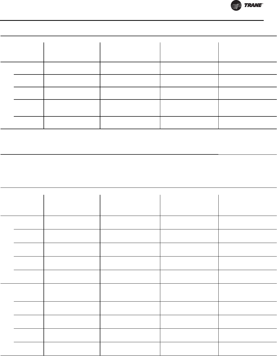
Installation - Electrical
RLC-SVX09H-EN 97
200
200 1 760 N/A #4-500(a) 700 N/A #1-500(b) 800 N/A #1-500(b) 800 N/A #1-500(b)
2 380 N/A #4-500 400 N/A 3/0-500(a) 600 N/A 3/0-500(a) 600 N/A 3/0-500(a)
230 1 760 N/A #4-500(a) 600 N/A 3/0-500(a) 700 N/A #1-500(b) 700 N/A #1-500(b)
2 380 N/A #4-500 400 N/A 3/0-500(a) 500 N/A 3/0-500(a) 500 N/A 3/0-500(a)
380 1 380 #4-500 #4-500 400 3/0-500(a) 3/0-500(a) 450 3/0-500(a) 3/0-500(a) 450 3/0-500(a) 3/0-500(a)
2 380 #4-500 #4-500 250 #6-350 #6-350 300 3/0-500(a) 3/0-500(a) 300 3/0-500(a) 3/0-500(a)
460
1 380 #4-500 #4-500 400 3/0-500(a) 3/0-500(a) 350 3/0-500(a) 3/0-500(a) 350 3/0-500(a) 3/0-500(a)
2XL 380
YD 175 #4-500 #14-2/0 250 #6-350 #6-350 250 #6-350 #6-350 250 #6-350 #6-350
575 1 380 #4-500 #4-500 250 #6-350 #6-350 300 3/0-500(a) 3/0-500(a) N/A N/A N/A
2 175 #14-2/0 #14-2/0 250 #6-350 #6-350 200 #6-350 #6-350 N/A N/A N/A
Notes:
1. Optional non-fused disconnect and circuit breaker.
2. Copper wire only, based on nameplate minimum circuit ampacity (MCA).
3. Standard condensing temperature option refers to entering condenser water temperatures 95°F (35°C) and below.
4. Circuit two information is the same as circuit one unless listed on a separate line below circuit one values.
5. XL - across-the-line starter and YD - wye-delta starter.
(a) Will accept 2 conduits per phase in this size.
(b) Will accept 3 conduits per phase in this size.
(c) Will accept 3 conduits per phase in this size.
Table 83. Customer Wire Selection - RTWD - 60 Hz - premium efficiency - high condensing temperature (continued)
Size
Rated
Voltage
#
Conn
Wire Selection
Main Terminal Block Disconnect Circuit Breaker Hi-Fault Panel Ckt Brkr
Size Wire Range Size Wire Range Size Wire Range Size Wire Range
Amp XL YD Amp XL YD Amp XL YD Amp XL YD
Table 84. Customer Wire Selection - RTUD - 60 Hz
Size
Rated
Voltage
#
Conn
Wire Selection
Main Terminal Block Disconnect Circuit Breaker Hi-Fault Panel Ckt Brkr
Size Wire Range Size Wire Range Size Wire Range Size Wire Range
Amp XL YD Amp XL YD Amp XL YD Amp XL YD
80
200 1 380 N/A #4-500 400 N/A 3/0-500(a) 400 N/A 3/0-500(a) 400 N/A 3/0-500(a)
2 175 N/A #14-2/0 250 N/A #6-350 250 N/A #6-350 250 N/A #6-350
230 1 380 N/A #4-500 400 N/A 3/0-500(a) 350 N/A 3/0-500(a) 350 N/A 3/0-500(a)
2 175 N/A #14-2/0 250 N/A #6-350 250 N/A #6-350 250 N/A #6-350
380 1 175 #14-2/0 #14-2/0 250 #6-350 #6-350 225 #6-350 #6-350 225 #6-350 #6-350
2 175 #14-2/0 #14-2/0 100 #10-1/0 #10-1/0 150 #6-350 #6-350 150 #6-350 #6-350
460 1 175 #14-2/0 #14-2/0 250 #6-350 #6-350 175 #6-350 #6-350 175 #6-350 #6-350
2 175 #14-2/0 #14-2/0 100 #10-1/0 #10-1/0 125 #6-350 #6-350 125 #6-350 #6-350
575 1 175 #14-2/0 #14-2/0 250 #6-350 #6-350 150 #6-350 #6-350 N/A N/A N/A
2 175 #14-2/0 #14-2/0 100 #10-1/0 #10-1/0 100 #6-350 #6-350 N/A N/A N/A
90
200
1 380 N/A #4-500 400 N/A 3/0-500(a) 500 N/A 3/0-500(a) 500 N/A 3/0-500(a)
2 380 N/A #4-500 250 N/A #6-350 350/
300 N/A 3/0-500(a) 350/
300 N/A 3/0-500(a)
230 1 380 N/A #4-500 400 N/A 3/0-500(a) 400 N/A 3/0-500(a) 400 N/A 3/0-500(a)
2 175 N/A #14-2/0 250 N/A #6-350 250 N/A #6-350 250 N/A #6-350
380 1 380 #4-500 #4-500 250 #6-350 #6-350 250 3/0-500(a) 3/0-500(a) 250 3/0-500(a) 3/0-500(a)
2 175 #14-2/0 #14-2/0 250 #6-350 #6-350 175 #6-350 #6-350 175 #6-350 #6-350
460 1 175 #14-2/0 #14-2/0 250 #6-350 #6-350 200 #6-350 #6-350 200 #6-350 #6-350
2 175 #14-2/0 #14-2/0 100 #10-1/0 #10-1/0 150 #6-350 #6-350 150 #6-350 #6-350
575 1 175 #14-2/0 #14-2/0 250 #6-350 #6-350 175 #6-350 #6-350 N/A N/A N/A
2 175 #14-2/0 #14-2/0 100 #10-1/0 #10-1/0 110 #6-350 #6-350 N/A N/A N/A

Installation - Electrical
98 RLC-SVX09H-EN
100
200
1 760 N/A #4-500(a) 600 N/A 3/0-500(a) 500 N/A 3/0-500(a) 500 N/A 3/0-500(a)
2 380 N/A #4-500 250 N/A #6-350 350/
400 N/A 3/0-500(a) 350/
400 N/A 3/0-500(a)
230
1 380 N/A #4-500 400 N/A 3/0-500(a) 500 N/A 3/0-500(a) 500 N/A 3/0-500(a)
2175/
380 N/A #14-2/0
#4-500 250 N/A #6-350 250/
350 N/A #6-350
3/0-500(a)
250/
350 N/A #6-350
3/0-500(a)
380
1 380 #4-500 #4-500 250 #6-350 #6-350 300 3/0-500(a) 3/0-500(a) 300 3/0-500(a) 3/0-500(a)
2 175 #14-2/0 #14-2/0 250 #6-350 #6-350 175/
225 #6-350 #6-350 175/
225 #6-350 #6-350
460
1 175 #14-2/0 #14-2/0 250 #6-350 #6-350 250 #6-350 #6-350 250 #6-350 #6-350
2 175 #14-2/0 #14-2/0 100/
250
#10-1/0
#6-350
#10-1/0
#6-350
150/
175 #6-350 #6-350 150/
175 #6-350 #6-350
575
1 175 #14-2/0 #14-2/0 250 #6-350 #6-350 200 #6-350 #6-350 N/A N/A N/A
2 175 #14-2/0 #14-2/0 100 #10-1/0 #10-1/0 110/
150 #6-350 #6-350 N/A N/A N/A
110
200
1 760 N/A #4-
(2)500(a) 600 N/A 3/0-
(2)500(a) 600 N/A 3/0-
(2)500(a) 600 N/A 3/0-
(2)500(a)
2 380 N/A #4-500 250 N/A #6-350 400 N/A 3/0-
(2)500(a) 400 N/A 3/0-
(2)500(a)
230
1 380 N/A #4-500 600 N/A 3/0-
(2)500(a) 500 N/A 3/0-
(2)500(a) 500 N/A 3/0-
(2)500(a)
2 380 N/A #4-500 250 N/A #6-350 350 N/A 3/0-
(2)500(a) 350 N/A 3/0-
(2)500(a)
380 1 380 #4-500 #4-500 400 3/0-(2)500 3/0-
(2)500(a) 300 3/0-
(2)500
3/0-
(2)500(a) 300 3/0-
(2)500
3/0-
(2)500(a)
2 175 #14-2/0 #14-2/0 250 #6-350 #6-350 225 #6-350 #6-350 225 #6-350 #6-350
460 1 380 #4-500 #4-500 250 #6-350 #6-350 250 3/0-
(2)500
3/0-
(2)500(a) 250 3/0-
(2)500
3/0-
(2)500(a)
2 175 #14-2/0 #14-2/0 250 #6-350 #6-350 175 #6-350 #6-350 175 #6-350 #6-350
575 1 175 #14-2/0 #14-2/0 250 #6-350 #6-350 200 #6-350 #6-350 N/A N/A N/A
2 175 #14-2/0 #14-2/0 100 #10-1/0 #10-1/0 150 #6-350 #6-350 N/A N/A N/A
120
200
1 760 N/A #4-
(2)500(a) 600 N/A 3/0-
(2)500(a) 600 N/A 3/0-
(2)500(a) 600 N/A 3/0-
(2)500(a)
2 380 N/A #4-500 250/
400 N/A
#6-350
3/0-
(2)500(a)
400/
450 N/A 3/0-
(2)500(a)
400/
450 N/A 3/0-
(2)500(a)
230
1 760 N/A #4-
(2)500(a) 600 N/A 3/0-
(2)500(a) 600 N/A 3/0-
(2)500(a) 600 N/A 3/0-
(2)500(a)
2 380 N/A #4-500 250 N/A #6-350 350/
450 N/A 3/0-
(2)500(a)
350/
450 N/A 3/0-
(2)500(a)
380
1 380 #4-500 #4-500 400 3/0-(2)500 3/0-
(2)500(a) 350 3/0-
(2)500
3/0-
(2)500(a) 350 3/0-
(2)500
3/0-
(2)500(a)
2 175 #14-2/0 #14-2/0 250 #6-350 #6-350 225/
250 #6-350 #6-350 225/
250 #6-350 #6-350
460
1 380 #4-500 #4-500 250 #6-350 #6-350 300 3/0-
(2)500(a)
3/0-
(2)500(a) 300 3/0-
(2)500(a)
3/0-
(2)500(a)
2 175 #14-2/0 #14-2/0 250 #6-350 #6-350 175/
225 #6-350 #6-350 175/
225 #6-350 #6-350
575
1 175 #14-2/0 #14-2/0 250 #6-350 #6-350 225 #6-350 #6-350 N/A N/A N/A
2 175 #14-2/0 #14-2/0 100 #10-1/0 #10-1/0 150/
175 #6-350 #6-350 N/A N/A N/A
Table 84. Customer Wire Selection - RTUD - 60 Hz (continued)
Size
Rated
Voltage
#
Conn
Wire Selection
Main Terminal Block Disconnect Circuit Breaker Hi-Fault Panel Ckt Brkr
Size Wire Range Size Wire Range Size Wire Range Size Wire Range
Amp XL YD Amp XL YD Amp XL YD Amp XL YD
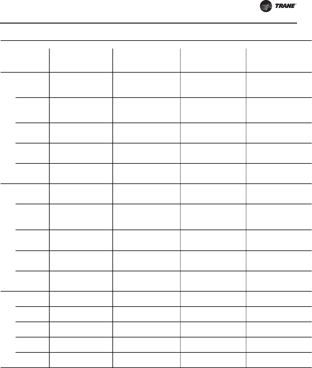
Installation - Electrical
RLC-SVX09H-EN 99
130
200
1 760 N/A #4-
(2)500(a) 600 N/A 3/0-
(2)500(a) 600 N/A 3/0-
(2)500(a) 600 N/A 3/0-
(2)500(a)
2 380 N/A #4-500 400 N/A 3/0-
(2)500(a) 450 N/A 3/0-
(2)500(a) 450 N/A 3/0-
(2)500(a)
230
1 760 N/A #4-
(2)500(a) 600 N/A 3/0-
(2)500(a) 600 N/A 3/0-
(2)500(a) 600 N/A 3/0-
(2)500(a)
2 380 N/A #4-500 250 N/A #6-350 450 N/A 3/0-
(2)500(a) 450 N/A 3/0-
(2)500(a)
380 1 380 #4-500 #4-500 400 3/0-
(2)500(a)
3/0-
(2)500(a) 350 3/0-
(2)500
3/0-
(2)500(a) 350 3/0-
(2)500
3/0-
(2)500(a)
2 175 #14-2/0 #14-2/0 250 #6-350 #6-350 250 #6-350 #6-350 250 #6-350 #6-350
460 1 380 #4-500 #4-500 250 #6-350 #6-350 300 3/0-
(2)500(a)
3/0-
(2)500(a) 300 3/0-
(2)500(a)
3/0-
(2)500(a)
2 175 #14-2/0 #14-2/0 250 #6-350 #6-350 225 #6-350 #6-350 225 #6-350 #6-350
575 1 380 #4-500 #4-500 250 #6-350 #6-350 250 3/0-
(2)500(a)
3/0-
(2)500(a) N/A N/A N/A
2 175 #14-2/0 #14-2/0 100 #10-1/0 #10-1/0 175 #6-350 #6-350 N/A N/A N/A
150
200
1 760 N/A #4-500(a) 700 N/A #1-500(b) 800 N/A #1-500(b) 800 N/A #1-500(b)
2 380 N/A #4-500 400 N/A 3/0-500(a) 450/
600 N/A 3/0-500(a) 450/
600 N/A 3/0-500(a)
230
1 760 N/A #4-500(a) 600 N/A 3/0-500(a) 700 N/A #1-500(b) 700 N/A #1-500(b)
2 380 N/A #4-500 250/
400 N/A #6-350
3/0-500(a)
700
450/
500
N/A #1-500(b)
3/0-500(a)
700
450/
500
N/A #1-500(b)
3/0-500(a)
380
1 380 #4-500 #4-500 400 3/0-500(a) 3/0-500(a) 400 3/0-500(a) 3/0-500(a) 400 3/0-500(a) 3/0-500(a)
2175/
380
#14-2/0
#4-500
#14-2/0
#4-500 250 #6-350 #6-350 250/
300
#6-350
3/0-500(a)
#6-350
3/0-500(a)
250/
300
#6-350
3/0-500(a)
#6-350
3/0-500(a)
460
1 380 #4-500 #4-500 400 3/0-500(a) 3/0-500(a) 350 3/0-500(a) 3/0-500(a) 350 3/0-500(a) 3/0-500(a)
2 175 #14-2/0 #14-2/0 250 #6-350 #6-350 225/
250 #6-350 #6-350 225/
250 #6-350 #6-350
575
1 380 #4-500 #4-500 250 #6-350 #6-350 250 3/0-500(a) 3/0-500(a) N/A N/A N/A
2 175 #14-2/0 #14-2/0 100/
250
#10-1/0
#6-350
#10-1/0
#6-350
175/
200 #6-350 #6-350 N/A N/A N/A
160
200 1 760 N/A #4-500(a) 700 N/A #1-500(b) 800 N/A #1-500(b) 800 N/A #1-500(b)
2 380 N/A #4-500 400 N/A 3/0-500(a) 600 N/A 3/0-500(a) 600 N/A 3/0-500(a)
230 1 760 N/A #4-500(a) 600 N/A 3/0-500(a) 700 N/A #1-500(b) 700 N/A #1-500(b)
2 380 N/A #4-500 400 N/A 3/0-500(a) 500 N/A 3/0-500(a) 500 N/A 3/0-500(a)
380 1 380 #4-500 #4-500 400 3/0-500(a) 3/0-500(a) 450 3/0-500(a) 3/0-500(a) 450 3/0-500(a) 3/0-500(a)
2 380 #4-500 #4-500 250 #6-350 #6-350 300 3/0-500(a) 3/0-500(a) 300 3/0-500(a) 3/0-500(a)
460 1 380 #4-500 #4-500 400 3/0-500(a) 3/0-500(a) 350 3/0-500(a) 3/0-500(a) 350 3/0-500(a) 3/0-500(a)
2 175 #14-2/0 #14-2/0 250 #6-350 #6-350 250 #6-350 #6-350 250 #6-350 #6-350
575 1 380 #4-500 #4-500 250 #6-350 #6-350 300 3/0-500(a) 3/0-500(a) N/A N/A N/A
2 175 #14-2/0 #14-2/0 250 #6-350 #6-350 200 #6-350 #6-350 N/A N/A N/A
Table 84. Customer Wire Selection - RTUD - 60 Hz (continued)
Size
Rated
Voltage
#
Conn
Wire Selection
Main Terminal Block Disconnect Circuit Breaker Hi-Fault Panel Ckt Brkr
Size Wire Range Size Wire Range Size Wire Range Size Wire Range
Amp XL YD Amp XL YD Amp XL YD Amp XL YD

Installation - Electrical
100 RLC-SVX09H-EN
180
200
1 760 N/A #4-500(a) 800 N/A #1-500(b) 800 N/A #1-500(b) 800 N/A #1-500(b)
2380/
760 N/A #4-500/
#4-500(a) 400 N/A 3/0-500(a) 600/
700 N/A 3/0-500(a)/
#1-500(b)
600/
700 N/A 3/0-500(a)/
#1-500(b)
230
1 760 N/A #4-500(a) 700 N/A #1-500(b) 800 N/A #1-500(b) 800 N/A #1-500(b)
2 380 N/A #4-500 400 N/A 3/0-500(a) 500/
600 N/A 3/0-500(a) 500/
600 N/A 3/0-500(a)
380
1 380 #4-500 #4-500 400 3/0-500(a) 3/0-500(a) 500 3/0-500(a) 3/0-500(a) 500 3/0-500(a) 3/0-500(a)
2 380 #4–500 #4–500 250 #6-350 #6-350 300/
350 3/0-500(a) 3/0-500(a) 300/
350 3/0-500(a) 3/0-500(a)
460 1 380 #4-500 #4-500 400 3/0-500(a) 3/0-500(a) 400 3/0-500(a) 3/0-500(a) 400 3/0-500(a) 3/0-500(a)
2 175 #14-2/0 #14-2/0 250 #6-350 #6-350 250 #6-350 #6-350 250 #6-350 #6-350
575
1 380 #4-500 #4-500 250 #6-350 #6-350 300 3/0-500(a) 3/0-500(a) N/A N/A N/A
2 175 #14-2/0 #14-2/0 250 #6-350 #6-350 200/
225 #6-350 #6-350 N/A N/A N/A
200
200 1 760 N/A #4-500(a) 800 N/A #1-500(b) 1000 N/A 250-500(c) 1000 N/A 250-500(d)
2 760 N/A #4-500(a) 400 N/A 3/0-500(a) 700 N/A #1-500(b) 700 N/A #1-500(b)
230 1 760 N/A #4-500(a) 700 N/A #1-500(b) 800 N/A #1-500(b) 800 N/A #1-500(b)
2 380 N/A #4-500 400 N/A 3/0-500(a) 600 N/A 3/0-500(a) 600 N/A 3/0-500(a)
380 1 760 #4-
500(a) #4-500(a) 600 3/0-500(a) 3/0-500(a) 500 3/0-500(a) 3/0-500(a) 500 3/0-500(a) 3/0-500(a)
2 380 #4-500 #4-500 250 #6-350 #6-350 350 3/0-500(a) 3/0-500(a) 350 3/0-500(a) 3/0-500(a)
460 1 380 #4-500 #4-500 400 3/0-500(a) 3/0-500(a) 400 3/0-500(a) 3/0-500(a) 400 3/0-500(a) 3/0-500(a)
2 175 #14-2/0 #14-2/0 250 #6-350 #6-350 250 #6-350 #6-350 250 #6-350 #6-350
575
1 380 #4-500 #4-500 400 3/0-500(a) 3/0-500(a) 350 3/0-500(a) 3/0-500(a) N/A N/A N/A
2 175 #14-2/0 #14-2/0 250 #6-350 #6-350 250/
225 #6-350 #6-350 N/A N/A N/A
220
200
1 760 N/A #4-500(a) 800 N/A #1-500(b) 1000 N/A 250-500(c) 1000 N/A 250-500(c)
2 760 N/A #4-500(a) 400/
600 N/A 3/0-500(a) 700 N/A #1-500(b) 700 N/A #1-500(b)
230
1 760 N/A #4-500(a) 800 N/A #1-500(b) 1000 N/A 250-500(c) 1000 N/A 250-500(c)
2380/
760 N/A #4-500/
#4-500(a)
400/
600 N/A 3/0-500(a) 600/
700 N/A 3/0-500(a)/
#1-500(b)
600/
700 N/A 3/0-500(a)/
#1-500(b)
380
1 760 #4-
500(a) #4-500(a) 600 3/0-500(a) 3/0-500(a) 600 3/0-500(a) 3/0-500(a) 600 3/0-500(a) 3/0-500(a)
2 380 #4-500 #4-500 250 #6-350 #6-350 350/
450 3/0-500(a) 3/0-500(a) 350/
450 3/0-500(a) 3/0-500(a)
460
1 380 #4-500 #4-500 400 3/0-500(a) 3/0-500(a) 500 3/0-500(a) 3/0-500(a) 500 3/0-500(a) 3/0-500(a)
2175/
380
#14-2/0/
#4-500
#14-2/0/
#4-500 250 #6-350 #6-350 250/
350
#6-350/
3/0-500(a)
#6-350/
3/0-500(a)
250/
350
#6-350/
3/0-500(a)
#6-350/
3/0-500(a)
575 1 380 #4-500 #4-500 400 3/0-500(a) 3/0-500(a) 400 3/0-500(a) 3/0-500(a) N/A N/A N/A
2 175 #14-2/0 #14-2/0 250 #6-350 #6-350 250 #6-350 #6-350 N/A N/A N/A
Table 84. Customer Wire Selection - RTUD - 60 Hz (continued)
Size
Rated
Voltage
#
Conn
Wire Selection
Main Terminal Block Disconnect Circuit Breaker Hi-Fault Panel Ckt Brkr
Size Wire Range Size Wire Range Size Wire Range Size Wire Range
Amp XL YD Amp XL YD Amp XL YD Amp XL YD

Installation - Electrical
RLC-SVX09H-EN 101
250
200 1 760 N/A #4-500(a) 800 N/A #1-500(b) 1000 N/A 250-500(c) 1000 N/A 250-500(c)
2 760 N/A #4-500(a) 600 N/A 3/0-500(a) 700 N/A #1-500(b) 700 N/A #1-500(b)
230 1 760 N/A #4-500(a) 800 N/A #1-500(b) 1000 N/A 250-500(c) 1000 N/A 250-500(c)
2 760 N/A #4-500(a) 600 N/A 3/0-500(a) 700 N/A #1-500(b) 700 N/A #1-500(b)
380 1 760 #4-
500(a) #4-500(a) 600 3/0-500(a) 3/0-500(a) 600 3/0-500(a) 3/0-500(a) 600 3/0-500(a) 3/0-500(a)
2 380 #4-500 #4-500 250 #6-350 #6-350 450 3/0-500(a) 3/0-500(a) 450 3/0-500(a) 3/0-500(a)
460 1 380 #4-500 #4-500 600 3/0-500(a) 3/0-500(a) 500 3/0-500(a) 3/0-500(a) 500 3/0-500(a) 3/0-500(a)
2 380 #4-500 #4-500 250 #6-350 #6-350 350 3/0-500(a) 3/0-500(a) 350 3/0-500(a) 3/0-500(a)
575 1 380 #4-500 #4-500 400 3/0-500(a) 3/0-500(a) 400 3/0-500(a) 3/0-500(a) N/A N/A N/A
2 175 #14-2/0 #14-2/0 250 #6-350 #6-350 250 #6-350 #6-350 N/A N/A N/A
Notes:
1. Optional non-fused disconnect and circuit breaker.
2. Copper wire only, based on nameplate minimum circuit ampacity (MCA).
3. Standard condensing temperature option refers to entering condenser water temperatures 95°F (35°C) and below.
4. Circuit two information is the same as circuit one unless listed on a separate line below circuit one values.
5. XL - across-the-line starter and YD - wye-delta starter.
(a) Will accept 2 conduits per phase in this size.
(b) Will accept 3 conduits per phase in this size.
(c) Will accept 4 conduits per phase in this size.
(d) Will accept 4 conduits per phase in this size.
Table 84. Customer Wire Selection - RTUD - 60 Hz (continued)
Size
Rated
Voltage
#
Conn
Wire Selection
Main Terminal Block Disconnect Circuit Breaker Hi-Fault Panel Ckt Brkr
Size Wire Range Size Wire Range Size Wire Range Size Wire Range
Amp XL YD Amp XL YD Amp XL YD Amp XL YD
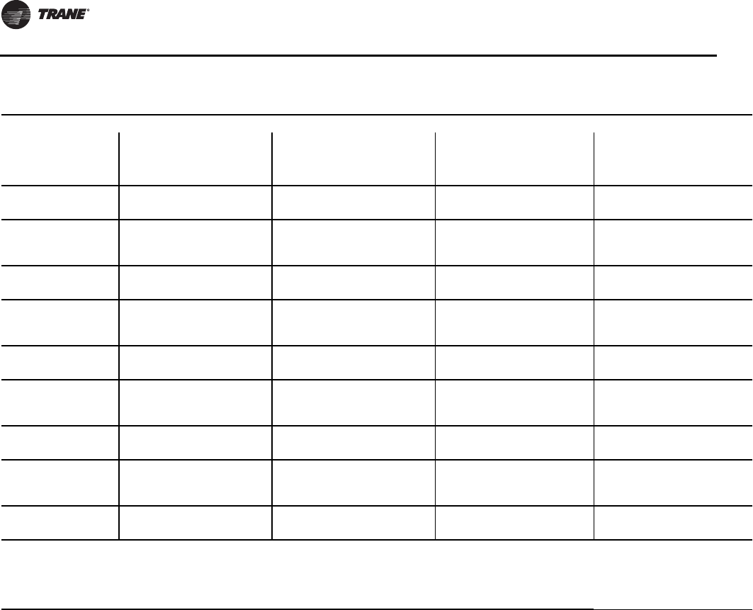
Installation - Electrical
102 RLC-SVX09H-EN
Table 85. Customer Wire Selection - RTWD - 50 Hz - standard efficiency - standard condensing temperature
Size
Rated
Voltage
#
Conn
Wire Selection
Main Terminal Block Disconnect Circuit Breaker Hi-Fault Panel Ckt Brkr
Size Wire Range Size Wire Range Size Wire Range Size Wire Range
Amp XL YD Amp XL YD Amp XL YD Amp XL YD
70 400 1 380 #4–500 #4–500 250 #6–#350 #6–#350 150 #6–#350 #6–#350 150 #6–#350 #6–#350
2 175 #14–2/0 #14–2/0 100 #10–1/0 #10–1/0 100 #6–#350 #6–#350 100 #6–#350 #6–#350
80 400
1 380 #4–500 #4–500 250 #6–#350 #6–#350 175 #6–#350 #6–#350 175 #6–#350 #6–#350
2 175 #14–2/0 #14–2/0 100 #10–1/0 #10–1/0 100
125 #6–#350 #6–#350 100
125 #6–#350 #6–#350
90 400 1 380 #4–500 #4–500 250 #6–#350 #6–#350 175 #6–#350 #6–#350 175 #6–#350 #6–#350
2 175 #14–2/0 #14–2/0 100 #10–1/0 #10–1/0 125 #6–#350 #6–#350 125 #6–#350 #6–#350
100 400
1 380 #4–500 #4–500 250 #6–#350 #6–#350 200 #6–#350 #6–#350 200 #6–#350 #6–#350
2 175 #14–2/0 #14–2/0 100 #10–1/0 #10–1/0 125
150 #6–#350 #6–#350 125
150 #6–#350 #6–#350
110 400 1 380 #4–500 #4–500 250 #6–#350 #6–#350 225 #6–#350 #6–#350 225 #6–#350 #6–#350
2 175 #14–2/0 #14–2/0 100 #10–1/0 #10–1/0 150 #6–#350 #6–#350 150 #6–#350 #6–#350
120 400
1 380 #4–500 #4–500 250 #6–#350 #6–#350 250 #6–#350 #6–#350 250 #6–#350 #6–#350
2 175 #14–2/0 #14–2/0 100 #10–1/0 #10–1/0 150
175 #6–#350 #6–#350 150
175 #6–#350 #6–#350
130 400 1 380 #4–500 #4–500 250 #6–#350 #6–#350 250 #6–#350 #6–#350 250 #6–#350 #6–#350
2 175 #14–2/0 #14–2/0 100 #10–1/0 #10–1/0 175 #6–#350 #6–#350 175 #6–#350 #6–#350
140 400
1 380 #4–500 #4–500 250 #6–#350 #6–#350 300 3/0-500(a) 3/0-500(a) 300 3/0-500(a) 3/0-500(a)
2 175 #14–2/0 #14–2/0 100
250
#10–1/0
#6–#350
#10–1/0
#6–#350
175
200 #6–#350 #6–#350 175
200 #6–#350 #6–#350
150 400 1 380 #4–500 #4–500 250 #6–#350 #6–#350 300 3/0-500(a) 3/0-500(a) 300 3/0-500(a) 3/0-500(a)
2 175 #14–2/0 #14–2/0 250 #6–#350 #6–#350 200 #6–#350 #6–#350 200 #6–#350 #6–#350
Notes:
1. Optional non-fused disconnect and circuit breaker.
2. Copper wire only, based on nameplate minimum circuit ampacity (MCA).
3. Standard condensing temperature option refers to entering condenser water temperatures 95°F (35°C) and below.
4. Circuit two information is the same as circuit one unless listed on a separate line below circuit one values.
5. XL - across-the-line starter and YD - wye-delta starter.
(a) Will accept 2conduits per phase in this size.
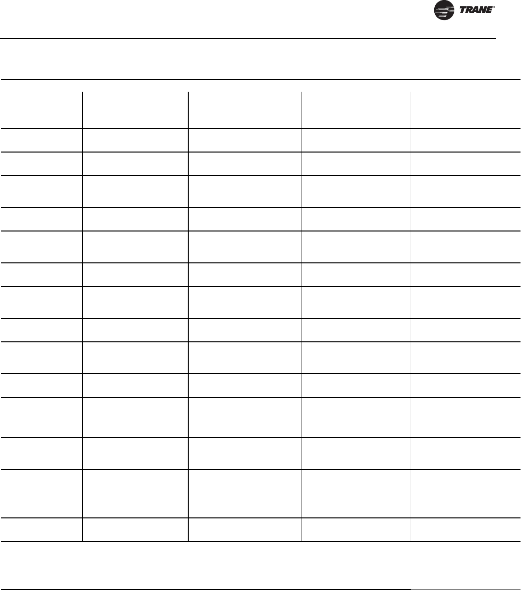
Installation - Electrical
RLC-SVX09H-EN 103
Table 86. Customer Wire Selection - RTWD - 50 Hz - high efficiency - standard condensing temperature
Size
Rated
Voltage
#
Conn
Wire Selection
Main Terminal Block Disconnect Circuit Breaker Hi-Fault Panel Ckt Brkr
Size Wire Range Size Wire Range Size Wire Range Size Wire Range
Amp XL YD Amp XL YD Amp XL YD Amp XL YD
60 400 1 380 #4–500 #4–500 100 #10–1/0 #10–1/0 125 #6–#350 #6–#350 125 #6–#350 #6–#350
2 175 #14–2/0 #14–2/0 100 #10–1/0 #10–1/0 80 #6–#350 #6–#350 80 #6–#350 #6–#350
70 400 1 380 #4–500 #4–500 250 #6–#350 #6–#350 125 #6–#350 #6–#350 125 #6–#350 #6–#350
2 175 #14–2/0 #14–2/0 100 #10–1/0 #10–1/0 100 #6–#350 #6–#350 100 #6–#350 #6–#350
80 400
1 380 #4–500 #4–500 250 #6–#350 #6–#350 175 #6–#350 #6–#350 175 #6–#350 #6–#350
2 175 #14–2/0 #14–2/0 100 #10–1/0 #10–1/0 100
125 #6–#350 #6–#350 100
125 #6–#350 #6–#350
90 400 1 380 #4–500 #4–500 250 #6–#350 #6–#350 175 #6–#350 #6–#350 175 #6–#350 #6–#350
2 175 #14–2/0 #14–2/0 100 #10–1/0 #10–1/0 125 #6–#350 #6–#350 125 #6–#350 #6–#350
100 400
1 380 #4–500 #4–500 250 #6–#350 #6–#350 200 #6–#350 #6–#350 200 #6–#350 #6–#350
2 175 #14–2/0 #14–2/0 100 #10–1/0 #10–1/0 125
150 #6–#350 #6–#350 125
150 #6–#350 #6–#350
110 400 1 380 #4–500 #4–500 250 #6–#350 #6–#350 225 #6–#350 #6–#350 225 #6–#350 #6–#350
2 175 #14–2/0 #14–2/0 100 #10–1/0 #10–1/0 150 #6–#350 #6–#350 150 #6–#350 #6–#350
120 400
1 380 #4–500 #4–500 250 #6–#350 #6–#350 250 #6–#350 #6–#350 250 #6–#350 #6–#350
2 175 #14–2/0 #14–2/0 100 #10–1/0 #10–1/0 150
175 #6–#350 #6–#350 150
175 #6–#350 #6–#350
130 400 1 380 #4–500 #4–500 250 #6–#350 #6–#350 250 3/0-500(a) 3/0-500(a) 250 3/0-500(a) 3/0-500(a)
2 175 #14–2/0 #14–2/0 100 #10–1/0 #10–1/0 175 #6–#350 #6–#350 175 #6–#350 #6–#350
140 400
1 380 #4–500 #4–500 250 #6–#350 #6–#350 300 3/0-500(a) 3/0-500(a) 300 3/0-500(a) 3/0-500(a)
2 175 #14–2/0 #14–2/0 100
250
#10–1/0
#6–#350
#10–1/0
#6–#350
175
200 #6–#350 #6–#350 175
200 #6–#350 #6–#350
160 400 1 380 #4–500 #4–500 250 #6–#350 #6–#350 300 3/0-500(a) 3/0-500(a) 300 3/0-500(a) 3/0-500(a)
2 175 #14–2/0 #14–2/0 250 #6–#350 #6–#350 200 #6–#350 #6–#350 200 #6–#350 #6–#350
180 400
1 380 #4–500 #4–500 250 #6–#350 #6–#350 350 3/0-500(a) 3/0-500(a) 350 3/0-500(a) 3/0-500(a)
2
XL 175/
380
YD 175
#14–2/0
#4–500 #14–2/0 250 #6–#350 #6–#350 200
250 #6–#350 #6–#350 200
250 #6–#350 #6–#350
200 400
1 380 #4–500 #4–500 400 3/0-500(a) 3/0-500(a) 350 3/0-500(a) 3/0-500(a) 350 3/0-500(a) 3/0-500(a)
2XL 380
YD 175 #4–500 #14–2/0 250 #6–#350 #6–#350 250 #6–#350 #6–#350 250 #6–#350 #6–#350
220 400
1 380 #4–500 #4–500 400 3/0-500(a) 3/0-500(a) 400 3/0-500(a) 3/0-500(a) 400 3/0-500(a) 3/0-500(a)
2
XL 380
YD
175/
380
#4–500 #14–2/0
#4–500 250 #6–#350 #6–#350 250
300
#6–#350
3/0-500(a)
#6–#350
3/0-500(a)
250
300
#6–#350
3/0-500(a)
#6–#350
3/0-500(a)
250 400 1 380 #4–500 #4–500 400 3/0-500(a) 3/0-500(a) 450 3/0-500(a) 3/0-500(a) 450 3/0-500(a) 3/0-500(a)
2 380 #4–500 #4–500 250 #6–#350 #6–#350 300 3/0-500(a) 3/0-500(a) 300 3/0-500(a) 3/0-500(a)
Notes:
1. Optional non-fused disconnect and circuit breaker.
2. Copper wire only, based on nameplate minimum circuit ampacity (MCA).
3. Standard condensing temperature option refers to entering condenser water temperatures 95°F (35°C) and below.
4. Circuit two information is the same as circuit one unless listed on a separate line below circuit one values.
5. XL - across-the-line starter and YD - wye-delta starter.
(a) Will accept 2conduits per phase in this size.
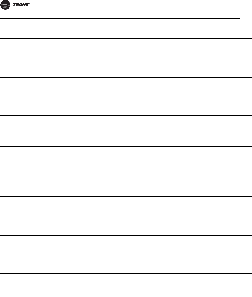
Installation - Electrical
104 RLC-SVX09H-EN
Table 87. Customer Wire Selection - RTWD - 50 Hz - high efficiency - high condensing temperature
Size
Rated
Voltage
#
Conn
Wire Selection
Main Terminal Block Disconnect Circuit Breaker Hi-Fault Panel Ckt Brkr
Size Wire Range Size Wire Range Size Wire Range Size Wire Range
Amp XL YD Amp XL YD Amp XL YD Amp XL YD
60 400
1 380 #4–500 #4–500 250 #6–#350 #6–#350 150 #6–#350 #6–#350 150 #6–#350 #6–#350
2 175 #14–2/0 #14–2/0 100 #10–1/0 #10–1/0 110
100 #6–#350 #6–#350 110
100 #6–#350 #6–#350
70 400 1 380 #4–500 #4–500 250 #6–#350 #6–#350 175 #6–#350 #6–#350 175 #6–#350 #6–#350
2 175 #14–2/0 #14–2/0 100 #10–1/0 #10–1/0 125 #6–#350 #6–#350 125 #6–#350 #6–#350
80 400
1 380 #4–500 #4–500 250 #6–#350 #6–#350 225 #6–#350 #6–#350 225 #6–#350 #6–#350
2 175 #14–2/0 #14–2/0 100 #10–1/0 #10–1/0 125
150 #6–#350 #6–#350 125
150 #6–#350 #6–#350
90 400 1 380 #4–500 #4–500 250 #6–#350 #6–#350 225 #6–#350 #6–#350 225 #6–#350 #6–#350
2 175 #14–2/0 #14–2/0 100 #10–1/0 #10–1/0 150 #6–#350 #6–#350 150 #6–#350 #6–#350
100 400
1 380 #4–500 #4–500 250 #6–#350 #6–#350 250 #6–#350 #6–#350 250 #6–#350 #6–#350
2 175 #14–2/0 #14–2/0 100
250
#10–1/0
#6–#350
#10–1/0
#6–#350
150
175 #6–#350 #6–#350 150
175 #6–#350 #6–#350
110 400
1 380 #4–500 #4–500 250 #6–#350 #6–#350 250 3/0-500(a) 3/0-500(a) 250 3/0-500(a) 3/0-500(a)
2 175 #14–2/0 #14–2/0 250 #6–#350 #6–#350 200
175 #6–#350 #6–#350 200
175 #6–#350 #6–#350
120 400
1 380 #4–500 #4–500 250 #6–#350 #6–#350 300 3/0-500(a) 3/0-500(a) 300 3/0-500(a) 3/0-500(a)
2 175 #14–2/0 #14–2/0 250 #6–#350 #6–#350 200
225 #6–#350 #6–#350 200
225 #6–#350 #6–#350
130 400
1 380 #4–500 #4–500 250 #6-350 #6–#350 300 3/0-500(a) 3/0-500(a) 300 3/0-500(a) 3/0-500(a)
2 175 #14-2/0 #14-2/0 250 #6-350 #6-350 225
200 #6-350 #6-350 225
200 #6-350 #6-350
140 400
1 380 #4–500 #4–500 400 3/0-500(a) 3/0-500(a) 350 3/0-500(a) 3/0-500(a) 350 3/0-500(a) 3/0-500(a)
2
XL 175/
380
YD 175
#14-2/0
#4–500 #14-2/0 250 #6-350 #6-350 225
250 #6-350 #6-350 225
250 #6-350 #6-350
160 400
1 380 #4–500 #4–500 400 3/0-500(a) 3/0-500(a) 350 3/0-500(a) 3/0-500(a) 350 3/0-500(a) 3/0-500(a)
2XL 380
YD 175 #4–500 #14-2/0 250 #6-350 #6-350 250 #6-350 #6-350 250 #6-350 #6-350
180 400
1 380 #4–500 #4–500 400 3/0-500(a) 3/0-500(a) 400 3/0-500(a) 3/0-500(a) 400 3/0-500(a) 3/0-500(a)
2
XL 380
YD
175/
380
#4–500 #14-2/0
#4–500 250 #6-350 #6-350 250
300
#6-350
3/0-500(a)
#6-350
3/0-500(a)
250
300
#6-350
3/0-500(a)
#6-350
3/0-500(a)
200 400 1 380 #4–500 #4–500 400 3/0-500(a) 3/0-500(a) 450 3/0-500(a) 3/0-500(a) 450 3/0-500(a) 3/0-500(a)
2 380 #4–500 #4–500 250 #6-350 #6-350 300 3/0-500(a) 3/0-500(a) 300 3/0-500(a) 3/0-500(a)
220 400
1 380 #4–500 #4–500 400 3/0-500(a) 3/0-500(a) 500 3/0-500(a) 3/0-500(a) 500 3/0-500(a) 3/0-500(a)
2 380 #4–500 #4–500 250 #6-350 #6-350 300
350 3/0-500(a) 3/0-500(a) 300
350 3/0-500(a) 3/0-500(a)
250 400 1 380 #4–500 #4–500 600 3/0-500(a) 3/0-500(a) 500 3/0-500(a) 3/0-500(a) 500 3/0-500(a) 3/0-500(a)
2 380 #4–500 #4–500 250 #6-350 #6-350 350 3/0-500(a) 3/0-500(a) 350 3/0-500(a) 3/0-500(a)
Notes:
1. Optional non-fused disconnect and circuit breaker.
2. Copper wire only, based on nameplate minimum circuit ampacity (MCA).
3. Standard condensing temperature option refers to entering condenser water temperatures 95°F (35°C) and below.
4. Circuit two information is the same as circuit one unless listed on a separate line below circuit one values.
5. XL - across-the-line starter and YD - wye-delta starter.
(a) Will accept 2conduits per phase in this size.
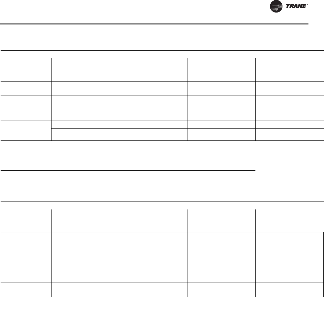
Installation - Electrical
RLC-SVX09H-EN 105
Installer-Supplied Components
Customer wiring interface connections are shown in the
electrical schematics and connection diagrams that are
shipped with the unit.The installer must provide the
following components if not ordered with the unit:
• Power supply wiring (in conduit) for all field-wired
connections.
• All control (interconnecting) wiring (in conduit) for
field supplied devices.
• Fused-disconnect switches or circuit breakers.
• Power factor correction capacitors. (See RLC-PRB023-
EN)
Table 88. Customer Wire Selection - RTWD - 50 Hz - premium efficiency - standard condensing temperature
Size
Rated
Voltage
#
Conn
Wire Selection
Main Terminal Block Disconnect Circuit Breaker Hi-Fault Panel Ckt Brkr
Size Wire Range Size Wire Range Size Wire Range Size Wire Range
Amp XL YD Amp XL YD Amp XL YD Amp XL YD
160 400 1 380 #4–500 #4–500 250 #6-350 #6-350 300 3/0-500(a) 3/0-500 (a) 300 3/0-500(a) 3/0-500(a)
2 175 #14-2/0 #14-2/0 250 #6-350 #6-350 200 #6-350 #6-350 200 #6-350 #6-350
180 400
1 380 #4–500 #4–500 250 #6-350 #6-350 350 3/0-500(a) 3/0-500(a) 350 3/0-500(a) 3/0-500(a)
2
XL 175/
380
YD 175
#14-2/0
#4–500 #14-2/0 250 #6-350 #6-350 200
250 #6-350 #6-350 200
250 #6-350 #6-350
200 400
1 380 #4–500 #4–500 400 3/0-500(a) 3/0-500(a) 350 3/0-500(a) 3/0-500(a) 350 3/0-500(a) 3/0-500(a)
2XL 380
YD 175 #4–500 #14-2/0 250 #6-350 #6-350 250 #6-350 #6-350 250 #6-350 #6-350
Notes:
1. Optional non-fused disconnect and circuit breaker.
2. Copper wire only, based on nameplate minimum circuit ampacity (MCA).
3. Standard condensing temperature option refers to entering condenser water temperatures 95°F (35°C) and below.
4. Circuit two information is the same as circuit one unless listed on a separate line below circuit one values.
5. XL - across-the-line starter and YD - wye-delta starter.
(a) Will accept 2 conduits per phase in this size.
Table 89. Customer Wire Selection - RTWD - 50 Hz - premium efficiency - high condensing temperature
Size
Rated
Voltage
#
Conn
Wire Selection
Main Terminal Block Disconnect Circuit Breaker Hi-Fault Panel Ckt Brkr
Size Wire Range Size Wire Range Size Wire Range Size Wire Range
Amp XL YD Amp XL YD Amp XL YD Amp XL YD
160 400
1 380 #4–500 #4–500 400 3/0-500(a) 3/0-500(a) 350 3/0-500(a) 3/0-500(a) 350 3/0-500(a) 3/0-500(a)
2XL 380
YD 175 #4–500 #14-2/0 250 #6-350 #6-350 250 #6-350 #6-350 250 #6-350 #6-350
180 400
1 380 #4–500 #4–500 400 3/0-500(a) 3/0-500(a) 400 3/0-500(a) 3/0-500(a) 400 3/0-500(a) 3/0-500(a)
2
XL 380
YD
175/
380
#4–500 #14-2/0
#4–500 250 #6-350 #6-350 250
300
#6-350
3/0-500(a)
#6-350
3/0-500(a)
250
300
#6-350
3/0-500(a)
#6-350
3/0-500(a)
200 400 1 380 #4–500 #4–500 400 3/0-500(a) 3/0-500(a) 450 3/0-500(a) 3/0-500(a) 450 3/0-500(a) 3/0-500(a)
2 380 #4–500 #4–500 250 #6-350 #6-350 300 3/0-500(a) 3/0-500(a) 300 3/0-500(a) 3/0-500(a)
Notes:
1. Optional non-fused disconnect and circuit breaker.
2. Copper wire only, based on nameplate minimum circuit ampacity (MCA).
3. Standard condensing temperature option refers to entering condenser water temperatures 95°F (35°C) and below.
4. Circuit two information is the same as circuit one unless listed on a separate line below circuit one values.
5. XL - across-the-line starter and YD - wye-delta starter.
(a) Will accept 2 conduits per phase in this size.
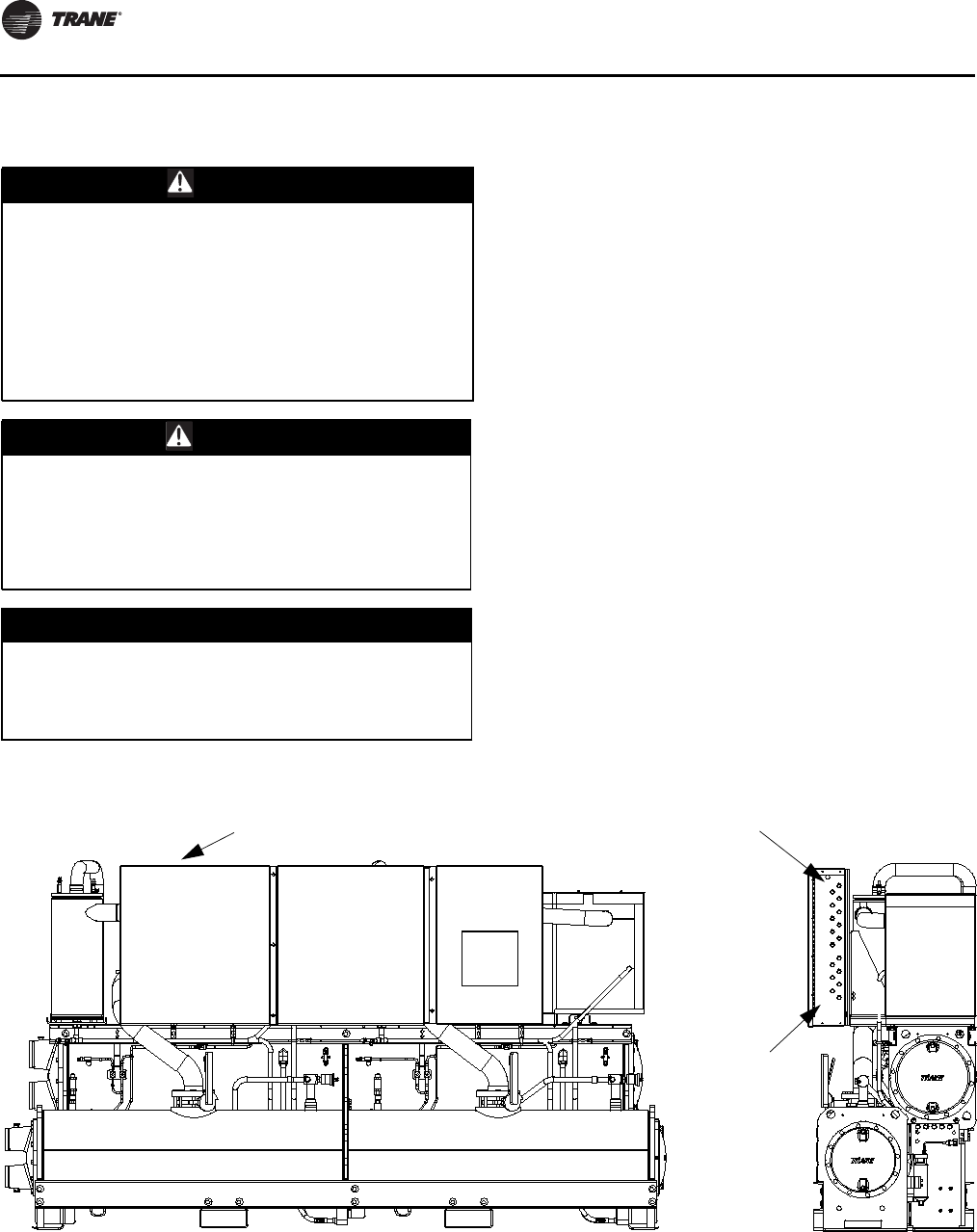
Installation - Electrical
106 RLC-SVX09H-EN
Power Supply Wiring All power supply wiring must be sized and selected
accordingly by the project engineer in accordance with
NECTable 310-16.
All wiring must comply with local codes and the National
Electrical Code.The installing (or electrical) contractor
must provide and install the system interconnecting
wiring, as well as the power supply wiring. It must be
properly sized and equipped with the appropriate fused
disconnect switches.
The type and installation location(s) of the fused
disconnects must comply with all applicable codes.
Knock-outs for wiring are located on the upper left side of
the control panel.The wiring is passed through these
conduits and connected to the terminal blocks, optional
unit-mounted disconnects, or HACR type breakers. Refer
to Figure 44, p. 106.
To provide proper phasing of 3-phase input, make
connections as shown in field wiring diagrams and as
stated on the WARNING label in the starter panel. For
additional information on proper phasing, refer to “Unit
Voltage Phasing.” Proper equipment ground must be
provided to each ground connection in the panel (one for
each customer-supplied conductor per phase).
115 volt field-provided connections (either control or
power) are made through knockouts on the right side of
the panel (Figure 44). Additional grounds may be required
for each 115 volt power supply to the unit. Green lugs are
provided for 115V customer wiring.
WARNING
Proper Field Wiring and Grounding
Required!
All field wiring MUST be performed by qualified
personnel. Improperly installed and grounded field
wiring poses FIRE and ELECTROCUTION hazards. To
avoid these hazards, you MUST follow requirements for
field wiring installation and grounding as described in
NEC and your local/state electrical codes. Failure to
follow code could result in death or serious injury.
WARNING
Hazardous Voltage!
Disconnect all electric power, including remote
disconnects before servicing. Follow proper lockout/
tagout procedures to ensure the power can not be
inadvertently energized. Failure to disconnect power
before servicing could result in death or serious injury.
NOTICE:
Use Copper Conductors Only!
Unit terminals are not designed to accept other types of
conductors. Failure to use copper conductors could
result in equipment damage.
Figure 44. Power entrance
Incoming
power entrance
High
voltage
entrance
(upper sd)
Low
voltage
entrance
(lower sd)
Installation - Electrical
RLC-SVX09H-EN 107
Control Power Supply
The unit is equipped with a control power transformer; it
is not necessary to provide additional control power
voltage to the unit.
All units are factory-connected for appropriate labeled
voltages.
Interconnecting Wiring
Chilled Water Flow (Pump) Interlock
If paddle option is selected, RTWD/RTUD Series R®chillers
require a field-supplied control voltage contact input
through a flow proving switch 5S5 and an auxiliary contact
5K9AUX. Connect the proving switch and auxiliary contact
to 1A15 J3-1 and 1X4-1. Refer to the field wiring for details.
The auxiliary contact can be BAS signal, starter contactor
auxiliary, or any signal which indicates the pump is
running. A flow switch is still required and cannot be
omitted.
Condenser Water Flow Interlock
If paddle option is selected, RTWD Series R®chillers
require a field-supplied control voltage contact input
through a flow proving switch 5S6 and an auxiliary contact
5K10 AUX. Connect the proving switch and auxiliary
contact to 1A15 J2-1 and 1X4-1. Refer to the field wiring for
details.The auxiliary contact can be BAS signal, starter
contactor auxiliary, or any signal which indicates the pump
is running. A flow switch is still required and cannot be
omitted.
Chilled Water Pump Control
An evaporator water pump output relay closes when the
chiller is given a signal to go into the Auto mode of
operation from any source.The contact is opened to turn
off the pump in the event of most machine level
diagnostics to prevent the build up of pump heat.
The relay output from board 1A14 is required to operate
the Evaporator Water Pump (EWP) contactor. Contacts
should be compatible with 115/240VAC control circuit.The
EWP relay operates in different modes depending on
CH530 orTracer commands, if available, or service
pumpdown (See maintenance section). Normally, the
EWP relay follows theAUTO mode of the chiller.Whenever
the chiller has no diagnostics and is in the AUTO mode,
regardless of where the auto command is coming from,
the normally open relay is energized. When the chiller
exits the AUTO mode, the relay is timed open for an
adjustable (usingTechView) 0 to 30 minutes.The non-
AUTO modes in which the pump is stopped, include Reset
(88), Stop (00), External Stop (100), Remote Display Stop
(600), Stopped byTracer (300), Low Ambient Run Inhibit
(200), and Ice Building complete (101).
Regardless of whether the chiller is allowed to control the
pump on a full-time basis, if the MP calls for a pump to start
and water does not flow, the evaporator may be damaged
catastrophically. It is the responsibility of the installing
contractor and/or the customer to ensure that a pump will
start when called upon by the chiller controls.
Note: Exceptions are listed below.
When going from Stop to Auto, the EWP relay is energized
immediately. If evaporator water flow is not established in
4 minutes and 15 sec., the CH530 de-energizes the EWP
relay and generates a non-latching diagnostic. If flow
returns (e.g. someone else is controlling the pump), the
diagnostic is cleared, the EWP is re-energized, and normal
control resumed.
If evaporator water flow is lost once it had been
established, the EWP relay remains energized and a non-
latching diagnostic is generated. If flow returns, the
diagnostic is cleared and the chiller returns to normal
operation.
In general, when there is either a non-latching or latching
diagnostic, the EWP relay is turned off as though there was
a zero time delay. Exceptions (see Table 90) whereby the
relay continues to be energized occur with:
A Low Chilled WaterTemp. diagnostic (non-latching)
(unless also accompanied by an Evap Leaving Water
Temperature Sensor Diagnostic)
OR
A starter contactor interrupt failure diagnostic, in which a
compressor continues to draw current even after
commanded to have shutdown
OR
A Loss of EvaporatorWater Flow diagnostic (non-latching)
and the unit is in the AUTO mode, after initially having
proven evaporator water flow.
NOTICE:
Evaporator Damage!
All RTUD units (systems with a remote condenser)
REQUIRE chilled water pumps be controlled by the
Trane CH530 to avoid catastrophic damage to the
evaporator due to freezing. It is strongly recommended
that chilled water pump control also be used on RTWD
to provide proper unit operation.
Table 90. Pump Relay Operation
Chiller Mode Relay Operation
Auto Instant close
Ice Building Instant close
Tracer Override Close
Stop Timed Open
Ice Complete Instant Open
Diagnostics Instant Open
Installation - Electrical
108 RLC-SVX09H-EN
Alarm and Status Relay Outputs
(Programmable Relays)
A programmable relay concept provides for enunciation of
certain events or states of the chiller, selected from a list of
likely needs, while only using four physical output relays,
as shown in the field wiring diagram.The four relays are
provided (generally with a Quad Relay Output LLID) as part
of the Alarm Relay Output Option.The relay’s contacts are
isolated Form C (SPDT), suitable for use with 120 VAC
circuits drawing up to 2.8 amps inductive, 7.2 amps
resistive, or 1/3 HP and for 240 VAC circuits drawing up to
0.5 amp resistive.
The list of events/states that can be assigned to the
programmable relays can be found in Table 91.The relay
will be energized when the event/state occurs.
Relay Assignments Using TechView
CH530 ServiceTool (TechView) is used to install the Alarm
and Status Relay Option package and assign any of the
above list of events or status to each of the four relays
provided with the option.The relays to be programmed
are referred to by the relay’s terminal numbers on the LLID
board 1A13.
The default assignments for the four available relays of the
RTWD/RTUD Alarm and Status Package Option are:
If any of the Alarm/Status relays are used, provide
electrical power, 115 VAC with fused-disconnect to the
panel and wire through the appropriate relays/terminals
on 1A13. Provide wiring (switched hot, neutral, and
ground connections) to the remote annunciation devices.
Do not use power from the chiller’s control panel
transformer to power these remote devices. Refer to the
field diagrams which are shipped with the unit.
Low Voltage Wiring
The remote devices described below require low voltage
wiring. All wiring to and from these remote input devices
to the Control Panel must be made with shielded, twisted
pair conductors. Be sure to ground the shielding only at
the control panel.
Note: To prevent control malfunctions, do not run low
voltage wiring (<30 V) in conduit with conductors
carrying more than 30 volts.
Table 91. Alarm and Status Relay Output Configuration Table
Description
Alarm - Latching This output is true whenever there is any active diagnostic that requires a manual reset to clear, that affects either the
Chiller, the Circuit, or any of the Compressors on a circuit. This classification does not include informational diagnostics.
Alarm - Auto Reset This output is true whenever there is any active diagnostic that could automatically clear, that affects either the Chiller,
the Circuit, or any of the Compressors on a circuit. This classification does not include informational diagnostics.
Alarm This output is true whenever there is any diagnostic affecting any component, whether latching or automatically clearing.
This classification does not include informational diagnostics
Alarm Ckt 1 This output is true whenever there is any diagnostic effecting Refrigerant Circuit 1, whether latching or automatically
clearing, including diagnostics affecting the entire chiller. This classification does not include informational diagnostics.
Alarm Ckt 2 This output is true whenever there is any diagnostic affecting Refrigerant Circuit 2 whether latching or automatically
clearing, including diagnostics effecting the entire chiller. This classification does not include informational diagnostics.
Chiller Limit Mode (with
a 20 minute filter)
This output is true whenever the chiller has been running in one of the Unloading types of limit modes (Condenser,
Evaporator, Current Limit or Phase Imbalance Limit) continuously for the last 20 minutes.
Circuit 1 Running This output is true whenever any compressors are running (or commanded to be running) on Refrigerant Circuit 1, and
false when no compressors are commanded to be running on that circuit.
Circuit 2 Running This output is true whenever any compressors are running (or commanded to be running) on Refrigerant Circuit 2, and
false when no compressors are commanded to be running on that circuit.
Chiller Running This output is true whenever any compressors are running (or commanded to be running) on the chiller and false when
no compressors are commanded to be running on the chiller.
Maximum Capacity
(software 18.0 or later)
This output is true whenever the chiller has reached maximum capacity or had reached its maximum capacity and since
that time has not fallen below 70% average current relative to the rated AHRI current for the chiller. The output is false
when the chiller falls below 70% average current and, since that time, had not reestablished maximum capacity.
Table 92. Default Assignments
Relay
Relay 1 Terminals J2 -12,11,10: Alarm
Relay 2 Terminals J2 - 9,8,7: Chiller Running
Relay 3 Terminals J2-6,5,4: Maximum Capacity
(software 18.0 or later)
Relay 4 Terminals J2-3,2,1: Chiller Limit
WARNING
Proper Field Wiring and Grounding
Required!
All field wiring MUST be performed by qualified
personnel. Improperly installed and grounded field
wiring poses FIRE and ELECTROCUTION hazards. To
avoid these hazards, you MUST follow requirements for
field wiring installation and grounding as described in
NEC and your local/state electrical codes. Failure to
follow code could result in death or serious injury.
Installation - Electrical
RLC-SVX09H-EN 109
Emergency Stop
CH530 provides auxiliary control for a customer specified/
installed latching trip out. When this customer-furnished
remote contact 5K24 is provided, the chiller will run
normally when the contact is closed. When the contact
opens, the unit will trip on a manually resettable
diagnostic.This condition requires manual reset at the
chiller switch on the front of the control panel.
Connect low voltage leads to terminal strip locations on
1A5, J2-3 and 4. Refer to the field diagrams that are
shipped with the unit.
Silver or gold-plated contacts are recommended.These
customer-furnished contacts must be compatible with 24
VDC, 12 mA resistive load.
External Auto/Stop
If the unit requires the external Auto/Stop function, the
installer must provide leads from the remote contacts
5K23 to the proper terminals on board 1A5 J2-1 and 2.
The chiller will run normally when the contacts are closed.
When either contact opens, the compressor(s), if
operating, will go to the RUN:UNLOAD operating mode
and cycle off. Unit operation will be inhibited. Closure of
the contacts will permit the unit to return to normal
operation.
Field-supplied contacts for all low voltage connections
must be compatible with dry circuit 24 VDC for a 12 mA
resistive load. Refer to the field diagrams that are shipped
with the unit.
External Circuit Lockout – Circuit #1 and
Circuit #2
CH530 provides auxiliary control of a customer specified
or installed contact closure, for individual operation of
either Circuit #1 or #2. If the contact is closed, the
respective refrigerant circuit will not operate. In the
schematic, 5K21 is shown as controlling circuit 1 and 5K22
is controlling circuit 2.
Upon contact opening, the refrigerant circuit will run
normally. This feature is used to restrict total chiller
operation, e.g. during emergency generator operations.
Connections to board 1A6 are shown in the field diagrams
that are shipped with the unit.
These customer-supplied contact closures must be
compatible with 24 VDC, 12 mA resistive load. Silver or
gold plated contacts are recommended.
Ice Building Option
CH530 provides auxiliary control for a customer specified/
installed contact closure for ice building if so configured
and enabled.This output is known as the Ice Building
Status Relay.The normally open contact will be closed
when ice building is in progress and open when ice
building has been normally terminated either through Ice
Termination setpoint being reached or removal of the Ice
Building command.This output is for use with the ice
storage system equipment or controls (provided by
others) to signal the system changes required as the chiller
mode changes from “ice building” to “ice complete”.
When contact 5K20 is provided, the chiller will run
normally when the contact is open.
CH530 will accept either an isolated contact closure
(External Ice Building command) or a Remote
Communicated input (Tracer) to initiate and command the
Ice Building mode.
CH530 also provides a “Front Panel IceTermination
Setpoint” throughTechView, adjustable from 20 to 31°F
(-6.7 to -0.5°C) in at least 1°F (1°C) increments.
When in the Ice Building mode, and the evaporator
entering water temperature drops below the ice
termination setpoint, the chiller terminates the Ice
Building mode and changes to the Ice Building Complete
Mode.
Techview must also be used to enable or disable Ice
Machine Control.This setting does not prevent theTracer
from commanding Ice Building mode.
Upon contact closure, the CH530 will initiate an ice
building mode, in which the unit runs fully loaded at all
times. Ice building shall be terminated either by opening
the contact or based on the entering evaporator water
temperature. CH530 will not permit the ice building mode
to be reentered until the unit has been switched out of ice
building mode (open 5K20 contacts) and then switched
back into ice building mode (close 5K20 contacts.)
In ice building, all limits (freeze avoidance, evaporator,
condenser, current) will be ignored. All safeties will be
enforced.
If, while in ice building mode, the unit gets down to the
freeze stat setting (water or refrigerant), the unit will shut
down on a manually resettable diagnostic, just as in
normal operation.
Connect leads from 5K20 to the proper terminals of board
1A10. Refer to the field diagrams which are shipped with
the unit.
Silver or gold-plated contacts are recommended.These
customer furnished contacts must be compatible with 24
VDC, 12 mA resistive load.
NOTICE:
Evaporator Damage!
Freeze inhibitor must be adequate for the leaving water
temperature. Failure to do so may result in damage to
system components.

Installation - Electrical
110 RLC-SVX09H-EN
External Chilled or Hot Water Setpoint
(ECWS/EHWS) Option
The CH530 provides inputs that accept either 4-20 mA or 2-
10 VDC signals to set the external water setpoint (EWS).
• When the unit is in cooling mode, the EWS will
correspond to the chilled water setpoint (ECWS).
• When the unit is in heating mode, the EWS will
correspond to the hot water setpoint (EHWS).
This is not a reset function.The input defines the set point.
This input is primarily used with generic BAS (building
automation systems).The water setpoint set via the
DynaView or through digital communication withTracer
(Comm3). See Figure 45, p. 111 for wiring diagrams.
The chilled water setpoint may be changed from a remote
location by sending either a 2-10 VDC or 4-20 mA signal to
the 1A7, J2-5 and 6.The widest range of temperatures
available for the 2-10 VDC and 4-20 mA signals each
correspond to:
• ECWS of 10 to 65°F (-12.22 to 18.4°C)
• EHWS of 68 to 140°F (20 - 60°C).
The external chilled water setpoint (ECWS) and external
hot water setpoint (EHWS) minimum and maximum
values are configurable. See Table 93 for default values.
The equations in Table 94 apply if using default minimum
and maximum values, as shown in above.
If minimum and maximum values have been changed
from default values in Table 93, use the following
equations:
If the ECWS/EHWS input develops an open or short, the
LLID will report either a very high or very low value back to
the main processor. This will generate an informational
diagnostic and the unit will default to using the Front Panel
(DynaView) Chilled/Hot Water Setpoint.
TechView ServiceTool is used to set the input signal type
from the factory default of 2-10 VDC to that of 4-20 mA.
TechView is also used to install or remove the External
ChilledWater Setpoint option as well as a means to enable
and disable ECWS.
External Current Limit Setpoint (ECLS) Option
Similar to the above, the CH530 also provides for an
optional External Current Limit Setpoint that will accept
either a 2-10VDC (default) or a 4-20 mA signal.The Current
Limit Setting can also be set via the DynaView or through
digital communication withTracer (Comm 3).The
arbitration of the various sources of current limit is
described in the flow charts at the end of this section.The
External Current Limit Setpoint may be changed from a
remote location by hooking up the analog input signal to
the board 1A7, J2-2 and 3. Refer to the following paragraph
on Analog Input Signal Wiring Details.The following
equations apply for ECLS:
If the ECLS input develops an open or short, the LLID will
report either a very high or very low value back to the man
processor.This will generate an informational diagnostic
and the unit will default to using the Front Panel
(DynaView) Current Limit Setpoint.
TheTechView ServiceTool must be used to set the input
signal type from the factory default of 2-10 VDC to that of
4-20 mA current.TechView must be also be used to install
or remove the External Current Limit Setpoint Option for
field installation, or can be used to enable or disable the
feature (if installed).
ECLS and ECWS Analog Input Signal Wiring Details:
Both the ECWS and ECLS can be connected and setup as
either a 2-10 VDC (factory default), 4-20 mA, or resistance
input (also a form of 4-20mA) as indicated below.
Table 93. Default minimum and maximum values
Default Temperature
External Water Setpoint Minimum Maximum
Chilled (ECWS) 34°F (1.1°C) 65°F (18.4°C)
Hot (EHWS) 86°F (30°C) 122°F (50°C)
Table 94. EWS equations -
default minimum and maximum values(a)
(a) Temperatures are in units of °F.
Chilled Water
Setpoint Voltage Signal Current Signal
As generated
from external
source
VDC=
0.1455*(ECWS)
+0.5454
mA=
0.2909*(ECWS)
+1.0909
As processed by
CH530
ECWS=
6.875*(VDC)-3.75
ECWS=
3.4375*(mA)-3.75
Hot Water
Setpoint Voltage Signal Current Signal
As generated
from external
source
VDC=
0.2222*(EHWS)
-17.1092
mA=
0.4444*(EHWS)
-34.2184
As processed by
CH530
EHWS=
4.5*(VDC)+77
EHWS=
2.25*(mA)+77
Table 95. EWS equations -
any minimum and maximum values(a)
(a) Temperatures are in units of °F.
For Voltage
Input Signal EWS = Min + (Max - Min)*(VDC - 2)/8
For Current
Input Signal EWS = Min + (Max - Min)*(mA - 4)/16
Voltage Signal Current Signal
As generated from
external source VDC+0.133*(%)-6.0 mA=0.266*(%)-12.0
As processed by UCM %=7.5*(VDC)+45.0 %=3.75*(mA)+45.0
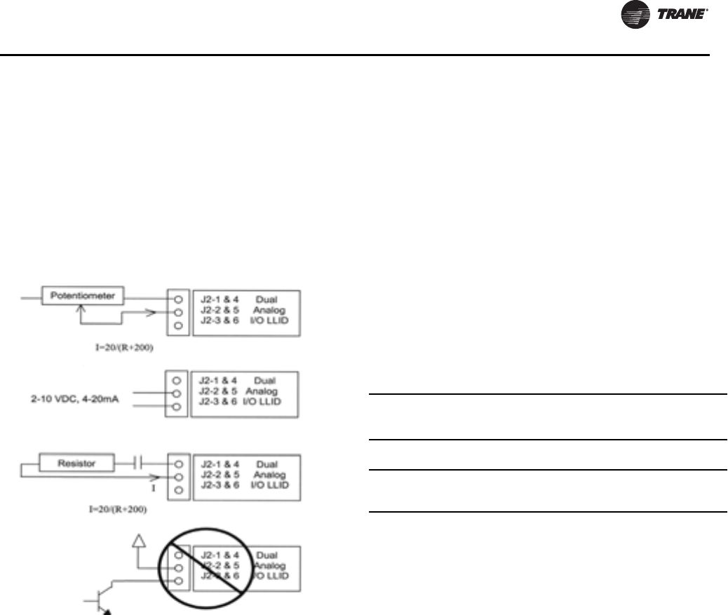
Installation - Electrical
RLC-SVX09H-EN 111
Depending on the type to be used, theTechView Service
Tool must be used to configure the LLID and the MP for the
proper input type that is being used.This is accomplished
by a setting change on the CustomTab of the
Configuration View withinTechView.
The J2-3 and J2-6 terminal is chassis grounded and
terminal J2-1 and J2-4 can be used to source 12 VDC.The
ECLS uses terminals J2-2 and J2-3. ECWS uses terminals
J2-5 and J2-6. Both inputs are only compatible with
high-side current sources.
Chilled Water Reset (CWR)
CH530 resets the chilled water temperature set point
based on either return water temperature, or outdoor air
temperature. Return Reset is standard, Outdoor Reset is
optional.
The following shall be selectable:
• One of three ResetTypes: None, Return Water
Temperature Reset, Outdoor AirTemperature Reset, or
Constant Return WaterTemperature Reset.
• Reset Ratio Set Points.
• For outdoor air temperature reset there shall be both
positive and negative reset ratio's.
• Start Reset Set Points.
• Maximum Reset Set Points.
The equations for each type of reset are as follows:
Return
CWS' = CWS + RATIO (START RESET - (TWE -TWL))
and CWS' > or = CWS
and CWS' - CWS < or = Maximum Reset
Outdoor
CWS' = CWS + RATIO * (START RESET -TOD)
and CWS' > or = CWS
and CWS' - CWS < or = Maximum Reset
where
CWS' is the new chilled water set point or the "reset CWS"
CWS is the active chilled water set point before any reset
has occurred, e.g. normally Front Panel,Tracer, or ECWS
RESET RATIO is a user adjustable gain
START RESET is a user adjustable reference
TOD is the outdoor temperature
TWE is entering evap. water temperature
TWL is leaving evap. water temperature
MAXIMUM RESET is a user adjustable limit providing the
maximum amount of reset. For all types of reset, CWS' -
CWS < or = Maximum Reset.
In addition to Return and Outdoor Reset, the MP provides
a menu item for the operator to select a Constant Return
Reset. Constant Return Reset will reset the leaving water
temperature set point so as to provide a constant entering
water temperature.The Constant Return Reset equation is
the same as the Return Reset equation except on selection
of Constant Return Reset, the MP will automatically set
Ratio, Start Reset, and Maximum Reset to the following.
RATIO = 100%
START RESET = Design DeltaTemp.
MAXIMUM RESET = Design DeltaTemp.
The equation for Constant Return is then as follows:
CWS' = CWS + 100% (Design DeltaTemp. - (TWE -TWL))
and CWS' > or = CWS
and CWS' - CWS < or = Maximum Reset
When any type of CWR is enabled, the MP will step the
Active CWS toward the desired CWS' (based on the above
equations and setup parameters) at a rate of 1 degree F
every 5 minutes until the Active CWS equals the desired
CWS'.This applies when the chiller is running.
When the chiller is not running, CWS is reset immediately
(within one minute) for Return Reset and at a rate of 1
degree F every 5 minutes for Outdoor Reset.The chiller
will start at the Differential to Start value above a fully reset
CWS or CWS' for both Return and Outdoor Reset.
Figure 45. Wiring examples for ECLS and ECWS/EHWS
Reset
Type
Reset
Ratio
Range
Start Reset
Range
°F (°C)
Max Reset
Range
°F (°C)
Increment Factory
Default
ValueIP SI
Return 10 to
120%
4 - 30
(2.2 - 16.7)
0 - 20
(0.0 - 11.) 1% 1% 50%
Outdoor 80 to
-80%
50 - 130
(10 - 54.4)
0 - 20
(0.0 - 11.1) 1% 1% 10%

Installation - Electrical
11 2 RLC-SVX09H-EN
Outdoor Air Temperature Sensor
Installation Requirements
The outdoor air temperature sensor is optional for the
RTWD water cooled units, but is a required sensor for the
RTUD compressor chiller units.The sensor is required as
an important input to the condenser fan control algorithm
as well as for the low outdoor air ambient lockout feature.
The temperature sensor probe is shipped separately
inside the control panel.
It is necessary for the chiller installer to locate and install
the separate outdoor air sensor probe at the remote air
cooled condenser at a location to sense the coil’s entering
air temperature, while avoiding direct sunlight. It should
be located at least 2” from the coil face and somewhere
“in-between” the two refrigerant circuits. Where the
condenser installation is such that the two refrigerant
circuit’s condensers are physically separate from each
other, or one circuit is more likely to see re-circulated
warmer air, an attempt should be made to locate the probe
to see an average temperature of the two separate
condensers.
Important: The probe provided ,must not be
substituted with another probe, as the
probe and the electronics are “matched /
calibrated” at the factory for accuracy.
A twisted pair sheathed cable shall be run and connected
between the probe at the remote condenser and its LLID
module in the chiller control panel.The sensor’s circuit is
a class II power limited analog circuit and therefore the
wire should not be run in close proximity to any power or
line voltage wiring.The splices at the condenser end,
should be made to be water tight.The wire run should be
physically supported at equal intervals with consideration
for safety and reliability/durability with wire ties or similar
to meet local codes.
Remote Air Cooled Condenser
If using a Levitor II remote air cooled condenser, refer to
wiring diagram provided from Krack located in the control
panel. If you have additional questions, please contact
PuebloTechnical Service.
Fan Control for the Remote Air Cooled
Condenser
The CH530 Controls for the RTUD compressor chiller
provide as an option, the flexible and full control of a 2-
circuit remote air cooled condenser fans. In addition to the
option for controlling between 2 to 8 fixed speed fans per
circuit (or multiples thereof), a separate additional option
includes the ability to control either two speed fans or
variable speed fan/drive combinations in conjunction with
other fixed speed fans, to provide low ambient outdoor air
temperature capability. The controls will also provide an
option for a simple per circuit interlock output (in lieu of
actual fan control) to use in the scenario in which
independent fan head pressure or differential pressure
controls (by others) is applied. It is recommended
however, that for the best overall unit performance, the
integral fan control option is selected.
The controls support control of a remote, air cooled
condenser fan deck, from 2 to 8 fans per circuit (1-8 fans for
variable speed). It supports options to control the
following types of standard ambient outdoor air
temperature fan decks: 1) all fans fixed speed, and 2) all
fans two speed. It will also support the following low
ambient outdoor air temperature fan decks 1) one fan per
circuit isTwo-Speed, (remaining fans fixed speed), and 2)
One fan per circuit is variable speed i.e. variable frequency
drive (VFD), (remaining fans fixed speed). In the variable
fan low ambient outdoor air option the VFD fan and fixed
speed fans are sequenced accordingly to provide
continuous control from 0-100% air flow per circuit. Fan
staging provides the correct combination of fixed speed
fan relay, VFD relay (to enable operation of the VFD), and
speed outputs to provide air flow control commanded by
the fan algorithm running inside the CH530 Main
Processor.The fan deck arrangement is independently
configurable per circuit.
Since the condenser is provided separately from the RTUD
compressor chiller, the RTUD electrical panel design does
not provide for condensing unit’s control power
requirements. The chiller’s control power transformer is
not sized to provide the control power for the additional
fan contactor loads. The CH530 controls, when properly
optioned, will provide for pilot duty rated relays, low
voltage binary inputs, and low voltage analog outputs to
control the remote contactors and inverters provided by
others.The CH530 fan control relays located in the chiller
control panel, are intended to control the fan contactors
that are located in the remote air cooled condenser panel.
The Fan Control Relays are rated for up to 7.2 Amps
resistive, 2.88 Amps pilot duty 1/3 HP, 7.2 FLA at 120 VAC,
and up to 5 Amps general purpose at 240 VAC. All wiring
for the field connections to the condenser, will have screw
terminals for termination in the RTUD control panel with
the exception of the outdoor air temperature sensor
(addressed above). Refer to the wiring diagrams.
Separate fan control algorithms are used for fixed speed
and variable speed systems. For the variable speed fan
deck option, the fan control reverts to fixed speed control
if an inverter drive fault is detected through a binary input
interface with the drive. An informational diagnostic is
also provided to indicate the issue.
Reference “Controls Interface” section for fan control
setting information.
Communications Interface
Optional Tracer Communications Interface
This option allows theTracer CH530 controller to exchange
information (e.g. operating setpoints and Auto/Standby
commands) with a higher-level control device, such as a
Tracer Summit or a multiple-machine controller. A
Installation - Electrical
RLC-SVX09H-EN 11 3
shielded, twisted pair connection establishes the bi-
directional communications link between theTracer
CH530 and the building automation system.
Note: To prevent control malfunctions, do not run low
voltage wiring (<30 V) in conduit with conductors
carrying more than 30 volts.
Field wiring for the communication link must meet the
following requirements:
• All wiring must be in accordance with the NEC and
local codes.
• Communication link wiring must be shielded, twisted
pair wiring (Belden 8760 or equivalent). See the table
below for wire size selection:
• The communication link cannot pass between
buildings.
• All units on the communication link can be connected
in a “daisy chain” configuration.
LonTalk Communications Interface for Chillers
(LCI-C)
CH530 provides an optional LonTalk Communication
Interface (LCI-C) between the chiller and a Building
Automation System (BAS). An LCI-C LLID shall be used to
provide "gateway" functionality between a LonTalk
compatible device and the Chiller. The inputs (outputs
include both mandatory and optional network variables as
established by the LonMark Functional Chiller Profile 8040.
Installation Recommendations
• 22 AWG Level 4 unshielded communication wire
recommended for most LCI-C installations
• LCI-C link limits: 4500 feet, 60 devices
• Termination resistors are required
• 105 ohms at each end for Level 4 wire
• 82 ohms at each end forTrane "purple" wire
• LCI-C topology should be daisy chain
• Zone sensor communication stubs limited to 8 per link,
50 feet each (maximum)
• One repeater can be used for an additional 4500 feet,
60 devices, 8 communication stubs
BACnet Communications Interface for Chillers
(BCI-C)
The optional BACnet Communication Interface for Chillers
(BCI-C) is comprised of aTracer UC400 controller with
interface software. It is a non-programmable
communications module that allows the RTWD or RTUD
unit to communicate on a BACnet communications
network.
BACnet Data Points and Configuration Property
Definitions. The BCI-C device allows certain models of
Trane chillers with CH530 controls to communicate with
WARNING
Proper Field Wiring and Grounding
Required!
All field wiring MUST be performed by qualified
personnel. Improperly installed and grounded field
wiring poses FIRE and ELECTROCUTION hazards.To
avoid these hazards, you MUST follow requirements for
field wiring installation and grounding as described in
NEC and your local/state electrical codes. Failure to
follow code could result in death or serious injury.
Table 96. Wire Size
Wire Size
Maximum Length of
Communication Wire
14 AWG (2.5 mm2) 5,000 ft (1525 m)
16 AWG (1.5 mm2) 2,000 ft (610 m)
18 AWG (1.0 mm2) 1,000 ft (305 m)
Table 97. LonTalk points list
LonTalk Communications Interface
Inputs
Variable
type SNVT_Type
Chiller Enable/Disable binary start(1)/
stop(0) SNVT_switch
Chilled Water Setpoint analog temperature SNVT_temp_p
Current Limit Setpoint analog % current SNVT_lev_percent
Chiller Mode Note 1 SNVT_hvac_mode
Outputs Variable
type SNVT_Type
Outputs Variable
type SNVT_Type
Chiller On/Off binary on(1)/off(0) SNVT_switch
Active Chilled Water
Setpoint analog temperature SNVT_temp_p
Percent RLA analog % current SNVT_lev_percent
Active Current Limit
Setpoint analog % current SNVT_lev_percent
Leaving Chilled Water
Temperature analog temperature SNVT_temp_p
Entering Chilled Water
Temperature analog temperature SNVT_temp_p
Entering Condenser
Water Temperature analog temperature SNVT_temp_p
Leaving Condenser
Water Temperature analog temperature SNVT_temp_p
Alarm Description See Note 2 SNVT_str_asc
Chiller Status See Note 3 SNVT_chlr_status
Notes:
1. Chiller Mode is used to place the chiller into an alternate mode; Cool or
Ice Build
2. Alarm Description denotes alarm severity and target.
Severity: no alarm, warning, normal shutdown, immediate shutdown
Target: Chiller, Platform, Ice Building (Chiller is refrigerant circuit and
Platform is control circuit)
3. Chiller Status describes Chiller Run Mode and Chiller Operating Mode.
Run Modes: Off, Starting, Running, Shutting Down
Operating Modes: Cool, Ice Build
States: Alarm, Run Enabled, Local Control, Limited, CHW Flow, Cond
Flow
Installation - Electrical
114 RLC-SVX09H-EN
BACnet systems and devices using BACnet MS/TP.This
section includes information about:
• BACnet protocol implementation conformance
statement (PICS)
• Object types: descriptions and configuration (see
Table 98, p. 11 5 )
• BACnet protocol: data link layers, device address
binding, networking options, and character sets
• Object data points and configurations
BACnet Protocol Implementation Conformance
Statement (PICS).
Standardized Device Profile (Annex L)
Interoperability Building Blocks (Annex K)
Segmentation Capability
Profile Description
Supported
Profile
BACnet Advanced Application Controller (B-AAC)
BACnet Application Specific Controller (B-ASC) ü
BACnet Building Controller (B-BC)
BACnet Operator Workstation (B-OWS)
BACnet Smart Actuator (B-SA)
BACnet Smart Sensor (B-SS)
Data Sharing Description
Supported
BIBB
Data Sharing-COV-B (DS-COV-B)
Data Sharing-ReadProperty-A (DS-RP-A) ü
Data Sharing-ReadProperty-B (DS-RP-B) ü
Data Sharing-ReadPropertyMultiple-B (DS-RPM-B) ü
Data Sharing-WriteProperty-A (DS-WP-A) ü
Data Sharing-WriteProperty-B (DS-WP-B) ü
Data Sharing-WritePropertyMultiple-B (DS-WPM-B) ü
Alarm and Event Management Description
Supported
BIBB
Alarm and Event-ACKI-B (AE-ACK-B) ü
Alarm and Event-Alarm Summary-B (AE-ASUM-B) ü
Alarm and Event-Enrollment Summary-B (AE-ESUM-
B) ü
Alarm and Event-Information-B (AE-INFO-B) ü
Alarm and Event-Notification Internal-B (AE-N-I-B) ü
Trending Description
Supported
BIBB
Trending-Automated Trend Retrieval-B (T-ATR-B) ü
Trending-viewing and Modifying Trends Internal-B (T-
VMT-I-B) ü
Device Management Description
Supported
BIBB
Device Management-Backup and Restore-B (DM-BR-
B) ü
Device Management-Device Communication Control-
B (DM-DCC-B) ü
Device Management-Dynamic Device Binding-A (DM-
DDB-A) ü
Device Management-Dynamic Device Binding-B (DM-
DDB-B) ü
Device Management-Dynamic Object Binding-B (DM-
DOB-B) ü
Device Management-List Manipulation-B (DM-LM-B) ü
Device Management-Object Creation and Deletion-B
(DM-OCD-B) ü
Device Management-Private Transfer-A (DM-PT-A) ü
Device Management-Private Transfer-B (DM-PT-B) ü
Device Management-Reinitialize Device-B (DM-RD-B) ü
Device Management-TimeSynchronization-B (DM-TS-
B) ü
Segmentation Description
Supported
Segment
Segmented Requests/ Window Size: 1 ü
Segmented Responses/ Window Size: 1 ü

Installation - Electrical
RLC-SVX09H-EN 11 5
Object Types
Table 98. Descriptions and configurations
Object Type Required Properties Read Properties Written(a) Optional Properties Read
Ability to
Create
Ability to
Delete
Analog Input • Object_Identifier
• Object_Name
• Object_Type
• Present_Value
• Status_Flags
• Event_State
• Out_Of_Service
• Units
• Object_Name
• Description
• Out_Of_Service
• Present_Value
• Reliability
• Min_Pres_Value
• Max_Pres_Value
• COV_Increment
• Time_Delay
• Notification_Class
• High_Limit
• Low_Limit
• Deadband
• Limit_Enable
• Event_Enable
• Notify_Type
• Description
• Reliability
• Min_Pres_Value
• Max_Pres_Value
• COV_Increment
• Time_Delay
• Notification _Class
• High_Limit
• Low_Limit
• Deadband
• Limit_Enable
• Event_Enable
• Acked_Transitions
• Notify_Type
• Event_Time_Stamps
Yes Yes, only user
created objects
Analog Output • Object_Identifier
• Object_Name
• Object_Type
• Present_Value
• Status_Flags
• Event_State
• Out_Of_Service
• Units
• Priority_Array
• Relinquish_Default
• Object_Name
• Description
• Out_Of_Service
• Present_Value
• Reliability
• Min_Pres_Value
• Max_Pres_Value
• Relinquish_Default
• COV_Increment
• Time_Delay
• Notification_Class
• High_Limit
• Low_Limit
• Deadband
• Limit_Enable
• Event_Enable
• Notify_Type
• Description
• Reliability
• Min_Pres-Value
• Max_Pres_Value
• COV_Increment
• Time_Delay
• Notification _Class
• High_Limit
• Low_Limit
• Deadband
• Limit_Enable
• Event_Enable
• Acked_Transitions
• Notify_Type
• Event_Time_Stamps
Yes Yes, only user
created objects
Analog Value • Object_Identifier
• Object_Name
• Object_Type
• Present_Value
• Status_Flags
• Event_State
• Out_Of_Service
• Units
• Object_Name
• Description
• Out_Of_Service
• Present_Value
• Reliability
• Relinquish_Default
• COV_Increment
• Time_Delay
• Notification_Class
• High_Limit
• Low_Limit
• Deadband
• Limit_Enable
• Event_Enable
• Notify_Type
• Description
• Reliability
• Priority_Array
• Relinquish_Default
• COV_Increment
• Time_Delay
• Notification_Class
• High_Limit
• Low_Limit
• Deadband
• Limit_Enable
• Event_Enable
• Acked_Transitions
• Notify_Type
• Event_Time_Stamps
Yes Yes, only user
created objects
Binary Input • Object_Identifier
• Object_Name
• Object_Type
• Present_Value
• Status_Flags
• Event_State
• Out_Of_Service
• Polarity
• Object_Name
• Description
• Out_Of_Service
• Inactive_Text
• Active_Text
• Present_Value
• Reliability
• Change_Of_State_Count
• Elapsed_Active_Time
• Time_Delay
• Notification_Class
• Alarm_Value
• Event_Enable
• Acked_Transitions
• Notify_Type
• Description
• Inactive_Text
• Active_Text
• Change_Of_State_Time
• Change_Of_State_Count
• Time_Of_State_Count_Reset
• Elapsed_Active_Time
• Time_Of_Active_Time_Reset
• Time_Delay
• Notification_Class
• Alarm_Value
• Event_Enable
• Acked_Transitions
• Notify_Type
• Event_Time_Stamps
• Reliability
Yes Yes, only user
created objects

Installation - Electrical
11 6 RLC-SVX09H-EN
Binary Output • Object_Identifier
• Object_Name
• Object_Type
• Present_Value
• Status_Flags
• Event_State
• Out_Of_Service
• Polarity
• Priority_Array
• Relinquish_Default
• Object_Name
• Description
• Out_Of_Service
• Inactive_Text
• Active_Text
• Present_Value
• Reliability
• Change_Of_State_Count
• Elapsed_Active_Time
• Minimum_On_Time
• Minimum_Off_Time
• Relinquish_Default
• Time_Delay
• Notification_Class
• Event_Enable
• Acked_Transitions
• Notify_Type
• Description
• Inactive_Text
• Active_Text
• Change_Of_State_Time
• Change_Of_State_Count
• Time_Of_State_Count_Reset
• Elapsed_Active_Time
• Time_Of_Active_Time_Reset
• Minimum_On_Time
• Minimum_Off_Time
• Time_Delay
• Notification_Class
• Feedback_Value
• Event_Enable
• Acked_Transitions
• Notify_Type
• Event_Time_Stamps
• Reliability
Yes Yes, only user
created objects
Binary Value • Object_Identifier
• Object_Name
• Object_Type
• Present_Value
• Status_Flags
• Event_State
• Out_Of_Service
• Polarity
• Object_Name
• Description
• Out_Of_Service
• Inactive_Text
• Active_Text
• Present_Value
• Reliability
• Change_Of_State_Count
• Elapsed_Active_Time
• Minimum_On_Time
• Minimum_Off_Time
• Relinquish_Default
• Time_Delay
• Notification_Class
• Alarm_Value
• Event_Enable
• Acked_Transitions
• Notify_Type
• Description
• Inactive_Text
• Active_Text
• Change_Of_State_Time
• Change_Of_State_Count
• Time_Of_State_Count_Reset
• Elapsed_Active_Time
• Time_Of_Active_Time_Reset
• Priority_Array
• Relinquish_Default
• Minimum_On_Time
• Minimum_Off_Time
• Time_Delay
• Notification_Class
• Alarm_Value
• Event_Enable
• Acked_Transitions
• Notify_Type
• Event_Time_Stamps
• Reliability
Yes Yes, only user
created objects
Device • Object_Identifier
• Object_Name
• Object_Type
• System_Status
• Vendor_Name
• Vendor_Identifier
• Model_Name
• Firmware_Revision
• Application_Software_Version
• Protocol_Version
• Protocol_Revision
• Protocol_Services_Supported
• Protocol_Object_Types_Supported
• Object_List
• Max_APDU_Length_Accepted
• Segmentation_Supported
• APDU_Timeout
• Number_Of_APDU_Retries
• Device_Address_Binding
• Database_Revision
• Object_Name
• Location
• Description
• APDU_Segment_Timeout
• APDU_Timeout
• Number_Of_APDU_Retries
• Backup_Failure_Timeout
• Location
• Description
• Max_Segments_Accepted
• APDU_Segment_Timeout
• Max_Master
• Max_Info_Frames
• Local_Time
• Local_Date
• Configuration_Files
• Last_Restore_Time
• Backup_Failure_Timeout
• Active_COV_Subscriptions
None None
Event
Enrollment
Object
• Object_Identifier
• Object_Name
• Object_Type
• Event_Type
• Notify_Type
• Event_Parameters
• Object_Property_Reference
• Event_State
• Event_Enable
• Acked_Transitions
• Notification_Class
• Event_Time_Stamps
• Object_Name
• Notify_Type
• Event_Parameters
• Object_Property_Reference
• Event_Enable
• Notification_Class
• None Yes Yes, only user
created objects
Table 98. Descriptions and configurations (continued)
Object Type Required Properties Read Properties Written(a) Optional Properties Read
Ability to
Create
Ability to
Delete

Installation - Electrical
RLC-SVX09H-EN 11 7
BACnet Protocol
Data Link Layer Options
Multistate
Input
• Object_Identifier
• Object_Name
• Object_Type
• Present_Value
• Status_Flags
• Event_State
• Out_Of_Service
• Number_Of_States
• Object_Name
• Description
• State_Text
• Out_Of_Service
• Present_Value
• Reliability
• Time_Delay
• Notification_Class
• Alarm_Values
• Fault_Values
• Event_Enable
• Notify_Type
• State_Text
• Reliability
• Time_Delay
• Notification_Class
• Alarm_Values
• Fault_Values
• Event_Enable
• Acked_Transitions
• Notify_Type
• Event_Time_Stamps
Yes Yes, only user
created objects
Multistate
Output
• Object_Identifier
• Object_Name
• Object_Type
• Present_Value
• Status_Flags
• Event_State
• Out_Of_Service
• Number_Of_States
• Priority_Array
• Relinquish Default
• Object_Name
• Description
• State_Text
• Out_Of_Service
• Present_Value
• Reliability
• Time_Delay
• Notification_Class
• Event_Enable
• Notify_Type
• State_Text
• Reliability
• Relinquish_Default
• Time_Delay
• Notification_Class
• Feedback_Values
• Event_Enable
• Acked_Transitions
• Notify_Type
• Event_Time_Stamps
Yes Yes, only user
created objects
Multistate
Value
• Object_Identifier
• Object_Name
• Object_Type
• Present_Value
• Status_Flags
• Event_State
• Out_Of_Service
• Number_Of_States
• Object_Name
• Description
• State_Text
• Out_Of_Service
• Present_Value
• Reliability
• Priority_Array
• Relinquish_Default
• Time_Delay
• Notification_Class
• Alarm_Values
• Fault_Values
• Event_Enable
• Notify_Type
• State_Text
• Reliability
• Relinquish_Default
• Time_Delay
• Notification_Class
• Alarm_Values
• Fault_Values
• Event_Enable
• Acked_Transitions
• Notify_Type
• Event_Time_Stamps
Yes Yes, only user
created objects
Notification
Class
• Object_Identifier
• Object_Name
• Object_Type
• Notification_Class
• Priority
• Ack_Required
• Recipient_List
• Object_Name
• Priority
• Ack_Required
• Recipient_List
None Yes Yes, only user
created objects
Trend • Object_Identifier
• Object_Name
• Object_Type
• Log_Enable
• Stop_When_Full
• Buffer_Size
• Log_Buffer
• Record_Count
• Total_Record_Count
• Event_State
• Object_Name
• Log_Enable
• Start_Time
• Stop_Time
• Log_DeviceObjectProperty
• Log_Interval
• Stop_When_Full
• Buffer_Size
• Log_Buffer
• Record_Count
• Notification_Threshold
• Notification_Class
• Event_Enable
• Notify_Type
• Start_Time
• Stop_Time
• Log_DeviceObjectProperty
• Log_Interval
• Stop_When_Full
• Buffer_Size
• Notification_Threshold
• Records_Since_Notification
• Last_Notify_Record
• Notification_Class
• Event_Enable
• Acked_Transitions
• Event_Time_Stamps
Yes Yes, only user
created objects
(a)Properties written for Present_Value and Reliability only if Out_of_Service is TRUE.
Table 98. Descriptions and configurations (continued)
Object Type Required Properties Read Properties Written(a) Optional Properties Read
Ability to
Create
Ability to
Delete
Data Link Layer Description
Supported
Option
ANSI/ATA 878.1, 2.5 Mb ARCNET (Clause 8)
ANSI/ATA 878.1, RS-485 ARCNET (Clause 8), Baud
Rate(s)
BACnet IP, (Annex J)
BACnet IP, (Annex J), Foreign Device
ISO 8802-3, Ethernet (Clause 7)(10Base2, 10Base5,
10BaseT, Fiber)
LonTalk, (Clause 11), Medium
MS/TP Master (Clause 9), Baud Rate(s): 9600,
19200, 38400, 76800, and 115200 @1.5% Nominal
Baud Rate
ü
MS/TP Slave (Clause 9), Baud Rate(s)
Other
Point-to-Point, EIA 232 (Clause 10), Baud Rate(s):
9600, 19200, 38400
Point-to-Point, Modem (Clause 10), Baud Rate(s):
9600, 19200, 38400
Installation - Electrical
11 8 RLC-SVX09H-EN
Device Address Binding
Networking Options
Character Sets
Indicates support for multiple characters sets, but does not
imply that all character sets are supported simultaneously.
Maximum supported string length is 64 bytes (any
character set).
Object Data Points and Diagnostic Data Points
with Corresponding Chiller Models
For quick reference, the following tables are listed two
different ways. Table 99 through Table 104 are listed by
input/output type and sorted by object identifier.These
tables provide the user with the units type for each object
type. Table 105 is sorted by object name and provides a
complete list of object names, types, values/ranges, and
descriptions. Not all points are available to the user. The
available data points are defined during self-configuration
and are dependent on the type of equipment
Device Address Binding Supported?
Static Device Binding Supported ü
Networking Descriptions
Supported
Option
Annex H, BACnet Tunneling
BACnet/IP Broadcast Management Device (BBMD)
Does the BBMD Support Registrations by Foreign Devices?
Router
Character Set Descriptions Supported
ANSI X3.4 ü
IBM/Microsoft DBCS
ISO 10646 (UCS-4)
ISO 10646 (UCS2) ü
ISO 8859-1 ü
JIS C 6226
Table 99. Analog output
Object
Identifier
Object
Name Description Units
Valid
Range
Relinq
Default
Analog
Output 1
Chilled
Water
Setpoint
Desired
leaving water
temperature if
chiller is in
cooling mode.
Degrees-
Fahrenheit
(64)
0°F to
75°F 44°F
Analog
Output 2
Current
Limit
Setpoint
Sets the
maximum
capacity that
the chiller can
use.
Percent
(98)
0% to
120% 100%
Analog
Output 4
Hot
Water
Setpoint
Desired
leaving water
temperature if
chiller is in
heating mode.
Degrees-
Fahrenheit
(64)
80°F to
140°F 120°F
Table 100. Analog Input
Object
Identifier Object Name Description Units
Analog
Input, 1
Active Cool
(Heat Setpoint
Temperature
Active chiller water
or hot water
setpoint.
Degrees-
Fahrenheit
(64)
Analog
Input, 2
Active Current
Limit Setpoint
Active capacity
current limit
setpoint.
Percent (98)
Analog
Input, 5
Actual Running
Capacity
Level of capacity
that the chiller is
currently running at.
Percent (98)
Analog
Input, 7
Suction
Pressure- Ckt 1
Circuit 1 suction
pressure. PSI
Analog
Input, 10
Suction
Pressure- Ckt 2
Circuit 2 suction
pressure. PSI
Analog
Input, 12
Evaporator
Saturated
Refrigerant
Temperature-
Ckt 1
Circuit 2 evaporator
refrigerant
temperature.
Degrees-
Fahrenheit
(64)
Analog
Input, 14
Evaporator
Saturated
Refrigerant
Temperature-
Ckt 2
Circuit 2 evaporator
refrigerant
temperature.
Degrees-
Fahrenheit
(64)
Analog
Input, 16
Condenser
Refrigerant
Pressure- Ckt 1
Circuit 1 condenser
refrigerant pressure. PSI
Analog
Input, 18
Condenser
Refrigerant
Pressure- Ckt 2
Circuit 2 condenser
refrigerant pressure. PSI
Analog
Input, 20
Condenser
Saturated
Refrigerant
Temperature-
Ckt 1
Circuit 1 condenser
refrigerant
temperature.
Degrees-
Fahrenheit
(64)
Analog
Input, 22
Condenser
Saturated
Refrigerant
Temperature-
Ckt 2
Circuit 2 condenser
refrigerant
temperature.
Degrees-
Fahrenheit
(64)

Installation - Electrical
RLC-SVX09H-EN 119
Analog
Input, 24
Unit Power
Consumption
The power being
consumed by the
chiller.
Kilowatts
Analog
Input, 25
Local
Atmospheric
Pressure
Local atmospheric
pressure. PSI
Analog
Input, 26
Starts-
Compressor 1A
Number of starts for
compressor 1A. None
Analog
Input, 27
Starts-
Compressor 1B
Number of starts for
compressor 1B. None
Analog
Input, 28
Starts-
Compressor 2A
Number of starts for
compressor 2A. None
Analog
Input, 29
Starts-
Compressor 2B
Number of starts for
compressor 2B. None
Analog
Input, 34
Run Time-
Compressor 1A
Total run time of
compressor 1A. Hours
Analog
Input, 35
Run Time-
Compressor 1B
Total run time of
compressor 1B. Hours
Analog
Input, 36
Run Time-
Compressor 2A
Total run time of
compressor 2A. Hours
Analog
Input, 37
Run Time-
Compressor 2B
Total run time of
compressor 2B. Hours
Analog
Input, 42
Airflow
Percentage-
Circuit 1
Approximate airflow
percentage of circuit
1.
Percent (98)
Analog
Input, 43
Airflow
Percentage-
Circuit 2
Approximate airflow
percentage of circuit
2.
Percent (98)
Analog
Input, 44
Evaporator
Entering Water
Temp
Temperature of the
water entering the
evaporator.
Degrees-
Fahrenheit
(64)
Analog
Input, 45
Evaporator
Leaving Water
Temp
Temperature of the
water leaving the
evaporator.
Degrees-
Fahrenheit
(64)
Analog
Input, 46
Condenser
Entering Water
Temp
Temperature of the
water entering the
condenser.
Degrees-
Fahrenheit
(64)
Analog
Input, 47
Condenser
Leaving Water
Temp
Temperature of the
water leaving the
condenser.
Degrees-
Fahrenheit
(64)
Analog
Input, 48
High Side Oil
Pressure-
Compressor 1A
Pressure of the oil at
the high side of
compressor 1A.
PSI
Analog
Input, 49
High Side Oil
Pressure-
Compressor 1B
Pressure of the oil at
the high side of
compressor 1B.
PSI
Analog
Input, 50
High Side Oil
Pressure-
Compressor 2A
Pressure of the oil at
the high side of
compressor 2A.
PSI
Analog
Input, 51
High Side Oil
Pressure-
Compressor 2B
Pressure of the oil at
the high side of
compressor 2B.
PSI
Analog
Input, 56
Refrigerant
Disch Temp-
Ckt 1
Temperature of the
refrigerant being
discharged from Ckt
1.
Degrees-
Fahrenheit
(64)
Analog
Input, 57
Outdoor Air
Temperature
Outdoor air
temperature.
Degrees-
Fahrenheit
(64)
Table 100. Analog Input (continued)
Object
Identifier Object Name Description Units
Analog
Input, 58
Condenser
Control Output
Percentage of
condenser water
flow being requested
by the chiller.
Percent (98)
Analog
Input, 59
Phase AB
Voltage-
Compressor 1A
Phase AB voltage,
compressor 1A. Volts
Analog
Input, 60
Phase BC
Voltage-
Compressor 1A
Phase BC voltage,
compressor 1A. Volts
Analog
Input, 61
Phase CA
Voltage-
Compressor 1A
Phase CA voltage,
compressor 1A. Volts
Analo5
Input, 62
Phase AB
Voltage-
Compressor 1B
Phase AB voltage,
compressor 1B. Volts
Analog
Input, 63
Phase BC
Voltage-
Compressor 1B
Phase BC voltage,
compressor 1B. Volts
Analog
Input, 64
Phase CA
Voltage-
Compressor 1B
Phase CA voltage,
compressor 1B. Volts
Analog
Input, 65
Phase AB
Voltage-
Compressor 2A
Phase AB voltage,
compressor 2A. Volts
Analog
Input, 66
Phase BC
Voltage-
Compressor 2A
Phase BC voltage,
compressor 2A. Volts
Analog
Input, 67
Phase CA
Voltage-
Compressor 2A
Phase CA voltage,
compressor 2A. Volts
Analog
Input, 68
Phase AB
Voltage-
Compressor 2B
Phase AB voltage,
compressor 2B. Volts
Analog
Input, 69
Phase BC
Voltage-
Compressor 2B
Phase BC voltage,
compressor 2B. Volts
Analog
Input, 70
Phase CA
Voltage-
Compressor 2B
Phase CA voltage,
compressor 2B Volts
Analog
Input, 71
Line 1 Current
(in Amps)-
Compressor 1A
Line 1 Current (in
Amps)- Compressor
1A
Amps
Analog
Input, 72
Line 2 Current
(in Amps)-
Compressor 1A
Line 2 Current (in
Amps)- Compressor
1A
Amps
Analog
Input, 73
Line 3 Current
(in Amps)-
Compressor 1A
Line 3 Current (in
Amps)- Compressor
1A
Amps
Analog
Input, 74
Line 1 Current
(in Amps)-
Compressor 1B
Line 1 Current (in
Amps)- Compressor
1B
Amps
Analog
Input, 75
Line 2 Current
(in Amps)-
Compressor 1B
Line 2 Current (in
Amps)- Compressor
1B
Amps
Analog
Input, 76
Line 3 Current
(in Amps)-
Compressor 1B
Line 3 Current (in
Amps)- Compressor
1B
Amps
Analog
Input, 77
Line 1 Current
(in Amps)-
Compressor 2A
Line 1 Current (in
Amps)- Compressor
2A
Amps
Table 100. Analog Input (continued)
Object
Identifier Object Name Description Units
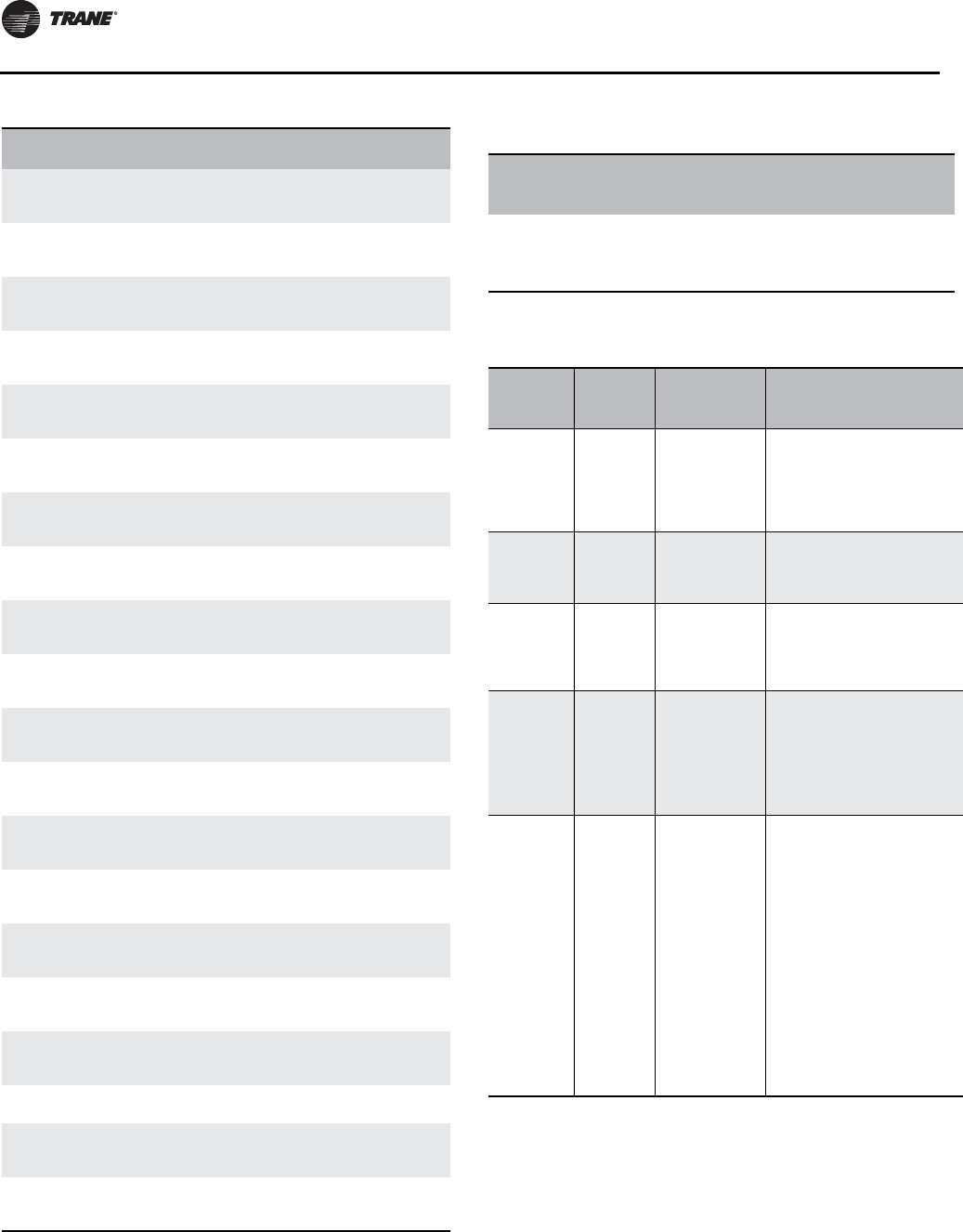
Installation - Electrical
120 RLC-SVX09H-EN
Analog
Input, 78
Line 2 Current
(in Amps)-
Compressor 2A
Line 2 Current (in
Amps)- Compressor
2A
Amps
Analog
Input, 79
Line 3 Current
(in Amps)-
Compressor 2A
Line 3 Current (in
Amps)- Compressor
2A
Amps
Analog
Input, 80
Line 1 Current
(in Amps)-
Compressor 2B
Line 1 Current (in
Amps)- Compressor
2B
Amps
Analog
Input, 81
Line 2 Current
(in Amps)-
Compressor 2B
Line 2 Current (in
Amps)- Compressor
2B
Amps
Analog
Input, 82
Line 3 Current
(in Amps)-
Compressor 2B
Line 3 Current (in
Amps)- Compressor
2B
Amps
Analog
Input, 83
Line 1 Current
(%RLA)-
Compressor 1A
Line 1 Current
(%RLA)-
Compressor 1A
Percent (98)
Analog
Input, 84
Line 2 Current
(%RLA)-
Compressor 1A
Line 2 Current
(%RLA)-
Compressor 1A
Percent (98
Analog
Input, 85
Line 3 Current
(%RLA)-
Compressor 1A
Line 3 Current
(%RLA)-
Compressor 1A
Percent (98)
Analog
Input, 86
Line 1 Current
(%RLA)-
Compressor 1B
Line 1 Current
(%RLA)-
Compressor 1B
Percent (98)
Analog
Input, 87
Line 2 Current
(%RLA)-
Compressor 1B
Line 2 Current
(%RLA)-
Compressor 1B
Percent (98)
Analog
Input, 88
Line 3 Current
(%RLA)-
Compressor 1B
Line 3 Current
(%RLA)-
Compressor 1B
Percent (98)
Analog
Input, 89
Line 1 Current
(%RLA)-
Compressor 2A
Line 1 Current
(%RLA)-
Compressor 2A
Percent (98)
Analog
Input, 90
Line 2 Current
(%RLA)-
Compressor 2A
Line 2 Current
(%RLA)-
Compressor 2A
Percent (98)
Analog
Input, 91
Line 3 Current
(%RLA)-
Compressor 2A
Line 3 Current
(%RLA)-
Compressor 2A
Percent (98)
Analog
Input, 92
Line 1 Current
(%RLA)-
Compressor 2B
Line 1 Current
(%RLA)-
Compressor 2B
Percent (98
Analog
Input, 93
Line 2 Current
(%RLA)-
Compressor 2B
Line 2 Current
(%RLA)-
Compressor 2B
Percent (98)
Analog
Input, 94
Line 3 Current
(%RLA)-
Compressor 2B
Line 3 Current
(%RLA)-
Compressor 2B
Percent (98)
Analog
Input, 95
Number of
Circuits Number of Circuits None
Analog
Input, 96
Number of
Compressors,
Ckt 1
Number of
Compressors, Ckt 1 None
Analog
Input, 97
Number of
Compressors,
Ckt 2
Number of
Compressors, Ckt 2 None
Table 100. Analog Input (continued)
Object
Identifier Object Name Description Units
Table 101. Multistate Output
Object
Identifier Object
Name Description
Relinq
Default Object States
Multi-State
Output, 1
Chiller
Mode
Command
Mode of
operation of
the chiller.
1 = Cool
1 = HVAC _Heat
2 = HVAC_Cool
3 = HVAC_Ice
4 = Not Used
Table 102. Multistate Input
BCI-C
Object
Identifier
Object
Name Description Object States
Multi-State
Input, 1
Running
Mode
Indicates the
primary
running mode
of the chiller.
1 = Chiller Off
2 = Chiller in Start Mode
3 = Chiller in Run Mode
4 = Chiller in Pre-shutdown
Mode
5 = Chiller in Service Mode
Multi-State
Input, 2
Operating
Mode
Indicates the
primary
operating mode
of the chiller.
1 = HVAC_Heat
2 = HVAC_Cool
3 = HVAC_Ice
4 = Not Used
Multi-State
Input, 3
MP Comm
Status
Communication
status.
1 = R-22
2 = Communication
3 = Communication Lost
4 = Failed to Established
5 = Waiting to Establish
Multi-State
Input, 4
Refrig
Type
Refrigerant
type.
1 = R-11
2 = R-12
3 = R-22
4 = R-123
5 = R-134A
6 = R407C
7 = R-410A
Multi-State
Input, 5 Model Info
Indicates the
model type of
the chiller.
1 = RTA
2 = CVH
3 = CVG
4 = CVR
5 = CDH
6 = RTH
7 = CGW
8 = CGA
9 = CCA
10 = RTW
11 = RTX
12 = RTU
13 = CCU
14 = CXA
15 = CGC
16 = RAU
Installation - Electrical
RLC-SVX09H-EN 121
Multi-State
Input, 6
Cooling
Type
Cooling type of
the condenser.
1 = Water Cooled
2 = Air Cooled
Multi-State
Input, 7
Manuf
Location
Location where
chiller was
manufactured.
1 = Field Applied
2 = La Crosse
3 = Pueblo
4 = Charmes
5 = Rushville
6 = Macon
7 = Waco
8 = Lexington
9 = Forsyth
10 = Clarksville
11 = Ft. Smith
12 = Penang
13 = Colchester
14 = Curitiba
15 = Taicang
16 = Taiwan
17 = Epinal
18 = Golbey
Table 103. Binary Output
Object
Identifier
Object
Name Description
Relinq
Default Object States
Binary
Output, 1
Chiller Auto
Stop
Command
Allows the
chiller to run if
conditions for
running are
met.
True Inactive = Stop
Active = Auto
Binary
Output, 2
Remote
Diagnostic
Reset
Command
Resets
remotely
diagnostics
that can be
reset.
False
Inactive = No
Reset Request
Active = Reset
Request
Binary
Output, 4
Noise
Reduction
Request
Requests
chiller to enter
mode to
reduce noise.
False
Inactive =
Normal
Active = Reduced
Noise
Table 104. Binary Input
Object
Identifier
Object
Name Description Object States
Binary
Input, 1
Run
Enabled
Indicates if the
chiller is available
to run or is
currently running.
Inactive = Stop
Active = Auto
Binary
Input, 2
Local
Setpoint
Control
Indicates if the
chiller is being
controlled by local
setpoints instead
of BAS setpoints.
Inactive =Remote Control
Active = Local Control
Binary
Input, 3
Capacity
Limited
Indicates if
conditions may
exist that prevent
the chiller from
reaching setpoint.
Inactive = Not Limited
Active = Limited
Table 102. Multistate Input (continued)
BCI-C
Object
Identifier
Object
Name Description Object States
Binary
Input, 4
Chiller
Running
State
Indicates if the
chiller is running
or stopped.
Inactive = Off
Active = On
Binary
Input, 5
Condenser
Water Flow
Status
Condenser water
flow status.
Inactive = No Flow
Active = Flow
Binary
Input, 6
Maximum
Capacity
Indicates if all
available chiller
capacity is being
used.
Inactive = Off
Active = On
Binary
Input, 7
Head Relief
Request
Indicates if the
chiller is asking an
outside system to
provide more heat
rejection from the
condenser water
loop.
Inactive = Off
Active = On
Binary
Input, 9
Compr 1A
Running
Indicates if
compressor 1A is
running.
Inactive = Off
Active = Running
Binary
Input, 10
Compr 1B
Running
Indicates if
compressor 1B is
running.
Inactive = Off
Active = Running
Binary
Input, 11
Compr 2A
Running
Indicates if
compressor 2A is
running.
Inactive = Off
Active = Running
Binary
Input, 12
Compr 2B
Running
Indicates if
compressor 2B is
running.
Inactive = Off
Active = Running
Binary
Input, 17
Evaporator
Water Pump
Request
Indicates a
request from the
chiller to turn on
the evaporator
water pump.
Inactive = Off
Active = On
Binary
Input, 19
Condenser
Water Pump
Request
Indicates a
request from the
chiller to turn on
the condenser
water pump.
Inactive = Off
Active = On
Binary
Input, 20
Noise
Reduction
Active
Indicates if the
chiller is in a state
where noise is
being reduced.
Inactive = Off
Active = On
Binary
Input, 22
Evaporator
Water Flow
Status
Indicates if water
is flowing through
the evaporator.
Inactive = No Flow
Active = Flow
Binary
Input, 23
Alarm
Present
Indicates if an
alarm is active.
Inactive = No Alarm
Active = Alarm
Binary
Input, 24
Shutdown
Alarm
Present
Indicates if a
shutdown alarm is
active.
Inactive = No Alarm
Active = None
Binary
Input, 25
Last
Diagnostic
Indicates last
diagnostic for the
chiller.
Inactive = Off
Active = On
Table 104. Binary Input (continued)
Object
Identifier
Object
Name Description Object States
Installation - Electrical
122 RLC-SVX09H-EN
Table 105. All ObjectTypes Sorted by Object Name (Refer to
previous tables for detailed descriptions of objects)
Object
Identifie
r(a) Object Name Description
Analog
Output 1
Chilled Water
Setpoint
Desired leaving water temperature
if chiller is in cooling mode.
Analog
Output 2
Current Limit
Setpoint
Sets the maximum capacity that the
chiller can use.
Analog
Output 4 Hot Water Setpoint Desired leaving water temperature
if chiller is in heating mode.
Analog
Input, 1
Active Cool/Heat
Setpoint
Temperature
Active chiller water or hot water
setpoint.
Analog
Input, 2
Active Current
Limit Setpoint
Active capacity current limit
setpoint.
Analog
Input, 5
Actual Running
Capacity
Level of capacity that the chiller is
currently running at.
Analog
Input, 7
Suction Pressure-
Ckt 1 Circuit 1 suction pressure.
Analog
Input, 10
Suction Pressure-
Ckt 2 Circuit 2 suction pressure.
Analog
Input, 12
Evaporator
Saturated
Refrigerant
Temperature- Ckt
1
Circuit 2 evaporator refrigerant
temperature.
Analog
Input, 14
Evaporator
Saturated
Refrigerant
Temperature- Ckt
2
Circuit 2 evaporator refrigerant
temperature.
Analog
Input, 16
Condenser
Refrigerant
Pressure- Ckt 1
Circuit 1 condenser refrigerant
pressure.
Analog
Input, 18
Condenser
Refrigerant
Pressure- Ckt 2
Circuit 2 condenser refrigerant
pressure.
Analog
Input, 20
Condenser
Saturated
Refrigerant
Temperature- Ckt
1
Circuit 1 condenser refrigerant
temperature.
Analog
Input, 22
Condenser
Saturated
Refrigerant
Temperature- Ckt
2
Circuit 2 condenser refrigerant
temperature.
Analog
Input, 24
Unit Power
Consumption
The power being consumed by the
chiller.
Analog
Input, 25
Local Atmospheric
Pressure Local atmospheric pressure.
Analog
Input, 26
Starts-
Compressor 1A Number of starts for compressor 1A.
Analog
Input, 27
Starts-
Compressor 1B Number of starts for compressor 1B.
Analog
Input, 28
Starts-
Compressor 2A Number of starts for compressor 2A.
Analog
Input, 29
Starts-
Compressor 2B Number of starts for compressor 2B.
Analog
Input, 34
Run Time-
Compressor 1A Total run time of compressor 1A.
Analog
Input, 35
Run Time-
Compressor 1B Total run time of compressor 1B.
Analog
Input, 36
Run Time-
Compressor 2A Total run time of compressor 2A.
Analog
Input, 37
Run Time-
Compressor 2B Total run time of compressor 2B.
Analog
Input, 42
Airflow
Percentage- Circuit
1
Approximate airflow percentage of
circuit 1.
Analog
Input, 43
Airflow
Percentage- Circuit
2
Approximate airflow percentage of
circuit 2.
Analog
Input, 44
Evaporator
Entering Water
Temp
Temperature of the water entering
the evaporator.
Analog
Input, 45
Evaporator Leaving
Water Temp
Temperature of the water leaving
the evaporator.
Analog
Input, 46
Condenser
Entering Water
Temp
Temperature of the water entering
the condenser.
Analog
Input, 47
Condenser Leaving
Water Temp
Temperature of the water leaving
the condenser.
Analog
Input, 48
High Side Oil
Pressure-
Compressor 1A
Pressure of the oil at the high side of
compressor 1A.
Analog
Input, 49
High Side Oil
Pressure-
Compressor 1B
Pressure of the oil at the high side of
compressor 1B.
Analog
Input, 50
High Side Oil
Pressure-
Compressor 2A
Pressure of the oil at the high side of
compressor 2A.
Analog
Input, 51
High Side Oil
Pressure-
Compressor 2B
Pressure of the oil at the high side of
compressor 2B.
Analog
Input, 56
Refrigerant Disch
Temp- Ckt 1
Temperature of the refrigerant
being discharged from Ckt 1.
Analog
Input, 57
Outdoor Air
Temperature Outdoor air temperature.
Analog
Input, 58
Condenser Control
Output
Percentage of condenser water flow
being requested by the chiller.
Analog
Input, 59
Phase AB Voltage-
Compressor 1A Phase AB voltage, compressor 1A.
Analog
Input, 60
Phase BC Voltage-
Compressor 1A Phase BC voltage, compressor 1A.
Analog
Input, 61
Phase CA Voltage-
Compressor 1A Phase CA voltage, compressor 1A.
Analo5
Input, 62
Phase AB Voltage-
Compressor 1B Phase AB voltage, compressor 1B.
Analog
Input, 63
Phase BC Voltage-
Compressor 1B Phase BC voltage, compressor 1B.
Analog
Input, 64
Phase CA Voltage-
Compressor 1B Phase CA voltage, compressor 1B.
Analog
Input, 65
Phase AB Voltage-
Compressor 2A Phase AB voltage, compressor 2A.
Analog
Input, 66
Phase BC Voltage-
Compressor 2A Phase BC voltage, compressor 2A.
Analog
Input, 67
Phase CA Voltage-
Compressor 2A Phase CA voltage, compressor 2A.
Table 105. All ObjectTypes Sorted by Object Name (Refer to
previous tables for detailed descriptions of objects)
Object
Identifie
r(a) Object Name Description
Installation - Electrical
RLC-SVX09H-EN 123
Analog
Input, 68
Phase AB Voltage-
Compressor 2B Phase AB voltage, compressor 2B.
Analog
Input, 69
Phase BC Voltage-
Compressor 2B Phase BC voltage, compressor 2B.
Analog
Input, 70
Phase CA Voltage-
Compressor 2B Phase CA voltage, compressor 2B
Analog
Input, 71
Line 1 Current (in
Amps)-
Compressor 1A
Line 1 Current (in Amps)-
Compressor 1A
Analog
Input, 72
Line 2 Current (in
Amps)-
Compressor 1A
Line 2 Current (in Amps)-
Compressor 1A
Analog
Input, 73
Line 3 Current (in
Amps)-
Compressor 1A
Line 3 Current (in Amps)-
Compressor 1A
Analog
Input, 74
Line 1 Current (in
Amps)-
Compressor 1B
Line 1 Current (in Amps)-
Compressor 1B
Analog
Input, 75
Line 2 Current (in
Amps)-
Compressor 1B
Line 2 Current (in Amps)-
Compressor 1B
Analog
Input, 76
Line 3 Current (in
Amps)-
Compressor 1B
Line 3 Current (in Amps)-
Compressor 1B
Analog
Input, 77
Line 1 Current (in
Amps)-
Compressor 2A
Line 1 Current (in Amps)-
Compressor 2A
Analog
Input, 78
Line 2 Current (in
Amps)-
Compressor 2A
Line 2 Current (in Amps)-
Compressor 2A
Analog
Input, 79
Line 3 Current (in
Amps)-
Compressor 2A
Line 3 Current (in Amps)-
Compressor 2A
Analog
Input, 80
Line 1 Current (in
Amps)-
Compressor 2B
Line 1 Current (in Amps)-
Compressor 2B
Analog
Input, 81
Line 2 Current (in
Amps)-
Compressor 2B
Line 2 Current (in Amps)-
Compressor 2B
Analog
Input, 82
Line 3 Current (in
Amps)-
Compressor 2B
Line 3 Current (in Amps)-
Compressor 2B
Analog
Input, 83
Line 1 Current
(%RLA)-
Compressor 1A
Line 1 Current (%RLA)- Compressor
1A
Analog
Input, 84
Line 2 Current
(%RLA)-
Compressor 1A
Line 2 Current (%RLA)- Compressor
1A
Analog
Input, 85
Line 3 Current
(%RLA)-
Compressor 1A
Line 3 Current (%RLA)- Compressor
1A
Analog
Input, 86
Line 1 Current
(%RLA)-
Compressor 1B
Line 1 Current (%RLA)- Compressor
1B
Analog
Input, 87
Line 2 Current
(%RLA)-
Compressor 1B
Line 2 Current (%RLA)- Compressor
1B
Analog
Input, 88
Line 3 Current
(%RLA)-
Compressor 1B
Line 3 Current (%RLA)- Compressor
1B
Table 105. All ObjectTypes Sorted by Object Name (Refer to
previous tables for detailed descriptions of objects)
Object
Identifie
r(a) Object Name Description
Analog
Input, 89
Line 1 Current
(%RLA)-
Compressor 2A
Line 1 Current (%RLA)- Compressor
2A
Analog
Input, 90
Line 2 Current
(%RLA)-
Compressor 2A
Line 2 Current (%RLA)- Compressor
2A
Analog
Input, 91
Line 3 Current
(%RLA)-
Compressor 2A
Line 3 Current (%RLA)- Compressor
2A
Analog
Input, 92
Line 1 Current
(%RLA)-
Compressor 2B
Line 1 Current (%RLA)- Compressor
2B
Analog
Input, 93
Line 2 Current
(%RLA)-
Compressor 2B
Line 2 Current (%RLA)- Compressor
2B
Analog
Input, 94
Line 3 Current
(%RLA)-
Compressor 2B
Line 3 Current (%RLA)- Compressor
2B
Analog
Input, 95 Number of Circuits Number of Circuits
Analog
Input, 96
Number of
Compressors, Ckt 1 Number of Compressors, Ckt 1
Analog
Input, 97
Number of
Compressors, Ckt 2 Number of Compressors, Ckt 2
Multi-
State
Input, 1
Running Mode Indicates the primary running mode
of the chiller.
Multi-
State
Input, 2
Operating Mode Indicates the primary operating
mode of the chiller.
Multi-
State
Input, 3
MP Communication
Status Communication status.
Multi-
State
Input, 4
Refrigerant Type Refrigerant type.
Multi-
State
Input, 5
Model Information Indicates the model type of the
chiller.
Multi-
State
Input, 6
Cooling Type Cooling type of the condenser.
Multi-
State
Input, 7
Manufacturing
Location
Location where chiller was
manufactured.
Binary
Output, 1
Chiller Auto Stop
Command
Allows the chiller to run if conditions
for running are met.
Binary
Output, 2
Remote Diagnostic
Reset Command
Resets remotely diagnostics that
can be reset.
Binary
Output, 4
Noise Reduction
Request
Requests chiller to enter mode to
reduce noise.
Binary
Output, 1
Chiller Auto Stop
Command
Allows the chiller to run if conditions
for running are met.
Binary
Input, 1 Run Enabled Indicates if the chiller is available to
run or is currently running.
Binary
Input, 2
Local Setpoint
Control
Indicates if the chiller is being
controlled by local setpoints instead
of BAS setpoints.
Table 105. All ObjectTypes Sorted by Object Name (Refer to
previous tables for detailed descriptions of objects)
Object
Identifie
r(a) Object Name Description
Installation - Electrical
124 RLC-SVX09H-EN
BCI-C Alarming
The BCI-C unit has three binary input points used to
communicate alarms and one binary output point used to
reset alarms remotely.Those inputs and output points are:
BI 23; Alarm Present. •This object indicates if any
alarms are active regardless of severity. A notification
will be sent to any recipients of the Information
Notification Class object when the point transitions
from No Alarm to Alarm.
BI 24; Shutdown Alarm Present. •This object
indicates if any alarms that result in the shutdown of
the chiller are active. A notification will be sent to any
recipients of the Critical Notification Class object when
the point transitions from No Alarm to Alarm.
BI 25; Last Diagnostic. •The active text of this object
will reflect the description of the last diagnostic to
occur on the chiller.
BO 2; Remote Diagnostic Reset Command. •This
object is used to remotely reset diagnostics on the
chiller. Immediately after commanding this point value
to 1, the BCI-C will send the reset command to the
chiller and set this point value back to 0 and clear the
priority array.
Note: Not all diagnostics are able to be reset remotely.
Some will require local reset at the chiller front
panel.
Binary
Input, 3 Capacity Limited
Indicates if conditions may exist
that prevent the chiller from
reaching setpoint.
Binary
Input, 4
Chiller Running
State
Indicates if the chiller is running or
stopped.
Binary
Input, 5
Condenser Water
Flow Status Condenser water flow status.
Binary
Input, 6 Maximum Capacity Indicates if all available chiller
capacity is being used.
Binary
Input, 7
Head Relief
Request
Indicates if the chiller is asking an
outside system to provide more
heat
Binary
Input, 9
Compressor 1A
Running
Indicates if compressor 1A is
running.
Binary
Input, 10
Compressor 1B
Running
Indicates if compressor 1B is
running.
Binary
Input, 11
Compressor 2A
Running
Indicates if compressor 2A is
running.
Binary
Input, 12
Compressor 2B
Running
Indicates if compressor 2B is
running.
Binary
Input, 17
Evaporator Water
Pump Request
Indicates a request from the chiller
to turn on the evaporator water
pump.
Binary
Input, 19
Condenser Water
Pump Request
Indicates a request from the chiller
to turn on the condenser water
pump.
Binary
Input, 20
Noise Reduction
Active
Indicates if the chiller is in a state
where noise is being reduced.
Binary
Input, 22
Evaporator Water
Flow Status
Indicates if water is flowing through
the evaporator.
Binary
Input, 23 Alarm Present Indicates if an alarm is active.
Binary
Input, 24
Shutdown Alarm
Present
Indicates if a shutdown alarm is
present.
Binary
Input, 25 Last Diagnostic Indicates the last diagnostic for the
chiller.
(a) AI=Analog Input, AO=Analog Output, AV=Analog Value, BI=Binary In-
put, BO=Binary Output, MI=Multistate Input, MO=Multistate Output
Table 105. All ObjectTypes Sorted by Object Name (Refer to
previous tables for detailed descriptions of objects)
Object
Identifie
r(a) Object Name Description
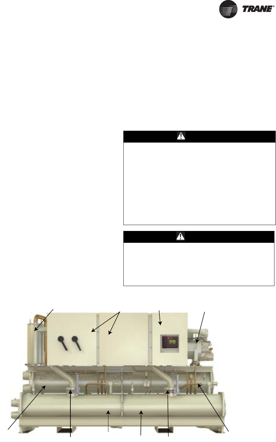
RLC-SVX09H-EN 125
RTWD/RTUD Operating Principles
This section contains an overview of the operation of
RTWD Series R chillers equipped with microcomputer-
based control systems. It describes the overall operating
principles of the RTWD water chiller.
Note: To ensure proper diagnosis and repair, contact a
qualified service organization if a problem should
occur.
General
RTWD
The Model RTWD units are dual-compressor, dual circuit,
water-cooled liquid chillers.These units are equipped with
unit-mounted starter/control panels.The basic
components of an RTWD unit are:
• Unit-mounted panel containing starter andTracer
CH530 controller and Input/Output LLIDS
• Helical-rotary compressors
• Evaporator
• Condenser
• Electronic expansion valves
• Water-cooled condenser with integral subcooler
• Oil supply system
• Oil cooler (application dependent)
• Related interconnecting piping.
RTUD
The Model RTUD units are dual compressor, dual circuit
compressor chillers.These units are equipped with unit
mounted starter/control panel.The basic components of
an RTUD unit are:
• Unit-mounted panel containing starter and tracer
CH530 controller and Input/Output LLIDs
• Helical-rotary compressors
• Evaporator
• Electronic expansion valves
• Oil supply system
• Oil cooler
• Related interconnecting piping
Components of a typical unit are identified in Figure 46
and Figure 47, p. 126.
WARNING
Refrigerant under High Pressure! (RTWD
Only)
System contains oil and refrigerant under high
pressure. Recover refrigerant to relieve pressure before
opening the system. See unit nameplate for refrigerant
type. Do not use non-approved refrigerants, refrigerant
substitutes, or refrigerant additives. Failure to recover
refrigerant to relieve pressure or the use of non-
approved refrigerants, refrigerant substitutes, or
refrigerant additives could result in an explosion which
could result in death or serious injury or equipment
damage.
WARNING
Hazardous Voltage!
Disconnect all electric power, including remote
disconnects before servicing. Follow proper lockout/
tagout procedures to ensure the power can not be
inadvertently energized. Failure to disconnect power
before servicing could result in death or serious injury.
Figure 46. RTWD/RTUD components (front view)
Control Panel
Suct
i
o
n
Se
rvi
ce
V
a
lv
e
Evaporator Circuit 1
Eva
p
orator Circuit 2
Oil Separator Circuit 1 Compressor B
Condenser Circuit 1
(RTWD only)
Condenser Circuit 2
(RTWD only)
Suction Service Valve
Starter Panel
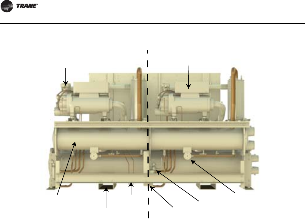
RTWD/RTUD Operating Principles
126 RLC-SVX09H-EN
Refrigeration (Cooling) Cycle
Overview
The refrigeration cycle of the Series R chiller is
conceptually similar to that of otherTrane chiller products.
It makes use of a shell-and-tube evaporator design with
refrigerant evaporating on the shell side and water flowing
inside tubes having enhanced surfaces.
The compressor is a twin-rotor helical rotary type. It uses
a suction gas-cooled motor that operates at lower motor
temperatures under continuous full and part load
operating conditions. An oil management system
provides an almost oil-free refrigerant to the shells to
maximize heat transfer performance, while providing
lubrication and rotor sealing to the compressor. The
lubrication system ensures long compressor life and
contributes to quiet operation.
For RTWD units, condensing is accomplished in a shell-
and-tube heat exchanger where refrigerant is condensed
on the shell side and water flows internally in the tubes.
For RTUD units, condensing is accomplished in a remote
air-cooled condenser unit.The refrigerant flows through
the tubes in the condenser. Air flows over the coils in the
condenser, removing the heat and condensing the
refrigerant.
Refrigerant is metered through the flow system using an
electronic expansion valve, that maximizes chiller
efficiency at part load.
A unit-mounted starter and control panel is provided on
every chiller. Microprocessor-based unit control modules
(Tracer CH530) provide for accurate chilled water control
as well as monitoring, protection and adaptive limit
functions.The “adaptive” nature of the controls
intelligently prevents the chiller from operating outside of
its limits, or compensates for unusual operating
conditions, while keeping the chiller running rather than
simply tripping due to a safety concern. When problems
do occur, diagnostic messages assist the operator in
troubleshooting.
Cycle Description
The refrigeration cycle for the RTWD/RTUD chiller can be
described using the pressure-enthalpy diagram shown in
Figure 48, p. 127. Key State Points are indicated on the
figure and are referenced in the discussion following. A
schematic of the system showing the refrigerant flow loop
as well as the lubricant flow loop is shown in
Figure 47. RTWD/RTUD components (back view)
Circuit 2 Circuit 1
Discharge Service Valve Compressor Junction Box
Refrigerant Filter
Liquid Level Sensor
Oil Cooler (optional on RTWD)
Gas Pump
(behind frame)
Base rail for forklifting
(optional)
Condenser
(RTWD only)
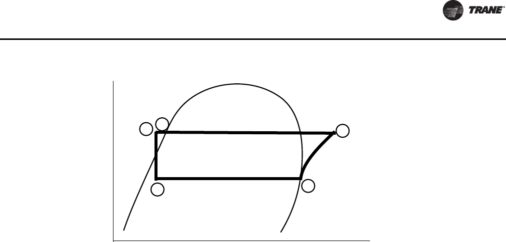
RTWD/RTUD Operating Principles
RLC-SVX09H-EN 127
Evaporation of refrigerant occurs in the evaporator. A
metered amount of refrigerant liquid enters a distribution
system in the evaporator shell and is then distributed to
the tubes in the evaporator tube bundle.The refrigerant
absorbs heat and vaporizes as it cools the water flowing
through the evaporator tubes. Refrigerant vapor leaves
the evaporator as saturated vapor (State Pt. 1).
The refrigerant vapor generated in the evaporator flows to
the suction end of the compressor where it enters the
motor compartment of the suction-gas-cooled motor.The
refrigerant flows across the motor, providing the
necessary cooling, then enters the compression chamber.
Refrigerant is compressed in the compressor to discharge
pressure conditions. Simultaneously, lubricant is injected
into the compressor for two purposes: (1) to lubricate the
rolling element bearings, and (2) to seal the very small
clearances between the compressor’s twin rotors.
Immediately following the compression process the
lubricant and refrigerant are effectively divided using an
oil separator. The oil-free refrigerant vapor enters the
condenser at State Pt. 2.The lubrication and oil
management issues are discussed in more detail in the
compressor description and oil management sections that
follow.
For RTWD units, a discharge baffle within the condenser
shell distributes the compressed refrigerant vapor evenly
across the condenser tube bundle. Cooling tower water,
circulating through the condenser tubes, absorbs heat
from this refrigerant and condenses it.
For RTUD units, air flows across the condenser coils,
absorbing heat from the refrigerant and condenses it.
As the refrigerant enters the bottom of the condenser
(State Pt. 3), it enters an integral subcooler where it is
subcooled before traveling to the electronic expansion
valve (State Pt. 4).The pressure drop created by the
expansion process vaporizes a portion of the liquid
refrigerant.The resulting mixture of liquid and gaseous
refrigerant then enters the Evaporator Distribution system
(State Pt. 5).The flash gas from the expansion process is
internally routed to compressor suction, and while the
liquid refrigerant is distributed over the tube bundle in the
evaporator.
The RTWD/RTUD chiller maximizes the evaporator heat
transfer performance while minimizing refrigerant charge
requirements.This is accomplished by metering the liquid
refrigerant flow to the evaporator’s distribution system
using the electronic expansion valve. A relatively low
liquid level is maintained in the evaporator shell, which
contains a bit of surplus refrigerant liquid and
accumulated lubricant. A liquid level measurement device
monitors this level and provides feedback information to
the CH530 unit controller, which commands the electronic
expansion valve to reposition when necessary. If the level
rises, the expansion valve is closed slightly, and if the level
is dropping, the valve is opened slightly such that a steady
level is maintained.
Figure 48. Pressure enthalpy curve
Pressure
Enthalpy
Liquid
Gas
1
2
3
4
5

RTWD/RTUD Operating Principles
128 RLC-SVX09H-EN
Figure 49. RTWD/RTUD refrigerant chart
1
2
34
56
7
8
9
10 11
12
13
14
15
16
17
18
19
31
21
22
23
24
25
26
27
28
29
30
33
32
34
20
36
35
1 Compressor - Circuit 1 13 Refrigerant Filter - Circuit 2 25 Evaporator Leaving Water Temperature
Sensor
2 High Pressure Cutout Switch 14 Condenser Entering Water Temperature
Sensor (RTWD only) 26 Evaporator Water Flow Switch
3Compressor Discharge Temperature
Sensor 15 Condenser Leaving Water Temperature
Sensor (RTWD only) 27 Gas Pump Drain Solenoid Valve
4Condenser Refrigerant Pressure
Transducer 16 Condenser Water Flow Switch (RTWD
only) 28 Gas Pump Fill Solenoid Valves
5 Load/Unload and Step Solenoids 17 Evaporator - Circuit 2 29 Suction Pressure Transducer
6 Oil Separator - Circuit 1 18 Evaporator - Circuit 1 30 Oil Pressure Transducer
7 Oil Heater 19 EXV - Circuit 2 31 Suction Service Valve
8 Optical Oil Loss Level Sensor 20 EXV - Circuit 1 32 Check Valve
9 Oil Cooler (optional on RTWD) 21 Liquid Level Sensor - Circuit 2 33 Filter
10 Condenser - Circuit 1 (RTWD only) 22 Liquid Level Sensor - Circuit 1 34 Condenser Service Valve
11 Condenser - Circuit 2 (RTWD only) 23 Gas Pump - Circuit 1 35 Liquid Line Isolation Valve - Circuit 1
(RTWD only)(a)
12 Refrigerant Filter - Circuit 1 24 Evaporator Entering Water Temperature
Sensor 36 Liquid Line Isolation Valve - Circuit 2
(RTWD only)(a)
(a) RTUD units do NOT ship with a factory installed liquid line isolation valve. A liquid line isolation valve must be field installed.

RTWD/RTUD Operating Principles
RLC-SVX09H-EN 129
Oil System Operation (RTWD/RTUD)
Overview
Oil that collects in the bottom of the oil separator is at
condensing pressure during compressor operation;
therefore, oil is constantly moving to lower pressure areas.
As the oil leaves the separator, it passes through the oil
cooler (if installed). It then goes through the service valve
and filter. At this point it travels through the oil control
valve.Then it provides oil injection and bearing
lubrication.
If the compressor stops for any reason, the oil control
valve closes, isolating the oil charge in the separator and
oil cooler during off periods.The master oil valve is a
pressure activated valve. Discharge pressure off the
rotors, that is developed when the compressor is on,
causes the valve to open.
Compressor Motor
A two-pole, hermetic, induction motor (3600 rpm at 60 hz,
3000 rpm at 50hz) directly drives the compressor rotors.
The motor is cooled by suction refrigerant gas from the
evaporator, entering the end of the motor housing through
the suction line.
Compressor Rotors
Each compressor has two rotors - “male” and “female” -
which provide compression. See Figure 51, p. 130 .The
male rotor is attached to, and driven by, the motor, and the
female rotor is, in turn, driven by the male rotor.
Separately housed bearing sets are provided at each end
of both rotors.
Figure 50. RTWD/RTUD oil system
EXV
Evaporator
Manual
Service
Valve
Oil Cooler
(optional on RTWD)
Compressor Oil
Separator
Gas Pump
Oil Return System
Bearing and Rotor
Restrictors and
Oil injection
Condenser
Condenser
Refrigerant
Pressure
Transduce r
P
C
Oil Pressure
Transduce r
Po
Evaporator
Refrigerant
Pressure
Transduce r
P
E
Primary Oil System
Refrigerant & Oil Mixture
(refrigerant vapor and oil)
Oil Recovery System
(liquid refrigerant and oil)
Refrigerant with
small amount of Oil
KEY
Compressor Discharge
Temperature Sensor
Internal
Compressor
Oil Filter
Oil Separator
Sump Heater
Compressor
Heater
Optical Oil Eye
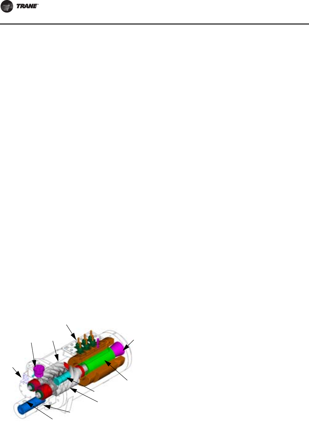
RTWD/RTUD Operating Principles
130 RLC-SVX09H-EN
The helical rotary compressor is a positive displacement
device.The refrigerant from the evaporator is drawn into
the suction opening at the end of the motor barrel, through
a suction strainer screen, across the motor, and into the
intake of the compressor rotor section.The gas is then
compressed and discharged directly into the discharge
line.
There is no physical contact between rotors and
compressor housing. Rotors contact each other at the
point where the driving action between male and female
rotors occurs. Oil is injected along top of compressor rotor
section, coating both rotors and compressor housing
interior. Although this oil does provide rotor lubrication, its
primary purpose is to seal the clearance spaces between
rotors and compressor housing.
A positive seal between these internal parts enhances
compressor efficiency by limiting leakage between the
high pressure and low pressure cavities.
Oil Filter
Each compressor is equipped with a replaceable element
oil filter.The filter removes any impurities that could foul
the solenoid valve orifices and compressor internal oil
supply galleries.This also prevents excessive wear of
compressor rotor and bearing surfaces.
Compressor Rotor Oil Supply
Oil flows through this circuit directly from the oil filter,
through the master oil valve to the top of the compressor
rotor housing.There it is injected along the top of the
rotors to seal clearance spaces between the rotors and the
compressor housing and to lubricate the rotors.
Compressor Bearing Oil Supply
Oil is injected into the bearing housings located at each
end of both the male and female rotors. Each bearing
housing is vented to compressor suction, so that oil
leaving the bearings returns through the compressor
rotors to the oil separator.
Oil Separator
The oil separator consists of a vertical tube, joined at the
top by the refrigerant discharge line from the compressor.
This causes the refrigerant to swirl in the tube and throws
the oil to the outside, where it collects on the walls and
flows to the bottom.The compressed refrigerant vapor,
stripped of oil droplets, exits out the top of the oil
separator and is discharged into the condenser.
Compressor Loading Sequence
The customer has the option to choose either Fixed
Sequence or Balanced Start and Hours.
Fixed Sequence. When Balanced Starts and Hours is
disabled, the controls will operate with Fixed Sequence
compressor loading. Whichever compressor that is
selected to be the lead compressor will start first on a
command for cooling, unless it is locked out. Compressors
will be unstepped and stopped in reverse order.
Balanced Starts and Hours. When Balanced Starts
and Hours option is enabled, the controls will start the
compressor with the lowest Start Bid, defined as:
Compressor X Start Bid =
(# of Starts for Compressor X) +
(Accumulated Running hours for CompressorX/10)
If the compressor with the lowest Start Bid is unavailable
due to a circuit lockout, circuit diagnostic, or compressor
diagnostic, the compressor with the next lowest Start Bid
will be started.
Once compressors are running, and demand is decreased,
the compressor to unstage or turn off next will be, in order
of priority:
1. Any compressor running at minimum load.
2. The compressor with the greatest hours.
Figure 51. RTWD/RTUD compressor
Suction
Strainer
Motor
Rotor
Motor Terminals
Discharge
Check Valve
Male Unloader
Oil Filter
Female
Oil Control Valve (hidden)
Male Rotor
Female
Rotor
Piston
Unloader
Piston

RLC-SVX09H-EN 131
Controls Interface
CH530 Communications
Overview
TheTrane CH530 control system that runs the chiller
consists of several elements:
• The main processor collects data, status, and
diagnostic information and communicates commands
to the starter module and the LLID (for Low Level
Intelligent Device) bus.The main processor has an
integral display (DynaView) with a built in serial port.
• Low level intelligent device (LLID) bus.The main
processor communicates to each input and output
device (e.g. temperature and pressure sensors, low
voltage binary inputs, analog input/output) all
connected to a four-wire bus, rather than the
conventional control architecture of signal wires for
each device.
• The communication interface to a building automation
system (BAS).
• A service tool to provide all service/maintenance
capabilities.
Main processor and service tool (TechView) software is
downloadable from www.trane.com.The process is
discussed later in this section underTechView Interface.
DynaView provides bus management. It has the task of
restarting the link, or filling in for what it sees as“missing”
devices when normal communications has been
degraded. Use ofTechView may be required.
The CH530 uses the IPC3 protocol based on RS485 signal
technology and communicating at 19.2 Kbaud to allow 3
rounds of data per second on a 64-device network. A
typical RTWD/RTUD chiller will have around 40 devices,
depending upon its configuration.
Most diagnostics are handled by the DynaView. If a
temperature or pressure is reported out of range by a LLID,
the DynaView processes this information and calls out the
diagnostic.The individual LLIDs are not responsible for
any diagnostic functions.
Note: It is imperative that the CH530 ServiceTool
(TechView) be used to facilitate the replacement of
any LLID or reconfigure any chiller component.
TechView is discussed later in this section.
Note: For definition of terms, see Service
Document section ofTechview, or selection
icon button next to setpoint title.
Controls Interface
DynaView
Each chiller is equipped with a DynaView interface.The
DynaView has the capability to display information to the
operator including the ability to adjust settings. Multiple
screens are available and text is presented in multiple
languages as factory-ordered or can be easily downloaded
from www.trane.com.
The DynaView enclosure design is weatherproof and
made of durable plastic for use as a device on the outside
of the unit.
The display on DynaView is a 1/4 VGA display with a
resistive touch screen and an LED backlight.The display
area is approximately 4 inches wide by 3 inches high
(102mm x 60mm).
Key Functions
In this touch screen application, key functions are
determined completely by software and change
depending upon the subject matter currently being
displayed.The basic touch screen functions are outlined
below.
Radio Buttons
Radio buttons show one menu choice among two or more
alternatives, all visible. (It is the AUTO button in.)The radio
button model mimics the buttons used on old-fashioned
radios to select stations.When one is pressed, the one that
was previously pressed “pops out” and the new station is
selected. In the DynaView model the possible selections
are each associated with a button.The selected button is
darkened, presented in reverse video to indicate it is the
selected choice.The full range of possible choices as well
as the current choice is always in view.
Spin Value Buttons
Spin values are used to allow a variable setpoint to be
changed, such as leaving water setpoint.The value
increases or decreases by touching the increment (+) or
decrement (-) arrows.
Action Buttons
Action buttons appear temporarily and provide the user
with a choice such as Enter or Cancel.
Hot Links
Hot links are used to navigate from one view to another
view.
File Folder Tabs
File folder tabs are used to select a screen of data. Just like
tabs in a file folder, these serve to title the folder/screen
selected, as well as provide navigation to other screens. In
DynaView, the tabs are in one row across the top of the
display.The folder tabs are separated from the rest of the
display by a horizontal line.Vertical lines separate the tabs
from each other.The folder that is selected has no
horizontal line under its tab, thereby making it look like a
part of the current folder (as would an open folder in a file
cabinet).The user selects a screen of information by
touching the appropriate tab.
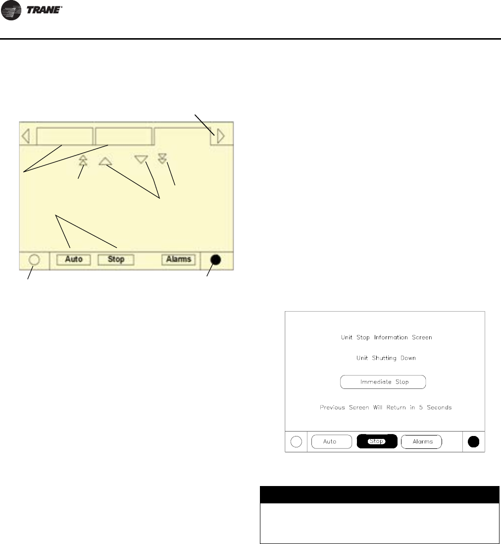
Controls Interface
132 RLC-SVX09H-EN
Display Screens
Basic Screen Format
The basic screen format appears as:
The file folder tabs across the top of the screen are used to
select the various display screens.
Scroll arrows are added if more file tabs (choices) are
available. When the tabs are at the left most position, the
left navigator will not show and only navigation to the right
will be possible. Likewise when the right most screen is
selected, only left navigation will be possible.
The main body of the screen is used for description text,
data, setpoints, or keys (touch sensitive areas).The Chiller
Mode is displayed here.
The double up arrows cause a page-by-page scroll either
up or down.The single arrow causes a line by line scroll to
occur. At the end of the page, the appropriate scroll bar will
disappear.
A double arrow pointing to the right indicates more
information is available about the specific item on that
same line. Pressing it will bring you to a subscreen that will
present the information or allow changes to settings.
The bottom of the screen (Fixed Display) is present in all
screens and contains the following functions.The left
circular area is used to reduce the contrast/viewing angle
of the display. The right circular area is used to increase
the contrast/viewing angle of the display. The contrast
may require re-adjustment at ambient temperatures
significantly different from those present at last
adjustment.
The other functions are critical to machine operation.The
AUTO and STOP keys are used to enable or disable the
chiller.The key selected is in black (reverse video).The
chiller will stop when the STOP key is touched and after
completing the Shutting Down mode.
Touching the AUTO key will enable the chiller for active
cooling if no diagnostic is present. (A separate action must
be taken to clear active diagnostics.)
The AUTO and STOP keys, take precedence over the Enter
and Cancel keys. (While a setting is being changed, AUTO
and STOP keys are recognized even if Enter or Cancel has
not been pressed.)
The ALARMS button appears only when an alarm is
present, and blinks (by alternating between normal and
reverse video) to draw attention to a diagnostic condition.
Pressing the ALARMS button takes you to the
corresponding tab for additional information.
Auto, Stop/Immediate Stop
The Auto and Stop keys will be presented as radio buttons
within the persistent key display area.The selected key
will be black.
The chiller will stop when the Stop key is touched, entering
the Run Unload mode. An informational screen will be
displayed for 5 seconds indicating that a second
depression of an “Immediate Stop” key during this time
period will result in an immediate stop. Pressing the
“Immediate Stop” key while the immediate stop screen is
displayed, will cause the unit to stop immediately,
skipping normal shutdown.
Touching theAuto key will arm the chiller for active cooling
if no diagnostic is present. As in UCP2, a separate action
must be taken to clear active diagnostics.
The AUTO and STOP, take precedence over the ENTER and
CANCEL keys. (While a setting is being changed, AUTO
and STOP keys are recognized even if ENTER or CANCEL
has not been pressed.
Diagnostic Annunciation
When an active diagnostic is present, an Alarms key will be
added to the persistent display area.This key will serve
two purposes.The first purpose will be to alert the
Contrast control (lighter)
Tab navigator
Tabs
File folder
Radio buttons
Line scroll
Page scroll
(up (down)
Contrast control (darker)
Page scroll
(down)
(up)
NOTICE:
Equipment Damage!
Do NOT enable/disable the chiller by removing water
flow or equipment damage can occur
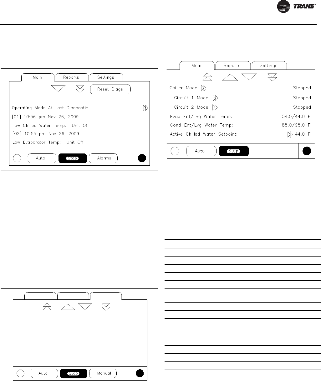
Controls Interface
RLC-SVX09H-EN 133
operator that a diagnostic exists.The second purpose is to
provide navigation to a diagnostic display screen.
Note: A complete listing of diagnostics and codes is
included in the Diagnostic Section.
Manual Override Exists
An indicator to present the presence of a manual override
will share space with the Alarms enunciator key. While a
manual override exists, the space used for the Alarms key
will be occupied by a “Manual” icon, that will display solid
inverse color similar to the appearance of the Alarms
enunciator. An Alarm will take precedence of the Manual,
until the reset of active alarms, at which point the Manual
indicator would re-appear if such an override exists.
If the Manual indicator is pressed, the Manual Control
Settings screen will be displayed.
Main Screen
The Main screen is a “dashboard” of the chiller. High level
status information is presented so that a user can quickly
understand the mode of operation of the chiller.
The Chiller Operating Mode will present a top level
indication of the chiller mode (i.e. Auto, Running, Inhibit,
Run Inhibit, etc.).The “additional info” icon will present a
subscreen that lists in further detail the subsystem modes.
The Main screen shall be the default screen. After an idle
time of 30 minutes the CH530 shall display the Main screen
with the first data fields.
The remaining items (listed in the following table) will be
viewed by selecting the up/down arrow icons.
Chiller Operating Mode
The machine-operating mode indicates the operational
status of the chiller. A subscreen with additional mode
summary information will be provided by selection of an
additional information icon (>>).The operating mode line
will remain stationary while the remaining status items
scroll with the up/down arrow keys.
Figure 52. Diagnostic screen
Table 106. Main screen data fields table
Description Units Resolution
Chiller Mode (>> submodes) enumeration
Circuit 1 Mode (>> submodes) enumeration
Circuit 2 Mode (>> submodes) enumeration
Evap Ent (Lvg Water Temp F/C 0.1
Cond Ent (Lvg Water Temp F/C 0.1
Active Chilled Water Setpoint
(>>source) F/C 0.1
Active Hot Water Setpoint (>>source) F/C 0.1
Average Line Current %RLA 1
Active Current Limit Setpoint
(>>source) F/C 0.1
Active Ice Termination Setpoint
(>>front panel setpoint) F/C 0.1
Outdoor Air Temperature F/C 0.1
Software Type enumeration RTWD/UD
Software Version X.XX
Controls Interface
134 RLC-SVX09H-EN
Table 107. Chiller mode
Chiller Modes Description
Top Level Mode Further information is provided by the submode
Sub-modes
Stopped The chiller is not running either circuit, and cannot run without intervention.
Stopped Sub-modes
Local Stop Chiller is stopped by DynaView Stop button command- cannot be remotely
overridden.
Immediate Stop
Chiller is stopped by the DynaView Immediate Stop (by pressing Stop button
then Immediate Stop buttons in succession) - previous shutdown was manually
commanded to shutdown immediately without a run-unload or pumpdown cycle
- cannot be remotely overridden.
No Circuits Available The entire chiller is stopped by circuit diagnostics or lockouts that may
automatically clear.
Diagnostic Shutdown - Manual Reset The chiller is stopped by a diagnostic that requires manual intervention to reset.
Cond Pmp Strt Dly (Head Pres Ctrl) min:sec
Only possible when Condenser Head Pressure Control option is enabled and the
condenser pump is being manually commanded to run. This wait may be
necessary due to the Head Pressure control device’s stroke time.
Run Inhibit The chiller is currently being inhibited from starting (running), but may be
allowed to start if the inhibiting or diagnostic condition is cleared.
Run Inhibit Sub-modes
No Circuits Available The entire chiller is stopped by circuit diagnostics or lockouts that may
automatically clear.
Ice Building Is Complete
The chiller is inhibited from running as the Ice Building process has been normally
terminated on the evaporator entering temperature. The chiller will not start
unless the ice building command (hardwired input or Building Automation
System command) is removed or cycled.
Ice to Normal Transition
The chiller is inhibited from running for a brief period of time if it is commanded
from active ice building mode into normal cooling mode via the ice building
hardwired input or Tracer. This allows time for the external system load to
"switchover" from an ice bank to the chilled water loop, and provides for a
controlled pull down of the loop's warmer temperature. This mode is not seen if
the ice making is automatically terminated on return brine temperature per the
mode below.
Start is Inhibited by BAS (Building Automation System) Chiller is stopped by Tracer or other BAS system.
Start is Inhibited by External Source The chiller is inhibited from starting (and running) by the "external stop"
hardwired input.
Diagnostic Shutdown - Auto Reset The entire chiller is stopped by a diagnostic that may automatically clear.
Waiting for BAS Communications (to Establish Operating
Status)*
The chiller is inhibited because of lack of communication with the BAS. This is
only valid 15 minutes after power up.
Start is Inhibited by Low Ambient Temp
The chiller is inhibited from starting (and running) by an outdoor air ambient
temperature lower than a specified temperature - per user adjustable settings
and can be disabled.
Start is Inhibited by Low Condenser Temperature The chiller is inhibited from starting due to the Low Condenser Temperature Start
Inhibit function.
Start is Inhibited by Local Schedule The chiller is inhibited from starting based on the local time of day scheduling
(option).
Auto The chiller is not currently running but can be expected to start at any moment
given that the proper conditions and interlocks are satisfied.
Auto Sub-modes
Waiting For Evap Water Flow The unit will wait up to 20 minutes in this mode for water flow to be established
per the flow switch hardwired input
Waiting for Need to Cool The chiller will wait indefinitely in this mode, for a leaving water temperature
higher than the Chilled Water Setpoint plus some control dead-band.
Waiting for Need to Heat The chiller will wait indefinitely in this mode, for a leaving water temperature
lower than the Hot Water Setpoint plus some control dead-band.
Power Up Delay Inhibit: min:sec On Power Up, the chiller will wait for the Power Up Delay Timer to expire.
Controls Interface
RLC-SVX09H-EN 135
Waiting to Start The chiller is not currently running and there is a call for cooling but the lead
circuit start is delayed by certain interlocks or proofs.
Waiting to Start Sub-modes
Waiting For Condenser Water Flow The chiller will wait up to 4 minutes in this mode for condenser water flow to be
established per the flow switch hardwired input.
Cond Water Pump PreRun Time min:sec The chiller will wait up to 30 minutes (user adjustable) in this mode for to allow
the condenser water loop to equalize in temperature
Cond Pmp Strt Dly (Head Pres Ctrl) min:sec Only possible when Condenser Head Pressure Control option is enabled, this wait
may be necessary due to the Head Pressure control device's stroke time.
Cprsr Strt Delay (Head Pres Ctrl) min:sec Only possible when Condenser Head Pressure Control option is enabled, this wait
may be necessary due to the Head Pressure control device's stroke time
Running At least one circuit on the chiller is currently running.
Running Sub-modes
Maximum Capacity The chiller is operating at its maximum capacity.
Capacity Control Softloading The control is limiting the chiller loading due to capacity based softloading
setpoints.
Current Control Softloading
The chiller is running, and loading of individual compressors may be limited by
a gradual filter of the chiller’s softloading current limit setpoint. The starting
current limit and the settling time of this filter is user adjustable as part of the
current control softload feature. The mode will be displayed as long as the
Current Control Softloading limit is ramping or “settling”.
Running - Limit
At least one circuit on the chiller is currently running, but the operation of any
of the circuits on the chiller are being actively limited by the controls chiller level
limit. Other sub modes that apply to the Chiller Running top level modes may also
be displayed here. Refer to the list of circuit limit modes for circuit limits that will
cause display of this Chiller Level Running Limit mode.
Shutting Down The chiller is still running but shutdown is imminent. The chiller is going through
a compressor run-unload of the lag circuit/compressor.
Shutting Down Sub-modes
Evaporator Water Pump Off Delay: min:sec The Evaporator water pump is continuing to run past the shutdown of the
compressors, executing the pump off delay timer.
Cond Water Pump Off Delay: min:sec The Condenser water pump is continuing to run past the shutdown of the
compressors, executing the pump off delay timer.
Misc. These sub modes may be displayed in most of the top level chiller modes
Misc. Sub-modes
Manual Evap Water Pump Override The Evaporator water pump relay is on due to a manual command.
Diagnostic Evap Water Pump Override The Evaporator water pump relay is on due to a diagnostic.
Diagnostic Cond Water Pump Override The Condenser water pump relay is on due to a diagnostic.
Local Schedule Active
The local time of day scheduler (option) is operational and could automatically
change modes or setpoints as scheduled. Must be enabled in Configuration menu
to be functional.
Manual Condenser Water Pump Override The condenser water pump relay is on due to a manual command.
Manual Compressor Control Signal Chiller capacity control is being controlled by DynaView or TechView.
Hot Water Control These modes are mutually exclusive and they indicate that the chiller is
controlling to the active hot water setpoint, the active chilled water setpoint, or
the active ice termination setpoint respectively.
Chilled Water Control
Ice Building
Table 107. Chiller mode (continued)
Chiller Modes Description
Top Level Mode Further information is provided by the submode
Sub-modes
Controls Interface
136 RLC-SVX09H-EN
Table 108. Circuit modes
Circuit Modes Description
Top Level Mode Further information is provided by the submode
Sub-modes
Stopped The given circuit is not running and cannot run without intervention.
Stopped Sub-modes
Diagnostic Shutdown - Manual Reset The circuit has been shutdown on a latching diagnostic.
Front Panel Circuit Lockout The circuit is manually locked out by the circuit lockout setting - the nonvolatile
lockout setting is accessible through either the DynaView or TechView.
External Circuit Lockout The respective circuit is locked out by the external circuit lockout binary input.
Run Inhibit The given circuit is currently being inhibited from starting (and running), but may
be allowed to start if the inhibiting or diagnostic condition is cleared.
Run Inhibit Sub-modes
Diagnostic Shutdown - Auto Reset The circuit has been shutdown on a diagnostic that may clear automatically.
Low Oil Flow Cool Down Time min:sec See oil flow protection spec
Restart Inhibit min:sec
The compressor (and therefore, its circuit) is currently unable to start due to its
restart inhibit timer. A given compressor is not allowed to start until 5 minutes (adj)
has expired since its last start, once a number of "free starts" have been used up.
Auto The given circuit is not currently running but can be expected to start at any
moment given that the proper conditions and interlocks are satisfied.
Auto Sub-mode
Calibrating EXV
This submode is displayed when the EXV is performing a calibration. A calibration
is only performed when the chiller is not running and never more frequently than
once every 24 hours
Waiting to Start The chiller is going through the necessary steps to allow the lead circuit to start.
Waiting to Start Sub-modes
Start Inhibited Waiting For Oil The compressor (and thus its circuit) will wait up to 2 minutes in this mode for oil
level to appear in the oil tank.
Waiting For EXV Preposition
The Chiller will wait for the time it takes the EXV to get to its commanded pre-
position prior to starting the compressor. This is typically a relatively short delay
and no countdown timer is necessary (less than 15 seconds)
Running The compressor on the given circuit is currently running.
Running Sub-modes
Establishing Min Cap - Low Diff Pressure
The circuit is experiencing low system differential pressure and its compressor is
being force loaded, regardless of Chilled Water Temperature Control, to develop
pressure sooner.
Establishing Min Cap - High Disch Temp
The circuit is running with high discharge temperatures and its compressor is being
force loaded to its step load point, without regard to the leaving water temperature
control, to prevent tripping on high compressor discharge temperature.
EXV Controlling Differential Pressure
Liquid level control of the Electronic Expansion Valve has temporarily been
suspended. The EXV is being modulated to control for a minimum differential
pressure. This control implies low liquid levels and higher approach temperatures,
but only as is necessary to provide minimum oil flow for the compressor until the
condenser water loop can warm up to approximately 50F. (Future mode display -
display of mode not implemented in Phase 1 or 2 although present in algorithms.)
EXV Controlling for Low Evaporator Pressure
Liquid level control of the Electronic Expansion Valve has temporarily been
suspended. The EXV is being modulated to control for a minimum evaporator
pressure that is based on the pressure of the Low Refrigerant Temperature Cutout.
This control will tend to increase the liquid level above the setpoint or to open the
valve more quickly than liquid level control can, in order to avoid an LRTC trip. It
is most often invoked transiently to help open the EXV in the event of rapidly falling
liquid level and rapidly declining evaporator pressures. (Future Mode display -
display of mode not implemented in Phase 1 or 2 although present in algorithms.)
Running - Limited
The circuit, and compressor are currently running, but the operation of the chiller/
compressor is being actively limited by the controls. * See the section below
regarding criteria for annunciation of limit modes
Running-Limited Sub-modes
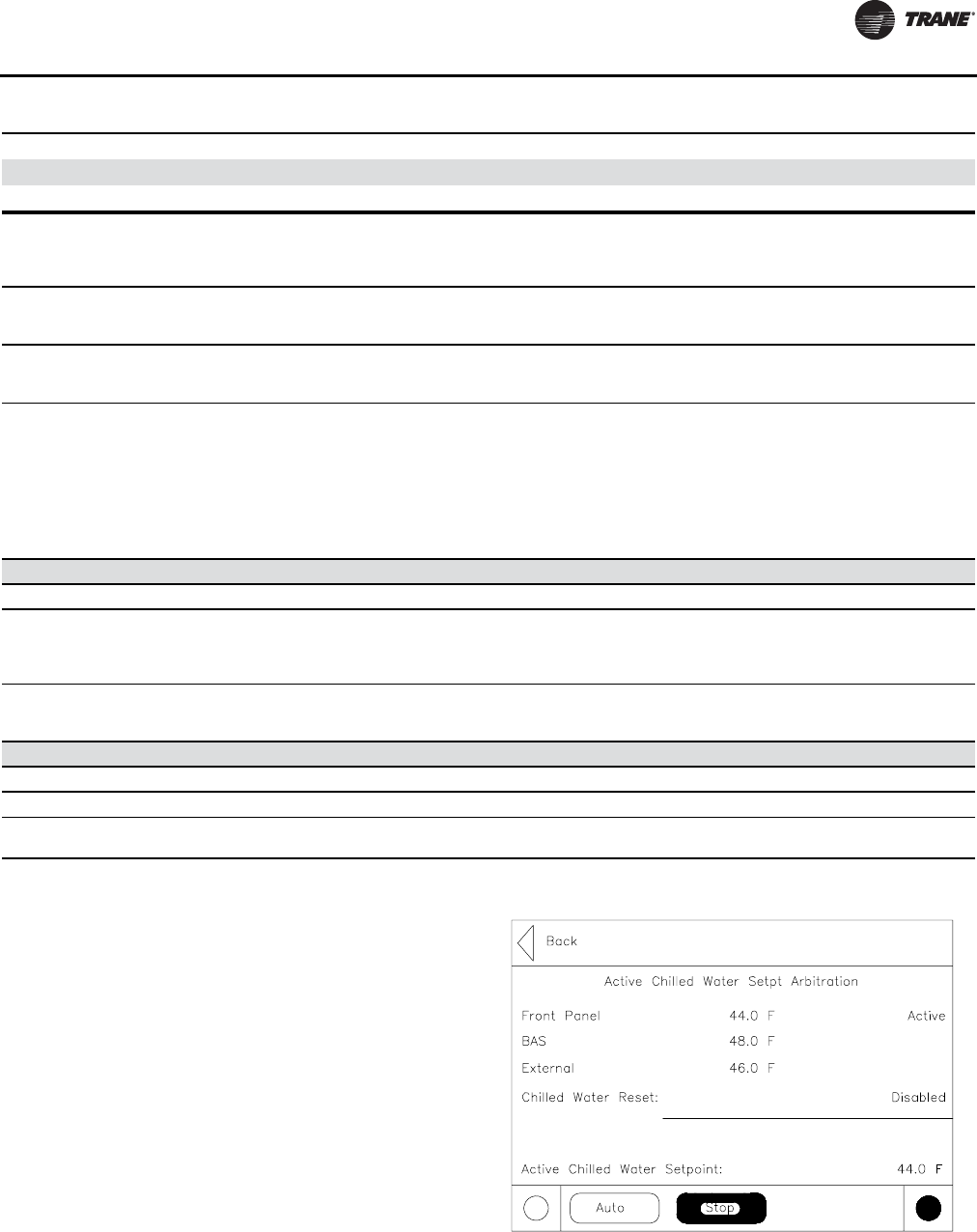
Controls Interface
RLC-SVX09H-EN 137
Active Chilled Water Setpoint
The active chilled water setpoint is the setpoint that is
currently in use. It results from the logical hierarchy of
setpoint arbitration by the main processor. It will be
displayed to 0.1 degrees Fahrenheit or Celsius.
Touching the double arrow to the left of the Active Chilled
Water Setpoint will take the user to the active chilled water
setpoint arbitration sub-screen.
Active Chilled Water Subscreen
The active chilled water setpoint is that setpoint to which
the unit is currently controlling. It is the result of arbitration
between the front panel, BAS, schedule, external, and
auxiliary setpoints (schedule and auxiliary not shown in
the following diagram), which in turn may be subjected to
a form of chilled water reset.
The chilled water reset status area in the right most column
will display one of the following messages
• Return
Current Limit
The compressor is running and its capacity is being limited by high currents. The
current limit setting is 120% RLA (to avoid overcurrent trips) or lower as set by the
compressor's "share" of the active current limit (demand limit) setting for the entire
chiller.*
High Condenser Pressure Limit
The circuit is experiencing condenser pressures at or near the condenser limit
setting. Compressors on the circuit will be unloaded to prevent exceeding the
limits.*
Low Evaporator Rfgt Temperature Limit
The circuit is experiencing saturated evaporator temperatures at or near the Low
Refrigerant Temperature Cutout setting. Compressors on the circuit will be
unloaded to prevent tripping. *
Hot Start Limit
This mode will occur if the leaving evaporator water temperature exceeds 75ºF (for
SW version 6.30 and earlier) or 90ºF (for software 7.01 and later) at the point at
which the step load for the respective circuit would be desired. This is often the case
in a high water temperature pull-down. While in this mode, no compressor on the
circuit will be allowed to load past its minimum load capacity step, but it will not
inhibit other compressors from staging on. This mode is necessary to prevent
nuisance trips due to Compressor Overcurrent or High Pressure Cutout. Reasonable
pull-down rates can still be expected despite this limit, since the compressor's
capacity even at partial load is much greater at high suction temperatures.
Shutting Down The circuit is preparing to de-energize the compressor.
Preparing Shutdown Sub-mode
Operational Pumpdown
The circuit is in the process of shutting down by performing an operational
pumpdown just prior to stopping the last running compressor. The EXV is
commanded closed. Pumpdown will terminate when both the liquid level and the
evap pressure are low (below specific criteria) or after a specific time has expired.
Compressor Unloading: min:sec
The compressor is in its run unload time. The number of seconds remaining in run
unload is shown in the submode. The run unload time must expire before the
compressor will shut down.
Misc These sub modes may be displayed in most of the top level circuit modes
Misc. Sub-modes
Service Pumpdown The circuit is currently performing a service pumpdown.
Restart Time Inhibit: min:sec If there is accumulated Restart Inhibit Time, it must expire before a compressor is
allowed to start.
Table 108. Circuit modes (continued)
Circuit Modes Description
Top Level Mode Further information is provided by the submode
Sub-modes
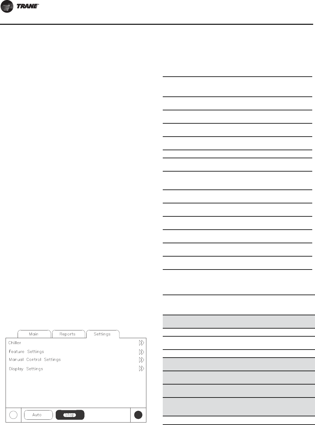
Controls Interface
138 RLC-SVX09H-EN
• Constant Return
• Outdoor
• Disabled
The left column text “Front Panel”, “BAS” or “Schedule”,
“External”, “Auxiliary”, “Chilled Water Reset”, and “Active
Chilled Water Setpoint” will always be present regardless
of installation or enabling those optional items. In the
second column “-----” will be shown if that option is Not
Installed, otherwise the current setpoint from that source
will be shown.
Setpoints that are adjustable from the DynaView (Front
Panel Chilled Water Setpoint, Auxiliary Chilled Water
Setpoint) will provide navigation to their respective
setpoint change screen via a double-arrow to the right of
the setpoint source text.The setpoint change screen will
look identical to the one provided in the Chiller Setpoints
screen.The “Back” button on the setpoint change screen
provides navigation back to the setpoint arbitration
screen.
The “Back” button on the setpoint arbitration screen
provides navigation back to the chiller screen.
Other Active Setpoints
The Active Current Limit Setpoint will behave the same
was as the Active Chilled Water Setpoint, except that its
units are in percent and there is an Ice Building source in
place of the Auxiliary source. Front Panel Current Limit
Setpoint will provide navigation to its setpoint change
screen.
Settings Screen
The Settings screen provides a user the ability to adjust
settings necessary to support daily tasks.The layout
provides a list of sub-menus, organized by typical
subsystem.This organization allows each subscreen to be
shorter in length which should improve the user's
navigation.
A sample Settings screen is a list of the subsystems as
shown below.
Settings Sub-Screens -Table of Text, Data,
Ranges, etc.
Below is the table of text, resolution, field size, enumerated
selections, and data for Settings subscreens.
Table 109. Chiller
Description
Resolution or
(Enumerations),
Default Units
Front Panel Cool/Heat
Command (Cool, Heat), Cool Enum
Front Panel Chilled Water
Setpt: + or - XXX.X Temperature
Front Panel Hot Water
Setpt + or - XXX.X Temperature
Front Panel Current Limit
Setpt: XXX %RLA
Front Panel Ice Build Cmd On/Auto Enum
Front Panel Ice
Termination Setpoint XXX.X Temperature
Setpoint Source:
(BAS/Ext/FP, Ext/Front
Panel, Front Panel),
BAS/Ext/FP
Enum
Differential to Start XX.X Delta
Temperature
Differential to Stop XX.X Delta
Temperature
Leaving Water Temp
Cutout XX.X Temperature
Low Refrigerant Temp
Cutout XX.X Temperature
Staging Sequence (Bal Starts/Hrs, Fixed),
Bal Starts/Hrs Enum
Condenser Pump Prestart
Time XX, 0 Minutes
Table 110. Feature settings
Description
Resolution or
(Enumerations),
Default Units
Cooling Low Ambient Lockout (Enable, Disable),
Enable Enum
Cooling Low Ambient Lockout Subscreeen (see below)
Cooling Low Ambient Lockout (Enable, Disable),
Enable Enum
Cooling Low Amb Lockout Setpt XXX.X Temp
Ice Building: (Enable, Disable),
Disable Enum
Ext Chilled/Hot Water Setpt (Enable, Disable),
Disable Enum
Ext Current Limit Setpoint (Enable, Disable),
Disable Enum
Chilled Water Reset
(Const Return,
Outdoor, Return,
Disable), Disable
Enum
Chilled Water Reset Subscreens (see below)
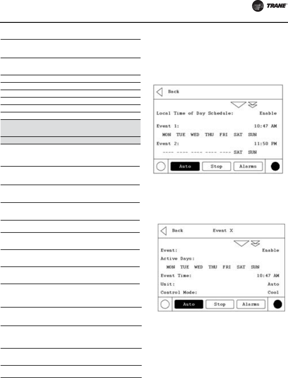
Controls Interface
RLC-SVX09H-EN 139
Local Time of Day Schedule Screen
To access the optional LocalTime of Day Schedule Screen
it must be configured inTechView.This option will then be
shown under the Feature Settings screen.
This screen shows the overall feature enable/disable
setting, plus a listing of all 10 events, including their event
time and active days of the week.
Local Settings Event Screen
This screen displays the details for a particular event,
including the active days, event time, and the Local
Schedule arbitrated setpoints. Selecting a given item will
allow the user to modify it.
Chilled Water Reset
(Const Return,
Outdoor, Return,
Disable), Disable
Enum
Return Reset Ratio XXX %
Return Start Ratio XXX.X Temp
Return Maximum Reset XXX.X Temp
Outdoor Reset Ratio XXX %
Outdoor Start Reset XXX.X Temp
Outdoor Maximum Reset XXX.X Temp
LCI-C Diag Language
(English, Selection 2,
Selection 3) English
(0)
Enum
LCI-C Diag Encoding (Text, Code) Text Enum
Table 111. System manual control settings
Description
Resolution or
(Enumerations),
Default Units Monitor Value
Evap Water
Pump (Auto, On), Auto Enum
1) Water Flow status
2) Override Time
Remaining
Cond Water
Pump (Auto, On), Auto Enum
1) Water Flow status
2) Override Time
Remaining
Head Pressure
Control (Auto, On), Auto Enum 1) Override status -
Auto/Manual
Staging
(Stepping
Control
(Auto, Manual) Auto Enum 1) Override status -
Auto/Manual
Capacity
Modulation
Control
(Auto, Manual) Auto Enum 1) Override status -
Auto/Manual
Clear Energy
Consumption
1) Resettable
Energy consumption
totalization (kWh)
Enum
1) Resettable Energy
consumption
totalization (kWh)
Table 112. Circuit manual control settings
Description
Resolution or
(Enumerations),
Default Units Monitor Value
Compressor
Pumpdown
(Continue, Not
Available) Enum
1) Override status: Not
Available/Continue/
Starting/Pumpdown
2) Suction Pressure
Front Panel
Ckt Lockout
(Not Locked Out,
Locked Out), Not
Locked Out
Enum
Expansion
Valve Control (Auto, Manual) Enum
Table 110. Feature settings (continued)
Description
Resolution or
(Enumerations),
Default Units
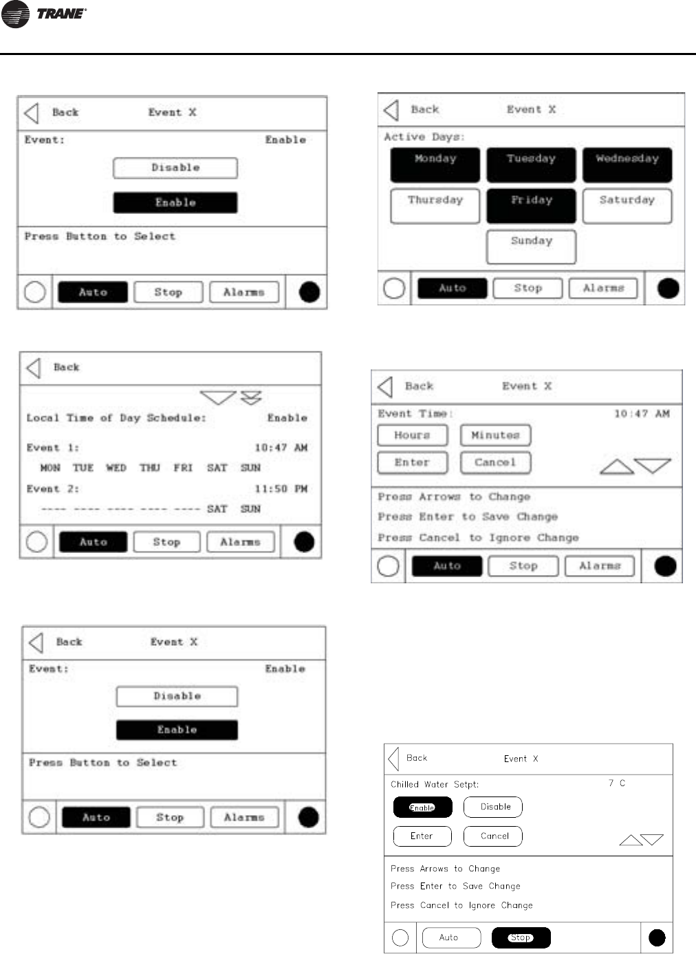
Controls Interface
140 RLC-SVX09H-EN
Event Enable/Disable Screen
Event Active Days Screen
This screen is unusual because it does not use radio
buttons, which only allow one active selection at a time.
These buttons are more like “selection buttons” or check
boxes.The user can select any combination of days, or
none at all.
Event Time Screen
Event Arbitrated Settings Screens
For analog setpoints, the screen is slightly different than
the standard screen, because there are two additional
buttons - “Enable” and “Disable”. Selecting “Used” will
make the setting valid and allow the user to change the
value. Selecting “Not Used” will make the setting invalid,
and will not allow the user to change the value.
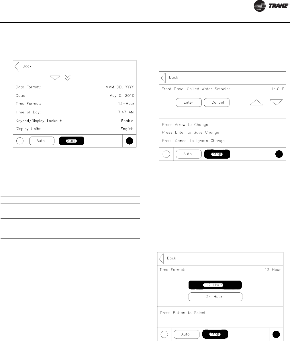
Controls Interface
RLC-SVX09H-EN 141
Display Settings Screen
Upon selecting a Settings list all setpoints available to
change along with their current value will appear.The
operator selects a setpoint to change by touching either
the verbal description or setpoint value. Doing this causes
the screen to switch to either the Analog Settings
Subscreen or the Enumerated Settings Subscreen.
Analog Setting Subscreens
Analog Settings Subscreen displays the current value of
the chosen setpoint in the upper ½ of the display. It is
displayed in a changeable format consistent with its type.
Binary setpoints are considered to be simple two state
enumerations and will use radio buttons.Analog setpoints
are displayed as spin buttons.The lower half of the screen
is reserved for help screens.
All setpoint subscreens will execute the equivalent of a
Cancel key if any display activities cause the subscreen to
be left before a new setpoint is entered. E.g. if the Alarms
key is pressed before a new setpoint is entered, the new
setpoint will be cancelled.The same applies to any time-
outs.
Pressing the Auto or Stop keys will not cause a cancel
since the setpoint subscreen is not left on this action.
Enumerated Settings Subscreen
The enumerated setpoint subscreen has no cancel or enter
key. Once a radio key is depressed the item is immediately
set to the new enumeration value.
Mode Override Subscreens
The Mode Override subscreen has no cancel or enter key.
Once a radio key is depressed that new value is
immediately assumed.
Table 113. Display settings
Description
Resolution or (Enumerations),
Default Units
Date Format (“mmm dd, yyyy”, “dd-mmm-yyyy”),
“mmm dd, yyyy Enum
Date3
Time Format (12-hour, 24-hour), 12-hour Enum
Time of Day3
Keypad (Display
Lockout2(Enable, Disable), Disable Enum
Display Units (SI, English), SI Enum
Pressure Units (Absolute, Gauge), Gauge Enum
Language4(English, Selection 2, Selection 3),
English1Enum
Notes:
1. Language choices are dependent on what the Service Tool has setup
in the Main Processor. Get Radio Button names from Main Processor
setups. Language selections will include English and qty 2 alternate
as loaded by TechView.
2. Enables a DynaView Lockout screen. All other screens timeout in 30
minutes to this screen. The DynaView Lockout Screen will have 0-9
keypad to permit the user to re-enter the other DynaView screens
with a fixed password (159).
3. The Date and Time setup screen formats deviate slightly from the
standard screens defined above. See the alternate screen layouts
below.
4. Language shall always be the last setting listed on the Control
Settings menu (which will also always be the last item listed on the
Settings menu list). This will allow a user to easily find language
selection if looking at an unrecognizable language.
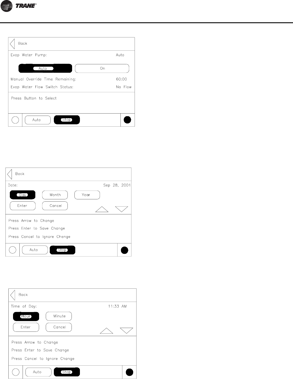
Controls Interface
142 RLC-SVX09H-EN
Mode Override for Enumerated Settings is shown below:
Date/Time Subscreen
The setpoint screen for setting up the CH530 date is shown
below:The user must select Day, Month, orYear and then
use the up/down arrows to adjust.
The setpoint screen for setting up the CH530 time with a 12
hour format is shown below:The user must select Hour or
Minute and then use the up/down arrows to adjust.
Adjusting hours will also adjust am/pm.
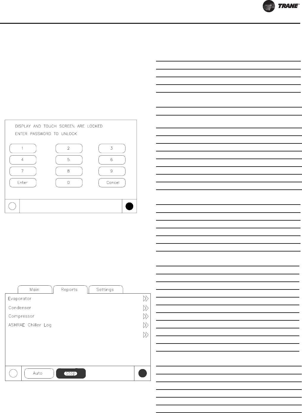
Controls Interface
RLC-SVX09H-EN 143
Lockout Screen
The DynaView Display andTouch Screen Lock screen is
shown.This screen is used if the Display andTouch Screen
Lock feature is Enabled.Thirty minutes after the last key
stroke this screen will be displayed and the Display and
Touch Screen will be locked out until “159 Enter” is
entered.
Until the proper password is entered there will be no
access to the DynaView screens including all reports, all
setpoints, and Auto/Stop/Alarms/Interlocks.The
password “159” is not programmable from either
DynaView orTechView.
If the Display andTouch Screen Lock feature is Disabled, a
similar screen including “Enter 159 to Unlock” will show if
the MP temperature is approximately less than 32°F (0°C)
and it has been 30 minutes after the last key stroke.
Reports
The Reports tab will allow a user to select from a list of
possible reports headings (i.e. Custom, ASHRAE Chiller
Log, Refrigerant, etc.) Each report will generate a list of
status items as defined in the tables that follow:
Historic Diagnostics
Table 114. Report name: system evaporator
Description Resolution Units
Evap Entering Water Temp: + or - XXX.X Temperature
Evap Leaving Water Temp: + or - XXX.X Temperature
Evap Water Flow Switch Status: Flow, No Flow Enumeration
Figure 53. Report name: circuit evaporator
Description Resolution Units
Evap Entering Water
Temperature +/- XXX.X Temperature
Evap Leaving Water Temperature +/- XXX.X Temperature
Evap Sat Rfgt Temp +/- XXX.X Temperature
Suction Pressure XXX.X Pressure
Evap Approach Temp: +/- XXX.X Temperature
Evap Water Flow Switch Status (Flow, No Flow) Enum
Expansion Valve Position XXX.X %
Expansion Valve Position Steps XXXX Steps
Evaporator Liquid Level XX.X Height
Table 115. Report name: system condenser
Description Resolution Units
Cond Entering Water Temp +/- XXX.X Temperature
Cond Leaving Water Temp +/- XXX.X Temperature
Cond Water Flow Switch Status (Flow, No Flow) Enum
Outdoor Air Temperature +/- XXX.X Temperature
Cond Head Pressure Ctrol XXX %
Table 116. Report name: circuit condenser
Description Resolution Units
Cond Entering Water Temp +/- XXX.X Temperature
Cond Leaving Water Temp +/- XXX.X Temperature
Condenser Air Flow XXX %
Cond Inverter Speed XXX %
Outdoor Air Temperature +/- XXX.X Temperature
Cond Water Flow Switch Status (Flow, No Flow) Enum
Cond Sat Rfgt Temp +/- XXX.X Temperature
Cond Rfgt Pressure XXX.X Pressure
Differential Pressure XXX.X Pressure
Cond Approach Temp +/- XXX.X Temperature
Table 117. Report name: system compressor
Description Resolution Units
Average Line Current XXX %RLA
Unit Volts XXX Volts
Unit Running Time XXXX:XX hr:min
Power Demand kW
Power Demand Time Period min
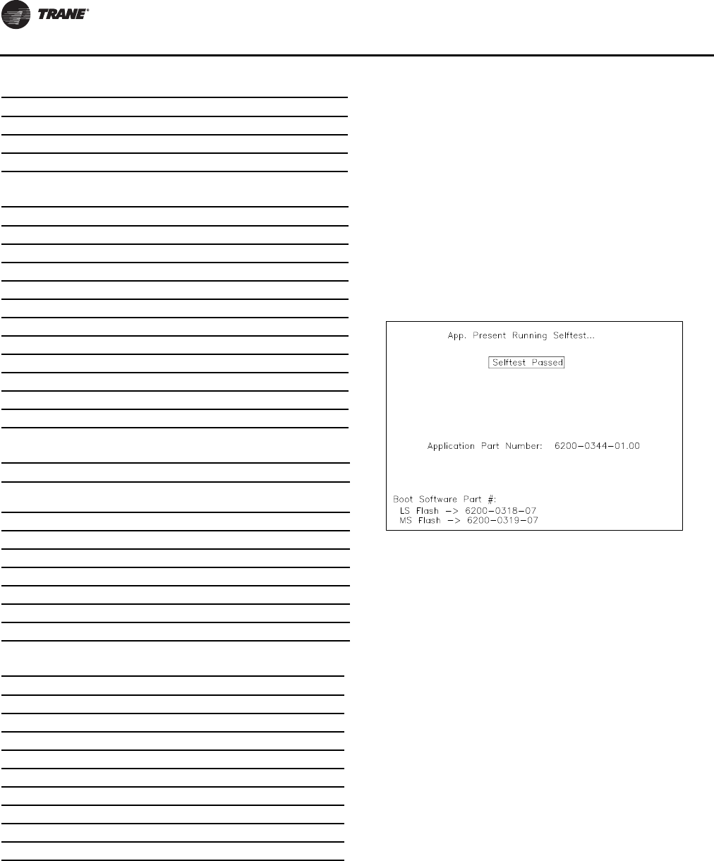
Controls Interface
144 RLC-SVX09H-EN
Power Up and Self Tests
Power-Up DynaView
On Power-Up DynaView will progress through three
screens:
First Screen, Application Status, Boot Software P/N, Self
Test and ApplicationTime Stamp.
This screen will display for 3-10 seconds.This screen will
give the status of the Application software, the Boot
Software P/N, display SelfTest results and display the
Application Part Number.The contrast will also be
adjustable from this screen.The message “Selftest
Passed” may be replaced with “Err2: RAM Error” or “Err3:
CRC Failure”
Display Formats
Temperature settings can be expressed in F or C,
depending on Display Units settings.
Pressure settings can be expressed in psia, psig, kPaa (kPa
absolute), or kPag (kPa gauge) depending on Display Units
settings.
Dashes (“-----”) appearing in a temperature or pressure
report, indicates that the value is invalid or not applicable.
Languages
The languages for DynaView will reside in the main
processor.The main processor will hold three languages,
English, and two alternate languages.The service tool
(TechView) will load the main processor with user selected
languages from a list of available translations.
Energy Consump - Resettable kWh
Time of Last Reset time-date
Energy Consump - NonReset kWh
Table 118. Report name: circuit compressor
Description Resolution Units
Oil Pressure XXX.X Pressure
Compressor Rfgt Dschg Temp +/- XXX.X Temperature
Cond Sat Rfgt Temp +/- XXX.X Temperature
Average Line Current XXX %RLA
%RLA L1 L2 L3 XXX.X %RLA
Amps L1 L2 L3 XXX.X Amps
Phase Voltages XXX Vac
Power Consumption XXX kW
Load Power Factor X.XXX
Compressor Starts XXXX Integer
Compressor Running Time XXXX:XX hr:min
Table 119. Report name: system ASHRAE chiller log
Description Resolution Units
Current Time/Date: XX:XX mmm
dd, yyyy Date/Time
Chiller Mode: Enum
Active Chilled Water Setpoint: XXX.X Temperature
Active Hot Water Setpoint: XXX.X Temperature
Evap Entering Water Temp: XXX.X Temperature
Evap Leaving Water Temp: XXX.X Temperature
Evap Water Flow Switch Status: Enum
Outdoor Air Temperature: XXX.X Temperature
Table 120. Report name: circuit ASHRAE chiller log
Description Resolution Units
Circuit Mode: Enum
Evap Sat Rfgt Temp XXX.X Temperature
Suction Pressure XXX.X Pressure
Evap Approach Temp XXX.X Temperature
Cond Sat Rfgt Temp: XXX.X Temperature
Cond Rfgt Pressure XXX.X Pressure
Cond Approach Temp XXX.X Temperature
Compressor Starts XXXX Integer
Compressor Running Time XX:XX Hours:Minutes
Table 117. Report name: system compressor (continued)
Description Resolution Units
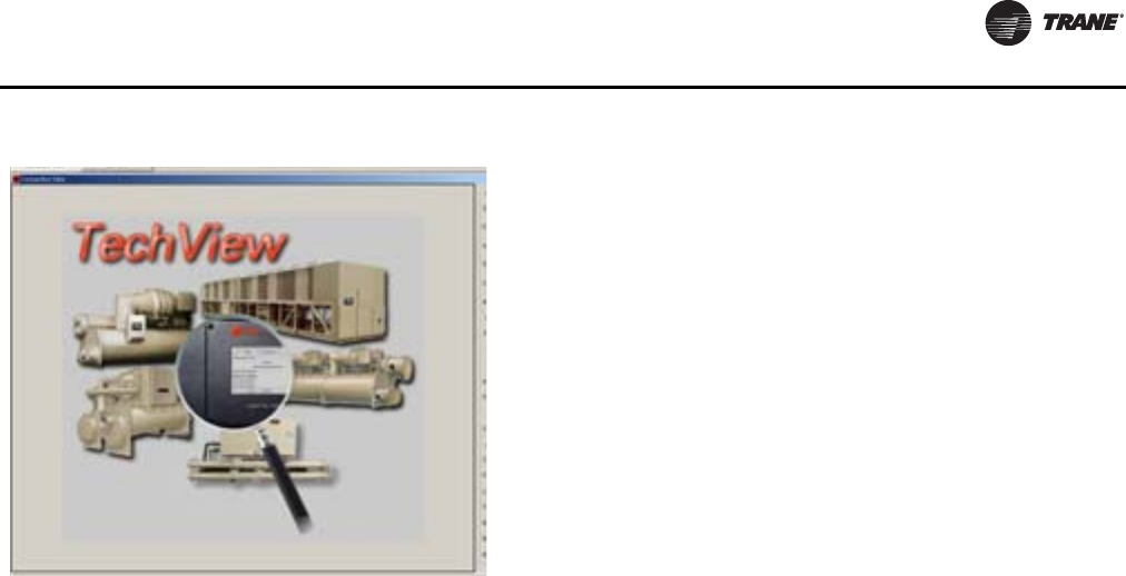
Controls Interface
RLC-SVX09H-EN 145
TechView
TechView is the PC (laptop) based tool used for servicing
Tracer CH530.Technicians that make any chiller control
modification or service any diagnostic withTracer CH530
must use a laptop running the software application
“TechView.”TechView is aTrane application developed to
minimize chiller downtime and aid the technicians
understanding of chiller operation and service
requirements.
Important: Performing anyTracer CH530 service
functions should be done only by a properly
trained service technician. Please contact
your localTrane service agency for
assistance with any service requirements.
TechView software is available viaTrane.com.
http://www.trane.com/COMMERCIAL/DesignAnalysis/
TechView.aspx?i=1435
This download site provides a user theTechView
installation software and CH530 main processor software
that must be loaded onto your PC in order to service a
CH530 main processor. TheTechView service tool is used
to load software into theTracer CH530 main processor.
TechView Software Download, Installation
This information can also be found at http://
www.trane.com/COMMERCIAL/DesignAnalysis/
TechView.aspx?i=1435.
1. Create a folder called “CH530” on your (C:\CH530) on
your hard drive.This \CH530 folder is the standard
recommended location for the installation file. Storing
the installation file in this location helps you remember
where it is stored and makes it easier for technical
support personnel to assist you.
2. Click the link for the latest version on theTechView
Software Download page. Enter your name, e-mail
address and other required information. Click Submit.
3. A download link will be sent to the e-mail address
provided. Before you click the link please note:
• Sent link may only be used one time.
• Internet options must be set correctly to allow
download.To verify correct setting:
– Open Internet Explorer Browser
– ClickTools
– Select Internet Options
– Select Security tab
– Click on Internet zone
– Click Custom Level button
– Scroll to Downloads section
– Verify/Enable “Automatic prompting for file
downloads”
– Click OK
– ClickYES on warning window
– Click Apply, then OK
Note: If this setting is incorrect, you may or may
not receive an error message during
download attempt.
4. Click the download link in the e-mail message.
• If the download window does not open
immediately, please look for a yellow highlighted
message bar/line near the top of your browser. It
may contain a message such as "To help protect
your security, Internet Explorer blocked this site
from downloading files to your computer. Click here
for options.." Click on message line to see options.
• When dialog box appears, click Save and navigate
to the CH530 folder created in Step 1. Click OK.
• If you do not complete the download successfully,
you will have to request another download link
(Step 2).
5. Navigate to the CH530 folder created in Step 1. Double-
click the installation (.exe) file.The License Agreement
dialog box appears.
6. Click I Agree after reviewing License Agreement.The
Choose Components dialog box appears. All
components are selected by default. (These are the
actual MP versions for all units.) Deselect any
components you do not want.
Note: Deselecting components reduces the size of the
installed application.
7. Click Install. A progress meter dialog box appears. An
information file appears when installation is complete.
Note: Techview requires a current version of JAVA. If
you do not have the current release,TechView
installation will be interrupted, and you will be
provided with information for required JAVA
software download. Once you have completed
the JAVA installation, return to Step 5 to restart
installation.
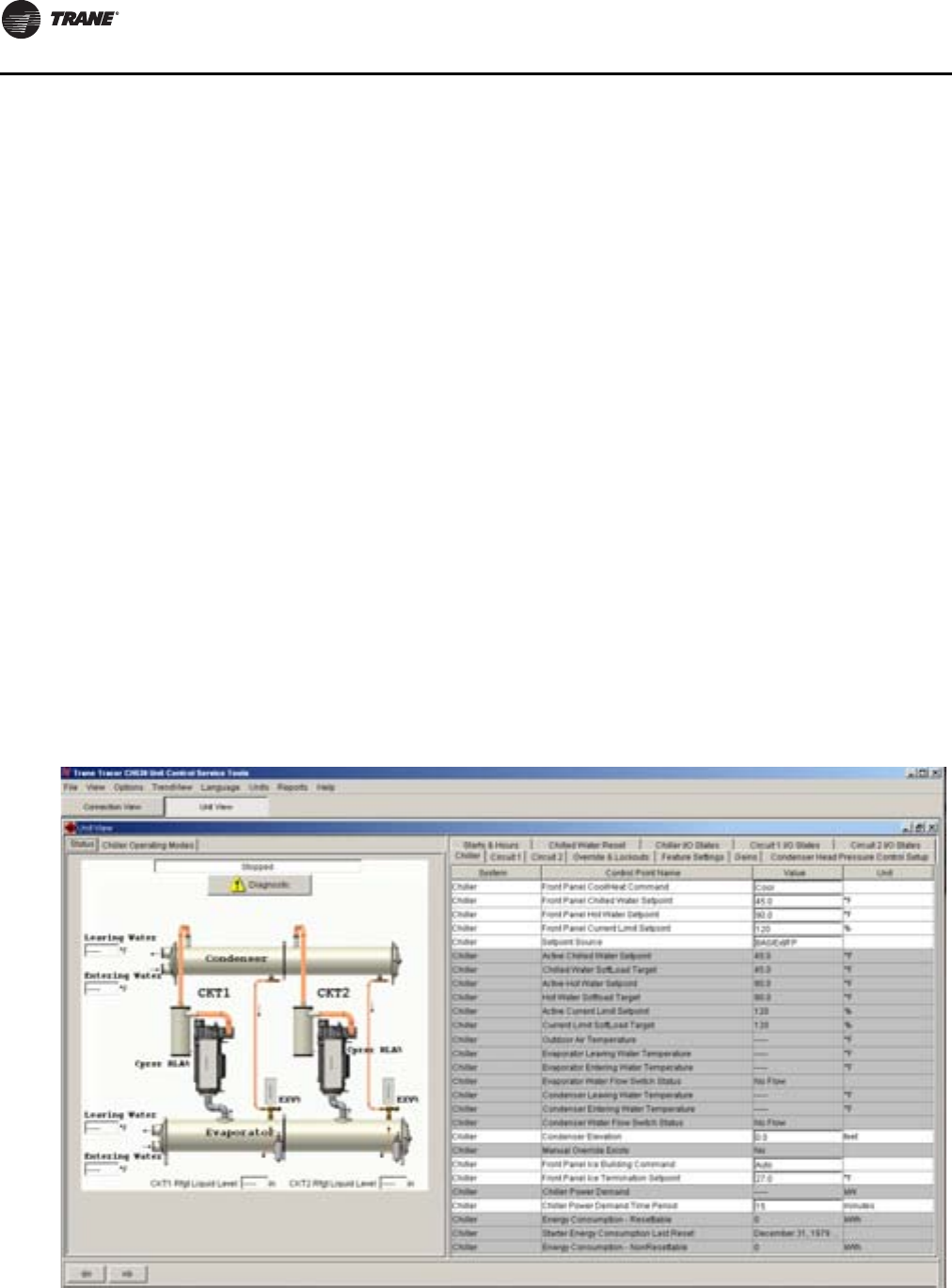
Controls Interface
146 RLC-SVX09H-EN
Minimum PC requirements to install and
operate TechView
• Microsoft Windows XP Professional or Windows Vista
Business operating system
• Internet Explorer 6.0 and higher
• USB 2.0 or higher
• Pentium II, III, or higher processor
• 128MB RAM minimum
• 1024 x 768 resolution
• CD-ROM (optional for copyingTechView install to CD)
• 56K modem (optional for internet connection)
• 9-pin RS-232 serial connection (optional for
connection to DynaView)
Note: TechView was designed and validated for this
specific laptop configuration. Any variation from
this configuration may have different results.
Therefore, support forTechView is limited to only
those laptops configured as described above.
Trane will not supportTechView on laptops
configured differently.There is no support for
laptops running Intel Celeron, AMD, Cyrix or
processors other than Pentium.
Optional Software
• Microsoft Office with Access
TechView is also used to perform any CH530 service or
maintenance function. Servicing a CH530 main processor
includes:
• Updating main processor software
• Monitoring chiller operation
• Viewing and resetting chiller diagnostics
• Low Level Intelligent Device (LLID) replacement and
binding
• Main processor replacement and configuration
modifications
• Setpoint modifications
• Service overrides
Unit View
Unit view is a summary for the system organized by chiller
subsystem.This provides an overall view of chiller
operating parameters and gives you an "at-a-glance"
assessment of chiller operation.
The Status tab displays important operating information
for the unit and allows you to change several key operating
parameters.The panel is divided into four or more sub-
panels (depending on the number of circuits in the unit).
The Chiller Operating Mode tab displays the unit, circuit
and compressor top level operating modes. Upon
successful Local Connect,Tech View will display UNIT
VIEW. RTWD and RTUD Unit Views are shown below.
Figure 54. Unit View (RTWD)
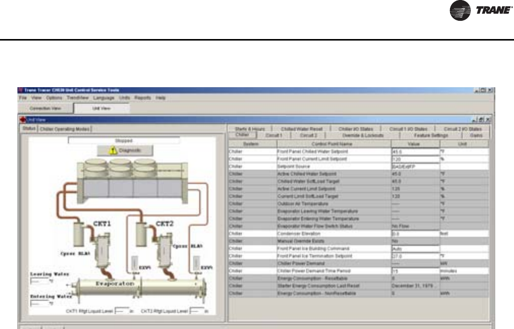
Controls Interface
RLC-SVX09H-EN 147
The Unit View displays the system, control point name,
value and unit of measure. It reflects active setpoints and
allows you to make changes.
Unit View also displays, in real time, all non-setpoint data
organized by tabs. As data changes on the chiller, it is
automatically updated in the Unit View.
Circuit/Compressor Lockout)
In order to lockout a circuit the user must go to the Unit
View/Circuit 1 (or Circuit 2)Tab and then select the Front
Panel Lockout for Circuit 1 and/or Circuit 2.The user can
select Not Locked Out or Locked Out.
Condenser Elevation Configuration - RTUD
Installations
Condenser elevation setting is a required input during
startup of RTUD units. Go to the Unit View/ChillerTab,
select Condenser Elevation setting and enter condenser
elevation in appropriate units. Reference Figure , p. 148.
The shipped default of this setting is 0 and it represents the
distance of the bottom of the condenser, relative to the top
of the evaporator. Use a positive value for the condenser
above the evaporator and a negative value for the
condenser below the evaporator. An estimate to within +
/- 3 feet is required.
Figure 55. Unit view (RTUD)
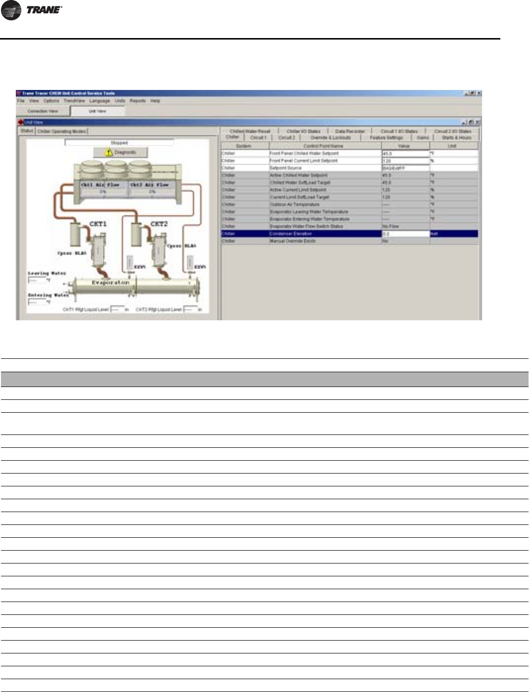
Controls Interface
148 RLC-SVX09H-EN
Figure 56. Unit view - RTUD condenser elevation
Table 121. Unit view tabs - detail
Tab System Control Point Name Status Unit Min Max Default
Chiller
Chiller Front Panel Cool/heat Command Setting
Chiller Front Panel Chilled Water Setpoint Setpoint deg F (C) 10 (-12.22) 65 (18.33) 45 (7.22)
Chiller Front Panel Hot Water Setpoint Setpoint deg F (C) 80 (26.66) 140 (60) 90 (32.22)
Chiller Front Panel Current Limit Setpoint Setpoint %RLA 60 120 120
Chiller Setpoint Source Setting
Chiller Active Chilled Water Setpoint Status °F (°C)
Chiller Chilled Water Softload Target Status °F (°C)
Chiller Active Hot Water Setpoint Status °F (°C)
Chiller Hot Water Softload Target Status °F (°C)
Chiller Active Current Limit Setpoint Status % RLA
Chiller Current Limit SoftLoad Target Status % RLA
Chiller Outdoor Air Temperature Status °F (°C)
Chiller Evaporator Leaving Water Temperature Status °F (°C)
Chiller Evaporator Entering Water Temperature Status °F (°C)
Chiller Evaporator Water Flow Switch Status Status
Chiller Condenser Leaving Water Temperature Status °F (°C)
Chiller Condenser Entering Water Temperature Status °F (°C)
Chiller Condenser Water Flow Switch Status Status
Chiller Condenser Elevation Setting ft -26.25 98.43 0
Chiller Manual Override Exists Status
Chiller Front Panel Ice Building Command Setting
Chiller Front Panel Ice Termination Setpoint Setting °F (°C) 20 32 27
Chiller Chiller Power Demand Status

Controls Interface
RLC-SVX09H-EN 149
Chiller Chiller Power Demand Time Period Setting min 1 60 15
Chiller Energy Consumption - Resettable Status
Chiller Starter Energy Consumption Last Reset Status
Chiller Energy Consumption - NonResettable Status
Circuit 1
Circuit 1 Front Panel Circuit Lockout Setting Not locked out
Circuit 1 External Circuit Lockout Status Status Not locked out
Circuit 1 Evaporator Refrigerant Pressure Status psi gauge
Circuit 1 Evaporator Saturated Refrigerant Temperature Status °F (°C)
Circuit 1 Evaporator Approach Temperature Status °F (°C)
Circuit 1 Evaporator Refrigerant Liquid Level Status in (mm)
Circuit 1 Evaporator Refrigerant Liquid Level Error Status in (mm)
Circuit 1 EXV Percent Open Status %
Circuit 1 EXV Position Steps Status steps
Circuit 1 Differential Refrigerant Pressure Status psid
Circuit 1 Condenser Refrigerant Pressure Status psi gauge
Circuit 1 Condenser Saturated Refrigerant Temperature Status °F (°C)
Circuit 1 Compressor Refrigerant Discharge Temperature Status °F (°C)
Circuit 1 Condenser Approach Temperature Status °F (°C)
Circuit 1 Compressor Refrigerant Discharge Superheat Status °F (°C)
Circuit 1 Compressor 1A Oil Pressure Status psi gauge
Circuit 1 Compressor 1A Average Line Current Status % RLA
Circuit 1 Compressor 1A Line 1 Current Status % RLA
Circuit 1 Compressor 1A Line 2 Current Status % RLA
Circuit 1 Compressor 1A Line 3 Current Status % RLA
Circuit 1 Starter 1A Voltage Vab Status volts
Circuit 1 Starter 1A Voltage Vbc Status volts
Circuit 1 Starter 1A Voltage Vca Status volts
Circuit 1 Compressor 1A Power Consumption Status kW
Circuit 1 Compressor 1A Power Factor Status
Circuit 1 Modulation Unload Steady Command Status
Circuit 1 Condenser Air Flow Status % of fan
deck
Circuit 1 Condenser Inverter Speed Status % of inverter
full speed
Circuit 1 Average Condenser Approach Temperature Status Diff Temp °F
(°C)
Circuit 1 Re-initialize Average Condenser Approach Temperature Setting
Circuit 1 Compressor 1A Average Oil Pressure Drop Status % of System
DP
Circuit 1 Re-initialize Compressor 1A Average Oil Pressure Drop Setting
Circuit 1 Compressor 1A Oil Filter Life Remaining Status %
Circuit 1 Re-initialize Compressor 1A Oil Filter Life Remaining Setting
Circuit 1 Time Remaining Until Oil Analysis Recommended Status Hrs
Circuit 1 Re-initialize Oil Time Remaining Setting
Circuit 2
Circuit 2 Front Panel Circuit Lockout Setting
Circuit 2 External Circuit Lockout Status Status
Circuit 2 Evaporator Refrigerant Pressure Status psi gauge
Table 121. Unit view tabs - detail (continued)
Tab System Control Point Name Status Unit Min Max Default

Controls Interface
150 RLC-SVX09H-EN
Circuit 2 Evaporator Saturated Refrigerant Temperature Status °F (°C)
Circuit 2 Evaporator Approach Temperature Status °F (°C)
Circuit 2 Evaporator Refrigerant Liquid Level Status in (mm)
Circuit 2 Evaporator Refrigerant Liquid Level Error Status in (mm)
Circuit 2 EXV Percent Open Status %
Circuit 2 EXV Position Steps Status steps
Circuit 2 Differential Refrigerant Pressure Status psid
Circuit 2 Condenser Refrigerant Pressure Status psi gauge
Circuit 2 Condenser Saturated Refrigerant Temperature Status °F (°C)
Circuit 2 Compressor refrigerant Discharge Temperature Status °F (°C)
Circuit 2 Condenser Approach Temperature Status °F (°C)
Circuit 2 Compressor Refrigerant Discharge Superheat Status °F (°C)
Circuit 2 Compressor 2A Oil Pressure Status psi gauge
Circuit 2 Compressor 2A Average Line Current Status % RLA
Circuit 2 Compressor 2A Line 1 Current Status % RLA
Circuit 2 Compressor 2A Line 2 Current Status % RLA
Circuit 2 Compressor 2A Line 3 Current Status % RLA
Circuit 2 Starter 2A Voltage Vab Status volts
Circuit 2 Starter 2A Voltage Vbc Status volts
Circuit 2 Starter 2A Voltage Vca Status volts
Circuit 2 Compressor 2A Power Consumption Status kW
Circuit 2 Compressor 2A Power Factor Status
Circuit 2 Modulation Unload Steady Command Status
Circuit 2 Condenser Air Flow Status % of fan
deck
Circuit 2 Condenser Inverter Speed Status % of inverter
full speed
Circuit 2 Average Condenser Approach Temperature Status Diff Temp °F
(°C)
Circuit 2 Re-initialize Average Condenser Approach Temperature Setting
Circuit 2 Compressor 2A Average Oil Pressure Drop Status % of System
DP
Circuit 2 Re-initialize Compressor 2A Average Oil Pressure Drop Setting
Circuit 2 Compressor 2A Oil Filter Life Remaining Status %
Circuit 2 Re-initialize Compressor 2A Oil Filter Life Remaining Setting
Circuit 2 Time Remaining Until Oil Analysis Recommended Status Hrs
Circuit 2 Re-initialize Oil Time Remaining Setting
Override & Lockouts
Circuit 1 Restart Inhibit Time - Compressor 1A Status mins:secs
Circuit 1 Restart Inhibit Time - Compressor 2A Status mins:secs
Manual
Overrides Clear Restart Inhibit Setting
Manual
Overrides Evaporator Water Pump Override Setting Auto
Chiller Evaporator Water Pump Override Time Remaining Status mins:secs
Manual
Overrides Condenser Water Pump Override Setting Auto
Chiller Condenser Water Pump override Time Remaining Status mins:secs
Circuit 1 EXV Control override Setting
Circuit 1 Manual EXV Position Command Setting % 0 100
Table 121. Unit view tabs - detail (continued)
Tab System Control Point Name Status Unit Min Max Default

Controls Interface
RLC-SVX09H-EN 151
Circuit 1 Evaporator Refrigerant Liquid Level Status in (mm)
Circuit 1 EXV Percent Open Status %
Circuit 1 EXV Position Steps Status steps
Circuit 1 Evaporator Approach Temperature Status °F (°C)
Circuit 1 Differential Refrigerant Pressure Status psid
Circuit 2 EXV Control Override Setting Auto
Circuit 2 Manual EXV Position Command Setting % 0 100
Circuit 2 Evaporator Refrigerant Liquid Level Status in (mm)
Circuit 2 EXV Percent Open Status %
Circuit 2 EXV Position Steps Status steps
Circuit 2 Evaporator Approach Temperature Status °F (°C)
Circuit 2 Differential Refrigerant Pressure Status psid
Manual
Overrides Compressor 1A Pumpdown Command Setting
Manual
Overrides Compressor 1A Pumpdown Status Status °F (°C)
Manual
Overrides Compressor 2A Pumpdown Command Setting
Manual
Overrides Compressor 2A Pumpdown Status Status °F (°C)
Circuit 1 Evaporator Refrigerant Pressure Status psi gauge
Circuit 2 Evaporator Refrigerant Pressure Status psi gauge
Chiller Keypad Lockout Setting Normal
Chiller CHRV Head Pressure Control Override Setting Auto
Manual
Overrides Manual Staging (Stepping Control Setting
Chiller Manual Staging (Stepping Control Command Status
Manual
Overrides Manual Capacity (Modulation Control Setting %
Chiller Manual Capacity Modulation Control Command Status % -100 100
Circuit 1 Compressor 1A Load Step Status
Circuit 1 Compressor 1A% Duty Cycle Sent Status %
Circuit 1 Compressor 1A Average Line Current Status % RLA
Circuit 2 Compressor 2A Load Step Status
Circuit 2 Compressor 2A % Duty Cycle Sent Status %
Circuit 2 Compressor 2A Average Line Current Status % RLA
Chiller Evaporator Leaving Water Temperature Status °F (°C)
Chiller Evaporator Entering Water Temperature Status °F (°C)
Chiller “Service Recommended” Messages Setting
Feature Settings
Chiller Cooling Low Ambient Lockout Setting Disable
Chiller Cooling Low Ambient Lockout Temperature Setpoint °F (°C) -9.94 (-23.3) 70 (21.11) 54.86 (12.7)
Chiller Differential to Start Setpoint °F (°C) 0.5 (.278) 10 (5.55) 2 (1.1)
Chiller Differential to Stop Setpoint °F (°C) 0.5 (.278) 10 (5.55) 2 (1.1)
Chiller Staging Sequence Setting Staging Seq
Chiller Power-Up Start Delay Setting sec 0 600 0
Chiller Local Stop Delay Setting sec 0 30 0
Chiller Capacity Control Softload Time Setting sec 0 7200 900
Chiller Current Limit Control Softload Time Setting sec 0 7200 600
Table 121. Unit view tabs - detail (continued)
Tab System Control Point Name Status Unit Min Max Default
Controls Interface
152 RLC-SVX09H-EN
Chiller Current Limit Softload Start Point Setting % 20 100 40
Chiller Variable Evaporator Water Flow Compensation Setting Disable
Chiller Evaporator Pump Off Delay Setting minutes 0 30 1
Chiller Condenser Pump Off Delay Setting minutes 0 30 1
Chiller Condenser Water Pump Pre-Run Tim Setting minutes 0 30 0
Chiller Low Evaporator Leaving Water Temperature Cutout Setting °F (°C) 5 (-15) 36 (2.22) 36 (2.22)
Chiller Low Refrigerant Temperature Cutout Setting °F (°C) -5 (-20.55) 36 (2.22) 28.6 (-1.89)
Chiller High Evaporator Water Temperature Cutout Setting °F (°C) 80 (26.67) 150 (65.56) 105 (40.55)
Chiller Local Atmospheric Pressure Setting psia 68.9 110.3 101.35
Chiller Ice Building Feature Setting Enable
Chiller External Chilled (Hot Water Setpoint Enable Setting Enable
Chiller External Current Limit Setpoint Enable Setting Enable
Chiller Under (Over Voltage Protection Enable Setting Enable
Chiller LCI-C Diagnostic Language Setting English
Chiller LCI-C diagnostic Encoding Setting Text
Chiller Head Relief Relay Filter Time Setting sec 0 1200 600
Chiller Limit Relay Filter Time Setting sec 0 1200 600
Chiller Maximum Capacity Relay Filter Time Setting sec 0 1200 600
Gains
Chiller Cooling Design Delta Temperature (Waterside) Setting °F (°C) 3.6 (2) 32.4 (18) 10 (5.55)
Chiller Heating Design Delta Temperature (Waterside) Setting °F (°C) 3.6 (2) 32.4 (18) 10 (5.55)
Chiller Condenser Pressure Limit Setpoint Setting % 80 120 90
Chiller Carryover Maximum Capacity Limit Setpoint Setpoint % 50 500 500
Chiller Carryover Maximum Capacity Limit Kp Setting 0.03 2.0 .2
Chiller Carryover Maximum Capacity Limit Ti Setting sec 0.1 500 3
Chiller Carryover Maximum Capacity Limit - Input Type Setting
Condenser Head Pressure Control
Chiller Head Pressure Control Coverride Setting Auto
Chiller Off State Output Command Setting volts 0 10 2
Chiller Output Voltage at Desired Minimum Flow Setting volts 0 10 2
Chiller Desired Minimum Flow Setting % 0 100 20
Chiller Output Voltage at Desired Maximum Flow Setting volts 0 10 10
Chiller Actuator Stroke Time Setting sec 1 1000 30
Chiller Damping Coefficient Setting 0.1 1.8 0.5
Chiller Condenser Water Pump Pre-Run Time Setting minutes 0 30 0
Chiller Condenser Water Pump Pre-Run Time Remaining Status mins:secs
Chiller Head Pressure Control Output Status %
Chiller Time Till Actuator at Position Status mins:secs
Chiller Time to Safe Start of Cond Wtr Pump Status mins:secs
Starts & Hours
Chiller Chiller Running Time Status hrs:mins
Circuit 1 Compressor 1A Running Time Status hrs:mins
Circuit 1 Compressor 1A Starts Status
Circuit 1 Revise Compressor 1A Run Time Setting hrs:mins
Circuit 1 Revise Compressor 1A Starts Setting starts 0 4294967295
Circuit 2 Compressor 2A Running Time Status hrs:mins
Circuit 2 Compressor 2A Starts Status
Table 121. Unit view tabs - detail (continued)
Tab System Control Point Name Status Unit Min Max Default
Controls Interface
RLC-SVX09H-EN 153
The items that can be modified show up in white.The
items that cannot be modified show up in gray.
Circuit 2 Revise Compressor 2A Run Time Setting hrs:mins
Circuit 2 Revise Compressor 2A Starts Setting starts 0 4294967295
Date Recorder
Chiller Data Recorder Enable/Disable Setpoint
Chiller Data Recorder Change Delta Setpoint 0 1.0 0.2
Chiller Data Recorder Sample Period Setpoint Sec 1 3600 2
Chiller Data Recorder Temperature Change Delta Setpoint Delta Temp
(°C) 0 2.8 0.6
Chiller Data Recorder Pressure Change Delta Setpoint Delta Press
(kPa) 0 34.5 13.8
Chiller Data Recorder Percent Change Delta Setpoint % 0 5 1
Chiller Data Recorder Count Change Delta Setpoint 0 120 30
Chilled Water Reset
Chiller Chilled Water Reset Type Setpoint Disable
Chiller Return Water Reset Ratio Setpoint % 10 120 50
Chiller Return Water Start Reset Setpoint °F (°C) 36 (2.22) 62 (16.67) 42 (5.56)
Chiller Return Water Maximum Reset Setpoint °F (°C) 32 (0) 52 (11.11) 37 (2.78)
Chiller Outdoor Air Reset Ratio Setpoint % -80 80 10
Chiller Outdoor Air Start Reset Setpoint °F (°C) 50 (10) 130 (54.44) 90 (32.22)
Chiller Outdoor Air Maximum Reset Setpoint °F (°C) 32 (0) 52 (11.11) 37 (2.78)
Chiller Actual Degrees of Chilled Water Reset Status °F (°C)
Chiller I/O States
Chiller Evaporator Water Pump Command Status
Chiller Condenser Water Pump Command Status
Chiller Ice Building Active Status
Circuit 1 I/O States
Circuit 1 Compressor 1A Load Step Status
Circuit 1 Oil Return Pump Drain Status
Circuit 1 Oil Return Pump Drain Status
Circuit 1 Optical Oil Sensor Input Status
Circuit 2 I/O States
Circuit 2 Compressor 2A Load Step Status
Circuit 2 Oil Return Pump Drain Status
Circuit 2 Oil Return Pump Drain Status
Circuit 2 Optical Oil Sensor Input Status
Table 121. Unit view tabs - detail (continued)
Tab System Control Point Name Status Unit Min Max Default
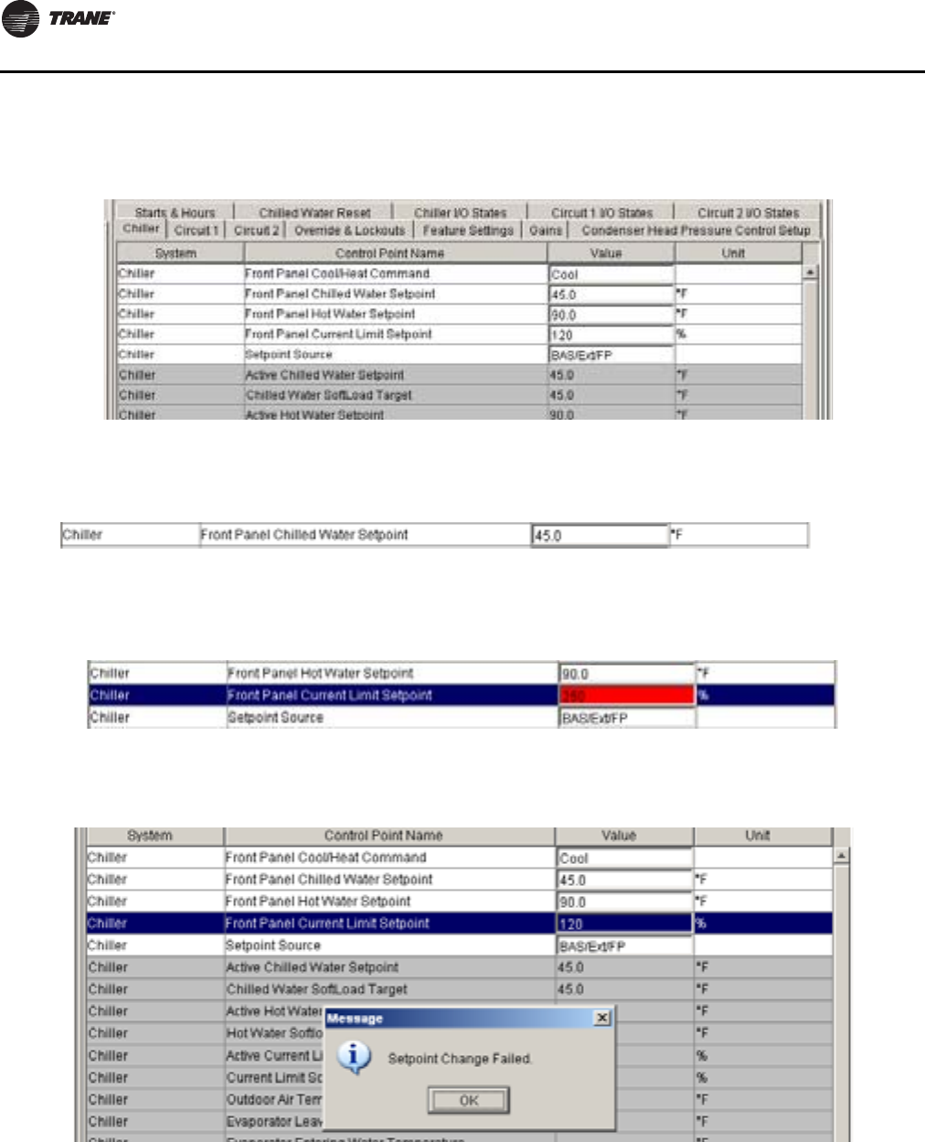
Controls Interface
154 RLC-SVX09H-EN
To change the setpoint, enter a new value for the setpoint
into the text field.
If the entered value is outside the given range, the
background turns red.
If the value entered is not valid, an error message will
display and the change will not occur.
Status View
Status View displays, in real time, all non-setpoint data
organized by subsystem tabs. As data changes on the
chiller, it is automatically updated in Status View.
Figure 57. Fields in white
Figure 58. Change setpoint
Figure 59. Change out of range
Figure 60. Setpoint change failed
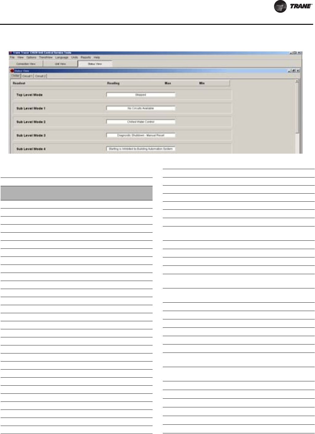
Controls Interface
RLC-SVX09H-EN 155
Figure 61. Status view
Table 122. Status view tab - detail
Tab Control Point Name Units
Chille
r
Front Panel Auto Stop Command
Local Atmospheric Pressure psia
Application Software Revision
Keypad Lockout
Local Stop Delay sec
Top Level Mode
Sub Level Mode 1
Sub Level Mode 2
Sub Level Mode 3
Sub Level Mode 4
Sub Level Mode 5
Sub Level Mode 6
Unit Running Powered Indicator
MMR
MAR
IFW
Chiller Running Time hrs:mins
Active Chiller Auto/Stop Command
Setpoint Source Manual Override Exists
Power-Up Start Delay sec
Outdoor Air Temperature °F (°C)
Cooling Low Ambient Lockout
Cooling Low Ambient Lockout Temperature °F (°C)
Chiller Mode at Time of Last Diagnostic °F (°C)
Chiller Sub Mode 1 at Time of Last Diagnostic
Chiller Sub Mode 2 at Time of Last Diagnostic
Chiller Sub Mode 3at Time of Last Diagnostic
Chiller Sub Mode 4 at Time of Last Diagnostic
Chiller Sub Mode 5 at Time of Last Diagnostic
Chiller Sub Mode 6 at Time of Last Diagnostic
Front Panel Current Limit Setpoint %
Active Current Limit Setpoint %
Active Current Limit Setpoint Source
Current Limit SoftLoad Target %
Average Percent RLA % RLA
Low Evaporator Leaving Water
Temperature Cutout °F (°C)
Evaporator Entering Water Temperature °F (°C)
Evaporator Leaving Water Temperature °F (°C)
Front Panel Cool/Heat Command
Staging Sequence
Cooling Design Delta Temperature
(Waterside) °F (°C)
Heating Design Delta Temperature
(Waterside) °F (°C)
Differential to Start °F (°C)
Differential to Stop °F (°C)
Start to Start Delay Time
Capacity Control Debug State
Active Hot Water Command
Capacity Control Source
Manual Staging/Stepping Control
Command
Manual Capacity Modulation Control
Command %
Variable Evaporator Water Flow Compensation
Variable Flow Filtered Result
Current Limit Control Softload Time sec
Current Limit Softload Start Point %
Front Panel Chilled Water Setpoint °F (°C)
Front Panel Hot Water Setpoint °F (°C)
Table 122. Status view tab - detail (continued)
Tab Control Point Name Units

Controls Interface
156 RLC-SVX09H-EN
Capacity Control Softload Time sec
Arbitrated Chilled Water Setpoint °F (°C)
Active Chilled Water Setpoint Source
Active Chilled Water Setpoint °F (°C)
Chilled Water Setpoint SoftLoad Target °F (°C)
Arbitrated Hot Water Setpoint °F (°C)
Active Hot Water Setpoint Source
Active Hot Water Setpoint °F (°C)
Hot Water Setpoint SoftLoad Target °F (°C)
Need to Run Cooling
Need to Run Heating
Chilled Water Reset Type
Return Water Reset Ratio %
Return Water Start Reset °F (°C)
Return Water Maximum Reset °F (°C)
Outdoor Air Reset Ratio %
Outdoor Air Start Reset °F (°C)
Outdoor Air Maximum Reset °F (°C)
Desired Degrees of Reset °F (°C)
Actual Degrees of Chilled Water Reset °F (°C)
Circulating Pump
Evaporator Water Flow Switch Status
Evaporator Pump Off Delay mins:secs
External Auto Stop
Emergency Stop
Head Relief Relay Filter Time sec
External Chilled Water Setpoint °F (°C)
Ext Hot Water Setpoint
External Chilled/Hot Water Setpoint Enable
External Current Limit Setpoint
External Current Limit Setpoint Enable
Maximum Capacity Relay Filter Time sec
Limit Relay filter Time sec
External Hot Water Command
High Evaporator Water Temperature Cutout °F (°C)
Condenser Entering Water Temperature °F (°C)
Condenser Leaving Water Temperature °F (°C)
Condenser Pump Off Delay minutes
Condenser Water Flow Switch Status
Front Panel ice Building Command
Front Panel Ice Termination Setpoint °F (°C)
Ice Building Feature
Active Ice Building Command
Active Ice Termination Setpoint °F (°C)
Table 122. Status view tab - detail (continued)
Tab Control Point Name Units
Active Ice Termination Setpoint Source
Ice Building Current Limit Setpoint %
External Ice Building Input
Need to run ice
Condenser Elevation
Starter Energy Consumption Last Reset
Chiller Power Demand kW
Chiller Power Demand Time Period minutes
Under/Over Voltage Protection Enable
CWRV Output Voltage at Desired Maximum Flow volts
CWRV 'Off State' Output Command volts
CWRV Desired Minimum Flow %
CWRV Actuator Stroke Time sec
CWRV Damping Coefficient
CWRV Head Pressure control Output %
CWRV Time Till Actuator at Position mins:secs
CWRV Time to Safe Start of Cond Wtr Pump mins:secs
CWRV Percent Status %
Circuit 1
EXV Position Steps steps
EXV Percent Open %
Front Panel Circuit Lockout
Evaporator Refrigerant Liquid Level in (mm)
Mode
Sub Level Mode 1
Sub Level Mode 2
Sub Level Mode 3
Sub Level Mode 4
Sub Level Mode 5
Sub Level Mode 6
Condenser Refrigerant Pressure psi gauge
Condenser Saturated Refrigerant Temperature °F (°C)
Evaporator Refrigerant Pressure psi gauge
Evaporator Saturated Refrigerant Temperature °F (°C)
Circuit Running Powered Indicator
Circuit Manual Reset Indicator (CMR)
Circuit Auto Reset Indicator (CAR)
Circuit Informational Warning Indicator (IFW)
Circuit Limit Min Command
Differential Refrigerant Pressure psid
Compressor 1A Service Pumpdown Status
Evaporator Approach Temperature °F (°C)
Condenser Approach Temperature °F (°C)
Compressor Refrigerant Discharge Superheat °F (°C)
Table 122. Status view tab - detail (continued)
Tab Control Point Name Units

Controls Interface
RLC-SVX09H-EN 157
Diagnostics View
This window lists the active and inactive (history)
diagnostics.There can be up to 60 diagnostics, both active
and historic. For example, if there were 5 active
diagnostics, the possible number of historic diagnostics
would be 55.You can also reset active diagnostics here,
(i.e., transfer active diagnostics to history and allow the
chiller to regenerate any active diagnostics).
Top Level Mode at Last Diagnostic
Submode 1 at Last Diagnostic
Submode 2 at Last Diagnostic
Submode 3 at Last Diagnostic
Submode 4 at Last Diagnostic
Submode 5 at Last Diagnostic
Submode 6 at Last Diagnostic
Compressor Lockout
Compressor 1A Starts
Compressor 1A Running Time
Compressor Running Indicator hrs:mins
Compressor 1A Load Step
Compressor Refrigerant Discharge Temperature °F (°C)
Compressor 1A Oil Pressure psi gauge
Compressor 1A Line 1 Current % RLA
Compressor 1A Line 2 Current % RLA
Compressor 1A Line 3 Current % RLA
Line 1 Current Amps amps
Line 2 Current Amps amps
Line 3 Current Amps amps
Starter 1A Voltage Vab volts
Compressor 1A Average Line Current % RLA
Maximum Line Current %
Compressor 1A Power Consumption kW
Compressor 1A Power Factor
Circuit 2
EXV Command (%) %
EXV Position Steps steps
EXV Percent Open %
Front Panel Circuit Lockout
Evaporator Refrigerant Liquid Level in
Mode
Sub Level Mode 1
Sub Level Mode 2
Sub Level Mode 3
Sub Level Mode 4
Sub Level Mode 5
Sub Level Mode 6
Condenser Refrigerant Pressure psi gauge
Condenser Saturated Refrigerant Temperature °F (°C)
Evaporator Refrigerant Pressure psi gauge
Evaporator Saturated Refrigerant Temperature °F (°C)
Circuit Running Powered Indicator
Circuit Manual Reset Indicator (CMR)
Table 122. Status view tab - detail (continued)
Tab Control Point Name Units
Circuit Auto Reset Indicator (CAR)
Circuit Informational Warning Indicator (IFW)
Circuit Limit Min Command
Differential Refrigerant Pressure psid
Compressor 1A Service Pumpdown Status
Evaporator Approach Temperature °F (°C)
Condenser Approach Temperature °F (°C)
Compressor Refrigerant Discharge Superheat °F (°C)
Top Level Mode at Last Diagnostic
Submode 1 at Last Diagnostic
Submode 2 at Last Diagnostic
Submode 3 at Last Diagnostic
Submode 4 at Last Diagnostic
Submode 5 at Last Diagnostic
Submode 6at Last Diagnostic
Compressor Lockout
Compressor 2A Starts
Compressor 2A Running Time hrs:mins
Compressor Running Indicator
Compressor 2A Load Step
Compressor Refrigerant Discharge Temperature °F (°C)
Compressor 2A Oil Pressure psi gauge
Compressor 2A Line 1 Current % RLA
Compressor 2A Line 2 Current % RLA
Compressor 2A Line 3 Current % RLA
Line 1 Current Amps amps
Line 2 Current Amps amps
Line 3 Current Amps amps
Compressor 2A Average Line Current % RLA
Maximum Line Current %
Compressor 2A Power Factor
Manual Overrides
Manual Staging/Stepping Control
Manual Capacity Modulation Control
Evaporator Water Pump Override
Condenser Water Pump Override
Compressor 1A service Pumpdown Status
Compressor 1A Pumpdown Command
Table 122. Status view tab - detail (continued)
Tab Control Point Name Units
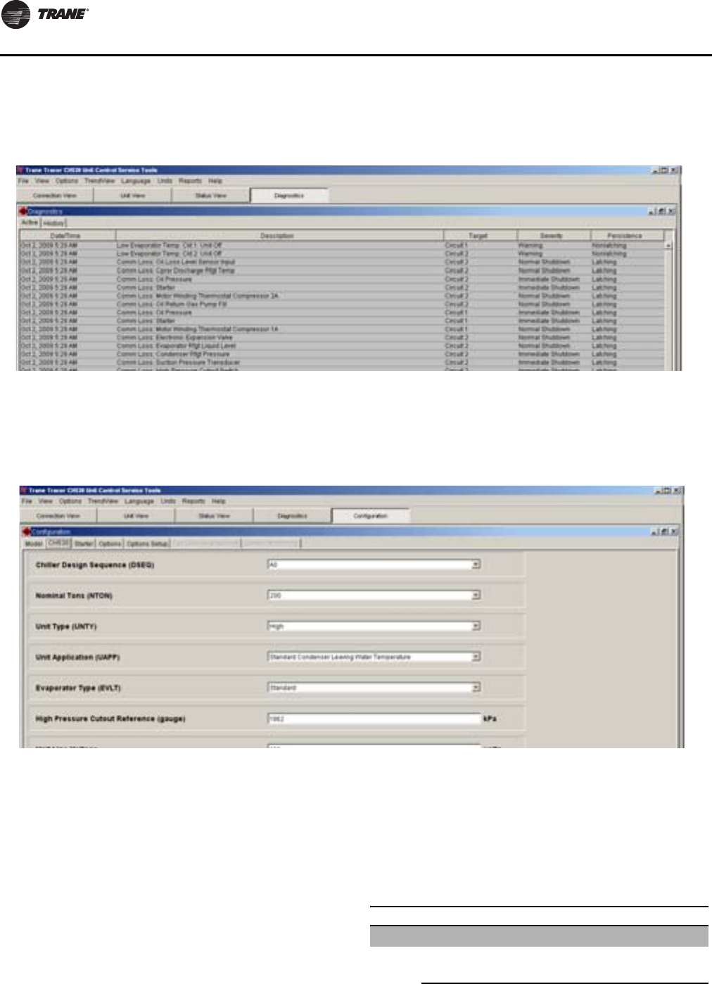
Controls Interface
158 RLC-SVX09H-EN
Resetting the active diagnostics may cause the chiller to
resume operation.
The Active and History diagnostics have separate tabs. A
button to reset the active diagnostics displays when either
tab is selected.
Configuration View
This view is under the CH530 tab. It displays the active
configuration and allows you to make changes to the unit
configuration.
Configuration View allows you to define the chiller's
components, ratings, and configuration settings.These
are all values that determine the required installed
devices, and how the chiller application is run in the main
processor. For example, a user may set an option to be
installed with Configuration View, which will require
devices to be bound using Binding View. And when the
main processor runs the chiller application, the
appropriate steps are taken to monitor required inputs and
control necessary outputs.
Any changes made in the ConfigurationView, on any of the
tabs, will modify the chiller configuration when you click
on the Load Configuration button (located at the base of
the window).The Load Configuration button uploads the
new configuration settings into the main processor.
Selecting the Undo All button will undo any configuration
setting changes made during the presentTechView
connection and since the last time the Load Configuration
button was selected.
Figure 62. Diagnostic view
Figure 63. Configuration view - CH530 tab
Table 123. Configuration view items - detail
Tab Item Description
Model
Model Type (MODL) RTWD
RTUD
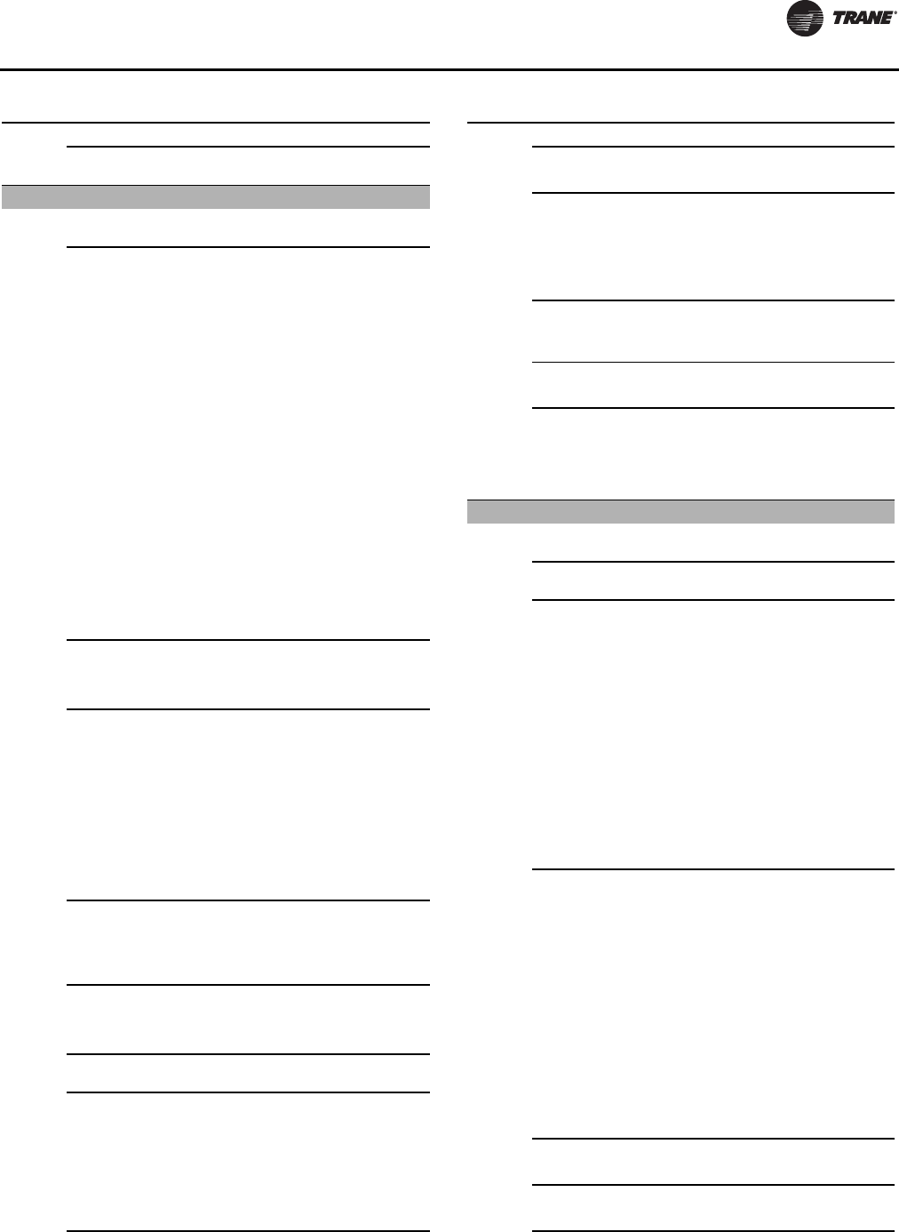
Controls Interface
RLC-SVX09H-EN 159
RTWD/CH530 Configuration
Control Sequence 1
CH530
Chiller Design Sequence
(DSEQ) Factory Assigned
Nominal Tons (NTON) 60
70
80
90
100
110
120
130
140
150
160
170
180
190
200
220
250
Unit Type (UNTY) Standard
High
Premium
Unit Application (UAAP) Standard Condenser Leaving
Water Temperature
High Temperature
Condenser Leaving Water
Temperature
Water-Water Heat Pump
Standard Ambient (Air-
Cooled Condenser)
High Ambient (Air-Cooled
Condenser)
No Fan Controls (Water
Cooled)
Fan Control by Others
Integral Fan Controls
Evaporator Type (EVLT) Standard
Process
Ice
High Pressure Cutout
Reference (gauge)
Unit Line Voltage 200V
230V
380V
400V
460V
575V
Table 123. Configuration view items - detail (continued)
Tab Item Description
Line Frequency (HRTZ) 50Hz
60Hz
Manufacturing Location
(DCLT) Curitiba, Brazil
Pueblo, USA
Charmes, France
Taicang, China
Line Voltage Sensing
(WUVO) Not Installed
Installed
Power Meter (PWRM) Not Installed
Installed
Water Flow Proving -Factory
Installed (FLOW)
115 VAC Paddle Type Flow
Switch
Factory Installed Low
Voltage Thermal Type Flow
Switch
Starter
Compressor 1A Rated Load
Amps Range = 1 - 999
Compressor 2A Rated Load
Amps Range = 1 - 999
Compressor 1A Current
Transformer Meter Scale 37.5 Amps
50 Amps
75 Amps
100 Amps
150 Amps
200 Amps
275 Amps
400 Amps
500 Amps
700 Amps
1000 Amps
Compressor 2A Current
Transformer Meter Scale 37.5 Amps
50 Amps
75 Amps
100 Amps
150 Amps
200 Amps
275 Amps
400 Amps
500 Amps
700 Amps
1000 Amps
Starter Type (SRTY) Wye-Delta Closed Transition
Across the Line
Contactor Integrity Test Enable
Disable
Table 123. Configuration view items - detail (continued)
Tab Item Description
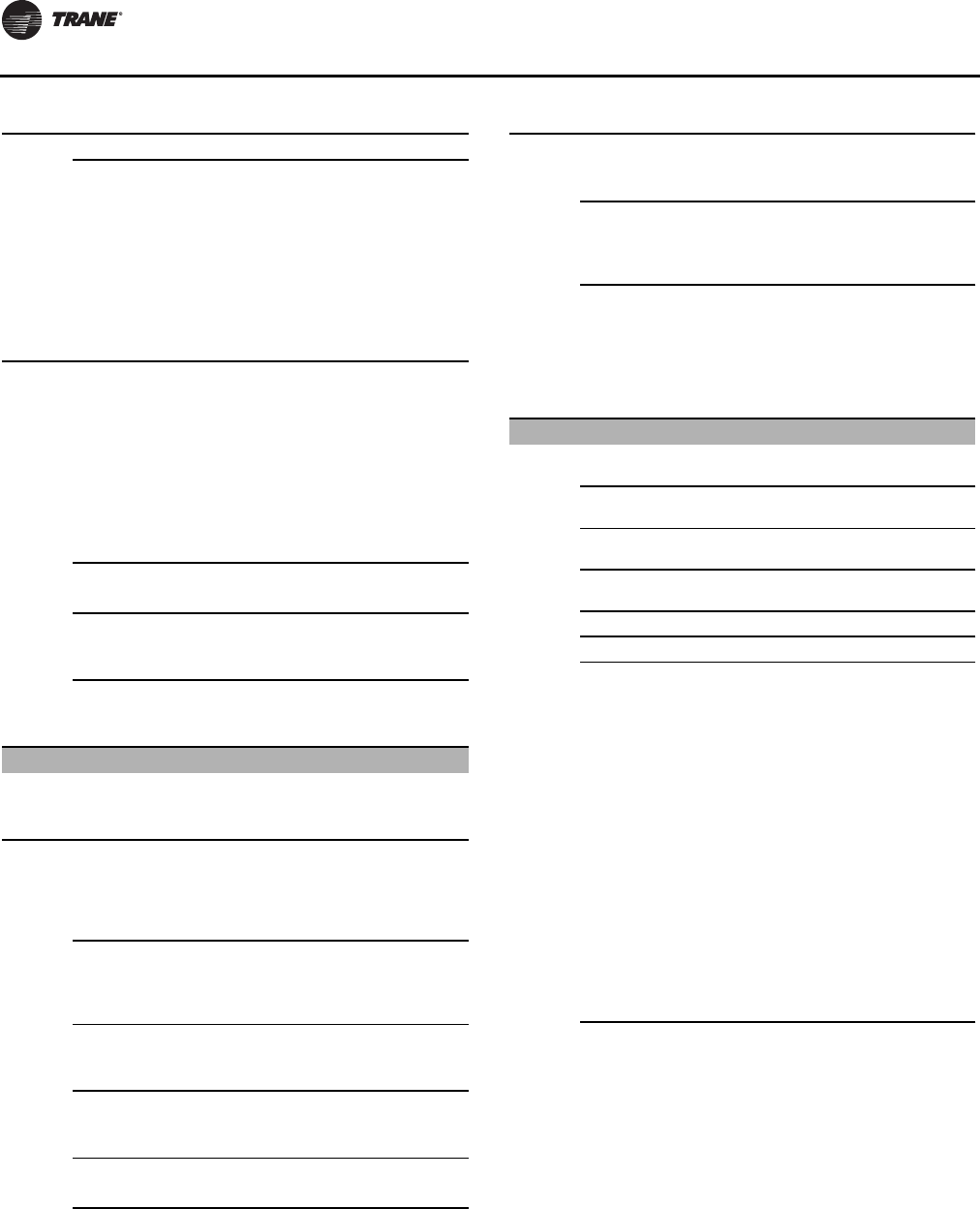
Controls Interface
160 RLC-SVX09H-EN
Compressor 1A Frame Size K1
K2
L1
L2
M1
M2
N1
N2
Compressor 2A Frame Size K1
K2
L1
L2
M1
M2
N1
N2
Phase Reversal Protection Enable
Disable
Current Unbalance Trip Point 15 to 90
Current Unbalance Grace
Point 30 to 255
Starter Panel Forced
Ventilation (SPFV) Not Installed
Installed
Options
Outdoor Air Temperature
(OATS) Not Installed
Installed
Ice Building Option (ICEB) Not Installed
Installed
Installed With Hardware
Installed Without Hardware
ECWS/EHWS and External
Current Limit Setpoint
(SETP)
4-20mA, 2-10Vdc
Not Installed
Motor Current Analog Output
(CAOA) Not Installed
Installed
Programmable Status Relays
(STAT) Not Installed
Installed
Generic Monitoring Package None
Installed
Refrigerant Pressure Output
Type (RPOT) Not Installed
Installed
Condenser Pressure in
%HPC
Differential Pressure
Table 123. Configuration view items - detail (continued)
Tab Item Description
Condenser Water Regulating
Valve Output
Condenser Leaving Hot
Water Temp Control (HWTC) None
Hot Water Temperature
Control
BAS Communication/Local
Time of Day Schedule
(COMM)
Not Installed
Lontalk
Local Time of Day Scheduling
BACnet Interface
Options Set Up
ECWS Minimum
Temperature -12.22 to 9.9°C
ECWS Maximum
Temperature 10 to 18.4°C
EHWS Minimum
Temperature 20 - 60°C
EHWS Maximum
Temperature 20 - 60°C
ECLS Minimum%RLA 60
ECLS Maximum%RLA 120
Programmable Status Relay
1 (J2-10,11,12) None
Chiller Limit Mode
Max Capacity
Compressor Running
Alarm
Latching Alarm
Non-Latching Alarm
Alarm Circuit 1
Alarm Circuit 2
Circuit 1 Running
Circuit 2 Running
Head Pressure Relief
Request
Warning
Programmable Status Relay
2 (J2-7,8,9) None
Chiller Limit Mode
Max Capacity
Compressor Running
Alarm
Latching Alarm
Non-Latching Alarm
Alarm Circuit 1
Alarm Circuit 2
Circuit 1 Running
Circuit 2 Running
Head Pressure Relief
Request
Table 123. Configuration view items - detail (continued)
Tab Item Description
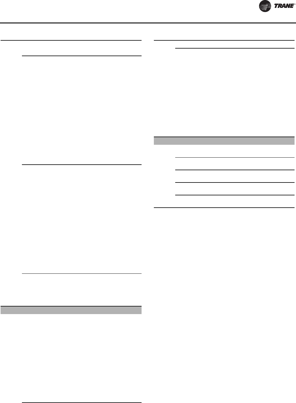
Controls Interface
RLC-SVX09H-EN 161
A couple of additional tabs in Configuration View allow
you to change other unit configuration options using the
Options tab and the Options SetupTab.The features that
are installed on the OptionsTab will control what is
displayed on the Options SetupTab.
Warning
Programmable Status Relay
3 (J2-4,5,6) None
Chiller Limit Mode
Max Capacity
Compressor Running
Alarm
Latching Alarm
Non-Latching Alarm
Alarm Circuit 1
Alarm Circuit 2
Circuit 1 Running
Circuit 2 Running
Head Pressure Relief
Request
Warning
Programmable Status Relay
4 (J2-1,2,3) None
Chiller Limit Mode
Max Capacity
Compressor Running
Alarm
Latching Alarm
Non-Latching Alarm
Alarm Circuit 1
Alarm Circuit 2
Circuit 1 Running
Circuit 2 Running
Head Pressure Relief
Request
Warning
Low Ambient Fan Control
Type None
Variable Speed Fan with
Analog Interface
Two Speed Fan
Fan Deck Arrangement
Fan Deck Arrangement
Circuit 1 (FDA1) 1 Fan (1H00)
2 Fans (1H10)
3 Fans (1H11)
3 Fans-type 2 (1H20)
4 Fans (1H12)
5 Fans (1H13)
5 Fans-type 2 (1112)
6 Fans (2H22)
6 Fans-type 2 (1212)
7 Fans-type 2 (1123)
8 Fans-type 2 (1124)
Table 123. Configuration view items - detail (continued)
Tab Item Description
Fan Deck Arrangement
Circuit 1 (FDA2) 1 Fan (1H00)
2 Fans (1H10)
3 Fans (1H11)
3 Fans-type 2 (1H20)
4 Fans (1H12)
5 Fans (1H13)
5 Fans-type 2 (1112)
6 Fans (2H22)
6 Fans-type 2 (1212)
7 Fans-type 2 (1123)
8 Fans-type 2 (1124)
Generic Monitoring
Monitoring Temperature
Sensors 0 - 8
Monitoring Pressure
Transducers 0 - 8
Monitoring Dual Current
Loop Input Modules 0 - 4
Monitoring Dual Low Voltage
Binary Input Modules 0 - 4
Monitoring Dual High Voltage
Binary Input Modules 0 - 4
Table 123. Configuration view items - detail (continued)
Tab Item Description

Controls Interface
162 RLC-SVX09H-EN
Software View
Software view allows you to verify the version of chiller
software currently running on the DynaView and
download a new version of chiller software to the
DynaView.
You can also add up to two available languages to load into
the DynaView. Loading an alternate language file allows
the DynaView to display its text in the selected alternate
language, English will always be available.
Binding View
Binding View allows you to assess the status of the
network and all the devices connected as a whole, or the
status of individual devices by using status icons and
function buttons.
Binding View is essentially a table depicting what devices
and options are actually discovered on the network bus
(and their communication status) versus what is required
to support the configuration defined by the feature codes
and categories. Binding View allows you to add, remove,
modify, verify, and reassign devices and options in order
to match the configuration requirements.Whenever a
device is installed, it must be correctly configured to
communicate and to function as intended.This process is
called binding. Some features of Binding View are
intended to serve a second purpose; that is diagnosing
problems with communication among the devices
Figure 64. Configuration view - options tab
Figure 65. Software view
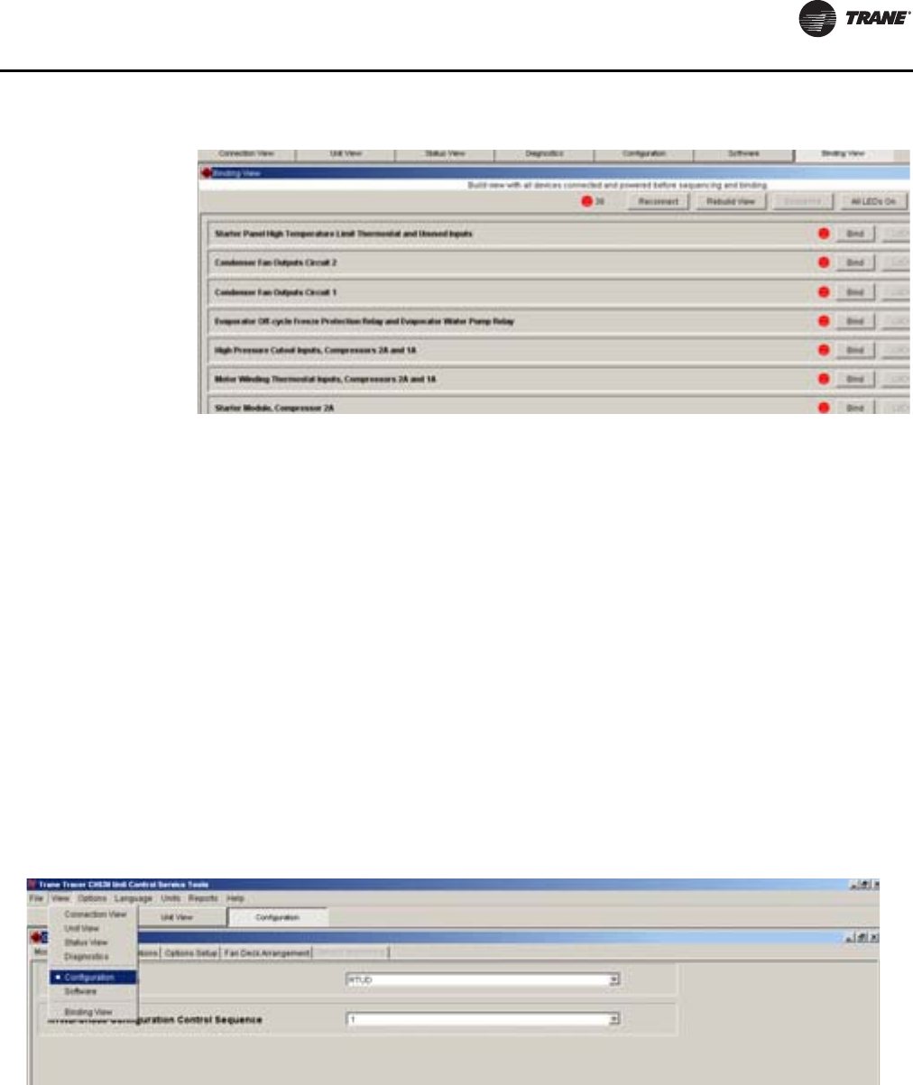
Controls Interface
RLC-SVX09H-EN 163
.
Replacing or Adding Devices
If a device is communicating but incorrectly configured, it
might not be necessary to replace it. If the problem with
the device is related to communication, attempt to rebind
it, and if the device becomes correctly configured, it will
then communicate properly.
If a device that needs to be replaced is still communicating,
it should be unbound. Otherwise, it will be necessary to
rebuild the CH530 network image for Binding View to
discover that it has been removed. An unbound device
stops communicating and allows a new device to be
bound in its place.
It is good practice to turn the power off while detaching
and attaching devices to the CH530 network. Be sure to
keep power on the service tool computer. After power is
restored to the CH530 network, the reconnect function in
BindingView restores communication with the network. If
the service tool computer is turned off, you must restart
TechView and Binding View.
If a device is not communicating, the binding function
displays a window to request manual selection of the
device to be bound. Previously-selected devices are
deselected when the function starts. When manual
selection is confirmed, exactly one device must be
selected; if it is the correct type, it is bound. If the desired
device cannot be selected or if multiple devices are
accidentally selected, you can close the manual selection
window by clicking on No and repeat the bind function.
Fan Configurations
The configurations discussed below are accessible using
TechView ServiceTool – View - Configurations, and only
applicable for UnitType (MODL) configuration = RTUD.
Conversely, the following configuration items are not
visible if UnitType (MODL) is set to = RTWD.
A/C Fan Controls
This configuration item is used to define the RTUD fan
control type including alternate operation as a water
cooled instead of an air cooled condenser.
Figure 66. Binding view
Figure 67. Fan configurations - RTUD
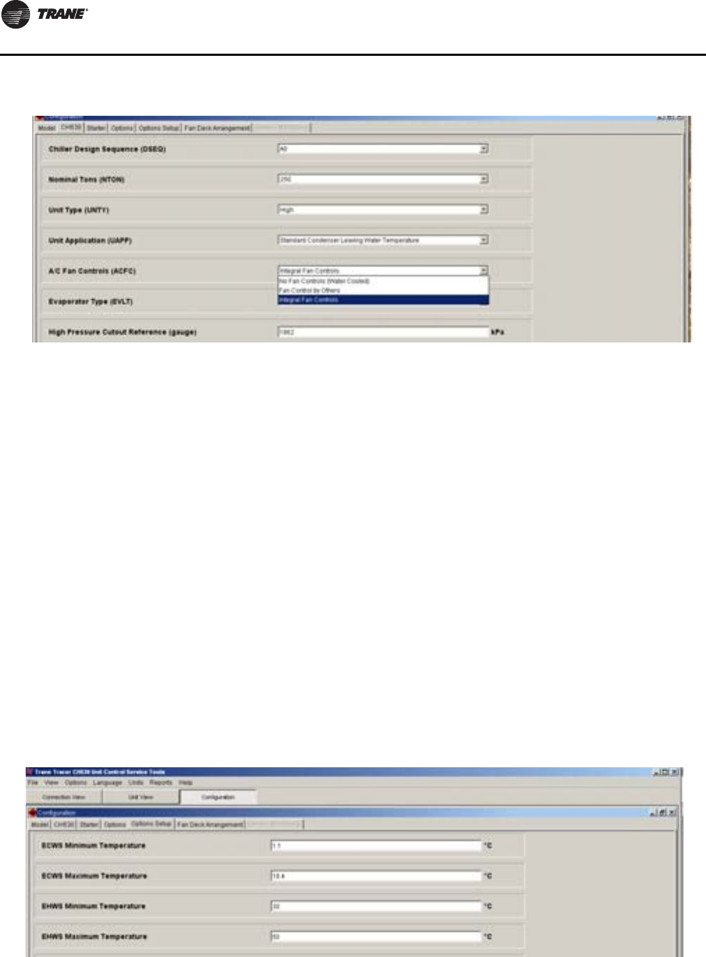
Controls Interface
164 RLC-SVX09H-EN
No Fan Controls (Water Cooled)
If this setting is set to“No Fan Controls (Water Cooled)”, the
unit shall be controlled exactly the same as an RTWD unit,
that is, that the control logic and sequences will assume
that there is a water cooled condenser and condenser
water pump control, condenser water flow proving, and
circuits start delay times associated with condenser water
pump prerun times shall be employed.The DynaView (and
TechView) shall display the condenser water temperatures
and condenser approach temperatures as defined
(although generally a RTUD unit will not ship with
condenser water temperature sensors installed and
bound) – for proper unit operation as a remote water
cooled condenser, the condenser water temperature LLIDs
will have to be field installed and bound.
Fan Control By Others
If this setting is set to “Fan Control By Others”, the first two
relays on the “Fan Control Interlock” quad relay output
board relays will function as interlock contacts for use as
in input to an external pressure or temperature based fan
controller on a per circuit basis. Concurrent with the
circuit’s EXV pre-position as part of the start sequence of
a given circuit, the respective “fan control interlock” relay
for that circuit will energize and close the NO contacts.
The respective relay shall be de-energized to return to its
normal state, once the circuit/compressor has stopped.
Note that this means the relay shall stay energized until the
compressor state is proven to be off.
Integral Fan Controls
If this setting is set to “Integral Fan Controls,” the fan
controls are integral to the CH530 main processor and
(depending on the selection for the other fan control
configurations - i.e. Fan Deck Arrangement Circuit 1
(FDA1), Fan Deck Arrangement Circuit 2 (FDA2), Low
Ambient Fan ControlType (LAFC)) shall control the
appropriate relays (and connected fans) and other outputs
(variable speed fan outputs and monitor VFD fault inputs)
to control the differential pressure per the chiller’s
requirements.
Low Ambient Fan Control Type
Note: Present if A/C Fan Control (ACFC) = Integral Fan
Control (INT)
Figure 68. A/C fan controls - RTUD
Figure 69. Low ambient fan control type
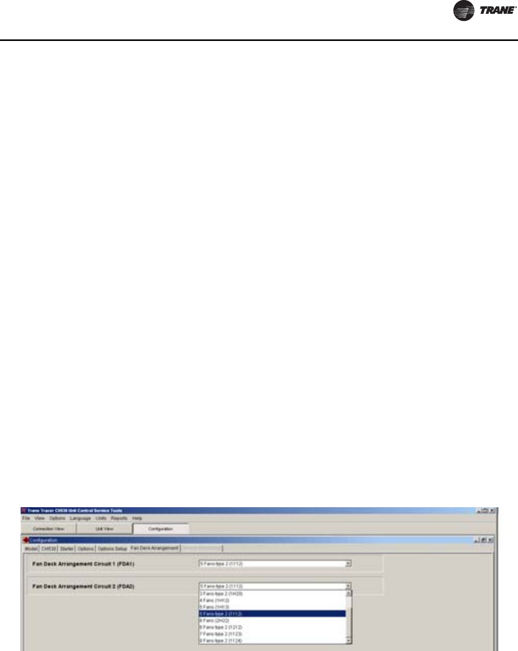
Controls Interface
RLC-SVX09H-EN 165
If this setting is set to “None”, fan control shall be per the
full speed fixed speed fan tables with each circuit applying
the Fan Deck Arrangement configuration selected below.
If this setting is “Two Speed Fan” (TSPD), fan control shall
provide for the first fan to be a two speed fan and control
and the first two relays of the quad relay shall be used for
low and high speed control of that fan. TheTwo–speed fan
operation, assumes the use of fans and contactors
designed for Wye (low speed) and Delta (high speed)
motor connections and the ratio of the low to high speed
cfm is approximately 80%. ForTwo-Speed fan
configurations, low to high and high to low speed
transitions are subject to a 5 second delay with neither the
low speed nor the high speed contacts being energized.
The low speed contact generally refers to relay 1 and the
high speed contact generally refers to relay 2.
Note: When selecting two speed fan control for the low
ambient option, only the Fan Deck Arrangements
with an “H” in the 2nd position of the fan grouping
definition are supported.
If this setting is “Variable Speed Fan with Analog
Interface”VARA, the fan control shall operate fixed speed
fans as well as a single inverter driven fan, and the controls
include the enabling and speed command signals to this
variable speed inverter.The inverter shall have an analog
interface and fault feedback and be similar to the DanFoss
TR1 2800 series inverter.
For variable speed fan decks, the first relay controls the
variable frequency drive, through an enable/disable input
of the inverter.The Variable speed fan option supports an
inverter fault input to monitor the fault state of the inverter.
An inverter fault or other inverter-related diagnostic
causes the fan control to de-energize the inverter relay,
command a zero percent speed via the analog speed
command interface, and reverts to a special fixed-speed
fan control mode.
In normal operation (no inverter diagnostics), the inverter
is not commanded to zero-speed unless all other fans are
commanded off. During normal operation, a minimum
inverter speed command is enforced to prevent counter-
rotation of the inverter driven fan. Counter-rotation can
reduce fan deck capacity and negatively affect reliability of
inverters and its fans.
Variable Speed Analog Fans
Each independently controlled variable speed fan has
three I/O points:
• A fan deck relay controls the inverter run/stop
command state. (Inverter power is continuously
applied and not controlled by a contactor.)
• A 0-10 Volt analog output commands the variable
frequency drive’s speed.
Output Voltage [V] = Desired VFD Speed [%] /10, with a
minimum Desired VFD Speed of 7% (0.7V).
To send a reset command, 0% (0.0V) is sent.
• A binary input senses inverter faults.
The Fan Inverter Fault LLID binary input expects to see and
open-circuit (i.e open dry contact) on its respective input
terminals when the inverter is de-energized or when an
inverter fault is present.
The Fan Inverter Fault LLID binary input expects to see a
closed circuit (i.e. closed dry contact) when the inverter is
energized and no faults are active.
The inverter fault diagnostic is not activated until 5
seconds after the inverter Run/Stop command relay is
energized.
Fan Deck Arrangement Circuit 1
Note: Present if A/C Fan Control (ACFC) = Integral Fan
Control (INT)
This setting defines the wiring of the four fan relays
outputs of the Fan Control Relay LLID for the respective
circuit (circuit 2’s setting is shown above). It indicates the
fan grouping in terms of how many fans each particular
relay is expected to control. The numbers in parentheses
refer to the number of fans controlled by each of the 4
relays in order (lowest terminal number designators first).
“H” means reserved for high speed of 2 speed fan, if
applicable - if no two-speed fan selected in LAFC, then “H”
implies no fans wired to this relay.
Figure 70. Fan deck arrangement
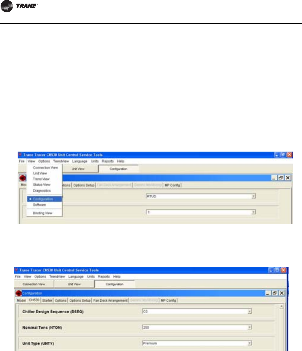
Controls Interface
166 RLC-SVX09H-EN
Fan Deck Arrangement Circuit 2
Note: Present if A/C Fan Control (ACFC) = Integral
This setting is the same as above, except for circuit 2. Each
circuit may have different fan arrangements, but both
must use an identical type of low ambient fan control if
applicable.
Example for Fan Configurations
An air cooled condensing unit is selected that properly
matches the capacity of the RTUD unit intended for a
comfort cooling application. Lets assume the condenser
has 5 fixed speed fans per circuit, and no variable speed
fans or two speed fans, since operation below 32F outdoor
air ambient temperature is not required.
The RTUD chiller should come factory configured as an
RTUD chiller, but the fan configurations will generally need
to be set in the field per the condenser selected and
installed with the chiller. UsingTechView PC based service
tool running on a laptop PC or similar, power up the
controls on the chiller and connect to the PC using an
RS232 cable (connection on the bottom of the CH530
Adaptive Control).
A/C Fan Controls (ACFC)
LaunchTechView and press the “Local Connection” button
in the bottom left hand corner. When the connection is
completed – proceed to the configurations view
And then select tab “CH530” and the “A/C Fan Controls”
item in that list, select “Integral Fan Controls” for that
item:view
Then proceed to theTab “Options Setup” and the item Low
Ambient ControlType in that list; select “None” for that
item.Then proceed to the Fan Deck ArrangementTab and
click on the Fan Deck Arrangement Circuit 1 item. By
clicking In the drop down box, you will see a number of
supported fan deck arrangements. In the drop down we
can see that there are two unique arrangements that
support 5 fans total.The first one is designated as “1H13”
and the 2nd is “1112”.
Figure 71. Service tool - view configuration
Figure 72. Service tool configuration - integral fan control selection
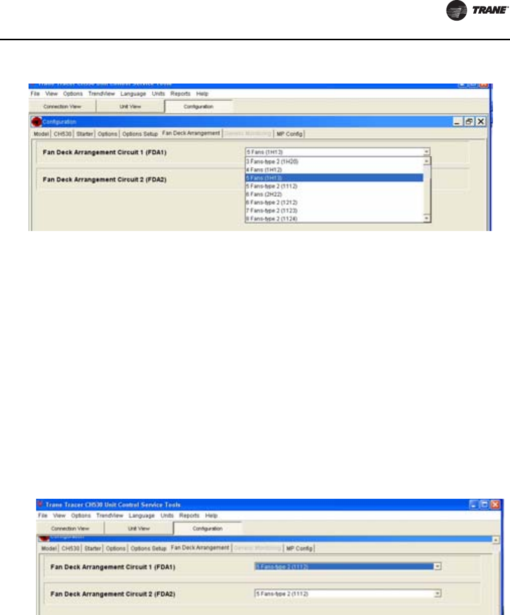
Controls Interface
RLC-SVX09H-EN 167
The character in the 4 digit descriptor define the number of
fans that are intended to be wired to each of the 4 relays on
the respective circuit’s quad fan control relay LLID.The
first of the two possible 5 fan arrangements uses sequence
1 H 1 3.This sequence implies there should be 1 fan wired
to relay 1 (terminals J2-1,3 of module 1A25 – Circuit 1 Fan
Control module, which are internally wired to the 1X11
terminals 1 & 2).Then next digit in the sequence H, is only
for use with the High speed of a 2 speed fan configuration
and since “none” was selected for low ambient options,
this means it is not to be used and nothing should be wired
to the 2nd relay (terminals J2-4,6 1X11 terminals3&4).
Likewise, the 3rd and 4th digits imply the number of fans
that are to be wired to the 3rd and 4th relays, (the relays
being internally wired to the terminal strip 1X11 terminals
5&6and7&8respectively.)
The second alternative wiring for a fixed speed 5 fan deck
is the 1112 selection. In this scheme, the first 3 relays
(terminals 1X11 1&2, 3&4, 5&6), should all be wired to
control one fan, and the last relay should control 2 fans
(1X11 terminals7&8)
Repeat the same selection for circuit 2 by click on the Fan
Deck Arrangement Circuit 2 item. In the drop down box,
you will see a number of supported fan deck
arrangements. Select the appropriate fan deck
arrangement for circuit 2.The selection of the
arrangement would then define the wiring for module
1A26 – Circuit 2 Fan Control Module and it associated field
wiring terminals 1X11 terminals 9 &10, 11 & 12, 13 &14, and
15&16).
Note: The fan deck arrangement does not necessarily
have to be the same as Circuit 1, but usually the
circuits have the same number of fans and
therefore the same arrangement selection is
appropriate.
As a last important step, the configurations need to be
downloaded to the CH530 DynaView/Main Processor.This
is accomplished by clicking on the “Load Configurations”
button at the bottom of the configurations screen.
Allow a short time for the configuration to be set and both
the CH530 DynaView andTechView to reboot. If new LLIDs
and hardware binding for them is required as a result of
the configuration just downloaded,TechView will
immediately launch the “Binding View” that provides for
a list of the required LLIDs and their communication
status. Install and bind all new LLIDs as required. Most
often, however, the proper LLIDs will already be present
and bound if the options were appropriately ordered with
the chiller.
Figure 73. Service tool configuration - fan deck arrangement
Figure 74. Load configurations
168 RLC-SVX09H-EN
Pre-Start Checkout
When installation is complete, but prior to putting the unit
into service, the following pre-start procedures must be
reviewed and verified correct:
Note: For any installation violations of this manual, use
Non-Compliance form PROD-ADF001-EN.
Note: Verify removal of oil separator shipping spaces as
required in Installation-Mechanical chapter. Failure
to remove the spacers could result in excessive
noise and vibration transmission into the building.
• Inspect all wiring connections to be sure they are clean
and tight.
• For RTUD units, verify that unit piping between RTUD
and condenser is as described in ”Installation-
Mechanical” section.
• Verify that all refrigerant valves are “OPEN”
• Check the power supply voltage to the unit at the main
power fused-disconnect switch. Voltage must be
within the voltage utilization range stamped on the unit
nameplate. Voltage imbalance must not exceed 2
percent. See "Unit Voltage Imbalance", p. 169.
• Check the unit power phasing to be sure that it has
been installed in an “ABC” sequence. See "UnitVoltage
Phasing", p. 169.
• Fill the evaporator and condenser chilled water
circuits. Vent the system while it is being filled. Open
the vents on the top of the evaporator and condenser
during filling and close when filling is completed.
• Close the fused-disconnect switch(es) that supplies
power to the chilled water pump starter and the
condenser water pump starter.
• Start the chilled water pump and condenser water
pump (RTWD only)
• to begin circulation of the water. Inspect all piping for
leakage and make any necessary repairs.
• With water circulating through the system, adjust
water flow and check water pressure drop through the
evaporator and condenser.
• Adjust the chilled water flow switch and condenser
water flow switch (if installed) for proper operation.
• Prove all Interlock and Interlock and External as
described in Section “Installation-Electrical”.
• Check and set, as required, all CH530 Menu Items.
• Stop the chilled water pump and condenser water
pump.
WARNING
Hazardous Voltage!
Disconnect all electric power, including remote
disconnects before servicing. Follow proper lockout/
tagout procedures to ensure the power can not be
inadvertently energized. Failure to disconnect power
before servicing could result in death or serious injury.
NOTICE:
Compressor Damage!
Do not operate the unit with the compressor, oil
discharge, liquid line service valves and the manual
shutoff on the refrigerant supply to the auxiliary coolers
“CLOSED”. Failure to “OPEN” all valves may cause
serious compressor damage.
WARNING
Live Electrical Components!
During installation, testing, servicing and
troubleshooting of this product, it may be necessary to
work with live electrical components. Have a qualified
licensed electrician or other individual who has been
properly trained in handling live electrical components
perform these tasks. Failure to follow all electrical
safety precautions when exposed to live electrical
components could result in death or serious injury.
NOTICE:
Proper Water Treatment!
The use of untreated or improperly treated water could
result in scaling, erosion, corrosion, algae or slime. It is
recommended that the services of a qualified water
treatment specialist be engaged to determine what
water treatment, if any, is required. Trane assumes no
responsibility for equipment failures which result from
untreated or improperly treated water, or saline or
brackish water.
WARNING
Hazardous Voltage!
Disconnect all electric power, including remote
disconnects before servicing. Follow proper lockout/
tagout procedures to ensure the power can not be
inadvertently energized. Failure to disconnect power
before servicing could result in death or serious injury.
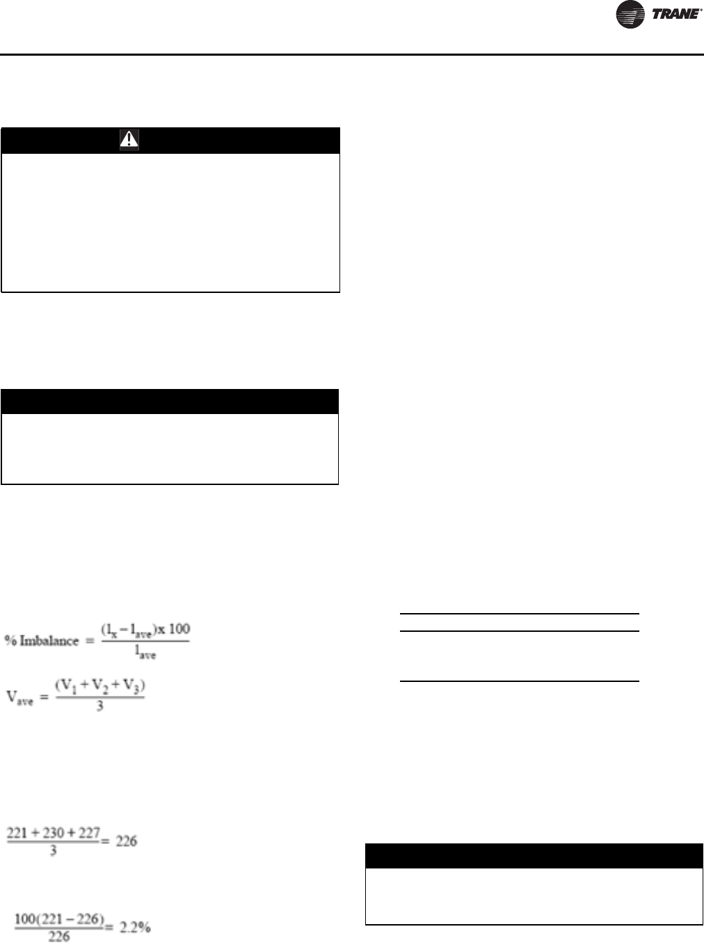
Pre-Start Checkout
RLC-SVX09H-EN 169
Unit Voltage Power Supply
Voltage to the unit must meet the criteria given in.
Measure each leg of the supply voltage at the unit's main
power fused-disconnect. If the measured voltage on any
leg is not within specified range, notify the supplier of the
power and correct the situation before operating the unit.
Unit Voltage Imbalance
Excessive voltage imbalance between the phases of a
three-phase system can cause motors to overheat and
eventually fail.The maximum allowable imbalance is 2
percent. Voltage imbalance is determined using the
following calculations:
= phase with greatest difference from Vave (without
regard to sign)
For example, if the three measured voltages are 221, 230,
and 227 volts, the average would be:
The percentage of imbalance is then:
This exceeds the maximum allowable (2%) by 0.2 percent.
Unit Voltage Phasing
It is important that proper rotation of the compressors be
established before the unit is started. Proper motor
rotation requires confirmation of the electrical phase
sequence of the power supply. The motor is internally
connected for clockwise rotation with the incoming power
supply phased A, B, C.
Basically, voltages generated in each phase of a polyphase
alternator or circuit are called phase voltages. In a three-
phase circuit, three sine wave voltages are generated,
differing in phase by 120 electrical degrees.The order in
which the three voltages of a three-phase system succeed
one another is called phase sequence or phase rotation.
This is determined by the direction of rotation of the
alternator. When rotation is clockwise, phase sequence is
usually called “ABC”, when counterclockwise, “CBA”.
This direction may be reversed outside the alternator by
interchanging any two of the line wires. It is this possible
interchange of wiring that makes a phase sequence
indicator necessary if the operator is to quickly determine
the phase rotation of the motor.
Proper compressor motor electrical phasing can be quickly
determined and corrected before starting the unit. Use a
quality instrument, such as the Associated Research
Model 45 Phase Sequence Indicator.
1. Press the Stop key on the Clear Language Display.
2. Open the electrical disconnect or circuit protection
switch that provides line power to the line power
terminal block(s) in the starter panel (or to the unit
mounted disconnect).
3. Connect the phase sequence indicator leads to the line
power terminal block, as follows:
4. Turn power on by closing the unit supply power fused-
disconnect switch.
5. Read phase sequence on indicator. “ABC” LED on the
face of the phase indicator will glow if phase is “ABC”.
6. If the “CBA” indicator glows instead, open the unit
main power disconnect and switch two line leads on
the line power terminal block(s) (or the unit mounted
disconnect). Reclose the main power disconnect and
recheck the phasing.
7. Reopen unit disconnect and disconnect phase
indicator.
WARNING
Live Electrical Components!
During installation, testing, servicing and
troubleshooting of this product, it may be necessary to
work with live electrical components. Have a qualified
licensed electrician or other individual who has been
properly trained in handling live electrical components
perform these tasks. Failure to follow all electrical
safety precautions when exposed to live electrical
components could result in death or serious injury.
NOTICE:
Equipment Damage!
Inadequate voltage to the unit may cause control
components to malfunction and shorten the life of relay
contact, compressor motors and contactor.
1
Vx
Phase Sequence Lead Terminal
Black (Phase A) L1
Red (Phase B) L2
Yellow (Phase C) L3
NOTICE:
Equipment Damage!
Do not interchange any load leads that are from the
unit contactors or the motor terminals.
Pre-Start Checkout
170 RLC-SVX09H-EN
Water System Flow Rates
Establish a balanced chilled water flow through the
evaporator. The flow rates should fall between the
minimum and maximum values. Chilled water flow rates
below the minimum values will result in laminar flow,
which reduces heat transfer and causes either loss of EXV
control or repeated nuisance, low temperature cutouts.
Flow rates that are too high can cause tube erosion.
The flow rates through the condenser must also be
balanced.The flow rates should fall between the minimum
and maximum values.
Water System Pressure Drop
Measure water pressure drop through the evaporator and
condenser at the field-installed pressure taps on the
system water piping. Use the same gauge for each
measurement. Do not include valves, strainers fittings in
the pressure drop readings.
Pressure drop readings should be approximately those
shown in the Pressure Drop Charts starting with Figure 21,
p. 43.
WARNING
Hazardous Voltage!
Disconnect all electric power, including remote
disconnects before servicing. Follow proper lockout/
tagout procedures to ensure the power can not be
inadvertently energized. Failure to disconnect power
before servicing could result in death or serious injury.
NOTICE:
Equipment Damage!
Ensure that the oil separator and compressor heaters
have been operating for a minimum of 24 hours before
starting. Failure to do so may result in equipment
damage.
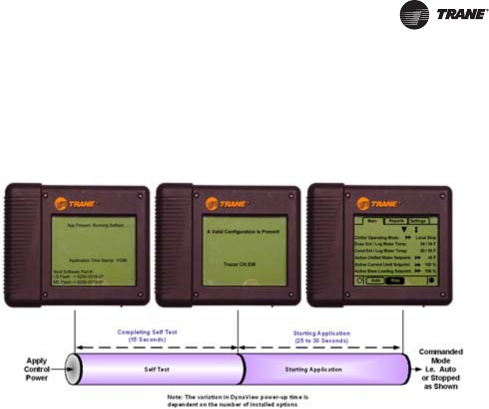
RLC-SVX09H-EN 171
Unit Start-Up Procedures
Sequence of Operation
Power Up
The Power up chart shows the respective DynaView
screens during a power up of the main processor. This
process takes from 30 to 50 seconds depending on the
number of installed Options. On all power ups, the
software model will always transition through the
'Stopped' Software state independent of the last mode. If
the last mode before power down was 'Auto', the
transition from 'Stopped' to 'Starting' occurs, but it is not
apparent to the user.
Power Up to Starting
The Power up to starting diagram shows the timing from
a power up event to energizing the compressor. The
shortest allowable time would be under the following
conditions:
1. No motor restart inhibit
2. Evaporator Water flowing
3. Condenser Water flowing (RTWD only)
4. Power up Start Delay setpoint set to 0 minutes
5. Adjustable Stop to StartTimer set to 5 seconds
6. Need to cool
The above conditions would allow for a minimum power
up to starting compressor time of 95 seconds.
Figure 75. Power up
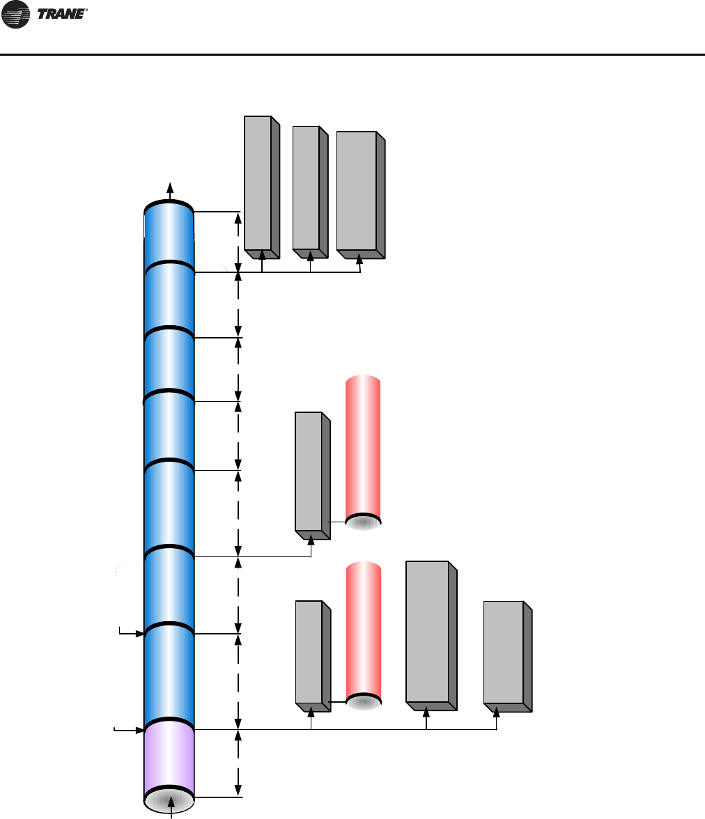
Unit Start-Up Procedures
172 RLC-SVX09H-EN
Figure 76. RTWD Power up to starting
Enforce Restart
Inhibit Timer
(0 to 5 mins)
Confirm
Condenser
Water Flow
RTWD Sequence of Operation
Power Up to Starting Compressor
Power
Applied
Last Mode
Was Auto
Auto
Call for Cooling (adj
Differential to Start is met)
Waiting
to Start
Energize Evaporator
Water Pump Relay
Energize Condenser
Water Pump Relay
Confirm Evaporator Water
Flow Within 20 minutes
(6 Sec Filter)
Confirm Condenser Water
Flow Within 20 minutes
(6 Sec Filter)
Waiting
to Start
Oil Heater always energized
when compressor is de-
energized
Confirm Evaporator
Water Flow
(6 Second Filter)
Waiting
to Start
Condenser
Water Pump
Pre-Run
Waiting
to Start
Enforce Cond
Pmp Strt Delay
(0 to 300 Sec)
(adj 0 to 30
mins)
Enforce
'Cprsr Strt
Delay'
Waiting
to Start
(0 to 300 Sec)(6 Second Filter)
Power
Up
CH530
Boot Time
(30 to 40 Sec)
Enforce Power Up
Start Delay Timer
(adj 0 to 30 mins)
Re-calibrate EXV
(overdrive closed
and then to 50%)
* Lead Compressor (and its lead circuit) is
determined by staging algorithm – “fixed staging”
or “balanced wear” selection - also influenced by
lockouts, restart inhibit, or diagnostics present
Confirm
Presence of Oil
(0 to 2 mins)
Energize Unload
Solenoid
Pre-Position EXV of
Lead Circuit
Energize Unload
Solenoid of Lead Cprsr
Energize Oil Return Fill
Solenoid of Lead Circuit
EXV stroke
to
Preposition
Waiting
to Start
Start
Command
to Lead
Cprsr*

Unit Start-Up Procedures
RLC-SVX09H-EN 173
Stopped to Starting:
The stopped to starting diagram shows the timing from a
stopped mode to energizing the compressor.The shortest
allowable time would be under the following conditions:
1. No motor restart inhibit
2. Evaporator and Condenser Water flowing
3. Power up Start DelayTimer has expired
4. Adjustable Stop to StartTimer has expired
5. Need to cool
The above conditions would allow the compressor to start
in 60 seconds.
NOTICE:
Compressor Damage!
If both suction and discharge pressures are low but sub-
cooling is normal, a problem other than refrigerant
shortage exists. Do not add refrigerant, as this may
result in overcharging the circuit.
Use only refrigerants specified on the unit nameplate
(HFC 134a) and Trane OIL00048. Failure to do so may
cause compressor damage and improper unit
operation.
NOTICE:
Equipment Damage!
Ensure that the oil separator and compressor heaters
have been operating for a minimum of 24 hours before
starting. Failure to do so may result in equipment
damage.

Unit Start-Up Procedures
174 RLC-SVX09H-EN
Figure 77. RTUD Power up to starting
Enforce Restart Inhibit Timer
(0 to 5 mins)
RTUD Sequence of Operation
Power Up to Starting Compressor
Power
Applied
Auto Mode
Commanded by Front
Panel setting or BAS
Auto
Call for Cooling (adj
Differential to Start is met)
Energize Evaporator
Water Pump Relay
Set Condenser Fan’s
Pre-Flow % per
Outdoor Temperature
Confirm Evaporator Water
Flow Within 20 minutes
(6 Sec Filter)
Waiting
to Start
Oil Heater always energized
when compressor is de-
energized
Waiting
to Start
Power
Up
CH530
Boot Time
(40 to 45 Sec)
Enforce Power Up Start Delay Timer
(adj 0 to 30 mins)
EXV remains closed
* Lead Compressor (and its lead circuit) is
determined by staging algorithm – “fixed
staging” or “balanced wear” selection - also
influenced by lockouts, restart inhibit, or
diagnostics present
Confirm
Presence of Oil
(0 to 2 mins)
Pre-Position EXV of
Lead Circuit
Energize Unload
Solenoid of Lead Cprsr
Energize Oil Return Fill
Solenoid of Lead Circuit
EXV stroke to
Preposition
0-20 sec
Start Command to
Lead Compressor*
EXVs self-
close on
power up Energize Oil Return Drain
Solenoid of Lead Circuit
Send Start Command to
Lead Compressor
Confirm Evaporator Water Flow
(6 Second Filter)
Check Evap Pressure for
Low Pressure Cutout
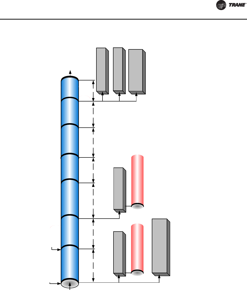
Unit Start-Up Procedures
RLC-SVX09H-EN 175
Figure 78. RTWD Stopped to starting
Enforce Restart
Inhibit Timer
(0 to 30 mins)
Confirm Condenser
Water Flow
(6 Second Filter)
RTWD Sequence of Operation
Stopped to Starting
Stopped
Or
Run
Inhibit
Chiller Mode
Set to Auto
Auto Waiting
to Start
Energize Evaporator
Water Pump Relay
Energize Condenser
Water Pump Relay
Confirm Evaporator Water
Flow Within 20 minutes
(6 Sec Filter)
Confirm Condenser Water
Flow Within 20 minutes
(6 Sec Filter)
Waiting
to Start
Oil Heaters Always Energized
When Respective Compressors
Are De-Energized
Confirm Evaporator
Water Flow
(6 Second Filter)
Energize Unload
Solenoid
Confirm
Presence of Oil
(0 to 2 mins)
Waiting
to Start
Condenser
Water Pump
Pre-Run
Waiting
to Start
Enforce 'Cond
Pmp Strt Delay'
(0 to 300 Sec)
(adj 0 to 30
mins)
Enforce 'Cprsr
Strt Delay'
(0 to 300 Sec)
Waiting
to Start
Call for Cooling (adj
Differential to Start is met)
Pre-Position EXV of
Lead Circuit
Start
Command
to Lead
Cprsr*
* Lead Compressor (and its lead circuit) determined by staging algorithm
and “fixed staging” or “balanced wear” selection. If “balanced wear”
then compressor with least wear (10* starts + hours) is lead. If “fixed
staging” Cprsr 1A is always lead and Cprsr 2A is always lag. Staging
order is also influenced by lockouts, restart inhibit, or diagnostics
present and will also obey priority staging rule: Any cprsr running but
not step loaded, has priority to either step load or to unstage (turn off).
Energize Unload
Solenoid of Lead Cprsr
Energize Oil Return Fill
Solenoid of Lead Circuit
EXV stroke
to
Preposition
Waiting
to Start
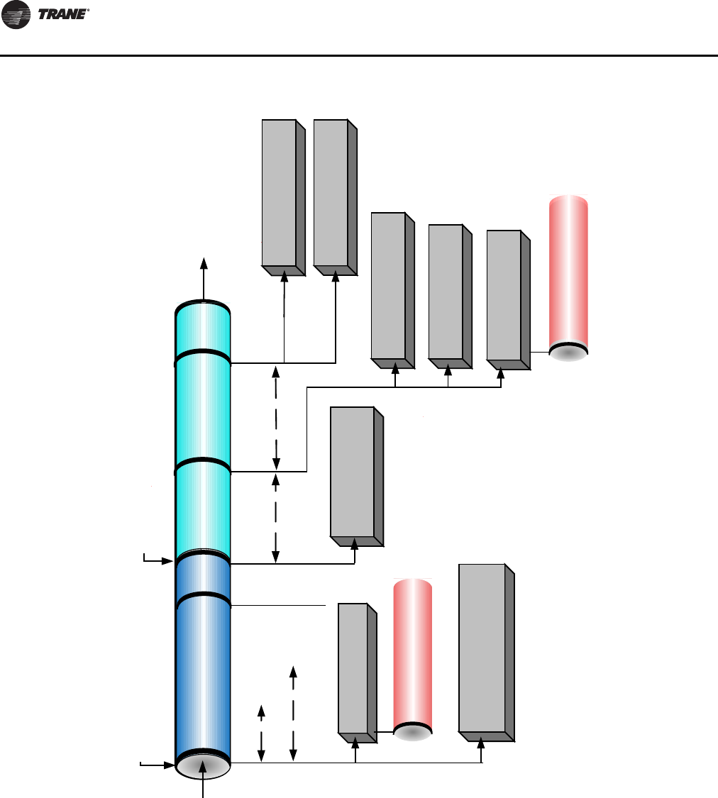
Unit Start-Up Procedures
176 RLC-SVX09H-EN
Figure 79. RTUD Stopped to starting
RTUD Sequence of Operation
Stopped to Starting
Stopped
Or
Run
Inhibit
Chiller Mode
Set to Auto
Auto
Energize Evaporator
Water Pump Relay
Confirm Evaporator Water
Flow Within 20 minutes
(6 Sec Filter)
Oil Heaters Always Energized
When Respective Compressors
Are De-Energized
Call for Cooling (adj
Differential to Start is met)
Start Command to
Lead Compressor*
* Lead Compressor (and its lead circuit) determined by staging algorithm
and “fixed staging” or “balanced wear” selection. If “balanced wear”
then compressor with least wear (10* starts + hours) is lead. If “fixed
staging” Cprsr 1A is always lead and Cprsr 2A is always lag. Staging
order is also influenced by lockouts, restart inhibit, or diagnostics
present and will also obey priority staging rule: Any cprsr running but
not step loaded, has priority to either step load or to unstage (turn off).
Set Condenser Fan’s
Pre-Flow % per
Outdoor Temperature
Confirm
Presence of Oil
(0 to 2 mins)
Pre-Position EXV of
Lead Circuit
Energize Unload
Solenoid of Lead Cprsr
Energize Oil Return Fill
Solenoid of Lead Circuit
EXV stroke to
Preposition
0-20 sec
Energize Oil Return Drain
Solenoid of Lead Circuit
Send Start Command to
Lead Compressor
Enforce Restart Inhibit Timer
(0 to 5 mins)
Confirm Evaporator Water Flow
(6 Second Filter)
Check Evap Pressure for
Low Pressure Cutout
Waiting
to Start
Waiting
to Start
Unit Start-Up Procedures
RLC-SVX09H-EN 177
Start-up
If the pre-start checkout, has been completed, the unit is
ready to start.
1. Press the STOP key on the CH530.
2. As necessary, adjust the setpoint values in the CH530
menus usingTechView.
3. Close the fused-disconnect switch for the chilled water
pump. Energize the pump(s) to start water circulation.
4. Check the service valves on the discharge line, suction
line, oil line and liquid line for each circuit.These valves
must be open (backseated) before starting the
compressors.
5. Press the AUTO key. If the chiller control calls for
cooling and all safety interlocks are closed, the unit will
start.The compressor(s) will load and unload in
response to the leaving chilled water temperature.
6. Verify that the chilled water pump runs for at least one
minute after the chiller is commanded to stop (for
normal chilled water systems).
Note: Once the system has been operating for
approximately 30 minutes and has become
stabilized, complete the remaining start-up
procedures, as follows:
7. Check the evaporator refrigerant pressure and the
condenser refrigerant pressure under Refrigerant
Report on the CH530TechView.The pressures are
referenced to sea level (14.6960 psia).
8. Check the EXV sight glasses after sufficient time has
elapsed to stabilize the chiller.The refrigerant flow past
the sight glasses should be clear. Bubbles in the
refrigerant indicate either low refrigerant charge or
excessive pressure drop in the liquid line or a stuck
open expansion valve. A restriction in the line can
sometimes be identified by a noticeable temperature
differential between the two sides of the restriction.
Frost will often form on the line at this point. Proper
refrigerant charges are shown in the General Data
tables.
Important: A clear sight glass alone does not mean that
the system is properly charged. Also check
system subcooling, liquid level control and
unit operating pressures.
9. Measure the system subcooling.
10. A shortage of refrigerant is indicated if operating
pressures are low and subcooling is also low. If the
operating pressures, sight glass, superheat and
subcooling readings indicate a refrigerant shortage,
gas-charge refrigerant into each circuit, as required.
With the unit running, add refrigerant vapor by
connecting the charging line to the suction service
valve and charging through the backseat port until
operating conditions become normal.
Seasonal Unit Start-Up Procedure
11. Close all valves and re-install the drain plugs in the
evaporator and condenser heads.
12. Service the auxiliary equipment according to the start-
up/maintenance instructions provided by the
respective equipment manufacturers.
13. Vent and fill the cooling tower, if used, as well as the
condenser and piping. At this point, all air must be
removed from the system (including each pass). Close
the vents in the evaporator chilled water circuits.
14. Open all the valves in the evaporator chilled water
circuits.
15. If the evaporator was previously drained, vent and fill
the evaporator and chilled water circuit.When all air is
removed from the system (including each pass), install
the vent plugs in the evaporator water boxes.
16. Verify condenser coils are clean.
NOTICE:
Equipment Damage!
Ensure that the oil separator and compressor heaters
have been operating for a minimum of 24 hours before
starting. Failure to do so may result in equipment
damage.
NOTICE:
Compressor Damage!
Catastrophic damage to the compressor will occur if the
oil line shut off valve or the isolation valves are left
closed on unit start-up.
NOTICE:
Equipment Damage!
Ensure that the oil separator and compressor heaters
have been operating for a minimum of 24 hours before
starting. Failure to do so may result in equipment
damage.
NOTICE:
Compressor Damage!
Catastrophic damage to the compressor will occur if the
oil line shut off valve or the isolation valves are left
closed on unit start-up.
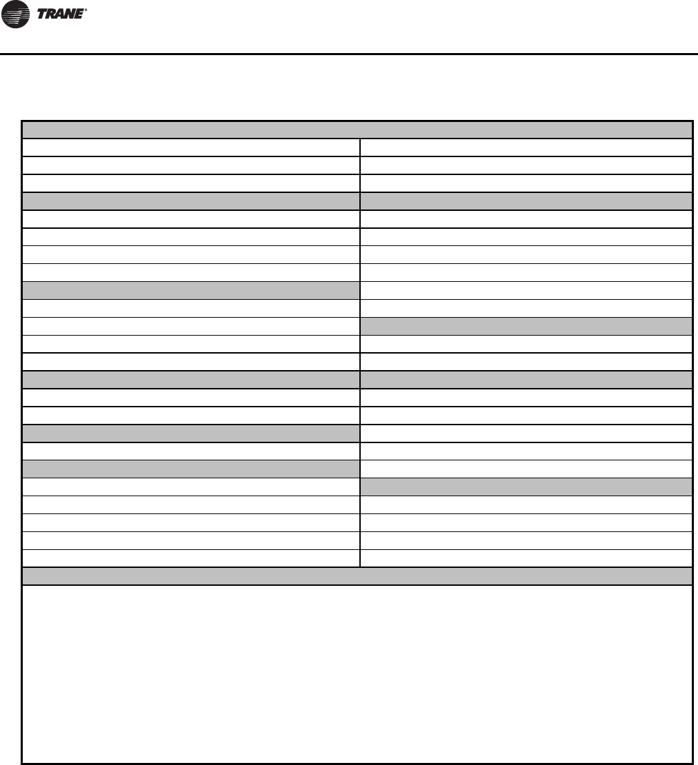
Unit Start-Up Procedures
178 RLC-SVX09H-EN
Figure 80. Start-up log
Job Name Job Location
Model # Serial # start date:
Sales Order # ship date: Job elevation (ft. above sea level)
STARTER DATA: START-UP ONLY
Manufacturer Chiller appearance at arrival:
Type: (x-line, wye-delta) Machine Gauge Pressure: psig/ kPag
Vendor ID #/Model #: Machine CH530 Pressure: psig/ kPag
Volts Amps Hz Complete if pressure test is required
COMPRESSOR DATA: Vacuum after leak test= mm
Compressor A: Model #: Standing vacuum test = mm rise in hrs
Compressor A: Serial #: UNIT CHARGES
Compressor B: Model #: Unit refrigerant charge: lbs/ Kg
Compressor B: Serial #: Unit Oil Charge: gal/ L
NAMEPLATE DATA: SUMMARY OF UNIT OPTIONS INSTALLED
RLA KW Volts Y N Tracer Communications Interface
50 60 Hz Y N Options Module
DESIGN DATA: Y N Outdoor Air Sensor (Required for RTUD)
RLA KW Volts Y N Ice Making Control
CURRENT TRANSFORMER Y N Other
Part Number (“X” code and 2-digit extension) RTUD UNIT VERIFICATION
Primary CT’s Y N Outdoor Air Sensor Cut and Installed at Condenser
X X Y N Condenser Elevation Setting Entered - Record Value:
X X Y N Chilled Water Pump Control Installed & Verified
X X Y N Review Nameplate Model No - Verify Ckts Piped Correctly
DESIGN CONDITIONS
Evap Desig ________GPM L/S _________ PSID kPad Ent. Water F/C__________ Leaving Water F/C_________
Evap Actual ________GPM L/S _________ PSID kPad Ent. Water F/C__________ Leaving Water F/C_________
Cond Design ________GPM L/S _________ PSID kPad Ent. Water F/C__________ Leaving Water F/C_________
Cond Actual ________GPM L/S _________ PSID kPad Ent. Water F/C__________ Leaving Water F/C_________
Owner Witness Signature: _________________________________________________
RTWD/RTUD Start-up Test Log

RLC-SVX09H-EN 179
Unit Shutdown
Normal Shutdown to Stopped
The Normal Shutdown diagram shows theTransition from
Running through a Normal (friendly) Shutdown.The
Dashed lines on the top attempt to show the final mode if
you enter the stop via various inputs.
Figure 81. RTWD Normal shutdown
RTWD Sequence of Operation:
Normal Shutdown to Stopped or Run Inhibit
Running
Local Stop
Chiller Level Diagnostic – Normal Shutdown Latched
Chiller Level Diagnostic – Normal Shutdown Nonlatched
Tracer Stop
External Auto-Stop
Stopped
or
Run Inhibit
Shutting Down
Energize Unload
Solenoid Both
Compressors
Shutting Down
De-Energize both
Compressors
Brief Run-Unload, both Compressors
(5 Seconds)
De-Energize Condenser
Water Pump Relay
Both Circuit’s EXVs to
50% for off cycle
Leave Both Cprsr’s
Unload Solenoids
Energized for 60 mins
Energize all Oil Heaters
Time out Evap Pump Off Delay
(adj 0-30 minutes)
De-Energize Evaporator
Water Pump Relay
DeEnergize Step
Load Solenoid Both
Compressors
1 sec
Recalibrate EXV if 24 hrs
since last recalibration
De-Energize Oil Return
Fill and Draing Solenoids
of Both Circuits
Confirm No Compressor Currents
8 Seconds after compressor is de-energized
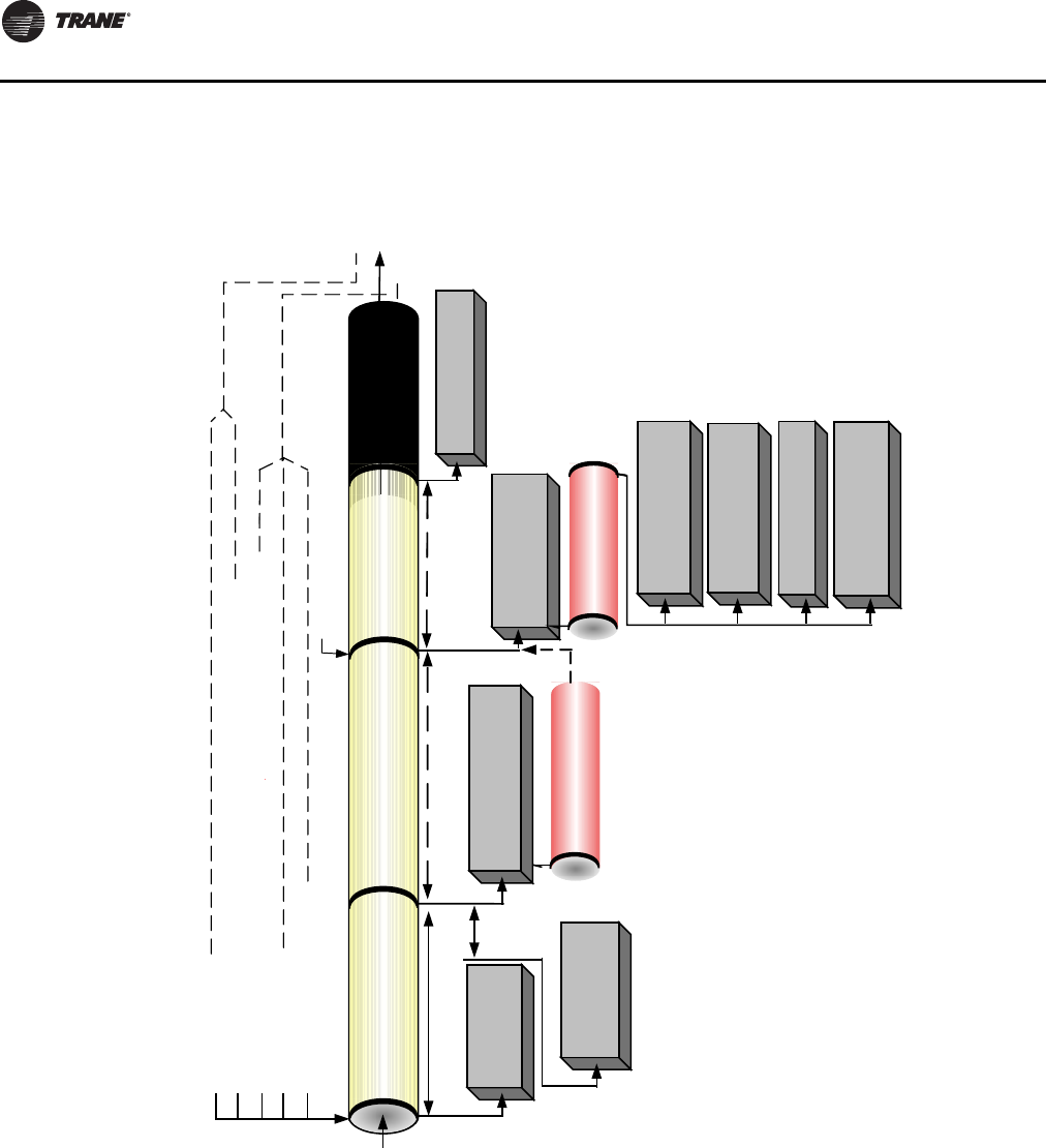
Unit Shutdown
180 RLC-SVX09H-EN
Seasonal Unit Shutdown
1. Perform normal unit stop sequence using <Stop> key.
Note: Do not open starter disconnect switch. It must
remain closed to provide power from control
power transformer to the oil heaters.
2. Verify chilled water and condenser water pumps are
off. If desired, open disconnect switches to pumps.
3. Drain condenser piping and cooling tower, if desired.
4. Remove drain and vent plugs from condenser headers
to drain the condenser.
5. Verify that the oil heaters are working.
6. Once unit is secured, perform maintenance identified
in the following sections.
Figure 82. RTUD Normal shutdown
RTUD Sequence of Operation:
Normal Commanded Shutdown to Stopped or Run Inhibit
Running
Local Stop
Chiller Level Diagnostic – Normal Shutdown Latched
Chiller Level Diagnostic – Normal Shutdown Nonlatched
Tracer Stop
External Auto-Stop
Stopped
or
Run Inhibit
Shutting Down
Energize Unload
Solenoid Both
Compressors
Shutting Down
Circuit Submodes:
Operational Pumpdown
De-Energize both
Compressors and
Energize Oil Heaters
Brief Run-Unload, both
Compressors (5 Seconds)
Leave Both Cprsr’s
Unload Solenoids
Energized for 60 mins
Time out Evap
Pump Off Delay
(adj 0-30 minutes)
De-Energize Evaporator
Water Pump Relay
1 sec
De-Energize Oil Return
Fill and Drain Solenoids
of Both Circuits
DeEnergize Step
Load Solenoid Both
Compressors
Turn off both Circuits’
Condenser Fans
Leave EXVs Closed or
Close EXV for
Circuits’ Off Cycle
Close EXV’s and Perform
Operational Pumpdown (if
regd*) for both Circuits
Shutting Down
Circuit Submodes:
AUTO
Check for Normal
Pumpdown Termination
Criteria Met**
Normal Pumpdown Termination
Criteria Met for both Circuits
Confirm No
Compressor Currents
Stopped
Circuit Submodes:
AUTO
*Operational Pumpdown is required if the Outdoor Air Temperature
is less than 50F, or if it is less than the Entering Evaporator Water
Temperature plus 5F.
**Operational pumpdown is terminated normally when:
The Evaporator liquid level for the circuit is -36 mm or lower
and
The Evaporator saturation temperature for the circuit is below either 32 F or
LRTC set point + 4F, whichever is lower
.
The maximum allowed time for Operational Pumpdown is 2 minutes.
Operational Pumpdown 2 minutes max
RLC-SVX09H-EN 181
Service and Maintenance
Overview
This section describes preventative maintenance
procedures and intervals for the RTWD unit. Use a periodic
maintenance program to ensure optimal performance and
efficiency of the Series R units.
An important aspect of the chiller maintenance program is
the regular completion of the“Series R Operating Log”; an
example of this log is provided in this manual.When filled
out properly the completed logs can be reviewed to
identify any developing trends in the chiller's operating
conditions.
For example, if the machine operator notices a gradual
increase in condensing pressure during a month's time, he
can systematically check for and then correct, the possible
cause(s) of this condition (e.g., fouled condenser tubes,
non-condensables in the system).
Maintenance
Weekly Maintenance and Checks
After the unit has operated for approximately 30 minutes
and the system has stabilized, check the operating
conditions and complete the procedures below:
• Log the chiller.
• Check evaporator and condenser pressures with
gauges and compare to the reading on the CH530.
Pressure readings should fall within the specified
ranges listed under Operating Conditions.
Note: For RTWD units, optimum condenser pressure is
dependent on condenser water temperature, and
should equal the saturation pressure of the
refrigerant at a temperature 2 to 5F above that of
leaving condenser water at full load.
Monthly Maintenance and Checks
• Review operating log.
• Clean all water strainers in both the chilled and
condensing water piping systems.
• Measure the oil filter pressure drop. Replace oil filter if
required. Refer to “Service Procedures”.
• Measure and log the subcooling and superheat.
• If operating conditions indicate a refrigerant shortage,
leak check the unit and confirm using soap bubbles.
• Repair all leaks.
• Trim refrigerant charge until the unit operates in the
conditions listed in the note below.
Note: AHRI conditions are: condenser water: 85oF and 3
GPM per ton and evaporator water: 54-44oF.
• Clean condenser coils.
• If full load conditions can not be met. Refer to note
below to trim the refrigerant charge
Note: Conditions at minimum must be: entering
condenser water: 85F and entering evaporator
water: 55F
Note: RTUD operating conditions are the physical
configuration of the installation.
Annual Maintenance
Shut down the chiller once each year to check the
following:
WARNING
Hazardous Voltage!
Disconnect all electric power, including remote
disconnects before servicing. Follow proper lockout/
tagout procedures to ensure the power can not be
inadvertently energized. Failure to disconnect power
before servicing could result in death or serious injury.
WARNING
Live Electrical Components!
During installation, testing, servicing and
troubleshooting of this product, it may be necessary to
work with live electrical components. Have a qualified
licensed electrician or other individual who has been
properly trained in handling live electrical components
perform these tasks. Failure to follow all electrical
safety precautions when exposed to live electrical
components could result in death or serious injury.
Table 124. RTWD Operating Conditions at Full Load
Description Condition
Evaporator pressure 30-45 psig
Condensing pressure 75-125 psig
Discharge superheat 10-15 F
Subcooling 5-10 F
Note: All conditions stated above are based on the unit running fully loaded,
running at AHRI conditions.
Table 125. RTWD Operating Conditions at Minimum Load
Description Condition
Evaporator approach *less than 7°F (non-glycol applications)
Condensing approach *less than 7°F
Subcooling 2-3°F
EXV percent open 10-20% open
* 1.0oF for new unit.
Service and Maintenance
182 RLC-SVX09H-EN
• Perform all weekly and monthly maintenance
procedures.
• Check the refrigerant charge and oil level. Refer to
“Maintenance Procedures”. Routine oil changing is not
necessary on a hermetic system.
• Have a qualified laboratory perform an oil analysis to
determine system moisture content and acid level.
Note: Due to the hygroscopic properties of the POE oil, all
oil must be stored in metal containers.The oil will
absorb water if stored in a plastic container.
• Check the pressure drop across the oil filter. Refer to
“Maintenance Procedures”.
• Contact a qualified service organization to leak check
the chiller, to inspect safety controls, and inspect
electrical components for deficiencies.
• Inspect all piping components for leakage and/or
damage. Clean out any inline strainers.
• Clean and repaint any areas that show signs of
corrosion.
• Test vent piping of all relief valves for presence of
refrigerant to detect improperly sealed relief valves.
Replace any leaking relief valve.
• Inspect the condenser tubes for fouling; clean if
necessary. Refer to “Maintenance Procedures”.
• Check to make sure that the crank case heater is
working.
Scheduling Other Maintenance
• Use a nondestructive tube test to inspect the
condenser and evaporator tubes at 3-year intervals.
Note: It may be desirable to perform tube tests on these
components at more frequent intervals, depending
upon chiller application.This is especially true of
critical process equipment.
• Depending on chiller duty, contact a qualified service
organization to determine when to conduct a complete
examination of the unit to determine the condition of
the compressor and internal components.
Operating Log
A sample of several operating logs and checklists have
been included.
WARNING
Hazardous Voltage!
Disconnect all electric power, including remote
disconnects before servicing. Follow proper lockout/
tagout procedures to ensure the power can not be
inadvertently energized. Failure to disconnect power
before servicing could result in death or serious injury.
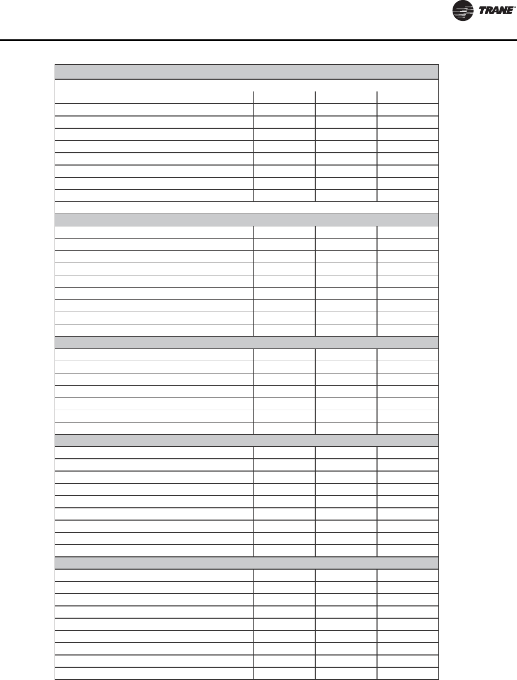
Service and Maintenance
RLC-SVX09H-EN 183
rh 1nim 03nim 51baT niaM
Chiller Mode
Evap Ent/Lvg Water Temp
Cond Ent/Lvg Water Temp
Active Chilled Water Setpoint (F)
Average Line Current (%RLA)
Active Current Limit Setpoint (%RLA)
Soware Type
Software Version
Reports Tab
Evap Entering Water Temperature (F)
Evap Leaving Water Temperature (F)
Evap Sat Rfgt Temp (F)
Evap Rfgt Pressure (psia)
Evap Approach Temp (F)
Evap Water Flow Switch Status
Expansion Valve Position (%)
Expansion Valve Position Steps
Evap Rfgt Liquid Level (in)
Cond Entering Water Temperature (F)
Cond Leaving Water Temperature (F)
Cond Sat Rfgt Temp (F)
Cond Rfgt Pressure (psia)
Cond Approach Temp (F)
Cond Water Flow Switch Status
Cond Head Pressure Ctrl Command (%)
Compressor Starts
Compressor Run Time
System Rfgt Diff Pressure (psid)
Oil Pressure (psia)
Compressor Rfgt Discharge Temp (F)
Discharge Superheat (F)
% RLA L1 L2 L3 (%)
Amps L1 L2 L3 (Amps)
Volts AB BC CA
Compressor Starts
Compressor Run Time
System Rfgt Diff Pressure (psid)
Oil Pressure (psia)
Compressor Rfgt Discharge Temp (F)
Discharge Superheat (F)
% RLA L1 L2 L3 (%)
Amps L1 L2 L3 (Amps)
Volts AB BC CA
Chiller Log
Run Time
Evaporator
Condenser
Compressor 1
Compressor 2
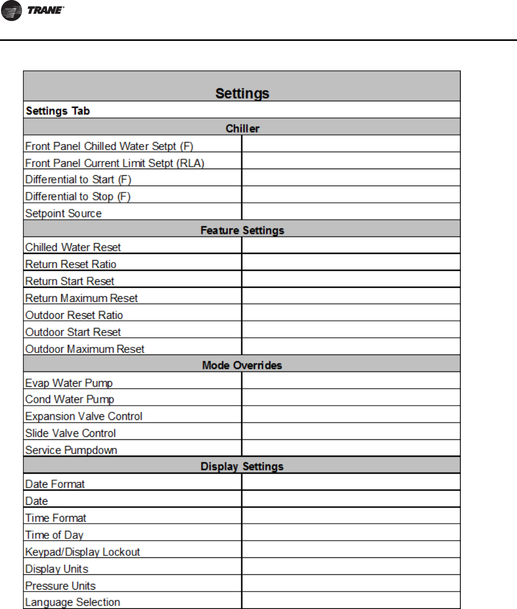
Service and Maintenance
184 RLC-SVX09H-EN

Service and Maintenance
RLC-SVX09H-EN 185
Service Procedures
Cleaning the Condense (RTWD Only)
Condenser tube fouling is suspect when the “approach”
temperature (i.e., the difference between the refrigerant
condensing temperature and the leaving condenser water
temperature) is higher than predicted.
Standard water applications will operate with less than a
10oF approach. If the approach exceeds 10oF cleaning the
condenser tubes is recommended.
Note: Glycol in the water system may as much as double
the standard approach.
If the annual condenser tube inspection indicates that the
tubes are fouled, 2 cleaning methods can be used to rid the
tubes of contaminants.The methods are:
Mechanical Cleaning Procedure
Mechanical tube cleaning method is used to remove
sludge and loose material from smooth-bore condenser
tubes.
Review mechanical room limitations and determine the
safest method or methods of rigging and lifting the
waterboxes.
1. Waterbox Removal Procedure - Method 1
This selection applies to the units and condenser side
waterboxes shown in Table 126.
2. Select the proper lift connection device from
Table 131.The rated lifting capacity of the selected lift
connection device must meet or exceed the published
weight of the waterbox. Reference Table 130, p. 188 for
waterbox weights.
3. Ensure the lift connection device has the correct
connection for the waterbox. Example: thread type
(course/fine, English/metric). Bolt diameter (English/
metric).
4. Properly connect the lift connection device to the
waterbox. See Figure 83, p. 186. Ensure lift connection
device is securely fastened.
NOTICE:
Proper Water Treatment!
The use of untreated or improperly treated water could
result in scaling, erosion, corrosion, algae or slime. It is
recommended that the services of a qualified water
treatment specialist be engaged to determine what
water treatment, if any, is required. Trane assumes no
responsibility for equipment failures which result from
untreated or improperly treated water, or saline or
brackish water.
WARNING
Heavy Objects!
Each of the individual cables (chains or slings) used to
lift the waterbox must be capable of supporting the
entire weight of the waterbox. The cables (chains or
slings) must be rated for overhead lifting applications
with an acceptable working load limit. Failure to
properly lift waterbox could result in death or serious
injury.
WARNING
Heavy Objects!
The proper use and ratings for eyebolts can be found in
ANSI/ASME standard B18.15. Maximum load rating for
eyebolts are based on a straight vertical lift in a
gradually increasing manner. Angular lifts will
significantly lower maximum loads and should be
avoided whenever possible. Loads should always be
applied to eyebolts in the plane of the eye, not at some
angle to this plane. Failure to properly lift waterbox
could result in death or serious injury.
Table 126. Waterbox Removal Procedure - Method 1
Size Hz Effic
Condenser
Waterbox
80, 90, 100, 110, 120, 130, 140 60 STD Supply,
Return
80, 90, 100, 110, 120, 130 60 HIGH Supply,
Return
70, 80, 90, 100, 110, 120, 130, 140, 150 50 STD Supply,
Return
60, 70, 80, 90, 100, 110, 120 50 HIGH Supply,
Return
150, 160, 180, 200, 220, 250 60 HIGH Supply
150, 160, 180, 200 60 PREM Supply
130, 140, 160, 180, 200, 220, 250 50 HIGH Supply
160, 180, 200 50 PREM Supply
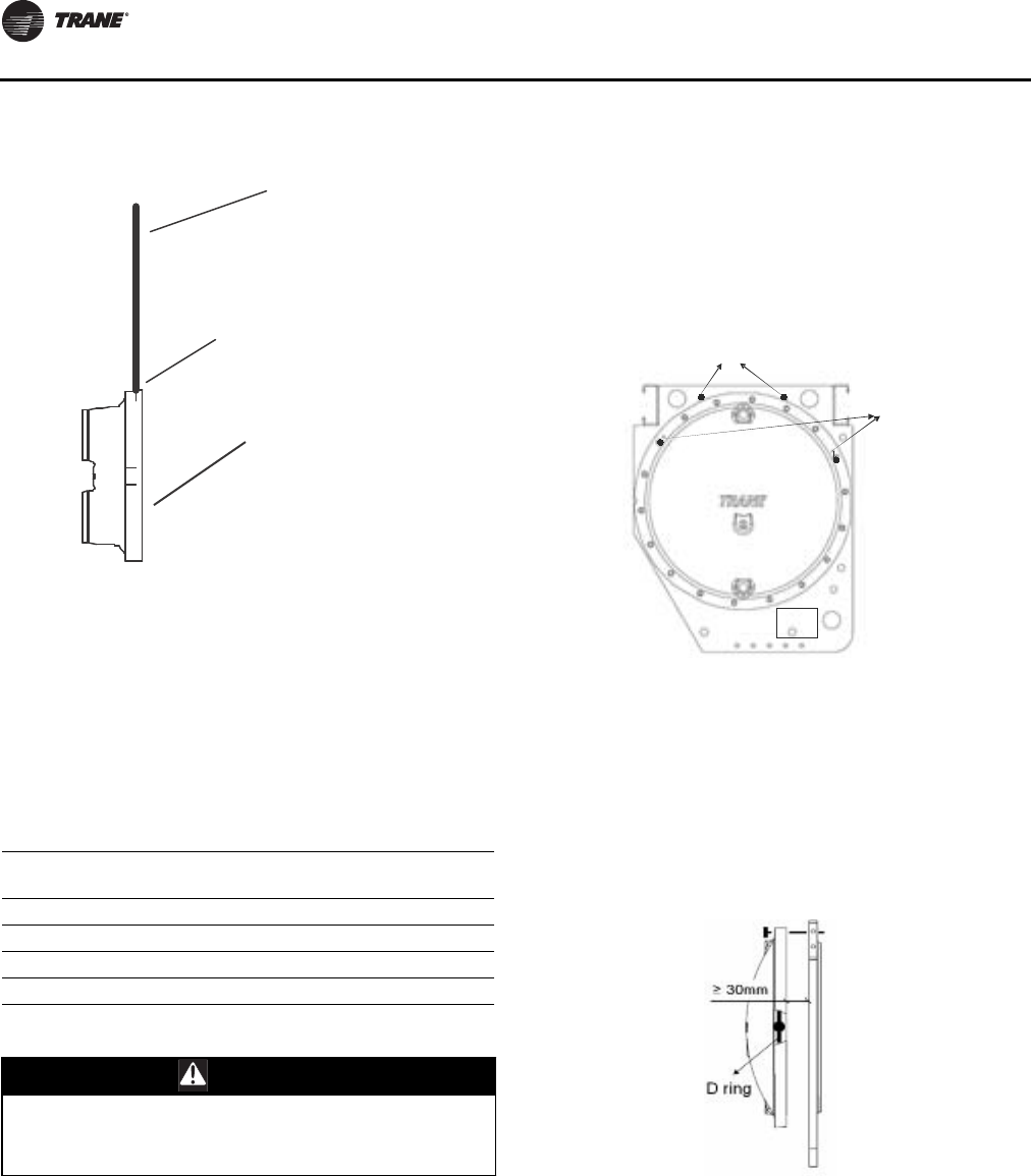
Service and Maintenance
186 RLC-SVX09H-EN
5. Install hoist ring on to the lifting connection on the
waterbox.Torque to 28 ft-lbs (37 Nm).
6. Disconnect water pipes, if connected.
7. Remove waterbox bolts
8. Lift the waterbox away from the shell.
Waterbox Removal Procedure – Method 2
This selection applies to the units and condenser side
waterboxes shown in Table 127
9. Select the proper lift connection device from Table 131,
p. 188.The rated lifting capacity of the selected lift
connection device must meet or exceed the published
weight of the waterbox. Reference Table 130, p. 188 for
waterbox weights.
10. Ensure the lift connection device has the correct
connection for the waterbox. Example: thread type
(course/fine, English/metric). Bolt diameter (English/
metric).
11. Disconnect water pipes, if connected.
12. Remove the two bolts with drill point mark. Install the
long bolts into these two holes.The long bolts are
located on the two thread holes just above the
waterbox, as shown in Figure 84.
13. Remove the remaining bolts. Slide the waterbox out
about 30 mm through two long bolts. Install the Safety
Hoist ring (D ring) connection device into the tap drill
hole located on waterbox right side (face to waterbox
convex). See Figure 85.
14. Remove the left long bolt while supporting waterbox
from outside of waterbox. Swing the waterbox
outboard. Put lifting chain on Safety Hoist ring and
remove the remaining long bolt. See Figure 86, p. 187.
Figure 83. Water box lifting
Table 127. Waterbox Removal Procedure - Method 2
Size Hz Effic
Condenser
Waterbox
150, 160, 180, 200, 220, 250 60 HIGH Return
150, 160, 180, 200 60 PREM Return
130, 140, 160, 180, 200, 220, 250 50 HIGH Return
160, 180, 200 50 PREM Return
CAUTION
Risk of Injury!
To prevent injury, do not place hands or fingers
between waterbox and condenser tubesheet.
#ONNECTION$EVICE
#ABLES#HAINSOR3LINGS
7ATERBOX
Figure 84. Waterbox removal - remove bolts
Figure 85. Waterbox removal - slide out, install safety
hoist ring
long bolt
drill point m ark
Label
long bolt
drill point m ark
Label
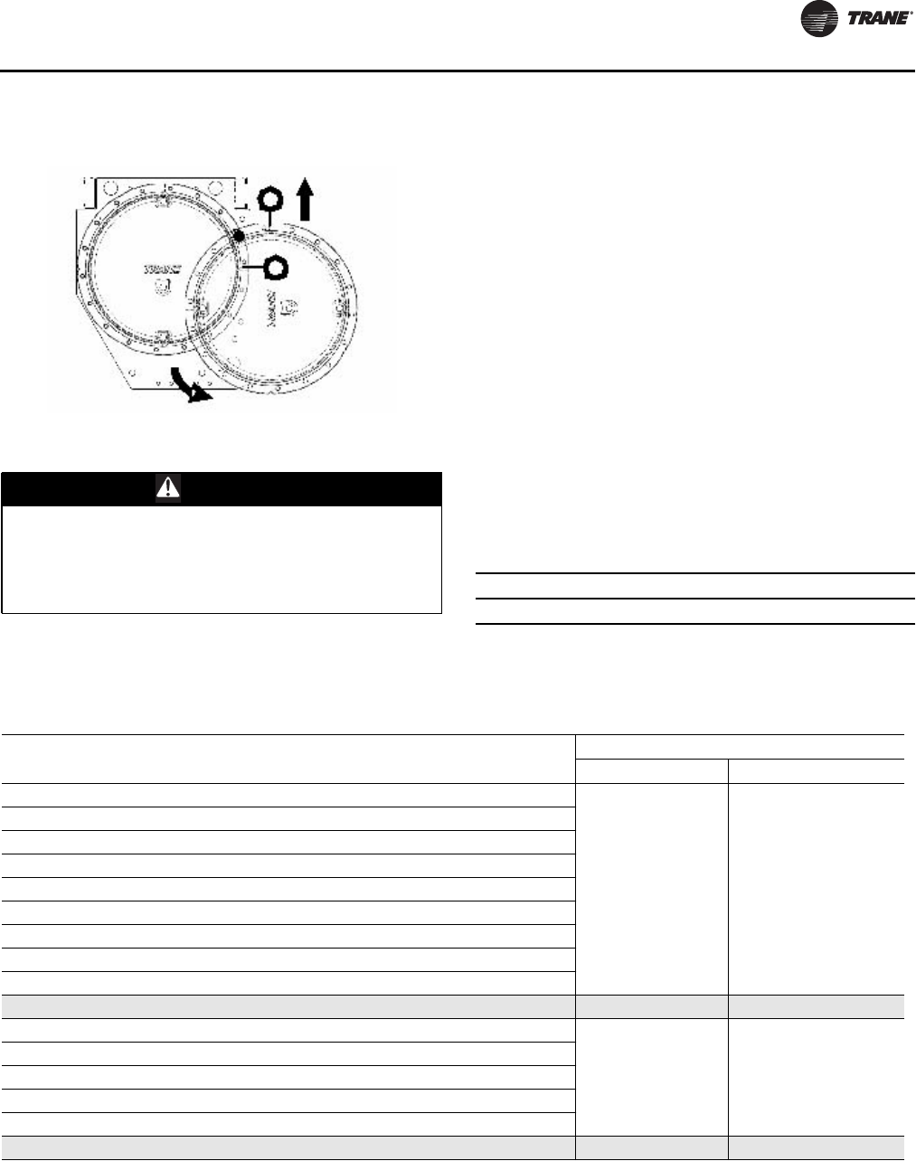
Service and Maintenance
RLC-SVX09H-EN 187
15. Lift the waterbox away from the shell.
All RTWD Units
16. Store waterbox in a safe and secure location and
position.
Important: Do not leave waterbox suspended from
lifting device.
17. Work a round nylon or brass bristled brush (attached to
a rod) in and out of each of the condenser water tubes
to loosen the sludge.
18.Thoroughly flush the condenser water tubes with clean
water.
Note: (To clean internally enhanced tubes, use a bi-
directional brush or consult a qualified service
organization for recommendations.)
Reassembly
Once service is complete, the waterbox should be
reinstalled on the shell following all previous procedures
in reverse.
• Use new o-rings or gaskets on all joints after
thoroughly cleaning each joint.
• Torque waterbox bolts.
Note: Torque bolts in a star pattern. Refer to Table 128 for
torque values.
Waterbox Weights
Figure 86. Waterbox removal - swing out, install lifting
chain
WARNING
Overhead Hazard!
Never stand below or in close proximately to heavy
objects while they are suspended from, or being lifted
by, a lifting device. Failure to follow these instructions
could result in death or serious injuries.
Table 128. Torque Values
Evaporator Condenser (RTWD only)
65 ft-lbs (88 Nm) 65 ft-lbs (88 Nm)
Table 129. RTWD/RTUD Evaporator waterbox weights
Standard Grooved Pipe Waterbox
Model Size Hz Effic Waterbox Weight - kg (lbs) Lifting Connection
RTWD 80, 90, 100, 110, 120, 130, 140 60 STD Supply, Return
20.4 (45) M12x1.75
RTWD 80, 90, 100, 110, 120, 130 60 HIGH Supply, Return
RTWD 70, 80, 90, 100, 110, 120, 130, 140, 150 50 STD Supply, Return
RTWD 60, 70, 80, 90, 100, 110, 120 50 HIGH Supply, Return
RTWD 150, 160, 180, 200, 220, 250 60 HIGH Supply, Return
RTWD 150, 160, 180, 200 60 PREM Supply, Return
RTWD 130, 140, 160, 180, 200, 220, 250 50 HIGH Supply, Return
RTWD 160, 180, 200 50 PREM Supply, Return
RTUD 80, 90, 100, 110, 120, 130 60 HIGH Supply, Return
RTWD 150, 160, 180, 200, 220, 250 60 HIGH Supply
33.6 (74) M12x1.75
RTWD 150, 160, 180, 200 60 PREM Supply
RTWD 130, 140, 160, 180, 200, 220, 250 50 HIGH Supply
RTWD 160, 180, 200 50 PREM Supply
RTUD 150, 160, 180, 200, 220, 250 60 HIGH Supply
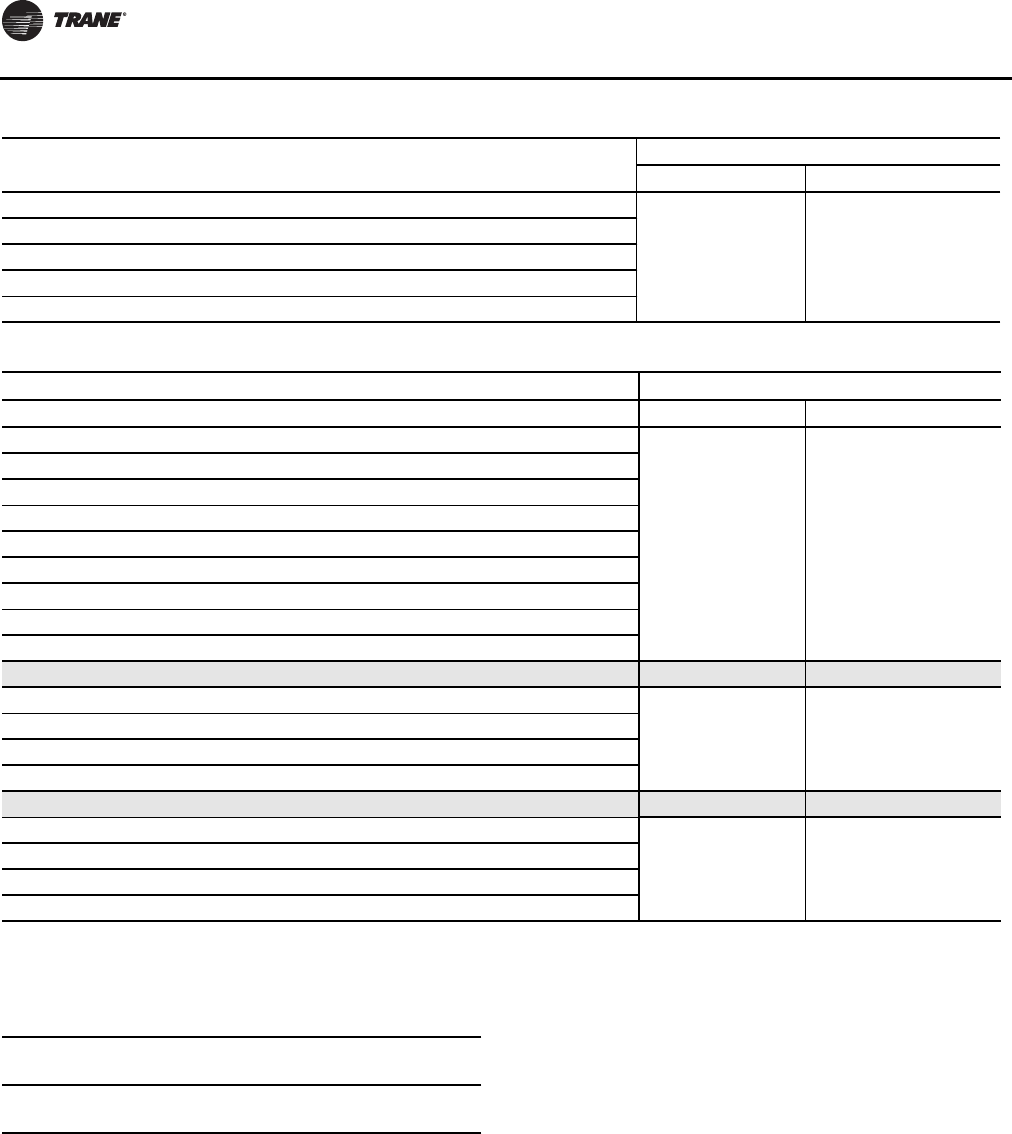
Service and Maintenance
188 RLC-SVX09H-EN
Parts Ordering Information
Obtain the required parts from your localTrane Parts
Center.
Chemical Cleaning Procedure
• Scale deposits are best removed by chemical means.
Consult a qualified water treatment specialist (i.e., one
that knows the local water supply chemical/mineral
content) for a recommended cleaning solution suitable
for the job. (A standard condenser water circuit is
composed solely of copper, cast iron and steel.)
Improper chemical cleaning can damage tube walls.
All of the materials used in the external circulation system,
the quantity of the solution, the duration of the cleaning
period, and any required safety precautions should be
approved by the company furnishing the materials or
performing the cleaning.
Note: Chemical tube cleaning should always be followed
by mechanical tube cleaning.
RTUD Air Cooled Condenser Applications -
High Condenser Pressure Limit and High
Pressure Cutout Diagnostics
If a circuit experiences significant time in the High
Condenser Pressure Limit mode, or if it experiences High
Pressure Cutout trip diagnostics, the air cooled condenser
may be the root cause and should be inspected.
The condenser coils should be checked for air flow
restrictions and cleanliness, as well as the possibility of
recirculated air, in which the air entering the coil is
RTWD 150, 160, 180, 200, 220, 250 60 HIGH Return
29.9 (66) M12x1.75
RTWD 150, 160, 180, 200 60 PREM Return
RTWD 130, 140, 160, 180, 200, 220, 250 50 HIGH Return
RTWD 160, 180, 200 50 PREM Return
RTUD 150, 160, 180, 200, 220, 250 60 HIGH Return
Table 130. RTWD Condenser waterbox weights
Standard Grooved Pipe Waterbox
Model Size Hz Effic Waterbox Weight - kg (lbs) Lifting Connection
RTWD 80, 90, 100, 110, 120, 130, 140 60 STD Supply, Return
20.4 (45) M12x1.75
RTWD 80, 90, 100, 110, 120, 130 60 HIGH Supply, Return
RTWD 70, 80, 90, 100, 110, 120, 130, 140, 150 50 STD Supply, Return
RTWD 60, 70, 80, 90, 100, 110, 120 50 HIGH Supply, Return
RTWD 150, 160, 180, 200, 220, 250 60 HIGH Supply, Return
RTWD 150, 160, 180, 200 60 PREM Supply, Return
RTWD 130, 140, 160, 180, 200, 220, 250 50 HIGH Supply, Return
RTWD 160, 180, 200 50 PREM Supply, Return
RTUD 80, 90, 100, 110, 120, 130 60 HIGH Supply, Return
RTWD 150, 160, 180, 200, 220, 250 60 HIGH Supply
38.6 (85) M12x1.75
RTWD 150, 160, 180, 200 60 PREM Supply
RTWD 130, 140, 160, 180, 200, 220, 250 50 HIGH Supply
RTWD 160, 180, 200 50 PREM Supply
RTWD 150, 160, 180, 200, 220, 250 60 HIGH Return
29.9 (66) M12x1.75
RTWD 150, 160, 180, 200 60 PREM Return
RTWD 130, 140, 160, 180, 200, 220, 250 50 HIGH Return
RTWD 160, 180, 200 50 PREM Return
Table 129. RTWD/RTUD Evaporator waterbox weights (continued)
Standard Grooved Pipe Waterbox
Model Size Hz Effic Waterbox Weight - kg (lbs) Lifting Connection
Table 131. Connection devices
Unit Product
Part
Number
RTWD/RTUD -
All units
Safety Hoist Ring M12x1.75 RNG01886
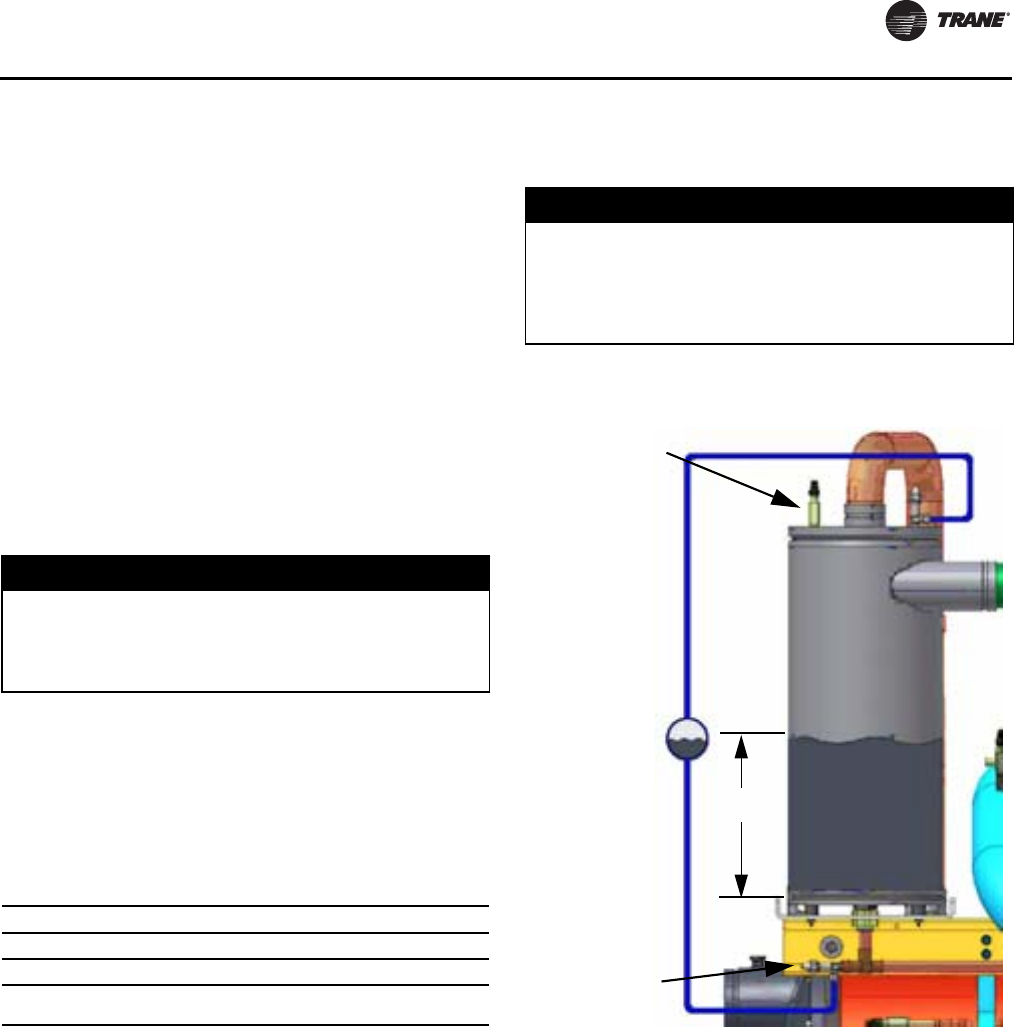
Service and Maintenance
RLC-SVX09H-EN 189
significantly higher temperature than the ambient outdoor
air temperature (5 ºF or more).
All of the fans should also be validated to be operational
with the proper fan blade rotation direction. Dirty, or
fouled coils, or otherwise limited or restricted air flow
through the coils, can significantly degrade the efficiency
of the chiller as well as result in unnecessary limits and
nuisance trips. Refer to the condenser manufacturers’
maintenance and cleaning procedures.
Cleaning the Evaporator
Since the evaporator is typically part of a closed circuit, it
does not accumulate appreciable amounts of scale or
sludge. However, if cleaning is deemed necessary, use the
same cleaning methods described for the condenser
tubes.
Compressor Oil
Trane Polyolester Oil is the approved oil for the RTWD/
RTUD units. Polyolester oil is extremely hygroscopic
meaning it readily attracts moisture.The oil can not be
stored in plastic containers due to the hygroscopic
properties. As with mineral oil, if water is in the system it
will react with the oil to form acids. UseTable 132 to
determine the acceptability of the oil.
Note: Use an oil transfer pump to change the oil
regardless of chiller pressure.
Oil Sump Level Check
Running the chiller at minimum load is the best for the
quickest return of oil to the separator and sump.The
machine still needs to sit for approximately 30 minutes
before the level is taken. At minimum load, the discharge
superheat should be highest.The more heat in the oil as it
lays in the sump, the more refrigerant will boil off in the
sump and leave more concentrated oil.
The oil level in the oil sump can be measured to give an
indication of the system oil charge. Follow the procedures
below to measure the level.
1. Run the unit fully unloaded for approximately 20
minutes.
2. Cycle the compressor off line.
3. Attach a 3/8” or 1/2” hose with a sightglass in the
middle to the oil sump service valve (1/4” flare) and the
oil separator service valve (1/4” flare).
Note: Using high pressure rated clear hose with
appropriate fittings can help speed up the process.
4. After the unit is off line for 30 minutes, move the
sightglass along the side of the oil sump.
5. The level should be between 4” and 9.5” from the
bottom of the oil sump. If the level appears to be above
9.5”, the oil sump is completely full. Most likely more oil
resides in the rest of the system and some oil needs to
be removed until the level falls between 4” and 9.5” in
the oil sump.
Note: Nominal height of oil is 8 inches.
NOTICE:
Equipment Damage!
To prevent oil sump heater burnout, open the unit
main power disconnect switch before removing
oil from the compressor.
Table 132. POE Oil Properties
Description Acceptable Levels
Moisture content less than 300 ppm
Acid Level less than 0.5 TAN (mg KOH/g)
Note: Mineral oil used in the RTHA and RTHB units has different acceptable
levels (< 50 ppm of moisture and < 0.05 mg KOH/g)
NOTICE:
Equipment Damage!
Never operate the compressor with the sight glass
service valves opened. Severe oil loss will occur. Close
the valves after checking the oil level. The sump is
above the condenser and it is possible to drain the oil.
Figure 87. Determining oil level in the sump
service valve
Oil separator
4 “- 9.5”
Oil sump
service valve
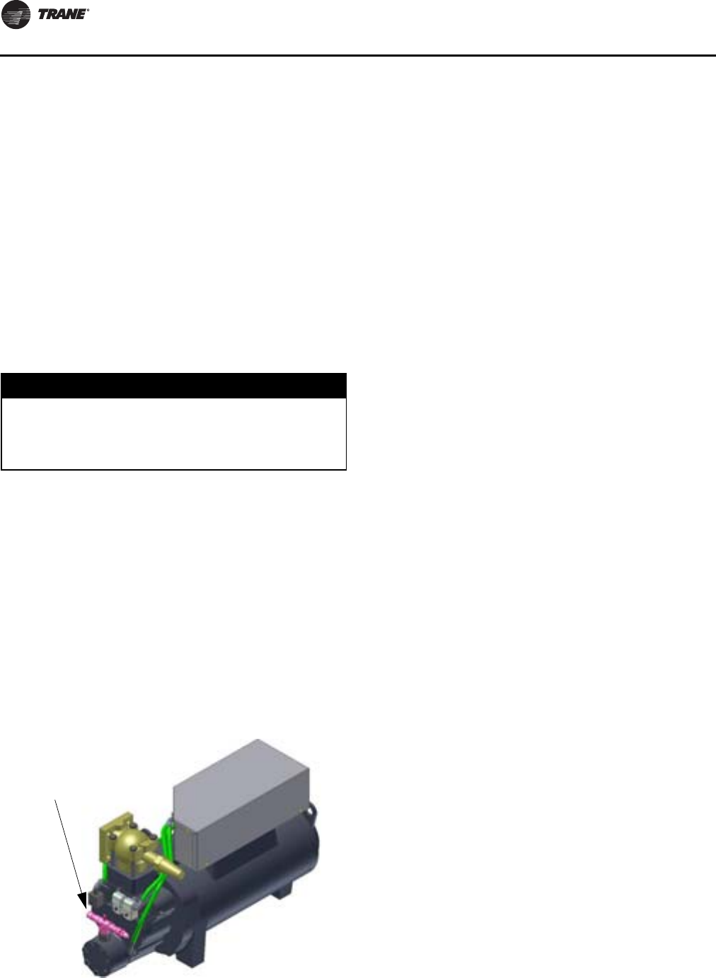
Service and Maintenance
190 RLC-SVX09H-EN
6. If the level is below 4”, there is not enough oil in the
sump.This can occur from not enough oil in the
system or more likely, oil migration to the evaporator.
Oil migration can occur from a low refrigerant charge,
gas pump malfunction, etc.
Note: If the oil is logged in the evaporator confirm the
operation of the gas pump. If the gas pump is not
functioning properly all oil will be logged in the
evaporator.
7. After the level is determined, close the service valves
and remove the hose/sightglass assembly.
Removing Compressor Oil
The oil in the compressor oil sump is under a constant
positive pressure at ambient temperature.To remove oil,
open the service valve located on the bottom of the oil
sump and drain the oil into a suitable container using the
procedure outlined below:
Oil should not be removed until the refrigerant is isolated
or removed.
8. Connect a line to the oil sump drain valve.
9. Open the valve and allow the desired amount of oil to
flow into the container and close the charging valve.
10. Measure the exact amount of oil removed from the
unit.
Oil Charging Procedure
It is critical to fill the oil lines feeding the compressor when
charging a system with oil.The diagnostic “Loss of oil at
the compressor stopped” will be generated if the oil lines
are not full on start-up.
To properly charge the system with oil, follow the steps
below:
1. Locate the 1/4” schrader valve on the end of the
compressor.
2. Loosely connect oil pump to schrader valve called out
in step 1.
3. Operate oil charging pump until oil appears at the
charging valve connection; then tighten the
connection.
Note: To keep air from entering the oil, the charging valve
connection must be air- tight.
4. Open the service valve and pump in the required
amount of oil.
Note: Adding oil at the oil charging port ensures that the
oil filter cavity and the oil lines back to the oil
separator are filled with oil. An internal oil valve
prevents oil from entering the compressor rotors.
Replacing the Oil Filter
The filter element should be changed if the oil flow is
sufficiently obstructed.Two things can happen: first, the
chiller may shut down on a “Low Oil Flow” diagnostic, or
secondly, the compressor may shut down on a “Loss of Oil
at Compressor (Running) diagnostic. If either of these
diagnostics occurs, it is possible the oil filter needs
replacement.The oil filter is not usually the cause of a Loss
of oil at Compressor diagnostic.
Specifically, the filter must be changed if the pressure drop
between the two service valves in the lubrication circuit
exceeds the maximum level as given in Figure 89, p. 191.
This chart shows the relationship between the pressure
drop measured in the lubrication circuit as compared with
operating pressure differential of the chiller (as measured
by pressures in the condenser and evaporator).
Normal pressure drops between the service valves of the
lubrication circuit are shown by the lower curve.The upper
curve represents the maximum allowable pressure drop
and indicates when the oil filter must be changed. Pressure
drops that lie between the lower and upper curves are
considered acceptable.
For a chiller equipped with an oil cooler, add 5 psid to the
values shown in Figure 89. For example, if the system
pressure differential was 80 psid, then the clean filter
pressure drop would be approximately 15 psid (up from 10
psid). For a chiller with an oil cooler and operating with a
dirty oil filter, the maximum allowable pressure drop
would be 28 psid (up from 23 psid).
Under normal operating conditions the element should be
replaced after the first year of operation and then as
needed thereafter.
NOTICE:
Equipment Damage!
Due to the hygroscopic properties of the POE oil, all oil
must be stored in metal containers.The oil will absorb
water if stored in a plastic container.
Figure 88. Oil charging port
Oil charging port
(1/4” flare with
schrader valve)
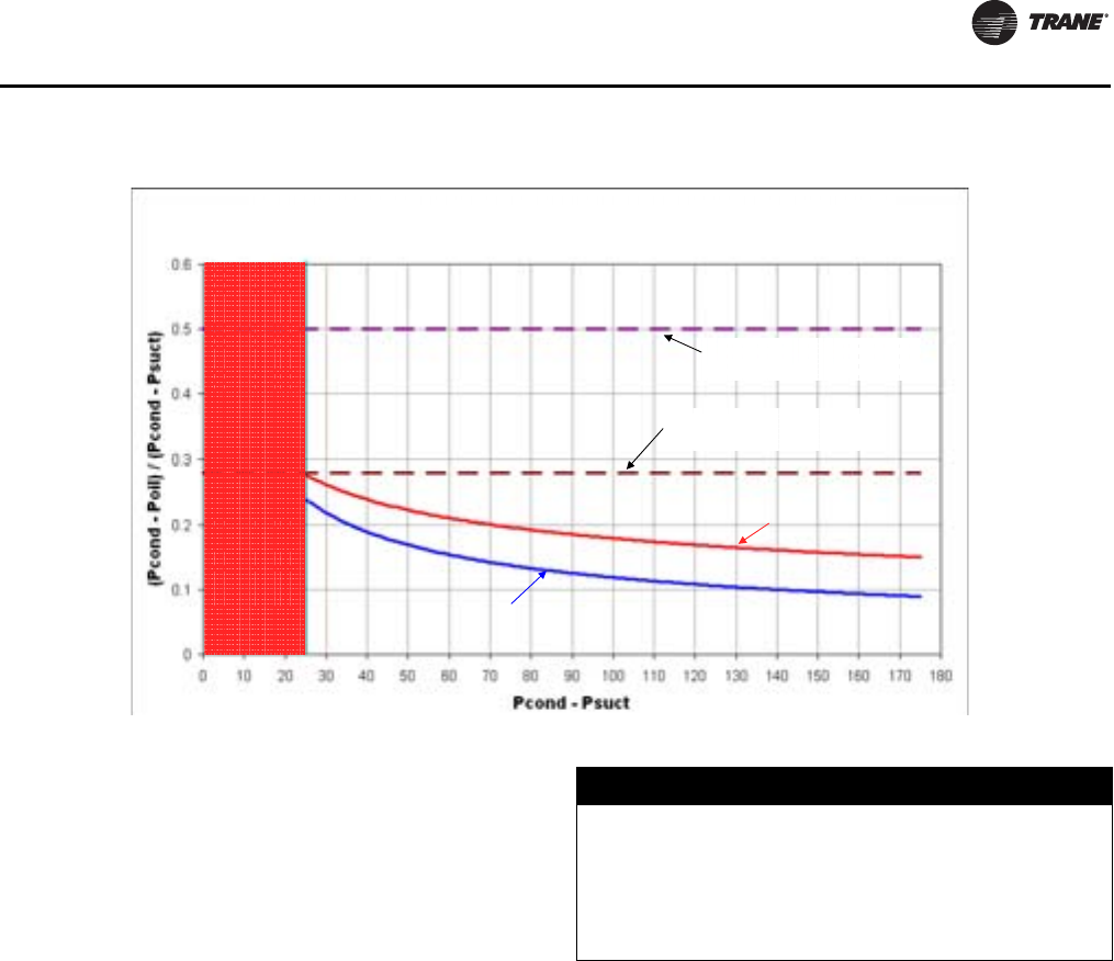
Service and Maintenance
RLC-SVX09H-EN 191
Refrigerant Charge
If a low refrigerant charge is suspected, first determine the
cause of lost refrigerant. Once the problem is repaired
follow the procedures below for evacuating and charging
the unit.
Evacuation and Dehydration
5. Disconnect ALL power before/during evacuation.
6. Connect the vacuum pump to the 5/8” flare connection
on the bottom of the evaporator and/or condenser.
7. To remove all of the moisture from the system and to
insure a leak free unit, pull the system down below 500
microns.
8. After the unit is evacuated, perform a standing rise test
for at least an hour.The pressure should not rise more
than 150 microns. If the pressures rises more than 150
microns, either a leak is present or moisture is still in
the system.
Note: If oil is in the system, this test is more difficult.The
oil is aromatic and will give off vapors that will raise
the pressure of the system.
Refrigerant Charging
On RTWD Units, once the system is deemed leak and
moisture free, use the 5/8” flare connections at the bottom
of the evaporator and condenser to add refrigerant charge.
For RTUD Units, once the system is deemed leak and
moisture free, use the service valve on the liquid line to
add refrigerant charge.
See “General Data,” p. 9 and Unit nameplate for
refrigerant charge information.
Refrigerant and Oil Charge Management
Proper oil and refrigerant charge is essential for proper
unit operation, unit performance, and environmental
protection. Only trained and licensed service personnel
should service the chiller.
Some symptoms of a refrigerant under-charged
unit:
• Low subcooling
• Higher than normal discharge superheat
• Bubbles in EXV sight glass
• Low liquid level diagnostic
• Larger than normal evaporator approach
temperatures (leaving water temperature - saturated
evaporator temperature)
• Low evaporator refrigerant temperature limit
• Low refrigerant temperature cutout diagnostic
Figure 89. Recommended oil filter replacement
Unit shut down
Minimum system pressure differential
= 25 psid
Clean Filter below this line
Recommend replacing filter
Start protection line for 1st
2.5 minutes of operation
Run protection line after 2.5
minutes of operation
GP2 / RTWD Clean Filter Versus Recommended Filter Replacement
Line CH530 RTWD Oil Pressure Protection Scheme
NOTICE:
Equipment Damage!
Add field refrigerant charge only through the service
valve on the liquid line, not the service valves on the
evaporator, and insure that water is flowing through the
evaporator during the charging process. Failure to do
the above could result in equipment damage.

Service and Maintenance
192 RLC-SVX09H-EN
• Fully open expansion valve
• Possible whistling sound coming from liquid line (due
to high vapor velocity)
• High condenser + subcooler pressure drop
Some symptoms of a refrigerant over-charged unit:
• High subcooling
• Evaporator liquid level higher than centerline after
shut down
• Larger than normal condenser approach temperatures
(entering condenser saturated temperature – leaving
condenser water temperature)
• Condenser pressure limit
• High pressure cutout diagnostic
• Higher than normal compressor power
• Very low discharge superheat at startup
• Compressor rattle or grinding sound at startup
Some symptoms of an oil over-charged unit:
• Larger than normal evaporator approach
temperatures (leaving water temperature - saturated
evaporator temperature)
• Low evaporator refrigerant temperature limit
• Erratic liquid level control
• Low unit capacity
• Low discharge superheat (especially at high loads)
• Low liquid level diagnostics
• High oil sump level after normal shut down
Some symptoms of an oil under-charged unit:
• Compressor rattle or grinding sound
• Lower than normal pressure drop through oil system
• Seized or welded compressors
• Low oil sump level after normal shut down
• Lower than normal oil concentrations in evaporator
Refrigerant Filter Replacement Procedure
A dirty filter is indicated by a temperature gradient across
the filter, corresponding to a pressure drop. If the
temperature downstream of the filter is 4°F (-15.5°C) lower
than the upstream temperature, the filter should be
replaced. A temperature drop can also indicate that the
unit is undercharged. Ensure proper subcooling before
taking temperature readings.
1. With the unit off, verify that the EXV is closed. Close
liquid line isolation valve.
2. Attach hose to service port on liquid line filter flange.
3. Evacuate refrigerant from liquid line and store.
4. Remove hose.
5. Depress schrader valve to equalize pressure in liquid
line with atmospheric pressure.
6. Remove bolts that retain filter flange.
7. Remove old filter element.
8. Inspect replacement filter element and lubricate o-ring
withTrane OIL00048.
Note: Do not use mineral oil. It will contaminate the
system.
9. Install new filter element in filter housing.
10. Inspect flange gasket and replace if damaged.
11. Install flange and torque bolts to 14-16 lb-ft (19-22 n-m).
12. Attach vacuum hose and evacuate liquid line.
13. Remove vacuum hose from liquid line and attach
charging hose.
14. Replace stored charge in liquid line.
15. Remove charging hose.
16. Open liquid line isolation valve.
Freeze Protection
For unit operation in a low temperature environment,
adequate protection measures must be taken against
freezing.

RLC-SVX09H-EN 193
Diagnostics
Diagnostic Name and Source: Name of Diagnostic and
its source. Note that this is the exact text used in the User
Interface and/or ServiceTool displays.
AffectsTarget: Defines the “target” or what is affected
by the diagnostic. Usually either the entire Chiller, or a
particular Circuit or Compressor is affected by the
diagnostic (the same one as the source), but in special
cases functions are modified or disabled by the diagnostic.
None implies that there is no direct affect to the chiller, sub
components or functional operation.
Severity: Defines the severity of the above effect.
Immediate means immediate shutdown of the affected
portion, Normal means normal or friendly shutdown of
the affected portion, Special Action means a special
action or mode of operation (limp along) is invoked, but
without shutdown, and Info means an Informational Note
or Warning is generated.
Persistence: Defines whether or not the diagnostic and
its effects are to be manually reset (Latched), or can be
either manually or automatically reset when and if the
condition returns to normal (Nonlatched).
Active Modes [Inactive Modes]: States the modes or
periods of operation that the diagnostic is active in and, as
necessary, those modes or periods that it is specifically
“not active” in as an exception to the active modes.The
inactive modes are enclosed in brackets, []. Note that the
modes used in this column are internal and not generally
annunciated to any of the formal mode displays.
Criteria: Quantitatively defines the criteria used in
generating the diagnostic and, if nonlatching, the criteria
for auto reset. If more explanation is necessary a hot link
to the Functional Specification is used.
Reset Level: Defines the lowest level of manual
diagnostic reset command which can clear the diagnostic.
The manual diagnostic reset levels in order of priority are:
Local or Remote. For example, a diagnostic that has a
reset level of Remote, can be reset by either a remote
diagnostic reset command or by a local diagnostic reset
command.
HelpText: Provides for a brief description of what kind of
problems might cause this diagnostic to occur. Both
control system component related problems as well as
chiller application related problems are addressed (as can
possibly be anticipated).These help messages will be
updated with accumulated field experience with the
chillers.

Diagnostics
194 RLC-SVX09H-EN
Starter Diagnostics
Table 133. Starter Diagnostics
Diagnostic Name and
Source
Affects
Target Severity
Persist
ence
Active Modes
[Inactive Modes] Criteria
Reset
Level
Compressor Did Not
Accelerate: Transition -
Compressor 1A
*Circuit Info Latch Start Mode
The compressor did not come up to speed (fall to
<85%RLA) in the allotted time defined by the
Maximum Acceleration Timer and a transition was
forced (motor put across the line) at that time.
This applies to all starter types.
Remote
Compressor Did Not
Accelerate: Transition -
Compressor 2A
*Circuit Info Latch Start Mode
The compressor did not come up to speed (fall to
<85%RLA) in the allotted time defined by the
Maximum Acceleration Timer and a transition was
forced (motor put across the line) at that time.
This applies to all starter types.
Remote
Motor Current Overload -
Compressor 1A Circuit Immediate Latch Cprsr Energized
Compressor current exceeded overload time vs.
trip characteristic. Must trip = 140% RLA, Must
hold=125%, nominal trip 132.5% in 30 seconds
Local
Motor Current Overload -
Compressor 2A Circuit Immediate Latch Cprsr Energized
Compressor current exceeded overload time vs.
trip characteristic. Must trip = 140% RLA, Must
hold=125%, nominal trip 132.5% in 30 seconds
Local
Over Voltage Chiller Normal Non
Latch
Pre-Start and Any
Ckt(s) Energzd
Nom. trip: 60 seconds at greater than 112.5%, 2.5%,
Auto Reset at 110% or less for 10 cont secs. Remote
Phase Loss - Compressor
1A *Circuit Immediate Latch Start Sequence and
Run modes
a) No current was sensed on one or two of the
current transformer inputs while running or
starting (See Nonlatching Power Loss Diagnostic
for all three phases lost while running). Must hold
= 20% RLA. Must trip = 5% RLA. Time to trip shall
be longer than guaranteed reset on Starter
Module at a minimum, 3 seconds maximum.
Actual design trip point is 10%. The actual design
trip time is 2.64 seconds.
b) If Phase reversal protection is enabled and
current is not sensed on one or more current
xformer inputs. Logic will detect and trip in a
maximum of 0.3 seconds from compressor start.
Local
Phase Loss - Compressor
2A *Circuit Immediate Latch Start Sequence and
Run modes
a) No current was sensed on one or two of the
current transformer inputs while running or
starting (See Nonlatching Power Loss Diagnostic
for all three phases lost while running). Must hold
= 20% RLA. Must trip = 5% RLA. Time to trip shall
be longer than guaranteed reset on Starter
Module at a minimum, 3 seconds maximum.
Actual design trip point is 10%. The actual design
trip time is 2.64 seconds.
b) If Phase reversal protection is enabled and
current is not sensed on one or more current
xformer inputs. Logic will detect and trip in a
maximum of 0.3 second from compressor start
Local
Phase Reversal -
Compressor 1A *Circuit Immediate Latch
Compressor energized
to transition command
[All Other Times]
A phase reversal was detected on the incoming
current. On a compressor startup the phase
reversal logic must detect and trip in a maximum
of.3 second from compressor start.
Local
Phase Reversal -
Compressor 2A *Circuit Immediate Latch
Compressor energized
to transition command
[All Other Times]
A phase reversal was detected on the incoming
current. On a compressor startup the phase
reversal logic must detect and trip in a maximum
of.3 second from compressor start.
Local

Diagnostics
RLC-SVX09H-EN 195
Power Loss - Compressor
1A *Circuit Immediate Non
Latch
All compressor running
modes
[all compressor
starting and non-
running modes]
The compressor had previously established
currents while running and then all three phases
of current were lost. Design: Less than 10% RLA,
trip in 2.64 seconds. This diagnostic will preclude
the Phase Loss Diagnostic and the Transition
Complete Input Opened Diagnostic from being
called out. To prevent this diagnostic from
occurring with the intended disconnect of main
power, the minimum time to trip must be greater
than the guaranteed reset time of the Starter
module. Note: This diagnostic prevents nuisance
latching diagnostics due to a momentary power
loss – It does not protect motor (compressor from
uncontrolled power reapplication. See Momentary
Power Loss Diagnostic for this protection. This
diagnostic is not active during the start mode
before the transition complete input is proven.
Thus a random power loss during a start would
result in either a “Starter Fault Type 3” or a
“Starter Did Not Transition” latching diagnostic.
Remote
Power Loss - Compressor
2A *Circuit Immediate Non
Latch
All compressor running
modes
[all compressor
starting and non-
running modes]
The compressor had previously established
currents while running and then all three phases
of current were lost. Design: Less than 10% RLA,
trip in 2.64 seconds. This diagnostic will preclude
the Phase Loss Diagnostic and the Transition
Complete Input Opened Diagnostic from being
called out. To prevent this diagnostic from
occurring with the intended disconnect of main
power, the minimum time to trip must be greater
than the guaranteed reset time of the Starter
module.
Remote
Severe Current
Imbalance - Compressor
1A
Circuit Immediate Latch All Running Modes
A 30% Current Imbalance has been detected on
one phase relative to the average of all 3 phases
for 90 continuous seconds.
Local
Severe Current
Imbalance - Compressor
2A
Circuit Immediate Latch All Running Modes
A 30% Current Imbalance has been detected on
one phase relative to the average of all 3 phases
for 90 continuous seconds
Local
Starter 1A Dry Run Test *Circuit Immediate Latch Starter Dry Run Mode
While in the Starter Dry Run Mode either 50% Line
Voltage was sensed at the Potential Transformers
or 10% RLA Current was sensed at the Current
Transformers.
Local
Starter 2A Dry Run Test *Circuit Immediate Latch Starter Dry Run Mode
While in the Starter Dry Run Mode either 50% Line
Voltage was sensed at the Potential Transformers
or 10% RLA Current was sensed at the Current
Transformers.
Local
Starter Contactor
Interrupt Failure -
Compressor 1A
Chiller Special
Action Latch
Starter Contactor not
Energized [Starter
Contactor Energized]
Detected compressor currents greater than 10%
RLA on any or all phases when the compressor was
commanded off. Detection time shall be 5 second
minimum and 10 seconds maximum. On detection
and until the controller is manually reset:
generate diagnostic, energize the appropriate
alarm relay, continue to energize the Evap Pump
Output, continue to command the affected
compressor off, fully unload the effected
compressor and command a normal stop to all
other compressors. For as long as current
continues, perform liquid level, oil return, and fan
control on the circuit effected.
Local
Table 133. Starter Diagnostics
Diagnostic Name and
Source
Affects
Target Severity
Persist
ence
Active Modes
[Inactive Modes] Criteria
Reset
Level

Diagnostics
196 RLC-SVX09H-EN
Starter Contactor
Interrupt Failure -
Compressor 2A
Chiller Special
Action Latch
Starter Contactor not
Energized [Starter
Contactor Energized]
Detected compressor currents greater than 10%
RLA on any or all phases when the compressor was
commanded off. Detection time shall be 5 second
minimum and 10 seconds maximum. On detection
and until the controller is manually reset:
generate diagnostic, energize the appropriate
alarm relay, continue to energize the Evap Pump
Output, continue to command the affected
compressor off, fully unload the effected
compressor and command a normal stop to all
other compressors. For as long as current
continues, perform liquid level, oil return, and fan
control on the circuit effected.
Local
Starter Did Not Transition
- Compressor 1A *Circuit Immediate Latch On the first check after
transition.
The Starter Module did not receive a transition
complete signal in the designated time from its
command to transition. The must hold time from
the Starter Module transition command is 1
second. The Must trip time from the transition
command is 6 seconds. Actual design is 2.5
seconds. This diagnostic is active only for Y-Delta,
Auto-Transformer, Primary Reactor, and X-Line
Starters.
Local
Starter Did Not Transition
- Compressor 2A *Circuit Immediate Latch On the first check after
transition.
The Starter Module did not receive a transition
complete signal in the designated time from its
command to transition. The must hold time from
the Starter Module transition command is 1
second. The Must trip time from the transition
command is 6 seconds. Actual design is 2.5
seconds. This diagnostic is active only for Y-Delta,
Auto-Transformer, Primary Reactor, and X-Line
Starters.
Local
Starter Fault Type I –
Compressor 1A *Circuit Immediate Latch Starting - Y Delta
Starters Only
This is a specific starter test where 1M(1K1) is
closed first and a check is made to ensure that
there are no currents detected by the CTs. If
currents are detected when only 1M is closed first
at start, then one of the other contactors is
shorted.
Local
Starter Fault Type I –
Compressor 2A *Circuit Immediate Latch Starting - Y Delta
Starters Only
This is a specific starter test where 1M(1K1) is
closed first and a check is made to ensure that
there are no currents detected by the CTs. If
currents are detected when only 1M is closed first
at start, then one of the other contactors is
shorted.
Local
Starter Fault Type II –
Compressor 1A *Circuit Immediate Latch Starting All types of
starters
a. This is a specific starter test where the Shorting
Contactor (1K3) is individually energized and a
check is made to ensure that there are no currents
detected by the CTs. If current is detected when
only S is energized at Start, then 1M is shorted. b.
This test in a. above applies to all forms of starters
(Note: It is understood that many starters do not
connect to the Shorting Contactor.).
Local
Starter Fault Type II –
Compressor 2A *Circuit Immediate Latch Starting – All types of
starters
a. This is a specific starter test where the Shorting
Contactor (1K3) is individually energized and a
check is made to ensure that there are no currents
detected by the CTs. If current is detected when
only S is energized at Start, then 1M is shorted. b.
This test in a. above applies to all forms of starters
(Note: It is understood that many starters do not
connect to the Shorting Contactor.).
Local
Starter Fault Type III –
Compressor 1A *Circuit Immediate Latch
Starting
[Adaptive Frequency
Starter Type]
As part of the normal start sequence to apply
power to the compressor, the Shorting Contactor
(1K3) and then the Main Contactor (1K1) were
energized. 1.6 seconds later there were no
currents detected by the CT's for the last 1.2
Seconds on all three phases. The test above
applies to all forms of starters except Adaptive
Frequency Drives.
Local
Table 133. Starter Diagnostics
Diagnostic Name and
Source
Affects
Target Severity
Persist
ence
Active Modes
[Inactive Modes] Criteria
Reset
Level
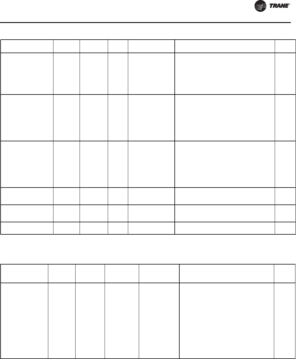
Diagnostics
RLC-SVX09H-EN 197
Main Processor Diagnostics
Starter Fault Type III –
Compressor 2A *Circuit Immediate Latch
Starting
[Adaptive Frequency
Starter Type]
As part of the normal start sequence to apply
power to the compressor, the Shorting Contactor
(1K3) and then the Main Contactor (1K1) were
energized. 1.6 seconds later there were no
currents detected by the CT's for the last 1.2
seconds on all three phases. The test above
applies to all forms of starters except Adaptive
Frequency Drives.
Local
Transition Complete Input
Opened – Compressor 1A *Circuit
Immediate
Latch All running modes
The Transition Complete input was found to be
opened with the compressor motor running after
a successful completion of transition. This is active
only for Y-Delta, Auto-Transformer, Primary
Reactor, and X-Line Starters. To prevent this
diagnostic from occurring as the result of a power
loss to the contactors, the minimum time to trip
must be greater than the trip time for the power
loss diagnostic.
Local
Transition Complete Input
Opened – Compressor 2A *Circuit
Immediate
Latch All running modes
The Transition Complete input was found to be
opened with the compressor motor running after
a successful completion of transition. This is active
only for Y-Delta, Auto-Transformer, Primary
Reactor, and X-Line Starters. To prevent this
diagnostic from occurring as the result of a power
loss to the contactors, the minimum time to trip
must be greater than the trip time for the power
loss diagnostic.
Local
Transition Complete Input
Shorted – Compressor 1A *Circuit Immediate Latch Pre-Start
The Transition Complete input was found to be
shorted before the compressor was started. This
is active for all electromechanical starters.
Local
Transition Complete Input
Shorted – Compressor 2A *Circuit Immediate Latch Pre-Start
The Transition Complete input was found to be
shorted before the compressor was started. This
is active for all electromechanical starters.
Local
Under Voltage Chiller Normal Non
Latch
Pre-Start and Any
Ckt(s) Energzd
Nom. trip: 60 seconds at less than 87.5%, 2.8% at 200V
1.8% at 575V, Auto Reset at 90% or greater. Remote
Table 133. Starter Diagnostics
Diagnostic Name and
Source
Affects
Target Severity
Persist
ence
Active Modes
[Inactive Modes] Criteria
Reset
Level
Table 134. Main Processor Diagnostics
Diagnostic Name
Affects
Target Severity Persistence
Active Modes
[Inactive
Modes] Criteria
Reset
Level
BAS Communication
Lost None Special
Action Non Latch All
The BAS was setup as "installed" at the MP and
the Lontalk LCIC lost communications with the
BAS for 15 contiguous minutes after it had been
established. Refer to Section on Setpoint
Arbitration to determine how setpoints and
operating modes may be effected by the comm
loss. The chiller follows the value of the Tracer
Default Run Command which can be previously
written by Tracer and stored nonvolatilely by
the MP (either use local or shutdown). Note
that this diagnostic is never operational for
BacNet Communication interface (BCIC) and
only operational with a LonTalk Communication
interface (LCIC) if so configured by the BAS or
Tracer system.
Remote

Diagnostics
198 RLC-SVX09H-EN
BAS Failed to Establish
Communication None Special Action Non Latch At power-up
The BAS was setup as "installed" and the BAS
did not communicate with the Lontalk LCIC
within 15 minutes after chiller controls power-
up. Refer to Section on Setpoint Arbitration to
determine how setpoints and operating modes
may be effected. Note that this diagnostic is
never operational for BacNet Communication
interface (BCIC) and only operational with a
LonTalk Communication interface (LCIC) if so
configured by the BAS or Tracer system.
Remote
Check Clock Chiller Info Latch All
The real time clock had detected loss of its
oscillator at some time in the past. Check/
replace battery? This diagnostic can be
effectively cleared only by writing a new value
to the chiller’s time clock using the TechView or
DynaView’s “set chiller time” functions.
Remote
Condenser Entering
Water Temperature
Sensor
Chiller Info and
Special Action Latch All
RTWD only: Bad Sensor or LLID. If chiller
running, and condenser water regulating valve
option installed, force valve to 100% flow.
Remote
Condenser Leaving
Water Temperature
Sensor
Chiller Info or Special
Action Latch All
RTWD only: Bad Sensor or LLID. If Chiller is
running in the heat mode of operation – normal
chiller shutdown, otherwise, informational
warning only. Discontinue Min Capacity Limit
forced cprsr loading due to Low DP in
subsequent startups.
Remote
Condenser Refrigerant
Pressure Transducer -
Circuit 1
Circuit Immediate Latch All Bad Sensor or LLID Remote
Condenser Refrigerant
Pressure Transducer -
Circuit 2
Circuit Immediate Latch All Bad Sensor or LLID Remote
Condenser Water Flow
Lost Chiller Immediate Non Latch Start and All Run
Modes
The condenser water flow proof input was open
for more than 6 contiguous seconds (or 15
seconds for thermal dispersion type flow
switch) after flow had been proven. This
diagnostic is automatically cleared once the
compressor is stopped by a fixed time out of 7
sec. In Cooling Mode: The Cond Pump shall be
commanded off but the Evap pump command
will not be effected. – once the diagnostic auto
clears, if diff to start is met, the cond pump can
be restarted. In Heating Mode: The Cond Pump
shall remain on, and the Evap pump shall shut
off – once diagnostic auto clears, if diff to start
is met, the chiller may restart normally and the
evap pump can be restarted.
Remote
Condenser Water Flow
Overdue Chiller Normal Non Latch Estab Cond Water
Flow
Condenser water flow was not proven within 20
minutes of the condenser pump relay being
energized. The Cond Pump shall be
commanded off. Diagnostic is reset with return
of flow (although only possible with external
control of pump)
Remote
Discharge Temperature
Sensor – Compressor
1A
Circuit Immediate Latch All Bad Sensor or LLID Remote
Discharge Temperature
Sensor – Compressor
2A
Circuit Immediate Latch All Bad Sensor or LLID Remote
Emergency Stop Chiller Immediate Latch All
a. EMERGENCY STOP input is open. An external
interlock has tripped. Time to trip from input
opening to unit stop shall be 0.1 to 1.0 seconds.
Local
Table 134. Main Processor Diagnostics (continued)
Diagnostic Name
Affects
Target Severity Persistence
Active Modes
[Inactive
Modes] Criteria
Reset
Level
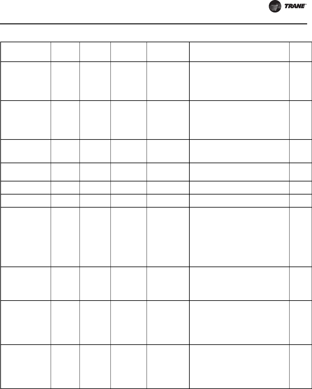
Diagnostics
RLC-SVX09H-EN 199
Evaporator Approach
Error – Circuit 1 Circuit Immediate Latch Respective circuit
running
The Evaporator approach temperature for the
respective circuit (ELWT – Evap Sat Temp Ckt
x) is negative by 10ºF or more, for 1 minute
continuously while the circuit/compressor is
operating. Either the Evap Leaving Water Temp
sensor, or Evap Suction Rfgt Pressure
Transducer Ckt 1 is in error.
Remote
Evaporator Approach
Error – Circuit 2 Circuit Immediate Latch Respective circuit
running
The Evaporator approach temperature for the
respective circuit (ELWT – Evap Sat Temp Ckt
x) is negative by 10ºF or more, for 1 minute
continuously while the circuit/compressor is
operating. Either the Evap Leaving Water Temp
sensor, or Evap Suction Rfgt Pressure
Transducer Ckt 2 is in error.
Evaporator Entering
Water Temperature
Sensor
Chiller Normal Latch All
Bad Sensor or LLID Note: Entering Water Temp
Sensor is used in EXV pressure control as well
as ice making so it must cause a unit shutdown
even if ice or CHW reset is not installed.
Remote
Evaporator Leaving
Water Temperature
Sensor
Chiller Normal Latch All Bad Sensor or LLID Remote
Evaporator Liquid Level
Sensor – Circuit 1 Circuit Normal Latch All Bad Sensor or LLID Remote
Evaporator Liquid Level
Sensor – Circuit 2 Circuit Normal Latch All Bad Sensor or LLID Remote
Evaporator Water Flow
(Entering Water Temp) None Info Non Latch
Any Ckt(s) Energzd
[No Ckt(s)
Energzd]
The entering evaporator water temp fell below
the leaving evaporator water temp by more
than 2°F for 100F-sec. For falling film
evaporators, this diagnostic cannot reliably
indicate loss of flow, but can warn of improper
flow direction through the evaporator,
misbound water temperature sensors,
improper sensor installation, partially failed
sensors, or other system problems. Note that
either entering or leaving water temp sensor
could be at fault.
Remote
Evaporator Water Flow
Lost Chiller Immediate Non Latch [All Stop modes]
a. The Evaporator water flow switch input was
open for more than 6 contiguous seconds (or 15
seconds for thermal dispersion type flow
switch). b. This diagnostic does not de-energize
the evap pump output c. 6 seconds of
contiguous flow shall clear this diagnostic.
Remote
Evaporator Water Flow
Overdue Chiller Normal Non Latch
Estab. Evap. Water
Flow on going from
STOP to AUTO or
Evap Pump
Override.
Evaporator water flow was not proven within 20
minutes of the Evaporator water pump relay
being energized in normal “Stop” to “Auto”
transition. If the pump is overridden to “On” for
certain diagnostics, the delay on diagnostic
callout shall be only 255 seconds. The pump
command status will not be effected by this
diagnostic in either case.
Remote
Excessive Condenser
Pressure – Circuit 1 Circuit Immediate Latch All
The condenser pressure transducer of this
circuit has detected a pressure in excess of the
safe high side pressure as limited by the
particular compressor type or the evaporator
distributor present on this particular chiller. For
Air Cooled Condenser, check for dirty coils or
any fouling or restrictions as well as proper
operation and rotational direction of all fans.
Remote
Table 134. Main Processor Diagnostics (continued)
Diagnostic Name
Affects
Target Severity Persistence
Active Modes
[Inactive
Modes] Criteria
Reset
Level

Diagnostics
200 RLC-SVX09H-EN
Excessive Condenser
Pressure – Circuit 2 Circuit Immediate Latch All
The condenser pressure transducer of this
circuit has detected a pressure in excess of the
safe high side pressure as limited by the
particular compressor type or the evaporator
distributor present on this particular chiller. For
Air Cooled Condenser, check for dirty coils or
any fouling or restrictions as well as proper
operation and rotational direction of all fans.
Remote
External Chilled (Hot
Water Setpoint None Info Latch All
a. Function Not “Enabled”: no diagnostics. B.
“Enabled “: Out-Of-Range Low or Hi or bad
LLID, set diagnostic, default CWS to next level
of priority (e.g. Front Panel SetPoint). This Info
diagnostic will automatically reset if the input
returns to the normal range.
Remote
External Current Limit
Setpoint None Info Latch All
a. Not “Enabled”: no diagnostics. B. “Enabled “:
Out-Of-Range Low or Hi or bad LLID, set
diagnostic, default CLS to next level of priority
(e.g. Front Panel SetPoint. This Info diagnostic
will automatically reset if the input returns to
the normal range.
Remote
Fan Fault - Circuit 1 Circuit (fan
control)
Special Mode
(or in single
fan deck:
Circuit
Immediate
shutdown
NonLatch (or in
single fan
deck:Latch)
Prestart and
Running w/Low
Ambient Variable
Spd Fan configured
A fault signal has been detected from the
respective condenser’s Variable Speed
Inverter Drive (fan). Condenser Fan control will
revert to constant speed operation without the
use of the inverter’s fan. If the inverter’s fault
clears, fan control will switch back to variable
speed. For single fan deck configurations, this
diagnostic causes a latching circuit shutdown.
Fan Fault - Circuit 2 Circuit (fan
control)
Special Mode
(or in single
fan deck:
Circuit
Immediate
shutdown
NonLatch (or in
single fan
deck:Latch)
Prestart and
Running w/Low
Ambient Variable
Spd Fan configured
A fault signal has been detected from the
respective condenser’s Variable Speed
Inverter Drive (fan). Condenser Fan control will
revert to constant speed operation without the
use of the inverter’s fan. If the inverter’s fault
clears, fan control will switch back to variable
speed. For single fan deck configurations, this
diagnostic causes a latching circuit shutdown.
High Differential
Refrigerant Pressure -
Circuit 1
Circuit Normal Latch Cprsr Energized
High Vi Cprsr: The differential pressure for the
respective circuit was above 275 Psid (1890
kPa) for 2 consecutive samples or more than 10
seconds.
Low Vi Cprsr: The system differential
pressure was above 188 Psid (1296.4 kPa) - for
2 consecutive samples or more than 10
seconds.
Remote
High Differential
Refrigerant Pressure -
Circuit 2
Circuit Normal Latch Cprsr Energized
High Vi Cprsr: The differential pressure for the
respective circuit was above 275 Psid (1890
kPa) for 2 consecutive samples or more than 10
seconds.
Low Vi Cprsr: The system differential
pressure was above 188 Psid (1296.4 kPa) - for
2 consecutive samples or more than 10
seconds.
Remote
High Discharge
Temperature –
Compressor 1A
Circuit Immediate Latch
All
[compressor run
unload or
compressor not
running]
The compressor discharge temperature exceeded
200F (without oil cooler) or 230ºF (with oil cooler).
This diagnostic will be suppressed during Run-Unload
or after the compressor has stopped. Note: As part of
the Compressor High Temperature Limit Mode (aka
Minimum Capacity Limit), the compressor shall be
forced loaded as the filtered discharge temperature
reaches 190ºF(without oil coolers), or 220ºF (with oil
coolers).
Remote
Table 134. Main Processor Diagnostics (continued)
Diagnostic Name
Affects
Target Severity Persistence
Active Modes
[Inactive
Modes] Criteria
Reset
Level
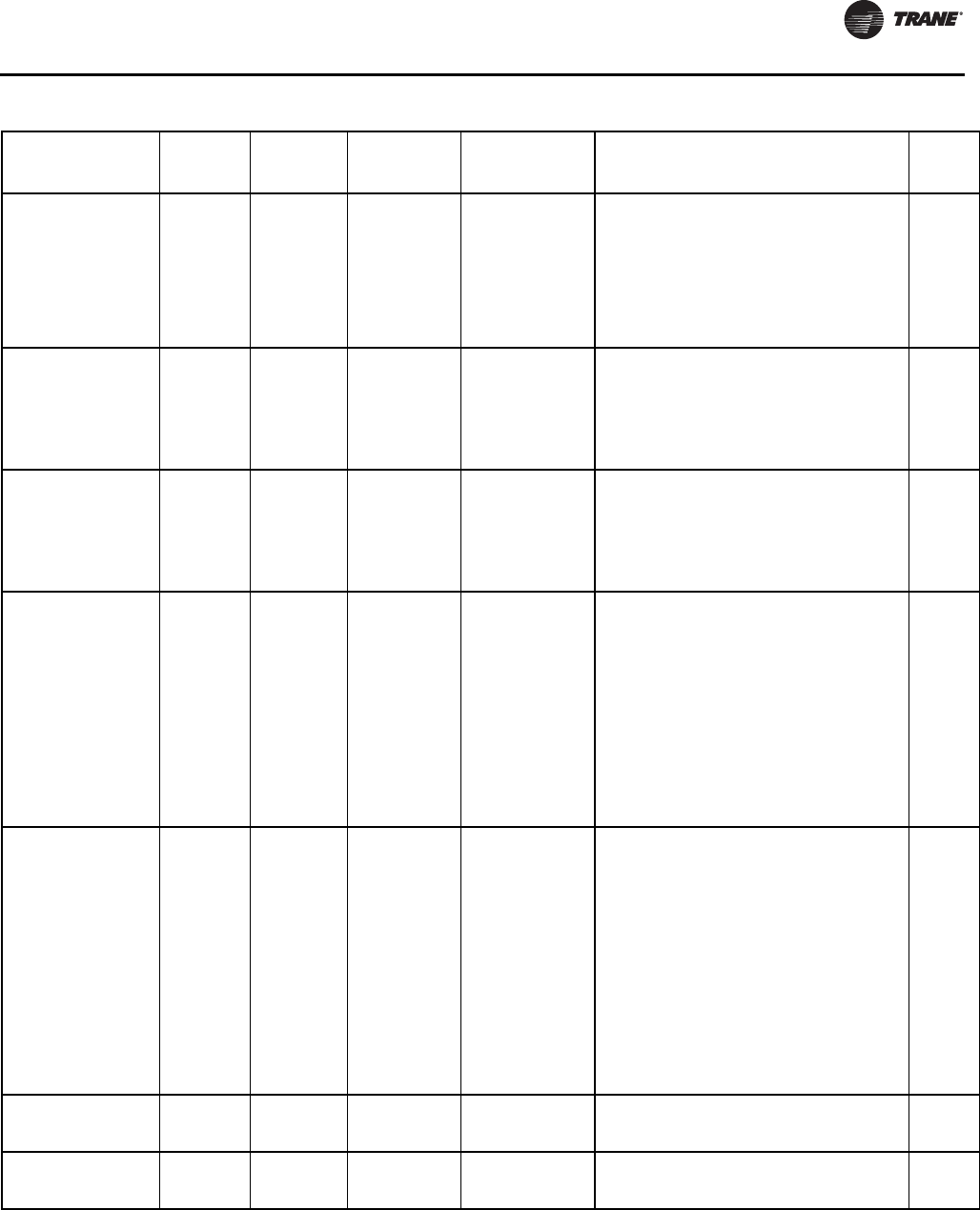
Diagnostics
RLC-SVX09H-EN 201
High Discharge
Temperature –
Compressor 2A
Circuit Immediate Latch
All
[compressor run
unload or
compressor not
running]
The compressor discharge temperature exceeded
200F (without oil cooler) or 230ºF (with oil cooler).
This diagnostic will be suppressed during Run-Unload
or after the compressor has stopped. Note: As part of
the Compressor High Temperature Limit Mode (aka
Minimum Capacity Limit), the compressor shall be
forced loaded as the filtered discharge temperature
reaches 190ºF(without oil coolers), or 220ºF (with oil
coolers).
Remote
High Evaporator Liquid
Level – Circuit 1 (early
Phase 1 RTWD
production only –
eliminated in 2nd
Phase 1 release in Sept
08)
Circuit Normal Latch
Starter Contactor
Energized [all Stop
modes]
The liquid level sensor is seen to be at or near
its high end of range for 80 contiguous minutes
while the compressor is running. (The
diagnostic timer will hold, but not clear when
the circuit is off). Design: approx 80% or more
of bit count corresponding to +30 mm or more
liquid level for 80 minutes)
Remote
High Evaporator Liquid
Level – Circuit 2 (early
Phase 1 RTWD
production only –
eliminated in 2nd
Phase 1 release in Sept
08)
Circuit Normal Latch
Starter Contactor
Energized [all Stop
modes]
The liquid level sensor is seen to be at or near
its high end of range for 80 contiguous minutes
while the compressor is running. (The
diagnostic timer will hold, but not clear when
the circuit is off). Design: approx 80% or more
of bit count corresponding to +30 mm or more
liquid level for 80 minutes)
. Remote
High Evaporator
Refrigerant Pressure Chiller Immediate Non Latch All
The evaporator refrigerant pressure of either
circuit has risen above 190 psig. The
evaporator water pump relay will be de-
energized to stop the pump regardless of why
the pump is running. The diagnostic will auto
reset and the pump will return to normal control
when all of the evaporator pressures fall below
185 psig. The primary purpose is to stop the
evaporator water pump and its associated
pump heat from causing refrigerant side
pressures, close to the evaporator relief valve
setting, when the chiller is not running, such as
could occur with Evap Water Flow Overdue or
Evaporator Water Flow Loss Diagnostics
Remote
High Evaporator Water
Temperature Chiller Info and
Special Action Non Latch
Only effective if
either
1)Evap Wtr Flow
Overdue,
2)Evap Wtr Flow
Loss, or 3)Low Evap
Rfgt Temp,-Unit
Off, diagnostic is
active.
The leaving water temperature exceeded the high
evap water temp limit (TV service menu settable –
default 105F) for 15 continuous seconds. The
evaporator water pump relay will be de-energized to
stop the pump but only if it is running due one of the
diagnostics listed on the left. The diagnostic will auto
reset and the pump will return to normal control when
the temperature falls 5F below the trip setting. The
primary purpose is to stop the evaporator water pump
and its associated pump heat from causing excessive
waterside temperatures and waterside pressures
when the chiller is not running but the evap pump is on
due to either Evap Water Flow Overdue, Evaporator
Water Flow Loss, or Low Evap Temp – Unit Off
Diagnostics. This diagnostic will not auto clear solely
due to the clearing of the enabling diagnostic.
Remote
High Motor
Temperature -
Compressor 1A
Circuit Immediate Latch All The respective compressor’s motor winding
thermostat is detected to be open Local
High Motor
Temperature -
Compressor 2A
Circuit Immediate Latch All The respective compressor’s motor winding
thermostat is detected to be open Local
Table 134. Main Processor Diagnostics (continued)
Diagnostic Name
Affects
Target Severity Persistence
Active Modes
[Inactive
Modes] Criteria
Reset
Level

Diagnostics
202 RLC-SVX09H-EN
High Pressure Cutout -
Compressor 1A Circuit Immediate Latch All
A high pressure cutout was detected on
Compressor 1A; trip at 270 ± 5 PSIG. Note:
Other diagnostics that may occur as an
expected consequence of the HPC trip will be
suppressed from annunciation. These include
Phase Loss, Power Loss, and Transition
Complete Input Open. For Air Cooled
Condenser, check for dirty coils or any fouling or
restrictions as well as proper operation and
rotational direction of all fans.
Local
High Pressure Cutout -
Compressor 2A Circuit Immediate Latch All
A high pressure cutout was detected on
Compressor 1A; trip at 270 ± 5 PSIG. Note:
Other diagnostics that may occur as an
expected consequence of the HPC trip will be
suppressed from annunciation. These include
Phase Loss, Power Loss, and Transition
Complete Input Open. For Air Cooled
Condenser, check for dirty coils or any fouling or
restrictions as well as proper operation and
rotational direction of all fans.
Local
High Refrigerant
Pressure Ratio – Circuit
1
Circuit Immediate Latch Service Pumpdown
Only
The pressure ratio for the respective circuit
exceeded 5.61 for 1 contiguous minute while in
service pumpdown. This pressure ratio is a
fundamental limitation of the compressor. The
pressure ratio is defined as Pcond (abs)
(Pevap(abs).
Remote
High Refrigerant
Pressure Ratio – Circuit
2
Circuit Immediate Latch Service Pumpdown
Only
The pressure ratio for the respective circuit
exceeded 5.61 for 1 contiguous minute while in
service pumpdown. This pressure ratio is a
fundamental limitation of the compressor. The
pressure ratio is defined as Pcond (abs)
(Pevap(abs).
Remote
LCI-C Software
Mismatch: Use BAS
Tool
Circuit Info Nonlatch All
The neuron software in the LCI-C module does
not match the chiller type. Download the
proper software into the LCI-C neuron. To do
this, use the Rover service tool, or a LonTalk®
tool capable of downloading software to a
Neuron 3150®.
Remote
Loss of Oil -
Compressor 1A
(Running)
Circuit Immediate Latch Starter Contactor
Energized
In running modes, Oil Loss Level Sensor
detects lack of oil in the oil sump feeding the
compressor (distinguishing a liquid flow from a
vapor flow)
Local
Loss of Oil -
Compressor 2A
(Running)
Circuit Immediate Latch Starter Contactor
Energized
In running modes, Oil Loss Level Sensor
detects lack of oil in the oil sump feeding the
compressor (distinguishing a liquid flow from a
vapor flow)
Local
Loss of Oil –
Compressor 1A
(Stopped)
Circuit
Immediate
and Special
Action
Latch
Compressor Pre-
start [all other
modes]
Oil Loss Level Sensor detects a lack of oil in the
oil sump feeding the compressor for 90 seconds
just prior to attempted compressor start. Note:
Compressor start is delayed while waiting for
oil to be detected, and compressor start is not
allowed.
Local
Loss of Oil –
Compressor 2A
(Stopped)
Circuit
Immediate
and Special
Action
Latch
Compressor Pre-
start [all other
modes]
Oil Loss Level Sensor detects a lack of oil in the
oil sump feeding the compressor for 90 seconds
just prior to attempted compressor start. Note:
Compressor start is delayed while waiting for oil
to be detected, and compressor start is not
allowed.
Local
Low Differential
Refrigerant Pressure -
Circuit 1
Circuit Immediate Latch Cprsr Energized
The system differential pressure for the
respective circuit was below 25 Psid (240.5
kPa) while its compressor was unstepped or
pressure ratio was below 1.75 if stepped - for a
varying period of time – refer to specification
for trip time as a function of system DP below
the requirement.
Remote
Table 134. Main Processor Diagnostics (continued)
Diagnostic Name
Affects
Target Severity Persistence
Active Modes
[Inactive
Modes] Criteria
Reset
Level

Diagnostics
RLC-SVX09H-EN 203
Low Differential
Refrigerant Pressure -
Circuit 2
Circuit Immediate Latch Cprsr Energized
The system differential pressure for the
respective circuit was below 25 Psid (240.5
kPa) while its compressor was unstepped or
pressure ratio was below 1.75 if stepped - for a
varying period of time – refer to specification
for trip time as a function of system DP below
the requirement
Remote
Low Discharge
Superheat – Circuit 1 Circuit Normal Latch Any Running Mode
While Running Normally, the Discharge
Superheat was less than 12 degrees F +- 1F for
more than 6500 degree F seconds. At circuit
startup the Discharge Superheat will be ignored
for 5 minutes.
Remote
Low Discharge
Superheat – Circuit 2 Circuit Normal Latch Any Running Mode
While Running Normally, the Discharge
Superheat was less than 12 degrees F +- 1F for
more than 6500 degree F seconds. At circuit
startup the Discharge Superheat will be ignored
for 5 minutes.
Remote
Low Evaporator
Refrigerant Pressure -
Circuit 1
Circuit Immediate Latch Cprsr Prestart and
Cprsr Energized
a. The Evap Refrig Pressure dropped below 10
Psia just prior to compressor start (after EXV
preposition). b. For RTUD A (C during early
startup period: The Evap Refrig Pressure fell
below the Condenser Pressure ÷ 8, limited to
between 2 and 10 psia. c. For RTWD (or RTUD,
ACFC=none) during early startup period: The
Evap Refrig Pressure fell below 10 Psia. d. For
all chiller types, after early Startup Period
expires: The Evap Refrig Pressure fell below 16
Psia.
(Note: the Startup Period for RTWD is 3 min ;
for RTUD it is between 1 and 5 min for as an
inverse function of the Cond Temp measured at
time of circuit startup).
Local
Low Evaporator
Refrigerant Pressure -
Circuit 2
Circuit Immediate Latch Cprsr Prestart and
Cprsr Energized
a. The Evap Refrig Pressure dropped below 10
Psia just prior to compressor start (after EXV
preposition). b. For RTUD A (C during early
startup period: The Evap Refrig Pressure fell
below the Condenser Pressure ÷ 8, limited to
between 2 and 10 psia. c. For RTWD (or RTUD,
ACFC=none) during early startup period: The
Evap Refrig Pressure fell below 10 Psia. d. For
all chiller types, after early Startup Period
expires: The Evap Refrig Pressure fell below 16
Psia.
(Note: the Startup Period for RTWD is 3 min; for
RTUD it is between 1 and 5 min for as an inverse
function of the Cond Temp measured at time of
circuit startup).
Local
Low Evaporator
Refrigerant
Temperature - Circuit 1
Circuit Immediate Latch All Ckt Running
Modes
The inferred Saturated Evap Refrigerant
Temperature (calculated from suction pressure
transducer dropped below the Low Refrigerant
Temperature Cutout Setpoint for 1125?F-sec
(25?F-sec max rate) while the circuit was
running. The minimum LRTC setpoint is -5?F
(18.7 Psia) the point at which oil separates from
the refrigerant. During the time that the trip
integral is non zero, the unload solenoid(s) of
the running compressors on the circuit, shall be
energized continuously and the load solenoid
shall be off. Normal load (unload operation will
be resumed if the trip integral decays to zero by
temps above the cutout setpoint. The integral
is held nonvolatily though power down, is
continuously calculated, and can decay during
the circuit’s off cycle as conditions warrant.
Remote
Table 134. Main Processor Diagnostics (continued)
Diagnostic Name
Affects
Target Severity Persistence
Active Modes
[Inactive
Modes] Criteria
Reset
Level

Diagnostics
204 RLC-SVX09H-EN
Low Evaporator
Refrigerant
Temperature - Circuit 2
Circuit Immediate Latch All Ckt Running
Modes
The inferred Saturated Evap Refrigerant
Temperature (calculated from suction pressure
transducer dropped below the Low Refrigerant
Temperature Cutout Setpoint for 1125?F-sec
(25?F-sec max rate) while the circuit was
running. The minimum LRTC setpoint is -5?F
(18.7 Psia) the point at which oil separates from
the refrigerant. During the time that the trip
integral is non zero, the unload solenoid(s) of
the running compressors on the circuit, shall be
energized continuously and the load solenoid
shall be off. Normal load (unload operation will
be resumed if the trip integral decays to zero by
temps above the cutout setpoint. The integral
is held nonvolatily though power down, is
continuously calculated, and can decay during
the circuit’s off cycle as conditions warrant.
Remote
Low Evaporator Temp –
Ckt 1: Unit Off Evap Pump Special Action Non Latch
Unit in Stop Mode,
or in Auto Mode and
No Ckt's Energzd
[Any Ckt Energzd]
The respective evap sat temp fell below the
water temp cutout setting while the evap liquid
level was greater than –36 mm for 150º-sec
degree F seconds while Chiller is in the Stop
mode, or in Auto mode with no compressors
running. Energize small Evap Circulating Pump
(RTUD A (C) and Evap Water pump Relay (but
only if “Evap Water Pump Diagnostic Override”
setting is enabled) until diagnostic auto resets,
then de-energize the circ pump and return to
normal evap pump control. Automatic reset
occurs when the derived evap sat temp rises
2?F (1.1?C) above the cutout setting for 1
minute or the liquid level is below –36.0 mm for
20 minutes, or any compressor restarts. OA
temp is substituted for evap sat temp in case of
invalidity. This diagnostic even while active,
does not prevent operation of either circuit.
Remote
Low Evaporator Temp –
Ckt 2: Unit Off
Evap (and
circ) Pump Special Action Non Latch
Unit in Stop Mode,
or in Auto Mode and
No Ckts Energzd
[Any Ckt Energzd]
The respective evap sat temp fell below the
water temp cutout setting while the evap liquid
level was greater than –36 mm for 150º-sec
degree F seconds while Chiller is in the Stop
mode, or in Auto mode with no compressors
running. Energize small Evap Circulating Pump
(RTUD A (C) and Evap Water pump Relay (but
only if “Evap Water Pump Diagnostic Override”
setting is enabled) until diagnostic auto resets,
then de-energize the circ pump and return to
normal evap pump control. Automatic reset
occurs when the derived evap sat temp rises
2?F (1.1?C) above the cutout setting for 1
minute or the liquid level is below –36.0 mm for
20 minutes, or any compressor restarts. OA
temp is substituted for evap sat temp in case of
invalidity. This diagnostic even while active,
does not prevent operation of either circuit.
Remote
Low Evaporator Water
Temp: Unit Off Evap Pump Special Action Non Latch
Unit in Stop Mode,
or in Auto Mode and
No Ckt(s) Energzd
[Any Ckt Energzd]
The leaving Evaporator water temp. fell below
the leaving water temp cutout setting for 30
degree F seconds while the Chiller is in the Stop
mode, or in Auto mode with no compressors
running. Energize small Evap Circulating Pump
(RTUD A (C) and Evap Water pump Relay (but
only if “Evap Water Pump Diagnostic Override”
setting is enabled) until diagnostic auto resets,
then de-energize the circ pump and return to
normal evap pump control. Automatic reset
occurs when the temp rises 2?F (1.1?C) above
the cutout setting for 30 minutes. This
diagnostic even while active, does not prevent
operation of either circuit.
Remote
Table 134. Main Processor Diagnostics (continued)
Diagnostic Name
Affects
Target Severity Persistence
Active Modes
[Inactive
Modes] Criteria
Reset
Level
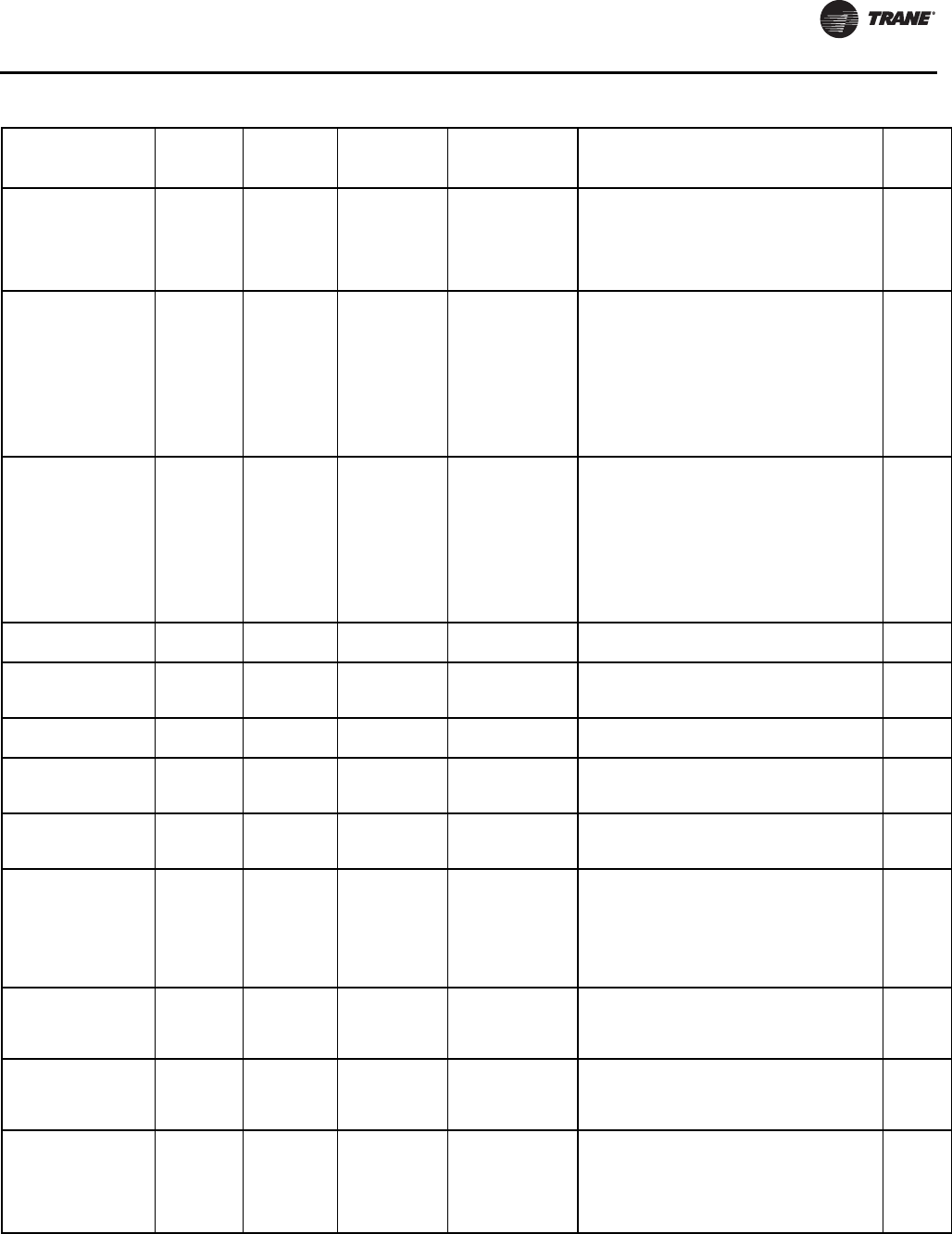
Diagnostics
RLC-SVX09H-EN 205
Low Evaporator Water
Temp: Unit On Chiller
Immediate
and Special
Action
Non Latch
Any Ckt[s] Energzd
[No Ckt(s)
Energzd]
The evaporator water temp. fell below the cutout
setpoint for 30 degree F Seconds while the
compressor was running. Automatic reset occurs
when the temperature rises 2 F (1.1C) above the
cutout setting for 2 minutes. This diagnostic shall not
de-energize the Evaporator Water Pump Output.
Remote
Low Oil Flow -
Compressor 1A Circuit Immediate Latch
Cprsr Energized
and Delta P above
15 Psid
The intermediate oil pressure transducer for
this compressor was indicating an
unacceptable oil pressure drop as a % of the
available oil pressure to move oil, suggesting
significantly reduced oil flow to the compressor.
Possible root causes include oil line service
valve closed or restricted, dirty or restricted oil
filter, compressor oil line kepner valve
malfunction, or plugged (restricted oil cooler
(when present).
Local
Low Oil Flow -
Compressor 2A Circuit Immediate Latch
Cprsr Energized
and Delta P above
15 Psid
The intermediate oil pressure transducer for
this compressor was indicating an
unacceptable oil pressure drop as a % of the
available oil pressure to move oil, suggesting
significantly reduced oil flow to the compressor.
Possible root causes include oil line service
valve closed or restricted, dirty or restricted oil
filter, compressor oil line kepner valve
malfunction, or plugged (restricted oil cooler
(when present).
Local
MP Application Memory
CRC Error Chiller Immediate Latch All Modes Memory error criteria TBD Remote
MP: Could not Store
Starts and Hours None Info Latch All
MP has determined there was an error with the
previous power down store. Starts and Hours
may have been lost for the last 24 hours.
Remote
MP: Invalid
Configuration None Immediate Latch All MP has an invalid configuration based on the
current software installed Remote
MP: Non-Volatile Block
Test Error None Info Latch All
MP has determined there was an error with a
block in the Non-Volatile memory. Check
settings.
Remote
MP: Non-Volatile
Memory Reformat None Info Latch All
MP has determined there was an error in a
sector of the Non-Volatile memory and it was
reformatted. Check settings.
Remote
MP: Reset Has
Occurred None Info Non Latch All
The main processor has successfully come out
of a reset and built its application. A reset may
have been due to a power up, installing new
software or configuration. This diagnostic is
immediately and automatically cleared and
thus can only be seen in the Historic Diagnostic
List in TechView
Remote
No Differential
Refrigerant Pressure –
Circuit 1
Circuit Immediate Latch Compressor
running on Circuit
The system differential pressure was below 7.7
Psid (53 kPa) for 6 seconds after the 11 seconds
ignore time relative to cprsr (circuit startup had
expired.
Remote
No Differential
Refrigerant Pressure –
Circuit 2
Circuit Immediate Latch Compressor
running on Circuit
The system differential pressure was below 7.7
Psid (53 kPa) for 6 seconds after the 11 seconds
ignore time relative to cprsr (circuit startup had
expired.
Remote
Oil Analysis
Recommended – Ckt
#1
Circuit Info Latch “Service Messages”
enabled
Diagnostic occurs when accumulated circuit
operating hours since last initialized exceeds
2000 hours. Diagnostic can be manually
cleared but will reoccur every month (720
hours on real time clock) as long as
accumulator is not re-initialized.
Remote
Table 134. Main Processor Diagnostics (continued)
Diagnostic Name
Affects
Target Severity Persistence
Active Modes
[Inactive
Modes] Criteria
Reset
Level

Diagnostics
206 RLC-SVX09H-EN
Oil Analysis
Recommended – Ckt
#2
Circuit Info Latch “Service Messages”
enabled
Diagnostic occurs when accumulated circuit
operating hours since last initialized exceeds
2000 hours. Diagnostic can be manually
cleared but will reoccur every month (720
hours on real time clock) as long as
accumulator is not re-initialized.
Remote
Oil Filter Change
Recommended – Cprsr
1A Circuit Info Latch “Service Messages”
enabled
Diagnostic occurs only when “service
messages” are enabled and when Oil Filter Life
remaining falls below 5%. Diagnostic can be
manually cleared but will reoccur every month
real time (720 hours on real time clock) as long
as the oil filter life remaining does not rise
above 20% (through normal calculations or
reinitializing) (Prior to RTUD Release in Fall of
09): Diagnostic occurs only when “service
messages” are enabled and when average oil
pressure drop exceeds 18%. Diagnostic can be
manually cleared but will reoccur every month
(720 hours on real time clock) as long as
average pressure drop does not fall below 16%.
Remote
Oil Filter Change
Recommended – Cprsr
2A
Circuit Info Latch “Service Messages”
enabled
Diagnostic occurs only when “service
messages” are enabled and when Oil Filter Life
remaining falls below 5%. Diagnostic can be
manually cleared but will reoccur every month
real time (720 hours on real time clock) as long
as the oil filter life remaining does not rise
above 20% (through normal calculations or
reinitializing) (Prior to RTUD Release in Fall of
09): Diagnostic occurs only when “service
messages” are enabled and when average oil
pressure drop exceeds 18%. Diagnostic can be
manually cleared but will reoccur every month
(720 hours on real time clock) as long as
average pressure drop does not fall below 16%.
Remote
Oil Pressure System
Fault – Circuit 1 Circuit Immediate Latch
Starter Contactor
Energized [all Stop
modes]
The Intermediate Oil Pressure Transducer for
this cprsr is reading a pressure either above its
respective circuit’s Condenser Pressure by 15
Psia or more, or below its respective Suction
Pressure 10 Psia or more for 30 seconds
continuously.
Local
Oil Pressure System
Fault – Circuit 2 Circuit Immediate Latch
Starter Contactor
Energized [all Stop
modes]
The Intermediate Oil Pressure Transducer for
this cprsr is reading a pressure either above its
respective circuit’s Condenser Pressure by 15
Psia or more, or below its respective Suction
Pressure 10 Psia or more for 30 seconds
continuously.
Local
Oil Pressure
Transducer –
Compressor 1A
Circuit Immediate Latch All Bad Sensor or LLID Remote
Oil Pressure
Transducer –
Compressor 2A
Circuit Immediate Latch All Bad Sensor or LLID Remote
Outdoor Air
Temperature Sensor Chiller
RTUD with
ACFC?NONE–
Normal
Shutdown;
OATS=INST-
Special Action
Latch All
Bad Sensor or LLID. If the outdoor temperature
is used for CHW reset, there shall be no CHW
reset. Apply slew rates per Chilled Water Reset
spec. RTUD: if this diagnostic occurs,
operational pumpdown will be performed
regardless of the last valid temperature. For
RTWD, if installed for low ambient lockout,
there shall be no LA lockout .
Remote
Table 134. Main Processor Diagnostics (continued)
Diagnostic Name
Affects
Target Severity Persistence
Active Modes
[Inactive
Modes] Criteria
Reset
Level
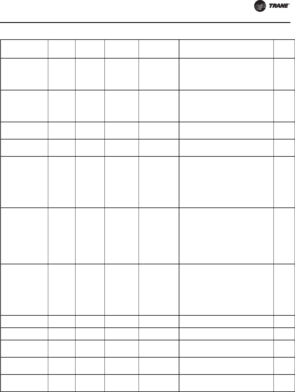
Diagnostics
RLC-SVX09H-EN 207
Pumpdown Terminated
- Circuit 1 Circuit Info NonLatch
Service or
Operational
Pumpdown
Operational or Service Pumpdown cycle for this
circuit was terminated abnormally due to
excessive time (op pd only) or due to a specific
set of diagnostic criteria – but w (o associated
latching diagnostics . (RTWD max Operation
Pumpdown = 2 min)
Pumpdown Terminated
- Circuit 2 Circuit Info NonLatch
Service or
Operational
Pumpdown
Operational or Service Pumpdown cycle for this
circuit was terminated abnormally due to
excessive time (op pd only) or due to a specific
set of diagnostic criteria – but w (o associated
latching diagnostics . (RTWD max Operation
Pumpdown = 2 min)
Pumpdown Terminated
by Time - Circuit 1 Circuit Info NonLatch Service Pumpdown
Service Pumpdown cycle for this circuit was
terminated abnormally due to excessive time
(RTWD max Service Pumpdown = 4 min).
Local
Pumpdown Terminated
by Time - Circuit 2 Circuit Info NonLatch Service Pumpdown
Service Pumpdown cycle for this circuit was
terminated abnormally due to excessive time
(RTWD max Service Pumpdown = 4 min).
Local
Software Error 1001:
Call Trane Service All functions Immediate Latch All
A high level software watchdog has detected a
condition in which there was a continuous 1
minute period of compressor operation, with
neither Evaporator water flow nor a” contactor
interrupt failure” diagnostic active. The
presence of this software error message
suggests an internal software problem has
been detected. The events that led up to this
failure, if known, should be recorded and
transmitted to Trane Controls Engineering.
Local
Software Error 1002:
Call Trane Service All functions Immediate Latch All
Reported if state chart misalignment in stopped
or inactive state occurred while a compressor
was seen to be operating and this condition
lasted for at least 1 minute (cmprsr operation
due to Service Pumpdown or with Contactor
Interrupt Failure diagnostic is excluded). The
presence of this software error message
suggests an internal software problem has
been detected. The events that led up to this
failure, if known, should be recorded and
transmitted to Trane Controls Engineering.
Local
Software Error 1003:
Call Trane Service All functions Immediate Latch All
Reported if state chart misalignment occurred
inferred from either the Capacity Control,
Circuit, or Compressor State Machines
remaining in the Stopping state for more than
3 minutes. The presence of this software error
message suggests an internal software
problem has been detected. The events that
led up to this failure, if known, should be
recorded and transmitted to Trane Controls
Engineering.
Local
Starter Failed to Arm
(Start – Cprsr 1A Circuit Normal Latch All Starter failed to arm or start within the allotted
time (15 seconds). Local
Starter Failed to Arm
(Start – Cprsr 2A Circuit Normal Latch All Starter failed to arm or start within the allotted
time (15 seconds). Local
Starter Module
Memory Error Type 1 -
Starter 2A
None Info Latch All
Checksum on RAM copy of the Starter LLID
configuration failed. Configuration recalled
from EEPROM.
Local
Starter Module
Memory Error Type
1Starter 1A
None Info Latch All
Checksum on RAM copy of the Starter LLID
configuration failed. Configuration recalled
from EEPROM.
Local
Starter Module
Memory Error Type 2 -
Starter 1A
Circuit Immediate Latch All
Checksum on EEPROM copy of the Starter LLID
configuration failed. Factory default values
used.
Local
Table 134. Main Processor Diagnostics (continued)
Diagnostic Name
Affects
Target Severity Persistence
Active Modes
[Inactive
Modes] Criteria
Reset
Level
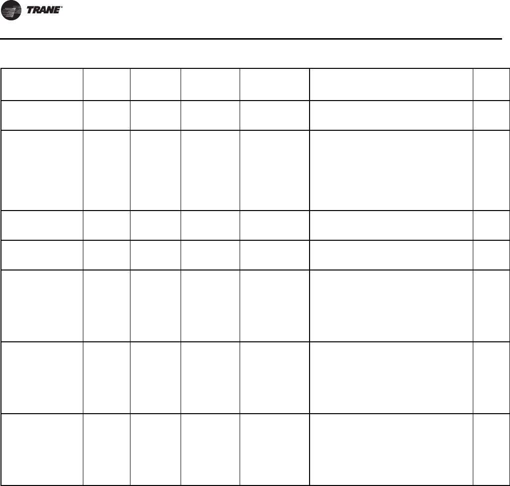
Diagnostics
208 RLC-SVX09H-EN
Communication Diagnostics
Notes:
1. The following communication loss diagnostics will not
occur unless that input or output is required to be
present by the particular configuration and installed
options for the chiller.
2. Communication diagnostics (with the exception of
“Excessive Loss of Comm” are named by the
Functional Name of the input or output that is no
longer being heard from by the Main Processor. Many
LLIDs, such as the Quad Relay LLID, have more than
one functional output associated with it. A comm loss
with such a multiple function board, will generate
multiple diagnostics. Refer to the Chiller's wiring
diagrams to relate the occurrence of multiple
communication diagnostics back to the physical LLID
boards that they have been assigned to (bound).
Starter Module
Memory Error Type 2 -
Starter 2A
Circuit Immediate Latch All
Checksum on EEPROM copy of the Starter LLID
configuration failed. Factory default values
used.
Local
Starter Panel High
Temperature Limit -
Compressor 1A
Circuit
Immediate
and Special
Action
Non Latch All
Starter Panel High Limit Thermostat (170?F)
trip was detected. Compressor 1A is shutdown
and inoperative until the thermostat resets.
Note: Other diagnostics that may occur as an
expected consequence of the Panel High Temp
Limit trip will be suppressed from annunciation.
These include Momentary Power Loss, Phase
Loss, Power Loss, and Transition Complete
Input for Compressor 1A.
Local
Suction Refrigerant
Pressure Transducer –
Circuit 1
Circuit Immediate Latch All Bad Sensor or LLID Remote
Suction Refrigerant
Pressure Transducer –
Circuit 2
Circuit Immediate Latch All Bad Sensor or LLID Remote
Unexpected Starter
Shutdown Circuit Normal Non latch
All Cprsr Running
modes, Starting,
Running and
Preparing to
Shutdown
The Starter module status reported back that it
is stopped when the MP thinks it should be
running and no Starter diagnostic exist. This
diagnostic will be logged in the active buffer
and then automatically cleared. This diagnostic
could be caused by intermittent communication
problems from the Starter to the MP, or due to
misbinding.
NA
Very Low Evaporator
Refrigerant Pressure –
Circuit 1
Chiller Immediate Latch
All
[compressor or
circuit in manual
lockout]
The respective circuit’s evaporator pressure
dropped below 80% of the current Low Evap
Refrig Press Cutout setting (see above) or 8
psia, whichever is less, regardless of the
running state of the circuit’s compressor. If a
given compressor or circuit is locked out, the
suction pressure transducer(s) associated with
it, will be excluded from causing this diagnostic.
Local
Very Low Evaporator
Refrigerant Pressure –
Circuit 2
Chiller Immediate Latch
All
[compressor or
circuit in manual
lockout]
The respective circuit’s evaporator pressure
dropped below 80% of the current Low Evap
Refrig Press Cutout setting (see above) or 8
psia, whichever is less, regardless of the
running state of the circuit’s compressor. If a
given compressor or circuit is locked out, the
suction pressure transducer(s) associated with
it, will be excluded from causing this diagnostic.
Local
Table 134. Main Processor Diagnostics (continued)
Diagnostic Name
Affects
Target Severity Persistence
Active Modes
[Inactive
Modes] Criteria
Reset
Level

Diagnostics
RLC-SVX09H-EN 209
Table 135. Communication Diagnostics
Diagnostic Name
Affects
Target Severity Persistence
Active
Modes
[Inactive
Modes] Criteria
Reset
Level
Comm Loss: Chiller% RLA
Output Chiller Info Latch All
Continual loss of communication between the MP
and the Functional ID has occurred for a 30
second period.
Remote
Comm Loss: Cond Head
Press Control Output Chiller Immediate Latch All
Continual loss of communication between the MP
and the Functional ID has occurred for a 30
second period.
Remote
Comm Loss: Cond Rfgt
Pressure, Circuit #1 Circuit Immediate Latch All
Continual loss of communication between the MP
and the Functional ID has occurred for a 30
second period.
Remote
Comm Loss: Cond Rfgt
Pressure, Circuit #2 Circuit Immediate Latch All
Continual loss of communication between the MP
and the Functional ID has occurred for a 30
second period.
Remote
Comm Loss: Condenser
Entering Water Temperature Chiller
Info and
Special
Action
Latch All
RTWD Only: Continual loss of communication
between the MP and the Functional ID has
occurred for a 30 second period. If chiller running,
and condenser water regulating valve option
installed, force valve to 100% flow.
Remote
Comm Loss: Condenser
Leaving Water Temperature Chiller
Info and
Special
Action
Latch All
RTWD Only: Continual loss of communication
between the MP and the Functional ID has
occurred for a 30 second period. If Chiller is
running in the heat mode of operation – normal
shutdown, otherwise, informational only.
Discontinue Min Capacity Limit forced cprsr
loading due to Low DP in subsequent startups.
Remote
Comm Loss: Condenser Rfgt
Pressure Output Chiller Info Latch All
Continual loss of communication between the MP
and the Functional ID has occurred for a 30
second period.
Remote
Comm Loss: Condenser
Water Flow Switch Chiller Immediate Latch All
RTWD only: Continual loss of communication
between the MP and the Functional ID has
occurred for a 30 second period.
Remote
Comm Loss: Condenser
Water Pump Relay Chiller Normal Latch All
RTWD only: Continual loss of communication
between the MP and the Functional ID has
occurred for a 30 second period.
Remote
Comm Loss: Discharge
Temperature Circuit 1, Cprsr
1A
Circuit Normal Latch All
Continual loss of communication between the MP
and the Functional ID has occurred for a 30
second period.
Remote
Comm Loss: Discharge
Temperature, Circuit 2,
Cprsr 2A
Circuit Normal Latch All
Continual loss of communication between the MP
and the Functional ID has occurred for a 30
second period.
Remote
Comm Loss: Electronic
Expansion Valve, Circuit #1 Circuit Normal Latch All
Continual loss of communication between the MP
and the Functional ID has occurred for a 30
second period.
Remote
Comm Loss: Electronic
Expansion Valve, Circuit #2 Circuit Normal Latch All
Continual loss of communication between the MP
and the Functional ID has occurred for a 30
second period.
Remote
Comm Loss: Emergency
Stop Chiller Normal Latch All
Continual loss of communication between the MP
and the Functional ID has occurred for a 30
second period.
Remote
Comm Loss: Evaporator
Entering Water Temperature Chiller Normal Latch All
Continual loss of communication between the MP
and the Functional ID has occurred for a 30
second period. Note: Entering Water Temp
Sensor is used in EXV pressure control as well as
ice making & CHW reset, so it must cause a unit
shutdown even if Ice or CHW reset is not installed.
Remote
Comm Loss: Evaporator
Leaving Water Temperature Chiller Normal Latch All
Continual loss of communication between the MP
and the Functional ID has occurred for a 30
second period.
Remote

Diagnostics
210 RLC-SVX09H-EN
Comm Loss: Evaporator Rfgt
Liquid Level, Circuit #1 Circuit Normal Latch All
Continual loss of communication between the MP
and the Functional ID has occurred for a 30
second period.
Remote
Comm Loss: Evaporator Rfgt
Liquid Level, Circuit #2 Circuit Normal Latch All
Continual loss of communication between the MP
and the Functional ID has occurred for a 30
second period.
Remote
Comm Loss: Evaporator
Water Flow Switch Chiller Immediate Latch All
Continual loss of communication between the MP
and the Functional ID has occurred for a 30
second period.
Remote
Comm Loss: Evaporator
Water Pump Relay Chiller Normal Latch All
Continual loss of communication between the MP
and the Functional ID has occurred for a 30
second period.
Remote
Comm Loss: Ext Noise
Setback Command None Info Latch All
Continual loss of communication between the MP
and the Functional ID has occurred for a 30
second period.
Remote
Comm Loss: External Auto
(Stop Chiller Normal Latch All
Continual loss of communication between the MP
and the Functional ID has occurred for a 30
second period.
Remote
Comm Loss: External Chilled
(Hot Water Setpoint
External
Chilled
Water
setpoint
Special
Action Latch All
Continual loss of communication between the MP
and the Functional ID has occurred for a 30
second period. Chiller shall discontinue use of the
External Chilled Water Setpoint source and revert
to the next higher priority for setpoint arbitration
Remote
Comm Loss: External Circuit
Lockout, Circuit #1 Circuit Special
Action Latch All
Continual loss of communication between the MP
and the Functional ID has occurred for a 30
second period. MP will nonvolatilely hold the
lockout state (enabled or disabled) that was in
effect at the time of comm loss.
Remote
Comm Loss: External Circuit
Lockout, Circuit #2 Circuit Special
Action Latch All
Continual loss of communication between the MP
and the Functional ID has occurred for a 30
second period. MP will nonvolatilely hold the
lockout state (enabled or disabled) that was in
effect at the time of comm loss
Remote
Comm Loss: External
Current Limit Setpoint
External
Current
Limit
setpoint
Special
Action Latch All
Continual loss of communication between the MP
and the Functional ID has occurred for a 30
second period. Chiller shall discontinue use of the
External Current limit setpoint and revert to the
next higher priority for Current Limit setpoint
arbitration
Remote
Comm Loss: External Ice
Building Command
Ice Making
Mode
Special
Action Latch All
Continual loss of communication between the MP
and the Functional ID has occurred for a 30
second period. Chiller shall revert to normal (non-
ice building) mode regardless of last state.
Remote
Comm Loss: Fan Control
Relays, Circuit #1 Circuit Normal Latch All
Continual loss of communication between the MP
and the Functional ID has occurred for a 30
second period.
Remote
Comm Loss: Fan Control
Relays, Circuit #2 Circuit Normal Latch All
Continual loss of communication between the MP
and the Functional ID has occurred for a 30
second period.
Remote
Comm Loss: Fan Inverter
Fault, Circuit #1
Circuit
(fan
control)
Special
Mode (or in
single fan
deck: Circuit
Immediate
shutdown)
Latch (or in
single fan
deck:Latch)
All
Continual loss of communication between the MP
and the Functional ID has occurred for a 30
second period. Operate the remaining fans as
fixed speed fan deck. For single fan deck
configurations, this diagnostic causes a latching
circuit shutdown
Remote
Comm Loss: Fan Inverter
Fault, Circuit #2
Circuit
(fan
control)
Special
Mode (or in
single fan
deck: Circuit
Immediate
shutdown)
Latch (or in
single fan
deck:Latch)
All
Continual loss of communication between the MP
and the Functional ID has occurred for a 30
second period. Operate the remaining fans as
fixed speed fan deck. For single fan deck
configurations, this diagnostic causes a latching
circuit shutdown
Remote
Table 135. Communication Diagnostics
Diagnostic Name
Affects
Target Severity Persistence
Active
Modes
[Inactive
Modes] Criteria
Reset
Level

Diagnostics
RLC-SVX09H-EN 211
Comm Loss: Fan Inverter
Speed Command, Circuit #1
Circuit
(fan
control)
Special
Mode (or in
single fan
deck: Circuit
Immediate
shutdown)
Latch (or in
single fan
deck:Latch)
All
Continual loss of communication between the MP
and the Functional ID has occurred for a 30
second period. Operate the remaining fans as
fixed speed fan deck. For single fan deck
configurations, this diagnostic causes a latching
circuit shutdown
Comm Loss: Fan Inverter
Speed Command, Circuit #2
Circuit
(fan
control)
Special
Mode (or in
single fan
deck: Circuit
Immediate
shutdown)
Latch (or in
single fan
deck:Latch)
All
Continual loss of communication between the MP
and the Functional ID has occurred for a 30
second period. Operate the remaining fans as
fixed speed fan deck. For single fan deck
configurations, this diagnostic causes a latching
circuit shutdown
Comm Loss: Female Step
Load Compressor 1A Circuit Normal Latch All
Continual loss of communication between the MP
and the Functional ID has occurred for a 30
second period.
Remote
Comm Loss: Female Step
Load Compressor 2A Circuit Normal Latch All
Continual loss of communication between the MP
and the Functional ID has occurred for a 30
second period.
Remote
Comm Loss: Heat (Cool
Switch Heat Mode Special
Action Latch All
Continual loss of communication between the MP
and the Functional ID has occurred for a 30
second period. The external input shall revert to
normal (cooling) request regardless of last state.
Chiller mode shall follow “OR” arbitration for
heating (cooling mode, i.e. If any of the remaining
inputs (front panel of BAS) are requesting heat
mode, then the chiller shall be in heat mode.
Remote
Comm Loss: High Pressure
Cutout Switch, Cprsr 1A Circuit Immediate Latch All
Continual loss of communication between the MP
and the Functional ID has occurred for a 30
second period.
Remote
Comm Loss: High Pressure
Cutout Switch, Cprsr 2A Circuit Immediate Latch All
Continual loss of communication between the MP
and the Functional ID has occurred for a 30
second period.
Remote
Comm Loss: Ice-Making
Status
Ice-
Machine
Special
Action Latch All
Continual loss of communication between the MP
and the Functional ID has occurred for a 30
second period. Chiller shall revert to normal (non-
ice building) mode regardless of last state.
Remote
Comm Loss: Local BAS
Interface None Special
Action Non Latch All
Continual loss of communication between the MP
and the Functional ID has occurred for a 30
second period.
Use last valid BAS setpoints.
Diagnostic is cleared when successful
communication is established with the LonTalk
LLID (LCIC) or BacNet LLID (BCIC).
Remote
Comm Loss: Male Port Load
Compressor 1A Circuit Normal Latch All
Continual loss of communication between the MP
and the Functional ID has occurred for a 30
second period.
Remote
Comm Loss: Male Port Load
Compressor 2A Circuit Normal Latch All
Continual loss of communication between the MP
and the Functional ID has occurred for a 30
second period.
Remote
Comm Loss: Male Port
Unload Compressor 1A Circuit Normal Latch All
Continual loss of communication between the MP
and the Functional ID has occurred for a 30
second period.
Remote
Comm Loss: Male Port
Unload Compressor 2A Circuit Normal Latch All
Continual loss of communication between the MP
and the Functional ID has occurred for a 30
second period.
Remote
Comm Loss: Motor Winding
Thermostat Compressor 1A Circuit Normal Latch All
Continual loss of communication between the MP
and the Functional ID has occurred for a 30
second period.
Remote
Comm Loss: Motor Winding
Thermostat Compressor 2A Circuit Normal Latch All
Continual loss of communication between the MP
and the Functional ID has occurred for a 30
second period.
Remote
Table 135. Communication Diagnostics
Diagnostic Name
Affects
Target Severity Persistence
Active
Modes
[Inactive
Modes] Criteria
Reset
Level

Diagnostics
212 RLC-SVX09H-EN
Comm Loss: Noise Setback
Relay None Info Latch All
Continual loss of communication between the MP
and the Functional ID has occurred for a 30
second period.
Remote
Comm Loss: Oil Loss Level
Sensor Input – Circuit #1 Circuit Normal Latch All
Continual loss of communication between the MP
and the Functional ID has occurred for a 30
second period.
Remote
Comm Loss: Oil Loss Level
Sensor Input – Circuit #2 Circuit Normal Latch All
Continual loss of communication between the MP
and the Functional ID has occurred for a 30
second period.
Remote
Comm Loss: Oil Pressure,
Cprsr 1A Cprsr Immediate Latch All
Continual loss of communication between the MP
and the Functional ID has occurred for a 30
second period.
Remote
Comm Loss: Oil Pressure,
Cprsr 2A Cprsr Immediate Latch All
Continual loss of communication between the MP
and the Functional ID has occurred for a 30
second period.
Remote
Comm Loss: Oil Return Gas
Pump Drain – Circuit #1 Circuit Normal Latch All
Continual loss of communication between the MP
and the Functional ID has occurred for a 30
second period.
Remote
Comm Loss: Oil Return Gas
Pump Drain – Circuit #2 Circuit Normal Latch All
Continual loss of communication between the MP
and the Functional ID has occurred for a 30
second period.
Remote
Comm Loss: Oil Return Gas
Pump Fill – Circuit #1 Circuit Normal Latch All
Continual loss of communication between the MP
and the Functional ID has occurred for a 30
second period.
Remote
Comm Loss: Oil Return Gas
Pump Fill – Circuit #2 Circuit Normal Latch All
Continual loss of communication between the MP
and the Functional ID has occurred for a 30
second period.
Remote
Comm Loss: Op Status
Programmable Relays None Info Latch All
Continual loss of communication between the MP
and the Functional ID has occurred for a 30
second period.
Remote
Comm Loss: Outdoor Air
Temperature Chiller
RTUD with
ACFC?NONE
- Normal
Shutdown;
OATS=INST-
Special
Action
Latch All
Continual loss of communication between the MP
and the Functional ID has occurred for a 30
second period. If the outdoor temperature is used
for CHW reset, there shall be no CHW reset. Apply
slew rates per Chilled Water Reset spec. For RTUD
if this diagnostic occurs, operational pumpdown
will be performed regardless of the last valid
temperature. For RTWD, if installed for low
ambient lockout, there shall be no lockout
Remote
Comm Loss: Starter 1A Circuit Immediate Latch All
Continual loss of communication between the MP
and the Functional ID has occurred for a 30
second period.
Local
Comm Loss: Starter 2A Circuit Immediate Latch All
Continual loss of communication between the MP
and the Functional ID has occurred for a 30
second period.
Local
Comm Loss: Starter Panel
High Temperature Limit,
Compressor 1A
None Info Latch All
Continual loss of communication between the MP
and the Functional ID has occurred for a 30
second period.
Local
Comm Loss: Suction Rfgt
Pressure, Circuit #1 Circuit Immediate Latch
All
[Ckt (Cprsr
lock out]
Continual loss of communication between the MP
and the Functional ID has occurred for a 30
second period. Note: This diagnostic is replaced
by diagnostic 5FB below with Rev 15.0
Remote
Comm Loss: Suction Rfgt
Pressure, Circuit #2 Circuit Immediate Latch
All
[Ckt (Cprsr
lock out]
Continual loss of communication between the MP
and the Functional ID has occurred for a 30
second period. Note: This diagnostic is replaced
by diagnostic 5FD below with Rev 15.0
Remote
Comm Loss:Evaporator Off-
Cycle Freeze Protection
Relay
None Info Latch All
Continual loss of communication between the MP
and the Functional ID has occurred for a 30
second period.
Remote
Table 135. Communication Diagnostics
Diagnostic Name
Affects
Target Severity Persistence
Active
Modes
[Inactive
Modes] Criteria
Reset
Level
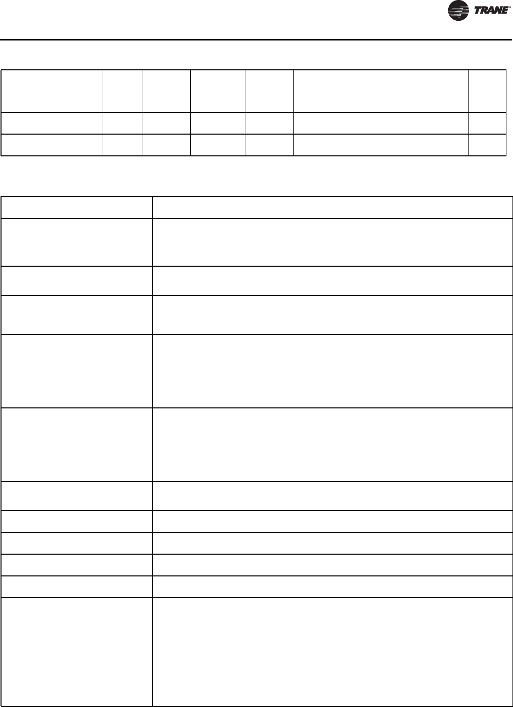
Diagnostics
RLC-SVX09H-EN 213
Starter 1A Comm Loss: MP Cprsr Immediate Latch All Starter has had a loss of communication with the
MP for a 15 second period. Local
Starter 2A Comm Loss: MP Cprsr Immediate Latch All Starter has had a loss of communication with the
MP for a 15 second period. Local
Table 135. Communication Diagnostics
Diagnostic Name
Affects
Target Severity Persistence
Active
Modes
[Inactive
Modes] Criteria
Reset
Level
Table 136. Main Processor (Boot Messages and Diagnostics)
DynaView Display Message
Description
Troubleshooting
A Valid Configuration is Present
A valid configuration is present in the MP’s nonvolatile memory. The configuration is a set of variables
and settings that define the physical makeup of this particular chiller. These include: number (airflow,
(and type of fans, number (and size of compressors, special features, characteristics, and control
options.
//Temporary display of this screen is part of the normal power up sequence.
An Invalid Configuration is Present
An invalid configuration has been detected in the Main Processor’s nonvolatile memory and the MP is
unable to proceed with the boot up. Communication via the service serial port is supported and the
TechView service tool, (Configuration View), needs to be employed to correct the configuration.
App Present. Running Selftest.…
Selftest Passed
An application has been detected in the Main Processor’s nonvolatile memory and the boot code is
proceeding to run a check on its entirety. 8 seconds later, the boot code had completed and passed
the (CRC) test.
//Temporary display of this screen is part of the normal power up sequence.
App Present. Running Selftest…
Err3: CRC Failure
An application has been detected in Main Processor’s nonvolatile memory and the boot code is
proceeding to run a check on its entirety. A few seconds later, the boot code had completed but failed
the (CRC) test.
//Connect a TechView Service Tool to the MP’s serial port, provide chiller model number (configuration
information) and download the configuration if prompted by TechView. Then proceed to download the
most recent RTWD application or specific version as recommended by Technical Service. Note that this
error display may also occur during the programming process, if the MP never had a valid application
any time prior to the download. If the problem persists, replace the MP.
Boot Software Part Numbers:
LS Flash --> 6200-0318-04
MS Flash --> 6200-0319-04
The “boot code” is the portion of the code that is resident in all MPs regardless of what application code
(if any) is loaded. Its main function is to run power up tests and provide a means for downloading
application code via the MP’s serial connection. The Part numbers for the code are displayed in the lower
left hand corner of the DynaView during the early portion of the power up sequence and during special
programming and converter modes. See below. For the EasyView, the extension of the boot code part
number is displayed for approximately 3 immediately following power up.
//This is normal, but you should provide this information when contacting Technical Service about
power up problems.
Converter Mode
A command was received from the Service Tool (Tech View) to stop the running application and run
in the “converter mode”. In this mode the MP acts as a simple gateway and allows the TechView service
computer to talk to all the LLIDS on the IPC3 bus.
Err2: RAM Addr Test #1 Failure There were RAM errors detected in RAM Address Test #1.
//Recycle power, if error persists, replace MP.
Err2: RAM Addr Test #2 Failure There were RAM errors detected in RAM Address Test #2.
//Recycle power, if the error persists, replace MP.
Err2: RAM Pattern 1 Failure There were RAM errors detected in RAM Test Pattern #1.
//Recycle power, if the error persists, replace MP.
Err2: RAM Pattern 2 Failure There were RAM errors detected in RAM Test Pattern #2.
//Recycle power, if the error persists, replace MP.
Err4: UnHandled Interrupt
Restart Timer:
[3 sec countdown timer]
An unhandled interrupt has occurred while running the application code. This event will normally cause
a safe shutdown of the entire chiller. Once the countdown timer reaches 0, the processor will reset,
clear diagnostics, and attempt to restart the application and allow a normal restart of chiller as
appropriate.
//This condition might occur due to a severe electro-magnetic transient such as can be caused by a
near lightening strike. Such events should be rare or isolated and if no damage results to the CH530
control system, the Chiller will experience a shutdown and restart. If this occurs more persistently it
may be due to an MP hardware problem. Try replacing the MP. If replacement of the MP proves
ineffective, the problem may be a result of extremely high radiated or conducted EMI. Contact Technical
Service.
If this screen occurs immediately after a software download, attempt to reload both the configuration
and the application. Failing this, contact Technical Service.
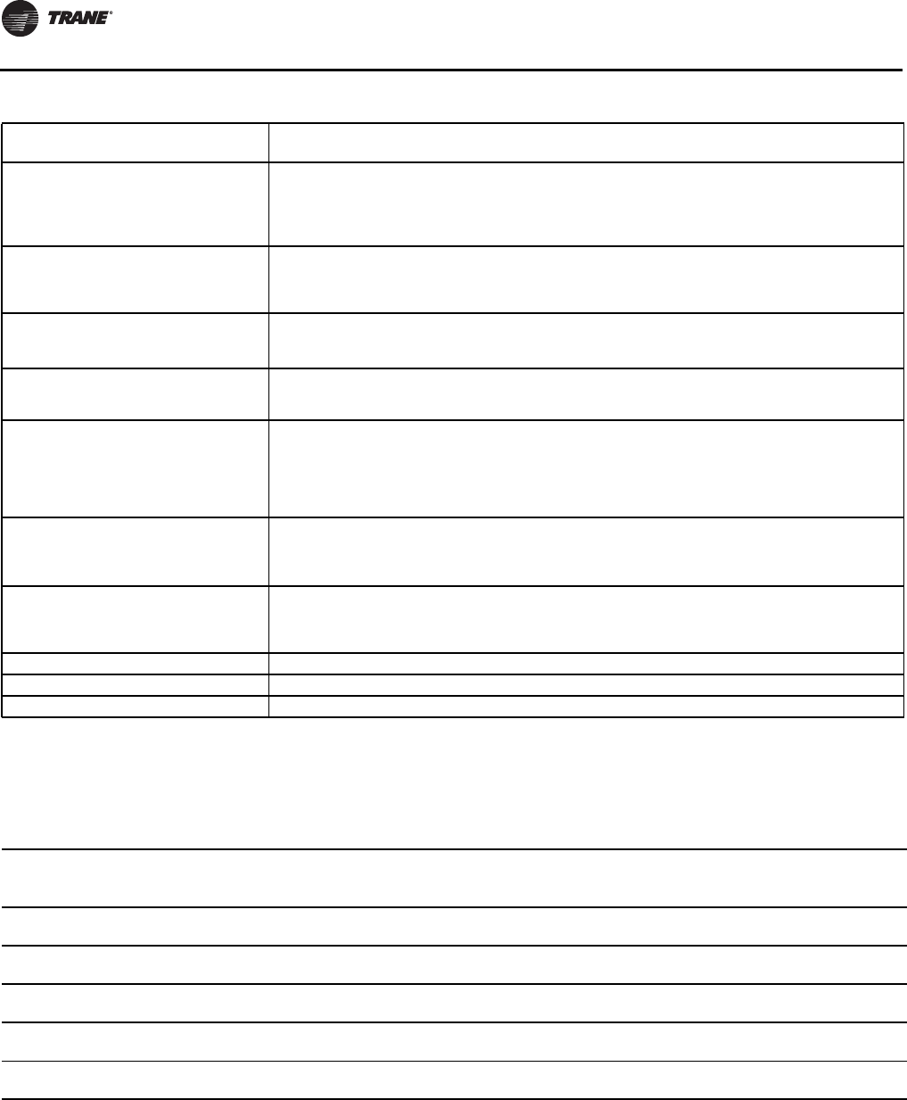
Diagnostics
214 RLC-SVX09H-EN
Limit Conditions
CH530 will automatically limit certain operating
parameters to maintain optimum chiller performance and
prevent nuisance diagnostic trips.These limit conditions
are noted in Table 137.
Err5: Operating System Error
Restart Timer:
[30 sec countdown timer]
An Operating System error has occurred while running the application code. This event will normally
cause a safe shutdown of the entire chiller. Once the countdown timer reaches 0, the processor will
reset, clear diagnostics, and attempt to restart the application and allow a normal restart of chiller as
appropriate.
//See Err 4 above
Err6: Watch Dog Timer Error
Restart Timer:
[30 sec countdown timer]
A Watch Dog Timer Error has occurred while running the application code. This event will normally cause
a safe shutdown of the entire chiller. Once the countdown timer reaches 0, the processor will reset,
clear diagnostics, and attempt to restart the application allowing a normal restart of chiller as
appropriate.
Err7: Unknown Error
Restart Timer:
[30 sec countdown timer]
An unknown Error has occurred while running the application code. This event will normally cause a
safe shutdown of the entire chiller. Once the countdown timer reaches 0, the processor will reset, clear
diagnostics, and attempt to restart the application allowing a normal restart of chiller as appropriate
Err8: Held in Boot by User Key Press
The boot detected a key press in the center of the DynaView or both the + and – keys pressed on an
EasyView while the MP was in the boot code. Upon seeing this message the user can use Techview to
connect to the MP to perform a software download or another service tool function.
LCI-C Hardware Mismatch
The configuration currently in the nonvolatile memory has the LonTalk or BacNet communication option
installed and the DynaView hardware does not contain adequate memory to support the option. The
MP is unable to proceed with the boot up. Communication via the service serial port is supported and
the TechView service tool, (Configuration View), needs to be employed to correct the configuration to
remove the unsupported comm option and return to the previous configuration. The communication
option can only be supported with MP hardware version -05 or newer.
No Application Present
Please Load Application...
No Main Processor Application is present – There are no RAM Test Errors.
//Connect a TechView Service Tool to the MP’s serial port, provide chiller model number (configuration
information) and download the configuration if prompted by TechView. Then proceed to download the
most recent RTWD application or specific version as recommended by Technical Service.
Programming Mode
A command was received by the MP from the Tech View Service Tool and the MP is in the process of
first erasing and then writing the program code to its internal Flash (nonvolatile) Memory. Note that
if the MP never had a prior application already in memory, the error code “Err3”will be displayed instead
of this, during the programming download process.
Software Error 1001: Call Trane Service See item in Main Processor Diagnostics table above
Software Error 1002: Call Trane Service See item in Main Processor Diagnostics table above
Software Error 1003: Call Trane Service See item in Main Processor Diagnostics table above
Table 136. Main Processor (Boot Messages and Diagnostics)
DynaView Display Message
Description
Troubleshooting
Table 137. Limit Conditions
Running - Limited
The chiller, circuit, and compressor are currently running, but the operation of the chiller
(compressor is being actively limited by the controls. Further information is provided by the sub-
mode.
Capacity Limited by High
Cond Press
The circuit is experiencing condenser pressures at or near the condenser limit setting. The compressor will be unloaded
to prevent exceeding the limits.
Capacity Limited by High
Current
The compressor is running and its capacity is being limited by high currents. The current limit setting is 120% RLA (to
avoid overcurrent trips).
Capacity Limited by Low
Evap Rfgt Temp
The circuit is experiencing saturated evaporator temperatures at or near the Low Refrigerant Temperature Cutout
setting. The compressors will be unloaded to prevent tripping.
Capacity Limited by Low
Liquid Level
The circuit is experiencing low refrigerant liquid levels and the EXV is at or near full open. The compressor will be
unloaded to prevent tripping.
Capacity Limited by Phase
Unbalance The compressor is running and its capacity is being limited by excessive phase current unbalance.

RLC-SVX09H-EN 215
Wiring Schematics
Table 138 provides a list of field wiring diagrams, electrical schematics and connection diagrams for RTWD and RTUD
units.The complete wiring package is documented in RLC-SVE01*-EN.A laminated wiring diagram booklet is also shipped
with each unit.
Unit Electrical Data
To determine the specific electrical characteristics of a particular chiller, refer to the nameplates mounted on the units.
Table 138. RTWD (UD Wiring diagrams
Drawing Description
2309-7584
Sheet 1
Schematic - Wye-Delta Starter
Compressor - Ckt 1 (1A)
Sheet 2 Compressor - Ckt 2 (2A)
Sheet 3 Controls
Sheet 4 Controls/LLID Bus
Sheet 5 Controls/Legend/LLID Bus
2309-7585
Sheet 1
Schematic - X-line Starters
Compressor - Ckt 1 (1A)
Sheet 2 Compressor - Ckt 2 (2A)
Sheet 3 Controls
Sheet 4 Controls/LLID Bus
Sheet 5 Controls/Legend/LLID Bus
2309-7596 Sheet 1 Unit Component Location Diagram
Sheet 2 Legend/Notes
2309-7597 Sheet 1 Control Panel Component Location Diagram
Sheet 2 Legend
2309-1913 Sheet 1 Field Wiring Diagram
Sheet 2 Notes/Fuses
2309-1969 Sheet 1 Interconnection Wiring, Field Wiring RTUD Paired Condenser Diagram
Sheet 2 Notes
2309-7598 Sheet 1 Field Layout Diagram
Sheet 2 Notes

Trane optimizes the performance of homes and buildings around the world. A business of Ingersoll Rand, the
leader in creating and sustaining safe, comfortable and energy efficient environments, Trane offers a broad
portfolio of advanced controls and HVAC systems, comprehensive building services, and parts. For more
information, visit www.Trane.com.
Trane has a policy of continuous product and product data improvement and reserves the right to change design and specifications without notice.
We are committed to using environmentally
conscious print practices that reduce waste.
© 2012Trane All rights reserved
RLC-SVX09H-EN 01 Oct 2012
Supersedes RLC-SVX09G-EN (May 2010)
