Trane Tsd Users Manual
TSD to the manual b9b675a7-eb83-4c1a-93bb-815447702fe1
2015-01-21
: Trane Trane-Tsd-Users-Manual-236129 trane-tsd-users-manual-236129 trane pdf
Open the PDF directly: View PDF ![]() .
.
Page Count: 68
Voyager™ I Rooftop Units
Cooling-only TSD/TSH 060 072 102 120
Reversible WSD/WSH 060 072 090
Gas-fired YSD/YSH 060 072 090 102 120
Installation
Operation
Maintenance
RT-SVX20A-E4

General information
RT-SVX20A-E42
Foreword
These instructions are given as a
guide to good practice in the
installation, start-up, operation, and
maintenance by the user, of Trane
TSD/TSH, WSKD/WSH and YSD/YSH
units. They do not contain full
service procedures necessary for
the continued successful operation
of this equipment. The services of a
qualified technician should be
employed through the medium of a
maintenance contract with a
reputable service company. Read
this manual thoroughly before unit
start-up.
TSD/TSH units are designed to
operate in cooling mode only, with
optional auxiliary heat (electric
heater or hot water coil).
WSD/WSH can operate in cooling
mode or heating mode by reversing
the refrigeration cycle with or
without auxiliary heat.
YSD/YSH units are designed to
operate In cooling mode and
equipped with a gas fired heating
module.
TSD/TSH, WSD/WSH and YSD/YSH
units are assembled, pressure
tested, dehydrated, charged and run
tested before shipment.
Warnings and cautions
Warnings and Cautions appear at
appropriate sections throughout
this manual. Your personal safety
and the proper operation of this
machine require that you follow
them carefully. The constructor
assumes no liability for installations
or servicing performed by
unqualified personnel.
WARNING! : Indicates a potentially
hazardous situation which, if not
avoided, could result in death or
serious injury.
CAUTION! : Indicates a potentially
hazardous situation which, if not
avoided, may result in minor or
moderate injury. It may also be
used to alert against unsafe
practices or for equipment or
property-damage-only accidents.

General information
3RT-SVX20A-E4
Reception
On arrival, inspect the unit before
signing the delivery note. In case of
visible damage: The consignee (or
the site representative) must specify
any damage on the delivery note,
legibly sign and date the delivery
note, and the truck driver must
countersign it. The consignee (or the
site representative) must notify
Trane Epinal Operations - Claims
team and send a copy of the
delivery note. The customer (or the
site representative) should send a
registered letter to the last carrier
within 3 days of delivery.
Reception in France only:
Concealed damage must be looked
for at delivery and immediately
treated as visible damage.
Reception in all countries except
France:
In case of concealed damage: The
consignee (or the site
representative) must send a
registered letter to the last carrier
within 7 days of delivery, claiming
for the described damage. A copy of
this letter must be sent to Trane
Epinal Operations - Claims team.
Warranty
Warranty is based on the general
terms and conditions of the
manufacturer. The warranty is void
if the equipment is repaired or
modified without the written
approval of the manufacturer, if the
operating limits are exceeded or if
the control system or the electrical
wiring is modified. Damage due to
misuse, lack of maintenance or
failure to comply with the
manufacturer's instructions or
recommendations is not covered by
the warranty obligation. If the user
does not conform to the rules of
this manual, it may entail
cancellation of warranty and
liabilities by the manufacturer.
Refrigerant
The refrigerant provided by the
manufacturer meets all the
requirements of our units. When
using recycled or reprocessed
refrigerant, it is advisable to ensure
its quality is equivalent to that of a
new refrigerant. For this, it is
necessary to have a precise analysis
made by a specialized laboratory. If
this condition is not respected, the
manufacturer warranty could be
cancelled.
Storage
Take precautions to prevent
condensate formation inside the
unit's electrical components and
motors when:
1. The unit is stored before it is
installed; or,
2. The unit is set on the roof curb
and temporary auxiliary heat is
provided in the building.
Isolate all side panel service
entrances and base pan openings
(e.g., conduit holes, S/A and R/A
openings, and flue openings) to
minimize ambient air from entering
the unit until it is ready for start-up.
Do not use the unit's heater as
temporary heat without completing
the start-up procedures detailed
under "Unit Start-Up".
The Trane Company will not assume
responsibility for equipment
damage resulting from
accumulation of condensate on the
unit electrical components.
Maintenance contract
It is strongly recommended that you
sign a maintenance contract with
your local Service Agency. This
contract provides regular
maintenance of your installation by
a specialist in our equipment.
Regular maintenance ensures that
any malfunction is detected and
corrected in good time and
minimizes the possibility that
serious damage will occur. Finally,
regular maintenance ensures the
maximum operating life of your
equipment. We would remind you
that failure to respect these
installation and maintenance
instructions may result in
immediate cancellation of the
warranty.
Training
To assist you in obtaining the best
use of it and maintaining it in
perfect operating condition over a
long period of time, the
manufacturer has at your disposal a
refrigeration and air conditioning
service school. The principal aim of
this is to give operators and
technicians a better knowledge of
the equipment they are using, or
that is under their charge. Emphasis
is particularly given to the
importance of periodic checks on
the unit operating parameters as
well as on preventive maintenance,
which reduces the cost of owning
the unit by avoiding serious and
costly breakdown.
Contents
RT-SVX20A-E44
General information 2
Foreword 2
Warnings and Cautions 2
Reception 3
Warranty 3
Refrigerant 3
Maintenance contract 3
Storage 3
Training 3
Installation 6
Reception of units 6
Roof curb installation 6
Dimensions/Weights/Clearances 7
Installing the unit 9
Connection of duct network 10
Condensate drain piping 12
Gas pipework installation 13
Filter installation 14
Supply fan adjustment 14
Component air pressure drops 16
Supply fan performances 17
Electrical connection 30
Controls 33
Control wiring 33
CO2sensors 35
Remote potentiometer 39
Fire thermostat 40
Clogged filter detector 41
Smoke detector 41
High temperature safety thermostat 41
Remote fault relay 41
Thermostats 42
Communication Interfaces 43
Contents
5RT-SVX20A-E4
Unit Options 44
Hot water coil 44
Electric Heater 45
Soft Starter 45
0 - 25% fresh air hood 46
Barometric relief 47
Operation 48
Operation with a conventional thermostat 48
Setting the economizer 50
Test procedures 52
Test modes 53
Unit Start-up 54
Cooling without an Economizer 56
Low Ambient Operation 57
Cooling with an Economizer 57
Economizer Set-Up 58
ReliaTel™ Control Heating Operation 58
Ignition Module 58
Final installation checklist 59
Maintenance 60
End user routine maintenance 60
Service technician maintenance 61
Troubleshooting 62
Installation
RT-SVX20A-E46
General information:The
installation must conform to all
local standards and regulations.
Reception of units
Rooftop unit
There are two ways to handle the
unit:
1. Use the openings in the base to
handle the machine using a
forklift, in accordance with
applicable safety regulations.
2. Use a lifting beam correctly
adjusted to fit the unit (Figure 1).
Unit handling
The units are supplied on the truck
but are not unloaded. An opening is
provided on each corner of the unit
base to facilitate handling. Four
shackles and four slings are
required. Use a lifting beam to
prevent the cables pressing too hard
on top of the unit during lifting. The
structure accommodating the unit(s)
must be designed to support the
equipment in operation, as a
minimum. (Refer to Figures 1 and
2 and Tables 2 and 3.)
Important: For unit to fit on the roof
curb the fork lift pockets must be
removed.
Figure 1 - Unit handing
Roof curb (accessory)
Roof curbs are available as an
accessory for downflow units. The
curbs can be adjustable and
supplied pre-assembled on wooden
pallets, packed under plastic film.
Two types of self-adhesive seals are
provided to ensure the roof curb
seal is leak-tight (40 mm wide for
the perimeter, 20 mm wide for the
crosspieces).
Roof curb Installation
(TSD-WSD-YSD
accessories)
Roof curbs are available as an
accessory for "downflow" units to
support the unit and ensure the
water tightness between the rooftop
and the roof.
The curbs can be adjustable and
supplied pre-assembled on wooden
pallets, packed under plastic film.
Two types of self-adhesive seals are
provided separate. (40 mm wide for
the perimeter, 20 mm wide for the
cross pieces). Make sure they are
properly installed where indicated
to assure an adequate curb to unit
seal.
Instructions for the roof curb
assembly and installation with curb
dimensions are provided with each
roof curb kit.
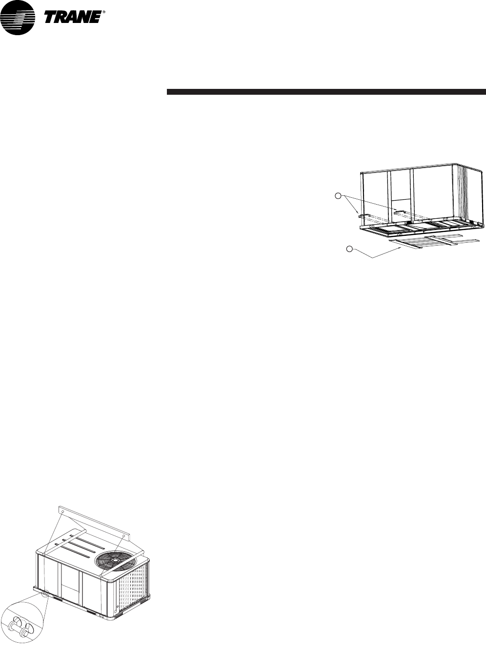
Figure 2 - Rigging
1 = Remove 2 fork lift brackets
2 = Remove 2 metal runners and 3
wooden boards
Lift the unit enough to allow the
removal of two Fork Lift brackets
and hardware. Remove the two Fork
Lift brackets, two metal runners and
three wooden boards as shown in
Figure 2.
1
2
Installation
7RT-SVX20A-E4
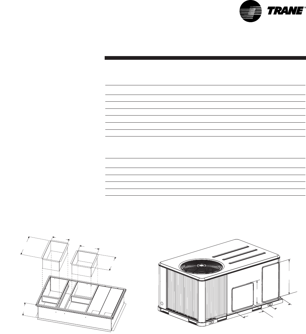
Dimensions/Weights/
Clearances
The structure accommodating the
unit(s) must be designed to support
the equipment in operation, as a
minimum. Refer to Table 2 and the
space requirement plan.
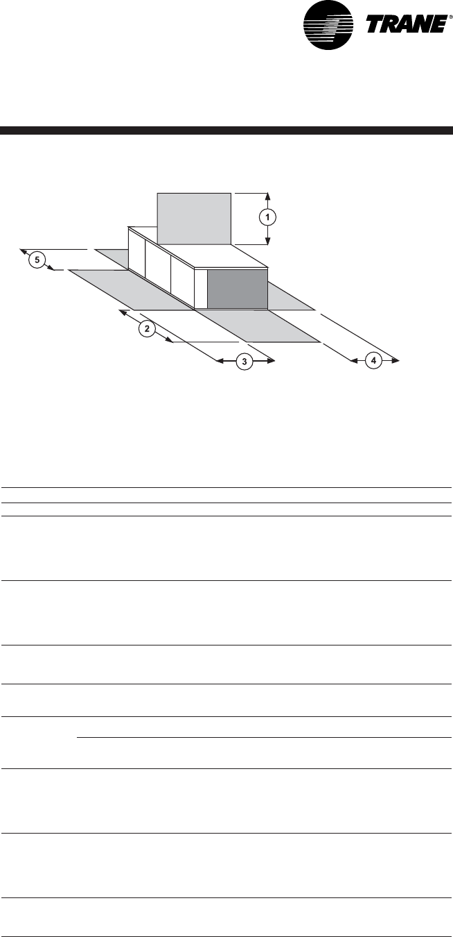
Figure 3 - Minimum clearances
Table 1 - Minimum recommended clearances
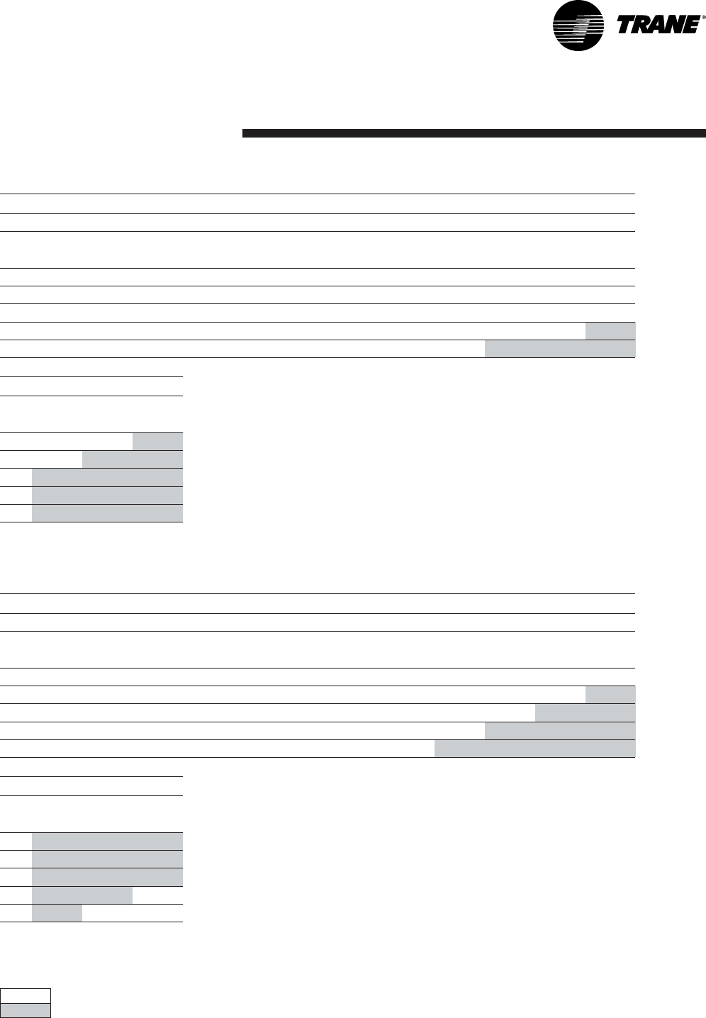
Table 2 - Unit weights and center of gravity
Notes:
(1) Corner weights are given for information only. All models must be supported continuously by a curb or
equivalent frame support.
Unit Size
Maximum weight Corner weight (1) Center of gravity
Shipping
(kg)
Net
(kg)
A
(kg)
B
(kg)
C
(kg)
D
(kg)
Length
(mm)
Width
(mm)
TSD/TSH 060 259 235 75 56 48 56 790 480
TSD/TSH 072 365 326 107 83 58 78 970 560
TSD/TSH 090 428 389 131 101 67 89 970 530
TSD/TSH 102 445 405 133 106 72 94 990 560
TSD/TSH 120 485 445 147 115 81 104 990 560
YSD/YSH 060 285 260 81 64 54 62 810 510
YSD/YSH 072 390 350 113 90 64 83 990 560
YSD/YSH 090 458 419 139 110 75 95 970 530
YSD/YSH 102 474 434 141 114 79 100 1020 560
YSD/YSH 120 520 481 155 126 89 111 1020 560
WSD/WSH 060 266 241 77 58 49 58 790 480
WSD/WSH 072 408 368 122 93 66 87 970 560
WSD/WSH 090 418 378 128 95 67 88 970 530
Unit size Mimum clearances (mm)
12345
TSD/TSH 060 1829 1219 914 914 914
TSD/TSH 072 1829 1219 914 914 914
TSD/TSH 090 1829 1219 914 914 914
TSD/TSH 102 1829 1219 914 914 914
TSD/TSH 120 1829 1219 914 914 914
YSD/YSH 060 1829 1219 914 914 914
YSD/YSH 072 1829 1219 914 914 914
YSD/YSH 090 1829 1219 914 914 914
YSD/YSH 102 1829 1219 914 914 914
YSD/YSH 120 1829 1219 914 914 914
WSD/WSH 060 1829 1219 914 914 914
WSD/WSH 072 1829 1219 914 914 914
WSD/WSH 090 1829 1219 914 914 914
Installation
RT-SVX20A-E48
Figure 4
AB
C
D
Center of
gravity width
Center of
gravity length
Center of
gravity
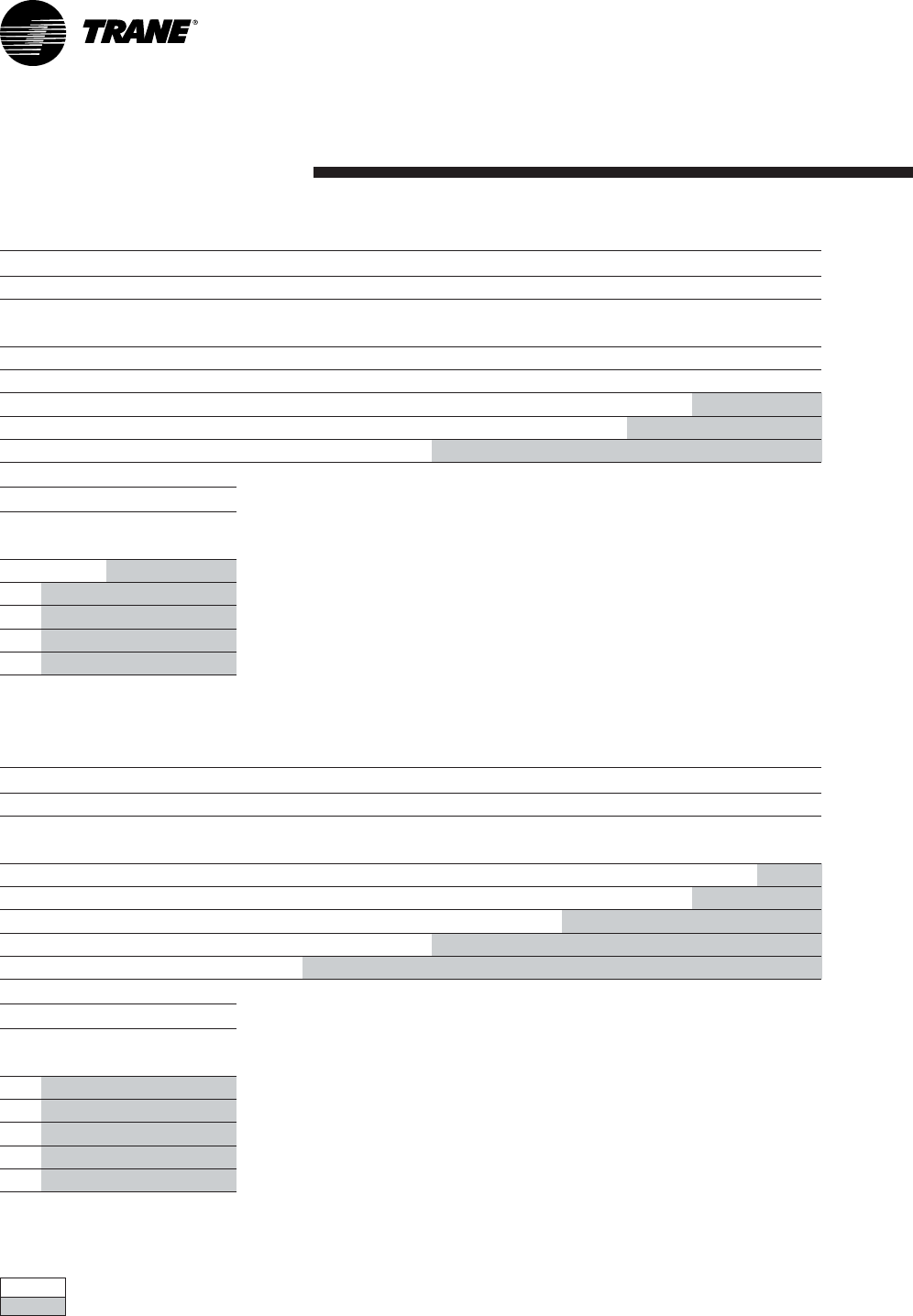
Table 3 - Factory-installed options and accessories net weights (kg)
Notes:
(1) Weights for options not listed are < 3 kg.
(2) Net weight should be added to unit weight when ordering factory-installed accessories.
(3) Some accessories are not available on all units.
Unit size Economizer Barometric
Relief
Motorized
Outside Air
Damper
Manual
Outside Air
Damper
Roof Curb Oversized
Motor
Electric
Heaters
Hot water
coil
TSD/TSH 060 11,8 3,2 9,1 7,3 31,8 - 6,8 14,0
TSD/TSH 072 16,3 4,5 13,6 11,8 52,2 3,6 13,6 17,0
TSD/TSH 090 16,3 4,5 13,6 11,8 52,2 3,6 13,6 17,0
TSD/TSH 1020 16,3 4,5 13,6 11,8 52,2 3,6 13,6 19,0
TSD/TSH 120 16,3 4,5 13,6 11,8 52,2 3,6 13,6 19,0
YSD/YSH 060 11,8 3,2 9,1 7,3 31,8 - 6,8
YSD/YSH 072 16,3 4,5 13,6 11,8 52,2 3,6 13,6
YSD/YSH 090 16,3 4,5 13,6 11,8 52,2 3,6 13,6
YSD/YSH 102 16,3 4,5 13,6 11,8 52,2 3,6 13,6
YSD/YSH 120 16,3 4,5 13,6 11,8 52,2 3,6 13,6
WSD/WSH 060 11,8 3,2 9,1 7,3 31,8 - 6,8 14,0
WSD/WSH 072 16,3 4,5 13,6 11,8 52,2 3,6 13,6 17,0
WSD/WSH 090 16,3 4,5 13,6 11,8 52,2 3,6 13,6 17,0
Installation
9RT-SVX20A-E4
Installing the unit
Discharge Conversion
If a unit is to be converted to
Vertical discharge, a panel must be
acquired from Trane.
If a unit is to be converted to
Horizontal discharge, the following
conversion must be performed:
1. Remove the return and supply
duct covers.
2. Apply gasket to the return duct
cover.
3. Position duct covers as shown in
Figure 4. The supply duct cover is
installed (insulation side down)
over the downflow return
opening by engaging one side of
the panel under a retaining angle
and securing the other side with
3 screws.
4. Slide return duct cover
(insulation side up) into supply
openings until outer edge of the
duct cover engages with the two
retaining clips on the duct
flanges. Secure the outer edge of
the each duct cover with two
screws.
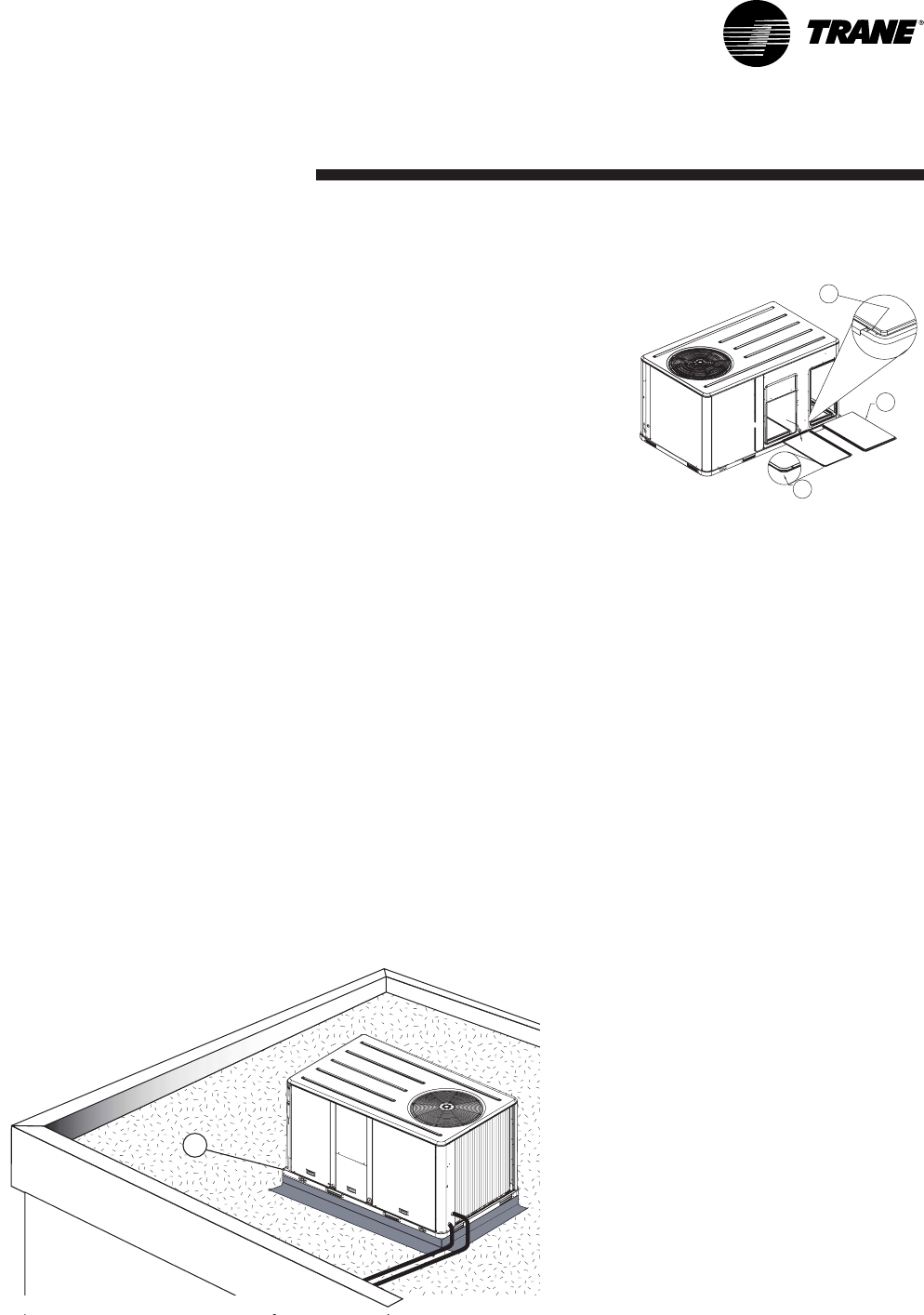
Figure 5 - Conversion to horizontal
discharge
1 = Supply duct cover, insulation side
down
2 = Return duct cover with gasket
installed, insulation side up
3 = Edge of duct cover goes under
retaining angle
Unit mounting on roof
Fix the rooftop curb on the joint
beam of the building's structure.
Make the rooftop curb's sealing
surface level using angle brackets
adjusted by screw bolts, located
around its perimeter. Place the
adhesive seals on the curb's sealing
surface (perimeter and cross
pieces). Make the rooftop leak-tight
around the curbs before installing
the unit, in compliance with current
construction standards.
Note:The unit must be installed
perfectly level to ensure
condensates flow from the
condensate tray.
The rooftop unit nests into the curb
and is supported by it. Position the
unit, taking care to comply with the
indicated directions: the unit's
discharge and intake openings must
match those of the curb.
1
2
3
Figure 6 - Unit mounting on roof
1 = Frame
1
Installation
RT-SVX20A-E410
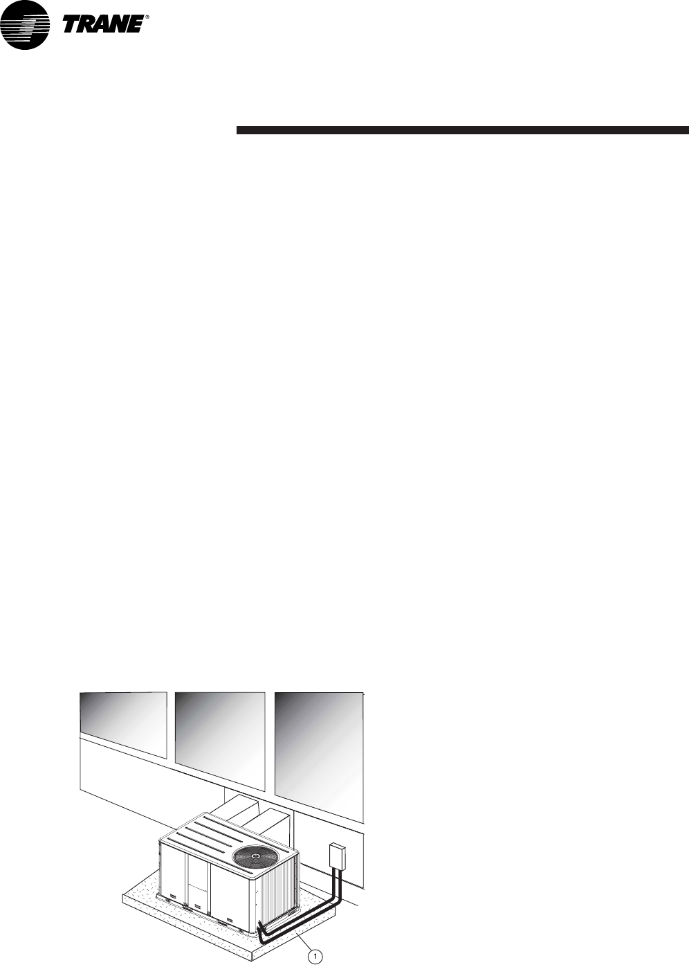
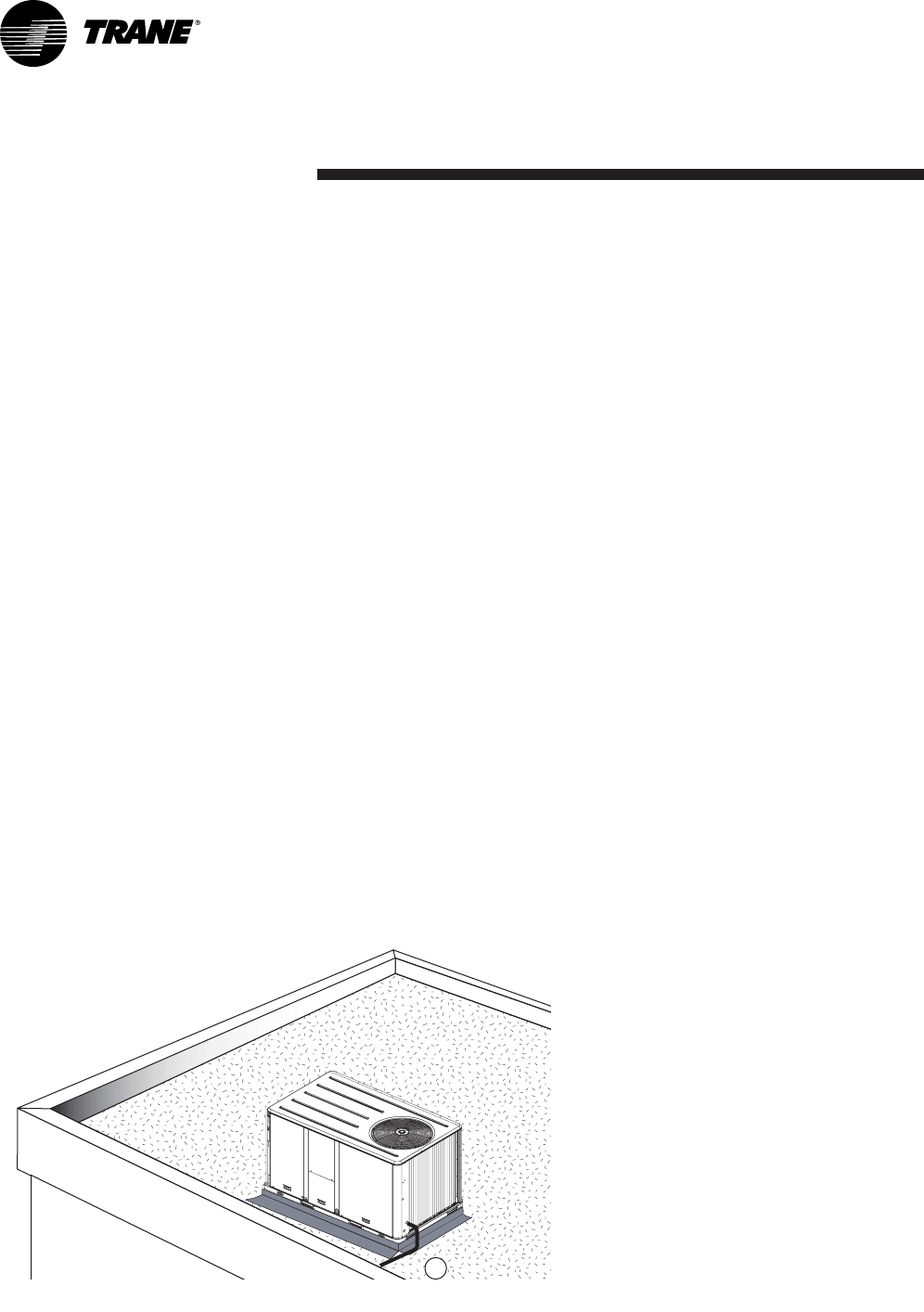
Installing the unit on the ground
To install the unit on the ground, its
base must be level and supported
securely. For horizontal discharge
units, a support is required such as
a metal or concrete slab whose
height must be determined
according to the amount of snow
cover, to prevent problems with
condensation drainage and
obstruction of the external coil. If
necessary use an anti-vibration
material between the rooftop unit's
base and the support.
Note: Unit installation must comply
to local codes
Connection of duct
network
1) Downflow discharge units
(TSD,WSD,YSD)
Using the rooftop curb
• The rooftop curb must be
insulated on the outside walls at
the discharge and intake
openings to prevent
condensation in the ducts.
• The rims around the discharge
and intake openings make it
possible to attach the flanges on
the ends of the ducts. If you are
using rigid duct ends
recommended on the rooftop
curb plan, it is essential to fix
these components before
installing the unit.
• For the design of the duct
network, comply with
recommendations currently
applicable on the market, in
particular:
. Installation of a section of
flexible ducts to limit
transmission of the unit's
vibrations
. Use of movable vanes or
deflectors to reduce the sound
level.
2) Horizontal discharge units
(TSH,WSH,YSH)
• The intake and discharge ducts
must be insulated (thermal
insulation).
• The duct section located outside
must be leak-tight.
• Provide a flexible connector to
prevent transmission of the unit
vibrations. This flexible duct
must be installed inside the
building.
Note: In case of use of units with
economizer option, temperature
and humidity sensors must be
installed in return duct.
Economizer linkage is factory
mounted but the damper position
must be adjusted on site.
Figure 7 - Unit installation on the ground
1 = Concrete slab
Installation
11RT-SVX20A-E4
Table 4 - Duct dimensions for downflow units (mm)
Table 5 - Duct dimensions for downflow units (mm)
Unit size ABCD
TSH/WSH 060 591 337 375 438
YSH 060 591 337 375 438
TSH/WSH/YSH 072/090 832 425 606 489
TSH/YSH 102/120 832 425 606 489
Unit size ABCDEFlanges
TSD 060 619 357 411 459 356 32
YSD 060 610 356 394 457 356 32
WSD 060 819 357 411 459 356 32
TSD/WSD 072/090 875 451 451 875 356 31
TSD 102/120 875 451 451 875 356 31
YSD 072/090/102/120 816 444 444 838 356 31
Figure 8 - Duct dimensions for downflow units
S = Supply
R = Return
A
B
C
D
E
SR
Figure 9 - Duct dimensions for horizontal units
S = Supply
R = Return
A
B
D
C
R
S
Installation
RT-SVX20A-E412
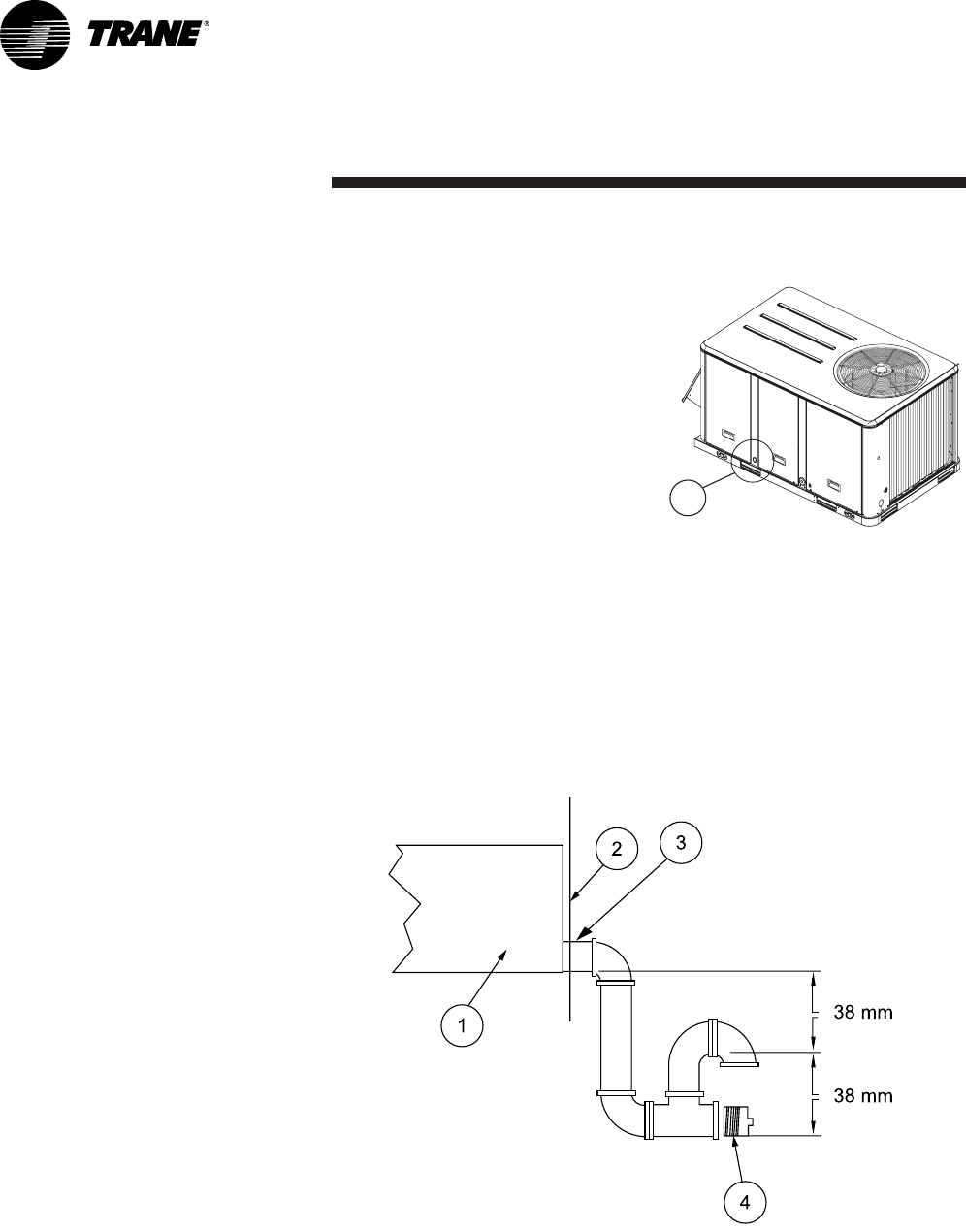
Condensate drain piping
A 3/4" condensate drain connection
with P-trap is provided. Follow local
codes and standard piping practices
when running the drain line. Install
a trap and be sure to fill with water
before starting the unit. Pitch the
line downward, away from the unit
to avoid long, level, horizontal runs.
Refer to Figure 11.
The condensate drain is reversible
to allow installation of a drain tap
on either side of the unit.
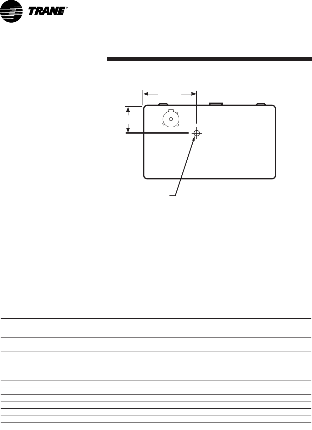
Figure 10 - Condensate drain location
1 = Main condensate drain location
1
Figure 11 - Condensate drain line location
1 = Static pressure drain pan
2 = Panel enclosure
3 = ¾ " drain
4 = Cleanout plug
Installation
13RT-SVX20A-E4
Gas pipework installation
The installation must conform to all
standards and regulations.
The gas supply pipework and gas
stop valve to be installed near the
unit must be sized so as to ensure
the gas pressure is sufficient at the
unit inlet when operating at full
load.
CAUTION! Should the pressure at
the unit valve gas inlet be higher
than 0.035 bar, an expansion valve
must be installed.
The pipework must be self-
supporting and the final connection
to the burner must be made by a
flexible pipe. Provide a dust
protection (filter) upstream the unit
connection.
CAUTION!The gas pipework must
not exert any stress on the burner
gas connection.
Note: Expansion valve must be
adapted to the type of gas used:
• G 20: 20 mb
• G 25: 25 mb
• G 31 (Propane): 37 or 50 mb
Table 6 - Gas burner models
See Table 51 for burner
performance.
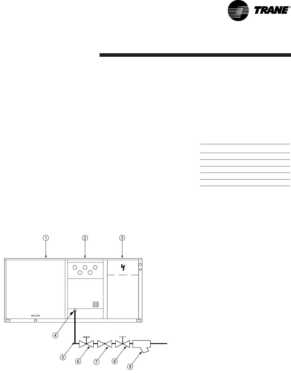
Gas leak check procedure
1. Vent the gas line
2. Gas supply line pressure test:
close valve 4 and open valve 2
3. Leak-check the gas pipe.
Look for gas pipe leaks using
"Typol", "1000 bulles" or a similar
product. Do not use soapy water.
WARNING! Never use an open
flame to check for gas leaks.
Required gas pressure at the unit
inlet connection are given in
Table 50.
Note:To operate with propane gas,
the burner is fitted with a pressure
limiter (supplied by Trane)
Unit Burner size
YSD/YSH 060 G120
YSD/YSH 072 G200
YSD/YSH 090 G200
YSD/YSH 102 G250
YSD/YSH 120 G250
Figure 12 - Typical gas supply pipework
1 = Evaporator section
2 = Gas burner section
3 = Condenser section
4 = Gas supply connection
5 = Gas supply line
6, 8 = Gas stop valve (Field supplied)
7 = Expansion valve (Field supplied)
9 = Filter (Field supplied)
Installation
RT-SVX20A-E414
Filter installation
To gain access to filters, remove the
supply fan access panel on
downflow units and the filter access
panel on the end for horizontal
units.
Number and size of filters is
determined by size and
configuration of the unit. If
disposable filters were chosen as an
option, they are shipped in the
supply fan section.
CAUTION! Do not operate unit
without filters in place.
The maximum pressure drops
allowable on filters are:
EU2/G2: 120 Pa
EU4/G4: 150 Pa
Table 7 - Filter arrangement
Unit EU2/G2 EU4/G4
Quantity Size Quantity Size
TSD/TSH/YSD/YSH/WSD/WSH 060 2 (508x762x25) 2 (500x750x25)
TSD/TSH/YSD/YSH/WSD/WSH 072 4 (406x635x50) 4 (395x625x50)
TSD/TSH/YSD/YSH/WSD/WSH 090 4 (406x635x50) 4 (395x625x50)
TSD/TSH/YSD/YSH 102 4 (508x635x50) 4 (500x625x50)
TSD/TSH/YSD/YSH 120 4 (508x635x50) 4 (500x625x50)
Supply fan adjustment
Use the following procedure to
determine the proper adjustment of
the supply fan for a specific
application.
1. Determine total external static
pressure about system and
accessories.
• Obtain the design airflow rate
and the design external static
pressure drop through the
distribution system.
• Add static pressure drop of the
accessories installed on the unit.
(Table 9)
• Add the total accessory static
pressure drop (from step 1b) to
the design external static
pressure (from step 1a). The sum
of these two values is the total
system external static pressure.
2. Using the Tables 10 through 35 to
find the external static pressure
that most closely approximates
total system external static
pressure. Then locate the
appropriate airflow rate for your
unit. The value obtained
represents the brake horsepower
for the supply fan motor and the
fan RPM.
3. Adjust motor sheave according
to Table 8.
Installation
15RT-SVX20A-E4
To adjust belt
The fan belts must be inspected
periodically to assure proper unit
operation. Replacement is
necessary if the belts appear frayed
or worn.
Units with dual belts require a
matched set of belts to ensure equal
belt length.
When removing or installing the
new belts, do not stretch them over
the sheaves. Loosen the belts using
the belt tension adjustment bolts on
the motor mounting base.
Once the new belts are installed,
adjust the belt tension.
Table 8 - Motor sheave / Fan speed
Fan speed (RPM)
Standard drive & motor
Unit 6 turns
Open
5 turns
Open
4 turns
Open
3 turns
Open
2 turns
Open
1 turns
Open Closed
TSD/TSH 060 N/A 898 967 1036 1105 1174 1243
TSD/TSH 072 N/A 698 751 806 859 913 967
TSD/TSH 090 N/A 752 806 860 914 968 1020
TSD/TSH 102 N/A 688 737 786 835 885 934
TSD/TSH 120 N/A 782 838 894 950 1006 1062
YSD/YSH 060 N/A 1036 1105 1174 1243 1312 1381
YSD/YSH 072 N/A 806 860 913 968 1022 1074
YSD/YSH 090 859 913 967 1021 1075 1129 N/A
YSD/YSH 102 786 836 885 934 982 1032 N/A
YSD/YSH 120 894 950 1006 1062 1118 1174 N/A
WSD/WSH 060 N/A 898 967 1036 1105 1174 1243
WSD/WSH 072 N/A 698 751 806 859 913 967
WSD/WSH 090 N/A 752 806 860 914 968 1020
Fan speed (RPM)
Oversized drive & motor
Unit 6 turns
Open
5 turns
Open
4 turns
Open
3 turns
Open
2 turns
Open
1 turns
Open Closed
TSD/TSH 060 N/A 1243 1311 1379 1450 1515 1588
TSD/TSH 072 N/A 967 1021 1075 1128 1183 1235
TSD/TSH 090 1112 1182 1252 1322 1392 1460 N/A
TSD/TSH 102 N/A 971 1041 1111 1181 1251 1321
TSD/TSH 120 1062 1118 1174 1229 1285 1341 N/A
YSD/YSH 060 -------
YSD/YSH 072 N/A 967 1021 1075 1128 1183 1235
YSD/YSH 090 1112 1182 1252 1322 1392 1460 N/A
YSD/YSH 102 N/A 971 1041 1111 1181 1251 1321
YSD/YSH 120 1062 1118 1174 1229 1285 1341 N/A
WSD/WSH 060 N/A 1243 1311 1379 1450 1515 1588
WSD/WSH 072 N/A 967 1021 1075 1128 1183 1235
WSD/WSH 090 1112 1182 1252 1322 1392 1460 N/A
To increase airflow
Loosen variable sheave set screw
and turn sheave clockwise.
To decrease airflow
Loosen variable sheave set screw
and turn sheave counter-clockwise.
Component air pressure drops
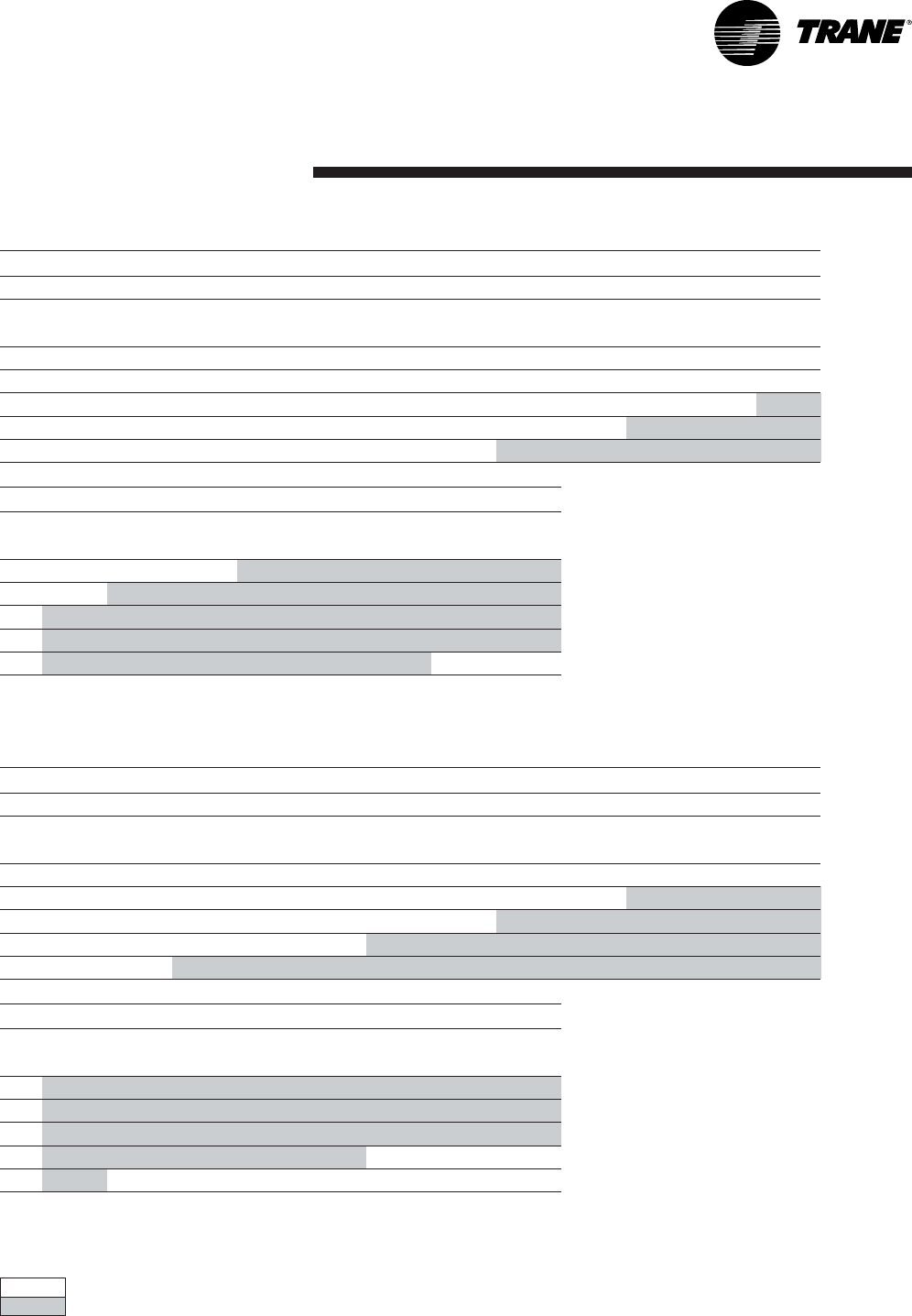
Table 9 - Pressure drop through accessories
Unit
size
Airflow
(m3/h)
Filter
EU2/G2
Filter
EU4/G4
Economizer
100%
outside air
Electric
heater
Hot water
coil
060
3060 31 50 38 17 49
34003855462155
3740 46 61 55 25 62
4080 55 66 64 30 68
072
3670 13 37 27 7 46
4080 16 42 29 9 52
4490 19 46 31 11 58
49002350331364
090
4590 19 47 33 12 66
5100 24 52 39 15 74
56102957452083
6120 35 62 52 25 92
102
5200 16 42 40 8 64
5780 20 47 50 10 72
6360 25 52 62 12 81
6940 30 57 75 15 90
120
6120 22 50 52 11 84
68002755621495
7480 33 61 73 17 106
8160 40 66 85 20 117
Installation
RT-SVX20A-E416
Installation
17RT-SVX20A-E4
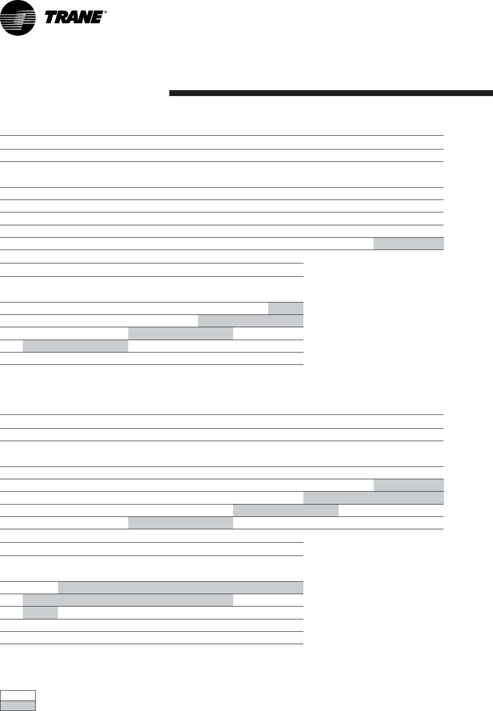
Standard drive
Oversize drive Note : Data includes pressure drops for standard filters and wet coils
Table 10 - TSD 060 Available static pressure
External Static Pressure (Pa)
25 50 75 100 125 150 175 200 225 250 275 300
m3/h RPM kW RPM kW RPM kW RPM kW RPM kW RPM kW RPM kW RPM kW RPM kW RPM kW kW kW
2720 - - - - - - ----8990.439440.499850.5410230.5910600.6410930.6911260.74
3060 - - - - - - - - 904 0.49 947 0.54 988 0.58 1028 0.64 1067 0.70 1104 0.76 1138 0.82 1171 0.87
3400 - - - - - - 918 0.57 958 0. 6 2 998 0.67 1036 0.71 1073 0.76 1111 0. 8 2 114 7 0.89 1182 0. 9 6 12 15 1.02
3740 - - - - 930 0.65 977 0.71 1016 0.77 1053 0.82 1089 0.88 1124 0.93 1158 0.98 1191 1.03 1226 1.10 1258 1.17
4080 909 0.71 950 0.76 990 0.80 1034 0.87 1074 0.93 1110 1.00 1143 1.06 1177 1.12 1209 1.17 1241 1.23 1272 1.29 - -
325 350 375
m3/h kW kW kW
2720 1160 0.79 1190 0.84 1222 0.90
3060 1203 0.93 1232 0.98 1262 1.04
3400 1246 1.09 1276 1.15 1306 1.21
3740 1290 1.25 - - - -
4080 - - - - - -
Fan
RPM
Fan
RPM
Fan
RPM
Fan
RPM
Fan
RPM
Table 11 - TSH 060 Available static pressure
External Static Pressure (Pa)
25 50 75 100 125 150 175 200 225 250 275 300
m3/h RPM kW RPM kW RPM kW RPM kW RPM kW RPM kW RPM kW RPM kW RPM kW RPM kW kW kW
2720 - - - - - - 898 0.43 953 0.48 1001 0.54 1045 0.59 1087 0.65 1129 0.71 1168 0.77 1206 0.83 1241 0.89
3060 - - - - 897 0.48 953 0.54 1008 0.60 1058 0.67 1102 0.73 1143 0.79 1181 0.85 1219 0.92 1256 0.99 1291 1.05
3400 - - 90 8 0.54 961 0.60 1012 0.6 7 1062 0.74 1111 0.81 115 7 0 . 8 8 1198 0.95 12 37 1.02 12 74 1.09 1309 1.16 1343 1.24
3740 923 0.63 978 0.69 1028 0.76 1075 0.83 1120 0.91 1166 0.99 1211 1.06 1254 1.14 1294 1.22 1330 1.29 - - - -
4080 997 0.80 1049 0.87 1096 0.94 1140 1.02 1183 1.10 1223 1.18 1266 1.27 - - - - - - - - - -
325 350 375
m3/h kW kW kW
2720 1275 0.96 1306 1.02 1338 1.09
3060 1326 1.12 1359 1.19 1390 1.26
3400 1376 1.31 - - - -
3740 - - - - - -
4080 - - - - - -
Fan
RPM
Fan
RPM
Fan
RPM
Fan
RPM
Fan
RPM
Supply fan performances
Installation
RT-SVX20A-E418
Standard drive
Oversize drive Note : Data includes pressure drops for standard filters and wet coils
Table 12 - TSD 072 Available static pressure
External Static Pressure (Pa)
25 50 75 100 125 150 175 200 225 250 275 300
m3/h RPM kW RPM kW RPM kW RPM kW RPM kW RPM kW RPM kW RPM kW RPM kW RPM kW kW kW
3260 - - - - - - ----7260.417690.478110.528510.588890.659250.719600.77
3670 - - - - - - - - 706 0.43 751 0.49 792 0.55 832 0.61 871 0.67 908 0.74 944 0.81 978 0.87
4080 - - - - - - - - 732 0.51 777 0.58 818 0.64 856 0.71 893 0.77 930 0.84 964 0.91 998 0.99
4490 - - - - - - 715 0.54 758 0.60 802 0.68 845 0.75 883 0.82 919 0.89 953 0.96 986 1.04 1019 1.11
4890 - - - - 706 0.58 749 0.64 789 0.71 830 0.79 870 0.87 909 0.95 945 1.02 979 1.10 1011 1.18 1043 1.26
325 350 375
m3/h kW kW kW
3260 994 0.83 1026 0.89 1057 0.95
3670 1010 0.94 1043 1.01 1073 1.08
4080 1030 1.06 1063 1.14 1092 1.21
4490 1051 1.19 1082 1.27 1112 1.35
4890 1073 1.34 1103 1.42 1133 1.51
Fan
RPM
Fan
RPM
Fan
RPM
Fan
RPM
Fan
RPM
Table 13 - TSH 072 Available static pressure
External Static Pressure (Pa)
25 50 75 100 125 150 175 200 225 250 275 300
m3/h RPM kW RPM kW RPM kW RPM kW RPM kW RPM kW RPM kW RPM kW RPM kW RPM kW kW kW
3260 - - - - - - - - 726 0.39 771 0.45 814 0.51 857 0.57 899 0.63 939 0.70 978 0.76 1015 0.83
3670 - - - - - - 716 0.42 762 0.48 804 0.54 843 0.60 883 0.67 922 0.74 960 0.81 996 0.87 1034 0.95
4080 - - - - 701 0.45 751 0.51 798 0.59 839 0.65 877 0.71 914 0.78 950 0.85 984 0.93 1020 1.00 1055 1.08
4490 - - 710 0.51 745 0.56 788 0.62 833 0.69 875 0.77 914 0.85 949 0.91 984 0.98 1016 1.06 1049 1.14 1081 1.23
4890 726 0.58 762 0.64 795 0.70 828 0.76 869 0.82 911 0.91 950 0.99 986 1.07 1019 1.14 1051 1.22 1081 1.30 1112 1.38
325 350 375
m3/h kW kW kW
3260 1051 0.90 1086 0.97 1118 1.04
3670 1069 1.02 1103 1.09 1136 1.17
4080 1089 1.16 1122 1.23 1154 1.31
4490 1113 1.31 1144 1.40 1176 1.48
4890 1141 1.47 1170 1.57 1199 1.66
Fan
RPM
Fan
RPM
Fan
RPM
Fan
RPM
Fan
RPM
Installation
19RT-SVX20A-E4
Standard drive
Oversize drive Note : Data includes pressure drops for standard filters and wet coils
Table 14 - TSD 090 Available static pressure
External Static Pressure (Pa)
25 50 75 100 125 150 175 200 225 250 275 300
m3/h RPM kW RPM kW RPM kW RPM kW RPM kW RPM kW RPM kW RPM kW RPM kW RPM kW kW kW
4080 - - - - - - - - 750 0.54 794 0.60 834 0.67 873 0.73 909 0.80 945 0.87 980 0.95 1013 1.02
4590 - - - - - - - - 787 0.66 830 0.74 871 0.82 908 0.89 943 0.96 977 1.04 1010 1.11 1043 1.19
5100 - - - - 747 0.68 789 0.74 827 0.82 867 0.90 906 0.98 944 1.06 980 1.15 1013 1.23 1045 1.31 1076 1.39
5610 - - 755 0.77 797 0.8 5 836 0.92 8 7 3 1.0 0 908 1.08 944 1.17 980 1.26 1016 1.35 1050 1.45 1081 1.54 1111 1.63
6120 771 0.88 809 0.96 848 1.06 885 1.14 921 1.22 954 1.30 986 1.39 1019 1.49 1052 1.58 1085 1.69 1116 1.79 1148 1.89
325 350 375
m3/h kW kW kW
4080 1046 1.10 1076 1.17 1106 1.25
4590 1074 1.27 1105 1.36 1134 1.44
5100 1105 1.47 1134 1.56 1163 1.65
5610 1141 1.72 1168 1.80 1197 1.90
6120 1177 1.99 1204 2.08 1232 2.18
Fan
RPM
Fan
RPM
Fan
RPM
Fan
RPM
Fan
RPM
Table 15 - TSH 090 Available static pressure
External Static Pressure (Pa)
25 50 75 100 125 150 175 200 225 250 275 300
m3/h RPM kW RPM kW RPM kW RPM kW RPM kW RPM kW RPM kW RPM kW RPM kW RPM kW kW kW
4080 - - - - - - 769 0.54 814 0.61 855 0.67 893 0.73 929 0.81 965 0.88 999 0.96 1035 1.04 1070 1.12
4590 - - - - 773 0.62 817 0.68 862 0.76 904 0.85 941 0.92 975 0.98 1009 1.06 1041 1.14 1073 1.22 1104 1.31
5100 771 0.68 805 0.74 837 0.81 870 0.87 912 0.94 951 1.03 989 1.12 1025 1.21 1056 1.28 1088 1.36 1117 1.44 1146 1.53
5610 842 0.89 873 0.96 903 1.03 930 1.10 963 1.17 1000 1.25 1037 1.34 1073 1.45 1106 1.55 1136 1.63 1165 1.72 1194 1.80
6120 913 1.14 942 1.22 970 1.30 996 1.37 1021 1.45 1052 1.52 1086 1.61 1121 1.71 1153 1.82 1184 1.93 1215 2.04 1242 2.13
325 350 375
m3/h kW kW kW
4080 1104 1.19 1137 1.27 1168 1.35
4590 1136 1.40 1167 1.48 1198 1.57
5100 1176 1.62 1205 1.72 1233 1.82
5610 1220 1.88 1248 1.98 1275 2.08
6120 1269 2.22 1295 2.31 1319 2.40
Fan
RPM
Fan
RPM
Fan
RPM
Fan
RPM
Fan
RPM
Installation
RT-SVX20A-E420
Standard drive
Oversize drive Note : Data includes pressure drops for standard filters and wet coils
Table 16 - TSD 102 Available static pressure
External Static Pressure (Pa)
25 50 75 100 125 150 175 200 225 250 275 300
m3/h RPM kW RPM kW RPM kW RPM kW RPM kW RPM kW RPM kW RPM kW RPM kW RPM kW kW kW
4620 - - - - - - ----6950.627330.717690.818020.908331.008631.118921.21
5200 - - - - - - - - 688 0.64 725 0.73 761 0.83 796 0.93 828 1.03 861 1.13 891 1.24 919 1.35
5780 - - - - - - 689 0.68 724 0.76 759 0.86 792 0.96 825 1.07 856 1.18 887 1.28 917 1.40 946 1.51
6350 - - - - 693 0.72 729 0.82 764 0.92 795 1.01 826 1.11 857 1.22 887 1.34 916 1.46 945 1.58 974 1.70
6930 - - 706 0.80 738 0.89 770 0.98 804 1.09 834 1.19 864 1.30 892 1.40 920 1.52 948 1.64 976 1.78 1002 1.91
325 350 375 400 425 450 475 500
m3/h kW kW kW kW kW kW kW kW
4620 920 1.33 946 1.44 973 1.55 999 1.67 1025 1.79 1050 1.90 1073 2.02 1098 2.14
5200 946 1.46 973 1.58 999 1.71 1024 1.83 1048 1.96 1072 2.09 1096 2.22 1119 2.34
5780 974 1.63 1001 1.75 1026 1.88 1051 2.01 1074 2.14 1099 2.27 1121 2.41 1143 2.55
6350 1001 1.82 1028 1.95 1054 2.08 1079 2.20 1103 2.34 1126 2.48 1148 2.62 1170 2.76
6930 1029 2.04 1055 2.17 1081 2.30 1105 2.43 1130 2.58 1154 2.72 1176 2.85 1199 3.01
Fan
RPM
Fan
RPM
Fan
RPM
Fan
RPM
Fan
RPM
Fan
RPM
Fan
RPM
Fan
RPM
Fan
RPM
Fan
RPM
Table 17 - TSH 102 Available static pressure
External Static Pressure (Pa)
25 50 75 100 125 150 175 200 225 250 275 300
m3/h RPM kW RPM kW RPM kW RPM kW RPM kW RPM kW RPM kW RPM kW RPM kW RPM kW kW kW
4620 - - - - - - 689 0.58 734 0.67 781 0.77 826 0.88 865 0.98 898 1.07 928 1.16 956 1.25 982 1.33
5200 - - - - 693 0.64 735 0.73 773 0.82 812 0.92 855 1.03 897 1.15 934 1.27 969 1.38 999 1.49 1026 1.58
5780 - - 711 0.75 743 0.82 781 0.91 819 1.01 853 1.11 886 1.21 925 1.34 964 1.47 1000 1.60 1034 1.73 1067 1.86
6350 735 0.89 770 0.97 799 1.04 830 1.12 865 1.23 899 1.34 930 1.45 960 1.56 994 1.68 1028 1.82 1063 1.96 1098 2.11
6930 796 1.14 828 1.23 857 1.31 883 1.39 913 1.48 945 1.60 977 1.72 1006 1.84 1034 1.96 1061 2.08 1093 2.23 1125 2.38
325 350 375 400 425 450 475 500
m3/h kW kW kW kW kW kW kW kW
4620 1008 1.42 1033 1.51 1056 1.60 1079 1.69 1102 1.78 1125 1.87 1146 1.95 1168 2.04
5200 1052 1.68 1078 1.78 1101 1.88 1124 1.98 1146 2.08 1168 2.18 1188 2.27 1209 2.37
5780 1094 1.97 1120 2.08 1145 2.20 1168 2.31 1191 2.42 1213 2.53 1234 2.63 1254 2.74
6350 1129 2.26 1158 2.40 1185 2.53 1210 2.66 1234 2.78 1256 2.90 1278 3.03 1299 3.15
6930 1157 2.53 1188 2.70 1218 2.86 1245 3.01 1273 3.16 1297 3.31 - - - -
Fan
RPM
Fan
RPM
Fan
RPM
Fan
RPM
Fan
RPM
Fan
RPM
Fan
RPM
Fan
RPM
Fan
RPM
Fan
RPM
Installation
21RT-SVX20A-E4
Standard drive
Oversize drive Note : Data includes pressure drops for standard filters and wet coils
Table 18 - TSD 120 Available static pressure
External Static Pressure (Pa)
25 50 75 100 125 150 175 200 225 250 275 300
m3/h RPM kW RPM kW RPM kW RPM kW RPM kW RPM kW RPM kW RPM kW RPM kW RPM kW kW kW
5440 - - - - - - ------7890.938221.038561.148871.259171.369451.47
6120 ----------7970.998291.108601.228921.349221.469511.579791.69
6800 - - - - - - 782 1.01 814 1.11 844 1.21 874 1.32 903 1.44 932 1.56 960 1.69 988 1.82 1015 1.95
7480 - - - - 803 1.14 834 1.24 864 1.36 894 1.48 922 1.59 948 1.70 975 1.82 1001 1.95 1028 2.09 1053 2.23
8160 803 1.21 833 1.31 861 1.42 887 1.52 916 1.64 945 1.77 972 1.90 997 2.02 1022 2.14 1046 2.27 1071 2.41 1095 2.55
325 350 375 400 425 450 475 500
m3/h kW kW kW kW kW kW kW kW
5440 973 1.60 999 1.72 1024 1.84 1048 1.97 1072 2.10 1095 2.23 1117 2.37 1140 2.51
6120 1007 1.82 1033 1.94 1059 2.07 1082 2.20 1107 2.34 1130 2.49 1152 2.63 1173 2.77
6800 1042 2.08 1068 2.21 1093 2.35 1117 2.48 1142 2.63 1164 2.76 1187 2.91 1209 3.06
7480 1078 2.38 1103 2.52 1128 2.66 1152 2.81 1176 2.95 1198 3.10 1221 3.25 - -
8160 1119 2.70 1142 2.86 1166 3.02 1189 3.17 1212 3.33 - - - - - -
Fan
RPM
Fan
RPM
Fan
RPM
Fan
RPM
Fan
RPM
Fan
RPM
Fan
RPM
Fan
RPM
Fan
RPM
Fan
RPM
Table 19 - TSH 120 Available static pressure
External Static Pressure (Pa)
25 50 75 100 125 150 175 200 225 250 275 300
m3/h RPM kW RPM kW RPM kW RPM kW RPM kW RPM kW RPM kW RPM kW RPM kW RPM kW kW kW
5440 - - - - - - - - 807 0.94 844 1.04 886 1.16 926 1.28 965 1.41 1000 1.53 1029 1.64 1057 1.75
6120 - - - - 792 0.99 829 1.08 865 1.19 898 1.30 930 1.41 965 1.53 1002 1.67 1038 1.81 1072 1.95 1106 2.10
6800 80 2 1.13 833 1.22 860 1.29 890 1.38 923 1.50 9 5 6 1.62 9 8 6 1.73 1015 1.85 1044 1.98 10 77 2.12 1111 2.28 1143 2. 4 3
7480 876 1.49 905 1.58 931 1.67 955 1.75 983 1.86 1014 1.99 1045 2.12 1072 2.25 1098 2.37 1125 2.51 1152 2.65 1182 2.81
8160 950 1.91 977 2.02 1002 2.11 1025 2.20 1048 2.30 1074 2.42 1102 2.56 1131 2.71 1156 2.84 1181 2.98 1205 3.12 1229 3.27
325 350 375 400 425 450 475 500
m3/h kW kW kW kW kW kW kW kW
5440 1084 1.86 1108 1.96 1132 2.06 1155 2.17 1177 2.27 1198 2.37 1219 2.48 1239 2.58
6120 1134 2.22 1160 2.35 1185 2.47 1209 2.59 1231 2.70 1252 2.82 1274 2.94 1295 3.06
6800 1174 2.58 1204 2.74 1232 2.90 1260 3.05 1283 3.18 1306 3.32 - - - -
748012112.9712413.1412703.31----------
8160 ----------------
Fan
RPM
Fan
RPM
Fan
RPM
Fan
RPM
Fan
RPM
Fan
RPM
Fan
RPM
Fan
RPM
Fan
RPM
Fan
RPM
Installation
RT-SVX20A-E422
Standard drive
Oversize drive Note : Data includes pressure drops for standard filters and wet coils
Standard drive
Oversize drive Note : Data includes pressure drops for standard filters and wet coils
Table 20 - YSD 060 Available static pressure
External Static Pressure (Pa)
25 50 75 100 125 150 175 200 225 250 275 300
m3/h RPM kW RPM kW RPM kW RPM kW RPM kW RPM kW RPM kW RPM kW RPM kW RPM kW kW kW
2720 - - - - - - --------10430.6210780.6711130.7211450.7711770.82
3060 - - - - - - ------10660.7011030.7611370.8211690.8712020.9312320.98
3400 - - - - - - - - 1052 0.73 1089 0.79 1126 0.85 1162 0.92 1196 0.98 1229 1.05 1260 1.11 1289 1.17
3740 - - - - 1051 0.82 1087 0.87 1122 0.92 1156 0.98 1190 1.03 1224 1.10 1257 1.17 1288 1.24 1320 1.32 - -
4080 1055 0.90 1093 0.97 1127 1.03 1160 1.09 1193 1.15 1225 1.20 1256 1.26 1288 1.32 - - - - - - - -
325 350 375
m3/h kW kW kW
2720 1208 0.87 1238 0.93 1268 0.98
3060 1262 1.04 1290 1.09 1319 1.15
3400 1319 1.24 1347 1.30 - -
3740 - - - - - -
4080 - - - - - -
Fan
RPM
Fan
RPM
Fan
RPM
Fan
RPM
Fan
RPM
Table 21 - YSH 060 Available static pressure
External Static Pressure (Pa)
25 50 75 100 125 150 175 200 225 250 275 300
m3/h RPM kW RPM kW RPM kW RPM kW RPM kW RPM kW RPM kW RPM kW RPM kW RPM kW kW kW
2720 - - - - - - ----10690.631111 0.68 115 1 0 .74 1189 0.80 1225 0.87 1260 0.93 1293 0.99
3060 - - - - - - 1056 0.66 1100 0.73 1141 0.79 1180 0.85 1218 0.92 1255 0.98 1290 1.05 1324 1.12 1357 1.19
3400 - - 1033 0.70 1083 0.77 1131 0.84 1176 0.91 1216 0.98 1253 1.05 1289 1.13 1323 1.20 1357 1.27 - - - -
3740 1072 0.83 1117 0.90 1163 0.98 1209 1.06 1251 1.14 1292 1.21 1329 1.29 - - - - - - - - - -
4080 1161 1.06 1203 1.14 1245 1.23 1287 1.31 - - - - - - - - - - - - - - - -
325 350 375
m3/h kW kW kW
2720 1324 1.06 1355 1.13 1383 1.20
3060 1390 1.26 - - - -
3400------
3740 - - - - - -
4080 - - - - - -
Fan
RPM
Fan
RPM
Fan
RPM
Fan
RPM
Fan
RPM
Installation
23RT-SVX20A-E4
Standard drive
Oversize drive Note : Data includes pressure drops for standard filters and wet coils
Standard drive
Oversize drive Note : Data includes pressure drops for standard filters and wet coils
Table 22 - YSD 072 Available static pressure
External Static Pressure (Pa)
25 50 75 100 125 150 175 200 225 250 275 300
m3/h RPM kW RPM kW RPM kW RPM kW RPM kW RPM kW RPM kW RPM kW RPM kW RPM kW kW kW
3260 - - - - - - ------8200.548590.608960.669320.729680.7810000.84
3670 - - - - - - ----8140.588540.648910.719280.789630.849960.9110280.98
4080 - - - - - - - - 814 0.64 853 0.70 890 0.77 926 0.84 961 0.91 994 0.98 1027 1.05 1058 1.13
4490 - - - - - - 815 0.70 857 0.77 894 0.84 929 0.91 963 0.98 996 1.06 1028 1.14 1060 1.22 1090 1.29
4890 - - - - 818 0.77 860 0.85 899 0.93 936 1.01 970 1.08 1003 1.16 1035 1.24 1066 1.32 1096 1.40 1125 1.48
325 350 375
m3/h kW kW kW
3260 1033 0.90 1063 0.96 1094 1.03
3670 1061 1.05 1091 1.12 1121 1.18
4080 1090 1.21 1118 1.28 1149 1.36
4490 1120 1.38 1150 1.46 1178 1.54
4890 1155 1.57 1181 1.66 1210 1.75
Fan
RPM
Fan
RPM
Fan
RPM
Fan
RPM
Fan
RPM
Table 23 - YSH 072 Available static pressure
External Static Pressure (Pa)
25 50 75 100 125 150 175 200 225 250 275 300
m3/h RPM kW RPM kW RPM kW RPM kW RPM kW RPM kW RPM kW RPM kW RPM kW RPM kW kW kW
3260 - - - - - - ----8240.528660.599070.659470.719860.7810230.8410590.92
3670 - - - - - - - - 826 0.57 865 0.64 903 0.71 943 0.78 979 0.84 1017 0.91 1053 0.98 1087 1.06
4080 - - - - - - 836 0.64 874 0.70 911 0.77 947 0.84 982 0.92 1017 1.00 1051 1.07 1085 1.15 1119 1.23
4490 - - - - 847 0.72 888 0.80 924 0.86 959 0.93 993 1.00 1026 1.08 1058 1.17 1089 1.25 1122 1.34 1153 1.42
4890 818 0.74 858 0.81 900 0.88 940 0.97 977 1.05 1010 1.13 1042 1.20 1073 1.27 1104 1.36 1133 1.45 1163 1.54 1192 1.64
325 350 375
m3/h kW kW kW
3260 1093 0.98 1126 1.06 1156 1.12
3670 1121 1.13 1153 1.21 1185 1.29
4080 1151 1.30 1182 1.38 1214 1.47
4490 1184 1.50 1215 1.59 - -
4890 1221 1.72 - - - -
Fan
RPM
Fan
RPM
Fan
RPM
Fan
RPM
Fan
RPM
Installation
RT-SVX20A-E424
Standard drive
Oversize drive Note : Data includes pressure drops for standard filters and wet coils
Standard drive
Oversize drive Note : Data includes pressure drops for standard filters and wet coils
Table 24 - YSD 090 Available static pressure
External Static Pressure (Pa)
25 50 75 100 125 150 175 200 225 250 275 300
m3/h RPM kW RPM kW RPM kW RPM kW RPM kW RPM kW RPM kW RPM kW RPM kW RPM kW kW kW
4080 - - - - - - ----8690.739060.809410.879760.9410091.0110421.0910731.17
4590 - - - - - - - - 887 0.85 922 0.92 958 0.99 991 1.07 1024 1.14 1055 1.22 1086 1.30 1117 1.39
5100 - - - - 865 0.89 905 0.98 943 1.06 979 1.15 1012 1.23 1044 1.31 1075 1.39 1105 1.47 1134 1.56 1163 1.65
5610 858 0.97 894 1.05 929 1.13 965 1.22 1001 1.32 1036 1.41 1068 1.50 1099 1.59 1129 1.68 1157 1.77 1185 1.86 1212 1.95
6120 930 1.24 963 1.33 995 1.42 1028 1.51 1061 1.61 1093 1.71 1126 1.82 1157 1.92 1185 2.02 1212 2.11 1239 2.21 1265 2.31
325 350 375
m3/h kW kW kW
4080 1104 1.24 1134 1.32 1163 1.40
4590 1146 1.47 1174 1.56 1203 1.65
5 10 0 11 91 1. 74 12 1 8 1. 8 3 12 4 5 1. 9 2
5610 1238 2.04 1265 2.14 1292 2.24
6120 1290 2.40 1316 2.51 1340 2.61
Fan
RPM
Fan
RPM
Fan
RPM
Fan
RPM
Fan
RPM
Table 25 - YSH 090 Available static pressure
External Static Pressure (Pa)
25 50 75 100 125 150 175 200 225 250 275 300
m3/h RPM kW RPM kW RPM kW RPM kW RPM kW RPM kW RPM kW RPM kW RPM kW RPM kW kW kW
4080 - - - - - - 851 0.67 889 0.73 926 0.80 962 0.88 997 0.95 1031 1.03 1067 1.11 1101 1.19 1134 1.26
4590 - - - - 880 0.80 919 0.88 955 0.94 989 1.01 1022 1.09 1054 1.17 1086 1.26 1117 1.35 1148 1.43 1180 1.52
5100 869 0.87 910 0.94 950 1.03 989 1.12 1023 1.21 1056 1.28 1086 1.36 1116 1.43 1146 1.52 1175 1.62 1204 1.72 1232 1.81
5610 949 1.14 985 1.22 1023 1.30 1058 1.40 1092 1.51 1124 1.60 1154 1.68 1182 1.77 1210 1.85 1237 1.94 1264 2.04 1290 2.14
6120 1029 1.47 1061 1.55 1096 1.64 1130 1.74 1162 1.85 1193 1.96 1222 2.06 1250 2.16 1276 2.25 1302 2.34 1327 2.43 1352 2.53
325 350 375
m3/h kW kW kW
4080 1166 1.34 1197 1.42 1229 1.50
4590 1210 1.60 1241 1.69 1269 1.78
5100 1260 1.91 1287 2.00 1316 2.10
5610 1316 2.25 1342 2.36 1367 2.46
6120 1376 2.64 1401 2.75 1425 2.87
Fan
RPM
Fan
RPM
Fan
RPM
Fan
RPM
Fan
RPM
Installation
25RT-SVX20A-E4
Standard drive
Oversize drive Note : Data includes pressure drops for standard filters and wet coils
Standard drive
Oversize drive Note : Data includes pressure drops for standard filters and wet coils
Table 26 - YSD 102 Available static pressure
External Static Pressure (Pa)
25 50 75 100 125 150 175 200 225 250 275 300
m3/h RPM kW RPM kW RPM kW RPM kW RPM kW RPM kW RPM kW RPM kW RPM kW RPM kW kW kW
4620 - - - - - - ------7870.858190.968501.068791.179071.279341.39
5200----------7940.928271.028591.138901.239181.349461.469711.58
5780 - - - - - - - - 805 1.00 837 1.11 869 1.22 900 1.33 929 1.44 959 1.56 986 1.68 1011 1.80
6350 - - - - 792 1.00 823 1.10 854 1.21 884 1.33 914 1.45 943 1.57 971 1.69 999 1.81 1025 1.94 1051 2.06
6930 786 1.03 818 1.14 848 1.24 877 1.34 905 1.46 933 1.58 961 1.71 988 1.84 1015 1.97 1041 2.10 1067 2.23 1092 2.36
325 350 375 400 425 450 475 500
m3/h kW kW kW kW kW kW kW kW
4620 960 1.50 987 1.62 1013 1.73 1038 1.85 1064 1.97 1087 2.09 1111 2.21 1134 2.34
5200 997 1.70 1023 1.83 1047 1.95 1070 2.08 1094 2.21 1117 2.34 1140 2.47 1163 2.60
5780 1037 1.93 1061 2.06 1085 2.19 1107 2.33 1130 2.46 1151 2.60 1174 2.75 1194 2.88
6350 1077 2.19 1100 2.32 1123 2.46 1147 2.61 1168 2.75 1189 2.89 1211 3.04 1231 3.19
6930 1117 2.50 1140 2.64 1164 2.78 1187 2.92 1208 3.07 1229 3.22 - - - -
Fan
RPM
Fan
RPM
Fan
RPM
Fan
RPM
Fan
RPM
Fan
RPM
Fan
RPM
Fan
RPM
Fan
RPM
Fan
RPM
Table 27 - YSH 102 Available static pressure
External Static Pressure (Pa)
25 50 75 100 125 150 175 200 225 250 275 300
m3/h RPM kW RPM kW RPM kW RPM kW RPM kW RPM kW RPM kW RPM kW RPM kW RPM kW kW kW
4620 - - - - - - 787 0.79 831 0.89 869 0.99 901 1.08 931 1.17 959 1.26 986 1.35 1011 1.43 1036 1.52
5200 - - - - 798 0.88 841 1.00 883 1.11 923 1.23 958 1.35 989 1.45 1017 1.55 1045 1.65 1070 1.75 1094 1.85
5780 793 0.94 830 1.04 863 1.14 898 1.25 937 1.37 975 1.51 1011 1.64 1045 1.77 1075 1.89 1103 2.01 1128 2.12 1152 2.23
6350 865 1.23 899 1.34 930 1.45 961 1.56 994 1.68 1028 1.82 1063 1.96 1097 2.11 1129 2.26 1159 2.40 1186 2.53 1210 2.65
6930 937 1.57 970 1.70 999 1.81 1027 1.93 1055 2.05 1085 2.19 1118 2.34 1150 2.50 1181 2.66 1211 2.82 1239 2.97 1267 3.13
325 350 375 400 425 450 475 500
m3/h kW kW kW kW kW kW kW kW
4620 1059 1.61 1082 1.69 1104 1.78 1127 1.87 1149 1.96 1170 2.05 1191 2.14 1212 2.24
5200 1117 1.95 1139 2.05 1161 2.15 1182 2.24 1203 2.35 1222 2.44 1243 2.54 1262 2.64
5780 1176 2.34 1198 2.45 1219 2.56 1241 2.67 1261 2.78 1280 2.88 1299 2.99 1319 3.11
6350 1233 2.78 1256 2.90 1278 3.03 1298 3.15 1319 3.27 - - - - - -
6930 1291 3.27 - - - - ----------
Fan
RPM
Fan
RPM
Fan
RPM
Fan
RPM
Fan
RPM
Fan
RPM
Fan
RPM
Fan
RPM
Fan
RPM
Fan
RPM
Installation
RT-SVX20A-E426
Standard drive
Oversize drive Note : Data includes pressure drops for standard filters and wet coils
Table 28 - YSD 120 Available static pressure
External Static Pressure (Pa)
25 50 75 100 125 150 175 200 225 250 275 300
m3/h RPM kW RPM kW RPM kW RPM kW RPM kW RPM kW RPM kW RPM kW RPM kW RPM kW kW kW
5440 - - - - - - --------8911.269211.379491.499761.6110011.73
6120 ------------9131.429421.549711.669991.7810251.9010522.03
6800 - - - - - - - - 913 1.48 941 1.60 969 1.73 997 1.86 1024 1.99 1050 2.12 1076 2.26 1101 2.39
7480 - - 895 1.48 923 1.59 949 1.70 976 1.83 1003 1.96 1029 2.10 1054 2.24 1079 2.38 1104 2.53 1129 2.67 1153 2.81
8160 939 1.75 967 1.87 992 1.99 1017 2.12 1042 2.24 1066 2.38 1090 2.52 1114 2.67 1138 2.83 1161 2.98 1184 3.14 1207 3.30
325 350 375 400 425 450 475 500
m3/h kW kW kW kW kW kW kW kW
5440 1027 1.86 1051 1.99 1075 2.12 1098 2.25 1120 2.38 1143 2.52 1166 2.66 1189 2.80
6120 1076 2.17 1100 2.30 1122 2.44 1145 2.58 1167 2.73 1188 2.87 1210 3.02 1230 3.17
6800 1126 2.53 1149 2.67 1172 2.81 1194 2.96 1216 3.12 1236 3.26 - - - -
748011762.9612003.1112223.26----------
8160 ----------------
Fan
RPM
Fan
RPM
Fan
RPM
Fan
RPM
Fan
RPM
Fan
RPM
Fan
RPM
Fan
RPM
Fan
RPM
Fan
RPM
Table 29 - YSH 120 Available static pressure
External Static Pressure (Pa)
25 50 75 100 125 150 175 200 225 250 275 300
m3/h RPM kW RPM kW RPM kW RPM kW RPM kW RPM kW RPM kW RPM kW RPM kW RPM kW kW kW
5440 - - - - - - - - 924 1.28 962 1.40 998 1.52 1028 1.64 1055 1.74 1082 1.85 1107 1.95 1131 2.06
6120 - - - - 921 1.37 955 1.49 992 1.63 1028 1.77 1063 1.91 1096 2.05 1126 2.19 1153 2.31 1178 2.43 1202 2.55
6800 943 1.57 973 1.68 1002 1.80 1031 1.92 1062 2.06 1096 2.21 1129 2.36 1161 2.52 1192 2.68 1222 2.84 1249 2.99 1273 3.13
7480 1031 2.06 1060 2.19 1086 2.32 1113 2.45 1139 2.57 1167 2.73 1198 2.90 1228 3.07 1257 3.24 - - - - - -
8160 1119 2.58 1146 2.79 1171 2.93 1195 3.07 1219 3.21 1243 3.36 - - - - - - - - - - - -
325 350 375 400 425 450 475 500
m3/h kW kW kW kW kW kW kW kW
5440 1154 2.16 1176 2.27 1197 2.37 1218 2.47 1238 2.58 1257 2.68 1276 2.78 1296 2.89
6120 1224 2.67 1247 2.79 1268 2.91 1288 3.02 1308 3.14 1328 3.26 - - - -
680012963.26--------------
7480 ----------------
8160 ----------------
Fan
RPM
Fan
RPM
Fan
RPM
Fan
RPM
Fan
RPM
Fan
RPM
Fan
RPM
Fan
RPM
Fan
RPM
Fan
RPM
Installation
27RT-SVX20A-E4
Standard drive
Oversize drive Note : Data includes pressure drops for standard filters and wet coils
Table 30 - WSD 060 Available static pressure
External Static Pressure (Pa)
25 50 75 100 125 150 175 200 225 250 275 300
m3/h RPM kW RPM kW RPM kW RPM kW RPM kW RPM kW RPM kW RPM kW RPM kW RPM kW kW kW
2720 - - - - - - ------9330.479750.5310140.5810500.6310850.6811180.72
3060 - - - - - - - - 892 0.48 935 0.52 976 0.57 1016 0.62 1056 0.68 1093 0.74 1128 0.80 1160 0.86
3400 - - - - - - 904 0.55 945 0.60 985 0.65 1023 0.70 1061 0.75 1098 0.80 1135 0.86 1170 0.93 1203 1.00
3740 - - - - 913 0.63 959 0.68 1001 0.74 1038 0.80 1074 0.85 1109 0.90 1143 0.96 1177 1.01 1212 1.07 1244 1.14
4080 - - 933 0.74 972 0.78 1014 0.84 1056 0.90 1094 0.97 1128 1.03 1160 1.09 1193 1.15 1225 1.20 1256 1.26 1287 1.32
325 350 375
m3/h kW kW kW
2720 1151 0.78 1183 0.83 1214 0.88
3060 1192 0.91 1223 0.97 1252 1.02
3400 1235 1.06 1265 1.12 1295 1.19
3740 1276 1.21 1308 1.29 - -
4080 - - - - - -
Fan
RPM
Fan
RPM
Fan
RPM
Fan
RPM
Fan
RPM
Table 31 - WSH 060 Available static pressure
External Static Pressure (Pa)
25 50 75 100 125 150 175 200 225 250 275 300
m3/h RPM kW RPM kW RPM kW RPM kW RPM kW RPM kW RPM kW RPM kW RPM kW RPM kW kW kW
2720 - - - - - - - - 941 0.47 990 0.52 1034 0.58 1077 0.64 1119 0.70 1158 0.75 1196 0.82 1231 0.88
3060 - - - - - - 937 0.52 992 0.58 1043 0.65 1088 0.71 1130 0.77 1169 0.83 1207 0.90 1244 0.96 1280 1.03
3400 - - - - 945 0.58 995 0.65 1045 0.72 1094 0.79 1141 0.86 1185 0.93 1224 1.00 1260 1.07 1295 1.14 1330 1.21
3740 901 0.60 958 0.67 1009 0.73 1057 0.80 1101 0.88 1146 0.95 1192 1.03 1235 1.11 1277 1.18 1314 1.26 - - - -
4080 973 0.76 1026 0.84 1075 0.91 1120 0.98 1163 1.06 1204 1.14 1245 1.23 - - - - - - - - - -
325 350 375
m3/h kW kW kW
2720 1265 0.94 1298 1.00 1330 1.07
3060 1314 1.10 1346 1.16 1380 1.24
3400 1363 1.28 - - - -
3740 - - - - - -
4080 - - - - - -
Fan
RPM
Fan
RPM
Fan
RPM
Fan
RPM
Fan
RPM
Installation
RT-SVX20A-E428
Standard drive
Oversize drive Note : Data includes pressure drops for standard filters and wet coils
Standard drive
Oversize drive Note : Data includes pressure drops for standard filters and wet coils
Table 32 - WSD 072 Available static pressure
External Static Pressure (Pa)
25 50 75 100 125 150 175 200 225 250 275 300
m3/h RPM kW RPM kW RPM kW RPM kW RPM kW RPM kW RPM kW RPM kW RPM kW RPM kW kW kW
3260 - - - - - - - - 705 0.38 751 0.44 794 0.50 835 0.56 874 0.62 912 0.68 948 0.75 982 0.81
3670 - - - - - - - - 736 0.47 779 0.53 821 0.59 860 0.65 898 0.72 936 0.79 971 0.86 1004 0.93
4080 - - - - - - 720 0.50 768 0.56 810 0.63 850 0.70 888 0.76 925 0.83 961 0.91 995 0.98 1027 1.06
4490 - - - - 709 0.53 753 0.60 799 0.67 843 0.75 882 0.82 919 0.89 954 0.97 987 1.04 1021 1.12 1053 1.20
4890 - - 705 0.58 749 0.64 791 0.72 832 0.79 874 0.88 914 0.96 950 1.04 985 1.12 1018 1.20 1050 1.28 1081 1.36
325 350 375
m3/h kW kW kW
3260 1015 0.87 1047 0.93 1079 0.99
3670 1037 1.00 1069 1.07 1099 1.14
4080 1060 1.13 1091 1.21 1121 1.29
4490 1085 1.28 1115 1.36 1145 1.45
4890 1112 1.44 1140 1.53 1170 1.62
Fan
RPM
Fan
RPM
Fan
RPM
Fan
RPM
Fan
RPM
Table 33 - WSH 072 Available static pressure
External Static Pressure (Pa)
25 50 75 100 125 150 175 200 225 250 275 300
m3/h RPM kW RPM kW RPM kW RPM kW RPM kW RPM kW RPM kW RPM kW RPM kW RPM kW kW kW
3260 - - - - - - - - 750 0.42 794 0.48 838 0.55 882 0.61 923 0.67 963 0.73 1002 0.80 1038 0.87
3670 - - - - 695 0.40 745 0.46 789 0.51 830 0.58 871 0.65 910 0.72 950 0.79 987 0.86 1025 0.93 1060 1.00
4080 - - - - 737 0.49 787 0.57 831 0.64 870 0.70 908 0.76 944 0.84 980 0.92 1015 0.99 1051 1.07 1085 1.15
4490 - - 740 0.55 781 0.61 828 0.68 872 0.77 911 0.84 948 0.91 983 0.98 1016 1.06 1049 1.14 1081 1.23 1113 1.31
4890 761 0.64 795 0.70 828 0.76 871 0.83 913 0.91 953 1.00 990 1.08 1023 1.15 1055 1.23 1086 1.31 1117 1.40 1147 1.49
325 350 375
m3/h kW kW kW
3260 1073 0.94 1107 1.01 1140 1.09
3670 1096 1.07 1129 1.15 1162 1.23
4080 1118 1.23 1152 1.31 1185 1.39
4490 1146 1.40 1178 1.49 1208 1.57
4890 1178 1.59 1206 1.68 1236 1.77
Fan
RPM
Fan
RPM
Fan
RPM
Fan
RPM
Fan
RPM
Installation
29RT-SVX20A-E4
Standard drive
Oversize drive Note : Data includes pressure drops for standard filters and wet coils
Standard drive
Oversize drive Note : Data includes pressure drops for standard filters and wet coils
Table 34 - WSD 090 Available static pressure
External Static Pressure (Pa)
25 50 75 100 125 150 175 200 225 250 275 300
m3/h RPM kW RPM kW RPM kW RPM kW RPM kW RPM kW RPM kW RPM kW RPM kW RPM kW kW kW
4080 - - - - - - - - 768 0.56 810 0.63 850 0.70 888 0.76 925 0.83 961 0.91 995 0.98 1027 1.06
4590 - - - - - - 763 0.63 807 0.70 850 0.78 889 0.85 926 0.93 961 1.00 995 1.08 1027 1.15 1059 1.23
5100 - - - - 770 0.71 810 0.78 849 0.86 890 0.95 929 1.03 967 1.12 1000 1.20 1034 1.28 1065 1.36 1095 1.45
5610 - - 782 0.83 823 0.90 861 0.97 897 1.05 933 1.12 969 1.23 1006 1.33 1041 1.42 1074 1.52 1104 1.60 1134 1.70
6120 798 0.94 838 1.04 876 1.12 913 1.20 947 1.28 980 1.37 1013 1.47 1047 1.57 1080 1.67 1113 1.77 1144 1.88 1173 1.98
325 350 375
m3/h kW kW kW
4080 1060 1.13 1091 1.21 1121 1.29
4590 1091 1.32 1121 1.40 1151 1.49
5100 1125 1.53 1154 1.62 1183 1.71
5610 1163 1.79 1191 1.88 1217 1.97
6120 1202 2.08 1229 2.17 1256 2.27
Fan
RPM
Fan
RPM
Fan
RPM
Fan
RPM
Fan
RPM
Table 35 - WSH 090 Available static pressure
External Static Pressure (Pa)
25 50 75 100 125 150 175 200 225 250 275 300
m3/h RPM kW RPM kW RPM kW RPM kW RPM kW RPM kW RPM kW RPM kW RPM kW RPM kW kW kW
4080 - - - - - - 787 0.57 831 0.64 870 0.70 908 0.76 944 0.84 980 0.92 1015 0.99 1051 1.07 1085 1.15
4590 - - 753 0.59 792 0.65 839 0.72 882 0.80 922 0.88 958 0.95 992 1.02 1026 1.10 1058 1.18 1090 1.27 1122 1.36
5100 789 0.71 822 0.78 853 0.84 892 0.91 935 0.99 974 1.08 1011 1.18 1044 1.25 1076 1.33 1106 1.41 1136 1.49 1165 1.59
5610 862 0.93 892 1.01 921 1.08 951 1.15 988 1.22 1026 1.31 1062 1.42 1096 1.52 1129 1.61 1158 1.69 1187 1.78 1214 1.86
6120 934 1.20 963 1.28 990 1.35 1016 1.43 1045 1.51 1079 1.59 1115 1.69 1148 1.80 1180 1.91 1210 2.02 1239 2.12 1266 2.21
325 350 375
m3/h kW kW kW
4080 1118 1.23 1152 1.31 1185 1.39
4590 1153 1.45 1185 1.53 1216 1.62
5100 1194 1.68 1223 1.78 1251 1.88
5610 1242 1.96 1269 2.06 1296 2.17
6120 1291 2.30 1317 2.39 1343 2.49
Fan
RPM
Fan
RPM
Fan
RPM
Fan
RPM
Fan
RPM
Installation
RT-SVX20A-E430
Electrical connection
The electric panel is located in the
unit compressor section. Remove
the compressor access panel. The
unit is designed to run with 400 V
+/- 5%/50 Hz/ 3 ph.
Factory supplied disconnect switch
(option)
The disconnect switch is factory
mounted. It is located in the
compressor section. Mount the
disconnect switch onto the exterior
of the unit, between the condenser
coil and the electrical panel (near
the unit top corner). Wire the
disconnect switch from the power
terminal block in the panel to the
disconnect switch with the wire
bundle provided by following the
electrical diagram found in the unit.
Figure 13 - Power supply
1 = Power supply
1
Over current protection
The branch circuit feeding the unit
must be protected in accordance
with national or local codes and
maximum unit amps indicated in
Table 36.
Power wiring
The unit's power supply must be
provided by 4-wire cable with cross-
sectional areas complying with
legislation.
The power supply cables must be
laid in leak-tight pipes and pass
through the bottom of the electric
panel for units without electric
heaters and through the heat
section when electric heater option
is selected. The cables must not be
taut.
Appropriate connectors must be
provided. Flexible pipe supports are
required to prevent noise
transmission in the building's
structure. Ensure all the connections
are tightened.
Note:
1. Earthing must be executed in
compliance to national and local
legislation.
2. The machines are designed for a
short-circuit current of 10 kA. In
the event of a higher application,
contact your local sales office.
Compressor electrical phasing
Proper phasing of the electrical
power wiring is critical for proper
operation and reliability of the scroll
compressor and fans.
Proper rotation of the scroll
compressor must be established
before the unit is started. This is
accomplished by confirming that
the electrical phase sequence of the
power supply is correct. The motor
is internally connected for clockwise
rotation with the inlet power supply
phased A,B,C.
The direction of rotation may be
reversed by interchanging any two
of the line wires. It is this possible
interchange of wiring that makes a
phase sequence indicator necessary
if the operator is to quickly
determine the phase rotation of the
compressor motor.
Installation
31RT-SVX20A-E4
The "ABC" indicator on the face of
the phase indicator will glow if
phase is ABC for terminals L1, L2,
L3.
IMPORTANT! After completion of
wiring, check all electrical
connections, and ensure all
connections are tight. Replace and
secure all electrical box covers and
access doors before leaving unit or
connecting power to circuit
supplying the unit.
CAUTION! Units with scroll
compressors are not equipped with
crankcase heaters.
WARNING! Disconnect all power,
including remote disconnects, and
discharge all capacitors before
servicing.
Follow proper lockout/tagout
procedures to ensure the power
cannot be inadvertently energized.
After power is removed, allow
4 minutes for capacitors to
discharge. Verify with an
appropriate voltmeter that all
capacitors have discharged. Failure
to disconnect power and/or
discharge capacitors before
servicing could result in death or
serious injury. For additional
information regarding the safe
discharge of capacitors, see Trane
Service Bulletin PROD-SVB06A.
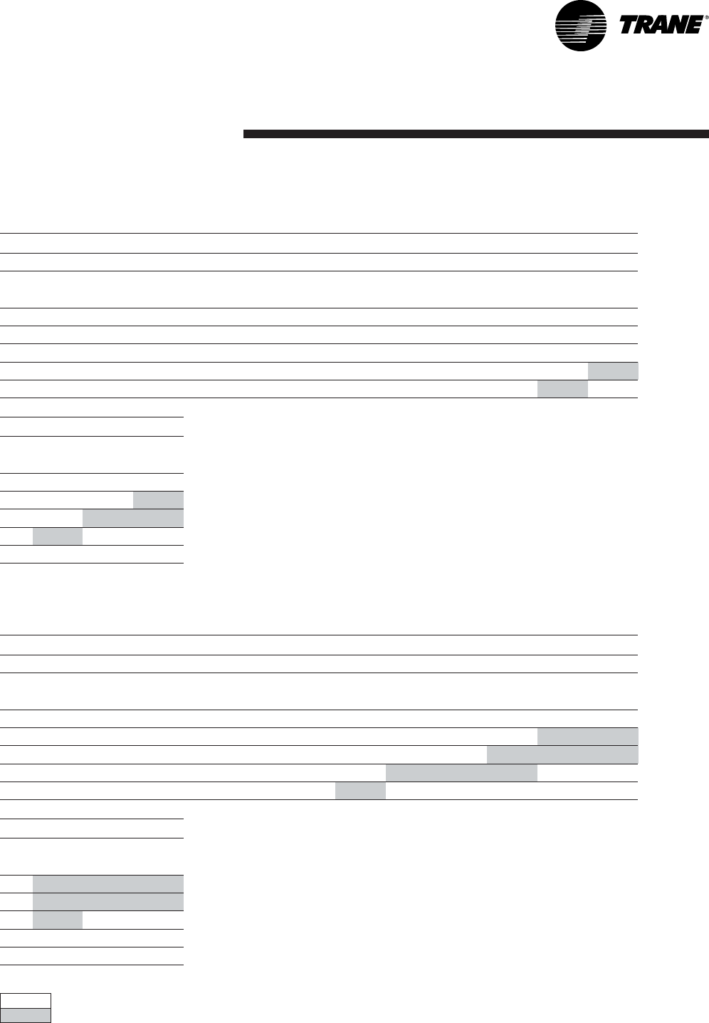
Table 36 - Unit wiring
Standard Supply Fan Motor Oversized Supply Fan Motor
Unit Model
and size
Main power
supply
(V/Ph/Hz)
Minimum Circuit
Ampacity
(A)
Maximum Overcurrent
Protective Device (Fuse
or Circuit Breaker)
(A)
Minimum circuit
ampacity
(A)
Maximum Overcurrent
Protective Device (Fuse
or Circuit Breaker)
(A)
Without Electric heat option
TSD/TSH 060 400/3/50 18,2 32 19,3 32
TSD/TSH 072 400/3/50 24,4 32 25,5 32
TSD/TSH 090 400/3/50 26,2 40 27,2 40
TSD/TSH 102 400/3/50 28,3 40 29,3 40
TSD/TSH 120 400/3/50 32,6 40 32,6 40
YSD/YSH 060 400/3/50 18,2 32 - -
YSD/YSH 072 400/3/50 24,4 32 25,5 32
YSD/YSH 090 400/3/50 26,2 40 27,2 40
YSD/YSH 102 400/3/50 28,3 40 29,3 40
YSD/YSH 120 400/3/50 32,6 40 32,6 40
WSD/WSH 060 400/3/50 20,1 32 21,2 32
WSD/WSH 072 400/3/50 23,1 32 24,2 32
WSD/WSH 090 400/3/50 26,2 40 27,2 40
With Electric heat
TSD/TSH 060 400/3/50 26,4 50 27,5 50
TSD/TSH 072 400/3/50 37,8 50 38,9 50
TSD/TSH 090 400/3/50 39,2 50 40,2 50
TSD/TSH 102 400/3/50 50,1 63 51,1 63
TSD/TSH 120 400/3/50 51,8 63 51,8 63
WSD/WSH 060 400/3/50 40,8 50 41,9 50
WSD/WSH 072 400/3/50 55,2 63 56,3 63
WSD/WSH 090 400/3/50 58,3 63 59,3 63
Installation
RT-SVX20A-E432
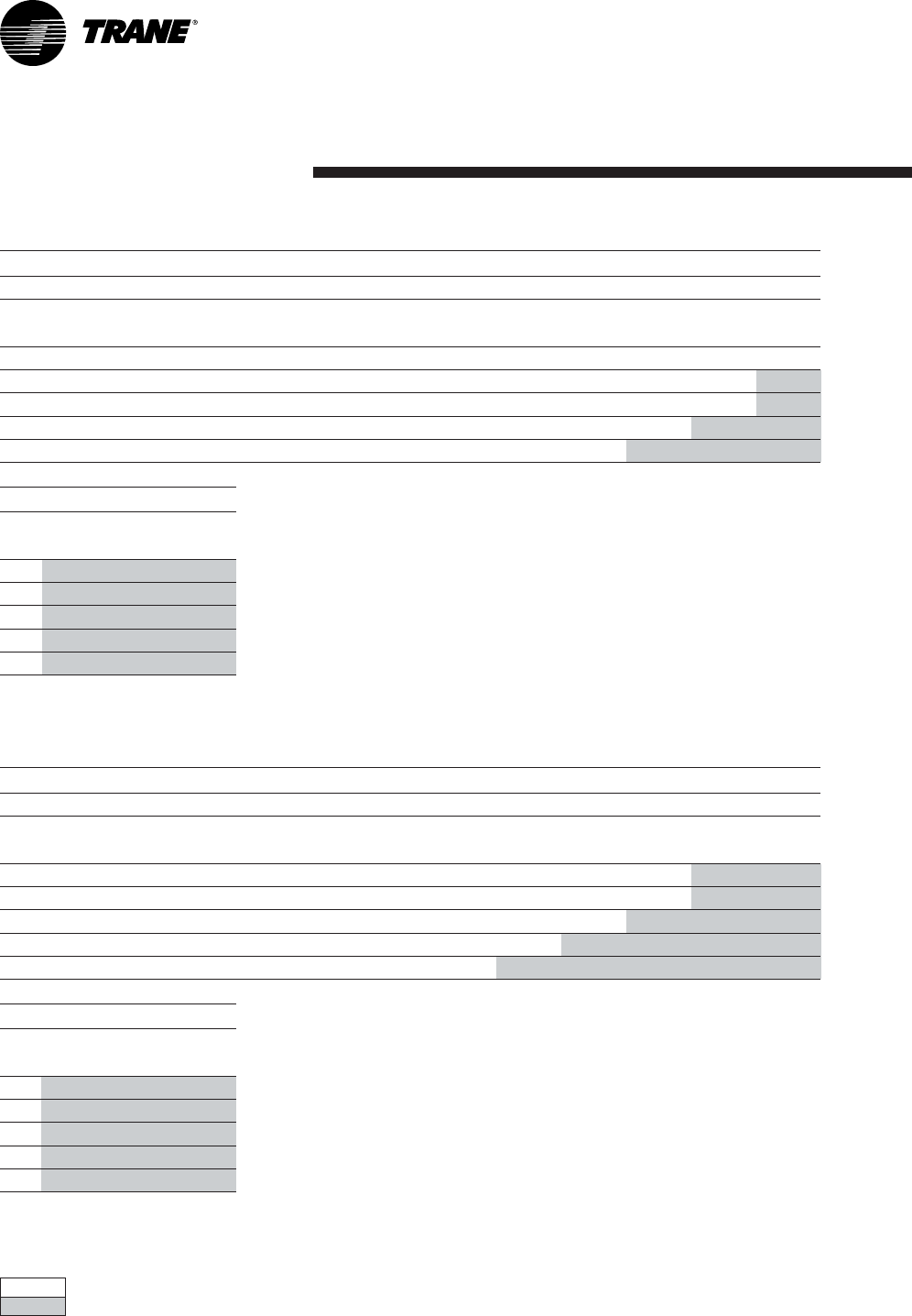
Table 37 - Compressor and condenser motors
Table 38 - Supply fan motor
Standard supply fan motor Oversized supply fan motor
Unit Model
and size
Number
of
motors
Main
power
supply
(V)
Number
of
phases
Motor
HP
(kW)
Rated
amps
(A)
Locked
rotor
amps
(A)
Number
of
motors
Main
power
supply
(V)
Number
of
phases
Motor
HP
(kW)
Rated
amps
(A)
Locked
rotor
amps
(A)
TSD/TSH 060 1 400 3 1,1 3,2 25,3 ------
TSD/TSH 072 1 400 3 1,1 3,2 25,3 1 400 3 1,5 4,3 36,4
TSD/TSH 090 1 400 3 1,5 4,3 36,4 1 400 3 2,2 5,3 57.0
TSD/TSH 102 1 400 3 1,5 4,3 36,4 1 400 3 2,2 5,3 57.0
TSD/TSH 120140032,25,357.0 ------
YSD/YSH 060140031,13,225,3 ------
YSD/YSH 072 1 400 3 1,1 3,2 25,3 1 400 3 1,5 4,3 36,4
YSD/YSH 090 1 400 3 1,5 4,3 36,4 1 400 3 2,2 5,3 57.0
YSD/YSH 102 1 400 3 1,5 4,3 36,4 1 400 3 2,2 5,3 57.0
YSD/YSH 120140032,25,357.0 ------
WSD/WSH 060140031,13,225,3 ------
WSD/WSH 072 1 400 3 1,1 3,2 25,3 1 400 3 1,5 4,3 36.4
WSD/WSH 090 1 400 3 1,5 4,3 36,4 1 400 3 2,2 5,3 57.0
Compressor motor Condensor fan motor
Unit Model
and size
Number
of
motors
Main
power
supply
(V)
Number
of
phases
Motor
HP
(kW)
Rated
amps
(A)
Locked
rotor
amps
(A)
Number
of
motors
Main
power
supply
(V)
Number
of
phases
Motor
HP
(kW)
Rated
amps
(A)
Locked
rotor
amps
(A)
TSD/TSH 060 1 400 3 4,2 10,3 74 1 400 1 0,3 1.0 2,8
TSD/TSH 072 1 400 3 5,6 13,7 95 1 400 1 0,56 3.0 7,1
TSD/TSH 090 1 400 3 6,2 14,3 100 1 400 1 0,56 3.0 7,1
TSD/TSH 102 2 400 3 4.5 / 2.8 10 / 7.5 74 / 48 2 400 1 0,56 3.0 7,1
TSD/TSH 120 2 400 3 4.5 / 3.5 10.7 / 9.2 74 / 62 2 400 1 0,56 3.0 7,1
YSD/YSH 060 1 400 3 4,2 10,3 74 1 400 1 0,3 1.0 2,8
YSD/YSH 072 1 400 3 5,6 13,7 95 1 400 1 0,56 3.0 7,1
YSD/YSH 090 1 400 3 6,2 14,3 100 1 400 1 0,56 3.0 7,1
YSD/YSH 102 2 400 3 4.5 / 2.8 10 / 7.5 74 / 48 2 400 1 0,56 3.0 7,1
YSD/YSH 120 2 400 3 4.5 / 3.5 10.7 / 9.2 74 / 62 2 400 1 0,56 3.0 7,1
WSD/WSH 060 1 400 3 4,5 11,8 74 1 400 1 0,3 1 2,8
WSD/WSH 072 1 400 3 5 12,6 101 1 400 1 0,56 3 7,1
WSD/WSH 090 1 400 3 6,2 14,3 100 1 400 1 0,56 3 7,1
Controls
33RT-SVX20A-E4
Control wiring
The control circuit is 24 V AC. Unit
includes a 400/24 V transformer.
WARNING!The unit disconnect
switch must be opened and locked
open. Risk of injury and
electrocution.
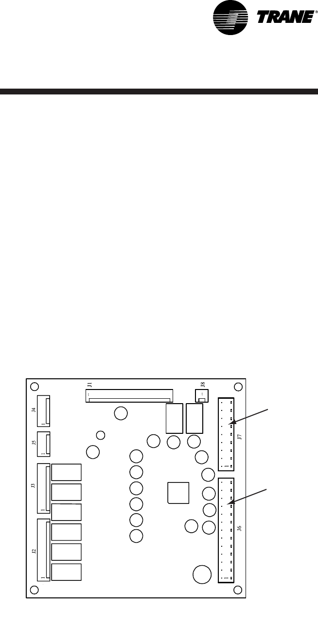
Figure 14 - Thermostat wiring
J7
J6
CAUTION!The unit 24 V transformer
must not be used to power
accessories mounted on site, other
than those proposed by Trane.
Unit controlled by thermostat
Controls
RT-SVX20A-E434
Trane THS01,THS02, THP01 and
THP02 Thermostats are directly
connected to RTRM board
(J7 connector).
Trane THS03 and THP03 thermostats
are directly connected to RTRM
board (J6 connector).
Install the electrical link between the
thermostat (thermostat terminal
strip) and the unit (J6 or
J7 connector) in compliance with
the interconnection diagram. The
low voltage wiring must not be laid
in the same pipes as the power
cables.
The sizes and lengths of the
thermostat connection wires are
given in Table 39. The total
resistance of these control cables
must not exceed 5 ohms. If the
resistance exceeds this value the
thermostat may not operate with
the same precision.
Table 39 - Zone sensor wire and
maximum length
Wire size
(mm²)
Maximum
wire lengh
(m)
0,33 45
0,5 76
0,75 115
1,3 185
2300
Unit controlled by BAS
Each unit must be equipped with a
TCI-R board. A communication bus
(twisted shielded pair) must link
each TCI-R to the Trane Roof Top
Manager (RTM) or to the
communication gateway (in the
case of an external BAS). Connect
one temperature sensor to each
unit. LonTalk®communication
interface LTCl-R board allows ICS
communication between a
ReliaTel™ unit and LonTalk®
communication applications.
Unit controlled by Tracker™
supervisor
The units must also be equipped
with the TCI-R communication
board. One remote sensor is
required on each unit for a constant
flow volume. In the case of a
variable flow installation
(VariTrac™) these sensors must not
be installed. A twisted shielded pair
must be used for the
communication link. The main
functions of the Tracker™ supervisor
are control of setpoints, timetable
management (Programming) and
display of faults. For more details
refer to the supervisor
documentation.

Controls
35RT-SVX20A-E4
The CO2sensor is designed to
operate with a nominal 24 Vac
supply. The power supply should
maintain the voltage between 20 to
26 Vac.
Table 41 - CO
2
sensor wire size
Wire size
(mm²)
Maximum
wire lengh
(m)
0,25 50
0,5 100
1200
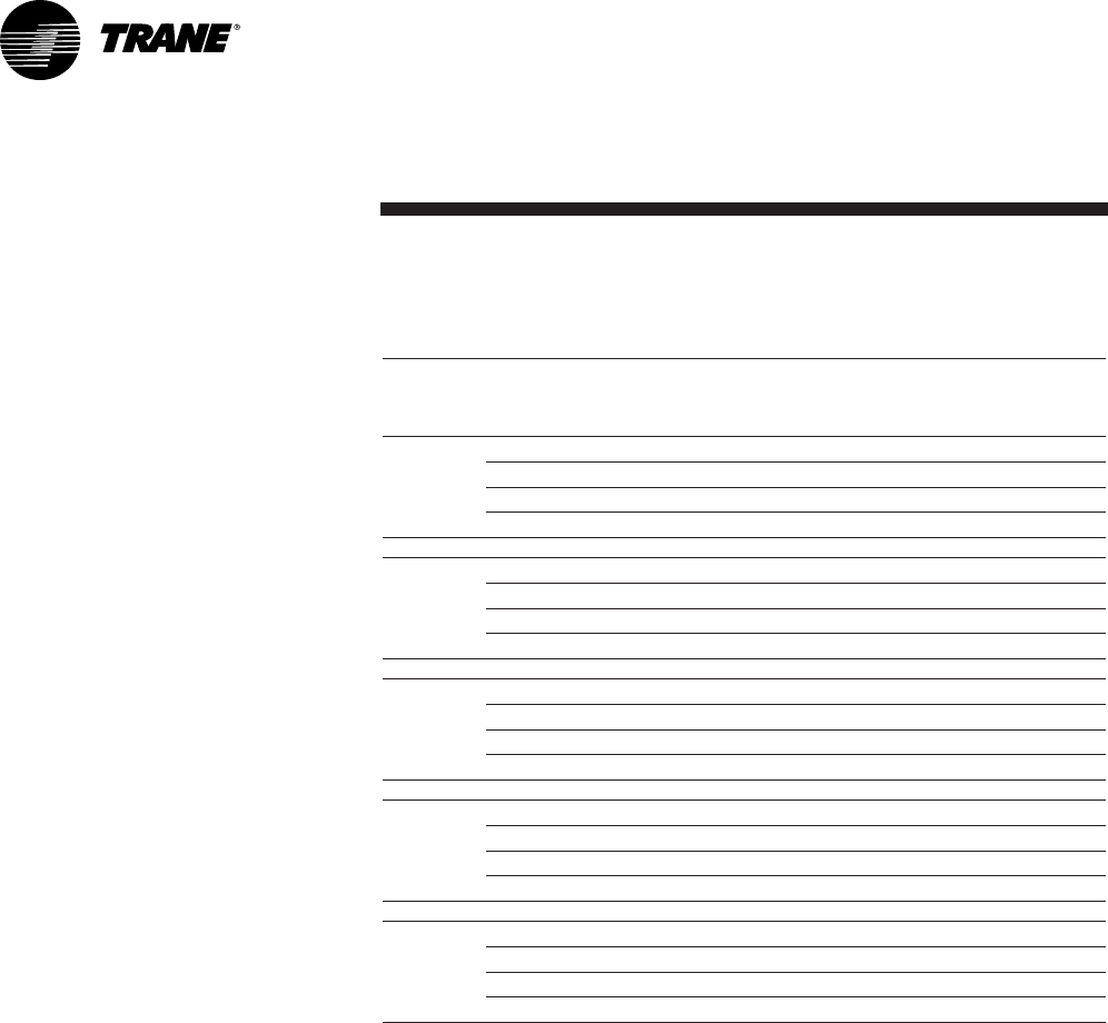
Table 40 - Specifications
Wall-mounted Duct-mounted
Measuring range CO20-2000 ppm
Accuracy at 25°C
< +/- [40 ppm CO2+ 3% of
reading]
(included repeatability and
calibration uncertainty)
< +/- [30 ppm CO2+ 2% of
reading]
(included repeatability and
calibration uncertainty)
Non-linearity < 1.0% full scale
Temperature dependence of output 0.3% full scale/°C
Long-term stability < 5.0% full scale/ 5 years
Recommended calibration interval 5 years
Response time 1 minute (0-63%)
Operating temperature 15-35°C -5-45°C
Storage temperature -20-70°C
Humidity range 0-85% relative humidity
Airflow range 0-10 m/s)
Output signals (jumper selectable) 0-10 Vdc
Resolution of analog outputs 10 ppm CO2
Recommended external load Current output: max 500
Voltage output: min. 1000
Power supply Nominal 24 Vac
Power consumption < 5 VA
Warm-up time < 15 minutes
Dimensions (mm) 108 x 80 x 36 80 x 80 x 200
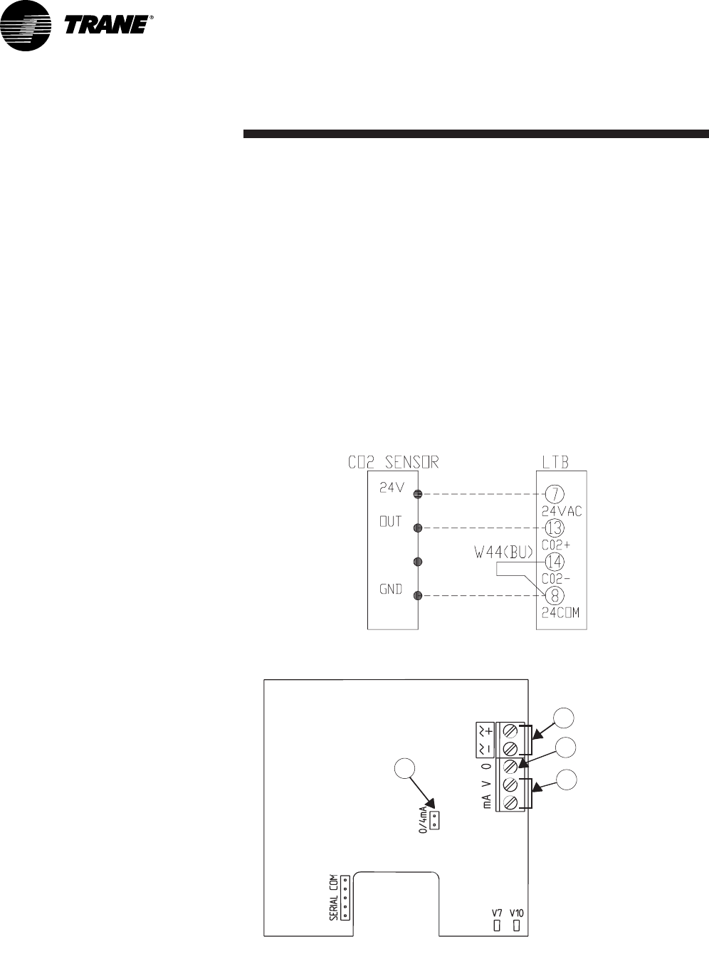
CO2sensors
Wall-mounted and duct-mounted
CO2sensors
Power supply requirements
CAUTION! Make sure that you
connect the power wire only to the
24V terminal. Connecting the power
wire to the output terminal may
result in equipment damage.
Controls
RT-SVX20A-E436
Wiring the wall-mounted CO2
sensor
DVC setpoint potentiometer on
economizer module can be adjusted
as follows:
0% - 500ppm, 50% - 1000 ppm,
100% - 1500ppm
The outside air damper will
modulate from minimum position
setting to up to 100% while
attempting to maintain the CO2
setpoint.
Wiring the duct-mounted CO2
sensor
1. Connect the common wire from
the controller to the ground
terminal (terminal 0) (Figure 16).
2. For voltage output, connect the
signal wire to terminal V.
3. Connect the power according to
the guidelines in Power supply
requirements.
Figure 15 - Wall-mounted CO
2
sensor wiring
Figure 16 - Terminal connections and LED locations
1 = Outer jumper
2 = Power terminal
3 = Ground terminal
4 = Output terminals
1
2
3
4
Controls
37RT-SVX20A-E4
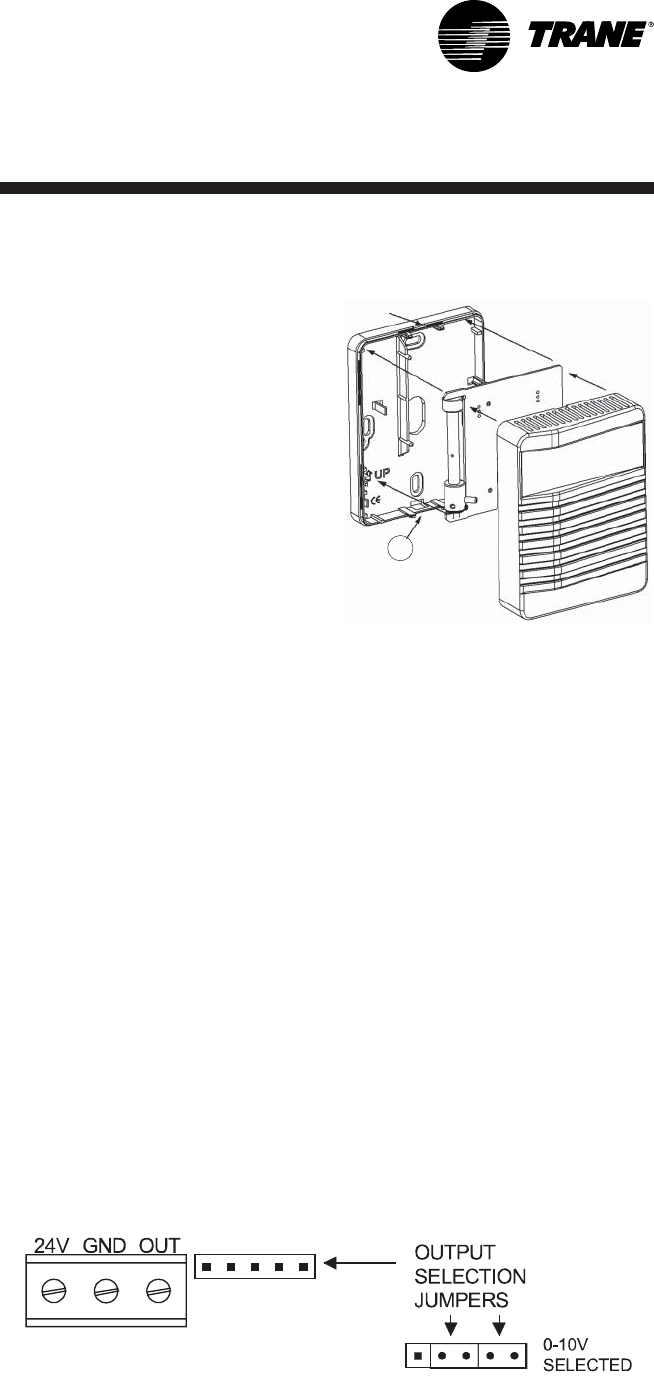
Mounting the wall-mounted sensor
1. Select a proper location in the
room to mount the CO2sensor.
Look for an interior wall with
good air circulation,
approximately 1.4 m from the
floor.
2. Remove the back plate from the
sensor and thread the power
wires and output signal wire
through the hole in the back
plate (Figure 17).
For surface wiring, make cut-
outs with pliers to the thinner
section of the upper or lower
edge of the back plate and to
thread the wires through.
3. Mount the back plate to the wall
with screws. Note that the arrow
on the back plate shows the
mounting direction.
4. On the circuit board, use the two
jumpers next to the terminal
block to set up the type of output
(0-10 Vdc) (Figure 18).
5. Insert the circuit board in the
back plate. (Figure 18.) Do not
press the metal tube while
inserting the circuit board.
6. Connect the power and signal
wires to the screw terminals of
the circuit board. Figure 16
shows the terminal locations.
Figure 17 - Wall-mounted CO
2
sensor
1 = Thinner section for cut-out
1
Figure 18 - Jumper settings
Controls
RT-SVX20A-E438
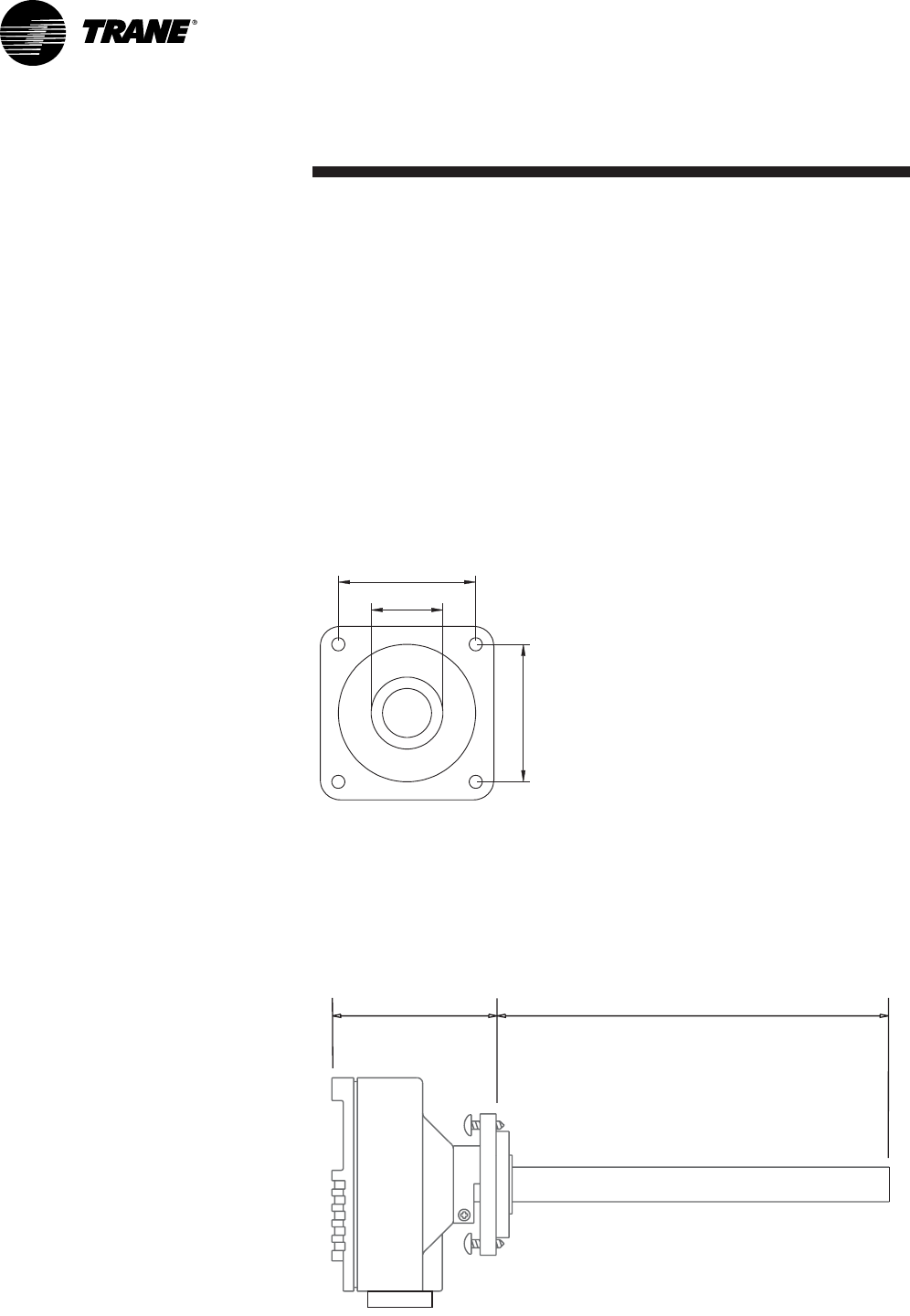
Mounting the duct-mounted CO2
sensor
1. Select a proper location on the
duct to mount the CO2sensor.
2. Drill a 22-25 mm hole in the
mounting surface for sensor
insertion (Figure 19).
3. Attach the mounting plate to the
duct wall with four screws.
4. Insert the sensor through the
mounting plate, adjusting the
depth for optimal air sensing.
Figure 19 - Duct-mounted CO
2
sensor
diameter
15/8 in. (42 mm)
7/8 in. (22 mm)
15/8 in.
(42 mm)
CO2sensor maintenance
This CO2sensor has excellent This
CO2sensor has excellent stability
and requires no maintenance. In
most environments the
recommended calibration interval is
five years. A trained service
technician can use a portable CO2
meter to certify sensor calibration.
If, when checking the sensor, the
reading differs too much from the
reference value, the sensor can be
recalibrated in the field. A
calibration kit, software, and
calibration gases are required. If
certified accuracy is required, the
sensor must be calibrated against
accurate and traceable calibration
gases in a laboratory. Consult Trane
BAS for further details.
Figure 20 - Duct-mounted CO
2
sensor insertion depth
21/2 in. (64 mm) 31/8 -5
1/2 in. (80 - 140 mm)
Controls
39RT-SVX20A-E4
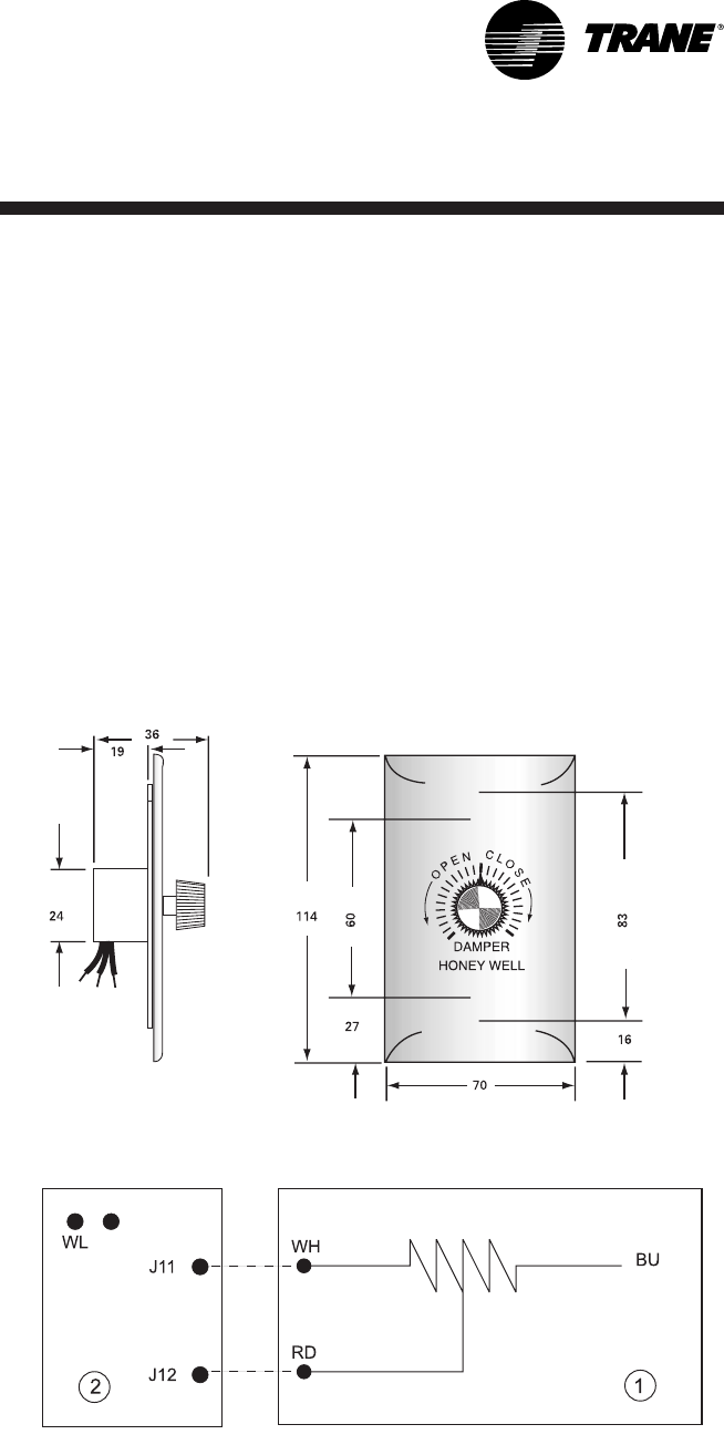
Remote potentiometer
To install the remote potentiometer,
cut the jumper WL on the
economizer ECA board, and connect
the wires to J11 and J12.
Note:This potentiometer allows to
adjust the permanent fresh air
intake from 0 to 50%.
0 W corresponds to closed fresh air
damper.
270 W corresponds to 50% open
fresh air damper.
Figure 21 - Remote potentiometer dimensions
Figure 22 - Remote potentiometer wiring
1 = Remote potentiometer
2 = ECA Board
WH = White wire
RD = Red Wire
BU = Blue wire
_____ Factory wiring
------- Field wiring
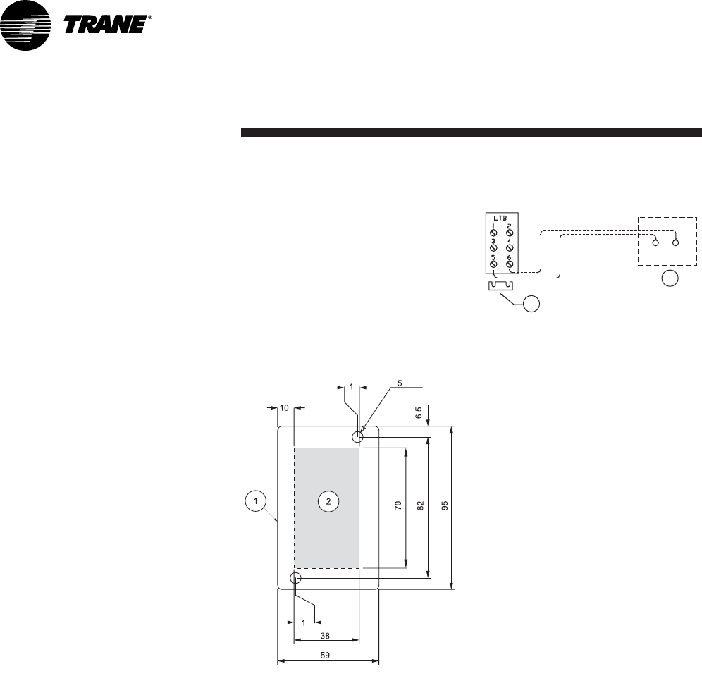
Controls
RT-SVX20A-E440
Fire thermostat
There are two sensors in the fire
thermostat Kit: Sensor X13100040-
01 is factory-set to open at 57°C,
Sensor X13100040-02 is set to open
at 115°C.
Sensors are mounted directly in the
ductwork. They should be installed
where elements can respond
quickly to air temperature changes.
If not possible, the sensor may be
installed on a suitable bracket so
the air is drawn across the element.
Sensor X13100040-01 has to be
mounted in the return air duct.
Sensor X13100040-02 has to be
mounted in the supply air duct.
Note: Do not permit element guard
to touch internal parts. Do not
locate sensor where the air
circulation is restricted by baffles.
At the selected location, cut a hole
to clear element guard and drill
holes for mounting screws
according to Figure 23. Connect
wires according to Figure 24.
Figure 23 - Duct mounting of fire
thermostat
1 = Fire thermostat
2 = Hole in the duct
Figure 24 - Connection of fire thermostat
with TCI board
1 = Field-supplied emergency stop
device
2 = Remove factory-supplied jumper
1
2
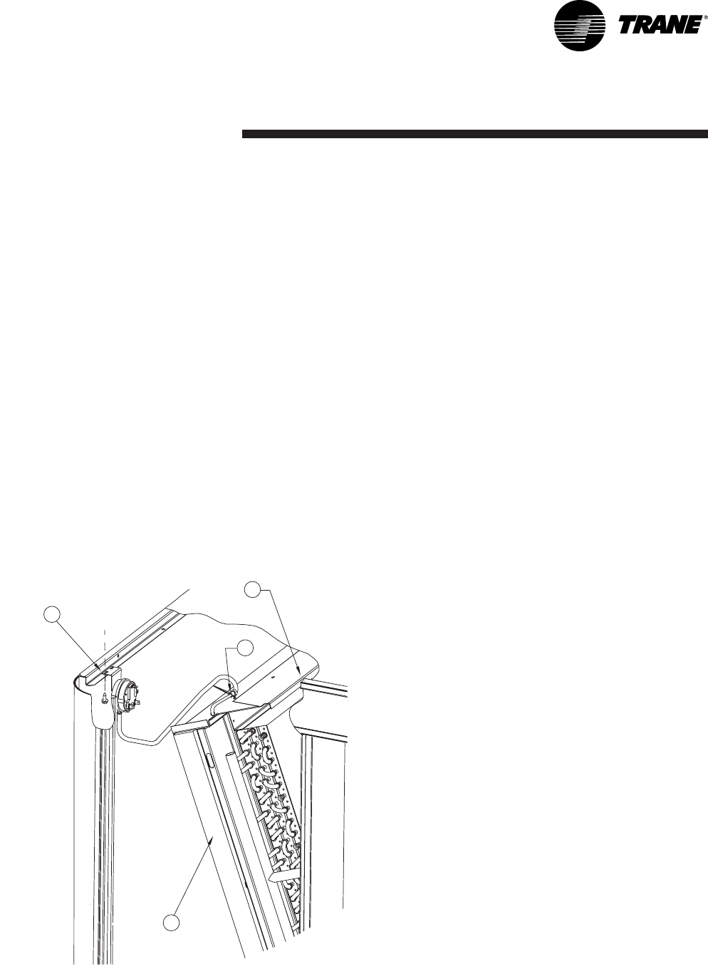
Controls
41RT-SVX20A-E4
Clogged filter detector
This device is mounted in the
indoor fan section. The sensor
measures the difference in pressure
before and after the filter section.
The information is sent to the THP03
thermostat, to a Tracker™ or to a
BMS. The setting range is 40 to
300 Pa.
Figure 25- Clogged filter sensor
1 = Secure with one screw
2 = Route wire harness between coil blockoff and roof rib
3 = Secure with pop-in wire tie
4 = Remove filter if necessary
1
2
3
4
Smoke detector
This device is used to detect smoke
in the air stream. It includes a
factory mounted detector connected
to a central panel, both fitted in the
fan section.
When smoke is detected, it shuts off
the unit. A dry contact is available
on the control panel for a remote
default.
High temperature safety
thermostat
This additional safety device is a
manual reset thermostat for gas
fired units (YKD/YKH), required
mainly by the French ERP
regulation. It is located in the gas
burner section. It stops the gas
burner and the supply air fan when
the supply air temperature rises to
120°C.
Remote fault relay
This is a factory mounted relay used
to send alarm signals (dry contact)
to a local BMS or a local control
panel. With this relay, the
compressor, heating, fan and power
supply alarm output signals from
the controller are reported to a
single dry contact.

Controls
RT-SVX20A-E442
Thermostats
6 thermostats are available:
THS01/THP01, THS02/THP02 and
THS03/THP03.
"THS" are non programmable
thermostats, "THP" are
programmable.
01 and 02 series are conventional
thermostat, 03 series are dedicated
to the controller.
Table 42 - Thermostat features
Note: thermostats are powered up by the rooftop control (24V)
THS01 THP01 THS02 THP02 THS03 THP03
non-programmable X -X -X -
programmable -X -X -X
electronic X X X X X X
unit control type design electromech. electromech. electromech. electromech. Reliatel Reliatel
interface card needed - - - - - -
for Cooling Only units X X - - X X
for Heat Pump units - - X X X X
for Gas Fired units X X - - X X
Cooling stages 2 2 2 2 2 2
auxiliary heating stages
(elec. heater, HWC ) 2 2 1 1 2 2
heating stages
(heat pump mode) none none 1 1 1 1
liquid crystal display X X X X -X

Controls
43RT-SVX20A-E4
Other accessories available
Remote temperature sensor to be
used with THS/THP 01-02.
TZS01: Remote room temperature
sensor to be used with THS/THP 03,
Tracker or Varitrac systems.
DTS: Duct temperature sensor to be
used with THS/THP 03.
TZS02: Remote room temperature
sensor with adjustable thumwheel
setpoint to be used with Tracker or
Varitrac systems.
TZS04: Room temperature sensor
with adjustable thumbwheel and
override button, to be used with
Tracker or Varitrac systems.
Refer to separate documentation for
more information.
Communication Interfaces
TRANE Communication Interface
(TCI-R) board
This is an electronic board, factory-
mounted in the main control panel,
needed to allow communication
between a TRANE Integrated
Comfort system (TRACKER or
Varitrac CCP2) and the unit. (COM3-
COM4)
LON Communication Interface
(LCI-R) board
This is an electronic board, factory-
mounted in the main control panel,
needed to allow communication on
a LonTalk®Network at the unit level.
LonTalk®Communication Interface
(LCI-R) board allows Voyager units
to communicate on a LonTalk®
Network at the unit level. Network
variables are based on the
LonMark®. Space Comfort Controller
Functional Profile Template. The
LCIV uses a Free Topology
transceiver FTT-10A. The FTT-10A
transceiver supports non-polarity
sensitive, free topology wiring,
allowing the system installer to use
star, bus, and loop architecture. The
LCI-V can also be connected to an
optional High Temperature Limit
Switch if installed with the rooftop
unit. For more information, see
attached manual LTCI-IN-1.
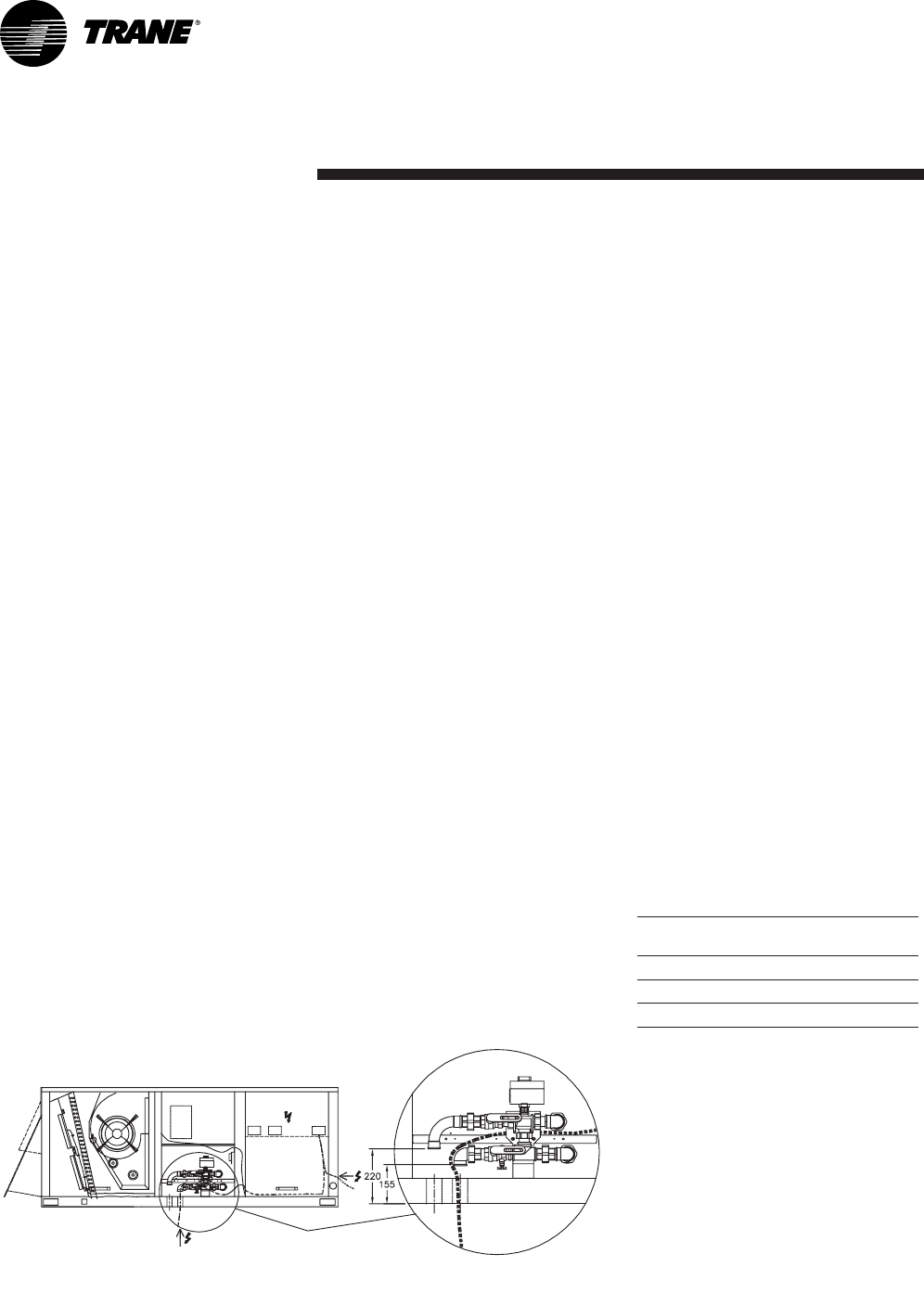
Unit Options
RT-SVX20A-E444
Hot water coil
(Down flow units only)
In order to prevent water to freeze
up in the coil during unoccupied
period or shutdown limited period,
a thermostat opens when there is a
risk of freeze-up. The services of a
water treatment specialist are
recommended if water used can
cause scaling deposits or erosion.
Insulate all the water piping likely to
be exposed to freezing
temperatures in order to avoid
freeze up of the coil and heat
losses. The water distribution
network must be fitted with vents in
places where air is likely to be
trapped.
The hot water coil is factory
mounted in the discharge section.
Two holes are provided to connect
the hot water coil. They are located
at the base of the unit. Remove the
central panel to access the coil,
using an 8 mm wrench (the bolts
are located on the bottom part of
the panels). The tubes for entering
and leaving water are equipped
with a threaded female connector.
Water connection inlet/outlet:
1 ¼" ISO R7.
Installation and connection
In order to prevent water to freeze
up in the coil during unoccupied
period or shutdown limited period,
it is recommended to use ethylene
glycol. The services of a water
treatment specialist are
recommended if water used can
cause scaling deposits or erosion.
Insulate all the water piping likely to
be exposed to freezing
temperatures in order to avoid
freeze up of the coil and heat
losses. The water distribution
network must be fitted with vents in
places where air is likely to be
trapped.
Table 43 - Ethylene glycol percentage
Ethylene glycol
percentage Freezing point
(%) (°C)
10 -4
20 -10
Figure 26 - Hot water coil connections
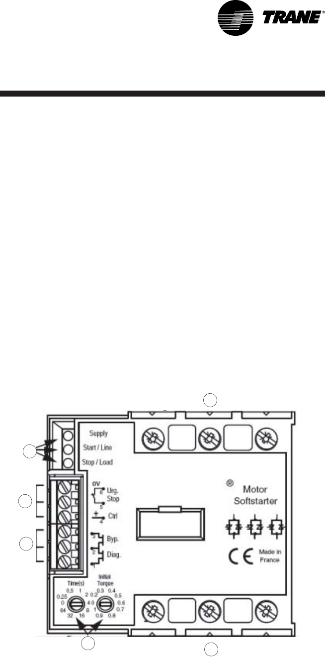
Unit Options
45RT-SVX20A-E4
Electric Heater
Electric heaters are fitted on the fan
discharge.
Heaters have two heating stages
and provided with two types of
overheat thermostats:
• Automatic reset thermostats
which stop the electric heater
when the air temperature rises to
76°C. Automatic reset at 60°C. No
alarm output available.
• The manual reset thermostat
which stop the unit when the air
temperature rises to 120°C. No
alarm output available.
Soft Starter
The soft starter is used to achieve a
progressive supply fan start and a
reduced starting current as well as
the motor starting torque. This
option is well adapted for textile
duct applications. It is factory
installed in the main control panel.
The soft starter gradually increases
the voltage of the supply fan motor
until it reaches full line voltage.
The starting time can be adjusted
from 0 to 40 seconds but the soft
starter is factory set to the
maximum starting time value,
40 seconds.
Figure 27 - Soft starter
1 = Three phase mains connections
2 = Motor connections
3 = Settings
4 = Status outputs
5 = Controls
6 = LEDs
1
2
3
4
5
6
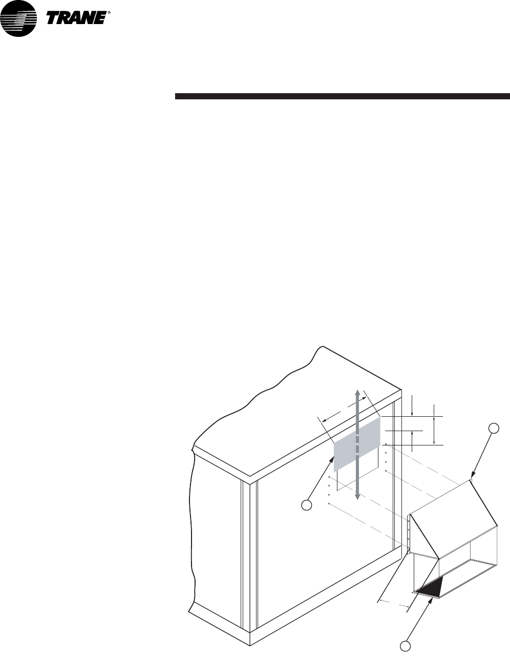
Unit Options
RT-SVX20A-E446
0 - 25% fresh air hood
The 0-25% fresh air hood allows to
introduce fresh air into the unit.
This is a manual device fitted on the
back of the unit, sized for a
maximum of 25% of the nominal
rooftop air flow.
This option includes for the hood
itself, a wire mesh and a slidable
damper.
The slidable damper has to be
adjusted manually by removing the
screws and sliding it off up or down
(Figure 28).
The amount of fresh air introduced
is then permanently fixed.
Figure 28 - 0-25% manual fresh air hood
1 = Intake hood
2 = Wire mesh
3 = Slidable damper
210
585
H
485
1
2
3
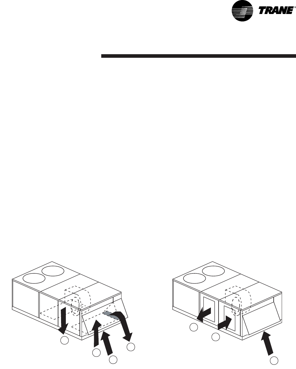
Unit Options
47RT-SVX20A-E4
Barometric relief
The barometric relief allows to
minimize overpressure in the
building caused by the introduction
of fresh air. This option is typically
installed when fresh air intake is
below 25% of the nominal air flow
and when the return air pressure
drop is below 25Pa.
This option includes exhaust hoods
and gravity dampers located in the
return air section. When the
pressure of the building increase,
the gravity dampers open and
relieve air to the outside.
If the return air duct pressure drop
is higher than the building
overpressure, the gravity dampers
will not open.
If the return air duct pressure drop
is lower than the building
overpressure, the gravity dampers
will open and relieve air outside of
the building.
Figure 29 - Economizer flow chart with barometric relief
Downflow version Horizontal flow version
R = return
S = supply
F = fresh air
E = exhaust
S
R
F
E
S
F
R
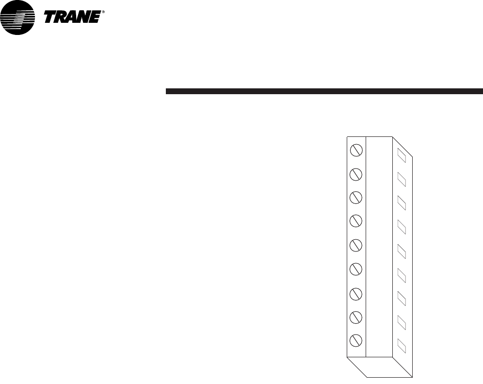
Operation
RT-SVX20A-E448
Operation with a
conventional thermostat
The ReliaTel module has
conventional thermostat
connections as well as Zone Sensor
Module connections. When a
conventional thermostat is
controlling the unit, operation
differs as follows:
• Supply Air Tempering feature is
not available. If outdoor air is
being introduced through the
equipment, discharge air
temperature may be cold when
not actively heating.
• Proportional Integral (PI) control
is not available.
• Zone Sensor Diagnostics are
only available on the RTRM
module on the J6 terminals,
instead of at the Zone Sensor in
the space.
• Intelligent Fall-Back is not
available. If a failure occurs in
the device controlling the
equipment, operation will cease.
• Heat Pump Smart Recovery and
Smart Staging is not available.
Heat Pump operation becomes
more costly unless the generic
control being applied can
accomplish this.
• Remote Sensing Capabilities are
not available on most
mechanical thermostats.
• Space Temperature Averaging
capabilities are not available on
most mechanical thermostats.
• 27½ to 50 VAV - Conventional
thermostat input terminals are
inactive.
• Built in Night Set Back and
Unoccupied Functions function
differently with a conventional
mechanical thermostat.
• A built-in algorithm which allows
for automatic reset of the
discharge air temperature while
economizing is not available.
The terminal strip for attaching the
thermostat wires is located on the
RTRM module in the control
compartment.
When the unit is operating from a
conventional thermostat or other
binary input, the economizer
setpoint feature, relative to the
cooling and heating setpoints, is
lost. The economizer control is
based strictly on a signal from the
thermostat, but still maintains
mixed air temperature control of
53°±3°F when in the economizer
mode. The economizer enable and
disable function is still determined
by the outside air sensor through
the RTRM.
If a single-stage thermostat is used,
only the economizer (if enabled) or
the compressor (if economizer is
disabled) will operate on a call for
cooling. A twostage thermostat is
required to achieve economizer
operation and compressor
operation at the same time.
With economizer enabled, a Y1 call
for 1st stage cooling will be the
economizer. The damper will
modulate between minimum
position and 100% to maintain
mixed air temperature at 53°±3°. At
50°F the damper will be at
minimum position. If the
economizer is enabled, a Y2 call for
2nd stage cooling will start the first
compressor if required. If the
economizer is disabled, 1st stage
(Y1) will be the first compressor. If
the unit has two compressors, a call
for 2nd stage cooling (Y2) will start
the second compressor. When using
a conventional thermostat, or other
binary input, the ReliaTel controls
will only allow two stages of
cooling.
Figure 30 - Terminal strip
Customers occasionally require
operation with a conventional
thermostat rather than a zone
sensor. In some cases there is a
preference for a specific thermostat
model, and in others there is
reluctance to adopt newer
technology that may not be as well
understood as conventional
thermostats. In addition, non-Trane
Building Controllers typically
provide an interface to HVAC
equipment based on a conventional
thermostat interface. Units applied
with this type of controller need to
accept conventional thermostat
inputs.
COM
T
R
Y1
W1/0
G
W2
X2
Y2
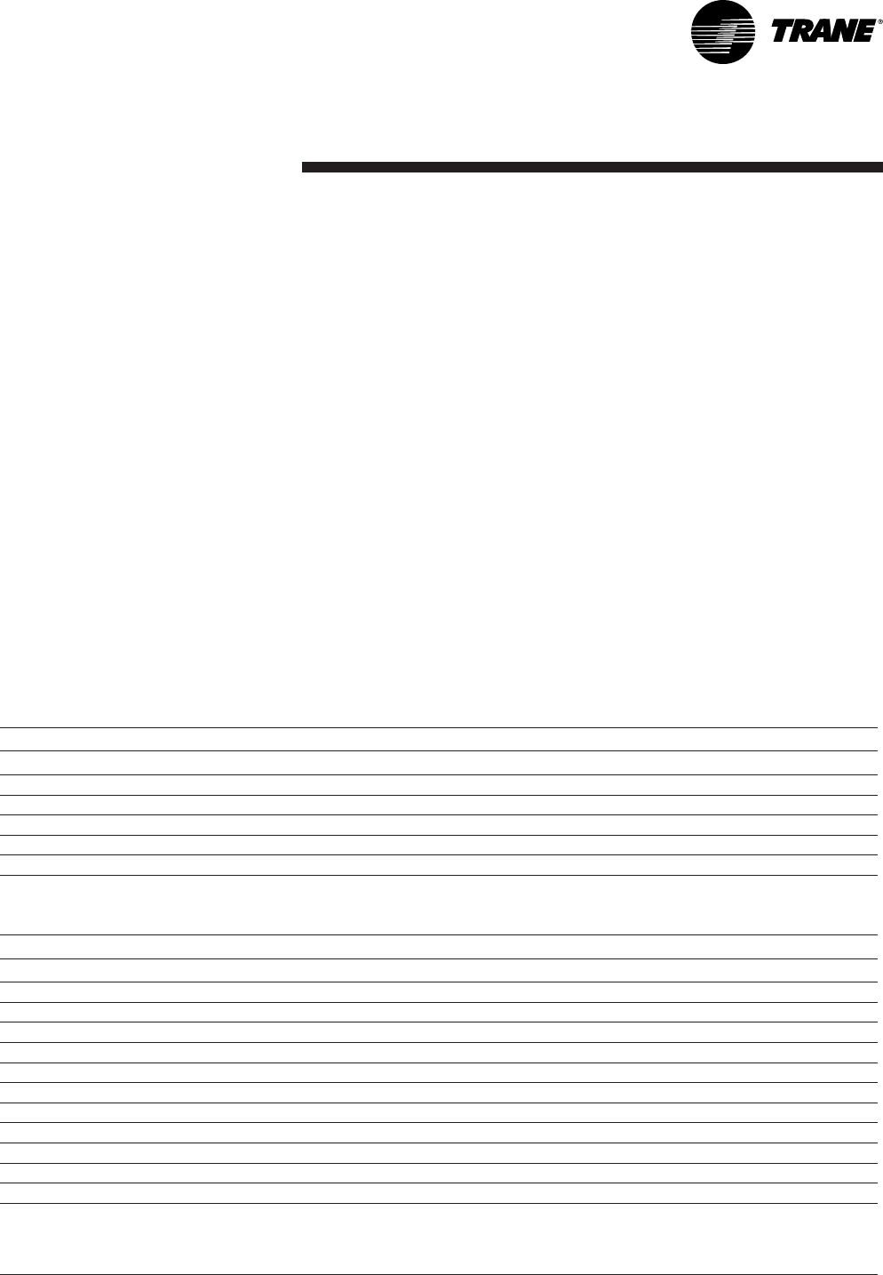
Operation
49RT-SVX20A-E4
Logic is also provided to cause
appropriate unit functions when
inappropriate thermostat signals are
provided. Simultaneous calls for
heating and cooling will be ignored,
and the fan will be turned on with a
call for heating or cooling even if
the fan request is not detected.
If the thermostat is immediately
changed from a heating to a cooling
call, or vice versa, there will be a
five minute delay before the new
call will initiate.
Thermostat signals are as follows:
R 24VAC power to thermostat
Y1 Call for compressor 1 or first
stage cooling
Y2 Call for compressor 2 or 2nd
stage cooling
G Call for supply fan
W1 Call for heat 1
W2 Call for heat 2
Heat pump only:
X2 Call for emergency heat
O Switchover valve On = cooling,
Off = heating
T Bias for heat anticipation for those
mechanical thermostats that use
this function
Table 44
Table 45
Conventional thermostat Heat pump
Input / connection Function when energized
Cooling mode
G(fan) Fan runs continuously except during unoccupied mode (see next page)
O(reversing valve during cooling) Reversing valve in cool mode
Y1 + O (first cooling stage) Compressor #1 runs or economizer operates
Y1 + Y2 + O (2nd cooling stage) Compressor #2 also runs, or #1 compressor runs while economizing
Heating mode
G(fan) Fan runs continuously except during unoccupied mode (see next page)
Y1 (both compressors 1st heating stage) Both compressors run
Y2 (during heating nothing happens) No change
W2 (electric heat 2nd stage) 2nd stage (electric) heat
X2 (electric heat only) Electric heat only - no compressors
T(provides heat anticipation signal for those mechanical
thermostats that use this feature.
If the thermostat used does not have a "T" terminal, disregard
this terminal.)
Conventional thermostat Gas / Electric, Electric Heat
Input / connection Function when energized
G(fan) Fan runs continuously except during unoccupied mode (see next page)
Y1 (compressor 1 or economizer) Compressor #1 runs or economizer operates
Y2 (compressor 2 or compressor 1 while economizing) Compressor #2 also runs, or #1 compressor runs while economizing
W1 (gas / electric heat first stage) 1st stage heat
W2 (gas / electric heat 2nd stage) 2nd stage heat (if available)
Conventional thermostat signals
represent direct calls for unit
functions. In their simplest
applications, thermostat contacts
directly control contactors or other
load switching devices. This function
provides inputs for the thermostat
signals and processing to enhance
reliability and performance.
Compressor protection and
reliability enhancement functions
(HPC, LPC, Minimum On/Off timers,
etc.). All operate the same whether
applied with zone sensors or a
conventional thermostat.
Operation
RT-SVX20A-E450
Unoccupied mode
If the thermostat being used is
programmable, it will have its own
strategy for unoccupied mode and
will control the unit directly. If a
mechanical thermostat is being
used, a field applied time clock with
relay contacts connected to J6-11
and J6-12 can initiate an
unoccupied mode as follows:
• Contacts open: Normal occupied
operation.
• Contacts closed: Unoccupied
operation as follows - Fan in
auto mode regardless of fan
switch position. Economizer
closes except while economizing
regardless of minimum position
setting.
Cooling/Economizer Operation
If unit does not have an economizer,
the Cool/Econ Stage 1 and Stage 2
will call directly for mechanical
cooling (compressor) stages. If the
unit has an economizer, the
Cool/Econ stages will function as
shown in Table 46.
Table 46 - Cooling/Economizer Operation with Thermostat
Notes:
40 to 50 ton CV only
This unit has 3 stages of cooling if using a zone sensor. If using a conventional thermostat it has 2 stages as
follows:
Y1 = 1st stage
Y1 + Y2 = 3rd stage
VAV
Thermostat inputs are ignored on VAV units.
OK to
Economize?
Thermostat
Y1
Thermostat
Y2
Call for Economizer
Cooling
Compressor Staging
Request
No On Off Inactive Compressor Output 1
No Off On Inactive Compressor Output 2
No On On Inactive Compressor
Outputs 1 & 2
Yes On Off Active Off
Yes Off On Active Compressor off
Yes On On Active Compessor
Setting the economizer or
0-50% motorized hood
(option)
The ECA board is mounted on the
damper actuator. To access the ECA
board on economizers:
• Remove the filter access panel of
the unit.
• The electrical power must be
disconnected to set the
minimum position and check the
economizer.
• Disconnect the power supply,
put the thermostat fan selector
to "ON" and the "HEAT/COOL"
selector to "OFF". This puts the
damper in the minimum
ventilation position.
• To set the required minimum
ventilation air position, turn the
dial on the ECA clockwise to
increase ventilation, or anti-
clockwise to decrease ventilation.
The damper will open at this
setting whenever the fan circuit
is powered up (see Figure 25).
• When the arrow on the dial's
adjustment screw is pointing to
8 o'clock, the minimum position
is roughly 0%. When the dial is
pointing to 12 o'clock it is
roughly 25%, and when the dial
is pointing to 4 o'clock it is
roughly 50% (see figure 25).
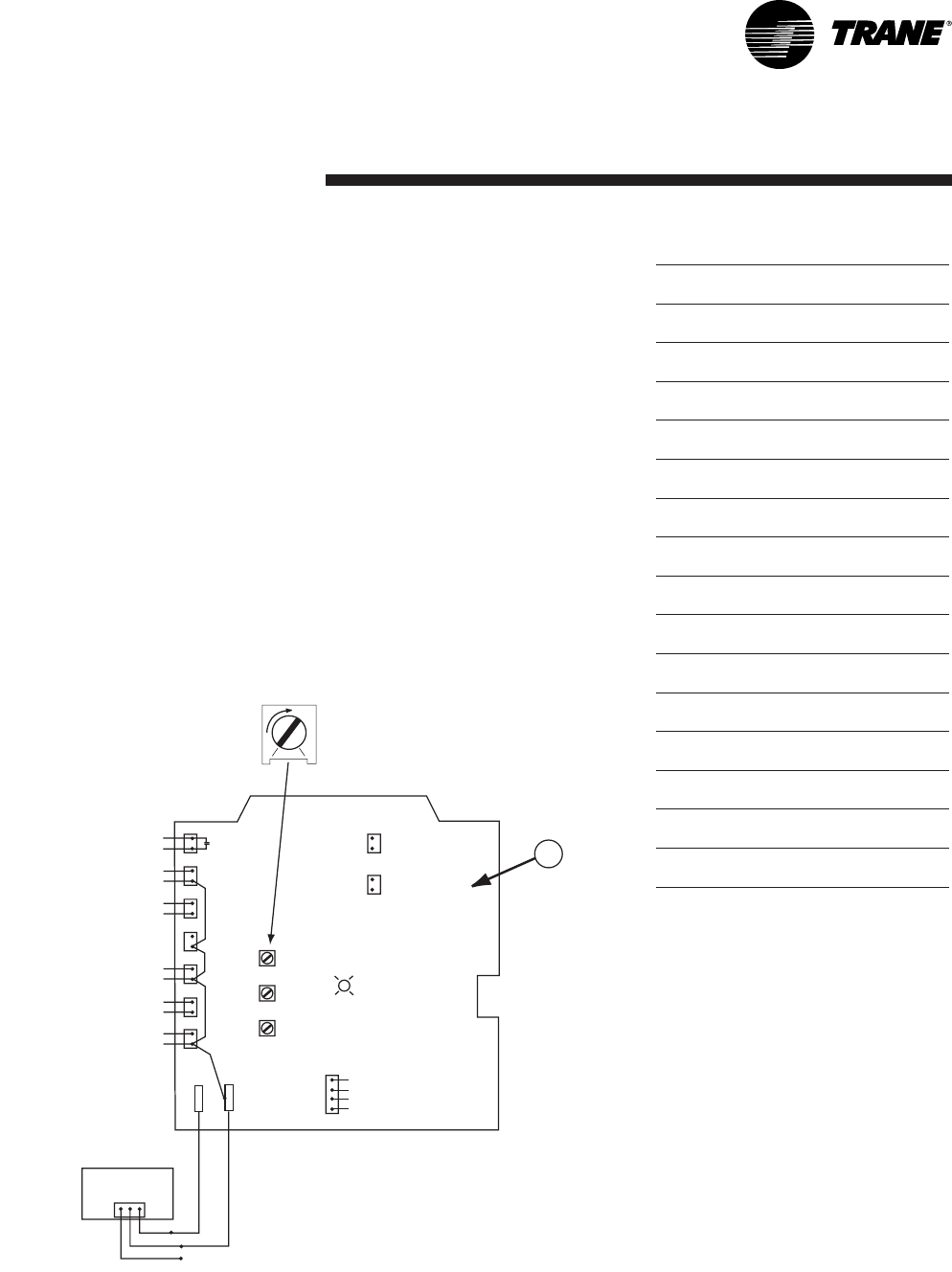
Operation
51RT-SVX20A-E4
To check the damper is functioning
correctly, the ECA is equipped with
an indicator light in the middle of
the board. This light operates as in
Table 42.
Table 47 - ECA board LED
While setting the minimum position
the damper may move towards the
new setting in several small steps.
Once the damper has remained in
the same position for 10 to 15
seconds it can be assumed it is in
the new position.
OFF: No Power or Failure
ON: Normal, OK to Economize
Slow Flash: Normal, Not OK to
Economize
Fast Flash: Communications Failure
Pulse Flash: Error Code
1 Flash: Actuator Fault
2 Flashes: CO2Sensor
3 Flashes: RA Humidity Sensor
4 Flashes: RA Temp Sensor
5 Flashes: OA Quality Sensor
6 Flashes: OA Humidity Sensor
7 Flashes: OA Temp Sensor
8 Flashes: MA Temp Sensor
9 Flashes: RAM Fault
10 Flashes: ROM Fault
11 Flashes: EEPROM Fault
Figure 31 - Minimum fresh air adjustment
1 = ECA board
1234
1
1
2
1
1
2
1
1
2
1
1
2
1
1
2
1
1
2
1
1
2
EXF
EXF
MAT
MAT
OAH/
OAH/
OAE
OAE
OAT
OAT
RAT
RAT
RAH/
RAH/
RAE
RAE
DCV
DCV
2-10 VDC
2-10 VDC
FEEDBACK
FEEDBACK
INPUT
INPUT
+
+
-
+
+
-
2-10 VDC
2-10 VDC
CONTROL
CONTROL
OUTPUT
OUTPUT
MIN POS.
MIN POS.
SETPOINT
SETPOINT
0-50%
0-50%
ABCD
ABCD
SETTINGS
SETTINGS
CO2 "PURGE"
CO2 "PURGE"
SETPOINT
SETPOINT
ADJUSTMENT
ADJUSTMENT
500-1500 PPM
500-1500 PPM
GREEN
GREEN
LED
LED
POWER EXHAUST
POWER EXHAUST
CONTACTS
CONTACTS
MIXED AIR SENSOR INPUT
MIXED AIR SENSOR INPUT
COMMON
COMMON
COMMON
COMMON
OHS INPUT
OHS INPUT
NOT USED-OAT IS
NOT USED-OAT IS
CONNECTED TO RTRM
CONNECTED TO RTRM
RA INPUT
RA INPUT
COMMON
COMMON
COMMON
COMMON
RHS INPUT
RHS INPUT
CO2 SENSOR INPUT
CO2 SENSOR INPUT
COMMON
COMMON
P
P1
P1
REMOTE
REMOTE
MINIMUM
MINIMUM
POTENTIOMETER
POTENTIOMETER
SHORTED=CLOSED
SHORTED=CLOSED
OPEN=ON BOARD POT.
OPEN=ON BOARD POT.
270 omega = 50%
270 omega = 50%
WHT
WHT
RED
RED
BLUE
BLUE
MODBUS
MODBUS
-
+
COMMON
COMMON
24VAC
24VAC
+
1

Operation
RT-SVX20A-E452
Test procedures
Operating checklist before start-up
• Unit is level, with sufficient
clearance all round
• Duct network is correctly sized
according to the unit
configuration, insulated, and
water-tight
• Condensate drainage line is
correctly sized, equipped with a
trap, and sloped
• Filters are in position, of correct
size and quantity and clean
• Wiring is correctly sized and
connected in accordance with
wiring diagrams
• Power supply lines are protected
by recommended fuses and
correctly earthed
• Thermostat is correctly wired
and positioned
• Unit is checked for refrigerant
charge and leaks
• Indoor and outdoor fans rotate
freely and are fixed on shafts
• Supply fan rotation speed is set
• Access panels and doors are
replaced to prevent air entering
and risks of injury
• Checking of the gas heating
section, in accordance with
above procedure
WARNING! If any operating checks
must be performed with the unit
operating, it is the technician's
responsibility to recognize any
possible hazards and proceed in a
safe manner. Failure to do so could
result in severe personal injury or
death due to electrical shock or
contact with moving parts.
Power-up initialization
CAUTION! Before proceeding with
any test procedure or operation,
make sure that crankcase heaters
have been energized for at least
8 hours.
Units equipped with Scroll
compressors do not have crankcase
heaters.
Note: Upon power initialization, the
RTRM performs self-diagnostic
checks to insure that all internal
controls are functional. It also
checks the configuration parameters
against the components connected
to the system. The Liteport LED
located on the RTRM module is
turned "On" within 1 second of
power-up if internal operation is
okay.
Test mode procedure at the
ReliaTel™ control board
Operating the unit from the roof
using the test mode at the
ReliaTel™ control board.
CAUTION! Before proceeding with
the following test procedures, make
sure that thermostat or zone sensor
is off.
CAUTION! Use one of the following
"Test" procedures to bypass some
time delays and to start the unit at
the control panel.
Each step of unit operation can be
activated individually by
temporarily shorting across the
"Test" terminals for two to three
seconds. The Liteport LED located
on the RTRM module will blink
when the test mode has been
initiated. The unit can be left in any
"Test" step for up to one hour
before it will automatically
terminate, or it can be terminated
by opening the main power
disconnect switch. Once the test
mode has been terminated, the
Liteport LED will glow continuously
and the unit will revert to the
"System" control.
Operation
53RT-SVX20A-E4
Test modes
There are 2 methods in which the
"Test" mode can be cycled with the
test button:
1. Step Test Mode
This method initiates the different
components of the unit, one at a
time, by temporarily shorting across
the two test terminals for two to
three seconds. For the initial startup
of the unit, this method allows the
technician to cycle a component
"On" and have up to 1 hour to
complete the check.
2. Auto Test Mode
This method is not recommended
for start-up due to the short timing
between individual component
steps. This method initiates the
different components of the unit,
one at a time, when a jumper is
installed across the test terminals.
The unit will start the first test step
and change to the next step every
30 seconds. At the end of the test
mode, control of the unit will
automatically revert to the applied
"System" control method.
For unit test steps and test modes,
values to cycle the various
components, refer to Tables 48
and 49.
Table 48 - Service Test Guide for Component Operation on cooling only units
* With Optional Accessory
** "Off" If temperature falls below 16° (±1°C), "On" if temperature rises above 18° (±1°C).
Note: Steps for optional accessories and modes not present in unit will be skipped.
Table 49 - Service Test Guide for Component Operation on Heat Pump Units
* With Optional Accessory
** "Off" If temperature falls below 16° (±1°C), "On" if temperature rises above 18° (±1°C).
Note: Steps for optional accessories and modes not present in unit will be skipped.
Step
Mode
Indoor Fan motor
Economizer
Compressor 1
Compressor 2
Heat 1
Heat 2
Outdoor Fan Motor 1
Outdoor Fan Motor 1
1 Fan On On Min Off Off Off Off Off Off
2* Economizer On Open Off Off Off Off Off Off
3 Cool 1 On Min On Off Off Off On **
4 Cool 2 On Min On On Off Off On **
5* Heat 1 On Min Off Off On Off Off Off
6* Heat 2 On Min Off Off On On Off Off
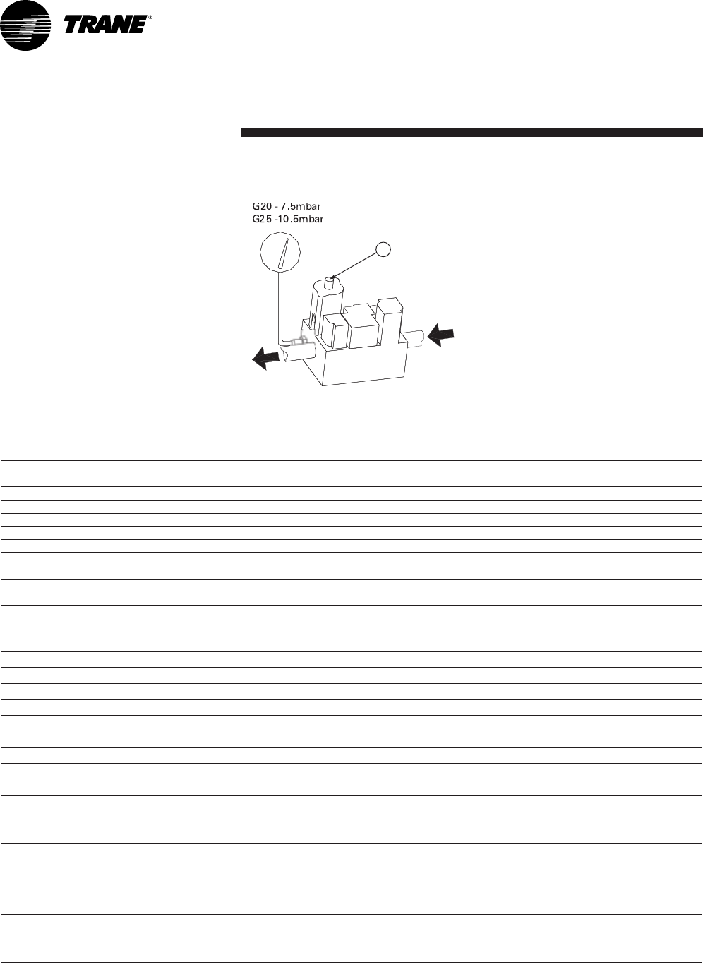
Operation
RT-SVX20A-E454
Unit start-up
Verification of gas valve settings -
(Reserved for the qualified gas
technician)
WARNING! Improper gas valve
setting may lead to burner
destruction and people injury.
Note: Unit factory-set for G20.
Figure 32 - Gas valve
1 = Screw to set gas valve
13/32"
G
20 - 7.
5
mb
a
r
G20 - 7.5mbar
G
2
5
-10.
5
mb
a
r
G25 -10.5mbar
13/32"
Note: Unit to be installed outside
only.
Note: Expansion valve must be
adapted to the type of gas used:
• G 20: 20 mb
• G 25: 25 mb
• G 31 (Propane): 37 or 50 mb
Table 50 - Gas type designation per country
Table 51 - Gas burner data
Notes:
(1) G20 heating output given for 34,02 MJ/m3(15°C-1013)
(2) G25 heating output given for 29,30 MJ/m3(15°C-1013)
(3) G31 heating output given for 46.34 MJ/kg
Burner G120 G200 G250
Gas Type G20 G25 G31 G20 G25 G31 G20 G25 G31
Heating Input (kW) 0,0 0,0 0,0 0,0 0,0 0,0 0,0 0,0 0,0
Heating Output (kW) 24,6 25 25,1 41,3 41,7 41,9 51,9 52,3 52,6
Efficiency 93% 93% 93% 93% 93% 93% #DIV/0! #DIV/0! 93%
Gas Flow rate (Nm3/h) 2,8 3,3 2,1 4,7 5,5 3,5 5,9 6,9 4,4
Specific Heating Capacity (MJ/kg) 34,02 29,3 46,34 34,02 29,3 46,34 34,02 29,3 46,34
Heating Output per stage (1st/2nd) (%) 0%-100% 0%-70%-100% 0%-70%-100%
Inlet pressure Min/Nominal/Max (mbar) 17 / 20 / 25 20 / 25 / 30 25 / 37 / 45 17 / 20 / 25 20 / 25 / 30 25 / 37 / 45 17 / 20 / 25 20 / 25 / 30 25 / 37 / 45
Low pressure switch setting (mbar) 15 15 20 15 15 20 15 15 20
Manifold pressure (mbar) 7,5 10,5 24,9 7,5 10,5 24,9 7,5 10,5 24,9
No of injectors 3 4 5
Injector size (Drill / mm) (33) / 2.87mm (51) / 1.70mm (1/8") / 3.175mm (49) / 1.85mm (1/8") / 3.175mm (49) / 1.85mm
Smoke analysis
Gas / Voltage G20 - 20mbar
400/3/50 G25 - 25mbar
400/3/50 G31 - 37mbar
400/3/50 G20 - 20mbar
400/3/50 G25 - 25mbar
400/3/50 G31 - 37mbar
400/3/50 G20 - 20mbar
400/3/50 G25 - 25mbar
400/3/50 G31 - 37mbar
400/3/50
CO % 0.0012% 0.0017% 0.0003% 0.0020% 0.0015% 0.0011% 0.0020% 0.0015% 0.0011%
Nox ppm 59 ppm 44 ppm 8.7 ppm 10 ppm 10 ppm 11 ppm 10 ppm 10 ppm 11 ppm
CO2% 8,29% 9,20% 8,90% 7,10% 7,10% 8,28% 7,10% 7,10% 8,28%
Destination countries Pressure in mbar Category
FR 20/25 37 II2E+3P
DE-LU-PL 20 I2E
CH-ES-GB-IE-PT-CZ-GR 20 37 II2H3P
NL 25 30 II2L3P
IT-AT-NO-FI-SE-EE-LT-LV 20 I2H
IT 28-30/37 I3+
BE 20/25 I2E
DK-SK-SI-TR 20 I2H
BE-PL 37 I3P
AT-DE-LU-HU-SK 50 I3P
HU 25 I2H

Operation
55RT-SVX20A-E4
Starting the unit in cooling mode
Before start-up, ensure that all
power cables are tightened.
Verify that the unit airflow rate is
adjusted according to the
information provided in the "Supply
fan adjustment" section of this
manual.
To start the unit in cooling mode:
• Place the zone sensor system
switch in the "COOL" position.
• Position the cooling setpoint
approximately 10° below room
temperature and place the fan
switch in the "AUTO" or "ON"
position.
• Turn on unit main power supply.
The condenser fan motor,
compressor and supply fan motor
should operate automatically.
There will be a delay of up to
5 minutes before the unit starts in
cooling mode.
Operating pressures
After the unit has operated in
cooling mode for a short period of
time, install pressure gauges on the
gauge ports of the discharge and
suction line valves.
Note:To bypass time delays and
verify the operation of this unit from
the roof, use the "Test procedure"
section in this manual. Check the
suction and discharge pressures.
Note: Always route refrigerant
hoses through the port hole
provided and ensure that the
compressor access panel is in place.
Cooling shutdown
To exit the test mode, disconnect
unit power for 3-5 seconds and
reapply. When running the unit
using the zone sensor as the
control, position the selector switch
to "OFF".
There may be a delay of up to
3 minutes before compressors shut
down and an additional one minute
before the fan shuts down in this
setting.
Do not de-energize main power
disconnect except when unit is to
be serviced. Power is required to
keep the compressor crankcase
warm and boil off refrigerant in the
oil (except on units with Scroll
compressors).
Final installation checklist
• Are all power cables tightened?
Check torque of power cables
contact !
• Is the condenser fan and indoor
blower operating correctly, i.e.
correct rotation and without
undue noise?
• Are the compressors operating
correctly and has the system
been checked for leaks?
• Have the voltage and running
currents been checked to
determine if they are within
limits?
• Have the air discharge grilles
been adjusted to balance the
system?
• Has the ductwork been checked
for air leaks and any
condensation?
• Has the air temperature rise
been checked?
• Has the indoor airflow been
checked and adjusted if
necessary?
• Has the unit been checked for
tubing and sheet metal rattles or
any unusual noises?
• Are all covers and panels in
place and properly fastened?

Operation
RT-SVX20A-E456
ReliaTel™ is a microelectronic
control feature, which provides
operating functions that are
significantly different from
conventional electro-mechanical
units. The master module is the
ReliaTel™ Refrigeration Module
(RTRM).
The RTRM provides compressor
antishort cycle timing functions
through minimum "Off" and "On"
timing to increase reliability,
performance and to maximize unit
efficiency.
Upon power initialization, the RTRM
performs self-diagnostic checks to
insure that all internal controls are
functioning. It checks the
configuration parameters against
the components connected to the
system.
The LED located on the RTRM
module is turned "On" within one
second after power-up if all internal
operations are okay.
Cooling without an
Economizer
When the system switch is set to
the "Cool" position and the zone
temperature rises above the cooling
setpoint controlband, the RTRM
energizes the (K9) relay coil located
on the RTRM. When the K9 relay
contacts close, the compressor
contactor (CC1) coil is energized
provided the low pressure control
(LPC1) and high pressure control
(HPC1) are closed. When the CC1
contacts close, compressor (CPR1)
and the outdoor fan motor (ODM)
start to maintain the zone
temperature to within ± 2 F of the
sensor setpoint at the sensed
location.
If the first stage of cooling can not
satisfy the cooling requirement, the
RTRM energizes the (K10) relay coil
located on the RTRM. When the
(K10) relay contacts close, the
compressor contactor (CC2) coil is
energized provided the low
pressure control (LPC2) and high
pressure control (HPC2) are closed.
When the CC2 contacts close,
compressor (CPR2) starts to
maintain the zone temperature to
within ± 2 F of the sensor setpoint
at the sensed location.
Evaporator Fan Operation
When the fan selection switch is set
to the "Auto" position, the RTRM
energizes the (K6) relay coil
approximately one second after
energizing the compressor
contactor coil (CC1) in the cooling
mode. In heating mode, the RTRM
energizes the (K6) relay coil
approximately 45 seconds after gas
ignition. Closing the K6 contacts on
the RTRM energizes the supply fan
relay (F) coil to start the supply fan
motor (IDM).
The RTRM de-energizes the fan
relay (F) approximately 60 seconds
after the cooling requirement has
be satisfied to enhance unit
efficiency.
When the heating cycle is
terminated, the supply fan relay (F)
coil is de-energized approximately
90 seconds after the heating
requirement.
When the fan selection switch is set
to the "On" position, the RTRM
keeps the supply fan relay coil (F)
energized for continuous fan motor
operation.
When the unit is equipped with the
optional clogged filter switch, wired
between terminals J7-3 and J7-4 on
the ReliaTel™ Options Module
(RTOM), the RTRM produces an
analog output if the clogged filter
switch (CFS) closes for two minutes
after a request for fan operation.
When the system is connected to a
remote panel, the "SERVICE" LED
will be turned on when this failure
occurs.

Operation
57RT-SVX20A-E4
Low Ambient Operation
During low ambient operation,
outside air temperature below 13ºC,
the RTRM will cycle the compressor
and outdoor fan motor "Off" for
approximately three minutes after
every 10 minutes of accumulated
compressor run time. The supply
fan motor (IDM) will continue to
operate during this evaporator
defrost cycle (EDC) and the
compressor and outdoor fan will
return to normal operation once the
defrost cycle has terminated and
the compressor "Off" time delay has
been satisfied.
Cooling with an
Economizer
The economizer is utilized to control
the zone temperature providing the
outside air conditions are suitable.
Outside air is drawn into the unit
through modulating dampers. When
cooling is required and economizing
is possible, the RTRM sends the
cooling request to the unit
economizer actuator (ECA) to open
the economizer damper. The RTRM
tries to cool the zone utilizing the
economizer to slightly below the
zone temperature setpoint. If the
mixed air sensor (MAS) senses that
the mixed air temperature is below
53ºF, the damper modulates toward
the closed position. If the zone
temperature continues to rise above
the zone temperature setpoint
controlband and the economizer
damper is full open, the RTRM
energizes the compressor contactor
(CC1). If the zone temperature
continues to rise above the zone
temperature setpoint controlband
and the economizer damper is fully
open, the RTRM energizes the
compressor contactor (CC2).
The ECA continues to modulate the
economizer damper open/closed to
keep the mixed air temperature that
is calculated by the RTRM.
If economizing is not possible, the
ECA drives the damper to the
minimum position setpoint when
the supply fan relay (F) is energized
and allows mechanical cooling
operation. When the unit is
equipped with the optional fan
failure switch, wired between
terminals J7-5 and J7-6 on the
RTOM, the RTRM will stop all
cooling functions and produce an
analog output if the fan failure
switch (FFS) does not open within
40 seconds after a request for fan
operation. When the system is
connected to a remote panel, the
"SERVICE" LED will flash when this
failure occurs.
Operation
RT-SVX20A-E458
Economizer Set-Up
Adjusting the minimum position
potentiometer located on the unit
economizer Actuator (ECA) sets the
required amount of ventilation air.
Two of the three methods for
determining the suitability of the
outside air can be selected utilizing
the enthalpy potentiometer on the
ECA, as described below:
1. Ambient Temperature -
controlling the economizing
cycle by sensing the outside air
dry bulb temperature. The Table
below lists the selectable dry
bulb values by potentiometer
setting.
2. Reference Enthalpy - controlling
the economizer cycle by sensing
the outdoor air humidity. The
Table below lists the selectable
enthalpy values by
potentiometer setting.
If the outside air enthalpy value
is less than the selected value,
the economizer is allowed to
operate.
3. Comparative Enthalpy - By
utilizing a humidity sensor and a
temperature sensor in both the
return air stream and the
outdoor air stream, the unit
control processor (RTRM) will be
able to establish which
conditions are best suited for
maintaining the zone
temperature, i.e. indoor
conditions or outdoor conditions.
The potentiometer located on
the ECA is non-functional when
both the temperature and
humidity sensors are installed.
Table 52 - Potentiometer Setting
*Factory Setting
ReliaTel™ Control Heating
Operation
When the system switch is set to
the "Heat" position and the zone
temperature falls below the heating
setpoint controlband, a heat cycle is
initiated when the RTRM
communicates ignition information
to the Ignition module (IGN).
Potentiometer
Setting
Dry BuIb Enthalpy
(°C) (KJ/kg)
A 23* 63
B21 58
C19 53
D17 51
Ignition Module
Two Stage (IGN) runs self-check
(including verification that the gas
valve is de-energized). (IGN) checks
the high-limit switches (TC01 &
TC02) for normally closed contacts.
With 115 VAC power supplied to the
ignition module (IGN), the hot
surface ignition probe (IP) is
preheated for approximately
45 seconds. The gas valve (GV) is
energized for approximately
7 seconds for trial for ignition, to
ignite the burner.
Once the burner is ignited, the hot
surface ignition probe (IP) is de-
energized by the ignition module
(IGN) and functions as the flame
sensing device.
If the burner fails to ignite, the
ignition module will make two more
attempts before locking out. The
green LED will indicate a lock out by
two fast flashes. An ignition lockout
can be reset by:
1. Opening for 3 seconds and
closing the main power
disconnect switch
2. By switching the "Mode" switch
on the zone sensor to "OFF" and
then to the desired position
3. Allowing the ignition control
module to reset automatically
after one hour.
Operation
59RT-SVX20A-E4
Refer to the ignition control module
diagnostics section for the LED
diagnostic definitions.
When the fan selection switch is set
to the "Auto" position, the RTRM
energizes the supply fan relay (F)
coil approximately 30 second after
initiating the heating cycle to start
the supply fan motor (IDM).
The automatic reset high limit
(TCO1), located in the bottom right
corner of the burner compartment,
protects against abnormally high
leaving air temperatures.
The automatic reset fan fail limit
(TCO2), located in the upper middle
section of the supply fan board,
protects against abnormally high
heat buildup which could occur
because of extended cycling of the
high limit (TCO1) or if the supply
fan motor (IDM) fails to operate.
Should TCO2open, the RTRM will
energize the supply fan relay (F) in
an attempt to start the fan motor.
The RTRM signals that a heat failure
has occurred by flashing the "Heat"
LED on the zone sensor.
There is a Green LED located in the
Ignition Control Module. The table
below lists the diagnostics and the
status of the LED during the various
operating states.
Final installation checklist
• Is the condenser fan and indoor
blower operating correctly, i.e.:
correct rotation and without
undue noise?
• Are the compressors operating
correctly and has the system
charge been checked?
• Has the gas module been
installed as per the procedure in
this manual?
• Have the voltage and running
currents been checked to
determine if they are with in
limits?
• Have the air discharge grilles
been adjusted to balance the
system?
• Has the ductwork been checked
for air leaks and any
condensation?
• Has the heating air temperature
rise been checked?
• Has the indoor airflow been
checked and adjusted if
necessary?
• Has the unit been checked for
tubing and sheet metal rattles
orany unusual noises?
• Are all covers and panels in
placeand properly fastened?
To keep the unit operating safely
and efficiently, the manufacturer
recommends that a qualified service
technician check the entire system
at least once each year, or more
frequently if conditions warrant.
Table 53 - LED status
Diagnostics Green LED Red LED
1. Powered but no heat dernand Off Off
2. Heat demand without fault Flash ing Off
3. No flame detection on ignition - or signal detected
and then lost Off Flashing
4. Gas unit incorrectly wired or flame signal detected on
a heat demand Steady Flashing
5. Internal fault Off Steady
Maintenance
RT-SVX20A-E460
To keep the unit operating safely
and efficiently, the manufacturer
recommends that a qualified service
technician check the entire system
at least once each year, or more
frequently if conditions warrant it.
End user routine
maintenance
Some of the periodic maintenance
functions for the unit can be
undertaken by the end user. This
includes replacing (disposable) or
cleaning (permanent) air filters,
cleaning unit cabinet, cleaning the
condenser coil, and carrying out a
general unit inspection on a regular
basis.
WARNING! Disconnect the power
supply before removing access
panels to service the unit. Failure to
disconnect power before attempting
any servicing can result in severe
injury or death.
Air filters
It is very important for the central
duct system air filters to be kept
clean.
These should be inspected at least
once a month when the system is in
constant operation (in new
buildings, the filters should be
checked every week for the first four
weeks). If disposable-type filters are
used, they should only be replaced
with ones of the same type and
size.
Table 54 - Refrigerant charge
Note: Refrigerant charges are given for information only. Check unit nameplate for exact values.
Unit model and size Number of circuits Refrigerant charge
(kg) (R22/R407C)
YSD/YSH 060 1 3.5
YSD/YSH 072 1 3.7
YSD/YSH 090 1 4.5
YSD/YSH 102 23.7/2.1
YSD/YSH 120 23.5/3.0

Maintenance
61RT-SVX20A-E4
Note: Do not attempt to clean
disposable filters. Permanent filters
can be cleaned by washing with a
mild detergent and water. Ensure
that the filters are thoroughly dry
before reinstalling them in the unit
(or duct system).
Note: Replace permanent filters
annually if washing fails to clean
them, or they show signs of
deterioration. Be sure to use the
same type and size as were
originally installed.
Condenser coil
Unfiltered air circulates through the
unit's condenser coil and can cause
the coil's surface to become
clogged with dust, dirt, etc. To clean
the coil, brush the coil surface in the
direction of the fins with a soft
bristled brush.
Keep all vegetation away from the
condenser coil area.
Hot water coil (option)
Stop the unit. Do not disconnect the
main supply to the unit. This will
permit the anti-frost protection to
continue to operate, and avoid
water to freeze-up in the coil.
Service technician
maintenance
Before the cooling season, your
service technician may examine the
following areas of your unit:
• Filters, for cleaning or
replacement
• Motors and drives system
components
• Economizer gaskets, for
replacement if necessary
• Condenser coils, for cleaning
• Safety controls, for mechanical
cleaning
• Electrical components and
wiring, for replacement and
tightening of connections as
necessary
• Condensate drain, for cleaning
• Unit duct connections, to ensure
they are physically sound and
sealed to the unit casing
• Unit mounting support, to
ensure that it is sound
• The unit, to ensure there is no
obvious deterioration
Before the heating season, your
service technician may examine the
following areas of your unit:
• The unit, to ensure that the
condenser coil can receive the
required airflow (that the
condenser fan grille is not
obstructed)
• The control panel wiring, to
verify that all electrical
connections are tight, and that
wire insulation is intact
• Clean burner area, verify the gas
heat system operates properly.

Maintenance
RT-SVX20A-E462
Troubleshooting
The RTRM has the ability to provide
the service personnel with some
unit diagnostics and system status
information. Before turning the
main power disconnect switch "Off",
follow the steps below to check the
ReliaTel™
Refrigeration Module (RTRM). All
diagnostics & system status
information stored in the RTRM will
be lost when the main power is
turned "Off".
1. Verify that the Liteport LED on
the RTRM is burning
continuously. If the LED is lit, go
to Step 3.
2. If the LED is not lit, verify that
24 VAC is present between J1-1
and J1-2. If 24 VAC is present,
proceed to Step 3. If 24 VAC is
not present, check the unit main
power supply, check transformer
(TNS1). Proceed to Step 3 if
necessary.
3. Utilizing "Method 1" or
"Method 2" in the system status
diagnostic section, check the
following: System status,
Heating status, Cooling status. If
a System failure is indicated,
proceed to Step 4. If no failures
are indicated, proceed to Step 5.
4. If a System failure is indicated,
recheck Steps 1 and 2. If the LED
is not lit in Step 1, and 24 VAC is
present in Step 2, the RTRM has
failed. Replace the RTRM.
5. If no failures are indicated, use
one of the TEST mode
procedures described in the unit
"Start-Up" section to start the
unit. This procedure will allow
you to check all of the RTRM
outputs, and all of the external
controls (relays, contactors, etc.)
that the RTRM outputs energize,
for each respective mode.
Proceed to Step 6.
6. Step the system through all of
the available modes, and verify
operation of all outputs, controls,
and modes. If a problem in
operation is noted in any mode,
you may leave the system in that
mode for up to one hour while
troubleshooting. Refer to the
sequence of operations for each
mode, to assist in verifying
proper operation. Make the
necessary repairs and proceed to
Steps 7 and 8.
7. If no abnormal operating
conditions appear in the test
mode, exit the test mode by
turning the power "Off" at the
main power disconnect switch.
8. Refer to the individual
component test procedures if
other microelectronic
components are suspect.
System Status Checkout Procedure
"System Status" is checked by using
one of the following two methods:
Method 1
If the Zone Sensor Module (ZSM) is
equipped with a remote panel with
LED status indication, you can check
the unit within the space. If the ZSM
does not have LED's, use Method 2.
THS/P03 have the remote panel
indication feature. The LED
descriptions are listed below:
LED 1 (System) "On" during normal
operation. "Off" if a system failure
occurs or the LED fails. "Flashing"
indicates test mode.
LED 2 (Heat) "On" when the heat
cycle is operating. "Off" when the
heat cycle terminates or the LED
fails. "Flashing" indicates a heating
failure.
LED 3 (Cool) "On" when the cooling
cycle is operating. "Off" when the
cooling cycle terminates or the LED
fails. "Flashing" indicates a cooling
failure.
LED 4 (Service) "On" indicates a
clogged filter. "Off" during normal
operation. "Flashing" indicates an
supply fan failure.

Maintenance
63RT-SVX20A-E4
Below is the complete listing of
failure indication causes:
System failure
Check the voltage between
terminals 6 and 9 on J6, it should
read approximately 32 VDC. If no
voltage is present, a system failure
has occurred. Refer to Step 4 in the
previous section for the
recommended troubleshooting
procedure.
Heating Failure
Verify Heat Failure by Ignition
Module (IGN) LED indicator:
OFF: No Power or Failure
ON: Normal
Slow Flash: Normal, Heat Call
Fast Flash: Error Code:
1 Flash: Communication Failure
2 Flashes: System Lockout
3 Flashes: Pressure Switch Fail
4 Flashes TC01 or TC02 Open
5 Flashes: Flame w/o Gas Valve
6 Flashes: Flame Rollout Open
Cooling Failure
1. Cooling and heating set point
(slide pot) on the zone sensor
has failed. Refer to the "Zone
Sensor Test Procedure" section.
2. Zone temperature thermistor
ZTEMP on ZTS failed. Refer to
the "Zone Sensor Test Procedure"
section.
3. CC1 or CC2 24 VAC control circuit
has opened, check CC1 & CC2
coils, and any of the controls
below that apply to the unit
(HPC1, HPC2).
4. LPC1 has opened during the
3 minute minimum "on time"
during 4 consecutive compressor
starts, check LPC1 or LPC2 by
testing voltage between the J1-8
& J3-2 terminals on the RTRM
and ground. If 24 VAC is present,
the LPC's has not tripped. If no
voltage is present, LPC's has
tripped.
Service Failure
1. If the supply fan proving switch
has closed, the unit will not
operate (when connected to
RTOM), check the fan motor,
belts, and proving switch.
2. Clogged filter switch has closed,
check the filters.
Simultaneous Heat and Cool Failure
1. Emergency Stop is activated
Method 2
The second method for determining
system status is done by checking
voltage readings at the RTRM (J6).
The system indication descriptions
and the approximate voltages are
listed below.
System Failure
Measure the voltage between
terminals J6-9 & J6-6.
Normal Operation = approximately
32 VDC
System Failure = less than 1 VDC,
approximately 0.75 VDC
Test Mode = voltage alternates
between 32 VDC & 0.75 VDC
Heat Failure
Measure the voltage between
terminals J6-7 & J6-6.
Heat Operating = approximately
32 VDC
Heat Off = less than 1 VDC,
approximately 0.75 VDC
Heating Failure = voltage alternates
between 32 VDC & 0.75 VDC
Cool Failure
Measure the voltage between
terminals J6-8 & J6-6.
Cool Operating = approximately
32 VDC
Cool Off = less than 1 VDC,
approximately 0.75 VDC
Cooling Failure = voltage alternates
between 32 VDC & 0.75 VDC

Maintenance
RT-SVX20A-E464
Service Failure
Measure the voltage between
terminals J6-10 & J6-6.
Clogged Filter = Approximately
32 VDC.
Normal = Less than 1 VDC,
approximately 0.75 VDC
Fan Failure = voltage alternates
between 32 VDC & 0.75 VDC.
To use LED's for quick status
information at the unit, purchase a
ZSM and connect wires with
alligator clamps to terminals 6
through 10.
Connect each respective terminal
wire (6 through 10) from the Zone
Sensor to the unit J6 terminals 6
through 10.
Note: If the system is equipped
with a programmable zone sensor
THS03, the LED indicators will not
function while the ZSM is
connected.
Resetting Cooling and Ignition
Lockouts
Cooling Failures and Ignition
Lockouts are reset in an identical
manner. Method 1 explains
resetting the system from the space,
Method 2 explains resetting the
system at the unit.
Note: Before resetting Cooling
Failures and Ignition Lockouts,
check the Failure Status Diagnostics
by the methods previously
explained.
Diagnostics will be lost when the
power to the unit is disconnected.
Method 1
To reset the system from the zone,
turn the "Mode" selection switch at
the zone sensor to the "Off"
position.
After approximately 30 seconds,
turn the "Mode" selection switch to
the desired mode, i.e. Heat, Cool or
Auto.
Method 2
To reset the system at the unit,
cycle the unit power by turning the
disconnect switch "Off" and then
"On".
Lockouts can be cleared through the
building management system. Refer
to the building management system
instructions for more information.
Zone Temperature Sensor (ZTS)
Service Indicator
The ZSM SERVICE LED is a generic
indicator that will signal the closing
of a Normally Open switch at any
time, providing the Indoor Motor
(IDM) is operating. This indicator is
usually used to indicate a clogged
filter, or an air side fan failure.
The RTRM will ignore the closing of
this Normally Open switch for 2 (±1)
minutes. This helps prevent
nuisance SERVICE LED indications.
The exception is the LED will flash
40 seconds after the fan is turned
"On" if the Fan Proving Switch is not
made.
Clogged Filter Switch
This LED will remain lit the entire
time that the Normally Open switch
is closed. The LED will be turned off
immediately after resetting the
switch (to the Normally Open
position), or any time that the IDM
is turned "Off".
If the switch remains closed, and
the IDM is turned "On", the SERVICE
LED will be turned "On" again after
the 2 (±1) minute ignore delay.
This LED being turned "On", will
have no other affect on unit
operation. It is an indicator only.
Fan Failure Switch
When the "Fan Failure" switch is
wired to the RTOM, the LED will
remain flashing the entire time the
fan proving switch is closed,
indicating a fan failure, and it will
shut the unit operations down.
Maintenance
65RT-SVX20A-E4
Zone Temperature Sensor (ZTS) Test
Note:These procedures are not for
programmable or digital models
and are conducted with the Zone
Sensor
Module electrically removed from
the system.
Test 1
Zone Temperature Thermistor
(ZTEMP)
This component is tested by
measuring the resistance between
terminals 1 and 2 on the Zone
Temperature Sensor.
Table 55 - Thermistor Resistance /
Temperature Chart
Temperature/resistance coefficient is
negative.
Temperature Resistance
(°C) (kOhms)
-21 103
-15 74. 65
-9 54.66
-7 46.94
-4 40.4
-1 34.85
2 30.18
426.22
722.85
10 19.96
13 17.47
16 15.33
18 13.49
21 11.89
24 10.5
27 9.297
29 8.247
32 7. 3 3
35 6.528
38 5.824
Maintenance
RT-SVX20A-E466
To Test Humidity Sensors
Return Air Humidity Sensor ECA RAH/RAE
Outdoor Humidity Sensor ECA OAH/OAE
To test this circuit, place a DC milliamp meter in series with either of the leads to the humidity sensor. If the reading
is 0ma, polarity may be reversed. Reverse + & - and retest. If the reading does not correspond to the table below,
check the output voltage from the ECA with the sensor disconnected. It should be approximately 20VDC. If so, and
all connections are intact, replace the sensor. If 20VDC is not present, yet the ECA green LED is on, the ECA module
has failed.Humidity sensor accuracy : +/-10% RH.
Table 56 - Humidity sensor test
RH% DCma RH%D Cma RH% DCma
100% 20.000 52.6 12.414 31.2 9.000
97.7 19.636 51.7 12.273 30.8 8.926
95.5 19.286 50.8 12.135 30.3 8.852
93.4 18.947 50.0 12.000 29.9 8.780
91.4 18.621 49.2 11.868 29.4 8.710
89.4 18.305 48.4 11.739 29.0 8.640
87.5 18.000 47.6 11.613 28.6 8.571
85.7 17.705 46.8 11.489 28.1 8.504
83.9 17.419 46.1 11.368 27.7 8.438
82.1 17.143 45.3 11.250 27.3 8.372
80.5 16.875 44.6 11.134 26.9 8.308
78.8 16.615 43.9 11.020 26.5 8.244
77.3 16.364 43.2 10.909 26.1 8.182
75.7 16.119 42.5 10.800 25.8 8.120
74.3 15.882 41.8 10.693 25.4 8.060
72.8 15.652 41.2 10.588 25.0 8.000
71.4 15.429 40.5 10.485 24.6 7.941
70.1 15.211 39.9 10.385 24.3 7.833
68.8 15.000 39.3 10.286 23.9 7.826
67.5 14.795 38.7 10.189 23.6 7.770
66.2 14.595 38.1 10.093 23.2 7.714
65.0 14.400 37.5 10.000 22.9 7.660
63.8 14.211 36.9 9.908 22.5 7.606
62.7 14.026 36.4 9.818 22.2 7.552
61.5 13.846 35.8 9.730 21.9 7.500
60.4 13.671 35.3 9.463 21.6 7.448
59.4 13.500 34.7 9.558 21.2 7.397
58.3 13.333 34.2 9.474 20.9 7.347
57.3 13.171 33.7 9.391 20.6 7.297
56.3 13.012 33.2 9.310 20.3 7.248
55.4 12.857 32.7 9.231 20.0 7.200
54.4 12.706 32.2 9.153
53.5 12.558 31.7 9.076

Notes
67RT-SVX20A-E4
Literature Order Number RT-SVX20A-E4
Date 0606
Supersedes RT-SVX20A-E4_1105
Literature Stocking Location Europe
Trane has a policy of continuous product and product data improvement and reserves the right to
change design and specifications without notice. Only qualified technicians should perform the
installation and servicing of equipment referred to in this publication.
www.trane.com
For more information, contact your local
sales office or e-mail us at comfort@trane.com
American Standard Europe BVBA
Registered Office: 1789 Chaussée de Wavre, 1160 Brussels - Belgium
