Trane Uni Fan Coil And Force Flo Catalogue CAB PRC001 EN (08 May 2012)
2015-04-02
: Trane Trane-Uni-Fan-Coil-And-Force-Flo-Catalogue-684301 trane-uni-fan-coil-and-force-flo-catalogue-684301 trane pdf
Open the PDF directly: View PDF ![]() .
.
Page Count: 69
- Introduction
- Features and Benefits
- Model Number Descriptions
- General Data
- Model A, Vertical Concealed
- Model B, Vertical Cabinet
- Model C, Horizontal Concealed
- Model D, Horizontal Cabinet
- Model E, Horizontal Recessed
- Model F, Vertical Wall Hung Cabinet
- Model H, Vertical Recessed
- Model J, Vertical Cabinet Slope Top
- Model M, Inverted Vertical Concealed
- Model N, Inverted Vertical Recessed
- Electric Heat
- Factory-Installed Piping Packages
- Performance Data
- Controls
- Electrical Data
- Dimensions and Weights
- Vertical Concealed, Model A
- Vertical Cabinet, Model B
- Horizontal Concealed, Model C
- Horizontal Cabinet, Model D
- Horizontal Recessed, Model E
- Vertical Wall Hung Cabinet, Model F
- Vertical Recessed, Model H
- Vertical Slope Top, Model J
- Inverted Vertical Cabinet, Model M
- Inverted Vertical Recessed, Model N
- Coil Connections
- Fresh Air Opening Locations-Horizontal Units Models C, D, and E
- Fresh Air Opening Locations-Vertical Units Models A, B, F, and J
- Wall Box
- Projection Panel
- Mechanical Specifications
Force-Flo™ Cabinet Heater
Air Terminal Devices
Horizontal and Vertical
Sizes 02–12
May 2012 CAB-PRC001-EN
Product Catalog
CAB-PRC001-EN.book Page 1 Tuesday, May 8, 2012 10:11 AM
© 2012 Trane All rights reserved CAB-PRC001-EN
Introduction
Trane has redesigned the traditional cabinet heater to lead the industry in:
• indoor air quality (IAQ) features
• easy installation and maintenance
• high quality and durability
• advanced controls
Revision History
The revision of this literature dated 08 May 2012 includes information for Tracer™ UC400 controls,
coil performance updates, and revised performance table formats per new AHRI listing
requirements.
Trademarks
Force-Flo, Integrated Comfort, Rover, TOPSS, Tracer, Tracer Summit, Trane, and the Trane logo are
trademarks of Trane in the United States and other countries. All trademarks referenced in this
document are the trademarks of their respective owners.
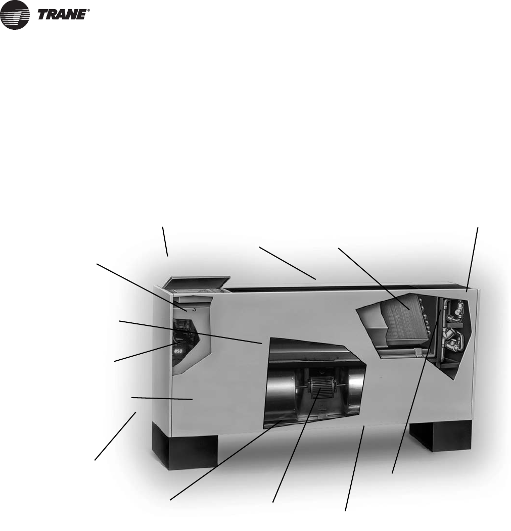
Factory-assembled, -installed,
and -tested piping package
with IAQ drain pan to collect
condensate.Two-, three-, or
four-row coils.
Quiet operation.
Smaller unit footprint.
Factory-installed and
-tested controls.
Removable, noncorrosive,
positively-sloped drain pan
that’s easy to clean.
Easy-to-remove fan assembly.
16-gage steel construction.
Cleanable closed-cell
insulator (non-fiberglass).
Easy filter access
without front panel
removal.
Damper allows up
to 100% fresh air.
Build in field service tool
with real language LED
Energy efficient
electronically
commutated motor
(ECM)
CAB-PRC001-EN.book Page 2 Tuesday, May 8, 2012 10:11 AM

Table of Contents
CAB-PRC001-EN 3
Introduction . . . . . . . . . . . . . . . . . . . . . . . . . . . . . . . . . . . . . . . . . . . . . . . . . . . . . . . . . . . . 2
Features and Benefits . . . . . . . . . . . . . . . . . . . . . . . . . . . . . . . . . . . . . . . . . . . . . . . . . . . 5
Model Number Descriptions . . . . . . . . . . . . . . . . . . . . . . . . . . . . . . . . . . . . . . . . . . . . . 7
General Data . . . . . . . . . . . . . . . . . . . . . . . . . . . . . . . . . . . . . . . . . . . . . . . . . . . . . . . . . . . 9
Model A, Vertical Concealed . . . . . . . . . . . . . . . . . . . . . . . . . . . . . . . . . . . . 9
Model B, Vertical Cabinet . . . . . . . . . . . . . . . . . . . . . . . . . . . . . . . . . . . . . . . 9
Model C, Horizontal Concealed . . . . . . . . . . . . . . . . . . . . . . . . . . . . . . . . . 10
Model D, Horizontal Cabinet . . . . . . . . . . . . . . . . . . . . . . . . . . . . . . . . . . . . 11
Model E, Horizontal Recessed . . . . . . . . . . . . . . . . . . . . . . . . . . . . . . . . . . 12
Model F, Vertical Wall Hung Cabinet . . . . . . . . . . . . . . . . . . . . . . . . . . . . . 12
Model H, Vertical Recessed . . . . . . . . . . . . . . . . . . . . . . . . . . . . . . . . . . . . 13
Model J, Vertical Cabinet Slope Top . . . . . . . . . . . . . . . . . . . . . . . . . . . . . 13
Model M, Inverted Vertical Concealed . . . . . . . . . . . . . . . . . . . . . . . . . . . . 14
Model N, Inverted Vertical Recessed . . . . . . . . . . . . . . . . . . . . . . . . . . . . . 14
Electric Heat . . . . . . . . . . . . . . . . . . . . . . . . . . . . . . . . . . . . . . . . . . . . . . . . . 16
Factory-Installed Piping Packages . . . . . . . . . . . . . . . . . . . . . . . . . . . . . . . 17
Performance Data . . . . . . . . . . . . . . . . . . . . . . . . . . . . . . . . . . . . . . . . . . . . . . . . . . . . . 22
Horizontal Concealed, Horizontal Recessed, Vertical Recessed, Inverted
Vertical Recessed . . . . . . . . . . . . . . . . . . . . . . . . . . . . . . . . . . . . . . . . . . . . 23
Vertical Concealed . . . . . . . . . . . . . . . . . . . . . . . . . . . . . . . . . . . . . . . . . . . . 24
Horizontal Cabinet, Vertical Cabinet, Inverted Vertical Cabinet . . . . . . . 25
Vertical Slope Top Cabinet . . . . . . . . . . . . . . . . . . . . . . . . . . . . . . . . . . . . . 26
Horizontal Concealed, Horizontal Recessed, Vertical Recessed, Horizontal
Cabinet . . . . . . . . . . . . . . . . . . . . . . . . . . . . . . . . . . . . . . . . . . . . . . . . . . . . . 27
Vertical Concealed . . . . . . . . . . . . . . . . . . . . . . . . . . . . . . . . . . . . . . . . . . . . 28
Controls . . . . . . . . . . . . . . . . . . . . . . . . . . . . . . . . . . . . . . . . . . . . . . . . . . . . . . . . . . . . . . 29
ECM Engine Controller . . . . . . . . . . . . . . . . . . . . . . . . . . . . . . . . . . . . . . . . 29
Control Options . . . . . . . . . . . . . . . . . . . . . . . . . . . . . . . . . . . . . . . . . . . . . . 30
Manual Fan Mode Switch . . . . . . . . . . . . . . . . . . . . . . . . . . . . . . . . . . . . . . 30
Customer Supplied Terminal Interface (CSTI) . . . . . . . . . . . . . . . . . . . . . 31
Tracer Controls . . . . . . . . . . . . . . . . . . . . . . . . . . . . . . . . . . . . . . . . . . . . . . 32
Sequence of Operation . . . . . . . . . . . . . . . . . . . . . . . . . . . . . . . . . . . . . . . . 34
Zone Sensor Options . . . . . . . . . . . . . . . . . . . . . . . . . . . . . . . . . . . . . . . . . 37
Control Features . . . . . . . . . . . . . . . . . . . . . . . . . . . . . . . . . . . . . . . . . . . . . 38
Tracer ZN520 and UC400 Additional Features . . . . . . . . . . . . . . . . . . . . . 39
End Device Options . . . . . . . . . . . . . . . . . . . . . . . . . . . . . . . . . . . . . . . . . . . 39
Electrical Data . . . . . . . . . . . . . . . . . . . . . . . . . . . . . . . . . . . . . . . . . . . . . . . . . . . . . . . . . 41
Dimensions and Weights . . . . . . . . . . . . . . . . . . . . . . . . . . . . . . . . . . . . . . . . . . . . . . . 46
Vertical Concealed, Model A . . . . . . . . . . . . . . . . . . . . . . . . . . . . . . . . . . . 46
Vertical Cabinet, Model B . . . . . . . . . . . . . . . . . . . . . . . . . . . . . . . . . . . . . . 47
Horizontal Concealed, Model C . . . . . . . . . . . . . . . . . . . . . . . . . . . . . . . . . 48
Horizontal Cabinet, Model D . . . . . . . . . . . . . . . . . . . . . . . . . . . . . . . . . . . . 49
CAB-PRC001-EN.book Page 3 Tuesday, May 8, 2012 10:11 AM

4 CAB-PRC001-EN
Horizontal Recessed, Model E . . . . . . . . . . . . . . . . . . . . . . . . . . . . . . . . . . 50
Vertical Wall Hung Cabinet, Model F . . . . . . . . . . . . . . . . . . . . . . . . . . . . . 51
Vertical Recessed, Model H . . . . . . . . . . . . . . . . . . . . . . . . . . . . . . . . . . . . 52
Vertical Slope Top, Model J . . . . . . . . . . . . . . . . . . . . . . . . . . . . . . . . . . . . 53
Inverted Vertical Cabinet, Model M . . . . . . . . . . . . . . . . . . . . . . . . . . . . . . 54
Inverted Vertical Recessed, Model N . . . . . . . . . . . . . . . . . . . . . . . . . . . . . 55
Coil Connections . . . . . . . . . . . . . . . . . . . . . . . . . . . . . . . . . . . . . . . . . . . . . 56
Fresh Air Opening Locations-Horizontal Units Models C, D, and E . . . . 57
Fresh Air Opening Locations-Vertical Units Models A, B, F, and J . . . . . 58
Wall Box . . . . . . . . . . . . . . . . . . . . . . . . . . . . . . . . . . . . . . . . . . . . . . . . . . . . 59
Projection Panel . . . . . . . . . . . . . . . . . . . . . . . . . . . . . . . . . . . . . . . . . . . . . . 60
Mechanical Specifications . . . . . . . . . . . . . . . . . . . . . . . . . . . . . . . . . . . . . . . . . . . . . . 61
Force-Flo Cabinet Heater Mechanical Specifications . . . . . . . . . . . . . . . . 61
Piping Components . . . . . . . . . . . . . . . . . . . . . . . . . . . . . . . . . . . . . . . . . . . 66
CAB-PRC001-EN.book Page 4 Tuesday, May 8, 2012 10:11 AM

CAB-PRC001-EN 5
Features and Benefits
The Force-Flo cabinet heater meets the standards of today’s market, as well as the anticipated
needs of tomorrow’s market. The tradition that company founder Reuben Trane began in 1913
continues with the latest generation of cabinet heaters from Trane.
The Force-Flo cabinet heater is the leader in these key areas:
• Energy Efficiency
• Indoor Air Quality (IAQ)
• Controls
•Flexibility
•Quality
• Serviceability
Today’s HVAC market is concerned with issues such as indoor air quality (IAQ) and CFCs that
demand a change in HVAC products. In addition, renovation has overtaken new construction in the
cabinet heater market - demanding a design that caters to renovation issues. Trane is concerned
with these issues, too. That’s why we designed the Force-Flo cabinet heater as an integral part of
the company’s system solutions with standard IAQ-related features that comply with ASHRAE 62.
Energy Efficiency
Trane’s commitment to providing premium quality products has led to the exclusive use of
Electronically Commutated Motors (ECM) in all fan coil models. These brushless DC motors
incorporate the latest technology for optimized energy efficiency, acoustical abatement,
maintenance free and extended motor life. Each motor has a built-in microprocessor that allows
for programmability, soft ramp-up, better airflow control, and serial communication.
• Trane units equipped with ECMs are significantly more efficient than the standard Permanent
Split Capacitor (PSC) motor.
• Lower operating costs on average of 50 percent (versus a PSC motor).
• The Reduced FLA feature allows units to ship with a nameplate FLA rating much lower than a
typical ECM unit.
IAQ Design
• Closed-cell insulation is standard on all units to help prevent fiberglass in the airstream.
• Easy filter access encourages frequent changing.
• Force-Flo cabinet heaters have a blow-thru design.
Controls
• This is the industry’s first solution that is factory mounted, wired and programmed for infinite
modulation of fan speed based on space loads, using the UC400.
• Auto Fan Speed control with the Tracer ZN520 ramps the fan speed up and down to meet space
loads.
• All controls are factory-mounted and tested to minimize field setup and improve reliability.
• Controls are wired with a 24 Vac transformer to keep only a single source power connection
requirement to the unit.
• All wall-mounted zone sensors require only low voltage control wiring from the device to the
unit control box. (No line voltage.)
• The random startup feature helps reduce electrical demand peaks by randomly staggering
multiple units at startup.
• Occupied/unoccupied operation allows the controller to utilize unoccupied temperature
setpoints for energy savings.
CAB-PRC001-EN.book Page 5 Tuesday, May 8, 2012 10:11 AM

6 CAB-PRC001-EN
Features and Benefits
• Warm-up energy feature is standard with Trane controls.
• Continuous fan or fan cycling is available with Tracer ZN010 or ZN510.
• Monitor unit operation using Tracer SC building management system with Tracer ZN510.
• To customize unit control, Tracer TU or Rover™ software will allow field modification of Tracer
ZN510, ZN520 and UC400 default settings.
• Maximize cabinet heater system efficiency with modulating valves on units with Tracer ZN520
and UC400.
Flexibility
• Two-, three-, and four row hot water coils allow greater design flexibility. Steam distributing or
electric heat coils are also available.
• Fan motors are available for either high static (0.4-inch external static pressure) or free
discharge applications.
• Piping is factory-assembled, -mounted, and -tested. Units are also available without piping.
• Factory piping options include interconnecting piping, control valves, and end valves. Deluxe
piping also has unions and a strainer.
• Control options range from a simple fan speed switch to a DDC controller that can tie into a
Tracer SC building automation system.
• The extended end pocket option adds 8 inches (20 cm) to the piping end of cabinet style units.
• Slope-top vertical cabinet units are an excellent application for school and dormitories to
prevent items from being placed on top of the units.
• Vertical wall hung units are used in vestibules, bathrooms, stairwells, or other applications
when the unit cannot be installed on the floor.
• Inverted unit models allow heating to circulate from the bottom of the unit.
Quality
• Coils and piping packages are air and leak-tested before mounting on the unit.
• Coil piping connections are also air and leak-tested after mounting on the unit.
• All control end devices and moving components (fans and motors) are computer-tested after
units are complete.
Serviceability
• Touch-safe control box.
• Integrated user interface with real language LED display.
• Built-in tachometer.
• Filters are easily removable and changed without removing the front panel on vertical cabinet
units.
• Motors are easy to disconnect from the fan board, allowing easy service.
• The manual output test function is an invaluable troubleshooting tool. By simply pressing the
test button on the Tracer ZN510, ZN520, or ZN010; service personnel can manually exercise
outputs in a pre-defined sequence.
CAB-PRC001-EN.book Page 6 Tuesday, May 8, 2012 10:11 AM

CAB-PRC001-EN 7
Force-Flo Cabinet
Heater Model
Number Description
Following is a complete description of
the cabinet heater model number.
Each digit in the model number has a
corresponding code that identifies
specific unit options.
Note: Some options may not be
available with all cabinet
styles. Contact your local
Trane representative for more
information.
Digit 1, 2 - Unit Type
FF = Force-Flo
Digit 3 - Cabinet Type
A = Vertical Concealed
B = Vertical Cabinet
C = Horizontal Concealed
D = Horizontal Cabinet
E = Horizontal Recessed
F = Vertical Wall Hung Cabinet
H = Vertical Recessed
J = Vertical Cabinet Slope Top
M = Inverted Vertical Cabinet
N = Inverted Vertical Recessed
Digit 4 - Development Sequence
“B”
Digit 5, 6, 7 - Unit Size
Digit 8 - Unit Voltage
020 040 080
030 060 100
120
1 = 115/60/1 6 = 230/60/3
2 = 208/60/1 7 = 480/60/3
3 = 277/60/1 8 = 110–120/50/1
4 = 230/60/1 9 = 220–240/50/1
5 = 208/60/3 A = 220–240/50/3
B = 380–415/50/3
Digit 9 - Piping System/
Placement
A = No Piping, RH
B = No Piping, LH
E = No Piping, RH, Extended
End Pocket
F = No Piping, LH, Extended
End Pocket
J = With Piping Package, RH
K = With Piping Package, LH
L = With Piping Package, RH,
Extended End Pocket
M = With Piping Package, LH,
Extended End Pocket
Digit 10, 11 - Design Sequence
“M0”
Digit 12 - Inlets
A = Front Toe Space
B = Front Bar Grille
C = Front Stamped Louver
D = Bottom Stamped Louver
E = Bottom Toe Space
F = Back Duct Collar
G= Back Open Return
H = Back Stamped Louver
J = Top Duct Collar
Digit 13 - Fresh Air Damper
0=None
A = Manual, Bottom Opening
B = Manual, Back Opening
C = Manual, Top Opening
D = Auto, 2-Position, Bottom FA
Opening
E = Auto, 2-Position, Back FA Opening
F = Auto, 2-Position, Top FA Opening
K = No Damper, Bottom Opening
L = No Damper, Back Opening
M = No Damper, top Opening
Digit 14 - Outlets
A = Front Duct Collar
B = Front Bar Grille
C = Front Stamped Louver
D = Front Quad Grille
E = Bottom Duct Collar
F = Bottom Stamped Louver
G = Top Quad Grille
H = Top Bar Grille
J = Top Duct Collar
Digit 15 - Color
0 = No Paint (Concealed Units Only)
1 = Deluxe Beige
4 = Driftwood Grey
2=Soft Dove
5 = Stone Grey
3=Cameo White
6=Rose Mauve
Digit 16 - Tamperproof Locks/
Leveling Feet
0=None
B = Keylock Access Door
C = Keylock Panel and Access Door
D = Leveling Feet
F = Keylock Access Door w/Leveling
Feet
G = Keylock Panel and Access Door
w/Leveling Feet
Digit 17 - Motor
A = Free Discharge ECM
B = High Static ECM
Digit 18 - Coil
G = 2-Row Hot Water
H = 3-Row Hot Water
J = 4-Row Hot Water
N = Electric Heat, Single-Stage
U = Electric Heat, Two-Stage
V = Electric Heat, Low kW, One-Stage
W = Steam Distributing
Digit 19 - Coil Series
1 = 108 fpf (Steam Only)
2 = 144 fpf (Hot Water Only)
Digit 20 - Coil Air Vent
A = Automatic Air Vent
M = Manual Air Vent
Digit 21, 22, 23 - Electric Heat
kW (208 V derate)
000 = No Electric Heat
010 = 1.0 kW (0.75 kW)
020 = 2.0 kW (1.5 kW)
030 = 3.0 kW (2.3 kW)
045 = 4.5 kW (3.3 kW)
060 = 6.0 kW (4.5 kW)
075 = 7.5 kW (5.7 kW)
090 = 9.0 kW (6.6 kW)
100 = 10.0 kW
105 = 10.5 kW (7.9 kW)
110 = 11.0 kW (9.0 kW)
120 = 12.0 kW
135 = 13.5 kW (10.2 kW)
150 = 15.0 kW
180 = 18.0 kW (13.5 kW)
200 = 20.0 kW (15.0 kW)
Digit 24 - Not Used
0
Digit 25 - Disconnect Switch
0=None
D = Disconnect Switch
Model Number Descriptions
CAB-PRC001-EN.book Page 7 Tuesday, May 8, 2012 10:11 AM

8 CAB-PRC001-EN
Model Number Descriptions
Digit 26 - Filter
0=None
1 = 1” Throwaway Filter
2 = 1” Throwaway MERV 8 Filter
3 = 1” Throwaway, 1 Extra
4 = 1” Throwaway MERV 8, 1 Extra
5 = 1” Throwaway, 2 Extras
6 = 1” Throwaway MERV 8, 2 Extras
7 = 1” Throwaway, 3 Extras
8 = 1” Throwaway MERV 8, 3 Extras
A = 1” Throwaway MERV 13 Filter
B = 1” Throwaway MERV 13, 1 Extra
C = 1” Throwaway MERV 13, 2 Extras
D = 1” Throwaway MERV 13, 3 Extras
Digit 27 - Main Control Valve
0=None
1 = Field Supplied Analog valve
A = 2-Way, 2-Position, NO (30 psig)
B = 3-Way, 2-Position, NO (28 psig)
C = 2-Way, 2-Position, NC (30 psig)
D = 3-Way, 2-Position, NC (20 psig)
E = 2-Way, 2-Position, NO (50 psig)
F = 3-Way, 2-Position, NO (28 psig)
G = 2-Way, 2-Position, NC (60 psig)
H = 3-Way, 2-Position, NC (28 psig)
J = 2-Way, Mod., 0.7 Cv (60 psig)
K = 3-Way, Mod., 0.7 Cv (60 psig)
L = 2-Way, Mod., 1.5 Cv (60 psig)
M = 3-Way, Mod., 1.5 Cv (60 psig)
N = 2-Way, Mod., 2.5 Cv (60 psig)
P = 3-Way, Mod., 2.5 Cv (60 psig)
Q = 2-Way, Mod., 4.0 Cv (60 psig)
R = 3-Way, Mod., 4.0 Cv (60 psig)
X = Field-Supplied, NO
Y = Field-Supplied, NC
Z = Field-Supplied 3-Wire Modulating
Digit 28 - Not Used
0
Digit 29 - Piping Packages
0=None
A = Basic Ball Valve supply and
Return
B = Basic Ball Valve Supply/Manual
Circuit Setter
C = Basic Ball Valve Supply and
Return w/Auto Circuit Setter
D = Deluxe Ball Valve Supply and
Return
E = Deluxe Ball Valve Supply/Manual
Circuit Setter
F = Deluxe Ball Valve Supply and
Return w/Auto Circuit Setter
Digit 30 - Control Type
A = Fan Speed Switch
E = Tracer ZN010
F = Tracer ZN510
G = Tracer ZN520
H = Customer Supplied Terminal
Interface
J = Tracer UC400, Single Zone VAV
Digit 31 - Control Option
D = Unit-Mounted Fan Mode Switch
K = Wall-Mounted Fan Mode Switch
V = Unit-Mounted Fan Speed Switch
w/Setpoint Dial Zone Sensor
W = Wall-Mounted Fan Speed Switch
w/Setpoint Dial Zone Sensor
X = Unit-Mounted Fan Speed Switch
w/Wall-Mounted Setpoint Dial
Zone Sensor
Y = Unit-Mounted Fan Speed Switch
& Wall-Mounted Setpoint Dial
w/Comm.
Z = Unit-Mounted Fan Speed Switch,
On/Cancel, Setpoint Dial
w/ Comm.
1 = Wall-Mounted On/Cancel
w/ Comm.
2 = Wall-Mounted Fan Speed Switch,
Setpoint Dial, On/Cancel
w/ Comm.
0 = Without Control Option
3 = Unit-Mounted Low Voltage Fan
Speed Switch (Off /Hi /Med /Low)
4 = Wall-Mounted Digital Zone
Sensor (OALMH, Setpoint,
On/Cancel, Comm Jack)
5 = Wall-Mounted Digital Zone
Sensor (On/Cancel, Comm Jack)
6 = Wireless Zone Sensor
7 = Wireless Display Sensor, Unit-
Mounted Receiver
Digit 32 - Not Used
0
Digit 33 -FLA Motor Option
0 = Standard FLA ECM Mode
A = Reduced FLA ECM Mode
Digit 34 - Future Control
Functions
0=None
Digit 35 - Control Function #3
0=None
Digit 36 - Control Function #4
0=None
Digit 37 - Control Function #5
0=None
Digit 38 - Control Function #6
0=None
Digit 39 - Projection Panels and
Falsebacks
0 = None
A = 5/8” Standard Recessed Panel
(Vertical Recessed Units Only)
B = 2” Projection Panel
C = 2.5” Projection Panel
D = 3” Projection Panel
E = 3.5” Projection Panel
F = 4” Projection Panel
G = 4.5” Projection Panel
H = 5” Projection Panel
J = 5.5” Projection Panel
L = 2” Falseback
K = 6” Projection Panel
M = 3” Falseback
N = 4” Falseback
P = 5” Falseback
Q = 6” Falseback
R = 7” Falseback
T = 8” Falseback
Digit 40 - Main Autoflow gpm
Digit 41 - Not Used
0
Digit 42 - Subbases
0 = None
A = 2” Subbase
B = 3” Subbase
C = 4” Subbase
D = 5” Subbase
E = 6” Subbase
F = 7” Subbase
Digit 43 - Recessed Flange
0 = None
A = Recessed Flange
Digit 44 - Wall Boxes
0 = None
A = Anodized Wall Box
A= 0.5 H=3.5
B = 0.75 J = 4.0
C=1.0 K=4.5
D= 1.5 L=5.0
E=2.0 M=6.0
F=2.5 N=7.0
G= 3.0 P= 8.0
CAB-PRC001-EN.book Page 8 Tuesday, May 8, 2012 10:11 AM
CAB-PRC001-EN 9
General Data
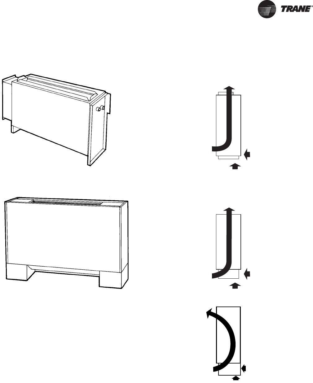
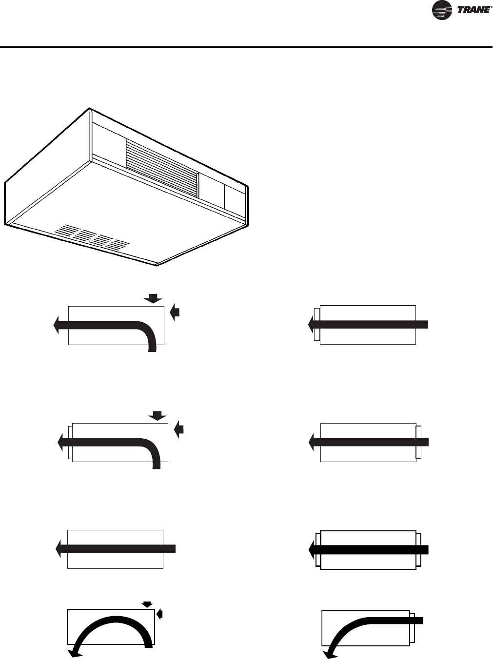
Model A, Vertical Concealed
Model B, Vertical Cabinet
Outlet
Top Duct Collar
Fresh Air
Bottom or Back
Inlet
Front Toe Space
Outlet
Top Quad Grille, Top Bar Grille
Fresh Air
Bottom or Back
Inlet
Front Toe Space,
Front Bar Grille
Outlet
Front Stamped Louver
Fresh Air
Bottom or Back
Inlet
Front Toe Space,
Front Bar Grille
CAB-PRC001-EN.book Page 9 Tuesday, May 8, 2012 10:11 AM
10 CAB-PRC001-EN
General Data
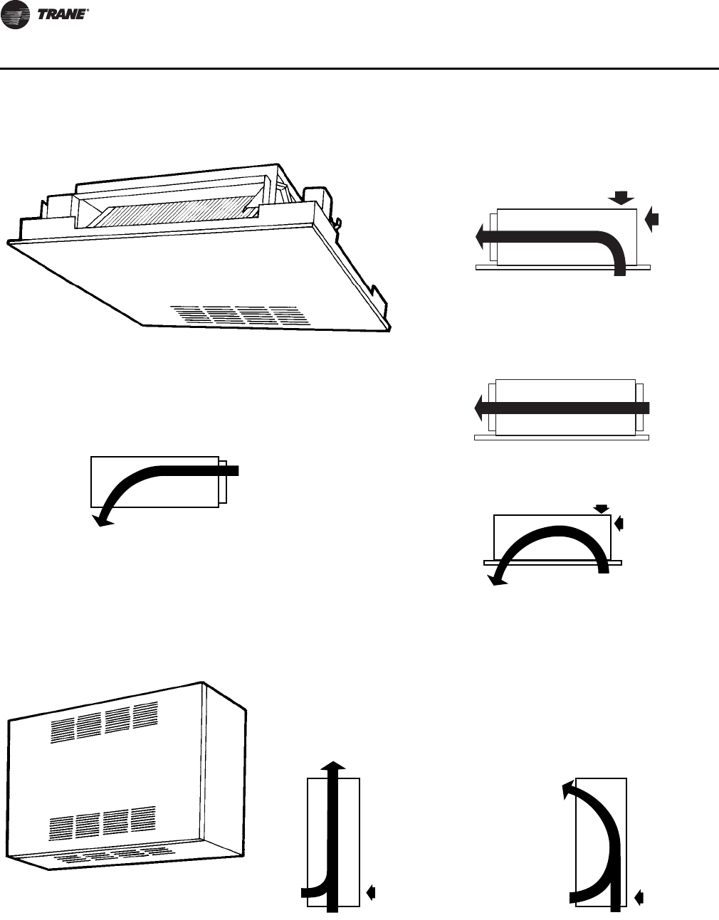
Model C, Horizontal Concealed
Outlet
Front Duct Collar Inlet
Back Duct Collar
Fresh Air
N/A
Outlet
Front Duct Collar
Outlet
Front Duct Collar
Fresh Air
Top or Back
Inlet
Bottom Toe Space
Fresh Air
N/A
Inlet
Open Return
No Filter
CAB-PRC001-EN.book Page 10 Tuesday, May 8, 2012 10:11 AM
CAB-PRC001-EN 11
General Data
Model D, Horizontal Cabinet
Fresh Air
Top or Back
Fresh Air
Top or Back
Fresh Air
N/A
Fresh Air
N/A
Fresh Air
N/A
Fresh Air
N/A
Inlet
Bottom Stamped
Louver
Inlet
Bottom Stamped
Louver
Inlet
Back Stamped
Louver
Inlet
Back Stamped
Louver
Inlet
Back Duct
Collar
Inlet
Back Duct
Collar
Outlet
Front Quad
Grille, Front Bar Grille
Outlet
Front Duct Collar
Outlet
Front Quad
Grille, Front Bar Grille
Outlet
Front Quad
Grille, Front Bar Grille
Outlet
Front Duct Collar
Outlet
Front Duct Collar
Fresh Air
Top or Back Fresh Air
N/A
Outlet
Bottom Stamped
Louver
Outlet
Bottom Stamped
Louver
Inlet
Bottom Stamped
Louver
Inlet
Back Duct
Collar or
Stamped
Louver
CAB-PRC001-EN.book Page 11 Tuesday, May 8, 2012 10:11 AM
12 CAB-PRC001-EN
General Data
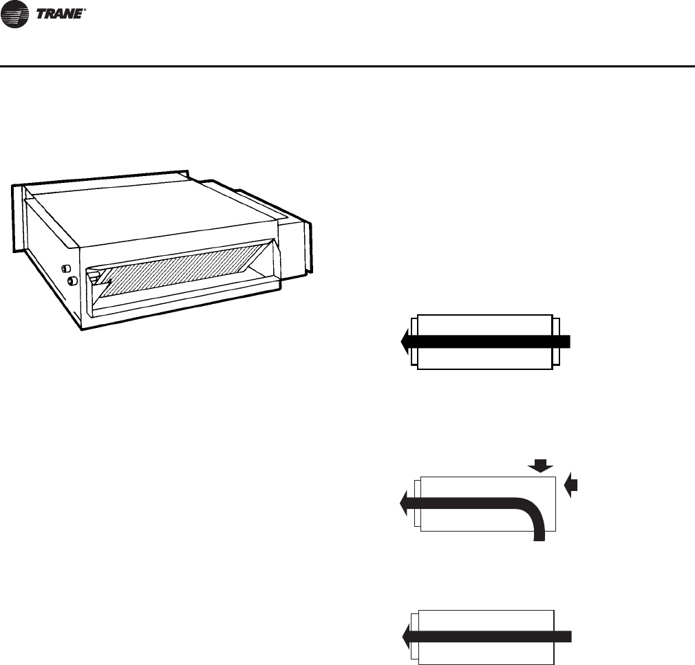
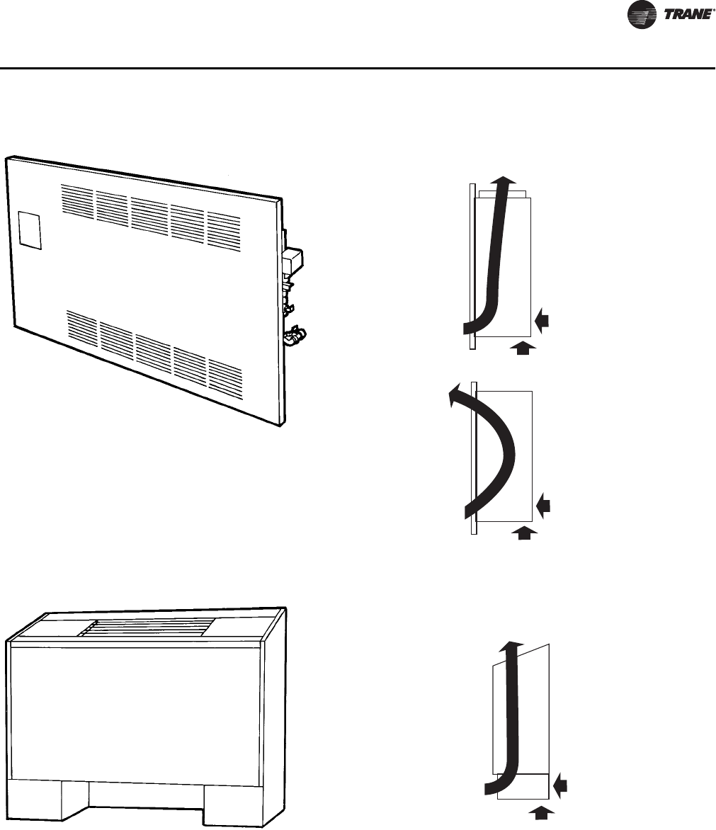
Model E, Horizontal Recessed
Model F, Vertical Wall Hung Cabinet
Fresh Air
Top or Back
Outlet
Front Duct Collar Inlet
Bottom Stamped
Louver
Outlet
Front Duct Collar
Fresh Air
N/A
Inlet
Back Duct
Collar
Fresh Air
Top or Back
Outlet
Bottom Stamped
Louver
Outlet
Bottom Stamped
Louver
Inlet
Bottom Stamped
Louver
Inlet
Back Duct
Collar
Outlet
Top Quad Grille,
Top Bar Grille
Fresh Air
Back
Inlet
Bottom & Front
Stamped Louver
Outlet
Front Stamped
Louver
Fresh Air
Back
Inlet
Bottom & Front
Stamped Louver
CAB-PRC001-EN.book Page 12 Tuesday, May 8, 2012 10:11 AM
CAB-PRC001-EN 13
General Data
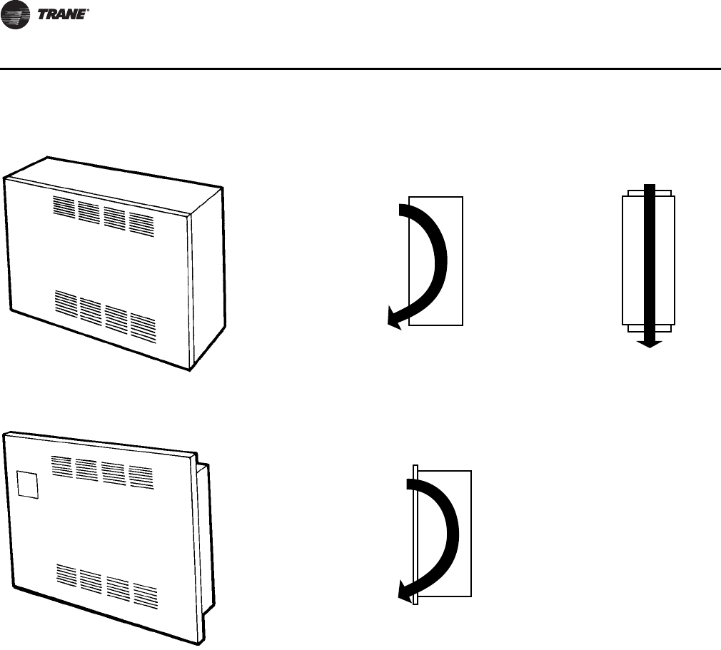
Model H, Vertical Recessed
Model J, Vertical Cabinet Slope Top
Outlet
Top Duct Collar
Outlet
Front
Stamped
Louver
Fresh Air
Bottom or Back
Fresh Air
Bottom or Back
Inlet
Front Stamped
Louver
Inlet
Front
Stamped
Louver
Outlet
Top Quad Grille, Top Bar Grille
Fresh Air
Bottom or Back
Inlet
Front Toe Space,
Front Bar Grille
CAB-PRC001-EN.book Page 13 Tuesday, May 8, 2012 10:11 AM
14 CAB-PRC001-EN
General Data
Model M, Inverted Vertical Concealed
Model N, Inverted Vertical Recessed
Inlet
Front Stamped
Louver
Outlet
Front Stamped
Louver
Inlet
Top Duct
Collar
Outlet
Top Duct
Collar
Inlet
Front Stamped
Louver
Outlet
Front Stamped
Louver
CAB-PRC001-EN.book Page 14 Tuesday, May 8, 2012 10:11 AM

CAB-PRC001-EN 15
General Data
Table 1. Force-Flo cabinet heater general data
Unit Size 02 03 04 06 08 10 12
Coil Data
Face Area-ft2 0.80.81.11.62.13.23.2
LxDxH-in.
2-Row 15x1.7x8 15x1.7x8 20x1.7x8 29.5x1.7x8 38x1.7x8 57x1.7x8 57x1.7x8
3-Row 15x2.6x8 15x2.6x8 20x2.6x8 29.5x2.6x8 38x2.6x8 57x2.6x8 57x2.6x8
4-Row 15x3.5x8 15x3.5x8 20x3.5x8 29.5x3.5x8 38x3.5x8 57x3.5x8 57x3.5x8
Volume-gal.
1-Row 0.06 0.06 0.08 0.11 0.14 0.21 0.21
2-Row 0.12 0.12 0.15 0.22 0.28 0.42 0.42
3-Row 0.18 0.18 0.23 0.33 0.42 0.62 0.62
4-Row 0.24 0.24 0.30 0.44 0.56 0.83 0.83
Fins/ft
2-Row 144 144 144 144 144 144 144
3-Row 144 144 144 144 144 144 144
4-Row 144 144 144 144 144 144 144
Fan/Motor Data
Fan Quantity 1112233
Size-Dia.” x Width” 6.31x4 6.31x6.5 6.31x7.5 6.31x6.5 6.31x7.5 (1) 6.31x7.5 6.31x7.5
(2) 6.31x6.5
Motor Quantity 1111122
Filter Data
1” TA and Pleated Media
Quantity 1111111
Size-in. 8-7/8x19-1/8 8-7/8x19-1/8 8-7/8x24-1/8 8-7/8x33-5/8 8-7/8x42-1/8 8-7/8x61-1/8 8-7/8x61-1/8
1” Fresh Air Filter (Only on Cabinet Styles D, E, and H with Bottom Return and Fresh Air Opening)
Quantity 1111111
Size-in. 5-1/2x19-1/8 5-1/2x19-1/8 5-1/2x24-1/8 5-1/2x33-5/8 5-1/2x42-1/8 5-1/2x61-1/8 5-1/2x61-1/8
CAB-PRC001-EN.book Page 15 Tuesday, May 8, 2012 10:11 AM
16 CAB-PRC001-EN
General Data
Electric Heat
All Force-Flo cabinet heaters, except inverted models M and N, are available with electric heating
coils as a standard option.
Coil Construction
Electric heat coils are open wire type with a nickel chromium element design.
Power Supply
Units have single-point power since the electric heating elements operate on line voltage. Electric
heat is available as 208/60/1, 230/60/1, 277/60/1, 208/60/3, or 480/60/3. Electric heat coils operate on
the same voltage as the unit, except for units with 480/60/3 electric heat. In this case, the unit
operates at 277/60/1, thus requiring a 4-wire supply. All fans and motors are single phase. In
addition, all control options are 24-volt, utilizing a factory-installed transformer.
Power Supply Location
All electric heat cabinet heaters have a terminal block for main power on the unit’s right-hand side.
Control Type
Single-stage electric heat units are controlled by either Tracer UC400, ZN010, ZN510, or ZN520
control options. Two-stage electric heat is controlled by the Tracer UC400, ZN520 only. Both
control options use PWM (pulse-width modulation) outputs to calculate the electric heat output
Table 2. Cabinet heater air flow
Unit Size Coil
ESP
FD Motor High Static Motor
0.05 0.1 0.2 0.3 0.4
02 2R144 246 344 314 283 251
3R144 242 352 319 284 249
4R144 222 326 295 263 230
03 2R144 313 410 380 350 319
3R144 309 391 358 324 290
4R144 276 360 330 299 267
04 2R144 381 446 410 373 336
3R144 365 544 506 467 427
4R144 340 506 470 434 397
06 2R144 609 757 700 642 582
3R144 604 880 824 766 707
4R144 557 812 760 706 652
08 2R144 790 1014 950 885 819
3R144 724 992 927 861 794
4R144 676 930 870 808 745
10 2R144 1015 1284 1199 1113 1024
3R144 1052 1456 1360 1262 1162
4R144 988 1366 1276 1183 1089
12 2R144 1105 1424 1330 1234 1134
3R144 1074 1514 1419 1320 1219
4R144 993 1421 1330 1238 1144
Note: This is data is based on horizontal concealed model only, with duct inlet, duct outlet and no filter, dry coil, all voltages
except 208 V.
CAB-PRC001-EN.book Page 16 Tuesday, May 8, 2012 10:11 AM

CAB-PRC001-EN 17
General Data
based on the capacity request and the electric heat cycles per hour. For example, if the electric heat
cycles per hour is configured for six cycles (as Trane recommends) the controller bases the output
on or off time on six 10-minute periods. If the capacity request is 40 percent, the controller controls
the electric heat output on for approximately four minutes each period.
Safety Features
• Fan/valve operation to ensure safe operation and to ensure that two modes of heat are not
operating simultaneously.
• All Force-Flo units with standard electric heat are UL listed.
• Units require only a single-point electrical connection.
• All electric heating coils are interlocked with the fan motor switch. Therefore, electric heat
operation is only possible when the fan is running.
• Each unit has a transformer, eliminating the need for field installation of a stepdown
transformer.
• Unit-mounted quiet magnetic relays are supplied on all unit voltages.
• A line-break high temperature cutout with automatic reset is provided as an integral part of the
elements to de-energize the electric heat in the event of an overheat condition.
Factory-Installed Piping Packages
Force-Flo cabinet heaters have standard piping packages available as a factory built and installed
option. Factory built assures all piping packages are fully tested under water for leaks and are built
within strict tolerances. Factory-installed means that supply and return pipes are the only field
connections required. The installer doesn’t have to sweat connect piping packages onto coil
connections in a tight end pocket. Field connections are brought to a point near the exterior of the
unit for easy access.
Piping Package Components
Force-Flo piping packages consist of a variety of components for each application. The following
section provides a detailed description of the piping components. Following this section are
additional illustrations and specifications.
Piping System/Placement
Factory piping packages are available with right or left hand connections. A simple coil connection
(a unit without a piping package) is also available in either a right or left hand configuration for
those applications requiring field piping.
Interconnecting Piping
Interconnecting piping refers to the copper piping that attaches the coil connections and all other
components such as control valves, end valves, etc. Piping is 1/2” nominal OD copper and extends
near the unit exterior to one inlet and one outlet connection.
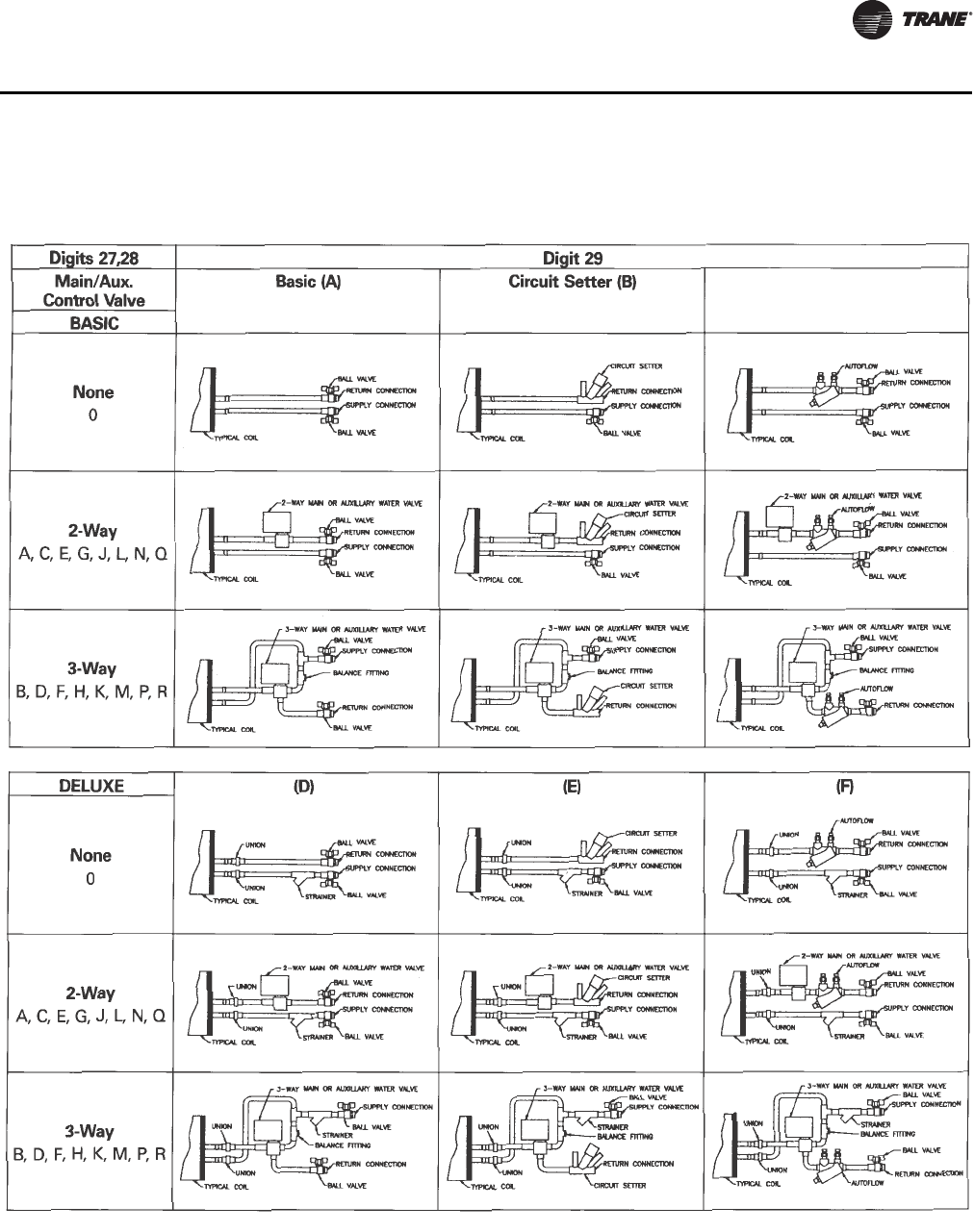
Deluxe or Basic Piping Package
The basic piping package includes only the main components of the piping package:
interconnecting piping, control valves, and end valves.
The deluxe piping package also includes a strainer on the entering water pipe and unions at the
coil connections along with the basic components listed above. The strainer body is cast brass
construction, with a stainless steel mesh strainer that is easily removed for cleaning. The unions
are forged brass construction and close with a minimum amount of effort.
CAB-PRC001-EN.book Page 17 Tuesday, May 8, 2012 10:11 AM

18 CAB-PRC001-EN
General Data
End Valves
Each piping package includes a ball valve for the entering water pipe and one of the following end
valves on the leaving water pipe: ball valve, manual circuit setter, or an auto circuit setter. These
valves serve as the field connection points on all Force-Flo piping packages.
Ball Valves
Ball valves, also known as stop or end valves, allow the unit to be cut off for service purposes. These
valves have a two-inch handle that rotates 90° to a fully open position. The valve body is cast brass,
and the ball is polished brass with a Teflon® seat. Ball valves are available as end valves on both
the entering and leaving water pipes.
Manual Circuit Setter
In lieu of a ball valve on the leaving water pipe, a manual circuit setter, also known as a manual flow
control valve, acts as both a flow setting device and a stop valve. This valve allows water flow
through the cabinet heater to be set quickly and accurately.
The manual circuit setter includes Schrader ports in the valve body. These ports are used to
measure the pressure drop across the valve. This pressure drop can be compared to factory
supplied curves that relate the pressure drop to a specific flow rate. This valve also has a memory
stop that helps find the correct setting quickly.
Auto Circuit Setter
An auto circuit setter is an automatic flow control device available on the leaving water pipe. The
auto circuit setter includes a cartridge within the valve body that is sized to allow a specific flow
rate through the coil. This valve sets flow through the coil without any action required by a system
piping balancer. The auto circuit setter is available on the leaving water pipe with a ball valve.
The auto circuit setter also includes two P/T’s plugs in the valve body to allow measurement of the
pressure drop temperature through the valve.
Control Valves
Piping packages are available with or without control valves. All control valve options are factory
mounted and wired to the Force-Flo unit controls.
Tw o - Wa y / Tw o - Po s i t i o n Va l v e s
These valves will either fully open or close in response to a 24 Vac signal from the Tracer controller.
Control valves are direct-acting valves. The control valve is factory mounted in the leaving water
pipe downstream of the coil. Always use some means of relieving pump head pressure with two-
way valve applications. Normally open or normally closed valves are available.
Three-Way/Two-Position Valves
These valves will either allow full water flow through the coil or divert the flow through a bypass
line. The valves respond to a 24 Vac signal from the Tracer controller. Control valves are direct
acting valves. All three-way valve packages include a balance fitting in the bypass line to allow flow
balancing in the bypass position. Three-way valves are factory mounted in the leaving water pipe
downstream of the coil. Normally open or normally closed valves are available.
Two-Way Modulating Valves
These valves modulate the water flow through the coil in response to a signal from the Tracer
controller. Modulating valves are three-wire floating point equal percentage valves, and are factory
mounted in the leaving water pipe downstream of the coil.
Three-Way Modulating Valves
These valves modulate the water flow through the coil in response to a signal from the Tracer
controller. Three-way valves allow water that is directed through the coil to mix with water directed
through the bypass line. This mixture exits through the leaving water pipe. Modulating valves are
CAB-PRC001-EN.book Page 18 Tuesday, May 8, 2012 10:11 AM
CAB-PRC001-EN 19
General Data
three-wire floating point equal percentage valves, and are factory mounted in the leaving water
pipe downstream of the coil.
Figure 1. Piping package options
Auto Flow Valve (C)
CAB-PRC001-EN.book Page 19 Tuesday, May 8, 2012 10:11 AM

20 CAB-PRC001-EN
General Data
Selecting the Correct Modulating Valve Size
Modulating valves are available in any of four port sizes: 0.7, 1.5, 2.5 or 4.0 Cv (coefficient of flow
values). The coefficient of flow is defined as the volume of water flow through a control valve in
the fully open position with a 1 psig differential across the valve. Calculate the coefficient of flow
using the formula:
Cv = Q/square root ΔP where:
Cv = flow coefficient
Q = flow rate (gpm)
ΔP = pressure drop across the valve or coil (psig).
For good control, the valve Cv should be approximately equal to the Cv of the water coil.
Modulating Valve Selection Example
Assume a size 06 vertical cabinet heater is selected to operate at the following conditions:
EWT = 180°F
LWT = 15 0°F
EAT = 70°F
The coil selection is a four-row coil. Select the best modulating valve size for this unit.
1. Find the ΔP across the water coil. Refer to the ARI performance table to determine the ΔP across
the water coil or use the Trane Official Product Selection System, TOPSS™, selection program.
The water pressure drop is found to be 5.7’ of water at a flow rate of 3.59 gpm. This converts
to a pressure drop of 2.47 psig (1.0 feet of water = 0.4328 psig.)
2. Calculate the Cv of the water coil.
Cv = gpm/Square root ΔP.
Cv = 3.59/Square root 2.47
Cv = 2.29
Therefore, select the 2.5 Cv valve because it is closest to the water coil.
Ta b l e 3 and Table 4, p. 21 illustrate possible valve selections at ARI conditions for horizontal
concealed units with a high static motor and vertical cabinet units with a free discharge motor. For
other applications, use TOPSS to determine flowrate and make calculations using the formulas
above.
Table 3. Modulating valve selections for horizontal concealed units, high static motor, 70°F EAT,
180°F EWT, 30°F ΔT
Unit Size Coil gpm Coil WPD Coil Cv Valve Cv
02 2-Row 1.19 6.0 0.74 0.7
3-Row 1.52 13.8 0.62 0.7
4-Row 1.59 3.8 1.24 1.5
03 2-Row 1.53 10.3 0.72 0.7
3-Row 1.82 4.3 1.33 1.5
4-Row 1.98 6.2 1.21 1.5
04 2-Row 1.73 3.3 1.45 1.5
3-Row 2.57 9.1 1.29 1.5
4-Row 2.81 13.4 1.17 1.5
06 2-Row 2.87 9.9 1.39 1.5
3-Row 3.96 5.9 2.48 2.5
4-Row 4.37 8.2 2.32 2.5
CAB-PRC001-EN.book Page 20 Tuesday, May 8, 2012 10:11 AM

CAB-PRC001-EN 21
General Data
08 2-Row 3.71 4.7 2.60 2.5
3-Row 4.74 9.1 2.39 2.5
4-Row 5.22 12.7 2.23 2.5
10 2-Row 4.71 8.1 2.52 2.5
3-Row 6.50 18.1 2.32 2.5
4-Row 7.13 25.3 2.15 2.5
12 2-Row 5.48 11.4 2.47 2.5
3-Row 7.19 14.5 2.87 2.5
4-Row 7.83 10.5 3.67 4.0
Table 4. Modulating valve selections for vertical cabinet units, free discharge motor, 70°F EAT,
180°F EWT, 30°F ΔT
Unit Size Coil gpm Coil WPD Coil Cv Valve Cv
02 2-Row 1.06 4.8 0.74 0.7
3-Row 1.31 10.5 0.61 0.7
4-Row 1.34 2.8 1.22 1.5
03 2-Row 1.40 8.8 0.72 0.7
3-Row 1.70 3.8 1.33 1.5
4-Row 1.81 5.3 1.20 1.5
04 2-Row 1.71 3.2 1.45 1.5
3-Row 2.12 6.4 1.27 1.5
4-Row 2.28 9.1 1.15 1.5
06 2-Row 2.70 8.9 1.38 1.5
3-Row 3.31 4.2 2.46 2.5
4-Row 3.59 5.7 2.29 2.5
08 2-Row 3.39 4.0 2.58 2.5
3-Row 4.11 6.9 2.38 2.5
4-Row 4.45 9.4 2.21 2.5
10 2-Row 4.32 6.8 2.52 2.5
3-Row 5.55 13.4 2.30 2.5
4-Row 6.00 18.3 2.13 2.5
12 2-Row 4.99 9.6 2.45 2.5
3-Row 6.10 10.5 2.86 2.5
4-Row 6.48 7.3 3.65 4.0
Table 3. Modulating valve selections for horizontal concealed units, high static motor, 70°F EAT,
180°F EWT, 30°F ΔT (continued)
Unit Size Coil gpm Coil WPD Coil Cv Valve Cv
CAB-PRC001-EN.book Page 21 Tuesday, May 8, 2012 10:11 AM
22 CAB-PRC001-EN
Performance Data
Force-Flo cabinet heater performance data is grouped based on performance. Unit performance
is impacted by the unit model and the airflow inlet and outlet configuration. Tab l e 5 summarizes
the performance groups.
Table 5. Force-Flo performance groupings
UNIT TYPE Motor Type Filter Static Performance Tables
Horizontal Concealed Free Discharge NO 0.05 Table 7 & Table 8
Horizontal Recessed Free Discharge NO 0.05
Vertical Recessed Free Discharge NO 0.05
Inverted Vertical Recessed Free Discharge NO 0.05
Vertical Concealed Free Discharge NO 0.05 Table 9 & Table 10
Horizontal Cabinet Free Discharge YES 0.00 Table 11 & Table 12
Vertical Cabinet Free Discharge YES 0.00
Inverted Vertical Cabinet Free Discharge YES 0.00
Vertical Slope Top Free Discharge YES 0.00 Table 13 & Table 14
Horizontal Concealed High Static NO 0.20 Table 15 & Table 16
Horizontal Recessed High Static NO 0.20
Vertical Recessed High Static NO 0.20
Horizontal Cabinet High Static NO 0.20
Vertical Concealed High Static NO 0.20 Table 17 & Table 18
Table 6. Steam properties
Steam Pressure (psig) 2 5 10 15
Saturated Temperature (°F) 219 227 239 250
Latent Heat (Btu/lb) 965 960 952 945
Note: Q/ITD = MBh / (saturated steam temp - entering air temp) When Δ T and gpm remain
constant. To determine heating capacities at a different saturated steam or entering air
temperature, compute the new ITD and multiply it by the new Q/ITD shown.
CAB-PRC001-EN.book Page 22 Tuesday, May 8, 2012 10:11 AM
CAB-PRC001-EN 23
Performance Data
Horizontal Concealed, Horizontal Recessed, Vertical Recessed, Inverted Vertical Recessed
Heating performance is based on 70°F entering air temperature, 180°F entering hot water
temperature with a 30°F ΔT. All performance measured on high speed tap, 115 V, 0.05 ESP, without
filter. Free discharge EC motor.
Table 7. Hot water performance—free discharge EC motor
SIZE COIL
Airflow
(cfm)
Hot Water Coils
Motor
Power (W)
Total
Capacity
(MBh) Q/ITD
Flow Rate
(gpm)
WPD
(ft H20)
020 2HC 246 16.68 0.15 1.11 5.65 37
3HC 242 20.15 0.18 1.34 2.37 37
4HC 222 21.48 0.20 1.43 3.33 37
030 2HC 313 19.63 0.18 1.31 7.53 39
3HC 309 24.17 0.22 1.61 3.30 39
4HC 276 25.69 0.23 1.71 4.61 39
040 2HC 381 24.00 0.22 1.60 2.74 58
3HC 365 30.04 0.27 2.00 5.55 58
4HC 340 32.47 0.30 2.16 8.01 58
060 2HC 609 38.29 0.35 2.55 7.70 79
3HC 604 47.34 0.43 3.15 3.74 79
4HC 557 51.54 0.47 3.43 5.09 79
080 2HC 790 48.10 0.44 3.20 3.48 122
3HC 724 58.70 0.53 3.91 6.13 122
4HC 676 63.95 0.58 4.26 8.42 122
100 2HC 1015 66.94 0.61 4.46 7.51 145
3HC 1052 86.01 0.78 5.73 9.10 145
4HC 988 94.57 0.86 6.30 10.52 145
120 2HC 1105 70.88 0.64 4.72 8.37 160
3HC 1074 87.35 0.79 5.82 9.38 160
4HC 993 94.97 0.86 6.33 10.60 160
Note: Q/ITD = MBh / (entering water temp - entering air temp) When Δ T and gpm remain constant.To determine
heating capacities at a different entering water or entering air temperature, compute the new ITD and multiply
it by the new Q/ITD shown.
Table 8. Steam coil performance—free discharge EC motor
SIZE COIL
Airflow
(cfm)
2 PSIG 5 PSIG
Motor
Power
(W)
Total
Capacity
(MBh) Q/ITD
Heating
LAT (°F)
Total
Capacity
(MBh) Q/ITD
Heating
LAT (°F)
020 Steam 228 15.13 0.102 131 16.02 0.102 135 37
030 Steam 275 16.59 0.111 126 17.57 0.112 129 39
040 Steam 345 21.77 0.146 128 23.06 0.147 132 58
060 Steam 544 33.92 0.228 128 35.94 0.229 131 79
080 Steam 701 43.58 0.292 127 46.18 0.294 131 122
100 Steam 933 62.02 0.416 131 65.72 0.419 135 145
120 Steam 990 63.85 0.429 129 67.66 0.431 133 160
Note: Q/ITD = MBh / (saturated steam temp - entering air temp) When Δ T and gpm remain constant. To determine heating
capacities at a different saturated steam or entering air temperature, compute the new ITD and multiply it by the new
Q/ITD shown.
CAB-PRC001-EN.book Page 23 Tuesday, May 8, 2012 10:11 AM
24 CAB-PRC001-EN
Performance Data
Vertical Concealed
Heating performance is based on 70°F entering air temperature, 180°F entering hot water
temperature with a 30°F ΔT. All performance measured on high speed tap, 115 V, 0.05 ESP, without
filter. Free discharge EC motor.
Table 9. Hot water performance—free discharge EC motor
SIZE COIL Airflow (cfm)
Hot Water Coils
Motor Power
(W)
Total Capacity
(MBh) Q/ITD
Flow Rate
(gpm)
WPD
(ft H20)
020 2HC 211 14.91 0.14 0.99 4.64 37
3HC 205 17.63 0.16 1.17 1.86 37
4HC 192 18.93 0.17 1.26 2.65 37
030 2HC 272 17.89 0.16 1.19 6.40 39
3HC 270 21.92 0.20 1.46 2.76 39
4HC 247 23.48 0.21 1.56 3.92 39
040 2HC 340 22.21 0.20 1.48 2.37 58
3HC 328 27.65 0.25 1.84 4.77 58
4HC 309 29.98 0.27 2.00 6.94 58
060 2HC 535 35.16 0.32 2.34 6.58 79
3HC 531 43.07 0.39 2.87 3.13 79
4HC 499 47.13 0.43 3.14 4.30 79
080 2HC 697 44.29 0.40 2.95 2.98 122
3HC 646 53.90 0.49 3.59 5.22 122
4HC 612 58.94 0.54 3.93 7.23 122
100 2HC 891 61.04 0.55 4.07 6.31 145
3HC 913 77.24 0.70 5.14 7.39 145
4HC 870 85.08 0.77 5.67 8.68 145
120 2HC 980 65.32 0.59 4.35 7.17 160
3HC 958 80.12 0.73 5.34 7.94 160
4HC 899 87.46 0.80 5.83 9.12 160
Note: Q/ITD = MBh / (entering water temp - entering air temp) When Δ T and gpm remain constant. To determine heating
capacities at a different entering water or entering air temperature, compute the new ITD and multiply it by the new
Q/ITD shown.
Table 10. Steam coil performance—free discharge EC motor
SIZE COIL
Airflow
(cfm)
2 PSIG 5 PSIG
Motor
Power (W)
Total
Capacity
(MBh) Q/ITD
Heating
LAT (°F)
Total
Capacity
(MBh) Q/ITD
Heating
LAT (°F)
020 Steam 203 14.27 0.096 135 15.11 0.096 139 37
030 Steam 250 15.83 0.106 128 16.76 0.107 132 39
040 Steam 317 20.90 0.140 131 22.13 0.141 134 58
060 Steam 496 32.43 0.218 130 34.35 0.219 134 79
080 Steam 642 41.72 0.280 130 44.20 0.282 134 122
100 Steam 846 59.00 0.396 134 62.52 0.398 138 145
120 Steam 909 61.19 0.411 132 64.84 0.413 136 160
Note: Q/ITD = MBh / (saturated steam temp - entering air temp) When Δ T and gpm remain constant. To determine heating
capacities at a different saturated steam or entering air temperature, compute the new ITD and multiply it by the new
Q/ITD shown.
CAB-PRC001-EN.book Page 24 Tuesday, May 8, 2012 10:11 AM
CAB-PRC001-EN 25
Performance Data
Horizontal Cabinet, Vertical Cabinet, Inverted Vertical Cabinet
Heating performance is based on 70°F entering air temperature, 180°F entering hot water
temperature with a 30°F ΔT. All performance measured on high speed tap, 115 V, 0 ESP, throwaway
filter. Free discharge EC motor.
Note: The steam coil option is not available on the Horizontal Cabinet or Horizontal Recessed
models.
Table 11. Hot water performance—free discharge EC motor
SIZE COIL
Airflow
(cfm)
Hot Water Coils
Motor Power
(W)
Total
Capacity
(MBh) Q/ITD
Flow Rate
(gpm)
WPD
(ft H20)
020 2HC 222 15.46 0.14 1.03 4.94 37
3HC 217 18.46 0.17 1.23 2.02 37
4HC 204 19.96 0.18 1.33 2.92 37
030 2HC 280 18.23 0.17 1.21 6.61 39
3HC 277 22.37 0.20 1.49 2.87 39
4HC 256 24.14 0.22 1.61 4.12 39
040 2HC 349 22.63 0.21 1.51 2.46 58
3HC 338 28.30 0.26 1.89 4.98 58
4HC 320 30.86 0.28 2.06 7.31 58
060 2HC 544 35.56 0.32 2.37 6.72 79
3HC 541 43.64 0.40 2.91 3.21 79
4HC 510 48.02 0.44 3.20 4.45 79
080 2HC 706 44.67 0.41 2.98 3.02 122
3HC 659 54.74 0.50 3.65 5.38 122
4HC 627 60.13 0.55 4.01 7.51 122
100 2HC 912 62.09 0.56 4.14 6.51 145
3HC 933 78.56 0.71 5.23 7.64 145
4HC 893 86.94 0.79 5.79 9.02 145
120 2HC 996 66.08 0.60 4.40 7.32 160
3HC 976 81.29 0.74 5.41 8.16 160
4HC 921 89.25 0.81 5.95 9.47 160
Note: Q/ITD = MBh / (entering water temp - entering air temp) When Δ T and gpm remain constant. To determine heating
capacities at a different entering water or entering air temperature, compute the new ITD and multiply it by the new
Q/ITD shown.
Table 12. Steam coil performance—free discharge EC motor
SIZE COIL
Airflow
(cfm)
2 PSIG 5 PSIG
Motor
Power
(W)
Total
Capacity
(MBh) Q/ITD
Heating
LAT (°F)
Total
Capacity
(MBh) Q/ITD
Heating
LAT (°F)
020 Steam 203 14.27 0.096 135 15.11 0.096 139 37
030 Steam 250 15.83 0.106 128 16.76 0.107 132 39
040 Steam 317 20.90 0.140 131 22.13 0.141 134 58
060 Steam 496 32.43 0.218 130 34.35 0.219 134 79
080 Steam 642 41.72 0.280 130 44.20 0.282 134 122
100 Steam 846 59.00 0.396 134 62.52 0.398 138 145
120 Steam 909 61.19 0.411 132 64.84 0.413 136 160
Note: Q/ITD = MBh / (saturated steam temp - entering air temp) When Δ T and gpm remain constant. To determine heating
capacities at a different saturated steam or entering air temperature, compute the new ITD and multiply it by the new
Q/ITD shown.
CAB-PRC001-EN.book Page 25 Tuesday, May 8, 2012 10:11 AM
26 CAB-PRC001-EN
Performance Data
Vertical Slope Top Cabinet
Heating performance is based on 70°F entering air temperature, 180°F entering hot water
temperature with a 30°F ΔT. All performance measured on high speed tap, 115 V, 0 ESP, throwaway
filter. Free discharge EC motor.
Table 13. Hot water performance—free discharge EC motor
SIZE COIL
Airflow
(cfm)
Hot Water Coils
Motor Power
(W)
Total
Capacity
(MBh) Q/ITD
Flow Rate
(gpm)
WPD
(ft H20)
020 2HC 206 14.62 0.13 0.97 4.48 37
3HC 200 17.31 0.16 1.15 1.80 37
4HC 190 18.75 0.17 1.25 2.61 37
030 2HC 262 17.42 0.16 1.16 6.10 39
3HC 260 21.31 0.19 1.42 2.63 39
4HC 242 23.05 0.21 1.54 3.79 39
040 2HC 330 21.75 0.20 1.45 2.28 58
3HC 320 27.12 0.25 1.81 4.61 58
4HC 304 29.59 0.27 1.97 6.77 58
060 2HC 512 34.09 0.31 2.27 6.22 79
3HC 508 41.67 0.38 2.78 2.94 79
4HC 483 45.89 0.42 3.06 4.09 79
080 2HC 665 42.88 0.39 2.86 2.80 122
3HC 623 52.44 0.48 3.49 4.96 122
4HC 596 57.65 0.52 3.84 6.94 122
100 2HC 856 59.29 0.54 3.95 5.97 145
3HC 873 74.56 0.68 4.97 6.91 145
4HC 839 82.51 0.75 5.50 8.21 145
120 2HC 940 63.45 0.58 4.23 6.78 160
3HC 923 77.85 0.71 5.19 7.51 160
4HC 876 85.55 0.78 5.70 8.76 160
Note: Q/ITD = MBh / (entering water temp - entering air temp) When Δ T and gpm remain constant. To determine heating
capacities at a different entering water or entering air temperature, compute the new ITD and multiply it by the new
Q/ITD shown.
Table 14. Steam coil performance—free discharge EC motor
SIZE COIL
Airflow
(cfm)
2 PSIG 5 PSIG
Motor
Power
(W)
Total
Capacity
(MBh) Q/ITD
Heating
LAT (°F)
Total
Capacity
(MBh) Q/ITD
Heating
LAT (°F)
020 Steam 191 13.83 0.093 137 14.64 0.093 141 37
030 Steam 237 15.42 0.103 130 16.33 0.104 134 39
040 Steam 303 20.42 0.137 132 21.63 0.138 136 58
060 Steam 472 31.62 0.212 132 33.49 0.213 135 79
080 Steam 611 40.71 0.273 131 43.13 0.275 135 122
100 Steam 801 57.40 0.385 136 60.81 0.387 140 145
120 Steam 867 59.74 0.401 134 63.30 0.403 137 160
Note: Q/ITD = MBh / (saturated steam temp - entering air temp) When Δ T and gpm remain constant. To determine heating
capacities at a different saturated steam or entering air temperature, compute the new ITD and multiply it by the new
Q/ITD shown.
CAB-PRC001-EN.book Page 26 Tuesday, May 8, 2012 10:11 AM

CAB-PRC001-EN 27
Performance Data
Horizontal Concealed, Horizontal Recessed, Vertical Recessed, Horizontal Cabinet
Heating performance is based on 70°F entering air temperature, 180°F entering hot water
temperature with a 30°F ΔT. All performance measured on high speed tap, 115 V, 0.20 ESP, without
filter. High static EC motor.
Note: The steam coil option is not available on the Horizontal Cabinet or Horizontal Recessed
models.
Table 15. Hot water performance—high static EC motor
SIZE COIL
Airflow
(cfm)
Hot Water Coils
Motor Power
(W)
Total
Capacity
(MBh) Q/ITD
Flow Rate
(gpm)
WPD
(ft H20)
2HC 314 19.68 0.18 1.31 7.18 84
3HC 319 24.71 0.22 1.65 3.28 84
200 4HC 295 27.07 0.25 1.80 4.83 84
2HC 380 22.14 0.20 1.47 8.85 91
3HC 358 26.79 0.24 1.78 3.80 91
300 4HC 330 29.52 0.27 1.97 5.65 91
2HC 410 25.18 0.23 1.68 2.85 110
3HC 506 37.80 0.34 2.52 8.05 110
400 4HC 470 41.89 0.38 2.79 12.12 110
2HC 700 41.80 0.38 2.78 8.63 162
3HC 824 58.43 0.53 3.89 5.36 162
600 4HC 760 65.21 0.59 4.34 7.59 162
2HC 950 53.86 0.49 3.59 4.16 298
3HC 927 69.93 0.64 4.66 8.20 298
800 4HC 870 77.84 0.71 5.19 11.67 298
2HC 1199 74.76 0.68 4.98 8.90 252
3HC 1360 103.27 0.94 6.88 12.55 252
1000 4HC 1276 113.35 1.03 7.55 9.41 252
2HC 1330 79.76 0.73 5.31 10.07 314
3HC 1418 106.27 0.97 7.08 13.26 314
1200 4HC 1330 116.96 1.06 7.79 10.00 314
Note: Q/ITD = MBh / (entering water temp - entering air temp) When Δ T and gpm remain constant. To determine heating
capacities at a different entering water or entering air temperature, compute the new ITD and multiply it by the new
Q/ITD shown.
Table 16. Steam coil performance—high static EC motor
SIZE COIL
Airflow
(cfm)
2 PSIG 5 PSIG
Motor
Power
(W)
Total
Capacity
(MBh) Q/ITD
Heating
LAT (°F)
Total
Capacity
(MBh) Q/ITD
Heating
LAT (°F)
020 Steam 290 17.00 0.114 124 18.01 0.115 127 84
030 Steam 348 18.52 0.124 119 19.62 0.125 122 91
040 Steam 383 22.91 0.154 125 24.27 0.155 128 110
060 Steam 653 37.03 0.249 122 39.24 0.250 125 162
080 Steam 890 48.80 0.328 121 51.73 0.329 124 298
100 Steam 1140 68.37 0.459 125 72.47 0.462 129 252
120 Steam 1252 71.49 0.480 123 75.79 0.483 126 314
Note: Q/ITD = MBh / (saturated steam temp - entering air temp) When Δ T and gpm remain constant. To determine heating
capacities at a different saturated steam or entering air temperature, compute the new ITD and multiply it by the new
Q/ITD shown.
CAB-PRC001-EN.book Page 27 Tuesday, May 8, 2012 10:11 AM

28 CAB-PRC001-EN
Performance Data
Vertical Concealed
Heating performance is based on 70°F entering air temperature, 180°F entering hot water
temperature with a 30°F ΔT. All performance measured on high speed tap, 115 V, 0.20 ESP, without
filter. High static EC motor.
Table 17. Hot water performance—high static EC motor
SIZE COIL
Airflow
(cfm)
Hot Water Coils
Motor Power
(W)
Total
Capacity
(MBh) Q/ITD
Flow Rate
(gpm)
WPD
(ft H20)
2HC 274 17.95 0.16 1.20 6.11 84
3HC 274 22.13 0.20 1.47 2.68 84
200 4HC 258 24.31 0.22 1.62 3.97 84
2HC 341 20.70 0.19 1.38 7.86 91
3HC 319 24.76 0.23 1.65 3.29 91
300 4HC 299 27.36 0.25 1.82 4.92 91
2HC 377 23.84 0.22 1.59 2.58 110
3HC 455 35.17 0.32 2.34 7.05 110
400 4HC 429 39.04 0.35 2.60 10.66 110
2HC 632 39.23 0.36 2.61 7.68 162
3HC 733 54.10 0.49 3.60 4.63 162
600 4HC 687 60.53 0.55 4.03 6.60 162
2HC 865 50.88 0.46 3.39 3.73 298
3HC 845 65.58 0.60 4.37 7.26 298
800 4HC 800 73.06 0.66 4.87 10.36 298
2HC 1089 70.18 0.64 4.68 7.90 252
3HC 1206 95.02 0.86 6.33 10.68 252
1000 4HC 1145 104.37 0.95 6.95 8.02 252
2HC 1218 75.51 0.69 5.03 9.07 314
3HC 1291 99.64 0.91 6.64 11.71 314
1200 4HC 1223 109.80 1.00 7.31 8.85 314
Note: Q/ITD = MBh / (entering water temp - entering air temp) When Δ T and gpm remain constant. To determine heating
capacities at a different entering water or entering air temperature, compute the new ITD and multiply it by the new
Q/ITD shown.
Table 18. Steam coil performance—high static EC motor
SIZE COIL
Airflow
(cfm)
2 PSIG 5 PSIG
Motor
Power
(W)
Total
Capacity
(MBh) Q/ITD
Heating
LAT (°F)
Total
Capacity
(MBh) Q/ITD
Heating
LAT (°F)
020 Steam 257 16.06 0.108 128 17.01 0.108 131 84
030 Steam 317 17.75 0.119 122 18.80 0.120 125 91
040 Steam 356 22.12 0.148 127 23.44 0.149 131 110
060 Steam 598 35.51 0.238 125 37.63 0.240 128 162
080 Steam 820 46.97 0.315 123 49.78 0.317 126 298
100 Steam 1045 65.56 0.440 128 69.48 0.443 131 252
120 Steam 1159 68.93 0.463 125 73.06 0.465 128 314
Note: Q/ITD = MBh / (saturated steam temp - entering air temp) When Δ T and gpm remain constant. To determine heating
capacities at a different saturated steam or entering air temperature, compute the new ITD and multiply it by the new
Q/ITD shown.
CAB-PRC001-EN.book Page 28 Tuesday, May 8, 2012 10:11 AM
CAB-PRC001-EN 29
Controls
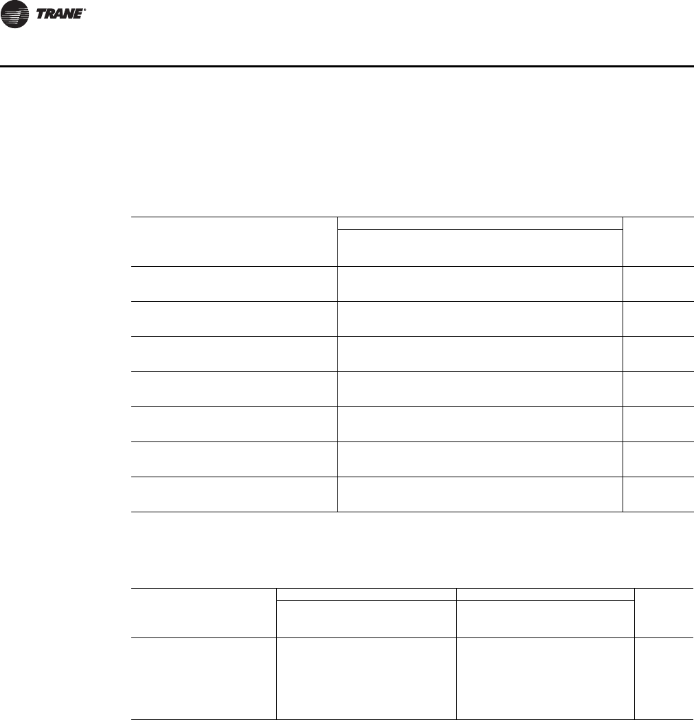
ECM Engine Controller
The Electronically Commutated Motor (ECM) engine controls and reports the performance of up
to two Trane Brushless DC (BLDC) motors.
• The engine also coordinates the operation of the fan in response to electric heat behavior and
electric behavior in response to hydronic heat behavior.
• The engine incorporates a user interface that allows adjustment of certain unit parameters and
provides constant feedback on motor operation.
• The engine integrates service and troubleshooting tools.
• The engine integrates a versatile configurable auxiliary temperature sensor.
• The engine incorporates various safety and lockout features, such as maintaining proper fan
speeds if electric heat is called for.
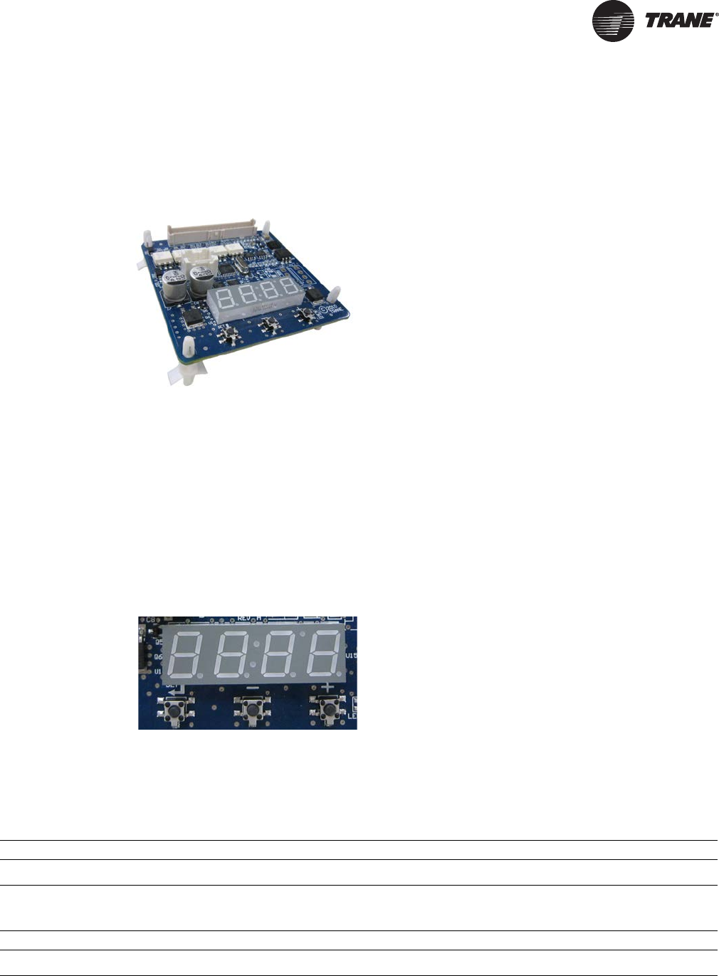
Status Display
The ECM engine board contains a four-digit, seven-segment display that is used to present
information in a format close to real-world language, while having a small-form factor. Most
characters are immediately recognizable; however, please consult Tab le 19 and Tab le 20 for the
graphical representation of each alphanumeric character.
Figure 2. ECM engine controller
Figure 3. Status display
Table 19. Screen representation of alphabetical characters
ABCDEFGHI JKLMNOPQRSTUVWXYZ
Table 20. Screen representation of numeric characters
1234567890
CAB-PRC001-EN.book Page 29 Tuesday, May 8, 2012 10:11 AM
30 CAB-PRC001-EN
Controls
Control Options
Force-Flo cabinet heaters are available with four different control options:
• Manual three-speed fan switch
• Tracer ZN010
• Tracer ZN510
• Tracer ZN520
• Tracer UC400
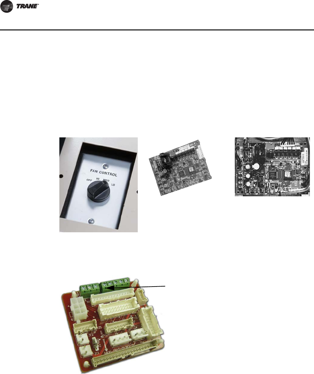
Manual Fan Mode Switch
Model Number Digit 30 = A and Digit 31 = D or K
Fan speed switch Tracer ZN010 control board Tracer ZN510 control board
Figure 4. Adapter board
Note: Customer Low-Voltage Interface for
Fan Speeds, Variable Fan Speed, and
24 Vac Supply
CAB-PRC001-EN.book Page 30 Tuesday, May 8, 2012 10:11 AM
CAB-PRC001-EN 31
Controls
The adapter allows direct customer interfacing through the use of terminal strips. Standard
interfacing includes:
• Fan Speeds (H, M, L) (for wall mounted fan speed switches)
• Variable speed (0–10V) inputs
The standard adapter board eliminates many separate wiring harnesses in the panel and allows
simple, mistake-proofed single-plug interfacing of:
• The ECM engine controller
•Transformers
•Motors
• Valves
•Dampers
• Electric heat control
• Fan speed switches
• Main power (except electric heat)
The manual fan mode switch is available for fan-coil units that do not have Trane factory-mounted
control packages. This four-position switch (off, high, medium, low) allows manual fan mode
selection and is available unit or wall mounted. The unit-mounted option (Digit 31 = D) operates
on line voltage. The wall-mounted option (Digit 31 = K) is low-voltage and has three 24-volt relays
using a factory-wired transformer and relays to control the fan motor.
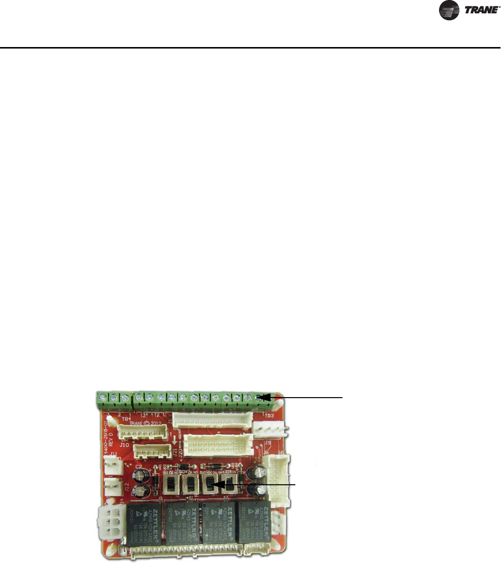
Customer Supplied Terminal Interface (CSTI)
Figure 5. CSTI adapter board
Customer Low-Voltage Interface for
Valves, Electric Heat, Dampers, Fan
Speeds, Variable Fan Speed, and
24 Vac Supply
Valve(s), Electric Heat, and Changeover
Configuration Switches (Factory-Set)
CAB-PRC001-EN.book Page 31 Tuesday, May 8, 2012 10:11 AM
32 CAB-PRC001-EN
Controls
The control interface is intended to be used with a field-supplied, low-voltage thermostat or
controller. The control box contains a relay board which includes a line voltage to 24-volt
transformer, quiet contactors (for electric heat units), and an optional disconnect switch. All end
devices are wired to a low-voltage terminal block and are run-tested, so the only a power
connection and thermostat connection is needed to commission the unit. Changeover sensors and
controls are provided whenever a change-over coil is selected. When N.O. valves are selected,
inverting relays are provided for use with standard thermostats.
The CSTI adapter board provides all the hookups of the standard adapter board, but in addition,
provides hookups for valve control (main and auxiliary coils), electric heat control, and damper
control. Screw terminal blocks provide convenient access to fan controls and to end device control.
In addition, a courtesy 10-Vdc supply is provided for use with an external potentiometer or rheostat.
The 10-Vdc supply supports up to 10 mA draw.
Tracer Controls
The Tracer family of controllers (Tracer ZN010, ZN510, ZN520, and UC400) offer the combined
advantages of simple and dependable operation with the latest Trane-designed controller.
Standard control features include options normally available on more elaborate control systems.
All control options are available factory-configured or can be field-configured using Trane service
software. For more detailed information, refer to CNT-IOP-1 (for Tracer ZN010 or ZN510) or
CNT-SVX04A-EN (for Tracer ZN520), or UNT-SVX07D-EN (for Tracer UC400), or the most recent
version of the publication
Tracer ZN010, Model Number digit 30 = E
Tracer ZN010 is a stand-alone microprocessor controller.
Tracer ZN510, Model Number digit 30 = F
Tracer ZN510 can be used as either a stand-alone or communicating microprocessor controller.
Tracer ZN520, Model Number digit 30 = G
Tracer ZN520 controller can be used in a stand-alone application or as part of a Trane Integrated
Comfort™ System (ICS).
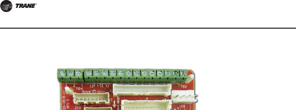
Figure 6. CSTI adapter board field connections
1. VSP 10V
2. VSP 0–10V
3. VSP DC COM
1. 24 Vac Y (hot)
2. 24 Vac Y (gnd)
3. High
4. Medium
5. Low
6. V1Op/Cooling
7. V1C1 (not std)
8. Not used
9. Not used
10. V2Op/EH1St/Heating
11. V2C1/EH2St (not std)
12. Damper Open
13. Dmp Cl (not std)
321 1098 7654321
11
12
13
CAB-PRC001-EN.book Page 32 Tuesday, May 8, 2012 10:11 AM
CAB-PRC001-EN 33
Controls
In the stand-alone configuration, Tracer ZN520 receives operation commands from the zone
sensor. The zone sensor module is capable of transmitting the following information to the
controller:
• Timed override on/cancel request
• Zone setpoint
• Current zone temperature
• Fan mode selection (off-auto-high-med-low)
For optimal system performance, Force-Flo units can be linked to an Integrated Comfort System
(ICS) building automation system controlled by Tracer SC. The controller is connected to the
building automation system with a LON Talk communications network. The Trane ICS system can
monitor or override Tracer ZN520 control points. This includes such points as temperature and
output positions.
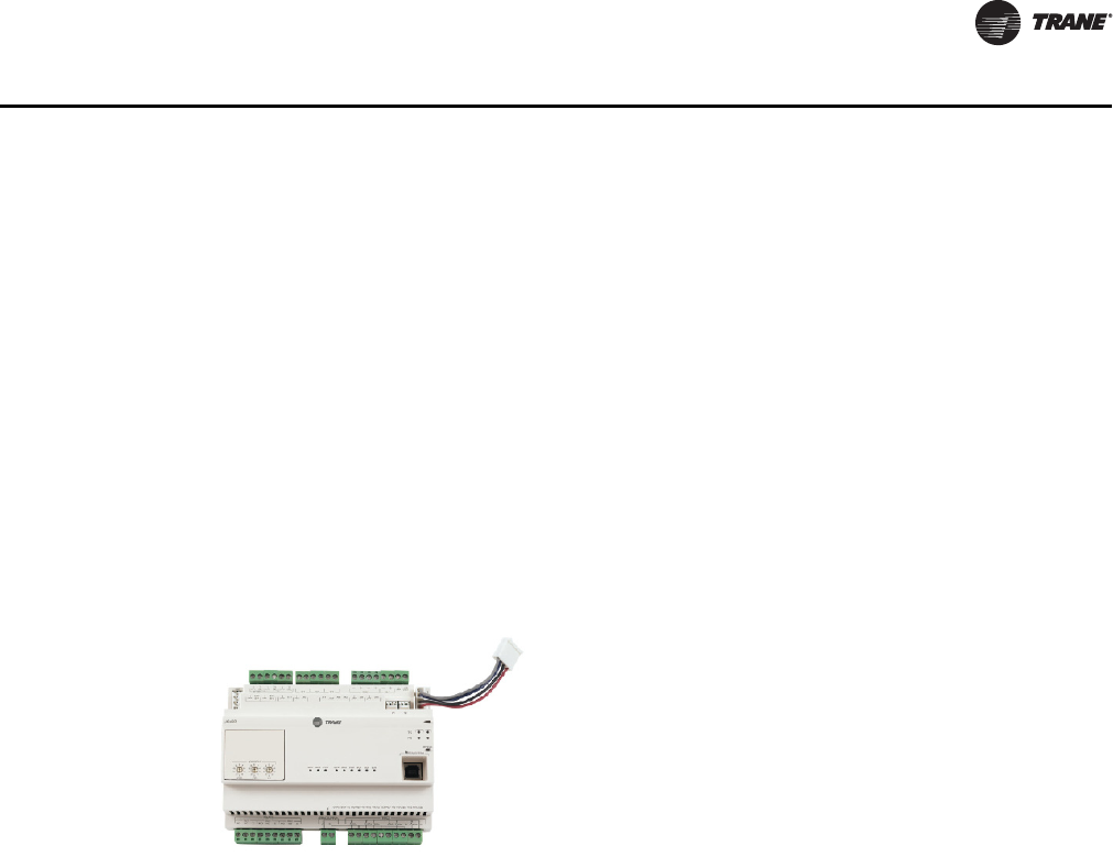
Tracer UC400, Model Number Digit 30 = J
The UC400 controller can be used in a stand-alone application or as part of a Trane Integrated
Comfort™ System (ICS).
In the stand-alone configuration, UC400 receives operation commands from the zone sensor
and/or the auto changeover sensor (on auto changeover units). The entering water temperature is
read from the auto changeover sensor and determines if the unit is capable of cooling or heating.
The zone sensor module is capable of transmitting the following information to the controller:
• Timed override on/cancel request
• Zone setpoint
• Current zone temperature
• Fan mode selection (off-auto-high-med-low)
For optimal system performance, fan-coil units can operate as part of an Integrated Comfort
System (ICS) building automation system controlled by Tracer SC. The controller is linked to the
building automation system using BACnet MS/TP. The building automation system can monitor or
override UC400 control points. This includes such points as temperature and output positions.
Service Software
A windows-based software package option allows field service personnel to easily monitor, save,
download, and configure Tracer unit controllers directly or through a communication link from a
portable computer. When connected over the communication link, the service software can view
any Tracer ZN controller that is on the same communication link. See Tracer TU or Rover literature
for more details.
Figure 7.
CAB-PRC001-EN.book Page 33 Tuesday, May 8, 2012 10:11 AM

34 CAB-PRC001-EN
Controls
Sequence of Operation
Fan Speed Switch
Off: Fan is turned off, two-position damper option spring-returns closed.
High, Medium, Low: Fan runs continuously at the selected speed. The two-position damper option
opens to an adjustable mechanical stop position.
Tracer ZN010 and ZN510
Off: Fan is off; control valves and fresh air damper option close.
Auto (Fan Cycling): Fan and fresh air damper cycle with control valve option to maintain setpoint
temperature. In heating mode it cycles from off to low (factory default that can be field-adjusted
using Rover service software). When heating is not required, the fan is off and the fresh air damper
option closes. The fan can also be field-configured (using Rover) to run at a user-defined speed
when the fan speed switch is in the auto position.
Low, Medium, High (Continuous Fan): Fan operates continuously while control valve option cycles
to maintain setpoint temperature. Fresh air damper option is open.
Tracer ZN520
Off: Fan is off; control valve options and fresh air damper options close.
Auto: Fan speed control in the auto setting allows the modulating (three-wire floating point) control
valve option and three-speed fan to work cooperatively to meet precise capacity requirements,
while minimizing fan speed (motor/energy/acoustics) and valve position (pump energy). As the
capacity requirement increases at low fan speed, the water valve opens. When the low fan speed
capacity switch point is reached, the fan switches to medium speed and the water valve repositions
to maintain an equivalent capacity. The reverse sequence takes place with a decrease in required
capacity.
Low, Medium, High: The fan will run continuously at the selected speed and the valve option will
cycle to meet setpoint.
Tracer UC400
Off: Fan is off; control valve options and fresh air damper options close.
Auto: Fan speed control in the auto setting allows the modulating (three-wire floating point) control
valve option and three-speed fan to work cooperatively to meet precise capacity requirements,
while minimizing fan speed (motor/energy/acoustics) and valve position (pump energy). As the
capacity requirement increases at low fan speed, the water valve opens. When the low fan speed
capacity switch point is reached, the fan switches to medium speed and the water valve repositions
to maintain an equivalent capacity. The reverse sequence takes place with a decrease in required
capacity.
Low, Medium, High: The fan will run continuously at the selected speed and the valve option will
cycle to meet setpoint.
Occupied Mode
In Occupied Mode, the UC400 controller maintains the space temperature based on the occupied
space temperature setpoint ± occupied offset. The controller uses the occupied mode as a default
mode when other forms of occupancy request are not present and the fan runs continuously. The
outdoor air damper, if present, will close when the fan is OFF. The temperature setpoints can be
local (hard wired), communicated, or stored default values (configurable using the Tracer TU
service tool).
Unoccupied Mode
In unoccupied mode, the UC400 controller attempts to maintain the space temperature based on
the unoccupied heating or cooling setpoint. The fan will cycle between high speed and OFF. In
CAB-PRC001-EN.book Page 34 Tuesday, May 8, 2012 10:11 AM
CAB-PRC001-EN 35
Controls
addition, the outdoor air damper remains closed, unless economizing. The controller always uses
the stored default setpoint values (configurable using the Tracer TU service tool), regardless of the
presence of a hard wired or communicated setpoint value.
Timed Override Control
If the UC400 controller has a timed override option (ON/CANCEL buttons), pushing the ON button
initiates a timed override on request. A timed override on request changes the occupancy mode
from unoccupied mode to occupied bypass mode. In occupied bypass mode, the controller
controls the space temperature based on the occupied heating or cooling setpoints. The occupied
bypass time, which resides in the UC400 controller and defines the duration of the override, is
configurable from 0 to 240 minutes (default value of 120 minutes). When the occupied bypass time
expires, the unit transitions from occupied bypass mode to unoccupied mode. Pushing the
CANCEL button cancels the timed override request. In addition, it will end the timed override
before the occupied bypass time has expired and transition the unit from occupied bypass mode
to unoccupied mode.
If the controller is in any mode other than unoccupied mode when the ON button is pressed, the
controller still starts the occupied bypass timer without changing to occupied bypass mode. If the
controller is placed in unoccupied mode before the occupied bypass timer expires, the controller
is placed into occupied bypass mode and remains in this mode until either the CANCEL button is
pressed on the Trane zone sensor or the occupied bypass time expires.
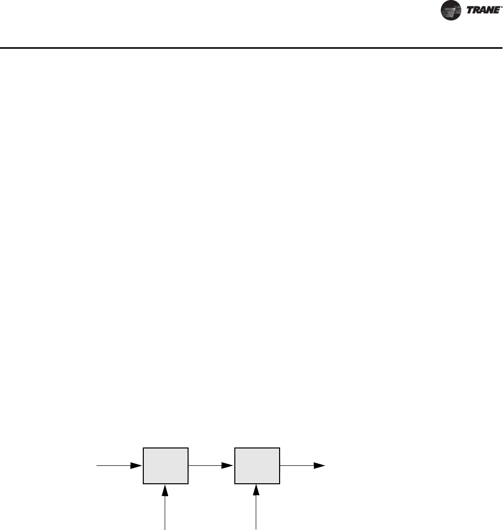
Zone Temperature Control
The UC400 controller has three methods of zone temperature control:
•Cascade zone control—used in the occupied, occupied bypass, and occupied standby
modes. It maintains zone temperature by controlling the discharge air temperature to control
the zone temperature. The controller uses the difference between the measured zone
temperature and the active zone temperature setpoint to produce a discharge air temperature
setpoint. The controller compares the discharge air temperature setpoint with the discharge air
temperature and calculates a unit heating/cooling capacity accordingly (refer to the illustration
below). The end devices (outdoor air damper, valves, and so on) operate in sequence based on
the unit heating/cooling capacity (0–100 percent).
If the discharge air temperature falls below the discharge air temperature low limit setpoint,
(configurable using the Tracer TU service tool), and the cooling capacity is at a minimum, the
available heating capacity is used to raise the discharge air temperature to the low limit.
•Simplified zone control— if discharge air temperature failure occurs, then simplified zone
controls runs. In the unoccupied mode, the controller maintains the zone temperature by
calculating the required heating or cooling capacity (0–100%) according to the measured zone
temperature and the active zone temperature setpoint. The active zone temperature setpoint
is determined by the current operating modes, which include occupancy and heat/cool modes.
•Discharge air temperature control— is the backup mode that runs only if there is not valid
zone temperature. In this mode, the active space temperature setpoint is used as the discharge
air temperature setpoint.
Difference
Active zone
temperature
setpoint
Calculated
discharge air
temperature
setpoint
Calculated unit
heating/cooling
capacity
Measured
zone
temperature
Measured
discharge air
temperature
Difference
CAB-PRC001-EN.book Page 35 Tuesday, May 8, 2012 10:11 AM

36 CAB-PRC001-EN
Controls
Important: This is not a normal operating mode. The source of the invalid zone temperature
needs to be corrected to restore normal operation.
** 'Generic' i/o - if there is unused i/o the user may create a new point to reference the i/o. But there is no dedicated 'generic'
i/o like on ZN
Binary inputs -- there is also a defrost and fan status (for 1,2,3 speed fans) for UC400 and ZN520.
The ECM fan does not use the Binary input for fan status but gets the info over IMC from the ECM.
ZN520 also had a binary input for fan status. ZN520 also had defrost but it was wired directly to the compressor (IOP
explains this).
Table 21. Controller input/output summary
ZN010 ZN510 ZN520 UC400
Binary Outputs X
3-Speed Fan XXXX
2-Position Hydronic Valve X X X X
2-Position Fresh Air Damper X X X
1-Stage Electric Heat X X X X
3-Wire Economizer Damper X X
3-Wire Hydronic Valve XX
2-Stage Electric Heat XX
Reheat (hydronic or electric) X X
Generic X X X **
Binary Inputs
Condensate Overflow Detection X X X X
Low Temperature Detection XXXX
Occupancy XXXX
Generic Input X X X **
Analog Inputs
Zone Temperature X X X X
Setpoint X X X X
Fan Mode: Auto, High, Medium, Low X X X X
Entering Water X X X X
Discharge Air XXXX
Outside Air XX
Generic X**
Analog Outputs
Variable speed fan X
Field supplied analog valves X
Note: The generic input and output are for use with a Tracer Building Automation System only.
Table 22. Controller function summary
ZN010 ZN510 ZN520 UC400
Control Functions
Entering Water Temp. Sampling (Purge) X X X X
Auto Changeover XXXX
Fan Cycling X X
Warm-Up X X X
Pre-Cool X X X
Data Sharing (Master/Slave) X X
Random Start X X X X
Dehumidification XX
Acoustic Mode X
Efficiency Mode X
Single Zone VAV Mode X
Staged Capacity (2-Stage Electric Supplementary) X X
Other Functions
Manual Test X X X in TU
Maintenance Timer X X X X
Setpoint Limits X X X X
CAB-PRC001-EN.book Page 36 Tuesday, May 8, 2012 10:11 AM
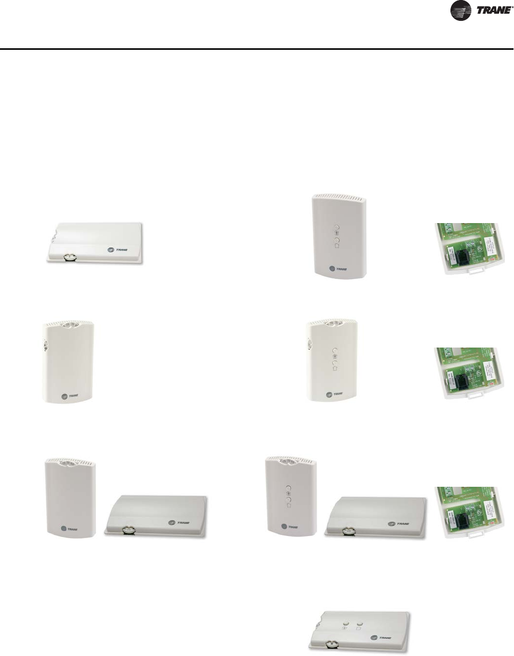
CAB-PRC001-EN 37
Controls
Zone Sensor Options
Zone sensors are available as either unit, wall, or split-mounted options for design flexibility. Force-
Flo units with the unit-mounted zone sensor option include a thermistor in the unit’s return air path.
Wall-mounted zone sensor options have an internal thermistor. Zone sensors operate on 24 Vac.
Tracer ZN010 Options Tracer UC400, ZN510, and ZN520 Options
Figure 8. Unit-mounted zone sensor: Digit 30 = E and
Digit 31 = V
Figure 9. Wall-mounted zone sensor: Digit 30 = F or G
and Digit 31 = 1
Figure 10. Wall-mounted zone sensor: Digit 30 = E and
Digit 31 = W
Figure 11. Wall-mounted zone sensor: Digit 30 = F or G
and Digit 31 = 2
Figure 12. Split-mounted zone sensor, unit-mounted fan
mode and wall-mounted setpoint dial:
Digit 30 = E and Digit 31 = X
Figure 13. Split-mounted zone sensor, unit-mounted fan
mode and wall-mounted setpoint dial:
Digit 30 = F or G and Digit 31 = Y
Figure 14. Unit-mounted zone sensor: Digit 30 = F or G
and Digit 31 = Z
X13790843-01
X13511530-01 (wall)
X13651467-02 (comm)
X13790841-01
X13790842-01 (wall)
X13651467-02 (comm)
X13511529-01 (wall)
X13790849-01 (unit)
X13511527-01 (wall)
X13790849-01 (unit)
X13651467-02 (comm)
X13790844-01
CAB-PRC001-EN.book Page 37 Tuesday, May 8, 2012 10:11 AM
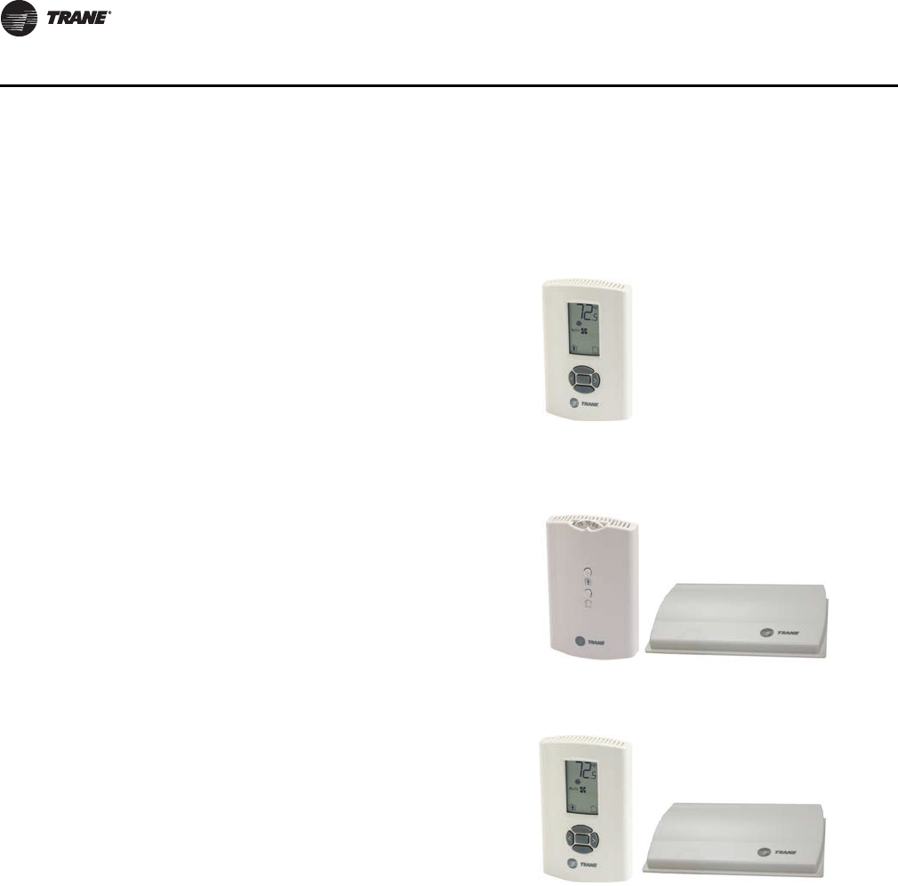
38 CAB-PRC001-EN
Controls
Control Features
The following control functions are standard features on units with Tracer UC400, ZN010, ZN510,
ZN520, or UC400.
Occupied/Unoccupied Operation
The occupancy input utilizes a binary switch (i.e. motion sensor, timeclock, etc.) that allows the zone
sensor to utilize its unoccupied internal setpoints.
Random Start
This feature randomly staggers multiple unit startup to reduce electrical demand spikes.
Warmup
The two-position fresh air damper option closes during the occupied mode when the space
temperature is three degrees or more below the heating setpoint temperature. The damper
remains closed during warmup until the space temperature is within two degrees of the heating
setpoint temperature.
Tracer UC400, ZN510, and ZN520 Options
(continued)
Figure 15. Wall-mounted digital zone sensor with
setpoint adjustment: Digit 30 = F or G and
Digit 31 = 4
Figure 16. Wireless zone sensor (setpoint adjustment, no
fan speed adjustment): Digit 30 = F or G and
Digit 31 = 6
Figure 17. Wireless zone sensor: Digit 30 = F or G and
Digit 31 = 7
X13790886-04 (wall)
X13790821-01 (wall)
X13790860-02 (unit)
X13790822-04 (wall)
X13790860-02 (unit)
CAB-PRC001-EN.book Page 38 Tuesday, May 8, 2012 10:11 AM

CAB-PRC001-EN 39
Controls
Manual Output Test Function
This feature is an invaluable tool for troubleshooting a unit. By simply pressing the controller’s test
button, service personnel can manually exercise outputs in a pre-defined sequence.
Peer to Peer Communication (Tracer ZN510, ZN520, and UC400)
Peer to peer communication allows multiple units in one space to share the same zone sensor and
provide simultaneous heating. The Tracer ZN510 or ZN520 controller can share information
between units on the same communication link using a twisted pair wire in the field. Unit
configuration must be modified with Rover service tool. On the UC400, zone sensor data sharing
can be accomplished by use of the BAS system controller.
Tracer ZN520 and UC400 Additional Features
Filter Maintenance Status
Tracer controller has an adjustable timer that indicates through the building automation system or
the service software tool when filter maintenance is necessary. Filter maintenance status is based
on cumulative fan run hours.
Water Valve Override
Using the building automation system or the service software tool, the water valve override
function drives all water valves in every unit fully open simultaneously. This helps reduce the time
required for waterside balancing.
Cascade Control
Tracer controller maintains discharge air temperature using a cascade control algorithm. The
discharge air temperature is based on the difference between the space temperature and setpoint.
Unit capacity modulates to achieve the discharge air temperature.
Interoperability
Tracer ZN520 can be used with a Tracer Summit system or on other control systems that support
LonTalk® and the SCC profile. For more information on specific inputs and outputs, see UNT-IOM-6
(Installation, Operation, and Maintenance: UniTrane® Fan-Coil Room Conditioners - Force Flo™
Cabinet Heaters), or the most recent version.
The Tracer UC400 can be used with the Tracer SC or another BACnet MS/TP building automation
system. For more information see the Installation Operation and Programming Guide BAS-SVX48
for more information.
End Device Options
All end device options are factory-installed and -tested.
Two-Position Control Valves; Model Number Digits 27 & 28 = A–H
Two-position valve options are available with either Tracer ZN010, ZN510, ZN520, or UC400. Valves
are spring-return type, sweat connections, and available as normally open or closed. The valves
respond to a 24 V signal and have 1/2-inch sweat connections. The two-way valve option will either
fully open or close. The three-way valve option allows either full water flow through the coil or
diverts waterflow through the bypass. If the control valve loses power, the valve returns to its de-
energized position. All control valve options are factory installed in the leaving water piping
downstream of the hydronic coil. The valve actuator is easily removable for service without
removing the valve body from piping.
Modulating Control Valves (Tracer ZN520 and UC400); Model Number Digits 27
& 28 = J–R
These 1/2-inch sweat connect valves are three-wire floating point valves, equal percentage type.
Modulating valves are available in four Cv sizes: 0.7, 1.5, 2.5, and 4.0. The valve responds to a 24 V
CAB-PRC001-EN.book Page 39 Tuesday, May 8, 2012 10:11 AM

40 CAB-PRC001-EN
Controls
triac signal from the controller, which determines the valve position by a control algorithm. If the
valve loses power, it remains in the position that it was in when the power loss occurred. All control
valves are factory installed in the leaving water piping downstream of the hydronic coil.
Field-Supplied Valves; Model Number Digits 27 and 28 = X, Y, Z or 1.
When using field-supplied valves, this option allows the controller to be factory-configured for the
normal position of the field-supplied valve.
Note: Trane does not recommend wild coil applications.
Two-Position Fresh Air Damper Actuator; Model Number Digit 13 = D, E, or F
(Available with all control options except Tracer ZN520)
This damper actuator uses a 24 V signal and is factory-wired and mounted to the damper assembly.
It allows zero to 50 percent fresh air. The damper will drive open to an adjustable mechanical stop-
position whenever the fan is running during occupied mode and will spring-return closed when the
fan turns off.
CAB-PRC001-EN.book Page 40 Tuesday, May 8, 2012 10:11 AM
CAB-PRC001-EN 41
Electrical Data
Table 23. Two-stage electric heat (digit 18 = U)
Unit Size Voltage Wires 1st Stage kW Total kW Total amps/ph
02 208/60/1 2 0.75 2.25 10.9
240/60/1 2 1.0 3.0 12.5
277/60/1 2 1.0 3.0 10.9
208/60/3 3 0.75 2.25 6.3
240/60/3 3 1.0 3.0 7.3
480/60/3 4 1.0 3.0 3.7
03 208/60/1 2 1.5 4.5 21.7
240/60/1 2 2.0 6.0 25.0
277/60/1 2 2.0 6.0 21.7
208/60/3 3 1.5 4.5 12.6
240/60/3 3 2.0 6.0 14.5
480/60/3 4 2.0 6.0 7.3
04 208/60/1 2 1.9 5.7 27.5
240/60/1 2 2.5 7.5 31.3
277/60/1 2 2.5 7.5 27.1
208/60/3 3 1.9 5.7 15.9
240/60/3 3 2.5 7.5 18.1
480/60/3 4 2.5 7.5 9.1
06 208/60/1 2 3.4 7.9 38.0
240/60/1 2 4.5 10.5 43.8
277/60/1 2 4.5 10.5 38.0
208/60/3 3 3.4 7.9 21.9
240/60/3 3 4.5 10.5 25.3
480/60/3 4 4.5 10.5 12.7
08 208/60/1 2 4.5 10.1 48.8
240/60/1 2 6.0 13.5 56.3
277/60/1 2 6.0 13.5 48.8
208/60/3 3 4.5 10.1 28.2
240/60/3 3 6.0 13.5 32.5
480/60/3 4 6.0 13.5 16.3
10 208/60/1 2 6.0 13.5 65.0
240/60/1 2 8.0 18.0 75.0
277/60/1 2 8.0 18.0 65.0
208/60/3 3 6.0 13.5 37.6
240/60/3 3 8.0 18.0 43.3
480/60/3 4 8.0 18.0 21.7
12 208/60/1 2 6.8 15.0 72.3
240/60/1 2 9.0 20.0 83.4
277/60/1 2 9.0 20.0 72.3
208/60/3 3 6.8 15.0 41.7
240/60/3 3 9.0 20.0 48.2
480/60/3 4 9.0 20.0 24.1
Note: When both stages are on, the electric heat will operate only when fan is in high speed. All data based
on individual units.
CAB-PRC001-EN.book Page 41 Tuesday, May 8, 2012 10:11 AM

42 CAB-PRC001-EN
Electrical Data
Table 24. Single-stage, max kW electric heat (digit 18 = N)
Unit Size Voltage Wires Heater kW Heater amps/ph
02 208/60/1 2 2.25 10.9
240/60/1 2 3.0 12.5
277/60/1 2 3.0 10.9
208/60/3 3 2.25 6.3
240/60/3 3 3.0 7.3
480/60/3 4 3.0 3.7
03 208/60/1 2 4.5 21.7
240/60/1 2 6.0 25.0
277/60/1 2 6.0 21.7
208/60/3 3 4.5 12.6
240/60/3 3 6.0 14.5
480/60/3 4 6.0 7.3
04 208/60/1 2 5.7 27.5
240/60/1 2 7.5 31.3
277/60/1 2 7.5 27.1
208/60/3 3 5.7 15.9
240/60/3 3 7.5 18.1
480/60/3 4 7.5 9.1
06 208/60/1 2 7.9 38.0
240/60/1 2 10.5 43.8
277/60/1 2 10.5 38.0
208/60/3 3 7.9 21.9
240/60/3 3 10.5 25.3
480/60/3 4 10.5 12.7
Note: All data based on individual units. Electric heat will operate only with fan at high speed.
Table 25. Single stage, low kW electric heat (digit 18 = V)
Unit Size Voltage # Wires kW amps/ph kW amps/ph kW amps/ph
02 208/60/1 2 0.75 3.7 1.5 7.3
240/60/1 2 1.0 4.2 2.0 8.4
277/60/1 2 1.0 3.7 2.0 7.3
03 208/60/1 2 2.25 10.9
240/60/1 2 3.0 12.5
277/60/1 2 3.0 10.9
208/60/3 3 2.25 6.3
240/60/3 3 3.0 7.3
480/60/3 4 3.0 3.7
04 208/60/1 2 2.25 10.9
240/60/1 2 3.0 12.5
277/60/1 2 3.0 10.9
208/60/3 3 2.25 6.3
240/60/3 3 3.0 7.3
480/60/3 4 3.0 3.7
06 208/60/1 2 2.25 10.9 3.3 15.9
240/60/1 2 3.0 12.5 4.5 18.8
277/60/1 2 3.0 10.9 4.5 16.3
208/60/3 3 2.25 6.3 3.3 9.2
240/60/3 3 3.0 7.3 4.5 10.9
480/60/3 4 3.0 3.7 4.5 5.5
08 208/60/1 2 2.25 10.9 3.3 15.9 4.5 21.7
240/60/1 2 3.0 12.5 4.5 18.8 6.0 25.0
277/60/1 2 3.0 10.9 4.5 16.3 6.0 21.7
208/60/3 3 2.25 6.3 3.3 9.2 4.5 12.5
240/60/3 3 3.0 7.3 4.5 10.9 6.0 14.5
480/60/3 4 3.0 3.7 4.5 5.5 6.0 7.3
10 208/60/1 2 2.25 10.9 3.3 15.9 5.7 27.5
240/60/1 2 3.0 12.5 4.5 18.8 7.5 31.3
277/60/1 2 3.0 10.9 4.5 16.3 7.5 27.1
208/60/3 3 2.25 6.3 3.3 9.2 5.7 15.9
240/60/3 3 3.0 7.3 4.5 10.9 7.5 18.1
480/60/3 4 3.0 3.7 4.5 5.5 7.5 9.1
12 208/60/1 2 2.25 10.9 3.3 15.9 6.6 31.8
240/60/1 2 3.0 12.5 4.5 18.8 9.0 37.5
277/60/1 2 3.0 10.9 4.5 16.3 9.0 32.5
208/60/3 3 2.25 6.3 3.3 9.2 6.6 18.4
240/60/3 3 3.0 7.3 4.5 10.9 9.0 21.7
480/60/3 4 3.0 3.7 4.5 5.5 9.0 10.9
Note: All data based on individual units. Electric heat will operate only with fan at high speed.
CAB-PRC001-EN.book Page 42 Tuesday, May 8, 2012 10:11 AM

CAB-PRC001-EN 43
Electrical Data
Minimum Circuit Ampacity (MCA) and Maximum Fuse Size (MFS) Calculations
Units with Electric Heat. HACR (heating, air conditioning, and refrigeration) type circuit
breakers are required in the branch circuit wiring for all units with electric heat. To compute MCA
and MFS, see Table 26, p. 44 through Table 29, p. 44 for motor FLAs and Table 23, p. 41 through
Table 25, p. 42 for electric heat amps.
Calculating electric heat amps:
Single stage, three phase = heat kW * 1000/1.732/volts
Two stage, three phase = total heat kW * 1000/1.732/volts
Note: Use 240 V heat voltage for 230 V units.
Calculating MCA (units with electric heat):
MCA = 1.25 * (heat amps + sum of all motor FLAs)
Calculating MFS (units with electric heat):
MFS = (2.25 * largest motor FLA) + second motor FLA, size 10-12 units only + heat amps
Use the closest larger fuse or HACR circuit breaker above the MCA. Standard fuse sizes are: 15,
20, 25, 30, 35, 40, 45, 50, 60 amps.
Electric heat MBh = heater kW * 3.413
Units without Electric Heat. To compute MCA and MFS, see Table 26, p. 44 through Tab le 2 9,
p. 44 for motor FLAs and Table 23, p. 41 through Table 25, p. 42 for electric heat amps.
Calculating MCA (units without electric heat):
MCA = (1.25) x largest motor FLA + second motor FLA, unit sizes 10 and 12 only
Calculating MFS (units without electric heat):
MFS or HACR1 type circuit breaker = 15 amps for all units without electric heat.
1HACR (heating, air-conditioning and refrigeration) type circuit breakers are required in the branch circuit wiring for all size 10 and 12
units.
CAB-PRC001-EN.book Page 43 Tuesday, May 8, 2012 10:11 AM
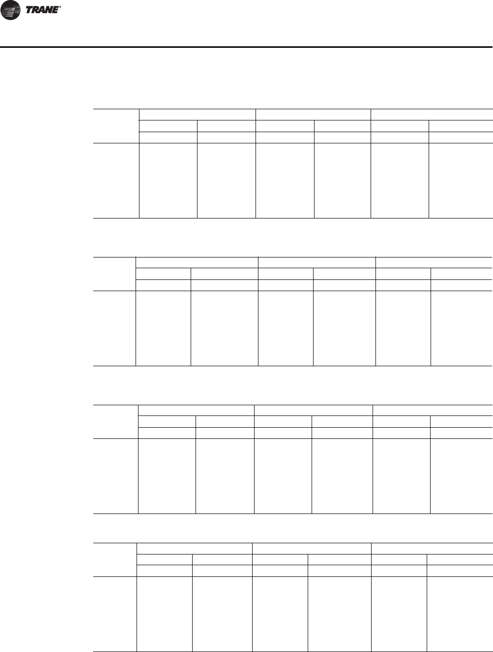
44 CAB-PRC001-EN
Electrical Data
Table 26. Free discharge electrically commutated motors (ECMs) programmed to standard ECM
mode
Unit Size
115 Volt 208–230 Volt 277 Volt
FLA HP FLA HP FLA HP
1212121212 1 2
2 3.1 0.22 1.8 0.22 1.6 0.24
3 3.1 0.22 1.8 0.22 1.6 0.24
4 3.1 0.22 1.8 0.22 1.6 0.24
6 3.1 0.22 1.8 0.22 1.6 0.24
8 3.1 0.22 1.8 0.22 1.6 0.24
10 3.1 3.1 0.22 0.22 1.8 1.8 0.22 0.22 1.6 1.6 0.24 0.24
12 3.1 3.1 0.22 0.22 1.8 1.8 0.22 0.22 1.6 1.6 0.24 0.24
Table 27. High static electrically commutated motors (ECMs) on units programmed to standard
ECM mode
Unit Size
115 Volt 208–230 Volt 277 Volt
FLA HP FLA HP FLA HP
12 1 2 12 1 2 12 1 2
2 3.1 0.22 1.8 0.22 1.6 0.24
3 3.1 0.22 1.8 0.22 1.6 0.24
4 3.1 0.22 1.8 0.22 1.6 0.24
6 3.1 0.22 1.8 0.22 1.6 0.24
8 3.1 0.22 1.8 0.22 1.6 0.24
10 3.1 3.1 0.22 0.22 1.8 1.8 0.22 0.22 1.6 1.6 0.24 0.24
12 3.1 3.1 0.22 0.22 1.8 1.8 0.22 0.22 1.6 1.6 0.24 0.24
Table 28. Free discharge electrically commutated motors (ECMs) programmed to reduced FLA
mode
Unit Size
115 Volt 208–230 Volt 277 Volt
FLA HP FLA HP FLA HP
121 212 1 2 12 1 2
2 0.6 0.22 0.4 0.22 0.3 0.24
3 0.6 0.22 0.4 0.22 0.3 0.24
4 0.8 0.22 0.6 0.22 0.4 0.24
6 1.1 0.22 0.8 0.22 0.6 0.24
8 1.6 0.22 1.1 0.22 0.8 0.24
10 0.7 1.2 0.22 0.22 0.5 0.8 0.22 0.22 0.4 0.6 0.24 0.24
12 0.7 1.3 0.22 0.22 0.5 0.9 0.22 0.22 0.4 0.7 0.24 0.24
Table 29. High static electrically commutated motors (ECMs) programmed to reduced FLA mode
Unit Size
115 Volt 208–230 Volt 277 Volt
FLA HP (kW) FLA HP (kW) FLA HP (kW)
12 1 2 12 1 2 12 1 2
2 1.3 0.22 0.9 0.22 0.7 0.24
3 1.3 0.22 0.9 0.22 0.7 0.24
4 1.7 0.22 1.2 0.22 0.9 0.24
6 2.3 0.22 1.6 0.22 1.2 0.24
8 3.1 0.22 1.8 0.22 1.5 0.24
10 1.4 2 0.22 0.22 1 1.4 0.22 0.22 0.7 1.1 0.24 0.24
12 1.5 2.8 0.22 0.22 1.1 1.8 0.22 0.22 0.8 1.4 0.24 0.24
CAB-PRC001-EN.book Page 44 Tuesday, May 8, 2012 10:11 AM
CAB-PRC001-EN 45
Electrical Data
Table 30. Unit RPM
Unit
Size
Free Discharge-Units with 2-Row Coils Free Discharge-Units with 3- and 4-Row Coils
HML H M L
2 980 840 655 980 840 655
3 980 780 580 1080 800 600
4 1050 780 580 1080 800 600
6 1030 780 580 1080 800 600
8 1080 800 600 1080 800 600
10 1050 780 580 1080 800 600
1030 780 580 1080 800 600
12 1050 780 580 1080 800 600
1080 800 600 1080 800 600
Unit
Size
High Static-Units with 2-Row Coils High Static-Units with 3- and 4-Row Coils
HML H M L
2 1480 1110 865 1480 1110 865
3 1400 1175 860 1500 1355 1110
4 1475 1315 1070 1580 1375 1240
6 1400 1070 855 1475 1285 975
8 1475 1285 975 1475 1285 975
10 1475 1315 1070 1580 1375 1240
1400 1070 855 1475 1285 975
12 1475 1315 1070 1580 1375 1240
1475 1285 975 1475 1285 975
Note: Actual rpm will vary with application and configuration.
CAB-PRC001-EN.book Page 45 Tuesday, May 8, 2012 10:11 AM
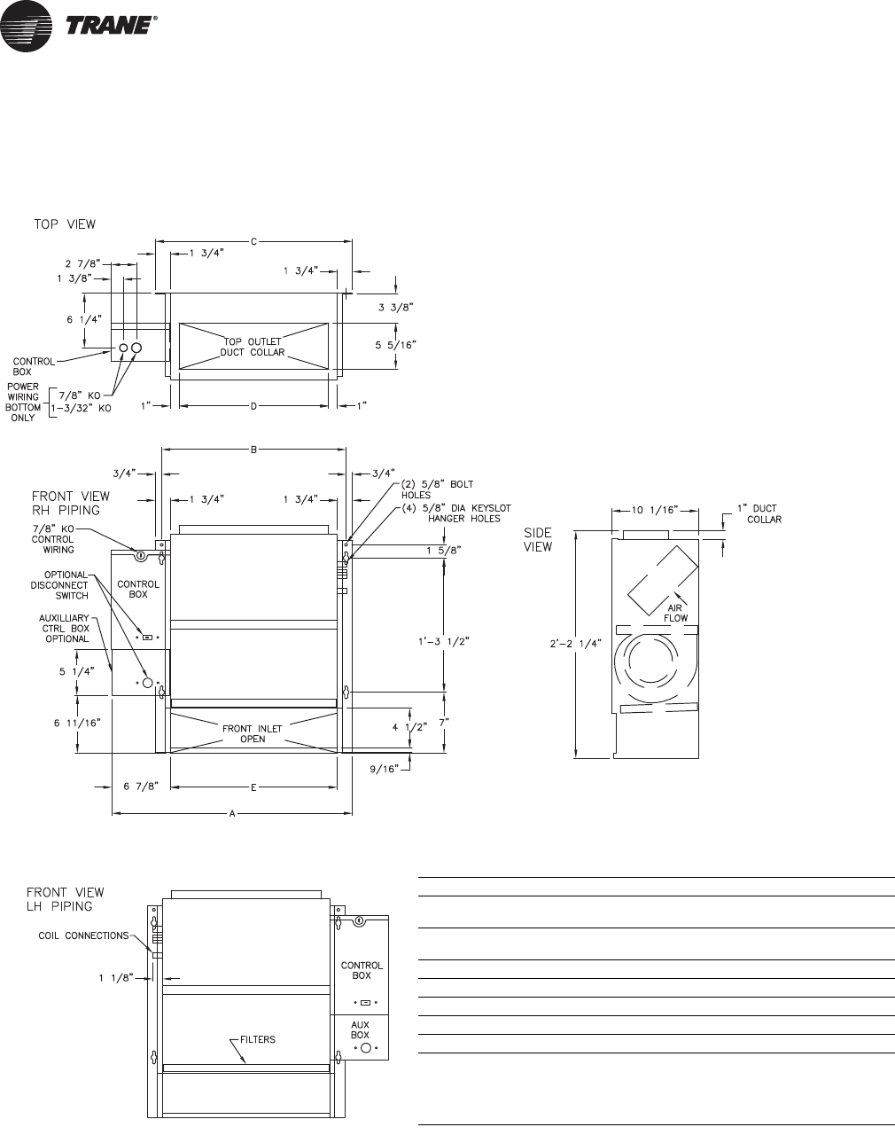
46 CAB-PRC001-EN
Dimensions and Weights
Vertical Concealed, Model A
Vertical Concealed Unit
Unit Size 200–300 400 600 800 1000-1200
No. of
Fans 11223
No. of
Motors 11112
A 2’-3 7/8” 2’-8 7/8” 3’-6 3/8” 4’-2 7/8” 5’-9 7/8”
B 1’-9 5/16” 2’-2 5/16” 2’-11 13/16” 3’-8 5/16” 5’-3 5/16”
C 1’-10 13/16” 2’-3 13/16” 3’-1 5/16” 3’-9 13/16” 5’-4 13/16”
D 1’-5 5/16” 1’-10 5/16” 2’-7 13/16” 3’-4 5/16” 4’-11 5/16”
E 1’-7 5/16” 2’-0 5/16” 2’-9 13/16” 3’-4 5/16” 5’-1 5/16”
Notes:
1. Coil connections are always opposite the control box.
2. Coil connections are 5/8” O.D. sweat. See p. 56 for locations.
3. All duct collar dimensions are to the outside of the collar.
4. See p. 58 for dimensions for air openings.
CAB-PRC001-EN.book Page 46 Tuesday, May 8, 2012 10:11 AM
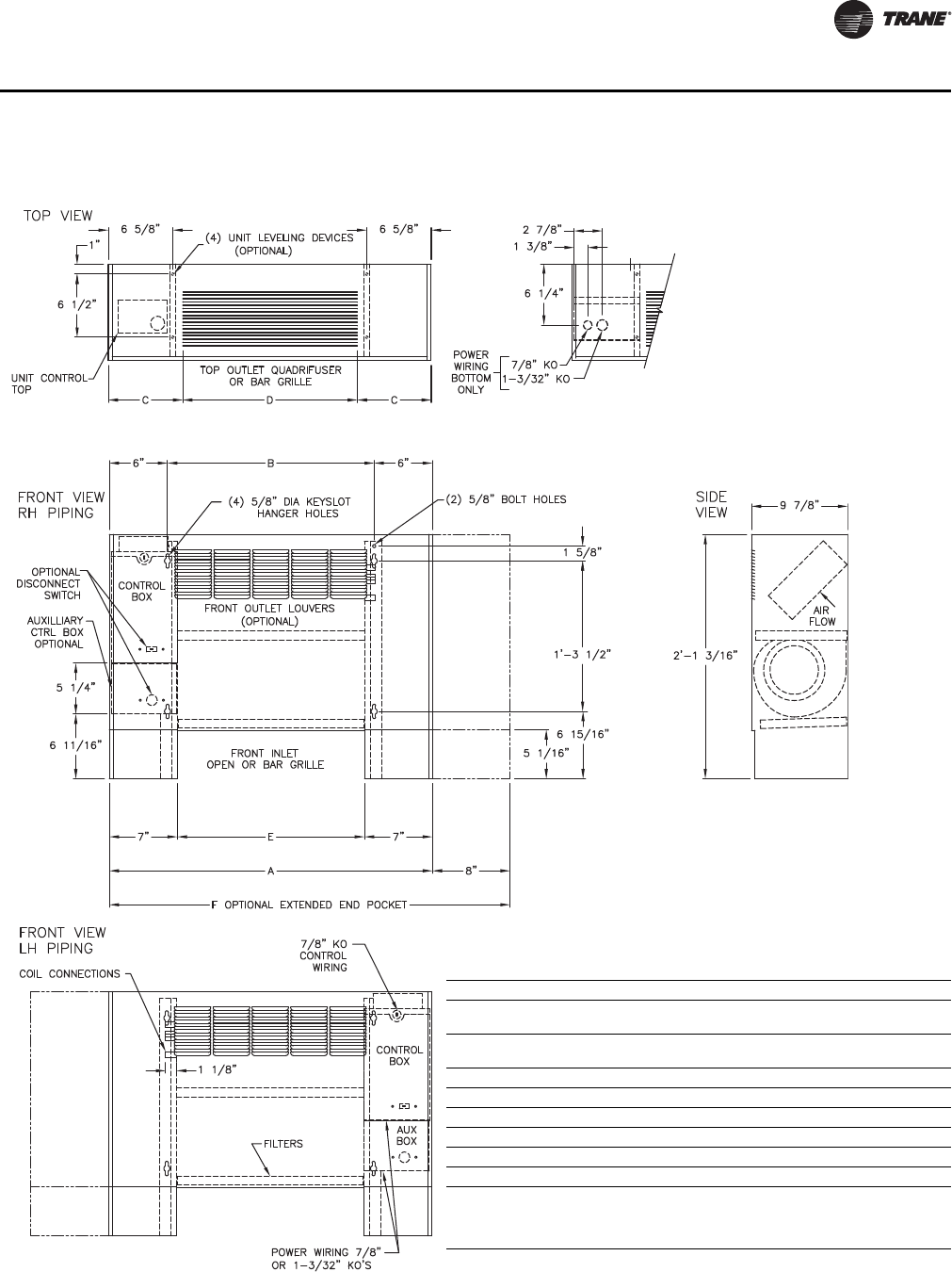
CAB-PRC001-EN 47
Dimensions and Weights
Vertical Cabinet, Model B
Vertical Cabinet Unit
Unit Size 200–300 400 600 800 1000-1200
No. of
Fans 11 2 2 3
No. of
Motors 11 1 1 2
A 2’-9 7/8” 3’-2 5/16” 3’-11 13/16” 4’-8 5/16” 6’-3 5/16”
B 1’-9 5/16” 2’-2 5/16” 2’-11 13/16” 3’-8 5/16” 5’-3 5/16”
C 7 5/8” 7 1/8” 8’ 7/8” 7 1/8” 7 5/8”
D 1’-6” 2’-0” 2’-6” 3’-6” 5’-0”
E 1’-7 5/16” 2’-0 5/16” 2’-9 13/16” 3’-6 5/16” 5’-1 5/16”
F 3’-5 5/16” 3’-10 5/16” 4’-7 13/16” 5’-4 5/16” 6’-11 5/16”
Notes:
1. Coil connections are always opposite the control box.
2. Coil connections are 5/8” O.D. sweat. See p. 56 for locations.
3. See p. 58 for dimensions for air openings.
CAB-PRC001-EN.book Page 47 Tuesday, May 8, 2012 10:11 AM
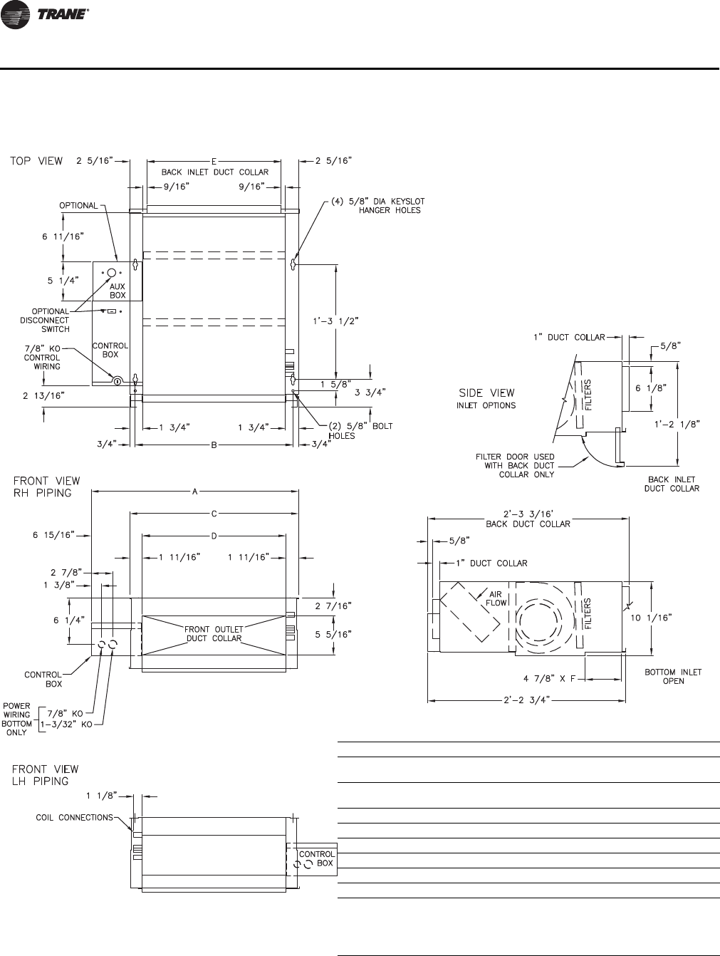
48 CAB-PRC001-EN
Dimensions and Weights
Horizontal Concealed, Model C
Horizontal Concealed Unit
Unit Size 200–300 400 600 800 1000-1200
No. of
Fans 11223
No. of
Motors 11112
A 2’-4 1/16” 2’-9 1/16” 3’-6 9/16” 4’-3 1/16” 1’-10 1/16”
B 1’-9 5/16” 2’-2 5/16” 2’-11 13/16” 3’-8 5/16” 5’-3 5/16”
C 1’-10 13/16” 2’-3 13/16” 3’-1 5/16” 3’-9 13/16” 5’-4 13/16”
D 1’-7 3/8” 2’-0 3/8” 2’-9 7/8” 3’-6 3/8” 5’-1 3/8”
E 1’-6 1/8” 1’-11 1/8” 2’-8 5/8” 3’-5 1/8” 5’-0 1/8”
F 1’-7 5/16” 2’-0 5/16” 2’-9 13/16” 3’-6 5/16” 5’-1 5/16”
Notes:
1. Coil connections are always opposite the control box.
2. Coil connections are 5/8” O.D. sweat. See p. 56 for locations.
3. All duct collar dimensions are to the outside of the collar.
4. See p. 58 for dimensions for air openings.
CAB-PRC001-EN.book Page 48 Tuesday, May 8, 2012 10:11 AM
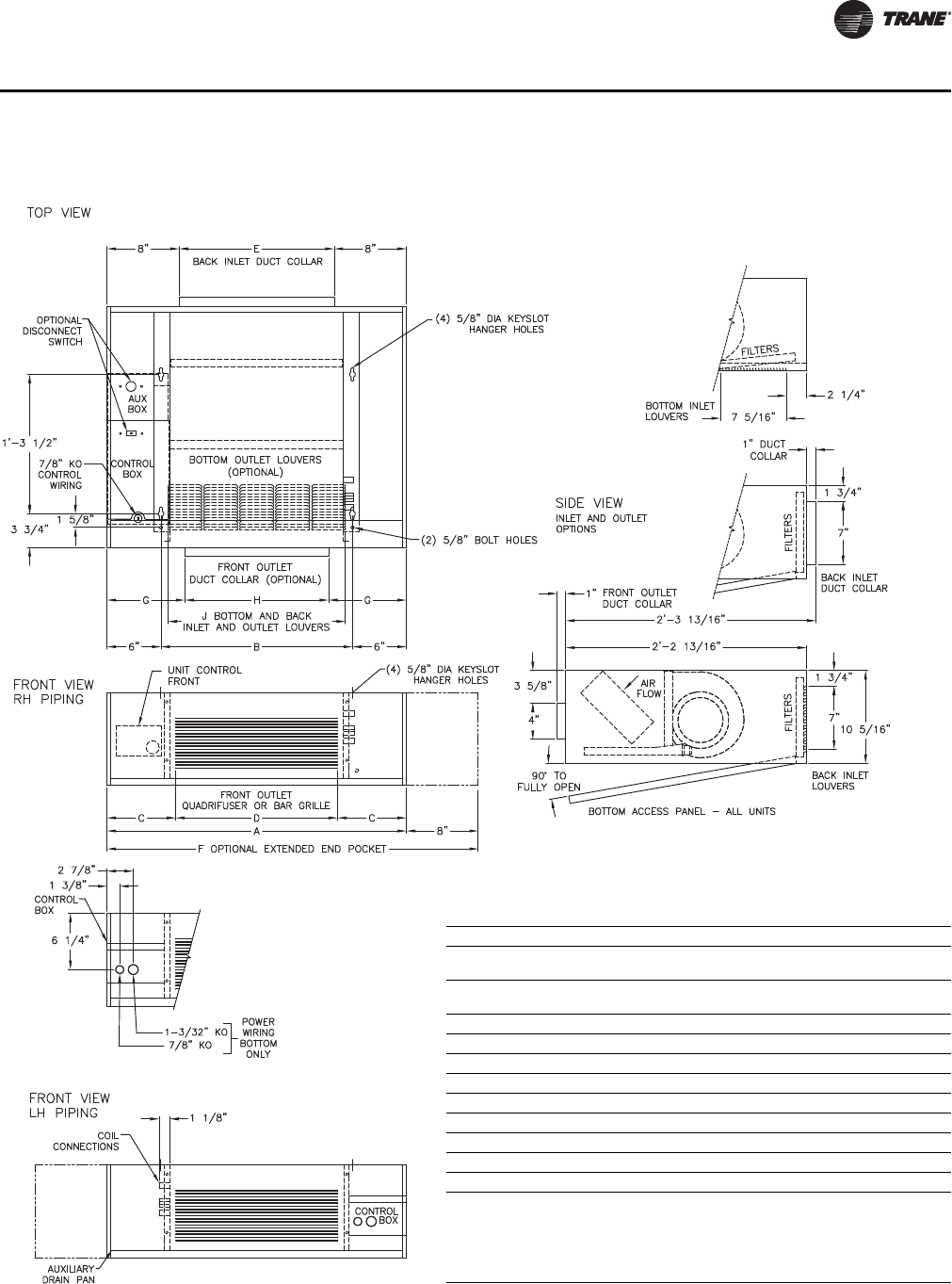
CAB-PRC001-EN 49
Dimensions and Weights
Horizontal Cabinet, Model D
Horizontal Cabinet Unit
Unit Size 200–300 400 600 800 1000-1200
No. of
Fans 11 2 2 3
No. of
Motors 11 1 1 2
A 2’-9 5/16” 3’-1 5/16” 3’-11 3/16” 4’-8 5/16” 6’-3 5/16”
B 1’-9 5/16” 2’-2 5/16” 2’-11 13/16” 3’-8 5/16” 5’-3 5/16”
C 7 5/8” 7 1/8” 8 7/8” 7 1/8” 7 5/8”
D 1’-6” 2’-0” 2’-6” 3’-6” 5’-0”
E 1’-5 1/4” 1’-10 1/4” 2’-7 3/4” 3’-4 1/4” 4’-11 1/4”
F 3’-5 5/16” 3’-10 5/16” 4’-7 3/16” 5’-4 5/16” 6’-11 5/16”
G 8-5/8” 8-1/8” 9-1/8” 8-1/8” 8-5/8”
H 1’-4” 1’-10” 2’-4” 3’-4” 4’-10”
J 1’-7 3/4” 1’-11 3/4” 2’-7 3/4” 3’-3 3/4” 4’-11 3/4”
Notes:
1. Coil connections are always on the drain pan side and opposite the control
box.
2. Coil connections are 5/8” O.D. sweat. See p. 56 for locations.
3. All duct collar dimensions are to the outside of the collar.
4. See p. 57 for dimensions for outside air openings.
CAB-PRC001-EN.book Page 49 Tuesday, May 8, 2012 10:11 AM
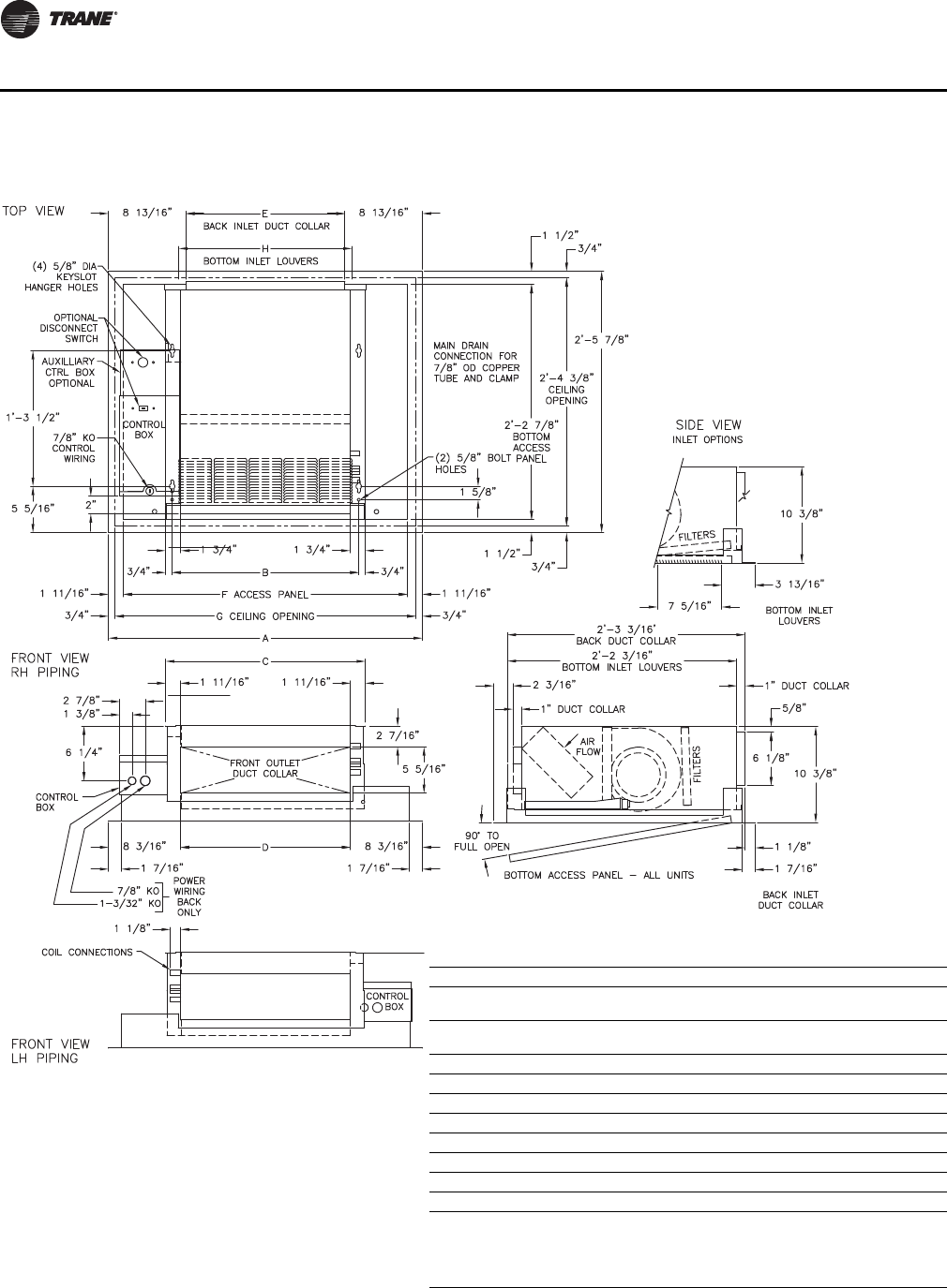
50 CAB-PRC001-EN
Dimensions and Weights
Horizontal Recessed, Model E
Horizontal Recessed Unit
Unit Size 200–300 400 600 800 1000-1200
No. of
Fans 11 2 2 3
No. of
Motors 11 1 1 2
A 2’-11 13/16” 3’-4 13/16” 4’-2 5/16” 4’-10 13/16” 6’-5 13/16”
B 1’-9 5/16” 2’-2 5/16” 2’-11 13/16” 3’-8 5/16” 5’-3 5/16”
C 1’-10 13/16” 2’-3 13/16” 3’-1 5/16” 3’-9 13/16” 5’-4 13/16”
D 1’-7 3/8” 2’-0 3/8” 2’-9 7/8” 3’-6 3/8” 5’-1 3/8”
E 1’-6 1/8” 1’-11 1/8” 2’-8 5/8” 3’-5 1/8” 5’-0 1/8”
F 2’-8 7/16” 3’-1 7/16” 3’-10 15/16” 4’-7 7/16” 6’-2 7/16”
G 2’-10 5/16” 3’-3 5/16” 4’-0 13/16” 4’-9 5/16” 6’-4 5/16”
H 1’-7 3/4” 1’-11 3/4” 2’-7 3/4” 3’-3 3/4” 4’-11 3/4”
Notes:
1. Coil connections are always opposite the drain pan side.
2. Coil connections are 5/8” O.D. sweat. See p. 56 for locations.
3. All duct collar dimensions are to the outside of the collar.
4. See p. 57 for dimensions for outside air openings.
CAB-PRC001-EN.book Page 50 Tuesday, May 8, 2012 10:11 AM
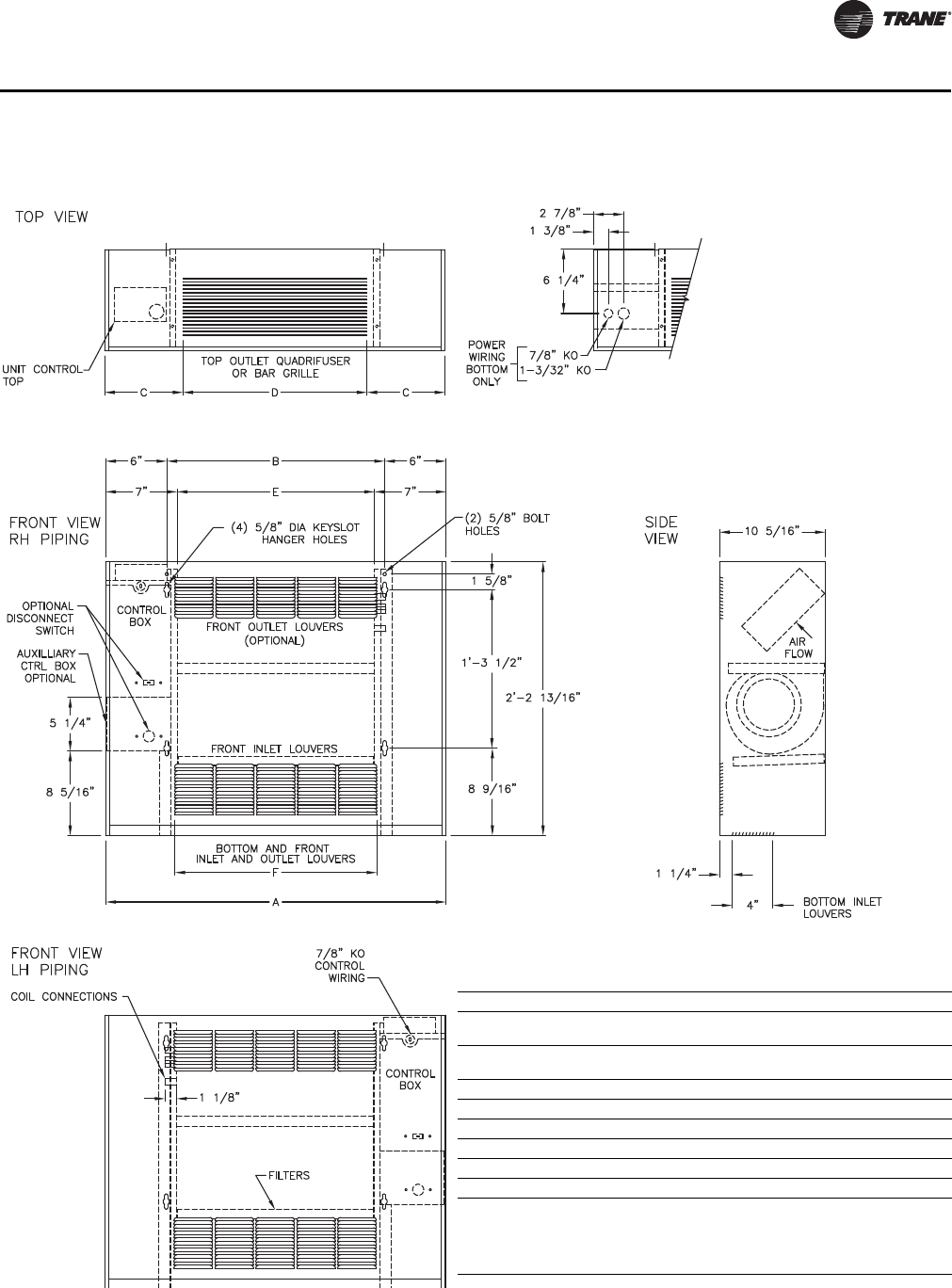
CAB-PRC001-EN 51
Dimensions and Weights
Vertical Wall Hung Cabinet, Model F
Vertical Wall Hung Cabinet Unit
Unit Size 200–300 400 600 800 1000-1200
No. of
Fans 11223
No. of
Motors 11112
A 2’-9 5/16” 3’-2 5/16” 3’-11 13/16” 4’-8 5/16” 6’-3 5/16”
B 1’-9 5/16” 2’-2 5/16” 2’-11 13/16” 3’-8 5/16” 5’-3 5/16”
C 7 5/8” 7 1/8” 8 7/8” 7 1/8” 7 5/8”
D 1’-6” 2’-0” 2’-6” 3’-6” 5’-0”
E 1’-7 5/16” 2’-0 5/16” 2’-9 13/16” 3’-6 5/16” 5’-1 5/16”
F 1’-7 3/4” 1’-11 3/4” 2’-7 3/4” 3’-3 3/4” 4’-11 3/4”
Notes:
1. Coil connections are always opposite the control box side.
2. Coil connections are 5/8” O.D. sweat. See p. 56 for locations.
3. All duct collar dimensions are to the outside of the collar.
4. See p. 58 for dimensions for outside air openings.
CAB-PRC001-EN.book Page 51 Tuesday, May 8, 2012 10:11 AM
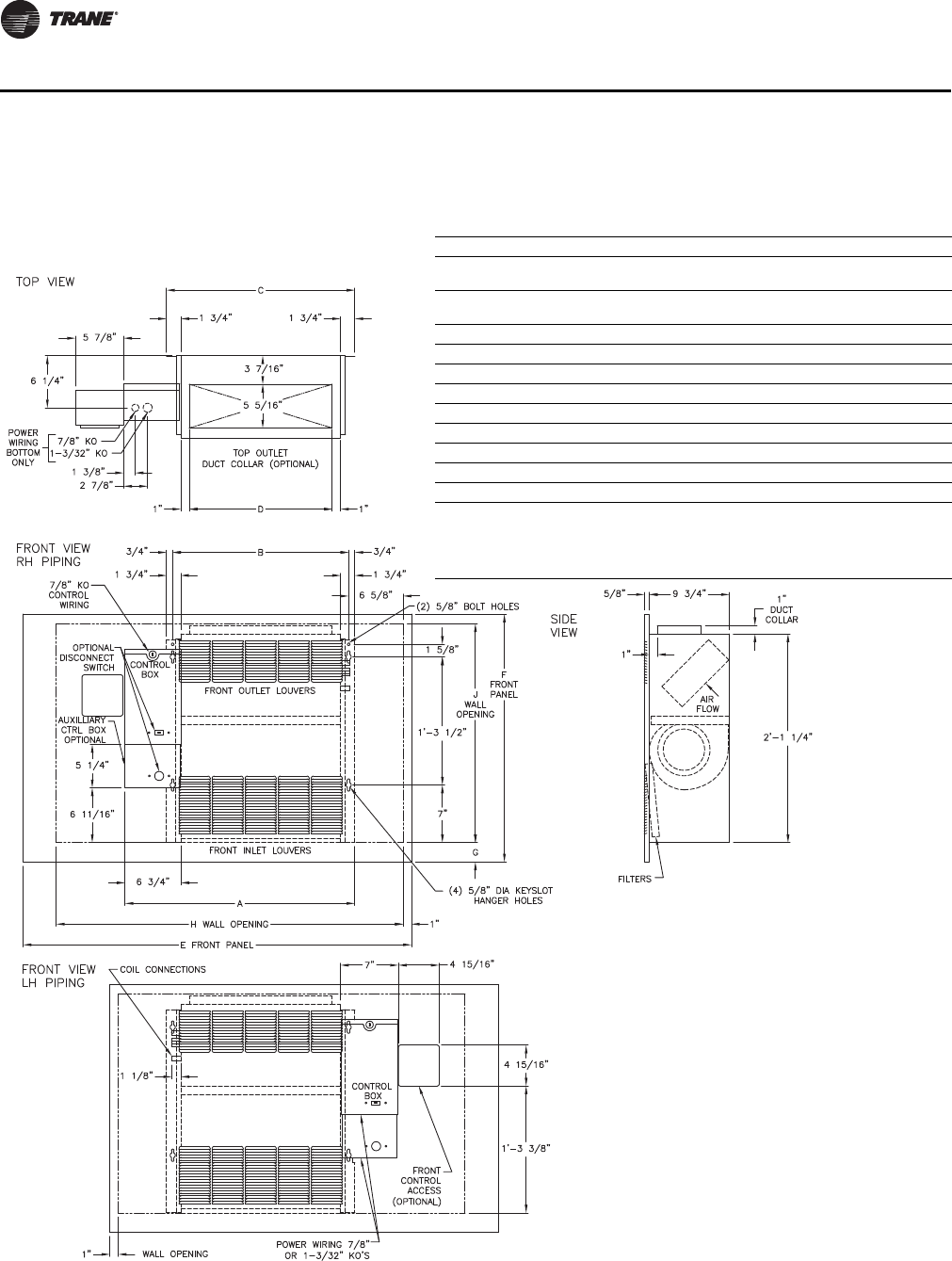
52 CAB-PRC001-EN
Dimensions and Weights
Vertical Recessed, Model H
Vertical Recessed Unit
Unit Size 200–300 400 600 800 1000-1200
No. of
Fans 11223
No. of
Motors 11112
A 2’-3 7/8” 2’-8 7/8” 3’-6 3/8” 4’-2 7/8” 5’-9 7/8”
B 1’-9 5/16” 2’-2 5/16” 2’-11 13/16” 3’-8 5/16” 5’-3 5/16”
C 1’-10 13/16” 2’-3 13/16” 3’-1 5/16” 3’-9 13/16” 5’-4 13/16”
D 1’-5 5/16” 1’-10 5/16” 2’-7 13/16” 3’-4 5/16” 3’-11 5/16”
E 3’-11” 4’-3” 5’-3” 5’-5 1/2” 7’-5 1/2”
F 2’-6” 2’-6” 2’-6” 2’-9 1/2” 2’-9 1/2”
G 2-3/8” 2-3/8” 2-3/8” 4-1/8” 4-1/8”
H 3’-6” 4’-0” 4’-9” 5’-3” 7’-3”
J 2’-2 1/2” 2’-2 1/2” 2’-2 1/2” 2’-3 1/2” 2’-3 1/2”
Notes:
1. Coil connections are always on the drain pan side and opposite the control box.
2. Coil connections are 5/8” O.D. sweat. See p. 56 for locations.
3. All duct collar dimensions are to the outside of the collar.
4. See p. 57 for dimensions for outside air openings.
CAB-PRC001-EN.book Page 52 Tuesday, May 8, 2012 10:11 AM
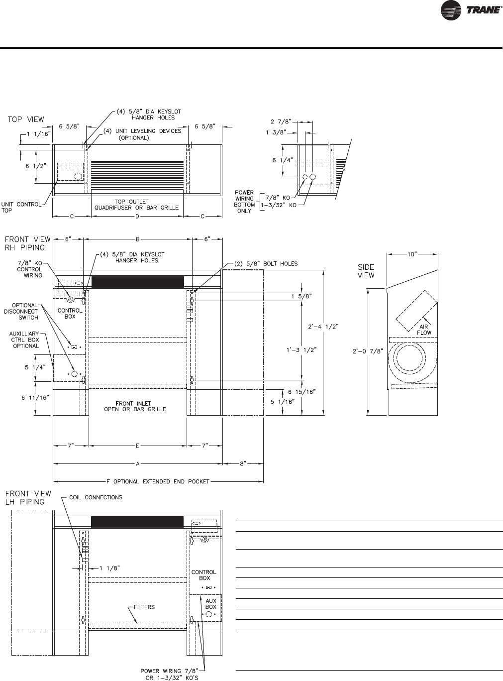
CAB-PRC001-EN 53
Dimensions and Weights
Vertical Slope Top, Model J
Vertical Slope Top Unit
Unit Size 200–300 400 600 800 1000-1200
No. of
Fans 11 2 2 3
No. of
Motors 11 1 1 2
A 2’-9 5/16” 3’-2 5/16” 3’-11 13/16” 4’-8 5/16” 6’-3 5/16”
B 1’-9 5/16” 2’-2 5/16” 2’-11 13/16” 3’-8 5/16” 5’-3 5/16”
C 7 5/8” 7 1/8” 8 7/8” 7 1/8” 7 5/8”
D 1’-6” 2’-0” 2’-6” 3’-6” 5’-0”
E 1’-7 5/16” 2’-0 5/16” 2’-9 13/16” 3’-6 5/16” 5’-1 5/16”
F 3’-5 5/16” 3’-10 5/16” 4’-7 13/16” 5’-4 5/16” 6’-11 5/16”
Notes:
1. Coil connections are always on the drain pan side and opposite the control box
and unit control.
2. Coil connections are 5/8” O.D. sweat. See p. 56 for locations.
3. See p. 58 for dimensions for outside air openings.
CAB-PRC001-EN.book Page 53 Tuesday, May 8, 2012 10:11 AM
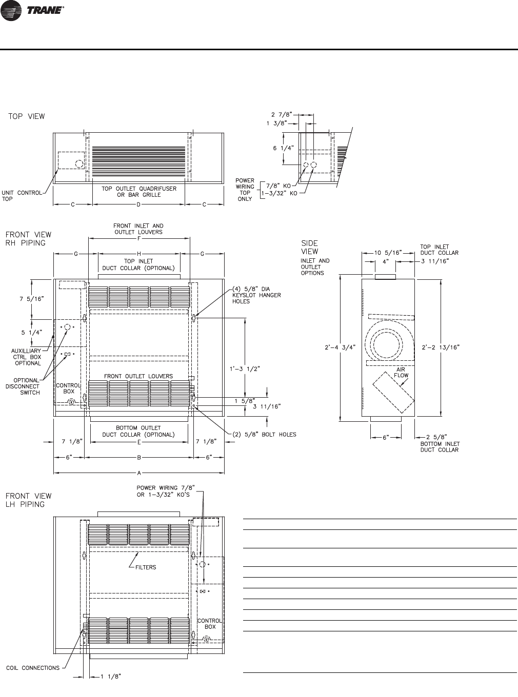
54 CAB-PRC001-EN
Dimensions and Weights
Inverted Vertical Cabinet, Model M
Inverted Vertical Cabinet Unit
Unit Size 200–300 400 600 800 1000-1200
No. of
Fans 11223
No. of
Motors 11112
A 2’-9 5/16” 3’-2 5/16” 3’-11 13/16” 4’-8 5/16” 6’-3 5/16”
B 1’-9 5/16” 2’-2 5/16” 2’-11 13/16” 3’-8 5/16” 5’-3 5/16”
C 7 5/8” 7 1/8” 8 7/8” 7 1/8” 7 5/8”
D 1’-6” 2’-0” 2’-6” 3’-6” 5’-0”
E 1’-7 5/16” 2’-0 5/16” 2’-9 13/16” 3’-6 5/16” 5’-1 5/16”
F 1’-7 3/4” 1’-11 3/4” 2’-7 3/4” 3’-3 3/4” 4’-11 3/4”
Notes:
1. Coil connections are always opposite the control box side.
2. Coil connections are 5/8” O.D. sweat. See p. 56 for locations.
3. All duct collar dimensions are to the outside of the collar.
4. See p. 58 for dimensions for outside air openings.
CAB-PRC001-EN.book Page 54 Tuesday, May 8, 2012 10:11 AM
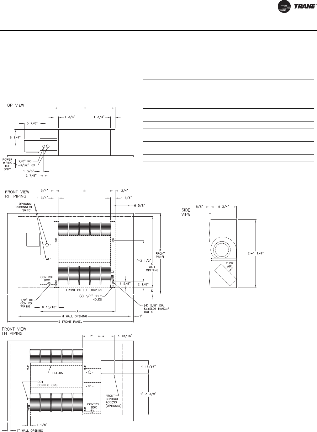
CAB-PRC001-EN 55
Dimensions and Weights
Inverted Vertical Recessed, Model N
Inverted Vertical Recessed Unit
Unit Size 200–300 400 600 800 1000-1200
No. of
Fans 11 2 2 3
No. of
Motors 11 1 1 2
A 2’-3 7/8” 2’-8 7/8” 3’-6 3/8” 4’-2 7/8” 5’-9 7/8”
B 1’-9 5/16” 2’-2 5/16” 2’-11 13/16” 3’-8 5/16” 5’-3 5/16”
C 1’-10 13/16” 2’-3 13/16” 3’-1 5/16” 3’-9 13/16” 5’-4 13/16”
D 2’ 3/8” 2’ 3/8” 2’ 3/8” 4’ 1/8” 4’ 1/8”
E 3’-11” 4’-3” 5’-3” 5’-5 1/2” 7’-5 1/2”
F 2’-6” 2’-6” 2’-6” 2’-9 1/2” 2’-9 1/2”
E 2’-2 1/2” 2’-2 1/2” 2’-2 1/2” 2’-3 1/2” 2’-3 1/2”
F 3’-6” 4’-0” 4’-9” 5’-3” 7’-3”
Notes:
1. Coil connections are always opposite the control box side.
2. Coil connections are 5/8” O.D. sweat. See p. 56 for locations.
3. See p. 58 for dimensions for outside air openings.
CAB-PRC001-EN.book Page 55 Tuesday, May 8, 2012 10:11 AM
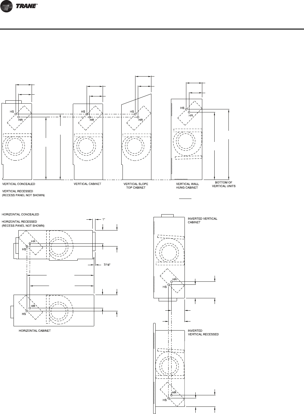
56 CAB-PRC001-EN
Dimensions and Weights
Coil Connections
Vertical Units
Horizontal Units Inverted Units
5-5/16" HS
4-3/8" HR
20-13/16"
HR
21-13/16"
HS
5-5/16" HS
4-3/8" HR
5-3/8" HS
4-7/16" HR
5-5/16" HS
4-3/8" HR
23-3/8"
HS
22-3/8"
HR
HR = Hot Water Return
HS = Hot Water Supply
22-3/8" HS
21-3/8" HR
4-3/8"
HR 5-5/16"
HS
4-3/8"
HR 5-5/16"
HS
HR = Hot Water Return
HS = Hot Water Supply
4-7/16"
HS
5-7/16"
HR
4-3/8" HR
5-5/16" HS
2-13/16"
HS
3-13/16"
HR
HR = Hot Water Return
HS = Hot Water Supply
CAB-PRC001-EN.book Page 56 Tuesday, May 8, 2012 10:11 AM
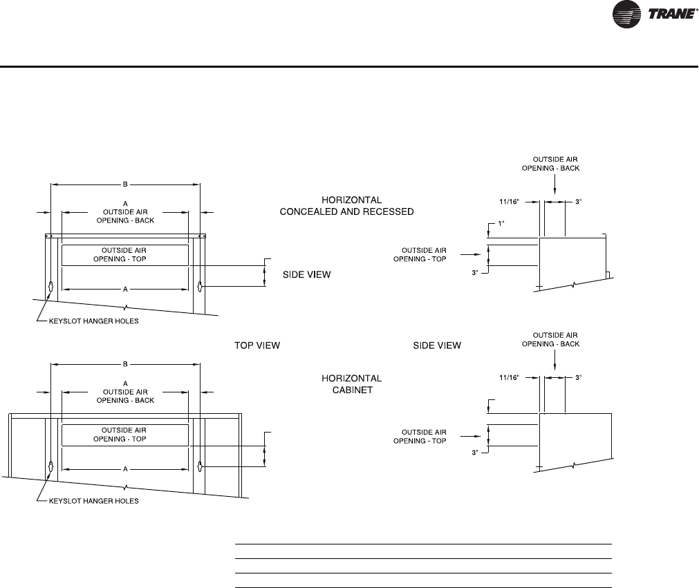
CAB-PRC001-EN 57
Dimensions and Weights
Fresh Air Opening Locations-Horizontal Units Models C, D, and E
1-5/8" 1-5/8"
2-15/16"
1-5/8"
1-5/8" 1-5/8"
2-15/16"
Fresh Air Opening Dimensions, Horizontal Units
Unit Size 02–03 04 06 08 10–12
A 18” 23” 32-1/2” 41” 60”
B 21-5/16” 26-5/16” 35-13/16” 44-5/16” 63-5/16”
CAB-PRC001-EN.book Page 57 Tuesday, May 8, 2012 10:11 AM
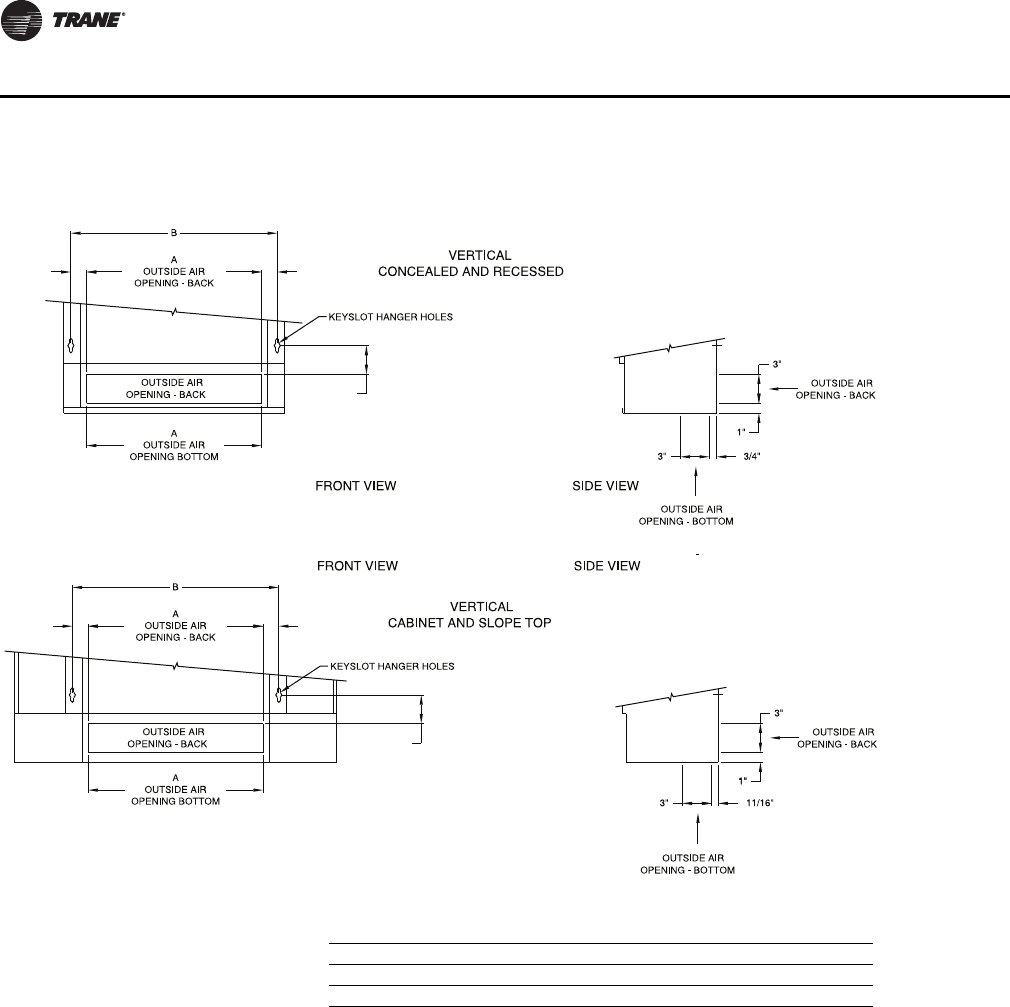
58 CAB-PRC001-EN
Dimensions and Weights
Fresh Air Opening Locations-Vertical Units Models A, B, F, and J
1-5/8" 1-5/8"
2-15/16"
WALL HUNG
1-5/8"
2-15/16"
1-5/8"
Fresh Air Opening Dimensions, Vertical Units
Unit Size 02–03 04 06 08 10–12
A 18” 23” 32-1/2” 41” 60”
B 21-5/16” 26-5/16” 35-13/16” 44-5/16” 63-5/16”
CAB-PRC001-EN.book Page 58 Tuesday, May 8, 2012 10:11 AM
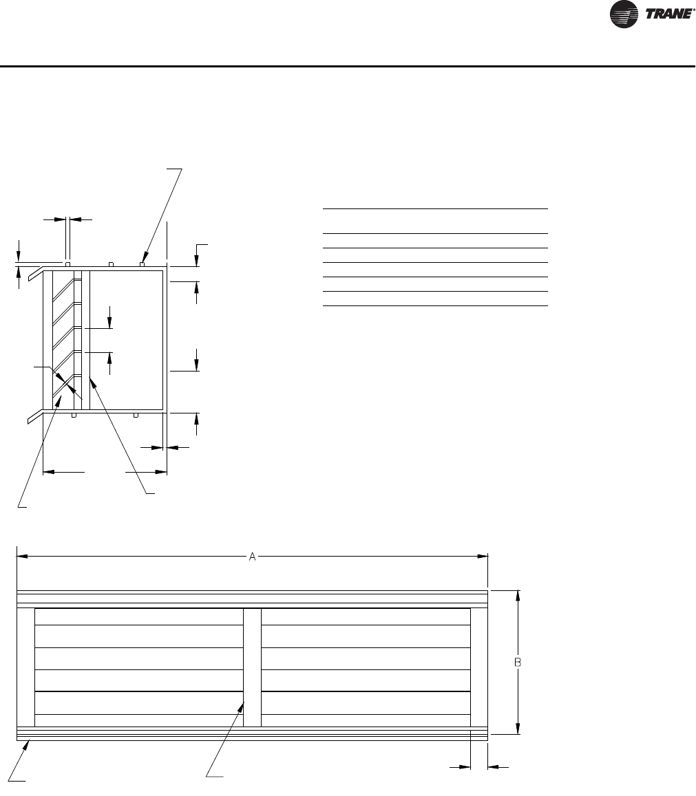
CAB-PRC001-EN 59
Dimensions and Weights
Wall Box
CONTINUOUS
MORTAR RIBS
TOP AND BOTTOM
WOVEN ALUMINUM
INSECT SCREEN
CLEARANCE
FOR DRAINAGE
Wall Box Dimension
Unit Size
Ref. Only
Dimensions
A x B
Internal
Supports
02–03 24-3/8” x 4-3/4” 1
04 24-3/8” x 7-1/2” 1
06 33-1/8” x 7-1/2” 2
08 37-1/2” x 7-1/2” 3
10–12 58-1/4” x 7-1/2” 4
1/8” 1/8”
1/2”
3/4”
1-3/8”
1/2”
4”
1/8”
ADDITIONAL INTERNAL
SUPPORTS EQUALLY SPACED.
NOT TO EXCEED 12” O.C.
CONTINUOUS DRIP LIP
TOP AND BOTTOM
5/8”
CAB-PRC001-EN.book Page 59 Tuesday, May 8, 2012 10:11 AM
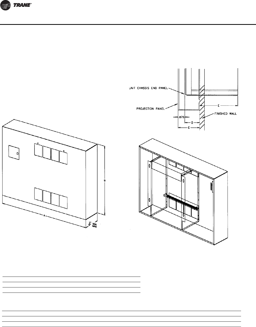
60 CAB-PRC001-EN
Dimensions and Weights
Projection Panel
UNIT TO WALL-TOP VIEW
FRONT VIEW ISO
REAR VIEW ISO
Projection Panel Dimensions
Unit Size 02–03 04 06 08 10–12
A 47” 51” 63” 65-1/2” 89-1/2”
B 30” 30” 30” 339-1/2” 33-1/2”
Projection Panel Dimensions
C 2” 2-1/2” 3” 3-1/2” 4” 4-1/2” 5” 5-1/2” 6”
D 1-1/8” 1-5/8” 2-1/8” 2-5/8” 3-1/8” 3-5/8” 4-1/8” 4-5/8” 5-1/8”
E 8-5/8” 8-1/8” 7-5/8” 7-1/8” 6-5/8” 6-1/8” 5-5/8” 5-1/8” 4-5/8”
CAB-PRC001-EN.book Page 60 Tuesday, May 8, 2012 10:11 AM

CAB-PRC001-EN 61
Mechanical Specifications
Force-Flo Cabinet Heater Mechanical Specifications
Performance Data
Capacity: Unit capacities are in accordance with Industry Room Fan-Coil Air Conditioner
Certification Program under ARI Standard 440-97. Safety: All standard units are UL listed in the
United States and Canada. Units comply with NFPA90A requirements.
Construction-All Units
The unit includes a chassis, coil, fan wheel(s), fan casing(s), fan board, and motor(s). The fan board
assembly is easily removable. The fan board assembly includes a quick-disconnect motor plug. The
chassis construction is 18-gage galvanized steel, and continuous throughout the unit. The unit is
acoustically and thermally insulated with closed-cell insulation. All panels are made rigid by
channel forming.
Vertical Cabinet and Slope Top Units
Front panel fabrication is 16-gage galvanized steel. All other panels are 18-gage galvanized steel.
Hinged access door construction is 20-gage steel and is flush with top panel.
Vertical Wall Hung Unit
Front panel fabrication is 16-gage galvanized steel. All other panels are 18-gage galvanized steel.
Side panels are removable for piping access.
Horizontal Cabinet Units
All panels are 18-gage galvanized steel, including the bottom panel. The hinged access door is flush
with front panel. Bottom panels ship with tamperproof screw fasteners and safety chain.
Concealed/Recessed Units
Exposed panels on recessed units are 18-gage steel construction and ship separate from the unit.
Bottom panels on horizontal recessed models ship with tamperproof screw fasteners and safety
chain. Horizontal recessed units feature a telescoping panel to allow the panel to be adjusted to line
up flush with the ceiling. The telescoping panel extends 1.25” to 2” depending on the configuration
of airflow.
Unit Finish
All cabinet parts and exposed recessed panels are cleaned, bonderized, phosphatized, and painted
with a baked powder finish available in six decorator colors. Standard finish meets ASTM B117
specifications (salt spray test).
Fans
The galvanized metal fan wheels are centrifugal forward-curved and double-width. Fan wheels and
housings are corrosion resistant. Fan housing construction is formed sheet metal.
Motors
All motors are brushless DC (BLDC)/electronically commutated motors (ECM) factory-
programmed and run-tested in assembled units. The motor controller is mounted in a touch-safe
control box with a built-in integrated user interface and LED tachometer. If adjustments are needed,
motor parameters can be adjusted through momentary contact switches accessible without
factory service personnel on the motor control board.
Motors will soft-ramp between speeds to lessen the acoustics due to sudden speed changes.
Motors can be operated at three speeds or with a field-supplied variable speed controller. The
motor will choose the highest speed if there are simultaneous/conflicting speed requests.
All motors have integral thermal overload protection with a maximum ambient operating
temperature of 104°F and are permanently lubricated. Motors are capable of starting at 50 percent
CAB-PRC001-EN.book Page 61 Tuesday, May 8, 2012 10:11 AM

62 CAB-PRC001-EN
Mechanical Specifications
of rated voltage and operating at 90 percent of rated voltage on all speed settings. Motors can
operate up to 10 percent over voltage.
Controls
Controls options are: fan speed switch, control interface, and Tracer UC400, ZN010, ZN510, and
ZN520. A variety of inputs and outputs are available for the control interface and Tracer controller
options. A disconnect switch (for non-electric heat units), fused transformer, contactor(s), and
terminal strip are provided with the control interface and Tracer controller options. For specifics on
the Tracer UC400, ZN010, ZN510, and ZN520, please refer to “Controls,” p. 29.
Control Interface
The control interface is intended to be used with a field-supplied, low-voltage thermostat or
controller. The control box contains a relay board which includes a line voltage to 24-volt
transformer, quiet contactors (for electric heat units), and an optional disconnect switch. All end
devices are wired to a low-voltage terminal block and are run-tested, so the only a power
connection and thermostat connection is needed to commission the unit. Changeover sensors and
controls are provided whenever a change-over coil is selected. When NO valves are selected,
inverting relays are provided for use with standard thermostats.
Fan Speed Switch
The fan speed switch is available with or without the control interface option and is available as
wall-mount or unit-mount. Both the wall-mount and unit-mount FSS will employ low-voltage fan
switches. However, the low-voltage fan speed option will provide an interface to factory wiring,
including variable-speed/high-medium-low (HML) control. The control box contains a line voltage
to 24-volt transformer, ECM motor controller, and an optional disconnect switch.
Hot Water Coils
Hot water coils are proof tested at 350 psig (air under water) and leak tested at 125 psig (air under
water). Additionally a pressure decay test is conducted at 120 psig.
Maximum main coil working pressure is 300 psig. Maximum entering water temperature is 200°F.
Tubes and u-bends are 3/8”OD copper. Fins are aluminum and are mechanically bonded to the
copper tubes. Coil stubouts are 5/8”OD copper tubing.
Steam Coils
The steam heating coil is a one-row, tube-in-tube distributing type coil. Coil construction is
aluminum fins mechanically bonded with 1”OD copper tubing. Steam coils are (air) burst tested
at 250 psig. Maximum steam coil working pressure is 100 psig. Maximum entering steam
temperature is 325°F. Tubes and u-bends are 5/8” OD copper. Fins are aluminum, 9 fpi, and are
mechanically bonded to the copper tubes. Coil stubouts are 1” OD copper tubing. Piping is field-
supplied.
Piping Packages (Hot Water Coils Only)
All piping packages are proof-tested at 350 psig (air under water) and leak-tested at 125 psig (air
under water). The maximum working pressure of the interconnecting piping is 300 psig.
Piping packages are available in either basic or deluxe configurations. The deluxe package includes
unions at the coil connections and a 20 mesh strainer on the supply side with a pressure rating on
the strainer of up to 400 psig. The basic package does not include either unions or the strainer.
End valve options available on both the basic and deluxe piping packages include ball valves,
manual circuit setters, and auto circuit setters.
Ball Valve Supply and Return
A ball-type stop valve is on the piping supply and return. The ball valve is a shutoff valve only with
a maximum working pressure of 400 psig.
CAB-PRC001-EN.book Page 62 Tuesday, May 8, 2012 10:11 AM

CAB-PRC001-EN 63
Mechanical Specifications
Ball Valve Supply, Manual Circuit Setter Return
A ball valve is provided on the supply with a manual circuit setter on the return. The manual circuit
setter is a combination flow-setting device and shutoff valve that includes two Schrader ports. The
maximum working pressure of the valve is 300 psig.
Ball Valve S & R, Auto Circuit Setter Return
Ball type end valves are mounted on the supply and return, with an additional auto circuit setter
mounted on the return. The auto circuit setter is an automatic flow control valve that is sized to
allow a specific flow rate through the coil. Auto circuit setters also include two P/T plugs and have
a maximum working pressure of 400 psig.
Control Valve Options
All control valves have a maximum working pressure of 300 psig. The maximum entering water
temperature of the valve is 200°F.
Two-Way, Two-Position Control Valves
When using two-way valves, use some means such as a pump and chiller bypass to ensure the
maximum closed off DP rating of the valve is not exceeded. Two-way, two-position valves are rated
for a maximum pressure differential across the valves of 30 psig. The valves are also available with
a close-off pressure of 50 psig. The valve actuator is easily removable for service without removing
the valve body from piping.
Three-Way, Two-Position Control Valves
Normally open three-way, two-position valves are rated for a maximum 28 psig pressure
differential across the valve. Normally closed three-way two-position valves are rated for a
maximum 20 psig pressure differential across the valve. All 3-way valve piping packages include
a bypass line with a balance fitting to set flow through the bypass line. The balance fitting has a
maximum working pressure of 150 psig. The valves are also available with a maximum close-off
pressure of 50 psig. The valve actuator is easily removable for service without removing the valve
body from piping.
Modulating Control Valves
Two-way and three-way modulating valves are rated for a maximum 50 psig pressure differential
across the valve. Modulating valves are available in Cv values of 0.7, 1.5, 2.5, and 4.0.
Electric Heat Coil
A single- or dual-stage electric heating coil is provided as the total source of heat. Electric heat coils
are open-wire type. The coils are a nickel-chromium element design. The electric heat operates at
the same voltage as the unit, and only a single power connection is necessary.
All units with factory-mounted electric heat are UL-listed and interlocked with the fan motor switch.
A call for electric heat operation will turn the fan on. Motors controls are synchronized with
fan/valve operation to ensure safe operation and to ensure that two modes of heat are not
operating simultaneously. A transformer is supplied on any voltage unit, eliminating the need for
field installation of a step-down transformer. Unit-mounted quiet magnetic relays are supplied on
all voltages. A line-break high temperature cutout with automatic reset is provided as an integral
part of the elements to de-energize the electric heat in the event of a malfunction.
Filters
Filters are concealed from sight and easily removable. Filters are located behind an integral access
door on horizontal type units. Filters are either 1” throwaway, MERV 8, or MERV 13.
Units equipped with 1” MERV 8 filters have a rating based on ASHRAE Standard 52.2. The average
dust spot efficiency is no less than 35 to 40 percent when tested in accordance with ASHRAE 52.1
atmospheric dust spot method.
CAB-PRC001-EN.book Page 63 Tuesday, May 8, 2012 10:11 AM

64 CAB-PRC001-EN
Mechanical Specifications
Units equipped with 1” MERV 13 filters have a rating based on ASHRAE Standard 52.2. The
average dust spot efficiency is no less than 90 percent efficiency on 1–3 micron particles and
greater than 90 percent efficiency on 3–10 micron particles when tested in accordance with
ASHRAE Test Standard 52.2.
Fresh Air Damper
A fresh air opening with damper is a factory-installed option. Dampers are constructed of 18-gage
steel. Fresh air is sealed off with gasket material when the damper is set in the closed position.
Return and fresh air mixes when the damper is open.
Manual Damper
The manual damper is field-adjustable to allow zero to 100 percent fresh air. The automatic two-
position damper is accompanied by a factory-installed and wired two-position (spring-return)
actuator.
Auto Two-Position Damper
The auto two-position damper is factory set at 25 percent when open. The damper can be set in the
field to allow from zero to 50 percent fresh air.
Disconnect Switch
A unit mounted disconnect switch is available as a standard option on all units (except electric heat
units).
Colors
Six decorator colors are available in a baked powder finish. For a color chart, contact your local
Trane office for a copy of UNT-SLB017-EN (Color Selector: Cabinet Heaters, Fan-Coils, Unit
Ventilators, & Water-Source Heat Pump Consoles).
Extended End Pockets
On vertical or horizontal cabinet units, an 8” extended end pocket is available on the piping end.
Tamperproof Locks
Key-operated locking access doors and/or panels will help prevent nuisance tampering with unit
and/or controls. Tamperproof locks are available on vertical cabinet, horizontal cabinet, vertical
wall-hung cabinet, vertical recessed, and vertical slope-top units.
Leveling Feet
Refrigerator type screw-in bolts to level the unit are available on vertical units.
Quad Grille Outlet
Quad grilles are square multi-directional grilles that allow four different discharge directions by
rotating the grilles 90°. The quad grille is constructed of a black plastic material (NORYL-SE 1-731)
with a 15° angle on the discharge louvers. Quad grilles are available on all cabinet style units.
Bar Grille Inlet/Outlet
Bar grilles are formed steel grille options available on the discharge of all units and the return of
vertical cabinet and vertical slope tops. The grilles have a black paint finish with 18-gage steel
construction. The louvers are formed at a 15° angle. The bar grilles are fixed in one discharge
direction.
Sub-bases
Sub-bases elevate vertical cabinet or slope top cabinet units to a specified height; for example, to
reach the bottom of a window sill. The sub-base also provides a cavity through which to run piping
underneath the unit. Sub-bases are 16-gage steel construction and have the same black paint finish
CAB-PRC001-EN.book Page 64 Tuesday, May 8, 2012 10:11 AM
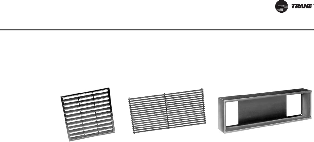
CAB-PRC001-EN 65
Mechanical Specifications
as the unit’s base. The sub-base is available in heights between 2”–7” (5 cm–18 cm) in 1/2” (1 cm)
increments. The sub-base depth and width is identical to the unit’s dimensions.
False Backs
False backs increase the depth of a vertical cabinet unit and provide a cavity through which to run
piping behind the unit. False backs are also an excellent application when installing a unit beneath
a window sill that extends out past the front of the unit.
False backs are 18-gage steel construction and have the same paint finish as the unit. The false back
is available in depths between 2”–8” in 1” increments, with height and width identical to the unit’s
dimensions.
Recessing Flanges
Recessing flanges have 18-gage steel construction and are painted the same finish as the unit.
Recessing flanges provide an aesthetic architectural border or frame around vertical and horizontal
cabinet units.
Aluminum Wall Boxes
Wall boxes have a clear anodized finish and include a single core wire mesh insect screen. The
frame is 10-gage extruded aluminum alloy 6063-T5 construction. Horizontal louvers have 16-gage
extruded aluminum alloy 6063-T5 construction.
Wall boxes ship separate for field installation. A field supplied duct or sleeve from the wall box to
the unit fresh air opening is required to provide fresh air. Wall boxes are sized to handle up to
100 percent of nominal airflow.
Quad grille outlet Bar grille inlet and outlet Sub-base (shown turned on its side)
CAB-PRC001-EN.book Page 65 Tuesday, May 8, 2012 10:11 AM
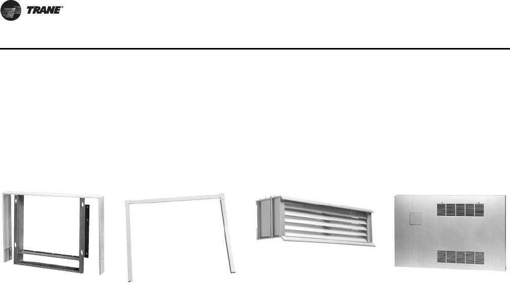
66 CAB-PRC001-EN
Mechanical Specifications
Projection Panels
Projection panels allow semi-recessing of vertical recessed units.
Panels are 16-gage steel construction, painted with a baked powder finish. They are available in
projection depths ranging from 2”–6” in 1/2” increments. There is a distance of 7/8” between the
projection panel and the front of the unit.
Piping Components
Ball Valve
Working Pressure
400 psi
Manual Circuit Setter
Material
body-forged brass alloy
trim-forged brass alloy
all wetted parts brass
Temperature
250°F max
Working Pressure
300 psi
False back Recessing flange Wall box Project panel
Part Material Spec ASTM
lever steel, zinc plated
seat Teflon VTFE
packing Teflon RTFE
stem rod brass B16
g-nut hex brass B16
ball brass, chrome plated B16
retainer brass B16
body cast brass B584-C84400
CAB-PRC001-EN.book Page 66 Tuesday, May 8, 2012 10:11 AM
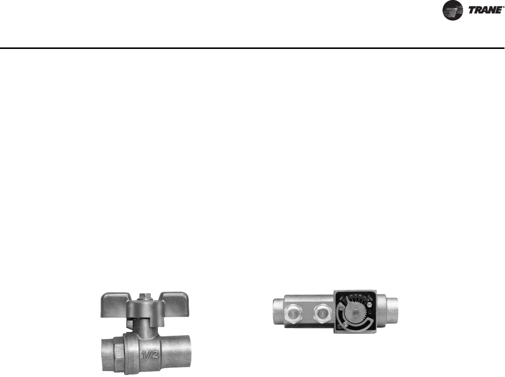
CAB-PRC001-EN 67
Mechanical Specifications
Auto Circuit Setter
Material
Body-Forged Brass
Flow Cartridge-Electroless Nickel and Stainless Steel
Temperature
250°F max
Working Pressure
400 psi
Pressure Drop
0.5–9.0 gpm = 2 psi ΔP
10.0–12.0 gpm = 5 psi ΔP
Control Valve
Material
body-forged brass
drive shaft stem-chrome-plated brass (modulating) brass (2-position)
seat-stainless steel (modulating)
ball plug-Buna N rubber (2-postion)
plug-high temperature thermoplastic (modulating)
o-ring seals-EPDM rubber (2-position)
actuator-stainless steel base plate, aluminum cover
Temperature
200°F max
Working Pressure
300 psi
Pressure Drop (close-off ΔP)*
2-way, two-position, N.O. = 30 psig & 50 psig
2-way, two-position, N.C. = 30 psig & 50 psig
3-way, two-position, N.O. = 28 psig
3-way, two-position, N.C. = 20 psig
2-way modulating = 50 psig
3-way modulating = 50 psig
Ball valve Manual circuit setter
CAB-PRC001-EN.book Page 67 Tuesday, May 8, 2012 10:11 AM

68 CAB-PRC001-EN
Mechanical Specifications
Balance Fitting
Material
packing washer-11 ga. brass
o-ring-EPDM rubber
stem-rod brass
gland screw-hex brass
valve body-cast brass
Union
Material
nut-forged brass
body-copper
tail-copper
Strainer
Material
body-cast bronze (85-5-5-5)
cover-cast bronze (85-5-5-5)
screen-stainless steel (20 mesh)
gasket-Teflon
Pressure and Temperature
400 psi (2,758 kPa) at 150°F (66°C)
CAB-PRC001-EN.book Page 68 Tuesday, May 8, 2012 10:11 AM

Trane optimizes the performance of homes and buildings around the world. A business of Ingersoll Rand, the
leader in creating and sustaining safe, comfortable and energy efficient environments, Trane offers a broad
portfolio of advanced controls and HVAC systems, comprehensive building services, and parts.
For more information, visit www.Trane.com.
Trane has a policy of continuous product and product data improvement and reserves the right to change design and specifications without notice.
We are committed to using environmentally
conscious print practices that reduce waste.
© 2012 Trane All rights reserved
CAB-PRC001-EN 08 May 2012
Supersedes CAB-PRC001-EN (11 Jan 2012)
CAB-PRC001-EN.book Page 69 Tuesday, May 8, 2012 10:11 AM
