Trane Uni Fan Coil And Force Flo Installation Maintenance Manual UNT SVX07D EN (27 Apr 2012)
2015-04-02
: Trane Trane-Uni-Fan-Coil-And-Force-Flo-Installation-And-Maintenance-Manual-684303 trane-uni-fan-coil-and-force-flo-installation-and-maintenance-manual-684303 trane pdf
Open the PDF directly: View PDF ![]() .
.
Page Count: 138 [warning: Documents this large are best viewed by clicking the View PDF Link!]
- Warnings, Cautions and Notices
- Model Number Descriptions
- General Information
- Pre-Installation
- Dimensions and Weights
- Available Models
- Factory-Installed Piping Packages
- Vertical Concealed, Model A
- Vertical Cabinet, Model B
- Horizontal Concealed, Model C
- Horizontal Cabinet, Model D
- Horizontal Recessed, Model E
- Vertical Wall Hung Cabinet, Model F (Force-Flo Units Only)
- Vertical Recessed, Model H
- Vertical Slope Top, Model J
- Low Vertical Concealed, Model K
- Low Vertical Cabinet, Model L
- Inverted Vertical Cabinet, Model M (Force-Flo Units Only)
- Inverted Vertical Recessed, Model N (Force-Flo Units Only)
- Compact Concealed, Model P
- Fan-Coil Coil Connections
- Force-Flo Coil Connections
- Fresh Air Opening Locations
- Wall Box
- Projection Panel
- Installation—Mechanical
- Installation—General
- Installation—Controls
- Installation—Electrical
- ECM Overview and Setup
- Wired Controllers—Communication Wiring
- Wireless Sensors
- Pre-Start
- Startup
- Tracer ZN510 and ZN520 Unit Startup
- Tracer UC400 Unit Startup
- General Information
- Fan Mode Switch Operation
- Tracer ZN010 & ZN510 Operation
- Tracer ZN520 Operation
- UC400 Controller Operation
- Sequence of Operation: Tracer ZN010 and ZN510
- Tracer ZN520 Sequence of Operation
- UC400 Sequence of Operation
- Power-up Sequence (UC400)
- Random Start (UC400)
- Occupancy Modes (UC400)
- Timed Override Control (UC400)
- Zone Temperature Control (UC400)
- Discharge Air Tempering (UC400)
- Heating or Cooling Mode (UC400)
- Entering Water Temperature Sampling Function (UC400)
- Fan Operation (UC400)
- Exhaust Control (UC400)
- Valve Operation (UC400)
- Modulating Outdoor/Return Air Damper (UC400)
- Two-position Control Of A Modulating Outdoor Air Damper (UC400)
- Electric Heat Operation (UC400)
- Dehumidification Operation (UC400)
- Peer-to-peer Communication (UC400)
- Unit Protection Strategies (UC400)
- Maintenance
- Diagnostics
- Replacing ECM Components
- ECM Application Notes
- Wiring Diagrams
SAFETY WARNING
Only qualified personnel should install and service the equipment. The installation, starting up, and
servicing of heating, ventilating, and air-conditioning equipment can be hazardous and requires specific
knowledge and training. Improperly installed, adjusted or altered equipment by an unqualified person could
result in death or serious injury. When working on the equipment, observe all precautions in the literature
and on the tags, stickers, and labels that are attached to the equipment.
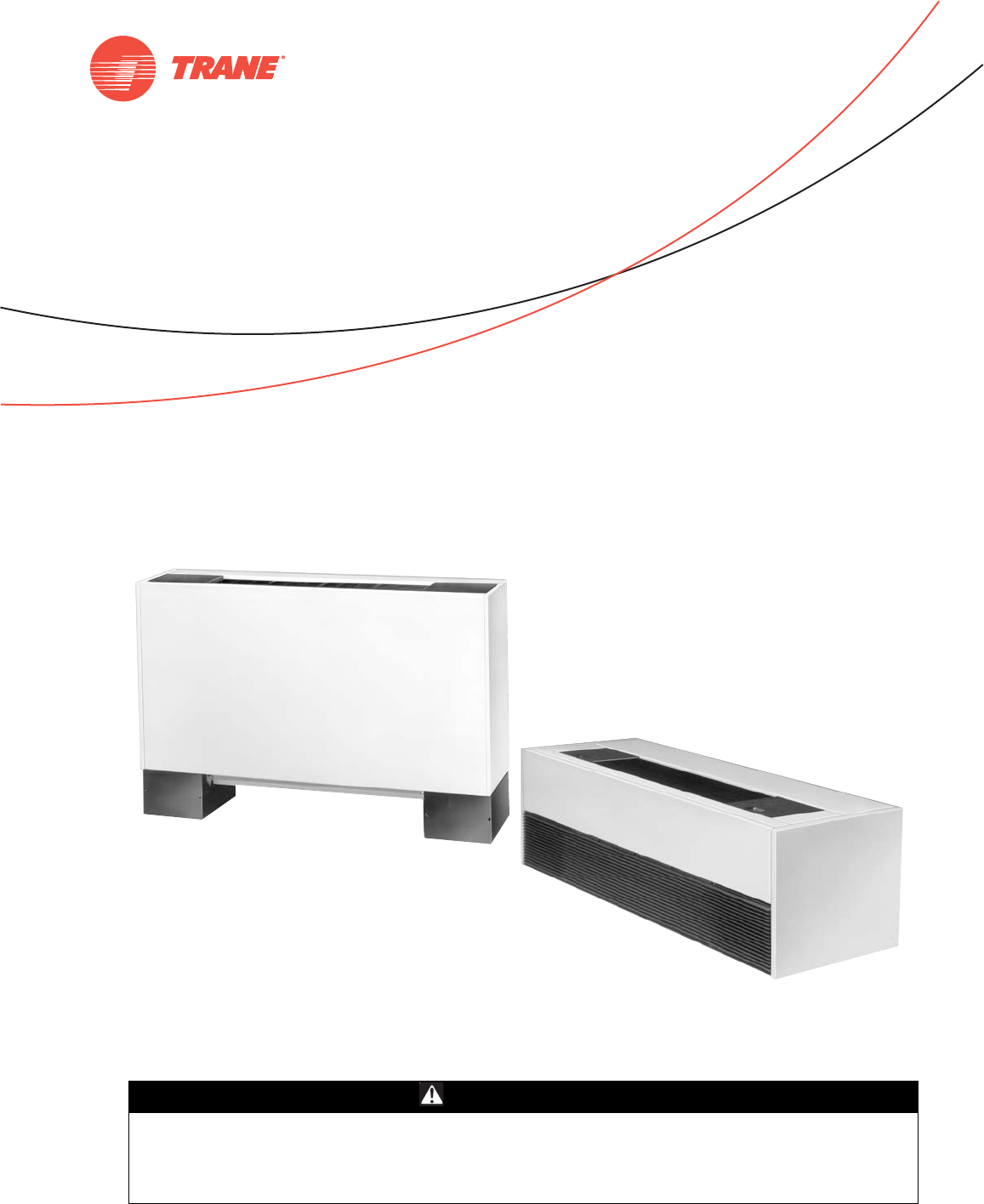
UniTrane™ Fan-Coil and Force-Flo™ Air Conditioners
200 to 1,200 cfm
April 2012 UNT-SVX07D-EN
Installation, Operation,
and Maintenance
Models FC and FF “ZO” and later design sequence
Low vertical models FCKB and FCLB “SO” and later design sequence
UNT-SVX07_-EN.book Page 1 Friday, April 27, 2012 9:40 AM
© 2012 Trane All rights reserved UNT-SVX07D-EN
Warnings, Cautions and Notices
Warnings, Cautions and Notices. Note that warnings,
cautions and notices appear at appropriate intervals
throughout this manual. Warnings are provide to alert
installing contractors to potential hazards that could result
in death or personal injury. Cautions are designed to alert
personnel to hazardous situations that could result in
personal injury, while notices indicate a situation that
could result in equipment or property-damage-only
accidents.
Your personal safety and the proper operation of this
machine depend upon the strict observance of these
precautions.
Read this manual thoroughly before operating or servicing
this unit.
Important
Environmental Concerns!
Scientific research has shown that certain man-made
chemicals can affect the earth’s naturally occurring
stratospheric ozone layer when released to the
atmosphere. In particular, several of the identified
chemicals that may affect the ozone layer are refrigerants
that contain Chlorine, Fluorine and Carbon (CFCs) and
those containing Hydrogen, Chlorine, Fluorine and
Carbon (HCFCs). Not all refrigerants containing these
compounds have the same potential impact to the
environment. Trane advocates the responsible handling of
all refrigerants-including industry replacements for CFCs
such as HCFCs and HFCs.
Responsible Refrigerant Practices!
Trane believes that responsible refrigerant practices are
important to the environment, our customers, and the air
conditioning industry. All technicians who handle
refrigerants must be certified. The Federal Clean Air Act
(Section 608) sets forth the requirements for handling,
reclaiming, recovering and recycling of certain
refrigerants and the equipment that is used in these
service procedures. In addition, some states or
municipalities may have additional requirements that
must also be adhered to for responsible management of
refrigerants. Know the applicable laws and follow them.
This product uses an electronic variable speed motor
control, which includes a line reactor to minimize power
line harmonic currents. It is recommended that good
wiring practices be followed to manage building electrical
power system harmonic voltages and currents to avoid
electrical system problems or other equipment
interaction.
ATTE NT ION: Warnings, Cautions and Notices appear at
appropriate sections throughout this literature. Read
these carefully:
WARNING Indicates a potentially hazardous
situation which, if not avoided, could
result in death or serious injury.
CAUTIONsIndicates a potentially hazardous
situation which, if not avoided, could
result in minor or moderate injury. It
could also be used to alert against
unsafe practices.
NOTICE: Indicates a situation that could result in
equipment or property-damage only
WARNING
Proper Field Wiring and Grounding
Required!
All field wiring MUST be performed by qualified
personnel. Improperly installed and grounded field
wiring poses FIRE and ELECTROCUTION hazards. To
avoid these hazards, you MUST follow requirements for
field wiring installation and grounding as described in
NEC and your local/state electrical codes. Failure to
follow code could result in death or serious injury.
WARNING
Personal Protective Equipment (PPE)
Required!
Installing/servicing this unit could result in exposure to
electrical, mechanical and chemical hazards.
• Before installing/servicing this unit, technicians
MUST put on all Personal Protective Equipment (PPE)
recommended for the work being undertaken.
ALWAYS refer to appropriate MSDS sheets and OSHA
guidelines for proper PPE.
• When working with or around hazardous chemicals,
ALWAYS refer to the appropriate MSDS sheets and
OSHA guidelines for information on allowable
personal exposure levels, proper respiratory
protection and handling recommendations.
• If there is a risk of arc or flash, technicians MUST put
on all Personal Protective Equipment (PPE) in
accordance with NFPA 70E or other country-specific
requirements for arc flash protection, PRIOR to
servicing the unit.
Failure to follow recommendations could result in death
or serious injury.
UNT-SVX07_-EN.book Page 2 Friday, April 27, 2012 9:40 AM

Warnings, Cautions and Notices
UNT-SVX07D-EN 3
Revision History
The revision of this literature dated 27 Apr 2012 includes
information for Tracer™ UC400 controls.
Trademarks
Force-Flo, Rover, Tracer, Tracer Summit, Trane, the Trane
logo, and UniTrane are trademarks or registered
trademarks of Trane in the United States and other
countries. All trademarks referenced in this document are
the trademarks of their respective owners.
Echelon, LonTalk, and LONWORKS are registered
trademarks of Echelon Corporation; Energizer is a
registered trademark of Eveready Battery Company, Inc.;
Loctite is a registered trademark of Henkel Corporation.
UNT-SVX07_-EN.book Page 3 Friday, April 27, 2012 9:40 AM

4 UNT-SVX07D-EN
Table of Contents
Warnings, Cautions and Notices . . . . . . . . . . 2
Model Number Descriptions . . . . . . . . . . . . . . 6
General Information . . . . . . . . . . . . . . . . . . . . . 9
Pre-Installation . . . . . . . . . . . . . . . . . . . . . . . . . 10
Receiving and Handling . . . . . . . . . . . . . . 10
Jobsite Storage . . . . . . . . . . . . . . . . . . . . 10
Installation Preparation . . . . . . . . . . . . . . 10
Service Access . . . . . . . . . . . . . . . . . . . . . 11
Pre-Installation Checklist . . . . . . . . . . . . . 11
Dimensions and Weights . . . . . . . . . . . . . . . . 12
Available Models . . . . . . . . . . . . . . . . . . . 14
Factory-Installed Piping Packages . . . . . 15
Vertical Concealed, Model A . . . . . . . . . . 16
Vertical Cabinet, Model B . . . . . . . . . . . . 17
Horizontal Concealed, Model C . . . . . . . . 18
Horizontal Cabinet, Model D . . . . . . . . . . 19
Horizontal Recessed, Model E . . . . . . . . . 20
Vertical Wall Hung Cabinet, Model F (Force-
Flo Units Only) . . . . . . . . . . . . . . . . . . . . . 21
Vertical Recessed, Model H . . . . . . . . . . . 22
Vertical Slope Top, Model J . . . . . . . . . . 23
Low Vertical Concealed, Model K . . . . . . 24
Low Vertical Cabinet, Model L . . . . . . . . 25
Inverted Vertical Cabinet, Model M
(Force-Flo Units Only) . . . . . . . . . . . . . . . 26
Inverted Vertical Recessed, Model N (Force-
Flo Units Only) . . . . . . . . . . . . . . . . . . . . . 27
Compact Concealed, Model P . . . . . . . . . 28
Fan-Coil Coil Connections . . . . . . . . . . . . 29
Force-Flo Coil Connections . . . . . . . . . . . 30
Fresh Air Opening Locations . . . . . . . . . . 32
Wall Box . . . . . . . . . . . . . . . . . . . . . . . . . . 34
Projection Panel . . . . . . . . . . . . . . . . . . . . 35
Installation—Mechanical . . . . . . . . . . . . . . . . 36
Duct Connections . . . . . . . . . . . . . . . . . . . 36
Piping Considerations . . . . . . . . . . . . . . . 36
Installation—General . . . . . . . . . . . . . . . . . . . . 42
Installing the Unit . . . . . . . . . . . . . . . . . . . . . 42
Vertical Units . . . . . . . . . . . . . . . . . . . . . . 42
Horizontal Units . . . . . . . . . . . . . . . . . . . . .42
Cabinet Units . . . . . . . . . . . . . . . . . . . . . . .42
Recessed Units . . . . . . . . . . . . . . . . . . . . . .42
Installation Checklist . . . . . . . . . . . . . . . . . . .44
Installation—Controls . . . . . . . . . . . . . . . . . . . .45
General Information . . . . . . . . . . . . . . . . . . .45
Control Options (Including Factory-Installed)
. . . . . . . . . . . . . . . . . . . . . . . . . . . . . . . . . . .45
Installing Wall-Mounted Wired Sensors . .46
Location Considerations . . . . . . . . . . . . . .47
Location Considerations for Wireless zone
sensors . . . . . . . . . . . . . . . . . . . . . . . . . . . .47
Fan Mode Switch Installation . . . . . . . . . .47
Zone Sensor Installation . . . . . . . . . . . . . .47
Installation—Electrical . . . . . . . . . . . . . . . . . . .49
Unit Wiring Diagrams . . . . . . . . . . . . . . . .49
Supply Power Wiring . . . . . . . . . . . . . . . . .49
Electrical Grounding Restrictions . . . . . . .49
Wall-Mounted Control Interconnection Wir-
ing . . . . . . . . . . . . . . . . . . . . . . . . . . . . . . . .49
ECM Overview and Setup . . . . . . . . . . . . . . . .53
Overview . . . . . . . . . . . . . . . . . . . . . . . . . . . . .53
General Information . . . . . . . . . . . . . . . . . . .53
Trane BLDC Motor . . . . . . . . . . . . . . . . . . .53
ECM Engine Controller . . . . . . . . . . . . . . .54
Standard Adapter Board . . . . . . . . . . . . . .54
CSTI Adapter Board . . . . . . . . . . . . . . . . . .54
Installation and Initial Setup . . . . . . . . . . . .55
Installation and Initial Setup . . . . . . . . . . .55
Adjustment and Configuration of the Engine
Board . . . . . . . . . . . . . . . . . . . . . . . . . . . . . .57
Status Display . . . . . . . . . . . . . . . . . . . . . . .58
Initial Setup and Configuration . . . . . . . . .63
Configuration . . . . . . . . . . . . . . . . . . . . . . . . .63
Configuring the ECM Engine Controller . .63
Configuring the ECM Engine Board . . . . .68
Wired Controllers—Communication Wiring 73
Wiring Installation (ZN510 and ZN520) . . .73
Device Addressing . . . . . . . . . . . . . . . . . . .73
UNT-SVX07_-EN.book Page 4 Friday, April 27, 2012 9:40 AM

UNT-SVX07D-EN 5
Recommended Communication Wiring Prac-
tices . . . . . . . . . . . . . . . . . . . . . . . . . . . . . . 73
Wiring Installation (Tracer UC400) . . . . . . 73
Wiring Overview Outline . . . . . . . . . . . . . 74
General Instructions . . . . . . . . . . . . . . . . . 74
BACnet MS/TP Link . . . . . . . . . . . . . . . . . 74
Power Supply . . . . . . . . . . . . . . . . . . . . . . 75
Wireless Sensors . . . . . . . . . . . . . . . . . . . . . . . 77
Address Setting . . . . . . . . . . . . . . . . . . . . 77
Observing the Receiver for Readiness to As-
sociate . . . . . . . . . . . . . . . . . . . . . . . . . . . . 78
Associating the Sensor to the Receiver . 78
Testing Signal Strength and Battery Status
. . . . . . . . . . . . . . . . . . . . . . . . . . . . . . . . . . 78
Configuring the Wireless Display Sensor
(Model WDS only) . . . . . . . . . . . . . . . . . . 79
Sensor Operations . . . . . . . . . . . . . . . . . . 82
Wireless Sensor Specifications . . . . . . . . 85
Pre-Start . . . . . . . . . . . . . . . . . . . . . . . . . . . . . . . 87
Pre-Startup Checklist . . . . . . . . . . . . . . . . 87
Startup . . . . . . . . . . . . . . . . . . . . . . . . . . . . . . . . 88
Tracer ZN510 and ZN520 Unit Startup . . 88
Tracer UC400 Unit Startup . . . . . . . . . . . 88
General Information . . . . . . . . . . . . . . . . . 88
Fan Mode Switch Operation . . . . . . . . . . 89
Tracer ZN010 & ZN510 Operation . . . . . . 89
Tracer ZN520 Operation . . . . . . . . . . . . . 89
UC400 Controller Operation . . . . . . . . . . 89
Sequence of Operation: Tracer ZN010 and
ZN510 . . . . . . . . . . . . . . . . . . . . . . . . . . . . . . . 89
Binary Inputs (Tracer ZN010 and ZN510) 90
Binary Outputs (Tracer ZN010 and ZN510) 90
Tracer ZN520 Sequence of Operation . . . 92
Cooling Operation (Tracer ZN520) . . . . . 93
Fan Mode Operation (Tracer ZN520) . . . 94
UC400 Sequence of Operation . . . . . . . . . 99
Power-up Sequence (UC400) . . . . . . . . . 99
Random Start (UC400) . . . . . . . . . . . . . . . 99
Occupancy Modes (UC400) . . . . . . . . . . . 99
Timed Override Control (UC400) . . . . . 100
Zone Temperature Control (UC400) . . . 100
Discharge Air Tempering (UC400) . . . . .100
Heating or Cooling Mode (UC400) . . . . .100
Entering Water Temperature Sampling Func-
tion (UC400) . . . . . . . . . . . . . . . . . . . . . . .101
Fan Operation (UC400) . . . . . . . . . . . . . .101
Exhaust Control (UC400) . . . . . . . . . . . . .102
Valve Operation (UC400) . . . . . . . . . . . . .102
Modulating Outdoor/Return Air Damper
(UC400) . . . . . . . . . . . . . . . . . . . . . . . . . . .102
Two-position Control Of A Modulating Out-
door Air Damper (UC400) . . . . . . . . . . . .103
Electric Heat Operation (UC400) . . . . . . .103
Dehumidification Operation (UC400) . . .103
Peer-to-peer Communication (UC400) . .104
Unit Protection Strategies (UC400) . . . . .104
Maintenance . . . . . . . . . . . . . . . . . . . . . . . . . . .106
Maintenance Procedures . . . . . . . . . . . . .106
Replacing Motors . . . . . . . . . . . . . . . . . . .108
Periodic Maintenance Checklists . . . . . .110
Diagnostics . . . . . . . . . . . . . . . . . . . . . . . . . . . .112
Output Testing and Diagnostics (Tracer
ZN520) . . . . . . . . . . . . . . . . . . . . . . . . . . . . . .112
Output Testing and Diagnostics (UC400) .115
Output Testing (UC400) . . . . . . . . . . . . . .115
Diagnostics (UC400) . . . . . . . . . . . . . . . .115
Troubleshooting (Wireless Controls) . . . .117
Troubleshooting (Tracer ZN520) . . . . . . .122
Troubleshooting (UC400) . . . . . . . . . . . .124
Troubleshooting (ECM) . . . . . . . . . . . . . .126
General Information (ECM) . . . . . . . . . . .126
Troubleshooting Information (ECM) . . .126
Replacing ECM Components . . . . . . . . . . . .129
Circuit Modules Replacement Notes/Work In-
structions . . . . . . . . . . . . . . . . . . . . . . . . .130
ECM Application Notes . . . . . . . . . . . . . . . . .132
Wiring Diagrams . . . . . . . . . . . . . . . . . . . . . . .133
UNT-SVX07_-EN.book Page 5 Friday, April 27, 2012 9:40 AM

6 UNT-SVX07D-EN
Model Number Descriptions
UniTrane Fan-Coil
Following is a complete description
of the fan-coil model number. Each
digit in the model number has a
corresponding code that identifies
specific unit options.
Note: Not all options are available
on all cabinet styles. Contact
your local Trane sales
representative for more
information.
Digits 1, 2 — Unit Type
FC = Fan-Coil
Digit 3 — Cabinet Type
A = Vertical Concealed
B = Vertical Cabinet
C = Horizontal Concealed
D = Horizontal Cabinet
E = Horizontal Recessed
H = Vertical Recessed
J = Vertical Cabinet Slope Top
P = Compact Concealed
Digit 4 — Development
Sequence “B”
Digits 5, 6, 7 — Unit Size
Digit 8 — Unit Voltage
Digit 9 — Piping System/
Placement
A = No piping, RH, No Auxiliary
Drain
Pan
B = No piping, LH, No Auxiliary
Drain
Pan
C = No piping, RH, with Auxiliary
Drain Pan
D = No piping, LH, with Auxiliary
Drain Pan
E = No piping, RH, No Auxiliary
Drain
Pan, Extended End Pocket
F = No piping, LH, No Auxiliary
Drain
Pan, Extended End Pocket
G = No piping, RH, with Auxiliary
Drain Pan, Extended End Pocket
H = No piping, LH, with Auxiliary
Drain Pan, Extended End Pocket
J = With piping package, RH
K = With piping package, LH
L = With piping package, RH,
Extended End Pocket
M = With piping package, LH,
Extended End Pocket
Digits 10, 11 — Design
Sequence
Digit 12 — Inlets
A = Front Toe Space
B = Front Bar Grille
C = Front Stamped Louver
D = Bottom Stamped Louver
E = Bottom Toe Space
F = Back Duct Collar
G= Back Open Return
H = Back Stamped Louver
K = Exposed fan (Model P only)
L = Bottom filter (Model P only)
Digit 13 — Fresh Air Damper
0=None
A = Manual, Bottom Opening
B = Manual, Back Opening
C = Manual, Top Opening
D = Auto, 2-Position, Bottom
Opening
E = Auto, 2-Position, Back Opening
F = Auto, 2-Position, Top Opening
G = Auto, Economizer, Bottom
Opening
H = Auto, Economizer, Back Opening
J = Auto, Economizer, Top Opening
K = No Damper, Bottom Opening
L = No Damper, Back Opening
M = No Damper, Top Opening
Digit 14 — Outlets
A = Front Duct Collar
B = Front Bar Grille
C = Front Stamped Louver
D = Front Quad Grille
G = Top Quad Grille
H = Top Bar Grille
J = Top Duct Collar
Digit 15 — Color
0 = No Paint (Concealed Units Only)
1 = Deluxe Beige
2=Soft Dove
3 = Cameo White
4 = Driftwood Grey
5 = Stone Grey
6=Rose Mauve
Digit 16 — Tamperproof Locks/
Leveling Feet
0=None
B = Keylock Access Door
C = Keylock Panel and Access Door
D = Leveling Feet
F = Keylock Access Door with
Leveling Feet
G = Keylock Panel and Access Door
with Leveling Feet
Digit 17 — Motor
A = Free Discharge ECM
B = High Static ECM
Digit 18 — Coil
A = 2-Row Cooling/Heating1
B = 3-Row Cooling/Heating1
C = 4-Row Cooling/Heating1
D = 2-Row Cooling/1-Row Heating
E = 2-Row Cooling/2-Row Heating
F = 3-Row Cooling/1-Row Heating
G = 2-Row Cooling Only
H = 3-Row Cooling Only
J = 4-Row Cooling Only
K = 2-Row Cooling/Heating1 with
Electric Heat
L = 3-Row Cooling/Heating1 with
Electric Heat
M = 4-Row Cooling/Heating1 with
Electric Heat
P = 2-Row Cooling/Heating1 with
1-Row Heating
Q = 2-Row Cooling/Heating1 with
2-Row Heating
R = 3-Row Cooling/Heating1 with
1-Row Heating
X = 2-Row Cooling Only, Electric
Heat
Y = 3-Row Cooling Only, Electric
Heat
Z = 4-Row Cooling Only, Electric
Heat
Digit 19 — Drain Pan Material
3 = Polymer Drain Pan
4 = Stainless Steel Main Drain Pan
Digit 20 — Coil Air Vent
A = Automatic Air Vent
M= Manual Air Vent
020 040 080
030 060 100
120
1 = 115/60/1 4 = 230/60/1
2 = 208/60/1 9 = 220/50/1
3 = 277/60/1
UNT-SVX07_-EN.book Page 6 Friday, April 27, 2012 9:40 AM

Model Number Descriptions
UNT-SVX07D-EN 7
Digits 21, 22, 23 — Electric Heat
kW — ( ) = 208V Derate
000 = No Electric Heat
010 = 1.0 kW (0.75 kW)
015 = 1.5 kW (1.1 kW)
020 = 2.0 kW (1.5 kW)
025 = 2.5 kW (1.9 kW)
030 = 3.0 kW (2.3 kW)
040 = 4.0 kW (3.0 kW)
050 = 5.0 kW (3.8 kW)
060 = 6.0 kW (4.5 kW)
070 = 7.0 kW (5.3 kW)
080 = 8.0 kW (6.0 kW)
100 = 10.0 kW
Digit 24 — Reheat Coil
0=None
A = Steam Coil
B=Hot Water Coil
D = High Capacity Hot Water Coil
Digit 25 — Disconnect Switch
0=None
D = Disconnect Switch
Digit 26 — Filter
0=None
1 = 1” Throwaway Filter
2 = 1” Throwaway MERV 8 Filter
3 = 1” Throwaway, 1 Extra
4 = 1” Throwaway MERV 8, 1 Extra
5 = 1” Throwaway, 2 Extras
6 = 1” Throwaway MERV 8, 2 Extras
7 = 1” Throwaway, 3 Extras
8 = 1” Throwaway MERV 8, 3 Extras
A = 1” Throwaway MERV 13 Filter
B = 1” Throwaway MERV 13, 1 Extra
C = 1” Throwaway MERV 13, 2
Extras
D = 1” Throwaway MERV 13, 3
Extras
Digit 27 — Main Control Valve
0=None
A = 2-Way, 2-Position, NO (30 psig)
B = 3-Way, 2-Position, NO (28 psig)
C = 2-Way, 2-Position, NC (30 psig)
D = 3-Way, 2-Position, NC (20 psig)
E = 2-Way, 2-Position, NO (50 psig)
F = 3-Way, 2-Position, NO (28 psig)
G = 2-Way, 2-Position, NC (50 psig)
H = 3-Way, 2-Position, NC (28 psig)
J = 2-Way, Mod., 0.6 Cv (60 psig)
K = 3-Way, Mod., 0.6 Cv (60 psig)
L = 2-Way, Mod., 1.1 Cv (60 psig)
M = 3-Way, Mod., 1.1 Cv (60 psig)
N = 2-Way, Mod., 2.3 Cv (60 psig)
P = 3-Way, Mod., 2.7 Cv (60 psig)
Q = 2-Way, Mod., 3.3Cv (60 psig)
R = 3-Way, Mod., 3.8 Cv (60 psig)
X = Field-supplied, NO
Y = Field-supplied, NC
Z = Field-supplied 3-Wire
Modulating
1 = Field supplied analog valve
Digit 28 — Auxiliary Control
Valve
0=None
A = 2-Way, 2-Position, NO (30 psig)
B = 3-Way, 2-Position, NC (28 psig)
C = 2-Way, 2-Position, NC (30 psig)
D = 3-Way, 2-Position, NC (20 psig)
E = 2-Way, 2-Position, NO (50 psig)
F = 3-Way, 2-Position, NO (28 psig)
G = 2-Way, 2-Position, NC (50 psig)
H = 3-Way, 2-Position, NC (28 psig)
J = 2-Way, Mod., 0.6 Cv (60 psig)
K = 3-Way, Mod., 0.6 Cv (60 psig)
L = 2-Way, Mod., 1.1 Cv (60 psig)
M = 3-Way, Mod., 1.1 Cv (60 psig)
N = 2-Way, Mod., 2.3 Cv (60 psig)
P = 3-Way, Mod., 2.7 Cv (60 psig)
Q = 2-Way, Mod., 3.3Cv (60 psig)
R = 3-Way, Mod., 3.8 Cv (60 psig)
X = Field-supplied, NO
Y = Field-supplied, NC
Z = Field-supplied 3-Wire
Modulating
1 = Field supplied analog valve
Digit 29 — Piping Packages
0=None
A = Basic Ball Valve Supply and
Return
B = Basic Ball Valve Supply/Manual
Circuit Setter
C = Basic Ball Valve Supply and
Return with Auto Circuit Setter
D = Deluxe Ball Valve Supply and
Return
E = Deluxe Ball Valve Supply/Manual
Circuit Setter
F = Deluxe Ball Valve Supply and
Return with Auto Circuit Setter
Digit 30 — Control Type
A = Fan Mode Switch
E = Tracer ZN010
F = Tracer ZN510
G = Tracer ZN520
H = Customer Supplied Terminal
Interface (CSTI)
J = Tracer UC400, Single Zone VAV
Digit 31 — Control Option
D = Unit-Mounted Fan Mode Switch
K = Wall-Mounted Fan Mode Switch
V = Unit-Mounted Fan Speed Switch
w/Setpoint Dial Zone Sensor
W = Wall-Mounted Fan Speed Switch
w/Setpoint Dial Zone Sensor
X = Unit-Mounted Fan Speed Switch
w/Wall-Mounted Setpoint Dial
Zone Sensor
Y = Unit-Mounted Fan Speed Switch
& Wall-Mounted Setpoint Dial
w/Comm.
Z = Unit-Mounted Fan Speed Switch,
On/Cancel, Setpoint Dial
w/ Comm.
1 = Wall-Mounted On/Cancel
w/ Comm.
2 = Wall-Mounted Fan Speed Switch,
Setpoint Dial, On/Cancel
w/ Comm.
0 = Without Control Option
3 = Unit-Mounted Low Voltage Fan
Speed Switch (Off /Hi /Med /Low)
4 = Wall-Mounted Digital Zone
Sensor (OALMH, Setpoint,
On/Cancel, Comm Jack)
5 = Wall-Mounted Digital Zone
Sensor (On/Cancel, Comm Jack)
6 = Wireless Zone Sensor
7 = Wireless Display Sensor, Unit-
Mounted Receiver
Digit 32 — IAQ Options
0 = Without IAQ Options
1 = Dehumidification
4 = Dehumidification w/ Sensor
Digit 33 —FLA Motor Option
0 = Standard FLA ECM Mode
A = Reduced FLA ECM Mode
1Designates coils provided with a changeover sensor.
UNT-SVX07_-EN.book Page 7 Friday, April 27, 2012 9:40 AM

Model Number Descriptions
8 UNT-SVX07D-EN
Digit 34
0 = None
Digit 35 — Control Function #3
0=None
2 = Condensate Overflow Detection
Digit 36 — Control Function #4
0=None
2 = Low Temperature Detection
Digits 37, 38 — Future Control
Functions
Digit 39 — Projection Panels
and Falsebacks
0=None
A = 5/8” Standard Recessed Panel
(Vertical Recessed Units Only)
B = 2” Projection Panel
C = 2.5” Projection Panel
D = 3” Projection Panel
E = 3.5” Projection Panel
F = 4” Projection Panel
G = 4.5” Projection Panel
H = 5” Projection Panel
J = 5.5” Projection Panel
K = 6” Projection Panel
L = 2”Falseback
M = 3” Falseback
N = 4” Falseback
P = 5” Falseback
Q = 6” Falseback
R = 7” Falseback
T = 8” Falseback
Digit 40 — Main Autoflow Gpm
Digit 41 — Auxiliary Autoflow
Gpm
Digit 42 — Subbases
0=None
A = 2” Subbase
B = 3” Subbase
C = 4” Subbase
D = 5” Subbase
E = 6” Subbase
F = 7” Subbase
Digit 43 — Recessed Flange
0=None
A = Recessed Flange
Digit 44 — Wall Boxes
0=None
A = Anodized Wall Box
0=None H=3.5
A= 0.5 J=4.0
B = 0.75 K = 4.5
C=1.0 L=5.0
D= 1.5 M=6.0
E=2.0 N=7.0
F=2.5 P=8.0
G= 3.0
0=None H=3.5
A= 0.5 J=4.0
B = 0.75 K = 4.5
C=1.0 L=5.0
D= 1.5 M=6.0
E=2.0 N=7.0
F=2.5 P=8.0
G= 3.0
UNT-SVX07_-EN.book Page 8 Friday, April 27, 2012 9:40 AM
UNT-SVX07D-EN 9
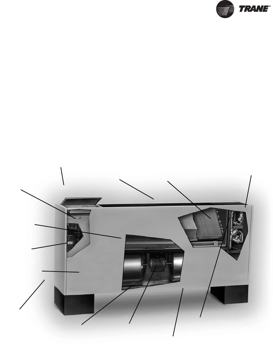
General Information
UniTrane fan-coil and Force-Flo units are intended for
single zone applications. These units have load
capabilities of 200 to 1200 cfm. See Figure 1 for unit
components. Fan-coil units are available as two-pipe, with
or without electric heat (one hydronic circuit) or four-pipe
(two hydronic circuits). Force-Flo units feature two-pipe
hydronic, electric heat only, or steam only. Also, these
units feature a variety of factory mounted piping packages.
Units with the three-speed fan switch only, are available
with the switch mounted on the unit, or shipped
separately, to be mounted in the occupied space. The unit
mounted three-speed switch option can be ordered with a
low voltage (24 vols AC) transformer and three fan speed
relays. The three-speed switch option, which ships
separately, comes with a low voltage (24 volt AC)
transformer.
The Tracer ZN010, ZN510, ZN520, and UC400 controllers
are included inside the units control box assembly. These
controllers utilize analog signals from a unit-mounted
control device or from a control device mounted in the
occupied space.
The controls interface option, includes a 24 volt AC
transformer, and an interface terminal board. Controls
provided by an external source can be tied into the
interface terminal board utilizing the integrated terminal
block with 3mm screw connections.
Figure 1. UniTrane fan-coil unit components (vertical cabinet model is shown)
Factory-assembled, -installed,
and -tested piping package
with IAQ drain pan to collect
condensate.
Two-, three-, or
four-row coils.
Quiet operation.
Smaller unit footprint.
Factory-installed and
-tested controls.
Removable, noncorrosive,
positively-sloped drain pan
that’s easy to clean.
Easy-to-remove fan assembly.
16-gage steel construction.
Cleanable closed-cell
insulator (non-fiberglass).
Easy filter access
without front panel
removal. Damper allows up to 100% fresh air.
Build in field service tool
with real language LED
Energy efficient
electronically
commutated motor (ECM)
UNT-SVX07_-EN.book Page 9 Friday, April 27, 2012 9:40 AM
10 UNT-SVX07D-EN
Pre-Installation
Receiving and Handling
Upon delivery, inspect all components for possible
shipping damage. See “Receiving Checklist” (below) for
detailed instructions. Trane recommends leaving units
and accessories in their shipping packages/skids for
protection and ease of handling until installation.
Shipping Package
UniTrane fan-coil and Force-Flo cabinet heaters ship in
individual cartons for handling and storage ease. Each
carton has tagging information such as the model number,
sales order number, serial number, unit size, piping
connections, and unit style to help properly locate the unit
in the floor plan. If specified, the unit will ship with tagging
designated by the customer.
Receiving Checklist
Complete the following checklist immediately after
receiving unit shipment to detect possible shipping
damage.
Jobsite Storage
This unit is intended for indoor use only. Store the unit
indoors to protect the unit from damage due to the
elements. If indoor storage is not possible, make the
following provisions for outdoor storage:
1. Place the unit(s) on a dry surface or raised off the
ground to assure adequate air circulation beneath unit
and to assure that no portion of the unit contacts
standing water at any time.
2. Cover the entire unit with a canvas tarp only. Do not
use clear, black or plastic tarps as they may cause
excessive moisture condensation and equipment
damage.
Installation Preparation
Before installing the unit, consider the following unit
location recommendations to ensure proper unit
operation.
1. Clearances: Allow adequate service and code
clearances as recommended in “Service Access” (the
next section). Position the unit and skid assembly in its
final location.
2. Structural support: Ensure the structural support is
strong enough to adequately support the unit. The
installer is responsible for supply support rods for
installation of ceiling units.
3. Level: Verify the floor or foundation is level. Shim or
repair as necessary. To ensure proper unit operation,
install the unit level (zero tolerance) in both horizontal
axes. Failure to level the unit properly can result in
condensate management problems, such as standing
water inside the unit.
4. Condensate line & piping: Consider coil piping and
condensate drain requirements. Verify condensate line
WARNING
Hazardous Voltage w/Capacitors!
Disconnect all electric power, including remote
disconnects and discharge all motor start/run
capacitors before servicing. Follow proper lockout/
tagout procedures to ensure the power cannot be
inadvertently energized. For variable frequency drives
or other energy storing components provided by Trane
or others, refer to the appropriate manufacturer’s
literature for allowable waiting periods for discharge of
capacitors. Verify with an appropriate voltmeter that all
capacitors have discharged. Failure to disconnect
power and discharge capacitors before servicing could
result in death or serious injury.
For additional information regarding the safe discharge of
capacitors, see PROD-SVB06A-EN
Inspect individual cartons before accepting. Check for
rattles, bent carton corners, or other visible indications
of shipping damage.
If a unit appears damaged, inspect it immediately
before accepting the shipment. Manually rotate the fan
wheel to ensure it turns freely. Make specific notations
concerning the damage on the freight bill. Do not
refuse delivery.
Inspect the unit for concealed damage before it is
stored and as soon as possible after delivery. Report
concealed damage to the freight line within the allotted
time after delivery. Check with the carrier for their
allotted time to submit a claim.
Do not move damaged material from the receiving
location. It is the receiver’s responsibility to provide
reasonable evidence that concealed damage did not
occur after delivery.
Do not continue unpacking the shipment if it appears
damaged. Retain all internal packing, cartons, and
crate. Take photos of damaged material.
Notify the carrier’s terminal of the damage
immediately by phone and mail. Request an immediate
joint inspection of the damage by the carrier and
consignee.
Notify your Trane representative of the damage and
arrange for repair. Have the carrier inspect the damage
before making any repairs to the unit.
Compare the electrical data on the unit nameplate with
the ordering and shipping information to verify the
correct unit is received.
UNT-SVX07_-EN.book Page 10 Friday, April 27, 2012 9:40 AM
Pre-Installation
UNT-SVX07D-EN 11
is continuously pitched 1 inch per 10 feet of condensate
line run to adequately drain condensate.
5. Wall & ceiling openings: Vertical recessed/concealed
units require wall/ceiling openings. Refer to submittal
for specific dimensions before attempting to install.
Horizontal recessed/concealed units must meet the
requirements of the National Fire Protection
Association (NFPA) Standard 90A or 90B concerning
the use of concealed ceiling spaces as return air
plenums. Refer to the submittal for specific
dimensions of ceiling openings.
6. Exterior: Touch up painted panels if necessary. If
panels need paint, sanding is not necessary. However,
clean the surface of any oil, grease, or dirt residue so
the paint will adhere. Purchase factory approved touch
up epoxy paint from your local Trane Service Parts
Center and apply.
Service Access
Service access is available from the front on vertical units
and from the bottom on horizontal units. Cabinet and
recessed units have removable front or bottom panels to
allow access into the unit. See Figure 2, p. 11 for
recommended service and operating clearances.
Units have either right or left hand piping. Reference
piping locations by facing the front of the unit (airflow
discharges from the front). The control panel is always on
the end opposite the piping.
The fan board assembly and main drain pan are easily
removable for cleaning. See “Maintenance,” p. 106 for
more details on servicing.
Pre-Installation Checklist
Complete the following checklist before beginning unit
installation.
Figure 2. Recommended service clearances
model B, vertical cabinet
model L, low vertical cabinet
12"
both sides
24"
3"
36"
model A, vertical concealed
model K, low vertical concealed
model H, vertical recessed
8.5"
both sides
12"
both sides 8.5"
both sides
28"
28"
model D, horizontal cabinet
model C, horizontal concealed
model E, horizontal recessed
24"
front discharge
Verify the unit size and tagging with the unit nameplate.
Make certain the floor or foundation is level, solid, and
sufficient to support the unit and accessory weights.
See “Dimensions and Weights,” p. 12. Level or repair
the floor before positioning the unit if necessary.
Allow minimum recommended clearances for routine
maintenance and service. Refer to unit submittals for
dimensions.
Allow one and one half fan diameters above the unit
before the discharge ductwork makes any turns.
UNT-SVX07_-EN.book Page 11 Friday, April 27, 2012 9:40 AM
12 UNT-SVX07D-EN
Dimensions and Weights
Table 1. Fan-coil component data
Unit Size 02 03 04 06 08 10 12
Coil Data
Face Area — ft20.8 0.8 1.1 1.6 2.1 3.2 3.2
LxDxH — in.
2-Row 15 x 1.7 x 8 15 x 1.7 x 8 20 x 1.7 x 8 29.5 x 1.7 x 8 38 x 1.7 x 8 57 x 1.7 x 8 57 x 1.7 x 8
3-Row 15 x 2.6 x 8 15 x 2.6 x 8 20 x 2.6 x 8 29.5 x 2.6 x 8 38 x 2.6 x 8 57 x 2.6 x 8 57 x 2.6 x 8
4-Row 15 x 3.5 x 8 15 x 3.5 x 8 20 x 3.5 x 8 29.5 x 3.5 x 8 38 x 3.5 x 8 57 x 3.5 x 8 57 x 3.5 x 8
Volume — gal
1-Row (Heat) 0.06 0.06 0.08 0.11 0.14 0.21 0.21
2-Row 0.12 0.12 0.15 0.22 0.28 0.42 0.42
3-Row 0.18 0.18 0.23 0.33 0.42 0.62 0.62
4-Row 0.24 0.24 0.30 0.44 0.56 0.83 0.83
Fins/ft
2-Row 144 144 144 144 144 144 144
3-Row 144 144 144 144 144 144 144
4-Row 144 144 144 144 144 144 144
Reheat Coil Data (1-Row), Standard or High-Capacity(a)
(a) Standard and high-capacity reheat coils share the same component data except that standard capacity reheat coils have 48 fins/ft (1.6 fins/cm) while
high-capacity reheat coils have 144 fins/ft (4.7 fins/cm).
Hot Water or Steam
Face Area — ft20.6 0.6 0.8 1.2 1.6 2.4 2.4
L x D x H — in. 15 x 1.5 x 6 15 x 1.5 x 6 20 x 1.5 x 6 29.5 x 1.5 x 6 38 x 1.5 x 6 57 x 1.5 x 6 57 x 1.5 x 6
Volume — gal 0.12 0.12 0.15 0.22 0.28 0.42 0.42
Standard Capacity(a) Fins/ft 48 48 48 48 48 48 48
High-Capacity(a) Fins/ft 144 144 144 144 144 144 144
Fan/Motor Data
Fan Quantity 1112233
Size — Dia” x Width” 6.31 x 4 6.31 x 6.5 6.31 x 7.5 6.31 x 6.5 6.31 x 7.5 (1) 6.31 x 7.5 6.31 x 7.5
Size — Dia” x Width” (2) 6.31 x 6.5
Motor Quantity 1111122
Filter Data
1” TA and Pl. Media
Quantity 1111111
Size — in. 8-7/8 x 19-1/8 8-7/8 x 19-1/8 8-7/8 x 24-1/8 8-7/8 x 33-5/8 8-7/8 x 42-1/8 8-7/8 x 61-1/8 8-7/8 x 61-1/8
1” Fresh Air Filter (only on cabinet styles D, E, and H with bottom return and fresh air opening)
Quantity 1111111
Size — in 5-1/2 x 19-1/8 5-1/2 x 19-1/8 5-1/2 x 24-1/8 5-1/2 x 33-5/8 5-/2 x 42-1/8 5-1/2 x 61-1/8 5-1/2 x 61-1/8
UNT-SVX07_-EN.book Page 12 Friday, April 27, 2012 9:40 AM
Dimensions and Weights
UNT-SVX07D-EN 13
Table 2. Low vertical fan-coil component data
Unit Size 03 04 06
Coil Data
Face Area — ft21.1 1.6 2.1
L x D x H — in.
2-Row 20 x 1.7 x 8 29.5 x 1.7 x 8 38 x 1.7 x 8
3-Row 20 x 2.6 x 8 29.5 x 2.6 x 8 38 x 2.6 x 8
Volume — gal
1-Row (Heat) 0.08 0.11 0.14
2-Row 0.15 0.22 0.28
3-Row 0.23 0.33 0.42
Fins/ft
2-Row 144 144 144
3-Row 144 144 144
Fan/Motor Data
Fan Quantity 1 1 1
Size — Dia”x Width” 5 x 23 5 x 32 5 x 41
Motor Quantity 1 1 1
Filter Data
1” (2.5 cm) TA
Quantity 1 1 1
Size — in. 8-7/8 x 24-1/8 8-7/8 x 33-5/8 8-7/8 x 42-1/8
UNT-SVX07_-EN.book Page 13 Friday, April 27, 2012 9:40 AM
Dimensions and Weights
14 UNT-SVX07D-EN
Available Models
Model A:
Vertical Concealed
Model B:
Vertical Short
Model C:
Horizontal Concealed
Model D:
Horizontal Cabinet
Model E:
Horizontal Recessed
Model F:
Wall Hung Cabinet
(Force-Flo units only)
Model L:
Low Vertical Concealed
Model K:
Low Vertical Cabinet
Model H:
Vertical Recessed
Model J:
Slope-Top Cabinet
Model M:
Inverted Vertical Cabinet
(Force-Flo units only)
Model N:
Inverted Vertical Recessed
(Force-Flo units only)
Model P:
Compact Concealed
UNT-SVX07_-EN.book Page 14 Friday, April 27, 2012 9:40 AM
Dimensions and Weights
UNT-SVX07D-EN 15
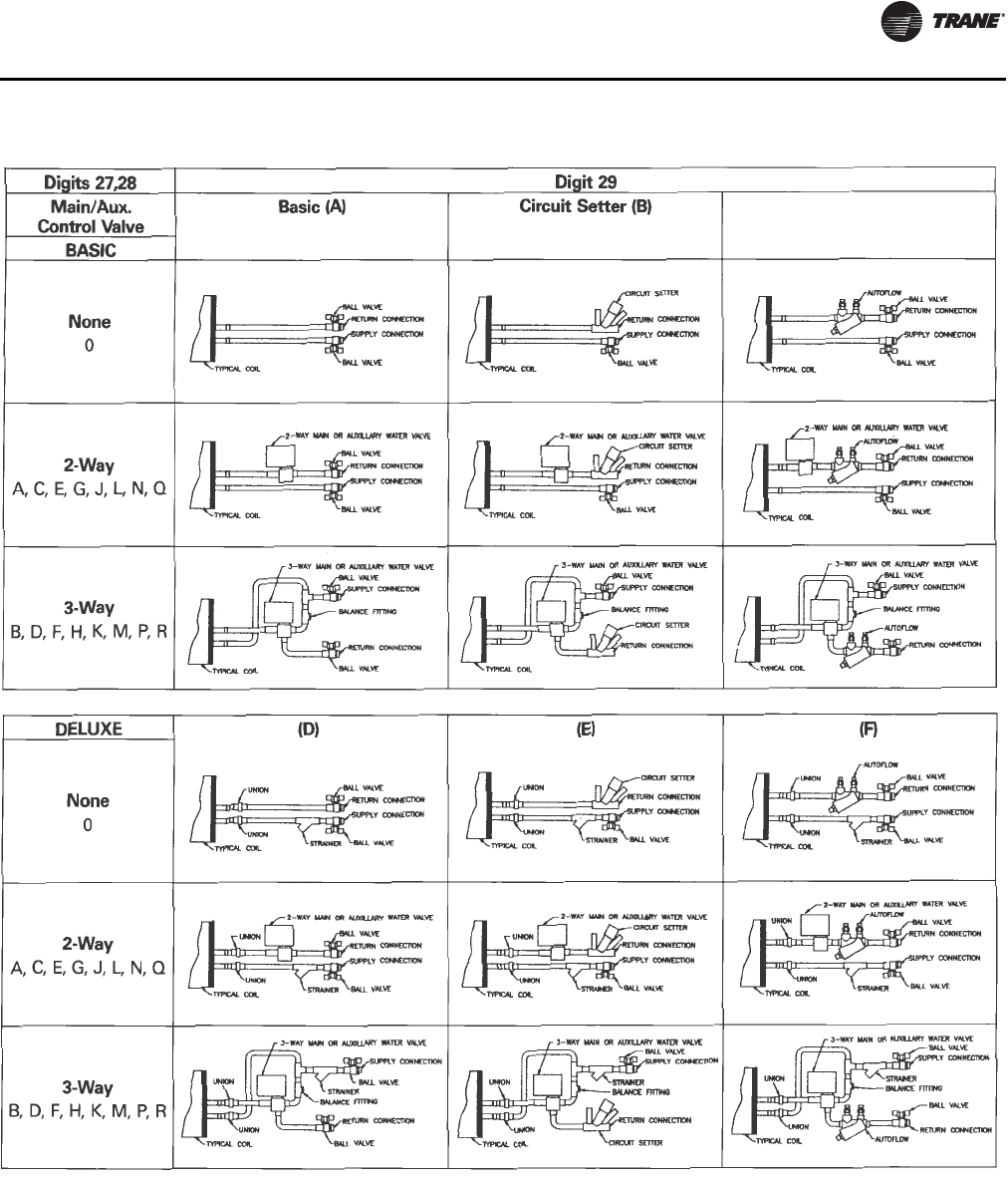
Factory-Installed Piping Packages
Note: This figure shows piping package components and
basic arrangement. It is not an accurate pictorial of
what factory-installed piping packages look like.
Auto Circuit Setter (C)
UNT-SVX07_-EN.book Page 15 Friday, April 27, 2012 9:40 AM
Dimensions and Weights
16 UNT-SVX07D-EN
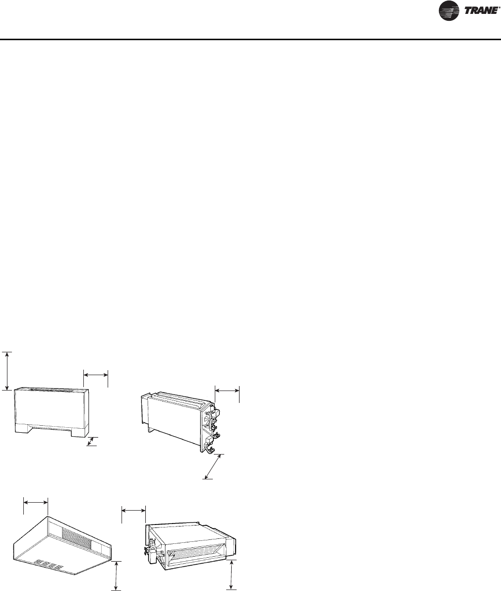
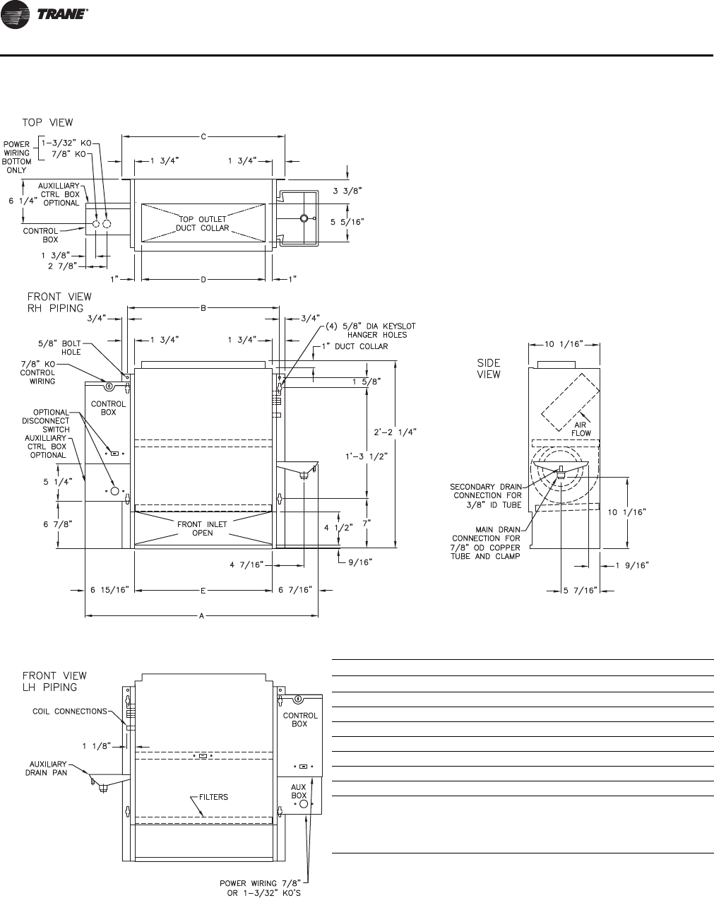
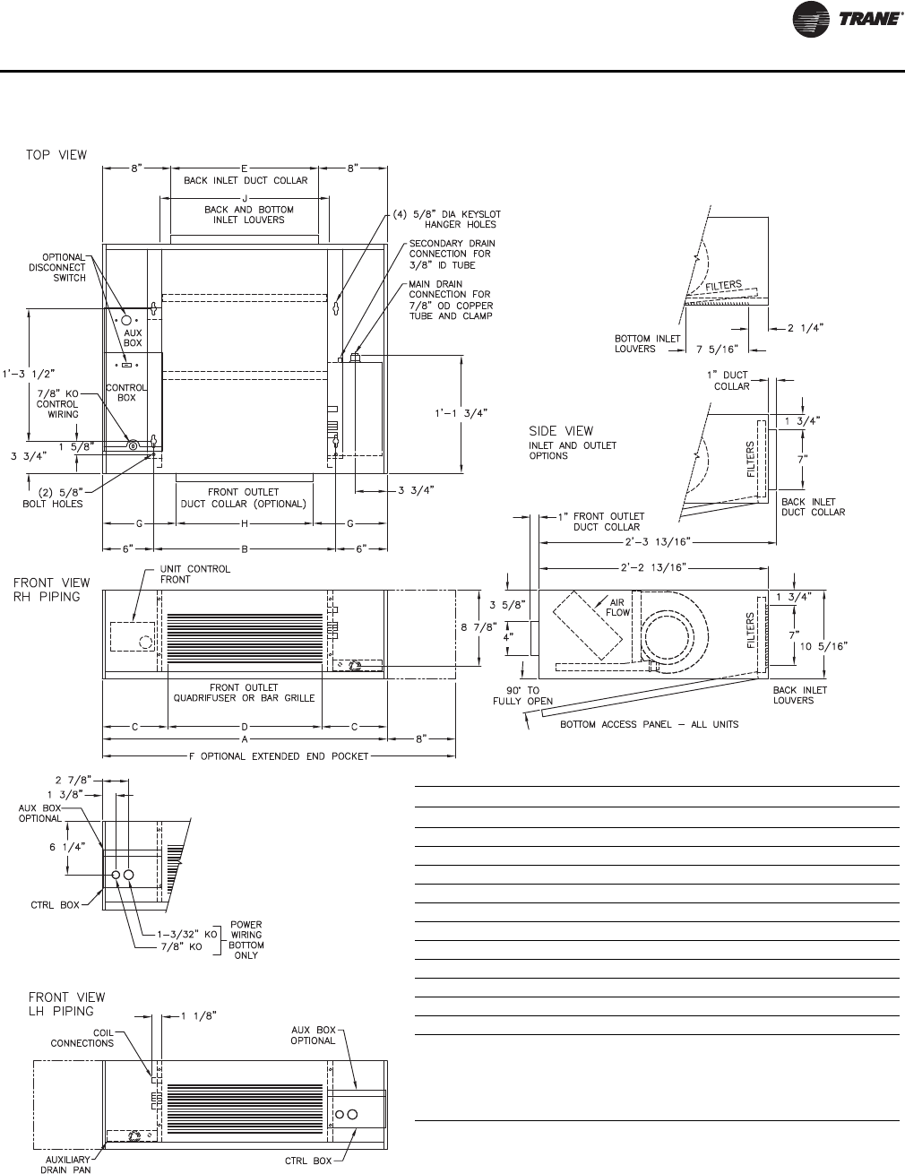
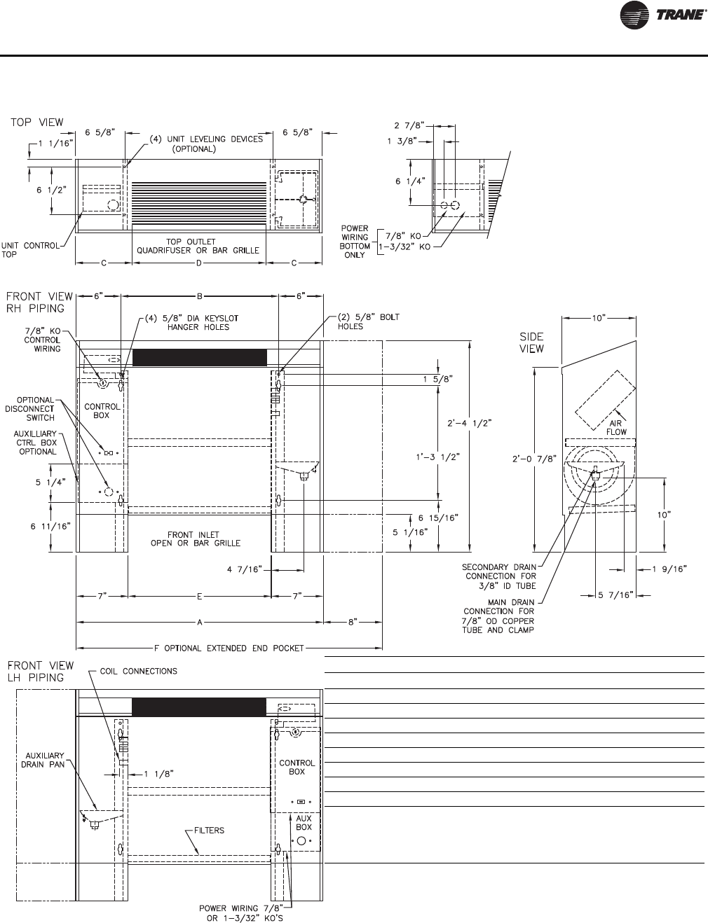
Vertical Concealed, Model A
Vertical Concealed Unit
Unit Size 200-300 400 600 800 1000-1200
No. of Fans1122 3
No. of Motors1111 2
A 2’-8 11/16” 3’-1 11/16” 3’-11 3/16” 4’-7 11/16” 6’-2 11/16”
B 1’-9 5/16” 2’-2 5/16” 2’-11 13/16” 3’-8 5/16” 5’-3 5/16”
C 1’-10 13/16” 2’-3 13/16” 3’-1 5/16” 3’-9 13/16” 5’-4 13/16”
D 1’-5 5/16” 1’-10 5/16” 2’-7 13/16” 3’-4 5/16” 4’-11 5/16”
E 1’-7 5/16” 2’-0 5/16” 2’-9 13/16” 3’-6 5/16” 5’-1 5/16”
Notes:
1. Coil connections are always on the drain pan side and opposite the control box.
2. Coil connections are 5/8” O.D. sweat. See p. 29 and p. 30 for locations.
3. All duct collar dimensions are to the outside of the collar.
4. See p. 33 for dimensions for outside air openings.
UNT-SVX07_-EN.book Page 16 Friday, April 27, 2012 9:40 AM
Dimensions and Weights
UNT-SVX07D-EN 17
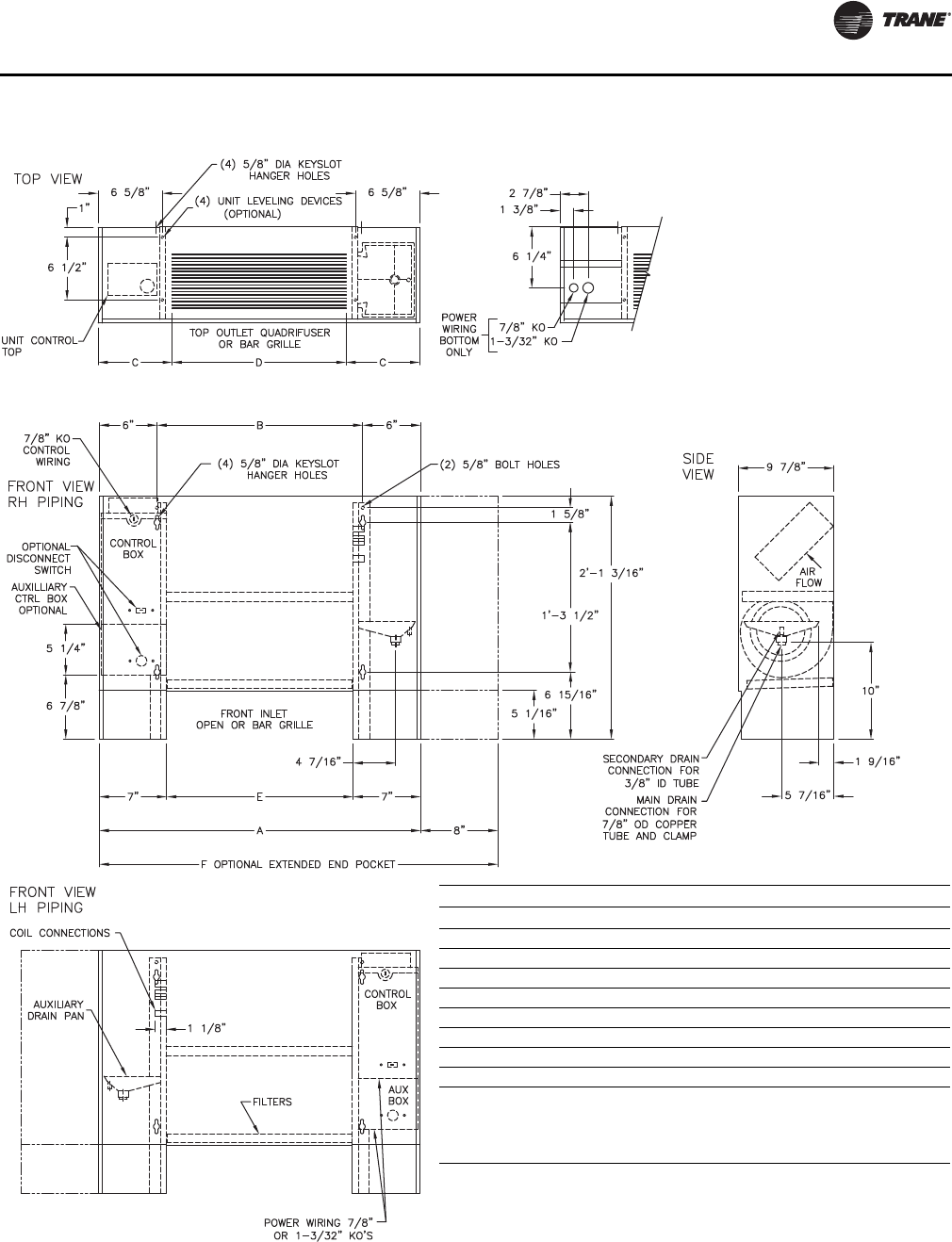
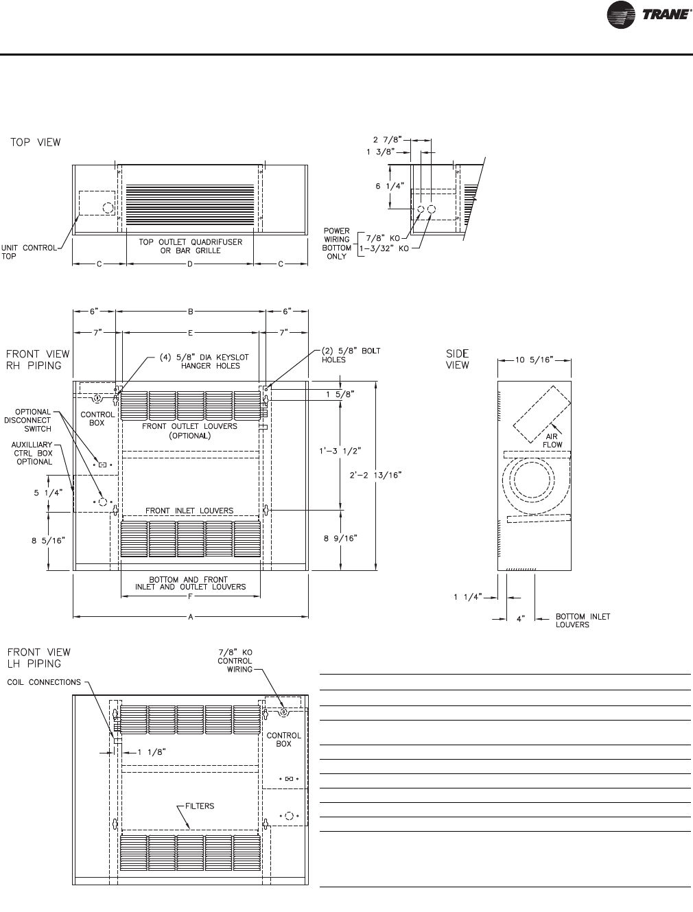
Vertical Cabinet, Model B
Vertical Cabinet Unit
Unit Size 200-300 400 600 800 1000-1200
No. of Fans1122 3
No. of Motors1111 2
A 2’-9 5/16” 3’-2 5/16” 3’-11 13/16” 4’-8 5/16” 6’-3 5/16”
B 1’-9 5/16” 2’-2 5/16” 2’-11 13/16” 3’-8 5/16” 5’-3 5/16”
C 7 5/8” 7 1/8” 8 7/8” 7 1/8” 7 5/8”
D 1’-16” 2’-0” 2’-6” 3’-6” 5’-0”
E 1’-7 5/16” 2’-0 5/16” 2’-9 13/16” 3’-6 5/16” 5’-1 5/16”
F 3’-5 5/16” 3’-10 5/16” 4’-7 13/16” 5’-4 5/16” 6’-11 5/16”
Notes:
1. Coil connections are always on the drain pan side and opposite the control box
and unit control.
2. Coil connections are 5/8” O.D. sweat. See p. 29 and p. 30 for locations.
3. See p. 33 for dimensions for outside air openings.
UNT-SVX07_-EN.book Page 17 Friday, April 27, 2012 9:40 AM
Dimensions and Weights
18 UNT-SVX07D-EN
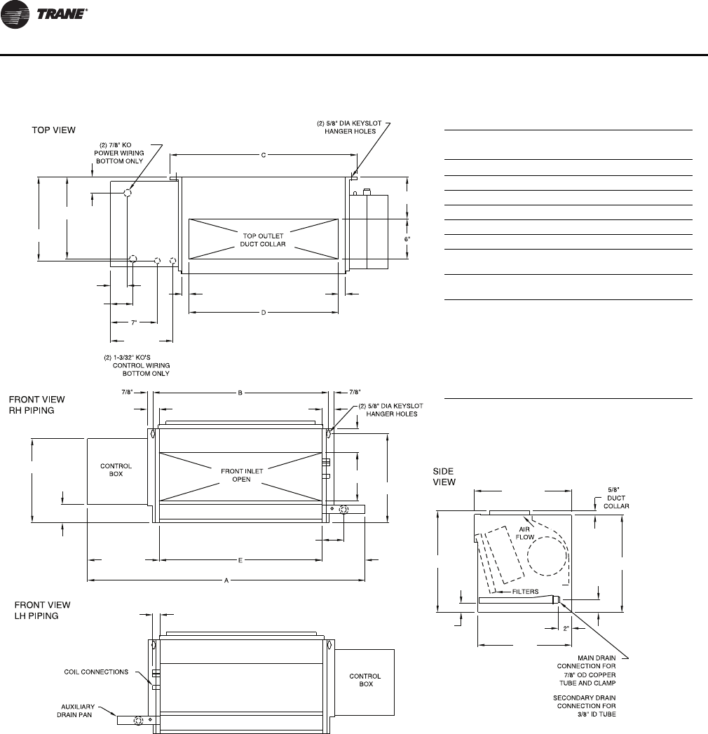
Horizontal Concealed, Model C
Horizontal Concealed Unit Dimensions (in.) and Weights (lb)
Unit Size 200-300 400 600 800 1000-1200
No. of Fans1122 3
No. of Motors1111 2
A 2’-8 11/16” 3’-1 11/16” 3’-11 3/16” 4’-7 11/16” 6’-2 11/16”
B 1’-9 5/16” 2’-2 5/16” 2’-11 13/16” 3’-8 5/16” 5’-3 5/16”
C 1’-10 13/16” 2’-3 13/16” 3’-1 5/16” 3’-9 13/16” 5’-4 13/16”
D 1’-7 3/8” 2’-0 3/8” 2’-9 7/8” 3’-6 3/8” 5’-1 3/8”
E 1’-6 1/8” 1’-11 1/8” 2’-8 5/8” 3’-5 1/8” 5’-0 1/8”
F 1’-7 5/16” 2’-0 5/16” 2’-9 13/16” 3’-6 5/16” 5’-1 5/16”
Notes:
1. Coil connections are always on the drain pan side and opposite the control
box.
2. Coil connections are 5/8” O.D. sweat. See p. 29 and p. 30 for locations.
3. All duct collar dimensions are to the outside of the collar.
4. See p. 32 for dimensions for outside air openings.
UNT-SVX07_-EN.book Page 18 Friday, April 27, 2012 9:40 AM
Dimensions and Weights
UNT-SVX07D-EN 19
Horizontal Cabinet, Model D
Horizontal Cabinet Unit
Unit Size 200-300 400 600 800 1000-1200
No. of Fans1122 3
No. of Motors1111 2
A 2’-9 5/16” 3’-2 5/16” 3’-11 3/16” 4’-8 5/16” 6’-3 5/16”
B 1’-9 5/16” 2’-2 5/16” 2’-11 13/16” 3’-8 5/16” 5’-3 5/16”
C 7 5/8” 7 1/8” 8 7/8” 7 1/8” 7 5/8”
D 1’-6” 2’-0” 2’-6” 3’-6” 5’-0”
E 1’-5 1/4” 1’-10 1/4” 2’-7 3/4” 3’-4 1/4” 3’-4 1/4”
F 3’-5 1/4” 3’-10 5/16” 4’-7 3/16” 5’-4 5/16” 6’-11 5/16”
G 8-5/8” 8-1/8” 9-7/8” 8-1/8” 8-5/8”
H 1’-4” 1’-10” 2’-4” 3’-4” 4’-10”
J 1’-7 3/4” 1’-11 3/4” 2’-7 3/4” 3’-3 3/4” 4’-11 3/4”
Notes:
1. Coil connections are always on the drain pan side and opposite the control
box.
2. Coil connections are 5/8” O.D. sweat. See p. 29 and p. 30 for locations.
3. All duct collar dimensions are to the outside of the collar.
4. See p. 32 for dimensions for outside air openings.
UNT-SVX07_-EN.book Page 19 Friday, April 27, 2012 9:40 AM
Dimensions and Weights
20 UNT-SVX07D-EN
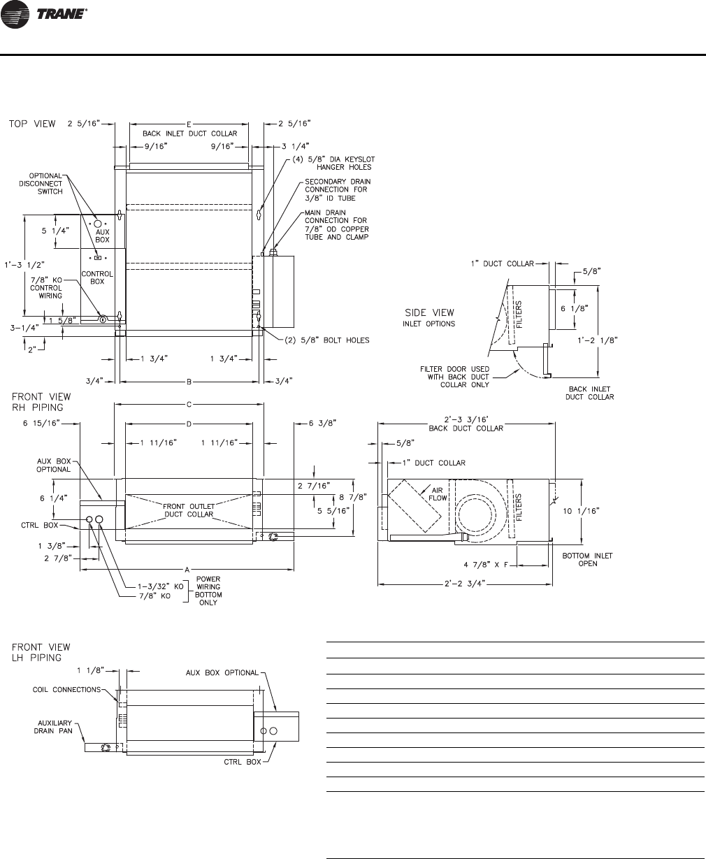
Horizontal Recessed, Model E
Horizontal Recessed Unit
Unit Size 200-300 400 600 800 1000-1200
No. of Fans1122 3
No. of Motors1111 2
A 2’-11 13/16” 3’-4 13/16” 4’-2 5/16” 4’-10 13/16” 6’-5 13/16”
B 1’-9 5/16” 2’-2 5/16” 2’-11 13/16” 3’-8 5/16” 5’-3 5/16”
C 1’-10 13/16” 2’-3 13/16” 3’-1 5/16” 3’-9 13/16” 5’-4 13/16”
D 1’-7 3/8” 2’-0 3/8” 2’-9 7/8” 3’-6 3/8” 5’-1 3/8”
E 1’-6 1/8” 1’-11 1/8” 2’-8 5/8” 3’-5 1/8” 5’-0 1/8”
F 2’-8 7/16” 3’-1 7/16” 3’-10 15/16” 4’-7 7/16” 6’-2 7/16”
G 2’-10 5/16” 3’-3 5/16” 4’-0 13/16” 4’-9 5/16” 6’-4 5/16”
H 1’-7 3/4” 1’-11 3/4” 2’-7 3/4” 3’-3 3/4” 4’-11 3/4”
Notes:
1. Coil connections are always on the drain pan side.
2. Coil connections are 5/8” O.D. sweat. See p. 29 and p. 30 for locations.
3. All duct collar dimensions are to the outside of the collar.
4. See p. 32 for dimensions for outside air openings.
UNT-SVX07_-EN.book Page 20 Friday, April 27, 2012 9:40 AM
Dimensions and Weights
UNT-SVX07D-EN 21
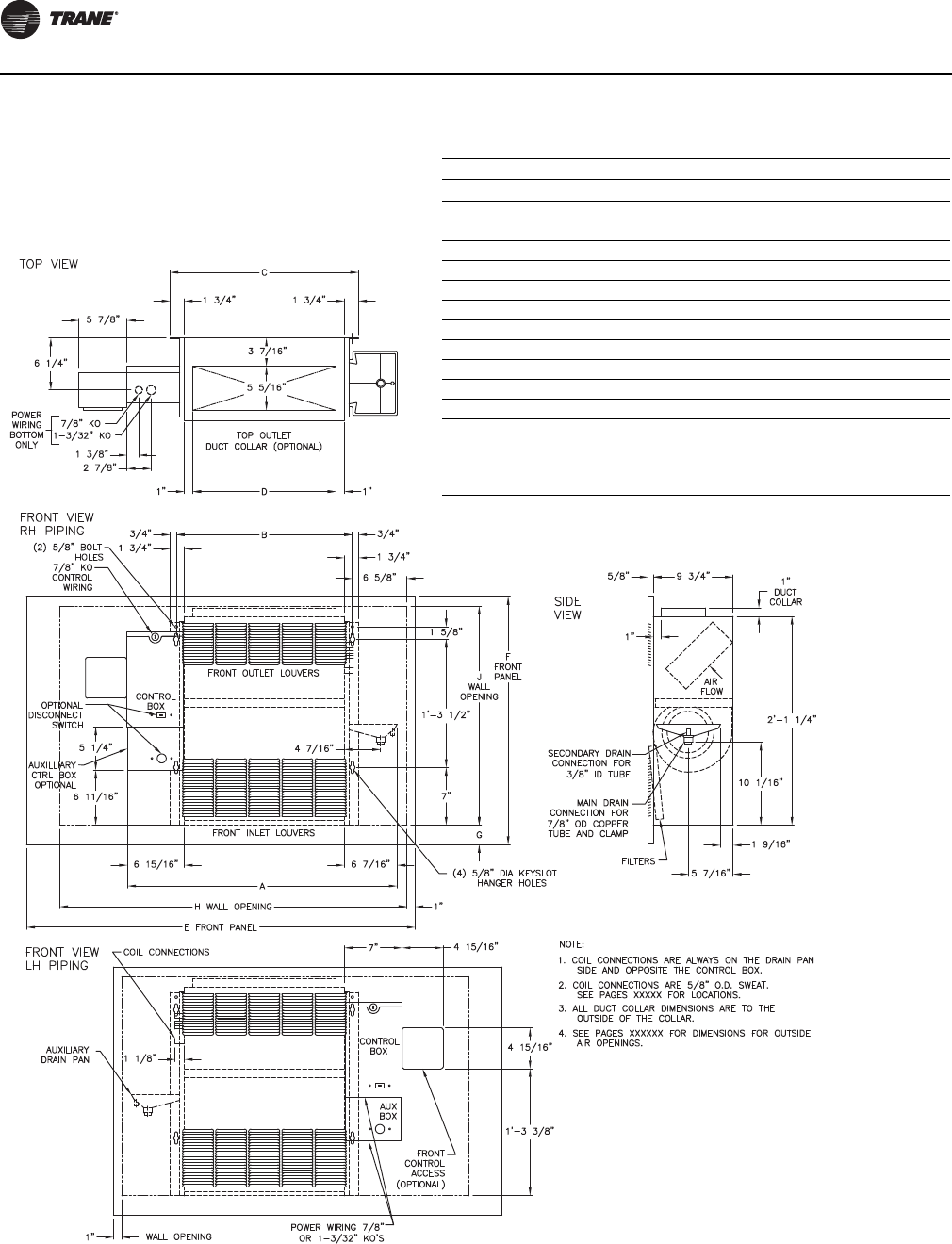
Vertical Wall Hung Cabinet, Model F
(Force-Flo Units Only)
Vertical Wall Hung Cabinet Unit
Unit Size 200-300 400 600 800 1000-1200
No. of Fans1122 3
No. of
Motors 1111 2
A 2’-9 5/16” 3’-2 5/16” 3’-11 13/16” 4’-8 5/16” 6’-3 5/16”
B 1’-9 5/16” 2’-2 5/16” 2’-11 13/16” 3’-8 5/16” 5’-3 5/16”
C 7 5/8” 7 1/8” 8 7/8” 7 1/8” 7 5/8”
D 1’-6” 2’-0” 2’-6” 3’-6” 5’-0”
E 1’-7 5/16” 2’-0 5/16” 2’-9 13/16” 3’-6 5/16” 5’-1 5/16”
F 1’-7 3/4” 1’-11 3/4” 2’-7 3/4” 3’-3 3/4” 4’-11 3/4”
Notes:
1. Coil connections are always opposite the control box side.
2. Coil connections are 5/8” O.D. sweat. See p. 29 and p. 30 for locations.
3. All duct collar dimensions are to the outside of the collar.
4. See p. 33 for dimensions for outside air openings.
UNT-SVX07_-EN.book Page 21 Friday, April 27, 2012 9:40 AM
Dimensions and Weights
22 UNT-SVX07D-EN
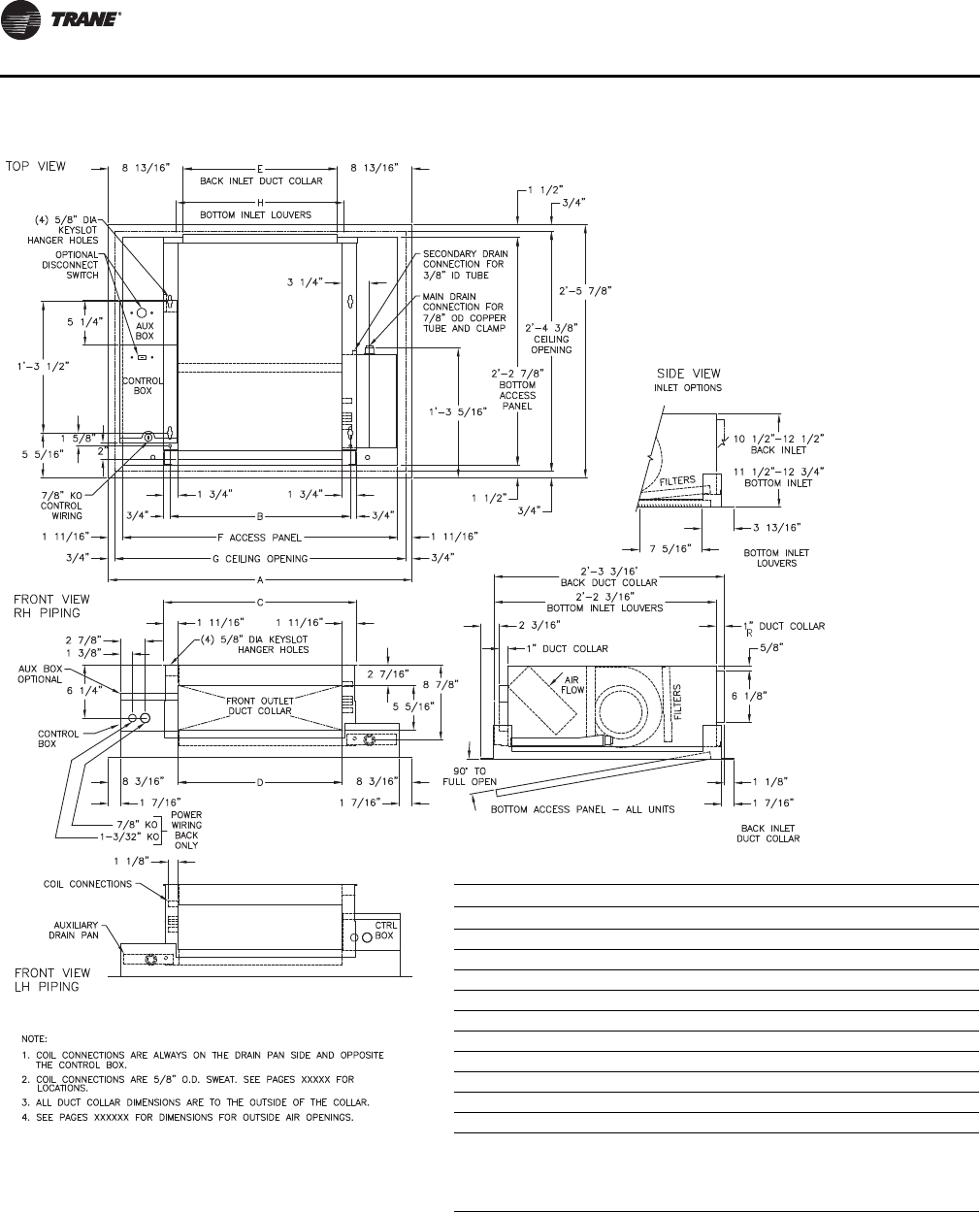
Vertical Recessed, Model H
Vertical Recessed Unit
Unit Size 200-300 400 600 800 1000-1200
No. of Fans1122 3
No. of Motors1111 2
A 2’-8 11/16” 3’-1 11/16” 3’-11 3/16” 4’-7 11/16” 6’-2 11/16”
B 1’-9 5/16” 2’-2 5/16” 2’-11 13/16” 3’-8 5/16” 5’-3 5/16”
C 1’-10 13/16” 2’-3 13/16” 3’-1 5/16” 3’-9 13/16” 5’-4 13/16”
D 1’-5 5/16” 1’-10 5/16” 2’-7 13/16” 3’-4 5/16” 4’-11 5/16”
E 3’-11” 4’-3” 5’-3” 5’-5 1/2” 7’-5 1/2”
F 2’-6” 2’-6” 2’-6” 2’-9 1/2” 2’-9 1/2”
G 2 3/8” 2 3/8” 2 3/8” 4 1/8” 4 1/8”
H 3’-6” 4’-0” 4’-9” 5’-3” 7’-3”
J 2’-2 1/2” 2’-2 1/2” 2’-2 1/2” 2’-3 1/2” 2’-3 1/2”
Notes:
1.
Coil connections are always on the drain pan side and opposite the control box.
2. Coil connections are 5/8” O.D. sweat. See p. 29 and p. 30 for locations.
3. All duct collar dimensions are to the outside of the collar.
4. See p. 33 for dimensions for outside air openings.
UNT-SVX07_-EN.book Page 22 Friday, April 27, 2012 9:40 AM
Dimensions and Weights
UNT-SVX07D-EN 23
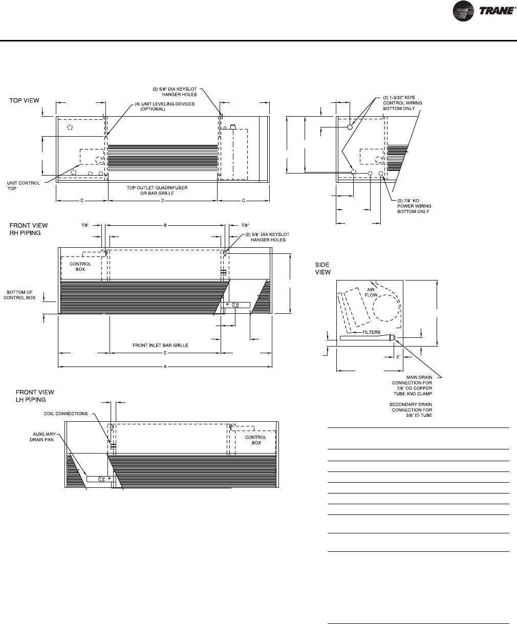
Vertical Slope Top, Model J
Vertical Slope Top Unit
Unit Size 200-300 400 600 800 1000-1200
No. of Fans 1 1 2 2 3
No. of Motors 1 1 1 1 2
A 2’-9 5/16” 3’-2 5/16” 3’-11 13/16” 4’-8 5/16” 6’-3 5/16”
B 1’-9 5/16” 2’-2 5/16” 2’-11 13/16” 3’-8 5/16” 5’-3 5/16”
C 7 5/8” 7 1/8” 8 7/8” 7 1/8” 7 5/8”
D 1’-6” 2’-0” 2’-6” 3’-6” 5’-0”
E 1’-7 5/16” 2’-0 5/16” 2’-9 13/16” 3’-6 5/16” 5’-1 5/16”
F 3’-5 5/16” 3’-10 5/16” 4’-7 13/16” 5’-4 5/16” 6’-11 5/16”
Notes:
1. Coil connections are always on the drain pan side and opposite the control box
and unit control.
2. Coil connections are 5/8” O.D. sweat. See p. 29 and p. 30 for locations.
3. See p. 33 for dimensions for outside air openings.
UNT-SVX07_-EN.book Page 23 Friday, April 27, 2012 9:40 AM
Dimensions and Weights
24 UNT-SVX07D-EN
Low Vertical Concealed, Model K
12-9/16"
2-11/16"
10-11/16"
1-13/16"
1-1/8"
1-13/16"
3-1/4"
6-7/16"
7-1/4"
3-9/16"
13-1/4"
14-1/4"
1-5/16"
14"
14-1/2"
1-15/16"
13-1/2"
9-5/16"
3-3/8"
2-9/16"
1-1/16"
2-3/8"
12-1/4"
12-1/2"
1-1/16"
6-1/4"
Low Vertical Concealed Unit Dimensions
(in.) and Weights (lb)
Unit Size 03 04 06
A 41-7/16” 50-15/16” 59-7/16”
B 26-1/4” 35-3/4” 44-1/4”
C 27-15/16” 36-13/16” 45-15/16”
D 22-5/16” 31-13/16” 40-5/16”
E 24-1/4” 339-3/4” 42-1/4”
Operating
Weight 109 139 147
Shipping
Weight 96 123 131
Notes:
1. Coil connections are always on the drain pan side
and opposite the control box.
2. Coil connections are 5/8” O.D. sweat.
3. All duct collar dimensions are to the outside of the
collar.
4. See p. 33 for dimensions for outside air openings.
5. Serviceability for some components within this
unit may require panel or drain pan removal.
UNT-SVX07_-EN.book Page 24 Friday, April 27, 2012 9:40 AM
Dimensions and Weights
UNT-SVX07D-EN 25
Low Vertical Cabinet, Model L
10-15/16"
4-7/16"
8-1/2"
10-15/16"
2-3/8"
12-1/4"
12-1/2"
3-7/8"
7-1/2"
9-13/16"
2-11/16"
1-13/16" 1-13/16"
3-1/4"
6-7/16"
11-5/16"
13-3/16"
1-5/16"
13-1/2"
1-15/16"
14-1/2"
11-5/16"
1-1/8"
3-1/16"
Low Vertical Cabinet Unit Dimensions (in.)
and Weights (lb)
Unit Size 03 04 06
A 46-15/16” 56-7/16” 64-15/16”
B 26-1/4” 35-3/4” 44-1/4”
C 11-7/16” 13-5/16” 11-7/16”
D 24” 30” 42”
E 24-1/4” 33-3/4” 42-1/4”
Operating
Weight 125 155 164
Shipping
Weight 112 139 148
Notes:
1. Coil connections are always on the drain pan side
and opposite the control box.
2. Coil connections are 5/8” O.D. sweat.
3. All duct collar dimensions are to the outside of the
collar.
4. See p. 33 for dimensions for outside air openings.
5. Serviceability for some components within this
unit may require panel or drain pan removal.
UNT-SVX07_-EN.book Page 25 Friday, April 27, 2012 9:40 AM
Dimensions and Weights
26 UNT-SVX07D-EN
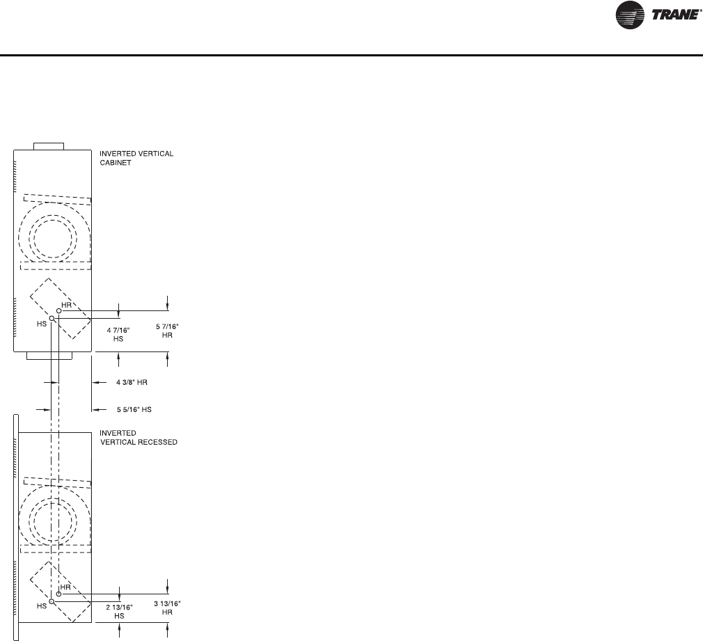
Inverted Vertical Cabinet, Model M
(Force-Flo Units Only)
Inverted Vertical Cabinet Unit Dimensions (in.) and Weights (lb)
Unit Size 02–03 04 06 08 10–12
A 33-5/16” 38-5/16” 47-13/16” 56-5/16” 75-5/16”
B 21-5/16” 26-5/16” 35-13/16” 44-5/16” 63-5/16”
C 7-5/8” 7-1/8” 8-7/8” 7-1/8” 7-5/8”
D 18” 24” 30” 42” 60”
E 19-5/16” 24-5/16” 33-13/16” 42-5/16” 61-5/16”
F 19-3/4” 23-3/4” 31-3/4” 39-3/4” 59-3/4”
Operating
Weight 97 125 155 164 218
Shipping
Weight 84 112 139 148 200
Notes:
1. Coil connections are always opposite the control box side.
2. Coil connections are 5/8” O.D. sweat. See p. 31 for locations.
3. All duct collar dimensions are to the outside of the collar.
4. See p. 33 for dimensions for outside air openings.
UNT-SVX07_-EN.book Page 26 Friday, April 27, 2012 9:40 AM
Dimensions and Weights
UNT-SVX07D-EN 27
Inverted Vertical Recessed, Model N
(Force-Flo Units Only)
Inverted Vertical Recessed Unit Dimensions (in.) and Weights
(lb)
Unit Size 02–03 04 06 08 10–12
A 27-7/8” 32-7/8” 42-3/8” 50-7/8” 69-7/8”
B 21-5/16” 26-5/16” 35-13/16” 44-5/16” 63-5/16”
C 22-13/16” 27-13/16” 37-5/16” 45-13/16” 64-13/16”
D 2-3/8” 2-3/8” 2-3/8” 4-1/8” 4-1/8”
E 47” 51” 63” 65-1/2” 89-1/2”
F 30” 30” 30” 33-1/2” 33-1/2”
G 26-1/2” 26-1/2” 26-1/2” 27-1/2” 27-1/2”
H 42” 48” 57” 63” 87”
Operating
Weight 78 88 128 139 253
Shipping
Weight 68 78 118 129 243
Notes:
1. Coil connections are always opposite the control box side.
2. Coil connections are 5/8” O.D. sweat. See p. 30 for locations.
3. All duct collar dimensions are to the outside of the collar.
4. See p. 33 for dimensions for outside air openings.
UNT-SVX07_-EN.book Page 27 Friday, April 27, 2012 9:40 AM
Dimensions and Weights
28 UNT-SVX07D-EN
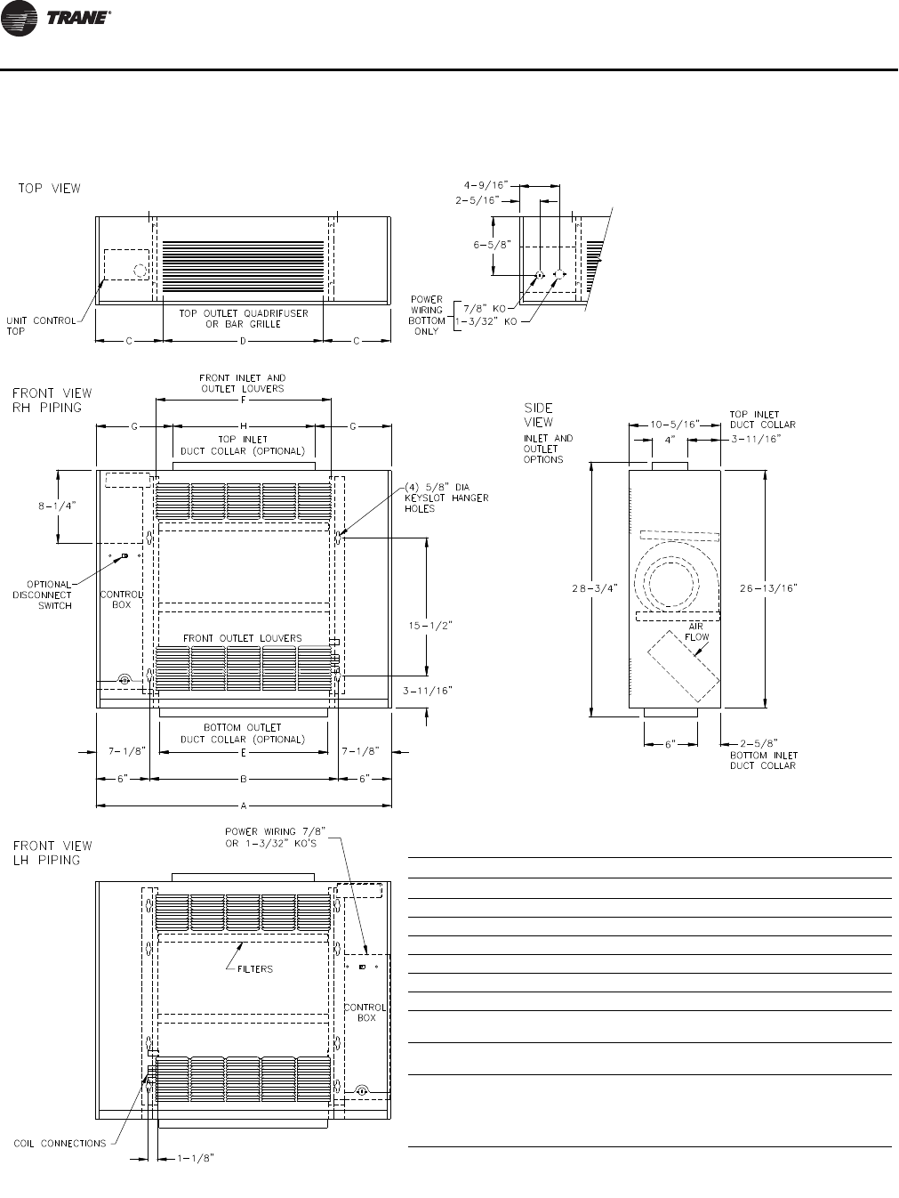
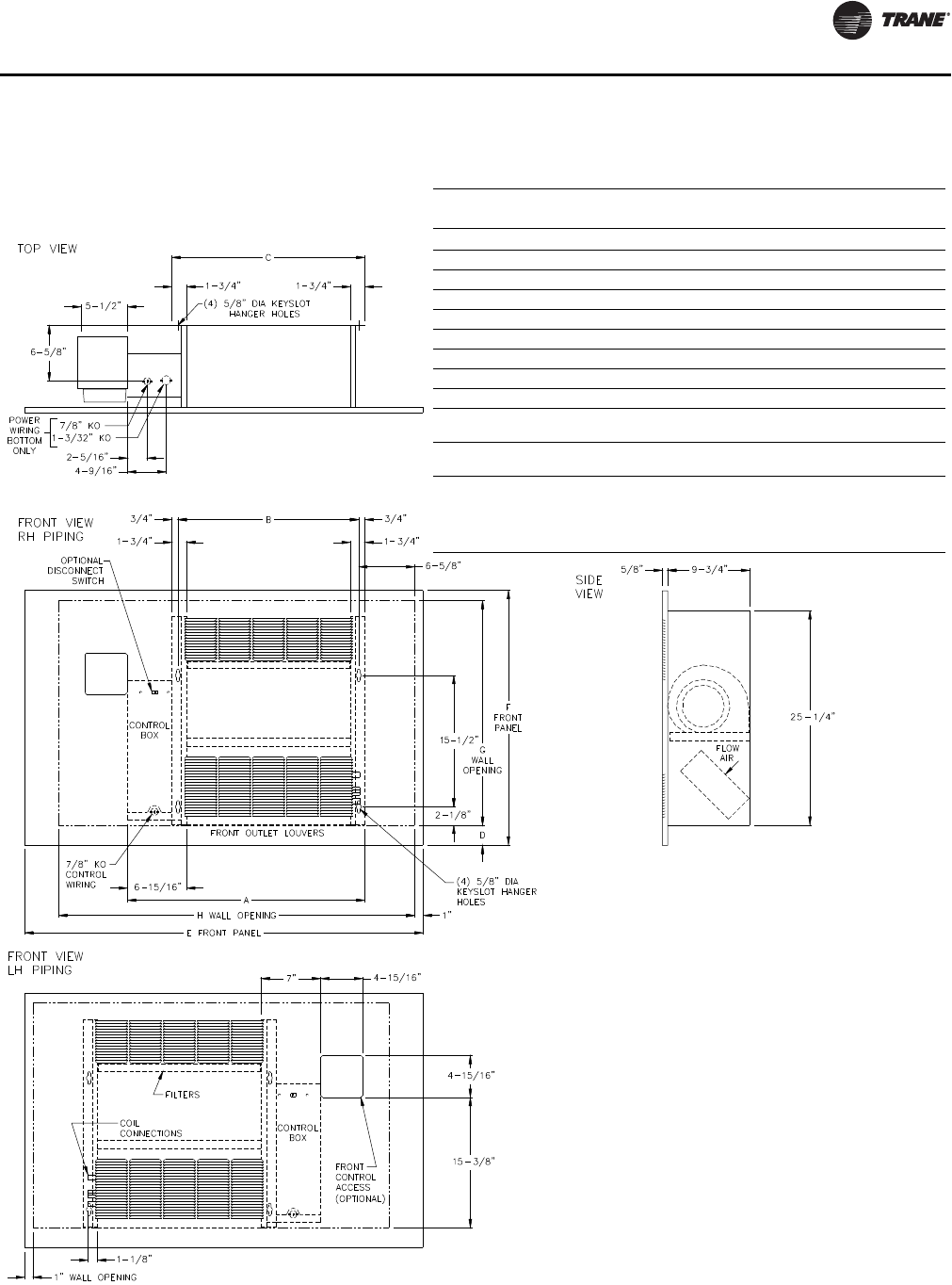
Compact Concealed, Model P
CONTROL
BOX
MAIN DRAIN (OPTIONAL)
CONNECTION FOR
7/8” OD COPPER
TUBE AND CLAMP
SECONDARY DRAIN
CONNECTION FOR
3/8” ID TUBE
(4) 5/8” DIA KEYSLOT
HANGER HOLES
TOP VIEW
B
15-1/2”
3-1/4”
3/4”3/4”
9/16”9/16”
E
BACK INLET DUCT COLLAR
2-5/16”2-5/16”
1-3/4” 1-3/4”
3-1/4” 2”
7/8” KO
CONTROL
WIRING
(4) 5/8” DIA KEYSLOT
HANGER HOLES
FRONT VIEW
RH PIPING
FRONT OUTLET
DUCT COLLAR
8-7/8”
2-7/16”
5-5/16”
A
C
1-11/16” 1-11/16”
D6-3/8”6-15/16”
6-5/8”
7/8” KO
1-3/32” KO
POWER
WIRING
BOTTOM
ONLY
CONTROL
BOX
2-5/16”
4-9/16”
AIR
FLOW
SIDE VIEW
INLET OPTIONS
4-7/8” X F
5/8”
6-1/8”
1” DUCT COLLAR
1" DUCT COLLAR
27-3/16”
BACK DUCT COLLAR
FILTER DOOR USED
WITH BACK DUCT
COLLAR ONLY
FILTERS
FILTERS
10-1/16”
14-1/8”
5/8”
BOTTOM INLET
OPEN
BACK INLET
DUCT COLLAR
26-3/4”
COIL CONNECTIONS
AUXILIARY
DRAIN PAN
FRONT VIEW
LH PIPING
CONTROL
BOX
1-1/8”
Compact Concealed Unit
Unit Size 200-300 400 600 800 1000-1200
A 32-11/16” 37-11/16” 47-3/16” 55-11/16” 74-11/16”
B 21-5/16” 26-5/16” 35-13/16” 44-5/16” 63-5/16”
C 22-13/16” 27-13/16” 37-5/16” 45-13/16” 64-13/16”
D 19-3/8” 24-3/8” 33-7/8” 42-3/8” 61-3/8”
E 18-1/8” 23-1/8” 32-5/8” 41-1/8” 60-1/8”
F 19-5/16” 24-5/16” 33-13/16” 42-5/16” 61-5/16”
Notes:
1. Coil connections are always on the drain pan side and opposite the control box
and unit control.
2. Coil connections are 5/8” O.D. sweat. See p. 30 and p. 31 for locations.
3. All duct collar dimensions are to the outside of the collar.
4. See p. 32 for dimensions for outside air openings.
UNT-SVX07_-EN.book Page 28 Friday, April 27, 2012 9:40 AM
Dimensions and Weights
UNT-SVX07D-EN 29
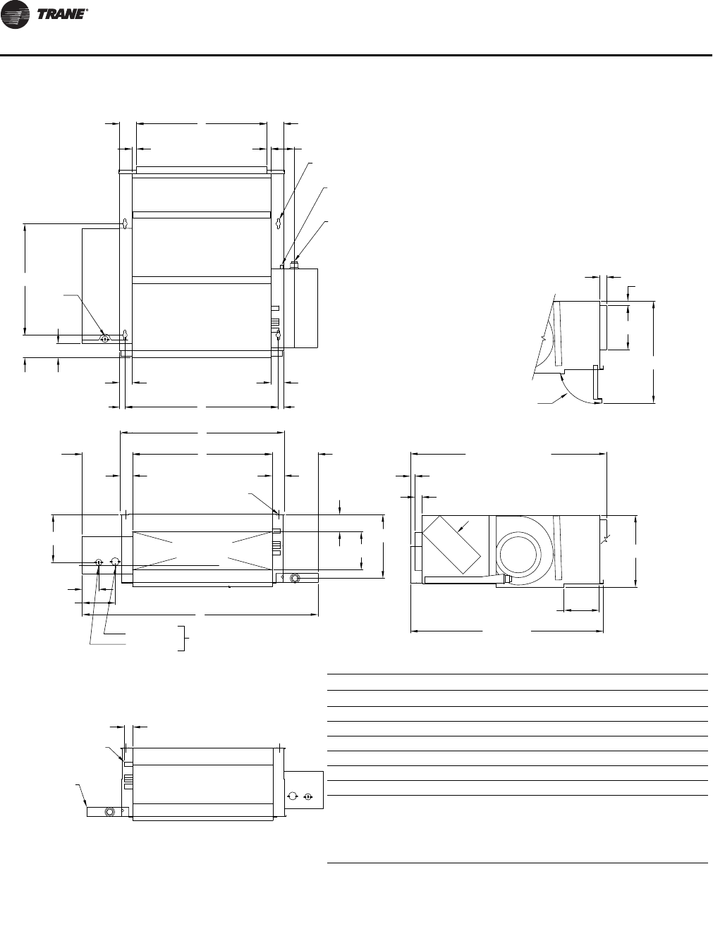
Fan-Coil Coil Connections
Vertical Units
Horizontal Units
UNT-SVX07_-EN.book Page 29 Friday, April 27, 2012 9:40 AM
Dimensions and Weights
30 UNT-SVX07D-EN
Force-Flo Coil Connections
Vertical Units
Horizontal Units
UNT-SVX07_-EN.book Page 30 Friday, April 27, 2012 9:40 AM
Dimensions and Weights
UNT-SVX07D-EN 31
Force-Flo Coil Connections
Inverted Units
UNT-SVX07_-EN.book Page 31 Friday, April 27, 2012 9:40 AM
Dimensions and Weights
32 UNT-SVX07D-EN
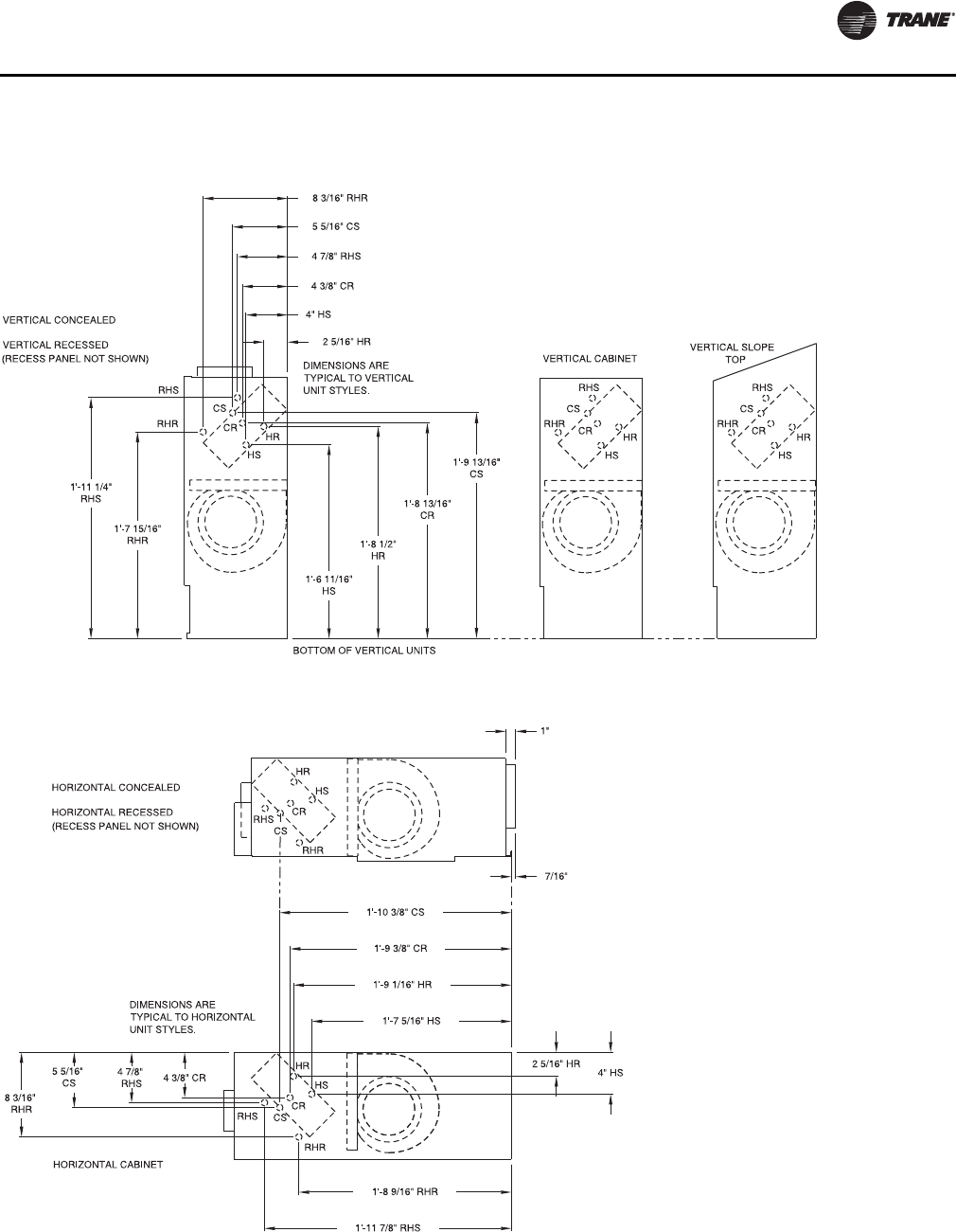
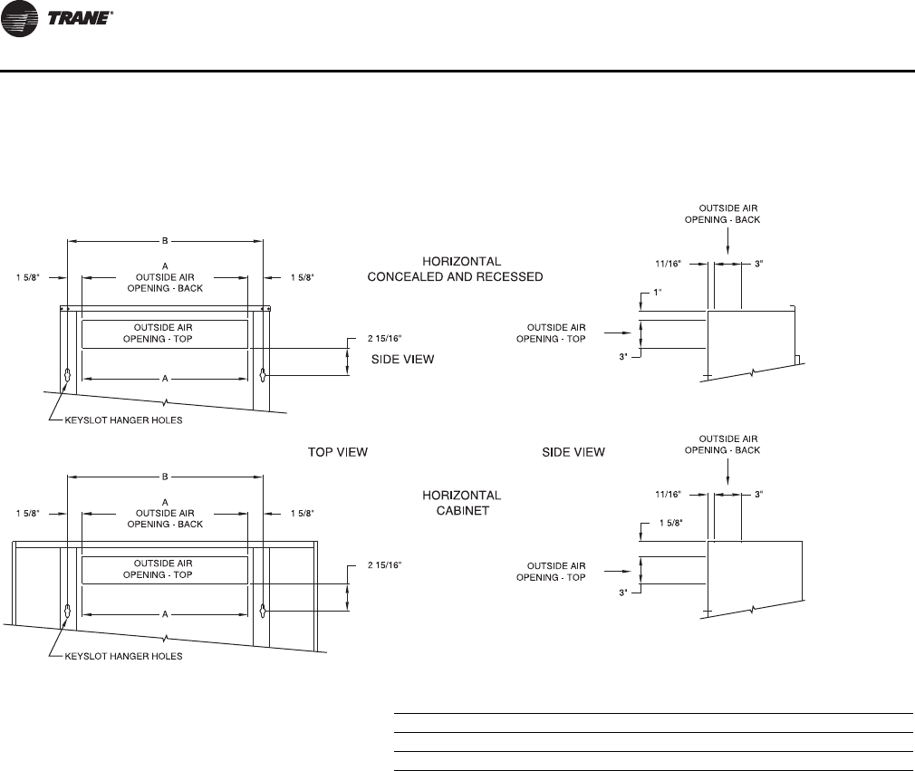
Fresh Air Opening Locations
Horizontal Units—Models C, D, E, and P (Back
Duct Collar Only for Model P)
Fresh air opening dimensions, horizontal units
Unit Size 02–03 04 06 08 10–12
A 1’ 6” 1’ 11” 2’ 8-1/2” 3’ 5” 5’ 0”
B 1’ 9-5/16” 2’ 2-5/16” 2’ 11-13/16” 3’ 8-5/16” 5’ 3-5/16”
UNT-SVX07_-EN.book Page 32 Friday, April 27, 2012 9:40 AM
Dimensions and Weights
UNT-SVX07D-EN 33
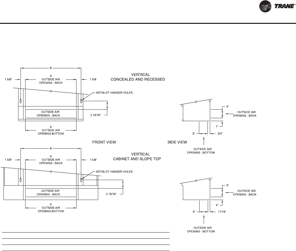
Fresh Air Opening Locations
Vertical Units—Models A, B, F, H, J, K, L, M,
and N
Fresh air opening dimensions, vertical units
Unit Size 02–03 04 06 08 10–12
A 1’ 6” 1’ 11” 2’ 8-1/2” 3’ 5” 5’ 0”
B 1’ 9-5/16” 2’ 2-5/16” 2’ 11-13/16” 3’ 8-5/16” 5’ 3-5/16”
UNT-SVX07_-EN.book Page 33 Friday, April 27, 2012 9:40 AM
Dimensions and Weights
34 UNT-SVX07D-EN
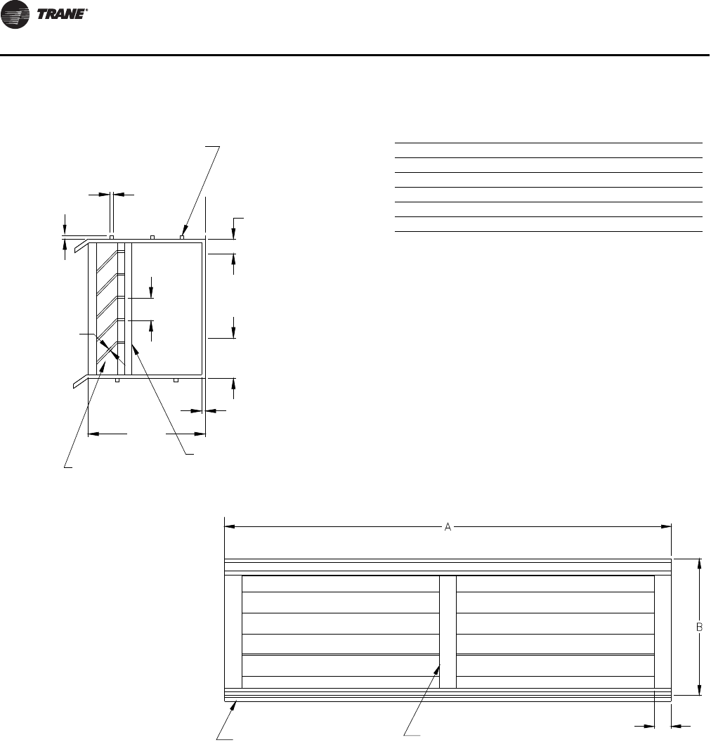
Wall Box
Wall box dimensions
Unit Size, Ref. only Dimensions A x B Internal Supports
02–03 24-3/8 x 4- 3/4 1
04 24-3/8 x 7-1/2 1
06 33-1/8 x 7-1/2 2
08 37-1/2 x 7-1/2 3
10–12 58-1/4 x 7-1/2 4
1/2”
1-3/8”
1/8”
4”
Continuous
Mortar Ribs
Top and
Bottom
Clearance for
Drainage
Woven Aluminum
Insect Screen
1/8” 1/8”
1/2”
3/4”
Additional Internal
Supports Equally Spaced
Not to Exceed 12” O.C.
Continuous Drip Lip
Top and Bottom
5/8”
UNT-SVX07_-EN.book Page 34 Friday, April 27, 2012 9:40 AM
Dimensions and Weights
UNT-SVX07D-EN 35
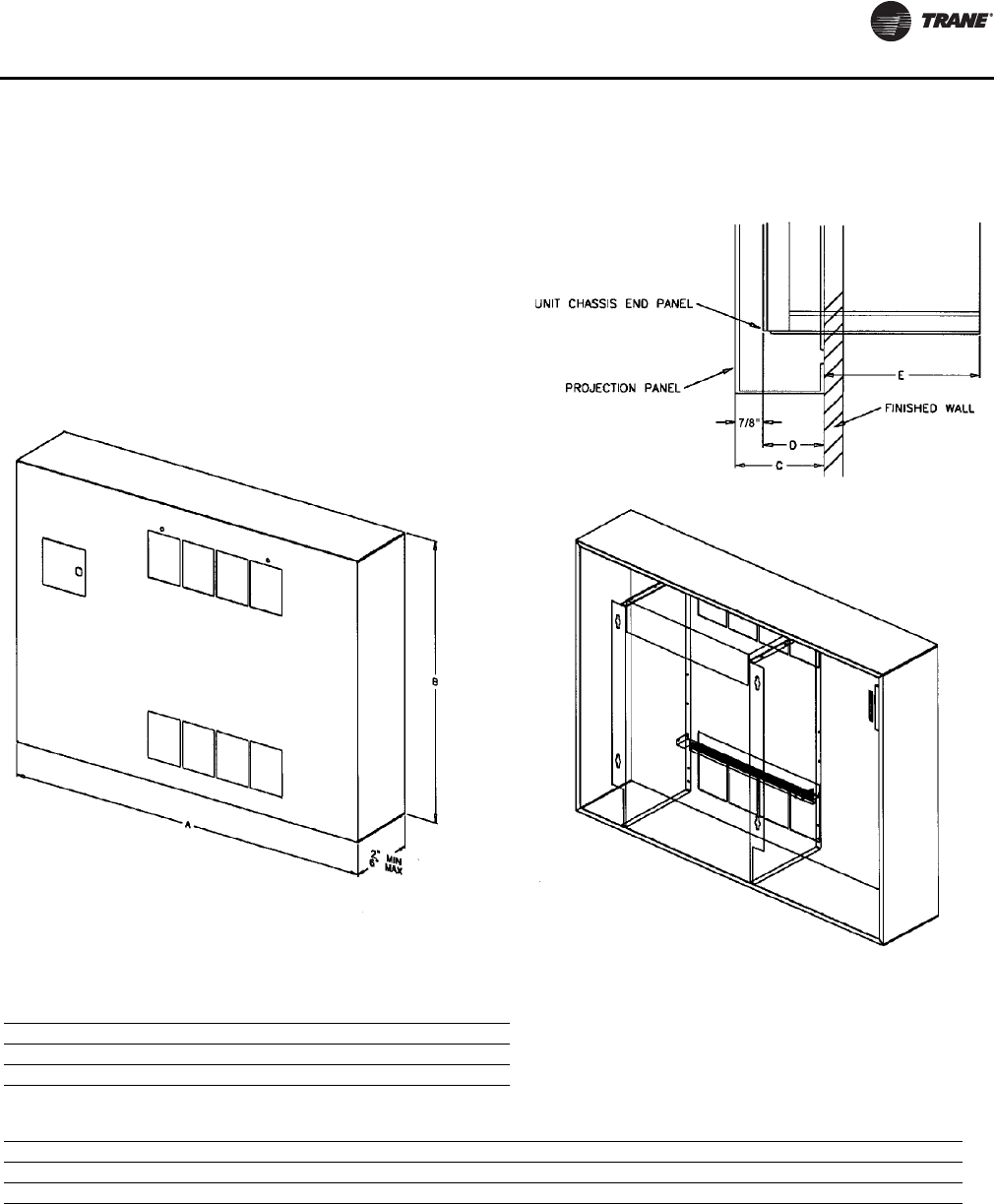
Projection Panel
Projection panel dimensions
Projection panel, all unit sizes
Unit Size 02–03 04 06 08 10–12
A 3’ 11” 4’ 3” 5’ 3” 5’ 5-1/2” 7’ 5-1/2”
B 2’ 6” 2’ 6” 2’ 6” 2’ 9-1/2” 2’ 9-1/2”
C 2” 2-1/2” 3” 3-1/2” 4” 4-1/2” 5” 5-1/2” 6” 2”
D 1-1/8” 1-5/8” 2-1/8” 2-5/8” 3-1/8” 3-5/8” 4-1/8” 4-5/8” 5-1/8” 1-1/8”
E 8-5/8” 8-1/8” 7-5/8” 7-1/8” 6-5/8” 6-1/8” 5-5/8” 5-1/8” 4-5/8” 8-5/8”
Unit to Wall—Top View
Front View ISO
Rear View ISO
UNT-SVX07_-EN.book Page 35 Friday, April 27, 2012 9:40 AM
36 UNT-SVX07D-EN
Installation—Mechanical
Duct Connections
Install all air ducts according to National Fire Protection
Association standards for the Installation of Air
Conditioning and Ventilating Systems (NFPA 90A and
90B).
Install all air ducts according to the National Fire Protection
Association standards for the “Installation of Air
Conditioning and Ventilation Systems other than
Residence Type (NFPA 90A) and Residence Type Warm Air
Heating and Air Conditioning Systems (NFPA 90B).
The unit’s airflow configuration varies dependent on the
model and options ordered. A one-inch duct collar is
provided on units with a ducted return and/or discharge to
attach ductwork to the unit.
Trane recommends using galvanized sheet metal
ductwork with fan-coil and cabinet heater units. Slide the
sheetmetal duct over the duct collar flange of the unit, seal
the joint and fasten with sheetmetal screws.
Note: Do not run screws through the removable front
panel on concealed units.
Ductwork Recommendations
Follow the general recommendations listed below when
installing ductwork for the unit.
1. Discharge ductwork should run in a straight line,
unchanged in size or direction, for a minimum
equivalent distance of three fan diameters from the
unit (approximately 20 inches).
2. When making duct turns and transitions avoid sharp
turns and use proportional splits, turning vanes, and
air scoops when necessary.
3. When possible, construct, and orient supply ductwork
turns in the same direction as the fan rotation.
Piping Considerations
Hydronic Coil Piping
Before installing field piping to the coil, consider the
following:
• All coil connections are 5/8-inch O.D. (or 1/2-inch
nominal) female copper connections.
• The supply and return piping should not interfere with
the auxiliary drain pan or condensate line. See
“Connecting the Condensate Drain” section for more
detailed information.
• The installer must provide adequate piping system
filtration and water treatment.
• Exterior condensate may be an issue (fan-coils only) if
field piping does not have a control valve. Refer to the
supply and return header locations in the “Dimensions
and Weights” section.
Note: When using a field supplied piping package in a
fan-coil unit, allow sufficient room to install the
auxiliary drain pan. In addition, piping package
must not extend over edges of auxiliary drain pan.
Connecting Field Piping to Coil
1. Remove the auxiliary drain pan, if it is in place, to
prevent exposure to dripping solder or excessive
temperatures.
2. Slide a 1/2-inch sweat connection coupling (installer
provided) onto the coil headers.
Note: For vertical fan-coil units, push the main
condensate drain hose and overflow
condensate drain hose through the inside of the
chassis end panel to prevent them from getting
burned when making sweat connections. Be
sure to pull the hoses back through and route to
the auxiliary drain pan when the end panel has
cooled.
3. Solder the joint using bridgit lead-free solder (ASTM
B32-89) to provide a watertight connection. Avoid
overheating factory soldered joints when soldering
field connections to the coil to prevent leakage from
occurring.
4. Insulate all piping to coil connections as necessary
after connections are complete.
Note: Maintain a minimum distance of one foot
between the reduction fitting for the 1/2-inch
diameter line and the fan-coil unit piping
connections.
5. Install the optional auxiliary drain pan, which ships in
the accessory packet.
WARNING
Hazardous Voltage w/Capacitors!
Disconnect all electric power, including remote
disconnects and discharge all motor start/run
capacitors before servicing. Follow proper lockout/
tagout procedures to ensure the power cannot be
inadvertently energized. For variable frequency drives
or other energy storing components provided by Trane
or others, refer to the appropriate manufacturer’s
literature for allowable waiting periods for discharge of
capacitors. Verify with an appropriate voltmeter that all
capacitors have discharged. Failure to disconnect
power and discharge capacitors before servicing could
result in death or serious injury.
For additional information regarding the safe discharge of
capacitors, see PROD-SVB06A-EN
UNT-SVX07_-EN.book Page 36 Friday, April 27, 2012 9:40 AM
Installation—Mechanical
UNT-SVX07D-EN 37
Water Piping Connections to Factory-Installed
Piping Package
Before installing water piping supply and return lines to
factory piping package, note the following items.
• All piping connections are 5/8-inch O.D. (1/2-inch
nominal) female copper connections.
• The fan-coil supply and return piping should not
interfere with the auxiliary drain pan or condensate
line. See “Condensate Drain,” p. 37 for more
information.
• The installer must provide adequate piping system
filtration and water treatment.
• If the unit has a factory deluxe piping package, the
piping includes a strainer with a 20-mesh size screen,
which allows minimal protection from debris.
Therefore, clean the strainer regularly.
Note: Maintain a minimum distance of one foot between
the reduction fitting for the 1/2-inch diameter line
and the fan-coil piping connections.
1. The factory piping package ships with brackets to
adequately support the piping during shipment.
Remove these brackets before connecting water piping
to the unit.
2. Close the piping end valves to the fully open position
to prevent damage to the valve seat during brazing.
3. Remove the auxiliary drain pan, if it is in place, to
prevent exposure to dripping solder or excessive
temperatures.
4. Solder water piping connections to supply and return
end connections. Avoid overheating factory soldered
joints to prevent the possibility of leakage.
5. Insulate fan-coil piping to auxiliary drain pan
connections and any piping that is not above the
auxiliary drain pan.
Condensate Drain
1. De-burr the pipe end before making the connection to
the drain pan.
2. Connect a 7/8-inch O.D. copper pipe or tube, with a 0.20
inch wall thickness, to the auxiliary drain pan. This
should be a mechanical connection that allows easy
removal of the auxiliary drain pan when servicing the
piping end pocket.
3. Slide the copper pipe over the drain pan nipple and
tighten the collar on the pipe with a hose clamp
(installer supplied).
Maintain a continuous drain line pitch of one inch per ten
feet of drain line run to provide adequate condensate
drainage. Extend the drain line straight from the drain pan
a minimum distance of six inches before making any turns.
The installer must provide proper support for the drain line
to prevent undue stress on the auxiliary drain pan.
Install a secondary overflow drain line if necessary by
punching out the overflow drain nipple on the auxiliary
drain pan. Next, place a 3/8-inch inside diameter flexible
plastic tube over the nipple and secure with a field
supplied hose clamp.
Note: The installer is responsible for adequately
insulating field piping. See the “External Insulating
Requirements section for more information.
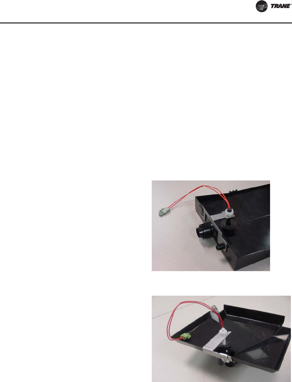
Condensate Overflow Detection Device
The condensate overflow detection device is an option on
fan-coil units with either a Tracer ZN010, ZN510, ZN520,
UC400, or the customer-supplied control interface. The
float switch, mounting bracket, and coiled leads ship
attached inside the piping end pocket of the unit. Install the
switch by placing the hole or slot in the bracket over the
condensate overflow drain (of the auxiliary drain pan) with
the switch float extending over the pan. Secure the drain
pan by attaching the pan’s bracket with the factory
provided clip. See Figure 3 and Figure 4.
Figure 3. Condensate float switch installed in
horizontal auxiliary drain pan
Figure 4. Condensate float switch installed in vertical
auxiliary drain pan
UNT-SVX07_-EN.book Page 37 Friday, April 27, 2012 9:40 AM
Installation—Mechanical
38 UNT-SVX07D-EN
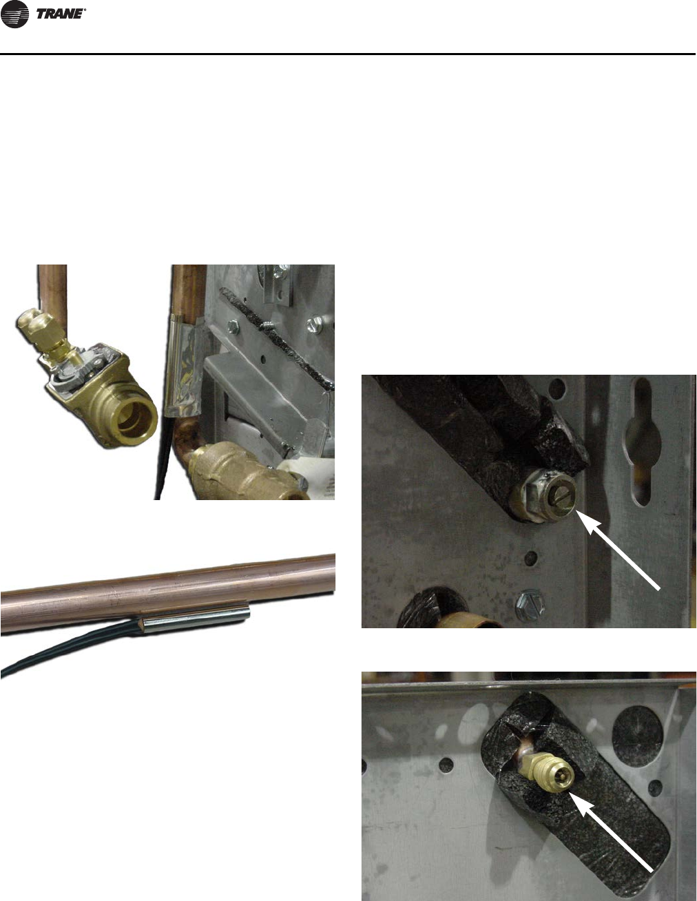
Automatic Changeover Sensor
Two-pipe changeover units with either the Tracer ZN010,
ZN510, ZN520, and UC400 and CSTI controls have an
automatic changeover sensor that determines heating or
cooling mode based on the supply water temperature. On
units with a factory piping package, the factory straps the
changeover sensor to the piping supply water pipe. See
Figure 5, p. 38 and Figure 6, p. 38.
If the unit does not have a factory piping package, the
factory attaches the sensor and coiled lead wires to the
piping side end panel. The installer should attach the
sensor parallel to and in direct contact with the supply
water pipe.
Note: The installer is responsible to ensure the
changeover sensor is installed in a location that can
sense active water temperature. Otherwise, the
unit may fail to sense the correct operating mode
and disable temperature control.
When using field supplied three-way valves, install the
changeover sensor upstream of the valve on the supply
water pipe. When using field supplied two-way control
valves, install the changeover sensor in a location that will
detect active water temperature. The unit must always be
able to sense the correct system water temperature,
regardless of the control valve position.
Note: The maximum length of the automatic changeover
wire cannot exceed ten feet from the control panel.
If the sensor extends beyond the unit chassis, use
shielded conductors to eliminate radio frequency
interference (RFI).
Venting the Hydronic Coil
The hydronic coil contains a vent, either manual or
automatic, to release air from the unit. This vent is not
sufficient for venting the water piping system in the
building.
The coil air vent is on the piping side, above the coil
connections on the unit. See Figure 7 and Figure 8.
Perform the following steps to vent the coil after installing
the unit.
1. Pressurize the building piping system with water and
vent any trapped air at system vents.
Figure 5. Attach the changeover sensor to the entering
water pipe as shown for changeover to work
properly
Figure 6. Close-up view of the changeover sensor
Figure 7. Manual coil air vent with set screw
Figure 8. Manual coil air vent with Shrader fitting
UNT-SVX07_-EN.book Page 38 Friday, April 27, 2012 9:40 AM
Installation—Mechanical
UNT-SVX07D-EN 39
2. For units with manual air vents, back the set screw out
to expel air from the unit and then re-tighten the set
screw.
The automatic air vent should require no adjustment for
the coil to vent. However, if the coil does not vent
immediately, unscrew the outer portion of the fitting to
expel air from the port.
If debris has become trapped in the vent, completely
remove the outer portion of the fitting and clean.
External Insulating Requirements
Insulate and vapor seal surfaces colder than surrounding
air dew-point a to prevent unplanned condensation. Trane
recommends field-insulation of the following areas to
prevent potential condensate problems:
1. Supply and return water piping connections
2. Condensate drain lines and connections
3. Fresh air intake duct connections
4. Discharge duct connections
5. Wall boxes
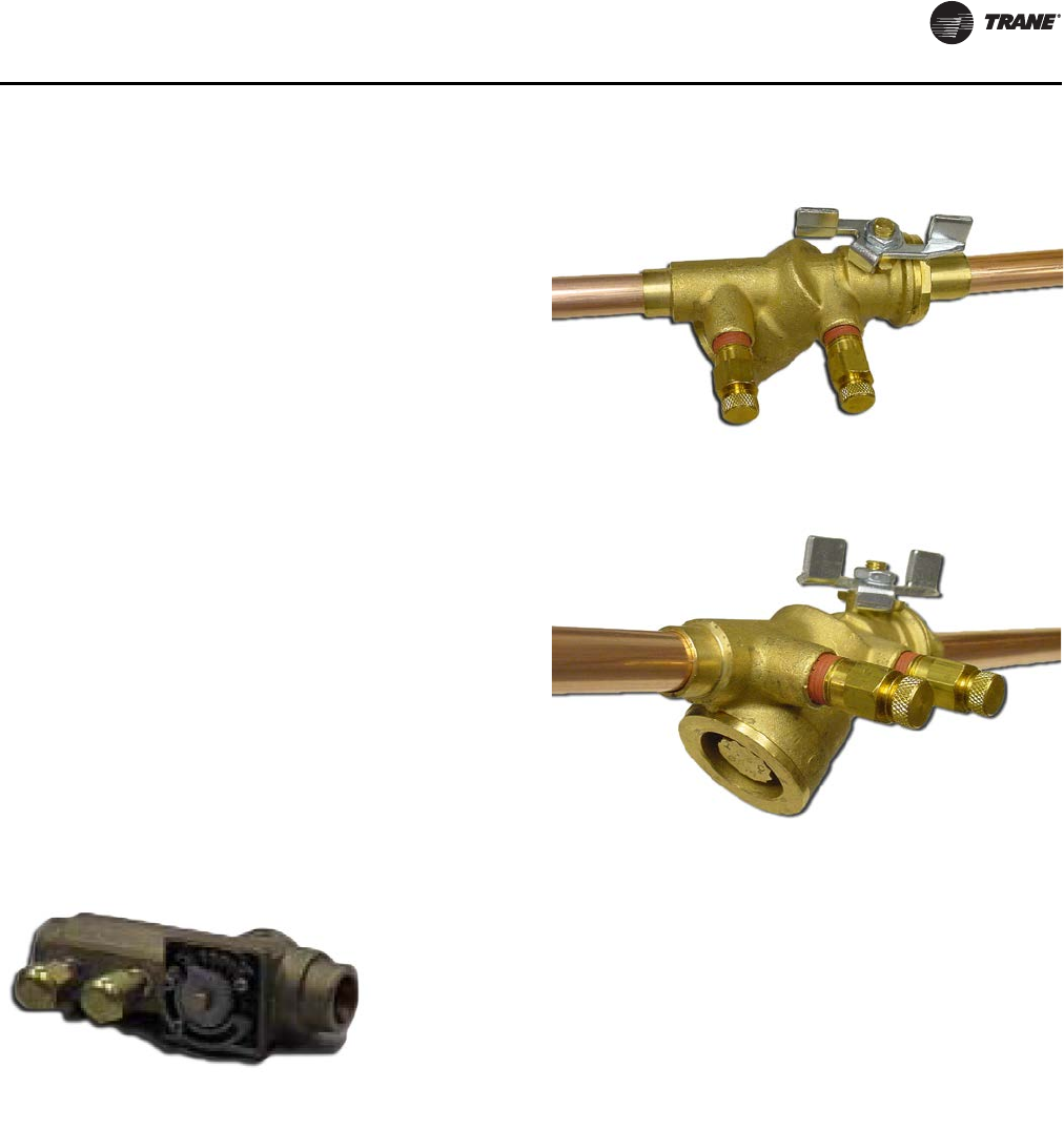
Balancing The Manual Circuit Setter Valve
The manual circuit setter valve is an optional end valve
supplied on the return pipe of the factory piping package.
The valve allows the operator to regulate water flow
through the hydronic coil, balance the water flow through
the unit with other units in the piping system, and serves
as a shutoff or end valve. See Figure 9.
Perform the following procedure to set maximum water
flow through the coil:
1. Establish water flow through the coil. Perform an open
override of the valve if the control valve is closed to the
coil, either manually or by Tracer.
If the piping package has two-position, normally
closed valves: Drive open the valve using a 24 V signal.
If the piping package has two-position, normally open
valves: Manually drive open the valve by removing
power to the valve.
If the piping package has modulating valves: To
manually drive the valve open, depress the button
stem on top of the valve and push the lever located on
the side of the valve to the full open position.
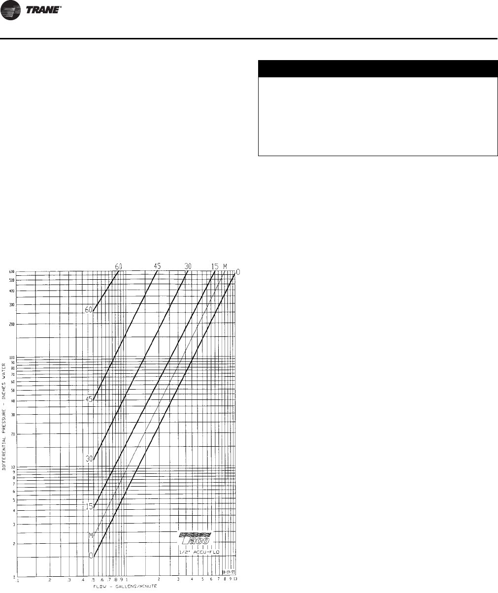
2. For presetting, use the appropriate valve curve shown
in Figure 12, p. 40 to determine which setting is
necessary to achieve the appropriate pressure drop.
The “M” line is the appropriate line.
3. Carefully remove the Schrader pressure port
connection caps on the manual circuit setter, since they
will be at the same temperature as the pipeline.
4. Bleed all air from the hoses and meter before reading
the pressure drop. Refer to the gauge operating
instructions.
Figure 9. Manual circuit setter valve
Figure 10. Automatic circuit setter valve
Figure 11. Automatic circuit setter valve
UNT-SVX07_-EN.book Page 39 Friday, April 27, 2012 9:40 AM
Installation—Mechanical
40 UNT-SVX07D-EN
5. Adjust the circuit setter valve by turning the valve stem
until the appropriate pressure drop is achieved.
6. After achieving the proper setting, slightly loosen the
two socket head cap screws and rotate the memory
stop around until it touches the back side of the
indicator. Then tighten the screws to securely set the
open memory position. The memory stop indicates the
last set open position.
7. If using a three-way valve: close the control valve to the
coil, with the differential pressure meter still
connected. This will divert flow to the bypass side of a
three-way valve.
Adjust the balancing fitting to obtain the same pressure
drop across the circuit setter valve as in step two when the
control valve was open to the coil.
Note: Instructions for using this chart appear on the
preceding page. For the manual circuit setter
provided with fan-coil or Force-Flo units, use the
‘M’.
1. Make piping connections to the steam coil as shown in
Figure 14. Cap the unused connection.
2. The coil is already pitched within the unit to provide
proper pitch to drain condensate out of the coil. Verify
that the unit has been properly leveled.
3. Install a 1/2-inch, 15-degree swing check vacuum
breaker in the unused condensate return tapping as
close as possible to the coil.
4. Vent the vacuum breaker line to atmosphere or
connect it into the return main at the discharge side of
the steam trap.
5. Pitch all steam supply and return mains down a
minimum of one inch per ten feet in the direction of
flow.
6. Do not drain the steam mains or take-off through the
coils. Drain the mains ahead of the coils through a
steam trap to the return line.
7. Overhead returns require one psig of pressure at the
steam trap discharge for each two-feet elevation to
ensure continuous condensate removal.
8. Proper steam trap selection and installation is
necessary for satisfactory coil performance and
service life. For installation, use the following steps:
a. Position the steam trap discharge at least 12 inches
below the condensate return connection. This
provides sufficient hydrostatic head pressure to
overcome trap losses and ensure complete
condensate removal.
b. Trane recommends using flat and thermostatic
traps because of gravity drain and continuous
discharge operation.
c. Use float and thermostatic traps with atmospheric
pressure gravity condensate return, with automatic
controls or where the possibility of low pressure
supply steam exists.
d. Always install strainers as close as possible to the
trap inlet side. Reference Figure 13 for an example
of a properly piped steam coil.
Figure 12. Manual circuit setter valve, differential
pressure vs. flow
NOTICE:
Coil Damage!
In all steam coil installations, the condensate return
connections must be at the low point of the coil to
ensure condensate flows freely from the coil at all
times. Failure to do so could cause physical coil
damage from water hammer, unequal thermal stresses,
freeze-up and/or corrosion.
UNT-SVX07_-EN.book Page 40 Friday, April 27, 2012 9:40 AM
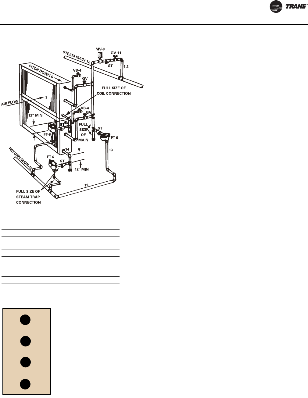
Installation—Mechanical
UNT-SVX07D-EN 41
Figure 13. Typical piping for steam coils
Figure 14. Main steam coil connection diagram
Code of System Components in Piping Diagram
FT Float and thermostatic steam trap
BT Bucket steam trap
GV Gate valve
OV Automatic two-position (on-off) control valve
TV Automatic three-way control valve
VB Vacuum breaker
CV Check valve
ST Strainer
AV Automatic or manual air vent
vacuum breaker (if desired)
steam supply
plugged
condensate return
UNT-SVX07_-EN.book Page 41 Friday, April 27, 2012 9:40 AM
42 UNT-SVX07D-EN
Installation—General
Installing the Unit
Follow the procedures below to install the unit properly.
Refer to “Dimensions and Weights,” p. 12 for specific unit
dimensions and mounting hole locations.
Vertical Units
Install vertical units in an upright position using the 5/8-
inch diameter double key slot hanger holes, located on the
back of unit. The hanger holes allow a maximum shank
size of 5/16-inch diameter threaded rods or lag screws
(installer provides).
1. Prepare wall openings for recessed units. Reference
unit submittal for each unit size dimensions. When
installing vertical units, consideration should be given
for units with an outside air intake.
2. If the unit has leveling legs, adjust them correctly to
level unit.
3. Mark the position of the keyslot hanger holes on the
wall according to the dimensions given in
“Dimensions and Weights,” p. 12 for each unit model
and size. Align the hole locations evenly.
4. Insert the threaded rods or lag screws in the wall before
setting the unit in place.
5. Remove the front panel (cabinet unit only) by lifting it
upward.
6. Position the hanger holes, located on the back of the
unit, over the rod or lag screw heads, pushing the unit
downward to properly position.
7. Complete piping and wiring connections, in addition to
any necessary ductwork to the unit as instructed in the
following sections. Ensure that the auxiliary drain pan
is in position on fan-coil units.
8. Install the front panel before starting the unit.
On cabinet units, replace the front panel by aligning the
bottom tabs on the unit with the respective slots on the
panel bottom. Slide the front panel down onto the tabs
while holding the panel close as possible to the cabinet.
While the bottom tabs are engaged, slide the front panel
upward enough to allow the top engaging edge of the front
panel to lap over the engaging edge of the unit. This
should allow the panel to drop down and lock into
position.
On recessed units, install the front panel by aligning and
locking together the interlocking support channel of the
panel and unit. While holding the panel against the unit,
tighten the screws at the top of the panel until it fits tight
against the unit’s front. Do not over tighten the screws.
Horizontal Units
Install horizontal units suspended from the ceiling using
the four 5/8-inch diameter double key slot hanger holes,
located on the top of the unit. The hanger holes allow a
maximum shank size of
5/16-inch diameter threaded rods or lag screws (installer
provided). Follow the installation procedure below.
Note: Follow the requirements of National Fire Protection
Association (NFPA) Standard 90A or 90B,
concerning the use of concealed ceiling spaces as
return air plenums.
1. Prepare the ceiling opening for recessed units.
Reference the unit submittals for dimensions.
2. Position and install the suspension rods or a
suspension device (supplied by installer) according to
the unit model and size in “Dimensions and Weights,”
p. 12.
3. On cabinet units, remove the bottom panel by using a
5/32-inch Allen wrench to unscrew fasteners. Swing
the panel down and lift outward.
4. Level the unit by referencing the chassis end panels.
Adjust the suspension device.
5. Complete piping and wiring connections, in addition to
any necessary ductwork as instructed in the following
sections. Ensure that the auxiliary drain pan is in
position on fan-coil units.
6. Install the bottom panel before starting the unit.
7. Ensure condensate drain line is pitched one inch per
ten feet of pipe away from the fan-coil unit.
Cabinet Units
Install the bottom panel by placing the hinged end on the
unit’s hinged end (always at the return end of the unit).
Refer to “Dimensions and Weights,” p. 12 for keyslot
hanger hole locations. Swing the panel upward into
position. Secure the panel with the fasteners provided. Do
not overtighten the fasteners.
Recessed Units
Refer to “Dimensions and Weights,” p. 12 for mounting
locations and unit weights. Follow the procedure below
and see Figure 15, p. 43.
NOTICE:
Electrical Wiring!
Do not allow electrical wire to fall between the unit and
installation surface. Failure to comply may result in
electrical shorts or difficulty accessing wires.
NOTICE:
Motor Overload!
All unit panels and filters must be in place prior to unit
startup. Failure to have panels and filters in place may
cause motor overload.
UNT-SVX07_-EN.book Page 42 Friday, April 27, 2012 9:40 AM
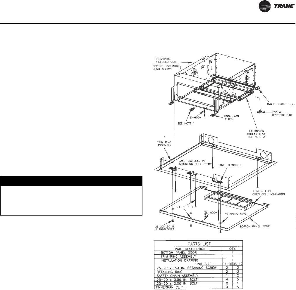
Installation—General
UNT-SVX07D-EN 43
1. Insert the mounting bolts through the panel brackets of
the trim ring and secure to the hanger holes on the unit.
Tighten the mounting bolts to pull the trim ring snug
against the finished ceiling.
2. Install the bottom panel by placing the hinged end on
the trim ring hinged end (always at the unit’s return
end).
3. Adjust the expansion collar’s inner duct (only on fan-
coil units with a bottom return) to ensure a tight fit
against the insulation located on the perimeter of the
bottom panel’s return louver.
4. Close the s-hook on each end of safety chain assembly.
Insert s-hooks through holes in unit and door. Close s-
hook on door.
5. Insert retaining screws through bottom panel door and
place retaining rings on screws.
6. Swing the bottom panel upward into position. Hook
the safety chain to the bottom panel and the unit.
Tighten the panel to the unit with the fasteners
provided.
Notes:
•The trim ring assembly cannot accommodate unlevel
ceilings.
•On sizes 8, 10, and 12 center installation position and
use 2- or 3.5-inch bolts, whichever is best suited for
installation. Also, install two safety chains assemblies
on these sizes.
•Expansion collar is furnished with fan-coil with bottom
return only. The collar is not necessary for Force-Flo
units.
NOTICE:
Unit Leveling!
All unit panels and filters must be in place prior to unit
start-up. Failure to have panels and filters in place may
cause motor overload.
Figure 15. Installing the trim ring assembly on
horizontal recessed units
UNT-SVX07_-EN.book Page 43 Friday, April 27, 2012 9:40 AM
Installation—General
44 UNT-SVX07D-EN
Installation Checklist
The following checklist is only an abbreviated guide to the
detailed installation procedures given in this manual. Use
this list to ensure all necessary procedures are complete.
For more detailed information, refer to the appropriate
sections in this manual.
WARNING
Hazardous Voltage w/Capacitors!
Disconnect all electric power, including remote
disconnects and discharge all motor start/run
capacitors before servicing. Follow proper lockout/
tagout procedures to ensure the power cannot be
inadvertently energized. For variable frequency drives
or other energy storing components provided by Trane
or others, refer to the appropriate manufacturer’s
literature for allowable waiting periods for discharge of
capacitors. Verify with an appropriate voltmeter that all
capacitors have discharged. Failure to disconnect
power and discharge capacitors before servicing could
result in death or serious injury.
For additional information regarding the safe discharge of
capacitors, see PROD-SVB06A-EN
1. Inspect the unit for shipping damage.
2. Level installation location to support the unit
weight adequately. Make all necessary wall or
ceiling openings to allow adequate air flow and
service clearances.
3. Ensure the unit chassis is installed level.
NOTICE:
Unit Leveling!
The unit must be installed level (zero tolerance) in both
horizontal axis for proper operation. Do not use the coil
or drain pan as the reference point because the coil may
be pitched and the drain pan has an inherent positive
slope to provide proper drainage.
4. Verify that wall and ceiling openings are properly
cut per the unit submittals.
5. Verify that installation of horizontal concealed units
meets the national Fire Protection Association
(N.F.P.A.) Standard 90A or 90B concerning the use of
concealed ceiling spaces as return air plenums.
Verify correct ceiling opening dimensions on unit
submittals.
Secure the unit and any accessory items properly to
the wall or ceiling support rods.
6. Complete all piping connections correctly.
7. Check field sweat connections for leaks and tighten
the valve stem packing, and piping package unions
if necessary.
8. Install the auxiliary drain pan, if ordered, properly
under piping package on fan-coil units.
9. Complete condensate drain line connections on
fan-coil units.
10. Pitch condensate drain line away from fan-coil one-
inch drop per ten feet of pipe.
11. Install automatic changeover sensor option on the
supply water line, if applicable.
12. Install condensate overflow switch option correctly
on the auxiliary drain pan, if applicable.
13. Ensure the low temperature detection device
option is correctly installed.
14. Complete all necessary duct connections.
15. Complete all interconnection wiring for the wall-
mounted fan mode switch or zone sensor per the
wiring schematic and guidelines established in
“Wall-Mounted Control Interconnection Wiring,”
p. 49.
16. Install the wall-mounted fan mode switch, or zone
sensor module options properly.
For wireless zone sensors, be sure to set the
address (see “Address Setting,” p. 77).
17. Make field mounted controller / fan speed switch
connections to CSTI / FSS as indicated on unit
schematic.
18. Connect electrical supply power according to the
NEC and unit wiring diagrams.
19. Remove any miscellaneous debris, such as
sheetrock dust, that may have infiltrated the unit
during construction.
20. Replace the air filter as required.
UNT-SVX07_-EN.book Page 44 Friday, April 27, 2012 9:40 AM
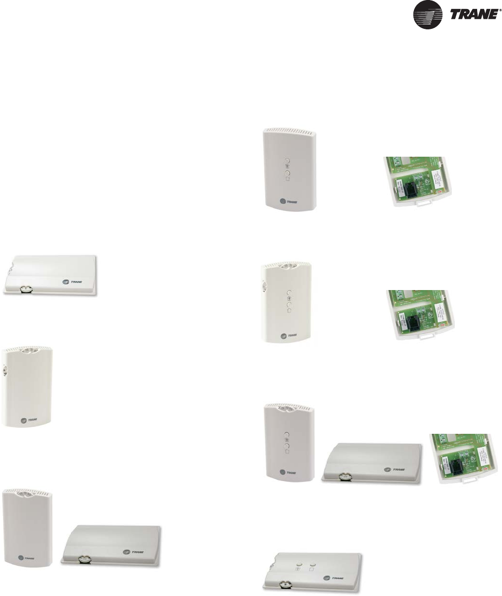
UNT-SVX07D-EN 45
Installation—Controls
Control sensor options include both unit-mounted
(factory-installed) and wall-mounted sensors. Installation
instructions for the wall-mounted sensors are provided in
this chapter.
General Information
Control Options (Including Factory-
Installed)
Tracer ZN010 Options
Tracer ZN510, ZN520, and UC400 Options
Unit-mounted zone sensor:
Digit 30 = E and Digit 31 = V
Wall-mounted zone sensor:
Digit 30 = E and Digit 31 = W
Split-mounted zone sensor, unit-mounted fan mode
and wall-mounted setpoint dial:
Digit 30 = E and Digit 31 = X
X13790843-01
X13790841-01
X13511529-01 (wall)
X13790849-01 (unit)
Wall-mounted zone sensor:
Digit 30 = F, G, or J and Digit 31 = 1
Wall-mounted zone sensor:
Digit 30 = F, G, or J and Digit 31 = 2
Split-mounted zone sensor, unit-mounted fan mode and
wall-mounted setpoint dial:
Digit 30 = F, G, or J and Digit 31 = Y
Unit-mounted zone sensor:
Digit 30 = F, G, or J and Digit 31 = Z
X13511530-01 (wall)
X13651467-02 (comm)
X13790842-01 (wall)
X13651467-02 (comm)
X13511527-01 (wall)
X13790849-01 (unit)
X13651467-02 (comm)
X13790844-01
UNT-SVX07_-EN.book Page 45 Friday, April 27, 2012 9:40 AM
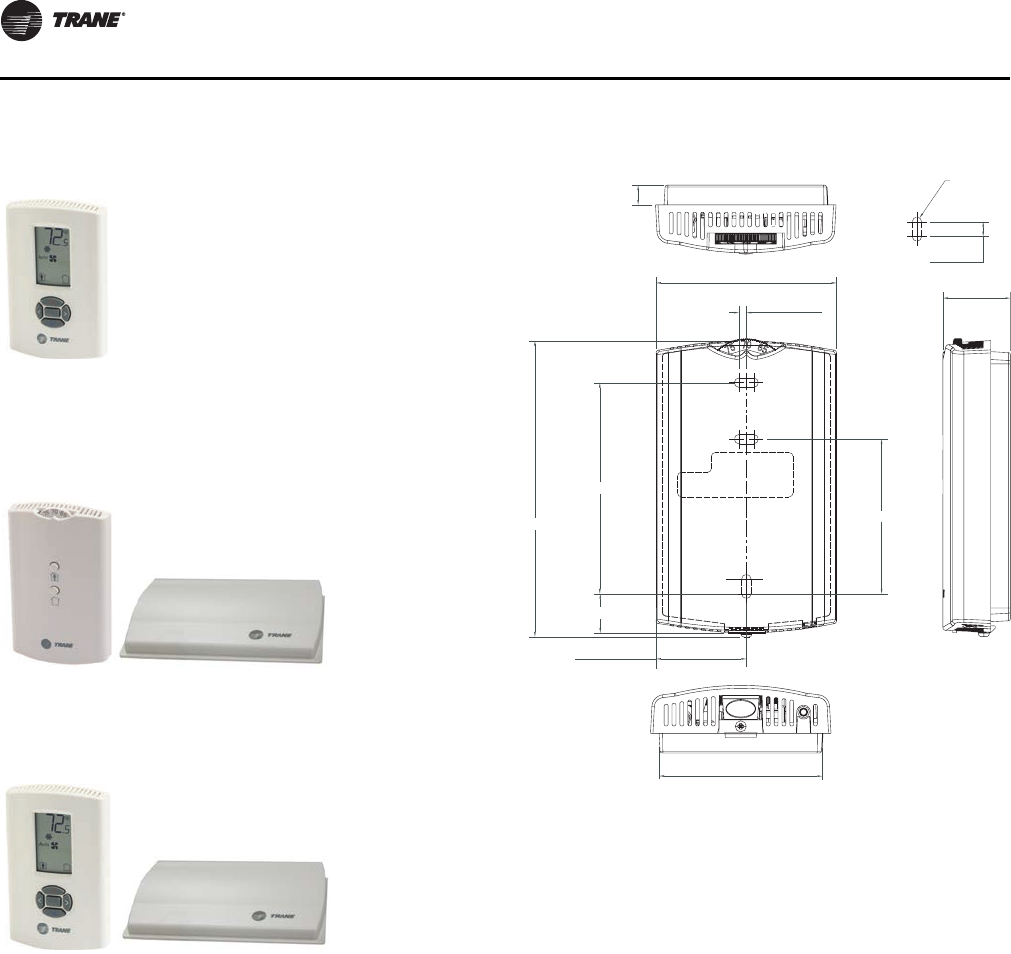
Installation—Controls
46 UNT-SVX07D-EN
Installing Wall-Mounted Wired
Sensors
Reference the wall-mounted zone sensor dimensions in
Figure 16, p. 46. Position the sensor on an inside wall three
to five feet above the floor and at least 18 inches from the
nearest outside wall. Installing the sensor at a lower height
may give the advantage of monitoring the temperature
closer to the zone, but it also exposes the sensor to airflow
obstructions. Ensure that air flows freely over the sensor.
Sensor
When selecting a sensor location, avoid the following:
• Areas of direct sunlight
• Areas in the direct airstream of air diffusers
• Exterior walls and other walls that have a temperature
differential between the two sides
• Areas that are close to heat sources such as sunlight,
appliances, concealed pipes, chimneys, or other heat-
generating equipment
• Drafty areas
• Dead spots behind doors, projection screens, or
corners
• Walls that are subject to high vibration
• Areas with high humidity
• High traffic areas (to reduce accidental damage or
tampering)
Wall-mounted wired display sensor
with setpoint adjustment:
Digit 30 = F, G, or J and Digit 31 = 4
Wall-mounted wireless temperature sensor (WZS)
(setpoint adjustment, no fan speed adjustment) and
unit-mounted receiver:
Digit 30 = F, G, or J and Digit 31 = 6
Wall-mounted wireless display sensor (WDS) and
unit-mounted receiver:
Digit 30 = F, G, or J and Digit 31 = 7
X13790886-04 (wall)
X13790821-01 (wall)
X13790860-02 (unit)
X13790822-04 (wall)
X13790860-02 (unit)
Figure 16. Wall-mounted wired and wireless zone
sensor dimensions
1. 0.31 in
2. TYP R.07 in (R1.9)
3. TYP 0.24 in)
4. 2.9 in
5. 1.08 in
6. 0.12 in
7. 3.39 in
8. 4.68 in
9. 2.48 in
10. 0.63 in
11. 1.45 in
12. 2.62 in
12
3
45
6
7
89
0
-
=
UNT-SVX07_-EN.book Page 46 Friday, April 27, 2012 9:40 AM

Installation—Controls
UNT-SVX07D-EN 47
• Metal barriers between the receiver and the sensor (for
example, plastered walls with metal lathe or metal roof
decks)
• Thick, solid concrete walls between the receiver and
the sensor
• Placing the sensor inside metal enclosures
Height Requirements
It is recommended that you mount the back plate a
maximum distance of 54 inches above the floor. If a
parallel approach by a person in a wheelchair is required,
reduce the maximum height to 48 inches.
Note: Consult section 4.27.3 of the 2002 ADA (Americans
with Disability Act) guideline, and local building
codes, for further details regarding wheelchair
requirements.
Mounting Surfaces
Using the hardware provided, mount the back plate of the
sensor to a flat surface such as sheetrock or plaster, or an
electrical junction box. The sensor must be mounted
plumb for accurate temperature control and to ensure
proper air movement through the sensor.
• If mounting onto sheetrock or plaster, use the plastic
threaded anchors (pre-drilling holes is not usually
necessary) and the two M3.5 x 20 mm mounting
screws.
• For mounting onto an electrical junction box, use the
two 6-32 x 3/4 in. screws.
Before beginning installation, consider the location
considerations below. Also, refer to the unit wiring
schematic for specific wiring details and point
connections.
Location Considerations
Avoid mounting the sensor in an area subject to the
following conditions:
• Dead spots, such as behind doors or in corners that do
not allow free air circulation.
• Air drafts from stairwells, outside doors, or
unsectioned hollow walls.
• Radiant heat from the sun, fireplaces, appliances, etc.
• Airflow from adjacent zones or other units.
• Unheated or uncooled spaces behind the controller,
such as outside walls or unoccupied spaces.
• Concealed pipes, air ducts, or chimneys in partition
spaces behind the controller.
Location Considerations for Wireless zone
sensors
Placement of the sensor is critical to proper operation (the
receiver is factory mounted on fan-coil units). For most
installations, barriers limit proper radio signal strength
more than distance. For best radio transmission range and
reliability, mount the receiver and sensor in line of sight.
Where this is not possible, try to minimize the number of
barriers between the pair of devices. In general, sheetrock
walls and ceiling tiles offer little restriction to the
transmission range for the sensor is as follows:
• Open range: 2,500 ft (packet error rate = 2%)
• Usable range: 200 ft
• Typical range: 75 ft
Fan Mode Switch Installation
The fan mode switch ships loose inside the unit accessory
bag. Follow the steps below to install the fan mode switch.
Items needed:
2 x 4 electrical junction box
1. Remove the brown wire if not using a field-supplied
damper.
2. Remove the terminals, cut and strip wires as required
for installation.
3. Level and position a 2 x 4 electrical junction box.
4. Follow the instructions given in “Wall-Mounted
Control Interconnection Wiring,” p. 49 and route the
wires as shown in the wiring diagram. Refer to the
typical wiring diagram or to the unit specific diagram
on the unit.
5. Position the fan mode switch over the junction box
with the two screws supplied.
Zone Sensor Installation
Follow the procedure below to install the wired zone
sensor module.
1. Note the position of the setpoint adjustment knob and
gently pry the adjustment knob from the cover using
the blade of a small screwdriver.
2. Insert the screwdriver blade behind the cover at the top
of the module and carefully pry the cover away from
the base.
3. To mount the sensor back plate:
a. Hold the back plate against the mounting surface
and mark the screw locations.
b. Secure the back plate against the mounting surface
using included hardware.
4. To install the zone sensor module to a standard
junction box:
a. Level and install a 2 x 4-in. junction box (installer
supplied) vertically on the wall.
b. Pull the control wires through the cutout. Attach the
module to the wall using the screws provided.
5. Strip the insulation on the interconnection wires back
0.25-inch and connect to TB1 (for wired sensors).
6. Screw down the terminal blocks (for wired sensors).
UNT-SVX07_-EN.book Page 47 Friday, April 27, 2012 9:40 AM
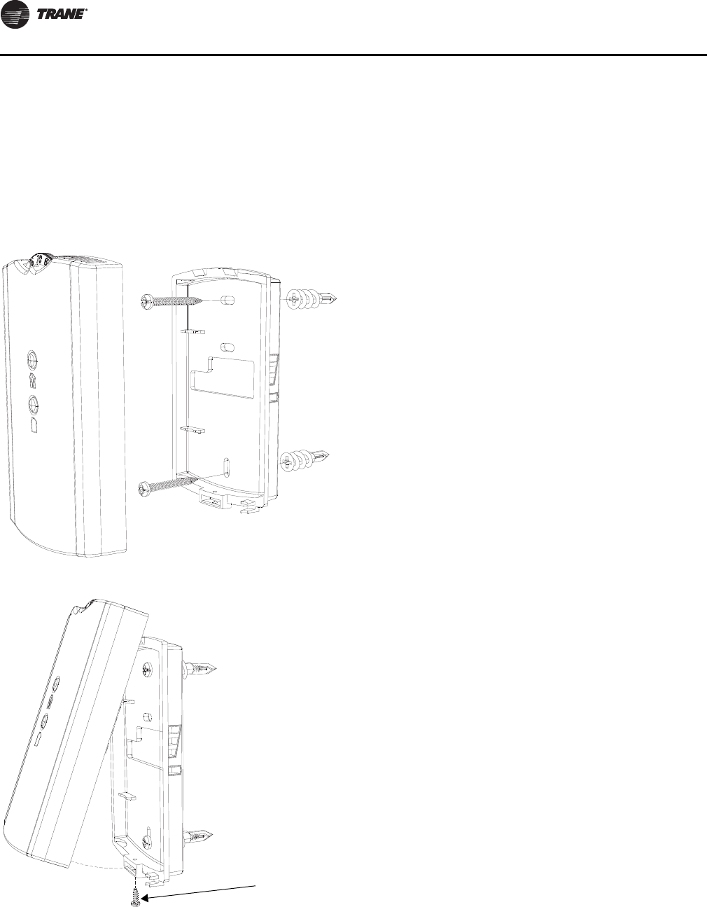
Installation—Controls
48 UNT-SVX07D-EN
7. To replace the cover:
a. Hook the cover over the top of the back plate. Apply
light pressure to the bottom of the cover until it
snaps in place.
b. Install the security screw into the bottom of the
cover (if desired).
If installing a Tracer ZN510 or Tracer ZN520 zone sensor,
see “Tracer ZN510, ZN520, and UC400 Options,” p. 45 for
more information.
Figure 17.
Figure 18.
Security
screw
UNT-SVX07_-EN.book Page 48 Friday, April 27, 2012 9:40 AM
UNT-SVX07D-EN 49
Installation—Electrical
Unit Wiring Diagrams
Specific unit wiring diagrams, based on unit options
ordered, are provided inside each unit and can be easily
removed for reference. Use these diagrams for
connections or trouble analysis. Wiring diagrams are
attached on the inside of the front panel of vertical cabinet
and recessed models and on the fan and motor panel of
vertical concealed and all horizontal models.
Supply Power Wiring
Refer to the unit nameplate to obtain the minimum circuit
ampacity (MCA) and maximum fuse size (MFS) or
maximum circuit breaker (MCB) to properly size field
supply wiring and fuses or circuit breakers.
Refer to the unit operating voltage listed on the unit wiring
schematic, submittal, or nameplate. Reference the wiring
schematic for specific wiring connections.
Note: All field wiring should conform to NEC and all
applicable state and local code requirements. The
control panel box is always on the end opposite the
piping connections. Access the control box by
removing the two screws that secure the front
cover. This will allow the panel to be removed, to
provide access to the electrical components.
If the unit does not have a disconnect switch, the power
leads and capped ground wire are inside the control panel.
If the unit has a disconnect switch, the power leads are
wired to the junction box switch on the control panel. Pull
the capped ground wire into the junction box.
Electrical Grounding Restrictions
All sensor and input circuits are normally at or near ground
(common) potential. When wiring sensors and other input
devices to the Tracer controller, avoid creating ground
loops with grounded conductors external to the unit
control circuit. Ground loops can affect the measurement
accuracy of the controller.
All input/output circuits (except isolated relay contacts and
optically isolated inputs) assume a grounded source,
either a ground wire at the supply transformer to control
panel chassis, or an installer supplied ground.
Wall-Mounted Control Interconnection
Wiring
The installer must provide interconnection wiring to
connect wall-mounted devices such as a fan mode switch
or zone sensor module.
Refer to the unit wiring schematic for specific wiring
details and point-to-point wiring connections. Dashed
lines indicate field wiring on the unit wiring schematics. All
interconnection wiring must conform to NEC Class 2
wiring requirements and any state and local requirements.
Refer to Ta b l e 3 for the wire size range and maximum
wiring distance for each device.
WARNING
Hazardous Voltage w/Capacitors!
Disconnect all electric power, including remote
disconnects and discharge all motor start/run
capacitors before servicing. Follow proper lockout/
tagout procedures to ensure the power cannot be
inadvertently energized. For variable frequency drives
or other energy storing components provided by Trane
or others, refer to the appropriate manufacturer’s
literature for allowable waiting periods for discharge of
capacitors. Verify with an appropriate voltmeter that all
capacitors have discharged. Failure to disconnect
power and discharge capacitors before servicing could
result in death or serious injury.
For additional information regarding the safe discharge of
capacitors, see PROD-SVB06A-EN
NOTICE:
Use Copper Conductors Only!
Unit terminals are not designed to accept other types
of conductors. Failure to use copper conductors may
result in equipment damage.
WARNING
Hazardous Electrical Shorts!
Insulate all power wire from sheet metal ground.
Failure to do so may cause electrical shorts that could
result in death or serious injury.
NOTICE:
Equipment Damage!
Unit transformer IT1 provides power to fan-coil unit
only. Field connections directly to the transformer IT1
may create immediate or premature unit component
failure.
Table 3. Maximum wiring distances for low voltage
controls (ft)
Device Wire Size Range
Fan Speed Switch 14–22 AWG 500
Zone Sensor 16–22 AWG 200
UNT-SVX07_-EN.book Page 49 Friday, April 27, 2012 9:40 AM
Installation—Electrical
50 UNT-SVX07D-EN
Recommendation: Do not bundle or run interconnection
wiring in parallel with or in the same conduit with any
high-voltage wires (110 V or greater). Exposure of
interconnection wiring to high voltage wiring, inductive
loads, or RF transmitters may cause radio frequency
interference (RFI). In addition, improper separation may
cause electrical noise problems. Therefore, use shielded
wire (Belden 83559/83562 or equivalent) in applications
that require a high degree of noise immunity. Connect the
shield to the chassis ground and tape at the other end.
Note: Do not connect any sensor or input circuit to an
external ground connection.
Table 4. Free discharge and High static electrically
commutated motors (ECMs) programmed to
standard ECM mode
Unit
Size
115 Volt 208–230 Volt 277 Volt
FLA HP FLA HP FLA HP
121 212121212
2 3.1 0.22 1.8 0.22 1.6 0.24
3 3.1 0.22 1.8 0.22 1.6 0.24
4 3.1 0.22 1.8 0.22 1.6 0.24
6 3.1 0.22 1.8 0.22 1.6 0.24
8 3.1 0.22 1.8 0.22 1.6 0.24
10 3.1 3.1 0.22 0.22 1.8 1.8 0.22 0.22 1.6 1.6 0.24 0.24
12 3.1 3.1 0.22 0.22 1.8 1.8 0.22 0.22 1.6 1.6 0.24 0.24
Table 5. Free discharge electrically commutated motors
(ECMs) programmed to reduced FLA mode
Unit
Size
115 Volt 208–230 Volt 277 Volt
FLA HP FLA HP FLA HP
12 1 212 1 2 12 1 2
2 0.6 0.22 0.4 0.22 0.3 0.24
3 0.6 0.22 0.4 0.22 0.3 0.24
4 0.8 0.22 0.6 0.22 0.4 0.24
6 1.1 0.22 0.8 0.22 0.6 0.24
8 1.6 0.22 1.1 0.22 0.8 0.24
10 0.7 1.2 0.22 0.22 0.5 0.8 0.22 0.22 0.4 0.6 0.24 0.24
12 0.7 1.3 0.22 0.22 0.5 0.9 0.22 0.22 0.4 0.7 0.24 0.24
Table 6. High static electrically commutated motors
(ECMs) programmed to reduced FLA mode
Unit
Size
115 Volt 208–230 Volt 277 Volt
FLA HP FLA HP FLA HP
12 1 2 12 1 2 12 1 2
2 1.3 0.22 0.9 0.22 0.7 0.24
3 1.3 0.22 0.9 0.22 0.7 0.24
4 1.7 0.22 1.2 0.22 0.9 0.24
6 2.3 0.22 1.6 0.22 1.2 0.24
8 3.1 0.22 1.8 0.22 1.5 0.24
10 1.4 2 0.22 0.22 1 1.4 0.22 0.22 0.7 1.1 0.24 0.24
12 1.5 2.8 0.22 0.22 1.1 1.8 0.22 0.22 0.8 1.4 0.24 0.24
Table 7. Low vertical free discharge electrically
commutated motors (ECMs)
Unit Size
115 Volt RPM
FLA HP H M L
3 3.1 0.22 1090 770 560
4 3.1 0.22 1090 750 560
6 3.1 0.22 1115 760 560
Note: Actual rpm will vary with application and configuration.
Table 8. Lowboy vertical free discharge electrically
commutated motors (ECMs) programmed
with reduced FLA mode
Unit Size
115 Volt RPM
FLA HP H M L
3 0.5 0.22 1090 770 560
4 0.8 0.22 1090 750 560
6 1 0.22 1115 760 560
Note: Actual rpm will vary with application and configuration.
Table 9. Unit RPM
Unit
Size
Free Discharge—Units
with 2-Row Coils
Free Discharge—Units with
3- and 4-Row Coils
HM L H M L
2 980 840 655 980 840 655
3 980 780 580 1080 800 600
4 1050 780 580 1080 800 600
6 1030 780 580 1080 800 600
8 1080 800 600 1080 800 600
10 1050 780 580 1080 800 600
1030 780 580 1080 800 600
12 1050 780 580 1080 800 600
1080 800 600 1080 800 600
Unit
Size
High Static—Units with
2-Row Coils
High Static—Units with 3-
and 4-Row Coils
HM L H M L
2 1480 1110 865 1480 1110 865
3 1400 1175 860 1500 1355 1110
4 1475 1315 1070 1580 1375 1240
6 1400 1070 855 1475 1285 975
8 1475 1285 975 1475 1285 975
10 1475 1315 1070 1580 1375 1240
1400 1070 855 1475 1285 975
12 1475 1315 1070 1580 1375 1240
1475 1285 975 1475 1285 975
Note: Actual rpm will vary with application and configuration.
UNT-SVX07_-EN.book Page 50 Friday, April 27, 2012 9:40 AM
Installation—Electrical
UNT-SVX07D-EN 51
Minimum Circuit Ampacity (MCA) and
Maximum Fuse Size (MFS) Calculations for
Fan-Coils with Single Phase Electric Heat
Heater amps = (heater kW x 1000)/heater voltage
Note: Use 120 V heater voltage for 115 V units. Use 240 V
heater voltage for 230 V units.
MCA = 1.25 x (heater amps + all motor FLAs)
MFS or HACR type circuit breaker = (2.25 x largest motor
FLA) + second motor FLA + heater amps (if applicable)
HACR (heating, air-conditioning and refrigeration) type
circuit breakers are required in the branch circuit wiring for
all fan-coils with electric heat.
Select a standard fuse size or HACR type circuit breaker
equal to the MCA. Use the next larger standard size if the
MCA does not equal a standard size.
Standard fuse sizes are: 15, 20, 25, 30, 35, 40, 45, 50, 60
amps
Fan-coil electric heat MBh = (heater kW) (3.413)
Table 10. Electric heat kW, low vertical fan-coil
Unit Size Unit Voltage kW kW kW kW
3.0 115 1.0 1.5 2.0
4.0 115 1.0 1.5 2.0 2.5
6.0 115 1.0 1.5 2.0 2.5
Note: Low vertical units are only available with electric heat in combination
with the two-row cooling coil.
Table 11. Force-Flo single-stage, max kW electric heat
Unit
Size Voltage # Wires Heater kW
Heater
amps/ph
02 208/60/1 2 2.25 10.9
240/60/1 2 3.0 12.5
277/60/1 2 3.0 10.9
208/60/3 3 2.25 6.3
240/60/3 3 3.0 7.3
480/60/3 4 3.0 3.7
03 208/60/1 2 4.5 21.7
240/60/1 2 6.0 25.0
277/60/1 2 6.0 21.7
208/60/3 3 4.5 12.6
240/60/3 3 6.0 14.5
480/60/3 4 6.0 7.3
04 208/60/1 2 5.7 27.5
240/60/1 2 7.5 31.3
277/60/1 2 7.5 27.1
208/60/3 3 5.7 15.9
240/60/3 3 7.5 18.1
480/60/3 4 7.5 9.1
06 208/60/1 2 7.9 38.0
240/60/1 2 10.5 43.8
277/60/1 2 10.5 38.0
208/60/3 3 7.9 21.9
240/60/3 3 10.5 25.3
480/60/3 4 10.5 12.7
Note: All data based on individual units. Electric heat will operate only with
fan at high speed.
UNT-SVX07_-EN.book Page 51 Friday, April 27, 2012 9:40 AM

Installation—Electrical
52 UNT-SVX07D-EN
Table 12. Force-Flo single stage, low kW electric heat
Unit
Size Voltage
#
Wires kW
amps
/ph kW
amps
/ph kW
amps
/ph
02 208/60/1 2 0.8 3.7 1.5 7.3
240/60/1 2 1.0 4.2 2.0 8.4
277/60/1 2 1.0 3.7 2.0 7.3
03 208/60/1 2 2.3 10.9
240/60/1 2 3.0 12.5
277/60/1 2 3.0 10.9
208/60/3 3 2.3 6.3
240/60/3 3 3.0 7.3
480/60/3 4 3.0 3.7
04 208/60/1 2 2.3 10.9
240/60/1 2 3.0 12.5
277/60/1 2 3.0 10.9
208/60/3 3 2.3 6.3
240/60/3 3 3.0 7.3
480/60/3 4 3.0 3.7
06 208/60/1 2 2.3 10.9 3.3 15.9
240/60/1 2 3.0 12.5 4.5 18.8
277/60/1 2 3.0 10.9 4.5 16.3
208/60/3 3 2.3 6.3 3.3 9.2
240/60/3 3 3.0 7.3 4.5 10.9
480/60/3 4 3.0 3.7 4.5 5.5
08 208/60/1 2 2.3 10.9 3.3 15.9 4.5 21.7
240/60/1 2 3.0 12.5 4.5 18.8 6.0 25.0
277/60/1 2 3.0 10.9 4.5 16.3 6.0 21.7
208/60/3 3 2.3 6.3 3.3 9.2 4.5 12.5
240/60/3 3 3.0 7.3 4.5 10.9 6.0 14.5
480/60/3 4 3.0 3.7 4.5 5.5 6.0 7.3
10 208/60/1 2 2.3 10.9 3.3 15.9 5.7 27.5
240/60/1 2 3.0 12.5 4.5 18.8 7.5 31.3
277/60/1 2 3.0 10.9 4.5 16.3 7.5 27.1
208/60/3 3 2.3 6.3 3.3 9.2 5.7 15.9
240/60/3 3 3.0 7.3 4.5 10.9 7.5 18.1
480/60/3 4 3.0 3.7 4.5 5.5 7.5 9.1
12 208/60/1 2 2.3 10.9 3.3 15.9 6.6 31.8
240/60/1 2 3.0 12.5 4.5 18.8 9.0 37.5
277/60/1 2 3.0 10.9 4.5 16.3 9.0 32.5
208/60/3 3 2.3 6.3 3.3 9.2 6.6 18.4
240/60/3 3 3.0 7.3 4.5 10.9 9.0 21.7
480/60/3 4 3.0 3.7 4.5 5.5 9.0 10.9
Note: All data based on individual units.
Table 13. Force-Flo two-stage electric heat
Unit
Size Voltage # Wires
1st Stage
kW
Total
kW
Total
amps/ph
02 208/60/1 2 0.8 2.3 10.9
240/60/1 2 1.0 3.0 12.5
277/60/1 2 1.0 3.0 10.9
208/60/3 3 0.8 2.3 6.3
240/60/3 3 1.0 3.0 7.3
480/60/3 4 1.0 3.0 3.7
03 208/60/1 2 1.5 4.5 21.7
240/60/1 2 2.0 6.0 25.0
277/60/1 2 2.0 6.0 21.7
208/60/3 3 1.5 4.5 12.6
240/60/3 3 2.0 6.0 14.5
480/60/3 4 2.0 6.0 7.3
04 208/60/1 2 1.9 5.7 27.5
240/60/1 2 2.5 7.5 31.3
277/60/1 2 2.5 7.5 27.1
208/60/3 3 1.9 5.7 15.9
240/60/3 3 2.5 7.5 18.1
480/60/3 4 2.5 7.5 9.1
06 208/60/1 2 3.4 7.9 38.0
240/60/1 2 4.5 10.5 43.8
277/60/1 2 4.5 10.5 38.0
208/60/3 3 3.4 7.9 21.9
240/60/3 3 4.5 10.5 25.3
480/60/3 4 4.5 10.5 12.7
08 208/60/1 2 4.5 10.1 48.8
240/60/1 2 6.0 13.5 56.3
277/60/1 2 6.0 13.5 48.8
208/60/3 3 4.5 10.1 28.2
240/60/3 3 6.0 13.5 32.5
480/60/3 4 6.0 13.5 16.3
10 208/60/1 2 6.0 13.5 65.0
240/60/1 2 8.0 18.0 75.0
277/60/1 2 8.0 18.0 65.0
208/60/3 3 6.0 13.5 37.6
240/60/3 3 8.0 18.0 43.3
480/60/3 4 8.0 18.0 21.7
12 208/60/1 2 6.8 15.0 72.3
240/60/1 2 9.0 20.0 83.4
277/60/1 2 9.0 20.0 72.3
208/60/3 3 6.8 15.0 41.7
240/60/3 3 9.0 20.0 48.2
480/60/3 4 9.0 20.0 24.1
Note: When both stages are on, the electric heat will operate only when fan
is in high speed. All data based on individual units.
UNT-SVX07_-EN.book Page 52 Friday, April 27, 2012 9:40 AM
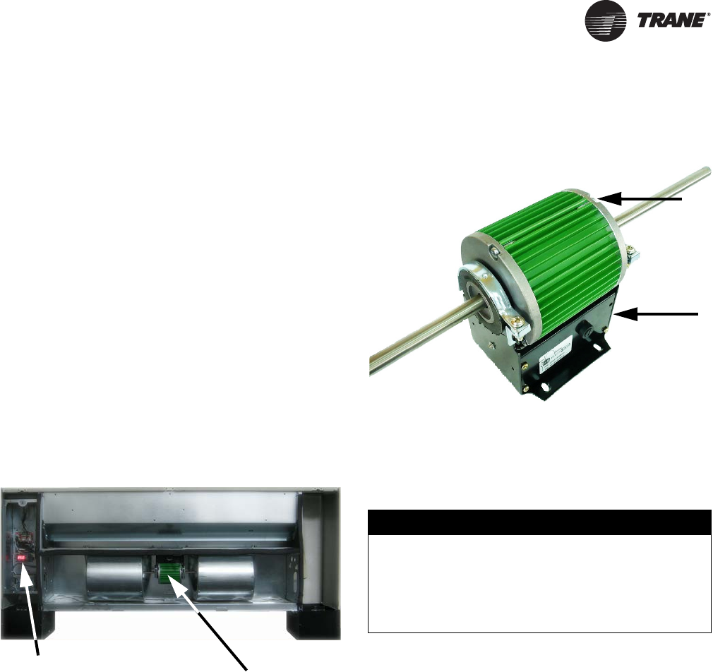
UNT-SVX07D-EN 53
ECM Overview and Setup
Overview
This addendum addresses changes to UniTrane Fan-Coil
and Cabinet Heater units, integrating new Trane Brushless
DC motors and controllers. This exciting new series
delivers outstanding comfort, safety, and performance
with greatly reduced energy consumption compared to
traditional units with permanent split capacitance AC
motors.
The new series of units will provide a long service life with
proper installation and operation. The new system
provides a high degree of flexibility and configurability,
but the simplicity of customized factory configuration
appropriate to most installations.
Very little intervention is needed by service and
installation personnel in most applications; however,
installers must read through the entire document before
beginning installation of the new equipment.
This literature focuses on unit motors and controls,
including three new circuit modules developed
specifically for this series.
General Information
There are four primary components that enable the
technology on your product:
1. Trane B LDC Mo tor
2. ECM Engine Board
3. Adapter Board
4. CSTI Adapter Board
The motors and modules are combined as systems, and
cannot work without each other.
Trane BLDC Motor
• The BLDC motor has integrated electronics, overload
protection and short circuit protection. The motor
contains no user-serviceable components inside.
• The motor mates to the unit electrically via a single
plug that contains both the operating voltage and the
control signals that are needed for correct operation.
• The BLDC motor comes in both single shaft (sizes 200,
300, 400, 1000, and 1200) and double shaft (sizes 600,
800, 1000, and 1200) configurations.
Note: Sizes 1000 and 1200 have both a single shaft
and a double shaft motor installed.
• The BLDC motor has two voltage variations, 115/
208-230V and 277V. Units with three-phase and neutral
have motors wired to the L-N (as opposed to L-L). The
115/208-230V is configured for voltage by use of an
external jumper. If the jumper is present the motor will
be configured for use with 115V. The jumper must NOT
be present for use with 208-230V.
Figure 19. UniTrane fan-coil with Trane BLDC motor
Trane BLDC Motor
Circuit Modules
Figure 20. Trane BLDC motor
1. High Efficiency Brushless DC (BLDC) Motor Core
2. Motor Base Housing Potted Electronics Package
NOTICE:
Equipment Damage!
The motor harness attached to the single plug to which
the motor mates contains the very important motor
voltage jumper and should not be modified or
substituted. Failure to follow this instruction could
result in equipment damage.
1
2
UNT-SVX07_-EN.book Page 53 Friday, April 27, 2012 9:40 AM
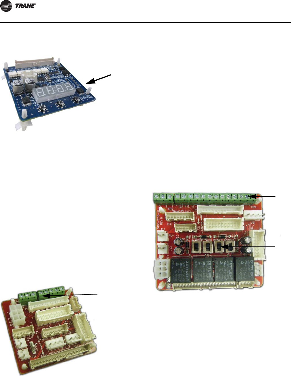
ECM Overview and Setup
54 UNT-SVX07D-EN
ECM Engine Controller
• The ECM engine controls and reports the performance
of up to two Trane BLDC motors.
• The engine also co-ordinates the operation of the fan
in response to electric heat behavior, and electric heat
behavior in response to hydronic heat behavior and
fan behavior.
• The engine incorporates a user interface that allows
adjustment of certain unit parameters and provides
constant feedback on motor operation.
• The engine integrates service and troubleshooting
tools, including high-precision tachometers, fan
status, and electric heat-enable indicators.
• The engine integrates a versatile configurable
auxiliary temperature sensor.
• The engine incorporates various safety and lockout
features, such as maintaining proper fan speeds, if
electric heat is called for.
Standard Adapter Board
• The adapter allows direct customer interfacing
through the use of terminal strips. Standard
interfacing includes:
– Fan Speeds (H, M, L) (for wall mounted fan speed
switches)
– Variable speed (0–10V) inputs
• The standard adapter board eliminates many separate
wiring harnesses in the panel and allows simple,
mistake-proofed single-plug interfacing of:
– The ECM engine controller
–T
ransformers
–Motors
– Valves
–Dampers
– Electric heat control
– Fan speed switches
– Main Power (except electric heat).
• Electric heat lockout circuits and fan proving circuits
for electric heat are standard, and are pre-configured at
the factory.
CSTI Adapter Board
• Performs all the functions of the standard adapter
module, but in addition, provides convenient field
connections to factory mounted end devices,
including:
– Valves
–D
ampers
– Electric Heat
• Performs courtesy “inversion” of thermostatic inputs
to match selected valves:
Figure 21. ECM engine controller
Figure 22. Adapter board
Note: Display and Menu/
Enter, Increase, and
Decrease Buttons
Note: Customer Low-
Voltage
Interface for
Fan Speeds,
Variable Fan
Speed, and
24 Vac Supply
Figure 23. CSTI adapter board
1. Customer Low-Voltage Interface for Valves, Electric Heat, Dampers, Fan
Speeds, Variable Fan Speed, and 24 Vac Supply
2. Valve(s), Electric Heat, and Changeover Configuration Switches (Factory-
Set)
1
2
UNT-SVX07_-EN.book Page 54 Friday, April 27, 2012 9:40 AM
ECM Overview and Setup
UNT-SVX07D-EN 55
– Standard thermostats put out only “on” signals,
however customer may select a normally open
valve. A selectable switch allows the customer to
invert the thermostat outputs for correct operation.
These switches are set at the factory, but can be
adjusted in the field.
– Sophisticated changeover function when used with
a thermistor, that replaces traditional bi-metallic
disc temperature switches:
•Board will automatically honor only the
appropriate customer request (Heat/Cool)
depending on sensed water temperature.
•Feature can be enabled or disabled with a
selector switch—however, it is set correctly at
the factory, based on customer choice of coil.
•The bi-metallic disc temperature switch
emulation is programmable, and dead-band
range can be adjusted.
•Electric heat lockout circuits and fan proving
circuits for electric heat are standard, and are
pre-configured at the factory.
Installation and Initial Setup
Installation and Initial Setup
Note: Normally, the Trane BLDC motors are configured
for soft ramps and transitions between speeds.
However, to aid in commissioning of the unit, for
approximately 10–15 minutes, the ramps will be
shortened to quickly observe proper unit behavior
and response to speeds.
For new installations, all boards and motors are pre-
installed and pre-configured according to the unit
configuration, indicated by its model number.
Under normal and intended operation, the only required
intervention specific to the new BLDC units is the wiring of:
WARNING
Hazardous Voltage w/Capacitors!
Disconnect all electric power, including remote
disconnects and discharge all motor start/run
capacitors before servicing. Follow proper lockout/
tagout procedures to ensure the power cannot be
inadvertently energized. For variable frequency drives
or other energy storing components provided by Trane
or others, refer to the appropriate manufacturer’s
literature for allowable waiting periods for discharge of
capacitors. Verify with an appropriate voltmeter that all
capacitors have discharged. Failure to disconnect
power and discharge capacitors before servicing could
result in death or serious injury.
WARNING
Safety Alert!
You MUST follow all recommendations below. Failure
to do so could result in death or serious injury.
• The BLDC motors contain capacitors which store
residual energy. Please keep clear of the fan wheels
for 5 minutes after the power has been removed from
the system, as a power request with the motor
powered off, could result in a very short period of
actuation.
• All settings take effect immediately, including fan
startup and enabling of electric heat. Caution should
be taken to stay clear of hazardous voltages, moving
parts and electric heat elements while making
adjustments to the ECM engine board. If it is not
practical to stay clear of these areas during
adjustment of the ECM engine board, please contact
Trane Global Parts for configuration kit that allows
easy powering of the engine board outside of the unit
with a 9V battery.
• The adapter boards contain high voltage.
Configuration adjustments to the ECM engine board
should be made through the SMALLER of the two
low-voltage lids on the front of the control panel,
through the low-voltage insulation/shielding.
• Changes to switch settings on the CSTI adapter
board take effect immediately. Changes should be
made to the CSTI configuration switches with the
power off.
• Initial hookups to the CSTI and Standard Adapter
board, including low voltage interconnections, must
be made with the power off.
• Do not make connections to the motors or the
adapter boards while power is ON. Do not remove
connections to the motor or the adapter boards while
the power is ON.
• Do not free spin the fan wheels with your hands while
the unit is powered on. The system is constantly
scanning and responding to the operational status of
the motors.
UNT-SVX07_-EN.book Page 55 Friday, April 27, 2012 9:40 AM
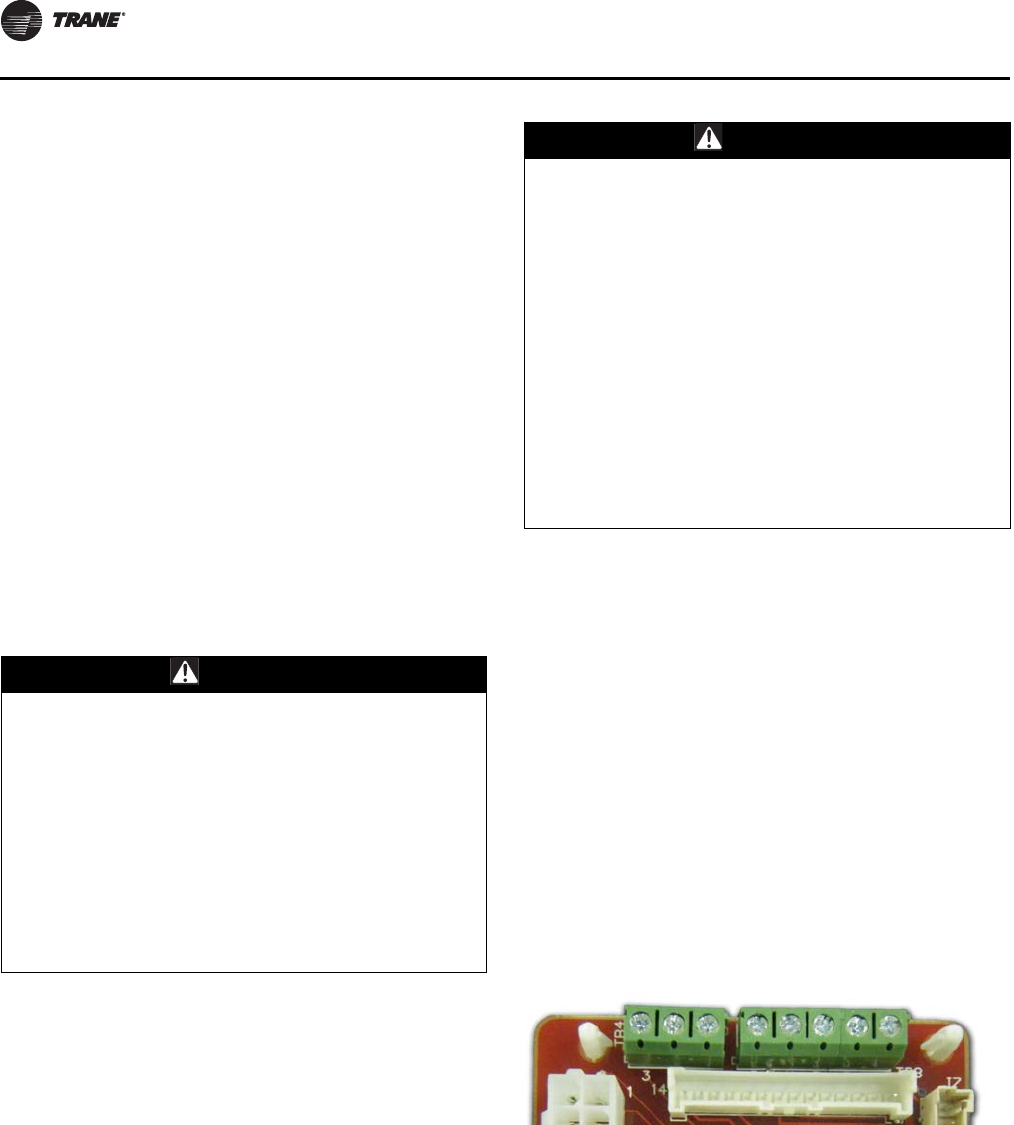
ECM Overview and Setup
56 UNT-SVX07D-EN
• Wall-mounted low-voltage fan speed switch inputs to
the adapter boards’ terminal strips and 24 Vac tap to
field-installed fan speed switch.
• Field-supplied controllers/thermostats to the adapter
boards’ terminal strips and 24 Vac power tap to
field-supplied controller/thermostat.
• Adjustment and calibration of the variable speed
inputs (VSP/0–10V) on the system.
• Adjustment, calibration or disabling of the optional
auto-changeover function on CSTI units.
Otherwise, proceed with the mechanical, electrical and
controls installations as defined in other sections of
UNT-SVX07B-EN (Installation, Operation, and
Maintenance: UniTrane™ Fan-Coil and Force-Flo™ Air
Conditioners), while obeying the warnings communicated
in this literature.
Proceed with the power on after installation, as defined in
the other sections of UNT-SVX07B-EN.
Wall Mounted Low Voltage Fan Speed Switch/
Customer-Supplied Controller/Thermostat
Instructions
Note: Specifications subject to change without notice.
Consult the unit submittals and unit schematics
before determining hookup requirements to the
fan-coil unit. Terminal block positions, polarities
and assignments are determined for specific unit
configurations only. Signal assignments are
indicated, for reference only.
Both adapter boards come equipped with integrated
terminal blocks to hook up to the field supplied/mounted
Fan Speed Switches and external controls. Connections
should be made to the screw terminals with wires between
16 AWG and 24 AWG, with a ~4–5-mm wire strip length.
The terminal blocks have 5-mm spacing, and are equipped
with 3-mm screws. The field-supplied wires should have
an insulation rating of 600V.
Standard Adapter Board Field Connections
All customer connections to the two adapter boards are
made to the terminal strips on both adapter boards.
Screw terminal blocks provide convenient access to fan
controls for High, Medium, Low, and Variable speed. In
addition, a courtesy 10 Vdc supply is provided for use with
WARNING
Hazardous Voltage w/Capacitors!
Disconnect all electric power, including remote
disconnects and discharge all motor start/run
capacitors before servicing. Follow proper lockout/
tagout procedures to ensure the power cannot be
inadvertently energized. For variable frequency drives
or other energy storing components provided by Trane
or others, refer to the appropriate manufacturer’s
literature for allowable waiting periods for discharge of
capacitors. Verify with an appropriate voltmeter that all
capacitors have discharged. Failure to disconnect
power and discharge capacitors before servicing could
result in death or serious injury.
WARNING
Safety Alert!
You MUST follow all recommendations below. Failure
to do so could result in death or serious injury.
• Hook ups to the adapter boards should be made only
with the power off to the unit.
• Only connect Class 2 voltages to the terminal blocks
on the adapter boards that share a common with the
unit mounted low-voltage transformer.
• Secure low voltage connections firmly to terminal
strips, and strain-relieve all low voltage connection to
prevent accidental detachment and possible short-
circuiting of high voltage components. Care should
be taken to avoid contact of low voltage wiring to the
back side of the adapter boards, which contain high
voltage.
Figure 24. Standard adapter board field connections
1. VSP 10V
2. VSP 0–10V
3. VSP DC COM
1. 24 Vac Y (gnd)
2. 24 Vac B (com)
3. High
4. Medium
5. Low
321 543 21
UNT-SVX07_-EN.book Page 56 Friday, April 27, 2012 9:40 AM
ECM Overview and Setup
UNT-SVX07D-EN 57
an external potentiometer or rheostat. The 10 Vdc supply
supports up to 10 mA draw.
TB3 (right five positions) is normally used to provide 24V
hookup to a wall mounted fan speed switch, and to accept
the returns from the switch for High, Medium, and Low
requests.
TB4 (left three positions) is normally used to control the
system with a 0–10 Vdc output from a thermostat/
controller, or a fan control rheostat/potentiometer.
The terminal block functional assignments and polarity
are shown for reference only, and the schematics that ship
with each unit should be consulted before wiring. Wiring
assignments are configured for each unit.
CSTI Adapter Board Field Connections
The CSTI adapter board provides all the hookups of the
standard adapter board, but in addition provides hookups
for valve control (main and auxiliary coils), electric heat
control and damper control.
Screw terminal blocks provide convenient access to fan
controls and to end device control. In addition, a courtesy
10 Vdc supply is provided for use with an external
potentiometer or rheostat. The 10 Vdc supply supports up
to 10 mA draw.
TB3 (right 13 positions) is normally used to provide:
1. 24 Vac supply to a wall fan speed switch or
2. 24 Vac supply to a field-installed unit-mounted
controller, or a wall-mounted controller or thermostat
3. Inputs (returns) for thermostatic fan control: High,
Medium, and Low
4. Inputs (returns) for cooling/heating requests
5. Inputs (returns) for electric heat requests
6. Inputs (returns) for damper operation requests
TB4 (left three positions) is normally used to control the
system with a 0–10 Vdc input from a thermostat/controller
with a variable speed output, or a fan control rheostat.
The terminal block functional assignments and polarity
are shown for reference only, and the schematics that ship
with each unit should be consulted before wiring. Wiring
assignments are configured for each unit.
Adjustment and Configuration of the
Engine Board
Note: The engine board functions and unit specific
settings are summarized on the ECM engine
configuration label affixed to the back side of the
control panel low voltage lid on every unit.
Figure 25. CSTI adapter board field connections
1. V S P 10V
2. VSP 0–10V
3. VSP DC COM
1. 24 Vac Y (hot)
2. Damper Open
3. 24 Vac Y (gnd)
4. High
5. Medium
6. Low
7. V1Op/Cooling
8. Not used
9. Not used
10. V1C1 (not std)
11. V2Op/EH1St/Heating
12. V2C1/EH2St (not std)
13. Dmp Cl (not std)
321 1098 7654 321
11
12
13
WARNING
Safety Alert!
You MUST follow all recommendations below. Failure
to do so could result in death or serious injury.
• All settings take effect immediately, including fan
startup and enabling of electric heat. Caution should
be taken to stay clear of hazardous voltages, moving
parts and electric heat elements while making
adjustments to the ECM engine board. If it is not
practical to stay clear of these areas during
adjustment of the ECM engine board, please contact
Trane Global Parts for configuration kit that allows
easy powering of the engine board outside of the unit
with a 9V battery.
• Configuration adjustments to the ECM engine board
should be made through the SMALLER of the two
low-voltage lids on the front of the control panel,
through the low-voltage insulation/shielding.
CAUTION
Burn Hazard!
On electric heat units, certain parameter values are
locked out to prevent overheating of the unit. These
functions will appear to be saved; however, they will
not be accepted if the Electric Heat Protection setting is
“On”. Do not change the Electric Heat Protection setting
to “Off” and make changes to the protected settings
unless you are programming an unconfigured service
replacement board to match the unit settings on a ECM
configuration label. Failure to follow this instruction
could result in the unit overheating and becoming hot
to the touch, which could result in minor or moderate
injury, and/or equipment damage.
UNT-SVX07_-EN.book Page 57 Friday, April 27, 2012 9:40 AM
ECM Overview and Setup
58 UNT-SVX07D-EN
The ECM engine board features a nested menu integrated
user interface (UI) that supports:
1. Status display for instant touch-free confirmation of
unit operation.
2. Configuration parameter and value display and
modification changes (using integrated menu/set
buttons).
3. Error code prioritized reporting.
Status Display
The ECM engine board contains a four-digit, seven-
segment display that is used to present information in a
format close to real-world language, while having a small-
form factor. Most characters are immediately
recognizable; however, please consult Ta b le 14 and
Tabl e 15 for the graphical representation of each
alphanumeric character.
Note: Characters on the ECM engine board display
appear in red, on a black background.
The display contains decimal positions as well that change
position with each parameter, as appropriate. Under
normal conditions (i.e., with no error code displayed), the
status will loop the following message:
Figure 26. ECM engine label
1. To check status, configuration, or to change settings on
the engine board with the power on the unit, detach the
low voltage access lid and look or reach through the
low voltage access panel.
2. The ECM engine label is affixed to the back or front of
the low voltage access lid.
1
2
Figure 27. Status display
Table 14. Screen representation of alphabetical
characters
ABCDEFGHI JKLM
NOPQR S TUVWX Y Z
Table 15. Screen representation of numeric characters
1234567890
UNT-SVX07_-EN.book Page 58 Friday, April 27, 2012 9:40 AM
ECM Overview and Setup
UNT-SVX07D-EN 59
RPM Mode
RUNNING/ FAN STATUS
CONTINUOUS LOOP
Displayed when:
1) No error codes are present
2) Motor has completed ramping
Indicates the current rpm of Motor 1 in the system. “0” rpm
here indicate that no fan speed has been requested.
→
Indicates the current rpm of Motor 2 in the system. “0” rpm
here indicate a fan off condition OR a fan “missing”
condition(a).
→
Indicates the status being calculated or Fan Motor 1. If “off,”
this indicates that either:
1) No fan speed is being requested or
2) The fan performance is failing to meet the request; refer
to “Troubleshooting (ECM),” p. 126 for additional
information.
If “on,” this indicates that the fan is performing correctly and
will be used to report fan status correctly, depending on
mode.
/
Indicates the status being calculated or Fan Motor 2. If “off,”
this indicates that either:
1) No fan speed is being requested or
2) The fan performance is failing to meet the request; refer
to “Troubleshooting (ECM),” p. 126 for additional
information.
3) If the target speed for Motor 2 is “0,”this is used to
indicate a missing motor(a).
If “on,” this indicates that the fan is performing correctly and
will be used to report fan status correctly, depending on
mode.
/
Indicates that the temperature sensing circuit has
calculated a logical “on” based on the settings of the
following parameters:
///
(a)Motor 1 is the only motor in sizes 200, 300, 400, 600, and 800. Sizes 1000 and 1200 units contain two motors: Motor 1 (single shaft) and Motor 2
(double shaft).
UNT-SVX07_-EN.book Page 59 Friday, April 27, 2012 9:40 AM
ECM Overview and Setup
60 UNT-SVX07D-EN
Configuration parameter and value display
and modification changes
The ECM engine board’s on-board user interface is easy to
use and supports:
1. Verification/auditing of on-board parameter settings
(read-only)
2. Adjustment of the on-board settings (write)
The user interface has three input buttons, from left to
right:
1. “M enu /Set”
2. “Decrement”
3. “Increment”
Each button has several different actuation levels
depending on length of press, and what the UI is currently
displaying.
Figure 28. User interface input buttons
Table 16. Button actuation levels
Button
Menu/Set
Duration Action
Short Press in
Status Display <1 sec None
Short Press in
Configuration
Display
Toggles between parameter
name and value without saving
(abandons value if changed).
Long Press/Hold
in Status Display >3 sec Enters the configuration menu
Long Press/Hold
in Configuration
Display
>3 sec If on a parameter name, toggles
to the value. If on a parameter
value, saves the value settings
and returns to the parameter
name as confirmation.
Button
Decrement
Duration Action
Short Press in
Status Display <1 sec None
Short Press in
Configuration
Display
<1 sec Scrolls through parameter
names, or decreases value of
parameter.
Long Press/Hold
in Status Display >3 sec N/A
Long Press/Hold
in Configuration
Display
>3 sec Faster scroll through parameter
name, or faster decrease of
values of parameters.
Button
Increment
Duration Action
Short Press in
Status Display <1 sec None
Short Press in
Configuration
Display
<1 sec Scrolls through parameter
names, or increases value of
parameter.
Long Press/Hold
in Status Display >3 sec N/A
Long Press/Hold
in Configuration
Display
Faster scroll through parameter
name, or faster increase of
values of parameters.
UNT-SVX07_-EN.book Page 60 Friday, April 27, 2012 9:40 AM

ECM Overview and Setup
UNT-SVX07D-EN 61
Configuration Use Examples
Example 1. To view the value of parameters without
saving. In this case we wish to verify that the “Low Speed
Value” for Motor 1 is set correctly to 800 rpm.
We start with the ECM engine scrolling status display and
proceed as follows:
Example 2. We wish to change the change the value of
Low Speed to 820 rpm:
We will continue from the previous example as shown
below, using a long press to “save” the new desired value.
Note: If the display has timed out and returned to the
status loop, repeat Example 1 to arrive back at this
example’s starting point.
Example 3. We wish to double check to see if the value of
“820 rpm” has been saved.
Note: If the display has timed out and returned to the
status loop, repeat Example 1 and Example 2 to
arrive back at this example’s starting point.
Example 4. We wish to change the value of a protected
value on an electric heat unit.
It would appear that the value has been changed, but if we
check the value, we notice that the original value has been
retained.
Priority / Error Display
Under special conditions, the status display will interrupt
briefly to prioritize display of events:
Notes:
•During error displays, the user interface will be
disabled, until the error is removed or resolved.
•If changes are made to parameters and saved, most
settings take effect immediately. Any change to fan
speeds will take effect and cause the configuration
menu to exit immediately to begin tracking speeds via
the on-board tachometer.
•Where practical, the unit will offer “limp-in”
performance, but to ensure safe operation, certain unit
functions will be disabled. For example, if one motor
fails, the unit will display an error code, but the second
motor (if present) will continue to operate. However, to
ensure safe operation, the electric heat (if present) will
be disabled.
•If a error occurs while the configuration menu is in
effect, all unsaved values will be discarded and the
error codes will be displayed.
UNT-SVX07_-EN.book Page 61 Friday, April 27, 2012 9:40 AM
ECM Overview and Setup
62 UNT-SVX07D-EN
Error Codes
Displayed during
abnormal operation.
Indicates a locked rotor condition of Motor 1. The motor will be locked
out until the cause has been resolved, and the power cycled; refer to
“Troubleshooting (ECM),” p. 126 for resolution details.
Motor 2 will continue to operate, but will not be monitored. Fan Status
function, if being used, will report an inoperative motor. Electric heat
and changeover heat will be shut down.
Indicates a locked rotor condition of Motor 2. The motor will be locked
out until the cause has been resolved, and the power cycled; refer to
“Troubleshooting (ECM),” p. 126 for resolution details.
Motor 1 will continue to operate, but will not be monitored. Fan Status
function, if being used, will report an inoperative motor. Electric heat
and changeover heat will be shut down.
Indicates that Motor 1 has experienced a run-away or over speed
condition, and has been shutdown. The unit will offer limited “limp-in”
performance, and Motor 2 will continue to operate, but will not be
monitored. Fan Status function, if being used, will report an
inoperative motor.
Refer to “Troubleshooting (ECM),” p. 126: to reset, the cause must be
resolved and the power to the unit cycled. Electric heat and changeover
heat will be shut down.
Indicates that Motor 2 has experienced a run-away or over speed
condition, and has been shutdown. The unit will offer limited “limp-in”
performance, and Motor 1 will continue to operate, but will not be
monitored. Fan Status function, if being used, will report an
inoperative motor.
Refer to “Troubleshooting (ECM),” p. 126: to reset, the cause must be
resolved and the power to the unit cycled. Electric heat and changeover
heat will be shut down.
Indicates the motor is transitioning between speeds, ramping up or
down. The message “RAMP” is briefly displayed, followed by the
target speed for “Motor 1” only. Once the target speed has been
reached, the status display will resume operation.
→
→
On power on, the version of software is briefly displayed, followed by
the results of a POST (power on self test).
UNT-SVX07_-EN.book Page 62 Friday, April 27, 2012 9:40 AM
ECM Overview and Setup
UNT-SVX07D-EN 63
Initial Setup and Configuration
After connections of power and hookup of customer
installed controls/fan speed switches and under normal/
operative conditions the only adjustments needed to be
made to the ECM engine board during commissioning of
the unit are:
• Adjustment and calibration of the variable speed
inputs (VSP/0–10V) on the system, where applicable.
• Adjustment, calibration or disabling of the optional
auto-changeover function on CSTI units, where
applicable.
In addition, the CSTI adapter board offers configurability
that can be used in special cases to adjust the following
operation of the unit:
• Courtesy cooling/main valve logic inversion relays for
use with normally open valves
• Courtesy heating/auxiliary valve logic inversion relays
for use with normally open valves
• Changeover function for use with changeover coils (in
conjunction with the ECM engine board)
The switches are factory-set based on the model number
configuration as ordered; however, the information is
provided below to aid in the understanding of the
operation of the system.
Configuration
Configuring the ECM Engine Controller
Adjustment and Calibration of the Variable
Speed Inputs (VSP/0–10V)
Notes:
•The 0–10V (variable speed) inputs are available for use,
but are not mandatory. The Trane Brushless DC system
WARNING
Hazardous Voltage w/Capacitors!
Disconnect all electric power, including remote
disconnects and discharge all motor start/run
capacitors before servicing. Follow proper lockout/
tagout procedures to ensure the power cannot be
inadvertently energized. For variable frequency drives
or other energy storing components provided by Trane
or others, refer to the appropriate manufacturer’s
literature for allowable waiting periods for discharge of
capacitors. Verify with an appropriate voltmeter that all
capacitors have discharged. Failure to disconnect
power and discharge capacitors before servicing could
result in death or serious injury.
WARNING
Safety Alert!
You MUST follow all recommendations below. Failure
to do so could result in death or serious injury.
• The adapter boards contain high voltage.
Connections to the adapter boards/changes to the
CSTI configuration switches should be made only
with the power to the unit disconnected.
• The adapter boards contain high voltage.
Configuration adjustments to the ECM engine board
should be made through the SMALLER of the two
low-voltage lids on the front of the control panel,
through the low-voltage insulation/shielding.
• All settings take effect immediately, including fan
startup and enabling of electric heat. Caution should
be taken to stay clear of hazardous voltages, moving
parts and electric heat elements while making
adjustments to the ECM engine board. If it is not
practical to stay clear of these areas during
adjustment of the ECM engine board, please contact
Trane Global Parts for configuration kit that allows
easy powering of the engine board outside of the unit
with a 9V battery.
CAUTION
Burn Hazard!
On electric heat units, certain parameter values are
locked out to prevent overheating of the unit. These
functions will appear to be saved; however, they will
not be accepted if the Electric Heat Protection setting is
“On”. Do not change the Electric Heat Protection setting
to “Off” and make changes to the protected settings
unless you are programming an unconfigured service
replacement board to match the unit settings on a ECM
configuration label. Failure to follow this instruction
could result in the unit overheating and becoming hot
to the touch, which could result in minor or moderate
injury, and/or equipment damage.
NOTICE:
Equipment Damage!
You MUST follow all recommendations below. Failure
to do so could result in equipment damage.
• Care should be taken in the system to use a single
24 Vac supply system to avoid damage to equipment.
• Care should be taken to observe proper polarity and
grounding in the hookup of the 0–10V system to
avoid damage to equipment.
UNT-SVX07_-EN.book Page 63 Friday, April 27, 2012 9:40 AM
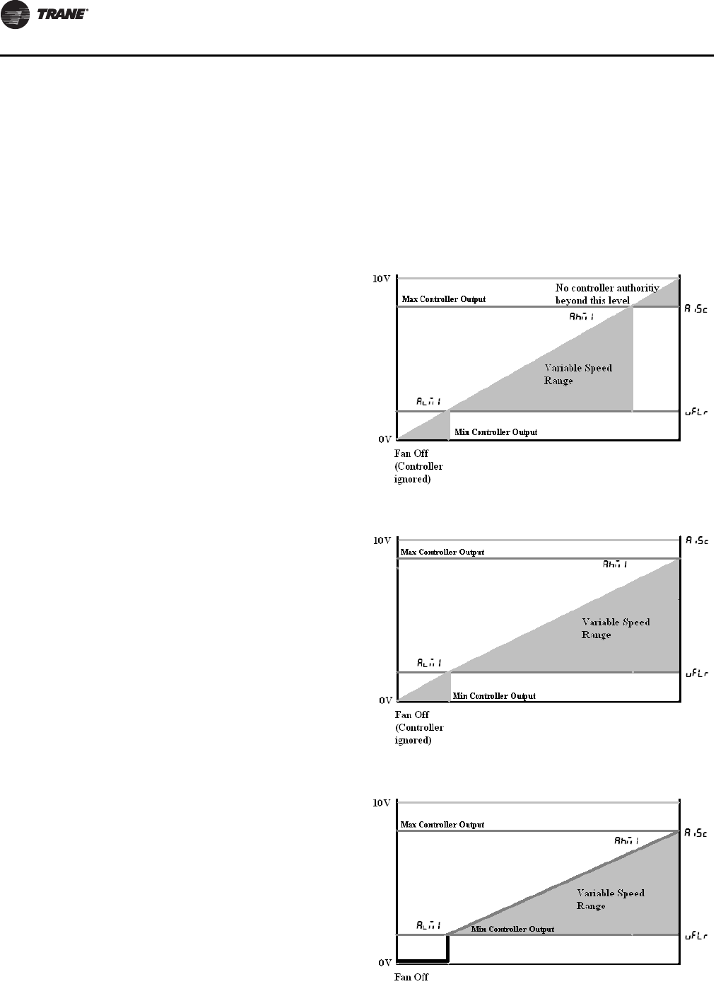
ECM Overview and Setup
64 UNT-SVX07D-EN
comes standard with three to five field-accessible
thermostatic inputs (with adjustable speed), so the use
of the 0–10V inputs is optional.
•All inputs are independently configurable and
simultaneously accessible, and the ECM engine will
choose the highest user (configured and requested)
speed. However, care should be taken with customer
controls to avoid contention of signals.
The ECM engine and adapter boards offer standard,
normalizing 0–10V Variable speed fan inputs for use with
field supplied controllers or thermostats. These inputs can
be used as the only input to the system, used in addition
to the thermostatic (H, M, L) inputs, or not used at all. The
inputs are accessible via 1TB4 on the adapter boards.
The ECM engine is factory configured to drive the unit to
a minimum speed (catalogue “low speed” value), defined
as - and - once the analog (0–10V) input is
honored. As a default, the noise floor/threshold is set to
3 percent (0.3V). At 0.3V, the system will drive the motors
to the speeds defined in defined as - and -. If the
analogue input goes to 10V, the ECM engine will drive the
motor to maximum speed (normally catalogue “high
speed” value), defined as and , and will
change speed in response.
Although the ECM engine board ships with settings that
will work with most 0–10 Vdc outputs, calibration should
be performed to maximize response range and controller
authority. Typically, the only settings needed for the VSP
inputs are calibration of the signal to ensure that the
system obeys the following rules:
1. The minimum output from the field supplied controller
is met with a positive fan response. That is, we do not
want the - setting on the ECM engine board to be
higher than the minimum output of the field supplied
controller, as the ECM engine will “ignore” a portion of
the usable range of the customer fan variable speed
output.
2. The minimum output from the field supplied controller
is not significantly greater than the floor setting -
floor. If the minimum output of the controller is
significantly greater than the floor setting, the first
point that the motor will turn on will be above the
- and - value. The full range of motor control
will not be fully utilized in this case, as the motor will
never reach the low speed motor analogue input
scaling value for Motor 1 and Motor 2 (- and
-)
3. The maximum output of the controller needs to be 10V,
or if lower, needs to be compensated using the analog
input scaling value, to normalize the operational
range. As a default, the scaling value is set to 1.00 (so
a voltage of 5V will be graded as 5V); however, to
compensate for long runs or lower max voltages (i.e.,
lower than 10.00), the scaling value can be increased
accordingly to maximize operational range.
For example, if the voltage is only reaching a value of
9.0V at the adapter boards, then the parameter
should be set to (10/9=) .. If left un-calibrated, the
unit will never attain maximum speeds, defined as
and .
4. The ECM engine can accept slightly over-biased inputs
up to 12 Vdc, and the parameter can be set to a
value less than 1.0 to compensate.
VSP Setup Examples
Example 1: - set too high and set too high
Example 2: - set too high but set correctly
Example 3: - set correctly and set correctly
UNT-SVX07_-EN.book Page 64 Friday, April 27, 2012 9:40 AM
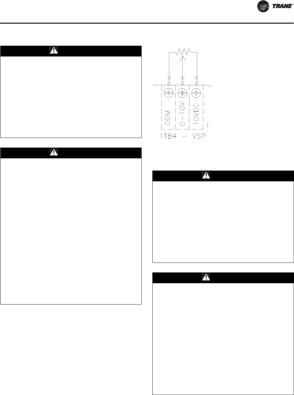
ECM Overview and Setup
UNT-SVX07D-EN 65
Use of Potentiometer/Rheostat For VSP
A courtesy 10-Vdc supply is provided that can support a
10-mA draw. The use of a 1K or a 10K potentiometer is
recommended, and only a stand-alone potentiometer (not
shared with any other electrical system) should be
employed. When a simple potentiometer is used as
depicted in Figure 29, the - setting will define a null-
zone (off).
The typical connection is depicted in Figure 29; however,
please consult the unit schematic for the most updated
instruction, as Figure 29 is provided as reference only.
Adjustment or Disabling of Optional Auto-
Changeover Function on CSTI Units
WARNING
Hazardous Voltage w/Capacitors!
Disconnect all electric power, including remote
disconnects and discharge all motor start/run
capacitors before servicing. Follow proper lockout/
tagout procedures to ensure the power cannot be
inadvertently energized. For variable frequency drives
or other energy storing components provided by Trane
or others, refer to the appropriate manufacturer’s
literature for allowable waiting periods for discharge of
capacitors. Verify with an appropriate voltmeter that all
capacitors have discharged. Failure to disconnect
power and discharge capacitors before servicing could
result in death or serious injury.
WARNING
Safety Alert!
You MUST follow all recommendations below. Failure
to do so could result in death or serious injury.
• The adapter boards contain high voltage.
Connections to the adapter boards/changes to the
CSTI configuration switches should be made only
with the power to the unit disconnected.
• Configuration adjustments to the ECM engine board
should be made through the SMALLER of the two
low-voltage lids on the front of the control panel,
through the low-voltage insulation/shielding.
• All settings take effect immediately, including fan
startup, enabling of electric heat. Caution should be
taken to stay clear of hazardous voltages, moving
parts and electric heat elements while making
adjustments to the ECM engine board. If it is not
practical to stay clear of these areas during
adjustment of the ECM engine board, please contact
Trane Global Parts for configuration kit that allows
easy powering of the engine board outside of the unit
with a 9V battery.
Figure 29. Typical connection
WARNING
Hazardous Voltage w/Capacitors!
Disconnect all electric power, including remote
disconnects and discharge all motor start/run
capacitors before servicing. Follow proper lockout/
tagout procedures to ensure the power cannot be
inadvertently energized. For variable frequency drives
or other energy storing components provided by Trane
or others, refer to the appropriate manufacturer’s
literature for allowable waiting periods for discharge of
capacitors. Verify with an appropriate voltmeter that all
capacitors have discharged. Failure to disconnect
power and discharge capacitors before servicing could
result in death or serious injury.
WARNING
Safety Alert!
You MUST follow all recommendations below. Failure
to do so could result in death or serious injury.
• The adapter boards contain high voltage.
Connections to the adapter boards should be made
only with the power to the unit disconnected.
• All settings take effect immediately, including fan
startup, enabling of electric heat. Caution should be
taken to stay clear of hazardous voltages, moving
parts and electric heat elements while making
adjustments to the ECM engine board. If it is not
practical to stay clear of these areas during
adjustment of the ECM engine board, please contact
Trane Global Parts for configuration kit that allows
easy powering of the engine board outside of the unit
with a 9V battery.
UNT-SVX07_-EN.book Page 65 Friday, April 27, 2012 9:40 AM
ECM Overview and Setup
66 UNT-SVX07D-EN
The ECM engine board provides additional temperature
controlled logic to help coordinate certain electric-heat
and valve logic functions:
• On units with electric heat and a changeover coil, the
engine board and adapter boards are pre-configured
to cause hydronic heat and electric heat to be mutually
exclusive:
– On units with ComfortLink™ controls (Tracer ZN
controllers), the Tracer ZN board will serve as the
primary logic to select the electric heat only if hot
water is not available, but the engine board will
service as a backup lockout.
– On units with Customer Supplied Controllers (CSTI
units), the engine board and CSTI board will serve
as the primary lockout.
• On CSTI units selected with a changeover coil
configuration, the engine board is factory configured
to work in conjunction with the CSTI adapter board to
provide a useful auto-changeover function.
Traditionally, a fixed setpoint bi-metallic disc
temperature switch is used to provide changeover with
customer controls; however, the engine board has
defeatable and configurable bi-metallic disc
temperature switch emulation when combined with
the CSTI adapter board. The ECM engine is
preconfigured for typical values, so changeover
settings do not necessarily need to be changed.
– An NTC thermistor is supplied and affixed to the
supply pipes where applicable. The ECM engine
has several settings that affect the operation of the
changeover function:
• parameter should normally be set to -
or to use the changeover functions.
•- parameter should be chosen if the unit has
a changeover coil without electric heat.
• parameter should be chosen if the unit
has a changeover coil with electric heat.
Generally, this will perform the same as the -
parameter but in addition, will disable heating
function on electric heat and on the changeover
coil if there are fan failures. The auxillary heating
coil function will continue to operate and
respond to the customer heating request.
• parameter should be set to for CSTI units and
to for ComfortLink controller units.
• parameter defines the temperature at which the
engine board will close the triac onboard the ECM
engine (if parameter is set correctly).
• parameter defines the temperature at which the
engine board will open the triac onboard the ECM
Engine (if parameter is set correctly). By leaving
a “gap” between the make and break value, we will
simulate hysteresis of a real bi-metallic disc
temperature switch.
• When combined with the CSTI adapter board, the bi-
metallic disc temperature switch emulation and the
electric heat lockout function will work when the
switches are set correctly.
Adjustment and Configuration of the CSTI
Adapter Board
For CSTI units, the board mounted switches have to be set
appropriately to enable the desired functionality.
Notes:
•All switches are factory-set based on customer
configuration of the unit model number. The unit will
function correctly as shipped; however, the switch
functions and positions are depicted for customer
convenience and for service and troubleshooting aids.
•SW3 and SW4 work in conjunction with settings on the
ECM engine controller. Simple activation of
CAUTION
Burn Hazard!
If SW4 is turned off, the factory/customer controller/
thermostat will be able to actuate the electric heat
while hot water is available or if the fans have failed.
This switch should NOT be turned off if the unit
schematic indicates that it should be on, to prevent
overheating of the unit (due to simultaneous electric
heat and hydronic heat actuation, or failure of the fan)
and to use the preferred hydronic heating over electric
heat. Failure to follow this instruction could result in
the unit overheating and becoming hot to the touch,
which could result in minor or moderate injury, and/or
equipment damage.
Figure 30. CSTI adapter board: board-mounted
switches
Table 17. CSTI adapter board: switch functions
Switch
(L-R) SW1 SW2 SW3 SW4
Function Valve one
operation
logic
Valve two
operation
logic
Changeover
Function Electric Heat /
Fan Proving
Function
UP position
(towards
terminal
strip)
Normally
Open Valve Normally
Open Valve Changeover
Function ON Electric Heat /
Fan Proving
Function
DOWN
position
(towards
black relays)
Normally
Closed Valve Normally
Closed Valve Changeover
Function OFF Electric Heat /
Fan Proving
Function
UNT-SVX07_-EN.book Page 66 Friday, April 27, 2012 9:40 AM

ECM Overview and Setup
UNT-SVX07D-EN 67
changeover and electric heat lockout function may not
work correctly unless the ECM engine board is
configured to perform these functions.
•Customers are advised to locate the changeover coil
temperature sensor on the bypass line if possible, to
avoid measuring standing water temperature.
•If a 4-pipe unit with changeover function is selected,
the heating input will drive the main coil if hot water is
detected, but will always drive the auxiliary coil or
electric heat (where available).
•Where electric heat is available with a changeover coil,
the electric heat is factory-configured to be deactivated
if there is hot water available and if there is a fan failure.
The CSTI board comes with courtesy valve inversion
relays that allow both normally open and normally closed
two-position valves to be used with simple thermostats
that do not have the configurability to adapt to the
customer choice of valves. Independent switches, SW1
and SW2, are provided for 2-pipe or 4-pipe units, or 2-pipe
units with an optional reheat coil. The functions of SW1
and SW2 is downstream of the changeover function (SW3
and ECM engine board). Decisions made by the
changeover circuits will be flowed to the inversion circuits,
if they are selected.
SW3 enables or disables the changeover function for
2-pipe changeover coil units, or 4-pipe units where the coil
has both a heating/cooling circuit and a heating circuit
piped internally. If SW3 is turned off, the changeover
function will be disabled, and the unit will then be
configured as a cooling only coil, a heating only coil, or a
combination of cooling only/heating only coil. Thus,
customer cooling requests will drive the main valve, and
heating requests will drive the auxiliary valve.
The changeover function is designed to work with
customer controllers that request heating or cooling
(based on customer request), but have coil water
temperatures that are “changed over” from heating to
cooling (or cooling to heating) depending on the season
and the building equipment available. Customer
thermostats MUST be hooked to the correct terminal strip
locations (V1 and V2) for the changeover function to work.
Cooling
In general, the (CSTI) changeover function will provide
cooling if:
1. A unit is factory configured with a changeover coil
(cooling/heating) as the only coil or as the main coil
portion.
2. SW3 on the CSTI adapter board is turned on, and the
parameter set to - or to use the
changeover functions.
a. - parameter should be chosen if the unit has a
changeover coil without electric heat.
b. parameter should be chosen if the unit has a
changeover coil with electric heat. Generally, this
will perform the same as the - parameter but
will in addition, disable the heating function on
electric heat and on the changeover coil heat if there
are fan failures. The auxiliary heating coil valve will
continue to respond to customer heating requests.
3. The ECM engine has sensed that there is cold water
available on the supply/bypass line for the changeover
coil. In this case, “cold” water is inferred by the ECM
engine if:
a. A 10K NTC thermistor (similar to Trane part number
X13790374010) is wired properly to the engine
board, through the crossover cables and CSTI
adapter boards.
b. The input impedance of the thermistor circuit must
be set correctly (the parameter should be set
to for CSTI units).
c. The temperature sensed is lower than the
parameter.
d. The parameter is higher than the
parameter.
e. The temperature is not in the dead-band between
the parameter and the parameter (in
this case, previous state will be retained).
4. The customer thermostat is properly hooked up the
input strip 1TB3, and is requesting cooling input (V1)
based on the customer cooling setpoint being lower
than the space temperature.
Heating
In general, the (CSTI) changeover function will provide
heating if:
1. A unit is factory-configured with a changeover coil
(cooling/heating) as the only coil or as the main coil
portion.
2. SW3 on the CSTI adapter board is turned on, and the
parameter set to - or to use the
changeover functions.
a. - parameter should be chosen if the unit has a
changeover coil without electric heat.
b. parameter should be chosen if the unit has a
changeover coil with electric heat. Generally, this
will perform the same as the - parameter but
will in addition, disable the heating function on
electric heat and on the changeover coil heat if there
are fan failures. The auxiliary heating coil valve will
continue to respond to customer heating requests.
3. The ECM engine has sensed that there is hot water
available on the supply/bypass line for the changeover
coil. In this case, “hot” water is determined if:
a. A 10K NTC thermistor (similar to Trane part number
X13790374010) is wired properly to the engine
board, through the crossover cables and CSTI
adapter boards.
UNT-SVX07_-EN.book Page 67 Friday, April 27, 2012 9:40 AM
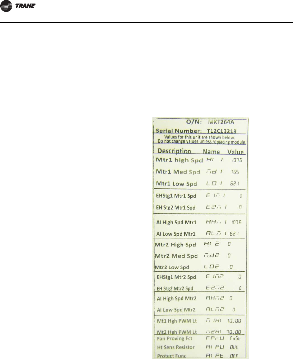
ECM Overview and Setup
68 UNT-SVX07D-EN
b. The input impedance of the thermistor circuit must
be set correctly (the parameter should be set
to for CSTI units).
c. The temperature sensed is higher than the
parameter.
d. The parameter is higher than the
parameter.
e. The temperature is not in the dead-band between
the parameter and the parameter (in
this case, previous state will be retained).
4. The customer thermostat is properly hooked up the
input strip 1TB3, and is requesting heating input (V2)
based on the customer heating set point being higher
than the space temperature.
5. The heating input on 1TB3 will drive the main
changeover coil IF conditions 1–4 are satisfied, but will
always drive the auxiliary coil valve (if present).
Electric heat will be locked out (where present) if hot
water is available since SW4 will be factory set to “ON”
in these units.
SW4 selects the electric heat lockout function, where we
will lock out the electric heat circuit based on either:
1. The presence of hot water in the changeover coil
section (if the parameter is set to -).
2. Abnormal behavior of the fan/s (if the parameter
is set to ).
3. Or a combination of both the presence of hot water or
abnormal behavior of the fan/s (if the parameter
is set to ).
4. The preceding three examples depend on the
inference of the engine board that hot water is present.
In this case, “hot” water is determined if:
a. The temperature sensed is higher than the
parameter.
b. The parameter is higher than the
parameter.
c. The temperature is not in the dead-band between
the parameter and the parameter (in
this case, previous state will be retained).
d. The input impedance of the thermistor circuit must
be set correctly (the parameter should be set
to for CSTI units).
Configuring the ECM Engine Board
Every Trane Fan-Coil or Cabinet Heater unit with BLDC
motors will have modules specifically configured at the
factory for the operation of that unit. The ECM engine
configuration label is affixed to the low-voltage access lid
on the outside of the control panel (see Figure 26, p. 58
and Figure 31, p. 68). The ECM engine label may be on the
back-side of the low voltage access lid, depending on the
unit configuration.
The serial number of each unit and the custom
configuration settings specific to that unit will be printed
on the label for convenient matching of labels/settings to
specific units. Programming a unit with the settings from
another unit will result in abnormal operation. The label
contains four important sections:
1. How to enter the configuration menu
2. The description and meaning of the Error Codes
3. The description and meaning of the status display
4. The parameter names and values specific to that unit
Note: This label is provided for reference only, as an
example, and should not be used to configure the
unit.
Figure 31. ECM engine label
UNT-SVX07_-EN.book Page 68 Friday, April 27, 2012 9:40 AM
ECM Overview and Setup
UNT-SVX07D-EN 69
Configuration Settings of the ECM Engine
Board
Note: The engine board functions and unit specific
settings are summarized on the ECM engine
configuration label affixed to the back side of the
control panel low voltage lid, on every unit.
The following table lists the parameter names and typical
settings of the ECM engine board, for reference only.
Additional Notes:
1. This list is applicable only to Fan-coil and Force-Flo
products.
2. Do not change the electric heat protection settings if
your unit has electric heat.
3. If the format setting for rpm values are not correct (i.e.,
not four-digit: XXXX), please check the operation mode
of the ECM engine board and and motor
signal output format and .
WARNING
Safety Alert!
You MUST follow all recommendations below. Failure
to do so could result in death or serious injury.
All settings take effect immediately, including fan
startup and enabling of electric heat. Caution should be
taken to stay clear of hazardous voltages, moving parts
and electric heat elements while making adjustments
to the ECM engine board. If it is not practical to stay
clear of these areas during adjustment of the ECM
engine board, please contact Trane Global Parts for
configuration kit that allows easy powering of the
engine board outside of the unit with a 9V battery.
The adapter boards contain high voltage. Configuration
adjustments to the ECM engine board should be made
through the SMALLER of the two low-voltage lids on
the front of the control panel, through the low-voltage
insulation/shielding.
CAUTION
Burn Hazard!
On electric heat units, certain parameter values are
locked out to prevent overheating of the unit. These
functions will appear to be saved; however, they will
not be accepted if the Electric Heat Protection setting is
“On”. Do not change the Electric Heat Protection setting
to “Off” and make changes to the protected settings
unless you are programming an unconfigured service
replacement board to match the unit settings on a ECM
configuration label. Failure to follow this instruction
could result in the unit overheating and becoming hot
to the touch, which could result in minor or moderate
injury, and/or equipment damage.
NOTICE:
Equipment Damage!
Do not change the PWM output voltage settings as
motor damage could occur.
UNT-SVX07_-EN.book Page 69 Friday, April 27, 2012 9:40 AM

ECM Overview and Setup
70 UNT-SVX07D-EN
Table 18. Configuration settings of the ECM engine board
Description on
Unit Label
User
Interface
Name
Typical
User
Interface
Value Description
Notes:
These notes are provided for reference
only, and the ECM engine label must be
used as the ultimate guide for setting up an
engine board on specific units.
Mtr 1 High Spd Sets the high-speed rpm for Motor 1. Do not exceed 1700 rpm.
Do not set under 450 rpm.
On units with two motors, the single shafted
motor is designated as Motor 1.
If the unit has only one motor, all seven speed
settings for the second motor (, ,
, , , , )
should be set to zero.
Analog inputs below the - setting will be
rejected.
Note: , , , settings
are locked out on units with electric heat.
Mtr 1 Med Spd Sets the medium-speed rpm for Motor 1.
Mtr 1 Low Spd - Sets the low-speed rpm for Motor 1.
EHStg1 Mtr1 Spd Assigns an rpm to be associated with a call
for 1st stage electric heat, for Motor 1 (only
on units equipped with electric heat).
EH Stg 2 Mtr 1 Spd Assigns an rpm to be associated with a call
for 2nd stage electric heat, for Motor 1
(only on electric heat equipped units).
AI High Spd Mtr 1 Sets the maximum rpm for Motor 1 for the
maximum input value of the analog input.
AI Low Spd Mtr 1 - Sets the minimum turn-on rpm for
Motor 1, when the analog input becomes
active.
Mtr 2 Hgh Spd Sets the high-speed rpm for Motor 2.
Mtr 2 Med Spd Sets the medium-speed rpm for Motor 2.
Mtr 2 Low Spd Sets the low-speed rpm for Motor 2.
EHStg1 Mtr2 Spd Assigns an rpm to be associated with a call
for 1st stage electric heat, for Motor 2 (only
on electric heat equipped units).
EH Stg 2 Mtr 2 Spd Assigns an rpm to be associated with a call
for 2nd stage electric heat, for Motor 2
(only on electric heat equipped units).
AI High Spd Mtr 2 Sets the maximum rpm for Motor 2 for the
maximum input value of the analog input.
AI Low Spd Mtr 2 - Sets the minimum turn-on rpm for
Motor 2, when the analog input becomes
active.
Op Mode Mtr 1 Sets the operational mode for Motor 1. Must be set to for fan-coil products.
Op Mode Mtr 2 Sets the operational mode for Motor 2. Must be set to for fan-coil products.
Mtr 1 Out Format Sets the interface type for Motor 1. Must be set to for fan-coil products.
Mtr 2 Out Format Sets the interface type for Motor 2 Must be set to for fan coil products.
Mtr 1/2 PWM Freq. Sets the PWM frequency, for cases when
the PWM outputs are used. On fan-coil units, the must not be
changed.
Mtr 1 PWM Volt - Sets the PWM voltage, for cases when the
PWM outputs are used. This setting must NOT be changed, as damage to
the motor may occur!
Mtr 2 PWM Volt - Sets the PWM voltage, for cases when the
PWM outputs are used. This setting must NOT be changed, as damage to
the motor may occur!
Mt1 Hgh PWM Lt Sets the maximum output % that the
controller will request from Motor 1. This envelope protection value should not be
altered.
Mt1 Low PWM Lt .Sets the minimum maximum output %
that the controller will request from
Motor 1.
This envelope protection value should not be
altered.
Mt2 Hgh PWM Lt Sets the maximum output % that the
controller will request from Motor 2. This envelope protection value should not be
altered.
Mt2 Low PWM Lt .Sets the minimum maximum output %
that the controller will request from
Motor 2.
This envelope protection value should not be
altered.
Mt1 Ovspd RPM Selects the rpm above which the Motor 1
will be assumed to be in an overspeed
condition and will need to be shut down.
This envelope protection value should not be
altered.
UNT-SVX07_-EN.book Page 70 Friday, April 27, 2012 9:40 AM
ECM Overview and Setup
UNT-SVX07D-EN 71
Mt2 Ovspd RPM Selects the rpm above which the Motor 2
will be assumed to be in an overspeed
condition and will need to be shut down.
This envelope protection value should not be
altered.
Fan Proving Fct Selects which mode should be assigned to
the Binary output circuit, depending on
unit type.
This setting has to be correct for proper unit
operation of electric heat and changeover units.
AI Boost Amp Boosts or attenuates the analog input
signal to compensate for long wire runs. A value of should be used if no voltage level
compensation is needed (i.e., voltage peak is at
10 Vdc).
AI Floor - .Rejects noise on the analog input lines and
sets up the engine board to turn on if the
thermostat or controller is commanding its
analog outputs on.
PulsePerRev Sets up the tachometer function to be
compatible with the on-board motor and
for correct speed calculation and
calibration.
Do not change this setting as this is critical to
proper unit operation.
P Value Mtr 1 - . Sets up the on board closed loop control to
control Motor 1 with proper stability. Do not change this setting.
I Value Mtr 1 - . Sets up the on board closed loop control to
control Motor 1 with proper stability. Do not change this setting.
P Value Mtr 2 - . Sets up the on board closed loop control to
control Motor 2 with proper stability. Do not change this setting.
I Value Mtr 2 - . Sets up the on board closed loop control to
control Motor 2 with proper stability. Do not change this setting.
Ht Sens Mk Val F Sets the make value for the engine board
triac output based on the thermistor input. Operation also depends on , , and
settings.
Ht Sens Bk Val F Sets the break value for the engine board
triac output based on the thermistor input. Operation also depends on , , and
settings.
Ht Sens Resistor Sets the input impedance of the thermistor
input. Should be pre-set to “OUT” for Tracer ZN
controllers.
Mt 1 Ramp %/sec Sets the ramp rate for Motor 1, in % per
second.
Mt 2 Ramp %/sec Sets the ramp rate for Motor 2, in % per
second
EH Rmp Accel Sets the acceleration factor for the electric
heat inputs. Is used to force faster ramps when electric heat
is requested.
Ramp MAX Time Sets the maximum ramp time for both
Motor 1 and Motor 2 (in seconds). Overrides the ramp rates and if
the calculated ramp time exceeds .
EH Fan off delay - Selects how long the fan needs to stay on
after an electric heat request has been
turned off.
Not used on fan-coil unit.
Lck Rtr Protect Selects whether to use the on-board
locked rotor protection function. This will shut down the affected motor, if
rotational response is not detected.
Table 18. Configuration settings of the ECM engine board (continued)
Description on
Unit Label
User
Interface
Name
Typical
User
Interface
Value Description
Notes:
These notes are provided for reference
only, and the ECM engine label must be
used as the ultimate guide for setting up an
engine board on specific units.
UNT-SVX07_-EN.book Page 71 Friday, April 27, 2012 9:40 AM
ECM Overview and Setup
72 UNT-SVX07D-EN
Fan Speed Response Verification
1. After performing controller specific commissioning,
observe the display on the ECM engine board with the
power on, to the unit. The ECM engine display should
display a looping status indicator as follows:
→→→→→
→→
→→
Notes:
•The indicator is unit-specific and may indicate
“Off” at this point; refer to thermistor function for more
information.
•A representative fan speed of “1080” rpm are shown in
the example below. Each unit is factory-configured
differently and will have different settings for different
fan speeds.
2. While the unit remains on, exercise the fan controls on
the unit, either directly or indirectly through request for
unit heat/cool. Observe the fan spinning, and then
observe the fan display on the ECM engine board. It
should display a looping status indicator as follows:
For a size 200, 300, 400, 600, or 800 unit (using typical
unit operating fan speeds):
→→→→
→→→
→→
For a size 1000 or 1200 unit (using typical unit
operating fan speeds):
→→→→
→→→
→→
Note: The indicator is unit-specific and may
indicate “Off” at this point; refer to thermistor
function for more information.
3. OPTIONAL:
While the fan is running, if practical, change the fan
speeds and observe the display temporarily indicate:
Exercise all fan speeds to ensure positive unit
response and to validate any field wiring.
Congratulations! Your new Trane BLDC Engine/Motor
system is performing properly.
Protect Funct This function protects settings on the
board that affect the safety of the electric
heat system.
Do NOT change this setting. This setting locks
out the following parameters from being
changed, for safe operation of the unit.
Rmp dft (auto rst) This function shortens the ramps for faster
unit commissioning and auto-resets to off
after approximately 15 minutes of power-
on operation.
To aid in commissioning of the unit, for
approximately 10–15 minutes, the ramps will be
shortened to quickly observe proper unit
behavior and response to speeds.
Soft Rev . Displays the software version.
Table 18. Configuration settings of the ECM engine board (continued)
Description on
Unit Label
User
Interface
Name
Typical
User
Interface
Value Description
Notes:
These notes are provided for reference
only, and the ECM engine label must be
used as the ultimate guide for setting up an
engine board on specific units.
UNT-SVX07_-EN.book Page 72 Friday, April 27, 2012 9:40 AM

UNT-SVX07D-EN 73
Wired Controllers—Communication Wiring
Wiring Installation (ZN510 and
ZN520)
Tracer ZN510 and ZN520 controllers are LonTalk® devices
that interface with the Trane Tracer Summit building
management system. Reference the unit wiring diagram
or submittals.
Ground shields at each Tracer ZN510 and ZN520, taping
the opposite end of each shield to prevent any connection
between the shield and anther ground. Refer to the most
recent version of Trane publication CNT-SVX04A-EN
(Tracer ZN.520 Unit Controller: Installation, Operation and
Programming Guide) for the communication wiring
diagram.
Communication wire must conform to the following
specification:
1. Shielded twisted pair 18 AWG
2. Capacitance 23 (21–25) picofarads (pF) per foot
3. Listing/Rating—300 V 150C NEC 725-2 (b) Class 2 Type
CL2P
4. Trane Part No. 400-20-28 or equivalent, available
through Trane BAS Buying Group Accessories catalog.
Note: Communication link wiring is a shielded, twisted
pair of wire and must comply with applicable
electrical codes.
Follow these general guidelines when installing
communication wiring on units with a Tracer ZN510 or
ZN520 controller:
• Maintain a maximum 5000 ft. aggregate run.
• Install all communication wiring in accordance with
the NEC and all local codes.
• Solder the conductors and insulate (tape) the joint
sufficiently when splicing communication wire. Do not
use wire nuts to make the splice.
• Do not pass communication wiring between buildings
because the unit will assume different ground
potentials.
• Do not run power in the same conduit or wire bundle
with communication link wiring.
Note: You do not need to observe polarity for LonTalk
communication links.
Device Addressing
LonTalk devices are given a unique address by the
manufacturer. This address is called a Neuron ID. Each
Tracer ZN510 and ZN520 controller can be identified by its
unique Neuron ID, which is printed on a label on the
controller’s logic board. The Neuron ID is also displayed
when communication is established using Tracer Summit
or Rover service tool. The Neuron ID format is
00-01-64-1C-2B-00.
Wire Characteristics
Controller communication-link wiring must be low
capacitance, 18-gage, shielded, twisted pair with stranded,
tinned-copper conductors. For daisy chain configurations,
limit the wire run length to 5,000 ft. Truck and branch
configurations are significantly shorter. LonTalk wire
length limitations can be extended through the use of a
link repeater.
Recommended Communication Wiring
Practices
The following guidelines should be followed while
installing communication wire.
• LonTalk is not polarity sensitive. Trane recommends
that the installer keep polarity consistent throughout
the site.
• Only strip away two inches maximum of the outer
conductor of shielded cable.
• Make sure that the 24 Vac power supplies are
consistent in how they are grounded. Avoid sharing
24 Vac between LonTalk UCMs.
• Avoid over-tightening cable ties and other forms of
cable wraps. A tight tie or wrap could damage the
wires inside the cable.
• Do not run LonTalk cable alongside or in the same
conduit as 24 Vac power.
• In an open plenum, avoid lighting ballasts, especially
those using 277 Vac.
• Do not use a trunk and branch configuration, if
possible. Trunk and branch configurations shorten the
distance cable can be run.
Wiring Installation (Tracer UC400)
This section provides information about wiring the UC400
controller. For more detailed information, refer to the
Tracer UC400 Programmable Controller Installation,
Operation, and Maintenance Manual (BAS-SVX20C-EN, or
the most recent revision).
UNT-SVX07_-EN.book Page 73 Friday, April 27, 2012 9:40 AM
Wired Controllers—Communication Wiring
74 UNT-SVX07D-EN
Wiring Overview Outline
General Instructions
Conformance to Regulatory Standards
All wiring must comply with the National Electrical Code
(NEC™) and local electrical codes.
Connecting Wires to Terminals
To connect wires to the UC400 controller or the expansion
modules:
1. Strip the wires to expose 0.28 inch (7 mm) of bare wire.
2. Insert the wire into a terminal connector.
3. Tighten the terminal screw to 0.5 to 0.6 N-m (71 to
85 ozf-in or 4.4 to 5.3 lbf-in.).
4. Tug on the wires after tightening the screws to ensure
all wires are secure as shown on the right.
BACnet MS/TP Link
Setting the Address
The rotary address dials on the UC400 controller serve one
or two purposes depending upon the network: they are
always used for the MAC Address, which is sometimes all
or part of the BACnet Device ID (refer to the illustration
below).
MAC Address. The MAC Address is required by the RS-
485 communication protocol on which BACnet operates. A
UC400 controller can use a MAC Address from 001 to 120.
Important: Each device on the link must have a unique
MAC Address/Device ID. The controller
rotary addresses should be sequentially set,
with no gaps in the numbering, starting with
001 on each link (for example 001, 002, 003,
004 and so on). A duplicate address or a 000
address setting will interrupt
communications and cause the Tracer SC
device installation process to fail.
BACnet Device ID. The BACnet Device ID is required by
the BACnet network. Each device must have a unique
number from 001 to 4094302.
BACnet networks without a Tracer SC system
controller
On BACnet networks without a Tracer SC system
controller, the Device ID can be assigned one of two ways:
• It can be the same number as the MAC Address,
determined by the rotary address dials on the UC400
controller. For example, if the rotary address dials are
set to 042, both the MAC Address and the BACnet
Device ID are 042.
• It can be soft set using the Tracer TU service tool. If the
BACnet Device ID is set using the Tracer TU service
tool, the rotary address dials only affect the MAC
Address, they do not affect the BACnet Device ID.
BACnet networks with a Tracer SC system
controller
On BACnet networks with a Tracer SC system controller,
the Device ID for the UC400 controller is always soft set by
the system controller using the following scheme
illustrated below.
BACnet MS/TP
Link
Power ON Check
(p. 76)
Wiring
Requirements
(p. 76)
Connection
Wiring (p. 75)
Setting the
Address (p. 74)
General
Instructions
(p. 74)
Power Supply
VAC
24
XFRM
BI4
AO1 BI
5
AO2 UI
1
UI
2
P
1
P
2
CNCNO BO3
CNCNO BO2
CNCNO BO1 RELAYS
ADDRESS
TRIAC SUPPLY TRIACS
A
BO9BO8BO7BO6BO5BO4
AB
B
TX
RX
LINK IMC
SERVI
C
E
SERVICE TOOL
CONNECT AC POWER TO THE TRAIC SUPPLY TO POWER THE TRIACS
BO1 BO2 BO3 BO4 BO5 BO6 BO7 BO8 BO9
1
2
3
4
5
6
7
8
9
0
x10
IM
C
1
1
3
4
5
6
7
1
2
3
4
5
6
7
8
9
0
x100
8
9
0
x1
Use a 1/8 inch (3.2 mm) flathead screwdriver to set rotary address
dials. Dials rotate in either direction.
UNT-SVX07_-EN.book Page 74 Friday, April 27, 2012 9:40 AM
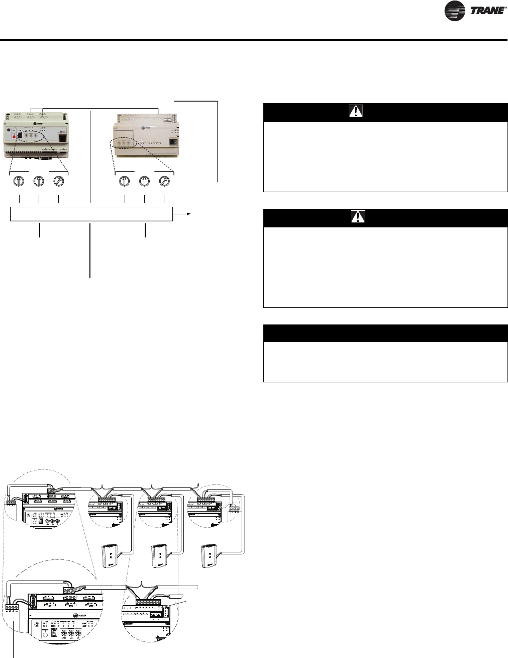
Wired Controllers—Communication Wiring
UNT-SVX07D-EN 75
Note: The BACnet Device ID is displayed as the Software
Device ID on the Tracer TU Controller Settings
page in the Protocol group.
Connection Wiring
Field-supplied BACnet MS/TP link wiring must be installed
in compliance with NEC and local codes. The wire must be
low-capacitance, 18-gauge, stranded, tinned-copper,
shielded, twisted-pair. The illustration below shows an
example of BACnet link wiring with multiple UC400
controllers.
Note: For more details, refer to Wiring Guide: Unit
Controller Wiring for the Tracer SC™ System
Controller (BAS-SVN03D-EN, or the most recent
revision).
Power Supply
Please read all of the warnings, cautions, and notices
below before proceeding with this section.
A separate transformer is recommended for each UC400
controller. The line input to the transformer must be
equipped with a circuit breaker sized to handle the
maximum transformer line current.
If a single transformer is shared by multiple UC400
controllers:
• The transformer must have sufficient capacity.
• Polarity must be maintained for every UC400
controller powered by the transformer.
Important: If the polarity is inadvertently reversed
between two controllers powered by the
same transformer, a difference of 24Vac will
occur between the grounds of each
controller, which can result in:
• Partial or full loss of communication on
the entire BACnet MS/TP link
• Improper function of the UC400
controller outputs
• Damage to the transformer or a blown
transformer fuse
ADDRESS
0
1
2
3
4
5
6
7
8
9
x1
0
1
2
3
4
5
6
7
8
9
x10
0
1
2
3
4
5
6
7
8
9
x100
001 0201
ADDRESS
0
1
2
3
4
5
6
7
8
9
x1
0
1
2
3
4
5
6
7
8
9
x10
0
1
2
3
4
5
6
7
8
9
x100
ADDRESS
0
1
2
3
4
5
6
7
8
9
x1
0
1
2
3
4
5
6
7
8
9
x10
0
1
2
3
4
5
6
7
8
9
x100
001 0201
ADDRESS
0
1
2
3
4
5
6
7
8
9
x1
0
1
2
3
4
5
6
7
8
9
x10
0
1
2
3
4
5
6
7
8
9
x100
BACnet
Device ID for
this UC400
The first three digits
are determined by the
address rotary dials on
the Tracer SC system
controller.
The fourth digit is
determined by the link
number to which the
UC400 controller is
attached.
The last three digits
are determined by the
rotary address dials
on the UC400
controller.
= 0012001
UC400
Link 2
Link 1
BI LINK IMC
+
VDC
AIAIAI AI AI
PP
TX
RX
LINK IM
SERVI
SERVICE TOOL
IM
BI LINK IMC
+
VDC
AIAIAI AI AI
PP
TX
RX
LINK IM
SERVI
SERVICE TOOL
IM
BI LINK IMC
+
VDC
AIAIAI AI AI
PP
TX
RX
LINK IM
SERVI
SERVICE TOOL
IM
+
+
BI LINK IMC
+
VDC
AIAIAI AI AI
PP
TX
RX
LINK IM
SERVI
SERVICE TOOL
IM
+
BI LINK IMC
+
VDC
AIAIAI AI AI
PP
TX
RX
LINK IM
SERVI
SERVICE TOOL
IM
+
Tracer SC UC400 UC400 UC400
Zone sensor
communications
jack wiring
Trane BACnet
Terminator
Zone
Sensor Zone
Sensor Zone
Sensor
WARNING
Hazardous Voltage!
Disconnect all electric power, including remote
disconnects before servicing. Follow proper lockout/
tagout procedures to ensure the power can not be
inadvertently energized. Failure to disconnect power
before servicing could result in death or serious injury.
CAUTION
Personal Injury and Equipment Damage!
After installation, make sure to check that the 24 Vac
transformer is grounded through the controller. Failure
to check could result in personal injury and/or damage
to equipment. Measure the voltage between chassis
ground and any ground terminal on the UC400
controller. Expected result: Vac £ 4.0 V
NOTICE:
Avoid Equipment Damage!
Sharing 24 Vac power between controllers could cause
equipment damage.
UNT-SVX07_-EN.book Page 75 Friday, April 27, 2012 9:40 AM
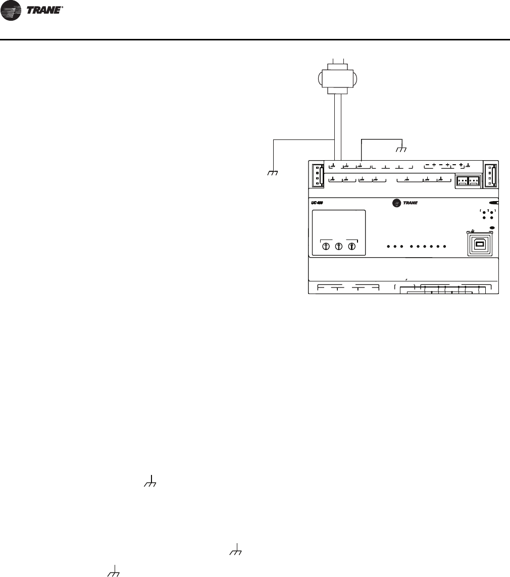
Wired Controllers—Communication Wiring
76 UNT-SVX07D-EN
Transformer Recommendations
A 24Vac power supply must be used for proper operation
of the binary inputs, which requires 24Vac detection. In
addition, the spare 24Vac outputs may be used to power
relays and TRIACS.
• AC transformer requirements: UL listed, Class 2 power
transformer, 24Vac ±15%, device max load 24VA. The
transformer must be sized to provide adequate power
to the controller (12VA) and outputs (maximum 12VA
per binary output).
• CE-compliant installations: The transformer must be
CE marked and SELV compliant per IEC standards.
Wiring Requirements
To ensure proper operation of the UC400 controller, install
the power supply circuit in accordance with the following
guidelines:
• A dedicated power circuit disconnect switch must be
near the controller, easily accessible by the operator,
and marked as the disconnecting device for the
controller.
• 18 AWG (0.823 mm2) copper wire is recommended for
the circuit between the transformer and the controller.
Important: The controller must receive AC power from
a dedicated power circuit; failure to comply
may cause the controller to malfunction. DO
NOT run AC power wires in the same wire
bundle with input/output wires; failure to
comply may cause the controller to
malfunction due to electrical noise.
Connecting Wires
To connect the wires:
1. Disconnect power to the transformer.
2. Connect the 24Vac secondary wires from the
transformer to the 24Vac and terminals on the
UC400 controller (refer to the illustration below).
3. Do one of the following to ensure the controller is
adequately grounded:
•Connect a grounding pigtail at some point along the
secondary wire that runs between the controller
terminal and the transformer.
•Ground one of the terminals on the controller to
the enclosure (if the enclosure is adequately
grounded) or to an alternate earth ground.
.
Power ON Check
To perform a Power ON check:
1. Verify that the 24Vac connector and the chassis ground
are properly wired.
2. Remove the lockout/tagout from the line voltage power
to the electrical cabinet.
3. Energize the transformer to apply power to the UC400
controller.
4. Observe the UC400 controller when power is applied
to verify the power check sequence as follows:
a. The power LED lights red for 1 second
b. The power LED lights green
•If the sequence above is completed as described,
the controller is properly booted and ready for the
application code.
If the power LED flashes red, a fault condition exists.
VAC
24
XFRM VAC
24
VAC
24
BI
1
BI
2
BI
3
LINK IMC
+
24
VDC
BI4
AO1 BI
5
AO2 UI
1
UI
2
AI
3
AI
2
AI
1
AI
4
AI
5
P
1
P
2
CNCNO BO3
CNCNO BO2
CNCNO BO1 RELAYS
ADDRESS
TRIAC SUPPLY TRIACS
A
BO9BO8BO7BO6BO5
BO4
ABB
TX
RX
LINK IMC
SERVI
C
E
SERVICE TOOL
CONNECT AC POWER TO THE TRAIC SUPPLY TO POWER THE TRIACS
BO1 BO2 BO3 BO4 BO5 BO6 BO7 BO8 BO9
1
2
3
4
5
6
7
8
9
IM
C
1
IM
C
1
3
4
5
6
7
1
2
3
4
5
6
7
8
9
8
9
x1
A pigtail connection may be
necessary between earth ground
and/or enclosure ground if the
device is not grounded through
one leg of the transformer wiring.
Alternate ground method.
24Vac
transformer
UNT-SVX07_-EN.book Page 76 Friday, April 27, 2012 9:40 AM
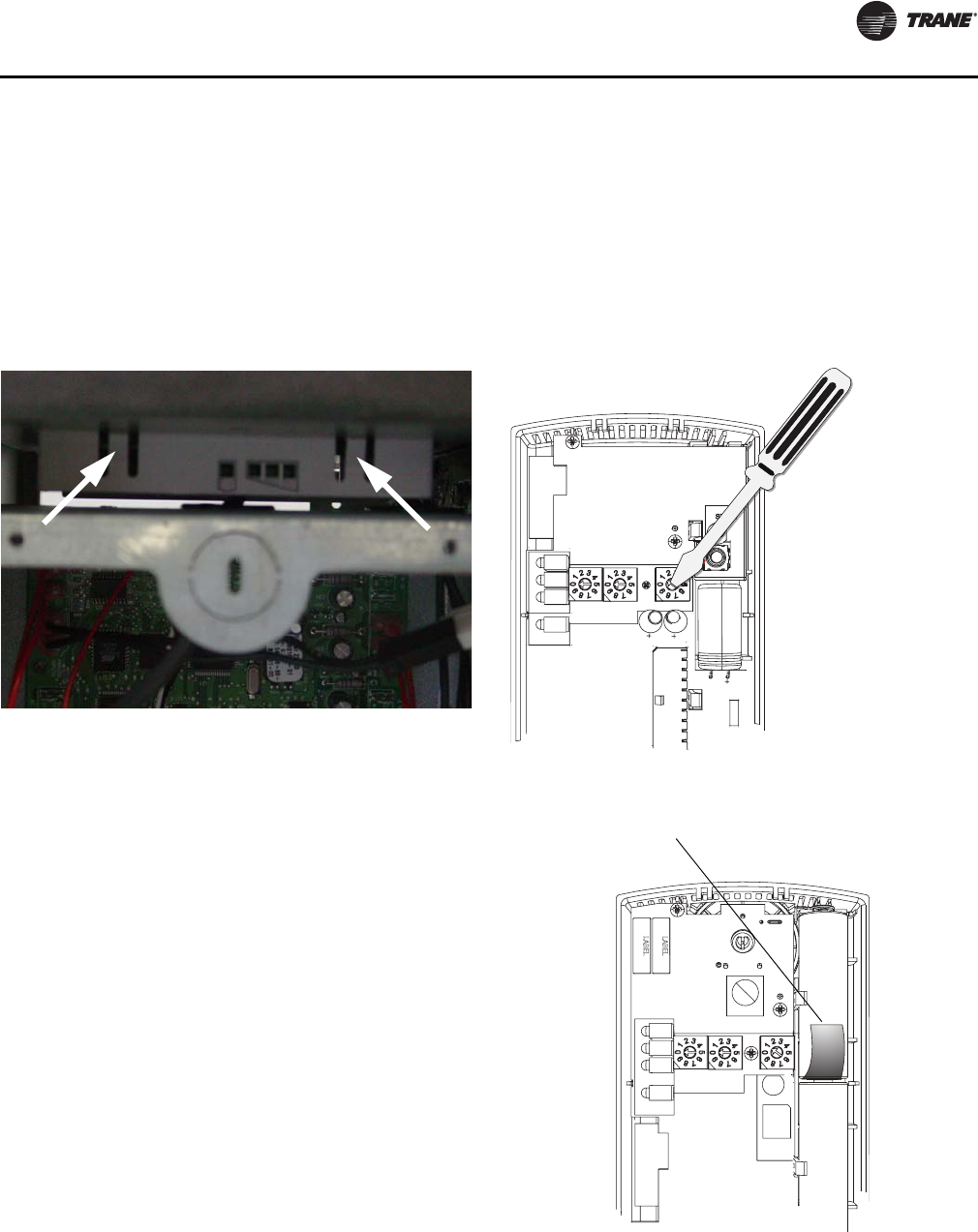
Wireless Sensors
UNT-SVX07D-EN 77
Wireless Sensors
Note: Receivers ship installed on the unit. To remove the
receiver, press in the retention tabs on the
underside of the receiver enclosure (see Figure 32)
and push upward.
Note: For more detailed information for wireless sensors,
please see BAS-SVX04E-EN
Address Setting
The process of establishing communication between a
receiver and sensor is referred to as association. The
following limitations apply:
• Each associated receiver/sensor set that
communicates within the reception range of the
wireless system must have a unique address.
It is not possible to associate more than one sensor to a
receiver, nor is it possible to associate more than one
receiver to a sensor.
To associate a receiver and sensor, the two devices must
have their rotary address switches set to the same
address.
Important: Set the addresses before applying power to
the receiver and before removing the
insulation strip (Figure 33) from the sensor.
To set the receiver and sensor addresses:
1. Using a small screwdriver, set the three rotary address
switches (locations S1, S2, S3) on the receiver to an
address between 001 and 999 (see Figure 33). You do
not have to remove the covers to access the rotary
address switches.
Note: Do not use 000 as an address. An address of
000 returns the receiver outputs to their factory
defaults (zone temperature and setpoint
outputs: 72.5°F, removes all association
knowledge, and prevents association with a
sensor.
2. Set the three rotary address switches (locations S1, S2,
S3) on the sensor to the same address as the receiver
(see Figure 33).
Figure 32. Retention tabs on underside of receiver
enclosure
Figure 33. Setting the rotary address switches on the
receiver and the sensor
S5
GND
R77
C35
S1 S2
C33
LED4
S4
S5
S3
LED1
LED2
LED3
LED5
C34
J1
COMM -
24VAC/DC
SETPOINT
HEATING SET
SIGNAL
POWER
ADDDRESS
FAN/SYSTEM
ZONE
COMM +
INSTALL
WIRELESS
GND
LED3
LED2
L
T
A
L
L
L
E
S
S
L
T
A
A
L
E
Receiver
DRESS
IN
B1 +
INSTALL
WIRELESS
S4
S3
S2
S1
ADDRESS
STATUS
BATTERY
LED5
SIGNAL
LED3
LED2
LED1
Pb
Pb-FREE
STATUS
LED4
Do not remove the
insulation strip yet.
Sensor
UNT-SVX07_-EN.book Page 77 Friday, April 27, 2012 9:40 AM
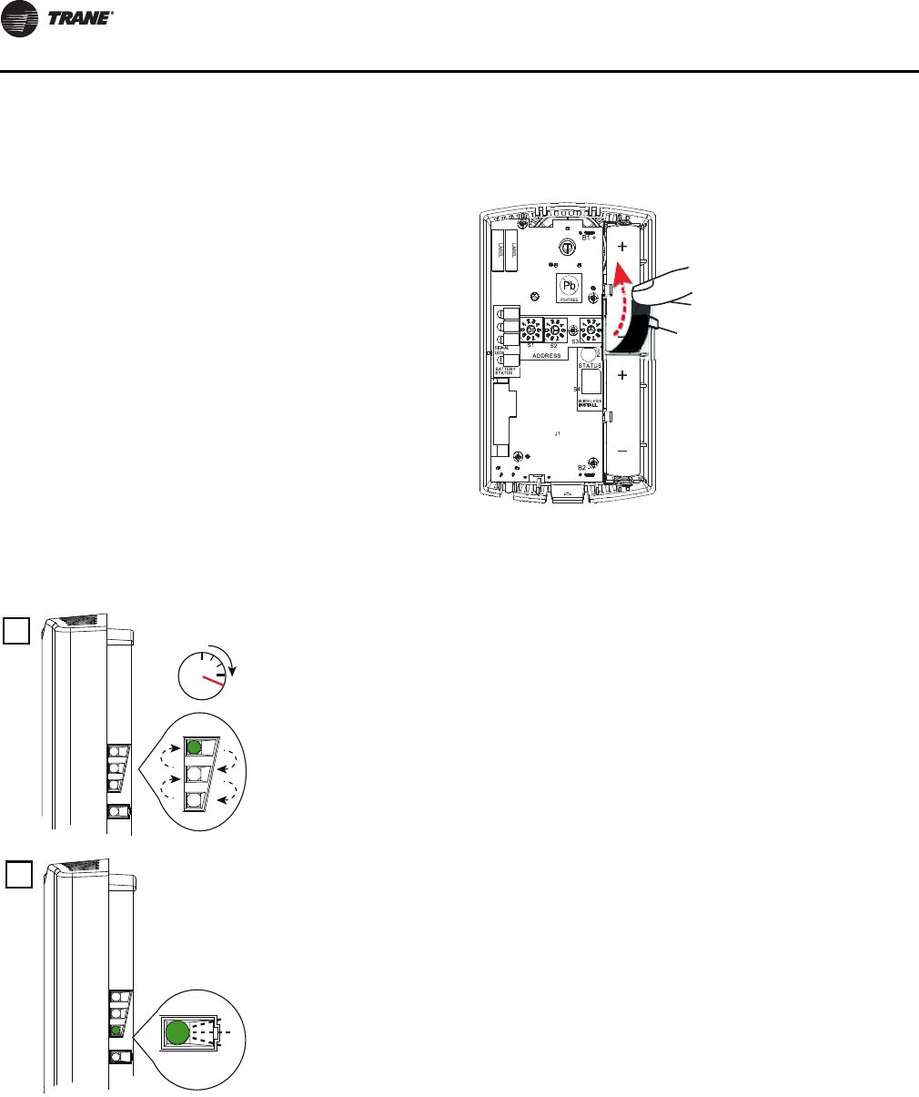
Wireless Sensors
78 UNT-SVX07D-EN
Note: Do not use 000 as an address. An address of
000 removes all association knowledge, reverts
the sensor to a low-power hibernation mode,
and sends a disassociation request to the
receiver.
3. Record the address and location of the receiver and
sensor pair.
Observing the Receiver for Readiness to
Associate
After initial power up, the receiver conducts a channel scan
for 20 seconds. During this time, the receiver selects from
16 available channels the clearest channel on which to
operate. LED1, LED2, and LED3 flash rapidly in succession
(round-robin style) while the channel scan is in progress,
as shown in part 1 of the illustration.
Important: Do not attempt association (leave the
insulation strip in place) until the channel
scan is finished.
After the channel scan is finished, LED3 begins blinking
(one-blink pattern) to show that the receiver is ready to be
associated with a sensor (see part 2 of the following
figure).
Associating the Sensor to the Receiver
To associate the sensor to the receiver:
1. Remove the sensor cover by firmly pressing the thumb
tab at the bottom of the cover and pulling the cover
away from the back plate.
2. Verify that the sensor is set to the same address as the
receiver it is to be associated with.
3. Power the sensor by removing the insulation strip from
between the two batteries.
Association is automatically initiated between the sensor
and the receiver. When LED3 on the receiver stops
blinking, association has been established.
If the first association attempt is unsuccessful, the sensor
automatically re-attempts association with the receiver
every 10 minutes.
Note: An associated sensor that has lost communication
with the receiver will transmit an association
request every 50 minutes. You can manually
initiate association (see “Manual Association
(Wireless Controls),” p. 120”).
Testing Signal Strength and Battery Status
To verify that the association process was successful and
that the batteries have adequate charge:
1. Firmly press and release the Test button on the bottom
of the sensor (as illustrated below).
2. For model WZS, view LED1, LED2, and LED3 to
determine the signal strength. View LED5 to determine
the battery status (see the following figure for model
WZS sensors).
Note: The LEDs will turn Off after 5 seconds to
conserve battery strength.
For model WDS, determine the signal strength and
battery status by viewing the symbols on the sensor
display (see the following figure for model WDS
sensors).
3. Record the results in your commissioning statement.
Note: For more information, see “Testing Signal Strength
(Wireless Controls),” p. 118 and “Testing Battery
Status (Wireless Controls),” p. 118.
10
20
Sec.
2
LED3
UNT-SVX07_-EN.book Page 78 Friday, April 27, 2012 9:40 AM
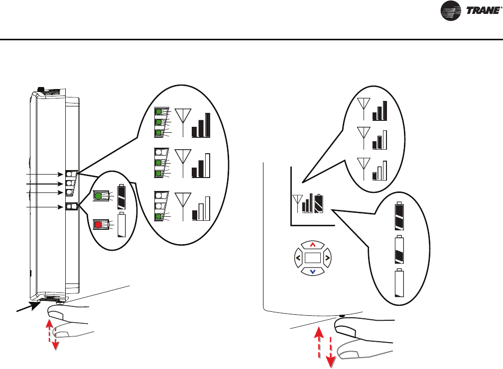
Wireless Sensors
UNT-SVX07D-EN 79
Configuring the Wireless Display Sensor
(Model WDS only)
Note: Sensors shipped with the fan-coil are pre-
configured for three speeds.
The configuration of the sensor determines which system
features can be accessed and changes can be made by the
tenant (for example, changes to cooling/heating mode,
setpoint, or fan speed. Verify system and associated unit
features before configuring the sensor.
The building owner or operator may choose to limit tenant
access to certain features. This can be done through
configuration. Or, if a sensor is configured to match all
control capabilities of the building automation system, the
locking feature can be used to restrict the tenant from
making changes.
Configuration Procedure
To configure settings on the model WDS sensor, follow
this procedure in the order presented.
1. Press the configuration button for 3 seconds.
LED1
LED2
LED3
LED5
Model WZS sensor
Push firmly,
then release
Test button
Model WDS sensor
Test button
Push firmly,
then release
UNT-SVX07_-EN.book Page 79 Friday, April 27, 2012 9:40 AM
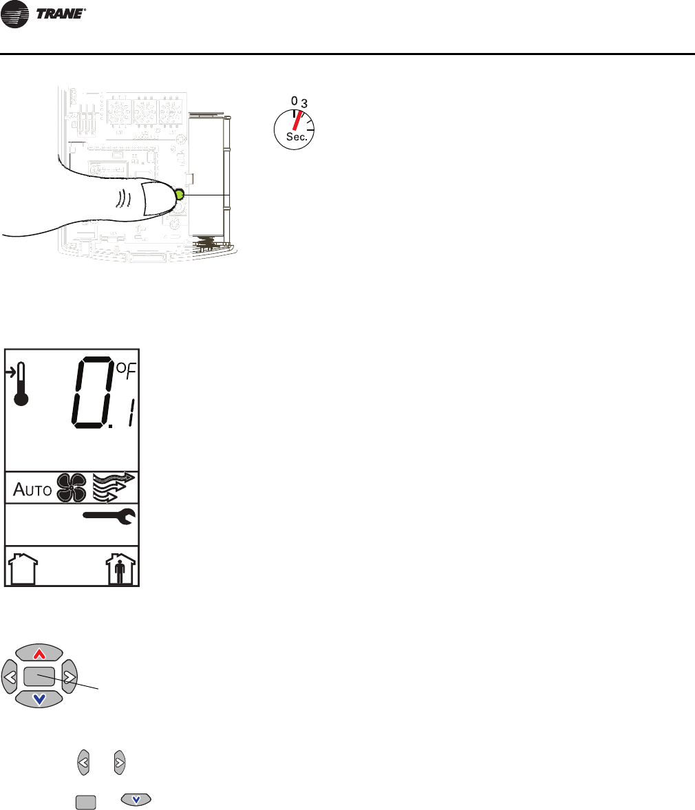
Wireless Sensors
80 UNT-SVX07D-EN
The display will change to configuration mode. When the
sensor is in configuration mode, a wrench symbol appears
on the display and the menus are separated by lines, as
illustrated below.
2. Press the center button on the keypad to begin the
configuration process.
3. Configure the sensor options in the order shown in the
table.
•Press or to scroll to the next selection (as
illustrated).
•Press or to move to the next menu (as
illustrated).
Configuration
button
Center button
UNT-SVX07_-EN.book Page 80 Friday, April 27, 2012 9:40 AM
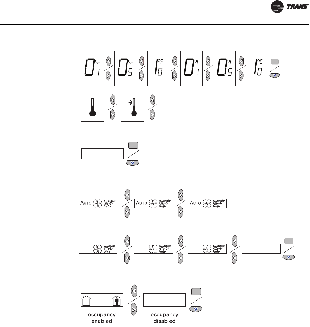
Wireless Sensors
UNT-SVX07D-EN 81
4. Review the display to ensure that you have selected the
correct configuration.
5. To return the display to operating mode, press the
configuration button (see Step 1, p. 79).
Note: The sensor will revert to operating mode if no
buttons are pressed for 10 minutes.
Optional Features
Displaying Setpoint or Temperature. You can
configure the sensor to display either the temperature
(default) or setpoint. To select either option:
1. Verify that the sensor is in operating mode and at the
home screen.
2. Press the up and down arrows for 3 seconds. The arrow
indicates setpoint display, as shown in the figure.
Setting Configuration Options
Temperature
• Choose Fahrenheit or Celsius
• Choose the degree resolution
(whole degrees, half degrees, or
tenths of degrees).
Setpoint
System
Fan
Note: Not all fan options are available
for all systems.
Occupancy (timed override)
. . .
.
.
.
dual setpoint
no
setpoint
single
setpoint
no system
options enabled
auto/off/low
med/high
auto/off/
low/high
auto/off
off/high (on) off/low/high off/low/
med/high
no fan options
enabled
(Default)
UNT-SVX07_-EN.book Page 81 Friday, April 27, 2012 9:40 AM
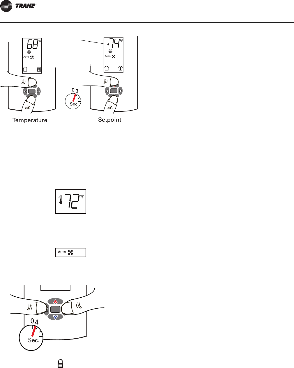
Wireless Sensors
82 UNT-SVX07D-EN
Locking or Unlocking Settings. You can lock or unlock
the setpoint, system, or fan setting to prevent changes.
To lock or unlock a setting:
1. Verify that the sensor is in operating mode and at the
home screen.
2. Choose a setting to lock or unlock:
•Select the setpoint by pressing the up or down
arrow.
•From the system menu press the down arrow to
select the fan menu. Use the left or right arrow to
choose the setting.
3. Press the left and right arrows for 4 seconds.
Note: If you try to access a feature that is locked, the
locked symbol will appear on the display.
If you press a keypad button to try change a locked
setting, the locked symbol will flash.
Sensor Operations
Temporary Occupancy (Timed Override)
Temporary occupancy (timed override) is available on
model WDS. Temporary occupancy is selected for after-
business-hours adjustment of temperature setting, fan
settings, or heat/cool settings, when the system has
changed to unoccupied mode. System control will revert
to unoccupied after a pre-determined time period.
Note: Not all systems support the occupancy function.
Model WDS Sensor
To request and cancel temporary occupancy on a model
WDS sensor, see “Requesting Temporary Occupancy,”
p. 83.
End-of-Range Temperature Values
Receiver: The end-of-range temperature limits of the
receiver for all models are 32°F to 122°F. The receiver
cannot replicate temperature values outside this range. If
the sensor transmits a temperature value to the receiver
that is out of the receiver replication range, the receiver
will “freeze” the output at the end-of-range values. This
value will remain frozen until the transmitted temperature
moves to between the end-of-range temperature limits.
Sensor: The end-of-range temperature setpoint limits for
the model WDS sensor is 50°Fto 89.6°F.
Receiver Power-up Sequence
When power is applied to the receiver, one of the following
sequences occurs. The sequence is dependent on the
address setting and the association status of the receiver.
Address set to 000 and receiver is not associated
with a sensor
• LED5 is constantly On, indicating power is applied and
the receiver is functional.
• All models: Zone temperature and cooling setpoint
default to 72.5°F.
WDS only: The heating setpoint defaults to 70.5°F and
the fan/system output will be 2230 Ω (see “Output
Values—Failure and Default Modes of Operation
(Wireless Controls),” p. 121).
• Status LED3 will display a 2-blink pattern diagnostic
(Tabl e 45, p. 11 8 ).
Address set from 001 to 999 and receiver is not
associated with a sensor
• LED5 is constantly On, indicating power is applied and
the receiver is functional.
• All models: Zone temperature and cooling setpoint
default to 72.5°F.
WDS only: The heating setpoint defaults to 70.5°F and
the fan/system output will be 2230 Ω (see “Output
Values—Failure and Default Modes of Operation
(Wireless Controls),” p. 121).
Arrow
indicates
setpoint is
shown on
display
Setpoint
Fan menu
UNT-SVX07_-EN.book Page 82 Friday, April 27, 2012 9:40 AM
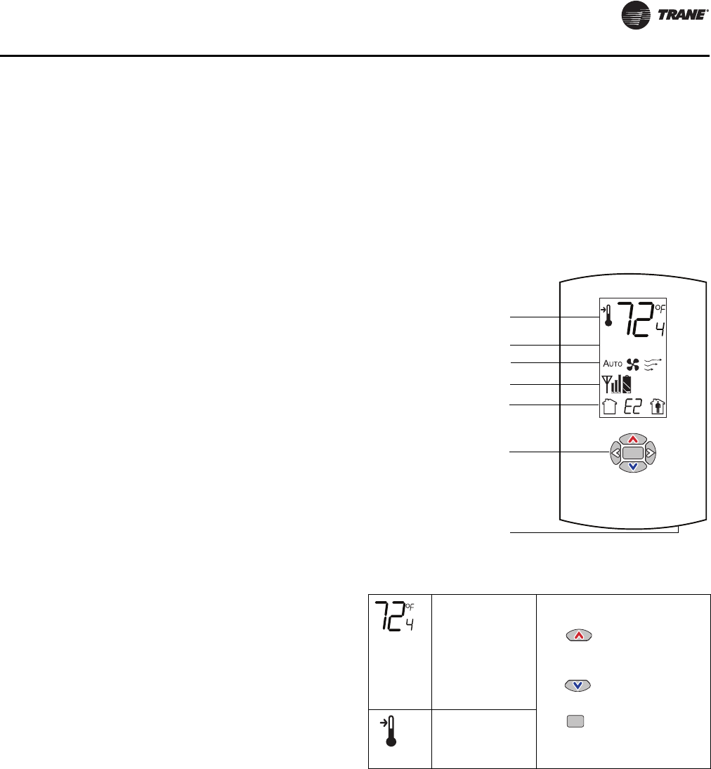
Wireless Sensors
UNT-SVX07D-EN 83
• The receiver conducts an energy scan for 20 seconds to
determine the clearest channel on which to operate.
• LED3 flashes On every 2 seconds when it is ready to
accept a sensor association request. When an
association request is made by a sensor, the receiver
instructs the sensor on which power level to operate.
Then the receiver and sensor begin operation at the
appropriate channel and power level (see “Observing
the Receiver for Readiness to Associate,
” p. 78).
Address set from 001 to 999 (and not changed since
most recent power-up) and receiver is associated
with a sensor
• LED5 is constantly On, indicating power is applied and
the receiver is functional.
• Zone temperature and setpoint default to 72.5°F. WDS
only: Heating setpoint defaults to 70.5°F, Fan = Auto,
System = Off.
• The receiver waits for a broadcast transmission from
its associated sensor. When a transmission is received,
the receiver positions its zone temperature and
setpoint outputs appropriately.
• If the receiver does not receive a communicated signal
from its associated sensor within 35 minutes, zone
temperature and setpoint outputs fail, generating a
unit controller alarm (see “Output Values—Failure and
Default Modes of Operation (Wireless Controls),”
p. 121).
Note: Once a receiver communicates to a WZS sensor,
the receiver disables (opens) its zone setpoint
output indefinitely.
Sensor Transmission Time and Temperature
Variables
Sensor transition time variables are as follows:
• The maximum time between sensor temperature
transmissions is 15 minutes.
• The minimum time between sensor temperature
transmissions is 30 seconds.
• The minimum time for transmitting temperature
setpoint changes is 10 seconds.
Note: If a sensor transmits a message to the receiver and
the receiver does not reply, the sensor will
retransmit the message to the receiver every 30
seconds until communication to the receiver is re-
established.
Sensor temperature time variables are as follows:
• The minimum change in zone temperature required to
force a sensor transmission is:
– 0.2°F when the temperature range is between 60°F
and 80°F
– 0.5°F when the temperature range is between 32°F
and 60°F or between 80°F and 122°F
• The minimum change in temperature setpoint
required to force a sensor transmission is:
– 0.1°C for a model WDS sensor
Operating Mode (Model WDS)
This section describes how to operate the Trane wireless
sensor, model WDS. Figure 34 shows an example of a
model WDS that has been configured and is in operating
mode.
Changing Room Temperature
Changing Heating and Cooling Room Temperature
Settings (applies to some systems)
Changing the Fan Setting
Requesting Temporary Occupancy
Error Codes
Lock Symbol
Figure 34. Wireless sensor (model WDS) in operating
mode
This symbol
shows the
current room
temperature, or
your setpoint
selection while
you are making
an adjustment.
1. To increase the room
temperature, press
.
To decrease the room
temperature, press
.
2. To confirm, press
or wait 5 seconds.
The display will return
to the home screen.
When you select
a setpoint, this
symbol
appears.
.
Keypad
Test button
Test symbols (appear only
when Test button is pushed
Occupancy
indicator/Error code
Temperature
System settings (not available for
fan-coil or Force-Flo units)
Fan settings
.
UNT-SVX07_-EN.book Page 83 Friday, April 27, 2012 9:40 AM
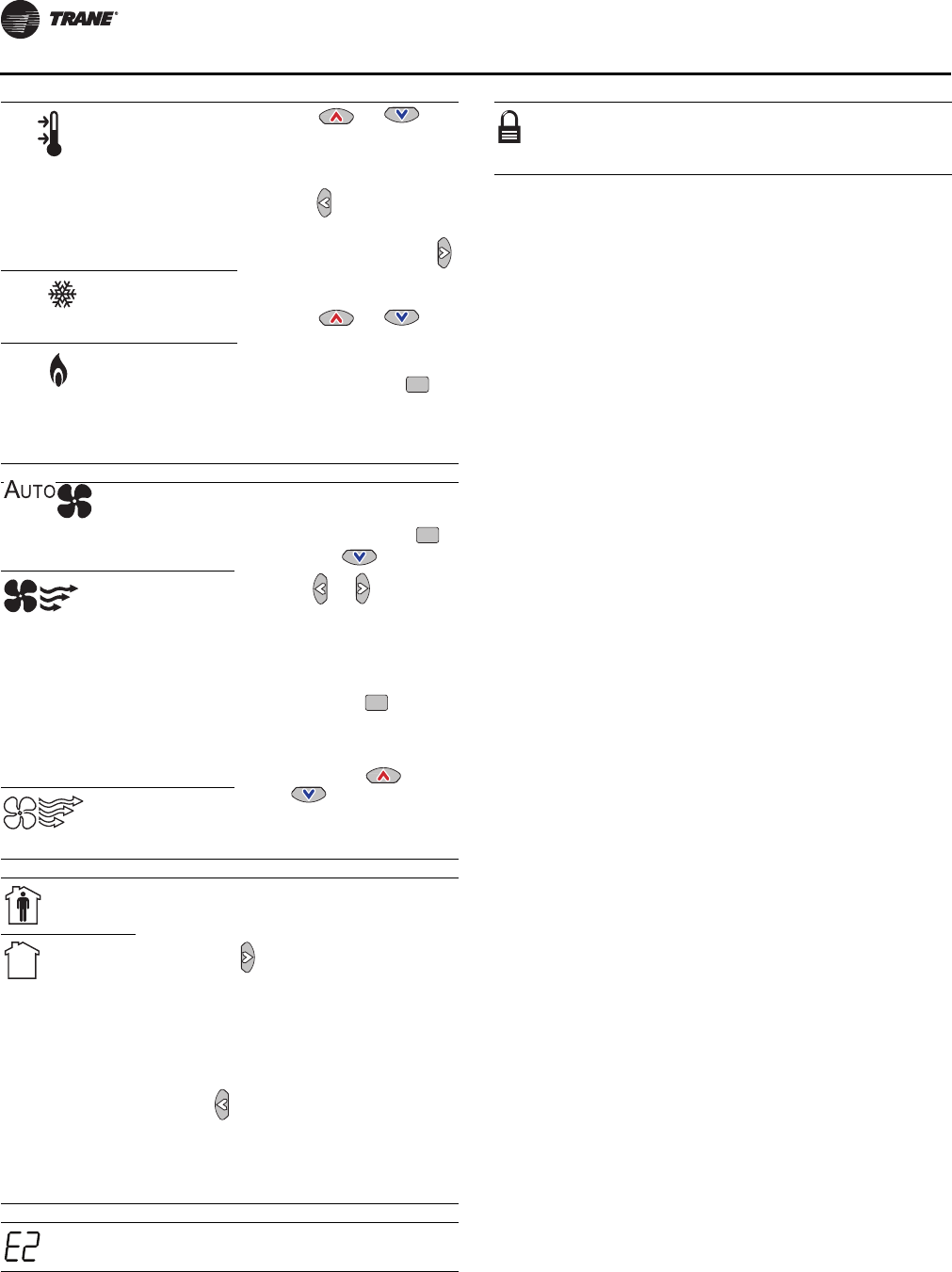
Wireless Sensors
84 UNT-SVX07D-EN
Some systems allow
you to select both
heating and cooling
room temperature
settings. If your
system has this
option, this symbol
appears when you
adjust the
temperature setting.
1. Press or to
select the heating/
cooling setting.
2. If in cooling mode,
press to change to
heating mode. If in
heating mode, press
to change to cooling
mode.
3. Press or to
select the heating/
cooling setting.
4. To confirm, press or
wait 5 seconds. The
home screen will
appear.
When you adjust the
cooling setting, the
top arrow and
snowflake flash.
When you adjust the
heating setting, the
bottom arrow and
flame flash.
Indicates that the
fan will operate as
needed to reach
the selected
temperature.
1. From the home screen,
activate the fan setting
menu by pressing
and then .
2. Press or to choose
the desired fan setting.
3. When the symbol for the
desired setting appears,
confirm your choice by
•Pressing (the
home screen will
appear), or
•Pressing or
(the next menu
will appear), or
•Waiting five seconds.
Indicates that the
fan setting is On.
The number of
arrows indicates
fan speed
(3: high, 2:
medium, 1: low).
The example
shown indicates a
fan on high speed.
Not all systems
offer all three
speeds.
Indicates that the
fan setting is Off.
Select to
request
occupancy
• If you need heating or cooling after
normal business hours, you can
“request” temporary occupancy by
pressing and holding it for
2 seconds. The occupied symbol
remains on the screen and the
unoccupied symbol disappears.
After 30 seconds, the unoccupied
symbol will re-appear.
• To cancel temporary occupancy,
press and hold for 2 seconds. The
unoccupied symbol will remain on
the screen and the occupied symbol
will disappear. After 30 seconds, the
occupied symbol will re-appear.
Select to
cancel
occupancy
Indicates an
error code If an error code (E0–E7) is displayed,
technical assistance may be required.
Indicates
that a
setting is
locked
The lock symbol appears if you try to
adjust a setting that cannot be
changed.
UNT-SVX07_-EN.book Page 84 Friday, April 27, 2012 9:40 AM
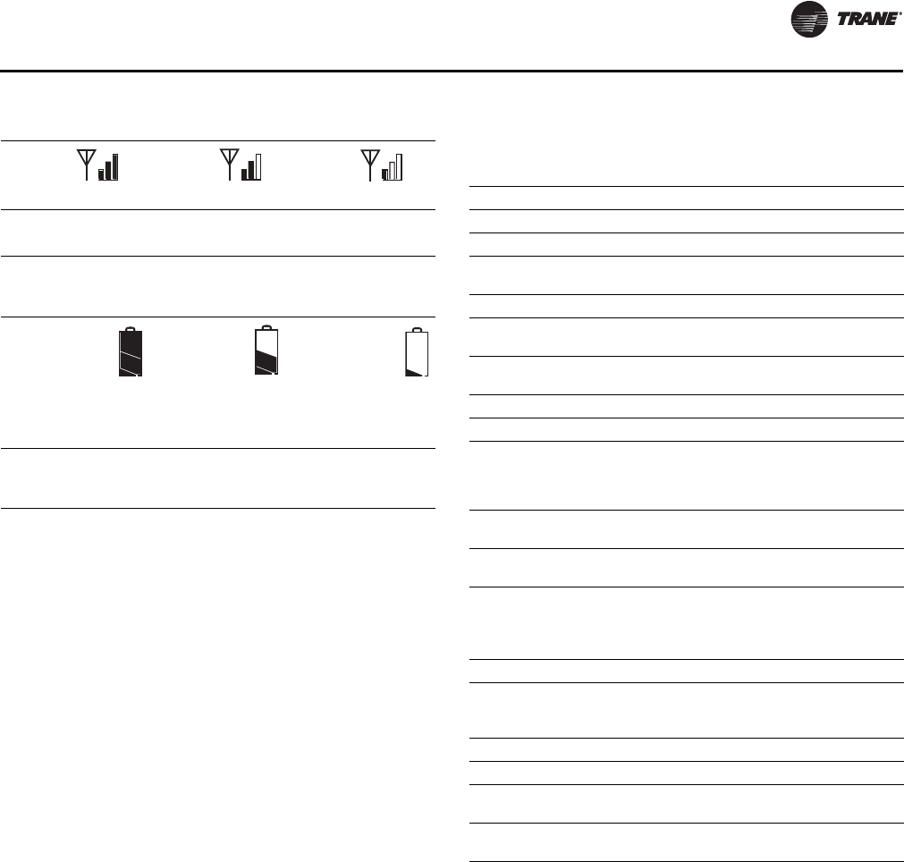
Wireless Sensors
UNT-SVX07D-EN 85
Testing Signal Strength
Testing Battery Status
Wireless Sensor Specifications
The following table presents specifications for all models
of the wireless sensor sets.
Indicates
excellent
signal
strength
Indicates
satisfacto
ry signal
strength
Indicate
s poor
signal
strength
Press the Test button to display the signal strength
symbols.
Indicates full
battery power Indicates
50% of
battery life
left.
Indicates 25%
of battery life
left. Replace
batteries.
Flashing symbol
indicates that
approximately 14 days
of operation remain.
Press the Test button to display the battery status symbols.
Use only UL-listed non-rechargeable 1.5 V lithium AA
batteries (Trane p/n X13770035010 or equivalent).
Sensor operating temperature 32°F to 122°F
Receiver operating temperature -40°F to 158°F
Storage temperature -40°F to 185°F
Storage and operating humidity
range 5% to 95%, non-condensing
Accuracy 0.5°F over a range of 55ºF to 85°F
Resolution 0.125°F over a range of 60°F to 80°F
0.25°F when outside this range
Setpoint functional range (WDS
only) 50°F to 89.6°F
Receiver voltage 24 V nominal ac/dc ±10%
Receiver power consumption <1 VA
Housing Polycarbonate/ABS blend, UV
protected, UL 94-5VA flammability
rating, suitable for application in a
plenum
Mounting 3.24 in (8.26 cm) for 2 mounting
screws (supplied)
Sensor battery (2) AA, 1.5 V, 2800 mAh, lithium,
5-year life, UL listed
Range(a)
(a) Range values are estimated transmission distances for satisfactory op-
eration. Actual distance is job specific and must be determined during
site evaluation.
Open range: 2,500 ft (762 m)
(packet error rate = 2%)
Usable: 200 ft (61 m)
Typical: 75 ft (23 m)
Output power 100 mW
Radio frequency 2.4 GHz (IEEE Std 802.15.4-2003
compliant)
(2405 to 2480 MHz, 5 MHz spacing)
Radio channels 16
Address range 000 to 999
Minimum time between
transmissions 30 seconds
Maximum time between
transmissions 15 minutes
UNT-SVX07_-EN.book Page 85 Friday, April 27, 2012 9:40 AM
Wireless Sensors
86 UNT-SVX07D-EN
The following table presents agency compliance
information for wireless sensor set models as shown.
United States compliance
(all models)
UL listed: UL 94-5VA Flammability rating
UL 916: Energy management equipment
FCC CFR47, Section 15.247 & Subpart E Digital Modulation Transmission with no SAR (FCC Identification TFP-
13651127)
This device complies with Part 15 of the FCC Rules.
Operation is subject to the following two conditions:
1. This device may not cause harmful interference, and
2. This device must accept any interference received,
including interference that may cause undesired operation.
Warning:
Changes or modifications not expressly approved by the party responsible for compliance could void the
user’s authority to operate the equipment.
20 cm separation distance:
To comply with FCC’s RF exposure limits for general population/uncontrolled exposure, the antenna(s) used
for this transmitter must be installed to provide a separation distance of at least 20 cm from all persons and
must not be co-located or operating in conjunction with any other antenna or transmitter.
Canada compliance
(all models)
CSA22.2 No. 205-M1983 Signal Equipment
Industry Canada (Certification no: IC: 6178A-13651127)
Industry Canada statement:
the term “IC” before the certification/registration number signifies only that the Industry Canada technical
specifications were met.
Section 14 of RSS-210:
The installer of this radio equipment must ensure that the antenna is located or pointed such that it does
not emit RF field in excess of Health Canada limits for the general population.
IEEE compliance for radio
frequency range
(all models)
IEEE 802.15.4-2003, IEEE Standard for Information Technology—Telecommunications and information
exchange between systems—Local and metropolitan area networks—Specific requirements, Part 15.4:
Wireless Medium Access Control (MAC) and Physical Layer (PHY) Specifications for Low Rate Wireless
Personal Area Networks (LR-WPANs)
UNT-SVX07_-EN.book Page 86 Friday, April 27, 2012 9:40 AM
UNT-SVX07D-EN 87
Pre-Start
Pre-Startup Checklist
Complete this checklist after installing the unit to verify all
recommended installation procedures are complete
before unit startup. This does not replace the detailed
instructions in the appropriate sections of this manual.
Disconnect electrical power before performing this
checklist. Always read the entire section carefully to
become familiar with the procedures.
Receiving
Unit Location
1. Ensure the unit location is adequate for unit
dimensions, ductwork, piping, and electrical
connections.
2. Ensure access and maintenance clearances around the
unit are adequate.
Unit Mounting
1. Ensure unit is installed level.
Component Overview
1. Ensure the fan rotates freely in the correct direction.
2. Ensure all unit access panels and air grilles are in place.
3. Verify that a clean air filter is in place.
4. Properly set the damper position to meet the fresh air
requirement.
Unit Piping
1. Properly vent the hydronic coil to allow water flow
through the unit.
2. Units with deluxe piping package: Tighten unions
adequately.
3. Set water flow to the unit properly if unit piping has the
circuit setter valve.
4. Check strainers (if supplied) for debris after apply
system water.
5. Install the auxiliary drain pan and route the main drain
pan hoses to the auxiliary drain pan on vertical fan-coil
units.
6. Verify the condensate drain piping is complete for the
unit drain pan.
7. Ensure the drain pan and condensate line are not
obstructed. Remove any foreign matter that may have
fallen into the drain pan during installation.
Electrical
Note: Some circumstances may require the unit to run
before building construction is complete. These
operating conditions may be beyond the design
parameters of the unit and may adversely affect the
unit.
WARNING
Hazardous Voltage w/Capacitors!
Disconnect all electric power, including remote
disconnects and discharge all motor start/run
capacitors before servicing. Follow proper lockout/
tagout procedures to ensure the power cannot be
inadvertently energized. For variable frequency drives
or other energy storing components provided by Trane
or others, refer to the appropriate manufacturer’s
literature for allowable waiting periods for discharge of
capacitors. Verify with an appropriate voltmeter that all
capacitors have discharged. Failure to disconnect
power and discharge capacitors before servicing could
result in death or serious injury.
For additional information regarding the safe discharge of
capacitors, see PROD-SVB06A-EN
Inspect unit and components for shipping damage. File
damage claims immediately with the delivering carrier.
Check unit for missing material. Look for ship-with
options and sensors that may be packaged separately
from the main unit (see “Receiving and Handling,”
p. 10).
Check nameplate unit data so that it matches the sales
order requirements.
Check all electrical connections for tightness.
UNT-SVX07_-EN.book Page 87 Friday, April 27, 2012 9:40 AM
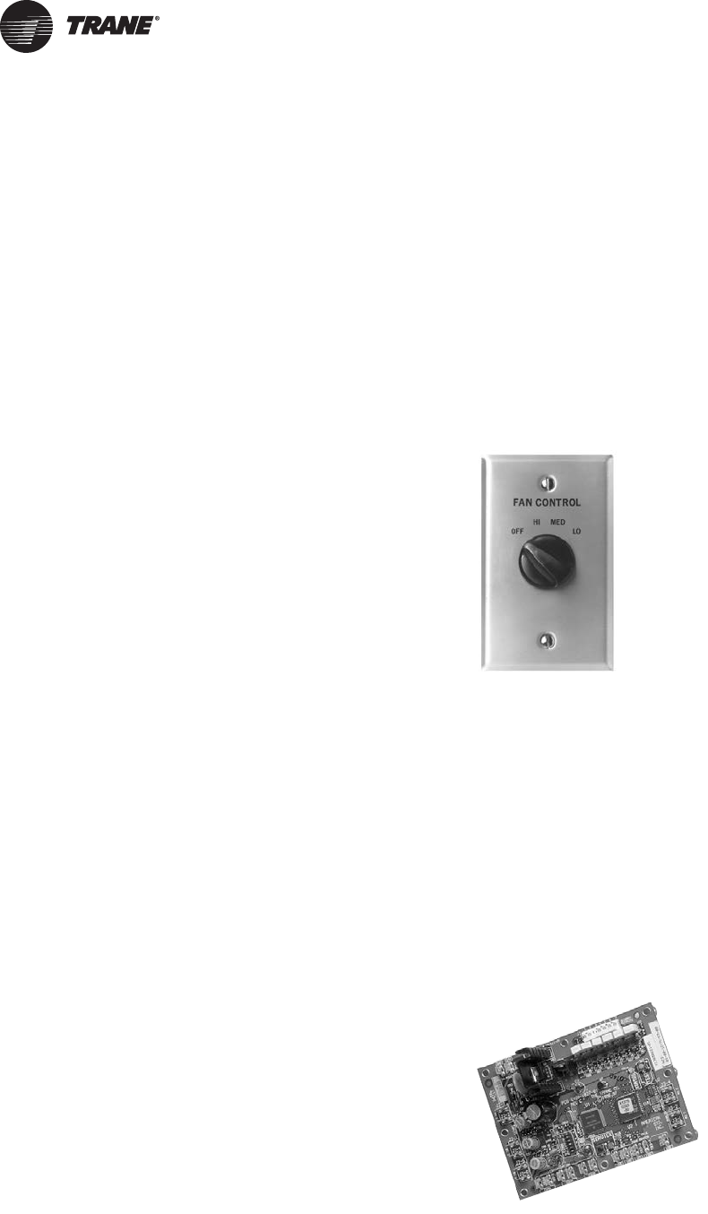
88 UNT-SVX07D-EN
Startup
Tracer ZN510 and ZN520 Unit Startup
Refer to the Trane publication, CNT-IOP-1 (ComfortLink 10
Controller: Installation, Operation and Programming
Guide) for Tracer ZN510 and CNT-SVX04A-EN for Tracer
ZN520. The factory pre-programs the Tracer ZN510 and
ZN520 with default values to control the temperature and
unit airflow. Use Tracer Summit building automation
system or Rover™ software to change the default values.
Follow the procedure below to operate the Tracer ZN510 or
ZN520 in a stand-alone operation:
1. Turn power on at the disconnect switch option.
2. Position the fan mode switch to either high, medium,
low, or the auto position.
3. Rotate the setpoint dial on the zone sensor module to
55°F for cooling or 85°F for heating.
The appropriate control valve will actuate assuming the
following conditions:
1. Room temperature should be greater than 55°F and
less than 85°F.
2. For a 2-pipe fan-coil unit with an automatic changeover
sensor, the water temperature input is appropriate for
the demand placed on the unit. For example, cooling
operation is requested and cold water (5° lower than
room temperature) flows into the unit.
3. Select the correct temperature setpoint.
Note: Select and enable zone sensor temperature
settings to prevent freeze damage to unit.
Tracer UC400 Unit Startup
Refer to the Trane publication, Installation, Operation, and
Programming Guide for Factory or Field-installed Blower
Coil and Fan Coil (BAS-SVX48A-EN, or the most recent
revision) for Tracer UC400 Fan Coil. The factory pre-
programs the Tracer UC400 Fan Coil with default values to
control the temperature and unit airflow. Use Tracer SC
building automation system or Tracer TU™ software to
change the default values.
Follow the procedure below to operate the Tracer UC400 in
a stand-alone operation:
1. Turn power on at the disconnect switch option.
2. Position the fan mode switch to either high, medium,
low, or the auto position.
3. Rotate the setpoint dial on the zone sensor module to
55°F for cooling or 85°F for heating.
The appropriate control valve will actuate assuming the
following conditions:
1. Room temperature should be greater than 55°F and
less than 85°F.
2. For a 2-pipe fan-coil unit with an automatic changeover
sensor, the water temperature input is appropriate for
the demand placed on the unit. For example, cooling
operation is requested and cold water (5° lower than
room temperature) flows into the unit.
3. Select the correct temperature setpoint.
Note: Select and enable zone sensor temperature
settings to prevent freeze damage to unit.
General Information
Manual Fan Speed Switch
The manual fan mode switch is available with a four-
position switch (off-hi-med-lo) allows manual fan mode
selection and is available unit- or wall-mounted. See
Figure 35.
The fan speed switch can be used to provide simultaneous
fan speed customer requests in addition to external
controller fan speed request. The wall-mounted option is
low-voltage and has three 24-volt relays using a factory-
wired transformer and relays to control the fan motor.
Tracer ZN010 and ZN510
Tracer ZN010 is a stand-alone device that controls fan-coils
and cabinet heaters. Tracer ZN510 can be stand-alone or
use peer-to-peer communications.
The controller is easily accessible in the control end panel
for service. The control end panel is on the end of the unit
opposite the piping. See Figure 36.
Figure 35. Fan speed switch
Figure 36. Tracer ZN010 board
UNT-SVX07_-EN.book Page 88 Friday, April 27, 2012 9:40 AM

Startup
UNT-SVX07D-EN 89
Fan Mode Switch Operation
Off
Fan is turned off, two-position damper option spring-
returns closed.
Hi, Med, Lo
Fan runs continuously at the selected speed. The two-
position damper option opens to an adjustable
mechanical stop position.
Tracer ZN010 & ZN510 Operation
Off
Fan is off; control valves and fresh air damper option close.
Low air temperature detection option is still active.
Auto (Fan Cycling)
Fan and fresh air damper cycle with control valve option to
maintain setpoint temperature. In cooling mode, the fan
cycles from off to medium and in heating mode it cycles
from off to low. When no heating or cooling is required, the
fan is off and the fresh air damper option closes.
Low/Med/High (Continuous Fan)
Fan operates continuously while control valve option
cycles to maintain setpoint temperature. Fresh air damper
option is open.
Tracer ZN520 Operation
Off
Fan is off; control valve options and fresh air damper
options close. The low air temperature detection option is
still active.
Auto
Fan speed control in the auto setting allows the
modulating (3-wire floating point) or 2–position control
valve option and three-speed fan to work cooperatively to
meet precise capacity requirement, while minimizing fan
speed (motor/energy/acoustics ) and valve position (pump
energy, chilled water reset ). As the capacity requirement
increases at low fan speed, the water valve opens. When
the low fan speed capacity switch point is reached, the fan
switches to medium speed and the water valve repositions
to maintain an equivalent capacity. The reverse sequence
takes place with a decrease in required capacity.
Low/Med/High
The fan runs continuously at the selected speed and the
valve option will cycle to meet setpoint.
UC400 Controller Operation
Off
Fan is off; control valve options and fresh air damper
options close. The low air temperature detection option is
still active.
Auto
Fan speed control in the auto setting allows the
modulating (3-wire floating point) or 2-position control
valve option and 1-, 2-, 3- or variable-speed fan to work
cooperatively to meet precise capacity requirement, while
minimizing fan speed (motor/energy/acoustics) and valve
position (pump energy, chilled water reset). As the
capacity requirement increases, the water valve opens.
When the fan speed capacity switch points are reached,
the fan speed ramps up and the water valve repositions to
maintain an equivalent capacity. The reverse sequence
takes place with a decrease in required capacity.
Low/Med/High
The fan runs continuously at the selected speed and the
valve option will cycle to meet setpoint.
Sequence of Operation: Tracer
ZN010 and ZN510
Note: This section applies only to units with a Tracer
ZN010 or ZN510 controller.
Power-Up Sequence (Tracer ZN010 and ZN510)
When 24 Vac power is initially applied to the Tracer ZN010
or ZN510, the following sequence occurs:
1. All outputs are controlled off.
2. Tracer ZN010 and ZN510 reads all input values to
determine initial values.
3. The random start time (0-25 seconds) expires.
4. Normal operation begins.
Entering Water Temperature Sampling
Function (Tracer ZN010 and ZN510)
Both Tracer ZN010 and ZN510 use an entering water
temperature sampling function to test for the correct water
temperature for the unit operating mode. For all
applications not involving changeover, the water
temperature does not affect unit operation.
The entering water temperature sampling function opens
the main hydronic valve, waits no more than three minutes
to allow the water temperature to stabilize, then measures
the entering water temperature to see if the correct water
temperature is available.
The entering water must be five degrees or more above
the space temperature to allow hydronic heating and five
degrees or more below the space temperature to allow
hydronic cooling.
UNT-SVX07_-EN.book Page 89 Friday, April 27, 2012 9:40 AM

Startup
90 UNT-SVX07D-EN
If the correct water temperature is available, the unit
begins normal heating or cooling operation. If the
measured entering water temperature is too low or high,
the controller closes the valve and waits 60 minutes before
attempting to sample the entering water. Refer to Tab le 19.
Binary Inputs (Tracer ZN010 and ZN510)
BIP1: Low Temperature Detection Option
(Tracer ZN010 and ZN510)
The factory hard wires the low temperature detection
sensor to binary input #1 (BIP1) on the Tracer ZN010 and
ZN510. The sensor defaults normally closed (N.C.), and
will trip off the unit on a low temperature diagnostic when
detecting low temperature. In addition, the Tracer ZN010
and ZN510 control unit devices as listed below:
Fan: Off
Valves: Open
Electric heat: Off
Damper: Closed
Note: See “Diagnostics,” p. 112 for more information.
BIP2: Condensate Overflow Detection Option
(Tracer ZN010 and ZN510)
The factory hard wires the condensate overflow sensor to
binary input #2 (BIP2) on the Tracer ZN010 and ZN510. The
sensor defaults normally closed (N.C.), and will trip off the
unit on a condensate overflow diagnostic if condensate
reaches the trip point. In addition, the Tracer ZN010 and
ZN510 control unit devices as listed below:
Fan: Off
Valves: Closed
Electric heat: Off
BIP3: Occupancy Sensor (Tracer ZN010 and
ZN510)
Binary input #3 (BIP3) on Tracer ZN010 and ZN510 is
available for field-wiring an occupancy sensor, such as a
binary switch or a timeclock, to detect occupancy. The
sensor can be either normally open or normally closed.
Refer to Table 20.
Binary Outputs (Tracer ZN010 and ZN510)
Refer to Table 21 for the six binary outputs of Tracer ZN010
and ZN510.
Both Tracer ZN010 and ZN510 accept a maximum of five
analog inputs. Refer to Table 22, p. 90.
Table 19. Unit mode as related to water temperature
Unit Type
EWT
Sensor
Required? Coil Water Temperature
2-pipe changeover Yes COOLS if: Space temp - EWT ≥ 5°F
HEATS if: EWT - space temp ≥ 5°F
4-pipe changeover Yes COOLS if: Space temp - EWT ≥ 5°F
HEATS if: EWT - space temp≥ 5°F
2-pipe heating only No Hot water assumed
2-pipe cooling only No Cold water assumed
4 pipe (2 pipe heat
and 2 pipe cool) No Cold water assumed in main coil
Hot water assumed in aux. coil
Table 20. Occupancy sensor state table
Sensor Type Sensor Position Unit Occupancy Mode
Normally open Open Occupied
Normally open Closed Unoccupied
Normally closed Open Unoccupied
Normally closed Closed Occupied
Table 21. Binary outputs
Binary output Description Pin
BOP1 Fan high speed J1-1
BOP2 Fan medium speed J1-2
BOP3 Fan low speed J1-4
BOP4 Main valve J1-5
BOP5 Auxiliary valve/electric heat J1-6
BOP6 2-position fresh air damper J1-7
Notes:
1. In a four-pipe application, BOP4 is used for cooling and BOP5 is used
for heating.
2. If no valves are ordered with the unit, the factory defaults for the
Tracer ZN010 and ZN510 controller are:
BOP4 configured as normally closed
BOP5 configured as normally open
3. If the fresh air damper option is not ordered on the unit, BOP6 will be
configured as none.
Table 22. Analog inputs
Analog Input Description Application
Zone Space temperature Space temperature detection /
timed override detection
Set Local setpoint Thumbwheel setpoint
Fan Fan mode input Zone sensor fan switch
Analog input 1
(AI1) Entering water
temperature Entering water temperature
detection
Analog input 2
(AI2) Discharge air
temperature Discharge air temperature
detection
Notes:
1. 1.The zone sensor, entering water temperature sensor, and the
discharge air temperature sensor are 10 KΩ thermistors. Figure 43,
p. 117 provides the resistance-temperature curve for these
thermistors.
2. Zone sensor:
Wall-mounted sensors include a thermistor soldered to the sensor’s cir-
cuit board
Unit mounted sensors include a return air sensor in the unit’s return
air stream.
3. Changeover units include an entering water temperature sensor.
UNT-SVX07_-EN.book Page 90 Friday, April 27, 2012 9:40 AM
Startup
UNT-SVX07D-EN 91
Zone Sensors (Tracer ZN010 and ZN510)
The zone sensors available with the Tracer ZN010 and
ZN510 provide up to three different inputs
1. Space temperature measurement (10 KΩ thermistor)
2. Local setpoint
3. Fan mode switch
Wall-mounted zone sensors include a thermistor as a
component of the internal printed circuit board. Unit
mounted zone sensors use a sensor placed in the unit’s
return air stream.
Each zone sensor is equipped with a thumb wheel for
setpoint adjustment.
Fan Mode Switch (Tracer ZN010 and ZN510)
The zone sensor may be equipped with a fan mode switch.
The fan mode switch offers selections of off, low, medium,
high, or auto.
Supply Fan Operation (Tracer ZN010 and
ZN510)
Refer to Table 23 for fan mode operation. Tracer ZN010 and
ZN510 will operate in either continuous fan or fan cycling
mode. The fan cycles when the fan mode switch is placed
in auto. The fan runs continuous when placed in the high,
medium, or low position. Use Rover, Trane’s installation
and service tool, to change auto defaults.
Table 23. Fan mode operation
Heating Mode Cooling Mode
Fan mode Occupied Unoccupied Occupied Unoccupied
Off Off Off Off Off
Low Low Off/high(a)
(a)Whenever two states are listed for the fan:
The first state (off) applies when there is not a call for heating or cooling.
The second state (varies) applies when there is a call for heating or cool-
ing.
The heat default is factory configured for low fan speed, and the cool
default is medium.
Low Off/high(a)
Medium Medium Off/high(a) Medium Off/high(a)
High High Off/high(a) High Off/high(a)
Auto
Continuous Heat default Off/high(a) Cool default Off/high(a)
Cycling off/heat default Off/high(a) Off/cool
default Off/high(a)
Notes:
1. During the transition from off to any fan speed but high, Tracer ZN010
and ZN510 automatically starts the fan on high speed and runs for
three seconds before transitioning to the selected speed (if it is other
than high). This provides enough torque to start all fan motors from
the off position.
2. When the heating output is controlled off, Tracer ZN010 and ZN510
automatically controls the fan on for an additional 30 seconds. This
delay allows the fan to dissipate any residual heat from the heating
source, such as electric heat.
Table 24. Valid operating range and factory default
setpoints
Setpoint/parameter Default Setting Valid Operating Range
Unoccupied cooling setpoint 85°F 40°F to 115°F
Occupied cooling setpoint 74°F 40°F to 115°F
Occupied heating setpoint 71°F 40°F to 115°F
Unoccupied heating
setpoint 60°F 40°F to 115°F
Cooling setpoint high limit 110°F 40°F to 115°F
Cooling setpoint low limit 40°F 40°F to 115°F
Heating setpoint high limit 105°F 40°F to 115°F
Heating setpoint low limit 40°F 40°F to 115°F
Power-up control wait 0 sec 0 sec to 240 sec
UNT-SVX07_-EN.book Page 91 Friday, April 27, 2012 9:40 AM

Startup
92 UNT-SVX07D-EN
Tracer ZN520 Sequence of
Operation
The Tracer ZN520 operates the fan in the following modes:
1. occupied
2. unoccupied
3. occupied standby
4. occupied bypass
5. Tracer Summit with supply fan control
Occupied (Tracer ZN520)
When the controller is in the occupied mode, the unit
attempts to maintain the space temperature at the active
occupied heating or cooling setpoint, based on the
measured space temperature, the discharge air
temperature, the active setpoint, and the proportional/
integral control algorithm. The modulating control
algorithm used when occupied or in occupied standby is
described in the following sections. Additional
information related to the handling of the controller
setpoints can be found in the previous Setpoint operation
section.
Unoccupied Mode (Tracer ZN520)
When the controller is in the unoccupied mode, the
controller attempts to maintain the space temperature at
the stored unoccupied heating or cooling setpoint, based
on the measured space temperature, the active setpoint
and the control algorithm, regardless of the presence of a
hard-wired or communicated setpoint. Similar to other
configuration properties of the controller, the locally
stored unoccupied setpoints can be modified using Rover
service tool.
In unoccupied mode, a simplified zone control algorithm is
run. During the cooling mode, when the space
temperature is above the cool setpoint, the primary
cooling capacity operates at 100 percent. If more capacity
is needed, the supplementary cooling capacity turns on (or
opens to 100 percent). During the heating mode, when the
space temperature is below the heat setpoint, the primary
heating capacity turns on. All capacity is turned off when
the space temperature is between the unoccupied cooling
and heating setpoints. Note that primary heating or
cooling capacity is defined by unit type and whether
heating or cooling is enabled or disabled. For example, if
the economizer is enabled and possible, it will be the
primary cooling capacity. If hydronic heating is possible, it
will be the primary heating capacity.
Occupied Standby Mode (Tracer ZN520)
The controller can be placed into the occupied standby
mode when a communicated occupancy request is
combined with the local (hard-wired) occupancy binary
input signal. When the communicated occupancy request
is unoccupied, the occupancy binary input (if present)
does not affect the controller’s occupancy. When the
communicated occupancy request is occupied, the
controller uses the local occupancy binary input to switch
between the occupied and occupied standby modes.
During occupied standby mode, the controller’s
economizer damper position goes to the economizer
standby minimum position. The economizer standby
minimum position can be changed using Rover service
tool.
In the occupied standby mode, the controller uses the
occupied standby cooling and heating setpoints. Because
the occupied standby setpoints typically cover a wider
range than the occupied setpoints, the Tracer ZN520
controller reduces the demand for heating and cooling the
space. Also, the outdoor air economizer damper uses the
economizer standby minimum position to reduce the
heating and cooling demands.
When no occupancy request is communicated, the
occupancy binary input switches the controller’s operating
mode between occupied and unoccupied. When no
communicated occupancy request exists, the unit cannot
switch to occupied standby mode.
Occupied Bypass Mode (Tracer ZN520)
The controller can be placed in occupied bypass mode by
either communicating an occupancy request of Bypass to
the controller or by using the timed override On button on
the Trane zone sensor.
When the controller is in unoccupied mode, you can press
the On button on the zone sensor to place the controller
into occupied bypass mode for the duration of the bypass
time (typically 120 minutes).
Occupancy Sources (Tracer ZN520)
There are four ways to control the controller’s occupancy:
• Communicated request (usually provided by the
building automation system or peer device)
• By pressing the zone sensor’s timed override On
button
• Occupancy binary input
• Default operation of the controller (occupied mode)
A communicated request from a building automation
system or another peer controller can change the
controller’s occupancy. However, if communication is lost,
the controller reverts to the default operating mode
(occupied) after 15 minutes (configurable, specified by the
“receive heartbeat time”), if no local hard-wired
occupancy signal exists.
A communicated request can be provided to control the
occupancy of the controller. Typically, the occupancy of
the controller is determined by using time-of-day
scheduling of the building automation system. The result
of the time-of-day schedule can then be communicated to
the unit controller.
UNT-SVX07_-EN.book Page 92 Friday, April 27, 2012 9:40 AM

Startup
UNT-SVX07D-EN 93
Tracer Summit with Supply Fan Control
(Tracer ZN520)
If the unit is communicating with Tracer Summit and the
supply fan control programming point is configured for
Tracer (the factory configures as local), Tracer Summit will
control the fan regardless of the fan mode switch position.
When the fan mode switch is set to Off or when power is
restored to the unit, all Tracer ZN520 lockouts (latching
diagnostics) are manually reset. The last diagnostic to
occur is retained until the unit power is disconnected.
Refer to Trane publication, CNT-SVX04A-EN (Tracer
ZN.520 Unit Controller: Installation, Operation and
Programming Guide) for specific instructions regarding
the procedure for running the Tracer ZN520.
Cooling Operation (Tracer ZN520)
The heating and cooling setpoint high and low limits are
always applied to the occupied and occupied standby
setpoints. During the cooling mode, the Tracer ZN520
controller attempts to maintain the space temperature at
the active cooling setpoint. Based on the controller’s
occupancy mode, the active cooling setpoint is one of the
following:
• Occupied cooling setpoint
• Occupied standby cooling setpoint
• Unoccupied cooling setpoint
The controller uses the measured space temperature, the
active cooling setpoint, and discharge air temperature
along with the control algorithm to determine the
requested cooling capacity of the unit (0 percent–
100 percent). The outputs are controlled based on the unit
configuration and the required cooling capacity. To
maintain space temperature control, the Tracer ZN520
cooling outputs (modulating hydronic valve, two-position
hydronic valve, or outdoor air economizer damper) are
controlled based on the cooling capacity output.
The cooling output is controlled based on the cooling
capacity. At 0 percent capacity, all cooling capacities are
off and the damper is at minimum position. Between
0 percent and 100 percent capacity, the cooling outputs
are controlled according to modulating valve logic
(modulating valves) or cycled on (2-position valves). As
the load increases, modulating outputs open further and
binary outputs are energized longer. At 100 percent
capacity, the cooling valve or damper is fully open
(modulating valves) or on continuously (and 2-position
valves).
Unit diagnostics can affect fan operation, causing
occupied and occupied standby fan operation to be
defined as abnormal. Refer to “Troubleshooting (Wireless
Controls),” p. 117 for more information about abnormal
fan operation.
The Tracer ZN520 controller operates the supply fan
continuously when the controller is in the occupied and
occupied standby modes, for either heating or cooling.
The controller only cycles the fan off with heating and
cooling capacity in the unoccupied mode.
The economizer is used for cooling purposes whenever
the outdoor temperature is below the economizer enable
setpoint and there is a need for cooling. The economizer is
used first to meet the space demand, and other forms of
cooling are used if the economizer cannot meet the
demand alone. See modulating outdoor air damper
operation for additional information.
Cascade cooling control initiates a discharge air tempering
function if the discharge air temperature falls below the
discharge air temperature control low limit, all cooling
capacity is at minimum, and the discharge control loop
determines a need to raise the discharge air temperature.
The controller then provides heating capacity to raise the
discharge air temperature to its low limit.
Discharge Air Tempering (Tracer ZN520)
The discharge air tempering function enables when cold
outdoor air is brought in through the outdoor air damper,
causing the discharge air to fall below the discharge air
temperature control low limit. The controller exits the
discharge air tempering function when heat capacity has
been at 0 percent for five minutes.
Heating Operation (Tracer ZN520)
During heating mode, the Tracer ZN520 controller
attempts to maintain the space temperature at the active
heating setpoint. Based on the occupancy mode of the
controller, the active heating setpoint is one of the
following:
• Occupied heating
• Occupied standby heating
• Unoccupied heating
During dehumidification in the heating mode, the
controller adjusts the heating setpoint up to the cooling
setpoint. This reduces the relative humidity in the space
with a minimum of energy usage.
The controller uses the measured space temperature, the
active heating setpoint, and discharge air temperature,
along with the control algorithm, to determine the
requested heating capacity of the unit (0 percent–
100 percent). The outputs are controlled based on the unit
configuration and the required heating capacity.
Unit diagnostics can affect the Tracer ZN520 controller
operation, causing unit operation to be defined as
abnormal. Refer to the Troubleshooting section for more
information about abnormal unit operation.
The heating output is controlled based on the heating
capacity. At 0 percent capacity, the heating output is off
continuously. Between 0 percent and 100 percent
capacity, the heating output is controlled according to
modulating valve logic (modulating valves) or cycled on
(two-position valves). As the load increases, modulating
outputs open further and binary outputs are energized
UNT-SVX07_-EN.book Page 93 Friday, April 27, 2012 9:40 AM
Startup
94 UNT-SVX07D-EN
longer. At 100 percent capacity, the heating valve is fully
open (modulating valves) or on continuously (two-
position valves).
The Tracer ZN520 fan output(s) normally run continuously
during the occupied and occupied standby modes, but
cycle between high and off speeds with heating/cooling
during the unoccupied mode. When in the occupied mode
or occupied standby mode and the fan speed is set at the
high, medium, or low position, the fan runs continuously
at the selected speed. Refer to the Troubleshooting section
for more information on abnormal fan operation.
When the unit’s supply fan is set to auto, the controller’s
configuration determines the fan speed when in the
occupied mode or occupied standby mode. The fan runs
continuously at the configured heating fan speed or
cooling fan speed. For all fan speed selections except off,
the fan cycles off during unoccupied mode.
The economizer outdoor air damper is never used as a
source of heating. Instead, the economizer damper (when
present) is only used for ventilation; therefore, the damper
is at the occupied minimum position in the occupied
mode. The damper control is primarily associated with
occupied fan operation.
Fan Mode Operation (Tracer ZN520)
For multiple fan speed applications, the Tracer ZN520
controller offers additional fan configuration flexibility.
Separate default fan speeds for heating and cooling
modes can be configured. The fan runs continuously for
requested speeds (off, high, medium, or low). When the
fan mode switch is in the Auto position or a hard-wired fan
mode input does not exist, the fan operates at the default
configured speed. See Table 25, p. 94 for default fan
configuration for heat and cool mode. During unoccupied
mode, the fan cycles between high speed and off with
heating and cooling fan modes. If the requested speed is
off, the fan always remains off.
During dehumidification, when the fan is on Auto, the fan
speed can switch depending on the error. Fan speed
increases as the space temperature rises above the active
cooling setpoint.
Additional flexibility built into the controller allows you to
enable or disable the local fan switch input. The fan mode
request can be either hard-wired or communicated to the
controller. When both are present, the communicated
request has priority over the hard-wired input. See
Table 26, Table 27, and Table 28.
Continuous Fan Operation (Tracer ZN520)
During occupied and occupied standby modes, the fan
normally is on. For multiple speed fan applications, the fan
normally operates at the selected or default speed (off,
high, medium, or low). When fan mode is auto, the fan
operates at the default fan speed.
During unoccupied mode, the controller controls the fan
off. While unoccupied, the controller heats and cools to
maintain the unoccupied heating and cooling setpoints. In
unoccupied mode, the fan is controlled on high speed only
with heating or cooling.
The unit fan is always off during occupied, occupied
standby, and unoccupied modes when the unit is off due
to a diagnostic or when the unit is in the off mode due to
Table 25. Fan configuration (Tracer ZN520)
Auto Fan Operation Fan Speed Default
Heating Continuous Off
Low
Medium
High
Cooling Continuous Off
Low
Medium
High
Table 26. Local fan switch enabled (Tracer ZN520)
Communicated Fan Speed
Input
Fan Switch
(Local)
Fan
Operation
Off Ignored Off
Low Ignored Low
Medium Ignored Medium
High Ignored High
Auto Off
Low
Medium
High
Auto Off
Low
Medium
High
Auto (configured default, determined by heat/cool mode)
Table 27. Fan operation in heating and cooling modes
(Tracer ZN520)
Fan Mode
Heating Cooling
Occ. Unocc. Occ. Unocc.
Off Off Off Off Off
Low Low Off/high Low Off/high
Medium Med Off/high Med Off/high
High High Off/high High Off/high
Auto Default fan sp. Off/high Default fan sp. Off/high
Table 28. Local fan switch disabled or not present (Tracer
ZN520)
Communicated Fan Speed Input Fan Operation
Off Off
Low Low
Medium Medium
High High
Auto (or not present) Auto (fan runs at the default speed)
UNT-SVX07_-EN.book Page 94 Friday, April 27, 2012 9:40 AM

Startup
UNT-SVX07D-EN 95
the local zone sensor module, a communicated request, or
the default fan speed (off).
If both a zone sensor module and communicated request
exist, the communicated request has priority.
Fan Cycling Operation (Tracer ZN520)
Tracer ZN520 does not support fan cycling in
occupied mode. The fan cycles between high speed and
off in the unoccupied mode only. The controller’s cascade
control algorithm requires continuous fan operation in the
occupied mode.
Fan Off Delay (Tracer ZN520)
When a heating output is controlled off, the Tracer ZN520
controller automatically holds the fan on for an additional
30 seconds. This 30-second delay gives the fan time to
blow off any residual heat from the heating source, such as
a steam coil. When the unit is heating, the fan off delay is
normally applied to control the fan; otherwise, the fan off
delay does not apply.
Fan Start on High Speed (Tracer ZN520)
On a transition from off to any other fan speed, the Tracer
ZN520 controller automatically starts the fan on high
speed and runs the fan at high speed for 0.5 seconds. This
provides the ample torque required to start all fan motors
from the off position.
Entering Water Temperature Sampling
Function (Tracer ZN520)
Only units using the main hydronic coil for both heating
and cooling (2-pipe changeover and 4-pipe changeover
units) use the entering water temperature sampling
function. Two-pipe changeover and 4-pipe changeover
applications allow the main coil to be used for heating and
for cooling; therefore, these applications require an
entering water temperature sensor.
When three-way valves are ordered with a Tracer ZN520
control, the controller is factory-configured to disable the
entering water temperature sampling function, and the
entering water sensor is mounted in the proper location.
Disabling entering water temperature sampling
eliminates unnecessary water flow through the main coil
when three-way valves are used.
The controller invokes entering water temperature
sampling only when the measured entering water
temperature is too cool to heat or too warm to cool.
Entering water is cold enough to cool when it is five
degrees below the measured space temperature. Entering
water is warm enough to heat when it is five degrees
above the measured space temperature.
When the controller invokes the entering water
temperature sampling function, the unit opens the main
hydronic valve for no more than three minutes before
considering the measured entering water temperature. An
initial stabilization period is allowed to flush the coil. This
period is equal to 30 seconds plus half of the valve stroke
time. Once this temperature stabilization period has
expired, the controller compares the entering water
temperature against the effective space temperature
(either hard-wired or communicated) to determine
whether the entering water can be used for the desired
heating or cooling. If the water temperature is not usable
for the desired mode, the controller continues to compare
the entering water temperature against the effective space
temperature for a maximum of three minutes.
The controller automatically disables the entering water
temperature sampling and closes the main hydronic valve
when the measured entering water exceeds the high
entering water temperature limit (110°F). When the
entering water temperature is warmer than 110°F, the
controller assumes the entering water temperature is hot
because it is unlikely the coil would drift to a high
temperature unless the actual loop temperature was very
high.
If the entering water temperature is unusable—too cool to
heat or too warm to cool—the controller closes the
hydronic valve and waits 60 minutes before initializing
another sampling. If the controller determines the
entering water temperature is valid for heating or cooling,
it resumes normal heating/cooling control and effectively
disables entering water temperature sampling until it is
required.
Electric Heat Operation (Tracer ZN520)
The Tracer ZN520 controller supports one or two-stage
electric heat operation for heating. To control the space
temperature, electric heat is cycled to control the
discharge air temperature. The rate of cycling is
dependent upon the load in the space and the temperature
of the incoming fresh air from the economizer (if any).
Two-pipe changeover units with electric heat use the
electric heat only when hot water is not available.
Manual Fresh Air Damper (Tracer ZN520)
Units with the manual fresh air damper option ship with
the damper in the closed position, which is adjustable
from zero to 100 percent in 25 percent increments. To
adjust the position, first remove the air filter to expose the
damper stop screw on the control panel end. Relocate the
stop screw to the appropriate position. Then loosen the
stop screw wingnut and adjust the linkage.
Economizer Damper Option (Tracer ZN520)
With a valid outdoor air temperature (either hard-wired or
communicated), Tracer ZN520 uses the modulating
economizer damper as the highest priority source of
cooling. Economizer operation is only possible through
the use of a modulating damper.
Economizing is possible during the occupied, occupied
standby, unoccupied, and occupied bypass modes.
The controller initiates the economizer function if the
outdoor air temperature is cold enough to be used as free
cooling capacity. If the outdoor air temperature is less than
UNT-SVX07_-EN.book Page 95 Friday, April 27, 2012 9:40 AM
Startup
96 UNT-SVX07D-EN
the economizer enable setpoint (absolute dry bulb), the
controller modulates the outdoor air damper (between the
active minimum damper position and 100 percent) to
control the amount of outdoor air cooling capacity. When
the outdoor air temperature rises 5°F above the
economizer enable point, the controller disables
economizing and moves the outdoor air damper back to its
predetermined minimum position based on the current
occupancy mode or communicated minimum damper
position.
Dehumidification (Tracer ZN520)
Dehumidification is possible when mechanical cooling is
available, the heating capacity is located in the reheat
position, and the space relative humidity setpoint is
valid.The controller starts dehumidifying the space when
the space humidity exceeds the humidity setpoint.
The controller continues to dehumidify until the sensed
humidity falls below the setpoint minus the relative
humidity offset.The controller uses the cooling and reheat
capacities simultaneously to dehumidify the space. While
dehumidifying, the discharge air temperature is controlled
to maintain the space temperature at the current setpoint.
A typical scenario involves high humidity and high
temperature load of the space.The controller sets the
cooling capacity to 100 percent and uses the reheat
capacity to warm the discharge air to maintain space
temperature control. Dehumidification may be disabled
via Tracer or configuration.
Note: If the unit is in the unoccupied mode, the
dehumidification routine will not operate.
Data Sharing (Tracer ZN520)
Because this controller utilizes LONWORKS® technology, the
controller can send or receive data (setpoint, heat/cool
mode, fan request, space temperature, etc.) to and from
other controllers on the communication link, with or
without the existence of a building automation system.
This applies to applications where multiple unit
controllers share a single space temperature sensor (for
rooms with multiple units but only one zone sensor) for
both standalone (with communication wiring between
units) and building automation system applications. For
this application you will need to use the Rover service tool.
For more information on setup, refer to the Trane
publication EMTX-SVX01G-EN, or the most recent
version.
Binary Inputs (Tracer ZN520)
The Tracer ZN520 controller has four available binary
inputs (see Table 30). Normally, these inputs are factory-
configured for the following functions:
• Binary input 1: Low temperature detection (freezestat)
• Binary input 2: Condensate overflow
• Binary input 3: Occupancy/ Generic
• Binary input 4: Fan status
Note: The generic binary input can be used with a Tracer
Summit™ building automation system only.
Each binary input default configuration (including
normally open/closed) is set at the factory. However, you
can configure each of the four binary inputs as normally
open or normally closed. The controller will be set
properly for each factory-supplied binary input end-
device. When no device is connected to the input,
configure the controller’s input as not used.
Table 29. Relationship between outdoor temperature
sensors and damper position (Tracer ZN520)
Outdoor Air
Temp. Modulating Outdoor Air Damper
Occupied or
Occupied
Bypass Occupied Standby Unoccupied
None or invalid Open to
occupied
minimum
position
Open to occupied
standby minimum
position
Closed
Failed Open to
occupied
minimum
position
Open to occupied
standby minimum
position
Closed
Present and
economizing
feasible
Economizing
minimum
postion to
100%
Economizing between
occupied standby
minimum position to
100%
Open &
economizing
when unit is
operating, closed
Present &
economizing
not feasible
Open to
occupied
minimum
position
Open to occupied
standby minimum
position
Closed
Table 30. Binary input configurations (Tracer ZN520)
Binary
Input Description Configuration
Controller Operation
Contact
Closed
Contact
Open
BI 1 Low temperature
detection(a)
(a)During low temperature, condensate overflow, and fan status diagnos-
tics, the Tracer ZN520 control disables all normal unit operation of the
fan, valves, and damper.
Normally closed Normal Diagnostic(b)
(b)Table 31, p. 97 shows the controller’s response to low temperature de-
tection, condensate overflow, and fan status diagnostics.
BI 2 Condensate
overflow(a) Normally closed Normal Diagnostic(b)
BI 3 Occupancy Normally open Unoccupied Occupied
BI 3 Generic binary
input Normally open Normal(c)
(c) The generic binary input does not affect unit operation. A building au-
tomation system reads this input as a generic binary input.
Normal(c)
BI 4 Fan status(a) N o r m a l l y o p e n N o r m a l D i a g n o s t i c (d)
(d)If the fan mode input is in the off position or the controller is in the un-
occupied mode with the fan off, the fan status input will be open. A di-
agnostic will not be generated when the controller commands the fan
off. A diagnostic will only be generated if the fan status input does not
close after one minute from energizing a fan output or any time the input
is open for one minute. The controller waits up to one minute after en-
ergizing a fan output to allow the differential pressure to build up across
the fan.
Note: The occupancy binary input is for standalone unit controllers as an
occupied/unoccupied input. However, when the controller receives
a communicated occupied/unoccupied request, the communicated
request has priority over the hard-wired input.
UNT-SVX07_-EN.book Page 96 Friday, April 27, 2012 9:40 AM
Startup
UNT-SVX07D-EN 97
Binary Outputs (Tracer ZN520)
Binary outputs are configured to support the following:
• Three fan stages (when one or two fan stages are
present, medium fan speed can be configured as
exhaust fan)
• One hydronic cooling stage
• One hydronic heating stage (dehumidification requires
this to be in the reheat position)
• One DX cooling stage
• One or two-stage electric heat (dehumidification
requires this to be in the reheat position)
• Face and bypass damper
• Modulating outdoor air damper
• One baseboard heat stage
For more information, see Table 31, p. 97.
Zone Sensor (Tracer ZN520)
The Tracer ZN520 controller accepts the following zone
sensor module inputs:
• Space temperature measurement (10kΩ thermistor)
• Local setpoint (either internal or external on the zone
sensor module)
•Fan switch
• Timed override (On) and Cancel timed override
• Communication jack
Space Temperature Measurement (Tracer
ZN520)
Trane zone sensors use a 10kΩ thermistor to measure the
space temperature. Typically, zone sensors are wall-
mounted in the room and include a space temperature
thermistor. As an option, the zone sensor can be unit-
mounted with a separate space temperature thermistor
located in the unit’s return air stream. If both a hard-wired
and communicated space temperature value exist, the
Table 31. Binary output configuration (Tracer ZN520)
Binary
Output Configuration
J1-1 Fan high
J1-2 Fan medium
J1-3 Fan low
J1-4 (Key)
J1-5 Cool valve—open, or 2-position valve(a)
(a)For Tracer ZN520 units configured and applied as 2-pipe hydronic heat/
cool changeover, terminals J1-5 and J1-6 are used to control the pri-
mary valve for both heating and cooling. For Tracer ZN520 units con-
figured and applied as 2-pipe hydronic heat/cool changeover with
electric heat, terminals J1-5 and J1-6 are used to control the primary
valve (for both cooling and heating), and terminals J1-9 and J1-10 are
used only for the electric heat stage. For those 2-pipe changeover units,
electric heat will not be energized while the hydronic supply is hot (5°
or more above the space temperature).
J1-6 Cool valve—close Note 1
J1-9 Heat valve—open, or 2 position valve, or 1st electric heat
stage(a)
J1-10 Heat valve—close or 2nd Electric heat stage(a)
J1-11 Fresh air damper—open
J1-12 Fresh air damper—close
TB4-1 Generic/baseboard heat output
TB4-2 24 Vac
Table 32. Analog inputs (Tracer ZN520)
Descripti
on
Termina
ls Function Range
Zone TB3-1 Space temperature
input 5°F to 122°F
Ground TB3-2 Analog ground NA
Set TB3-3 Setpoint input 40°F to 115°F
Fan B3-4 Fan switch input 4821 to 4919 W (off)
2297 to 2342 W (auto)
10593 to 10807 W (low)
13177 to 13443 W
(medium)
15137 to 16463 W (high)
Ground TB3-6 Analog ground NA
Analog
input 1 J3-1 Entering water
temperature -40°F to 212°F
J3-2 Analog ground NA
Analog
input 2 J3-3 Discharge air
temperature -40°F to 212°F
J3-4 Analog ground NA
Analog
input 3 J3-5 Fresh air temp/generic
temp -40°F to 212°F
J3-6 Analog ground NA
Analog
input 4 J3-7 Universal input 0% to 100%
Generic 4–20mA 0% to 100%
Humidity 0 to 2000 ppm
CO2
J3-8 Analog ground NA
G r o u n d J 3 - 9 A n a l o g g r o u n d N A
Notes:
1. The zone sensor, entering water temperature sensor, discharge air
sensor, and the outside air temperature sensor are 10KΩ thermistors.
2. Zone sensor: Wall-mounted sensors include a thermistor soldered to
the sensor’s circuit board. Unit mounted sensors include a return air
sensor in the units return air stream.
3. Changeover units include an entering water temperature sensor.
UNT-SVX07_-EN.book Page 97 Friday, April 27, 2012 9:40 AM

Startup
98 UNT-SVX07D-EN
controller ignores the hard-wired space temperature input
and uses the communicated value.
External Setpoint Adjustment (Tracer ZN520)
Zone sensors with an external setpoint adjustment (1kΩ)
provide the Tracer ZN520 controller with a local setpoint
(50°F to 85°F or 10°C to 29.4°C). The external setpoint is
exposed on the zone sensor’s front cover.
When the hard-wired setpoint adjustment is used to
determine the setpoints, all unit setpoints are calculated
based on the hard-wired setpoint value, the configured
setpoints, and the active mode of the controller. The hard-
wired setpoint is used with the controller’s occupancy
mode (occupied, occupied standby, or unoccupied), the
heating or cooling mode, the temperature deadband
values, and the heating and cooling setpoints (high and
low limits) to determine the controller’s active setpoint.
When a building automation system or other controller
communicates a setpoint to the controller, the controller
ignores the hard-wired setpoint input and uses the
communicated value. The exception is the unoccupied
mode, when the controller always uses the stored default
unoccupied setpoints. After the controller completes all
setpoint calculations, based on the requested setpoint, the
occupancy mode, the heating and cooling mode, and
other factors, the calculated setpoint is validated against
the following setpoint limits:
• Heating setpoint high limit
• Heating setpoint low limit
• Cooling setpoint high limit
• Cooling setpoint low limit
These setpoint limits only apply to the occupied and
occupied standby heating and cooling setpoints. These
setpoint limits do not apply to the unoccupied heating and
cooling setpoints stored in the controller’s configuration.
When the controller is in unoccupied mode, it always uses
the stored unoccupied heating and cooling setpoints.The
unit can also be configured to enable or disable the local
(hard-wired) setpoint. This parameter provides additional
flexibility to allow you to apply communicated, hard-
wired, or default setpoints without making physical
changes to the unit.
Similar to hard-wired setpoints, the effective setpoint
value for a communicated setpoint is determined based
on the stored default setpoints (which determines the
occupied and occupied standby temperature deadbands)
and the controller’s occupancy mode.
Fan Switch (Tracer ZN520)
The zone sensor fan switch provides the controller with an
occupied (and occupied standby) fan request signal (Off,
Low, Medium, High, Auto). If the fan control request is
communicated to the controller, the controller ignores the
hard-wired fan switch input and uses the communicated
value. The zone sensor fan switch input can be enabled or
disabled through configuration using the Rover service
tool. If the zone sensor switch is disabled, the controller
resorts to its stored configuration default fan speeds for
heating and cooling, unless the controller receives a
communicated fan input.
When the fan switch is in the off position, the controller
does not control any unit capacity. The unit remains
powered and all outputs drive to the closed position. Upon
a loss of signal on the fan speed input, the controller
reports a diagnostic and reverts to using the default fan
speed.
On/Cancel Buttons (Tracer ZN520)
Momentarily pressing the on button during unoccupied
mode places the controller in occupied bypass mode for
120 minutes. You can adjust the number of minutes in the
unit controller configuration using Rover service tool. The
controller remains in occupied bypass mode until the
override time expires or until you press the Cancel button.
Communication Jack (Tracer ZN520)
Use the RJ-11 communication as the connection point
from Rover service tool to the communication link—when
the communication jack is wired to the communication
link at the controller. By accessing the communication jack
via Rover, you can access any controller on the link.
Communications (Tracer ZN520)
Tracer ZN520 controller communicates via Trane’s LonTalk
protocol. Typically, a communication link is applied
between unit controllers and a building automation
system. Communication also is possible via Rover, Trane’s
service tool. Peer-to-peer communication across
controllers is possible even when a building automation
system is not present. You do not need to observe polarity
for LonTalk communication links.
The controller provides six 0.25-inch quick-connect
terminals for the LonTalk communication link connections,
as follows:
• Two terminals for communication to the board
• Two terminals for communication from the board to
the next unit (daisy chain)
• Two terminals for a connection from the zone sensor
back to the controller
Table 33. Zone sensor wiring connections (Tracer ZN520)
TB1 Description
1 Space temperature / timed override detection
2Common
3Setpoint
4Fan mode
5 Communications
6 Communications
UNT-SVX07_-EN.book Page 98 Friday, April 27, 2012 9:40 AM

Startup
UNT-SVX07D-EN 99
UC400 Sequence of Operation
The UC400 controller will operate to maintain the space
temperature setpoint. This section provides information
about sequence of operations.
Power-up Sequence (UC400)
When 24Vac power is initially applied to the UC400
controller, the following sequence occurs:
1. The Power Marquee LED turns on as red, then flashes
green, and then turns a solid green.
2. All outputs are controlled OFF and all modulating
valves and dampers close.
3. The controller reads all input local values to determine
initial values.
4. The random start timer begins (refer to the following
section, “Random Start (UC400)”).
5. The random start timer expires.
6. Normal operation begins, assuming there are no
generated diagnostics. If any points are in fault or
alarm mode, the Power Marquee LED flashes red.
Important: Flashing red does not indicate that the
UC400 controller will fail to operate.
Instead, the point(s) that are in fault or alarm
mode should be checked to determine if the
status of the point(s) is acceptable to allow
equipment operation.
Random Start (UC400)
Random start is intended to prevent all units in a building
from energizing at the same time. The random start timer
delays the fan and any heating or cooling start-up from 5
to 30 seconds.
Occupancy Modes (UC400)
Occupancy modes can be controlled in the following ways:
• The state of the local (hard wired) occupancy binary
input BI1.
• A timed override request from a Trane zone sensor (see
“Timed Override Control (UC400),” p. 100).
• A communicated signal from either a Tracer SC or BAS.
A communicated request, from either a Tracer SC or BAS,
takes precedence over local requests. If a communicated
occupancy request has been established, and is no longer
present, the controller reverts to the default (occupied)
occupancy mode after 15 minutes (if no hard wired
occupancy request exists). The UC400 controller has the
following occupancy modes:
• Occupied
• Unoccupied
• Occupied standby
• Occupied bypass
Occupied Mode (UC400)
In Occupied Mode, the UC400 controller maintains the
space temperature based on the occupied space
temperature setpoint ± occupied offset. The controller
uses the occupied mode as a default mode when other
forms of occupancy request are not present and the fan
runs continuously. The outdoor air damper, if present, will
close when the fan is OFF. The temperature setpoints can
be local (hard wired), communicated, or stored default
values (configurable using the Tracer TU service tool).
Unoccupied Mode (UC400)
In unoccupied mode, the UC400 controller attempts to
maintain the space temperature based on the unoccupied
heating or cooling setpoint. The fan will cycle between
high speed and OFF. In addition, the outdoor air damper
remains closed, unless economizing. The controller
always uses the stored default setpoint values
(configurable using the Tracer TU service tool), regardless
of the presence of a hard wired or communicated setpoint
value.
Occupied Standby Mode (UC400)
The UC400 controller is placed in occupied standby mode
only when a communicated occupied request is combined
with an unoccupied request from occupancy binary input
BI1. In occupied standby mode, the controller maintains
the space temperature based on the occupied standby
heating or cooling setpoints. Because the occupied
standby setpoints have a typical temperature spread of 2°F
(1.1°C) in either direction, and the outdoor air damper is
closed, occupied standby mode reduces the demand for
heating and cooling the space. The fan will run as
configured (continuously) for occupied mode. The
controller always uses the stored default setpoint values
(configurable using the Tracer TU service tool), regardless
of hard wired or communicated setpoint values. In
addition, the outdoor air damper uses the economizer
occupied standby minimum position setpoint to reduce
the ventilation rate.
Occupied Bypass Mode (UC400)
The UC400 controller is placed in occupied bypass mode
when the controller is operating in the unoccupied mode
and when either the timed override ON button on the
Trane zone sensor is pressed or the controller receives a
communicated occupied bypass signal from a BAS. In
occupied bypass mode, the controller maintains the space
temperature based on the occupied heating or cooling
setpoints. The fan will run as configured (continuous or
cycling). The outdoor air damper closes when the fan is
OFF. The controller remains in occupied bypass mode
until either the CANCEL button is pressed on the Trane
zone sensor or the occupied bypass time (configurable
using the Tracer TU service tool) expires. The temperature
setpoints can configured as local (hard wired),
communicated, or stored default values using the Tracer
TU service tool.
UNT-SVX07_-EN.book Page 99 Friday, April 27, 2012 9:40 AM
Startup
100 UNT-SVX07D-EN
Timed Override Control (UC400)
If the UC400 controller has a timed override option
(ON/CANCEL buttons), pushing the ON button initiates a
timed override on request. A timed override on request
changes the occupancy mode from unoccupied mode to
occupied bypass mode. In occupied bypass mode, the
controller controls the space temperature based on the
occupied heating or cooling setpoints. The occupied
bypass time, which resides in the UC400 controller and
defines the duration of the override, is configurable from
0 to 240 minutes (default value of 120 minutes). When the
occupied bypass time expires, the unit transitions from
occupied bypass mode to unoccupied mode. Pushing the
CANCEL button cancels the timed override request. In
addition, it will end the timed override before the occupied
bypass time has expired and transition the unit from
occupied bypass mode to unoccupied mode.
If the controller is in any mode other than unoccupied
mode when the ON button is pressed, the controller still
starts the occupied bypass timer without changing to
occupied bypass mode. If the controller is placed in
unoccupied mode before the occupied bypass timer
expires, the controller is placed into occupied bypass
mode and remains in this mode until either the CANCEL
button is pressed on the Trane zone sensor or the occupied
bypass time expires.
Zone Temperature Control (UC400)
The UC400 controller has three methods of zone
temperature control:
•Cascade zone control—used in the occupied,
occupied bypass, and occupied standby modes. It
maintains zone temperature by controlling the
discharge air temperature to control the zone
temperature. The controller uses the difference
between the measured zone temperature and the
active zone temperature setpoint to produce a
discharge air temperature setpoint. The controller
compares the discharge air temperature setpoint with
the discharge air temperature and calculates a unit
heating/cooling capacity accordingly (refer to the
illustration below). The end devices (outdoor air
damper, valves, and so on) operate in sequence based
on the unit heating/cooling capacity (0–100 percent).
If the discharge air temperature falls below the
discharge air temperature low limit setpoint,
(configurable using the Tracer TU service tool), and the
cooling capacity is at a minimum, the available heating
capacity is used to raise the discharge air temperature
to the low limit (refer to the following section,
“Discharge Air Tempering (UC400).”).
•Simplified zone control— if discharge air
temperature failure occurs, then simplified zone
controls runs. In the unoccupied mode, the controller
maintains the zone temperature by calculating the
required heating or cooling capacity (0–100%)
according to the measured zone temperature and the
active zone temperature setpoint. The active zone
temperature setpoint is determined by the current
operating modes, which include occupancy and heat/
cool modes.
•Discharge air temperature control— is the backup
mode that runs only if there is not valid zone
temperature. In this mode, the active space
temperature setpoint is used as the discharge air
temperature setpoint.
Important: This is not a normal operating mode. The
source of the invalid zone temperature
needs to be corrected to restore normal
operation.
Discharge Air Tempering (UC400)
If the UC400 controller is in cooling mode, cascade zone
control initiates a discharge air tempering function when:
• The discharge air temperature falls below the
discharge air temperature low limit setpoint
(configurable using the Tracer TU service tool)
• All cooling capacity is at a minimum. The discharge air
tempering function allows the controller to provide
heating capacity (if available) to raise the discharge air
temperature to the discharge air temperature low limit
setpoint.
• The cold outdoor air is brought in through the outdoor
air damper and when the damper is at (high) minimum
position. This causes the discharge air temperature to
fall below the discharge air temperature low limit
setpoint.
Heating or Cooling Mode (UC400)
The heating or cooling mode can be determined in one of
two ways:
• By a communicated signal from a BAS or a peer
controller
• Automatically, as determined by the UC400 controller
A communicated heating signal permits the controller to
only heat and a communicated cooling signal permits the
controller to only cool. A communicated auto signal
allows the controller to automatically change from heating
to cooling and vice versa.
Difference
Active zone
temperature
setpoint
Calculated
discharge air
temperature
setpoint
Calculated unit
heating/cooling
capacity
Measured
zone
temperature
Measured
discharge air
temperature
Difference
UNT-SVX07_-EN.book Page 100 Friday, April 27, 2012 9:40 AM

Startup
UNT-SVX07D-EN 101
In heating or cooling mode, the controller maintains the
zone temperature based on the active heating setpoint and
the active cooling setpoint, respectively. The active
heating and cooling setpoints are determined by the
occupancy mode of the controller.
For 2-pipe and 4-pipe changeover units, normal heat/cool
operation will not begin until the ability to conduct the
desired heating or cooling operation is verified. This is
done using the entering water temperature sampling
function, for which a valid entering water temperature is
required. When neither a hard wired nor a communicated
entering water temperature value is present on
changeover units, the controller operates in only heating
mode and assumes the coil water is hot. The sampling
function is not used.
The entering water temperature sampling function is used
only for changeover applications and for information and
troubleshooting. It does not affect the operation of the
controller. (For more information, refer to the following
section, “Entering Water Temperature Sampling Function
(UC400)”.)
Entering Water Temperature Sampling
Function (UC400)
The entering water temperature sampling function is used
with 2-pipe and 4-pipe changeover units and requires a
valid entering water temperature value. If the entering
water temperature value is less than 5°F (2.8°C) above a
valid zone temperature value for hydronic heating, and
greater than 5°F (2.8°C) below a valid zone temperature
value for hydronic cooling, the sampling function is
enabled. When the sampling function is enabled, the
UC400 controller opens the main hydronic valve to allow
the water temperature to stabilize. After 3 minutes, the
controller again compares the entering water temperature
value to the zone temperature value to determine if the
desired heating or cooling function can be accomplished.
If the entering water temperature value remains out of
range to accomplish the desired heating/cooling function,
the controller closes the main hydronic valve and waits 60
minutes to attempt another sampling. If the entering water
temperature value falls within the required range, it
resumes normal heating/cooling operation and disables
the sampling function.
Fan Operation (UC400)
The UC400 controller supports 1-, 2-, 3-speed fans and
variable-speed fans. The fan always operates
continuously while either heating or cooling during
occupied, occupied standby, and occupied bypass
operation. During unoccupied operation, the fan cycles
between OFF and HIGH, regardless of the fan
configuration. When running in AUTO mode, the fan
operates differently based on the mode and the type of fan.
For 1-, 2-, and 3-speed fans, each time the fan is enabled,
the fan begins operation and runs on high speed for a
period of time (0.5 seconds for fan coils and 3 seconds for
unit ventilators and blower coils) before changing to
another speed. Initially running on high speed provides
adequate torque to start the fan motor from the OFF
position.
Note: In occupied mode, the UC400 controller requires
continuous fan operation because of cascade zone
control. In unoccupied mode, the fan cycles.
Manual Fan Speed Control (UC400)
Regardless of the fan type, the fan runs continuously at the
desired fan speed during occupied, occupied standby, and
occupied bypass operation as follows:
• When the controller receives a communicated fan
speed signal (HIGH, MEDIUM, LOW)
• The associated fan speed switch is set to a specific fan
speed
• The Supply Fan Speed Request point is overridden
During unoccupied operation, the fan cycles between OFF
and HIGH, regardless of the communicated fan speed
signal or fan speed switch setting (unless either of these is
OFF, which in turn, will control the fan OFF).
The fan turns OFF when:
• The controller receives a communicated OFF signal
• The fan speed switch is set to OFF
• Specific diagnostics are generated
• The default fan speed is set to OFF and the fan is
operating in the AUTO mode
Note: The supply fan speed source can be configured for
BAS, local, or default value control using the Tracer
TU service tool.
AUTO Fan Operation; 1-, 2-, 3-speed Fans
(UC400)
When the controller receives a communicated auto signal
(or the associated fan speed switch is set to AUTO with no
communicated value present), the fan operates in the
AUTO mode. In AUTO mode, the fan operates according
to the fan default (configurable using the Tracer TU service
tool). The fan speed has multiple speed configurations
(default is AUTO) or set to OFF for both heating and
cooling operation. When configured as AUTO (and with
multiple speeds available), the fan changes based on the
required capacity calculated by the control algorithm.
AUTO Fan Operation; ECM Energy Efficient
Mode (UC400)
When the controller is configured for Energy Efficient
Mode, by means of the Fan Operating Mode Request MV
point, the controller and daughter board will minimize
energy use by running the fan at the lowest possible speed
while maintaining space temperature. The controller will
fully utilize valves, economizer, or electric heat which
increases fan speed to meet space temperature (unless the
fan has been manually controlled. Refer to the preceding
UNT-SVX07_-EN.book Page 101 Friday, April 27, 2012 9:40 AM

Startup
102 UNT-SVX07D-EN
section, “Manual Fan Speed Control (UC400)”).
AUTO Fan Operation; ECM Acoustical Mode
(UC400)
When the controller is configured for Acoustical Mode, by
means of the Fan Operating Mode Request MV point, the
controller and daughter board will minimize acoustical
nuisance by balancing changes in fan speed and total fan
noise. The controller will fully OPEN cooling and heating
valves before increasing fan speed to meet space
temperature (unless the fan has been manually controlled.
Refer to the preceding section, “Manual Fan Speed
Control (UC400)”). If multiple stages of electric heat exist
the controller will use a single minimum air flow for each
stage.
Exhaust Control (UC400)
Exhaust control is achieved by a single-speed exhaust fan
and controlled by binary output 2 (BO2). Exhaust control,
if not present, can be enabled by selecting Ye s under the
Exhaust Fan Selection on the Tracer TU Configuration
page under the Equipment Options group.
Note: Exhaust fan configuration cannot be selected with
3-speed fan operation.
Important: If exhaust control is added to an existing
configuration, all other configuration
options should be verified to match the
correct equipment options.Temperature
and flow setpoints will revert to default
values.
The exhaust function is coordinated with the supply fan
and outdoor/return air dampers as follows:
• The exhaust fan energizes when the fan is running and
when the outdoor air damper position is greater than
or equal to the exhaust fan enable position (or the
outside air damper position at which the exhaust fan
turns ON).
• The exhaust fan turns OFF when the fan either turns
OFF or the outdoor air damper closes to 10 percent
below the exhaust fan enable position.
• If the exhaust fan/damper enable setpoint is less than
10 percent, the exhaust output is energized if the
outdoor air damper position is at the setpoint and de-
energized at 0.
Valve Operation (UC400)
The UC400 controller supports one or two modulating or
two-position valves, depending on the application (refer
Table 34, p. 103). The controller opens and closes the
appropriate valve(s) to maintain the active zone
temperature setpoint at the heating setpoint in heating
mode or the cooling setpoint in cooling mode (refer to
“Cascade Zone Control,” p. 100).
Modulating Valve Operation (UC400)
The UC400 controller supports tri-state modulating valve
control. Two binary outputs control each valve: one to
drive the valve open and one to drive the valve closed. The
stroke time for each valve is configurable using the Tracer
TU service tool. The controller supports the following:
•Heating
• Cooling
• Heat/cool changeover with a single valve and coil for 2-
pipe applications
• Cooling or heat, cool changeover with the main valve,
and coil
• Only heating with the auxiliary valve and coil for 4-pipe
applications
The controller moves the modulating valve to the desired
positions based on heating or cooling requirements.
Modulating Valve Calibration (UC400)
Modulating valve calibration is automatic. During normal
controller operation, the UC400 overdrives the actuator
(135 percent of the stroke time) whenever there is a
request for a position of 0 percent or 100 percent. At either
power-up, after a power outage, or when the occupancy
status changes to unoccupied, the controller first drives all
modulating valves (and dampers) to the closed position.
The controller calibrates to the fully CLOSED position by
over driving the actuator (135 percent of the stroke time).
Thereafter, the controller resumes normal operation.
Two-position Valve Operation (UC400)
The UC400 controller supports two-position valves with a
single binary output for each valve. Controllers used for
2-pipe applications support heating, cooling, or heat/cool
changeover with a single valve/coil. A controller used for
4-pipe applications supports cooling or heat/cool
changeover with a main valve/coil and heating only with
an auxiliary valve/coil.
Modulating Outdoor/Return Air Damper
(UC400)
The UC400 controller operates the modulating outdoor/
return air dampers based on the following:
• Occupancy mode
• Outdoor air temperature (communicated or hard wired
sensor)
• Zone temperature
•Setpoint
• Discharge air temperature
• Discharge air temperature setpoint
The minimum position for an outdoor air damper is
configurable using the Tracer TU service tool for both
occupied mode and occupied standby mode and for low-
UNT-SVX07_-EN.book Page 102 Friday, April 27, 2012 9:40 AM
Startup
UNT-SVX07D-EN 103
speed fan operation. A controller can receive a BAS-
communicated outdoor air damper minimum position.
A BAS-communicated minimum position setpoint has
priority over all locally configured setpoints. When a
communicated minimum position setpoint is not present,
the controller uses the configured minimum position for
low fan speed whenever the fan is running at low speed,
regardless of the occupancy state. Refer to Table 34 and
Tab l e 3 5 for more information about how the controller
determines the position of the modulating outdoor air
damper.
Economizing (Free Cooling) (UC400)
Cooling with outdoor air (during the times when the
temperature is low enough to allow) is referred to as
economizing (free cooling). The UC400 controller and
applications with modulating outside air damper, support
economizing. The modulating outdoor air damper
provides the first source of cooling for the controller.
The controller initiates economizing if the outdoor air
temperature is below the economizer enable point
(configurable using the Tracer TU service tool). If
economizing is initiated, the controller modulates the
outdoor air damper (between the active minimum damper
position and 100 percent) to control the amount of outdoor
air cooling capacity. When the outdoor air temperature
rises 5°F (2.8°C) above the economizer enable point, the
controller disables economizing and moves the outdoor
air damper back to its predetermined minimum position,
based on the current occupancy mode or communicated
minimum outdoor air damper position. If an outdoor air
temperature value is not present, economizing is disabled.
Two-position Control Of A Modulating
Outdoor Air Damper (UC400)
The UC400 controller supports two-position outdoor air
damper actuators. However, a modulating outdoor/return
air damper actuator can be used for two-position control.
Two-position control can be achieved by not providing an
outdoor air temperature (neither hard wired nor
communicated) to the controller, and by setting the
damper minimum position (using the Tracer TU service
tool) to the desired value, typically 100 percent.
Electric Heat Operation (UC400)
The UC400 controller supports both SCR (modulating) and
staged electric heat (1- or 2-stages). SCR heat is only a
field-installed option. In a unit configured with staged
electric heat, the electric heating circuit(s) are cycled ON
and OFF appropriately to maintain the desired space
temperature at the active heating setpoint. In a unit
configured with SCR (modulating) electric heat, the UC400
will send a 0 to 10 Volt DC signal to adjust SCR capacity in
order to maintain the desired space temperature.
In both staged and modulating electric heat applications,
the simultaneous use of electric and hydronic heat is not
supported and the UC400 will operate electric heat only
when hot water is not available (for example, in a
changeover unit). In addition, the UC400 will run the
supply fan for 30 seconds after electric heat is turned OFF
in order to dissipate heat from the unit
Note: This delay does not apply to steam or hydronic
heating.
Factory-configured electric heat units have built-in
mechanical protections to prevent dangerously high
discharge air temperatures.
Dehumidification Operation (UC400)
The UC400 controller supports space dehumidification
when:
• Mechanical (DX or hydronic) cooling is available
Table 34. Modulating outdoor air damper position
setpoint determination (UC400)
Occupancy
BAS-
communicated
Setpoint
Fan
speed
Active
Minimum
Setpoint
Unoccupied Any value Any value 0% (closed).
• Occupied
• Occupied bypass
• Occupied standby
Valid Any value BAS-
communicated.
• Occupied
• Occupied bypass
• Occupied standby
Invalid Low Occupied low fan
minimum.
• Occupied
• Occupied bypass Invalid Medium/
high Occupied
minimum.
Occupied standby Invalid Medium/
high Occupied
standby
minimum.
Table 35. Relationship between outdoor temperature
sensors and damper position (UC400)
Outdoor Air
Temperature
Modulating outdoor air damper position
Occupied or
Occupied
Bypass
Occupied
Standby Unoccupied
No or invalid
outdoor air
temperature.
Open to occupied
minimum
position.
Open to occupied
standby minimum
position.
Closed.
Failed outdoor air
sensor. Open to occupied
minimum
position.
Open to occupied
standby minimum
position.
Closed.
Outdoor air
temperature
present and
economizing
possible (Refer to
section,
“Economizing
(Free Cooling)
(UC400),”
p. 103).
Economizing;
damper
controlled
between occupied
minimum
position and
100%.
Economizing;
damper
controlled
between occupied
standby
minimum position
and 100%.
Open and
economizing
during unit
operation;
otherwise closed.
Outdoor air
temperature
present and
economizing not
possible (Refer to
section,
“Economizing
(Free Cooling)
(UC400),”
p. 103).
Open to occupied
minimum
position.
Open to occupied
standby minimum
position.
Closed.
UNT-SVX07_-EN.book Page 103 Friday, April 27, 2012 9:40 AM

Startup
104 UNT-SVX07D-EN
• The heating capacity is located in the reheat position
• The space relative humidity is valid
The space relative humidity can be a BAS-communicated
value or come directly from a wired relative humidity
sensor. The controller begins to dehumidify the space
when the space humidity exceeds the humidity setpoint.
The controller continues to dehumidify until the sensed
humidity falls below the setpoint minus the relative
humidity offset.
Peer-to-peer Communication (UC400)
Peer-to-peer communication is accomplished by means of
custom TGP2 programming in the Tracer SC system
controller or via hard wiring only between controllers.
Unit Protection Strategies (UC400)
The following unit protection strategies are initiated when
specific conditions exist in order to protect the unit or
building from damage:
• Smart reset
• Low coil temperature protection
• Condensate overflow
•Fan status
• Fan off delay
• Filter maintenance timer
• Freeze avoidance
• Freeze protection (discharge air temperature low limit)
Smart Reset (UC400)
The UC400 controller will automatically restart a unit that
is locked out as a result of a Low Coil Temp Detection
(BI3) diagnostic. Referred to as smart reset, this automatic
restart will occur 30 minutes after the diagnostic occurs. If
the unit is successfully restarted, the diagnostic is cleared.
If the unit undergoes another Low Coil Temp Detection
diagnostic within a 24-hour period, the unit will be locked
out until it is manually reset.
Note: Freeze protection will also perform a smart reset.
Low Coil Temperature Protection (UC400)
For more information refer to Installation, Operation, and
Maintenance: Tracer™ UC400 Programmable Controller
Factory- or Field-installed for Blower Coil and Fan Coil
(BAS-SVX48B-EN, or the most recent revision) and the
preceding section, “Smart Reset (UC400)”.
Condensate Overflow (UC400)
For more information refer to Installation, Operation, and
Maintenance: Tracer™ UC400 Programmable Controller
Factory- or Field-installed for Blower Coil and Fan Coil
(BAS-SVX48B-EN, or the most recent revision).
Fan Status (UC400)
In 1-, 2- and 3-speed fans, the status is based on the
statuses of the supply fan output multistate and analog
points dedicated to fan control. The fan status is reported
as HIGH, MEDIUM, LOW, and as a percentage, whenever
the fan is running. The fan status is reported as OFF
whenever the fan is not running. In addition, a fan status
switch can be connected to binary input 5 (BI5) to monitor
the status of the fan for belt-driven or direct-driven units
(except Trane Macon factory ECM fan motor units). The fan
status switch provides feedback to the controller as
follows:
• If the fan is not operating when the controller has the
fan controlled to ON, the controller generates a Low
Airflow-Supply Fan Failure diagnostic.
• If the UC400 controller energizes the fan output for
1 minute, and the fan status switch indicates no fan
operation, the controller performs a unit shutdown
and generates a Low Airflow-Supply Fan Failure
diagnostic.
• If the fan has been operating normally for one minute,
but the fan status switch indicates no fan operation, the
same diagnostic is generated.
This manual diagnostic discontinues unit operation until
the diagnostic has been cleared from the controller. If a
diagnostic reset is sent to the controller, and the fan
condition still exists, the controller attempts to run the fan
for 1 minute before generating another diagnostic and
performing a unit shutdown. A diagnostic reset can be
sent to the controller from the Tracer TU Alarms page or by
temporarily overriding the Reset Diagnostic Request on
the Tracer TU Binary Status page.
Note: In the ECM fan application, the ECM engine board
will monitor the status of the fan. In case of a
failure, the engine board will disable the motor
immediately, and the low airflow diagnostic is sent.
Fan Off Delay (UC400)
After heating has been controlled OFF, the UC400
controller keeps the fan energized for an additional 30
seconds in order to remove residual heat from the heating
source.
Filter Maintenance Timer (UC400)
The filter maintenance timer tracks the amount of time (in
hours) that the fan is enabled. The Filter Runtime Hours
Setpoint (configurable using the Tracer TU service tool) is
used to set the amount of time until maintenance
(typically, a filter change) is required. The timer can be
enabled/disabled from the Supply Fan group on the
Setup Parameters page in Tracer TU.
The UC400 controller compares the fan run time to filter
runtime hours setpoint. Once the setpoint is reached, the
controller generates a Filter Change Required
diagnostic. When the diagnostic is cleared, the controller
resets the filter maintenance timer to zero, and the timer
UNT-SVX07_-EN.book Page 104 Friday, April 27, 2012 9:40 AM

Startup
UNT-SVX07D-EN 105
begins accumulating fan run time again. The diagnostics
can be cleared and the filter timer reset by temporarily
overriding the Filter Timer Reset Request on the Binary
Status page or by using the reset button on the Alarms
page in Tracer TU.
Freeze Avoidance (UC400)
Freeze avoidance is used for low ambient temperature
protection. It is initiated only when the fan is OFF. The
UC400 controller enters the freeze avoidance mode when
the outdoor air temperature is below the freeze avoidance
setpoint (configurable using the Tracer TU service tool).
The controller disables freeze avoidance when the outdoor
air temperature rises 3°F (1.7°C) above the freeze
avoidance setpoint.
The following occurs when the controller is in freeze
avoidance mode:
• Valves are driven open to allow water to flow through
the coil
•Fan is OFF
• Economizing is disabled
• The outdoor/return air damper is closed
• DX cooling is OFF
• Electric heat stages are OFF
Freeze Protection (Discharge Air Temperature
Low Limit) (UC400)
The UC400 controller monitors the discharge air
temperature with a 10 kΩ thermistor wired to AI4. The
freeze protection operation is initiated whenever the
discharge air temperature falls below the discharge air
temperature low limit. The discharge air temperature low
limit is configurable using the Tracer TU service tool.
During freeze protection, the controller increases the
heating capacity or decreases the cooling capacity in order
to raise the discharge air temperature above the low limit.
If the discharge air temperature remains below the low
limit for 3 minutes, the controller generates a Discharge
Air Temp Limit diagnostic.
Freeze protection will also perform a smart reset. Refer to
“Smart Reset (UC400),” p. 104.
UNT-SVX07_-EN.book Page 105 Friday, April 27, 2012 9:40 AM
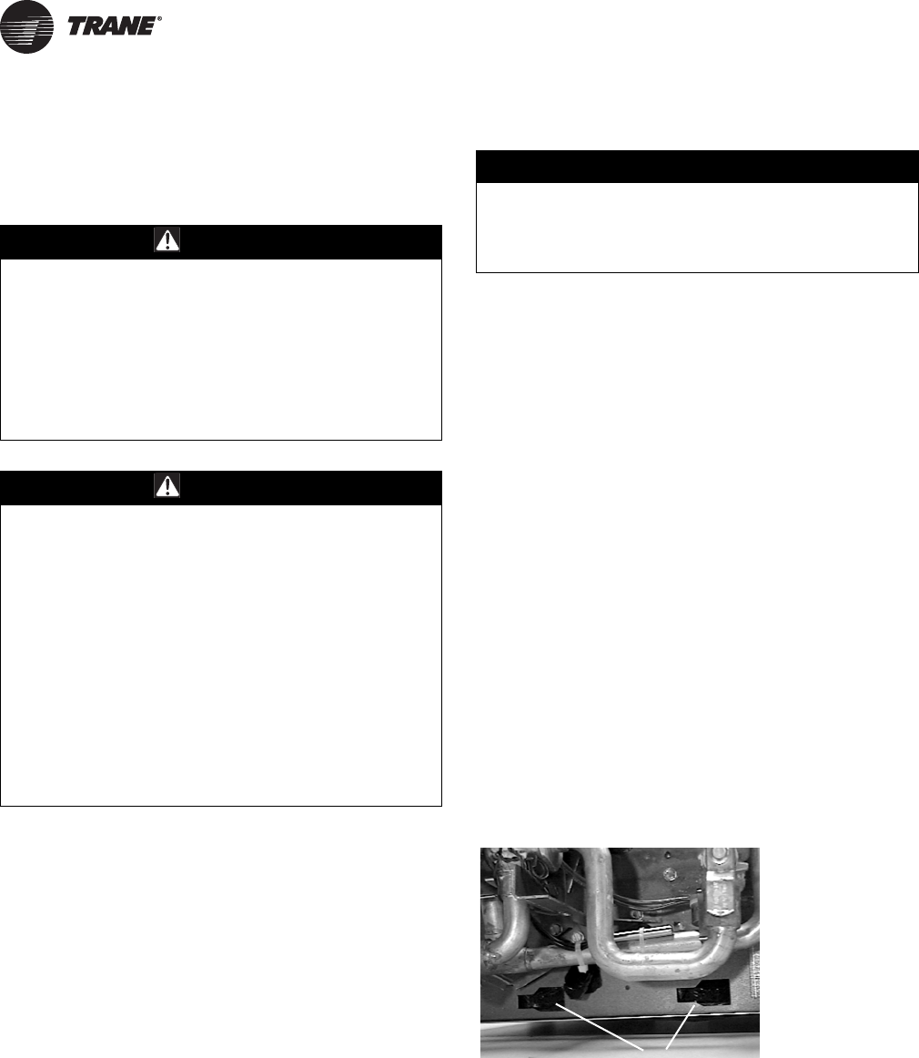
106 UNT-SVX07D-EN
Maintenance
Maintenance Procedures
Perform the following maintenance procedures to ensure
proper unit operation.
Air Filters
Change or clean air filters at least twice a year. Filters
require more frequent care under high load or dirty air
conditions since a clogged filter reduces airflow. Table 1,
p. 12 lists filter size and quantity by unit size. Throwaway
and pleated media filters are available for all units. Follow
the instructions below to replace the disposable filters.
All Models Except Vertical Cabinets
Remove the front panel of the vertical recessed unit and
open the bottom panel door of the horizontal cabinet and
horizontal recessed unit to access the filter. The front panel
of the vertical cabinet unit does not require removal to
change the filter.
Note: Vertical recessed, horizontal cabinet, and
horizontal recessed units with a bottom return have
filter guides to secure the filter in position. Also, if
these unit types have a fresh air opening, they
require an additional filter for the fresh air opening.
Inspecting and Cleaning Drain Pans
Clean the fan-coil unit’s main and auxiliary drain pans to
ensure the unit drains condensate properly.
Check the condensate drain pan and drain line to assure
the condensate drains properly at least every six months
or as dictated by operating experience.
If evidence of standing water or condensate overflow
exists, immediately identify and remedy the cause.
Clean the drain pans of any moisture or debris.
Auxiliary Drain Pan
1. To remove the auxiliary drain pan, loosen the hose
clamp (installer supplied) around the drain connection
collar and disconnect the drain line.
2. Remove the overflow drain line to the auxiliary drain
pan if it was installed.
3. Remove the condensate overflow switch option from
the auxiliary drain pan.
4. Slide the pan horizontally towards the end of the large
groove of the mounting slots in the chassis end panel
and remove pan from unit (see Figure 37).
WARNING
Live Electrical Components!
During installation, testing, servicing and
troubleshooting of this product, it may be necessary to
work with live electrical components. Have a qualified
licensed electrician or other individual who has been
properly trained in handling live electrical components
perform these tasks. Failure to follow all electrical
safety precautions when exposed to live electrical
components could result in death or serious injury.
WARNING
Hazardous Voltage w/Capacitors!
Disconnect all electric power, including remote
disconnects and discharge all motor start/run
capacitors before servicing. Follow proper lockout/
tagout procedures to ensure the power cannot be
inadvertently energized. For variable frequency drives
or other energy storing components provided by Trane
or others, refer to the appropriate manufacturer’s
literature for allowable waiting periods for discharge of
capacitors. Verify with an appropriate voltmeter that all
capacitors have discharged. Failure to disconnect
power and discharge capacitors before servicing could
result in death or serious injury.
For additional information regarding the safe discharge of
capacitors, see PROD-SVB06A-EN
NOTICE:
Replace All Panels and Filters Properly!
All unit panels and filters must be in place prior to unit
startup. Failure to have panels and filters in place could
result in equipment damage.
Figure 37. Insert the auxiliary drain pan tabs into these
slots in the fan-coil’s chassis end panel
(horizontal unit shown).
Aux. Drain Pan Attaches to These Slots
UNT-SVX07_-EN.book Page 106 Friday, April 27, 2012 9:40 AM
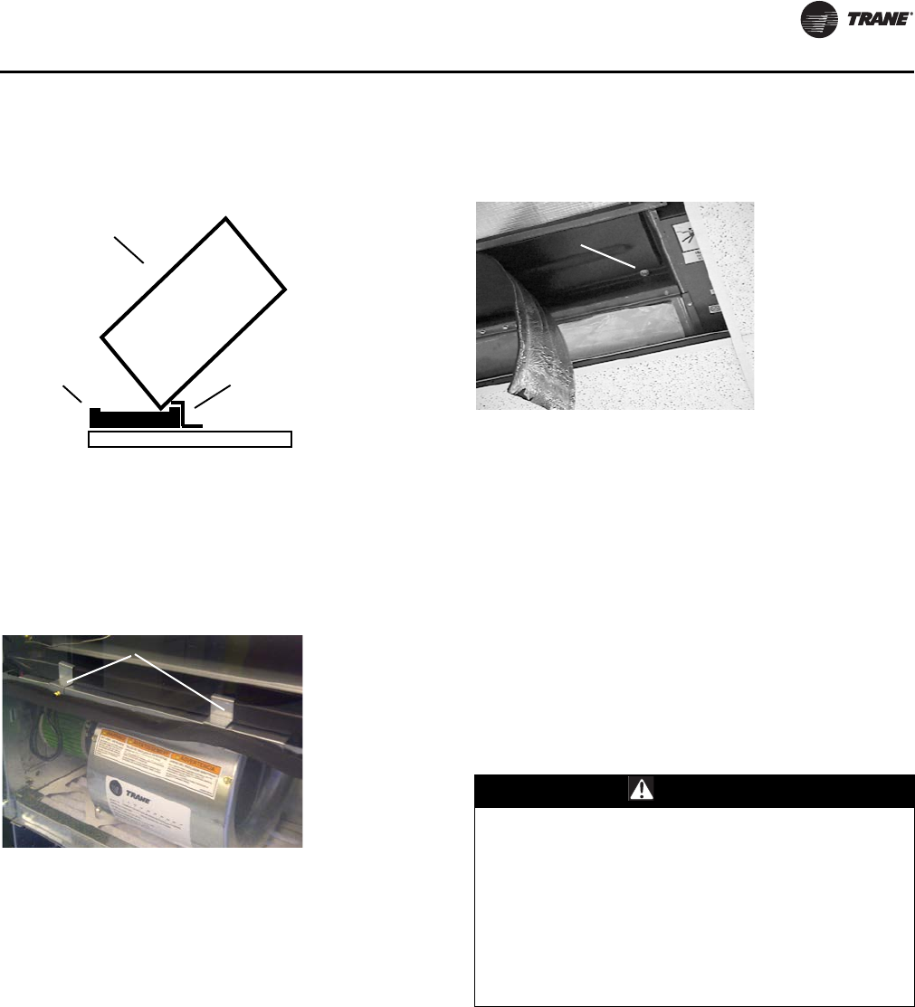
Maintenance
UNT-SVX07D-EN 107
Main Drain Pan
See Figure 38 to replace main drain correctly.
Vertical Units. To remove the main drain pan on vertical
fan-coil units, disconnect the clips holding the pan to the
fanboard. Disconnect the main and overflow drain hoses
and slide pan forward to remove (see Figure 39).
Horizontal Units. To remove the main drain pan on a
horizontal fan-coil unit, peel the insulation from the edges
of the pan’s underside to access the mounting screws.
Remove the screws and lower the end of the drain pan
closest to the control box. Remove the drain spout by
pulling it from the hole in the chassis end panel (see
Figure 40).
Note: Do not operate the fan-coil unit without the main
and auxiliary drain pans in place to prevent
condensate leakage.
Coil Maintenance
Keep coils clean to maintain maximum performance. For
operation at its highest efficiency, clean the coil often
during periods of high demand or when dirty conditions
prevail. Clean the coil a minimum of once a year to prevent
dirt buildup in the coil fins, where it may not be visible.
Remove large debris from the coils and straighten fins
before cleaning. Remove filters before cleaning.
Clean the coil fins using steam with detergent, hot water
spray and detergent, or a commercially available chemical
coil cleaner. Be sure to rinse coils thoroughly after
cleaning.
Inspecting and Cleaning Coils
Coils become externally fouled as a result of normal
operation. Dirt on the coil surface reduces it’s ability to
transfer heat that can result in comfort problems,
increased airflow resistance and thus increased operating
energy costs. If the coil surface dirt becomes wet, which
commonly occurs with cooling coils, microbial growth
(mold) may result, causing unpleasant odors and serious
health-related indoor air quality problems.
Inspect coils at least every six months or more frequently
as dictated by operating experience. Cleaning frequently
Figure 38. When replacing the fan-coil’s main drain pan,
install it correctly under the z-bar.
Figure 39. To remove the main drain pan on vertical fan-
coil units, disconnect the clips holding the
pan to the fanboard.
Z-Bar
Main Drain
Coil
Side
Clips Hold Drain Pan in Place
Figure 40. To remove the main drain pan on horizontal
fan-coil units, peel the insulation from the
edges of the pan’s underside to access the
mounting screws.
WARNING
Hazardous Chemicals!
Coil cleaning agents can be either acidic or highly
alkaline. Handle chemical carefully. Proper handling
should include goggles or face shield, chemical
resistant gloves, boots, apron or suit as required. For
personal safety refer to the cleaning agent
manufacturer’s Materials Safety Data Sheet and follow
all recommended safe handling practices. Failure to
follow all safety instructions could result in death or
serious injury.
Mounting Screw
UNT-SVX07_-EN.book Page 107 Friday, April 27, 2012 9:40 AM
Maintenance
108 UNT-SVX07D-EN
is dependent upon system operating hours, filter
maintenance, and efficiency and dirt load. Follow the
suggested methods in the following paragraphs.
Steam and Hydronic Coil Cleaning Procedure
1. Disconnect all electrical power to the unit.
2. Don the appropriate personal protective equipment
(PPE).
3. Access both sides of the coil.
4. Use a soft brush to remove loose debris from both
sides of the coil.
5. Use a steam cleaning machine, starting from the top of
the coil and working downward. Clean the leaving air
side of the coil first, then the entering air side. Use a
block-off to prevent steam from blowing through the
coil and into a dry section of the unit.
6. Repeat step five as necessary. Confirm that the drain
line is open following completion of the cleaning
process.
7. Allow the unit to dry thoroughly before putting the
system back into service.
8. Straighten any coil fins that may be damaged with a fin
rake.
9. Replace all panels and parts and restore electrical
power to the unit.
Winterizing the Coil
Make provisions to drain coils that are not in use,
especially when subjected to freezing temperatures.
To drain the coil, blow the coil out with compressed air.
Next, fill and drain the tubes with full-strength ethylene
glycol several times. Drain the coil as completely as
possible.
Fan Board Assembly Removal
Follow the procedure below when replacing the coil or
making repairs to the fan or motor.
Vertical Units.
1. Remove the front panel of cabinet and recessed units.
2. Pull the main and overflow drain hoses of the main
drain pan into the inside of the fan-coil chassis end
panel.
3. Remove the two fanboard mounting screws.
4. Slide the fanboard out horizontally to remove.
Horizontal Units.
1. Open the bottom panel of cabinet and recessed
models.
2. Remove the main drain pan following the instructions
given under the drain pan section above for horizontal
fan-coil units.
3. While supporting the fanboard in place, remove the
two fanboard mounting screws which secure the
fanboard to the unit.
Replacing Motors
Motors are attached to the fan boards with screws at the
rear of the motors. Fan wheels are attached with Allen
screws on the fan hubs. In most applications, it is
necessary to remove the fan board to change out the
motor. The fan board is easily removable, with screws on
the front left and right edges of fan boards (vertical units)
or on the front left underside and front right underside of
the fan board (horizontal units).
NOTICE:
Coil Freeze-up Damage!
Failure to properly drain and vent coils when not in use
during freezing temperatures may result in coil freeze-
up damage.
WARNING
Hazardous Voltage w/Capacitors!
Disconnect all electric power, including remote
disconnects and discharge all motor start/run
capacitors before servicing. Follow proper lockout/
tagout procedures to ensure the power cannot be
inadvertently energized. For variable frequency drives
or other energy storing components provided by Trane
or others, refer to the appropriate manufacturer’s
literature for allowable waiting periods for discharge of
capacitors. Verify with an appropriate voltmeter that all
capacitors have discharged. Failure to disconnect
power and discharge capacitors before servicing could
result in death or serious injury.
For additional information regarding the safe discharge of
capacitors, see PROD-SVB06A-EN
NOTICE:
Heavy Object!
Support the fanboard when removing it from the unit.
Failure to properly support fanboard may result in
minor to moderate personal injury.
UNT-SVX07_-EN.book Page 108 Friday, April 27, 2012 9:40 AM
Maintenance
UNT-SVX07D-EN 109
Vertical Units
Notes:
•In vertical units, wiring to the motor transitions from
the control panel onto a trough onto the fan board.
•The motor harnesses are routed through holes at the
motor location below the fan board and into the
motors with a latching multi-plug.
•The crossover harnesses, which are used to make
connections to the piping side of the unit, are routed in
the same manner but continue to the piping side
entirely through the trough on the fan board.
•On vertical fan-coil units with drain pans, a drain pan
support covers most of the wiring. Please be sure to
remove or secure the wiring before removing fan
board.
•Fan board attachment screws are located on the front
left and right edges of fan boards, and may be
concealed by gasketing.
Routing Motor and Crossover Harnesses
Fan board attachment
screw locations on
vertical units may be
hidden behind “H”
insulation.
UNT-SVX07_-EN.book Page 109 Friday, April 27, 2012 9:40 AM
Maintenance
110 UNT-SVX07D-EN
Note: Motor plug with latch.
Horizontal Units
Notes:
•In horizontal units, wiring to the motor is routed below
the fan board but is wire-tied to the fan board for
harness management and to avoid sharp edges.
•The motor harnesses terminate at the motor location
with a latching multi-plug.
•The crossover harnesses, which are used to make
connections to the piping side of the unit, are routed
initially below the fan board, but transition into a
trough on the top side of the fan board, and into the
piping section of the unit.
•Fan board attachment screws are located on the front
left underside and front right underside of the fan
board.
Work Instruction Steps
In general, replacement of a motor needs to be carried out
as follows:
1. Remove front panels of unit.
2. Remove drain pan and drain pan support (vertical
units) or remove drain pan (horizontal units).
3. Free the motor and crossover harnesses from the fan
board, either by unplugging from the motors and
valves and threading backwards, or by unplugging the
motor plug from the adapter boards.
4. Remove the fan board attachment screws and carefully
lower/slide out fan board.
5. Remove at least one fan housing and loosen fan Allen
screw on first fan. Loosen the wheel of the other (if a
double-shafted motor).
6. Unscrew the motor and remove.
7. Insert the replacement motor (plug must face front of
fan board) and drive the screws in with 100 in·lb of
torque.
Control Device Replacement
To order control components such as relays, contactors,
transformers, low temperature detection devices,
condensate overflow detection devices, differential
pressure switches, sensors, control valves and actuators,
contact the local Trane Service Parts Center. To order, the
Trane parts center will need the unit model number (which
can be found on the unit nameplate), the serial number,
and the part name or ID.
Periodic Maintenance Checklists
Monthly Checklist
The following check list provides the recommended
maintenance schedule to keep the unit running efficiently.
Figure 41. Motor attachment screws (located behind
motor)
WARNING
Hazardous Voltage w/Capacitors!
Disconnect all electric power, including remote
disconnects and discharge all motor start/run
capacitors before servicing. Follow proper lockout/
tagout procedures to ensure the power cannot be
inadvertently energized. For variable frequency drives
or other energy storing components provided by Trane
or others, refer to the appropriate manufacturer’s
literature for allowable waiting periods for discharge of
capacitors. Verify with an appropriate voltmeter that all
capacitors have discharged. Failure to disconnect
power and discharge capacitors before servicing could
result in death or serious injury.
WARNING
Live Electrical Components!
During installation, testing, servicing and
troubleshooting of this product, it may be necessary to
work with live electrical components. Have a qualified
licensed electrician or other individual who has been
properly trained in handling live electrical components
perform these tasks. Failure to follow all electrical
safety precautions when exposed to live electrical
components could result in death or serious injury.
UNT-SVX07_-EN.book Page 110 Friday, April 27, 2012 9:40 AM
Maintenance
UNT-SVX07D-EN 111
Monthly Maintenance
1. Inspect unit air filters. Clean or replace if airflow is
blocked or if filters are dirty.
2. Check the main and auxiliary drain pans on fan-coil
units to be sure the pans are clean and do not impede
the condensate flow through the drain line.
Annual Maintenance
Check and tighten all set screws, bolts, locking collars and
sheaves.
1. Inspect the unit cabinetry for chips or corrosion. Clean
or repair to provide unit protection.
2. Inspect the fan wheel and housing for damage. Rotate
the fan wheel manually to be sure movement is not
blocked by obstructions.
3. Inspect the coil fins for excessive dirt or damage.
Remove dirt and straighten fins.
4. Clean and tighten all electrical connections.
5. Inspect the strainer option for debris trapped in the
filter screen.
WARNING
Hazardous Voltage w/Capacitors!
Disconnect all electric power, including remote
disconnects and discharge all motor start/run
capacitors before servicing. Follow proper lockout/
tagout procedures to ensure the power cannot be
inadvertently energized. For variable frequency drives
or other energy storing components provided by Trane
or others, refer to the appropriate manufacturer’s
literature for allowable waiting periods for discharge of
capacitors. Verify with an appropriate voltmeter that all
capacitors have discharged. Failure to disconnect
power and discharge capacitors before servicing could
result in death or serious injury.
For additional information regarding the safe discharge of
capacitors, see PROD-SVB06A-EN
UNT-SVX07_-EN.book Page 111 Friday, April 27, 2012 9:40 AM
11 2 UNT-SVX07D-EN
Diagnostics
Output Testing and Diagnostics
(Tracer ZN520)
Translating Multiple Diagnostics (Tracer
ZN520)
The controller senses and records each diagnostic
independently of other diagnostics. It is possible to have
multiple diagnostics present simultaneously. The
diagnostics are reported in the order they occur.
Possible diagnostics include:
• Low temperature detection
• Condensate overflow
• Low air flow—fan status
• Discharge air temp limit
• Space temperature failure1
• Entering water temp failure1
• Discharge air temp failure1
• Outdoor air temp failure1
• Local setpoint failure1
• Local fan mode failure1
•CO
2 sensor failure1
• Generic AIP failure1
• Humidity input failure1
• Defrosting compressor lockout1
• Maintenance required
• Invalid unit configuration
• Generic temperature failure
• Discharge air low limit
Resetting Diagnostics (Tracer ZN520)
There are a number of ways in which diagnostics are reset:
1. Automatic reset by the controller
2. By initiating a manual output test at the controller
3. By cycling power to the controller
4. Through Rover, Trane’s service tool
5. Tracer ZN520: by using any other communicating
device ab le to access the controller’s diagnostic reset
input.
6. Tracer ZN520: by cycling the fan switch from Off to any
speed setting.
Automatic Reset by the Controller (Tracer
ZN520)
The controller includes an automatic diagnostic reset
function that attempts to automatically restore the unit
when a low temperature diagnostic occurs.
Note: The controller implements the automatic
diagnostic reset function only once every 24 hours.
For the controller to increment the 24 hour timer,
you must maintain power to the controller. Cycling
power resets all timers and counters.
After the controller detects the first special diagnostic, the
unit waits 30 minutes before invoking the automatic
diagnostic reset function. The automatic diagnostic reset
function clears the special diagnostic and attempts to
restore the controller to normal operation. The controller
resumes normal operation until another diagnostic
occurs.
Table 36. Tracer ZN520 diagnostics
Diagnostic Fan Other Outputs(a)
(a)The generic binary output (TB4-1, TB4-2) state is unaffected by all unit
diagnostics.
Condensate
overflow Off Valves Closed, Fresh air damper Closed, Electric
heat Off, Baseboard heat Off
Low temperature
detection Off Valves Open, Fresh air damper Closed, Electric heat
Off, Baseboard heat Off
Low air flow - fan
failure Off Valves Closed, Fresh air damper Closed, Electric
heat Off, Baseboard heat Off
Space
temperature
failure
Off Valves Closed, Fresh air damper Closed, Electric
heat Off, Baseboard heat Off
Entering water
temp failure On Valves Enabled(b), Fresh air damper Enabled(b),
Electric heat Enabled(b), Baseboard heat Off
(b)When the entering water temperature is required but not present, the
Tracer ZN520 controller generates a diagnostic to indicate the sensor
loss condition. The controller automatically clears the diagnostic once
a valid entering water temperature value is present (non-latching di-
agnostic). When the entering water temperature sensor fails, the con-
troller prohibits all hydronic cooling operation, but allows the delivery
of heat when heating is required. In the Cool mode, all cooling is locked-
out, but normal fan and outdoor air damper operation is permitted.
Discharge air
temp low limit Off Valves Open, Fresh air damper Closed, Electric heat
Off, Baseboard heat Off
Discharge air
temp failure Off Valves Closed, Fresh air damper Closed, Electric
heat Off, Baseboard heat Off
Fresh air temp
failure On Valves Enabled, Fresh air damper Minimum
position(c), Electric heat Enabled, Baseboard heat
Enabled
(c) When the outdoor air temperature sensor has failed or is not present,
the Tracer ZN520 controller generates a diagnostic to indicate the sen-
sor loss condition. The controller automatically clears the diagnostic
once a valid outdoor air temperature value is present (non-latching di-
agnostic). When the outdoor air temperature sensor fails or is not pres-
ent, the controller prohibits economizer operation.
Relative humidity
failure On Valves Enabled, Fresh air damper Enabled, Electric
heat Enabled, Baseboard heat Enabled
Generic 4–20mA
failure On Valves Enabled, Fresh air damper Enabled, Electric
heat Enabled, Baseboard heat Enabled
CO2 Input failure On Valves Enabled, Fresh air damper Enabled, Electric
heat Enabled, Baseboard heat Enabled
Maintenance
required On Valves Enabled, Fresh air damper Enabled, Electric
heat Enabled, Baseboard heat Enabled
Local fan mode
failure On Valves Enabled, Fresh air damper Enabled, Electric
heat Enabled, Baseboard heat Enabled
Local setpoint
failure On Valves Enabled, Fresh air damper Enabled, Electric
heat Enabled, Baseboard heat Enabled
Invalid unit
configuration Off Valves Disabled, Fresh air damper Disabled,
Electric heat Disabled, Baseboard heat Disabled
Normal—power
up On Valves Enabled, Fresh air damper Enabled, Electric
heat Enabled
1Non-latching diagnostics automatically reset when the input is present and valid.
UNT-SVX07_-EN.book Page 112 Friday, April 27, 2012 9:40 AM
Diagnostics
UNT-SVX07D-EN 11 3
Note: The automatic diagnostic reset function does not
operate during the manual output test sequence.
If a special diagnostic occurs within 24 hours after an
automatic diagnostic reset, the controller must be
manually reset. Other possible methods of resetting
diagnostics are described in the sections that follow.
Manual Output Test (Tracer ZN520)
To verify proper end device operation, press the
controller’s Test button. This exercise will verify all outputs
in a predefined sequence, the first of which will attempt to
reset the controller diagnostics if any are present.
Cycling Power to the Controller (Tracer ZN520)
After removing and reapplying the 24 Vac power from the
board, the unit cycles through a power-up sequence. By
default, the controller attempts to reset all diagnostics
present at power-up. Diagnostics present at power-up and
those that occur after power-up are handled according to
Tab l e 3 7 .
Using Trane’s Service Tool, Rover (Tracer
ZN520)
Rover, Trane’s service tool, can reset diagnostics present in
the controller and troubleshoot the unit. For more
information, refer to the Trane publication EMTX-SVX01G-
EN (Rover Service Tool: Installation, Operation, and
Programming Guide).
Diagnostic Reset (Tracer ZN520)
Any device that can communicate the network variable
nviRequest (enumeration “clear_alarm”) can reset
diagnostics in the Tracer ZN520 controller.The controller
also attempts to reset diagnostics whenever power is
cycled.
Cycling the Fan Switch (Tracer ZN520)
Cycle the fan speed switch from Off to any speed and the
controller resets all diagnostics. Diagnostics may recur
immediately if the problem still exists.
Table 37. Tracer ZN510 controller diagnostics
Diagnostic Latching? Fan Valves
Elec
Heat Damper
Auxiliary temp.
failure No Enable
dNo
action No action No action
Condensate overflow
detection Yes Off Closed Off Closed
Entering water temp.
failure No Enable
dEnabled Enabled Enabled
Fan mode failure No Enable
dEnabled Enabled Enabled
Invalid unit
configuration failure Yes Disable
dDisabled Disabled Disabled
Low temp. detection Yes Off Open Off Closed
Maintenance
required Yes Enable
dNo
action No action No action
Setpoint No Enable
dNo
action No action No action
Zone temp. failure No Off Closed Off Closed
Notes:
1. Priority Level: Diagnostics are listed in order from highest to lowest
priority. The controller senses and records each diagnostic
independently of other diagnostics. It is possible to have multiple
diagnostics present simultaneously. The diagnostics affect unit
operation according to priority level.
2. Latching: A latching diagnostic requires a manual reset of the
controller; while a non-latching diagnostic automatically resets when
the input is present and valid.
3. Enabled: End device is allowed to run if there is a call for it to run.
4. Disabled: End device is not allowed to run even if there is a call for it
to run.
5. No Action: The diagnostic has no affect on the end device.
Table 38. Fan outputs do not energize (Tracer ZN520)
Probable
Cause Explanation
Random start After power-up, the controller always observes a random
start that varies observed between 0 and 25 seconds. The
controller remains off until the random start time expires.
Power-up
control wait When power-up control wait is enabled (non-zero time), the
controller remains off until one of two conditions occurs:
1. The controller exits power-up control wait once it receives
communicated information.
2. The controller exits power-up control wait once the
power-up control wait time expires.
Cycling fan
operation When the fan mode switch is in the auto position, the unit
fan cycles off when there is no call for heating or cooling. The
heating/cooling sources cycle on or off periodically with the
unit fan to match the capacity according to pulse-width-
modulation (PWM) logic.
Unoccupied
operation The fan cycles with capacity when the unit is in unoccupied
mode. This occurs even if the unit is in continuous fan
operation. While unoccupied, the fan cycles on or off with
heating/cooling to provide varying amounts of heating or
cooling to the space to match the to pulse-width-modulation
(PWM) logic.
Fan mode off When using the local fan mode switch to determine the fan
operation, the off position controls the unit fan to off.
Requested
mode: off It is possible to communicate the operating mode (such as
off, heat, and cool) to the controller. When “off” is
communicated to the controller, the unit controls the fan to
off. The unit is not capable of heating or cooling when the
controller is in this mode.
Diagnostic
present A specific list of diagnostics effects fan operation. For more
information, see “Diagnostics,” p. 112.
No power to
the controller If the controller does not have power, the unit fan will not
operate. For the controller to operate normally, it must have
an input voltage of 24 Vac. When the green LED is off
continuously, the controller does not have sufficient power
or the controller has failed.
Manual output
test The controller includes a manual output test sequence to
verify binary output operation and the associated wiring.
However, based on the current step in the test sequence, the
unit fan may not be powered on. Refer to “Manual Output
Test (Tracer ZN520),” p. 113.
Unit wiring The wiring between the controller outputs and the fan relays
and contacts must be present and correct for normal fan
operation. Refer to the typical unit wiring diagrams (see
“Wiring Diagrams,” p. 133).
UNT-SVX07_-EN.book Page 113 Friday, April 27, 2012 9:40 AM
Diagnostics
114 UNT-SVX07D-EN
Table 39. Valves stay closed (Tracer ZN520)
Probable
Cause Explanation
Normal
operation The controller opens and closes the valves to meet the unit
capacity requirements.
Requested
mode: off It is possible to communicate the operating mode (such as
off, heat, and cool) to the controller. When off is
communicated to the controller, the unit controls the fan to
off. The unit is not capable of heating or cooling when the
controller is in this mode.
Valve override The controller can communicate a valve override request.
This request affects the valve operation.
Manual output
test The controller includes a manual output test sequence to
verify analog and binary output operation and the associated
wiring. However, based on the current step in the test
sequence, the valves may not be open. Refer to “Manual
Output Test (Tracer ZN520),” p. 113.
Diagnostic
present A specific list of diagnostics affects valve operation. For more
information, see “Diagnostics,” p. 112.
Sampling
logic The controller includes entering water temperature
sampling logic that automatically invokes during 2-pipe or
4-pipe changeover. It determines when the entering water
temperature is either too cool or too hot for the desired
heating or cooling mode. Refer to “Entering Water
Temperature Sampling Function (Tracer ZN010 and
ZN510),” p. 89.
Unit
configuration The controller must be properly configured based on the
actual installed end devices and application. When the unit
configuration does not match the actual end device, the
valves may not work correctly.
No power to
the controller If the controller does not have power, the valves do not
operate. For the controller to operate normally, it must have
an input voltage of 24 Vac. When the green LED is off
continuously, the controller does not have sufficient power,
or the controller has failed.
Unit wiring The wiring between the controller outputs and the valve(s)
must be present and correct for normal valve operation.
Refer to the typical unit wiring diagrams (see “Wiring
Diagrams,” p. 133).
Table 40. Valves stay open (Tracer ZN520)
Probable
Cause Explanation
Normal
operation The controller opens and closes the valves to meet the unit
capacity requirements.
Valve override The controller can communicate a valve override request to
affect the valve operation.
Manual output
test
The controller includes a manual output test sequence that
verifies analog and binary output operation and the
associated wiring. However, based on the current step in the
test sequence, the valves may be open. Refer to “Manual
Output Test (Tracer ZN520),” p. 113.
Diagnostic
present A specific list of diagnostics affects valve operation. For more
information, see “Diagnostics,” p. 112.
Sampling
logic
The controller includes entering water temperature
sampling logic that automatically invokes during 2-pipe or
4-pipe changeover to determine if the entering water
temperature is correct for the unit operating mode. Refer to
“Entering Water Temperature Sampling Function (Tracer
ZN010 and ZN510),” p. 89.
Unit
configuration
The controller must be properly configured based on the
actual installed end devices and application. When the unit
configuration does not match the actual end device, the
valves may not work correctly.
Unit wiring
The wiring between the controller outputs and the valve(s)
must be present and correct for normal valve operation.
Refer to the typical unit wiring diagrams (see “Wiring
Diagrams,” p. 133).
Table 41. Electric heat not operating (Tracer ZN520)
Probable
Cause Explanation
Normal
operation The controller cycles electric heat on and off to meet the
unit capacity requirements.
Requested
mode: off It is possible to communicate the operating mode (such as
off, heat, cool) to the controller. When off is communicated
to the controller, the units shuts off the electric heat.
Communicated
disable Numerous communicated requests may disable electric
heat, including an auxiliary heat enable input and the heat/
cool mode input. Depending on the state of the
communicated request, the unit may disable electric heat.
Manual output
test The controller includes a manual output test sequence that
verifies analog and binary output operation and associated
output wiring. However, based on the current step in the
test sequence, the electric heat may not be on. Refer to
“Manual Output Test (Tracer ZN520),” p. 113.
Diagnostic
present A specific list of diagnostics affects electric heat operation.
For more information, see “Diagnostics,” p. 112.
Unit
configuration The controller must be properly configured based on the
actual installed end devices and application. When the unit
configuration does not match the actual end device, the
electric heat may not work properly.
No power to
the controller If the controller does not have power, electric heat does not
operate. For the controller to operate normally, a 24 Vac
input voltage must be applied. When the green LED is off
continuously, the controller does not have sufficient power
or has failed.
Unit wiring The wiring between the controller outputs and the electric
heat contacts must be present and correct for normal
electric heat operation. Refer to the typical unit wiring
diagrams (see “Wiring Diagrams,” p. 133).
ECM Motor /
Control Board
Failure
ECM controls include sophisticated fan proving / interlock
circuitry that will disable electric heat if one or more motors
are not performing normally
Hot water is
present on a
changeover
unit
On units with changeover coil and electric heat,
simultaneous operation of hydronic heat and electric heat
is not allowed.
Table 42. Fresh air damper stays open (Tracer ZN520)
Probable
Cause Explanation
Normal
operation The controller opens and closes the fresh air damper based
on the controller’s occupancy mode and fan status.
Normally, the fresh air damper is open during occupied mode
when the fan is running and closed during unoccupied mode.
Manual output
test The controller includes a manual output test sequence that
verifies analog and binary output operation and associated
output wiring. However, based on the current step in the test
sequence, the fresh air damper may not be open. Refer to
“Manual Output Test (Tracer ZN520),” p. 113.
Unit
configuration The controller must be properly configured based on the
actual installed end devices and application. When the unit
configuration does not match the actual end device, the
damper may not work correctly.
Unit wiring The wiring between the controller outputs and the fresh air
damper must be present and correct for normal damper
operation. Refer to the typical unit wiring diagrams (see
“Wiring Diagrams,” p. 133).
UNT-SVX07_-EN.book Page 114 Friday, April 27, 2012 9:40 AM
Diagnostics
UNT-SVX07D-EN 11 5
Output Testing and Diagnostics
(UC400)
This section provides information about the following:
• Output testing
• Diagnostics
Note: For detailed description of LED activities and
troubleshooting tips, refer to the section.
Output Testing (UC400)
Important: Do not directly overwrite the outputs.
Output testing can be accomplished by
overriding the following analog and
multistate value points in the desired state
or position:
• Cool valve request
• DX cool request
• Economizer request
• Electric heat request
• Heat valve request
• Supply fan speed request
The points can be overridden on the Tracer TU analog or
multistate pages by clicking on the Override icon in
the control column. A higher priority (lower number) must
be chosen over the current control setting.
Diagnostics (UC400)
Diagnostics are informational messages that indicate the
operational status of the UC400 controller. In response to
most diagnostics, the controller attempts to protect the
equipment by enabling/disabling, or by opening/closing
specific outputs. Other diagnostics provide information
about the status of the controller, but have no effect on
outputs. Diagnostics are reported in the order in which
they occur. Multiple diagnostics can be present
simultaneously. Diagnostic messages are viewed using
the Tracer TU service tool or through a BAS.
Note: Tracer TU will report only active diagnostics.
Diagnostics Types (UC400)
Diagnostics are categorized according to the type of
clearing method each uses and the type of information
each provides.
The diagnostic types are:
• Manual (latching) diagnostics
• Automatic (non-latching) diagnostics
• Smart reset diagnostics
• Informational diagnostics
Note: Clearing diagnostics refers to deleting diagnostics
from the software; it does not affect the problem
that generated the message.
Table 43. Fresh air damper stays closed (Tracer ZN520)
Probable
Cause Explanation
Normal
operation The controller opens and closes the fresh air damper based
on the controller’s occupancy mode and fan status.
Normally, the fresh air damper is open during occupied mode
when the fan is running and closed during unoccupied mode.
Warmup and
cooldown The controller includes both a warmup and cooldown
sequence to keep the fresh air damper closed during the
transition from unoccupied to occupied. This is an attempt to
bring the space under control as quickly as possible.
Requested
mode: off It is possible to communicate the operating mode (such as
off, heat, cool) to the controller. When off is communicated
to the controller, the unit closes the fresh air damper.
Manual output
test The controller includes a manual output test sequence that
verifies analog and binary output operation and associated
output wiring. However, based on the current step in the test
sequence, the fresh air damper may not be open. Refer to
“Manual Output Test (Tracer ZN520),” p. 113.
Diagnostic
present A specific list of diagnostics effects fresh air damper
operation. For more information, see “Diagnostics,” p. 112.
Unit
configuration The controller must be properly configured based on the
actual installed end devices and application. When the unit
configuration does not match the actual end device, the
damper may not work correctly.
No power to
the controller If the controller does not have power, the fresh air damper
does not operate. For the controller to operate normally, a
24 Vac input voltage must be applied. When the green LED
is off continuously, the controller does not have sufficient
power or has failed.
Unit wiring The wiring between the controller outputs and the fresh air
damper must be present and correct for normal damper
operation. Refer to the typical unit wiring diagrams (see
“Wiring Diagrams,” p. 133).
UNT-SVX07_-EN.book Page 115 Friday, April 27, 2012 9:40 AM
Diagnostics
11 6 UNT-SVX07D-EN
Manual (Latching) Diagnostics (UC400). Manual
diagnostics (also referred to as latching) cause the unit to
shut down. Manual diagnostics can be cleared from the
UC400 controller in one of the following ways:
• By using the Tracer TU service tool to reset latching
diagnostics on the Alarms Status tab or by
temporarily overriding the Reset Diagnostic
Request (bv/2) on the Binary Status tab.
• Through a building automation system.
• By cycling power to the controller. When the 24Vac
power to the controller is cycled OFF and then ON
again, a power-up sequence occurs.
Automatic (Non-latching) Diagnostics (UC400).
Automatic diagnostics clear automatically when the
problem that generated the diagnostic is solved.
Smart Reset Diagnostics (UC400). Smart Reset
Diagnostics are latching diagnostics that will auto-recover
if the condition is corrected. After the controller detects the
first smart reset diagnostic, the unit waits 30 minutes
before initiating the smart reset function. If another
diagnostic of this type occurs again within 24 hours after
an automatic clearing, clear the diagnostic manually by
using any of the ways listed under the preceding section,
“Manual (Latching) Diagnostics (UC400).”
Informational Diagnostics (UC400). Informational
diagnostics provide information about the status of the
controller. They do not affect machine operation, but can
be cleared from the controller using the BAS or Tracer SC.
Table of Diagnostics (UC400)
Tab l e 4 4 lists each diagnostic that can be generated by the
UC400 controller, the diagnostic effect on outputs
(consequences), and diagnostic type.
Note: The generic binary output is unaffected by
diagnostics.
Table 44. UC4000 diagnostics
Diagnostic Probable Cause Consequences
Diagnostic
Type
Filter change
required Fan run hours
exceed the time set
to indicate filter
change.
•Fan Unaffected
•Valves Unaffected
•Electric heat
Unaffected
Informational
Condensate
overflow The drain pan is full
of water. •Fan OFF
•Valves Closed
• Outdoor air damper
Closed
• DX/electric heat OFF
Manual
Low coil
temp
detection
The leaving fluid
temperature may be
close to freezing.
•Fan OFF
•Valves Open
• Outdoor air damper
Closed
• DX/electric heat OFF
Smart reset/
Manual
Low airflow
supply fan
failure
The fan drive belt,
contactor, or motor
has failed.
•Fan OFF
•Valves Closed
• Outdoor air damper
Closed
• DX/electric heat OFF
Manual
Space
temperature
failure(a)
Invalid or missing
value for zone
temperature.
• Discharge air
temperature control
runs
• Unit shuts OFF if both
space temperature
and discharge air
temperature fail
Automatic
Entering
water temp
failure
Invalid or missing
value for zone
temperature.
•Fan Unaffected
(enabled)
•Valves Unaffected
• Outdoor air damper
Unaffected
•DX/electric heat
Unaffected
Automatic
Discharge air
temp low
limit
Discharge air
temperature has
fallen below the
Discharge Air
Temperature Low
Limit.
•Fan OFF
•Valves Open
• Outdoor air damper
Closed
•DX/electric heat OFF
Smart reset/
manual
Discharge air
temp
failure(a)
Invalid or missing
value for discharge
air temperature.
• Simplified zone
control algorithm runs
• Unit shuts OFF if zone
temperature fails
Automatic
Outdoor air
temp failure Invalid or missing
value for outdoor air
temperature.
•Fan Unaffected
•Valved Unaffected
• Outdoor air damper
Minimum
Position
• DX cooling/electric
heat unaffected
Automatic
Humidity
input failure Invalid or missing
value for relative
humidity.
•Fan Unaffected
•Valves Unaffected
• Outdoor air damper
Unaffected
• DX cooling/electric
heat Unaffected
Automatic
CO2 sensor
failure Invalid or missing
value for CO2.•Fan Unaffected
•Valves Unaffected
• Outdoor air damper
Unaffected
• DX cooling/electric
heat Unaffected
Informational
Generic AIP
failure Invalid or missing
value for generic
analog input.
•Fan Unaffected
•Valves Unaffected
• Outdoor air damper
Unaffected
• DX cooling/electric
heat Unaffected
Informational
Local fan
mode failure Invalid or missing
fan-speed switch
(reverts to default
fan speed).
•Fan Unaffected
•Valves Unaffected
• Outdoor air damper
Unaffected
• DX cooling/electric
heat Unaffected
Automatic
Local
setpoint
failure
Invalid or missing
value for zone
temperature
setpoint (reverts to
default setpoint).
•Fan Unaffected
•Valves Unaffected
• Outdoor air damper
Unaffected
• DX cooling/electric
heat Unaffected
Automatic
(a) For detailed information about zone temperature control methods, refer
to “Zone Temperature Control (UC400),” p. 100.
Table 44. UC4000 diagnostics (continued)
Diagnostic Probable Cause Consequences
Diagnostic
Type
UNT-SVX07_-EN.book Page 116 Friday, April 27, 2012 9:40 AM
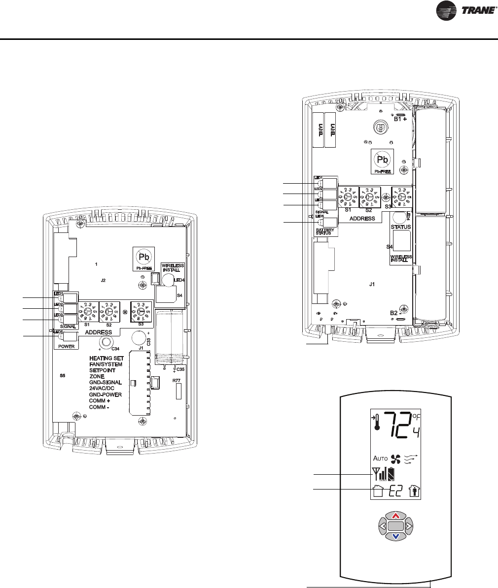
Diagnostics
UNT-SVX07D-EN 11 7
Troubleshooting (Wireless
Controls)
Locations of LEDs, Test button, Test Symbols,
and Error Codes
The receiver for all models has four LEDs: LED1, LED2,
LED3, and LED5. Figure 42 shows their locations.
Note: To view LEDs on a flush mount receiver on a fan-
coil unit, the front panel of the unit must be
removed.
The sensor for model WZS have four LEDs: LED1, LED2,
LED3, and LED5. The sensor for model WDS has test
symbols and error codes that appear on the display. All
three sensor models have a Test button. Figure 43 shows
their locations.
Diagnostics (Wireless Controls)
LED1, LED2, and LED3, located on the sensor of model
WZS respond to diagnostics by exhibiting specific blinking
patterns. View their response by pressing the Test button
(see Table 45, p. 118).
Figure 42. LED locations on the receiver
LED1
LED2
LED3
LED5
Figure 43. LED, Test button, and symbol locations on
the sensor
LED1
LED2
LED3
LED5
Test button
WZS sensor
.
Test symbols
Error code
Test button
WDS sensor
UNT-SVX07_-EN.book Page 117 Friday, April 27, 2012 9:40 AM
Diagnostics
11 8 UNT-SVX07D-EN
Error codes appear on the display of the model WDS
sensor when diagnostics occur (see Table 45).
LED1, LED2, and LED3, located on the receiver of all
models, respond to diagnostics by exhibiting specific
blinking patterns. They respond independently of any user
action (see Table 46).
Testing Signal Strength (Wireless Controls)
To initiate a signal strength test, push the Test button on
the sensor (see location of Test button in Figure 43, p. 117).
•Models WZS: LED1, LED2, and LED3 respond by
indicating signal strength. You can view them on the
sensor (Ta b l e 47) and the receiver (Ta b l e 48).
•Model WDS: Test symbols on the sensor display
indicate signal strength (Ta b l e 47). LED1, LED2, and
LED3, on the receiver, respond by indicating signal
strength (Ta b l e 48).
Testing Battery Status (Wireless Controls)
Initiate a battery status test as follows:
• On model WZS, push the Test button on the sensor (see
location on Figure 43, p. 117 ). LED5 on the sensor
responds by indicating the level of battery strength, as
Table 45. Diagnostics on the sensor (wireless controls)
LED state when Test
button is pressed (WZS
sensor)
Error code
(WDS
sensor
display) Indicates...
N/A E0, E5, E7 Sensor failure
•Replace sensor
LED1: Off
LED2: Off
LED3(a): 1-blink pattern
repeated 3 times
(a) Blink pattern is On for 1/4 s, Off for 1/4 s, with 2 s Off between repe-
titions.
E1 Disassociated
• Sensor is not associated with
a receiver.
LED1: Off
LED2: Off
LED3(a): 2-blink pattern
repeated 3 times
E2 Address set to 000
• Address not set to between
001–999.
LED1: Off
LED2: Off
LED3(a): 3-blink pattern
repeated 3 times
E3 Software error
•Replace sensor
LED1: Off
LED2: Off
LED3(a): 4-blink pattern
repeated 3 times
E4 Input voltage too high
• No RF transmission is
permitted with an input
battery voltage greater than
3.9 V.
Table 46. Diagnostics on the receiver (wireless controls)
LED state Indicates...
LED1: Off
LED2: Off
LED3: 1-blink pattern
repeated continuously(a)
(a) Blink pattern is On for 1/4 s, Off for 1/4 s, with 2 s Off between repe-
titions.
Disassociated
•Receiver is not associated, waiting for a
sensor.
• Receiver lost communication with sensor.
• Receiver has no devices on its wireless
personal area network.
• Association with a device has been
manually removed.
LED1: Off
LED2: Off
LED3: 2-blink pattern
repeated continuously(a)
Address set to 000
• Address not set to between 001–999.
LED1: Off
LED2: Off
LED3: 3-blink pattern
repeated continuously(a)
Not configured
• Receiver configuration properties not
properly set (defective receiver).
Table 47. Observing signal strength on the sensor
(wireless controls)
User action
LED state
(WZS sensors)
Symbol (WDS
sensor
display) Indicates...
None LED1: Off
LED2: Off
LED3: Off
No Test symbols
appear Normal state
• No Test button press.
Press Test
button on the
sensor
LED1: Off
LED2: Off
LED3: Off
Associated; no
communication with
receiver
• Associated, but no
signal from the
receiver after
pressing Test button.
LED1: On
LED2: On
LED3: On
Displays for 5
seconds, then
constantly Off
Excellent signal
strength
•Good signal margin
for reliable
communication.
LED1: Off
LED2: On
LED3: On
Displays for 5
seconds, then
constantly Off
Satisfactory signal
strength
• Adequate signal
strength for reliable
communication.
• Moving sensor or
receiver may improve
signal strength.
• Increased channel
switching may reduce
battery life.
LED1: Off
LED2: Off
LED3: On
Displays for 5
seconds, then
constantly Off
Poor signal strength
•Unreliable
communication.
• Strongly recommend
moving the sensor or
receiver to a better
location.
Table 48. Observing signal strength on the receiver
(wireless controls)
User
action
LED state (receiver, all
models) Indicates...
None LED1: Off
LED2: Off
LED3: Off
Normal state
• No Test button press.
Press
Test
button
on the
sensor
LED1: On
LED2: On
LED3: On
Displays for 5 seconds, then
constantly Off
Excellent signal strength
• Good signal margin for reliable
communication.
LED1: Off
LED2: On
LED3: On
Displays for 5 seconds, then
constantly Off
Satisfactory signal strength
• Adequate signal strength for
reliable communication.
• Moving sensor or receiver may
improve signal strength.
• Increased channel switching may
reduce battery life.
LED1: Off
LED2: Off
LED3: On
Displays for 5 seconds, then
constantly Off
Poor signal strength
• Unreliable communication
• Strongly recommend moving the
sensor or receiver to a better
location
UNT-SVX07_-EN.book Page 118 Friday, April 27, 2012 9:40 AM
Diagnostics
UNT-SVX07D-EN 119
shown in Ta b l e 49, p. 119 .
• On model WDS, push the Test button on the sensor
(see location on Figure 43, p. 11 7 ). In response, a
battery test symbol appears on the display. The
symbol shown indicates battery life expectancy (see
Ta b l e 50).
24 V Power Status Indicator (Wireless Controls
LED5 on the receiver of all models (Figure 42, p. 117) lights
and stays constantly On when 24 V power is normal.
Using the Wireless Sensor System to Check
Signal Strength on a Site (Wireless Controls)
Follow these steps to check the signal strength on a site:
1. Power up a receiver with a 24 V transformer (user
supplied)
2. Associate the sensor to a receiver of the same model
intended for the job
3. Place the receiver at the desired location
4. Place or hold the sensor at the desired location
5. Press the Test button (S5) on the sensor and observe
the signal strength as indicated by LED1, LED2, and
LED3 on model WZS, and on the display on model
WDS (Figure 43, p. 11 7 ).
For more information on interpreting the LEDs and the
display symbols that indicate signal strength, see “Testing
Signal Strength (Wireless Controls),” p. 118.
Replacing Sensor Batteries (Wireless Controls)
Sensor battery type, length of life, and installation are
addressed in this section.
Battery Type (Wireless Controls)
Use two non-rechargeable 1.5 V lithium AA batteries in the
sensor. To maintain UL rating, use only UL-listed lithium
batteries. The sensor ships with Energizer® L91 batteries
already installed. Replacement batteries are available at
Trane Service Parts Centers (p/n X13770035010) or other
local suppliers.
Battery Life (Wireless Controls)
Battery life is five years under normal conditions. If the
sensor is not used for an extended period of time, do one
of the following:
• Set the sensor address to 000 to place the sensor into
a low-power hibernation mode.
• Remove the batteries
Notes:
•If lithium batteries are temporarily unavailable,
alkaline batteries can be used. However, alkaline
battery life is very short by comparison.
•The battery life for a model WDS may decrease with
extended LCD display activity.
Battery Installation (Wireless Controls)
Table 49. Battery status: LED5 on model WZS sensors
(wireless controls)
User
action LED state (WZS) Indicates...
Press
Test
button
Solid green for 5 seconds Battery is adequate for proper
operation.
Solid red for 5 seconds 25% battery life left. Batteries should
be replaced.
No light Batteries life expired or not installed
properly, or sensor is defective.
None Blinking red: 1-blink
pattern(a) repeated 5
times. Cycle repeats
every 15 minutes.
(a) Blink pattern is On for 1/4 s, Off for 3/4 s, with 2 s Off between repe-
titions.
Approximately 14 days of operation
remain before the battery is too weak
to power the sensor.
Table 50. Battery status: Battery symbol on model WDS
sensor display (wireless controls)
User
action
Battery
test
symbol Indicates...
Press Test
button Full battery power.
50% battery life left.
25% battery life left. Replace batteries.
Flashing symbol indicates that approximately 14
days of operation remain before the battery is too
weak to power the sensor.
NOTICE:
Equipment Damage!
The batteries are manufactured in a ready-to-use state.
They are not designed for recharging. Recharging can
cause battery leakage or, in some cases, can cause the
safety release vent to open.
NOTICE:
Equipment Damage!
Do not attempt to hook up the sensor to a power
supply. Equipment damage may result.
WARNING
Prevent Injury!
Batteries can explode or leak and cause burns if
installed backwards, disassembled, charged, or
exposed to water, fire, or high temperature.
UNT-SVX07_-EN.book Page 119 Friday, April 27, 2012 9:40 AM
Diagnostics
120 UNT-SVX07D-EN
6. Observe the polarity indicators that are molded into
the cover.
7. Install two batteries (of the type specified in “Battery
Type (Wireless Controls),” p. 119 ) in the battery-holding
slot that is molded into the sensor cover.
The sensor has been designed to prevent damage if the
batteries are installed backwards, to reduce the potential
for injury.
Manual Association (Wireless Controls)
Before attempting manual or automatic association, the
receiver must indicate readiness to associate (one blink
pattern of LED3 on receiver). Refer to “Observing the
Receiver for Readiness to Associate,” p. 78.
At any time, the manual association method can be used
to associate the receiver with the sensor. If an association
was previously established between a receiver and a
sensor and needs to be re-established, the manual
association process may be used. If an association has not
yet been established, the automatic association process is
recommended (see “Associating the Sensor to the
Receiver,” p. 78).
8. Using a small screwdriver, set the three rotary address
switches (Figure 33, p. 77, locations S1, S2, S3) on the
receiver to an address between 001 and 999.
Notes:
•An address can be changed without powering
down the receiver or sensor.
•An address can be changed at any time after initial
association has been established.
9. Set the three rotary address switches (Figure 33, p. 77,
locations S1, S2, S3) on the sensor to the same address
as the receiver.
10. Record the address and location of the receiver and
sensor pair.
•After verifying that the receiver and sensor are
powered up, press the Test button on the sensor to
establish that the signal strength (“Testing Signal
Strength (Wireless Controls),” p. 118) and the
battery life “Testing Battery Status (Wireless
Controls),” p. 118) are adequate for proper
functioning.
Disassociation (Wireless Controls)
The receiver disassociates from the sensor (by removing
all stored association information), conducts a channel
scan, and restarts itself, if any of the following are true:
• The receiver address is changed from its current
setting (001–999)
• The receiver receives a disassociation notification
from its associated sensor
• The receiver does not receive a communication from
its associated sensor within 50 minutes.
• The sensor and receiver are associated and
communicating at the time the sensor is set to 000 and
the Test button is pressed.
Note: A disassociated sensor will transit an association
request every 10 minutes.
Sensor/Receiver Compatibility (Wireless
Controls)
Version 1.5 (p/n X13790854 and X13790855) and higher
receivers are compatible with all sensors models and
support all functions. Receivers released prior to version
1.5 are compatible with only model WZS.
Replacing a Failed Sensor or Receiver
(Wireless Controls)
Note: Receivers ship installed on the unit. To remove the
receiver, press in the retention tabs on the
underside of the receiver enclosure (see Figure 32,
p. 77) and push upward.
To replace a failed sensor or receiver:
11. Confirm that the device is disassociated (see Ta b l e 45
and Tab l e 46, p. 11 8 ).
12. Set the rotary address switch of the new device to
match the address of the remaining sensor or receiver.
Note: There is no need to remove power from the
remaining device.
13. Apply power to the new device. Association between
the new and the remaining devices will automatically
occur.
Note: When replacing a WDS sensor, the receiver
(version 1.5 or higher) will automatically configure
the sensor to match the last stored configuration, if
the sensor has not been placed into configuration
mode and the factory default configuration is still
valid. If the sensor configuration does not match
the desired system features, it can be manually
configured (see “Manual Association (Wireless
Controls),” p. 120).
Servicing and Testing (Wireless Controls)
If the wireless sensor system is not working as expected,
use the tools and procedure described in this section.
Servicing and Testing Tools (Wireless Controls)
No special tools or software are necessary to service and
test the wireless sensor system. Test the system by using:
• The LEDs on the receiver, LEDs on the model WZS
sensor, and the display on the model WDS sensor
WARNING
Prevent Injury!
Keep away from small children. If swallowed, contact
your local poison control center immediately.
UNT-SVX07_-EN.book Page 120 Friday, April 27, 2012 9:40 AM
Diagnostics
UNT-SVX07D-EN 121
• The Test button on the sensor
• The address test mode on the receiver
• A common volt-ohm meter
Procedure for Testing the Wireless Sensor System
(Wireless Controls)
If the wireless sensor system is not working as expected:
1. Observe LED5 on the receiver. LED5 is On solid green
whenever the receiver is powered.
2. Verify that the receiver is properly grounded. Both the
GND-SIGNAL (black) wire and the GND-POWER
(yellow) wire must be grounded.
3. Press the Test button on the sensor.
•Model WZS: LED5 should turn On solid green,
indicating proper battery strength. LED1, LED2, and
LED3 will indicate signal strength.
Note: When checking signal strength, both LED1
and LED3 on the receiver and sensor
illuminate in unison if the sensor and
receiver are associated. Use this feature to
confirm association.
•Model WDS: Battery life (“Testing Battery Status
(Wireless Controls),” p. 118) and signal strength
(“Testing Signal Strength (Wireless Controls),”
p. 118) are indicated on the display.
Procedure for Testing the Receiver (Wireless
Controls)
If the receiver is not working as expected:
1. Verify that the receiver is powered.
2. Set the receiver address to 000 to force the zone
temperature output and zone temperature setpoint
output to their default mode values (see “Output
Values—Failure and Default Modes of Operation
(Wireless Controls),” p. 121).
3. Measure the receiver output resistance (see
“Measuring Output Resistance (Wireless Controls),”
p. 121).
4. When the test is complete, reset the receiver address to
its previous setting.
5. Press the Test button on the sensor to force re-
association.
6. Confirm association and communication by noting
LED1, LED2, and LED3 as described in “Testing Signal
Strength (Wireless Controls),” p. 11 8 .
Forcing a Sensor to Transmit (Wireless Controls)
To force a wireless sensor to transmit during servicing,
press the Test button on the sensor.
Output Power Level (Wireless Controls)
The maximum output power level of a wireless sensor set
is controlled by software and restricted by channel of
operation and agency requirements per country or region.
The sensor has a default maximum power level of 10 mW,
but the receiver determines the ultimate output power
level of the sensor.
Output Values—Failure and Default Modes of
Operation (Wireless Controls)
The following table provides output values for failure and
default modes of operation, which can be used for
troubleshooting.
Measuring Output Resistance (Wireless
Controls)
To measure the resistance of receiver outputs for zone
temperature and setpoints for all models, and heating
setpoint and fan/system for the WDS:
1. Ensure that the GND-SIGNAL (black) wire and the
GND-POWER (yellow) wire are grounded to the
transformer.
2. Disconnect the ZONE (white) and SETPOINT (RED)
wires from the controller. Disconnect the HEAT
SETPOINT (brown) and FAN/SYSTEM (green) wires
from the controller, if applicable.
3. Measure resistance as follows:
a. All models: Measure between the grounded GND-
SIGNAL (black) wire and either the SETPOINT (red)
or ZONE (white) wire. Compare resistance
measurements to those in Table 52, p. 122.
b. WDS only: Measure between the grounded GND-
SIGNAL (black) wire and the FAN/SYSTEM (green)
wire. Compare resistance measurements to those
Table 51. Output values
Situation
Zone
temperature
output
Zone
setpoint
output
Heating
setpoint
output
Fan/
System
output
Receiver address = 000 11.17 kΩ,
72.5°F
(22.5°C),
indefinitely
451 Ω,
72.5°F
(22.5°C),
indefinitely
501 Ω,
70.5°F
(21.4°C),
indefinitely
2320 Ω
Fan =
Auto
System
= Off
Receiver address = 001
to 999 and:
Receiver is powered up,
but not is associated, or
Receiver has received a
disassociation request
from the associated
sensor.
11.17 kΩ,
72.5°F
(22.5°C) Hold
for 15 minutes,
then open
451 Ω,
72.5°F
(22.5°C),
Hold for 15
minutes,
then open
501 Ω,
70.5°F
(21.4°C),
indefinitely
2320 Ω
Fan =
Auto
System
= Off
Receiver address = 001
to 999 and receiver has
not received a
communication within
35 minutes from the
associated sensor.
Open Open Open Open
Receiver has no power. Open Open Open Open
Thermistor in sensor
has failed to either open
or close.
Open Normal
value Normal
value N/A
Setpoint potentiometer
has failed to either open
or close.
Normal value Open Open N/A
UNT-SVX07_-EN.book Page 121 Friday, April 27, 2012 9:40 AM
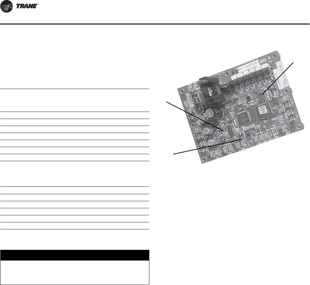
Diagnostics
122 UNT-SVX07D-EN
given in Table 53, p. 122.
Note: The output circuits are not electrically
powered; consequently, resistance can be
measured without risk of damage to the
volt-ohm meter.
Cleaning the Sensor (Wireless Controls)
You can clean the sensor by applying glass cleaner to a
soft, non-abrasive cloth, and gently wiping the face,
including the buttons and LCD display. Use of a pre-
moistened towelette designed for lens or screen cleaning
is also acceptable.
Avoid inadvertent pressing of the Occupied/Unoccupied
buttons on the keypad on the WDS sensor as this may
result in an unwanted timed override or settings change.
Troubleshooting (Tracer ZN520)
Red SERVICE LED (Tracer ZN520)
During normal operation, the LED is off continuously when
power is applied to the controller.
If the LED is on continuously, even when power is applied
to the controller means that someone is pressing the
SERVICE button or that the controller has failed.
If the LED flashes once every second, use Rover, Trane’s
service tool, to restore the unit to normal operation. Refer
to the Rover product literature for more information.
Note: If the Service button is held down for more than
15 seconds on the Tracer ZN520 controller, it will
uninstall itself from the ICS communication
network and shut down all unit operation.
Green STATUS LED (Tracer ZN520)
During normal operation, the LED is on continuously.
If the LED blinks once, the controller is in Manual output
test mode.
If the LED blinks twice the controller is in Manual output
test mode, with one or more diagnostics present.
If the LED blinks (1/4 second on, 1/4 second off for 10
seconds) the controller is in the “Wink” mode.
Note: The “wink” feature allows the identification of a
particular controller. When sending a request from
a device, such as Rover, the controller will “wink” to
indicate it received the signal.
Table 52. Receiver resistance table for all models
(wireless controls)
Zone or setpoint
temperature
Nominal zone
temperature output
resistance
Nominal setpoint
and heating
setpoint output
resistance
55°F (12.8°C) 17.47 kΩ792 Ω
60°F (15.6°C) 15.3 kΩ695 Ω
65°F (18.3°C) 13.49 kΩ597 Ω
70°F (21.1°C) 11.9 kΩ500 Ω
75°F (23.9°C) 10.5 kΩ403 Ω
80°F (26.7°C 9.3 kΩ305 Ω
85°F (29.4°C) 8.25 kΩ208 Ω
Table 53. Receiver resistance table for model WDS
(wireless controls)
Fan command Nominal output resistance
High 16,130 Ω
Med 13,320 Ω
Low 10,770 Ω
Auto 2320 Ω
Off 4870 Ω
NOTICE:
Equipment Damage!
Spraying glass cleaner or any other solution directly on
the sensor may damage it.
1. Green STATUS LED
Indicates Whether the Controller is Powered On (24 Vac Supplied)
2. Yellow COMM LED
Indicates if Communication is Functioning
3. Red SERVICE LED
Indicates if Service is Needed
1
2
3
UNT-SVX07_-EN.book Page 122 Friday, April 27, 2012 9:40 AM
Diagnostics
UNT-SVX07D-EN 123
If the LED is off, either the power is off, an abnormal
condition is present or the TEST button is pressed.
Yellow COMM LED (Tracer ZN520)
If the LED is off continuously, the controller is not detecting
any communication. This is normal for units in standalone
applications.
If the LED blinks, the controller detects communication.
If the LED is on continuously, this indicates an abnormal
condition.
Manual Output Test (Tracer ZN520)
The purpose of the manual output test sequence is to
verify output and end device operation. Use the manual
output test to:
• Verify output wiring and operation without using
Rover, service tool
• Force the water valve to open and balance the hydronic
system
Note: The manual output test is not an automatic cycle.
You must press the TEST button to proceed
through each step.
The controller observes all diagnostics that occur during
the test sequence. Although an automatic diagnostic reset
sequence exists as part of the controller’s normal
operation, the automatic diagnostic reset feature is not
active during the test sequence.
If left in an individual test step, the controller remains in
test mode for 60 minutes and then exits to normal
operation.
Many service calls are due to unit diagnostics. The test
sequence resets unit diagnostics and attempts to restore
normal unit operation prior to testing the outputs. If the
diagnostics remain after a reset, the STATUS LED indicates
the diagnostic condition is still present (two blinks).
Manual Output Test Procedure (Tracer ZN010,
ZN510, and ZN520)
Follow the procedure below to test the Tracer ZN010,
ZN510, and ZN520 controllers.
1. Press and hold the TEST button for at least two
seconds (not exceeding 5 seconds), and then release,
to start the test mode.
2. The test sequence will turn off all outputs and then
attempt to clear all diagnostics.
3. Press the TEST button several more times (no more
than once per second) to advance through the test
sequence.
The outputs are not subject to minimum times during the
test sequence. However, the test sequence only permits
one step per second which limits minimum output time.
The green LED is turned off when the TEST button is
pressed. To begin the manual output test mode, press and
hold the TEST button (turning off the green LED) for at least
two seconds.The green LED will begin to blink, indicating
the controller is in test mode.
Table 54. Test sequence for 1-heat/1-cool configurations
(Tracer ZN010, ZN510, and ZN520)
Steps
Fan
BOP1-3
Cool
Output
BOP4(a)
(a)At the beginning of the Fan High step, the controller attempts to clear
all diagnostics.
Heat
Output
BOP5
Damper
BOP6
1. Off Off Off Off Closed
2. Fan High High Off Off Closed
3. F a n Me d i u m M e d i um O f f Off C l os e d
4. Fan Low Low Off Off Closed
5. Cool High On Off Closed
6. Heat High Off On Closed
7. Fresh Air Damper(b)
(b)The fresh air damper (BOP6) only energizes during this step if binary
output 6 has been configured as a fresh air damper.
High Off Off Open
8. Exit (c)
(c) After the Fresh Air Damper step, the test sequence performs the Exit
step.This initiates a reset and attempts to return the controller to normal
operation.
Note: For all 1-heat/1-cool applications including 2-pipe changeover, BOP4
energizes in the cooling test stage and BOP5 energizes in the heat
test stage.This occurs even though during normal 2-pipe changeover
operation BOP4 controls the unit valve for both cooling and heating.
UNT-SVX07_-EN.book Page 123 Friday, April 27, 2012 9:40 AM
Diagnostics
124 UNT-SVX07D-EN
Troubleshooting (UC400)
Tab l e 5 5 through Table 60, p. 125 provide troubleshooting
information if encountering operational problems with the
UC400 controller.
Table 55. Fan does not energize (UC400)
Probable
Cause Explanation
Unit wiring The wiring between the controller outputs and the fan
relays and contacts must be present and correct for normal
fan operation. Refer to applicable wiring diagram.
Failed end
device The fan motor and relay must be checked to ensure proper
operation.
Normal
operation The fan will turn OFF when:
• The controller receives a communicated off signal
• The fan-speed switch is set to OFF if no communicated
value is present
• Specific diagnostics are generated
• The default fan speed is set to OFF and the fan is
operating in the Auto mode.
If the controller is in unoccupied mode, the fan cycles
between OFF and the highest fan speed.
No power to
the controller If the controller does not have power, the unit fan does not
operate. For the controller to operate normally, it must
have an input voltage of 24 Vac. If the Marquee/Power LED
is OFF continuously, the controller does not have sufficient
power or has failed.
Diagnostic
present Several diagnostics affect fan operation. For detailed
information about these diagnostics, refer to Table 44,
p. 116.
Unit
configuration The controller must be properly configured based on the
actual installed end devices and application. If the unit
configuration does not match the actual end device, the
fans may not work correctly.
Random start
observed After power-up, the controller always observes a random
start from 5 to 30 seconds. The controller remains OFF
until the random start time expires.
Cycling fan
operation/
continuous
The controller continuously operates the fan when in the
occupied, occupied standby, or occupied bypass mode.
When the controller is in the unoccupied mode, the fan is
cycled between high speed and OFF with capacity.
Unoccupied
operation Even if the controller is configured for continuous fan
operation, the fan normally cycles with capacity during
unoccupied mode. While unoccupied, the fan cycles ON or
OFF with heating/cooling to provide varying amounts of
heating or cooling to the space.
Fan mode off If a local fan mode switch determines the fan operation, the
OFF position controls the fan to off.
Requested
mode off The user can communicate a desired operating mode (such
as OFF, heat, and cool) to the controller. If OFF is
communicated to the controller, the unit controls the fan to
off. There is no heating or cooling.
Table 56. Valves remain closed (UC400)
Probable
Cause Explanation
Unit wiring The wiring between the controller outputs and the valve(s)
must be present and correct for normal valve operation.
Refer to applicable wiring diagram.
Failed end
device The valves must be checked to ensure proper operation.
No power to
the controller If the controller does not have power, the unit valve(s) will
not operate. For the controller to operate normally, apply
an input voltage of 24 Vac. If the Marquee/Power LED is
OFF continuously, the controller does not have sufficient
power or has failed.
Diagnostic
present Several diagnostics affect valve operation. For detailed
information about these diagnostics, refer to Table 44,
p. 116.
Normal
operation The controller opens and closes the valves to meet the unit
capacity requirements.
Unit
configuration The controller must be properly configured based on the
actual installed end devices and application. If the unit
configuration does not match the actual end device, the
valves may not work correctly.
Random start
observed After power-up, the controller always observes a random
start from 5 to 30 seconds. The controller remains OFF
until the random start time expires.
Requested
mode off The user can communicate a desired operating mode (such
as OFF, heat, and cool) to the controller. If OFF is
communicated to the controller, the unit controls the fan to
off. There is no heating or cooling.
Entering water
temperature
sampling logic
The controller includes entering water temperature
sampling logic, which is automatically initiated during
2-pipe and 4-pipe changeover, if the entering water
temperature is either too cool or too hot for the desired
heating or cooling.
Valve
configuration Ensure the valves are correctly configured, using the Tracer
TU service tool, as normally open or normally closed as
dictated by the application.
Table 57. Valves remain open (UC400)
Probable
Cause Explanation
Unit wiring The wiring between the controller outputs and the valve(s)
must be present and correct for normal valve operation.
Refer to applicable wiring diagram.
Failed end
device The valves must be checked to ensure proper operations.
Normal
operation The controller opens and closes the valves to meet the unit
capacity requirements.
Diagnostic
present Several diagnostics affect valve operation. For detailed
information about these diagnostics, refer to Table 44,
p. 116.
Unit
configuration The controller must be properly configured based on the
actual installed end devices and application. If the unit
configuration does not match the actual end device, the
valves may not work correctly.
Entering water
temperature
sampling logic
The controller includes entering water temperature
sampling logic, which is automatically initiated during 2-
pipe and 4-pipe changeover, if the entering water
temperature is either too cool or too hot for the desired
heating or cooling.
Valve
configuration Ensure the valves are correctly configured, using the Tracer
TU service tool, as normally open (NO) or normally closed
(NC) as dictated by the application.
Freeze
avoidance When the fan is OFF with no demand for capacity (0%),
and the outdoor air temperature is below the freeze
avoidance setpoint, the controller opens the water valves
(100%) to prevent coil freezing. This includes unoccupied
mode when there is no call for capacity or any other time
the fan is OFF.
Table 56. Valves remain closed (UC400) (continued)
Probable
Cause Explanation
UNT-SVX07_-EN.book Page 124 Friday, April 27, 2012 9:40 AM
Diagnostics
UNT-SVX07D-EN 125
Table 58. DX or electric heat does not energize (UC400)
Probable
Cause Explanation
Unit wiring The wiring between the controller outputs and the end
devices must be present and correct for normal operation.
Refer to applicable wiring diagram.
Failed end
device Check the control contactors or the electric heat element,
including any auxiliary safety interlocks, to ensure proper
operation.
No power to
the controller If the controller does not have power, heat outputs do not
operate. For the controller to operate normally, apply an
input voltage of 24 Vac. If the Marquee/Power LED is OFF
continuously, the controller does not have sufficient power
or has failed.
Diagnostic
present Several diagnostics affect DX and electric heat operation.
For detailed information about these diagnostics, refer to
Table 44, p. 116.
Normal
operation The controller controls compressor or electric heat outputs
as needed to meet the unit capacity requirements.
Unit
configuration The controller must be properly configured based on the
actual installed end devices and application. If the unit
configuration does not match the actual end device, DX or
electric heat may not operate correctly.
Requested
mode off The user can communicate a desired operating mode (such
as OFF, heat, and cool) to the controller. If OFF is
communicated to the controller, the unit shuts off the
compressor or electric heat.
Freeze
avoidance When the fan is OFF with no demand for capacity (0%),
and the outdoor air temperature is below the freeze
avoidance setpoint, the controller disables compressors
and electric heat outputs (100%) to prevent coil freezing.
This includes unoccupied mode when there is no call for
capacity or any other time the fan is OFF.
Table 59. Outdoor air damper remains closed (UC400)
Probable
Cause Explanation
Unit wiring The wiring between the controller outputs and the outdoor
air damper must be present and correct for normal outdoor
air damper operation. Refer to applicable wiring diagram.
Failed end
device Check damper actuator to ensure proper operation.
No power to
the controller If the controller does not have power, the outdoor air
damper does not operate. For the controller to operate
normally, apply an input voltage of 24 Vac. If the Marquee/
Power LED is OFF continuously, the controller does not
have sufficient power or has failed.
Diagnostic
present Several diagnostics affect outdoor air damper operation.
For detailed information about these diagnostics, refer to
Table 44, p. 116.
Normal
operation The controller opens and closes the outdoor air damper
based on the controller’s occupancy mode and fan status.
Normally, the outdoor air damper is open during occupied
mode when the fan is running and closed during
unoccupied mode.
Unit
configuration The controller must be properly configured based on the
actual installed end devices and application. If the unit
configuration does not match the actual end device, the
outdoor air damper may not work correctly.
Warm-up and
cool-down
sequence
The controller includes both a morning warm-up and cool-
down sequence to keep the outdoor air damper closed
during the transition from unoccupied to occupied. This is
an attempt to bring the space under control as quickly as
possible.
Requested
mode off The user can communicate a desired operating mode (such
as OFF, heat, or cool) to the controller. If OFF is
communicated to the controller, the unit closes the outdoor
air damper.
Table 60. Outdoor air damper remains open
Probable
Cause Explanation
Unit wiring The wiring between the controller outputs and the outdoor
air damper must be present and correct for normal outdoor
air damper operation. Refer to applicable wiring diagram.
Failed end
device Check damper actuator to ensure proper operation.
Normal
operation The controller opens and closes the outdoor air damper
based on the controller occupancy mode and fan status.
Normally, the outdoor air damper is open during occupied
mode when the fan is running and closed during
unoccupied mode. (Refer to the section, “Modulating
Outdoor/Return Air Damper (UC400),” p. 102.)
Unit
configuration The controller must be properly configured based on the
actual installed end devices and application. If the unit
configuration does not match the actual end device, the
outdoor air damper may not work correctly.
UNT-SVX07_-EN.book Page 125 Friday, April 27, 2012 9:40 AM
Diagnostics
126 UNT-SVX07D-EN
Troubleshooting (ECM)
Notes:
•The new Trane BLDC system is a closed loop system
that has equipment protections and envelope
enforcements. Do not assume that the motor has failed
without first consulting the ECM engine status/
diagnostics screen. In many cases, the engine shuts
down the motor operation and locks it out to prevent
equipment damage.
•Electric Heat operation and Changeover Coil control on
CSTI units are co-coordinated by the ECM engine
board. Changeover function on Tracer ZN units can
also be affected by incorrect configuration of the ECM
engine or improper wiring of terminals to analog
input 1 on the Tracer ZN controller (polarity
sensitivity).
•The mini-access lid on the front of the main control
panel lid has the ECM engine troubleshooting/setup
guide affixed to the back of the lid. This guide is unit-
specific and should be consulted before determining
the disposition of a unit.
General Information (ECM)
The ECM engine oversees and monitors all motor
operations and changes to speed resulting from:
• Direct Fan Speed Requests
– Customer Fan Speed Switches
–Thermostat Fan Speed, On or 0–10V requests
– Automatic Fan Request from Tracer ZN / UC
controllers
• Indirect Fan Speed Requests
– Electric Heat requests will bring the fan to the
proper speed.
• Conflicting Fan Speed Requests
– If two or more commands are received (direct or
indirect), the fan will honor the higher speed
requested.
Note: In some cases, indirect requests will result in fan
behavior change regardless of whether the end-
device fails to actuate (due to device failure, or
safety/down-stream lockouts).
The ECM engine board also coordinates the operation of
Electric Heat, Electric/Hydronic Heat lockouts, and CSTI
Changeover coil operation.
Troubleshooting Information (ECM)
General system troubleshooting tips (ECM)
• ECM engine configuration must perfectly match the
factory-supplied ECM.
– Refer to “ECM Overview and Setup,” p. 53 for
troubleshooting configuration of the engine board.
• The ECM engine will display troubleshooting
information, and contains dual tachometers to aid in
performance verification.
• Under normal circumstances, the ECM engine display
will display the operational status of the motors and
electric heat circuit/sensors, however, a malfunction
will drive a priority display mode that will present the
error code instantly to the screen. The error must be
cleared by solving by powering down, removing the
cause of the problem and restarting the engine board.
• Engine Label setup document (affixed to the back of the
low voltage access lid) should be used to verify engine
configuration settings.
• For proper operation of the system, all plugs must be
firmly seated in all boards and motors. Insecure
WARNING
Hazardous Voltage w/Capacitors!
Disconnect all electric power, including remote
disconnects and discharge all motor start/run
capacitors before servicing. Follow proper lockout/
tagout procedures to ensure the power cannot be
inadvertently energized. For variable frequency drives
or other energy storing components provided by Trane
or others, refer to the appropriate manufacturer’s
literature for allowable waiting periods for discharge of
capacitors. Verify with an appropriate voltmeter that all
capacitors have discharged. Failure to disconnect
power and discharge capacitors before servicing could
result in death or serious injury.
WARNING
Safety Alert!
You MUST follow all recommendations below. Failure
to do so could result in death or serious injury.
• The BLDC motors contain capacitors which store
residual energy. Please keep clear of the fan wheels
for 5 minutes after the power has been removed from
the system, as a power request with the motor
powered off, could result in a very short period of
actuation. Unplugging the motor is adequate to
ensure that there will be no power request.
• The adapter boards contain high voltage.
Configuration adjustments to the ECM engine board
should be made through the SMALLER of the two
low-voltage lids on the front of the control panel,
through the low-voltage insulation/shielding.
• Initial hookups to the CSTI and standard adapter
boards, including low voltage interconnections,
must be made with the power off.
• Do not make connections to the motors or the
adapter boards while power is ON. Do not remove
connections to the motor or the adapter boards while
the power is ON.
UNT-SVX07_-EN.book Page 126 Friday, April 27, 2012 9:40 AM

Diagnostics
UNT-SVX07D-EN 127
connections will cause malfunction and the system
will shutdown.
• Do not unplug or plug-in motors or connectors while
the system is receiving a speed request of any kind.
The system must be powered down before plugging or
un-plugging connections to the adapter boards,
engine boards or motors. Failure do so will register
diagnostics or cause unsafe operation and reduction in
the contact life of the connectors.
• The motor will not spin if plugged in while the ECM
engine is requesting power.
Troubleshooting a motor that does not spin,
or spins too slowly (ECM)
The motor connections and motor plug connections to the
adapter boards should be secure. Unit should be powered
off to check the fit of the connectors.
When configured correctly, the system will always
respond positively to direct, indirect, and conflicting speed
requests with very few exceptions:
These exceptions are:
1. If a motor has been locked out due to engine locked
rotor protection:
– Assuming Motor 1 has an obstruction. In this case,
the “Status Display” will be interrupted to display:
→→
Solution:
i. Remove obstruction from the fan wheel.
ii. Ensure that motor plugs and all plugs to adapter
boards and the ECM engine board are secure
iii. Verify that the configuration does not specify a
motor that is physically missing. Most units
require only one motor. The controller is made
aware of the missing motor by specifying all
speeds related to Motor 2 to 0 rpm.
iv. Verify that and , the low motor
signal output limits, are set correctly.
2. If a motor has been locked out due to overspeed or
runaway condition:
– Assuming Motor 1 has an overspeed condition. In
this case, the “Status Display” will be interrupted to
display:
→→
Solution:
i. Ensure that set-screw is attached firmly to the
motor shaft.
ii. Ensure that motor plugs and all plugs to adapter
boards and the ECM engine board are secure.
iii. Verify that the configuration does not specify a
speed lower than 450 rpm for the affected motor.
Speeds below 450 rpm are not supported on fan-
coil units.
3. VSP Inputs (0–10V inputs) are of the wrong polarity
– Verify that variable speed (VSP) inputs are properly
wired to 1TB4.
Notes:
•Do not short the courtesy 10 Vdc supply to chassis
or loads that require greater than 10 mA of DC
current.
•Please observe proper polarity of 0–10 Vdc inputs.
Failure to observe proper polarity can cause failure
of the ECM engine board, the customer-supplied
controller or the Tracer ZN controller.
4. Customer Controller output signal to VSP Inputs are
too low.
Note: If the customer supplied controller outputs
signals that are below the noise threshold, they
will be ignored by the ECM Engine.
– The ECM Engine board contains an adjustable
noise floor parameter, - that can be configured
to reject signals below the noise floor.
– If the noise floor parameter is set too high, it can be
lowered as long as there are acceptable noise levels
on the inputs lines.
Troubleshooting a motor that spins too fast, or
spins without any apparent speed request
(ECM)
Typical equipment and controls design practice will
ensure that the fans will come on if there is a call for heat,
cool, or ventilation. In most cases, we will depend on the
controller/thermostat to call for the fan to come on when
appropriate, but during calls for electric heat, or calls for
heat on CSTI units equipped with electric heat, as a call for
the appropriate fan speed. This behavior, as described
previously, is an indirect request.
When a call for electric heat is made, the system will
positively drive the fan on to the correct speed, regardless
of whether the controller has asked for fan operation or
not. The unit design incorporates an interlock instead of a
lock-out. (It does not lock out electric heat if the fan is set
to off; it brings the fan on.)
Notes:
•In many cases, indirect requests will result in fan
behavior change regardless of whether the end-device
fails to actuate (due to device failure, or safety/down-
stream lockouts). If there is hot water available on CSTI
units with changeover coils and electric heat, we will
still drive the fan to the appropriate electric heat speed.
•The new fan coil designs incorporate sophisticated fan
interlocks that will lockout heat if there is a fan failure.
If the preceding conditions do not describe the behavior of
the unit, the following checks should be performed:
UNT-SVX07_-EN.book Page 127 Friday, April 27, 2012 9:40 AM

Diagnostics
128 UNT-SVX07D-EN
• Verify that the voltage jumper on the motor plug
harness is absent for 208-230V units and 277V units. If
the jumper is present for these units, the motor
electronics will be damaged, and the motor will not be
controllable.
• Verify that the fan speed request is not below 450 rpm.
Speeds below 450 rpm are not supported on the fan-
coil product.
• Verify that the all binary inputs to the customer
terminal blocks are of proper and consistent polarity.
– For CSTI units, the fan inputs and end device inputs
on TB3 must receive signals that are 24 Vac with
respect to the unit chassis.
Note: Do not short 24 Vac (pos 1 or pos 2) to
chassis; refer to the unit schematic.
– For Fan Speed Switch units, that incorporate the
Tracer ZN/CSTI adapter board, all inputs to TB3
must be 24 Vac with respect to unit chassis.
Note: Do not short 24 Vac (pos 1 or pos 2) to
chassis; refer to the unit schematic.
– For Tracer ZN units, where there is a desire to use
parallel fan inputs on the adapter board TB3 strip,
the inputs must be COM (i.e., the inputs will honor
only 0 V with respect to unit chassis).
Note: Do not short 24 Vac (pos 1 or pos 2) to
chassis; refer to the unit schematic.
• Verify that variable speed (VSP) inputs are properly
wired to 1TB4.
Notes:
•Do not short the courtesy 10 Vdc supply to chassis
or loads that require greater than 10 mA of DC
current.
•Please observe proper polarity of 0–10 Vdc inputs.
Failure to observe proper polarity can cause failure
of the ECM Engine board, the customer-supplied
controller or the Tracer ZN controller.
• Verify that the signal on the VSP inputs is noise free.
The ECM engine board contains an adjustable noise
floor parameter, -, that can be configured to reject
signals below the noise floor.
Note: If the customer supplied controller outputs
signals that are below the noise threshold, they
will be ignored by the ECM engine.
• Verify that VSP input settings are correct. The ECM
engine board contains an adjustable digital amplifier,
, to compensate for long 10 Vdc cable runs. For
normalized (0–10 Vdc) signals, this setting should be
set to 1.000. If it is set too high, the motors will faster
than the requested ratio, and will hit the limit
before the input voltage has reached its upper limit.
• Verify that and , the low motor signal
output limits, are set correctly.
UNT-SVX07_-EN.book Page 128 Friday, April 27, 2012 9:40 AM
UNT-SVX07D-EN 129
Replacing ECM Components
Notes:
•Ensure that drip-loops are maintained on wiring on
pipe end of unit to avoid wicking of water into the unit.
WARNING
Hazardous Voltage w/Capacitors!
Disconnect all electric power, including remote
disconnects and discharge all motor start/run
capacitors before servicing. Follow proper lockout/
tagout procedures to ensure the power cannot be
inadvertently energized. For variable frequency drives
or other energy storing components provided by Trane
or others, refer to the appropriate manufacturer’s
literature for allowable waiting periods for discharge of
capacitors. Verify with an appropriate voltmeter that all
capacitors have discharged. Failure to disconnect
power and discharge capacitors before servicing could
result in death or serious injury.
WARNING
Safety Alert!
You MUST follow all recommendations below. Failure
to do so could result in death or serious injury.
• The BLDC motors contain capacitors which store
residual energy. Please keep clear of the fan wheels
for 5 minutes after the power has been removed from
the system, as a power request with the motor
powered off, could result in a very short period of
actuation. Unplugging the motor is adequate to
ensure that there will be no power request.
• The adapter boards contain high voltage.
Configuration adjustments to the ECM engine board
should be made through the SMALLER of the two
low-voltage lids on the front of the control panel,
through the low-voltage insulation/shielding.
• Initial hookups to the CSTI and standard adapter
board, including low voltage interconnections, must
be made with the power off.
• Do not make connections to the motors or the
adapter boards while power is ON. Do not remove
connections to the motor or the adapter boards while
the power is ON.
• Caution should be taken to stay clear of hazardous
voltages, moving parts and electric heat elements
while making adjustments to the ECM engine board.
If it is not practical to stay clear of these areas during
adjustment of the ECM engine board, please contact
Trane Global Parts for configuration kit that allows
easy powering of the engine board outside of the unit
with a 9V battery.
• For safe operation, it is necessary to configure
replacement boards to match the setup/switch
configuration of the previously installed boards.
• Ensure that new circuit modules are firmly seated on
the nylon standoffs, and that the nylon standoffs are
firmly seated on the metal panel.
NOTICE:
Equipment Damage!
The motor harness attached to the single plug to which
the motor mates contains the very important 115V
motor voltage jumper; the motor harness should
always be present for 115V units and should not be
modified or substituted. Failure to follow this
instruction could result in equipment damage.
UNT-SVX07_-EN.book Page 129 Friday, April 27, 2012 9:40 AM
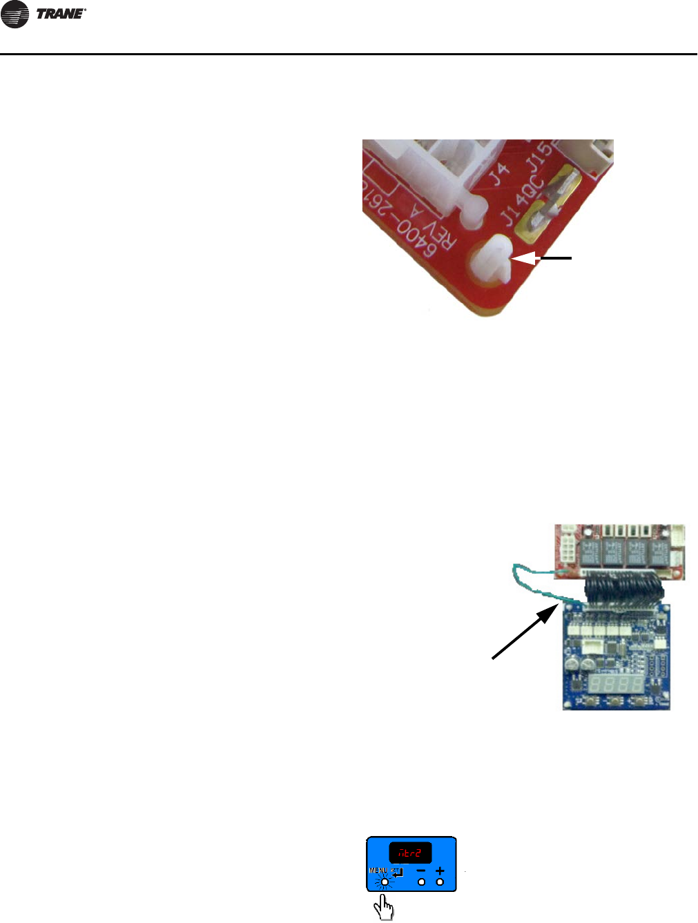
Replacing ECM Components
130 UNT-SVX07D-EN
•Before assuming that any of the boards or components
in the new system have failed, please ensure that the
ECM engine board has been configured correctly and
that the switches on the CSTI board (where applicable)
are set correctly.
•It is necessary to configure the service replacement
ECM engine board before commissioning the unit. The
ECM engine board is pre-configured with safe values,
but will NOT work correctly unless properly
configured.
•Only genuine Trane® replacement components with
identical Trane part numbers should be used.
•Unit fan assemblies contain concealed wires that
should be removed before the fan-board is removed,
to avoid nicking the wire.
•Care should be maintained to retain the order of the
motors with respect to the motor plugs. On a unit with
two motors, the double-shafted motor will always be
to the left side, and will be designated as Motor 2 by the
controller.
Tips:
•Ensure that motor nameplate voltage is the same as
unit voltage (for 3-phase/ 4-wire units with Neutral,
motor voltage will be L-N, not L1-L2).
•Ensure that motor harness is correct (harness will have
jumper installed for 115V units only).
•Ensure that configuration on ECM Engine matches the
affixed label.
•Maintain correct plug/motor association. The plugs
will have the motor number and shaft configuration
printed on an affixed label.
•Ensure that configuration of switches on CSTI adapter
board matches depiction of switches on the unit
schematic.
•Ensure that all wires are plugged in securely.
•Ensure that edge protection on sharp edges,
grommets, and wire management devices are
maintained when replacing components.
•Ensure that blunt-tip screws are used when in the
proximity of wire harnesses.
Circuit Modules Replacement Notes/Work
Instructions
1. Circuit modules are equipped with nylon standoffs
which can either be removed by squeezing the barbs at
the rear of the control panel, or squeezing the latch
above the circuit module. If the latter method is chosen,
the standoffs will be retained on the metal panel. The
new standoffs (affixed to the replacement modules)
can be removed if necessary, so the new module circuit
board can be attached to the retained standoffs.
2. If replacing the ECM engine module, special care
should be taken to avoid electro-static discharge
damage. Please use an ESD protection wrist-strap and
frequently touch a grounded surface (with unit power
off) to discharge any static buildup.
3. Replace connectors carefully onto the appropriate
board. For units with a green wire attached to the CSTI
or standard adapter boards, please ensure that the
green wire is attached to the engine board white
connector as shown in Figure 45.
4. Ensure that the new ECM engine controller is
configured to match the ECM engine configuration
label that is present on the unit. It is necessary to
configure the ECM engine board to avoid improper
operation of the unit, discomfort to the end user, and
loud fan operation.
Figure 44.
Figure 45.
Depress latch to
remove PCB, leaving
standoff attached to
the metal panel.
Green wire attached to
white plug on blue ECM
engine board, and to
quick-connect terminal
on the adapter board.
UNT-SVX07_-EN.book Page 130 Friday, April 27, 2012 9:40 AM
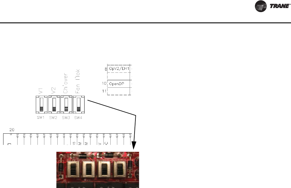
Replacing ECM Components
UNT-SVX07D-EN 131
5. Ensure that the CSTI adapter board switches are set
correctly, as indicated on the attached unit schematic
(where applicable).
6. After replacing modules, commission the unit by
performing at a minimum, “Fan Speed Response
Verification,” p. 72.
Figure 46.
UNT-SVX07_-EN.book Page 131 Friday, April 27, 2012 9:40 AM
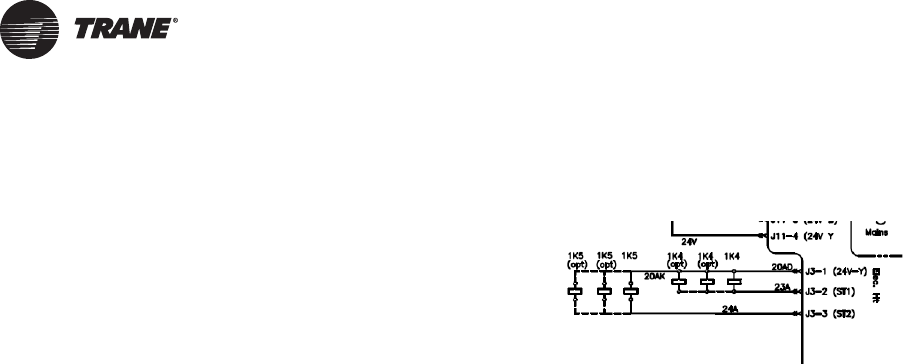
132 UNT-SVX07D-EN
ECM Application Notes
The new Trane BLDC system has some notable differences
to traditional designs.
RPM Mode
The motors are programmed from the factory to run in
rpm mode and will not change rpm based on external
static pressure, except at the performance limits of the
motor/controller. For ducted units, the units are shipped
with the rpm set for 0.2” ESP for High, Medium, and Low
speeds. The speeds can for high, medium, and low
operation, but should not be changed for the electric heat
actuation speeds.
Generally, the fans deliver less cfm for the same rpm, if the
static is increased and the power will decrease. The fan will
deliver more cfm for the same rpm, if the static is
decreased and the fan power will increase. A unit with high
static configuration should not be used to free-deliver air
(i.e., with no ducting attached).
Field Power Wiring
Note: This product uses an electronic variable speed
motor control, which includes a line reactor to
minimize power line harmonic currents. It is
recommended that good wiring practices be
followed to manage building electrical power
system harmonic voltages and currents to avoid
electrical system problems or other equipment
interaction.
Performance Boundaries
While the speeds of the fan motors can be adjusted, never
program a fan speed higher than 1700 rpm, or lower than
450 rpm. In many cases, units configured for high-static
operation will not achieve the desired rpm if the ESP of the
unit is too low, or the unit is allowed to “free-discharge.”
The ECM engine contains settings that will limit the output
power of the motor under these overload conditions. If the
motors cannot achieve rpm close to the target for a specific
period of time, the unit will disable electric heat and fan-
status indicators.
MCA/MFS and Power Draw
The Trane BLDC motors have variable output but are
shipped at specific settings to deliver proper performance
and reliability. The power draw indicated in the catalogue
indicates the power consumed when applied properly (as
shipped and with the nominal ESP applied). However, the
nameplate of the unit indicates the maximum input draw
of the motor, as the motor settings can be changed to draw
more power.
Electric Heat Relays
For quiet operation, the new BLDC units employ power
relays instead of definite purpose contactors for electric
heat actuation. The coils of multiple relays are hooked in
parallel to simulate a multi-pole contactor, as shown in
Figure 47. In Figure 47, two sets of three relays are used to
perform the function of a two 3-pole contactors.
Troubleshooting Other Unit Functions
In some cases, the normal or abnormal operation of the
BLDC system may interact with other components in the
system. Generally, verification of the engine and adapter
boards’ wiring and configuration should be checked if
there are unexplained abnormalities in other areas of the
unit:
1. Valve operation
2. Electric Heat operation
3. Changeover sensor operation
4. Damper operation
5. Condensate overflow switch
A high degree of protection is provided on electric heat
units. If electric heat fails to actuate, it may be because of
one of the following events:
1. Fans are failing to meet target speed. If a second motor
is not present, all settings for speeds for Motor 2
should be set to 0000.
2. Hot water may be available in the changeover coil.
3. The connection to analogue input 1 on the Tracer ZN
controller may be reversed in polarity.
4. Target speeds for motors may be set too high:
a. The parameter may be set incorrectly.
b. The parameter may be set incorrectly.
Figure 47. Sample arrangement: electric heat relay
UNT-SVX07_-EN.book Page 132 Friday, April 27, 2012 9:40 AM
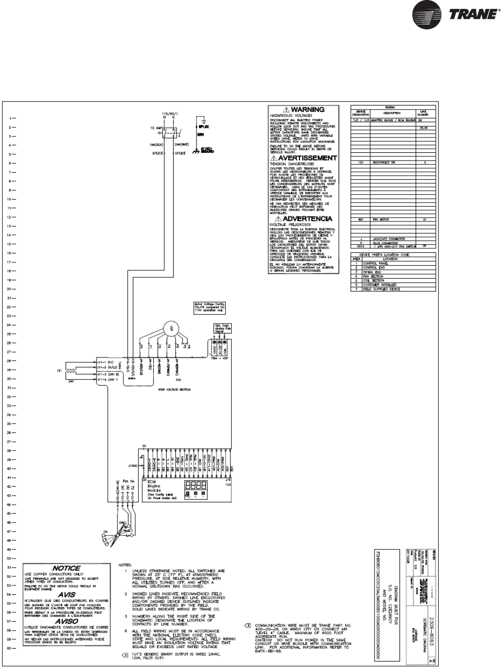
UNT-SVX07D-EN 133
Wiring Diagrams
Figure 48. Unit-mounted fan speed switch with factory-mounted disconnect
UNT-SVX07_-EN.book Page 133 Friday, April 27, 2012 9:40 AM
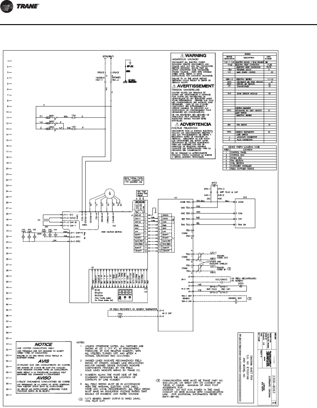
Wiring Diagrams
134 UNT-SVX07D-EN
Figure 49. Tracer ZN 520 unit with two-stage electric heat and unit-mounted zone sensor
UNT-SVX07_-EN.book Page 134 Friday, April 27, 2012 9:40 AM
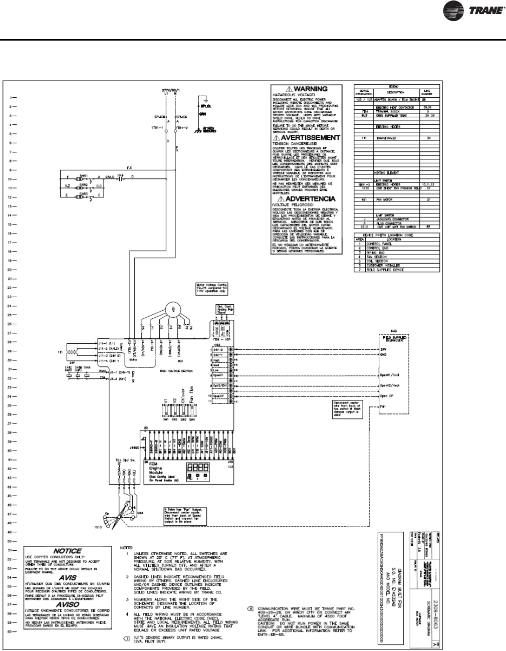
Wiring Diagrams
UNT-SVX07D-EN 135
Figure 50. CSTI unit with single-stage electric heat and unit-mounted fan switch (Note: CSTI configuration switches)
UNT-SVX07_-EN.book Page 135 Friday, April 27, 2012 9:40 AM
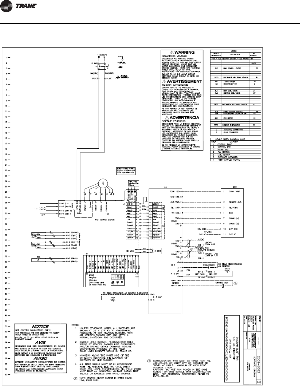
Wiring Diagrams
136 UNT-SVX07D-EN
Figure 51. Tracer ZN520 unit with four-pipe configuration, condensate overflow switch and wall-mounted zone sensor
UNT-SVX07_-EN.book Page 136 Friday, April 27, 2012 9:40 AM
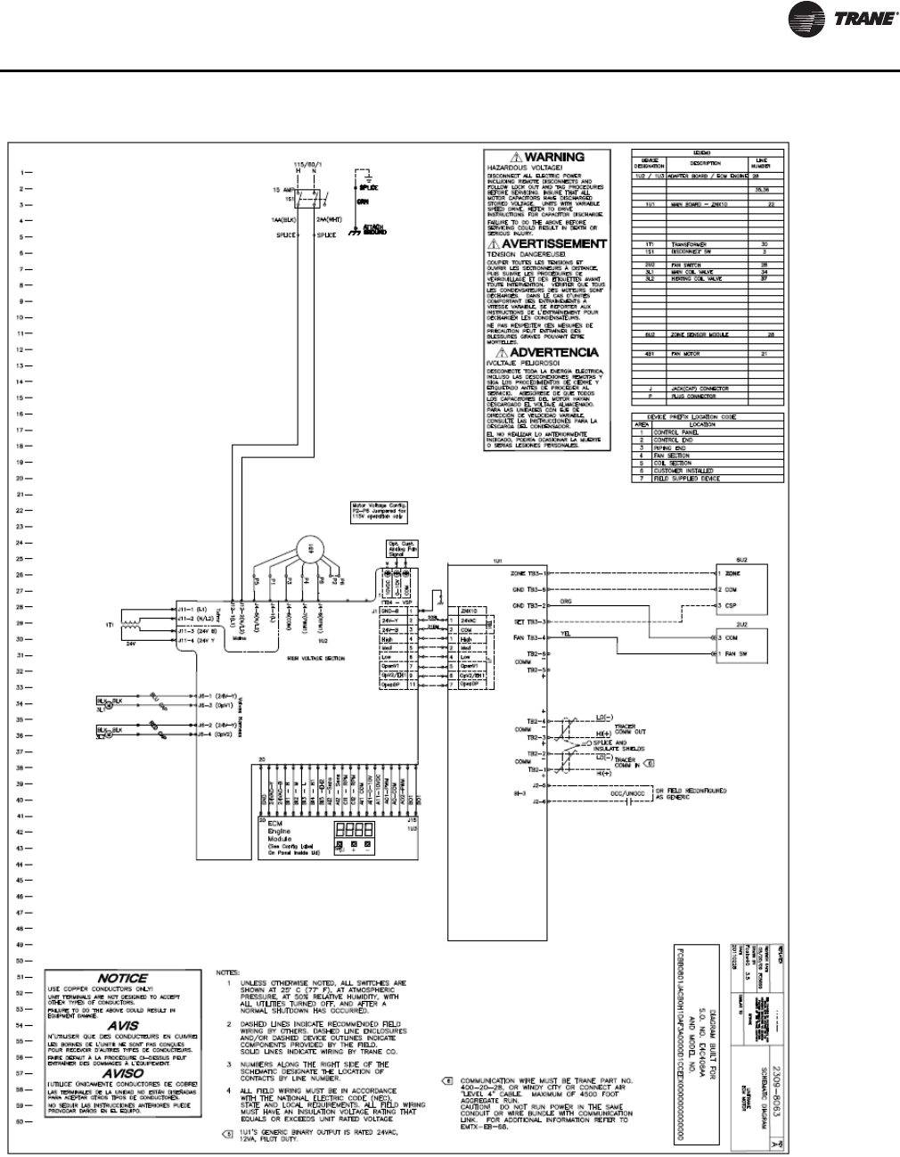
Wiring Diagrams
UNT-SVX07D-EN 137
Figure 52. Tracer ZN510 unit with four-pipe configuration and split zone sensor/unit fan switch configuration
UNT-SVX07_-EN.book Page 137 Friday, April 27, 2012 9:40 AM

Trane optimizes the performance of homes and buildings around the world. A business of Ingersoll Rand, the
leader in creating and sustaining safe, comfortable and energy efficient environments, Trane offers a broad
portfolio of advanced controls and HVAC systems, comprehensive building services, and parts.
For more information, visit www.Trane.com.
Trane has a policy of continuous product and product data improvement and reserves the right to change design and specifications without notice.
We are committed to using environmentally
conscious print practices that reduce waste.
© 2012 Trane All rights reserved
UNT-SVX07D-EN 27 Apr 2012
Supersedes UNT-SVX07C-EN (01 Nov 2011)
UNT-SVX07_-EN.book Page 138 Friday, April 27, 2012 9:40 AM
