Trane Vertical Stack Fan Coil Catalogue
2015-04-02
: Trane Trane-Vertical-Stack-Fan-Coil-Catalogue-684304 trane-vertical-stack-fan-coil-catalogue-684304 trane pdf
Open the PDF directly: View PDF ![]() .
.
Page Count: 40
Vertical Stack Fan Coil Units
Model RSG
3/4 through 4 ton capacity
July 2013 UNT-PRC019-EN
Catalog
UNT-PRC019-EN_072013_Vertical Stack Fan Coil.book Page 1 Wednesday, July 17, 2013 9:37 AM
2 UNT-PRC019-EN
Vertical Stack Fan Coil Units
Trane vertical stack fan coil units are used in high-rise hotels, condominiums, dormitories, military
barracks, and residential buildings. Trane specializes in flexible response to customers’ needs.
We work closely with engineers at the design stage to ensure optimum use of the units within the
HVAC system.
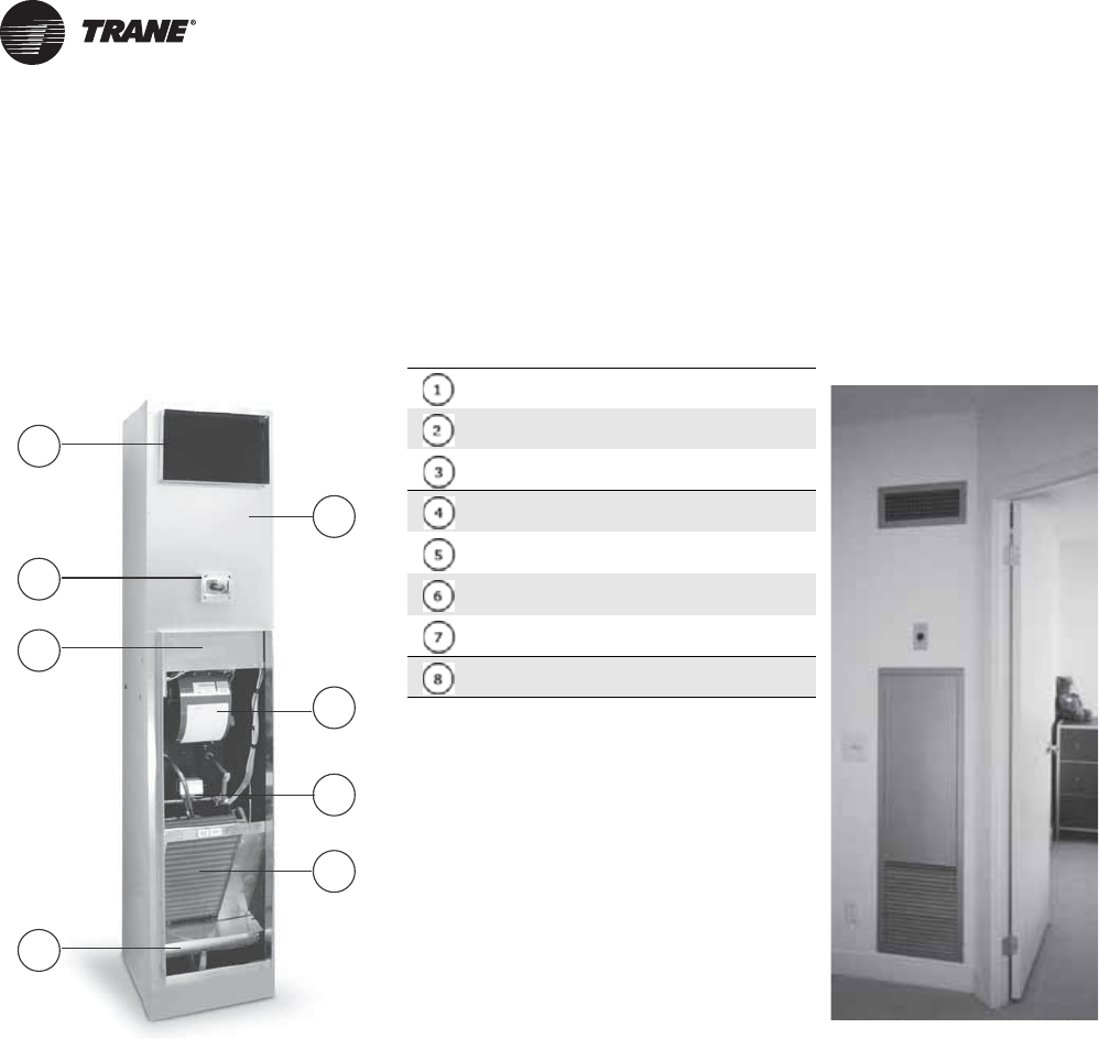
Figure 1. Fan coil - Model RSG Figure 2. Furred-in fan coil
18 ga. galvanized cabinet with acoustical liner
Direct-drive centrifugal fan - PSC fan motor
with sealed bearings standard
Piping package factory installed (HW pre-
heat)
CW/HW coils - 2-pipe or 4-pipe
Drain pan - galvanized, positively sloped to
outlet - standard
Optional electric heater (behind panel)
Optional electrical box for unit-mounted
thermostat
Supply air opening (multiple openings
available)
Also available but not shown:
•Risers
• Double deflection supply air grille/
registers
• Return air panel
•Filter
• Fan shield/motor cover
Grille and return air panel
standard color is white.
6
2
4
5
8
1
7
3
UNT-PRC019-EN_072013_Vertical Stack Fan Coil.book Page 2 Wednesday, July 17, 2013 9:37 AM

Table of Contents
UNT-PRC019-EN 3
Vertical Stack Fan Coil Units . . . . . . . . . . . . . . . . . . . . . . . . . . . . . . . . . . . . . . . . . 2
Model Number Description . . . . . . . . . . . . . . . . . . . . . . . . . . . . . . . . . . . . . . . . . . 5
Riser Package . . . . . . . . . . . . . . . . . . . . . . . . . . . . . . . . . . . . . . . . . . . . . . . . . . . 6
Raised Base Package . . . . . . . . . . . . . . . . . . . . . . . . . . . . . . . . . . . . . . . . . . . . . 6
Supply Air Grille/Registers . . . . . . . . . . . . . . . . . . . . . . . . . . . . . . . . . . . . . . . . 7
Filters . . . . . . . . . . . . . . . . . . . . . . . . . . . . . . . . . . . . . . . . . . . . . . . . . . . . . . . . . 7
Performance Data . . . . . . . . . . . . . . . . . . . . . . . . . . . . . . . . . . . . . . . . . . . . . . . . . 8
Cooling Capacities . . . . . . . . . . . . . . . . . . . . . . . . . . . . . . . . . . . . . . . . . . . . . . . 8
Heating Capacities . . . . . . . . . . . . . . . . . . . . . . . . . . . . . . . . . . . . . . . . . . . . . . . 9
Sound Data . . . . . . . . . . . . . . . . . . . . . . . . . . . . . . . . . . . . . . . . . . . . . . . . . . . 10
Components and Options . . . . . . . . . . . . . . . . . . . . . . . . . . . . . . . . . . . . . . . . . . 11
Electric Heat . . . . . . . . . . . . . . . . . . . . . . . . . . . . . . . . . . . . . . . . . . . . . . . . . . . 11
Fans Curves . . . . . . . . . . . . . . . . . . . . . . . . . . . . . . . . . . . . . . . . . . . . . . . . . . . 13
Motor Data . . . . . . . . . . . . . . . . . . . . . . . . . . . . . . . . . . . . . . . . . . . . . . . . . . . . 16
Control Packages . . . . . . . . . . . . . . . . . . . . . . . . . . . . . . . . . . . . . . . . . . . . . . . 16
Thermostats . . . . . . . . . . . . . . . . . . . . . . . . . . . . . . . . . . . . . . . . . . . . . . . . . 16
Tracer ZN521 Zone Controller . . . . . . . . . . . . . . . . . . . . . . . . . . . . . . . . . . 17
Tracer UC400 Controller . . . . . . . . . . . . . . . . . . . . . . . . . . . . . . . . . . . . . . . 20
Dimensions and Weights . . . . . . . . . . . . . . . . . . . . . . . . . . . . . . . . . . . . . . . . . . 22
Vertical Fan Coil Units . . . . . . . . . . . . . . . . . . . . . . . . . . . . . . . . . . . . . . . . . . . 22
2-Pipe Chilled Water Cooling Unit . . . . . . . . . . . . . . . . . . . . . . . . . . . . . . . 22
2-Pipe Chilled Water Cooling Unit with Electric Heat . . . . . . . . . . . . . . . . 24
4-Pipe Chilled Water Cooling and Hot Water Heating Unit . . . . . . . . . . . 26
Fan Coil Units Without Risers . . . . . . . . . . . . . . . . . . . . . . . . . . . . . . . . . . . 28
Riser Packages . . . . . . . . . . . . . . . . . . . . . . . . . . . . . . . . . . . . . . . . . . . . . . . . . 29
Raised Base Options . . . . . . . . . . . . . . . . . . . . . . . . . . . . . . . . . . . . . . . . . . . . 31
Raised Base . . . . . . . . . . . . . . . . . . . . . . . . . . . . . . . . . . . . . . . . . . . . . . . . . 31
Raised Base with Condensate Pump and Front Access Panel . . . . . . . . . 32
Return Air Panels . . . . . . . . . . . . . . . . . . . . . . . . . . . . . . . . . . . . . . . . . . . . . . . 33
Return Air Panel with Flush Mount . . . . . . . . . . . . . . . . . . . . . . . . . . . . . . 33
Return Air Panel with Framed Out Drywall with Hinged Filter Access . . 34
Fan Coil Weights . . . . . . . . . . . . . . . . . . . . . . . . . . . . . . . . . . . . . . . . . . . . . . . 35
Mechanical Specifications . . . . . . . . . . . . . . . . . . . . . . . . . . . . . . . . . . . . . . . . . . 36
Certifications . . . . . . . . . . . . . . . . . . . . . . . . . . . . . . . . . . . . . . . . . . . . . . . . 36
Construction . . . . . . . . . . . . . . . . . . . . . . . . . . . . . . . . . . . . . . . . . . . . . . . . 36
Fan . . . . . . . . . . . . . . . . . . . . . . . . . . . . . . . . . . . . . . . . . . . . . . . . . . . . . . . . 36
Motors . . . . . . . . . . . . . . . . . . . . . . . . . . . . . . . . . . . . . . . . . . . . . . . . . . . . . 36
Coils . . . . . . . . . . . . . . . . . . . . . . . . . . . . . . . . . . . . . . . . . . . . . . . . . . . . . . . 36
Piping Packages . . . . . . . . . . . . . . . . . . . . . . . . . . . . . . . . . . . . . . . . . . . . . . 36
UNT-PRC019-EN_072013_Vertical Stack Fan Coil.book Page 3 Wednesday, July 17, 2013 9:37 AM

4 UNT-PRC019-EN
Electric Heat . . . . . . . . . . . . . . . . . . . . . . . . . . . . . . . . . . . . . . . . . . . . . . . . . 36
Filters . . . . . . . . . . . . . . . . . . . . . . . . . . . . . . . . . . . . . . . . . . . . . . . . . . . . . . 37
Controls . . . . . . . . . . . . . . . . . . . . . . . . . . . . . . . . . . . . . . . . . . . . . . . . . . . . 37
Riser Package . . . . . . . . . . . . . . . . . . . . . . . . . . . . . . . . . . . . . . . . . . . . . . . . 37
Return Air Access Panel . . . . . . . . . . . . . . . . . . . . . . . . . . . . . . . . . . . . . . . 38
Supply Air Grilles and Registers . . . . . . . . . . . . . . . . . . . . . . . . . . . . . . . . 38
Raised Bases . . . . . . . . . . . . . . . . . . . . . . . . . . . . . . . . . . . . . . . . . . . . . . . . 38
UNT-PRC019-EN_072013_Vertical Stack Fan Coil.book Page 4 Wednesday, July 17, 2013 9:37 AM

UNT-PRC019-EN 5
The following is a complete description of
the vertical stack fan coil model number.
Each digit in the model number has a
corresponding code that identifies
specific unit options. Example of model
number:
RS-GF05-86MKX-WWX-R1PDABCDEFGA
Digits 1, 2 – Finished Goods
Identifier
Must always be “RS”
Digit 3 – Spacer
Digits 4, 5 – Unique Part
Identifier - Reserved
Must always be “GF”
Digits 6, 7 – Cabinet Footprint
05 = 17-in. x 17-in. Cabinet footprint (350
and 450 CFM models)
08 = 20-in. x 20-in. Cabinet footprint (600
and 800 CFM models)
12 = 20-in. x 24-in. Cabinet footprint (1000
and 1200 CFM models)
Digit 8 – Spacer
Digits 9, 10 – Unique Part
Identifier - Reserved
Must always be digits “86”
Digits 11, 12, 13 – Unique Part
Identifier – Reserved
Must always be entered as “MKX”
Digit 14 – Spacer
Digit 15 – Primary Cooling Means
C = Chilled Water (Single Purpose Coil)
W = Chilled Water (2-pipe Changeover
Coil - requires a change-over sensor)
X = No Cooling Coil
Digit 16 – Primary Heating Means
H = Hot Water (Single Purpose Coil)
W = Hot Water (2-pipe Changeover Coil)
E = Electric Resistance
X = No Heating Coil
Digit 17 – Auxiliary Heating
Means
E = Electric Resistance (requires
additional change-over sensor)
X = No Heating Coil
Digit 18 – Spacer
Digit 19 – Cabinet Nominal CFM
E = 350
G = 450
K = 600
M = 800
P = 1000
R = 1200
Digit 20 – Unit Connection
Voltage
1 = 120/1/60
2 = 208/1/60
3 = 240/1/60
4 = 277/1/60
Digit 21 – Motor Type
P = PSC
D = ECM (Discrete speed)
V = ECM (Variable Speed)
Digit 22 – Water Coil and Fins
Per Inch (FPI)
Note: X/Y format, where X = Number of
Cooling rows and Y = Number of
Heating rows. Function (cooling
only, changeover, etc) is handled
in positions 15 and 16 of the model
number.
3 row coils
K = 3/0 (2-pipe), 12 FPI
L = 3/1 (4-pipe), 12 FPI
M = 3/2 (4-pipe), 12 FPI
N = 3/0 (2-pipe), 14 FPI
P = 3/1 (4-pipe), 14 FPI
Q = 3/2 (4-pipe), 14 FPI
4-row coils
U = 4/0 (2-pipe), 12 FPI
V = 4/1 (4-pipe), 12 FPI
W = 4/2 (2-pipe), 12 FPI
X = 4/0 (2-pipe), 14 FPI
Y = 4/1 (4-pipe), 14 FPI
Z = 4/2 (4-pipe), 14 FPI
Digit 23 – Chilled Water Piping
Packages
Note: Manual air vent, drain cock,
flexible braided hoses and unions
on supply and return are standard
features. Control valves are
mounted on coil return.
A = 2-way control valve, shutoff valves on
supply and return
B = 3-way control valve, shutoff valves on
supply and return
C = 2-way control valve, shutoff valve on
supply, manual balancing valve with
shutoff on return.
D = 3-way control valve, shutoff valve on
supply, manual balancing valve with
shutoff on return.
E = 2-way control valve, combo strainer/
shutoff valve on supply, manual
balancing valve with shutoff on return
F = 3-way control valve, combo strainer/
shutoff valve on supply, manual
balancing valve with shutoff on return
G = 2-way control valve, combo strainer/
shutoff valve on supply, automatic
balancing valve with shutoff on return
H = 3-way control valve, combo strainer/
shutoff valve on supply, automatic
balancing valve with shutoff on return
Digit 24 – Hot Water Piping
Packages
Note: Manual air vent, drain cock,
flexible braided hoses and unions
on supply and return are standard
features. Control valves are
mounted on coil return.
A = 2-way control valve, shutoff valves on
supply and return
B = 3-way control valve, shutoff valves on
supply and return
C = 2-way control valve, shutoff valve on
supply, manual balancing valve with
shutoff on return.
D = 3-way control valve, shutoff valve on
supply, manual balancing valve with
shutoff on return.
E = 2-way control valve, combo strainer/
shutoff valve on supply, manual
balancing valve with shutoff on return
F = 3-way control valve, combo strainer/
shutoff valve on supply, manual
balancing valve with shutoff on return
G = 2-way control valve, combo strainer/
shutoff valve on supply, automatic
balancing valve with shutoff on return
H = 3-way control valve, combo strainer/
shutoff valve on supply, automatic
balancing valve with shutoff on return
Digit 25 – Electric Heat
Note: Must operate at supply voltage,
subject to cabinet size and airflow.
0 = No Electric Heating Coil
A = 0.75 kW
B = 1.0 kW
C = 1.5 kW
D = 2.0 kW
E = 2.5 kW
F = 3.0 kW
G = 3.5 kW
H = 4.0 kW
J = 4.5 kW
K = 5.0 kW
M = 6.0 KW
P = 7.0 KW
R = 8.0 KW
Digit 26 – Control Type
(Provided and installed by factory unless
otherwise noted)
0 = Low-voltage control by Others,
Installed by Others, Terminal Strip
provided.
A = Auto Changeover, Non-
Programmable, Fan Speed Switch
B = Auto Changeover, Programmable, Fan
Speed Switch
C = Auto Changeover, Non-
Programmable, No Fan Speed Switch
D = Auto Changeover, Programmable, No
Fan Speed Switch
E = Manual Changeover, Non-
Programmable, Fan Speed Switch
F = Manual Changeover, Programmable,
Fan Speed Switch
Model Number Description
UNT-PRC019-EN_072013_Vertical Stack Fan Coil.book Page 5 Wednesday, July 17, 2013 9:37 AM

6 UNT-PRC019-EN
Model Number Description
G = Manual Changeover, Non-
Programmable, No Fan Speed Switch
H = Manual Changeover, Programmable,
No Fan Speed Switch
1 = Tracer™ ZN521 (zone sensor ordered
separately)
2 = Tracer™ UC400 (zone sensor ordered
separately)
Digit 27 – Actuator Operation
(Provided and installed by factory unless
otherwise noted)
0 = None, Low Voltage, installed by
others, outside of unit
C = Control Contractor Supplied, Low
Voltage, installed by factory
L = Line Voltage, 2-position
B = 24 V 2-position (normally closed
spring return)
F = 3-Wire Floating Point
M = 0-10 or 2-10 V Modulating
Digit 28 – Cabinet Type/
Thermostat Location/Insulation
1 = Flush Mounted RA panel, remote
mounted thermostat (Fiberglass
insulation)
2 = Flush Mounted RA panel unit
mounted thermostat (Fiberglass
insulation)
3 = Hinge Mounted RA panel, remote
mounted thermostat (Fiberglass
insulation)
4 = Hinge Mounted RA panel unit
mounted thermostat (Fiberglass
insulation)
5 = Flush Mounted RA panel, remote
mounted thermostat (Closed Cell
Insulation)
6 = Flush Mounted RA panel unit
mounted thermostat (Closed Cell
Insulation)
7 = Hinge Mounted RA panel, remote
mounted thermostat (Closed Cell
Insulation)
8 = Hinge Mounted RA panel unit
mounted thermostat (Closed Cell
Insulation)
Digit 29 – Drain Pan
0 = None (Heating Only Unit)
1 = Acrylic coated galvanized steel double
sloped drain pan
2 = Acrylic coated galvanized steel double
sloped drain pan CW float switch
3 = Stainless Steel double sloped drain
pan
4 = Stainless Steel double sloped drain
pan CW float switch
Digit 30 – Design Sequence
Current design sequence is “A”
Riser Package
Digit 1, 2, 3 – Riser Package
Must always be “YRP”
Digit 4 – Configuration
A = 2-pipe system
S = 4-pipe system
Digit 5 – Spacer
Digit 6 – Riser Type
1 = Single
2 = Master
Digit 7 – Copper Pipe Type
1 = All risers - type “M”
2 = All risers - type “L”
3 = Supply, Return - type “L”, Condensate -
type “M”
4 = Supply, Return - type “M”, No
Condensate
Digit 8, 9, 10 – Riser Insulation
Type*
0 = None
1 = Closed cell polyolefin
2 = Closed cell elastomeric
4 = Fiberglass
X = n/a
Digit 11 – Spacer
Digit 12, 13, 14 – Riser Insulation
Thickness*
0 = None
2 = 1/2 inch
4 = 1 inch
X = n/a
Note:
*
For a 2-pipe system:
First character: Use to describe the
cooling supply and return (or
heating supply and return)
Second character: Enter “X”
Third character: use to describe
condensate
Note: *For a 4-pipe system:
First character: Use to describe
cooling supply and return.
Second character: Use to describe
heating supply and return.
Third character: Use to describe
condensate.
Raised Base Package
Digit 1, 2, 3, 4 – Raised Base
Package
Must always be “YRBP”
Digit 5 – Spacer
Digit 6 – Unit Foot Print
1 = 350/450 (17 in. x 17 in.)
2 = 600/800 (20 in. x 20 in.)
3 = 1000/1200 (24 in. x 20 in.)
Digit 7, 8 – Raised Base Height
04 = 4 inches
08 = 8 inches
12 = 12 inches
Digit 9 – Access Panel**
0 = None
1 = Yes, front
Digit 10 – Condensate Pump*
(Voltages are connection
voltages)
0 = No pump
1 = 120V
2 = 208V
3 = 240V
4 = 277V (c/w Transformer)
Note: Raised base is not insulated.
Optional access panel only
available on the front side.
Note: *If condensate pump is required,
raised base with condensate
pump must be factory installed.
Electrical connections to the pump
are by Trane.
Note: **Access panel is only available
with a 12-inch raised base.
UNT-PRC019-EN_072013_Vertical Stack Fan Coil.book Page 6 Wednesday, July 17, 2013 9:37 AM
UNT-PRC019-EN 7
Model Number Description
Supply Air Grille/
Registers
Digit 1, 2, 3 – Grille Supply
GSS = Grille Supply Steel
GSR = Grille Supply Steel with Register
GSA = Grille Supply Aluminum
GSB = Grille Supply Aluminum with
Register
Digit 4 – Spacer
Digit 5, 6 – Width**
XX = Round inches
Digit 7 – Type
0= Double deflection, horizontal front
blades with mounting clips
1 = Double deflection, horizontal front
blades with mounting holes
Digit 8, 9 – Height**
XX = round inches
Digit 10 – Color/Finish
W = Nailorhart White
C = Custom color
Note: * Mounting holes are on front
flange of supply grille.
Note: ** Dimensions given for nominal
frame size. These correspond to
the nominal unit opening.
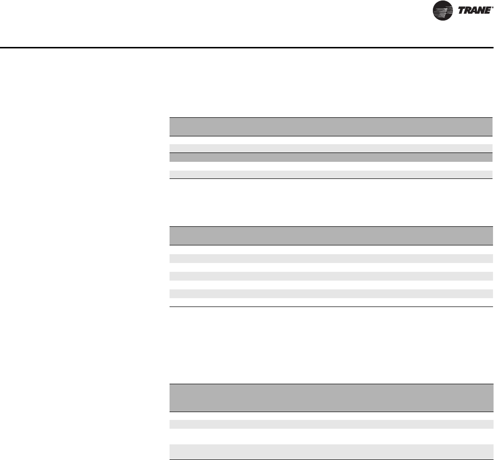
Filters
Table 1. Return Air Grille Part
Numbers
Return Air Panel Type Standard White
Size 350/450/600/800 Size 1000/1200
Flush Mounted FSM 0145XA FSM 0145XB
Hinge Mounted GRS 14152W GRS 16154W
Custom Color
Flush Mounted FSM 0145XAC FSM 0145XBC
Hinge Mounted GRS 14152C GRS 16154C
Table 2. Register/Grille Quick
Reference
Nominal
Size Clips Screw Holes
Grilles Registers Grilles Registers
14 x 5 GSS 14005W GSR 14005W GSS 14105W GSR 14105W
14 x 8 GSS 14008W GSR 14008W GSS 14108W GSR 14108W
14 x 10 GSS 14010W GSR 14010W GSS 14110W GSR 14110W
14 x 12 GSS 14012W GSR 14012W GSS 14112W GSR 14112W
14 x 14 GSS 14014W GSR 14014W GSS 14114W GSR 14114W
16 x 12 GSS 16012W GSR 16012W GSS 16112W GSR 16112W
16 x 14 GSS 16014W GSR 16014W GSS 16114W GSR 16114W
Note: For custom color grille, replace “W” with “C” at the end of the part number.
Registers and grilles are only available in the sizes listed in this table.
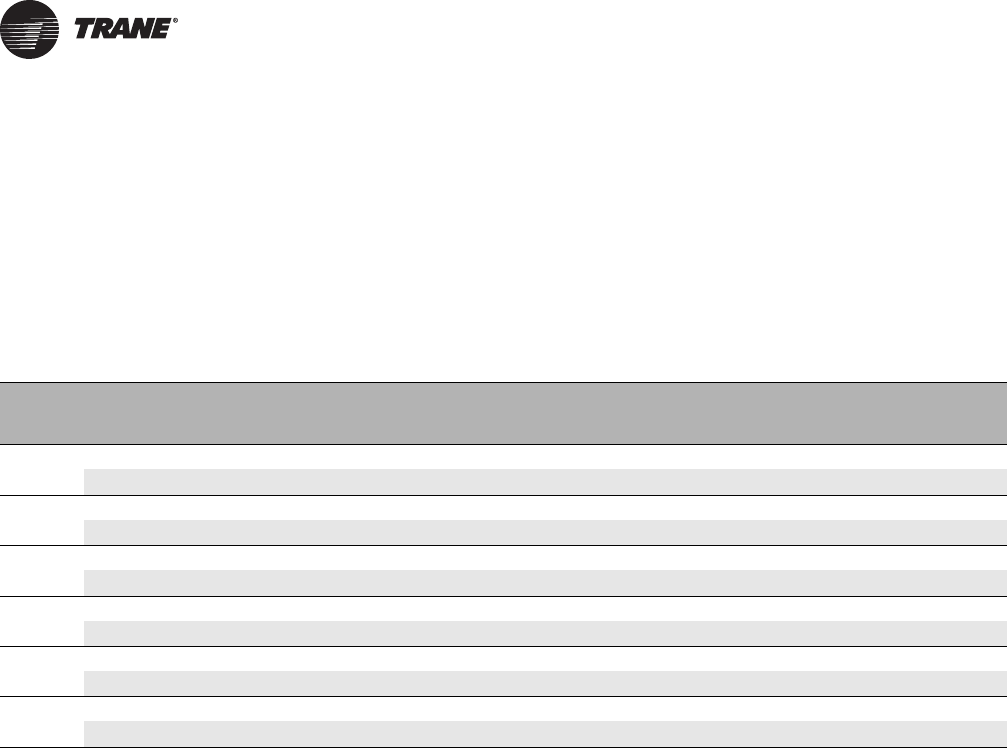
Table 3. Filter Part Numbers
Filter Type
Filter Part Numbers
Size 350/450/600/800
14 x 25 nominal size Size 1000/1200
16 x 25 nominal size
Pleated - MERV 13 FPH 14125 FPH 16125
Pleated - MERV 10 FPY 14125 FPY 16125
Throwaway Wire Frame - for Units with
Hinged Access Panel FWX 14125A FWX 16125
Throwaway Cardboard Frame - for Units
with Flush Mounted Access Panel FRX 14125 FRX 16125
Note: All filters are 1-inch thick.
UNT-PRC019-EN_072013_Vertical Stack Fan Coil.book Page 7 Wednesday, July 17, 2013 9:37 AM
8 UNT-PRC019-EN
Performance Data
Cooling Capacities
AHRI-certified cooling performance is based on ANSI/AHRI Standard 440-2008: Performance
Rating of Room Fan-Coils: 80/67°F entering air temperature, 45°F entering chilled water
temperature with a 10°F delta T. All performance measured on high speed tap using a 120 V AC
motor, 0.05 inches ESP without filters or grilles.
Table 4. AHRI-certified ratings for cooling capacities
Size Coil Airflow
(cfm)
Cooling Power Input (W)
Total Capacity
(MBh) Sensible Capacity
(MBh) Water Flow
(GPM) WPD
(ft H2O) PSC
350 3HC 300 8.5 5.3 2.3 5.2 132
4HC 300 9.2 5.6 2.4 5.3 132
450 3HC 470 11.8 7.7 3.1 10.0 175
4HC 470 12.9 8.3 3.4 7.5 175
600 3HC 620 19.8 12.6 4.7 18.6 259
4HC 620 22.4 13.7 5.3 19.1 259
800 3HC 700 21.6 13.8 5.1 19.7 290
4HC 700 24.6 15.1 5.8 17.9 290
1000 3HC 1010 31.6 20.0 7.4 18.9 446
4HC 1010 36.3 22.1 8.5 16.5 446
1200 3HC 1140 34.3 22.1 8.0 20.4 621
4HC 1140 39.7 24.4 9.3 18.9 621
Note: EC motor also available.
UNT-PRC019-EN_072013_Vertical Stack Fan Coil.book Page 8 Wednesday, July 17, 2013 9:37 AM
UNT-PRC019-EN 9
Performance Data
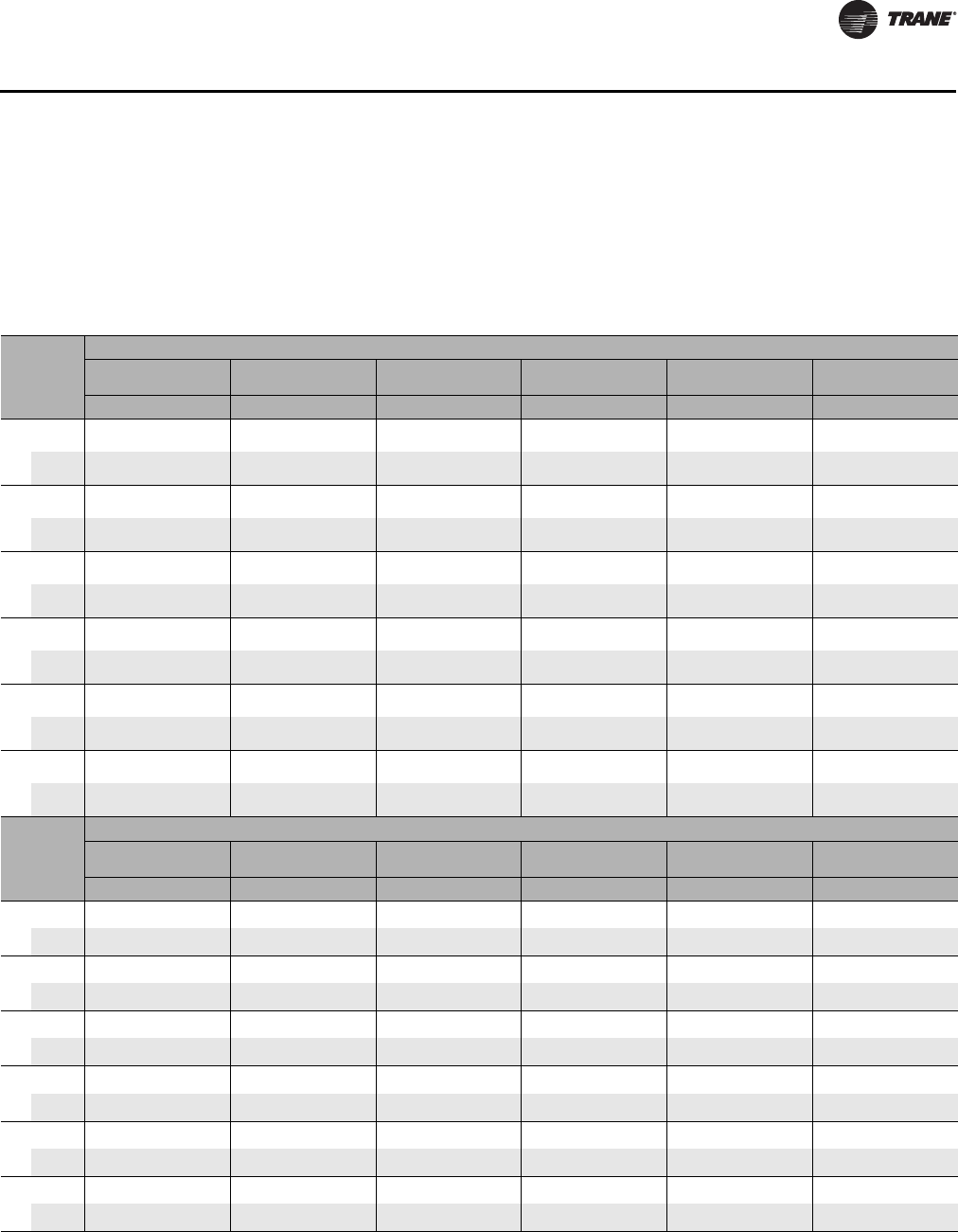
Heating Capacities
Heating performance is based on 70°F entering air temperature, and listed entering water
temperatures. All performance data measured on high speed tap using a 120 V AC motor, 0.05
inches ESP without filters and grilles. 1-row and 2-row coils are in the preheat configuration as part
of a 4-pipe system. 3-row and 4-row coils are only available as part of a 2-pipe system.
Table 5. Heating capacities
Size Rows
Heating
Entering Water Temp. 160°F
Total
Capacity
(MBh) WPD
(ft H
2
0) LWT
(°F)
Total
Capacity
(MBh) WPD
(ft H
2
0) LWT
(°F)
Total
Capacity
(MBh) WPD
(ft H
2
0) LWT
(°F)
Total
Capacity
(MBh) WPD
(ft H
2
0) LWT
(°F)
Total
Capacity
(MBh) WPD
(ft H
2
0) LWT
(°F)
Total
Capacity
(MBh) WPD
(ft H
2
0) LWT
(°F)
0.5 GPM 1.0 GPM 2.0 GPM 3.0 GPM 4.0 GPM 5.0 GPM
350
1-row
Preheat 10.2 0.5 118 13.1 1.8 133 15.3 6.7 144 16.2 14.5 149 - - - - - -
2-row
Preheat 12.5 0.2 109 17.2 0.7 125 20.8 2.6 139 22.3 5.7 145 - - - - - -
450
1-row
Preheat 11.5 0.5 113 15.6 1.8 128 19.0 6.7 141 20.4 14.5 146 - - - - - -
2-row
Preheat 14.1 0.2 102 20.6 0.7 118 26.6 2.6 133 29.3 5.7 140 - - - - - -
600
1-row
Preheat - - - 19.5 0.6 120 25.2 2.3 134 27.9 5.1 141 29.5 8.8 145 - - -
2-row
Preheat - - - 26.6 0.9 106 35.9 3.3 123 40.3 7.1 133 42.8 12.2 138 - - -
800
1-row
Preheat - - - 20.2 0.6 119 26.4 2.3 133 29.4 5.1 140 31.2 8.8 144 32.4 13.6 147
2-row
Preheat - - - 27.5 0.9 104 38.0 3.3 121 43.0 7.1 131 45.9 12.2 137 - - -
1000
1-row
Preheat - - - 24.5 0.4 110 33.6 1.6 126 38.3 3.4 134 41.1 5.8 139 43.0 8.8 142
2-row
Preheat - - - 32.0 0.8 95 47.2 2.7 112 55.3 5.7 122 60.2 9.7 129 63.5 14.7 134
1200
1-row
Preheat - - - 25.3 0.4 108 35.3 1.6 124 40.5 3.4 132 43.7 5.8 138 45.8 8.8 141
2-row
Preheat - - - 33.0 0.8 93 49.6 2.7 109 58.9 5.7 120 64.6 9.7 127 68.5 14.7 132
Size Rows
Heating
Entering Water Temp. 140°F
Total
Capacity
(MBh) WPD
(ft H
2
0) LWT
(°F)
Total
Capacity
(MBh) WPD
(ft H
2
0) LWT
(°F)
Total
Capacity
(MBh) WPD
(ft H
2
0) LWT
(°F)
Total
Capacity
(MBh) WPD
(ft H
2
0) LWT
(°F)
Total
Capacity
(MBh) WPD
(ft H
2
0) LWT
(°F)
Total
Capacity
(MBh) WPD
(ft H
2
0) LWT
(°F)
0.5 GPM 1.0 GPM 2.0 GPM 3.0 GPM 4.0 GPM 5.0 GPM
350
3-row
Heating
10.5 0.2 97 14.7 0.9 110 18.0 3.3 122 19.3 7.2 127 - - - - - -
4-row
Heating
11.9 0.1 92 16.1 0.5 107 19.7 2.0 120 20.9 4.5 126 - - - - - -
450
3-row
Heating
11.7 0.2 93 17.6 0.9 104 23.3 3.3 116 25.9 7.2 122 - - - - - -
4-row
Heating
13.2 0.1 86 19.2 0.5 101 25.7 2.0 114 28.6 4.5 121 - - - - - -
600
3-row
Heating
- - - 22.9 0.6 93 31.8 2.2 108 36.0 4.7 116 38.2 8.2 121 - - -
4-row
Heating
- - - 24.5 0.4 90 34.7 1.7 105 39.3 3.8 113 41.6 6.6 119 - - -
800
3-row
Heating
- - - 23.7 0.6 92 33.7 2.2 106 38.5 4.7 114 41.3 8.2 119 43.0 12.6 123
4-row
Heating
- - - 25.3 0.4 89 36.7 1.7 103 42.2 3.8 111 45.1 6.6 117 46.9 10.2 121
1000
3-row
Heating
- - - 27.0 0.4 85 41.5 1.4 98 49.4 3.0 107 54.3 5.1 112 57.4 7.7 117
4-row
Heating
- - - 28.4 0.2 82 44.9 0.9 94 54.2 1.9 103 59.7 3.3 110 63.1 5.1 114
1200
3-row
Heating
- - - 27.7 0.4 84 43.6 1.4 96 52.7 3.0 104 58.4 5.1 110 62.3 7.8 115
4-row
Heating
- - - 29.0 0.2 81 47.2 0.9 92 57.7 2.0 101 64.4 3.3 107 68.7 5.1 112
UNT-PRC019-EN_072013_Vertical Stack Fan Coil.book Page 9 Wednesday, July 17, 2013 9:37 AM
10 UNT-PRC019-EN
Performance Data
Sound Data
Table 6. Sound data for vertical stack fan coils
Unit Size CFM Fan Speed Sound Pressure Level -
dBA
350
325 High 31
275 Medium 29
225 Low 28
450
500 High 37
425 Medium 34
325 Low 31
600
650 High 39
500 Medium 37
425 Low 35
800
725 High 41
600 Medium 39
500 Low 37
1000
1050 High 45
950 Medium 43
800 Low 41
1200
1175 High 50
1100 Medium 47
1000 Low 44
Note: Sound level is measured at a distance of 8 ft. from the return air grille. Measurements are for a typical furnished and
carpeted hotel suite. CFM in the above chart is approximate. Airflow is dependent on the number of coil rows, coil fins
per inch, the amount of condensate on the fins, supply voltage, motor manufacturer, supply air configuration, filter
cleanliness and altitude.
UNT-PRC019-EN_072013_Vertical Stack Fan Coil.book Page 10 Wednesday, July 17, 2013 9:37 AM
UNT-PRC019-EN 11
Components and Options
Electric Heat
• Heaters are wired for single stage operation.
• An auto-reset high limit device is included.
• Power connection is single point.
• The heater is located in the reheat position relative to the cooling coil.
• The fan coil unit does not include a fuse or fusible type disconnect. Motor sub-fusing as per
electrical code.
S.A. = Supply Air
FLA = Full Load Amps
= S.A. fan motor Amps + Electric Heater Amps
MCA = Minimum Circuit Ampacity
= FLA x 1.25
MOP = Rating of maximum overcurrent protection device
= (2.25 x S.A. fan motor Amps) + Electric Heater Amps
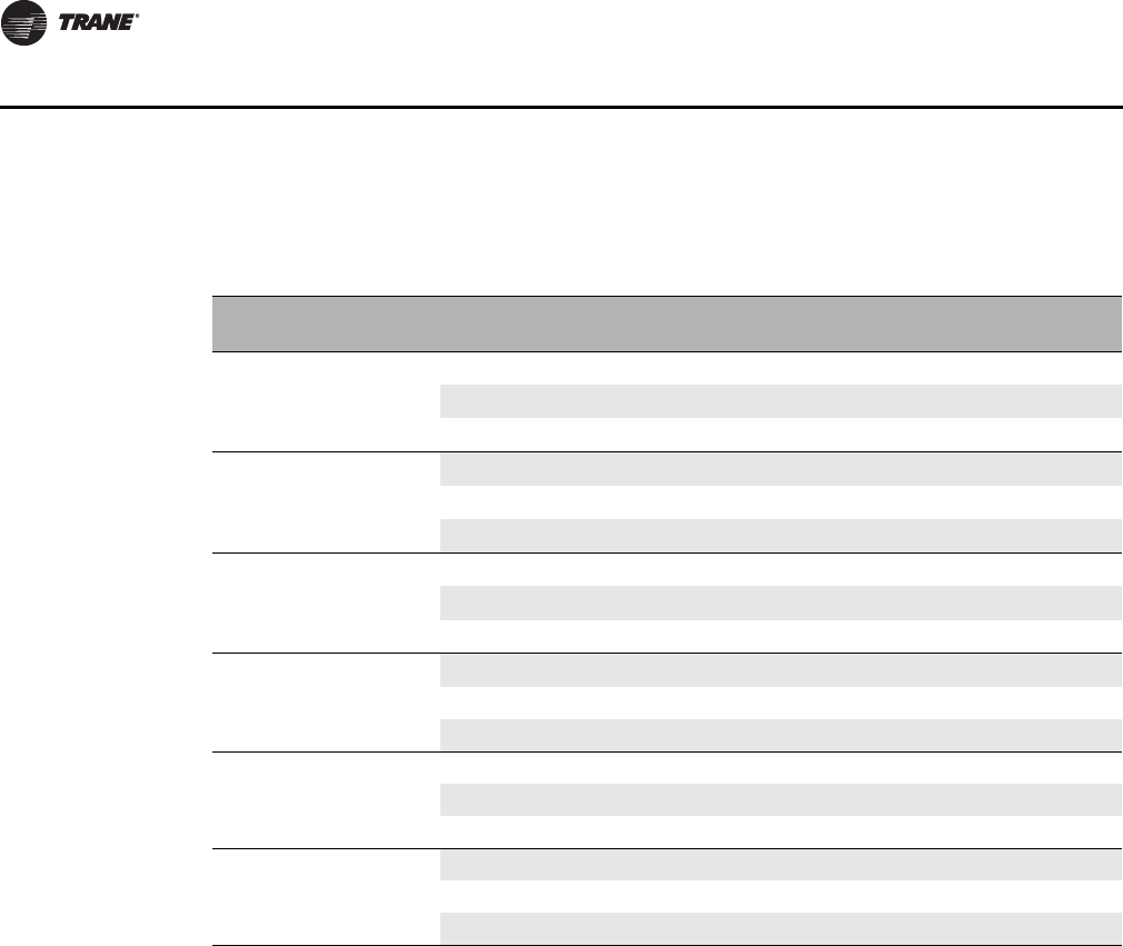
Table 7. Kilowatts (kW) per model
Model
kW 0.75 1.0 1.5 2.0 2.5 3.0 3.5 4.0 4.5 5.0 6.0 7.0 8.0
Volts/ph/Hz Heater Amps
350/450
120V/1/60 6.3 8.3 12.5 16.7
208V/1/60 4.8 7.2 9.6 12.0 14.4 16.8
240V/1/60 4.2 6.3 8.3 10.4 12.5 14.6
277V/1/60 3.6 5.4 7.2 9.0 10.8 12.6
600/800
120V/1/60 6.3 8.3 12.5 16.7
208V/1/60 4.8 7.2 9.6 12.0 14.4 16.8 19.2 21.6 24.0 28.8
240V/1/60 4.2 6.3 8.3 10.4 12.5 14.6 16.7 18.8 20.8 25.0
277V/1/60 3.6 5.4 7.2 9.0 10.8 12.6 14.4 16.2 18.1 21.7
1000/1200
120V/1/60 6.3 8.3 12.5 16.7
208V/1/60 4.8 7.2 9.6 12.0 14.4 16.8 19.2 21.6 24.0 28.8 33.7 38.5
240V/1/60 4.2 6.3 8.3 10.4 12.5 14.6 16.7 18.8 20.8 25.0 29.2 33.3
277V/1/60 3.6 5.4 7.2 9.0 10.8 12.6 14.4 16.2 18.1 21.7 25.3 28.9
Amps = Watts
Volts
Air temp. rise (Delta T) = kW x 3160 = MBH x 925
CFM CFM
UNT-PRC019-EN_072013_Vertical Stack Fan Coil.book Page 11 Wednesday, July 17, 2013 9:37 AM

12 UNT-PRC019-EN
Components and Options
Requirements of Standards: UL 1995 and CSA C22.2 No.236
• If the value of the calculated rating does not equal a standard current rating of overcurrent
protective device, the marked maximum rating shall be the next lower standard rating.
• Exception No. 1: The marked maximum rating of the overcurrent protective device shall be the
standard rating next higher than the computed value if the next lower standard ratings is less
than 125 percent of the current rating of an electric heater load, when the unit includes an
electric heater.
• Exception No. 2: if the computed value of the overcurrent protective device is less than the
minimum ampacity of the supply circuit, the marked rating of the device shall be increased to
the largest standard overcurrent protective device rating appropriate for the marked minimum
circuit ampacity.
• Exception No. 3: If the marked minimum circuit ampacity does not correspond to a standard
protective device rating, the next higher standard rating of the protective device may be
marked.
UNT-PRC019-EN_072013_Vertical Stack Fan Coil.book Page 12 Wednesday, July 17, 2013 9:37 AM
UNT-PRC019-EN 13
Components and Options
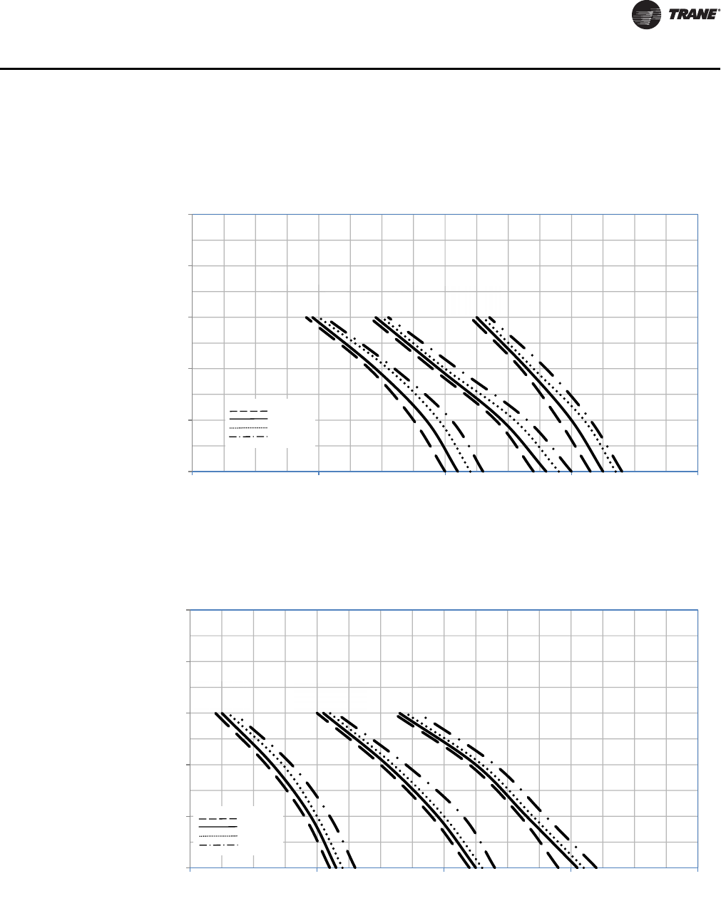
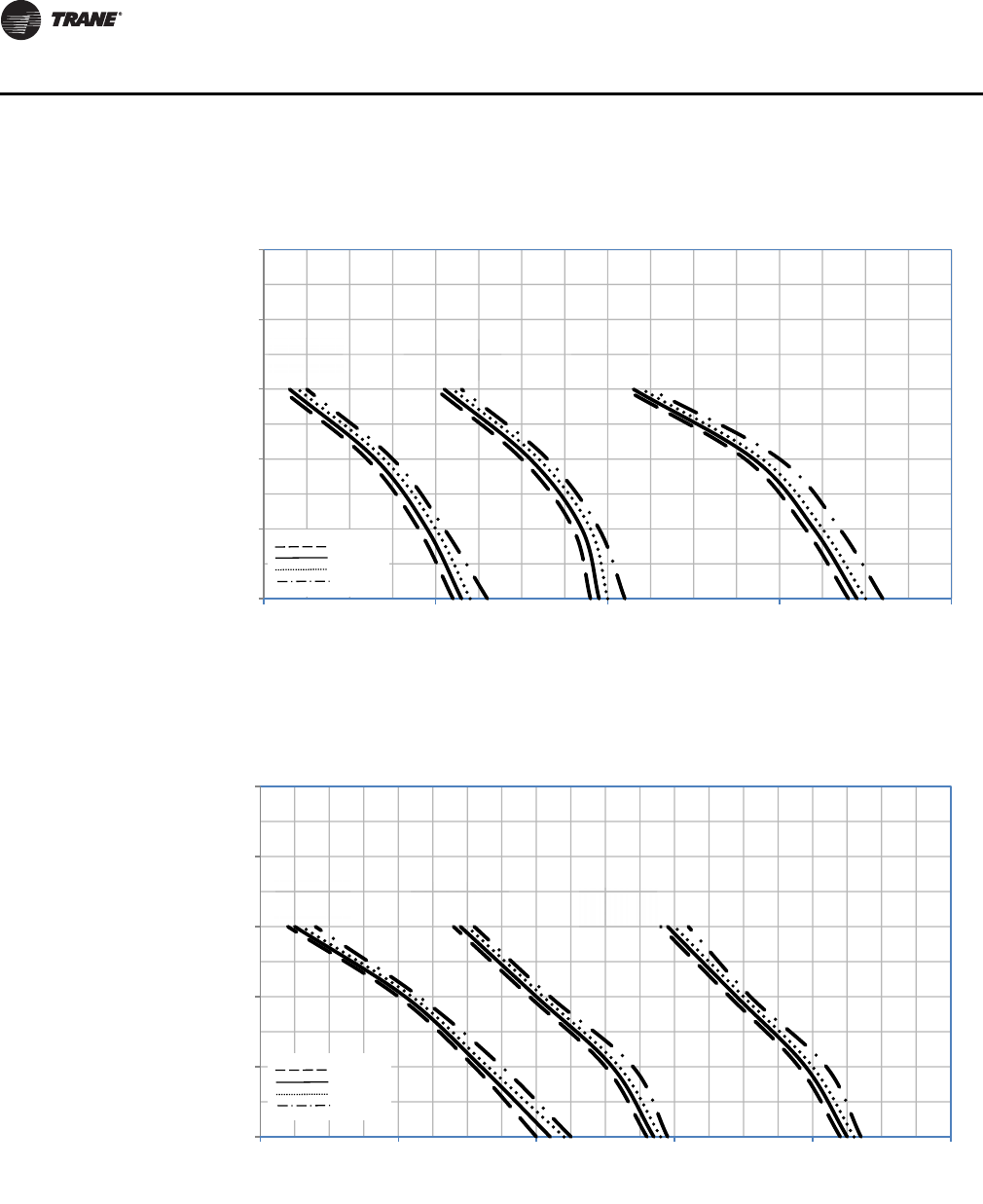
Fans Curves
Figure 3. Unit size 350
Figure 4. Unit size 450
0
0.1
0.2
0.3
0.4
0.5
0 100 200 300 400
External Static Pressure (in. wg.)
Supply Air Volume (SCFM)
High
Medium
Low
6 Row
5 Row
4 Row
3 Row
0
0.1
0.2
0.3
0.4
0.5
200 300 400 500 600
External Static Pressure (in. wg.)
Supply Air Volume (SCFM)
High
Medium
Low
6 Row
5 Row
4 Row
3 Row
UNT-PRC019-EN_072013_Vertical Stack Fan Coil.book Page 13 Wednesday, July 17, 2013 9:37 AM
14 UNT-PRC019-EN
Components and Options
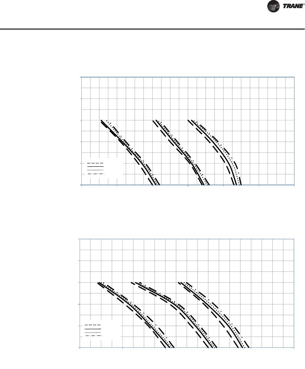
Figure 5. Unit size 600
Figure 6. Unit size 800
0
0.1
0.2
0.3
0.4
0.5
300 400 500 600 700
External Static Pressure (in. wg.)
Supply Air Volume (SCFM)
High
Medium
Low
6 Row
5 Row
4 Row
3 Row
0
0.1
0.2
0.3
0.4
0.5
300400500600700800
External Static Pressure (in. wg.)
Supply Air Volume (SCFM)
High
Medium
Low
6 Row
5 Row
4 Row
3 Row
UNT-PRC019-EN_072013_Vertical Stack Fan Coil.book Page 14 Wednesday, July 17, 2013 9:37 AM
UNT-PRC019-EN 15
Components and Options
Fan curves are based on 120V AC PSC motor at high, medium and low fan speed settings. The
following test conditions apply:
• Centrifugal direct drive fan with double inlet and forward curved impeller.
• Cooling coil is dry.
• One-inch throwaway filter is clean.
Figure 7. Unit size 1000
Figure 8. Unit size 1200
0
0.1
0.2
0.3
0.4
0.5
600 700 800 900 1000 1100 1200
External Static Pressure (in. wg.)
Supply Air Volume (SCFM)
High
Medium
Low
6 Row
5 Row
4 Row
3 Row
0
0.1
0.2
0.3
0.4
0.5
800 900 1000 1100 1200 1300
External Static Pressure (in. wg.)
Supply Air Volume (SCFM)
High
Medium
Low
6 Row
5 Row
4 Row
3 Row
UNT-PRC019-EN_072013_Vertical Stack Fan Coil.book Page 15 Wednesday, July 17, 2013 9:37 AM
16 UNT-PRC019-EN
Components and Options
Motor Data
Control Packages
Trane offers a range of standard thermostats and controllers for the vertical stack fan coil units. For
applications where a larger BAS is to be installed, Trane can provide factory mounting of the ZN521
or UC400 controllers.
Thermostats
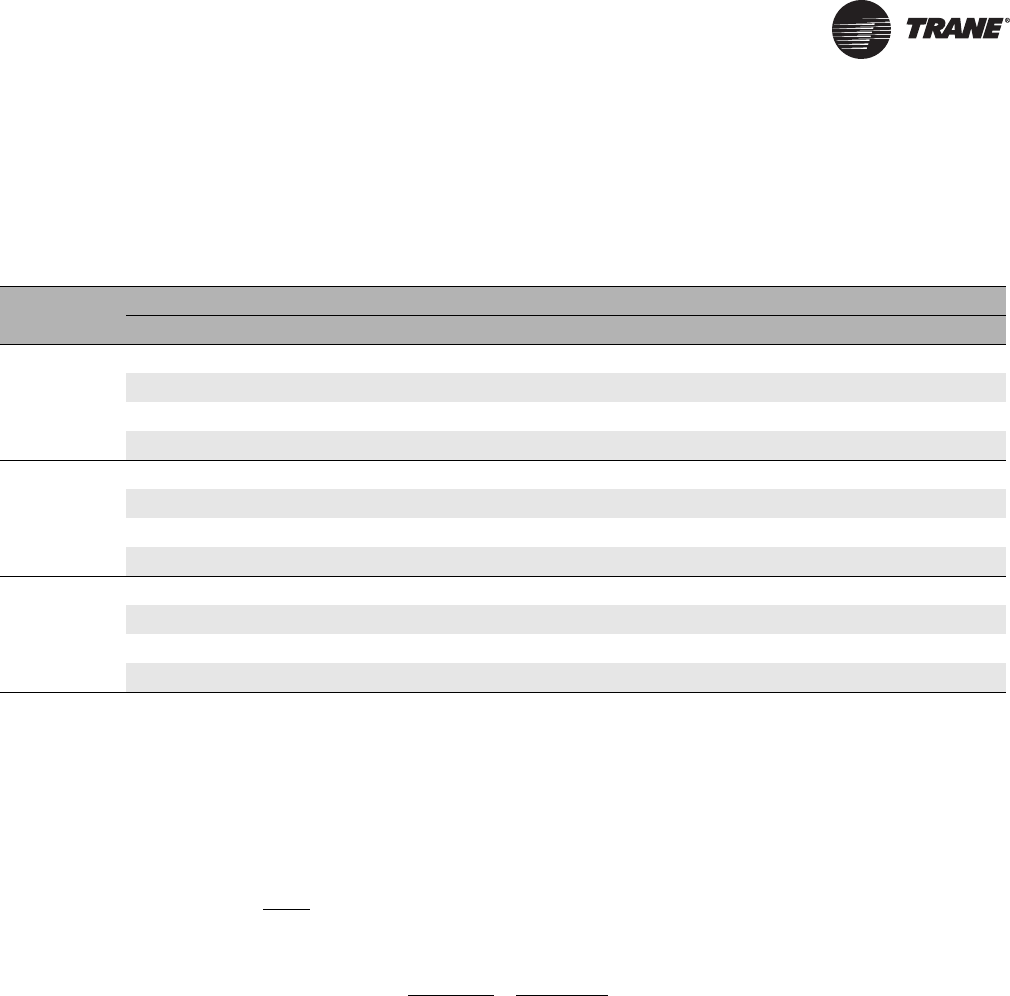
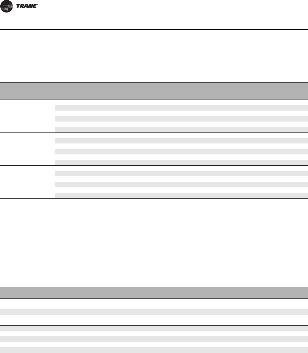
Table 8. Motor data
Size Connection Voltage
Volts/ph/Hz
PSC ECM
Max. Plate Ratings Max. Plate Ratings
HP Amps HP Amps
350 120V/1/60 1/20 1.2 1/3 4.8
208-240V/1/60 1/14 0.6 1/3 2.8
277V/1/60 1/12 0.6 1/3 2.6
450 120V/1/60 1/6 1.7 1/3 4.8
208-240V/1/60 1/12 0.8 1/3 2.8
277V/1/60 1/12 0.6 1/3 2.6
600 120V/1/60 1/6 2.6 1/3 4.8
208-240V/1/60 1/12 0.8 1/3 2.8
277V/1/60 1/12 0.6 1/3 2.6
800 120V/1/60 1/6 2.6 1/3 4.8
208-240V/1/60 1/6 1.4 1/3 2.8
277V/1/60 1/6 0.9 1/3 2.6
1000 120V/1/60 1/4 4.6 1/3 4.8
208-240V/1/60 1/4 2.2 1/3 2.8
277V/1/60 1/4 1.6 1/3 2.6
1200 120V/1/60 1/3 6.4 1/2 6.8
208-240V/1/60 1/3 3.1 1/2 4.1
277V/1/60 1/3 2.1 1/2 3.6
Note: EC motors have been programmed for three (3) discrete speed operation. Variable speed also available (not shown.) Motor nameplate data is shown
in table. Fan motors are single phase and have a minimum of three speeds. Trane has several fan motor suppliers in order to ensure availability. Amp
draws may differ between motors from different manufacturers. Trane reserves the right to change motor HP and therefore amp draws without notice
Table 9. Thermostat information
Thermostat
Voltage Manufacturer Model Heat/Cool
Changeover Fan Operation Available Fan
Speeds Application
24 Honeywell TB8575A1000 Automatic or Manual User Selectable 3 Residential or
Hospitality
24 Honeywell TB7100A1000
1
Automatic or Manual User Selectable 3Residential
120/208/240 Honeywell TB6575A1000 Automatic or Manual User Selectable 3 Residential or
Hospitality
24 HotelTech LT24A Automatic see Note 2 2Hotel
24 HotelTech LT24A3 Automatic see Note 2 3 Hotel
120 HotelTech LT120A Automatic see Note 2 2Hotel
208-230 HotelTech LT220A Automatic see Note 2 2 Hotel
277 HotelTech LT277A Automatic see Note 2 2Hotel
1. The Honeywell TB7100A1000 is a 7-day programmable thermostat.
2. The HotelTech thermostats feature automatic fan speed switching between the available speeds and off. The thermostat selects speed based on
deviation of the room temperature from set point. The occupant can also manually select between the available speeds.
UNT-PRC019-EN_072013_Vertical Stack Fan Coil.book Page 16 Wednesday, July 17, 2013 9:37 AM
UNT-PRC019-EN 17
Components and Options
Residential applications include: Condominiums, apartments, student residences/dormitories,
assisted living/retirement facilities, and military barracks.
Trane recommends the remote mounting of low voltage (24V) thermostats to achieve optimal zone
control. When thermostats are remote mounted, a terminal strip is provided inside the unit for field
connection to the remote thermostat. Unit mounting of thermostat is also available, however all
thermostats are shipped loose for field installation after the unit is installed, drywall is applied and
the walls are painted.
The standard standalone thermostats listed above cycle a two position (on/off) valve and feature
discrete speed fan speed operation. If modulating (0-10V DC or 3-wire floating point) valve
actuators or modulating or 0-10V DC EC motors are a requirement, a thermostat or controller with
the necessary analog outputs must be used.
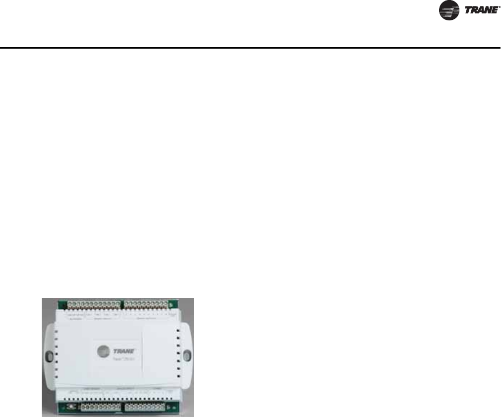
Tracer ZN521 Zone Controller
The Tracer ZN521 is a factory-installed LonTalk® control board designed to provide control of the
fan-coil products (see Figure 9).
The Tracer ZN521 controller is designed to be used in the following applications:
• As part of the Trane Tracer Summit building automation system, the Tracer ZN521 becomes an
important part of the Trane Integrated Comfort system (ICS).
• The Tracer ZN521 can function as a completely standalone controller in situations where a
building automation system (BAS) is not present.
• For situations when a non-Trane BAS is present, the Tracer ZN521 can be where ever a LonTalk
front-end system is present.
Through building management of the HVAC system, optimizing energy consumption becomes
possible at a zone level. Each unit is capable of functioning independently of one another during
occupied and unoccupied hours of the day. This allows the temperature setpoint and ventilation
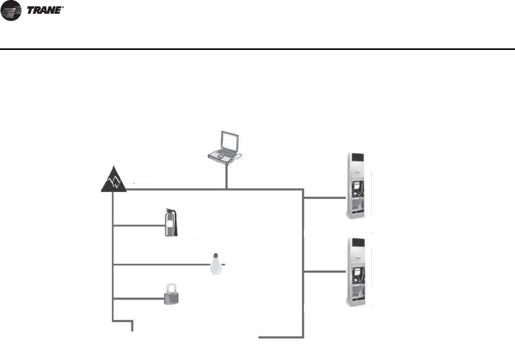
setting to be changed automatically based on zone usage (see Figure 10).
Figure 9. Tracer ZN521 controller
Features include:
• Automatic fan-speed reset
• Automatic ventilation reset
• Manual output test
• Filter maintenance
• Master slave
• Water valve override
• Freeze avoidance
• Interoperability
• Three generic I/O ports
UNT-PRC019-EN_072013_Vertical Stack Fan Coil.book Page 17 Wednesday, July 17, 2013 9:37 AM
18 UNT-PRC019-EN
Components and Options
Two Systems in One
In an ICS environment, the Tracer ZN521 is pre-designed to install quickly and easily into the
system. Since the controller is mounted on the unit, the start-up time for the entire system is
minimized. Trane becomes the single source of responsibility for the equipment, unit controls, and
building automation system.
Once power is applied to the controller, it will automatically start up and run based upon the
setpoint on the local zone sensor. The Tracer ZN521 is certified to the interoperable L
ON
M
ARK
®
Space Comfort Controller profile. This allows the controller to be used with another vendor’s BAS
and thereby still provide the high quality of factory installation. In addition, the Tracer ZN521
provides one of the most extensive interoperable data lists of any controller of its type in the
industry.
Automatic Fan and Ventilation Reset
With the Tracer ZN521 controller, a multi-speed fan control for the fan coil delivers the airflow
output customized to support the cfm space needs. When less cfm is necessary to meet the load
of the zone (typically 75 to 80 percent of the time), the equipment operates on low speed. However,
if the room temperature rises, the controller will switch to high speed.
Manual Output Test
The Tracer ZN521 controller includes a manual output test function. This function may be initiated
from the blue test push button on the controller or through the Rover™ service tool. This feature
is used to manually exercise the outputs in a defined sequence.
The purpose of this test sequence is to verify output and end device operation. The manual output
test function may also be used in the following situations:
• Reset latching diagnostics
• Verify output wiring and operation
• Force the water valve(s) open to balance the hydronic system during installation set-up or
service.
Figure 10. Tracer ZN521 System
Fan
coil
Fan
coil
To other
building products
To other
Trane products
Security
system
Rover™
(optional)
Tracer
Summit®
System
Lighting
system
Fire safety
system
UNT-PRC019-EN_072013_Vertical Stack Fan Coil.book Page 18 Wednesday, July 17, 2013 9:37 AM

UNT-PRC019-EN 19
Components and Options
Filter Maintenance
Filter status for the controller is based on the cumulative run hours of the unit fan. The controller
compares the amount of fan run time against an adjustable fan run hour (stored in the controller)
to determine when maintenance is recommended for the unit. The run-hours value may be user
edited as required (through Rover). The valid range for the fan run hours limit is 0 to 5000 hours
with a default of 600 hours. Once the run hours limit has been exceeded, the controller generates
a maintenance required diagnostic (unit will not shut-down). The user will be notified of this
diagnostic through the building automation system or when a Trane Service Tool is communicating
with the controller.
Master Slave (Data Sharing)
Because the Tracer ZN521 controller utilizes L
ON
W
ORKS
® technology, the controller can send or
receive data (setpoint, heat/cool mode, fan request, space temperature, etc.) to and from other
controllers on the communication link with or without the existence of a building automation
system. This applies to applications where multiple units might share one zone sensor for both
stand-alone (with communication wiring between units) and a building automation system.
Water Valve Override
The Tracer ZN521 can be commanded via the Rover service tool to open all hydronic valves
100 percent. This allows for the faster water balancing of each unit and the entire system when the
command is sent globally to all controllers. A properly balanced system is essential for proper and
efficient operation.
Hydronic Coil Freeze Protection (Freeze Avoidance)
Fan coil systems in cold climates need to take precautions to avoid hydronic coil freeze-up. The
Tracer ZN521 does this from three different aspects. Any of these methods of protections will result
in the unit fan being disabled, the outside air damper being shut, and the hydronic valves being
opened 100 percent.
The three methods of freeze avoidance include:
1. A binary freeze protection thermostat is mounted on the coil and will cause a latching diagnostic
if the coil temperature falls below 35°F.
2. An analog discharge air sensor monitors the temperature of the air coming off of the coil and
if the temperature falls below 40°F the outside air damper is closed, the fan is turned off and
the valves are fully opened.
3. When in the unoccupied mode the Tracer ZN521 has an adjustable freeze avoidance setpoint.
If the outside air temperature is below the setpoint the unit will open the valves to allow water
to flow through the coils.
Interoperability
Interoperability allows the owner freedom to select multiple vendors, and multiple products. With
this advantage, the owner can choose the best products, the best application, and the best service
from a variety of suppliers to meet their evolving building control needs in a cost effective manner.
Generic Binary Input/Output
The three generic binary inputs/outputs are not part of the normal control, but are actually
controlled through the Tracer Summit system (when present) to issue commands to the Tracer
ZN521 control to turn the generic inputs/outputs of add-on equipment (such as baseboard heating,
exhaust fans, occupancy sensor, lighting, etc.) on and off. This binary port is not affected when
other binary diagnostics interrupt unit operation.
UNT-PRC019-EN_072013_Vertical Stack Fan Coil.book Page 19 Wednesday, July 17, 2013 9:37 AM
20 UNT-PRC019-EN
Components and Options
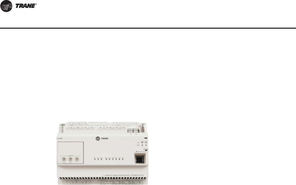
Tracer UC400 Controller
The Tracer UC400 is a factory-installed BACnet® MS/TP control designed to provide control of the
fan coil (see Figure 11). The Tracer UC400 controller is designed to be used in the following
applications: as stand-alone operation, part of the Trane Tracer SC building automation system, or
part of another BACnet MS/TP Building Automation System. The Tracer UC400 can function as a
completely standalone controller in situations where a building automation system (BAS) is not
present.
The Tracer UC400 is designed to install quickly and easily into the system. Trane becomes the single
source of responsibility for the equipment, unit controls, and building automation system. As a
standalone controller, the Tracer UC400 is ideally suited for fix-on-fail replacement of units with old
pneumatic controllers, or in situations where a BAS will be added at a later date. Once power is
applied to the controller, it will automatically start up and run based upon the setpoint on the local
zone sensor. An individual time clock can be added to the unit for local scheduling. The Tracer
UC400 is BTL listed as B-ASC profile. This ensures the controller to be used with other BACnet®
building automation systems.
The Tracer UC400 controller delivers single zone VAV control and can be used in a stand-alone
application or as part of a Trane Integrated Comfort™ System (ICS).
In the stand-alone configuration, Tracer UC400 receives operation commands from the zone sensor
and/or the auto changeover sensor (on auto changeover units). The entering water temperature is
read from the auto changeover sensor and determines if the unit is capable of cooling or heating.
The zone sensor module is capable of transmitting the following information to the controller:
• Timed override on/cancel request
• Zone setpoint
• Current zone temperature
• Fan mode selection (off-auto-high-med-low)
For optimal system performance, fan coils can operate as part of an ICS building automation
system controlled by Tracer Summit. The controller is linked directly to the Summit control panel
via a twisted pair communication wire, requiring no additional interface device (i.e., a command
unit). The Trane ICS system can monitor or override Tracer UC400 control points. This includes such
points as temperature and output positions.
Figure 11. Tracer UC400 Controller
Features include:
• Single Zone VAV
• Automatic ventilation reset
• Filter maintenance
• Water valve override
• Freeze avoidance
• Interoperability
• Unused I/O can be used as generic I/O
UNT-PRC019-EN_072013_Vertical Stack Fan Coil.book Page 20 Wednesday, July 17, 2013 9:37 AM
UNT-PRC019-EN 21
Components and Options
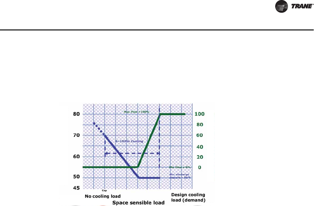
Single Zone VAV with Fully Modulating Fan Speed
With a single zone VAV with fully modulating fan speed, and EDM with modulating signal is
required. The Tracer UC400 will minimize fan speed, and in turn energy usage, by only delivering
the air flow needed. See Figure 12.
Filter Maintenance
Filter status for the controller is based on the cumulative run hours of the unit fan. The controller
compares the amount of fan run time against an adjustable fan run hour (stored in the controller)
to determine when maintenance is recommended for the unit. The run-hours value may be user
edited as required. The valid range for the fan run hours limit is 0 to 5000 hours with a default of
600 hours. Once the run hours limit has been exceeded, the controller generates a maintenance
required diagnostic (unit will not shut-down). The user will be notified of this diagnostic through
the building automation system or when a Trane® service tool is communicating with the
controller.
Hydronic Coil Freeze Protection (Freeze Avoidance)
Fan coil systems in cold climates need to take precautions to avoid hydronic coil freeze-up. The
controller does this from three different aspects. Any of these methods of protections will result
in the unit fan being disabled, the outside air damper being shut, and the hydronic valves being
opened 100 percent.
The three methods of freeze avoidance include:
1. A binary freeze protection thermostat is mounted on the coil and will cause a latching diagnostic
if the coil temperature falls below 35°F.
2. An analog discharge air sensor monitors the temperature of the air coming off of the coil and
if the temperature falls below 40°F the outside air damper is closed, the fan is turned off and
the valves are fully opened.
3. When in the unoccupied mode, the controller has an adjustable freeze avoidance setpoint. If the
outside air temperature is below the setpoint, the unit will open the valves to allow water to flow
through the coils.
Interoperability
Interoperability allows the owner freedom to select multiple vendors, and multiple products. With
this advantage, the owner can choose the best products, the best application, and the best service
from a variety of suppliers to meet their evolving building control needs in a cost effective manner.
Figure 12. Cool mode nominal hydronic cooling control
Discharge temp setpoint (°F)
Fan speed command (%)
UNT-PRC019-EN_072013_Vertical Stack Fan Coil.book Page 21 Wednesday, July 17, 2013 9:37 AM
22 UNT-PRC019-EN
Dimensions and Weights
Vertical Fan Coil Units
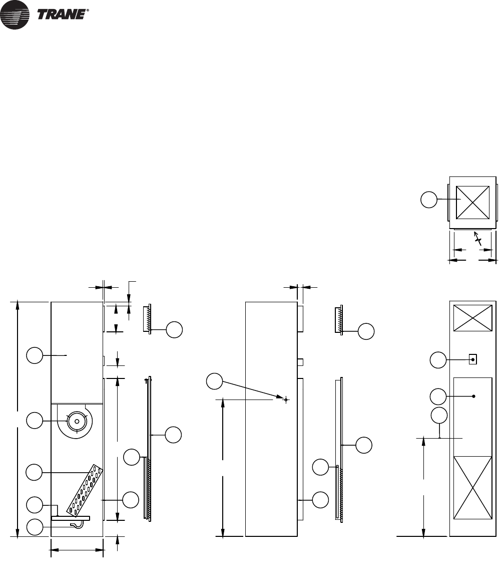
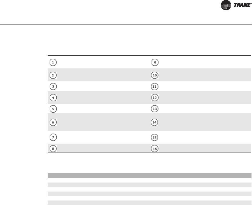
2-Pipe Chilled Water Cooling Unit
Figure 13. 2-pipe chilled water cooling unit - hot water changeover coil optional
FRONT VIEW
SIDE SECTION
(Flush Mounted Panel Option)
TOP VIEW
F. F. L .
SIDE VIEW
(Hinged Panel Option)
E
86 in.
C
36 in.
2 1/8 in.
A
B
8
16
2
3
4
5
6
14
15
7
13
9
6
10
12
11
1
9
6 in.
1/2 in. 1 1/2 in.
D
47 in.
4 in.
UNT-PRC019-EN_072013_Vertical Stack Fan Coil.book Page 22 Wednesday, July 17, 2013 9:37 AM
UNT-PRC019-EN 23
Dimensions and Weights
Table 10. 2-pipe chilled water cooling unit callouts
18 ga. steel cabinet, lined with 1/2-inch fiberglass
insulation coated on air side; 3/8-inch closed-cell
foam optional.
1/2-inch flange on front of unit. Allows direct
application of drywall to the unit.
Direct-drive centrifugal fan and PSC motor; EC motor
optional.
7/8-inch hole on each side of cabinet for power and
control cable entry points on all units. See CLCH-
SVX021A-EN installation manual for details.
Chilled water coil; hot water changeover optional. Hinged return air grille/access panel (optional).
Acrylic coated galvanized steel drain pan, pitched in
two directions, insulated on the underside; stainless
steel optional.
2 1/8-inch flange on front of unit. Drywall to be
framed out in front of unit.
Drain hose from drain pan to condensate riser. The
flexible hose forms a running trap. Unit mounting location for thermostat/controller.
Double deflection steel supply air grille at front, left,
right or back or any combination when there are
multiple openings. Dimension “D” varies with CFM:
5, 8, 10, 12, or 14 inches.
Fan shield, acoustically lined. Identification and
safety caution labels are affixed to this panel.
Flush mounted return air grille/access panel
attached by quarter turn fasteners.
Vertical centerline of coil connection run outs.
Connections are at the back, left or right sides of the
unit.
One inch disposable filter. Top supply air opening (knock out) for attachment of
ductwork.
Table 11. 2-pipe chilled water cooling unit dimensions (inches)
Size A B C E
350 17 17 14 52
450 17 17 14 52
600 20 20 14 52
800 20 20 14 52
1000 20 24 16 54
1200 20 24 16 54
UNT-PRC019-EN_072013_Vertical Stack Fan Coil.book Page 23 Wednesday, July 17, 2013 9:37 AM

24 UNT-PRC019-EN
Dimensions and Weights
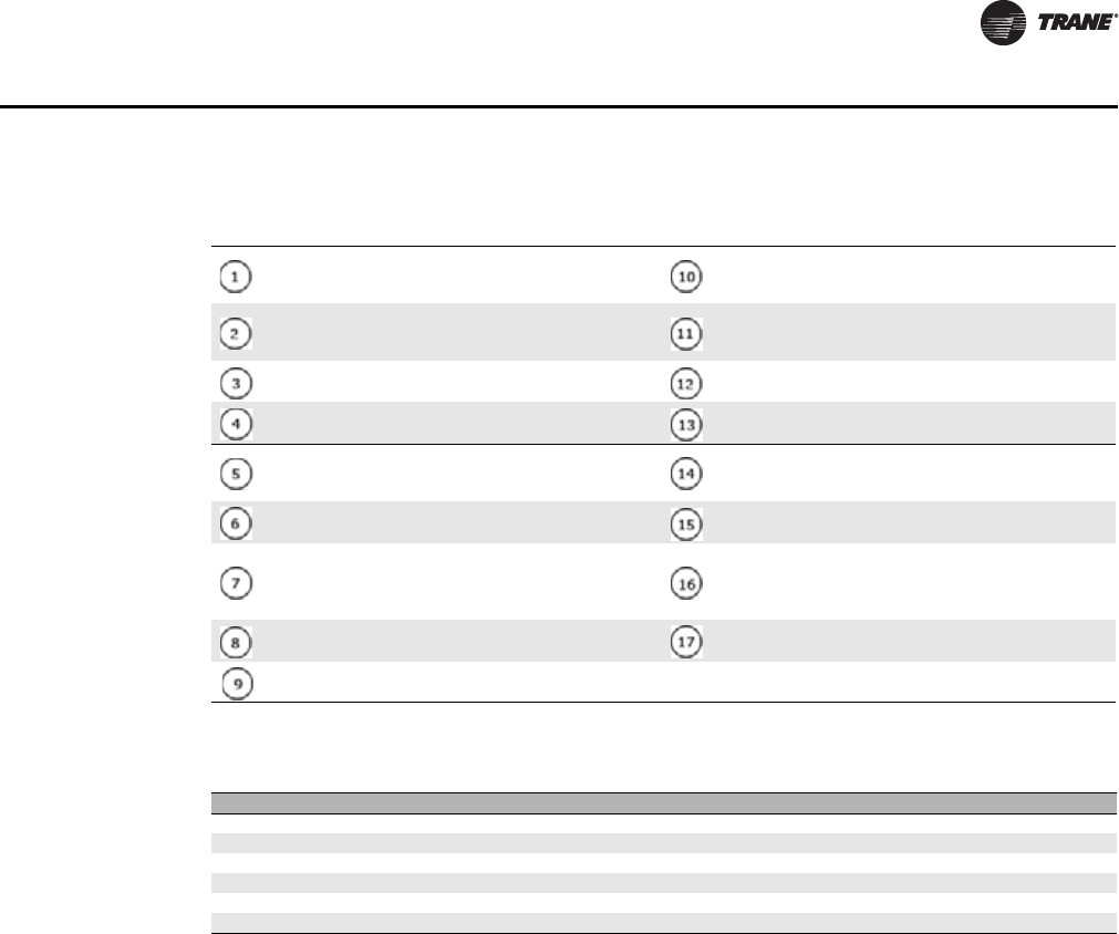
2-Pipe Chilled Water Cooling Unit with Electric Heat
Figure 14. 2-pipe chilled water cooling unit with electric heat
FRONT VIEW
SIDE SECTION
(Flush Mounted Panel Option)
TOP VIEW
F. F. L .
SIDE SECTION
(Hinged Panel Option)
A
E
86 in.
36 in.
1/2 in.
D
C
B
9
17
3
4
5
6
7
15
16
8
2
14
1
9
7
12
13
10
47 in.
1 1/2 in. 2 1/8 in.
6 in.
11
4 in.
UNT-PRC019-EN_072013_Vertical Stack Fan Coil.book Page 24 Wednesday, July 17, 2013 9:37 AM
UNT-PRC019-EN 25
Dimensions and Weights
Table 12. 2-pipe chilled water cooling unit with electric heat callouts
18 ga. steel cabinet, lined with 1/2-inch fiberglass
insulation coated on air side; 3/8-inch closed-cell
foam optional.
1/2-inch flange on front of unit. Allows direct
application of drywall to the unit.
Electric heater (primary or auxiliary). 7/8-inch hole on each side of cabinet for power and
control cable entry points on all units. See CLCH-
SVX021A-EN installation manual for details.
Direct-drive centrifugal fan and PSC motor; EC motor
optional. Hinged return air grille/access panel (optional).
Chilled water coil; hot water changeover optional. 2 1/8-inch flange on front of unit. Drywall to be
framed out in front of unit.
Acrylic coated galvanized steel drain pan, pitched in
two directions, insulated on the underside; stainless
steel optional. Unit mounting location for thermostat/controller.
Drain hose from drain pan to condensate riser. The
flexible hose forms a running trap. Fan shield, acoustically lined. Identification and
safety caution labels are affixed to this panel.
Double deflection steel supply air grille at front, left,
right or back or any combination when there are
multiple openings. Dimension “D” varies with CFM:
5, 8, 10, 12, or 14 inches.
Vertical centerline of coil connection run outs.
Connections are at the back, left or right sides of the
unit.
Flush mounted return air grille/access panel
attached by quarter turn fasteners. Top supply air opening (knock out) for attachment of
ductwork.
One inch disposable filter.
Table 13. 2-pipe chilled water cooling unit with electric heat dimensions (inches)
Size A B C E
350 17 17 14 52
450 17 17 14 52
600 20 20 14 52
800 20 20 14 52
1000 20 24 16 54
1200 20 24 16 54
UNT-PRC019-EN_072013_Vertical Stack Fan Coil.book Page 25 Wednesday, July 17, 2013 9:37 AM
26 UNT-PRC019-EN
Dimensions and Weights
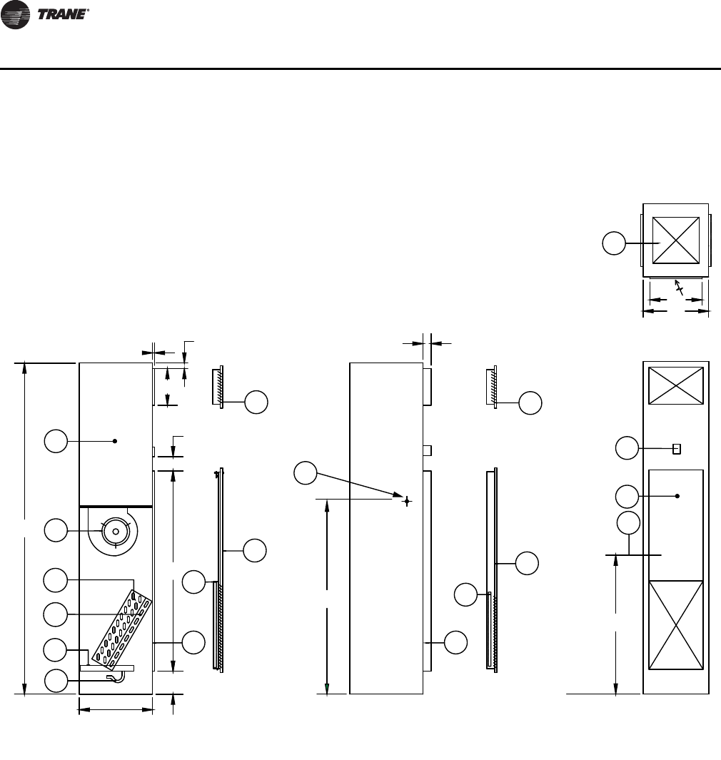
4-Pipe Chilled Water Cooling and Hot Water Heating Unit
Figure 15. 4-pipe chilled water cooling and hot water heating unit
9
17
2
5
6
7
15
16
8
3
4
14
9
7
12
1
1310
FRONT VIEW
SIDE SECTION
(Flush Mounted Panel Option)
TOP VIEW
F. F. L .
SIDE SECTION
(Hinged Panel Option)
6 in.
E
86 in.
36 in.
1 1/2 in.
D
C
B
A
1/2 in.
4 in.
47 in.
2 1/8 in.
11
UNT-PRC019-EN_072013_Vertical Stack Fan Coil.book Page 26 Wednesday, July 17, 2013 9:37 AM

UNT-PRC019-EN 27
Dimensions and Weights
Table 14. 4-pipe chilled water cooling hot water heating unit callouts
18 ga. steel cabinet, lined with 1/2-inch fiberglass
insulation coated on air side; 3/8-inch closed-cell
foam optional.
1/2-inch flange on front of unit. Allows direct
application of drywall to the unit.
Direct-drive centrifugal fan and PSC motor; EC motor
optional.
7/8-inch hole on each side of cabinet for power and
control cable entry points on all units. See CLCH-
SVX021A-EN installation manual for details.
Chilled water coil. Hinged return air grille/access panel (optional).
Hot water coil. 2 1/8-inch flange on front of unit. Drywall to be
framed out in front of unit.
Acrylic coated galvanized steel drain pan, pitched in
two directions, insulated on the underside; stainless
steel optional. Unit mounting location for thermostat/controller.
Drain hose from drain pan to condensate riser. The
flexible hose forms a running trap. Fan shield, acoustically lined. Identification and
safety caution labels are affixed to this panel.
Double deflection steel supply air grille at front, left,
right or back or any combination when there are
multiple openings. Dimension “D” varies with CFM:
5, 8, 10, 12, or 14 inches.
Vertical centerline of coil connection run outs.
Connections are at the back, left or right sides of the
unit.
Flush mounted return air grille/access panel
attached by quarter turn fasteners. Top supply air opening (knock out) for attachment of
ductwork.
One inch disposable filter.
Table 15. 4-pipe chilled water cooling and hot water heating unit dimensions (inches)
Size A B C E
350 17 17 14 52
450 17 17 14 52
600 20 20 14 52
800 20 20 14 52
1000 20 24 16 54
1200 20 24 16 54
UNT-PRC019-EN_072013_Vertical Stack Fan Coil.book Page 27 Wednesday, July 17, 2013 9:37 AM
28 UNT-PRC019-EN
Dimensions and Weights
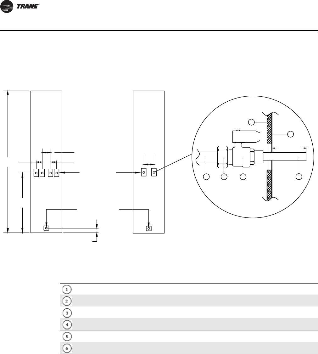
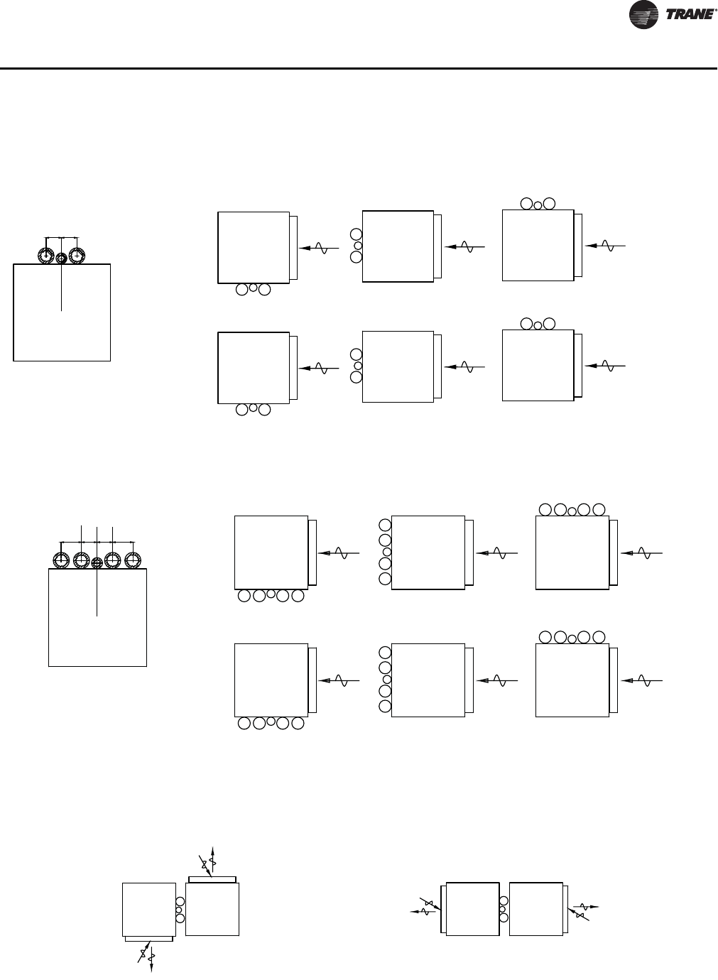
Fan Coil Units Without Risers
Figure 16. Fan Coil Units Without Risers
B K
C
CWS
HWS
HWR
CWR
B K
C
SR
12 3 4
6
5
2-pipe slave unit
with BK connection
4-pipe slave unit
with BK connection
Stub-out detail - typical
Inside
unit
Outside
unit
36 in.
2 5/8 in.
Condensate
connection
5/8 in. I.D. hose
Supply and return
connections
1/2 in. or 3/4 in. nom.
Copper pipe
3 3/4 in.
5 1/4 in.
3 3/4 in.
86 in. 7"
1 1/2 in.
Table 16. Fan coil units without risers - 2-pipe and 4-pipe slave units callouts
1/2-inch or 3/4-inch supply and return coil branch copper pipe
Union fitting
Ball valve (shut-off valve)
1/2-inch or 3/4-inch copper tail piece soldered into valve body at factory
Insulation lining on interior surface of fan coil cabinet
Fan coil cabinet
UNT-PRC019-EN_072013_Vertical Stack Fan Coil.book Page 28 Wednesday, July 17, 2013 9:37 AM
UNT-PRC019-EN 29
Dimensions and Weights
Riser Packages
Figure 17. Riser 2-Pipe Package
RA
RA
RA
RA
RA
RA
3 1/2 in. 3 1/2 in.
Right risers (RT)
RCS
Reverse right risers (RR)
R
CS
R
C
S
Back risers (BK)
R
C
S
Reverse back risers (RB)
R
Left risers (LT)
TOP VIEW
CS
R
Reverse left risers (RL)
TOP VIEW
CS
S = Supply riser
R = Return riser
C = Condensate riser
C
L
Figure 18. Riser 4-Pipe Package
RARARA
RARARA
3 3/4 in.
2 5/8 in.
3 3/4 in.
2 5/8 in.
HWS
HWR
Cond.
CWR
CWS
HWS
HWR
Cond.
CWR
CWS
HWS
HWR
Cond.
CWR
CWS
Left risers (LT) Back risers (BK) Right risers (RT)
HWS = Hot Water Supply Riser
HWR = Hot Water Return Riser
CWS = Chilled Water Supply Riser
CWR = Chilled Water Return Riser
Cond. = Condensate Riser
TOP VIEW
C
L
HWS
HWR
Cond.
CWR
CWS
HWS
HWR
Cond.
CWR
CWS
HWS
HWR
Cond.
CWR
CWS
Reverse left risers (RL) Reverse back risers (RB) Reverse right risers (RR)
TOP VIEW
Reverse Riser orientations are used to aid in eliminating cross over piping when units on a riser
stack change position from floor to floor or when two units share a common riser (Master/Slave).
RReverse right risers (RR)Right risers (RT)
TOP VIEW
C
S
R
C
SR
C
S
Back risers (BK)
Reverse back risers (RB)
R
C
S
TOP VIEW
UNT-PRC019-EN_072013_Vertical Stack Fan Coil.book Page 29 Wednesday, July 17, 2013 9:37 AM
30 UNT-PRC019-EN
Dimensions and Weights
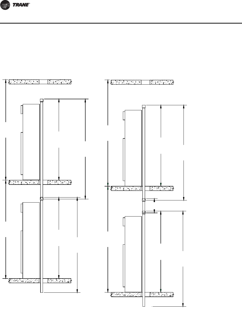
Figure 19. Riser Installation Dimensions (inches)
L = F + 2 inches
Spool Piece Length = F - L + 4 inches
L = F - Spool Length + 4 inches
Standard Installation
Standard Installation Using
Spool Pieces
92 in.
92 in.
F
F
L
L
92 in.
92 in.
F
F
L
L
F - L + 4 in.
UNT-PRC019-EN_072013_Vertical Stack Fan Coil.book Page 30 Wednesday, July 17, 2013 9:37 AM
UNT-PRC019-EN 31
Dimensions and Weights
Raised Base Options
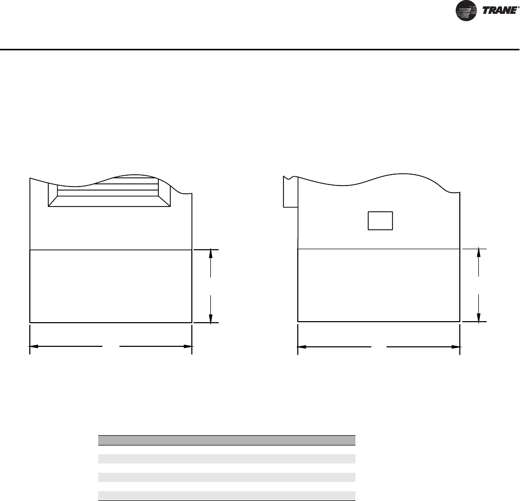
Raised Base
Figure 20. Raised base - no access panel
Available in 4-inch, 8-inch and 12-inch heights (shown)
Side View
12 in.
B
Front View
12 in.
A
Table 17. Raised base dimensions (inches)
Size A B
350 17 17
450 17 17
600 20 20
800 20 20
1000 24 20
1200 24 20
UNT-PRC019-EN_072013_Vertical Stack Fan Coil.book Page 31 Wednesday, July 17, 2013 9:37 AM
32 UNT-PRC019-EN
Dimensions and Weights
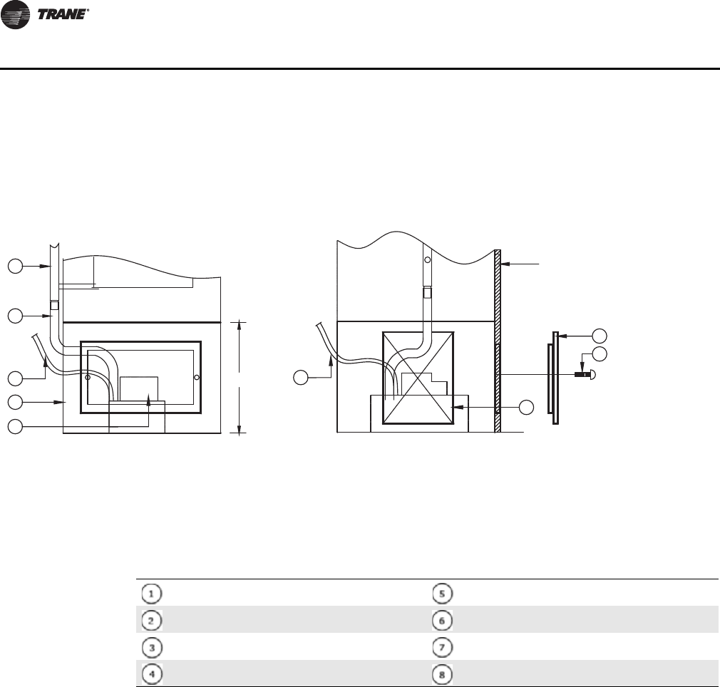
Raised Base with Condensate Pump and Front Access Panel
Figure 21. Raised base with condensate pump and front access panel
Front View Left Side View
Side ViewFront View
1
12 in.
8
6
7
Drywall
F. F. L .
2
3
4
5
3
Available only with 12 inch raised base.
Table 18. Raised base with condensate pump and front access panel callouts
Condensate riser (if applicable) 120V - 208V condensate pump
Drain tube factory installed Front access panel (350 - 800 - 16 in. x 10 in.,
1000, 1200 - 18 in. x 10 in.
3/8-inch I.D. outlet tube by contractor Screws for front access panel
12 inch raised base Opening for condensate hose running in and out
Note: If the supply is 277V, an appropriately sized step-down transformer is included for condensate pump.
UNT-PRC019-EN_072013_Vertical Stack Fan Coil.book Page 32 Wednesday, July 17, 2013 9:37 AM
UNT-PRC019-EN 33
Dimensions and Weights
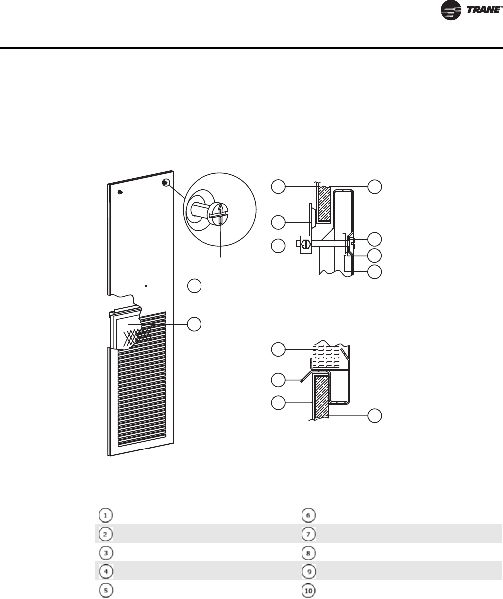
Return Air Panels
Return Air Panel with Flush Mount
Features
• Drywall attached directly to front of the unit
• Industry standard
• Fast access with quarter turn fasteners
• Easily removable for filter changing
Figure 22. Return air panel - flush mount with quarter turn fasteners
1
9
2
4
5
6
7
8
3
10
10
3
2
Bottom side section
Top side section
Up arrow indicates
locked position
Table 19. Return air panel - flush mount with quarter turn fasteners callouts
Return air grille/access panel with quarter turn
fasteners Pawl lock screw
Throwaway 1-inch filter. Plastic washer
1/2-inch deep collar around return air opening on fan
coil unit Spring retainer
1/4 turn fastener with slotted head and square shaft Bottom hook of access panel
Pawl of the 1/4 turn fastener 1/2-inch drywall
UNT-PRC019-EN_072013_Vertical Stack Fan Coil.book Page 33 Wednesday, July 17, 2013 9:37 AM
34 UNT-PRC019-EN
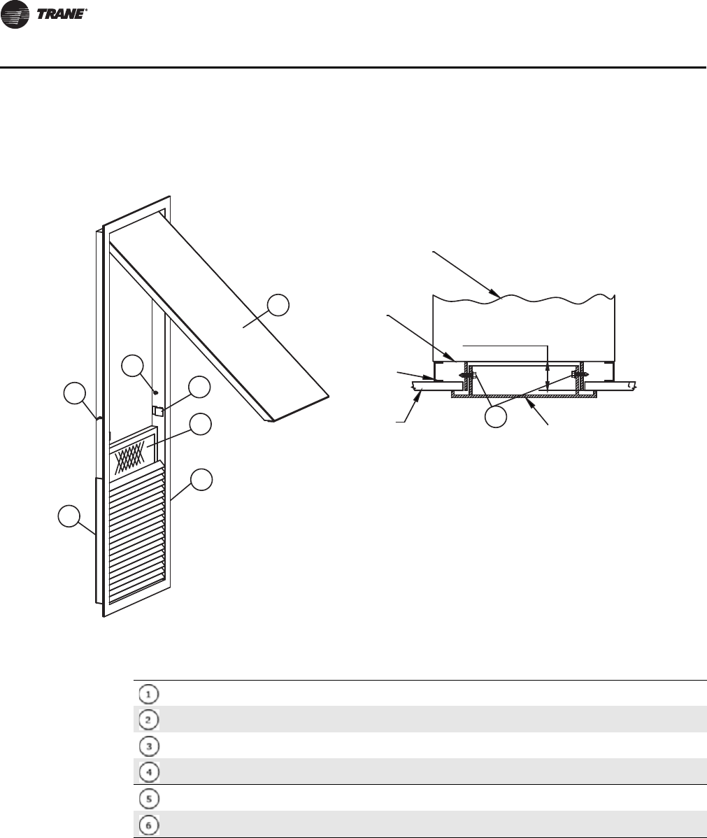
Dimensions and Weights
Return Air Panel with Framed Out Drywall with Hinged Filter Access
Features
No exposed fasteners
Improved aesthetics
Easy filter changing - no tools required
Drywall is framed out around two-inch collar/flange
Figure 23. Return air panel - framed out drywall with hinged filter access
1
2
3
4
5
6
6
6
2-in. collar on
front of fan coil unit
Return air panel
Fan coil unit
Front of
fan coil
unit
Drywall stud
by others
Drywall
by others
Table 20. Return air panel with framed out drywall with hinged access filter access callouts
Hinged filter access door
Access panel retaining clip
Throwaway 1-inch filter
Grille frame
Filter channel
Sheet metal screw by contractor
UNT-PRC019-EN_072013_Vertical Stack Fan Coil.book Page 34 Wednesday, July 17, 2013 9:37 AM
UNT-PRC019-EN 35
Dimensions and Weights
Fan Coil Weights
The weights are approximate. Risers, external sheet metal accessories and supply air grilles are not
included in the weight.
Table 21. Weights for fan coil units
Size Weight
350 140 lbs (63 kg)
450 150 lbs (68 kg)
600 170 lbs (77 kg)
800 180 lbs (82 kg)
1000 210 lbs (95 kg)
1200 220 lbs (100 kg)
UNT-PRC019-EN_072013_Vertical Stack Fan Coil.book Page 35 Wednesday, July 17, 2013 9:37 AM

36 UNT-PRC019-EN
Mechanical Specifications
Certifications
Performance: Unit performance is certified by AHRI in accordance with ANSI/AHRI 440-2008:
Performance Rating of Room Fan-Coils.
Safety: All standard units are agency listed in the United States and Canada and comply with the
requirements of the current editions of UL 1995/CSA C22.2 No. 236.
Construction
The cabinets shall be fabricated from 18 gage steel lined with ½-inch fiberglass insulation bonded
with a thermosetting resin and coated on the airstream side with an acrylic facing. In addition, there
is an option available for 3/8-inch closed cell cabinet insulation.
The drain pan shall be an acrylic (black polyester powder) coated 20 gauge galvanized steel
positively sloped in two directions towards the outlet. The drain pan shall be insulated on the
underside with ½-inch fiberglass insulation (same as cabinet). The drain hose from the outlet to the
condensate riser shall form a running trap. An optional Stainless Steel drain pan is also available.
A drain pan float switch is also available. The float switch will close CW control valve upon detection
of high water level in condensate drain pan.
Fan
The galvanized metal fan wheels are centrifugal forward-curved and double-width. Fan wheels and
housings are corrosion resistant.
Motors
The fan motor shall be a three speed P.S.C. type with internal thermal protection and sealed
bearings. All motors have a maximum ambient operating temperature of 104°F and are
permanently lubricated.
An optional ECM type brushless fan motor is available. The motor is available, programmed at the
factory for three (3) discrete speed operation. A variable speed EC motor is also available for use
with a 2-10V DC signal.
An unfused service disconnect switch shall be included, mounted inside the unit behind the motor
cover.
Coils
The coil shall have aluminum fins mechanically bonded to ½-inch copper tube. The coil shall be
factory pressure tested at not less than 300 psig. A manual air vent shall be incorporated at the high
point, and a drain cock at the low point of the connecting pipework to the coil.
Piping Packages
The piping package shall include: Ball type shut-off valves on the coil supply and returns (combined
with balancing valves or strainers when used), and a two- or three-way control valve with two-
position actuator. Chilled water and hot water valves are normally closed.
Control valves are also available in 3 wire floating point or 2-10V DC modulating valves.
Additionally balancing valves (manual or automatic) and strainers supplied as riser system
dictates. These devices are provided as combo-valves with the shut-off on supply and return and
can be equipped with PT ports.
Electric Heat
Units with electric heat shall be wired for single-stage operation with an open wire nickel-chrome
element. An auto-reset high limit device shall be included.
UNT-PRC019-EN_072013_Vertical Stack Fan Coil.book Page 36 Wednesday, July 17, 2013 9:37 AM

UNT-PRC019-EN 37
Mechanical Specifications
Filters
A one-inch disposable filter shall be shipped loose with the return air access panel.
Units equipped with one inch MERV 10 filters have a rating based on ASHRAE Standard 52.2. The
average dust spot efficiency is no less than 35 to 40 percent when tested in accordance with
ASHRAE 52.1 atmospheric dust spot method.
Units equipped with one inch MERV 13 filters have a rating based on ASHRAE Standard 52.2. The
average dust spot efficiency is no less than 90 percent efficiency on 1–3 micron particles and greater
than 90 percent efficiency on 3–10 micron particles when tested in accordance with ASHRAE Test
Standard 52.2.
Controls
Thermostat (option)
The fan coil manufacturer shall supply a low voltage (24V) thermostat for remote mounting, or
optionally unit mounted. Remote mounted thermostats are connected to a terminal strip that is
mounted inside the unit. The thermostat is shipped loose for installation after the unit is installed,
dry-wall is applied and the walls are painted.
Line voltage controls for unit mounting is also available. Thermostat quick-connect plug provided;
thermostat ships loose for installation after drywall is applied and walls are painted.
Tracer ZN521 (option)
The Tracer ZN521 discrete speed controller can be used in a stand-alone application or used as part
of a Trane Integrated Comfort System (ICS) with LonTalk® communication. The Tracer ZN521 offers
the combined advantages of simple and dependable operation. Standard control features include
options normally available on more elaborate control systems. All control options are available
factory-mounted and can be field-configured using a service tool.
Tracer UC400 (option)
The Tracer UC400 controller delivers single zone VAV control in a stand-alone application or as part
of a Trane Integrated Comfort system with BACnet® communication. Standard control features
include options normally available on more elaborate control systems.
Riser Package
Risers are available in both type “L” and type “M” copper for supply, return and condensate pipes.
Riser insulation is available in ½-inch and one-inch wall thickness for closed cell foam (polyolefin),
closed cell elastomeric (similar to Armaflex®) and fiberglass (wrapped with vapor barrier).
Riser diameter and insulation thickness are subject to physical limitations. Contact Trane when
risers are larger than 2 1/2 inches in diameter. The risers shall have an approximately 2 1/2 inch
swaged expansion at the top end to allow a 2 inch insertion of the riser from above without the use
of couplings. Risers may be provided plain ended in lieu of swaged for field supplied/installed
fittings (similar to Pro-Press®).
The riser insulation shall have a flame spread rating of 25 or less and a smoke developed rating
of 50 or less in compliance with ASTM E 84. The insulation shall be continuous over the riser length
within the height of the cabinet. Provision for insulation beyond the ends of the cabinet shall be
the responsibility of the installing contractor.
The specification of riser anchoring, expansion loops and fire stopping requirements are not
detailed in this specification and are not part of the Trane fan coils scope. Trane can provide
expansion loops installed on the risers at the factory as per the engineers specification.
Hot water risers which are continuous over twelve or more floors may incorporate expansion
compensation loops within the fan coil cabinet, location and spacing of expansion joints are the
responsibility of the design engineer.
UNT-PRC019-EN_072013_Vertical Stack Fan Coil.book Page 37 Wednesday, July 17, 2013 9:37 AM

38 UNT-PRC019-EN
Mechanical Specifications
Return Air Access Panel
The return air access panel shall have a fixed blade return air grille in the lower portion with filter
access achieved by removal of the panel. The panel installs flush on to the drywall which has been
applied directly to the front of the unit. The panel is of stamped steel construction and shall be
finished in standard white baked enamel. The panel secures to the unit by a hook on the bottom
edge and two quarter-turn fasteners in the upper corners. The panel is shipped loose for installation
after the unit is installed, dry-wall is applied and the walls are painted.
There is also a return air access panel with hinged filter access as an option. Stamped steel
construction with return air grille in lower portion of grille and hinged filter access in the top
portion. Secured to the two-inch flange on the front of the unit with sheet metal screws. Drywall
is framed out in front of the unit and is not applied directly to the unit face.
Supply Air Grilles and Registers
Supply air grilles and registers shall be provided for unit mounting locations. The grilles shall be
steel, have double deflection airfoil blades and shall be finished in standard white baked enamel.
The grilles shall attach to the collar of the fan coil unit by spring clips. When a unit has more than
one supply air opening a balancing damper (horizontal in the front) is included with the grille
(register) to balance the air flow (screw holes optional). Any supply air grilles which are part of
supply air ductwork shall be provided by the sheet metal contractor. Grilles are shipped loose for
installation after the unit is installed, dry-wall applied and the walls are painted.
A line of sight baffle with acoustical wrap shall be included in units which have left and right or front
and back supply air openings.
There is also an option to upgrade the supply air grille material to aluminum as well as the option
to provide custom colors for return air panels and supply air grilles/registers.
Raised Bases
Raised bases are available in heights of 4 inches, 8 inches or 12 inches. An access panel is available
only in the 12-inch height option. If a condensate pump is required, 12-inch high raised base with
access panel is required.
UNT-PRC019-EN_072013_Vertical Stack Fan Coil.book Page 38 Wednesday, July 17, 2013 9:37 AM

UNT-PRC019-EN 39
Notes
Notes
UNT-PRC019-EN_072013_Vertical Stack Fan Coil.book Page 39 Wednesday, July 17, 2013 9:37 AM
Trane optimizes the performance of homes and buildings around the world. A business of Ingersoll Rand, the leader in
creating and sustaining safe, comfortable and energy efficient environments, Trane offers a broad portfolio of advanced
controls and HVAC systems, comprehensive building services, and parts. For more information, visit www.Trane.com.
Trane has a policy of continuous product and product data improvement and reserves the right to change design and specifications without notice.
We are committed to using environmentally
conscious print practices that reduce waste.
4008161
ETL LISTED
CONFORMS TO
UL STD 1995
CERTIFIED TO
CSA STD C22.2 NO. 236
© 2013 Trane All rights reserved
UNT-PRC019-EN 15 July 2013
(NEW)
UNT-PRC019-EN_072013_Vertical Stack Fan Coil.book Page 40 Wednesday, July 17, 2013 9:37 AM
