Trane Voyager 12 5 To 25 Tons Catalogue Voyager™, R 410A 15 — 50 Hz
2015-04-02
: Trane Trane-Voyager-12-5-To-25-Tons-Catalogue-684200 trane-voyager-12-5-to-25-tons-catalogue-684200 trane pdf
Open the PDF directly: View PDF ![]() .
.
Page Count: 100

Voyager™ — TS*/YS*/WS*
Packaged Cooling, Gas/Electric & Heat Pump
15–25 Tons, 50 Hz
August 2012 RT-PRC034-EN
Product Catalog

© 2012 Trane All rights reserved RT-PRC034-EN
Introduction
Packaged Rooftop Air Conditioners
Through the years, Trane has designed and developed the most complete line of Packaged Rooftop
products available in the market today. Trane was the first to introduce the Micro—microelectronic
unit controls—and has continued to improve and revolutionize this design concept.
The ReliaTel control platform offers the same great features and functionality as the original Micro,
with additional benefits for greater application flexibility.
Voyager continues to provide the highest standards in quality and reliability, comfort, ease of
service, and the performance of Trane light commercial products.
Trane customers demand products that provide exceptional reliability, meet stringent performance
requirements, and are competitively priced. Trane delivers with Voyager.
Voyager features cutting edge technologies: reliable compressors, Trane engineered ReliaTel
controls, computer-aided run testing, and Integrated Comfort™ Systems. So, whether you’re the
contractor, the engineer, or the owner you can be certain Voyager Products are built to meet your
needs.
Trademarks
and the logo, Frostat, Integrated Comfort, ReliaTel, Tracer, are trademarks of in the United States
and other countries. All trademarks referenced in this document are the trademarks of their
respective owners.
Revision Summary
RT-PRC034-EN (20 August 2012)
• New configurable model number
• New optional features: Condensate Overflow Switch, MERV 8 and Filter Removal Tool, Stainless
Steel Drain Pan
• Updated Features/Benefits, Model Number Description, General Data, Electrical Data,
Mechanical Specifications
Packaged Gas/Electric Packaged Cooling/Heat Pump

Table of Contents
RT-PRC034-EN 3
Introduction . . . . . . . . . . . . . . . . . . . . . . . . . . . . . . . . . . . . . . . . . . . . . . . . . . . . . . . . . . . . 2
Features and Benefits . . . . . . . . . . . . . . . . . . . . . . . . . . . . . . . . . . . . . . . . . . . . . . . . . . . 4
Standard Features . . . . . . . . . . . . . . . . . . . . . . . . . . . . . . . . . . . . . . . . . . . . . . . . . 4
Options . . . . . . . . . . . . . . . . . . . . . . . . . . . . . . . . . . . . . . . . . . . . . . . . . . . . . . . . . . . 5
Other Benefits . . . . . . . . . . . . . . . . . . . . . . . . . . . . . . . . . . . . . . . . . . . . . . . . . . . . . 6
Standard Features . . . . . . . . . . . . . . . . . . . . . . . . . . . . . . . . . . . . . . . . . . . . . . . . . 6
Variety of Options . . . . . . . . . . . . . . . . . . . . . . . . . . . . . . . . . . . . . . . . . . . . . . . . . . 9
Other Benefits . . . . . . . . . . . . . . . . . . . . . . . . . . . . . . . . . . . . . . . . . . . . . . . . . . . . 12
Application Considerations . . . . . . . . . . . . . . . . . . . . . . . . . . . . . . . . . . . . . . . . . . . . . 15
Selection Procedure (SI/IP) . . . . . . . . . . . . . . . . . . . . . . . . . . . . . . . . . . . . . . . . . . . . . 16
SI Selection Procedure . . . . . . . . . . . . . . . . . . . . . . . . . . . . . . . . . . . . . . . . . . . . . 16
IP Selection Procedure . . . . . . . . . . . . . . . . . . . . . . . . . . . . . . . . . . . . . . . . . . . . . 19
Model Number Descriptions . . . . . . . . . . . . . . . . . . . . . . . . . . . . . . . . . . . . . . . . . . . . 22
General Data . . . . . . . . . . . . . . . . . . . . . . . . . . . . . . . . . . . . . . . . . . . . . . . . . . . . . . . . . . 24
Performance Data . . . . . . . . . . . . . . . . . . . . . . . . . . . . . . . . . . . . . . . . . . . . . . . . . . . . . 30
Controls . . . . . . . . . . . . . . . . . . . . . . . . . . . . . . . . . . . . . . . . . . . . . . . . . . . . . . . . . . . . . . 59
Electrical Data . . . . . . . . . . . . . . . . . . . . . . . . . . . . . . . . . . . . . . . . . . . . . . . . . . . . . . . . . 62
Typical Wiring . . . . . . . . . . . . . . . . . . . . . . . . . . . . . . . . . . . . . . . . . . . . . . . . . . . . . . . . . 66
Jobsite Connections . . . . . . . . . . . . . . . . . . . . . . . . . . . . . . . . . . . . . . . . . . . . . . . . . . . 80
Dimensional Data . . . . . . . . . . . . . . . . . . . . . . . . . . . . . . . . . . . . . . . . . . . . . . . . . . . . . . 81
Weights . . . . . . . . . . . . . . . . . . . . . . . . . . . . . . . . . . . . . . . . . . . . . . . . . . . . . . . . . . . . . . 87
Mechanical Specifications . . . . . . . . . . . . . . . . . . . . . . . . . . . . . . . . . . . . . . . . . . . . . . 93
Factory Installed Options . . . . . . . . . . . . . . . . . . . . . . . . . . . . . . . . . . . . . . . . . . . 95
Factory or Field Installed Options . . . . . . . . . . . . . . . . . . . . . . . . . . . . . . . . . . . 96
Field Installed Options . . . . . . . . . . . . . . . . . . . . . . . . . . . . . . . . . . . . . . . . . . . . . 97

4 RT-PRC034-EN
Features and Benefits
Standard Features
•2” throwaway filters provided on 15–25 ton units
•Anti-Short Cycle Timer
•Belt Drive Motors
•Colored and Numbered Wiring
•Crankcase Heaters
•Dedicated Airflow
•Discharge Line Thermostat
•Easy Access Low Voltage Terminal Board (LTB)
•Foil-Faced and Edge Captured Insulation
•High Efficiency Drum and Tube Heat Exchanger
•High Efficiency Gas Heat with Hot Surface Ignition
•High Pressure Cutout
•IAQ Sloped Condensate Drain Pan
•Liquid Line Refrigerant Drier
•Low Ambient Cooling to 0°F
•Microchannel Type Condenser Coils (Major Design Sequence F, T and Y Units Only)
•Operating Charge of R-410A
•Patented Hybrid Condenser Coil for Easy cleaning
•Phase Monitor
•Provisions for Through-the-Base Gas and Condensate Drain Connections
•Quick Access Panels
•Quick Adjust Idler Arm Pulley
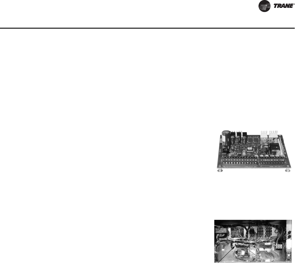
•ReliaTel™ Microprocessor Controls
Figure 1. Factory installed options
A
B
C
D
E
F
H
I
J
G
Foil-Faced Insulation
Quick Adjust Idler Pulley
ReliaTel™ Microprocessor Controls
Colored and Numbered Wiring
Low Ambient Cooling to Zero° F
High and Low Pressure Switches
Scroll Compressors (R-410A)
Available in R-410A refrigerant
Hinged Access Doors
Single Side Service
Smoke Detector
Fan Failure Switch
Clogged Filter Switch
Through-the-Base Gas Piping
A
B
C
D
E
F
G
H
I
J
K
L
M
N
L
M
N
K

RT-PRC034-EN 5
Features and Benefits
•Single Point Power
•Single Side Service
•Standardized Components
•Trane Built Scroll Compressors
•U-shaped Airflow Pattern
Options
Factory Installed Options*10
•2" MERV 8 or MERV 13 Filters with Filter Removal Tool
•Black Epoxy Pre-Coated Coils4, 11
•CO2 Sensor Wiring (Wiring Only)
•Complete Coat™ Microchannel Condenser Coil
•Condensate Overflow Switch
•Hinged Access Doors
•Stainless Steel Drain Pan
•Stainless Steel Heat Exchanger with 10 year warranty4
•Through the Base Electrical Access
•Through the Base Electrical with Circuit Breaker8, 9
•Through the Base Electrical with Disconnect Switch5, 8, 9
Factory* or Field Installed Options10
Note: *Some Factory Installed Options (FIOPS) available for Downflow Air Discharge units only.
Please verify with ordering system for availability.
Explanation of Notes 1–10 located on page 23 following Model Number Description.
•Clogged Filter/Fan Failure Switch2, 4
•Discharge Air Sensing Kit2, 4
•Economizer - Downflow
•Electric Heaters4, 6, 9
•Frostat2, 4
•LonTalk® Communications Interface (LCI)4
•ReliaTel™ Options Module7
•Trane Communications Interface (TCI)1, 4
Field Installed Options
•Barometric Relief
•CO2 Sensor
•Digital Display Zone Sensor
•Economizer - Horizontal
•High and Low Static Drive Kits
•LP Conversion Kit
•Manual Outside Air Damper
•Motorized Outside Air Dampers
•Oversized Motors
•Reference or Comparative Enthalpy3, 4
•Remote Potentiometer
•Roof Curb (Downflow Only)
•Thermostat
•Tool-less Hail Guards
•Ventilation Override Accessory2
•Zone Sensors and Remote Zone Sensors

6 RT-PRC034-EN
Features and Benefits
Other Benefits
•Cabinet Design Ensures Water Integrity
•Ease of Service, Installation and Maintenance
•Mixed Model Build Enables “Fastest in the Industry” Ship Cycle Times
•Outstanding Airflow Distribution
•ReliaTel™ Controls benefits
•Rigorous Testing
•Unmatched Product Support
•Varitrac
Standard Features
Anti-Short Cycle Timer (Standard with ReliaTel™)
Provides a 3 minute minimum “ON” time and 3 minute “OFF” time for compressors to enhance
compressor reliability by assuring proper oil return.
Colored And Numbered Wiring
Save time and money tracing wires and diagnosing the unit.
Compressors Microchannel Condenser Coil
Voyager contains the best
compressor technology
available to achieve the highest
possible performance.
Dual compressors are
outstanding for humidity
control, light load cooling
conditions and system back-up
applications. Dual compressors
are available on all models.
Microchannel coils have better heat transfer performance due
to flat streamlined tubes with small ports, and metallurgical
tube-to-fin bond.
Microchannel condenser coil can reduce system refrigerant
charge by up to 50% (potential LEED credit) because of smaller
internal volume, which can lead to better compressor
reliability. Compact all aluminum microchannel coils also help
to reduce the unit weight. All-aluminum construction
improves recyclability. Galvanic corrosion is also minimized
due to all aluminum construction. Strong aluminum brazed
structure provides better fin protection.
Header
(top removed)
Microchannel Flat Tube
Ribbon Fin
RT-PRC034-EN 7
Features and Benefits
Crankcase Heaters
These band heaters provide improved compressor reliability by warming the oil to prevent
migration during off-cycles or low ambient conditions. These are standard on all Voyager models.
Discharge Line Thermostat
A bi-metal element discharge line thermostats installed as a standard option on the discharge line
of each system. This standard option provides extra protection to the compressors against high
discharge temperatures in case of loss of charge, extremely high ambient and other conditions
which could drive the discharge temperature higher.
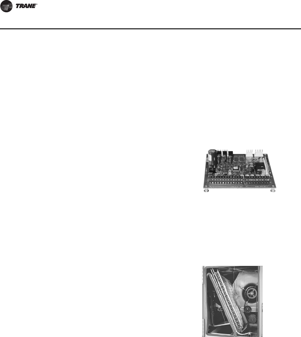
Condenser Coil Controls—ReliaTel
ReliaTel™ microprocessor controls provide unit control for
heating, cooling and ventilating utilizing input from sensors
that measure indoor and outdoor temperature and other zone
sensors. ReliaTel also provides outputs for building
automation systems and expanded diagnostics.
For a complete list of ReliaTel offerings, refer to “Other
Benefits,” p. 12.
Conversionless Units
The dedicated design units (either downflow or horizontal)
require no panel removal or alteration time to convert in the
field—a major cost savings during installation. Horizontal
units come complete with duct flanges so the contractor
doesn’t have to field fabricate them. These duct flanges are a
time and cost saver.
Voyager boasts a patent-
pending 1+1+1 condenser coil,
permanently gapped for easy
cleaning.
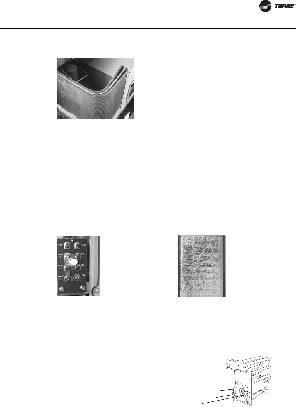
Easy Access Low Voltage Terminal Board Foil Faced Insulation
Voyager’s Low Voltage Terminal Board is
external to the electrical control cabinet. It is
extremely easy to locate and attach the
thermostat wire and test operation of all unit
functions. This is another cost and time saving
installation feature.
All panels in the evaporator section of the unit
have cleanable foil-faced insulation. All edges
are either captured or sealed to ensure no
insulation fibers get into the airstream.
Heat Exchanger—Drum and Tube
The cabinet (pictured right) features a drum
and tube heat exchanger that is manufactured
using aluminized steel with stainless steel
components for maximum durability.
The requirement for cycle testing of heat
exchangers is 10,000 cycles by ANSI Z21.47.
This is the standard required by both UL and
AGA for cycle test requirements.
Hot Surface Ignitor
Negative Pressure Gas Valve
Forced Combustion Blower
8 RT-PRC034-EN
Features and Benefits
The drum and tube design has been tested and passed over 150,000 cycles, which is over 15 times
the current ANSI cycling requirements. The negative pressure gas valve will not allow gas flow
unless the combustion blower is operating. This is one of our unique safety features.
The forced combustion blower supplies pre-mixed fuel through a single stainless steel burner
screen into a sealed drum where ignition takes place. It is more reliable to operate and maintain
than a multiple burner system.
The hot surface ignitor is a gas ignition device which doubles as a safety device utilizing a
continuous test to prove the flame. The design is cycle tested at the factory for quality and
reliability. Our gas/electric rooftops exceed all California seasonal efficiency requirements and
perform even better than the California NOx emission requirements.
Low Ambient Cooling
All Voyager microprocessor units have cooling capabilities down to 0°F as standard.
Pressure Cutouts
Low and high pressure cutouts are standard on all Voyager models.
Phase Monitor
The Phase Monitor is a three-phase line monitor module that protects against phase loss, phase
reversal and phase unbalance. It is intended to protect compressors from reverse rotation. It has
an operating input voltage range of 190–600 Vac, and LED indicators for ON and FAULT. There are
no field adjustments and the module will automatically reset from a fault condition.
Single Side Service
Single side service is standard on all units.
Sloped Drain Pans
Every Voyager unit has a non-corrosive, sloped drain pan made of pre-painted steel and standard
on all units.
Low Voltage Connections
The wiring of the low voltage connections to the unit
and the zone sensors is as simple as 1-1, 2-2, and 3-3.
This simplified system makes it easy for the installer to
wire.
Motors
All indoor fan motors are belt drive as standard.
Quick-Access Panels
Remove three or more screws for access to the
standardized internal components and wiring.
Quick-Adjust Slider Plate
With the Quick-Adjust Slider Plate, the belt and
sheaves can be quickly adjusted without moving the
mounted fan motor. The result is a major savings in
time and money.
Single Point Power
A single electrical connection powers the unit.

RT-PRC034-EN 9
Features and Benefits
Standardized Components
Components are placed in the same location on all Voyager units. Familiarize yourself with one
Voyager and you are familiar with every Voyager.
Due to standardized components throughout the Voyager line, contractors/owners can stock fewer
parts.
Through the Base Condensate
Every unit includes provisions for through the base condensate drain connections. This allows the
drain to be connected through the roof curb instead of a roof penetration.
Variety of Options1
Factory Installed Options
Black Epoxy Pre-Coated Coils (W Units Only)
The pre-coated coils are an economical option for protection in mildly corrosive environments.
Circuit Breaker (Required with Through-the-Base Electrical)
This option is a factory installed thermal magnetic, molded case, HACR Circuit Breaker with
provisions for through the base electrical connections. Available on all models.
CO2 Sensor Wiring
This is the unit wiring for field installed C02 sensors. Factory-installed C02 sensor wiring saves time
and ensures proper unit connections for the field installed C02 sensor kits.
Complete Coat™ Condenser Coil (T/Y Units Only)
The cathodic epoxy type electrodisposition coating is formulated for high edge build to a number
of different types of heat exchangers. The coating is selected to provide excellent resistance and
durability to corrosive effects of alkalies, acids, alcohols, petroleum, seawater, salt air, and
corrosive environments. This coating shall be available on microchannel condenser coils.
Condensate Overflow Switch
A condensate overflow switch is available to shut the unit down in the event that the condensate
drain line becomes clogged. This option protects the unit from water overflowing from the drain
pan and entering the base of the units.
1Refer to Model Number Description for option availability.
Disconnect Switch (Required with
Through-the-Base Electrical)
Factory installed three-pole, molded case, disconnect
switch with provisions for through the base electrical
connections are available. Available on all models.
Codes require a method of assured unit shutdown for
servicing. Field-installed disconnects sometimes
interfere with service access. Factory installation of
unit disconnects reduces costs, assures proper
mounting and provides the opportunity to upgrade to
unit circuit breaker protection.
10 RT-PRC034-EN
Features and Benefits
High Efficiency Filtration
Voyager units offer a variety of high efficiency filtration options. MERV 8 and MERV 13 filters
provide additional filtration beyond the capabilities of typical 2” throwaway filters. Also, when
MERV 8 or MERV 13 filters are ordered, units come equipped with a filter removal tool.
Stainless Steel Drain Pan
For excellent corrosion and oxidation resistance, the optional stainless steel drain pan provides a
cleanable surface that complement other IAQ solutions such as high efficiency filtration (MERV 8
or 13), or demand control ventilation (CO2).
Stainless Steel Heat Exchanger
The optional stainless steel heat exchanger is constructed of 304 stainless steel. It is resistant to
corrosion and oxidation and easy to clean. The high strength to weight ratio allows for high
ventilation rates with gas units. With this option, a 10-year stainless steel heat exchanger warranty
is standard.
Through-the-Base Electrical Utility Access
An electrical service entrance shall be provided allowing electrical access for both control and main
power connections inside the curb and through the base of downflow units, and through the front
of horizontal units. Option will allow for field installation of liquid-tight conduit and an external field
installed disconnect switch.
Factory provided through the base openings simplify wiring and piping. Because these utility
openings frequently minimize the number of roof penetrations, the integrity of roofing materials
is enhanced.
Factory or Field Installed Options1
Clogged Filter/Fan Failure Switch
A dedicated differential pressure switch is available to achieve active fan failure indication and/or
clogged filter indication.
These sensors allow a zone sensor service light or Integrated Comfort System to indicate a dirty
filter or a fan that’s not working. The field installation charges for these valuable feedback devices
often eliminate them from consideration. Factory installation can make such features a good
investment.
Discharge Air Sensing Kit
Provides true discharge air sensing in heating models. The kit is functional only with the ReliaTel™
Options Module.
Economizer - Downflow
Economizers are equipped with either dry bulb or reference or comparative enthalpy sensing.
These economizers provide free cooling as the outdoor temperature and/or humidity decreases.
Correctly installed, they offer a valuable energy savings.
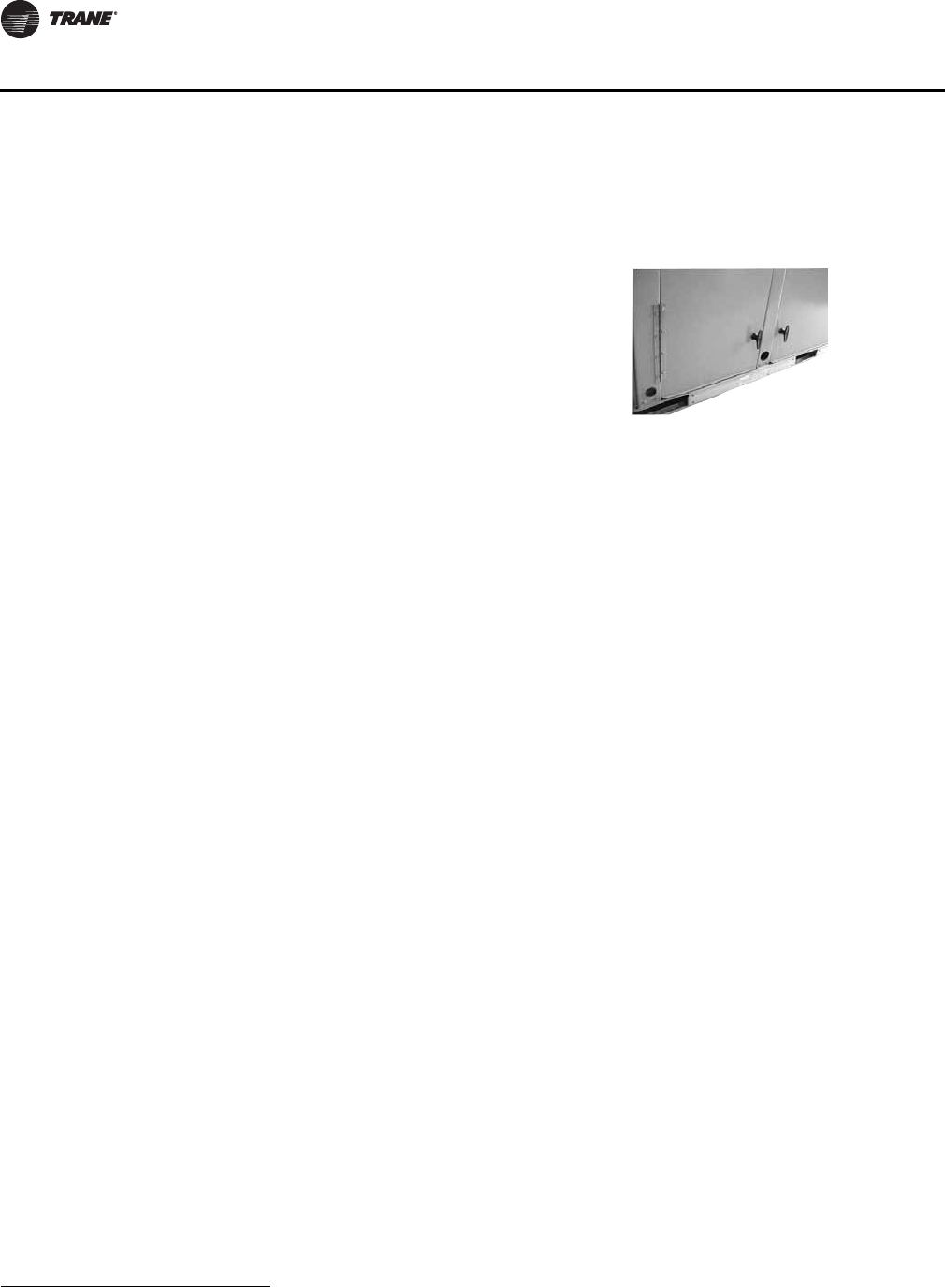
Hinged Access Doors
These doors permit easy access to the filter, fan/heat,
and compressor/control sections. They reduce the
potential roof damage from screws or sharp access
door corners.
1Refer to Model Number Description for option availability.

RT-PRC034-EN 11
Features and Benefits
Electric Heaters
Electric heat modules are available within the basic unit. If ordering the Through the Base Electrical
option with an Electrical Heater, the heater must be factory installed.
Frostat™
This capillary bulb embedded in the face of the evaporator coil monitors coil temperature to
prevent evaporator icing and protect the compressor. Recommended for applications with low
leaving air temperatures, low airflow and or high latent load applications.
LonTalk® Communications Interface
The LonTalk communications interface allows the unit to communicate as a Tracer™LCI-V device
or directly with generic LonTalk Network Building Automation System Controls.
Motors
Factory or field installed oversized motors available for high static applications are available.
Oversized Motors
Factory or field installed oversized motors available for high static applications.
Reference or Comparative Enthalpy
Measures and communicates humidity while maximizing comfort control.
Trane Communication Interface (TCI)
Available factory or field installed. This module when applied with the ReliaTel™ easily interfaces
with Trane’s Integrated Comfort™ System.
*Refer to Model Number Description for option availability.
Field Installed Options1
Barometric Relief
Designed to be used on downflow units, barometric relief is an unpowered means of relieving
excess building pressure.
CO2 Sensor - Demand Control Ventilation (DCV)
Demand-controlled ventilation (DCV) is a control strategy that responds to the actual demand
(need) for ventilation by regulating the rate at which the HVAC system brings outdoor air into the
building. A CO2 sensor measures the concentration (parts per million, ppm) of CO2 (Carbon
Dioxide) in the air. As the CO2 concentration changes, the outside air damper modulates to meet
the current ventilation needs of the zone. The CO2 sensor kit is available as a field installed
accessory.
Note: Choose factory-installed CO2 sensor wiring option to save time and ensure proper unit
connections for the field installed CO2 sensor kits.
Dampers
0–25 percent manual or 0–50 percent motorized outside air dampers are available.
Digital Display Zone Sensor
The Digital LCD (Liquid Crystal Display) zone sensor has the look and functionality of standard zone
sensors. This sensor should be utilized with ReliaTel™ controls.
1Refer to Model Number Description for option availability.
12 RT-PRC034-EN
Features and Benefits
Economizer - Horizontal
Economizers are equipped with either dry bulb or reference or comparative enthalpy sensing.
These economizers provide free cooling as the outdoor temperature and/or humidity decreases.
Correctly installed, they offer a valuable energy savings.
High Static Drive
Available on many models, this high static drive accessory extends the capability of the standard
motor. Avoid expensive motors and operating costs by installing this optimized sheave accessory.
LP Conversion Kit
Provided for field conversion of gas/electric units from Natural gas to Propane.
Remote Potentiometer
When properly installed in the economizer control circuitry, this accessory provides a remote
variable resistance to enable the operator to adjust the minimum damper position.
Roof Curbs
Available for downflow units. Only two roof curbs for the entire Voyager line simplifies curb
selection.
Zone Sensors/Thermostats
Available in programmable, automatic and manual styles.
Note: Zone sensor required for units configured for Single Zone VAV indoor fan system control
to enable Single Zone VAV functionality.
Other Benefits
Airflow Distribution
Airflow is outstanding. The Voyager can replace an older machine with old ductwork and, in many
cases, improve the comfort through better air distribution. The U-shaped airflow allows for
improved static capabilities.
Cabinet Integrity
For added water integrity, Voyager has a raised 1 1/8” lip around the supply and return of the
downflow units to prevent water from blowing into the ductwork.
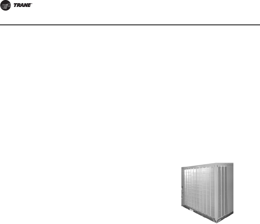
Tool-less Hail Guards
Tool-less, hail protection quality coil guards shall be
field-installed for condenser coil protection. This
option protects the condenser coil from vandalism
and/or hail damage.
Ventilation Override Accessory
With the Ventilation Override Accessory installed, the
unit can be set to transition to up to three different pre-
programmed sequences for Smoke Purge,
Pressurization, and Exhaust. The transition occurs
when a binary input on the RTOM is closed (shorted).
This would typically be a hard wired relay output from
a smoke detector or fire control panel.
RT-PRC034-EN 13
Features and Benefits
Easy to Install, Service and Maintain
Because today’s owners are very cost-conscious when it comes to service and maintenance, the
Trane Voyager was designed with direct input from service contractors. This valuable information
helped to design a product that would get the serviceman off the job quicker and save the owner
money. Voyager does this by offering outstanding standard features enhanced by a variety of
factory and field installed options, multiple control options, rigorously tested proven designs and
superior product and technical support.
Outstanding Airflow Distribution
Airflow is outstanding. The Voyager can replace an older machine with old ductwork and, in many
cases, improve the comfort through better air distribution.
– ensures that the compressor will run for a specific amount of time which allows oil to return
for better lubrication, enhancing the reliability of the compressor.
Voyager with ReliaTel™ reduces the number of components required to operate the unit, thereby
reducing possibilities for component failure.
ReliaTel Makes Testing Easy
ReliaTel™ requires no special tools to run the Voyager unit through its paces. Simply place a jumper
between Test 1 and Test 2 terminals on the Low Voltage Terminal Board and the unit will walk
through its operational steps automatically.
The unit automatically returns control to the zone sensor after stepping through the test mode a
single time, even if the jumper is left on the unit.
As long as the unit has power and the “system on” LED is lit, ReliaTel is operational. The light
indicates that the controls are functioning properly.
ReliaTel features expanded diagnostic capabilities when utilized with Trane Integrated Comfort™
Systems.
Some zone sensor options have central control panel lights which indicate the mode the unit is in
and possible diagnostic information (dirty filters for example).
Other ReliaTel Benefits
The ReliaTel™ built-in anti-shortcycle timer, time delay relay and minimum “on” time control
functions are factory tested to assure proper operation.
ReliaTel Controls Benefits
ReliaTel™ controls provide unit control for heating, cooling
and ventilating utilizing input from sensors that measure
outdoor and indoor temperature.
ReliaTel Control Logic Enhances Quality and Reliability
– prevents the unit from short cycling, considerably
improving compressor life.
ReliaTel Makes Installing and Servicing Easy
ReliaTel™ eliminates the need for field installed anti-
shortcycle timer and time delay relays. ReliaTel™ controls
provide these functions as an integral part of the unit. The
contractor no longer has to purchase these controls as
options and pay to install them. The wiring of the low voltage
connections to the unit and the zone sensors is as easy as 1-1,
2-2, and 3-3. This simplified system makes wiring easier for
the installer.
ReliaTel™
14 RT-PRC034-EN
Features and Benefits
ReliaTel softens electrical “spikes” by staging on fans, compressors and heaters.
Intelligent Fallback is a benefit to the building occupant. If a component goes astray, the unit will
continue to operate at predetermined temperature setpoint.
Intelligent Anticipation is a standard ReliaTel feature. It functions continuously as ReliaTel and zone
sensor(s) work together in harmony to provide much tighter comfort control than conventional
electro-mechanical thermostats.
The same ReliaTel Board fits all Voyager Packaged Gas/Electrics, Cooling, and Heat Pump models.
This provides standardization of parts for contractors. Less money is tied up in inventory with
ReliaTel.
Rigorous Testing
All of Voyager’s designs were rigorously rain tested at the factory to ensure water integrity. Actual
shipping tests were performed to determine packaging requirements. Units were test shipped
around the country to determine the best packaging. Factory shake and drop tests were used as
part of the package design process to help assure that the unit arrives at the job site in top condition.
Rigging tests include lifting a unit into the air and letting it drop one foot, assuring that the lifting
lugs and rails hold up under stress.
The evaporator and condenser coils are leak tested at 225 psig and pressure tested to 450 psig. All
parts are inspected at the point of final assembly. Sub-standard parts are identified and rejected
immediately.
Every unit receives a 100 percent unit run test before leaving the production line to make sure it
lives up to rigorous Trane requirements. Voyager units incorporate either a one piece top or the
Trane-Tite-Top (T3). Each part of the top (either two or three pieces) overlaps in such a way that
water cannot leak into the unit. These overlapped edges are gasketed and sealed to ensure superior
water integrity.
Unmatched Support
Trane Sales Representatives are a Support Group that can assist you with:
•Product
•Application
•Service
•Training
•Special Applications
•Specifications
•Computer Programs and much more
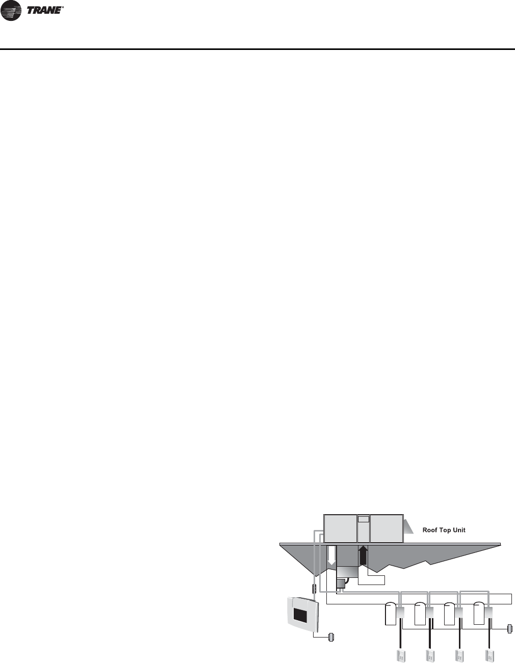
VariTrac—Building Automation
System
When Trane’s changeover VAV System
for light commercial applications is
coupled with Voyager, it provides the
latest in technological advances for
comfort management systems and can
allow thermostat control in every zone
served by VariTrac.

RT-PRC034-EN 15
Application Considerations
Application of this product should be within the cataloged airflow and cooling considerations.
Barometric Relief
This product line offers an optional barometric relief damper for use in conjunction with
economizer option. This accessory consists of gravity dampers which open with increased
pressure. As the building air pressure increases, the pressure in the unit return air section also
increases, opening the dampers and relieving the conditioned space.
Notes:
•The effectiveness of barometric relief damper during economizing operation is system related.
•Pressure drop of the return air system should be considered to control building pressurization.
Black Epoxy Coil
The coils are manufactured with a thermoset, vinyl coating that is bonded to the aluminum fin stock
prior to the fin stamping process. These coils are an economical option for protection in mildly
corrosive environments.
Note: Not to be used where seacoast applications exist.
Clearance Requirements
The recommended clearances identified with unit dimensions should be maintained to ensure
adequate serviceability, maximum capacity and peak operating efficiency. Actual clearances which
appear inadequate should be reviewed with the local Trane sales personnel.
Complete Coat™ Microchannel Condenser Coil
The cathodic epoxy type electrodisposition coating is formulated for high edge build to a number
of different types of heat exchangers. The coating is selected to provide excellent resistance and
durability to corrosive effects of alkalies, acids, alcohols, petroleum, seawater, salty air and other
corrosive environments. This coating shall be available on microchannel condenser coils.
Condensate Trap
The evaporator is a draw-thru configuration. A trap must be field provided prior to start-up on the
cooling cycle.
Heating Operation
The heat exchanger is manufactured with aluminized steel. To prevent condensation within the
heat exchanger, do not exceed 50 percent outside air or a minimum mixed air temperature of 40°F.
Optional Stainless Steel Heat Exchanger
The optional stainless steel heat exchanger is manufactured with 304 stainless steel. To prevent
corrosion and prolong heat exchanger reliability, the minimum mixed air temperature allowed
across the heat exchanger is 20°F.
Low Ambient Cooling
The Voyager™ line features, with ReliaTel™ microprocessor controls, low ambient cooling down
to 0°F. The following options need to be included/considered when low ambient applications are
required: continuous fan operation, crankcase heaters (standard), thermal expansion valves,
frostat.
Contact your local Trane Representative for more assistance with low ambient cooling
applications.
Unit Pitch
These units have sloped condensate drain pans. Units must be installed level. Any unit slope must
be toward access side of the unit.

16 RT-PRC034-EN
Selection Procedure (SI/IP)
SI Selection Procedure
Cooling Capacity
Note: Cooling Capacity Procedure is the same for cooling (TS*), gas/electric (YS*) and heat pump
(WS*) units.
Step 1.
Calculate the building’s total and sensible cooling loads at design conditions. Use the Trane
calculation methods or any other standard accepted method.
Factors used in unit selection:
• Total Cooling Load: 40.0 kW
• Sensible Cooling Load: 29.0 kW
• Airflow: 8500 m3/h
• Electrical Characteristics:
380-415/50/3
• Summer Design Conditions:
• Entering Evaporator Coil:
27°C DB, 22°C WB,
35°C Outdoor Ambient
• External Static Pressure: 127 Pa
• Rooftop—downflow configuration accessories
•Roof Curb
•Economizer
•Electric Heat
Step 2.
Size the equipment using Table 4, p. 30. Match the cooling loads at design conditions.
Table 4, p. 30 shows that a TSD155F has a gross cooling capacity of 47.5 kW and 35.6 kW sensible
capacity at 8500 m3/h and 35°C DB outdoor ambient with 27°C DB, 19°C WB air entering the
evaporator.
To Find Capacity at Intermediate Conditions Not in the Table:
When the design conditions are between two numbers that are in the capacity table, interpolation
is required to approximate the capacity.
Note: Extrapolation outside of the table conditions is not recommended.

RT-PRC034-EN 17
Selection Procedure (SI/IP)
Step 3.
In order to select the correct unit which meets the building’s requirements, the fan motor heat must
be deducted from the gross cooling capacity. The amount of heat that the fan motor generates is
dependent on the effort by the motor, airflow and static pressure. To determine the total unit static
pressure (see Table 48, p. 56 for Static Pressure Drops Through Accessories):
Note: The Evaporator Fan Performance (see Table 20, p. 44) has already accounted for the
pressure drop for standard filters and wet coils (see note below Table 20, p. 44). Therefore,
the actual total static pressure is 169 - 19 (from Table 48, p. 56) = 150 Pa.
With 8500 m3/h and 150 Pa. Table 20, p. 44 shows 1.12 kW for this unit. The formula below can be
used to calculate Fan Motor Heat:
Fan Motor Heat = 1.23 * Fan Power (kW)
1.23 * 1.12 kW = 1.3776 kW
Now subtract the fan motor heat from the gross cooling capacity of the unit:
Net Total Cooling Capacity =
47.5 - 1.37 = 46.12
Net Sensible Cooling Capacity =
35.6 - 1.37 = 34.22
Step 4.
If the performance will not meet the required load of the building, total or sensible cooling load,
try a selection at the next higher size unit.
Heating Capacity
Note: Heating capacity procedures DIFFER for cooling (TS*), gas/electric (YS*) and heat pump
(WS*) units.
Step 1.
Calculate the building heating load using the Trane calculation form or other standard accepted
method.
Step 2.
Size the system heating capacity to match the calculated building heating load. The following are
building heating requirements:
TS* cooling units:
• 380 volt/three-phase Power Supply
• Total heating load of 20.5 kW
• Airflow of 8500 m3/h
The electric heat accessory capacities are listed in Table 52, p. 62. From the table, a 26.9 kW heater
at 415 volts is selected. In order to determine capacity at 380 volts, the heater voltage correction
External Static Duct System 127 Pa
Standard Filter 25mm 19 Pa
Economizer (100% OA) 12 Pa
Electric Heater Size 27 kW 11Pa
Total Static Pressure 169 Pa
Notes:
1. Reference “Heating Capacity” section on
this page for determination of heater size.
2. No additional static add for gas/heat
exchanger.

18 RT-PRC034-EN
Selection Procedure (SI/IP)
factor from Table 53, p. 62 must be used. Therefore, 26.9 kW x 0.84 (voltage correction factor) =
22.59 kW.
YS* gas/electric:
The fuel used is natural gas with a total heating load of 30 kW. Table 2, p. 26 shows 61.1 kW and
85.5 kW input models. The output capacities of these furnaces are 49.6 kW and 69.4 kW,
respectively. The low heat model with 49.6 kW output best matches the building requirements.
WS* heat pumps:
Total heating load of 30.0 kW. Outdoor ambient (Winter) of -9°C DB and indoor return of 21°C DB
and an airflow of 8500 m3/h. The unit is using a 380 V power supply. Use the integrated portion of
Table 16, p. 42 for the WC*155 to determine capacity at winter design conditions. The mechanical
heating portion of the heat pump will provide 20.9 kW.
Step 3.
Note: This step does not apply to TS* and YS* units.
WS* heat pumps:
Because 22.1 kW is less than the building's required heating capacity at winter design condition,
a supplementary heater must be selected.
30.0 - 20.9 = 9.1 kW
From Table 62, p. 64, a 13.4 kW heater at 415 V is selected. To find the capacity at 380 V, the heater
voltage correction factor from Table 63, p. 64 must be used. Therefore, 13.4 kW x 0.84 (voltage
correction factor) = 11.26 kW. This heater will be adequate to do the job.
Air Delivery Selection
Note: Air Deliver procedures is the same for cooling (TS*), gas/electric (YS*) and heat pump
(WS*) units.
External static pressure drop through the air distribution system has been calculated to be 150 Pa.
From Table 48, p. 56, static pressure drop through the economizer is 12 Pa and the 27 kW heater
is 12 Pa (127 + 12 + 12). Enter (Table 20, p. 44) for a TSD155F at 8500 m3/h and 150 Pa static
pressure.
The standard motor at 566 rpm will give the desired airflow at a rated kW of 1.12.

RT-PRC034-EN 19
Selection Procedure (SI/IP)
IP Selection Procedure
Cooling Capacity
Note: Cooling Capacity Procedure is the same for cooling (TS*), gas/electric (YS*) and heat pump
(WS*) units.
Step 1.
Calculate the building’s total and sensible cooling loads at design conditions. Use the Trane
calculation methods or any other standard accepted method.
Factors used in unit selection:
• Total Cooling Load: 140 MBh
• Sensible Cooling Load: 100 MBh
• Airflow: 5000 cfm
• Electrical Characteristics:
380-415/50/3
• Summer Design conditions:
• Entering Evaporator Coil:
80 DB, 73 WB
• Outdoor Ambient: 95 DB
• External Static pressure:
0.50 in. wg
• Rooftop - downflow configuration
• Accessories
•Roof Curb
•Economizer
•Electric Heat
Step 2.
As a starting point, a rough determination must be made of the size of the unit. The final selection
will be made after examining the performance at the given conditions. Divide the total cooling load
by nominal Btu/h per ton (12 MBh per ton); then round up to the nearest unit size.
140 MBh / 12 MBh = 11.6 tons
Step 3.
Table 5, p. 31 shows that a TSD155F has a gross cooling capacity of 162.2 MBh and 121.4 MBh
sensible capacity at 5000 cfm and 95 DB outdoor ambient with 80 DB, 73 WB air entering the
evaporator.
To Find Capacity at Intermediate Conditions Not in the Table:
When the design conditions are between two numbers that are in the capacity table, interpolation
is required to approximate the capacity.
Note: Extrapolation outside of the table conditions is not recommended.
20 RT-PRC034-EN
Selection Procedure (SI/IP)
Step 4.
In order to select the correct unit which meets the building’s requirements, the fan motor heat must
be deducted from the gross cooling capacity. The amount of heat that the fan motor generates is
dependent on the effort by the motor, cfm and static pressure. To determine the total unit static
pressure you add the external static pressure to the additional static related by the added features
(see Table 49, p. 57 for Static Pressure Drops Through Accessories):
Note: The Evaporator Fan Performance Table 21, p. 44 has already accounted for the pressure
drop for standard filters and wet coils (see note below Table 21, p. 44). Therefore, the actual
total static pressure is 0.68 - 0.08 (from Table 49, p. 57) = 0.60 wg.
With 5000 cfm and 0.60 wg, Table 21, p. 44 shows 1.50 bhp for this unit. The formula below can be
used to calculate Fan Motor Heat:
Fan Motor Heat = 3.15 * Fan bhp
3.15 * 1.50 = 4.725 MBh
Now subtract the fan motor heat from the gross cooling capacity of the unit:
Net Total Cooling Capacity =
162.2 - 4.725 = 157.475 MBh
Net Sensible Cooling Capacity =
121.4 - 4.725 = 116.675 MBh
Step 5.
If the performance will not meet the required load of the building, total or sensible cooling load,
try a selection at the next higher size unit.
External Static Duct System 0.50 wg
Standard Filter 1in. 0.08 wg
Economizer (100% OA) 0.05 wg
Electric Heater Size 27 kW 0.05 wg
Total Static Pressure 0.68 wg
Notes:
1. Reference “Heating Capacity” section on
this page for determination of heater size.
2. No additional static add for gas/heat
exchanger.

RT-PRC034-EN 21
Selection Procedure (SI/IP)
Heating Capacity
Note: Heating capacity procedures DIFFER for cooling (TS*), gas/electric (YS*) and heat pump
(WS*) units.
Step 1.
Calculate the building heating load using the Trane calculation form or other standard accepted
method.
Step 2.
Size the system heating capacity to match the calculated building heating load. The following are
building heating requirements:
TS* cooling units:
380 volt/3 phase Power Supply
Total heating load of 75.0 MBh
5000 cfm
The electric heat accessory capacities are listed in Table 52, p. 62. From the table, a 26.9 kW heater
will deliver 91.73 MBh at 415 volts. In order to determine capacity at 380 volts, the heater voltage
correction factor from Table 53, p. 62 must be used. Therefore, 91.73 MBh x 0.84 (voltage correction
factor) = 77.05 MBh.
YS* gas/electric:
Fuel natural gas and a total heating load of 115 MBh. Ta bl e 2, p . 26 shows 208.3 MBh and 291.7 MBh
input models. The output capacities of these furnaces are 169.2 MBh and 236.7 MBh respectively.
The low heat model with 169.2 MBh output best matches the building requirements.
WS* heat pumps:
Total heating load of 100 MBh. Outdoor ambient (Winter) of 17 DB and Indoor Return of 70 DB and
an airflow of 5000 cfm. The unit is using a 380 V power supply. Use the integrated portion of
Table 17, p. 42 for the WC*155 to determine capacity at winter design conditions. The mechanical
heating portion of the heat pump will provide 71.2 MBh.
Step 3.
Note: This step does not apply to TS* and YS* units.
WS* heat pumps:
Because 71.2 MBh is less than the building’s required heating capacity at winter design conditions,
a supplementary heater must be selected.
100 MBh - 71.2 MBh = 28.8 MBh
From Table 62, p. 64, a 13.4 kW heater at 415 V is selected. To find the capacity at 380 V, the heater
voltage correction factor from Table 63, p. 64 must be used. Therefore, 13.4 kW x 0.84 (voltage
correction factor) = 11.26 kW. This heater will be adequate to do the job. 38.3 MBh.
Air Delivery Selection
Note: Air Delivery procedures is the same for cooling (TS*), gas/electric (YS*) and heat pump
(WS*) units.
External static pressure drop through the air distribution system has been calculated to by
0.60 inches of water. From Table 49, p. 57, static pressure drop through the economizer is 0.05 and
the 26.9 kW heater is 0.05 inches of water (0.50 + 0.05 + 0.05). Enter (Table 21, p. 44) for a TSD155
at 5000 cfm and 0.60 static pressure. The standard motor at 566 rpm will give the desired airflow
at a rated bhp of 1.50.

22 RT-PRC034-EN
Digit 1 — Unit Type
T = Packaged Cooling, Electric Heat
Y = Packaged Gas/Electric
W = Packaged Heat Pump, Electric
Heat
Digit 2 — Efficiency
S=Standard
Digit 3 — Airflow Configuration
D=Downflow
H=Horizontal
Digit 4, 5, 6 — Nominal Gross
Cooling Capacity (MBh)
155 = 15 Tons Standard Efficiency
175 = 17½ Tons Standard Efficiency
200= 20 Tons Standard Efficiency
250= 25 Tons Standard Efficiency
Digit 7 — Major Design
Sequence
E = Round Tube Plate Fin Type
Condenser Coils
F = Microchannel Type Condenser
Coils
Digit 8 — Voltage Selection
D = 380-415/50/3
T = 200/50/311
Digit 9 — Unit Controls
R = Reliatel
Digit 10 — Heating Capacity
Note: (Applicable to Digit 1 T/W models
only)
0 = No Heat
G = 18 kW Electric Heat
K = 27 kW Electric Heat
N = 36 kW Electric Heat
P = 54 kW Electric Heat
R = 72 kW Electric Heat
Note: (Applicable to Digit 1 Y models
only)
H = Gas Heat - High
L=Gas Heat - Low
X = Gas Heat - SS Ht Ex - Low
Z = Gas Heat - SS Ht Ex - High
Digit 11 — Minor Design
Sequence
Digit 12, 13 — Service Sequence
Digit 14 — Fresh Air Selection
0=No Fresh Air
A = Manual Damper
B = Motorized Damper
D = Econ Dry Bulb w/ Barometric
Relief
F = Econ Reference Enthaply w/
Barometric Relief
H = Econ Comparative Enthaply w/
Barometric Relief
T S D 155 F D R 0 A A
123456789101112
Digit 15 — Supply Fan/Drive
Type/Motor
0=Standard Motor
1 = Oversized Motor
3 = High Efficiency Motor
6 = Single Zone Variable Air Volume
Standard Motor
7 = Multi-Speed Standard Motor
8 = Single Zone Variable Air Volume
Oversized Motor
9 = Multi-Speed Oversized Motor
A = Single Zone Variable Air Volume
Standard Motor w/ Shaft Ground
Ring
B = Multi-Speed Standard Motor w/
Shaft Ground Ring
C = Single Zone Variable Air Volume
Oversized Motor w/ Shaft Ground
Ring
D = Multi-Speed Oversized Motor w/
Shaft Ground Ring
Digit 16 — Hinged Service
Access / Filters
0 = Standard Panels/Standard Filters
A = Hinged Access/Standard Filters
Digit 17 — Condenser Coil
Protection
0 = Standard Coil
1 = Standard Coil With Hail Guard
2 = Black Epoxy Pre-Coated Coil
3 = Black Epoxy Pre-Coated Coil With
Hail guard
4 = CompleteCoat™Condenser Coil
5 = CompleteCoat™Condenser Coil
with Hail Guard
Digit 18 — Through The Base
Provisions
0 = No Through The Base Provisions
A = Through The Base Electric
B = Through The Base Gas
C = Through The Base Electric/Gas
D = Through The Base Access
Digit 19 — Disconnect Switch/
Circuit Breaker
0 = No Disconnect/circuit break
1 = Unit Mounted Non-Fused
Disconnect Switch
2 = Unit Mounted Circuit Breaker
Digit 20 — Convenience Outlet
Option
0 = Without Convenience Outlet
A = Unpowered Convenience Outlet
B = Powered Convenience Outlet
Digit 21 — Communications
Options
0 = Without Communications
Options
6 = Building Automation Control
Network Communications
Interface
Digit 22 — Refrigeration System
Option
0 = Standard refrigeration system
Digit 23 — Refrigeration
Controls
0 = Without Refrigeration Controls
1=Frostat
Digit 24 — Smoke Detector
0 = Without Smoke Detector
A = Return Air Smoke Detector
B = Supply Air Smoke Detector
C = Return/Supply Air Smoke
Detector
D = Plenum Smoke Detector
Digit 25 — System Monitoring
Controls
0 = No Monitoring Controls
1 = Clogged Filter Switch
2 = Fan Failure Switch
3 = Discharge Air Sensing
4 = Clogged Filter Switch and Fan
Failure
5 = Clogged Switch and Discharge Air
Sensing
6 = Fan Failure Switch and Discharge
Air Sensing
7 = Clogged Filter Switch, Fan Failure
Switch and Discharge Air Sensing
A = Condensate Drain Pan Overflow
Switch
B = Clogged Filter Switch and
Condensate Drain Pan Overflow
Switch
C = Fan Failure Switch and
Condensate Drain Pan Overflow
Switch
D = Discharge Air Sensing and
Condensate Drain Pan Overflow
Switch
E = Clogged Filter Switch, Fan Failure
Switch and Condensate Drain Pan
Overflow Switch
F = Clogged Filter Switch, Discharge
Air Sensing Tube and Condensate
Drain Pan Overflow Switch
G = Fan Failure Switch, Discharge Air
Sensing Tube and Condensate
Drain Pan Overflow Switch
H = Clogged Filter Switch, Fan Failure
Switch, Discharge Air Sensing
and Condensate Drain Pan
Overflow Switch
Model Number Descriptions

RT-PRC034-EN 23
Model Number Descriptions
Digit 26 - System Monitoring
Controls
0 No Monitoring Controls
A Demand Control Ventilation (CO2)12
Digit 27 - Unit Hardware
Enhancements
0 No Enhancements
1 Stainless Steel Drain Pan
Options
Factory Installed Options*10
• Black Epoxy Pre-Coated Coils4
•CO
2 Sensor Wiring (Wiring Only)
• Complete Coat Microchannel Coil
• Condensate Overflow Switch
• Hinged Access Doors
• MERV 8 or 13 with Filter Removal Tool
• Stainless Steel Drain Pan
• Stainless Steel Heat Exchanger with
10 year warranty4
• Through the Base Electrical Access
• Through the Base Electrical with
Circuit Breaker8, 9
• Through the Base Electrical with
Disconnect Switch5, 8, 9
Factory* or Field Installed
Options10
• Clogged Filter/Fan Failure Switch2, 4
• Discharge Air Sensing Kit2, 4
•Economizer - Downflow
•Electric Heaters
4, 6, 9
•Frostat
2, 4
•LonTalk
® Communications Interface
(LCI)4
• ReliaTel Options Module7
Field Installed Options
• Barometric Relief
•CO
2 Sensing
• Digital Display Zone Sensor
• Dual Thermistor Remote Zone Sensor
• Economizer - Horizontal
• High and Low Static Drive Kits
• LP Conversion Kit
• Manual Outside Air Damper
• Motorized Outside Air Dampers
• Oversized Motors
• Reference or Comparative
Enthalpy3, 4
• Remote Potentiometer
• Roof Curb (Downflow Only)
•Thermostat
• Tool-less Hail Guards
• Trane Communications Interface
(TCI)1, 4
• Ventilation Override Accessory2
• Zone and Remote Zone Sensors
Model Number Notes
1. TCI is for use with non-VariTrac
systems and VariTrac systems.
2. Requires ReliaTel options module.
3. Requires Economizer.
4. Available factory installed on
downflow AND horizontal units.
Verify with ordering system.
5. Cannot be fused.
6. Must be factory installed when
using Through-the-Base Options.
7. ReliaTel Options Module is
required when ordering the
following accessories (Factory- or
Field-Installed Options): Clogged
Filter Switch, Fan Fail Switch,
Discharge Air Sensing Kit, Frostat,
Ventilation Override.
8. Unit mounted disconnect and
circuit breakers are mutually
exclusive of each other.
9. Through-the-base electrical
option or Horizontal Side Access
must be ordered with either unit
mounted disconnect or circuit
breaker. When adding heat, must
order Trane Electric Heat.
10. All Factory Installed Options are
Built-to-Order. Check order
services for estimated production
cycle.
11. Available on Heat Pump (W) units
only.
12. Demand Control Ventilation
Option includes wiring only. The
C02 sensor is a field-installed only
option.
Note: *Some Factory Installed Options
(FIOPS) available for Downflow Air
Discharge units only. Please verify
with ordering system for
availability.

24 RT-PRC034-EN
General Data
Table 1. TS* general data
15–25 Tons Downflow and Horizontal Units
Model TS*155FD TS*175FD TS*200FD TS*250FD
Cooling Performance(a)
ARI Gross Capacity kW (MBh) 44.8 (153) 51.2 (174.8) 62.7 (214.1) 68.3 (233.0)
COP/EER(b) 3.47 / 11.8 3.51 / 12.0 3.14 / 10.7 3.10 / 10.8
Nominal Airflow - m3/h (cfm) 7480 (4400) 9000 (5300) 10400 (6125) 12240 (7200)
ARI Airflow - m3/h (cfm) 44.0 (150) 49.8 (170.0) 61.0 (208.2) 66.0 (225.3)
ARI Net Capacity - kW (MBh) 13 14.6 20.0 21.6
System Power - kW 12.9 14.5 19.6 21.0
Compressor
No./Type 2/Scroll 2/Scroll 2/Scroll 2/Scroll
Sound Rating dB(c) 9.0 9.2 9.2 9.2
Outdoor Coil - Type Microchannel Microchannel Microchannel Microchannel
Coil Width mm (in.) 25.4 (1) 25.4 (1) 25.4 (1) 25.4 (1)
Face Area - m2 (sq. ft.) 3.27 (35.2) 3.27 (35.2) 3.27 (35.2) 3.27 (35.2)
Rows/Fins per inch 1 / 20 1 / 20 1 / 20 1 / 20
Indoor Coil - Type Hi-Performance Hi-Performance Hi-Performance Hi-Performance
Tube Size OD - in. 0.3125 0.3125 0.3125 0.3125
Face Area - m2 (sq. ft.) (2.42) 26 (2.42) 26 (2.42) 26 (2.42) 26
Rows/Fins per inch 3/ 15 4 / 15 4 / 15 4 / 15
Refrigerant Control Short Orifice Short Orifice Short Orifice Short Orifice
Drain Connection No./Size - in. 1/1.00 NPT 1/1.00 NPT 1/1.00 NPT 1/1.00 NPT
Outdoor Fan - Type Propeller Propeller Propeller Propeller
No. Used/Diameter - mm (in.) 2 / 660 (26) 2 / 660 (26) 2 / 660 (26) 2 / 710(28)
Drive Type/No. Speeds Direct / 1 Direct / 1 Direct / 1 Direct / 1
Airflow - m3/h (cfm) 15630 (9200) 18860 (11100) 18000 (10600) 19880 (11700)
No. Motors/Power - W (HP) 2 / 250(0.33) 2 / 560(0.75) 2 / 560(0.75) 2 / 560(0.75)
Motor RPM 925 950 950 950
Indoor Fan - Type FC Centrifugal FC Centrifugal FC Centrifugal FC Centrifugal
No. Used 1 1 1 1
Diameter x Width - mm (in.) 457x457 (18x18) 457x457 (18x18) 457x457 (18x18) 457x457 (18x18)
Drive Type/No. Speeds Belt / 1 Belt / 1 Belt / 1 Belt / 1
No. Motors 1 1 1 1
Standard/Oversized Motor Power —
W (HP) 1500(2.0) / 2200(3.0) 2200(3.0) / 3700(5.0) 2200(3.0) / 3700(5.0) 3700(5.0) / N/A
Motor RPM - Standard/Oversized 1450 / 2850 2850 / 2920 2850 / 2920 2920/N/A
RT-PRC034-EN 25
General Data
Filters—Type/Furnished
Type Furnished Throwaway Throwaway Throwaway Throwaway
Number Size Recommended
Downflow—mm (4)508x508x50
(4)508x635x50 (4)508x508x50
(4)508x635x50 (4)508x508x50
(4)508x635x50 (4)508x508x50
(4)508x635x50
Downflow—in (4)20x20x2 (4)20x25x2 (4)20x20x2 (4)20x25x2 (4)20x20x2 (4)20x25x2 (4)20x20x2 (4)20x25x2
Horizontal—mm (8)508x635x50 (8)508x635x50 (8)508x635x50 (8)508x635x50
Horizontal—in (8)20x25x2 (8)20x25x2 (8)20x25x2 (8)20x25x2
Refrigerant Charge
R-410A kg (lb)(d) 5.2/2.7 (11.4/6) 6.5/3.4 (14.4/7.6) 6.1/3.2 (13.5/7) 4.8/4.8 (10.5/10.5)
(a) Cooling Performance is rated at 35°C (95°F) ambient, 26.7°C (80°F) entering dry bulb, 19.4°C (67°F) entering wet bulb. Gross capacity does not include
the effect of fan motor heat. ARI capacity is net and includes the effect of fan motor heat. Units are suitable for operation ±20% of nominal airflow.
Ratings shown are tested and certified in accordance with ARI Standard 210/240 or 340/360 certification program.
(b)EER is rated at ARI conditions and in accordance with DOE test procedures.
(c) Sound Ratings shown are tested in accordance with ARI Standard 270 or 370.
(d)Refrigerant charge is an approximate value. For a more precise value, see unit nameplate and service instructions.
Table 1. TS* general data (continued)
15–25 Tons Downflow and Horizontal Units
Model TS*155FD TS*175FD TS*200FD TS*250FD
TS* General Data

26 RT-PRC034-EN
General Data
Table 2. YS* general data
15–25 Tons Downflow and Horizontal Units
Model YS*155FD YS*175FD YS*200FD YS*250FD
Cooling Performance(a)
ARI Gross Capacity—kw (MBh)) 44.8 (153) 51.2 (174.8) 62.7 (214.1) 68.3 (233.0)
COP/EER(b) 3.47 / 11.8 3.51 / 12.0 3.14 / 10.7 3.10 / 10.8
Nominal Airflow—m3/h (cfm) 7480 (4400) 5300 6125 7175
ARI Airflow—m3/h (cfm) 44.0 (150) 49.8 (170.0) 61.0 (208.2) 66.0 (225.3)
System Power—kW 13 14.6 20.0 21.6
Heating Performance(c)
Heating Models Low High Low High Low High Low High
Heating Input—(MBh) 61.1(208.3) 85.5(291.7) 61.1(208.3) 85.5(291.7) 61.1(208.3) 97.7(333.3) 61.1(208.3) 97.7(333.3)
1st Stage (2 Stage Only)—(MBh) 42.7(145.8) 61.1(208.3) 42.7(145.8) 61.1(208.3) 42.7(145.8) 73.3(250.0) 42.7(145.8) 73.3(250.0)
Heating Output—(MBh) 49.6(169.2) 69.4(236.7) 49.6(169.2) 69.4(236.7) 49.6(169.2) 79.1(270.0) 49.6(169.2) 79.1(270.0)
1st Stage (2 Stage Only)—(MBh) 34.7(118.3) 49.6(169.2) 34.7(118.3) 49.6(169.2) 34.7(118.3) 59.3(202.5) 34.7(118.3) 59.3(202.5)
Steady State Efficiency % 23.7(81.0) 23.7(81.0) 23.7(81.0) 23.7(81.0) 23.7(81.0) 23.7(81.0) 23.7(81.0) 23.7(81.0)
Numbers of Gas Heat
Stages
Number of Gas Burners 11111111
Gas Connection Pipe Size—in. 1/2 3/4 1/2 3/4 1/2 3/4 1/2 3/4
Compressor
Number/Type 2/Scroll 2/Scroll 2/Scroll 2/Scroll
Sound Rating dB(d) 9.0 9.2 9.2 9.2
Outdoor Coil
Type Microchannel Microchannel Microchannel Microchannel
Coil Width—mm (in.) 25.4 (1) 25.4 (1) 25.4 (1) 25.4 (1)
Face Area—m3 (sq. ft.) 3.27 (35.2) 3.27 (35.2) 3.27 (35.2) 3.27 (35.2)
Rows / Fins per inch 1 / 20 1 / 20 1 / 20 1 / 20
Indoor Coil
Type Hi-Performance Hi-Performance Hi-Performance Hi-Performance
Tube Size (in.) ID 0.3125 0.3125 0.3125 0.3125
Face Area—m3 (sq. ft.) (2.42) 26 (2.42) 26 (2.42) 26 (2.42) 26
Rows/Fins per inch 3/15 4/15 4/15 4/15
Refrigerant Control Short Orifice Short Orifice Short Orifice Short Orifice
Drain Connection Number/
Size—in. 1/1.00 NPT 1/1.00 NPT 1/1.00 NPT 1/1.00 NPT
Outdoor Fan
Type Propeller Propeller Propeller Propeller
Number Used/Diameter—mm
(in.) 2/660 (26) 2/660 (26) 2/660 (26) 2/710 (28)
Drive Type/No. Speeds Direct/1 Direct/1 Direct/1 Direct/1
Airflow—m3/h (CFM) 15630 (9200) 18860 (11100) 18000 (10600) 19880 (11700)
Number Motors/W (HP) 2/250(0.33) 2/560(0.75) 2/560(0.75) 2/560(0.75)
Motor RPM 925 950 950 950
YS* General Data
RT-PRC034-EN 27
General Data
Indoor Fan
Type FC Centrifugal FC Centrifugal FC Centrifugal FC Centrifugal
Number Used 1 1 1 1
Diameter x Width—mm (in.) 457x457 (18x18) 457x457 (18x18) 457x457 (18x18) 457x457 (18x18)
Drive Type/No. Speeds Belt / 1 Belt / 1 Belt / 1 Belt / 1
Number Motors 1111
Motor W (HP)
(Standard/Oversized) 1500 (2.0) / 2200 (3.0) 2200 (3.0) / 3700 (5.0) 2200 (3.0) / 3700 (5.0) 3700 (5.0) / N/A
Motor RPM
(Standard/Oversized) 1450 / 2850 2850 / 2920 2850 / 2920 2920/N/A
Filters
Type Furnished Throwaway Throwaway Throwaway Throwaway
Number Size Recommended
Downflow—mm (4)508x508x50 (4)508x508x50 (4)508x508x50 (4)508x508x50
(4)508x635x50 (4)508x635x50 (4)508x635x50 (4)508x635x50
Downflow—in. (4)20x20x2 (4)20x25x2 (4)20x20x2 (4)20x25x2 (4)20x20x2 (4)20x25x2 (4)20x20x2 (4)20x25x2
Horizontal—mm (8)508x635x50 (8)508x635x50 (8)508x635x50 (8)508x635x50
Horizontal—in. (8)20x25x2 (8)20x25x2 (8)20x25x2 (8)20x25x2
Refrigerant Charge
R-410A kg (lb)(e) 5.2/2.7 (11.4/6) 6.5/3.4 (14.4/7.6) 6.1/3.2 (13.5/7) 4.8/4.8 (10.5/10.5)
(a) Cooling Performance is rated at 35°C (95°F) ambient, 26.7°C (80°F) entering dry bulb, 19.4°C (67°F) entering wet bulb. Gross capacity does not include
the effect of fan motor heat. ARI capacity is net and includes the effect of fan motor heat. Units are suitable for operation ±20% of nominal airflow.
Ratings shown are tested and certified in accordance with ARI Standard 210/240 or 340/360 certification program.
(b)EER is rated at ARI conditions and in accordance with DOE test procedures.
(c) Heating performance unit settings and data were established under laboratory test conditions using American National Standards Institute standards.
Ratings shown are for elevations up to 610 meters (2000 ft.). For elevations above 610 meters (2000 ft.), ratings should be reduced at the rate of 4%
for each 305 meters (1000 ft.) above sea level.
(d)Sound Rating shown is tested in accordance with ARI Standard 270 or 370.
(e) Refrigerant charge is an approximate value. For a more precise value, see unit nameplate and service instructions.
Table 2. YS* general data (continued)
15–25 Tons Downflow and Horizontal Units
Model YS*155FD YS*175FD YS*200FD YS*250FD
YS* General Data

28 RT-PRC034-EN
General Data
Table 3. WS* general data
15–20 Tons Downflow and Horizontal Units
Model WS*155ED, ET WS*200ED, ET
Cooling Performance(a)
ARI Gross Capacity—kW (MBh) 44.1 (150.7) 62.9 (214.8)
COP/EER(b) 3.3 (11.3) 2.9 (9.9)
Nominal Airflow—m3/h (cfm) 8500 (5000) (11890) 7000
ARI Airflow—m3/h (cfm) 8500 (5000) (11890) 7000
ARI Net Capacity—kW (MBh) 43.2 (147.5) 61.0 (208.5)
System Power—kW 13.1 21.0
Heating Performance(a)
High Temperature Capacity—kW (MBh) 41.8 (142.7) 61.4 (209.6)
COP 3.8 3.6
System Power—kW 11.0 17.2
Compressor
Number/Type 2 / Scrolls 2 / Scrolls
Sound Rating dB(c) 9.0 9.2
Outdoor Coil
Type Hi-Performance Hi-Performance
Refrigerant Control Expansion Valve Expansion Valve
Tube Size (in.) OD 0.3125 0.3125
Face Area-m3 (sq. ft.) 3.3 (35.2) 4.0 (42.53)
Rows / Fins per inch 3 / 16 3 / 16
Indoor Coil
Type Hi-Performance Hi-Performance
Tube Size (in.) ID 0.3125 0.3125
Face Area-m3 (sq. ft.) 2.4 (26) 2.9 (31.42)
Rows / Fins per inch 4 / 15 4 / 15
Refrigerant Control Short Orifice Short Orifice
Drain Connection Number/Size (in.) 1/1.00 NPT 1/1.00 NPT
Outdoor Fan
Type Propeller Propeller
Number Used/Diameter—mm (in.) 2 / 660 (26) 2 / 710(28)
Drive Type/No. Speeds Direct / 1 Direct / 1
Airflow—m3/h (CFM) 15300 (9000) 20900 (12300)
Number Motors/W (HP) 2 / 250 (0.33) 2 / 560 (0.75)
Motor RPM 925 950
WS* General Data

RT-PRC034-EN 29
General Data
Indoor Fan
Type FC Centrifugal FC Centrifugal
Number Used 1 1
Diameter x Width—mm (in.) 457x457 (18x18) 457x457 (18x18)
Drive Type/No. Speeds Belt / 1 Belt / 1
Number Motors 1 1
Motor W (HP) (Standard/Oversized) 1500 (2.0) / 2200 (3.0) 2200 (3.0) / 3700 (5.0)
Motor RPM (Standard/Oversized) 1450 / 2850 2850 / 2920
Filters
Type Furnished Throwaway Throwaway
Number Size Recommended
Downflow—mm (4)508x508x50 (8)20x20x2 (4)20x16x2
Downflow (4)508x635x50 (8)508x508x50
Downflow—in (4)20x20x2 (4)20x25x2 (4)508x406x50
Horizontal—mm (8)508x635x50 (12)508x508x50
Horizontal—in (8)20x25x2 (12)20x20x2
Refrigerant Charge
R-410A kg (lb)(d) 6.6 / 6.4 (14.5 / 14.2) 9.0 / 8.2 (19.75 / 18)
(a) Cooling Performance is rated at 35°C (95°F) ambient, 26.7°C (80°F) entering dry bulb, 19.4°C (67°F) entering wet bulb. Heating Performance is rated
at 20°C (68°F) ambient, 8.3°C (47°F) entering dry bulb, 6.1°C (43°F) entering wet bulb. Gross capacity does not include the effect of fan motor heat.
ARI capacity is net and includes the effect of fan motor heat. Units are suitable for operation to ±20% of nominal airflow. Rated in accordance with ARI
Standard 210/240 or 340/360.
(b)EER is rated at ARI conditions and in accordance with DOE test procedures.
(c) Sound Rating shown is tested in accordance with ARI Standard 270 or 370.
(d)Refrigerant charge is an approximate value. For a more precise value, see unit nameplate and service instructions.
Table 3. WS* general data (continued)
15–20 Tons Downflow and Horizontal Units
Model WS*155ED, ET WS*200ED, ET
WS* General Data
30 RT-PRC034-EN
Performance Data
Table 4. Gross cooling capacities T/YS*155FD (SI)
Ambient Temperature (°C)
Airflow
m3/h
Enter
DB
(°C)
30 35 40
Entering Wet Bulb Temperature (°C)
16 19 22 16 19 22 16 19 22
TGC SHC TGC SHC TGC SHC TGC SHC TGC SHC TGC SHC TGC SHC TGC SHC TGC SHC
7140
24 42.3 34.8 46.1 25.1 51.3 17.9 38.7 32.6 42.6 23.7 47.7 16.7 34.7 30.2 38.6 22.0 43.8 15.3
27 44.2 41.1 47.1 33.6 51.3 20.4 41.0 38.8 43.9 32.1 48.1 19.6 37.4 36.3 40.3 30.2 44.5 18.5
30 46.3 46.3 48.2 41.0 51.4 29.9 43.4 43.4 45.4 39.3 48.6 28.9 40.1 40.1 42.1 37.3 45.3 27.7
33 48.5 48.5 49.4 47.2 51.7 38.3 45.9 45.9 46.9 45.4 49.2 37.2 43.0 43.0 44.0 43.3 46.3 35.8
7820
24 43.5 36.1 47.0 26.4 51.9 18.2 39.9 34.0 43.5 25.0 48.4 16.9 35.9 31.6 39.6 23.3 44.5 15.6
27 45.5 42.6 48.1 35.0 52.0 21.7 42.3 40.3 44.9 33.5 48.9 20.9 38.7 37.8 41.3 31.6 45.3 19.8
30 47.7 47.7 49.3 42.4 52.2 31.3 44.8 44.8 46.5 40.8 49.4 30.3 41.5 41.5 43.2 38.8 46.2 29.1
33 49.9 49.9 50.6 48.7 52.6 39.7 47.4 47.4 48.1 46.9 50.1 38.6 44.7 44.5 45.2 44.8 47.2 37.2
8500
24 44.5 37.4 47.8 27.6 52.4 18.3 41.0 35.3 44.3 26.2 48.9 17.1 37.0 32.9 40.4 24.5 45.0 15.8
27 46.6 43.9 49.0 36.3 52.6 22.9 43.4 41.7 45.8 34.7 49.4 22.1 39.8 39.1 42.2 32.9 45.9 21.0
30 48.9 48.9 50.2 43.8 52.9 32.5 46.0 46.0 47.4 42.1 50.1 31.6 42.7 42.7 44.2 40.1 46.9 30.3
33 51.2 51.2 51.6 50.1 53.3 41.0 48.7 48.7 49.1 48.3 50.8 40.0 46.2 46.2 46.2 46.2 48.0 38.6
9180
24 45.4 38.6 48.4 28.7 52.7 18.4 41.8 36.4 44.9 27.3 49.2 17.2 37.9 34.0 41.0 25.6 45.4 15.9
27 47.6 45.2 49.7 37.4 53.0 24.0 44.4 42.9 46.5 35.9 49.9 23.1 40.8 40.4 42.9 34.1 46.3 22.0
30 49.9 49.9 51.0 45.0 53.4 33.7 47.1 47.1 48.2 43.4 50.6 32.7 43.8 43.8 45.0 41.4 47.4 31.5
33 52.3 52.3 52.4 51.5 53.9 42.3 49.5 49.5 50.0 49.7 51.4 41.2 47.1 47.1 47.1 47.1 48.6 39.8
Airflow
m3/h
Enter
DB
(°C)
Ambient Temperature (°C)
45 49 52
Entering Wet Bulb Temperature (°C)
16 19 22 16 19 22 16 19 22
TGC SHC TGC SHC TGC SHC TGC SHC TGC SHC TGC SHC TGC SHC TGC SHC TGC SHC
7140
24 30.3 27.5 34.3 20.0 39.5 13.8 28.0 26.0 31.9 18.9 37.1 13.0 25.5 24.5 29.5 17.7 34.7 12.1
27 33.3 33.3 36.3 28.1 40.5 17.1 31.1 31.1 34.1 26.9 38.4 16.2 28.9 28.9 31.8 25.7 36.1 15.3
30 36.4 36.4 38.4 35.1 41.7 26.1 34.4 34.4 36.4 33.8 39.7 25.3 32.3 32.3 34.3 32.5 37.6 24.3
33 40.6 40.6 40.6 40.6 43.0 34.1 38.8 38.8 38.8 38.8 41.1 33.1 36.9 36.9 36.9 36.9 39.2 32.1
7820
24 31.6 28.9 35.2 21.3 40.2 14.1 29.2 27.4 32.9 20.2 37.8 13.2 26.8 25.9 30.5 19.0 35.4 12.4
27 34.6 34.6 37.3 29.5 41.3 18.4 32.5 32.5 35.2 28.3 39.2 17.5 30.2 30.2 32.9 27.1 36.9 16.6
30 37.8 37.8 39.6 36.5 42.6 27.5 35.8 35.8 37.6 35.3 40.6 26.6 33.7 33.7 35.5 34.0 38.5 25.7
33 41.9 41.9 41.9 41.9 43.9 35.5 40.0 40.0 40.0 40.0 42.1 34.6 38.1 38.1 38.1 38.1 40.2 33.6
8500
24 32.6 30.2 36.0 22.5 40.7 14.2 30.3 28.7 33.7 21.4 38.4 13.4 27.9 27.2 31.3 20.2 36.0 12.6
27 35.8 35.8 38.2 30.8 41.9 19.6 33.6 33.6 36.1 29.6 39.8 18.7 31.4 31.4 33.8 28.4 37.5 17.8
30 39.1 39.1 40.5 37.9 43.3 28.8 37.1 37.1 38.5 36.7 41.3 27.9 35.0 35.0 36.5 35.3 39.2 27.0
33 42.9 42.9 42.9 42.9 44.7 36.9 41.1 41.1 41.1 41.1 42.9 36.0 39.2 39.2 39.2 39.2 41.0 34.9
9180
24 33.6 31.3 36.7 23.6 41.1 14.4 31.2 29.9 34.4 22.5 38.8 13.6 28.8 28.3 31.9 21.3 36.4 12.7
27 36.8 36.8 39.0 32.0 42.4 20.6 34.7 34.7 36.8 30.8 40.3 19.8 32.4 32.4 34.6 29.5 38.0 18.9
30 40.2 40.2 41.3 39.2 43.8 30.0 38.2 38.2 39.4 37.9 41.8 29.1 36.1 36.1 37.3 36.6 39.8 28.2
33 43.8 43.8 43.8 43.8 45.3 38.2 42.0 42.0 42.0 42.0 43.5 37.2 40.1 40.1 40.1 40.1 41.6 36.2
Notes:
1. All capacities shown are gross and have not considered indoor fan heat.
2. TGC = Total gross capacity (kW)
3. SHC = Sensible heat capacity (kW)

RT-PRC034-EN 31
Performance Data
Table 5. Gross cooling capacities T/YS*155FD (IP)
Ambient Temperature (°F)
Airflow
CFM
Enter
DB
(°F)
85 95 105
Entering Wet Bulb Temperature (°F)
61 67 73 61 67 73 61 67 73
TGC SHC TGC SHC TGC SHC TGC SHC TGC SHC TGC SHC TGC SHC TGC SHC TGC SHC
4200
75 144.2 118.6 157.4 85.8 174.9 61.2 132.1 111.3 145.3 81.0 162.9 57.0 118.5 103.0 131.8 75.1 149.4 52.3
80 151.0 140.2 160.8 114.7 175.0 69.7 139.9 132.5 149.9 109.5 164.2 66.9 127.5 123.8 137.5 103.2 151.9 63.0
85 158.0 158.0 164.5 139.8 175.4 102.1 148.2 148.2 154.8 134.1 165.8 98.8 136.9 136.9 143.6 127.3 154.7 94.5
90 165.4 165.4 168.6 161.0 176.2 130.5 156.7 156.7 160.1 154.8 167.8 126.8 146.6 146.6 150.1 147.6 157.9 122.0
4600
75 148.3 123.2 160.5 90.2 177.1 62.0 136.2 116.0 148.5 85.4 165.1 57.8 122.6 107.8 135.0 79.6 151.8 53.1
80 155.3 145.2 164.2 119.4 177.5 74.1 144.3 137.5 153.4 114.1 166.7 71.3 132.0 128.8 141.1 107.9 154.5 67.4
85 162.6 162.6 168.2 144.7 178.2 106.7 152.8 152.8 158.6 139.0 168.6 103.4 141.6 141.6 147.5 132.3 157.6 99.2
90 170.3 170.3 172.6 166.2 179.3 135.4 161.7 161.7 164.1 160.0 170.9 131.7 152.6 151.7 154.2 152.9 161.0 127.0
5000
75 151.8 127.6 163.1 94.2 178.7 62.6 139.8 120.4 151.1 89.4 166.8 58.4 126.3 112.1 137.7 83.6 153.5 53.7
80 159.1 149.8 167.1 123.7 179.4 78.1 148.2 142.1 156.3 118.5 168.7 75.3 135.9 133.5 144.1 112.2 156.6 71.5
85 166.7 166.7 171.4 149.3 180.4 111.0 157.0 157.0 161.8 143.7 170.9 107.8 145.8 145.8 150.7 137.0 159.9 103.5
90 174.6 174.6 176.0 171.1 181.8 140.0 166.1 166.1 167.6 165.0 173.4 136.3 157.7 157.7 157.7 157.7 163.7 131.6
5400
75 154.8 131.5 165.1 97.9 179.8 62.9 142.8 124.3 153.2 93.1 168.0 58.8 129.4 116.1 139.9 87.3 154.8 54.2
80 162.3 154.1 169.4 127.7 180.8 81.7 151.5 146.4 158.7 122.5 170.2 79.0 139.3 137.8 146.5 116.2 158.1 75.2
85 170.2 170.2 174.0 153.6 182.1 115.0 160.6 160.6 164.4 147.9 172.6 111.7 149.5 149.5 153.4 141.3 161.7 107.5
90 178.4 178.4 178.9 175.6 183.8 144.3 168.8 168.8 170.5 169.5 175.4 140.6 160.7 160.7 160.7 160.7 165.7 135.9
5800
75 157.2 135.2 166.6 101.2 180.4 63.1 145.2 128.0 154.8 96.4 168.6 59.0 131.9 119.8 141.5 90.7 155.4 54.4
80 165.0 158.0 171.2 131.3 181.7 85.1 154.3 150.3 160.5 126.1 171.1 82.3 142.1 141.7 148.4 119.9 159.0 78.6
85 173.2 173.2 176.0 157.5 183.2 118.5 163.6 163.6 166.5 151.8 173.8 115.3 152.6 152.6 155.6 145.2 163.0 111.1
90 179.5 179.5 181.3 179.8 185.2 148.2 172.9 172.9 172.9 172.9 176.9 144.5 163.2 163.2 163.2 163.2 167.3 139.8
Airflow
CFM
Enter
DB
(°F)
Ambient Temperature (°F)
115 120 125
Entering Wet Bulb Temperature (°F)
61 67 73 61 67 73 61 67 73
TGC SHC TGC SHC TGC SHC TGC SHC TGC SHC TGC SHC TGC SHC TGC SHC TGC SHC
4200
75 103.5 93.8 116.9 68.3 134.6 47.1 95.4 88.8 108.9 64.5 126.7 44.3 87.0 83.5 100.5 60.5 118.4 41.4
80 113.7 113.7 123.8 95.9 138.3 58.2 106.2 106.2 116.4 91.9 130.9 55.4 98.4 98.4 108.6 87.6 123.2 52.3
85 124.2 124.2 131.1 119.6 142.2 89.2 117.4 117.4 124.3 115.4 135.5 86.2 110.2 110.2 117.1 110.9 128.3 82.9
90 138.7 138.7 138.7 138.7 146.5 116.3 132.4 132.4 132.4 132.4 140.4 113.0 125.9 125.9 125.9 125.9 133.8 109.5
4600
75 107.7 98.5 120.2 72.7 137.0 47.9 99.7 93.5 112.2 69.0 129.1 45.2 91.3 88.3 103.9 64.9 120.8 42.3
80 118.2 118.2 127.4 100.6 140.9 62.6 110.8 110.8 120.0 96.6 133.6 59.8 103.0 103.0 112.3 92.4 125.9 56.8
85 129.1 129.1 134.9 124.6 145.2 93.9 122.2 122.2 128.2 120.4 138.4 90.9 115.0 115.0 121.0 115.9 131.4 87.6
90 142.8 142.8 142.8 142.8 149.8 121.3 136.6 136.6 136.6 136.6 143.6 118.0 130.1 130.1 130.1 130.1 137.1 114.6
5000
75 111.4 102.9 122.9 76.8 138.8 48.6 103.4 97.9 115.0 73.1 130.9 45.8 95.1 92.7 106.7 69.0 122.7 42.9
80 122.2 122.2 130.4 105.0 143.0 66.7 114.8 114.8 123.1 101.0 135.7 63.9 107.1 107.1 115.4 96.8 128.1 60.9
85 133.3 133.3 138.3 129.3 147.6 98.3 126.5 126.5 131.5 125.1 140.9 95.3 119.4 119.4 124.4 120.6 133.8 92.0
90 146.4 146.4 146.4 146.4 152.5 125.9 140.3 140.3 140.3 140.3 146.3 122.7 133.8 133.8 133.8 133.8 139.9 119.2
5400
75 114.5 106.9 125.1 80.6 140.1 49.0 106.6 102.0 117.2 76.8 132.3 46.3 98.3 96.7 109.0 72.8 124.1 43.4
80 125.6 125.6 132.9 109.0 144.6 70.4 118.2 118.2 125.6 105.0 137.3 67.7 110.5 110.5 118.0 100.8 129.7 64.6
85 137.0 137.0 141.0 133.6 149.4 102.3 130.2 130.2 134.3 129.4 142.8 99.3 123.1 123.1 127.2 124.9 135.7 96.0
90 149.5 149.5 149.5 149.5 154.6 130.2 143.4 143.4 143.4 143.4 148.5 127.0 136.9 136.9 136.9 136.9 142.1 123.6
5800
75 117.1 110.6 126.8 84.0 140.8 49.3 109.2 105.6 118.9 80.2 133.0 46.6 100.9 100.4 110.7 76.2 124.8 43.7
80 128.5 128.5 134.9 112.7 145.6 73.8 121.1 121.1 127.6 108.7 138.4 71.0 113.5 113.5 120.0 104.5 130.8 68.0
85 140.2 140.2 143.3 137.6 150.7 105.9 133.4 133.4 136.6 133.4 144.1 103.0 128.2 128.2 129.5 128.9 137.1 99.7
90 152.0 152.0 152.0 152.0 156.2 134.2 145.9 145.9 145.9 145.9 150.1 131.0 139.4 139.4 139.4 139.4 143.7 127.5
Notes:
1. All capacities shown are gross and have not considered indoor fan heat.
2. TGC = Total gross capacity (kW)
3. SHC = Sensible heat capacity (kW)
Gross Cooling Capacities
32 RT-PRC034-EN
Performance Data
Table 6. Gross cooling capacities T/YS*175FD (SI)
Ambient Temperature (°C)
Airflow
m3/h
Enter
DB
(°C)
30 35 40
Entering Wet Bulb Temperature (°C)
16 19 22 16 19 22 16 19 22
TGC SHC TGC SHC TGC SHC TGC SHC TGC SHC TGC SHC TGC SHC TGC SHC TGC SHC
7985
24 46.9 39.4 52.1 29.4 59.4 20.8 42.1 36.6 47.2 27.5 54.5 19.1 36.7 33.4 41.8 25.2 49.0 17.1
27 49.2 46.4 53.1 38.6 59.1 24.9 45.1 43.8 49.0 36.8 54.9 24.0 40.4 40.4 44.2 34.5 50.1 22.7
30 51.8 51.8 54.3 46.4 59.0 34.9 48.4 48.4 50.9 44.8 55.5 34.1 44.4 44.4 46.9 42.6 51.4 32.8
33 54.5 54.5 55.7 53.0 59.0 43.6 51.8 51.8 53.0 51.4 56.3 42.9 49.2 48.6 49.7 49.3 52.9 41.7
8750
24 48.2 40.9 53.2 30.9 60.3 21.1 43.4 38.1 48.3 29.0 55.4 19.4 38.0 34.9 42.9 26.7 49.9 17.5
27 50.6 48.0 54.2 40.1 60.0 26.4 46.5 45.3 50.1 38.3 55.8 25.5 41.8 41.8 45.4 36.1 51.1 24.2
30 53.1 53.1 55.5 48.0 59.9 36.4 49.8 49.8 52.1 46.3 56.5 35.7 45.8 45.8 48.1 44.2 52.4 34.4
33 55.9 55.9 57.0 54.7 60.1 45.2 53.3 53.3 54.3 53.1 57.3 44.5 50.5 50.5 51.0 51.0 54.0 43.3
9515
24 49.4 42.4 54.2 32.4 61.1 21.4 44.6 39.6 49.4 30.5 56.2 19.7 39.3 36.3 44.0 28.1 50.8 17.8
27 51.8 49.5 55.3 41.6 60.9 27.9 47.8 46.8 51.2 39.9 56.7 27.1 43.1 43.1 46.5 37.6 52.0 25.7
30 54.4 54.4 56.6 49.6 60.8 38.0 51.1 51.1 53.2 47.9 57.4 37.2 47.2 47.2 49.3 45.7 53.4 35.9
33 57.3 57.3 58.1 56.3 61.0 46.8 54.7 54.7 55.5 54.7 58.3 46.1 52.2 52.2 52.2 52.2 55.0 44.9
10280
24 50.5 43.8 55.1 33.8 61.8 21.6 45.8 41.1 50.3 32.0 57.0 19.9 40.4 37.8 45.0 29.6 51.5 18.0
27 52.9 51.0 56.2 43.1 61.6 29.4 49.0 48.4 52.2 41.4 57.5 28.6 44.4 44.4 47.6 39.1 52.8 27.2
30 55.6 55.6 57.6 51.2 61.7 39.6 52.4 52.4 54.3 49.5 58.3 38.8 48.5 48.5 50.4 47.3 54.3 37.5
33 58.5 58.5 59.2 57.9 61.9 48.4 56.0 56.0 56.6 56.3 59.2 47.7 53.4 53.4 53.4 53.4 56.0 46.5
11045
24 51.5 45.3 55.9 35.3 62.4 21.8 46.8 42.5 51.2 33.4 57.6 20.2 41.5 39.2 45.9 31.0 52.2 18.3
27 54.0 52.5 57.1 44.6 62.3 30.9 50.1 49.9 53.1 42.8 58.2 30.0 45.5 45.5 48.5 40.6 53.6 28.6
30 56.8 56.8 58.5 52.7 62.4 41.1 53.5 53.5 55.3 51.0 59.0 40.3 49.7 49.7 51.4 48.8 55.1 39.0
33 59.7 59.7 60.2 59.5 62.7 50.0 57.6 57.6 57.6 57.6 60.1 49.3 54.4 54.4 54.4 54.4 56.8 48.1
Airflow
m3/h
Enter
DB
(°C)
Ambient Temperature (°C)
45 49 52
Entering Wet Bulb Temperature (°C)
16 19 22 16 19 22 16 19 22
TGC SHC TGC SHC TGC SHC TGC SHC TGC SHC TGC SHC TGC SHC TGC SHC TGC SHC
7985
24 30.7 29.6 35.7 22.4 42.8 15.0 27.5 27.5 32.5 20.7 39.6 13.8 24.1 24.1 29.1 19.0 36.1 12.6
27 35.2 35.2 38.9 31.8 44.7 20.8 32.3 32.3 36.0 30.2 41.8 19.7 29.3 29.3 32.9 28.5 38.7 18.4
30 39.8 39.8 42.2 39.9 46.7 31.0 37.3 37.3 39.7 38.4 44.1 29.9 36.6 34.7 37.0 36.7 41.4 28.7
33 45.8 45.8 45.8 45.8 48.9 40.0 43.6 43.6 43.6 43.6 46.7 38.9 41.3 41.3 41.3 41.3 44.4 37.8
8750
24 32.1 31.1 36.9 23.8 43.8 15.3 28.8 28.8 33.7 22.2 40.6 14.2 25.5 25.5 30.3 20.5 37.1 13.0
27 36.6 36.6 40.1 33.3 45.7 22.3 33.7 33.7 37.2 31.7 42.8 21.2 30.7 30.7 34.2 30.0 39.8 19.9
30 41.3 41.3 43.5 41.5 47.8 32.6 38.8 38.8 41.0 39.9 45.2 31.5 38.0 38.0 38.3 38.3 42.6 30.3
33 47.1 47.1 47.1 47.1 50.1 41.6 45.0 45.0 45.0 45.0 47.9 40.5 42.7 42.7 42.7 42.7 45.6 39.4
9515
24 33.3 32.6 38.0 25.3 44.7 15.7 30.2 30.2 34.8 23.6 41.5 14.5 26.8 26.8 31.4 21.9 38.1 13.3
27 37.9 37.9 41.3 34.8 46.7 23.8 35.1 35.1 38.4 33.2 43.8 22.7 32.1 32.1 35.4 31.5 40.7 21.4
30 42.7 42.7 44.7 43.0 48.8 34.1 40.2 40.2 42.2 41.5 46.3 33.1 39.6 39.6 39.6 39.6 43.6 31.8
33 48.4 48.4 48.4 48.4 51.1 43.2 46.2 46.2 46.2 46.2 49.0 42.1 44.0 44.0 44.0 44.0 46.7 41.0
10280
24 34.6 34.0 39.0 26.7 45.5 15.9 31.4 31.4 35.8 25.1 42.3 14.8 28.1 28.1 32.5 23.3 38.9 13.6
27 39.2 39.2 42.3 36.3 47.5 25.3 36.4 36.4 39.5 34.7 44.7 24.2 33.4 33.4 36.5 33.0 41.6 22.9
30 44.0 44.0 45.8 44.6 49.7 35.7 42.9 41.6 43.4 43.0 47.2 34.6 40.7 40.7 40.7 40.7 44.6 33.4
33 49.6 49.6 49.6 49.6 52.1 44.8 47.4 47.4 47.4 47.4 50.0 43.7 45.2 45.2 45.2 45.2 47.7 42.6
11045
24 35.7 35.4 39.9 28.1 46.3 16.2 32.5 32.5 36.8 26.5 43.1 15.1 29.2 29.2 33.4 24.7 39.7 13.9
27 40.4 40.4 43.3 37.8 48.3 26.8 37.6 37.6 40.5 36.2 45.5 25.6 34.6 34.6 37.5 34.4 42.5 24.4
30 45.3 45.3 46.9 46.1 50.6 37.2 44.4 44.4 44.4 44.4 48.1 36.1 41.8 41.8 41.8 41.8 45.4 34.9
33 50.7 50.7 50.7 50.7 53.0 46.4 48.5 48.5 48.5 48.5 50.9 45.3 46.3 46.3 46.3 46.3 48.6 44.1
Notes:
1. All capacities shown are gross and have not considered indoor fan heat.
2. TGC = Total gross capacity (kW)
3. SHC = Sensible heat capacity (kW)
Gross Cooling Capacities
RT-PRC034-EN 33
Performance Data
Table 7. Gross cooling capacities T/YS*175FD (IP)
Ambient Temperature (°F)
Airflow
CFM
Enter
DB
(°F)
85 95 105
Entering Wet Bulb Temperature (°F)
61 67 73 61 67 73 61 67 73
TGC SHC TGC SHC TGC SHC TGC SHC TGC SHC TGC SHC TGC SHC TGC SHC TGC SHC
4700
75 160.0 134.4 177.8 100.3 202.7 70.9 143.6 125.0 161.2 94.0 185.9 65.1 125.1 113.9 142.5 86.0 167.0 58.5
80 168.0 158.5 181.2 131.5 201.6 84.8 154.0 149.4 167.1 125.6 187.2 81.9 138.0 138.0 150.9 117.8 170.8 77.3
85 176.6 176.6 185.3 158.4 201.2 118.9 165.0 165.0 173.6 152.7 189.3 116.3 151.5 151.5 159.9 145.3 175.3 111.9
90 185.9 185.9 190.1 180.9 201.4 148.6 176.8 176.8 180.8 175.5 192.0 146.3 167.8 165.7 169.5 168.3 180.5 142.2
5150
75 164.3 139.5 181.4 105.3 205.6 72.0 148.0 130.1 165.0 99.0 189.0 66.1 129.7 119.0 146.4 91.0 170.2 59.6
80 172.5 163.7 185.1 136.8 204.7 90.1 158.6 154.6 171.0 130.8 190.5 87.1 142.7 142.7 154.9 123.0 174.2 82.5
85 181.3 181.3 189.4 163.9 204.5 124.3 169.9 169.9 177.8 158.1 192.7 121.7 156.4 156.4 164.1 150.6 178.9 117.3
90 190.7 190.7 194.3 186.5 205.0 154.2 181.8 181.8 185.2 181.1 195.6 151.8 172.2 172.2 174.0 173.9 184.3 147.7
5600
75 168.4 144.5 184.8 110.4 208.3 72.9 152.2 135.1 168.4 104.1 191.8 67.1 134.0 124.0 150.1 96.0 173.2 60.6
80 176.7 169.0 188.6 142.0 207.6 95.2 163.0 159.8 174.7 136.0 193.5 92.3 147.2 147.2 158.7 128.2 177.4 87.6
85 185.7 185.7 193.1 169.2 207.6 129.7 174.4 174.4 181.6 163.5 195.9 127.0 161.1 161.1 168.1 156.0 182.2 122.6
90 195.3 195.3 198.2 192.1 208.2 159.7 186.5 186.5 189.2 186.6 199.0 157.3 178.2 178.2 178.2 178.2 187.8 153.2
6050
75 172.1 149.5 187.9 115.4 210.7 73.8 156.1 140.1 171.7 109.0 194.3 68.0 138.0 128.9 153.4 100.9 175.8 61.5
80 180.6 174.2 191.9 147.2 210.2 100.4 167.0 165.0 178.1 141.1 196.2 97.4 151.4 151.4 162.3 133.3 180.2 92.7
85 189.8 189.8 196.6 174.6 210.4 135.0 178.7 178.7 185.2 168.8 198.8 132.3 165.5 165.5 171.8 161.3 185.3 127.9
90 199.7 199.7 201.9 197.6 211.2 165.2 191.1 191.1 193.0 192.1 202.1 162.8 182.0 182.0 182.0 182.0 191.0 158.7
6500
75 175.6 154.5 190.7 120.3 212.9 74.5 159.7 145.0 174.6 113.9 196.6 68.8 141.7 133.8 156.4 105.8 178.2 62.4
80 184.3 179.3 194.9 152.3 212.5 105.5 170.8 170.1 181.2 146.2 198.7 102.5 155.3 155.3 165.5 138.4 182.8 97.7
85 193.7 193.7 199.7 179.9 212.9 140.3 182.6 182.6 188.5 174.1 201.5 137.5 169.6 169.6 175.2 166.5 188.0 133.1
90 203.7 203.7 205.3 203.1 213.9 170.7 196.5 196.5 196.5 196.5 204.9 168.2 185.7 185.7 185.7 185.7 193.9 164.1
Airflow
CFM
Enter
DB
(°F)
Ambient Temperature (°F)
115 120 125
Entering Wet Bulb Temperature (°F)
61 67 73 61 67 73 61 67 73
TGC SHC TGC SHC TGC SHC TGC SHC TGC SHC TGC SHC TGC SHC TGC SHC TGC SHC
4700
75 104.7 101.1 121.9 76.3 146.2 51.2 93.7 93.7 110.8 70.8 135.0 47.2 82.2 82.2 99.2 64.8 123.3 43.1
80 120.0 120.0 132.6 108.4 152.4 70.9 110.2 110.2 122.8 103.0 142.5 67.1 99.9 99.9 112.4 97.2 132.0 62.9
85 135.9 135.9 144.1 136.1 159.3 105.9 127.3 127.3 135.4 130.9 150.6 102.2 125.0 118.3 126.3 125.2 141.4 98.1
90 156.2 156.2 156.2 156.2 166.9 136.4 148.8 148.8 148.8 148.8 159.4 132.8 140.8 140.8 140.8 140.8 151.4 128.9
5150
75 109.4 106.1 125.9 81.3 149.5 52.3 98.4 98.4 114.9 75.7 138.4 48.4 87.0 87.0 103.3 69.8 126.7 44.4
80 124.8 124.8 136.8 113.6 156.0 76.1 115.1 115.1 127.0 108.2 146.0 72.3 104.9 104.9 116.7 102.4 135.6 68.0
85 141.0 141.0 148.5 141.4 163.1 111.2 132.5 132.5 139.9 136.2 154.4 107.5 129.5 129.5 130.8 130.5 145.2 103.4
90 160.8 160.8 160.8 160.8 170.9 141.9 153.4 153.4 153.4 153.4 163.4 138.3 145.5 145.5 145.5 145.5 155.4 134.4
5600
75 113.8 111.1 129.6 86.2 152.6 53.4 102.9 102.9 118.7 80.7 141.5 49.5 91.5 91.5 107.2 74.7 129.9 45.5
80 129.4 129.4 140.8 118.7 159.2 81.2 119.8 119.8 131.0 113.3 149.4 77.4 109.6 109.6 120.8 107.5 139.0 73.1
85 145.7 145.7 152.6 146.8 166.5 116.5 137.3 137.3 144.1 141.5 157.9 112.8 135.0 135.0 135.0 135.0 148.8 108.6
90 165.1 165.1 165.1 165.1 174.5 147.4 157.8 157.8 157.8 157.8 167.1 143.8 150.0 150.0 150.0 150.0 159.2 139.8
6050
75 117.9 116.0 133.1 91.1 155.3 54.4 107.1 107.1 122.2 85.6 144.3 50.5 95.8 95.8 110.7 79.6 132.8 46.5
80 133.7 133.7 144.4 123.8 162.2 86.3 124.1 124.1 134.7 118.4 152.4 82.4 114.0 114.0 124.5 112.5 142.1 78.1
85 150.2 150.2 156.4 152.0 169.7 121.7 146.5 141.9 147.9 146.7 161.1 118.0 139.0 139.0 139.0 139.0 152.0 113.9
90 169.1 169.1 169.1 169.1 177.8 152.8 161.8 161.8 161.8 161.8 170.5 149.2 154.1 154.1 154.1 154.1 162.6 145.2
6500
75 121.7 120.9 136.3 96.0 157.8 55.2 111.0 111.0 125.4 90.4 146.9 51.4 99.7 99.7 114.0 84.4 135.4 47.4
80 137.8 137.8 147.8 128.8 164.9 91.3 128.2 128.2 138.1 123.4 155.1 87.4 118.2 118.2 128.0 117.5 144.9 83.1
85 154.5 154.5 160.0 157.2 172.5 126.9 151.6 151.6 151.6 151.6 164.0 123.2 142.6 142.6 142.6 142.6 155.0 119.0
90 172.8 172.8 172.8 172.8 180.9 158.2 165.6 165.6 165.6 165.6 173.6 154.6 157.9 157.9 157.9 157.9 165.8 150.5
Notes:
1. All capacities shown are gross and have not considered indoor fan heat.
2. TGC = Total gross capacity (kW)
3. SHC = Sensible heat capacity (kW)
Gross Cooling Capacities

34 RT-PRC034-EN
Performance Data
Table 8. Gross cooling capacities T/YS*200FD (SI)
Ambient Temperature (°C)
Airflow
m3/h
Enter
DB
(°C)
30 35 40
Entering Wet Bulb Temperature (°C)
16 19 22 16 19 22 16 19 22
TGC SHC TGC SHC TGC SHC TGC SHC TGC SHC TGC SHC TGC SHC TGC SHC TGC SHC
9005
24 57.5 47.4 63.3 35.1 71.6 25.1 52.6 44.6 58.4 33.3 66.6 23.3 47.6 41.6 53.2 31.2 61.3 21.5
27 60.1 55.6 64.7 46.1 71.7 29.7 55.9 52.8 60.3 44.2 67.2 28.8 51.3 49.7 55.7 42.0 62.5 27.6
30 62.7 62.1 65.9 55.3 71.6 41.7 58.9 58.9 62.1 53.4 67.7 40.7 55.0 55.0 58.0 51.2 63.5 39.5
33 65.1 65.1 67.1 62.9 71.4 52.0 61.9 61.9 63.8 60.9 68.0 51.0 58.5 58.5 60.2 58.7 64.4 49.7
9940
24 59.7 49.7 65.2 37.1 73.1 25.6 54.8 46.9 60.2 35.3 68.1 23.8 49.7 43.9 55.0 33.2 62.8 22.0
27 62.4 58.0 66.6 48.2 73.2 31.5 58.0 55.2 62.1 46.3 68.7 30.6 53.5 52.1 57.5 44.1 64.0 29.4
30 64.9 64.6 67.8 57.5 73.2 43.6 61.1 61.1 63.9 55.6 69.2 42.6 57.1 57.1 59.8 53.4 65.0 41.4
33 67.4 67.4 69.0 65.2 73.0 54.0 64.1 64.1 65.6 63.3 69.6 53.0 60.6 60.6 62.1 61.1 65.9 51.8
10875
24 61.5 51.6 66.7 38.7 74.3 26.0 56.6 48.8 61.7 36.9 69.2 24.2 51.5 45.8 56.5 34.8 63.9 22.4
27 64.2 60.1 68.1 49.9 74.4 33.0 59.8 57.2 63.6 48.0 69.8 32.0 55.3 54.2 58.9 45.9 65.1 30.9
30 66.8 66.8 69.3 59.4 74.3 45.2 63.0 63.0 65.4 57.5 70.3 44.2 58.9 58.9 61.3 55.3 66.1 43.0
33 69.2 69.2 70.5 67.2 74.2 55.8 66.0 66.0 67.1 65.3 70.7 54.7 62.9 62.5 63.5 63.1 67.1 53.5
11810
24 63.0 53.2 67.8 40.0 75.0 26.3 58.1 50.4 62.8 38.2 69.9 24.5 52.9 47.4 57.5 36.1 64.6 22.6
27 65.7 61.7 69.2 51.3 75.2 34.1 61.3 58.9 64.7 49.4 70.6 33.1 56.7 55.9 60.0 47.3 65.8 32.0
30 68.3 68.3 70.5 60.9 75.2 46.4 64.4 64.4 66.6 59.0 71.1 45.5 60.4 60.4 62.4 56.9 66.9 44.2
33 70.8 70.8 71.7 68.9 75.0 57.1 67.4 67.4 68.3 66.9 71.5 56.1 64.6 64.6 64.6 64.6 67.8 54.8
12745
24 64.1 54.4 68.6 40.9 75.5 26.4 59.1 51.6 63.5 39.1 70.3 24.6 53.9 48.6 58.2 37.0 64.9 22.7
27 66.8 63.1 70.0 52.4 75.6 34.8 62.4 60.3 65.5 50.5 71.0 33.9 57.7 57.2 60.7 48.4 66.2 32.7
30 69.4 69.4 71.3 62.1 75.6 47.3 65.5 65.5 67.3 60.2 71.5 46.4 61.4 61.4 63.1 58.0 67.3 45.1
33 71.9 71.9 72.5 70.2 75.5 58.1 68.6 68.6 69.1 68.2 72.0 57.1 65.4 65.4 65.4 65.4 68.2 55.9
Airflow
m3/h
Enter
DB
(°C)
Ambient Temperature (°C)
45 49 52
Entering Wet Bulb Temperature (°C)
16 19 22 16 19 22 16 19 22
TGC SHC TGC SHC TGC SHC TGC SHC TGC SHC TGC SHC TGC SHC TGC SHC TGC SHC
9005
24 42.3 38.3 47.9 28.8 55.9 19.6 39.5 36.6 45.1 27.6 53.0 18.6 36.7 34.8 42.2 26.2 NA NA
27 46.6 46.4 50.8 39.7 57.6 26.1 44.1 44.1 48.3 38.4 55.0 25.3 41.6 41.6 45.8 37.0 NA NA
30 50.7 50.7 53.7 48.8 59.1 38.0 48.5 48.5 51.5 47.5 56.8 37.2 46.3 46.3 49.2 46.1 NA NA
33 55.9 55.9 56.5 56.2 60.6 48.2 54.5 54.5 54.5 54.5 58.6 47.3 52.5 52.5 52.5 52.5 NA NA
9940
24 44.4 40.6 49.6 30.8 57.3 20.0 41.6 38.8 46.8 29.6 54.4 19.1 38.8 37.0 43.9 28.2 NA NA
27 48.7 48.7 52.6 41.8 59.0 27.9 46.2 46.2 50.1 40.5 56.4 27.1 43.6 43.6 47.5 39.1 NA NA
30 52.9 52.9 55.5 51.0 60.6 39.9 50.6 50.6 53.2 49.7 58.3 39.1 48.4 48.4 50.9 48.4 NA NA
33 58.3 58.3 58.3 58.3 62.0 50.3 56.3 56.3 56.3 56.3 60.0 49.4 54.2 54.2 54.2 54.2 NA NA
10875
24 46.1 42.5 51.0 32.5 58.3 20.4 43.3 40.8 48.2 31.2 55.5 19.4 40.5 39.0 45.3 29.9 NA NA
27 50.4 50.4 54.0 43.5 60.0 29.4 47.9 47.9 51.5 42.3 57.5 28.6 45.4 45.4 48.9 40.9 NA NA
30 54.6 54.6 56.9 52.9 61.6 41.5 52.4 52.4 54.6 51.6 59.3 40.7 50.1 50.1 52.3 50.3 NA NA
33 59.7 59.7 59.7 59.7 63.1 52.0 57.7 57.7 57.7 57.7 61.1 51.1 55.6 55.6 55.6 55.6 NA NA
11810
24 47.5 44.1 52.0 33.7 59.0 20.7 44.7 42.4 49.2 32.5 56.1 19.6 41.8 40.6 46.3 31.2 NA NA
27 51.8 51.8 55.1 44.9 60.7 30.5 49.3 49.3 52.5 43.7 58.1 29.7 46.7 46.7 49.9 42.3 NA NA
30 56.0 56.0 58.0 54.5 62.4 42.8 53.8 53.8 55.7 53.2 60.0 42.0 51.5 51.5 53.3 51.8 NA NA
33 60.8 60.8 60.8 60.8 63.9 53.3 58.7 58.7 58.7 58.7 61.8 52.5 56.7 56.7 56.7 56.7 NA NA
12745
24 48.5 45.3 52.7 34.7 59.3 20.8 45.7 43.6 49.8 33.4 56.4 19.8 42.8 41.8 46.9 32.1 NA NA
27 52.8 52.8 55.7 46.0 61.1 31.3 50.3 50.3 53.2 44.7 58.5 30.5 47.7 47.7 50.5 43.4 NA NA
30 57.1 57.1 58.7 55.6 62.7 43.7 54.8 54.8 56.4 54.3 60.4 42.8 52.5 52.5 54.0 53.0 NA NA
33 61.5 61.5 61.5 61.5 64.2 54.4 59.4 59.4 59.4 59.4 62.1 53.5 NA NA NA NA NA NA
Notes:
1. All capacities shown are gross and have not considered indoor fan heat.
2. TGC = Total gross capacity (kW)
3. SHC = Sensible heat capacity (kW)
Gross Cooling Capacities

RT-PRC034-EN 35
Performance Data
Table 9. Gross cooling capacities T/YS*200FD (IP)
Ambient Temperature (°F)
Airflow
CFM
Enter
DB
(°F)
85 95 105
Entering Wet Bulb Temperature (°F)
61 67 73 61 67 73 61 67 73
TGC SHC TGC SHC TGC SHC TGC SHC TGC SHC TGC SHC TGC SHC TGC SHC TGC SHC
5300
75 196.1 161.7 216.0 119.8 244.3 85.5 179.6 152.2 199.2 113.5 227.2 79.5 162.3 141.9 181.7 106.4 209.3 73.3
80 205.2 189.7 220.7 157.1 244.5 101.4 190.6 180.1 205.7 150.7 229.3 98.1 175.1 169.6 190.0 143.4 213.2 94.1
85 213.9 211.9 224.9 188.7 244.3 142.3 201.1 201.1 211.8 182.1 230.9 138.9 187.5 187.5 197.9 174.7 216.7 134.7
90 222.1 222.1 228.8 214.5 243.7 177.4 211.2 211.2 217.5 207.8 232.2 173.9 199.4 199.4 205.5 200.3 219.8 169.6
5850
75 203.6 169.5 222.3 126.6 249.4 87.3 187.0 160.0 205.5 120.3 232.2 81.3 169.6 149.6 187.8 113.1 214.2 75.0
80 212.7 197.9 227.1 164.3 249.7 107.5 198.0 188.3 212.0 157.9 234.4 104.3 182.4 177.8 196.2 150.6 218.2 100.3
85 221.5 220.5 231.4 196.3 249.6 148.8 208.6 208.6 218.2 189.7 236.1 145.5 194.9 194.9 204.2 182.4 221.8 141.3
90 229.8 229.8 235.3 222.5 249.0 184.4 218.7 218.7 223.9 215.8 237.4 180.9 206.9 206.9 211.7 208.3 224.9 176.6
6400
75 209.8 176.1 227.4 132.1 253.3 88.7 193.1 166.6 210.4 125.8 236.0 82.6 175.6 156.2 192.6 118.7 217.9 76.3
80 219.0 204.9 232.2 170.3 253.7 112.5 204.2 195.3 217.0 163.9 238.2 109.3 188.5 184.8 201.1 156.6 221.9 105.3
85 227.8 227.8 236.6 202.7 253.6 154.2 214.8 214.8 223.2 196.2 240.0 150.9 201.0 201.0 209.1 188.8 225.6 146.7
90 236.2 236.2 240.5 229.3 253.1 190.2 225.0 225.0 229.0 222.7 241.3 186.8 214.6 213.1 216.8 215.2 228.8 182.5
6950
75 214.9 181.4 231.3 136.5 256.0 89.6 198.1 171.9 214.2 130.2 238.6 83.5 180.4 161.6 196.2 123.1 220.4 77.1
80 224.1 210.7 236.1 175.1 256.4 116.3 209.2 201.1 220.8 168.7 240.8 113.1 193.4 190.6 204.8 161.4 224.4 109.1
85 233.0 233.0 240.5 207.9 256.4 158.4 219.8 219.8 227.1 201.4 242.7 155.1 205.9 205.9 212.9 194.0 228.1 151.0
90 241.4 241.4 244.5 235.0 256.0 194.8 230.1 230.1 232.9 228.3 244.1 191.4 220.6 220.6 220.6 220.6 231.4 187.1
7500
75 218.7 185.6 233.9 139.6 257.5 90.1 201.7 176.1 216.7 133.4 239.9 84.0 184.0 165.8 198.6 126.3 221.6 77.6
80 228.0 215.3 238.8 178.7 257.9 118.9 212.9 205.7 223.4 172.3 242.2 115.7 197.0 195.2 207.2 165.0 225.7 111.7
85 236.9 236.9 243.3 211.9 258.0 161.4 223.6 223.6 229.7 205.4 244.1 158.2 209.6 209.6 215.4 198.0 229.5 154.0
90 245.4 245.4 247.3 239.4 257.6 198.3 234.0 234.0 235.6 232.8 245.6 194.8 223.1 223.1 223.1 223.1 232.8 190.6
Airflow
CFM
Enter
DB
(°F)
Ambient Temperature (°F)
115 120 125
Entering Wet Bulb Temperature (°F)
61 67 73 61 67 73 61 67 73
TGC SHC TGC SHC TGC SHC TGC SHC TGC SHC TGC SHC TGC SHC TGC SHC TGC SHC
5300
75 144.3 130.7 163.3 98.4 190.6 66.7 134.9 124.7 153.8 94.0 180.9 63.3 125.4 118.6 144.1 89.5 NA NA
80 158.9 158.3 173.5 135.3 196.4 89.1 150.4 150.4 164.9 130.9 187.6 86.4 141.8 141.8 156.1 126.3 NA NA
85 173.1 173.1 183.2 166.5 201.7 129.7 165.6 165.6 175.6 162.0 193.9 126.8 157.9 157.9 167.7 157.4 NA NA
90 190.7 190.7 192.6 191.9 206.7 164.4 185.9 185.9 185.9 185.9 199.8 161.5 178.9 178.9 178.9 178.9 NA NA
5850
75 151.4 138.4 169.3 105.1 195.4 68.4 142.0 132.5 159.7 100.8 185.7 65.0 132.4 126.4 149.9 96.3 NA NA
80 166.1 166.1 179.5 142.5 201.2 95.3 157.6 157.6 170.9 138.1 192.4 92.6 148.9 148.9 162.0 133.5 NA NA
85 180.3 180.3 189.3 174.1 206.6 136.3 172.8 172.8 181.6 169.7 198.8 133.4 165.0 165.0 173.7 165.0 NA NA
90 198.8 198.8 198.8 198.8 211.6 171.5 192.0 192.0 192.0 192.0 204.7 168.6 185.0 185.0 185.0 185.0 NA NA
6400
75 157.3 145.0 174.0 110.7 199.0 69.6 147.9 139.1 164.4 106.4 189.2 66.2 138.2 133.0 154.6 101.9 NA NA
80 172.0 172.0 184.3 148.5 204.9 100.4 163.5 163.5 175.6 144.2 196.0 97.6 154.8 154.8 166.7 139.6 NA NA
85 186.4 186.4 194.2 180.6 210.3 141.7 178.8 178.8 186.4 176.1 202.4 138.9 170.9 170.9 178.4 171.5 NA NA
90 203.7 203.7 203.7 203.7 215.4 177.3 196.8 196.8 196.8 196.8 208.4 174.4 189.8 189.8 189.8 189.8 NA NA
6950
75 162.0 150.4 177.5 115.1 201.3 70.5 152.5 144.5 167.8 110.8 191.5 67.0 142.8 138.4 158.0 106.3 NA NA
80 176.8 176.8 187.9 153.3 207.3 104.2 168.2 168.2 179.1 149.0 198.4 101.4 159.4 159.4 170.2 144.4 NA NA
85 191.2 191.2 197.8 185.8 212.8 146.0 183.5 183.5 190.0 181.4 204.8 143.1 175.6 175.6 182.0 176.7 NA NA
90 207.3 207.3 207.3 207.3 217.9 182.0 200.4 200.4 200.4 200.4 210.8 179.1 193.3 193.3 193.3 193.3 NA NA
7500
75 165.4 154.6 179.8 118.3 202.4 70.9 155.9 148.7 170.1 114.0 192.6 67.4 146.1 142.6 160.1 109.5 NA NA
80 180.3 180.3 190.2 157.0 208.4 106.8 171.6 171.6 181.4 152.6 199.5 104.0 162.8 162.8 172.4 148.0 NA NA
85 194.7 194.7 200.2 189.8 214.0 149.0 187.0 187.0 192.3 185.4 205.9 146.2 179.0 179.0 184.2 180.8 NA NA
90 209.8 209.8 209.8 209.8 219.1 185.4 202.8 202.8 202.8 202.8 212.0 182.6 NA NA NA NA NA NA
Notes:
1. All capacities shown are gross and have not considered indoor fan heat.
2. TGC = Total gross capacity (kW)
3. SHC = Sensible heat capacity (kW)
Gross Cooling Capacities

36 RT-PRC034-EN
Performance Data
Table 10. Gross cooling capacities T/YS*250FD (SI)
Ambient Temperature (°C)
Airflow
m3/h
Enter
DB
(°C)
30 35 40
Entering Wet Bulb Temperature (°C)
16 19 22 16 19 22 16 19 22
TGC SHC TGC SHC TGC SHC TGC SHC TGC SHC TGC SHC TGC SHC TGC SHC TGC SHC
11380
24 66.1 54.9 70.9 39.4 77.7 27.2 61.5 52.4 66.3 38.0 73.0 25.6 56.4 49.4 61.1 36.0 67.7 23.7
27 68.6 64.1 72.3 52.1 77.9 31.6 64.5 61.4 68.1 50.5 73.7 31.1 59.8 58.2 63.4 48.4 68.9 30.1
30 70.8 70.8 73.4 62.7 77.9 45.7 67.2 67.2 69.7 60.9 74.1 45.0 63.0 63.0 65.4 58.6 69.9 43.8
33 72.7 72.7 74.1 71.1 77.5 57.7 69.6 69.6 71.0 69.2 74.3 56.8 66.5 65.9 67.2 66.6 70.5 55.4
12490
24 67.6 56.6 72.1 41.1 78.6 27.5 62.9 54.1 67.4 39.7 73.8 25.8 57.8 51.1 62.2 37.8 68.6 24.0
27 70.1 65.9 73.5 53.9 78.9 33.4 66.0 63.2 69.3 52.3 74.7 32.9 61.4 60.0 64.6 50.2 69.9 31.9
30 72.4 72.4 74.7 64.5 78.9 47.6 68.8 68.8 71.0 62.8 75.2 46.9 64.7 64.7 66.8 60.5 70.9 45.7
33 74.5 74.5 75.6 73.0 78.7 59.6 71.4 71.4 72.4 71.1 75.5 58.8 68.0 68.0 68.7 68.7 71.7 57.4
13590
24 68.8 58.2 73.0 42.7 79.2 27.7 64.2 55.8 68.4 41.4 74.5 26.1 59.1 52.9 63.2 39.5 69.3 24.3
27 71.5 67.6 74.6 55.6 79.7 35.1 67.4 65.0 70.4 54.1 75.5 34.7 62.8 61.9 65.7 52.0 70.7 33.7
30 73.9 73.9 75.9 66.3 79.8 49.3 70.3 70.3 72.2 64.6 76.1 48.8 66.2 66.2 68.0 62.4 71.8 47.6
33 76.1 76.1 76.9 74.9 79.7 61.5 73.0 73.0 73.7 73.0 76.5 60.7 70.0 70.0 70.0 70.0 72.7 59.4
14700
24 69.9 59.8 73.8 44.3 79.7 27.9 65.3 57.5 69.2 43.0 75.1 26.3 60.2 54.6 64.0 41.2 69.8 24.4
27 72.7 69.3 75.5 57.3 80.3 36.7 68.6 66.7 71.4 55.8 76.1 36.4 64.0 63.6 66.7 53.8 71.4 35.5
30 75.2 75.2 76.9 68.1 80.5 51.1 71.6 71.6 73.3 66.4 76.9 50.6 67.5 67.5 69.1 64.3 72.6 49.5
33 77.5 77.5 78.0 76.7 80.5 63.3 74.9 74.9 74.9 74.9 77.3 62.6 71.2 71.2 71.2 71.2 73.6 61.3
15800
24 70.8 61.4 74.5 45.8 80.1 28.0 66.3 59.1 69.9 44.6 75.4 26.4 61.2 56.2 64.7 42.8 70.2 24.6
27 73.8 70.9 76.3 58.9 80.7 38.4 69.7 68.4 72.1 57.5 76.6 38.1 65.1 65.1 67.5 55.5 71.9 37.2
30 76.4 76.4 77.8 69.8 81.1 52.8 72.8 72.8 74.1 68.2 77.4 52.3 68.7 68.7 70.0 66.1 73.2 51.3
33 78.2 78.2 79.0 78.5 81.2 65.1 75.9 75.9 75.9 75.9 78.0 64.4 72.2 72.2 72.2 72.2 74.3 63.2
Airflow
m3/h
Enter
DB
(°C)
Ambient Temperature (°C)
45 49 52
Entering Wet Bulb Temperature (°C)
16 19 22 16 19 22 16 19 22
TGC SHC TGC SHC TGC SHC TGC SHC TGC SHC TGC SHC TGC SHC TGC SHC TGC SHC
11380
24 50.6 45.8 55.3 33.5 61.9 21.7 47.6 43.7 52.2 32.0 58.8 20.6 44.4 41.6 49.0 30.4 55.6 19.4
27 54.6 54.4 58.1 45.7 63.6 28.5 51.8 51.8 55.3 44.1 60.8 27.5 48.8 48.8 52.3 42.4 57.8 26.3
30 58.3 58.3 60.7 55.7 65.0 42.0 55.7 55.7 58.1 54.1 62.4 40.9 53.0 53.0 55.3 52.3 59.7 39.7
33 62.9 62.9 62.9 62.9 66.2 53.4 60.6 60.6 60.6 60.6 63.8 52.3 58.1 58.1 58.1 58.1 61.3 50.9
12490
24 52.1 47.6 56.4 35.3 62.8 22.0 49.0 45.6 53.4 33.9 59.7 20.9 45.9 43.5 50.2 32.3 56.4 19.8
27 56.2 56.2 59.4 47.6 64.6 30.4 53.4 53.4 56.6 46.0 61.7 29.4 50.4 50.4 53.6 44.4 58.7 28.2
30 60.0 60.0 62.0 57.7 66.1 44.0 57.4 57.4 59.5 56.1 63.5 42.9 54.7 54.7 56.7 54.3 60.8 41.7
33 64.4 64.4 64.4 64.4 67.4 55.5 62.1 62.1 62.1 62.1 65.0 54.3 59.6 59.6 59.6 59.6 62.5 53.0
13590
24 53.4 49.4 57.5 37.1 63.5 22.2 50.3 47.4 54.4 35.7 60.4 21.1 47.2 45.3 51.2 34.1 57.2 20.0
27 57.6 57.6 60.5 49.4 65.4 32.2 54.8 54.8 57.7 47.9 62.6 31.2 51.8 51.8 54.7 46.3 59.6 30.1
30 61.5 61.5 63.3 59.6 67.1 45.9 58.9 58.9 60.7 58.0 64.5 44.9 56.2 56.2 58.0 56.3 61.7 43.7
33 65.8 65.8 65.8 65.8 68.4 57.5 63.4 63.4 63.4 63.4 66.1 56.4 61.0 61.0 61.0 61.0 63.6 55.1
14700
24 54.5 51.1 58.3 38.8 64.1 22.4 51.5 49.2 55.2 37.4 61.0 21.3 48.3 47.1 52.0 35.9 57.7 20.2
27 58.8 58.8 61.5 51.2 66.1 34.0 56.0 56.0 58.6 49.8 63.2 33.1 53.1 53.1 55.7 48.1 60.3 32.0
30 62.8 62.8 64.3 61.5 67.8 47.8 60.3 60.3 61.8 59.9 65.2 46.8 57.6 57.6 59.1 58.2 62.5 45.6
33 67.0 67.0 67.0 67.0 69.3 59.5 64.6 64.6 64.6 64.6 67.0 58.3 62.2 62.2 62.2 62.2 64.5 57.1
15800
24 55.5 52.8 59.0 40.5 64.5 22.6 52.5 50.9 55.9 39.2 61.4 21.5 49.3 48.8 52.8 37.6 58.2 20.4
27 59.9 59.9 62.3 53.0 66.6 35.8 57.1 57.1 59.5 51.6 63.8 34.9 54.2 54.2 56.5 50.0 60.8 33.8
30 64.0 64.0 65.3 63.4 68.5 49.7 61.5 61.5 62.7 61.8 65.9 48.7 60.0 60.0 60.0 60.0 63.2 47.5
33 68.0 68.0 68.0 68.0 70.0 61.4 65.7 65.7 65.7 65.7 67.7 60.3 63.2 63.2 63.2 63.2 65.2 59.1
Notes:
1. All capacities shown are gross and have not considered indoor fan heat.
2. TGC = Total gross capacity (kW)
3. SHC = Sensible heat capacity (kW)
Gross Cooling Capacities

RT-PRC034-EN 37
Performance Data
Table 11. Gross cooling capacities T/YS*250FD (IP)
Ambient Temperature (°F)
Airflow
CFM
Enter
DB
(°F)
85 95 105
Entering Wet Bulb Temperature (°F)
61 67 73 61 67 73 61 67 73
TGC SHC TGC SHC TGC SHC TGC SHC TGC SHC TGC SHC TGC SHC TGC SHC TGC SHC
6700
75 225.7 187.4 242.0 134.4 265.2 92.8 209.9 178.9 226.1 129.6 249.1 87.2 192.3 168.4 208.3 122.9 231.1 80.9
80 234.1 218.8 246.6 177.8 265.9 107.9 220.0 209.6 232.4 172.4 251.5 106.2 204.1 198.6 216.3 165.1 235.2 102.6
85 241.6 241.6 250.3 213.9 265.7 156.0 229.2 229.2 237.7 207.9 252.9 153.7 215.0 215.0 223.3 199.9 238.3 149.5
90 248.2 248.2 253.0 242.6 264.5 196.8 237.5 237.5 242.1 235.9 253.4 193.9 227.0 224.9 229.3 227.4 240.5 189.0
7350
75 230.5 193.1 245.8 140.1 268.0 93.8 214.7 184.7 230.0 135.4 251.9 88.2 197.2 174.5 212.2 128.9 234.0 81.9
80 239.3 224.8 250.8 183.8 269.1 113.8 225.3 215.8 236.6 178.5 254.7 112.3 209.4 204.9 220.5 171.4 238.5 108.9
85 247.2 247.2 254.8 220.2 269.2 162.3 234.8 234.8 242.3 214.3 256.5 160.1 220.6 220.6 227.9 206.5 242.0 156.0
90 254.1 254.1 257.9 249.1 268.4 203.3 243.5 243.5 247.1 242.6 257.4 200.5 232.0 232.0 234.4 234.2 244.6 195.9
8000
75 234.7 198.7 249.1 145.7 270.3 94.6 219.1 190.5 233.3 141.2 254.3 89.0 201.5 180.4 215.6 134.8 236.4 82.7
80 243.9 230.6 254.5 189.7 271.8 119.7 230.0 221.8 240.3 184.5 257.4 118.3 214.1 211.1 224.3 177.5 241.2 115.0
85 252.2 252.2 258.9 226.3 272.3 168.4 239.9 239.9 246.4 220.5 259.6 166.3 225.7 225.7 232.1 212.9 245.1 162.5
90 259.5 259.5 262.3 255.5 271.9 209.7 248.9 248.9 251.5 249.2 260.9 207.0 238.9 238.9 238.9 238.9 248.1 202.5
8650
75 238.5 204.2 251.9 151.1 272.0 95.2 222.9 196.1 236.1 146.8 256.1 89.6 205.4 186.2 218.4 140.5 238.2 83.4
80 248.1 236.4 257.6 195.4 273.9 125.4 234.1 227.7 243.5 190.4 259.6 124.1 218.3 217.1 227.5 183.6 243.5 121.0
85 256.7 256.7 262.4 232.3 274.8 174.3 244.5 244.5 249.9 226.7 262.2 172.5 230.3 230.3 235.7 219.2 247.8 168.7
90 264.4 264.4 266.2 261.8 274.8 215.9 255.5 255.5 255.5 255.5 263.9 213.4 242.9 242.9 242.9 242.9 251.1 209.1
9300
75 241.7 209.5 254.1 156.4 273.3 95.6 226.1 201.6 238.4 152.2 257.4 90.1 208.7 191.8 220.7 146.2 239.6 83.9
80 251.7 242.0 260.2 201.0 275.5 130.9 237.8 233.4 246.1 196.1 261.3 129.9 222.0 222.0 230.2 189.5 245.2 126.9
85 260.7 260.7 265.3 238.1 276.8 180.2 248.5 248.5 253.0 232.7 264.2 178.5 234.4 234.4 238.7 225.4 249.8 174.9
90 266.9 266.9 269.5 267.9 277.1 222.0 258.9 258.9 258.9 258.9 266.3 219.7 246.3 246.3 246.3 246.3 253.6 215.5
Airflow
CFM
Enter
DB
(°F)
Ambient Temperature (°F)
115 120 125
Entering Wet Bulb Temperature (°F)
61 67 73 61 67 73 61 67 73
TGC SHC TGC SHC TGC SHC TGC SHC TGC SHC TGC SHC TGC SHC TGC SHC TGC SHC
6700
75 172.8 156.1 188.6 114.3 211.3 73.9 162.3 149.2 178.1 109.3 200.7 70.2 151.4 141.9 167.1 103.8 189.6 66.4
80 186.3 185.6 198.3 155.9 217.0 97.1 176.7 176.7 188.6 150.6 207.3 93.7 166.6 166.6 178.5 144.8 197.0 89.8
85 198.9 198.9 207.0 190.1 221.9 143.4 190.1 190.1 198.1 184.5 213.0 139.7 180.9 180.9 188.8 178.4 203.6 135.4
90 214.7 214.7 214.7 214.7 225.8 182.3 206.7 206.7 206.7 206.7 217.7 178.3 198.3 198.3 198.3 198.3 209.1 173.8
7350
75 177.7 162.3 192.6 120.5 214.2 75.0 167.3 155.5 182.1 115.5 203.6 71.3 156.4 148.3 171.1 110.2 192.6 67.4
80 191.6 191.6 202.6 162.3 220.4 103.5 182.0 182.0 193.0 157.1 210.6 100.2 172.0 172.0 182.8 151.4 200.4 96.4
85 204.6 204.6 211.7 196.8 225.6 150.1 195.8 195.8 202.9 191.3 216.7 146.5 186.6 186.6 193.6 185.3 207.3 142.3
90 219.8 219.8 219.8 219.8 229.9 189.3 211.9 211.9 211.9 211.9 221.8 185.3 203.4 203.4 203.4 203.4 213.3 180.9
8000
75 182.1 168.4 196.0 126.5 216.7 75.8 171.8 161.7 185.5 121.7 206.1 72.1 160.9 154.5 174.6 116.4 195.1 68.3
80 196.4 196.4 206.4 168.7 223.2 109.9 186.9 186.9 196.8 163.5 213.5 106.6 176.9 176.9 186.7 157.9 203.3 102.8
85 209.7 209.7 215.9 203.4 228.8 156.7 201.0 201.0 207.1 198.0 219.9 153.1 191.9 191.9 197.8 192.1 210.6 149.1
90 224.4 224.4 224.4 224.4 233.4 196.2 216.4 216.4 216.4 216.4 225.4 192.3 208.0 208.0 208.0 208.0 216.9 187.9
8650
75 186.0 174.3 198.9 132.4 218.6 76.5 175.7 167.7 188.5 127.7 208.0 72.8 164.8 160.6 177.6 122.5 197.0 69.0
80 200.7 200.7 209.7 174.9 225.5 116.0 191.2 191.2 200.1 169.8 215.8 112.8 181.2 181.2 190.0 164.3 205.6 109.2
85 214.4 214.4 219.5 209.9 231.4 163.1 205.7 205.7 210.8 204.5 222.6 159.6 196.6 196.6 201.5 198.7 213.3 155.7
90 228.4 228.4 228.4 228.4 236.5 202.9 220.5 220.5 220.5 220.5 228.5 199.1 212.1 212.1 212.1 212.1 220.0 194.8
9300
75 189.4 180.1 201.3 138.2 219.9 77.0 179.1 173.6 190.9 133.6 209.4 73.3 168.3 166.6 180.0 128.4 198.5 69.5
80 204.4 204.4 212.4 180.9 227.2 122.1 194.9 194.9 202.9 175.9 217.6 119.0 185.0 185.0 192.8 170.5 207.4 115.4
85 218.5 218.5 222.7 216.2 233.6 169.5 209.9 209.9 213.9 210.9 224.8 166.1 204.7 204.7 204.7 204.7 215.5 162.2
90 231.9 231.9 231.9 231.9 239.0 209.5 224.0 224.0 224.0 224.0 231.0 205.8 215.7 215.7 215.7 215.7 222.6 201.6
Notes:
1. All capacities shown are gross and have not considered indoor fan heat.
2. TGC = Total gross capacity (kW)
3. SHC = Sensible heat capacity (kW)
Gross Cooling Capacities

38 RT-PRC034-EN
Performance Data
Table 12. Gross cooling capacities WS*155ED, ET (SI)
Ambient Temperature (°C)
Airflow
m3/h
Enter
DB
(°C)
30 35 40
Entering Wet Bulb Temperature (°C)
16 19 22 16 19 22 16 19 22
TGC SHC TGC SHC TGC SHC TGC SHC TGC SHC TGC SHC TGC SHC TGC SHC TGC SHC
7650
24 44.4 36.8 47.8 25.6 49.0 12.5 39.5 34.6 46.8 26.1 49.0 14.0 33.5 31.8 43.6 25.3 48.1 14.7
27 45.7 44.0 47.8 33.0 49.1 19.8 42.1 42.1 47.0 33.5 49.3 21.1 37.6 37.6 43.8 32.6 48.4 22.4
30 47.2 47.2 48.1 40.3 49.4 27.3 45.7 45.7 47.3 41.0 49.5 28.2 42.5 42.5 44.4 40.0 48.6 29.8
33 48.5 48.5 48.6 46.3 49.3 34.0 47.9 47.9 48.1 46.7 49.7 35.6 46.3 46.3 46.5 46.4 48.9 37.0
8500
24 45.7 39.4 48.0 26.6 49.2 11.8 41.8 37.4 47.2 27.1 49.4 12.8 35.7 34.5 44.7 26.6 48.5 14.2
27 46.7 45.8 48.2 34.6 49.4 19.7 44.2 44.2 47.5 35.4 49.6 20.7 40.9 40.9 44.9 34.9 48.8 22.5
30 48.1 48.1 48.5 41.7 49.6 27.6 47.3 47.3 48.0 43.2 49.8 28.8 44.9 44.9 46.1 43.0 49.0 30.5
33 49.2 49.2 48.9 47.6 49.8 34.7 48.9 48.9 48.9 48.4 49.8 37.0 47.8 47.8 47.8 47.8 49.3 38.9
9350
24 46.4 41.1 48.3 26.8 49.3 10.7 43.1 39.8 47.7 28.0 49.4 12.5 37.7 37.0 45.5 27.6 48.9 14.3
27 47.2 46.9 48.2 34.7 49.4 18.4 46.2 46.2 48.0 37.0 49.9 21.3 42.8 42.8 45.9 37.0 49.2 23.1
30 48.3 48.6 48.8 43.3 49.9 27.8 48.1 48.1 48.4 44.6 50.0 30.3 46.8 46.8 47.1 45.0 49.4 32.3
33 49.6 49.6 48.9 48.9 50.0 35.0 49.6 49.6 49.4 49.4 50.3 39.2 48.7 48.7 48.7 48.7 49.7 41.0
10200
24 47.1 42.7 48.4 26.6 49.4 9.0 44.5 42.2 48.0 28.5 49.8 12.4 39.6 39.4 46.1 28.7 49.2 13.8
27 47.9 47.9 48.6 36.1 49.6 18.7 47.2 47.2 48.2 38.1 50.1 22.0 44.3 44.3 46.7 38.9 49.5 23.6
30 49.0 49.0 48.8 45.0 49.9 27.8 48.8 48.8 48.7 45.9 50.3 31.7 47.6 47.6 47.8 46.6 49.6 33.3
33 49.8 49.8 49.5 49.5 50.0 36.1 50.1 50.1 50.1 50.1 50.5 40.6 49.4 49.4 49.4 49.4 50.1 42.5
Airflow
m3/h
Enter
DB
(°C)
Ambient Temperature (°C)
45
Entering Wet Bulb
Temperature (°C)
16 19 22
TGC SHC TGC SHC TGC SHC
7650
24 28.7 28.7 37.5 22.7 45.9 14.6
27 33.3 33.3 38.1 30.4 46.1 22.0
30 38.6 38.6 39.6 37.9 46.4 29.6
33 43.1 43.1 43.2 43.2 46.6 36.9
8500
24 30.7 30.7 38.9 24.2 46.5 14.8
27 36.0 36.0 39.3 32.6 46.7 22.9
30 41.3 41.3 41.8 41.1 47.0 31.3
33 45.4 45.4 45.5 45.5 47.3 39.5
9350
24 32.6 32.6 40.3 25.7 47.0 14.7
27 38.3 38.3 40.8 35.0 47.2 23.7
30 43.3 43.3 43.6 43.4 47.4 32.9
33 46.9 46.9 47.0 47.0 47.7 41.6
10200
24 34.3 34.3 41.5 27.3 47.3 14.5
27 40.1 40.1 42.3 37.4 47.6 24.7
30 45.1 45.1 45.2 45.2 47.8 34.6
33 47.8 47.8 47.8 47.8 48.4 43.5
Notes:
1. All capacities shown are gross and have not considered indoor fan heat.
2. TGC = Total gross capacity (kW)
3. SHC = Sensible heat capacity (kW)
Gross Cooling Capacities

RT-PRC034-EN 39
Performance Data
Table 13. Gross cooling capacities WS*155ED, ET (IP)
Ambient Temperature (°C)
Airflow
m3/h
Enter
DB
(°C)
30 35 40
Entering Wet Bulb Temperature (°C)
16 19 22 16 19 22 16 19 22
TGC SHC TGC SHC TGC SHC TGC SHC TGC SHC TGC SHC TGC SHC TGC SHC TGC SHC
7650
24 151.6 125.7 163.0 87.3 167.2 42.6 134.7 118.0 159.6 89.1 167.3 47.9 114.5 108.6 148.8 86.3 164.2 50.3
27 155.8 150.2 163.1 112.5 167.6 67.6 143.7 143.7 160.4 114.2 168.2 72.1 128.3 128.3 149.4 111.1 165.1 76.4
30 161.0 161.0 164.2 137.3 168.4 93.0 155.9 155.9 161.4 139.8 168.8 96.1 145.0 145.0 151.6 136.6 165.8 101.6
33 165.3 165.3 165.9 157.8 168.3 115.9 163.5 163.5 164.2 159.2 169.6 121.4 158.1 158.1 158.6 158.2 166.8 126.3
8500
24 156.0 134.3 163.8 90.9 167.8 40.1 142.5 127.7 161.2 92.4 168.4 43.7 121.7 117.6 152.4 90.8 165.5 48.6
27 159.3 156.3 164.4 117.9 168.7 67.3 150.7 150.7 162.2 120.6 169.2 70.8 139.5 139.5 153.3 119.2 166.6 76.8
30 164.0 164.0 165.4 142.2 169.3 94.2 161.4 161.4 163.7 147.5 170.0 98.3 153.1 153.1 157.2 146.8 167.3 104.2
33 167.8 167.8 166.8 162.5 169.9 118.5 166.8 166.8 166.7 165.2 170.0 126.3 163.1 163.1 163.2 163.2 168.2 132.9
9350
24 158.3 140.1 164.6 91.3 168.2 36.6 147.2 135.8 162.7 95.6 168.5 42.7 128.6 126.4 155.1 94.3 167.0 48.9
27 161.2 159.9 164.5 118.5 168.6 62.9 157.7 157.7 163.6 126.2 170.3 72.8 145.9 145.9 156.7 126.1 167.8 78.9
30 164.9 165.7 166.6 147.6 170.2 95.0 164.1 164.1 165.2 152.1 170.7 103.3 159.5 159.5 160.8 153.6 168.4 110.2
33 169.2 169.2 166.8 166.8 170.6 119.4 169.2 169.2 168.7 168.7 171.5 133.7 166.1 166.1 166.2 166.2 169.7 139.7
10200
24 160.6 145.8 165.0 90.9 168.6 30.8 151.9 143.8 163.6 97.2 170.1 42.4 135.1 134.3 157.4 97.9 168.0 46.9
27 163.4 163.4 165.9 123.0 169.4 63.8 161.0 161.0 164.5 130.0 171.1 75.0 151.1 151.1 159.3 132.6 168.8 80.7
30 167.0 167.0 166.5 153.6 170.2 94.8 166.4 166.4 166.3 156.5 171.6 108.2 162.5 162.5 163.2 158.9 169.3 113.6
33 169.9 169.9 169.0 169.0 170.6 123.2 170.9 170.9 170.9 170.9 172.2 138.4 168.5 168.5 168.6 168.6 171.0 144.9
Airflow
m3/h
Enter
DB
(°C)
Ambient Temperature (°C)
45
Entering Wet Bulb
Temperature (°C)
16 19 22
TGC SHC TGC SHC TGC SHC
7650
24 97.9 97.9 127.9 77.6 156.5 49.9
27 113.7 113.7 129.9 103.7 157.4 75.2
30 131.6 131.6 135.1 129.4 158.3 100.9
33 147.1 147.1 147.3 147.3 159.1 126.0
8500
24 104.7 104.7 132.8 82.6 158.6 50.6
27 122.7 122.7 134.0 111.3 159.3 78.2
30 141.0 141.0 142.7 140.1 160.2 106.9
33 155.0 155.0 155.4 155.4 161.4 134.9
9350
24 111.2 111.2 137.4 87.6 160.2 50.2
27 130.8 130.8 139.0 119.5 161.0 81.0
30 147.9 147.9 148.7 148.0 161.8 112.4
33 160.0 160.0 160.3 160.3 162.8 142.1
10200
24 117.2 117.2 141.7 93.3 161.4 49.4
27 136.7 136.7 144.2 127.5 162.3 84.1
30 153.7 153.7 154.1 154.1 163.2 118.0
33 163.2 163.2 163.1 163.1 165.2 148.4
Notes:
1. All capacities shown are gross and have not considered indoor fan heat.
2. TGC = Total gross capacity (kW)
3. SHC = Sensible heat capacity (kW)
Gross Cooling Capacities

40 RT-PRC034-EN
Performance Data
Table 14. Gross cooling capacities WS*200ED, ET (SI)
Ambient Temperature (°C)
Airflow
m3/h
Enter
DB
(°C)
30 35 40
Entering Wet Bulb Temperature (°C)
16 19 22 16 19 22 16 19 22
TGC SHC TGC SHC TGC SHC TGC SHC TGC SHC TGC SHC TGC SHC TGC SHC TGC SHC
10100
24 56.4 47.3 67.8 36.0 74.3 20.5 49.7 44.6 62.9 34.5 71.1 20.2 43.6 42.2 57.0 32.5 66.8 19.5
27 58.0 57.4 68.2 45.9 75.1 30.6 52.9 52.9 63.4 44.4 71.6 30.2 48.7 48.7 57.4 42.4 67.2 29.5
30 62.9 62.9 68.9 56.0 76.0 40.9 59.2 59.2 64.3 54.5 72.4 40.5 55.3 55.3 58.2 52.6 67.7 39.6
33 68.4 68.4 70.0 66.3 76.9 51.2 64.9 64.9 65.8 64.8 73.0 50.8 60.7 60.7 60.8 60.8 68.3 49.8
11220
24 59.1 50.7 69.3 37.3 75.3 19.9 52.4 48.2 65.0 36.0 72.0 19.4 46.1 45.5 58.7 34.2 67.9 18.8
27 61.0 61.0 69.9 48.4 76.1 30.9 56.8 56.8 65.4 47.1 72.7 30.7 52.4 52.4 59.3 45.2 68.4 30.2
30 66.9 66.9 70.7 59.6 77.1 42.3 62.6 62.6 66.3 58.3 73.6 42.1 58.5 58.5 60.3 56.6 69.1 41.5
33 71.5 71.5 72.3 70.8 78.2 53.7 68.1 68.1 68.3 68.2 74.5 53.5 64.3 64.3 64.4 64.4 69.9 52.9
12340
24 61.1 53.9 70.6 38.4 75.7 18.7 55.0 51.6 66.2 37.3 72.7 18.7 48.3 48.2 60.5 35.8 68.7 18.6
27 63.8 63.8 71.3 50.7 76.9 31.3 59.8 59.8 66.9 49.6 73.6 31.4 55.4 55.4 61.2 48.0 69.4 31.0
30 69.5 69.5 72.3 63.1 78.0 43.8 65.9 65.9 67.9 62.0 74.5 43.7 61.4 61.4 63.0 60.6 70.2 43.3
33 74.1 74.1 74.4 74.1 79.2 56.4 70.6 70.6 70.8 70.8 75.7 56.3 66.8 66.8 66.9 66.9 71.2 55.9
13460
24 62.8 57.0 71.6 39.6 76.3 18.3 57.3 54.9 67.3 38.7 73.3 18.5 50.7 50.7 62.1 37.4 69.3 18.2
27 66.8 66.8 72.5 53.0 77.4 31.8 62.2 62.2 68.0 52.1 74.3 31.9 57.8 57.8 63.0 50.8 70.2 31.8
30 71.6 71.6 73.7 66.4 78.7 45.3 68.0 68.0 69.4 65.5 75.4 45.4 64.1 64.1 64.6 63.8 71.0 45.2
33 76.2 76.2 76.3 76.3 80.0 58.7 72.8 72.8 72.9 72.9 76.7 59.0 68.9 68.9 69.0 69.0 72.2 59.0
Airflow
m3/h
Enter
DB
(°C)
Ambient Temperature (°C)
45
Entering Wet Bulb
Temperature (°C)
16 19 22
TGC SHC TGC SHC TGC SHC
10100
24 38.3 38.3 50.6 30.4 61.7 18.2
27 44.5 44.5 51.1 40.4 62.0 28.2
30 51.0 51.0 52.4 50.7 62.4 38.3
33 56.5 56.5 56.6 56.6 62.9 48.5
11220
24 41.0 41.0 52.6 32.2 62.8 18.3
27 47.7 47.7 53.1 43.3 63.2 29.2
30 54.2 54.2 54.7 54.3 63.7 40.4
33 59.9 59.9 60.0 60.0 64.4 51.8
12340
24 43.2 43.2 54.0 33.9 63.7 17.9
27 50.6 50.6 54.7 46.1 64.2 30.3
30 56.6 56.6 56.8 56.8 64.8 42.6
33 62.5 62.5 62.6 62.6 65.7 55.1
13460
24 45.6 45.6 55.1 35.5 64.4 17.6
27 53.1 53.1 55.9 48.8 65.0 31.1
30 59.3 59.3 59.4 59.4 65.7 44.6
33 64.5 64.5 64.6 64.6 66.8 58.4
Notes:
1. All capacities shown are gross and have not considered indoor fan heat.
2. TGC = Total gross capacity (kW)
3. SHC = Sensible heat capacity (kW)
Gross Cooling Capacities
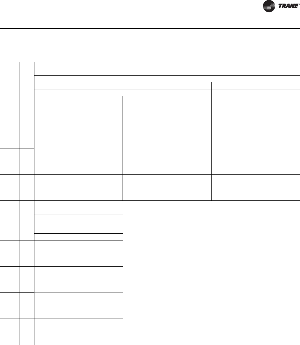
RT-PRC034-EN 41
Performance Data
Table 15. Gross cooling capacities WS*200ED, ET (IP)
Ambient Temperature (°F)
Airflow
CFM
Enter
DB
(°F)
85 95 105
Entering Wet Bulb Temperature (°F)
61 67 73 61 67 73 61 67 73
TGC SHC TGC SHC TGC SHC TGC SHC TGC SHC TGC SHC TGC SHC TGC SHC TGC SHC
5950
75 192.6 161.3 231.2 122.7 253.7 69.8 169.6 152.2 214.6 117.5 242.5 68.8 148.6 144.0 194.5 110.8 227.9 66.4
80 197.9 195.8 232.5 156.5 256.4 104.5 180.6 180.6 216.3 151.4 244.4 102.9 166.2 166.2 196.0 144.8 229.2 100.7
85 214.5 214.5 235.0 191.1 259.3 139.6 202.0 202.0 219.3 186.1 246.9 138.0 188.6 188.6 198.6 179.4 231.1 135.1
90 233.2 233.2 238.7 226.2 262.4 174.5 221.5 221.5 224.5 221.1 249.1 173.3 207.0 207.0 207.4 207.4 233.1 169.8
6600
75 201.8 173.1 236.6 127.1 256.8 67.7 178.9 164.4 221.7 122.9 245.6 66.1 157.2 155.3 200.4 116.5 231.6 64.3
80 208.3 208.1 238.5 165.0 259.7 105.4 193.9 193.9 223.3 160.7 248.1 104.9 178.6 178.6 202.4 154.3 233.4 103.1
85 228.3 228.3 241.2 203.4 263.2 144.2 213.7 213.7 226.1 199.0 251.1 143.8 199.6 199.6 205.9 193.0 235.8 141.6
90 243.8 243.8 246.8 241.7 266.9 183.2 232.3 232.3 232.9 232.7 254.1 182.7 219.3 219.3 219.8 219.8 238.6 180.6
7250
75 208.5 183.9 240.9 131.1 258.3 63.7 187.6 176.1 225.8 127.4 248.0 63.9 164.9 164.6 206.3 122.2 234.5 63.5
80 217.7 217.7 243.1 173.0 262.3 106.7 203.9 203.9 228.1 169.3 251.2 107.1 189.0 189.0 208.9 163.9 236.8 105.8
85 237.1 237.1 246.7 215.1 266.2 149.4 224.9 224.9 231.5 211.6 254.3 149.1 209.5 209.5 214.9 206.7 239.4 147.8
90 252.8 252.8 253.7 252.8 270.4 192.3 240.9 240.9 241.5 241.5 258.3 192.1 227.8 227.8 228.2 228.2 242.8 190.7
7900
75 214.3 194.4 244.2 135.0 260.2 62.3 195.5 187.3 229.5 132.1 250.0 63.3 172.9 172.9 212.0 127.7 236.5 62.1
80 228.0 228.0 247.2 180.8 264.0 108.3 212.4 212.4 232.1 177.7 253.5 108.9 197.2 197.2 214.9 173.2 239.4 108.6
85 244.4 244.4 251.4 226.6 268.3 154.5 232.0 232.0 236.6 223.6 257.1 154.8 218.8 218.8 220.6 217.8 242.4 154.2
90 259.9 259.9 260.4 260.4 272.9 200.3 248.4 248.4 248.6 248.6 261.5 201.3 235.2 235.2 235.5 235.5 246.4 201.3
Airflow
CFM
Enter
DB
(°F)
Ambient Temperature (°F)
115
Entering Wet Bulb
Temperature (°F)
61 67 73
TGC SHC TGC SHC TGC SHC
5950
75 130.5 130.5 172.8 103.7 210.4 62.2
80 152.0 152.0 174.4 137.7 211.4 96.3
85 173.9 173.9 178.7 173.0 212.8 130.6
90 192.8 192.8 193.1 193.1 214.8 165.5
6600
75 139.9 139.9 179.4 109.9 214.3 62.3
80 162.7 162.7 181.3 147.7 215.7 99.8
85 184.8 184.8 186.6 185.3 217.2 137.9
90 204.4 204.4 204.8 204.8 219.6 176.8
7250
75 147.4 147.4 184.2 115.6 217.2 61.2
80 172.5 172.5 186.5 157.3 219.0 103.3
85 193.3 193.3 193.9 193.9 221.1 145.3
90 213.1 213.1 213.5 213.5 224.0 188.0
7900
75 155.5 155.5 188.1 121.1 219.7 60.1
80 181.1 181.1 190.7 166.6 221.7 106.0
85 202.2 202.2 202.8 202.8 224.3 152.3
90 219.9 219.9 220.3 220.3 227.8 199.1
Notes:
1. All capacities shown are gross and have not considered indoor fan heat.
2. TGC = Total gross capacity (kW)
3. SHC = Sensible heat capacity (kW)
Gross Cooling Capacities

42 RT-PRC034-EN
Performance Data
Table 16. WS*155ED, ET net heating capacities (kW)—8500 m3/h—(SI)
Outdoor Peak Net Heating (kW) Peak Total Power (kW)
Temp (°C) at Indicated Dry Bulb (°C) at Indicated Dry Bulb (°C)
70% RH 15 21 24 27 15 21 24 27
-24 13.8 13.4 13.2 13.0 10.5 11.5 12.0 12.5
-21 15.3 14.9 14.7 14.5 10.7 11.7 12.1 12.7
-18 17.0 16.5 16.3 16.0 10.9 11.8 12.4 12.9
-15 18.6 17.4 17.1 17.3 11.1 12.0 12.5 14.0
-12 20.2 17.8 18.8 18.8 12.0 12.1 12.7 13.7
-9 21.5 20.9 20.5 20.2 11.4 12.4 12.9 13.5
-6 23.4 22.7 22.3 21.9 11.6 12.5 13.1 13.7
-3 25.4 24.6 24.2 23.8 11.8 12.7 13.3 13.9
0 27.4 26.6 26.2 25.8 11.9 13.0 13.5 14.1
3 29.5 28.6 28.2 27.8 12.1 13.2 13.8 14.4
6 36.1 35.1 34.5 34.0 12.2 13.3 13.9 14.5
9 43.8 42.4 41.7 41.0 12.6 13.6 14.2 14.8
12 46.6 45.3 44.5 43.7 12.8 13.9 14.4 15.0
15 49.8 48.3 47.4 46.8 13.1 14.1 14.7 15.3
18 53.2 51.4 50.7 49.8 13.4 14.4 15.0 15.6
21 57.0 55.1 54.0 53.0 13.7 14.8 15.4 16.0
24 60.5 58.6 57.5 56.5 14.1 15.2 15.8 16.4
Notes:
1. For other airflow conditions, see heating capacity correction factor
2. Net Heating Capacity and Power Input include indoor fan heat at nominal cfm and 0.35 inch ESP. To obtain net
heating at other conditions, subtract fan heat at this condition and add fan heat at new condition.
3. Heating capacities and powers are integrated to include the effects of defrost in the frost region.
Table 17. WS*155ED, ET net heating capacities (MBh)—5000 cfm (IP)
Outdoor Peak Net Heating (MBh) Peak Total Power (kW)
Temp (°F) at Indicated Dry Bulb (°F) at Indicated Dry Bulb (°F)
70% RH 60 70 75 80 60 70 75 80
-8 46.9 45.7 45.0 44.4 10.5 11.5 12.0 12.5
-3 52.4 51.0 50.2 49.5 10.7 11.7 12.1 12.7
2 57.9 56.3 55.5 54.7 10.9 11.8 12.4 12.9
7 63.5 59.2 58.2 59.0 11.1 12.0 12.5 14.0
12 69.0 60.9 64.1 64.1 12.0 12.1 12.7 13.7
17 73.5 71.2 70.0 68.9 11.4 12.4 12.9 13.5
22 79.9 77.3 76.1 74.9 11.6 12.5 13.1 13.7
27 86.5 83.8 82.4 81.1 11.8 12.7 13.3 13.9
32 93.6 90.8 89.2 87.9 11.9 13.0 13.5 14.1
37 100.6 97.5 96.2 94.7 12.1 13.2 13.8 14.4
42 123.3 119.7 117.8 116.0 12.2 13.3 13.9 14.5
47 149.3 144.8 142.4 140.0 12.6 13.6 14.2 14.8
52 159.0 154.4 151.9 149.2 12.8 13.9 14.4 15.0
57 170.0 164.7 161.8 159.6 13.1 14.1 14.7 15.3
62 181.5 175.5 172.9 169.7 13.4 14.4 15.0 15.6
67 194.6 187.9 184.2 180.8 13.7 14.8 15.4 16.0
72 206.5 199.8 196.2 192.6 14.1 15.2 15.8 16.4
Notes:
1. For other airflow conditions, see heating capacity correction factor
2. Net Heating Capacity and Power Input include indoor fan heat at nominal cfm and 0.35 inch ESP. To obtain net
heating at other conditions, subtract fan heat at this condition and add fan heat at new condition.
3. Heating capacities and powers are integrated to include the effects of defrost in the frost region.
Heating Capacities
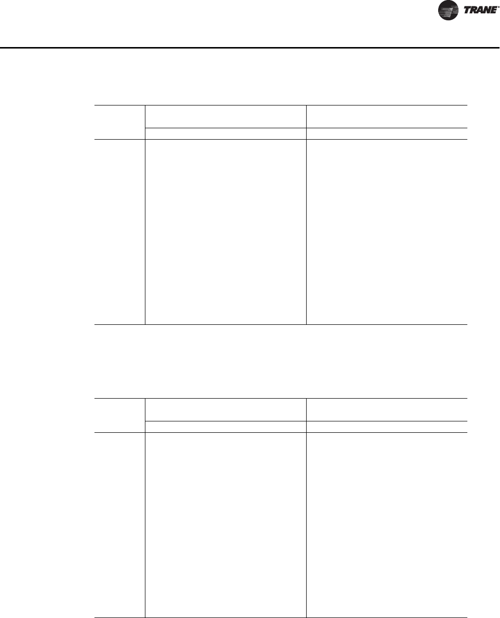
RT-PRC034-EN 43
Performance Data
Table 18. WS*200ED, ET net heating capacities (kW)—11210 m3/h—(SI)
Outdoor Peak Net Heating (kW) Peak Total Power (kW)
Temp (°C) at Indicated Dry Bulb (°C) at Indicated Dry Bulb (°C)
70% RH 15 21 24 27 15 21 24 27
-24 21.3 20.7 20.5 20.3 15.1 15.9 16.4 16.9
-21 23.1 22.5 22.3 22.0 15.3 16.0 16.5 17.0
-18 25.4 24.8 24.5 24.2 15.4 16.2 16.7 17.2
-15 28.0 27.2 27.0 26.6 15.5 16.3 16.8 17.3
-12 31.2 30.7 30.5 30.3 15.7 16.5 17.0 17.5
-9 34.6 33.8 33.6 33.3 15.9 16.7 17.2 17.7
-6 37.7 37.0 36.6 36.2 16.1 16.9 17.4 17.9
-3 40.7 39.9 39.6 39.2 16.4 17.3 17.8 18.3
0 43.7 42.8 42.5 42.1 16.5 17.4 17.9 18.4
3 47.7 46.8 46.3 46.0 16.8 17.7 18.2 18.7
6 51.8 50.6 50.1 49.6 17.0 17.9 18.4 18.9
9 56.3 55.2 54.6 54.2 17.1 18.0 18.5 19.0
12 60.4 59.1 58.4 58.0 17.4 18.3 18.8 19.3
15 64.2 62.7 62.1 61.5 17.8 18.8 19.3 19.8
18 69.1 67.5 66.6 65.9 20.0 21.1 21.6 22.1
21 73.8 71.8 70.9 70.0 20.1 21.2 21.7 22.2
24 78.7 76.8 75.9 74.9 20.4 21.5 22.0 22.6
Notes:
1. For other airflow conditions, see heating capacity correction factor
2. Net Heating Capacity and Power Input include indoor fan heat at nominal cfm and 0.35 inch ESP. To obtain net
heating at other conditions, subtract fan heat at this condition and add fan heat at new condition.
3. Heating capacities and powers are integrated to include the effects of defrost in the frost region.
Table 19. WS*200ED, ET net heating capacities (MBh)—6600 cfm (IP)
Outdoor Peak Net Heating (MBh) Peak Total Power (kW)
Temp (°F) at Indicated Dry Bulb (°F) at Indicated Dry Bulb (°F)
70% RH 60 70 75 80 60 70 75 80
-8 72.5 70.6 69.8 69.1 15.1 15.9 16.4 16.9
-3 78.8 76.8 76.1 75.1 15.3 16.0 16.5 17.0
2 86.7 84.5 83.5 82.5 15.4 16.2 16.7 17.2
7 95.4 92.9 92.1 90.9 15.5 16.3 16.8 17.3
12 106.5 104.6 104.0 103.2 15.7 16.5 17.0 17.5
17 118.0 115.4 114.7 113.7 15.9 16.7 17.2 17.7
22 128.6 126.3 124.9 123.5 16.1 16.9 17.4 17.9
27 138.7 136.2 135.0 133.7 16.4 17.3 17.8 18.3
32 149.0 146.2 145.1 143.6 16.5 17.4 17.9 18.4
37 162.8 159.8 158.1 157.1 16.8 17.7 18.2 18.7
42 176.9 172.7 170.8 169.4 17.0 17.9 18.4 18.9
47 192.0 188.2 186.3 184.9 17.1 18.0 18.5 19.0
52 206.0 201.8 199.3 197.8 17.4 18.3 18.8 19.3
57 219.1 213.9 212.0 209.7 17.8 18.8 19.3 19.8
62 235.7 230.1 227.3 225.0 20.0 21.1 21.6 22.1
67 251.6 244.8 242.0 238.8 20.1 21.2 21.7 22.2
72 268.7 262.0 259.1 255.4 20.4 21.5 22.0 22.6
Notes:
1. For other airflow conditions, see heating capacity correction factor
2. Net Heating Capacity and Power Input include indoor fan heat at nominal cfm and 0.35 inch ESP. To obtain net
heating at other conditions, subtract fan heat at this condition and add fan heat at new condition.
3. Heating capacities and powers are integrated to include the effects of defrost in the frost region.
Heating Capacities

44 RT-PRC034-EN
Performance Data
Table 20. Evaporator fan performance TS*155F downflow or horizontal (SI)
External Static Pressure (Pascals)
25.00 50.00 75.00 100.00 125.00 150.00 175.00 200.00 225.00 250.00
m3/h RPM kW RPM kW RPM kW RPM kW RPM kW RPM kW RPM kW RPM kW RPM kW RPM kW
1.49 Nom kW Standard Motor & Low Static
Drive Accessory 1.49 Nom kw Standard Motor & High Static
Drive Accessory
7140 — — 393 0.46 430 0.54 467 0.64 503 0.74 536 0.84 570 0.95 601 1.06 630 1.18 659 1.31
7820 376 0.48 416 0.58 451 0.66 484 0.75 518 0.86 551 0.97 581 1.08 612 1.20 642 1.32 669 1.45
8500 400 0.60 440 0.70 473 0.80 504 0.89 534 1.00 566 1.12 597 1.24 625 1.35 653 1.48 681 1.61
9180 425 0.73 464 0.85 496 0.96 525 1.06 554 1.16 582 1.28 611 1.41 640 1.54 666 1.66 692 1.79
9860 450 0.89 488 1.01 520 1.14 548 1.24 575 1.35 601 1.47 627 1.59 654 1.73 681 1.87 707 2.01
1.49 Nom kw Standard Motor Drive 2.24 Nom kw Oversized Motor & Drive
Continued External Static Pressure (Pascals)
275.00 300.00 325.00 350.00 375.00 400.00 425.00 450.00 475.00 500.00
m3/h RPM kW RPM kW RPM kW RPM kW RPM kW RPM kW RPM kW RPM kW RPM kW RPM kW
1.49 Nom kw Standard Motor & High Static Drive Accessory 2.24 Nom kw Oversized Motor & Drive
7140 686 1.44 713 1.56 738 1.69 763 1.82 786 1.95 809 2.08 831 2.21 852 2.34 — — — —
7820 696 1.58 722 1.72 747 1.86 771 2.00 795 2.14 818 2.28 840 2.42 — — — — — —
8500 707 1.75 732 1.88 757 2.03 780 2.18 804 2.33 826 2.49 — — — — — — — —
9180 718 1.93 744 2.08 768 2.22 791 2.37 813 2.53 — — — — — — — — — —
9860 730 2.14 754 2.29 779 2.44 — — — — — — — — — — — — — —
Note: Data includes pressure drop for filters and wet coil.
Table 21. Evaporator fan performance TS*155F downflow or horizontal (IP)
External Static Pressure (Inches of Water Pressure)
.10 .20 .30 .40 .50 .60 .70 .80 .90 1.00
CFM RPM BHP RPM BHP RPM BHP RPM BHP RPM BHP RPM BHP RPM BHP RPM BHP RPM BHP RPM BHP
2HP Standard Motor & Low Static Drive Accessory 2HP Standard Motor & High Static Drive Accessory
4000 — — 382 0.56 420 0.66 459 0.79 496 0.91 531 1.05 564 1.19 595 1.34 625 1.50 654 1.67
4500 — — 410 0.73 446 0.85 479 0.97 514 1.11 548 1.26 578 1.40 610 1.56 639 1.72 666 1.89
5000 400 0.80 440 0.95 473 1.07 504 1.20 534 1.34 566 1.50 597 1.66 625 1.81 653 1.98 681 2.16
5500 431 1.03 470 1.19 502 1.34 531 1.48 559 1.62 586 1.77 615 1.95 643 2.12 670 2.30 695 2.47
6000 463 1.30 500 1.48 531 1.65 559 1.80 585 1.95 611 2.11 636 2.28 662 2.46 689 2.66 714 2.85
2HP Standard Motor Drive 3HP Oversized Motor & Drive
Continued External Static Pressure (Inches of Water Pressure)
1.10 1.20 1.30 1.40 1.50 1.60 1.70 1.80 1.90 2.00
CFM RPM BHP RPM BHP RPM BHP RPM BHP RPM BHP RPM BHP RPM BHP RPM BHP RPM BHP RPM BHP
2HP Standard Motor & High Static Drive Accessory 3HP Oversized Motor & Drive
4000 682 1.83 708 1.99 734 2.16 758 2.32 782 2.49 804 2.66 826 2.83 847 3.01 — — — —
4500 693 2.07 719 2.25 745 2.44 769 2.62 793 2.80 815 2.99 838 3.17 — — — — — —
5000 707 2.34 732 2.53 757 2.72 780 2.92 804 3.13 826 3.33 — — — — — — — —
5500 721 2.66 747 2.86 771 3.05 794 3.26 — — — — — — — — — — — —
6000 738 3.04 760 3.22 784 3.43 — — — — — — — — — — — — — —
Note: Data includes pressure drop for filters and wet coil.
Fan Performance
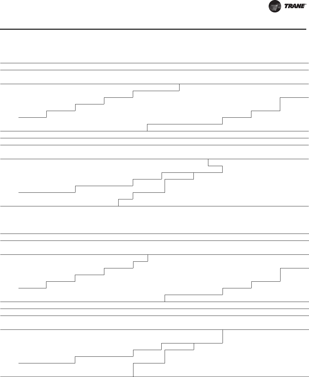
RT-PRC034-EN 45
Performance Data
Table 22. Evaporator fan performance TS*175F downflow or horizontal (SI)
External Static Pressure (Pascals)
25.00 50.00 75.00 100.00 125.00 150.00 175.00 200.00 225.00 250.00
m3/h RPM kW RPM kW RPM kW RPM kW RPM kW RPM kW RPM kW RPM kW RPM kW RPM kW
2.24 Nom kw Standard Motor & Low Static Drive Accessory 2.24 Nom kw Standard Motor Drive
7985 — — 429 0.62 463 0.71 496 0.81 529 0.92 562 1.03 592 1.14 622 1.26 652 1.39 679 1.52
8750 419 0.67 457 0.78 489 0.88 520 0.98 549 1.09 580 1.21 610 1.33 638 1.45 665 1.58 693 1.72
9515 449 0.84 485 0.96 516 1.07 545 1.18 572 1.29 599 1.41 628 1.54 656 1.68 682 1.81 707 1.94
10280 478 1.04 513 1.17 544 1.30 571 1.41 597 1.52 623 1.64 648 1.77 674 1.92 700 2.07 725 2.21
11045 508 1.26 542 1.40 572 1.55 598 1.67 623 1.79 647 1.92 671 2.05 694 2.19 718 2.34 743 2.50
2.24 Nom kw Standard Motor & High Static Drive Accessory
Continued External Static Pressure (Pascals)
275.00 300.00 325.00 350.00 375.00 400.00 425.00 450.00 475.00 500.00
m3/h RPM kW RPM kW RPM kW RPM kW RPM kW RPM kW RPM kW RPM kW RPM kW RPM kW
2.24 Nom kw Standard Motor & High Static Drive Accessory
7985 705 1.65 731 1.79 756 1.94 780 2.09 803 2.23 826 2.37 848 2.52 870 2.66 890 2.81 910 2.95
8750 719 1.86 744 2.00 768 2.14 792 2.30 815 2.45 837 2.61 859 2.77 880 2.93 901 3.09 921 3.25
9515 732 2.08 758 2.23 782 2.39 805 2.54 827 2.70 849 2.86 870 3.03 891 3.20 912 3.37 932 3.55
10280 749 2.35 771 2.49 795 2.65 819 2.82 841 2.98 862 3.15 883 3.31 903 3.49 923 3.67 943 3.85
11045 767 2.66 789 2.81 811 2.96 832 3.12 854 3.29 876 3.46 897 3.64 917 3.82 937 4.00 956 4.18
3.73 Nom Oversized Motor & Drive 3.73 Nom Oversized Motor & High Static Drive Accessory
Note: Data includes pressure drop for filters and wet coil.
Table 23. Evaporator fan performance TS*175F downflow or horizontal (IP)
External Static Pressure (Inches of Water)
.10 .20 .30 .40 .50 .60 .70 .80 .90 1.00
cfm RPM BHP RPM BHP RPM BHP RPM BHP RPM BHP RPMBHPRPMBHPRPMBHPRPMBHPRPMBHP
3HP Standard Motor & Low Static Drive Accessory 3HP Standard Motor Drive
4700 — — 429 0.84 463 0.96 496 1.08 529 1.23 562 1.38 592 1.53 622 1.69 652 1.86 679 2.04
5150 419 0.90 457 1.05 489 1.18 520 1.31 549 1.46 580 1.62 610 1.79 638 1.95 665 2.12 693 2.30
5600 449 1.13 485 1.29 516 1.44 545 1.58 572 1.73 599 1.88 628 2.07 656 2.25 682 2.43 707 2.60
6050 478 1.39 513 1.56 544 1.74 571 1.89 597 2.04 623 2.20 648 2.38 674 2.57 700 2.77 725 2.96
6500 508 1.69 542 1.88 572 2.07 598 2.24 623 2.40 647 2.57 671 2.75 694 2.93 718 3.14 743 3.35
3HP Standard Motor & High Static Drive Accessory
Continued External Static Pressure (Inches of Water)
1.10 1.20 1.30 1.40 1.50 1.60 1.70 1.80 1.90 2.00
cfm RPM BHP RPM BHP RPM BHP RPM BHP RPM BHP RPMBHPRPMBHPRPMBHPRPMBHPRPMBHP
3HP Standard Motor & High Static Drive Accessory
4700 705 2.22 731 2.41 756 2.60 780 2.80 803 2.99 826 3.18 848 3.37 870 3.57 890 3.76 910 3.96
5150 719 2.49 744 2.68 768 2.88 792 3.08 815 3.29 837 3.51 859 3.72 880 3.93 901 4.14 921 4.35
5600 732 2.79 758 3.00 782 3.20 805 3.41 827 3.62 849 3.84 870 4.06 891 4.29 912 4.53 932 4.76
6050 749 3.15 771 3.34 795 3.56 819 3.78 841 4.00 862 4.22 883 4.44 903 4.68 923 4.92 943 5.16
6500 767 3.56 789 3.77 811 3.97 832 4.18 854 4.41 876 4.65 897 4.88 917 5.12 937 5.36 956 5.61
5HP Oversized Motor & Drive 5HP Oversized Motor & High Static Drive Accessory
Note: Data includes pressure drop for filters and wet coil.
Fan Performance

46 RT-PRC034-EN
Performance Data
Table 24. Evaporator fan performance TS*200F downflow or horizontal (SI)
External Static Pressure (Pascals)
25.00 50.00 75.00 100.00 125.00 150.00 175.00 200.00 225.00 250.00
m3/hRPMkWRPMkWRPMkWRPMkWRPMkWRPMkWRPMkWRPMkWRPMkWRPMkW
2.24 Nom kw Standard Motor & Low Static Drive Accy 2.24 Nom kw Standard Motor & High Static Drive Accy
9005 429 0.72 466 0.84 498 0.94 528 1.04 557 1.15 586 1.27 616 1.40 644 1.53 670 1.65 697 1.78
9940 465 0.94 501 1.07 531 1.19 559 1.30 586 1.42 612 1.53 638 1.66 666 1.81 692 1.95 717 2.09
10875 502 1.21 536 1.35 565 1.49 592 1.61 617 1.73 642 1.86 665 1.98 689 2.12 714 2.28 739 2.43
11810 539 1.53 572 1.67 600 1.83 626 1.97 650 2.10 673 2.23 695 2.36 717 2.50 739 2.65 761 2.81
12745 575 1.87 607 2.05 635 2.21 660 2.37 683 2.52 704 2.66 726 2.80 747 2.95 767 3.10 787 3.25
2.24 Nom kw Standard Motor Drive 3.73 Nom kw Oversized Motor & Drive
Continued External Static Pressure (Pascals)
275.00 300.00 325.00 350.00 375.00 400.00 425.00 450.00 475.00 500.00
m3/hRPMkWRPMkWRPMkWRPMkWRPMkWRPMkWRPMkWRPMkWRPMkWRPMkW
2.24 Nom kw Standard Motor & High Static Drive Accessory
9005 724 1.93 749 2.07 772 2.22 796 2.37 818 2.53 841 2.69 862 2.86 884 3.02 904 3.18 925 3.34
9940 741 2.22 765 2.37 790 2.53 813 2.69 835 2.85 856 3.01 877 3.18 898 3.36 918 3.53 938 3.71
10875 763 2.59 786 2.74 807 2.89 829 3.05 851 3.22 873 3.39 894 3.57 914 3.74 934 3.92 953 4.10
11810 784 2.98 807 3.15 829 3.32 850 3.48 870 3.64 889 3.81 910 3.99 931 4.18 — — — —
12745 808 3.42 829 3.60 850 3.78 871 3.96 892 4.14 ——————————
3.73 Nom kw Oversized Motor & Drive 3.73 Nom kw Oversized Motor & High Static Drive Accessory
Note: Data includes pressure drop for filters and wet coil.
Table 25. Evaporator fan performance TS*200F downflow or horizontal (IP)
External Static Pressure (Inches of Water)
.10 .20 .30 .40 .50 .60 .70 .80 .90 1.00
cfm RPM BHP RPM BHP RPM BHP RPM BHP RPM BHP RPM BHP RPM BHP RPM BHP RPM BHP RPM BHP
3HP Standard Motor & Low Static Drive Accessory 3HP Standard Motor & High Static Drive Accessory
5300 429 0.97 466 1.13 498 1.26 528 1.40 557 1.54 586 1.70 616 1.88 644 2.05 670 2.21 697 2.39
5850 465 1.27 501 1.44 531 1.60 559 1.75 586 1.90 612 2.06 638 2.23 666 2.42 692 2.61 717 2.80
6400 502 1.62 536 1.81 565 2.00 592 2.16 617 2.32 642 2.49 665 2.66 689 2.85 714 3.05 739 3.26
6950 539 2.05 572 2.24 600 2.45 626 2.64 650 2.82 673 2.99 695 3.17 717 3.36 739 3.55 761 3.77
7500 575 2.51 607 2.74 635 2.97 660 3.18 683 3.38 704 3.57 726 3.76 747 3.95 767 4.16 787 4.36
3HP Standard Motor Drive 5HP Oversized Motor & Drive
Continued External Static Pressure (Inches of Water)
1.10 1.20 1.30 1.40 1.50 1.60 1.70 1.80 1.90 2.00
cfm RPM BHP RPM BHP RPM BHP RPM BHP RPM BHP RPM BHP RPM BHP RPM BHP RPM BHP RPM BHP
3HP Standard Motor & High Static Drive Accessory
5300 724 2.59 749 2.78 772 2.98 796 3.18 818 3.40 841 3.61 862 3.83 884 4.05 904 4.27 925 4.48
5850 741 2.98 765 3.18 790 3.40 813 3.61 835 3.82 856 4.04 877 4.27 898 4.50 918 4.74 938 4.98
6400 763 3.47 786 3.67 807 3.87 829 4.08 851 4.31 873 4.55 894 4.78 914 5.01 934 5.26 953 5.50
6950 784 4.00 807 4.23 829 4.45 850 4.67 870 4.89 889 5.11 910 5.35 931 5.60 — — — —
7500 808 4.59 829 4.82 850 5.07 871 5.31 892 5.56 — — — — — — — — — —
5HP Oversized Motor & Drive 5HP Oversized Motor & High Static Drive Accessory
Note: Data includes pressure drop for filters and wet coil.
Fan Performance

RT-PRC034-EN 47
Performance Data
Table 26. Evaporator fan performance TS*250F downflow or horizontal (SI)
External Static Pressure (Pascals)
25.00 50.00 75.00 100.00 125.00 150.00 175.00 200.00 225.00 250.00
m3/hRPMkWRPMkWRPMkWRPMkWRPMkWRPMkWRPMkWRPMkWRPMkWRPMkW
3.73 Nom kW Standard Motor & Low Static Drive Accessory 3.73 Nom kw Standard Motor and Drive
11380 521 1.37 556 1.52 584 1.67 610 1.80 635 1.93 658 2.05 681 2.19 704 2.32 727 2.47 751 2.63
12485 566 1.78 597 1.94 625 2.11 650 2.26 674 2.41 696 2.54 717 2.68 738 2.82 759 2.97 780 3.13
13590 610 2.26 639 2.43 667 2.61 691 2.79 714 2.96 735 3.11 755 3.26 775 3.41 795 3.56 814 3.72
14695 656 2.84 683 3.02 709 3.20 732 3.40 754 3.58 775 3.76 794 3.93 813 4.09 832 4.25 — —
15800 701 3.51 725 3.68 750 3.88 773 4.09 ————————————
3.73 Nom kw Standard Motor & High Static Drive Accessory (1)
Continued External Static Pressure (Pascals)
275.00 300.00 325.00 350.00 375.00 400.00 425.00 450.00 475.00 500.00
m3/hRPMkWRPMkWRPMkWRPMkWRPMkWRPMkWRPMkWRPMkWRPMkWRPMkW
3.73 Nom kw Standard Motor & High Static Drive Accessory (1)
11380 774 2.80 797 2.96 819 3.12 839 3.27 860 3.44 882 3.61 903 3.79 924 3.98 943 4.16 — —
12485 801 3.29 823 3.47 844 3.65 865 3.83 886 4.01 905 4.18 ————————
13590 833 3.88 852 4.06 871 4.24 — —————————————
14695 — ———————————————————
15800 — ———————————————————
3.73 Nom kw Standard Motor & High Static Drive Accessory (2)
Note: Data includes pressure drop for filters and wet coil.
Table 27. Evaporator fan performance TS*250F downflow or horizontal (IP)
External Static Pressure (Inches of Water)
.10 .20 .30 .40 .50 .60 .70 .80 .90 1.00
cfm RPM BHP RPM BHP RPM BHP RPM BHP RPM BHP RPM BHP RPM BHP RPM BHP RPM BHP RPM BHP
5HP Standard Motor & Low Static Drive Accessory 5HP Standard Motor and Drive
6700 521 1.84 556 2.04 584 2.23 610 2.42 635 2.58 658 2.75 681 2.93 704 3.11 727 3.31 751 3.53
7350 566 2.39 597 2.60 625 2.82 650 3.03 674 3.23 696 3.40 717 3.59 738 3.78 759 3.98 780 4.19
8000 610 3.03 639 3.26 667 3.50 691 3.74 714 3.97 735 4.17 755 4.37 775 4.57 795 4.78 814 4.99
8650 656 3.81 683 4.06 709 4.30 732 4.56 754 4.80 775 5.05 794 5.27 813 5.48 832 5.70 — —
9300 701 4.70 725 4.93 750 5.20 773 5.48 — — — — — — — — — — — —
5HP Standard Motor & High Static Drive Accessory (1)
Continued External Static Pressure (Inches of Water)
1.10 1.20 1.30 1.40 1.50 1.60 1.70 1.80 1.90 2.00
cfm RPM BHP RPM BHP RPM BHP RPM BHP RPM BHP RPM BHP RPM BHP RPM BHP RPM BHP RPM BHP
5HP Standard Motor & High Static Drive Accessory (1)
6700 774 3.75 797 3.97 819 4.18 839 4.39 860 4.61 882 4.84 903 5.09 924 5.33 943 5.58 — —
7350 801 4.42 823 4.66 844 4.90 865 5.13 886 5.37 905 5.60 — — — — — — — —
8000 833 5.21 852 5.44 871 5.69 — — — — — — — — — — — — — —
8650 — — — — — — — — — — — — — — — — — — — —
9300 — — — — — — — — — — — — — — — — — — — —
5HP Standard Motor & High Static Drive Accessory (2)
Note: Data includes pressure drop for filters and wet coil.
Fan Performance
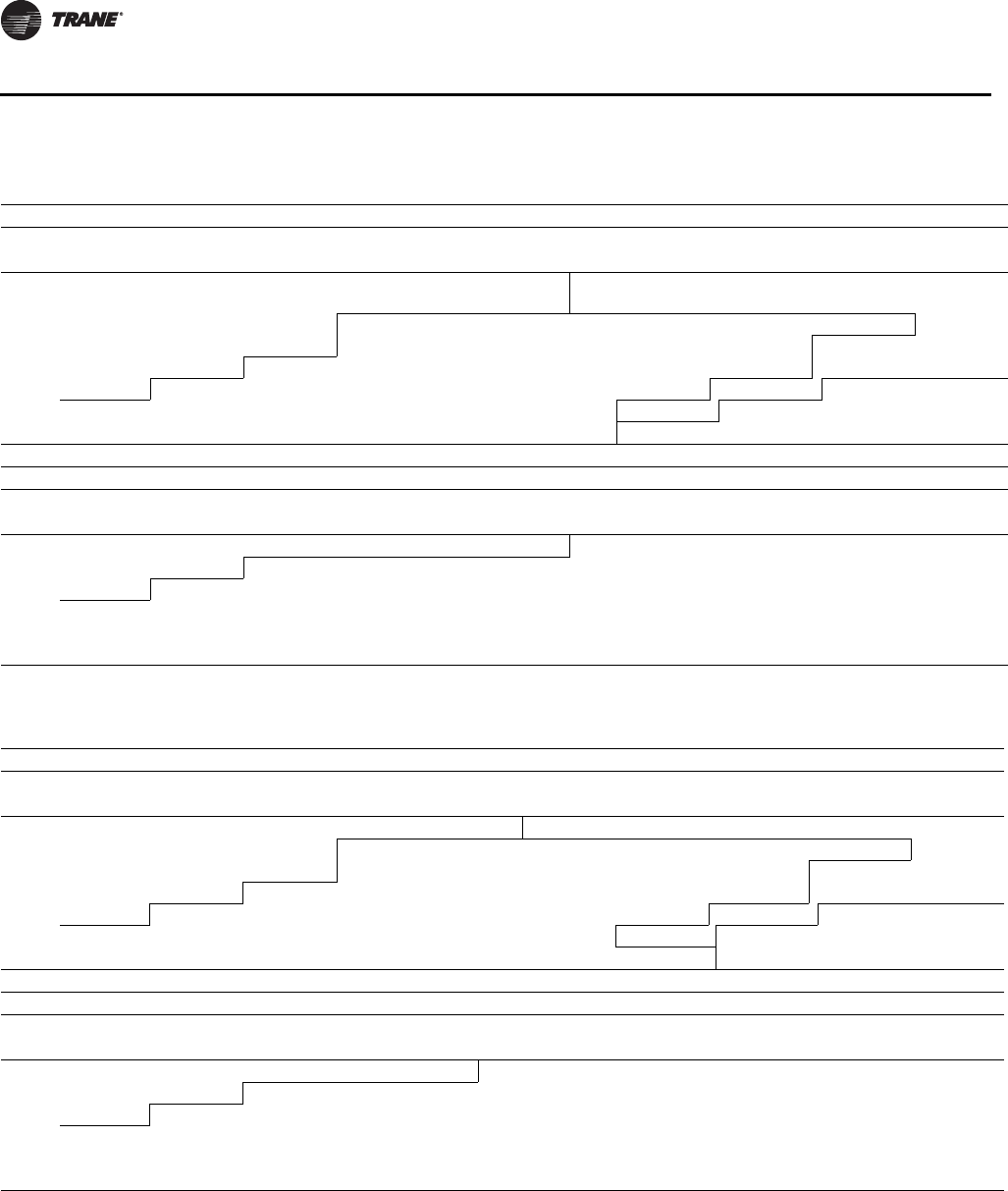
48 RT-PRC034-EN
Performance Data
Table 28. Evaporator fan performance YS*155F downflow or horizontal (SI)
External Static Pressure (Pascals)
25.00 50.00 75.00 100.00 125.00 150.00 175.00 200.00 225.00 250.00
m3/h RPM kW RPM kW RPM kW RPM kW RPM kW RPM kW RPM kW RPM kW RPM kW RPM kW
1.49 Nom kW Standard Motor & Low Static
Drive Accessory 1.49 Nom kw Standard Motor & High Static
Drive Accessory
7140 — — 404 0.49 441 0.57 478 0.67 514 0.77 547 0.87 580 0.98 610 1.10 639 1.22 667 1.35
7820 391 0.52 429 0.61 463 0.69 496 0.79 530 0.90 563 1.01 593 1.12 624 1.24 652 1.37 679 1.49
8500 418 0.64 455 0.75 487 0.84 517 0.94 548 1.05 579 1.17 609 1.29 636 1.40 665 1.53 692 1.67
9180 446 0.79 481 0.91 511 1.01 540 1.11 568 1.22 596 1.34 626 1.47 653 1.60 679 1.73 705 1.86
9860 473 0.96 507 1.09 536 1.20 564 1.31 590 1.42 616 1.54 643 1.67 670 1.81 696 1.95 720 2.09
1.49 Nom kw Standard Motor Drive 2.24 Nom kw Oversized Motor & Drive
Continued External Static Pressure (Pascals)
275.00 300.00 325.00 350.00 375.00 400.00 425.00 450.00 475.00 500.00
m3/h RPM kW RPM kW RPM kW RPM kW RPM kW RPM kW RPM kW RPM kW RPM kW RPM kW
1.49 Nom kw Standard Motor & High Static Drive Accessory 2.24 Nom kw Oversized Motor & Drive
7140 694 1.48 721 1.60 746 1.73 770 1.86 793 1.99 816 2.12 837 2.25 859 2.38 ————
7820 705 1.63 731 1.77 756 1.91 780 2.05 803 2.19 826 2.33 848 2.47 — — ————
8500 718 1.80 743 1.95 767 2.09 790 2.24 813 2.40 836 2.55 — — — — ————
9180 732 2.01 756 2.15 779 2.30 802 2.45 —————— —— ————
9860 744 2.22 769 2.38 793 2.53 — ——————— —— ————
Note: Data includes pressure drop for filters and wet coil.
Table 29. Evaporator fan performance YS*155F downflow or horizontal (IP)
External Static Pressure (Inches of Water)
.10 .20 .30 .40 .50 .60 .70 .80 .90 1.00
CFM RPM BHP RPM BHP RPM BHP RPM BHP RPM BHP RPM BHP RPM BHP RPM BHP RPM BHP RPM BHP
2HP Standard Motor & Low Static Drive Accessory 2HP Standard Motor & High Static Drive Accessory
4200 — — 404 0.65 441 0.77 478 0.90 514 1.03 547 1.17 580 1.32 610 1.47 639 1.63 667 1.80
4600 391 0.69 429 0.81 463 0.93 496 1.06 530 1.21 563 1.36 593 1.50 624 1.67 652 1.83 679 2.00
5000 418 0.86 455 1.00 487 1.13 517 1.26 548 1.41 579 1.57 609 1.73 636 1.88 665 2.06 692 2.24
5400 446 1.06 481 1.22 511 1.35 540 1.49 568 1.63 596 1.80 626 1.97 653 2.15 679 2.31 705 2.49
5800 473 1.28 507 1.46 536 1.61 564 1.75 590 1.90 616 2.06 643 2.24 670 2.43 696 2.62 720 2.80
2HP Standard Motor Drive 3HP Oversized Motor & Drive
Continued External Static Pressure (Inches of Water)
1.10 1.20 1.30 1.40 1.50 1.60 1.70 1.80 1.90 2.00
CFM RPM BHP RPM BHP RPM BHP RPM BHP RPM BHP RPM BHP RPM BHP RPM BHP RPM BHP RPM BHP
2HP Standard Motor & High Static Drive Accessory 3HP Oversized Motor & Drive
4200 694 1.98 721 2.15 746 2.32 770 2.49 793 2.67 816 2.84 837 3.02 859 3.20 — — — —
4600 705 2.18 731 2.37 756 2.56 780 2.75 803 2.94 826 3.12 848 3.31 — — — — — —
5000 718 2.42 743 2.61 767 2.81 790 3.01 813 3.22 836 3.42 — — — — — — — —
5400 732 2.69 756 2.88 779 3.08 802 3.29 — — — — — — — — — — — —
5800 744 2.98 769 3.19 793 3.40 — — — — — — — — — — — — — —
Note: Data includes pressure drop for filters and wet coil.
Fan Performance

RT-PRC034-EN 49
Performance Data
Table 30. Evaporator fan performance YS*175F downflow or horizontal (SI)
External Static Pressure (Pascals)
25.00 50.00 75.00 100.00 125.00 150.00 175.00 200.00 225.00 250.00
m3/h RPM kW RPM kW RPM kW RPM kW RPM kW RPM kW RPM kW RPM kW RPM kW RPM kW
2.24 Nom kw Standard Motor & Low Static Drive Accy 2.24 Nom kw Standard Motor & High Static Drive Accy
7985 — — 442 0.66 476 0.75 508 0.85 542 0.96 574 1.07 603 1.19 634 1.31 662 1.44 689 1.57
8750 437 0.72 472 0.83 503 0.92 533 1.03 563 1.14 594 1.27 623 1.39 650 1.51 678 1.64 705 1.78
9515 469 0.91 502 1.02 532 1.13 560 1.24 587 1.35 615 1.48 643 1.61 671 1.75 696 1.88 720 2.01
10280 502 1.12 533 1.25 561 1.37 588 1.48 613 1.60 638 1.72 664 1.86 690 2.01 716 2.16 740 2.30
11045 533 1.36 564 1.51 591 1.64 616 1.76 640 1.88 664 2.01 688 2.15 711 2.30 736 2.46 760 2.61
2.24 Nom kw Standard Motor Drive 3.73 Nom kw Oversized Motor & Drive
Continued External Static Pressure (Pascals)
275.00 300.00 325.00 350.00 375.00 400.00 425.00 450.00 475.00 500.00
m3/h RPM kW RPM kW RPM kW RPM kW RPM kW RPM kW RPM kW RPM kW RPM kW RPM kW
2.24 Nom kw Standard Motor & High Static Drive Accessory
7985 715 1.71 741 1.85 765 1.99 789 2.14 812 2.28 835 2.43 856 2.57 877 2.72 898 2.86 918 3.01
8750 731 1.92 755 2.06 779 2.21 802 2.37 825 2.53 847 2.69 869 2.85 890 3.00 910 3.16 930 3.32
9515 746 2.16 771 2.32 794 2.47 817 2.62 839 2.78 860 2.95 882 3.12 902 3.30 923 3.47 943 3.64
10280 763 2.44 786 2.59 810 2.75 833 2.92 854 3.08 875 3.25 896 3.42 916 3.60 936 3.78 956 3.97
11045 783 2.77 805 2.92 826 3.07 848 3.24 870 3.42 892 3.59 912 3.77 931 3.95 951 4.13 — —
3.73 Nom kw Oversized Motor & Drive 3.73 Nom kw Oversized Motor & High Static Drive Accessory
Note: Data includes pressure drop for filters and wet coil.
Table 31. Evaporator fan performance YS*175F downflow or horizontal (IP)
External Static Pressure (Inches of Water)
.10 .20 .30 .40 .50 .60 .70 .80 .90 1.00
CFM RPM BHP RPM BHP RPM BHP RPM BHP RPM BHP RPM BHP RPM BHP RPM BHP RPM BHP RPM BHP
3HP Standard Motor & Low Static Drive Accessory 3HP Standard Motor & High Static Drive Accessory
4700 — — 442 0.88 476 1.00 508 1.14 542 1.29 574 1.44 603 1.59 634 1.76 662 1.93 689 2.10
5150 437 0.97 472 1.11 503 1.24 533 1.38 563 1.53 594 1.70 623 1.86 650 2.02 678 2.20 705 2.39
5600 469 1.22 502 1.37 532 1.51 560 1.66 587 1.81 615 1.98 643 2.16 671 2.35 696 2.52 720 2.70
6050 502 1.50 533 1.68 561 1.83 588 1.99 613 2.14 638 2.31 664 2.50 690 2.70 716 2.89 740 3.08
6500 533 1.82 564 2.02 591 2.20 616 2.36 640 2.53 664 2.70 688 2.88 711 3.08 736 3.29 760 3.50
3HP Standard Motor Drive 5HP Oversized Motor & Drive
Continued External Static Pressure (Inches of Water)
1.10 1.20 1.30 1.40 1.50 1.60 1.70 1.80 1.90 2.00
CFM RPM BHP RPM BHP RPM BHP RPM BHP RPM BHP RPM BHP RPM BHP RPM BHP RPM BHP RPM BHP
3HP Standard Motor & High Static Drive Accessory
4700 715 2.29 741 2.48 765 2.68 789 2.87 812 3.06 835 3.25 856 3.45 877 3.64 898 3.84 918 4.03
5150 731 2.58 755 2.77 779 2.97 802 3.18 825 3.39 847 3.60 869 3.82 890 4.03 910 4.24 930 4.45
5600 746 2.90 771 3.11 794 3.31 817 3.52 839 3.73 860 3.96 882 4.19 902 4.42 923 4.65 943 4.88
6050 763 3.27 786 3.48 810 3.69 833 3.91 854 4.14 875 4.36 896 4.59 916 4.83 936 5.07 956 5.32
6500 783 3.71 805 3.92 826 4.12 848 4.35 870 4.58 892 4.82 912 5.05 931 5.29 951 5.54 — —
5HP Oversized Motor & Drive 5HP Oversized Motor & High Static Drive Accessory
Note: Data includes pressure drop for filters and wet coil.
Fan Performance

50 RT-PRC034-EN
Performance Data
Table 32. Evaporator fan performance YS*200F downflow or horizontal (SI)
External Static Pressure (Pascals)
25.00 50.00 75.00 100.00 125.00 150.00 175.00 200.00 225.00 250.00
m3/h RPM kW RPM kW RPM kW RPM kW RPM kW RPM kW RPM kW RPM kW RPM kW RPM kW
2.24 Nom kw Standard Motor & Low Static Drive Accy 2.24 Nom kw Standard Motor & High Static Drive Accy
9005 448 0.78 482 0.89 513 0.99 542 1.09 571 1.21 601 1.33 630 1.46 657 1.59 683 1.71 710 1.86
9940 487 1.02 519 1.15 548 1.26 575 1.37 601 1.48 627 1.61 655 1.75 682 1.89 707 2.03 731 2.17
10875 527 1.31 557 1.45 584 1.58 610 1.69 634 1.82 658 1.95 682 2.08 707 2.23 732 2.39 756 2.54
11810 566 1.64 595 1.80 622 1.95 646 2.08 668 2.21 691 2.34 713 2.48 735 2.63 757 2.78 780 2.95
12745 607 2.05 634 2.21 659 2.37 682 2.52 704 2.66 725 2.80 746 2.94 767 3.09 787 3.25 807 3.41
2.24 Nom kw Standard Motor Drive 3.73 Nom kw Oversized Motor & Drive
Continued External Static Pressure (Pascals)
275.00 300.00 325.00 350.00 375.00 400.00 425.00 450.00 475.00 500.00
m3/h RPM kW RPM kW RPM kW RPM kW RPM kW RPM kW RPM kW RPM kW RPM kW RPM kW
2.24 Nom kw Standard Motor & High Static Drive Accessory
9005 736 2.00 760 2.15 784 2.29 807 2.45 829 2.61 851 2.77 873 2.94 894 3.10 914 3.26 934 3.42
9940 755 2.31 780 2.47 803 2.62 826 2.78 847 2.95 868 3.11 889 3.28 910 3.46 930 3.64 950 3.82
10875 779 2.69 800 2.84 822 3.00 845 3.17 867 3.34 888 3.51 908 3.69 928 3.87 947 4.05 966 4.23
11810 803 3.12 825 3.29 847 3.46 866 3.62 886 3.78 907 3.96 928 4.15 ——————
12745 828 3.59 850 3.78 871 3.96 891 4.14 — — ———— ——————
3.73 Nom kw Oversized Motor & Drive 3.73 Nom kw Oversized Motor & High Static Drive Accessory
Note: Data includes pressure drop for filters and wet coil.
Table 33. Evaporator fan performance YS*200F downflow or horizontal (IP)
External Static Pressure (Inches of Water)
.10 .20 .30 .40 .50 .60 .70 .80 .90 1.00
CFM RPM BHP RPM BHP RPM BHP RPM BHP RPM BHP RPM BHP RPM BHP RPM BHP RPM BHP RPM BHP
3HP Standard Motor & Low Static Drive Accessory 3HP Standard Motor & High Static Drive Accessory
5300 448 1.05 482 1.19 513 1.33 542 1.46 571 1.62 601 1.79 630 1.96 657 2.13 683 2.30 710 2.49
5850 487 1.37 519 1.54 548 1.68 575 1.83 601 1.99 627 2.16 655 2.35 682 2.54 707 2.72 731 2.91
6400 527 1.76 557 1.95 584 2.11 610 2.27 634 2.44 658 2.61 682 2.79 707 2.99 732 3.20 756 3.41
6950 566 2.20 595 2.41 622 2.62 646 2.79 668 2.96 691 3.14 713 3.33 735 3.52 757 3.73 780 3.96
7500 607 2.75 634 2.97 659 3.18 682 3.38 704 3.57 725 3.76 746 3.94 767 4.15 787 4.36 807 4.57
3HP Standard Motor Drive 5HP Oversized Motor & Drive
Continued External Static Pressure (Inches of Water)
1.10 1.20 1.30 1.40 1.50 1.60 1.70 1.80 1.90 2.00
CFM RPM BHP RPM BHP RPM BHP RPM BHP RPM BHP RPM BHP RPM BHP RPM BHP RPM BHP RPM BHP
3HP Standard Motor & High Static Drive Accessory
5300 736 2.68 760 2.88 784 3.08 807 3.29 829 3.50 851 3.72 873 3.94 894 4.16 914 4.37 934 4.59
5850 755 3.10 780 3.31 803 3.52 826 3.73 847 3.95 868 4.17 889 4.40 910 4.64 930 4.88 950 5.12
6400 779 3.61 800 3.81 822 4.02 845 4.25 867 4.48 888 4.71 908 4.95 928 5.19 947 5.43 966 5.68
6950 803 4.19 825 4.41 847 4.63 866 4.85 886 5.07 907 5.31 928 5.56 — — — — — —
7500 828 4.82 850 5.06 871 5.31 891 5.55 — — — — — — — — — — — —
5HP Oversized Motor & Drive 5HP Oversized Motor & High Static Drive Accessory
Note: Data includes pressure drop for filters and wet coil.
Fan Performance

RT-PRC034-EN 51
Performance Data
Table 34. Evaporator fan performance YS*250F downflow or horizontal (SI)
External Static Pressure (Pascals)
25.00 50.00 75.00 100.00 125.00 150.00 175.00 200.00 225.00 250.00
m3/hRPMkWRPMkWRPMkWRPMkWRPMkWRPMkWRPMkWRPMkWRPMkWRPMkW
3.73 Nom kW Standard Motor & Low Static Drive Accessory 3.73 Nom kW Standard Motor and Drive
11380 548 1.48 578 1.64 604 1.77 629 1.90 653 2.02 676 2.15 699 2.29 721 2.44 745 2.60 769 2.76
12485 596 1.93 623 2.09 649 2.25 672 2.39 694 2.53 716 2.67 737 2.81 758 2.96 778 3.12 800 3.28
13590 641 2.44 670 2.64 693 2.80 716 2.97 737 3.12 757 3.27 777 3.42 797 3.58 816 3.74 835 3.90
14695 690 3.07 717 3.27 739 3.45 760 3.64 780 3.81 799 3.97 818 4.13 ——————
15800 737 3.76 762 3.98 784 4.20 — —————————————
3.73 Nom kW Standard Motor & High Static Drive Accessory (1)
Continued External Static Pressure (Pascals)
275.00 300.00 325.00 350.00 375.00 400.00 425.00 450.00 475.00 500.00
m3/hRPMkWRPMkWRPMkWRPMkWRPMkWRPMkWRPMkWRPMkWRPMkWRPMkW
3.73 Nom kW Standard Motor & High Static Drive Accessory (1)
11380 792 2.92 814 3.08 835 3.24 855 3.40 877 3.57 898 3.75 919 3.93 939 4.12 — — — —
12485 821 3.46 843 3.64 864 3.82 885 3.99 904 4.17 ——————————
13590 853 4.07 873 4.26 — — — —————————————
14695 — ———————————————————
15800 — ———————————————————
3.73 Nom kW Standard Motor & High Static Drive Accessory (2)
Note: Data includes pressure drop for filters and wet coil.
Table 35. Evaporator fan performance YS*250F downflow or horizontal (IP)
External Static Pressure (Inches of Water)
.10 .20 .30 .40 .50 .60 .70 .80 .90 1.00
CFM RPM BHP RPM BHP RPM BHP RPM BHP RPM BHP RPM BHP RPM BHP RPM BHP RPM BHP RPM BHP
5HP Standard Motor & Low Static Drive Accessory 5HP Standard Motor and Drive
6700 548 1.98 578 2.19 604 2.37 629 2.54 653 2.71 676 2.89 699 3.07 721 3.27 745 3.48 769 3.70
7350 596 2.59 623 2.81 649 3.02 672 3.21 694 3.39 716 3.58 737 3.77 758 3.97 778 4.18 800 4.40
8000 641 3.27 670 3.54 693 3.76 716 3.99 737 4.19 757 4.39 777 4.59 797 4.80 816 5.02 835 5.24
8650 690 4.12 717 4.39 739 4.63 760 4.89 780 5.11 799 5.32 818 5.54 — — — — — —
9300 737 5.04 762 5.34 784 5.63 — — — — — — — — — — — — — —
5HP Standard Motor & High Static Drive Accessory (1)
Continued External Static Pressure (Inches of Water)
1.10 1.20 1.30 1.40 1.50 1.60 1.70 1.80 1.90 2.00
CFM RPM BHP RPM BHP RPM BHP RPM BHP RPM BHP RPM BHP RPM BHP RPM BHP RPM BHP RPM BHP
5HP Standard Motor & High Static Drive Accessory (1)
6700 792 3.92 814 4.13 835 4.34 855 4.55 877 4.79 898 5.03 919 5.28 939 5.52 — — — —
7350 821 4.64 843 4.88 864 5.12 885 5.36 904 5.59 — — — — — — — — — —
8000 853 5.46 873 5.72 — — — — — — — — — — — — — — — —
8650 — — — — — — — — — — — — — — — — — — — —
9300 — — — — — — — — — — — — — — — — — — — —
5HP Standard Motor & High Static Drive Accessory (2)
Note: Data includes pressure drop for filters and wet coil.
Fan Performance

52 RT-PRC034-EN
Performance Data
Table 36. Evaporator fan performance WS*155E downflow or horizontal (SI)
External Static Pressure (Pascals)
25.00 50.00 75.00 100.00 125.00 150.00 175.00 200.00 225.00 250.00
m3/hRPMkWRPMkWRPMkWRPMkWRPMkWRPMkWRPMkWRPMkWRPMkWRPMkW
1.49 Nom kW Standard Motor & Low Static
Drive Accessory 1.49 Nom kW Standard Motor & High Static
Drive Accessory
6800 346 0.35 388 0.43 426 0.51 465 0.60 502 0.70 537 0.80 570 0.91 601 1.02 631 1.14 660 1.27
7650 377 0.47 417 0.56 452 0.65 486 0.74 521 0.85 554 0.96 585 1.07 617 1.19 646 1.31 673 1.44
8500 409 0.62 448 0.73 480 0.82 512 0.92 542 1.03 574 1.15 604 1.27 632 1.38 661 1.51 689 1.65
9350 442 0.80 479 0.92 510 1.03 539 1.13 567 1.24 595 1.36 624 1.49 652 1.63 678 1.76 703 1.89
10200 475 1.01 510 1.14 541 1.27 568 1.38 594 1.50 620 1.62 645 1.74 672 1.89 698 2.04 723 2.18
1.49 Nom kW Standard Motor Drive 2.24 Nom kW Oversized Motor & Drive
Continued External Static Pressure (Pascals)
275.00 300.00 325.00 350.00 375.00 400.00 425.00 450.00 475.00 500.00
m3/hRPMkWRPMkWRPMkWRPMkWRPMkWRPMkWRPMkWRPMkWRPMkWRPMkW
1.49 Nom kW Standard Motor & High Static Drive Accessory
6800 687 1.39 714 1.51 739 1.64 763 1.76 787 1.88 809 2.01 831 2.14 851 2.27 — — — —
7650 700 1.57 726 1.71 751 1.85 775 1.99 799 2.13 821 2.27 843 2.40 ——————
8500 714 1.78 739 1.93 764 2.07 788 2.22 811 2.38 833 2.54 ————————
9350 730 2.03 755 2.18 779 2.33 802 2.48 ————————————
10200 747 2.32 770 2.46 — — — —————————————
2.24 Nom kw Oversized Motor & Drive
Notes:
1. Data includes pressure drop for filters and wet coil.
2. For 200 volt, use 50 Hz reference Performance Data Table and Standard Motor & Sheave/Fan Speed (RPM) to determine applicable operating range.
Table 37. Evaporator fan performance WS*155E downflow or horizontal (IP)
External Static Pressure (Inches of Water)
.10 .20 .30 .40 .50 .60 .70 .80 .90 1.00
CFM RPM BHP RPM BHP RPM BHP RPM BHP RPM BHP RPM BHP RPM BHP RPM BHP RPM BHP RPM BHP
2HP Standard Motor & Low Static Drive Accessory 2HP Standard Motor & High Static Drive Accessory
4000 346 0.47 388 0.57 426 0.68 465 0.81 502 0.94 537 1.07 570 1.22 601 1.37 631 1.53 660 1.70
4500 377 0.63 417 0.75 452 0.87 486 1.00 521 1.14 554 1.29 585 1.43 617 1.60 646 1.76 673 1.93
5000 409 0.83 448 0.98 480 1.10 512 1.23 542 1.38 574 1.54 604 1.70 632 1.86 661 2.03 689 2.21
5500 442 1.07 479 1.23 510 1.38 539 1.51 567 1.66 595 1.82 624 2.00 652 2.18 678 2.36 703 2.53
6000 475 1.36 510 1.53 541 1.70 568 1.85 594 2.01 620 2.17 645 2.34 672 2.53 698 2.73 723 2.92
2HP Standard Motor Drive 3HP Oversized Motor & Drive
Continued External Static Pressure (Inches of Water)
1.10 1.20 1.30 1.40 1.50 1.60 1.70 1.80 1.90 2.00
CFM RPM BHP RPM BHP RPM BHP RPM BHP RPM BHP RPM BHP RPM BHP RPM BHP RPM BHP RPM BHP
2HP Standard Motor & High Static Drive Accessory 3HP Oversized Motor & Drive
4000 687 1.86 714 2.03 739 2.19 763 2.36 787 2.53 809 2.70 831 2.87 851 3.05 — — — —
4500 700 2.11 726 2.30 751 2.48 775 2.67 799 2.85 821 3.04 843 3.22 — — — — — —
5000 714 2.39 739 2.58 764 2.78 788 2.98 811 3.19 833 3.40 — — — — — — — —
5500 730 2.72 755 2.92 779 3.12 802 3.33 — — — — — — — — — — — —
6000 747 3.11 770 3.30 — — — — — — — — — — — — — — — —
Notes:
1. Data includes pressure drop for filters and wet coil.
2. For 200 volt, use 50 Hz reference Performance Data Table and Standard Motor & Sheave/Fan Speed (RPM) to determine applicable operating range.
Fan Performance

RT-PRC034-EN 53
Performance Data
Table 38. Evaporator fan performance WS*200E downflow or horizontal (SI)
External Static Pressure (Pascals)
25.00 50.00 75.00 100.00 125.00 150.00 175.00 200.00 225.00 250.00
m3/hRPMkWRPMkWRPMkWRPMkWRPMkWRPMkWRPMkWRPMkWRPMkWRPMkW
2.24 Nom kW Standard Motor Drive 2.24 Nom kw Standard Motor Drive & High Static Drive Accessory
8970 — — — — 446 0.80 475 0.91 504 1.03 533 1.15 561 1.28 588 1.42 613 1.56 636 1.69
10090 — — 449 0.94 481 1.05 510 1.18 536 1.31 561 1.44 587 1.58 611 1.72 636 1.87 660 2.03
11210 451 1.10 486 1.25 517 1.38 545 1.51 570 1.65 593 1.80 616 1.95 639 2.10 661 2.25 684 2.41
12330 491 1.45 525 1.62 554 1.77 581 1.91 605 2.06 628 2.21 649 2.38 670 2.54 691 2.71 711 2.87
13450 531 1.86 563 2.06 592 2.24 617 2.39 641 2.54 663 2.70 684 2.88 704 3.06 723 3.24 742 3.42
3.73 Nom kw Oversized Motor & Low Static Drive Accessory
Continued External Static Pressure (Pascals)
275.00 300.00 325.00 350.00 375.00 400.00 425.00 450.00 475.00 500.00
m3/hRPMkWRPMkWRPMkWRPMkWRPMkWRPMkWRPMkWRPMkWRPMkWRPMkW
2.24 Nom kw Standard Motor & High Static Drive Accessory 3.73 Nom kw Oversized Motor & Drive
8970 657 1.83 678 1.97 699 2.11 721 2.26 742 2.41 762 2.57 782 2.72 801 2.87 820 3.03 837 3.18
10090 683 2.18 704 2.34 724 2.49 743 2.65 762 2.81 780 2.97 799 3.13 817 3.30 836 3.47 854 3.65
11210 706 2.57 728 2.75 749 2.92 769 3.10 787 3.27 805 3.44 822 3.62 839 3.79 856 3.97 872 4.15
12330 731 3.04 751 3.22 772 3.40 792 3.59 811 3.78 830 3.97 848 4.17 ——————
13450 760 3.60 779 3.78 798 3.96 816 4.15 ————————————
3.73 Nom kw Oversized Motor & Low Static Drive Accessory
Notes:
1. Data includes pressure drop for filters and wet coil.
2. For 200 volt, use 50 Hz reference Performance Data Table and Standard Motor & Sheave/Fan Speed (RPM) to determine applicable operating range.
Table 39. Evaporator fan performance WS*200E downflow or horizontal (IP)
External Static Pressure (Inches of Water)
.10 .20 .30 .40 .50 .60 .70 .80 .90 1.00
CFM RPM BHP RPM BHP RPM BHP RPM BHP RPM BHP RPM BHP RPM BHP RPM BHP RPM BHP RPM BHP
3HP Standard Motor Drive 3HP Standard Motor Drive & High Static Drive Accessory
5200 — — — — 446 1.07 475 1.22 504 1.38 533 1.54 561 1.72 588 1.90 613 2.09 636 2.27
5900 — — 449 1.26 481 1.41 510 1.58 536 1.76 561 1.94 587 2.12 611 2.31 636 2.51 660 2.72
6600 451 1.47 486 1.67 517 1.85 545 2.02 570 2.21 593 2.41 616 2.61 639 2.81 661 3.02 684 3.23
7300 491 1.95 525 2.17 554 2.38 581 2.56 605 2.76 628 2.97 649 3.19 670 3.41 691 3.63 711 3.85
8000 531 2.50 563 2.77 592 3.00 617 3.21 641 3.41 663 3.62 684 3.86 704 4.10 723 4.34 742 4.58
5HP Oversized Motor & Low Static Drive Accessory
Continued External Static Pressure (Inches of Water)
1.10 1.20 1.30 1.40 1.50 1.60 1.70 1.80 1.90 2.00
CFM RPM BHP RPM BHP RPM BHP RPM BHP RPM BHP RPM BHP RPM BHP RPM BHP RPM BHP RPM BHP
3HP Standard Motor & High Static Drive Accessory 5HP Oversized Motor & Drive
5200 657 2.45 678 2.64 699 2.84 721 3.03 742 3.24 762 3.44 782 3.65 801 3.85 820 4.06 837 4.26
5900 683 2.93 704 3.14 724 3.34 743 3.55 762 3.76 780 3.98 799 4.20 817 4.43 836 4.66 854 4.89
6600 706 3.45 728 3.68 749 3.92 769 4.15 787 4.38 805 4.62 822 4.85 839 5.09 856 5.32 872 5.57
7300 731 4.08 751 4.31 772 4.56 792 4.81 811 5.07 830 5.33 848 5.59 — — — — — —
8000 760 4.82 779 5.07 798 5.32 816 5.57 — — — — — — — — — — — —
5HP Oversized Motor & Low Static Drive Accessory
Notes:
1. Data includes pressure drop for filters and wet coil.
2. For 200 volt, use 50 Hz reference Performance Data Table and Standard Motor & Sheave/Fan Speed (RPM) to determine applicable operating range.
Fan Performance
54 RT-PRC034-EN
Performance Data
Table 40. T/YS*155–250 standard motor and drive/fan speed (rpm)
Unit 6 Turns 5 Turns 4 Turns 3 Turns 2 Turns 1Turns
Model No. Open Open Open Open Open Open Closed
T/YS*155F 466 501 535 570 604 639 N/A
T/YS*175F 500 537 574 611 648 685 N/A
T/YS*200F 500 537 574 611 648 685 N/A
T/YS*250F 587 619 651 682 714 746 N/A
Notes:
1. * indicates both horizontal and downflow units
2. Factory set at 3 turns open.
Table 41. T/YS*155–250 standard motor and low static fan drive
Unit 6 Turns 5 Turns 4 Turns 3 Turns 2 Turns 1Turns
Model No. Open Open Open Open Open Open Closed
T/YS*155F 376 404 432 460 488 516 N/A
T/YS*175F 418 442 466 489 513 537 N/A
T/YS*200F 418 442 466 489 513 537 N/A
T/YS*250F 492 524 556 587 619 651 N/A
Note: * indicates both horizontal and downflow units
Table 42. T/YS*155–250 standard motor and high static drive accessory/fan speed (rpm)
Unit 6 Turns 5 Turns 4 Turns 3 Turns 2 Turns 1Turns
Model No. Open Open Open Open Open Open Closed
T/YS*155F 600 628 656 683 711 739 N/A
T/YS*175F 685 722 759 796 833 870 N/A
T/YS*200F 685 722 759 796 833 870 N/A
T/YS*250F 702 740 778 815 853 891 N/A
Note: * indicates both horizontal and downflow units
Table 43. T/YS*155–250 oversized motor and drive/fan speed (rpm)
Unit 6 Turns 5 Turns 4 Turns 3 Turns 2 Turns 1Turns
Model No. Open Open Open Open Open Open Closed
T/YS*155F 621 667 713 758 804 850 N/A
T/YS*175F 682 714 746 777 809 841 N/A
T/YS*200F 682 714 746 777 809 841 N/A
T/YS*250F 702 740 778 815 853 891 N/A
Note: * indicates both horizontal and downflow units
Fan Speeds

RT-PRC034-EN 55
Performance Data
\
Table 44. WS*155, 200 standard motor and drive/fan speed (rpm)
Unit 6 Turns 5 Turns 4 Turns 3 Turns 2 Turns 1Turns
Model No. Open Open Open Open Open Open Closed
WS*155ED, ET 416 447 478 509 540 571 N/A
WS*200ED, ET 574 611 648 685 722 759 N/A
Note: * indicates both horizontal and downflow units
Table 45. WS*155, 200 standard motor and low static fan drive
Unit 6 Turns 5 Turns 4 Turns 3 Turns 2 Turns 1Turns
Model No. Open Open Open Open Open Open Closed
WS*155ED 316 339 363 386 410 433 N/A
WS*200ED 418 449 480 512 543 574 N/A
Note: * indicates both horizontal and downflow units
Table 46. WS*155, 200 standard motor and high static drive accessory/fan speed (rpm)
Unit 6 Turns 5 Turns 4 Turns 3 Turns 2 Turns 1Turns
Model No. Open Open Open Open Open Open Closed
WS*155ED 571 602 633 663 694 725 N/A
WS*200ED 574 611 648 685 722 759 N/A
Note: * indicates both horizontal and downflow units
Table 47. WS*155, 200 oversized motor and drive/fan speed (rpm)
Unit 6 Turns 5 Turns 4 Turns 3 Turns 2 Turns 1Turns
Model No. Open Open Open Open Open Open Closed
WS*155ED 621 667 698 728 759 850 N/A
WS*200ED 702 740 777 814 851 891 N/A
Note: * indicates both horizontal and downflow units
Fan Speeds
56 RT-PRC034-EN
Performance Data
Table 48. T/YS*155–250—static pressure drops through accessories—pascals
Economizer
with OA/RA Dampers(a) Electric Heater - Nom kW(b)
Unit
Model No. Airflow
m3/h Standard
Filters 100% OA 100% RA 5-12 14-27 33-41 45-54
D155 7140 6 8 5 7 9 10 —
D155 8500 9 11 7 9 12 15 —
D155 9860 12 15 10 12 16 20 —
H155 7140 6 8 5 7 9 10 —
H155 8500 9 11 7 9 12 15 —
H155 9860 12 15 10 12 16 20 —
D175 7985 7 10 7 8 10 13 —
D175 9515 11 14 9 12 15 18 —
D175 11045 14 18 12 16 20 24 —
H175 7985 7 10 7 8 10 13 —
H175 9515 11 14 9 12 15 18 —
H175 11045 14 18 12 16 20 24 —
D200 9005 12 29 6 — 11 14 16
D200 10875 18 42 9 — 16 21 23
D200 12745 24 57 13 — 22 29 31
H200 9005 10 33 6 — 11 14 16
H200 10875 15 48 9 — 16 21 23
H200 12745 21 66 13 — 22 29 31
D250 11380 20 46 9 — 17 22 25
D250 13590 28 66 13 — 24 31 36
D250 15800 38 89 18 — 33 42 49
H250 11380 16 52 9 — 17 22 25
H250 13590 23 75 13 — 24 31 36
H250 15800 31 101 18 — 33 42 49
(a)OA = Outside Air, RA = Return Air
(b)Nominal kW ratings are at 415 V. Not all Heater sizes may be available.
* Indicates both horizontal and downflow units.
Static Pressure Drop

RT-PRC034-EN 57
Performance Data
Table 49. T/YS*155–250—static pressure drops through accessories—(inches water column)
Economizer
with OA/RA Dampers(a) Electric Heater - Nom kW(b)
Unit
Model No. Airflow
CFM Standard
Filters 100% OA 100% RA 5-12 14-27 33-41 45-54
D155 4200 0.02 0.03 0.02 0.03 0.03 0.04 —
D155 5000 0.04 0.05 0.03 0.04 0.05 0.06 —
D155 5800 0.05 0.06 0.04 0.05 0.07 0.08 —
H155 4200 0.02 0.03 0.02 0.03 0.03 0.04 —
H155 5000 0.04 0.05 0.03 0.04 0.05 0.06 —
H155 5800 0.05 0.06 0.04 0.05 0.07 0.08 —
D175 4700 0.03 0.04 0.03 0.03 0.04 0.05 —
D175 5600 0.04 0.06 0.04 0.05 0.06 0.07 —
D175 6500 0.06 0.07 0.05 0.06 0.08 0.10 —
H175 4700 0.03 0.04 0.03 0.03 0.04 0.05 —
H175 5600 0.04 0.06 0.04 0.05 0.06 0.07 —
H175 6500 0.06 0.07 0.05 0.06 0.08 0.10 —
D200 5300 0.05 0.11 0.03 — 0.04 0.06 0.06
D200 6400 0.07 0.17 0.04 — 0.06 0.08 0.09
D200 7500 0.10 0.23 0.05 — 0.09 0.11 0.13
H200 5300 0.04 0.13 0.03 — 0.04 0.06 0.06
H200 6400 0.06 0.19 0.04 — 0.06 0.08 0.09
H200 7500 0.08 0.26 0.05 — 0.09 0.11 0.13
D250 6700 0.08 0.19 0.04 — 0.07 0.09 0.10
D250 8000 0.11 0.27 0.05 — 0.10 0.12 0.15
D250 9300 0.15 0.36 0.07 — 0.13 0.17 0.20
H250 6700 0.06 0.21 0.04 — 0.07 0.09 0.10
H250 8000 0.09 0.30 0.05 — 0.10 0.12 0.15
H250 9300 0.13 0.40 0.07 — 0.13 0.17 0.20
(a)OA = Outside Air, RA = Return Air
(b)Nominal kW ratings are at 415 V. Not all Heater sizes may be available.
* Indicates both horizontal and downflow units.
Static Pressure Drop

58 RT-PRC034-EN
Performance Data
Table 50. WS*155, 200—static pressure drops through accessories—pascals
Economizer
with OA/RA Dampers(a) Electric Heater - Nom kW(b)
Unit
Model No. Airflow
m3/h Standard
Filters 100% OA 100% RA 5-14 16-27 33-41 45-54
D155 6800 6 45 5 7 7 10 —
D155 8500 8 62 5 10 12 15 —
D155 10200 11 87 7 17 20 22 —
H155 6800 6 45 5 7 7 10 —
H155 8500 8 62 5 10 12 15 —
H155 10200 11 87 7 17 20 22 —
D200 8970 8 37 5 — 10 12 15
D200 11210 14 57 7 — 17 20 22
D200 13450 19 77 12 — 25 27 35
H200 8970 8 50 7 — 12 15 17
H200 11210 15 75 10 — 22 27 32
H200 13450 24 124 17 — 37 42 52
(a)OA = Outside Air, RA = Return Ai
(b)Nominal kW ratings are at a 415 V
* Indicates both horizontal and downflow units.
Table 51. WS*155, 200—static pressure drops through accessories—(inches water column)
Economizer
with OA/RA Dampers(a) Electric Heater - Nom kW(b)
Unit
Model No. Airflow
CFM Standard
Filters 100% OA 100% RA 5-14 16-27 33-41 45-54
D155 4000 0.02 0.18 0.02 0.03 0.03 0.04 —
D155 5000 0.03 0.25 0.02 0.04 0.05 0.06 —
D155 6000 0.05 0.35 0.03 0.07 0.08 0.09 —
H155 4000 0.02 0.18 0.02 0.03 0.03 0.04 —
H155 5000 0.03 0.25 0.02 0.04 0.05 0.06 —
H155 6000 0.05 0.35 0.03 0.07 0.08 0.09 —
D200 5200 0.03 0.15 0.02 — 0.04 0.05 0.06
D200 6600 0.05 0.23 0.03 — 0.07 0.08 0.09
D200 8000 0.07 0.31 0.05 — 0.10 0.11 0.14
H200 5200 0.03 0.20 0.03 — 0.05 0.06 0.07
H200 6600 0.06 0.30 0.04 — 0.09 0.11 0.13
H200 8000 0.10 0.50 0.07 — 0.15 0.17 0.21
(a)OA = Outside Air, RA = Return Ai
(b)Nominal kW ratings are at a 415 V
* Indicates both horizontal and downflow units.
Static Pressure Drop

RT-PRC034-EN 59
Controls
ReliaTel Controlled Units
Note: Zone sensor required for units configured for Single Zone VAV indoor fan system control
to enable Single Zone VAV functionality.
Zone Sensors are the building occupant’s comfort control devices. They replace the conventional
electro-mechanical thermostats. The following zone sensor options are available for Voyager units:
Differential Enthalpy
Differential Enthalphy Replaces the standard dry bulb control with two enthalpy sensors that
compare total heat content of the indoor air and outdoor air to determine the most efficient air
source. This control option offers the highest level of comfort control, plus energy efficiency,
available.
Differential Pressure Switches
This factory or field-installed option allows individual fan failure and dirty filter indication. The fan
failure switch will disable all unit functions and “flash” the Service LED on the zone sensor. The dirty
filter switch will light the Service LED on the zone sensor and will allow continued unit operation.
RA Remote Sensor & Room Remote Sensor
The RA Remote Sensor is a Return Air Remote Sensor which can be mounted in the return air duct
to report return air temperature. The Room Remote Sensor is a Space Remote Sensor which can
be mounted on the wall to report/control from a remote location in the space.
Manual Changeover Manual/Automatic
Changeover Manual/Automatic
Changeover
Heat, Cool or Off System
Switch. Fan Auto or Off Switch.
One temperature setpoint
lever.
Auto, Heat, Cool or Off
System Switch. Fan Auto or
Off Switch. Two temperature
setpoint levers.
Auto, Heat, Cool or Off
System Switch. Fan Auto or
Off Switch. Two temperature
setpoint levers. Status
Indication LED lights, System
On, Heat, Cool, or Service.
Wireless Zone Sensor
LCD display that provides heat, cool, auto, or off. Includes
two temperature setpoints and a lockable setting with °F or
°C indicators.
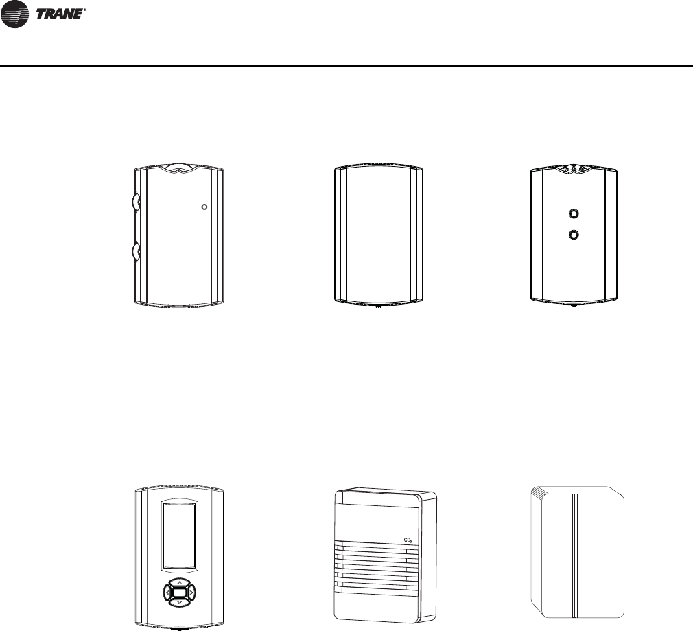
60 RT-PRC034-EN
Controls
Manual/Automatic
Changeover Remote Sensor Integrated Comfort™
System
Auto, Heat, Cool or Off System
Switch. Fan Auto or Off Switch.
Two temperature setpoint
levers.
Sensor(s) available for all
zone sensors to provide
remote sensing capabilities.
Sensor(s) available with
optional temperature
adjustment and override
buttons to provide central
control through a Trane
Integrated Comfort™
system.
Programmable Night
Setback CO2 Sensing Humidity Sensor
Auto or manual changeover
with seven-day programming.
Keyboard selection of Heat,
Cool, Fan, Auto, or On. All
programmable sensors have
System On, Heat, Cool, Service
LED/indicators as standard.
Night Setback Sensors have
one (1) Occupied, one (1) Un-
occupied, and one (1) Override
program per day.
The CO2 sensor shall have the
ability to monitor space
occupancy levels within the
building by measuring the
parts per million of CO2
(Carbon Dioxide) in the air. As
the CO2 levels increase, the
outside air damper modulates
to meet the CO2 space
ventilation requirements. The
CO2 accessory shall be
available as field installed.
Field installed, wall-mounted
or duct-mounted humidity
sensor is used to control
activation of the hot gas
reheat dehumidification
option. The humidity sensor
can be set for humidity levels
between 40 percent and
60 percent relative humidity
by adjusting the ReliaTel
Options Module.
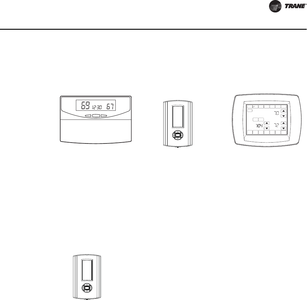
RT-PRC034-EN 61
Controls
Remote Potentiometer
Minimum position setting of economizer can be remotely adjusted with this accessory.
Trane Communication Interface (TCI)
This factory or field-installed micro-processor interface allows the unit to communicate to Trane’s
Integrated Comfort™ system.Economizer Controls
The standard equipment offering is a fixed dry bulb changeover control. In addition, there are two
optional controls, Enthalpy and Differential Enthalpy Control.
Enthalpy Control
Replaces the dry bulb control with a wet bulb changeover controller which has a fully adjustable
setpoint. Enthalpy control offers a higher level of comfort control, along with energy savings
potential, than the standard dry bulb control. This is due to the additional wet bulb sensing
capability.
Digital Display
Programmable
Thermostat with Built-
In Relative Humidity
Sensing (3H/2C)
Digital Display
Programmable
Thermostat (3H/2C)
Touchscreen
Programmable
Thermostat (2H/2C)
Three Heat/Two Cool digital
display thermostat with built-
in humidity control and
display. This thermostat
combines both humidity and
dry bulb into one. Fully
programmable with night
setback.
Two Heat/Two Cool auto
changeover digital display
thermostat. Seven-day
programmable stat with night
setback shall be available.
Two Heat/Two Cool
programmable thermostat
with touch screen digital
display. Menu-driven
programming. Effortless set-
up. Program each day
separately with no need to
copy multiple days. All
programming can be done on
one screen. Easy to read and
use. Large, clear backlit digital
display.
Digital Display Thermostat (3H/2C)
Three Heat, Two Cool auto changeover digital display
thermostat.
Tue
DONE WAKE LEAVE RETURN SLEEPEDIT CANCEL
MON TUE WED THU FRI SAT SUN
PM
FAN
ON
AUTO
CIRC
SYSTEM
EM HEAT
HEAT
OFF
COOL
AUTO
RESET
HEAT
COOL
DEHUMIDIFIER
CANCEL
PERIOD
62 RT-PRC034-EN
Electrical Data
Table 52. TS* auxiliary electric heat capacity
Unit Model No. Total heater
kW(1)(2) No. of Stages
Stage 1
heater
kW(1)
Stage 2
heater
kW(1)
TS*155FD 26.9 2 13.4 13.4
TS*175FD 26.9 2 13.4 13.4
40.3 2 26.9 13.4
TS*200FD 26.9 2 13.4 13.4
TS*250FD 40.3 2 26.9 13.4
53.8 2 26.9 26.9
Notes:
1. Heaters are rated at 415 V. For other than rated voltage, apply the following formula - kW =
(Required Voltage/415)2 x Rated kW.
2. Not all Heater Models are available.
3. To calculate temperature rise across the electric heat use the following formulas:
Temp Rise Across Electric Heater - °C = 2982 * Heater Capacity (kW)/Airflow (m3/h)
Temp Rise Across Electric Heater - °F = 3160 * Heater Capacity (kW)/Airflow (cfm)
Table 53. TS* electric heater voltage correction factors (apply to auxiliary electric heat capacity)
Nominal
Voltage Distribution
Voltage Capacity
Multiplier
415
380 0.84
400 0.93
415 1.00
Table 54. TS* unit wiring
Unit Model Voltage Standard Indoor
Fan Motor—MCA Oversize Indoor
Fan Motor—MCA
TS*155FD 380–415 41.0 44.0
TS*175FD 380–415 51.0 54.0
TS*200FD 380–415 56.0 59.0
TS*250FD 380–415 65.0 —
Table 55. TS* unit wiring with electric heat (single point connection)
Unit Model to
Use With Heater kW
Rating Unit Supply
Power Control
Stages Standard Indoor
Motor MCA Oversized Motor
MCA
TS*155ED 11.3–13.5 380–415/50/3 1 41/41 44/44
TS*155FD 22.6–26.9 380–415/50/3 2 49/53 53/57
TS*155FD 33.8–40.4 380–415/50/3 2 71/77 74/80
TS*175FD 22.6–26.9 380–415/50/3 2 53/57 57/61
TS*175FD 33.8–40.4 380–415/50/3 2 74/80 79/84
TS*200FD 22.6–26.9 380–415/50/3 2 56/57 59/61
TS*200FD 33.8–40.4 380–415/50/3 2 74/80 79/84
TS*200FD 45.1–53.8 380–415/50/3 2 96/104 100/108
TS*250FD 22.6–26.9 380–415/50/3 2 65/65 —
TS*250FD 33.8–40.4 380–415/50/3 2 79/84 —
TS*250FD 45.1–53.8 380–415/50/3 2 100/108 —
Note: * All units to be installed under local codes.

RT-PRC034-EN 63
Electrical Data
Table 56. TS* electric characteristics—evaporator fan motor—50 cycle
Standard Evaporator Motor Oversize Evaporator Motor
Model No.
Motors Volts Ph Watts FLA LRA Service
Factor No.
Motors Volts Ph Watts FLA LRA Service
Factor
TS*155FD 1 380–415 3 1500 4.6 36.4 1.15 1 380–415 3 2200 6.5 57 1.15
TS*175FD 1 380–415 3 2200 6.5 57.0 1.15 1 380–415 3 3700 7.4 71.9 1.15
TS*200FD 1 380–415 3 2200 6.5 57.0 1.15 1 380–415 3 3700 7.0 65.1 1.15
TS*250FD 1 380–415 3 3700 7.4 71.9 1.15 — — — — — — —
Table 57. TS* electric characteristics—compressor motor and condenser motor—50 cycle
Unit Model No.
Compressor Motors Condenser Fan Motors
Amps(a) Ampsa
No. Volts Ph Watts rpm RLA LRA No. Ph Watts FLA LRA
TS*155FD 2 380–415/50 3 /4610 2900 17 142 2 1 300 1.6 3.8
TS*175FD 2 380–415/50 3 /4460 2900 21.4 142 2 1 560 2.5 5.8
TS*200FD 2 380–415/50 3 2900 22.1 147 2 1 560 2.5 5.8
TS*250FD 2 380–415/50 3 2900 21.4 142 2 1 665 2.5 5.8
(a) For Compressor Motors and Condenser Fan Motors: Amp draw for each motor; multiply value by number of motors to determine total amps.
*Indicates both downflow and horizontal units.
Table 58. YS* unit wiring
Unit Model Voltage Standard Indoor Fan Motor—MCA Oversize Indoor Fan Motor—MCA
YS*155FD 380–415 41.0 44.0
YS*175FD 380–415 51.0 54.0
YS*200FD 380–415 56.0 59.0
YS*250FD 380–415 65.0 —
Table 59. YS* electric characteristics—evaporator fan motor—50 cycle
Standard Evaporator Motor Oversize Evaporator Motor
Model No.
Motors Volts Ph Watts FLA LRA Service
Factor No.
Motors Volts Ph Watts FLA LRA Service
Factor
YS*155FD 1 380–415 3 1500 4.6 36.4 1.15 1 380/415 3 2200 6.5 57 1.15
YS*175FD 1 380–415 3 2200 6.5 57.0 1.15 1 380/415 3 3700 7.4 71.9 1.15
YS*200FD 1 380–415 3 2200 6.5 57.0 1.15 1 380/415 3 3700 7.0 65.1 1.15
YS*250FD 1 380–415 3 3700 7.4 71.9 1.15 — — — — — — —
Table 60. YS* electric characteristics—compressor motor and condenser motor—50 cycle
Unit Model No.
Compressor Motors Condenser Fan Motors
Amps(a) Ampsa
No. Volts Ph Watts rpm RLA LRA No. Ph Watts FLA LRA
YS*155FD 2 380–415/50 3 /4610 2900 17 142 2 1 300 1.6 3.8
YS*175FD 2 380–415/50 3 /4460 2900 21.4 142 2 1 560 2.5 5.8
YS*200FD 2 380–415/50 3 2900 22.1 147 2 1 560 2.5 5.8
YS*250FD 2 380–415/50 3 2900 21.4 142 2 1 665 2.5 5.8
(a) For Compressor Motors and Condenser Fan Motors: Amp draw for each motor; multiply value by number of motors to determine total amps.
*Indicates both downflow and horizontal units.

64 RT-PRC034-EN
Electrical Data
Table 61. YS* electrical characteristics—combustion blower motor
Model Heat Heating
Stages Watts RPM Volts Phase FLA LRA
YS*155FD Low 2 75 3500/3000 230 1 0.8 2.0
YS*155FD High 2 75 3500/3000 230 1 0.6 1.5
YS*175FD Low 2 75 3500/3000 230 1 0.8 2.0
YS*175FD High 2 75 3500/3000 230 1 0.6 1.5
YS*200FD Low 2 75 3500/3000 230 1 0.8 2.0
YS*200FD High 2 75 3500/3000 230 1 0.6 1.5
YS*250FD Low 2 75 3500/3000 230 1 0.8 2.0
YS*250FD High 2 75 3500/3000 230 1 0.6 1.5
Table 62. WS* auxiliary electric heat capacity
Unit Model No. Total heater
kW(1)(2) No. of Stages Stage 1
heater kW(1) Stage 2
heater kW(1)
WS*155ED 40.3 2 26.9 13.4
WS*155ET 37.5 2 25.0 12.5
WS*200ED
26.9 2 13.4 13.4
40.3 2 26.9 13.4
53.8 2 26.9 26.9
WS*200ET
25.0 1 25.0 —
37.5 2 25.0 12.5
50.0 2 25.0 25.0
Notes:
1. Heaters are rated at 415 V. For other than rated voltage, apply the following formula - kW = (Required
Voltage/415)2 x Rated kW.
2. Not all Heater Models are available.
3. To calculate temperature rise across the electric heat use the following formulas:
Temp Rise Across Electric Heater - °C = 2982 * Heater Capacity (kW)/Airflow (m3/h)
Temp Rise Across Electric Heater - °F = 3160 * Heater Capacity (kW)/Airflow (cfm)
Table 63. WS* electric heater voltage correction factors (apply to auxiliary electric heat capacity)
Nominal Voltage Distribution Voltage Capacity Multiplier
200 200 1.00
415
380 0.84
400 0.93
415 1.00
Table 64. WS* unit wiring
Unit Model Voltage
MCA
Standard Indoor
Fan Motor—MCA Oversize Indoor
Fan Motor—MCA
WS*155ED 380–415/50/3 40.0 43.0
WS*155ET 200/50/3 83.0 —
WS*200ED 380–415/50/3 59.0 62.0
WS*200ET 200/50/3 115.0 —

RT-PRC034-EN 65
Electrical Data
Table 65. WS* unit wiring with electric heat (single point connection)
Models Heater kW Rating Unit Supply Power Control
Stages
MCA
Standard Indoor
Motor MCA Oversized Motor MCA
WS*155ED
22.6–26.9 380–415/50/3 1 60–63 64–66
33.8–40.4 380–415/50/3 2 83–87 86–90
45.1–53.8 380–415/50/3 2 104–110 107–113
WS*155ET
12.5 200/50/3 1 128 —
25.0 200/50/3 1 173 —
37.5 200/50/3 2 219 —
WS*200ED
22.6–26.9 380–415/50/3 2 102–105 105–109
33.8–40.4 380–415/50/3 2 123–129 126–132
45.1–53.8 380–415/50/3 2 144–152 148–156
WS*200ET
25.0 200/50/3 1 206 —
37.5 200/50/3 2 251 —
50.0 200/50/3 2 296 —
Note: * All units to be installed under local codes.
Table 66. WS* electric characteristics—evaporator fan motor—50 cycle
Standard Evaporator Motor Oversize Evaporator Motor
Model No.
Motors Volts Ph Watts FLA LRA Service
Factor No.
Motors Volts Ph Watts FLA LRA Service
Factor
WS*155ED 1 380–415/50/3 3 1500 4.6 36.4 1.15 1 380–415/50/3 3 2200 5.7 57.0 1.5
WS*155ET 1 200/50/3 3 2200 10.8 108 1.5 — — — — — — —
WS*200ED 1 380–415/50/3 3 2200 5.7 57.0 1.5 1 380–415/50/3 3 3700 7.4 71.9 1.15
WS*200ET 1 200/50/3 3 3700 16.6 120 1.15 — — — — — — —
Table 67. WS* electric characteristics—compressor motor and condenser motor—50 cycle
Unit Model No.
Compressor Motors Condenser Fan Motors
Amps(a) Ampsa
No. Volts Ph Watts rpm RLA LRA No. Ph Watts FLA LRA
WS*155ED 2 380–415/50 3 6400 2900 14 101 2 1 300 1.6 3.8
WS*155ET 2 200/50 3 6400 2900 28 179 2 1 300 2.6 8.7
WS*200ED 2 380–415/50 3 2900 19.9 142 2 1 665 2.5 5.8
WS*200ET 2 200/50 3 2900 43 267 2 1 665 4.4 14.8
(a) For Compressor Motors and Condenser Fan Motors: Amp draw for each motor; multiply value by number of motors to determine total amps.
*Indicates both downflow and horizontal units.

66 RT-PRC034-EN
Typical Wiring
Figure 2. TS*155F–250F

RT-PRC034-EN 67
Typical Wiring
Figure 2. (continued from previous page) TS*155F–250F
**

68 RT-PRC034-EN
Typical Wiring
Figure 3. TS*200F–250F

RT-PRC034-EN 69
Typical Wiring
\
Figure 3. (continued from previous page) TS*200F–250F
**

70 RT-PRC034-EN
Typical Wiring
Figure 4. YS*155F–250F
1
2
3
4
5
6
7
8
9
10
11
12
13
14
15
16
17
18
19
20
21
22
23
24
25
26
27
28
29
30
64,65
COMMUNICATION MODULE
RELIATEL REFRIGERATION MODULE
RELIATEL OPTIONS MODULE
EXHAUST FAN RELAY
COMM
RTRM
RTOM
91
DISCHARGE TEMPERATURE SENSORDTS
EXF
1D, 2C, 3D
8B(BL)
9B(RD)
5A(BL)
10A(RD)
1A(RD)
3A(BK)
5A(BL)
CC1,CC2
HTB1
2A,
(BL)
1A,
(RD)
21A(BL)
22A(RD)
OUTDOOR FAN MOTOR
OUTDOOR FAN RELAY
9A(RD)
10A (RD)
21A(BL)
22 (RD)
TCI
1B (RD)
80
66
3B(BK) 66
RETURN AIR SENSOR 96
DEVICE
DESIGNATION
2A(BL) 8A(BL)
DESCRIPTION
LEGEND
LINE
NUMBER
CFS
CPR1,CPR2
FFS
F
HTB1
IDM
HPC1,HPC2
BMS
OHS
PPF6,PPM6
RHS
TNS1
RMP
COMPRESSOR CONTACTOR
OUTDOOR MOTOR CAPACITOR
COMPRESSOR
ECONOMIZER ACTUATOR
FAN FAILURE SWITCH
FAN TERMINAL BLOCK
HI VOLTAGE TERMINAL BLOCK
INDOOR FAN MOTOR
HIGH PRESSURE CONTROL
BUILDING MANAGEMENT SYSTEM
LOW VOLTAGE TERM BLOCK
LOW PRESSURE CONTROL
OUTDOOR AIR SENSOR
OUTDOOR HUMIDITY SENSOR
ECONOMIZER PLUG
REMOTE MINIMUM POSITION
CONTROL POWER TRANSFORMER
SUPPLY AIR SENSOR
64,65
21,26
98
91
100
17,18
16,17,18
10
17
69,68,34,38ODF1,ODF2
100
90-102
98
98
93
58
91
RHT
SHT
ZSM ZONE SENSOR MODULE
RETURN HIGH TEMPERATURE
SUPPLY HIGH TEMPERATURE
DEVICE
DESIGNATION DESCRIPTION
LEGEND
LINE
NUMBER
ECA
OAS
RAS
SAS
CLOGGED FILTER SWITCH
RETURN HUMIDITY SENSOR
1B, 2B, 3B,
3B(BK)
1B(RD)
2B(BL)
3A,
(BK)
3C(BK)
3A(BK)
8A(BL)
9A(RD) FTB-D
FTB-C
FTB-B
INDOOR FAN CONTACTOR
FTB
LTB
LPC1,LPC2 78,80
70
63TRANE COMMUNICATION INTERFACE
XFR EXHAUST FAN RELAY 99
CC2
CC2 A
1D(RD)
3D(BK)
2C(BL)
3D(BK)
T2
L2
F
T1
L1
T2
L2
3
8
9
T1L1
F
T1
L1
CC1
T2
L2
CC1
IDM
T3
T2
T1
CPR1
T3
T2
T1
CPR2
L1
L2
L3
11
L1 L2 L3
LINE VOLTAGE
AVERTISSEMENT ADVERTENCIA
TENSION DANGEREUSE!
COUPER TOUTES LES TENSIONS ET
OUVRIR LES SECTIONNEURS À DISTANCE,
PUIS SUIVRE LES PROCÉDURES DE
VERROUILLAGE ET DES ÉTIQUETTES AVANT
TOUTE INTERVENTION. VÉRIFIER QUE TOUS
LES CONDENSATEURS DES MOTEURS SONT
DÉCHARGÉS. DANS LE CAS D'UNITÉS
COMPORTANT DES ENTRAÎNEMENTS À
VITESSE VARAIBLE, SE REPORTER AUX
INSTRUCTIONS DE L'ENTRAÎNEMENT POUR
DÉCHARGER LES CONDENSATEURS.
NE PAS RESPECTER CES MESURES DE
PRÉCAUTION PEUT ENTRAÎNER DES
BLESSURES GRAVES POUVANT ÊTRE
MORTELLES.
WARNING
DISCONNECT ALL ELECTRIC POWER
INCLUDING REMOTE DISCONNECTS
AND FOLLOW LOCK OUT AND TAG
PROCEDURES BEFORE SERVICING.
INSURE THAT ALL MOTOR
CAPACITORS HAVE DISCHARGED
STORED VOLTAGE. UNITS WITH
VARIABLE SPEED DRIVE, REFER
TO DRIVE INSTRUCTIONS FOR
CAPACITOR DISCHARGE.
FAILURE TO DO THE ABOVE
BEFORE SERVICING COULD RESULT
IN DEATH OR SERIOUS INJURY.
HAZARDOUS VOLTAGE!
iVOLTAJE PELIGROSO!
DESCONECTE TODA LA ENERGÍA ELÉCTRICA,
INCLUSO LAS DESCONEXIONES REMOTAS Y
SIGA LOS PROCEDIMIENTOS DE CIERRE Y
ETIQUETADO ANTES DE PROCEDER AL
SERVICIO. ASEGÚRESE DE QUE TODOS
LOS CAPACITORES DEL MOTOR HAYAN
DESCARGADO EL VOLTAJE ALMACENADO.
PARA LAS UNIDADES CON EJE DE
DIRECCIÓN DE VELOCIDAD VARIABLE,
CONSULTE LAS INSTRUCCIONES PARA LA
DESCARGA DEL CONDENSADOR.
EL NO REALIZAR LO ANTERIORMENTE
INDICADO, PODRÍA OCASIONAR LA MUERTE
O SERIAS LESIONES PERSONALES.
USE COPPER CONDUCTORS ONLY!
UNIT TERMINALS ARE NOT DESIGNED TO ACCEPT
OTHER TYPES OF CONDUCTORS.
FAILURE TO DO SO MAY CAUSE DAMAGE TO THE
EQUIPMENT.
CAUTION
¡UTILICE ÚNICAMENTE CONDUCTORES DE COBRE!
LAS TERMINALES DE LA UNIDAD NO ESTÁN DISEÑADAS
PARA ACEPTAR OTROS TIPOS DE CONDUCTORES.
SI NO LO HACE, PUEDE OCASIONAR DAÑO AL EQUIPO.
N'UTILISER QUE DES CONDUCTEURS EN CUIVRE!
LES BORNES DE L'UNITÉ NE SONT PAS CONÇUES
POUR RECEVOIR D'AUTRES TYPES DE CONDUCTEURS.
L'UTILISATION DE TOUT AUTRE CONDUCTEUR PEUT
ENDOMMAGER L'ÉQUIPEMENT.
PRECAUCIÓN
ATTENTION
69
TIMED OVERIDE
TIOR
71LOW PRESSURE CONTROLLPC3
81SPACE HUMIDITY SENSOR
SHS
71
REHEAT VALVE
RHV
64
BLACK
BLACK BLACK
ODM1,ODM2 33,37
10B(RD)
1C(RD)
BLACK 22B(RD)
1E(RD)
PPF11,PPM11
1D (RD)
CF1,CF2
CFM
IGN
IP
TCO1
TCO2
COMBUSTION FAN MOTOR
IGNITION CONTROL MODULE
IGNITION PROBE
HIGH LIMIT CUTOUT
FAN FAILURE LIMIT
33,37
43
76
74,50
50
72
72
GV
TNS2 IGNITION TRANSFORMER 41
PPF3
PPF4,PPM4
IGNITION CONTROL PLUG
IGNITER PLUG
50,75
50
GAS VALVE
COMBUSTION FAN MOTOR PLUG 41-46
W5 W6
GREEN
GREEN
CCH1,CCH2 CRANKCASE HEATER 23,28
,C ,B
,E ,B
CCH2
CCH1
PHM
L1
L2
L3
1P
2P
3P
PHM PHASE MONITOR 13-15
1P 2P
3P
TDL1 THERMOSTAT DISCHARGE LINE CKT 1
TDL2 THERMOSTAT DISCHARGE LINE CKT 2
CFR COMBUSTION FAN RELAY 41,42
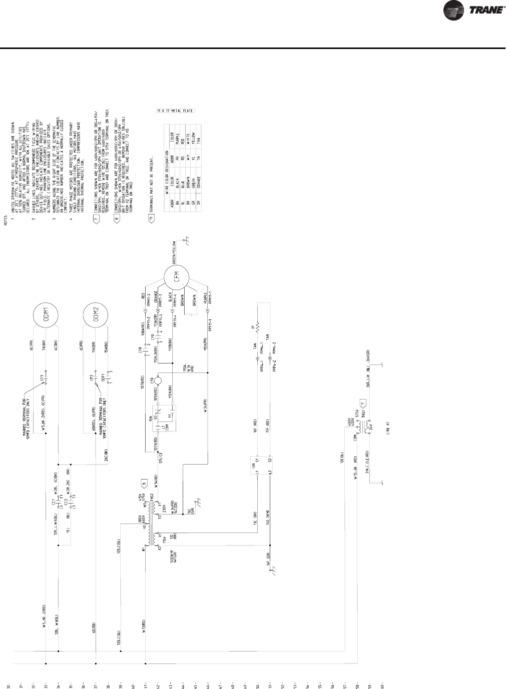
RT-PRC034-EN 71
Typical Wiring
Figure 4. (continued from previous page) YS*155F–250F
30
31
32
33
34
35
36
37
38
39
40
41
42
43
44
45
46
47
48
49
50
51
52
53
54
55
56
57
58
59
60
TERMINALS MAY NOT BE PRESENT.
6K (RD)
6C(PR)
7A(BR)
4C(BK)
ABBR
BK
BL
BR
GR
OR
WIRE COLOR DESIGNATION
COLOR
BLACK
BLUE
BROWN
GREEN
ORANGE
ABBR
PR
RD
WH
YL
COLOR
PURPLE
RED
WHITE
YELLOW
31A,C,D (RD)
LINE 61
TNS1
NOTES:
UNLESS OTHERWISE NOTED ALL SWITCHES ARE SHOWN
AT 25 C (77 F), AT ATMOSPHERIC PRESSURE.
AT 50% RELATIVE HUMIDITY, WITH ALL UTILITIES
TURNED OFF, AND AFTER A NORMAL SHUTDOWN HAS
OCCURED. ALL THERMISTORS ARE 10K AT 25 C (77 F).
1
2
THREE PHASE MOTORS ARE PROTECTED UNDER PRIMARY
SINGLE PHASING CONDITIONS. ALL MOTORS HAVE
INTERNAL OVERLOAD PROTECTION. COMPRESSORS HAVE
INTERNAL THERMAL PROTECTION.
11 X 17 METAL PLATE
6K
W28,
W2812J
NUMBERS ALONG THE RIGHT SIDE OF THE SCHEMATIC
DESIGNATE THE LOCATION OF CONTACTS BY LINE NUMBER.
AN UNDERLINED NUMBER INDICATES A NORMALLY CLOSED
CONTACT.
DASHED LINES INDICATE RECOMMENDED FIELD WIRING
BY OTHERS. DASHED LINE ENCLOSURES AND/OR DASHED
DEVICE OUTLINES INDICATE COMPONENTS PROVIDED BY
THE FIELD. PHANTOM LINE ENCLOSURES INDICATE
ALTERNATE CIRCUITRY OR AVAILABLE SALES OPTIONS.
3
4
6K
,J,
(BL)
36B,J,W (BL) ,36V(GR)
T3
L3
CC1
T3
L3
CC2
CF1
MARKED TERMINAL FOR
10MFD CAPACITORS ONLY
COM
24V
ODM1
7
7
8
11
,E
L1
CBM
LO
HI
12B,C(BL) 12B,C(BL)
SPLICE
W5,
GREEN/YELLOW
W34(PR)
6D(RD), 6E(PR)
6E(PR)
11A(BR)
15A(BK)
,D(RD) ,D(RD), 6C(PR)
BROWN
6D(RD)
RED
BROWN
PURPLE
575V
460V
400V
W13,
4C(BK)
14F (GR) 14G (WH) TAN
TAN
16F (RD)
ORANGE
BLACK
17F (RD)
PPM4-1
PPM4-2
W34(PR)
14C(GR)
PPF4-2
W6
PPF4-1
L1
14C
(GR)
13C
(BK)
14G(WH)
14F(GR)
W13(RD)
26C(BK)
(BK)
12B
12B, (BL)
W5,
S1
13C (BK) IGN
L2 S2
12C(BL)
CONNECTIONS SHOWN ARE FOR 460V/60HZ/3PH OR 380-415V/
50HZ/3PH. WHEN 575V/60HZ/3PH UNIT OPERATION IS
REQUIRED, REMOVE WIRE 12C(BL) FROM 460V/400V
TERMINAL ON TNS1 AND CONNECT TO 575V TERMINAL ON TNS1.
W14(RD)
TN TAN
CONNECTIONS SHOWN ARE FOR 460V/60HZ/3PH OR 380V/
50HZ/3PH. WHEN 575V/60HZ/3PH OR 415V/50HZ/3PH
UNIT OPERATION IS REQUIRED, REMOVE WIRES 12B,C(BL)
FROM H2 TERMINAL ON TNS2, AND CONNECT TO H3
TERMINAL ON TNS2
,26C
W6 (BL)
IGN
415V
575V
Y2
TNS2
H1
380V
460V
X2
230V
115V
H2 H3
X1 Y1
CF2
PPM11-3
PPF11-3
PPM11-4
PPF11-4
3
1
ODF1
PPM11-2
PPF11-2
PPM11-1
PPF11-1
IP
MARKED TERMINAL FOR
10MFD CAPACITORS ONLY
CFR
CFR
CFR 112A,B(BK) 113A(OR)
108A(RD)
112B(BK)
110A(PR)
112A(BK)
109A(RD)
107B(RD)
110A,
W34
(PR)
107A(RD)
12
34
CFM
ODM2
8
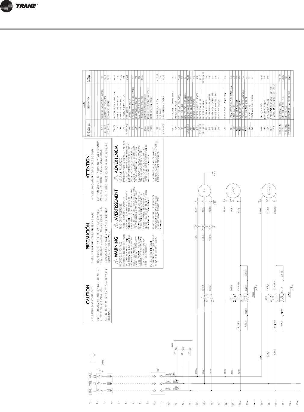
72 RT-PRC034-EN
Typical Wiring
Figure 5. YS*200F–250F
1
2
3
4
5
6
7
8
9
10
11
12
13
14
15
16
17
18
19
20
21
22
23
24
25
26
27
28
29
30
64,65
COMMUNICATION MODULE
RELIATEL REFRIGERATION MODULE
RELIATEL OPTIONS MODULE
EXHAUST FAN RELAY
COMM
RTRM
RTOM
91
DISCHARGE TEMPERATURE SENSORDTS
EXF
1D, 2C, 3D
8B(BL)
9B(RD)
5A(BL)
10A(RD)
1A(RD)
3A(BK)
5A(BL)
CC1,CC2
HTB1
2A,
(BL)
1A,
(RD)
21A(BL)
22A(RD)
OUTDOOR FAN MOTOR
OUTDOOR FAN RELAY
9A(RD)
10A (RD)
21A(BL)
22 (RD)
TCI
1B (RD)
80
66
3B(BK) 66
RETURN AIR SENSOR 96
DEVICE
DESIGNATION
2A(BL) 8A(BL)
DESCRIPTION
LEGEND
LINE
NUMBER
CFS
CPR1,CPR2
FFS
F
HTB1
IDM
HPC1,HPC2
BMS
OHS
PPF6,PPM6
RHS
TNS1
RMP
COMPRESSOR CONTACTOR
OUTDOOR MOTOR CAPACITOR
COMPRESSOR
ECONOMIZER ACTUATOR
FAN FAILURE SWITCH
FAN TERMINAL BLOCK
HI VOLTAGE TERMINAL BLOCK
INDOOR FAN MOTOR
HIGH PRESSURE CONTROL
BUILDING MANAGEMENT SYSTEM
LOW VOLTAGE TERM BLOCK
LOW PRESSURE CONTROL
OUTDOOR AIR SENSOR
OUTDOOR HUMIDITY SENSOR
ECONOMIZER PLUG
REMOTE MINIMUM POSITION
CONTROL POWER TRANSFORMER
SUPPLY AIR SENSOR
64,65
21,26
98
91
100
17,18
16,17,18
10
17
69,68,34,38ODF1,ODF2
100
90-102
98
98
93
58
91
RHT
SHT
ZSM ZONE SENSOR MODULE
RETURN HIGH TEMPERATURE
SUPPLY HIGH TEMPERATURE
DEVICE
DESIGNATION DESCRIPTION
LEGEND
LINE
NUMBER
ECA
OAS
RAS
SAS
CLOGGED FILTER SWITCH
RETURN HUMIDITY SENSOR
1B, 2B, 3B,
3B(BK)
1B(RD)
2B(BL)
3A,
(BK)
3C(BK)
3A(BK)
8A(BL)
9A(RD) FTB-D
FTB-C
FTB-B
INDOOR FAN CONTACTOR
FTB
LTB
LPC1,LPC2 78,80
70
63
TRANE COMMUNICATION INTERFACE
XFR EXHAUST FAN RELAY 99
CC2
CC2 A
1D(RD)
3D(BK)
2C(BL)
3D(BK)
T2
L2
F
T1
L1
T2
L2
3
8
9
T1L1
F
T1
L1
CC1
T2
L2
CC1
IDM
T3
T2
T1
CPR1
T3
T2
T1
CPR2
L1
L2
L3
11
L1 L2 L3
LINE VOLTAGE
AVERTISSEMENT ADVERTENCIA
TENSION DANGEREUSE!
COUPER TOUTES LES TENSIONS ET
OUVRIR LES SECTIONNEURS À DISTANCE,
PUIS SUIVRE LES PROCÉDURES DE
VERROUILLAGE ET DES ÉTIQUETTES AVANT
TOUTE INTERVENTION. VÉRIFIER QUE TOUS
LES CONDENSATEURS DES MOTEURS SONT
DÉCHARGÉS. DANS LE CAS D'UNITÉS
COMPORTANT DES ENTRAÎNEMENTS À
VITESSE VARAIBLE, SE REPORTER AUX
INSTRUCTIONS DE L'ENTRAÎNEMENT POUR
DÉCHARGER LES CONDENSATEURS.
NE PAS RESPECTER CES MESURES DE
PRÉCAUTION PEUT ENTRAÎNER DES
BLESSURES GRAVES POUVANT ÊTRE
MORTELLES.
WARNING
DISCONNECT ALL ELECTRIC POWER
INCLUDING REMOTE DISCONNECTS
AND FOLLOW LOCK OUT AND TAG
PROCEDURES BEFORE SERVICING.
INSURE THAT ALL MOTOR
CAPACITORS HAVE DISCHARGED
STORED VOLTAGE. UNITS WITH
VARIABLE SPEED DRIVE, REFER
TO DRIVE INSTRUCTIONS FOR
CAPACITOR DISCHARGE.
FAILURE TO DO THE ABOVE
BEFORE SERVICING COULD RESULT
IN DEATH OR SERIOUS INJURY.
HAZARDOUS VOLTAGE!
iVOLTAJE PELIGROSO!
DESCONECTE TODA LA ENERGÍA ELÉCTRICA,
INCLUSO LAS DESCONEXIONES REMOTAS Y
SIGA LOS PROCEDIMIENTOS DE CIERRE Y
ETIQUETADO ANTES DE PROCEDER AL
SERVICIO. ASEGÚRESE DE QUE TODOS
LOS CAPACITORES DEL MOTOR HAYAN
DESCARGADO EL VOLTAJE ALMACENADO.
PARA LAS UNIDADES CON EJE DE
DIRECCIÓN DE VELOCIDAD VARIABLE,
CONSULTE LAS INSTRUCCIONES PARA LA
DESCARGA DEL CONDENSADOR.
EL NO REALIZAR LO ANTERIORMENTE
INDICADO, PODRÍA OCASIONAR LA MUERTE
O SERIAS LESIONES PERSONALES.
USE COPPER CONDUCTORS ONLY!
UNIT TERMINALS ARE NOT DESIGNED TO ACCEPT
OTHER TYPES OF CONDUCTORS.
FAILURE TO DO SO MAY CAUSE DAMAGE TO THE
EQUIPMENT.
CAUTION
¡UTILICE ÚNICAMENTE CONDUCTORES DE COBRE!
LAS TERMINALES DE LA UNIDAD NO ESTÁN DISEÑADAS
PARA ACEPTAR OTROS TIPOS DE CONDUCTORES.
SI NO LO HACE, PUEDE OCASIONAR DAÑO AL EQUIPO.
N'UTILISER QUE DES CONDUCTEURS EN CUIVRE!
LES BORNES DE L'UNITÉ NE SONT PAS CONÇUES
POUR RECEVOIR D'AUTRES TYPES DE CONDUCTEURS.
L'UTILISATION DE TOUT AUTRE CONDUCTEUR PEUT
ENDOMMAGER L'ÉQUIPEMENT.
PRECAUCIÓN
ATTENTION
69
TIMED OVERIDETIOR
71LOW PRESSURE CONTROLLPC3
81
SPACE HUMIDITY SENSORSHS
71
REHEAT VALVE
RHV
64
BLACK
BLACK BLACK
ODM1,ODM2 33,37
10B(RD)
1C(RD)
BLACK 22B(RD)
1E(RD)
PPF11,PPM11
1D (RD)
CF1,CF2
CFM
IGN
IP
TCO1
TCO2
COMBUSTION FAN MOTOR
IGNITION CONTROL MODULE
IGNITION PROBE
HIGH LIMIT CUTOUT
FAN FAILURE LIMIT
33,37
43
76
74,50
50
72
72
GV
TNS2 IGNITION TRANSFORMER 41
PPF3
PPF4,PPM4
IGNITION CONTROL PLUG
IGNITER PLUG
50,75
50
GAS VALVE
COMBUSTION FAN MOTOR PLUG 41-46
W5 W6
GREEN
GREEN
CCH1,CCH2 CRANKCASE HEATER 23,28
,C ,B
,E ,B
CCH2
CCH1
PHM
L1
L2
L3
1P
2P
3P
PHM PHASE MONITOR 13-15
1P 2P
3P
TDL1 THERMOSTAT DISCHARGE LINE CKT 1
TDL2 THERMOSTAT DISCHARGE LINE CKT 2
CFR COMBUSTION FAN RELAY 41,42

RT-PRC034-EN 73
Typical Wiring
Figure 5. (continued from previous page) YS*200F–250F
30
31
32
33
34
35
36
37
38
39
40
41
42
43
44
45
46
47
48
49
50
51
52
53
54
55
56
57
58
59
60
TERMINALS MAY NOT BE PRESENT.
6K (RD)
6C(PR)
7A(BR)
4C(BK)
ABBR
BK
BL
BR
GR
OR
WIRE COLOR DESIGNATION
COLOR
BLACK
BLUE
BROWN
GREEN
ORANGE
ABBR
PR
RD
WH
YL
COLOR
PURPLE
RED
WHITE
YELLOW
31A,C,D (RD)
LINE 61
TNS1
NOTES:
UNLESS OTHERWISE NOTED ALL SWITCHES ARE SHOWN
AT 25 C (77 F), AT ATMOSPHERIC PRESSURE.
AT 50% RELATIVE HUMIDITY, WITH ALL UTILITIES
TURNED OFF, AND AFTER A NORMAL SHUTDOWN HAS
OCCURED. ALL THERMISTORS ARE 10K AT 25 C (77 F).
1
2
THREE PHASE MOTORS ARE PROTECTED UNDER PRIMARY
SINGLE PHASING CONDITIONS. ALL MOTORS HAVE
INTERNAL OVERLOAD PROTECTION. COMPRESSORS HAVE
INTERNAL THERMAL PROTECTION.
11 X 17 METAL PLATE
6K
W28,
W2812J
NUMBERS ALONG THE RIGHT SIDE OF THE SCHEMATIC
DESIGNATE THE LOCATION OF CONTACTS BY LINE NUMBER.
AN UNDERLINED NUMBER INDICATES A NORMALLY CLOSED
CONTACT.
DASHED LINES INDICATE RECOMMENDED FIELD WIRING
BY OTHERS. DASHED LINE ENCLOSURES AND/OR DASHED
DEVICE OUTLINES INDICATE COMPONENTS PROVIDED BY
THE FIELD. PHANTOM LINE ENCLOSURES INDICATE
ALTERNATE CIRCUITRY OR AVAILABLE SALES OPTIONS.
3
4
6K
,J,
(BL)
36B,J,W (BL) ,36V(GR)
T3
L3
CC1
T3
L3
CC2
CF1
MARKED TERMINAL FOR
10MFD CAPACITORS ONLY
COM
24V
ODM1
7
7
8
11
,E
L1
CBM
LO
HI
12B,C(BL) 12B,C(BL)
SPLICE
W5,
GREEN/YELLOW
W34(PR)
6D(RD), 6E(PR)
6E(PR)
11A(BR)
15A(BK)
,D(RD) ,D(RD), 6C(PR)
BROWN
6D(RD)
RED
BROWN
PURPLE
575V
460V
400V
W13,
4C(BK)
14F (GR) 14G (WH) TAN
TAN
16F (RD)
ORANGE
BLACK
17F (RD)
PPM4-1
PPM4-2
W34(PR)
14C(GR)
PPF4-2
W6
PPF4-1
L1
14C
(GR)
13C
(BK)
14G(WH)
14F(GR)
W13(RD)
26C(BK)
(BK)
12B
12B, (BL)
W5,
S1
13C (BK) IGN
L2 S2
12C(BL)
CONNECTIONS SHOWN ARE FOR 460V/60HZ/3PH OR 380-415V/
50HZ/3PH. WHEN 575V/60HZ/3PH UNIT OPERATION IS
REQUIRED, REMOVE WIRE 12C(BL) FROM 460V/400V
TERMINAL ON TNS1 AND CONNECT TO 575V TERMINAL ON TNS1.
W14(RD)
TN TAN
CONNECTIONS SHOWN ARE FOR 460V/60HZ/3PH OR 380V/
50HZ/3PH. WHEN 575V/60HZ/3PH OR 415V/50HZ/3PH
UNIT OPERATION IS REQUIRED, REMOVE WIRES 12B,C(BL)
FROM H2 TERMINAL ON TNS2, AND CONNECT TO H3
TERMINAL ON TNS2
,26C
W6 (BL)
IGN
415V
575V
Y2
TNS2
H1
380V
460V
X2
230V
115V
H2 H3
X1 Y1
CF2
PPM11-3
PPF11-3
PPM11-4
PPF11-4
3
1
ODF1
PPM11-2
PPF11-2
PPM11-1
PPF11-1
IP
MARKED TERMINAL FOR
10MFD CAPACITORS ONLY
CFR
CFR
CFR 112A,B(BK) 113A(OR)
108A(RD)
112B(BK)
110A(PR)
112A(BK)
109A(RD)
107B(RD)
110A,
W34
(PR)
107A(RD)
12
34
CFM
ODM2
8
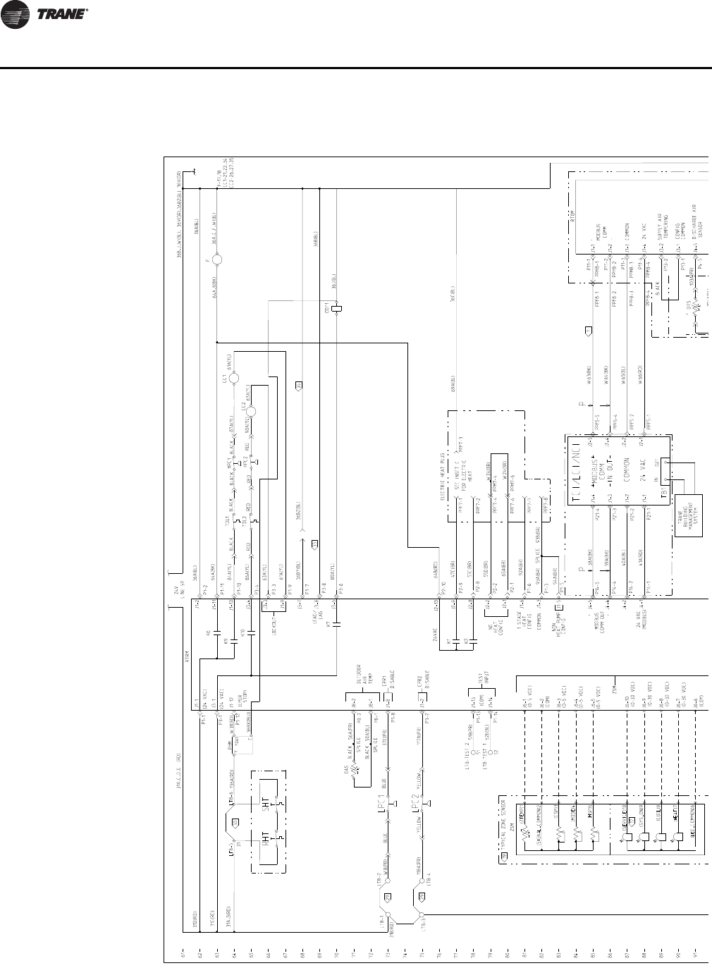
74 RT-PRC034-EN
Typical Wiring
Figure 6. TS*155F–250F
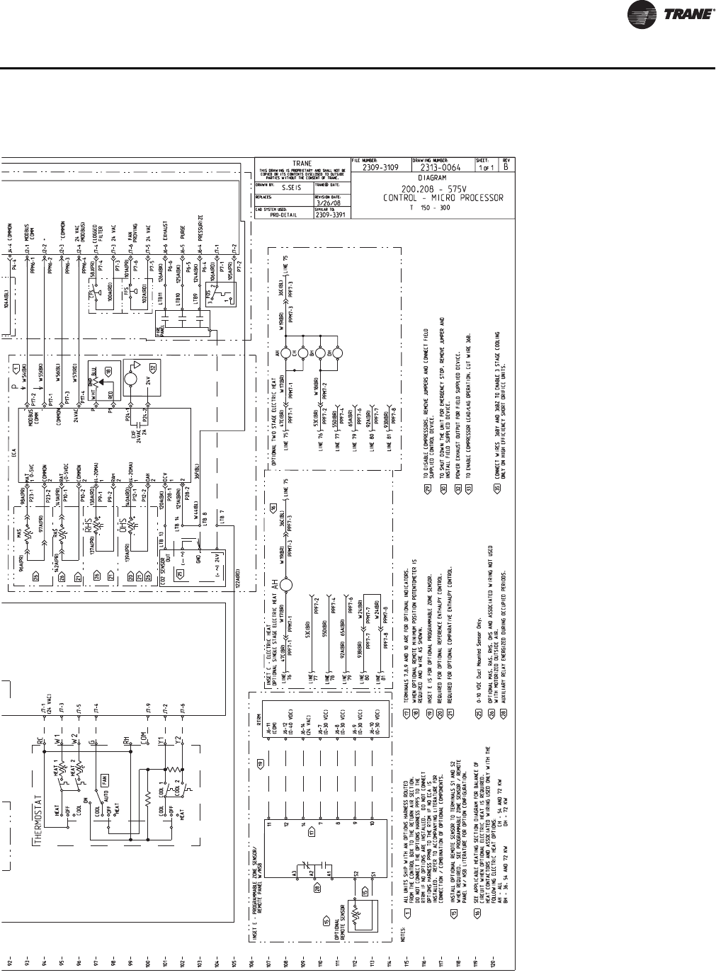
RT-PRC034-EN 75
Typical Wiring
Figure 6. (continued from previous page) TS*155F–250F
**
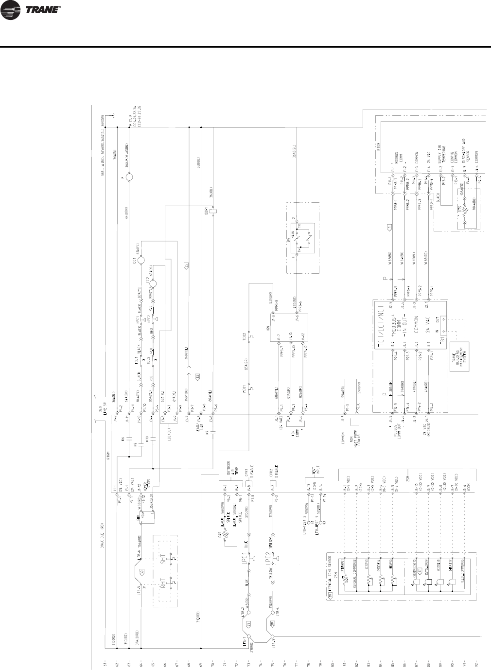
76 RT-PRC034-EN
Typical Wiring
Figure 7. YS*155F–250F
61
62
63
64
65
66
67
68
69
70
71
72
73
74
75
76
77
78
79
80
81
82
83
84
85
86
87
88
89
90
91
92
31B(RD)
104A(BL)
103A(PR)
36B(BL)
41A(RD)
40A(BL)
39A(BK)
38A(BK)
31A,B(RD)
W66(RD)
W65(BL)
W64(BK)
W63(BK)
31C(RD)
LTB-3
K7
K10
K9
K6
(24 VAC)
(24 VAC)
LEAD/
LAG
P4-4
P4-5
DTS
P13-1
P13-2
PPF5-1
PPF5-2
PPF5-4
PPF5-5
P14-1
P14-2
P11-4
P11-3
P11-2
P11-1
P21-1
P21-2
P21-3
P21-4
80A(YL)
OAS
118A(PR)
36V(GR)
36B,J,W(BL), 36V(GR)
31D(RD)
LINE 59
24V
90A(YL)
36A(BL)
56A(PR)
50A(BL)
OUTDOOR
AIR
TEMP
RTRM
31A,C,D,E (RD)
SPLICE
SPLICE
36A(BL)
61A(YL)
63A(YL)
63A(YL)
86A(YL)
84A(YL)
61A(YL)
64A(BK)
(0-5 VDC)
(0-5 VDC)
(COM)
(0-5 VDC)
(0-5 VDC)
(0-30 VDC)
(0-30 VDC)
(COM)
(0-30 VDC)
(0-30 VDC)
CPR2
DISABLE
BLACK
BLACK
CPR1
DISABLE
37C(PR)
W8(PR)
(EMER
STOP)
F-17,18
CC1-21,22,34
CC2-26,27,35
YELLOW YELLOW 117A(PR)
ZSM
51B(PR)
TEST
INPUT
LOCKOUT
PPM8-4
PPM8-3
PPM8-2
PPM8-1
PPF8-3
PPF8-2
LTB-1
P3-6
P3-8
P14-4
P1-12
P3-1
P1-1
LTB-4
LTB-2
COMMON
DISCHARGE AIR
SENSOR
SUPPLY AIR
TEMPERING
CONFIG
COMMON
(COM)
PPF8-1
BLACK
TRANE
BUILDING
MANAGEMENT
SYSTEM
P14-5
-
COMMON
24 VAC
+
MODBUS
COMM
+
24 VAC
(MODBUS)
MODBUS
COMM OUT
-
ODF1
P8-1
P8-2
P3-3
P1-9
P1-2
P1-10
P3-4
P1-11 CC1
CC2
F
LTB-TEST 2
P1-14
P1-13
31
P1-8
P3-2
PPF8-4
BLUE
LTB-TEST 1
51
52
52E(BL)
IN OUT
TYPICAL ZONE SENSOR
ZSM
J1-1
J3-1
RHT
30
SHT
33
29
29
LPC1
LPC2
17
MODBUS
COMM
IN
24 VAC
+
-
+
-
TCI/LCI/NCI
COMMON
OUT
TB1
P
J4-4
J4-2
J4-1
J4-5
P
J1-4
J1-3
J1-2
J1-1
J2-5
J2-4
J2-2
J2-1
J1-2
J1-11
J1-10
J3-4
J3-3
J1-9
J3-8
J3-6
J8-2
J8-1
J1-8
J3-2
J1-13
J1-14
J6-1
J6-2
J6-3
J6-4
J6-5
J6-10
J6-9
J6-8
J6-7
J6-6
(ZTEMP)1
(CSP)3
(MODE)4
(HSP)5
(SERVICE)10
(SIGNAL_COMMON)2
(SYS_ON)9
(COOL)8
(HEAT)7
(LED_COMMON)6
J1-1
J1-2
J1-3
J1-4
J3-2
J3-1
J4-5
J4-4
1
LTB-5 LTB-6
19
82A(BK)
81A(BK)
68A(YL)
83A(BR)
85A(BR)
31E(RD)
36AS(BL)
42D(BR)
IGN
COMM
(24 VAC)
J1-8
J1-7
36A,F,W,AS(BL)
64A(BK)
IGN
J1-6
J1-10
J1-12
GV
PPF3-6
PPF3-8
PPF3-12
PPF3-10
PPF3-7
P5-4
P5-3
P5-1
2
3MAIN
-
+
TC02
TC01
TH TR
J5-1
J5-3
J5-4
59A(PR)
59A(PR)
P1-5
P1-3
COMMON
NON
HEAT PUMP
CONFIG
J1-3
RTOM
BLUE
87A(YL)
36J(BL)
W38(RD)
Y
YOUT
C36BX(BlU)
136A(RD) PHM BLACK
RED
RED
BLACK BLACK
RED
BLACK
HPC1
RED
HPC2
P3-7
36BY(BL) 36BZ(BL)
,36BZ(BL)
J3-7 35
J1-12 TDL1
TDL2
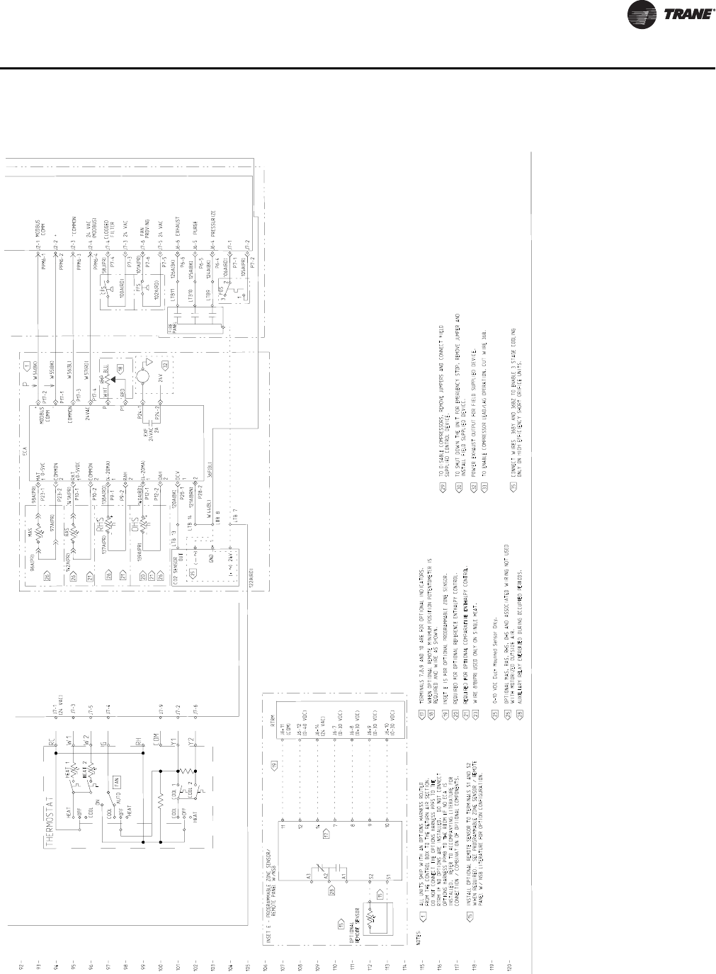
RT-PRC034-EN 77
Typical Wiring
Figure 7. (continued from previous page) YS*155F–250F
92
93
94
95
96
97
98
99
100
101
102
103
104
105
106
107
108
109
110
111
112
113
114
115
116
117
118
119
120
P6-4
P6-5
P6-6
0-10 VDC Duct Mounted Sensor Only.
120A(BK)
121A(BRN)
36F(BL)
122A(RD) P7-2
P7-1
105A(PR)
106A(RD)
ALL UNITS SHIP WITH AN OPTIONS HARNESS ROUTED
FROM THE CONTROL BOX TO THE RETURN AIR SECTION.
DO NOT CONNECT THE OPTIONS HARNESS PPF5 TO THE
RTRM IF NO OPTIONS ARE INSTALLED. DO NOT CONNECT
OPTIONS HARNESS PPM8 TO THE RTOM IF NO ECA IS
INSTALLED. REFER TO ACCOMPANYING LITERATURE FOR
CONNECTION / COMBINATION OF OPTIONAL COMPONENTS.
98A(PR)
102A(RD)
P7-5
P7-3
PPM6-4
PPM6-3
PPM6-2
PPM6-1
101A(PR)
100A(RD)
58J(PR)
97A(PR)
96A(PR)
W57(RD)
W56(BL)
W55(BK)
W54(BK)
140A(RD)
139A(PR)
138A(RD)
137A(PR)
142A(PR) 141A(PR)
CFS
1
2
1
2
2
1
2
1
BLU
RMP
WHT
RED
2A
EXF
24VAC
RAS
0-5VDC
0-5VC
MAS
P7-6
P7-4
J6-7
(0-30 VDC)
J6-10
(0-30 VDC)
J6-9
(0-30 VDC)
J6-8
(0-30 VDC)
RTRM
12
11
7
8
10
9
J6-12
(0-40 VDC)
J6-11
(COM)
INSET E - PROGRAMMABLE ZONE SENSOR/
REMOTE PANEL W/NSB
NOTES:
WHEN OPTIONAL REMOTE MINIMUM POSITION POTENTOMETER IS
REQUIRED AND WIRE AS SHOWN.
INSET E IS FOR OPTIONAL PROGRAMMABLE ZONE SENSOR.
OPTIONAL
REMOTE SENSOR
A3
A2
A1
14 J6-14
(24 VAC)
TERMINALS 7,8,9 AND 10 ARE FOR OPTIO NAL INDICATORS.
INSTALL OPTIONAL REMOTE SENSOR TO TERMINALS S1 AND S2
WHEN REQUIRED. SEE PROGRAMMABLE ZONE SENSOR / REMOTE
PANEL W/ NSB LITERATURE FOR OPTION CONFIGURATION.
OPTIONAL MAS, RAS, RHS, OHS AND ASSOCIATED WIRING NOT USED
WITH MOTORIZED OUTSIDE AIR.
AUXILIARY RELAY ENERGIZED DURING OCC UPIED PERIODS.
TO DISABLE COMPRESSORS, REMOVE JUMPERS AND CONNECT FIELD
SUPPLIED CONTROL DEVICE.
TO SHUT DOWN THE UNIT FOR EMERGENCY STOP, REMOVE JUMPER AND
INSTALL FIELD SUPPLIED DEVICE.
POWER EXHAUST OUTPUT FOR FIELD SUPPL IED DEVICE.
TO ENABLE COMPRESSOR LEAD/LAG OPERAT ION, CUT WIRE 36B.
REQUIRED FOR OPTIONAL REFERENCE ENTH ALPY CONTROL.
REQUIRED FOR OPTIONAL COMPARATIVE EN THALPY CONTROL.
S2
S1
1
P28-2
P28-1
124A(BK)
125A(BK)
W44(BL)
126A(BK)
()24V
+
FIRE
PANEL
PRESSURIZE
PURGE
EXHAUST
LTB9
LTB10
LTB11
LTB 7
GND
)
(
OUT
LTB 8
2
3FOS
CO2 SENSOR LTB 13
LTB 14
P17-4
P17-3
P17-1
P17-2
P12-1
P12-2
P9-2
P9-1
P10-2
P10-1
P23-2
P23-1
MODBUS
COMM
ECA
24 VAC
(MODBUS)
COMMON
MODBUS
COMM
24 VAC
FAN
PROVING
24 VAC
CLOGGED
FILTER
FFS
+
-
24V
1
J2-1
J2-2
J2-3
J2-4
J7-4
J7-3
J7-6
J7-5
J6-6
J6-5
J6-4
J7-1
J7-2
+
-
COMMON
24VAC
P
P
P1 18
32
P24-1
P24-2
MAT
COMMON
RAT
COMMON
RHS
h+
-
(4-20MA)
RAH
(4-20MA)
OAH
OHS
h+
-
26
21
26
26
21
20
21
26
DCV
2
15
15
28
17
19
1
15
17
18
19
20
21
25
26
28
29
30
32
33
25
1
J7-9
J7-5
J7-1
(24 VAC)
J7-2
J7-6
J7-4
J7-3
HEAT 2
HEAT 1
COOL
OFF
HEAT
ON
AUTO FAN
COOL
OFF
HEAT
COOL
OFF
HEAT
COOL 1
COOL 2
THERMOSTAT
W1
W2
G
Y1
Y2
RC
RH
COM
WIRE 81B(PR) USED ONLY ON SINGLE HEA T.
23
CONNECT WIRES 36BY AND 36BZ TO ENABLE 3 STAGE COOLING
ONLY ON HIGH EFFICIENCY SHORT ORIFICE UNITS.
35
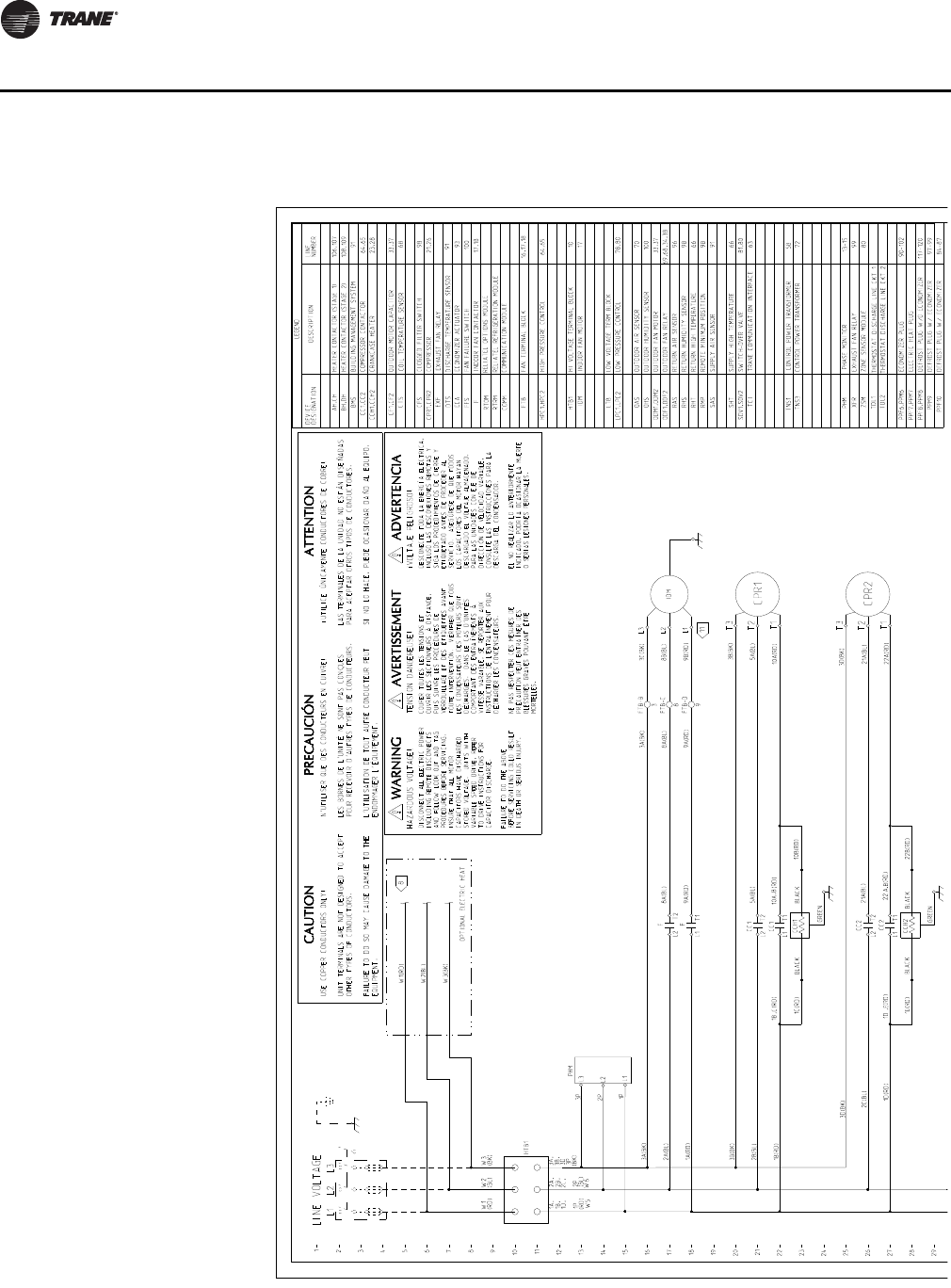
78 RT-PRC034-EN
Typical Wiring
Figure 8. WS*155E–250E
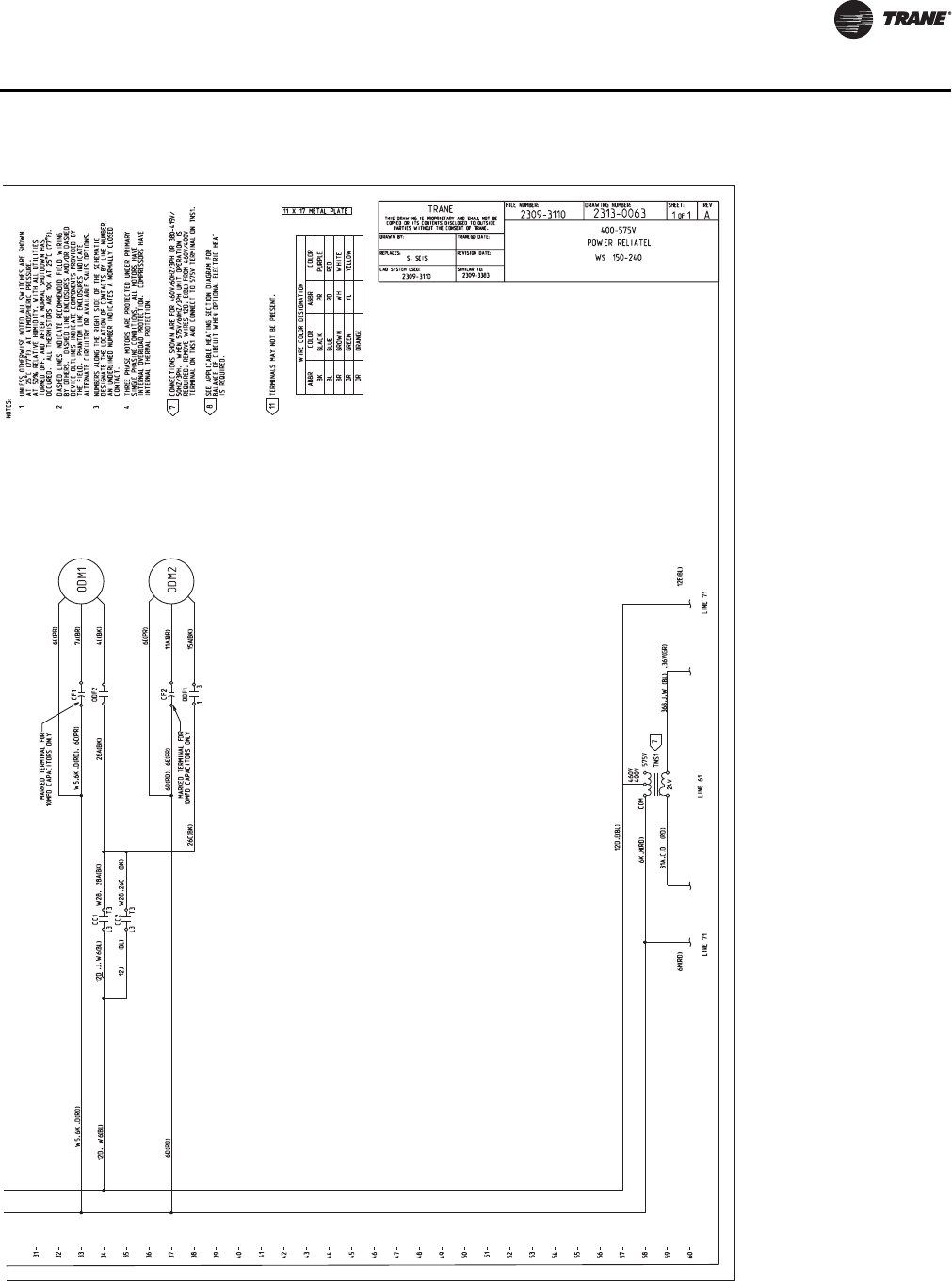
RT-PRC034-EN 79
Typical Wiring
Figure 8. (continued from previous page) WS*155E–250E
*

80 RT-PRC034-EN
Jobsite Connections
Notes:
•For specific wiring information, see the installation instructions.
•All wiring except power wire is low voltage.
•All customer supplied wiring to be copper and must conform to applicable electrical codes
(such as NEC or CEC) and local electric codes. Wiring shown dotted is to be furnished and
installed by the customer.
•Zone sensor required for units configured for Single Zone VAV indoor fan system control to
enable Single Zone VAV functionality.
Table 68. Typical number of wires
Zone Sensors
AManual Changeover 4
Manual/Auto Changeover 5
Manual/Auto Changeover with Status Indication LED’s 10
Programmable Night Setback with Status Indication LED’s 7
Thermostats
B3 Power Wires + 1 Ground Wire (three phase)
DISCONNECT
SWITCH
(BY OTHERS)
ZONE SENSOR OR
THERMOSTAT ROOFTOP
UNIT
A
B

RT-PRC034-EN 81
Dimensional Data
Figure 9. Cooling with optional electric heat and gas/electric models—15–25 tons—downflow unit clearance
* All dimensions are in inches/millimeters.
121 11/16”
(3091 mm)
54”
(1372 mm)
26 3/4”
(679 mm)
84 3/16”
(2138 mm)
8 15/16”
(227 mm)
1”
(25 mm)
33 3/16”
(843 mm)
2 11/16”
(68 mm)
64 11/16”
(1643 mm)
6”
(152 mm)
(SEE NOTE)
7/8” (22 mm) DIA. HOLE
(UNIT CONTROL WIRE)
3” (76 mm) DIA. HOLE
(UNIT POWER WIRE)
DOWNFLOW CONDENSATE
DRAIN CONN 1” (25 mm) NPT
Figure 10. Cooling with optional electric heat and gas/electric models–15–25 tons—unit clearance and horizontal unit
supply/return
* All dimensions are in inches/millimeters.

82 RT-PRC034-EN
Dimensional Data
Figure 11. Heat pump—15 tons—downflow unit clearance
* All dimensions are in inches/millimeters.
2138 MM
(TS*/WS* MODELS ONLY)
Figure 12. Heat pump—15 tons—unit clearance and horizontal unit supply/return
* All dimensions are in inches/millimeters.
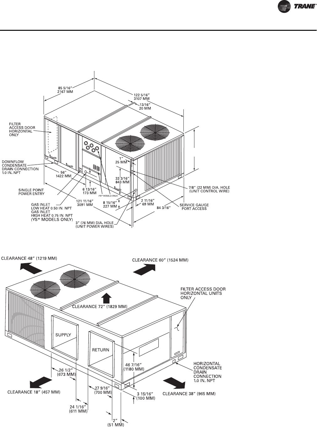
RT-PRC034-EN 83
Dimensional Data
Figure 13. Heat pump—20 tons—downflow unit clearance
* All dimensions are in inches/millimeters.
2138 MM
(TS*/WS* MODELS ONLY)
64 1/8”
1629 MM
Figure 14. Heat pump—20 tons—unit clearance and horizontal unit supply/return
* All dimensions are in inches/millimeters.
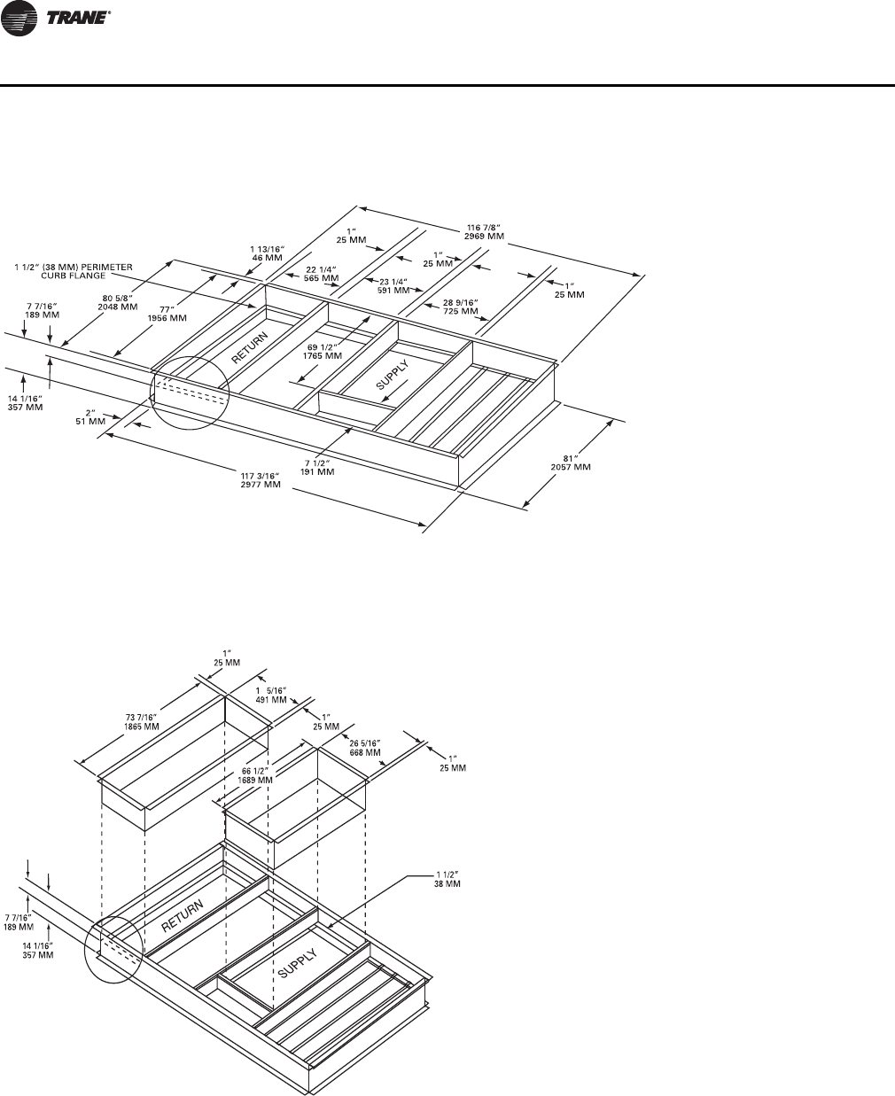
84 RT-PRC034-EN
Dimensional Data
Figure 15. Cooling and heat pump with optional electric heat and gas/electric models—15–25 tons—roof curb
* All dimensions are in inches/millimeters.
Figure 16. Cooling and heat pump with optional electric heat and gas/electric models 15–25 tons—downflow duct
connections—field fabricated
* Duct flanges mount 7-7/16" (189mm) down inside the curb on the 1.5" (38mm) curb flanges. Roofcurb is intended for downflow use only.
* All dimensions are in inches/millimeters.
9
PERIMETER
CURB FLANGE

RT-PRC034-EN 85
Dimensional Data
Figure 17. Cooling and heat pump with optional electric heat and gas/electric models 15–25 tons—downflow unit
clearance
* All dimensions are in inches/millimeters.
Figure 18. Downflow & horizontal condensate locations
Table 69. Standard efficiency units (cooling and gas/electric)
Condensate Condensate Drain
Location
Tons Downflow Only Drain Size Downflow Horizontal
AB C DFG H J K
15–25 26 7/16”
672 mm 28 3/4”
730 mm 19 15/16”
506 mm 4 1/4”
108 mm 4 1/4”
108 mm 76 5/16”
1938 mm 68 11/16”
1745 mm 1NPT 26 3/4”
679 mm 5 3/8”
137 mm

86 RT-PRC034-EN
Dimensional Data
Table 70. Cooling unit—swing diameter & through the base electrical
Unit Model # A B C D E
TSD/YSD 155F, 175F, 200F, 250F, WSD155E, 200E 29 1/2 56 38 1/2 18 1/2 N/A
Note: *All dimensions are in inches
SWING RADIUS (C)
OD SECTION
ACCESS PANEL
THROUGH THE
BASE ELECTRICAL
SWING RADIUS (A)
ID SECTION
ACCESS PANEL
TOP VIEW SHOWING THROUGH THE BASE
ELECTRICAL UTILITY LOCATIONS AND ACCESS PANEL SWING CLEARANCES.
SWING RADIUS (E)
HORIZONTAL FILTER
ACCESS PANEL
SWING RADIUS (D)
ID FAN SECTION
ACCESS PANEL
B
6 7/8"
Figure 19. Fresh air hood (horizontal units) Figure 20. Fresh air hood (downflow units)
19 1/2”
FRESH AIR HOOD (MANUAL)
HORIZONTAL UNITS
495 MM
495 MM
Figure 21. Economizer - horizontal units Figure 22. Economizer - downflow units
Note: When applying economizer to horizontal units, connected
ductwork must be run full size to allow proper operation of
economizer damper.

RT-PRC034-EN 87
Weights
Table 71. TS* maximum unit and corner weights (kg) and center of gravity dimensions (mm)
Max Weight (kg) Corner Weights (kg) Center of Gravity (mm)
Model Shipping Net A B C D Length Width
TS*155F 1022 826 268 226 162 170 149 86
TS*175F 1040 845 268 231 169 176 154 89
TS*200F 1068 873 278 233 170 191 145 90
TS*250F 1060 852 270 231 169 182 153 89
Notes:
1. Corner weights are given for information only. All models must be supported continuously by a curb or equivalent frame support.
2. Weights are approximate. Horizontal and downflow unit and corner weights may vary slightly.
3. *Indicates both horizontal and downflow units.
Table 72. TS* maximum unit and corner weights (lb) and center of gravity dimensions (inches)
Max Weight (lb) Corner Weights (lb) Center of Gravity (in)
Model Shipping Net A B C D Length Width
TS*155F 2253 1822 590 498 358 376 59 34
TS*175F 2292 1863 591 510 372 388 61 35
TS*200F 2353 1925 614 514 375 422 57 35
TS*250F 2337 1878 595 510 372 402 60 35
Notes:
1. Corner weights are given for information only. All models must be supported continuously by a curb or equivalent frame support.
2. Weights are approximate. Horizontal and downflow unit and corner weights may vary slightly.
3. *Indicates both horizontal and downflow units.

88 RT-PRC034-EN
Weights
Table 73. TS* accessory net weights (kg/lb)(a), (b), (c)
Model
Economizer Outside Air Damper
Roof Curb
Oversized
Motor
Adder(d) All Zone
Sensors High Static
Drive(d) Low Static
Drive(d)
Net Motorized Manual
TSD155F, 175F — — — — — — — —
TSD200F 36/79 34/75 15/33 107/236 2/4 0.5/1 1/2 —
TSD250F 36/79 34/75 15/33 107/236 — 0.5/1 — 1/2
TSH155F, 175F — — — — — — — —
TSH200F 30/66 34/75 15/33 — 2/4 0.5/1 1/2 —
TSH250F 30/66 34/75 15/33 — — 0.5/1 — 1/2
(a) Net weight should be added to unit weight when ordering factory installed accessories.
(b)For 600V heaters net weights are same as 480 V heaters.
(c) To estimate shipping weight add 2.3 kg (5 lb) to net weight.
(d)Downflow only.
Table 74. TS* accessory net weights (kg)
Models
Electric Heat
5–27 kW 11–14 kW 22–27 kW 22–41 kW 45–54 kW
380–415 kW 380–415 kW 380–415 kW 380–415 kW 380–415 kW
TS*155F, 175F — 9.5 12.3 14.5 —
TS*200F — — 12.3 14.5 15.4
TS*250F — — 12.3 14.5 15.4
Notes:
1. Net weight should be added to unit weight when ordering factory installed accessories.
2. For 600 V heaters net weights are same as 480 V heaters.
3. Not available on all models (see Fan Performance tables for specific models).
4. To estimate shipping weight add 5 lb (2.27 kg) to net weight.
5. TS*155F-250F factory installed options for economizers, multiply net capacity x 0.99, EER x 0.97. For oversized motors, multiply net
capacity x 0.98, EER x 0.93.
6. * Indicates both downflow and horizontal units
Table 75. TS* accessory net weights (lb)
Models
Electric Heat
5–27 kW 11–14 kW 22–27 kW 22–41 kW 45–54 kW
380–415 kW 380–415 kW 380–415 kW 380–415 kW 380–415 kW
TS*155F, 175F — 21 27 32 —
TS*200F — — 27 32 34
TS*250F — — 27 32 34
Notes:
1. Net weight should be added to unit weight when ordering factory installed accessories.
2. For 600 V heaters net weights are same as 480 V heaters.
3. Not available on all models (see Fan Performance tables for specific models).
4. To estimate shipping weight add 5 lb (2.27 kg) to net weight.
5. TS*155F-250F factory installed options for economizers, multiply net capacity x 0.99, EER x 0.97. For oversized motors, multiply net
capacity x 0.98, EER x 0.93.
6. * Indicates both downflow and horizontal units
TS* Accessories
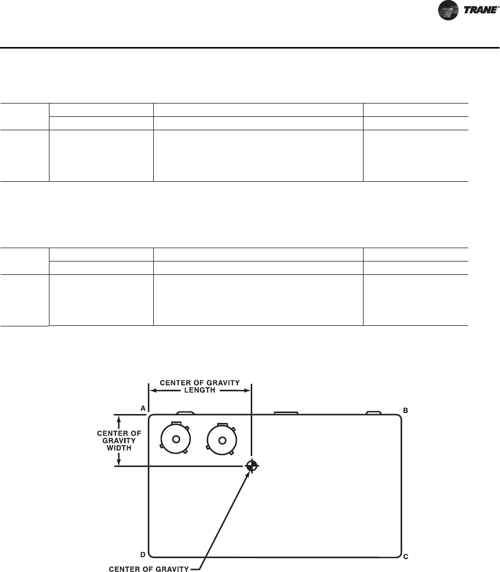
RT-PRC034-EN 89
Weights
Table 76. YS* maximum unit and corner weights (kg) and center of gravity dimensions (mm)
Max Weight Corner Weights Center of Gravity
Model Shipping Net A B C D Length Width
YS*155F 1100 888 285 242 175 184 148 86
YS*175F 1119 910 289 248 181 191 153 89
YS*200F 1147 939 299 250 182 206 145 90
YS*250F 1140 932 297 252 183 200 153 89
Notes:
1. Corner weights are given for information only. All models must be supported continuously by a curb or equivalent frame support.
2. Weights are approximate. Horizontal and downflow unit and corner weights may vary slightly.
3. *Indicates both horizontal and downflow units.
Table 77. YS* maximum unit and corner weights (lb) and center of gravity dimensions (inches)
Model
Max Weight Corner Weights Center of Gravity
Shipping Net A B C D Length Width
YS*155F 2424 1958 628 534 387 406 58 34
YS*175F 2467 2007 637 547 400 421 60 35
YS*200F 2528 2069 659 551 402 455 57 35
YS*250F 2513 2054 655 555 403 442 60 35
Notes:
1. Corner weights are given for information only. All models must be supported continuously by a curb or equivalent frame support.
2. Weights are approximate. Horizontal and downflow unit and corner weights may vary slightly.
3. *Indicates both horizontal and downflow units.
YS* Unit & Corner Weights, Center of Gravity

90 RT-PRC034-EN
Weights
Table 78. YS* accessory net weights (kg)(a), (b)
Economizer Outside Air Damper Oversized
Motor
Adder(c)
LPG
Conversion
Kit
High
Static
Drive(c)
Low
Static
Drive(c)
Model Net Motorized Manual Roof
Curb(d) All Zone
Sensors
YSD155F, 175F — — — — — — — — —
YSD200F 36 34 15 107 2 2 0.5 1 —
YSD250F 36 34 15 107 — 2 0.5 — 1
YSH155F, 175F — — — — — — — — —
YSH200F 30 34 15 — 2 2 0.5 1 —
YSH250F 30 34 15 — — 2 0.5 — 1
(a) Net weight should be added to unit weight when ordering factory installed accessories.
(b)Not available on all models. (See fan performance table for specific models).
(c) YS*155F-250F factory installed options for economizers, multiply net capacity x 0.99, EER x 0.97. For oversize motors, multiply net capacity
x 0.98, EER x 0.93.
(d)Downflow only.
Table 79. YS* accessory net weights (lb)(a), (b)
Economizer Outside Air Damper
Roof
Curb(c)
Oversized
Motor
Adder(d)
LPG
Conversion
Kit
High
Static
Drive(d)
Low
Static
Drive(d)
Model No Net Motorized Manual All Zone
Sensors
YSD155F, 175F — — — — — — — — —
YSD200F 79 75 33 236 4 4 1 2 —
YSD250F 79 75 33 236 4 1 2
YSH155F, 175F — — — — — — — — —
YSH200F 66 75 33 — 4 4 1 2 —
YSH250F 66 75 33 — 4 1 — 2
(a) Net weight should be added to unit weight when ordering factory installed accessories.
(b)Not available on all models. (See fan performance table for specific models).
(c) Downflow only.
(d)YS*155F-250F factory installed options for economizers, multiply net capacity x 0.99, EER x 0.97. For oversize motors, multiply net capacity
x 0.98, EER x 0.93.
YS* Accessories

RT-PRC034-EN 91
Weights
Table 80. WS* maximum unit and corner weights (kg) and center of gravity dimensions (mm)
Max Weight Corner Weights Center of Gravity
Model Shipping Net A B C D Length Width
WS*155E 1105 899 288 234 171 207 1262 811
WS*200E 1164 956 306 220 181 268 1285 789
Notes:
1. Corner weights are given for information only. All models must be supported continuously by a curb or equivalent frame support.
2. *Indicates both horizontal and downflow units.
Table 81. WS* maximum unit and corner weights (lb) and center of gravity dimensions (inches)
Max Weight Corner Weights Center of Gravity
Model Shipping Net A B C D Length Width
WS*155E 2435 1982 634 515 377 456 56 36
WS*200E 2566 2107 674 485 400 590 57 35
Notes:
1. Corner weights are given for information only. All models must be supported continuously by a curb or equivalent frame support.
2. *Indicates both horizontal and downflow units.
WS* Unit & Corner Weights, Center of Gravity
92 RT-PRC034-EN
Weights
Table 82. WS* accessory net weights (kg)(a), (b), (c), (d)
Economizer(e) Outside Air Damper
Roof Curb
Oversized
Motor
Adder(e) All Zone
Sensors High Static
Drive(f) Low Static
Drive(f)
Model Net Motorized Manual
WSD155E — — ——————
WSD200E 36 34 15 107 2 0.5 5 —
WSH155E — — ——————
WSH200E 30 34 15 — — 0.5 7 —
(a) To estimate shipping weight add 2.3 kg to net weight.
(b)Downflow only.
(c) Not available on all models (see fan performance tables for specific models).
(d)D = Downflow unit, H = Horizontal unit.
(e) Net weight should be added to unit weight when ordering factory installed accessories.
(f) Multiply by 1.25 for net weight of 200–230 V rated heaters.
Table 83. WS* accessory net weights (lb)(a), (b), (c), (d)
Economizer(e) Outside Air Damper
Roof Curb
Oversized
Motor
Adder(e) All Zone
Sensors High Static
Drive(f) Low Static
Drive(f)
Model Net Motorized Manual
WSD155E — — — — ————
WSD200E 79 75 33 236 4 1 11 —
WSH155E — — — — ————
WSH200E 66 75 33 — — 1 15 —
(a) To estimate shipping weight add 2.3 kg to net weight.
(b)Downflow only.
(c) Not available on all models (see fan performance tables for specific models).
(d)D = Downflow unit, H = Horizontal unit.
(e) Net weight should be added to unit weight when ordering factory installed accessories.
(f) Multiply by 1.25 for net weight of 200–230 V rated heaters.
Table 84. WS* accessory net weights (kg)
Models
Electric Heat
5–27 kW 11–14 kW 22–27 kW 22–41 kW 45–54 kW
380–415 kW 380–415 kW 380–415 kW 380–415 kW 380–415 kW
WS*155E — 9.5 12.3 14.5 —
WS*200E — — 12.3 14.5 15.4
Notes:
1. Net weight should be added to unit weight when ordering factory installed economizer or oversize motor.
2. Not available on all models (see Fan Performance tables for specific models).
3. To estimate shipping weight add 2.3 kg to net weight.
4. Downflow only.
5. * Indicates both downflow and horizontal units
Table 85. WS* accessory net weights (lb)
Models
Electric Heat
5–27 kW 11–14 kW 22–27 kW 22–41 kW 45–54 kW
380–415 kW 380–415 kW 380–415 kW 380–415 kW 380–415 kW
WS*155E — 21 27 32 —
WS*200E — — 27 32 34
Notes:
1. Net weight should be added to unit weight when ordering factory installed economizer or oversize motor.
2. Not available on all models (see Fan Performance tables for specific models).
3. To estimate shipping weight add 5 lb to net weight.
4. Downflow only.
5. * Indicates both downflow and horizontal units
WS* Accessories

RT-PRC034-EN 93
Mechanical Specifications
General
The units shall be dedicated downflow or horizontal airflow. The operating range shall be between
115°F and 0°F in cooling as standard from the factory for all units. Cooling performance shall be
rated in accordance with ARI testing procedures. All units shall be factory assembled, internally
wired, fully charged with R-410A, and 100 percent run tested to check cooling operation, fan and
blower rotation and control sequence, before leaving the factory. Wiring internal to the unit shall
be colored and numbered for simplified identification.
Casing
Unit casing shall be constructed of zinc coated, heavy gauge, galvanized steel. Exterior surfaces
shall be cleaned, phosphatized, and finished with a weather-resistant baked enamel finish. Unit's
surface shall be tested 500 hours in a salt spray test in compliance with ASTM B117. Cabinet
construction shall allow for all maintenance on one side of the unit. In order to ensure a water and
air tight seal, service panels shall have lifting handles and no more than three screws to remove.
All exposed vertical panels and top covers in the indoor air section shall be insulated with a 1/2-inch,
1-pound density foil-faced, fire-resistant, permanent, odorless, glass fiber material. The base of the
downflow unit shall be insulated with 1/2-inch, 1-pound density foil-faced, closed-cell material. The
downflow unit’s base pan shall have no penetrations within the perimeter of the curb other than
the raised 11/8-inch high supply/return openings to provide an added water integrity precaution,
if the condensate drain backs up. The base of the unit shall have provisions for forklift and crane
lifting.
Discharge Line Thermostat
A bi-metal element discharge line thermostats installed as a standard option on the discharge line
of each system. This standard option provides extra protection to the compressors against high
discharge temperatures in case of loss of charge, extremely high ambient and other conditions
which could drive the discharge temperature higher. Discharge line thermostat is wired in series
with high pressure control. When the discharge temperature raises high above the protection limit,
the bi-metal disc in the thermostat switches to off position to open the 24 Vac circuit. When the
temperature on discharge line cools down, the bi-metal disc closes the contactor circuit to provide
power to compressor. When the thermostat opens the fourth time, the ReliaTel™ control must be
manually reset to resume operation on that stage.
Unit Top
The top cover shall be one piece, or where seams exist, double hemmed and gasket sealed to
prevent water leakage.
Filters
Two inch standard filters shall be factory supplied on all units. Optional 2-inch MERV 8 and MERV
13 filters with a filter removal too shall also be available.
Compressors
All units shall have direct-drive, hermetic, scroll type compressors with centrifugal type oil pumps.
Motor shall be suction gas-cooled and shall have a voltage utilization range of plus or minus
10 percent of nameplate voltage. Internal overloads shall be provided with the scroll compressors.
All models shall have crankcase heaters, low and high pressure control as standard.
Crankcase Heaters
These band heaters provide improved compressor reliability by warming the oil to prevent
migration during off-cycles or low ambient conditions. These are standard on all Voyager™
models.

94 RT-PRC034-EN
Mechanical Specifications
Refrigerant Circuits
Each refrigerant circuit shall have independent fixed orifice or thermostatic expansion devices,
service pressure ports, and refrigerant line filter driers factory installed as standard. An area shall
be provided for replacement suction line driers.
Evaporator and Condenser Coils
Internally finned, 5/16” copper tubes mechanically bonded to a configured aluminum plate fin shall
be standard for evaporator coils. Condenser coils may also be microchannel type (major design
sequence F units only). Coils shall be leak tested at the factory to ensure the pressure integrity. The
evaporator coil and condenser coil shall be leak tested to 225 psig and pressure tested to 450 psig.
All dual compressor units shall have intermingled evaporator coils. Sloped condensate drain pans
are standard. Round tube plate fin type condenser coils are patent-pending 1+1+1 coils,
permanently gapped for easy cleaning.
Gas Heating Section
The heating section shall have a drum and tube heat exchanger design using corrosion resistant
steel components. A forced combustion blower shall supply premixed fuel to a single burner
ignited by a pilotless hot surface ignition system. In order to provide reliable operation, a negative
pressure gas valve shall be used that requires blower operation to initiate gas flow. On an initial
call for heat, the combustion blower shall purge the heat exchanger 45 seconds before ignition.
After three unsuccessful ignition attempts, the entire heating system shall be locked out until
manually reset at the thermostat. Units shall be suitable for use with natural gas or propane (field
installed kit) and shall also comply with California requirements for low NOx emissions. The 15–
25 tons shall have two stage heating (Gas/Electric Only).
Outdoor Fans
The outdoor fan shall be direct-drive, statically and dynamically balanced, draw-through in the
vertical discharge position. The fan motor(s) shall be permanently lubricated and shall have built-
in thermal overload protection.
Indoor Fan
Units above shall have belt driven, FC centrifugal fans with adjustable motor sheaves. Units with
standard motors shall have an adjustable idler-arm assembly for quick-adjustment of fan belts and
motor sheaves. All motors shall be thermally protected. Oversized motors shall be available for
high static application. All indoor fan motors meet the U.S. Energy Policy Act of 1992 (EPACT).
Controls
Unit shall be completely factory wired with necessary controls and contactor pressure lugs or
terminal block for power wiring. Unit shall provide an external location for mounting a fused
disconnect device. ReliaTel controls shall be provided for all 24-volt control functions. The resident
control algorithms shall make all heating, cooling, and/or ventilating decisions in response to
electronic signals from sensors measuring indoor and outdoor temperatures. The control
algorithm maintains accurate temperature control, minimizes drift from set point, and provides
better building comfort. A centralized control shall provide anti-short cycle timing and time delay
between compressors to provide a higher level of machine protection.
Defrost Controls
Adaptive demand defrost shall be provided to permit defrost wherever coil icing conditions begin
to significantly reduce unit capacity.

RT-PRC034-EN 95
Mechanical Specifications
Factory Installed Options
Black Epoxy Coated Pre-Coated Coils
The black epoxy coils have a thermoset vinyl coating that is bonded to the aluminum fin stock prior
to the fin-stamping process. The pre-coated coils are an economical option for protection in mildly
corrosive environments.
CO2 Sensor Wiring
The unit wiring for field installed C02 sensors. Factory-installed C02 sensor wiring saves time and
ensures proper unit connections for the field installed C02 sensor kits.
Complete Coat™ Microchannel Condenser Coil
The cathodic epoxy type electrodisposition coating is formulated for high edge build to a number
of different types of heat exchangers. The coating is selected to provide excellent resistance and
durability to corrosive effects of alkalies, acids, alcohols, petroleum, seawater, salty air and other
corrosive environments. This coating shall be available on microchannel condenser coils.
Condensate Overflow Switch
This option shall shut the unit down in the event that a clogged condensate drain line prevents
proper condensate removal from the unit.
Hinged Access Doors
Sheet metal hinges are available on the Filter, Evaporator, Fan/Motor and the Compressor/Control
Access Doors. This option is available on all models.
Stainless Steel Drain Pan
This option provides excellent corrosion and oxidation resistance. Drain pan shall be reversible and
constructed of 304 stainless steel.
Stainless Steel Heat Exchanger
Gas heat exchanger shall be of drum and tube design constructed from a minimum 304 Grade
stainless steel. The stainless steel heat exchanger shall have a 10-year warranty as standard (Gas/
Electric Only).
Through the Base Electrical with Circuit Breaker
This option is a thermal magnetic, molded case, HACR Circuit Breaker with provisions for through
the base electrical connections. The circuit breaker will be installed in a water tight enclosure in the
unit with access through a swinging door. Factory wiring will be provided from the switch to the
unit high voltage terminal block. The circuit breaker will provide overcurrent protection, be sized
per NEC and UL guidelines, and be agency recognized by UL/CSA. This option is available on all
downflow models.
Through the Base Electrical With Disconnect Switch
Three-pole, molded case, disconnect switch with provisions for through the base electrical
connections are available. The disconnect switch will be installed in the unit in a water tight
enclosure with access through a swinging door. Factory wiring will be provided from the switch to
the unit high voltage terminal block. The switch will be UL/CSA agency recognized.
Note: The disconnect switch will be sized per NEC and UL guidelines but will not be used in place
of unit overcurrent protection. This option is available on all downflow models.
Through the Base Utilities Access
An electrical service entrance shall be provided allowing electrical access for both control and main
power connections inside the curb and through the base of the unit. Option will allow for field
installation of liquid-tight conduit and an external field installed disconnect switch.

96 RT-PRC034-EN
Mechanical Specifications
Two-Inch Pleated Filters
Two-inch MERV 8 and MERV 13 media filters with filter removal tool shall be available on all
models.
Factory or Field Installed Options
Clogged Filter/Fan Failure Switch
A dedicated differential pressure switch is available to achieve active fan failure indication and/or
clogged filter indication. These indications will be registered with either a zone sensor with status
indication lights or an Integrated Comfort™ System.
These options allow for individual fan failure and dirty filter indication. The fan failure switch will
disable all unit functions and “flash” the Service LED on the zone sensor. The dirty filter switch will
light the Service LED on the zone sensor and will allow continued unit operation.
Discharge Air Sensing Kit
This kit provides true discharge air sensing in heating models. This sensor is a status indicator
readable through Tracer™ or Tracker™. The kit is functional only with the ReliaTel™ Options
Module.
Economizer—Downflow
The assembly includes fully modulating 0–100 percent motor and dampers, barometric relief,
minimum position setting, preset linkage, wiring harness with plug, fixed dry bulb and spring
return actuator. The barometric relief damper shall be standard with the downflow economizer and
shall provide a pressure operated damper that shall be gravity closing and shall prohibit entrance
of outside air during the equipment “off” cycle. Solid state enthalpy and differential enthalpy
control shall be field-installed.
Electric Heaters
Electric heat modules shall be available for installation within the basic unit. Electric heater
elements shall be constructed of heavy-duty nickel chromium elements internally delta connected
for 240 volt, wye connected for 480 and 600 volt. Staging shall be achieved through ReliaTel. Each
heater package shall have automatically reset high limit control operating through heating element
contactors. All heaters shall be individually fused from the factory, where required, and shall meet
all NEC and CEC requirements when properly installed. Power assemblies shall provide single-
point connection. Electric heat modules shall be UL listed or CSA certified. If ordering the Through
the Base Electrical option with an Electric Heater, the heater must be factory installed.
Frostat
This option is to be utilized as a safety device. The Frostat opens when temperatures on the
evaporator coil fall below 10°F. The temperature will need to rise to 50°F before closing. This option
should be utilized in low airflow or high outside air applications.
LonTalk® Communications Interface
The LonTalk communications interface, when installed in a Voyager unit, allows the unit to
communicate as a Tracer LCI-V device or directly with generic LonTalk Network Building
Automation System Controls.
Trane Communication Interface
This factory or field-installed option shall be provided to interface ReliaTel controlled units with the
Trane Integrated Comfort systems.

RT-PRC034-EN 97
Mechanical Specifications
Field Installed Options
Barometric Relief
Designed to be used on downflow units, barometric relief is an unpowered means of relieving
excess building pressure.
CO2 Sensor
The CO2 sensor shall have the ability to monitor the concentration (parts per million, ppm) of CO2
(Carbon Dioxide) in the air. As the CO2 concentration changes, the outside air damper modulates
to meet the current ventilation needs of the zone.
Note: Choose factory-installed CO2 sensor wiring option to save time and ensure proper unit
connections for the field installed CO2 sensor kits.
Digital Display Zone Sensor
The Digital LCD (Liquid Crystal Display) zone sensor has the look and functionality of standard zone
sensors. This sensor includes a digital display of set point adjustment and space temperature in
F (Fahrenheit) or C (Celsius). Includes FAN and SYSTEM buttons (supports the service functions of
the standard sensor). E-squared memory stores last programmed set points. Requires 24 Vac (Volts
AC). This sensor should be utilized with ReliaTel™ controls.
Economizer—Horizontal
The horizontal economizer shall contain the same features as the downflow economizer with the
exception of barometric relief.
High Static Drive
The high static drive option shall allow the standard motor on the 15-, 20-, and 25-ton units to
operate with improved external static capabilities.
Low Static Drive
The low static drive option shall allow the standard motor on the 17½- and 20-ton to operate at low
static conditions.
Manual Outside Air Damper
The rain hood and screen shall provide up to 25 percent outside air.
Motorized Outside Air Dampers
Manually set outdoor air dampers shall provide up to 50 percent outside air. Once set, outdoor air
dampers shall open to set position when indoor fan starts. The damper shall close to the full closed
position when indoor fan shuts down.
Reference or Comparative Enthalpy
Reference Enthalpy is used to measure and communicate outdoor humidity. The unit receives and
uses this information to provide improved comfort cooling while using the economizer.
Comparative Enthalpy measures and communicates humidity for both outdoor and return air
conditions, and return air temperature. The unit receives and uses this information to maximize use
of economizer cooling, and to provide maximum occupant comfort control. Reference or
Comparative Enthalpy option shall be available when a field installed Downflow Economizer is
ordered. This option is available on all models.
The powered exhaust shall provide exhaust of return air, when using an economizer, to maintain
better building pressurization.

98 RT-PRC034-EN
Mechanical Specifications
Roof Curb—Downflow
The roof curb shall be designed to mate with the downflow unit and provide support and a water
tight installation when installed properly. The roof curb design shall allow field-fabricated
rectangular supply/return ductwork to be connected directly to the curb. Curb design shall comply
with NRCA requirements. Curb shall be shipped knocked down for field assembly and shall include
wood nailer strips.
Economizer—Horizontal
The horizontal economizer shall contain the same features as the downflow economizer with the
exception of barometric relief.
Oversized Motors
Oversized motors shall be available for high static applications.
Remote Potentiometer
The minimum position setting of the economizer shall be adjusted with this accessory.
Tool-less Hail Guards
Tool-less, hail protection quality coil guards are available for condenser coil protection.
Ventilation Override Accessory
With the Ventilation Override Accessory installed, the unit can be set to transition up to three
different pre-programmed sequences for Smoke Purge, Pressurization, and Exhaust. The transition
occurs when a binary input on the RTOM is closed (shorted). This would typically be a hard wired
relay output from a smoke detector or fire control panel.
Zone Sensors
This option shall be provided to interface with the Micro equipped Voyagers and shall be available
in either manual, automatic, programmable with night setback, with system malfunction lights or
remote sensor options.

Trane optimizes the performance of homes and buildings around the world. A business of Ingersoll Rand, the
leader in creating and sustaining safe, comfortable and energy efficient environments, Trane offers a broad
portfolio of advanced controls and HVAC systems, comprehensive building services, and parts.
For more information, visit www.Trane.com.
Trane has a policy of continuous product and product data improvement and reserves the right to change design and specifications without notice.
We are committed to using environmentally
conscious print practices that reduce waste.
© 2012 Trane All rights reserved
RT-PRC034-EN 20 Aug 2012
Supersedes RT-PRC034-EN (16 Jun 2011)
