Trane Xr 90 Series Owners Manual ManualsLib Makes It Easy To Find Manuals Online!
2014-12-11
: Trane Trane-Xr-90-Series-Owners-Manual-121666 trane-xr-90-series-owners-manual-121666 trane pdf
Open the PDF directly: View PDF ![]() .
.
Page Count: 16
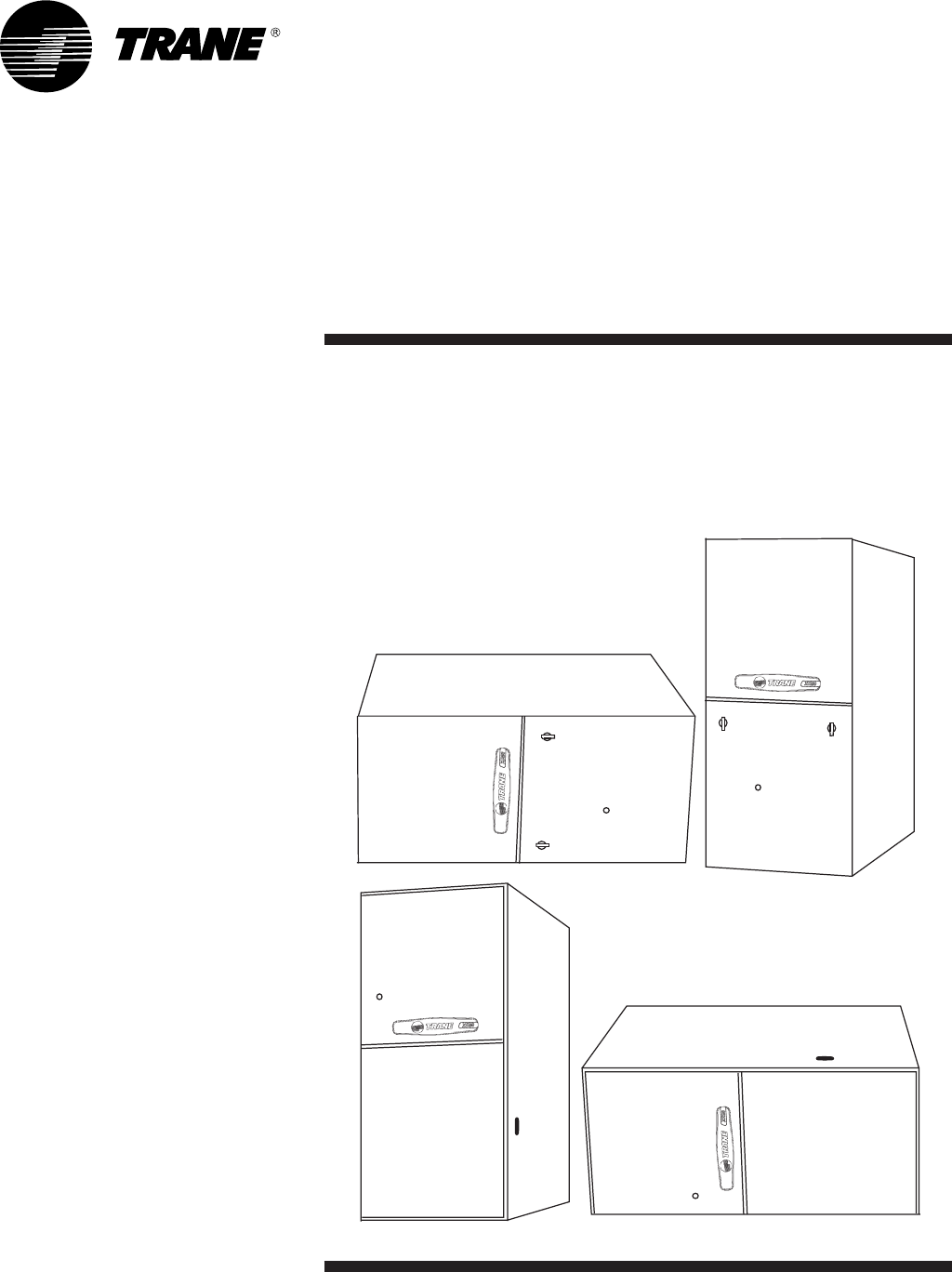
Upflow/Horizontal Left
Downflow/Horizontal Right
Condensing, Direct Vent
Gas-Fired Furnace
XR 90
TUX040,060,080,100,120C
TDX040,060,080,100,120C
Single-Stage Fan Assisted
Combustion System
PUB. NO. 22-1674-04-0803 (EN)
TUX-D-2

© 2003 American Standard Inc. All Rights Reserved 2 22-1674-04-0803 (EN)
General
Features
NATURAL GAS MODELS
Central Heating furnace designs are
certified by the American Gas Association
for both natural and L.P. gas. Limit
setting and rating data were established
and approved under standard rating
conditions using American National
Standards Institute standards.
SAFE OPERATION
The Integrated System Control has solid
state devices, which continuously monitor
for presence of flame, when the system is
in the heating mode of operation. Dual
solenoid combination gas valve and
regulator provide extra safety.
QUICK HEATING
Durable, cycle tested, heavy gauge
aluminized steel heat exchanger
quickly transfers heat to provide warm
conditioned air to the structure. Low
energy power vent blower, to increase
efficiency and provide a positive dis-
charge of gas fumes to the outside.
BURNERS
Multiport Inshot burners will give years of
quiet and efficient service. All models
can be converted to L.P. gas without
changing burners.
INTEGRATED SYSTEM CONTROL
Exclusively designed operational pro-
gram provides total control of furnace
limit sensors, blowers, gas valve, flame
control and includes self diagnostics for
ease of service. Also contains connec-
tion points for E.A.C./humidifier.
AIR DELIVERY
The four speed, direct drive blower
motor, has sufficient airflow for most
heating and cooling requirements, will
switch from heating to cooling speeds on
demand from room thermostat. The
blower door safety switch will prevent or
terminate furnace operation when the
blower door is removed.
STYLING
Heavy gauge steel and “wrap-around”
cabinet construction is used in the
cabinet with baked-on enamel finish for
strength and beauty. The heat ex-
changer section of the cabinet is com-
pletely lined with foil faced fiberglass
insulation. This results in quiet and
efficient operation due to the excellent
acoustical and insulating qualities of
fiberglass. Built-in bottom pan and
alternate bottom, left or right side return
air connection provision.
FEATURES AND
GENERAL OPERATION
The XR 90 High Efficiency Gas Furnaces
employ a Silicon Carbide Hot Surface
Ignition system, which eliminates the
waste of a constant burning pilot. The
integrated system control lights the main
burners upon a demand for heat from the
room thermostat. Complete front service
access.
a. Low energy power venter
b. Vent proving pressure switch.
22-1674-04-0803 (EN) 3
Contents
General Features 2
Features and Benefits 3
XR 90 Standard Equipment 3
XR 90 Optional Equipment 4
General Data 5
TUX040C924D 5
TUX060C936D 5
TUX080C942D 5
TUX080C960D 5
TUX100C948D 6
TUX100C960D 6
TUX120C960D 6
TDX040C924D 7
TDX060C936D 7
TDX080C942D 7
TDX100C948D 8
TDX120C960D 8
Performance Data 9
Electrical Data 11
Field Wiring 13
Twinning Field Wiring 14
Dimensions 15
Features
and Benefits
XR 90 Standard Equipment
• Power supply 115/1/60
• Convertible to horizontal left
•Type 29-4C™ stainless steel second-
ary heat exchanger
• Inner blower doors
• Direct drive, 4-speed motors
• Silicon Nitride igniter with adaptive
heat up
• Accessory hook-up capability –
Hum and EAC
• Quiet induced draft blower
• Blower door safety switch
• Dual solenoid combination gas valve &
regulator
• Cleanable high velocity filters
• PVC venting – 1 or 2 pipe vent option
• Left/right gas connection
• Selectable cooling fan off delay
eliminates need for BAY24X045 time
delay relay
• Single wire twinning
• Integrated solid state control with self-
diagnostics
• 24 volt fuse
• Manual reset burner box limit
•Lifetime limited primary heat
exchanger or secondary heat
exchanger warranty to original
owner (Residential use)
•5 Year limited parts warranty
•Optional extended warranties

4 22-1674-04-0803 (EN)
Features and
Benefits
XR 90 Optional Equipment
Thermostat, Mechanical Heating Only Without Fan Switch ......................................................................................BAYSTAT388 [ ]
Thermostat, Mechanical Heating Only With Fan Switch ...........................................................................................BAYSTAT303 [ ]
Thermostat, Heating/Cooling Single Stage (Mounts Horizontally) ................................................................................ AY28X092 [ ]
Thermostat, Heating/Cooling Single Stage (Mounts Vertically) ................................................................................BAYSTAT305 [ ]
Thermostat, Electronic Programmable 1-Stage Heating/1-Stage Cooling .............................................................. TAYSTAT300C [ ]
Propane Conversion Kit ........................................................................................................................................ BAYLPKT210B [ ]
Propane Conversion Kit (stainless steel burners) .................................................................................................. BAYLPSS210B [ ]
Wall Mount Flange – 3".............................................................................................................................................. BAY96X147 [ ]
Wall Mount Flange – 2".............................................................................................................................................. BAY96X148 [ ]
Downflow Subbase ................................................................................................................................................. BAYBASE205 [ ]
Filter Access Door Kit .............................................................................................................................................. BAYFLTR206 [ ]
Electronic Air Filter, “Perfect Fit” Super Efficiency (17-1/2" Wide Gas Furnace) ..................................................... TFE175A9FR0 [ ]
Electronic Air Filter, “Perfect Fit” Super Efficiency (21" Wide Gas Furnace) ........................................................... TFE210A9FR0 [ ]
Electronic Air Filter, “Perfect Fit” Super Efficiency (24-1/2" Wide Gas Furnace) ..................................................... TFE245A9FR0 [ ]
Electronic Air Filter, “Perfect Fit” High Efficiency (17-1/2" Wide Gas Furnace) ....................................................... TFM175A9FR0 [ ]
Electronic Air Filter, “Perfect Fit” High Efficiency (21" Wide Gas Furnace) ............................................................. TFM210A9FR0 [ ]
Electronic Air Filter, “Perfect Fit” High Efficiency (24-1/2" Wide Gas Furnace) ....................................................... TFM245A9FR0 [ ]
Electronic Air Filter, “Perfect Fit” Standard Efficiency (17-1/2" Wide Gas Furnace) ................................................ TFP175A9FR0 [ ]
Electronic Air Filter, “Perfect Fit” Standard Efficiency (21" Wide Gas Furnace) ...................................................... TFP210A9FR0 [ ]
Electronic Air Filter, “Perfect Fit” Standard Efficiency (24-1/2" Wide Gas Furnace) ................................................ TFP245A9FR0 [ ]
Side Filter Rack ...................................................................................................................................................... BAYFLTR200 [ ]
Coil Enclosure (17-1/2" Wide Cabinets) ................................................................................................................ BAYCLE1700C [ ]
Coil Enclosure (21" Wide Cabinets) ...................................................................................................................... BAYCLE2100C [ ]
Coil Enclosure (24-1/2" Wide Cabinets) ................................................................................................................ BAYCLE2400C [ ]
High Altitude Pressure Switch Kit TUX040,100C960D; TDX040C ........................................................................... BAYHALT230 [ ]
High Altitude Pressure Switch Kit TUX060C ............................................................................................................ BAYHALT231 [ ]
High Altitude Pressure Switch Kit TUX080C ............................................................................................................ BAYHALT232 [ ]
High Altitude Pressure Switch Kit TUX100C948D,120C; TDX080,120C ................................................................. BAYHALT233 [ ]
High Altitude Pressure Switch Kit TDX100C ............................................................................................................ BAYHALT234 [ ]
High Altitude Pressure Switch Kit TDX060C ............................................................................................................ BAYHALT241 [ ]
Concentric Vent Kit ...............................................................................................................................................BAYVENT100A [ ]
Sidewall Vent Termination Kit .............................................................................................................................. BAYVENT200B [ ]
Manufactured/Mobile Home Kit ............................................................................................................................ BAYMFGH100A [ ]

22-1674-04-0803 (EN) 5
Product Specifications 1
MODEL
TYPE
RATINGS
2
Input BTUH
Capacity BTUH (ICS)
3
AFUE (ICS)
Temp. rise (Min.-Max.) °F.
BLOWER DRIVE
Diameter - Width (In.)
No. Used
Speeds (No.)
CFM vs. in. w.g.
Motor HP
R.P.M.
Volts / Ph / Hz
COMBUSTION FAN - Type
Drive - No. Speeds
Motor HP - RPM
Volts / Ph / Hz
FLA
FILTER — Furnished?
Type Recommended
Hi Vel. (No.-Size-Thk.)
VENT — Size (in.)
HEAT EXCHANGER
Type-Fired
-Unfired
Gauge (Fired)
ORIFICES — Main
Nat. Gas. Qty. — Drill Size
L.P. Gas Qty. — Drill Size
GAS VALVE
PILOT SAFETY DEVICE
Type
BURNERS — Type
Number
POWER CONN. — V / Ph / Hz
4
Ampacity (In Amps)
Max. Overcurrent Protection (Amps)
PIPE CONN. SIZE (IN.)
DIMENSIONS
Crated (In.)
WEIGHT
Shipping (Lbs.) / Net (Lbs)
General
Data
1Central Furnace heating designs are certified by AGA and CSA.
2For U.S. applications, above input ratings (BTUH) are up to 2,000 feet, derate 4% per 1,000 feet for elevations above 2,000 feet above sea
level. For Canadian applicaitons, above input ratings (BTUH) are up to 4,500 feet, derate 4% per 1,000 feet for elevations above 4,500 feet
above sea level.
3Based on U.S. government standard tests.
4The above wiring specifications are in accordance with National Electrical Code; however, installations must comply with local codes.
TUX080C960D
Upflow / Horizontal
80,000
74,000
92.0
30 - 60
DIRECT
10 x 11
1
4
See Fan Performance Table
3/4
1075
115/1/60
Centrifugal
Direct - 1
1/25 - 3200
115/1/60
1.35
Yes
High Velocity
1 - 20x25 - 1in.
2 Round
Aluminized Steel - Type I
20
4 — 45
4 — 56
Redundant - Single Stage
Hot Surface Ignition
Multiport Inshot
4
115/1/60
13.5
20
1/2
H x W x D
41-3/4 x 23 x 30-1/2
171 / 160
TUX040C924D
Upflow / Horizontal
40,000
38,000
92.0
30 - 60
DIRECT
9 x 7
1
4
See Fan Performance Table
1/5
1075
115/1/60
Centrifugal
Direct - 1
1/55 - 3000
115/1/60
1.0
Yes
High Velocity
1 - 17x25 - 1in.
2 Round
Aluminized Steel - Type I
20
2 — 45
2 — 56
Redundant - Single Stage
Hot Surface Ignition
Multiport Inshot
2
115/1/60
4.8
15
1/2
H x W x D
41-3/4 x 19-1/2 x 30-1/2
139 / 129
TUX060C936D
Upflow / Horizontal
60,000
56,000
92.0
30 - 60
DIRECT
10 x 7
1
4
See Fan Performance Table
1/3
1075
115/1/60
Centrifugal
Direct - 1
1/55 - 3000
115/1/60
1.0
Yes
High Velocity
1 - 17x25 - 1in.
2 Round
Aluminized Steel - Type I
20
3 — 45
3 — 56
Redundant - Single Stage
Hot Surface Ignition
Multiport Inshot
3
115/1/60
8.4
15
1/2
H x W x D
41-3/4 x 19-1/2 x 30-1/2
150 / 140
TUX080C942D
Upflow / Horizontal
80,000
74,000
92.0
35 - 65
DIRECT
10 x 8
1
4
See Fan Performance Table
1/3
1075
115/1/60
Centrifugal
Direct - 1
1/24 - 3200
115/1/60
1.35
Yes
High Velocity
1 - 17x25 - 1in.
2 Round
Aluminized Steel - Type I
20
4 — 45
4 — 56
Redundant - Single Stage
Hot Surface Ignition
Multiport Inshot
4
115/1/60
9.5
15
1/2
H x W x D
41-3/4 x 19-1/2 x 30-1/2
158 / 148

6 22-1674-04-0803 (EN)
General
Data
Product Specifications 1
MODEL
TYPE
RATINGS
2
Input BTUH
Capacity BTUH (ICS)
3
AFUE (ICS)
Temp. rise (Min.-Max.) °F.
BLOWER DRIVE
Diameter - Width (In.)
No. Used
Speeds (No.)
CFM vs. in. w.g.
Motor HP
R.P.M.
Volts / Ph / Hz
COMBUSTION FAN - Type
Drive - No. Speeds
Motor HP - RPM
Volts / Ph / Hz
FLA
FILTER — Furnished?
Type Recommended
Hi Vel. (No.-Size-Thk.)
VENT — Size (in.)
HEAT EXCHANGER
Type-Fired
-Unfired
Gauge (Fired)
ORIFICES — Main
Nat. Gas. Qty. — Drill Size
L.P. Gas Qty. — Drill Size
GAS VALVE
PILOT SAFETY DEVICE
Type
BURNERS — Type
Number
POWER CONN. — V / Ph / Hz
4
Ampacity (In Amps)
Max. Overcurrent Protection (Amps)
PIPE CONN. SIZE (IN.)
DIMENSIONS
Crated (In.)
WEIGHT
Shipping (Lbs.) / Net (Lbs)
1Central Furnace heating designs are certified by AGA and CSA.
2For U.S. applications, above input ratings (BTUH) are up to 2,000 feet, derate 4% per 1,000 feet for elevations above 2,000 feet above sea
level. For Canadian applicaitons, above input ratings (BTUH) are up to 4,500 feet, derate 4% per 1,000 feet for elevations above 4,500 feet
above sea level.
3Based on U.S. government standard tests.
4The above wiring specifications are in accordance with National Electrical Code; however, installations must comply with local codes.
TUX100C948D
Upflow / Horizontal
100,000
93,000
92.0
35 - 65
DIRECT
10 x 10
1
4
See Fan Performance Table
1/2
1075
115/1/60
Centrifugal
Direct - 1
1/20 - 3450
115/1/60
0.71
Yes
High Velocity
1 - 20x25 - 1in.
2 Round
Aluminized Steel - Type I
20
5 — 45
5 — 56
Redundant - Single Stage
Hot Surface Ignition
Multiport Inshot
5
115/1/60
12.5
15
1/2
H x W x D
41-3/4 x 23 x 30-1/2
171 / 160
TUX120C960D
Upflow / Horizontal
120,000
113,000
92.0
40 - 70
DIRECT
11 x 10
1
4
See Fan Performance Table
3/4
1100
115/1/60
Centrifugal
Direct - 1
1/20 - 3450
115/1/60
0.71
Yes
High Velocity
1 - 24x25 - 1in.
3 Round
Aluminized Steel - Type I
20
6 — 45
6 — 56
Redundant - Single Stage
Hot Surface Ignition
Multiport Inshot
6
115/1/60
12.9
15
1/2
H x W x D
41-3/4 x 26-1/2 x 30-1/2
205 / 193
TUX100C960D
Upflow / Horizontal
100,000
93,000
92.0
35 - 65
DIRECT
11 x 10
1
4
See Fan Performance Table
3/4
1100
115/1/60
Centrifugal
Direct - 1
1/20 - 3450
115/1/60
0.71
Yes
High Velocity
1 - 24x25 - 1in.
2 Round
Aluminized Steel - Type I
20
5 — 45
5 — 56
Redundant - Single Stage
Hot Surface Ignition
Multiport Inshot
5
115/1/60
12.9
15
1/2
H x W x D
41-3/4 x 26-1/2 x 30-1/2
197 / 185

22-1674-04-0803 (EN) 7
General
Data
Product Specifications 1
MODEL
TYPE
RATINGS
2
Input BTUH
Capacity BTUH (ICS)
3
AFUE (ICS)
Temp. rise (Min.-Max.) °F.
BLOWER DRIVE
Diameter - Width (In.)
No. Used
Speeds (No.)
CFM vs. in. w.g.
Motor HP
R.P.M.
Volts / Ph / Hz
COMBUSTION FAN - Type
Drive - No. Speeds
Motor HP - RPM
Volts / Ph / Hz
FLA
FILTER — Furnished?
Type Recommended
Hi Vel. (No.-Size-Thk.)
VENT — Size (in.)
HEAT EXCHANGER
Type-Fired
-Unfired
Gauge (Fired)
ORIFICES — Main
Nat. Gas. Qty. — Drill Size
L.P. Gas Qty. — Drill Size
GAS VALVE
PILOT SAFETY DEVICE
Type
BURNERS — Type
Number
POWER CONN. — V / Ph / Hz
4
Ampacity (In Amps)
Max. Overcurrent Protection (Amps)
PIPE CONN. SIZE (IN.)
DIMENSIONS
Crated (In.)
WEIGHT
Shipping (Lbs.) / Net (Lbs)
1Central Furnace heating designs are certified by AGA and CSA.
2For U.S. applications, above input ratings (BTUH) are up to 2,000 feet, derate 4% per 1,000 feet for elevations above 2,000 feet above sea
level. For Canadian applicaitons, above input ratings (BTUH) are up to 4,500 feet, derate 4% per 1,000 feet for elevations above 4,500 feet
above sea level.
3Based on U.S. government standard tests.
4The above wiring specifications are in accordance with National Electrical Code; however, installations must comply with local codes.
TDX040C924D
Downflow / Horizontal
40,000
38,000
91.0
30 - 60
DIRECT
10 x 7
1
4
See Fan Performance Table
1/5
1080
115/1/60
Centrifugal
Direct - 1
1/55 - 3000
115/1/60
1.14
Yes
High Velocity
2 - 14x20 - 1in.
2 Round
Aluminized Steel - Type I
20
2 — 45
2 — 56
Redundant - Single Stage
Hot Surface Ignition
Multiport Inshot
2
115/1/60
4.8
15
1/2
H x W x D
41-3/4 x 19-1/2 x 30-1/2
145 / 135
TDX060C936D
Downflow / Horizontal
60,000
56,000
91.0
30 - 60
DIRECT
10 x 8
1
4
See Fan Performance Table
1/3
1075
115/1/60
Centrifugal
Direct - 1
1/55 - 3000
115/1/60
1.0
Yes
High Velocity
2 - 14x20 - 1in.
2 Round
Aluminized Steel - Type I
20
3 — 45
3 — 56
Redundant - Single Stage
Hot Surface Ignition
Multiport Inshot
3
115/1/60
9.2
15
1/2
H x W x D
41-3/4 x 19-1/2 x 30-1/2
155 / 145
TDX080C942D
Downflow / Horizontal
80,000
74,000
91.0
35 - 65
DIRECT
11 x 8
1
4
See Fan Performance Table
1/2
1075
115/1/60
Centrifugal
Direct - 1
1/25 - 3200
115/1/60
1.35
Yes
High Velocity
2 - 14x20 - 1in.
2 Round
Aluminized Steel - Type I
20
4 — 45
4 — 56
Redundant - Single Stage
Hot Surface Ignition
Multiport Inshot
4
115/1/60
11.4
15
1/2
H x W x D
41-3/4 x 19-1/2 x 30-1/2
168 / 158

8 22-1674-04-0803 (EN)
General
Data
Product Specifications 1
MODEL
TYPE
RATINGS
2
Input BTUH
Capacity BTUH (ICS)
3
AFUE (ICS)
Temp. rise (Min.-Max.) °F.
BLOWER DRIVE
Diameter - Width (In.)
No. Used
Speeds (No.)
CFM vs. in. w.g.
Motor HP
R.P.M.
Volts / Ph / Hz
COMBUSTION FAN - Type
Drive - No. Speeds
Motor HP - RPM
Volts / Ph / Hz
FLA
FILTER — Furnished?
Type Recommended
Hi Vel. (No.-Size-Thk.)
VENT — Size (in.)
HEAT EXCHANGER
Type-Fired
-Unfired
Gauge (Fired)
ORIFICES — Main
Nat. Gas. Qty. — Drill Size
L.P. Gas Qty. — Drill Size
GAS VALVE
PILOT SAFETY DEVICE
Type
BURNERS — Type
Number
POWER CONN. — V / Ph / Hz
4
Ampacity (In Amps)
Max. Overcurrent Protection (Amps)
PIPE CONN. SIZE (IN.)
DIMENSIONS
Crated (In.)
WEIGHT
Shipping (Lbs.) / Net (Lbs)
1Central Furnace heating designs are certified by AGA and CSA.
2For U.S. applications, above input ratings (BTUH) are up to 2,000 feet, derate 4% per 1,000 feet for elevations above 2,000 feet above sea
level. For Canadian applicaitons, above input ratings (BTUH) are up to 4,500 feet, derate 4% per 1,000 feet for elevations above 4,500 feet
above sea level.
3Based on U.S. government standard tests.
4The above wiring specifications are in accordance with National Electrical Code; however, installations must comply with local codes.
TDX120C960D
Downflow / Horizontal
120,000
110,000
91.0
40 - 70
DIRECT
11 x 10
1
4
See Fan Performance Table
3/4
1075
115/1/60
Centrifugal
Direct - 1
1/20 - 3450
115/1/60
0.71
Yes
High Velocity
2 - 16x20 - 1in.
3 Round
Aluminized Steel - Type I
20
6 — 45
6 — 56
Redundant - Single Stage
Hot Surface Ignition
Multiport Inshot
6
115/1/60
13.9
20
1/2
H x W x D
41-3/4 x 26-1/2 x 30-1/2
206 / 196
TDX100C948D
Downflow / Horizontal
100,000
94,000
91.0
35 - 65
DIRECT
11 x 10
1
4
See Fan Performance Table
1/2
1075
115/1/60
Centrifugal
Direct - 1
1/20 - 3450
115/1/60
0.71
Yes
High Velocity
2 - 16x20 - 1in.
2 Round
Aluminized Steel - Type I
20
5 — 45
5 — 56
Redundant - Single Stage
Hot Surface Ignition
Multiport Inshot
5
115/1/60
13.6
20
1/2
H x W x D
41-3/4 x 23 x 30-1/2
185 / 175
22-1674-04-0803 (EN) 9
Performance
Data
FURNACE AIRFLOW (CFM) VS. EXTERNAL STATIC PRESSURE (in. w.c.)
MODEL SPEED TAP 0.10 0.20 0.30 0.40 0.50 0.60 0.70 0.80 0.90
TUX040C924D
4 -
3 -
2 -
1 -
HIGH - Black
MED.-HIGH - Blue
MED.-LOW - Yellow
LOW - Red
1043
940
837
729
992
895
798
694
930
841
752
657
885
791
705
600
812
726
649
545
740
650
560
478
647
559
438
376
518
420
305
220
457
390
279
178
TUX060C936D
4 -
3 -
2 -
1 -
HIGH - Black
MED.-HIGH - Blue
MED.-LOW - Yellow
LOW - Red
1394
1250
1102
957
1359
1232
1092
944
1314
1202
1069
922
1260
1160
1034
891
1196
1106
986
853
1122
1040
925
806
1038
962
852
750
945
873
766
686
853
771
668
614
TUX080C942D
4 -
3 -
2 -
1 -
HIGH - Black
MED.-HIGH - Blue
MED.-LOW - Yellow
LOW - Red
1748
1375
1178
859
1683
1367
1167
863
1615
1347
1147
856
1544
1314
1119
839
1470
1268
1082
811
1393
1210
1036
772
1314
1139
982
723
1232
1056
919
663
1147
960
847
592
TUX080C960D
4 -
3 -
2 -
1 -
HIGH - Black
MED.-HIGH - Blue
MED.-LOW - Yellow
LOW - Red
2304
1980
1668
1375
2262
1963
1654
1372
2219
1946
1640
1368
2170
1919
1626
1361
2121
1892
1611
1354
2048
1853
1587
1330
1975
1814
1562
1305
1893
1751
1511
1267
1811
1687
1460
1229
TUX100C948D
4 -
3 -
2 -
1 -
HIGH - Black
MED.-HIGH - Blue
MED.-LOW - Yellow
LOW - Red
2054
1932
1762
1558
1980
1875
1720
1546
1906
1818
1677
1533
1826
1746
1615
1477
1746
1673
1552
1421
1649
1577
1463
1350
1551
1481
1373
1278
1428
1371
1266
1175
1305
1260
1158
1071
TUX100C960D
4 -
3 -
2 -
1 -
HIGH - Black
MED.-HIGH - Blue
MED.-LOW - Yellow
LOW - Red
2411
2108
1772
1480
2358
2083
1759
1477
2304
2058
1745
1474
2235
2007
1723
1458
2165
1956
1700
1441
2083
1893
1657
1414
2001
1829
1613
1386
1915
1754
1544
1327
1828
1679
1475
1268
TUX120C960D
4 -
3 -
2 -
1 -
HIGH - Black
MED.-HIGH - Blue
MED.-LOW - Yellow
LOW - Red
2454
2105
1747
1445
2406
2092
1742
1447
2358
2078
1736
1449
2310
2045
1720
1440
2261
2012
1703
1430
2184
1950
1677
1400
2106
1887
1651
1369
2017
1826
1593
1325
1928
1765
1535
1280
From D330656 Sh.1 Rev. 12
CFM VS. TEMPERATURE RISE
MODEL Cubic Feet Per Minute (CFM)
600 700 800 900 1000 1100 1200 1300 1400 1500 1600 1700 1800 1900 2000 2100 2200
TUX040C924 56 48 42 37 33
TUX060C936 56 50 45 42 39 36
TUX080C942 61 56 51 48 44 42
TUX080C960 61 56 51 48 44 42 39 37 35 33 32 30
TUX100C948 64 60 56 52 49 46 44 42
TUX100C960 64 60 56 52 49 46 44 42 40 38
TUX120C960 63 59 56 53 50 48 46
From C340405 Sh. 1 Rev. 5
NOTE: See page 11 for factory heat & cool speed tap settings
10 22-1674-04-0803 (EN)
Performance
Data
FURNACE AIRFLOW (CFM) VS. EXTERNAL STATIC PRESSURE (in. w.c.)
MODEL SPEED TAP 0.10 0.20 0.30 0.40 0.50 0.60 0.70 0.80 0.90
TDX040C924D
4 -
3 -
2 -
1 -
HIGH - Black
MED.-HIGH - Blue
MED.-LOW - Yellow
LOW - Red
998
856
753
647
965
832
728
617
922
797
694
581
870
751
650
538
807
695
596
490
735
628
533
435
653
550
460
375
561
462
378
308
459
363
286
235
TDX060C936D
4 -
3 -
2 -
1 -
HIGH - Black
MED.-HIGH - Blue
MED.-LOW - Yellow
LOW - Red
1487
1342
1181
877
1425
1291
1147
863
1362
1240
1113
849
1286
1182
1061
820
1209
1124
1009
791
1125
1047
943
739
1040
989
877
686
935
869
779
612
830
769
681
537
TDX080C942D
4 -
3 -
2 -
1 -
HIGH - Black
MED.-HIGH - Blue
MED.-LOW - Yellow
LOW - Red
1547
1487
1388
1263
1498
1436
1348
1234
1445
1382
1302
1196
1386
1325
1249
1150
1323
1265
1191
1095
1254
1202
1126
1032
1180
1137
1056
960
1101
1069
979
879
1016
998
896
790
TDX100C948D
4 -
3 -
2 -
1 -
HIGH - Black
MED.-HIGH - Blue
MED.-LOW - Yellow
LOW - Red
1892
1779
1630
1444
1827
1726
1587
1416
1762
1672
1544
1388
1688
1605
1485
1348
1614
1538
1426
1308
1531
1460
1362
1246
1448
1381
1297
1184
1354
1291
1208
1108
1260
1200
1119
1032
TDX120C960D
4 -
3 -
2 -
1 -
HIGH - Black
MED.-HIGH - Blue
MED.-LOW - Yellow
LOW - Red
2213
2057
1765
1468
2138
2000
1733
1452
2062
1943
1700
1435
2001
1883
1652
1409
1939
1822
1603
1382
1863
1752
1552
1336
1786
1681
1500
1290
1706
1595
1424
1225
1625
1508
1347
1159
From D330710 Rev.10
CFM VS. TEMPERATURE RISE
MODEL Cubic Feet Per Minute (CFM)
600 700 800 900 1000 1100 1200 1300 1400 1500 1600 1700 1800 1900 2000 2100 2200 2300 2400
TDX040C924D 56 48 42 37 34
TDX060C936D 63 56 51 46 42 39 36 34
TDX080C942D 61 56 52 48 45 42 40 37 35
TDX100C948D 65 60 56 53 50 47 44 42 40 38 37 35
TDX120C960D 67 63 59 56 53 51 48 46 44 42
From C330767 Sh. 1 Rev. 3
22-1674-04-0803 (EN) 11
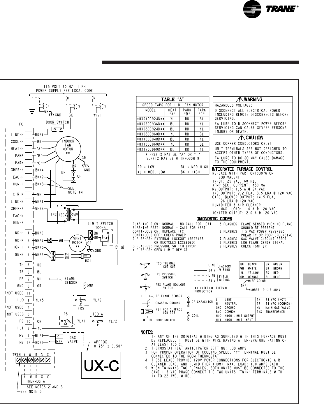
Electrical
Data
From Dwg. D341852 Rev. 1
12 22-1674-04-0803 (EN)
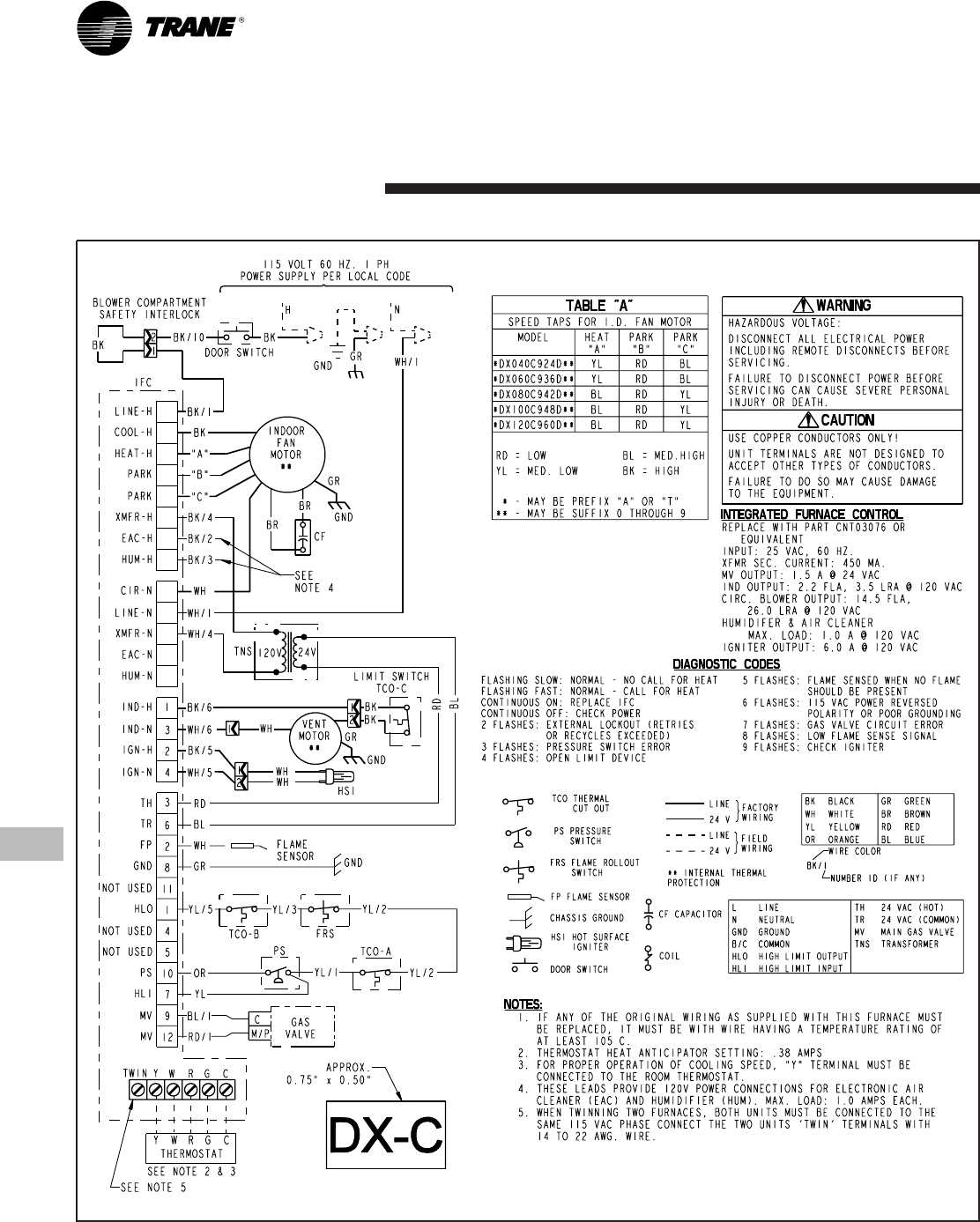
Electrical
Data
From Dwg. D341854 Rev. 1
22-1674-04-0803 (EN) 13
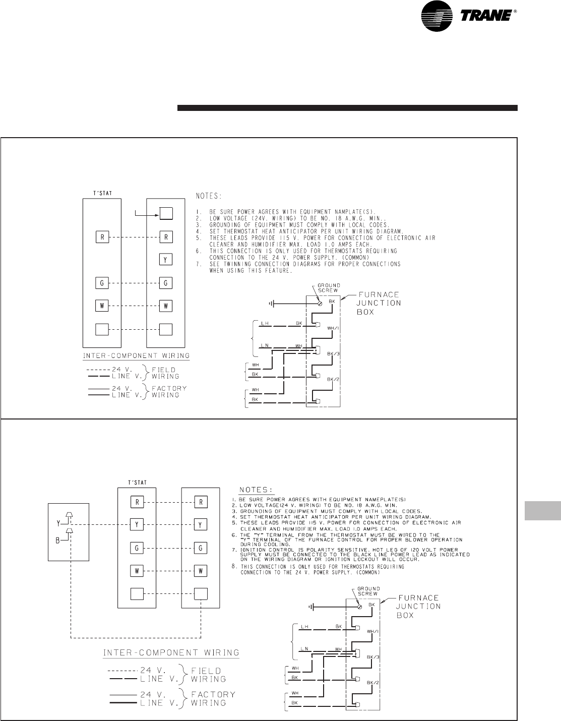
Field
Wiring
OUTDOOR UNIT
(NO TRANSFORMER)
SEE
NOTE 6
From Dwg. B340388 Rev. 2
SEE
NOTE 8
FURNACE
B/C
B/C
TO 115 V 1 PH.,
60 HZ., POWER
SUPPLY PER
LOCAL CODES
HUM SEE
NOTE 5
EAC SEE
NOTE 5
FIELD WIRING DIAGRAM FOR 1 STAGE FURNACE
1 STAGE HEATING, 1 STAGE COOLING
USING A 1 STAGE HEATING, 1 STAGE COOLING THERMOSTAT
(OUTDOOR SECTION WITHOUT TRANSFORMER)
SEE
NOTE 6
From Dwg. B341437 Rev. 1
FURNACE
TWIN
SEE
NOTE 7
B/C
B/C TO 115 V 1 PH.,
60 HZ., POWER
SUPPLY PER
LOCAL CODES
HUM SEE
NOTE 5
EAC SEE
NOTE 5
FIELD WIRING DIAGRAM FOR 1 STAGE FURNACE
1 STAGE HEATING
USING A 1 STAGE HEATING THERMOSTAT
NO COOLING

14 22-1674-04-0803 (EN)
Twinning
Field Wiring
TWIN TWIN
R1 R1
TWINNING CONNECTION DIAGRAM
FOR TWINNING 1 STAGE FURNACES WITH
SINGLE WIRE TWINNING FEATURE
1 STAGE HEATING ONLY THERMOSTAT
1 STAGE HEAT
ONLY
THERMOSTAT
(WITH FAN SWITCH) FURNACE NO. 1 FURNACE NO. 2
BLOWER OPERATION OF
UNIT NO. 2 IS SYNCRONIZED
WITH UNIT NO. 1 VIA SIGNALS
FROM TWIN CONNECTION.
SEE NOTE 4
SEE NOTE 3
ISOLATION RELAY
(FIELD SUPPLIED)
SEE NOTE 4
ISOLATION RELAY
SEE NOTE 4
B/C
B/C
B/C
From Dwg. 21B341422 Rev. 3
TWIN TWIN
R1
R1
TWINNING CONNECTION DIAGRAM
FOR TWINNING 1 STAGE FURNACES WITH
SINGLE WIRE TWINNING FEATURE
1 STAGE HEAT / 1 STAGE COOL THERMOSTAT
1 STAGE
HEATING / COOLING
THERMOSTAT FURNACE NO. 1 FURNACE NO. 2
BLOWER OPERATION OF
UNIT NO. 2 IS SYNCRONIZED
WITH UNIT NO. 1 VIA SIGNALS
FROM TWIN CONNECTION.
SEE NOTE 4
SEE NOTE 5
ISOLATION RELAY
(FIELD SUPPLIED)
SEE NOTE 4
ISOLATION RELAY
SEE NOTE 4
OUTDOOR UNIT
(NO TRANSFORMER)
OUTDOOR UNIT
(WITH TRANSFORMER)
RC
ISOLATION RELAY
(FIELD SUPPLIED)
SEE NOTE 3
B/C
B/C
B/C
From Dwg. 21B341423 Rev. 2
22-1674-04-0803 (EN) 15
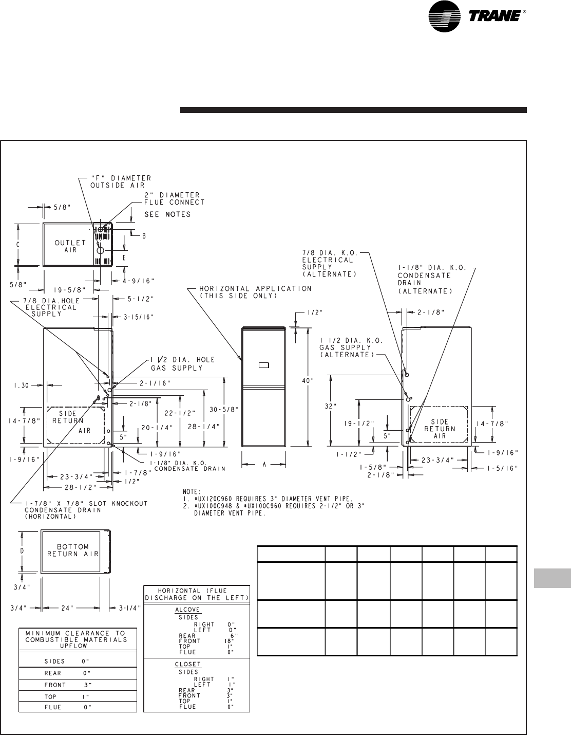
From Dwg. 21C340574 Rev. 12
TUX-C-D Outline Drawing
(ALL DIMENSIONS ARE IN INCHES)
Dimensions
MODEL A B C D E F
TUX040C924
TUX060C936
TUX080C942
17-1/2" 2-1/4" 16-1/4" 16" 7-1/2" 2"
TUX080C960
TUX100C948 21" 2-1/2" 19-3/4" 19-1/2" 9" 3"
TUX100C960
TUX120C960 24-1/2" 2-15/16" 23-1/4" 23" 10" 3"
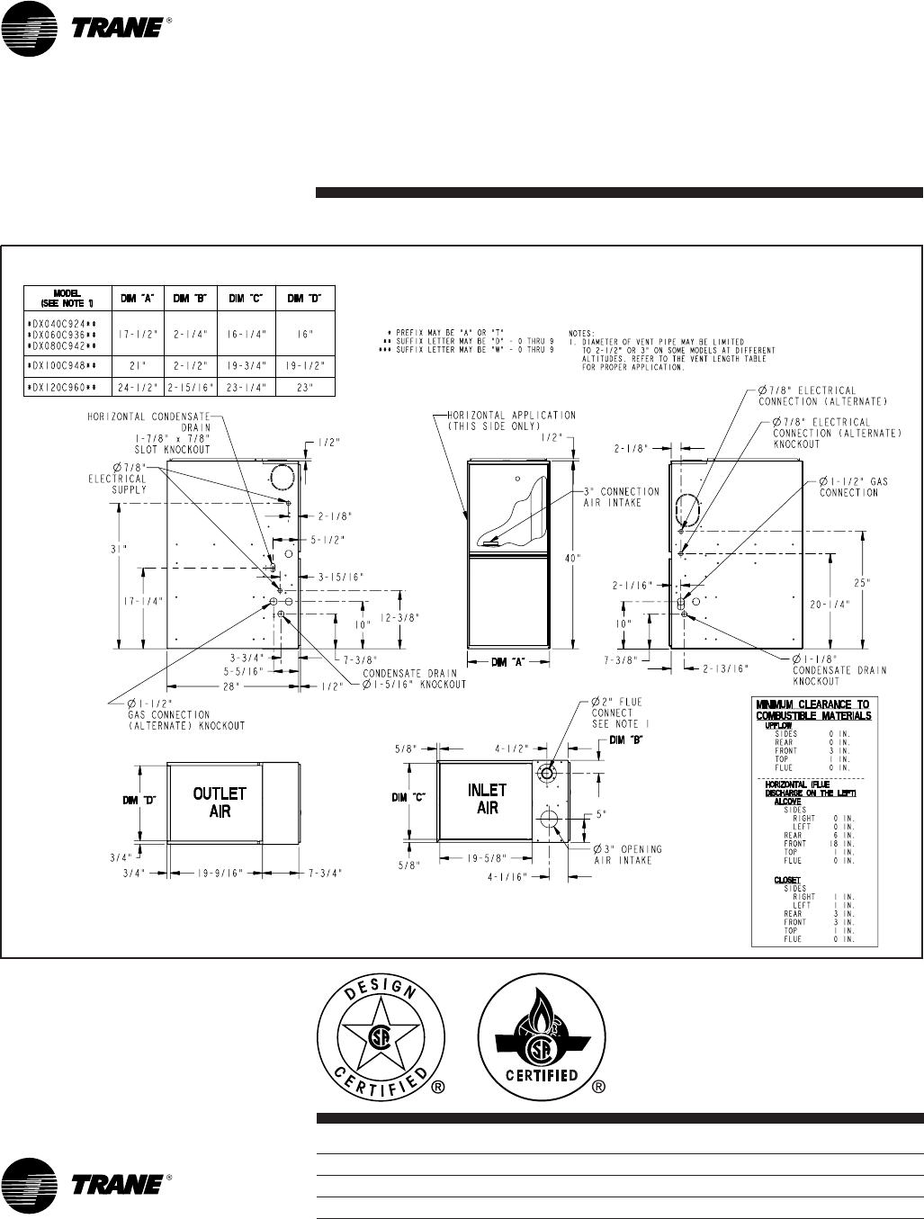
P.I.
Trane has a policy of continuous product and product data improvement and it reserves the right to change
design and specifications without notice.
Trane
A business of
American Standard Companies
www.trane.com
From Dwg. 21C341885 Rev. 0
TDX-C-D Outline Drawing
(ALL DIMENSIONS ARE IN INCHES)
Dimensions
Literature Order Number TUX-D-2
File Number PL-UN-FURN-TUX-D-2 08/03
Supersedes TUX-D-1 06/02
Stocking Location PI Louisville
