TransCore 05716 LOCATION MONITORING SERVICE TRANSMITTER User Manual MPRR SG
TransCore LOCATION MONITORING SERVICE TRANSMITTER MPRR SG
UserManual.wiki
>
TransCore
>
05716 User Manual
Users Manual
Navigation menu
Upload a User Manual
Namespaces
Wiki Guide
HTML
PDF
Info
Views
User Manual
Discussion / Help
Navigation


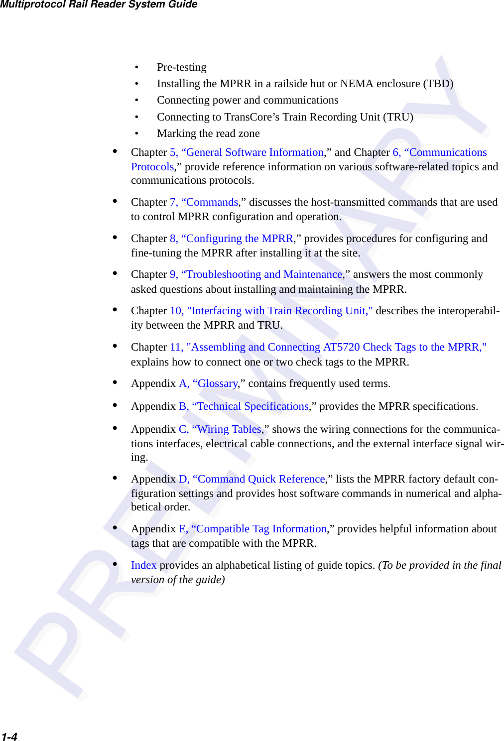


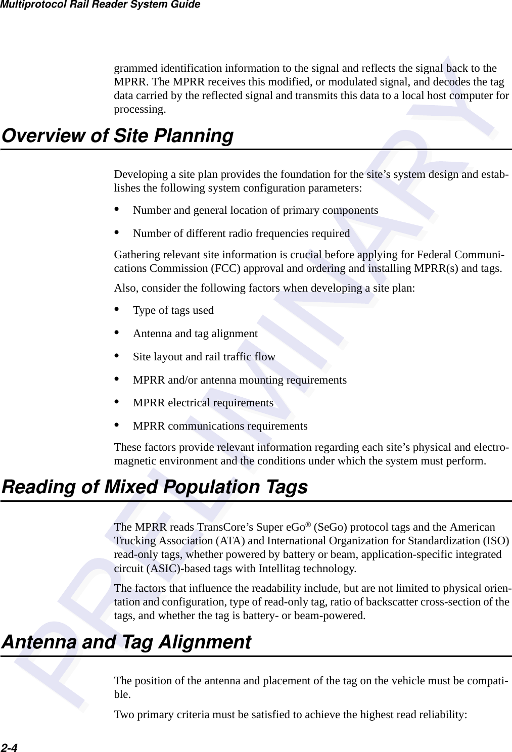
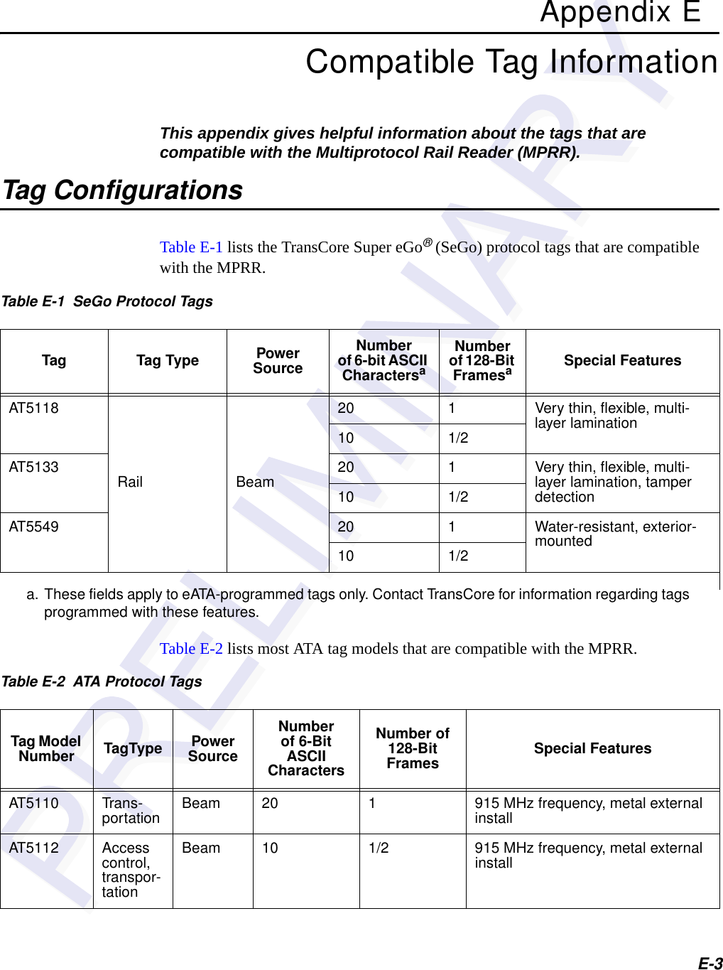
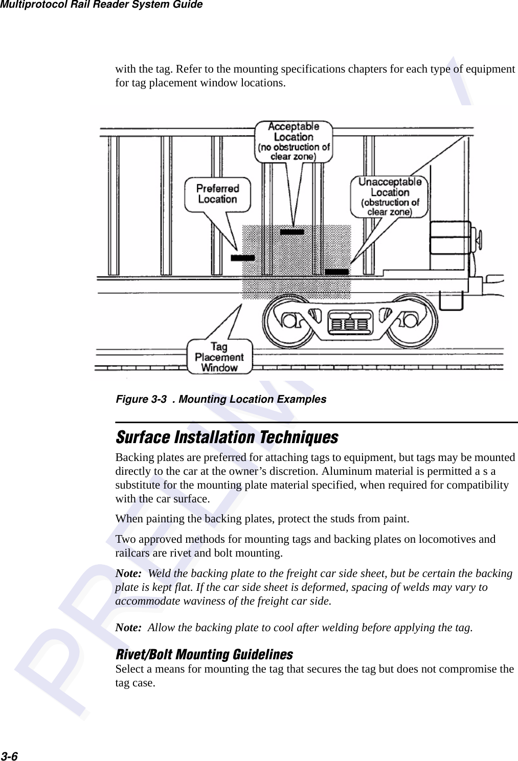
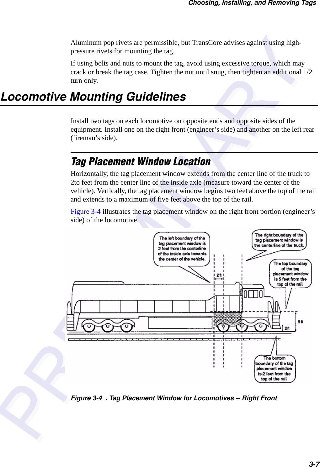
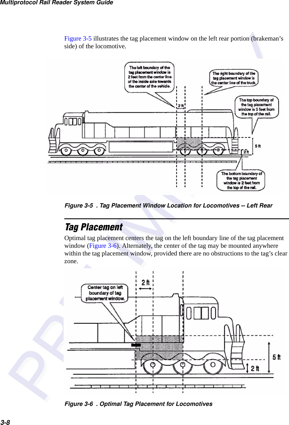
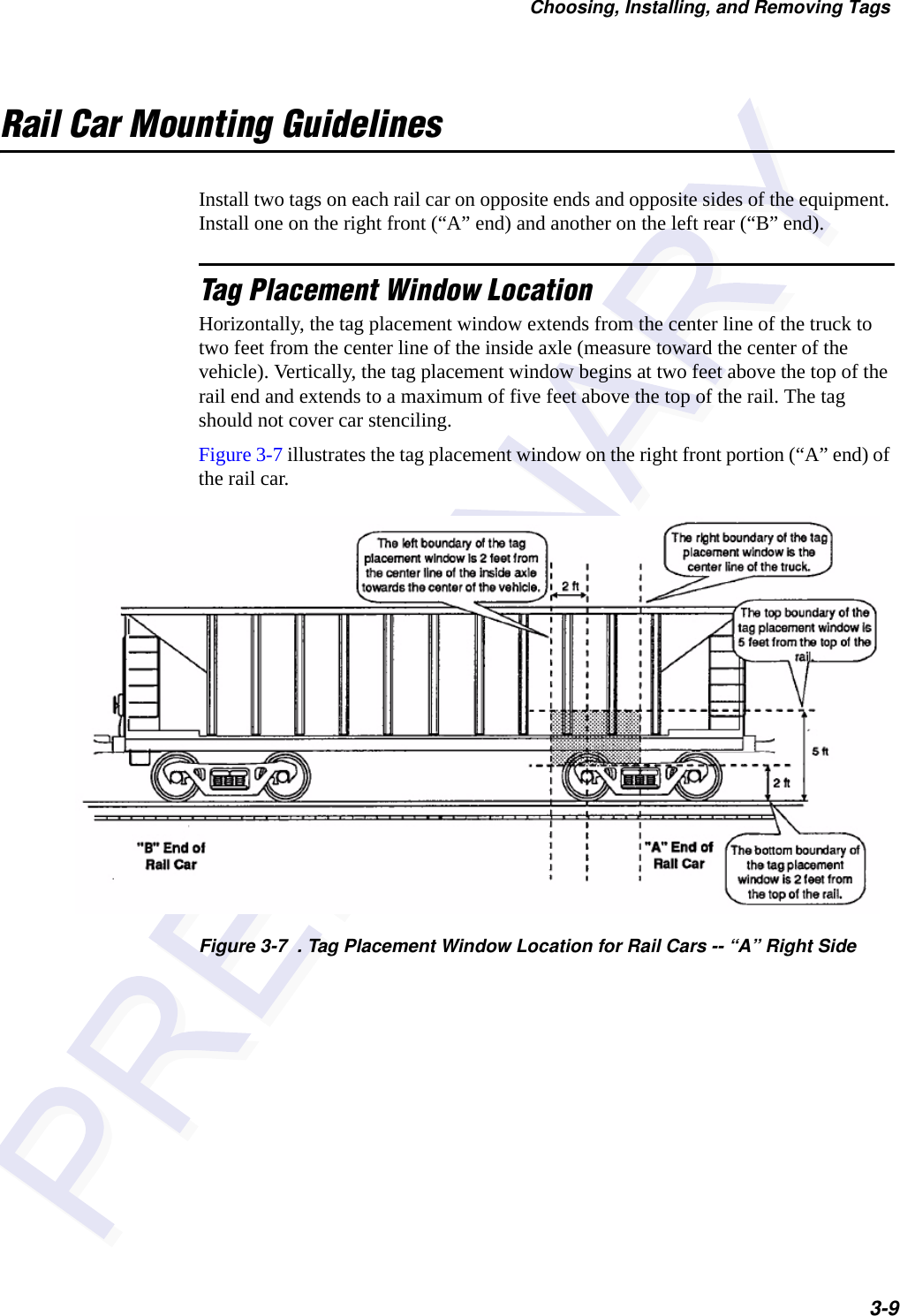
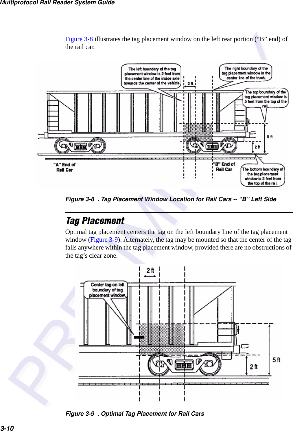
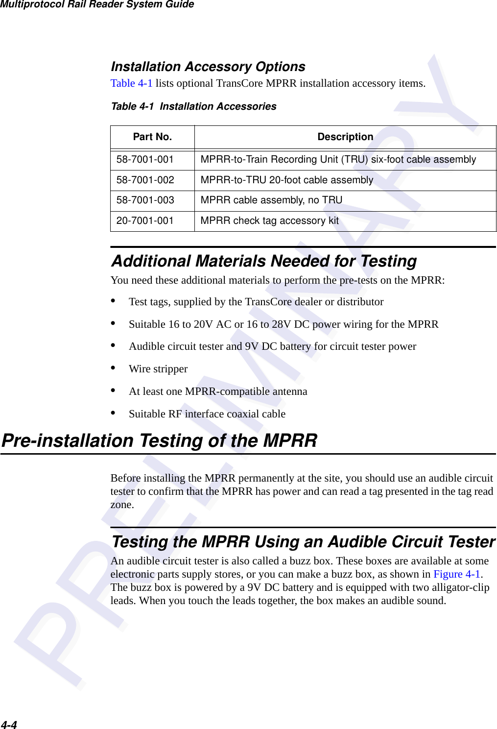
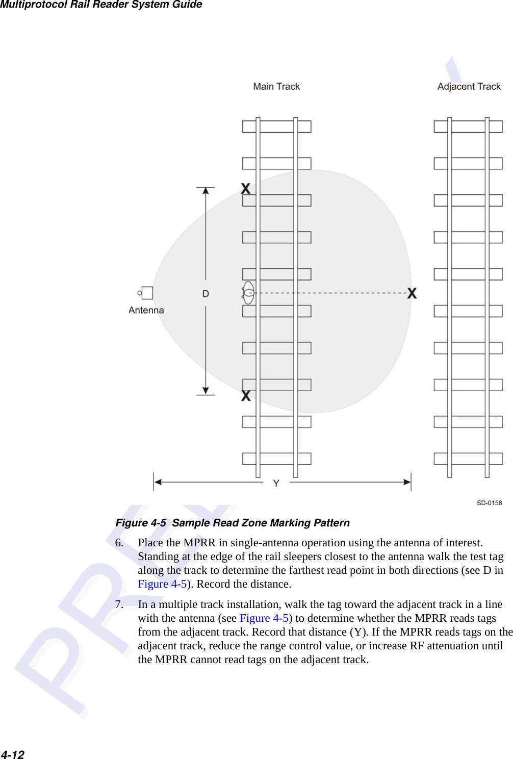
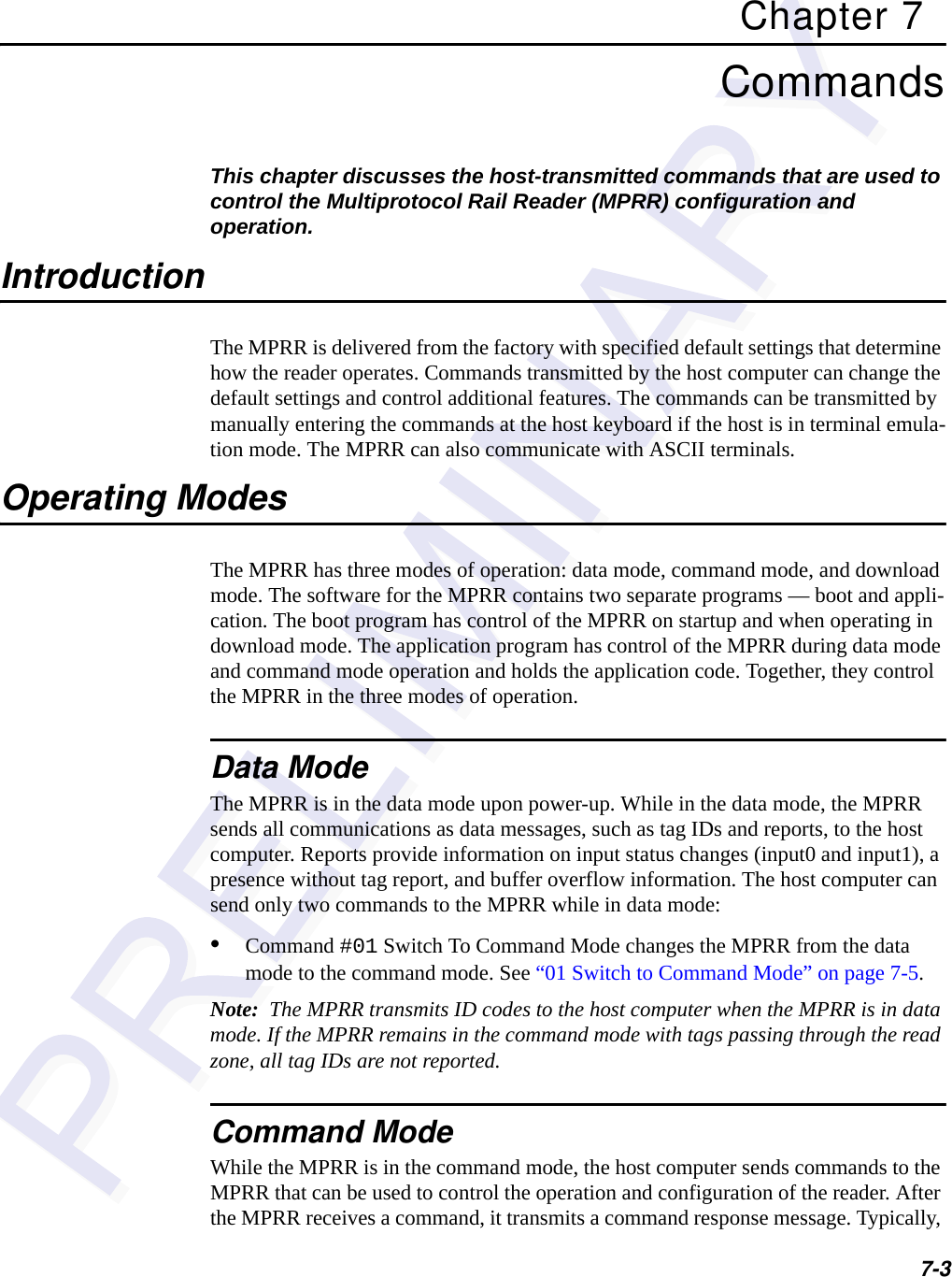
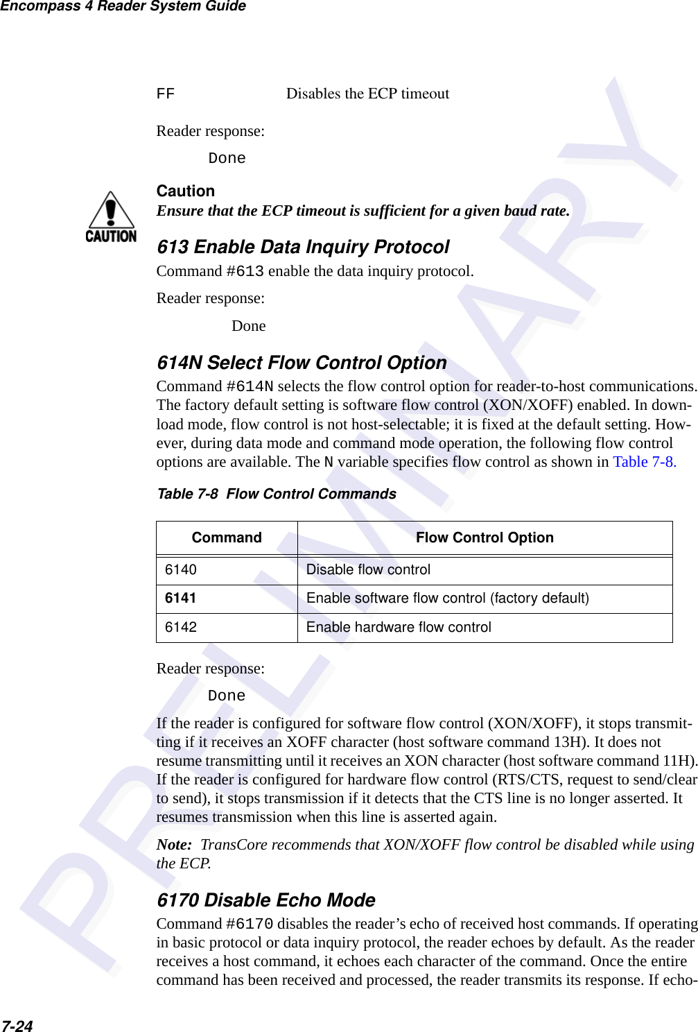
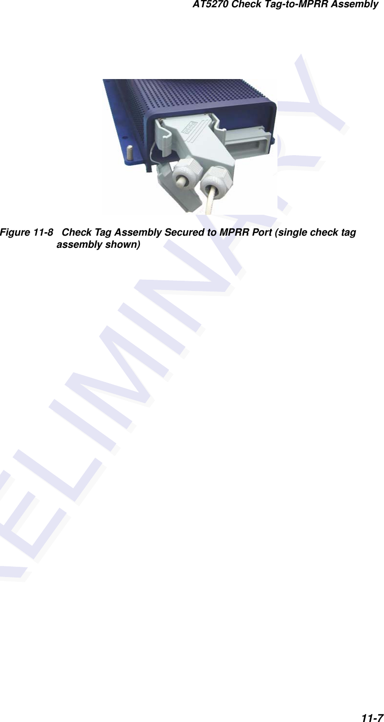
![Developing the Site Plan2-7AA3110 ParapanelAppropriate for installations with the following requirements and conditions:•902 to 928 MHz operation•Exposure to harsh environments•Broad radiation pattern in one dimension, narrow in the other•Low antenna profile•Horizontal polarizationAA3140 PCB Log PeriodicAppropriate for installations with the following requirements and conditions:•845 to 950 MHz operation•Exposure to harsh environments•Maximum coverage at close range (<20 ft [6.1 m])•Vertical or horizontal polarizationSite Layout and Traffic FlowThe following site layout and traffic flow considerations are critical when determining MPRR installation locations:•The MPRR read zone•Other MPRR units and antennas in the area•Reflection, refraction, and diffraction of RF signals •Existing signal interference at the siteThe MPRR Read ZoneThe MPRR must be able to read the tag data properly within a specified area, called the read zone, without reading other nearby tags or interfering with other MPRRs at the site. The following are some of the factors that affect the size and shape of the read zone:•Mounting method used for the antenna•Mounting location of the antenna•Height from the ground and mounting angle of the antenna](https://usermanual.wiki/TransCore/05716/User-Guide-1366466-Page-31.png)

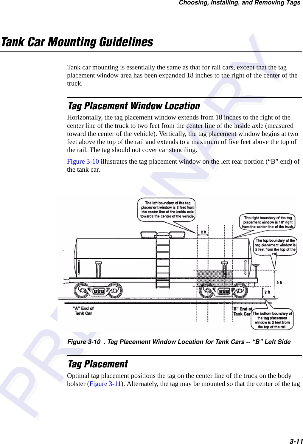


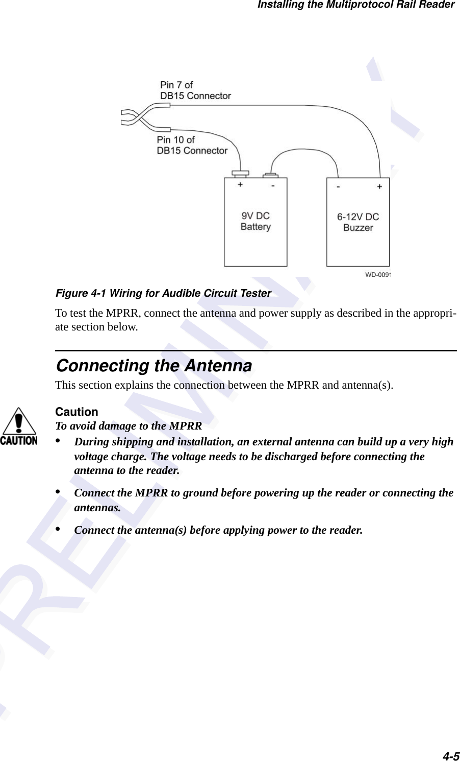


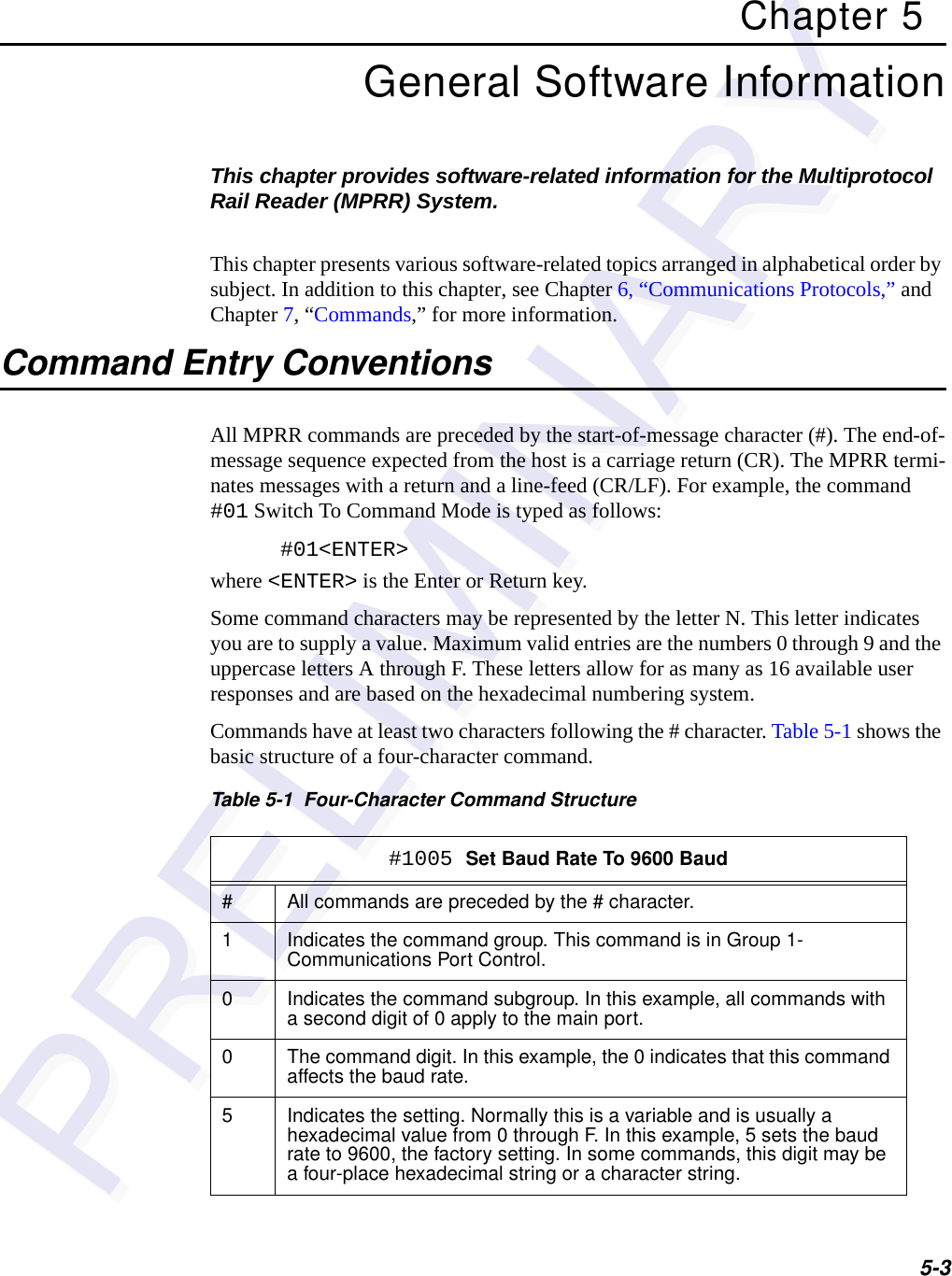
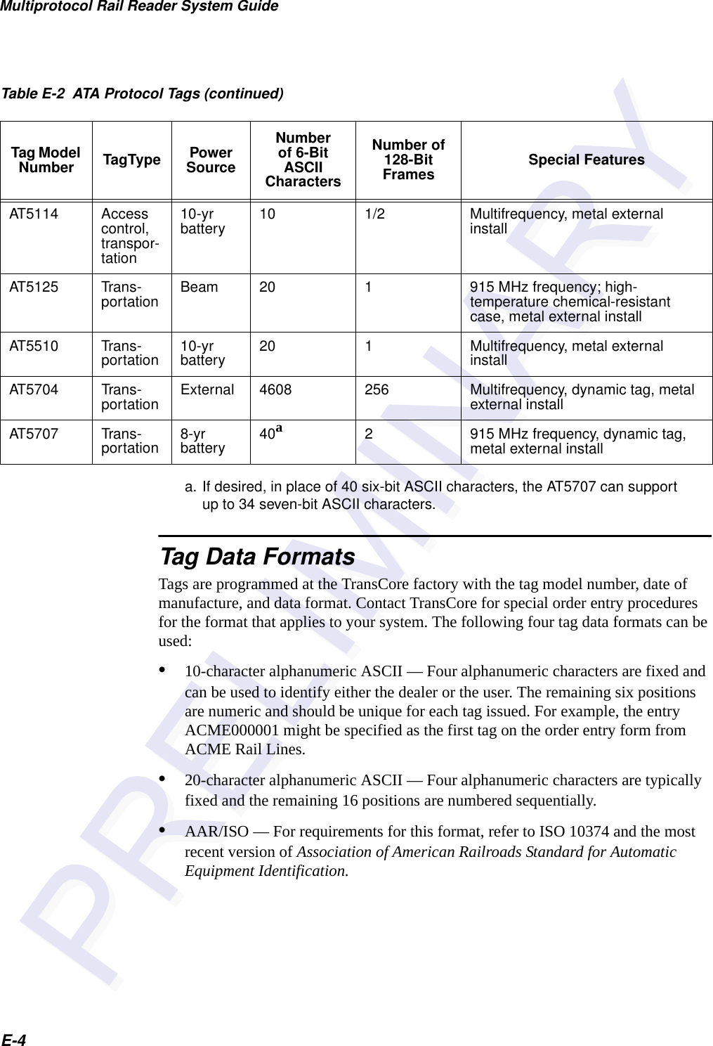
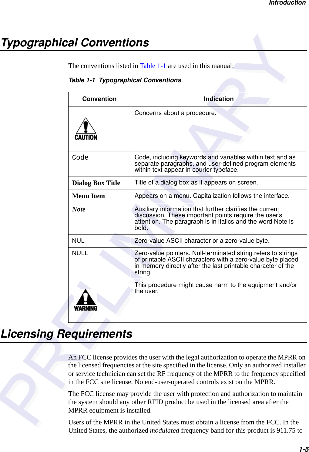
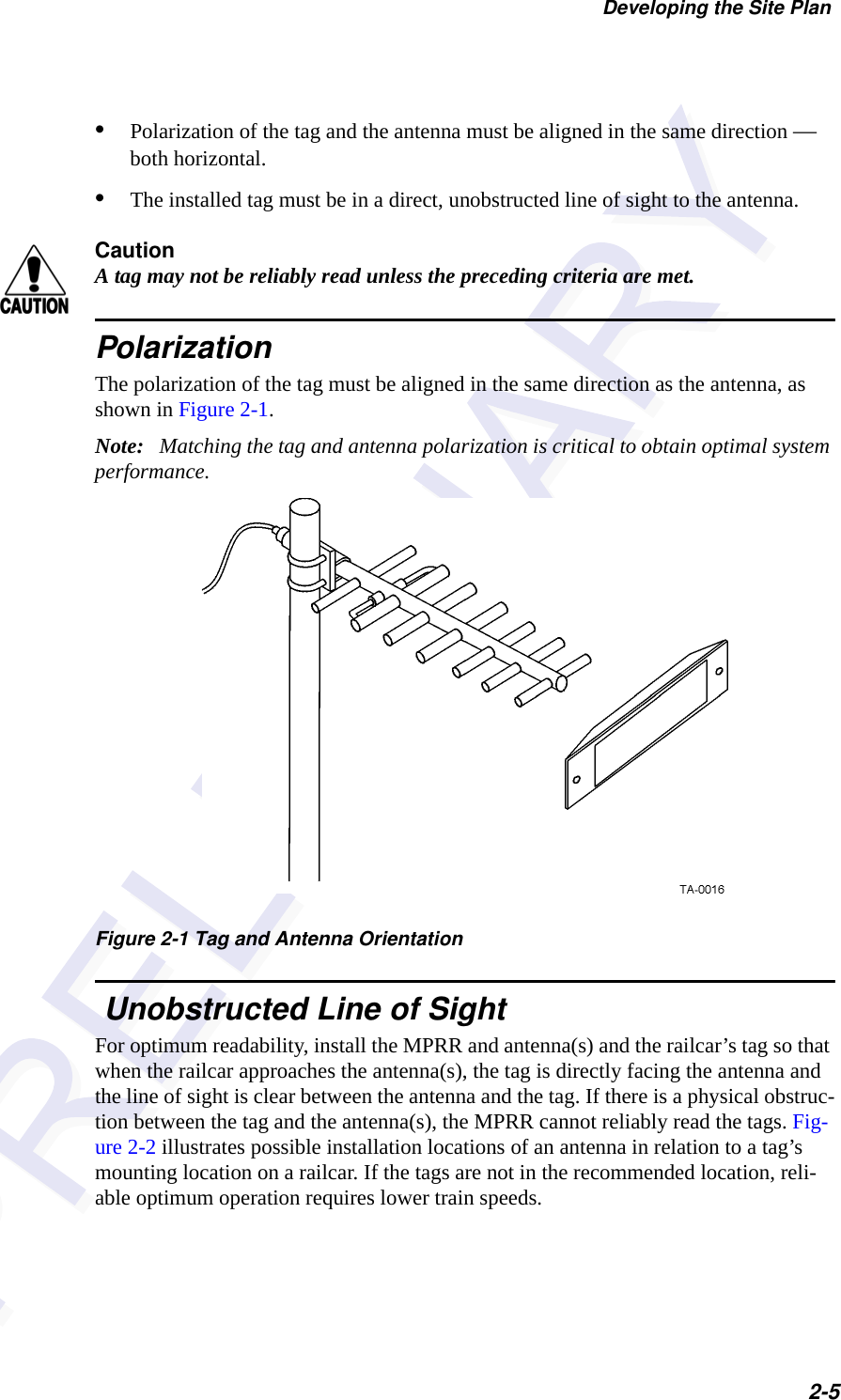
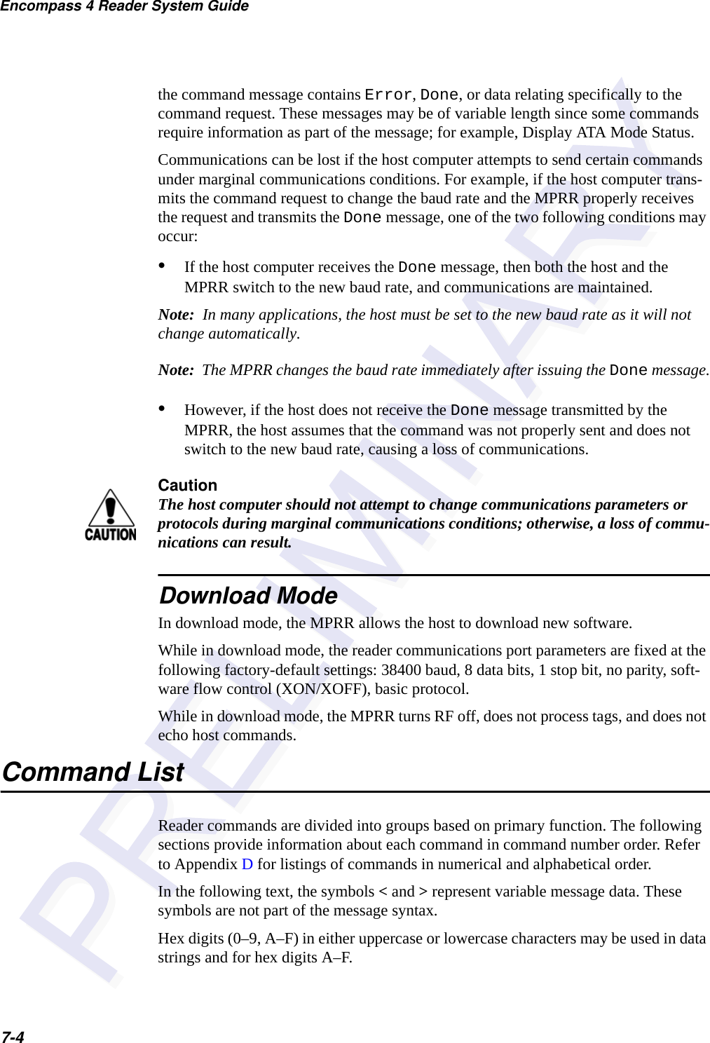
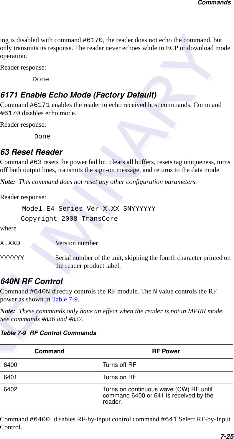
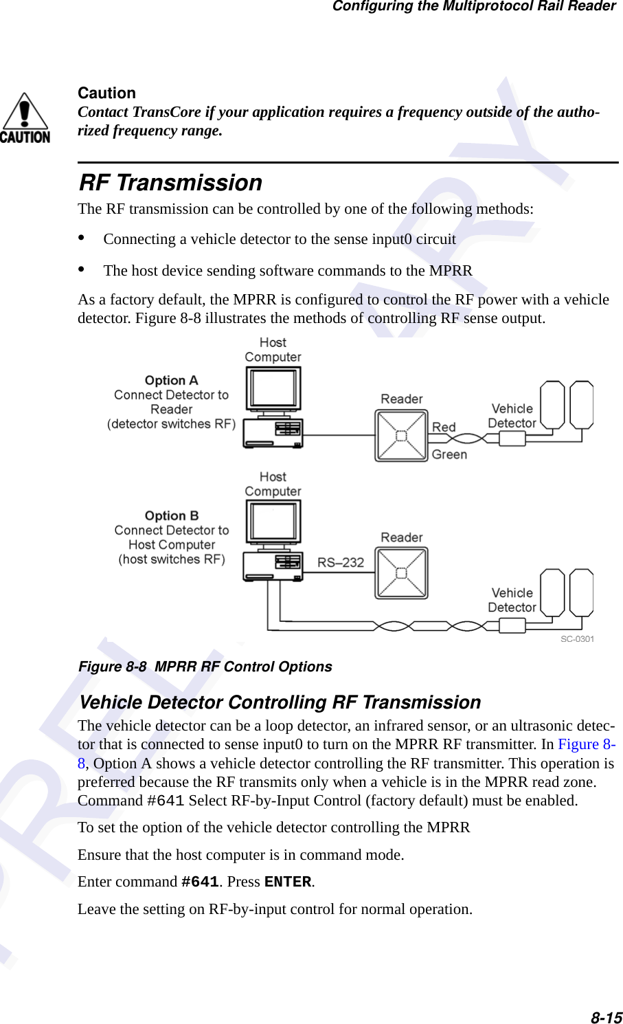
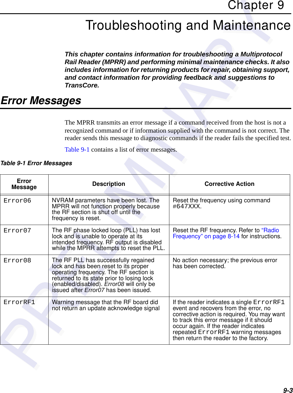
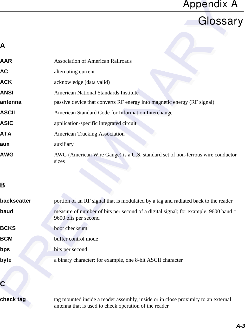
![Multiprotocol Rail Reader System Guide5-6Sign-On MessageIf startup is successful, the sign-on message appears as follows: Model E4 Series [software version] SNYYYYYY[Copyright notice]where YYYYYY is the serial number assigned to the MPRR unit being used.Serial number 000000 is the default setting and is not a valid number. If this number appears in the sign-on message, the serial number has never been stored into reader memory. The serial number must be assigned by factory-authorized personnel using command #695S...S Set Serial Number. Because only six digits are allowed in the software, when setting the serial number skip the fourth (middle) digit of the seven-digit number shown on the reader label.If the flash memory checksum does not indicate verification, the sign-on message appears as follows:Model [E4] Ver 0.00x[Copyright notice]Boot Failure MessageThe software performs a checksum function on itself. The function returns a specific value for the particular version of software. If the value returned is not correct, the boot ROM checksum assumes that locations have been corrupted and a failure condi-tion exists. If the boot ROM checksum is not correct, a boot failure message is trans-mitted. If the failure message does not transmit, a communications error has occurred or the boot failed to the extent that it cannot transmit the failure message.If the failure message version number equals 0.00 and no serial number exists, the flash memory checksum has failed, and the MPRR is operating out of boot ROM. In this case, the MPRR automatically enters download mode and waits for a new pro-gram to be loaded into the flash memory. Follow the instructions in “Program Down-load” on page 5-5 to download a new program.Tag/Message BufferIn basic communication protocol, the MPRR does not provide tag memory storage beyond the quantity required for uniqueness checking. This feature allows adequate buffering of tag data under normal operating conditions. The MPRR cannot operate as a stand-alone component. When the buffer fills, subsequent tag IDs will be lost. In error correcting protocol (ECP), a buffer of up to three additional tag reads will be held in case a host system is unable to acknowledge tag reads in real time.](https://usermanual.wiki/TransCore/05716/User-Guide-1366466-Page-66.png)


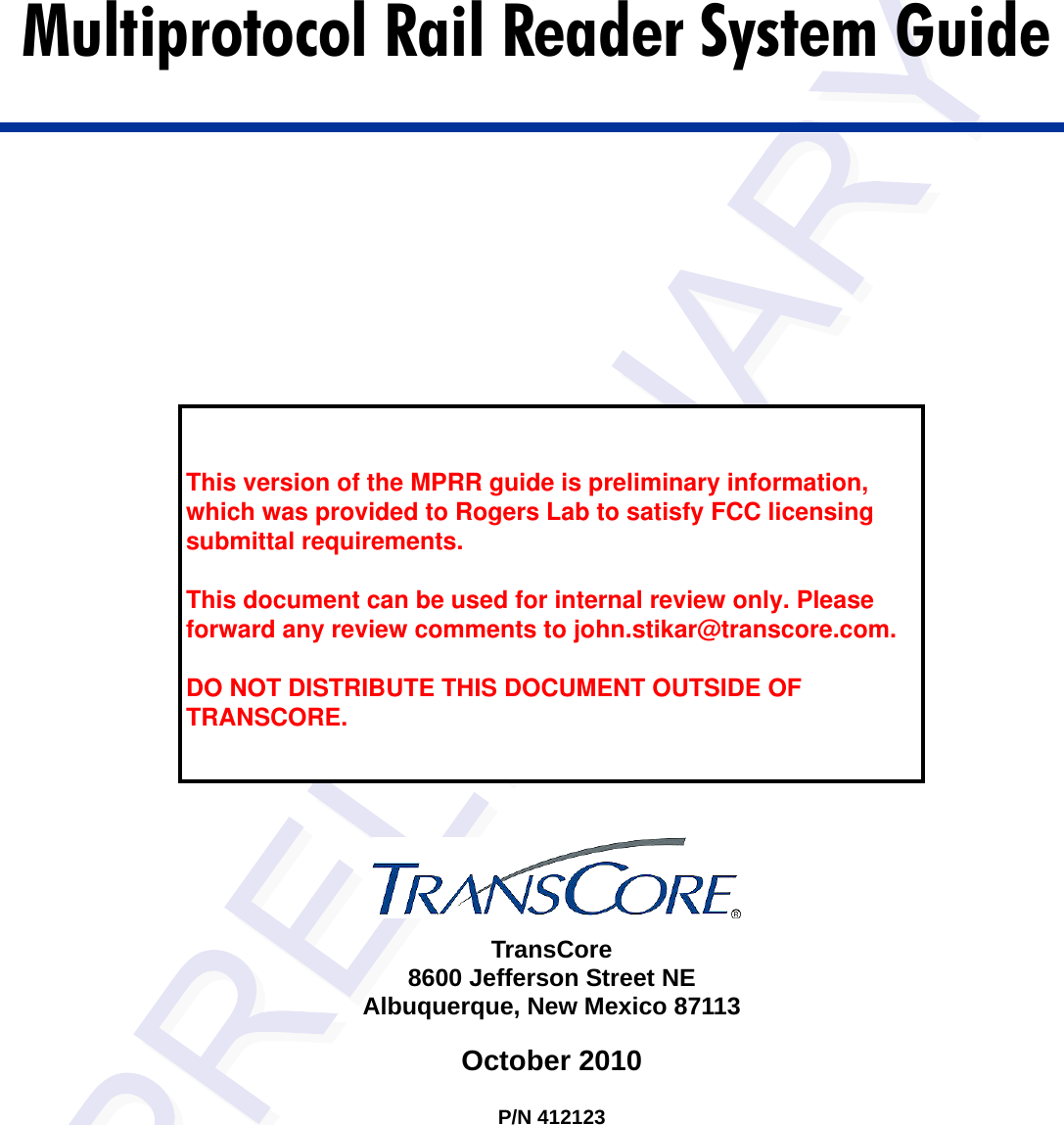
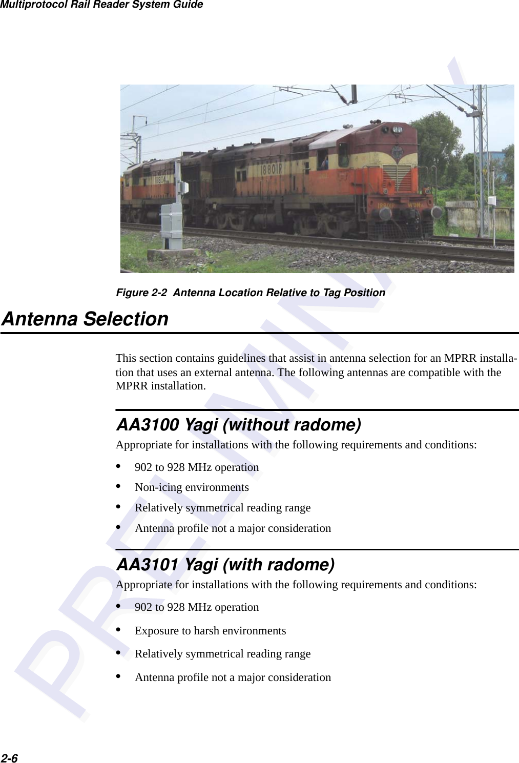
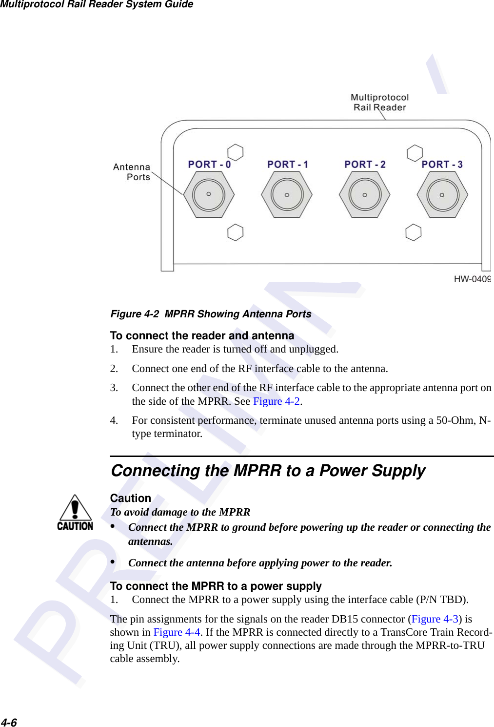
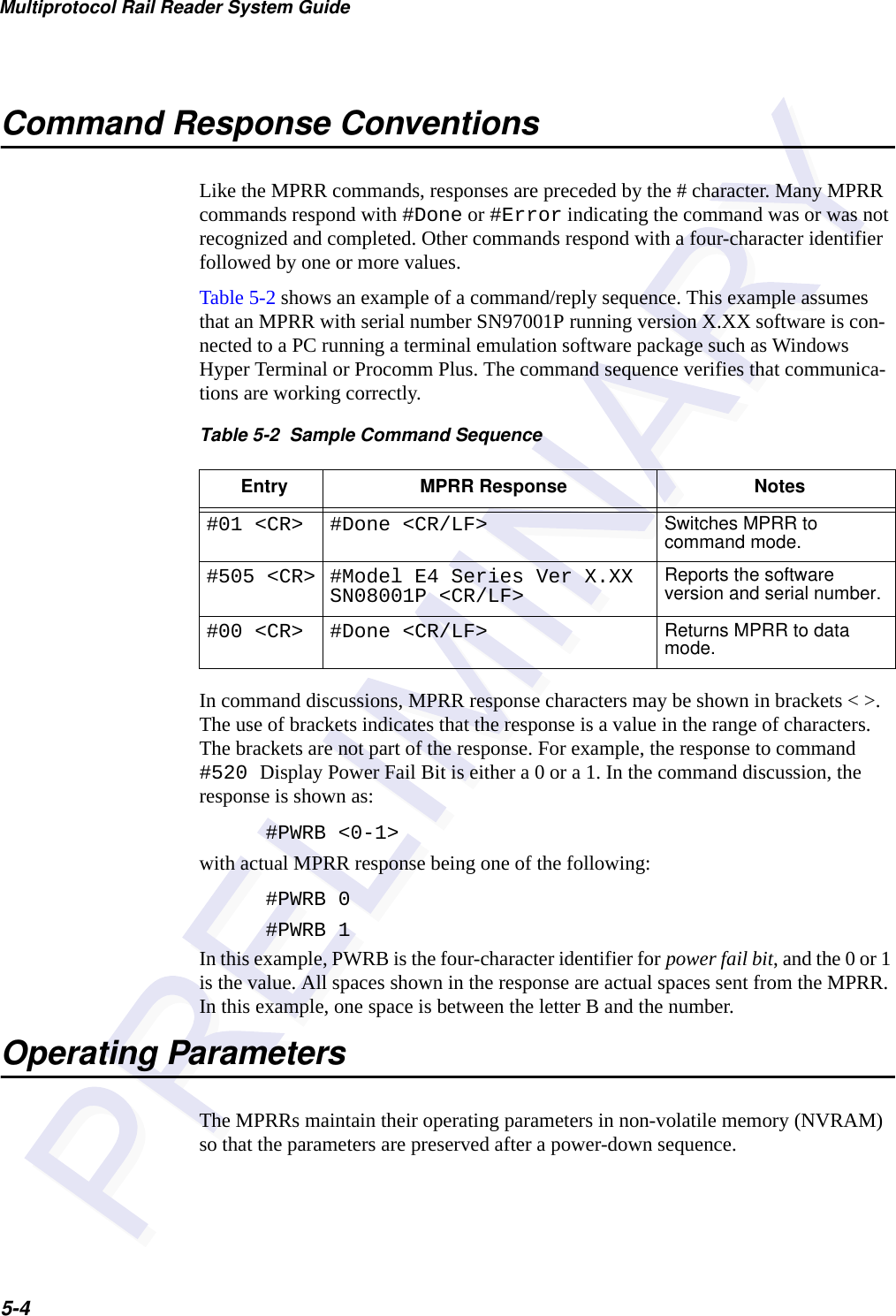
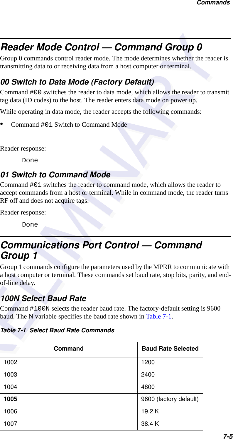
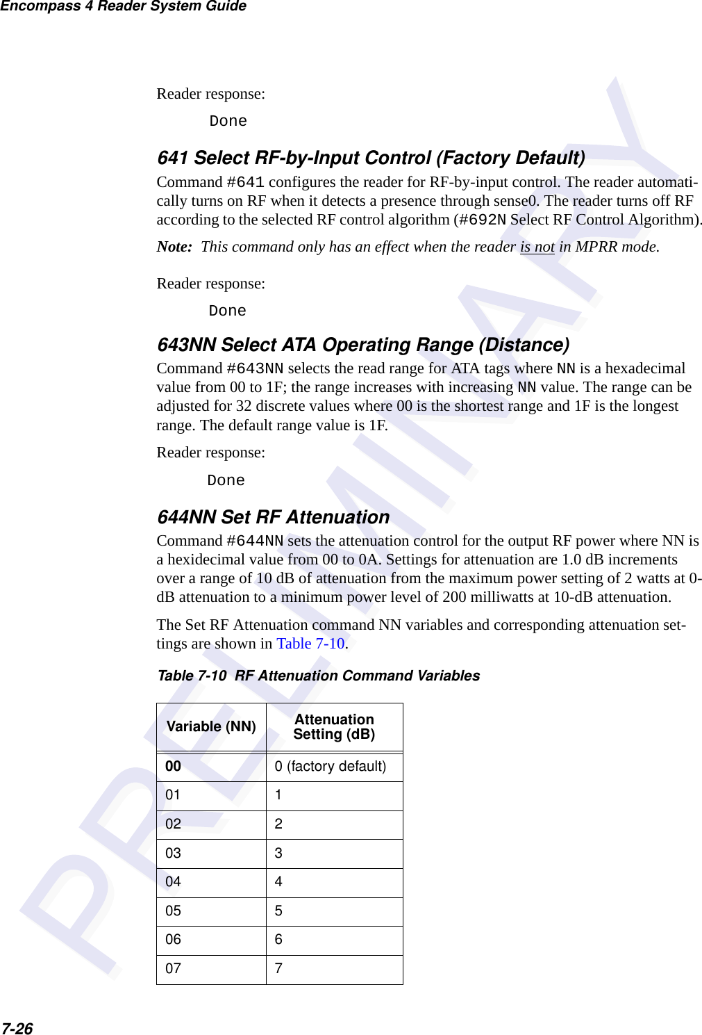
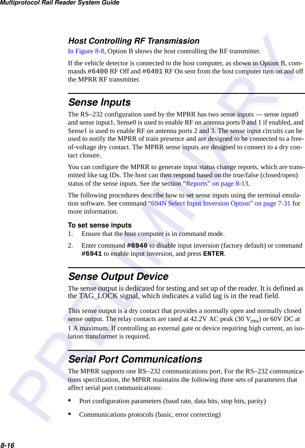
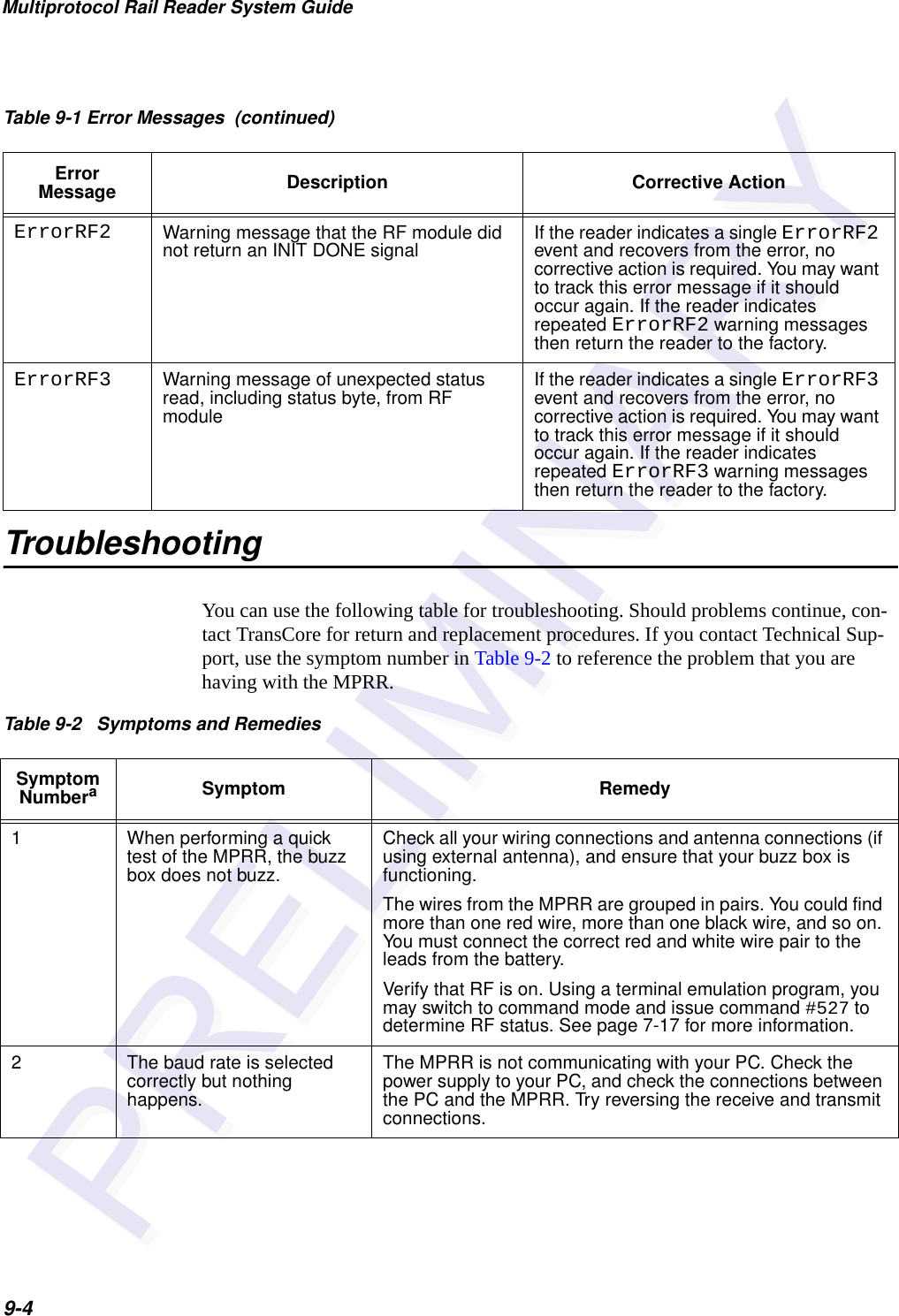
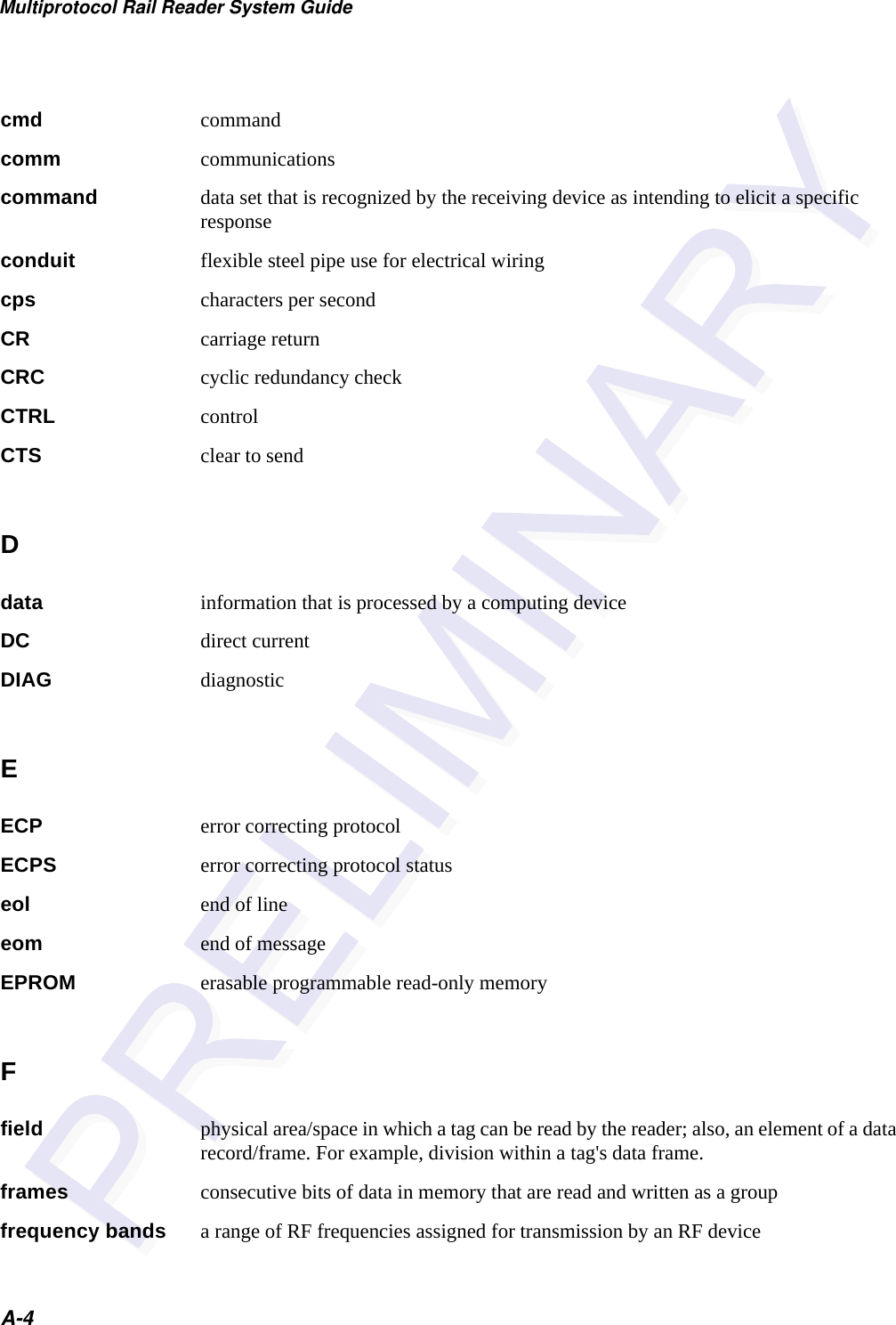
![Communications Protocols6-5Basic Protocol and ECP FormatNote: In the following text, the symbols < and > are used to represent required vari-able message data, and the symbols [and] are used to represent optional data. These symbols are not part of the message syntax.Reader TransmissionsThe basic protocol format and the data inquiry protocol format are as follows:<som><data><eom>The ECP format is as follows:<som><seq><data><crc><eom>where<som> Start-of-message (ASCII # character)<seq> Sequence number (ASCII hex) that represents an even number in the range 0–9, A–F (0, 2, 4, 6, 8, A, C, E). The MPRR maintains the number. The host must acknowledge reader transmissions by sending an ACK message with the same sequence number received from the MPRR. The MPRR updates its sequence number upon receipt of a valid host ACK. If an ACK is not received, the MPRR retransmits the message. A reader transmission sequence is not considered complete until the MPRR receives an ACK and updates its sequence number.<data> An ASCII string up to 72 characters long. This string may contain tag data, a presence without tag report; an input status change report; an Error06, Error07, Error08, or Error11 message; or a sign-on message. Auxiliary data may also be included.<crc> Field containing four ASCII digits that represent the 16-bit CRC value calculated on the message. The CRC value is calculated on bytes between the som character and the first <crc> byte.When the host receives a properly framed message, it can calculate a 16-bit CRC value. The calculation is applied to the character string that immediately follows the <som> and that ends with the character immediately preceding the first <crc> character.The transmitted CRC value can then be compared with the binary equivalent of the received <crc> characters. If the transmitted and received CRC values do not match, the recipient assumes the](https://usermanual.wiki/TransCore/05716/User-Guide-1366466-Page-71.png)
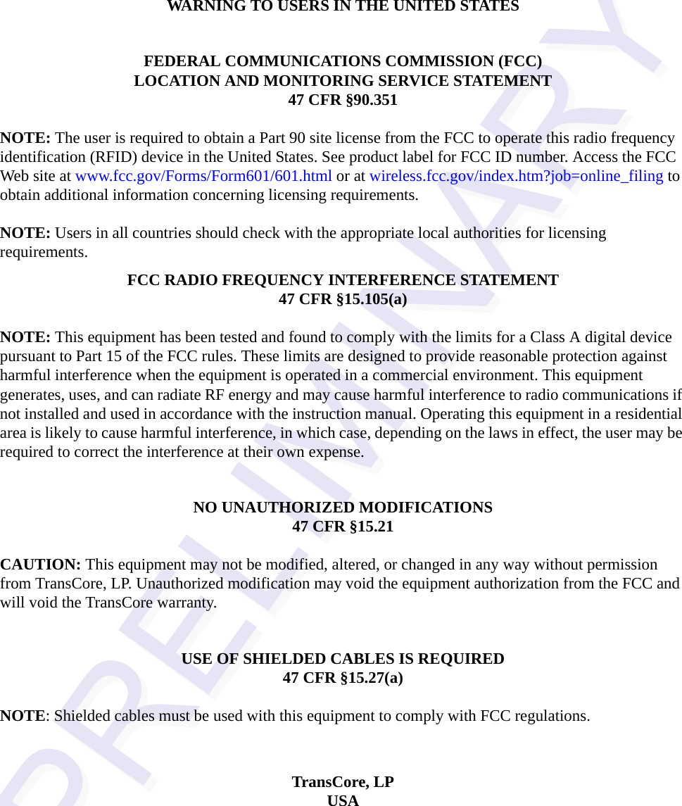
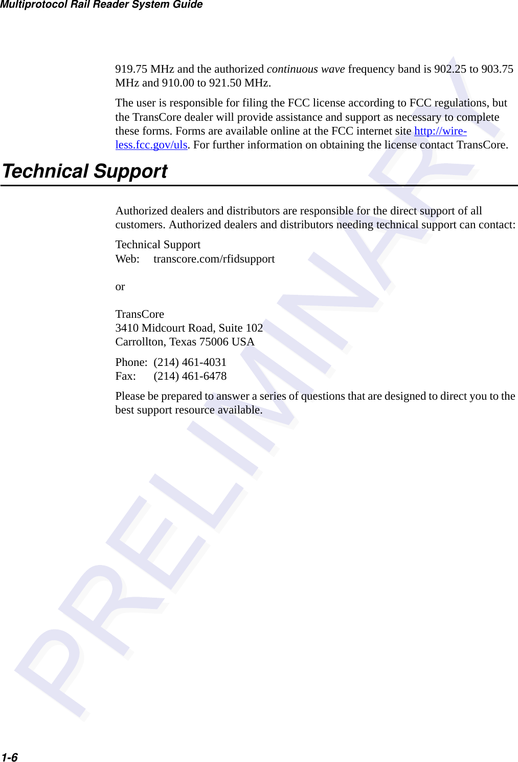
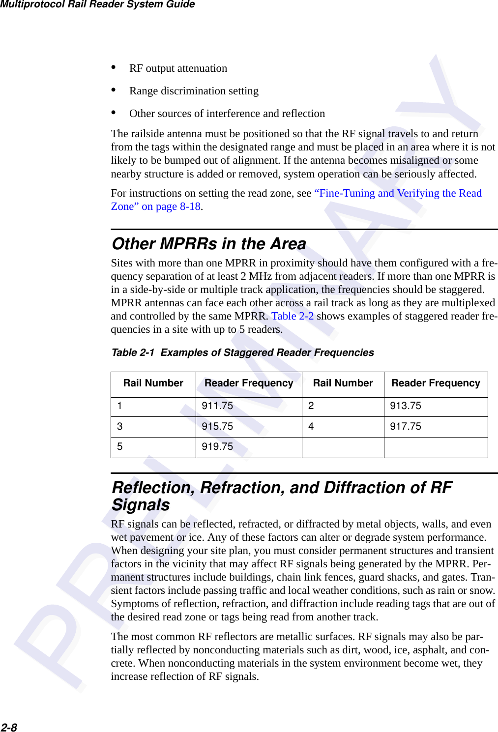
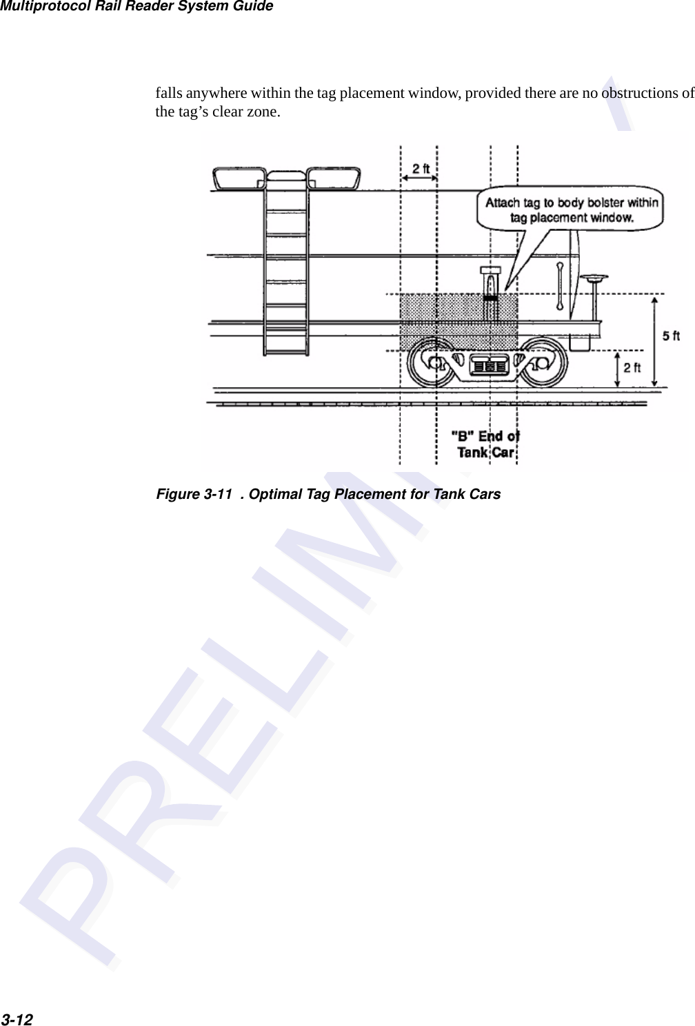
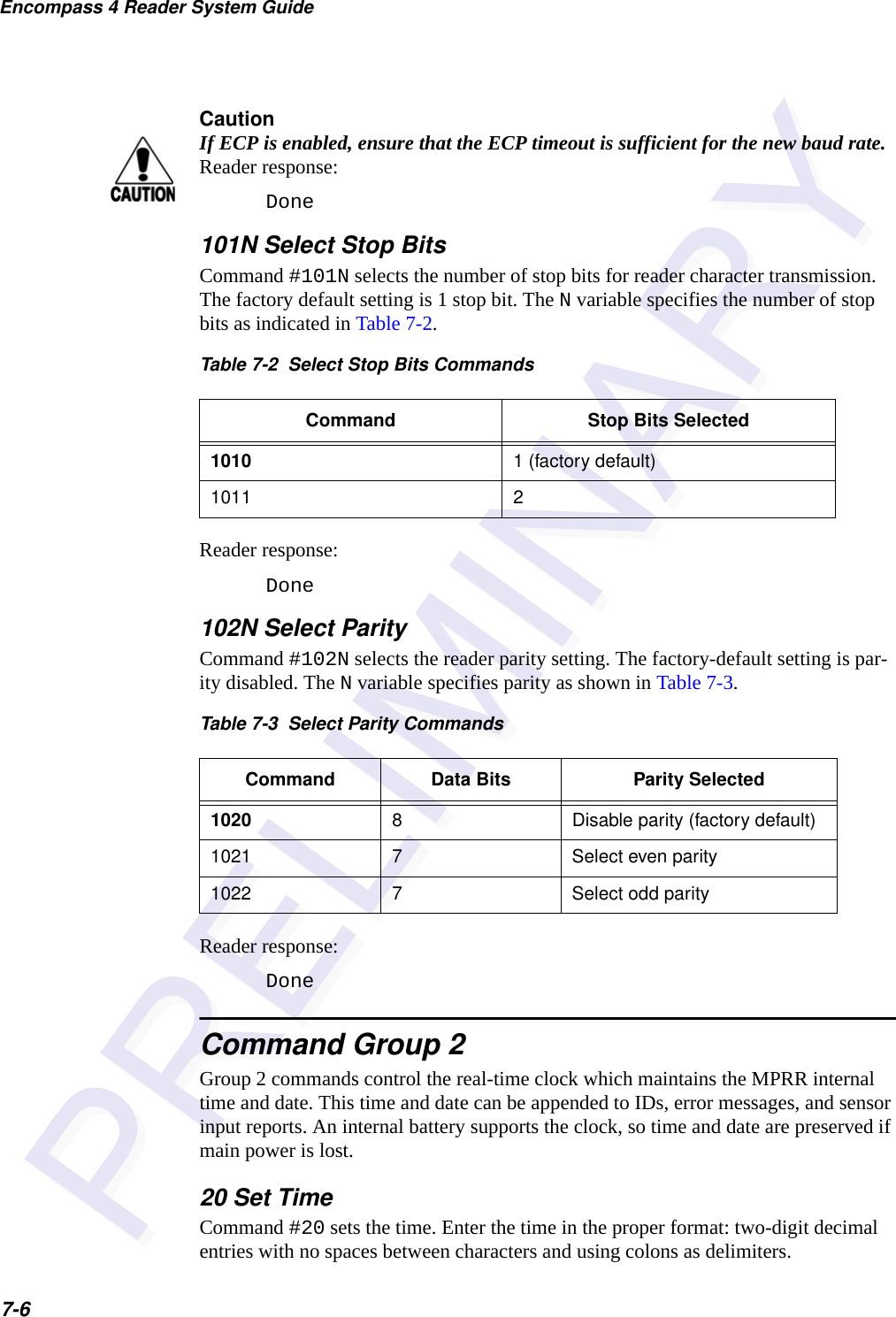
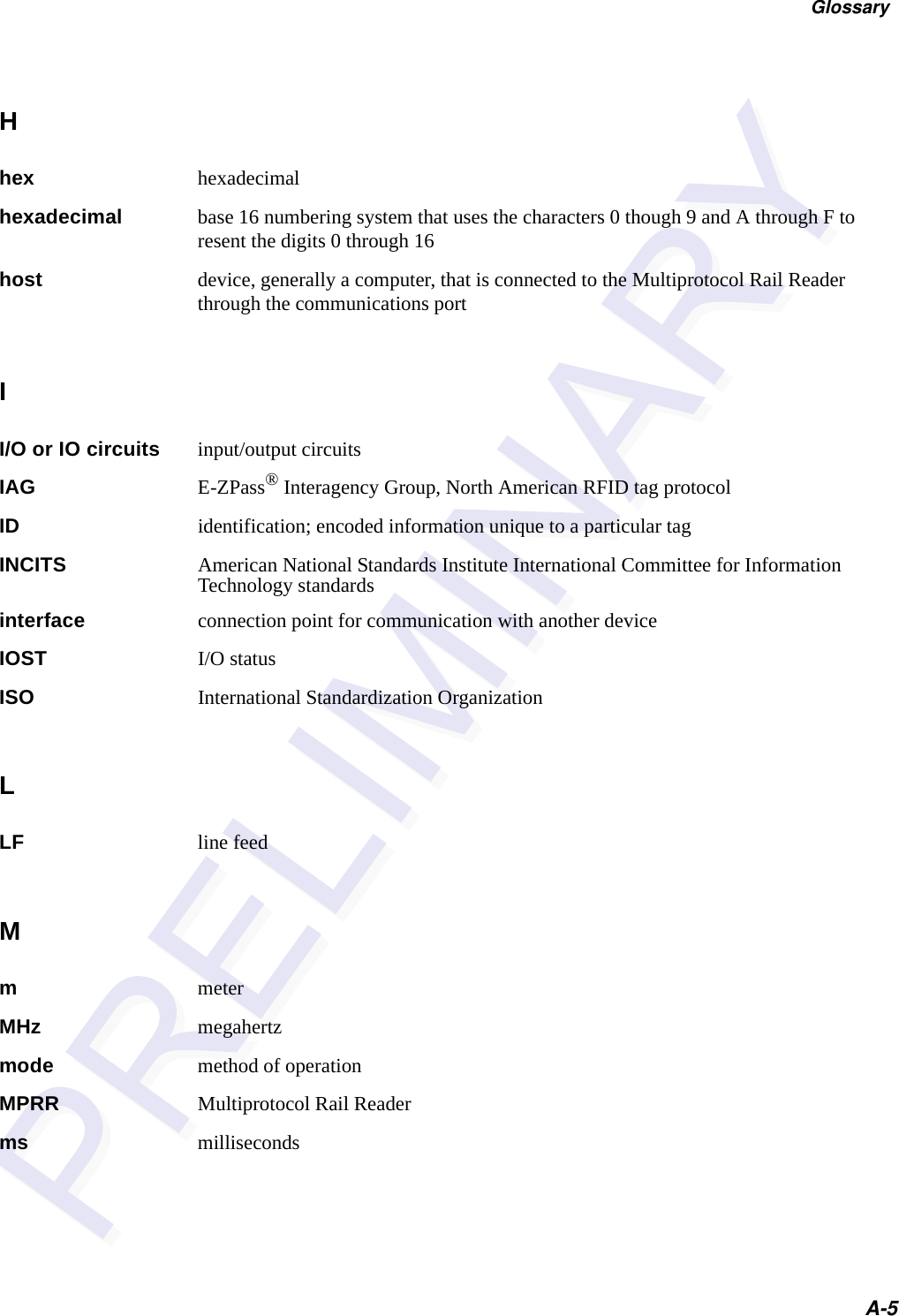
![Communications Protocols6-7number, and advances pointers to the next message in the MPRR’s message queue to prepare for sending the next message.Switch to Command Mode RequestThe host computer may issue command #01 Switch to Command Mode while in data mode.The basic protocol format is as follows:<som><cmd><eom>The ECP format is as follows:<som><seq><cmd><crc><eom>where<som> Start-of-message (ASCII # character)<seq> Sequence number generated by the host computer separately from that appearing in data messages transmitted by the MPRR <cmd> Switch to command mode (ASCII characters 01)<crc> CRC value for the message<eom> End-of-message character (ASCII CR)Host TransmissionThe host computer initiates synchronous communications between the MPRR and the host. The host begins a sequence by issuing a command; the MPRR responds accord-ingly.The basic protocol format is as follows:<som><cmd>[<data>]<eom>The ECP format is as follows:<som><seq><cmd>[<data>]<crc><eom>where<som> Start-of-message (ASCII # character)<seq> Sequence number (ASCII hex digit) that represents an odd number in the range 0–9, A–F (1, 3, 5, 7, 9, B, D, F). The host should use odd sequence numbers in its command since the MPRR uses even sequence numbers in its transmissions. This method eliminates the possibility of a synchronous host command and an asynchronous reader transmission having the same sequence number.](https://usermanual.wiki/TransCore/05716/User-Guide-1366466-Page-73.png)
![Multiprotocol Rail Reader System Guide6-8Upon receiving a host command, the MPRR echoes the command’s sequence number in its response. Therefore, the host computer updates its sequence number upon receipt of a valid reader message. If the sequence number is not updated before transmission of the next command, the MPRR will not service the new command; it will retransmit its previous message. A command/message sequence is not complete until the host updates its sequence number.<cmd> Command code, a string that contains from two to four ASCII hex characters[<data>] Optional data field, an ASCII string of as many as 20 characters in length. For example, the store hardware configuration string command is #696S...S or command #696 Store Hardware Configuration String followed by the data string S...S.<crc> CRC value for the message<eom> End-of-message character (ASCII CR)Reader Command ResponseThe basic protocol format is<som><resp><eom>The ECP format is<som><seq><resp><crc><eom>where<som> Start-of-message (ASCII # character)<seq> Echo of sequence number received in host command message<resp> Response string. The MPRR returns Done, Error, or another ASCII string depending on the host transmission. This string can be up to 72 characters long.<crc> CRC value for the message<eom> End-of-message character (ASCII CR and LF)Sample MessagesThis section contains examples of typical messages transmitted between the MPRR and the host computer.](https://usermanual.wiki/TransCore/05716/User-Guide-1366466-Page-74.png)
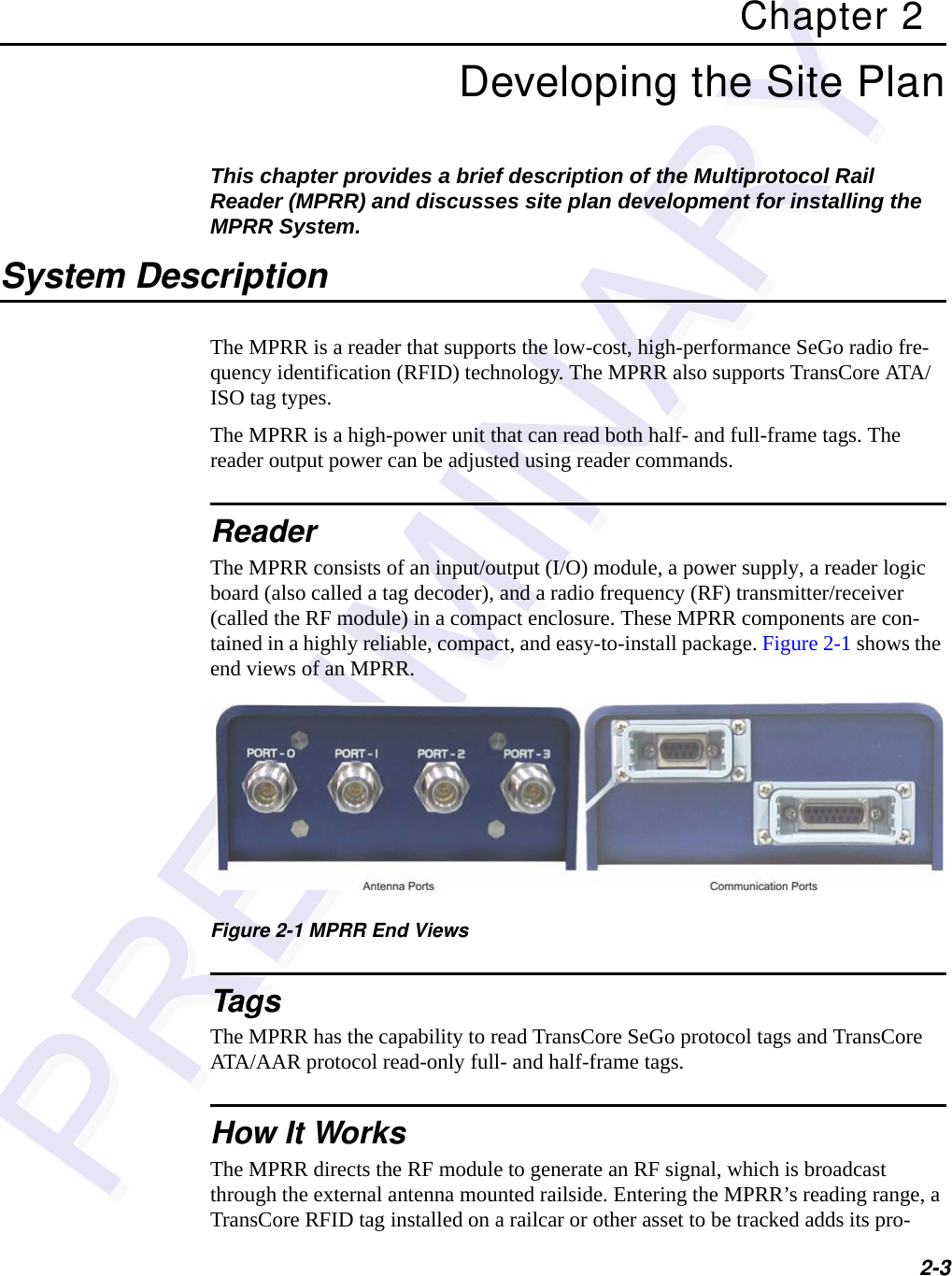
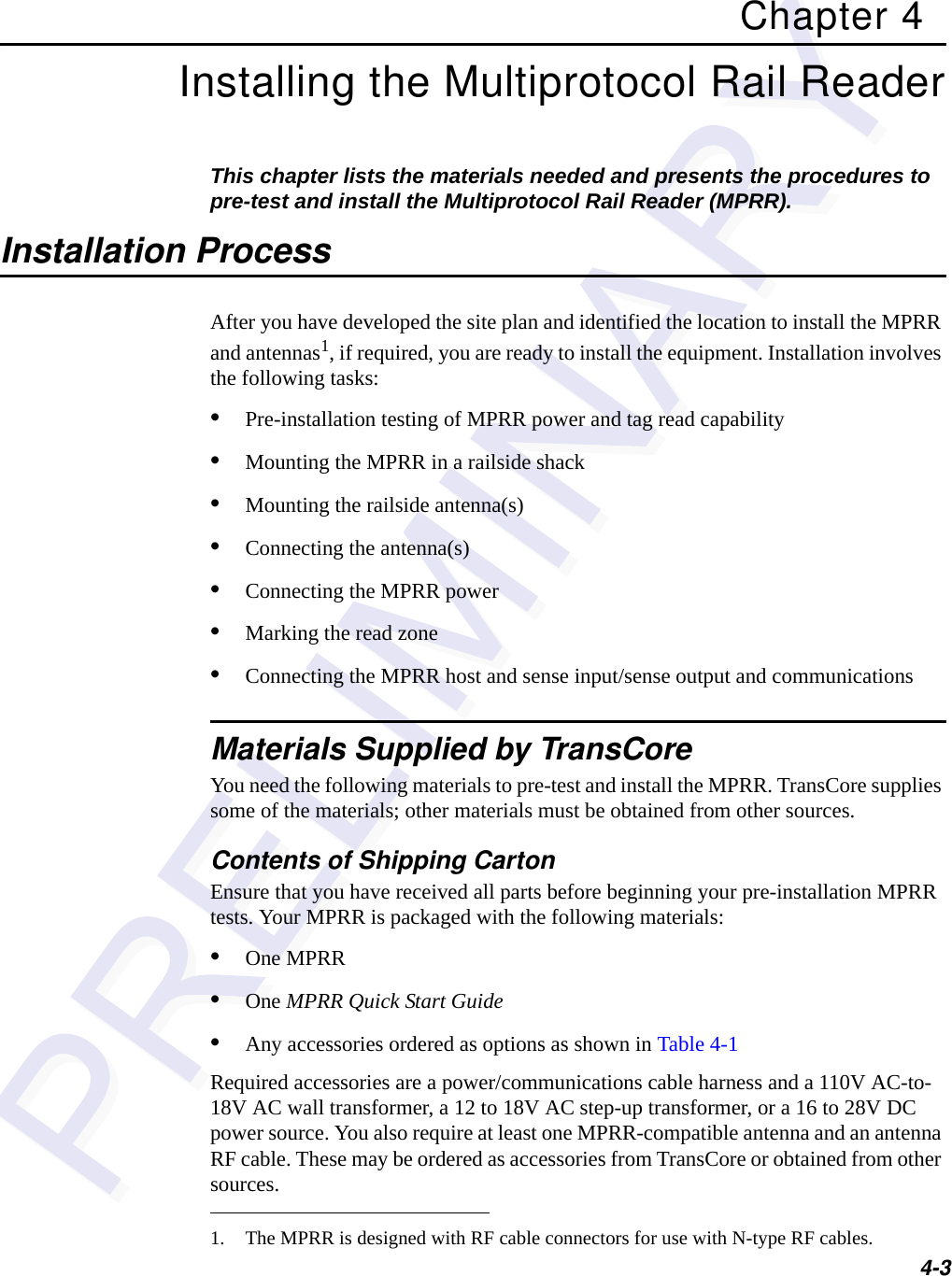
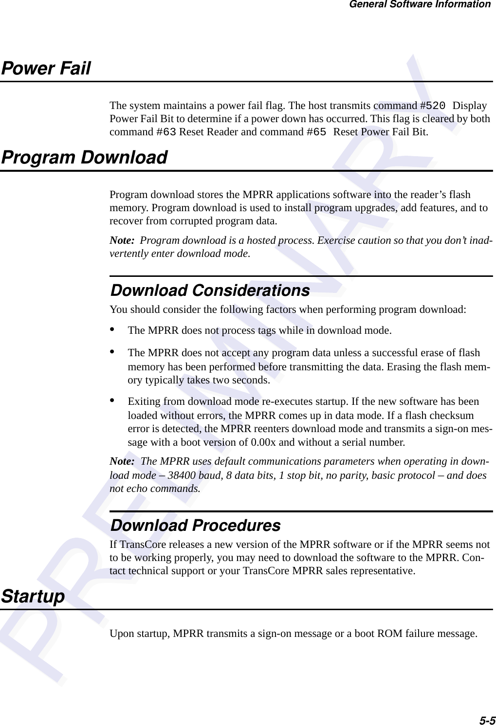
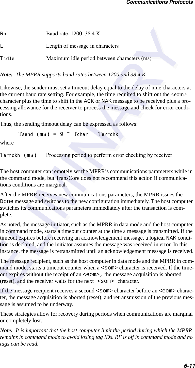
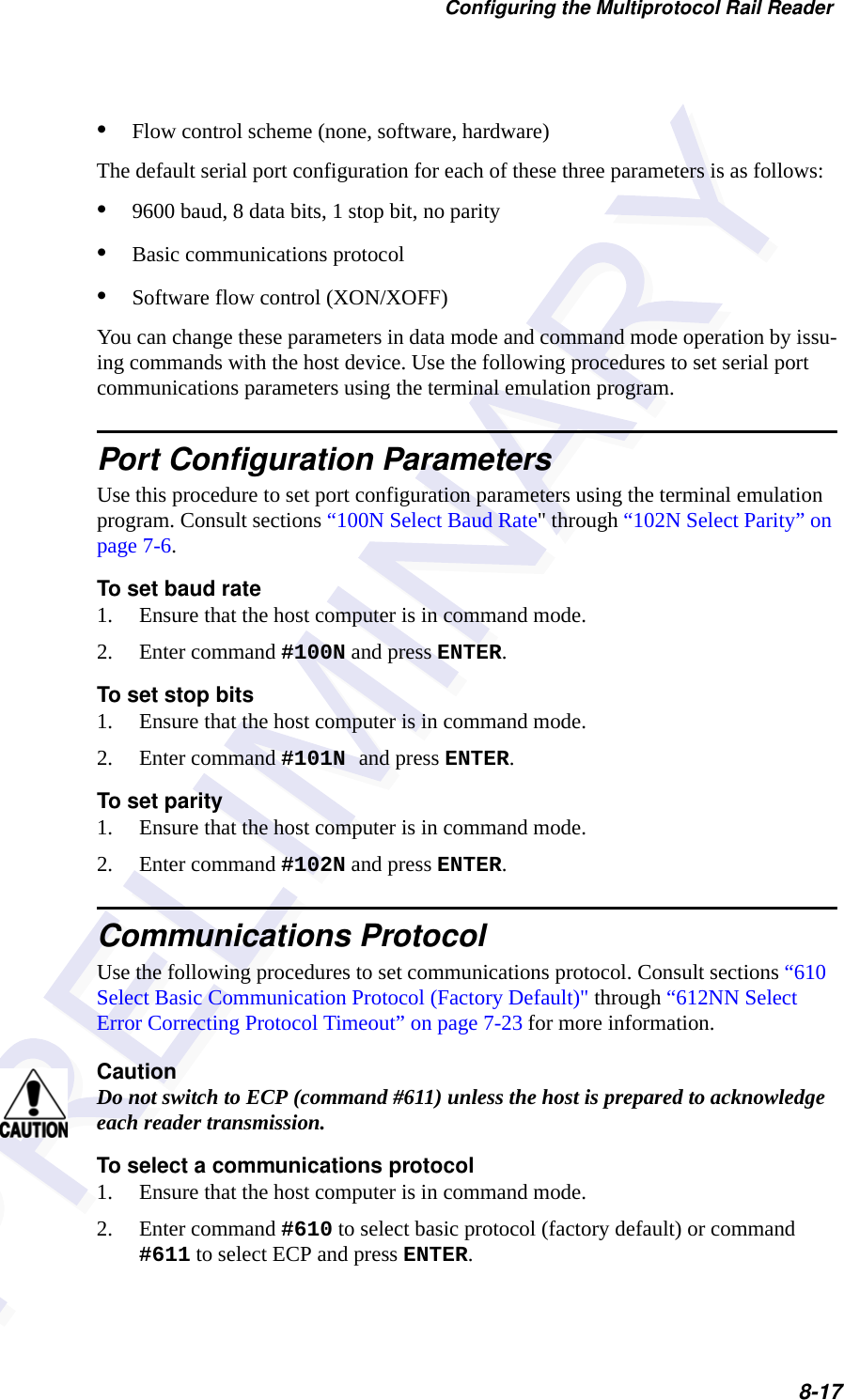
![Multiprotocol Rail Reader System Guide6-10ECP host transmission#7647XXX<crc><eom>where#Start-of-message character7Message sequence number647XXX Select RF Operating Frequency command where 647XXX is the command and XXX is a hexadecimal value from 000 to 118. In this example, XXX sets the RF frequency to 903 MHz.<crc> CRC value for the message<eom> End-of-message characterDone Command has been invoked by the MPRR Reader response#7Done<crc><eom> or #7Error<eom>For some commands, the MPRR responds with data that relates to the command, such as T0F 0, to indicate (TBD) mode enabled for a #XXX Display (TBD) Mode Status command.#7Error<eom> will be returned if host transmission is not a legal command with legal data.Timing and SynchronizationThe ECP is largely independent of baud rate. The timeout delays previously described are a function of baud rate.The MPRR supports an ECP timeout, which applies equally to both transmit and receive. The receiver’s minimum timeout delay equals the time to transmit/receive the longest anticipated message at the current baud rate setting. Additional margin should be included for idle periods between characters; for example, processing overhead, if any. The timeout delay period can be expressed as follows:Τrec (ms) = L x [Τchar + Τidle]whereΤchar (ms) 1000 x [ Bc / Rb ]BcBits per character, typically 10](https://usermanual.wiki/TransCore/05716/User-Guide-1366466-Page-76.png)
![Multiprotocol Rail Reader System Guide6-14Example 3 contains an example of UPDCRC that does require a lookup table. Example 1 presents an example of a function (CALCCRC) that calculates the CRC value through a call to a separate function (UPDCRC).unsigned short calccrc(char *message){unsigned short crc = 0;for ( ; *message != (char)0;message++) crc = updcrc(*message & 0xff, crc);return (crc)}Example 2 shows an example of UPDCRC that does not require a lookup table.#define BITS_PER_CHAR 8unsigned short updcrc (unsigned short ch, unsigned short crc){register short counter = BITS_PER_CHAR;register short temp = crc;while (--counter >= 0) if (temp & 0x8000) {temp <<= 1;temp += (((ch <<= 1) & 0x0100) != 0);temp ^= 0x1021; } else {temp <<= 1;temp += (((ch <<= 1) & 0x0100) != 0); }return(temp);}#define updcrc(cp, crc)( crctab[((crc >> 8) & 255)]^ (crc << 8) ^ cpstatic unsigned short crctab [256] = {0x0000, 0x1021, 0x2042, 0x3063, 0x4048, 0x50a5, 0x60c6, 0x70e7,0x8108, 0x9129, 0xa14a, 0xb16b, 0xc18c, 0xd1ad, 0xe1ce, 0xf1ef,0x1231, 0x0210, 0x3273, 0x2252, 0x52b5, 0x4294, 0x72f7, 0x62d6,0x9339, 0x8318, 0xb37b, 0xa35a, 0xd3bd, 0xc39c, 0xf3ff, 0xe3de,0x2462, 0x3443, 0x0420, 0x1401, 0x64e6, 0x74c7, 0x44a4, 0x5485,0xa56a, 0xb54b, 0x8528, 0x9509, 0xe5ee, 0xf5cf, 0xc5ac, 0xd58d,](https://usermanual.wiki/TransCore/05716/User-Guide-1366466-Page-80.png)
![Communications Protocols6-15Example 4 shows an example of a function that creates the lookup table.#include <stdio.h>#define MAX_CHAR 256#define BITS_CHAR 8#define SIGN_BIT 0x8000#define POLY 0x1021unsigned short crctab [MAX_CHAR];main (){unsigned short ch;unsigned short workval;unsigned short bit;0x3653, 0x2672, 0x1611, 0x0630, 0x76d7, 0x66f6, 0x5695, 0x46b4,0xb75b, 0xa77a, 0x9719, 0x8738, 0xf7df, 0xe7fe, 0xd79d, 0xc7bc,0x48c4, 0x58e5, 0x6886, 0x78a7, 0x0840, 0x1861, 0x2802, 0x3823,0xc9cc, 0xd9ed, 0xe98e, 0xf9af, 0x8948, 0x9969, 0xa90a, 0xb92b,0x5af5, 0x4ad4, 0x7ab7, 0x6a96, 0x1a71, 0x0a50, 0x3a33, 0x2a12,0xdbfd, 0xcbdc, 0xfbbf, 0xeb9e, 0x9b79, 0x8b58, 0xbb3b, 0xab1a,0x6ca6, 0x7c87, 0x4ce4, 0x5cc5, 0x2c22, 0x3c03, 0x0c60, 0x1c41,0xedae, 0xfd8f, 0xcdec, 0xddcd, 0xad2a, 0xbd0b, 0x8d68, 0x9d49,0x7e97, 0x6eb6, 0x5ed5, 0x4ef4, 0x3e13, 0x2e32, 0x1e51, 0x0e70,0xff9f, 0xefbe, 0xdfdd, 0xcffc, 0xbf1b, 0xaf3a, 0x9f59, 0x8f78,0x9188, 0x81a9, 0xb1ca, 0xa1eb, 0xd10c, 0xc12d, 0xf14e, 0xe16f,0x1080, 0x00a1, 0x30c2, 0x20e3, 0x5004, 0x4025, 0x7046, 0x6067,0x83b9, 0x9398, 0xa3fb, 0xb3da, 0xc33d, 0xd31c, 0xe37f, 0xf35e,0x02b1, 0x1290, 0x22f3, 0x32d2, 0x4235, 0x5214, 0x6277, 0x7256,0xb5ea, 0xa5cb, 0x95a8, 0x8589, 0xf56e, 0xe54f, 0xd52c, 0xc50d,0x34e2, 0x24c3, 0x14a0, 0x0481, 0x7466, 0x6447, 0x5424, 0x4405,0xa7db, 0xb7fa, 0x8799, 0x97b8, 0xe75f, 0xf77e, 0xc71d, 0xd73c,0x26d3, 0x36f2, 0x0691, 0x16b0, 0x6657, 0x7676, 0x4615, 0x5634,0xd94c, 0xc96d, 0xf90e, 0xe92f, 0x99c8, 0x89e9, 0xb98a, 0xa9ab,0x5844, 0x4865, 0x7806, 0x6827, 0x18c0, 0x08e1, 0x3882, 0x28a3,0xcb7d, 0xdb5c, 0xeb3f, 0xfb1e, 0x8bf9, 0x9bd8, 0xabbb, 0xbb9a,0x4a75, 0x5a54, 0x6a37, 0x7a16, 0x0af1, 0x1ad0, 0x2ab3, 0x3a92,0xfd2e, 0xed0f, 0xdd6c, 0xcd4d, 0xbdaa, 0xad8b, 0x9de8, 0x8dc9,0x7c26, 0x6c07, 0x5c64, 0x4c45, 0x3ca2, 0x2c83, 0x1ce0, 0x0cc1,0xef1f, 0xff3e, 0xcf5d, 0xdf7c, 0xaf9b, 0xbfba, 0x8fd9, 0x9ff8,0x6e17, 0x7e36, 0x4e55, 0x5e74, 0x2e93, 0x3eb2, 0x0ed1, 0x1ef0,};](https://usermanual.wiki/TransCore/05716/User-Guide-1366466-Page-81.png)
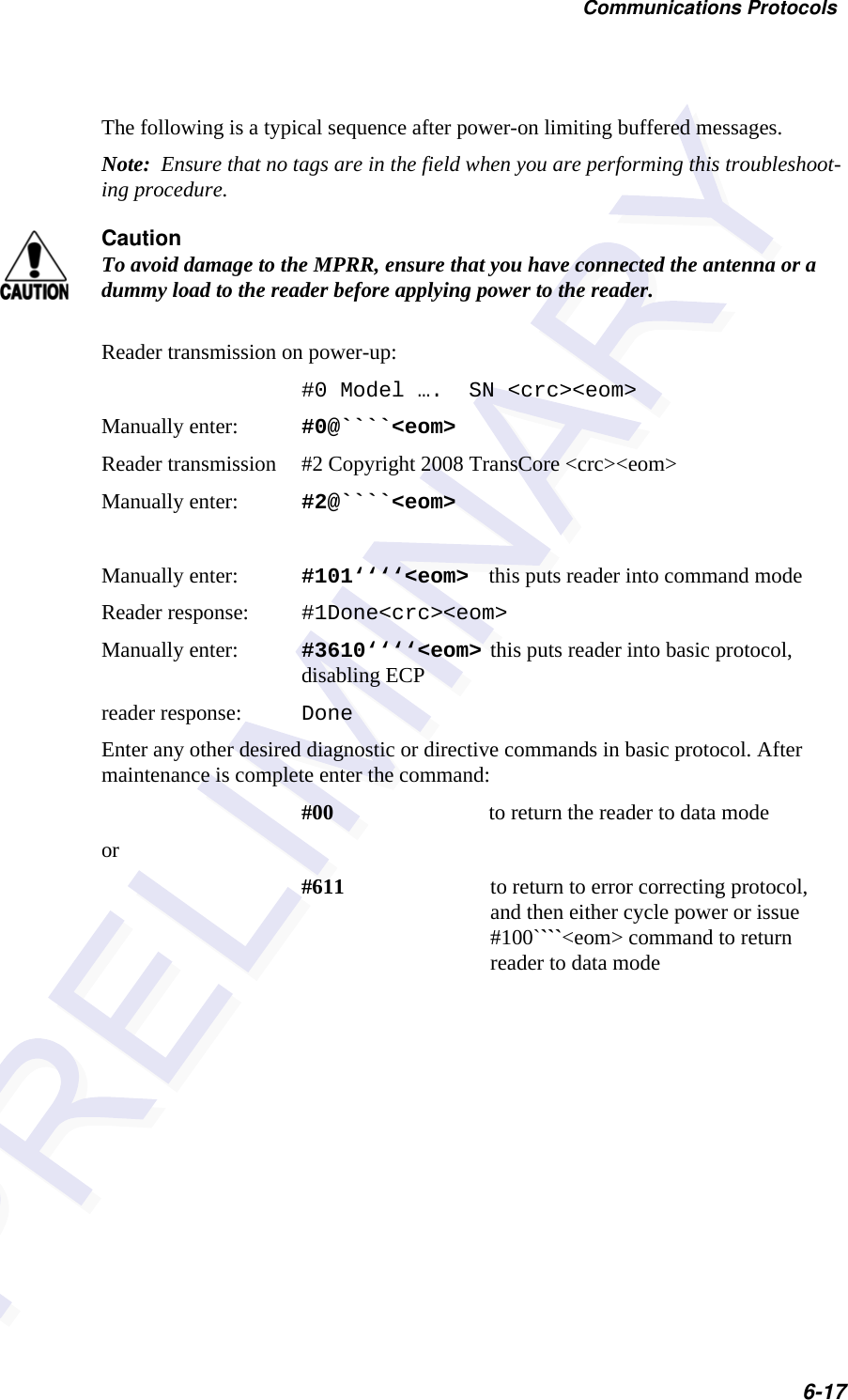
![Multiprotocol Rail Reader System Guide6-16unsigned short carry;for (ch = 0; ch != MAX_CHAR; ch++) {workval = ch << BITS_CHAR;for (bit = BITS_CHAR; bit != 0; bit--) {carry = (workval & SIGN_BIT);workval <<= 1;if (carry)workval ^= POLY;}crctab[ch] = workval;}for (ch = 0; ch != MAX_CHAR; ch++)printf("0x%04x\n", crctab[ch]);}Manually Disabling ECP for MaintenanceUnder certain conditions, communications between the host and MPRR may be lost temporarily and maintenance may be required. The reader or host is sending out a message and waiting for an acknowledgment. When the acknowledgment is not received, the message is sent again. Additional messages are also buffered. Often the first indication that the MPRR software is in an ECP “loop” is when the user/techni-cian sees a recurring display of the same message repeated over and over again on the monitor. The procedure described in the following paragraphs enables the mainte-nance technician to change configuration or test tag reading manually.Assuming that the ECP timeout is at the factory default of 12.7 seconds (or other value that allows enough time for the commands to be manually entered) the following com-mand sequence may be used to break out of an ECP loop. This command sequence uses four ASCII < ` > characters (60 hex) as wild card CRC values.Note: The ASCII <`> character (60 hex) is commonly located on the ~ key.You must acknowledge existing messages by issuing commands with the generic for-mat:#x@‘‘‘‘<eom>where#Start-of-message characterxMessage sequence number. This must be the same as the sequence number of the message being acknowledged@ACK (acknowledgment character)<‘‘‘‘> Wild card CRC value for the message<eom> End-of-message character](https://usermanual.wiki/TransCore/05716/User-Guide-1366466-Page-82.png)


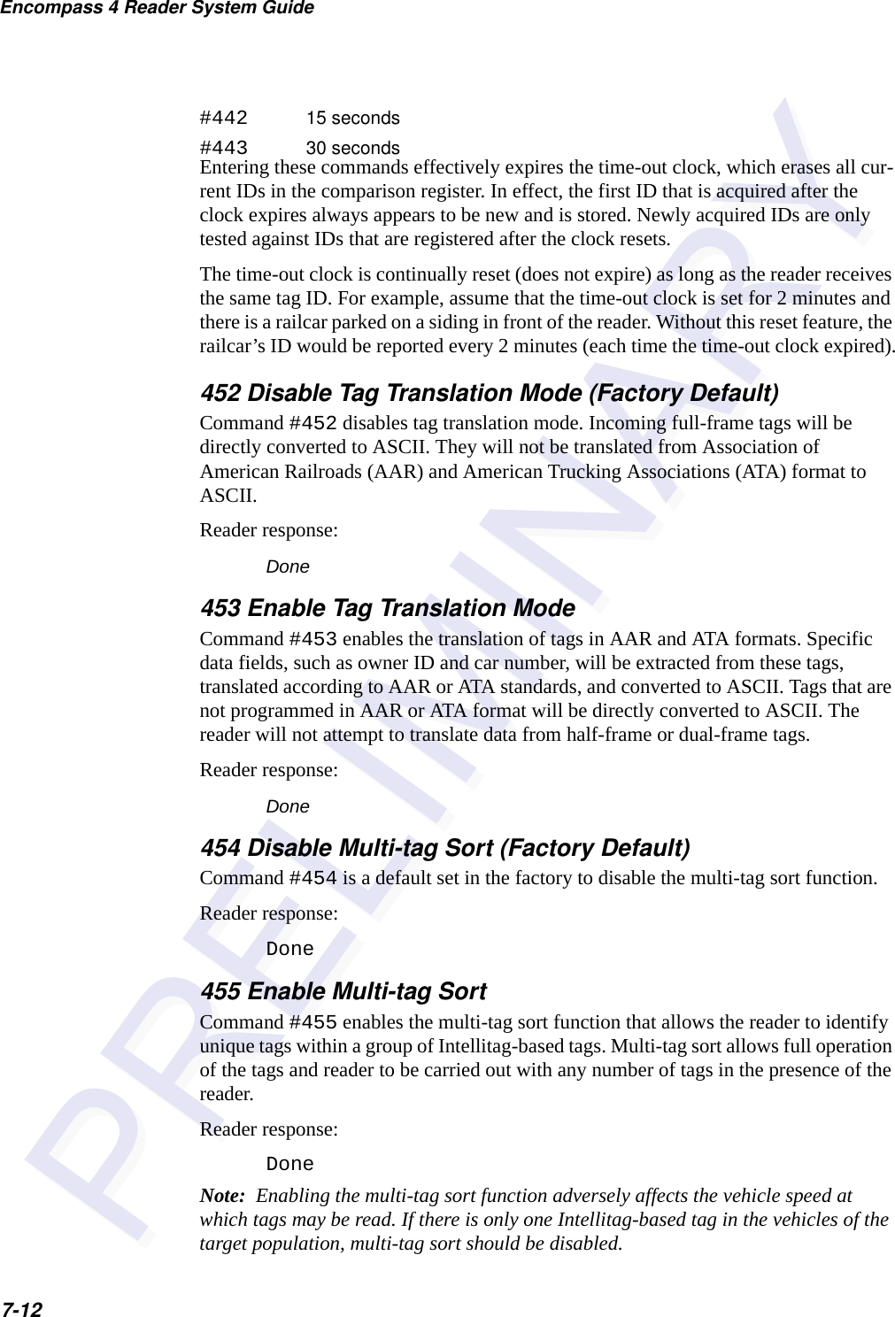
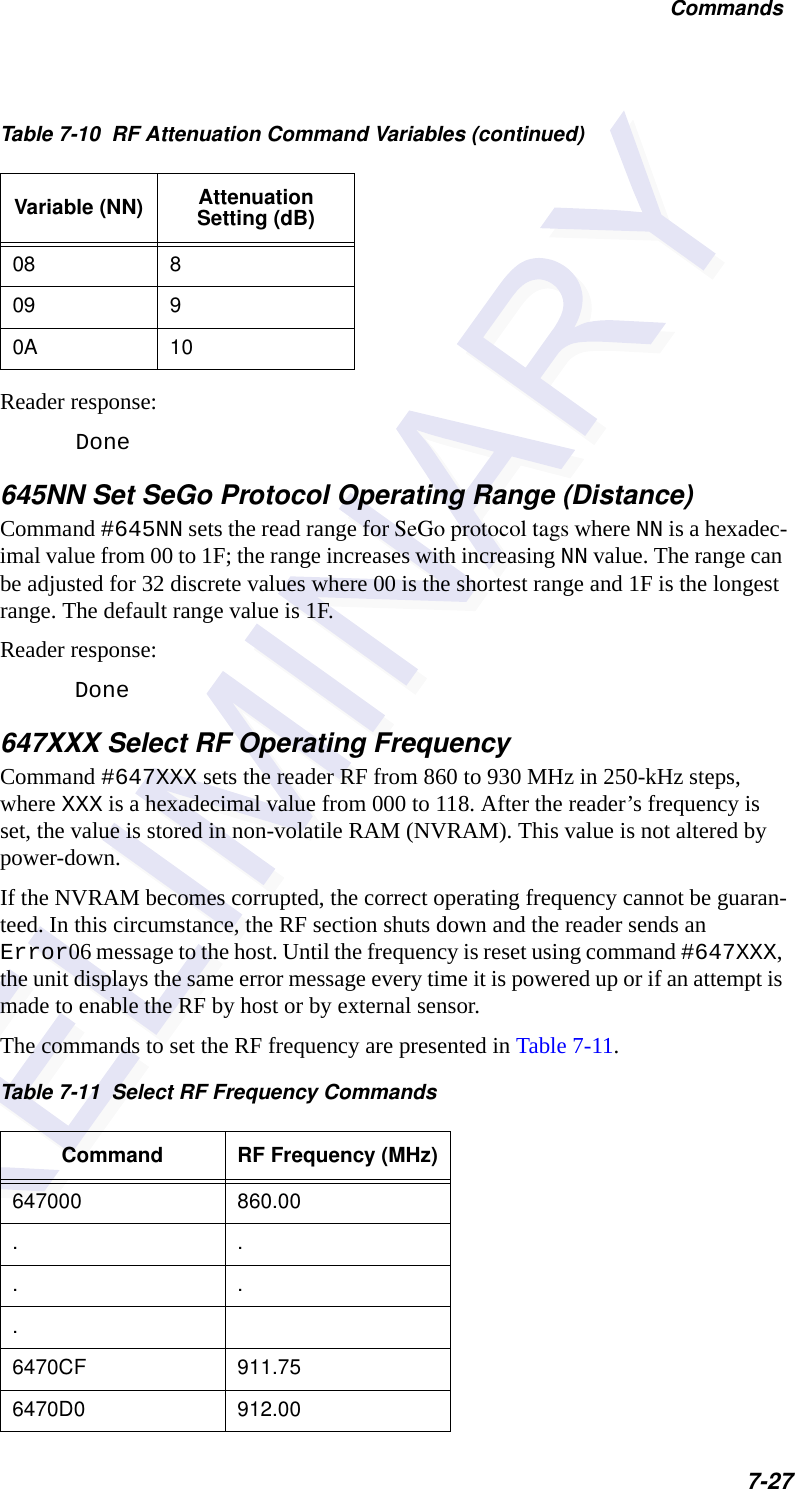
![Commands7-11obtained a specified number of times in sequence. Values for N are 0 through 3 (Table 7-7). The factory setting is one acquisition (N = 0).The validation procedure is executed before the unique ID test (Select Unique ID Code Criteria [#410N] commands). IDs that do not pass the validation test are not reported.For example, command #4203 specifies that the same ID must be obtained from the antenna/RF module 4 times in succession before it is considered for the uniqueness test. This feature is useful in installations where RF reflections may cause a single tag to be read multiple times or where an occasional ID might be read from fringe areas43 Buffer All ID CodesCommand #43 buffers all acquired ID codes. It effectively cancels any uniqueness criteria previously set by select unique ID code criteria command 410N. Note: Command #43 is for diagnostic purposes only.After diagnostics are complete, reset the select unique ID code criteria using command 410N.Reader response:Done440 Reset UniquenessCommand 440 causes the ID filtering process set by Select Unique ID Code Criteria (#410N) to restart. It is used in conjunction with the Variable Timeout #44N) com-mands. This command provides a one-time reset at which point the previously set time-out interval resumes. This command can be sent in data or command mode.44N Set Uniqueness TimeoutPlaces a time limit on the uniqueness criterion set by Select Unique ID Code Criteria (#410N). The parameter N sets the number of minutes on the time-out clock. The factory setting is two minutes (N = 1).Command Time-Out Clock#441 2 minutes (factory setting)Table 7-7 Select Valid Code Commands and FramesCommand Valid Code Frames4200 1 (factory default)4201 24202 34203 4](https://usermanual.wiki/TransCore/05716/User-Guide-1366466-Page-95.png)

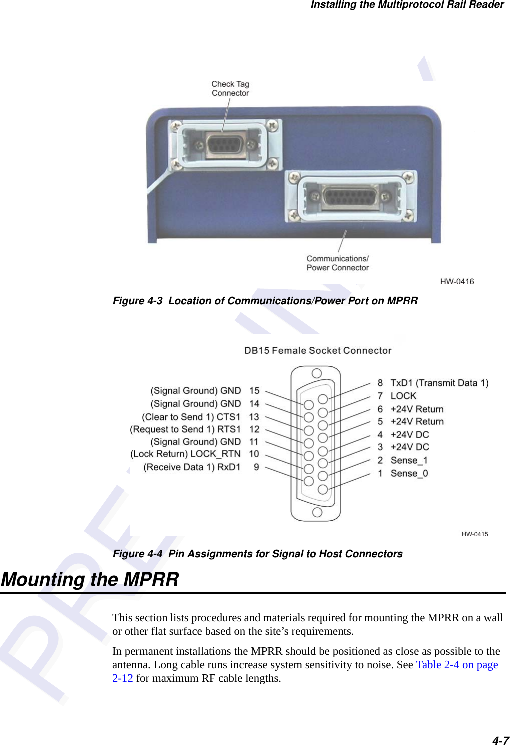
![Configuring the Multiprotocol Rail Reader8-9Figure 8-5 Sign-on MessageThe sign-on message appears as follows: Model [software version] SNYYYYYY[Copyright notice]where YYYYYY is the serial number assigned to the MPRR skipping the fourth character printed on the reader product label.Serial number 000000 is the default setting and is not a valid number. If this number appears in the sign-on message, the serial number has never been stored into reader memory. Contact TransCore Technical Support.If the flash memory checksum is not verifiable, the sign-on message appears as follows:Model [E4 BOOT] Ver 0.00 A[Copyright notice]If the failure message version number equals 0.00 E and no serial number exists, the flash memory checksum has failed, and the MPRR is operating out of boot ROM. In this case, the MPRR automatically enters download mode and waits for a new program to be loaded into the flash memory. Follow the instructions in “Program Download” on page 5-5.Communications can also be verified by using the command sequence in Table 8-3.](https://usermanual.wiki/TransCore/05716/User-Guide-1366466-Page-129.png)


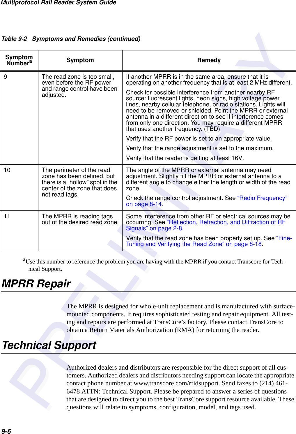
![Troubleshooting and Maintenance9-53 When testing the MPRR, all the wires are connected correctly but the unit does not respond. The MPRR may not have the software loaded inside the unit. Contact Technical Support as described on page 9-6. If you are using a terminal emulation program, check that the terminal emulation setting on the MPRR is VT100.Check that the MPRR communication cable is connected to the correct COM port.Verify that the external antenna is connected correctly.4 Strange signal responses come from the MPRR when tested with the PC.Ensure that the reader is in the correct interface mode for the test tag, i.e., ATA mode for an ATA tag. Check the system defaults using a terminal emulation program. Both PC and reader should be set to 9600 baud, 8 bits, 1 stop bit, and no parity.5 When a tag is moved in front of the antenna, a clicking sound comes from the MPRR.The MPRR works. The sound is the relay inside the MPRR that is controlled by a lock signal. The relay is actuated when a tag is in the read zone. (TBD)6 Nothing happens when the test tag is passed in front of the MPRR or external antenna.Ensure that the MPRR is powered on and is in predefined output mode. (#621)Verify that the reader is set to RF ON (#6401).Verify that the external antenna is connected correctly.7 The MPRR came from another site and does not work the way the factory defaults indicate that it should.Different commands were probably used to support the other site’s specific configuration. You can restore the factory defaults by using a terminal emulation program to switch to command mode and issuing command #66F Load Default Operating Parameters. All factory defaults except RF frequency will be restored.8 When connected to a PC that is running terminal communications software, a just-powered up MPRR displays one of the following messages: #Model E4 Series X.XX SNYYYYYY#[Copyright notice]The MPRR works. The software is now loaded. YYYYYY is the TransCore-assigned serial number for this MPRR. However, if YYYYYY = 000000, a serial number has never been assigned. If a serial number has not been assigned to your MPRR, contact TransCore Technical Support.Table 9-2 Symptoms and Remedies (continued)Symptom NumberaSymptom Remedy](https://usermanual.wiki/TransCore/05716/User-Guide-1366466-Page-147.png)


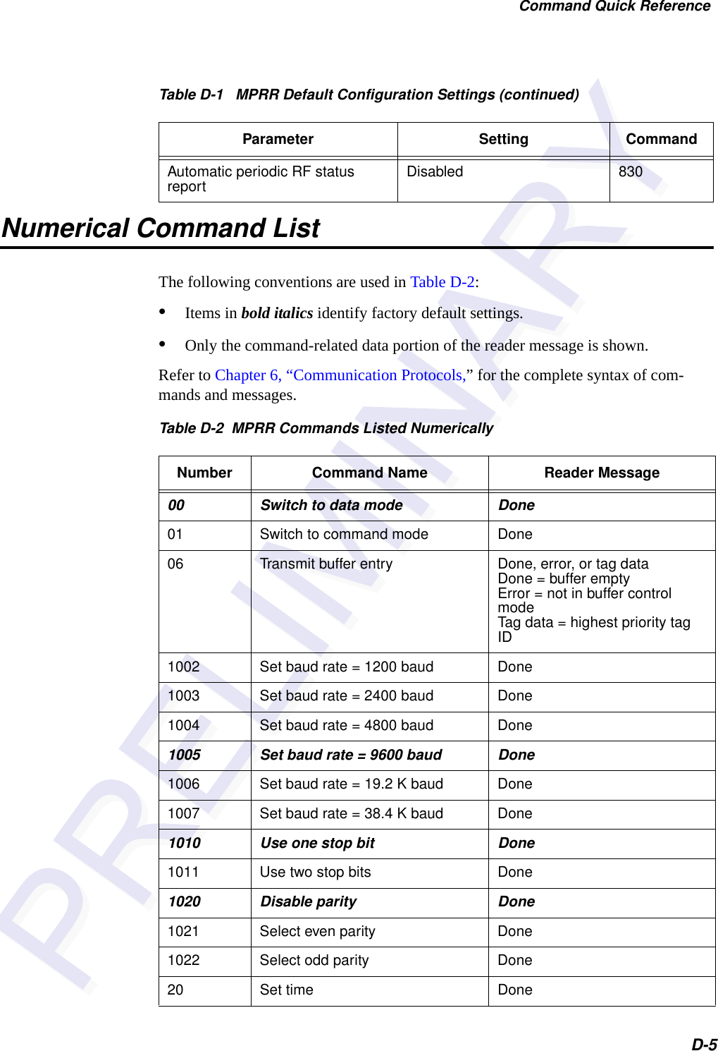
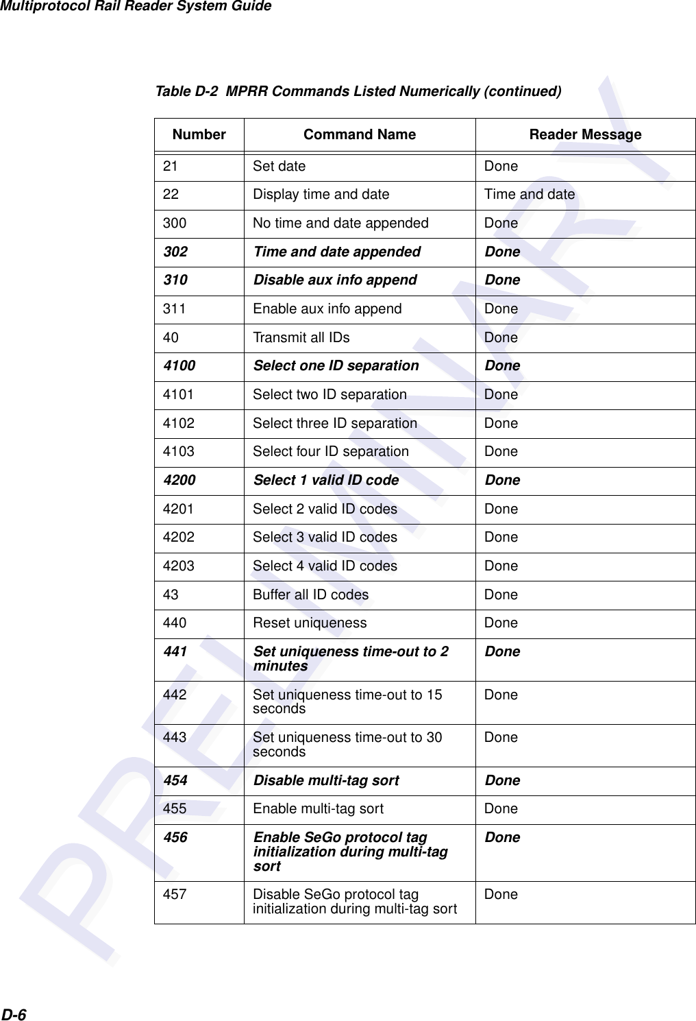
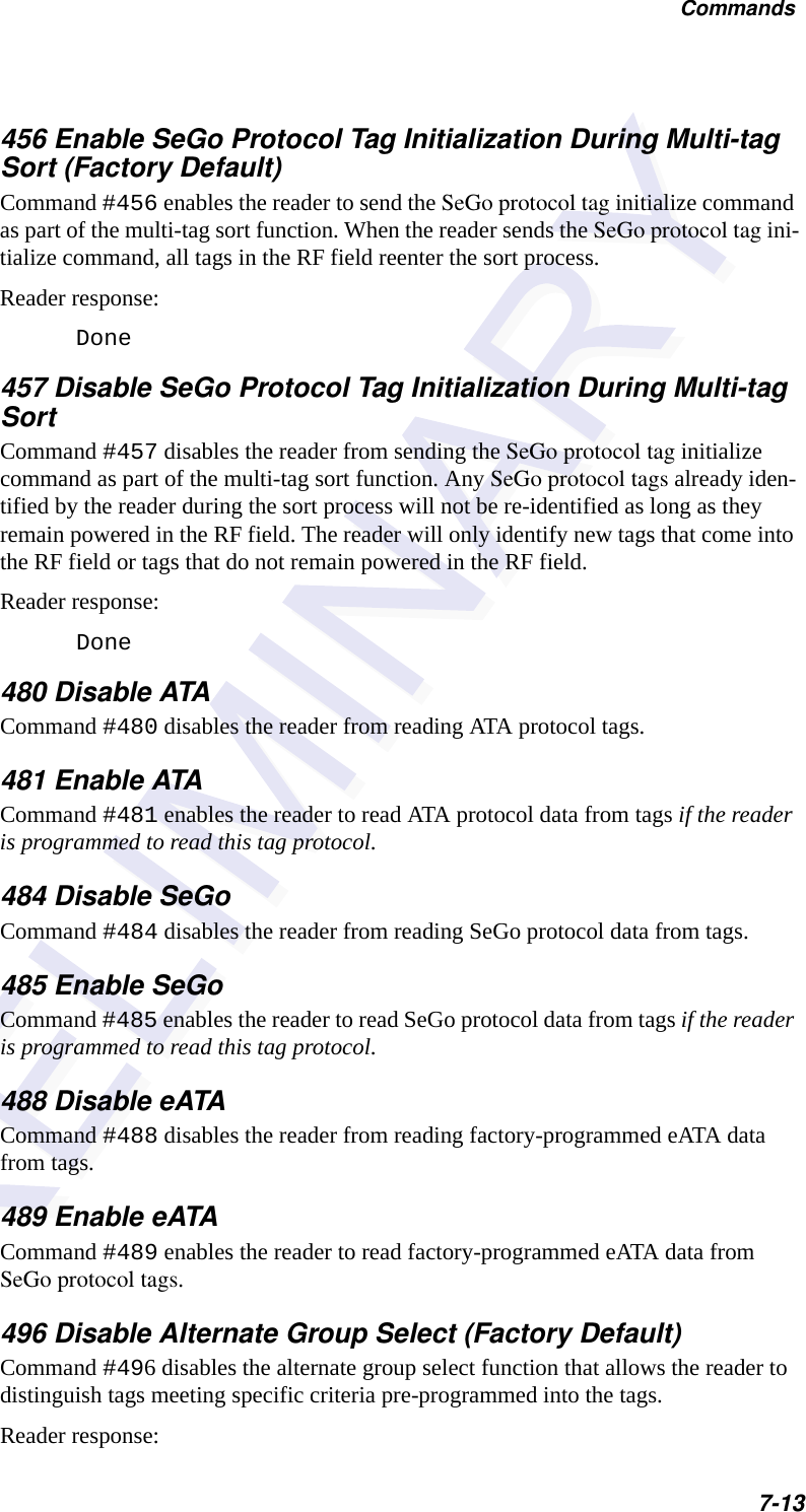
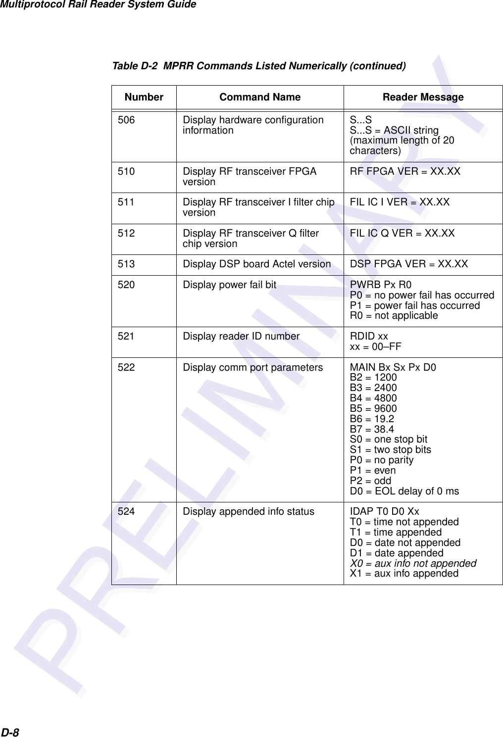
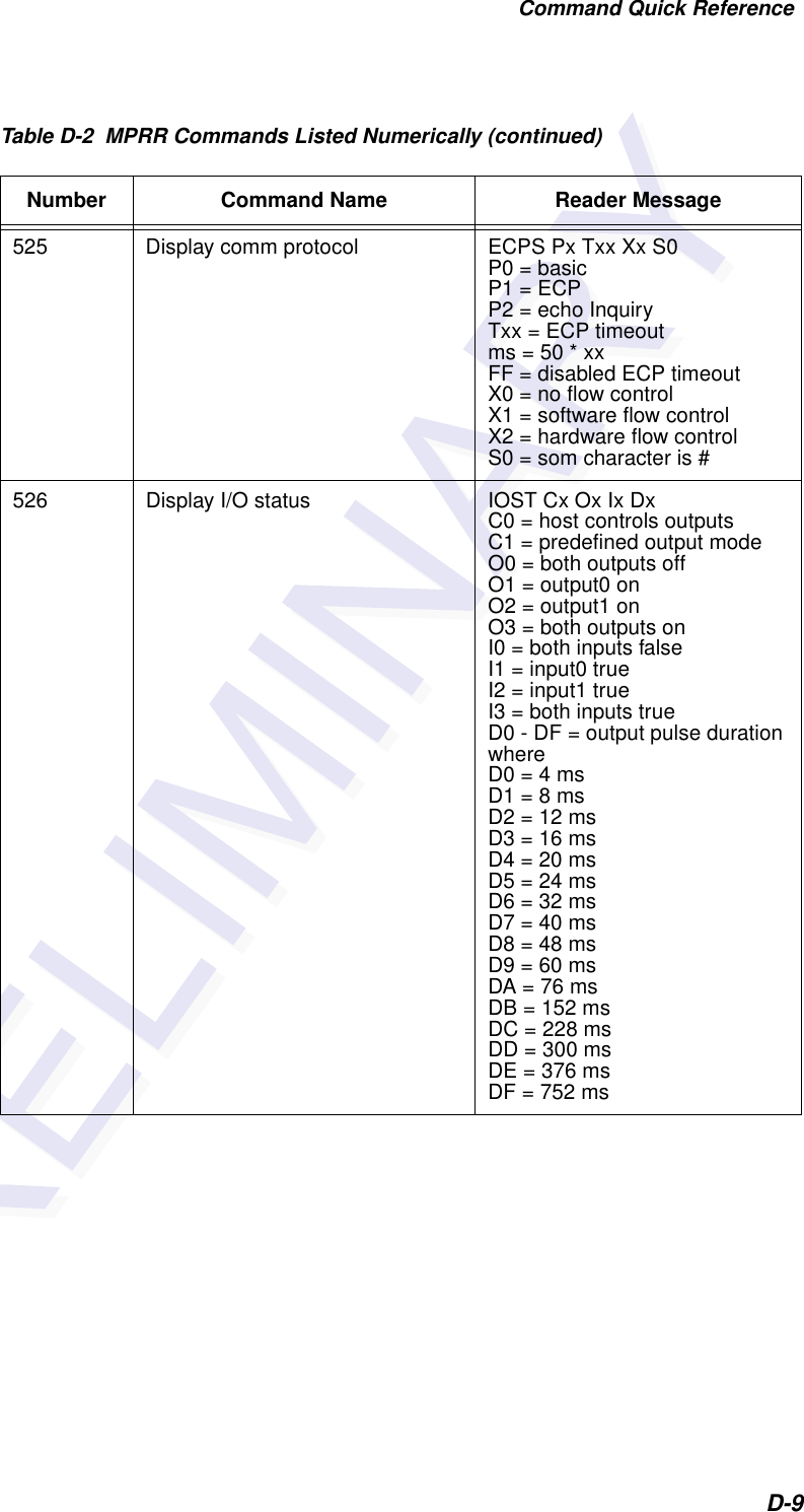
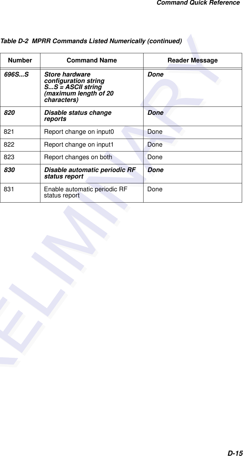
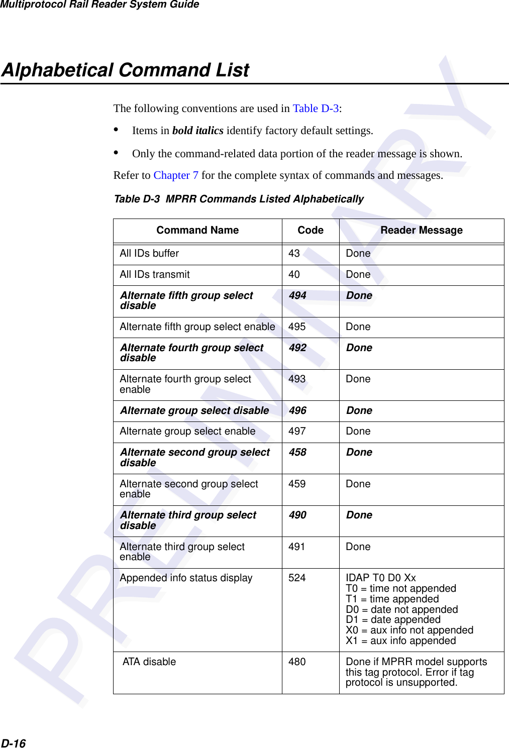
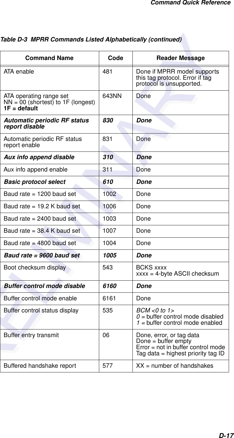
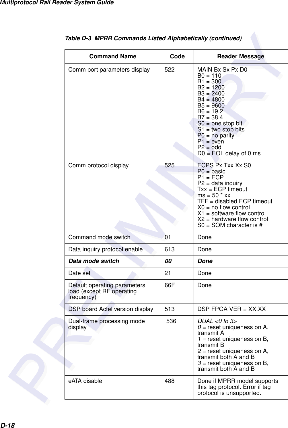
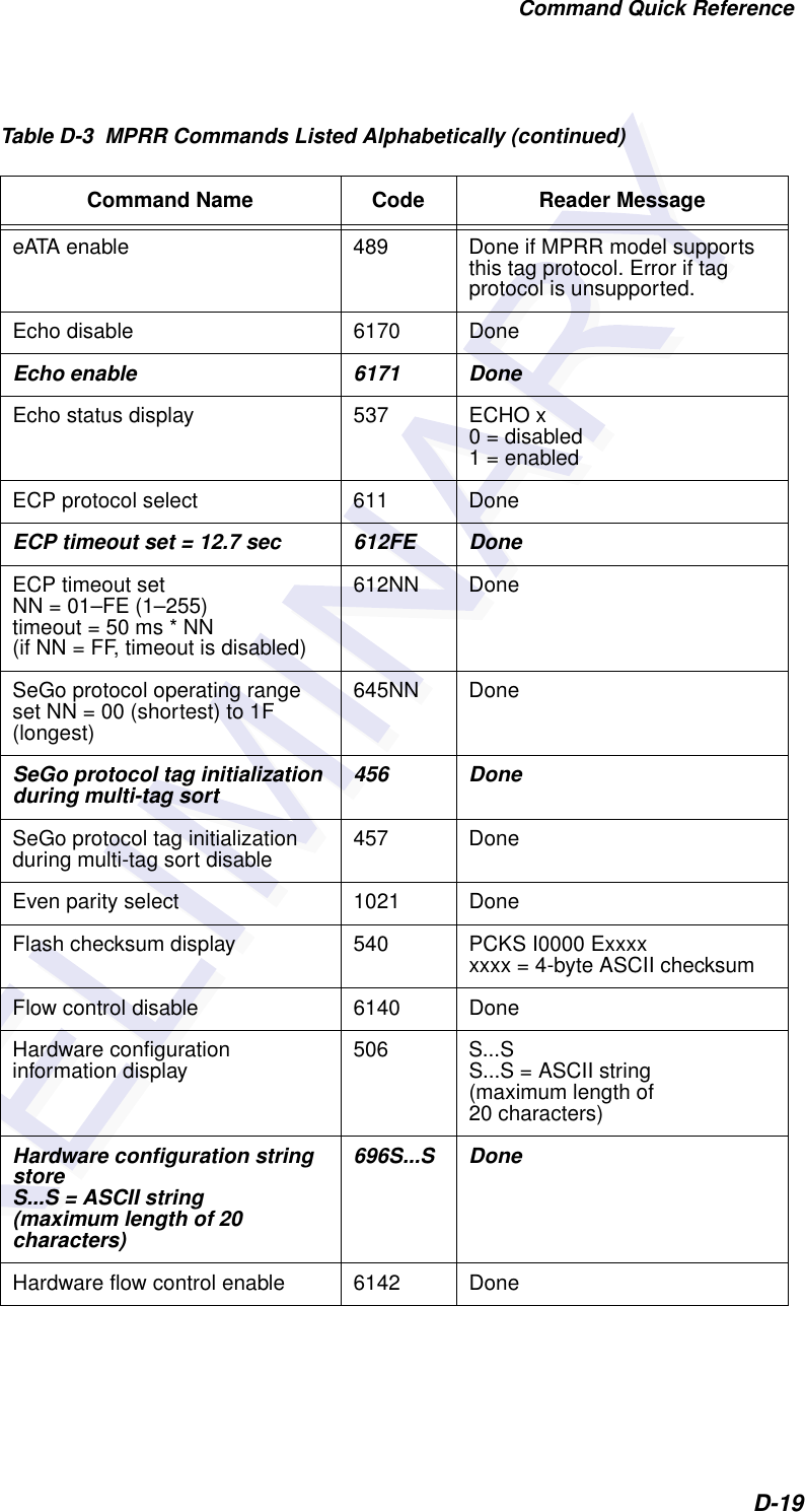
![Command Quick ReferenceD-7458 Disable second alternate group select Done459 Enable second alternate group select Done 480 Disable ATA Done if MPRR model supports this tag protocol. Error if tag protocol is unsupported.481 Enable ATA Done if MPRR model supports this tag protocol. Error if tag protocol is unsupported.484 Disable SeGo Done if MPRR model supports this tag protocol. Error if tag protocol is unsupported.485 Enable SeGo Done if MPRR model supports this tag protocol. Error if tag protocol is unsupported.488 Disable eATA Done if MPRR model supports this tag protocol. Error if tag protocol is unsupported.489 Enable eATA Done if MPRR model supports this tag protocol. Error if tag protocol is unsupported.490 Disable third alternate group select Done491 Enable third alternate group select Done 492 Disable fourth alternate group select Done493 Enable fourth alternate group select Done 494 Disable fifth alternate group select Done495 Enable fifth alternate group select Done 496 Disable alternate group select Done497 Enable alternate group select Done505 Display version Model [model] Ver [version no.] SN [serial no.]Table D-2 MPRR Commands Listed Numerically (continued)Number Command Name Reader Message](https://usermanual.wiki/TransCore/05716/User-Guide-1366466-Page-185.png)
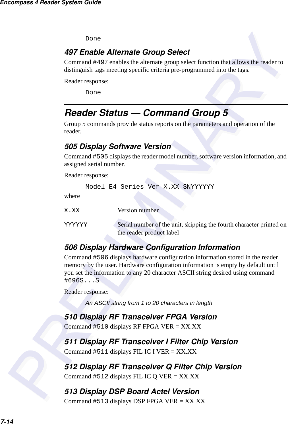
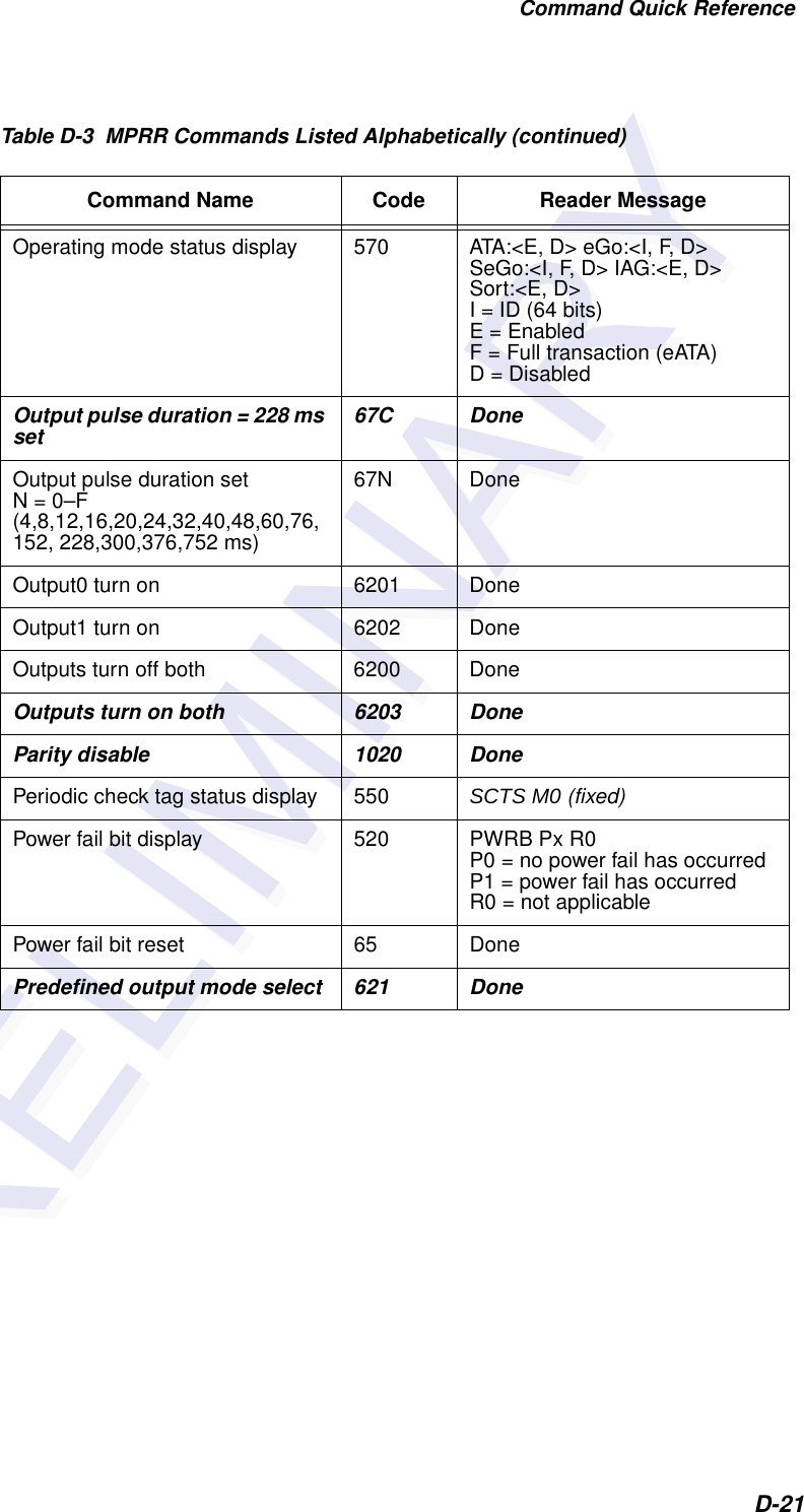
![Command Quick ReferenceD-13612NN Set ECP timeoutNN = 01–FE (1–255)timeout = 50 ms * NN(if NN = FF, timeout isdisabled)Done 612FE Set ECP timeout = 12.7 sec Done 613 Enable data inquiry protocol Done6140 Disable flow control Done6141 Enable software flow control Done6142 Enable hardware flow control Done6160 Disable buffer control mode Done6161 Enable buffer control mode Done6170 Disable echo Done6171 Enable echo Done 6200 Turn both outputs off Done6201 Turn output0 on Done6202 Turn output1 on Done6203 Turn both outputs on Done621 Select predefined output mode Done63 Reset reader Model [model] Ver [version no.] SN [serial no.]Copyright [date]TransCore 6400 Turn off RF Done6401 Turn on RF Done6402 Turns on continuous wave RF until commands 6400 or 641 are received by the readerDone641 Select RF-by-input control Done642NN Select RF operating frequency Done643NN Set ATA operating rangeNN = 00 (shortest) to 1F (longest)1F = defaultDoneTable D-2 MPRR Commands Listed Numerically (continued)Number Command Name Reader Message](https://usermanual.wiki/TransCore/05716/User-Guide-1366466-Page-191.png)
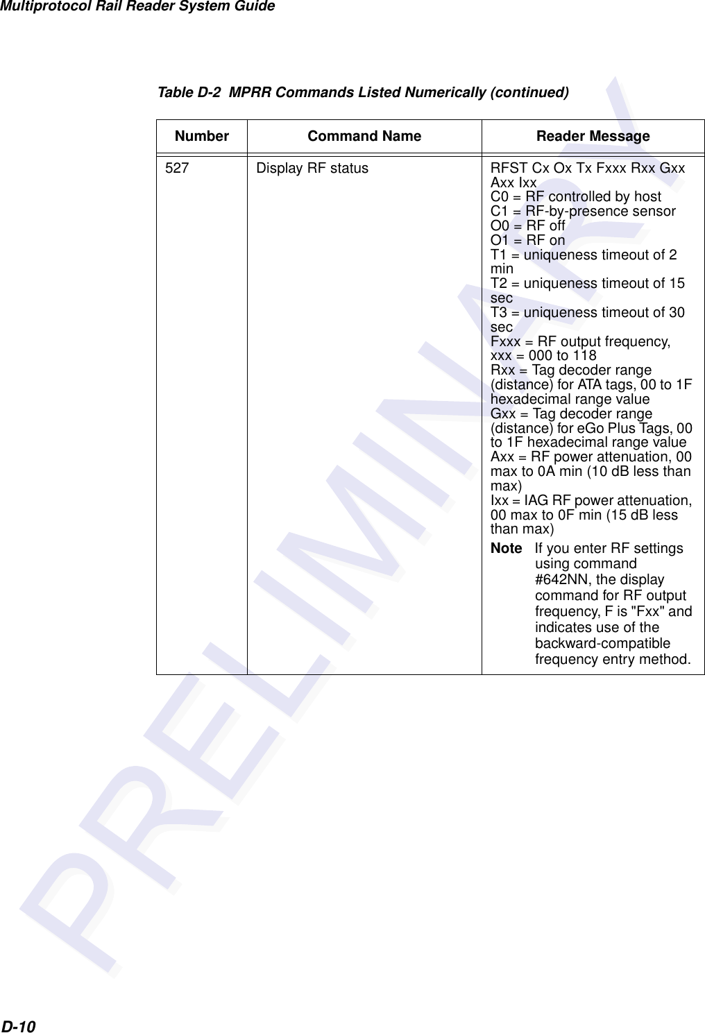
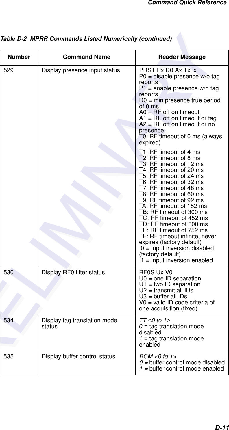
![Multiprotocol Rail Reader System GuideD-22Presence input status display 529 PRST Px D0 Ax Tx IxP0 = disable presence w/o tag reportsP1 = enable presence w/o tag reportsD0 = min presence true period of 0 msA0 = RF off on timeoutA1 = RF off on timeout or tagA2 = RF off on timeout or no presenceT0: RF timeout of 0 ms (always expired)T1: RF timeout of 4 msT2: RF timeout of 8 msT3: RF timeout of 12 msT4: RF timeout of 20 msT5: RF timeout of 24 msT6: RF timeout of 32 msT7: RF timeout of 48 msT8: RF timeout of 60 msT9: RF timeout of 92 msTA: RF timeout of 152 msTB: RF timeout of 300 msTC: RF timeout of 452 msTD: RF timeout of 600 msTE: RF timeout of 752 msTF: RF timeout infinite, never expires (factory default)I0 = Input inversion disabled (factory default)I1 = Input inversion enabledPresence without tag reports disable 6900 DonePresence without tag reports enable 6901 DoneReader ID number display 521 RDID xx xx = 00–FFReader ID number setNN = 00-FF(00 = factory default)60NN DoneReader reset 63 Model [model] Ver [version no.] SN [serial no.]Copyright [date]TransCore Report changes both 823 DoneRF attenuation setNN = 00 to 0A 644NN Done Table D-3 MPRR Commands Listed Alphabetically (continued)Command Name Code Reader Message](https://usermanual.wiki/TransCore/05716/User-Guide-1366466-Page-200.png)
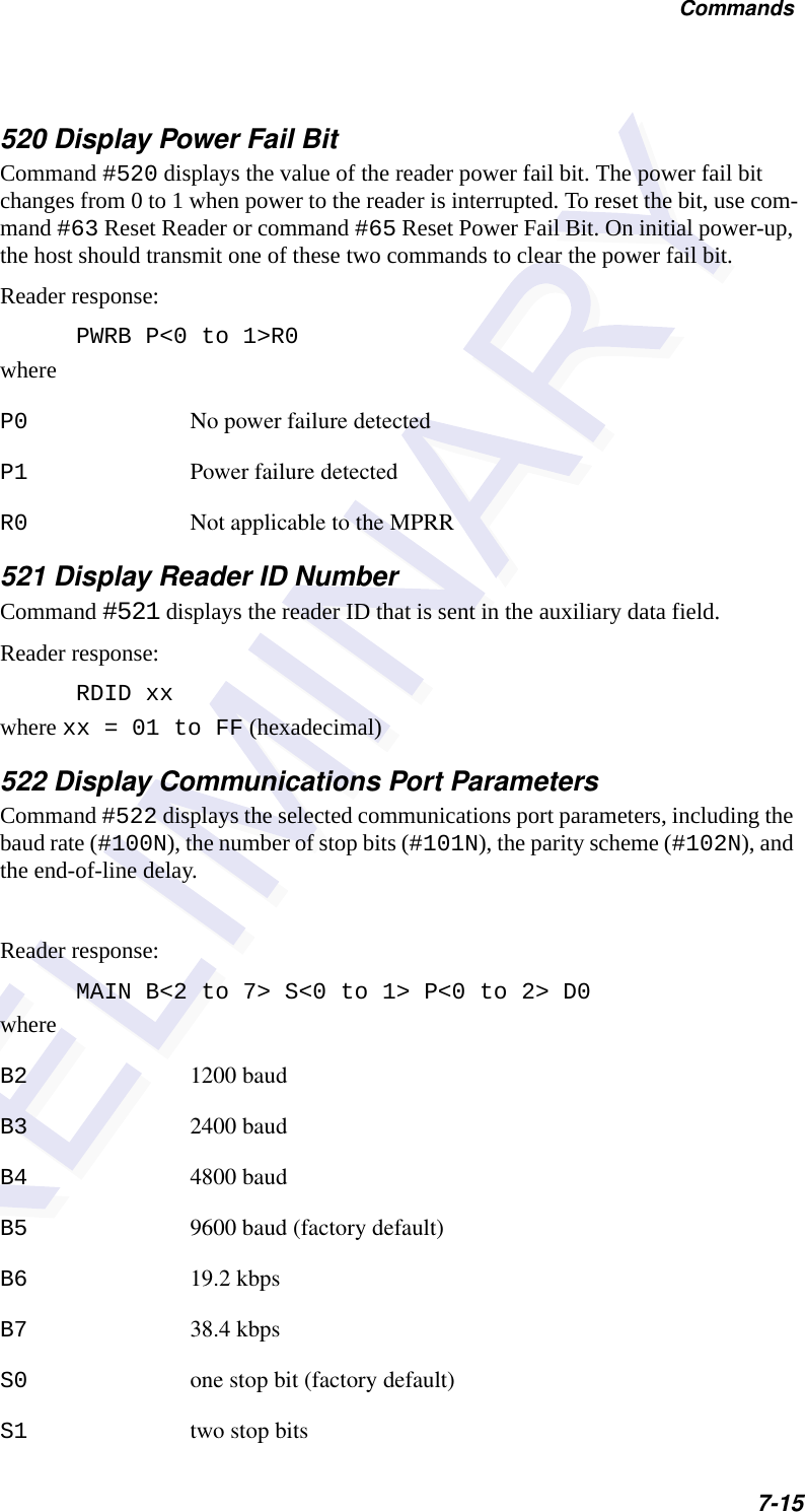
![Command Quick ReferenceD-25Tag translation mode status display 534 TT <0 to 1>0 = tag translation mode disabled1 = tag translation mode enabledTime and date appended 302 DoneTime and date display 22 Time and dateTime and date not appended 300 DoneTime set 20 DoneUniqueness reset 440 DoneUniqueness time-out set to 2 minutes 441 DoneUniqueness time-out set to 15 seconds 442 DoneUniqueness time-out set to 30 seconds 443 DoneValid ID code select four 4203 DoneValid ID code select one 4200 DoneValid ID code select three 4202 DoneValid ID code select two 4201 DoneVersion display 505 Model [model] Ver [ver no.] SN [serial no.]Table D-3 MPRR Commands Listed Alphabetically (continued)Command Name Code Reader Message](https://usermanual.wiki/TransCore/05716/User-Guide-1366466-Page-203.png)