TransCore 05716 LOCATION MONITORING SERVICE TRANSMITTER User Manual MPRR SG
TransCore LOCATION MONITORING SERVICE TRANSMITTER MPRR SG
Users Manual

TransCore
8600 Jefferson Street NE
Albuquerque, New Mexico 87113
October 2010
P/N 412123
Multiprotocol Rail Reader System Guide
This version of the MPRR guide is preliminary information,
which was provided to Rogers Lab to satisfy FCC licensing
submittal requirements.
This document can be used for internal review only. Please
forward any review comments to john.stikar@transcore.com.
DO NOT DISTRIBUTE THIS DOCUMENT OUTSIDE OF
TRANSCORE.

Multiprotocol Rail Reader System Guide
Information in this document is subject to change and does not represent a commitment on the part of
TC License, Ltd.
© 2010 TC License, Ltd. All rights reserved. TRANSCORE, AMTECH, and EGO are registered
trademarks of TC License, Ltd. All other trademarks listed are the property of their respective owners.
Contents are subject to change. Printed in the U.S.A.
For further information, contact:
TransCore
3410 Midcourt Road, Suite 102
Carrollton, Texas 75006 USA
Phone: (214) 461-4031
Fax: (214) 461-6478
Technical Support
Web: transcore.com/rfidsupport
For comments or questions about this document, e-mail tech.pubs@transcore.com.

WARNING TO USERS IN THE UNITED STATES
FEDERAL COMMUNICATIONS COMMISSION (FCC)
LOCATION AND MONITORING SERVICE STATEMENT
47 CFR §90.351
NOTE: The user is required to obtain a Part 90 site license from the FCC to operate this radio frequency
identification (RFID) device in the United States. See product label for FCC ID number. Access the FCC
Web site at www.fcc.gov/Forms/Form601/601.html or at wireless.fcc.gov/index.htm?job=online_filing to
obtain additional information concerning licensing requirements.
NOTE: Users in all countries should check with the appropriate local authorities for licensing
requirements.
FCC RADIO FREQUENCY INTERFERENCE STATEMENT
47 CFR §15.105(a)
NOTE: This equipment has been tested and found to comply with the limits for a Class A digital device
pursuant to Part 15 of the FCC rules. These limits are designed to provide reasonable protection against
harmful interference when the equipment is operated in a commercial environment. This equipment
generates, uses, and can radiate RF energy and may cause harmful interference to radio communications if
not installed and used in accordance with the instruction manual. Operating this equipment in a residential
area is likely to cause harmful interference, in which case, depending on the laws in effect, the user may be
required to correct the interference at their own expense.
NO UNAUTHORIZED MODIFICATIONS
47 CFR §15.21
CAUTION: This equipment may not be modified, altered, or changed in any way without permission
from TransCore, LP. Unauthorized modification may void the equipment authorization from the FCC and
will void the TransCore warranty.
USE OF SHIELDED CABLES IS REQUIRED
47 CFR §15.27(a)
NOTE: Shielded cables must be used with this equipment to comply with FCC regulations.
TransCore, LP
USA

Multiprotocol Rail Reader System Guide
Health Limits for Multiprotocol Rail Reader Using Exter-
nal Antenna (902 to 928 MHz)
Within the United States, environmental guidelines regulating safe exposure levels are
issued by the Occupational Safety and Health Administration (OSHA).
Section 1910.97 of OSHA Safety and Health Standards 2206 legislates a maximum
safe exposure limit of 10 milliwatts per square centimeter (mW/cm2) averaged over 6
minutes at 902 MHz.
Although not binding, other organizations such as the American National Standards
Institute (ANSI) have issued similar guidelines that are more restrictive than the
OSHA limits (ANSI C95.1). ANSI guidelines recommend a maximum safe power
density in mW/cm2 of:
Frequency (in MHz)
1500
Thus, the maximum permissible exposure for general population/uncontrolled expo-
sure at 902 MHz is 0.60 mW/cm2. The power limit is a six-minute average.
The RF power density generated by the Multiprotocol Rail Reader (MPRR) was cal-
culated using a maximum antenna gain of 9.5 dBd, equivalent to the antenna gain of
the external antenna.
Warning
At 2 W conducted into the antenna and a distance of 30 inches (77 cm) from the
antenna, the maximum power density calculated was less than 0.60 mW/cm2. Install
the antenna at least 30 inches (77 cm) from the general public. Maintenance per-
sonnel must remain at least 14 inches (35 cm) from antenna when system is operat-
ing.
The data confirms that the TransCore MPRR effectively meets OSHA requirements
and thus does not represent an operating hazard to either the general public or mainte-
nance personnel.

Contents

Contents
Health Limits for Multiprotocol Rail Reader Using External Antenna
(902 to 928 MHz). . . . . . . . . . . . . . . . . . . . . . . . . . . . . . . . . . . . . . . . . . . . . . . . . . . . . . iv
1 Introduction
Purpose. . . . . . . . . . . . . . . . . . . . . . . . . . . . . . . . . . . . . . . . . . . . . . . . . . . . . . . . . . . . 1-3
Audience. . . . . . . . . . . . . . . . . . . . . . . . . . . . . . . . . . . . . . . . . . . . . . . . . . . . . . . . . . . 1-3
System Guide Organization . . . . . . . . . . . . . . . . . . . . . . . . . . . . . . . . . . . . . . . . . . . 1-3
Typographical Conventions . . . . . . . . . . . . . . . . . . . . . . . . . . . . . . . . . . . . . . . . . . . 1-5
Licensing Requirements . . . . . . . . . . . . . . . . . . . . . . . . . . . . . . . . . . . . . . . . . . . . . . 1-5
Technical Support . . . . . . . . . . . . . . . . . . . . . . . . . . . . . . . . . . . . . . . . . . . . . . . . . . . 1-6
2 Developing the Site Plan
System Description . . . . . . . . . . . . . . . . . . . . . . . . . . . . . . . . . . . . . . . . . . . . . . . . . . 2-3
Reader. . . . . . . . . . . . . . . . . . . . . . . . . . . . . . . . . . . . . . . . . . . . . . . . . . . . . . . . . . . 2-3
Tags . . . . . . . . . . . . . . . . . . . . . . . . . . . . . . . . . . . . . . . . . . . . . . . . . . . . . . . . . . . . 2-3
How It Works. . . . . . . . . . . . . . . . . . . . . . . . . . . . . . . . . . . . . . . . . . . . . . . . . . . . . . 2-3
Overview of Site Planning. . . . . . . . . . . . . . . . . . . . . . . . . . . . . . . . . . . . . . . . . . . . . 2-4
Reading of Mixed Population Tags . . . . . . . . . . . . . . . . . . . . . . . . . . . . . . . . . . . . . 2-4
Antenna and Tag Alignment . . . . . . . . . . . . . . . . . . . . . . . . . . . . . . . . . . . . . . . . . . . 2-4
Polarization . . . . . . . . . . . . . . . . . . . . . . . . . . . . . . . . . . . . . . . . . . . . . . . . . . . . . . . 2-5
Unobstructed Line of Sight. . . . . . . . . . . . . . . . . . . . . . . . . . . . . . . . . . . . . . . . . . . 2-5
Antenna Selection . . . . . . . . . . . . . . . . . . . . . . . . . . . . . . . . . . . . . . . . . . . . . . . . . . . 2-6
AA3100 Yagi (without radome) . . . . . . . . . . . . . . . . . . . . . . . . . . . . . . . . . . . . . . . . 2-6
AA3101 Yagi (with radome) . . . . . . . . . . . . . . . . . . . . . . . . . . . . . . . . . . . . . . . . . . 2-6
AA3110 Parapanel . . . . . . . . . . . . . . . . . . . . . . . . . . . . . . . . . . . . . . . . . . . . . . . . . 2-7
AA3140 PCB Log Periodic . . . . . . . . . . . . . . . . . . . . . . . . . . . . . . . . . . . . . . . . . . . 2-7
Site Layout and Traffic Flow . . . . . . . . . . . . . . . . . . . . . . . . . . . . . . . . . . . . . . . . . . . 2-7
The MPRR Read Zone . . . . . . . . . . . . . . . . . . . . . . . . . . . . . . . . . . . . . . . . . . . . . . 2-7
Other MPRRs in the Area . . . . . . . . . . . . . . . . . . . . . . . . . . . . . . . . . . . . . . . . . . . . 2-8
Reflection, Refraction, and Diffraction of RF Signals . . . . . . . . . . . . . . . . . . . . . . . 2-8
Existing Interference . . . . . . . . . . . . . . . . . . . . . . . . . . . . . . . . . . . . . . . . . . . . . . . . 2-9

vii
Electrical and Communications Requirements. . . . . . . . . . . . . . . . . . . . . . . . . . . . 2-9
Junction Box . . . . . . . . . . . . . . . . . . . . . . . . . . . . . . . . . . . . . . . . . . . . . . . . . . . . . . 2-9
Power and Communications Cables . . . . . . . . . . . . . . . . . . . . . . . . . . . . . . . . . . . . 2-9
Electrical Power . . . . . . . . . . . . . . . . . . . . . . . . . . . . . . . . . . . . . . . . . . . . . . . . 2-10
Host Communications . . . . . . . . . . . . . . . . . . . . . . . . . . . . . . . . . . . . . . . . . . . . . . 2-10
Input/Output Circuits . . . . . . . . . . . . . . . . . . . . . . . . . . . . . . . . . . . . . . . . . . . . . . . 2-11
Antenna Interface . . . . . . . . . . . . . . . . . . . . . . . . . . . . . . . . . . . . . . . . . . . . . . . . . 2-12
3 Choosing, Installing, and Removing Tags
Compatible Tag Types. . . . . . . . . . . . . . . . . . . . . . . . . . . . . . . . . . . . . . . . . . . . . . . . 3-3
Reader and Tag Model Interoperability . . . . . . . . . . . . . . . . . . . . . . . . . . . . . . . . . . 3-3
Recommended Mounting Locations . . . . . . . . . . . . . . . . . . . . . . . . . . . . . . . . . . . . 3-3
Required Materials . . . . . . . . . . . . . . . . . . . . . . . . . . . . . . . . . . . . . . . . . . . . . . . . . 3-3
Mounting Surface . . . . . . . . . . . . . . . . . . . . . . . . . . . . . . . . . . . . . . . . . . . . . . . . . . 3-4
Tag Positioning . . . . . . . . . . . . . . . . . . . . . . . . . . . . . . . . . . . . . . . . . . . . . . . . . . . . 3-4
Surface Installation Techniques . . . . . . . . . . . . . . . . . . . . . . . . . . . . . . . . . . . . . . . 3-6
Rivet/Bolt Mounting Guidelines. . . . . . . . . . . . . . . . . . . . . . . . . . . . . . . . . . . . . . 3-6
Locomotive Mounting Guidelines . . . . . . . . . . . . . . . . . . . . . . . . . . . . . . . . . . . . . . 3-7
Tag Placement Window Location . . . . . . . . . . . . . . . . . . . . . . . . . . . . . . . . . . . . . . 3-7
Tag Placement . . . . . . . . . . . . . . . . . . . . . . . . . . . . . . . . . . . . . . . . . . . . . . . . . . . . 3-8
Rail Car Mounting Guidelines. . . . . . . . . . . . . . . . . . . . . . . . . . . . . . . . . . . . . . . . . . 3-9
Tag Placement Window Location . . . . . . . . . . . . . . . . . . . . . . . . . . . . . . . . . . . . . . 3-9
Tag Placement . . . . . . . . . . . . . . . . . . . . . . . . . . . . . . . . . . . . . . . . . . . . . . . . . . . 3-10
Tank Car Mounting Guidelines . . . . . . . . . . . . . . . . . . . . . . . . . . . . . . . . . . . . . . . . 3-11
Tag Placement Window Location . . . . . . . . . . . . . . . . . . . . . . . . . . . . . . . . . . . . . 3-11
Tag Placement . . . . . . . . . . . . . . . . . . . . . . . . . . . . . . . . . . . . . . . . . . . . . . . . . . . 3-11
4 Installing the Multiprotocol Rail Reader
Installation Process . . . . . . . . . . . . . . . . . . . . . . . . . . . . . . . . . . . . . . . . . . . . . . . . . . 4-3
Materials Supplied by TransCore . . . . . . . . . . . . . . . . . . . . . . . . . . . . . . . . . . . . . . 4-3
Contents of Shipping Carton. . . . . . . . . . . . . . . . . . . . . . . . . . . . . . . . . . . . . . . . 4-3
Installation Accessory Options (TBD). . . . . . . . . . . . . . . . . . . . . . . . . . . . . . . . . 4-4
Additional Materials Needed for Testing . . . . . . . . . . . . . . . . . . . . . . . . . . . . . . . . . 4-4
Pre-installation Testing of the MPRR. . . . . . . . . . . . . . . . . . . . . . . . . . . . . . . . . . . . 4-4
Testing the MPRR Using an Audible Circuit Tester. . . . . . . . . . . . . . . . . . . . . . . . . 4-4
Connecting the Antenna . . . . . . . . . . . . . . . . . . . . . . . . . . . . . . . . . . . . . . . . . . . . . 4-5
Connecting the MPRR to a Power Supply. . . . . . . . . . . . . . . . . . . . . . . . . . . . . . . . 4-6
Mounting the MPRR. . . . . . . . . . . . . . . . . . . . . . . . . . . . . . . . . . . . . . . . . . . . . . . . . . 4-7
Mounting to an Enclosure Wall or Flat Surface . . . . . . . . . . . . . . . . . . . . . . . . . . . . 4-8
Required Materials . . . . . . . . . . . . . . . . . . . . . . . . . . . . . . . . . . . . . . . . . . . . . . . 4-8

Multiprotocol Rail Reader System Guide
viii
Mounting the Antenna Rail-Side. . . . . . . . . . . . . . . . . . . . . . . . . . . . . . . . . . . . . . . . 4-8
Connecting the Power Supply. . . . . . . . . . . . . . . . . . . . . . . . . . . . . . . . . . . . . . . . . 4-8
Connecting Communications . . . . . . . . . . . . . . . . . . . . . . . . . . . . . . . . . . . . . . . . . . 4-9
Required Materials . . . . . . . . . . . . . . . . . . . . . . . . . . . . . . . . . . . . . . . . . . . . . . . . . 4-9
Connecting the MPRR to the Host . . . . . . . . . . . . . . . . . . . . . . . . . . . . . . . . . . . . . 4-9
Connecting Sense Input and Sense Output Circuits . . . . . . . . . . . . . . . . . . . . . . . 4-9
Sense Input Circuits . . . . . . . . . . . . . . . . . . . . . . . . . . . . . . . . . . . . . . . . . . . . . . . . 4-9
Sense Output Circuit . . . . . . . . . . . . . . . . . . . . . . . . . . . . . . . . . . . . . . . . . . . . . . . 4-10
Marking the Read Zone . . . . . . . . . . . . . . . . . . . . . . . . . . . . . . . . . . . . . . . . . . . . . . 4-10
Required Materials . . . . . . . . . . . . . . . . . . . . . . . . . . . . . . . . . . . . . . . . . . . . . . . . 4-10
5 General Software Information
Command Entry Conventions. . . . . . . . . . . . . . . . . . . . . . . . . . . . . . . . . . . . . . . . . . 5-3
Command Response Conventions. . . . . . . . . . . . . . . . . . . . . . . . . . . . . . . . . . . . . . 5-4
Operating Parameters . . . . . . . . . . . . . . . . . . . . . . . . . . . . . . . . . . . . . . . . . . . . . . . . 5-4
Power Fail . . . . . . . . . . . . . . . . . . . . . . . . . . . . . . . . . . . . . . . . . . . . . . . . . . . . . . . . . . 5-5
Program Download . . . . . . . . . . . . . . . . . . . . . . . . . . . . . . . . . . . . . . . . . . . . . . . . . . 5-5
Download Considerations . . . . . . . . . . . . . . . . . . . . . . . . . . . . . . . . . . . . . . . . . . . . 5-5
Download Procedures. . . . . . . . . . . . . . . . . . . . . . . . . . . . . . . . . . . . . . . . . . . . . . . 5-5
Startup. . . . . . . . . . . . . . . . . . . . . . . . . . . . . . . . . . . . . . . . . . . . . . . . . . . . . . . . . . . . . 5-5
Sign-On Message . . . . . . . . . . . . . . . . . . . . . . . . . . . . . . . . . . . . . . . . . . . . . . . . . . 5-6
Boot Failure Message . . . . . . . . . . . . . . . . . . . . . . . . . . . . . . . . . . . . . . . . . . . . . . . 5-6
Tag/Message Buffer. . . . . . . . . . . . . . . . . . . . . . . . . . . . . . . . . . . . . . . . . . . . . . . . . . 5-6
6 Communications Protocols
Introduction . . . . . . . . . . . . . . . . . . . . . . . . . . . . . . . . . . . . . . . . . . . . . . . . . . . . . . . . 6-3
Basic Protocol . . . . . . . . . . . . . . . . . . . . . . . . . . . . . . . . . . . . . . . . . . . . . . . . . . . . . . 6-4
Error Correcting Protocol . . . . . . . . . . . . . . . . . . . . . . . . . . . . . . . . . . . . . . . . . . . . . 6-4
Basic Protocol and ECP Format. . . . . . . . . . . . . . . . . . . . . . . . . . . . . . . . . . . . . . . . 6-5
Reader Transmissions . . . . . . . . . . . . . . . . . . . . . . . . . . . . . . . . . . . . . . . . . . . . . . 6-5
ECP Host ACK/NAK Response. . . . . . . . . . . . . . . . . . . . . . . . . . . . . . . . . . . . . . . . 6-6
Switch to Command Mode Request . . . . . . . . . . . . . . . . . . . . . . . . . . . . . . . . . . . . 6-7
Host Transmission. . . . . . . . . . . . . . . . . . . . . . . . . . . . . . . . . . . . . . . . . . . . . . . . . . 6-7
Reader Command Response . . . . . . . . . . . . . . . . . . . . . . . . . . . . . . . . . . . . . . . . . 6-8
Sample Messages. . . . . . . . . . . . . . . . . . . . . . . . . . . . . . . . . . . . . . . . . . . . . . . . . . 6-8

Contents
ix
Reader Transmissions . . . . . . . . . . . . . . . . . . . . . . . . . . . . . . . . . . . . . . . . . . . . 6-9
Host Command Transmissions. . . . . . . . . . . . . . . . . . . . . . . . . . . . . . . . . . . . . . 6-9
Timing and Synchronization . . . . . . . . . . . . . . . . . . . . . . . . . . . . . . . . . . . . . . . . . 6-10
Reader-Addressed Failure Conditions . . . . . . . . . . . . . . . . . . . . . . . . . . . . . . . . . 6-12
Illegal Sequence Number (not in the range 0–9, A–F) . . . . . . . . . . . . . . . . . . . 6-12
Wrong Sequence Number . . . . . . . . . . . . . . . . . . . . . . . . . . . . . . . . . . . . . . . . 6-12
Incorrect CRC. . . . . . . . . . . . . . . . . . . . . . . . . . . . . . . . . . . . . . . . . . . . . . . . . . 6-12
Illegal Command. . . . . . . . . . . . . . . . . . . . . . . . . . . . . . . . . . . . . . . . . . . . . . . . 6-12
Transmission Timeout . . . . . . . . . . . . . . . . . . . . . . . . . . . . . . . . . . . . . . . . . . . 6-12
Receive Timeout. . . . . . . . . . . . . . . . . . . . . . . . . . . . . . . . . . . . . . . . . . . . . . . . 6-12
Asynchronous Message/Command Message Collision . . . . . . . . . . . . . . . . . . 6-12
Host-Addressed Failure Conditions. . . . . . . . . . . . . . . . . . . . . . . . . . . . . . . . . . . . 6-12
Illegal or Wrong Sequence Number . . . . . . . . . . . . . . . . . . . . . . . . . . . . . . . . . 6-12
Incorrect CRC. . . . . . . . . . . . . . . . . . . . . . . . . . . . . . . . . . . . . . . . . . . . . . . . . . 6-13
Transmission Timeout . . . . . . . . . . . . . . . . . . . . . . . . . . . . . . . . . . . . . . . . . . . 6-13
Receive Timeout. . . . . . . . . . . . . . . . . . . . . . . . . . . . . . . . . . . . . . . . . . . . . . . . 6-13
Asynchronous Message/Command Message Collision . . . . . . . . . . . . . . . . . . 6-13
ECP Reliability . . . . . . . . . . . . . . . . . . . . . . . . . . . . . . . . . . . . . . . . . . . . . . . . . . . . . 6-13
CRC Calculation . . . . . . . . . . . . . . . . . . . . . . . . . . . . . . . . . . . . . . . . . . . . . . . . . . . . 6-13
Manually Disabling ECP for Maintenance . . . . . . . . . . . . . . . . . . . . . . . . . . . . . . . 6-16
7 Commands
Introduction . . . . . . . . . . . . . . . . . . . . . . . . . . . . . . . . . . . . . . . . . . . . . . . . . . . . . . . . 7-3
Operating Modes . . . . . . . . . . . . . . . . . . . . . . . . . . . . . . . . . . . . . . . . . . . . . . . . . . . . 7-3
Data Mode. . . . . . . . . . . . . . . . . . . . . . . . . . . . . . . . . . . . . . . . . . . . . . . . . . . . . . . . 7-3
Command Mode . . . . . . . . . . . . . . . . . . . . . . . . . . . . . . . . . . . . . . . . . . . . . . . . . . . 7-3
Download Mode. . . . . . . . . . . . . . . . . . . . . . . . . . . . . . . . . . . . . . . . . . . . . . . . . . . . 7-4
Command List . . . . . . . . . . . . . . . . . . . . . . . . . . . . . . . . . . . . . . . . . . . . . . . . . . . . . . 7-4
Reader Mode Control — Command Group 0 . . . . . . . . . . . . . . . . . . . . . . . . . . . . . 7-5
00 Switch to Data Mode (Factory Default) . . . . . . . . . . . . . . . . . . . . . . . . . . . . . 7-5
01 Switch to Command Mode. . . . . . . . . . . . . . . . . . . . . . . . . . . . . . . . . . . . . . . 7-5
Communications Port Control — Command Group 1 . . . . . . . . . . . . . . . . . . . . . . . 7-5
100N Select Baud Rate . . . . . . . . . . . . . . . . . . . . . . . . . . . . . . . . . . . . . . . . . . . 7-5
101N Select Stop Bits. . . . . . . . . . . . . . . . . . . . . . . . . . . . . . . . . . . . . . . . . . . . . 7-6
102N Select Parity . . . . . . . . . . . . . . . . . . . . . . . . . . . . . . . . . . . . . . . . . . . . . . . 7-6
Command Group 2 . . . . . . . . . . . . . . . . . . . . . . . . . . . . . . . . . . . . . . . . . . . . . . . . . 7-6
20 Set Time . . . . . . . . . . . . . . . . . . . . . . . . . . . . . . . . . . . . . . . . . . . . . . . . . . . . 7-6
21 Set Date. . . . . . . . . . . . . . . . . . . . . . . . . . . . . . . . . . . . . . . . . . . . . . . . . . . . . 7-7
22 Display Time and Date . . . . . . . . . . . . . . . . . . . . . . . . . . . . . . . . . . . . . . . . . 7-7
Append Information — Command Group 3. . . . . . . . . . . . . . . . . . . . . . . . . . . . . . . 7-8
30N Append Time and Date Selection . . . . . . . . . . . . . . . . . . . . . . . . . . . . . . . . 7-8
31N Append Auxiliary Information Selection . . . . . . . . . . . . . . . . . . . . . . . . . . . 7-9

Multiprotocol Rail Reader System Guide
x
ID Filtering — Command Group 4. . . . . . . . . . . . . . . . . . . . . . . . . . . . . . . . . . . . . . 7-9
40 Transmit All ID Codes . . . . . . . . . . . . . . . . . . . . . . . . . . . . . . . . . . . . . . . . . . 7-9
410N Select Unique ID Code Criteria (Anti-passback Feature) . . . . . . . . . . . . 7-10
420N Select Valid ID Code Criteria . . . . . . . . . . . . . . . . . . . . . . . . . . . . . . . . . 7-10
43 Buffer All ID Codes . . . . . . . . . . . . . . . . . . . . . . . . . . . . . . . . . . . . . . . . . . . 7-11
440 Reset Uniqueness . . . . . . . . . . . . . . . . . . . . . . . . . . . . . . . . . . . . . . . . . . . . . 7-11
44N Set Uniqueness Timeout. . . . . . . . . . . . . . . . . . . . . . . . . . . . . . . . . . . . . . 7-11
452 Disable Tag Translation Mode (Factory Default). . . . . . . . . . . . . . . . . . . . 7-12
453 Enable Tag Translation Mode . . . . . . . . . . . . . . . . . . . . . . . . . . . . . . . . . . 7-12
454 Disable Multi-tag Sort (Factory Default). . . . . . . . . . . . . . . . . . . . . . . . . . . 7-12
455 Enable Multi-tag Sort . . . . . . . . . . . . . . . . . . . . . . . . . . . . . . . . . . . . . . . . . 7-12
456 Enable SeGo Protocol Tag Initialization During Multi-tag Sort
(Factory Default). . . . . . . . . . . . . . . . . . . . . . . . . . . . . . . . . . . . . . . . . . . . . . . . 7-13
457 Disable SeGo Protocol Tag Initialization During Multi-tag Sort . . . . . . . . . 7-13
480 Disable ATA. . . . . . . . . . . . . . . . . . . . . . . . . . . . . . . . . . . . . . . . . . . . . . . . 7-13
481 Enable ATA . . . . . . . . . . . . . . . . . . . . . . . . . . . . . . . . . . . . . . . . . . . . . . . . 7-13
484 Disable SeGo. . . . . . . . . . . . . . . . . . . . . . . . . . . . . . . . . . . . . . . . . . . . . . . 7-13
485 Enable SeGo . . . . . . . . . . . . . . . . . . . . . . . . . . . . . . . . . . . . . . . . . . . . . . . 7-13
488 Disable eATA. . . . . . . . . . . . . . . . . . . . . . . . . . . . . . . . . . . . . . . . . . . . . . . 7-13
489 Enable eATA . . . . . . . . . . . . . . . . . . . . . . . . . . . . . . . . . . . . . . . . . . . . . . . 7-13
496 Disable Alternate Group Select (Factory Default) . . . . . . . . . . . . . . . . . . . 7-13
497 Enable Alternate Group Select . . . . . . . . . . . . . . . . . . . . . . . . . . . . . . . . . 7-14
Reader Status — Command Group 5 . . . . . . . . . . . . . . . . . . . . . . . . . . . . . . . . . . 7-14
505 Display Software Version. . . . . . . . . . . . . . . . . . . . . . . . . . . . . . . . . . . . . . 7-14
506 Display Hardware Configuration Information. . . . . . . . . . . . . . . . . . . . . . . 7-14
510 Display RF Transceiver FPGA Version . . . . . . . . . . . . . . . . . . . . . . . . . . . 7-14
511 Display RF Transceiver I Filter Chip Version. . . . . . . . . . . . . . . . . . . . . . . 7-14
512 Display RF Transceiver Q Filter Chip Version. . . . . . . . . . . . . . . . . . . . . . 7-14
513 Display DSP Board Actel Version . . . . . . . . . . . . . . . . . . . . . . . . . . . . . . . 7-14
520 Display Power Fail Bit . . . . . . . . . . . . . . . . . . . . . . . . . . . . . . . . . . . . . . . . 7-15
521 Display Reader ID Number . . . . . . . . . . . . . . . . . . . . . . . . . . . . . . . . . . . . 7-15
522 Display Communications Port Parameters . . . . . . . . . . . . . . . . . . . . . . . . 7-15
524 Display Appended Information Status . . . . . . . . . . . . . . . . . . . . . . . . . . . . 7-16
525 Display Communications Protocol Status . . . . . . . . . . . . . . . . . . . . . . . . . 7-17
527 Display RF Status . . . . . . . . . . . . . . . . . . . . . . . . . . . . . . . . . . . . . . . . . . . 7-17
529 Display Presence Input Status. . . . . . . . . . . . . . . . . . . . . . . . . . . . . . . . . . 7-18
530 Display RF0 Filter Status. . . . . . . . . . . . . . . . . . . . . . . . . . . . . . . . . . . . . . 7-20
534 Display Tag Translation Mode Status . . . . . . . . . . . . . . . . . . . . . . . . . . . . 7-20
537 Display Echo Status. . . . . . . . . . . . . . . . . . . . . . . . . . . . . . . . . . . . . . . . . . 7-20
540 Display Flash Checksum . . . . . . . . . . . . . . . . . . . . . . . . . . . . . . . . . . . . . . 7-21
543 Display Boot Checksum. . . . . . . . . . . . . . . . . . . . . . . . . . . . . . . . . . . . . . . 7-21
552 Display Antenna Multiplexing Mode. . . . . . . . . . . . . . . . . . . . . . . . . . . . . . 7-21
560 Request Sensor Status Change . . . . . . . . . . . . . . . . . . . . . . . . . . . . . . . . 7-22
570 Display Operating Mode Status. . . . . . . . . . . . . . . . . . . . . . . . . . . . . . . . . 7-22
577 Report Buffered Handshakes . . . . . . . . . . . . . . . . . . . . . . . . . . . . . . . . . . 7-22
Reader Control Functions — Command Group 6 . . . . . . . . . . . . . . . . . . . . . . . . . 7-23
60NN Set Reader ID Number. . . . . . . . . . . . . . . . . . . . . . . . . . . . . . . . . . . . . . 7-23
610 Select Basic Communication Protocol (Factory Default). . . . . . . . . . . . . . 7-23
611 Select Error Correcting Protocol . . . . . . . . . . . . . . . . . . . . . . . . . . . . . . . . 7-23
612NN Select Error Correcting Protocol Timeout. . . . . . . . . . . . . . . . . . . . . . . 7-23

Contents
xi
613 Enable Data Inquiry Protocol. . . . . . . . . . . . . . . . . . . . . . . . . . . . . . . . . . . 7-24
614N Select Flow Control Option . . . . . . . . . . . . . . . . . . . . . . . . . . . . . . . . . . . 7-24
6170 Disable Echo Mode . . . . . . . . . . . . . . . . . . . . . . . . . . . . . . . . . . . . . . . . . 7-24
6171 Enable Echo Mode (Factory Default). . . . . . . . . . . . . . . . . . . . . . . . . . . . 7-25
63 Reset Reader. . . . . . . . . . . . . . . . . . . . . . . . . . . . . . . . . . . . . . . . . . . . . . . . 7-25
640N RF Control. . . . . . . . . . . . . . . . . . . . . . . . . . . . . . . . . . . . . . . . . . . . . . . . 7-25
641 Select RF-by-Input Control (Factory Default) . . . . . . . . . . . . . . . . . . . . . . 7-26
643NN Select ATA Operating Range (Distance) . . . . . . . . . . . . . . . . . . . . . . . 7-26
644NN Set RF Attenuation . . . . . . . . . . . . . . . . . . . . . . . . . . . . . . . . . . . . . . . . 7-26
645NN Set SeGo Protocol Operating Range (Distance) . . . . . . . . . . . . . . . . . 7-27
647XXX Select RF Operating Frequency. . . . . . . . . . . . . . . . . . . . . . . . . . . . . 7-27
65 Reset Power Fail Bit . . . . . . . . . . . . . . . . . . . . . . . . . . . . . . . . . . . . . . . . . . 7-28
66F Load Default Operating Parameters . . . . . . . . . . . . . . . . . . . . . . . . . . . . . 7-29
690N Select Presence Without Tag Report Option . . . . . . . . . . . . . . . . . . . . . 7-29
692N Select RF Control Algorithm . . . . . . . . . . . . . . . . . . . . . . . . . . . . . . . . . . 7-29
693N Select RF Timeout Period. . . . . . . . . . . . . . . . . . . . . . . . . . . . . . . . . . . . 7-30
694N Select Input Inversion Option . . . . . . . . . . . . . . . . . . . . . . . . . . . . . . . . . 7-31
695S...S Set Serial Number . . . . . . . . . . . . . . . . . . . . . . . . . . . . . . . . . . . . . . . 7-31
696S...S Store Hardware Configuration String. . . . . . . . . . . . . . . . . . . . . . . . . 7-32
Auxiliary Reader Control — Command Group 8 . . . . . . . . . . . . . . . . . . . . . . . . . . 7-32
8110 . . . . . . . . . . . . . . . . . . . . . . . . . . . . . . . . . . . . . . . . . . . . . . . . . . . . . . . . . 7-32
8111 . . . . . . . . . . . . . . . . . . . . . . . . . . . . . . . . . . . . . . . . . . . . . . . . . . . . . . . . . 7-32
8112 . . . . . . . . . . . . . . . . . . . . . . . . . . . . . . . . . . . . . . . . . . . . . . . . . . . . . . . . . 7-32
8113 . . . . . . . . . . . . . . . . . . . . . . . . . . . . . . . . . . . . . . . . . . . . . . . . . . . . . . . . . 7-32
8142X . . . . . . . . . . . . . . . . . . . . . . . . . . . . . . . . . . . . . . . . . . . . . . . . . . . . . . . . 7-32
8143X . . . . . . . . . . . . . . . . . . . . . . . . . . . . . . . . . . . . . . . . . . . . . . . . . . . . . . . . 7-33
8150 . . . . . . . . . . . . . . . . . . . . . . . . . . . . . . . . . . . . . . . . . . . . . . . . . . . . . . . . . 7-33
8151 . . . . . . . . . . . . . . . . . . . . . . . . . . . . . . . . . . . . . . . . . . . . . . . . . . . . . . . . . 7-33
8152 . . . . . . . . . . . . . . . . . . . . . . . . . . . . . . . . . . . . . . . . . . . . . . . . . . . . . . . . . 7-33
8153 . . . . . . . . . . . . . . . . . . . . . . . . . . . . . . . . . . . . . . . . . . . . . . . . . . . . . . . . . 7-33
830 Disable Automatic Periodic RF Status Report (Factory Default) . . . . . . . . 7-33
831 Enable Automatic Periodic RF Status Report . . . . . . . . . . . . . . . . . . . . . . 7-33
836 Disable MPRR Mode . . . . . . . . . . . . . . . . . . . . . . . . . . . . . . . . . . . . . . . . . 7-33
837 Enable MPRR Mode . . . . . . . . . . . . . . . . . . . . . . . . . . . . . . . . . . . . . . . . . 7-33
850 MUX RF Port 0 (Factory Default). . . . . . . . . . . . . . . . . . . . . . . . . . . . . . . . 7-34
851 MUX Between RF Port 0 . . . . . . . . . . . . . . . . . . . . . . . . . . . . . . . . . . . . . . 7-34
852 MUX Between RF Ports 0 and 1 . . . . . . . . . . . . . . . . . . . . . . . . . . . . . . . . 7-34
853 MUX Between RF Ports 0, 1, and 2. . . . . . . . . . . . . . . . . . . . . . . . . . . . . . 7-34
891 MUX RF Port 1 Only . . . . . . . . . . . . . . . . . . . . . . . . . . . . . . . . . . . . . . . . . 7-34
892 MUX RF Port 2 Only . . . . . . . . . . . . . . . . . . . . . . . . . . . . . . . . . . . . . . . . . 7-34
893 MUX RF Port 3 Only . . . . . . . . . . . . . . . . . . . . . . . . . . . . . . . . . . . . . . . . . 7-34
Check Tag Operation . . . . . . . . . . . . . . . . . . . . . . . . . . . . . . . . . . . . . . . . . . . . . . 7-35
MUX Operational Modes . . . . . . . . . . . . . . . . . . . . . . . . . . . . . . . . . . . . . . . . . . . . 7-35
MUX Test Modes. . . . . . . . . . . . . . . . . . . . . . . . . . . . . . . . . . . . . . . . . . . . . . . . . . 7-36

Multiprotocol Rail Reader System Guide
xii
8 Configuring the Multiprotocol Rail Reader
Configuring the Reader . . . . . . . . . . . . . . . . . . . . . . . . . . . . . . . . . . . . . . . . . . . . . . . 8-3
General Configuration Labeling. . . . . . . . . . . . . . . . . . . . . . . . . . . . . . . . . . . . . . . . 8-3
Default Operating Parameter Settings . . . . . . . . . . . . . . . . . . . . . . . . . . . . . . . . . . 8-4
Configuring Parameters with Terminal Emulation Software . . . . . . . . . . . . . . . . . 8-5
Starting the Terminal Emulation Software. . . . . . . . . . . . . . . . . . . . . . . . . . . . . . . . 8-5
Verifying Communications. . . . . . . . . . . . . . . . . . . . . . . . . . . . . . . . . . . . . . . . . . . . 8-8
Verifying Tag Read Capability. . . . . . . . . . . . . . . . . . . . . . . . . . . . . . . . . . . . . . . . 8-10
Configuring MPRR Parameters. . . . . . . . . . . . . . . . . . . . . . . . . . . . . . . . . . . . . . . . 8-12
Appended Tag Data . . . . . . . . . . . . . . . . . . . . . . . . . . . . . . . . . . . . . . . . . . . . . . . 8-12
ID Separation . . . . . . . . . . . . . . . . . . . . . . . . . . . . . . . . . . . . . . . . . . . . . . . . . . . . 8-12
Reports . . . . . . . . . . . . . . . . . . . . . . . . . . . . . . . . . . . . . . . . . . . . . . . . . . . . . . . . . 8-13
Reset Reader . . . . . . . . . . . . . . . . . . . . . . . . . . . . . . . . . . . . . . . . . . . . . . . . . . . . 8-14
Radio Frequency. . . . . . . . . . . . . . . . . . . . . . . . . . . . . . . . . . . . . . . . . . . . . . . . . . 8-14
RF Transmission . . . . . . . . . . . . . . . . . . . . . . . . . . . . . . . . . . . . . . . . . . . . . . . . . . 8-15
Vehicle Detector Controlling RF Transmission. . . . . . . . . . . . . . . . . . . . . . . . . 8-15
Host Controlling RF Transmission . . . . . . . . . . . . . . . . . . . . . . . . . . . . . . . . . . 8-16
Sense Inputs . . . . . . . . . . . . . . . . . . . . . . . . . . . . . . . . . . . . . . . . . . . . . . . . . . . . . 8-16
Sense Output Device . . . . . . . . . . . . . . . . . . . . . . . . . . . . . . . . . . . . . . . . . . . . . . 8-16
Serial Port Communications . . . . . . . . . . . . . . . . . . . . . . . . . . . . . . . . . . . . . . . . . 8-16
Port Configuration Parameters . . . . . . . . . . . . . . . . . . . . . . . . . . . . . . . . . . . . . . . 8-17
Communications Protocol . . . . . . . . . . . . . . . . . . . . . . . . . . . . . . . . . . . . . . . . . . . 8-17
Software Flow Control. . . . . . . . . . . . . . . . . . . . . . . . . . . . . . . . . . . . . . . . . . . . . . 8-18
Fine-Tuning and Verifying the Read Zone . . . . . . . . . . . . . . . . . . . . . . . . . . . . . . 8-18
Physically Orienting the MPRR Antenna(s) . . . . . . . . . . . . . . . . . . . . . . . . . . . 8-19
Fine-Tuning the Read Zone by Lowering Output Power . . . . . . . . . . . . . . . . . 8-19
Fine-tuning the Read Zone by Adjusting Sensitivity Range . . . . . . . . . . . . . . . 8-20
9 Troubleshooting and Maintenance
Error Messages . . . . . . . . . . . . . . . . . . . . . . . . . . . . . . . . . . . . . . . . . . . . . . . . . . . . . 9-3
Troubleshooting. . . . . . . . . . . . . . . . . . . . . . . . . . . . . . . . . . . . . . . . . . . . . . . . . . . . . 9-4
MPRR Repair . . . . . . . . . . . . . . . . . . . . . . . . . . . . . . . . . . . . . . . . . . . . . . . . . . . . . . . 9-6
Technical Support . . . . . . . . . . . . . . . . . . . . . . . . . . . . . . . . . . . . . . . . . . . . . . . . . . . 9-6
Marketing Support . . . . . . . . . . . . . . . . . . . . . . . . . . . . . . . . . . . . . . . . . . . . . . . . . . . 9-7
Find a Problem with the MPRR or Have Suggestions? . . . . . . . . . . . . . . . . . . . . . 9-7
10 Interface to Train Recording Unit
TBD . . . . . . . . . . . . . . . . . . . . . . . . . . . . . . . . . . . . . . . . . . . . . . . . . . . . . . . . . . . . . . 10-3

Contents
xiii
11 AT5270 Check Tag-to-MPRR Assembly
Required Supplies . . . . . . . . . . . . . . . . . . . . . . . . . . . . . . . . . . . . . . . . . . . . . . . . . . 11-3
Procedures . . . . . . . . . . . . . . . . . . . . . . . . . . . . . . . . . . . . . . . . . . . . . . . . . . . . . . . . 11-3
A Glossary
B Reader Specifications
Communications. . . . . . . . . . . . . . . . . . . . . . . . . . . . . . . . . . . . . . . . . . . . . . . . . B-3
Hardware Features. . . . . . . . . . . . . . . . . . . . . . . . . . . . . . . . . . . . . . . . . . . . . . . B-3
Power Requirements . . . . . . . . . . . . . . . . . . . . . . . . . . . . . . . . . . . . . . . . . . . . . B-3
Physical Attributes . . . . . . . . . . . . . . . . . . . . . . . . . . . . . . . . . . . . . . . . . . . . . . . B-3
Environmental Parameters . . . . . . . . . . . . . . . . . . . . . . . . . . . . . . . . . . . . . . . . . B-4
Options . . . . . . . . . . . . . . . . . . . . . . . . . . . . . . . . . . . . . . . . . . . . . . . . . . . . . . . . B-4
C Communications Interfaces
D Command Syntax
Factory Default Settings . . . . . . . . . . . . . . . . . . . . . . . . . . . . . . . . . . . . . . . . . . . . . . D-3
Numerical Command List . . . . . . . . . . . . . . . . . . . . . . . . . . . . . . . . . . . . . . . . . . . . . D-5
Alphabetical Command List . . . . . . . . . . . . . . . . . . . . . . . . . . . . . . . . . . . . . . . . . . D-16
E Tag Configurations
Tag Data Formats . . . . . . . . . . . . . . . . . . . . . . . . . . . . . . . . . . . . . . . . . . . . . . . . . . E-4

Multiprotocol Rail Reader System Guide
xiv

Contents
xv
List of Figures
Figure 2-2 Antenna Location Relative to Tag Position . . . . . . . . . . . . . . . . . . . . . . . . . . . . . . . . 2-6
Figure 2-3 Location of Communications/Power Port on MPRR . . . . . . . . . . . . . . . . . . . . . . . . 2-11
Figure 2-4 Pin Assignments for Communications Connectors . . . . . . . . . . . . . . . . . . . . . . . . . 2-11
Figure 3-1 Clear Zone - Side View . . . . . . . . . . . . . . . . . . . . . . . . . . . . . . . . . . . . . . . . . . . . . . .3-5
Figure 3-2 Clear Zone - End View . . . . . . . . . . . . . . . . . . . . . . . . . . . . . . . . . . . . . . . . . . . . . . . .3-5
Figure 3-3 Mounting Location Examples . . . . . . . . . . . . . . . . . . . . . . . . . . . . . . . . . . . . . . . . . . . 3-6
Figure 3-4 Tag Placement Window for Locomotives -- Right Front . . . . . . . . . . . . . . . . . . . . . . 3-7
Figure 3-5 Tag Placement Window Location for Locomotives -- Left Rear . . . . . . . . . . . . . . . . . 3-8
Figure 3-6 Optimal Tag Placement for Locomotives . . . . . . . . . . . . . . . . . . . . . . . . . . . . . . . . . . 3-8
Figure 3-7 Tag Placement Window Location for Rail Cars -- “A” Right Side . . . . . . . . . . . . . . . 3-9
Figure 3-8 Tag Placement Window Location for Rail Cars -- “B” Left Side . . . . . . . . . . . . . . . . 3-10
Figure 3-9 Optimal Tag Placement for Rail Cars . . . . . . . . . . . . . . . . . . . . . . . . . . . . . . . . . . . 3-10
Figure 3-10 Tag Placement Window Location for Tank Cars -- “B” Left Side . . . . . . . . . . . . . . 3-11
Figure 3-11 Optimal Tag Placement for Tank Cars . . . . . . . . . . . . . . . . . . . . . . . . . . . . . . . . . 3-12
Figure 4-2 MPRR Showing Antenna Ports . . . . . . . . . . . . . . . . . . . . . . . . . . . . . . . . . . . . . . . . . 4-6
Figure 4-3 Location of Communications/Power Port on MPRR . . . . . . . . . . . . . . . . . . . . . . . . . 4-7
Figure 4-4 Pin Assignments for Signal to Host Connectors . . . . . . . . . . . . . . . . . . . . . . . . . . . . 4-7
Figure 4-5 Sample Read Zone Marking Pattern . . . . . . . . . . . . . . . . . . . . . . . . . . . . . . . . . . . . 4-12
Figure 8-2 Phone Number Dialog Box . . . . . . . . . . . . . . . . . . . . . . . . . . . . . . . . . . . . . . . . . . . . 8-6
Figure 8-3 COM 1 Properties Dialog Box . . . . . . . . . . . . . . . . . . . . . . . . . . . . . . . . . . . . . . . . . . 8-7
Figure 8-4 Hyper Terminal Main Screen . . . . . . . . . . . . . . . . . . . . . . . . . . . . . . . . . . . . . . . . . . . 8-8
Figure 8-5 Sign-on Message . . . . . . . . . . . . . . . . . . . . . . . . . . . . . . . . . . . . . . . . . . . . . . . . . . . . 8-9
Figure 8-6 Successful Tag Read . . . . . . . . . . . . . . . . . . . . . . . . . . . . . . . . . . . . . . . . . . . . . . . . 8-11
Figure 8-7 Second Successful Tag Read . . . . . . . . . . . . . . . . . . . . . . . . . . . . . . . . . . . . . . . . . 8-11
Figure 8-8 MPRR RF Control Options . . . . . . . . . . . . . . . . . . . . . . . . . . . . . . . . . . . . . . . . . . . 8-15
Figure 11-1 Place Nut and Grommet Over Exposed Check Tag Wires . . . . . . . . . . . . . . . . . . 11-4
Figure 11-2 Feed Check Tag Wires through Plastic Housing Connector . . . . . . . . . . . . . . . . . 11-4
Figure 11-3 Connect Check Tag Wires . . . . . . . . . . . . . . . . . . . . . . . . . . . . . . . . . . . . . . . . . . . 11-4
Figure 11-4 Two Check Tag Assemblies Connected to Terminal Strip . . . . . . . . . . . . . . . . . . 11-5
Figure 11-5 Securing Terminal Strip into Connector Housing . . . . . . . . . . . . . . . . . . . . . . . . . . 11-5
Figure 11-6 Plastic Nuts with Grommets . . . . . . . . . . . . . . . . . . . . . . . . . . . . . . . . . . . . . . . . . . 11-6
Figure 11-7 Nylon Cap Securely Fastened in Unused Port . . . . . . . . . . . . . . . . . . . . . . . . . . . 11-6
Figure 11-8 Check Tag Assembly Secured to MPRR Port
(single check tag assembly shown) . . . . . . . . . . . . . . . . . . . . . . . . . . . . . . . . . . . 11-7

Multiprotocol Rail Reader System Guide
xvi

Contents
xvii
List of Tables
Table 2-1 Examples of Staggered Reader Frequencies . . . . . . . . . . . . . . . . . . . . . . . . . . . . . . . 2-8
Table 2-2 Connector Cabling Accessory Kits . . . . . . . . . . . . . . . . . . . . . . . . . . . . . . . . . . . . . . 2-10
Table 2-3 Power Supply Current Requirements . . . . . . . . . . . . . . . . . . . . . . . . . . . . . . . . . . . . 2-10
Table 2-4 Reader to Antenna Cable Performance . . . . . . . . . . . . . . . . . . . . . . . . . . . . . . . . . . 2-12
Table 3-1 Tags Read by the MPRR . . . . . . . . . . . . . . . . . . . . . . . . . . . . . . . . . . . . . . . . . . . . . . 3-3
Table 4-2 Commands for Testing . . . . . . . . . . . . . . . . . . . . . . . . . . . . . . . . . . . . . . . . . . . . . . 4-11
Table 5-2 Sample Command Sequence . . . . . . . . . . . . . . . . . . . . . . . . . . . . . . . . . . . . . . . . . . . 5-4
Table 7-2 Select Stop Bits Commands . . . . . . . . . . . . . . . . . . . . . . . . . . . . . . . . . . . . . . . . . . . . 7-6
Table 7-3 Select Parity Commands . . . . . . . . . . . . . . . . . . . . . . . . . . . . . . . . . . . . . . . . . . . . . . 7-6
Table 7-4 Append Time and Date Commands . . . . . . . . . . . . . . . . . . . . . . . . . . . . . . . . . . . . . . 7-8
Table 7-5 Append Auxiliary Information Commands . . . . . . . . . . . . . . . . . . . . . . . . . . . . . . . . . . 7-9
Table 7-6 Unique ID Code Criteria . . . . . . . . . . . . . . . . . . . . . . . . . . . . . . . . . . . . . . . . . . . . . . 7-10
Table 7-7 Select Valid Code Commands and Frames . . . . . . . . . . . . . . . . . . . . . . . . . . . . . . . 7-11
Table 7-8 Flow Control Commands . . . . . . . . . . . . . . . . . . . . . . . . . . . . . . . . . . . . . . . . . . . . . 7-24
Table 7-9 RF Control Commands . . . . . . . . . . . . . . . . . . . . . . . . . . . . . . . . . . . . . . . . . . . . . . . 7-25
Table 7-10 RF Attenuation Command Variables . . . . . . . . . . . . . . . . . . . . . . . . . . . . . . . . . . . 7-26
Table 7-11 Select RF Frequency Commands . . . . . . . . . . . . . . . . . . . . . . . . . . . . . . . . . . . . . . 7-27
Table 7-12 Presence Without Tag Report Commands . . . . . . . . . . . . . . . . . . . . . . . . . . . . . . . 7-29
Table 7-13 RF Control Algorithm Commands . . . . . . . . . . . . . . . . . . . . . . . . . . . . . . . . . . . . . . 7-29
Table 7-14 Timeout Period Values . . . . . . . . . . . . . . . . . . . . . . . . . . . . . . . . . . . . . . . . . . . . . . 7-30
Table 7-15 Input Inversion Options . . . . . . . . . . . . . . . . . . . . . . . . . . . . . . . . . . . . . . . . . . . . . . 7-31
Table 8-2 MPRR Default Configuration Settings . . . . . . . . . . . . . . . . . . . . . . . . . . . . . . . . . . . . 8-4
Table 8-3 Command Sequence to Verify Communications . . . . . . . . . . . . . . . . . . . . . . . . . . 8-10
Table 9-2 Symptoms and Remedies . . . . . . . . . . . . . . . . . . . . . . . . . . . . . . . . . . . . . . . . . . . . . . 9-4
Table 11-1 Check Tag Kit Parts List . . . . . . . . . . . . . . . . . . . . . . . . . . . . . . . . . . . . . . . . . . . . . 11-3
Table 11-2 Check Tag 0 Wire Assignments . . . . . . . . . . . . . . . . . . . . . . . . . . . . . . . . . . . . . . . 11-4
Table 11-3 Check Tag 1 Wire Assignments . . . . . . . . . . . . . . . . . . . . . . . . . . . . . . . . . . . . . . . 11-5

Multiprotocol Rail Reader System Guide
xviii

1
Introduction


1-3
Chapter 1
Introduction
This chapter is the introduction to this manual and provides information
pertaining to the audience, organization, document conventions, system
description, and license information for the Multiprotocol Rail Reader
System.
Purpose
This guide provides site planning and testing, installing, and operating instructions for
TransCore’s Multiprotocol Rail Reader (MPRR) System, which reads TransCore
Super eGo® (SeGo) and American Trucking Associations (ATA)/International Orga-
nization for Standardization (ISO) protocols. Before you begin installing the MPRR,
TransCore recommends that you read this entire manual.
Audience
This document is intended to be used by authorized TransCore MPRR dealers, install-
ers, and service personnel. Because the MPRR has no operator- or end-user service-
able components or features, no end-user manual or operator guide exists. Once the
system is set up and tested by the authorized installer, MPRR operation requires no
end-user intervention.
System Guide Organization
The chapters of this guide and a description of the contents are listed below.
•Chapter 1, “Introduction,” explains the purpose and describes the audience for the
guide, outlines the manual’s organization, provides a brief description of the
MPRR, and discusses Federal Communications Commission (FCC) licensing
requirements.
•Chapter 2, “Developing the Site Plan,” discusses factors to be considered when
developing the site plan and before ordering equipment and installing the MPRR.
These considerations include antenna and tag alignment, site layout and traffic
flow, and electrical and communications requirements.
•Chapter 3, “Choosing, Installing, and Removing Tags,” contains information on
compatible tag models and provides procedures for installing tags onto, and
removing tags from, railcars where the MPRR is installed.
•Chapter 4, “Installing the MPRR,” lists the materials needed and provides proce-
dures to install the MPRR. Steps include:

Multiprotocol Rail Reader System Guide
1-4
• Pre-testing
• Installing the MPRR in a railside hut or NEMA enclosure (TBD)
• Connecting power and communications
• Connecting to TransCore’s Train Recording Unit (TRU)
• Marking the read zone
•Chapter 5, “General Software Information,” and Chapter 6, “Communications
Protocols,” provide reference information on various software-related topics and
communications protocols.
•Chapter 7, “Commands,” discusses the host-transmitted commands that are used
to control MPRR configuration and operation.
•Chapter 8, “Configuring the MPRR,” provides procedures for configuring and
fine-tuning the MPRR after installing it at the site.
•Chapter 9, “Troubleshooting and Maintenance,” answers the most commonly
asked questions about installing and maintaining the MPRR.
•Chapter 10, "Interfacing with Train Recording Unit," describes the interoperabil-
ity between the MPRR and TRU.
•Chapter 11, "Assembling and Connecting AT5720 Check Tags to the MPRR,"
explains how to connect one or two check tags to the MPRR.
•Appendix A, “Glossary,” contains frequently used terms.
•Appendix B, “Technical Specifications,” provides the MPRR specifications.
•Appendix C, “Wiring Tables,” shows the wiring connections for the communica-
tions interfaces, electrical cable connections, and the external interface signal wir-
ing.
•Appendix D, “Command Quick Reference,” lists the MPRR factory default con-
figuration settings and provides host software commands in numerical and alpha-
betical order.
•Appendix E, “Compatible Tag Information,” provides helpful information about
tags that are compatible with the MPRR.
•Index provides an alphabetical listing of guide topics. (To be provided in the final
version of the guide)
Introduction
1-5
Typographical Conventions
The conventions listed in Table 1-1 are used in this manual:
Licensing Requirements
An FCC license provides the user with the legal authorization to operate the MPRR on
the licensed frequencies at the site specified in the license. Only an authorized installer
or service technician can set the RF frequency of the MPRR to the frequency specified
in the FCC site license. No end-user-operated controls exist on the MPRR.
The FCC license may provide the user with protection and authorization to maintain
the system should any other RFID product be used in the licensed area after the
MPRR equipment is installed.
Users of the MPRR in the United States must obtain a license from the FCC. In the
United States, the authorized modulated frequency band for this product is 911.75 to
Table 1-1 Typographical Conventions
Convention Indication
Concerns about a procedure.
Code Code, including keywords and variables within text and as
separate paragraphs, and user-defined program elements
within text appear in courier typeface.
Dialog Box Title Title of a dialog box as it appears on screen.
Menu Item Appears on a menu. Capitalization follows the interface.
Note Auxiliary information that further clarifies the current
discussion. These important points require the user’s
attention. The paragraph is in italics and the word Note is
bold.
NUL Zero-value ASCII character or a zero-value byte.
NULL Zero-value pointers. Null-terminated string refers to strings
of printable ASCII characters with a zero-value byte placed
in memory directly after the last printable character of the
string.
This procedure might cause harm to the equipment and/or
the user.

Multiprotocol Rail Reader System Guide
1-6
919.75 MHz and the authorized continuous wave frequency band is 902.25 to 903.75
MHz and 910.00 to 921.50 MHz.
The user is responsible for filing the FCC license according to FCC regulations, but
the TransCore dealer will provide assistance and support as necessary to complete
these forms. Forms are available online at the FCC internet site http://wire-
less.fcc.gov/uls. For further information on obtaining the license contact TransCore.
Technical Support
Authorized dealers and distributors are responsible for the direct support of all
customers. Authorized dealers and distributors needing technical support can contact:
Technical Support
Web: transcore.com/rfidsupport
or
TransCore
3410 Midcourt Road, Suite 102
Carrollton, Texas 75006 USA
Phone: (214) 461-4031
Fax: (214) 461-6478
Please be prepared to answer a series of questions that are designed to direct you to the
best support resource available.

2
Developing the Site Plan

2-3
Chapter 2
Developing the Site Plan
This chapter provides a brief description of the Multiprotocol Rail
Reader (MPRR) and discusses site plan development for installing the
MPRR System.
System Description
The MPRR is a reader that supports the low-cost, high-performance SeGo radio fre-
quency identification (RFID) technology. The MPRR also supports TransCore ATA/
ISO tag types.
The MPRR is a high-power unit that can read both half- and full-frame tags. The
reader output power can be adjusted using reader commands.
Reader
The MPRR consists of an input/output (I/O) module, a power supply, a reader logic
board (also called a tag decoder), and a radio frequency (RF) transmitter/receiver
(called the RF module) in a compact enclosure. These MPRR components are con-
tained in a highly reliable, compact, and easy-to-install package. Figure 2-1 shows the
end views of an MPRR.
Figure 2-1 MPRR End Views
Tags
The MPRR has the capability to read TransCore SeGo protocol tags and TransCore
ATA/AAR protocol read-only full- and half-frame tags.
How It Works
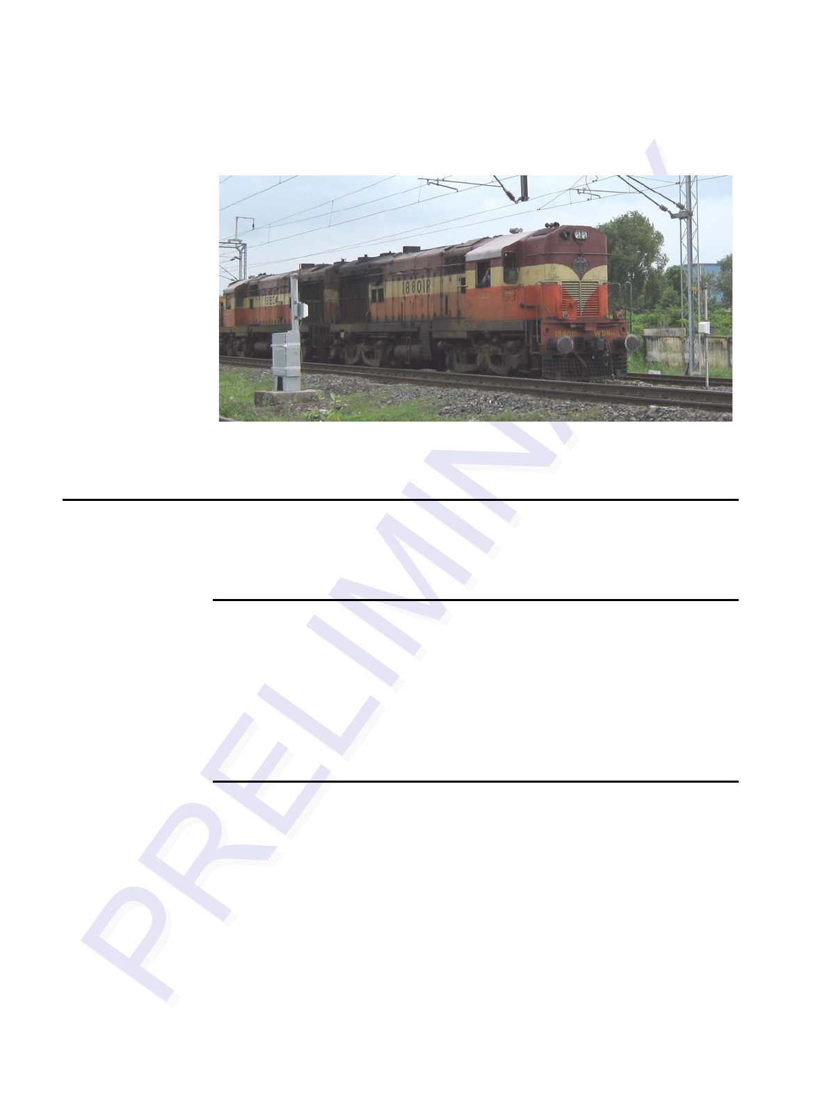
The MPRR directs the RF module to generate an RF signal, which is broadcast
through the external antenna mounted railside. Entering the MPRR’s reading range, a
TransCore RFID tag installed on a railcar or other asset to be tracked adds its pro-

Multiprotocol Rail Reader System Guide
2-4
grammed identification information to the signal and reflects the signal back to the
MPRR. The MPRR receives this modified, or modulated signal, and decodes the tag
data carried by the reflected signal and transmits this data to a local host computer for
processing.
Overview of Site Planning
Developing a site plan provides the foundation for the site’s system design and estab-
lishes the following system configuration parameters:
•Number and general location of primary components
•Number of different radio frequencies required
Gathering relevant site information is crucial before applying for Federal Communi-
cations Commission (FCC) approval and ordering and installing MPRR(s) and tags.
Also, consider the following factors when developing a site plan:
•Type of tags used
•Antenna and tag alignment
•Site layout and rail traffic flow
•MPRR and/or antenna mounting requirements
•MPRR electrical requirements
•MPRR communications requirements
These factors provide relevant information regarding each site’s physical and electro-
magnetic environment and the conditions under which the system must perform.
Reading of Mixed Population Tags
The MPRR reads TransCore’s Super eGo® (SeGo) protocol tags and the American
Trucking Association (ATA) and International Organization for Standardization (ISO)
read-only tags, whether powered by battery or beam, application-specific integrated
circuit (ASIC)-based tags with Intellitag technology.
The factors that influence the readability include, but are not limited to physical orien-
tation and configuration, type of read-only tag, ratio of backscatter cross-section of the
tags, and whether the tag is battery- or beam-powered.
Antenna and Tag Alignment
The position of the antenna and placement of the tag on the vehicle must be compati-
ble.
Two primary criteria must be satisfied to achieve the highest read reliability:
Developing the Site Plan
2-5
•Polarization of the tag and the antenna must be aligned in the same direction —
both horizontal.
•The installed tag must be in a direct, unobstructed line of sight to the antenna.
Caution
A tag may not be reliably read unless the preceding criteria are met.
Polarization
The polarization of the tag must be aligned in the same direction as the antenna, as
shown in Figure 2-1.
Note: Matching the tag and antenna polarization is critical to obtain optimal system
performance.
Figure 2-1 Tag and Antenna Orientation
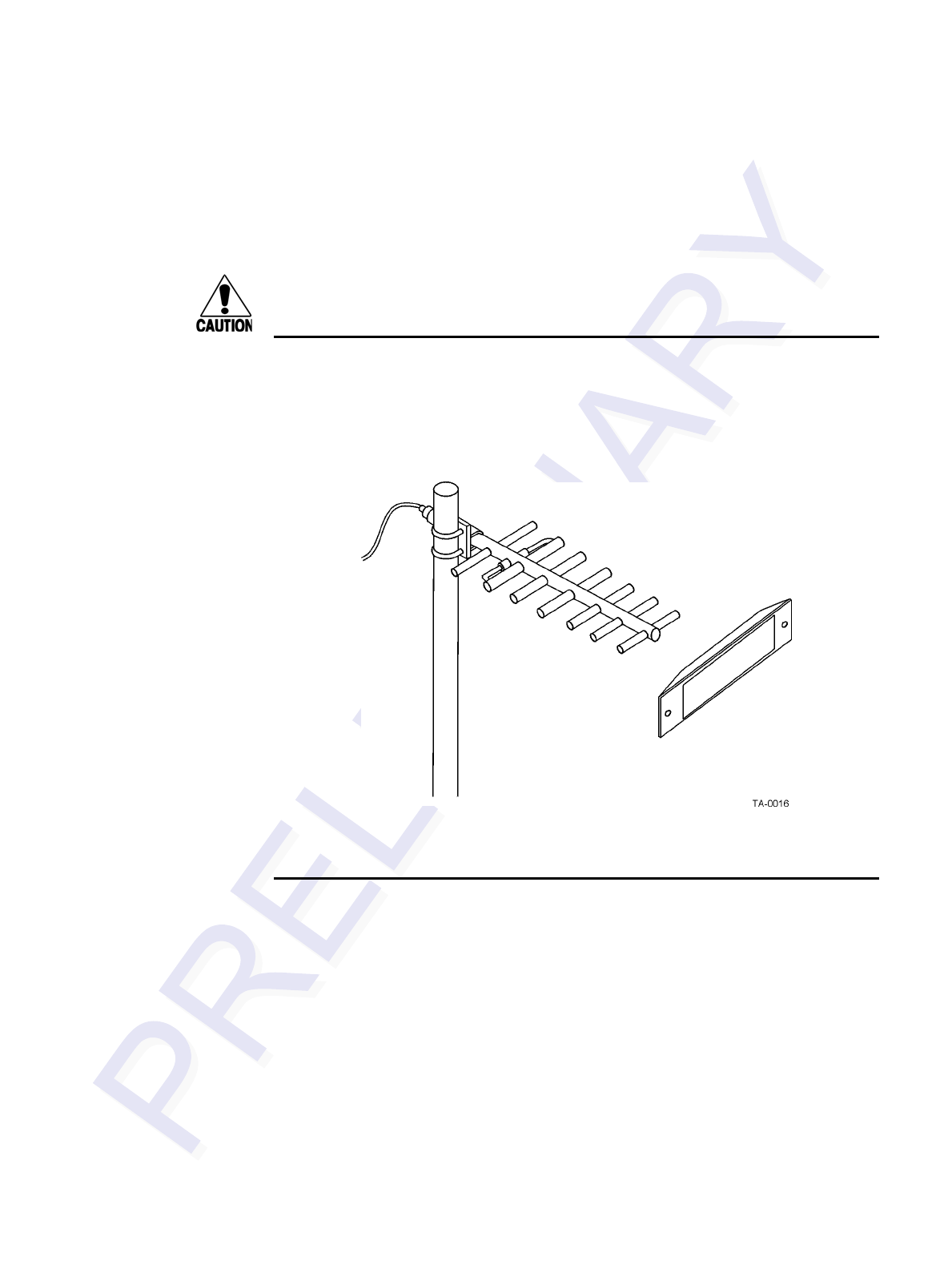
Unobstructed Line of Sight
For optimum readability, install the MPRR and antenna(s) and the railcar’s tag so that
when the railcar approaches the antenna(s), the tag is directly facing the antenna and
the line of sight is clear between the antenna and the tag. If there is a physical obstruc-
tion between the tag and the antenna(s), the MPRR cannot reliably read the tags. Fig-
ure 2-2 illustrates possible installation locations of an antenna in relation to a tag’s
mounting location on a railcar. If the tags are not in the recommended location, reli-
able optimum operation requires lower train speeds.
Multiprotocol Rail Reader System Guide
2-6
Figure 2-2 Antenna Location Relative to Tag Position
Antenna Selection
This section contains guidelines that assist in antenna selection for an MPRR installa-
tion that uses an external antenna. The following antennas are compatible with the
MPRR installation.
AA3100 Yagi (without radome)
Appropriate for installations with the following requirements and conditions:
•902 to 928 MHz operation
•Non-icing environments
•Relatively symmetrical reading range
•Antenna profile not a major consideration
AA3101 Yagi (with radome)
Appropriate for installations with the following requirements and conditions:
•902 to 928 MHz operation
•Exposure to harsh environments
•Relatively symmetrical reading range
•Antenna profile not a major consideration

Developing the Site Plan
2-7
AA3110 Parapanel
Appropriate for installations with the following requirements and conditions:
•902 to 928 MHz operation
•Exposure to harsh environments
•Broad radiation pattern in one dimension, narrow in the other
•Low antenna profile
•Horizontal polarization
AA3140 PCB Log Periodic
Appropriate for installations with the following requirements and conditions:
•845 to 950 MHz operation
•Exposure to harsh environments
•Maximum coverage at close range (<20 ft [6.1 m])
•Vertical or horizontal polarization
Site Layout and Traffic Flow
The following site layout and traffic flow considerations are critical when determining
MPRR installation locations:
•The MPRR read zone
•Other MPRR units and antennas in the area
•Reflection, refraction, and diffraction of RF signals
•Existing signal interference at the site
The MPRR Read Zone
The MPRR must be able to read the tag data properly within a specified area, called
the read zone, without reading other nearby tags or interfering with other MPRRs at
the site. The following are some of the factors that affect the size and shape of the read
zone:
•Mounting method used for the antenna
•Mounting location of the antenna
•Height from the ground and mounting angle of the antenna

Multiprotocol Rail Reader System Guide
2-8
•RF output attenuation
•Range discrimination setting
•Other sources of interference and reflection
The railside antenna must be positioned so that the RF signal travels to and return
from the tags within the designated range and must be placed in an area where it is not
likely to be bumped out of alignment. If the antenna becomes misaligned or some
nearby structure is added or removed, system operation can be seriously affected.
For instructions on setting the read zone, see “Fine-Tuning and Verifying the Read
Zone” on page 8-18.
Other MPRRs in the Area
Sites with more than one MPRR in proximity should have them configured with a fre-
quency separation of at least 2 MHz from adjacent readers. If more than one MPRR is
in a side-by-side or multiple track application, the frequencies should be staggered.
MPRR antennas can face each other across a rail track as long as they are multiplexed
and controlled by the same MPRR. Table 2-2 shows examples of staggered reader fre-
quencies in a site with up to 5 readers.
Reflection, Refraction, and Diffraction of RF
Signals
RF signals can be reflected, refracted, or diffracted by metal objects, walls, and even
wet pavement or ice. Any of these factors can alter or degrade system performance.
When designing your site plan, you must consider permanent structures and transient
factors in the vicinity that may affect RF signals being generated by the MPRR. Per-
manent structures include buildings, chain link fences, guard shacks, and gates. Tran-
sient factors include passing traffic and local weather conditions, such as rain or snow.
Symptoms of reflection, refraction, and diffraction include reading tags that are out of
the desired read zone or tags being read from another track.
The most common RF reflectors are metallic surfaces. RF signals may also be par-
tially reflected by nonconducting materials such as dirt, wood, ice, asphalt, and con-
crete. When nonconducting materials in the system environment become wet, they
increase reflection of RF signals.
Table 2-1 Examples of Staggered Reader Frequencies
Rail Number Reader Frequency Rail Number Reader Frequency
1 911.75 2 913.75
3 915.75 4 917.75
5919.75

Developing the Site Plan
2-9
The antenna mounting location, aiming, and range control adjustment, and use of
presence detectors can reduce interference from RF reflections. When these actions
cannot adequately control reflections, other techniques such as shielding, absorbing,
range sensitivity adjustment, or barriers can also be used. See Chapter 9, “Trouble-
shooting and Maintenance” for more information.
Existing Interference
Interference from RF and electrical sources can degrade system performance and must
also be considered in the site design. Fluorescent lights, neon signs, nearby radio sta-
tions, or power lines can interfere with the optimal operation of the system. The mag-
netic impulse noise from relays that control gate opening and closing can also disrupt
the RF signal.
Interference may degrade both reader and tag performance. Existing interference at
the site may be shielded, removed, or positioned further from the antenna. In some
cases, changing the operating frequency of the MPRR may provide a simple solution.
Readers in proximity should have at least a 2 MHz frequency separation. See “Other
MPRRs in the Area” on page 2-8. Strong RF sources of any frequency, in proximity to
the tag, can preclude the tag receiving the reader interrogation. See Chapter 9, “Trou-
bleshooting and Maintenance.”
Electrical and Communications Requirements
All construction work at the site must be completed before installing the MPRR. Elec-
trical and communications cables should be installed according to all applicable local
and federal building code requirements. Specific instructions for positioning and
installing the MPRR are discussed in Chapter 4, “Installing the MPRR.”
Junction Box
Use a watertight junction box that meets applicable local and national building codes
for connecting power and communications wiring. The junction box houses the termi-
nal strip for power and communications connections. TransCore recommends a
NEMA Type-4 junction box with a back mounting panel.
Power and Communications Cables
Cable length for power and communications depends on the physical characteristics
of the MPRR installation site. Table 2-2 lists accessory kits available for cabling
options based on your site’s requirements.

Multiprotocol Rail Reader System Guide
2-10
Electrical Power
A dedicated electrical power supply must be present at the site and available to the
MPRR at all times. The power must be 16-20V AC or 16-28V DC. A step-down trans-
former is available (North America only) to convert a 120V AC duplex wall outlet
with ground to 18V AC, as is a step-up transformer to convert a low-voltage 12V AC
outlet to 18V AC. Consult your local and national electrical codes for installation and
safety requirements.
Note: MPRRs installed outside North America require a locally supplied transformer.
If 18V AC or 18V DC power is available, the transformer option is unnecessary.
TransCore offers a Class C transformer accessory kit (part number 76-1620-005) for
sites where 110V AC is available. It is the installer’s responsibility to supply conver-
sion equipment and wiring for other voltages. Table 2-3 contains power supply current
requirements.
Power circuits are protected internally against power surges.
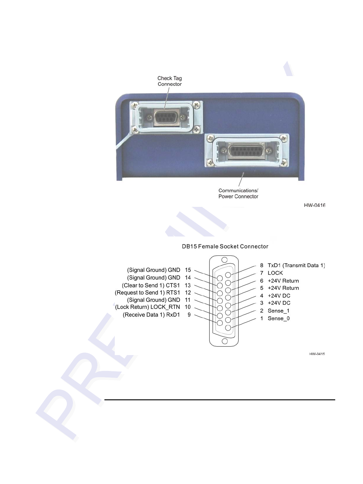
Host Communications
Your site design must include communications between the MPRR and a host device.
The MPRR communicates with the host device through an asynchronous serial line.
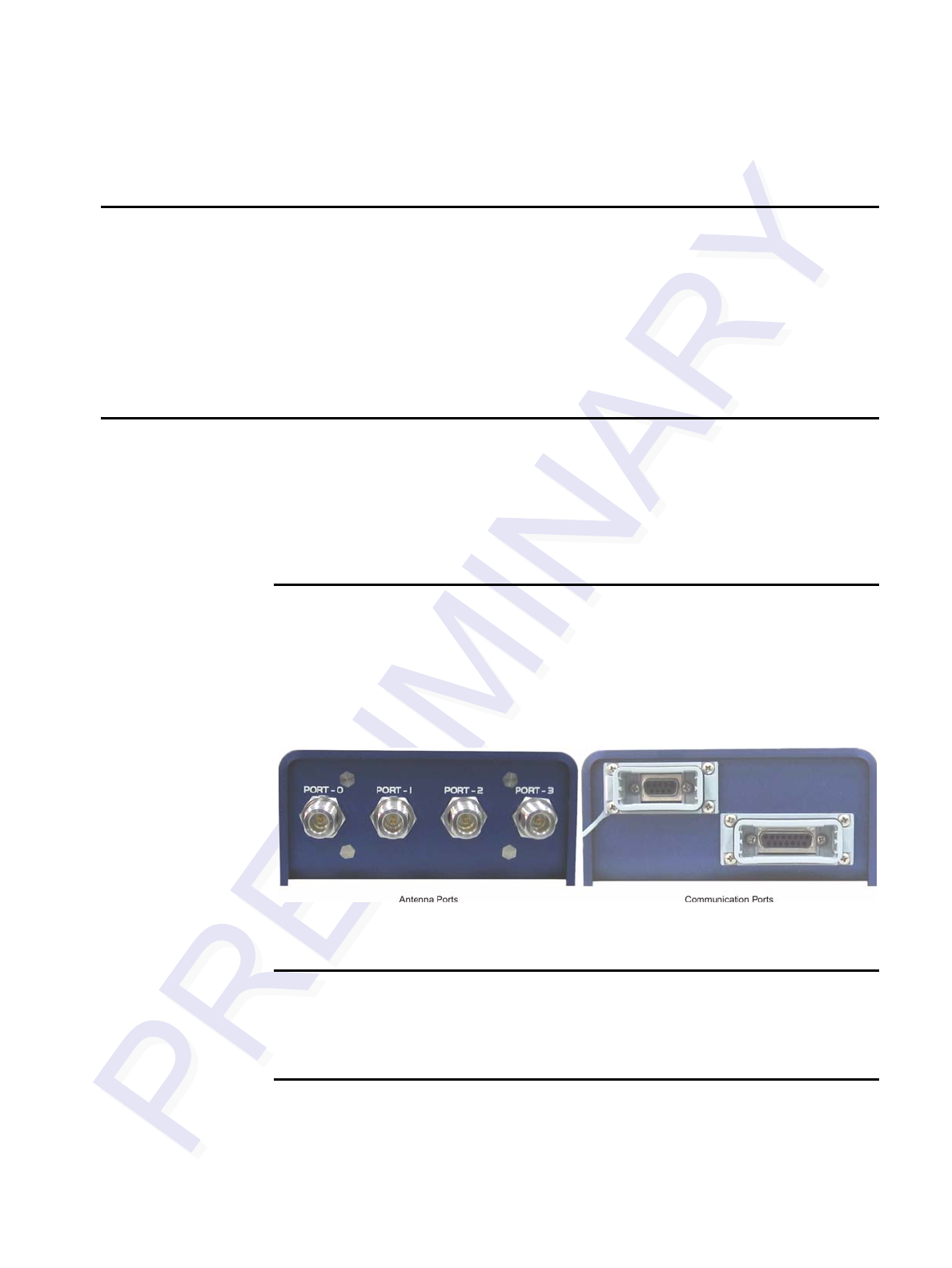
This serial line is an RS–232 interface. Figure 2-3 shows the MPRR communications
port and Figure 2-4 shows the connector pin designations.
Table 2-2 Connector Cabling Accessory Kits
Part Number Description
58-7001-001 MPRR-to-TRU six-foot cable assembly
58-7001-002 MPRR-to-TRU 20-foot cable assembly
58-7001-003 MPRR cable assembly, no TRU
Table 2-3 Power Supply Current Requirements
Supply
(RF On)
Worst Case
Maximum Current at
68°F (20°C)
(RF Off)
Standby Operating
Current at 68°F
(20°C)
16 to 20V AC 1.7 A at 18V AC 1 A at 18V AC
16 to 28V DC 1.7 A at 18V DC 1 A at 18V DC
Developing the Site Plan
2-11
Figure 2-3 Location of Communications/Power Port on MPRR
Figure 2-4 Pin Assignments for Communications Connectors
The standard RS–232 connection maximum distance depends on the baud rate, cable
type, and the RS–232 device at the other end.
Input/Output Circuits
The MPRR’s two RF sense input circuits are designed to connect to dry contact clo-
sures. The MPRR’s tag lock output circuit is a single-pole, double-throw relay provid-
ing a dry contact closure. These contacts are rated at 42.2V AC peak (30Vrms) or 60V
DC, at 1 A maximum with noninductive load.

Multiprotocol Rail Reader System Guide
2-12
Output circuit is not intended for the direct control of electromechanical devices such
as motorized barrier arms. For such applications, the MPRR output circuit should be
used to drive a secondary, appropriately rated high-power relay.
Antenna Interface
The site design must include interface cable(s) between the MPRR and the compatible
antenna(s) chosen for the site. The antenna interface is RF coaxial cable with male
Type N sockets on each end.
Table 2-4 is a summary of coaxial cable performance. Figures indicate maximum
lengths of cable in feet.
a. Suffixes 50, 50A, and 50B indicate 50-ohm cables available from the Andrew
Corporation.
b. These cable lengths ensure optimal system performance (1 dB loss).
c. These cable lengths ensure adequate, but not optimal, system performance (3 dB
loss).
Table 2-4 Reader to Antenna Cable Performance
Cable TypeaOverall
Diameter (in.)
915MHz
Low Medium
Lossb Lossc
RG–223 0.216 6 18
RG–214 0.425 12 37
FHJ1–50 0.250 16 48
FSJ1–50 0.250 15 45
LDF2–50 0.375 28 85
FSJ4–50B 0.500 27 83
LDF4–50A 0.500 42 128
LDF5–50A 0.875 76 229
LDF6–50 1.125 103 310
LDF7–50A 1.625 122 366

3
Choosing, Installing, and Removing
Tags


3-3
Chapter 3
Choosing, Installing, and Removing Tags
This chapter describes the various tag types compatible with the
Multiprotocol Rail Reader (MPRR) and the procedures for installing and
removing compatible internal and external tags.
Compatible Tag Types
The MPRR provides the capability to read the various TransCore tags employing
Super eGo (SeGo) protocol. Depending on options ordered, the MPRR can read SeGo
protocol, ATA-protocol, and ISO-compliant tags.
See Appendix E for information about the numerous tag models.
Reader and Tag Model Interoperability
Table 3-1 lists the tags that are read by the MPRR. See www.transcore.com/pdf/Tag-
Reader-Matrix.pdf for most current information concerning readers and supported tag
protocols.
Recommended Mounting Locations
Each piece of rail equipment has a specific area or window for optimum tag place-
ment. Tag positioning in the tag placement window is based on the center of the tag in
reference to window physical specifications.
Required Materials
•Torque wrench (in/lb. range)
•Bolts and nuts (#10-24 NC threaded studs and nuts)
•Aluminum pop rivets
•Pop rivet gun
Table 3-1 Tags Read by the MPRR
Reader Beam Tags Battery Tags
MPRR AT5110; AT5112; AT5113;
AT5118; AT5125; AT5133; AT5114; AT5510; AT5541; AT5549

Multiprotocol Rail Reader System Guide
3-4
Mounting Surface
The mounting surface must be metal, vertical, and smooth within the area of the tag. If
the mounting area does not meet this requirement, you must use a metal mounting
bracket.
If the mounting surface is irregular or non-metal (e.g., fiberglass), the tag must be
attached to a metal bracket to provide an electrical reflector for the tag. Use a 1/8-inch
(0.32-cm) or thicker smooth metal bracket whose dimensions are at least equal to
those of the tag. Mounting brackets are preferred for application of the tag such that
the tag and the bracket are in intimate contact to avoid interference with transmission
of radio waves.
Tag Positioning
Each piece of equipment has a specific area or tag placement window for optimum tag
placement. Tag positioning in the tag placement window is based on the center of the
tag in reference to window physical parameters.
The tag placement window is on opposite ends and opposite sides of the equipment.
The front and rear ends of the equipment are referred to as the “A” end and “B” end.
The “B” end represents the hand brake end and the “A” end represents the opposite
end looking forward. To determine left and right sides, stand at the “B” end and look
toward the front end of the equipment.
Refer to the appropriate section for tag placement window location rail cars and
locomotive devices. Where possible, tags should be mounted in locations to minimize
the likelihood of damage from equipment such as forklifts, cranes, and other hazards.
Mount the tag on a plane perpendicular to the rail (back of the tag against the
equipment) with the long edge of the tag horizontal to the rail.
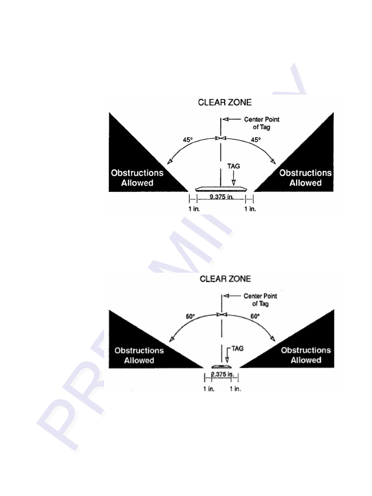
There is a clear zone surrounding the tag and toward the wayside that allows for
unobstructed transmission of data. This zone must not be obstructed by any metallic
objects or protrusions.
Choosing, Installing, and Removing Tags
3-5
As Figure 3-1 illustrates, there should be no obstructions in the area extending 45º
from the center line of the tag to one inch outside either narrow side of the tag. The
side view depicts the tag as viewed from the top of the equipment.
Figure 3-1 . Clear Zone - Side View
Figure 3-2 illustrates that there should be no obstructions in the area extending 60º
from the center line of the tag to 1 inch outside either long side of the tag. The end
view depicts the tag as viewed from the end of the equipment.
Figure 3-2 . Clear Zone - End View
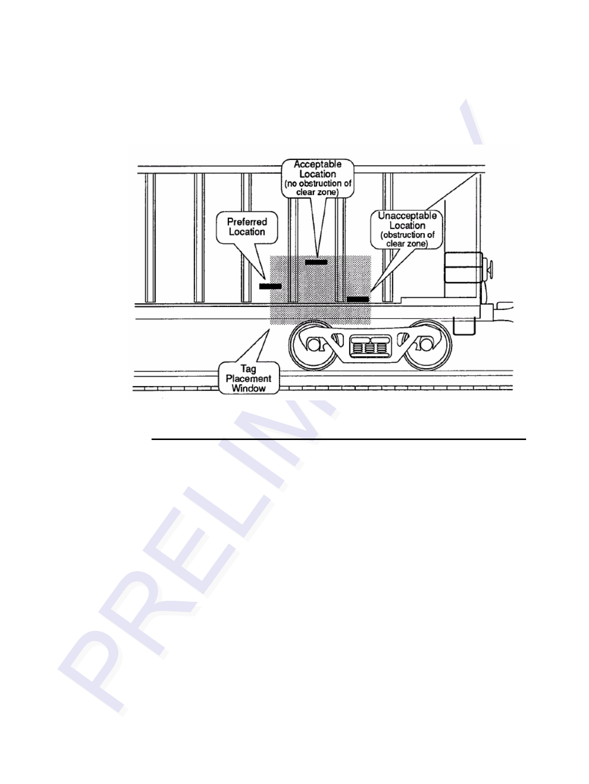
Figure 3-3 shows examples of acceptable and unacceptable mounting locations based
on the clear zone. Any obstructions in the clear zone may introduce reading problems
Multiprotocol Rail Reader System Guide
3-6
with the tag. Refer to the mounting specifications chapters for each type of equipment
for tag placement window locations.
Figure 3-3 . Mounting Location Examples
Surface Installation Techniques
Backing plates are preferred for attaching tags to equipment, but tags may be mounted
directly to the car at the owner’s discretion. Aluminum material is permitted a s a
substitute for the mounting plate material specified, when required for compatibility
with the car surface.
When painting the backing plates, protect the studs from paint.
Two approved methods for mounting tags and backing plates on locomotives and
railcars are rivet and bolt mounting.
Note: Weld the backing plate to the freight car side sheet, but be certain the backing
plate is kept flat. If the car side sheet is deformed, spacing of welds may vary to
accommodate waviness of the freight car side.
Note: Allow the backing plate to cool after welding before applying the tag.
Rivet/Bolt Mounting Guidelines
Select a means for mounting the tag that secures the tag but does not compromise the
tag case.
Choosing, Installing, and Removing Tags
3-7
Aluminum pop rivets are permissible, but TransCore advises against using high-
pressure rivets for mounting the tag.
If using bolts and nuts to mount the tag, avoid using excessive torque, which may
crack or break the tag case. Tighten the nut until snug, then tighten an additional 1/2
turn only.
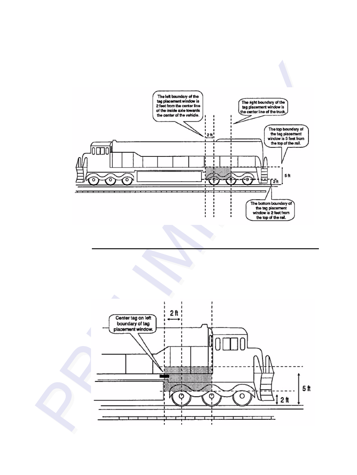
Locomotive Mounting Guidelines
Install two tags on each locomotive on opposite ends and opposite sides of the
equipment. Install one on the right front (engineer’s side) and another on the left rear
(fireman’s side).
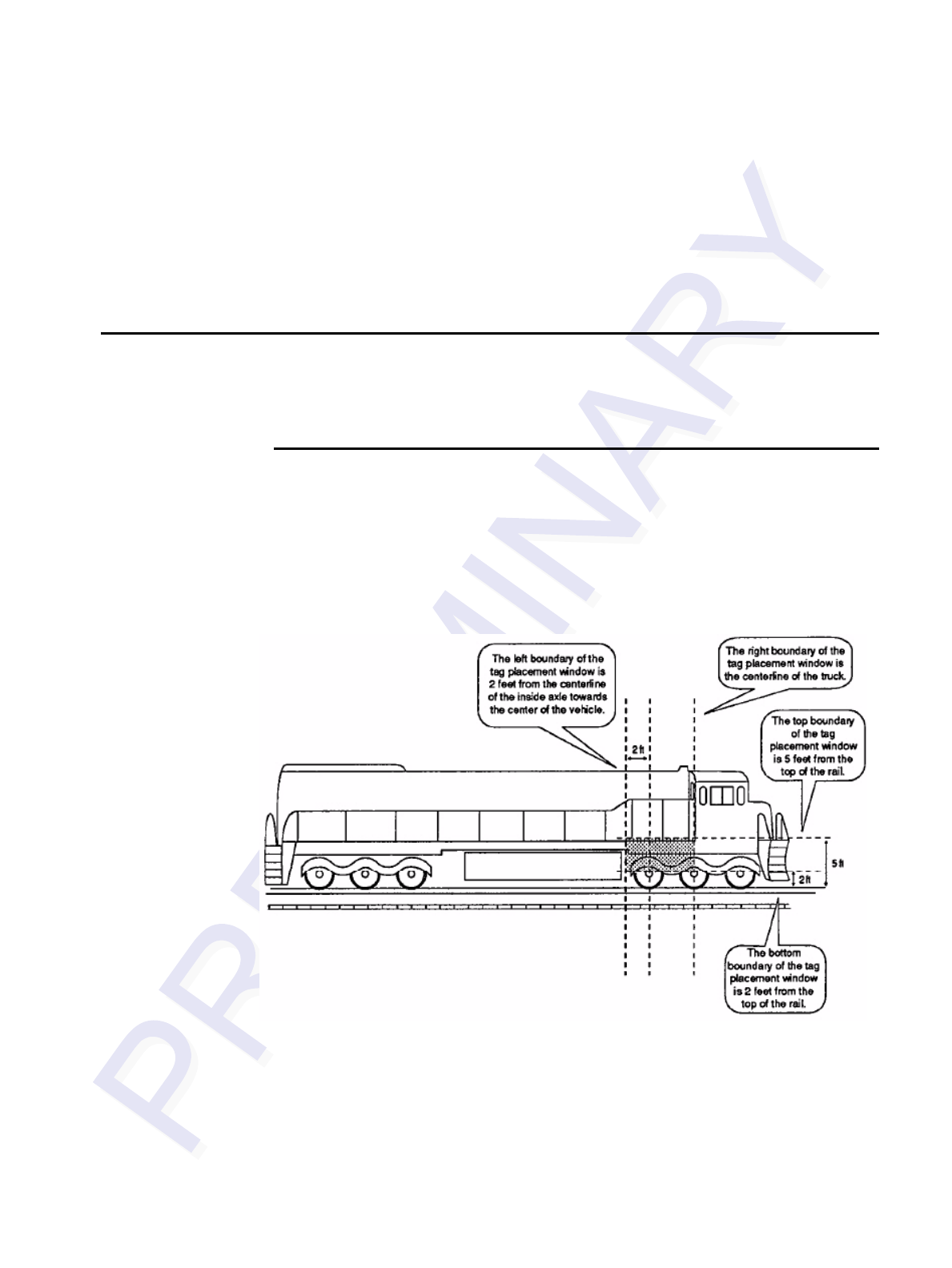
Tag Placement Window Location
Horizontally, the tag placement window extends from the center line of the truck to
2to feet from the center line of the inside axle (measure toward the center of the
vehicle). Vertically, the tag placement window begins two feet above the top of the rail
and extends to a maximum of five feet above the top of the rail.
Figure 3-4 illustrates the tag placement window on the right front portion (engineer’s
side) of the locomotive.
Figure 3-4 . Tag Placement Window for Locomotives -- Right Front
Multiprotocol Rail Reader System Guide
3-8
Figure 3-5 illustrates the tag placement window on the left rear portion (brakeman’s
side) of the locomotive.
Figure 3-5 . Tag Placement Window Location for Locomotives -- Left Rear
Tag Placement
Optimal tag placement centers the tag on the left boundary line of the tag placement
window (Figure 3-6). Alternately, the center of the tag may be mounted anywhere
within the tag placement window, provided there are no obstructions to the tag’s clear
zone.
Figure 3-6 . Optimal Tag Placement for Locomotives
Choosing, Installing, and Removing Tags
3-9
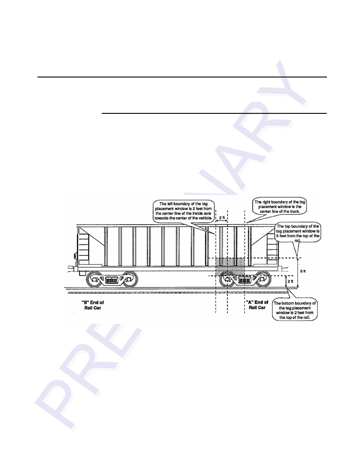
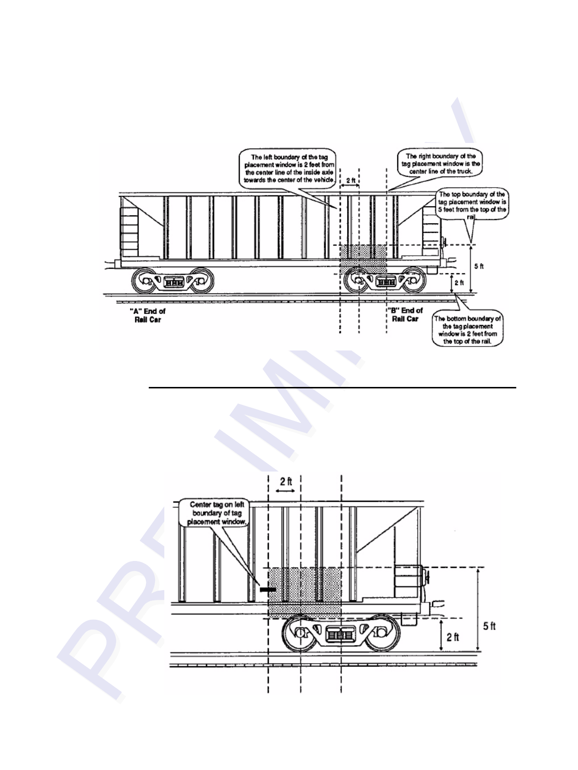
Rail Car Mounting Guidelines
Install two tags on each rail car on opposite ends and opposite sides of the equipment.
Install one on the right front (“A” end) and another on the left rear (“B” end).
Tag Placement Window Location
Horizontally, the tag placement window extends from the center line of the truck to
two feet from the center line of the inside axle (measure toward the center of the
vehicle). Vertically, the tag placement window begins at two feet above the top of the
rail end and extends to a maximum of five feet above the top of the rail. The tag
should not cover car stenciling.
Figure 3-7 illustrates the tag placement window on the right front portion (“A” end) of
the rail car.
Figure 3-7 . Tag Placement Window Location for Rail Cars -- “A” Right Side
Multiprotocol Rail Reader System Guide
3-10
Figure 3-8 illustrates the tag placement window on the left rear portion (“B” end) of
the rail car.
Figure 3-8 . Tag Placement Window Location for Rail Cars -- “B” Left Side
Tag Placement
Optimal tag placement centers the tag on the left boundary line of the tag placement
window (Figure 3-9). Alternately, the tag may be mounted so that the center of the tag
falls anywhere within the tag placement window, provided there are no obstructions of
the tag’s clear zone.
Figure 3-9 . Optimal Tag Placement for Rail Cars
Choosing, Installing, and Removing Tags
3-11
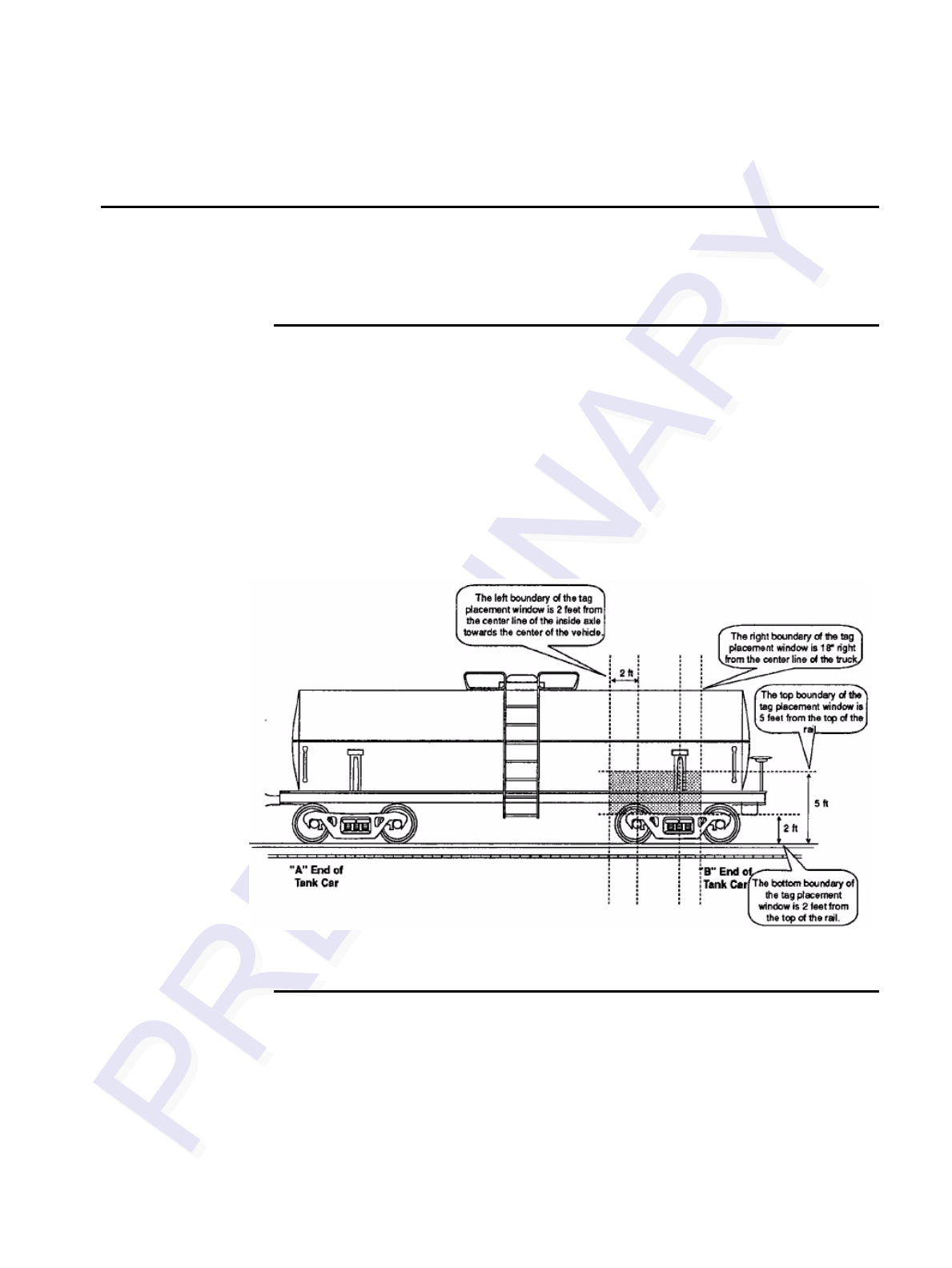
Tank Car Mounting Guidelines
Tank car mounting is essentially the same as that for rail cars, except that the tag
placement window area has been expanded 18 inches to the right of the center of the
truck.
Tag Placement Window Location
Horizontally, the tag placement window extends from 18 inches to the right of the
center line of the truck to two feet from the center line of the inside axle (measured
toward the center of the vehicle). Vertically, the tag placement window begins at two
feet above the top of the rail and extends to a maximum of five feet above the top of
the rail. The tag should not cover car stenciling.
Figure 3-10 illustrates the tag placement window on the left rear portion (“B” end) of
the tank car.
Figure 3-10 . Tag Placement Window Location for Tank Cars -- “B” Left Side
Tag Placement
Optimal tag placement positions the tag on the center line of the truck on the body
bolster (Figure 3-11). Alternately, the tag may be mounted so that the center of the tag
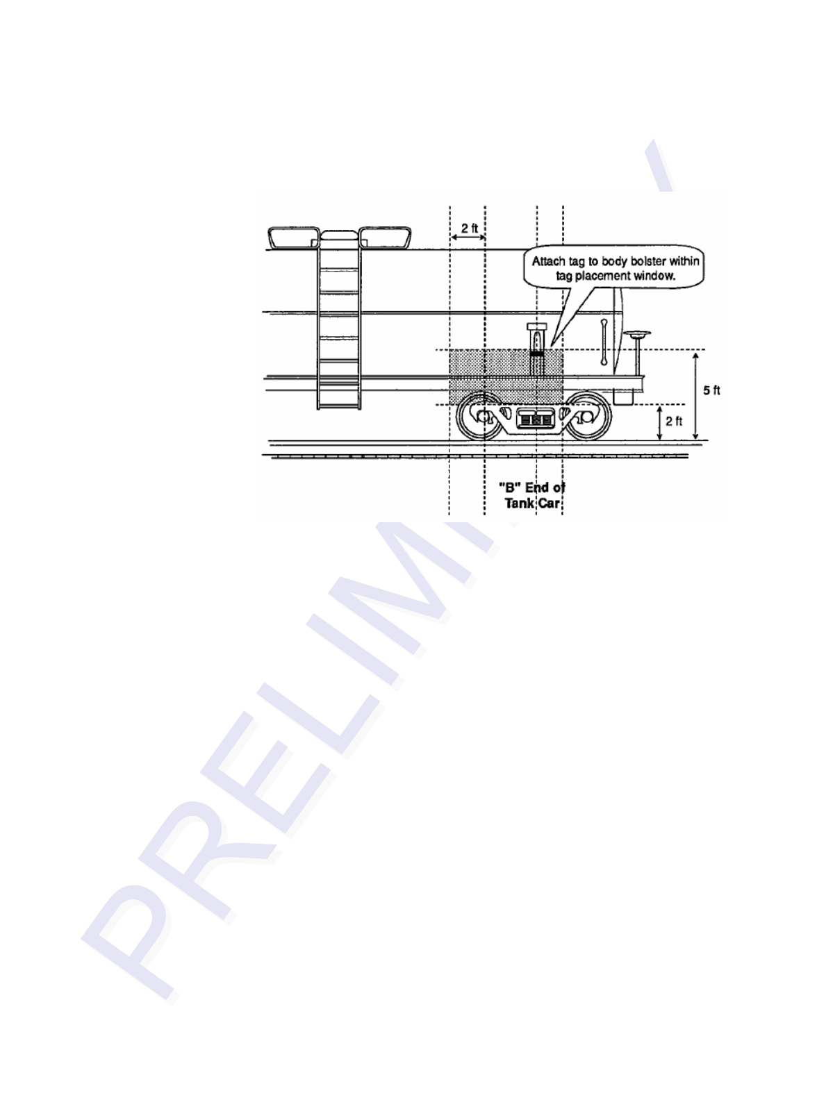
Multiprotocol Rail Reader System Guide
3-12
falls anywhere within the tag placement window, provided there are no obstructions of
the tag’s clear zone.
Figure 3-11 . Optimal Tag Placement for Tank Cars

4
Installing the Multiprotocol Rail Reader


4-3
Chapter 4
Installing the Multiprotocol Rail Reader
This chapter lists the materials needed and presents the procedures to
pre-test and install the Multiprotocol Rail Reader (MPRR).
Installation Process
After you have developed the site plan and identified the location to install the MPRR
and antennas1, if required, you are ready to install the equipment. Installation involves
the following tasks:
•Pre-installation testing of MPRR power and tag read capability
•Mounting the MPRR in a railside shack
•Mounting the railside antenna(s)
•Connecting the antenna(s)
•Connecting the MPRR power
•Marking the read zone
•Connecting the MPRR host and sense input/sense output and communications
Materials Supplied by TransCore
You need the following materials to pre-test and install the MPRR. TransCore supplies
some of the materials; other materials must be obtained from other sources.
Contents of Shipping Carton
Ensure that you have received all parts before beginning your pre-installation MPRR
tests. Your MPRR is packaged with the following materials:
•One MPRR
•One MPRR Quick Start Guide
•Any accessories ordered as options as shown in Table 4-1
Required accessories are a power/communications cable harness and a 110V AC-to-
18V AC wall transformer, a 12 to 18V AC step-up transformer, or a 16 to 28V DC
power source. You also require at least one MPRR-compatible antenna and an antenna
RF cable. These may be ordered as accessories from TransCore or obtained from other
sources.
1. The MPRR is designed with RF cable connectors for use with N-type RF cables.

Multiprotocol Rail Reader System Guide
4-4
Installation Accessory Options
Table 4-1 lists optional TransCore MPRR installation accessory items.
Additional Materials Needed for Testing
You need these additional materials to perform the pre-tests on the MPRR:
•Test tags, supplied by the TransCore dealer or distributor
•Suitable 16 to 20V AC or 16 to 28V DC power wiring for the MPRR
•Audible circuit tester and 9V DC battery for circuit tester power
•Wire stripper
•At least one MPRR-compatible antenna
•Suitable RF interface coaxial cable
Pre-installation Testing of the MPRR
Before installing the MPRR permanently at the site, you should use an audible circuit
tester to confirm that the MPRR has power and can read a tag presented in the tag read
zone.
Testing the MPRR Using an Audible Circuit Tester
An audible circuit tester is also called a buzz box. These boxes are available at some
electronic parts supply stores, or you can make a buzz box, as shown in Figure 4-1.
The buzz box is powered by a 9V DC battery and is equipped with two alligator-clip
leads. When you touch the leads together, the box makes an audible sound.
Table 4-1 Installation Accessories
Part No. Description
58-7001-001 MPRR-to-Train Recording Unit (TRU) six-foot cable assembly
58-7001-002 MPRR-to-TRU 20-foot cable assembly
58-7001-003 MPRR cable assembly, no TRU
20-7001-001 MPRR check tag accessory kit
Installing the Multiprotocol Rail Reader
4-5
Figure 4-1 Wiring for Audible Circuit Tester
To test the MPRR, connect the antenna and power supply as described in the appropri-
ate section below.
Connecting the Antenna
This section explains the connection between the MPRR and antenna(s).
Caution
To avoid damage to the MPRR
•During shipping and installation, an external antenna can build up a very high
voltage charge. The voltage needs to be discharged before connecting the
antenna to the reader.
•Connect the MPRR to ground before powering up the reader or connecting the
antennas.
•Connect the antenna(s) before applying power to the reader.
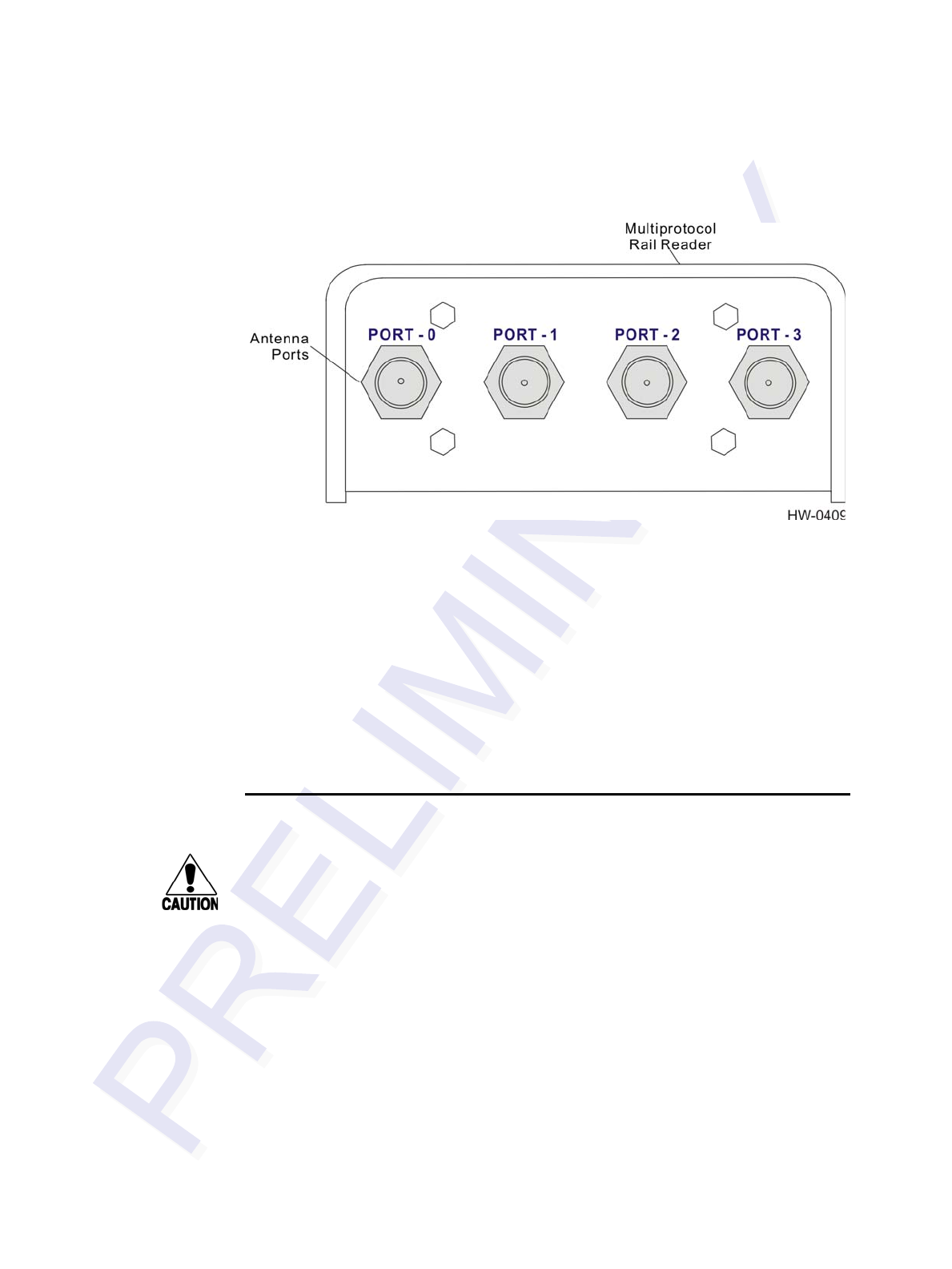
Multiprotocol Rail Reader System Guide
4-6
Figure 4-2 MPRR Showing Antenna Ports
To connect the reader and antenna
1. Ensure the reader is turned off and unplugged.
2. Connect one end of the RF interface cable to the antenna.
3. Connect the other end of the RF interface cable to the appropriate antenna port on
the side of the MPRR. See Figure 4-2.
4. For consistent performance, terminate unused antenna ports using a 50-Ohm, N-
type terminator.
Connecting the MPRR to a Power Supply
Caution
To avoid damage to the MPRR
•Connect the MPRR to ground before powering up the reader or connecting the
antennas.
•Connect the antenna before applying power to the reader.
To connect the MPRR to a power supply
1. Connect the MPRR to a power supply using the interface cable (P/N TBD).
The pin assignments for the signals on the reader DB15 connector (Figure 4-3) is
shown in Figure 4-4. If the MPRR is connected directly to a TransCore Train Record-
ing Unit (TRU), all power supply connections are made through the MPRR-to-TRU
cable assembly.
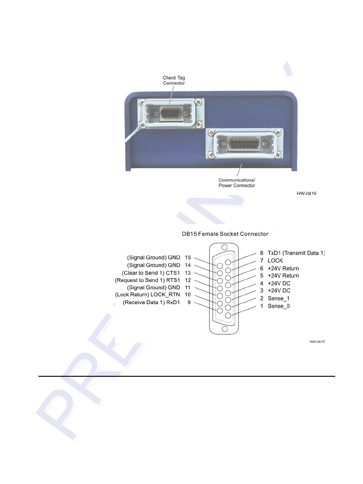
Installing the Multiprotocol Rail Reader
4-7
Figure 4-3 Location of Communications/Power Port on MPRR
Figure 4-4 Pin Assignments for Signal to Host Connectors
Mounting the MPRR
This section lists procedures and materials required for mounting the MPRR on a wall
or other flat surface based on the site’s requirements.
In permanent installations the MPRR should be positioned as close as possible to the
antenna. Long cable runs increase system sensitivity to noise. See Table 2-4 on page
2-12 for maximum RF cable lengths.
Multiprotocol Rail Reader System Guide
4-8
Mounting to an Enclosure Wall or Flat Surface
Required Materials
You need the following materials to install the MPRR on an enclosure wall or flat sur-
face. Ensure the use of high-quality, corrosion-resistant anchor hardware.
•Anchor hardware suitable for the surface on which you mount the MPRR
The MPRR weighs 5.1 lbs (2.31 kg) so choose mounting hardware that is adequate
to secure the unit to a wall.
Caution
Connect the reader bracket to earth ground using a ground cable and stake.
TransCore recommends that you follow the National Electric Code or equivalent
code for lightning protection for the locale where you are installing the MPRR.
After mounting the MPRR, you must connect it to a dedicated 16 to 20V AC or 16 to
28V DC power supply.
Caution
To avoid damage to the MPRR
•Connect the MPRR to ground before powering up the reader or connecting the
antenna(s).
•Connect the antenna(s) before applying power to the reader.
Mounting the Antenna Rail-Side
The antenna should be positioned as close as possible to the MPRR. Long cable runs
increase system sensitivity to noise. See Table 2-4 on page 2-12 for maximum RF
cable lengths (TBD). This section provides guidelines for mounting antennas.
After mounting the antenna, you must connect it to the MPRR. Follow the procedures
described previously in the section “Connecting the Antenna” on page 4-5.
Note: Adjust the antenna(s) to provide the most direct line of sight to the tags.
Connecting the Power Supply
After mounting the MPRR and antenna, connect the reader to a dedicated 16 to 20V
AC or 16 to 28V DC power supply. If the MPRR is connected directly to a TRU, all
power supply connections are made through the MPRR-to-TRU cable assembly.
Caution
To avoid damage to the MPRR
•During shipping and installation, an external antenna can build up a very high
voltage charge. The voltage needs to be discharged before connecting the
antenna to the reader.

Installing the Multiprotocol Rail Reader
4-9
•Connect the MPRR to ground before powering up the reader or connecting the
antenna(s).
•Connect the antenna(s) before applying power to the reader.
Connecting Communications
The MPRR communicates through RS–232 protocol.
Required Materials
You need the following materials to connect the communications cable to the host
device:
•Host device
•Any terminal emulation program such as Procomm Plus™ or Hyper Terminal™
running on a PC
•If the MPRR is connected directly to a TRU, all communications connections are
made through the MPRR-to-TRU cable assembly.
Connecting the MPRR to the Host
MPRR communications and customer interface signals are supplied from the MPRR
to the host through a multiwire cable. The connector for this cable is located on the
end of the MPRR.
Plug one end of the MPRR communications/power interface connector into the DB15
connector at the MPRR and the other end, using the customer-supplied wiring, into the
host device.
Connecting Sense Input and Sense Output Circuits
The MPRR has two sense input circuits and a tag lock output circuit available. Sense0
is used to enable RF on antenna ports 0 and 1 if enabled, and Sense1 is used to enable
RF on antenna ports 2 and 3. The sense input circuits can be used to notify the
MPRR of train presence and are designed to be connected to a free-of-voltage dry
contact. The tag lock output circuit is a single-pole, double-throw relay that provides a
normally closed and normally open dry contact. The relay contact is rated at 42.2V
AC peak (30 Vrms) or 60V DC at 1 A maximum. If controlling an external gate or
device requiring high current, an isolation transformer is required.
Sense Input Circuits
The MPRR supports two sense inputs – sense input0 and sense input1 – which require
two sense input lines (SENSEx and GND) for each loop sense or a total of four sense
input connections. Sense input0 is the presence detection and is used to control RF
Multiprotocol Rail Reader System Guide
4-10
power. As shown in Figure 4-4, the sense inputs are wired through the reader DB15
connector. The MPRR expects the sense input0 circuit to close when a railcar is
present (on the track with antennas connected to ports 0 and 1). Sense1 must be closed
when a railcar is present on the track connected to antenna ports 2 and 3. The mini-
mum presence true period is fixed at 0 ms, which indicates that no delay occurs in
closing the circuit when a railcar is present.
Sense Output Circuit
The sense output is dedicated for testing and set up of the reader. It is defined as
the TAG_LOCK signal, which indicates a valid tag is in the read field.
This sense output is a dry contact that provides a normally open and normally closed
sense output. The relay contacts are rated at 42.2V AC peak (30 Vrms) or 60V DC at
1 A maximum. If controlling an external gate or device requiring high current, an iso-
lation transformer is required.
Marking the Read Zone
Caution
Be sure to follow all applicable rail safety regulations when marking the read zone.
The area where the MPRR reads tags at the current RF range is called the read zone.
The antenna pattern, or read zone, of the MPRR would look roughly like a pear-
shaped balloon if you were able to see it. When installing the MPRR, you should first
mark the unit’s read zone using the RF range set at the factory-default maximum. You
can later adjust the read zone using the techniques discussed in “Fine-Tuning and Ver-
ifying the Read Zone” on page 8-18.
If two MPRRs are installed near each other, TransCore recommends that you fine-tune
each reader for the ideal read zone before connecting it permanently to sense input/
sense output and communications cables. A minimum of 2 MHz frequency separation
and 40 feet (12.2 m) of antenna separation between the two adjacent readers is
required for correct operation.
Required Materials
You need the following materials to mark the read zone:
•Test tags, supplied by the TransCore dealer or distributor
To mark the read zone
1. Confirm that you have correctly connected the power supply/communications
cable as described in this chapter.
2. Start the terminal emulation application Microsoft HyperTerminal by selecting
Programs>Accessories>Communications>HyperTerminal and press
ENTER.

Installing the Multiprotocol Rail Reader
4-11
3. In the HyperTerminal dialog boxes choose the com port to which the
communications interface is attached and set the properties as:
• Bits per second: 9600 baud
• Data bits: 8
• Parity: none
• Stop bits: 1
• Flow control: none
4. Cycle the power on the MPRR and ensure that the sign-on message displays.
5. Input the commands listed in Table 4-2.
You can now connect the outer marks to draw the outer boundary of the read zone.
Figure 4-5 is a view of a sample read zone. The outer X marks show the outside
edges of the read zone.
Table 4-2 Commands for Testing
Entry Reader Response Notes
#01 <CR> #Done <CR/LF> Switches MPRR to command mode
#647XXX #Done <CR/LF> Sets frequency
#6401 #Done <CR/LF> Turns on RF
#00 <CR> #Done <CR/LF> Returns MPRR to data
Multiprotocol Rail Reader System Guide
4-12
Figure 4-5 Sample Read Zone Marking Pattern
6. Place the MPRR in single-antenna operation using the antenna of interest.
Standing at the edge of the rail sleepers closest to the antenna walk the test tag
along the track to determine the farthest read point in both directions (see D in
Figure 4-5). Record the distance.
7. In a multiple track installation, walk the tag toward the adjacent track in a line
with the antenna (see Figure 4-5) to determine whether the MPRR reads tags
from the adjacent track. Record that distance (Y). If the MPRR reads tags on the
adjacent track, reduce the range control value, or increase RF attenuation until
the MPRR cannot read tags on the adjacent track.

5
General Software Information


5-3
Chapter 5
General Software Information
This chapter provides software-related information for the Multiprotocol
Rail
Reader (MPRR) System.
This chapter presents various software-related topics arranged in alphabetical order by
subject. In addition to this chapter, see Chapter 6, “Communications Protocols,” and
Chapter 7, “Commands,” for more information.
Command Entry Conventions
All MPRR commands are preceded by the start-of-message character (#). The end-of-
message sequence expected from the host is a carriage return (CR). The MPRR termi-
nates messages with a return and a line-feed (CR/LF). For example, the command
#01 Switch To Command Mode is typed as follows:
#01<ENTER>
where <ENTER> is the Enter or Return key.
Some command characters may be represented by the letter N. This letter indicates
you are to supply a value. Maximum valid entries are the numbers 0 through 9 and the
uppercase letters A through F. These letters allow for as many as 16 available user
responses and are based on the hexadecimal numbering system.
Commands have at least two characters following the # character. Table 5-1 shows the
basic structure of a four-character command.
Table 5-1 Four-Character Command Structure
#1005 Set Baud Rate To 9600 Baud
# All commands are preceded by the # character.
1 Indicates the command group. This command is in Group 1-
Communications Port Control.
0 Indicates the command subgroup. In this example, all commands with
a second digit of 0 apply to the main port.
0 The command digit. In this example, the 0 indicates that this command
affects the baud rate.
5 Indicates the setting. Normally this is a variable and is usually a
hexadecimal value from 0 through F. In this example, 5 sets the baud
rate to 9600, the factory setting. In some commands, this digit may be
a four-place hexadecimal string or a character string.

Multiprotocol Rail Reader System Guide
5-4
Command Response Conventions
Like the MPRR commands, responses are preceded by the # character. Many MPRR
commands respond with #Done or #Error indicating the command was or was not
recognized and completed. Other commands respond with a four-character identifier
followed by one or more values.
Table 5-2 shows an example of a command/reply sequence. This example assumes
that an MPRR with serial number SN97001P running version X.XX software is con-
nected to a PC running a terminal emulation software package such as Windows
Hyper Terminal or Procomm Plus. The command sequence verifies that communica-
tions are working correctly.
In command discussions, MPRR response characters may be shown in brackets < >.
The use of brackets indicates that the response is a value in the range of characters.
The brackets are not part of the response. For example, the response to command
#520 Display Power Fail Bit is either a 0 or a 1. In the command discussion, the
response is shown as:
#PWRB <0-1>
with actual MPRR response being one of the following:
#PWRB 0
#PWRB 1
In this example, PWRB is the four-character identifier for power fail bit, and the 0 or 1
is the value. All spaces shown in the response are actual spaces sent from the MPRR.
In this example, one space is between the letter B and the number.
Operating Parameters
The MPRRs maintain their operating parameters in non-volatile memory (NVRAM)
so that the parameters are preserved after a power-down sequence.
Table 5-2 Sample Command Sequence
Entry MPRR Response Notes
#01 <CR> #Done <CR/LF> Switches MPRR to
command mode.
#505 <CR> #Model E4 Series Ver X.XX
SN08001P <CR/LF> Reports the software
version and serial number.
#00 <CR> #Done <CR/LF> Returns MPRR to data
mode.

General Software Information
5-5
Power Fail
The system maintains a power fail flag. The host transmits command #520 Display
Power Fail Bit to determine if a power down has occurred. This flag is cleared by both
command #63 Reset Reader and command #65 Reset Power Fail Bit.
Program Download
Program download stores the MPRR applications software into the reader’s flash
memory. Program download is used to install program upgrades, add features, and to
recover from corrupted program data.
Note: Program download is a hosted process. Exercise caution so that you don’t inad-
vertently enter download mode.
Download Considerations
You should consider the following factors when performing program download:
•The MPRR does not process tags while in download mode.
•The MPRR does not accept any program data unless a successful erase of flash
memory has been performed before transmitting the data. Erasing the flash mem-
ory typically takes two seconds.
•Exiting from download mode re-executes startup. If the new software has been
loaded without errors, the MPRR comes up in data mode. If a flash checksum
error is detected, the MPRR reenters download mode and transmits a sign-on mes-
sage with a boot version of 0.00x and without a serial number.
Note: The MPRR uses default communications parameters when operating in down-
load mode – 38400 baud, 8 data bits, 1 stop bit, no parity, basic protocol – and does
not echo commands.
Download Procedures
If TransCore releases a new version of the MPRR software or if the MPRR seems not
to be working properly, you may need to download the software to the MPRR. Con-
tact technical support or your TransCore MPRR sales representative.
Startup
Upon startup, MPRR transmits a sign-on message or a boot ROM failure message.

Multiprotocol Rail Reader System Guide
5-6
Sign-On Message
If startup is successful, the sign-on message appears as follows:
Model E4 Series [software version] SNYYYYYY
[Copyright notice]
where YYYYYY is the serial number assigned to the MPRR unit being used.
Serial number 000000 is the default setting and is not a valid number. If this number
appears in the sign-on message, the serial number has never been stored into reader
memory. The serial number must be assigned by factory-authorized personnel using
command #695S...S Set Serial Number. Because only six digits are allowed in
the software, when setting the serial number skip the fourth (middle) digit of the
seven-digit number shown on the reader label.
If the flash memory checksum does not indicate verification, the sign-on message
appears as follows:
Model [E4] Ver 0.00x
[Copyright notice]
Boot Failure Message
The software performs a checksum function on itself. The function returns a specific
value for the particular version of software. If the value returned is not correct, the
boot ROM checksum assumes that locations have been corrupted and a failure condi-
tion exists. If the boot ROM checksum is not correct, a boot failure message is trans-
mitted. If the failure message does not transmit, a communications error has occurred
or the boot failed to the extent that it cannot transmit the failure message.
If the failure message version number equals 0.00 and no serial number exists, the
flash memory checksum has failed, and the MPRR is operating out of boot ROM. In
this case, the MPRR automatically enters download mode and waits for a new pro-
gram to be loaded into the flash memory. Follow the instructions in “Program Down-
load” on page 5-5 to download a new program.
Tag/Message Buffer
In basic communication protocol, the MPRR does not provide tag memory storage
beyond the quantity required for uniqueness checking. This feature allows adequate
buffering of tag data under normal operating conditions. The MPRR cannot operate as
a stand-alone component. When the buffer fills, subsequent tag IDs will be lost.
In error correcting protocol (ECP), a buffer of up to three additional tag reads will be
held in case a host system is unable to acknowledge tag reads in real time.

6
Communications Protocols


6-3
Chapter 6
Communications Protocols
This chapter describes the communications protocols for the
Multiprotocol Rail Reader (MPRR).
Introduction
The MPRR supports the following communications protocols:
•Basic
•Error correcting protocol (ECP)
The following protocol information provides reference information relevant to devel-
oping host software.
Communications are performed using the 7-bit ASCII code with optional parity, thus
providing easy setup, testing, and diagnostics with standard ASCII terminals and
serial printers. Parity must be enabled to achieve the specified undetected error rate.
Each message is framed within the start-of-message (som) and end-of-message (eom)
characters so that the host computer can detect the beginning and end of each mes-
sage. This convention is most important under marginal communications conditions
during which the host may receive extraneous noise-induced characters between
reader transmissions. In such instances, the host is capable of ignoring any messages
that do not conform to the som...eom frame sequence.
Both data mode and command mode require a two-way message interchange is when
using ECP. This interchange is completed by the message recipient returning a mes-
sage acknowledgement to the message sender.
With ECP, all transmissions require a message. If a message is not received, the sender
will time out with the same effect as if it had received a negative acknowledgment
(from the host) or an Error message from the MPRR.
Software (XON/XOFF) flow control is optionally supported. Be careful in the use of
XON/XOFF since noise-induced characters may be interpreted by the MPRR as the
XOFF character, which would suspend reader output without information reaching the
host computer. For more information see “Software Flow Control” on page 8-18.
Note: TransCore recommends that XON/XOFF flow control be disabled while using
ECP.

Multiprotocol Rail Reader System Guide
6-4
Basic Protocol
With basic protocol, messages sent to and from the MPRR and the host are transmitted
without error checking. For each host transmission, the MPRR returns a Done or
Error message to the host.
When the host computer is physically close to the MPRR and no sources of interfer-
ence exist, the basic protocol provides reliable communications.
The host must be ready to receive reader-transmitted messages because in basic proto-
col the MPRR does not wait for the host to acknowledge a message before transmit-
ting the next message. If necessary, the host may halt reader transmissions by using
software or hardware flow control. Refer to Chapter 8 for flow control information.
Error Correcting Protocol
When the quality of data communications is imperative or may be suspect, you can
invoke ECP to ensure the integrity of data transmitted between the MPRR and the
host.
Note: TransCore recommends that basic protocol (not ECP) be used when commands
are entered manually at the keyboard.
Error correction is accomplished with the use of a cyclic redundancy check (CRC)
value that is based on the message data. The originator (reader or host) calculates the
CRC value of a message and includes it in the transmitted message.
The recipient (reader or host) also calculates a CRC value for the received message. If
the transmitted message data is correct, the CRC value calculated by the recipient will
agree with the CRC value calculated by the originator. If the CRC values do not agree,
the recipient rejects the message.
Message sequence numbers are also included when using ECP. These sequence num-
bers are checked to determine if the message received has the correct sequence num-
ber; if not, the recipient rejects the message.
Since the seven-bit ASCII code is used and there are eight data bits per character, the
eighth bit can optionally be used to support parity. Where parity is selected, the CRC
value calculation includes the parity of each character in the calculation of the CRC
value.
Parity is required to achieve the most reliable communications. If parity is enabled,
both the MPRR and the host must issue a message if any received character has a par-
ity error. However, the message must not be transmitted before receipt of the eom
character. In this case, the MPRR will issue an Error message, and the host com-
puter will issue a negative acknowledgment message.

Communications Protocols
6-5
Basic Protocol and ECP Format
Note: In the following text, the symbols < and > are used to represent required vari-
able message data, and the symbols [and] are used to represent optional data. These
symbols are not part of the message syntax.
Reader Transmissions
The basic protocol format and the data inquiry protocol format are as follows:
<som><data><eom>
The ECP format is as follows:
<som><seq><data><crc><eom>
where
<som> Start-of-message (ASCII # character)
<seq> Sequence number (ASCII hex) that represents an even number in
the range 0–9, A–F (0, 2, 4, 6, 8, A, C, E). The MPRR maintains
the number. The host must acknowledge reader transmissions by
sending an ACK message with the same sequence number
received from the MPRR. The MPRR updates its sequence
number upon receipt of a valid host ACK. If an ACK is not
received, the MPRR retransmits the message. A reader
transmission sequence is not considered complete until the
MPRR receives an ACK and updates its sequence number.
<data> An ASCII string up to 72 characters long. This string may contain
tag data, a presence without tag report; an input status change
report; an Error06, Error07, Error08, or Error11
message; or a sign-on message. Auxiliary data may also be
included.
<crc> Field containing four ASCII digits that represent the 16-bit CRC
value calculated on the message. The CRC value is calculated on
bytes between the som character and the first <crc> byte.
When the host receives a properly framed message, it can
calculate a 16-bit CRC value. The calculation is applied to the
character string that immediately follows the <som> and that
ends with the character immediately preceding the first <crc>
character.
The transmitted CRC value can then be compared with the binary
equivalent of the received <crc> characters. If the transmitted
and received CRC values do not match, the recipient assumes the

Multiprotocol Rail Reader System Guide
6-6
message was received in error, and transmits a NAK message
response.
<eom> End-of-message characters (ASCII CR and LF). The system
includes both a carriage return (CR) and line feed (LF) to
facilitate the use of terminals and printers.
If the host receives a <som> character in the middle of a data
message, the message in progress is aborted. The assumption is
that an <eom> was lost and the MPRR is in the process of
retransmitting the previous message.
ECP Host ACK/NAK Response
With ECP, the host computer responds to all data message transmissions from the
MPRR using the following acknowledgment or negative acknowledgment response
format.
<som><seq><ack/nak><crc><eom>
where
<som> Start-of-message (ASCII # character)
<seq> An echo of the sequence number received from the MPRR. The
sequence number should correspond to the data message that is
being positively or negatively acknowledged by the host. If the
MPRR receives an ACK message with the incorrect sequence
number, the data message is retransmitted.
The host computer resets the anticipated data message sequence
number to that of the MPRR before communications can resume
without error.
<ack/nak> ASCII @ character for ACK response; ASCII ? character for NAK
response
<crc> CRC value for the message
<eom> End-of-message character (ASCII CR)
The MPRR sets a user-programmable timeout delay at the time each message is trans-
mitted based on command #612NN Set Error Correcting Protocol Timeout, where NN
= timeout delay. To disable the timeout delay for diagnostic purposes, issue the com-
mand #612FF Disable Error Correcting Protocol Timeout.
If the timeout delay expires before the MPRR receives an ACK or NAK message from
the host, a logical NAK condition will be declared. If the MPRR receives a NAK or
timeout, the reader retransmits the data message.
When the MPRR receives an ACK message, the system software treats the message as
having been properly received by the host. The software increments the sequence

Communications Protocols
6-7
number, and advances pointers to the next message in the MPRR’s message queue to
prepare for sending the next message.
Switch to Command Mode Request
The host computer may issue command #01 Switch to Command Mode while in data
mode.
The basic protocol format is as follows:
<som><cmd><eom>
The ECP format is as follows:
<som><seq><cmd><crc><eom>
where
<som> Start-of-message (ASCII # character)
<seq> Sequence number generated by the host computer separately
from that appearing in data messages transmitted by the MPRR
<cmd> Switch to command mode (ASCII characters 01)
<crc> CRC value for the message
<eom> End-of-message character (ASCII CR)
Host Transmission
The host computer initiates synchronous communications between the MPRR and the
host. The host begins a sequence by issuing a command; the MPRR responds accord-
ingly.
The basic protocol format is as follows:
<som><cmd>[<data>]<eom>
The ECP format is as follows:
<som><seq><cmd>[<data>]<crc><eom>
where
<som> Start-of-message (ASCII # character)
<seq> Sequence number (ASCII hex digit) that represents an odd
number in the range 0–9, A–F (1, 3, 5, 7, 9, B, D, F). The host
should use odd sequence numbers in its command since the
MPRR uses even sequence numbers in its transmissions. This
method eliminates the possibility of a synchronous host
command and an asynchronous reader transmission having the
same sequence number.

Multiprotocol Rail Reader System Guide
6-8
Upon receiving a host command, the MPRR echoes the
command’s sequence number in its response. Therefore, the host
computer updates its sequence number upon receipt of a valid
reader message. If the sequence number is not updated before
transmission of the next command, the MPRR will not service the
new command; it will retransmit its previous message. A
command/message sequence is not complete until the host
updates its sequence number.
<cmd> Command code, a string that contains from two to four ASCII
hex characters
[<data>] Optional data field, an ASCII string of as many as 20 characters
in length. For example, the store hardware configuration string
command is #696S...S or command #696 Store Hardware
Configuration String followed by the data string S...S.
<crc> CRC value for the message
<eom> End-of-message character (ASCII CR)
Reader Command Response
The basic protocol format is
<som><resp><eom>
The ECP format is
<som><seq><resp><crc><eom>
where
<som> Start-of-message (ASCII # character)
<seq> Echo of sequence number received in host command message
<resp> Response string. The MPRR returns Done, Error, or another
ASCII string depending on the host transmission. This string can
be up to 72 characters long.
<crc> CRC value for the message
<eom> End-of-message character (ASCII CR and LF)
Sample Messages
This section contains examples of typical messages transmitted between the MPRR
and the host computer.

Communications Protocols
6-9
Reader Transmissions
Basic protocol reader transmission
#KING 1302<eom>
Host response
No host response for non-ECP
ECP reader transmission
#4KING 1302 <crc><eom>
where
#Start-of-message character
4Message sequence number
KING 1302 Message data: Tag ID is shown.
Other sample message data could be as follows:
IOST C0 O2 I0 D24 (display I/O status)
Error06 (frequency not set)
<crc> CRC value for the message
<eom> End-of-message character
Host response
#4@<crc><eom>
where
#Start-of-message character
4Message sequence number
@ ACK (acknowledgment character)
(? returned for a negative acknowledgment)
<crc> CRC value for the message
<eom> End-of-message character
Host Command Transmissions
Basic protocol host transmission
#647XXX<eom>
Reader response
#Done<eom> or #Error<eom>
#Error<eom> is returned if the host transmission is not a legal command with legal
data.

Multiprotocol Rail Reader System Guide
6-10
ECP host transmission
#7647XXX<crc><eom>
where
#Start-of-message character
7Message sequence number
647XXX Select RF Operating Frequency command where
647XXX is the command and XXX is a hexadecimal value from
000 to 118. In this example, XXX sets the RF frequency to 903
MHz.
<crc> CRC value for the message
<eom> End-of-message character
Done Command has been invoked by the MPRR
Reader response
#7Done<crc><eom> or #7Error<eom>
For some commands, the MPRR responds with data that relates to the command, such
as T0F 0, to indicate (TBD) mode enabled for a #XXX Display (TBD) Mode Status
command.
#7Error<eom> will be returned if host transmission is not a legal command with
legal data.
Timing and Synchronization
The ECP is largely independent of baud rate. The timeout delays previously described
are a function of baud rate.
The MPRR supports an ECP timeout, which applies equally to both transmit and
receive.
The receiver’s minimum timeout delay equals the time to transmit/receive the longest
anticipated message at the current baud rate setting. Additional margin should be
included for idle periods between characters; for example, processing overhead, if
any. The timeout delay period can be expressed as follows:
Τrec (ms) = L x [Τchar + Τidle]
where
Τchar (ms) 1000 x [ Bc / Rb ]
BcBits per character, typically 10

Communications Protocols
6-11
RbBaud rate, 1200–38.4 K
LLength of message in characters
Τidle Maximum idle period between characters (ms)
Note: The MPRR supports baud rates between 1200 and 38.4 K.
Likewise, the sender must set a timeout delay equal to the delay of nine characters at
the current baud rate setting. For example, the time required to shift out the <eom>
character plus the time to shift in the ACK or NAK message to be received plus a pro-
cessing allowance for the receiver to process the message and check for error condi-
tions.
Thus, the sending timeout delay can be expressed as follows:
Τsend (ms) = 9 * Τchar + Τerrchk
where
Τerrckh (ms) Processing period to perform error checking by receiver
The host computer can remotely set the MPRR’s communications parameters while in
the command mode, but TransCore does not recommend this action if communica-
tions conditions are marginal.
After the MPRR receives new communications parameters, the MPRR issues the
Done message and switches to the new configuration immediately. The host computer
switches its communications parameters immediately after the transaction is com-
plete.
As noted, the message initiator, such as the MPRR in data mode and the host computer
in command mode, starts a timeout counter at the time a message is transmitted. If the
timeout expires before receiving an acknowledgement message, a logical NAK condi-
tion is declared, and the initiator assumes the message was received in error. In this
instance, the message is retransmitted until an acknowledgement message is received.
The message recipient, such as the host computer in data mode and the MPRR in com-
mand mode, starts a timeout counter when a <som> character is received. If the time-
out expires without the receipt of an <eom>, the message acquisition is aborted
(reset), and the receiver waits for the next <som> character.
If the message recipient receives a second <som> character before an <eom> charac-
ter, the message acquisition is aborted (reset), and retransmission of the previous mes-
sage is assumed to be underway.
These strategies allow for recovery during periods when communications are marginal
or completely lost.
Note: It is important that the host computer limit the period during which the MPRR
remains in command mode to avoid losing tag IDs. RF is off in command mode and no
tags can be read.

Multiprotocol Rail Reader System Guide
6-12
Reader-Addressed Failure Conditions
The MPRR addresses the following failure conditions.
Illegal Sequence Number (not in the range 0–9, A–F)
If the MPRR detects an illegal sequence number in a host command message, it dis-
cards the received message and sends no response. If it receives an illegal sequence
number in an ACK message, it responds as if a NAK had been received and retransmits
the data.
Wrong Sequence Number
If the MPRR receives the wrong sequence number in an ACK message, it responds as
if a NAK had been received, and it retransmits the data.
Incorrect CRC
If the MPRR detects an incorrect CRC value in a host command message, it discards
the received message. No response is sent. If it receives an incorrect CRC value in an
ACK message, it responds as if a NAK had been received, and it retransmits the data.
Illegal Command
If the MPRR receives an illegal command, it returns its standard Error message.
Transmission Timeout
If the MPRR transmits an asynchronous message and the host does not send an ACK
before the ECP timeout occurs, the MPRR retransmits the message.
Receive Timeout
If the MPRR receives a <som> but does not receive a matching <eom> before the
ECP timeout occurs, it discards the incomplete message and resets its receiver.
Asynchronous Message/Command Message Collision
If the MPRR transmits asynchronous data at the same time that the host sends a com-
mand, the MPRR gives priority to receiving the command. It processes the command
and sends a message before it retransmits the asynchronous data.
Host-Addressed Failure Conditions
The host computer addresses the following failure conditions.
Illegal or Wrong Sequence Number
If the host detects an illegal or wrong sequence number in a reader response, it retrans-
mits the command with the same sequence number. If the host detects an illegal
sequence number in an asynchronous reader transmission, it sends a NAK message.

Communications Protocols
6-13
Incorrect CRC
If the host detects an incorrect CRC value in a reader message, it retransmits the com-
mand with the same sequence number. If the host detects an incorrect CRC value in an
asynchronous reader transmission, it transmits a NAK message.
Transmission Timeout
If the MPRR does not respond to a host command within a specified interval, the host
software retransmits the command with the same sequence number.
Receive Timeout
If the host receives a <som> but does not receive a matching <eom> within a specified
timeout interval, it discards the incomplete message and resets its receiver.
Asynchronous Message/Command Message Collision
If the host receives an asynchronous reader transmission at the same time it transmits
a command, it ignores the asynchronous message and waits for the MPRR’s response.
The MPRR retransmits asynchronous data after it transmits the command message.
ECP Reliability
An undetected error is defined as a message having incorrect data or status but no par-
ity or CRC errors. An error transaction is defined as a message having either a parity
or CRC error. Laboratory testing indicates an undetected error rate of less than one
undetected error per 1,000,000 error transactions with parity enabled.
To ensure this error rate is not exceeded, the host must enable parity and adhere
closely to the timing specifications discussed previously in this chapter in the “Timing
and Synchronization” section.
CRC Calculation
The CRC used by the ECP is based on a 16-bit algorithm. The algorithm, as imple-
mented, operates on eight-bit characters, for example, seven-bit ASCII character plus
one optional parity bit. The 16-bit result is converted to four ASCII hex characters and
is appended to messages transmitted by the MPRR.
The MPRR accepts four ASCII < ` > characters (60 hex) as a wild card CRC value in
lieu of a valid four-character CRC value to facilitate testing and diagnostic checkout.
The MPRR implements the algorithm with a 512-byte lookup table to reduce the pro-
cessing overhead requirements.
To simplify the implementation of the CRC algorithm by host software developers,
several examples of the calculation are provided in C source code on the following
pages. The calculation may be performed with or without a lookup table, depending
on the trade-off between code memory and processing overhead.

Multiprotocol Rail Reader System Guide
6-14
Example 3 contains an example of UPDCRC that does require a lookup table.
Example 1 presents an example of a function (CALCCRC) that calculates the CRC
value through a call to a separate function (UPDCRC).
unsigned short calccrc(char *message)
{
unsigned short crc = 0;
for ( ; *message != (char)0;message++)
crc = updcrc(*message & 0xff, crc);
return (crc)
}
Example 2 shows an example of UPDCRC that does not require a lookup table.
#define BITS_PER_CHAR 8
unsigned short updcrc (unsigned short ch, unsigned short
crc)
{
register short counter = BITS_PER_CHAR;
register short temp = crc;
while (--counter >= 0)
if (temp & 0x8000) {
temp <<= 1;
temp += (((ch <<= 1) & 0x0100) != 0);
temp ^= 0x1021;
}
else {
temp <<= 1;
temp += (((ch <<= 1) & 0x0100) != 0);
}
return(temp);
}
#define updcrc(cp, crc)( crctab[((crc >> 8) & 255)]^ (crc << 8) ^ cp
static unsigned short crctab [256] = {
0x0000, 0x1021, 0x2042, 0x3063, 0x4048, 0x50a5, 0x60c6, 0x70e7,
0x8108, 0x9129, 0xa14a, 0xb16b, 0xc18c, 0xd1ad, 0xe1ce, 0xf1ef,
0x1231, 0x0210, 0x3273, 0x2252, 0x52b5, 0x4294, 0x72f7, 0x62d6,
0x9339, 0x8318, 0xb37b, 0xa35a, 0xd3bd, 0xc39c, 0xf3ff, 0xe3de,
0x2462, 0x3443, 0x0420, 0x1401, 0x64e6, 0x74c7, 0x44a4, 0x5485,
0xa56a, 0xb54b, 0x8528, 0x9509, 0xe5ee, 0xf5cf, 0xc5ac, 0xd58d,

Communications Protocols
6-15
Example 4 shows an example of a function that creates the lookup table.
#include <stdio.h>
#define MAX_CHAR 256
#define BITS_CHAR 8
#define SIGN_BIT 0x8000
#define POLY 0x1021
unsigned short crctab [MAX_CHAR];
main ()
{
unsigned short ch;
unsigned short workval;
unsigned short bit;
0x3653, 0x2672, 0x1611, 0x0630, 0x76d7, 0x66f6, 0x5695, 0x46b4,
0xb75b, 0xa77a, 0x9719, 0x8738, 0xf7df, 0xe7fe, 0xd79d, 0xc7bc,
0x48c4, 0x58e5, 0x6886, 0x78a7, 0x0840, 0x1861, 0x2802, 0x3823,
0xc9cc, 0xd9ed, 0xe98e, 0xf9af, 0x8948, 0x9969, 0xa90a, 0xb92b,
0x5af5, 0x4ad4, 0x7ab7, 0x6a96, 0x1a71, 0x0a50, 0x3a33, 0x2a12,
0xdbfd, 0xcbdc, 0xfbbf, 0xeb9e, 0x9b79, 0x8b58, 0xbb3b, 0xab1a,
0x6ca6, 0x7c87, 0x4ce4, 0x5cc5, 0x2c22, 0x3c03, 0x0c60, 0x1c41,
0xedae, 0xfd8f, 0xcdec, 0xddcd, 0xad2a, 0xbd0b, 0x8d68, 0x9d49,
0x7e97, 0x6eb6, 0x5ed5, 0x4ef4, 0x3e13, 0x2e32, 0x1e51, 0x0e70,
0xff9f, 0xefbe, 0xdfdd, 0xcffc, 0xbf1b, 0xaf3a, 0x9f59, 0x8f78,
0x9188, 0x81a9, 0xb1ca, 0xa1eb, 0xd10c, 0xc12d, 0xf14e, 0xe16f,
0x1080, 0x00a1, 0x30c2, 0x20e3, 0x5004, 0x4025, 0x7046, 0x6067,
0x83b9, 0x9398, 0xa3fb, 0xb3da, 0xc33d, 0xd31c, 0xe37f, 0xf35e,
0x02b1, 0x1290, 0x22f3, 0x32d2, 0x4235, 0x5214, 0x6277, 0x7256,
0xb5ea, 0xa5cb, 0x95a8, 0x8589, 0xf56e, 0xe54f, 0xd52c, 0xc50d,
0x34e2, 0x24c3, 0x14a0, 0x0481, 0x7466, 0x6447, 0x5424, 0x4405,
0xa7db, 0xb7fa, 0x8799, 0x97b8, 0xe75f, 0xf77e, 0xc71d, 0xd73c,
0x26d3, 0x36f2, 0x0691, 0x16b0, 0x6657, 0x7676, 0x4615, 0x5634,
0xd94c, 0xc96d, 0xf90e, 0xe92f, 0x99c8, 0x89e9, 0xb98a, 0xa9ab,
0x5844, 0x4865, 0x7806, 0x6827, 0x18c0, 0x08e1, 0x3882, 0x28a3,
0xcb7d, 0xdb5c, 0xeb3f, 0xfb1e, 0x8bf9, 0x9bd8, 0xabbb, 0xbb9a,
0x4a75, 0x5a54, 0x6a37, 0x7a16, 0x0af1, 0x1ad0, 0x2ab3, 0x3a92,
0xfd2e, 0xed0f, 0xdd6c, 0xcd4d, 0xbdaa, 0xad8b, 0x9de8, 0x8dc9,
0x7c26, 0x6c07, 0x5c64, 0x4c45, 0x3ca2, 0x2c83, 0x1ce0, 0x0cc1,
0xef1f, 0xff3e, 0xcf5d, 0xdf7c, 0xaf9b, 0xbfba, 0x8fd9, 0x9ff8,
0x6e17, 0x7e36, 0x4e55, 0x5e74, 0x2e93, 0x3eb2, 0x0ed1, 0x1ef0,
};

Multiprotocol Rail Reader System Guide
6-16
unsigned short carry;
for (ch = 0; ch != MAX_CHAR; ch++) {
workval = ch << BITS_CHAR;
for (bit = BITS_CHAR; bit != 0; bit--) {
carry = (workval & SIGN_BIT);
workval <<= 1;
if (carry)
workval ^= POLY;
}
crctab[ch] = workval;
}
for (ch = 0; ch != MAX_CHAR; ch++)
printf("0x%04x\n", crctab[ch]);
}
Manually Disabling ECP for Maintenance
Under certain conditions, communications between the host and MPRR may be lost
temporarily and maintenance may be required. The reader or host is sending out a
message and waiting for an acknowledgment. When the acknowledgment is not
received, the message is sent again. Additional messages are also buffered. Often the
first indication that the MPRR software is in an ECP “loop” is when the user/techni-
cian sees a recurring display of the same message repeated over and over again on the
monitor. The procedure described in the following paragraphs enables the mainte-
nance technician to change configuration or test tag reading manually.
Assuming that the ECP timeout is at the factory default of 12.7 seconds (or other value
that allows enough time for the commands to be manually entered) the following com-
mand sequence may be used to break out of an ECP loop. This command sequence
uses four ASCII < ` > characters (60 hex) as wild card CRC values.
Note: The ASCII <`> character (60 hex) is commonly located on the ~ key.
You must acknowledge existing messages by issuing commands with the generic for-
mat:
#x@‘‘‘‘<eom>
where
#Start-of-message character
xMessage sequence number. This must be the same as the
sequence number of the message being acknowledged
@ACK (acknowledgment character)
<‘‘‘‘> Wild card CRC value for the message
<eom> End-of-message character

Communications Protocols
6-17
The following is a typical sequence after power-on limiting buffered messages.
Note: Ensure that no tags are in the field when you are performing this troubleshoot-
ing procedure.
Caution
To avoid damage to the MPRR, ensure that you have connected the antenna or a
dummy load to the reader before applying power to the reader.
Reader transmission on power-up:
#0 Model …. SN <crc><eom>
Manually enter: #0@````<eom>
Reader transmission #2 Copyright 2008 TransCore <crc><eom>
Manually enter: #2@````<eom>
Manually enter: #101‘‘‘‘<eom> this puts reader into command mode
Reader response: #1Done<crc><eom>
Manually enter: #3610‘‘‘‘<eom> this puts reader into basic protocol,
disabling ECP
reader response: Done
Enter any other desired diagnostic or directive commands in basic protocol. After
maintenance is complete enter the command:
#00 to return the reader to data mode
or
#611 to return to error correcting protocol,
and then either cycle power or issue
#100````<eom> command to return
reader to data mode

Multiprotocol Rail Reader System Guide
6-18

7
Commands


7-3
Chapter 7
Commands
This chapter discusses the host-transmitted commands that are used to
control the Multiprotocol Rail Reader (MPRR) configuration and
operation.
Introduction
The MPRR is delivered from the factory with specified default settings that determine
how the reader operates. Commands transmitted by the host computer can change the
default settings and control additional features. The commands can be transmitted by
manually entering the commands at the host keyboard if the host is in terminal emula-
tion mode. The MPRR can also communicate with ASCII terminals.
Operating Modes
The MPRR has three modes of operation: data mode, command mode, and download
mode. The software for the MPRR contains two separate programs — boot and appli-
cation. The boot program has control of the MPRR on startup and when operating in
download mode. The application program has control of the MPRR during data mode
and command mode operation and holds the application code. Together, they control
the MPRR in the three modes of operation.
Data Mode
The MPRR is in the data mode upon power-up. While in the data mode, the MPRR
sends all communications as data messages, such as tag IDs and reports, to the host
computer. Reports provide information on input status changes (input0 and input1), a
presence without tag report, and buffer overflow information. The host computer can
send only two commands to the MPRR while in data mode:
•Command #01 Switch To Command Mode changes the MPRR from the data
mode to the command mode. See “01 Switch to Command Mode” on page 7-5.
Note: The MPRR transmits ID codes to the host computer when the MPRR is in data
mode. If the MPRR remains in the command mode with tags passing through the read
zone, all tag IDs are not reported.
Command Mode
While the MPRR is in the command mode, the host computer sends commands to the
MPRR that can be used to control the operation and configuration of the reader. After
the MPRR receives a command, it transmits a command response message. Typically,

Encompass 4 Reader System Guide
7-4
the command message contains Error, Done, or data relating specifically to the
command request. These messages may be of variable length since some commands
require information as part of the message; for example, Display ATA Mode Status.
Communications can be lost if the host computer attempts to send certain commands
under marginal communications conditions. For example, if the host computer trans-
mits the command request to change the baud rate and the MPRR properly receives
the request and transmits the Done message, one of the two following conditions may
occur:
•If the host computer receives the Done message, then both the host and the
MPRR switch to the new baud rate, and communications are maintained.
Note: In many applications, the host must be set to the new baud rate as it will not
change automatically.
Note: The MPRR changes the baud rate immediately after issuing the Done message.
•However, if the host does not receive the Done message transmitted by the
MPRR, the host assumes that the command was not properly sent and does not
switch to the new baud rate, causing a loss of communications.
Caution
The host computer should not attempt to change communications parameters or
protocols during marginal communications conditions; otherwise, a loss of commu-
nications can result.
Download Mode
In download mode, the MPRR allows the host to download new software.
While in download mode, the reader communications port parameters are fixed at the
following factory-default settings: 38400 baud, 8 data bits, 1 stop bit, no parity, soft-
ware flow control (XON/XOFF), basic protocol.
While in download mode, the MPRR turns RF off, does not process tags, and does not
echo host commands.
Command List
Reader commands are divided into groups based on primary function. The following
sections provide information about each command in command number order. Refer
to Appendix D for listings of commands in numerical and alphabetical order.
In the following text, the symbols < and > represent variable message data. These
symbols are not part of the message syntax.
Hex digits (0–9, A–F) in either uppercase or lowercase characters may be used in data
strings and for hex digits A–F.

Commands
7-5
Reader Mode Control — Command Group 0
Group 0 commands control reader mode. The mode determines whether the reader is
transmitting data to or receiving data from a host computer or terminal.
00 Switch to Data Mode (Factory Default)
Command #00 switches the reader to data mode, which allows the reader to transmit
tag data (ID codes) to the host. The reader enters data mode on power up.
While operating in data mode, the reader accepts the following commands:
•Command #01 Switch to Command Mode
Reader response:
Done
01 Switch to Command Mode
Command #01 switches the reader to command mode, which allows the reader to
accept commands from a host or terminal. While in command mode, the reader turns
RF off and does not acquire tags.
Reader response:
Done
Communications Port Control — Command
Group 1
Group 1 commands configure the parameters used by the MPRR to communicate with
a host computer or terminal. These commands set baud rate, stop bits, parity, and end-
of-line delay.
100N Select Baud Rate
Command #100N selects the reader baud rate. The factory-default setting is 9600
baud. The N variable specifies the baud rate shown in Table 7-1.
Table 7-1 Select Baud Rate Commands
Command Baud Rate Selected
1002 1200
1003 2400
1004 4800
1005 9600 (factory default)
1006 19.2 K
1007 38.4 K
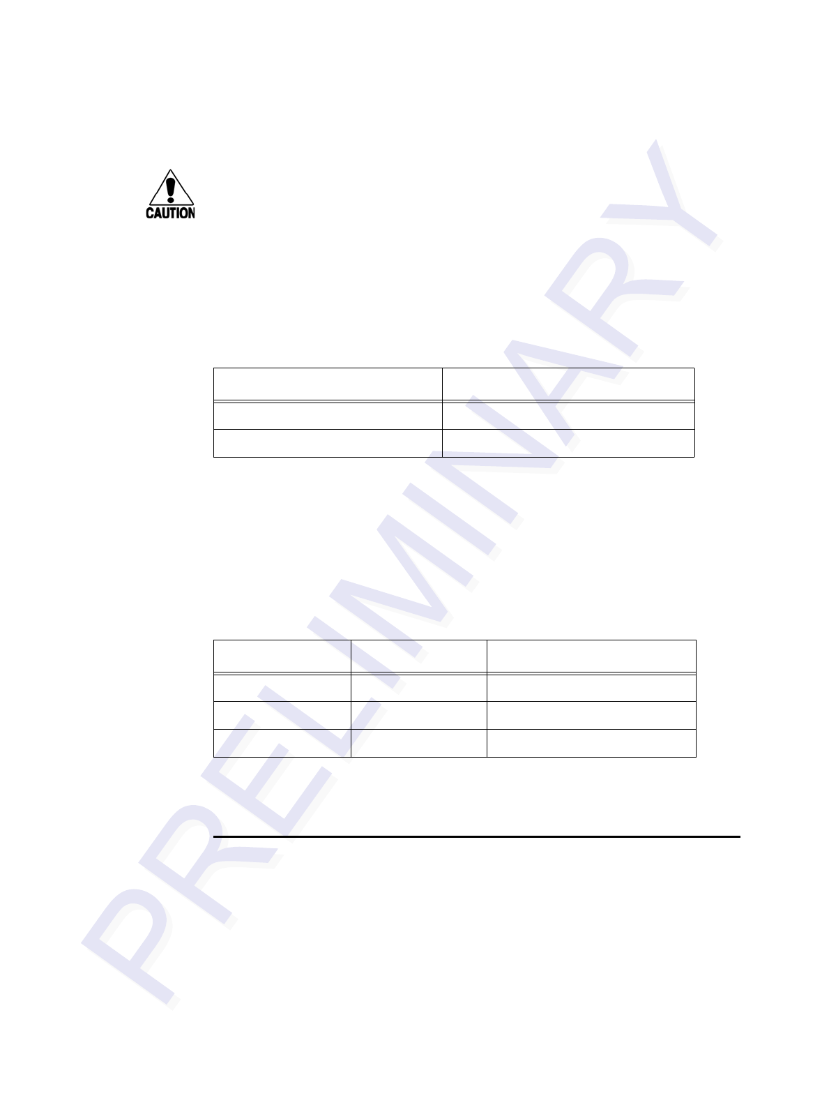
Encompass 4 Reader System Guide
7-6
Caution
If ECP is enabled, ensure that the ECP timeout is sufficient for the new baud rate.
Reader response:
Done
101N Select Stop Bits
Command #101N selects the number of stop bits for reader character transmission.
The factory default setting is 1 stop bit. The N variable specifies the number of stop
bits as indicated in Table 7-2.
Reader response:
Done
102N Select Parity
Command #102N selects the reader parity setting. The factory-default setting is par-
ity disabled. The N variable specifies parity as shown in Table 7-3.
Reader response:
Done
Command Group 2
Group 2 commands control the real-time clock which maintains the MPRR internal
time and date. This time and date can be appended to IDs, error messages, and sensor
input reports. An internal battery supports the clock, so time and date are preserved if
main power is lost.
20 Set Time
Command #20 sets the time. Enter the time in the proper format: two-digit decimal
entries with no spaces between characters and using colons as delimiters.
Table 7-2 Select Stop Bits Commands
Command Stop Bits Selected
1010 1 (factory default)
1011 2
Table 7-3 Select Parity Commands
Command Data Bits Parity Selected
1020 8 Disable parity (factory default)
1021 7 Select even parity
1022 7 Select odd parity

Commands
7-7
The entry format is as follows:
20HH:MM:SS or 20HH:MM:SS:hh
where
HH represents hours (00 to 23).
MM represents minutes (00 to 59).
SS represents seconds (00 to 59).
hh represents hundredths of a second (00 to 99).
:is the time delimiter.
If hundredths of a second is not specified, the reader sets the hundredths register to 00.
Reader response:
Done
21 Set Date
Command #21 sets the date. Enter the date in the proper format: two-digit decimal
entries with no spaces between characters and using forward slashes “/” as delimiters.
The entry format is as follows:
21MM/DD/YY
where
MM represents the month (01 to 12).
DD represents the day (01 to 31).
YY represents the last two digits of the year (00 to 99).
/is the date delimiter.
Reader response:
Done
22 Display Time and Date
Command #22 displays the reader’s current time and date. One space separates the
time and the date output.
Reader response:
HH:MM:SS.hh MM/DD/YY
where
HH represents hours.
MM represents minutes.
SS represents seconds.
hh represents hundredths of seconds.

Encompass 4 Reader System Guide
7-8
:is the time delimiter.
MM represents the month.
DD represents the day.
YY represents the last two digits of the year.
/is the date delimiter.
Append Information — Command Group 3
Group 3 commands append useful information to reader transmissions, such as IDs,
error messages, and sensor input reports. Auxiliary information such as reader num-
ber, antenna number (or manual entry code), number of times the previous tag was
read, and sensor input status can be appended to the ID using the Group 3 commands.
30N Append Time and Date Selection
Command #30N selects the option of appending the time and date to transmitted IDs,
error messages, presence without tag reports, and input status change reports. The
factory default setting is time and date appended (command #302).
The reader returns an Error message if its tag buffer contains data. The reset reader
command #63 may be transmitted to clear the buffer; however, tag ID data will not be
reported. If this is unacceptable, allow the buffer to empty before re-issuing append
time and date command #30N. Append Time and Date commands are shown in Table
7-4
The reader transmits messages with time and date appended as follows. One space
separates the time from the date.
<string>&<HH:MM:SS.hh MM/DD/YY>
where
string is a tag ID, error message, or report.
& separates <string> from the time and date.
HH:MM:SS is the time delimiter.
MM/DD/YY is the date delimiter.
Reader response:
Done
Table 7-4 Append Time and Date Commands
Command Append Option
300 No time and date appended
302 Time and date appended (factory default)

Commands
7-9
31N Append Auxiliary Information Selection
Command #31N selects the option of appending auxiliary information to transmitted
IDs, presence-without-tag reports, and input status change reports. Auxiliary informa-
tion is not appended to error messages. The factory-default setting is no auxiliary
information appended. The N variable specifies whether or not auxiliary information
is to be appended. Append Auxiliary Information commands are shown in Table 7-5.
The reader transmits messages with auxiliary information appended as:
<message data>%<xx-y-zz-q>
where
%separates the auxiliary information and signals the host
computer that auxiliary information is appended.
xx reader ID. Value can be set with command #60NN.
-auxiliary information delimiter
yantenna number. Value fixed at 0.
zz number of reads (00 to FF hexadecimal) of the previous tag
qcurrent status of input0 and input1 (0 to 3). Not applicable to the
MPRR.
Reader response:
Done
ID Filtering — Command Group 4
Group 4 commands set criteria for filtering (buffering or discarding) ID codes. These
commands are useful for eliminating duplicate ID codes and selecting the type of tags
read by the MPRR.
40 Transmit All ID Codes
Command #40 instructs the reader to transmit all IDs without regard for uniqueness.
This command can be useful when tuning the read zone and mapping the footprint or
performing diagnostics.
After diagnostics are complete, you may want to reinstate the uniqueness check using
command #410N Select Unique ID Code Criteria.
Table 7-5 Append Auxiliary Information Commands
Command Append Option
310 No auxiliary information appended (factory default)
311 Auxiliary information appended

Encompass 4 Reader System Guide
7-10
Reader response:
Done
410N Select Unique ID Code Criteria (Anti-passback Feature)
Command #410N instructs the reader to buffer and transmit ID codes according to
the following test: an ID is read if previously decoded IDs have changed value at
least N+1 times since the new ID was last received. IDs that do not pass the test are not
read. The factory-default setting is command #4100, which selects a separation of
one ID. Variable N specifies ID separation as shown in Table 7-6.
Each time the reader receives a tag ID, it compares the ID with the contents of a com-
parison register. This register contains the following two items:
Item 1 Most recently acquired ID (different from Item 2)
Item 2 Second-most recently acquired ID (different from Item 3)
Item 3 Third-most recently acquired ID (different from Item 4)
Item 4 Fourth-most recently acquired ID
When the uniqueness filter is set to separation of one ID, the newly acquired ID is
transmitted only if it is different from the first item. Separation of two IDs allows
transmission if the new ID is different from Items 1 and 2 in the comparison register.
Separation of three and four IDs transmit the new ID only if it is different from the
first three and the first four items, respectively.
Note: A new ID can fail the filter test and not be transmitted; however, it remains
stored in the comparison register.
The uniqueness test has a two-minute time limit. If an ID is buffered, it will not be
accepted again unless it arrives at the reader more than two minutes from the previous
arrival or until the receipt of one or more other IDs reset the uniqueness.
Reader response:
Done
420N Select Valid ID Code Criteria
Command #420N directs the reader to validate an ID received only after it has been
Table 7-6 Unique ID Code Criteria
Command Uniqueness Criteria
4100 Separation of 1 ID (factory default)
4101 Separation of 2 IDs
4102 Separation of 3 IDs
4103 Separation of 4 IDs

Commands
7-11
obtained a specified number of times in sequence. Values for N are 0 through 3 (Table
7-7). The factory setting is one acquisition (N = 0).
The validation procedure is executed before the unique ID test (Select Unique ID
Code Criteria [#410N] commands). IDs that do not pass the validation test are not
reported.
For example, command #4203 specifies that the same ID must be obtained from the
antenna/RF module 4 times in succession before it is considered for the uniqueness
test. This feature is useful in installations where RF reflections may cause a single tag
to be read multiple times or where an occasional ID might be read from fringe areas
43 Buffer All ID Codes
Command #43 buffers all acquired ID codes. It effectively cancels any uniqueness
criteria previously set by select unique ID code criteria command 410N.
Note: Command #43 is for diagnostic purposes only.
After diagnostics are complete, reset the select unique ID code criteria using
command 410N.
Reader response:
Done
440 Reset Uniqueness
Command 440 causes the ID filtering process set by Select Unique ID Code Criteria
(#410N) to restart. It is used in conjunction with the Variable Timeout #44N) com-
mands. This command provides a one-time reset at which point the previously set
time-out interval resumes. This command can be sent in data or command mode.
44N Set Uniqueness Timeout
Places a time limit on the uniqueness criterion set by Select Unique ID Code Criteria
(#410N). The parameter N sets the number of minutes on the time-out clock. The
factory setting is two minutes (N = 1).
Command Time-Out Clock
#441 2 minutes (factory setting)
Table 7-7 Select Valid Code Commands and Frames
Command Valid Code Frames
4200 1 (factory default)
4201 2
4202 3
4203 4

Encompass 4 Reader System Guide
7-12
#442 15 seconds
#443 30 seconds
Entering these commands effectively expires the time-out clock, which erases all cur-
rent IDs in the comparison register. In effect, the first ID that is acquired after the
clock expires always appears to be new and is stored. Newly acquired IDs are only
tested against IDs that are registered after the clock resets.
The time-out clock is continually reset (does not expire) as long as the reader receives
the same tag ID. For example, assume that the time-out clock is set for 2 minutes and
there is a railcar parked on a siding in front of the reader. Without this reset feature, the
railcar’s ID would be reported every 2 minutes (each time the time-out clock expired).
452 Disable Tag Translation Mode (Factory Default)
Command #452 disables tag translation mode. Incoming full-frame tags will be
directly converted to ASCII. They will not be translated from Association of
American Railroads (AAR) and American Trucking Associations (ATA) format to
ASCII.
Reader response:
Done
453 Enable Tag Translation Mode
Command #453 enables the translation of tags in AAR and ATA formats. Specific
data fields, such as owner ID and car number, will be extracted from these tags,
translated according to AAR or ATA standards, and converted to ASCII. Tags that are
not programmed in AAR or ATA format will be directly converted to ASCII. The
reader will not attempt to translate data from half-frame or dual-frame tags.
Reader response:
Done
454 Disable Multi-tag Sort (Factory Default)
Command #454 is a default set in the factory to disable the multi-tag sort function.
Reader response:
Done
455 Enable Multi-tag Sort
Command #455 enables the multi-tag sort function that allows the reader to identify
unique tags within a group of Intellitag-based tags. Multi-tag sort allows full operation
of the tags and reader to be carried out with any number of tags in the presence of the
reader.
Reader response:
Done
Note: Enabling the multi-tag sort function adversely affects the vehicle speed at
which tags may be read. If there is only one Intellitag-based tag in the vehicles of the
target population, multi-tag sort should be disabled.

Commands
7-13
456 Enable SeGo Protocol Tag Initialization During Multi-tag
Sort (Factory Default)
Command #456 enables the reader to send the SeGo protocol tag initialize command
as part of the multi-tag sort function. When the reader sends the SeGo protocol tag ini-
tialize command, all tags in the RF field reenter the sort process.
Reader response:
Done
457 Disable SeGo Protocol Tag Initialization During Multi-tag
Sort
Command #457 disables the reader from sending the SeGo protocol tag initialize
command as part of the multi-tag sort function. Any SeGo protocol tags already iden-
tified by the reader during the sort process will not be re-identified as long as they
remain powered in the RF field. The reader will only identify new tags that come into
the RF field or tags that do not remain powered in the RF field.
Reader response:
Done
480 Disable ATA
Command #480 disables the reader from reading ATA protocol tags.
481 Enable ATA
Command #481 enables the reader to read ATA protocol data from tags if the reader
is programmed to read this tag protocol.
484 Disable SeGo
Command #484 disables the reader from reading SeGo protocol data from tags.
485 Enable SeGo
Command #485 enables the reader to read SeGo protocol data from tags if the reader
is programmed to read this tag protocol.
488 Disable eATA
Command #488 disables the reader from reading factory-programmed eATA data
from tags.
489 Enable eATA
Command #489 enables the reader to read factory-programmed eATA data from
SeGo protocol tags.
496 Disable Alternate Group Select (Factory Default)
Command #496 disables the alternate group select function that allows the reader to
distinguish tags meeting specific criteria pre-programmed into the tags.
Reader response:

Encompass 4 Reader System Guide
7-14
Done
497 Enable Alternate Group Select
Command #497 enables the alternate group select function that allows the reader to
distinguish tags meeting specific criteria pre-programmed into the tags.
Reader response:
Done
Reader Status — Command Group 5
Group 5 commands provide status reports on the parameters and operation of the
reader.
505 Display Software Version
Command #505 displays the reader model number, software version information, and
assigned serial number.
Reader response:
Model E4 Series Ver X.XX SNYYYYYY
where
X.XX Version number
YYYYYY Serial number of the unit, skipping the fourth character printed on
the reader product label
506 Display Hardware Configuration Information
Command #506 displays hardware configuration information stored in the reader
memory by the user. Hardware configuration information is empty by default until
you set the information to any 20 character ASCII string desired using command
#696S...S.
Reader response:
An ASCII string from 1 to 20 characters in length
510 Display RF Transceiver FPGA Version
Command #510 displays RF FPGA VER = XX.XX
511 Display RF Transceiver I Filter Chip Version
Command #511 displays FIL IC I VER = XX.XX
512 Display RF Transceiver Q Filter Chip Version
Command #512 displays FIL IC Q VER = XX.XX
513 Display DSP Board Actel Version
Command #513 displays DSP FPGA VER = XX.XX

Commands
7-15
520 Display Power Fail Bit
Command #520 displays the value of the reader power fail bit. The power fail bit
changes from 0 to 1 when power to the reader is interrupted. To reset the bit, use com-
mand #63 Reset Reader or command #65 Reset Power Fail Bit. On initial power-up,
the host should transmit one of these two commands to clear the power fail bit.
Reader response:
PWRB P<0 to 1>R0
where
P0 No power failure detected
P1 Power failure detected
R0 Not applicable to the MPRR
521 Display Reader ID Number
Command #521 displays the reader ID that is sent in the auxiliary data field.
Reader response:
RDID xx
where xx = 01 to FF (hexadecimal)
522 Display Communications Port Parameters
Command #522 displays the selected communications port parameters, including the
baud rate (#100N), the number of stop bits (#101N), the parity scheme (#102N), and
the end-of-line delay.
Reader response:
MAIN B<2 to 7> S<0 to 1> P<0 to 2> D0
where
B2 1200 baud
B3 2400 baud
B4 4800 baud
B5 9600 baud (factory default)
B6 19.2 kbps
B7 38.4 kbps
S0 one stop bit (factory default)
S1 two stop bits

Encompass 4 Reader System Guide
7-16
P0 no parity (factory default)
P1 even parity
P2 odd parity
D0 00 ms end-of-line delay (fixed)
One space is required between each value. For example, if factory default settings are
assigned, the reader message is
MAIN B5 S0 P0 D0
indicating 9600 baud, one stop bit, no parity, and 0 ms end-of-line delay.
Note: The information transmitted in response to command #522 applies to data and
command mode operation only. While operating in download mode, default communi-
cations parameters are always used.
524 Display Appended Information Status
Command #524 displays the information being appended to the reader transmissions.
Command #31N appends information.
Reader response:
IDAP T<0 to 1> D<0 to 1> X<0 to 1>
where
T0 Time not appended
T1 Time appended
D0 Date not appended
D1 Date appended
X0 Auxiliary information not appended (factory default)
X1 Auxiliary information appended
One space is required between each value. For example, if factory-default settings are
assigned, the reader response is
IDAP T1 D1 X0
indicating time and date appended, and auxiliary information not appended.
Note: Time and date may be appended to ID codes, error messages, presence without
tag reports, and input status change reports. Auxiliary information may only be
appended to ID codes, presence without tag reports, and input change reports.

Commands
7-17
525 Display Communications Protocol Status
Command #525 displays the status of command #61N Selected Communications
Protocol, command #614N Selected Mode of Flow Control, and command #612NN
ECP Timeout.
Reader response:
ECPS P<0 to 1> T<01 to FF> X<0 to 2> S0
where
P0 Basic protocol enabled (factory default)
P1 ECP enabled
Txx ECP timeout where xx = 01 to FE (hexadecimal)
Timeout (ms) = 50 * xx
If xx = FF timeout disabled
X0 Flow control disabled
X1 Software flow control enabled (factory default)
X2 Hardware flow control enabled
S0 start of message character is #
For example, if factory default settings are assigned, the reader message is:
ECPS P0 TFE X1 S0
which means basic protocol enabled, an ECP timeout of 254 (12,700 ms, 12.7 sec),
software flow control enabled, and start of message character is #.
527 Display RF Status
Command #527 displays the current status of the RF module. The reader response
indicates whether RF is controlled externally by the host, set by command #640N RF
Control, or internally by input set by command #641 (not applicable to the MPRR).
RF always controlled by Sense0 and Sense1 when reader is in MPRR mode. See
“MUX Operational Modes” on page 7-35. Command #527 also displays the current
RF status and the uniqueness timeout.
Note: If you enter RF settings using command #642NN, the display command for RF
output frequency, F is “Fxx” and indicates use of the backward-compatible frequency
entry method.
Reader response:
RFST C<0 to 1> O<0 to 1> T<1 to 3> Fxxx Rxx Gxx Axx Ixx
where
C0 RF controlled by host
C1 RF controlled by presence sensor on input0, the red/green pair
(factory default)
O0 RF off

Encompass 4 Reader System Guide
7-18
O1 RF on
T1 Uniqueness timeout of two minutes
T2 Uniqueness timeout of 15 seconds
T3 Uniqueness timeout of 30 seconds
Fxxx RF output frequency, xxx = 000 to 118 hexadecimal offset in 250
kHz from 860 MHz. If an invalid frequency value is stored
(corrupted NVRAM), then xxx = “XXX” to indicate an error in
the frequency setting.
Rxx Tag decoder range (distance) for ATA tags, xx = 00 to 1F
hexadecimal range value
Gxx Tag decoder range (distance) for SeGo protocol tags, xx = 00 to
1F hexadecimal range value
Axx RF power attenuation, where 00 is maximum output power and
0A is minimum output power (10dB less than maximum power).
Ixx IAG RF power attenuation, where 00 is maximum output power
and 0F is minimum output power (15 dB less than maximum
power)
For example, if factory default settings are assigned, the reader message is
RFST C1 O0 T1 Fxx R1F G1F A00 I04
which means that RF is enabled by presence sensor on input0, RF signal off, unique-
ness timeout of two minutes, RF output frequency has not been set, maximum RF out-
put range for ATA tags, maximum RF output range for eGo and eGo Plus tags, full RF
power, and IAG power set at 4 dB attenuation.
529 Display Presence Input Status
Command #529 displays the parameters associated with presence detection and RF
control. The reader’s message indicates if presence without tag reports are enabled/
disabled (#690N Select Presence without Tag Report Option), if input inversion is
enabled/disabled (#694N Select Input Inversion Option), and the minimum presence
true period (always true). The reader’s message also reports the selected RF timeout
(#693N Select RF Timeout Period) and the selected means of RF-off control (#692N
Select RF Control Algorithm). If presence without tag reports is enabled (#6901
Enable Presence without Tag Reports), the reader transmits a report if a presence is
detected without the subsequent acquisition of a valid tag.
Note: RF timeout values vary depending on the operative tag read mode and the type
of tag in the read field. All times are approximate.
Reader response:
PRST P<0 to 1> D0 A<0 to 2> T<0 to F> I<0 to 1>

Commands
7-19
where
P0 Presence without tag reports disabled (factory default)
P1 Presence without tag reports enabled
D0 Minimum presence true period of 0 ms (fixed)
A0 RF off on timeout only
A1 RF off on timeout or tag
A2 RF off on timeout or presence condition false (factory default)
T0 RF timeout of 0 ms (always expired)
T1 4 ms
T2 8 ms
T3 12 ms
T4 20 ms
T5 24 ms
T6 32 ms
T7 48 ms
T8 60 ms
T9 92 ms
TA 152 ms
TB 300 ms
TC 452 ms
TD 600 ms
TE 752 ms
TF RF timeout infinite, never expires (factory default)
I0 input inversion disabled (factory default)
I1 input inversion enabled
For example, if factory default settings are assigned, the reader message is

Encompass 4 Reader System Guide
7-20
PRST P0 D0 A2 TF I0
which means that presence without tag reports is disabled, minimum presence true
period is 0, RF off control on timeout or presence false, infinite RF timeout, and input
inversion disabled.
530 Display RF0 Filter Status
Command #530 displays the parameter set for the RF input, including the selected
unique ID code criteria (#410N Select Unique ID Code Criteria) and the valid ID code
criteria, which are fixed at one acquisition.
Reader response:
RF0S U<0 to 2> V0
where
U0 One ID separation (factory default)
U1 Two ID separations
U2 Transmit all IDs
V0 Valid ID code criteria of one acquisition (fixed)
For example, if factory default settings are assigned, the reader message is
RF0S U0 V0
which means separation of one ID for uniqueness filtering and a valid ID code criteria
of one acquisition.
534 Display Tag Translation Mode Status
Command #534 displays tag translation mode status, enabled or disabled. If tag
translation mode is enabled, incoming full-frame tags in AAR or ATA format are
translated according to ISO standards. Refer to “452 Disable Tag Translation Mode
(Factory Default)” on page 7-12 and “453 Enable Tag Translation Mode” on page 7-
12 for more information.
Reader response:
TT <0 to 1>
where
0tag translation mode disabled
1tag translation mode enabled
537 Display Echo Status
Command #537 displays echo mode status. In basic protocol (#610 Select Basic
Protocol), the reader may be configured to enable (#6171 Enable Echo Mode) or dis-
able (#6170 Disable Echo Mode) the echo of received commands. Refer to sections
6170 Disable Echo Mode and “6171 Enable Echo Mode (Factory Default)” on page 7-
25 for more information.

Commands
7-21
Reader response:
ECHO <0 to 1>
where
0Echo status disabled (factory default)
1Echo status enabled
540 Display Flash Checksum
Command #540 displays the flash memory checksum.
Reader response:
PCKS I0000 Exxxx
where
0000 Not applicable to the MPRR
xxxx Represents the four-byte ASCII representation of the flash
memory checksum
543 Display Boot Checksum
Command #543 displays the boot ROM checksum.
Reader response:
BCKS xxxx
where xxxx represents the four-byte ASCII representation of the boot ROM check-
sum.
552 Display Antenna Multiplexing Mode
Command #552 displays the antenna multiplexing mode When the MPRR mode is
enabled, the response is
Reader response:
MUX <x>
where
x = 0 antenna multiplexing disabled, RF on port 0 only
x = 1 antenna multiplexing between RF ports 0 and 1 when sense0 active
x = 2 antenna multiplexing between RF ports 0 and 1 when sense0 active and
RF port 2 when sense1 active
x = 3 antenna multiplexing between RF ports 0 and 1 when sense0 active and
RF ports 2 and 3 when sense1 active

Encompass 4 Reader System Guide
7-22
560 Request Sensor Status Change
Command #560 displays the sensor status change reporting. Not applicable to the
MPRR
Reader response:
SSTC E<0 to 1>M<0 to 3>
where
E0 Input status change reports disabled (factory default)
E1 Input status change reports enabled
M0 Reporting disabled (factory default)
M1 Changes on input0 reported
M2 Changes on input1 reported
M3 Changes on either input reported
For example, if factory default settings are assigned, the reader message is
SSTC E0 M0
which means that input status change reports are disabled on both input0 and input1.
570 Display Operating Mode Status
Command #570 displays the currently selected tag read mode.
Reader response:
ATA:<E, D> eGo:<I, F, D> SeGo:<I, F, D> IAG:<E, D> Sort:<E, D>
where
I ID (64 bits)
E Enabled
F Full transaction (eATA)
D Disabled
577 Report Buffered Handshakes
Command #577 reports the buffered handshakes. When in MPRR mode and/or if
antenna multiplexing is enabled, the response is
Reader response:
HDSH C0 <ww> C1 <xx> C2 <yy> C3 <zz>
where
ww is count from part 0, xx is count from part 1, yy is count from part 2, and zz is
count from part 3.

Commands
7-23
Reader Control Functions — Command Group 6
Group 6 commands set reader control functions such as reader ID, communication
protocol, output pulse, and RF control.
60NN Set Reader ID Number
Command #60NN sets the reader ID that will be sent in the auxiliary data field (com-
mand #311). Uppercase or lowercase characters are allowed for NN; for example, hex
digits A though F or a through f
where NN = 00 to FF (hex for 0 to 255, factory default = 00).
Reader response:
Done
610 Select Basic Communication Protocol (Factory Default)
Command #610 enables the basic communications protocol.
Reader response:
Done
611 Select Error Correcting Protocol
Command #611 enables the error correcting protocol.
Reader response:
Done
Caution
Do not switch to ECP (command #611 Select Error Correcting Protocol) unless
the host is prepared to acknowledge each reader transmission.
612NN Select Error Correcting Protocol Timeout
Command #612NN selects the timeout interval for ECP. This timeout applies to the
transmission of tag, report, and error messages and to the receipt of host commands.
The transmit timeout is initiated immediately after the end-of-message sequence CR/
LF is transmitted. If the host does not acknowledge the message within the specified
interval, the reader times out and retransmits the message.
The receive timeout is initiated upon receipt of the start-of-message character (#). If
the end-of-message character (CR) is not received within the specified interval, the
reader discards the partially received message and resets its receiver.
Uppercase or lowercase characters are allowed for NN; for example, hex digits A
through F or a through f.
The value for NN specifies the timeout interval as follows:
ms 50 * NN for NN = 01 to FE (1–254)
FE Factory default (12,700 ms, 12.7 seconds)
Encompass 4 Reader System Guide
7-24
FF Disables the ECP timeout
Reader response:
Done
Caution
Ensure that the ECP timeout is sufficient for a given baud rate.
613 Enable Data Inquiry Protocol
Command #613 enable the data inquiry protocol.
Reader response:
Done
614N Select Flow Control Option
Command #614N selects the flow control option for reader-to-host communications.
The factory default setting is software flow control (XON/XOFF) enabled. In down-
load mode, flow control is not host-selectable; it is fixed at the default setting. How-
ever, during data mode and command mode operation, the following flow control
options are available. The N variable specifies flow control as shown in Table 7-8.
Reader response:
Done
If the reader is configured for software flow control (XON/XOFF), it stops transmit-
ting if it receives an XOFF character (host software command 13H). It does not
resume transmitting until it receives an XON character (host software command 11H).
If the reader is configured for hardware flow control (RTS/CTS, request to send/clear
to send), it stops transmission if it detects that the CTS line is no longer asserted. It
resumes transmission when this line is asserted again.
Note: TransCore recommends that XON/XOFF flow control be disabled while using
the ECP.
6170 Disable Echo Mode
Command #6170 disables the reader’s echo of received host commands. If operating
in basic protocol or data inquiry protocol, the reader echoes by default. As the reader
receives a host command, it echoes each character of the command. Once the entire
command has been received and processed, the reader transmits its response. If echo-
Table 7-8 Flow Control Commands
Command Flow Control Option
6140 Disable flow control
6141 Enable software flow control (factory default)
6142 Enable hardware flow control

Commands
7-25
ing is disabled with command #6170, the reader does not echo the command, but
only transmits its response. The reader never echoes while in ECP or download mode
operation.
Reader response:
Done
6171 Enable Echo Mode (Factory Default)
Command #6171 enables the reader to echo received host commands. Command
#6170 disables echo mode.
Reader response:
Done
63 Reset Reader
Command #63 resets the power fail bit, clears all buffers, resets tag uniqueness, turns
off both output lines, transmits the sign-on message, and returns to the data mode.
Note: This command does not reset any other configuration parameters.
Reader response:
Model E4 Series Ver X.XX SNYYYYYY
Copyright 2008 TransCore
where
X.XXD Version number
YYYYYY Serial number of the unit, skipping the fourth character printed on
the reader product label.
640N RF Control
Command #640N directly controls the RF module. The N value controls the RF
power as shown in Table 7-9.
Note: These commands only have an effect when the reader is not in MPRR mode.
See commands #836 and #837.
Command #6400 disables RF-by-input control command #641 Select RF-by-Input
Control.
Table 7-9 RF Control Commands
Command RF Power
6400 Turns off RF
6401 Turns on RF
6402 Turns on continuous wave (CW) RF until
command 6400 or 641 is received by the
reader.

Encompass 4 Reader System Guide
7-26
Reader response:
Done
641 Select RF-by-Input Control (Factory Default)
Command #641 configures the reader for RF-by-input control. The reader automati-
cally turns on RF when it detects a presence through sense0. The reader turns off RF
according to the selected RF control algorithm (#692N Select RF Control Algorithm).
Note: This command only has an effect when the reader is not in MPRR mode.
Reader response:
Done
643NN Select ATA Operating Range (Distance)
Command #643NN selects the read range for ATA tags where NN is a hexadecimal
value from 00 to 1F; the range increases with increasing NN value. The range can be
adjusted for 32 discrete values where 00 is the shortest range and 1F is the longest
range. The default range value is 1F.
Reader response:
Done
644NN Set RF Attenuation
Command #644NN sets the attenuation control for the output RF power where NN is
a hexidecimal value from 00 to 0A. Settings for attenuation are 1.0 dB increments
over a range of 10 dB of attenuation from the maximum power setting of 2 watts at 0-
dB attenuation to a minimum power level of 200 milliwatts at 10-dB attenuation.
The Set RF Attenuation command NN variables and corresponding attenuation set-
tings are shown in Table 7-10.
Table 7-10 RF Attenuation Command Variables
Variable (NN) Attenuation
Setting (dB)
00 0 (factory default)
01 1
02 2
03 3
04 4
05 5
06 6
07 7

Commands
7-27
Reader response:
Done
645NN Set SeGo Protocol Operating Range (Distance)
Command #645NN sets the read range for SeGo protocol tags where NN is a hexadec-
imal value from 00 to 1F; the range increases with increasing NN value. The range can
be adjusted for 32 discrete values where 00 is the shortest range and 1F is the longest
range. The default range value is 1F.
Reader response:
Done
647XXX Select RF Operating Frequency
Command #647XXX sets the reader RF from 860 to 930 MHz in 250-kHz steps,
where XXX is a hexadecimal value from 000 to 118. After the reader’s frequency is
set, the value is stored in non-volatile RAM (NVRAM). This value is not altered by
power-down.
If the NVRAM becomes corrupted, the correct operating frequency cannot be guaran-
teed. In this circumstance, the RF section shuts down and the reader sends an
Error06 message to the host. Until the frequency is reset using command #647XXX,
the unit displays the same error message every time it is powered up or if an attempt is
made to enable the RF by host or by external sensor.
The commands to set the RF frequency are presented in Table 7-11.
08 8
09 9
0A 10
Table 7-11 Select RF Frequency Commands
Command RF Frequency (MHz)
647000 860.00
..
..
.
6470CF 911.75
6470D0 912.00
Table 7-10 RF Attenuation Command Variables (continued)
Variable (NN) Attenuation
Setting (dB)

Encompass 4 Reader System Guide
7-28
Reader response:
Done
65 Reset Power Fail Bit
Command #65 resets the power fail bit to 0. The bit changes from 0 to 1 when power
is restored to the reader. Upon reader power-up, the host transmits either command
#65 or #63 Reset Reader to properly initialize this bit. The current state of the power
fail bit may be displayed. Refer to “520 Display Power Fail Bit” on page 7-15 for
more information.
6470D1 912.25
6470D2 912.50
6470D3 912.75
6470D4 913.00
..
..
..
6470EA 918.50
6470EB 918.75
6470EC 919.00
6470ED 919.25
6470EE 919.50
6470EF 919.75
..
..
.
657113 928.75
647114 929.00
647115 929.25
647116 929.50
647117 929.75
647118 930.00
Table 7-11 Select RF Frequency Commands (continued)
Command RF Frequency (MHz)

Commands
7-29
Reader response:
Done
66F Load Default Operating Parameters
Command #66F loads all the factory default operating parameters except RF operat-
ing frequency. Refer to Table 8-2, MPRR Default Configuration Settings” for a listing
of the defaults.
Reader response:
Done All parameters loaded OK
Error A parameter load failed
690N Select Presence Without Tag Report Option
Command #690N enables or disables the presence without tag report option. If the
presence without tag reporting option is enabled using command #6901, input
reports are transmitted when a tag presence is detected without the subsequent acqui-
sition of a valid tag. The value for N specifies the reports as shown in Table 7-12.
Note: These commands only have an effect when the reader is not in MPRR mode.
Reader response:
Done
Refer to “Basic Protocol and ECP Format” on page 6-5 for message format informa-
tion.
692N Select RF Control Algorithm
Command #692N selects the algorithm for turning off RF power when RF-by-input
control is enabled using command #641 Select RF-by-Input Control.
The values for N specify the RF control algorithms as shown in Table 7-13.
Note: These commands only have an effect when the reader is not in MPRR mode.
Table 7-12 Presence Without Tag Report Commands
Command Report Option
6900 Disable presence without tag reports (factory
default)
6901 Enable presence without tag reports
Table 7-13 RF Control Algorithm Commands
Command RF Power Off
6920 On timeout only
6921 Timeout or tag ID acquired

Encompass 4 Reader System Guide
7-30
Command #6920 turns off RF power based on the timeout established by command
#693N Set RF Timeout Period.
Command #6921 allows RF power to be turned off either after the timeout period or
upon acquisition of a valid tag ID, whichever occurs first.
Command #6922 turns off RF power either after the timeout period or upon the pres-
ence false condition, whichever occurs first.
Reader response:
Done
693N Select RF Timeout Period
Command #693N selects the RF timeout period used by command #692N Select RF
Control Algorithm. Values for N range from 0 through F.
Command #693F disables the RF timeout. The reader turns off the RF immediately
following the acquisition of a valid tag, whether or not it is unique.
Uppercase or lowercase characters are allowed for N; for example, hex digits A
through F or a through f. The commands and corresponding timeouts are shown in
Table 7-14.
Note: These commands only have an effect when the reader is not in MPRR mode.
6922 Timeout or presence false (factory default)
Table 7-14 Timeout Period Values
Command Timeout (ms)
6930 0 (always expired)
6931 4
6932 8
6933 12
6934 20
6935 24
6936 32
6937 48
6938 60
6939 92
693A 152
Table 7-13 RF Control Algorithm Commands
Command RF Power Off

Commands
7-31
Reader response:
Done or Error.
The reader returns an Error message if a valid hexadecimal digit is not substituted
for N in command #693N.
694N Select Input Inversion Option
Command #694N enables or disables input inversion. When inversion is enabled, an
open circuit input is interpreted as a closed circuit, and a closed circuit input is inter-
preted as an open circuit. This feature allows greater flexibility in the attachment of
external equipment to the reader inputs. For example, some proximity sensors indicate
presence with an open circuit. In this instance, command #6941 can enable input
inversion so that an open circuit input indicates a presence. The values for N represent
the two inversion options as shown in Table 7-15.
Reader response:
Done
695S...S Set Serial Number
Command #695 assigns the reader serial number according to the format:
695SSSSSS
where SSSSSS is the serial number.
The serial number may contain as many as six uppercase or lowercase ASCII alphanu-
meric characters.
Note: The factory-assigned serial number of the reader contains seven characters.
However, to maintain backward compatibility, the reader software allows only six
693B 300
693C 452
693D 600
693E 752
693F Infinite (never expires, factory
default)
Table 7-15 Input Inversion Options
Command Option
6940 Disable input inversion (factory default)
6941 Enable input inversion
Table 7-14 Timeout Period Values (continued)
Command Timeout (ms)

Encompass 4 Reader System Guide
7-32
characters to be entered. When setting the serial number, skip the fourth (middle)
character of the seven-character number shown on the reader product label.
Note: Once assigned, the serial number is preserved during power-down and the
loading of default parameters.
Reader response:
Done
696S...S Store Hardware Configuration String
Command #696S...S stores hardware configuration information into reader mem-
ory.
The hardware configuration string is assigned according to the following format:
696S...S
where S...S is the hardware configuration string that may contain as many as 20
uppercase or lowercase ASCII alphanumeric characters.
Note: Once assigned, configuration information is preserved during power-down and
the loading of default parameters.
Reader response:
Done
Auxiliary Reader Control — Command Group 8
Group 8 commands provide control of reader functions, such as the sense input lines.
8110
Command #8110 turns on RF port0, sends the command on Ctag pin 0 to fire off
Ctag address 0.
8111
Command #8111 turns on RF port1 and sends the command on Ctag pin 0 to fire off
Ctag address 1.
8112
Command #8112 turns on RF port2 and sends the command on Ctag pin 1 to fire off
Ctag address 0.
8113
Command #8113 turns RF port3 and sends the command on Ctag pin 1 to fire off
Ctag address 1.
8142X
Command #8142X sends the command on Ctag pin 0 to set the Ctag character.

Commands
7-33
8143X
Command #8143X sends the command on Ctag pin 1 to set the Ctag character.
8150
Command #8150 sets the check tag address to 0 on check tag pin 0.
8151
Command #8151 sets the check tag address to 1 on check tag pin 0.
8152
Command #8152 send the command on Ctag pin 1 to set the Ctag address to 0.
8153
Command #8153 send the command on Ctag pin 1 to set the Ctag address to 1.
830 Disable Automatic Periodic RF Status Report (Factory
Default)
Command #830 is a default set in the factory to disable the automatic periodic RF
status report.
Reader response:
Done
831 Enable Automatic Periodic RF Status Report
Command #831 enables the automatic periodic RF status report. This function sends
out a periodic RF status report if no other message (a tag read) is sent from the reader
for a period of time. This message is the same message that would be sent in response
to the #527 Display RF Status command. Enabling this function is helpful in some
sites where there may not be much tag activity, and the user wants an automatic way to
ensure the communication channel with the reader is still intact. With this function
enabled, the host system will get a message from the reader at least every three min-
utes.
Reader response:
Done
836 Disable MPRR Mode
Command #836 disables the MPRR mode.
Reader response:
Done
837 Enable MPRR Mode
Command #837 enables the MPRR mode.

Encompass 4 Reader System Guide
7-34
Reader response:
Done
850 MUX RF Port 0 (Factory Default)
Command #850 enables RF port 0.
Reader response:
Done
851 MUX Between RF Port 0
Command #851 multiplexes between RF port 0.
Reader response:
Done
852 MUX Between RF Ports 0 and 1
Command #852 multiplexes between RF ports 0 and 1.
Reader response:
Done
853 MUX Between RF Ports 0, 1, and 2
Command #853 multiplexes between RF ports 0, 1, and 2.
Reader response:
Done
891 MUX RF Port 1 Only
Command #891 multiplexes RF port 1 only.
Reader response:
Done
892 MUX RF Port 2 Only
Command #892 multiplexes RF port 2 only.
Reader response:
Done
893 MUX RF Port 3 Only
Command #893 multiplexes RF port 3 only.
Reader response:
Done

Commands
7-35
Check Tag Operation
To enable check tag 0, issue the following commands
#8110 – turn on RF port0, send the command on Ctag pin 0, to fire off Ctag address 0.
#8111 – turn on RF port1, send the command on Ctag pin 0, to fire off Ctag address 1.
#8142X – send the command on Ctag pin 0 to set the Ctag character.
#8150 – send the command on Ctag pin 0 to set the Ctag address to 0.
#8151 – send the command on Ctag pin 0 to set the Ctag address to 1.
To enable check tag 1, issue the following commands
#8112 – turn on RF port2, send the command on Ctag pin 1, to fire off Ctag address 0.
#8113 – turn on RF port3, send the command on Ctag pin 1, to fire off Ctag address 1.
#8143X – send the command on Ctag pin 1 to set the Ctag character.
#8152 – send the command on Ctag pin 1 to set the Ctag address to 0.
#8153 – send the command on Ctag pin 1 to set the Ctag address to 1.
MUX Operational Modes
To enable antenna multiplexing (muxing) operational modes, issue the
following commands
#836/#837 – Disable/enable MPRR mode
#850 – RF port 0 only (factory default)
#851 – mux between RF port 0
#852 – mux between RF port 0, 1
#853 – mux between RF port 0, 1, 2
#552 – Display mux setting. This display message will include “MPRR” if MPRR
mode is enabled (#837).
When MPRR mode is disabled, the reader will continuously step through each port
that has been enabled with #85X, running through whichever tag protocols are
enabled on each port, in order. The reader turning RF on will be qualified “RF on by
sense” setting. Command #6401 is used to turn RF on continuously and bypass the RF
on by sense. Sense0 is used for all antennas that are enabled, if RF is turned on by
sense, #641.
When MPRR mode is enabled, you must use Sense0 and Sense1 to turn on RF and
read tags. Sense0, when shorted to reader signal ground, will enable tag reads on RF
ports 0 and 1 (if enabled with #851) and Sense1 will enable tag reads on Ports 2 and 3
(if enabled with #853). For example, if commands #837 and #853 have been entered,
Sense0 is open, Sense1 shorted, and the reader is in data mode, the reader will attempt
tag reads toggling between RF ports 2 and 3 only. Smart muxing, ATA tag data sniff-

Encompass 4 Reader System Guide
7-36
ing and ATA dwell of two handshakes per antenna is automatic in MPRR mode.
MUX Test Modes
To enable antenna muxing test modes, issue the following commands
#891 – RF port 1 only
#892 – RF port 2 only
#893 – RF port 3 only
To use these test modes, MPRR mode must be disabled (#836) and muxing must be
disabled (#850). These command modes are not saved to non volatile memory, and
will be cleared by a power cycle of the reader, or by enabling either MPRR mode or
muxing. When these modes are enabled, the reader will continually run through
whichever tag protocols have been enabled, but only on the selected RF port. These
test mode commands are qualified by the RF on by sense settings. Use #6401 to dis-
able RF on by sense, if desired.

8
Configuring the Multiprotocol Rail
Reader


8-3
Chapter 8
Configuring the Multiprotocol Rail Reader
This chapter provides instructions for configuring the Multiprotocol Rail
Reader (MPRR), including factory configuration parameter defaults and
instructions for using terminal emulation software to check and change
the MPRR factory configuration defaults.
Configuring the Reader
After installing the MPRR, you need to configure its operating parameters. Terminal
settings should be initially set at 9600 baud, 8 data bits, no parity, 1 stop bit, and no
flow control.
General Configuration Labeling
Each MPRR and its shipping carton are labeled to indicate the unit’s general configu-
ration. Table 8-1 contains explanations of the MPRR label fields.
Table 8-1 MPRR Configuration Label Fields
Field Description
1st TransCore reader designator (10-)
2nd Model number
To be provided in the final version of the guide (7032-)
3rd Interface
To be provided in the final version of the guide (TBD-)
4th To be provided in the final version of the guide (TBD-)

Multiprotocol Rail Reader System Guide
8-4
Default Operating Parameter Settings
Table 8-2 contains the factory default configuration settings for the MPRR operating
parameters.The default configuration settings may not be the correct operating config-
uration settings for a specific site. Changes to the configuration settings may have to
be made, depending on the site plan, as described in Chapter 2 “Developing the Site
Plan.”
Review the default configurations shown in Table 8-2 to determine which parameters,
in addition to operating frequency and operating range, need to be adjusted. Refer to
Chapter 7, “Commands,” for a complete list of parameters and the corresponding
commands.
Note: The dual-protocol MPRR internal timing varies depending on the operative tag
read mode and the type of tag in the read field.
Table 8-2 MPRR Default Configuration Settings
Parameter Setting Command
Operating mode Data 00
Baud rate 9600 1005
Stop bits 1 1010
Parity None 1020
Time and data appended Enabled 302
Auxiliary information appended Disabled 310
Unique ID code criteria Separation of 1 ID 4100
Tag translation mode Disabled 452
Multi-tag sort Disabled 454
SeGo protocol tag initialization
during multi-tag sort Enabled 456
Alternate group select Disabled 496
Reader ID number 00 6000
Communications protocol Basic 610
Error correcting protocol (ECP)
timeout 12.7 sec 612FE
Flow control Software (XON/XOFF) 6141
Echo mode Enabled 6171
ATA operating range Maximum 6431F

Configuring the Multiprotocol Rail Reader
8-5
a. Local laws apply. The authorized frequency band for the TransCore MPRR in the
United States is 911.75 MHz to 919.75 MHz. Contact TransCore if your application
requires a frequency outside of this range.
Configuring Parameters with Terminal Emulation Software
To configure the MPRR using a PC and terminal emulation software to manually
enter MPRR host commands, follow the instructions in the section “Connecting the
MPRR to the Host” on page 4-9. Then, enter the appropriate configuration commands
through the terminal emulation software on the host.
See Chapter 7, “Commands,” for a detailed description of all available configuration
commands.
Starting the Terminal Emulation Software
You can use a PC and any terminal emulation software to enter the host commands to
download flash software, configure reader operating parameters, perform diagnostics,
and retrieve tag data. The following procedures show examples using Hyper Termi-
nal™, an application included with Microsoft Windows. Most terminal emulation
applications have a similar sequence for launching.
To start the terminal emulation software
1. At the command prompt, type your terminal emulation start command; or if
using Windows Hyper Terminal, select:
RF attenuation Full power 64400
SeGo protocol tag operating
range Maximum 6451F
Sense output pulse duration 228 ms 67C
Presence without tag reports Disabled 6900
RF-off control Timeout or no presence 6922
RF timeout Never true 693F
Input inversion Disabled 6940
Serial number NNNNNN 695
Store hardware configuration Hardware configuration not
known 696
Input status change reports Disabled 820
Automatic periodic RF status
report Disabled 830
Table 8-2 MPRR Default Configuration Settings (continued)
Parameter Setting Command
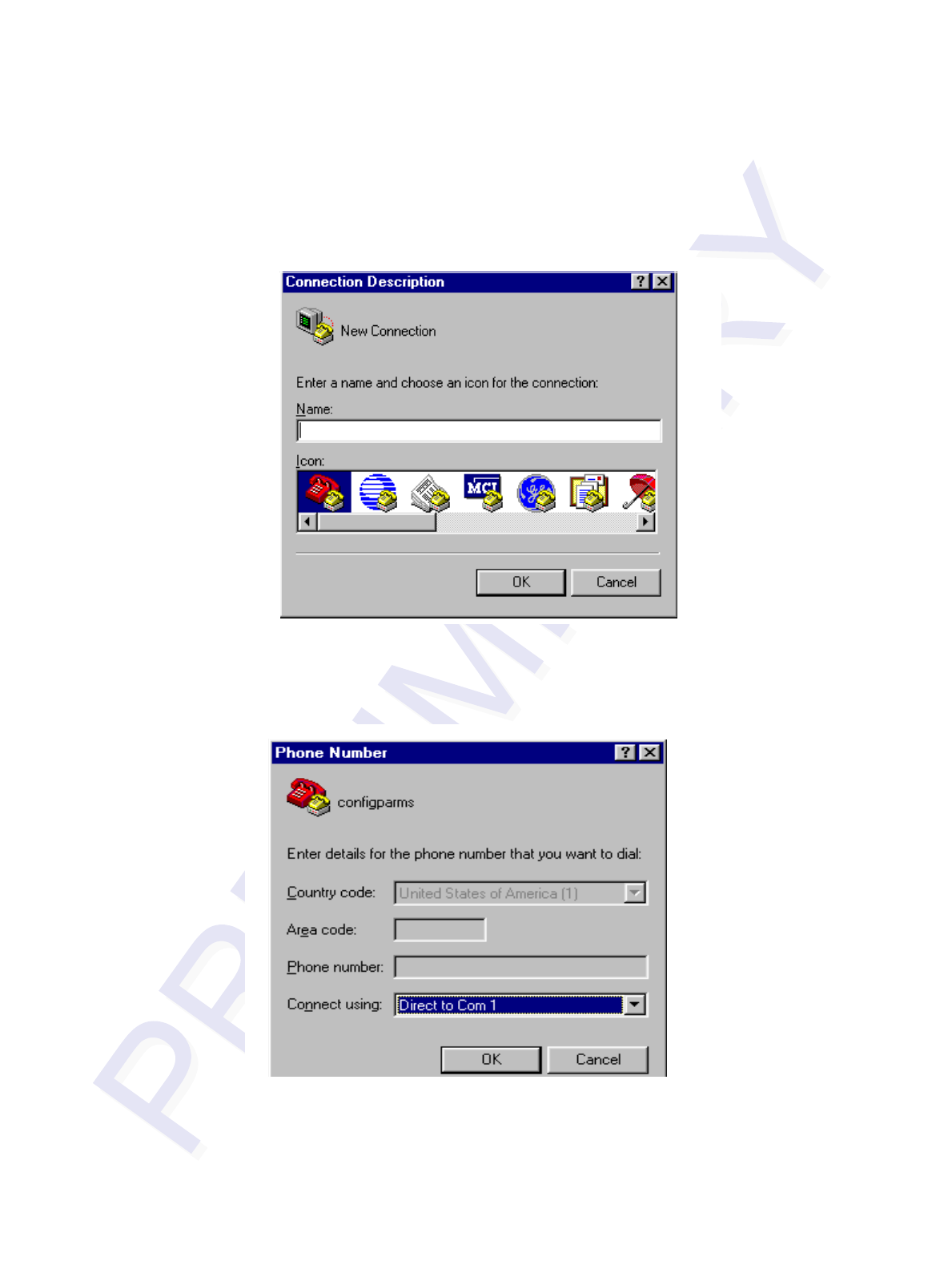
Multiprotocol Rail Reader System Guide
8-6
Programs>Accessories>Hyperterm
and press ENTER.
The application displays the Connection Description dialog box as shown in
Figure 8-1.
Figure 8-1 Connection Description Dialog Box
2. Enter a name for the session and click OK.
The application displays the Phone Number dialog box as shown in Figure 8-2.
Figure 8-2 Phone Number Dialog Box
3. From the Connect using pull-down list, choose the Com 1 option (or whichever
com port on the PC to which the RS-232 cable is attached) and click OK.
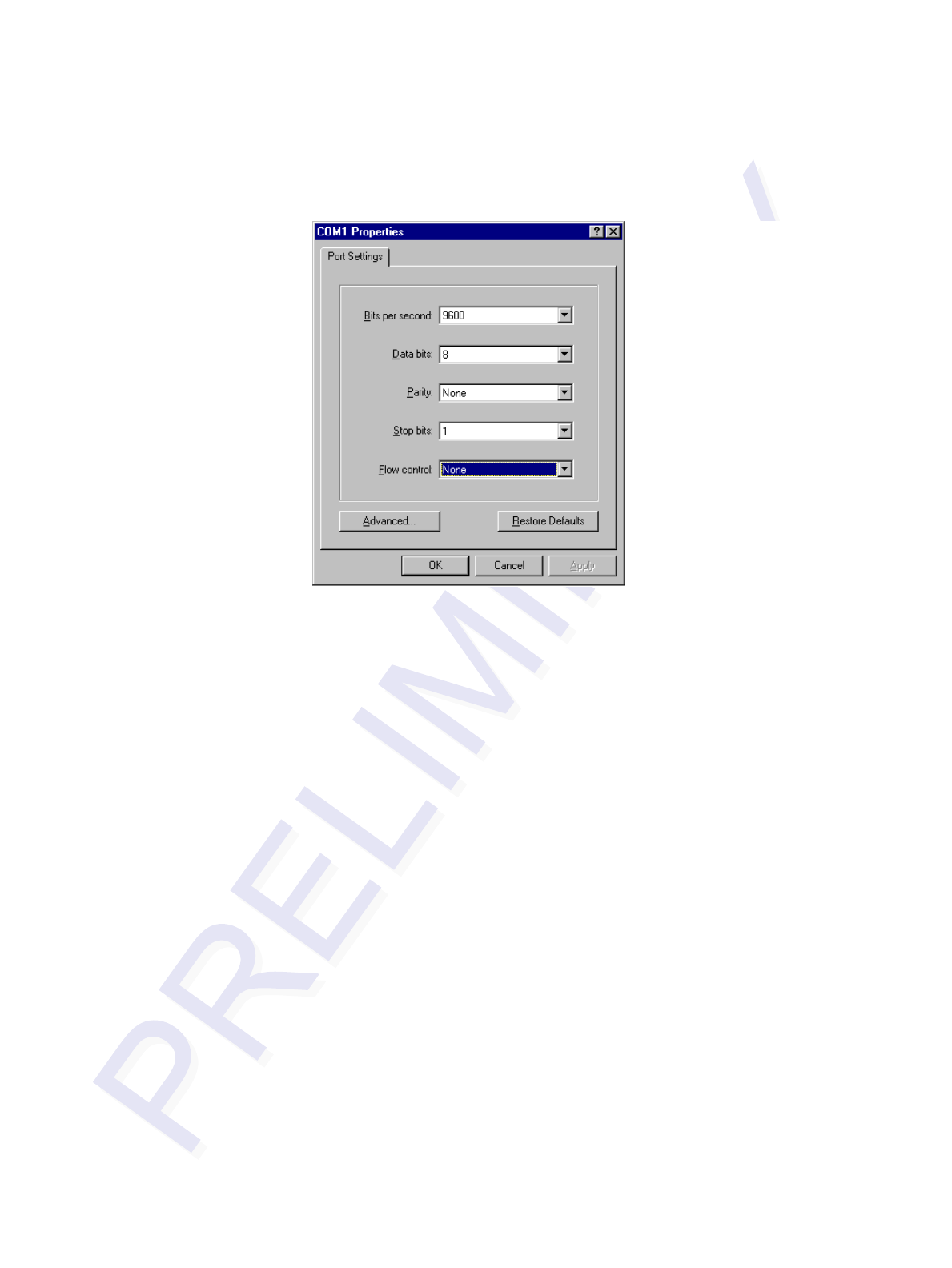
Configuring the Multiprotocol Rail Reader
8-7
The application displays the COM1 Properties dialog box as shown in
Figure 8-3.
Figure 8-3 COM 1 Properties Dialog Box
4. In the pull-down lists on the COM1 Properties dialog box, choose the following
values:
•Bits per second: 9600 baud
•Data bits: 8
•Parity: None
•Stop bits: 1
•Flow control: None
Click OK.
The application displays the configparms - Hyper Terminal main screen as
shown in Figure 8-4.

Multiprotocol Rail Reader System Guide
8-8
Figure 8-4 Hyper Terminal Main Screen
Verifying Communications
You must verify that the MPRR and the PC or laptop are communicating.
To verify communications
1. Start the terminal emulation application as described previously in “Starting the
Terminal Emulation Software” on page 8-5.
Note: When testing the MPRR using a laptop, TransCore recommends that you con-
figure laptop communication parameters to match those of the host computer to which
the MPRR will be connected after testing and configuration are completed.
2. Cycle the power on the MPRR.
Upon startup, the MPRR transmits a sign-on message, displayed on the terminal
emulation screen as shown in Figure 8-5, or a boot ROM failure message.
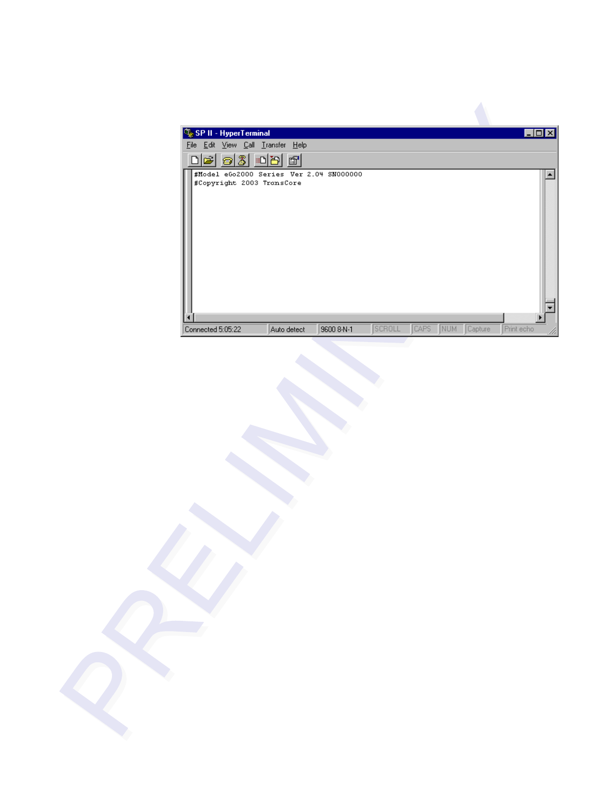
Configuring the Multiprotocol Rail Reader
8-9
Figure 8-5 Sign-on Message
The sign-on message appears as follows:
Model [software version] SNYYYYYY
[Copyright notice]
where YYYYYY is the serial number assigned to the MPRR skipping the fourth
character printed on the reader product label.
Serial number 000000 is the default setting and is not a valid number. If this
number appears in the sign-on message, the serial number has never been stored
into reader memory. Contact TransCore Technical Support.
If the flash memory checksum is not verifiable, the sign-on message appears as
follows:
Model [E4 BOOT] Ver 0.00 A
[Copyright notice]
If the failure message version number equals 0.00 E and no serial number exists,
the flash memory checksum has failed, and the MPRR is operating out of boot
ROM. In this case, the MPRR automatically enters download mode and waits for
a new program to be loaded into the flash memory. Follow the instructions in
“Program Download” on page 5-5.
Communications can also be verified by using the command sequence in
Table 8-3.
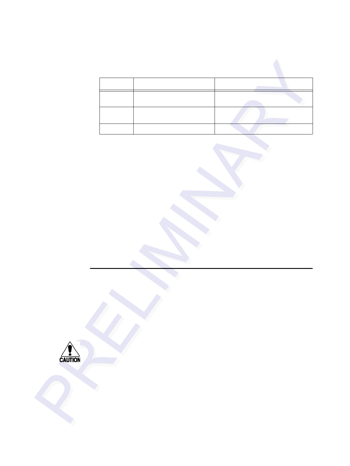
Multiprotocol Rail Reader System Guide
8-10
Table 8-3 Command Sequence to Verify Communications
3. If a successful sign-on message is not returned, check connections and
communications factors and correct any errors.
To check connections and communications factors
1. Confirm that the MPRR has power.
2. Verify the connections between the PC and the MPRR.
3. Verify the receive (Rx) and transmit (Tx) connections.
4. If using handshaking, verify the RTS and CTS connections.
5. Verify the COM port settings for the MPRR using the instructions in “Serial Port
Communications” on page 8-16.
Repeat the procedures in “Verifying Communications” on page 8-8.
If you still cannot verify the MPRR and PC communications, use the information in
“Technical Support” on page 9-6 to contact TransCore.
Verifying Tag Read Capability
After verifying communications between the MPRR and the PC, verify the capability
to read tags.
Note: The default tag read mode of the reader is the protocol(s) programmed into the
reader. Table 8-1 shows how to determine which tag protocol(s) your MPRR
supports. Use only those test tags programmed with the correct protocol(s) for the
reader.
Caution
To avoid damage to the MPRR using an external antenna, you must connect the
antenna before applying power to the reader.
To verify tag read capability
1. Once communications are verified as described in “Verifying Communications”
on page 8-8, enter the following sequence of commands to turn on continuous
RF:
• #01
• #6401
• #40
• #00
Entry MPRR Response Notes
#01 <CR> #Done <CR/LF> Switches the MPRR to command
mode.
#505 <CR> #Model E4 Series Ver X.XX
SN97001P <CR/LF> Reports the software version and
serial number.
#00 <CR> #Done <CR/LF> Returns the MPRR to data mode.
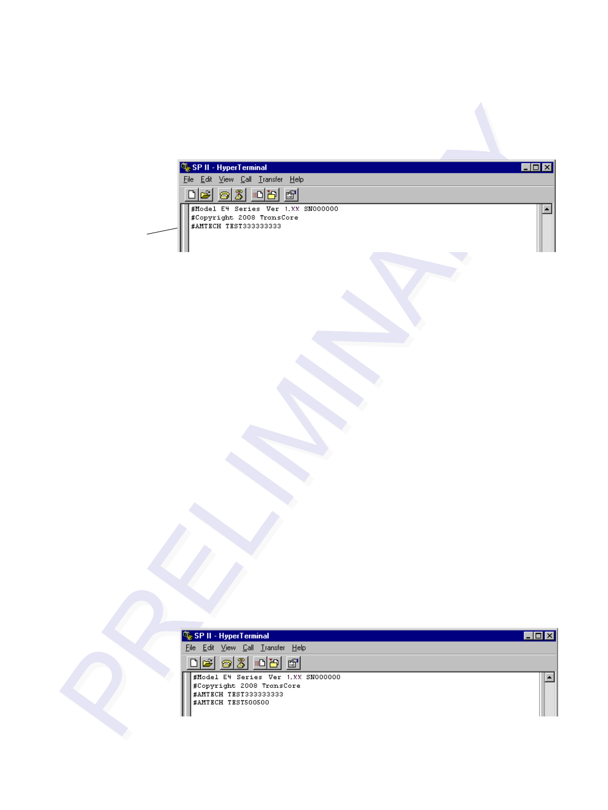
Configuring the Multiprotocol Rail Reader
8-11
2. Pass one test tag in front of the unit. If the MPRR reads the tag, the terminal
emulation application displays the tag information on the screen as shown in
Figure 8-6.
Figure 8-6 Successful Tag Read
If the tag ID is not displayed, perform the following actions:
•Verify that the MPRR is in data mode (command #00 Switch to
Data Mode).
•Ensure that the tag you are using is compatible with the MPRR.
The MPRR can read tag types that are compatible with the reader
model.
•An MPRR displays the tag read for any tag that is compatible
with the reader programming. Table 8-1 shows how to determine
which tag protocol(s) your MPRR supports.
•Using the audible circuit tester as described in “Testing the
MPRR Using an Audible Circuit Tester” on page 4-4, verify that
the reader is capable of reading the tag in the read zone. If it is,
the problem is probably in the communications between the
MPRR and the host.
3. Pass a different reader-compatible test tag in front of your MPRR.
4. When the MPRR reads the second tag successfully, the terminal emulation
application displays that tag’s information in the main screen below the
information for the first tag, as shown in Figure 8-7.
Figure 8-7 Second Successful Tag Read
Successful
Tag Read

Multiprotocol Rail Reader System Guide
8-12
If the read is unsuccessful, perform the following actions:
•Ensure the tag you are using is compatible with the MPRR.
•Using the audible circuit tester as described in “Testing the
MPRR Using an Audible Circuit Tester” on page 4-4, verify that
the reader is capable of reading the tag in the read zone. If it is,
the problem is probably in the communications between the
MPRR and the host computer.
Configuring MPRR Parameters
Follow the procedures in this section to configure MPRR parameters using a PC, lap-
top, or terminal emulator. The PC or laptop must be connected to and communicating
with the MPRR, and the terminal emulation application must be configured correctly,
as described in the section “Verifying Communications” on page 8-8.
To configure parameters
1. Switch to command mode by typing #01 at the prompt on the terminal
emulation screen, and pressing ENTER.
Note: All MPRR commands are preceded by the start-of-message character (#).
2. To meet requirements of your site, make changes to default operating parameters
as described in the following sections.
The following sections contain procedures to set some of the parameters that are
commonly changed to meet the requirements of a specific site. Procedures are
listed in alphabetical order by parameter.
Appended Tag Data
Use this procedure to set appended tag data parameters using the terminal emulation
application. See “31N Append Auxiliary Information Selection” on page 7-9 for more
information.
To set appended tag data parameters
1. Ensure that the host computer is in command mode.
2. Enter command #311 to append auxiliary information or command #310 to
have no auxiliary information appended (factory default). Press ENTER.
ID Separation
The host can select a unique ID separation of one ID or two IDs. The reader default
operation is for a unique ID separation of one ID and a uniqueness timeout of
two minutes. You can disable the uniqueness check using command #40 Transmit All
ID Codes. In this case, every tag ID received is transmitted without regard to unique-
ness. You can reinstate uniqueness checking with commands #4100 or #4101 Select
ID Separation.

Configuring the Multiprotocol Rail Reader
8-13
Note: The MPRR internal timing varies depending on the operative tag read mode
and the type of tag in the read field.
See section “40 Transmit All ID Codes” on page 7-9 and section “410N Select Unique
ID Code Criteria (Anti-passback Feature)” on page 7-10.
To set ID separation parameters
1. Ensure that the host computer is in command mode.
2. Enter command #4100 to select a separation of one ID; enter command #4101
to select a separation of two IDs. Press ENTER.
Reports
The MPRR can be configured to transmit presence without tag reports and input status
change reports. A presence without tag report is transmitted in data mode only, and
only if the system has a presence detector. This report is sent if a presence is detected
without the detection of a valid tag ID. See sections “529 Display Presence Input Sta-
tus” on page 7-18 and “690N Select Presence Without Tag Report Option” on page 7-
29.
If configured with command #82N Select Input Status Change Report Option to
transmit input status change reports, the reader will transmit a message to the host
computer any time the inputs change state. Input status change reports are transmitted
in data mode only. Input status change reporting is disabled by default. See “560
Request Sensor Status Change” on page 7-22. Also refer to Chapter 6, ”Communica-
tions Protocols” for information on message formats.
To set presence reporting
1. Ensure that the host computer is in command mode.
2. Enter command #529 to display presence input status and press ENTER. P0
indicates presence without tag reports disabled (factory default), and P1 indicates
presence without tag reports enabled.
3. Enter command #6901 to enable presence without tag reports, or enter
command #6900 to disable presence without tag reports (factory default). Press
ENTER.
To set input status change reporting
1. Ensure that the host computer is in command mode.
2. Enter command #560 to display input status change report options and press
ENTER.
• EO = input status change reports disabled (factory default)
• E1 = input status change reports enabled
• M0 = reporting disabled (factory default)
• M1 = changes on input0 reported
• M2 = changes on input1 reported
• M3 = changes on either input reported

Multiprotocol Rail Reader System Guide
8-14
3. Enter command #821 to report any change on input0, command #822 to report
any change on input 1, command #823 to report changes on input0 and input1,
or command #820 to disable status change reports (factory default). Press
ENTER.
Reset Reader
Command #63 Reset Reader resets uniqueness, clears the power fail bit, and trans-
mits the sign-on message. The reader returns to data mode following the completion
of this command.
Note: This command does not reset any of the configuration parameters.
See “63 Reset Reader” on page 7-25.
To reset the reader
1. Ensure that the host computer is in command mode.
2. Enter command #63. Press ENTER.
The terminal emulation screen displays the sign-on message as shown in Figure
8-5 on page 8-9.
Radio Frequency
Caution
The authorized continuous wave (CW) frequency band for the MPRR in the U.S. is
902.25 to 903.75 MHz and 910.00 to 921.50 MHz. The authorized modulated fre-
quency band for the MPRR in the U.S. is 911.75 to 919.75 MHz. The RF for each
MPRR at the site must be set according to the frequency specified in the FCC site
license. Only trained, authorized installation and maintenance personnel are per-
mitted by FCC to set the RF.
By using the MPRR an authorized person can set the frequency within the range from
902 to 928 MHz in 0.25 MHz steps. You can set the frequency by using a terminal
emulation program and issuing the frequency command, as discussed in section
“647XXX Select RF Operating Frequency” on page 7-27.
Note: For backward compatibility to existing controllers, you can set the RF operat-
ing frequency in 500-kHz steps using command #642NN.
To set the frequency range
1. Ensure that the host computer is in command mode.
2. Enter command #647XXX – where XXX is a hexadecimal value from 000 to 118
– and press ENTER. See command “647XXX Select RF Operating Frequency”
on page 7-27 for a complete listing of the hexadecimal values and the
corresponding frequencies.
3. To verify that the RF has been changed to the proper setting, type in command
#527 to see the current frequency setting.
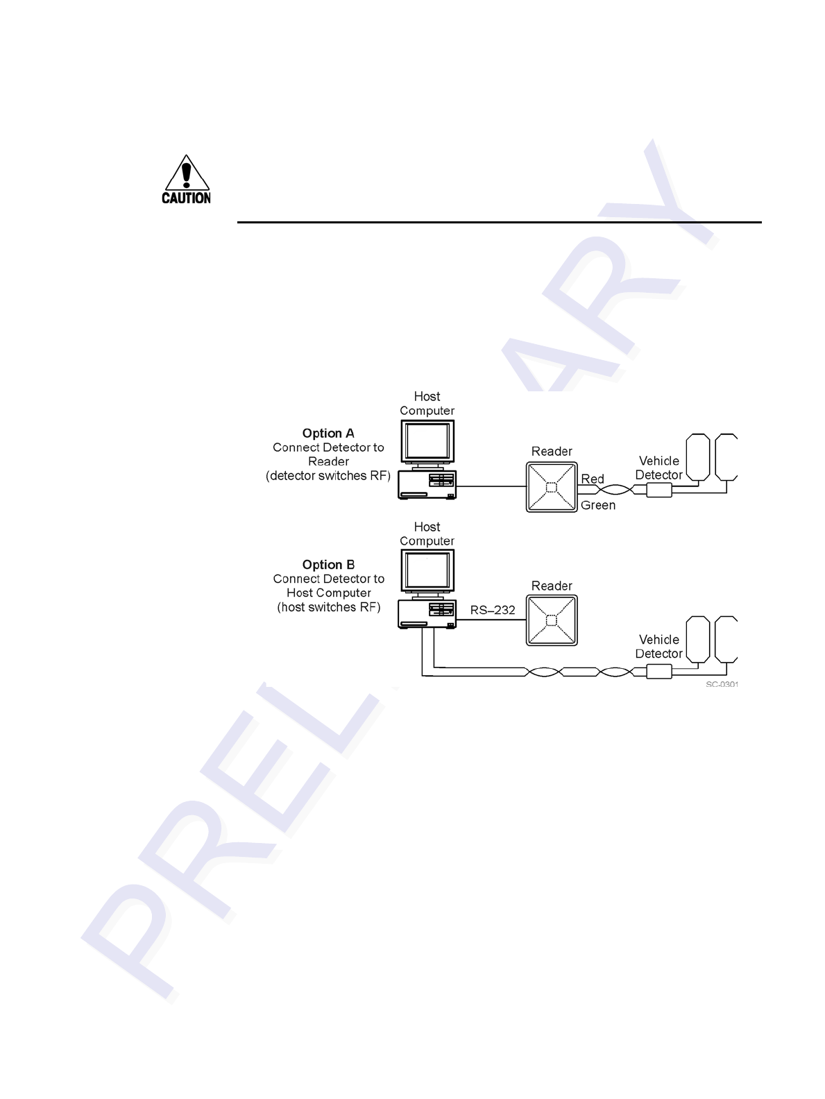
Configuring the Multiprotocol Rail Reader
8-15
Caution
Contact TransCore if your application requires a frequency outside of the autho-
rized frequency range.
RF Transmission
The RF transmission can be controlled by one of the following methods:
•Connecting a vehicle detector to the sense input0 circuit
•The host device sending software commands to the MPRR
As a factory default, the MPRR is configured to control the RF power with a vehicle
detector. Figure 8-8 illustrates the methods of controlling RF sense output.
Figure 8-8 MPRR RF Control Options
Vehicle Detector Controlling RF Transmission
The vehicle detector can be a loop detector, an infrared sensor, or an ultrasonic detec-
tor that is connected to sense input0 to turn on the MPRR RF transmitter. In Figure 8-
8, Option A shows a vehicle detector controlling the RF transmitter. This operation is
preferred because the RF transmits only when a vehicle is in the MPRR read zone.
Command #641 Select RF-by-Input Control (factory default) must be enabled.
To set the option of the vehicle detector controlling the MPRR
Ensure that the host computer is in command mode.
Enter command #641. Press ENTER.
Leave the setting on RF-by-input control for normal operation.

Multiprotocol Rail Reader System Guide
8-16
Host Controlling RF Transmission
In Figure 8-8, Option B shows the host controlling the RF transmitter.
If the vehicle detector is connected to the host computer, as shown in Option B, com-
mands #6400 RF Off and #6401 RF On sent from the host computer turn on and off
the MPRR RF transmitter.
Sense Inputs
The RS–232 configuration used by the MPRR has two sense inputs — sense input0
and sense input1. Sense0 is used to enable RF on antenna ports 0 and 1 if enabled, and
Sense1 is used to enable RF on antenna ports 2 and 3. The sense input circuits can be
used to notify the MPRR of train presence and are designed to be connected to a free-
of-voltage dry contact. The MPRR sense inputs are designed to connect to a dry con-
tact closure.
You can configure the MPRR to generate input status change reports, which are trans-
mitted like tag IDs. The host can then respond based on the true/false (closed/open)
status of the sense inputs. See the section “Reports” on page 8-13.
The following procedures describe how to set sense inputs using the terminal emula-
tion software. See command “694N Select Input Inversion Option” on page 7-31 for
more information.
To set sense inputs
1. Ensure that the host computer is in command mode.
2. Enter command #6940 to disable input inversion (factory default) or command
#6941 to enable input inversion, and press ENTER.
Sense Output Device
The sense output is dedicated for testing and set up of the reader. It is defined as
the TAG_LOCK signal, which indicates a valid tag is in the read field.
This sense output is a dry contact that provides a normally open and normally closed
sense output. The relay contacts are rated at 42.2V AC peak (30 Vrms) or 60V DC at
1 A maximum. If controlling an external gate or device requiring high current, an iso-
lation transformer is required.
Serial Port Communications
The MPRR supports one RS–232 communications port. For the RS–232 communica-
tions specification, the MPRR maintains the following three sets of parameters that
affect serial port communications:
•Port configuration parameters (baud rate, data bits, stop bits, parity)
•Communications protocols (basic, error correcting)

Configuring the Multiprotocol Rail Reader
8-17
•Flow control scheme (none, software, hardware)
The default serial port configuration for each of these three parameters is as follows:
•9600 baud, 8 data bits, 1 stop bit, no parity
•Basic communications protocol
•Software flow control (XON/XOFF)
You can change these parameters in data mode and command mode operation by issu-
ing commands with the host device. Use the following procedures to set serial port
communications parameters using the terminal emulation program.
Port Configuration Parameters
Use this procedure to set port configuration parameters using the terminal emulation
program. Consult sections “100N Select Baud Rate" through “102N Select Parity” on
page 7-6.
To set baud rate
1. Ensure that the host computer is in command mode.
2. Enter command #100N and press ENTER.
To set stop bits
1. Ensure that the host computer is in command mode.
2. Enter command #101N and press ENTER.
To set parity
1. Ensure that the host computer is in command mode.
2. Enter command #102N and press ENTER.
Communications Protocol
Use the following procedures to set communications protocol. Consult sections “610
Select Basic Communication Protocol (Factory Default)" through “612NN Select
Error Correcting Protocol Timeout” on page 7-23 for more information.
Caution
Do not switch to ECP (command #611) unless the host is prepared to acknowledge
each reader transmission.
To select a communications protocol
1. Ensure that the host computer is in command mode.
2. Enter command #610 to select basic protocol (factory default) or command
#611 to select ECP and press ENTER.

Multiprotocol Rail Reader System Guide
8-18
Software Flow Control
Two modes of flow control are supported — software (XON/XOFF) and hardware
(CTS - clear to send). The host can enable or disable flow control with command
#614N Select Flow Control Option.
The host can use software control characters (XON/XOFF) or the hardware CTS
handshake line to interrupt reader transmissions. When the reader is configured for
software flow control, it stops transmitting if it receives the XOFF character from the
host (host software command 13H). It resumes transmitting only when it receives the
XON character (host software command 11H) from the host. Likewise, when the
reader is configured for hardware flow control, it stops transmitting if it detects that
the CTS line is no longer asserted. It resumes transmitting when this line is asserted. If
flow control is not needed, the reader should be configured for no flow control
(#6140 Disable Flow Control).
Note: TransCore recommends that XON/XOFF flow control be disabled while using
the error correcting protocol.
Use the following procedure to set flow control parameters using the terminal emula-
tion program. See section “614N Select Flow Control Option” on page 7-24.
To select flow control
1. Ensure that the host computer is in command mode.
2. Enter command #6140 to disable flow control, command #6141 to enable
software flow control (factory default), or command #6142 to enable hardware
flow control and press ENTER.
Fine-Tuning and Verifying the Read Zone
If the read zone is too wide or too deep for your application, it can be fine-tuned by
physically adjusting the MPRR or external antenna mounting orientation, reprogram-
ming the actual RF power output (#644NN Set RF Attenuation), and/or reprogram-
ming the RF sensitivity range (#643NN Set ATA Operating Range and #645NN Set
SeGo Protocol Tag Operating Range). The combination of these adjustments allows
you to confine the read zone to the area where tagged vehicles pass.
See sections “643NN Select ATA Operating Range (Distance)” on page 7-26, “645NN
Set SeGo Protocol Operating Range (Distance)” on page 7-27, and “644NN Set RF
Attenuation” on page 7-26 for more information.
Note: As described in “Marking the Read Zone” on page 4-10, marking the read pat-
tern using test tags that are not mounted to vehicles give a general idea of the read
pattern but the pattern will vary somewhat when actual vehicles with tags are tested.
Final adjustments must be made with tags properly mounted on a variety of vehicles.

Configuring the Multiprotocol Rail Reader
8-19
Physically Orienting the MPRR Antenna(s)
You can manually adjust the location of the read zone by loosening the antenna(s)
mounting hardware and pointing the antenna in the desired direction. The unit should
be aligned to point directly at the tag as it enters the desired read zone.
Fine-Tuning the Read Zone by Lowering Output Power
You can make the read zone smaller by adjusting the MPRR RF power output from a
maximum of 2 watts to a minimum of 200 milliwatts using command #644NN Set RF
Attenuation.
To adjust the read zone by lowering output power
1. Ensure that your PC is communicating with the MPRR using a terminal
emulation program as described in section “Verifying Communications” on page
8-8.
2. Mark the current read zone as described in section “Marking the Read Zone” on
page 4-10.
Caution
Test tags should be compatible with your MPRR. Test tags can be ATA-protocol,
ISO-compliant, or SeGo-protocol tags.
3. Enter command #01 to switch to command mode. You are prompted with
#DONE from the reader and can now enter reader commands.
4. Enter in command #64401 to lower the RF power by 1 dB below 2 watts
(default). Press ENTER.
Note: In the command #644NN, NN can be any hexadecimal value from 00 to
0A. Settings for attenuation are 1.0 dB increments over a range of 10 dB of atten-
uation from the maximum power setting of 2 watts at 0 dB attenuation to a mini-
mum power level of 200 milliwatts at 10 dB attenuation. Increasing the
attenuation lowers the output RF power.
5. Switch to data mode by entering command #00 and pressing ENTER.
6. Verify that the read zone has decreased by moving the tag through the desired
read area. If the read zone is still too large, switch to command mode and enter
the command #64402 to lower the output RF power another 1 dB. Continue
increasing the NN value until the read zone matches the desired read zone.
When the desired read zone is established, test the read zone with simulated and
real traffic by performing the following procedures:
To test the read zone
1. Ensure that the MPRR is in data mode.
2. With the MPRR running, place one tag behind your back while you hold another
tag in the new read zone. If a valid read, the data from the tag held in the read
zone displays on the PC screen.
3. Switch tags, placing the other tag behind your back and holding the first tag in
the read zone. If a valid read, the data from this tag held in the read zone displays

Multiprotocol Rail Reader System Guide
8-20
on the PC screen. If both tags are read, you have successfully adjusted the read
range.
4. If one or both tags did not read, follow the suggestions in “Verifying Tag Read
Capability” on page 8-10.
5. As a last test, attach test tags to vehicles and simulate traffic going through the
read zone to verify that the system performs accurately in a live environment.
Fine-tuning the Read Zone by Adjusting Sensitivity Range
The MPRR read zone can be fine-tuned by using command #643NN for ATA tag
read mode or #645NN for SeGo protocol tag read mode to reprogram the RF sensi-
tivity range. Sensitivity range adjustments have less impact on the read pattern than
RF power adjustment, thus RF power adjustment should be used as the main read pat-
tern adjustment tool. Sensitivity range control may be helpful in stopping some tag
reads on the very edges of the read pattern. To produce a noticeable change in the read
pattern, you must decrease the range sensitivity by more than one increment.
To adjust the read zone by adjusting sensitivity range
1. Ensure that your PC is communicating with the MPRR using a terminal
emulation program as described in “Verifying Communications” on page 8-8.
2. Mark the current read zone as described in “Marking the Read Zone” on page 4-
10.
3. Enter command #01 to switch to command mode. You are prompted with
#DONE from the reader and can now enter reader commands.
4. Enter command #64318 or #64518 to decrease the range sensitivity seven
increments below the maximum (default). Press ENTER.
Note: In the command #643NN or #645NN,NN can be any hexadecimal
value from 00 to 1F. The reader’s receiver becomes less sensitive to tag signals
as the value of NN is lowered from the maximum sensitivity of 1F to the mini-
mum sensitivity of 00.
5. Verify that the read zone has decreased by moving the tag through the desired
read area. If the read zone is still too large, switch to command mode and enter
the command #64317 or #64517 to decrease the range another increment.
Continue increasing the NN value until the read zone matches the desired read
zone.
When the desired read zone is established, test the read zone with simulated and
real traffic by performing the following procedures.
To test the read zone
1. Ensure that the MPRR is in data mode.
2. With the MPRR running, place one tag behind your back while you hold another
tag in the new read zone. If a valid read, the data from the tag held in the read
zone displays on the host device screen.
3. Switch tags, placing the other tag behind your back and holding the first tag in
the read zone. If a valid read, the data from this tag held in the read zone displays
on the host device screen.

Configuring the Multiprotocol Rail Reader
8-21
4. If both tags are read, you have successfully adjusted the read range. If one or both
tags did not read, follow the suggestions in “Verifying Tag Read Capability” on
page 8-10.
5. As a last test, attach test tags to vehicles and simulate traffic going through the
read zone to verify that the system performs accurately in a live environment.

Multiprotocol Rail Reader System Guide
8-22

9
Troubleshooting and Maintenance


9-3
Chapter 9
Troubleshooting and Maintenance
This chapter contains information for troubleshooting a Multiprotocol
Rail Reader (MPRR) and performing minimal maintenance checks. It also
includes information for returning products for repair, obtaining support,
and contact information for providing feedback and suggestions to
TransCore.
Error Messages
The MPRR transmits an error message if a command received from the host is not a
recognized command or if information supplied with the command is not correct. The
reader sends this message to diagnostic commands if the reader fails the specified test.
Table 9-1 contains a list of error messages.
Table 9-1 Error Messages
Error
Message Description Corrective Action
Error06 NVRAM parameters have been lost. The
MPRR will not function properly because
the RF section is shut off until the
frequency is reset.
Reset the frequency using command
#647XXX.
Error07 The RF phase locked loop (PLL) has lost
lock and is unable to operate at its
intended frequency. RF output is disabled
while the MPRR attempts to reset the PLL.
Reset the RF frequency. Refer to “Radio
Frequency” on page 8-14 for instructions.
Error08 The RF PLL has successfully regained
lock and has been reset to its proper
operating frequency. The RF section is
returned to its state prior to losing lock
(enabled/disabled). Error08 will only be
issued after Error07 has been issued.
No action necessary; the previous error
has been corrected.
ErrorRF1 Warning message that the RF board did
not return an update acknowledge signal If the reader indicates a single ErrorRF1
event and recovers from the error, no
corrective action is required. You may want
to track this error message if it should
occur again. If the reader indicates
repeated ErrorRF1 warning messages
then return the reader to the factory.

Multiprotocol Rail Reader System Guide
9-4
Troubleshooting
You can use the following table for troubleshooting. Should problems continue, con-
tact TransCore for return and replacement procedures. If you contact Technical Sup-
port, use the symptom number in Table 9-2 to reference the problem that you are
having with the MPRR.
ErrorRF2 Warning message that the RF module did
not return an INIT DONE signal If the reader indicates a single ErrorRF2
event and recovers from the error, no
corrective action is required. You may want
to track this error message if it should
occur again. If the reader indicates
repeated ErrorRF2 warning messages
then return the reader to the factory.
ErrorRF3 Warning message of unexpected status
read, including status byte, from RF
module
If the reader indicates a single ErrorRF3
event and recovers from the error, no
corrective action is required. You may want
to track this error message if it should
occur again. If the reader indicates
repeated ErrorRF3 warning messages
then return the reader to the factory.
Table 9-1 Error Messages (continued)
Error
Message Description Corrective Action
Table 9-2 Symptoms and Remedies
Symptom
NumberaSymptom Remedy
1 When performing a quick
test of the MPRR, the buzz
box does not buzz.
Check all your wiring connections and antenna connections (if
using external antenna), and ensure that your buzz box is
functioning.
The wires from the MPRR are grouped in pairs. You could find
more than one red wire, more than one black wire, and so on.
You must connect the correct red and white wire pair to the
leads from the battery.
Verify that RF is on. Using a terminal emulation program, you
may switch to command mode and issue command #527 to
determine RF status. See page 7-17 for more information.
2 The baud rate is selected
correctly but nothing
happens.
The MPRR is not communicating with your PC. Check the
power supply to your PC, and check the connections between
the PC and the MPRR. Try reversing the receive and transmit
connections.

Troubleshooting and Maintenance
9-5
3 When testing the MPRR, all
the wires are connected
correctly but the unit does
not respond.
The MPRR may not have the software loaded inside the unit.
Contact Technical Support as described on page 9-6.
If you are using a terminal emulation program, check that the
terminal emulation setting on the MPRR is VT100.
Check that the MPRR communication cable is connected to
the correct COM port.
Verify that the external antenna is connected correctly.
4 Strange signal responses
come from the MPRR when
tested with the PC.
Ensure that the reader is in the correct interface mode for the
test tag, i.e., ATA mode for an ATA tag.
Check the system defaults using a terminal emulation
program. Both PC and reader should be set to 9600 baud, 8
bits, 1 stop bit, and no parity.
5 When a tag is moved in front
of the antenna, a clicking
sound comes from the
MPRR.
The MPRR works. The sound is the relay inside the MPRR
that is controlled by a lock signal. The relay is actuated when a
tag is in the read zone. (TBD)
6 Nothing happens when the
test tag is passed in front of
the MPRR or external
antenna.
Ensure that the MPRR is powered on and is in predefined
output mode. (#621)
Verify that the reader is set to RF ON (#6401).
Verify that the external antenna is connected correctly.
7 The MPRR came from
another site and does not
work the way the factory
defaults indicate that it
should.
Different commands were probably used to support the other
site’s specific configuration. You can restore the factory
defaults by using a terminal emulation program to switch to
command mode and issuing command #66F Load Default
Operating Parameters. All factory defaults except RF
frequency will be restored.
8 When connected to a PC
that is running terminal
communications software, a
just-powered up MPRR
displays one of the following
messages:
#Model E4 Series X.XX
SNYYYYYY
#[Copyright notice]
The MPRR works. The software is now loaded. YYYYYY is
the TransCore-assigned serial number for this MPRR.
However, if YYYYYY = 000000, a serial number has never
been assigned. If a serial number has not been assigned to
your MPRR, contact TransCore Technical Support.
Table 9-2 Symptoms and Remedies (continued)
Symptom
NumberaSymptom Remedy

Multiprotocol Rail Reader System Guide
9-6
aUse this number to reference the problem you are having with the MPRR if you contact Transcore for Tech-
nical Support.
MPRR Repair
The MPRR is designed for whole-unit replacement and is manufactured with surface-
mounted components. It requires sophisticated testing and repair equipment. All test-
ing and repairs are performed at TransCore’s factory. Please contact TransCore to
obtain a Return Materials Authorization (RMA) for returning the reader.
Technical Support
Authorized dealers and distributors are responsible for the direct support of all cus-
tomers. Authorized dealers and distributors needing support can locate the appropriate
contact phone number at www.transcore.com/rfidsupport. Send faxes to (214) 461-
6478 ATTN: Technical Support. Please be prepared to answer a series of questions
that are designed to direct you to the best TransCore support resource available. These
questions will relate to symptoms, configuration, model, and tags used.
9 The read zone is too small,
even before the RF power
and range control have been
adjusted.
If another MPRR is in the same area, ensure that it is
operating on another frequency that is at least 2 MHz different.
Check for possible interference from another nearby RF
source: fluorescent lights, neon signs, high voltage power
lines, nearby cellular telephone, or radio stations. Lights will
need to be removed or shielded. Point the MPRR or external
antenna in a different direction to see if interference comes
from only one direction. You may require a different MPRR
that uses another frequency. (TBD)
Verify that the RF power is set to an appropriate value.
Verify that the range adjustment is set to the maximum.
Verify that the reader is getting at least 16V.
10 The perimeter of the read
zone has been defined, but
there is a “hollow” spot in the
center of the zone that does
not read tags.
The angle of the MPRR or external antenna may need
adjustment. Slightly tilt the MPRR or external antenna to a
different angle to change either the length or width of the read
zone.
Check the range control adjustment. See “Radio Frequency”
on page 8-14.
11 The MPRR is reading tags
out of the desired read zone. Some interference from other RF or electrical sources may be
occurring. See “Reflection, Refraction, and Diffraction of RF
Signals” on page 2-8.
Verify that the read zone has been properly set up. See “Fine-
Tuning and Verifying the Read Zone” on page 8-18.
Table 9-2 Symptoms and Remedies (continued)
Symptom
NumberaSymptom Remedy

Troubleshooting and Maintenance
9-7
Note: End users and facility operators contacting Technical Support will be referred
to the dealer responsible for the system sale.
Marketing Support
Dealers requiring marketing support may call TransCore Marketing at
(214) 461-4031, 9:00 a.m. to 5:00 p.m. Central Standard Time, Monday through Fri-
day. Send faxes to (214) 461-6478 ATTN: TransCore Marketing.
Find a Problem with the MPRR or Have Suggestions?
Send faxes to (214) 461-6478 ATTN: MPRR product manager.

Multiprotocol Rail Reader System Guide
9-8

10
Interface to Train Recording Unit


10-3
Chapter 10
Interface to Train Recording Unit
This chapter will describe the interface between the Multiprotocol Rail
Reader (MPRR) and the Train Recording Unit (TRU).
TBD
TBD

Multiprotocol Rail Reader System Guide
10-4

11
AT5720 Check Tag-to-MPRR Assembly


11-3
Chapter 11
AT5270 Check Tag-to-MPRR Assembly
This document describes the procedures to assemble and connect a
check tag assembly to a Multiprotocol Rail Reader.
Required Supplies
Before assembling the check tag antenna kit, make sure you have the necessary sup-
plies and tools. Check Tag Kit (TransCore P/N 20-7001-001). Table 11-1 lists the kit
parts.
You need the following additional materials and/or tools to complete the installation.
•AT5720 Check Tag(s)
•Jeweler flat-blade screwdriver
•Standard tools (Phillips screwdriver, wire stripper, crescent wrench)
•Multiprotocol Rail Reader
Procedures
To assemble the kit for two check tags
1. Strip the cable insulation to expose the three check tag wires. Strip wire
insulation approximately 1/4 inch to expose bare wire. Slide the plastic nut and
rubber grommet over the wires (Figure 11-1).
Table 11-1 Check Tag Kit Parts List
Quantity Description
1 Terminal connector strip (9 position)
2 Self-tapping screw
1 Plastic connector housing sleeve
2 Plastic nut cap with rubber insert
1 Nylon closing cap
1 Check Tag Assembly Instructions
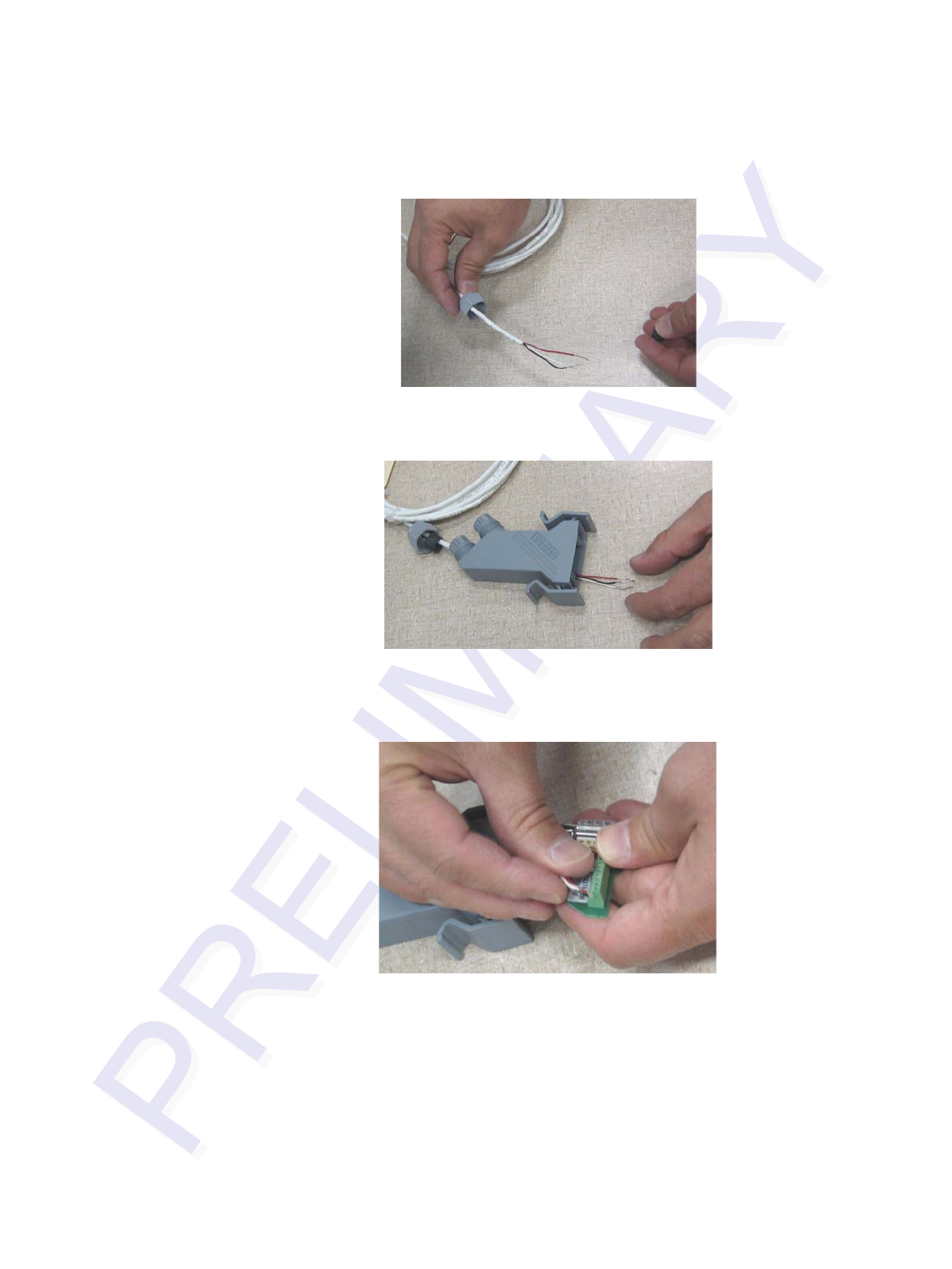
Multiprotocol Rail Reader System Guide
11-4
Figure 11-1 Place Nut and Grommet Over Exposed Check Tag Wires
2. Pull the check tag wires through the connector housing (Figure 11-2).
Figure 11-2 Feed Check Tag Wires through Plastic Housing Connector
3. For Check Tag 0, insert and tighten the check tag wires to the terminal strip as
shown in Figure 11-3 and Table 11-2.
Figure 11-3 Connect Check Tag Wires
Table 11-2 Check Tag 0 Wire Assignments
Wire Color Pin No.
Ground Black 3
Power Red 4
Data White 5
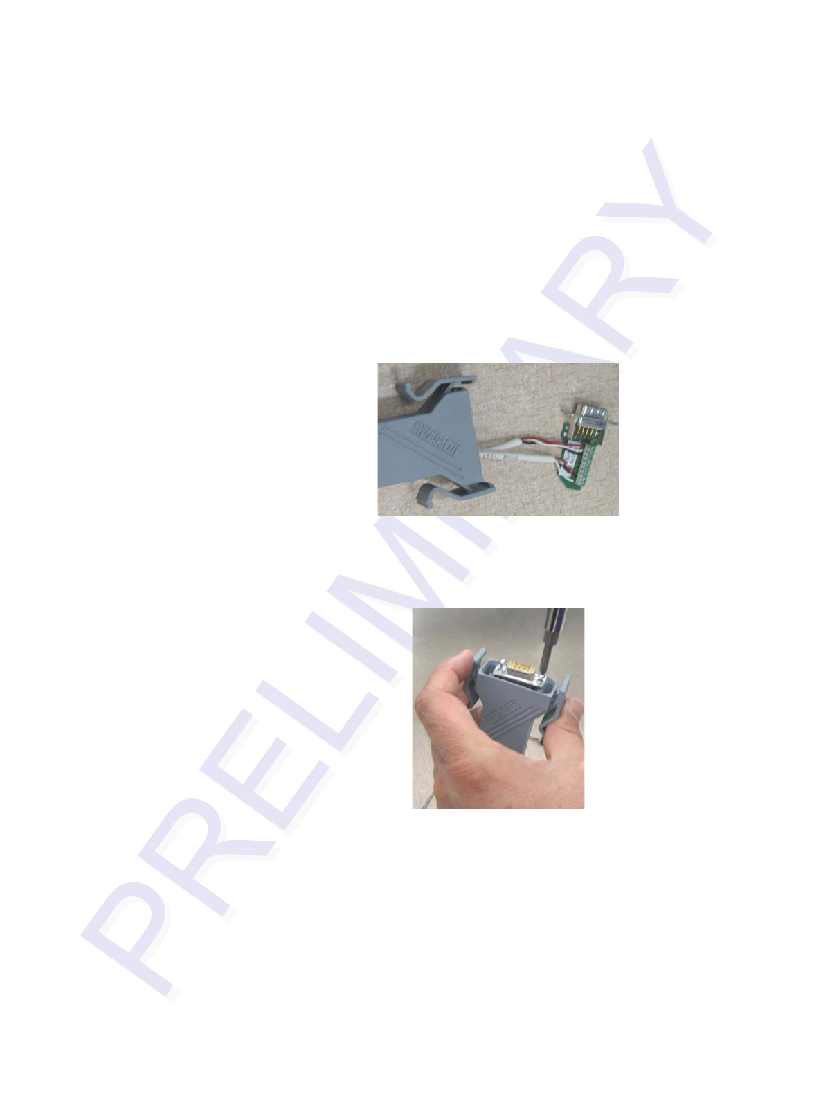
AT5270 Check Tag-to-MPRR Assembly
11-5
4. If connecting two check tags, repeat steps 1 through 3. Connect Check Tag 1 to
the terminal strip as listed in Table 11-3.
Figure 11-4 shows both check tags connected to terminal strip.
Figure 11-4 Two Check Tag Assemblies Connected to Terminal Strip
5. Insert and tighten the two self-tapping screws to secure the terminal strip (Figure
11-5).
Figure 11-5 Securing Terminal Strip into Connector Housing
Table 11-3 Check Tag 1 Wire Assignments
Wire Color Pin No.
Ground Black 7
Power Red 8
Data White 9
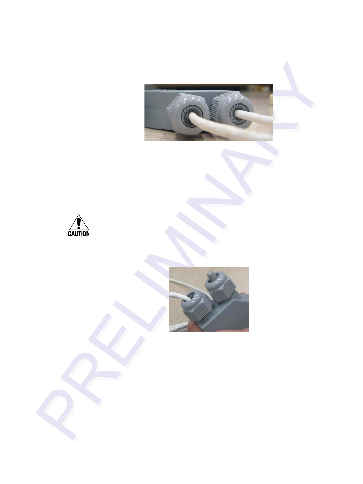
Multiprotocol Rail Reader System Guide
11-6
6. To complete the connector assembly, tighten the nuts on the cable end snugly
(Figure 11-6).
Figure 11-6 Plastic Nuts with Grommets
As the nut is tightened, the connector compresses the grommet around the check
tag cable.
To assemble the kit for one check tag
1. Follow the procedure steps described above in steps 1 through 6, but connect
only one check tag cable.
Caution
If connecting only one check tag, you must insert and secure the nylon closing cap
into the unused terminal connector to protect the terminal strip from possible
contamination.
2. To cover the unused terminal connector, insert the nylon closing cap into the
plastic cap with rubber grommet and tighten snugly (Figure 11-7).
Figure 11-7 Nylon Cap Securely Fastened in Unused Port
To connect the check tag assembly to the Multiprotocol Reader
Remove the dust cover from the Check Tag port of the MPRR and plug in the
check tag cable assembly (Figure 11-8). Be sure that the two handles snap into
place on the MPRR. This ensures a solid connection.
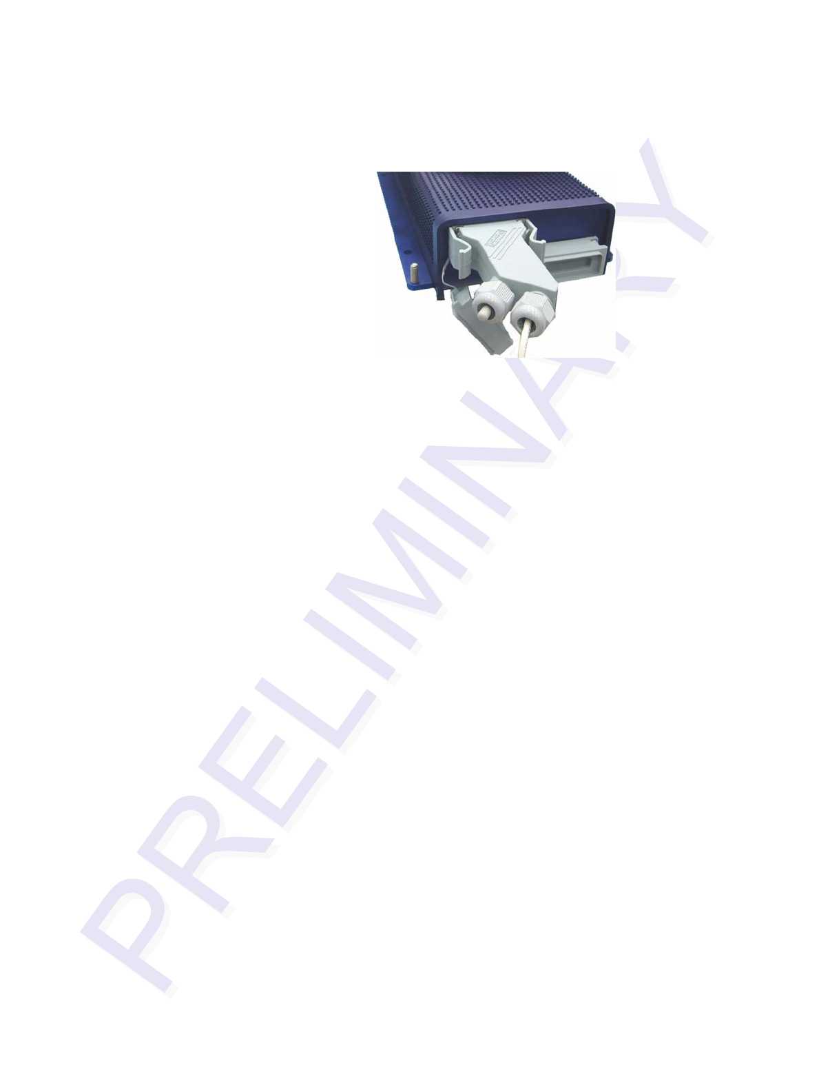
AT5270 Check Tag-to-MPRR Assembly
11-7
Figure 11-8 Check Tag Assembly Secured to MPRR Port (single check tag
assembly shown)

Multiprotocol Rail Reader System Guide
11-8

A
Glossary


A-3
Appendix A
Glossary
A
AAR Association of American Railroads
AC alternating current
ACK acknowledge (data valid)
ANSI American National Standards Institute
antenna passive device that converts RF energy into magnetic energy (RF signal)
ASCII American Standard Code for Information Interchange
ASIC application-specific integrated circuit
ATA American Trucking Association
aux auxiliary
AWG AWG (American Wire Gauge) is a U.S. standard set of non-ferrous wire conductor
sizes
B
backscatter portion of an RF signal that is modulated by a tag and radiated back to the reader
baud measure of number of bits per second of a digital signal; for example, 9600 baud =
9600 bits per second
BCKS boot checksum
BCM buffer control mode
bps bits per second
byte a binary character; for example, one 8-bit ASCII character
C
check tag tag mounted inside a reader assembly, inside or in close proximity to an external
antenna that is used to check operation of the reader

Multiprotocol Rail Reader System Guide
A-4
cmd command
comm communications
command data set that is recognized by the receiving device as intending to elicit a specific
response
conduit flexible steel pipe use for electrical wiring
cps characters per second
CR carriage return
CRC cyclic redundancy check
CTRL control
CTS clear to send
D
data information that is processed by a computing device
DC direct current
DIAG diagnostic
E
ECP error correcting protocol
ECPS error correcting protocol status
eol end of line
eom end of message
EPROM erasable programmable read-only memory
F
field physical area/space in which a tag can be read by the reader; also, an element of a data
record/frame. For example, division within a tag's data frame.
frames consecutive bits of data in memory that are read and written as a group
frequency bands a range of RF frequencies assigned for transmission by an RF device

Glossary
A-5
H
hex hexadecimal
hexadecimal base 16 numbering system that uses the characters 0 though 9 and A through F to
resent the digits 0 through 16
host device, generally a computer, that is connected to the Multiprotocol Rail Reader
through the communications port
I
I/O or IO circuits input/output circuits
IAG E-ZPass® Interagency Group, North American RFID tag protocol
ID identification; encoded information unique to a particular tag
INCITS American National Standards Institute International Committee for Information
Technology standards
interface connection point for communication with another device
IOST I/O status
ISO International Standardization Organization
L
LF line feed
M
mmeter
MHz megahertz
mode method of operation
MPRR Multiprotocol Rail Reader
ms milliseconds

Multiprotocol Rail Reader System Guide
A-6
N
NAK negative acknowledgment (data not valid)
P
passback used to refer to a tag ID that is not passed on to the tag buffer
PC personal computer
PCKS EPROM flash checksum
protocol specified convention for the format of data messages communicated between devices
PRST presence status
PWRB power fail bit
R
RAM random access memory
RDID reader ID
read process of acquiring data from a device; for example, from a tag or from computer
memory
reader controlled interrogating device capable of acquiring data from a device; for example,
acquiring and interrupting data from a tag
read zone the physical area in which a tag can be read by the reader
RF radio frequency
RFID radio frequency identification
RFST RF status
ROM read-only memory
RTC real-time clock
RTS request-to-send
S
SCTS status of check tag status
SeGo Super eGo (SeGo) is a superset of the eGo protocol

Glossary
A-7
SN serial number
som start of message
SSTC input status change reporting options
T
tag small self-contained device acting as an identifying transponder
Tau timeout delay
TRU Train Recording Unit
TT tag translation
V
Vvolts
Ver version (software)
W
write process of recording data; for example, writing to computer memory or to a tag’s
memory. Writing writes over (erases) previous data stored at the specified memory
locations.
X
XON/XOFF protocol for controlling the flow of data between computers and other devices on an
asynchronous serial connection. X/ON and X/OFF are signals to turn a transmitter on
or off. The actual signal for X/ON is the same bit configuration as the ASCII Ctrl-Q
keyboard combination (11 hexadecimal). The X/OFF signal is the Ctrl-S character (13
hexadecimal).

Multiprotocol Rail Reader System Guide
A-8

B
Technical Specifications


B-3
Appendix B
Technical Specifications
Reader Specifications
Communications
Hardware Features
Power Requirements
Physical Attributes
Frequency Selection 860 to 930 MHz capable
Reading Range Read performance varies depending on tag,
reader, and external antenna (if required) config-
uration and environment.
Typical read range should be 12 to 17 ft (3.7 to
5.2 m).a
a. Reading range depends on reader or external antenna configu-
ration, tag type, tag read mode, and operating environment.
Integrated system with
connector for external
antenna
RF module, tag decoder, power supply, I/O ports,
and serial communications interface all housed in
a single package.
Case (TBD)
Input Voltage 16 to 20V AC, 47 to 63 Hz
or
16 to 28V DC
Size 13 x 5 x 2.49 inches (33 x 7.62 x 6.32 cm)
Weight 5.1 pounds (2.31 kg)

Multiprotocol Rail Reader System Guide
B-4
Environmental Parameters
Options
Operating Temperature -40°F to +158°F (-40°C to +70°C)
Humidity 95% noncondensing
Vibration Tolerance 0.5 Grms, 10 to 500 Hz TBD
Communications Interface RS–232 or RS–422
Cable Accessory Kits 58-7001-001: MPRR-to-TRU cable assembly, 6
ft (1.8 m)
58-7001-002: MPRR-to-TRU cable assembly, 20
ft (6.1 m)
58-7001-003: MPRR cable assembly, no TRU
Transformer A Class C transformer is available to allow 110V
AC to 18V AC conversion.
Include the part number 76-1620-005 when
ordering.
A Class C transformer (part number 76-1620-
008) to allow 220V AC to 18V AC conversion is
available by special request.

C
Wiring Information


C-3
Appendix C
Wiring Information
This appendix will contain a graphical representation that shows the
wiring connections as well as any wiring signal tables that may be
needed used to test and install the Multiprotocol Rail Reader (MPRR).
Communications Interfaces
Table C-1 lists the interfaces available with the MPRR.
Table C-1 Communications Interfaces and Conductor Requirements
Interface Number of
Conductors
RS–232 3
RS–232 with RTS and CTS hardware handshake signals 5
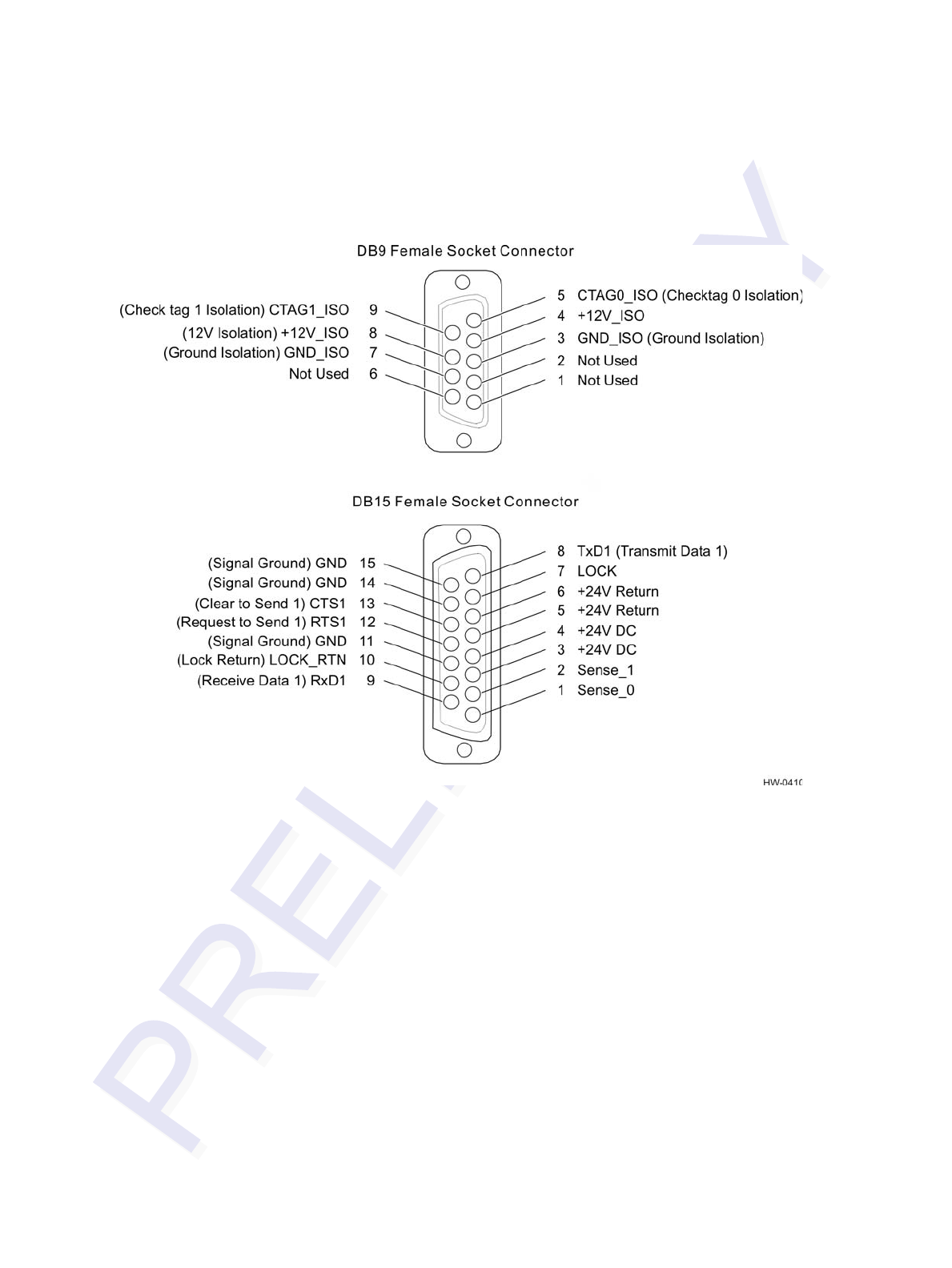

D
Command Quick Reference


D-3
Appendix D
Command Quick Reference
This appendix lists the default configuration settings for the
Multiprotocol Rail Reader (MPRR) and its commands. Commands are
listed both numerically and alphabetically.
Command Syntax
The command numbers consist of from 2 to 4 hex digits. The letters N or S may follow
a command number. The letter N indicates that part of the command number is vari-
able. The letter S indicates the requirement for an alphanumeric data string that is to
be included immediately following the command number. Hex digits (0–9, A–F) in
either uppercase or lowercase characters may be used in data strings and for hex digits
A–F. For more information see Chapter 5, “General Software Information” .
Table D-1 lists factory default settings. Table D-2 on page D-5 lists, in numerical
order, all of the commands available to users. Table D-3 on page D-16 lists the same
commands by command name.
Factory Default Settings
Note: Table D-1 lists the factory default settings for the MPRR.
Table D-1 MPRR Default Configuration Settings
Parameter Setting Command
Operating mode Data 00
Baud rate 9600 1005
Stop bits 1 1010
Parity None 1020
Time and data appended Enabled 302
Auxiliary information appended Disabled 310
Unique ID code criteria Separation of 1 ID 4100
Valid ID code criteria Acquisition of 1 ID 4200
Uniqueness time-out 2 minutes 441
Tag translation mode Disabled 452

Multiprotocol Rail Reader System Guide
D-4
Multi-tag sort Disabled 454
SeGo protocol tag initialization
during multi-tag sort Enabled 456
Second alternate group select Disabled 458
Third alternate group select Disabled 490
Fourth alternate group select Disabled 492
Fifth alternate group select Disabled 494
Alternate group select Disabled 496
Reader ID number 00 6000
Communications protocol Basic 610
Error correcting protocol (ECP)
timeout 12.7 sec 612FE
Flow control Software (XON/XOFF) 6141
Buffer control mode Disabled 6160
Echo mode Enabled 6171
Set output control Turn on both outputs 6203
Sense output control Predefined 621
RF-by-input control Enabled 641
ATA operating range Maximum 6431F
RF attenuation Full power 64400
SeGo protocol operating range Maximum 6451F
Sense output pulse duration 228 ms 67C
Presence without tag reports Disabled 6900
RF-off control Timeout or no presence 6922
RF timeout Never true 693F
Input inversion Disabled 6940
Serial number NNNNNN 695
Store hardware configuration Hardware configuration not
known 696
Input status change reports Disabled 820
Table D-1 MPRR Default Configuration Settings (continued)
Parameter Setting Command

Command Quick Reference
D-5
Numerical Command List
The following conventions are used in Table D-2:
•Items in bold italics identify factory default settings.
•Only the command-related data portion of the reader message is shown.
Refer to Chapter 6, “Communication Protocols,” for the complete syntax of com-
mands and messages.
Automatic periodic RF status
report Disabled 830
Table D-1 MPRR Default Configuration Settings (continued)
Parameter Setting Command
Table D-2 MPRR Commands Listed Numerically
Number Command Name Reader Message
00 Switch to data mode Done
01 Switch to command mode Done
06 Transmit buffer entry Done, error, or tag data
Done = buffer empty
Error = not in buffer control
mode
Tag data = highest priority tag
ID
1002 Set baud rate = 1200 baud Done
1003 Set baud rate = 2400 baud Done
1004 Set baud rate = 4800 baud Done
1005 Set baud rate = 9600 baud Done
1006 Set baud rate = 19.2 K baud Done
1007 Set baud rate = 38.4 K baud Done
1010 Use one stop bit Done
1011 Use two stop bits Done
1020 Disable parity Done
1021 Select even parity Done
1022 Select odd parity Done
20 Set time Done

Multiprotocol Rail Reader System Guide
D-6
21 Set date Done
22 Display time and date Time and date
300 No time and date appended Done
302 Time and date appended Done
310 Disable aux info append Done
311 Enable aux info append Done
40 Transmit all IDs Done
4100 Select one ID separation Done
4101 Select two ID separation Done
4102 Select three ID separation Done
4103 Select four ID separation Done
4200 Select 1 valid ID code Done
4201 Select 2 valid ID codes Done
4202 Select 3 valid ID codes Done
4203 Select 4 valid ID codes Done
43 Buffer all ID codes Done
440 Reset uniqueness Done
441 Set uniqueness time-out to 2
minutes Done
442 Set uniqueness time-out to 15
seconds Done
443 Set uniqueness time-out to 30
seconds Done
454 Disable multi-tag sort Done
455 Enable multi-tag sort Done
456 Enable SeGo protocol tag
initialization during multi-tag
sort
Done
457 Disable SeGo protocol tag
initialization during multi-tag sort Done
Table D-2 MPRR Commands Listed Numerically (continued)
Number Command Name Reader Message

Command Quick Reference
D-7
458 Disable second alternate group
select Done
459 Enable second alternate group
select Done
480 Disable ATA Done if MPRR model supports
this tag protocol. Error if tag
protocol is unsupported.
481 Enable ATA Done if MPRR model supports
this tag protocol. Error if tag
protocol is unsupported.
484 Disable SeGo Done if MPRR model supports
this tag protocol. Error if tag
protocol is unsupported.
485 Enable SeGo Done if MPRR model supports
this tag protocol. Error if tag
protocol is unsupported.
488 Disable eATA Done if MPRR model supports
this tag protocol. Error if tag
protocol is unsupported.
489 Enable eATA Done if MPRR model supports
this tag protocol. Error if tag
protocol is unsupported.
490 Disable third alternate group
select Done
491 Enable third alternate group
select Done
492 Disable fourth alternate group
select Done
493 Enable fourth alternate group
select Done
494 Disable fifth alternate group
select Done
495 Enable fifth alternate group select Done
496 Disable alternate group select Done
497 Enable alternate group select Done
505 Display version Model [model]
Ver [version no.] SN [serial no.]
Table D-2 MPRR Commands Listed Numerically (continued)
Number Command Name Reader Message

Multiprotocol Rail Reader System Guide
D-8
506 Display hardware configuration
information S...S
S...S = ASCII string
(maximum length of 20
characters)
510 Display RF transceiver FPGA
version RF FPGA VER = XX.XX
511 Display RF transceiver I filter chip
version FIL IC I VER = XX.XX
512 Display RF transceiver Q filter
chip version FIL IC Q VER = XX.XX
513 Display DSP board Actel version DSP FPGA VER = XX.XX
520 Display power fail bit PWRB Px R0
P0 = no power fail has occurred
P1 = power fail has occurred
R0 = not applicable
521 Display reader ID number RDID xx
xx = 00–FF
522 Display comm port parameters MAIN Bx Sx Px D0
B2 = 1200
B3 = 2400
B4 = 4800
B5 = 9600
B6 = 19.2
B7 = 38.4
S0 = one stop bit
S1 = two stop bits
P0 = no parity
P1 = even
P2 = odd
D0 = EOL delay of 0 ms
524 Display appended info status IDAP T0 D0 Xx
T0 = time not appended
T1 = time appended
D0 = date not appended
D1 = date appended
X0 = aux info not appended
X1 = aux info appended
Table D-2 MPRR Commands Listed Numerically (continued)
Number Command Name Reader Message

Command Quick Reference
D-9
525 Display comm protocol ECPS Px Txx Xx S0
P0 = basic
P1 = ECP
P2 = echo Inquiry
Txx = ECP timeout
ms = 50 * xx
FF = disabled ECP timeout
X0 = no flow control
X1 = software flow control
X2 = hardware flow control
S0 = som character is #
526 Display I/O status IOST Cx Ox Ix Dx
C0 = host controls outputs
C1 = predefined output mode
O0 = both outputs off
O1 = output0 on
O2 = output1 on
O3 = both outputs on
I0 = both inputs false
I1 = input0 true
I2 = input1 true
I3 = both inputs true
D0 - DF = output pulse duration
where
D0 = 4 ms
D1 = 8 ms
D2 = 12 ms
D3 = 16 ms
D4 = 20 ms
D5 = 24 ms
D6 = 32 ms
D7 = 40 ms
D8 = 48 ms
D9 = 60 ms
DA = 76 ms
DB = 152 ms
DC = 228 ms
DD = 300 ms
DE = 376 ms
DF = 752 ms
Table D-2 MPRR Commands Listed Numerically (continued)
Number Command Name Reader Message

Multiprotocol Rail Reader System Guide
D-10
527 Display RF status RFST Cx Ox Tx Fxxx Rxx Gxx
Axx Ixx
C0 = RF controlled by host
C1 = RF-by-presence sensor
O0 = RF off
O1 = RF on
T1 = uniqueness timeout of 2
min
T2 = uniqueness timeout of 15
sec
T3 = uniqueness timeout of 30
sec
Fxxx = RF output frequency,
xxx = 000 to 118
Rxx = Tag decoder range
(distance) for ATA tags, 00 to 1F
hexadecimal range value
Gxx = Tag decoder range
(distance) for eGo Plus Tags, 00
to 1F hexadecimal range value
Axx = RF power attenuation, 00
max to 0A min (10 dB less than
max)
Ixx = IAG RF power attenuation,
00 max to 0F min (15 dB less
than max)
Note If you enter RF settings
using command
#642NN, the display
command for RF output
frequency, F is "Fxx" and
indicates use of the
backward-compatible
frequency entry method.
Table D-2 MPRR Commands Listed Numerically (continued)
Number Command Name Reader Message

Command Quick Reference
D-11
529 Display presence input status PRST Px D0 Ax Tx Ix
P0 = disable presence w/o tag
reports
P1 = enable presence w/o tag
reports
D0 = min presence true period
of 0 ms
A0 = RF off on timeout
A1 = RF off on timeout or tag
A2 = RF off on timeout or no
presence
T0: RF timeout of 0 ms (always
expired)
T1: RF timeout of 4 ms
T2: RF timeout of 8 ms
T3: RF timeout of 12 ms
T4: RF timeout of 20 ms
T5: RF timeout of 24 ms
T6: RF timeout of 32 ms
T7: RF timeout of 48 ms
T8: RF timeout of 60 ms
T9: RF timeout of 92 ms
TA: RF timeout of 152 ms
TB: RF timeout of 300 ms
TC: RF timeout of 452 ms
TD: RF timeout of 600 ms
TE: RF timeout of 752 ms
TF: RF timeout infinite, never
expires (factory default)
I0 = Input inversion disabled
(factory default)
I1 = Input inversion enabled
530 Display RF0 filter status RF0S Ux V0
U0 = one ID separation
U1 = two ID separation
U2 = transmit all IDs
U3 = buffer all IDs
V0 = valid ID code criteria of
one acquisition (fixed)
534 Display tag translation mode
status TT <0 to 1>
0 = tag translation mode
disabled
1 = tag translation mode
enabled
535 Display buffer control status BCM <0 to 1>
0 = buffer control mode disabled
1 = buffer control mode enabled
Table D-2 MPRR Commands Listed Numerically (continued)
Number Command Name Reader Message

Multiprotocol Rail Reader System Guide
D-12
536 Display dual-frame processing
mode DUAL <0 to 3>
0 = reset uniqueness on A,
transmit A
1 = reset uniqueness on B,
transmit B
2 = reset uniqueness on A,
transmit both A and B
3 = reset uniqueness on B,
transmit both A and B
537 Display echo status ECHO x
0 = disabled
1 = enabled
540 Display flash checksum PCKS I0000 Exxxx
xxxx = 4-byte ASCII checksum
543 Display boot checksum BCKS xxxx
xxxx = 4-byte ASCII checksum
550 Display periodic check tag status SCTS M0 (fixed)
551 Display selected check tag option CTAG 0 (fixed)
560 Display input status change SSTC Ex Mx
E0 = status change reports
disabled
E1 = status change reports
enabled
M0 = no reporting
M1 = report change on input0
M2 = report change on input1
M3 = report change on either
input
570 Display operating mode status ATA:<E, D> eGo:<I, F, D>
SeGo:<I, F, D> IAG:<E, D>
Sort:<E, D>
I = ID (64 bits)
E = Enabled
F = Full transaction (eATA)
D = Disabled
577 Report buffered handshakes XX = number of handshakes
60NN Set reader ID number
NN = 00–FF
(00 = factory default)
Done
610 Select basic protocol Done
611 Select ECP protocol Done
Table D-2 MPRR Commands Listed Numerically (continued)
Number Command Name Reader Message

Command Quick Reference
D-13
612NN Set ECP timeout
NN = 01–FE (1–255)
timeout = 50 ms * NN
(if NN = FF, timeout is
disabled)
Done
612FE Set ECP timeout = 12.7 sec Done
613 Enable data inquiry protocol Done
6140 Disable flow control Done
6141 Enable software flow control Done
6142 Enable hardware flow control Done
6160 Disable buffer control mode Done
6161 Enable buffer control mode Done
6170 Disable echo Done
6171 Enable echo Done
6200 Turn both outputs off Done
6201 Turn output0 on Done
6202 Turn output1 on Done
6203 Turn both outputs on Done
621 Select predefined output mode Done
63 Reset reader Model [model]
Ver [version no.] SN [serial no.]
Copyright [date]
TransCore
6400 Turn off RF Done
6401 Turn on RF Done
6402 Turns on continuous wave RF
until commands 6400 or 641 are
received by the reader
Done
641 Select RF-by-input control Done
642NN Select RF operating frequency Done
643NN Set ATA operating range
NN = 00 (shortest) to 1F (longest)
1F = default
Done
Table D-2 MPRR Commands Listed Numerically (continued)
Number Command Name Reader Message

Multiprotocol Rail Reader System Guide
D-14
644NN Set RF attenuation
NN = 00 to 0A Done
645NN Set SeGo protocol operating
range NN = 00 (shortest) to
1F (longest)
Done
647XXX Select RF operating frequency
from 860 to 930 in 250 kHz steps
XXX = 000 - 118 (hexadecimal)
Done
65 Reset power fail bit Done
66F Load default operating
parameters (except RF operating
frequency)
Done
67C Output pulse duration = 228 ms
set Done
67N Set output pulse duration N = 0–F
(4,8,12,16,20,24,32,40,48,60,76,
152, 228,300,376,752 ms)
Done
6900 Disable presence without tag
reports Done
6901 Enable presence without tag
reports Done
6920 Turn RF off on timeout Done
6921 Turn RF off on timeout/tag Done
6922 Turn RF off on
timeout/no presence Done
693N Set RF timeout
N = 0–F
(always expired, 4,8,12,20,24,
32,48,60,92,152, 300,452,
600,752, infinite)
Done
693F Set RF timeout = infinite Done
6940 Disable input inversion Done
6941 Enable input inversion Done
695S...S Set serial number
S...S = ASCII string
(maximum length of 6
characters)
Done
Table D-2 MPRR Commands Listed Numerically (continued)
Number Command Name Reader Message

Command Quick Reference
D-15
696S...S Store hardware
configuration string
S...S = ASCII string
(maximum length of 20
characters)
Done
820 Disable status change
reports Done
821 Report change on input0 Done
822 Report change on input1 Done
823 Report changes on both Done
830 Disable automatic periodic RF
status report Done
831 Enable automatic periodic RF
status report Done
Table D-2 MPRR Commands Listed Numerically (continued)
Number Command Name Reader Message

Multiprotocol Rail Reader System Guide
D-16
Alphabetical Command List
The following conventions are used in Table D-3:
•Items in bold italics identify factory default settings.
•Only the command-related data portion of the reader message is shown.
Refer to Chapter 7 for the complete syntax of commands and messages.
Table D-3 MPRR Commands Listed Alphabetically
Command Name Code Reader Message
All IDs buffer 43 Done
All IDs transmit 40 Done
Alternate fifth group select
disable 494 Done
Alternate fifth group select enable 495 Done
Alternate fourth group select
disable 492 Done
Alternate fourth group select
enable 493 Done
Alternate group select disable 496 Done
Alternate group select enable 497 Done
Alternate second group select
disable 458 Done
Alternate second group select
enable 459 Done
Alternate third group select
disable 490 Done
Alternate third group select
enable 491 Done
Appended info status display 524 IDAP T0 D0 Xx
T0 = time not appended
T1 = time appended
D0 = date not appended
D1 = date appended
X0 = aux info not appended
X1 = aux info appended
ATA disable 480 Done if MPRR model supports
this tag protocol. Error if tag
protocol is unsupported.

Command Quick Reference
D-17
ATA enable 481 Done if MPRR model supports
this tag protocol. Error if tag
protocol is unsupported.
ATA operating range set
NN = 00 (shortest) to 1F (longest)
1F = default
643NN Done
Automatic periodic RF status
report disable 830 Done
Automatic periodic RF status
report enable 831 Done
Aux info append disable 310 Done
Aux info append enable 311 Done
Basic protocol select 610 Done
Baud rate = 1200 baud set 1002 Done
Baud rate = 19.2 K baud set 1006 Done
Baud rate = 2400 baud set 1003 Done
Baud rate = 38.4 K baud set 1007 Done
Baud rate = 4800 baud set 1004 Done
Baud rate = 9600 baud set 1005 Done
Boot checksum display 543 BCKS xxxx
xxxx = 4-byte ASCII checksum
Buffer control mode disable 6160 Done
Buffer control mode enable 6161 Done
Buffer control status display 535 BCM <0 to 1>
0 = buffer control mode disabled
1 = buffer control mode enabled
Buffer entry transmit 06 Done, error, or tag data
Done = buffer empty
Error = not in buffer control mode
Tag data = highest priority tag ID
Buffered handshake report 577 XX = number of handshakes
Table D-3 MPRR Commands Listed Alphabetically (continued)
Command Name Code Reader Message

Multiprotocol Rail Reader System Guide
D-18
Comm port parameters display 522 MAIN Bx Sx Px D0
B0 = 110
B1 = 300
B2 = 1200
B3 = 2400
B4 = 4800
B5 = 9600
B6 = 19.2
B7 = 38.4
S0 = one stop bit
S1 = two stop bits
P0 = no parity
P1 = even
P2 = odd
D0 = EOL delay of 0 ms
Comm protocol display 525 ECPS Px Txx Xx S0
P0 = basic
P1 = ECP
P2 = data inquiry
Txx = ECP timeout
ms = 50 * xx
TFF = disabled ECP timeout
X0 = no flow control
X1 = software flow control
X2 = hardware flow control
S0 = SOM character is #
Command mode switch 01 Done
Data inquiry protocol enable 613 Done
Data mode switch 00 Done
Date set 21 Done
Default operating parameters
load (except RF operating
frequency)
66F Done
DSP board Actel version display 513 DSP FPGA VER = XX.XX
Dual-frame processing mode
display 536 DUAL <0 to 3>
0 = reset uniqueness on A,
transmit A
1 = reset uniqueness on B,
transmit B
2 = reset uniqueness on A,
transmit both A and B
3 = reset uniqueness on B,
transmit both A and B
eATA disable 488 Done if MPRR model supports
this tag protocol. Error if tag
protocol is unsupported.
Table D-3 MPRR Commands Listed Alphabetically (continued)
Command Name Code Reader Message

Command Quick Reference
D-19
eATA enable 489 Done if MPRR model supports
this tag protocol. Error if tag
protocol is unsupported.
Echo disable 6170 Done
Echo enable 6171 Done
Echo status display 537 ECHO x
0 = disabled
1 = enabled
ECP protocol select 611 Done
ECP timeout set = 12.7 sec 612FE Done
ECP timeout set
NN = 01–FE (1–255)
timeout = 50 ms * NN
(if NN = FF, timeout is disabled)
612NN Done
SeGo protocol operating range
set NN = 00 (shortest) to 1F
(longest)
645NN Done
SeGo protocol tag initialization
during multi-tag sort 456 Done
SeGo protocol tag initialization
during multi-tag sort disable 457 Done
Even parity select 1021 Done
Flash checksum display 540 PCKS I0000 Exxxx
xxxx = 4-byte ASCII checksum
Flow control disable 6140 Done
Hardware configuration
information display 506 S...S
S...S = ASCII string
(maximum length of
20 characters)
Hardware configuration string
store
S...S = ASCII string
(maximum length of 20
characters)
696S...S Done
Hardware flow control enable 6142 Done
Table D-3 MPRR Commands Listed Alphabetically (continued)
Command Name Code Reader Message

Multiprotocol Rail Reader System Guide
D-20
I/O status display 526 IOST Cx Ox Ix Dx
C0 = host controls outputs
C1 = predefined output mode
O0 = both outputs off
O1 = output0 on
O2 = output1 on
O3 = both outputs on
I0 = both inputs false
I1 = input0 true
I2 = input1 true
I3 = both inputs true
D0 - DF = output pulse duration
where
D0 = 4 ms
D1 = 8 ms
D2 = 12 ms
D3 = 16 ms
D4 = 20 ms
D5 = 24 ms
D6 = 32 ms
D7 = 40 ms
D8 = 48 ms
D9 = 60 ms
DA = 76 ms
DB = 152 ms
DC = 228 ms
DD = 300 ms
DE = 376 ms
DF = 752 ms
Input inversion disable 6940 Done
Input inversion enable 6941 Done
Input status change display 560 SSTC Ex Mx
E0 = status change reports
disabled
E1 = status change reports
enabled
M0 = no reporting
M1 = report change on input0
M2 = report change on input1
M3 = report change on either
input
Input0 change report 821 Done
Input1 change report 822 Done
Multi-tag sort disable 454 Done
Multi-tag sort enable 455 Done
Odd parity select 1022 Done
Table D-3 MPRR Commands Listed Alphabetically (continued)
Command Name Code Reader Message

Command Quick Reference
D-21
Operating mode status display 570 ATA:<E, D> eGo:<I, F, D>
SeGo:<I, F, D> IAG:<E, D>
Sort:<E, D>
I = ID (64 bits)
E = Enabled
F = Full transaction (eATA)
D = Disabled
Output pulse duration = 228 ms
set 67C Done
Output pulse duration set
N = 0–F
(4,8,12,16,20,24,32,40,48,60,76,
152, 228,300,376,752 ms)
67N Done
Output0 turn on 6201 Done
Output1 turn on 6202 Done
Outputs turn off both 6200 Done
Outputs turn on both 6203 Done
Parity disable 1020 Done
Periodic check tag status display 550 SCTS M0 (fixed)
Power fail bit display 520 PWRB Px R0
P0 = no power fail has occurred
P1 = power fail has occurred
R0 = not applicable
Power fail bit reset 65 Done
Predefined output mode select 621 Done
Table D-3 MPRR Commands Listed Alphabetically (continued)
Command Name Code Reader Message

Multiprotocol Rail Reader System Guide
D-22
Presence input status display 529 PRST Px D0 Ax Tx Ix
P0 = disable presence w/o tag
reports
P1 = enable presence w/o tag
reports
D0 = min presence true period
of 0 ms
A0 = RF off on timeout
A1 = RF off on timeout or tag
A2 = RF off on timeout or no
presence
T0: RF timeout of 0 ms (always
expired)
T1: RF timeout of 4 ms
T2: RF timeout of 8 ms
T3: RF timeout of 12 ms
T4: RF timeout of 20 ms
T5: RF timeout of 24 ms
T6: RF timeout of 32 ms
T7: RF timeout of 48 ms
T8: RF timeout of 60 ms
T9: RF timeout of 92 ms
TA: RF timeout of 152 ms
TB: RF timeout of 300 ms
TC: RF timeout of 452 ms
TD: RF timeout of 600 ms
TE: RF timeout of 752 ms
TF: RF timeout infinite, never
expires (factory default)
I0 = Input inversion disabled
(factory default)
I1 = Input inversion enabled
Presence without tag reports
disable 6900 Done
Presence without tag reports
enable 6901 Done
Reader ID number display 521 RDID xx
xx = 00–FF
Reader ID number set
NN = 00-FF
(00 = factory default)
60NN Done
Reader reset 63 Model [model]
Ver [version no.] SN [serial no.]
Copyright [date]
TransCore
Report changes both 823 Done
RF attenuation set
NN = 00 to 0A 644NN Done
Table D-3 MPRR Commands Listed Alphabetically (continued)
Command Name Code Reader Message

Command Quick Reference
D-23
RF CW turns on until commands
6400, 6401, or 641 are received
by reader
6402 Done
RF off on timeout 6920 Done
RF off on timeout/no presence 6922 Done
RF off on timeout/tag 6921 Done
RF turn off 6400 Done
RF turn on 6401 Done
RF on by input control 641 Done
RF operating frequency from 860
to 930 in 250 kHz steps select
XXX = 000 - 118 (hexadecimal)
647XXX Done
RF operating frequency select 642NN Done
RF status display 527 RFST Cx Ox Tx Fxxx Rxx Gxx
Axx Ixx
C0 = RF controlled by host
C1 = RF-by-presence sensor
O0 = RF off
O1 = RF on
T1 = uniqueness timeout of 2
min
T2 = uniqueness timeout of 15
sec
T3 = uniqueness timeout of 30
sec
Fxxx = RF output frequency,
xxx = 000 to 118
Rxx = Tag decoder range
(distance) for ATA tags, 00 to 1F
hexadecimal range value
Gxx = Tag decoder range
(distance) for eGo Plus Tags, 00
to 1F hexadecimal range value
Axx = RF power attenuation, 00
max to 0A min (10 dB less than
max)
Ixx = IAG RF power attenuation,
00 max to 0F min (15 dB less
than max)
If you enter RF settings using
command #642NN, the display
command for RF output
frequency, F is "Fxx" and
indicates use of the backward-
compatible frequency entry
method.
Table D-3 MPRR Commands Listed Alphabetically (continued)
Command Name Code Reader Message

Multiprotocol Rail Reader System Guide
D-24
RF timeout = infinite set 693F Done
RF timeout set
N = 0–F
(always expired, 4,8,12,20,24,32,
48,60,92,152,300,452,600,752
ms, infinite)
693N Done
RF transceiver FPGA version
display 510 RF FPGA VER = XX.XX
RF transceiver I filter chip version
display 511 FIL IC I VER = XX.XX
RF transceiver Q filter chip
version display 512 FIL IC Q VER = XX.XX
RF0 filter status display 530 RF0S Ux V0
U0 = one ID separation
U1 = two ID
U2 = transmit all
SeGo disable 484 Done if MPRR model supports
this tag protocol. Error if tag
protocol is unsupported.
SeGo enable 485 Done if MPRR model supports
this tag protocol. Error if tag
protocol is unsupported.
Selected check tag option display 551 CTAG 0 (fixed)
Serial number set
S...S = ASCII string
(maximum length of 6
characters)
695S...S Done
Software flow control enable 6141 Done
Status change reports disable 820 Done
Stop bit use one 1010 Done
Stop bit use two 1011 Done
Tag ID separation select four 4103 Done
Tag ID separation select one 4100 Done
Tag ID separation select three 4102 Done
Tag ID separation select two 4101 Done
Table D-3 MPRR Commands Listed Alphabetically (continued)
Command Name Code Reader Message

Command Quick Reference
D-25
Tag translation mode status
display 534 TT <0 to 1>
0 = tag translation mode
disabled
1 = tag translation mode enabled
Time and date appended 302 Done
Time and date display 22 Time and date
Time and date not appended 300 Done
Time set 20 Done
Uniqueness reset 440 Done
Uniqueness time-out set to 2
minutes 441 Done
Uniqueness time-out set to 15
seconds 442 Done
Uniqueness time-out set to 30
seconds 443 Done
Valid ID code select four 4203 Done
Valid ID code select one 4200 Done
Valid ID code select three 4202 Done
Valid ID code select two 4201 Done
Version display 505 Model [model]
Ver [ver no.] SN [serial no.]
Table D-3 MPRR Commands Listed Alphabetically (continued)
Command Name Code Reader Message

Multiprotocol Rail Reader System Guide
D-26

E
Compatible Tag Information


E-3
Appendix E
Compatible Tag Information
This appendix gives helpful information about the tags that are
compatible with the Multiprotocol Rail Reader (MPRR).
Tag Configurations
Table E-1 lists the TransCore Super eGo® (SeGo) protocol tags that are compatible
with the MPRR.
Table E-2 lists most ATA tag models that are compatible with the MPRR.
Table E-1 SeGo Protocol Tags
Tag Tag Type Power
Source
Number
of 6-bit ASCII
Charactersa
Number
of 128-Bit
FramesaSpecial Features
AT5118
Rail Beam
20 1 Very thin, flexible, multi-
layer lamination
10 1/2
AT5133 20 1 Very thin, flexible, multi-
layer lamination, tamper
detection10 1/2
AT5549 20 1 Water-resistant, exterior-
mounted
10 1/2
a. These fields apply to eATA-programmed tags only. Contact TransCore for information regarding tags
programmed with these features.
Table E-2 ATA Protocol Tags
Tag Model
Number TagType Power
Source
Number
of 6-Bit
ASCII
Characters
Number of
128-Bit
Frames Special Features
AT5110 Trans-
portation Beam 20 1 915 MHz frequency, metal external
install
AT5112 Access
control,
transpor-
tation
Beam 10 1/2 915 MHz frequency, metal external
install

Multiprotocol Rail Reader System Guide
E-4
a. If desired, in place of 40 six-bit ASCII characters, the AT5707 can support
up to 34 seven-bit ASCII characters.
Tag Data Formats
Tags are programmed at the TransCore factory with the tag model number, date of
manufacture, and data format. Contact TransCore for special order entry procedures
for the format that applies to your system. The following four tag data formats can be
used:
•10-character alphanumeric ASCII — Four alphanumeric characters are fixed and
can be used to identify either the dealer or the user. The remaining six positions
are numeric and should be unique for each tag issued. For example, the entry
ACME000001 might be specified as the first tag on the order entry form from
ACME Rail Lines.
•20-character alphanumeric ASCII — Four alphanumeric characters are typically
fixed and the remaining 16 positions are numbered sequentially.
•AAR/ISO — For requirements for this format, refer to ISO 10374 and the most
recent version of Association of American Railroads Standard for Automatic
Equipment Identification.
AT5114 Access
control,
transpor-
tation
10-yr
battery 10 1/2 Multifrequency, metal external
install
AT5125 Trans-
portation Beam 20 1 915 MHz frequency; high-
temperature chemical-resistant
case, metal external install
AT5510 Trans-
portation 10-yr
battery 20 1 Multifrequency, metal external
install
AT5704 Trans-
portation External 4608 256 Multifrequency, dynamic tag, metal
external install
AT5707 Trans-
portation 8-yr
battery 40a2 915 MHz frequency, dynamic tag,
metal external install
Table E-2 ATA Protocol Tags (continued)
Tag Model
Number TagType Power
Source
Number
of 6-Bit
ASCII
Characters
Number of
128-Bit
Frames Special Features

Compatible Tag Information
E-5

Multiprotocol Rail Reader System Guide
E-6