TransCore 10-510-100 Location and Monitoring Transmitter User Manual SUG
TransCore Location and Monitoring Transmitter SUG
UserManual.wiki
>
TransCore
>
10-510-100 User Manual
>
Exhibit 8 Users Manual
Contents
1.
Exhibit 8 Users Manual
2.
Exhibit 8 Users Manual Supplement
Exhibit 8 Users Manual
Navigation menu
Upload a User Manual
Namespaces
Wiki Guide
HTML
PDF
Info
Views
User Manual
Discussion / Help
Navigation


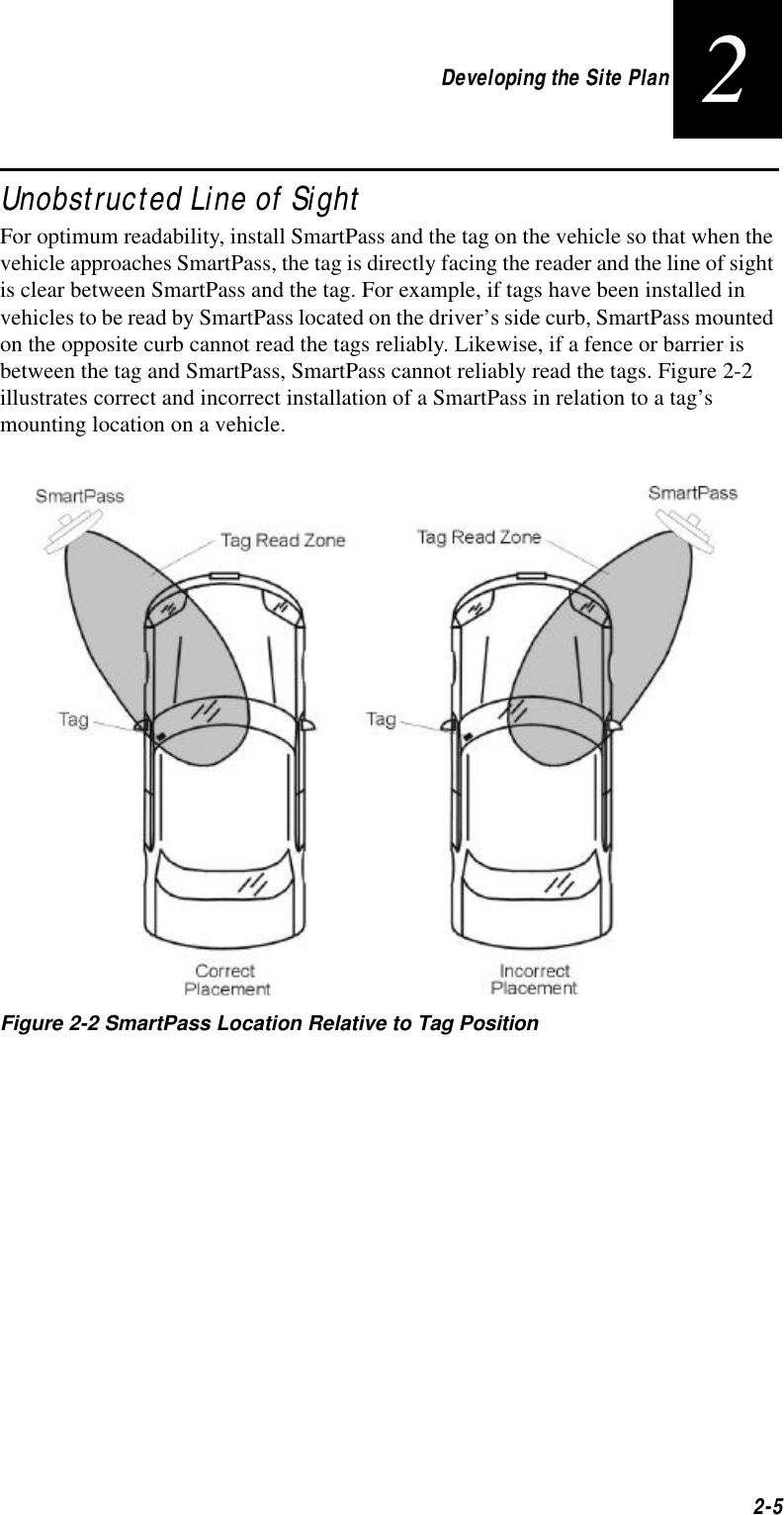
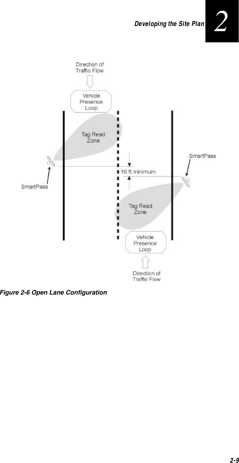
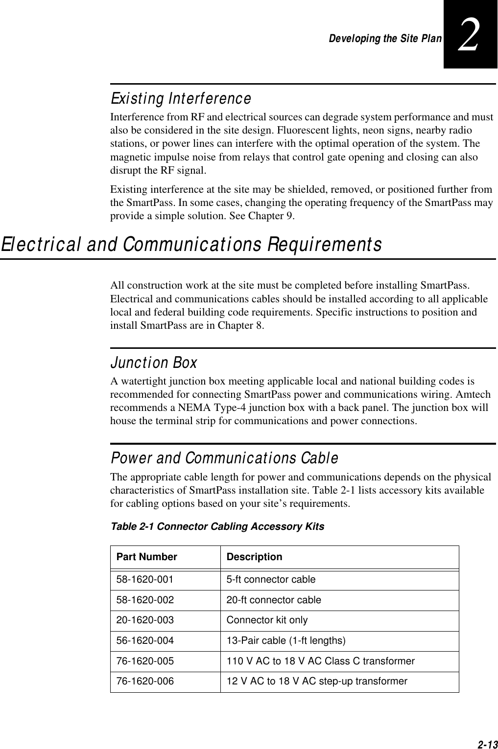
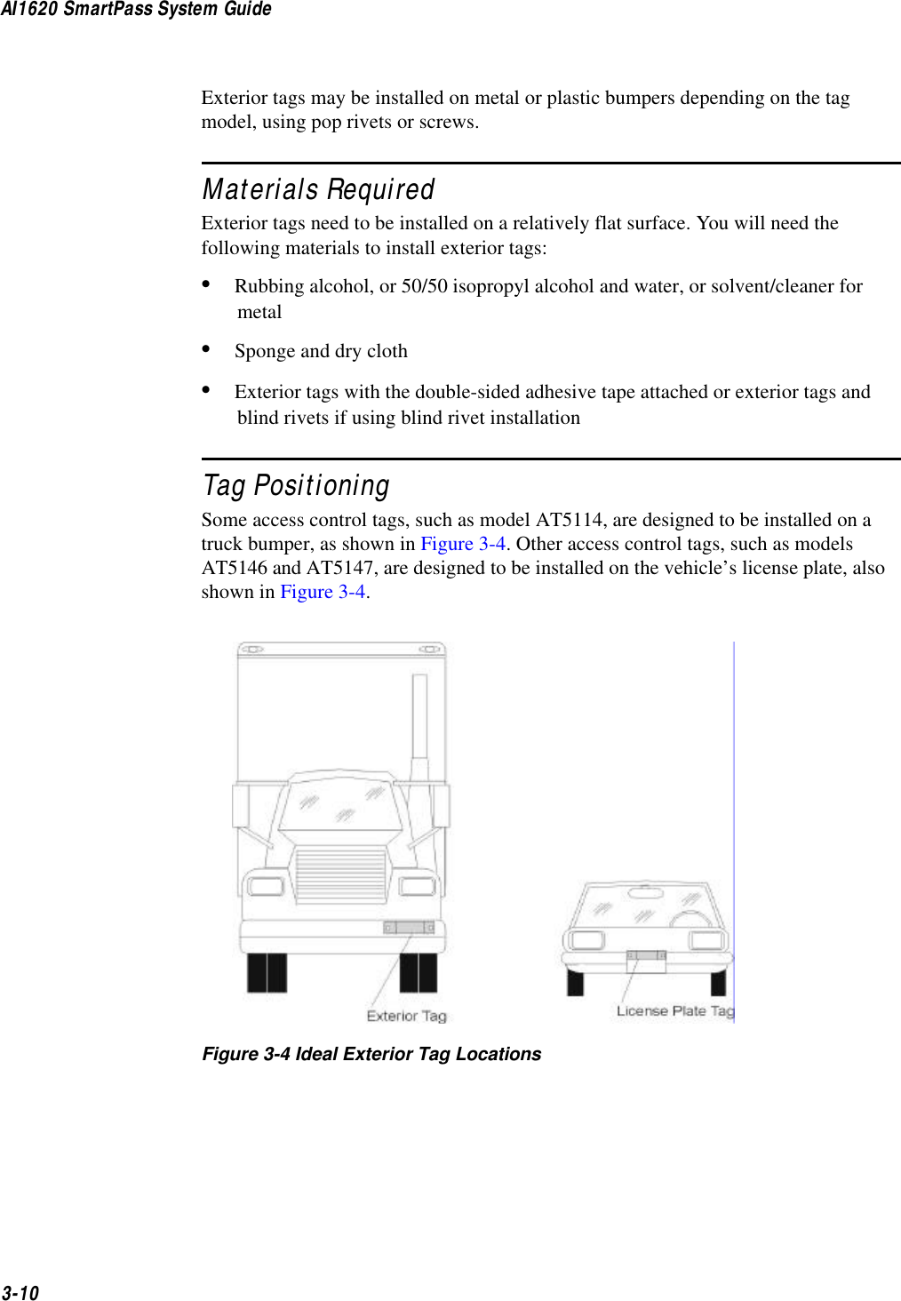

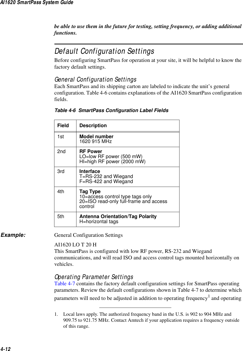
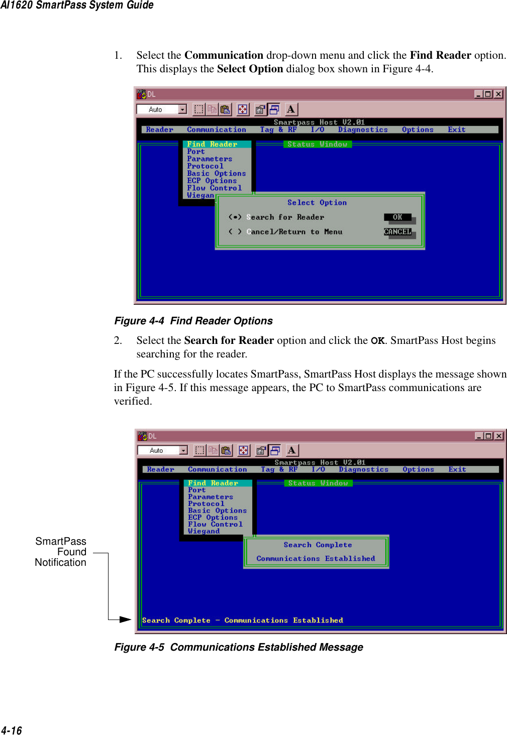
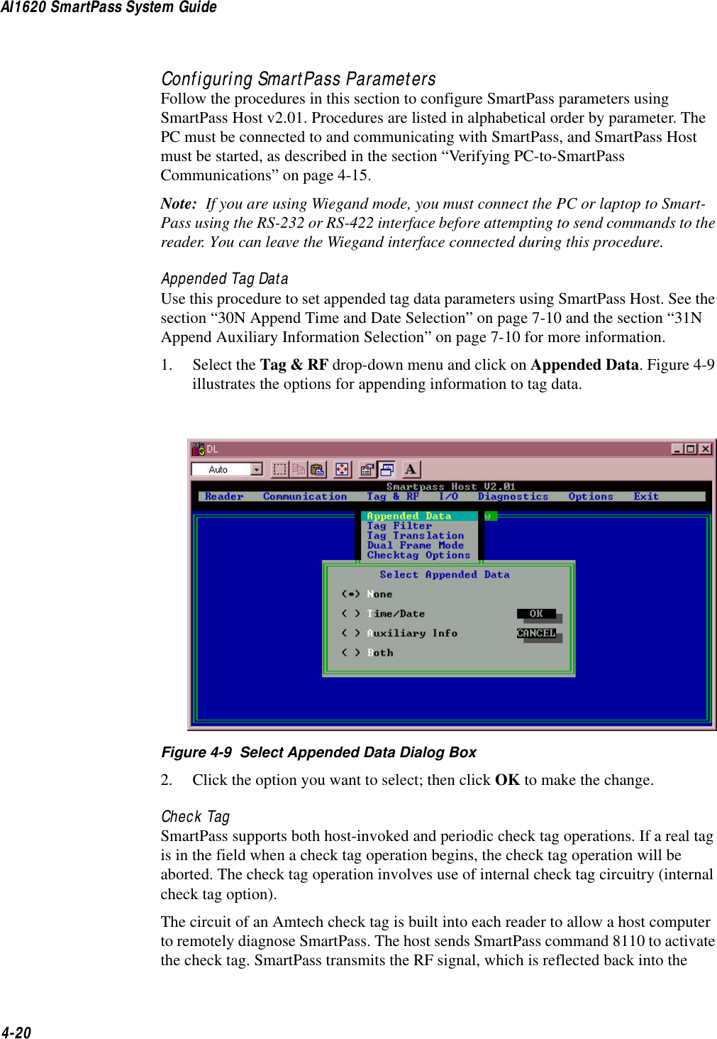
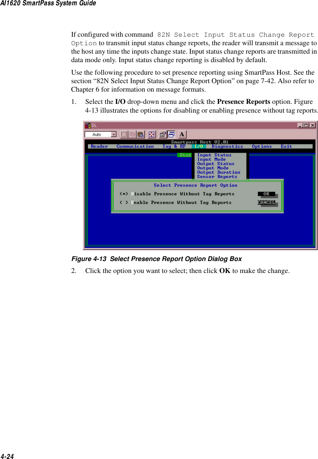
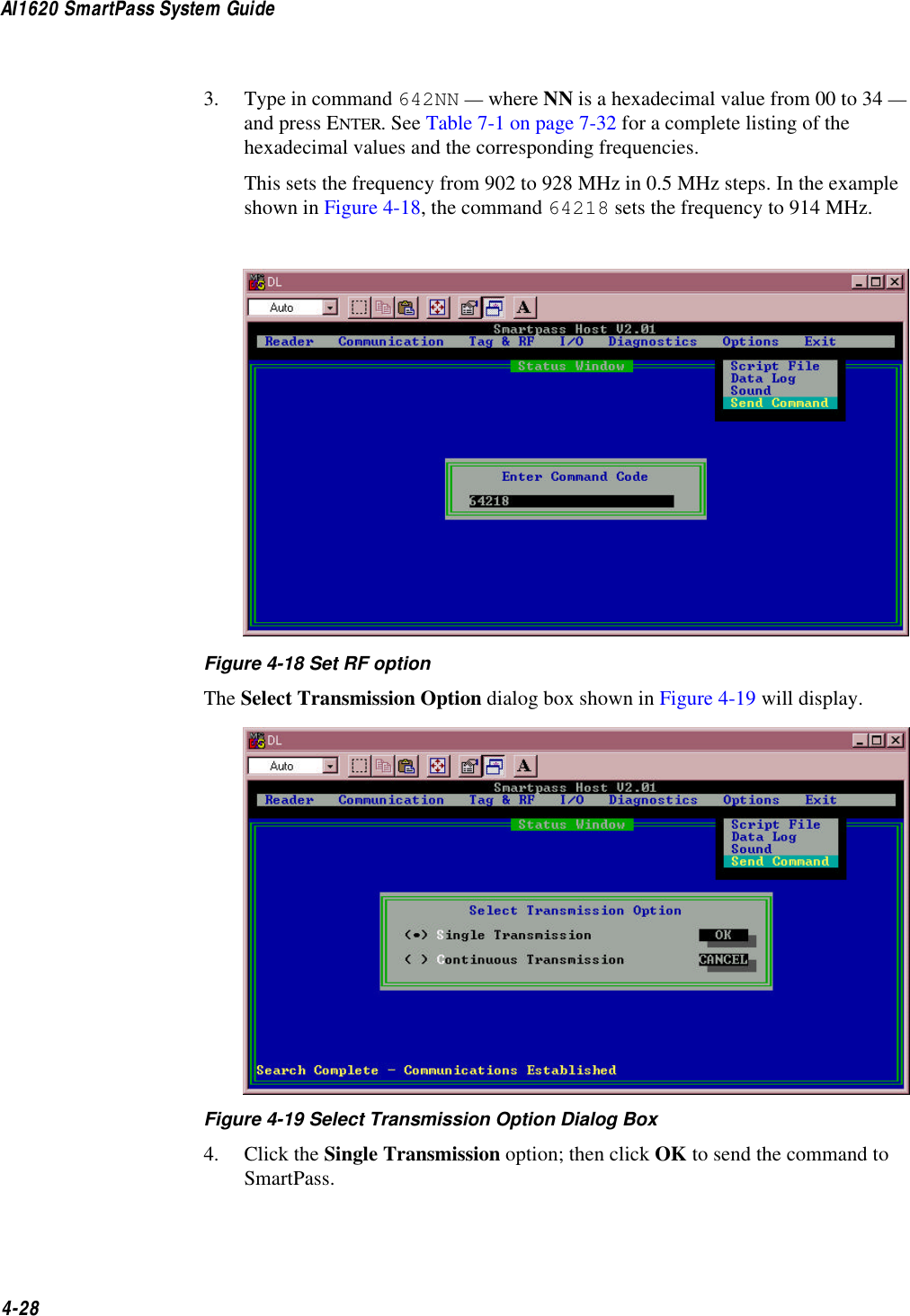
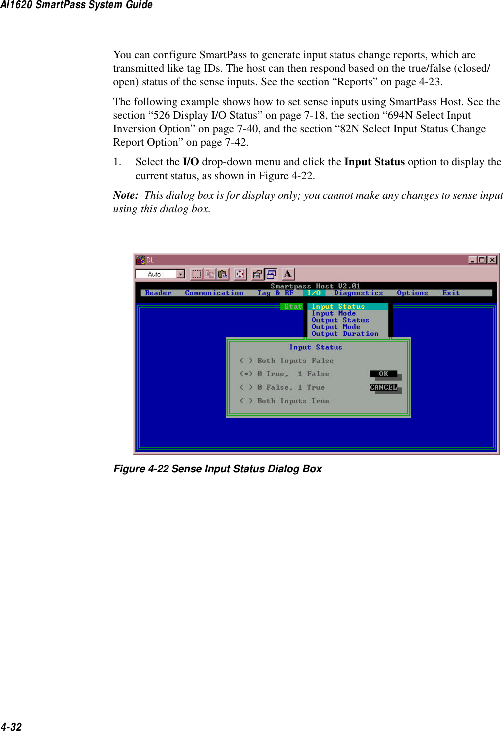
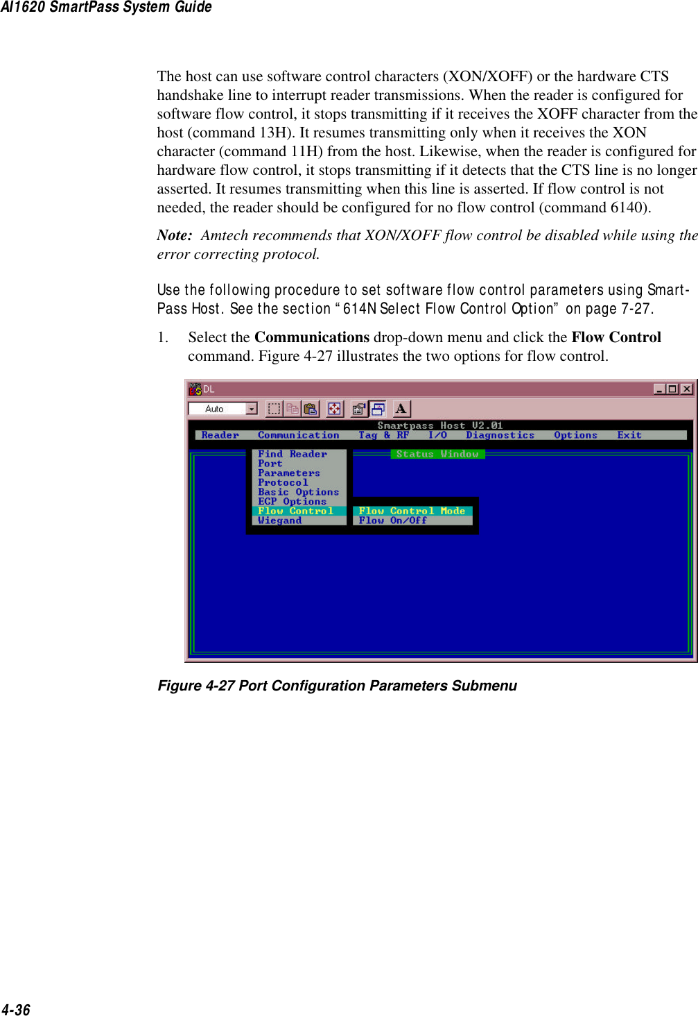

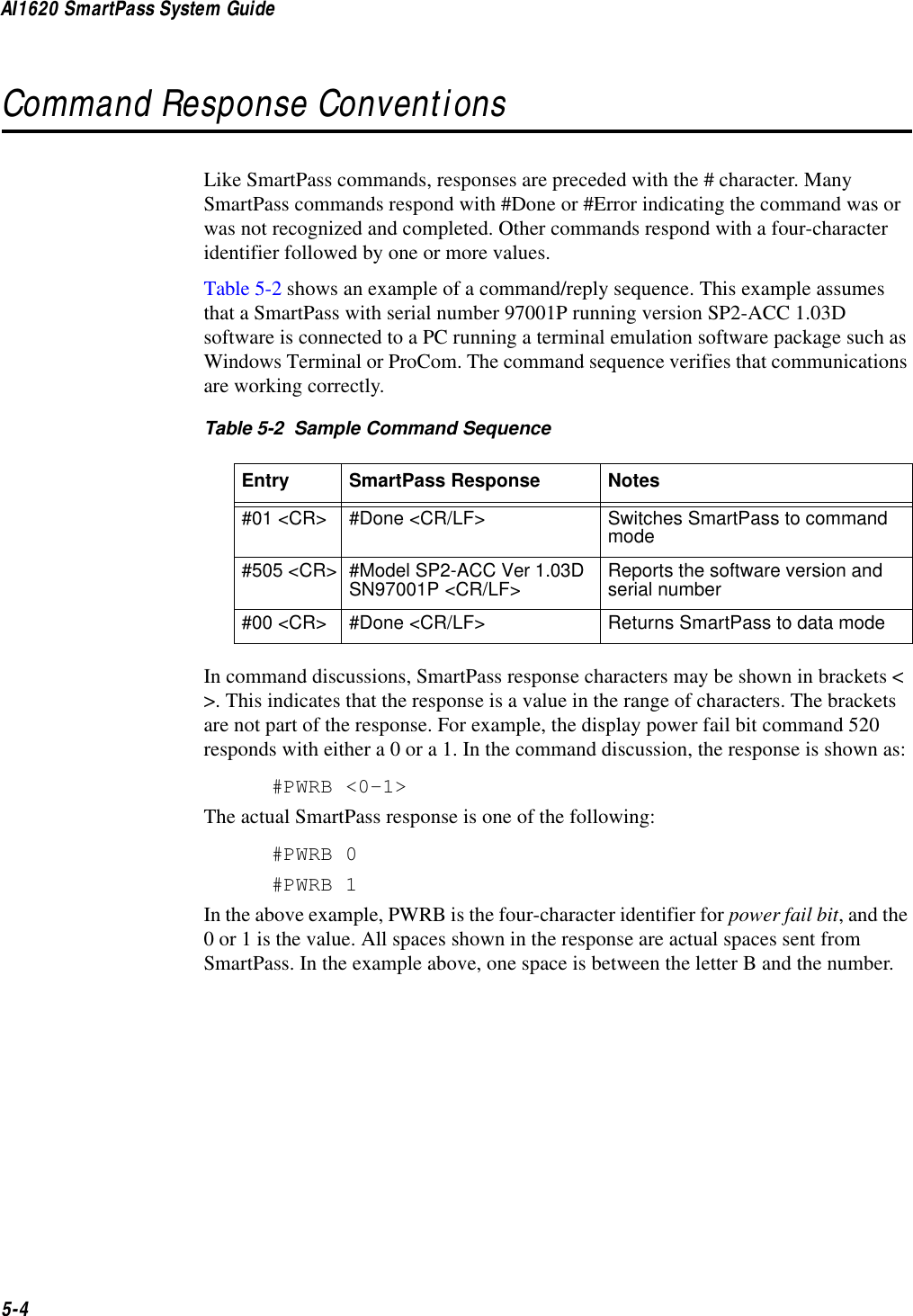
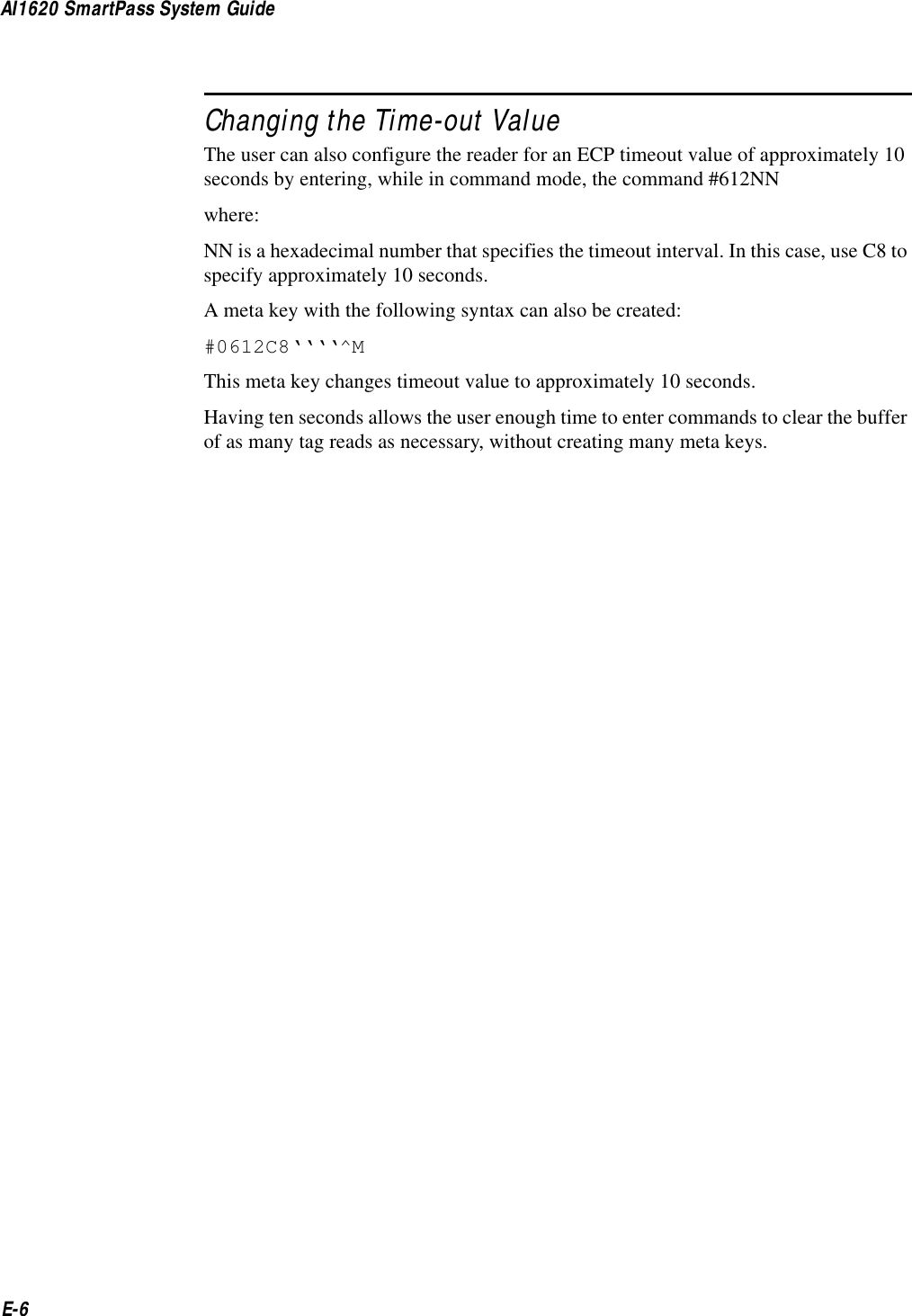
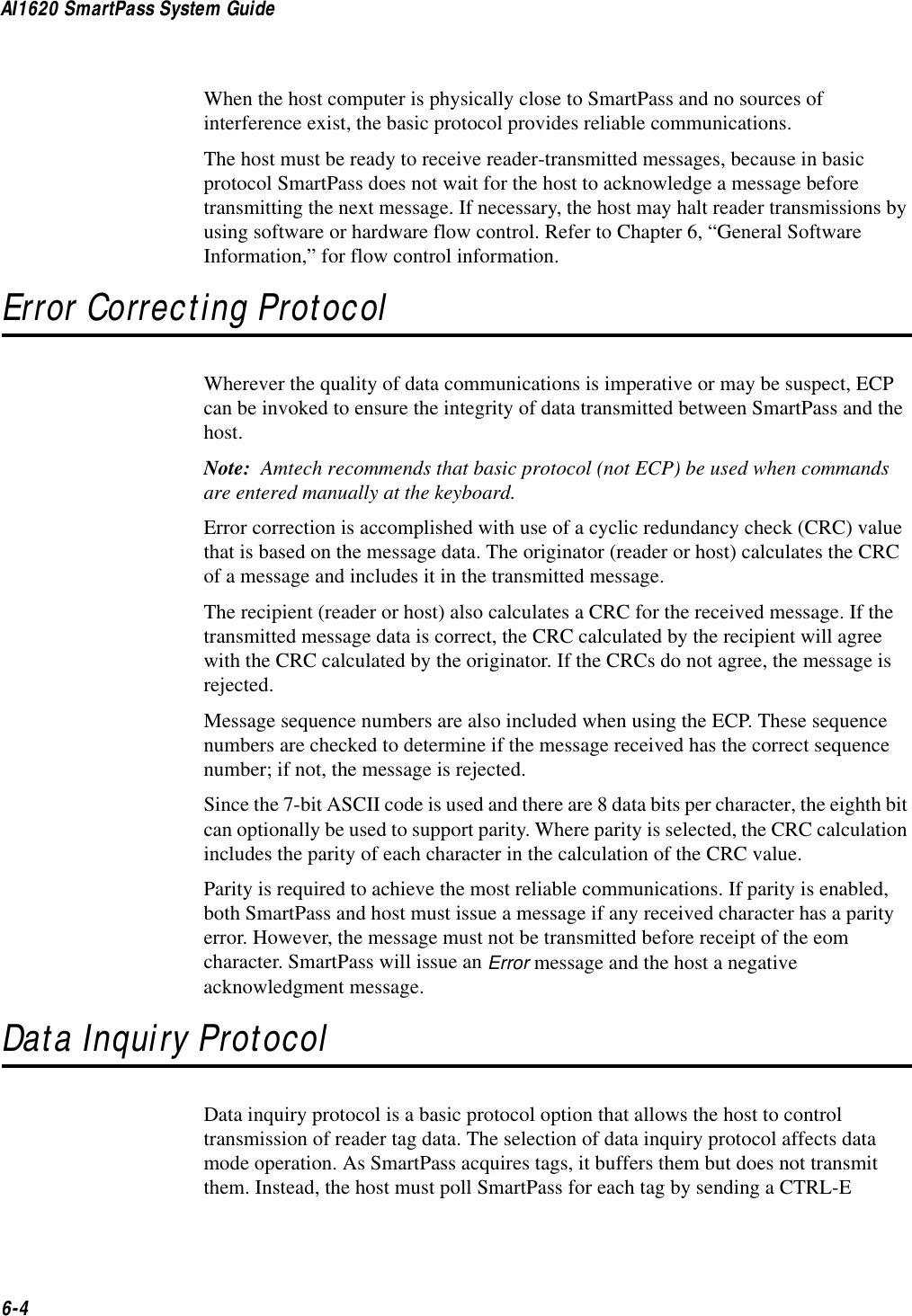
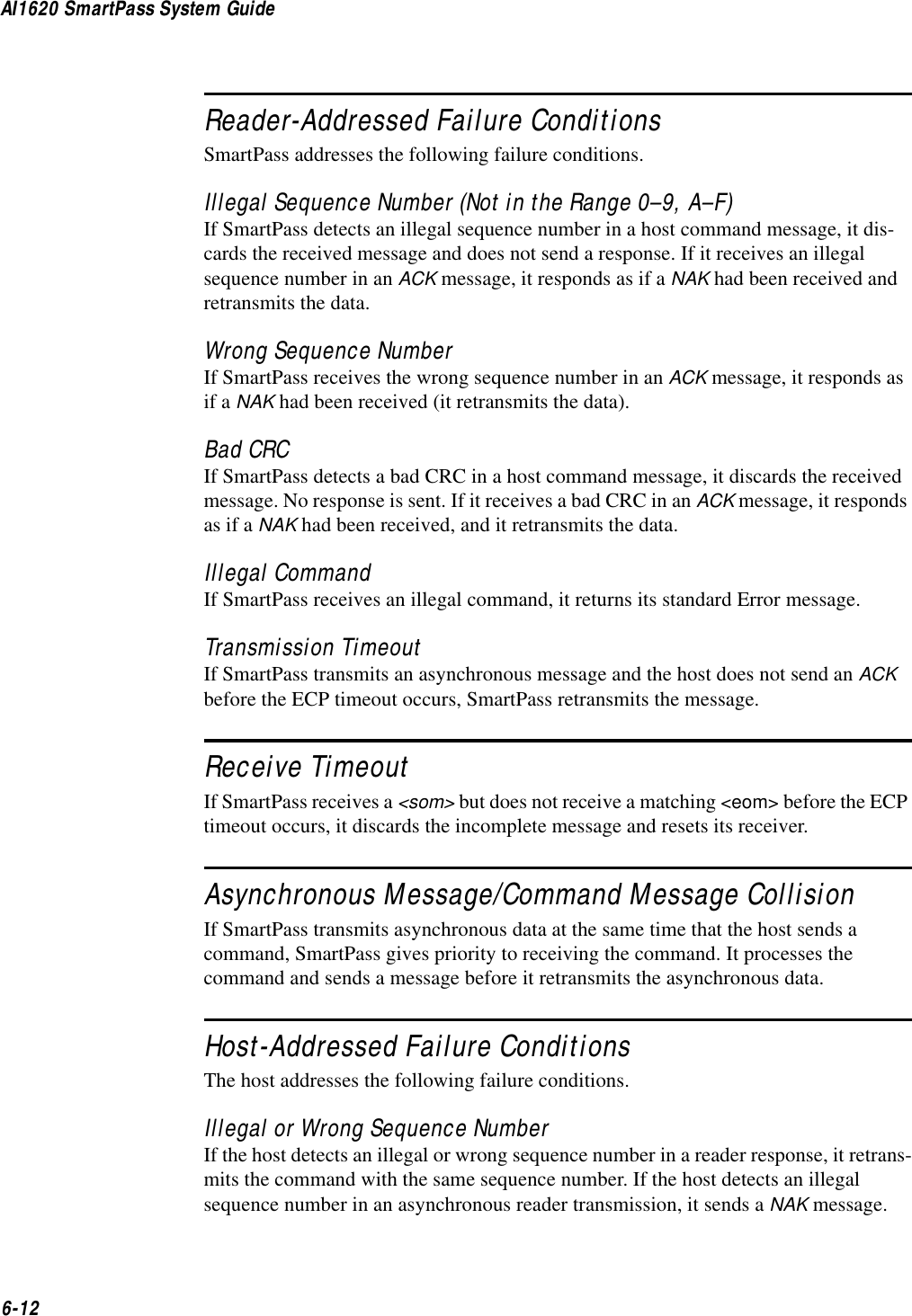
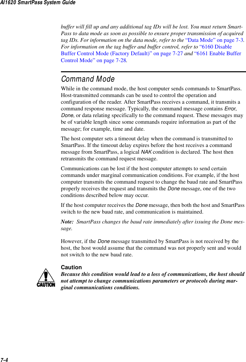
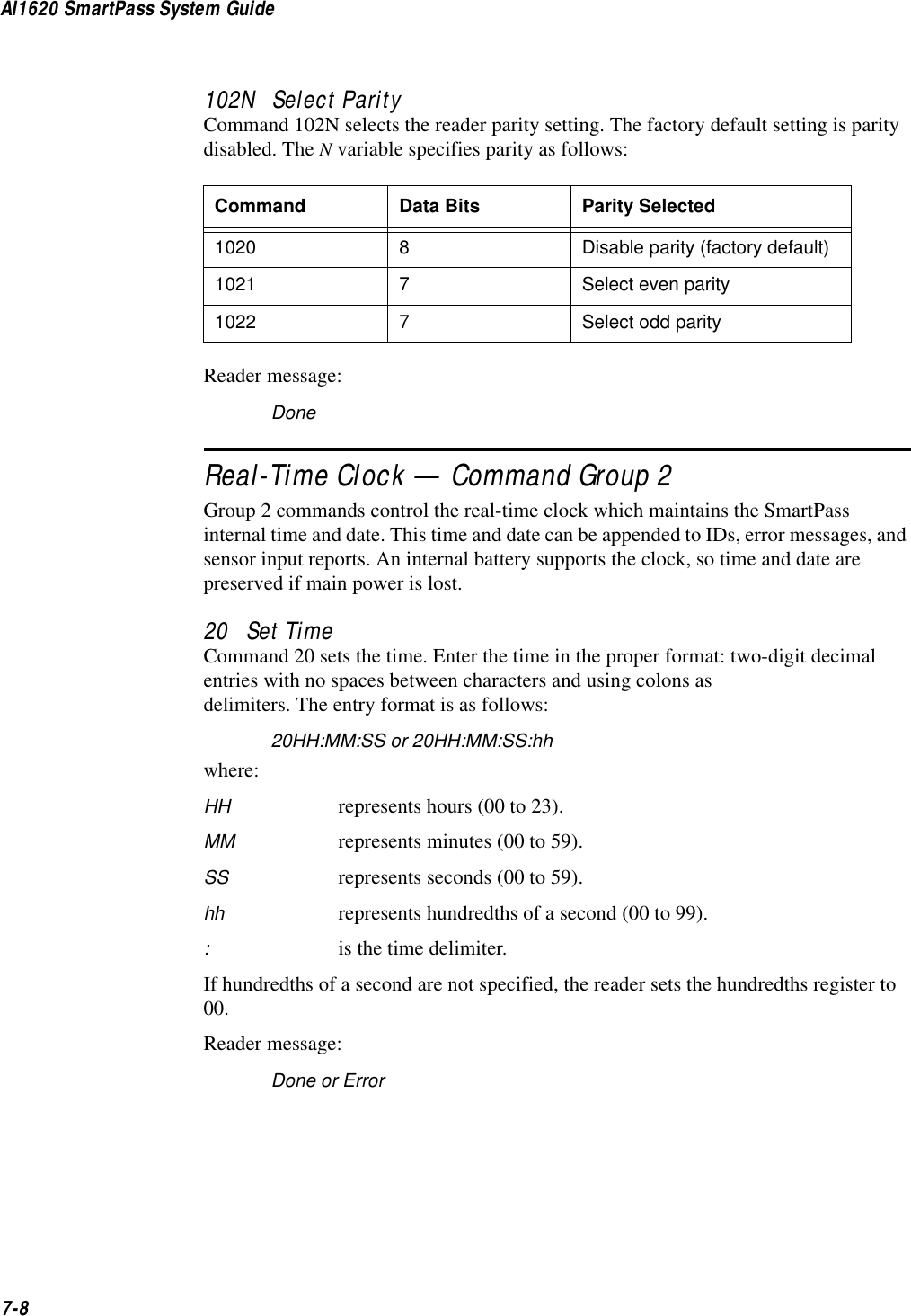
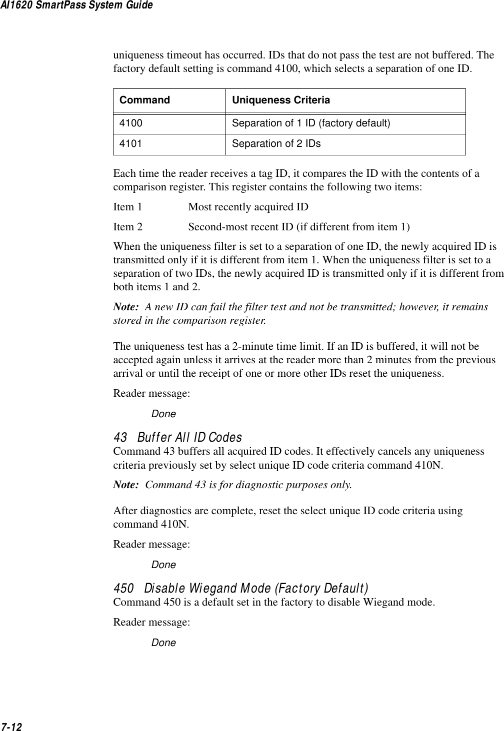
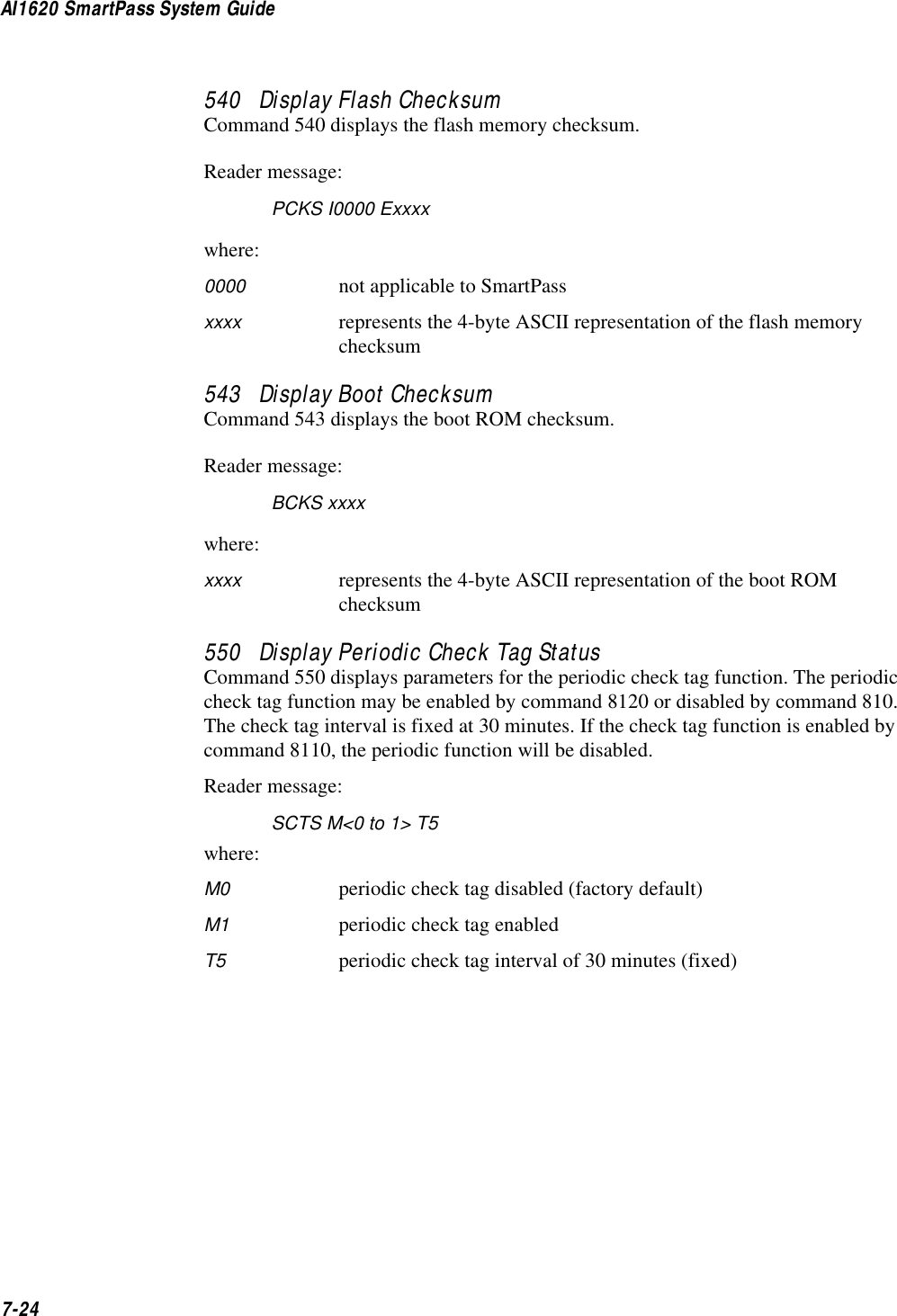
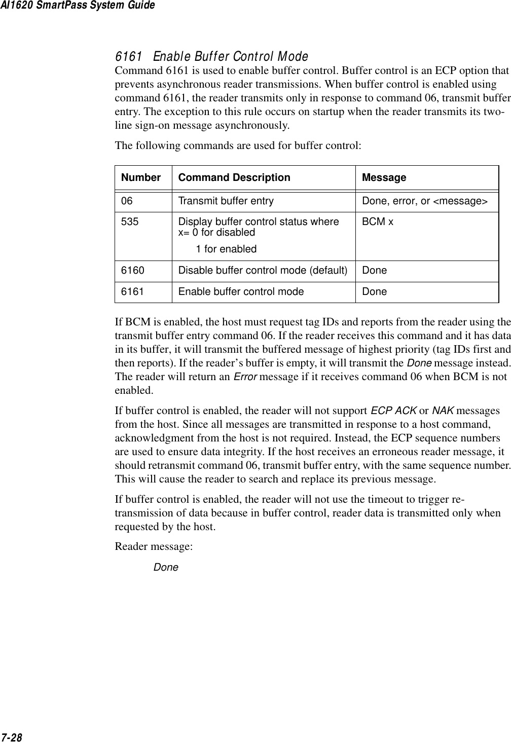
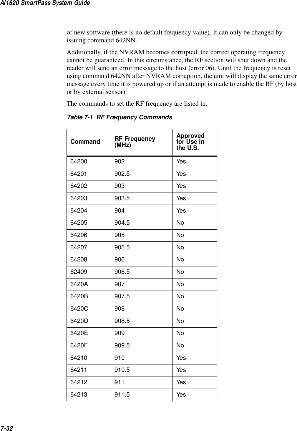
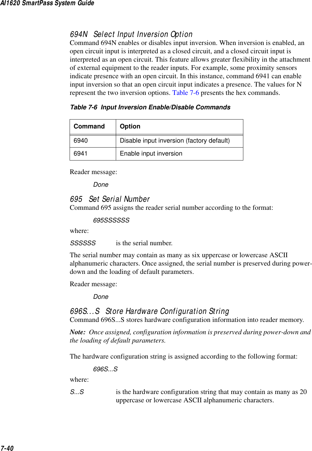
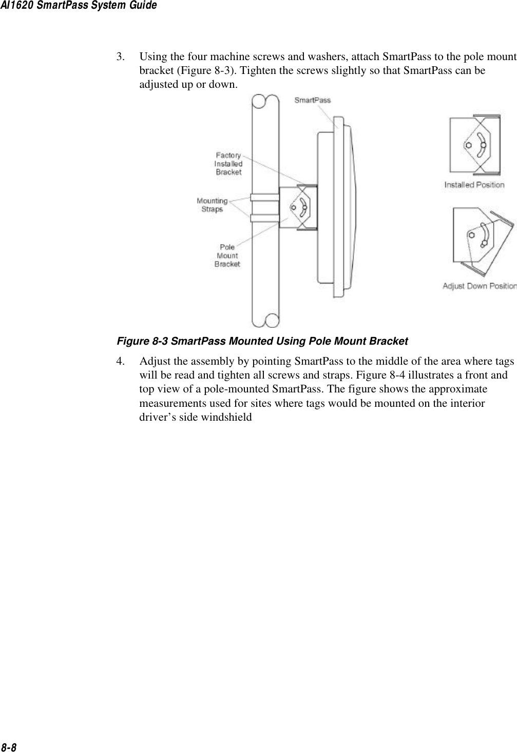
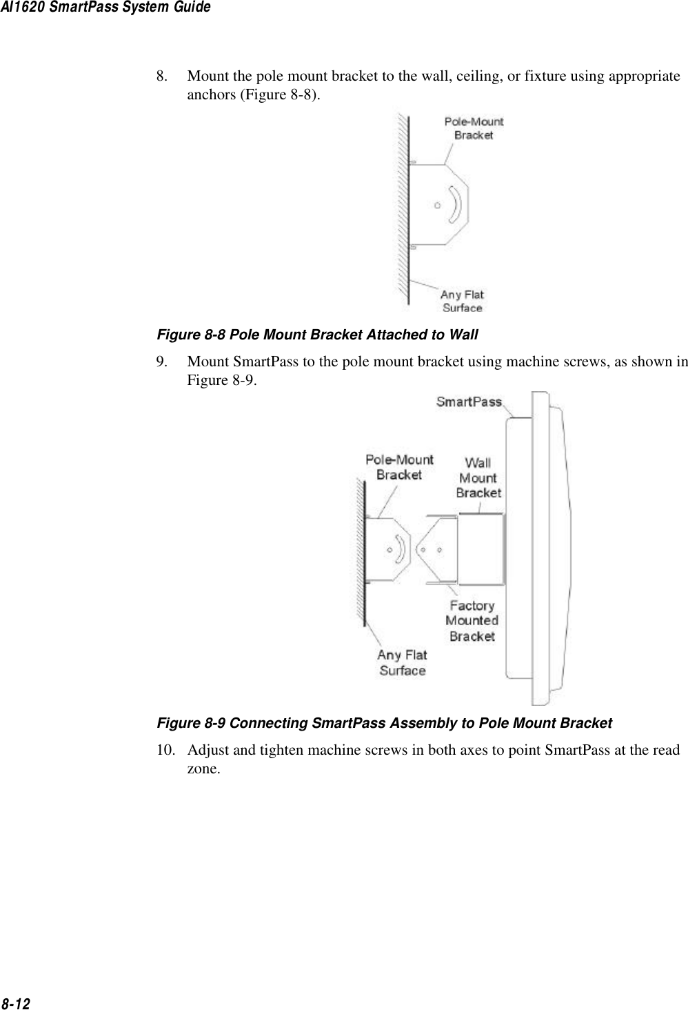
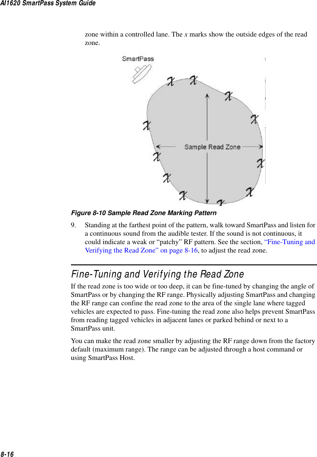
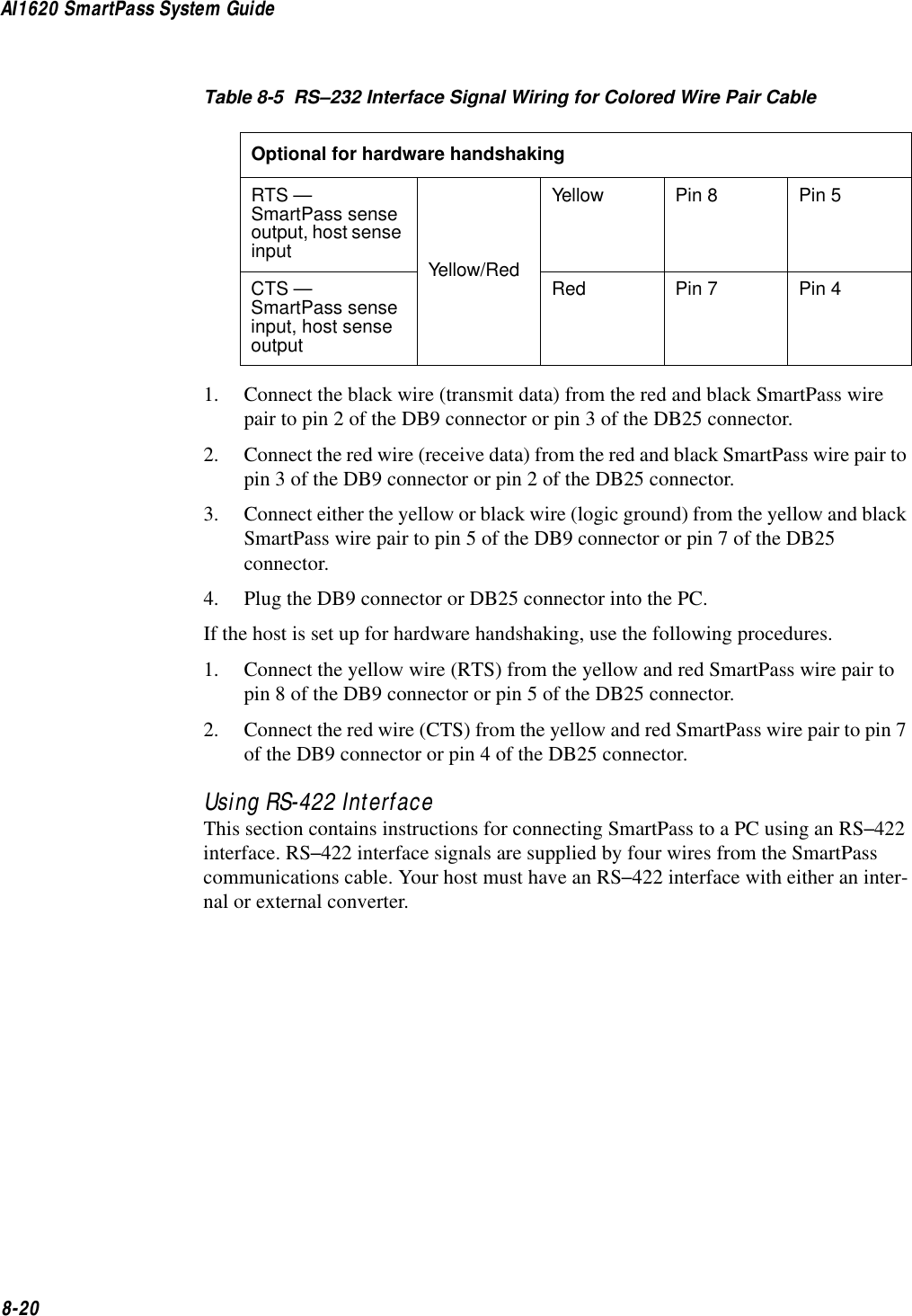
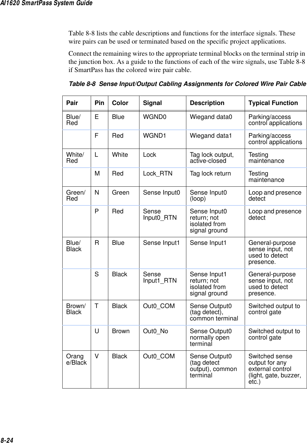
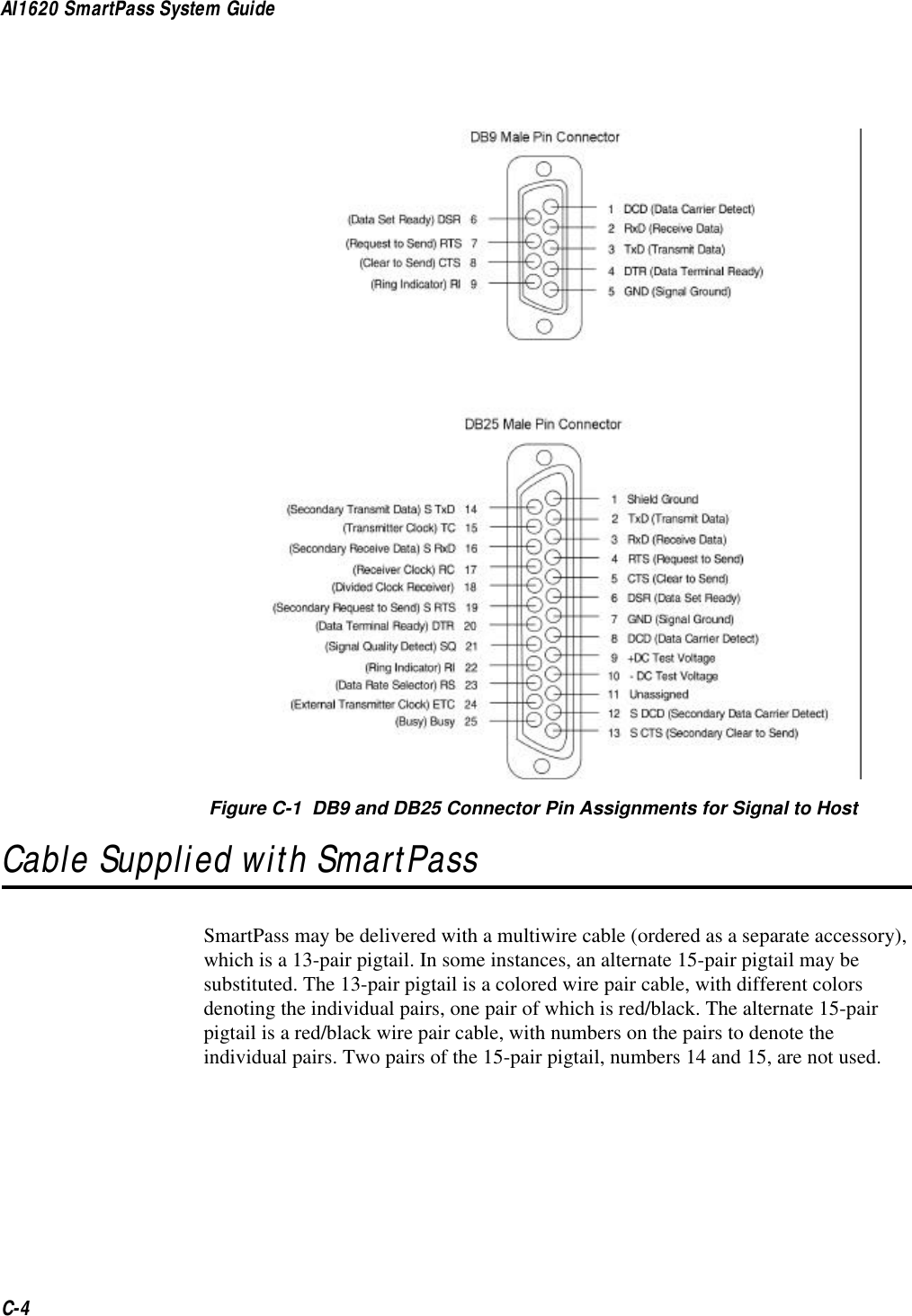
![General Software Information5-75StartupUpon startup, SmartPass readers transmit a sign-on message or a boot ROM failure message.Sign-On MessageThe sign-on message should appear as shown below: Model [software version] SNYYYYYY[Copyright notice]where YYYYYY is the serial number assigned to the SmartPass unit being used.Serial number 000000 is the default setting and is not a valid number. If this number appears in the sign-on message, either the battery has failed or the serial number has never been stored into reader memory. The appropriate serial number is assigned using command 695. If the flash memory checksum does not verify, the sign-on message appears as shown below:Model [Model] Ver 0.00[Copyright notice]Boot Failure MessageThe software performs a checksum function on itself. The function returns a specific value for the particular version of software. If the value returned is not correct, the boot ROM checksum assumes that locations have been corrupted, and a failure condition exists. If the boot ROM checksum is not correct, a boot failure message is transmitted. If the failure message does not transmit, a communications error has occurred, or the boot failed to the extent that it cannot transmit the failure message.If the failure message version number equals 0.00 and no serial number exists, the flash memory checksum has failed, and SmartPass is operating out of boot ROM. In this case, SmartPass automatically enters download mode and waits for a new program to be loaded into the flash memory. Follow the instructions in “Program Download” on page 5-5.Tag/Message BufferSmartPass readers maintain a tag buffer in battery-backed RAM to save tag IDs acquired while in the command mode and when data inquiry protocol is used. This buffer holds up to 195 time-stamped messages. Error messages will be transmitted to the host to provide buffer status as it fills. When the buffer fills, subsequent tag IDs will be lost. For more information on how the buffer works, refer to “Command Entry Conventions” on page 5-3 and “6161 Enable Buffer Control Mode” on page 7-28.](https://usermanual.wiki/TransCore/10-510-100.Exhibit-8-Users-Manual/User-Guide-75384-Page-97.png)


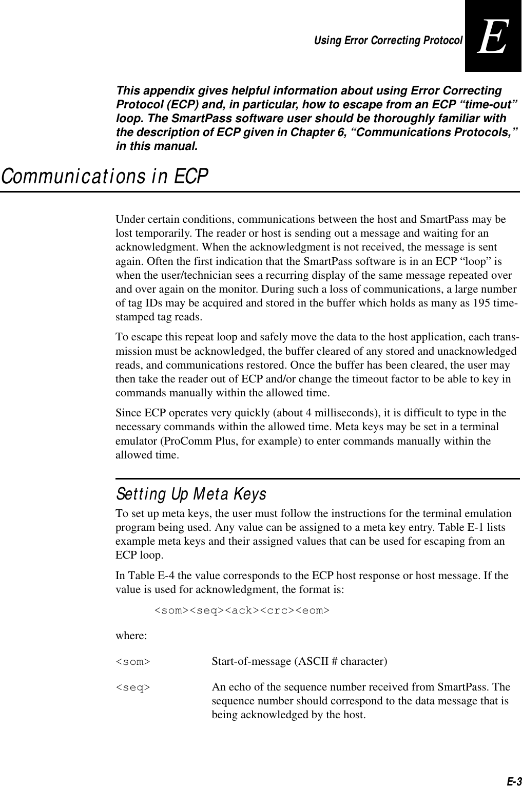
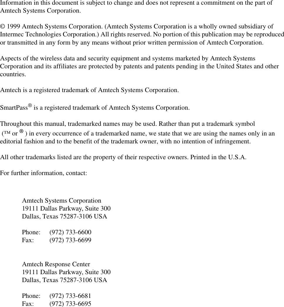
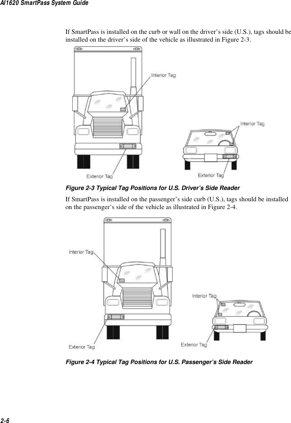
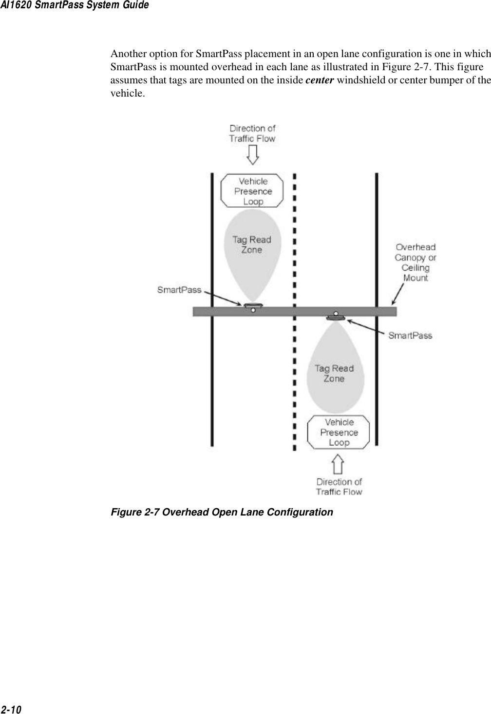
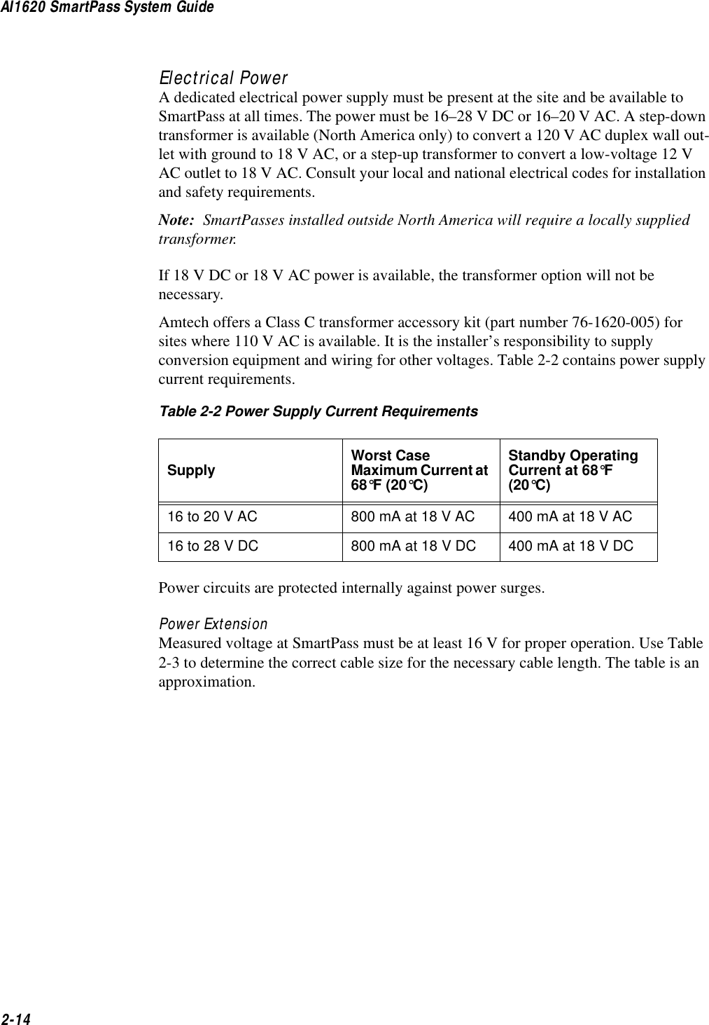
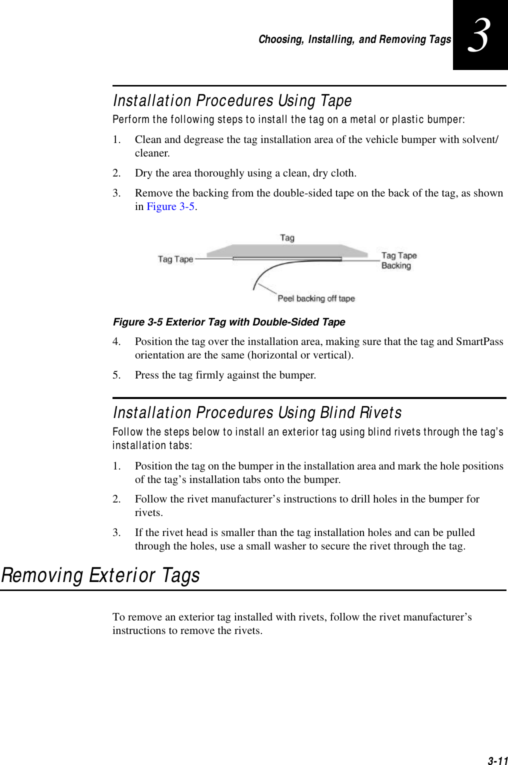
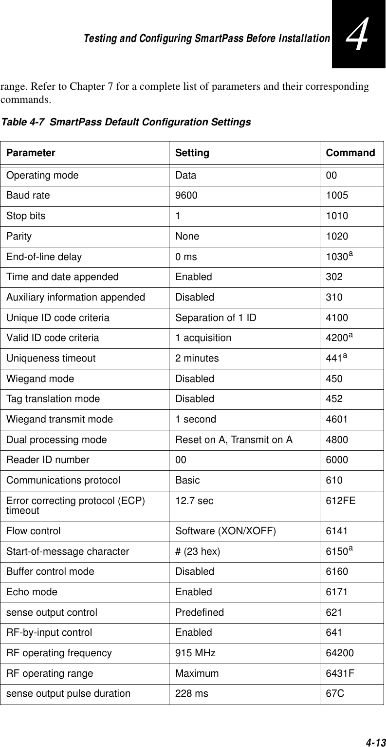
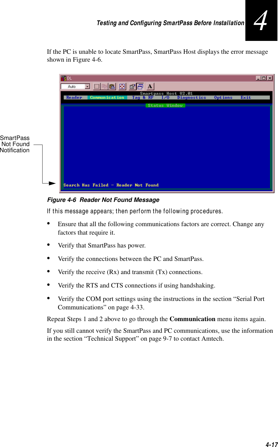
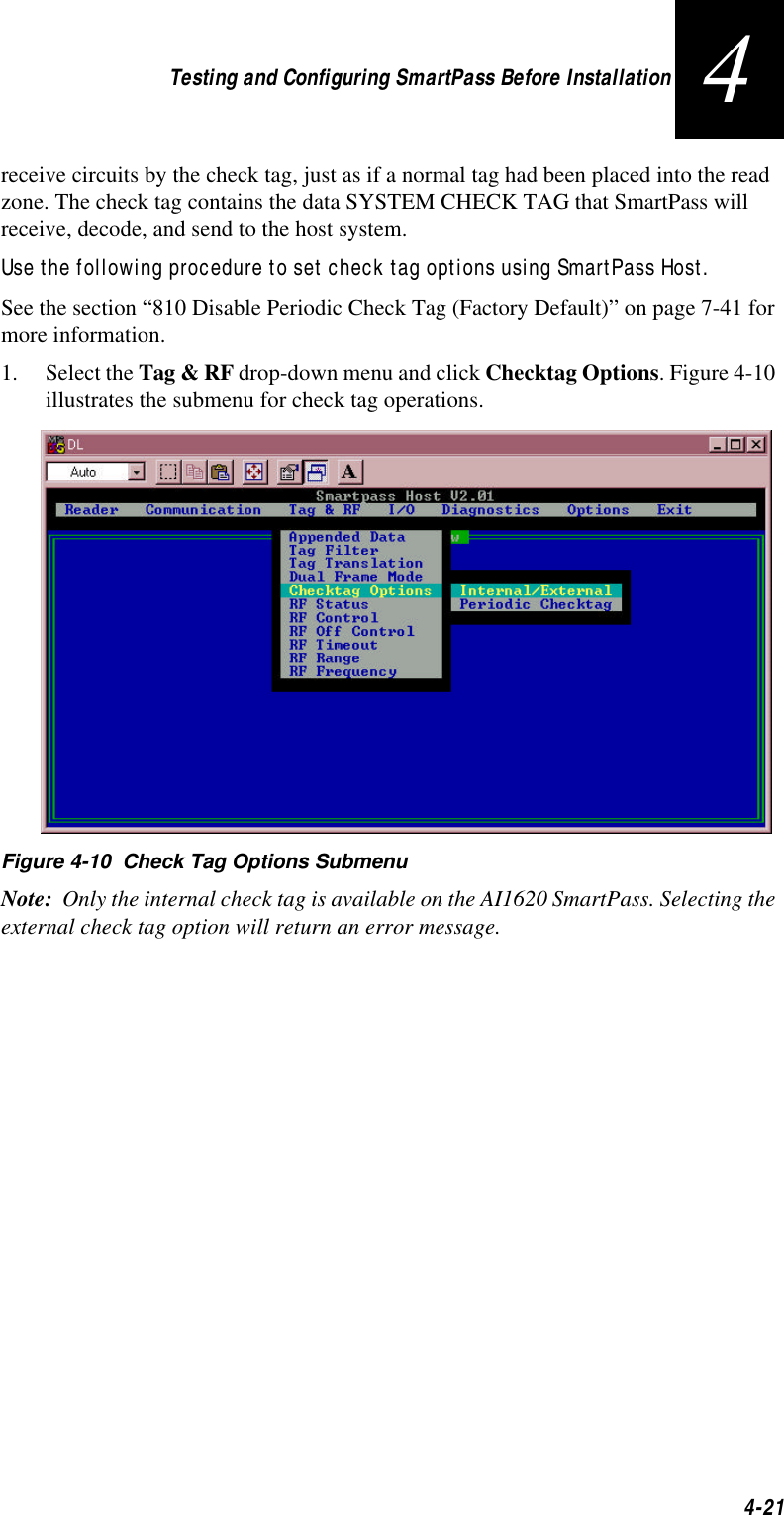
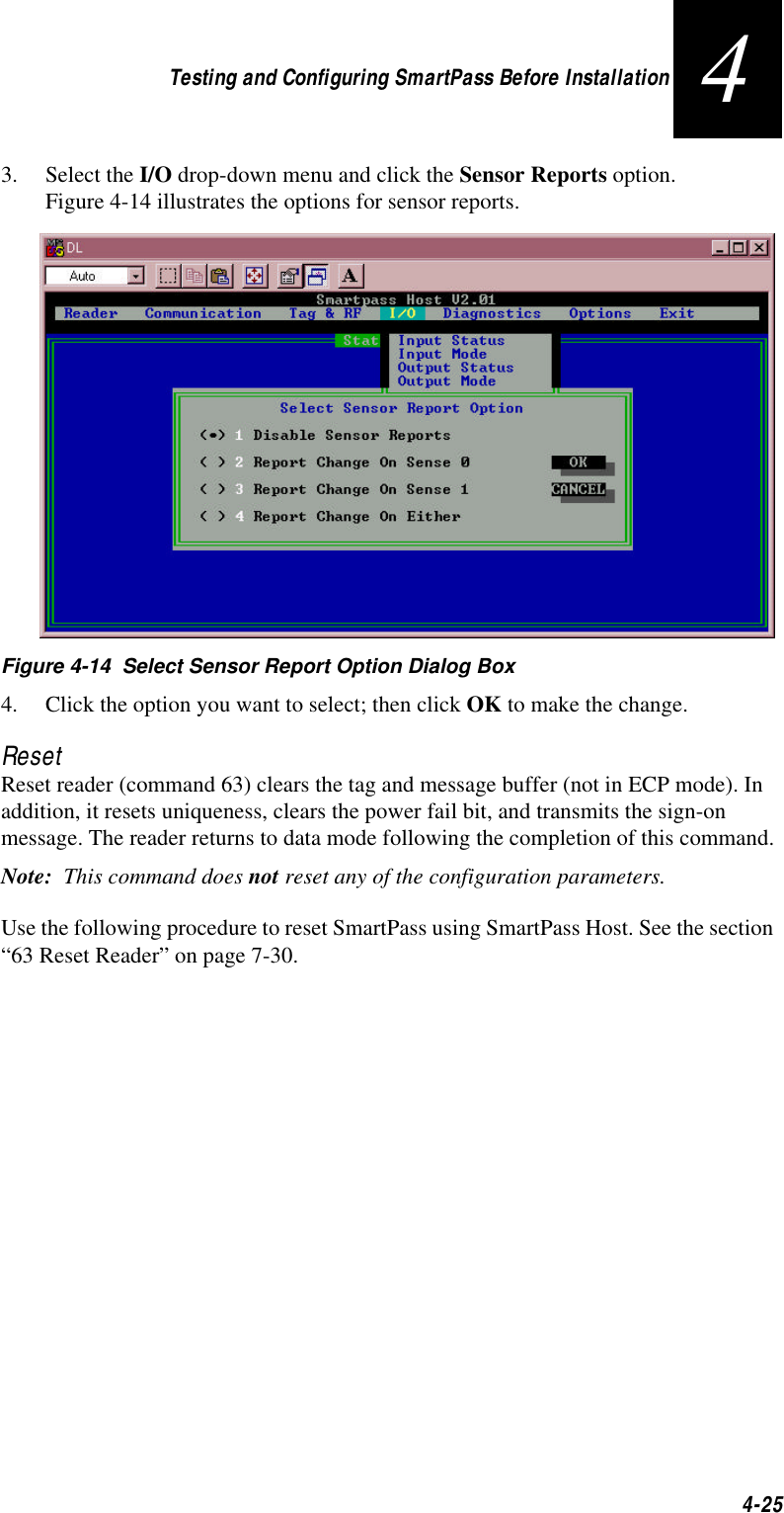
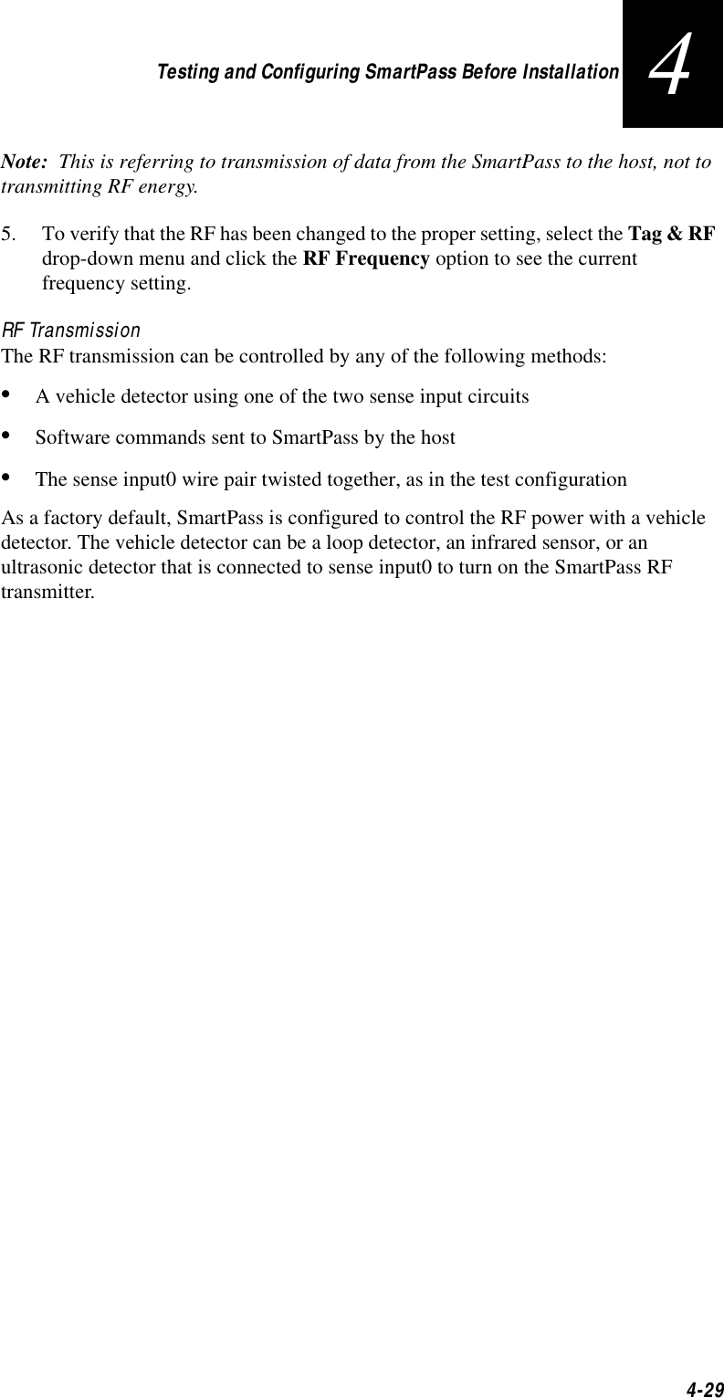
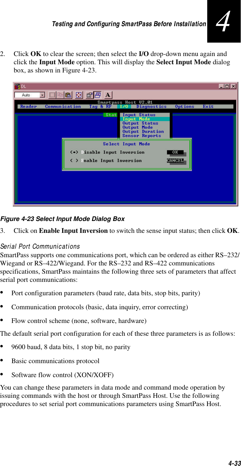
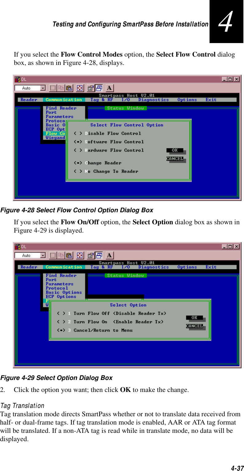
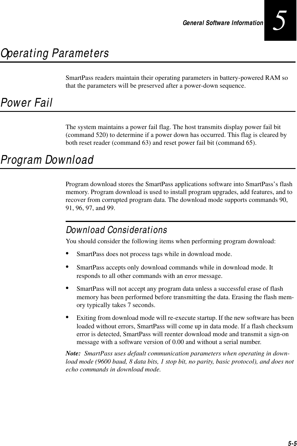
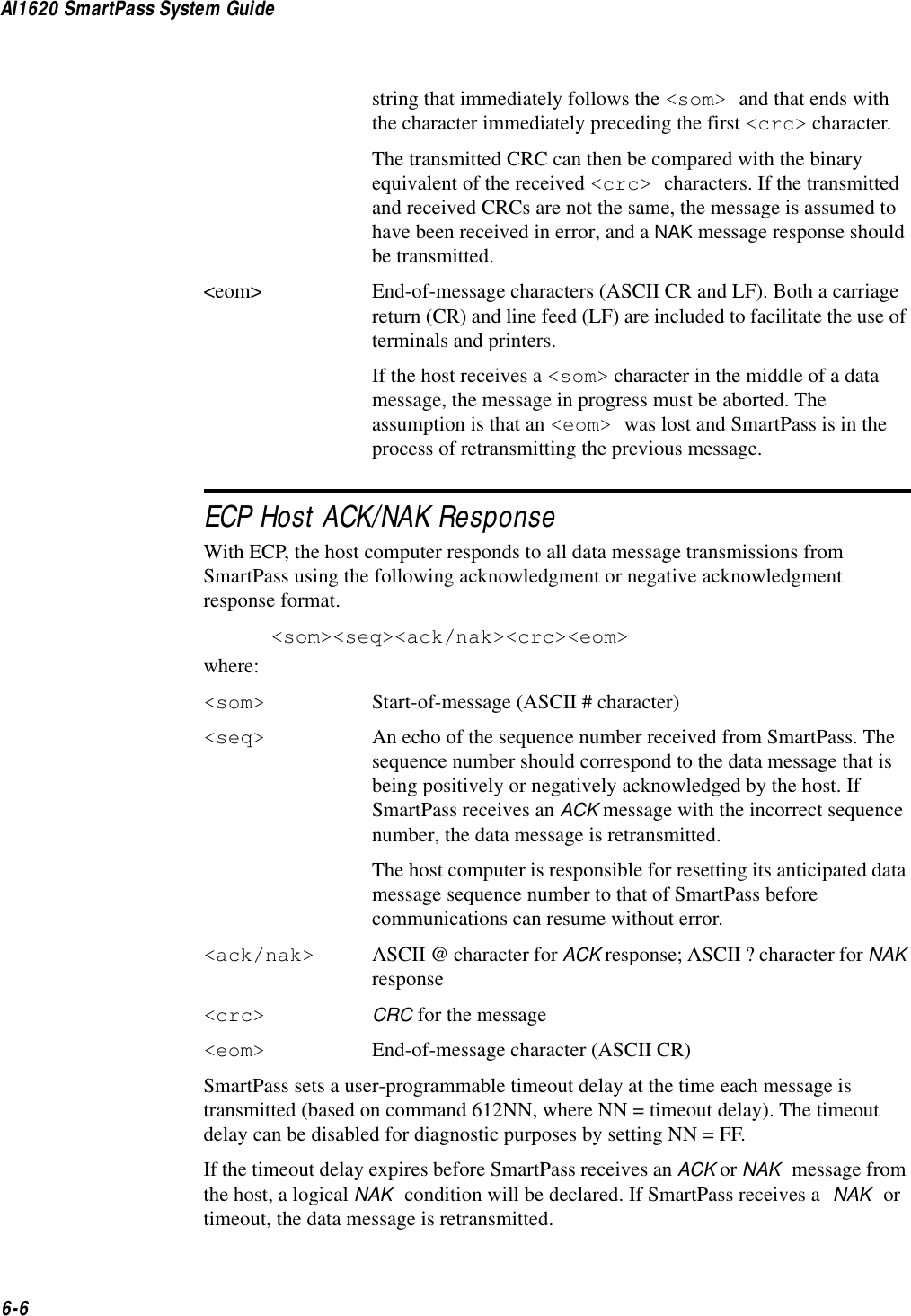
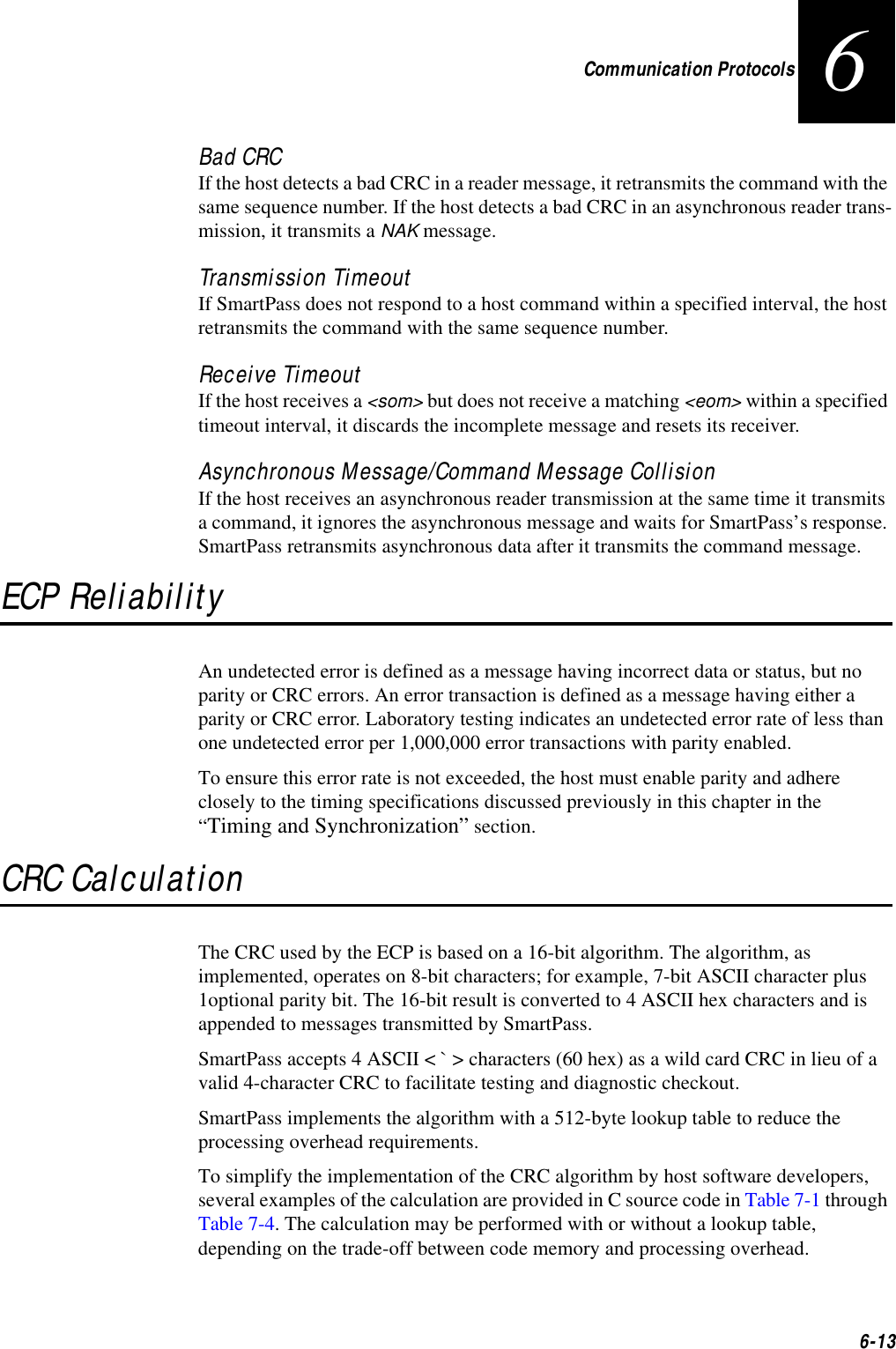
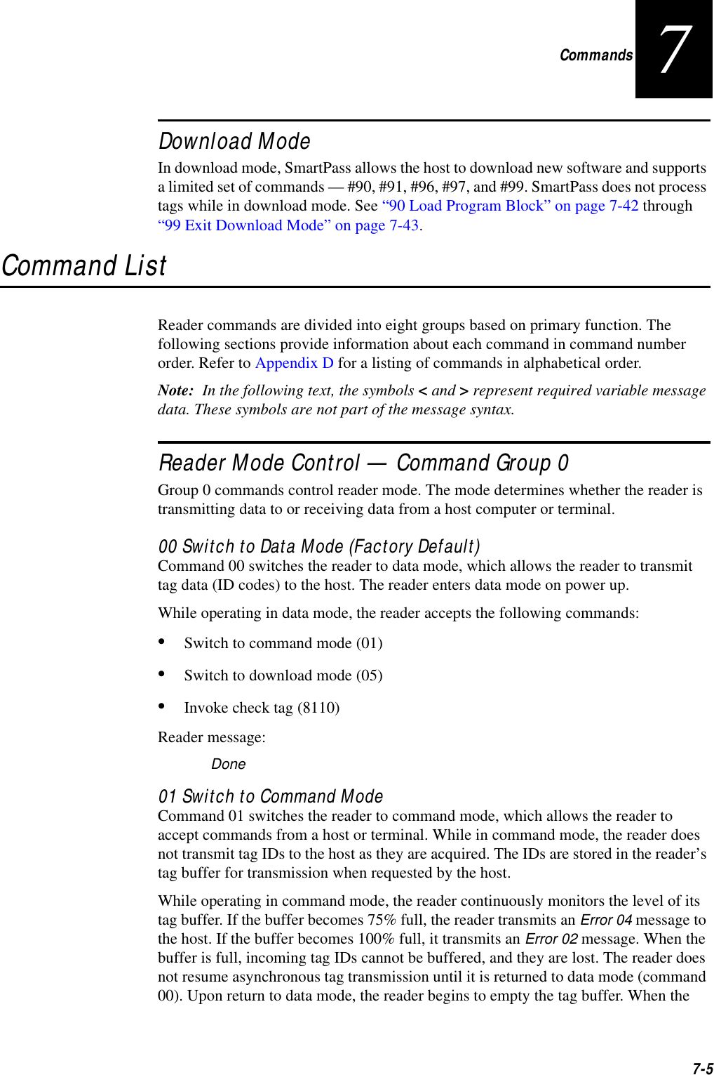
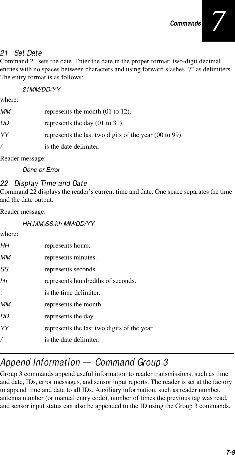
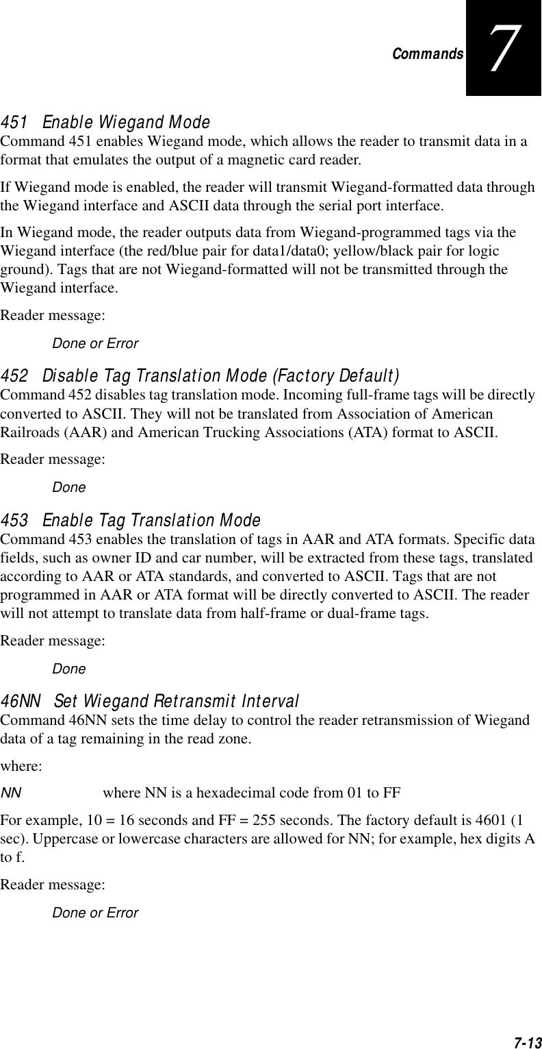
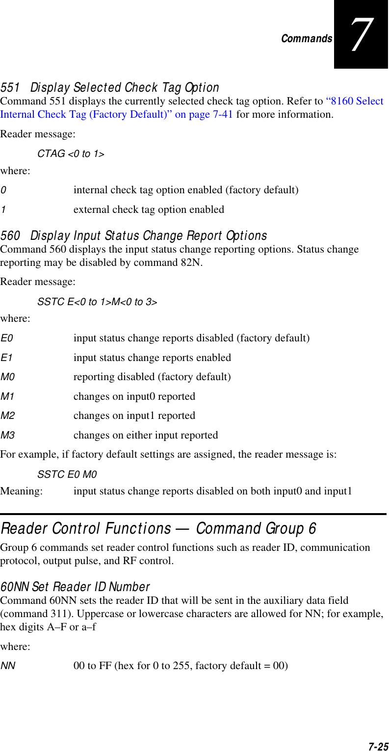
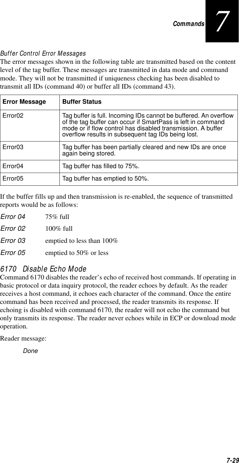
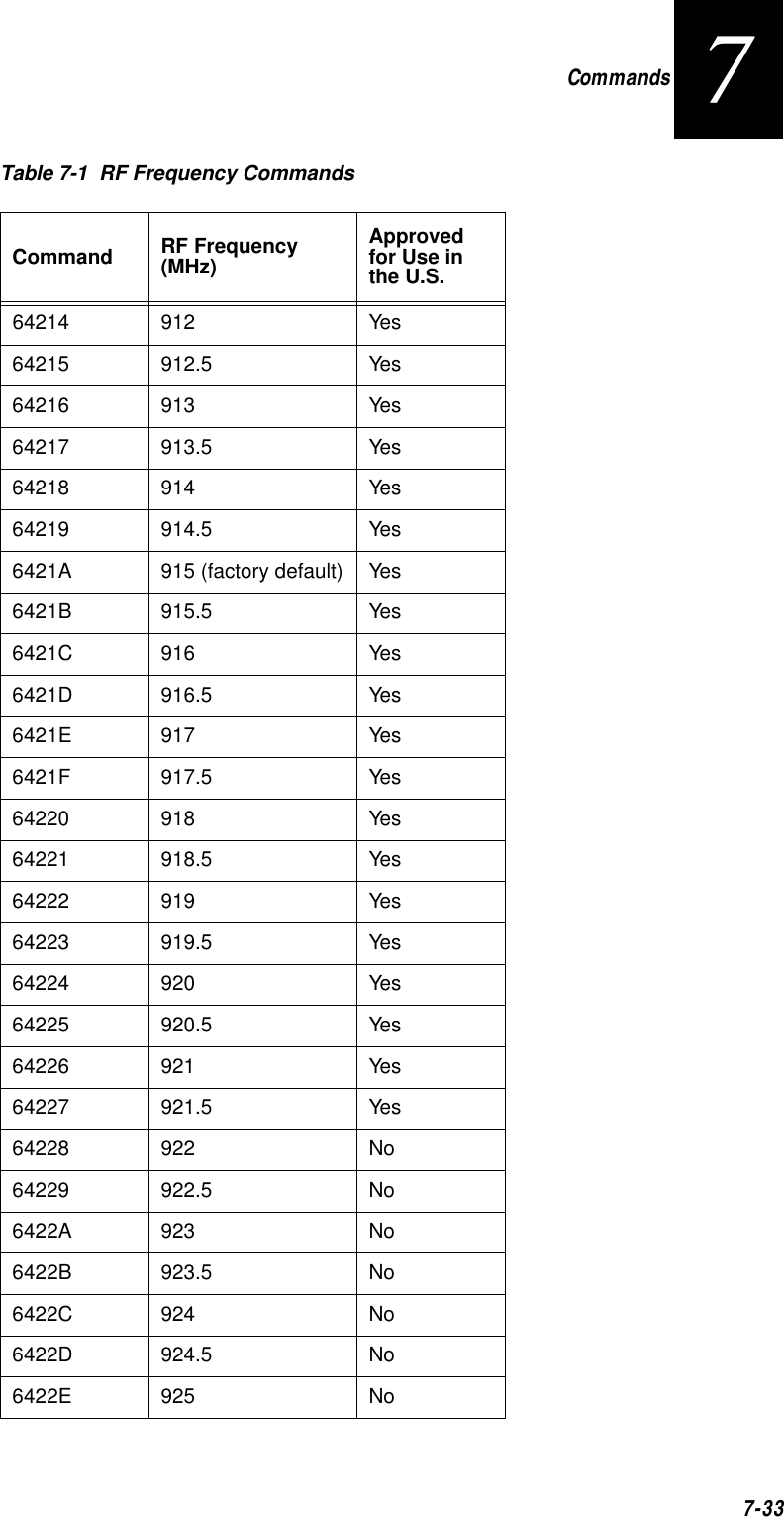
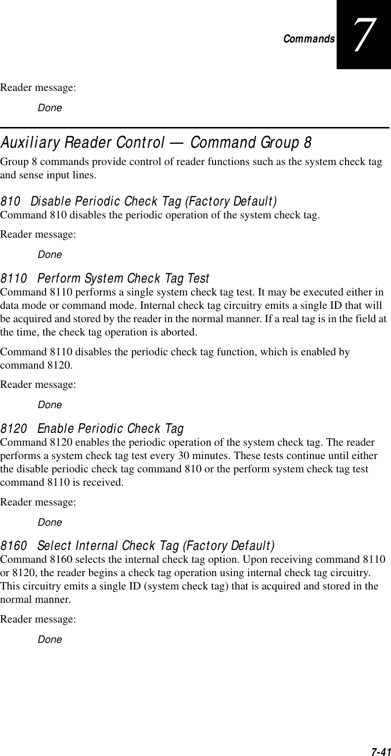
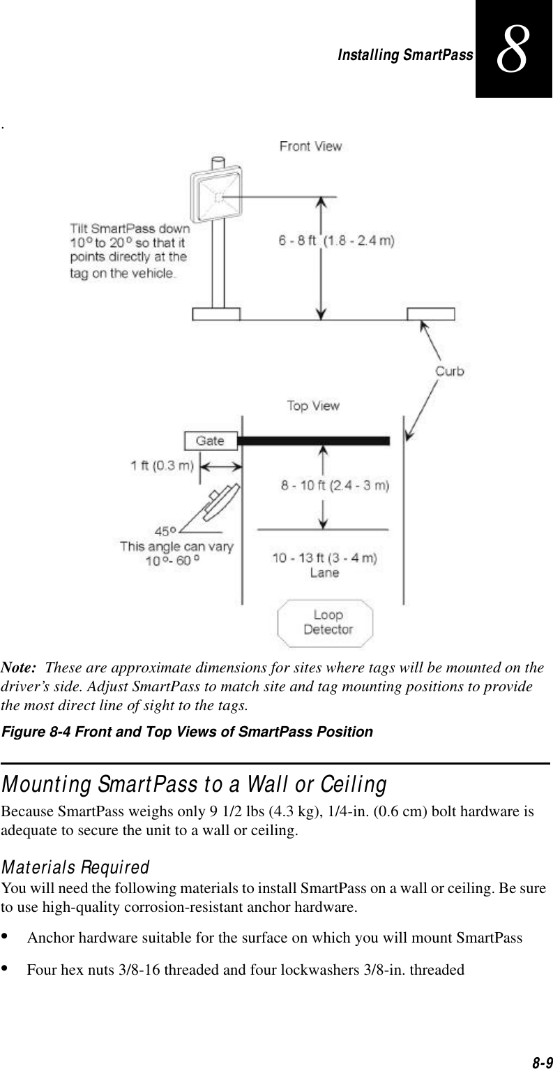
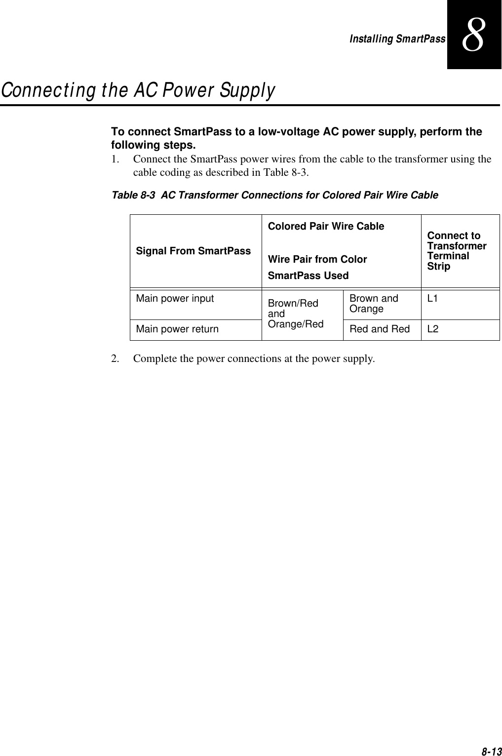
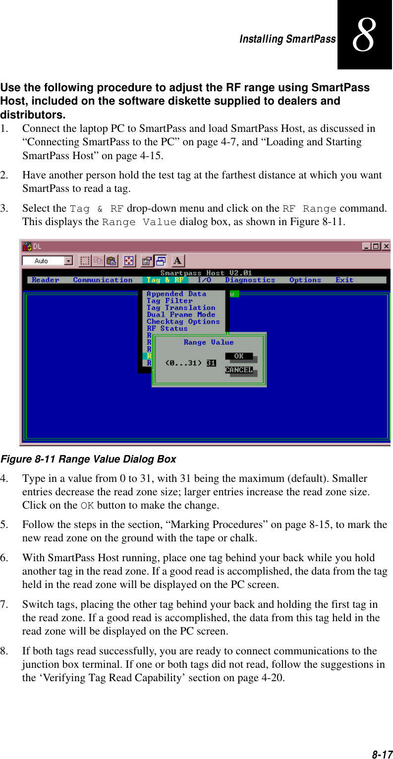
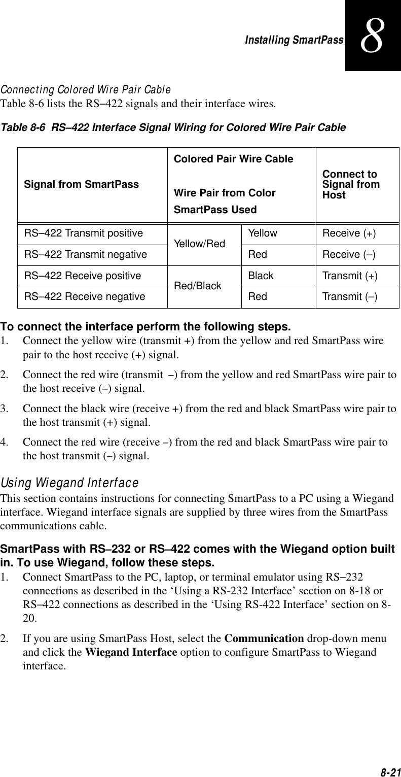
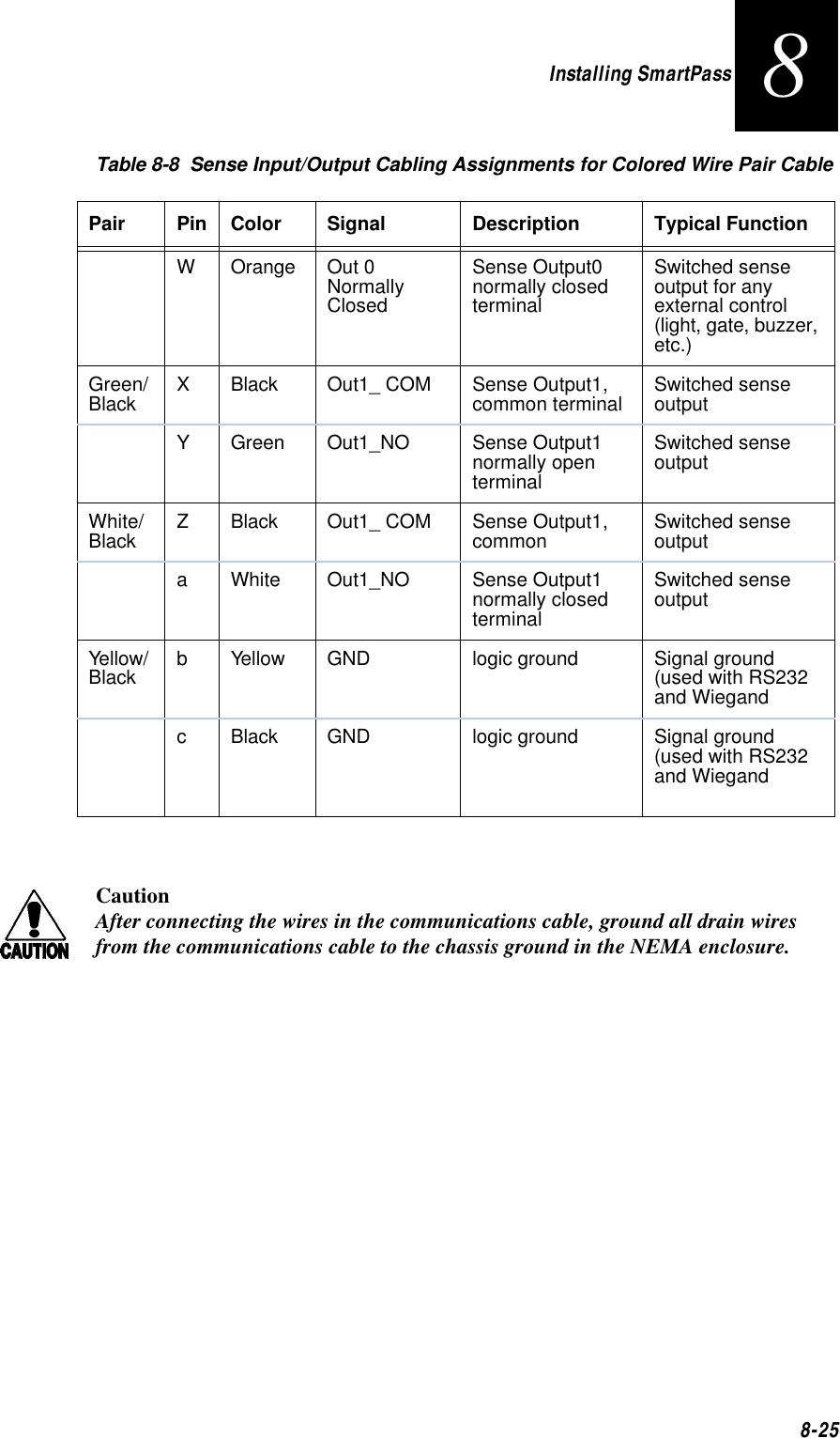
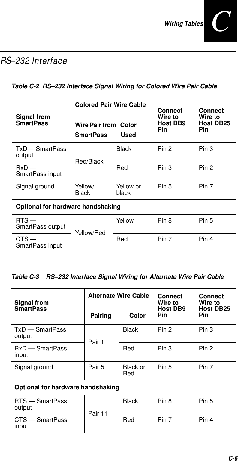
![Communication Protocols6-56character (hex 5 digits). SmartPass transmits one message (tag ID or report data) for each CTRL-E it receives until the buffer is empty.Each tag request message sent by the host consists only of the CTRL-E character; no som or eom characters are sent. SmartPass data transmission (tag ID and report data) format is the same as for basic protocol.Selection of data inquiry protocol does not affect command mode operation.Basic and ECP Protocol FormatNote: In the following text, the symbols < and > are used to represent required vari-able message data, and the symbols [ and ] are used to represent optional data. These symbols are not part of the message syntax.Reader TransmissionsThe basic protocol format and the data inquiry protocol format are shown below.<som><data><eom>The ECP format is shown below.<som><seq><data><crc><eom>where:<som> Start-of-message (ASCII # character)<seq> Sequence number (ASCII hex) that represents an even number in the range 0–9, A–E (0, 2, 4, 6, 8, A, C, E). This number is maintained by SmartPass. The host must acknowledge reader transmissions by sending an ACK message with the same sequence number received from SmartPass. SmartPass will update its sequence number upon receipt of a valid host ACK. If an ACK is not received, SmartPass will retransmit the message. A reader transmission sequence is not considered compete until SmartPass receives an ACK and updates its sequence number.<data> An ASCII string up to 72 characters long. This string may contain tag data, a presence without tag report, an input status change report, an Error02, 03, 04, or 05 message (buffer level report), or a sign-on message. Time, date, and auxiliary data may also be included.<crc> Cyclic redundancy check (CRC). This field contains four ASCII digits that represent the 16-bit CRC calculated on the message. The CRC is calculated on bytes between the som character and the first CRC byte.When the host receives a properly framed message, it can calculate a 16-bit CRC. The calculation is applied to the character](https://usermanual.wiki/TransCore/10-510-100.Exhibit-8-Users-Manual/User-Guide-75384-Page-103.png)
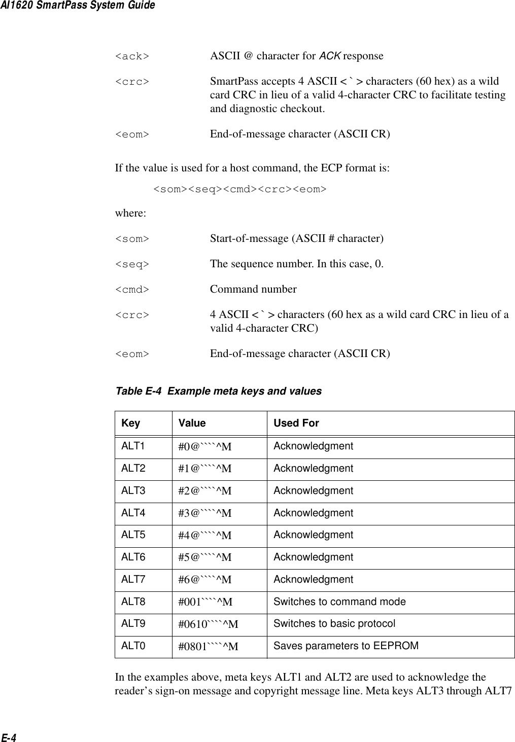
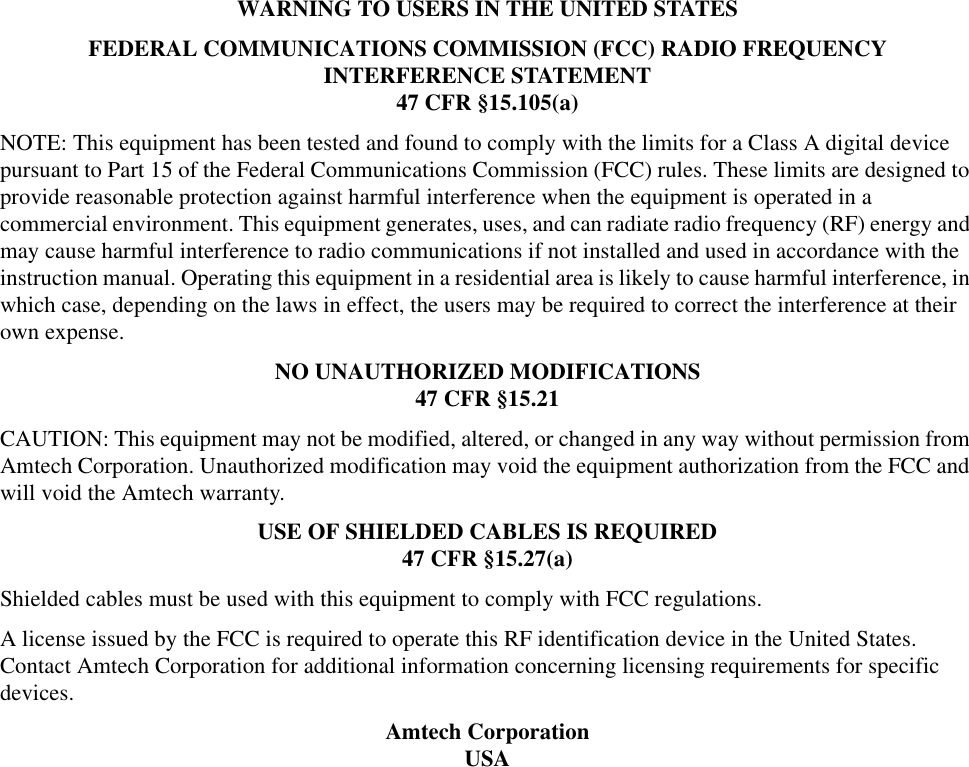
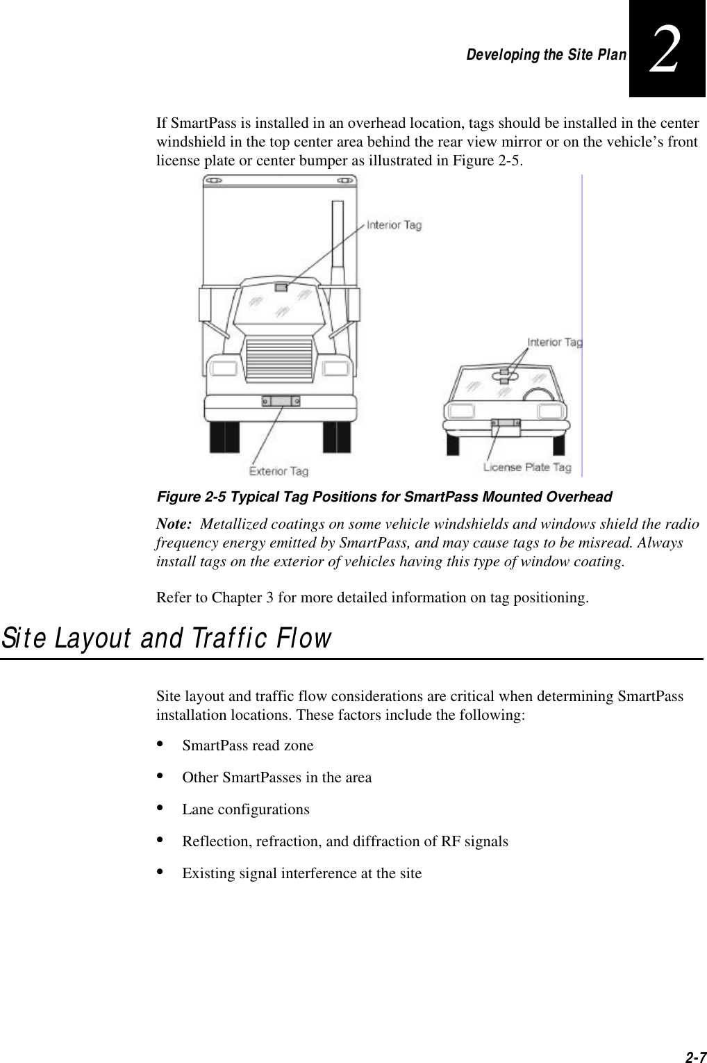
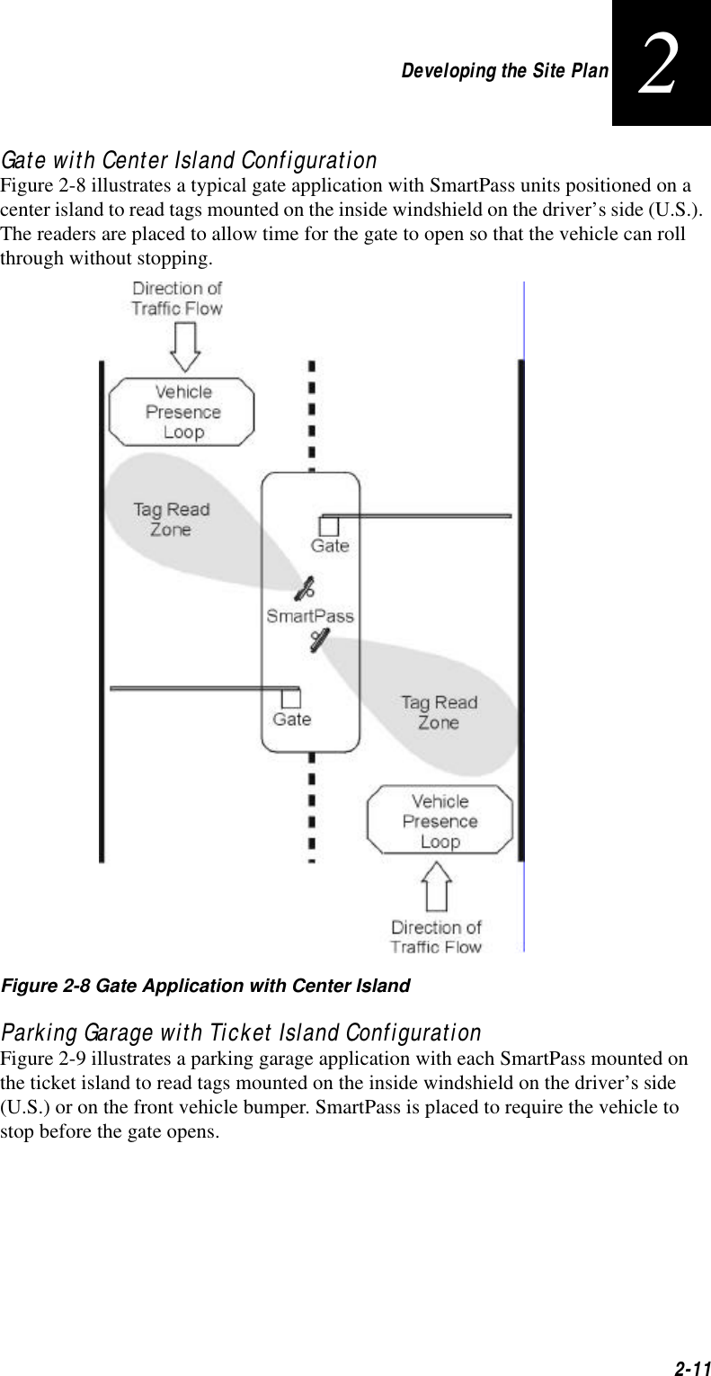
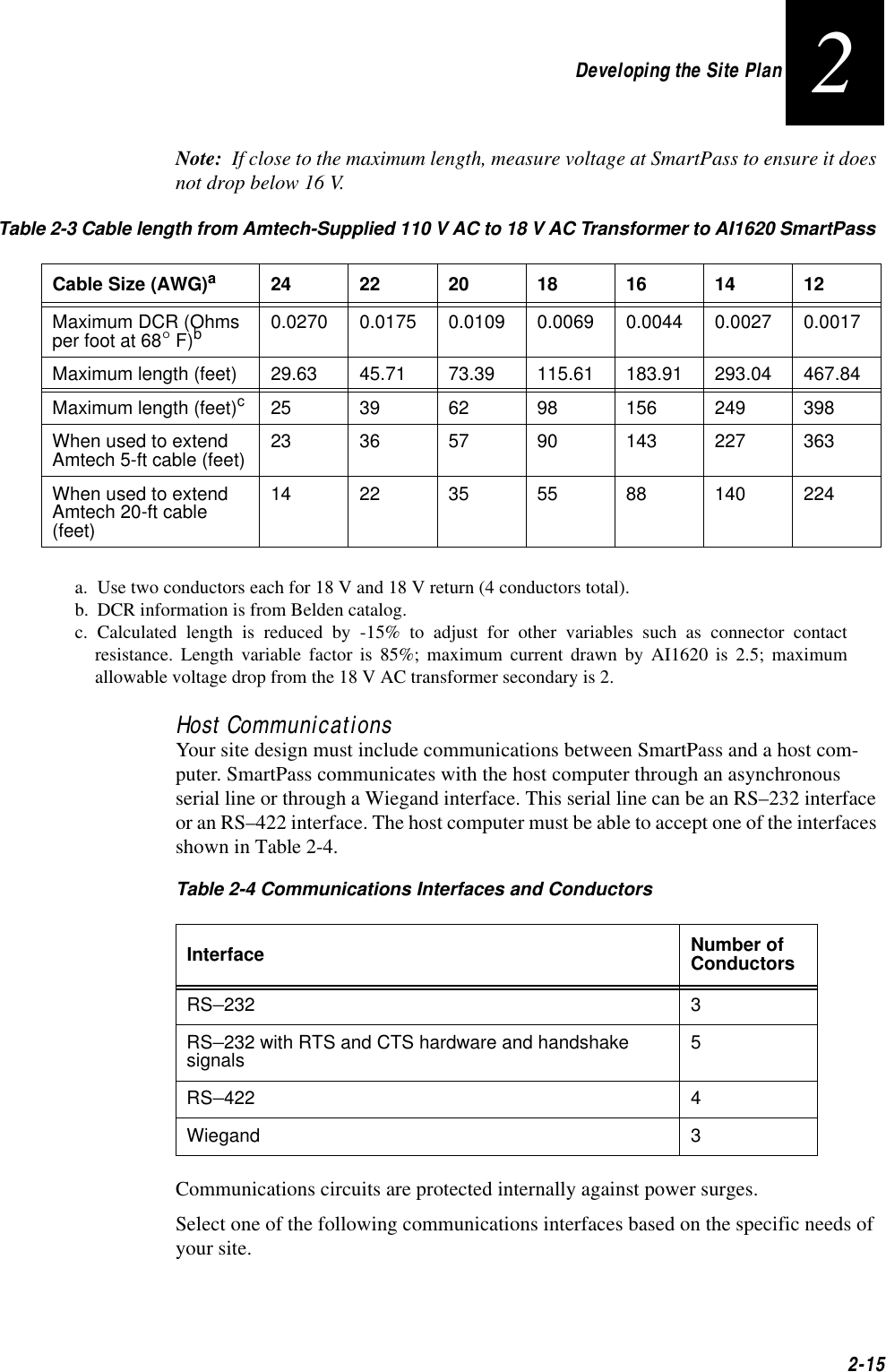
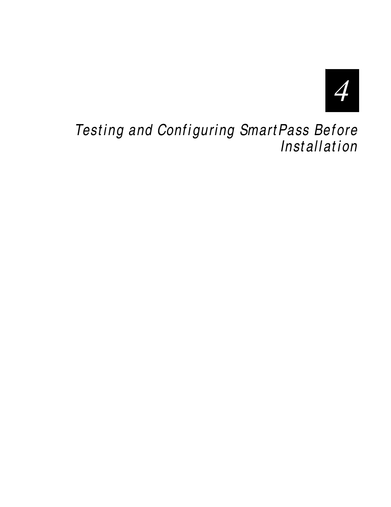
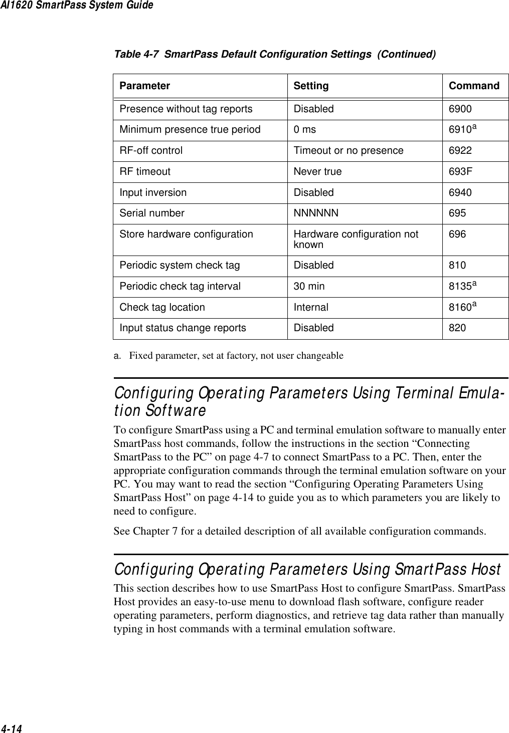
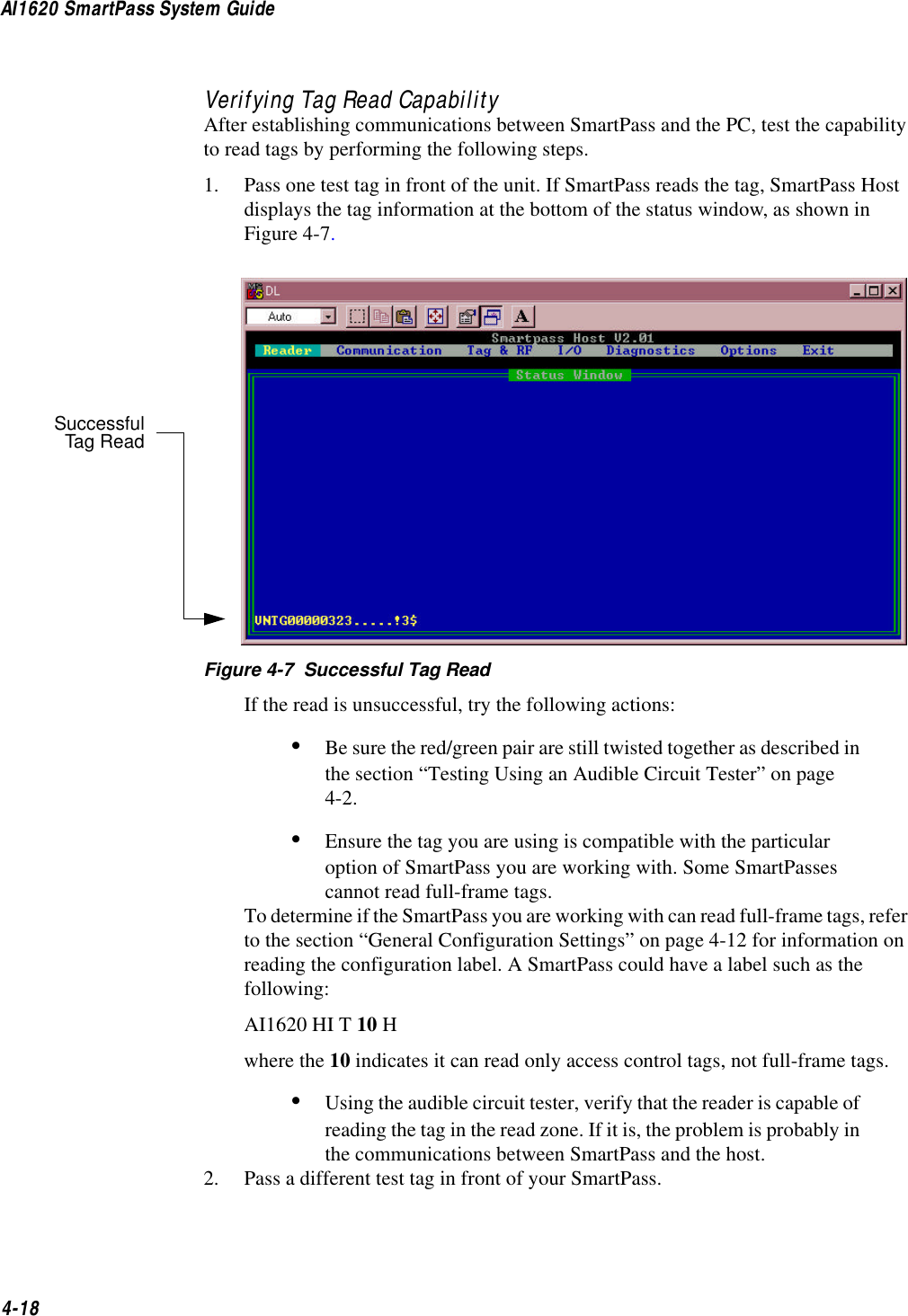
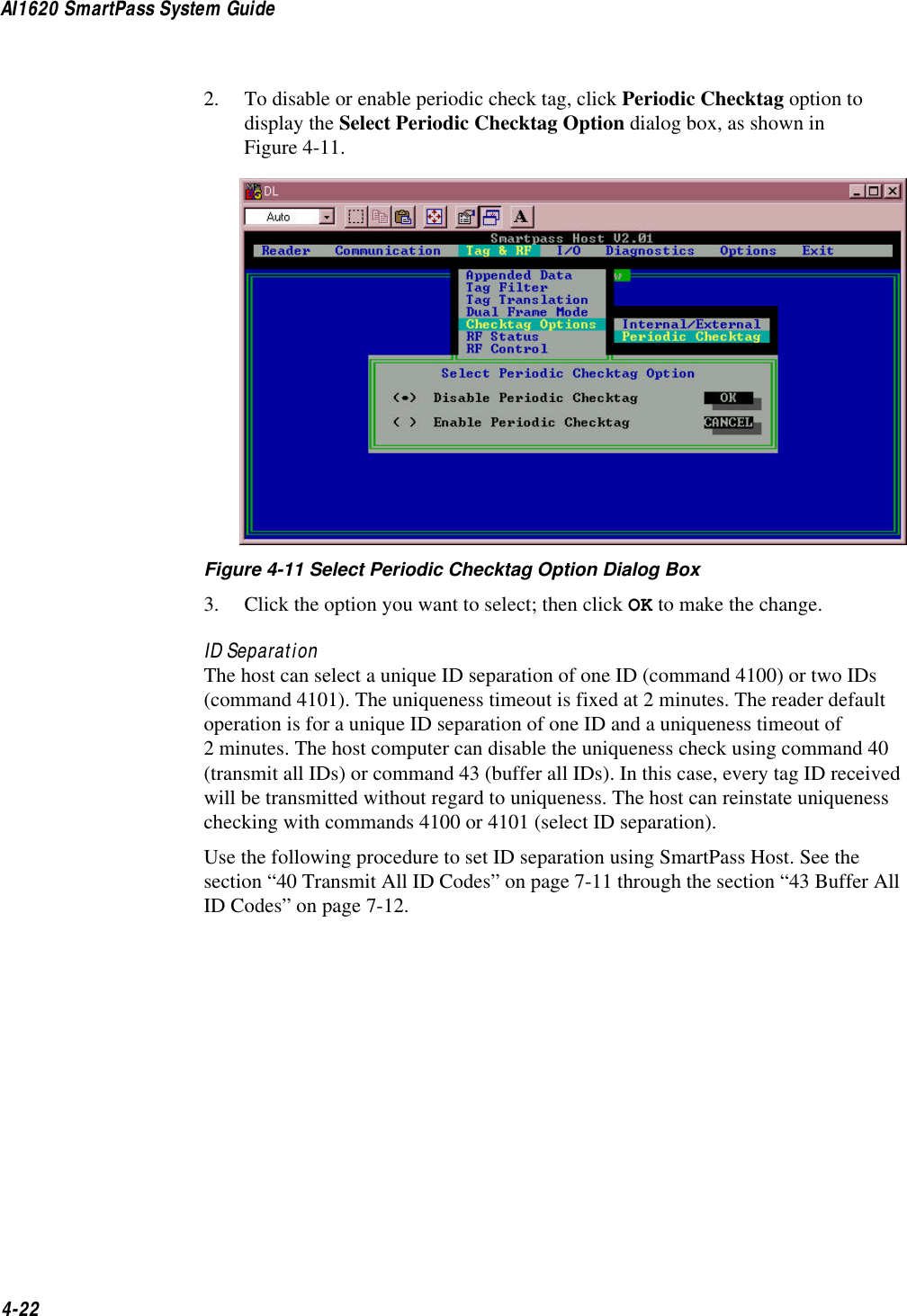
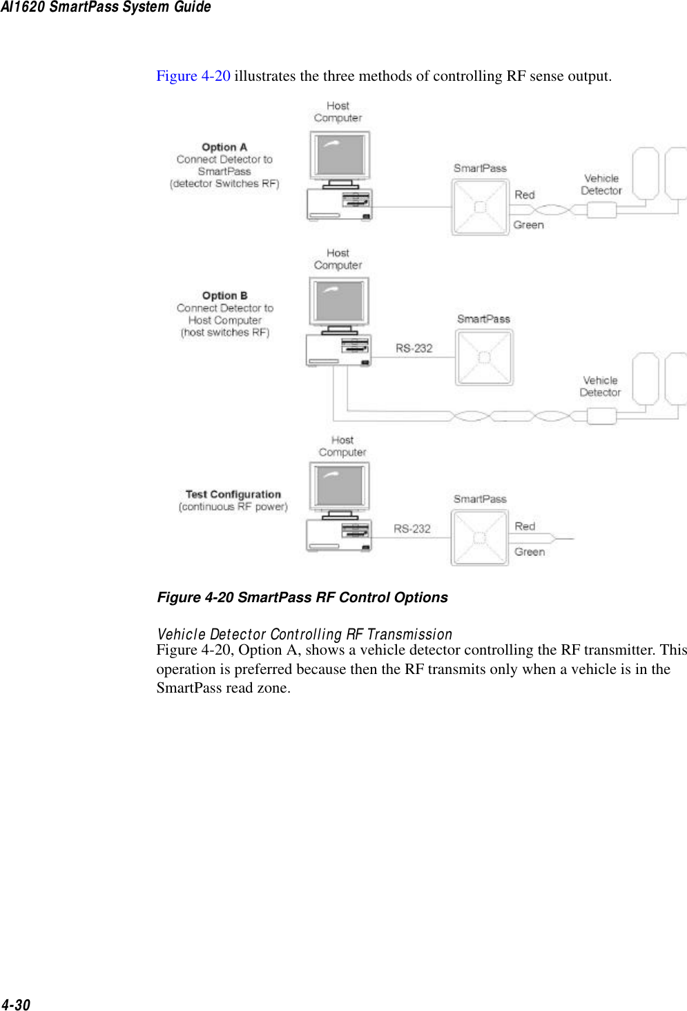
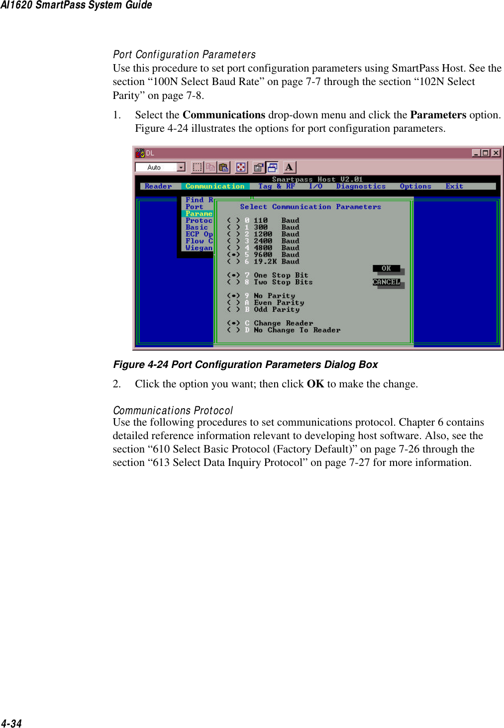
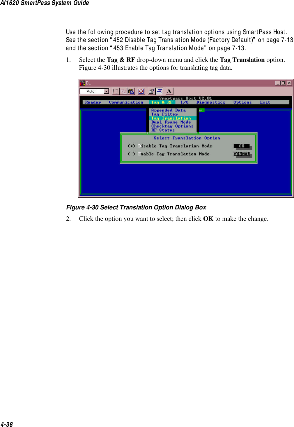
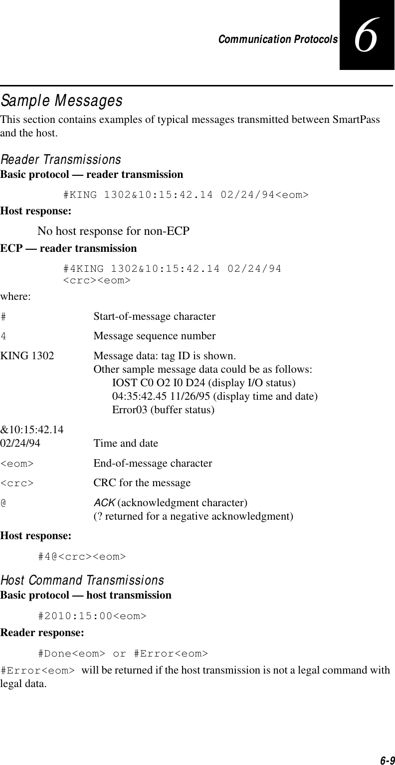
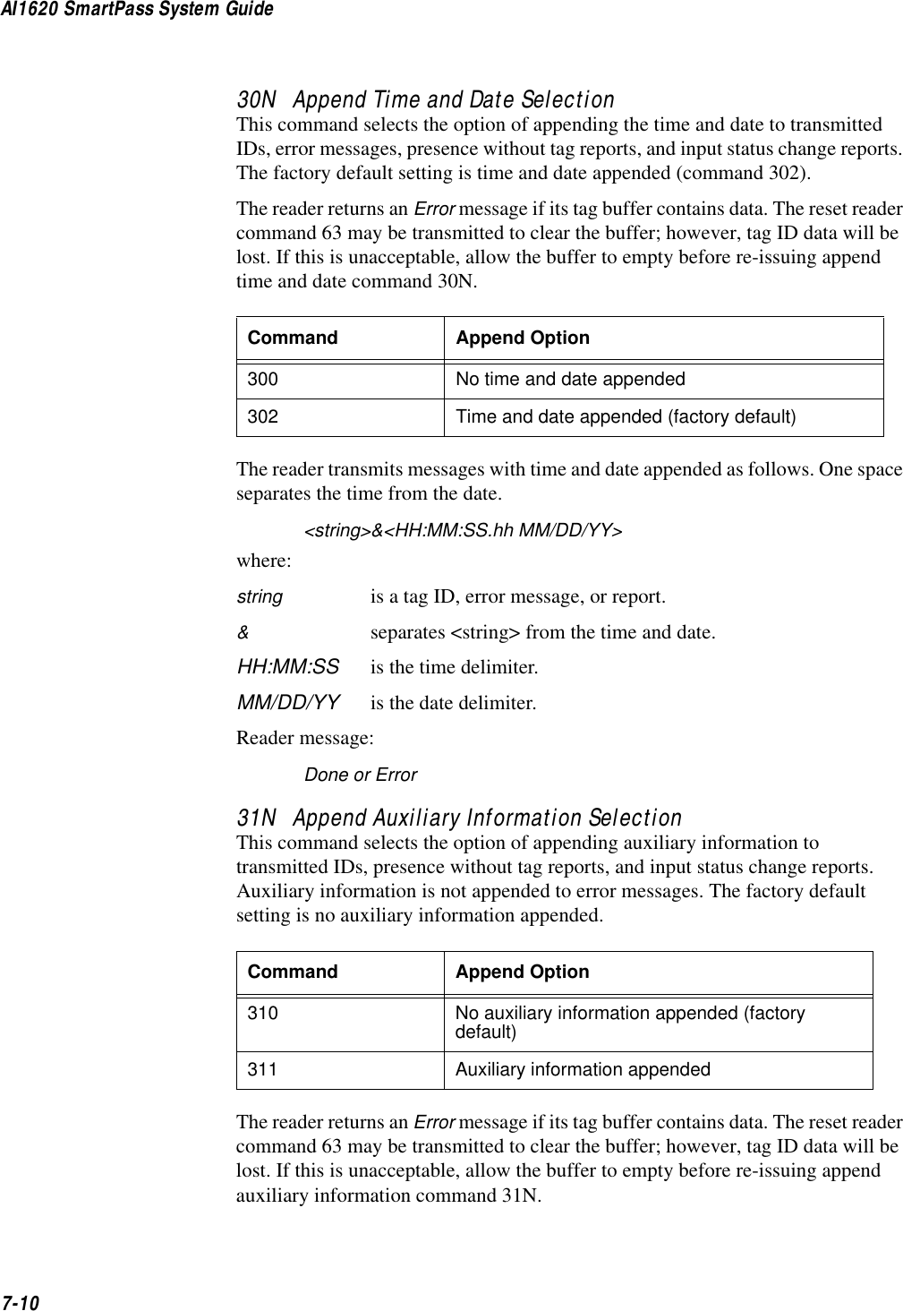
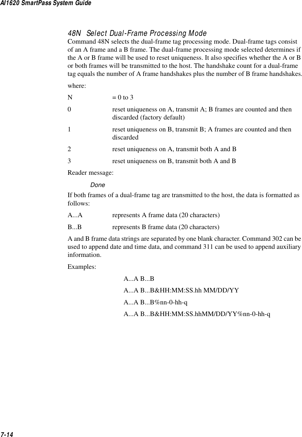
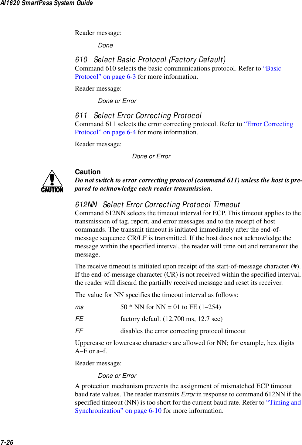
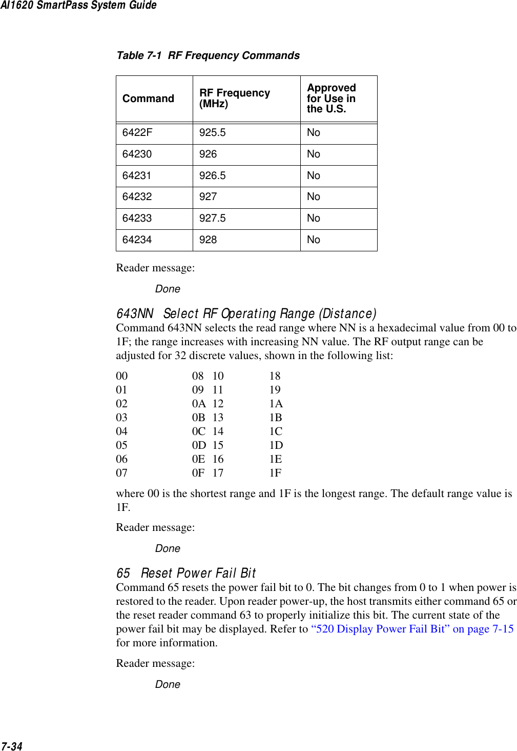
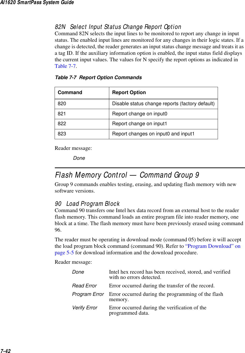
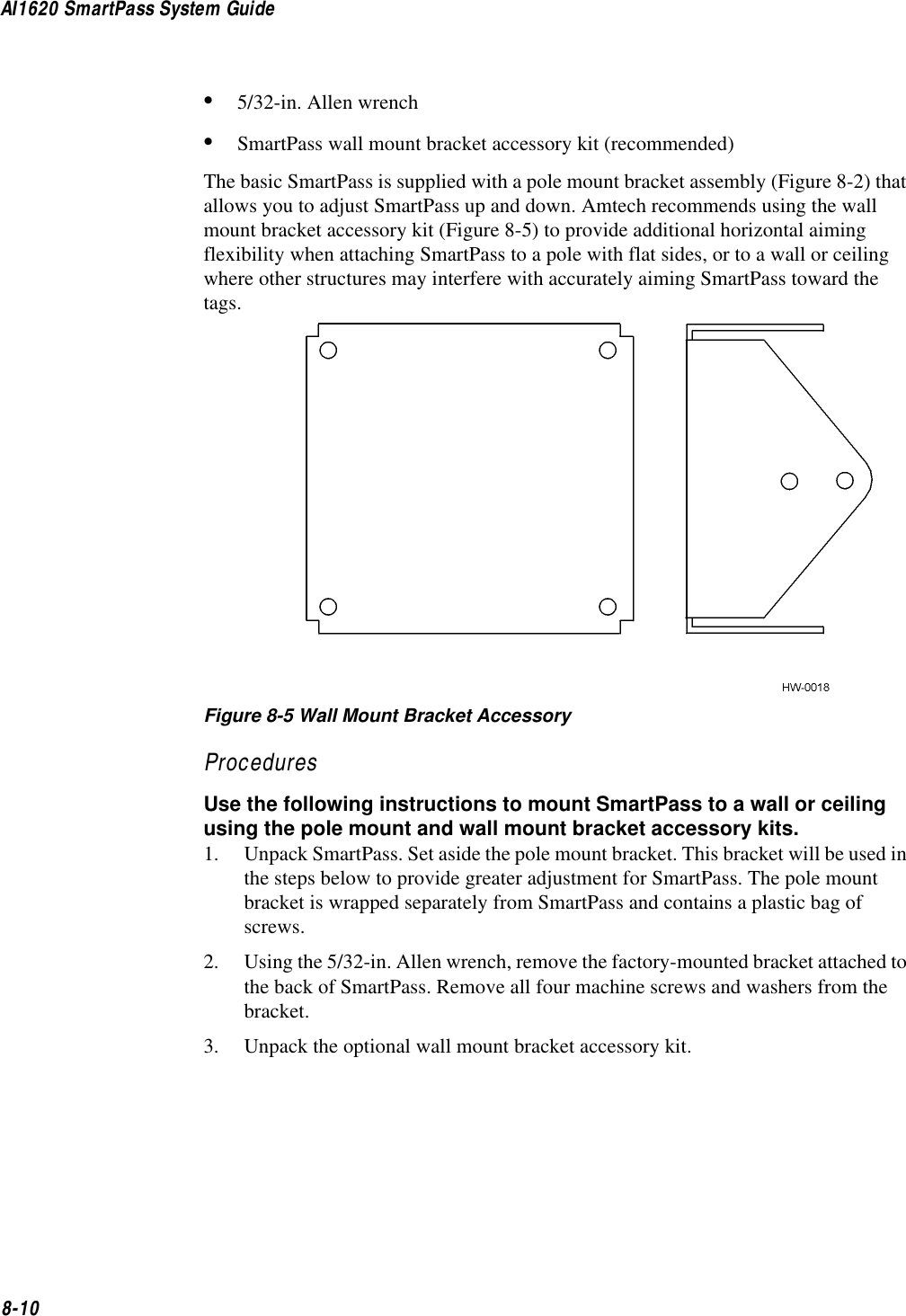
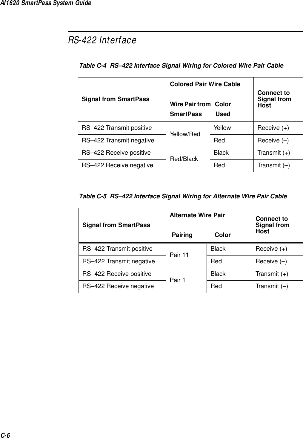
![Communication Protocols6-76When SmartPass receives an ACK message, the message is treated as having been properly received by the host. The sequence number is then incremented, and pointers are advanced to the next message in SmartPass’s message queue to prepare for sending the next message.Switch to Command Mode RequestThe host may issue command 01 (switch to command mode) while in data mode.The basic protocol format is shown below.<som><cmd><eom>The ECP format is shown below.<som><seq><cmd><crc><eom>where:<som> Start-of-message (ASCII # character)<seq> The sequence number is generated by the host computer separately from that appearing in data messages transmitted by SmartPass.<cmd> Switch to command mode, command number (ASCII characters 01)<crc> CRC for the message<eom> End-of-message character (ASCII CR)Host TransmissionThe host initiates synchronous communications between SmartPass and the host. The host begins a sequence by issuing a command; SmartPass will respond accordingly.The data inquiry protocol format is shown below.<CTRL-E>The basic protocol format is shown below.<som><cmd>[<data>]<eom>The ECP format is shown below.<som><seq><cmd>[<data>]<crc><eom>where:<CTRL-E> ASCII Control E (hex 5 digits). When in data inquiry mode, each transmission of a CTRL-E by the host causes SmartPass to transmit one tag ID.<som> Start-of-message (ASCII # character)](https://usermanual.wiki/TransCore/10-510-100.Exhibit-8-Users-Manual/User-Guide-75384-Page-105.png)
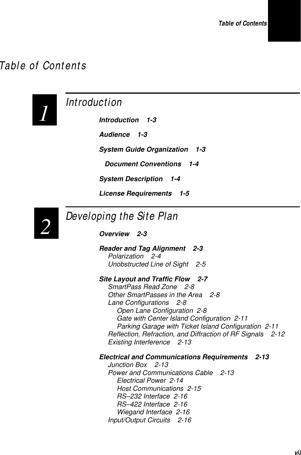
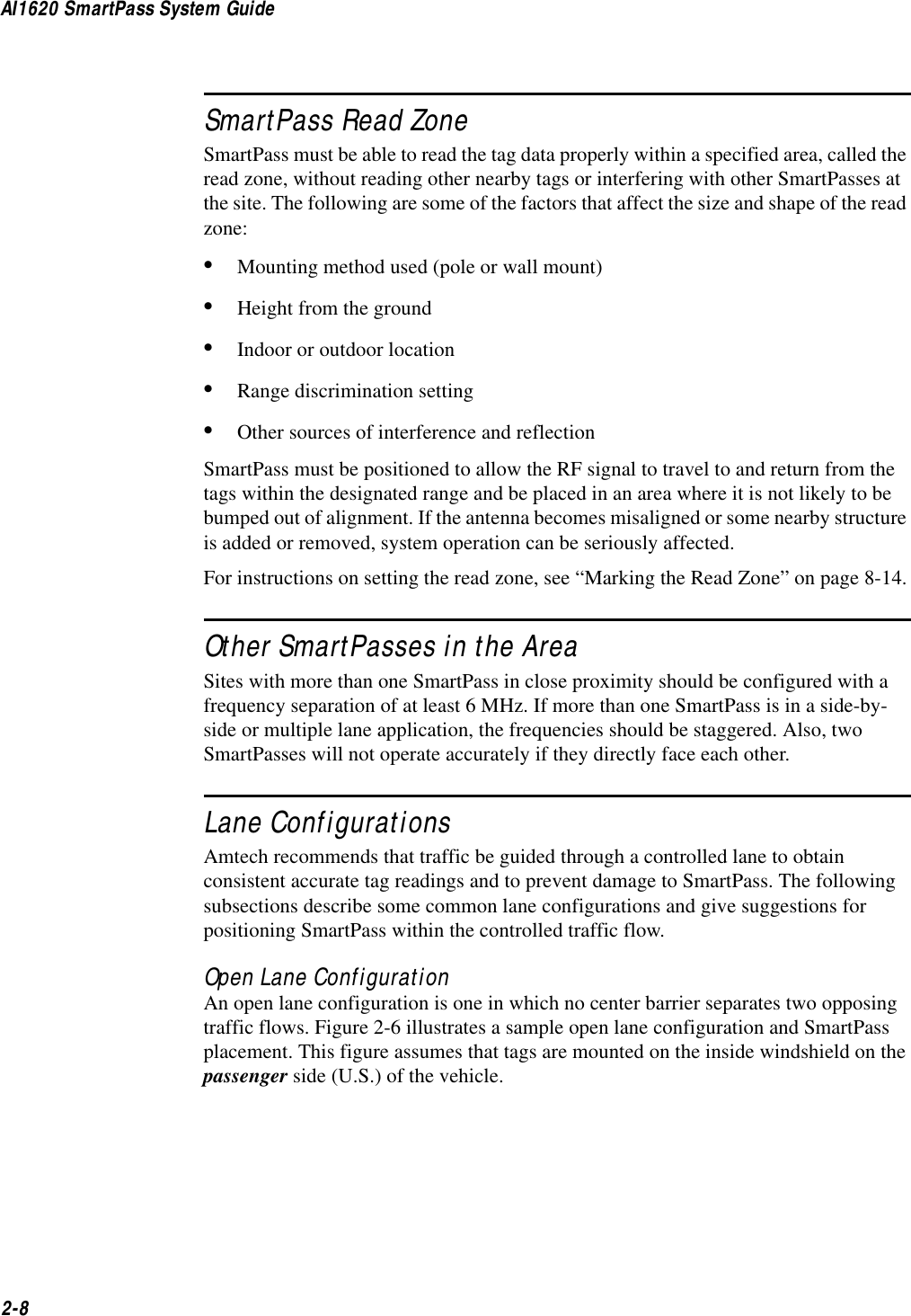
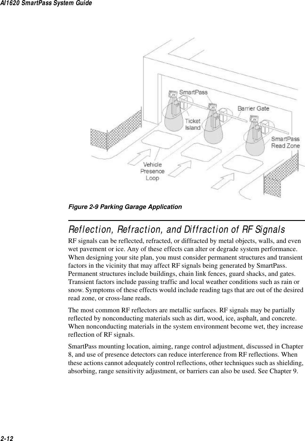
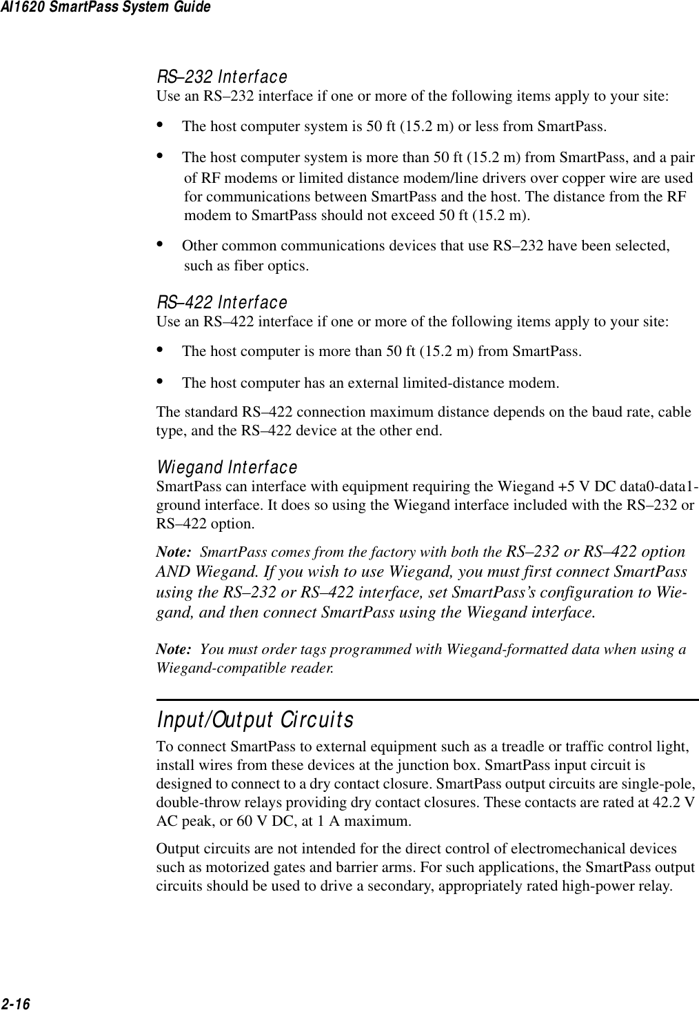
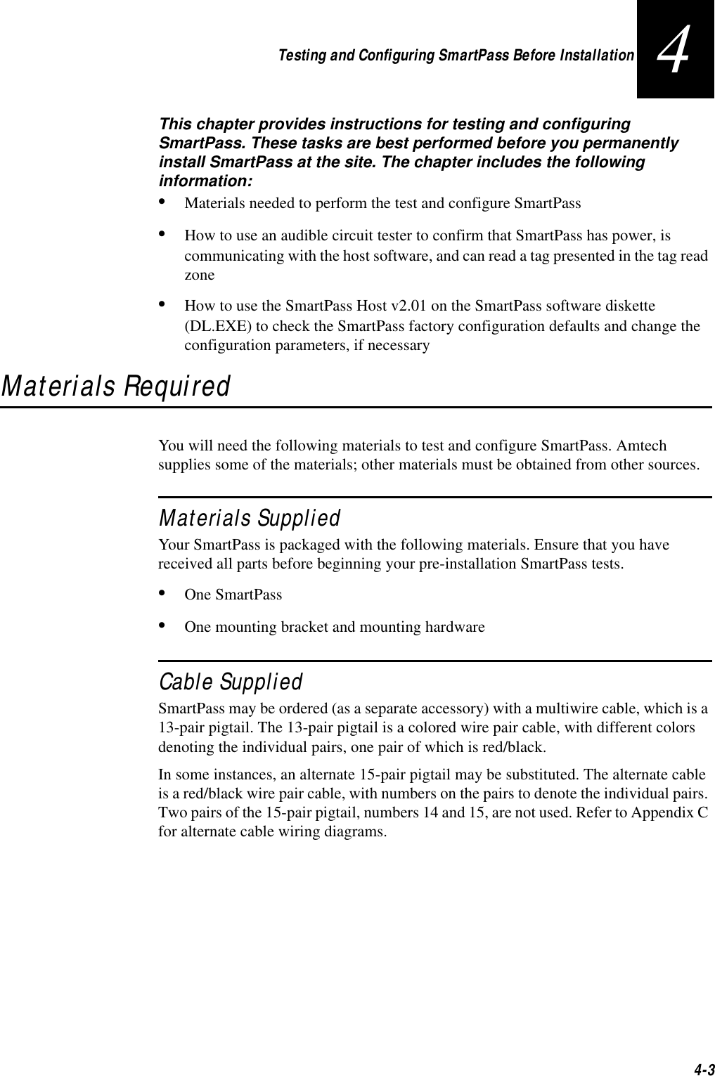
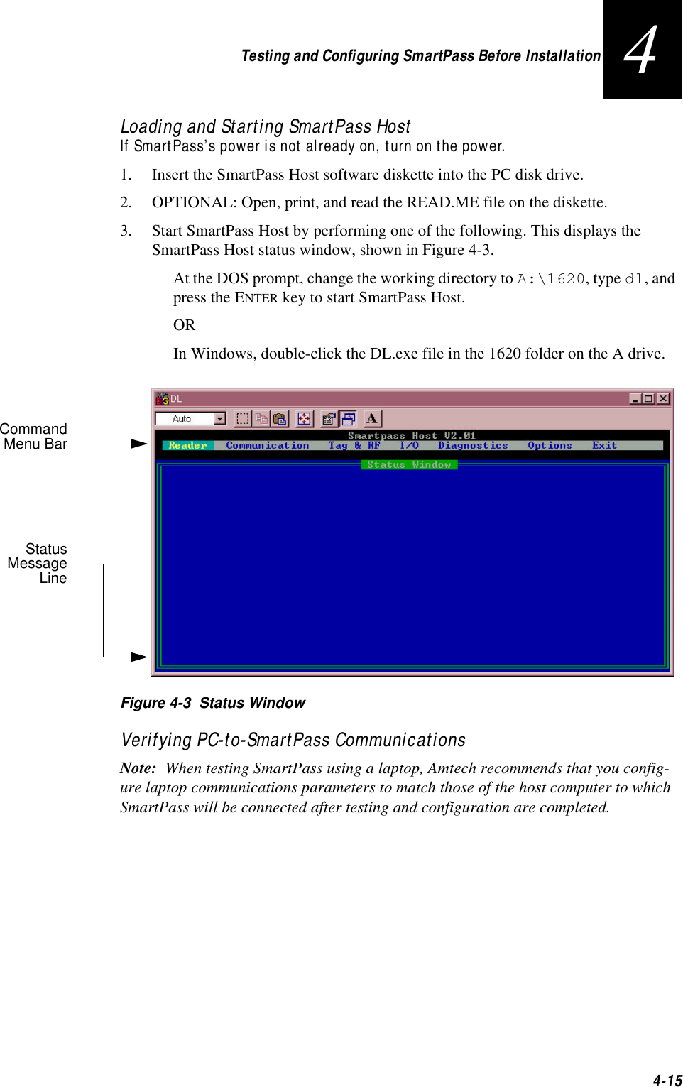
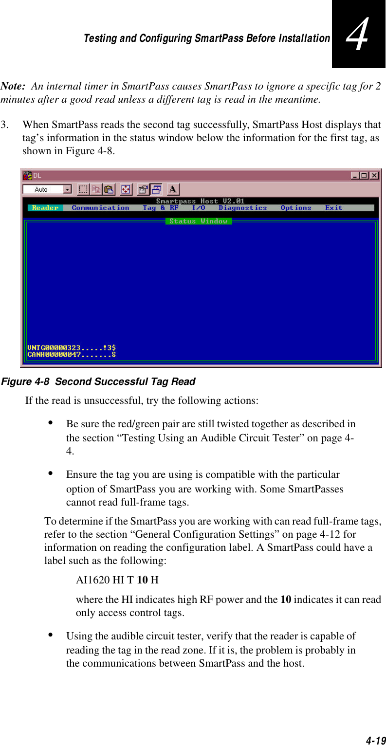
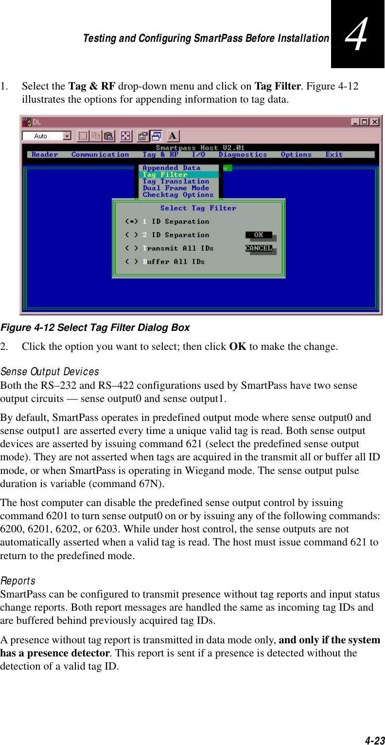
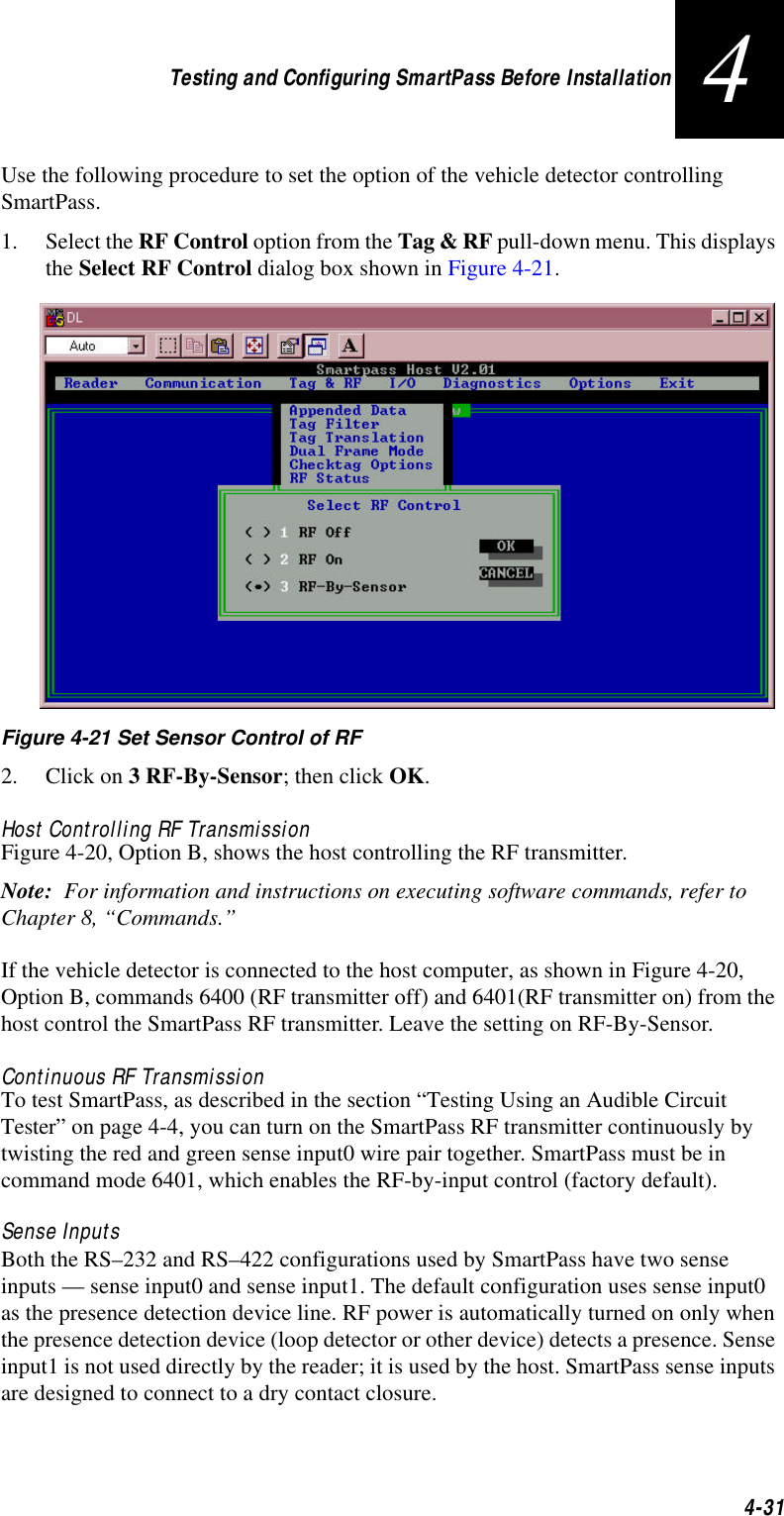
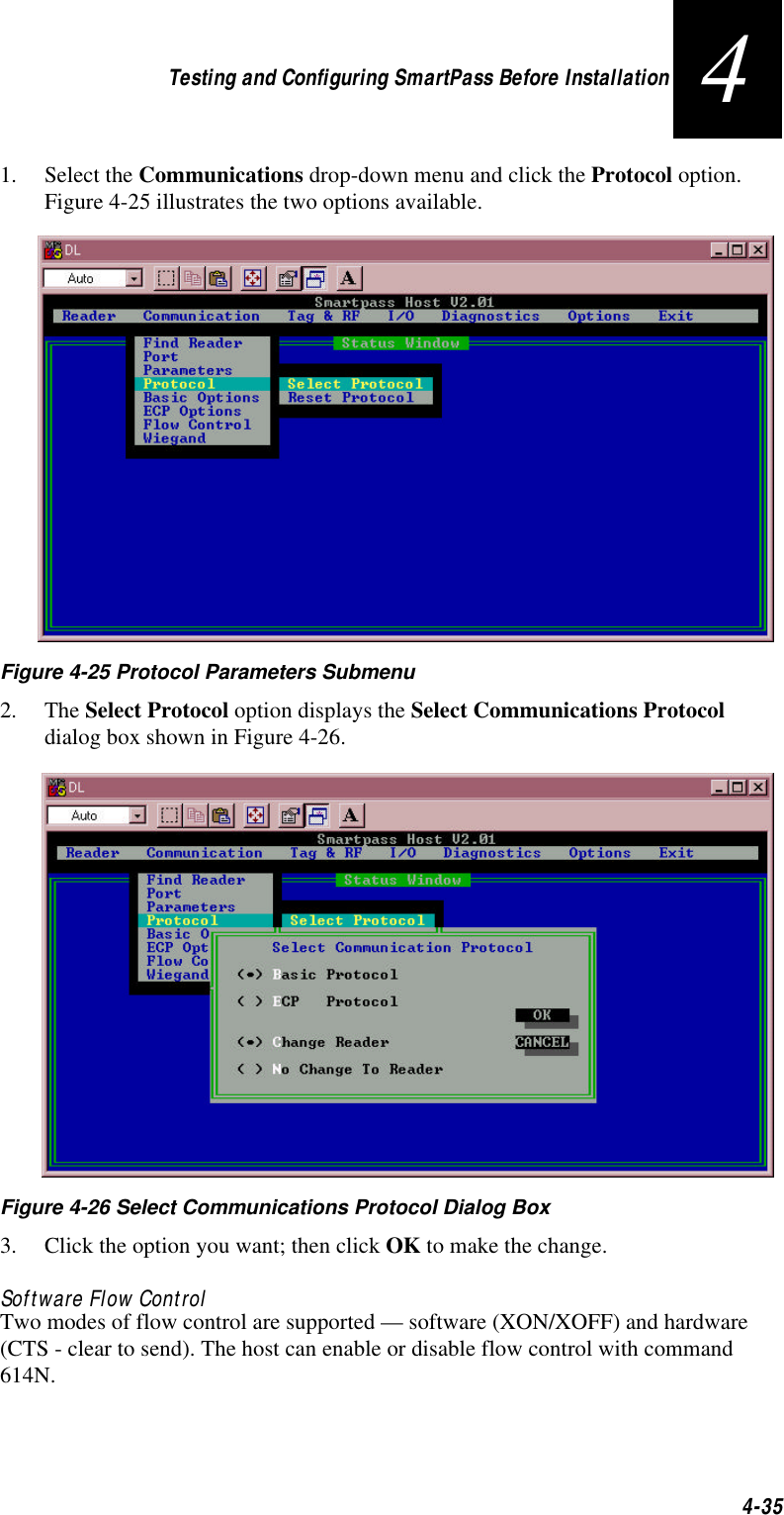
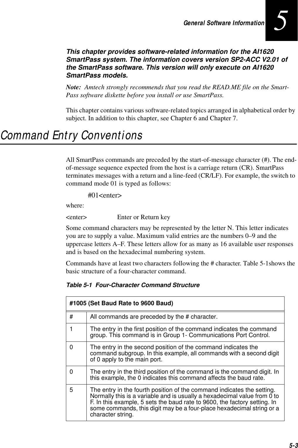
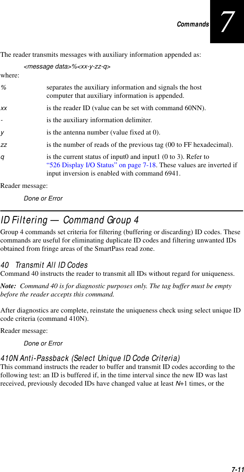
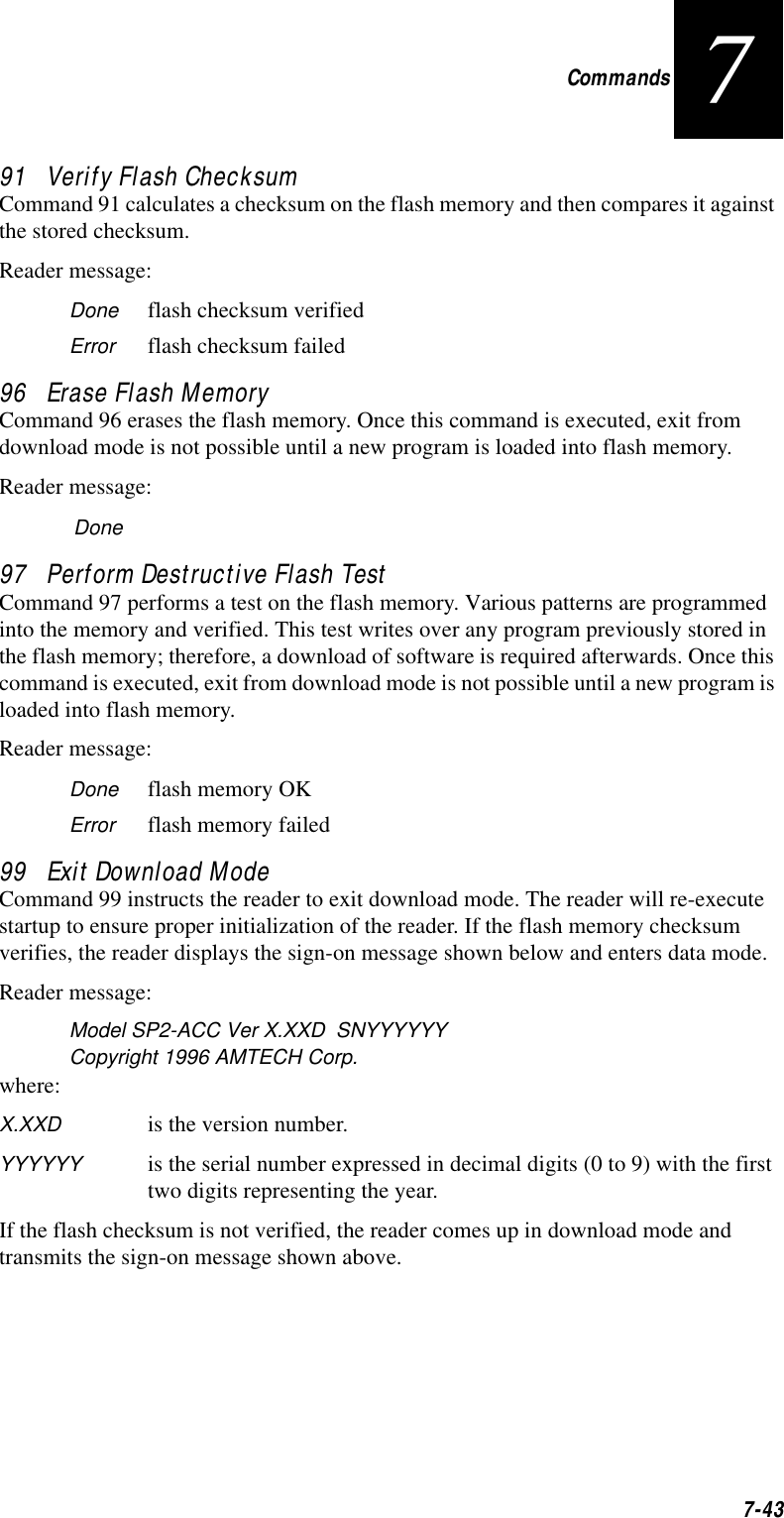
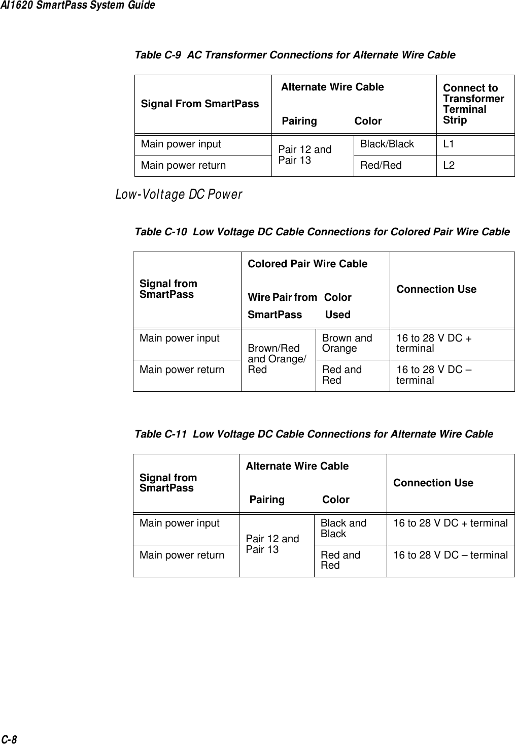
![AI1620 SmartPass System Guide6-8<seq> Sequence number (ASCII hex digit) that represents an odd number in the range 1–9, A–F. The host should use odd sequence numbers in its command because SmartPass uses even sequence numbers in its transmissions. This method eliminates the possibility of a synchronous host command and an asynchronous reader transmission having the same sequence number.Upon receiving a host command, SmartPass is expected to echo the command’s sequence number in its response. Therefore, the host must update its sequence number upon receipt of a valid reader message. If the sequence number is not updated before transmission of the next command, SmartPass will not service the new command; it will retransmit its previous message. A command/message sequence is not considered compete until the host updates its sequence number.<cmd> Command code, a string that contains from two to four ASCII hex characters[<data>] Optional data field, an ASCII string of as many as 20 characters in length. For example, the set date command is 21MM/DD/YY (command 21 followed by the data string MM/DD/YY).<crc> CRC for the message<eom> End-of-message character (ASCII CR)Reader Command ResponseThe basic protocol format is shown below.<som><resp><eom>The ECP format is shown below.<som><seq><resp><crc><eom>where:<som> Start-of-message (ASCII # character)<seq> Echo of sequence number received in host command message<resp> Response string. SmartPass will return Done, Error, or another ASCII string depending on the host transmission. This string can be as many as 72 characters long.<crc> CRC for the message<eom> End-of-message character (ASCII CR and LF)](https://usermanual.wiki/TransCore/10-510-100.Exhibit-8-Users-Manual/User-Guide-75384-Page-106.png)
![AI1620 SmartPass System Guide6-10ECP — host transmission#72010:15:00<crc><eom>where:#Start-of-message character7Message sequence number20 Set time command10:15:00Set time data (Not all commands include data. For example, Turn RF off host transmission is #7640<eom> where 640 is the command number.)<crc> CRC for the message<eom> End-of-message characterDone Command has been invoked by SmartPass.Reader response:#7Done<crc><eom> or #7Error<eom>For some commands, SmartPass will respond with data that relates to the command, such as TT 1, to indicate tag translation enabled for a 534 display tag translation mode command.#7Error<eom> will be returned if host transmission is not a legal command with legal data.Timing and SynchronizationThe ECP is largely independent of baud rate. The timeout delays previously described are a function of baud rate.SmartPass supports an ECP timeout, which applies equally to both transmit and receive. In addition, a protection mechanism has been implemented for SmartPass that prevents the assignment of mismatched ECP timeout and baud rate values. SmartPass will not allow the host to alter the ECP timeout (command 612NN) if the specified timeout is too short for the current baud rate. Conversely, SmartPass will not allow the host to alter the baud rate (command 100N) if the specified baud rate is too fast for the current ECP timeout.The receiver’s minimum timeout delay should equal the time to transmit/receive the longest anticipated message at the current baud rate setting. Additional margin should be included for idle periods between characters; for example, processing overhead, if any. The timeout delay period can be expressed as follows:Τrec (ms) = L x [Τchar + Τidle]where:Τchar (ms) 1000 x [ Bc / Rb ]BcBits per character (typically 10)](https://usermanual.wiki/TransCore/10-510-100.Exhibit-8-Users-Manual/User-Guide-75384-Page-108.png)
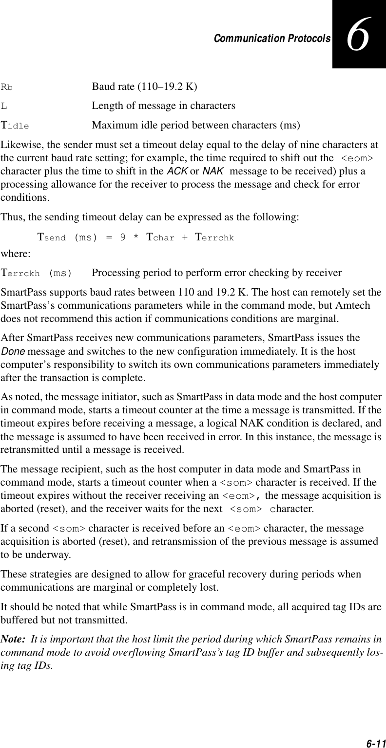
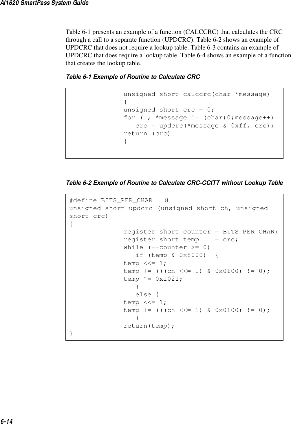
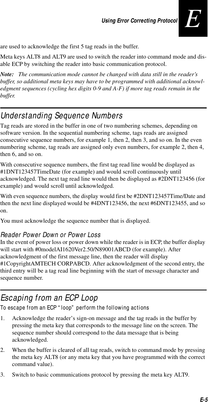
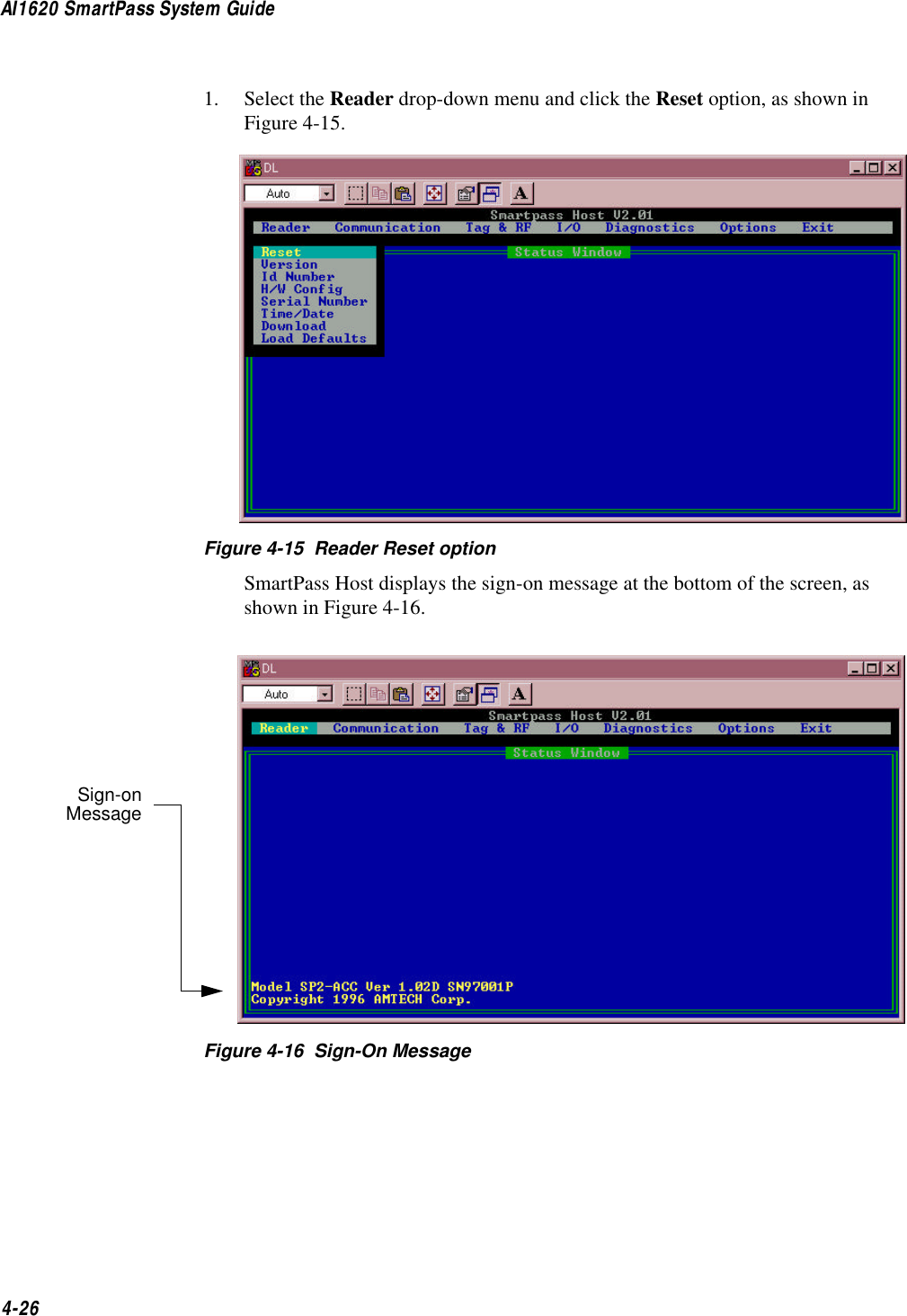
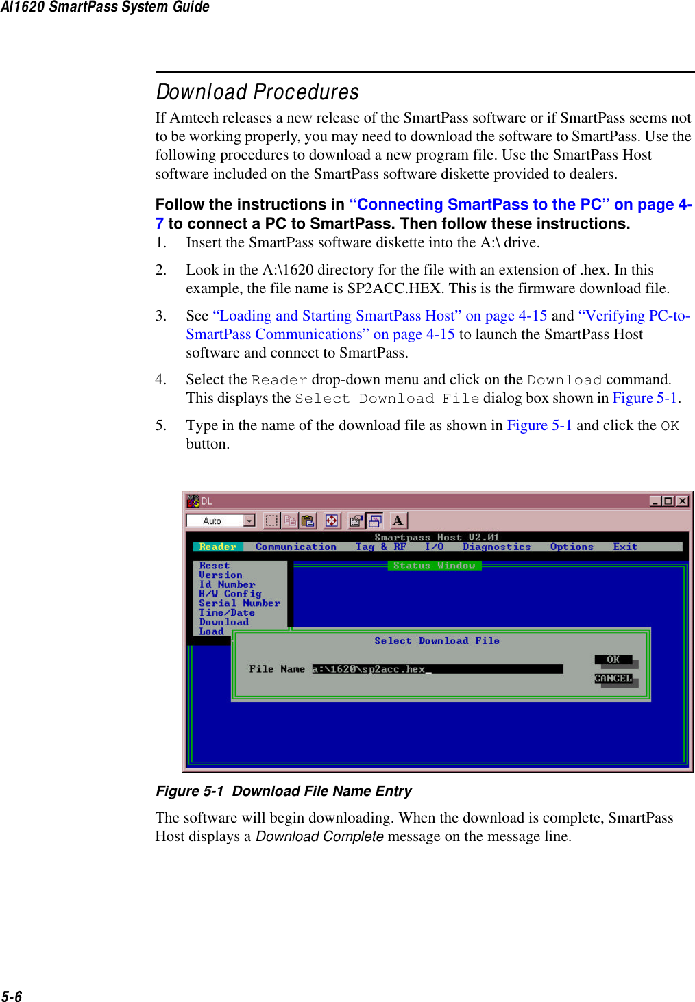
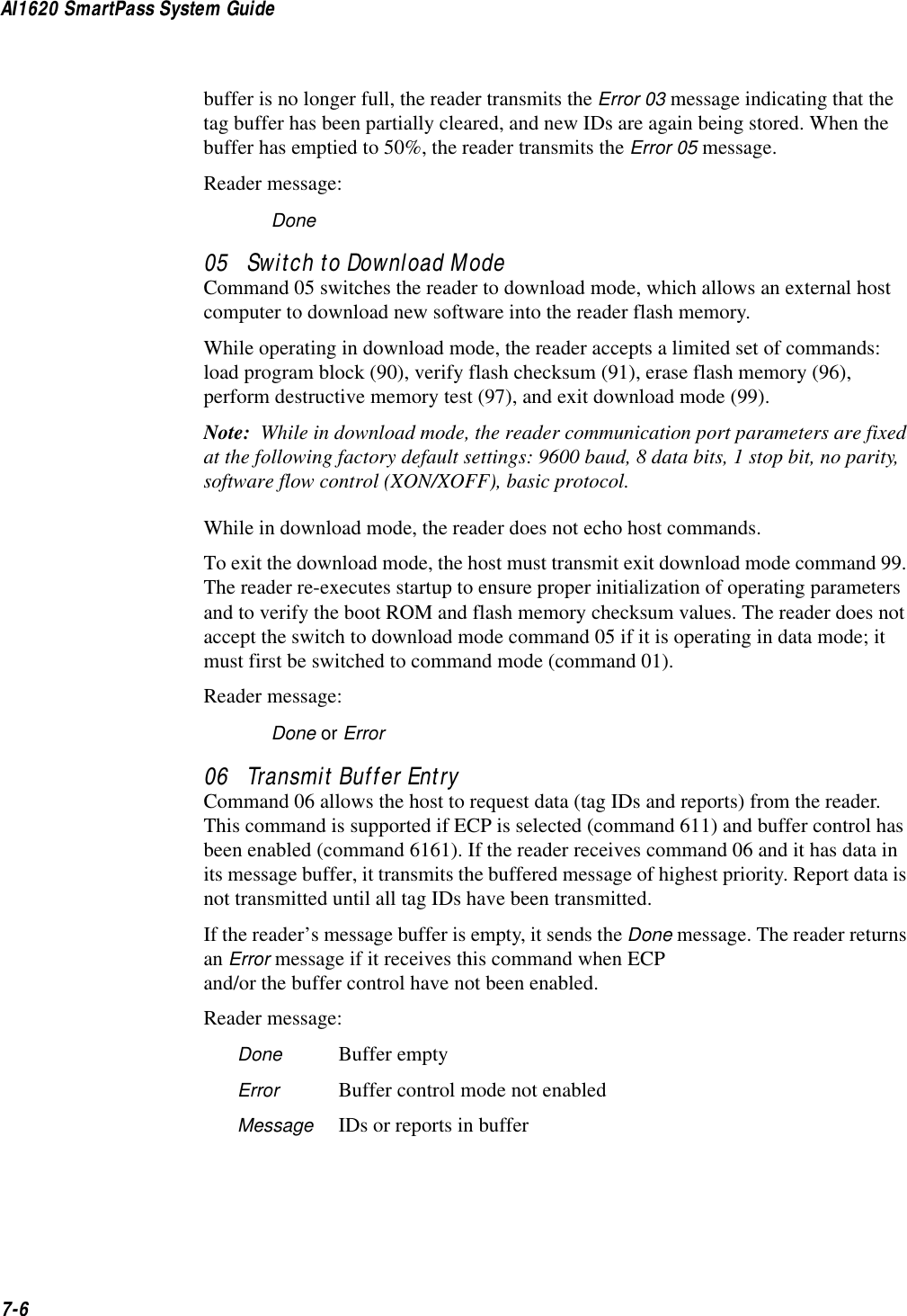
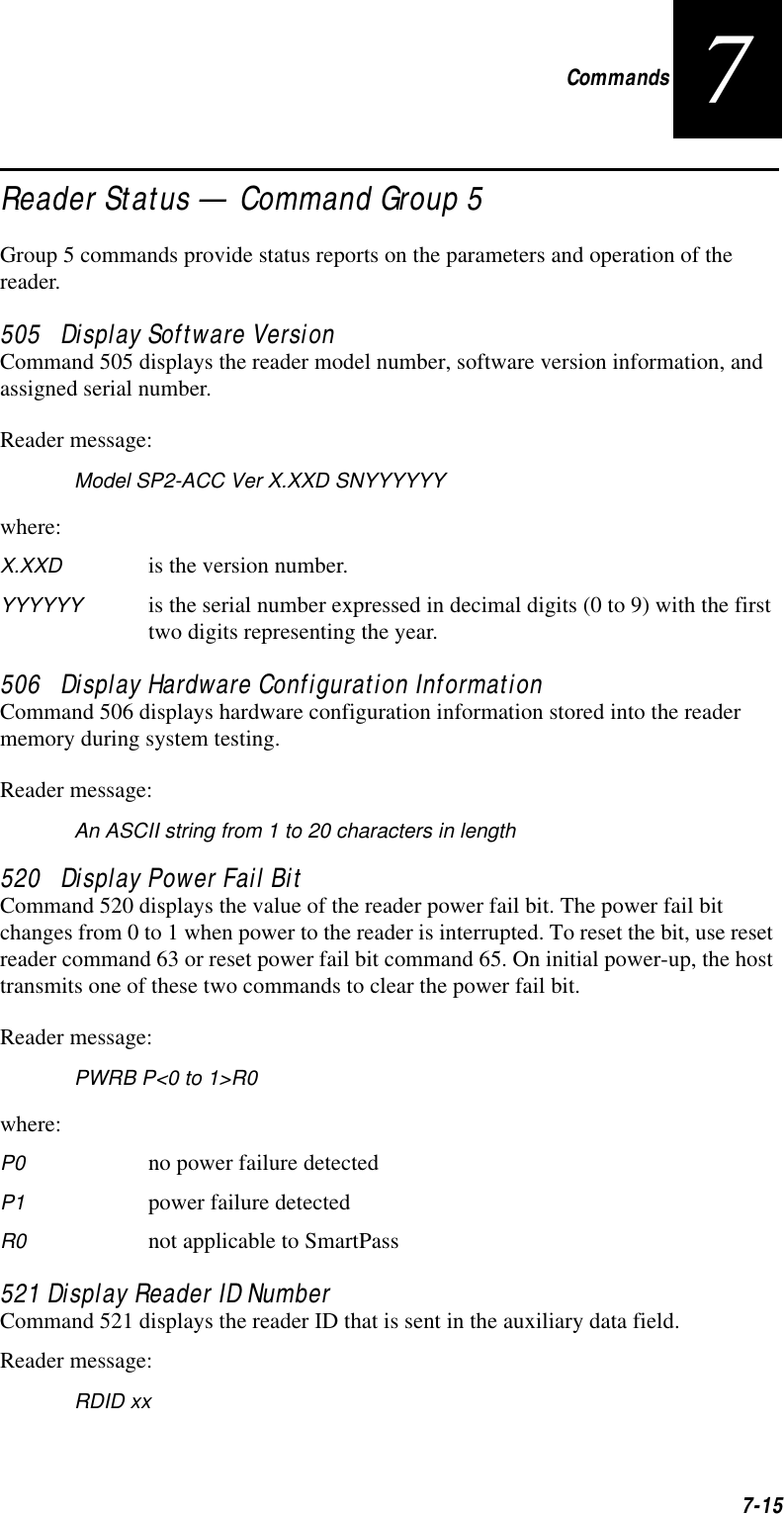
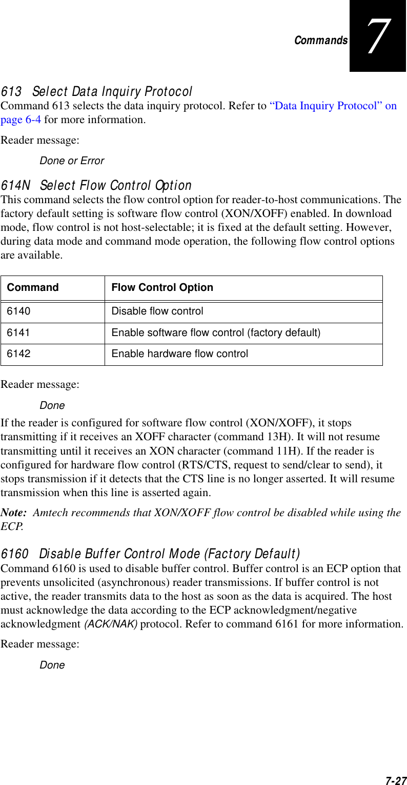
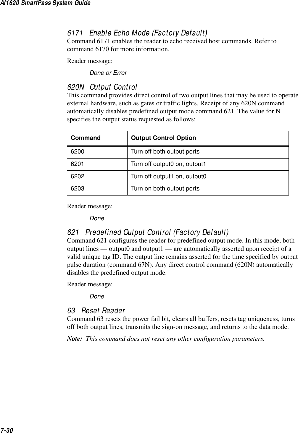
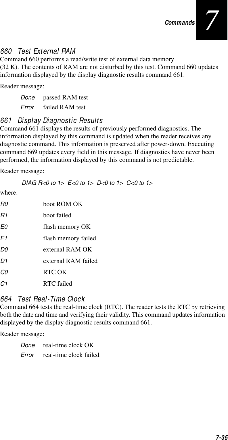
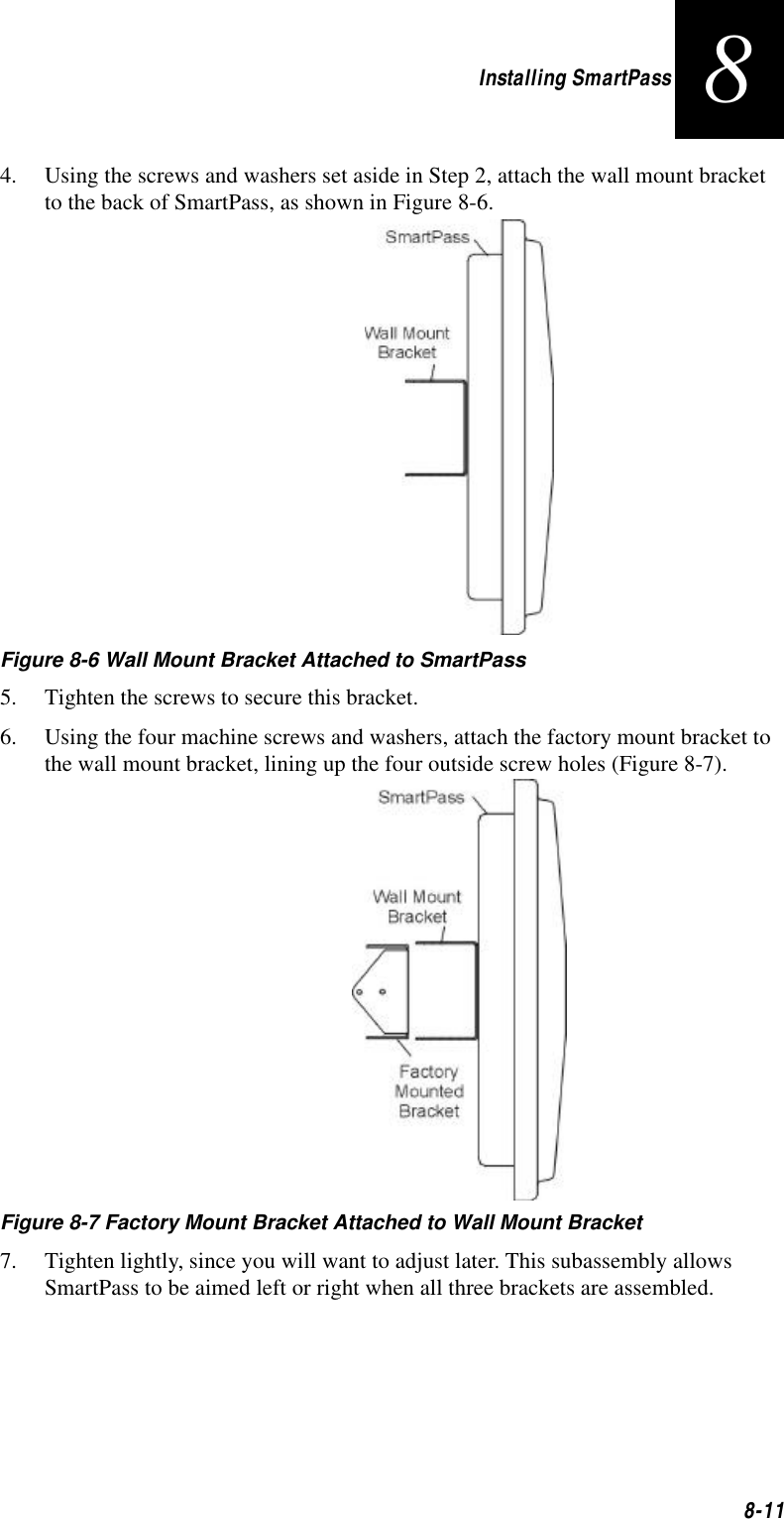
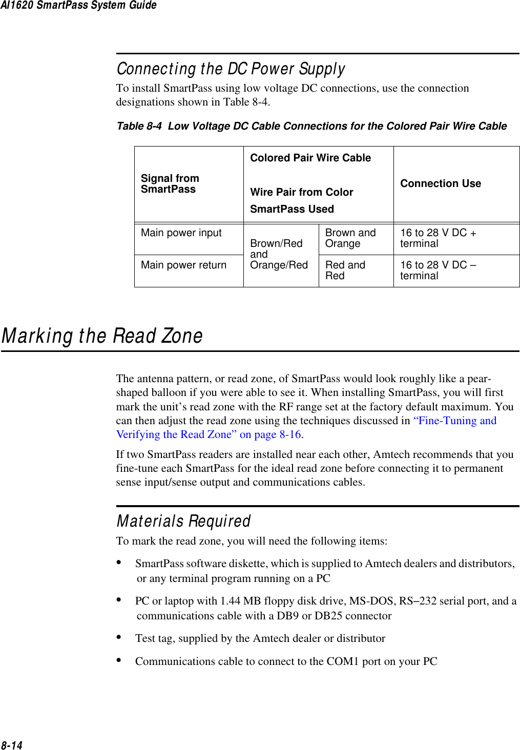
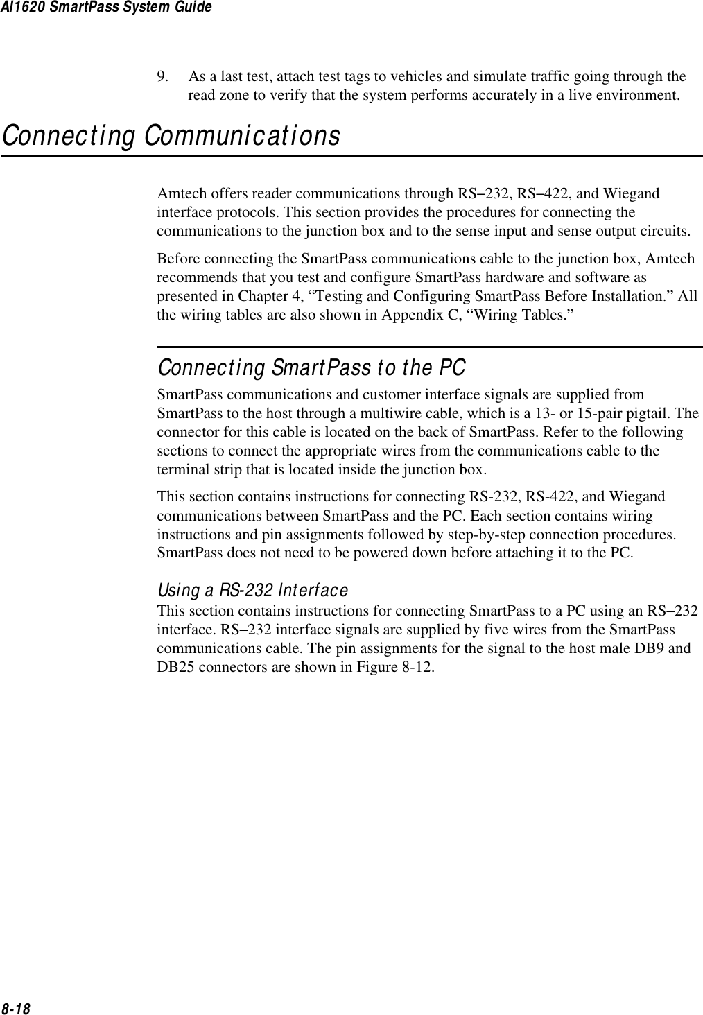
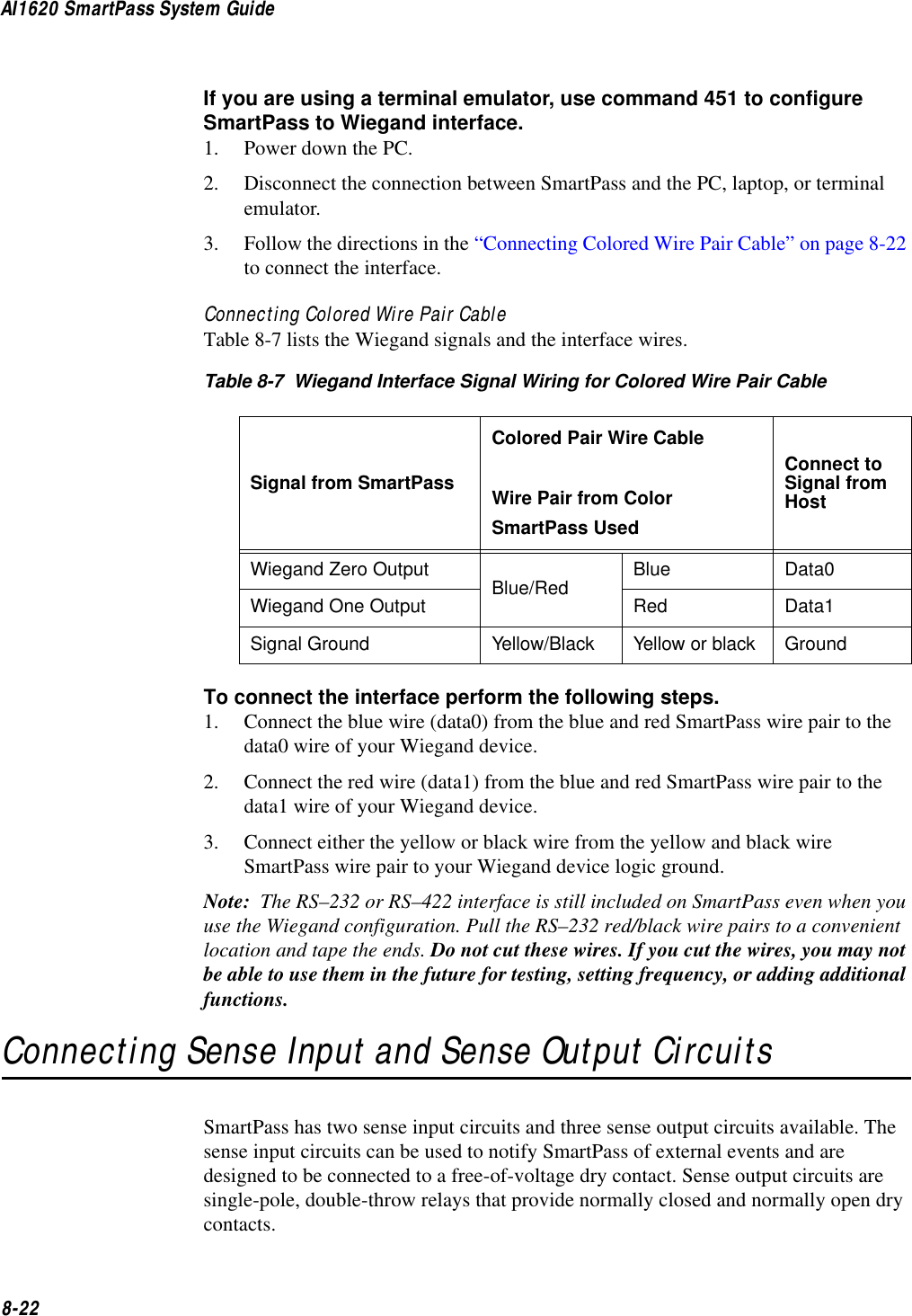
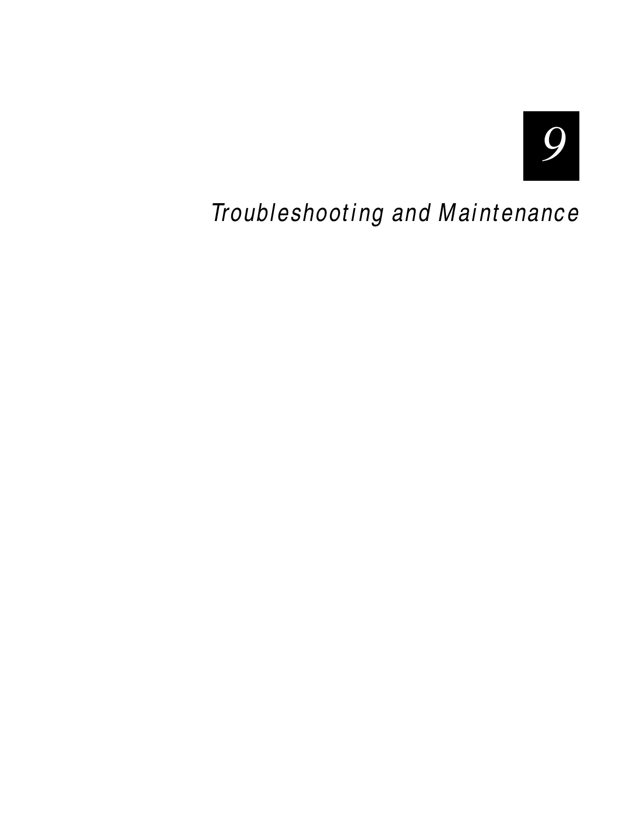
![Communication Protocols6-156Table 6-3 Example of Routine to Calculate CCITT-CRC with Lookup Table#define updcrc(cp, crc)( crctab[((crc >> 8) & 255)]^ (crc << 8) ^ cpstatic unsigned short crctab [256] = {0x0000, 0x1021, 0x2042, 0x3063, 0x4048, 0x50a5, 0x60c6, 0x70e7,0x8108, 0x9129, 0xa14a, 0xb16b, 0xc18c, 0xd1ad, 0xe1ce, 0xf1ef,0x1231, 0x0210, 0x3273, 0x2252, 0x52b5, 0x4294, 0x72f7, 0x62d6,0x9339, 0x8318, 0xb37b, 0xa35a, 0xd3bd, 0xc39c, 0xf3ff, 0xe3de,0x2462, 0x3443, 0x0420, 0x1401, 0x64e6, 0x74c7, 0x44a4, 0x5485,0xa56a, 0xb54b, 0x8528, 0x9509, 0xe5ee, 0xf5cf, 0xc5ac, 0xd58d,0x3653, 0x2672, 0x1611, 0x0630, 0x76d7, 0x66f6, 0x5695, 0x46b4,0xb75b, 0xa77a, 0x9719, 0x8738, 0xf7df, 0xe7fe, 0xd79d, 0xc7bc,0x48c4, 0x58e5, 0x6886, 0x78a7, 0x0840, 0x1861, 0x2802, 0x3823,0xc9cc, 0xd9ed, 0xe98e, 0xf9af, 0x8948, 0x9969, 0xa90a, 0xb92b,0x5af5, 0x4ad4, 0x7ab7, 0x6a96, 0x1a71, 0x0a50, 0x3a33, 0x2a12,0xdbfd, 0xcbdc, 0xfbbf, 0xeb9e, 0x9b79, 0x8b58, 0xbb3b, 0xab1a,0x6ca6, 0x7c87, 0x4ce4, 0x5cc5, 0x2c22, 0x3c03, 0x0c60, 0x1c41,0xedae, 0xfd8f, 0xcdec, 0xddcd, 0xad2a, 0xbd0b, 0x8d68, 0x9d49,0x7e97, 0x6eb6, 0x5ed5, 0x4ef4, 0x3e13, 0x2e32, 0x1e51, 0x0e70,0xff9f, 0xefbe, 0xdfdd, 0xcffc, 0xbf1b, 0xaf3a, 0x9f59, 0x8f78,0x9188, 0x81a9, 0xb1ca, 0xa1eb, 0xd10c, 0xc12d, 0xf14e, 0xe16f,0x1080, 0x00a1, 0x30c2, 0x20e3, 0x5004, 0x4025, 0x7046, 0x6067,0x83b9, 0x9398, 0xa3fb, 0xb3da, 0xc33d, 0xd31c, 0xe37f, 0xf35e,0x02b1, 0x1290, 0x22f3, 0x32d2, 0x4235, 0x5214, 0x6277, 0x7256,0xb5ea, 0xa5cb, 0x95a8, 0x8589, 0xf56e, 0xe54f, 0xd52c, 0xc50d,0x34e2, 0x24c3, 0x14a0, 0x0481, 0x7466, 0x6447, 0x5424, 0x4405,0xa7db, 0xb7fa, 0x8799, 0x97b8, 0xe75f, 0xf77e, 0xc71d, 0xd73c,0x26d3, 0x36f2, 0x0691, 0x16b0, 0x6657, 0x7676, 0x4615, 0x5634,0xd94c, 0xc96d, 0xf90e, 0xe92f, 0x99c8, 0x89e9, 0xb98a, 0xa9ab,0x5844, 0x4865, 0x7806, 0x6827, 0x18c0, 0x08e1, 0x3882, 0x28a3,0xcb7d, 0xdb5c, 0xeb3f, 0xfb1e, 0x8bf9, 0x9bd8, 0xabbb, 0xbb9a,0x4a75, 0x5a54, 0x6a37, 0x7a16, 0x0af1, 0x1ad0, 0x2ab3, 0x3a92,0xfd2e, 0xed0f, 0xdd6c, 0xcd4d, 0xbdaa, 0xad8b, 0x9de8, 0x8dc9,0x7c26, 0x6c07, 0x5c64, 0x4c45, 0x3ca2, 0x2c83, 0x1ce0, 0x0cc1,0xef1f, 0xff3e, 0xcf5d, 0xdf7c, 0xaf9b, 0xbfba, 0x8fd9, 0x9ff8,0x6e17, 0x7e36, 0x4e55, 0x5e74, 0x2e93, 0x3eb2, 0x0ed1, 0x1ef0,};](https://usermanual.wiki/TransCore/10-510-100.Exhibit-8-Users-Manual/User-Guide-75384-Page-113.png)
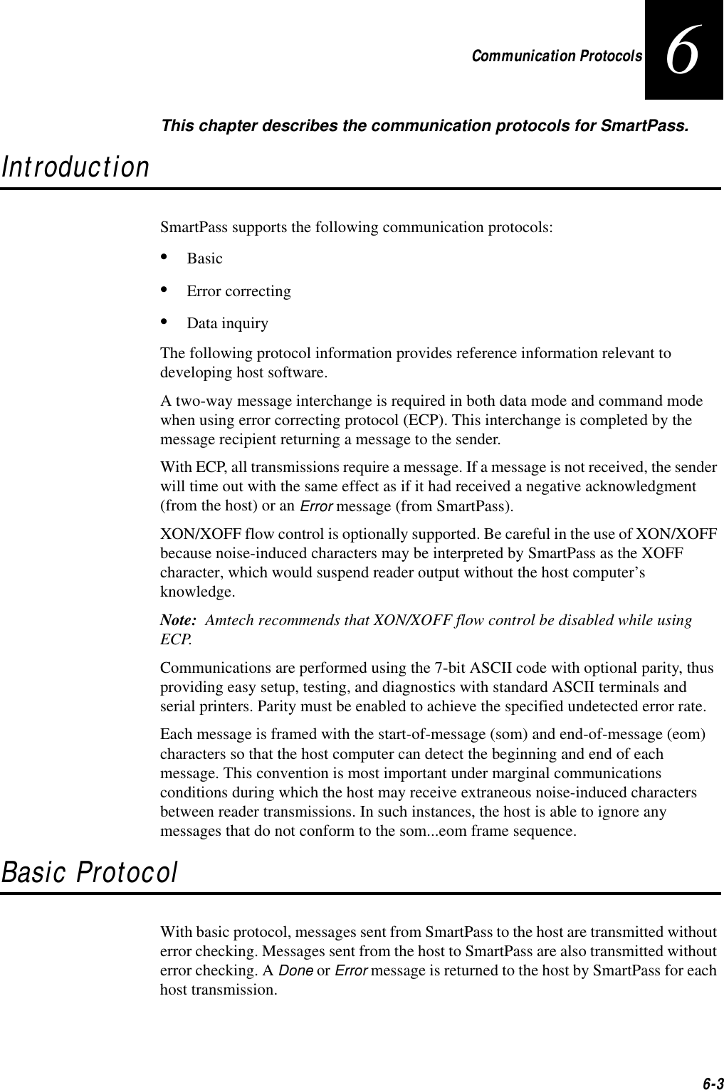
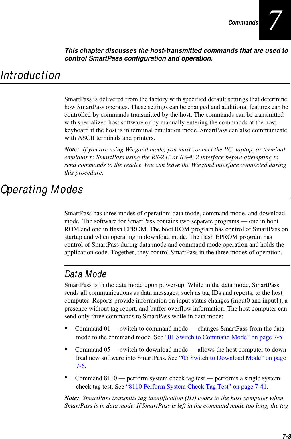
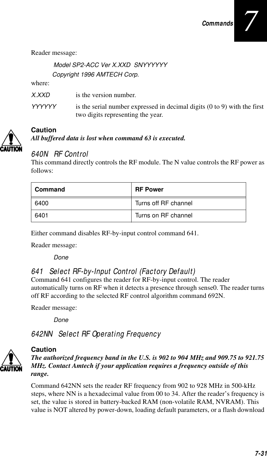
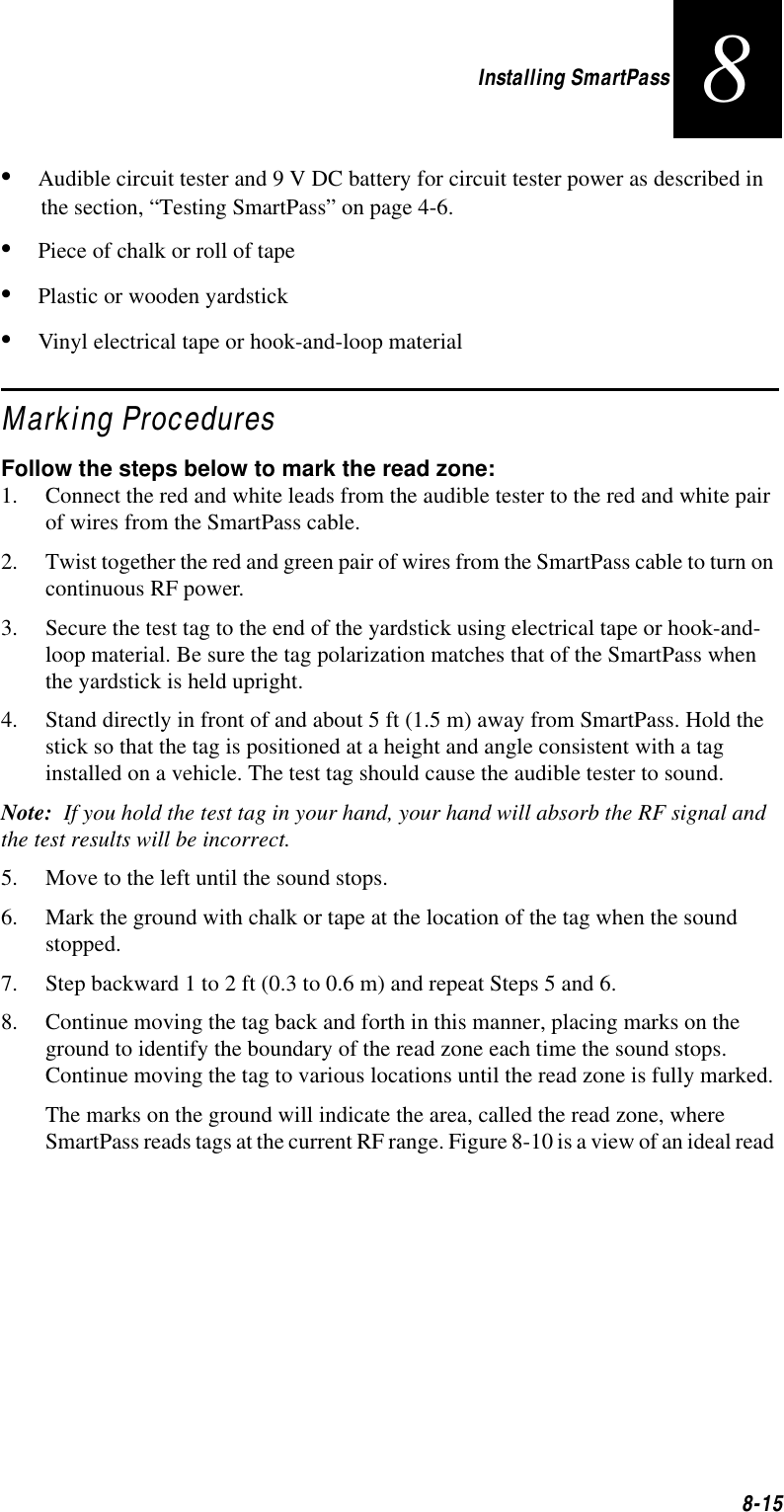
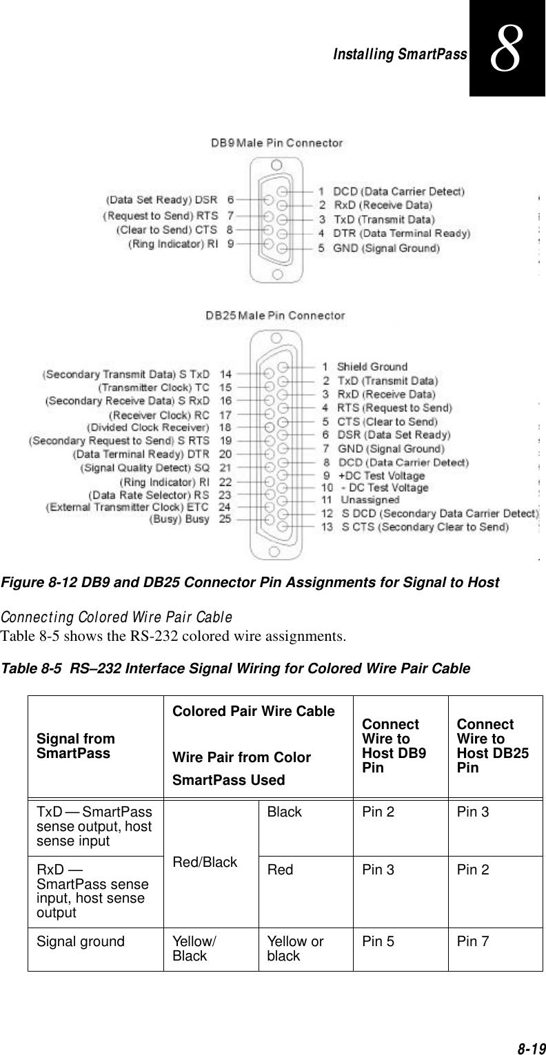
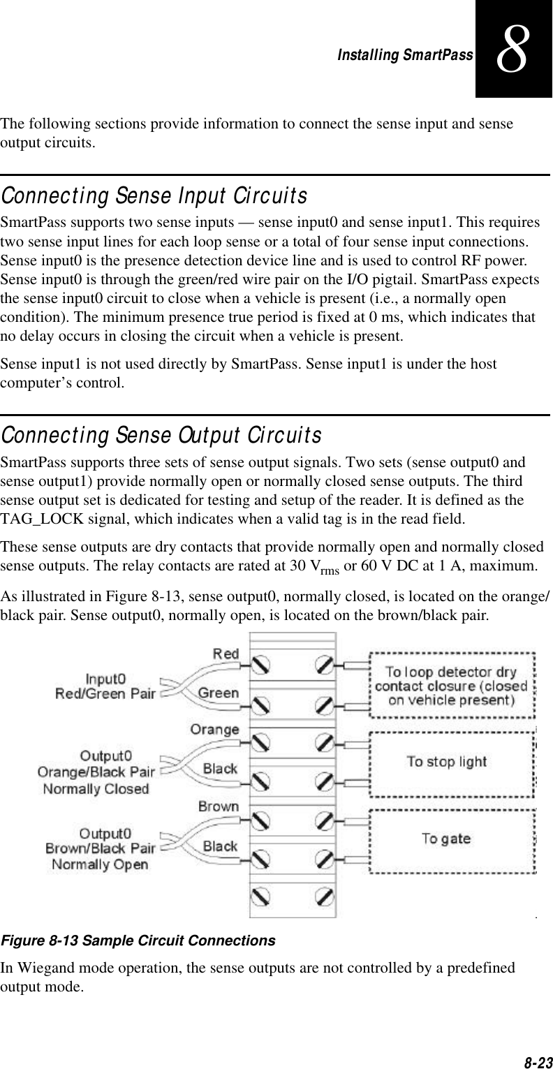
![AI1620 SmartPass System Guide6-16Table 6-4 Example of Routine to Create Lookup Table#include <stdio.h>#define MAX_CHAR 256#define BITS_CHAR 8#define SIGN_BIT 0x8000#define POLY 0x1021unsigned short crctab [MAX_CHAR];main (){unsigned short ch;unsigned short workval;unsigned short bit;unsigned short carry;for (ch = 0; ch != MAX_CHAR; ch++) {workval = ch << BITS_CHAR;for (bit = BITS_CHAR; bit != 0; bit--) {carry = (workval & SIGN_BIT);workval <<= 1;if (carry)workval ^= POLY;}crctab[ch] = workval;}for (ch = 0; ch != MAX_CHAR; ch++)printf("0x%04x\n", crctab[ch]);}](https://usermanual.wiki/TransCore/10-510-100.Exhibit-8-Users-Manual/User-Guide-75384-Page-114.png)

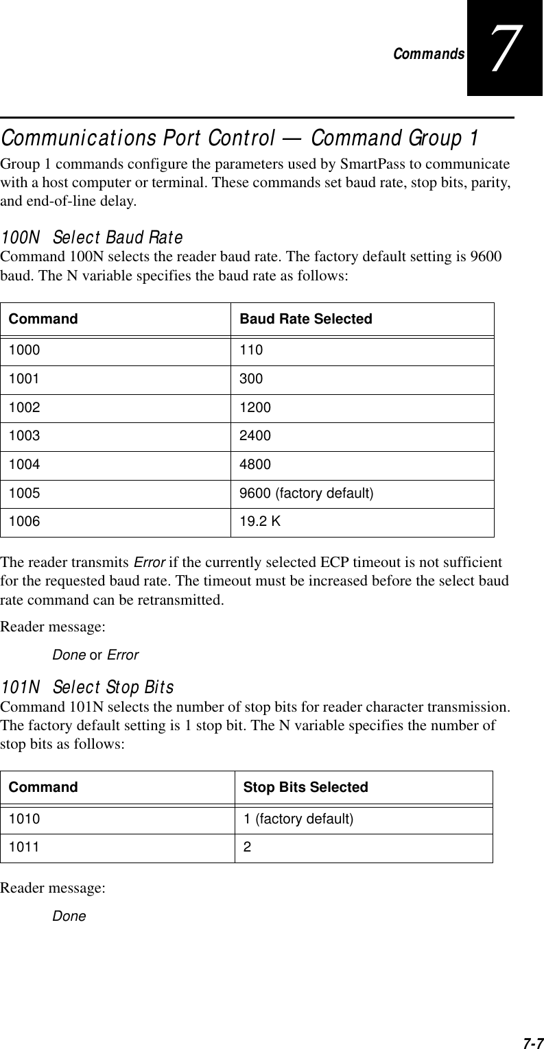


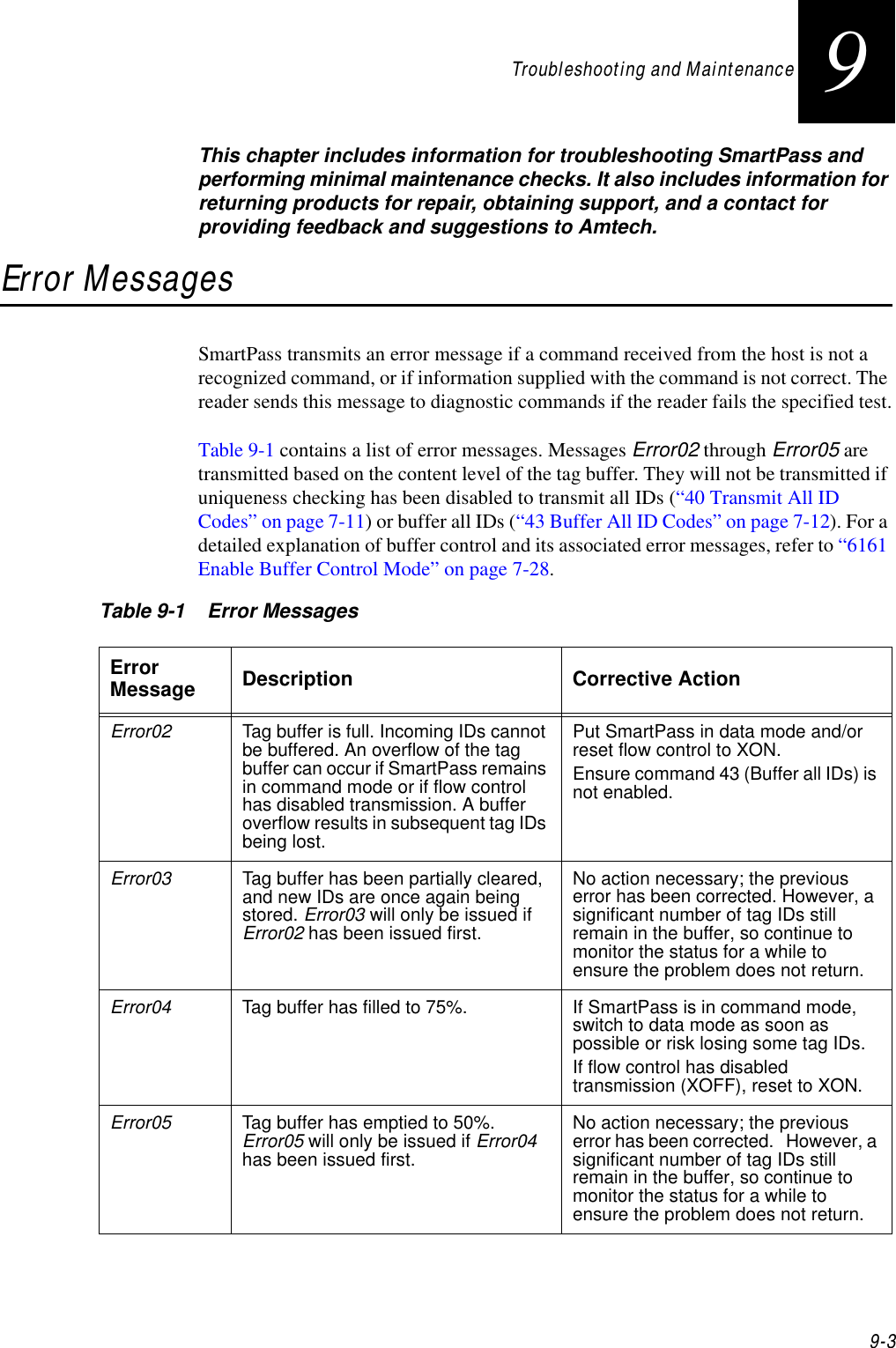
![AI1620 SmartPass System Guide9-6*Use this number to reference the problem you are having with SmartPass if you call Technical Support. 7SmartPass came from another site and does not work the way the factory defaults indicate that it should.Different commands were probably used to support the other site’s specific configuration. You can restore the defaults by first disconnecting the power. Next, twist the red/black pair of wires together and power up the SmartPass for 3 or 4 seconds. The factory defaults will be restored.8When connected to a PC that is running terminal communications software, a just-powered up SmartPass displays one of the following messages: #Model SP-ACC Ver 2.00D SNYYYYYY #[Copyright notice]SmartPass works! The software is now loaded. YYYYYY is the Amtech-assigned serial number for this SmartPass. However, if YYYYYY = 000000, the internal battery has failed, or a serial number has never been assigned. If the internal battery has failed, the SmartPass must be returned to the factory for replacement. If a serial number has not been assigned to SmartPass, you can assign a unique serial number by using command 695. Note that each SmartPass unit must have its own unique serial number.9The read zone is too small, even before the range control has been adjusted.If another SmartPass is in the same area, be sure it operates on another frequency that is at least 6 MHz different.Check for possible interference from another nearby RF source: fluorescent lights, neon signs, high voltage power lines, nearby cellular telephone, or radio stations. Lights will need to be removed or shielded. Point SmartPass in a different direction to see if interference comes from only one direction. You may require a different SmartPass that uses another frequency.Verify that the range adjustment is set to the maximum. 10 The perimeter of the read zone has been defined, but there is a “hollow” spot in the center of the zone that does not read tags.The angle of SmartPass may need adjustment. Slightly tilt SmartPass to a different angle to change either the length or width of the read zone.Check the range control adjustment. See “Radio Frequency” on page 4-27. 11 SmartPass is reading tags out of the desired read zone, or cross-lane reads are occurring.Some interference from other RF or electrical sources may be occurring. See “Reflection, Refraction, and Diffraction of RF Signals” on page 2-12. 12 How do I download the SmartPass software diskette? To download SmartPass software, you will need a SmartPass software diskette with READ.ME, DL.EXE, and the software file. Insert the demonstration diskette into your PC, and print the instructions on the READ.ME file.13 SmartPass is not providing any output to the Wiegand interface.Ensure SmartPass is in Wiegand mode. The default is either RS-232 or RS-422 mode; refer to “Using Wiegand Interface” on page 4-10. Table 9-2 Symptoms and RemediesSymptom Number*Symptom Remedy](https://usermanual.wiki/TransCore/10-510-100.Exhibit-8-Users-Manual/User-Guide-75384-Page-190.png)


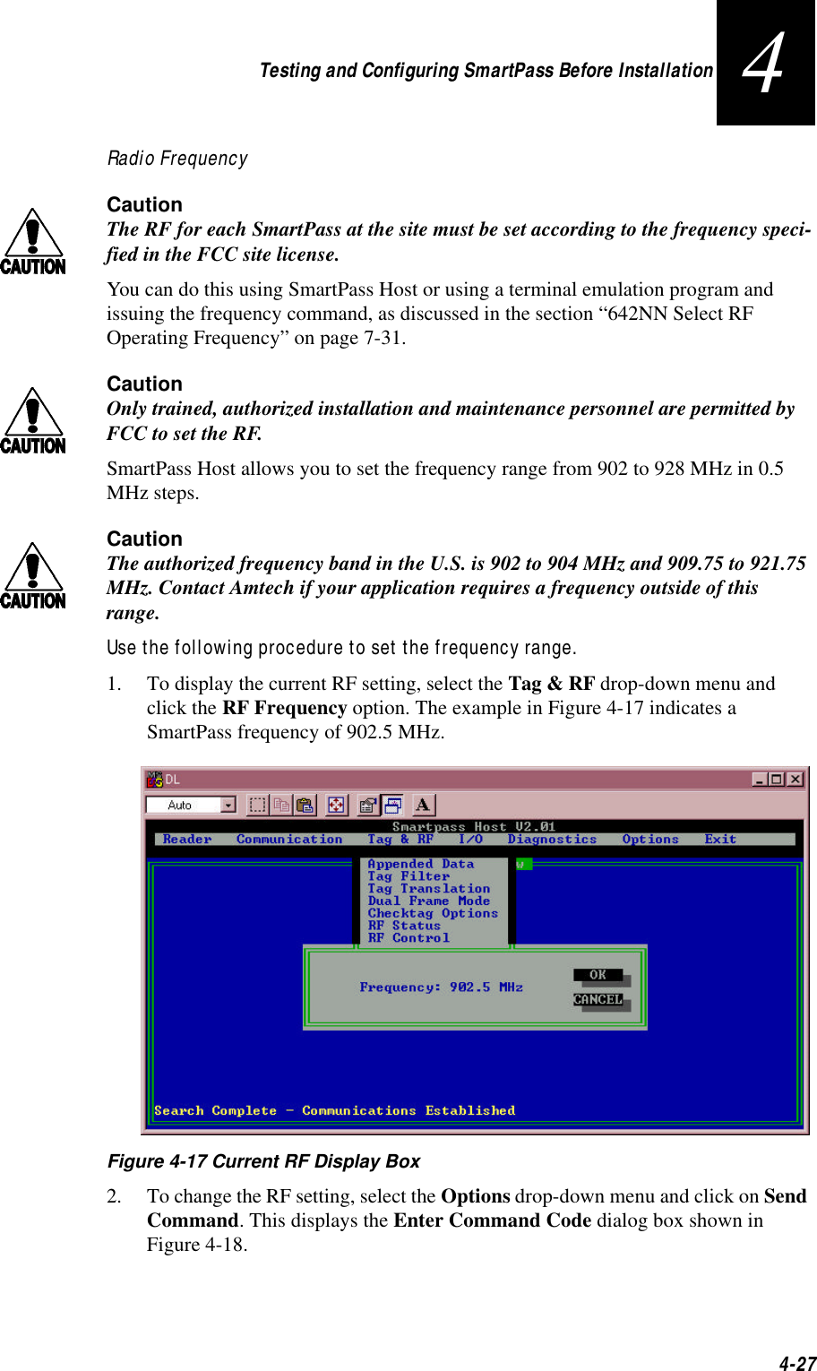
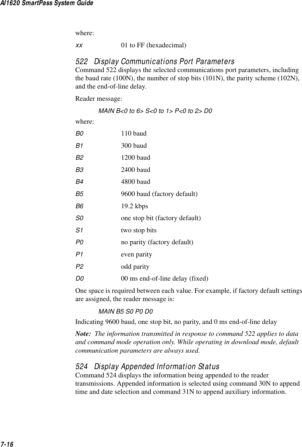
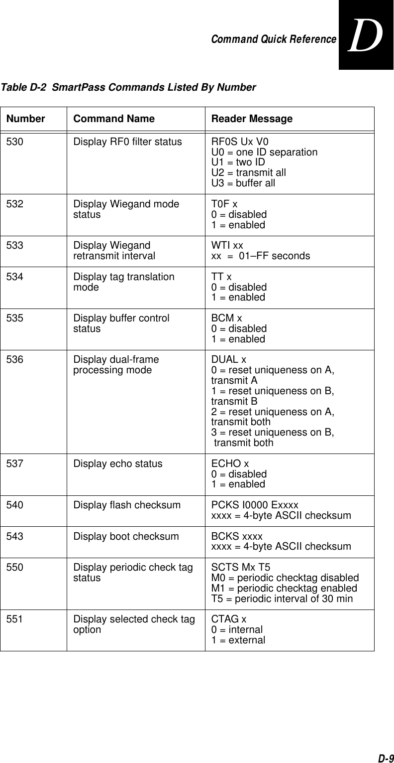
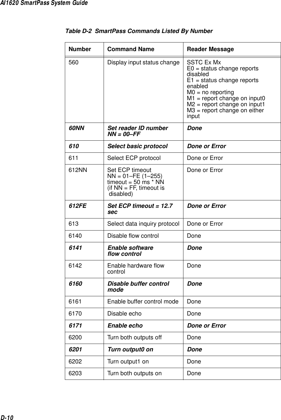
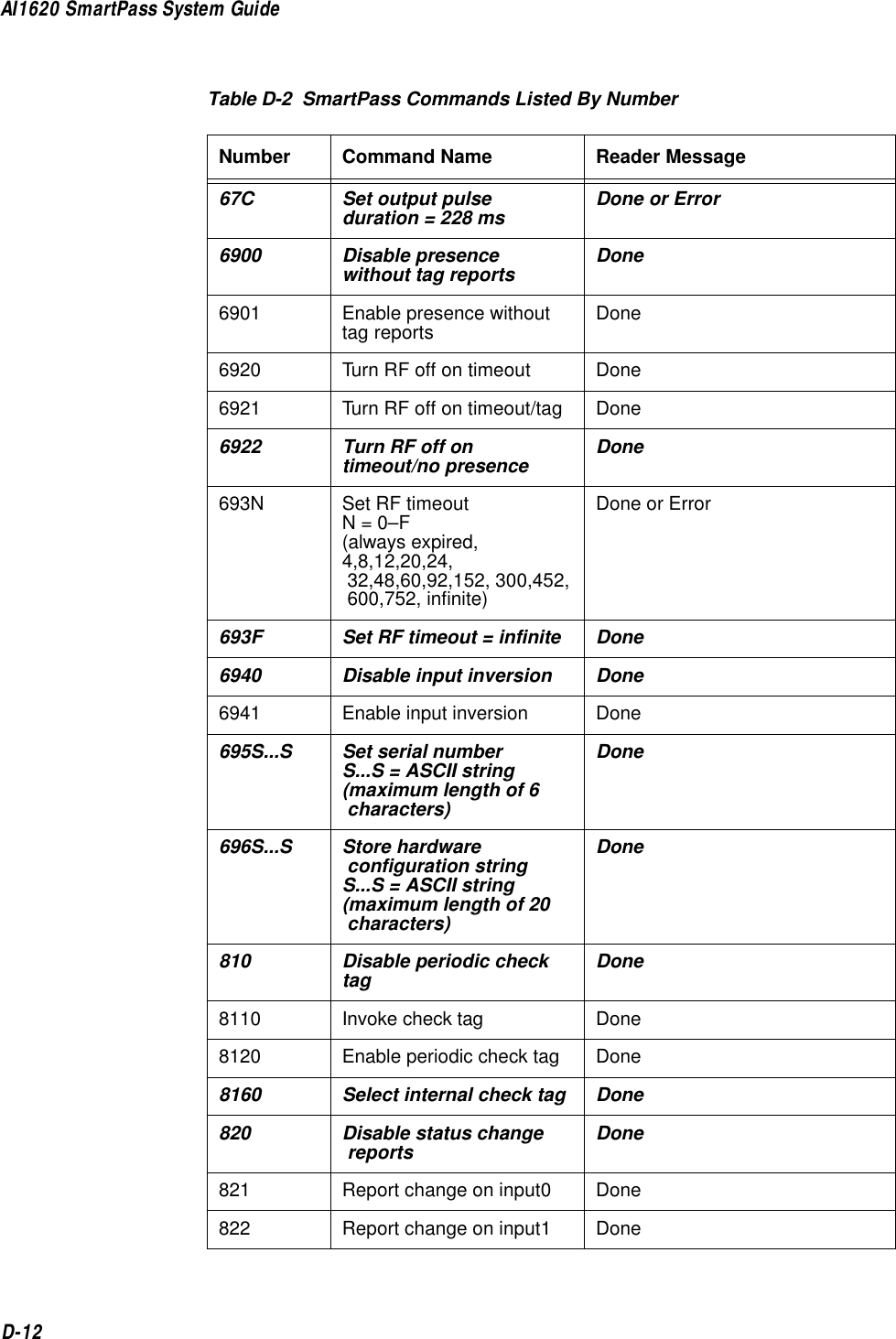
![Command Quick ReferenceD-7D48N Select dual-frame processing modeN = 0–30 = Reset uniqueness on A, transmit A1 = Reset uniqueness on B, transmit B2 = Reset uniqueness on A, transmit both3 = Reset uniqueness on B, transmit bothDone505 Display version Model [model] Ver [ver no.] SN [serial no.]506 Display hardware configuration information S...S S...S = ASCII string(maximum length of 20 characters)520 Display power fail bit PWRB Px R0 P0 = no power fail has occurredP1 = power fail has occurred521 Display reader ID number RDID xx xx = 00–FF522 Display comm port parameters MAIN Bx Sx Px D0 B0 = 110B1 = 300B2 = 1200B3 = 2400B4 = 4800B5 = 9600B6 = 19.2S0 = one stop bitS1 = two stop bitsP0 = no parityP1 = evenP2 = oddD0 = EOL delay of 0 ms524 Display appended info status IDAP Tx Dx Xx T0 = time not appendedT1 = time appendedD0 = date not appendedD1 = date appendedX0 = aux info not appendedX1 = aux info appendedTable D-2 SmartPass Commands Listed By NumberNumber Command Name Reader Message](https://usermanual.wiki/TransCore/10-510-100.Exhibit-8-Users-Manual/User-Guide-75384-Page-225.png)
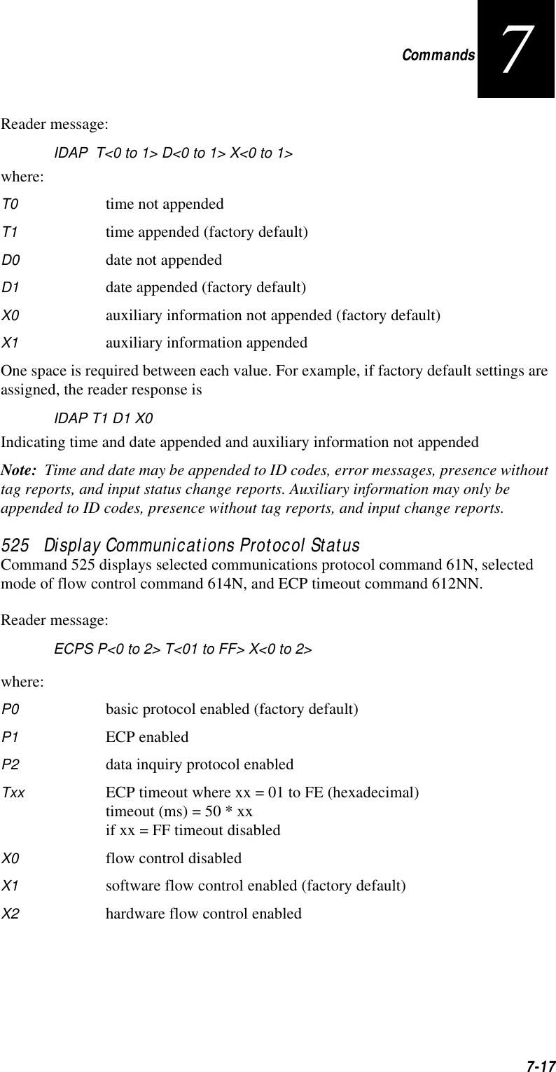
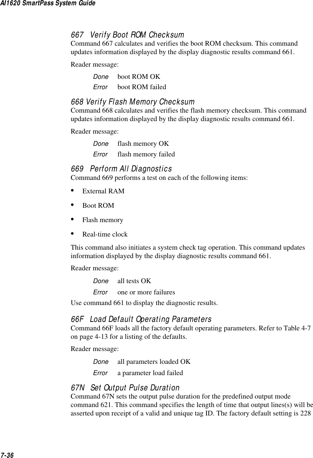
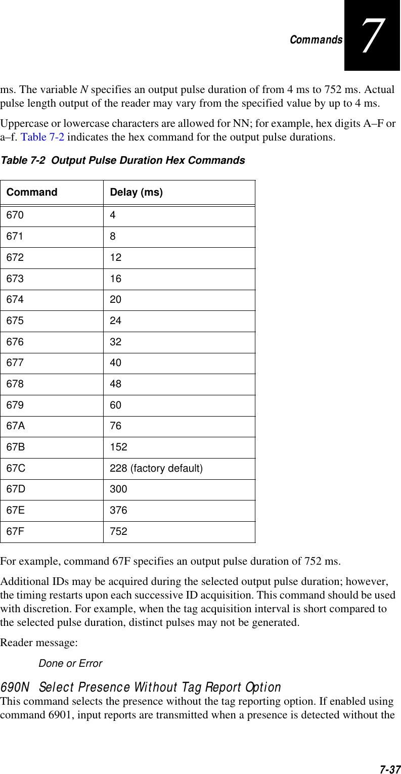
![Command Quick ReferenceD-11D621 Select predefined output mode Done63 Reset reader Model [model] Ver [ver no.] SN [serial no.]Copyright [date]AMTECH Corp.6400 Turn RF off Done6401 Turn RF on Done641 Select RF-by-input control Done642 Set RF operating frequency Done643NN Set RF operating range Done65 Reset power fail bit Done660 Test external RAM Done or Error661 Display diagnostic results DIAG Rx Ex Dx Cx R0 = boot ROM OKR1 = boot failedE0 = flash memory OKE1 = flash failedD0 = external RAM OKD1 = RAM failedC0 = RTC OKC1 = RTC failed664 Test real-time clock Done or Error667 Verify boot ROM checksum Done or Error668 Verify flash memory checksum Done or Error669 Perform all diagnosticsUse 661 to display diagnostic resultsDone or Error66F Load default operating parameters Done or Error67N Set output pulse durationN = 0–F(4,8,12,16,20,24,32,40,48,60,76,152,228,300,376,752 ms)Done or ErrorTable D-2 SmartPass Commands Listed By NumberNumber Command Name Reader Message](https://usermanual.wiki/TransCore/10-510-100.Exhibit-8-Users-Manual/User-Guide-75384-Page-229.png)
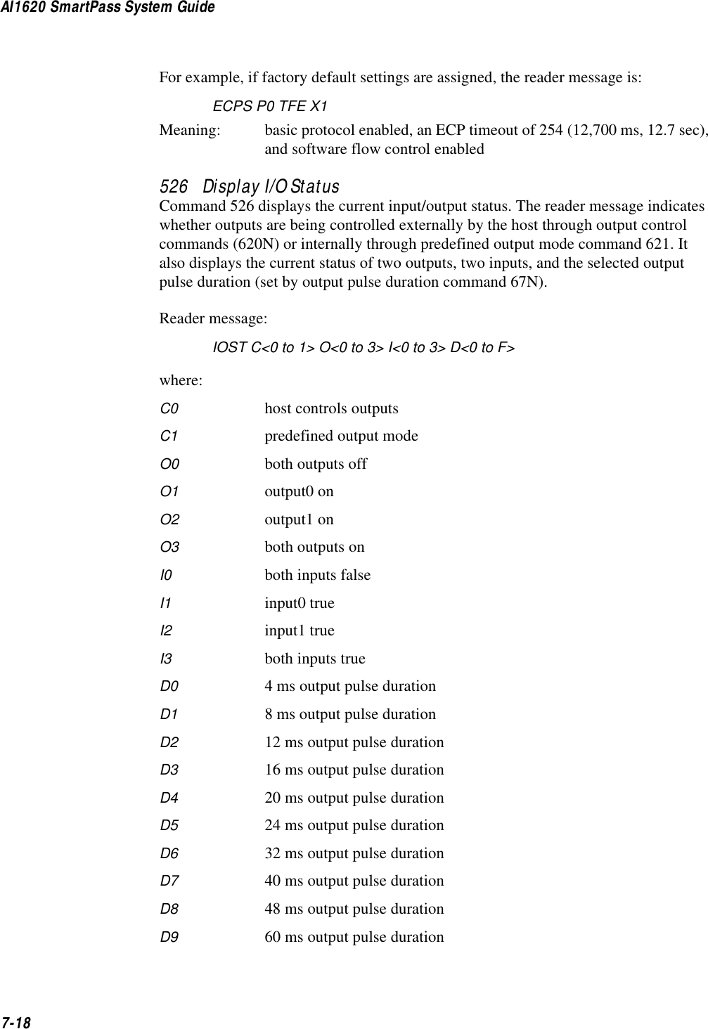
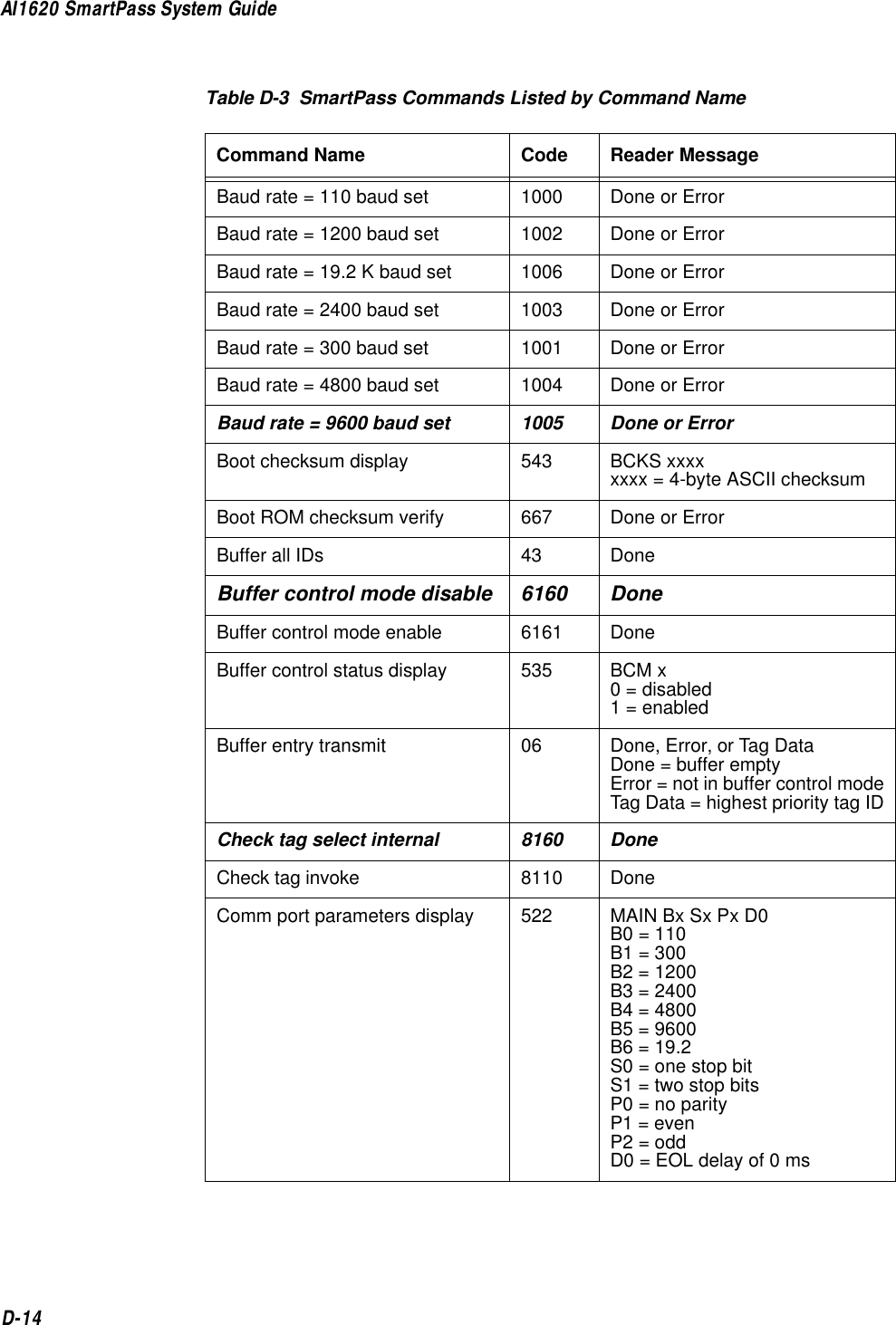
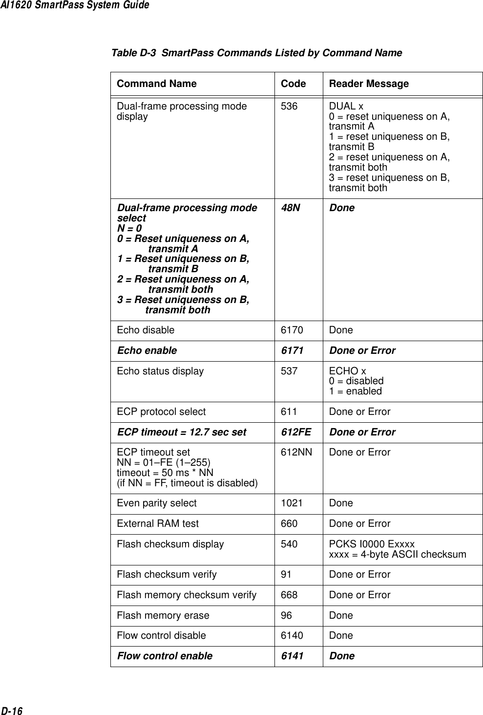
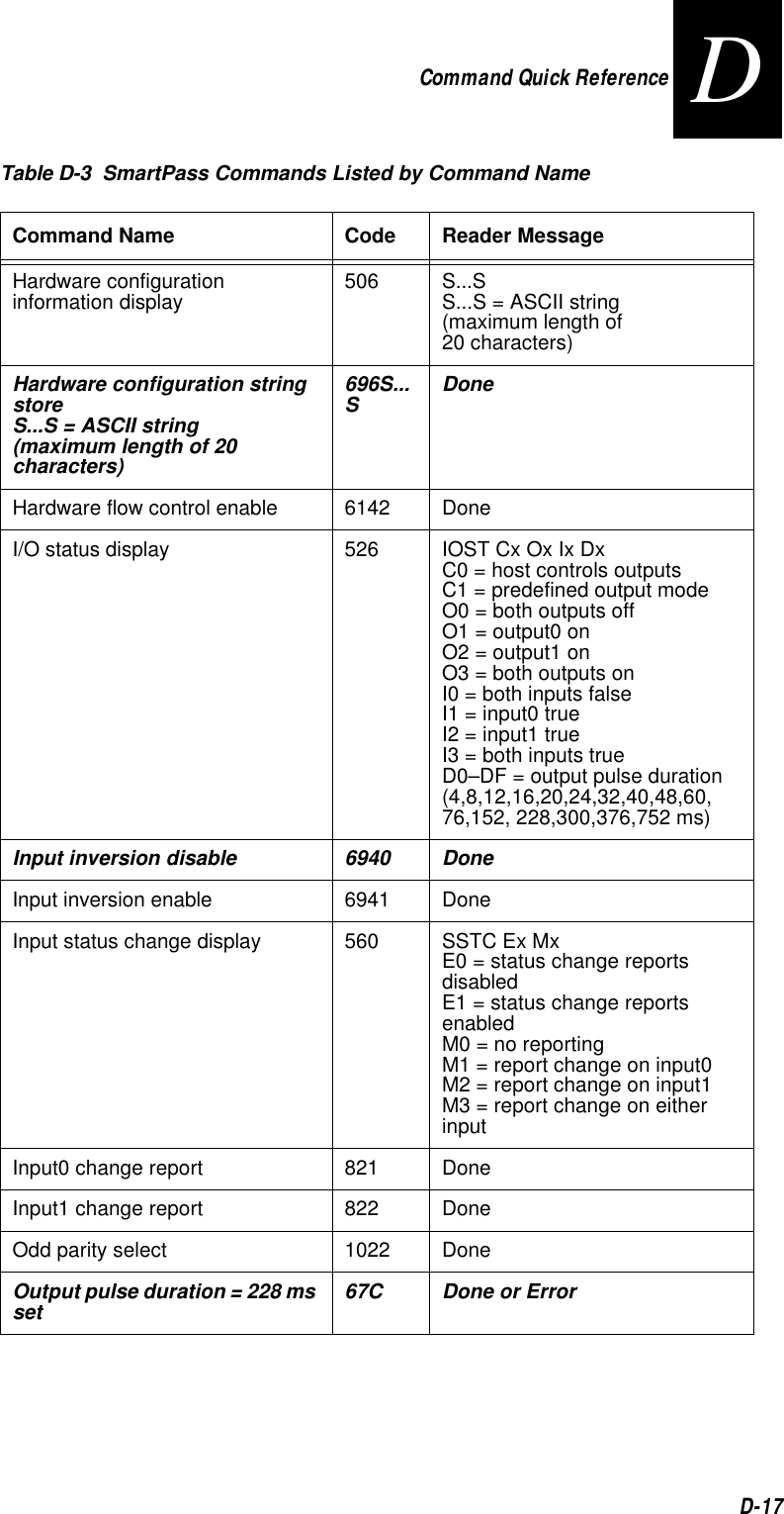
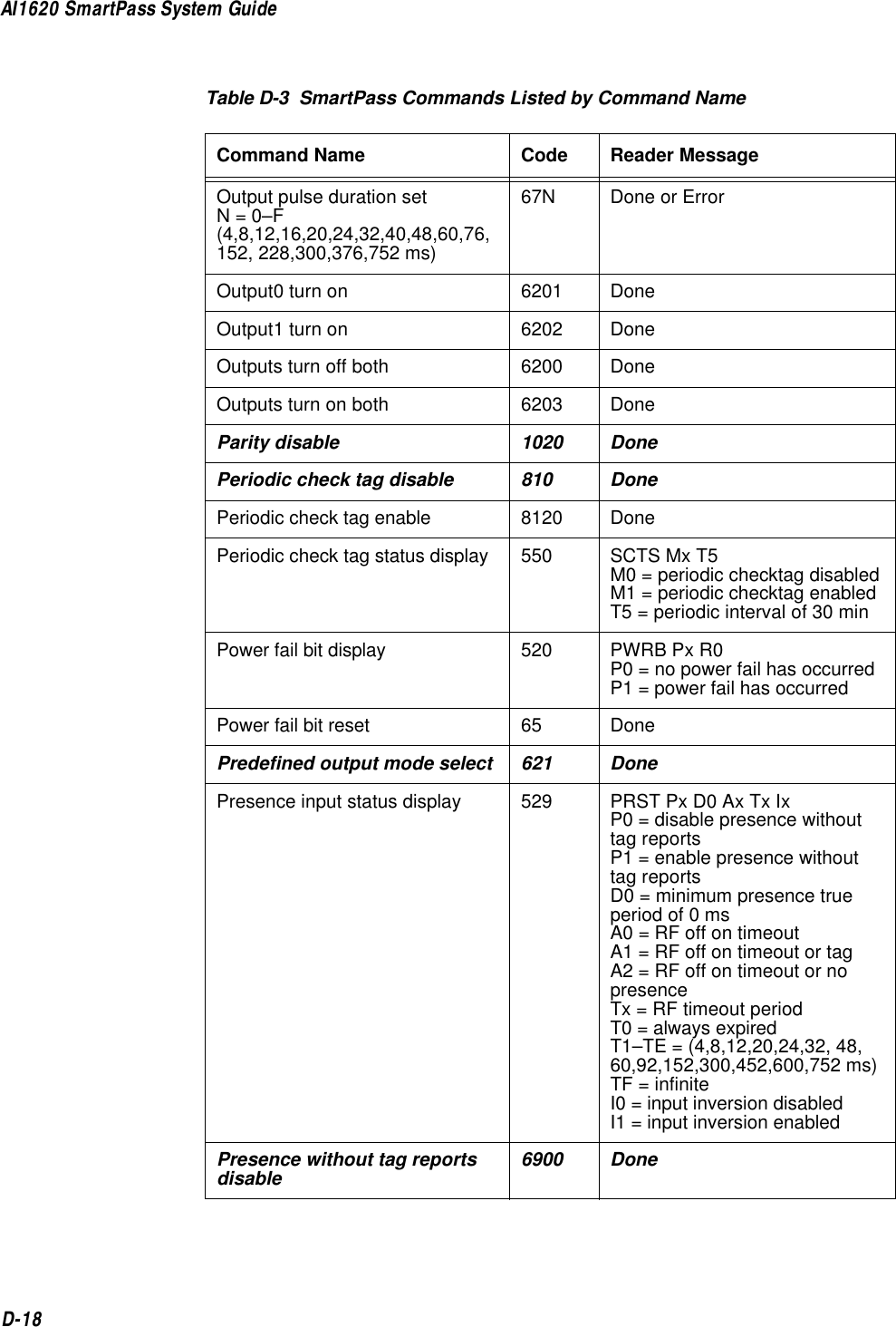
![Command Quick ReferenceD-13DAlphabetical Command ListNote: The following conventions are used in Table D-3: •Items in bold italics identify factory default settings.•Only the data portion of the command number is shown. •Only the command-related data portion of the reader message is shown.•Refer to 7 for the complete syntax of commands and messages.823 Report changes on both Done90 Load program block Done, Checksum Error, Program Error, or Verify Error91 Verify flash checksum Done or Error96 Erase flash memory Done97 Perform destructive flash test Done or Error99 Exit download mode Model [model] Ver [ver no.] SN [serial no.]Copyright [date]AMTECH Corp.Table D-2 SmartPass Commands Listed By NumberNumber Command Name Reader MessageTable D-3 SmartPass Commands Listed by Command NameCommand Name Code Reader MessageAll IDs transmit 40 DoneAppended info status display 524 IDAP Tx Dx Xx T0 = time not appendedT1 = time appendedD0 = date not appendedD1 = date appendedX0 = aux info not appendedX1 = aux info appendedAux info append disable 310 Done or ErrorAux info append enable 311 Done or ErrorBasic protocol select 610 Done or Error](https://usermanual.wiki/TransCore/10-510-100.Exhibit-8-Users-Manual/User-Guide-75384-Page-231.png)
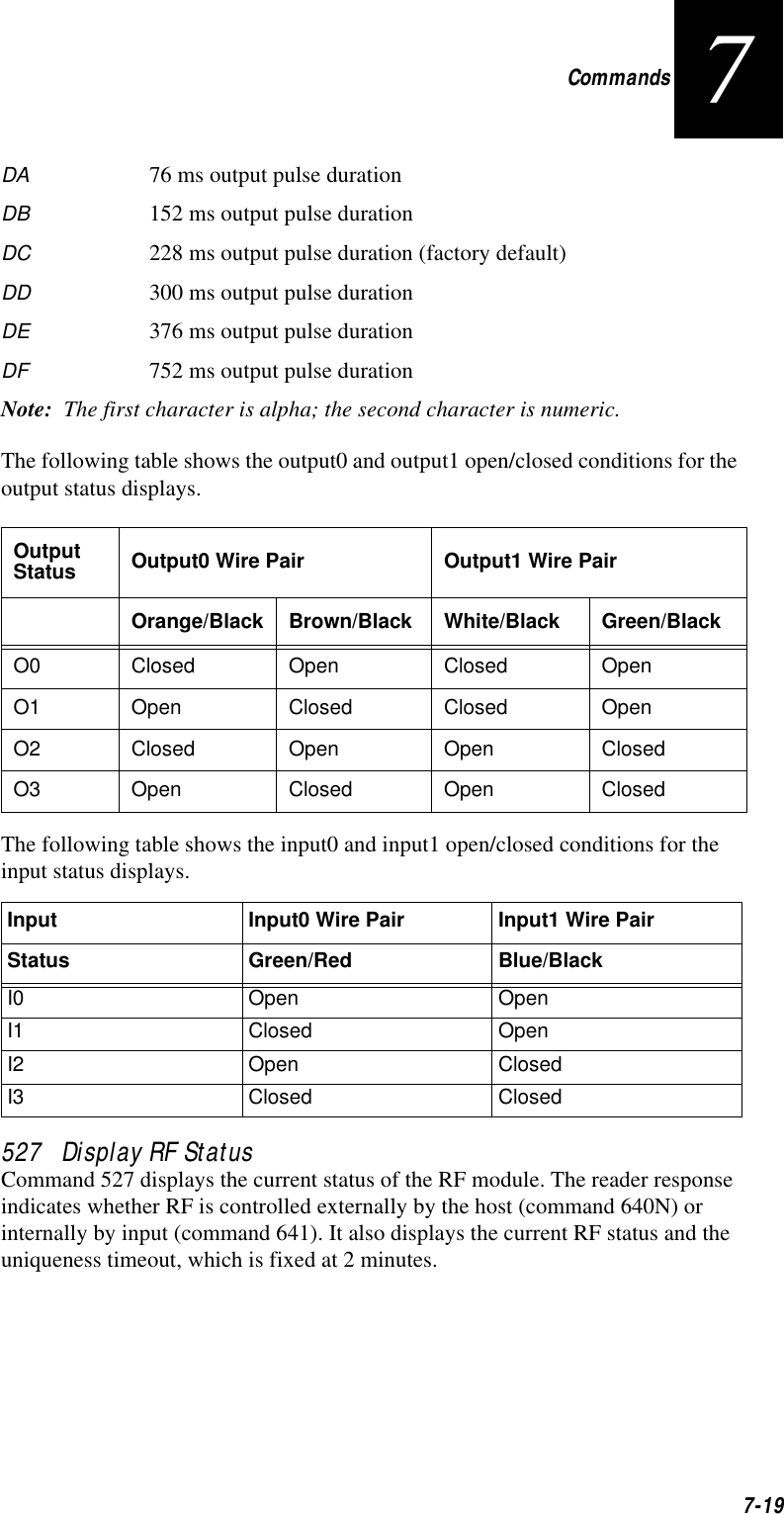
![Command Quick ReferenceD-15DComm protocol display 525 ECPS Px Txx Xx S0 P0 = basicP1 = ECPP2 = data inquiryTxx = ECP timeoutms = 50 * xxTFF = disabled ECP timeoutX0 = no flow controlX1 = software flow controlX2 = hardware flow controlS0 = SOM character is #Command mode switch 01 DoneData inquiry protocol select 613 Done or ErrorData mode switch 00 DoneDate setS...S = MM/DD/YY 21S...S Done or ErrorDefault operating parameters load 66F Done or ErrorDestructive flash test perform 97 Done or ErrorDiagnostic results display 661 DIAG Rx Ex Dx Cx R0 = boot ROM OKR1 = boot failedE0 = flash memory OKE1 = flash failedD0 = external RAM OKD1 = RAM failedC0 = RTC OKC1 = RTC failedDiagnostics perform allUse 661 to display diagnostic results.669 Done or ErrorDownload mode exit 99 Model [model] Ver [ver no.] SN [serial no.]Copyright [date]AMTECH Corp.Download mode switch 05 DoneTable D-3 SmartPass Commands Listed by Command NameCommand Name Code Reader Message](https://usermanual.wiki/TransCore/10-510-100.Exhibit-8-Users-Manual/User-Guide-75384-Page-233.png)
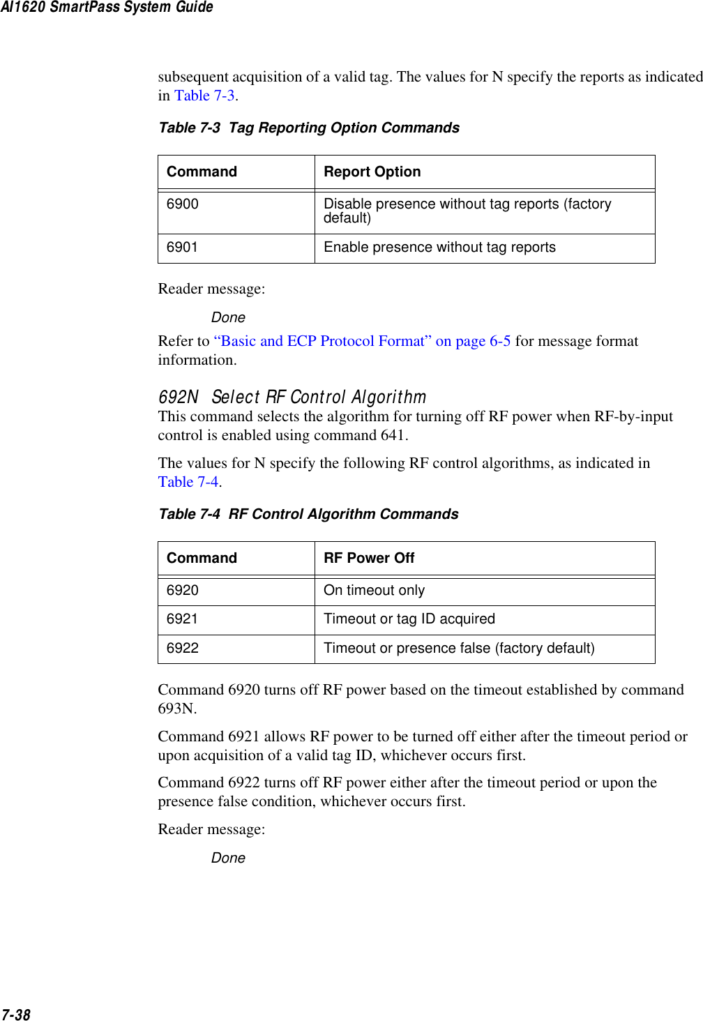
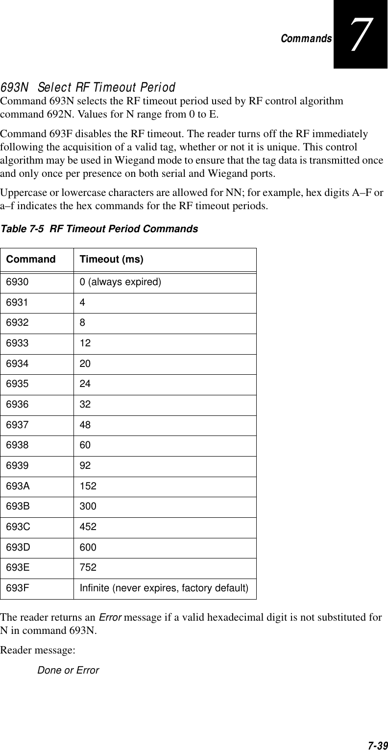
![Command Quick ReferenceD-19DPresence without tag reports enable 6901 DoneProgram block load 90 Done, Checksum Error, Program Error, or Verify ErrorReader ID number display 521 RDID xx xx = 00–FFReader ID number setNN = 00 60NN DoneReader reset 63 Model [model] Ver [ver no.] SN [serial no.]Copyright [date]AMTECH Corp.Real-time clock test 664 Done or ErrorReport changes both 823 DoneRF off 6400 DoneRF off on timeout 6920 DoneRF off on timeout/no presence 6922 DoneRF off on timeout/tag 6921 DoneRF on 6401 DoneRF on by input control 641 DoneRF operating frequency set 642 DoneRF operating range set 643NN DoneRF status display 527 RFST Cx Ox T1 C0 = RF controlled by hostC1 = RF-by-input controlO0 = RF offO1 = RF onT1 = uniqueness timeout of 2 minRF timeout = infinite set 693F DoneRF timeout setN = 0–F(always expired, 4,8,12,20,24,32, 48,60,92,152,300,452,600,752 ms, infinite)693N Done or ErrorTable D-3 SmartPass Commands Listed by Command NameCommand Name Code Reader Message](https://usermanual.wiki/TransCore/10-510-100.Exhibit-8-Users-Manual/User-Guide-75384-Page-237.png)
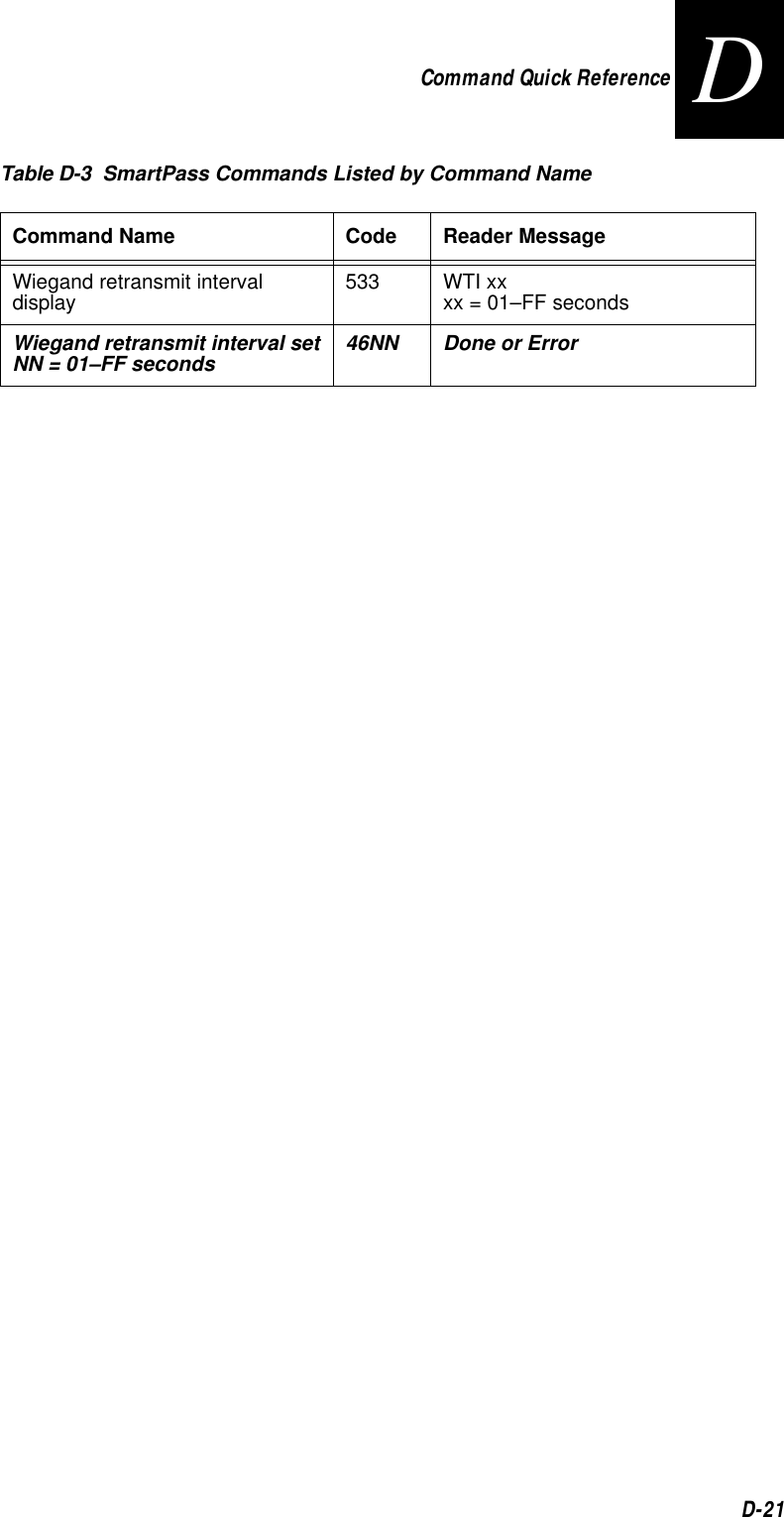
![AI1620 SmartPass System GuideD-20RF0 filter status display 530 RF0S Ux V0 U0 = one ID separationU1 = two IDU2 = transmit allU3 = buffer allSelected checktag option display 551 CTAG x0 = internal1 = externalSerial number setS...S = ASCII string(maximum length of 6 characters)695S...SDoneStatus change reports disable 820 DoneStop bit use one 1010 DoneStop bit use two 1011 DoneTag ID separation select one 4100 DoneTag ID separation select two 4101 DoneTag translation mode disable 452 DoneTag translation mode display 534 TT x0 = disabled1 = enabledTag translation mode enable 453 DoneTime and date append disable 300 Done or ErrorTime and date append enable 302 Done or ErrorTime and date display 22 HH:MM:SS.hh MM/DD/YYTime setS...S = HH:MM:SS or HH:MM:SS:hh20S...S Done or ErrorVersion display 505 Model [model] Ver [ver no.] SN [serial no.]Wiegand mode disable 450 DoneWiegand mode enable 451 DoneWiegand mode status display 532 T0F x0 = disabled1 = enabledTable D-3 SmartPass Commands Listed by Command NameCommand Name Code Reader Message](https://usermanual.wiki/TransCore/10-510-100.Exhibit-8-Users-Manual/User-Guide-75384-Page-238.png)