TransCore 22000555201 LMS Transmitter User Manual AR2200UG
TransCore LMS Transmitter AR2200UG
UserManual.wiki
>
TransCore
>
22000555201 User Manual
users manual
Navigation menu
Upload a User Manual
Namespaces
Wiki Guide
HTML
PDF
Info
Views
User Manual
Discussion / Help
Navigation

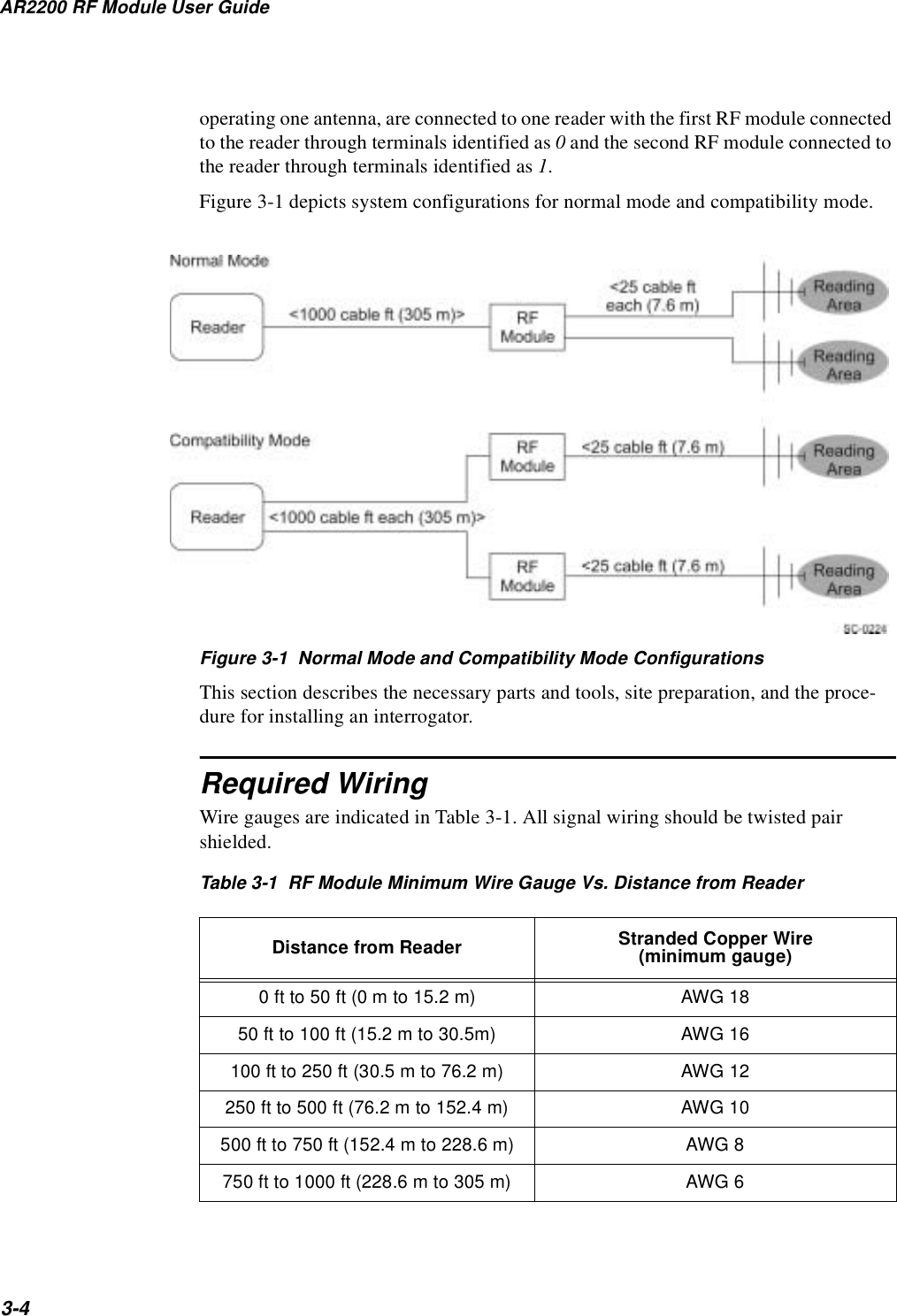
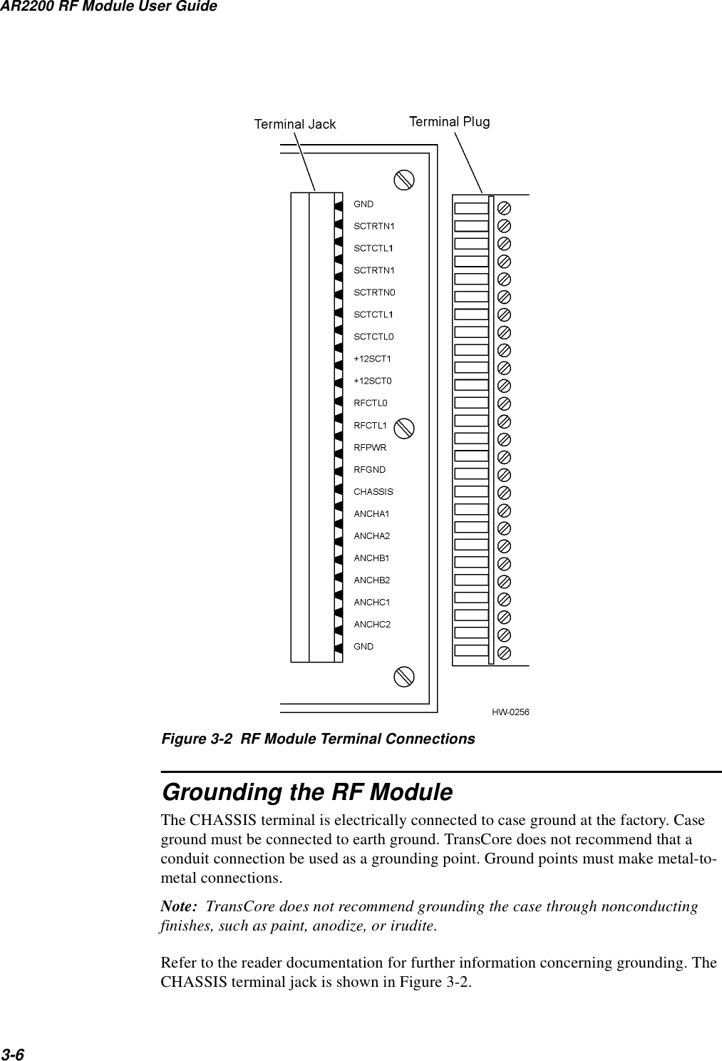
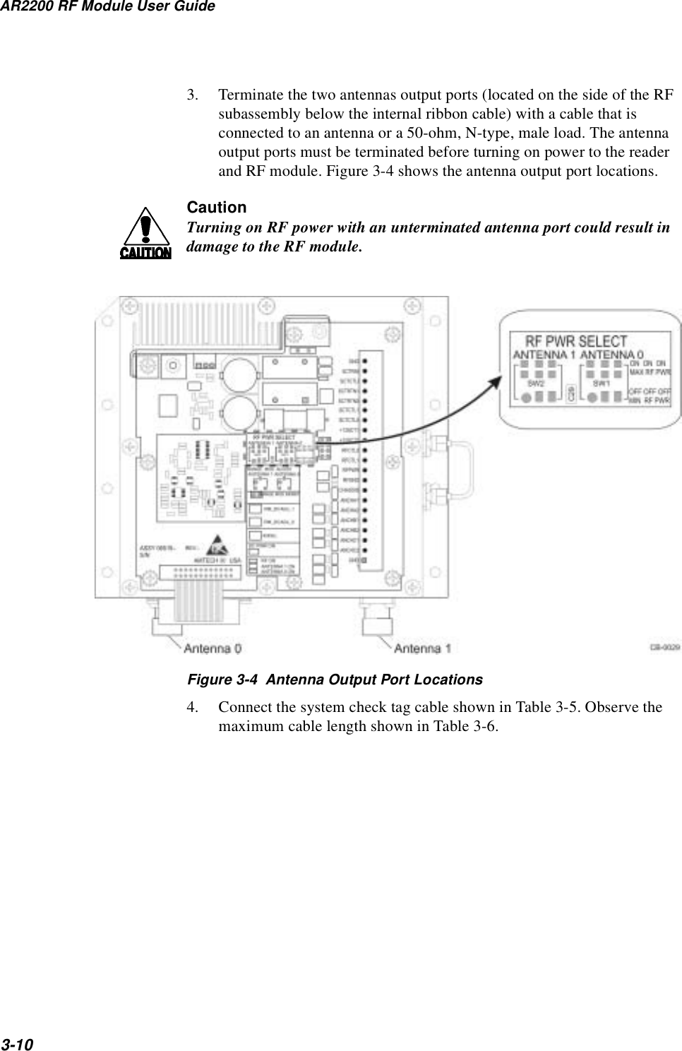
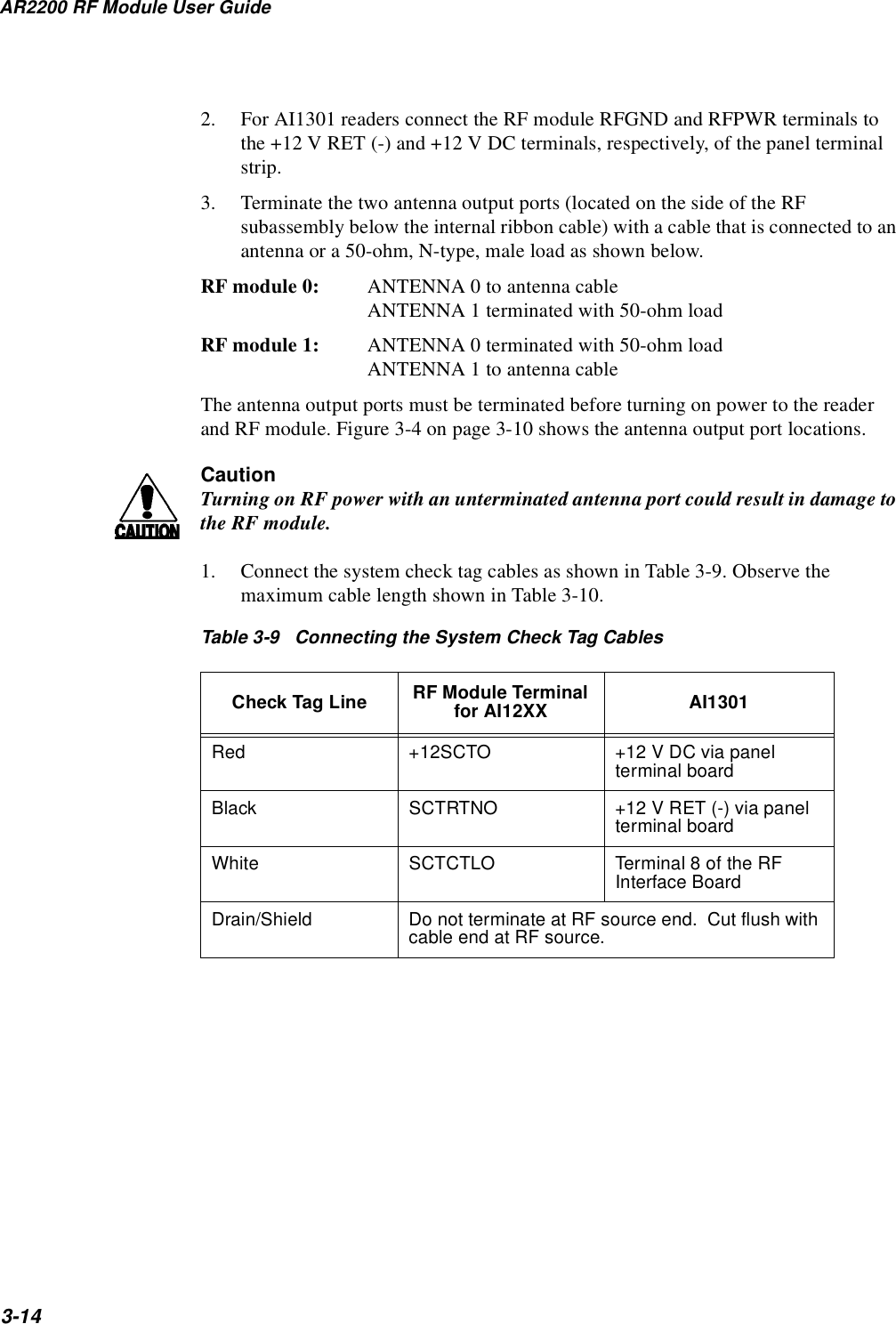
![Installing the AR2200 RF Module3-5Required Equipment•Voltmeter•Oscilloscope, 100 MHz (for monitoring intermediate frequency [IF] signals and discriminate signals)•Data terminal or computer•Phillips and flat-blade screwdrivers•N-type 50-ohm load (placed at the antenna port for testing)•N-type attenuators (as needed to adjust RF power)Positioning the RF ModuleIn permanent installations, position the RF module as close as possible to the antenna and within 1,000 signal cable ft (305 m) of the reader. Long cable lengths will increase system sensitivity to noise. Coaxial cable runs in excess of 50 ft (15.2 m) between the RF module and antenna are not recommended.1 Longer signal cable connections (up to 1,000 cable ft) (305 m) should be made on the reader-to-RF module link.Refer to the reader documentation for further information concerning RF module positioning.Terminal ConnectionsThe RF module plug and jack connector pair have 21 terminals. Connections from the reader are made to the removable plug. After connections are made, the plug can be removed from the jack for interface board servicing or repair/replacement.Figure 3-2 shows the RF module terminal connections.1. Based on 2 dB loss, Andrews LDF4-50A 0.5 in. OD coaxial cable. If 3 dB loss is tolera-ble, cable up to 75 ft (22.9 m) long may be used between the RF module and the antenna.](https://usermanual.wiki/TransCore/22000555201/User-Guide-318164-Page-29.png)