TransCore 22000555201 LMS Transmitter User Manual AR2200UG
TransCore LMS Transmitter AR2200UG
users manual

TransCore Inc.
19111 Dallas Parkway, Suite 300
Dallas, Texas 75287-3106
March 2003
P/N 411052-003
AR2200 RF Module
User Guide
Information in this document is subject to change and does not represent a commitment on the part of
TC IP, Ltd.
©2003 TC IP, Ltd. All rights reserved. TRANSCORE is a trademark and Amtech is a registered trademark of
TC IP, Ltd. and is used under license. All other trademarks listed are the property of their respective owners.
Contents subject to change. Printed in the U.S.A.
For further information, contact:
TransCore
19111 Dallas Parkway, Suite 300
Dallas, Texas 75287-3106 USA
Phone: (972) 733-6600
Fax: (972) 733-6699
TransCore Action Center (TrAC)
19111 Dallas Parkway, Suite 300
Dallas, Texas 75287-3106 USA
Phone: (800) 755-0378
Fax: (972) 733-6695
WARNING TO USERS IN THE UNITED STATES
FEDERAL COMMUNICATIONS COMMISSION (FCC) RADIO FREQUENCY
INTERFERENCE STATEMENT
47 CFR §15.105(a)
NOTE: This equipment has been tested and found to comply with the limits for a Class A digital device
pursuant to Part 15 of the Federal Communications Commission (FCC) rules. These limits are designed to
provide reasonable protection against harmful interference when the equipment is operated in a
commercial environment. This equipment generates, uses, and can radiate radio frequency (RF) energy and
may cause harmful interference to radio communications if not installed and used in accordance with the
instruction manual. Operating this equipment in a residential area is likely to cause harmful interference, in
which case, depending on the laws in effect, the users may be required to correct the interference at their
own expense.
NO UNAUTHORIZED MODIFICATIONS
47 CFR §15.21
CAUTION: This equipment may not be modified, altered, or changed in any way without permission
from TransCore, Inc. Unauthorized modification may void the equipment authorization from the FCC and
will void the TransCore warranty.
USE OF SHIELDED CABLES IS REQUIRED
47 CFR §15.27(a)
Shielded cables must be used with this equipment to comply with FCC regulations.
A license issued by the FCC is required to operate this RF identification device in the United States.
Contact TransCore, Inc. for additional information concerning licensing requirements for specific devices.
TransCore, Inc.
USA

Contents

vii
Contents
1 Before You Begin
Purpose. . . . . . . . . . . . . . . . . . . . . . . . . . . . . . . . . . . . . . . . . . . . . . . . . . . . . . . . . . . . 1-3
Intended Audience . . . . . . . . . . . . . . . . . . . . . . . . . . . . . . . . . . . . . . . . . . . . . . . . . . . 1-3
Guide Topics . . . . . . . . . . . . . . . . . . . . . . . . . . . . . . . . . . . . . . . . . . . . . . . . . . . . . . . 1-3
Typographical Conventions . . . . . . . . . . . . . . . . . . . . . . . . . . . . . . . . . . . . . . . . . . . 1-4
Health Limits. . . . . . . . . . . . . . . . . . . . . . . . . . . . . . . . . . . . . . . . . . . . . . . . . . . . . . . . 1-5
2 AR2200 RF Module Overview
Overview . . . . . . . . . . . . . . . . . . . . . . . . . . . . . . . . . . . . . . . . . . . . . . . . . . . . . . . . . . . 2-3
Features . . . . . . . . . . . . . . . . . . . . . . . . . . . . . . . . . . . . . . . . . . . . . . . . . . . . . . . . . 2-5
Range Sensitivity Adjustment . . . . . . . . . . . . . . . . . . . . . . . . . . . . . . . . . . . . . . . 2-5
ISO Compatible . . . . . . . . . . . . . . . . . . . . . . . . . . . . . . . . . . . . . . . . . . . . . . . . . 2-5
Patented Design: High-Speed Signal Capture, Noise Immunity. . . . . . . . . . . . . 2-5
Frequency Range . . . . . . . . . . . . . . . . . . . . . . . . . . . . . . . . . . . . . . . . . . . . . . . . 2-5
Preamplifier Line Driver Output . . . . . . . . . . . . . . . . . . . . . . . . . . . . . . . . . . . . . 2-6
Connections . . . . . . . . . . . . . . . . . . . . . . . . . . . . . . . . . . . . . . . . . . . . . . . . . . . . 2-6
Circuit Protection . . . . . . . . . . . . . . . . . . . . . . . . . . . . . . . . . . . . . . . . . . . . . . . . 2-6
International Safety Standards . . . . . . . . . . . . . . . . . . . . . . . . . . . . . . . . . . . . . . 2-6
Output Power . . . . . . . . . . . . . . . . . . . . . . . . . . . . . . . . . . . . . . . . . . . . . . . . . . . 2-7
Options . . . . . . . . . . . . . . . . . . . . . . . . . . . . . . . . . . . . . . . . . . . . . . . . . . . . . . . . . . 2-7
Harsh Environment Option . . . . . . . . . . . . . . . . . . . . . . . . . . . . . . . . . . . . . . . . . 2-7
Custom Frequencies. . . . . . . . . . . . . . . . . . . . . . . . . . . . . . . . . . . . . . . . . . . . . . 2-7
Replacement I/O Interface Board . . . . . . . . . . . . . . . . . . . . . . . . . . . . . . . . . . . . 2-7
Accessories . . . . . . . . . . . . . . . . . . . . . . . . . . . . . . . . . . . . . . . . . . . . . . . . . . . . . . . 2-7
Attenuators . . . . . . . . . . . . . . . . . . . . . . . . . . . . . . . . . . . . . . . . . . . . . . . . . . . . . 2-7
Hex Key . . . . . . . . . . . . . . . . . . . . . . . . . . . . . . . . . . . . . . . . . . . . . . . . . . . . . . . 2-7
Weatherproof Enclosure . . . . . . . . . . . . . . . . . . . . . . . . . . . . . . . . . . . . . . . . . . . 2-7
3 Installing the AR2200 RF Module
AR2200 RF Module Installation Options . . . . . . . . . . . . . . . . . . . . . . . . . . . . . . . . . 3-3
Differences in Installation Options . . . . . . . . . . . . . . . . . . . . . . . . . . . . . . . . . . . 3-3
AI1200 Reader Power Supply Upgrade . . . . . . . . . . . . . . . . . . . . . . . . . . . . . . . 3-3
Configuring the RF Module. . . . . . . . . . . . . . . . . . . . . . . . . . . . . . . . . . . . . . . . . 3-3
Required Wiring. . . . . . . . . . . . . . . . . . . . . . . . . . . . . . . . . . . . . . . . . . . . . . . . . . . . 3-4
Required Equipment . . . . . . . . . . . . . . . . . . . . . . . . . . . . . . . . . . . . . . . . . . . . . . . . 3-5
Positioning the RF Module . . . . . . . . . . . . . . . . . . . . . . . . . . . . . . . . . . . . . . . . . . . 3-5

AR2200 RF Module User Guide
viii
Terminal Connections . . . . . . . . . . . . . . . . . . . . . . . . . . . . . . . . . . . . . . . . . . . . . . . 3-5
Grounding the RF Module . . . . . . . . . . . . . . . . . . . . . . . . . . . . . . . . . . . . . . . . . . . . 3-6
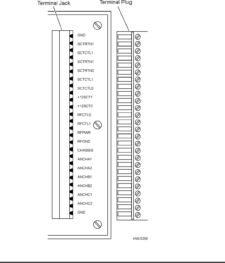
Terminal Designations. . . . . . . . . . . . . . . . . . . . . . . . . . . . . . . . . . . . . . . . . . . . . . . 3-7
Normal Mode Connections . . . . . . . . . . . . . . . . . . . . . . . . . . . . . . . . . . . . . . . . . . . 3-8
Compatibility Mode Connections. . . . . . . . . . . . . . . . . . . . . . . . . . . . . . . . . . . . . . 3-11
4 Testing the RF Module
Setting Voltage . . . . . . . . . . . . . . . . . . . . . . . . . . . . . . . . . . . . . . . . . . . . . . . . . . . . 4-4
5 Indicator Lights
6 Adjusting RF Power
7 Range Modulation Sensitivity Adjustment
A Technical Specifications
Component Specifications . . . . . . . . . . . . . . . . . . . . . . . . . . . . . . . . . . . . . . . . . . . . A-3
Electrical Specifications . . . . . . . . . . . . . . . . . . . . . . . . . . . . . . . . . . . . . . . . . . . A-3
Environmental Specifications . . . . . . . . . . . . . . . . . . . . . . . . . . . . . . . . . . . . . . . A-3
Physical Specifications . . . . . . . . . . . . . . . . . . . . . . . . . . . . . . . . . . . . . . . . . . . . A-3

Contents
ix
List of Figures
Figure 2-1 AR2200 RF Module I/O Interface . . . . . . . . . . . . . . . . . . . . . . . . . . . . . . . . . . . . . 2-4
Figure 3-1 Normal Mode and Compatibility Mode Configurations . . . . . . . . . . . . . . . . . . . . . 3-4
Figure 3-2 RF Module Terminal Connections . . . . . . . . . . . . . . . . . . . . . . . . . . . . . . . . . . . . 3-6
Figure 3-3 Normal Mode Connections . . . . . . . . . . . . . . . . . . . . . . . . . . . . . . . . . . . . . . . . . . 3-8
Figure 3-4 Antenna Output Port Locations . . . . . . . . . . . . . . . . . . . . . . . . . . . . . . . . . . . . . . 3-10
Figure 3-5 Compatibility Mode Connections . . . . . . . . . . . . . . . . . . . . . . . . . . . . . . . . . . . . 3-12
Figure 4-1 RF Board Test Points . . . . . . . . . . . . . . . . . . . . . . . . . . . . . . . . . . . . . . . . . . . . . . 4-3
Figure 5-1 RF Module LED Indicators . . . . . . . . . . . . . . . . . . . . . . . . . . . . . . . . . . . . . . . . . . 5-3
Figure 6-1 RF Power Select Dipswitch Locations . . . . . . . . . . . . . . . . . . . . . . . . . . . . . . . . . 6-3
Figure 7-1 Range Modulation Sensitivity Potentiometers . . . . . . . . . . . . . . . . . . . . . . . . . . . 7-3
List of Tables
Table 1-1 AR2200 RF Module User Guide Information . . . . . . . . . . . . . . . . . . . . . . . . . . . . . . . 1-3
Table 1-2 Typographical Conventions . . . . . . . . . . . . . . . . . . . . . . . . . . . . . . . . . . . . . . . . . . . . 1-4
Table 2-1 AR2200 RF Module Options and Operating Frequency Bands . . . . . . . . . . . . . . . . . 2-6
Table 3-1 RF Module Minimum Wire Gauge Vs. Distance from Reader . . . . . . . . . . . . . . . . . . 3-4
Table 3-2 Jack and Plug Terminal Designations . . . . . . . . . . . . . . . . . . . . . . . . . . . . . . . . . . . . 3-7
Table 3-3 Connecting Wires Between the RF Module and the Reader Interface . . . . . . . . . . . 3-9
Table 3-4 Maximum Cable Lengths for Power Wiring . . . . . . . . . . . . . . . . . . . . . . . . . . . . . . . . 3-9
Table 3-5 Connecting the Check Tag Cable . . . . . . . . . . . . . . . . . . . . . . . . . . . . . . . . . . . . . . 3-11
Table 3-6 Maximum Cable Length for Check Tag Cable . . . . . . . . . . . . . . . . . . . . . . . . . . . . . 3-11
Table 3-7 Connecting Wires Between the RF Modules and the Reader Interface . . . . . . . . . 3-13
Table 3-8 Maximum Cable Lengths for Power Wiring and Signal Wiring . . . . . . . . . . . . . . . . 3-13
Table 3-9 Connecting the System Check Tag Cables . . . . . . . . . . . . . . . . . . . . . . . . . . . . . . 3-14
Table 3-10 Maximum Cable Lengths for Check Tag Cable . . . . . . . . . . . . . . . . . . . . . . . . . . . 3-15
Table 4-1 Test Point Definition . . . . . . . . . . . . . . . . . . . . . . . . . . . . . . . . . . . . . . . . . . . . . . . . . . 4-4
Table 5-1 LED Indicators and Messages . . . . . . . . . . . . . . . . . . . . . . . . . . . . . . . . . . . . . . . . . . 5-3
Table 6-1 RF Power Output Select Dipswitch Settings . . . . . . . . . . . . . . . . . . . . . . . . . . . . . . . 6-4
Table A-1 AR2200 RF Module Electrical Requirements . . . . . . . . . . . . . . . . . . . . . . . . . . . . . .A-3
Table A-2 AR2200 RF Module Environmental Specifications . . . . . . . . . . . . . . . . . . . . . . . . . .A-3
Table A-3 AR2200 RF Module Physical Specifications . . . . . . . . . . . . . . . . . . . . . . . . . . . . . . .A-4
AR2200 RF Module User Guide
x

1
Before You Begin

1-3
Chapter 1
Before You Begin
This chapter describes this guide’s purpose and intended audience. It
provides a list of topics covered in each section, a list of related
documents, and the symbols and typographical conventions used.
Purpose
This guide provides the information necessary for TransCore-certified personnel to
successfully install and test the AR2200 RF Module.
Intended Audience
This guide was written for TransCore-certified personnel who design, configure,
install, test, and maintain TransCore systems in the field.
Guide Topics
Table 1-1 lists the information found in this user guide.
Table 1-1 AR2200 RF Module User Guide Information
Chapter 1–Before You
Begin Describes the purpose, intended audience, guide topics, related
documentation, and document conventions.
Chapter 2–AR2200 RF
Module Overview Provides an overview of the AR2200 RF Module’s features, options, and
accessories.
Chapter 3–Installing the
AR2200 RF Module
Provides detailed installation instructions for installing a stand-alone RF
module, or connecting one or two RF modules to an AI12xx or AI1301
Reader.
Chapter 4–Testing the
AR200 RF Module Provides instructions for testing the installed RF module.
Chapter 5–Indicator
Lights Describes the locations and features of the RF module’s indicator lights.
Chapter 6–Adjusting RF
Power Explains how to adjust the RF power, if needed.
Chapter 7–Sensitivity
Range Adjustment Explains how to adjust the range sensitivity to screen unwanted tag signals.
Appendix A–Technical
Specifications Presents reference information on the AR2200 RF Module.
AR2200 RF Module User Guide
1-4
Typographical Conventions
Table 1-2 lists the conventions used in this manual:
Table 1-2 Typographical Conventions
Convention Indication
This procedure might cause harm to the equipment and/or
the user.
Concerns about a procedure.
Code Code, including keywords and variables within text and as
separate paragraphs, and user-defined program elements
within text appear in courier typeface.
Dialog Box Title Title of a dialog box as it appears on screen.
Function Start with the characters G4, and are in mixed case with no
underscores, and include parentheses after the name, as in
G4FunctionName().
Menu Item Appears on a menu. Capitalization follows the interface.
Note Auxiliary information that further clarifies the current
discussion. These important points require the user’s
attention. The paragraph is in italics and the word Note is
bold.
NUL Zero-value ASCII character or a zero-value byte.
NULL Zero-value pointers. Null-terminated string refers to strings
of printable ASCII characters with a zero-value byte placed
in memory directly after the last printable character of the
string.

Before You Begin
1-5
Health Limits
Within the United States, environmental guidelines regulating safe exposure levels are
issued by the Occupational Safety and health Administration (OSHA).
Section 1910.97 of OSHA Safety and Health Standards 2206 legislates a maximum
safe exposure limit of 10 milliwatts per square centimeter (mW/cm 2 ) averaged over 6
minutes at both 915 and 2450 MHz.
Although not binding, other organizations such as the American National Standards
Institute (ANSI) have issued similar guidelines that are more restrictive than the
OSHA limits (ANSI C95.1). ANSI guidelines recommend a maximum safe power
density in mW/cm2 of:
Thus, the maximum permissible exposure for general population/uncontrolled
exposure at 915 MHz is 0.61 mW/cm2. The power limit is a 6-minute average.
The RF power density generated by Amtech® equipment was calculated using a max-
imum antenna gain of 14 dBi that is equivalent to that typically used in an AR2200
installation.
The antenna gain should not exceed 14 dBi. The antennas used for this transmitter
must not be collocated or operated in conjunction with any other antenna or transmit-
ter.
At 1.6 W transmitted power and a distance of 22 inches (55 cm) from the antenna, the
maximum power density calculated was 0.6 mW/cm2. Install the antennas at least 22
inches (55 cm) from the general public. Maintenance personnel must remain at least
9.7 inches (24.5 cm) from antennas when system is operating.
The data confirms that the Amtech® system effectively meets OSHA requirements
and thus does not represent an operating hazard to either the general public or mainte-
nance personnel.
Frequency
(in MHz)
1500
-------------------------------------------------------
AR2200 RF Module User Guide
1-6

2
Overview of AR2200 RF Module

2-3
Chapter 2
AR2200 RF Module Overview
This chapter presents an overview of the AR2200 RF Module’s features,
options, and accessories.
Overview
The AR2200 RF Module, hereafter referred to as the RF module, is a dual-output
radio transmitter/receiver that, on command from a TransCore reader, generates a
radio frequency (RF) signal in the 865- to 930-MHz radio frequency range, over five
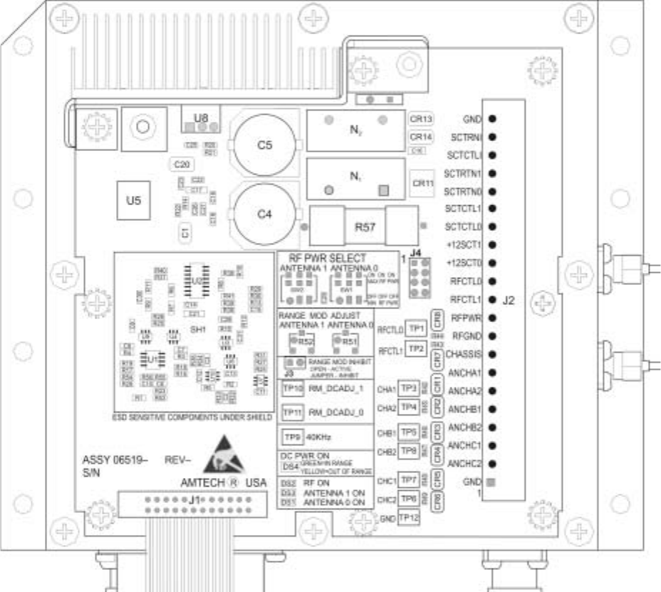
bands, and delivers the signal to the antenna for broadcast. Figure 2-1 shows the top
view of the RF module I/O interface.
AR2200 RF Module User Guide
2-4
Figure 2-1 AR2200 RF Module I/O Interface
The RF module also receives and demodulates the reflected tag signal returned
through the antenna, then preamplifies and conditions the demodulated signal before
sending it to the reader. The RF module generates the RF power necessary to read an
TransCore tag. It also contains receiver and preamplifier circuitry to preprocess the
tag signal returned through the antenna. Once connected to the antenna and reader and
tuned, the RF module should require no further mechanical adjustment by the user.
The RF module receives DC power through a cable connection made to the reader. A
separate reader-to-RF module cable carries the demodulated tag signal from the RF
module to the reader and the on/off control signal from the reader to the RF module
Note: Long coaxial cable lengths between the RF module and antenna can degrade
system performance and should be avoided in system configuration.

AR2200 RF Module Overview
2-5
RF output power is on whenever the reader is on. However, RF output power may be
switched off through reader firmware commands. RF output power can also be con-
trolled through interfacing proximity sensors with the reader. Proximity sensors allow
RF output power to be switched on only in the presence of objects to be identified.
Proximity sensors are useful in installations using battery power or where continuous
RF output power is not desirable.
Increasing or decreasing the RF signal strength directly impacts the system's reading
range. To confine the reading range to its optimal area, RF power can be indepen-
dently adjusted, in eight steps, from +32.5 dBm to +25.5 dBm, for each antenna. You
can adjust the RF power with RF power select switches on the RF module’s input/out-
put (I/O) interface.
Caution
Do not attempt to increase the RF signal strength. Contact TransCore if you think
that you need to adjust the RF signal strength.
For ease of installation, the RF module is connected to the reader by cable attached to
a removable 21-terminal plug.
Features
The RF module includes the features listed in this section.
Range Sensitivity Adjustment
Jumper JP1 can be jumpered to inhibit the effect of the range sensitivity adjustments.
When JP1 is jumpered the maximum broadcast range will be ensured. This may be
done when the RF module is used in a traffic monitoring system where the maximum
size read zone is desired. Sensitivity circuit potentiometers, one for each antenna,
access an infinite range of settings from maximum broadcast range (range sensitivity
adjustment OFF, no mask signal injection) to maximum signal injection (minimum
sensitivity).
ISO Compatible
The RF module meets the criteria for equipment configuration and performance spec-
ified by the International Organization for Standardization’s DIS 10374 container
identification standard.
Patented Design: High-Speed Signal Capture,
Noise Immunity
The RF demodulation circuitry consists of a two-channel homodyne receiver patented
by TransCore that prevents signal loss, allowing the system to read tags moving at
high speeds. The differential aspect of the RF module design improves system
immunity to noise.
Frequency Range
The RF module is available in a range of 865–930 MHz band frequencies (see Table
2-1).1

AR2200 RF Module User Guide
2-6
The primary manufactured frequency for the RF module is 912 MHz. For multiple RF
modules at one site, TransCore recommends using separate frequencies. TransCore
can provide units operating at multiple frequencies in the authorized band.
Preamplifier Line Driver Output
The preamplifier provides balanced low-impedance analog signal lines capable of
driving up to 1,000 ft (305 m) of cable. The preamplifier output incorporates
electrostatic discharge protection.
Note:
Cable lengths over 500 ft (152.4 m) should be used with discretion; longer cables
are more susceptible to receiving electrical noise. For more information on cables and
cable lengths, refer to Chapter 6 of the AI1200 System Guide, "System Configuration."
Connections
The RF module is connected to the reader through cable attached to a 21-terminal
plug. The 21-terminal plug mates with a 21-terminal jack on the RF module interface
board. The plug, removable for servicing, uses captive-screw compression terminals.
The antenna coaxial cable connects to the RF module through an N-type connector on
the side of the RF subassembly.
Circuit Protection
The RF module interface board filters DC power received from the reader and protects
output circuitry from damage caused by transients on the cable between the reader and
RF module.
International Safety Standards
The RF module complies with United States and international RF safety standards as
specified by ANSI C95.1, IEC Pub 215 and 657, and NRPB.
1. The authorized frequency bands in the United States are 902–904 and 909.75–921.75
MHz. Contact TransCore if your application requires a different operating frequency.
Table 2-1 AR2200 RF Module Options and Operating Frequency Bands
RF Module Option Operating Frequency Band (MHz)
-01 865.0 to 869.5
-02 869.501 to 892.0
-03 892.001 to 908.5
-04 908.501 to 917.0
-05 917.001 to 930.0

AR2200 RF Module Overview
2-7
Output Power
The output power of the RF module is set at the factory to 1.6 W.
Options
The following two options are available for the RF module.
Harsh Environment Option
The RF module has a harsh environment option, which is vibration- and shock-
resistant. The vibration specification for the harsh environment RF module is
2 g RMS from 5-500 Hz.
Custom Frequencies
The RF module can be set at the factory to operate at a discrete, narrow band
frequency. This option avoids frequency interference from other closely-situated units
operating at similar frequencies. If your application requires an operating frequency
outside of the 902 to 904 MHz or 909.75 to 921.75 MHz bands, contact TransCore.
Local laws apply in the determination of operating frequencies.
Replacement I/O Interface Board
The I/O interface board is the only replaceable part in the RF module. A ribbon cable
to connect to the RF subassembly is permanently wired to the RF interface board.
Accessories
The following accessories are available for the RF module.
Attenuators
Five-watt 1- to 24-dB attenuators with N-type connectors are available from
TransCore. Other attenuators may be available for specialized applications; contact
TransCore for information. Power output can be reduced by up to 7 dB using the RF
module’s RF power output select feature.
Hex Key
The hex key, used for removal and installation of RF module and reader circuit
boards, has a 0.16-in. (4-mm) hex cross-section and a 9.13-in. (230-mm) shaft.
Weatherproof Enclosure
The RF module may be housed in a weatherproof NEMA-4 enclosure ready for
custom installation. Enclosure locking loops accept padlocks with a maximum 1/4-in.-
(6.3-mm-) diameter shackle.
AR2200 RF Module User Guide
2-8

3
Installing the AR2200 RF Module
3-3
Chapter 3
Installing the AR2200 RF Module
This chapter presents information and procedures for mounting and
installing a stand-alone RF module, or connecting one or two RF
modules to a single AI1200- or AI1301-series Reader.
AR2200 RF Module Installation Options
The AR2200 RF Module can be installed in either of two ways:
•RF module enclosed in a standard NEMA box
•Custom installed using a TransCore standard mounting kit
Differences in Installation Options
NEMA Box — If you install the RF module in a NEMA box, TransCore recommends
that the maximum operating temperature outside the NEMA enclosure not exceed
131°F (55°C).
Custom Installation — You may choose a custom installation for your stand-alone RF
module. If you do, TransCore strongly recommends that you contact TransCore’s
TrAC (the telephone number is listed on page iii of this guide) to have your mounting
option evaluated. TransCore recommends that the maximum outside temperature for
this mounting option not exceed 158°F (70°C). You must use a baseplate that serves
as a heat sink to lower the RF module temperature to an acceptable degree. You must
have an air gap of at least 0.45 inches (1.1 cm) underneath the mounting baseplate. If
you choose not to leave room for an air gap, you can install an additional metal plate
under the baseplate.
Caution
If your custom installation setup does not meet TransCore recommended mounting
constraints, temperatures above the maximum operating temperature may occur
resulting in premature failure of the RF module.
AI1200 Reader Power Supply Upgrade
If you are using the RF module with an AI1200 Reader with TransCore standard AC
power supply (P/N 47049-01, KEPCO ERX 15-4), you must replace that power sup-
ply with a new AC standard power assembly that incorporates a power supply with a
higher current rating.
Configuring the RF Module
The RF module has a dual-antenna output and may be configured to operate in one of
two modes: normal mode or compatibility mode. In normal mode, a single RF module
with one or two antennas is connected to the reader through terminals identified as 0
and 1 on the RF module and the reader. In compatibility mode, two RF modules, each
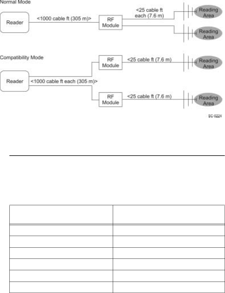
AR2200 RF Module User Guide
3-4
operating one antenna, are connected to one reader with the first RF module connected
to the reader through terminals identified as 0 and the second RF module connected to
the reader through terminals identified as 1.
Figure 3-1 depicts system configurations for normal mode and compatibility mode.
Figure 3-1 Normal Mode and Compatibility Mode Configurations
This section describes the necessary parts and tools, site preparation, and the proce-
dure for installing an interrogator.
Required Wiring
Wire gauges are indicated in Table 3-1. All signal wiring should be twisted pair
shielded.
Table 3-1 RF Module Minimum Wire Gauge Vs. Distance from Reader
Distance from Reader Stranded Copper Wire
(minimum gauge)
0 ft to 50 ft (0 m to 15.2 m) AWG 18
50 ft to 100 ft (15.2 m to 30.5m) AWG 16
100 ft to 250 ft (30.5 m to 76.2 m) AWG 12
250 ft to 500 ft (76.2 m to 152.4 m) AWG 10
500 ft to 750 ft (152.4 m to 228.6 m) AWG 8
750 ft to 1000 ft (228.6 m to 305 m) AWG 6

Installing the AR2200 RF Module
3-5
Required Equipment
•Voltmeter
•Oscilloscope, 100 MHz (for monitoring intermediate frequency [IF] signals and
discriminate signals)
•Data terminal or computer
•Phillips and flat-blade screwdrivers
•N-type 50-ohm load (placed at the antenna port for testing)
•N-type attenuators (as needed to adjust RF power)
Positioning the RF Module
In permanent installations, position the RF module as close as possible to the antenna
and within 1,000 signal cable ft (305 m) of the reader. Long cable lengths will
increase system sensitivity to noise. Coaxial cable runs in excess of 50 ft (15.2 m)
between the RF module and antenna are not recommended.1 Longer signal cable
connections (up to 1,000 cable ft) (305 m) should be made on the reader-to-RF
module link.
Refer to the reader documentation for further information concerning RF module
positioning.
Terminal Connections
The RF module plug and jack connector pair have 21 terminals. Connections from the
reader are made to the removable plug. After connections are made, the plug can be
removed from the jack for interface board servicing or repair/replacement.
Figure 3-2 shows the RF module terminal connections.
1. Based on 2 dB loss, Andrews LDF4-50A 0.5 in. OD coaxial cable. If 3 dB loss is tolera-
ble, cable up to 75 ft (22.9 m) long may be used between the RF module and the antenna.
AR2200 RF Module User Guide
3-6
Figure 3-2 RF Module Terminal Connections
Grounding the RF Module
The CHASSIS terminal is electrically connected to case ground at the factory. Case
ground must be connected to earth ground. TransCore does not recommend that a
conduit connection be used as a grounding point. Ground points must make metal-to-
metal connections.
Note: TransCore does not recommend grounding the case through nonconducting
finishes, such as paint, anodize, or irudite.
Refer to the reader documentation for further information concerning grounding. The
CHASSIS terminal jack is shown in Figure 3-2.

Installing the AR2200 RF Module
3-7
Terminal Designations
The jack and plug terminals are designated for use as listed in Table 3-2.
Table 3-2 Jack and Plug Terminal Designations
Designation Purpose
GND Chassis ground terminal
SCTRTNI System check tag DC return input
(RFGND from reader)
SCTCTLI System check tag control input
(AUXIO0 from reader)
SCTRTN1 System check tag DC return (RFGND)
SCTRTN0 System check tag DC return from check tag (RF
module 0)
SCTCTL1 System check tag control line (RF module 1) a
a. Used only in compatibility mode.
SCTCTL0 System check tag control line
(RF module 1)
+12SCT1 System check tag power for RF module 1 b
b. For +12SCT1 and RFCTL1
+12SCT0 System check tag 12 V DC power
RFCTL0 RF output control channel 0
(RF module 0)
RFCTL1 RF output control channel 1 (RF module 1) b
RFPWR RF power
RFGND RF ground
CHASSIS Connection to NEMA ground
Caution: Do not remove.
ANCHA1 IF signal A1
ANCHA2 IF signal A2
ANCHB1 IF signal B1
ANCHB2 IF signal B2
ANCHC1 IF signal C1
ANCHC2 IF signal C2
GND Chassis ground terminal
AR2200 RF Module User Guide
3-8
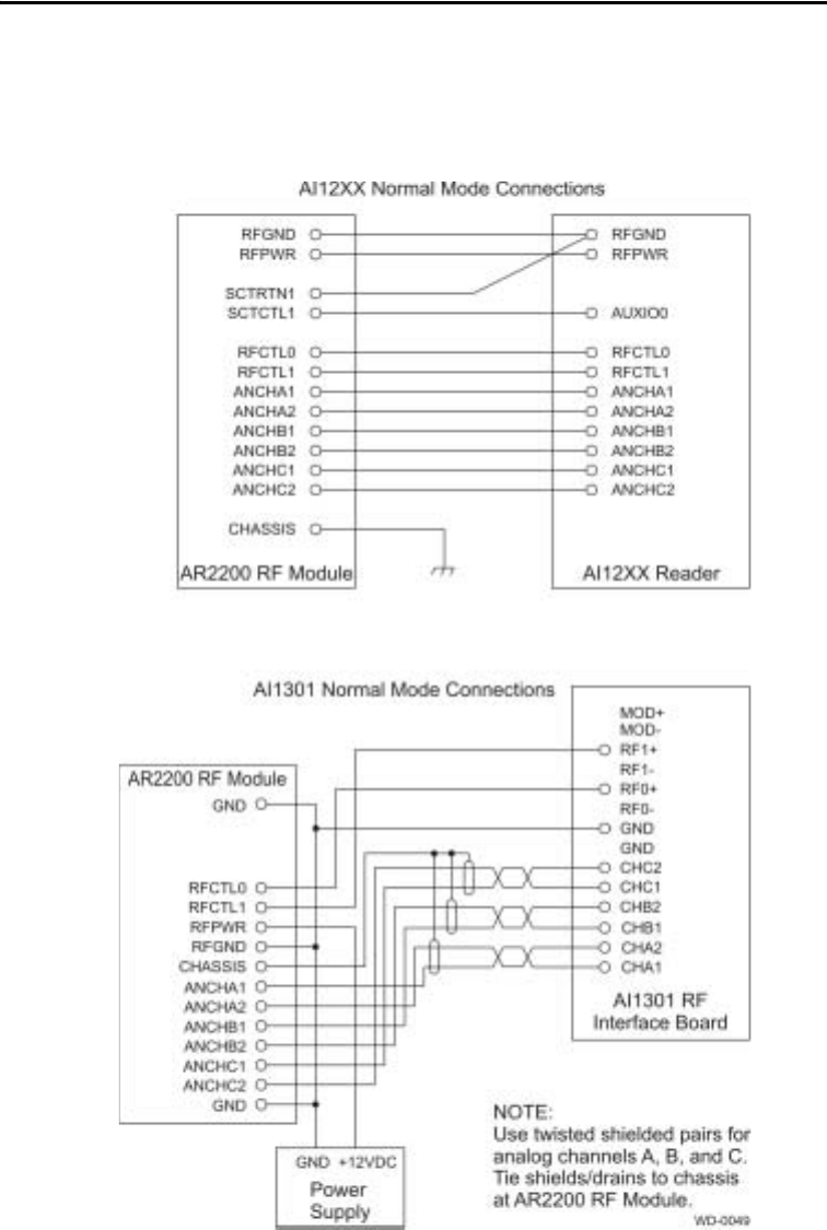
Normal Mode Connections
In normal mode, only one RF module (with one or two antennas) is connected to a
reader. Figure 3-3 shows the connections used for normal mode.
Figure 3-3 Normal Mode Connections

Installing the AR2200 RF Module
3-9
To install your RF module for operation in normal mode, follow these steps:
1. Turn off power to the RF module and the reader.
2. Connect wires between the RF module and the reader interface as shown in Table
3-3. Observe the maximum cable lengths shown in Table 3-4.
Table 3-3 Connecting Wires Between the RF Module and the Reader Interface
Table 3-4 Maximum Cable Lengths for Power Wiring
1. Terminate cable shields at the reader end.
2. For AI1301 readers connect the RF module RFGND and RFPWR terminals to
the +12 V RET (-) and +12 V DC terminals, respectively, of the panel terminal
strip.
RF Module Signal AI12XX Terminal AI1301 RF Interface
Board Terminal
RFGND 43 NA
RFPWR 42 NA
SCTRTNI 43 NA
SCTCTLI 36 NA
RFCTLO 40 10
RFCTL1 41 12
ANCHA1 45 1
ANACA2 46 2
ANCHB1 47 3
ANCHB2 48 4
ANCHC1 49 5
ANCHC2 50 6
Application Cable Type (or
equivalent) Maximum Length
Power wiring Belden 9364 120 ft (36.6 m)
Power wiring Belden 9365 200 ft (61.0 m)
Power wiring Belden 9366 300 ft (91.4 m)
Power wiring Belden 9357 500 ft (152.4 m)
Power wiring Manhattan 33867 500 ft (152.4 m)
Signal wiring Belden 9775 500 ft (152.4 m)
AR2200 RF Module User Guide
3-10
3. Terminate the two antennas output ports (located on the side of the RF
subassembly below the internal ribbon cable) with a cable that is
connected to an antenna or a 50-ohm, N-type, male load. The antenna
output ports must be terminated before turning on power to the reader
and RF module. Figure 3-4 shows the antenna output port locations.
Caution
Turning on RF power with an unterminated antenna port could result in
damage to the RF module.
Figure 3-4 Antenna Output Port Locations
4. Connect the system check tag cable shown in Table 3-5. Observe the
maximum cable length shown in Table 3-6.

Installing the AR2200 RF Module
3-11
Table 3-5 Connecting the Check Tag Cable
Note: Voltage standing wave ratio (VSWR) measurements at the antenna must be
made. Readings should be in line with antenna specifications. See the technical speci-
fications for the antenna for information on appropriate VSWR readings.
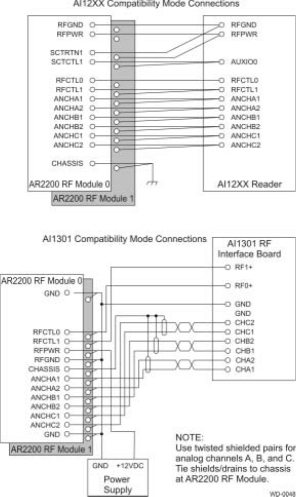
Compatibility Mode Connections
In compatibility mode, two RF modules are connected to a single reader. In
compatibility mode each RF module operates only one antenna.
All compatibility mode connections are made in parallel, with the exception of the RF
control connections. Only one RF control line from the reader (RFCTL0 or RFCTL1)
is connected to each RF module.
Figure 3-5 shows compatibility mode connections.
Check Tag Line RF Module Terminal
for AI12XX AI1301
Red +12SCTO +12 V DC via panel
terminal board
Black SCTRTNO +12 V RET (-) via panel
terminal board
White SCTCTLO Terminal 8 of the RF
interface board
Drain/shield Do not terminate at RF source end. Cut flush with
cable end at RF source.
Table 3-6 Maximum Cable Length for Check Tag Cable
Application Cable Type
(or equivalent) Maximum Length
Check tag cable Belden 9773 100 ft (30.5 m)
AR2200 RF Module User Guide
3-12
Figure 3-5 Compatibility Mode Connections
To install your RF module in compatibility mode, follow these steps:
1. Turn off power to the RF module and the reader.
2. Connect wires between the RF modules and the reader interface shown in Table
3-7. Observe the maximum cable lengths shown in Table 3-8.

Installing the AR2200 RF Module
3-13
1. Terminate cable shields at the reader end.
Table 3-7 Connecting Wires Between the RF Modules and the Reader Interface
RF Module Signal AI12XX Terminal AI1301 RF Interface
Board Terminal
RFGND 43 NA
RFPWR 42 NA
SCTRTNI 43 NA
SCTCTLI 36 NA
RFCTLO 40 (RF module 0
only) 10 (RF module 0 only)
RFCTL1 41(RF module 1
only) 12 (RF module 1 only)
ANCHA1 45 1
ANACA2 46 2
ANCHB1 47 3
ANCHB2 48 4
ANCHC1 49 5
ANCHC2 50 6
Table 3-8 Maximum Cable Lengths for Power Wiring and Signal Wiring
Application Cable Type
(or equivalent) Maximum Length
Power wiring Belden 9364 120 ft (36.6 m)
Power wiring Belden 9365 200 ft (61.0 m)
Power wiring Belden 9366 300 ft (91.4 m)
Power wiring Belden 9357 500 ft (152.4 m)
Power wiring Manhattan 33867 500 ft (152.4 m)
Signal wiring Belden 9775 500 ft (152.4 m)
AR2200 RF Module User Guide
3-14
2. For AI1301 readers connect the RF module RFGND and RFPWR terminals to
the +12 V RET (-) and +12 V DC terminals, respectively, of the panel terminal
strip.
3. Terminate the two antenna output ports (located on the side of the RF
subassembly below the internal ribbon cable) with a cable that is connected to an
antenna or a 50-ohm, N-type, male load as shown below.
RF module 0: ANTENNA 0 to antenna cable
ANTENNA 1 terminated with 50-ohm load
RF module 1: ANTENNA 0 terminated with 50-ohm load
ANTENNA 1 to antenna cable
The antenna output ports must be terminated before turning on power to the reader
and RF module. Figure 3-4 on page 3-10 shows the antenna output port locations.
Caution
Turning on RF power with an unterminated antenna port could result in damage to
the RF module.
1. Connect the system check tag cables as shown in Table 3-9. Observe the
maximum cable length shown in Table 3-10.
Table 3-9 Connecting the System Check Tag Cables
Check Tag Line RF Module Terminal
for AI12XX AI1301
Red +12SCTO +12 V DC via panel
terminal board
Black SCTRTNO +12 V RET (-) via panel
terminal board
White SCTCTLO Terminal 8 of the RF
Interface Board
Drain/Shield Do not terminate at RF source end. Cut flush with
cable end at RF source.
Installing the AR2200 RF Module
3-15
Note: Voltage standing wave ratio (VSWR) measurements at the antenna must be
made. Readings should be in line with antenna specifications. See the antenna techni-
cal specifications for information on appropriate VSWR readings.
Table 3-10 Maximum Cable Lengths for Check Tag Cable
Application Cable Type (or
equivalent) Maximum Length
Check tag cable Belden 9773 100 ft (30.5 m)
AR2200 RF Module User Guide
3-16

4
Testing the RF Module
4-3
Chapter 4
Testing the RF Module
This chapter provides instructions for testing the installed RF module.
(Need required equipment, tools section here.)
After connecting terminals between the RF module and the reader, you should test the
RF module. You will need an oscilloscope and a data terminal or computer connected
to the AI1200 or AI1301 reader.
The RF module has 12 test points, numbered TP1 through TP12 as shown in
Figure 4-1.
Figure 4-1 RF Board Test Points

AR2200 RF Module User Guide
4-4
The test points are defined in Table 4-1.
Table 4-1 Test Point Definition
For optimal RF module performance, verify the following criteria.
1. Power output is 1.6 W ±0.1 W measured when module is powered up and after
15 minutes.
2. IF signal noise is less than 90 mV and output port is terminated.
3. Measured output frequency is ±25 PPM of factory-tuned frequency.
4. IF signal range injection is set to approximately 180 mV, measured at IF signals.
5. DC level range injection is between 0 V DC and 1 V DC, measured at test points
8 and 9.
Setting Voltage
During initial testing, set the DC voltage level at the RF module to a minimum of 11.0
V DC with RF power on and a maximum of 13.5 VDC with RF power off. Make the
adjustment to achieve this DC level at the reader power supply. Adjusting the DC
voltage level compensates for the voltage drop within the DC power cable.
Test Point Purpose
3, 4 (CHA1, CHA2) RF module analog signals A
5, 8 (CHB1, CHB2) RF module analog signals B
7, 6 (CHC1, CHC2) RF module analog signals C
9 (40 kHz) Range modulator (unattenuated), 5-V square wave, 40
KHz
10 (RM_DC_ADJ1) RF1 range adjust level, 5.0–4.0 VDC, with 4.0 VDC
minimum sensitivity and 5.0 VDC maximum sensitivity
11 (RM_DC_ADJ0) RF0 range adjust level, 5.0–4.0 VDC, with 4.0 VDC
minimum sensitivity and 5.0 VDC maximum sensitivity
12 (GND) Oscilloscope or digital multimeter ground point
2 (RCCTL1) RF control line 1, output time on duration
1 (RFCTL0) RF control line 0, output time on duration
J3 (RANGE MOD
INHIBIT) Shorted with jumper to disable modulation feature
Steps 4 & 5 values TBD
according to J. Owerko.

5
Indicator Lights
5-3
Chapter 5
Indicator Lights
This chapter describes the RF module’s indicator lights.
The RF module has four LED indicators on the RF interface board, labeled as shown
in Figure 5-1.
Figure 5-1 RF Module LED Indicators
Each indicator and its message are described in Table 5-1.
Table 5-1 LED Indicators and Messages
Indicator Function Color(s) Message
DS4 DC PWR ON Green/Yellow DC input power
Green–Input in range of 11.5 VDC to 13.5 VDC
Yellow–Input out of range (<11.5 VDC, >13.5 VDC)
OFF–PWR is off
DS2 RF ON Red 12 VDC applied to RFPWR and RFGND
DS3 RF1 ON Red RF output channel 1 on
* Do not disconnect antenna transmission line to
RF output channel 1 when DS3 is on.
DS1 RF0 ON Red RF output channel 0 on
* Do not disconnect antenna transmission line to
RF output channel 0 when DS1 is on.
AR2200 RF Module User Guide
5-4

6
Adjusting RF Power
6-3
Chapter 6
Adjusting RF Power
This chapter explains how to adjust the RF power, if needed.
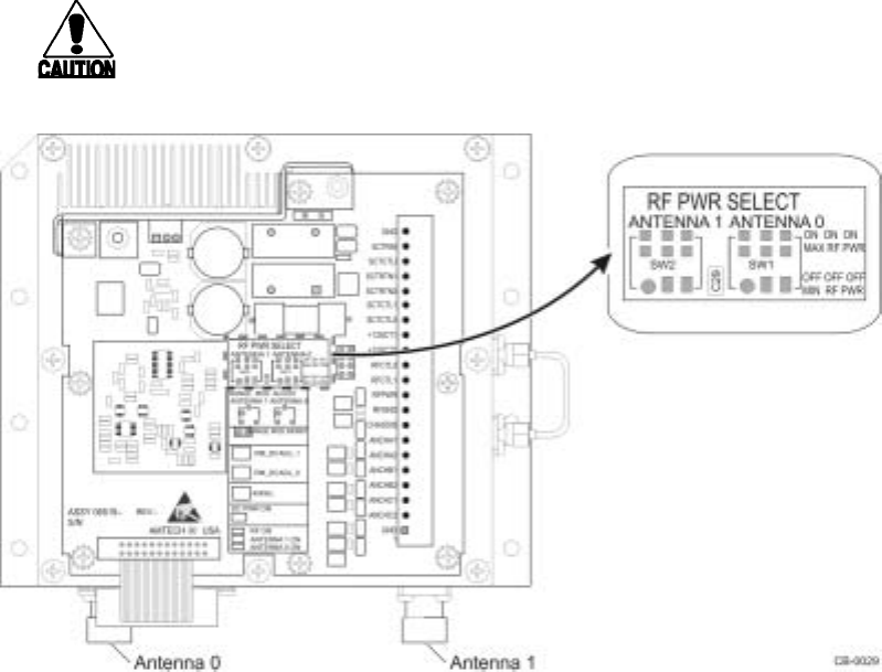
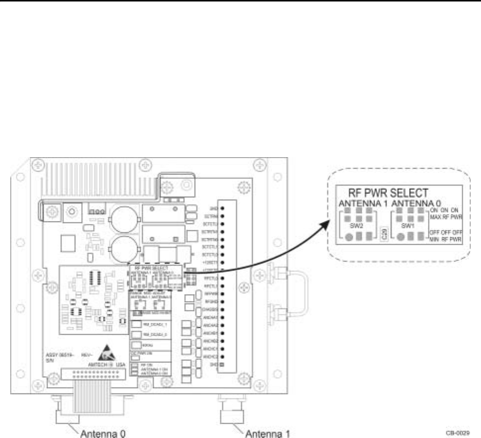
RF power may be independently reduced, when necessary, for each antenna port by
selecting the desired output RF power level setting for the RF PWR Select
dipswitches (SW2 or SW1) for Antenna 1 or Antenna 0. Figure 6-1 shows dipswitch
locations.
Figure 6-1 RF Power Select Dipswitch Locations

AR2200 RF Module User Guide
6-4
Independent RF power output level adjustments, for each antenna port, from +25.5
dBm to +32.5 dBm in 1-dB steps are specified in Table 6-1.
The RF power can be further reduced (independently) for each antenna port by
inserting external (fixed) attenuators between each antenna port and its associated
antenna. This method of independent port power reduction reduceS receiver
sensitivity (increasing attenuation reduces sensitivity). For any application requiring
the addition of external (fixed) attenuators, the power rating of the attenuators should
be at least twice the transmitted power.
Table 6-1 RF Power Output Select Dipswitch Settings
RF PWR SELECT
ANTENNA 1 or ANTENNA 0
DIPSWITCH SETTINGS
RF POWER OUTPUT
ATTENUATION (dB) NOMINAL RF POWER
OUTPUT LEVEL (dBm)
POS 1 (LSB) POS 2 POS 3 (MSB)
ON ON ON 0 (maximum RF power output) +32.5
OFF ON ON 1 +31.5
ON OFF ON 2 +30.5
OFF OFF ON 3 +29.5
ON ON OFF 4 +28.5
OFF ON OFF 5 +27.5
ON OFF OFF 6 +26.5
OFF OFF OFF 7 (minimum RF power output) +25.5

7
Range Modulation Sensitivity Adjustment
7-3
Chapter 7
Range Modulation Sensitivity Adjustment
This chapter explains how to adjust the AR2200 RF Module’s range
modulation sensitivity to screen unwanted tag signals.
The range modulation sensitivity adjustment feature of the RF module is used to
screen unwanted tag signals without decreasing RF power. This feature reduces the
system’s reading range and the difference between peak and continuous read
sensitivity.
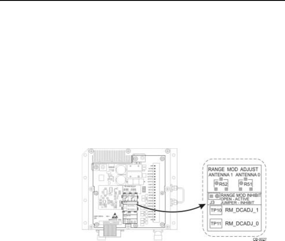
Using the range modulation feature you can independently reduce the receiver
sensitivity levels for Antenna Port 1 or Antenna Port 0 via two 14-turn continuously
adjustable potentiometers (one for each antenna port). You can enable the range
modulation by removing programming jumper J3 (Figure 7-1). Entailing J3 inhibits
the range modulation.
Figure 7-1 Range Modulation Sensitivity Potentiometers
You can enable or disable the range modulation using the two-position programming
jumper, J3 (Figure 7-1). Installing the jumper disables the range modulation.
Removing the jumper enables range modulation.
You can make continuos and independent adjustment for each antenna port via two
14-turn continuously adjustable potentiometers (one for each port) that are located on
the I/O Interface (Figure 7-1). The potentiometers specifics are as follows:
•Antenna Port 1 range modulation sensitivity adjustment: R52 (ANTENNA1)
•Antenna Port 0 range modulation sensitivity adjustment: R51 (ANTENNA0)
AR2200 RF Module User Guide
7-4
To adjust read sensitivity, insert a small flat-blade screwdriver into the potentiometer
slot for the appropriate antenna and rotate the potentiometer fully counter-clockwise
for maximum receiver sensitivity/read range or fully clockwise for minimum receiver
sensitivity/read range.
The sensitivity range parameters are as follows:
•RM_DCADJ_1, RM_DCADJ_0 = 5.0V DC, maximum sensitivity/read range
•RM_DCADJ_1, RM_DCADJ_0 = 4.0V DC, minimum sensitivity/read range
The resulting reduction in receiver sensitivity is as follows:
•0 dB to 20 dB (minimum)
•0 dB to 30 dB (nominal)
The range sensitivity adjustment does not cover the system’s entire tag reading
capability, or dynamic range. For some installations, you may need to reduce RF
power in conjunction with range sensitivity adjustment to achieve the desired results.
Experiment with both RF power attenuation and range sensitivity adjustment to
achieve the optimal read range.

A
AR2200 Technical Specifications
Technical Specifications
A-3
Appendix A
Technical Specifications
This appendix provides reference information for the AR2200 RF
Module.
Component Specifications
This appendix describes the engineering specifications for the AR2200 RF Module.
Electrical Specifications
Table A-1 shows the electrical requirements for the AR2200 RF Module.
Table A-1 AR2200 RF Module Electrical Requirements
Environmental Specifications
The AR2200 RF Module can withstand the environmental conditions shown in Table
A-2.
Table A-2 AR2200 RF Module Environmental Specifications
Physical Specifications
Table A-3 lists the physical specifications of the AR2200 RF Module.
Characteristic Specification
Input power 12 VDC
Power consumption 40 W maximum
Power connection 3-pin connector
Environment Specification
Shock 5 G ½-sine pulse, 10 ms duration, 3 axes
Vibration 1.0 Grms 10 to 500 Hz
Operating temperature -40° to +167°F (-40° to +75°C)
Humidity 95% noncondensing
AR2200 RF Module User Guide
A-4
Table A-3 AR2200 RF Module Physical Specifications
Specification Value
Size 13.5 x 13.0 x 6.36 in (34.3 x 33.0 x 16.2 cm)
Weight 22 lb (10 kg)