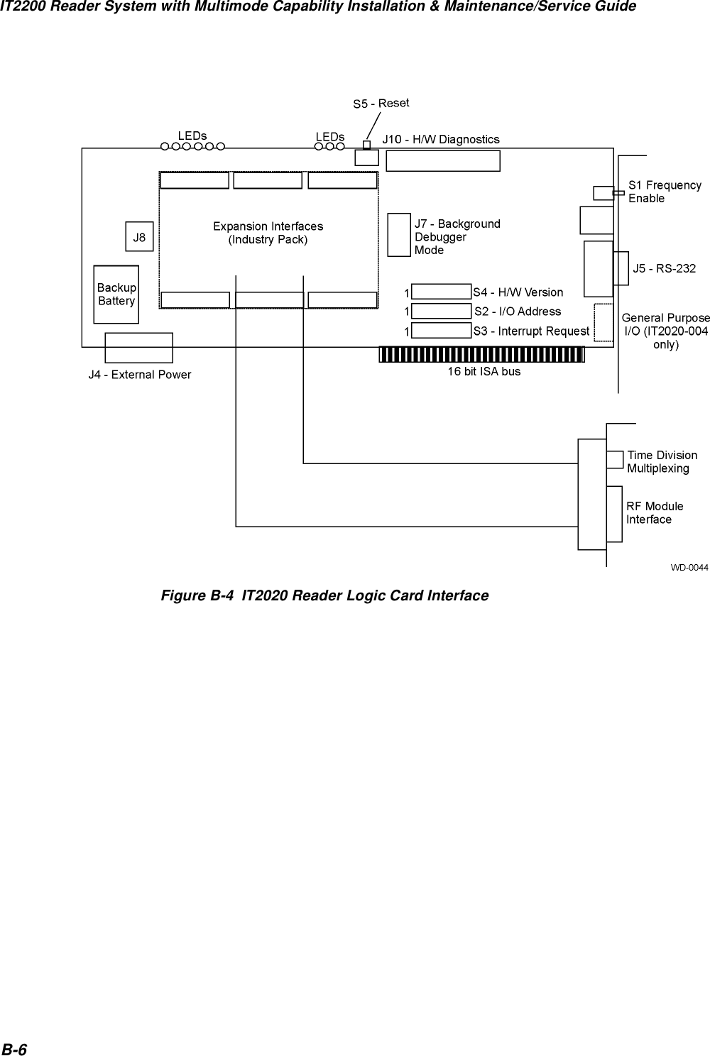
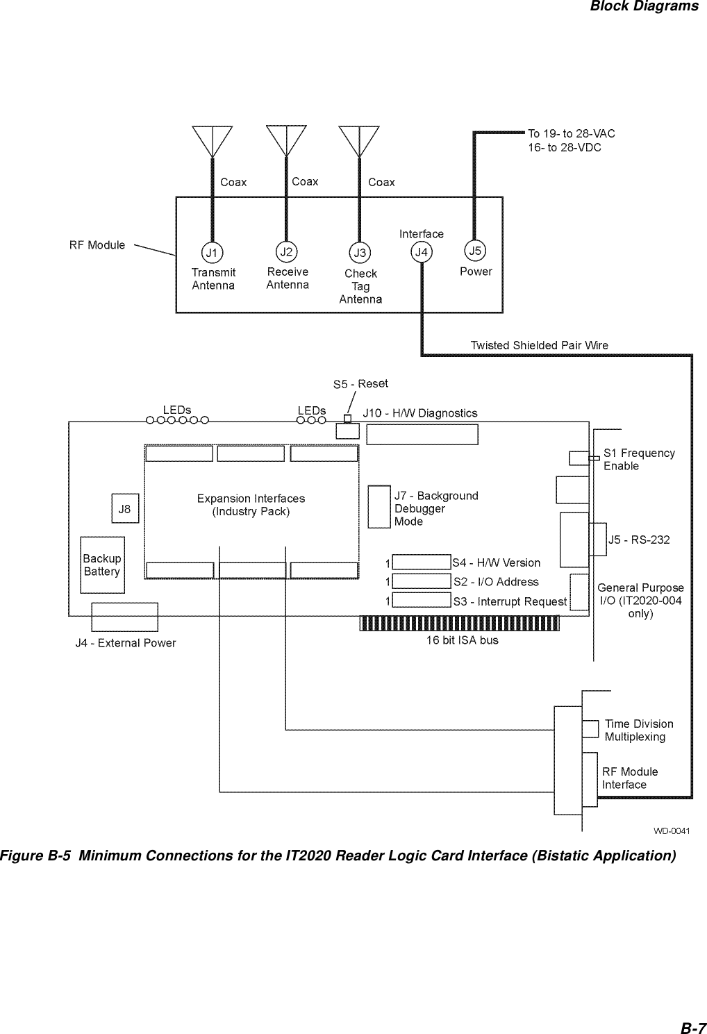
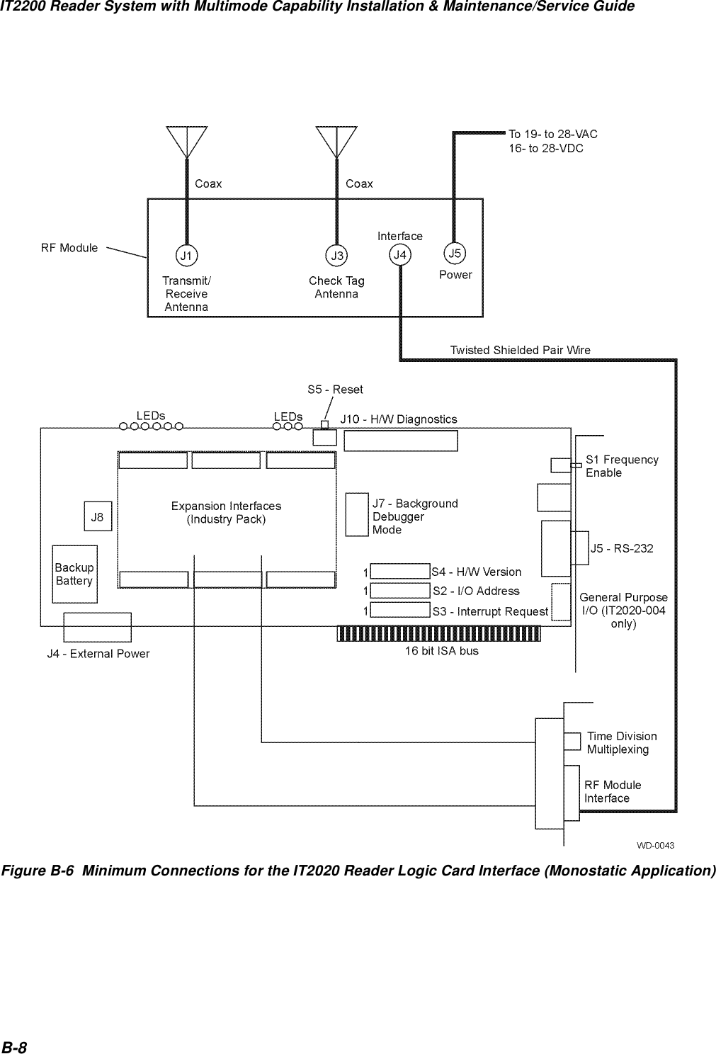
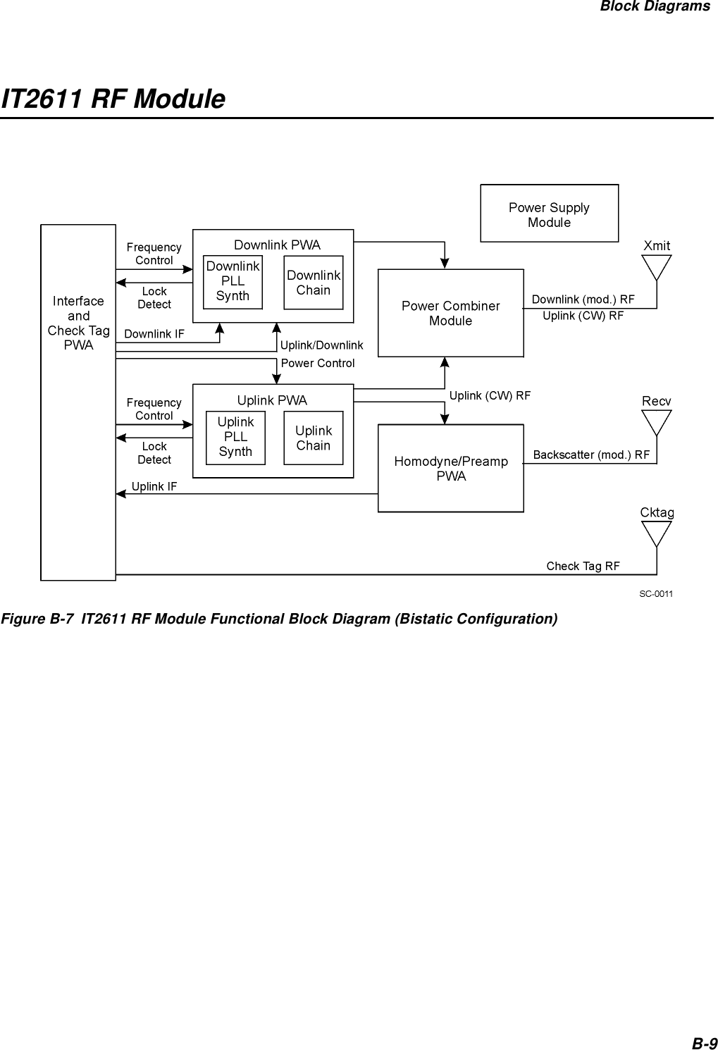
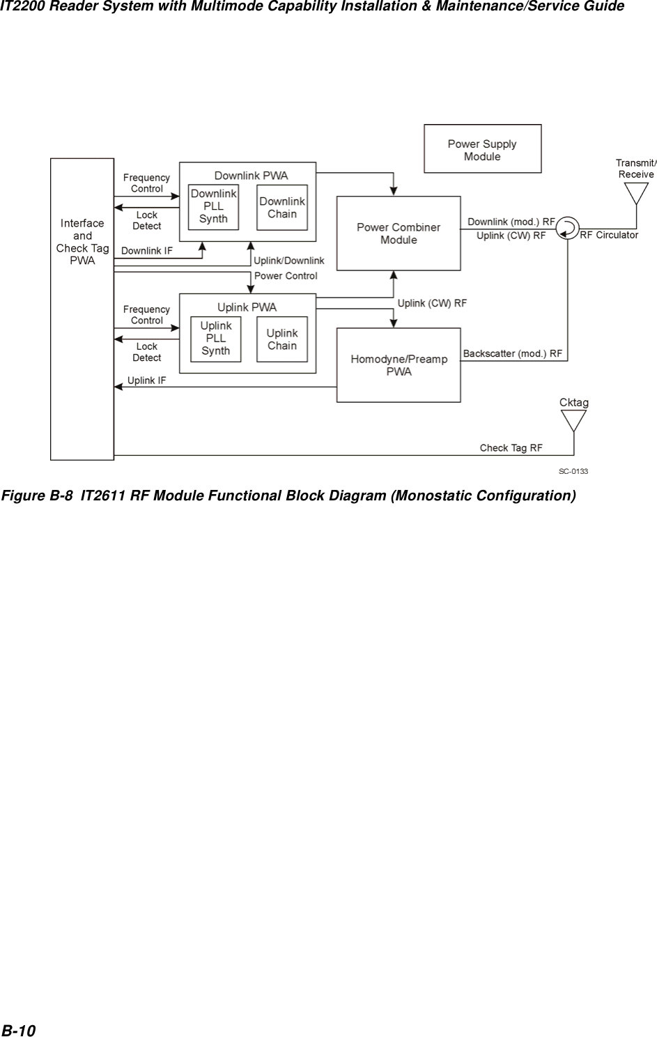
TransCore 2611SS IT2611 RF Transmitter User Manual install

TransCore IT2611 RF Transmitter install

NEW Users Manual

IT2200 Reader SystemP/N 411554Installation & Maintenance/Service Guidewith Multimode Capability
Information in this document is subject to change and does not represent a commitment on the part of TransCore, Inc. ©2002 TransCore, Inc. All rights reserved.  TransCore, TollTag, and Dynamic Tag are trademarks and Amtech, SmartPass, Dynicom, and PassKey are registered trademarks of TransCore, Inc.  The PassKey system is covered by U.S. Patents 5,414,624 and 5,737,710.  All other trademarks listed are the property of their respective owners.  Printed in the U.S.A.For further information, contact:TransCore19111 Dallas Parkway, Suite 300Dallas, Texas  75287-3106 USA  Phone: (972) 733-6600Fax: (972) 733-6699TransCore Action Center (TrAC)19111 Dallas Parkway, Suite 300Dallas, Texas  75287-3106 USA  Phone: (972) 733-6681Fax: (972) 733-6695
WARNING TO USERS IN THE UNITED STATESFEDERAL COMMUNICATIONS COMMISSION (FCC) RADIO FREQUENCY INTERFERENCE STATEMENT47 CFR §15.105(a)NOTE: This equipment has been tested and found to comply with the limits for a Class A digital device pursuant to Part 15 of the Federal Communications Commission (FCC) rules. These limits are designed to provide reasonable protection against harmful interference when the equipment is operated in a commercial environment. This equipment generates, uses, and can radiate radio frequency (RF) energy and may cause harmful interference to radio communications if not installed and used in accordance with the instruction manual. Operating this equipment in a residential area is likely to cause harmful interference, in which case, depending on the laws in effect, the users may be required to correct the interference at their own expense.NO UNAUTHORIZED MODIFICATIONS47 CFR §15.21CAUTION:  This equipment may not be modified, altered, or changed in any way without permission from TransCore, Inc.  Unauthorized modification may void the equipment authorization from the FCC and will void the TransCore warranty.USE OF SHIELDED CABLES IS REQUIRED47 CFR §15.27(a)Shielded cables must be used with this equipment to comply with FCC regulations.A license issued by the FCC is required to operate this RF identification device in the United States. Contact TransCore, Inc. for additional information concerning licensing requirements for specific devices.TransCore, Inc.USA
Contents
 ixContents1 Before You BeginPurpose  . . . . . . . . . . . . . . . . . . . . . . . . . . . . . . . . . . . . . . . . . . . . . . . . . . . . . . . . . 1-3Intended Audience  . . . . . . . . . . . . . . . . . . . . . . . . . . . . . . . . . . . . . . . . . . . . . . . . 1-3Guide Topics  . . . . . . . . . . . . . . . . . . . . . . . . . . . . . . . . . . . . . . . . . . . . . . . . . . . . . 1-3Related Documents . . . . . . . . . . . . . . . . . . . . . . . . . . . . . . . . . . . . . . . . . . . . . . .  1-4Typographical Conventions . . . . . . . . . . . . . . . . . . . . . . . . . . . . . . . . . . . . . . . . . 1-4Licensing Requirements   . . . . . . . . . . . . . . . . . . . . . . . . . . . . . . . . . . . . . . . . . . .1-5U.S. Licensing   . . . . . . . . . . . . . . . . . . . . . . . . . . . . . . . . . . . . . . . . . . . . . . . . . . 1-5Health Limits  . . . . . . . . . . . . . . . . . . . . . . . . . . . . . . . . . . . . . . . . . . . . . . . . . . . . . 1-62 Theory of OperationOverview of RFID Theory 2-3Components 2-3Reader 2-4RF Module 2-5Antennas 2-5Tags 2-7Host Computer 2-8Operational Characteristics 2-8Reading Range 2-9Reading Speed 2-9Number of Characters Stored in Tag 2-9Number of Characters Written to an IT2200-Series Tag 2-9Coding Format of the Tag Data 2-9Tag Orientation and Placement 2-10Noise and Interference Immunity 2-10Frequency and Power 2-11Tag Lifetime 2-11Tag Read/Write Accuracy Rate 2-11Amtech RF Technology 2-11Signal Transmission and Acquisition 2-12
IT2200 Reader System with Multimode Capability Installation & Maintenance/Service GuidexAutomatic Vehicle Identification Transaction Process 2-12Types of RFID Transactions 2-123 System ComponentsOverview 3-3IT2020 Reader Logic Card 3-5Functions 3-5Features 3-6IT2611 RF Module (Bistatic and Monostatic) 3-7RF Module Connections 3-9Transmit Connector (Bistatic RF Module) 3-9Receive Connector (Bistatic RF Module) 3-9Transmit/Receive Connector (Monostatic RF Module) 3-9Check Tag Connector 3-10Data Connector 3-10Power Supply Connector 3-10Functions 3-10Features 3-10Type Testing 3-11RF Emissions 3-11Antennas 3-13AA3152 Universal Toll Antenna 3-13Functions 3-13Features 3-14AA3153 Beacon Antenna 3-14Functions 3-14Features 3-14IT2502 Check Tag Antenna 3-14Check Tag 3-14Tags 3-15IT2221 Tag 3-15Functions 3-17Features 3-18IT2211 Exterior Tag 3-18IT2235 Tag 3-19Functions 3-20Features 3-21ATA Tag 3-23Tag Programmer 3-23IT2410 Tag Programmer 3-24
ContentsxiFunctions 3-24Features 3-254 Installing the IT2200 Reader SystemAssessing the Site and Formulating a Frequency Plan 4-3Site Preparation Checklist 4-4Components Checklist 4-4Task Checklist 4-5Where to Mount the Components 4-5Canopy Mount 4-6Overhead Gantry Mount 4-7Overpass Mount 4-8Cantilever Arm Mount 4-9Lane-side “Pillbox” Mount 4-11Installing the IT2200 Reader System 4-13Installing the IT2020 Reader Logic Card 4-14Installing the IT2611 RF Module 4-17Installing the AA3152 UTA 4-19Installing the AA3153 Beacon Antenna 4-21Installing the IT2502 Check Tag Antenna with a UTA 4-23Installing the IT2502 Check Tag Antenna with a Beacon Antenna 4-245 Tuning the LaneWhy You Need to Tune a Lane 5-3Required Equipment 5-4Optional Equipment 5-4Tuning the Lane 5-5Starting the Engineering Host 5-5Lane Tag Test 5-6Check Tag Test 5-9IT2000 Check Tag Test 5-9ATA Check Tag Test 5-11Testing the Footprint 5-11Running the CAM Test for IT2200-Series Tags 5-11Tag-on-a-Stick Test for IT2235 Tag 5-12Running the CAM Test for ATA-Type Tags 5-13Tag-on-a-Stick Test Using ATA-Type Tag 5-13
IT2200 Reader System with Multimode Capability Installation & Maintenance/Service GuidexiiVehicle-Mounted Tag Test Using IT2235 Tag 5-13Vehicle-Mounted Tag Test Using ATA-Type Tag 5-14Dynamic Performance Test 5-15Starting the Dynamic Performance Test 5-15IT2235 Dynamic Performance Drive-Through Tag Test 5-16IT2221 Dynamic Performance Drive-Through Tag Test 5-16ATA Tag Dynamic Performance Drive-Through Tag Test 5-17Adjusting the Read/Write Zone 5-18Completing Antenna Connections 5-186 Troubleshooting the InstallationRequired Equipment 6-3Cross-Lane Interference in RFID Systems 6-3What Is Cross-Lane Interference? 6-3Determining Acceptable Lane Performance 6-4Identifying Cross-Lane Interference 6-4Diagnosing Cross-Lane Interference 6-5Remedying Cross-Lane Interference 6-5Frequency Separation 6-6RF Power 6-6Time Division Multiplexing 6-6Physical Remedies 6-8Troubleshooting Indications and Actions 6-10Removal and Replacement Procedures 6-17Reader Logic Card 6-17Removal 6-17Replacement 6-17RF Module 6-18Removal 6-18Replacement 6-18Transmit/Receive Antennas 6-18Removal 6-18Replacement 6-18Check Tag Antenna 6-19Removal 6-19Replacement 6-19Data Cable 6-20Removal 6-20Replacement 6-20Antenna Cable 6-20Removal 6-20
ContentsxiiiReplacement 6-207 Preventive MaintenancePreventive Maintenance Schedule 7-3Visual Inspection 7-3A Acronyms and GlossaryB Block DiagramsIT2200 Reader System with Multimode Capability B-3IT2020 Reader Logic Card B-5IT2611 RF Module B-9C System Technical SpecificationsComponent Specifications C-3IT2020 Reader Logic Card C-3Electrical Specifications C-3Environmental Specifications C-4Physical Specifications C-4IT2611 RF Module C-5Interfaces C-5Electrical Specifications C-5Environmental Specifications C-5Physical Specifications C-6Housing Specifications C-6AA3152 Universal Toll Antenna and AA3153 Beacon Antenna C-6Environmental Specifications C-7IT2502 Check Tag Antenna C-7D Hardware InterfacesReader Logic Card Hardware Interconnection D-316 Bit ISA Bus D-4Optional External Power D-5Expansion Interfaces (Industry Pack) D-5LEDs D-6
IT2200 Reader System with Multimode Capability Installation & Maintenance/Service GuidexivTime Division Multiplexing Connector D-6Background Debugger Connector D-7General Purpose I/O Port (IT2020-004 Reader) D-8Hardware Diagnostic Port D-8RS-232 D-10IT2020 Reader Logic Card Interface D-11Pin Designations D-11IT2020 ISA Card Interface Connector D-11Interface Connector D-19Power Connector D-20Reader-to-RF Module Communications D-20RF Module Interface Connector D-21IT2410 Tag Programmer Hardware Interconnection D-23E Connector PinoutsIT2020 Reader Logic Card E-3Tag Data/Control E-3TDM E-5ISA Bus E-5IP Module Logic Interface E-9IP Module I/O Connector E-11Auxiliary Power E-13BDM E-14General Purpose I/O E-15HW Diagnostics Port E-16RS-232 E-17IT2611 RF Module E-18 Index(Index to be supplied with final version of guide.)
List of FiguresxvList of FiguresFigure 2-1  Typical RFID Components for a Bistatic (Two-Antenna) Configuration  . . . . . . . . . . .  2-4Figure 2-2  Field Size, Shape, and Antenna Polarization Define the Reading Range(Bistatic Configuration)   . . . . . . . . . . . . . . . . . . . . . . . . . . . . . . . . . . . . . . . . . . 2-6Figure 2-3  Field Size, Shape, and Antenna Polarization Define the Reading Range(Monostatic Configuration)  . . . . . . . . . . . . . . . . . . . . . . . . . . . . . . . . . . . . . . . .  2-6Figure 2-4  Tag Orientation with Linear Polarized Antenna . . . . . . . . . . . . . . . . . . . . . . . . . .  2-10Figure 2-5  Typical Read/Write Transaction Using the IT2200 Reader System and anIT2200-Series Tag  . . . . . . . . . . . . . . . . . . . . . . . . . . . . . . . . . . . . . . . . . . . . .  2-13Figure 2-6  Four Transactions Can Occur Within 96 Milliseconds   . . . . . . . . . . . . . . . . . . . . .  2-14Figure 2-7  Typical Read-only Transaction Using the IT2200 Reader System inATA Mode Operation with an ATA-Type Tag   . . . . . . . . . . . . . . . . . . . . . . . . . . .  2-15Figure 2-8  Typical Dedicated Read-Only Transaction Using the IT2200 Reader System inMultimode Operation with an ATA-Type Tag  . . . . . . . . . . . . . . . . . . . . . . . . . . .  2-15Figure 2-9  Typical Read-Only Transaction Using the IT2200 Reader System inATA Mode Operation with an ATA-Type Tag   . . . . . . . . . . . . . . . . . . . . . . . . . . .  2-16Figure 3-1  Relationship of the IT2200 Reader System Components(Bistatic Installation Shown) . . . . . . . . . . . . . . . . . . . . . . . . . . . . . . . . . . . . . . .  3-3Figure 3-2  IT2020 Reader Logic Card . . . . . . . . . . . . . . . . . . . . . . . . . . . . . . . . . . . . . . . . .  3-5Figure 3-3  IT2020 Reader Logic Card Block Diagram  . . . . . . . . . . . . . . . . . . . . . . . . . . . . . .  3-7Figure 3-4  IT2611 RF Module Connections (Bistatic Configuration)   . . . . . . . . . . . . . . . . . . . .  3-8Figure 3-5  IT2611 RF Module Connections (Monostatic Configuration)  . . . . . . . . . . . . . . . . . .  3-9Figure 3-6  Tag Orientation with Linear Polarized Antenna . . . . . . . . . . . . . . . . . . . . . . . . . .  3-13Figure 3-7  IT2221 Tag Block Diagram   . . . . . . . . . . . . . . . . . . . . . . . . . . . . . . . . . . . . . . .  3-16Figure 3-8  Alternative Mounting Locations for IT2221 Tag   . . . . . . . . . . . . . . . . . . . . . . . . .  3-17Figure 3-9   IT2211 Tag Placement  . . . . . . . . . . . . . . . . . . . . . . . . . . . . . . . . . . . . . . . . . .  3-18Figure 3-10  IT2235 Tag Block Diagram   . . . . . . . . . . . . . . . . . . . . . . . . . . . . . . . . . . . . . .  3-19Figure 3-11  IT2235 Tag Display Features  . . . . . . . . . . . . . . . . . . . . . . . . . . . . . . . . . . . . .  3-22Figure 3-12  IT2410 Tag Programmer System   . . . . . . . . . . . . . . . . . . . . . . . . . . . . . . . . . .  3-24Figure 3-13  Tag Programming Head   . . . . . . . . . . . . . . . . . . . . . . . . . . . . . . . . . . . . . . . .  3-25Figure 4-1   Canopy Mount   . . . . . . . . . . . . . . . . . . . . . . . . . . . . . . . . . . . . . . . . . . . . . . . .  4-6Figure 4-2  Overhead Gantry Mount   . . . . . . . . . . . . . . . . . . . . . . . . . . . . . . . . . . . . . . . . . .  4-7Figure 4-3  Overpass Mount   . . . . . . . . . . . . . . . . . . . . . . . . . . . . . . . . . . . . . . . . . . . . . . . 4-8Figure 4-4  Cantilever Arm Mount (Bistatic Configuration)  . . . . . . . . . . . . . . . . . . . . . . . . . . .  4-9Figure 4-5  Cantilever Arm Mount (Monostatic Configuration)   . . . . . . . . . . . . . . . . . . . . . . .  4-10Figure 4-6  Bistatic Laneside Mount  . . . . . . . . . . . . . . . . . . . . . . . . . . . . . . . . . . . . . . . . .  4-11Figure 4-7  Monostatic Laneside Mount   . . . . . . . . . . . . . . . . . . . . . . . . . . . . . . . . . . . . . .  4-12Figure 4-8  Antenna Placement for Pillbox Mount  . . . . . . . . . . . . . . . . . . . . . . . . . . . . . . . .  4-13Figure 4-9  IT2020 Reader Logic Card Installed in Typical Host Computer or Lane ControllerChassis (Top View)  . . . . . . . . . . . . . . . . . . . . . . . . . . . . . . . . . . . . . . . . . . . .  4-14Figure 4-10  IT2020 Reader Logic Card Factory Dipswitch Settings  . . . . . . . . . . . . . . . . . . . .  4-15Figure 4-11  Frequency Enable Switch on Rear of IT2020 Reader Logic Card  . . . . . . . . . . . . .  4-16Figure 4-12  Location of Battery Jumper (J8) in Relation to Battery . . . . . . . . . . . . . . . . . . . .  4-16Figure 4-13  IT2611 RF Module Mounting and Components for Both Monostaticand Bistatic Configurations   . . . . . . . . . . . . . . . . . . . . . . . . . . . . . . . . . . . . . .  4-18
IT2200 Reader System with Multimode Capability Installation & Maintenance/Service GuidexviFigure 4-14  IT2611 RF Module Connectors (Monostatic RF Module Shown)   . . . . . . . . . . . . .  4-19Figure 4-15  AA3152 UTA Mounting and Connections  . . . . . . . . . . . . . . . . . . . . . . . . . . . . .  4-20Figure 4-16  AA3153 Beacon Antenna Mounting  . . . . . . . . . . . . . . . . . . . . . . . . . . . . . . . . .  4-22Figure 4-17  IT2502 Check Tag Antenna Mounting   . . . . . . . . . . . . . . . . . . . . . . . . . . . . . . .  4-23Figure 5-1  Background Status Information Screen  . . . . . . . . . . . . . . . . . . . . . . . . . . . . . . . .  5-6Figure 5-2  Sample RF Attenuation Statistics for Check Tag . . . . . . . . . . . . . . . . . . . . . . . . . .  5-7Figure 5-3  Acceptable RF Attenuation Statistics   . . . . . . . . . . . . . . . . . . . . . . . . . . . . . . . . .  5-8Figure 5-4  Ranges of RF Attenuation Statistics  . . . . . . . . . . . . . . . . . . . . . . . . . . . . . . . . . .  5-9Figure 5-5  Sample Continuous Check Tag Read Request Display . . . . . . . . . . . . . . . . . . . . .  5-10Figure 5-6  Typical Read/Write Zone for a Reader (Bistatic Configuration) . . . . . . . . . . . . . . .  5-12Figure 5-7  Location of LEDs on Reader Logic Card   . . . . . . . . . . . . . . . . . . . . . . . . . . . . . .  5-17Figure 6-1  RF Footprint Extends Beyond Lane Boundaries (Bistatic Configuration Shown) . . . . .  6-5Figure 6-2  TDM Synchronization  . . . . . . . . . . . . . . . . . . . . . . . . . . . . . . . . . . . . . . . . . . . .  6-7Figure 6-3  Antenna Tilt Angle Adjustment   . . . . . . . . . . . . . . . . . . . . . . . . . . . . . . . . . . . . .  6-9Figure 6-4  Downlink Antenna Side Angle Adjustment . . . . . . . . . . . . . . . . . . . . . . . . . . . . .  6-10Figure 6-5  Location of Battery Jumper (J8) in Relation to Battery   . . . . . . . . . . . . . . . . . . . .  6-12Figure 6-6  Frequency Enable Switch on Rear of IT2020 Reader Logic Card  . . . . . . . . . . . . . .  6-12Figure 7-1  Visual Inspection Process . . . . . . . . . . . . . . . . . . . . . . . . . . . . . . . . . . . . . . . . .  7-4Figure B-1  IT2200 Bistatic Reader System Functional Block Diagram . . . . . . . . . . . . . . . . . . .  B-3Figure B-2  IT2200 Monostatic Reader System Functional Block Diagram  . . . . . . . . . . . . . . . .  B-4Figure B-3  IT2020 Reader Logic Card Functional Block Diagram  . . . . . . . . . . . . . . . . . . . . . .  B-5Figure B-4  IT2020 Reader Logic Card Interface  . . . . . . . . . . . . . . . . . . . . . . . . . . . . . . . . . .  B-6Figure B-5  Minimum Connections for the IT2020 Reader Logic Card Interface(Bistatic Application)   . . . . . . . . . . . . . . . . . . . . . . . . . . . . . . . . . . . . . . . . . . .  B-7Figure B-6  Minimum Connections for the IT2020 Reader Logic Card Interface(Monostatic Application)  . . . . . . . . . . . . . . . . . . . . . . . . . . . . . . . . . . . . . . . . .  B-8Figure B-7  IT2611 RF Module Functional Block Diagram (Bistatic Configuration) . . . . . . . . . . .  B-9Figure B-8  IT2611 RF Module Functional Block Diagram (Monostatic Configuration)  . . . . . . .  B-10Figure D-1  Locations of Switches on IT2020 Reader Logic Card   . . . . . . . . . . . . . . . . . . . . . . D-4Figure D-2  Typical TDM Installation   . . . . . . . . . . . . . . . . . . . . . . . . . . . . . . . . . . . . . . . . . D-6Figure D-3  Locations of LEDs on IT2020 Reader Logic Card   . . . . . . . . . . . . . . . . . . . . . . . .  D-18Figure D-4  Bistatic RF Module Interface . . . . . . . . . . . . . . . . . . . . . . . . . . . . . . . . . . . . . .  D-19Figure D-5  Monostatic RF Module Interface  . . . . . . . . . . . . . . . . . . . . . . . . . . . . . . . . . . .  D-19Figure D-6  Twenty-six Pin Connector Showing Terminal Designators (RF Module) . . . . . . . . .  D-20Figure D-7  IT2410 Tag Programmer Power Connections . . . . . . . . . . . . . . . . . . . . . . . . . . .  D-24
List of TablesxviiList of TablesTable 1-1  Typographical Conventions   . . . . . . . . . . . . . . . . . . . . . . . . . . . . . . . . . . . . . . . .  1-4Table 2-1  Time and Distance Required to Complete Payment Zone   . . . . . . . . . . . . . . . . . . .  2-14Table 3-1  IT2611 RF Module Uplink and Downlink Specifications   . . . . . . . . . . . . . . . . . . . .  3-12Table 3-2  Example of Condition Code Bit Programming for IT2235 Tag  . . . . . . . . . . . . . . . . .  3-21Table 3-3  Audio/Visual Options Bits Decoding for IT2235 Tag  . . . . . . . . . . . . . . . . . . . . . . .  3-23Table 3-4  IT2410 Tag Programmer Indicator LEDs and Descriptions . . . . . . . . . . . . . . . . . . .  3-26Table 4-1  Example Frequency Plan for Four-Lane Plaza  . . . . . . . . . . . . . . . . . . . . . . . . . . . .  4-4Table 4-2  Listing of Shorted Pins for Loopback Connector . . . . . . . . . . . . . . . . . . . . . . . . . .  4-14Table 6-1  Frequency Plan for Four-Lane Toll Plaza   . . . . . . . . . . . . . . . . . . . . . . . . . . . . . . . 6-6Table 6-2  Frequency Settings Using TDM for Four-Lane Toll Plaza with TDM . . . . . . . . . . . . . .  6-8Table 6-3  Failure Indicated by Host Software Diagnostics . . . . . . . . . . . . . . . . . . . . . . . . . .  6-11Table 6-4  Failure During Check Tag Test   . . . . . . . . . . . . . . . . . . . . . . . . . . . . . . . . . . . . .  6-13Table 6-5  Unacceptable RF Attenuation Statistics Using Check Tag  . . . . . . . . . . . . . . . . . . .  6-13Table 6-6  Unacceptable RF Attenuation Statistics Using Vehicle-Mounted Tag   . . . . . . . . . . .  6-13Table 6-7  Self-Test Fail LED on Reader Logic Card Lights . . . . . . . . . . . . . . . . . . . . . . . . . .  6-14Table 6-8  Spotty Pattern or Low Handshake Counts  . . . . . . . . . . . . . . . . . . . . . . . . . . . . . .  6-15Table 7-1  Preventive Maintenance Schedule . . . . . . . . . . . . . . . . . . . . . . . . . . . . . . . . . . . .  7-3Table C-1  IT2020 Reader Logic Card Electrical Requirements  . . . . . . . . . . . . . . . . . . . . . . . . C-3Table C-2  IT2020 Reader Logic Card Power Consumption . . . . . . . . . . . . . . . . . . . . . . . . . . . C-4Table C-3  IT2020 Reader Logic Card Environmental Tolerances   . . . . . . . . . . . . . . . . . . . . . . C-4Table C-4  IT2020 Reader Logic Card Physical Specifications   . . . . . . . . . . . . . . . . . . . . . . . . C-4Table C-5  IT2611 RF Module Electrical Requirements   . . . . . . . . . . . . . . . . . . . . . . . . . . . . . C-5Table C-6  IT2611 RF Module Environmental Specifications . . . . . . . . . . . . . . . . . . . . . . . . . . C-6Table C-7  IT2611 RF Module Physical Specifications  . . . . . . . . . . . . . . . . . . . . . . . . . . . . . . C-6Table C-8  Antenna Environmental Tolerances  . . . . . . . . . . . . . . . . . . . . . . . . . . . . . . . . . . . C-7Table D-1  Optional External Power Pin Definition   . . . . . . . . . . . . . . . . . . . . . . . . . . . . . . . . D-5Table D-2  TDM Connector   . . . . . . . . . . . . . . . . . . . . . . . . . . . . . . . . . . . . . . . . . . . . . . . . D-7Table D-3  BDM Connector   . . . . . . . . . . . . . . . . . . . . . . . . . . . . . . . . . . . . . . . . . . . . . . . . D-7Table D-4  General Purpose I/O Connector . . . . . . . . . . . . . . . . . . . . . . . . . . . . . . . . . . . . . . D-8Table D-5  Hardware Diagnostic Port   . . . . . . . . . . . . . . . . . . . . . . . . . . . . . . . . . . . . . . . . . D-9Table D-6  RS-232 Connector . . . . . . . . . . . . . . . . . . . . . . . . . . . . . . . . . . . . . . . . . . . . . . D-10Table D-7  IT2020 Reader Logic Card Default I/O Settings  . . . . . . . . . . . . . . . . . . . . . . . . . . D-11Table D-8  IT2020 Reader Logic Card Default IRQ Settings   . . . . . . . . . . . . . . . . . . . . . . . . . D-11Table D-9  ISA Bus Pin Definition  . . . . . . . . . . . . . . . . . . . . . . . . . . . . . . . . . . . . . . . . . . . D-11Table D-10  Optional External Power Pin Definition   . . . . . . . . . . . . . . . . . . . . . . . . . . . . . . D-15Table D-11  IP Module Logic Interface Connector  . . . . . . . . . . . . . . . . . . . . . . . . . . . . . . . . D-15Table D-12  IP Module I/O Connector   . . . . . . . . . . . . . . . . . . . . . . . . . . . . . . . . . . . . . . . . D-17Table D-13  LEDs  . . . . . . . . . . . . . . . . . . . . . . . . . . . . . . . . . . . . . . . . . . . . . . . . . . . . . . D-18Table D-14  RF Module-to-Reader Logic Card Interface Connector   . . . . . . . . . . . . . . . . . . . . D-21Table D-15  RF Module Power    . . . . . . . . . . . . . . . . . . . . . . . . . . . . . . . . . . . . . . . . . . . . D-23Table D-16  RF Module-Antenna Connectors for Bistatic Operation  . . . . . . . . . . . . . . . . . . . . D-23Table D-17  RF Module-Antenna Connectors for Monostatic Operation   . . . . . . . . . . . . . . . . . D-23Table D-18  IT2410 Tag Programmer Interconnection  . . . . . . . . . . . . . . . . . . . . . . . . . . . . .  D-24
IT2200 Reader System with Multimode Capability Installation & Maintenance/Service GuidexviiiTable E-1  Tag Data/Control Interface Connector   . . . . . . . . . . . . . . . . . . . . . . . . . . . . . . . . .  E-3Table E-2  TDM Connector   . . . . . . . . . . . . . . . . . . . . . . . . . . . . . . . . . . . . . . . . . . . . . . . .  E-4Table E-3  ISA Bus Pin Definition  . . . . . . . . . . . . . . . . . . . . . . . . . . . . . . . . . . . . . . . . . . . .  E-5Table E-4  IP Module Logic Interface Connector  . . . . . . . . . . . . . . . . . . . . . . . . . . . . . . . . . .  E-9Table E-5  IP Module I/O Connector   . . . . . . . . . . . . . . . . . . . . . . . . . . . . . . . . . . . . . . . . .  E-11Table E-6  Auxiliary Power Connector . . . . . . . . . . . . . . . . . . . . . . . . . . . . . . . . . . . . . . . .  E-13Table E-7  BDM Connector   . . . . . . . . . . . . . . . . . . . . . . . . . . . . . . . . . . . . . . . . . . . . . . .  E-14Table E-8  General Purpose I/O Connector . . . . . . . . . . . . . . . . . . . . . . . . . . . . . . . . . . . . .  E-15Table E-9  Hardware Diagnostics Port Connector  . . . . . . . . . . . . . . . . . . . . . . . . . . . . . . . .  E-16Table E-10  RS-232 Connector . . . . . . . . . . . . . . . . . . . . . . . . . . . . . . . . . . . . . . . . . . . . .  E-17Table E-11  RF Module-To-Reader Logic Card Interface Connector  . . . . . . . . . . . . . . . . . . . .  E-18Table E-12  RF Module Power  . . . . . . . . . . . . . . . . . . . . . . . . . . . . . . . . . . . . . . . . . . . . .  E-19Table E-13  RF Module-Antenna Connectors   . . . . . . . . . . . . . . . . . . . . . . . . . . . . . . . . . . .  E-19
1Before You Begin
1-3Chapter 1Before You BeginThis chapter describes this guide’s purpose and intended audience. It provides a list of topics covered in each section, a list of related documents, and the symbols and typographical conventions used. A discussion on licensing requirements and health limits for radio frequency devices is also included.PurposeThis guide provides the information necessary for TransCore-certified personnel to successfully install an Amtech® IT2200 Reader System with Multimode Capability at an electronic toll collection (ETC) site that has been designed and built to use this sys-tem.Intended AudienceThis guide should be used by TransCore-certified personnel who will design, config-ure, program, and test the Amtech® IT2200 Reader System with Multimode Capabil-ity in the field.Guide TopicsThis installation guide contains the following chapters and appendixes:Chapter 1 – Before You Begin Describes the purpose, intended audience, guide topics, related documentation, and document conventions. Also contained are licensing requirements and health limits for the RFID equipment.Chapter 2 – Theory of Operation Provides an overview of RFID theory, Amtech® RFID technology, and operational characteristics of the IT2200 Reader System with Multimode Capability.Chapter 3 – Overview of the IT2200 Reader System Describes the individual components and their interrelationships.Chapter 4 – Installing the IT2200 Reader System Provides instructions for installing the system.Chapter 5 – Tuning the Lane Provides instructions for testing and tuning an installed system.
IT2200 Reader System with Multimode Capability Installation & Maintenance/Service Guide1-4Related DocumentsRefer to the following documents for more information about operating the IT2200 Reader System with Multimode Capability components and for programming IT2200-series tags:•IT2200 Reader System with Multimode Capability Operations Guide•IT2410 Tag Programmer User GuideChapter 6 – Troubleshooting the Installation Describes problems that might occur during installation and tests and provides workable solutions.Chapter 7 – Preventive Maintenance Provides schedules and instructions for performing preventive maintenance on the IT2200 Reader System with Multimode Capability components.Appendix A – Acronyms and Glossary Provides an alphabetical list of abbreviations, acronyms, and terms used in this guide.Appendix B – Block Diagrams Provides block diagrams of the system components.Appendix C – System Technical Specifications Provides product information and technical specifications for the system components.Appendix D – Hardware Interfaces Describes the physical interconnections within the IT2200 Reader System with Multimode Capability.Appendix E – Connector Pin-outs Provides connector pin-outs for the IT2020 Reader Logic Card and IT2611 RF Module.Index Provides alphabetical listing of key information in this guide. (To be supplied with final version of guide.)
Before You Begin1-5Typographical ConventionsThe following conventions are used in this manual:Licensing RequirementsTo operate a radio frequency (RF) system in a given country, the user must first obtain permission from the regulatory agency that controls radio operations in that country.Most countries require type and safety approval, as well as licensing for RF transmit-ters.Amtech® data and literature are available to assist approval and licensing activities.Table 1-1  Typographical ConventionsConvention IndicationThis procedure might cause harm to the equipment and/or the user.Concerns about a procedure.Code Code, including keywords and variables within text and as separate paragraphs, and user-defined program elements within text appear in courier typeface.Dialog Box Title Title of a dialog box as it appears on screen.Function Start with the characters G4 and add mixed case with no underscores, and include parentheses after the name, as in G4FunctionName().Menu Item Appears on a menu.NoteAuxiliary information that further clarifies the current discussion. These important points require the user’s attention. The paragraph is in italics and the word Note is bold.NUL Zero-value ASCII character or a zero-value byte.NULL Zero-value pointers are null-terminated strings that refer to strings of printable ASCII characters with a zero-value byte placed in memory directly after the last printable character of the string.
IT2200 Reader System with Multimode Capability Installation & Maintenance/Service Guide1-6U.S. LicensingIT2200 Reader System with Multimode Capability users in the U.S. must obtain a license from the Federal Communications Commission (FCC). The authorized fre-quency bands in the U.S. are 902 to 904 and 909.75 to 921.75 MHz.The user is responsible for filing the FCC license according to FCC regulations, but the Amtech® dealer should provide assistance and support as necessary to complete these forms.An FCC license provides the user with the legal authorization to operate the IT2200 Reader System with Multimode Capability on the licensed frequencies at the site specified in the license. Only an authorized installer or service technician can set the IT2200 series of readers’ frequency to that specified in the FCC site license.The FCC license also provides the user with protection and authorization to maintain the system should any other RF identification product be used in the licensed area after the IT2200 equipment is installed. Health LimitsWithin the United States, environmental guidelines regulating safe exposure levels are issued by the Occupational Safety and Health Administration (OSHA).Section 1910.97 of OSHA Safety and Health Standards 2206 legislates a maximum safe exposure limit of 10 milliwatts per square centimeter (mW/cm 2) averaged over 6 minutes at both 915 and 2450 MHz.Although not binding, other organizations such as the American National Standards Institute (ANSI) have issued similar guidelines that are more restrictive than the OSHA limits (ANSI C95.1). ANSI guidelines recommends the following maximum safe power density in mW/cm2:Thus, the maximum safe power density at 915 MHz is 0.61mW/cm2. The power limit is a 6-minute average. At 915 MHz, Exclusion 4.2(2) provides an exclusion of the lim-its if transmitted power is 7 W or less.The RF power density generated by Amtech® equipment was calculated using an antenna gain that is equivalent to that typically used in an IT2200 installation. At 1.0 W transmitted power and a distance of 1 m (3 ft) from the antenna, the maximum power density recorded was 0.16mW/cm2. Personnel must remain at least 0.46 m (1.5 ft) from antennas when system is operating.The data confirm that the Amtech® system effectively meets OSHA requirements and  does not represent an operating hazard to either the general public or maintenance per-sonnel.Frequency (in MHz)1500-------------------------------------------------------
2Theory of Operation
2-3Chapter 2Theory of OperationThis chapter provides the theory of operation for radio frequency identification (RFID) systems and describes Amtech® RFID technology.Overview of RFID TheoryThe term radio frequency, or RF, describes the electromagnetic waves in the 10-kHz to 10-GHz range. Television, cellular phones, two-way radios, and radar are among the common technologies using RF energy. Many automatic door-opening systems are also RF based.Electronic identification (EID) systems automatically transfer data from an object to the user’s data management system, usually through an optical (barcode or laser), magnetic, or RF link. Radio frequency identification (RFID) provides the benefits of optical and magnetic systems, while overcoming many of their limitations.ComponentsThe primary components of a RFID system are•Readers (scanners, interrogators) that process the signal returned by the tag, and send the tag message to a host computer or control system.•RF sources (transmitters/receivers) that generate and send out a radio signal to the tag and preprocess the signal returned from the tag.•Antennas that transmit the RF signal into the environment and retrieve the reflected signal from the tag.•Tags (transponders) that carry unique codes and are attached to objects to be identified.An RFID system can include readers, RF modules, antennas, tags, and software, usually under the control of a host computer (Figure 2-1). Various additional equipment, such as vehicle detectors, gates, and lights, can be included in the system. Software can be included in a system, usually to process the data gathered from the tags.
IT2200 Reader System with Multimode Capability Installation & Maintenance/Service Guide2-4Figure 2-1  Typical RFID Components for a Bistatic (Two-Antenna) ConfigurationThe core RFID system components are described in the following sections. ReaderReaders provide an operational link between tagged objects and host information management systems. The reader receives a demodulated signal from the RF module, decodes the identification information, validates the identification code, and transmits the code along with any appended information to the host computer system. The reader also controls the RF module, sending it a command to generate the RF signal.The reader’s basic operation is to•Direct the RF module to transmit RF.•Receive the encoded signal from the tag through the RF module.•Decode the tag’s ID code.•Validate the ID code.•Transmit the ID along with any other data from the tag to the host computer system.•Send single or multiple requests to the tag to return data or write to tag memory.The reader may also have other functions, including accepting data from other input devices, such as the vehicle detector, and controlling the toll lane gate and signal lights.
Theory of Operation2-5Permanent programming (firmware) in the reader controls reader operation. The firmware can accept commands from the user through the host computer system or a local terminal; thus, the user can customize the reader’s operations to the user’s needs.RF ModuleThe RF module is the RF source. It is mounted with the antennas. An RF module is a radio transmitter/receiver that is controlled by a reader. Upon command from a reader, the RF module generates an RF signal and delivers the signal to one of the antennas for transmission. The RF module receives and demodulates the reflected tag signal returned through the antenna(s). It then amplifies and conditions the signal before sending it to the reader.AntennasThe antenna is the transmitter and/or receiver for the RF. Each RFID system includes at least one transmitting and receiving device, or antenna. In some systems, a single antenna may be used to transmit the RF and receive the encoded RF signal from the tag (monostatic); in others, one antenna transmits the RF and another receives the signal returned by the tag (bistatic).The sophistication of this device depends on the application and the type of tag used. Antenna type is very important for the application; one type of antenna may transmit a focused, strong field suitable for highly controlled, high-speed applications such as rail. Another type may transmit a broad but relatively weak field suitable for relatively open, slower-speed applications such as access control. Antennas may be stationary or mobile, depending upon the application. Transmission field size, shape, and polarization (directional sensitivity of energy emitted from the antenna) are used to further define the reading range to desired specifications.Each type of antenna transmits RF energy generated by the RF module in a characteristic pattern. The shape of the reading range generated by each antenna can be related directly to the radiation pattern. In the AA3152 Universal Toll Antenna and AA3153 Beacon Antenna, this pattern is balloon shaped (Figure 2-2 and Figure 2-3). This type of antenna is ideal when the reading range must be relatively symmetrical. When mounted with its elements oriented horizontally, the AA3152 and AA3153 Antennas are horizontally polarized.
IT2200 Reader System with Multimode Capability Installation & Maintenance/Service Guide2-6Figure 2-2  Field Size, Shape, and Antenna Polarization Define the Reading Range (Bistatic Configuration)Figure 2-3 Field Size, Shape, and Antenna Polarization Define the Reading Range (Monostatic Configuration)
Theory of Operation2-7TagsTags are small, self-contained RFID devices that are capable of bidirectional communications with a reader. Tag circuitry contains an internal antenna through which the tag modulates RF signals. Tags are available for interior and exterior installation, and for system diagnostics (check tags).Electronic circuitry in the tag can send a message to a reader either continuously or upon command from a reader, depending on the tag type and application.Tags and readers must be compatible. The RF generated by the reader system must be compatible to the tag. For example a 915-MHz RF reader system will not be able to read from or write to 2450-MHz tags. Tags also have different memory sizes, varying according to application. Some applications require only a small amount of memory, for example, 128 bits; while others may require more memory, e.g., 256 bytes (2048 bits), to contain more data.Read-Only and Read/Write TagsTags can be read-only or read/write. Electronic tags may simply return a fixed or programmed message such as an ID code. This is referred to as a tag read. With a read/write tag, data can be transmitted to the tag for archiving. This is referred to as a tag write.A read-only tag has an ID number preprogrammed either at the factory or the end user's facility. This ID number cannot be changed; it can only be read. Read-only applications have been used successfully for many applications, including high-performance electronic toll systems. In these applications, the tag’s only function is to signal its presence to the reader and provide the reader with its ID number.Read/write tags have two general types. One type has memory that can be written into only once, but can be read many times (called WORM memory). A second, more flexible type has nonvolatile (EEPROM) memory that can be read and written to repeatedly. Thus, information on the tag can be changed repeatedly by commands issued by the host computer. With this advanced technology, the user can store information on, or exchange information with, the RFID tag.Both read-only and read/write tags can be programmable by the end user or programmed by the manufacturer.Beam-Powered and Battery-Powered TagsIn systems designed for short-range reading, beam-powered tags are energized by a carrier signal sent by the reader. The tag returns a signal to the reader that is derived from the energizing signal and that carries tag information as a sequentially coded binary message. This type of beam-powered tag system is less expensive than a battery-powered system.Battery-powered tags use power from an internal battery to power circuitry that is used to decode modulated data sent from a reader and to encode signals sent back using modulated backscatter. Battery-powered tags are more expensive than beam-powered tags, but they offer greater reading range and faster response time. Battery-powered tags may offer increased capabilities and range, but they are limited by the life of the internal tag battery. An additional benefit of battery-powered tag systems is
IT2200 Reader System with Multimode Capability Installation & Maintenance/Service Guide2-8that they are better able to distinguish between a nearby tag to be read and one slightly more distant that is not to be read.Passive backscatter tags do not transmit any RF, they merely modulate and reflect the RF signal sent to them by the antenna. Beam-powered tags use the power from the RF signal to reflect the modulated signal back, much as a mirror simply reflects light. Beam-powered tags have an indefinite life expectancy, but are limited by a shorter range. When responding to a reader, active tags (ones that generate their own signal) add to radio noise background whereas passive backscatter tags do not. Depending upon the application, implementers can choose from read-only or read/write models. Passive tags that are battery-powered or beam-powered, or active tags (which are always battery-powered) can be chosen. Tags can also be selected with different memory capacities.Host ComputerThe host computer must be capable of accepting data from the specific type(s) of reader(s) being used in the system and variable bit formats, while offering flexibility and expandability. Finally, the host computer must support multi-user, multi-tasking, and multi-operating system environments. The host computer performs many functions aside from directing the reader(s), such as transferring the data received from the reader(s) to designated users, displaying it in required form, and archiving it for reference.The host computer may be used to provide other services such as controlling the vehicle detectors, exit gates, and lights at a toll plaza.Operational CharacteristicsThe performance of a given electronic identification system varies with the principles of the systems and the details of implementation. The operational characteristics are determined primarily by the following factors:•Reading range, or the maximum distance between the antennas and tag allowing a successful read and/or write transaction•Maximum speed at which a tag on a moving object can be successfully read•Number of characters stored in the tag•Number of characters to be written to the tag•Coding format of the tag data•Sensitivity to tag orientation and placement•Immunity of the system to noise and interference
Theory of Operation2-9•Frequency and power•Tag lifetime•Tag read/write accuracy rateReading RangeA well-defined reading range (sometimes called a capture window) is required for successful performance of any ID system. This region is a volume of space extending outward primarily from the front of the antenna.Tags outside the reading range do not reflect enough RF signal to be processed by the reader. Read/write tags may not receive a strong enough modulated signal from the reader to be able to interpret the command being transmitted.Reading SpeedReading speed capability of a system is limited by the need to receive a complete code frame (a tag's encoded message) while the tag is within reading range. Because signal reception does not always start at the beginning of the tag's message, the system must be designed to receive 10 full code frames to ensure reading an entire message.Reading speed can be extended by•Decreasing the number of characters (length of message) stored in the tag•Increasing the volume of the reading rangeNumber of Characters Stored in TagFor the IT2200-series tags, the number of characters stored in the tag consists of 16 pages of 16 bytes (128 bits) for a total of 256 bytes of data.Number of Characters Written to an IT2200-Series TagFrom 1 to 16 bytes of data can be written to a specified frame during a write command. If you only want to write one byte of data, then that byte has to be the most significant byte. The IT2200-series tags do not support byte addressing.Coding Format of the Tag DataThe coding format of the data written to the tag varies depending on tag configuration and customer requirements.
IT2200 Reader System with Multimode Capability Installation & Maintenance/Service Guide2-10Tag Orientation and PlacementIdeally, in any RFID system, the tag to be read is oriented such that the polarization of its internal antenna is aligned favorably with the polarization of the system antenna (Figure 2-4).Figure 2-4  Tag Orientation with Linear Polarized AntennaTags can be mounted on the inside of a vehicle’s windshield or mounted on the license plate area of the front of the vehicle. The surface upon which tags are mounted can affect the tag's performance by directing the reflected signal toward the transmitting/receiving antenna, or in some cases, by reflecting the signal away from the antenna. Interior tags cannot be mounted on metallic surfaces because the metal will interfere with the tag’s operation. Exterior tags can be mounted on metallic or non-metallic surfaces.Noise and Interference ImmunityElectrical noise and interference, as well as physical obstructions between the tag and antenna, can degrade communications between a tag and the reader system.Electrical Noise and InterferenceCommon sources of noise and interference are other communication devices such as TVs, cellular phones, two-way radios, radar, and other tags and readers. Other noise sources include motors, fans, digital equipment, automobile ignition systems, fluorescent lights, and neon signs.Physical ObstructionsSome types of obstructions or materials between the tag and antenna can cause little or moderate to substantial interference with the tag signal. Radio waves penetrate nonconducting materials (such as snow, ice, dirt, wood, paper, plastic, and cured concrete) with only moderate attenuation.
Theory of Operation2-11More conductive materials, such as water (especially salty water), not only attenuate the RF signal, but can also reflect a portion of the RF energy from the surface of the material, resulting in poor system performance. The amount of reflection produced is related to the dissimilarity in electromagnetic impedances of adjacent materials.Multipath and Signal DiffractionMany fundamental properties of radio waves influence the RFID system. Radio waves are reflected from dielectric (nonconducting) as well as metallic surfaces. These RF reflections can allow tags outside the antenna's line of sight to be read, and can cause multipath effects as well.Multipath occurs when two or more favorable radio paths exist between the tag and antenna. Multipath can cause high fields (extended reading range areas) and low fields (null regions), which must be taken into account in system configuration.Signal diffraction can also affect system performance. Diffraction is the bending of radio waves around an obstacle. The combined effects of signal diffraction and multipath reflections can allow tags to be read under seemingly impossible circumstances.Frequency and PowerAll RFID systems must operate within national and international laws and guidelines with respect to frequency and power. The common frequency bands available are near 888 MHz, 915 MHz, and 2450 MHz. (The authorized frequency bands in the United States are 902 to 904 MHz and 909.75 to 921.75 MHz.)Tag LifetimeThe housing and internal electronics of the IT2200-series tags, excluding the battery, have an operational life of at least 10 years.Tag Read/Write Accuracy RateBy using the specified equipment and system configuration outlined in this chapter, a tag read/write accuracy rate greater than 99.97% has been achieved with the IT2200 Reader System with Multimode Capability.Amtech® RF TechnologyThe Amtech® system operates on the principle of modulated backscatter. The system sends an unmodulated RF signal toward the tag, which acts as a field disturbance device. The tag signal is varied in a coded fashion so that the tag reflects a coded signal back toward the antenna at the same frequency transmitted by the RF module.Modulated backscatter technology is similar to systems used in air-traffic control and police radar systems, as well as in marine sonar systems.To provide enhanced lane-to-lane selectivity and the ability to isolate and operate in noisy RF environments, the IT2200 Reader System with Multimode Capability uses backscatter technology for tag-to-reader communications. In this system, the reader
IT2200 Reader System with Multimode Capability Installation & Maintenance/Service Guide2-12communicates the initial polling message to the tag. It then transmits an unmodulated continuous RF wave so that when a tag is within range of the antenna, it can backscatter its data to the reader. The reader and tag continue this two-way communications until the transaction has been completed. Normally, at this point, the reader transmits an encoded acknowledgment (sign-off) message to the tag, and the tag does not respond to further reader request messages for a programmable period of time—from 1 to 128 seconds—allowing the vehicle time to travel through the antenna pattern. During this time-out period, the reader starts communications with the next tag in the same lane.In ATA mode, the tags are read-only and do not use a reader-to-tag modulated signal. When powered, and in the presence of an unmodulated signal, ATA tags always attempt to backscatter.Signal Transmission and AcquisitionAmtech® technology uses a single frequency, continuous-wave signal, transmitted from the reader to the tag, and receives an amplitude modulated form of the same signal from the tag. This homodyne system uses a sensitive multi-channel preamplifier to distinguish the return signal from the transmitted signal.Automatic Vehicle Identification Transaction ProcessOperationally, each tagged vehicle is processed identically whether the toll is collected on a ticket or barrier system, or the lane is a confined plaza lane or an open, high-speed express lane. Typical automatic vehicle identification (AVI) operations are performed as follows:1. The reader polls for a tag to respond with an identification (ID) number.2. Once a tag enters the read zone, it responds with its ID number.3. The reader sends single or multiple requests to the tag to return data or write to tag memory.4. At the end of the transaction, the reader sends an acknowledge (ACK) message.5. The tag goes into a time-out state.6. The reader polls for the next tag.If the IT2200 tags respond in ATA mode, the tag identification is read. This completes the transaction.Types of RFID TransactionsThere are two types of RFID transactions: read-only and read/write. A read-only transaction is the simplest and consists of a tagged item entering an RF field where the reader queries the tag’s information. The exchange of information is from the tag to the reader, no information is returned to the tag.
Theory of Operation2-13A read/write transaction consists of the following processes:•The reader modulates a message to all tags until it receives a response from a sin-gle tag that has been activated by the reader message•The reader communicates with that individual tag by using the tag’s unique identi-fication. •The reader retrieves data from any of that tag’s memory location, and can also write data to any of that tag’s memory locations.This process is called read/write because the reader needs to write a message to the tag to obtain a response. The reader can then write data to memory also, if required.A read/write transaction is more complicated because not only does it entail commu-nication between the tag and a reader, but the reader can also modify information that is stored in the tag memory.The total transaction time for this RFID system is less than one-tenth of a second. Within that timeframe, a number of transactions occur. Figure 2-5 shows a timeline for a representative read/write transaction using the IT2200 Reader System with Mul-timode Capability and an IT2200-series tag that is controlled by an IT2200 reader with multimode capability housed in a lane controller.Figure 2-5 Typical Read/Write Transaction Using the IT2200 Reader System and an IT2200-series Tag
IT2200 Reader System with Multimode Capability Installation & Maintenance/Service Guide2-14Each sequence is equal to one valid transaction, and is composed of six RF data packets. If the amount of time it takes to complete one transaction is equal to the total length of the RF payment zone, then, because of a 95% effective RF link coverage, the probability of completing that transaction is 73.51% (.956). The probability of obtaining each transaction if the RF footprint is greater than the time for one transaction is shown in Table 2-1.Table 2-1  Time and Distance Required to Complete Payment ZoneThe value of 95% RF effective coverage is derived from variables such as nulls and multipath in the RF field because of reflections and various forms of interference. A properly mounted tag in a vehicle exhibits at least this 95% value. A 95% coverage for a 3m (10-ft) zone would mean that 0.15 m (0.5 ft) of the 3 m (10 ft) is a null or no RF.As shown in Table 2-1, the minimum footprints or payment zones for each lane to achieve an accuracy of 99.97% are 1.7 m (5.6 ft) at 64 kph (40 mph), 2.8 m (9.2 ft) at 105 kph (65 mph), and 4.3 m (14 ft) at 161 kph (100 mph).Figure 2-6 illustrates that a minimum of four transactions must be allowed to occur to achieve the required accuracy. The minimum time for these four transactions is 96 ms.Figure 2-6 Four Transactions Can Occur Within 96 MillisecondsFigure 2-7 shows a timeline for a sample read-only transaction using the IT2200 reader system with Multimode Capability operating in ATA mode and an ATA-type tag.Number of TransactionsTime to Complete Payment ZoneDistance to Complete Payment Zone (in meters (feet)) Probability (%)64 kph (40 mph) 105 kph (65 mph) 161 kph (100 mph)1 24 ms 0.4 (1.4) 0.7 (2.3) 1.1 (3.5) 73.50922 48 ms 0.8 (2.8) 1.4 (4.6) 2.1 (7.0) 98.50933 72 ms 1.3 (4.2) 2.1 (6.9) 3.2 (10.5) 99.92504 96 ms 1.7 (5.6) 2.8 (9.2) 4.3 (14) 99.99635 120 ms 2.1 (7.0) 3.5 (11.5) 5.3 (17.5) 99.9998
Theory of Operation2-15Figure 2-7Typical Read-only Transaction Using the IT2200 Reader System in ATA Mode Operation with an ATA-Type TagFigure 2-8 shows a timeline for a sample read-only transaction using the IT2200 Reader System with Multimode Capability operating in multimode and an ATA-type tag.Figure 2-8Typical Dedicated Read-Only Transaction Using the IT2200 Reader System in Multimode Operation with an ATA-Type TagFigure 2-9 shows a timeline for a sample read-only transaction using the IT2200 Reader System with Multimode Capability in ATA mode and an ATA-type tag.
IT2200 Reader System with Multimode Capability Installation & Maintenance/Service Guide2-16Figure 2-9Typical Read-Only Transaction Using the IT2200 Reader System in ATA Mode Operation with an ATA-Type Tag
3System Components
3-3Chapter 3System ComponentsThis chapter presents an overview of the IT2200 Reader System with Multimode Capability and then describes the individual components of the reader system and their relationship to each other.OverviewThe components of the IT2200 Reader System with Multimode Capability are as follows (Figure 3-1):•IT2020 Reader Logic Card•IT2611 RF Module•AA3152 Universal Toll Antenna (UTA) or AA3153 Beacon Antenna•IT2502 Check Tag Antenna•IT2221, IT2211, IT2235, and ATA-type Tags•IT2410 Tag ProgrammerFigure 3-1  Relationship of the IT2200 Reader System Components (Bistatic Installation Shown)The IT2200 Reader System with Multimode Capability consists of the reader, RF module, antennas, tags, and tag programmer. The reader's RF source is a separate
IT2200 Reader System with Multimode Capability Installation & Maintenance/Service Guide3-4component. The reader broadcasts RF energy over an adjustable area called the read zone or reader footprint. The tag on the vehicle reflects a small part of this RF energy back to the antenna. The reflected radio waves denote the tag's unique identification code and other stored data.The antenna relays the signal to the reader, which can add information such as date/time to the tag's identification code, and stores it in a buffer. The reader can transmit the tag's identification code to the customer's information management system. The entire process takes only milliseconds.The IT2020 Reader Logic Card is housed within a lane controller or PC chassis, eliminating the need for a stand-alone reader. The reader logic card uses application-specific software to communicate with the lane controller or host computer. All reader commands and logic functions are incorporated into a single IT2020 Reader Logic Card.The IT2611 RF Module is connected to and works in conjunction with the IT2020 Reader Logic Card to provide two-way RF communications with tags. It is mounted near the antennas to reduce signal losses to and from the antennas. The RF module attaches to the antennas with low-loss coaxial cables.The antennas, along with the RF module, provide the radio signal required to achieve the bidirectional wireless communications link between the tag and the reader.A check tag is a special purpose tag that can be permanently installed in an antenna or is installed near an antenna that does not have an internal check tag. For the IT2200 Reader System, the check tag is integrated into the RF module and has a separate check tag antenna.The check tag can simulate a toll transaction, thereby providing a means for the reader to check the system operation. The check tag, activated on command by the lane controller or host computer, provides a test of the antennas, RF source, preamplifier, encoder/decoder, microprocessor, communications port, and input/output (I/O) control.The IT2502 Check Tag Antenna is used to communicate with a check tag that is located inside the RF module. The check tag antenna is placed directly in front of the transmit antenna.IT2200-series tags are self-contained RFID devices that are capable of bidirectional communications with a reader. ATA tags are read-only that communicate from tag to reader. Tags are available for interior or exterior installation. The IT2410 Tag Programmer is used to read data from and write data to tags used in an RFID system.Each of the system components listed above is described in detail in this chapter.
System Components3-5IT2020 Reader Logic CardThe IT2020 Reader Logic Card is a full-size ISA card, bus-operated, modular component (see Figure 3-2). The IT2020 Reader Logic Card communicates with a governing device, such as a lane controller or personal computer (PC), using application-specific software. Readers control the two-way communications with any tags that are compatible with the IT2200 protocol. All reader commands and logic functions are incorporated into a single IT2020 Reader Logic Card. The IT2020 Reader Logic Card is housed within a lane controller or PC chassis, eliminating the need for stand-alone readers. The IT2020 Reader Logic Card requires two adjacent slots in the host PC.Figure 3-2  IT2020 Reader Logic CardFunctionsThe IT2020 Reader Logic Card establishes a direct interface with the lane controller or PC and acts as a switchboard for communications between the ground-based electronics and the mobile tags. The instructions executed by the reader logic card determine the data flow and processing rates and perform read-only and read/write transactions with tags.The reader communicates with the tags over a radio frequency (RF) communications link generated by the RF module and transmitted by the antenna. The communications link uses a protocol specifically designed to minimize transaction time and provide the
IT2200 Reader System with Multimode Capability Installation & Maintenance/Service Guide3-6most flexible set of capabilities available in electronic toll collection (ETC) equipment.FeaturesThe IT2020 Reader Logic Card provides the following features:•Program memory—The reader logic card contains 2 MB of flash memory.•Data memory—The reader logic card contains 1 MB of RAM.•Battery-backed data memory—The reader logic card uses battery backup to preserve data in the event of a power loss for 512K of SRAM in Bank1.•Password security—The reader logic card contains circuitry to encrypt/decrypt the tag password.•Direct access protocol—The reader logic card uses this protocol to communicate with a target tag even if many tags are present between the target tag and the reader.•Internal synchronization—Multiple readers can be placed in close proximity without requiring RF synchronization by the lane controller.•Extensive self-diagnostic capability—Extensive self-diagnostics are built into the hardware and software.•Expandable for future options—Both hardware and firmware features can be expanded in the reader.•Processor—The processing is based on the Motorola MC68EN360 microprocessor.•Frequency operation—The reader operates in the 902 to 904 MHz and 909.75 to 921.75 MHz bands.•Multiple tag—The reader with multimode capability can read IT2200-series tags alone, ATA tags alone, and/or a mixed population of IT2200-series and ATA tags.•FCC compliant—The reader is Part 15 verified and Part 90 type accepted.•Host interface—The host interface is a 16-bit ISA interface.By using the reader logic card approach, as opposed to a stand-alone reader, the user can employ available ISA card slots in existing lane controllers. This approach eliminates or diminishes expenses associated with stand-alone reader packaging, such as additional power supplies, electrostatic discharge (ESD) protection, and more robust environmental design factors, which require more expensive components and a higher level of maintenance.Additionally, the IT2020 Reader Logic Card is designed for integration into an industrial-level processor, such as a host computer or lane controller.
System Components3-7Because the IT2020 Reader Logic Card is integrated into the lane controller or host computer, lightning protection is unnecessary at the reader logic card; however, lightning protection is provided with the RF module. The RF module is contained in the vicinity of the antenna housing for simplified installation and maintenance. External signals are optically isolated to ensure that any potentially damaging transients do not propagate into the reader. A block diagram of the IT2020 Reader Logic Card is shown in Figure 3-3.Figure 3-3  IT2020 Reader Logic Card Block DiagramThe reader logic card acts as the carrier for industry pack (IP) modules that expand the reader’s functionality. The IP modules are expansion boards that interface to other processing, status, and control components, such as the RF module. One spare IP slot allows for an additional module to interface with the reader logic card.IT2611 RF Module (Bistatic and Monostatic)The IT2611 RF Module communicates with the IT2020 Reader Logic Card and the antennas to provide two-way RF communications with tags. It is mounted near the antennas to reduce signal losses to and from the antennas.
IT2200 Reader System with Multimode Capability Installation & Maintenance/Service Guide3-8The RF module housing consists of the following components:•Fiberglass enclosure•Bulkhead Type N connectors for antenna connections•Bulkhead circular waterproof connectors for power and interface•Stainless steel mounting hardwareThe RF module connects to a 19- to 28-VAC or 16- to 28-VDC power source and interfaces back to the lane controller and the IT2020 Reader Logic Card. These connections are illustrated in Figure 3-4 (bistatic) and Figure 3-5 (monostatic).Figure 3-4  IT2611 RF Module Connections (Bistatic Configuration)
System Components3-9Figure 3-5 IT2611 RF Module Connections (Monostatic Configuration)The interface connector connects to the reader logic card to supply tag data information and communication to the RF module.RF Module ConnectionsConnections to the IT2200 Reader System devices are made through connectors at the front of the RF module.Transmit Connector (Bistatic RF Module)This Type N RF connector connects the RF module to the transmitting (downlink) antenna through a short low-loss coaxial RF flexible cable. Receive Connector (Bistatic RF Module)This Type N RF connector connects the RF module to the receiving (uplink) antenna through a short low-loss coaxial RF flexible cable.Transmit/Receive Connector (Monostatic RF Module)This Type N RF connector connects the RF module to the transmitting/receiving antenna through a short low-loss coaxial RF flexible cable.
IT2200 Reader System with Multimode Capability Installation & Maintenance/Service Guide3-10Check Tag ConnectorThis Type N RF connector links the check tag, which is housed inside the RF module and is used to test the reader system, to its accompanying antenna.Data ConnectorThis connector links the RF module to the reader logic card. Data transfer between the reader logic card and the tag occurs through this data connector. The interface to the reader logic card is connected using the RF module interface connector. Power Supply ConnectorThis connector provides the primary power for the RF module. The power interface is 19 to 28 VAC or 16 to 28 VDC. It typically connects to a power supply in the host lane controller system.FunctionsThe RF module sends the RF signal to the antenna, receives the modulated tag signal, demodulates, amplifies, and filters the received tag signal, then forwards the digital data to the reader for processing. This technique is known as modulated backscatter. The RF module transmits the modulated signal at a reader-set discrete frequency within the 902- to 904-MHz and 909.75- to 921.75-MHz frequency bands. The transmitted signal is then received by a selected tag that backscatters or re-radiates the signal and modulates the signal to reflect tag information.FeaturesThe RF module features include the following:•FCC Part 90 type accepted and Part 15 verified•Two RF sources, one to downlink (write) and one to uplink (read)•Programmable RF—The transmitted carrier frequency can be adjusted. However, this can be performed only by trained, authorized dealers or service personnel.•Programmable RF power—Programmable control of RF output power is possible.•RF operation—Two-antenna (bistatic) operation for enhanced performance•Phase-lock loop (PLL) synthesizer with 250-kHz steps programmable•One-watt (W) maximum power output to each channel (downlink and uplink)•Power attenuation is programmable in 1dB steps to -15dB by digital-to-analog converter control of each channel•Check tag integrated into RF module with separate check tag antenna•Three-channel differential receiver with pre-amplifier
System Components3-11•Interface-to-ISA reader logic board used to control RF module sources and functionsThe generated RF levels fall well below IEEE C95.1-1991 and international health limits. The RF module transmits radio energy at a fixed frequency and is classified as a low-power radio transmitter. Maximum peak RF power is 1W for each channel—less than the power generated by many common radios, including ham radios and citizen band radios.A PLL crystal-controlled oscillator of the RF module makes degradation over time unlikely. The PLL is resistant to temperature, humidity, and power fluctuations. Transmitter failure does not result in the generation of more than the maximum specified power output of 1 W.Type TestingThe RF module has passed testing for type acceptance of FCC Part 90 as a location and monitoring service transceiver and verification of FCC Part 15 as Class A equipment, unintentional radiator. The end user will be required to obtain and maintain site licenses.RF EmissionsTo confine the read/write coverage to a single lane, the RF module can be adjusted to emit much less than the maximum 1 W. Depending on the particular installation site, typical RF emission is an estimated 0.05 to 0.5 W. The RF module connects to an automatic vehicle identification antenna that has a gain of approximately 10.5dB. This gain produces energy levels and specific absorption rates far below IEEE C95.1-1991-specified limits at any point around the antenna.
IT2200 Reader System with Multimode Capability Installation & Maintenance/Service Guide3-12Table 3-1 shows the downlink and uplink specifications.Table 3-1  IT2611 RF Module Uplink and Downlink SpecificationsDescription Specification CommentsDownlink frequency selection Adjustable from 912 to 918.75 MHz Other frequencies locked out by software control. Set by qualified technicians at the time of installation.Downlink frequency stability ≤20 ppm Minimizes lane-to-lane interference for ATA tag mode.Downlink frequency control step size ≤250 kHz N/ADownlink RF power output 1 W maximum Minimum attenuation/Maximum gainDownlink RF power control 0 to ≥15dBattenuation controlSet by host computer command; facilitates lane tuningDownlink RF power control steps 1dB nominal N/ADownlink modulation depth/spectrum Tailored to meet tag requirements An example is Title 21Uplink frequency selection Adjustable from 902 to 904 MHz and from 909.75 to 921.75 MHzOther frequencies locked out by software control. Set by qualified technicians at the time of installation.Uplink frequency stability ≤20 ppm Minimizes lane-to-lane interference for ATA tag mode.Uplink frequency control step size ≤250 kHz N/AUplink RF power output (transmit) 1 W maximum N/AUplink RF power control (transmit) 0 to ≥15dB attenuation Set by host computer command; facilitates lane tuningUplink RF power control steps (transmit) 1dB nominal N/A
System Components3-13AntennasThe antennas transmit and receive the radio signal generated by the RF module and receive the backscatter signal from the tag.The IT2200 Reader System with Multimode Capability uses either a pair of AA3152 or AA3153 Antennas for bistatic configuration or a single AA3152 or AA3153 Antenna for monostatic configuration depending on the installation. The AA3152 Antennas are used in overhead installations and AA3153 Antennas are used in side-mount installations.Ideally, in any RFID system, the tag to be read is oriented such that the polarization of its internal antenna is aligned favorably with the polarization of the system antenna. Figure 3-6 illustrates the linear polarization of an antenna and tag.Figure 3-6  Tag Orientation with Linear Polarized AntennaAA3152 Universal Toll AntennaThe IT2200 Reader System with Multimode Capability uses either one or two AA3152 Universal Toll Antennas (UTA) for overhead and gantry plaza installations.FunctionsIn a monostatic configuration, the AA3152 UTA acts as the downlink antenna transmitting signals to the tag, and also acts as the uplink antenna receiving signals from a vehicle tag. In a bistatic configuration, an AA3152 UTA acts as the downlink antenna transmitting signals to the tag, and another AA3152 UTA acts as the uplink antenna receiving signals from a vehicle tag.
IT2200 Reader System with Multimode Capability Installation & Maintenance/Service Guide3-14FeaturesThis antenna is specifically designed for use in toll lane applications, and it transmits and receives RF signals in the 902- to 928-MHz RF range. The AA3152 UTA transmission pattern has virtually no side or back lobes, which helps to confine antenna coverage to a single lane width. The antenna is enclosed in a weatherproof radome, which is made of materials selected for favorable electrical characteristics and resistance to ultraviolet radiation.The AA3152 UTA is designed for outdoor use. The antenna operates without performance degradation in hot or cold temperature extremes, strong wind, or vibrations caused by passing vehicles.AA3153 Beacon AntennaThe IT2200 Reader System with Multimode Capability uses either one or two AA3153 Beacon Antennas for pillbox-type plaza installations.FunctionsIn a monostatic configuration, the AA3153 Beacon Antenna acts as the downlink antenna transmitting signals to the tag, and the uplink antenna receiving signals from a vehicle tag. In a bistatic configuration, an AA3153 Antenna acts as the downlink antenna transmitting signals to the tag, and another AA3153 Antenna acts as the uplink antenna receiving signals from a vehicle tag.FeaturesThis antenna is specifically designed for use in toll lane applications, and transmits and receives RF signals in the 902- to 928-MHz RF range. The AA3153Antenna broadcast patter has virtually no side or back lobes, which helps to confine antenna coverage to a single lane width. The antenna is enclosed in a weatherproof radome, which is made of materials selected for favorable electrical characteristics and resistance to ultraviolet radiation.The beacon antenna is designed for outdoor use. The antenna operates without performance degradation in hot or cold temperature extremes, strong wind, or vibrations caused by passing vehicles.IT2502 Check Tag AntennaThe IT2502 Check Tag Antenna is used to communicate with the check tag that is located inside the RF module.Check TagA check tag is a special-purpose tag that is integrated in the RF module and has a separate check tag antenna.
System Components3-15The check tag simulates a toll transaction, thereby providing a means for the reader to check system operation. The check tag, activated on command by the lane controller, provides a test of the antennas, RF source, preamplifier, encoder/decoder, microprocessor, communications port, and I/O control.The reader controls the check tag operation with an enable logic signal that lets the check tag communicate through the reader in a manner similar to that of reading a normal tag. The host computer can set the check tag to operate automatically at a periodic rate or under command from the lane controller.Check tag status failures permit troubleshooting and repair of sections of the system (e.g., a lane), while the rest of the system remains operational.Any data that is written to the check tag is erased if system power is lost. The default check tag data is reloaded when system power is restored.TagsTags are self-contained RFID devices that are capable of two-way communications with a reader. Tags are available for interior or exterior installation. The IT2200 Reader System with Multimode Capability can read and write to IT2221, IT2211, and IT2235 tags, and can read ATA tags. Tags used with the IT2200 system are passive, battery powered. These tags are described in the following sections. IT2221 TagThe IT2221 Tag communicates with a reader via RF using an open protocol that has been adopted by various transportation agencies. In addition, the IT2221Tag com-mand set provides powerful capabilities for read/write access control and a non-pro-prietary time division, multiple access (TDMA) protocol that can communicate with multiple tags within an open-road configuration using a single reader. The multimode version of this tag (IT2200 and ATA) is also available.
IT2200 Reader System with Multimode Capability Installation & Maintenance/Service Guide3-16Figure 3-12 illustrates the IT2221 Tag block diagram.Figure 3-7  IT2221 Tag Block Diagram
System Components3-17The IT2221 Tag is designed to be mounted inside a vehicle on the windshield (see Figure 3-8). This tag has no visual displays or indicators and is used in all applications where driver feedback is not necessary. The tag can be used on any vehicle.Figure 3-8  Alternative Mounting Locations for IT2221 TagThe remainder of this section describes the IT2221 Tag function and features.FunctionsThe IT2221 Tag has the following technical and functional capabilities:•Built-in self-test (BIST) capability to indicate random access memory (RAM) failure or low battery•Operational life of eight years, from time of manufacture•-20°C to +75°C (-4°F to +167°F) operating temperature•915-MHz band operation •300kbps data rate transfer •Read/write capability and 16 pages (256 bytes) of RAM•Full data retention provided during a power loss•Eight-year battery from time of manufacture•Data protection using read and write passwords for each individual page
IT2200 Reader System with Multimode Capability Installation & Maintenance/Service Guide3-18FeaturesThe IT2221 Tag design provides full internal diagnostics indicating status of the following:•Internal RAM•Low battery voltage indication•Splash resistant (sealed, waterproof version is also an option)Results of the BIST are in the form of single-bit characters that are transmitted to a lane controller the next time the tag enters a read zone. One of the following two mes-sages is generated and sent to the lane controller if BIST results reveal a problem:•Memory failure•Low batteryIT2211 Exterior TagThe IT2211 Exterior Tag is identical in functions and features to the IT2221 Tag, but the IT2211 Exterior Tag circuitry is enclosed in a sealed watertight case that makes it ideal for mounting on the exterior of a vehicle (see Figure 3-9). The tag's case pro-vides resistance to chemicals and other agents typically found in transportation envi-ronments and is UV stabilized. The IT2211 Tag can be mounted on either metallic or non-metallic surfaces. A multimode version of this tag is planned for release in mid-2001.Figure 3-9   IT2211 Tag Placement
System Components3-19IT2235 TagThe functionality of the IT2235 Tag is the same as that of the IT2221 Tag. However, the IT2235 Tag has audio tones, LED lights, and an indicator screen to display trans-action activity to the driver.Figure 3-10 shows an IT2235 Tag block diagram.Figure 3-10  IT2235 Tag Block DiagramThe IT2235 Tag is designed to be mounted inside a vehicle on the windshield (see Figure 3-8). This tag uses visual and audio displays or indicators to provide the driver with tag status and account information. The tag can be used on any vehicle.
IT2200 Reader System with Multimode Capability Installation & Maintenance/Service Guide3-20FunctionsThe IT2235 Tag has the same BIST capability as the IT2221 Tag. Results of the self-tests are stored and accessed in the same manner described for the IT2221 Tag. A unique visual and/or audio indication can be activated on the tag by either a programmer, portable reader, or in-lane reader as a means of providing notification of these test results.The rates for downlink messages and uplink messages are as follows:The LCD alphanumeric display of the IT2235 Tag is activated in the following man-ner:•The LCD automatically displays messages during a transaction.•The LCD displays on demand by pressing the button. The tag’s alphanumeric LCD is automatically activated during the transaction to display the messages indicated in this section. These messages have an automatic shut-off after a time delay of 4 seconds and require no intervention from the patron. If the patron wants to view additional messages sent by the toll agency, they are available by scrolling through using the button. After a time delay of 4 seconds, the LCD display clears itself, allowing the tag to go to a low power mode.The alphanumeric LCD is also activated by pressing the button. The message readout consists of 16 characters. The message displays on a single line for ease of reading.Table 3-2 shows the condition code bits. These condition code bits each represent a condition applicable to a tolling environment. There are 8 different conditions that can arise, and there can be multiple conditions. The condition with the highest priority is the sequence that is displayed upon receipt of a general ACK request. The other conditions can be accessed by cycling to them using the pushbutton switch on the tag.Downlink data rate Encoded: 300 kbpsManchester decoded: 300 kbpsUplink data rate Encoded:  600/1200 kHzFSK decoded:  300 kbps
System Components3-21Table 3-2  Example of Condition Code Bit Programming for IT2235 TagNote:  * Denotes that the data to be inserted in ±XXX.XX is pulled from the balance/tolling page specified in page 0000 configuration.Another method of displaying a message on the IT2235 tag is by using the LCD custom message feature. This method allows the user to write a 16-byte maximum ASCII message to a page in the tag and then command the message written to that page to display upon receipt of the sign-off command. The tag is commanded to display this information by setting a hex data field in the sign-off command, which is called the LCD message page pointer.The LCD message page pointer is a one-byte field that points to the page where the LCD message to display is stored in ASCII. The valid range for the page pointer is 02H to 0FH. If this field is non-zero, the tag, upon receipt of a general ACK command, displays this ASCII data to the LCD display from the page specified in this field. The A/V sequence specified in the A/V options bits are associated with this action. All condition code bits are stored for later retrieval by cycling with the pushbutton.FeaturesThe IT2235 Tag features include an alphanumeric LCD; red, yellow, and green light-emitting diode (LED) visual indicators; an audio buzzer with varying tonal qualities; and a pushbutton for displaying the last reported toll balance and the last message written to the tag (see Figure 3-11). The alphanumeric display is visible in all daylight and nighttime conditions by use of LCD technology and backlighting.Bit Condition Message Indicator Tone Priority7 Negative list Invalid Red Low 16 Insufficient funds Insuff Bal Red Low 25 Low battery Low Battery Flash red Low-Low-Low 34* Conversion to cash/ticket Cur Bal=±XXX.XX Flash green Low-High 43* Account replenishment New Bal=±XXX.XX Flash green High-High 52 Good read/low balance Low Balance Yellow High-Low-High-Low 61* Good read Toll=±XXX.XX Green High 70 Good read/Pass used Pass used Green High 8
IT2200 Reader System with Multimode Capability Installation & Maintenance/Service Guide3-22Figure 3-11  IT2235 Tag Display FeaturesThe IT2235 Tag is suitable for mounting inside a vehicle and operates from the interior of any vehicle type. The IT2235 Tag has read/write capability and the same 16 pages of random access memory (RAM) as those described in the IT2221 section.The IT2235 Tag is capable of displaying a variety of messages on the alphanumeric LCD with additional signals provided through audible tones and lights. The light, tone, LCD indications, and a subset of the tag messages are provided in the tables shown in this section.The character height of 5 mm (0.2 in) provides ample viewing detail from approximately 0.9 m (3 ft) or less from the display. To provide sufficient readability in all light conditions, backlighting is supplied and is activated while a message displays. The IT2235 Tag has a pushbutton that provides a method of cycling through the last-sent message and the last-reported patron account balance. The pushbutton is in compliance with the environmental requirements of the tag. Because the LCD displays a message when the button is pressed, backlighting will also be activated.Each push of the button causes the next condition code to display, with a short beep (100-ms ±10% duration) to confirm key press, until all of the conditions are cycled through. The balance will then display at the end of all other stored conditions or LCD messages. This cycle repeats until the tag times out (four seconds) and goes into idle mode. At a minimum, the balance will be displayed upon button push, and nothing else cycles on subsequent pushes. At a maximum, eight conditions can be cycled by subsequent pushes. RF commands always have priority over the display of any LED, LCD, or audio tones.The IT2235 Tag has LED-type lights to provide visual alarms and messages in the form of on/off or flashing signals. Three LEDs will accommodate red, yellow, and green signals in a variety of sequences (Table 3-3).
System Components3-23Table 3-3  Audio/Visual Options Bits Decoding for IT2235 TagThe IT2235 Tag produces two distinct and discernible audible signals. These signals are in the form of high and low frequencies referred to as a beep (high frequency) HI, or a buzz (low frequency) LO. These two different tones are used to generate the various sequences as requested by the customer.RF commands always have priority over the display of any LED, LCD, or audio tones.ATA TagIn ATA mode, the tags are read-only and do not use a reader-to-tag modulated signal. When powered, and in the presence of an unmodulated signal, ATA tags always attempt to backscatter.Tag ProgrammerTag programmers are used to write data to and read data from tags that are used in an RFID system.Bit 4 Bit 3 Bit 2 Bit 1 Bit 0 LED Sequence Audio Sequence00000None None00001aLong Greena.  Denotes that the LED stays on for 1 second longer than the audio.HI-HI-HI-HI00010aLong Red LO-LO-LO-LO00011aFlash Green LO-HI00111aLong Red Long LO01011aLong Yellow HI-LO-HI-LO01111aFlash Red LO-LO-LO10011aLong Green HI-HI-HI10111aFlash Green HI-HI11011aLong Green Long HI11101aShort Red LO11110Short GreenHI11111bGreen-Ye llow -R e db.  Denotes that this sequence is used for testing.HI
IT2200 Reader System with Multimode Capability Installation & Maintenance/Service Guide3-24IT2410 Tag ProgrammerThe IT2410 Tag Programmer1 is part of a system that is used to program IT2200-series tags (Figure 3-12). The IT2410 Tag Programmer cannot program ATA tags.The IT2410 Tag Programmer can be used to select a number of standard formats or develop a unique, customized format to meet specific application needs.Figure 3-12  IT2410 Tag Programmer SystemFunctionsProgrammer functions include programming tag data pages, locking fixed data pages, and interrogating all data pages. Tag data pages can be easily programmed and locked with a password. Transferring programmed data to the tag is simple. Once the code is downloaded or entered into the host, the user issues a command to initiate code transfer to the tag programmer. The programmer then automatically transfers data to or reads data from the tag.1. For complete installation and programming instructions for the tag programmer, refer to Amtech® document Intellitag IT2000 Programmer User Guide (Document No. 411013).
System Components3-25The tag programmer is connected to a PC port that complies with the RS-232 communications interface standard. FeaturesThe programming head on the top of the programmer provides a mechanical interface to the tag. The programming head includes a drop-in tag well that is compatible with the IT2200-series tags. By placing the tag in the tag well on the head, the tag is correctly positioned to the programmer’s internal antenna. Figure 3-13 illustrates the tag programming head.Figure 3-13  Tag Programming HeadThe IT2410 Tag Programmer includes a simple interface that is compatible with computing equipment used in host computers. The link between the programmer and a patron account workstation is provided by an RS-232 communications port running at 19200 bps. The programmer is designed to read from and write to a tag at distances up to 5.08 cm (2 in) from the programmer head. The IT2410 Tag Programmer provides a highly reliable and focused RF pattern for programming only the tag on the programming head without interacting with any other tags in the area. The RF transmission of the programmer is active only during the read/write operation.All control and monitor accessories are easily available to the user from the outside of the programmer.
IT2200 Reader System with Multimode Capability Installation & Maintenance/Service Guide3-26As shown in Figure 3-13, all indicators are located on the top face of the programmer. The functional indicators of the tag programmer are listed in Table 3-4.Table 3-4  IT2410 Tag Programmer Indicator LEDs and DescriptionsThe tag programmer also has the following features:•FCC compliant—The programmer has been tested and found to comply with the limits established by the FCC for a Class A computing device.•AC power—The programmer is powered from a standard 120 VAC outlet. A UL-approved 12 VDC power module is included.Indicator LED DescriptionPROGRAM (GREEN)  The tag is being programmed with user-specified data.VERIFY (GREEN) The tag programmer has read valid data from the specified tag frame.ERROR (RED) The tag programmer has detected an error in the programming or verifying process or during other operations.POWER (GREEN) Power is being supplied to the tag programmer.READY (GREEN) The tag programmer is ready to accept commands from the PC.
4Installing the IT2200 Reader System
4-3Chapter 4Installing the IT2200 Reader SystemThis chapter includes information on:Assessing the Site — Instructions for conducting an RF survey of the chosen site and formulating a frequency plan.Preparing the Site — Checklist of tasks involved in preparing a site for installation.Installing the System — Checklist of required components and a checklist of installation tasks. Description of where to mount the reader system components for several typical site configurations. Step-by-step instructions for installing the system.Assessing the Site and Formulating a Frequency PlanPerform an RF site survey to check for RF noise sources near the toll plaza or toll lane being installed. Use a spectrum analyzer and a horizontally polarized whip antenna. (TransCore recommends a Agilent Technologies Model 8523 spectrum analyzer.)•Set up the test equipment under the plaza canopy, if possible, or within a 15m (50-ft) radius of the plaza.•Record any frequencies operating in the 902 to 904 MHz or the 909.75 to 921.75 MHz bands.•If you find frequencies within these bands, check the power level. Power levels exceeding -10dBm could possibly alter the consideration of installing the system at this site or the frequency plan for the system. Consult with Amtech® if you encounter this problem.Formulate a frequency plan for the plaza. There are two frequencies for each reader: downlink (reader-to-tag communication) and uplink (tag-to-reader response). For this system, all readers share the same downlink frequency, which is generally set to 918.75 MHz. Uplink frequencies should alternate between adjacent lanes. For exam-ple, a four-lane plaza would have the frequencies shown in Table 4-1.
IT2200 Reader System with Multimode Capability Installation & Maintenance/Service Guide4-4Table 4-1  Example Frequency Plan for Four-Lane Plaza Site Preparation ChecklistPrepare the site according to the design parameters determined by your system inte-grator. Some of the tasks you should complete, depending on the individual site, areComponents ChecklistEnsure you have the following components available for each lane to be installed:Lane Downlink Frequency Uplink Frequency1 918.75 MHz 903.00 MHz2 918.75 MHz 912.00 MHz3 918.75 MHz 903.00 MHz4 918.75 MHz 912.00 MHzAcquire a construction license.Acquire an FCC license.Acquire an environmental assessment permit.Ensure that you have assembled all the lights, buzzers, and vehicle detectors that will interface with the system.Ensure that you have software that allows a PC or laptop to interface with the reader firmware.Pull communications, coaxial, and power cables through outdoor-grade conduit. Ensure that construction work required for mounting the equipment is completed.Ensure that 120 V AC service is available.IT2020 Reader Logic CardOne or two AA3152 or AA3153 antennas (depending on whether the installation is monostatic or bistatic, and plaza type)IT2502 Check Tag AntennaIT2611 RF ModuleOne or two RF-grade coaxial cables with Type N connectors to link the antennas to the RF module (depending on whether installation is monostatic or bistatic)Tag data/control cable (data cable) to link the RF module to the reader logic card. The cable must have a DB-25 plug connector and a 26-pin circular socket connector (Souriau 851-06RJ16-26S50 or equivalent).
Installing the IT2200 Reader System4-5Task ChecklistThis checklist summarizes the installation procedure. Instructions for each task are provided in the “Installing the IT2200 Reader System” section later in this chapter.After installing a reader system in each lane, it is necessary to tune each lane as described in Chapter 5, “Tuning the Lane.”Where to Mount the ComponentsThe location for mounting the components is designated in the site installation plan. Most Electronic Toll Collection (ETC) site layouts are similar. Four typical mounts are the canopy, overhead gantry, overpass, and cantilever arm mounts. A fifth config-uration is the laneside or pillbox antenna mount.Test data cable for proper continuity and isolation.Install reader logic card in host computer. Connect data cable to reader logic card.Mount RF module. Connect either 19 to 28 VAC or 16 to 28 VDC power to RF module. Verify voltage with RF module powered (loaded voltage measurement). Proper voltage is 19 to 28 VAC or 16 to 28 VDC.Connect data cable to RF module.Mount transmit and receive antennas (bistatic installation) or transmit/receive antenna (monostatic installation), and check tag antennas. Connect antenna(s) to RF module.
IT2200 Reader System with Multimode Capability Installation & Maintenance/Service Guide4-6Canopy MountThe canopy mount is typically used for covered toll plazas. The reader logic card is installed in the host computer. The RF module, Universal Toll Antenna(s) (UTA), and check tag antenna are attached to a 5.0 to 7.6cm (2- to 3-in) pipe that is supported from the plaza canopy. The pipe is located approximately 4.5 to 5.5 m (15 to 18 ft) above the road surface and 1.8 m (6 ft) downstream of the collection point. The collec-tion point is the centerline of the toll booth door, coin basket, or light curtain, depend-ing on the site configuration. Figure 4-1 illustrates a typical canopy mount.Figure 4-1  Canopy Mount
Installing the IT2200 Reader System4-7Overhead Gantry MountIn the overhead gantry mount, the reader logic card is installed in the host computer, and the RF module, UTA(s), and check tag antenna are attached to a 5.0- to 7.6-cm (2- to 3-in) pipe that is supported from a gantry that spans the lanes. These components are mounted approximately 4.5 to 5.5 m (15 to 18 ft) above the road surface. Figure 4-2 illustrates a typical overhead gantry mount.Figure 4-2  Overhead Gantry Mount
IT2200 Reader System with Multimode Capability Installation & Maintenance/Service Guide4-8Overpass MountIn the overpass mount, the reader logic card is installed in the host computer, and the RF module, UTA(s), and check tag antenna are attached to a 5.0 to 7.6cm (2- to 3-in) pipe that is supported from an overpass. These components are mounted approxi-mately 4.5 to 5.5 m (15 to 18 ft) above the road surface.Figure 4-3  Overpass Mount
Installing the IT2200 Reader System4-9Cantilever Arm MountIn the cantilever arm mount, the reader logic card is installed in the host computer, and the RF module, UTA(s), and check tag antenna are attached to a 5.0 to 7.6cm (2- to 3-in) pipe at the end of the cantilever arm. These components are mounted approxi-mately 4.5 to 5.5 m (15 to 18 ft) above the road surface. Figure 4-4 illustrates a typical bistatic laneside cantilever arm mount with two antennas.Figure 4-4  Cantilever Arm Mount (Bistatic Configuration)
IT2200 Reader System with Multimode Capability Installation & Maintenance/Service Guide4-10Figure 4-5 illustrates a typical monostatic laneside cantilever arm mount with one antenna.Figure 4-5  Cantilever Arm Mount (Monostatic Configuration)
Installing the IT2200 Reader System4-11Laneside “Pillbox” MountThe laneside mount is typically used with the AA3153 Beacon Antenna for pillbox installations. The reader logic card is installed in the host computer. For bistatic con-figuration, the receive antenna is mounted on a horizontal section of 5.0 to 7.6cm (2- to 3-in) wide by 56-cm (22 in) long horizontal pipe mounted 3m (10 ft) above the ground on a vertical pole. The transmit antenna is mounted to a horizontal section of 76cm (30-in) long pipe that is 69 cm (27 in) below the upper pipe. The check tag antenna is mounted next to the transmit antenna. The RF module can be mounted next to the antennas or in a sheltered location nearby. Figure 4-6 illustrates a typical bistatic laneside mount.Figure 4-6  Bistatic Laneside Mount
IT2200 Reader System with Multimode Capability Installation & Maintenance/Service Guide4-12For monostatic configuration, the transmit/receive antenna is mounted on a horizontal section of 5.0 to 7.6cm (2- to 3-in) wide by 56cm (22-in) long horizontal pipe mounted 3m (10 ft) above the ground on a vertical pole. The check tag antenna is mounted next to the transmit/receive antenna. The RF module can be mounted next to the antenna or in a sheltered location nearby. Figure 4-6 illustrates a typical mono-static laneside mount.Figure 4-7  Monostatic Laneside MountThe exact placement of the antenna for a pillbox installation depends on the site con-figuration. The placement is the same for both bistatic and monostatic configurations. Figure 4-8 shows the antenna placement for a typical pillbox installation.
Installing the IT2200 Reader System4-13Figure 4-8  Antenna Placement for Pillbox MountInstalling the IT2200 Reader SystemThis section contains instructions for installing each component of the reader system. In addition to standard tools, you need the following equipment to install the system:•Wrist strap for electrostatic discharge (ESD) protection•Hydraulic lift•Torque wrench•Inclinometer•Multimeter, Fluke 87 or equivalent•Loopback connector for testing data cable. Use a DB-25 connector to make the loopback connector. Short the pins listed in Table 4-2. Refer to Table D-13, “LEDs,” on page 18 in Appendix D to this manual for a complete listing of IT2611 RF Module-to-IT2020 Reader Logic Card interface connector pin-outs.
IT2200 Reader System with Multimode Capability Installation & Maintenance/Service Guide4-14Table 4-2  Listing of Shorted Pins for Loopback ConnectorInstalling the IT2020 Reader Logic CardThis section describes the installation of the IT2020 Reader Logic Card in a host com-puter or lane controller. Details of installation may vary slightly depending on the site configuration.CautionWear a wrist strap when handling and installing the reader logic card. Failure to do so can result in ESD damage to the card.Figure 4-9 shows a reader logic card installed in a typical host computer or lane con-troller chassis. Because of its daughterboard and two connector panels, the reader logic card occupies two slots. One ISA slot provides power and communications through the card’s edge connector and provides access to the frequency mode switch and RS-232 port on the back of the card. The other slot provides space for the RF module interface.Figure 4-9  IT2020 Reader Logic Card Installed in Typical Host Computer or Lane Controller Chassis (top view) 1  - 15 3  - 14 4  - 18 6  - 17 8  - 22 9  - 2011 - 2512 - 23
Installing the IT2200 Reader System4-15To install the reader logic card1. Connect the loopback connector to the data cable, then test the cable for continuity and isolation.2. Remove the reader logic card, which is still in its ESD protective bag, from the shipping box.3. Put on the protective wrist strap; be sure it is properly grounded.4. Remove the reader logic card from the ESD protective bag.5. Verify that dipswitches S2, S3, and S4 are still set to the factory settings shown in Figure 4-10. Refer to page D-3 in Appendix D to this document for configuration settings information. Figure 4-10  IT2020 Reader Logic Card Factory Dipswitch Settings6. Set the frequency-enable switch (S1) to the left (normal) position as shown in Figure 4-11.
IT2200 Reader System with Multimode Capability Installation & Maintenance/Service Guide4-16Figure 4-11  Frequency Enable Switch on Rear of IT2020 Reader Logic Card7. Locate the battery jumper (might be on J8 or be loose in the ESD bag) and install over both J8 pins (see Figure 4-12).Figure 4-12  Location of Battery Jumper (J8) in Relation to Battery8. Turn off the host computer.9. Insert the reader logic card in an ISA slot in the host computer. Be sure the card’s edge connector is firmly seated, then secure the card with the retaining screw.10. Install the reader logic card’s RF interface connector in a slot next to the reader logic card, then secure the connector with the retaining screw.11. Do not turn on the host computer until ready to test the system as described in Chapter 5.
Installing the IT2200 Reader System4-17Installing the IT2611 RF ModuleThe IT2611 RF Module should be mounted on a 5.0 to 7.6cm (2- to 3-in) pipe. A mounting kit is provided with each RF module that includes:•RF module•Two U-bolts•Two brackets•Four spacers•Eight nuts•Four lock washers•Shrink tubingFigure 4-13 shows the correct way to mount the RF module.
IT2200 Reader System with Multimode Capability Installation & Maintenance/Service Guide4-18Figure 4-13  IT2611 RF Module Mounting and Components for Both Monostatic and Bistatic Configurations
Installing the IT2200 Reader System4-19To install the RF module1. Locate the RF module atop the mounting pipe and insert a U-bolt around the pole and up through the bracket. Place a spacer over each section of the U-bolt protruding through the bracket and place a lock washer and nut over each side of the U-bolt. Repeat for the other U-bolt.Note:  Depending on pole diameter, spacers may or may not be needed.2. Tighten nuts with torque wrench to 68 N-m (50 ft-lb). Tighten second nut over first nut to lock it in place.3. Check that 19 to 28 VAC or 16 to 28 VDC power is available at the module end of the power cable. Measure the voltage across pins A and C of the power cable connector.4. Connect the power cable to the RF module’s power supply plug (Figure 4-14).5. Connect the data cable to the RF module’s data connector.Figure 4-14  IT2611 RF Module Connectors (Monostatic RF Module Shown)Installing the AA3152 UTAThe UTA is mounted on a 5.0 to 7.6cm (2- to 3-in) pipe to accommodate various angles for lane tuning. Two UTAs are required for each dedicated or mixed-use lane in a bistatic configuration. One UTA is required for each dedicated or mixed-use lane
IT2200 Reader System with Multimode Capability Installation & Maintenance/Service Guide4-20in a monostatic configuration. A mounting kit is provided with each antenna that includes:•Antenna•Two U-bolts•Two brackets•Four spacers•Eight nuts•Four lock washers•One length of heat-shrink tubingFigure 4-15 shows the correct way to mount and connect a UTA.Figure 4-15  AA3152 UTA Mounting and ConnectionsNote:  When installing the UTA use only the mounting hardware provided. Do not use oversized washers to secure the plastic radome to the bracket. This practice can weaken the radome material.
Installing the IT2200 Reader System4-21To install the UTA1. Locate the UTA that will be used as the transmit antenna below the mounting pipe and insert a U-bolt around the pole and down through the bracket on the side of the antenna closest to the center of the lane. Place a lock washer and nut over each side of the U-bolt, but do not tighten the nuts. Repeat for the other U-bolt, but install two of the supplied spacers between the bracket and the antenna to angle the antenna toward the center of the lane.2. For bistatic installation, mount the second UTA the same way, but mount it on the other side of the RF module from the transmit antenna and do not add spacers.3. Rotate each antenna up and toward oncoming traffic. Rotate up 15° from horizontal for a dedicated lane or 10° up for a mixed-use lane. Use an inclinometer to check the angle.4. Tighten nuts with torque wrench to 68 N-m (50 ft-lb).5. Slide the shrink tubing over the coaxial cable, but do not heat it.6. Connect the coaxial cable to the antenna and to the appropriate connector on the RF module. Leave the shrink tubing loose until you have finished tuning the lane.Installing the AA3153 Beacon AntennaTwo beacon antennas are required for each lane in a bistatic configuration. One bea-con antenna is required for each lane in a monostatic configuration. A mounting kit is provided with each antenna that includes:•Antenna•Two U-bolts•Two brackets•Four spacers•Eight nuts•Four lock washers•One length of heat-shrink tubingFigure 4-16 shows the correct way to mount an AA3153 antenna.
IT2200 Reader System with Multimode Capability Installation & Maintenance/Service Guide4-22Figure 4-16  AA3153 Beacon Antenna MountingNote:  The location and positioning of the beacon antenna(s) can vary depending on the site configuration. These instructions provide a starting point that will work for many typical installations.To install the beacon antenna1. Locate the antenna along the mounting pipe and insert a U-bolt around the pole and through the bracket. Place lock washer and nut over each side of U-bolt. Repeat for the other U-bolt.Note:  For installations requiring horizontal polarization, mount the beacon antenna with the Amtech® label horizontal to the horizon. For installations requiring vertical polarization, rotate the antenna 90° so that the Amtech® label is perpendicular to the horizon.
Installing the IT2200 Reader System4-232. Rotate the antenna 10° down from vertical. For a pillbox mount, aim the antenna toward oncoming traffic as shown in Figure 4-8. If there is no pillbox, rotate the antenna 45° toward oncoming traffic. Use an inclinometer to check the angle.3. Tighten nuts with torque wrench to 68 N-m (50 ft-lb) to prevent slippage. Tighten second nut over first nut to lock it in place.4. Slide the shrink tubing over the coaxial cable, but do not heat it.5. Connect the coaxial cable to the antenna and to the appropriate connector on the RF module. Leave the shrink tubing loose until you have finished tuning the lane.Installing the IT2502 Check Tag Antenna with a UTAFor bistatic configuration, install the check tag antenna on the mounting pipe between the transmit and receive antennas. For monostatic configuration, install the check tag antenna on the mounting pipe next to the transmit/receive antenna. Figure 4-17 shows the correct way to mount a check tag antenna.Figure 4-17  IT2502 Check Tag Antenna Mounting
IT2200 Reader System with Multimode Capability Installation & Maintenance/Service Guide4-24To install the check tag antenna1. Locate the check tag antenna along the mounting pipe and insert a U-bolt around the pole and through the bracket. Place lock washer and nut over each side of U-bolt. Repeat for the other U-bolt.2. For bistatic configuration, adjust the check tag antenna so it is about 2.5 cm (1 in) from and centered on the transmit antenna. It should extend across about one third of the transmit antenna’s width.3. For monostatic configuration, adjust the check tag antenna so it is about 2.5 cm (1 in) from and centered on the transmit/receive antenna. It should extend across about one third of the transmit/receive antenna’s width.4. Tighten the nuts with a torque wrench to 68 N-m (50 ft-lb). Tighten a second nut over the first nut to lock it in place.5. Slide the shrink tubing over the check tag antenna cable, but do not heat it. Leave the shrink tubing loose until you have finished tuning the lane.6. Connect the cable to the check tag antenna connector on the RF module. See Figure 4-14 for the location of the RF module connectors.Installing the IT2502 Check Tag Antenna with a Beacon AntennaInstall the check tag antenna on the same mounting pipe as the transmit antenna (bistatic configuration) and transmit/receive antenna (monostatic configuration). Fig-ure 4-17 shows the correct way to mount a check tag antenna.To install the check tag antenna1. Locate the check tag antenna along the mounting pipe and insert a U-bolt around the pole and through the bracket. Place lock washer and nut over each side of U-bolt. Repeat for the other U-bolt.2. For bistatic configuration, adjust the check tag antenna so it is about 2.5 cm (1 in) from the transmit antenna and extends across about one third of the transmit antenna’s width.3. For monostatic configuration, adjust the check tag antenna so it is about 2.5 cm (1 in) from the transmit/receive antenna and extends across about one third of the transmit/receive antenna’s width.4. Tighten nuts with torque wrench to 68 N-m (50 ft-lb) to prevent slippage. Tighten second nut over first nut to lock it in place.5. Slide the shrink tubing over the check tag antenna cable, but do not heat it. Leave the shrink tubing loose until you have finished tuning the lane.6. Connect the cable to the check tag antenna connector on the RF module. See Figure 4-14 for the location of the RF module connectors.
5Tuning the Lane
5-3Chapter 5Tuning the LaneThis chapter provides instructions for tuning the lane for optimum performance and for verifying that the installed IT2200 Reader System is functioning correctly.Why You Need to Tune a LaneYou tune a lane to:•Test the installed reader system•Adjust the read/write zone footprint to guarantee reliable tag performance and proper transaction framing•Minimize the RF power output to decrease interference with adjacent lanesThe read/write zone is adjusted by changing the antenna position, antenna mounting angle, and uplink and downlink RF power. The nominal antenna angle is 15° up from horizontal in a dedicated lane and 10° up in a mixed-use lane.Note:   TransCore recommends that two people accomplish this procedure.WarningSwitch off RF power before working on antennas.The following procedure assumes that the equipment to be tested and commissioned has been properly installed and that host computer power is available. This lane tuning procedure tests the following equipment:•IT2611 RF Module•AA3152 or AA3153 antennas•IT2502 Check Tag Antenna•IT2020 Reader Logic Card•Reader-to-RF module tag data/control cable (data cable)•RF module power supply•RF module power supply cable
IT2200 Reader System with Multimode Capability Installation & Maintenance/Service Guide5-4Required EquipmentYou need the following equipment to complete the tuning procedure:•One IT2221 and one IT2235 tag to use as baseline tags for testing all lanes•One ATA-type tag to use as a baseline tag for testing multimode lanesNote:  The ATA-type tag is required only if you are tuning a multimode lane.•Plastic or wood stick. (A plastic kitchen spatula works well.)•Rubber bands or hook-and-loop fastener to mount tag to stick•Tape measure and masking tape•Test computer (PC or lunch box type) with version 1.03 of the IT2200 engineering host software (P/N 11254-00) and an available ISA slot for installing a reader logic card•Diskette with custom autonomous mode (CAM) files•Data cable to use as an extension cable to the installed data cable. Use a 2m (6-ft) DB-25, fully wired, plug and socket end cable•One pair of walkie talkie radios, preferably UHF band•Multimeter, Fluke 87 or equivalent•Vehicle. Use a car or truck for interior tags or a truck for exterior tags•Commercial grade heat gun•Protective electrostatic device bagOptional EquipmentTransCore manufactures diagnostic tools that you can use to check the reader system functions.•Breakout Box for the IT2020 Reader Logic Card. The breakout box is used to access IT2020-series Reader Logic Card internal signals for analysis, and uses light-emitting diodes (LEDs) to display various software signals. In addition, the breakout box can set the RF signal modulation high.•External Modulation Box for the IT2611 RF Module. The mod box is used to con-trol radio frequency (RF) modulation and measure maximum downlink power and depth of modulation using diagnostic equipment.•Beeper Box for the IT2200 Reader System. The beeper box is used to verify tag reads when diagnosing a reader system. The beeper box has internal audio/visual indicators and can also power remote light or audible buzzer for lane-side tag test-ing.
Tuning the Lane5-5Tuning the LaneIf you have installed multimode lanes (those using IT2200-series and ATA-type tags), then you must follow all of the directions outlined in this lane tuning section. If you have installed single-mode lanes (IT2200-series tags only), you can ignore the ATA tag testing instructions.This section provides instructions for installing and starting the IT2200 engineering host software diagnostic tool to check the reader system status.Starting the Engineering HostTo run the engineering host1. Disconnect the data cable from the reader logic card in the host computer.2. Remove the reader logic card from the host computer and install it in the test computer.3. Connect the data cable to the extension data cable, then connect the extension data cable to the reader logic card in the test computer.4. Start the test computer, then double-click the Host icon to start the host software. Upon startup, the Background status information screen displays (see Figure 5-1).
IT2200 Reader System with Multimode Capability Installation & Maintenance/Service Guide5-6Figure 5-1 Background Status Information ScreenIf the system is operating correctly, all Passed blocks on the diagnostics page are checked. Figure 5-1 shows a failure of the RF Data EEPROM, RF PLL Lock, and RF Serial Link tests. Any condition that results in a Fail status must be corrected before the testing proceeds. See Chapter Chapter 6, “Troubleshooting the Installation,” for corrective actions.5. Click Cancel to clear the Background status information screen.Lane Tag TestThis procedure determines the correct RF attenuation settings for the installed reader system.If more than one lane is to be tuned, the other lanes should be operating to obtain valid attenuation parameters. This might not be practical for the initial tuning, but final tun-ing must be performed with all lanes operating. For untuned lanes, set the attenuation to 9dB uplink and downlink. When these lanes are finally tuned, if their attenuation settings differ by more than 2dB from the selected 9dB, some repeat tuning might be necessary in other lanes.
Tuning the Lane5-71. From the Reader menu, select RF Attenuation. When the RF Attenuation Parameters screen appears, set the downlink and uplink attenuation to 0, then click Apply.2. From the Options menu, select Diagnostics, then Attenuation Statistics. When the Attenuation Statistics Control screen appears, click Read Frame #07, All Tags, then click Run.3. After about two minutes, a table of results displays (see Figure 5-2 for sample results). Save the table using screen capture (press Alt-Print Scrn), paste it into a word processing program such as Microsoft Word, and assign it a title.An attenuation response count of 9 or 10 is ideal. A count of 5 at 14dB uplink and downlink attenuation is acceptable.If the count at 14dB uplink and downlink attenuation is less than 5, or if the count at 15dB uplink and downlink attenuation is 0, go to Chapter Chapter 6, “Troubleshooting the Installation.”Figure 5-2  Sample RF Attenuation Statistics for Check Tag4. From the Reader menu, select Check Tag Control. When the Check Tag Control screen appears, select Check Tag Disabled, then click Apply.
IT2200 Reader System with Multimode Capability Installation & Maintenance/Service Guide5-85. Mount an IT2221 or IT2235 tag on the inside of the vehicle’s windshield. The tag must be at least 5 cm (2 in) from the windshield frame or rear view mirror post, and it must be below the tint line at the top of the windshield.6. Park the vehicle with the tag exactly 3 m (10 ft) upstream of the antenna.7. Run the attenuation statistics program (see Step 1 of this instructions section). Save and label the tables.8. Compare the attenuation statistics to those shown in Figure 5-3 and Figure 5-4.Figure 5-3 shows an example of acceptable results. Notice that the screen shows attenuation response counts of 9 or 10 at almost all attenuation settings. Figure 5-4 shows attenuation response counts that range from acceptable to marginal to unacceptable. If your results look like these, choose attenuation settings in the acceptable range.If the results are unacceptable, move the vehicle upstream 15 to 30 cm (6 to 12 in) and repeat attenuation statistics. Then move the vehicle downstream of the original position 15 to 30 cm (6 to 12 in) and repeat attenuation statistics. If moving the vehicle results in a good report, the vehicle was in a small hole or poor read area as a result of a standing wave pattern, and you can proceed with the tuning.If you are unable to achieve good attenuation statistics by moving the vehicle, go to Chapter Chapter 6, “Troubleshooting the Installation.”Figure 5-3  Acceptable RF Attenuation Statistics
Tuning the Lane5-9Figure 5-4  Ranges of RF Attenuation Statistics9. Select a pair of attenuation settings that give acceptable attenuation response counts. (Do not use 15dB attenuation.) Attenuation settings close to 8dB downlink and 12dB uplink are typical in many installations. In Figure 5-3, settings of 13dB downlink and 7dB uplink are an acceptable choice.Check Tag TestThe check tag works best if the check tag antenna whip is placed directly in front of the active elements of the transmit antenna. If a UTA or beacon antenna is used for the transmit antenna, the patches on the antenna lie directly down the center of the radome, equidistant from the long edges. If the check tag antenna is mounted on the same rail as the transmit antenna, the check tag antenna should be rotated down so that the whip is directly in front of the center of the transmit antenna radome. This is a good approximation for the check tag antenna placement. Ensure that the uplink and downlink RF power levels are set at the lane tuning levels previously set in the Lane Tag Test.IT2000 Check Tag TestThis test verifies that the IT2000 check tag and check tag antenna are working cor-rectly.Acceptable RFAttenuationSettingsMarginal RFAttenuationSettingsUnacceptableRF AttenuationSettings
IT2200 Reader System with Multimode Capability Installation & Maintenance/Service Guide5-101. Remove any tag from the read/write zone.2. From the Reader menu, select Check Tag Control. When the Check Tag Control screen appears, select IT-2000 Check Tag Enabled, then click Apply.3. From the Reader menu, select RF Attenuation. When the RF Attenuation Parameters screen appears, set the downlink and uplink attenuation to 6, then click Apply.4. From the Tag Requests menu, select Read. When the Read Request screen appears, set Execution Mode to Continuous.5. Click Run. Click the Raw Responses tab, if necessary. The tag read counter should increment fast and steady, and the tag serial number should be 0xFFFFFFFE, the check tag signature as shown in Figure 5-5.Figure 5-5  Sample Continuous Check Tag Read Request Display6. In Execution Mode, select Continuous.7. Rotate the check tag antenna to find the high-angle and low-angle points where the check tag begins to get continuous reads. Note the high- and low-angle positions of the check tag antenna.If the check tag test fails, check that the check tag antenna is correctly positioned and connected. If it is, replace the check tag antenna. See "Check Tag Antenna" on page 6-19.Check TagSignature
Tuning the Lane5-11ATA Check Tag TestFollow the steps outlined in the previous procedure for the IT2000 Check Tag Test. The only exceptions are in Steps 2 and 6. In Step 2 you will select ATA Check Tag Enabled instead of IT-2000 Check Tag Enabled. In Step 6 you will select the ATA Tag Read Request screen instead of the Read Request screen, then in Execution Mode, select Continuous.If the check tag test fails, check that the check tag antenna is correctly positioned and connected. If it is, replace the check tag antenna. See "Check Tag Antenna" on page 6-19.The optimum orientation for the antenna will be at a mounting angle that is located within both solid read zones previously established for the IT2000 and ATA lane test reads.Testing the FootprintTest the footprint using the custom autonomous mode (CAM) file. The CAM file causes an IT2235 Tag to beep when the host successfully interacts with it. Access the engineering host Background Status Information screen display.Running the CAM Test for IT2200-Series Tags1. Insert diskette with the Map4.cam files into the host computer’s floppy diskette drive and copy the files to host. Remove the diskette from the computer drive.2. From the Reader menu, select Download CAM File.3. Select the Map4.cam file. When the Map4.cam file has been successfully downloaded, an information box appears indicating that the CAM file is loaded into the reader logic card. Click OK to exit this screen.4. From the Reader menu, select Cam Sequencing. From the Cam Sequencing screen, select Non-Virtual Sequence. This command sets the host-reader interface for this series of tests.5. From the Reader menu, select Tag Command Mode. From the Tag Command Mode screen, select Process Autonomous Commands. From the Process Autonomous Commands screen, select Disable Response Display, then click Run. This operating mode causes the IT2235 Tag to beep after every read/write transaction. An IT2235 Tag should beep several times each second.Note:  An IT2235 Tag produces two audible tones: a lower pitch tone indicating a tag read and a higher pitch tone indicating a tag write.For this phase of lane testing, only listen for the lower pitched tone.
IT2200 Reader System with Multimode Capability Installation & Maintenance/Service Guide5-12Tag-on-a-Stick Test for IT2235 Tag1. Mount the IT2235 Tag on the stick or rubber or plastic spatula using Velcro or a rubber band.2. Hold the tag on the stick with the long side horizontal. 3. Move the tag around the desired read/write zone, and note where the tag beeps.The read/write area is roughly an oval, or egg, shape. The zone should extend from about 3 m (10 ft) ahead of the antenna to 0.9 m (3 ft) past the antenna (see Figure 5-6). Near the center of the pattern, the read/write zone should extend from one side of the lane to the other. This pattern width is necessary to read motorcycles at the extreme edges of the lane. If the actual pattern is shorter or narrower than desired, decrease both uplink and downlink attenuation 1dB and repeat the pattern mapping. If it is larger than desired, increase the attenuation 1dB. Pattern mapping with a tag on a stick only gives a representation of the actual pattern. The pattern probably will be different with the tag in a car. Also, some “holes” in the pattern are unavoidable. As a general rule, if a hole or holes does not occupy more than 10 percent of the total pattern, it is a good pattern.Figure 5-6  Typical Read/Write Zone for a Reader (Bistatic Configuration)
Tuning the Lane5-13Running the CAM Test for ATA-Type Tags1. From the Main menu, select Options, then Sound. Click On.2. From the Main menu, select Tag Requests. Select ATA Read. This operating mode causes the ATA tag to cause the host PC to emit an audible click after every read transaction.3. From the ATA Tag Read Request screen, then in Execution Mode select Continuous.4. Leave all other setting at defaults. Select Run.The IT2200 system is ready to read only single-mode or multimode ATA-type tags.Tag-on-a-Stick Test Using ATA-Type TagNote:   TransCore recommends that two people accomplish this procedure. If only one person is available, you can use the Beeper Box for the IT2200 Reader System (see product description in “Optional Equipment” on page 5-4 for more information).1. Replace the IT2235 Tag with an ATA-type tag. Place the IT2235 Tag in an ESD bag.2. Mount the ATA-type tag on the stick or rubber or plastic spatula using Velcro or a rubber band.3. Hold the tag on the stick with the long side horizontal. 4. Move the tag around the desired read/write zone, and watch the engineering host screen for a tag read indication (tag ID appears on the screen) and listen for an audible click from the host PC when the ATA tag is read.Vehicle-Mounted Tag Test Using IT2235 TagNote:  For the vehicle mounted tag test, you must mark the tag, not vehicle, location at the point where the tag starts and stops beeping.1. Mount an IT2235 Tag on the inside of the vehicle’s windshield. The tag must be at least 5 cm (2 in) from the windshield frame or rear view mirror post, and it must be below the tint line at the top of the windshield.2. Drive the car at a speed of about 8 to 16 km/h (5 to 10 mph) through the center of the lane.3. Use a piece of masking tape on the road or curb to mark the location in the lane where the tag starts to beep.
IT2200 Reader System with Multimode Capability Installation & Maintenance/Service Guide5-144. Continue driving the car through the lane until the tag stops beeping. 5. Mark the location where the tag stops beeping.6. Repeat this process of driving slowly through the pattern first along the left and then along the right curbs.7. Mark the pattern start and stop locations.8. Measure the start and stop points.All measurements are made with respect to the antenna-mounting pipe. In a toll lane, the light curtain is usually centered between the treadles 1.8 m (6 ft) upstream of the antenna. Measurements can be made from the light curtain but, when recording the distances, add or subtract the 1.8 m (6 ft) as appropriate so that the dimensions represent the distance to the antenna. Distance measurements past the antenna are recorded as negative numbers. An ideal pattern in the center of the lane is 3 m (10 ft) before the antenna to 0.9 m (3 ft) past the antenna, or +3 m to -0.9 m (+10 ft to -3 ft). These distances can vary by ±0.3 m (1 ft) and still be acceptable. With the car driving along the sides of the lane, the pattern can be up to 0.6 m (2 ft) shorter overall.If the pattern is larger or smaller than optimum, increase or decrease the attenuation in 1dB steps until the optimum pattern is obtained.Vehicle-Mounted Tag Test Using ATA-Type TagNote:  For the vehicle mounted tag test, you must mark the tag, not vehicle, location at the point where the tag starts and stops reading (indicated by audible clicks on host PC or beeper box).1. Replace the IT2235 Tag with an ATA-type tag. Place the IT2235 Tag in an ESD bag.2. Mount an ATA-type tag on the inside of the vehicle’s windshield. The tag must be at least 5 cm (2 in) from the windshield frame or rear view mirror post, and it must be below the tint line at the top of the windshield.3. Drive the car at a speed of about 8 to 16 km/h (5 to 10 mph) through the center of the lane.4. Use a piece of masking tape on the road or curb to mark the location in the lane where the tag starts to beep.Note:  For Step 5, you must either enable sound on the host PC or use a beeper box to hear the audible clicks when the ATA tag is read.5. Continue driving the car through the lane until the host PC or beeper box stops clicking, indicating the end of the read zone.
Tuning the Lane5-156. Mark the location where the tag stops beeping. Ensure that you mark the tag, not vehicle, location.7. Repeat this process of driving slowly through the pattern first along the left and then along the right curbs.8. Measure the ATA tag footprint.Pay close attention to the point of the first read. You may find that the first read point for the ATA tag differs from the first read point of the IT2235 Tag. If this difference is undesirable, you can adjust the ATA tag range independent of the IT2235 Tag read range by changing the uplink attenuation. ATA tags respond to uplink RF power only; the IT2235 Tag response is relatively independent of uplink power.To increase the ATA footprint, increase the uplink power. To decrease the ATA footprint, decrease the uplink power.Once the ATA and IT2235 footprints have been matched to a satisfactory degree, recheck the IT2235 Tag footprint to ensure that the ATA adjustments have not adversely affected the IT2235 footprint.Dynamic Performance TestThis test evaluates the host computer performance for continuous reads of a tag in the field.Starting the Dynamic Performance Test1. From the Reader menu, select Download CAM File. Select the HDSKS.cam file. When the HDSKS.cam file has been successfully downloaded, an information box appears indicating that the CAM file is loaded into the reader logic card. Click OK to exit this screen.2. From the Reader menu, select CAM Sequencing. When the CAM Sequencing screen appears, select Non-Virtual Sequence. This command initiates the host-reader interaction for this type of CAM file.3. From the Reader menu, select Tag Command Mode. When the Tag Command Mode screen appears, select Process Autonomous Commands. When the Process Autonomous Commands screen appears, select Disable Response Display, then click Run. The CAM file issues continuous reads to any tag in the field, and the host software counts the transactions. This is a very useful index of dynamic lane performance.
IT2200 Reader System with Multimode Capability Installation & Maintenance/Service Guide5-16IT2235 Dynamic Performance Drive-Through Tag Test1. Mount an IT2235 Tag on the inside of the vehicle’s windshield. The tag must be at least 5 cm (2 in) from the windshield frame or rear view mirror post, and it must be below the tint line at the top of the windshield. Drive the vehicle through the center of the lane at 48 km/h (30 mph).2. Toggle Run/Pause on the host computer to clear the counter.3. If a message appears signifying a buffer overflow, the total number of handshakes is too high for the host to process. To continue this test, drive faster through the lane to reduce the handshake count.4. Drive the vehicle through the lane three times. The handshake count should be between 65 and 100 for each run.IT2221 Dynamic Performance Drive-Through Tag Test1. Replace the IT2235 Tag with an IT2221 Tag and repeat Step 3 of “Starting the Dynamic Performance Test” on page 5-15.Note:  Remove the IT2235 Tag from the vehicle or place it in a sealed protective electrostatic device bag. 2. Drive the vehicle through the lane three times at 48 km/h (30 mph). The handshake count should be between 65 and 100 for each run.3. Close the host software.4. Connect the data cable to the reader logic card in the host computer. Tighten the connector and ensure that the cable’s ground wire is securely grounded to the host computer enclosure.5. Switch on the host computer. It should initiate automatically. In 30 to 45 seconds, the three LEDs (Transmit Active, Uplink Source On, and Downlink Source On) farthest from the bracket on the reader logic card should light (see Figure 5-7). If the Self-test Fail LED lights, go to Chapter Chapter 6, “Troubleshooting the Installation.”
Tuning the Lane5-17Figure 5-7  Location of LEDs on Reader Logic CardIf the lane performs to the stated standards, tuning is complete. If not, perform trouble-shooting procedures listed in Chapter Chapter 6, “Troubleshooting the Installation” of the IT2200 Reader System Installation & Maintenance/Service Guide.ATA Tag Dynamic Performance Drive-Through Tag Test1. Replace the IT2221 Tag with an ATA-type Tag.Note:  Remove the IT2221 Tag from the vehicle or place it in a sealed protective electrostatic device bag.2. From the Reader menu, select Download CAM File. Select the HDSKS_ATA.cam file. When the HDSKS_ATA.cam file has been successfully downloaded, an information box appears indicating that the CAM file is loaded into the reader logic card. Click OK to exit this screen.3. From the Reader menu, select CAM Sequencing. When the CAM Sequencing screen appears, select Non-Virtual Sequence. This command initiates the host-reader interaction for this type of CAM file.4. From the Reader menu, select Tag Command Mode. When the Tag Command Mode screen appears, select Process Autonomous Commands. When the Process Autonomous Commands screen appears, select Disable Response Display, then click Run. 5. Toggle Run/Pause on the host computer to clear the counter.
IT2200 Reader System with Multimode Capability Installation & Maintenance/Service Guide5-186. If a message appears signifying a buffer overflow, the total number of handshakes is too high for the host to process. To continue this test, drive faster through the lane to reduce the handshake count.7. Drive the vehicle through the lane three times. The handshake count should be significantly lower than the number obtained with the IT2200-series tags. A good handshake count for an ATA tag tested at 40 km/h (25 mph) is approximately 12 handshakes. Handshake counts of 7 to 8 are acceptable when targeting an 80 km/h (50 mph) application.Adjusting the Read/Write ZoneThe read/write zone is adjusted by changing the antenna position, antenna mounting angle, and uplink and downlink RF power. The nominal antenna angle is 15° up from horizontal in a dedicated lane and 10° up in a mixed-use lane.ATA-type tags are unaffected by downlink power. The read range for ATA tags can be adjusted by increasing or decreasing uplink power levels, or by adjusting antenna uptilt angles.IT2200-series tags are relatively insensitive to uplink power changes. You need uplink power to communicate with IT2200-series tags, but you can set uplink power at mid-dle to low power levels with little effect on performance. However, downlink power  significantly affects the read/write zone for IT2200-series tags. Antenna uptilt angle and placement are also important in determining the read zone length for IT2200-series tags.Completing Antenna ConnectionsWhen all tests and connections are completed, shrink the tubing by using a commer-cial heat gun at the connections between the antennas and the coaxial cables to water-proof the connections.
6Troubleshooting the Installation
6-3Chapter 6Troubleshooting the InstallationThis chapter provides information on cross-lane interference and troubleshooting instructions for use when installing and testing the IT2200 Reader System with Multimode Capability.Required EquipmentYou need the following equipment to complete the tuning procedure:•Hydraulic lift•Test computer (PC or lunch box type) with the IT2200 Engineering Host #11254-00 software, Version 1.03 installed and an available ISA slot for installing a reader logic card•Data cable to use as an extension cable to the installed data cable. Use a 2m (6-ft) DB-25, fully wired, plug and socket end cable.•One pair of walkie talkie radios, preferably UHF band•Multimeter, Fluke 87 or equivalent•Vehicle. Use a car or truck for interior tags or a truck for exterior tags.•Commercial grade heat gunCross-Lane Interference in RFID SystemsAs discussed in “Noise and Interference Immunity” on page 2-10, RFID systems are subject to various types of interference that can affect the level of communications between a tag and reader system. Another type of interference that can result from the operation of the reader system is called cross-lane interference.What Is Cross-Lane Interference?Cross-lane interference occurs when the RF generated in one toll lane interrupts the RFID operation in another lane thereby causing the affected lane to perform poorly. Before diagnosing cross-lane interference, it is necessary to understand what consti-tutes a satisfactorily performing lane.
IT2200 Reader System with Multimode Capability Installation & Maintenance/Service Guide6-4Determining Acceptable Lane PerformanceThe criteria for optimal lane performance are usually set by the customer and can vary according to the site requirements. In testing, acceptable lane operation criteria typi-cally are determined by the length of the RF footprint and the speed of the test vehicle. Usually, a test vehicle’s speed is limited by the amount of the toll lane that can be used for starting and stopping distances. Usually, testing speed is limited to 32 kph (20 mph) or less.An ideally performing toll lane will produce one handshake for every 4 ms of transac-tion time. At 32 kph (20 mph), the vehicle is using 34 ms to travel through 0.3 m (1.0 ft) of the footprint. If the footprint is 2.4 m (8 ft), this means that the vehicle will spend approximately 272 ms in the footprint. Based on a vehicle speed of 32 kph (20 mph) and an 2.4m (8-ft) footprint, this yields an ideal maximum number of 68 hand-shakes. Nulls and voids within the RF footprint will lower this number, as will any other local sources of RF noise and stray reflections. A rule of thumb for lane perfor-mance is to have 40 to 60 handshakes within an 2.4m (8-ft) footprint with a test vehi-cle traveling at 32 kph (20 mph). A system that operates with less than 40 handshakes should be tested for cross-lane interference.Identifying Cross-Lane InterferenceCross-lane interference is identified by an area in the RF read zone, or footprint, which has areas where a tag cannot be read. If a toll lane has been operating satisfacto-rily and then begins to show a degradation in system performance, that is, an increas-ing number of missed reads or a spotty read pattern, there is a probability that cross-lane interference is occurring.Cross-lane interference can be caused by several factors, including:•A downlink antenna transmitting strong RF beyond its lane boundaries•Reflection of RF from fixed objects (e.g., toll plazas with low, metal roofs)•Reflection of RF from moving objects (e.g., a passing tractor-trailer in an adjacent lane)A typical toll lane application encompasses more than a single lane. In some cases a toll plaza can have more than eight lanes with each lane having separate RF transmit-ting (downlink) and receiving (uplink) antennas. As shown in Figure 6-1, the RF transmitted within a lane is not bound by physical dividers such as lane barriers. With multiple-lane applications, this can create areas of possible cross-lane interference.
Troubleshooting the Installation6-5Figure 6-1  RF Footprint Extends Beyond Lane Boundaries (Bistatic Configuration Shown)Diagnosing Cross-Lane InterferenceTo diagnose this type of interference, first set the RF power in all lanes to a moderate setting (6 to 9 dB) for both downlink and uplink antennas. Follow the procedures out-lined in “Why You Need to Tune a Lane” on page 5-3. Next, tune a single lane by fol-lowing the lane tuning procedure outlined in that section. When tuning a lane be sure to use a tag and vehicle that have been used consistently at your site.Once the lane has been tuned and you determine that it is working satisfactorily, per-form lane tuning procedures in the adjacent lane. Continue for each lane in the toll plaza.If each adjacent lane tuning causes the previously tuned lane to start performing poorly (i.e., spotty read zone or areas of no reads), cross-lane interference is indicated.Remedying Cross-Lane InterferenceThere are several methods that can be used to remedy cross-lane interference. These are accomplished by software or hardware changes, or a combination of both. A rem-edy at one site may not be appropriate at another site, so iterative methods of correct-ing this interference are necessary.
IT2200 Reader System with Multimode Capability Installation & Maintenance/Service Guide6-6Frequency SeparationReview the toll plaza frequency plan that was developed during the IT2200 Reader System with Multimode Capability installation phase. There are two frequencies for each reader: downlink and uplink. For the IT2200 Reader System with Multimode Capability, all readers share the same downlink frequency, which is generally set to 918.75 MHz. Uplink frequencies should alternate between 903.00 MHz and 912.00 MHz in adjacent lanes. For example, a four-lane plaza would have the frequencies shown in Table 6-1.RF PowerA good rule of thumb when configuring a toll plaza is to set the RF attenuation at a lower output and increase the level as needed for optimal system operation (see “Lane Tag Test” on page 5-6 for procedures to set the RF output). This practice may provide you with RF attenuation settings at which your reader system can operate with mini-mal adjustment for cross-lane interference.Time Division MultiplexingIf after tuning each lane your toll plaza is still experiencing cross-lane interference, you may want to configure the IT2200 Reader System with Multimode Capability using time division multiplexing, or TDM. Time division multiplexing offers the option of isolating each lane in the system so that it operates as a stand-alone reader for a brief fraction of the transaction time. Time-division multiplexing permits the antennas in each individual lane to operate apart from the other antennas in the toll plaza. This results in one lane or alternating lanes transmitting and receiving RF at a time. Figure 6-2 shows how TDM can delay the reader period and isolate lanes from each other.Table 6-1  Frequency Plan for Four-Lane Toll PlazaLane Downlink Frequency Uplink Frequency1 918.75 MHz 903.00 MHz2 918.75 MHz 912.00 MHz3 918.75 MHz 903.00 MHz4 918.75 MHz 912.00 MHz
Troubleshooting the Installation6-7Figure 6-2 TDM SynchronizationBenefits of Using TDMTDM may remedy the problem of cross-lane interference by removing the possibility of the RF footprint transmitting into an actively transmitting and receiving adjacent lane. In this case no physical changes to the plaza or antennas is necessary.Drawbacks of Using TDMBased on site criteria, TDM may not be the best solution for correcting cross-lane interference. By using TDM, you may unintentionally introduce a period of dead time within the transaction time when a vehicle could pass through the lane unrecorded. For example, if a toll plaza has five lanes and you choose to use TDM, each lane will be operating only 20% of the time. If you have window of 80 ms when the lane is dead, this might be sufficient time for a vehicle to travel through the lane undetected. The TDM configuration for each lane can be adjusted so that more than one lane is switched on at the same time. This reduces the amount of time that a lane is off and reduces the probability of a vehicle passing through undetected. However, by config-uring the site in this manner, you may reintroduce cross-lane interference across alter-nating lanes.Frequency Settings Using TDMAs discussed in “Frequency Separation” on page 6-6, there are two frequencies for each reader: downlink and uplink. When using TDM to reduce cross-lane interfer-ence, alternating lanes are switched off for a specified duration. For the IT2200
IT2200 Reader System with Multimode Capability Installation & Maintenance/Service Guide6-8Reader System with Multimode Capability, all readers share the same downlink fre-quency, which is generally set to 918.75 MHz. When using TDM, adjacent lanes can be set to any of the uplink frequencies that are specified in the frequency plan (see Table 6-1). The uplink frequencies in the adjacent lanes can be set to the same fre-quency because one of the lanes is switched off when using TDM. This differs from the traditional lane frequency plan. For example, a four-lane plaza using TDM could have the frequencies shown in Table 6-2. Compare these settings with the frequency settings for a system not using TDM as shown in Table 6-1. Note:  Where X delay and corresponding period and direction meet system needs.Physical RemediesBy adjusting the angle or position of the downlink and uplink antennas, you may be able to minimize cross-lane interference.WarningSwitch off RF power before working on antennas.Adjusting the Antenna’s Uptilt AngleLowering an antenna’s uptilt angle (the angle between the antenna cover and the hori-zon) generally tends to reduce the interference (Figure 6-3).Table 6-2  Frequency Settings Using TDM for Four-Lane Toll Plaza with TDMLane Downlink Frequency Uplink Frequency TDM Phase Delay1 918.75 MHz 903.00 MHz 1 02 918.75 MHz 903.00 MHz 2 X3 918.75 MHz 912.75 MHz 1 04 918.75 MHz 912.75 MHz 2 X
Troubleshooting the Installation6-9Figure 6-3 Antenna Tilt Angle AdjustmentAdjusting the Downlink Antenna Side AngleIn the IT2200 Reader System with Multimode Capability, the downlink antenna side angle is adjusted so that the RF transmits toward the center of the toll lane, placing the RF footprint where it is useful. If the side angle is too small the footprint can project into the lane nearest to the downlink antenna. If the side angle is too great, and that the RF footprint is projecting toward the uplink antenna, you can reduce the side angle so that the antenna’s RF footprint is evenly placed within the correct lane boundaries (Figure 6-4).
IT2200 Reader System with Multimode Capability Installation & Maintenance/Service Guide6-10Figure 6-4 Downlink Antenna Side Angle AdjustmentAdjusting the Antenna PlacementBesides adjusting the antenna angles, you can also move the antenna farther back into its overhead location so that the read zone does not extend as far in front of the trans-action area. By shortening the read zone you may be able to reduce the required RF output power. This will result in reduced probability of cross-lane interference.Other Site ModificationsIn rare instances, applying radar absorbing foam to fixed areas of the toll plaza (e.g., metal roof) may reduce the incidence of interference.Troubleshooting Indications and ActionsThis section includes troubleshooting information for the listed problems. Refer to the appropriate table for detailed instructions. If applicable, the table refers you to the removal and replacement procedure later in this section.•Table 6-3, ”Failure Indicated by Host Software Diagnostics•Table 6-4, ”Failure During Check Tag Test •Table 6-5, ”Unacceptable RF Attenuation Statistics Using Check Tag•Table 6-6, ”Unacceptable RF Attenuation Statistics Using Vehicle-Mounted Tag•Table 6-7, ”Self-Test Fail LED on Reader Logic Card Lights
Troubleshooting the Installation6-11•Table 6-8, ”Spotty Pattern or Low Handshake CountsNote:  The troubleshooting procedures in this chapter test only the Amtech® IT2200 Reader System with Multimode Capability. For other problems, such as host computer or power supply failure, refer to the manufacturer’s documentation for the correct troubleshooting procedures.Table 6-3  Failure Indicated by Host Software DiagnosticsFailed Test ActionBoot Flash Boot sector of flash memory failed. Replace reader logic card.Application Flash Application sector of flash memory failed. Replace reader logic card.TDM Incorrect TDM settings.RFI RAM RFI RAM failed. Replace reader logic card.Processor RAM Processor RAM failed. Replace reader logic card.Battery Status Battery might be low or dead. Check that battery jumper J8 is shorted (see Figure 6-5). If the jumper is shorted, the battery failed. Replace the reader logic card.Serial EEPROM Serial EEPROM might have failed. Save configuration to nonvolatile RAM. If the problem persists, the serial EEPROM failed. Replace the reader logic card.Real Time Clock Clock or battery might have failed. Check that battery jumper J8 is shorted (see Figure 6-5). If the jumper is shorted, the clock failed. Replace the reader logic card.RF Data EEPROM Data cable, RF module data EEPROM, or RF module power supply failed. Open the RF module and check for 19 to 28 VAC or 16 to 28 VDC at terminals A and C. If the voltage setting meets your requirements, test the data cable using a loopback connector. If the cable is good, the RF module data EEPROM failed. Replace the RF module.RF Serial Link Data cable, RF module reader port, or RF module power supply failed. Open the RF module and check for 19 to 28 VAC or 16 to 28 VDC at terminals A and C. If the voltage setting meets your requirement, test the data cable using a loopback connector. If the cable is good, the RF module reader port failed. Replace the RF module.RF PLL Lock Data cable, RF module PLL lock, or RF module power supply failed. Open the RF module and check for 19 to 28 VAC or 16 to 28 VDC at terminals A and C. If the voltage setting meets your requirements, test the data cable using a loopback connector. If the cable is good, the RF module PLL lock failed. Replace the RF module.Frequency Program ModeCheck that the frequency enable switch SW1 on the reader logic card is set to diagnostic or normal as needed (see Figure 6-6).
IT2200 Reader System with Multimode Capability Installation & Maintenance/Service Guide6-12Figure 6-5  Location of Battery Jumper (J8) in Relation to BatteryFigure 6-6  Frequency Enable Switch on Rear of IT2020 Reader Logic Card
Troubleshooting the Installation6-13Table 6-4  Failure During Check Tag TestIndication ActionNo response to check tag read requestRepeat the check tag test, being careful to verify that all test parameters are correctly set.Slow or intermittent read count or incorrect serial numberThe check tag antenna might have failed. Verify that the check tag antenna is correctly positioned in relation to the transmit antenna (see Figure 4-17 on page 4-23). Be sure that the check tag antenna cable is securely fastened to the check tag antenna port on the RF module.Repeat the check tag test. If the problem persists, replace the check tag antenna.Table 6-5  Unacceptable RF Attenuation Statistics Using Check TagIndication ActionUnacceptable RF attenuation statistics using check tagVerify that the check tag antenna is correctly positioned in relation to the transmit antenna (see Figure 4-17 on page 4-23). Be sure that the check tag antenna cable is securely fastened to the check tag antenna port on the RF module.Repeat the check tag test. If the problem persists, replace the check tag antenna.Table 6-6  Unacceptable RF Attenuation Statistics Using Vehicle-Mounted TagIndication ActionUnacceptable RF attenuation statistics using vehicle-mounted tagIf, after moving vehicle to check for holes in the read pattern, the problem persists, repeat the test using a different tag.If the problem persists with a new tag, verify that the transmit and receive antennas are correctly positioned (see Figure 4-15 on page 4-20). Check that the antenna cables are securely connected to the RF module.If no problem can be found with the antennas or antenna cables, contact the TransCore Action Center (TrAC).
IT2200 Reader System with Multimode Capability Installation & Maintenance/Service Guide6-14Table 6-7  Self-Test Fail LED on Reader Logic Card LightsIndication ActionSELF-TEST FAIL LED on reader logic card lights during startupData cable or RF module power supply failed. Open the RF module and check for 24 VAC at terminals A and C. The voltage should be 19.2V to 28.8 VAC or 16 to 28 VDC. If voltage setting meets your requirements, test the data cable using a loopback connector. If the cable is good, the RF module failed. Replace the RF module.
Troubleshooting the Installation6-15Table 6-8  Spotty Pattern or Low Handshake CountsIndication ActionSpotty pattern or low handshake countsThis is a two-person operation. Person 1 checks commands and responses using the host software. Person 2 uses a hydraulic lift to check the physical connections.The problems of spotty pattern or low handshake counts usually have the same cause: either a defective RF coaxial cable between the RF module and an antenna or a defective antenna. This procedure checks both cables and antennas.WarningSwitch off RF power before working on antennas.CautionOnly switch on RF power when the RF module transmit port is connected to an antenna or other load device.Troubleshooting at the Lane1. Person 1: Disconnect the data cable from the reader logic card in the lane controller.2. Connect the data cable to the extension data cable, then connect the extension data cable to the reader logic card in the PC.3. Person 2: Open the RF module cover and measure the voltage at Terminals A and C. The voltage should be 19 to 28 VAC or 16 to 28 VDC depending on your requirements.Using Engineering Host Software Diagnostics1. Person 1: Start the PC, then double-click the Host icon to start the host software. Upon startup, the Power On Status Information screen appears. Click Cancel to clear this screen.2. From the Reader menu, select RF Attenuation. When the RF Attenuation Parameters screen appears, set the downlink and uplink attenuation to 0, then click Apply.3. From the Options menu, select Diagnostics, then Diagnostics Control.4. Person 2: Disconnect the transmit antenna cable from the RF module.
IT2200 Reader System with Multimode Capability Installation & Maintenance/Service Guide6-16Measuring Power and VSWR1. Connect the RF jumper cable from the RF module transmit port to the wattmeter input port.2. Connect the antenna cable to the wattmeter output port.3. Person 1: Select Continuous Uplink on the host software.4. Person 2: Measure uplink power. It should be 28 to 30 dBm.5. Measure the VSWR of the transmit antenna. It should be a maximum of 1.6:1.6. If VSWR is out of tolerance, test the antenna cable near the connectors by moving it. Any significant change in VSWR indicates a poorly terminated connection. Have Person 1 disable the continuous uplink, then replace the antenna cable and repeat Steps 10 and 12. If the VSWR is still out of tolerance, replace the transmit antenna.7. Person 1: Disable the uplink.8. Person 2: Disconnect the transmit antenna from the wattmeter and connect the receive antenna. 9. Person 1: Select Continuous Uplink on the engineering host software diagnostics.10. Person 2: Measure the VSWR of the receive antenna. It should be a maximum of 1.6:1.11. If VSWR is out of tolerance, test the antenna cable near the connectors by moving it. Any significant change in VSWR indicates a poorly terminated connection. Have Person 1 disable the continuous uplink, then replace the antenna cable and repeat Steps 16 and 17. If the VSWR is still out of tolerance, replace the receive antenna.12. Person 1: Disable the uplink and select Continuous Downlink RF.13. Person 2: Measure downlink power. It should be 20 to 27 dBm.If the previous procedures did not reveal a problem, replace the reader logic card and retest the system.Table 6-8  Spotty Pattern or Low Handshake Counts (continued)Indication Action
Troubleshooting the Installation6-17Removal and Replacement ProceduresThis section outlines the procedures to remove or replace IT2200 Reader System with Multimode Capability components.Reader Logic CardCautionTo prevent electrostatic discharge damage (ESD) be sure to wear a properly grounded wrist strap before handling the reader logic card. Be sure the host com-puter or lane controller is switched off before removing or replacing the card.RemovalTo remove the reader logic card1. Record frequency and attenuation settings.2. Turn off power to the host computer or lane controller.3. Disconnect the data cable from the reader logic card.4. Remove the screws holding the card brackets.5. Remove the card.ReplacementTo install the replacement reader logic card1. Check the dip switch settings on the new card.2. Short the battery jumper on the new card.3. Install the card in an ISA slot in the host computer or lane controller.4. Fasten both connector brackets.5. Connect the data cable to the reader logic card6. Set the frequency and attenuation levels.7. Check the lane tuning as described in “Testing the Footprint” on page 5-11.
IT2200 Reader System with Multimode Capability Installation & Maintenance/Service Guide6-18RF ModuleCautionOnly switch on RF power when the RF module transmit port is connected to an antenna or other load device.RemovalTo remove the RF module1. Turn off power to the RF module.2. Disconnect the RF module power cable, data cable, and all three antenna cables.3. Remove the nuts holding the mounting bracket U-bolts, then remove the RF module.ReplacementTo install the replacement RF module1. Position the RF module on the mounting pipe.2. Insert the U-bolts through the mounting brackets and secure with lock washers and nuts.3. Tighten the nuts to 50 ft/lb.4. Place a length of heat shrink tubing over each antenna cable.5. Connect the data cable, all three antenna cables, and the power cable.6. Check the lane tuning as described in “Testing the Footprint” on page 5-11.Transmit/Receive AntennasRemovalTo remove a transmit or receive antenna1. Turn off power to the RF module and disconnect the power cable.2. Remove shrink tubing covering connector.3. Disconnect the antenna cable from the antenna.4. Check the antenna mounting angle using an inclinometer and record the angle.5. If removing the transmit antenna, note the position of the spacers on the outside mounting bracket.6. Remove the nuts holding the mounting bracket U-bolts, then remove the antenna.
Troubleshooting the Installation6-19ReplacementTo install a replacement antenna1. Position the new antenna along the mounting pipe.2. Insert the U-bolts through the mounting brackets and secure with lock washers and nuts. If replacing the transmit antenna, add spacers in the same position as before.3. Set the antenna mounting angle to match the original antenna.4. Tighten the nuts to 68 N-m (50 ft/lb).5. Put a length of heat shrink tubing over the antenna cable and connect the cable to the antenna.6. Check the lane tuning as described in “Testing the Footprint” on page 5-11.7. When lane tuning is complete, heat the shrink tubing covering the antenna cable connection.Check Tag AntennaRemovalTo remove the check tag antenna1. Turn off power to the RF module and disconnect the power cable.2. Disconnect the check tag antenna cable.3. Note the position of the check tag antenna with relation to the transmit antenna (see Figure 3-1 on page 3-3.4. Remove the nuts holding the mounting bracket U-bolts, then remove the antenna.ReplacementTo install the replacement check tag antenna1. Position the new antenna along the mounting pipe.2. Insert the U-bolts through the mounting brackets and secure with lock washers and nuts.3. Position the check tag antenna to match the original antenna (see Figure 3-1 on page 3-3).4. Tighten the nuts to 68 N-m (50 ft/lb).5. Put a length of heat shrink tubing over the antenna cable and connect the cable.6. Perform the check tag test described on “Check Tag Test” on page 5-9.7. When lane tuning is complete, heat the shrink tubing covering the check tag antenna cable connection.
IT2200 Reader System with Multimode Capability Installation & Maintenance/Service Guide6-20Data CableRemovalTo remove the data cable1. Turn off power to the RF module and computer housing the reader logic card.2. Disconnect the data cable.ReplacementTo install the replacement data cable1. Connect the loopback connector to the new cable and test the cable for continuity.2. Connect the new cable to the RF module and reader logic card.3. Turn on power to the RF module.4. Check the lane tuning as described in “Testing the Footprint” on page 5-11.Antenna CableRemovalTo remove an antenna cable1. Turn off power to the RF module.2. Disconnect the antenna cable.ReplacementTo install a replacement antenna cable1. Connect the new cable to the RF module.2. Place a piece of heat shrink tubing over the antenna cable.3. Connect the cable to the antenna.4. Turn on power to the RF module.5. Check the lane tuning as described in “Testing the Footprint” on page 5-11.6. When lane tuning is complete, heat the shrink tubing covering the antenna cable connectors.
7Preventive Maintenance
7-3Chapter 7Preventive MaintenanceThis chapter provides schedules and instructions for performing preventive maintenance on the IT2200 Reader System with Multimode Capability components.Preventive Maintenance ScheduleTable 7-1 lists the schedule of preventive maintenance activities for the IT2200 Reader System with Multimode Capability components.Table 7-1  Preventive Maintenance ScheduleVisual InspectionThe IT2200 Reader System with Multimode Capability is very reliable, so many prob-lems will be due to external causes, such as damage to components. Visually inspect each system component and replace or repair components as needed. Replacement procedures are listed later in this chapter.To perform a visual inspection1. Inspect the antennas for signs of damage or corrosion.2. Check the RF module housing for signs of water leakage that might indicate a broken or loose connector or a damaged seal.3. Check cables between the RF module, antennas, and reader. Look for damage or loose connections.Use the flowchart in Figure 7-1 as a guide for performing visual inspections.Period Task DescriptionWeekly Visually inspect the antennas and RF module housing for physical damage such as cracks or stressed cables.Quarterly Visually inspect all antenna and RF module cables for signs of damage or water invasion.Semiannually Check the lane tuning (see Chapter 5, "Tuning the Lane").
IT2200 Reader System with Multimode Capability Installation & Maintenance/Service Guide7-4Figure 7-1  Visual Inspection Process
AAcronyms and Glossary
A-3Appendix AAcronyms and GlossaryAA/V audiovisualAamp(s)AAR Association of American RailroadsAC alternating currentACK acknowledge (data valid)active tag tag powered by a batteryantenna passive device that converts RF energy into magnetic energy (RF signal)ASCII American Standard Code for Information InterchangeATA American Trucking Association. This refers to a standard RF communications proto-col and data storage method. ATA-type tags are read only.AVI automatic vehicle identificationBbackscatter portion of an RF signal that is modulated by a tag and radiated back to the readerbaud measure of number of bits per second of a digital signal; for example, 9600 baud = 9600 bits per secondBDM background debugger modeBIST built-in self testbit The smallest unit of information, consisting of a 0 or 1 that is formed from binary digitbps bits per secondbyte binary character; for example, one 8-bit ASCII character
IT2200 Reader System with Multimode Capability Installation & Maintenance/Service GuideA-4CCAM Custom autonomous mode used to run reader in semi-intelligent modecheck tag tag mounted inside IT2611 RF Module assemblycm centimeter(s)command data set that is recognized by the receiving device as intending to elicit a specific responseconduit hardware portion of a particular interface; or, flexible steel pipe used for electrical wir-ingCR carriage returnCRC cyclic redundancy checkCTRL controlDdata information that is processed by a computing deviceDC direct currentdB decibel(s)dBM decibel(s)-milliwatts (30dBM = 1 watt; 1 dBM = 1 milliwatt)dedicated lane lane that is restricted to tag-equipped vehiclesEECP error correcting protocoleol end of lineeom end of messageEEPROM electrically erasable programmable read-only memoryEPROM erasable programmable read-only memoryESD electrostatic dischargeETC electronic toll collection
Acronyms and GlossaryA-5FFCC Federal Communications Commissionfield physical area/space in which a tag can be read by the reader; also, an element of a data record/frame. For example, division within a tag's data frame.frame consecutive bits of data in memory that are read and written as a groupfrequency bands range of RF frequencies assigned for transmission by an RF deviceft foot or feetHhex hexadecimalhexadecimal base 16 numbering system that uses the characters 0–9 and A–F to represent the digits 0–15host device, generally a computer, that is connected to the IT2200 Reader System compo-nents through the communications portHz hertzII/O input/outputID identification; encoded information unique to a particular tagin inch(es)interface connection point for communication with another deviceIP industry packISA industry standard architectureIRQ interrupt requestISO International Organization for StandardizationIT2200 the IT2200 product line of equipment capable of communicating with read/write tags
IT2200 Reader System with Multimode Capability Installation & Maintenance/Service GuideA-6Kkkilo (103)Llane controller device that is used to integrate all the activity that occurs in a toll lanelb pound(s)LCD liquid crystal displayLED light-emitting diodeLSB least significant byteMmessage combination of fields, frames, and pages as required by the system to transmit or receive associated command and response data to and from the reader and hostmmeter(s)Mega million (106)MB megabyte(s)MHz megahertzmixed-use lane lane equipped to handle cash transactions as well as tag-equipped vehiclesmode method of operationms millisecondsMSB most significant byteMTBF mean time between failureMTTR mean time to replacemilli one-thousandth (10-3)mW milliwatt(s)
Acronyms and GlossaryA-7NNNewton(s)NACK negative acknowledgment (data not valid)NEMA National Electrical Manufacturers Associationnibble sequence of four adjacent bits treated as a unitNVM nonvolatile memoryNVRAM nonvolatile RAM used to hold data over power lossPpage logical group of bytes representing data stored in a tag. A page is a maximum of 128 bitsPC personal computerPDT portable data terminalPLL phase locked loopprotocol specified convention for the format of data messages communicated between devicesPWA printed wiring assemblyRRAM random access memoryread process of acquiring data from a device; for example, from a tag or from computer memoryreader controlled interrogating device capable of acquiring data from a device; for example, acquiring and interrupting data from a tagread zone physical area in which a tag can be read by the reader systemRF radio frequencyRFID radio frequency identificationROM read-only memory
IT2200 Reader System with Multimode Capability Installation & Maintenance/Service GuideA-8Sssecond(s)SCSI small computer systems interfaceSRAM static random access memorysom start of messagesystem a reader, RF module, antenna, tag, and tag programmer, all described by their general application and their interfaces with each other and any connected devices that are defined as being outside the systemTtag small, self-contained device acting as an identifying transpondertag programmer initialization device that is capable of setting or programming a tag into its initial functional mode of operationTDM time division multiplexing, used in this document to refer to the use of time division multiplexing of multiple readers within close proximity of each otherTDMA time division, multiple access refers to the capability to read multiple tags in an open-road configuration by a single reader.Title 21 State of California code of regulations, Chapter 16, Title 21, standard used for AVI/DSRC (digital short-range communication) communication protocoltoll any application of the system equipment wherein the equipment is used to assist in the orderly collection of money in exchange for the passage of a vehicle through a partic-ular installation pointTrAC TransCore Action Centertransponder a tagUUPS uninterruptible power supplyUTA universal toll antenna
Acronyms and GlossaryA-9VVvolt(s)Ver version (software)VSWR voltage standing wave ratioWWwatt(s)write process of recording data; for example, writing to computer memory or to a tag’s memory. Writing writes over (erases) previous data stored at the specified memory locations
IT2200 Reader System with Multimode Capability Installation & Maintenance/Service GuideA-10
BBlock Diagrams
B-3Appendix BBlock DiagramsThis appendix shows the block diagrams for the individual IT2200 Reader System with Multimode Capability components as well as the interface connections between the components.IT2200 Reader System with Multimode CapabilityFigure B-1  IT2200 Bistatic Reader System Functional Block Diagram
IT2200 Reader System with Multimode Capability Installation & Maintenance/Service GuideB-4Figure B-2  IT2200 Monostatic Reader System Functional Block Diagram
Block DiagramsB-5IT2020 Reader Logic CardFigure B-3  IT2020 Reader Logic Card Functional Block Diagram
IT2200 Reader System with Multimode Capability Installation & Maintenance/Service GuideB-6Figure B-4  IT2020 Reader Logic Card Interface
Block DiagramsB-7Figure B-5  Minimum Connections for the IT2020 Reader Logic Card Interface (Bistatic Application)
IT2200 Reader System with Multimode Capability Installation & Maintenance/Service GuideB-8Figure B-6  Minimum Connections for the IT2020 Reader Logic Card Interface (Monostatic Application)
Block DiagramsB-9IT2611 RF ModuleFigure B-7  IT2611 RF Module Functional Block Diagram (Bistatic Configuration)
IT2200 Reader System with Multimode Capability Installation & Maintenance/Service GuideB-10Figure B-8  IT2611 RF Module Functional Block Diagram (Monostatic Configuration)
CSystem Technical Specifications
C-3Appendix CSystem Technical SpecificationsThis chapter provides reference information for the IT2200 Reader System with Multimode Capability components.Component SpecificationsThis appendix describes the engineering specifications for the IT2200 Reader System components.IT2020 Reader Logic CardElectrical SpecificationsThe reader logic card requires +5 VDC and +12 VDC power, which is supplied by the host computer or lane controller power supply.Circuit breakers and disconnects are unnecessary with the reader logic card. Because all input and output signals have limited short circuit current drive, there is no need to include a circuit breaker. Lightning protection is achieved through the use of optically coupled signals between the reader logic card and the RF module. These two units are connected via copper wire with optical isolation on the reader logic card. The card provides all of the following interfaces: card edge, ISA, RS-232, optically isolated input/output interface, optional external power, background debugger mode (BDM), TDM, diagnostics, and IP daughterboard.Table C-1 shows the electrical requirements for the IT2020 Reader Logic Card. Table C-2 shows the power consumption estimates for the card’s individual assem-blies.Table C-1  IT2020 Reader Logic Card Electrical RequirementsSpecification ValueInput power <10WPower connections ISA bus or directWarm-up time < 30 seconds
IT2200 Reader System with Multimode Capability Installation & Maintenance/Service GuideC-4Table C-2  IT2020 Reader Logic Card Power ConsumptionEnvironmental SpecificationsThe IT2020 Reader Logic Card can withstand the environmental tolerances shown in Table C-3.Table C-3  IT2020 Reader Logic Card Environmental Tolerances Physical SpecificationsTable C-4 lists the physical specifications of the IT2020 Reader Logic Card.Table C-4  IT2020 Reader Logic Card Physical SpecificationsComponent +5 VDC +12 VDCISA PWA 500 mAEncoder/Decoder/TDM Module 200 mAI/O Module 75 mA 200 mA                Total: 775 mA 200 mAEnvironment ToleranceDust Reader logic card is installed in host computer or lane controller Therefore it is not exposed to external environmental tolerances.RainCorrosive resistanceShock 5 G ½-sine pulse, 10 ms duration, 3 axisVibration 1.0 Grms 10-500 HzOperating temperature -20° to +55°C (-4° to +131°F)Storage temperature -20° to +70°C (-4° to +158°F) ambient air temperatureHumidity 10 to 95% noncondensingCharacteristic SpecificationSize 33.3 x 12.2 x 1.5 cm (13.1 x 4.8 x 0.6 in)Weight 0.45 kg (1 lb)
System Technical SpecificationsC-5IT2611 RF ModuleThe IT2611 RF Module provides two-way RF communication between the IT2020 Reader Logic Card and any tags compatible with the IT2200 protocol. It relays data and control signals from the reader logic card to the tags and relays tag responses to the reader logic card.InterfacesThe RF module has five external interfaces:•Antennas—Three Type N socket connectors are used to connect the RF module to the transmit, receive, and check tag antennas using low-loss, coaxial RF cables.•Tag data/control—A 26-pin connector is used to connect the RF module to the reader logic card using the data cable.•Power—A 3-pin connector is used to connect the RF module to a power supply (19-28 VAC @47-63 Hz or 16-28 V DC).The data connector connects to the logic card to supply tag data information and com-munication to the RF module.Electrical SpecificationsTable C-5 shows the electrical requirements for the IT2611 RF Module.Table C-5  IT2611 RF Module Electrical RequirementsEnvironmental SpecificationsThe IT2611 RF Module can withstand the environmental conditions shown in Table C-6.Characteristic SpecificationInput power 19-28 VAC @47-63 Hz or 16-28 V DCPower consumption 40 W maximumPower connection 3-pin connector
IT2200 Reader System with Multimode Capability Installation & Maintenance/Service GuideC-6Table C-6  IT2611 RF Module Environmental SpecificationsPhysical SpecificationsTable C-7 lists the physical specifications of the IT2611 RF Module.Table C-7  IT2611 RF Module Physical SpecificationsHousing SpecificationsThe RF module housing consists of the following components:•Fiberglass enclosure•Bulkhead Type N connectors for antenna connections•Bulkhead circular waterproof connectors for power and interface•Stainless steel mounting hardwareInternal RF module printed wiring assemblies mount into a half-size ISA card cage. This card cage mounts into the fiberglass enclosure for final mounting. All interface connectors to the RF module are made through the fiberglass enclosure wall in bulk-head style.AA3152 Universal Toll Antenna and AA3153 Beacon AntennaBecause the specifications for the AA3152 and AA3153 antennas are similar, this sec-tion covers both antennas.•Operates in the location and monitoring service band (902 to 928 MHz)•Optimum radiation pattern—Virtually no side or back lobes help confine antenna coverage to a single lane.Environment SpecificationShock 5 G ½-sine pulse, 10 ms duration, 3 axesVibration 1.0 Grms 10 to 500 HzOperating temperature -20° to +55°C (-4° to +131°F)Humidity 95% noncondensingSpecification ValueSize 33 x 35.6 x 21.6 cm (13 x 14 x 8.5 in)Weight 11.34 kg (25 lb)
System Technical SpecificationsC-7•Weatherproof—Each antenna is housed in a radome made of materials with favor-able electrical characteristics and resistance to ultraviolet radiation.•Bandpass filtering helps to attenuate interference from other RF sources.Environmental SpecificationsThe AA3152 and AA3153 antennas can withstand the environmental tolerances shown in Table C-8.Table C-8  Antenna Environmental TolerancesIT2502 Check Tag AntennaThe IT2502 Check Tag Antenna allows the reader logic card and RF module to test system operation using the check tag.  The check tag antenna is mounted near the transmit antenna and connected to the RF module through a low-loss, coaxial RF cable.Environment SpecificationDust NEMA pub 250-1991, Sec. 6.5, page 18Rain NEMA pub 250-1991, Sec. 6.4, page 17 and Sec. 6.7, page 19Corrosion resistance NEMA pub 250-1991, Sec. 6.9, page 20Shock 5 G ½-sine pulse, 10 ms duration, 3 axesVibration 0.5 Grms 10-500 HzTemperature range -40° to +75°C (-40° to +167°F)Humidity 100% condensing
IT2200 Reader System with Multimode Capability Installation & Maintenance/Service GuideC-8
DHardware Interfaces
D-3Appendix DHardware InterfacesThis appendix describes the physical interconnections within the IT2200 Reader System with Multimode Capability.Reader Logic Card Hardware InterconnectionInterconnection to the IT2020 reader logic card includes an ISA bus interface.  All power and communications to the lane controller computer are routed through this standard interface.  Interface lines from the reader logic card to the RF module are attached via an external connector.The default configuration settings areIRQ = 5 Possible range is 5, 6, 7, 10, 11, 12, 14, and 15 (Or no-interrupt with all switches off)I/O (Input/Output) address = 220H Possible range 000H to 3FCHNote:  Many PCs that have an installed sound card use 5 as its IRQ and 220H for its I/O address. If  you are installing the IT2020 Reader Logic Card into a PC with a sound card you must change the reader logic card I/O address and IRQ setting.•Frequency Enable Switch (S1)  Placing this switch to the right, places the reader into Frequency Programming Mode, which lets the user change frequencies of the RF.  This switch enables the use of the Set RF Frequency command.•I/O Address Switch (S2)  The switch for setting the I/O address has 8 positions, which controls the bit value for A9 through A2, with A1 and A0 defaulting to 0.  When the switch is placed in the ON position, it corresponds to a Hi State - 1.  An example of setting the switch to equal 220H (default) is shown below.  The possi-ble range of the I/O address switch S2 is from 000H to 3FCH.•Interrupt Request (IRQ) Switch (S3)  The IRQ switch provides selection of the ISA interrupt.  The switch has 8 positions and when on, corresponds to the Inter-rupt selected.  Note that all switches OFF will provide operation in the polled mode. Setting a switch to ON selects that interrupt.•Hardware (H/W) Version Switch (S4)  The H/W Version Switch sets the hard-ware version number on the logic board. CautionSwitch S4 is set at the factory and should not be changed.
IT2200 Reader System with Multimode Capability Installation & Maintenance/Service GuideD-4•Battery Jumper (J8)  This jumper must be installed for the battery to backup SRAM in the event of a power loss. This jumper should remain open while this reader logic card is in storage.Figure D-1 shows the locations of the IT2020 Reader Logic Card switches.Figure D-1  Locations of Switches on IT2020 Reader Logic Card16 Bit ISA BusThe card edge connector comprises two sets of contact pins on both sides of the board.  The set closest to the PC bracket and the back of the board is the signals for the origi-nal 8-bit ISA bus.  There are 31 contact pins on each side of the board in this set of signals.  The pins designated A1 through A31 are on the component side of the board, while the pins designated B1 through B31 are on the back side of the board. A1 and B1 are closest to the bracket end of the PC card.  The second set of pins on the board edge are all of the signals that were added when ISA expanded to a 16-bit data bus.  There are 18 contact pins on each side of the board in this set. The pins designated C1 through C18 are on the component side of the board, while the pins designated D1
Hardware InterfacesD-5through D18 are on the back side of the board.  Pins C1 and D1 are closest to the bracket end of the PC card. Signal I/O is with respect to the ISA reader.Optional External PowerTypically, the logic card receives power from the ISA bus. When the card is inserted into an ISA bus backplane, this connector is not used. If the logic card is used in an application where no ISA bus is present, the card receives power through this connec-tor. Table D-1 lists definitions of the connector pins and the power supply require-ments. The signal I/O is with respect to the ISA reader.Expansion Interfaces (Industry Pack)The ISA reader provides a minimum of two expansion slots on a mezzanine bus that follows the definition of the Industry Pack (IP) Bus VITA 4-1995 draft document.  The clock speed for this bus is 8 MHz.  The physical interface is made with two Type-D connectors per each expansion slot.  The connectors are AMP, Incorporated, part 173280-3 or equivalent on the ISA board.  One connector contains all of the bus inter-face and logic and the second is used for all user-defined I/O.For implementing the IT2000 Encoder/Decoder daughterboard, the I/O connector contains connections for a UART interface from the 68360 for the control interface to the RF module, and discrete outputs used to control the RF power on/off of the RF uplink and RF downlink of the RF module.  All unused pins are reserved.Signal I/O is with respect to the ISA printed wiring assembly (PWA).The RF module interface connector is a 25-pin Type-D (DB-25F) socket connector. It provides an interface to the RF module portion of the reader.Table D-1  Optional External Power Pin DefinitionPin Signal In/Out Description1 GND In/Out Ground2 +5 VDC In +5 volt power3 + 5VDC In +5 volt power4 -12 VDC In -12 volt power5 +12 VDC In +12 volt power6 GND In/Out Ground
IT2200 Reader System with Multimode Capability Installation & Maintenance/Service GuideD-6LEDsThese LEDs denote the reader status. The LEDs are placed in logical groups along the top edge of the board. The colors for the indicators were chosen to assist in trouble-shooting.  A software bit control circuit switches on all of the indicators in one of the reader board’s initialization routines.Time Division Multiplexing ConnectorInterconnect for time division multiplexing (TDM) is provided by a differential RS-485 interface with a DB-9 connector located on the expansion connector in slot 2. This connection provides a synchronization interface between readers to provide multiplex-ing in time. This interface connection can be daisy-chained from reader to reader dur-ing installation (Figure D-2) and can operate by synchronizing the readers to each other by a synchronization pulse from a primary reader. Because there are two sets of the TDM synchronization pins, one set can be used and the incoming and the second set can be used for outgoing signals. By daisy-chaining the readers on separate pins, the downstream side (away from the primary reader) loses synchronization when dis-connected. TransCore recommends that both upstream and downstream connections be wired to the same positive (+) and negative (-) pins as shown in Figure D-2.Figure D-2  Typical TDM InstallationWith the use of low-loss/capacitance twisted pair cable, the maximum distance is 305 m (1000 ft), but can vary with installation and type of cable used. The suggested cable is either Belden 89182 or 8132. Table D-2 shows the pin designations and descriptions for the TDM connector.
Hardware InterfacesD-7Table D-2  TDM ConnectorBackground Debugger ConnectorThe background debugger (BDM) connector is a 10-pin, 0.1-center dual-row header,  with a configuration is 2 by 5.  This connector is used for debugging only and is a Motorola proprietary interface.Table D-3 shows the pin designations and descriptions for the BDM connector.Table D-3  BDM ConnectorPin Name Type Description Recommended Connection1 N/C N/A  No connection2 TDM (-)  In/Out TDM synchronization negative Connect all negative connections together. Connect all positive connections together.3 TDM (+)  In/Out TDM synchronization positive4 N/C N/A No connection5 N/C N/A No connection6 N/C N/A No connection7 TDM (+) In/Out TDM synchronization positive Ignore pins 7 and 8.8 TDM (-) In/Out TDM synchronization negative9 N/C N/A No connectionPin Signal I/O Description1 DS_L Data strobe2 BERR_L Bus error3 GND Ground4 BKPT/DSCLK Development serial clock5 GND Ground 6 FREEZE Breakpoint acknowledge7 RESET_L Hard system reset8 IFETCH/DSI Development serial input9VCC +5 VDC10 IPIPE0/DSO Development serial output
IT2200 Reader System with Multimode Capability Installation & Maintenance/Service GuideD-8General Purpose I/O Port (IT2020-004 Reader)The connector is a 32-pin, 0.1-center dual-row header (2 by 16). This connector is for future use only. Table D-4 shows the pin designations for the general purpose I/O con-nector.Table D-4  General Purpose I/O ConnectorHardware Diagnostic PortThe connector is a 34-pin, 0.1-center dual-row header (2 by 17). Signal I/O is with respect to the ISA reader. Table D-5 shows the pin designations and descriptions for the hardware diagnostic connector.Pin Signal In/Out Description1 EXT_INT+ In External interrupt input signal (IT2020-004 reader only)2BIN1 In2BIN2 In3BIN3 In4BIN4 In5 BOUT4 Out6 BOUT3 Out7 BOUT2 Out8 BOUT1 Out Good tag output signal (active low) (IT2020-004 reader only)9VCC
Hardware InterfacesD-9Table D-5  Hardware Diagnostic PortPin Signal In/Out Description1 HDP_EN_L In Enables Output Buffers2 GND Out Ground3 CONT_CW_INP In Enable CW Mode4VCC Out+5 volts5 SWSIG0 Out SW Controlled Debug Bit6 SWSIG1 Out SW Controlled Debug Bit7 SWSIG2 Out SW Controlled Debug Bit8 SWSIG3 Out SW Controlled Debug Bit9 SWSIG4 Out SW Controlled Debug Bit10 SWSIG5 Out SW Controlled Debug Bit11 SWSIG6 Out SW Controlled Debug Bit12 SWSIG7 Out SW Controlled Debug Bit13 B_HDRDET Out Buffered Tag Data Present14 B_MOD Out Modulation15 B_DECINT_L Out Decoder Interrupt16 B_TDMINT_L Out TDM Interrupt17 B_MRESET_L Out 360 Reset from any Source18 B_ISARES_L Out ISA Command or HW Reset19 B_ISAIRQ_H Out IRQ to Host20 B_IRQ1_L Out IRQ from Host21 GND Out Ground22 GND Out Ground23 B_IF_A Out IF Data A24 B_IF_B Out IF Data B25 B_IF_C Out IF Data C26 B_SPARE1 Out Spare27 B_SPARE2 Out Spare
IT2200 Reader System with Multimode Capability Installation & Maintenance/Service GuideD-10RS-232The connector is an industry standard DB-9M plug. Table D-6 shows the RS-232 con-nector pin designations and descriptions for the RS-232 connector.Table D-6  RS-232 Connector28 B_SPARE3 Out Spare29 B_SPARE4 Out Spare30 B_SPARE5 Out Spare31 VCC Out +5 volts32 VCC Out +5 volts33 GND Out Ground34 GND Out GroundPin Signal In/Out Description1 RSD N/C Received line signal detect2 RXD In Receive data3 TXD Out Transmit data4 DTR N/C Data terminal ready5 GND In/Out Ground6 DSR N/C Data set ready7 RTS Out Request to send8 CTS In Clear to send9 RI N/C Ring indicatorTable D-5  Hardware Diagnostic Port (continued)Pin Signal In/Out Description
Hardware InterfacesD-11IT2020 Reader Logic Card InterfaceThis section shows the input/output and interrupt request line factory (default) config-uration settings (Table D-7 and Table D-8) for the IT2020 Reader Logic Card.Table D-7  IT2020 Reader Logic Card Default I/O SettingsTable D-8  IT2020 Reader Logic Card Default IRQ SettingsNote:  Only one IRQ switch should be selected. If more than one switch is set, multiple interrupts will occur.Pin DesignationsTables D-9 through D-13 list the pin specifications for the IT2020 Reader Logic Card, IT2611 RF Module, and IT2410 Tag Programmer. Figure D-3 shows the locations of the LEDs on the IT2020 Reader Logic Board.IT2020 ISA Card Interface ConnectorSwitch Number 8765 4321 xxSwitch State on off off off on off off off x xSwitch Number 87654321IRQ 15 14 12 11 10 7 6 5Table D-9  ISA Bus Pin DefinitionPin Signal In/Out DescriptionA1 IOCHK_L Out I/O channel checkA2 D7 In/Out Data bus, bit 7A3 D6 In/Out Data bus, bit 6A4 D5 In/Out Data bus, bit 5A5 D4 In/Out Data bus, bit 4A6 D3 In/Out Data bus, bit 3A7 D2 In/Out Data bus, bit 2
IT2200 Reader System with Multimode Capability Installation & Maintenance/Service GuideD-12A8 D1 In/Out Data bus, bit 1A9 D0 In/Out Data bus, bit 0A10 CHRDY Out I/O channel readyA11 AEN In Address enableA12 SA19 In System address, bit 19A13 SA18 In System address, bit 18A14 SA17 In System address, bit 17A15 SA16 In System address, bit 16A16 SA15 In System address, bit 15A17 SA14 In System address, bit 14A18 SA13 In System address, bit 13A19 SA12 In System address, bit 12A20 SA11 In System address, bit 11A21 SA10 In System address, bit 10A22 SA9 In System address, bit 9A23 SA8 In System address, bit 8A24 SA7 In System address, bit 7A25 SA6 In System address, bit 6A26 SA5 In System address, bit 5A27 SA4 In System address, bit 4A28 SA3 In System address, bit 3A29 SA2 In System address, bit 2A30 SA1 In System address, bit 1A31 SA0 In System address, bit 0B1 GND In/Out GroundB2 RESDRV In Reset driverB2 +5 VDC +5 volt powerB4 IRQ9 Out Interrupt request 9Table D-9  ISA Bus Pin Definition (continued)Pin Signal In/Out Description
Hardware InterfacesD-13B5 -5 VDC -5 volt powerB6 DRQ2 Out DMA request 2B7 -12 VDC -12 volt powerB8 NOWS_L Out No wait stateB9 +12 VDC +12 volt powerB10 GND In/Out GroundB11 SMWT_L In System memory writeB12 SMRD_L In System memory readB13 IOW_L In I/O writeB14 IOR_L In I/O readB15 DAK3_L In DMA acknowledge 3B16 DRQ3 Out DMA request 3B17 DAK1_L In DMA acknowledge 1B18 DRQ1 Out DMA request 1B19 REFRESH_L In/Out DRAM refresh controlB20 BCLK In Bus clockB21 IRQ7 Out Interrupt request 7B22 IRQ6 Out Interrupt request 6B23 IRQ5 Out Interrupt request 5B24 IRQ4 Out Interrupt request 4B25 IRQ3 Out Interrupt request 3B26 DAK2_L In DMA acknowledge 2B27 TC In Terminal countB28 BALE In Bus address latch enableB29 +5 VDC +5 volt powerB30 OSC In System oscillatorB31 GND In/Out GroundC1 SBHE_L In System bus high enableTable D-9  ISA Bus Pin Definition (continued)Pin Signal In/Out Description
IT2200 Reader System with Multimode Capability Installation & Maintenance/Service GuideD-14C2 LA23 In Unlatched address, bit 23C3 LA22 In Unlatched address, bit 22C4 LA21 In Unlatched address, bit 21C5 LA20 In Unlatched address, bit 20C6 LA19 In Unlatched address, bit 19C7 LA18 In Unlatched address, bit 18C8 LA17 In Unlatched address, bit 17C9 MRD_L In Memory writeC10 MWT_L In Memory readC11 D8 In/Out Data bus, bit 8C12 D9 In/Out Data bus, bit 9C13 D10 In/Out Data bus, bit 10C14 D11 In/Out Data bus, bit 11C15 D12 In/Out Data bus, bit 12C16 D13 In/Out Data bus, bit 13C17 D14 In/Out Data bus, bit 14C18 D15 In/Out Data bus, bit 15D1 MCS16_L Out Memory chip select 16D2 IO16_L Out I/O chip select 16D3 IRQ10 Out Interrupt request 10D4 IRQ11 Out Interrupt request 11D5 IRQ12 Out Interrupt request 12D6 IRQ15 Out Interrupt request 15D7 IRQ14 Out Interrupt request 14D8 DAK0_L In DMA acknowledge 0D9 DRQ0 Out DMA request 0D10 DAK5_L In DMA acknowledge 5D11 DRQ5 Out DMA request 5Table D-9  ISA Bus Pin Definition (continued)Pin Signal In/Out Description
Hardware InterfacesD-15Table D-10  Optional External Power Pin DefinitionD12 DAK6_L In DMA acknowledge 6D13 DRQ6 Out DMA request 6D14 DAK7_L In DMA acknowledge 7D15 DRQ7 Out DMA request 7D16 +5 VDC +5 volt powerD17 MASTER_L Out Primary D18 GND In/Out GroundPin Signal In/Out Description1 GND In/Out Ground2 +5 VDC In +5 volt power3 + 5VDC In +5 volt power4 -12 VDC In -12 volt power5 +12 VDC In +12 volt power6 GND In/Out GroundTable D-11  IP Module Logic Interface ConnectorPin Signal In/Out Description1 GND Out Ground2 CLK Out 8-MHz Clock3 RESET_L Out Reset signal (active low)4 D0 In/Out Data bit 05 D1 In/Out Data bit 16 D2 In/Out Data bit 2Table D-9  ISA Bus Pin Definition (continued)Pin Signal In/Out Description
IT2200 Reader System with Multimode Capability Installation & Maintenance/Service GuideD-167 D3 In/Out Data bit 38 D4 In/Out Data bit 49 D5 In/Out Data bit 510 D6 In/Out Data bit 611 D7 In/Out Data bit 712 D8 In/Out Data bit 813 D9 In/Out Data bit 914 D10 In/Out Data bit 1015 D11 In/Out Data bit 1116 D12 In/Out Data bit 1217 D13 In/Out Data bit 1318 D14 In/Out Data bit 1419 D15 In/Out Data bit 1520 BS0_L Out Byte select 0 (active low)21 BS1_L Out Byte select 1 (active low)22 -12 V Out +12 volt power23 +12 V Out -12 volt power24 +5 VDC Out +5 volt power25 GND Out Ground26 GND Out Ground27 +5 VDC Out +5 volt power28 R_W_L Out Data direction (read/write)29 IDSEL_L Out IP module Identification30 DMAREQ0_L In DMA request channel 0 (active low)31 MEMSEL_L Out Memory select (active low)32 DMAREQ1_L In DMA request channel 1 (active low)33 INTSEL_L Out Read interrupt vector (active low)34 DMACK_L Out DMA acknowledge (active low)35 IOSEL_L Out I/O select (active low)Table D-11  IP Module Logic Interface Connector (continued)Pin Signal In/Out Description
Hardware InterfacesD-1736 RESERVED N/C Reserved for future applications37 A1 Out Address line A138 DMAEND In/Out DMA termination (active low)39 A2 Out Address line A240 ERROR_L In IP module error (active low)41 A3 Out Address line A342 INTREQ0_L In Interrupt request 0 (active low)43 A4 Out Address line A444 INTREQ1_L In Interrupt request 1 (active low)45 A5 Out Address line A546 STROBE_L In/Out Function strobe (optional)47 A6 Out Address line A648 ACK_L In Data acknowledge (active low)49 RESERVED N/C Reserved for future applications50 GND Out GroundTable D-12  IP Module I/O ConnectorPin Signal I/O Description1 RCV In UART receive2XMT Out UART transmit3 GND In/Out System ground4 GND In/Out System ground5 RF_XMIT_EN Out RF downlink power on6 RF_RCV_EN Out RF uplink power on7-50 Reserved N/C ReservedTable D-11  IP Module Logic Interface Connector (continued)Pin Signal In/Out Description
IT2200 Reader System with Multimode Capability Installation & Maintenance/Service GuideD-18Figure D-3  Locations of LEDs on IT2020 Reader Logic CardThe reader-to-RF module interfaces to the reader logic card by nonformatted differen-tial signals. In addition to these nonformatted signals, for the bistatic version there are two communications lines (one receive and one transmit) to send commands to the RF module in the form of frequency control, power attenuation, and check tag command. The reader-RF module also connects to the transmit (bistatic downlink), receive (bistatic uplink), transmit/receive (monostatic downlink/uplink), and check tag anten-nas (both bistatic and monostatic) (see Figure D-4 and Figure D-5).Table D-13  LEDsAction Color StretchedBoard Selected by ISA Green NoReceive FIFO Data Present Red NoTransmit FIFO Data Present Yellow YesTag Data Green YesPower Green NoSelf-Test Fail Red NoDownlink Source On Yellow NoUplink Source On Red NoTransmit Active Yellow Yes
Hardware InterfacesD-19Figure D-4  Bistatic RF Module InterfaceFigure D-5  Monostatic RF Module InterfaceInterface ConnectorThis connector is a circular MIL-C-26482 style commercial grade connector, 26-pin jam nut receptacle. Figure D-6 shows the connector pin-out locations.
IT2200 Reader System with Multimode Capability Installation & Maintenance/Service GuideD-20Figure D-6  Twenty-Six Pin Connector Showing Terminal Designators (RF Module)The cabling, should be Belden 9732 or equivalent, nine-pair, twisted-shielded pair, maximum length 152 m (500 ft).Power ConnectorThis connector is a 3-pin circular plug.Reader-to-RF Module CommunicationsThe communication channel provides bi-directional communication between the reader logic card and the RF module. This channel is a differential I/O that provides two-way communication via half-duplex channels. Differential transmission provides signal integrity over long cable distances and in electrically noisy environments. This channel supports communication rates up to 19.2 Kbaud, with cable lengths up to 152 m (500 ft).The command/response communication channel is implemented in a microchip PIC16-series microcontroller, with the protocol executed in software that provides flexibility for future applications. Frequency and power attenuation settings are stored by the microcontroller in nonvolatile memory. A programming interface is provided so that the new software can be downloaded into the PIC16 device.The reader-to-RF module interface performs the following functions:•Receives two discrete, differential input signals from the reader logic card for RF power on/off control.
Hardware InterfacesD-21•Receives a differential input from the reader logic card and outputs a single-ended signal to the RF downlink and uplink functions for control of the output stage power. RF power on/off is also controlled via a microcontroller output under com-mand from the reader logic card.•Provides control output and status inputs for the RF uplink function — Initializes the RF phase locked loop (PLL) frequency. Controls the RF output power attenu-ation. Controls RF power on/off with a discrete differential input and reader com-mand.•Provides control output and status inputs for the RF downlink function — Initial-izes the RF PLL frequency as in the RF uplink. Controls the RF output power attenuation as in the RF uplink. Stores settings as in the RF uplink. Controls RF power on/off with a discrete differential input and reader command as in the RF uplink.•Provides control for the check tag — The check tag simulates an automatic vehi-cle identification (AVI) transaction thus providing a means for the reader to check the AVI operation. The check tag, activated on command by the lane controller, provides a test of the antenna, RF source, preamplifier, encoder/ decoder, micro-processor, communications port, and I/O control.The reader controls check tag operation with an enable logic signal, which provides the check tag to communicate with the reader, as a normal tag. The check tag may be set to operate automatically at a periodic rate, or under command from the lane controller through the reader.RF Module Interface ConnectorTable D-14 lists the pin-socket signals and descriptions for the IT2611 RF Module-to-IT2020 Reader Logic Card connector.The cable shields are not connected at the IT2611 RF Module. Tie all the shielded bare wires together and connect them to a good ground at the IT2020 Reader Logic Card end.Table D-14  RF Module-to-Reader Logic Card Interface ConnectorIT2611 RF Module SocketIT2020 Reader Logic Card DB-25 Pin Signal In/Out DescriptionA 1 IF_A+_I2000 In Uplink tag data, channel A+T 2 IF_A+_ATA In Uplink tag data, channel A+D 3 IF_B- In Uplink tag data, channel B-E 4 IF_C+ In Uplink tag data, channel C+
IT2200 Reader System with Multimode Capability Installation & Maintenance/Service GuideD-22Table D-15 shows the IT2611 RF Module power connector pin designations.V 5 IF_B+_ATA In Uplink tag data, channel B+H 6 MOD- Out Downlink modulation data, (-)Z 7 IF_C+_ATA In Uplink tag data, channel C+K 8 CTL_XMT- Out Control interface transmit, (-)L 9 CTL_RCV+  In/Out Control interface receive, (+)10 Reserved N/C Not connectedN 11 UL_OFF- Out RF uplink power on/off, (-)P 12 DL_OFF+ Out RF downlink power on/off, (+)13 Reserved N/C Not connectedB 14 IF_A- In Uplink tag data, channel A-C 15 IF_B+ In Uplink tag data, channel B+U 16 IF_A-_ATA In Uplink tag data, channel A-F 17 IF_C- In Uplink tag data, channel C-G 18 MOD+ Out Downlink modulation data, (-)W 19 IF_B-_ATA In Uplink tag data, channel B-J 20 CTL_XMT+ In/Out Control interface transmit, (+)a 21 IF_C-_ATA In Uplink tag data, channel C-Y 22 CTL_RCV- In Control interface receive, (-)M 23 UL_OFF+  Out RF uplink power on/off, (+)24 Reserved N/C Not connectedR 25 DL_OFF- Out RF downlink power on/off, (-)Table D-14  RF Module-to-Reader Logic Card Interface Connector (continued)IT2611 RF Module SocketIT2020 Reader Logic Card DB-25 Pin Signal In/Out Description
Hardware InterfacesD-23Table D-15  RF Module Power Table D-16 shows the IT2611 RF Module-to-antenna connectors for bistatic operation and Table D-17 shows the connectors for monostatic operation.IT2410 Tag Programmer Hardware InterconnectionThe IT2410 Tag Programmer requires only a small DC power supply and a DB-9 serial interface cable.  Cabling for the two interconnections requires proper shielding at both ends to meet Part 15 of FCC emission requirements.The serial interface is RS-232 compatible. A null-modem adapter is required to con-nect the programmer to RS-232 serial interfaces from most computers configured as data terminal equipment (DTE). No hardware handshaking is employed; however, handshaking is accomplished by firmware protocol as described in the interface defi-nitions. Pin-outs of the RS-232 serial interface are shown in Table D-18.Pin DescriptionA 19- to 28-VAC or16- to 28-VDCC 19- to 28 VAC Return or16- to 28-VDC ReturnB Not connectedTable D-16  RF Module-Antenna Connectors for Bistatic OperationConnector Description TypeJ1 RF uplink (receive) antenna N SocketJ2 RF downlink (transmit) antenna N SocketJ3 Check tag antenna N SocketTable D-17  RF Module-Antenna Connectors for Monostatic OperationConnector Description TypeJ1 RF uplink/downlink (receive/transmit) antenna N SocketJ3 Check tag antenna N Socket
IT2200 Reader System with Multimode Capability Installation & Maintenance/Service GuideD-24Table D-18  IT2410 Tag Programmer InterconnectionThe power is supplied to the programmer through a DIN-9 connector from a 40-W power switching supply provided with each unit. Figure D-7 shows the connector on the programmer.Figure D-7  IT2410 Tag Programmer Power ConnectionsThe power supply used with the programmer provides additional shielding to meet the Class B, Part 15 FCC requirements. The cable used for the modification is an 18-AWG, shielded, 2-conductor cable.Pin Name Type Description1RSDN/Aaa.   Not internally connected on the IT2410 Tag ProgrammerReceived line signal detect2 TxD Output Transmit data3 RxD Input Receive data4 DTR Outputbb.   Connected, but not currently used in IT2410 Tag Pro-grammer firmwareData terminal ready5 GND Ground Signal ground6DSRN/AaData set ready7 RTS OutputbRequest to send8 CTS InputbClear to send9 RI N/A Ring indicator
EConnector Pin-outs
E-3Appendix EConnector Pin-outsThis appendix provides connector pin-out information for the IT2020 Reader Logic Card and the IT2611 RF Module.IT2020 Reader Logic CardThis section provides pin-outs for the interface connectors on the IT2020 Reader Logic Card.Tag Data/ControlThe communication path between the IT2020 Reader Logic Card and the IT2611 RF Module runs through the input/output (I/O) module that is connected to IP slot A. The I/O module connects to the RF module through a ribbon cable terminating at a DB-25 connector mounted on the RF module interface bracket. The tag data/control cable from the RF module connects to this DB-25 connector.Table E-1 shows the pinout of the DB-25 connector. Signal I/O is with respect to the reader logic card.Table E-1   Tag Data/Control Interface ConnectorPin Name Type Description1 IF_A+ Input IT2200 tag data, channel A+2 Unused N/A N/A3 IF_B- Input IT2200 tag data, channel B-4 IF_C+ Input IT2200 tag data, channel C+5 Unused N/A N/A6 MOD- Output Downlink modulation data, negative7 Unused N/A N/A8 CTL_RCV- Input Communication with RF module9 CTL_XMT+ Output Communication with RF module10 Unused N/A N/A11 UL_RF_OFF- Output RF uplink power on/off, negative
IT2200 Reader System with Multimode Capability Installation & Maintenance/Service GuideE-4TDMThe TDM (time division multiplexing) connector is located on the reader logic card RF module interface bracket. The connector is a DB-9. The signals are RS-485. Two identical pairs are provided for ease of wiring in the field.Table E-2 shows the pinout of the TDM connector.12 DL_RF_OFF+ Output RF downlink power on/off, positive13 Unused N/A N/A14 IF_A- Input IT2200 tag data, channel A-15 IF_B+ Input IT2200 tag data, channel B+16 Unused N/A N/A17 IF_C- Input IT2200 tag data, channel C-18 MOD+ Output Downlink modulation data, negative19 Unused N/A N/A20 CTL_RCV+ Input/output Communication with RF module21 Unused N/A N/A22 CTL_XMT- Output Communication with RF module23 UL_RF_OFF+ Output RF uplink power on/off, positive24 Unused N/A N/A25 DL_RF_OFF- Output RF downlink power on/off, negativeTable E-2   TDM ConnectorPin Name Type Description1 N/A N/A No connection2 TDM-  Input/output TDM synchronization negative3 TDM+  Input/output TDM synchronization positive4 N/A N/A No connection5 N/A N/A No connection6 N/A N/A No connectionTable E-1   Tag Data/Control Interface Connector (continued)Pin Name Type Description
Connector Pin-outsE-5ISA BusThe IT2020’s edge connector has two sets of contact fingers on each side of the board. Pins A1 through A31 and C1 through C18 are on the component side of the card. Pins B1 through B31 and D1 through D18 are on the other side. For all pin sets, the lower numbers are toward the bracket end of the card.Table E-3 shows the pinout of the ISA bus connector. Signal I/O is with respect to the reader logic card. 7 TDM+ Input/output TDM synchronization positive8 TDM- Input/output TDM synchronization negative9 N/A N/A No connectionTable E-3   ISA Bus Pin DefinitionPin Name Type DescriptionA1 IOCHK_L Output I/O channel checkA2 D7 Input/output Data bus, bit 7A3 D6 Input/output Data bus, bit 6A4 D5 Input/output Data bus, bit 5A5 D4 Input/output Data bus, bit 4A6 D3 Input/output Data bus, bit 3A7 D2 Input/output Data bus, bit 2A8 D1 Input/output Data bus, bit 1A9 D0 Input/output Data bus, bit 0A10 CHRDY Output I/O channel readyA11 AEN Input Address enableA12 SA19 Input System address, bit 19A13 SA18 Input System address, bit 18A14 SA17 Input System address, bit 17A15 SA16 Input System address, bit 16A16 SA15 Input System address, bit 15Table E-2   TDM Connector (continued)Pin Name Type Description
IT2200 Reader System with Multimode Capability Installation & Maintenance/Service GuideE-6A17 SA14 Input System address, bit 14A18 SA13 Input System address, bit 13A19 SA12 Input System address, bit 12A20 SA11 Input System address, bit 11A21 SA10 Input System address, bit 10A22 SA9 Input System address, bit 9A23 SA8 Input System address, bit 8A24 SA7 Input System address, bit 7A25 SA6 Input System address, bit 6A26 SA5 Input System address, bit 5A27 SA4 Input System address, bit 4A28 SA3 Input System address, bit 3A29 SA2 Input System address, bit 2A30 SA1 Input System address, bit 1A31 SA0 Input System address, bit 0B1 GND GroundB2 RESDRV Input Reset driverB2 +5 VDC +5 volt powerB4 IRQ9 Output Interrupt request 9B5 -5 VDC -5 V powerB6 DRQ2 Output DMA request 2B7 -12 VDC -12 V powerB8 NOWS_L Output No wait stateB9 +12 VDC +12 V powerB10 GND GroundB11 SMWT_L Input System memory writeB12 SMRD_L Input System memory readB13 IOW_L Input I/O writeTable E-3   ISA Bus Pin Definition (continued)Pin Name Type Description
Connector Pin-outsE-7B14 IOR_L Input I/O readB15 DAK3_L Input DMA acknowledge 3B16 DRQ3 Output DMA request 3B17 DAK1_L Input DMA acknowledge 1B18 DRQ1 Output DMA request 1B19 REFRESH_L Input/output DRAM refresh controlB20 BCLK Input Bus clockB21 IRQ7 Output Interrupt request 7B22 IRQ6 Output Interrupt request 6B23 IRQ5 Output Interrupt request 5B24 IRQ4 Output Interrupt request 4B25 IRQ3 Output Interrupt request 3B26 DAK2_L Input DMA acknowledge 2B27 TC Input Terminal countB28 BALE Input Bus address latch enableB29 +5 VDC +5 volt powerB30 OSC Input System oscillatorB31 GND GroundC1 SBHE_L Input System bus high enableC2 LA23 Input Unlatched address, bit 23C3 LA22 Input Unlatched address, bit 22C4 LA21 Input Unlatched address, bit 21C5 LA20 Input Unlatched address, bit 20C6 LA19 Input Unlatched address, bit 19C7 LA18 Input Unlatched address, bit 18C8 LA17 Input Unlatched address, bit 17C9 MRD_L Input Memory writeC10 MWT_L Input Memory readTable E-3   ISA Bus Pin Definition (continued)Pin Name Type Description
IT2200 Reader System with Multimode Capability Installation & Maintenance/Service GuideE-8C11 D8 Input/output Data bus, bit 8C12 D9 Input/output Data bus, bit 9C13 D10 Input/output Data bus, bit 10C14 D11 Input/output Data bus, bit 11C15 D12 Input/output Data bus, bit 12C16 D13 Input/output Data bus, bit 13C17 D14 Input/output Data bus, bit 14C18 D15 Input/output Data bus, bit 15D1 MCS16_L Output Memory chip select 16D2 IO16_L Output I/O chip select 16D3 IRQ10 Output Interrupt request 10D4 IRQ11 Output Interrupt request 11D5 IRQ12 Output Interrupt request 12D6 IRQ15 Output Interrupt request 15D7 IRQ14 Output Interrupt request 14D8 DAK0_L Input DMA acknowledge 0D9 DRQ0 Output DMA request 0D10 DAK5_L Input DMA acknowledge 5D11 DRQ5 Output DMA request 5D12 DAK6_L Input DMA acknowledge 6D13 DRQ6 Output DMA request 6D14 DAK7_L Input DMA acknowledge 7D15 DRQ7 Output DMA request 7D16 +5 VDC +5 volt powerD17 MASTER_L Output Primary D18 GND GroundTable E-3   ISA Bus Pin Definition (continued)Pin Name Type Description
Connector Pin-outsE-9IP Module Logic InterfaceTable E-4 shows the pinout of the IP module logic interface connector. Signal I/O is with respect to the reader logic card.Table E-4   IP Module Logic Interface ConnectorPin Name Type Description1 GND Output Ground2 CLK Output 8-MHz clock3 RESET_L Output Reset signal (active low)4 D0 Input/output Data bit 05 D1 Input/output Data bit 16 D2 Input/output Data bit 27 D3 Input/output Data bit 38 D4 Input/output Data bit 49 D5 Input/output Data bit 510 D6 Input/output Data bit 611 D7 Input/output Data bit 712 D8 Input/output Data bit 813 D9 Input/output Data bit 914 D10 Input/output Data bit 1015 D11 Input/output Data bit 1116 D12 Input/output Data bit 1217 D13 Input/output Data bit 1318 D14 Input/output Data bit 1419 D15 Input/output Data bit 1520 BS0_L Output Byte select 0 (active low)21 BS1_L Output Byte select 1 (active low)22 -12 V Output -12 volt power23 +12 V Output +12 volt power24 +5 VDC Output +5 volt power25 GND Output Ground
IT2200 Reader System with Multimode Capability Installation & Maintenance/Service GuideE-1026 GND Output Ground27 +5 VDC Output +5 volt power28 R_W_L Output Data direction (read/write)29 IDSEL_L Output IP Module Identification30 DMAREQ0_L Input DMA request channel 0 (active low)31 MEMSEL_L Output Memory Select (active low)32 DMAREQ1_L Input DMA request channel 1 (active low)33 INTSEL_L Output Read Interrupt vector (active low)34 DMACK_L Output DMA Acknowledge (active low)35 IOSEL_L Output I/O select (active low)36 RESERVED N/A Reserved for future applications37 A1 Output Address line A138 DMAEND Input/output DMA Termination (active low)39 A2 Output Address line A240 ERROR_L Input IP module error (active low)41 A3 Output Address line A342 INTREQ0_L Input Interrupt request 0 (active low)43 A4 Output Address line A444 INTREQ1_L Input Interrupt request 1 (active low)45 A5 Output Address line A546 STROBE_L Input/output Function Strobe (optional)47 A6 Output Address line A648 ACK_L Input Data Acknowledge (active low)49 RESERVED N/A Reserved for future applications50 GND Output GroundTable E-4   IP Module Logic Interface Connector (continued)Pin Name Type Description
Connector Pin-outsE-11IP Module I/O ConnectorTable E-5 shows the pinout of the IP module I/O connector. Signal I/O is with respect to the reader logic card.Table E-5   IP Module I/O ConnectorPin Slot A (Input/output) Slot B (Encode/Decode) Slot C (Spare) Description1 IPRXD Unused Unused Responses from RF module2 B_IP_TXD Unused Unused Commands to RF module3 GND GND GND Ground4 GND GND GND Ground5 DL_RF_ON High to turn downlink power onBRF_XMITEN Buffered Port C, pin 2 of 360Unused These two are wired in Flex10K6 UL_RF_ON High to turn uplink power onBRF_RCVEN Buffered Port C, pin 8 of 360Unused These two are wired in Flex10K7 Unused Unused Unused8 IT2K_IF_A IT2K_IF_A Unused IT2200 IF channel A from RF9 IT2K_IF_B IT2K_IF_B Unused IT2200 IF channel B from RF10 IT2K_IF_C IT2K_IF_C Unused IT2200 IF channel C from RF11 UNUSED DL_RF_ON Unused High to turn downlink power on12 UNUSED UL_RF_ON Unused High to turn uplink power on13 IT2K_MOD IT2K_MOD Unused IT2200 MOD from Flex10K14 Unused XMTACT_PLS_L Unused Mod out has gone active15 A_SPARE4 B_SPARE4 C_SPARE4 Extra Via’s added to board for future upgrade16 A_SPARE3 B_SPARE3 C_SPARE317 A_SPARE2 B_SPARE2 C_SPARE218 A_SPARE1 B_SPARE1 C_SPARE1
IT2200 Reader System with Multimode Capability Installation & Maintenance/Service GuideE-1219 IP_PARA_6 IP_PARA_6 IP_PARA_6 Route extra signals between all expansion cards in anticipation of future possibilities20 IP_PARA_5 IP_PARA_5 IP_PARA_521 IP_PARA_4 IP_PARA_4 IP_PARA_422 IP_PARA_3 IP_PARA_3 IP_PARA_323 Unused Unused Unused24 IP_PARA_2 IP_PARA_2 IP_PARA_2 Route extra signals between all cards for future possibilities25 IP_PARA_1 IP_PARA_1 IP_PARA_126 Reserved N/A Reserved27 Reserved N/A Reserved28 Reserved N/A Reserved29 Reserved N/A Reserved N/A30 Reserved N/A Reserved N/A31 TDM_SYNC_OUT TDM_SYNC_OUT Unused TDM output sync pulse32 TDM_SYNC_IN TDM_SYNC_IN Unused TDM input sync pulse33 TDM_SYNC_EN TDM_SYNC_EN Unused TDM enable active high34 Unused Unused Unused35 Unused TAGDPLS_L Unused Valid header detected36 SWSIG7 SWSIG7 SWSIG7 These signals have no defined functionality at this time. They are run to the IP cards to give software future control signals 37 SWSIG6 SWSIG6 SWSIG638 SWSIG5 SWSIG5 SWSIG539 SWSIG4 SWSIG4 SWSIG440 IP_A_PRES Unused Unused HI = I/O PWA installed properly41 Unused IP_B_PRES Unused HI = ENC/DEC installed prop.42 Unused Unused IP_C_PRES HI = Future Amtech board inst.43 Unused IP_10KSTAT Unused LO = Flex10K not configured44 Unused IP_10KCONF Unused LO to HI transition starts configuration45 Unused IP_10KDONE Unused HI = ready for normal operationTable E-5   IP Module I/O Connector (continued)Pin Slot A (Input/output) Slot B (Encode/Decode) Slot C (Spare) Description
Connector Pin-outsE-13Auxiliary PowerTable E-6 shows the pinout of the auxiliary power connector. Signal I/O is with respect to the reader logic card.46 Unused CONT_CW_INP Unused Input - HI to turn CW on47 Unused Unused Unused N/A48 Unused Unused Unused N/A49 Unused Unused Unused N/A50 Unused Unused Unused N/ATable E-5   IP Module I/O Connector (continued)Pin Slot A (Input/output) Slot B (Encode/Decode) Slot C (Spare) DescriptionTable E-6   Auxiliary Power ConnectorPin Name Type Description1 GND Input/output Ground2 +5 VDC Input +5 V power3 +5 VDC Input +5 V power4 -12 VDC Input -12 V power5 +12 VDC Input +12 V power6  GND Input/output Ground
IT2200 Reader System with Multimode Capability Installation & Maintenance/Service GuideE-14BDMThe BDM (background debugger mode) connector is a 10-pin, 0.100 center, dual row header with a 2 x 5 configuration.Table E-7 shows the pinout of the BDM connector. Signal I/O is with respect to the reader logic card.Table E-7   BDM ConnectorPin Name Type Description1 DS_L Input/output Data strobe2 BERR_L Input/output Bus error3 GND Input/output Ground4 BKPT/DSCLK Input Development serial clock5 GND Input/output Ground6 FREEZE Output Breakpoint acknowledge7 RESET_L Input/output Hard system reset8 IFETCH/DSI Input Development serial input9 VCC Input/output +5 VDC power10 IPIPE0/DSO Output Development serial output
Connector Pin-outsE-15General Purpose I/OTable E-8 shows the pinout of the general purpose I/O connector. Signal I/O is with respect to the reader logic card.Table E-8   General Purpose I/O ConnectorPin Name Type Description1 BIN1 Input CMOS level status input2 BIN2 Input CMOS level status input3 BIN3 Input CMOS level status input4 BIN4 Input CMOS level status input5 BOUT4 Output CMOS drive output6 BOUT3 Output CMOS drive output7 BOUT2 Output CMOS drive output8 BOUT1 Output CMOS drive output9 VCC Output +5 VDC power10 GND Output Ground
IT2200 Reader System with Multimode Capability Installation & Maintenance/Service GuideE-16HW Diagnostics PortTable E-9 shows the pinout of the HW diagnostics port connector. Signal I/O is with respect to the reader logic card.Table E-9   Hardware Diagnostics Port ConnectorPin Name Type Description1 HDP_EN_L Input Enables output buffers2 GND Output Ground3 CONT_CW_INP Input Enable CW mode4 VCC Output +5 VDC power5 SWSIG0 Output SW controlled debug bit6 SWSIG1 Output SW controlled debug bit7 SWSIG2 Output SW controlled debug bit8 SWSIG3 Output SW controlled debug bit9 SWSIG4 Output SW controlled debug bit10 SWSIG5 Output SW controlled debug bit11 SWSIG6 Output SW controlled debug bit12 SWSIG7 Output SW controlled debug bit13 B_HDRDET_L Output Buffered tag data present14 B_MOD Output Modulation - IT200015 B_DECINT_L Output Decoder interrupt16 B_TDMINT_L Output TDM interrupt171 B_MRESET_L Output 360 reset from any source18 B_ISARES_L Output ISA command or HW reset19 B_ISAIRQ_H Output IRQ to host20 B_IRQISA_L Output IRQ from host21 Reserved N/A Reserved22 Reserved N/A N/A232 B_IF_A Output IF Data A - IT220024 B_IF_B Output IF Data B - IT220025 B_IF_C Output IF Data C - IT2200
Connector Pin-outsE-17RS-232The RS-232 connector is a standard DB-9 plug. The pinout of this connector is such that it does not need a null modem cable to connect to a PC serial port.Table E-10 shows the pinout of the DB-25 connector. Signal I/O is with respect to the reader logic card.26 Reserved N/A N/A27 Reserved N/A N/A28 Reserved N/A N/A29 BHW_IP_RXD Output Buffered RF module receive30 BHW_IP_TXD Output Buffered RF module transmit31 VCC Output +5 VDC power32 VCC Output +5 VDC power33 GND Output Ground34 GND Output GroundTable E-10   RS-232 ConnectorPin Name Type Description1 RSD N/A Received line signal detect2 TXD Output Transmit data3 RXD Input Receive data4 DTR N/A Data terminal ready5 GND Input/output Ground6 DSR N/A Data set ready7 CTS Input Clear to send8 RTS Output Request to send9 RI N/A Ring indicatorTable E-9   Hardware Diagnostics Port Connector (continued)Pin Name Type Description
IT2200 Reader System with Multimode Capability Installation & Maintenance/Service GuideE-18IT2611 RF ModuleTable E-11 lists the pin-socket names and descriptions for the IT2611 RF Module-to-IT2020 Reader Logic Card connector.Table E-11   RF Module-to-Reader Logic Card Interface ConnectorIT2611 RF ModuleSocket IT2020 Reader Logic Card DB-25 Pin Name Type DescriptionA 1 IF_A+ Input Uplink tag data, channel A+T 2 Reserved N/AD 3 IF_B- Input Uplink tag data, channel B-E 4 IF_C+ Input Uplink tag data, channel C+V 5 Reserved N/AH 6 MOD- Output Downlink modulation data, (-)Z 7 Reserved N/AK 8 CTL_XMT- Output Control interface transmit, (-)L 9 CTL_RCV+ Input/output Control interface receive, (+)10 Reserved N/AN 11 UL_OFF- Output RF uplink power on/off, (-)P 12 DL_OFF+ Output RF downlink power on/off, (+)13 Reserved N/AB 14 IF_A- Input Uplink tag data, channel A-C 15 IF_B+ Input Uplink tag data, channel B+U 16 Reserved N/AF 17 IF_C- Input Uplink tag data, channel C-G 18 MOD+ Output Downlink modulation data, (-)W 19 Reserved N/AJ 20 CTL_XMT+ Input/output Control interface transmit, (+)a 21 Reserved N/AY 22 CTL_RCV- Input Control interface receive, (-)M 23 UL_OFF+  Output RF uplink power on/off, (+)24 Reserved N/AR 25 DL_OFF- Output RF downlink power on/off, (-)
Connector Pin-outsE-19Table E-12 shows the IT2611 RF Module power connector pin designations. Table E-13 shows the IT2611 RF Module-to-antenna connectors.Table E-12   RF Module PowerPin DescriptionA 19- to 28-VAC or16- to 28-VDCC 19- to 28 VAC Return or16- to 28-VDC ReturnBN/ATable E-13   RF Module-Antenna ConnectorsConnector Type DescriptionJ1 N Socket RF uplink (receive) antennaJ2 N Socket RF downlink (transmit) antennaJ3 N Socket Check tag antenna
IT2200 Reader System with Multimode Capability Installation & Maintenance/Service GuideE-20

Navigation menu