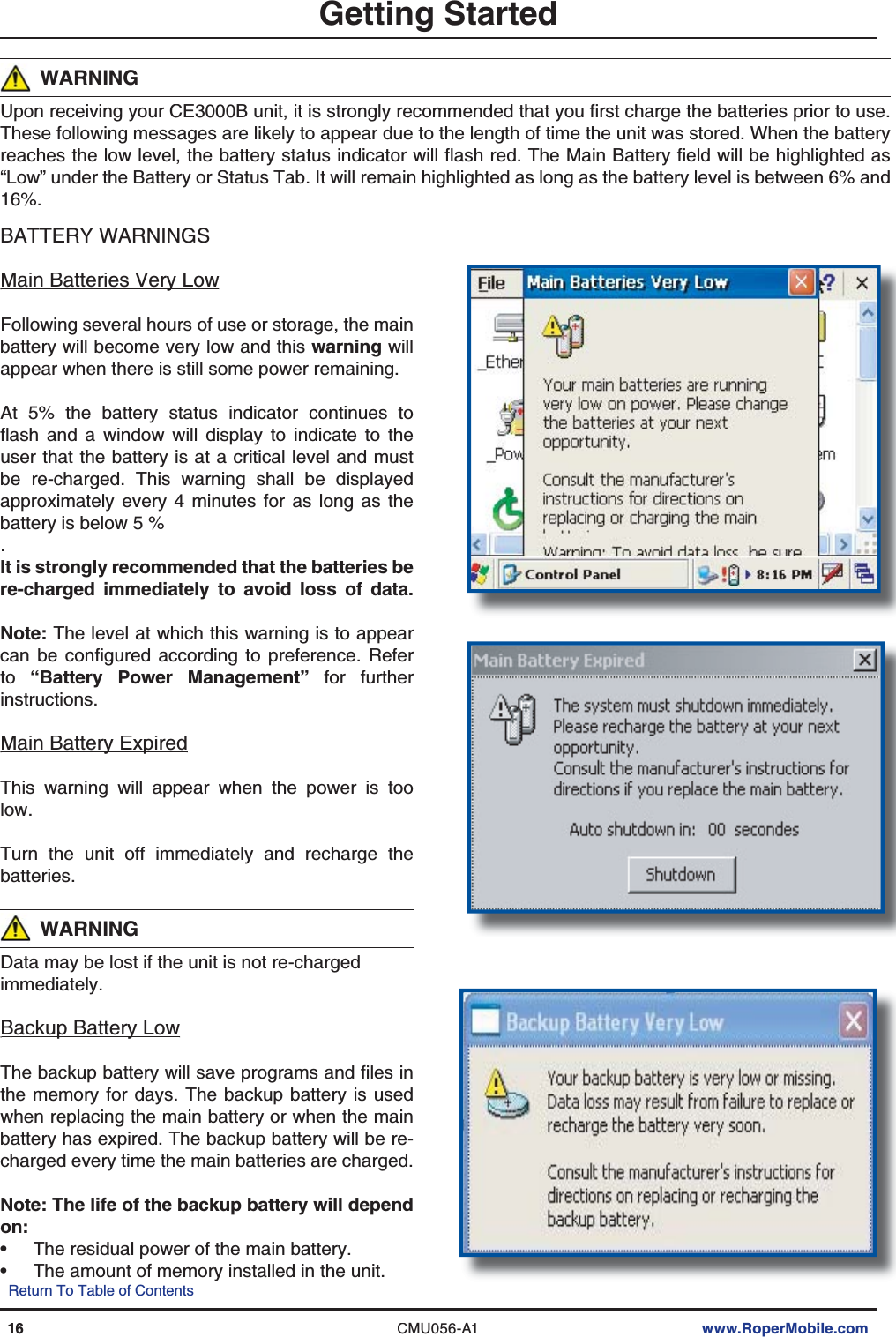
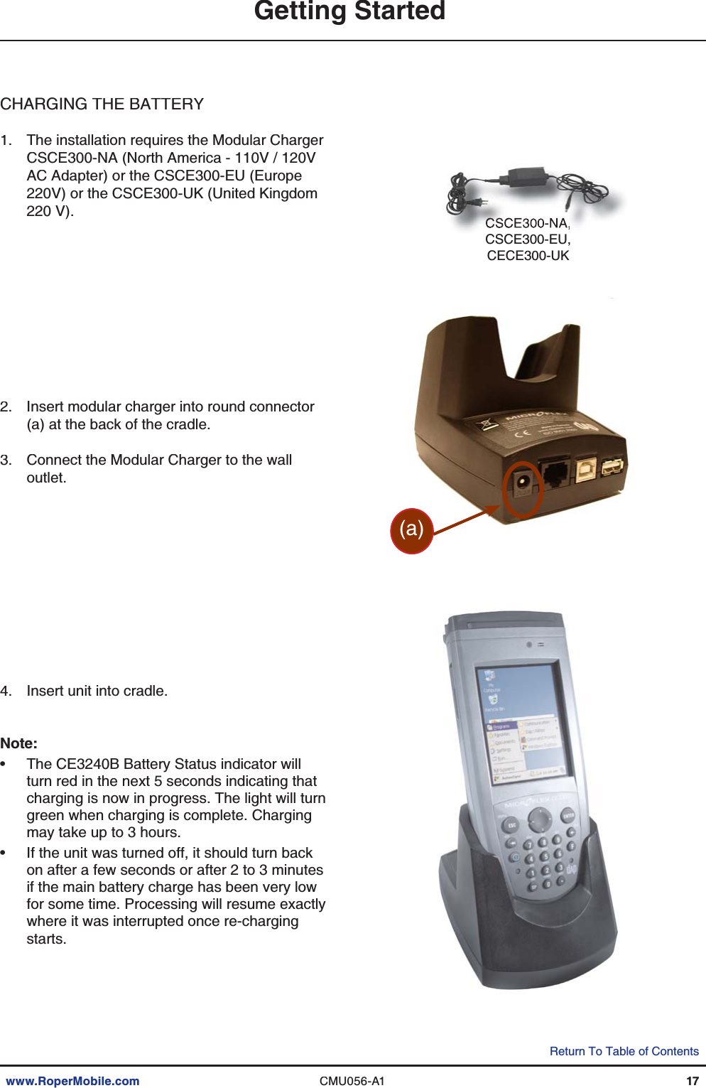
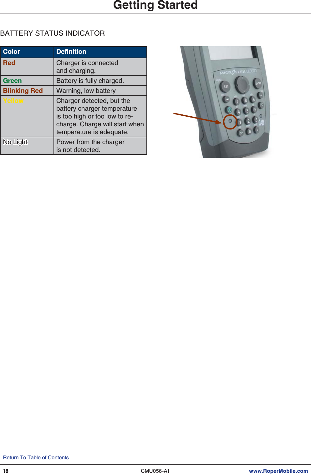
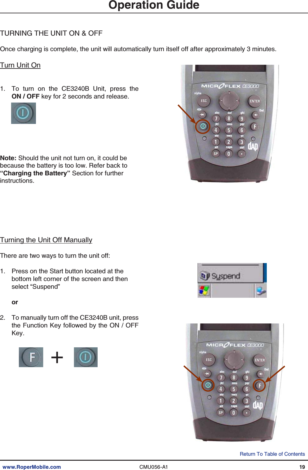
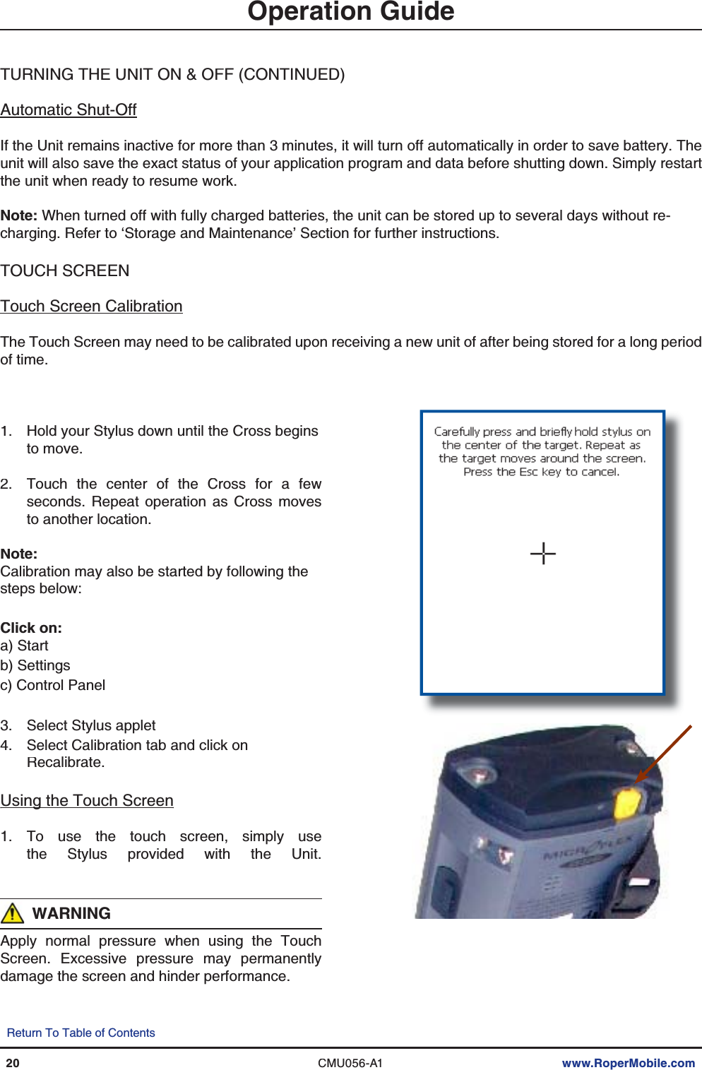
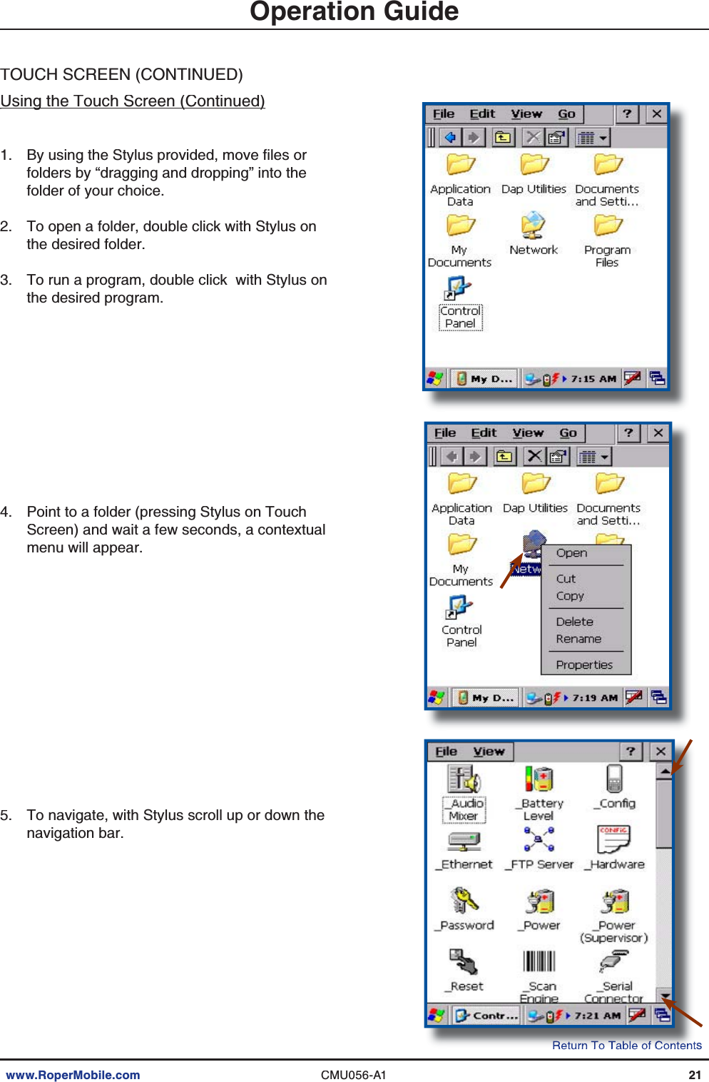
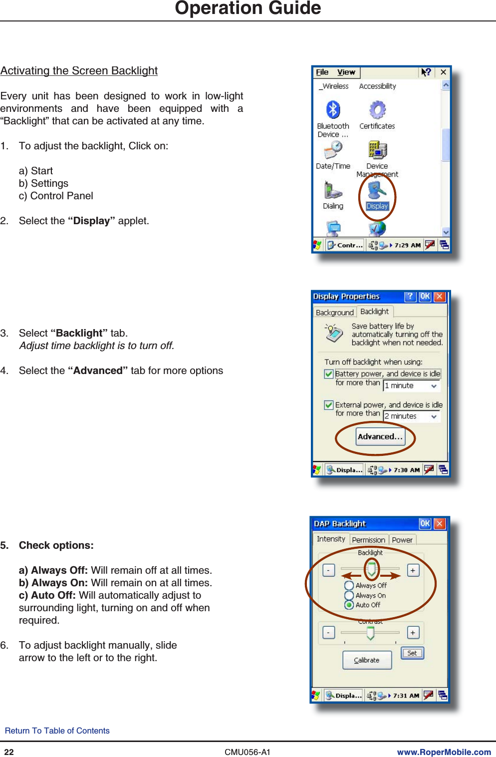
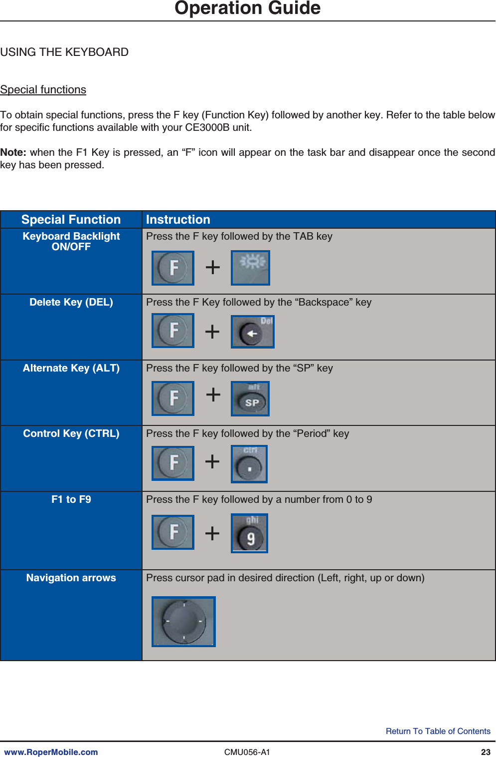
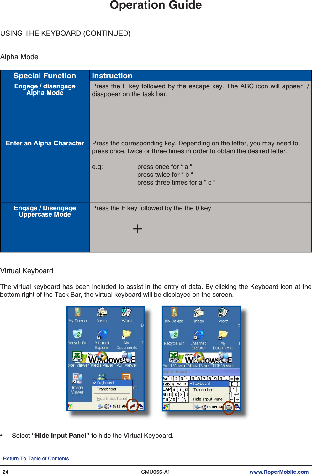
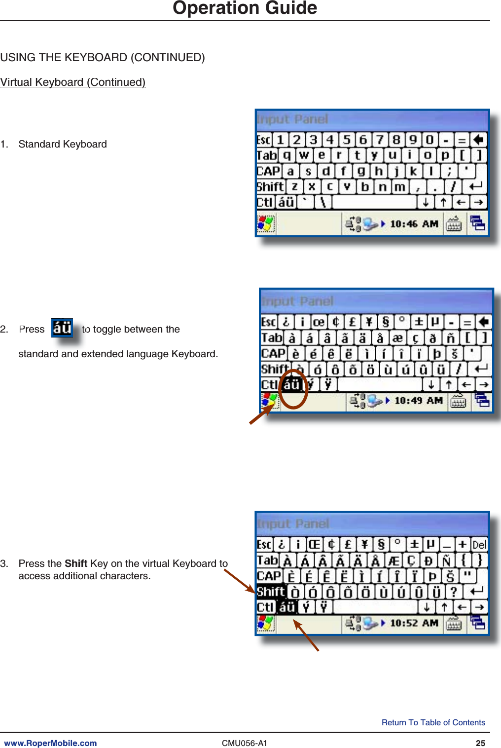
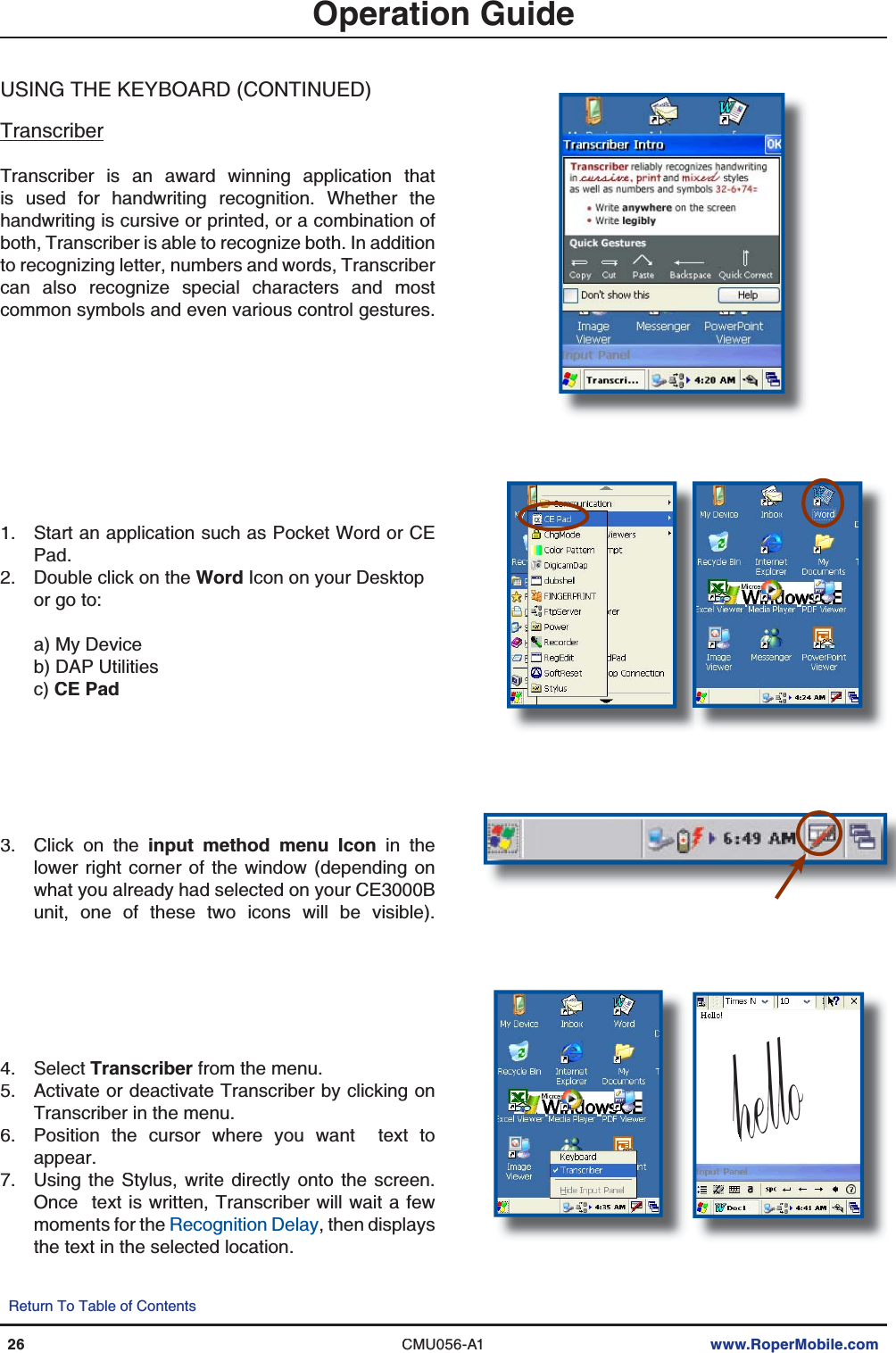
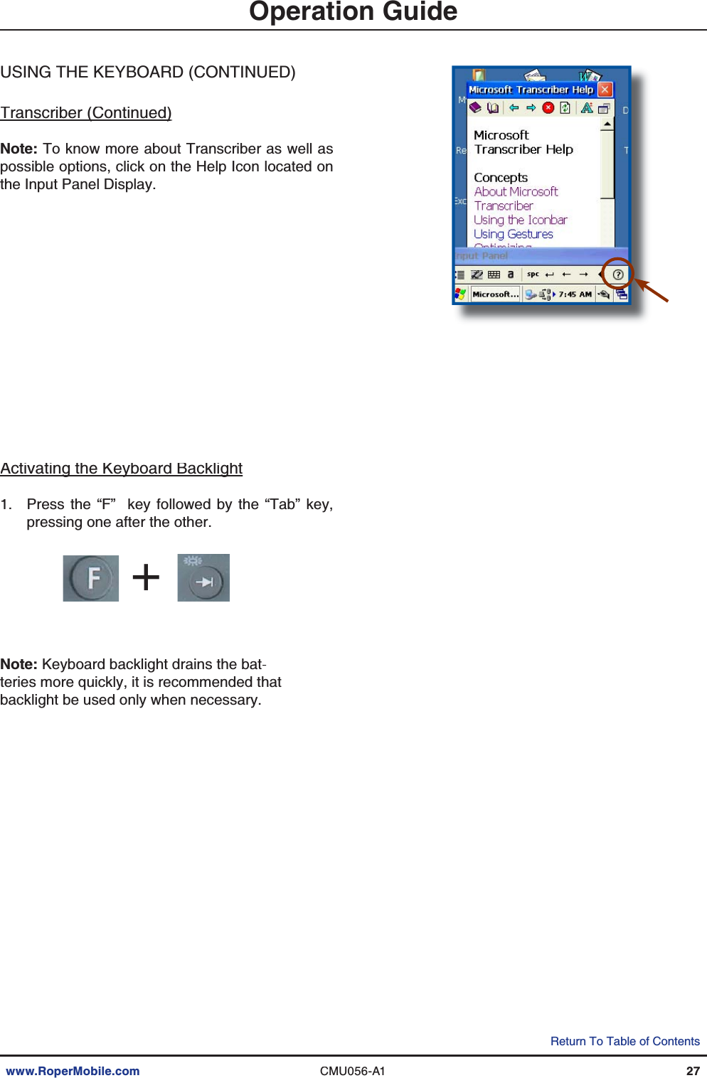
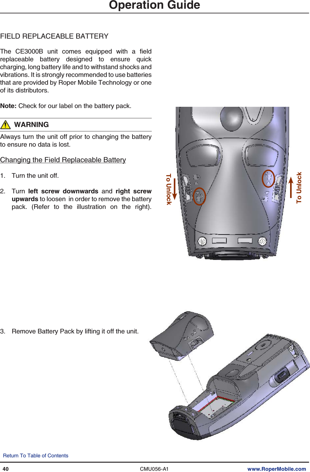
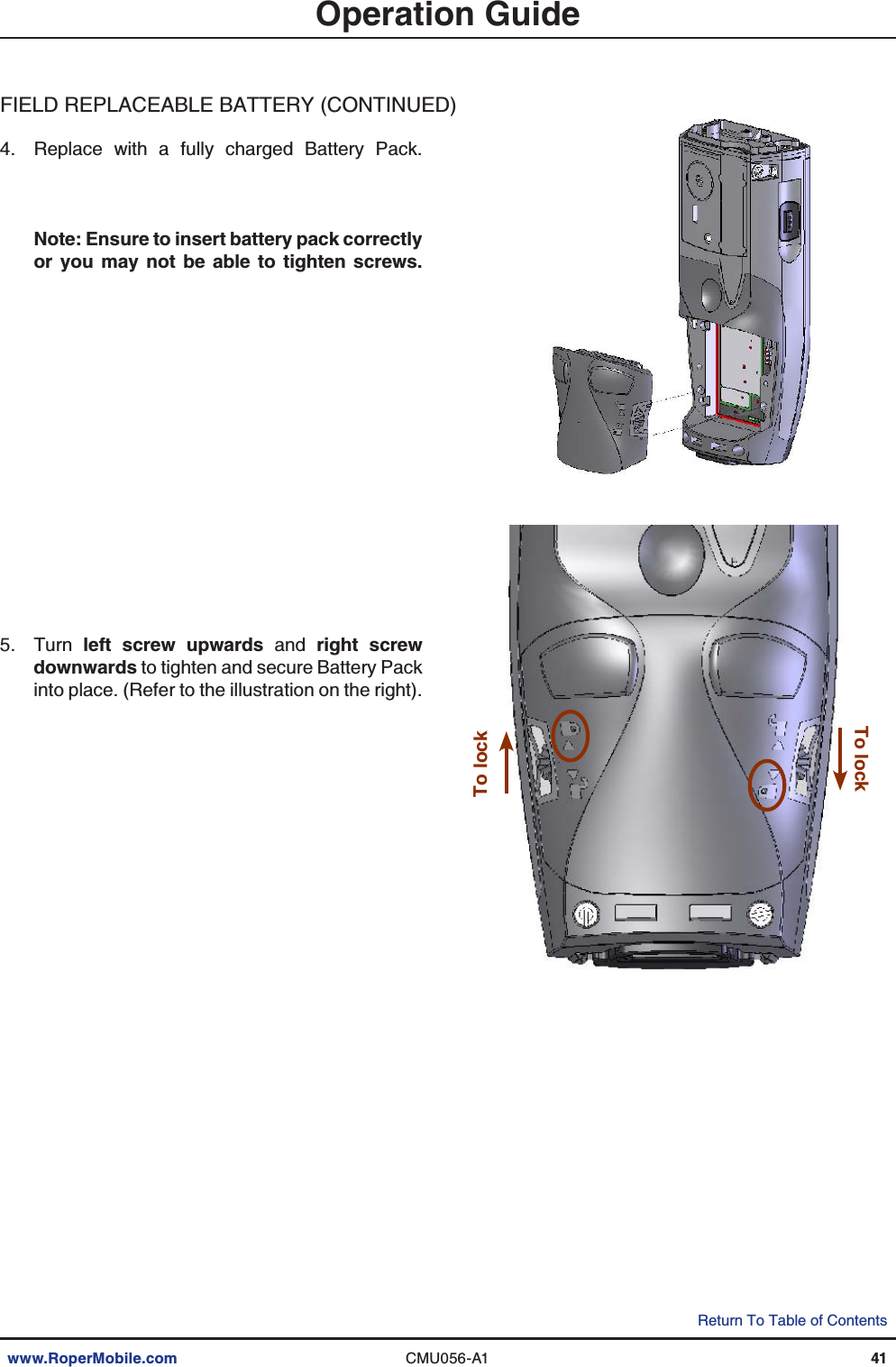
TransCore 3000B4 Rugged computer User Manual Binder1
TransCore Rugged computer Binder1
UserManual.wiki
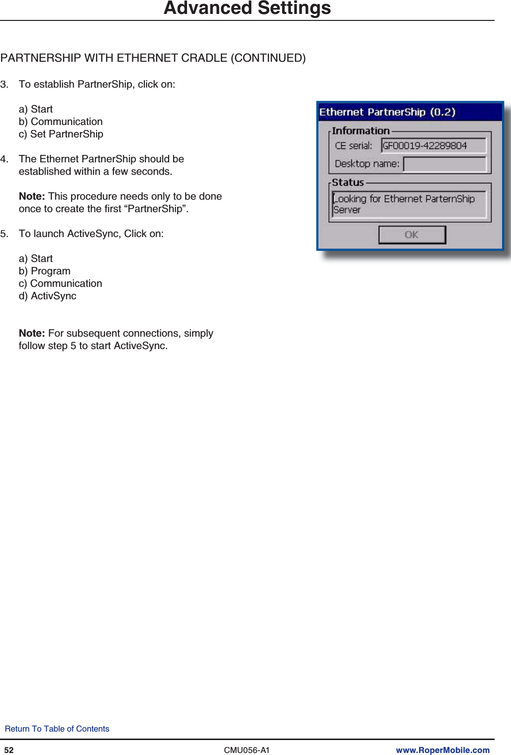
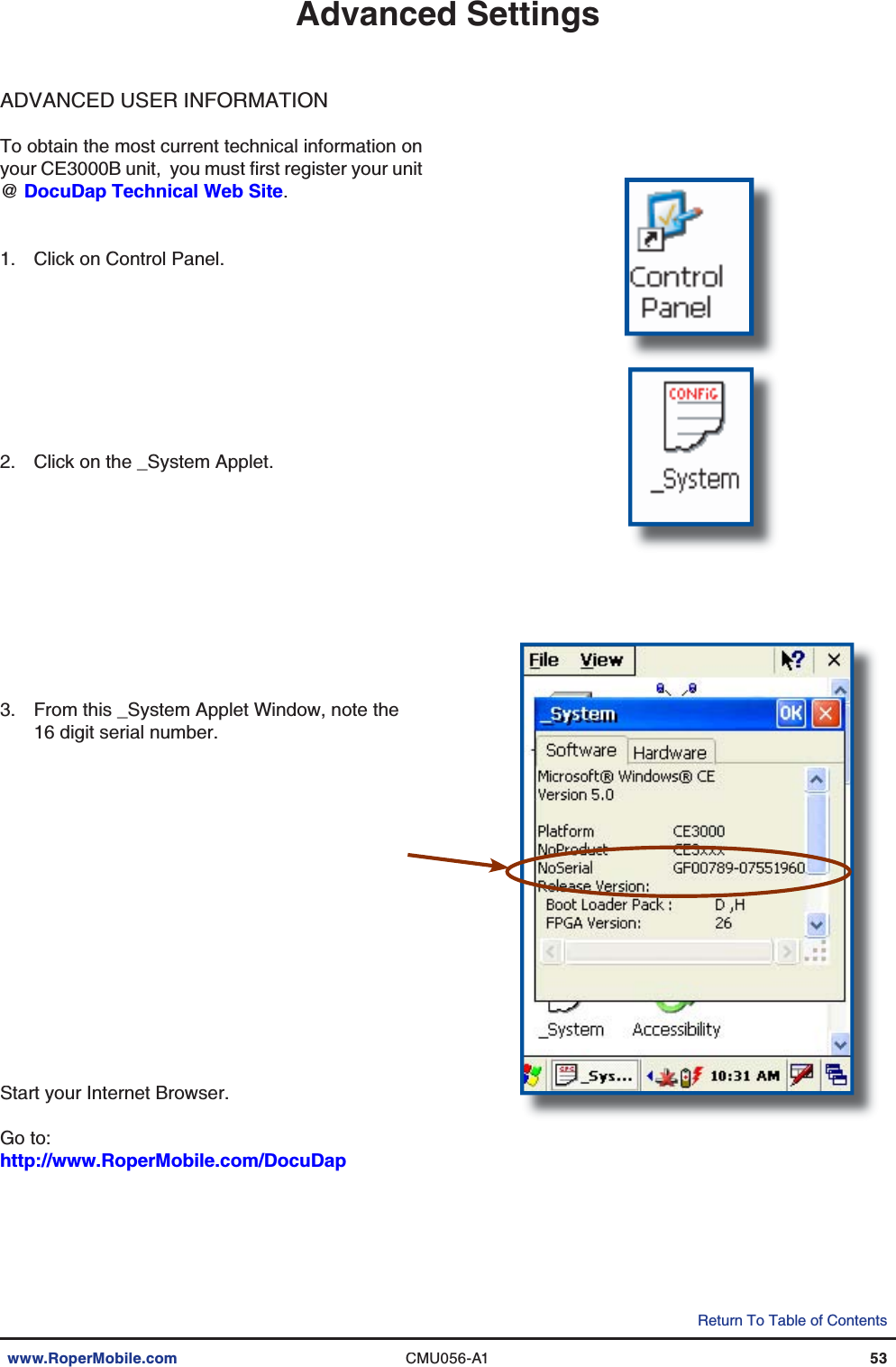
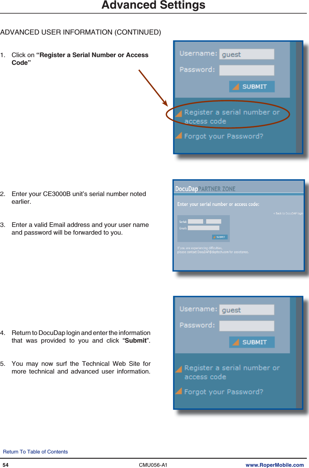
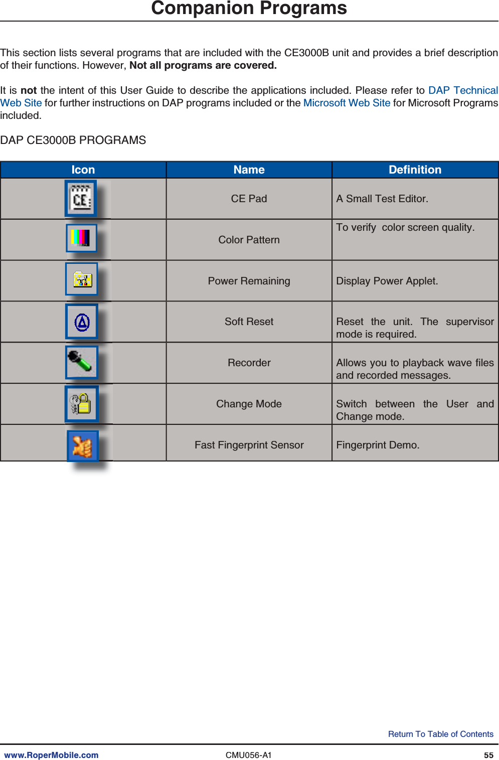
>
TransCore
>
3000B4 User Manual
>
User Manual
Contents
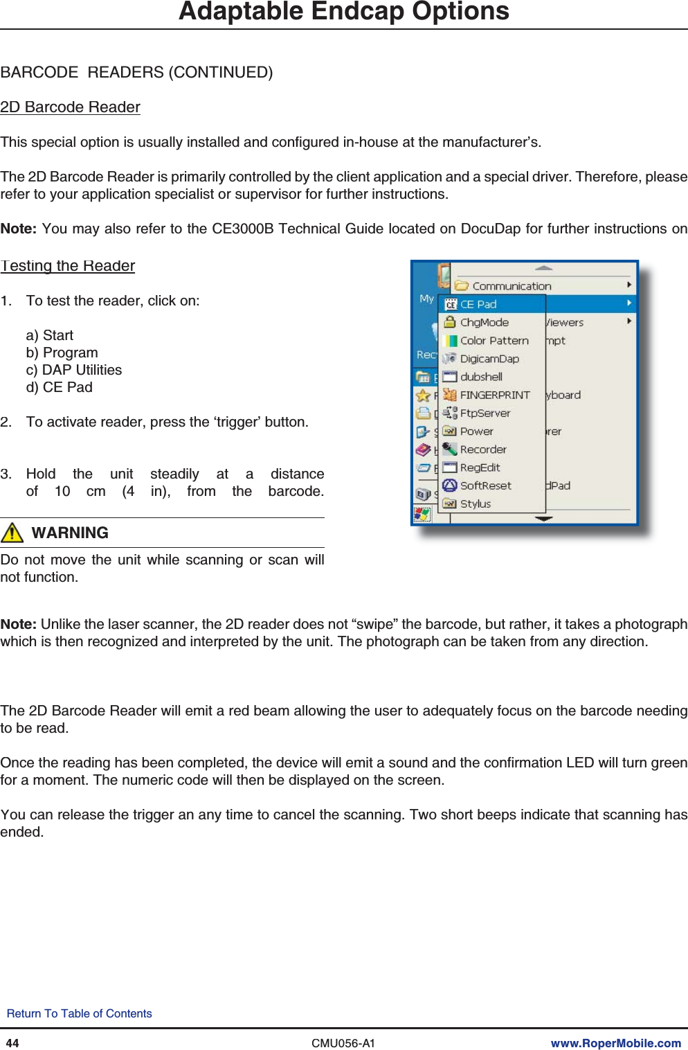
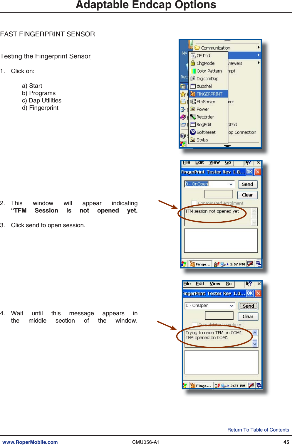
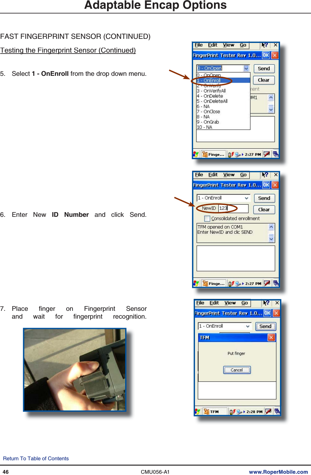
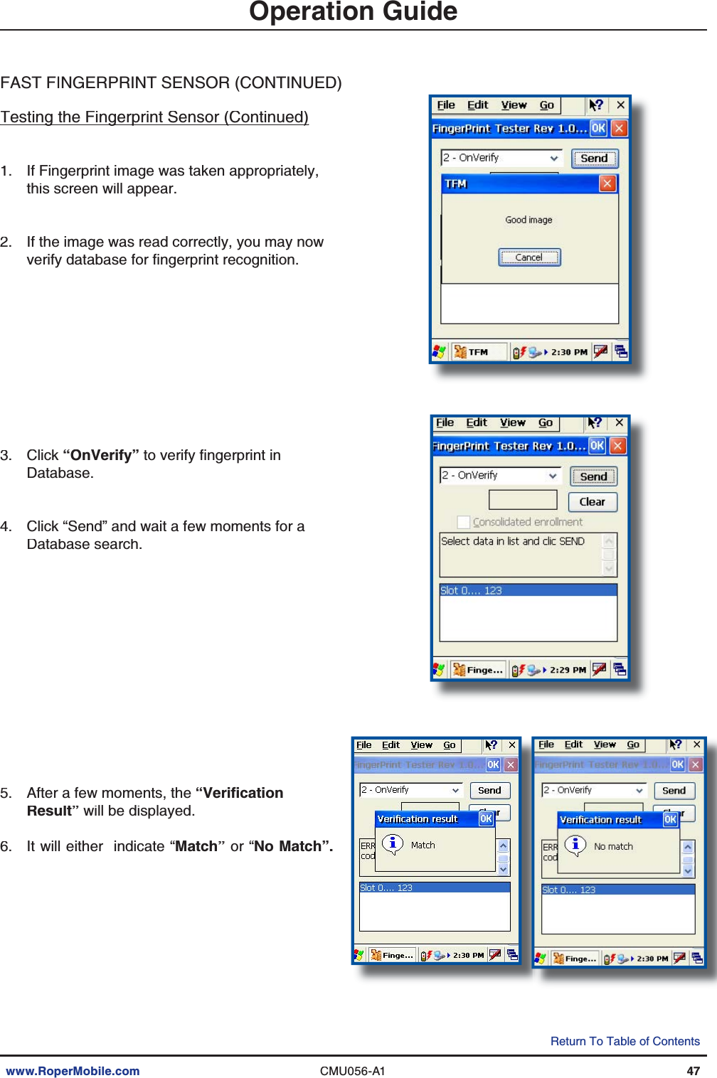
1.
User Manual
2.
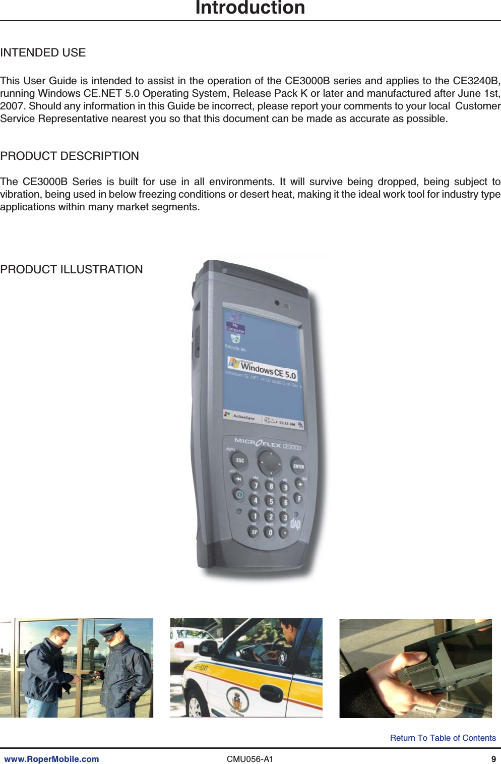
User manual
User Manual
Navigation menu
Upload a User Manual
Namespaces
Wiki Guide
HTML
PDF
Info
Views
User Manual
Discussion / Help
Navigation