TransCore 3000B4 Rugged computer User Manual Binder1
TransCore Rugged computer Binder1
Contents
- 1. User Manual
- 2. User manual
User Manual
2009/03CMU056-A1 (a) www.RoperMobile.com
CE3000B
User Guide
Ultimate

Leading Rugged Mobile Computer Companies
Merge To Form “Roper Mobile Technology”
TEMPE, AZ. and QUEBEC CITY, CANADA, March 27, 2007--JLT Mobile Computers, a leading provider
of rugged, wireless mobile computers built for use in challenging environments, and DAP Technologies,
LTD, manufacturer of rugged mobile computing solutions and services, have merged to form Roper Mobile
Technology (www.ropermobile.com). Both Companies are subsidiaries of Roper Industries, Inc. (NYSE:
ROP).
JLT Mobile Computers’ rugged vehicle mount computers are used throughout the world in warehousing,
construction, mining, law enforcement and in many other remote environments. JLT Mobile Computers’
sales grew 397% percent during the four-year period since 2002 and it has garnered many national awards
for its growth record, including being named to the Inc. 500 List of Fastest Growing Privately-Held Companies
in America for the last three consecutive years.
DAP Technologies, a Canadian company, designs and manufactures and markets the DAP line of rugged
mobile computing solutions and services in more than 60 countries. DAP’s products help increase the
productivity of data collection, processing and transmission for a wide variety of applications in industries
KPENWFKPIWVKNKVKGUſGNFUGTXKEGGOGTIGPE[UGTXKEGURWDNKEUCHGV[VTCPURQTVCVKQPUGEWTKV[CPFNQIKUVKEU
With this merger, Roper Mobile Technology is formed and is poised to enter the rugged computing
market with a comprehensive line of rugged computers, ranging from Vehicle Mount Terminals to PDAs.
6JKUOGTIGTKUVJGſTUVQHOCP[UVGRU4QRGT/QDKNG6GEJPQNQI[YKNNVCMGKPGUVCDNKUJKPIKVUGNHCUCPKPPQXCVKXG
technology leader in rugged, mobile computing.
This merger will help the growth of our core technology-rugged, vehicle computers. As Roper Mobile
Technology, we are able to use our added resources to strengthen our presence in international markets.
In addition, our customers can choose from a broader line of products and can expect an even higher level
of responsive world-class service and support.
For more information contact your local Sales or Customer
Representative nearest you or visit our new Web Site at
www.RoperMobile.Com.
ATTENTION DAP CUSTOMERS

www.RoperMobile.com CMU056-A1 5
Table of Contents
ISO %GTVKſECVKQP ...............................................................8
Introduction............................................................................9
Intended Use .......................................................................9
Product Description ..................................................................9
Product Illustration ...................................................................9
Product 5RGEKſECVKQPU ..............................................................10
Warning %CWVKQP0QVG&GſPKVKQP .....................................................11
Symbols .............................................................................12
Quick Tour ...........................................................................14
Front View ........................................................................14
Back View ........................................................................15
Getting Started ........................................................................16
Battery Warnings ...................................................................16
Main Batteries Very Low ..........................................................16
Main Battery Expired .............................................................16
Charging the Battery ................................................................17
Battery Status Indicator ..............................................................18
Operation Guide .......................................................................19
Turning the Unit On & Off ............................................................19
Turn Unit On ...................................................................19
Turning the Unit Off Manually ......................................................19
Automatic Shut-Off ..............................................................20
Touch Screen......................................................................20
Touch Screen Calibration .........................................................20
Using the Touch Screen ..........................................................20
Activating the Screen Backlight.....................................................22
Using the Keyboard .................................................................23
Special functions ................................................................23
Alpha Mode ....................................................................24
Virtual Keyboard ................................................................24
Transcriber ....................................................................26
Activating the Keyboard Backlight...................................................27
PC & SDIO Card Description ..........................................................28
PC Cards ......................................................................28
SDIO Cards ....................................................................28
Using PC & SDIO Cards .............................................................28
Inserting PC or SDIO Cards .......................................................29
Removing PC or SDIO Cards ......................................................30
Using the Cradle ...................................................................31
Using the Ethernet Cradle .........................................................31
Transferring Files in FTP Mode ........................................................32
USB Client Connection ..............................................................33
Vehicle %TCFNG%QPPGEVQT+FGPVKſECVKQP ..............................................35

6CMU056-A1 www.RoperMobile.com
Table of Contents
Using the Vehicle Cradle .............................................................35
Making your own Power Supply Lead ................................................36
Wiring ........................................................................36
Installing Vehicle Mount...........................................................36
Monitoring the Process on a 3 Serial Port Cradle ..........................................38
Serial Port Connector Pin-Out ......................................................38
Field Replaceable Battery ............................................................40
Changing the Field Replaceable Battery..............................................40
Adaptable Endcap Options...............................................................42
Barcode Readers ..................................................................43
Laser Scanner ..................................................................43
Testing the Scanner .............................................................43
2D Barcode Reader..............................................................44
Testing the Reader ..............................................................44
Fast Fingerprint Sensor ..............................................................45
Testing the Fingerprint Sensor .....................................................45
Advanced Settings . . . . . . . . . . . . . . . . . . . . . . . . . . . . . . . . . . . . . . . . . . . . . . . . . . . . . . . . . . . . . . . . . . . . .49
Advanced Battery Options ............................................................49
To See Power Remaining .........................................................49
Preserving Power ...............................................................49
Battery Power Management .......................................................49
Background Display and Contrast .....................................................50
ActiveSync Communication ...........................................................50
Partnership with Ethernet Cradle: ......................................................51
Advanced User Information ...........................................................53
Companion Programs...................................................................55
DAP CE3000B Programs.............................................................55
Microsoft Programs .................................................................56
Troubleshooting Guide ..................................................................57
Storage & Maintenance .................................................................58
Storage ..........................................................................58
Cleaning..........................................................................58
Shipping the Unit ...................................................................58
Carrying Strap .....................................................................58
Battery Maintenance ................................................................59
Main Battery ...................................................................59
Backup Battery .................................................................59
Replacing the Battery ............................................................59
Touch Screen Maintenance ...........................................................60
Adaptable EndCap With Laser Option ...................................................60
Quick-Reference Replacement Parts List ................................................60
Recycling Passport.....................................................................61
CE Conformity ........................................................................62

Table of Contents
www.RoperMobile.com CMU050-A1 7
FCC Statement, Copyright Policy..........................................................63
Microsoft End-User License Agreement.....................................................64
Limited Warranty ...................................................................65
Return Merchandise Authorization for Servicing (RMA) .....................................65
Extended Warranty on Roper Mobile Technology Manufactured Products .......................65
International Addresses .................................................................66

8CMU056-A1 www.RoperMobile.com
Return To Table of Contents
+51%GTVKſECVKQP
DAP Technologies has documented and implemented a Quality Management System in accordance with ISO
+PVGTPCVKQPCN5VCPFCTF%GTVKſECVGPWODGT
This International recognition has been made possible thanks to the continual efforts put forth by DAP’s
personnel.
In order to ensure continuous improvements to our products and services, we invite you to communicate your
comments to our Customer Service Department by dialing:
Canada: 1 (418) 681-7833 or 1 (800) 363-1993
United States: 1(800) 363-1993
Europe: + (800) 8899 1000
or
Sales@RoperMobile.com
www.RoperMobile.com
www.RoperMobile.com
C
MU056-A
1
9
Return To Table of Contents
I
ntr
oduc
ti
on
I
NTENDED
U
SE
T
his User
G
uide is intended to assist in the operation of the
C
E3000B series and applies to the
C
E3240B,
r
unning Windows CE.NET 5.0 Operating System, Release Pack K or later and manufactured after June 1st,
2
007. Should any information in this Guide be incorrect, please report your comments to your local Custome
r
S
ervice Representative nearest you so that this document can be made as accurate as possible.
P
RO
D
UC
T
D
E
SC
RIPTI
ON
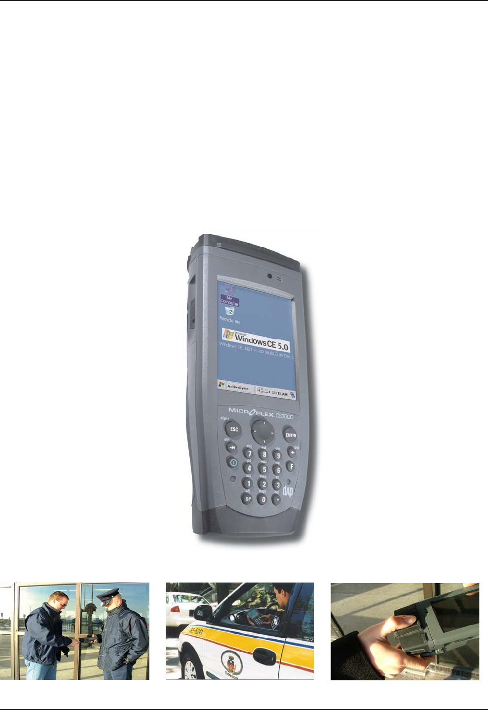
T
he CE3000B Series is built for use in all environments. It will survive bein
g
dropped, bein
g
subject to
v
ibration, bein
g
used in below
f
reezin
g
conditions or desert heat, makin
g
it the ideal work tool
f
or industry type
applications within many market segments
.
P
RO
D
UC
T
I
LL
US
TRATI
ON

10 CMU056-A1 www.RoperMobile.com
Return To Table of Contents
PRODUCT SPECIFICATIONS
BASE UNIT OPERATING SYSTEM & PROCESSOR
Windows CE 5.0
Intel XScale Bulverde - PXA270, 520 MHz
MEMORY
128 MB Storage Flash for Win CE & File system
(approx. 64MB available to the user)
128 MB SRAM (Approx. 64 MB used for OS)
Optional: Additional storage via PCMCIA/CF
Flash Cards and USB connected Memory de-
vices and SD Memory Flash Cards.
Voice System
Integrated and environmentally sealed speaker
Recording and play back fully supported by
Windows CE operating system
Optional: Integrated and environmentally sealed
microphone and headset connector
•
•
•
•
•
•
•
•
DISPLAY
KPEJFKCIQPCNOO38)#6(6VTCPUƀGEVKXG
color LCD with LED backlighting
Indoor and outdoor display
Scratch and shock resistant touch screen that can
DGWUGFGKVJGTYKVJ5V[NWUQTſPIGT
KEYBOARD
Highly ergonomic keyboard, 22-key keypad with 10
numeric and function keys plus 2 trigger keys
Programmable auto-repeat
Keyboard backlighting
Customized keyboard template
Ergonomic key grouping to speed up data entry
Tactile and programmable audible feedback
•
•
•
•
•
•
•
•
•
CONNECTIVITY CE3240W WIRELESS EDITION
Internal Bluetooth Class 2
Internal 802.11 b/g
•
•
CE3240B ETHERNET EDITION
Ethernet 10BaseT, 10Mbps through the cradle•
POWER Rechargeable 2000mAH Lithium-Ion battery
pack (user accessible)
Battery life: Typically 2 to 4 working days
Integrated charge status and low battery
indicator
Intelligent fast charge
•
•
•
•
Rechargeable backup battery
Backup system for RAM memory if main battery is
exhausted or removed
ON/OFF switch, manual or automatic shutoff
5 Volt power for external devices
•
•
•
•
ADAPTABLE
END-CAPS
Smart Card Reader: Contact/Contactless
*KIJTGUQNWVKQPſPIGTRTKPVUGPUQT
•
•
1D/2D Barcode reader (CMOS imager)
1D Barcode scanner
•
•
PC CARD & SDIO 1 PC Card Type II (CF Card via adapter)
1 Secure Digital (SD or SDIO) slot
•
•
CF Card support via adapter
User accessible via an environmentally sealed
expansion bay
•
•
COMMUNICATION
I/O
Ethernet 10BaseT, 10Mbps plus USB host and
client through cradles
• Internal, user accessible and environmentally
sealed
Ideal for OEM Integration
•
•
BUNDLED/
AVAILABLE
SOFTWARE
Microsoft ActiveSync
FTP Client/Server
CE Internet Explorer and Viewers for Word®,
Excel®, PowerPoint® & PDF files
Microsoft Outlook®
Microsoft Window Media Player®
Terminal Services Client
Image & Video Viewer
•
•
•
•
•
•
•
Voice Recorder
Handwriting recognition
DAPDUB system allowing: Backup/Restore utilities,
ENQPKPI15WRFCVGWVKNKV[CWVQOCVGFſNGVTCPUHGT
auto recovery system
CE Pad (Notepad)
Playback/Recording program
•
•
•
•
•
PERIPHERALS &
ACCESSORIES
Various communication and charging cradles
QHſEGQTXGJKENG
•
SIZE & HEIGHT 5.2 cm (2.05 in) x 7.9 cm (3.1 in) x 19.6 cm (7.7
in)
• 1 lb (454 g) with battery
ELECTRICAL &
ENVIRONMENTAL
REQUIREMENTS
TEMPERATURE
Operating: -20°C (-4°F) to +50°C (+122°F)
Storage: -30°C (-22°F) to + 60°C (+140°F)
Display refresh cycle may decrease
•
•
•
Immersion, Rain & Humidity:
Meets MIL-STD-810F method 512.3 procedure 1 &
IP65
Meets MIL-STD-810F method 506.3 procedure 1
(wind blown rain)
Humidity: 95% non-condensing
•
•
•
Introduction
www.RoperMobile.com CMU056-A1 11
Return To Table of Contents
PRODUCT SPECIFICATIONS (CONTINUED)
ELECTRICAL &
ENVIRONMENTAL
REQUIREMENTS
(Continued)
Free Fall Drop Resistance (*):
Meets and exceeds IEC 68-2-32 method 1 (2
meter drop on concrete)
Meets and exceeds MIL-STD-810F method
516.4 procedure IV<
•
•
Electrostatic Discharge:
Meets EN 61000-4-2•
Approvals %'%GTVKſECVKQP• FCC Class B•
Warranty Manufacturer’s warranty: 1 year parts & labor Optional DAPCare Warranty extension available
4QRGT/QDKNG6GEJPQNQI[TGUGTXGUVJGTKIJVVQEJCPIGURGEKſECVKQPUYKVJQWVPQVKEG
WARNING / CAUTION / NOTE DEFINITION
The words WARNING, CAUTION, and NOTE carry special meanings and should be carefully reviewed.
WARNING
Alerts the reader about a situation, which if not avoided, could affect the proper functioning of the unit and
result in permanent damage to the unit.
CAUTION
Alerts the reader of a potentially hazardous situation, which if not avoided, may result in minor injury to the
user or may cause damage to the equipment. This includes special care necessary for the safe and effective
use of the device and the care necessary to avoid any damage that may occur as a result of use or misuse.
Note:
This provides special information to make important instructions clearer.
Introduction
12 CMU056-A1 www.RoperMobile.com
Return To Table of Contents
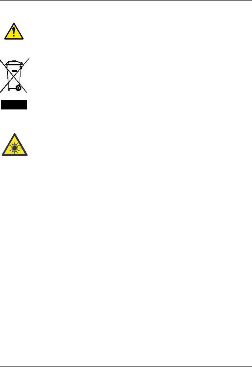
Symbols
Warning, pay special attention.
In accordance with European Directive 2002/96/EC on Waste Electrical and Electronic
Equipment (WEEE), this symbol indicates that the product must not be disposed of as unsorted
municipal waste, but should be collected separately. Refer to your local distributor for return
and/or collection systems available in your country.
Caution must be used when this symbol is present. This symbol indicates a danger for laser
radiation.

www.RoperMobile.com CMU056-A1 13
Return To Table of Contents
Safety Precautions
WARNING
Refer to this Guide when inserting or removing batteries, cables or external peripherals.
1RGTCVG CPF UVQTG [QWT  WPKV YKVJKP VJG VGORGTCVWTG NKOKVU URGEKſGF KP VJKU )WKFG
Do not use any pointed objects on the keyboard, door or mechanisms. Doing so may damage the unit.
Use the ‘Stylus’ which has been provided with the unit by Roper Mobile Technology, as it has been
designed with a non-abrasive material that cannot scratch or damage the touch screen.
Never expose the battery to extreme heat or dispose of by burning.
Any attempts to open the case of a CE3240B unit will void the warranty.
If you need to use a cable other than the ones provided or recommended by
Roper Mobile we recommend that you contact your Customer Service Representative nearest you.
•
•
•
•
•
•
•
14
C
MU056-A
1
www.RoperMobile.com
Return To Table of Contents
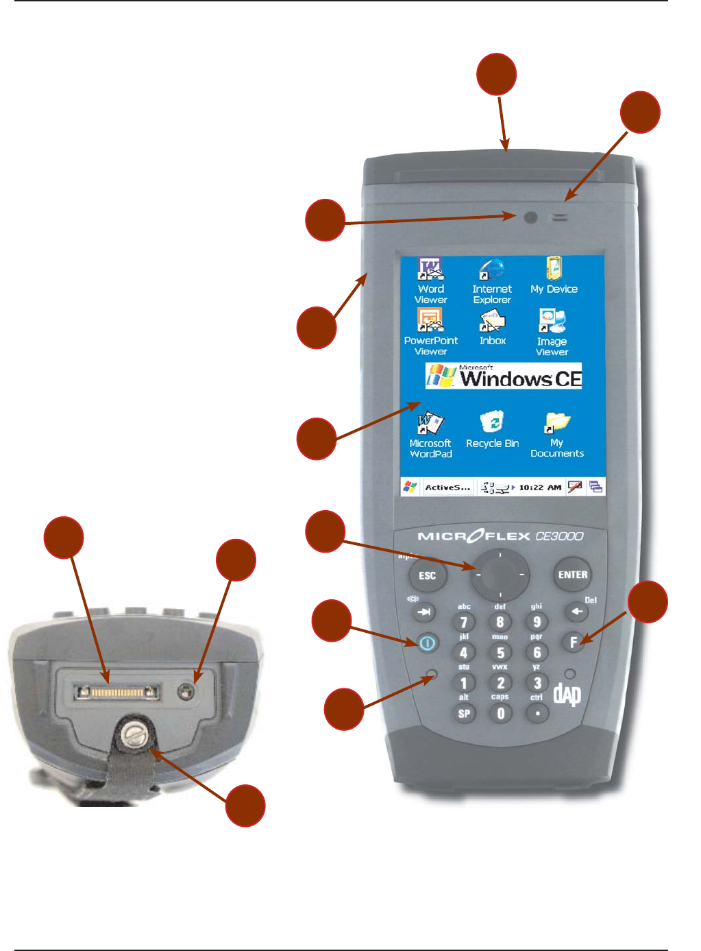
Q
uick Tour
FR
O
N
T
V
I
E
W
On/Off Ke
y
L
i
g
ht
S
ensor
E
ndCa
p
with aDAPtable Extensio
n
C
olor
S
cree
n
M
i
crophon
e
Battery Status Indicato
r
C
radle
C
ommunication
C
onnecto
r
H
ead-
S
et Adapte
r
H
and Stra
p
Attachmen
t
T
rigger Button
(
both sides
)
F
unct
i
on Ke
y
N
av
ig
at
i
on Key
(
Left, Ri
g
ht, Top & Bottom
)
1.
2.
3.
4.
5.
6
.
7.
8.
9.
1
0.
11.
12.
7
6
4
2
3
5
8
10
9
1
12
11
www.RoperMobile.com
C
MU056-A
1
1
5
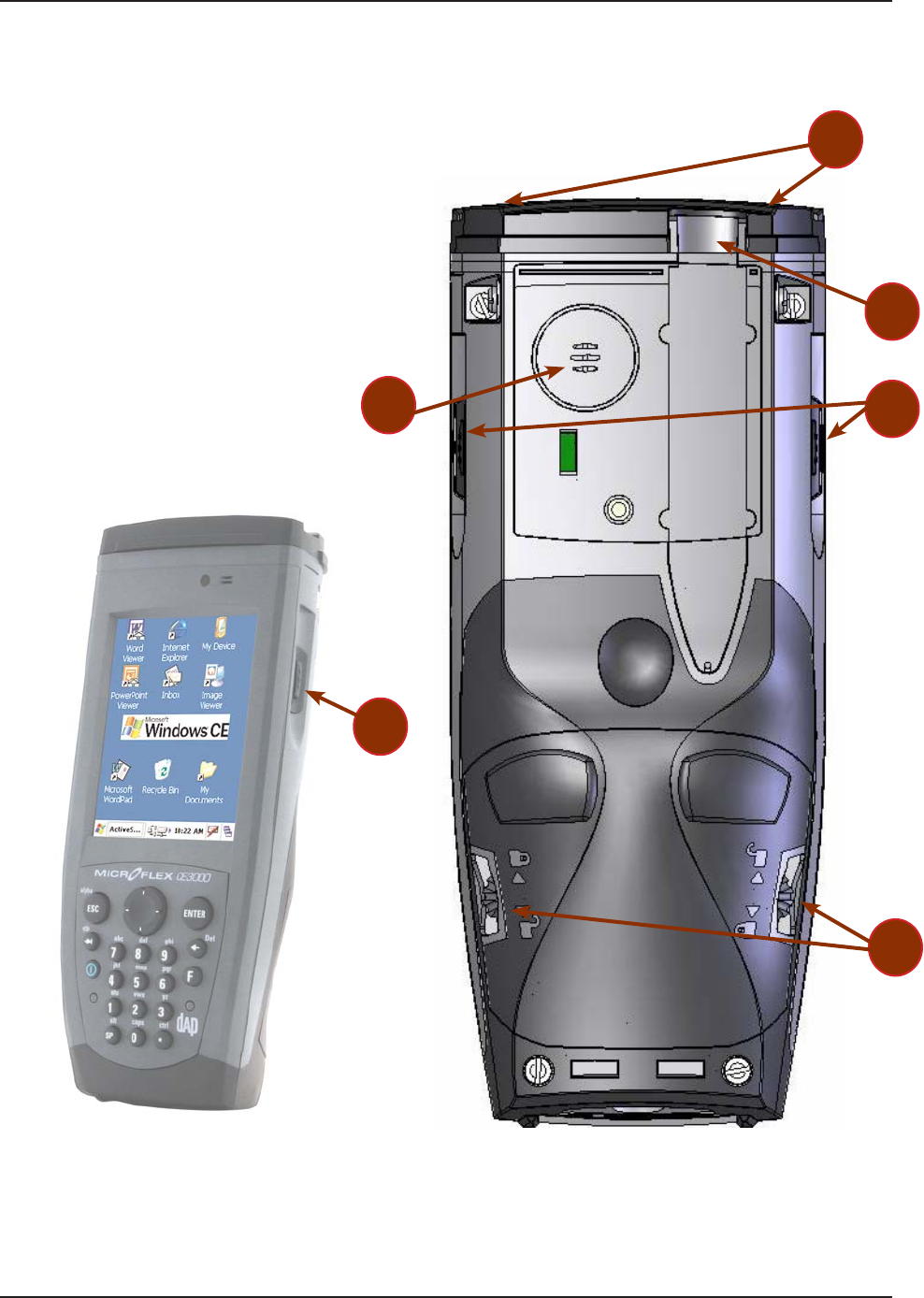
Return To Table of Contents
Q
uick Tour
2
1
3
4
B
A
CK
VIE
W
R
elease screws for P
C
&
S
DI
O
C
ard
Access
Doo
r
S
tylus (Pen) holde
r
T
ri
gg
er Buttons (Left & Ri
g
ht)
Sp
eaker
4
GNGCUGUETGYUVQEJCPIGſGNFTGRNCEGCDNG
b
attery (2 screws left and ri
g
ht)
.
1.
2.
3.
4.
5.
3
5
16
C
MU056-A
1
www.RoperMobile.com
Return To Table of Contents
Gettin
g
Starte
d
B
ATTERY
W
A
RNINGS
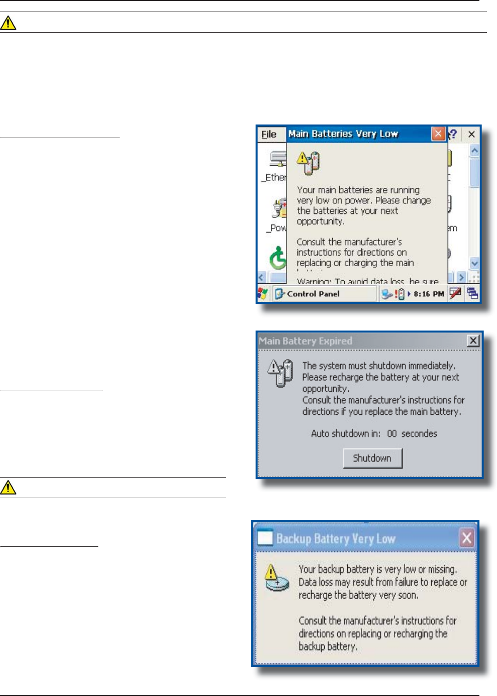
Main Batteries Very Low
y
F
ollowin
g
several hours o
f
use or stora
g
e, the main
battery w
i
ll become very low and th
is
warn
i
n
g
w
i
ll
appear when there is still some power remaining.
A
t 5% the battery status
i
nd
i
cator cont
i
nues to
ƀ
CUJ CPF C YKPFQY YKNN FKURNC
[
VQ KPFKECVG VQ VJG
u
ser that the battery
i
s at a cr
i
t
i
cal level and must
be re-char
g
ed. Th
i
s warn
i
n
g
shall be d
i
splayed
approximately every 4 minutes for as long as the
battery
i
s below 5
%
.
It
i
s stron
g
ly recommended that the batter
i
es be
re-charged immediately to avoid loss o
f
data
.
N
ote:
T
he level at which this warning is to appear
ECP DG EQP
ſI
WTGF CEEQTFKP
I
VQ RTG
H
GTGPEG 4G
H
GT
to
“
Battery Power Management”
fo
r
fu
rth
e
r
instructions
.
Main Battery Expired
yp
T
h
i
s warn
i
n
g
w
i
ll appear when the power
i
s too
l
o
w
.
T
urn the unit o
ff
immediately and rechar
g
e the
ba
tt
e
r
ies.
W
ARNIN
G
Data may be lost i
f
the unit is not re-charged
i
mmed
i
ately
.
Backup Battery Low
py
6
JGDCEMWRDCVVGT[YKNNUCXGRTQITCOUCPFſNGUKP
t
he memory
f
or days. The backup battery is used
w
hen replac
i
n
g
the ma
i
n battery or when the ma
i
n
battery has expired. The backup battery will be re
-
charged every t
i
me the ma
i
n batter
i
es are charged
.
N
ote: The life of the backup battery will depend
on
:
T
he residual power o
f
the main battery
.
T
he amount of memory installed in the unit
.
•
•
W
ARNING
7
RQPTGEGKXKPI[QWT
%
'$WPKVKVKUUVTQPIN[TGEQOOGPFGFVJCV[QWſTUVEJCTIGVJGDCVVGTKGURTKQTVQWUG
T
hese following messages are likely to appear due to the length of time the unit was stored. When the battery
T
GCEJGUVJGNQYNGXGNVJGDCVVGT[UVCVWUKPFKECVQTYKNN
ƀ
CUJTGF6JG/CKP$CVVGT[
ſ
GNFYKNNDGJK
I
JNK
I
JVGFCU
“Low” under the Battery or
S
tatus Tab. It will remain highlighted as long as the battery level is between 6% and
1
6
%.
www.RoperMobile.com
C
MU056-A
1
17
Return To Table of Contents
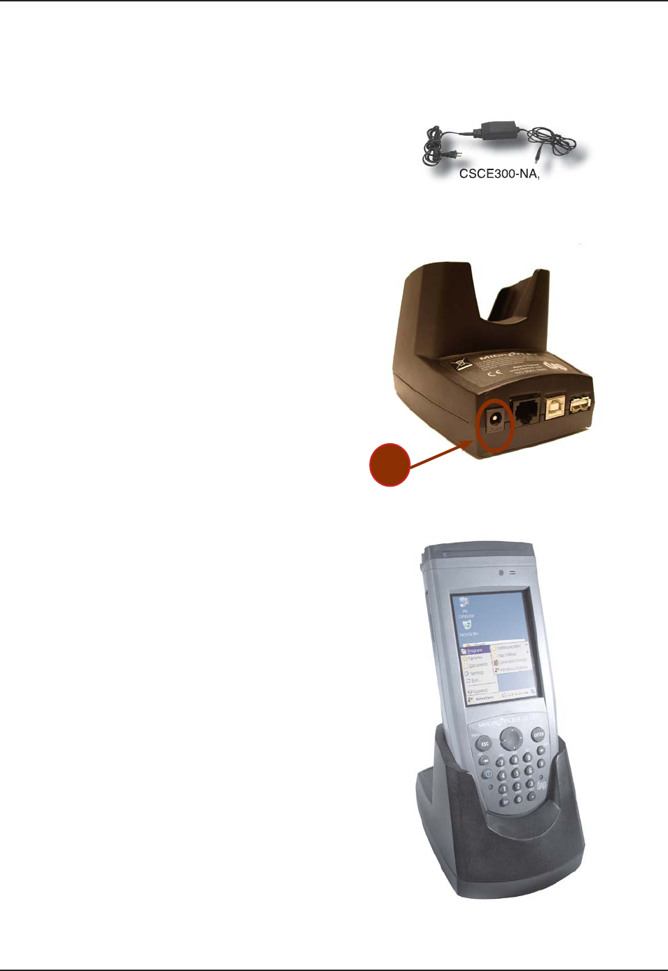
G
etting
S
tarte
d
C
H
ARGIN
G
THE
B
ATTERY
T
he installation requires the Modular
C
har
g
er
C
SCE300-NA
(
North America - 110V / 120V
AC
Ada
p
ter
)
or the
CSC
E300-EU
(
Euro
p
e
2
20V) or the
CSC
E300-UK (United Kin
g
dom
2
20 V
)
.
Insert modular char
g
er
i
nto round connector
(
a
)
at the back of the cradle.
C
onnect the Modular
C
har
g
er to the wall
o
utlet
.
Insert unit into cradle.
No
t
e
:
T
he
C
E3240B Battery
S
tatus indicator will
t
urn red
i
n the next 5 seconds
i
nd
i
cat
i
n
g
that
char
gi
n
g
i
s now
i
n pro
g
ress. The l
ig
ht w
i
ll turn
g
reen when char
g
in
g
is complete. Char
g
in
g
may ta
k
e up to 3
h
ours.
I
f
the unit was turned o
ff
, it should turn bac
k
o
n after a few seconds or after 2 to
3
minutes
if the main battery charge has been very low
f
or some time. Processing will resume exactly
w
here it was interrupted once re-charging
sta
r
ts.
1.
2.
3.
4.
•
•
CSCE300-EU
,
C
E
C
E300-UK
(a)
18 CMU056-A1 www.RoperMobile.com
Return To Table of Contents
Getting Started
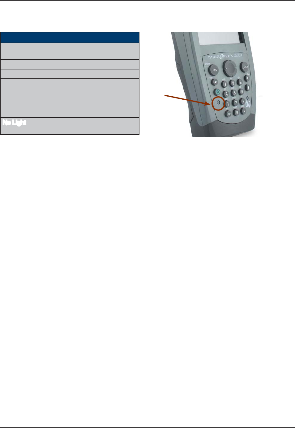
BATTERY STATUS INDICATOR
Color &GſPKVKQP
Red Charger is connected
and charging.
Green Battery is fully charged.
Blinking Red Warning, low battery
Yellow Charger detected, but the
battery charger temperature
is too high or too low to re-
charge. Charge will start when
temperature is adequate.
No Light Power from the charger
is not detected.
www.RoperMobile.com CMU056-A1 19
Return To Table of Contents
Operation Guide
TURNING THE UNIT ON & OFF
Once charging is complete, the unit will automatically turn itself off after approximately 3 minutes.
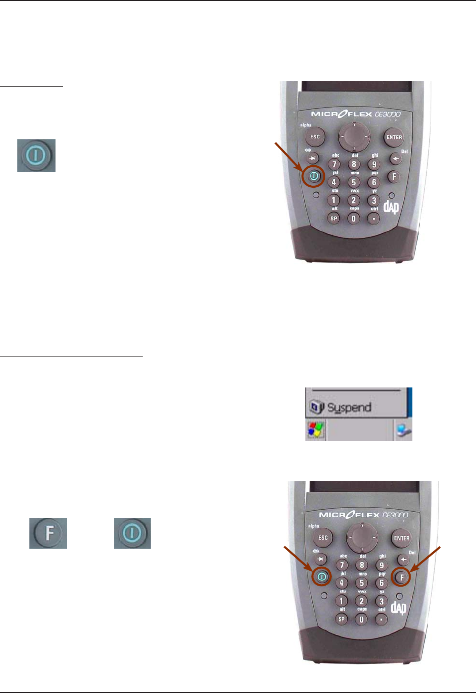
Turn Unit On
To turn on the CE3240B Unit, press the
ON / OFF key for 2 seconds and release.
Note: Should the unit not turn on, it could be
because the battery is too low. Refer back to
“Charging the Battery” Section for further
instructions.
Turning the Unit Off Manually
There are two ways to turn the unit off:
Press on the Start button located at the
bottom left corner of the screen and then
select “Suspend”
or
To manually turn off the CE3240B unit, press
the Function Key followed by the ON / OFF
Key.
1.
1.
2.
+
20
C
MU056-A
1
www.RoperMobile.com
Return To Table of Contents
O
p
eration Guid
e
T
U
RNIN
G
TH
E
U
N
IT
O
N&
O
F
F
(
CO
NTIN
U
ED
)
Automatic Shut-Off
If the Unit remains inactive for more than 3 minutes, it will turn off automatically in order to save battery. The
u
nit will also save the exact status of your application pro
g
ram and data before shuttin
g
down. Simply restart
t
he un
i
t when ready to resume work
.
N
ote:
W
hen turned off with fully charged batteries, the unit can be stored up to several days without re
-
char
g
in
g
. Refer to ‘
S
tora
g
e and Maintenance’
S
ection for further instructions
.
T
OUCH
S
C
REEN
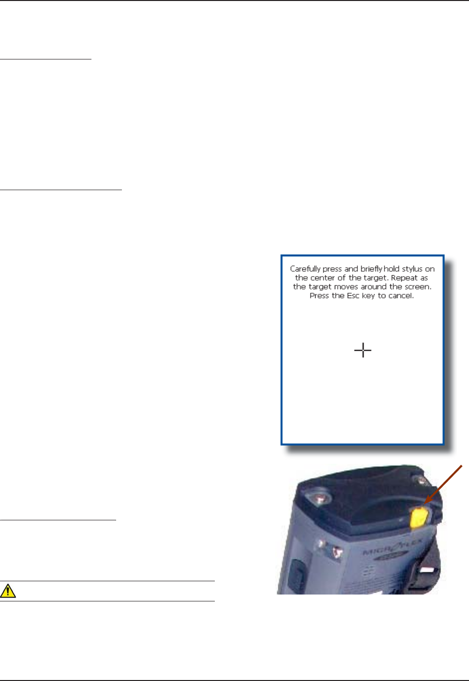
Touch Screen Calibration
T
he Touch Screen may need to be calibrated upon receiving a new unit of after being stored for a long period
of
tim
e
.
H
old your Stylus down until the Cross begins
t
o move.
T
ouch the center of the
C
ross for a few
s
econds. Re
p
eat o
p
eration as Cross moves
to
a
n
o
th
e
r l
oca
t
io
n
.
N
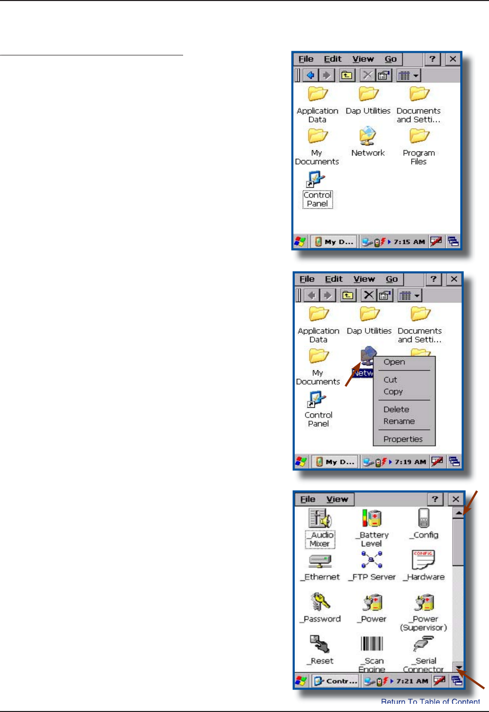
ote:
C
alibration may also be started by followin
g
the
s
teps
b
e
l
ow
:
C
lick on
:
a)
S
tar
t
b)
S
etting
s
c
)
Control Pane
l
Select St
y
lus apple
t
Select Calibration tab and click on
R
ecalibrate
.
Using the Touch Screen
g
T
o use the touch screen, s
i
mply use
t
he St
y
lus provided with the Unit
.
W
ARNING
A
pply normal pressure when using the Touch
Screen. Excessive pressure may permanently
d
ama
g
e the screen and hinder per
f
ormance
.
1.
2.
3.
4.
1.
www.RoperMobile.com
C
MU056-A
1
21
Return To Table of Contents
O
p
eration Guid
e
Using the Touch Screen (Continued)
g()
$[WUKP
I
VJG
5
V[NWURTQXKFGFOQXGſNGUQT
f
olders by “dragging and dropping” into the
f
older o
f
your choice
.
T
o open a folder, double click with St
y
lus on
t
h
e
des
ir
ed
fo
l
de
r
.
T
o run a program, double click with Stylus on
t
he des
i
red pro
g
ram.
P
oint to a folder (pressin
g
S
tylus on Touch
S
creen) and wait a few seconds, a contextual
menu will a
pp
ear
.
T
o navigate, with Stylus scroll up or down the
nav
ig
at
i
on bar
.
1.
2.
3.
4.
5.
T
OUC
H
S
C
REEN
(
C
O
NTINUED
)
22
C
MU056-A
1
www.RoperMobile.com
Return To Table of Contents
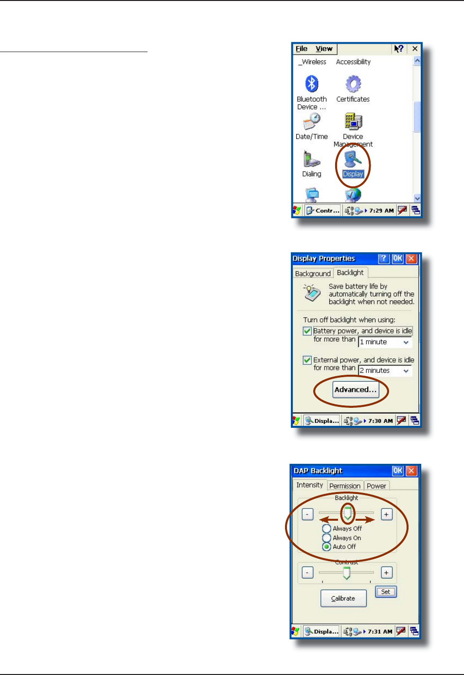
Activating the Screen Backlight
gg
E
very un
i
t has been des
ig
ned to work
i
n low-l
ig
ht
environments and have been equipped with a
“
Backlight” that can be activated at any time
.
T
o adjust the backlight,
C
lick on
:
a)
S
tar
t
b)
S
ettin
gs
c
)
Control Pane
l
S
elect the “Display
”
applet
.
S
elec
t
“
Backli
g
ht
”
tab
.
A
djust time backlight is to turn off
.
S
elect the “Advanced
”
tab for more options
C
heck options
:
a) Always Off: Will remain off at all times.
b
) Alwa
y
s
O
n:
Wi
ll r
e
m
ai
n
o
n
a
t
a
ll t
i
m
es.
c)
Auto
O
ff:
W
ill automatically adjust to
s
urrounding light, turning on and off when
r
equ
i
red
.
T
o adjust backlight manually, slide
arrow to the le
f
t or to the ri
g
ht
.
1.
2.
3.
4.
5.
6.
O
p
eration Guid
e
www.RoperMobile.com CMU056-A1 23
Return To Table of Contents
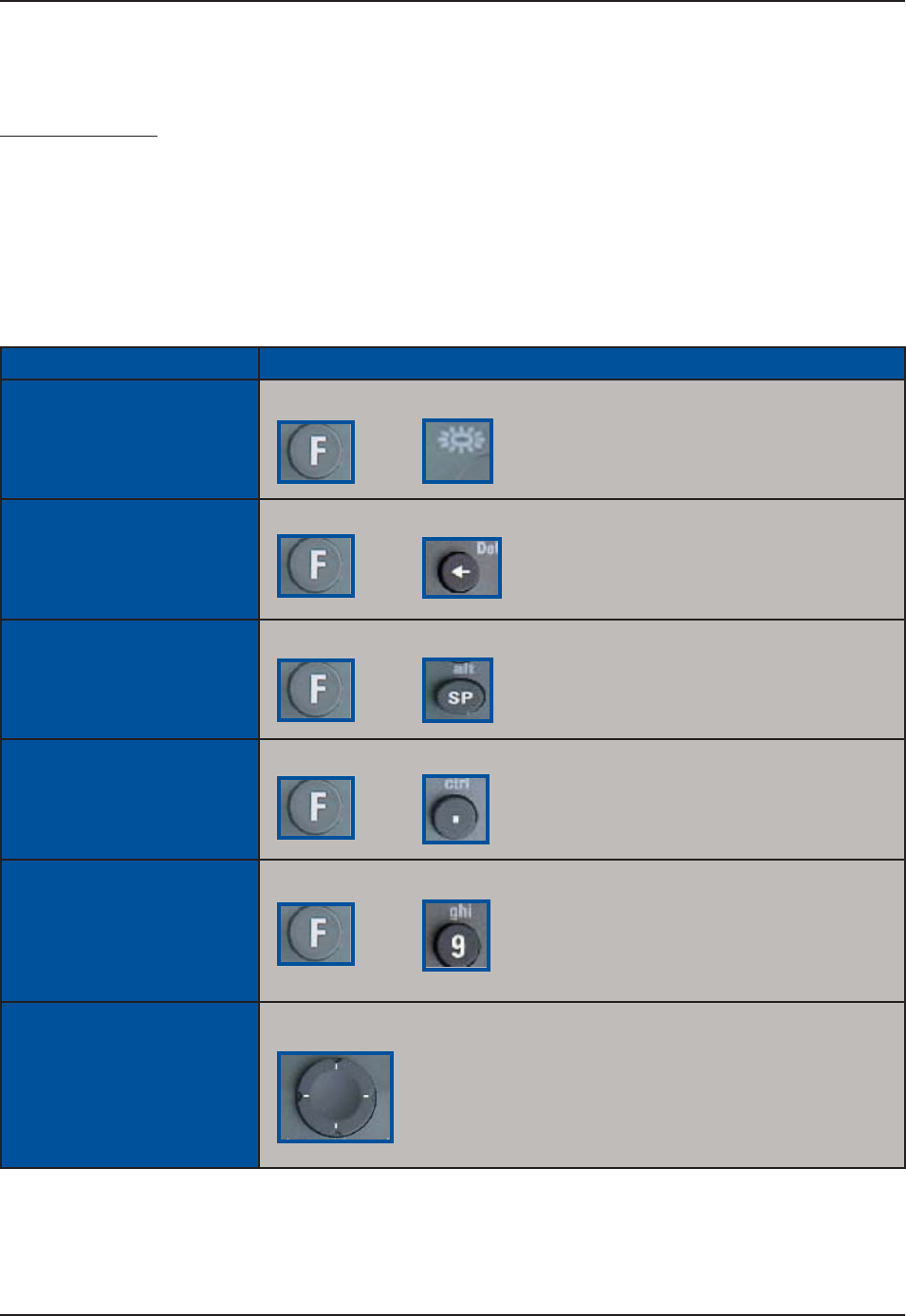
USING THE KEYBOARD
Special functions
To obtain special functions, press the F key (Function Key) followed by another key. Refer to the table below
HQTURGEKſEHWPEVKQPUCXCKNCDNGYKVJ[QWT%'$WPKV
Note: when the F1 Key is pressed, an “F” icon will appear on the task bar and disappear once the second
key has been pressed.
Special Function Instruction
Keyboard Backlight
ON/OFF
Press the F key followed by the TAB key
Delete Key (DEL) Press the F Key followed by the “Backspace” key
Alternate Key (ALT) Press the F key followed by the “SP” key
Control Key (CTRL) Press the F key followed by the “Period” key
F1 to F9 Press the F key followed by a number from 0 to 9
Navigation arrows Press cursor pad in desired direction (Left, right, up or down)
+
+
+
+
+
Operation Guide
24
C
MU056-A
1
www.RoperMobile.com
Return To Table of Contents
U
S
IN
G
T
HE
K
EYB
O
AR
D
(
C
O
NTIN
U
ED
)
Alpha Mode
p
Special Function Instruction
Engage / disengage
Alpha Mode
P
ress the F key followed by the escape key. The ABC icon will appear
/
d
i
sa
pp
ear on the task bar
.
Enter an Alpha Character
P
ress the correspondin
g
key. Dependin
g
on the letter, you may need to
p
ress once, twice or three times in order to obtain the desired letter
.
e
.
g
: press once for “ a
“
p
ress twice for “ b
“
press three times
f
or a “ c
”
Engage / Disengage
Uppercase Mode
P
ress the F key followed by the the
0
k
e
y
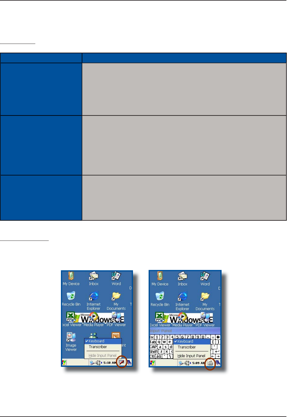
Virtual Keyboard
y
T
he virtual keyboard has been included to assist in the entry of data. By clickin
g
the Keyboard icon at the
bottom right of the Task Bar, the virtual keyboard will be displayed on the screen
.
S
elec
t
“
Hide In
p
ut Panel”
t
o hide the Virtual Ke
y
board
.
•
+
O
p
eration Guid
e
www.RoperMobile.com
C
MU056-A
1
25
Return To Table of Contents
O
p
eration Guid
e
U
S
IN
G
T
HE
K
EYB
O
AR
D
(
C
O
NTIN
U
ED
)
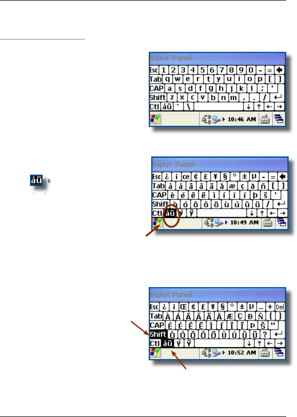
Virtual Keyboard (Continued)
y( )
S
tandard Keyboar
d
Press to toggle between the
standard and extended language Keyboard.
P
ress t
h
e
S
hif
t
K
e
y
on the virtual Ke
y
board to
access
addi
t
io
n
a
l
c
h
a
r
ac
t
e
r
s.
1.
2.
3.
26
C
MU056-A
1
www.RoperMobile.com
Return To Table of Contents
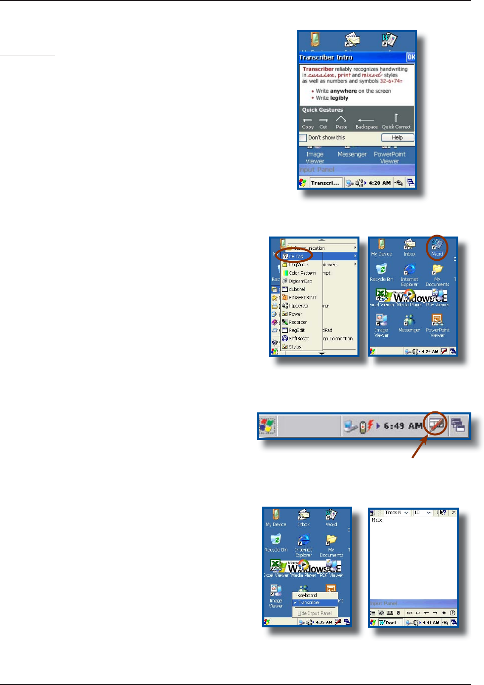
Tr
a
n
sc
ri
ber
T
ranscriber is an award winnin
g
application that
is used for handwriting recognition. Whether the
handwritin
g
is cursive or printed, or a combination o
f
both, Transcriber is able to reco
g
nize both. In addition
t
o recognizing letter, numbers and words, Transcriber
can also reco
g
n
i
ze spec
i
al characters and most
common symbols and even various control
g
estures
.
Start an a
pp
lication such as Pocket Word or CE
Pad.
D
oub
l
e
c
li
c
k
o
n th
e
W
o
r
d
Icon on your Desktop
o
r go
t
o
:
a) My Device
b
)
DAP Utilitie
s
c
)
C
E Pad
C
lick on the
i
n
p
ut method menu Ico
n
in th
e
lower right corner of the window
(
depending on
w
hat you already had selected on your
C
E3000B
u
nit, one of these two icons will be visible)
.
S
elec
t
Transcr
i
be
r
f
rom the menu
.
A
ct
i
vate or deact
i
vate Transcr
i
ber by cl
i
ck
i
n
g
on
T
r
a
n
sc
ri
be
r in th
e
m
e
n
u.
P
osition the cursor where
y
ou want text to
appear.
U
sin
g
the
S
tylus, write directly onto the screen.
Once text is written, Transcriber will wait a few
m
o
m
e
nt
s
fo
r th
e
Recognition Delay, then d
i
splays
t
h
e
t
e
xt
i
n th
e
se
l
ec
t
ed
l
oca
t
io
n
.
1.
2.
3.
4.
5.
6.
7
.
hello
O
p
eration Guid
e
U
SIN
G
THE
K
EYBOAR
D
(
C
O
NTINUED
)
www.RoperMobile.com
C
MU056-A
1
27
Return To Table of Contents
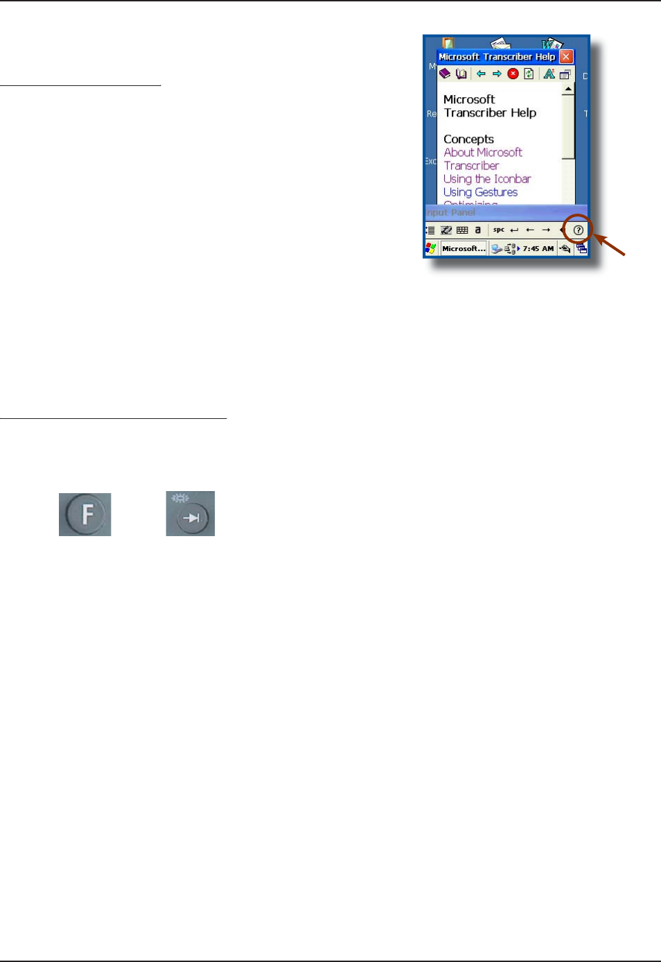
Transcriber (Continued)
()
N
ote: To know more about Transcriber as well as
p
oss
i
ble o
p
t
i
ons, cl
i
ck on the Hel
p
Icon located on
t
he Input Panel D
i
splay
.
Activating the Keyboard Backlight
gy g
P
ress the “F” key
f
ollowed by the “Tab” key,
pressing one after the other
.
No
t
e
: Keyboard backl
ig
ht dra
i
ns the ba
t
-
t
eries more quickly, it is recommended that
backl
ig
ht be used only when necessary
.
1.
O
p
eration Guid
e
+
U
S
IN
G
THE
K
EYB
O
AR
D
(
C
O
NTINUED
)

28 CMU056-A1 www.RoperMobile.com
Return To Table of Contents
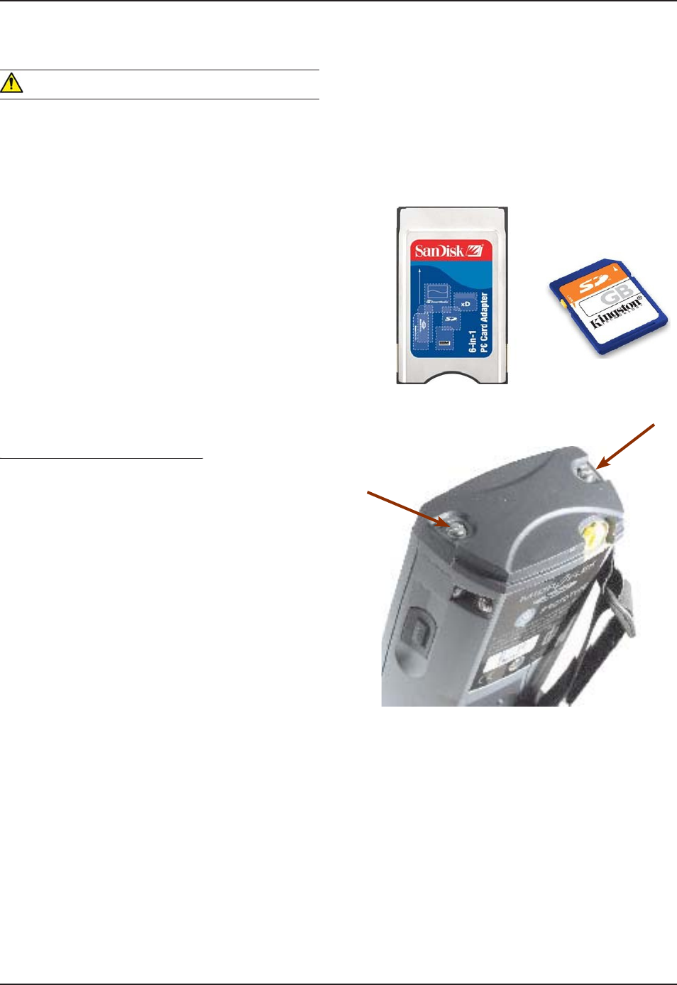
PC & SDIO CARD DESCRIPTION
PC Cards
PC cards are available in 3 basic formats: Type I, Type II & Type III. The type refers to the thickness of the
card; type III being the thickest. The width is the same for all cards, however the length will depend on the par-
ticular function of the card. (Memory cards are the shortest while wireless and GPS cards are much longer).
Note:6JGUVCPFCTFNGPIVJQHC2%ECTFKUOOū1/8 in). The maximum length a CE3000B unit can
CEEQOOQFCVGKUOOū1/2 in). The extended length is usually used for GPS, RF Tag Readers and
wireless cards.
Note: CF cards (Compact Flash Cards) are between the SDIO and PC Cards in terms of size and can
generally be installed in the CE3000B unit as a PC card, however, it requires the use of an Adapter.
SDIO Cards
These cards are available in a smaller format. Length will depend on the complexity of the card, e.g., a
memory card is much shorter than a wireless card.
SDIO Cards will come in 3 different lengths:
Short: 32 mm (standard cards such as memory cards)
Medium: 40 mm (such as Bluetooth cards)
Long: 54 mm (such as WIFI AND WLAN Cards)
Note: The CE3000B unit does not accept CardBus 32 bit PC Cards or extended PCM CIA Cards (which all
use the same technology). To ensure your unit may accept certain cards not described within this user guide,
it is recommended you refer to our Technical Support Web Site for the most current information, or contact
your Technical Support Representative nearest you.
USING PC & SDIO CARDS
One PC Card slot and one SDIO card slot are located at the top of the Endcap or the Adaptable Endcap.
Follow the instructions to insert, remove or to replace a card.
WARNING
To ensure no dirt particles or water enters the unit when inserting, removing or replacing PC or SDIO
cards, it is important to do so in a clean and dry area.
Some Adaptable Endcaps may make the installation of these cards more complex. You may require the
assistance of a skilled technician or assistance from customer technical support.
2%5&+1%#TFUECPTGFWEGDCVVGT[NKHGUKIPKſECPVN[GURGEKCNN[VJG9.#0CPF$NWGVQQVJECTFU
Most PC & SDIO cards that are not memory cards, will require the installation of a driver for proper
functioning. Refer to your technical suport team or Roper Mobile Technical Support Team for further
information.
•
•
•
•
•
•
•
Operation Guide
www.RoperMobile.com
C
MU056-A
1
2
9
Return To Table of Contents
Inserting PC or SDIO Cards
g
Tu
rn th
e
u
nit
off
.
U
sing a Flathead screwdriver, loosen the 2
s
crews located at the top o
f
your unit on Endcap
.
R
emove t
h
e
E
n
d
cap s
l
ow
ly
an
d
p
l
ace to t
h
e
side.
N
ote: The screws will remain inside the Endca
p.
W
ARNING
T
he Adaptable Endcap with
G
P
S
option has a
s
hort communication cable between Endca
p
and un
i
t. Kee
p
Endca
p
close to un
i
t not to brea
k
o
r
disco
nn
ec
t th
e
cab
l
e.
No
t
e
: You do not need to disconnect the GPS cable
t
o insert the P
C
or
S
DI
O
cards
.
Slide card into the a
pp
ro
p
riate socket.
(
PC or
S
DI
O
)
.
a
)
SDIO Slo
t
b) P
C
S
lot
T
urn sto
pp
er to secure cards into
p
lace
.
c)
S
DI
O
S
toppe
r
d)
PC Sto
pp
e
r
No
t
e
: The extended Endcap also comes w
i
th two
(
2
)
foams to secure PC or SDIO cards into
p
lace
wh
en sto
pp
ers cannot
b
e use
d.
R
eplace the door to its original
pos
i
t
i
on and t
ig
hten screws
.
1.
2.
3.
•
4.
5.
6.
U
SIN
G
PC & SDIO
C
A
RDS
(C
O
NTINUED
)
O
p
eration Guid
e
b
a
c
b
30
C
MU056-A
1
www.RoperMobile.com
Return To Table of Contents
O
p
eration Guid
e
U
S
IN
G
P
C
&
S
DI
O
C
A
RD
S
(
C
O
NTIN
U
ED
)
W
ARNIN
G
Installing PC cards is not recommen
d
e
d
w
hen Adaptable Endcap
i
s
i
nstalled
.
Insert PC or SDIO Cards in a clean
and dry env
i
ronment to ensure no
d
ust
p
articles or water enters the unit
.
E
nsure to insert P
C
or
S
DI
O
C
ards
appropriately or you may damage the unit
.
a
)
P
C
C
ards: Insert the end with the
V
YQ
TQYU QH NKVVNG JQNGU ſTUV CPF
manu
f
acturer label
f
acin
g
upwards
.
b)
SDIO Cards:
I
nsert the end with the row
QH
EQRRGT
ſ
P
I
GTU
ſ
TUV CPF OCPW
H
CEVWTGT NCDGN
f
acing upwards.
Removing PC or SDIO Cards
g
Tu
rn th
e
u
nit
off
.
U
sing a Flathead screwdriver, loosen the 2
s
crews located at the top o
f
your unit on Endcap
.
R
emove the Endcap slowl
y
and place to the side
.
N
ote:
T
he screws will remain inside the Endca
p.
a
)
To
r
e
m
o
v
e
t
he
P
C
C
ar
d
f
r
o
m th
e
u
nit,
p
ress the
‘
release button’ lo
-
cated to the right of the PC Card opening
.
b
)
To remove the SDIO Card, push ge
n
-
t
l
y
once and card will pop up. Remove card
.
R
eplace the door to its original position and
t
ighten screws
.
1.
2.
3.
1.
2.
3.
4.
www.RoperMobile.com
C
MU056-A
1
3
1
Return To Table of Contents
U
S
IN
G
T
HE
C
R
ADLE
No
t
e
:(QTKPUVTWEVKQPUTG
I
CTFKP
I
VJGKPUVCNNCVKQPCPFEQPſ
I
WTCVKQPQHVJGETCFNGUCXCKNCDNGHQT[QWT%'$
u
nit, refer to the Technical
G
uide available on the Roper Mobile Technical
S
upport web site. Refer to ‘Advanced
U
ser Information” for instructions on logging onto the Customer Service Web Site
.
T
he Technical
G
uide will provide information on the followin
g
C
radles
:
1HſEG%TCFNG
Cradle Code Description
C
B
C
E340B
E
C
har
g
e &
C
ommunication: U
S
B Host; U
S
B
C
lient and Etherne
t
Vehicle Cradles
Cradle Code Description
C
B
C
E340B
V
C
har
g
e and
C
ommunication: U
S
B Host; U
S
B
C
lient and 3
S
erial Ports
(
RS232
)
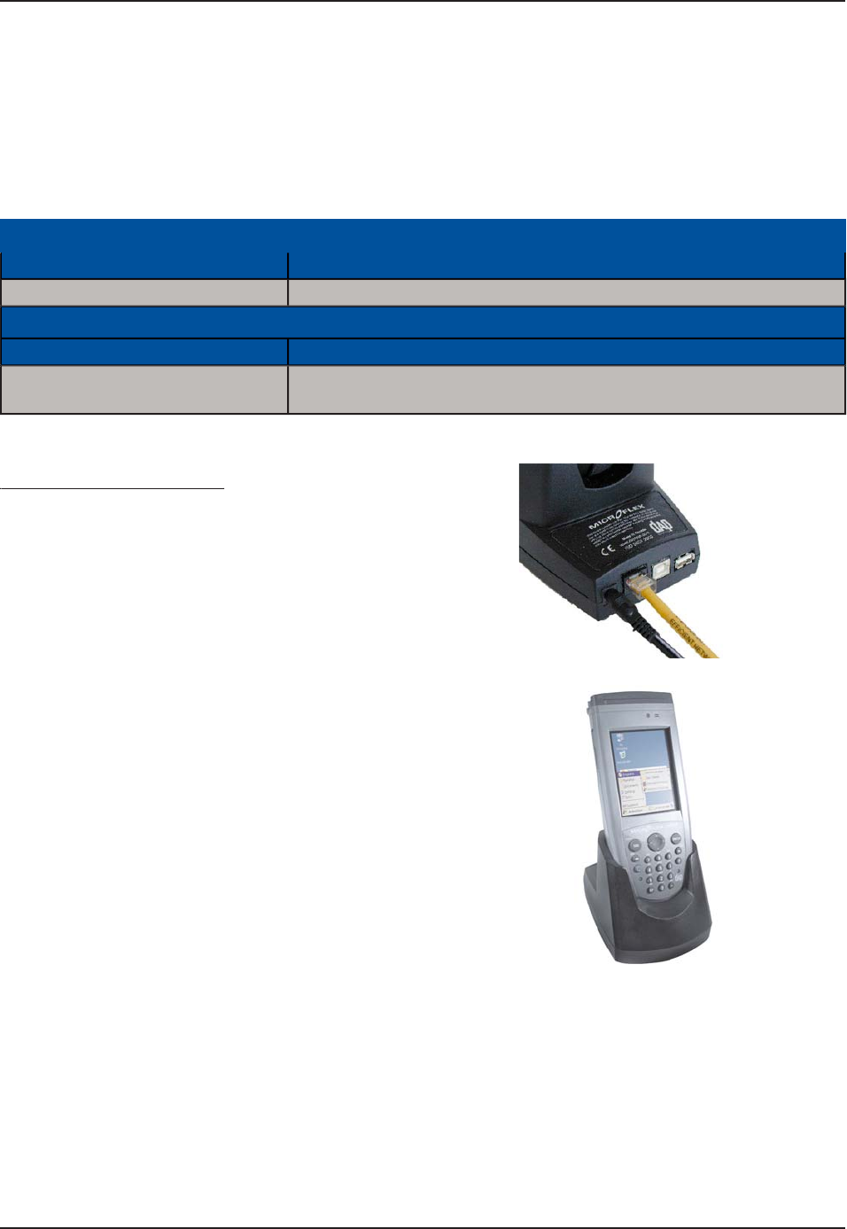
Using the Ethernet Cradle
g
6
QCEVKXCVGVJG'VJGTPGV%TCFNG[QWOWUVſTUV
connect a CSCE300 charger to the cradle
.
C
onnect the RJ-45 network cable to the cradle
.
S
lide the unit into the cradle
.
C
onnect
p
ower cable to the wall outlet
.
1.
2.
3.
4.
O
p
eration Guid
e
3
2
C
MU056-A
1
www.RoperMobile.com
Return To Table of Contents
O
p
eration Guid
e
U
S
IN
G
T
HE
C
R
ADLE (
C
O
NTIN
U
E
D
)
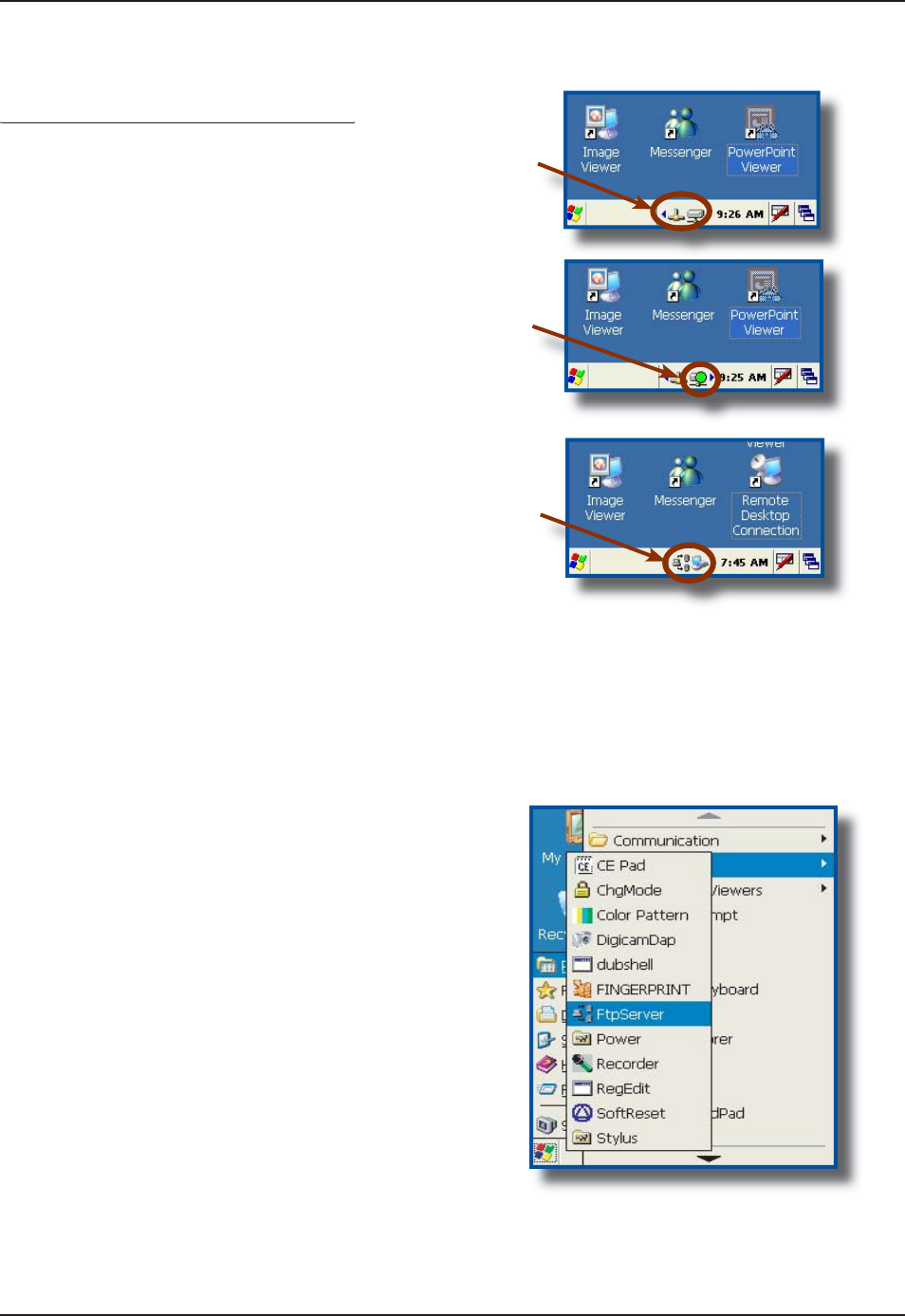
Using the Ethernet Cradle (Continued)
g()
E
thernet Ada
p
ter is activated and linked to the
Network. It
i
s ready to be used by a User or
Wi
ndows Appl
i
cat
i
on
.
T
h
i
s bl
i
nk
i
ng
i
con
i
nd
i
cates that a connect
i
on
is
es
t
ab
l
is
h
ed
w
i
th th
e
n
e
tw
o
rk
a
n
d
da
t
a
is
being transferred
.
T
he following icons indicate that the FTP
Server is running. By default, server starts
automat
i
cally when a network connect
i
on
i
s
established
.
1.
2.
3.
T
RANSFERRING
F
I
LE
S
IN
FTP M
O
D
E
6
JG%'$WPKVKPENWFGUCP(62%NKGPVCEEGUUYJKEJOCMGUVTCPUHGTTKPIſNGUGCU[CPFFQGUPQVTGSWKTG
t
he use of ActivS
y
nc
.
+PUGTVVJG
%
'$WPKVKPVQVJG
1
HſEG
%
TCFNG
N
ote: Once unit is inserted this will automatically activate the FTP server. If the
F
TP server does not activate automatically,
f
ollow the steps below
.
1.
C
lick on
:
a
)
Star
t
b) Pro
g
ram
c
)
DAP Utilities
d)
FTP Server
www.RoperMobile.com
C
MU056-A
1
33
Return To Table of Contents
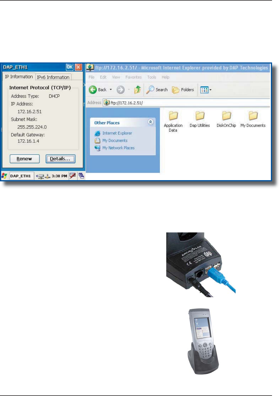
T
ransferrin
g
Files in FTP Mode (
C
ontinued
)
O
pen Internet Explorer on your Desktop
C
omputer then type
:
FTP:// <your CE3000B IP address
>
e
.g.: FTP:
//1
9
2.168.2.3
4
T
he contents of
y
our CE3000B unit will appear. Simpl
y
use the conventional
‘
Dra
g
and Drop / Copy
/
Dele
t
e’
f
unctions to mana
g
e its contents
.
3.
4.
U
SB
C
LIENT
C
O
NNECTION
6
QCEVKXCVGVJG75$%QPPGEVKQP[QWOWUVſTUV
connect a CSCE300 Char
g
er to the cradle
.
C
onnect
US
B cable to the
C
E3000B
U
nit and to
th
e
H
ost connector on your
d
es
k
top computer
.
Slide unit into the cradle
.
C
onnect power cable to wall outlet
.
1.
2.
3.
4.
O
p
eration Guid
e
34
C
MU056-A
1
www.RoperMobile.com
Return To Table of Contents
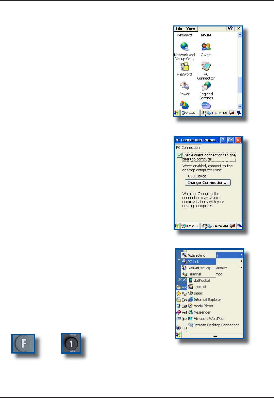
6
QEQPſ
I
WTG75$%QPPGEVKQP%NKEM
a
)
Star
t
b) Settin
gs
c)
C
ontrol Pane
l
d)
PC Connection
S
elect “Enable d
i
rect connect
i
ons to the
d
es
k
top compute
r
”.
C
lick “
O
K
”
T
o activate ActiveSync, Click
:
a
)
Star
t
b) Pro
g
ram
s
c)
C
ommunicatio
n
d)
PC Lin
k
No
t
e
:
S
hortcut to P
C
Link: Press the
F
unction Key followed by the 1
.
1.
2.
3.
4.
O
p
eration Guid
e
US
B
C
LIENT
C
O
NNE
C
TI
O
N (
C
O
NTIN
U
E
D
)
+
www.RoperMobile.com
C
MU056-A
1
35
Return To Table of Contents
O
p
eration Guid
e
U
S
IN
G
T
HE
V
EHI
C
L
E
C
RADL
E
A
vehicle adapter
/
charger is required and is
available throu
g
h Roper Mobile Technolo
g
y (Part
Number CS312
).
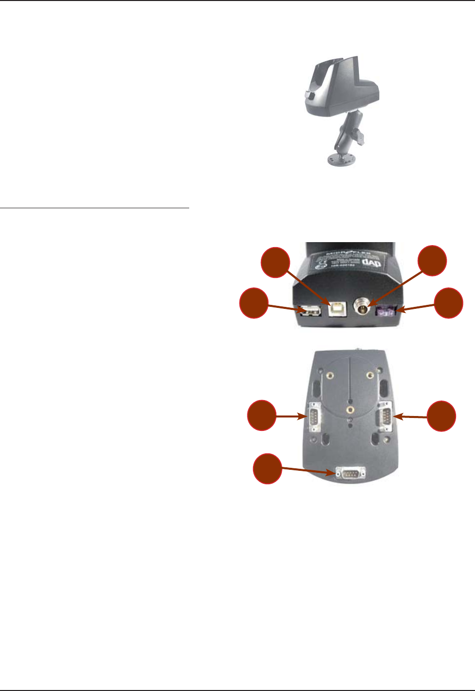
8GJKENG%TCFNG%QPPGEVQT+FGPVKſECVKQP
Back of
U
nit
:
US
B Hos
t
US
B
C
lien
t
P
ower Suppl
y
Fuse
Under the Unit
:
S
erial Port
1
Serial Port
2
S
erial Port 3
N
ote:
9
JGPKPUVCNNKPICPFEQP
ſ
IWTKPIRGTKRJGTCNU
ensure to select the proper Port (1, 2 or 3) and to
EQPPGEV VQ VJG EQPſIWTGF RQTV QPEG KPUVCNNCVKQP
com
pl
ete
.
Install power supply lead by
i
nsert
i
ng round
co
nn
ec
t
o
r
i
nt
o
th
e
r
ou
n
d
co
nn
ec
t
o
r
a
t th
e
back of the cradle
(
refer back to connector
KFGPVKſECVKQP
T
urn r
i
ng clockw
i
se to hold
i
n place
.
C
onnect other end of connector to cigarette
l
i
ghter.
N
ote:
T
he Vehicle Cradle re
q
uires a
p
ower source of
9
to 30
Vd
c
.
E
nsure cigarette lighter connector is clean and
corrosion-
f
ree to
p
rovide the least electrical
resis
t
a
n
ce
.
1.
2.
3.
4.
5.
6
.
7
.
1.
2.
3.
•
•
CBCE340BV with Optional Mount
7
5
6
4
3
2
1
36
C
MU056-A
1
www.RoperMobile.com
Return To Table of Contents
Making your own Power Supply Lead
g y pp y
T
o make your own power supply lead, you may order the power connector at Roper Mob
i
le Technolo
g
y us
i
n
g
t
he
f
ollowin
g
in
f
ormation:
R
oper Mob
i
le Technolo
g
y
i
tem #: NAM03
6
Manufacturer’s name and item #:
S
witch
C
raft 760
K
No
t
e
:
Be sure to insert a 3 amp time-la
g
f
use, or i
f
you are usin
g
a
f
use box, ensure to use a similar
f
use
.
A
ll contacts must be clean and corrosion-free to avoid electrical resistance
.
Keep the len
g
th o
f
the Lead to a minimum
.
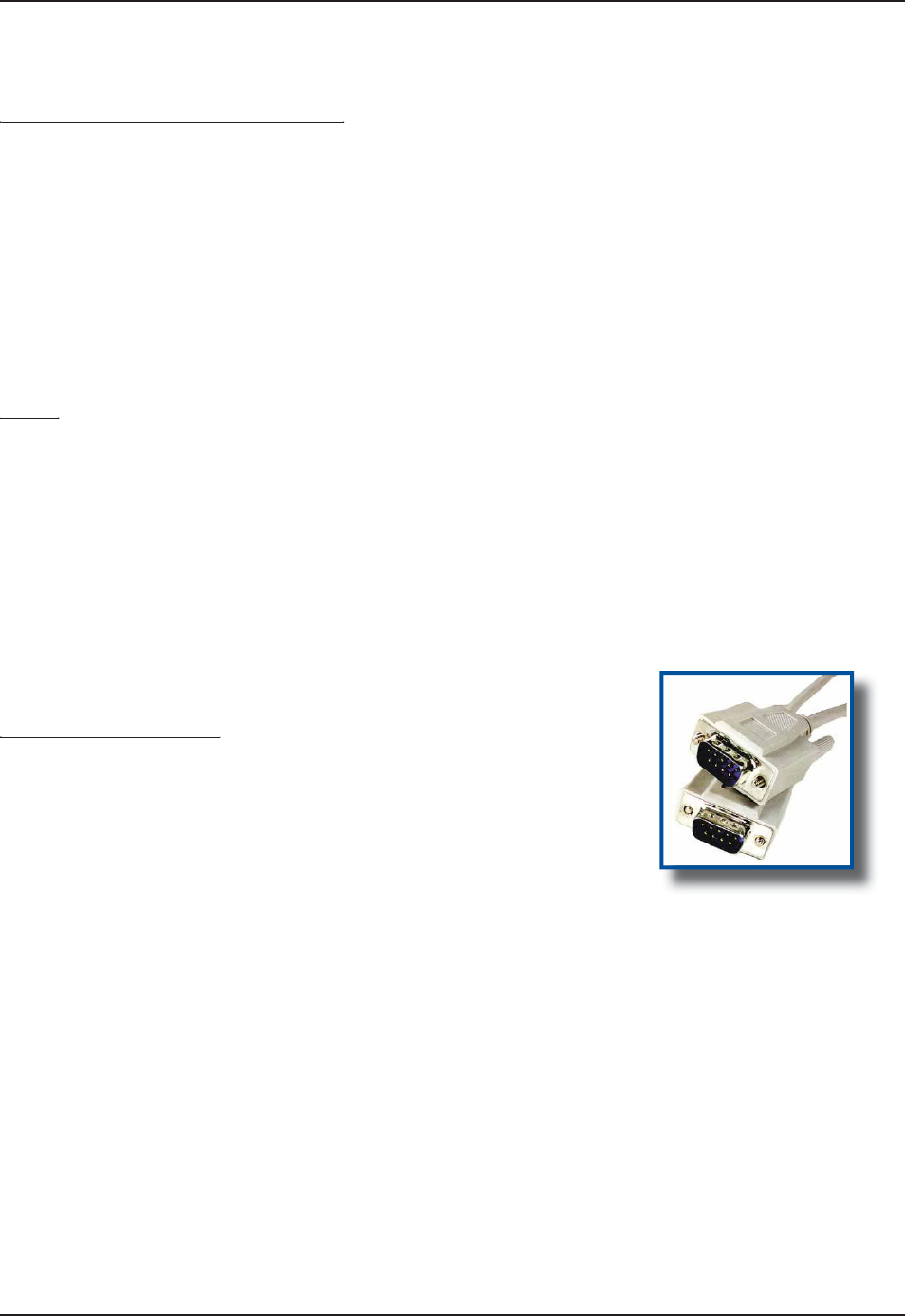
Wiring
g
T
he Vehicle
C
radle can have up to 3 serial cables connected at the same time
.
T
he DU-C-0040 measures approximately 180 cm (70 in) and includes 2 DB-9
s
ockets. Its sole use if for communicatin
g
with the host computer via ActiveSync
.
No
t
e
: Another type of cable may be required to link certain devices such as a
G
P
S
or external radio. The
DU-C-0040 may not be the appropriate cable for these devices and a special cable might therefore be required.
T
o customize your own cable, refer to the “Serial Connector Pin Layout” section for further information
.
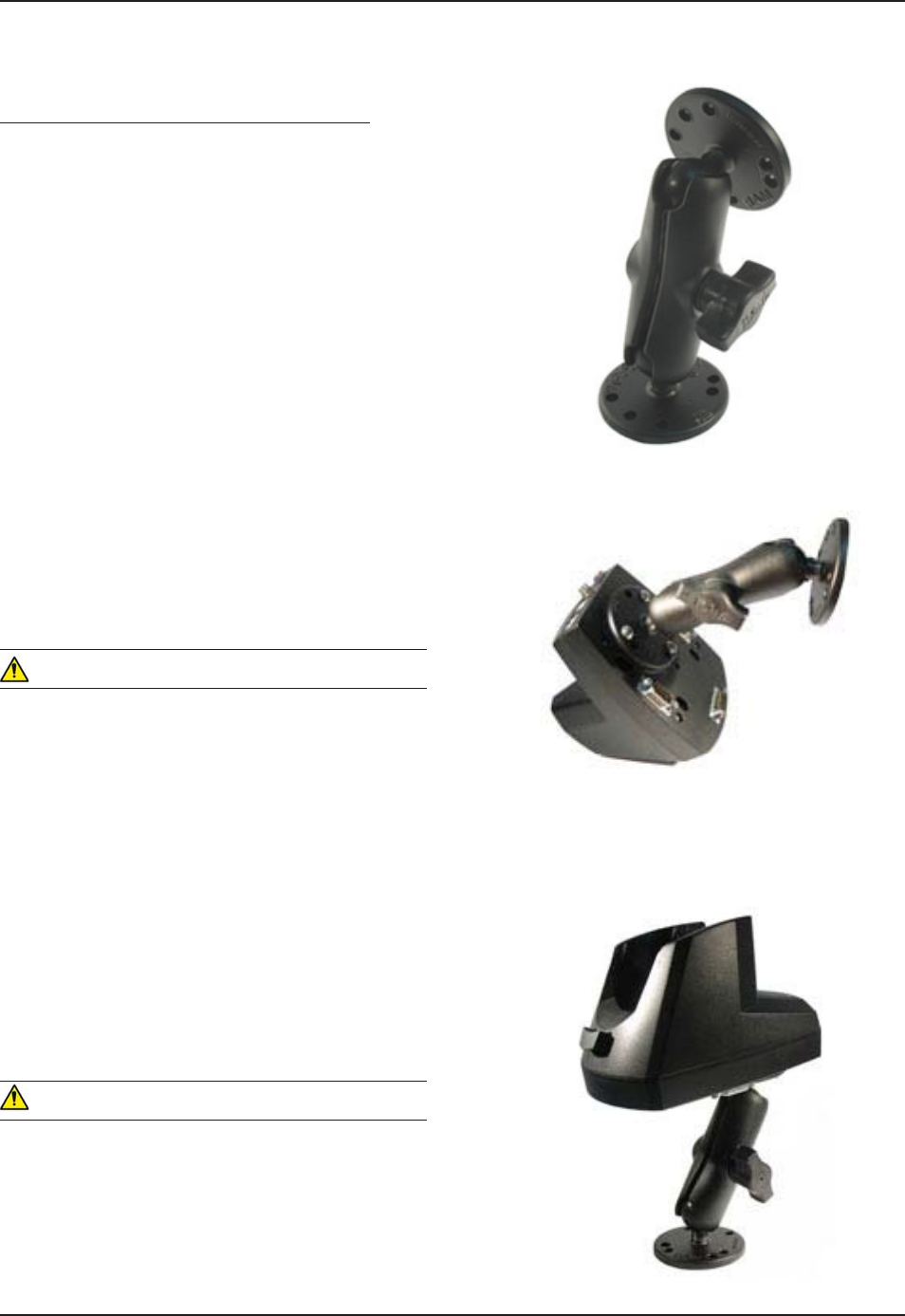
Installing Vehicle Mount
g
T
he vehicle cradle is compatible with the RAM-MOUNT System.
R
oper Mobile Technology item #: DC81
3
R
AM-MOUNT item number: RAM-B-101
U
R
AM-M
O
UNT offers several installation possibilities. For further information, consult their web site at
www.ram-mount.com.
T
he D
C
813 hin
g
ed support is comprised of the followin
g
parts:
1 RAM-B-201 Socket Arm with Handl
e
2
RAM-B-202 ant
i
-v
i
brat
i
on ball
s
3
screw
s
•
•
•
•
•
•
•
1.
2.
3.
U
SIN
G
V
E
HICL
E
C
RADLE
(
CONTINUED
)
O
p
eration Guid
e
DU-C-0040
www.RoperMobile.com CMU056-A1 37
Return To Table of Contents
Operation Guide
Installing the Vehicle Mount (Continued)
Place one of the 2 balls underneath the cradle
and align holes with the receptacles for the
screws.
Tighten all 3 screws to secure balls into place.
Position the second ball against
any solid area in the vehicle.
Secure into place by tightening 4 screws (not
provided).
WARNING
For safety reasons, it is strongly recommended that
the vehicle cradle be installed at level lower than
the driver’s and passenger’s heads.
Using handle, loosen the pin-head adaptor.
Insert each of the balls on either end of the arm.
Adjust cradle to desired angle and secure into
position by tightening the handle.
WARNING
Roper Mobile Technology may not be held
responsible for any injuries caused by the vehicle
cradle or handheld mobile computer in the event of
a collision. The Vehicle cradle has been designed
to withstand normal bumps and vibrations during
travel. It has not been designed to secure the
handheld in case of a collision.
1.
2.
3.
4.
5.
6.
7.
USING VEHICLE CRADLE (CONTINUED)
38
C
MU056-A
1
www.RoperMobile.com
Return To Table of Contents
M
O
NIT
O
RIN
G
TH
E
PR
OC
E
SS
ON
A
3
S
E
RIAL P
O
RT
C
R
ADLE
A
unique feature of the 3 Serial Port Cradle will allow you to monitor the process on the CE3000B screen
.
N
ote: A driver is required to ensure the 3 Serial Port Cradle (CBCE340BV) works correctly. For more
KPHQTOCVKQPQPVJGKPUVCNNCVKQPCPFEQPſ
I
WTCVKQPQHVJGETCFNGTGHGTVQVJG%'$6GEJPKECN)WKFGNQECVGF
on
Docudap t
ec
hn
ica
l w
eb
si
t
e.
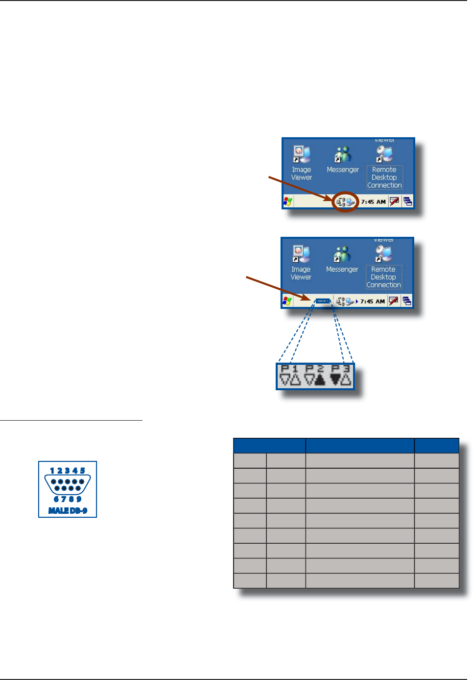
O
p
eration Guid
e
C
radle is
p
owered and driver is installed
correctly when the task bar d
i
splays the
f
ollowing icons.
W
hen commun
i
cat
i
on be
gi
ns and data
i
s
being transferred, additional icons will appear
to
i
n
dica
t
e
co
mm
u
n
ica
t
io
n
s
t
a
t
us
.
S
erial Port Connector Pin-Out
P
orts 1 2 & 3 on the
C
B
C
E340BV
C
radl
e
•
•
PIN DESCRIPTION TYPE
1
CD
C
arrier Detec
t
INP
U
T
2
RX
R
ecei
v
e
L
i
n
e
INPUT
3TX Transm
i
t L
i
n
e
OU
TP
UT
4
DTR
D
ata Terminal Read
y
OU
TP
UT
5
GND
G
round
6
DS
R
D
ata
S
et Read
y
INPUT
7
R
T
S
Re
q
uest To
S
en
d
INP
U
T
8
CTS Clear To Send OUTPU
T
9
RI
R
i
ng Ind
i
cator
www.RoperMobile.com CMU056-A1 39
Return To Table of Contents
Operation Guide
MONITORING THE PROCESS ON A 3 SERIAL PORT CRADLE (CONTINUED)
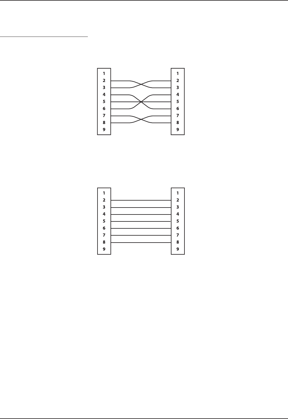
Serial Port Connector Pin-Out
Typical Communication Cable for Peripheral (Null Cable)
Typical Communication Cable for Peripheral
Cradle Side
Female DB-9
Peripheral Side
Female-- DB-9
Depends on the Peripheral
Depends on the Peripheral
Cradle Side
Female DB-9
Peripheral Side
Male DB-9
40 CMU056-A1 www.RoperMobile.com
Return To Table of Contents
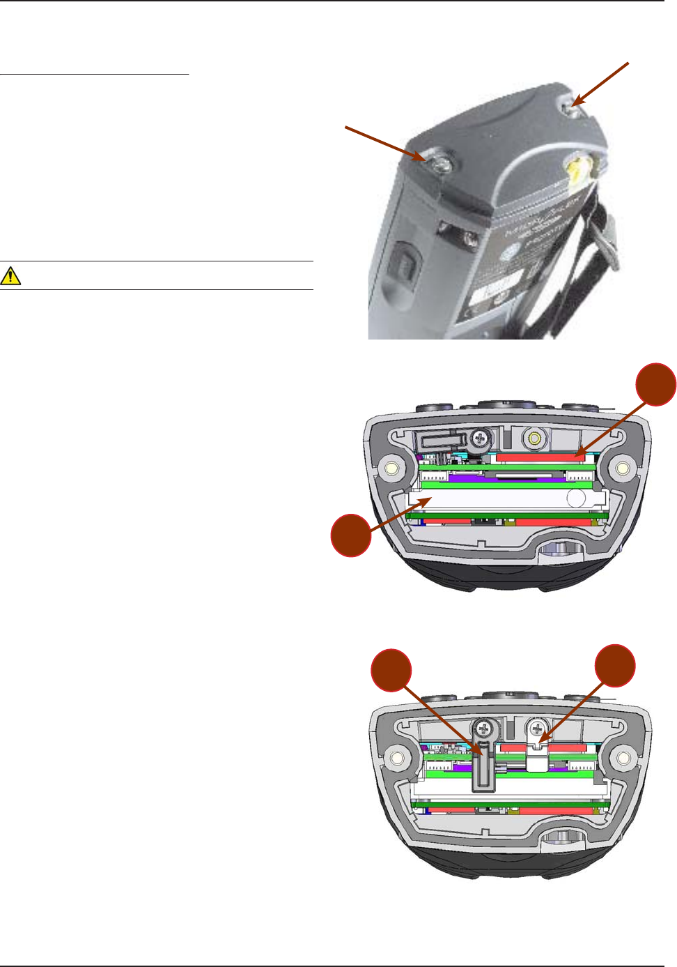
6JG %'$ WPKV EQOGU GSWKRRGF YKVJ C ſGNF
replaceable battery designed to ensure quick
charging, long battery life and to withstand shocks and
vibrations. It is strongly recommended to use batteries
that are provided by Roper Mobile Technology or one
of its distributors.
Note: Check for our label on the battery pack.
WARNING
Always turn the unit off prior to changing the battery
to ensure no data is lost.
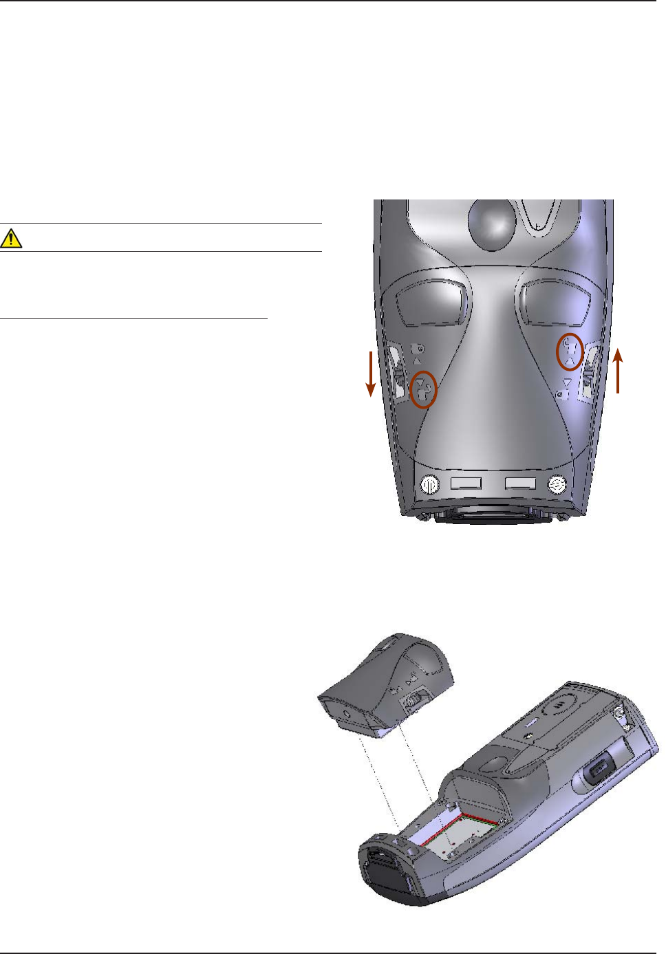
Changing the Field Replaceable Battery
Turn the unit off.
Turn left screw downwards and right screw
upwards to loosen in order to remove the battery
pack. (Refer to the illustration on the right).
Remove Battery Pack by lifting it off the unit.
1.
2.
3.
Operation Guide
FIELD REPLACEABLE BATTERY
To Unlock
To Unlock
www.RoperMobile.com CMU056-A1 41
Return To Table of Contents
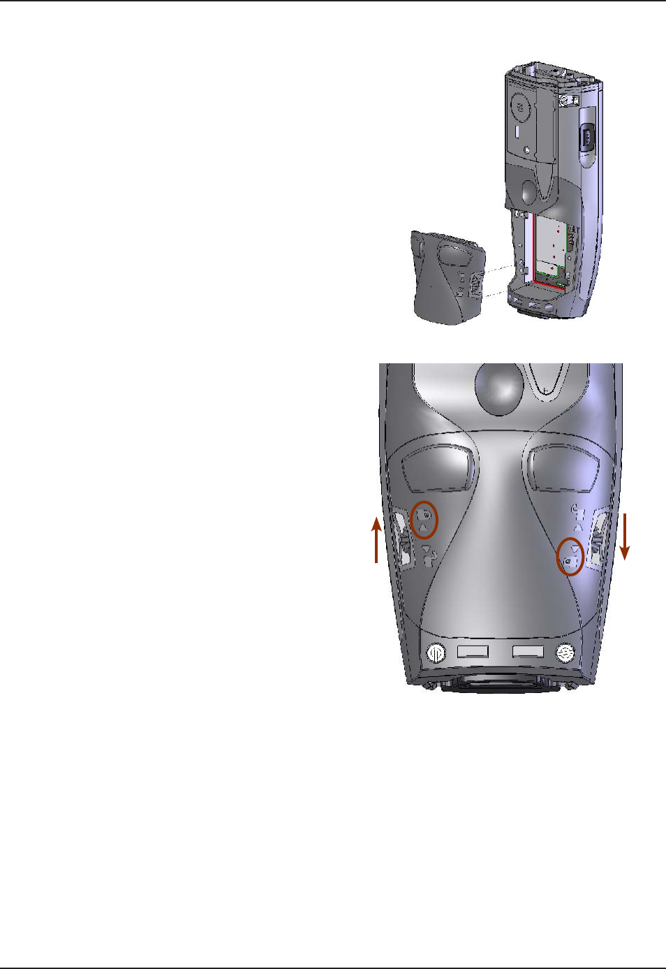
Replace with a fully charged Battery Pack.
Note: Ensure to insert battery pack correctly
or you may not be able to tighten screws.
Turn left screw upwards and right screw
downwards to tighten and secure Battery Pack
into place. (Refer to the illustration on the right).
4.
5.
Operation Guide
FIELD REPLACEABLE BATTERY (CONTINUED)
To lock
To lock

42 CMU056-A1 www.RoperMobile.com
Return To Table of Contents
Part Number Description
3240B-C 1D/2D Barcode Reader
3240B-EEC Extended End-Cap
3240B-FC Fingerprint & 1D/2D Barcode Reader
3240B-FEC Fingerprint Reader
3240B-LEC Laser Barcode Scanner
3240B-LF Laser Scanner & Fingerprint Reader
3240B-NEC Standard End-Cap
3240B-SCR Contact/Contactless SmartCard Reader
3240B-REC RS-232 DB9 End-Cap
Adaptable Endcap Options
www.RoperMobile.com
C
MU056-A
1
4
3
Return To Table of Contents
B
AR
CO
DE
R
EADER
S
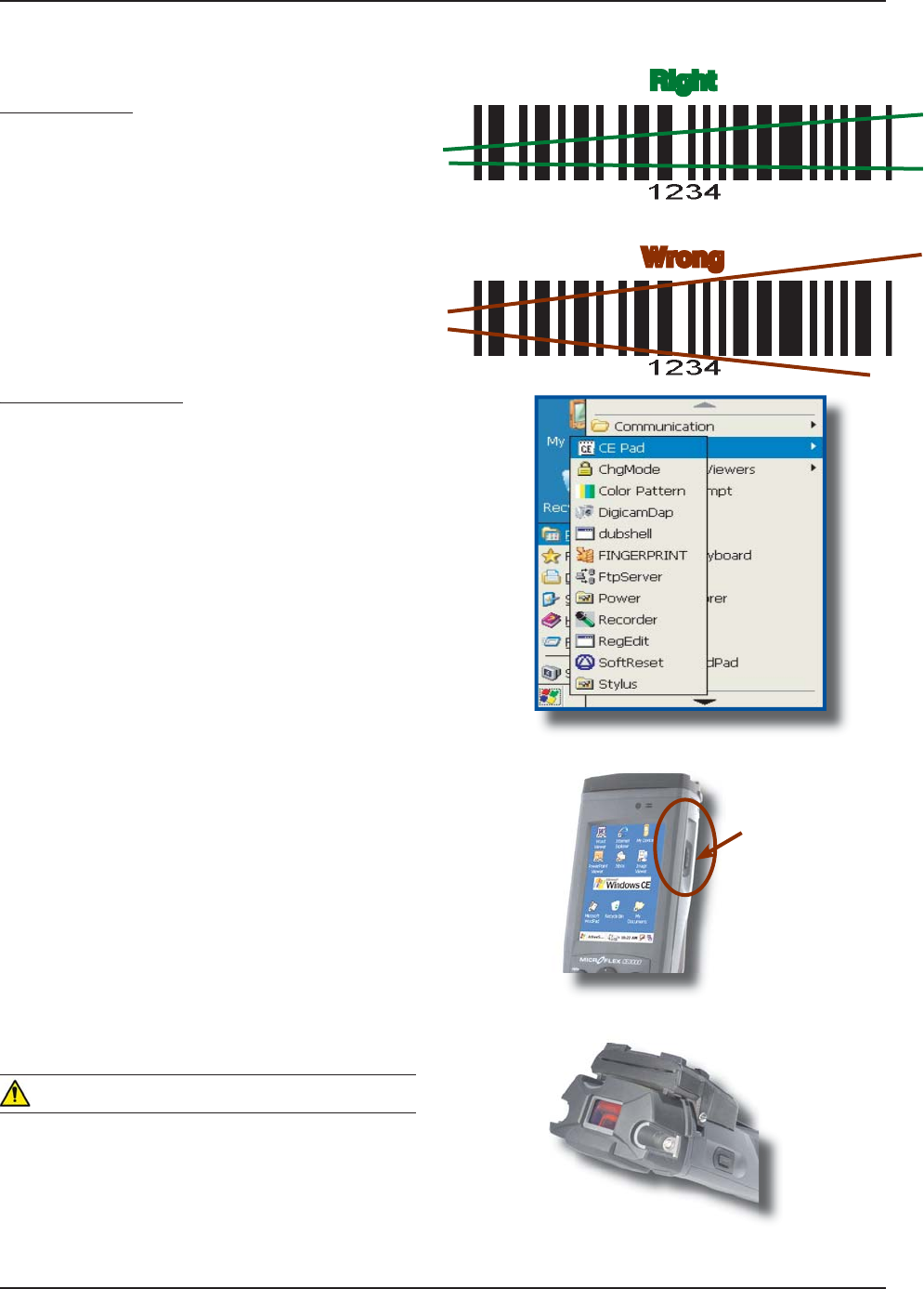
L
aser Scanner
T
he ‘Laser Scanner’ function will de
p
end on the
a
pp
lication used and a s
p
ecial so
f
tware driver.
R
efer to your application’s User
G
uide for furthe
r
instructions. Information included are basic
s
cann
i
n
g
i
nstruct
i
ons
.
R
efer to the diagram to the right for right and wrong
s
cann
i
n
g
methods
.
Testing the Scanner
g
T
o test the scanner, cl
i
ck on
:
a
)
Star
t
b) Pro
g
ram
s
c) DAP Utilities
d)
CE Pa
d
T
o activate scanner point the top o
f
the unit
t
oward the barcode label needed to be scanned
.
P
ress the ‘trigger’ button located on the side
of
th
e
u
nit
a
n
d
m
o
v
e
th
e
u
nit
bac
k
a
n
d
fo
rth
s
o the beam completely crosses the label
.
Once the label has been decoded, the unit will
s
ound a short ‘beep’
.
No
t
e
: I
f
you keep the ‘tri
gg
er’ button pressed
f
or
t
oo lon
g
, the unit will stop scannin
g
by itsel
f
a
f
ter a
f
ew moments. The unit will sound two
(
2
)
bee
p
s to
i
n
dica
t
e
th
a
t n
o
ba
r
code
h
as
bee
n
de
t
ec
t
ed.
Advanced
U
sers
:
Refer to the
C
E3000B Technical
Guide for further instructions on pro
g
rammin
g.
C
A
UTIO
N
A
void Exposure to Laser Light Beam
.
Do not intentionally look into the Laser Light
Bea
m.
1.
2.
3.
4.
•
•
R
ght
i
g
h
t
Wrong
W
ro
ro
ng
n
g
Ada
p
table Endca
p
O
p
tion
s
Trigger Button
44
C
MU056-A
1
www.RoperMobile.com
Return To Table of Contents
Testing the Reader
g
T
o test the reader
,
click on:
a)
S
tar
t
b
)
Program
c
)
DAP Utilities
d
)
C
E Pa
d
T
o activate reader, press the
‘
tri
gg
er’ button
.
H
old the un
i
t stead
i
ly at a d
i
stance
o
f 10 cm (4 in), from the barcode.
W
ARNIN
G
Do not move the unit while scanning or scan will
n
o
t
fu
n
c
ti
o
n.
1.
2.
3.
B
ARCODE
R
EADERS
(
CONTINUED
)
2D
Ba
r
code
Reade
r
6
JKUURGEKCNQRVKQPKUWUWCNN[KPUVCNNGFCPFEQP
ſI
WTGFKPJQWUGCVVJGOCPW
H
CEVWTGTŏU
T
he 2D Barcode Reader is primarily controlled by the client application and a special driver. There
f
ore, please
r
e
f
er to your application specialist or supervisor
f
or
f
urther instructions
.
No
t
e
:
Y
ou may also refer to the CE3000B Technical Guide located on DocuDap for further instructions on
Ada
p
table Endca
p
O
p
tion
s
N
ote: Unlike the laser scanner, the 2D reader does not
“
swipe” the barcode, but rather, it takes a photograph
w
hich is then reco
g
nized and interpreted by the unit. The photo
g
raph can be taken
f
rom any direction
.
T
he 2D Barcode Reader will emit a red beam allowin
g
the user to adequately focus on the barcode needin
g
t
o be read.
1
PEGVJGTGCFKP
I
JCUDGGPEQORNGVGFVJGFGXKEGYKNNGOKVCUQWPFCPFVJGEQPſTOCVKQP.'&YKNNVWTP
I
TGGP
f
or a moment. The numeric code will then be displa
y
ed on the screen
.
Y
ou can release the tri
gg
er an any time to cancel the scannin
g
. Two short beeps indicate that scannin
g
has
ended
.
www.RoperMobile.com
C
MU056-A
1
4
5
Return To Table of Contents
F
AS
T
F
I
N
G
ERPRINT
S
EN
SO
R
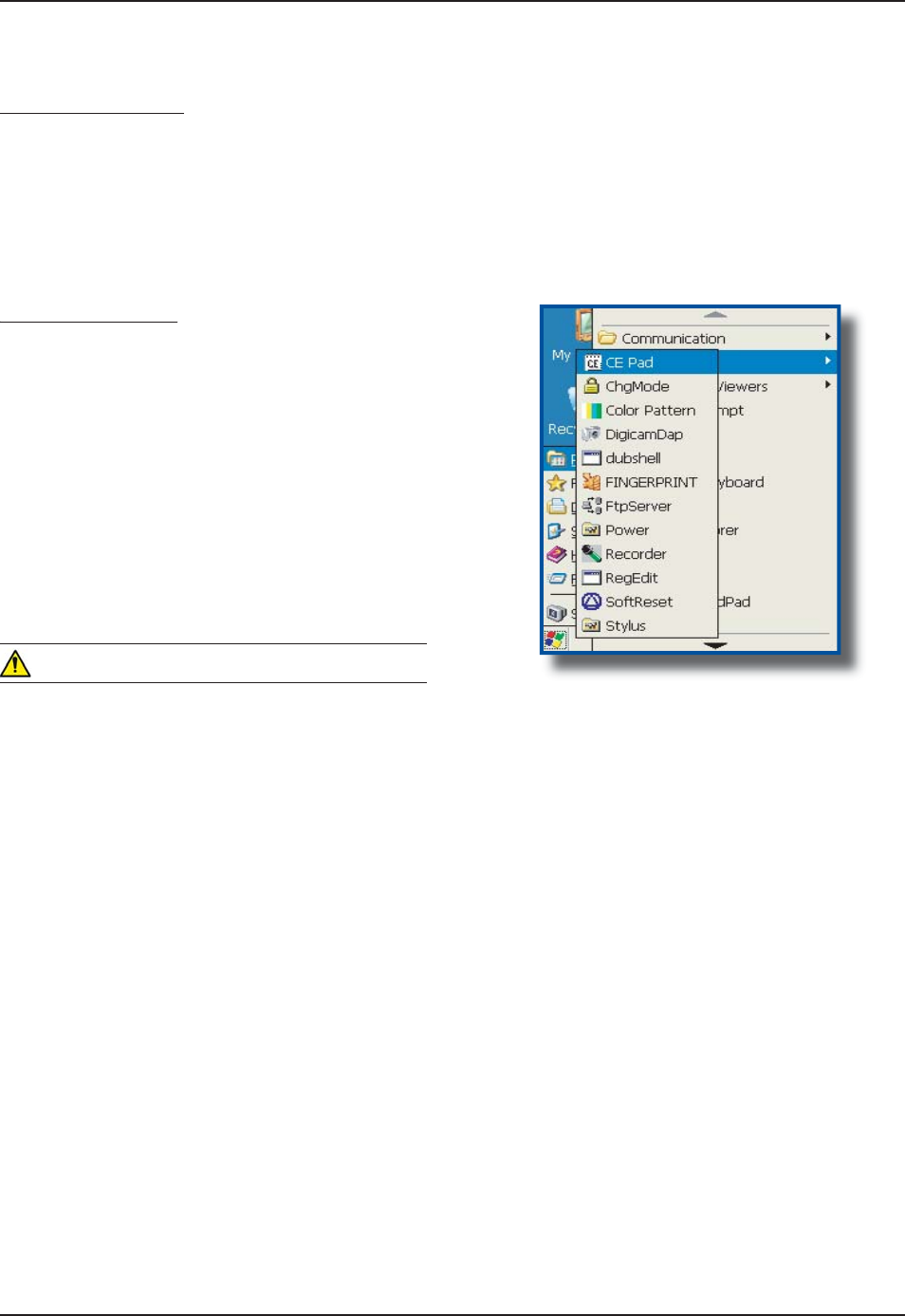
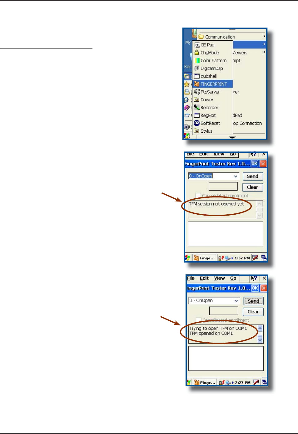
Testing the Fingerprint Sensor
ggp
C
lick on
:
a)
S
tar
t
b
)
Program
s
c) Dap Utilitie
s
d)
Fin
g
erprin
t
T
his window will appear indicating
“TFM
S
ession is not opened
y
et
.
C
lick send to o
p
en session
.
W
ait until this message appears in
t
h
e
mi
dd
l
e
sec
ti
o
n
of
th
e
win
do
w
.
1.
2.
3.
4.
Ada
p
table Endca
p
O
p
tion
s
4
6
C
MU056-A
1
www.RoperMobile.com
Return To Table of Contents
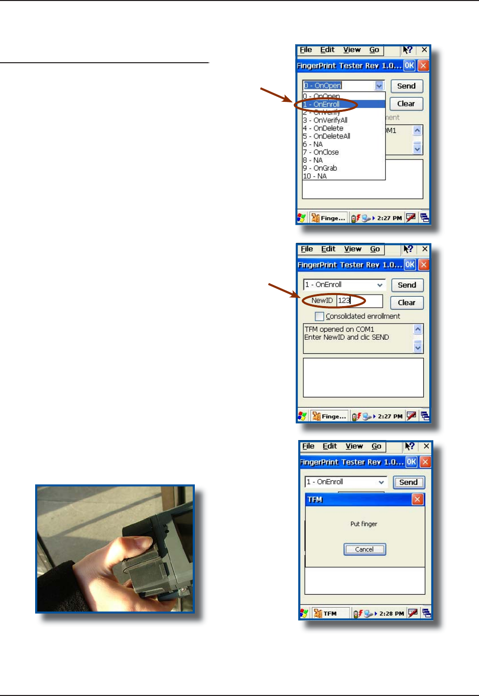
S
elec
t
1
-
O
nEnrol
l
f
rom the drop down menu
.
E
nt
e
r
Ne
w
ID
Nu
m
be
rand click
S
end
.
2
NCEG ſP
I
GT QP (KP
I
GTRTKPV
5
GPUQT
CPF YCKV HQT ſPIGTRTKPV TGEQIPKVKQP
5.
6.
7
.
Ada
p
table Enca
p
O
p
tion
s
F
AS
T
F
I
N
G
ERPRINT
S
EN
SO
R (
C
O
NTIN
U
E
D
)
Testing the Fingerprint Sensor (Continued)
ggp ( )
www.RoperMobile.com
C
MU056-A
1
47
Return To Table of Contents
O
p
eration Guid
e
F
AS
T
F
I
N
G
ERPRINT
S
EN
SO
R (
C
O
NTIN
U
E
D
)
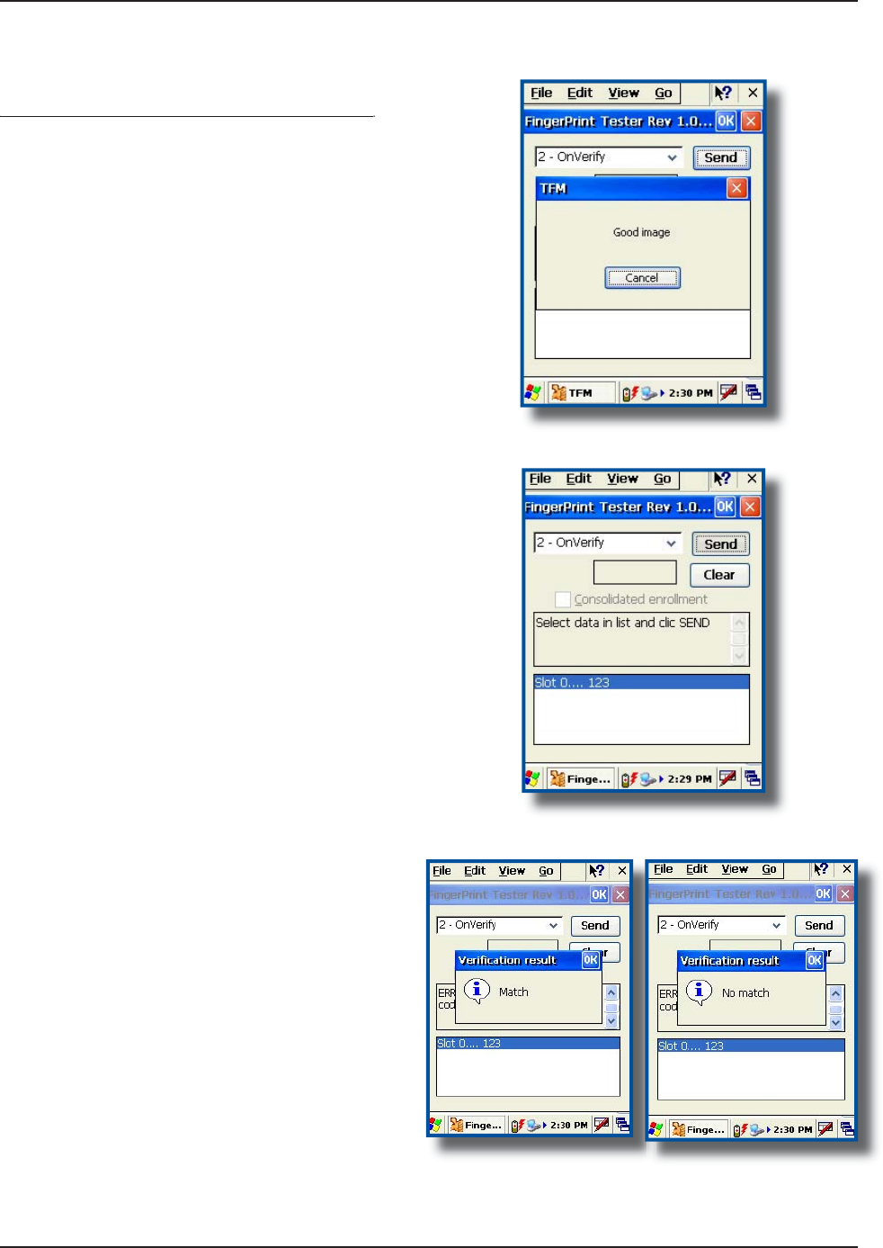
Testing the Fingerprint Sensor (Continued)
ggp ( )
I
f
Fingerprint image was taken appropriately,
t
h
i
s screen w
i
ll appear
.
I
f
the ima
g
e was read correctly, you may now
X
GTKH[FCVCDCUGHQTſPIGTRTKPVTGEQIPKVKQP
C
lic
k
“
O
nVerif
y
”VQXGTK
H
[
ſ
P
I
GTRTKPVKP
Database
.
C
lick “
S
end” and wait a few moments for a
D
ata
b
ase searc
h.
A
fter a few moments
,
the
ő
8GTKſECVKQP
R
esu
l
t
”
w
i
ll be d
i
splayed
.
It will either indicate
“
Match
”
or “No Match”.
1.
2.
3.
4.
5.
6.
48 CMU056-A1 www.RoperMobile.com
Return To Table of Contents
The CardMan® 5121 is based on a 13.56 MHz contactless Smart Card Interface that is compliant with ISO
5RGEKſECVKQPU#$CPF6JGTGCFGTYQTMUYKVJCXCTKGV[QH/*\EQPVCEVNGUU5OCTV%CTFU
including but not limited to:
Philips: MIFARE®, DESFire®, MIFARE ProX® Smart MX, and i.code;
HID: ICLASS®
Texas Instruments: TagIT®
ST Micro: x-indent, SR 176, SR 1X 4K
Infineon: My-d (in secure mode UID only)
Atmel: AT088RF020
Host Interface
USB 2.0 CCID (also supports 1.1) Ũ
Transmission speed 12 Mbps
Power Supply Bus
Powered
Max.
U25mA
Contactless (RFID) Smart Card Interface
ISO 14443 A Ũ
ISO 14443 B Ũ
ISO 15693 Ũ
Compliance
Microsoft®WHQL Certified Ũ
USB 1.1 & 2.0 Ũ
API
PC / SC Driver Ũ
Synchronous API ( On top of PC/SC) Ũ
Note: A basic Demo Program can be provided upon request. Contact your Customer Service Representative
nearest you.
•
•
•
•
•
•
SMARTCARD READER (CONTACT & CONTACTLESS)
Operation Guide
PC/SC Driver Support
Windows CE 3.0 Support
/ CE.NET (depend-
ing on the software)
Ũ
*CTFYCTG5RGEKſECVKQPU
Dimensions (LxBxH) 57 x 40 x 1.5 mm
Weight 20 grams
without Contact
Connector;
40 grams with
Contact Connector
Operating Temperature 10 - 55° C
(32-131° F)
Operating Humidity 10 - 90 % rH
Meantime Between
Failure (MTBF)
500,000 hours
5CHGV['PXKTQPOGPVCN5VCPFCTFURTGEGTVKſGF
CE, FCC & UL Ũ
www.RoperMobile.com
C
MU056-A
1
4
9
Return To Table of Contents
Advanced Settin
gs
A
DVANCE
D
B
ATTERY
O
PTIONS
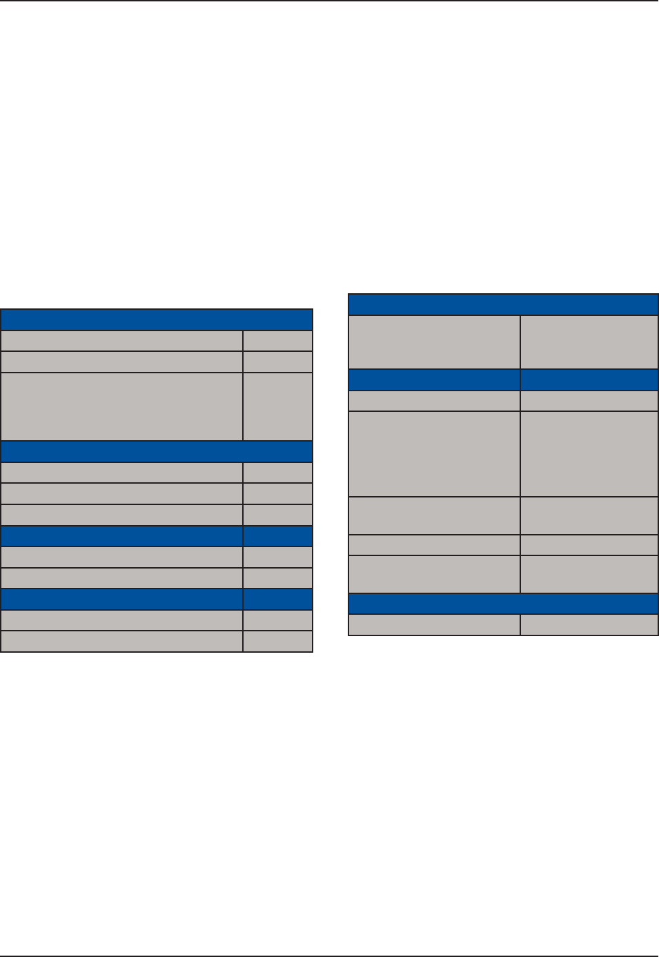
To See Power Remaining
g
U
nder Windows
C
E 5.0
,
click on
:
a)
S
tar
t
b)
S
etting
s
c
)
Control Pane
l
d
) Powe
r
e
)
Batter
y
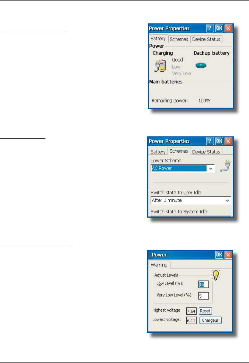
Preserving Power
g
It is possible to extend battery life by modifying the
power delays o
f
the unit, screen and backli
g
htin
g
s
ettings
.
T
o setup the screen and backl
ig
ht delays, cl
i
c
k
o
n:
a)
S
tar
t
b)
S
etting
s
c
)
Control Pane
l
d
) _Powe
r
e) Power
O
ff
Battery Power Management
yg
A
ll
C
E3000BB units are delivered with a calibrated
Main Batter
y.
&GſPG ő.QY .GXGNŒ CU RGT [QWT UGNGEVKQP CPF
a
pp
lications used
.
N
ote: The default settings are 16% for “Low Level”
and 5% for “Ver
y
Low”. When the batter
y
reaches
V
JGNQY NGXGN VJG DCVVGT[ UVCVWUKPFKECVQT YKNN
ƀ
CUJ
r
ed. A 5% the battery status indicator continues to
ƀ
CUJ CPF C YKPFQY YKNN FKURNC
[
VQ KPFKECVG VQ VJG
u
ser that the battery
i
s at a cr
i
t
i
cal level and must
be re-charged
.
1.
1.
1.

50 CMU056-A1 www.RoperMobile.com
Return To Table of Contents
Advanced Settings
BACKGROUND DISPLAY AND CONTRAST
6JG5ETGGPFKURNC[JCUDGGPEQPſIWTGFVQGPUWTGNKIJVKPIKUQRVKOK\GFKPCNNRQUUKDNGGPXK-
ronments and conditions. However, in extreme conditions and outside the normal tempera-
ture range (-20°C to +50°C (-4°F to + 122°F)), manual readjustment might be necessary.
ACTIVESYNC COMMUNICATION
7UKPIVJG/KETQUQHV#EVKXG5[PEEQOOWPKECVKQPKVKURQUUKDNGVQVTCPUHGTſNGUDGVYGGPCFGUMVQREQORWVGT
and the CE3000B unit.
Note: With Microsoft Outlook 2002 or later, it is also possible to synchronize information between the desktop
computer and the CE3000B unit.
ActiveSync Setup
Note: ActiveSync Client is already installed on the unit and the “ActiveSync Host” must be setup on the
desktop computer in order to function. (Should the host not be installed on the desktop, follow the instructions
below.
Download the latest version of the Microsoft ActiveSync Software from one of the following sites:
a) From the Microsoft Web Site
b) From DAP Technologies Customer Support Web Site @ www.support.daptech.com
Once download is complete, launch the ActiveSync “Install” program. A screen will appear prompting
you to Setup Microsoft ActiveSync Program.
Click Next
A screen will appear prompting you for what folder to save the program. The default folder is
recommended.
Click Next
Once installation is completed, click “Finish”. If prompted “Create Partnership between Desktop and
CE Device, Click “Cancel”.
Once the installation has been successfully completed, the ActiveSync Applet will be displayed on your
desktop and an icon will be added to your Task Bar. (The Software program will also be available through
the Start Menu).
1.
2.
3.
4.
5.
6.
7.
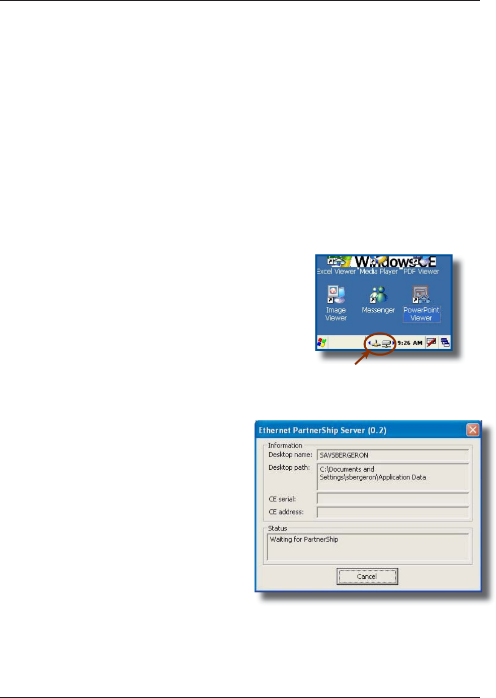
www.RoperMobile.com
C
MU056-A
1
5
1
Return To Table of Contents
Advanced Settin
gs
P
ARTNER
S
HI
P
W
IT
H
ETHERNE
T
C
RADL
E
:
No
t
e
:The “Ethernet Partnership” is only possible with ActiveSync 3.7 or 3.8
.
T
he Ethernet connection requires the use o
f
a cradle model # and an Ethernet cable connected between the
cradle and your network. Refer to the “usin
g
the Cradle” section for further instructions
.
A
n initial Ethernet connection normally requires a “Partnership” with your “Host” computer usin
g
a serial o
r
U
SB port. Roper Mobile Technology has made these following programs available to assist in the creation of
t
he
“
Ethernet Partnership” when usin
g
the Ethernet cradle
:
SetPartnerShip.exe (Already installed on the CE3000B unit
)
P
artnerShip Server.exe (This pro
g
ram must be downloaded
)
Download PartnerShi
p
Server.exe
G
o to http://www.support.daptech.co
m
R
efer to
C
E.NET P
U
BLI
C
D
O
WNL
O
A
D
C
opy to a folder that will be easily accessible; e.
g
. Desktop Folder
.
•
•
1.
2.
3.
%
TGCVGſTUV'VJGTPGVRCTVPGTUJK
R
Install the CE3000B unit into its Ethernet Cradle
a
n
d
w
ai
t
u
nt
i
l th
e
n
e
tw
o
rk h
as
bee
n
de
t
ec
t
ed.
Launc
h
PartnerShi
p
Server.exe on the Host
com
p
uter
.
1.
2.
C
lick on arrow to see more icons
if
n
e
tw
o
rk i
co
n
s
a
r
e
n
o
t vi
s
i
b
l
e
.
N
etwork connect
i
on
is
es
t
ab
l
is
h
ed
.
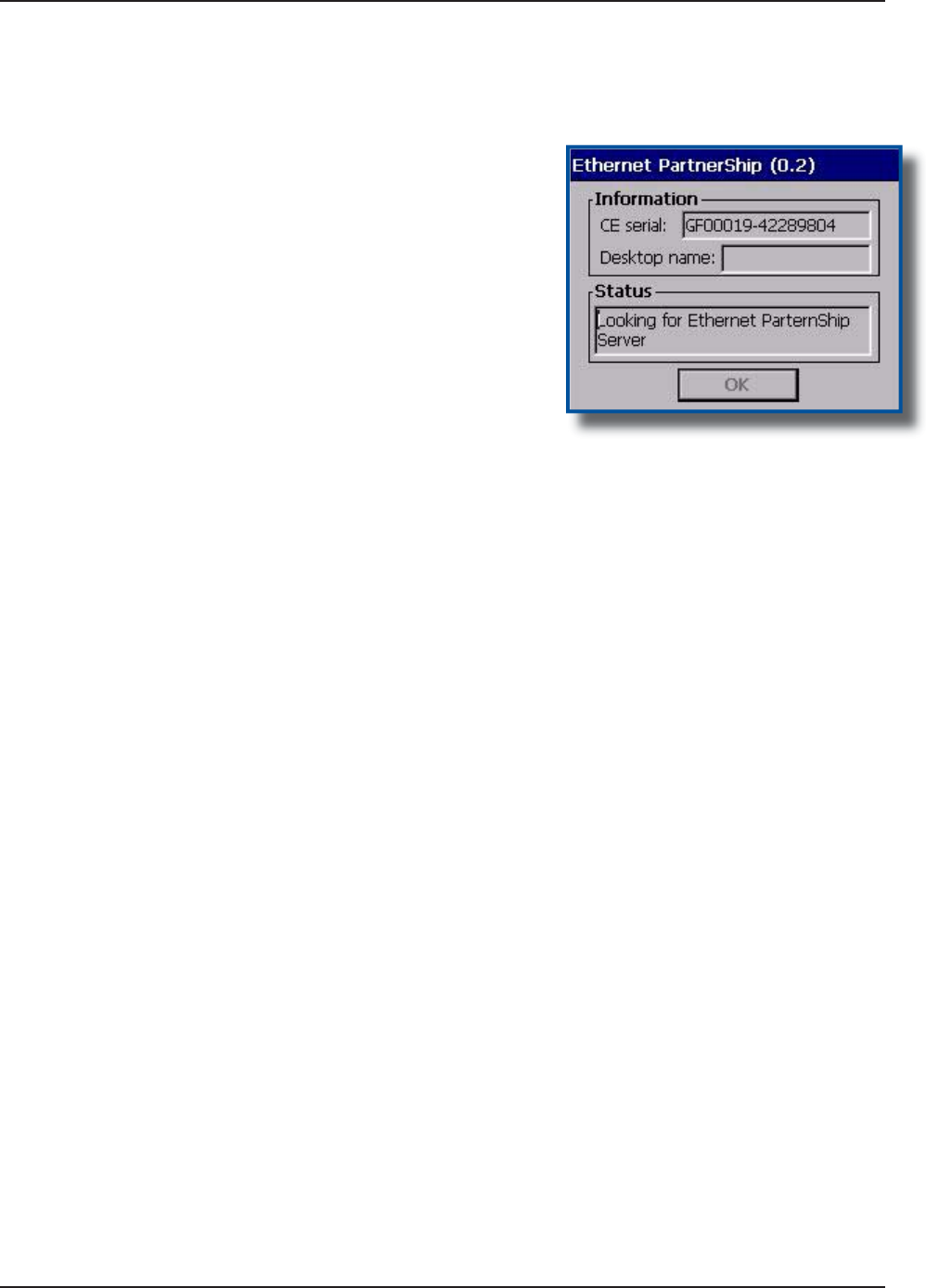
5
2
C
MU056-A
1
www.RoperMobile.com
Return To Table of Contents
P
ARTNER
S
HI
P
W
IT
H
ETHERNE
T
C
RADL
E
(
C
O
NTIN
U
E
D
)
T
o establish Partner
S
hip, click on
:
a
)
Star
t
b)
C
ommunicatio
n
c)
S
et Partner
S
hi
p
T
he Ethernet Partner
S
hip should be
established within a few seconds
.
No
t
e
: Th
i
s procedure needs only to be done
Q
PEGVQETGCVGVJGſTUVő2CTVPGT
5
JKRŒ
T
o launch Active
S
ync,
C
lick on
:
a
)
Star
t
b) Pro
g
ram
c)
C
ommunicatio
n
d
) ActivS
y
n
c
N
ote: For subsequent connections, simpl
y
f
ollow step 5 to start Active
S
ync
.
3.
4.
5.
Advanced Settin
gs
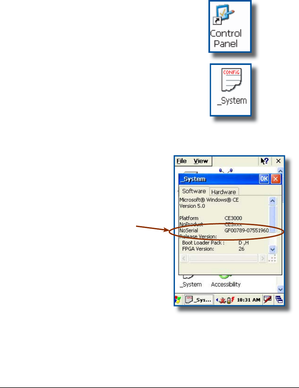
www.RoperMobile.com
C
MU056-A
1
53
Return To Table of Contents
Advanced Settin
gs
A
DVAN
C
E
D
U
S
E
R
I
NF
O
RMATI
ON
To
ob
t
a
in th
e
m
os
t
cu
rr
e
nt t
ec
hni
ca
l in
fo
rm
a
ti
o
n
o
n
[QWT%'$WPKV[QWOWUVſTUVTGIKUVGT[QWTWPKV
@
DocuDap Technical Web Site
.
C
lick on Control Panel
.
C
lick on the _System Applet
.
F
rom this _System Applet Window, note the
16 digit serial number
.
S
tart your Internet Browser
.
Go to:
http://www.RoperMobile.com/DocuDap
1.
2.
3.
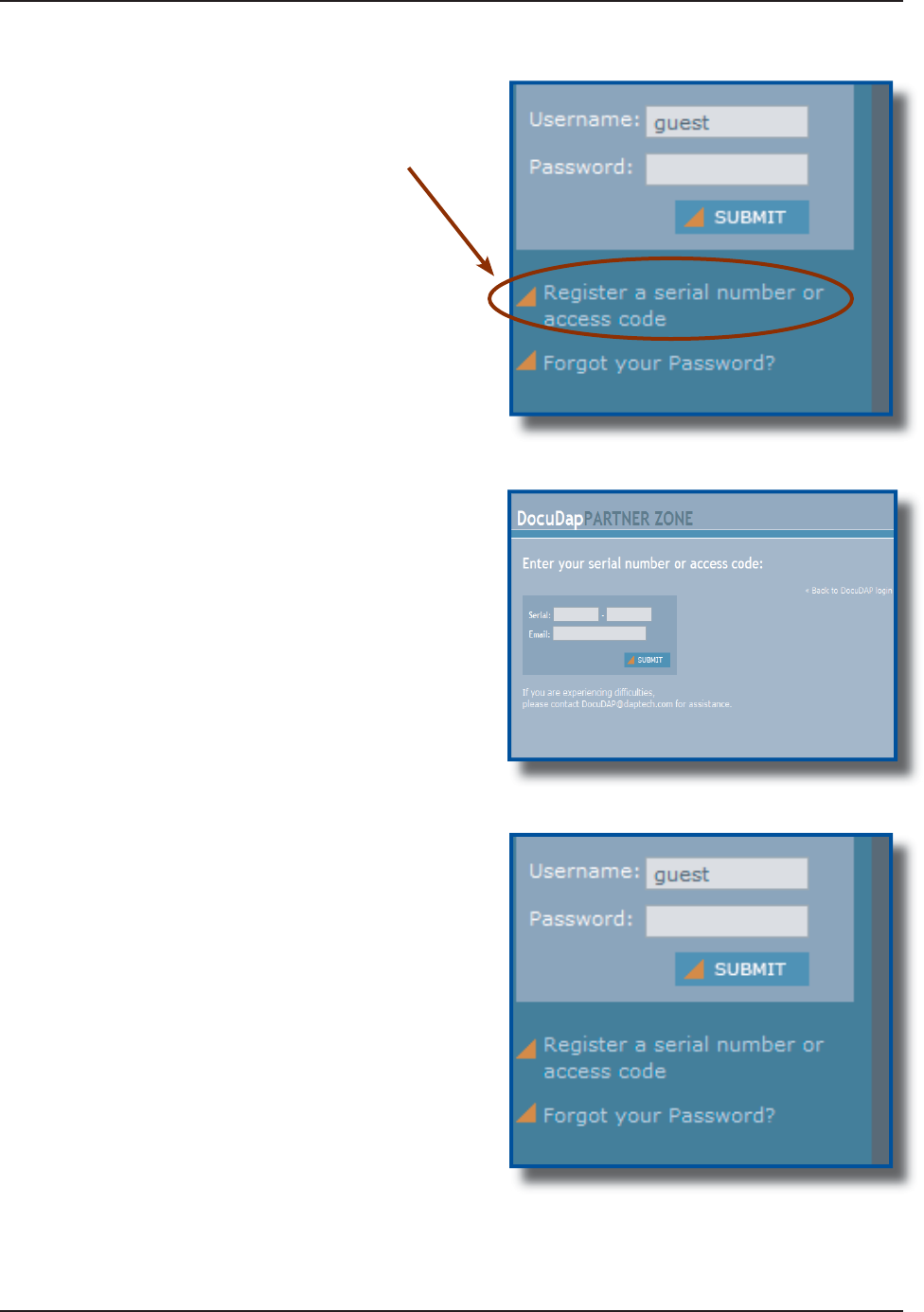
54
C
MU056-A
1
www.RoperMobile.com
Return To Table of Contents
Advanced Settin
gs
C
lick on
“
Re
g
ister a
S
erial Number or Access
C
ode
”
E
nter your
C
E3000B unit’s serial number noted
earlier
.
E
nter a valid Email address and
y
our user name
and password will be
f
orwarded to you
.
R
eturn to DocuDap lo
g
in and enter the information
t
hat was provided to
y
ou and click
“
S
ubmi
t
”
.
Y
ou ma
y
now surf the Technical Web Site for
m
o
r
e
t
ec
hni
ca
l
a
n
d
ad
v
a
n
ced
use
r in
fo
rm
a
ti
o
n
.
1.
2.
3.
4.
5.
A
DVAN
C
ED
U
S
E
R
I
NF
O
RMATI
ON
(
C
O
NTIN
U
E
D
)
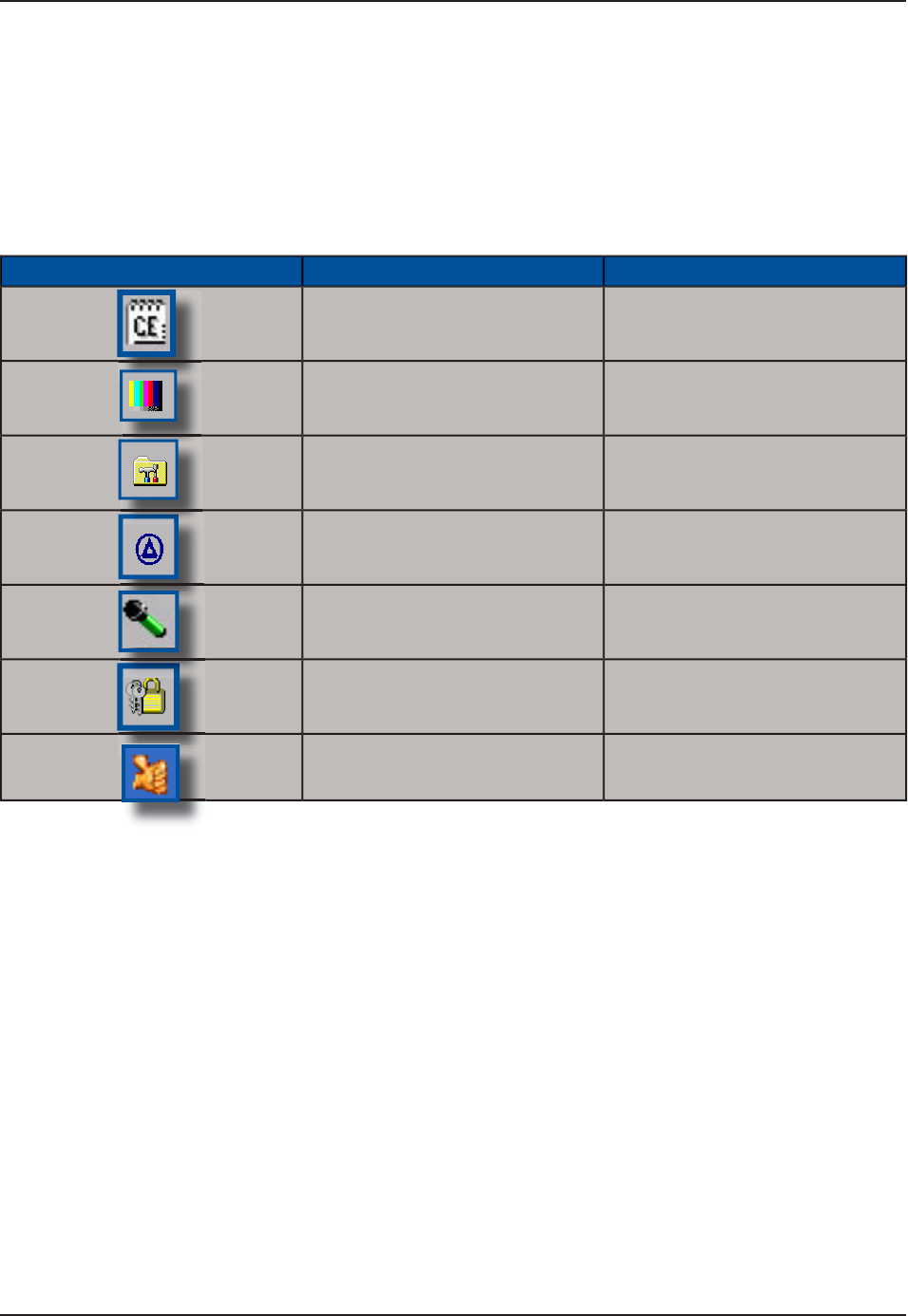
www.RoperMobile.com
C
MU056-A
1
55
Return To Table of Contents
Companion Pro
g
ram
s
T
his section lists several pro
g
rams that are included with the
C
E3000B unit and provides a brief description
o
f their functions. However, Not all pro
g
rams are covered
.
It i
s
n
ot
the intent of this User
G
uide to describe the applications included. Please refer to DAP Technical
Web Site for further instructions on DAP programs included or the Microsoft Web Site for Microsoft Programs
i
n
c
l
uded.
DAP CE3000B PROGRAMS
Icon Name &GſPKVKQP
C
E Pa
d
A
S
mall Test Editor
.
C
olor Patter
n
T
o verify color screen quality
.
P
ower Remainin
g
Display Power Applet
.
S
oft Reset Reset the un
i
t. The su
p
erv
i
sor
mode
i
s requ
i
red
.
Reco
r
der
#
NNQYU[QWVQRNC[DCEMYCXG
ſ
NGU
and recorded messages
.
C
hange Mod
e
S
witch between the User and
C
han
g
e mode
.
F
ast Fin
g
erprint
S
enso
r
Fi
n
g
erpr
i
nt Demo
.

56
C
MU056-A
1
www.RoperMobile.com
Return To Table of Contents
Companion Pro
g
ram
s
M
ICROSOF
T
P
R
OGRAM
S
Icon Name &GſPKVKQP
I
n
bo
x
S
end and receive Emails by
s
ynchron
i
z
i
n
g
Desktop w
i
th
C
E3000B unit
.
M
icrosoft Viewer Suit
e
9KNN FKURNC[ 'ZEGN ſNGU KOCIGU
2
&(
2QYGT2QKPVCPF9QTF
ſ
NGU
M
S
N Message
r
C
hat on M
S
N Messenger.
Re
q
uires an Microsoft Pass
p
ort or
E
xchan
g
e Ema
i
l Account wh
i
ch
i
s
p
rovided by employer
.
Internet Ex
p
lore
r
S
urf the Web by synchronizing
p
a
g
es w
i
th desktop computer or
b
y connect
i
n
g
to Internet
.
M
edia Playe
r
2
NC[OWUKEQTXKFGQſNGU

www.RoperMobile.com
C
MU056-A
1
57
Return To Table of Contents
Problem / Failure Recommended Action
Low Battery Messages on the Main Battery
.
S
till some power remains but it is recommended
that
y
ou replace the batter
y
before Data is lost.
1
.
I
f
neither o
f
these 2 icons appear in the Tas
k
Bar when usin
g
Ethernet
C
radle
.
Veri
f
y Network cable is connected on the back o
f
the cradle
.
Veri
f
y Network cable is not de
f
ective
.
Ethernet on-board adapter ma
y
be deactivated or
in Power
S
ave Mode
.
1
.
2
.
3
.
The screen is blank and keyboard does not
sound the ‘beep’ when a ke
y
is pressed
.
Verif
y
that the unit is turned on
.
Veri
f
y that the battery is
f
ully char
g
ed
.
1.
2
.
T
he un
i
t does not turn on
.
Verify batteries --- batteries may need re-charging.
O
nce unit is placed on the char
g
er, the unit should
turn itself on in the next few seconds and re-start
the operat
i
n
g
system
.
1.
T
he P
C
C
ard does not connect
.
Verify that the P
C
C
ard is inserted properly.
R
efer back to the section “Using PC Cards
”
1
.
T
he d
i
splay contrast
i
s very weak or back
g
round
ver
y
d
ar
k.
Verify the display contrast settings are appropriately
set. Use the contrast keys to ad
j
ust the sett
i
n
g
s
.
(
Refer to “Back
g
round Display and Contrast
Advanced
S
ettings
”
fo
r
fu
rth
e
r in
s
tr
uc
ti
o
n
s.
1
.
T
he unit does not turn o
ff
automaticall
y
or
manually
.
Veri
f
y unit is properly connected to the char
g
er
.
8GTKH[őUJWVQHHŒHGCVWTGKURTQRGTN[EQPſIWTGF
1.
2.
T
roubleshootin
g
Guid
e

58 CMU056-A1 www.RoperMobile.com
Return To Table of Contents
Storage & Maintenance
The CE3000B Unit is a reliable product requiring little maintenance. Only occasional replacement of the
battery and the carrying strap is required.
WARNING
There are no user-serviceable parts inside the CE3000B Unit. Do not try to repair the unit as this may affect
proper functioning as well as void the warranty.
STORAGE
If the unit is not going to be used for a few days or more, the unit may be kept directly on the charger.
If the unit is not going to be used for a few weeks, it is strongly recommended that the unit be fully
charged and stored in a location where the temperature will be between 20°C (68°F) to 25°C (77°F).
WARNING
If extended storage time is necessary, it is important to backup all data to ensure no data is lost or
corrupted.
Keeping the unit on the Charger is also possible, however, this may affect the battery life and capacity
over time. It is recommended that the unit be re-charged daily.
CLEANING
Use a normal soft cloth and mild soap to clean the CE3000B unit. Do not use abrasives as these cleansers
OC[FCOCIGVJGſPKUJCPFUETCVEJVJGVQWEJUETGGP'PUWTGVJCVCNNEQORCTVOGPVUCTGRTQRGTN[ENQUGFRTKQT
to cleaning unit.
SHIPPING THE UNIT
The CE3000B units have been designed to withstand vibrations and shocks that can occur during normal
use of the product. However, should shipping one of these units be required, it is strongly recommended
that these be packaged in the same packaging the unit was delivered in, or similar packaging to avoid any
damage to the units during transportation.
CARRYING STRAP
To clean the strap, simply use a mild soap and a normal soft cloth. If there is extensive wear on the strap, it
may be time to change it.
•
•
•
•

www.RoperMobile.com CMU056-A1 59
Return To Table of Contents
Storage & Maintenance
BATTERY MAINTENANCE
Main Battery
The high-quality Lithium-Ion battery provided with your unit may be re-charged over 500 times according to
the battery manufacturer.
Note:+HVJGDCVVGT[ŏUFWTCVKQPFQGUPQVNCUVVJGPQTOCNVKOGHTCOGURGEKſGFKVOC[DGVKOGVQEJCPIGKV6JG
main battery should last from 12 to 24 months if used under normal working conditions.
Backup Battery
The Backup Battery will normally not need to be replaced during the expected life of the CE3000B unit.
4GEJCTIGCUURGEKſGFCHVGTWUG
Replacing the Battery
Note: Always turn the unit off before removing the battery. The CE3000B Unit uses an approved battery to
ensure a quicker charging time, longer battery life and resistance to shock and vibrations. To ensure that the
batteries are appropriate for use on DAP equipment, it is strongly recommended that these be purchased
directly through Roper Mobile Technology or one of its distributors. (Check for our logo on the battery). Refer
back to “Field Replaceable Battery” for further instruction on changing the battery of your CE3000B unit.
60 CMU056-A1 www.RoperMobile.com
Return To Table of Contents
Storage & Maintenance
TOUCH SCREEN MAINTENANCE
The Touch Screen requires minimal maintenance. Only appropriate care when using and cleaning the touch
is required. Use the Stylus provided with the unit when using the touch screen to ensure other pointed devices
do not damage the screen. When cleaning, ensure to use a mild detergent and soft cloth.
WARNING
&Q0QVWUGCDTCUKXGUCUVJGUGOC[FCOCIGVJGſPKUJCPFUETCVEJVJGVQWEJUETGGP
Replace or clean the Stylus as soon as it seems damaged or dirty.
ADAPTABLE ENDCAP WITH LASER OPTION
Note:6JGGHſEKGPE[QHVJG.CUGTTGCFKPIYKNNFGRGPFQPVJGSWCNKV[QHVJGRNCUVKEYKPFQY#P[UETCVEJFKTVQT
ſPIGTRTKPVUYKNNFGITCFGVJGTGCFKPISWCNKV[
Clean aDAPtable end cap using a mild detergent and soft cloth to ensure no scratches
to the window. (A plastic Lens cleaner can also be used for cleaning the window).
QUICK-REFERENCE REPLACEMENT PARTS LIST
Part Description Part Number
Lithium-Ion Battery DCCE300
Carrying Strap (4 per package) DCCE301
Stylus (Pen) (5 per package) DCCE303
•
•
1.
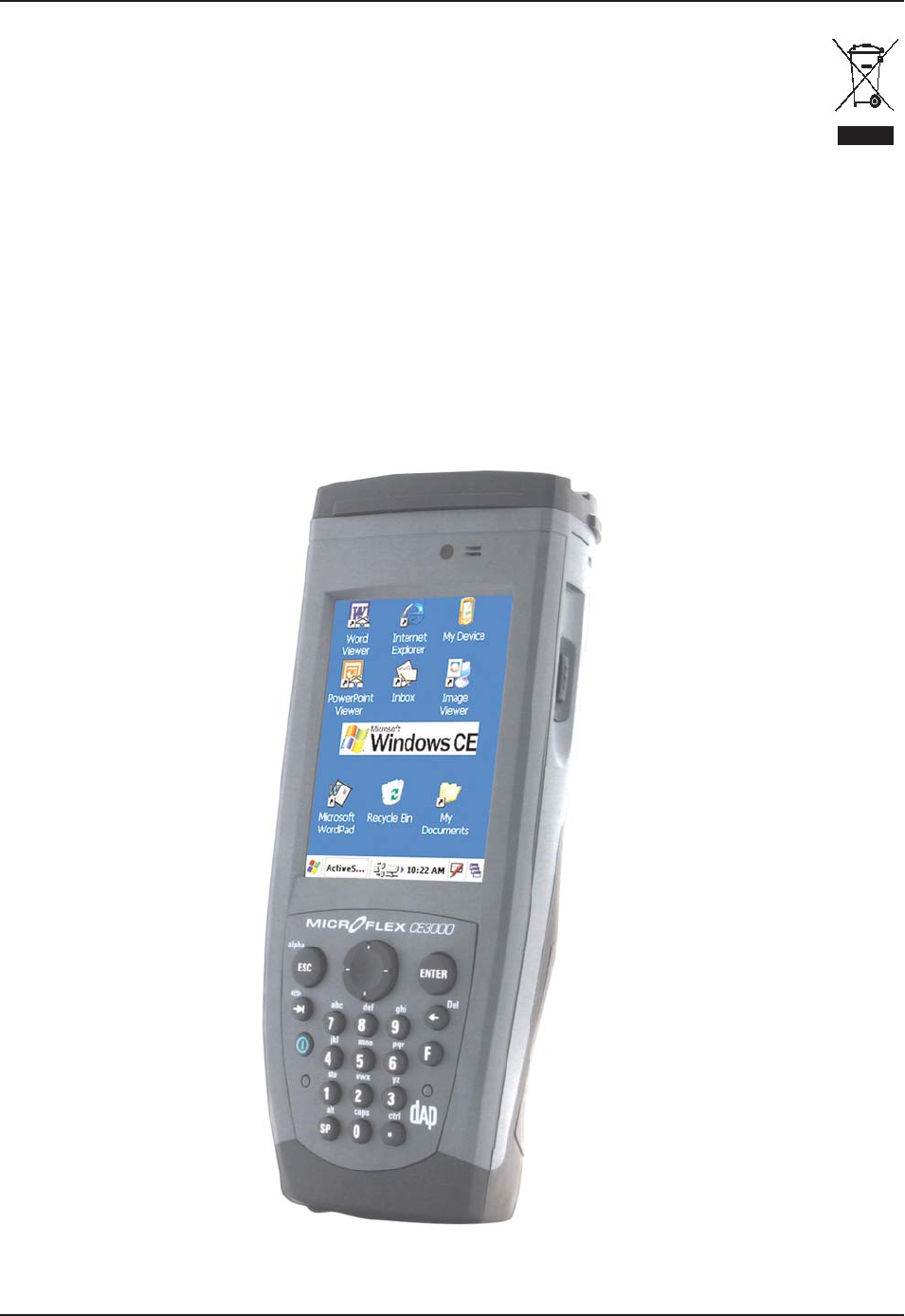
www.RoperMobile.com
C
MU056-A
1
61
Return To Table of Contents
R
ecyclin
g
Passport
C
E3000B
U
NI
T
T
he Waste Electrical and Electronic Equipment Directive (WEEE) is a European directive established in 2003
f
or the collection, recyclin
g
and recovery tar
g
ets for all types of electrical
g
oods
.
T
his European Directive imposes the responsibility
f
or the disposal o
f
waste electrical and electronic equipment
o
n the manufacturers of such equipment
.
In accordance to this directive, DAP Technolo
g
ies will assist you in the proper disposal o
f
your DAP Units.
F
or further instructions on how to dis
p
ose of these units,
p
lease refer to our web site
:
www.RoperMobile.com

62 CMU056-A1 www.RoperMobile.com
Return To Table of Contents
CE Conformity
The CE3240B, has been tested and is in compliance with the 89/336/EEC European Directive for
Electromagnetic Compatibility.
Electromagnetic Emissions & Electromagnetic Immunity
Standards &GſPKVKQP
EN55022 Radiated & Conducted, Class B
ENV 50204 4CFKCVGFGNGEVTQOCIPGVKEſGNFHTQOTCFKQVGNGRJQPGU
EN 61000-4-2 Electrostatic discharge
EN 61000-4-3 Radiated Immunity
EN 61000-4-5 Surge
EN 61000-4-6 Conducted Immunity
EN 61000-4-11 Voltage Variation
EN 61000-3-2 Harmonic
EN 61000-3-3 Flickers

FCC Information, Copyright Policy
CMU056-A1 (a) 63
COPYRIGHT POLICY
Any software described in this document is provided under a license agreement or non-disclosure agreement. It is
strictly prohibited by law to copy any portion of the software provided by DAP Technologies onto any media format.
DAP is a registered trademark of DAP Technologies. Microsoft, MS-DOS and Windows CE are registered
trademarks of Microsoft Corporation. PCM CIA and PC Cards are also registered trademarks of Microsoft
Corporation.
Note: A Copyright Policy is also applicable for any software provided by Microsoft on DAP Products. Please refer to
Microsoft End User License Agreement Section for further information.
RADIO FREQUENCY EXPOSURE REQUIREMENTS
(only for models with Wireless WAN)
For body worn operation, this product has been tested and meets FCC RF exposure
guidelines when used with an accessory that contains no metallic component. Use of
other accessories may not ensure compliance with FCC Radio Frequency exposure
guidelines. This device shall not be co-located or operating in conjuction with any other
antenna or transmitter.
INFORMATION TO USER
This device complies with Part 15 of the FCC Rules. Operation is subject to the following
two conditions: (1) This device may not cause harmful interference, and (2) This device
must accept any interference received, including interference that may cause undesired
operation.
This equipment has been tested and found to comply with the limits for Class B Digital
Device, pursuant to Part 15 of the FCC Rules. These limits are designed to provide
reasonable protection against harmful interference in a residential installation. This
equipment generates and can radiate radio frequency energy and, if not installed and
used in accordance with the instructions, may cause harmful interference to radio
communications. However, there is no guarantee that interference will not occur in a
particular installation. If this equipment does cause harmful interference to radio or
television reception, which can be determined by turning the equipment off and on, the
user is encouraged to try to correct the interference by one or more of the following
measures:
• Reorient or relocate the receiving antenna
• Increase the separation between the equipment and receiver
• Connect the equipment into an outlet on a circuit different from that to which the
receiver is connected
• Consult the dealer or an experienced radio/TV technician for help
Any changes or modifications not expressly approved by the party responsible for
compliance could void the user’s authority to operate the equipment.
For more information about RF exposure, please visit the FCC web site at www.fcc.gov
For more information about the product certification, please contact
support@daptech.com

64 CMU056-A1 www.RoperMobile.com
Return To Table of Contents
Microsoft End-User License Agreement
You have acquired a DAP device that includes software licensed from Microsoft Corporation. The Microsoft
software included in your device, as well as associated media, printed materials, and online documentation
are all protected by Copyright Laws and International Copyright Treaties. If you do not agree with this End-
User License Agreement (“EULA”), use of this device, or use and copying of, any installed software is strictly
prohibited. We strongly recommend that you immediately contact a DAP Customer Representative for return
instructions of the unused unit.
LICENSE GRANT
The software must only be used with the device provided.
There are no warranties for the software included.
Reverse engineering is strictly prohibited.
Software transfer is allowed but with restrictions. You may permanently transfer rights under this EULA
only as part of a permanent sale or transfer of the device as long as the recipient agrees to this EULA. If
the software is an upgrade, any transfer must also include all prior versions of the software.
JAVA SUPPORT
The software may contain support for programs written in Java. Java technology is not designed, manufactured,
or intended for use or resale as online control equipment in hazardous environments requiring fail-safe
performance. These environments include nuclear facilities, aircraft navigation, communication systems, air
VTCHſEEQPVTQNNKHGUWRRQTVOCEJKPGUQTYGCRQPU
•
•
•
•

www.RoperMobile.com CMU056-A1 65
Return To Table of Contents
Warranty
LIMITED WARRANTY
Roper Mobile Technology will replace or repair at its discretion, any products that prove to be defective, in
terms of material or workmanship, for a period of twelve (12) months following the purchase date of the DAP
HandHeld computers and its accessories.
This warranty does not cover damages caused by misuse, abuse, neglect, or those incurred during shipping
or storage of the DAP units. This warranty does not EQXGTCP[OQFKſECVKQPUQTUGTXKEKPID[CP[QPGQVJGTVJCP
a Roper Mobile Authorized Service Center.
Roper Mobile Technology shall not be held accountable for any damages caused by misuse of DAP units or
damage incurred due to the installation of any other software or hardware added to these units.
WARNING
DAP units and accessories should not be used in applications where device failure could result in physical
injury or loss of life.
The Operating System, MS-Dos, Windows CE and all other software sold or provided by Roper Mobile
Technology are provided as is, without any warranty, either expressed or implied.
In no event shall Roper Mobile Technology be liable for any direct damages, indirect damages or damages
KPEWTTGFD[VJGNQUUQHRTGUGPVQTRTQURGEVKXGRTQſVUCTKUKPIHTQOVJGHCKNWTGKPRGTHQTOCPEGQHVJGRTQFWEV
This warranty hereby excludes all other legal warranties related to the quality of the product or its capacities
VQHWNſNNURGEKſERWTRQUGUKPENWFKPICNNYCTTCPVKGUITCPVGFD[VJG7PKVGF0CVKQPU%QPXGPVKQPQP%QPVTCEVUHQT
the International Sale of Goods; the application of this Convention being expressly excluded.
RETURN MERCHANDISE AUTHORIZATION FOR SERVICING (RMA)
+PQTFGTVQJCXG[QWTRTQFWEVUGTXKEGF[QWOWUVſTUVQDVCKPC4GVWTP/CVGTKCN#WVJQTK\CVKQP4/#0WODGT
from Roper Mobile Technology. You must return your unit in its original packaging to your Value Added
Reseller (VAR), an Authorized Service Center, or directly to Roper Mobile Technology. Service under the
conditions of this warranty requires prepaid shipment from your facility to a Service Center.
The DAP unit and accessories have no user serviceable parts.
To obtain an RMA Number, you may call your service center closest to you or go directly to the online RMA
form @ www.RoperMobile.com, click on Support, RMA form.
EXTENDED WARRANTY ON ROPER MOBILE TECHNOLOGY MANUFACTURED PRODUCTS
The original purchaser may, at any time during the initial warranty period, extend the warranty with the
purchase of a Roper Mobile Technology Service Contract. Contact your local VAR or Customer Support
nearest you for further information.

66
C
MU056-A
1
www.RoperMobile.com
I
nt
e
rn
a
ti
o
n
a
l A
dd
r
esses
Roper Mobile Technology Worldwide
1
HſEG.QECVKQP
U
C
anada
875 Charest West Boulevard, suite 20
0
Quebec Cit
y
, Quebe
c
C
anada
G
1N 2
C9
T:
(
418
)
681-939
4
F:
(
418
)
681-079
9
TF:
(
800
)
363-199
3
E
:Sales@RoperMobile.com
U
nites
S
tate
s
7
450
S
outh Priest Drive
T
em
p
e, Ar
i
zon
a
United States, 8528
3
T
:
(
480
)
705-4200
F
:
(
480
)
705-4216
T
F:
(
800
)
363-199
3
E
:Sales@RoperMobile.com
E
urop
e
0WHſGNF9C
[
A
bingdon, OX14 1R
L
E
ng
l
an
d
T
: + 44
(
0
)
1235 46213
0
F
: + 44
(
0
)
1235 46213
1
TF
:
+ (800) 8899 1000
+
(
800
)
8899 100
0
+ (800) 8899 1000
E:
SalesUK@RoperMobile.com
Asia
L
evel 15,
S
hinjuku Dai-Ichi
S
eimei Bld
g.
2-7-1 Nishi-
S
hinjuk
u
S
hinjuku, Tokyo 163-0715
J
a
p
an
T
: + 81-3-3340-286
1
F
: + 81-3-3340-292
0
E:
SalesASIA@RoperMobile.com
Customer Su
pp
ort
Technical Su
pp
ort Canada & Internationa
l
+ 1
(
418
)
681-783
3
+ 1
(
800
)
363-199
3
TechSupportCanada@RoperMobile.com
Technical Su
pp
ort USA
+ 1
(
518
)
293-782
4
+ 1
(
800
)
363-199
3
TechSupportUSA@RoperMobile.com
Technical Su
pp
ort EME
A
+
(
800
)
8899 100
0
TechSupportEMEA@RoperMobile.com
Technical Support United Kin
g
do
m
+ 44
(
0
)
1235 462130
TechSupportUK@RoperMobile.com
Return To Table of Contents

2007/08 CMU056-A1 www.RoperMobile.com
Printed in Canada in Canada
Innovations for a Rugged World
Canada
875 Charest Boulevard West
Suite 200
Quebec City, Quebec
Canada, G1N 2C9
T: (418) 681-9394
TF: (800) 363-1993
F: (418) 681-0799
E:Sales@RoperMobile.com
United States
7450 South Priest Drive
Tempe, Arizona
United States, 85283
T: (480) 705-4200
TF: (800) 363-1993
F: (480) 705-4216
E: Sales@RoperMobile.com