TransCore AI1422E Location Monitoring Services Transmitter User Manual
TransCore Location Monitoring Services Transmitter Users Manual
UserManual.wiki
>
TransCore
>
AI1422E User Manual
>
Users Manual
Contents
1.
Users Manual
2.
User Manual
Users Manual
Navigation menu
Upload a User Manual
Namespaces
Wiki Guide
HTML
PDF
Info
Views
User Manual
Discussion / Help
Navigation

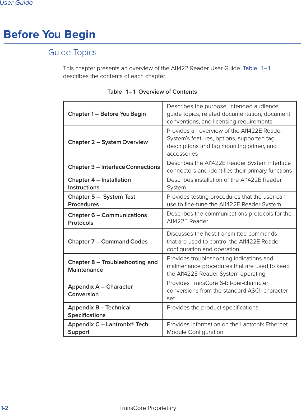


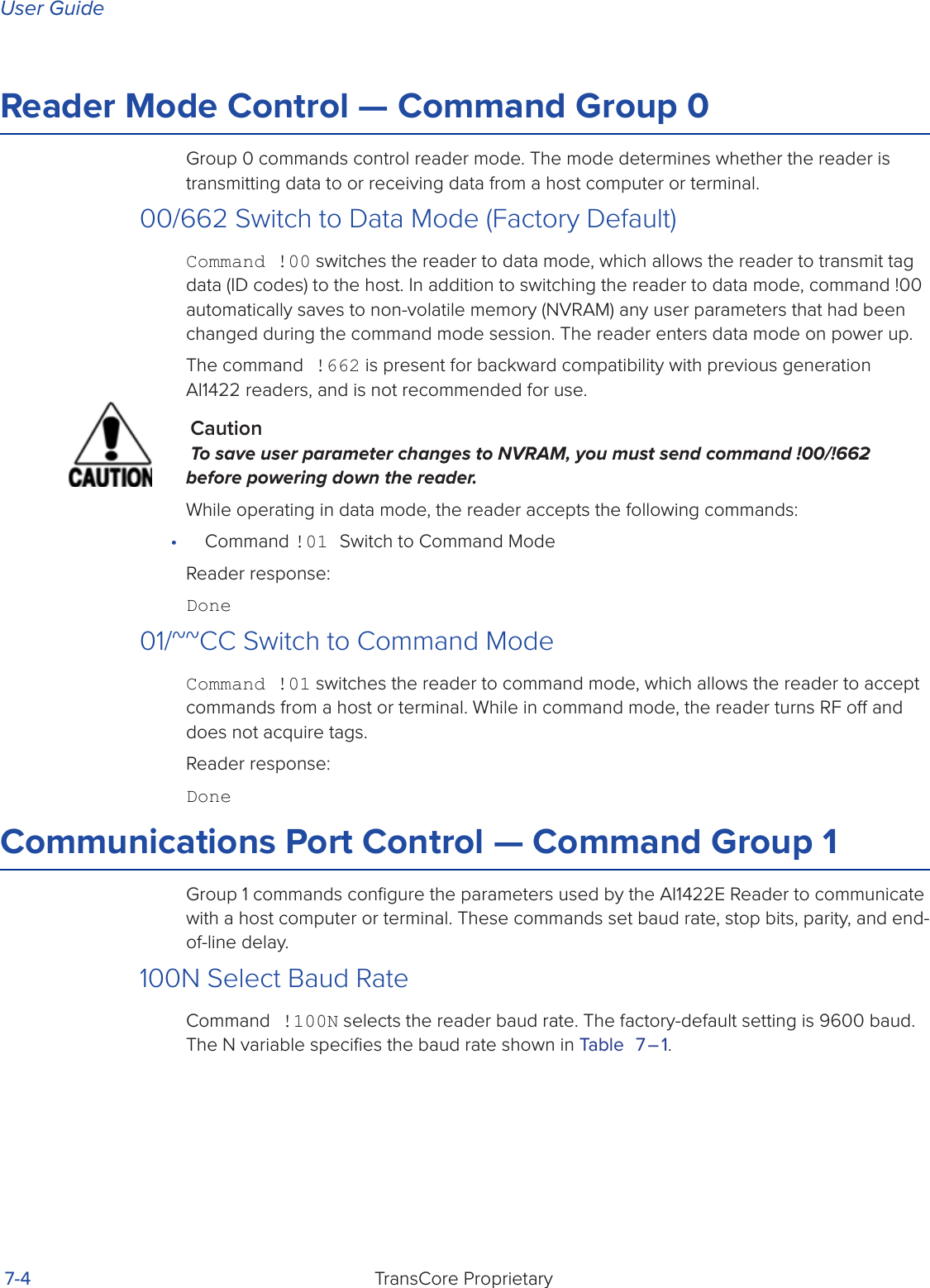
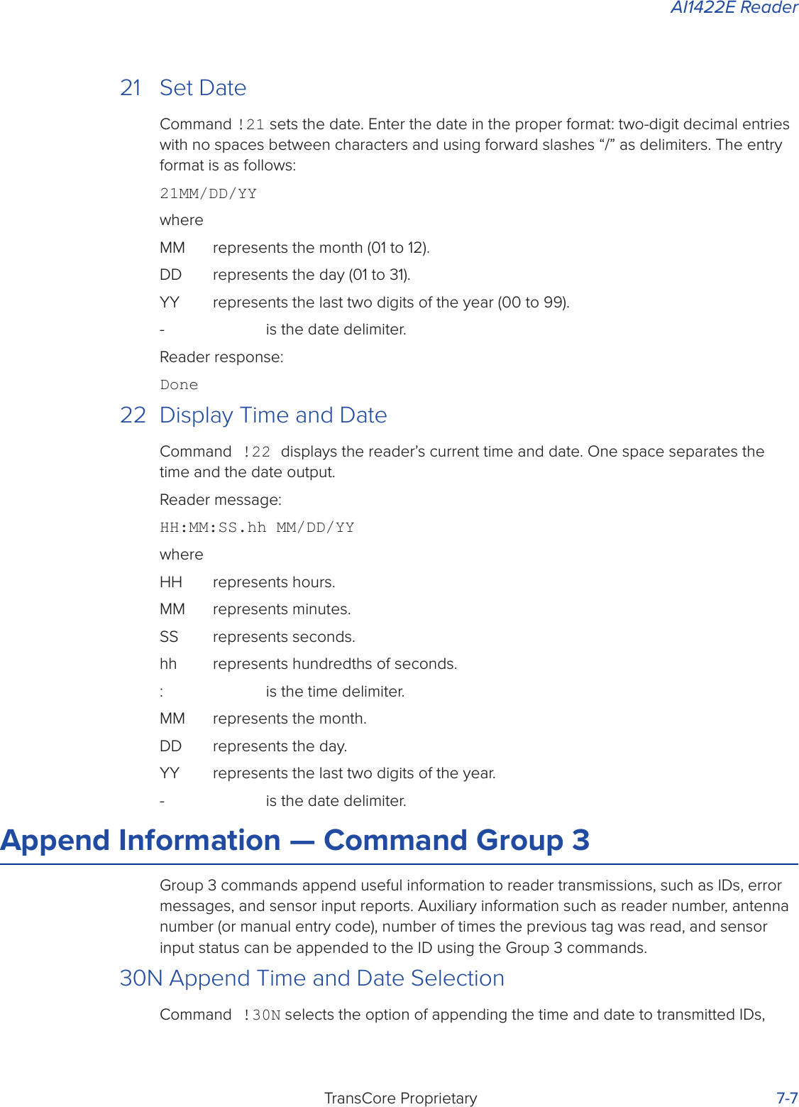
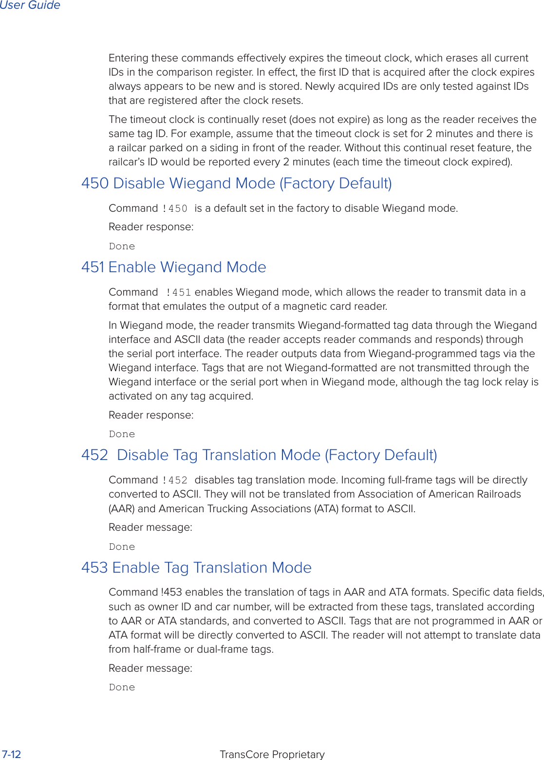
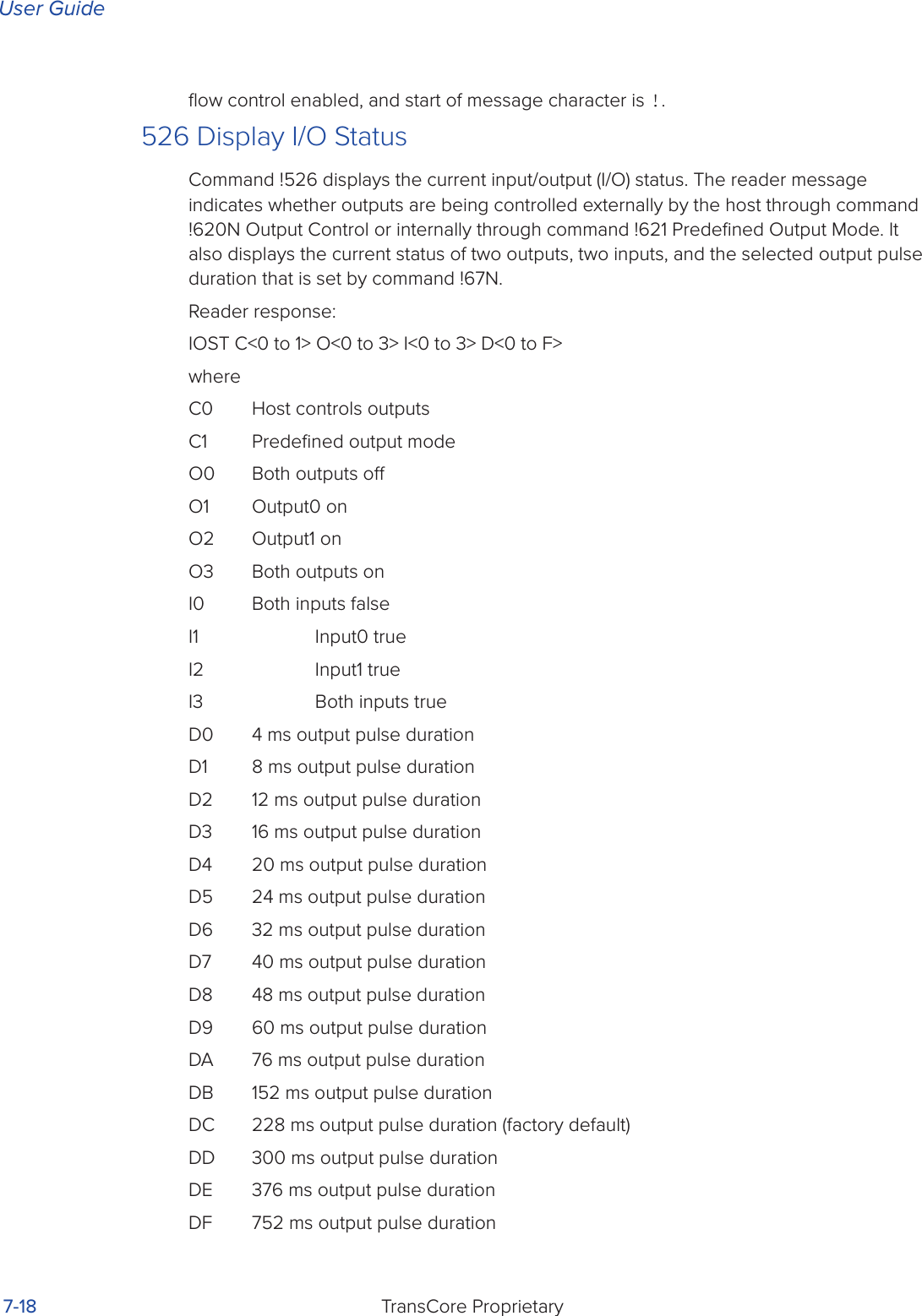
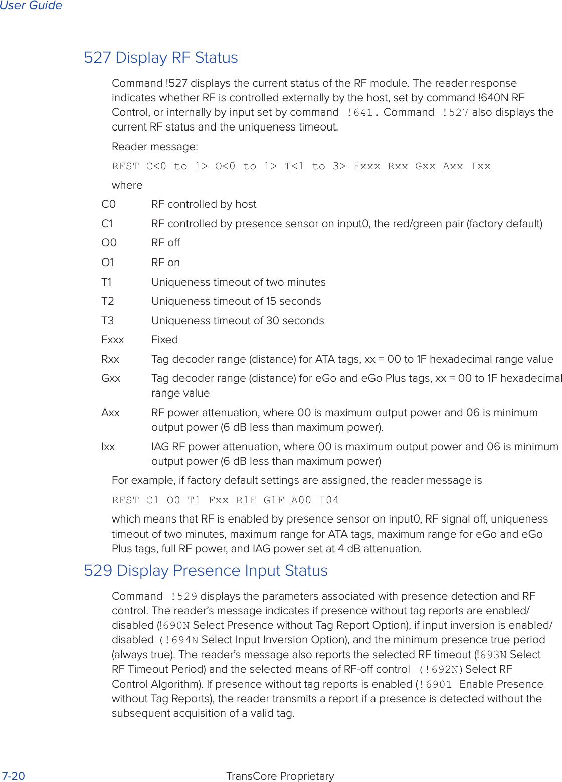
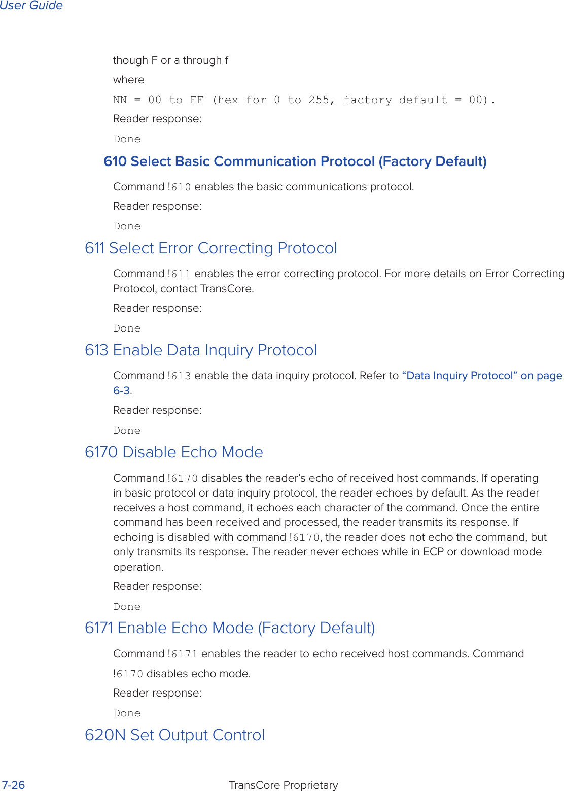
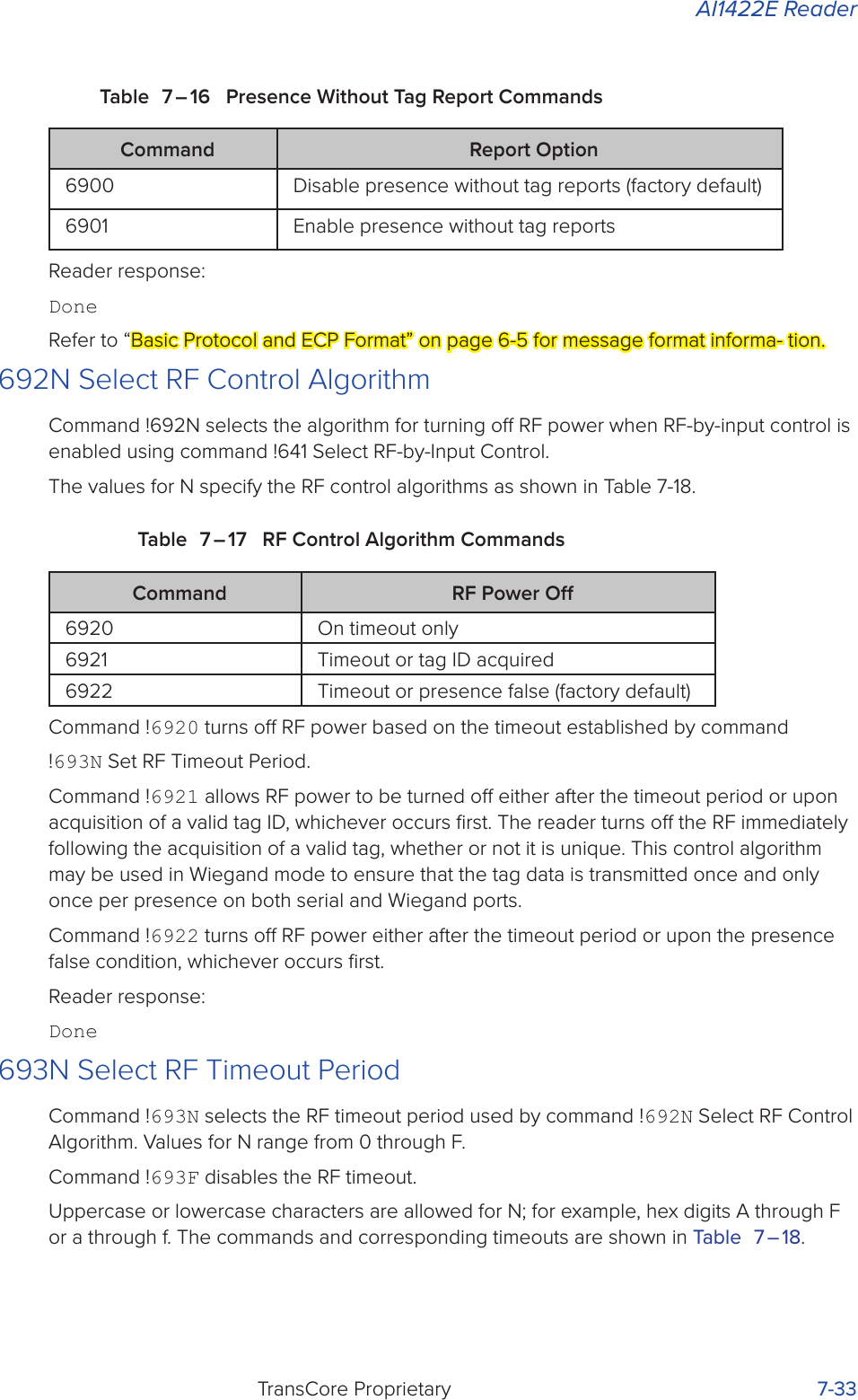
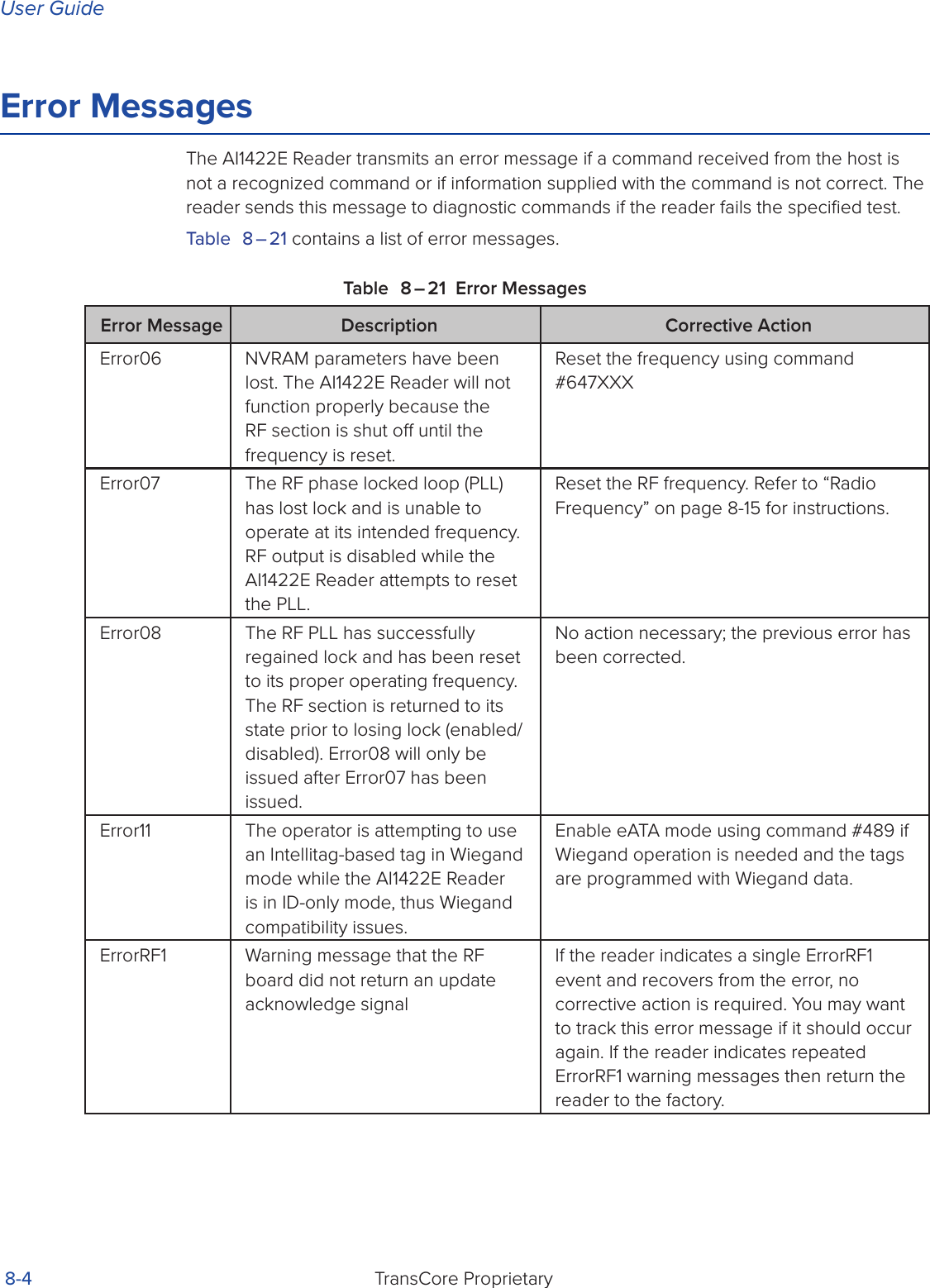
![AI1422E ReaderTransCore Proprietary 7-11stored in the comparison register.The uniqueness test’s time limit is set by Command !441. If an ID is buered, it will not be accepted again unless it arrives at the reader more than the programmed time interval from the previous arrival or until the receipt of one or more other IDs reset the uniqueness.Reader response:Done420N Select Valid ID Code CriteriaCommand !420N directs the reader to validate an ID received only after it has been obtained a specified number of times in sequence. Values for N are 0 through 3 (Table 7 – 7). The factory setting is one acquisition (N = 0).Table 7 – 7 Select Valid Code Commands and FramesCommand Valid Code Frames4200 1 (Factory default)4201 24202 34203 4The validation procedure is executed before the unique ID test (Select Unique ID Code Criteria [!410N] commands). IDs that do not pass the validation test are not reported.For example, command !4203 specifies that the same ID must be obtained from the RF module 4 times in succession before it is considered for the uniqueness test. This feature is useful in installations where RF reflections may cause a single tag to be read multiple times or where an occasional ID might be read from fringe areas440 Reset UniquenessCommand 440 causes the ID filtering process set by Select Unique ID Code Criteria (!410N) to restart. It is used in conjunction with the Variable Timeout (!44N) commands. This command provides a method to end all uniqueness timers.44N Set Uniqueness TimeoutPlaces a time limit on the uniqueness criterion set by Select Unique ID Code Criteria (!410N). The parameter N sets the number of minutes on the timeout clock. The factory setting is two minutes (N = 1).Command Timeout Clock!441 2 minutes (factory setting)!442 15 seconds!443 30 seconds](https://usermanual.wiki/TransCore/AI1422E.Users-Manual/User-Guide-3134635-Page-60.png)
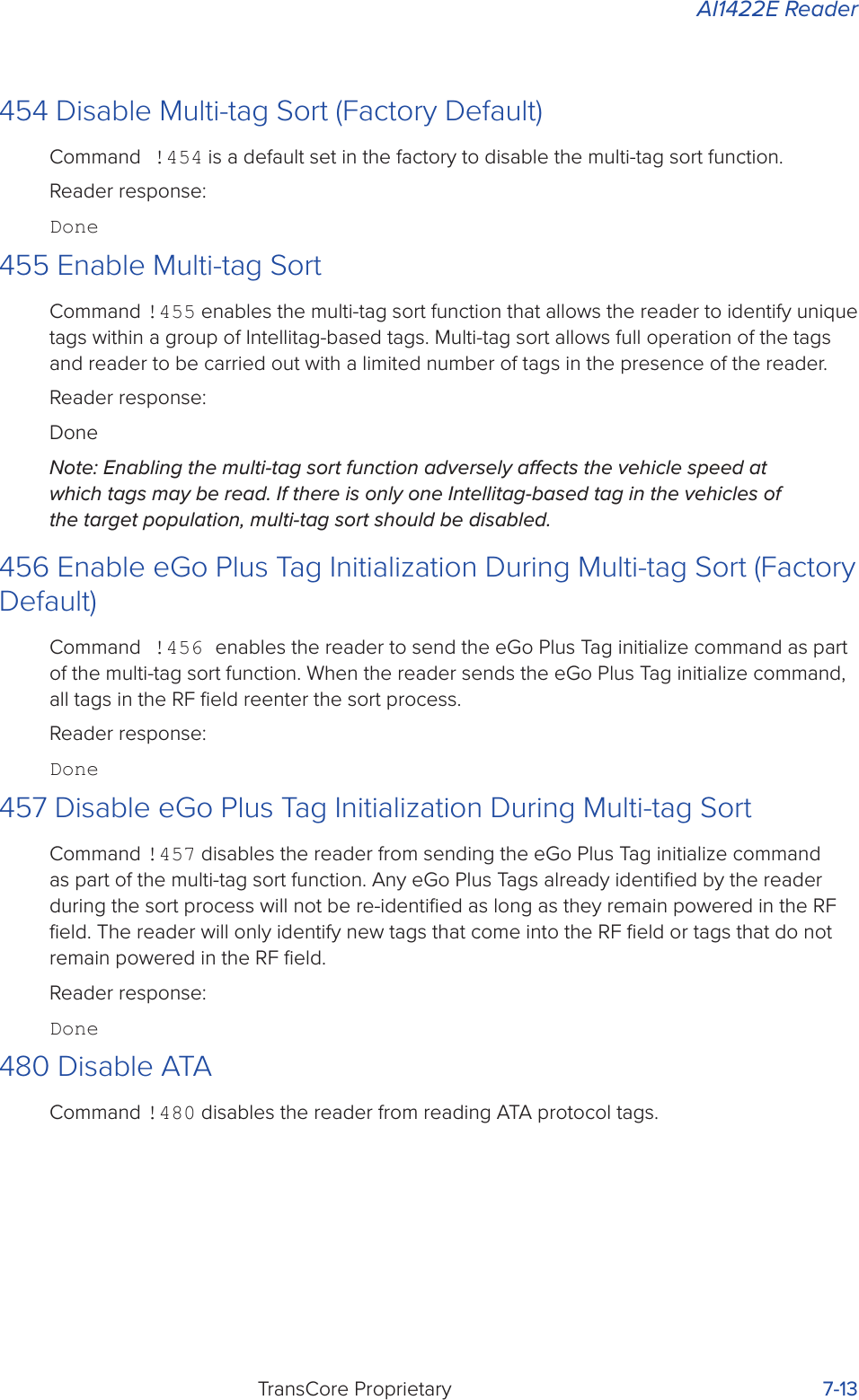
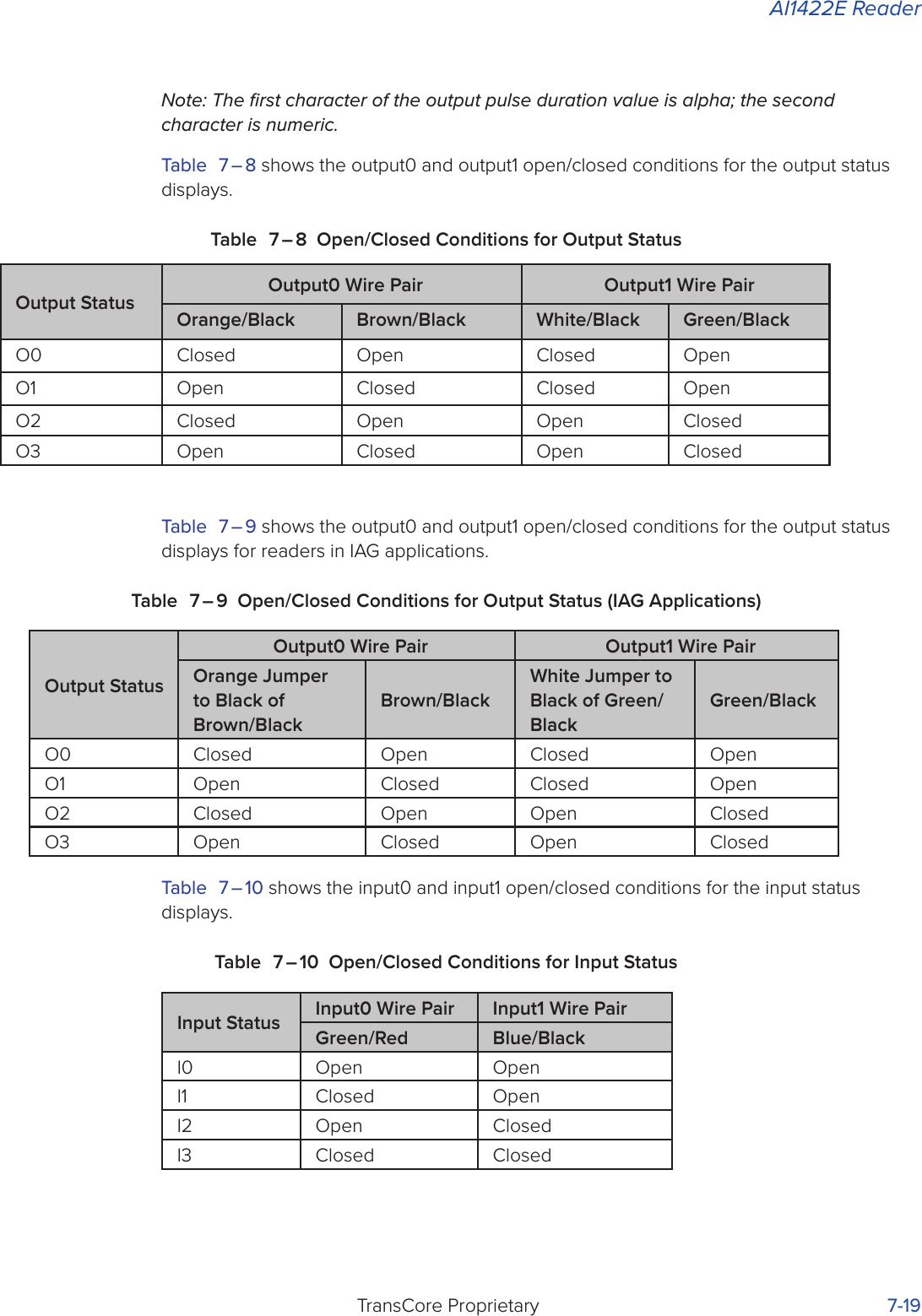
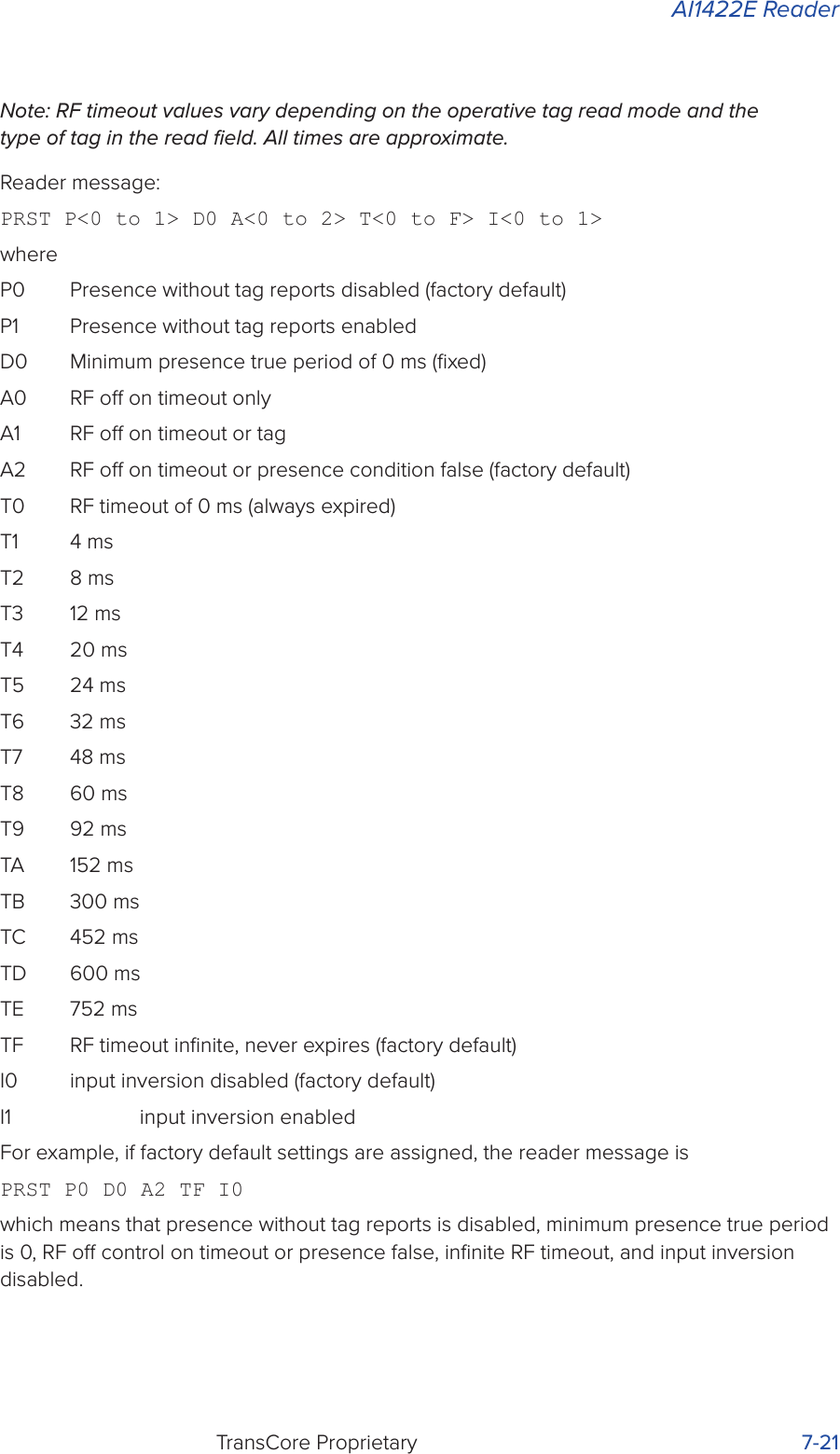

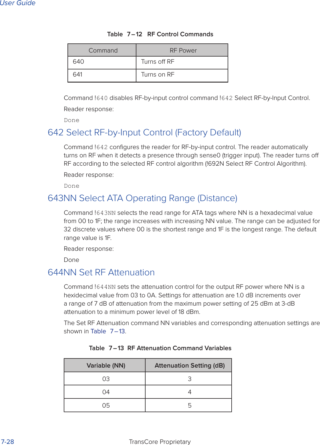
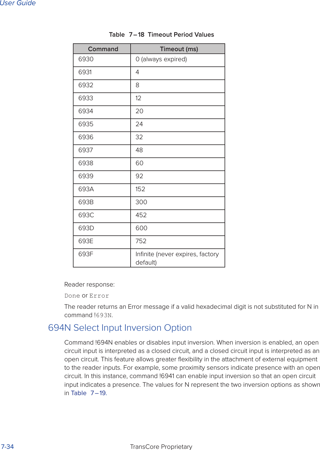

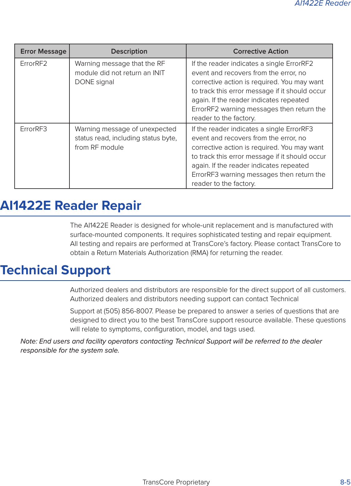

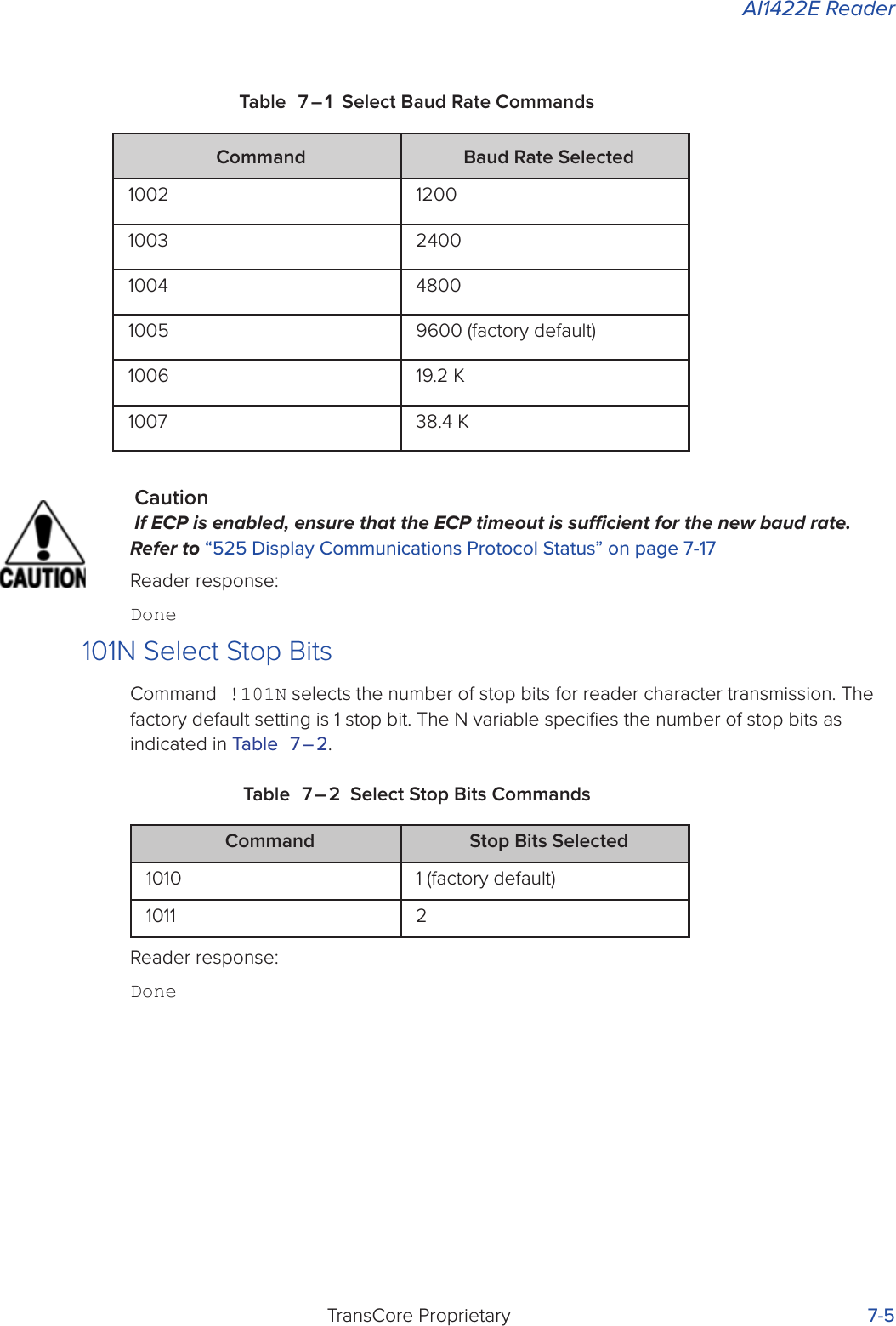
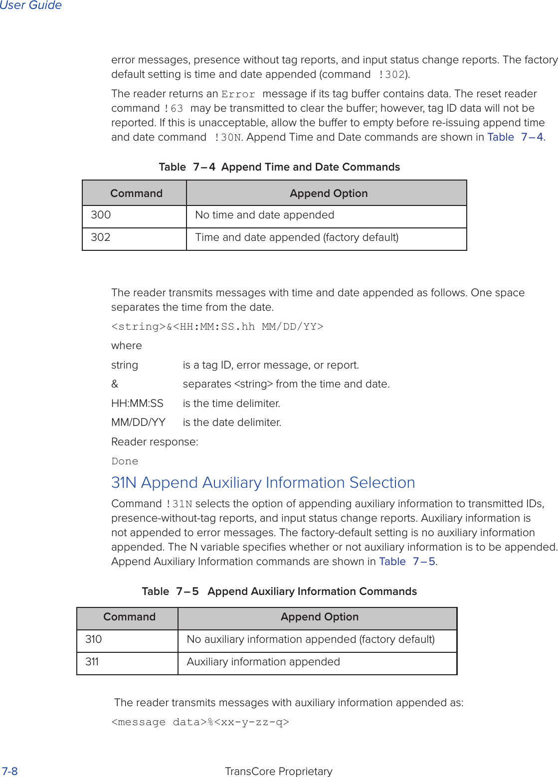
![User GuideTransCore Proprietary A-2Appendix ACharacter ConversionTable A-1 lists the TransCore 6-bit-per-character conversion from the standard ASCII character set.Table A – 22 TransCore 6-Bit-Per-Character Conversionspc 000000 6 010110 L 101100! 000001 7 010111 M 101101" 000010 8 011000 N 101110# 000011 9 011001 O 101111$000100 : 011010 P 110000% 000101 ; 011011 Q 110001& 000110 < 011100 R 110010' 000111 = 011101 S 110011( 001000 > 011110 T 110100) 001001 ? 011111 U 110101* 001010 @ 100000 V 110110+ 001011 A 100001 W 110111, 001100 B 100010 X 111000- 001101 C 100011 Y 111001. 001110 D 100100 Z 111010/ 001111 E 100101 [ 1110110 010000 F 100110 \ 1111001 010001 G 100111 ] 1111012 010010 H 101000 ^ 1111103 010011 I 101001 _ 1111114 010100 J 1010105 010101 K 101011](https://usermanual.wiki/TransCore/AI1422E.Users-Manual/User-Guide-3134635-Page-95.png)