TransCore AI1422E Location Monitoring Services Transmitter User Manual
TransCore Location Monitoring Services Transmitter
UserManual.wiki
>
TransCore
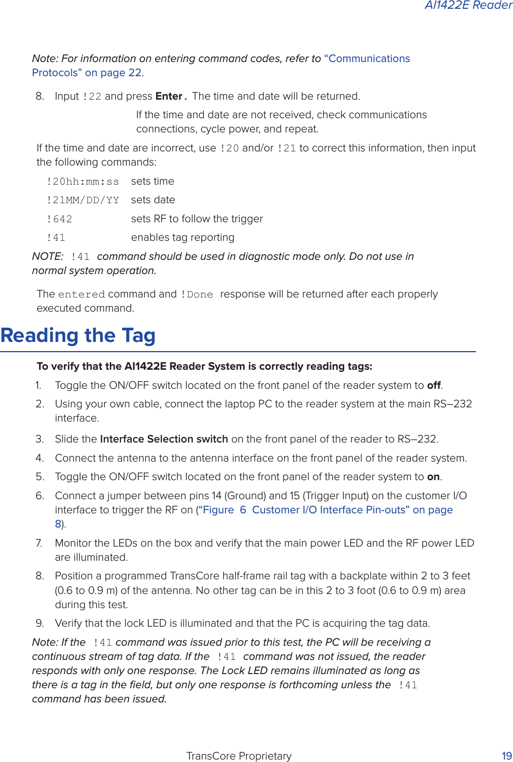
>
AI1422E User Manual
>
User Manual
Contents
1.
Users Manual
2.
User Manual
User Manual
Navigation menu
Upload a User Manual
Namespaces
Wiki Guide
HTML
PDF
Info
Views
User Manual
Discussion / Help
Navigation
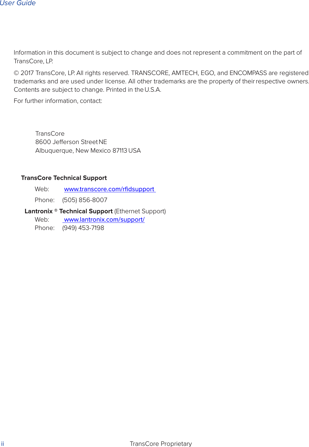
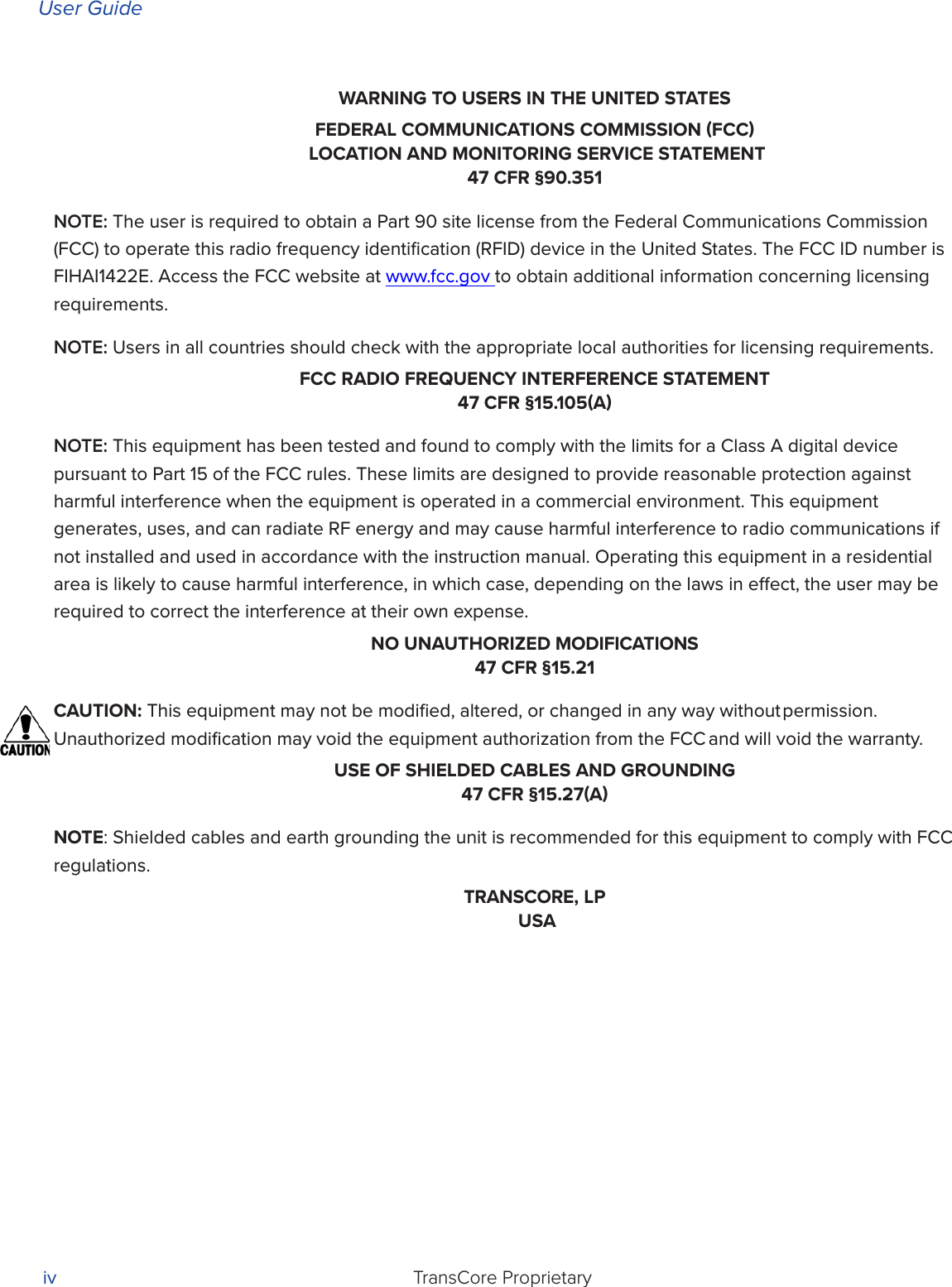

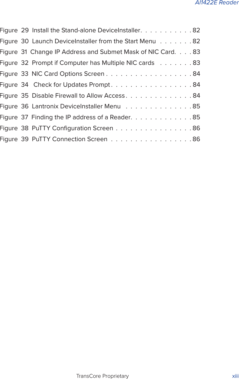

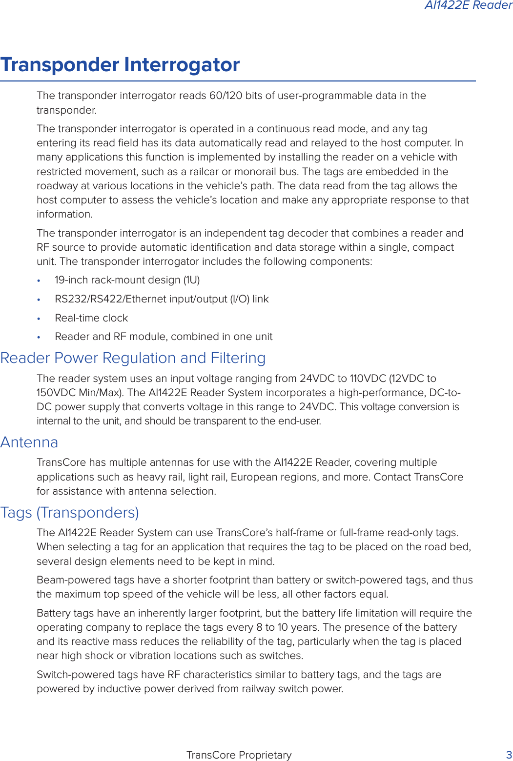

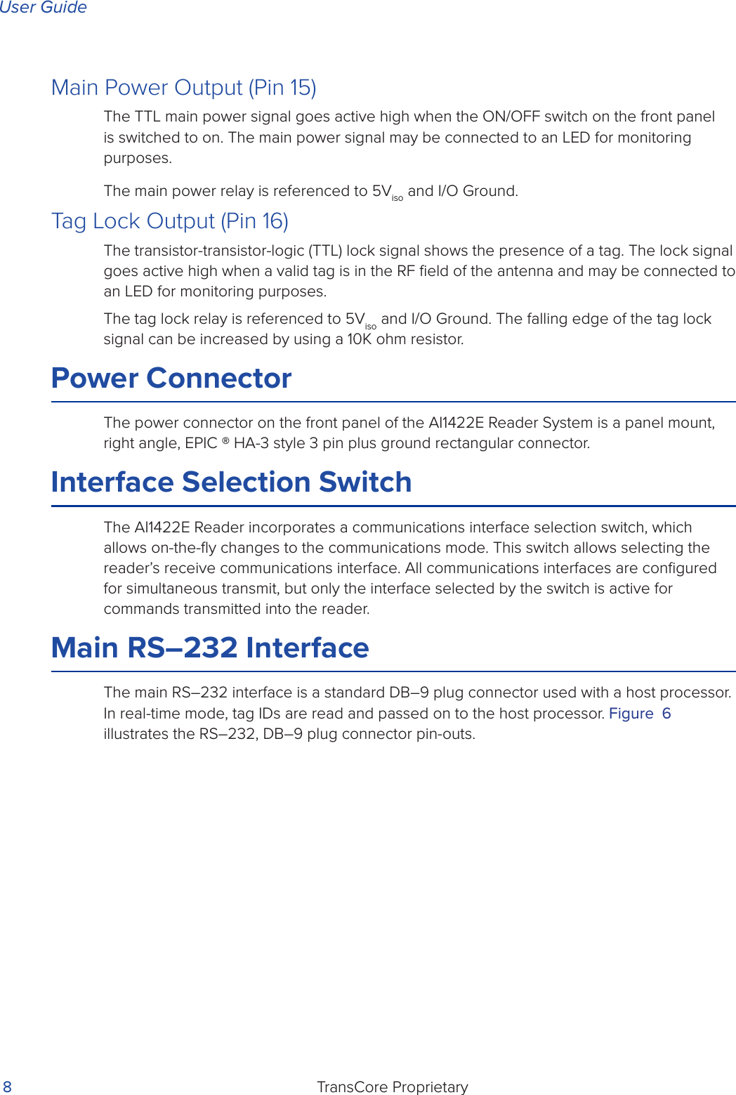

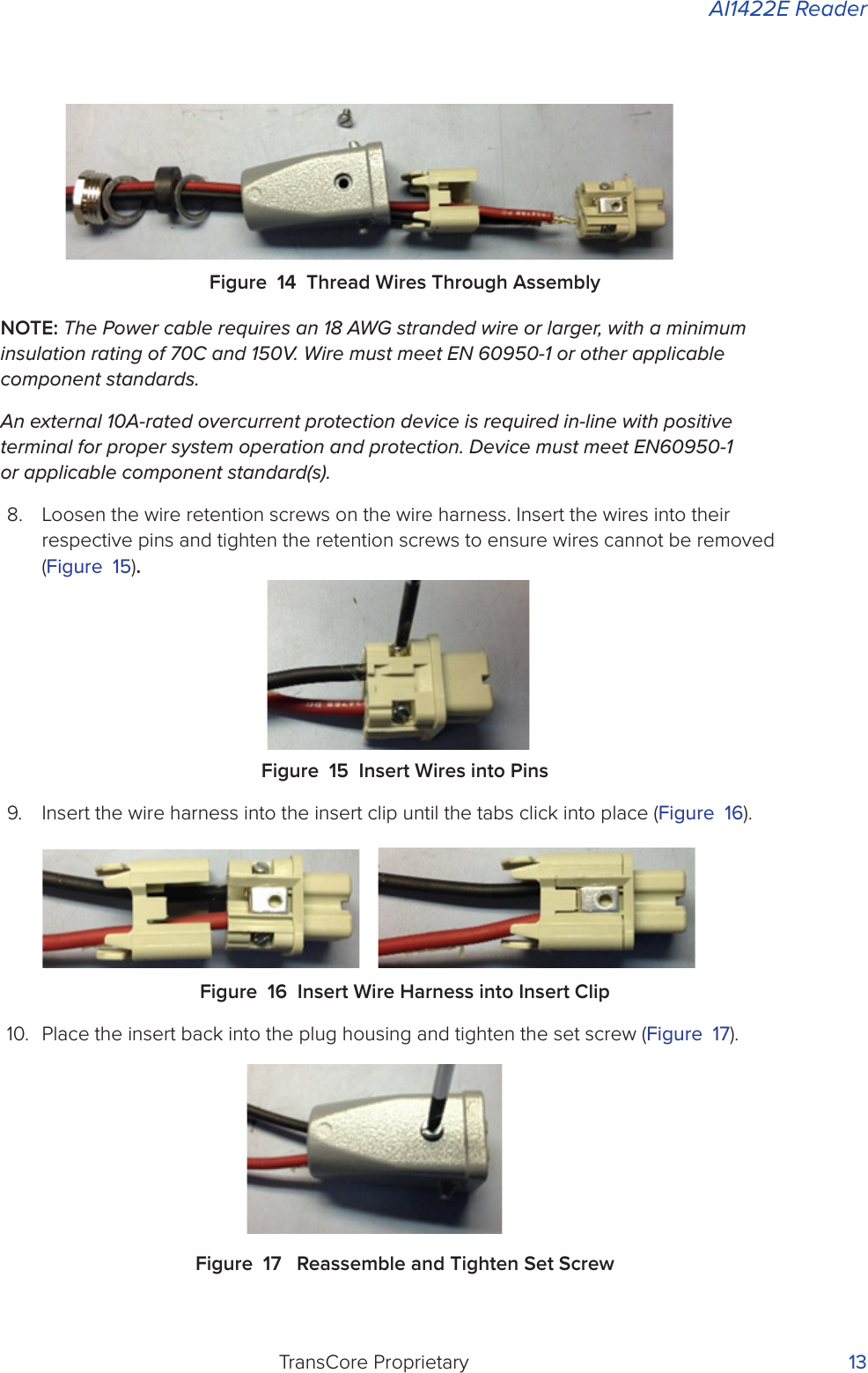

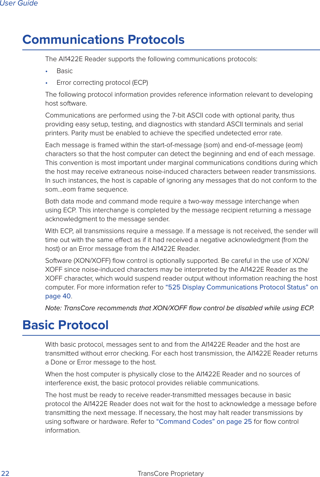
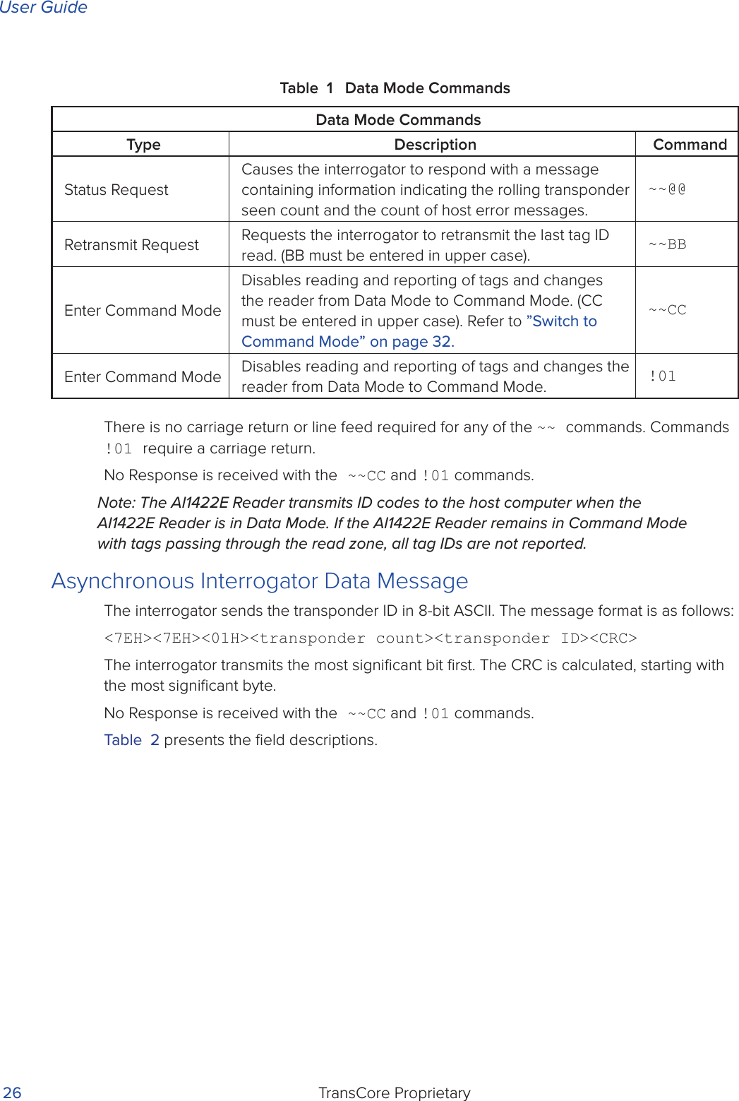
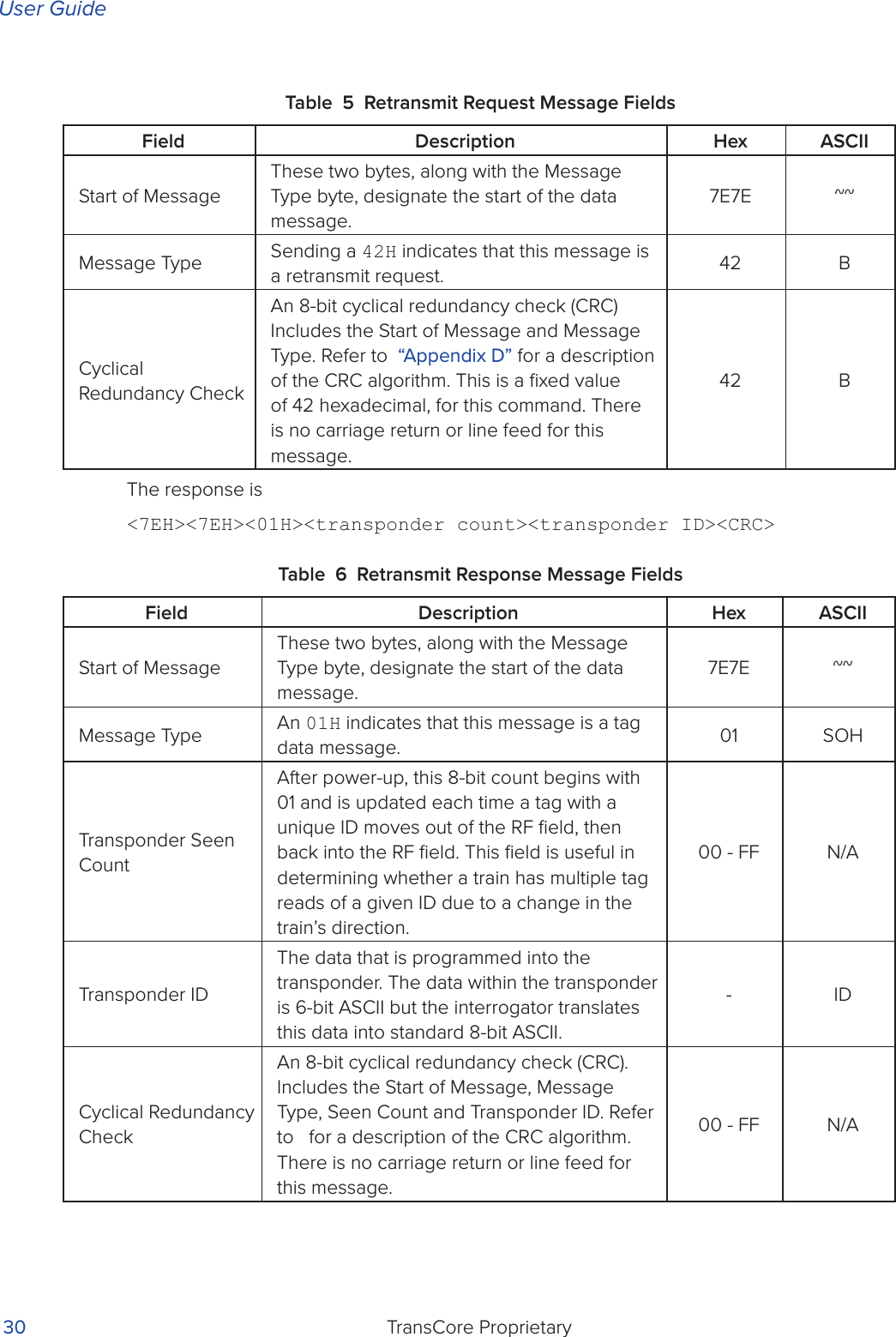
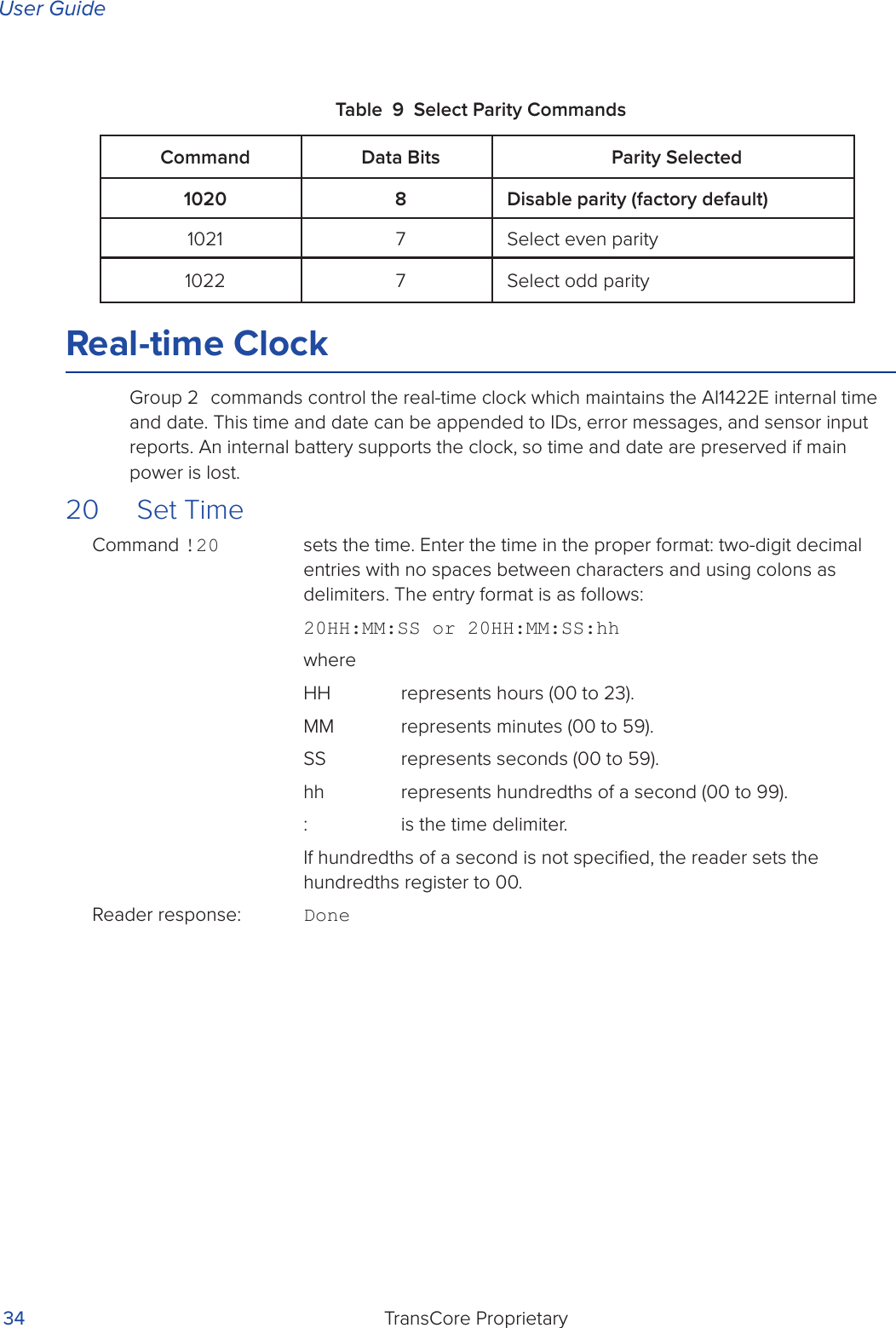
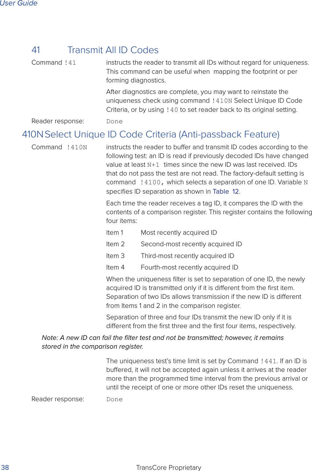
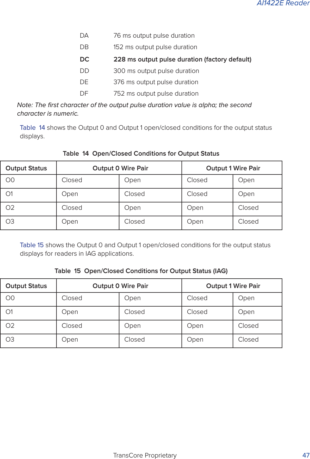
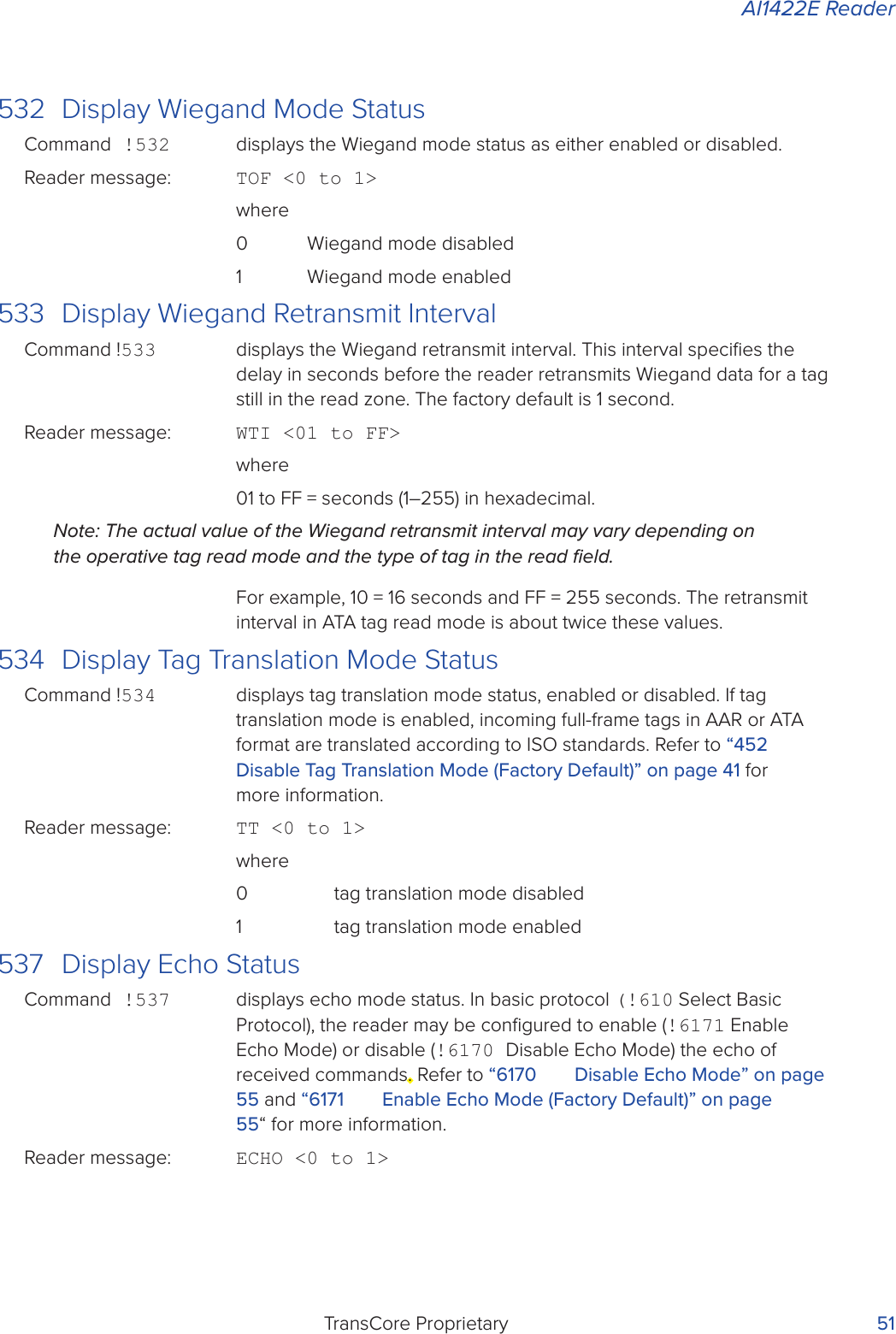
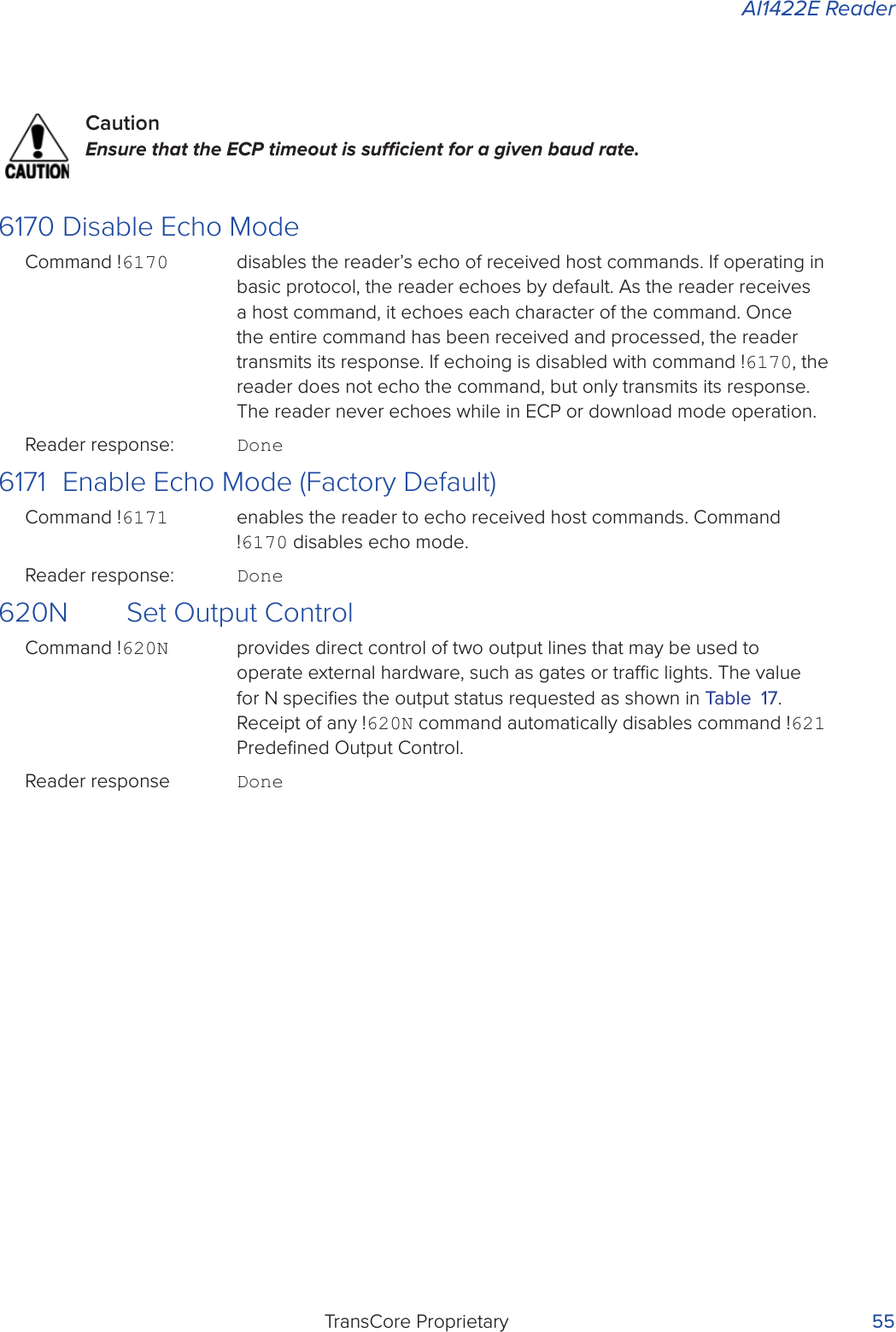
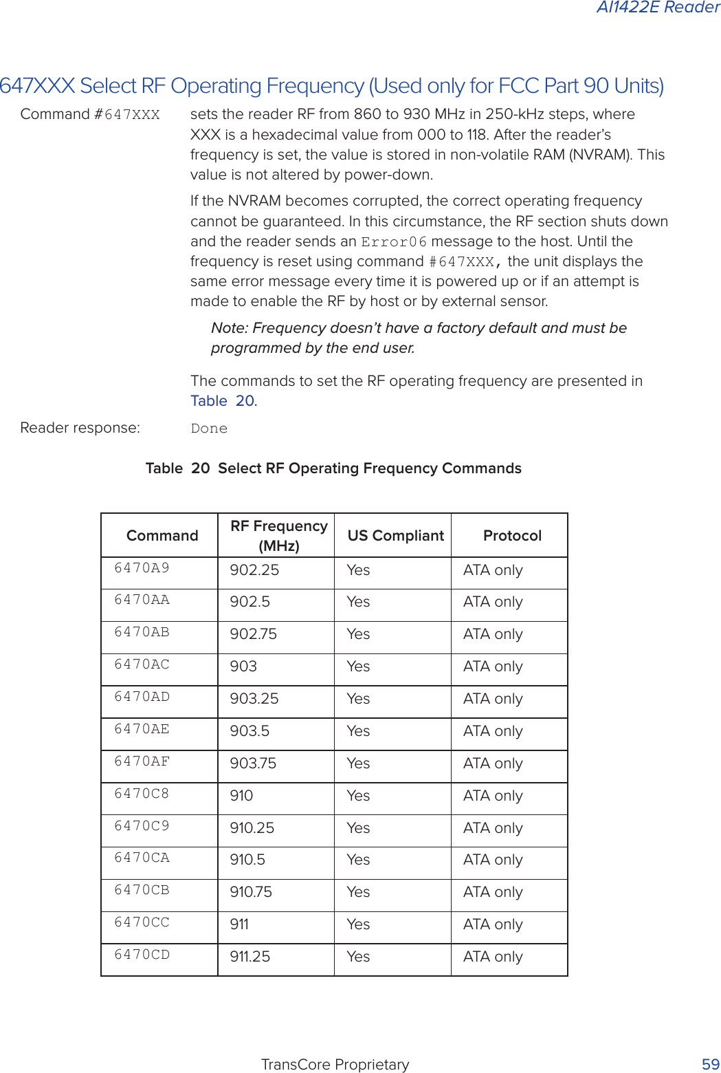
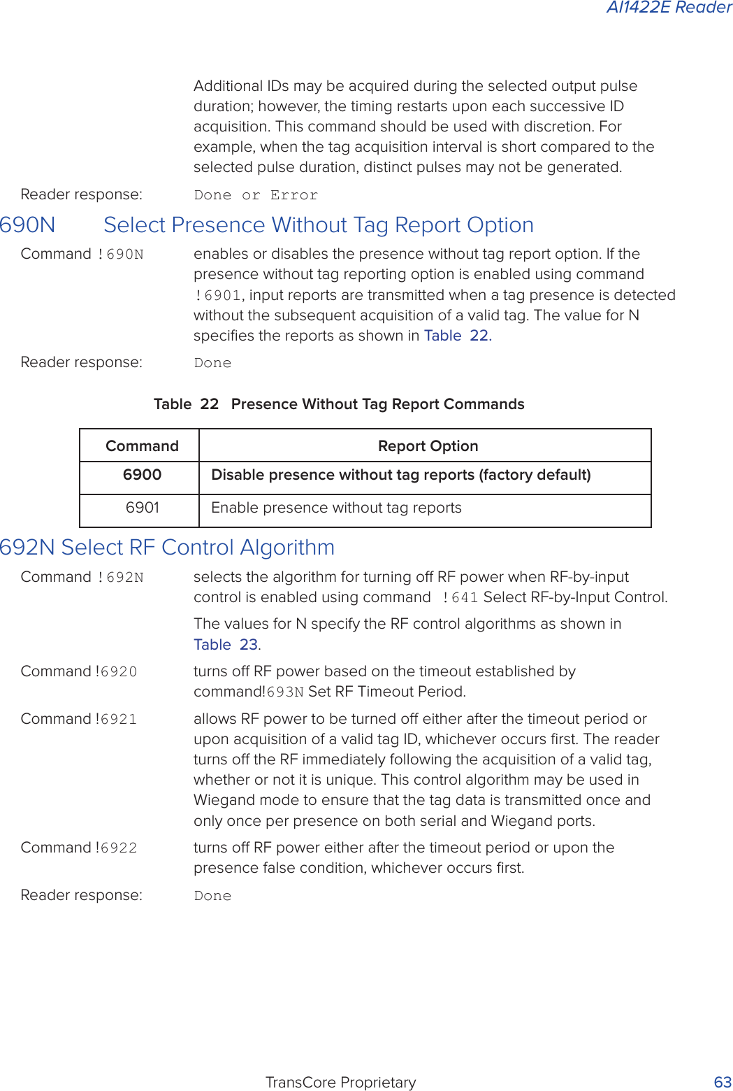
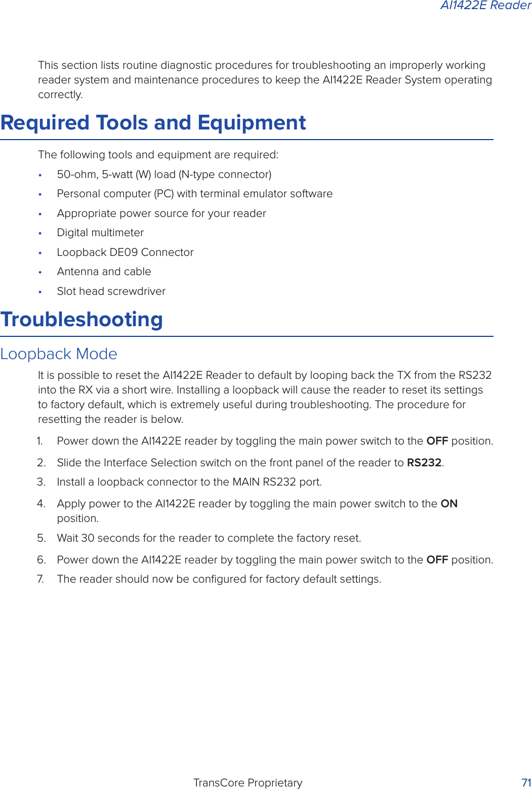
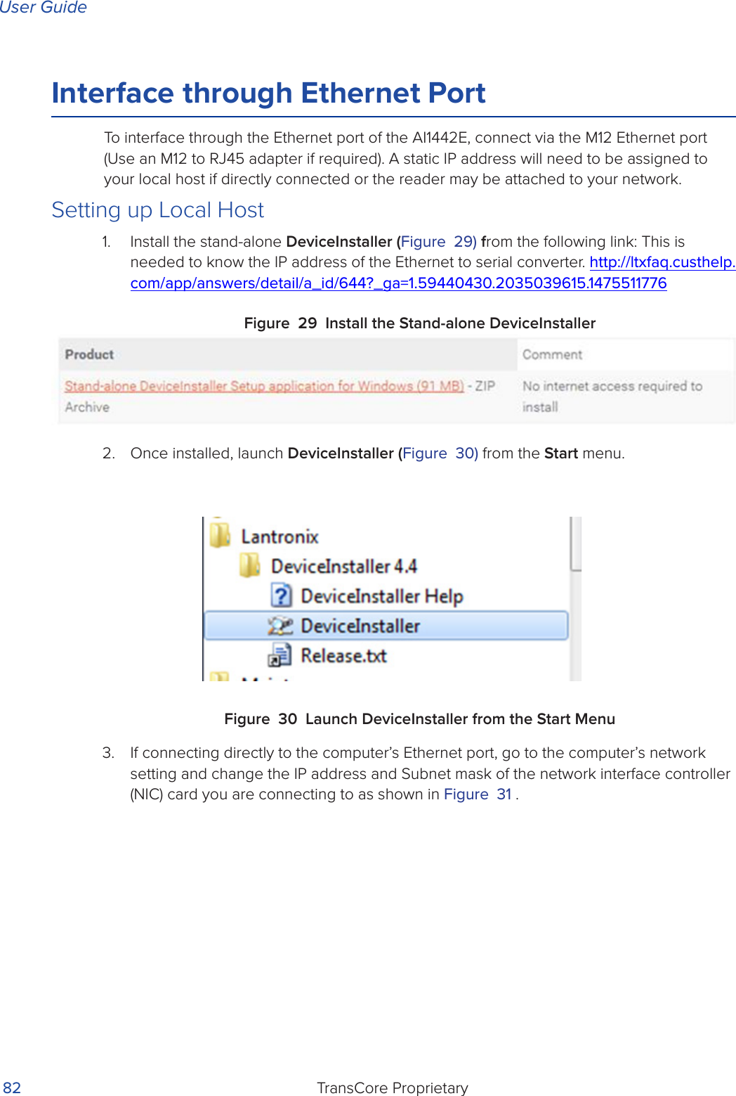
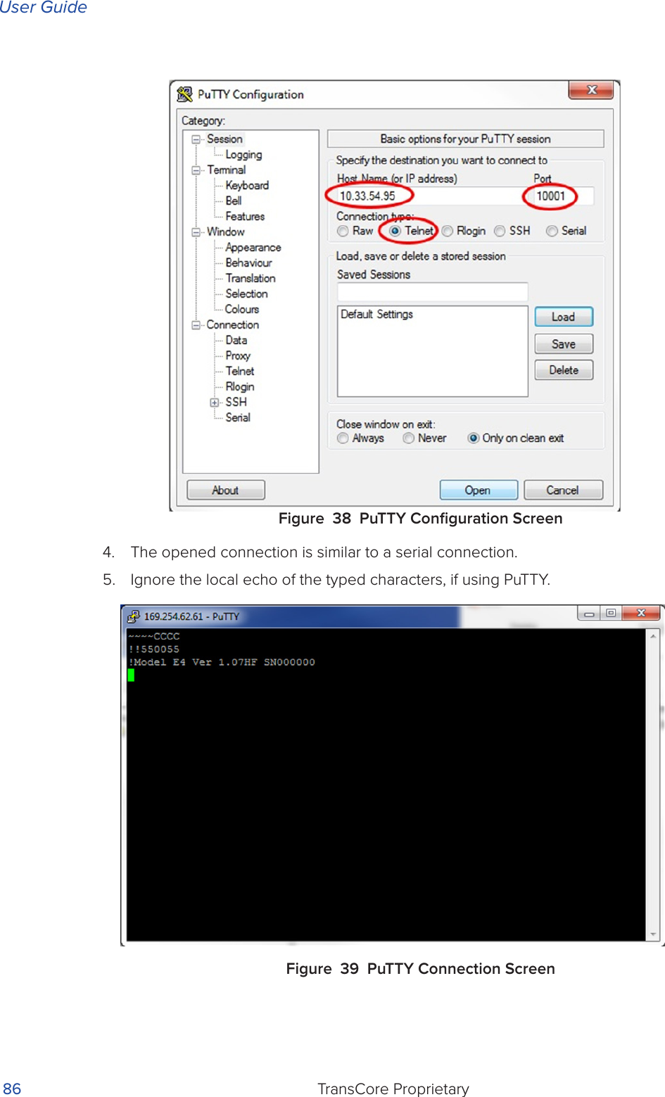
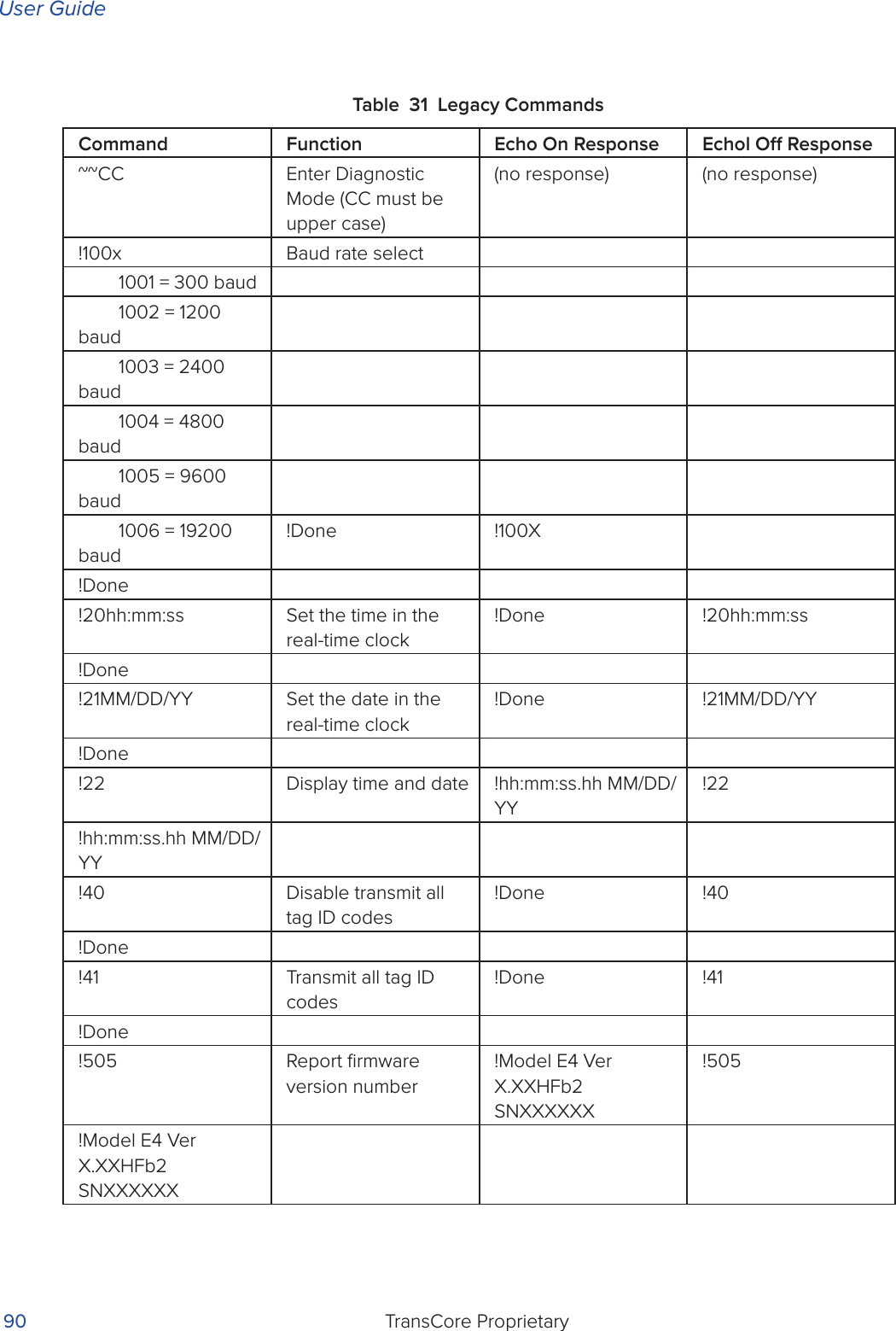
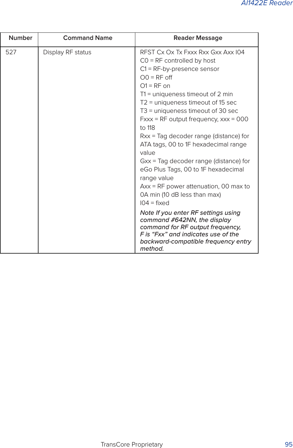
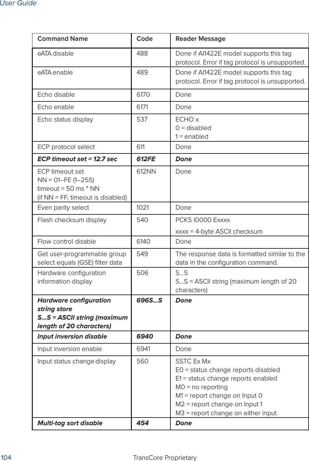
![AI1422E ReaderTransCore Proprietary 39Table 12 Unique ID Code Criteria420N Select Valid ID Code CriteriaCommand !420N directs the reader to validate an ID received only after it has been obtained a specified number of times in sequence. Values for N are 0 through 3 (Table 13). The factory setting is one acquisition (N = 0).The validation procedure is executed before the unique ID test (Select Unique ID Code Criteria [!410N] commands). IDs that do not pass the validation test are not reported.For example, command !4203 specifies that the same ID must be obtained from the RF module 4 times in succession before it is considered for the uniqueness test. This feature is useful in installations where RF reflections may cause a single tag to be read multiple times or where an occasional ID might be read from fringe areas.Table 13 Select Valid Code Commands and FramesCommand Uniqueness Criteria4100 Separation of 1 ID (factory default)4101 Separation of 2 IDs4102 Separation of 3 IDs4103 Separation of 4 IDsCommand Valid Code Frames4200 1 (Factory default)4201 24202 34203 4](https://usermanual.wiki/TransCore/AI1422E.User-Manual/User-Guide-3591270-Page-54.png)
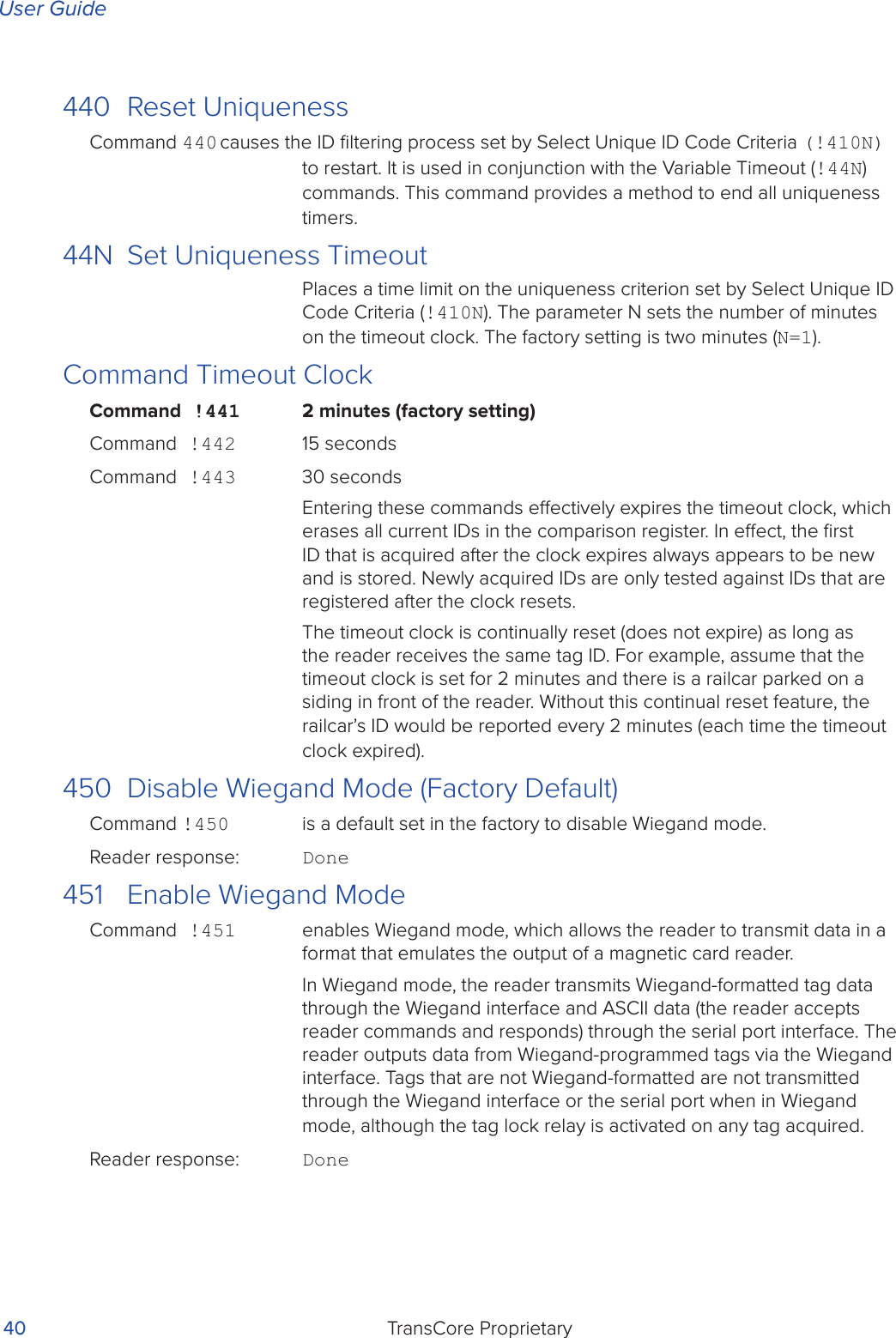
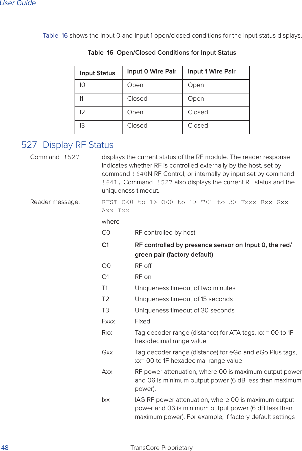
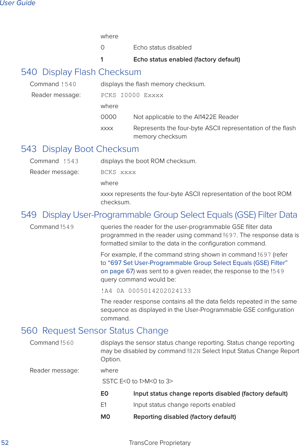
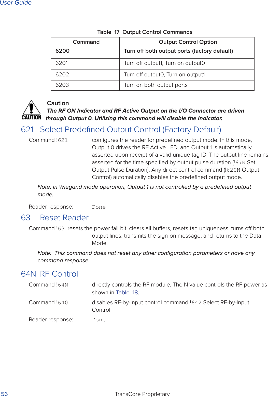
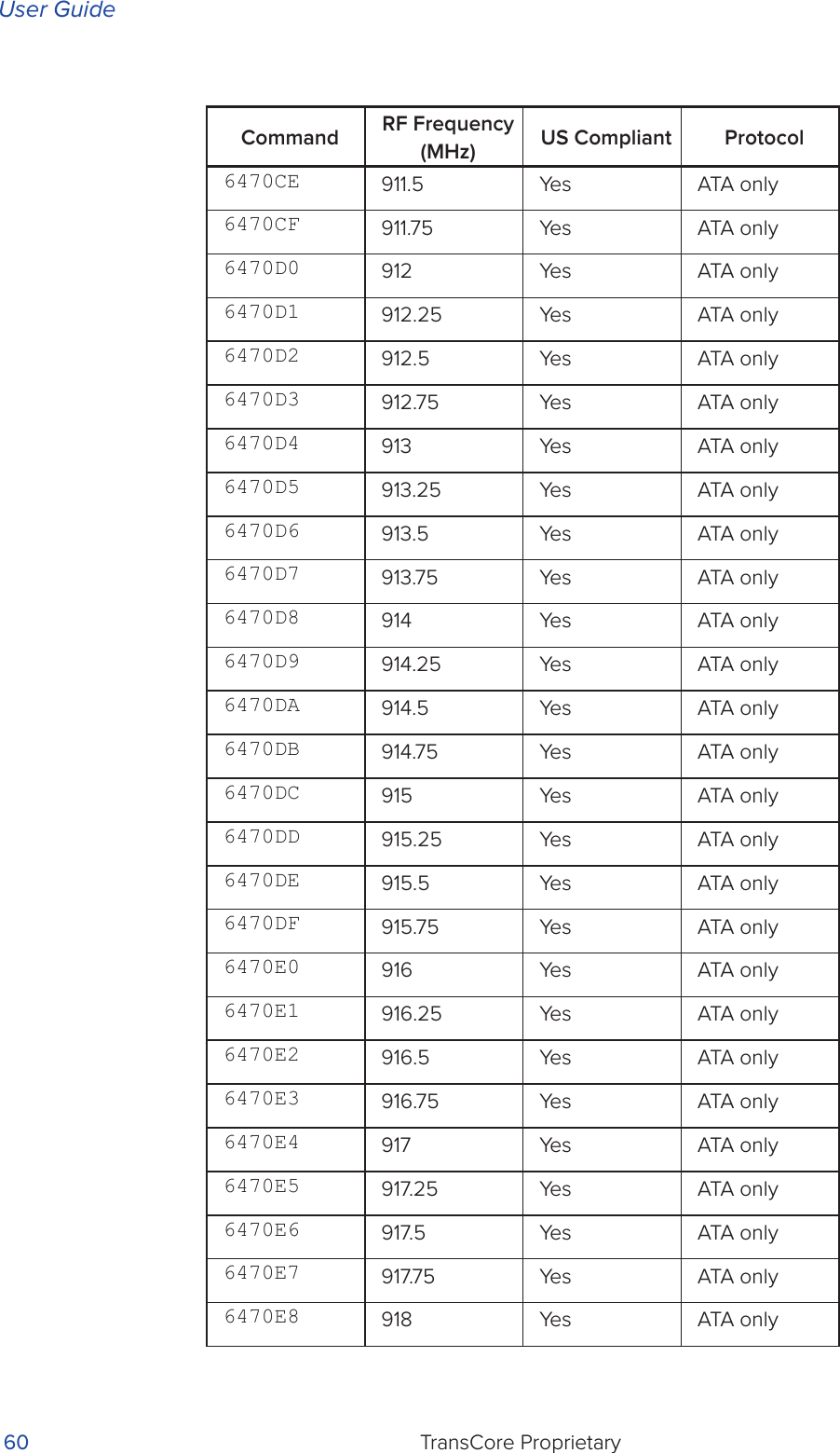
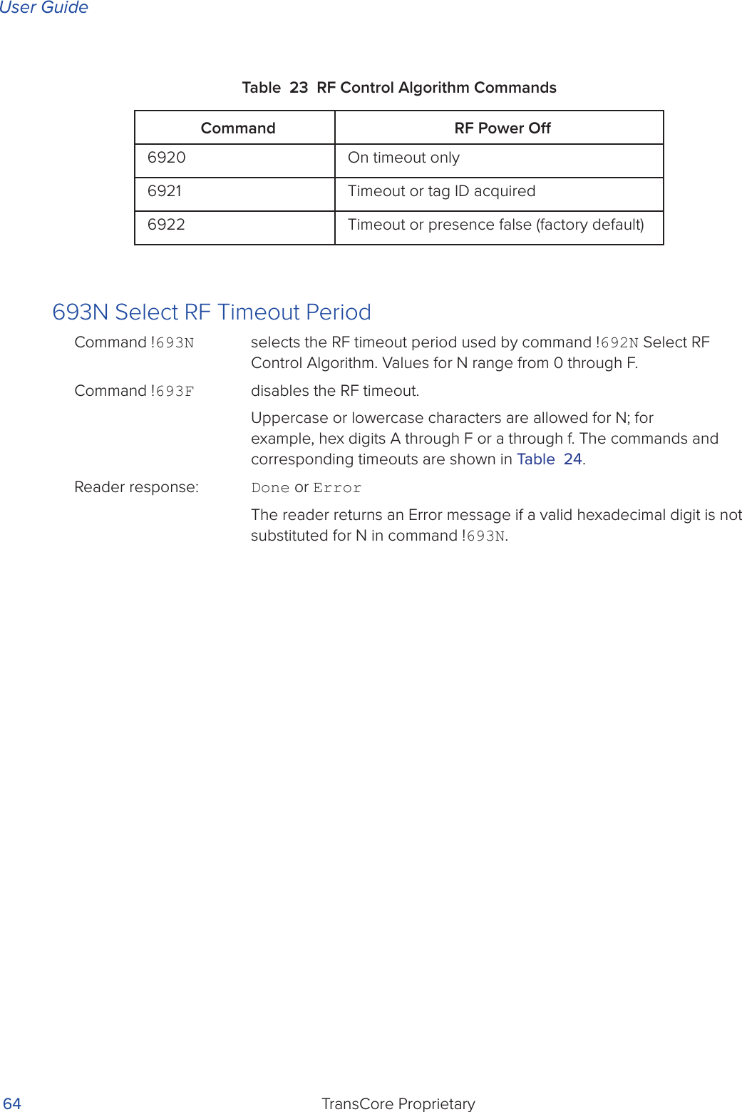
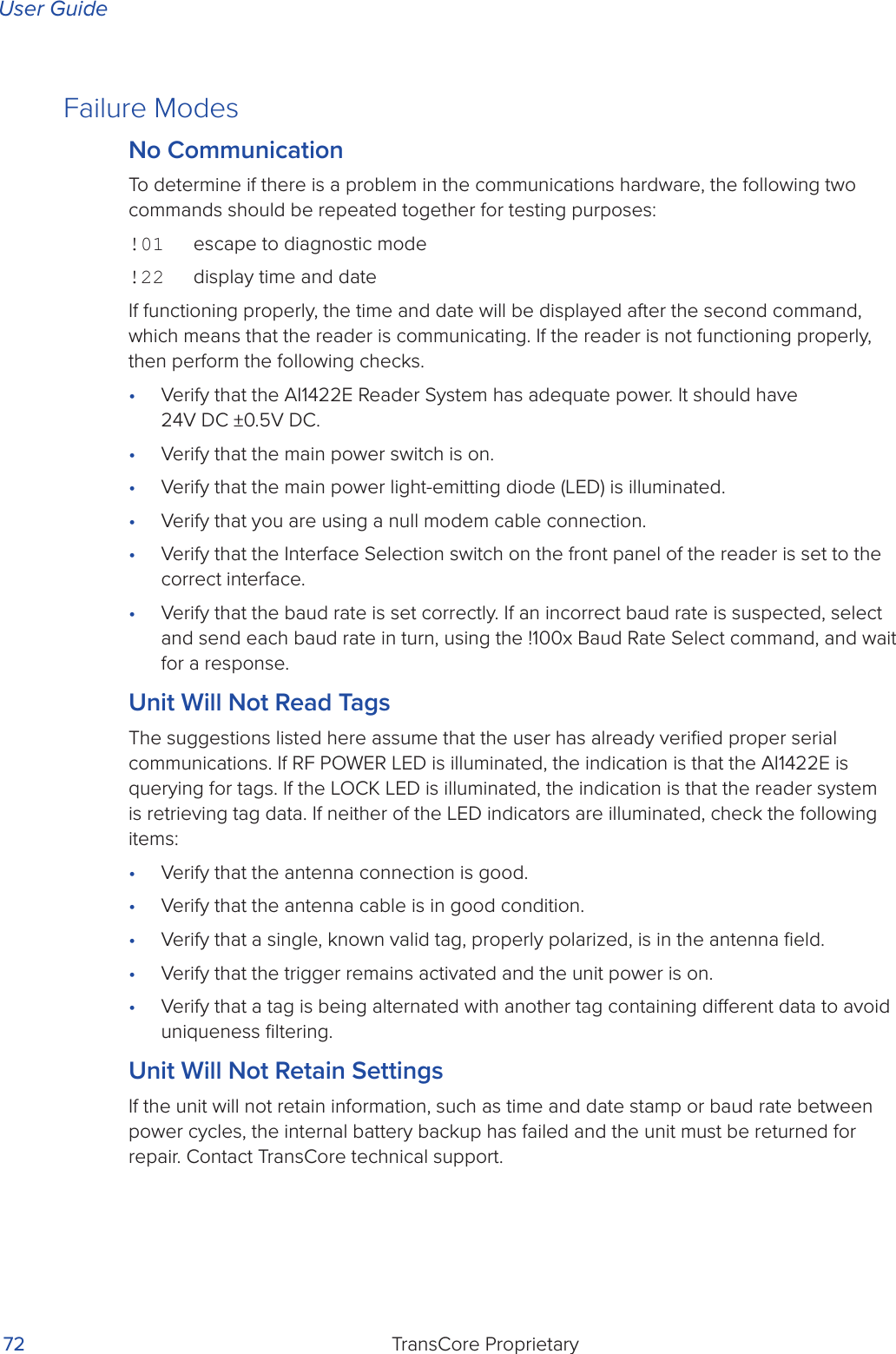

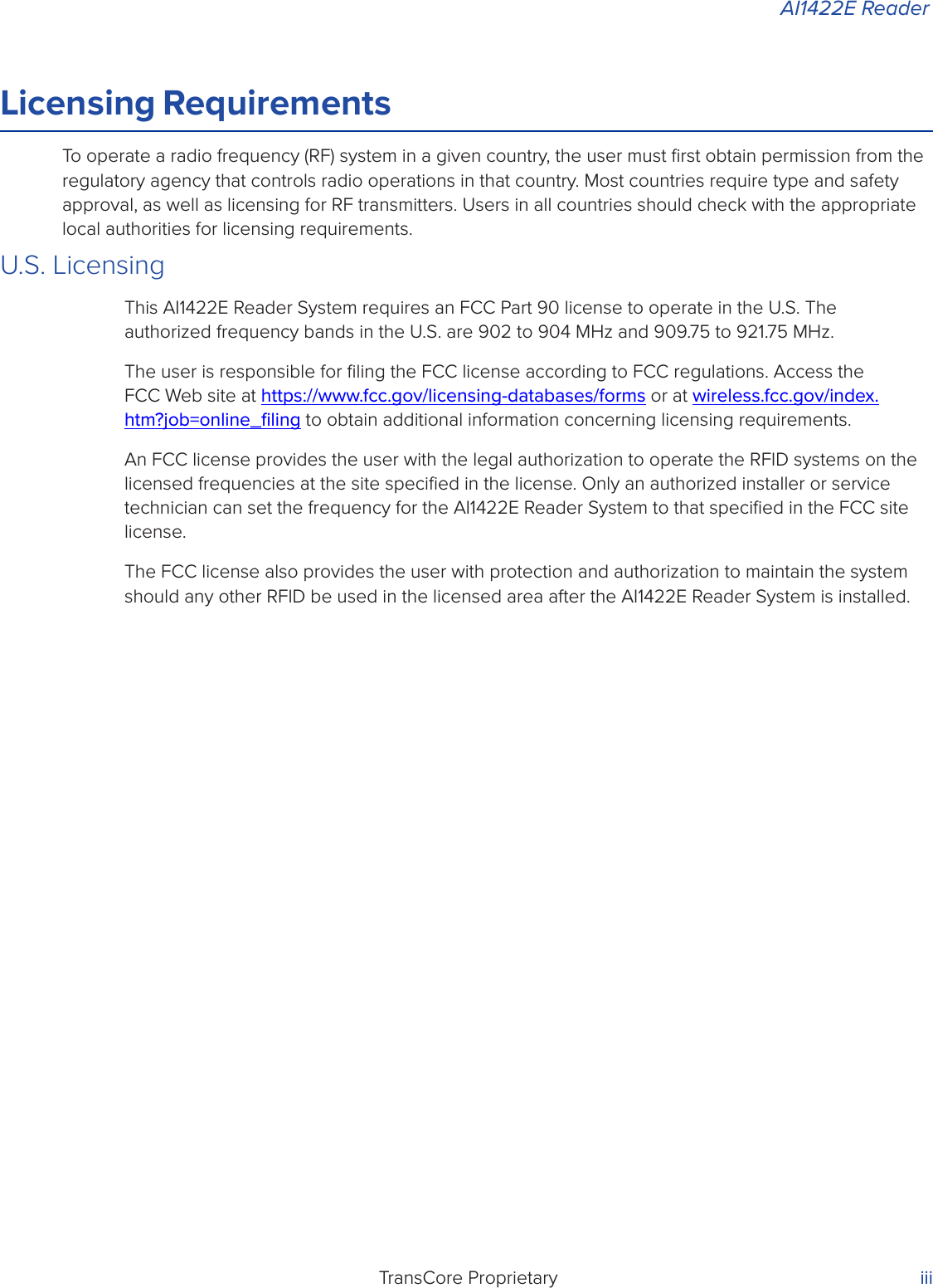
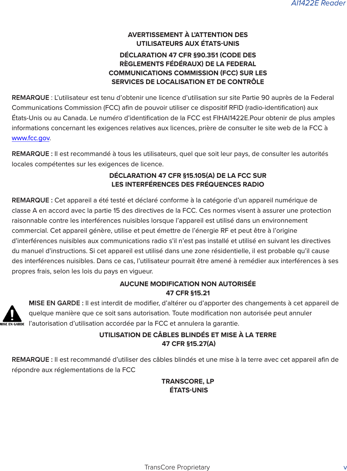
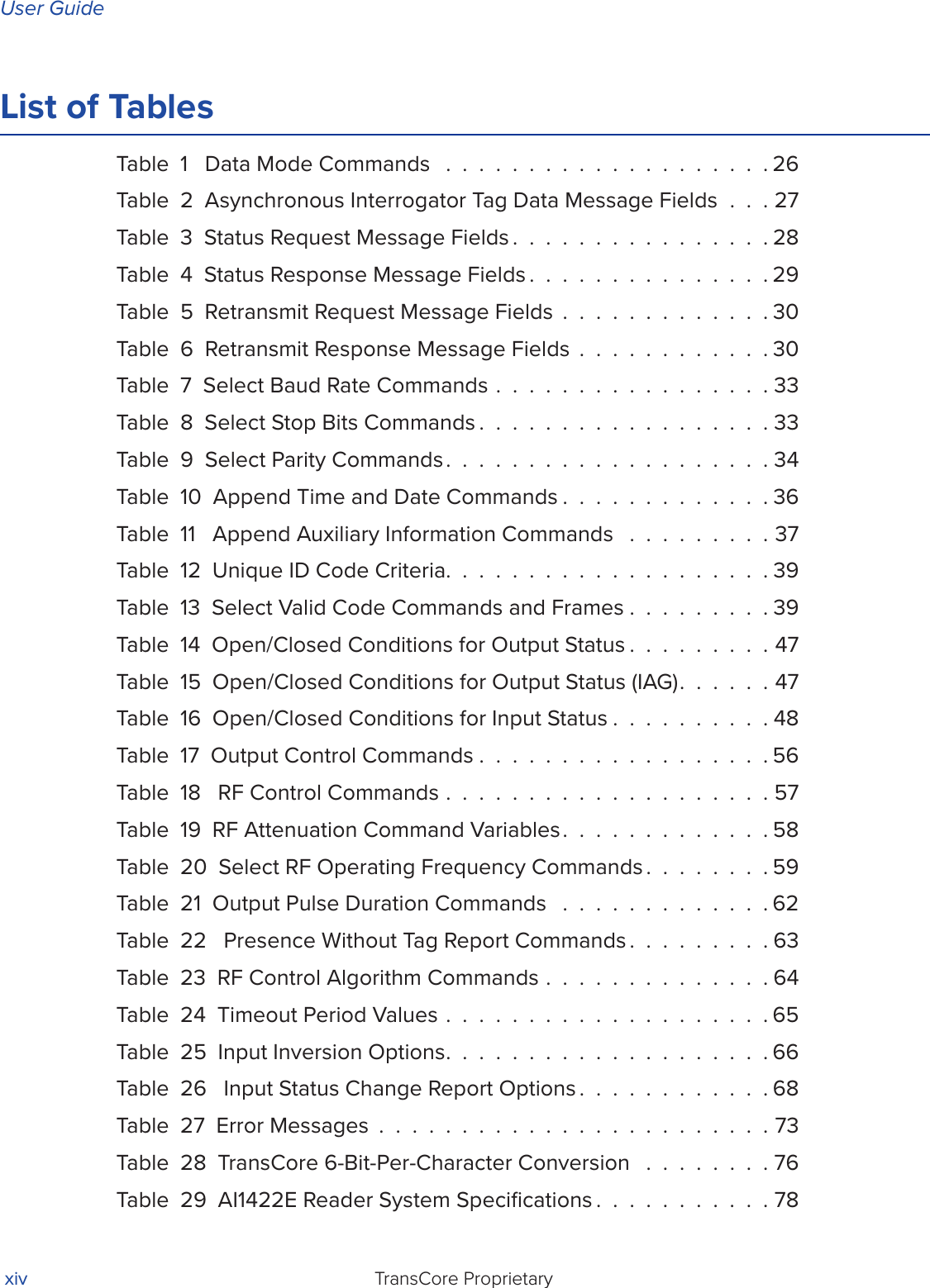
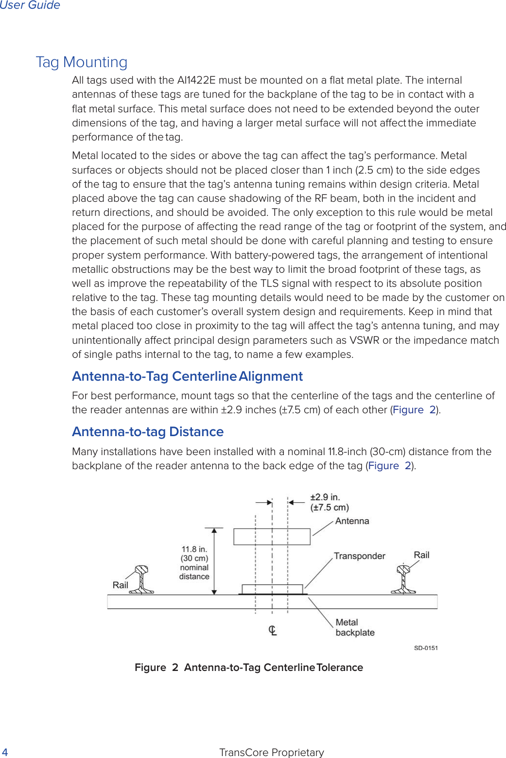
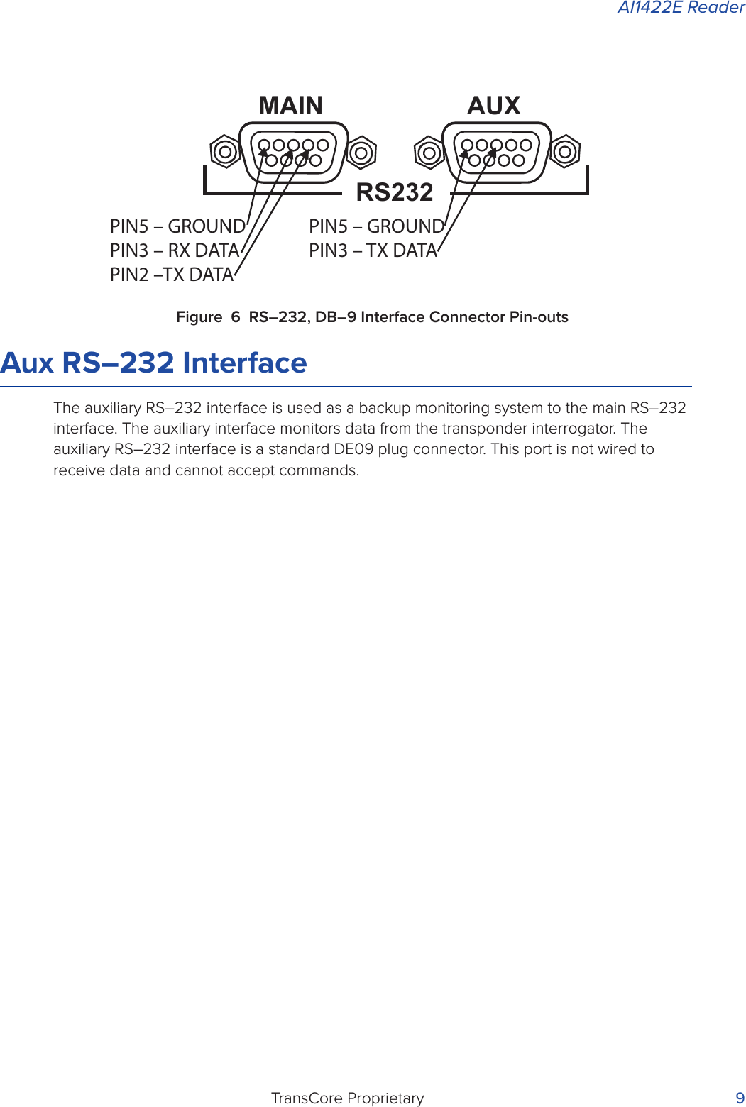
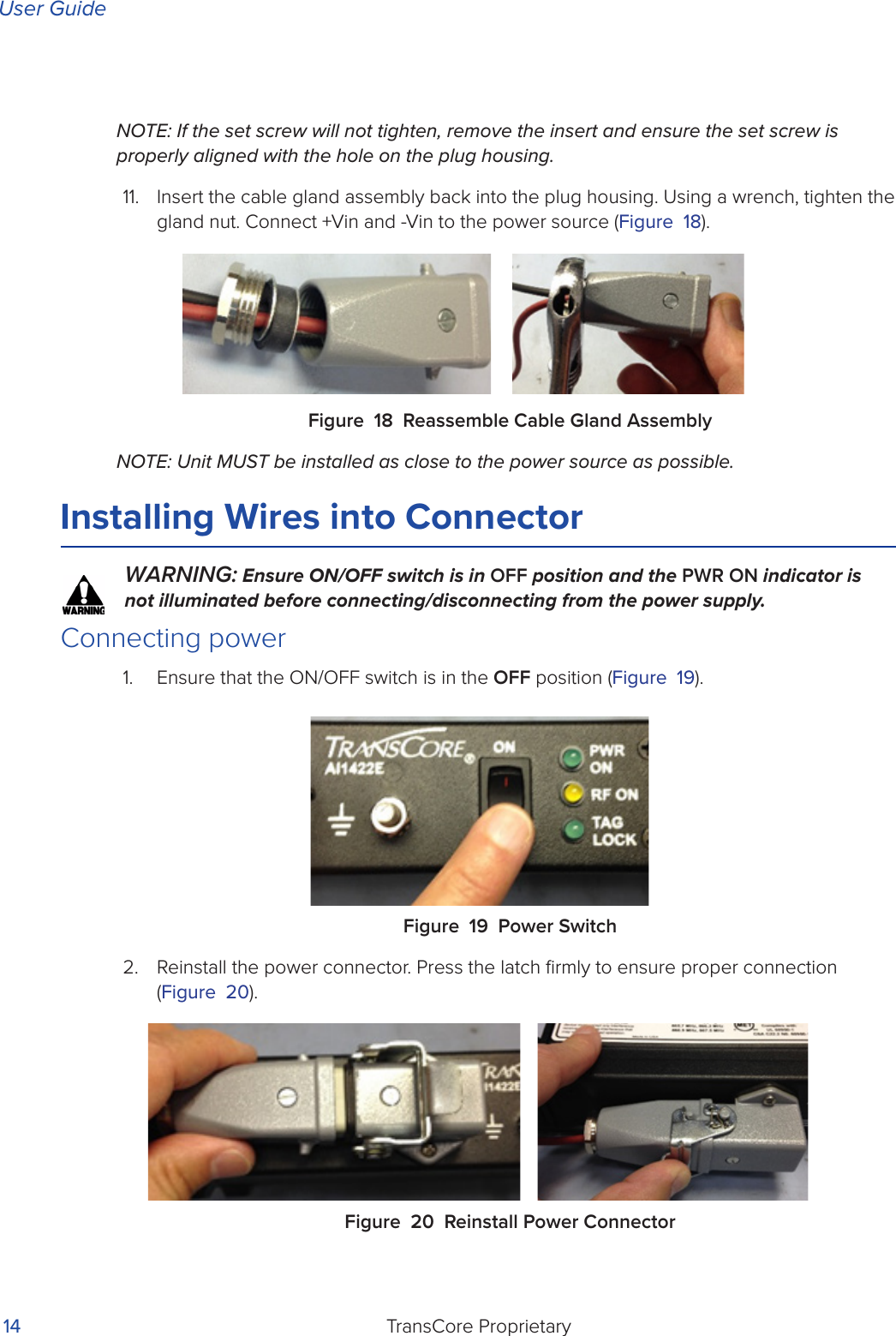
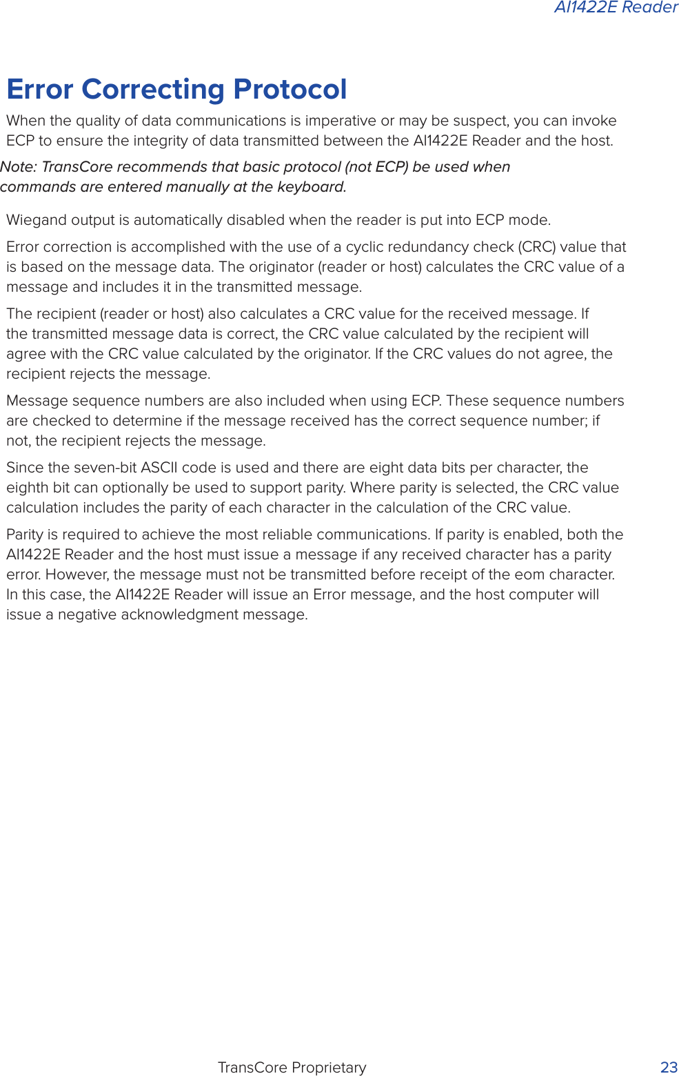
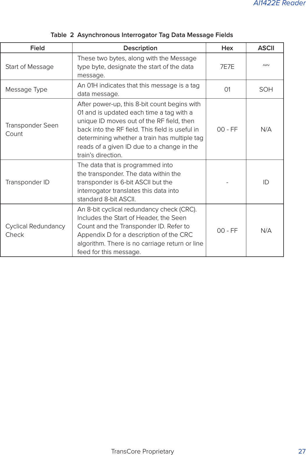
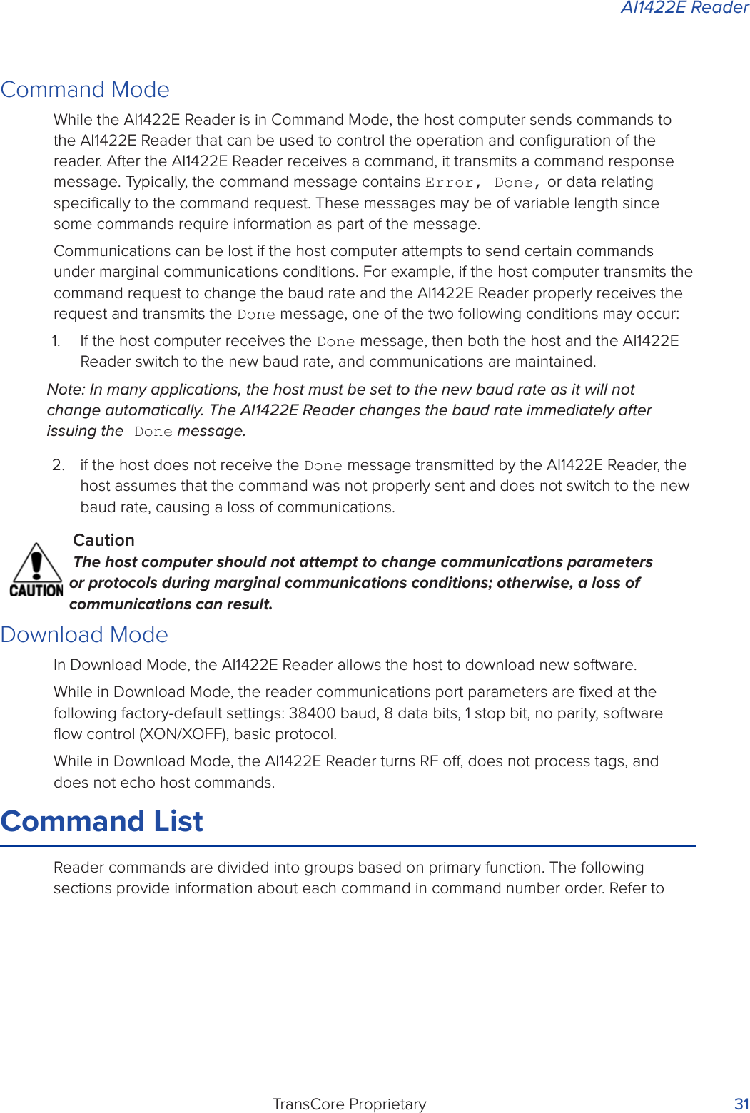
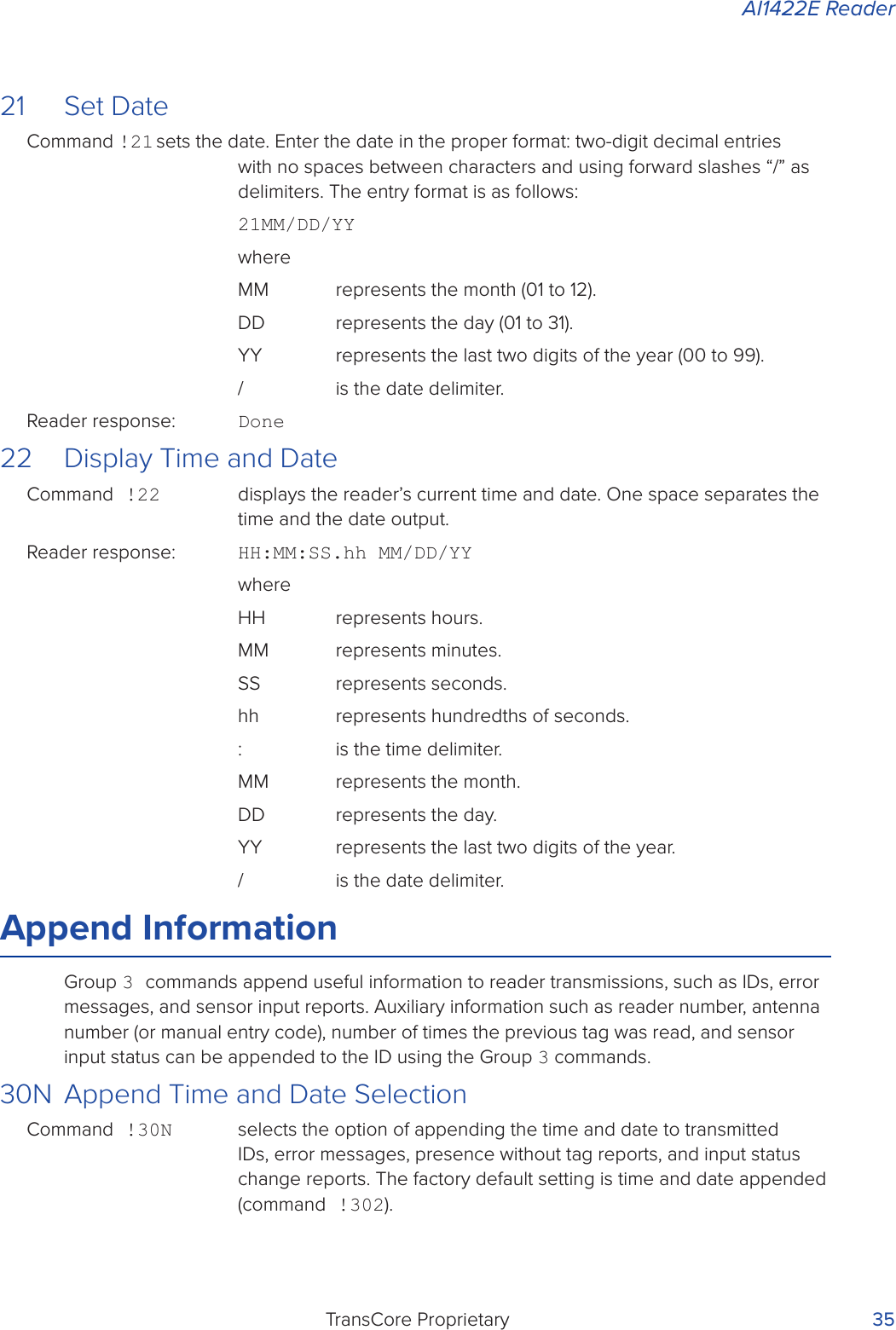
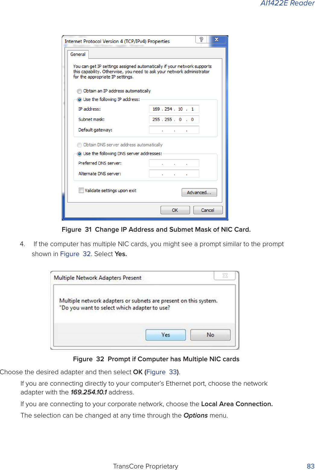
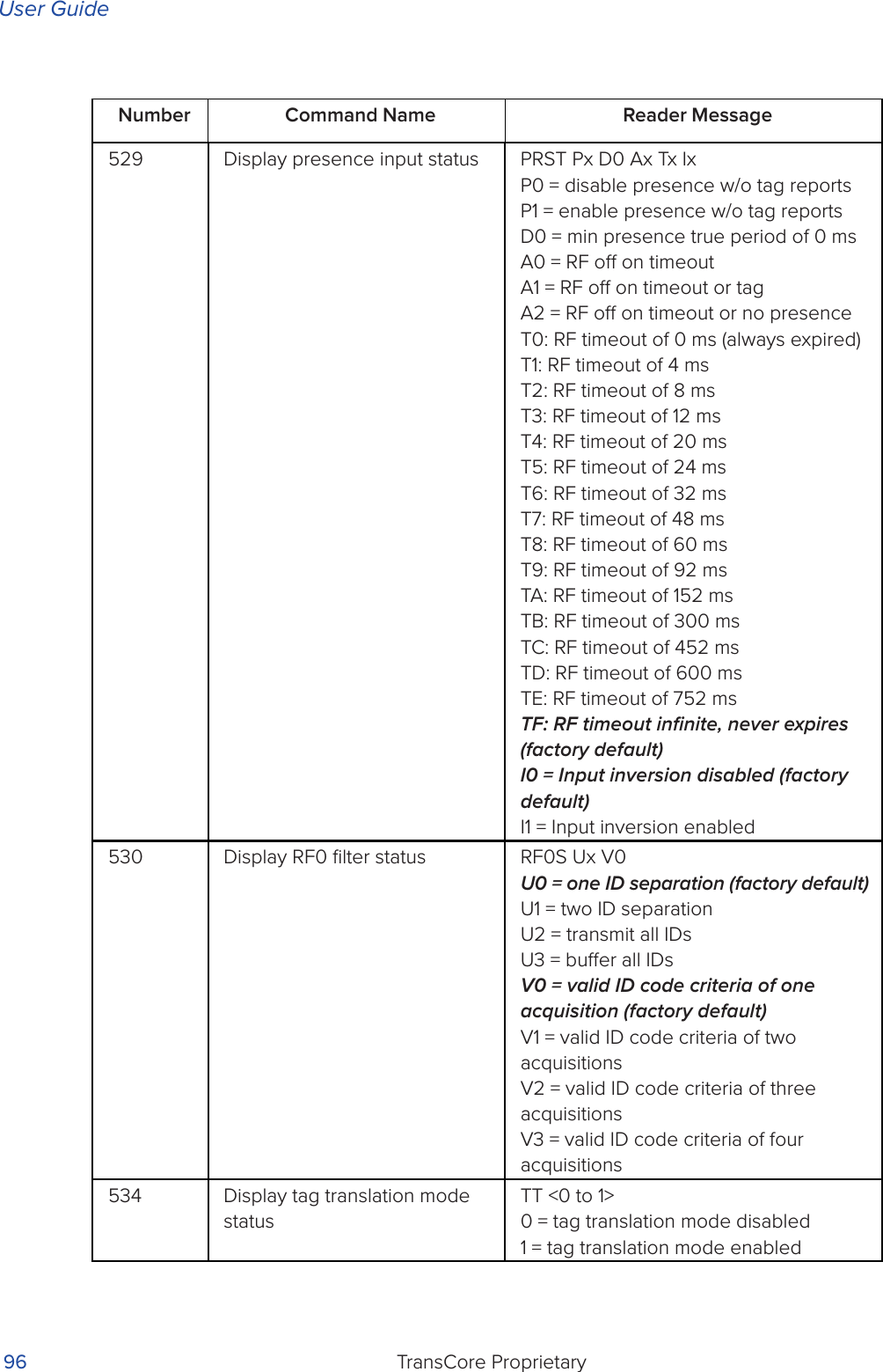
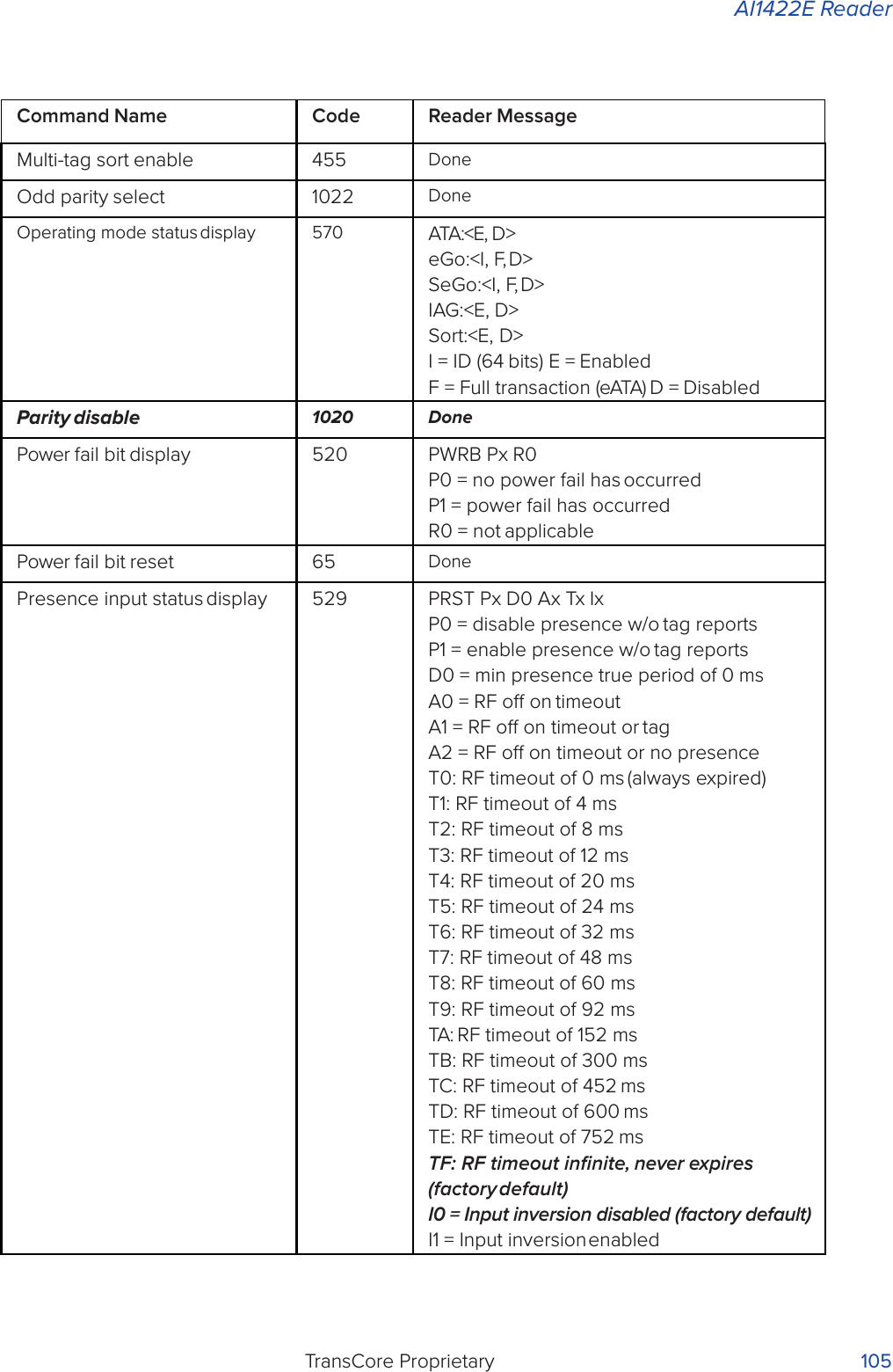
![User GuideTransCore Proprietary 76Appendix ACharacter ConversionTable 28 lists the TransCore 6-bit-per-character conversion from the standard ASCII character set.Table 28 TransCore 6-Bit-Per-Character Conversionspc 000000 6 010110 L 101100! 000001 7 010111 M 101101" 000010 8 011000 N 101110# 000011 9 011001 O 101111$ 000100 :011010 P 110000% 000101 ; 011011 Q 110001& 000110 < 011100 R 110010' 000111 = 011101 S 110011( 001000 > 011110 T 110100) 001001 ? 011111 U 110101* 001010 @ 100000 V 110110+ 001011 A 100001 W 110111, 001100 B 100010 X 111000- 001101 C 100011 Y 111001. 001110 D 100100 Z 111010/ 001111 E 100101 [ 1110110 010000 F 100110 \ 1111001 010001 G 100111 ] 1111012 010010 H 101000 ^ 1111103 010011 I 101001 _ 1111114 010100 J 1010105 010101 K 101011](https://usermanual.wiki/TransCore/AI1422E.User-Manual/User-Guide-3591270-Page-91.png)

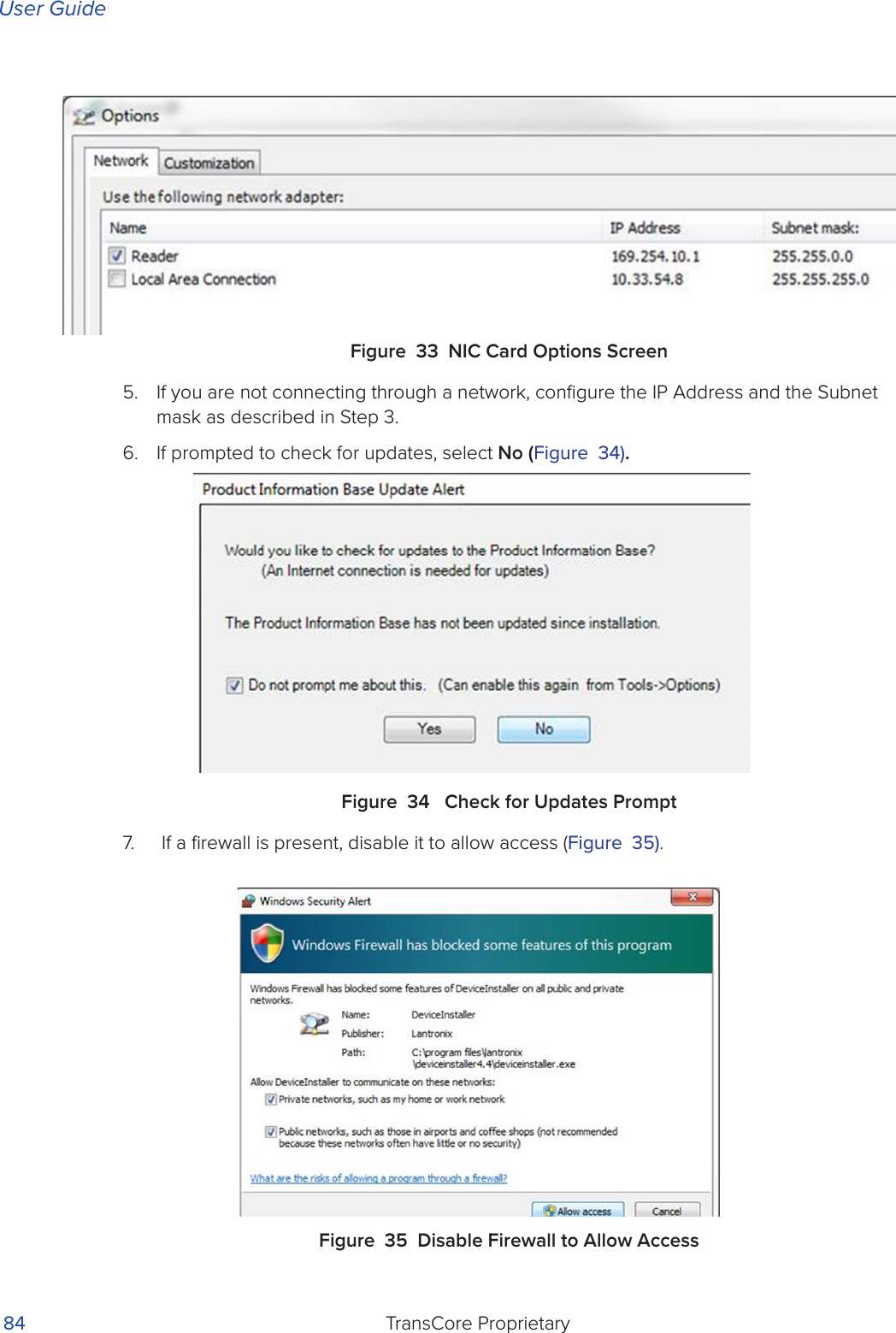
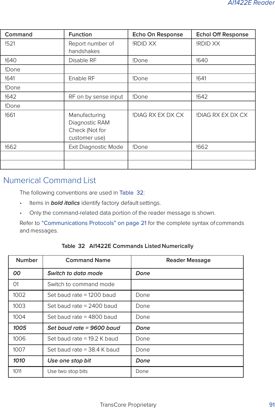
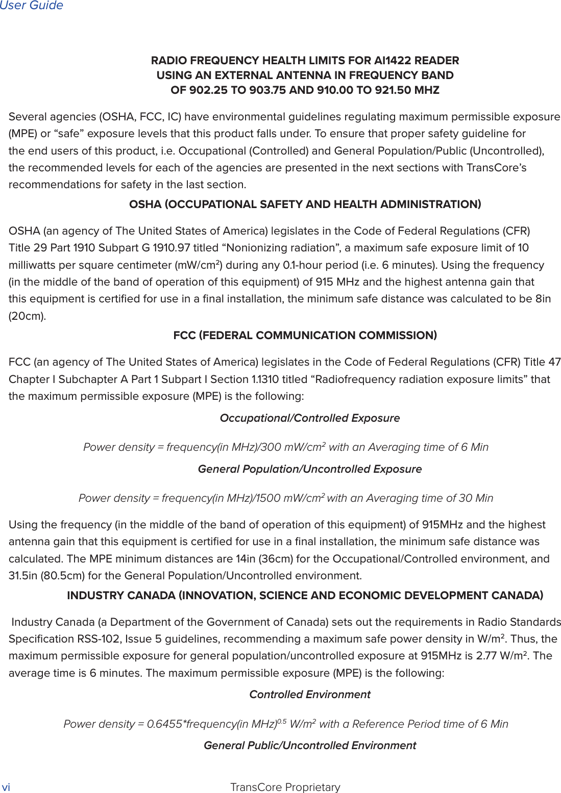
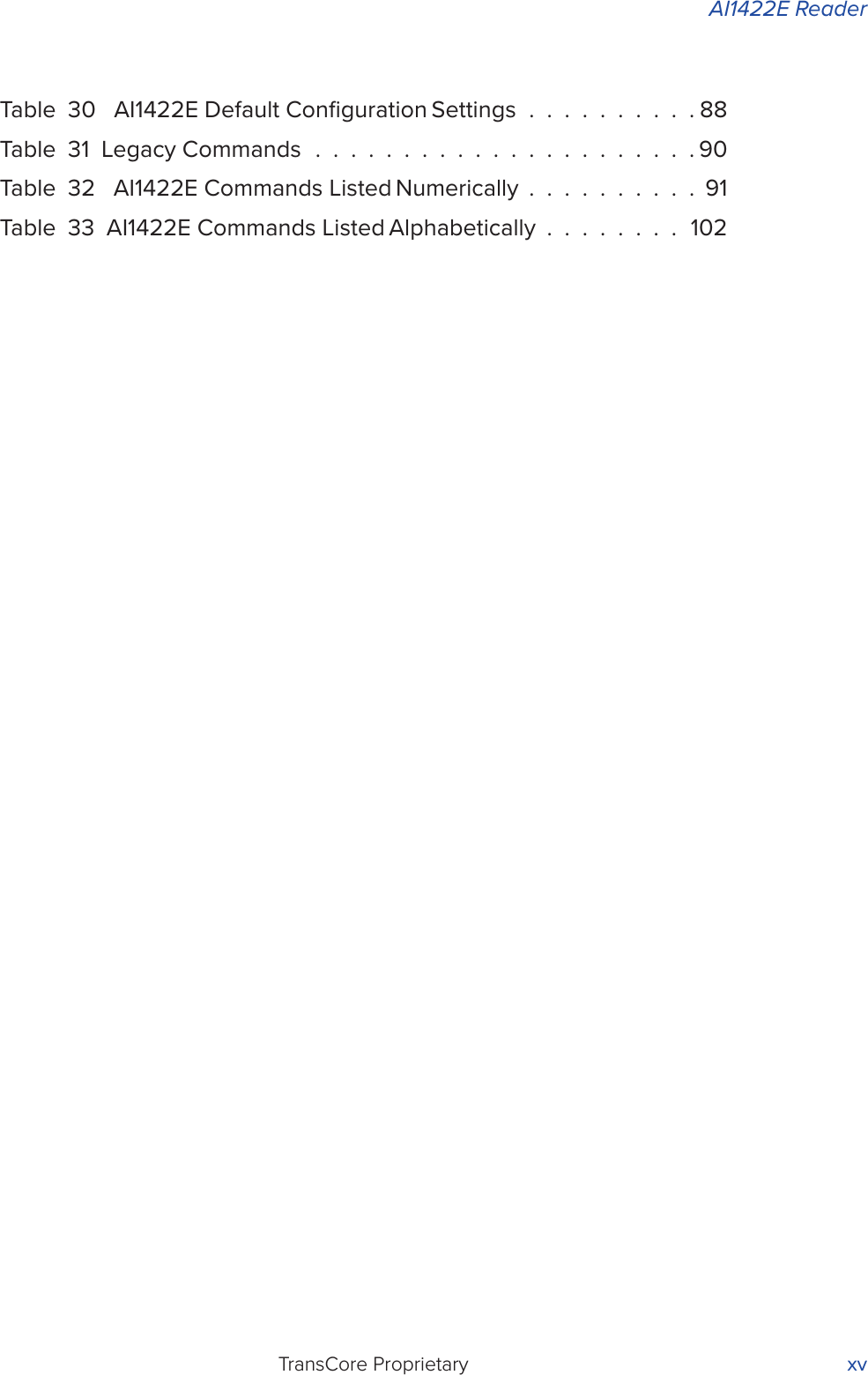
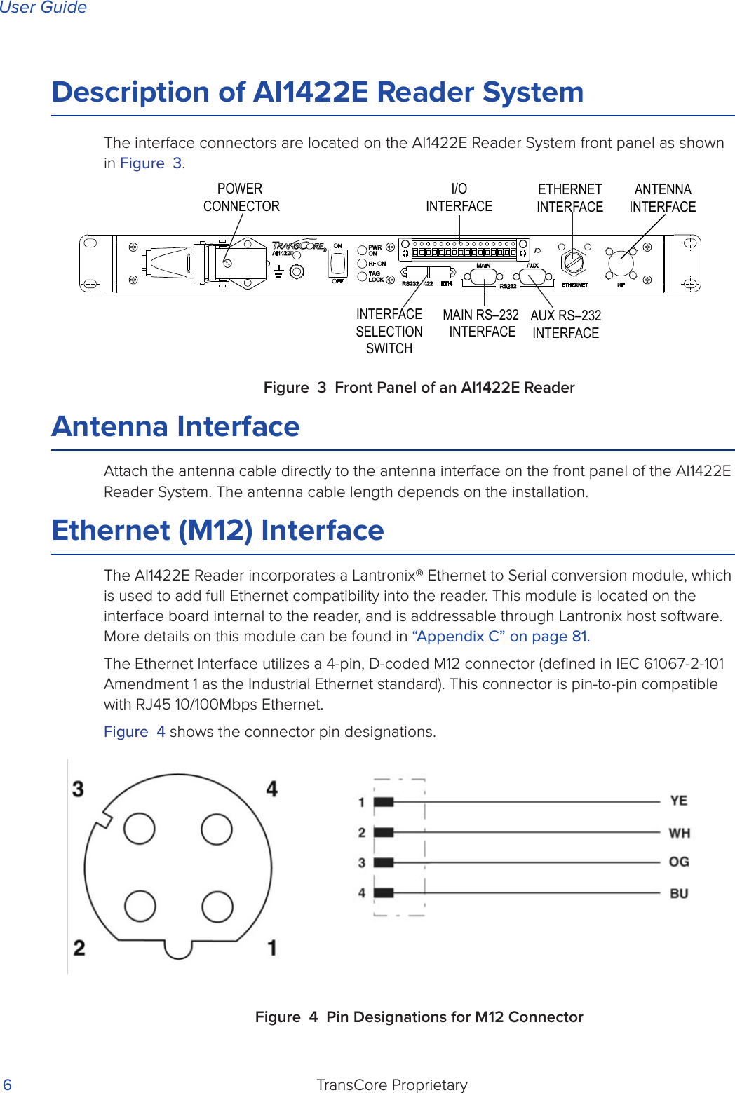
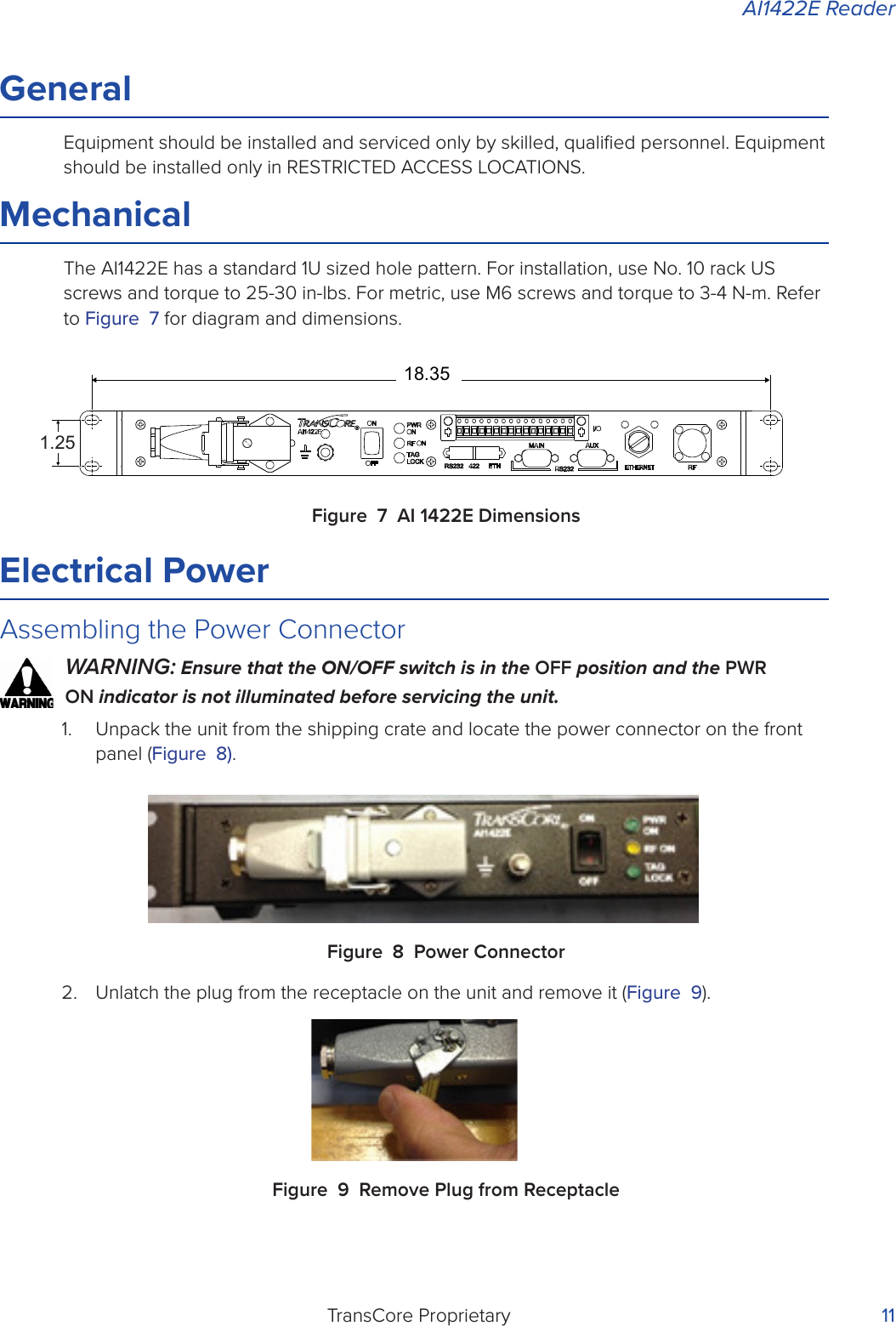
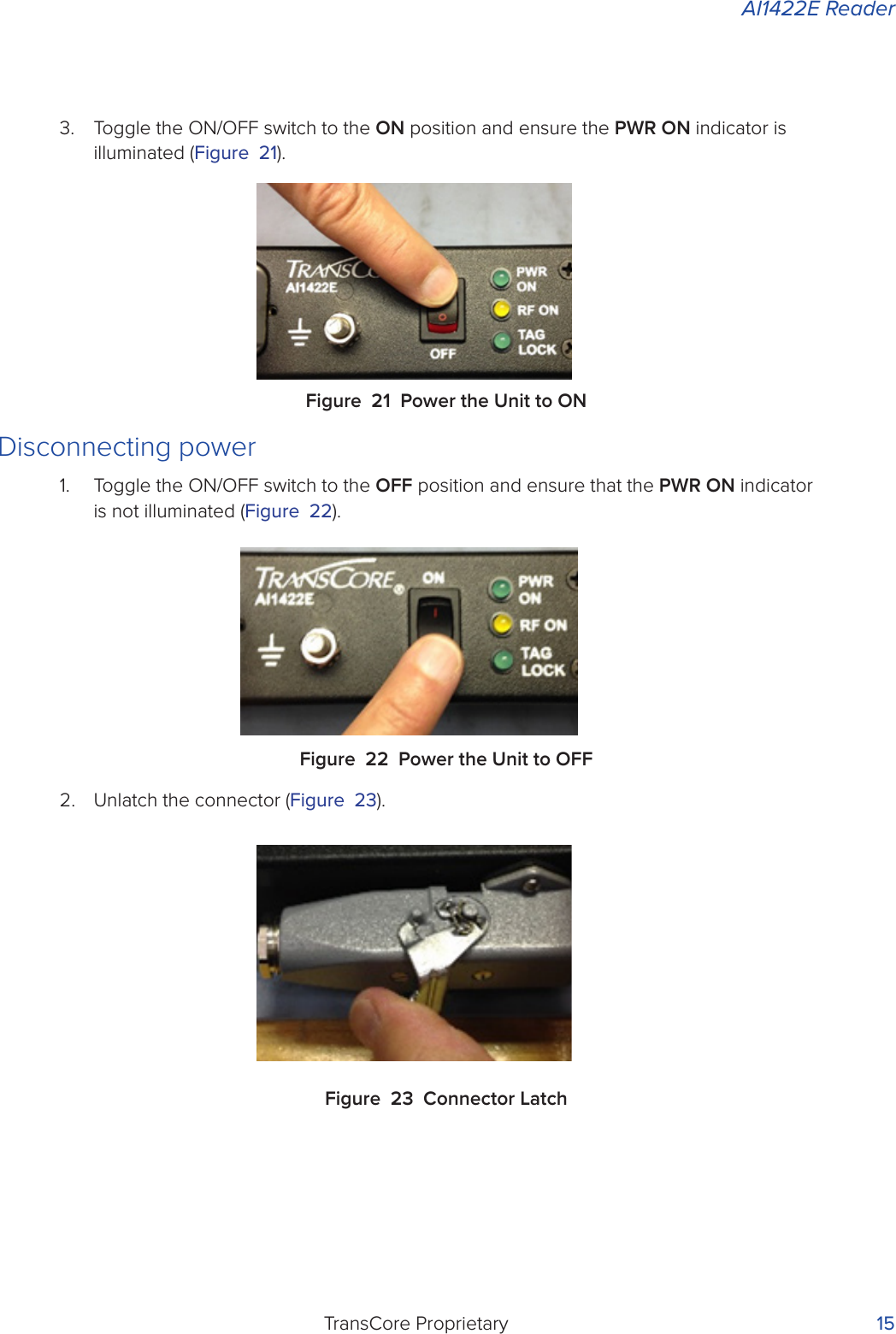
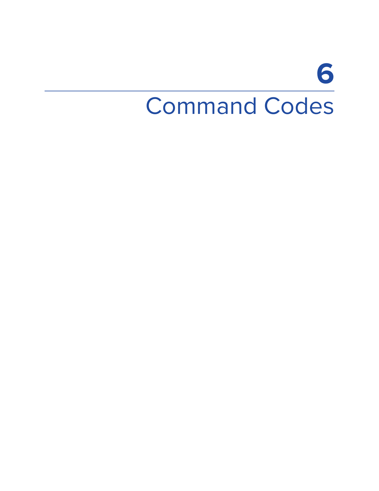
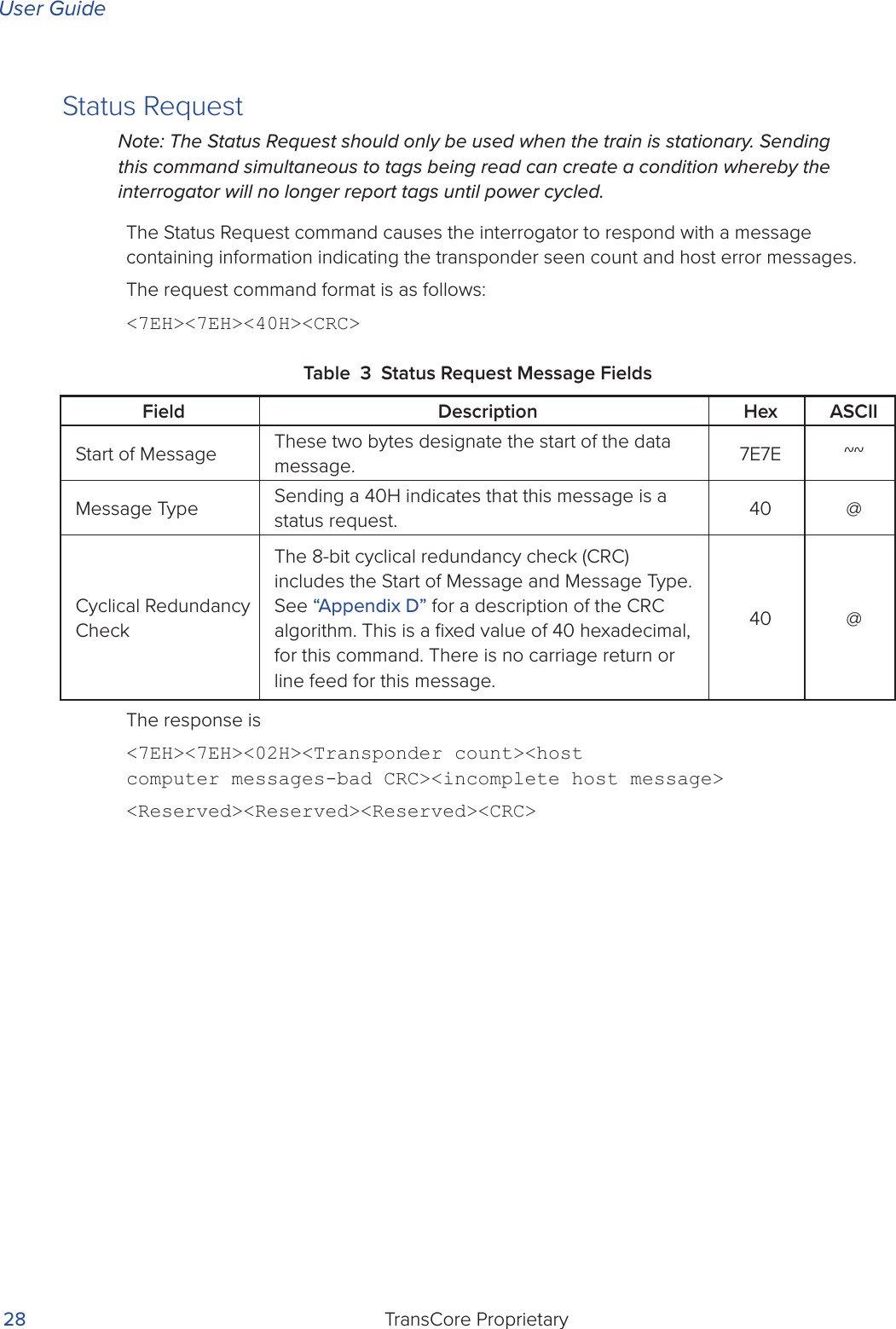
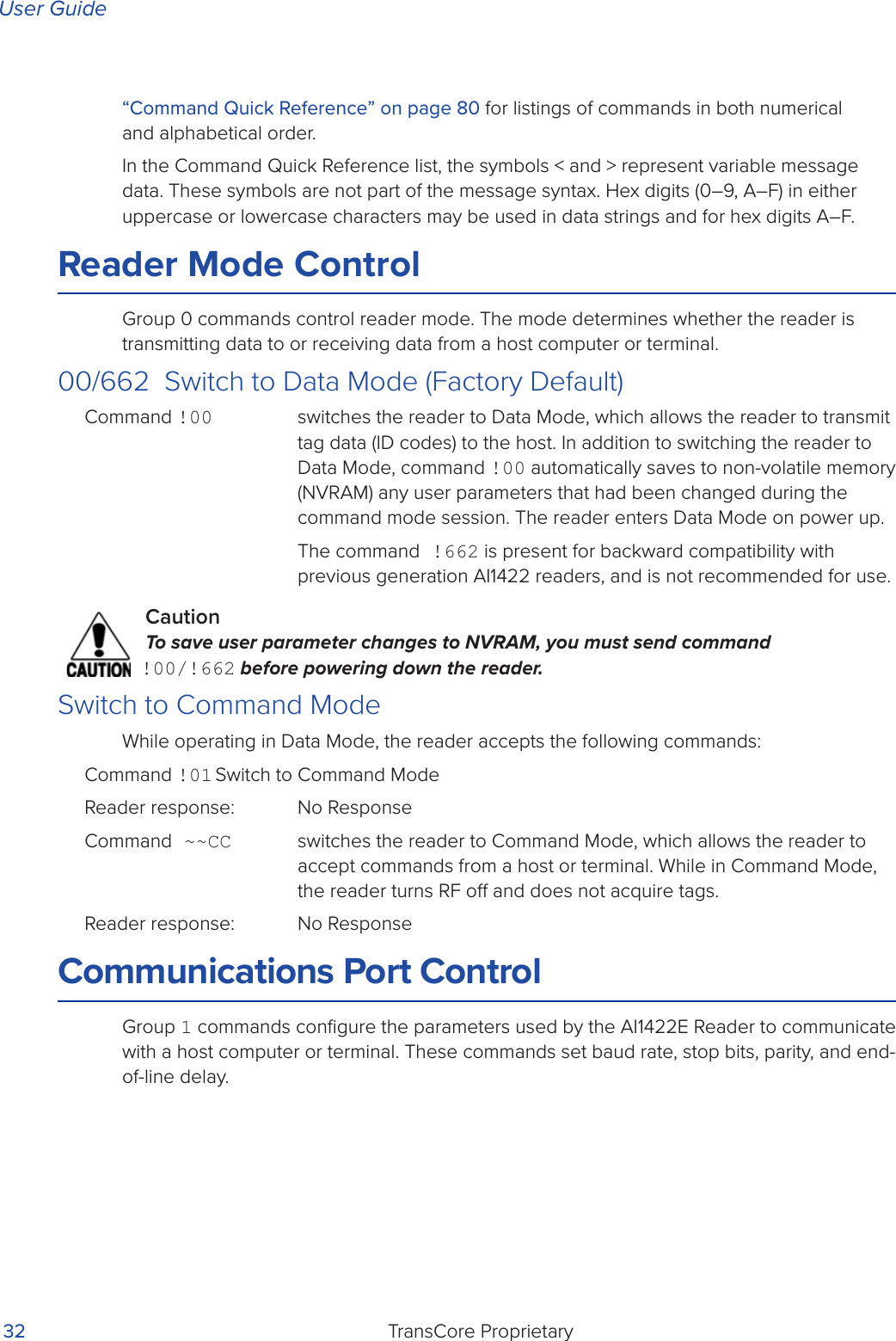
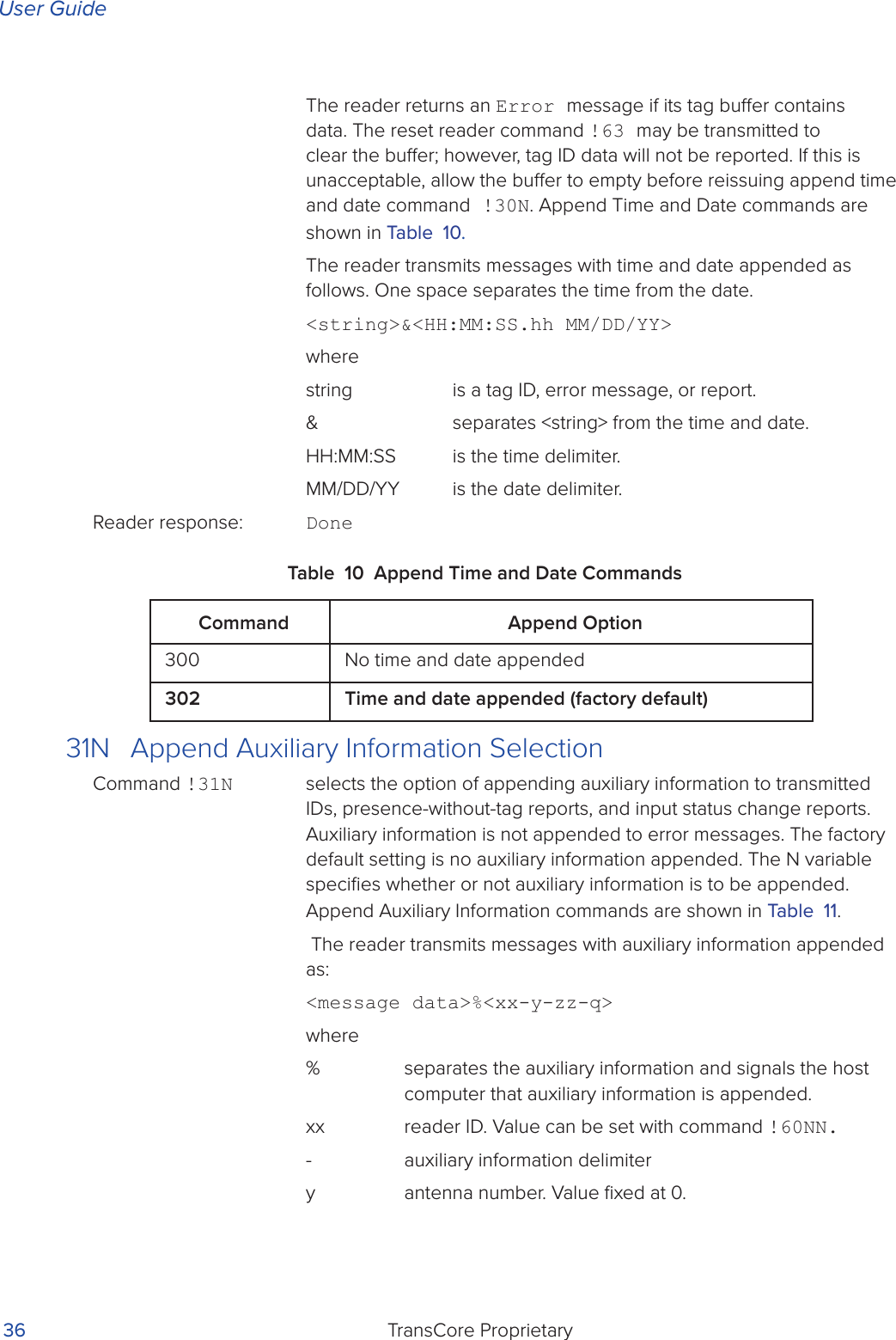
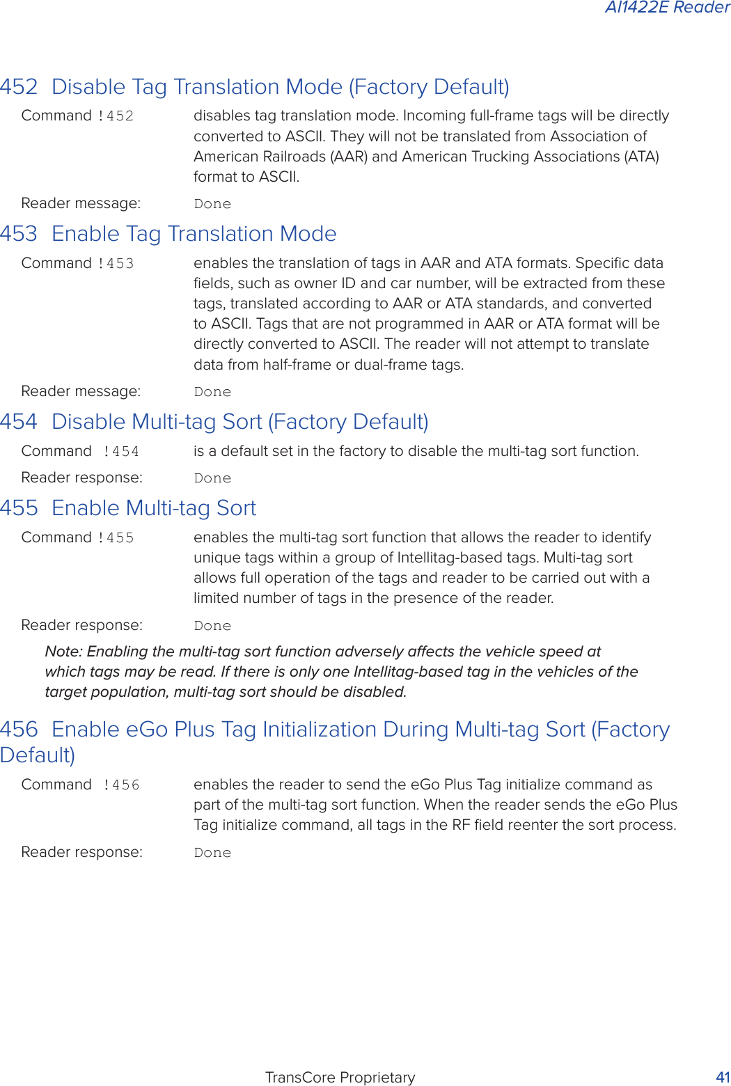
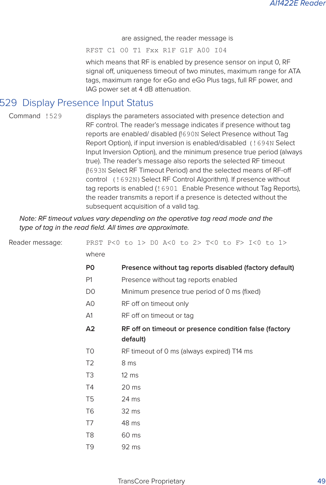
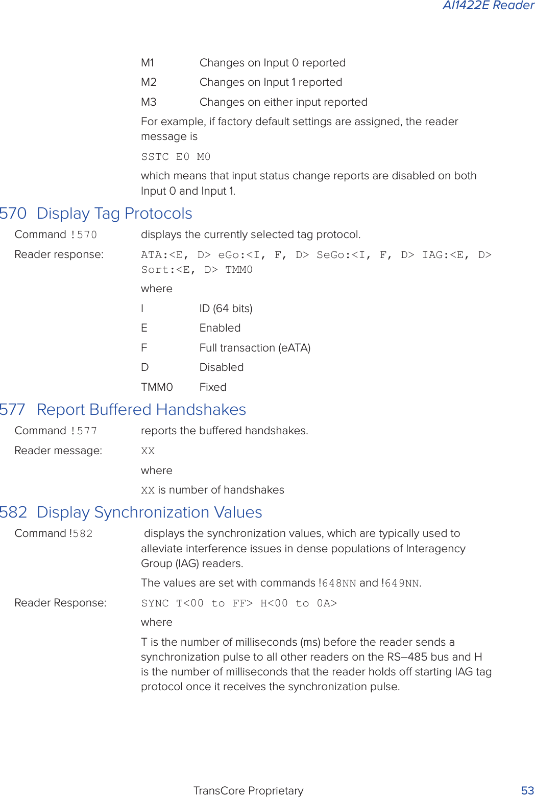
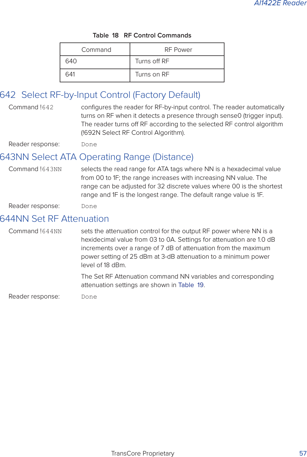
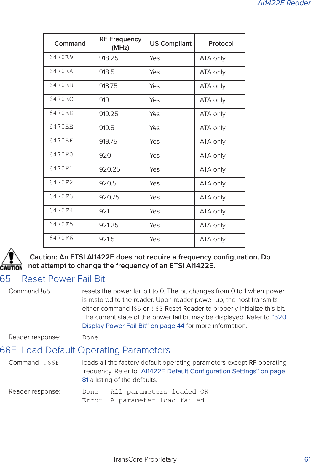
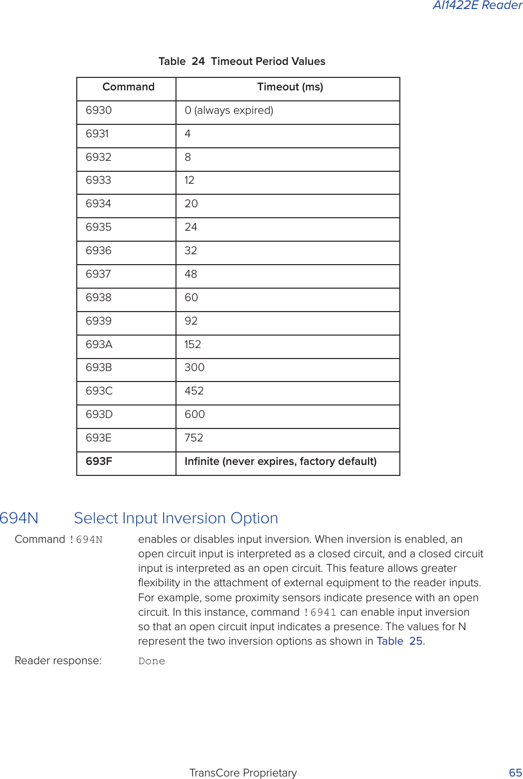
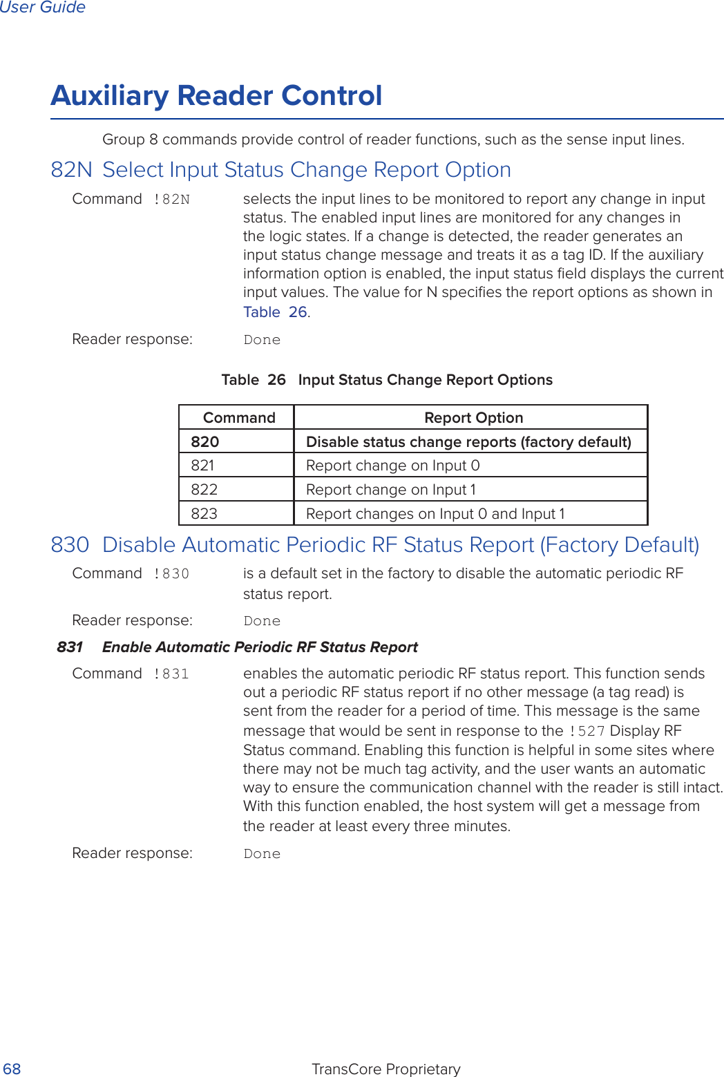
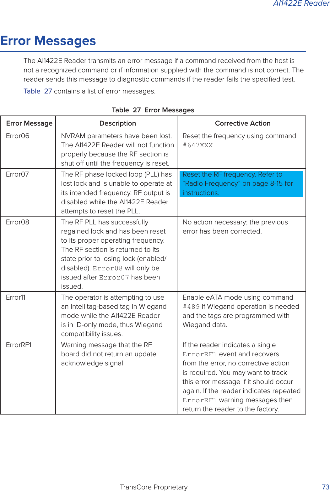
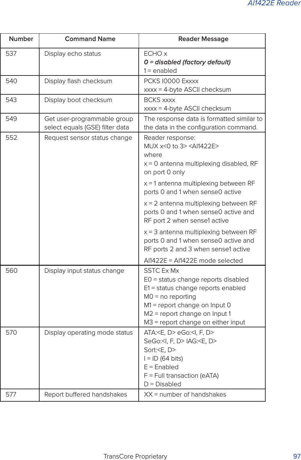
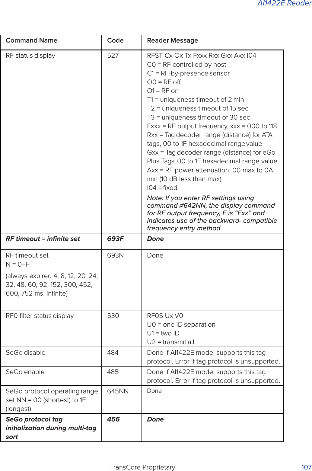
![AI1422E ReaderTransCore Proprietary 93Number Command Name Reader Message456 Enable SeGo protocol tag initialization during multi-tag sortDone457 Disable SeGo protocol tag initialization during multi-tag sortDone480 Disable ATA Done if AI1422E model supports this tag protocol. Error if tag protocol is unsupported.481 Enable ATA Done if AI1422E model supports this tag protocol. Error if tag protocol is unsupported.484 Disable SeGo Done if AI1422E model supports this tag protocol. Error if tag protocol is unsupported.485 Enable SeGo Done if AI1422E model supports this tag protocol. Error if tag protocol is unsupported.488 Disable eATA Done if AI1422E model supports this tag protocol. Error if tag protocol is unsupported.489 Enable eATA Done if AI1422E model supports this tag protocol. Error if tag protocol is unsupported.505 Display version Model [model] Ver [version no.] SN [serial no.]506 Display hardware configuration informationS...SS...S = ASCII string (maximum length of 20 characters)520 Display power fail bit PWRB Px R0 P0 = no power fail has occurred P1 = power fail has occurred R0 = not applicable to the AI1422E521 Display reader ID number RDID xx xx = 00–FF](https://usermanual.wiki/TransCore/AI1422E.User-Manual/User-Guide-3591270-Page-108.png)
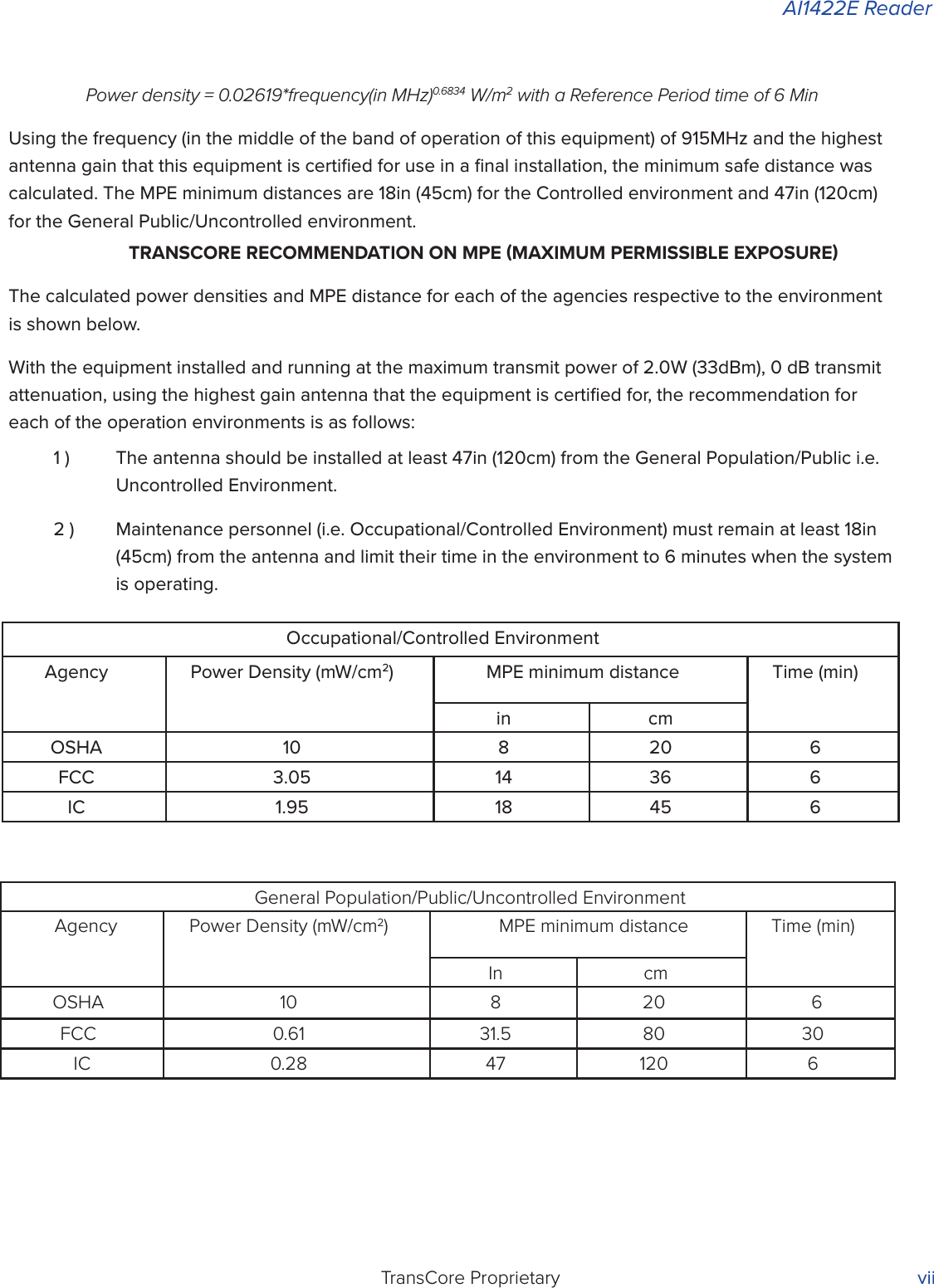
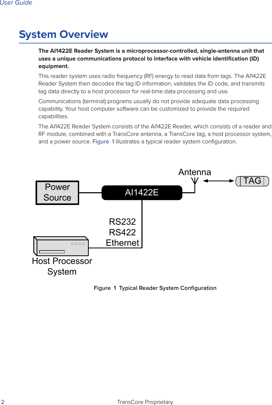
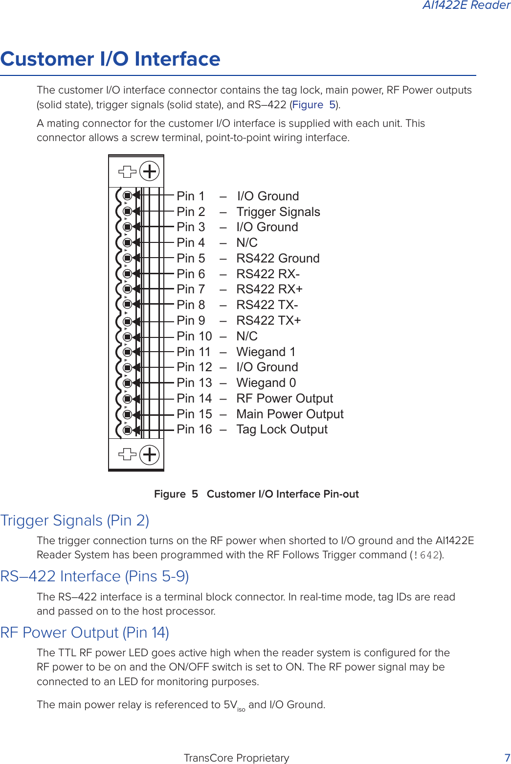
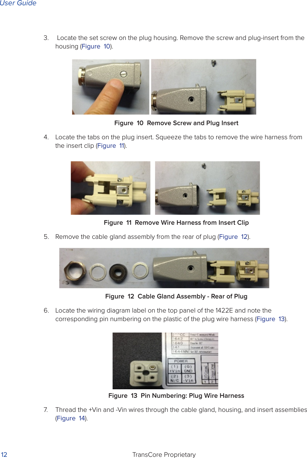
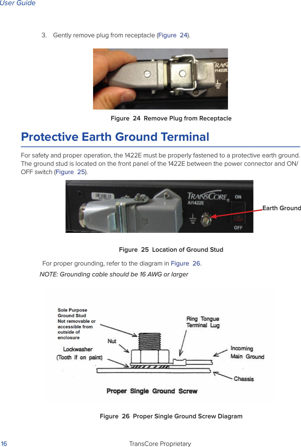
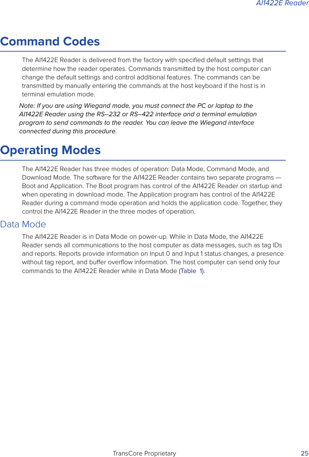
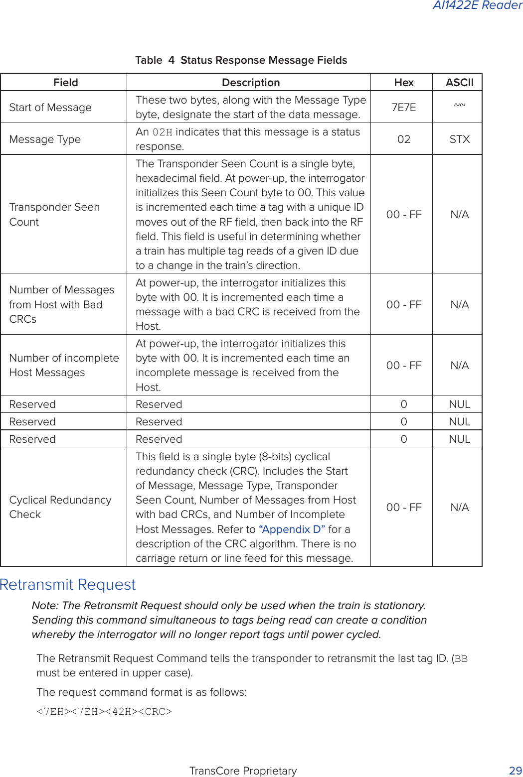
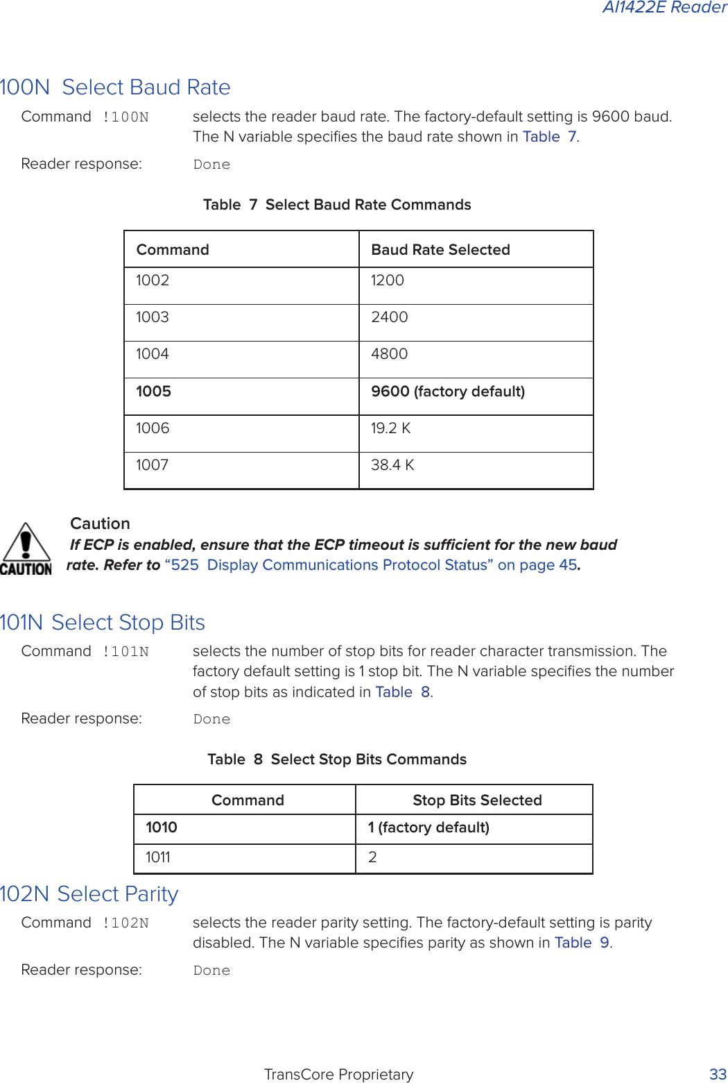
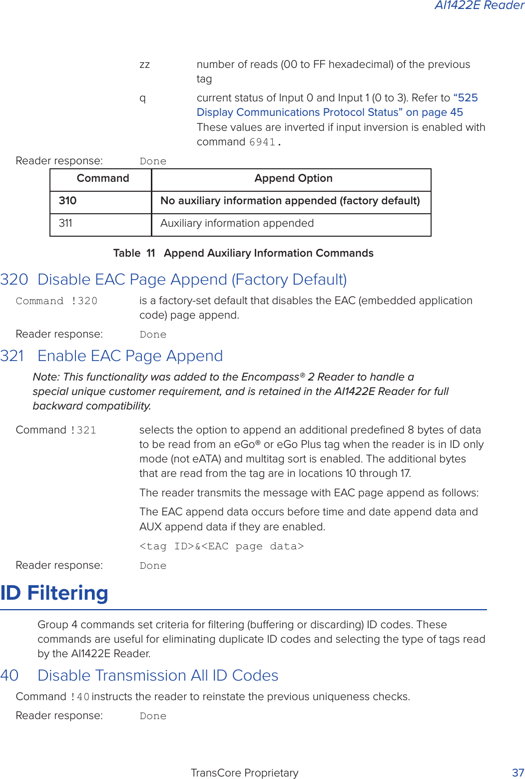
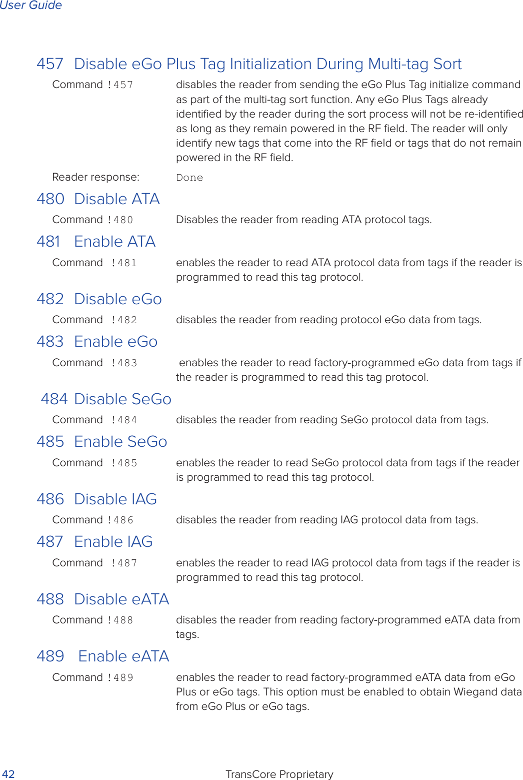
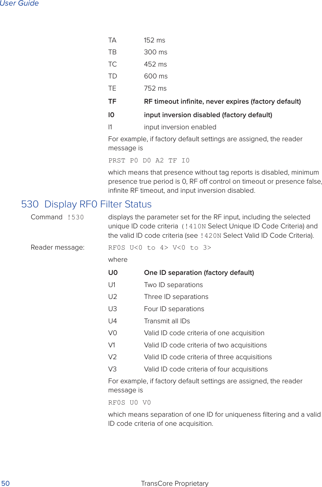
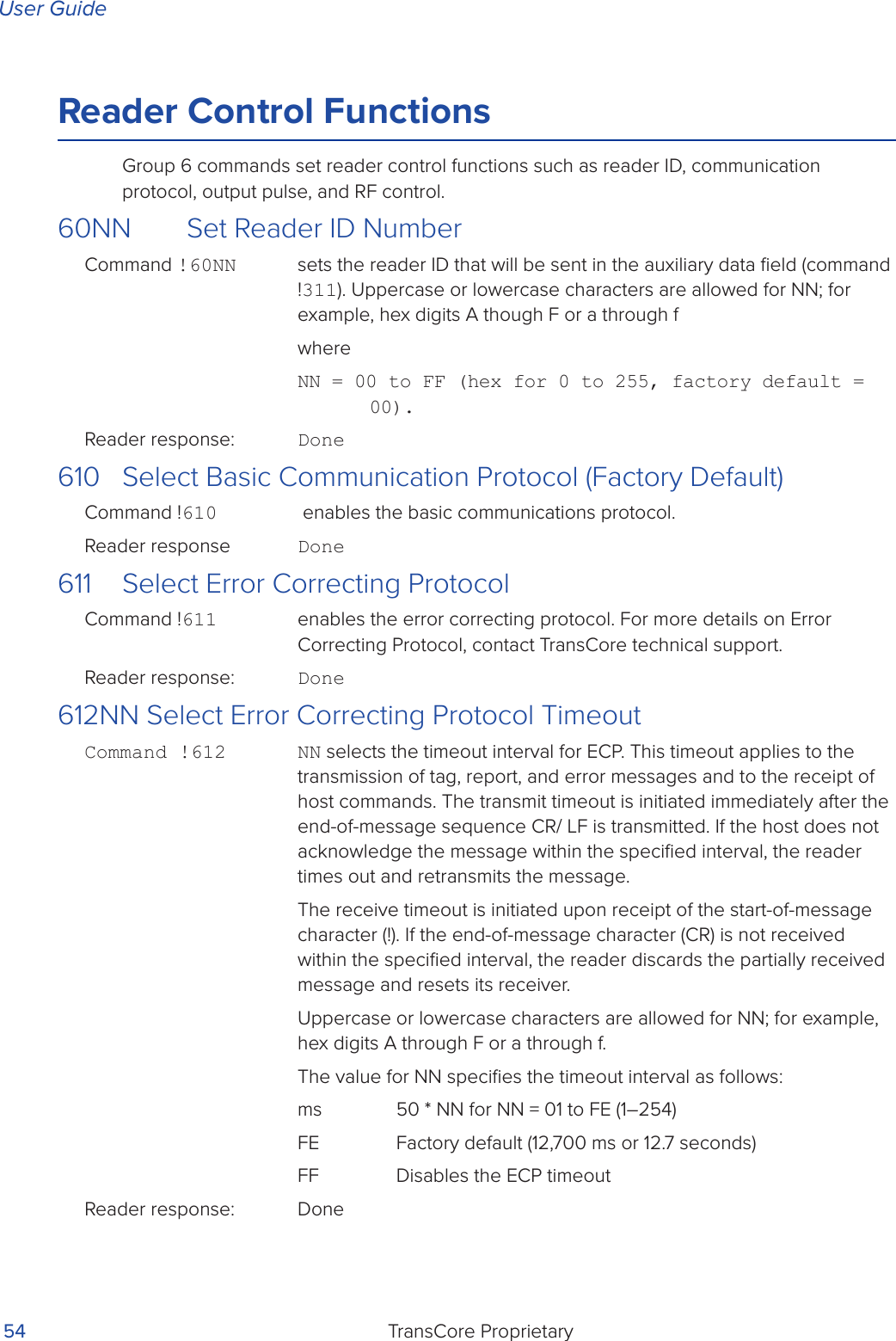
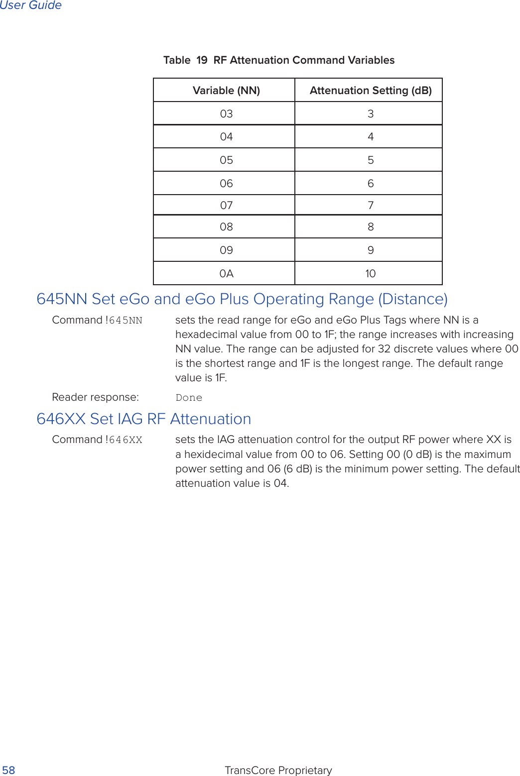
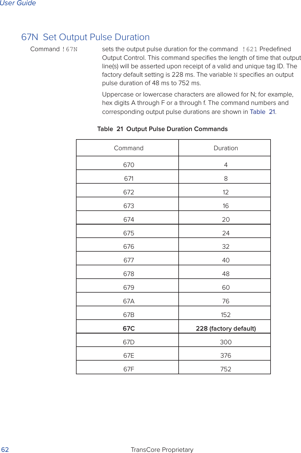
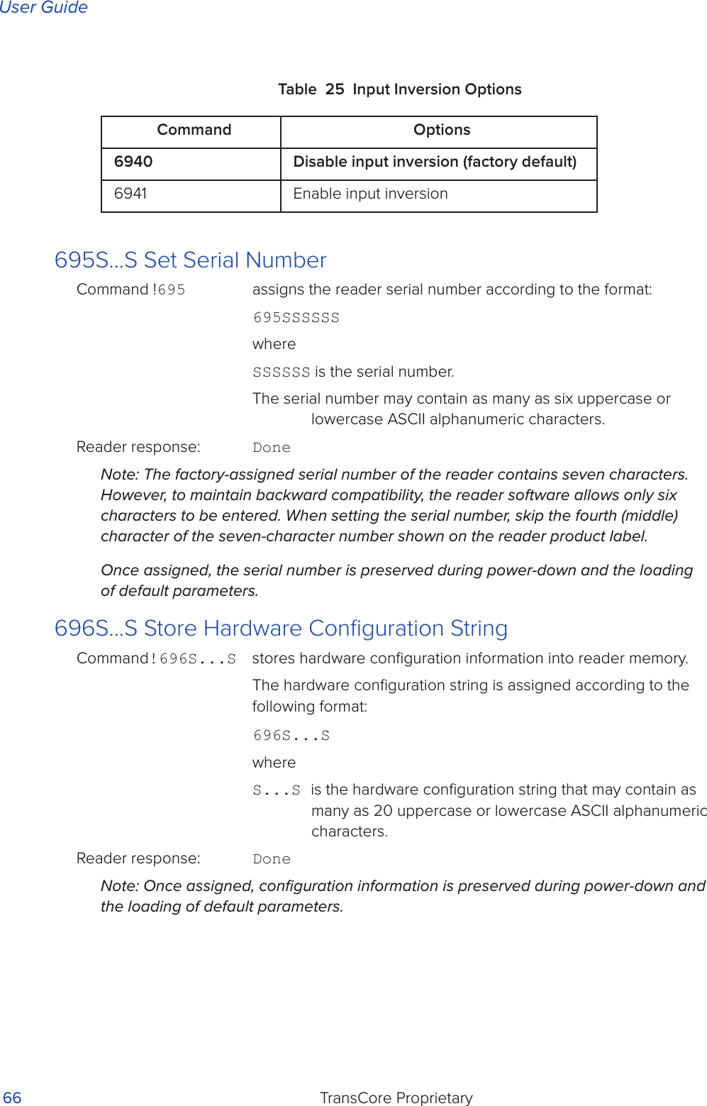
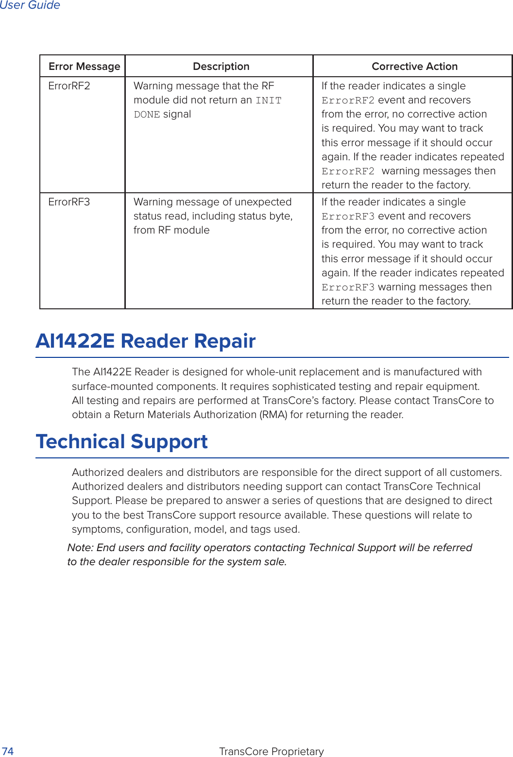
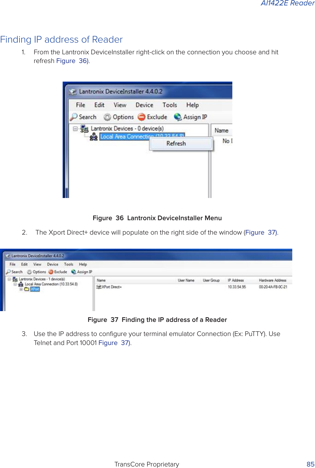
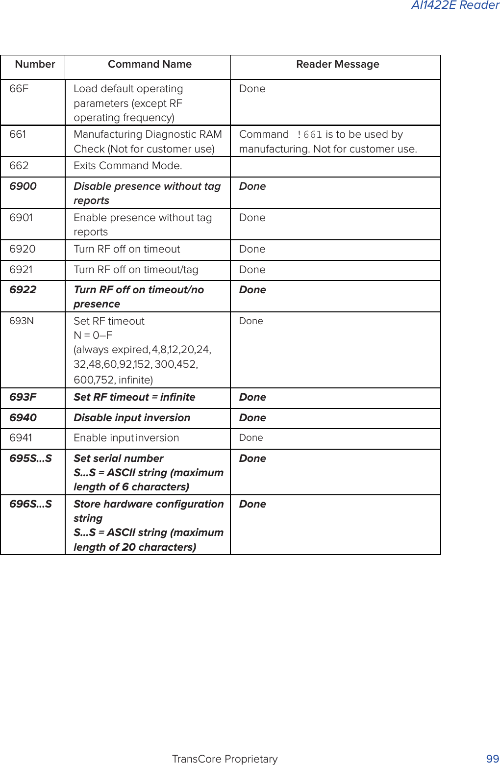
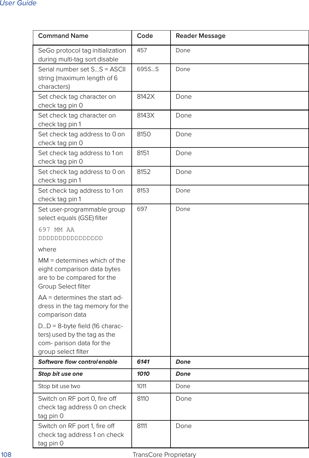
![User GuideTransCore Proprietary 98Number Command Name Reader Message60NN Set reader ID number NN = 00–FF(00 = factory default)Done610 Select basic protocol Done611 Select ECP protocol Done612NN Set ECP timeout NN = 01–FE (1–255) timeout = 50 ms * NN (if NN = FF, timeout is disabled)Done6140 Disable flow control Done6141 Enable software flow control Done6170 Disable echo Done6171 Enable echo Done63 Reset reader Model [model] Ver [version no.] SN [serial no.] Copyright [date] TransCore640 Turn o RF Done641 Turn on RF Done642 Select RF-by-input controlDone642NN Select RF operating frequency Done643NN Set ATA operating range (distance) NN = 00 (shortest) to 1F (longest) 1F = defaultDone644NN Set RF attenuation NN = 00 to 0A Done645NN Set SeGo protocol operating range (distance)NN = 00 (shortest) to 1F (longest)Done647XXX Select RF operating frequency from 860 to 930 in 250 kHz stepsXXX = 000 - 118 (hexadecimal)Done65 Reset power fail bit Done](https://usermanual.wiki/TransCore/AI1422E.User-Manual/User-Guide-3591270-Page-113.png)
![User GuideTransCore Proprietary 106Command Name Code Reader MessagePresence without tag reports disable6900 DonePresence without tag reports enable6901 DoneReader ID number display 521 RDID xx xx = 00–FFReader ID number set NN = 00-FF (00 = factory default)60NN DoneReader reset 63 Model [model] Ver [version no.] SN [serial no.] Copyright [date] TransCoreReport changes both 823 DoneRF attenuation set NN = 00 to 0A 644NN DoneRF o on timeout 6920 DoneRF o on timeout/no presence 6922 DoneRF o on timeout/tag 6921 DoneRF turn o 6400 DoneRF turn on 6401 DoneRF on by input control 641 DoneRF operating frequency from 860 to 930 in 250 kHz steps select XXX = 000 - 118 (hexadecimal)647XXX DoneRF operating frequency select 642NN Done](https://usermanual.wiki/TransCore/AI1422E.User-Manual/User-Guide-3591270-Page-121.png)
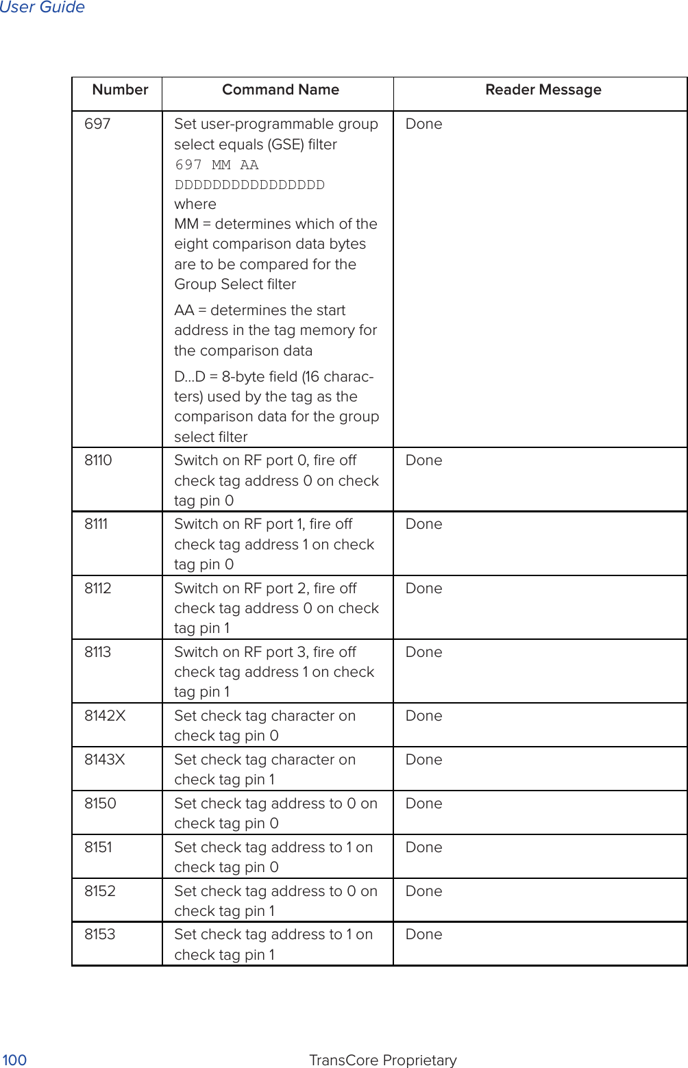
![AI1422E ReaderTransCore Proprietary 109Command Name Code Reader MessageSwitch on RF port 2, fire o check tag address 0 on check tag pin 18112 DoneSwitch on RF port 3, fire o check tag address 1 on check tag pin 18113 DoneTag ID separation select four 4103 DoneTag ID separation select one 4100 DoneTag ID separation select three 4102 DoneTag ID separation select two 4101 DoneTag translation mode status display534 TT <0 to 1>0 = tag translation mode disabled1 = tag translation mode enabledTime and date appended 302 DoneTime and date display 22 Time and dateTime and date not appended 300 DoneTime set 20 DoneUniqueness reset 440 DoneUniqueness time-out set to 2 minutes441 DoneUniqueness time-out set to 15 seconds442 DoneUniqueness time-out set to 30 seconds443 DoneValid ID code select four 4203 DoneValid ID code select one 4200 DoneValid ID code select three 4202 DoneValid ID code select two 4201 DoneVersion display 505 Model [model]Ver [ver no.] SN [serial no.]Command Name Code Reader MessageSeGo protocol tag initialization during multi-tag sort disable457 DoneSerial number set S...S = ASCII string (maximum length of 6 characters)695S...S DoneSet check tag character on check tag pin 08142X DoneSet check tag character on check tag pin 18143X DoneSet check tag address to 0 on check tag pin 08150 DoneSet check tag address to 1 on check tag pin 08151 DoneSet check tag address to 0 on check tag pin 18152 DoneSet check tag address to 1 on check tag pin 18153 DoneSet user-programmable group select equals (GSE) filter697 MM AA DDDDDDDDDDDDDDDDwhereMM = determines which of the eight comparison data bytes are to be compared for the Group Select filterAA = determines the start ad- dress in the tag memory for the comparison dataD...D = 8-byte field (16 charac- ters) used by the tag as the com- parison data for the group select filter697 DoneSoftware flow control enable 6141 DoneStop bit use one 1010 DoneStop bit use two 1011 DoneSwitch on RF port 0, fire o check tag address 0 on check tag pin 08110 DoneSwitch on RF port 1, fire o check tag address 1 on check tag pin 08111 Done](https://usermanual.wiki/TransCore/AI1422E.User-Manual/User-Guide-3591270-Page-124.png)