TransCore AI1422E Location Monitoring Services Transmitter User Manual
TransCore Location Monitoring Services Transmitter
Contents
- 1. Users Manual
- 2. User Manual
User Manual
1422E Reader
User Guide
Trusted Transportation Solutions
16-0058-001 Rev B (X3) 9/17
Purpose of This Guide
This user guide is intended for skilled personnel (including trained technicians and
engineers) to provide information for initializing the AI1422E Reader System. This
guide provides on-site test procedures useful in troubleshooting, as well as AI1422E
command codes and information on character translation.

TransCore Proprietary ii
User Guide
Information in this document is subject to change and does not represent a commitment on the part of
TransCore, LP.
© 2017 TransCore, LP. All rights reserved. TRANSCORE, AMTECH, EGO, and ENCOMPASS are
registered
trademarks and are used under license. All other trademarks are the property of their respective
owners.
Contents are subject to change. Printed in the U.S.A.
For further information, contact:
TransCore
8600 Jeerson Street NE
Albuquerque, New Mexico 87113 USA
TransCore Technical Support
Web: www.transcore.com/rfidsupport
Phone: (505) 856-8007
Lantronix ® Technical Support (Ethernet Support)
Web: www.lantronix.com/support/
Phone: (949) 453-7198

TransCore Proprietary iii
AI1422E Reader
Licensing Requirements
To operate a radio frequency (RF) system in a given country, the user must first obtain permission from the
regulatory agency that controls radio operations in that country. Most countries require type and safety
approval, as well as licensing for RF transmitters. Users in all countries should check with the appropriate
local authorities for licensing requirements.
U.S. Licensing
This AI1422E Reader System requires an FCC Part 90 license to operate in the U.S. The
authorized frequency bands in the U.S. are 902 to 904 MHz and 909.75 to 921.75 MHz.
The user is responsible for filing the FCC license according to FCC regulations. Access the
FCC Web site at https://www.fcc.gov/licensing-databases/forms or at wireless.fcc.gov/index.
htm?job=online_filing to obtain additional information concerning licensing requirements.
An FCC license provides the user with the legal authorization to operate the RFID systems on the
licensed frequencies at the site specified in the license. Only an authorized installer or service
technician can set the frequency for the AI1422E Reader System to that specified in the FCC site
license.
The FCC license also provides the user with protection and authorization to maintain the system
should any other RFID be used in the licensed area after the AI1422E Reader System is installed.

TransCore Proprietary iv
User Guide
WARNING TO USERS IN THE UNITED STATES
FEDERAL COMMUNICATIONS COMMISSION FCC
LOCATION AND MONITORING SERVICE STATEMENT
47 CFR §90.351
NOTE: The user is required to obtain a Part 90 site license from the Federal Communications Commission
(FCC) to operate this radio frequency identification (RFID) device in the United States. The FCC ID number is
FIHAI1422E. Access the FCC website at www.fcc.gov to obtain additional information concerning licensing
requirements.
NOTE: Users in all countries should check with the appropriate local authorities for licensing requirements.
FCC RADIO FREQUENCY INTERFERENCE STATEMENT
47 CFR §15.105A
NOTE: This equipment has been tested and found to comply with the limits for a Class A digital device
pursuant to Part 15 of the FCC rules. These limits are designed to provide reasonable protection against
harmful interference when the equipment is operated in a commercial environment. This equipment
generates, uses, and can radiate RF energy and may cause harmful interference to radio communications if
not installed and used in accordance with the instruction manual. Operating this equipment in a residential
area is likely to cause harmful interference, in which case, depending on the laws in eect, the user may be
required to correct the interference at their own expense.
NO UNAUTHORIZED MODIFICATIONS
47 CFR §15.21
CAUTION: This equipment may not be modified, altered, or changed in any way without permission.
Unauthorized modification may void the equipment authorization from the FCC and
will void the warranty.
USE OF SHIELDED CABLES AND GROUNDING
47 CFR §15.27A
NOTE: Shielded cables and earth grounding the unit is recommended for this equipment to comply with FCC
regulations.
TRANSCORE, LP
USA

TransCore Proprietary v
AI1422E Reader
AVERTISSEMENT À L’ATTENTION DES
UTILISATEURS AUX ÉTATSUNIS
DÉCLARATION 47 CFR §90.351 CODE DES
RÈGLEMENTS FÉDÉRAUX DE LA FEDERAL
COMMUNICATIONS COMMISSION FCC SUR LES
SERVICES DE LOCALISATION ET DE CONTRÔLE
REMARQUE : L’utilisateur est tenu d’obtenir une licence d’utilisation sur site Partie 90 auprès de la Federal
Communications Commission (FCC) afin de pouvoir utiliser ce dispositif RFID (radio-identification) aux
États-Unis ou au Canada. Le numéro d’identification de la FCC est FIHAI1422E.Pour obtenir de plus amples
informations concernant les exigences relatives aux licences, prière de consulter le site web de la FCC à
www.fcc.gov.
REMARQUE : Il est recommandé à tous les utilisateurs, quel que soit leur pays, de consulter les autorités
locales compétentes sur les exigences de licence.
DÉCLARATION 47 CFR §15.105A DE LA FCC SUR
LES INTERFÉRENCES DES FRÉQUENCES RADIO
REMARQUE : Cet appareil a été testé et déclaré conforme à la catégorie d’un appareil numérique de
classe A en accord avec la partie 15 des directives de la FCC. Ces normes visent à assurer une protection
raisonnable contre les interférences nuisibles lorsque l’appareil est utilisé dans un environnement
commercial. Cet appareil génère, utilise et peut émettre de l’énergie RF et peut être à l’origine
d’interférences nuisibles aux communications radio s’il n’est pas installé et utilisé en suivant les directives
du manuel d’instructions. Si cet appareil est utilisé dans une zone résidentielle, il est probable qu’il cause
des interférences nuisibles. Dans ce cas, l’utilisateur pourrait être amené à remédier aux interférences à ses
propres frais, selon les lois du pays en vigueur.
AUCUNE MODIFICATION NON AUTORISÉE
47 CFR §15.21
MISE EN GARDE : Il est interdit de modifier, d’altérer ou d’apporter des changements à cet appareil de
quelque manière que ce soit sans autorisation. Toute modification non autorisée peut annuler
l’autorisation d’utilisation accordée par la FCC et annulera la garantie.
UTILISATION DE CÂBLES BLINDÉS ET MISE À LA TERRE
47 CFR §15.27A
REMARQUE : Il est recommandé d’utiliser des câbles blindés et une mise à la terre avec cet appareil afin de
répondre aux réglementations de la FCC
TRANSCORE, LP
ÉTATSUNIS
TransCore Proprietary vi
User Guide
RADIO FREQUENCY HEALTH LIMITS FOR AI1422 READER
USING AN EXTERNAL ANTENNA IN FREQUENCY BAND
OF 902.25 TO 903.75 AND 910.00 TO 921.50 MHZ
Several agencies (OSHA, FCC, IC) have environmental guidelines regulating maximum permissible exposure
(MPE) or “safe” exposure levels that this product falls under. To ensure that proper safety guideline for
the end users of this product, i.e. Occupational (Controlled) and General Population/Public (Uncontrolled),
the recommended levels for each of the agencies are presented in the next sections with TransCore’s
recommendations for safety in the last section.
OSHA OCCUPATIONAL SAFETY AND HEALTH ADMINISTRATION
OSHA (an agency of The United States of America) legislates in the Code of Federal Regulations (CFR)
Title 29 Part 1910 Subpart G 1910.97 titled “Nonionizing radiation”, a maximum safe exposure limit of 10
milliwatts per square centimeter (mW/cm2) during any 0.1-hour period (i.e. 6 minutes). Using the frequency
(in the middle of the band of operation of this equipment) of 915 MHz and the highest antenna gain that
this equipment is certified for use in a final installation, the minimum safe distance was calculated to be 8in
(20cm).
FCC FEDERAL COMMUNICATION COMMISSION
FCC (an agency of The United States of America) legislates in the Code of Federal Regulations (CFR) Title 47
Chapter I Subchapter A Part 1 Subpart I Section 1.1310 titled “Radiofrequency radiation exposure limits” that
the maximum permissible exposure (MPE) is the following:
Occupational/Controlled Exposure
Power density = frequency(in MHz)/300 mW/cm2 with an Averaging time of 6 Min
General Population/Uncontrolled Exposure
Power density = frequency(in MHz)/1500 mW/cm2 with an Averaging time of 30 Min
Using the frequency (in the middle of the band of operation of this equipment) of 915MHz and the highest
antenna gain that this equipment is certified for use in a final installation, the minimum safe distance was
calculated. The MPE minimum distances are 14in (36cm) for the Occupational/Controlled environment, and
31.5in (80.5cm) for the General Population/Uncontrolled environment.
INDUSTRY CANADA INNOVATION, SCIENCE AND ECONOMIC DEVELOPMENT CANADA
Industry Canada (a Department of the Government of Canada) sets out the requirements in Radio Standards
Specification RSS-102, Issue 5 guidelines, recommending a maximum safe power density in W/m2. Thus, the
maximum permissible exposure for general population/uncontrolled exposure at 915MHz is 2.77 W/m2. The
average time is 6 minutes. The maximum permissible exposure (MPE) is the following:
Controlled Environment
Power density = 0.6455*frequency(in MHz)0.5 W/m2 with a Reference Period time of 6 Min
General Public/Uncontrolled Environment

TransCore Proprietary vii
AI1422E Reader
Power density = 0.02619*frequency(in MHz)0.6834 W/m2 with a Reference Period time of 6 Min
Using the frequency (in the middle of the band of operation of this equipment) of 915MHz and the highest
antenna gain that this equipment is certified for use in a final installation, the minimum safe distance was
calculated. The MPE minimum distances are 18in (45cm) for the Controlled environment and 47in (120cm)
for the General Public/Uncontrolled environment.
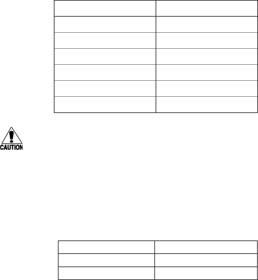
TRANSCORE RECOMMENDATION ON MPE MAXIMUM PERMISSIBLE EXPOSURE
The calculated power densities and MPE distance for each of the agencies respective to the environment
is shown below.
With the equipment installed and running at the maximum transmit power of 2.0W (33dBm), 0 dB transmit
attenuation, using the highest gain antenna that the equipment is certified for, the recommendation for
each of the operation environments is as follows:
1 ) The antenna should be installed at least 47in (120cm) from the General Population/Public i.e.
Uncontrolled Environment.
2 ) Maintenance personnel (i.e. Occupational/Controlled Environment) must remain at least 18in
(45cm) from the antenna and limit their time in the environment to 6 minutes when the system
is operating.
Occupational/Controlled Environment
Agency Power Density (mW/cm2) MPE minimum distance Time (min)
in cm
OSHA 10 8 20 6
FCC 3.05 14 36 6
IC 1.95 18 45 6
General Population/Public/Uncontrolled Environment
Agency Power Density (mW/cm2) MPE minimum distance Time (min)
In cm
OSHA 10 8 20 6
FCC 0.61 31.5 80 30
IC 0.28 47 120 6
TransCore Proprietary viii
User Guide
LIMITES D’EXPOSITION AUX RADIOFRÉQUENCES POUR LE LECTEUR AI1422
UTILISANT UNE ANTENNE EXTERNE SUR LA BANDE
DE FRÉQUENCES DE 902.25 À 903.75 ET DE 910.00 À 921.50 MHZ
Plusieurs organismes (OSHA, FCC, IC) publient des directives environnementales qui recommandent des
limites d’exposition maximale autorisée (normes MPE) ou des niveaux d’exposition «sûrs» auxquels cet
appareil se conforme. Pour faire en sorte que chaque utilisateur final ait connaissance des directives de
sécurité qui le concerne, que ce soit dans son travail (accès contrôlé) ou pour la population générale/le
grand public (accès non contrôlé), TransCore présente les niveaux recommandés par chaque organisme
dans ses recommandations sécuritaires détaillées dans la dernière section.
OSHA OCCUPATIONAL SAFETY AND HEALTH ADMINISTRATION
Dans le Code des réglementations fédérales (CFR), Titre 29, Partie 1910, Sous-partie G 1910.97, intitulée
«Nonionizing radiation» (Rayonnements non ionisants), l’OSHA (organisme américain) recommande un
plafond d’exposition maximale de 10 milliwatts par centimètre carré (mW/cm2) pendant une période de
0,1 heure (soit 6 minutes). En utilisant la fréquence de 915 MHz (milieu de la bande de fréquences de cet
appareil) et le gain d’antenne maximal pour lequel cet appareil a reçu une certification d’utilisation dans une
installation finale, la distance minimale sécuritaire est de 20 cm (8 po).
FCC FEDERAL COMMUNICATION COMMISSION
Dans le Code des réglementations fédérales (CFR), Titre 47, Chapitre I, Sous-chapitre A, Partie 1, Sous-partie
I, Section 1.1310 intitulée «Radiofrequency radiation exposure limits» (Limites d’exposition aux rayonnements
de radiofréquence), la FCC (organisme américain) établit les limites d’exposition maximale autorisée (normes
MPE) comme suit :
Exposition professionnelle/contrôlée
Densité de puissance = fréquence (en MHz)/300 mW/cm2 avec une durée moyenne de 6 min.
Exposition de la population générale/non contrôlée
Densité de puissance = fréquence (en MHz)/1500 mW/cm2 avec une durée moyenne de 30 min.
En utilisant la fréquence de 915 MHz (milieu de la bande de fréquences de cet appareil) et le gain
d’antenne maximal pour lequel cet appareil a reçu une certification d’utilisation dans une installation finale,
la distance minimale sécuritaire est la suivante : les distances MPE minimales sont de 36 cm (14 po) pour
l’environnement professionnel/contrôlé et de 80,5 cm (31,5 po) pour la population générale/environnement
non contrôlé.
INDUSTRIE CANADA INNOVATION, SCIENCES ET DÉVELOPPEMENT ÉCONOMIQUE CANADA
Le Cahier des charges sur les normes radioélectriques 102, 5e édition, d’Industrie Canada (un ministère
du Gouvernement du Canada) établit des recommandations pour une densité de puissance maximale
sécuritaire en W/m2. Ainsi, l’exposition maximale admissible pour la population générale/non contrôlée à
915 MHz est calculée à 2,77 W/m2. La durée moyenne est de 6 minutes. Les limites d’exposition maximale
autorisée (normes MPE) sont les suivantes :

TransCore Proprietary ix
AI1422E Reader
Environnement contrôlé
Densité de puissance = 0,6455*fréquence (en MHz)0,5 W/m2 avec une durée de référence de 6 min.
Grand public/environnement non contrôlé
Densité de puissance = 0,02619*fréquence (en MHz)0,6834 W/m2 avec une durée de référence de 6 min.
En utilisant la fréquence de 915 MHz (milieu de la bande de fréquences de cet appareil) et le gain
d’antenne maximal pour lequel cet appareil a reçu une certification d’utilisation dans une installation finale,
la distance minimale sécuritaire est la suivante : les distances MPE minimales sont de 45 cm (18 po) pour
l’environnement professionnel/contrôlé et de 120 cm (47 po) pour le grand public/environnement non
contrôlé.
RECOMMANDATIONS DE TRANSCORE SUR LES LIMITES D’EXPOSITION MAXIMALE AUTORISÉE
NORMES MPE
Les densités de puissance et la distance MPE calculées par chaque organisme pour un
environnement donné sont présentées ci-dessous.
Exposition professionnelle/environnement contrôlé
Organisme Densité de puissance (mW/
cm2)
Distance MPE minimale Durée (en
min.)
po cm
OSHA 10 8 20 6
FCC 3,05 14 36 6
IC 1,95 18 45 6
Population générale/environnement non contrôlé
Organisme Densité de puissance (mW/
cm2)
Distance MPE minimale Durée (en
min.)
po cm
OSHA 10 8 20 6
FCC 0,61 31,5 80 30
IC 0,28 47 120 6
Avec l’appareil installé et fonctionnant à la puissance de transmission maximale de 2,0 W (33 dBm), 0 dB
d’atténuation de transmission, et en utilisant le gain d’antenne maximal pour lequel l’appareil a reçu une
certification, les recommandations pour chaque environnement d’exploitation sont les suivantes :
1 ) L’antenne devrait être installée à au moins 120 cm (47 po) de la population générale/du grand
public, c’est-à-dire d’un environnement non contrôlé.
2 ) Le personnel d’entretien (c’est-à-dire dans un environnement professionnel/contrôlé) doit
rester à au moins 45 cm (18 po) de l’antenne et limiter son temps d’exposition à 6 minutes
lorsque l’appareil est en fonctionnement.

User Guide
TransCore Proprietary x
Table of Contents
Purpose of This Guide ............................................. i
Licensing Requirements............................................iii
System Overview
System Overview .................................................2
Transponder Interrogator ...........................................3
Interface Connections
Description of AI1422E Reader System ...............................6
Antenna Interface .................................................6
Ethernet (M12) Interface............................................6
Customer I/O Interface.............................................7
Power Connector .................................................8
Interface Selection Switch ..........................................8
Main RS–232 Interface.............................................8
Aux RS–232 Interface .............................................9
Installation Instructions
General ......................................................... 11
Mechanical ..................................................... 11
Electrical Power.................................................. 11
Installing Wires into Connector.....................................14
Protective Earth Ground Terminal ..................................16
System Test Procedures
System Test Procedures...........................................18
Required Tools and Equipment .....................................18
Testing Basic Operation ...........................................18
Reading the Tag..................................................19
Communications Protocols
Communications Protocols ........................................22
Basic Protocol ...................................................22
Command Codes
Command Codes.................................................25
AI1422E Reader
TransCore Proprietary xi
Operating Modes ................................................25
Command List ...................................................31
Reader Mode Control .............................................32
Communications Port Control......................................32
Real-time Clock ..................................................34
Append Information ..............................................35
ID Filtering ......................................................37
Reader Status....................................................43
Reader Control Functions .........................................54
Auxiliary Reader Control ..........................................68
Troubleshooting and Maintenance
Required Tools and Equipment .....................................71
Troubleshooting .................................................71
Error Messages ..................................................73
AI1422E Reader Repair............................................74
Technical Support ................................................74
Character Conversion
Appendix A......................................................76
Technical Specifications
Appendix B......................................................78
Lantronix® Ethernet Module Configuration
Appendix C......................................................81
Interface through Ethernet Port ....................................82
Command Quick Reference
Appendix D.....................................................88

User Guide
TransCore Proprietary xii
List of Figures
Figure 1 Typical Reader System Configuration . . . . . . . . . . . . .2
Figure 2 Antenna-to-Tag Centerline Tolerance . . . . . . . . . . . . . .4
Figure 3 Front Panel of an AI1422E Reader . . . . . . . . . . . . . . .6
Figure 4 Pin Designations for M12 Connector . . . . . . . . . . . . .6
Figure 5 Customer I/O Interface Pin-out . . . . . . . . . . . . . . . .7
Figure 6 RS–232, DB–9 Interface Connector Pin-outs. . . . . . . . .9
Figure 7 AI 1422E Dimensions . . . . . . . . . . . . . . . . . . . . . 11
Figure 8 Power Connector . . . . . . . . . . . . . . . . . . . . . . . 11
Figure 9 Remove Plug from Receptacle . . . . . . . . . . . . . . . . 11
Figure 10 Remove Screw and Plug Insert . . . . . . . . . . . . . . . 12
Figure 11 Remove Wire Harness from Insert Clip . . . . . . . . . . . 12
Figure 12 Cable Gland Assembly - Rear of Plug . . . . . . . . . . . 12
Figure 13 Pin Numbering: Plug Wire Harness . . . . . . . . . . . . . 12
Figure 14 Thread Wires Through Assembly . . . . . . . . . . . . . . 13
Figure 15 Insert Wires into Pins. . . . . . . . . . . . . . . . . . . . . 13
Figure 16 Insert Wire Harness into Insert Clip. . . . . . . . . . . . . 13
Figure 17 Reassemble and Tighten Set Screw . . . . . . . . . . . . 13
Figure 18 Reassemble Cable Gland Assembly . . . . . . . . . . . . 14
Figure 19 Power Switch . . . . . . . . . . . . . . . . . . . . . . . . . 14
Figure 20 Reinstall Power Connector . . . . . . . . . . . . . . . . . 14
Figure 21 Power the Unit to ON . . . . . . . . . . . . . . . . . . . . 15
Figure 22 Power the Unit to OFF. . . . . . . . . . . . . . . . . . . . 15
Figure 23 Connector Latch . . . . . . . . . . . . . . . . . . . . . . . 15
Figure 24 Remove Plug from Receptacle . . . . . . . . . . . . . . . 16
Figure 25 Location of Ground Stud . . . . . . . . . . . . . . . . . . 16
Figure 26 Proper Single Ground Screw Diagram. . . . . . . . . . . 16
Figure 27 Power Source Connections . . . . . . . . . . . . . . . . . 18
Figure 28 AI1422E Reader Mechanical Dimensions . . . . . . . . . 79
AI1422E Reader
TransCore Proprietary xiii
Figure 29 Install the Stand-alone DeviceInstaller. . . . . . . . . . . 82
Figure 30 Launch DeviceInstaller from the Start Menu . . . . . . . 82
Figure 31 Change IP Address and Submet Mask of NIC Card. . . . 83
Figure 32 Prompt if Computer has Multiple NIC cards . . . . . . . 83
Figure 33 NIC Card Options Screen . . . . . . . . . . . . . . . . . .84
Figure 34 Check for Updates Prompt . . . . . . . . . . . . . . . . . 84
Figure 35 Disable Firewall to Allow Access . . . . . . . . . . . . . . 84
Figure 36 Lantronix DeviceInstaller Menu . . . . . . . . . . . . . . 85
Figure 37 Finding the IP address of a Reader. . . . . . . . . . . . . 85
Figure 38 PuTTY Configuration Screen . . . . . . . . . . . . . . . .86
Figure 39 PuTTY Connection Screen . . . . . . . . . . . . . . . . . 86

User Guide
TransCore Proprietary xiv
List of Tables
Table 1 Data Mode Commands . . . . . . . . . . . . . . . . . . . . 26
Table 2 Asynchronous Interrogator Tag Data Message Fields . . . 27
Table 3 Status Request Message Fields . . . . . . . . . . . . . . . . 28
Table 4 Status Response Message Fields . . . . . . . . . . . . . . . 29
Table 5 Retransmit Request Message Fields . . . . . . . . . . . . .30
Table 6 Retransmit Response Message Fields . . . . . . . . . . . .30
Table 7 Select Baud Rate Commands . . . . . . . . . . . . . . . . .33
Table 8 Select Stop Bits Commands . . . . . . . . . . . . . . . . . . 33
Table 9 Select Parity Commands. . . . . . . . . . . . . . . . . . . . 34
Table 10 Append Time and Date Commands . . . . . . . . . . . . . 36
Table 11 Append Auxiliary Information Commands . . . . . . . . . 37
Table 12 Unique ID Code Criteria. . . . . . . . . . . . . . . . . . . . 39
Table 13 Select Valid Code Commands and Frames . . . . . . . . . 39
Table 14 Open/Closed Conditions for Output Status . . . . . . . . . 47
Table 15 Open/Closed Conditions for Output Status (IAG). . . . . . 47
Table 16 Open/Closed Conditions for Input Status . . . . . . . . . . 48
Table 17 Output Control Commands . . . . . . . . . . . . . . . . . . 56
Table 18 RF Control Commands . . . . . . . . . . . . . . . . . . . .57
Table 19 RF Attenuation Command Variables. . . . . . . . . . . . . 58
Table 20 Select RF Operating Frequency Commands. . . . . . . . 59
Table 21 Output Pulse Duration Commands . . . . . . . . . . . . . 62
Table 22 Presence Without Tag Report Commands. . . . . . . . . 63
Table 23 RF Control Algorithm Commands . . . . . . . . . . . . . .64
Table 24 Timeout Period Values . . . . . . . . . . . . . . . . . . . .65
Table 25 Input Inversion Options. . . . . . . . . . . . . . . . . . . . 66
Table 26 Input Status Change Report Options . . . . . . . . . . . . 68
Table 27 Error Messages . . . . . . . . . . . . . . . . . . . . . . . .73
Table 28 TransCore 6-Bit-Per-Character Conversion . . . . . . . . 76
Table 29 AI1422E Reader System Specifications . . . . . . . . . . . 78
AI1422E Reader
TransCore Proprietary xv
Table 30 AI1422E Default Configuration Settings . . . . . . . . . . 88
Table 31 Legacy Commands . . . . . . . . . . . . . . . . . . . . . . 90
Table 32 AI1422E Commands Listed Numerically . . . . . . . . . . 91
Table 33 AI1422E Commands Listed Alphabetically . . . . . . . . 102

1
System Overview
User Guide
TransCore Proprietary 2
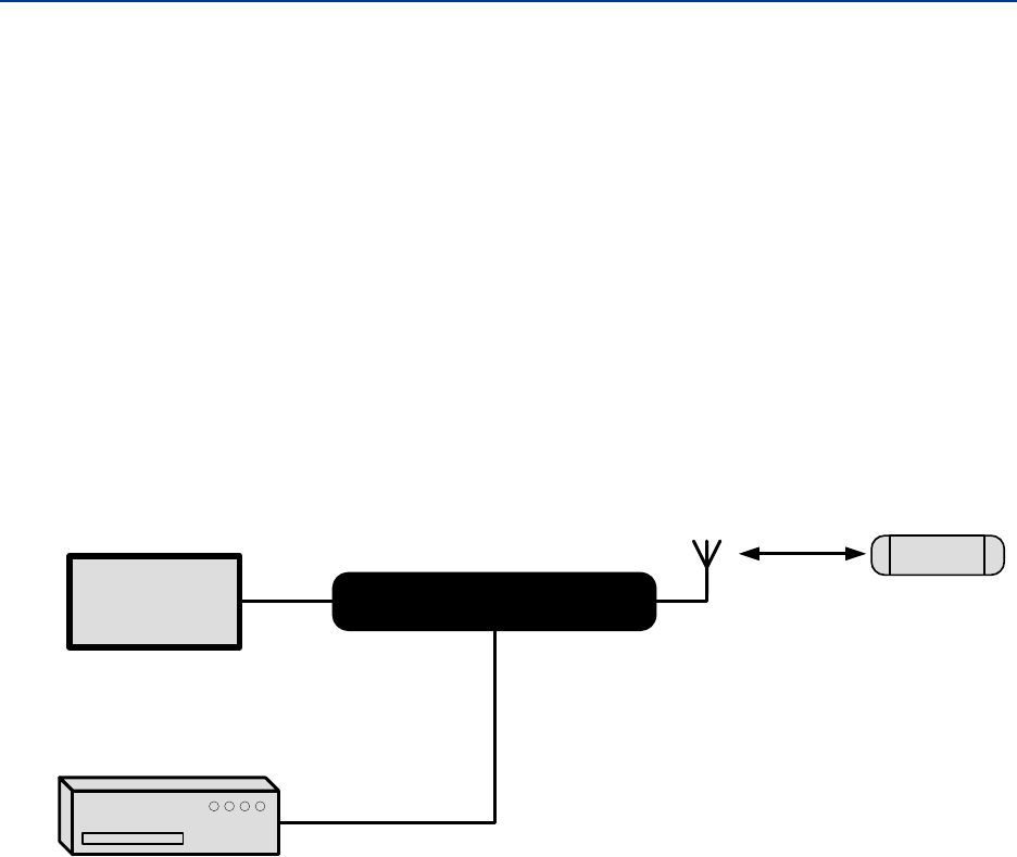
System Overview
The AI1422E Reader System is a microprocessor-controlled, single-antenna unit that
uses a unique communications protocol to interface with vehicle identification (ID)
equipment.
This reader system uses radio frequency (RF) energy to read data from tags. The AI1422E
Reader System then decodes the tag ID information, validates the ID code, and transmits
tag data directly to a host processor for real-time data processing and use.
Communications (terminal) programs usually do not provide adequate data processing
capability. Your host computer software can be customized to provide the required
capabilities.
The AI1422E Reader System consists of the AI1422E Reader, which consists of a reader and
RF module, combined with a TransCore antenna, a TransCore tag, a host processor system,
and a power source. Figure 1 illustrates a typical reader system configuration.
Power
Source
AI1422E
Host Processor
System
RS232
RS422
Ethernet
Antenna
TAG
Figure 1 Typical Reader System Configuration

AI1422E Reader
TransCore Proprietary 3
Transponder Interrogator
The transponder interrogator reads 60/120 bits of user-programmable data in the
transponder.
The transponder interrogator is operated in a continuous read mode, and any tag
entering its read field has its data automatically read and relayed to the host computer. In
many applications this function is implemented by installing the reader on a vehicle with
restricted movement, such as a railcar or monorail bus. The tags are embedded in the
roadway at various locations in the vehicle’s path. The data read from the tag allows the
host computer to assess the vehicle’s location and make any appropriate response to that
information.
The transponder interrogator is an independent tag decoder that combines a reader and
RF source to provide automatic identification and data storage within a single, compact
unit. The transponder interrogator includes the following components:
• 19-inch rack-mount design (1U)
• RS232/RS422/Ethernet input/output (I/O) link
• Real-time clock
• Reader and RF module, combined in one unit
Reader Power Regulation and Filtering
The reader system uses an input voltage ranging from 24VDC to 110VDC (12VDC to
150VDC Min/Max). The AI1422E Reader System incorporates a high-performance, DC-to-
DC power supply that converts voltage in this range to 24VDC. This voltage conversion is
internal to the unit, and should be transparent to the end-user.
Antenna
TransCore has multiple antennas for use with the AI1422E Reader, covering multiple
applications such as heavy rail, light rail, European regions, and more. Contact TransCore
for assistance with antenna selection.
Tags (Transponders)
The AI1422E Reader System can use TransCore’s half-frame or full-frame read-only tags.
When selecting a tag for an application that requires the tag to be placed on the road bed,
several design elements need to be kept in mind.
Beam-powered tags have a shorter footprint than battery or switch-powered tags, and thus
the maximum top speed of the vehicle will be less, all other factors equal.
Battery tags have an inherently larger footprint, but the battery life limitation will require the
operating company to replace the tags every 8 to 10 years. The presence of the battery
and its reactive mass reduces the reliability of the tag, particularly when the tag is placed
near high shock or vibration locations such as switches.
Switch-powered tags have RF characteristics similar to battery tags, and the tags are
powered by inductive power derived from railway switch power.
User Guide
TransCore Proprietary 4
Tag Mounting
All tags used with the AI1422E must be mounted on a flat metal plate. The internal
antennas of these tags are tuned for the backplane of the tag to be in contact with a
flat metal surface. This metal surface does not need to be extended beyond the outer
dimensions of the tag, and having a larger metal surface will not aect the immediate
performance of the tag.
Metal located to the sides or above the tag can aect the tag’s performance. Metal
surfaces or objects should not be placed closer than 1 inch (2.5 cm) to the side edges
of the tag to ensure that the tag’s antenna tuning remains within design criteria. Metal
placed above the tag can cause shadowing of the RF beam, both in the incident and
return directions, and should be avoided. The only exception to this rule would be metal
placed for the purpose of aecting the read range of the tag or footprint of the system, and
the placement of such metal should be done with careful planning and testing to ensure
proper system performance. With battery-powered tags, the arrangement of intentional
metallic obstructions may be the best way to limit the broad footprint of these tags, as
well as improve the repeatability of the TLS signal with respect to its absolute position
relative to the tag. These tag mounting details would need to be made by the customer on
the basis of each customer’s overall system design and requirements. Keep in mind that
metal placed too close in proximity to the tag will aect the tag’s antenna tuning, and may
unintentionally aect principal design parameters such as VSWR or the impedance match
of single paths internal to the tag, to name a few examples.
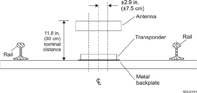
Antenna-to-Tag Centerline Alignment
For best performance, mount tags so that the centerline of the tags and the centerline of
the reader antennas are within ±2.9 inches (±7.5 cm) of each other (Figure 2).
Antenna-to-tag Distance
Many installations have been installed with a nominal 11.8-inch (30-cm) distance from the
backplane of the reader antenna to the back edge of the tag (Figure 2).
Figure 2 Antenna-to-Tag Centerline Tolerance

2
Interface Connections
User Guide
TransCore Proprietary 6
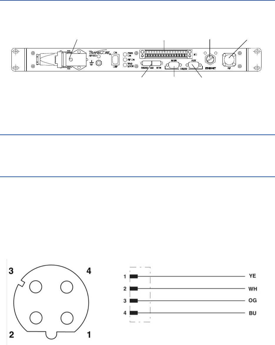
Description of AI1422E Reader System
The interface connectors are located on the AI1422E Reader System front panel as shown
in Figure 3.
Figure 3 Front Panel of an AI1422E Reader
Antenna Interface
Attach the antenna cable directly to the antenna interface on the front panel of the AI1422E
Reader System. The antenna cable length depends on the installation.
Ethernet (M12) Interface
The AI1422E Reader incorporates a Lantronix® Ethernet to Serial conversion module, which
is used to add full Ethernet compatibility into the reader. This module is located on the
interface board internal to the reader, and is addressable through Lantronix host software.
More details on this module can be found in “Appendix C” on page 81.
The Ethernet Interface utilizes a 4-pin, D-coded M12 connector (defined in IEC 61067-2-101
Amendment 1 as the Industrial Ethernet standard). This connector is pin-to-pin compatible
with RJ45 10/100Mbps Ethernet.
Figure 4 shows the connector pin designations.
Figure 4 Pin Designations for M12 Connector
ANTENNA
INTERFACE
ETHERNET
INTERFACE
AUX RS–232
INTERFACE
MAIN RS–232
INTERFACE
INTERFACE
SELECTION
SWITCH
POWER
CONNECTOR
I/O
INTERFACE
AI1422E Reader
TransCore Proprietary 7
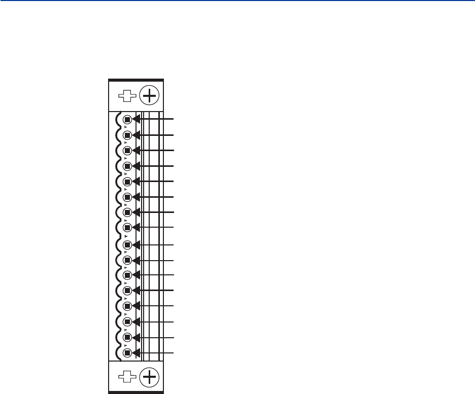
Customer I/O Interface
The customer I/O interface connector contains the tag lock, main power, RF Power outputs
(solid state), trigger signals (solid state), and RS–422 (Figure 5).
A mating connector for the customer I/O interface is supplied with each unit. This
connector allows a screw terminal, point-to-point wiring interface.
Figure 5 Customer I/O Interface Pin-out
Trigger Signals (Pin 2)
The trigger connection turns on the RF power when shorted to I/O ground and the AI1422E
Reader System has been programmed with the RF Follows Trigger command (!642).
RS–422 Interface (Pins 5-9)
The RS–422 interface is a terminal block connector. In real-time mode, tag IDs are read
and passed on to the host processor.
RF Power Output (Pin 14)
The TTL RF power LED goes active high when the reader system is configured for the
RF power to be on and the ON/OFF switch is set to ON. The RF power signal may be
connected to an LED for monitoring purposes.
The main power relay is referenced to 5Viso and I/O Ground.
Pin 1 – I/O Ground
Pin 2 – Trigger Signals
Pin 3 – I/O Ground
Pin 4 – N/C
Pin 5 – RS422 Ground
Pin 6 – RS422 RX-
Pin 7 – RS422 RX+
Pin 8 – RS422 TX-
Pin 9 – RS422 TX+
Pin 10 – N/C
Pin 11 – Wiegand 1
Pin 12 – I/O Ground
Pin 13 – Wiegand 0
Pin 14 – RF Power Output
Pin 15 – Main Power Output
Pin 16 – Tag Lock Output

User Guide
TransCore Proprietary 8
Main Power Output (Pin 15)
The TTL main power signal goes active high when the ON/OFF switch on the front panel
is switched to on. The main power signal may be connected to an LED for monitoring
purposes.
The main power relay is referenced to 5Viso and I/O Ground.
Tag Lock Output (Pin 16)
The transistor-transistor-logic (TTL) lock signal shows the presence of a tag. The lock signal
goes active high when a valid tag is in the RF field of the antenna and may be connected to
an LED for monitoring purposes.
The tag lock relay is referenced to 5Viso and I/O Ground. The falling edge of the tag lock
signal can be increased by using a 10K ohm resistor.
Power Connector
The power connector on the front panel of the AI1422E Reader System is a panel mount,
right angle, EPIC ® HA-3 style 3 pin plus ground rectangular connector.
Interface Selection Switch
The AI1422E Reader incorporates a communications interface selection switch, which
allows on-the-fly changes to the communications mode. This switch allows selecting the
reader’s receive communications interface. All communications interfaces are configured
for simultaneous transmit, but only the interface selected by the switch is active for
commands transmitted into the reader.
Main RS–232 Interface
The main RS–232 interface is a standard DB–9 plug connector used with a host processor.
In real-time mode, tag IDs are read and passed on to the host processor. Figure 6
illustrates the RS–232, DB–9 plug connector pin-outs.

AI1422E Reader
TransCore Proprietary 9
Figure 6 RS–232, DB–9 Interface Connector Pin-outs
Aux RS–232 Interface
The auxiliary RS–232 interface is used as a backup monitoring system to the main RS–232
interface. The auxiliary interface monitors data from the transponder interrogator. The
auxiliary RS–232 interface is a standard DE09 plug connector. This port is not wired to
receive data and cannot accept commands.
RS232
AUXMAIN
PIN5 – GROUND
PIN3 – RX DATA
PIN2 –TX DATA
PIN5 – GROUND
PIN3 – TX DATA

3
Installation Instructions
AI1422E Reader
TransCore Proprietary 11
General
Equipment should be installed and serviced only by skilled, qualified personnel. Equipment
should be installed only in RESTRICTED ACCESS LOCATIONS.
Mechanical
The AI1422E has a standard 1U sized hole pattern. For installation, use No. 10 rack US
screws and torque to 25-30 in-lbs. For metric, use M6 screws and torque to 3-4 N-m. Refer
to Figure 7 for diagram and dimensions.
Figure 7 AI 1422E Dimensions
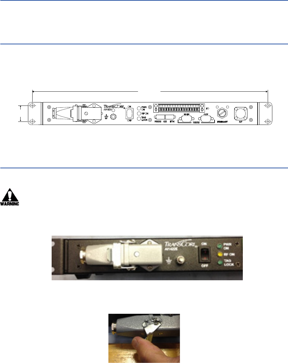
Electrical Power
Assembling the Power Connector
WARNING: Ensure that the ON/OFF switch is in the OFF position and the PWR
ON indicator is not illuminated before servicing the unit.
1. Unpack the unit from the shipping crate and locate the power connector on the front
panel (Figure 8).
Figure 8 Power Connector
2. Unlatch the plug from the receptacle on the unit and remove it (Figure 9).
Figure 9 Remove Plug from Receptacle
1.25
18.35
User Guide
TransCore Proprietary 12
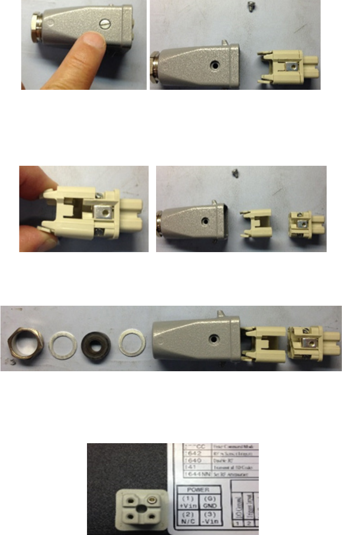
3. Locate the set screw on the plug housing. Remove the screw and plug-insert from the
housing (Figure 10).
Figure 10 Remove Screw and Plug Insert
4. Locate the tabs on the plug insert. Squeeze the tabs to remove the wire harness from
the insert clip (Figure 11).
Figure 11 Remove Wire Harness from Insert Clip
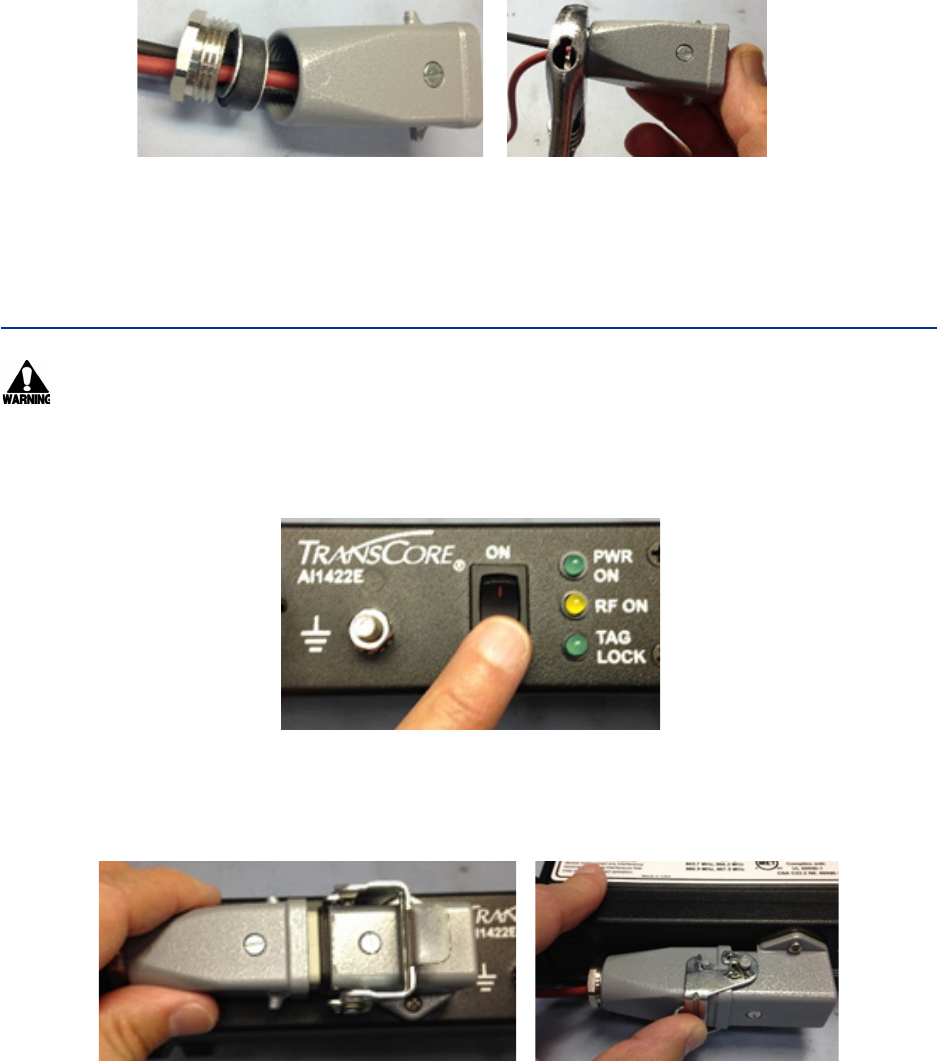
5. Remove the cable gland assembly from the rear of plug (Figure 12).
Figure 12 Cable Gland Assembly - Rear of Plug
6. Locate the wiring diagram label on the top panel of the 1422E and note the
corresponding pin numbering on the plastic of the plug wire harness (Figure 13).
Figure 13 Pin Numbering: Plug Wire Harness
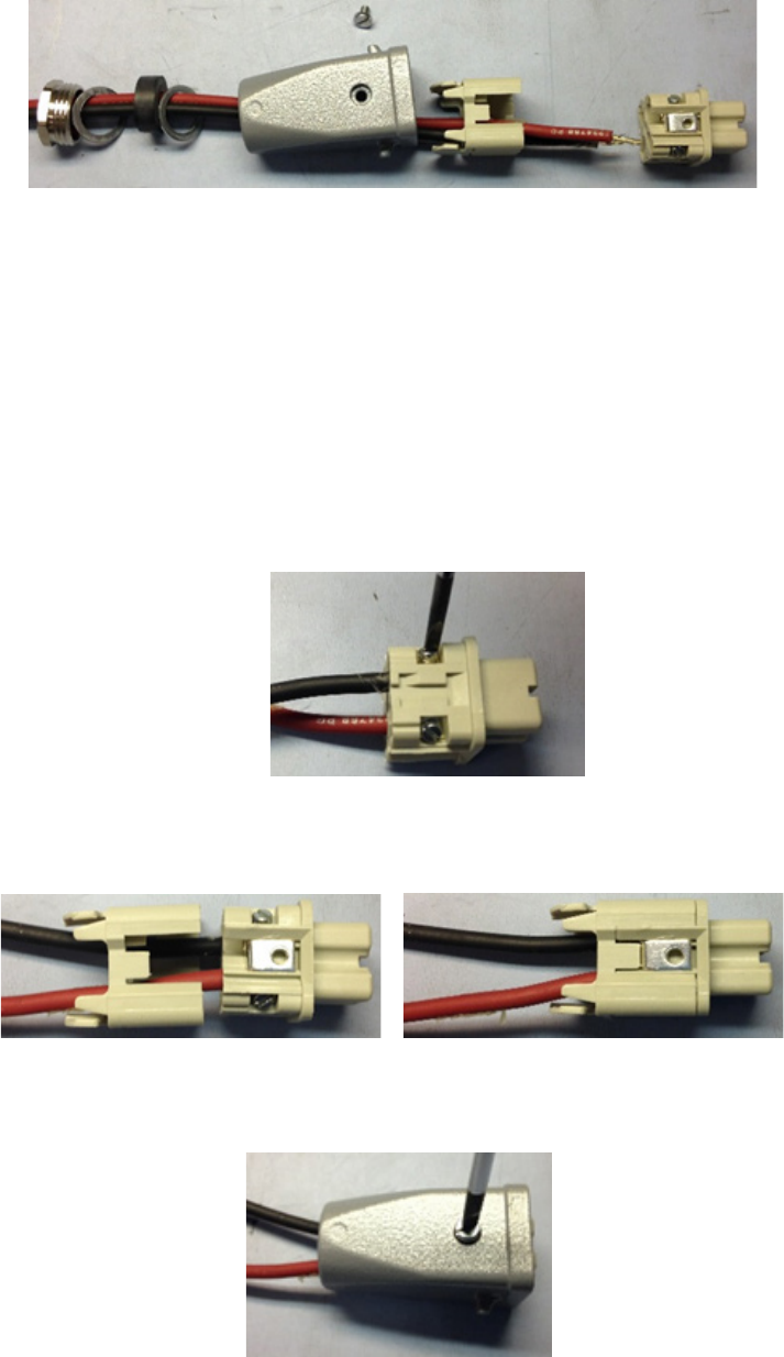
7. Thread the +Vin and -Vin wires through the cable gland, housing, and insert assemblies
(Figure 14).
AI1422E Reader
TransCore Proprietary 13
Figure 14 Thread Wires Through Assembly
NOTE: The Power cable requires an 18 AWG stranded wire or larger, with a minimum
insulation rating of 70C and 150V. Wire must meet EN 60950-1 or other applicable
component standards.
An external 10A-rated overcurrent protection device is required in-line with positive
terminal for proper system operation and protection. Device must meet EN60950-1
or applicable component standard(s).
8. Loosen the wire retention screws on the wire harness. Insert the wires into their
respective pins and tighten the retention screws to ensure wires cannot be removed
(Figure 15).
Figure 15 Insert Wires into Pins
9. Insert the wire harness into the insert clip until the tabs click into place (Figure 16).
Figure 16 Insert Wire Harness into Insert Clip
10. Place the insert back into the plug housing and tighten the set screw (Figure 17).
Figure 17 Reassemble and Tighten Set Screw
User Guide
TransCore Proprietary 14
NOTE: If the set screw will not tighten, remove the insert and ensure the set screw is
properly aligned with the hole on the plug housing.
11. Insert the cable gland assembly back into the plug housing. Using a wrench, tighten the
gland nut. Connect +Vin and -Vin to the power source (Figure 18).
Figure 18 Reassemble Cable Gland Assembly
NOTE: Unit MUST be installed as close to the power source as possible.
Installing Wires into Connector
WARNING: Ensure ON/OFF switch is in OFF position and the PWR ON indicator is
not illuminated before connecting/disconnecting from the power supply.
Connecting power
1. Ensure that the ON/OFF switch is in the OFF position (Figure 19).
Figure 19 Power Switch
2. Reinstall the power connector. Press the latch firmly to ensure proper connection
(Figure 20).
Figure 20 Reinstall Power Connector
AI1422E Reader
TransCore Proprietary 15
3. Toggle the ON/OFF switch to the ON position and ensure the PWR ON indicator is
illuminated (Figure 21).
Figure 21 Power the Unit to ON
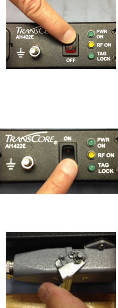
Disconnecting power
1. Toggle the ON/OFF switch to the OFF position and ensure that the PWR ON indicator
is not illuminated (Figure 22).
Figure 22 Power the Unit to OFF
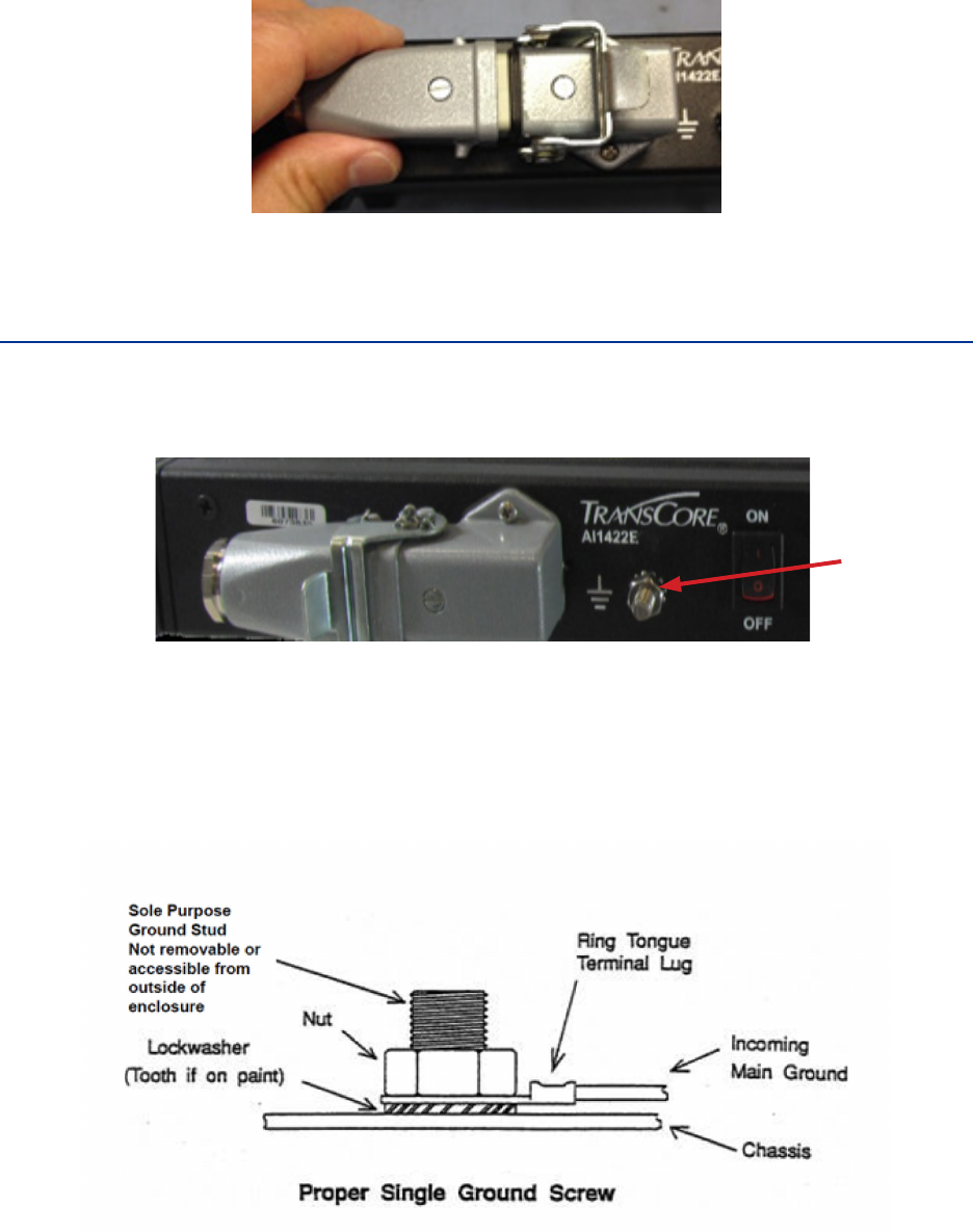
2. Unlatch the connector (Figure 23).
Figure 23 Connector Latch
User Guide
TransCore Proprietary 16
3. Gently remove plug from receptacle (Figure 24).
Figure 24 Remove Plug from Receptacle
Protective Earth Ground Terminal
For safety and proper operation, the 1422E must be properly fastened to a protective earth ground.
The ground stud is located on the front panel of the 1422E between the power connector and ON/
OFF switch (Figure 25).
Figure 25 Location of Ground Stud
For proper grounding, refer to the diagram in Figure 26.
NOTE: Grounding cable should be 16 AWG or larger
Figure 26 Proper Single Ground Screw Diagram
Earth Ground

4
System Test Procedures
User Guide
TransCore Proprietary 18
System Test Procedures
This chapter provides testing procedures that will help you fine-tune your reader system
and test basic operation, measure radio frequency (RF) power, measure system noise, read
tags, and monitor the system.
Required Tools and Equipment
The following tools and equipment are required:
• 50-ohm, 5-watt (W) load (N-type connector)
• Personal computer (PC) with terminal emulator software
• Appropriate power source for your reader
• Digital multimeter
• Antenna, cable, and connectors
Testing Basic Operation
To test the system operation, configure the reader system as follows:
1. Configure a terminal emulator (a PC using communications software) to 9600 baud, no
parity, 8 data bits, and 1 stop bit (factory default settings for the reader).
2. Connect the emulator to the main RS–232 interface located on the front panel of the
reader system.
3. Slide the Interface Selection switch on the front panel of the reader to RS–232.
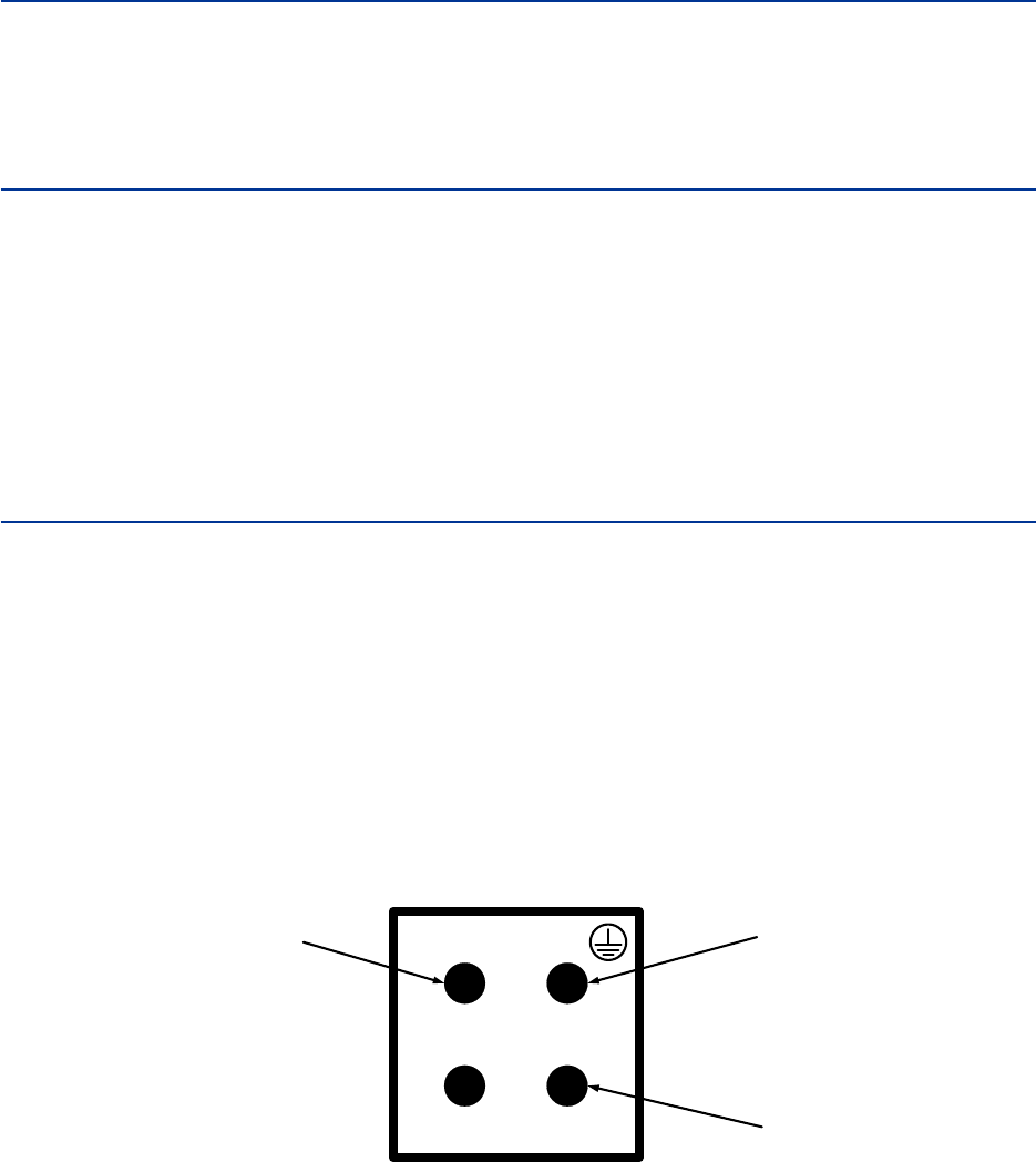
4. Toggle the ON/OFF switch located on the front panel of the reader system to o.
5. Connect a power source to pins 1 (+) and 3 (-) on the DC power input front panel
connector (Figure 27).
Figure 27 Power Source Connections
6. Toggle the ON/OFF switch located on the front panel of the reader system to o.
7. Enter the command !01 or ~~CC (CC must be entered in upper case) and press
Enter.
1
2 3
Chassis (GND)
-VDC
+12 to +150VDC

AI1422E Reader
TransCore Proprietary 19
Note: For information on entering command codes, refer to “Communications
Protocols” on page 22.
8. Input !22 and press Enter. The time and date will be returned.
If the time and date are not received, check communications
connections, cycle power, and repeat.
If the time and date are incorrect, use !20 and/or !21 to correct this information, then input
the following commands:
!20hh:mm:ss sets time
!21MM/DD/YY sets date
!642 sets RF to follow the trigger
!41 enables tag reporting
NOTE: !41 command should be used in diagnostic mode only. Do not use in
normal system operation.
The entered command and !Done response will be returned after each properly
executed command.
Reading the Tag
To verify that the AI1422E Reader System is correctly reading tags:
1. Toggle the ON/OFF switch located on the front panel of the reader system to o.
2. Using your own cable, connect the laptop PC to the reader system at the main RS–232
interface.
3. Slide the Interface Selection switch on the front panel of the reader to RS–232.
4. Connect the antenna to the antenna interface on the front panel of the reader system.
5. Toggle the ON/OFF switch located on the front panel of the reader system to on.
6. Connect a jumper between pins 14 (Ground) and 15 (Trigger Input) on the customer I/O
interface to trigger the RF on (“Figure 6 Customer I/O Interface Pin-outs” on page
8).
7. Monitor the LEDs on the box and verify that the main power LED and the RF power LED
are illuminated.
8. Position a programmed TransCore half-frame rail tag with a backplate within 2 to 3 feet
(0.6 to 0.9 m) of the antenna. No other tag can be in this 2 to 3 foot (0.6 to 0.9 m) area
during this test.
9. Verify that the lock LED is illuminated and that the PC is acquiring the tag data.
Note: If the !41 command was issued prior to this test, the PC will be receiving a
continuous stream of tag data. If the !41 command was not issued, the reader
responds with only one response. The Lock LED remains illuminated as long as
there is a tag in the field, but only one response is forthcoming unless the !41
command has been issued.
User Guide
TransCore Proprietary 20
10. Remove the tag from the antenna field. The PC should stop reading the tag data.
11. Disable the trigger by disconnecting the jumper.
12. Toggle the on/o switch located on the front panel of the reader system to o.
Note: Repeat this test several times. Each time, the lock LED should be illuminated
and the PC should be reporting the tag data.

5
Communications Protocols

User Guide
TransCore Proprietary 22
Communications Protocols
The AI1422E Reader supports the following communications protocols:
• Basic
• Error correcting protocol (ECP)
The following protocol information provides reference information relevant to developing
host software.
Communications are performed using the 7-bit ASCII code with optional parity, thus
providing easy setup, testing, and diagnostics with standard ASCII terminals and serial
printers. Parity must be enabled to achieve the specified undetected error rate.
Each message is framed within the start-of-message (som) and end-of-message (eom)
characters so that the host computer can detect the beginning and end of each message.
This convention is most important under marginal communications conditions during which
the host may receive extraneous noise-induced characters between reader transmissions.
In such instances, the host is capable of ignoring any messages that do not conform to the
som...eom frame sequence.
Both data mode and command mode require a two-way message interchange when
using ECP. This interchange is completed by the message recipient returning a message
acknowledgment to the message sender.
With ECP, all transmissions require a message. If a message is not received, the sender will
time out with the same eect as if it had received a negative acknowledgment (from the
host) or an Error message from the AI1422E Reader.
Software (XON/XOFF) flow control is optionally supported. Be careful in the use of XON/
XOFF since noise-induced characters may be interpreted by the AI1422E Reader as the
XOFF character, which would suspend reader output without information reaching the host
computer. For more information refer to “525 Display Communications Protocol Status” on
page 40.
Note: TransCore recommends that XON/XOFF flow control be disabled while using ECP.
Basic Protocol
With basic protocol, messages sent to and from the AI1422E Reader and the host are
transmitted without error checking. For each host transmission, the AI1422E Reader returns
a Done or Error message to the host.
When the host computer is physically close to the AI1422E Reader and no sources of
interference exist, the basic protocol provides reliable communications.
The host must be ready to receive reader-transmitted messages because in basic
protocol the AI1422E Reader does not wait for the host to acknowledge a message before
transmitting the next message. If necessary, the host may halt reader transmissions by
using software or hardware. Refer to “Command Codes” on page 25 for flow control
information.
AI1422E Reader
TransCore Proprietary 23
Error Correcting Protocol
When the quality of data communications is imperative or may be suspect, you can invoke
ECP to ensure the integrity of data transmitted between the AI1422E Reader and the host.
Note: TransCore recommends that basic protocol (not ECP) be used when
commands are entered manually at the keyboard.
Wiegand output is automatically disabled when the reader is put into ECP mode.
Error correction is accomplished with the use of a cyclic redundancy check (CRC) value that
is based on the message data. The originator (reader or host) calculates the CRC value of a
message and includes it in the transmitted message.
The recipient (reader or host) also calculates a CRC value for the received message. If
the transmitted message data is correct, the CRC value calculated by the recipient will
agree with the CRC value calculated by the originator. If the CRC values do not agree, the
recipient rejects the message.
Message sequence numbers are also included when using ECP. These sequence numbers
are checked to determine if the message received has the correct sequence number; if
not, the recipient rejects the message.
Since the seven-bit ASCII code is used and there are eight data bits per character, the
eighth bit can optionally be used to support parity. Where parity is selected, the CRC value
calculation includes the parity of each character in the calculation of the CRC value.
Parity is required to achieve the most reliable communications. If parity is enabled, both the
AI1422E Reader and the host must issue a message if any received character has a parity
error. However, the message must not be transmitted before receipt of the eom character.
In this case, the AI1422E Reader will issue an Error message, and the host computer will
issue a negative acknowledgment message.

6
Command Codes

AI1422E Reader
TransCore Proprietary 25
Command Codes
The AI1422E Reader is delivered from the factory with specified default settings that
determine how the reader operates. Commands transmitted by the host computer can
change the default settings and control additional features. The commands can be
transmitted by manually entering the commands at the host keyboard if the host is in
terminal emulation mode.
Note: If you are using Wiegand mode, you must connect the PC or laptop to the
AI1422E Reader using the RS–232 or RS–422 interface and a terminal emulation
program to send commands to the reader. You can leave the Wiegand interface
connected during this procedure.
Operating Modes
The AI1422E Reader has three modes of operation: Data Mode, Command Mode, and
Download Mode. The software for the AI1422E Reader contains two separate programs —
Boot and Application. The Boot program has control of the AI1422E Reader on startup and
when operating in download mode. The Application program has control of the AI1422E
Reader during a command mode operation and holds the application code. Together, they
control the AI1422E Reader in the three modes of operation.
Data Mode
The AI1422E Reader is in Data Mode on power-up. While in Data Mode, the AI1422E
Reader sends all communications to the host computer as data messages, such as tag IDs
and reports. Reports provide information on Input 0 and Input 1 status changes, a presence
without tag report, and buer overflow information. The host computer can send only four
commands to the AI1422E Reader while in Data Mode (Table 1).

User Guide
TransCore Proprietary 26
Table 1 Data Mode Commands
Data Mode Commands
Type Description Command
Status Request
Causes the interrogator to respond with a message
containing information indicating the rolling transponder
seen count and the count of host error messages.
~~@@
Retransmit Request Requests the interrogator to retransmit the last tag ID
read. (BB must be entered in upper case). ~~BB
Enter Command Mode
Disables reading and reporting of tags and changes
the reader from Data Mode to Command Mode. (CC
must be entered in upper case). Refer to ”Switch to
Command Mode” on page 32.
~~CC
Enter Command Mode Disables reading and reporting of tags and changes the
reader from Data Mode to Command Mode. !01
There is no carriage return or line feed required for any of the ~~ commands. Commands
!01 require a carriage return.
No Response is received with the ~~CC and !01 commands.
Note: The AI1422E Reader transmits ID codes to the host computer when the
AI1422E Reader is in Data Mode. If the AI1422E Reader remains in Command Mode
with tags passing through the read zone, all tag IDs are not reported.
Asynchronous Interrogator Data Message
The interrogator sends the transponder ID in 8-bit ASCII. The message format is as follows:
<7EH><7EH><01H><transponder count><transponder ID><CRC>
The interrogator transmits the most significant bit first. The CRC is calculated, starting with
the most significant byte.
No Response is received with the ~~CC and !01 commands.
Table 2 presents the field descriptions.

AI1422E Reader
TransCore Proprietary 27
Table 2 Asynchronous Interrogator Tag Data Message Fields
Field Description Hex ASCII
Start of Message
These two bytes, along with the Message
type byte, designate the start of the data
message.
7E7E ~~
Message Type An 01H indicates that this message is a tag
data message. 01 SOH
Transponder Seen
Count
After power-up, this 8-bit count begins with
01 and is updated each time a tag with a
unique ID moves out of the RF field, then
back into the RF field. This field is useful in
determining whether a train has multiple tag
reads of a given ID due to a change in the
train’s direction.
00 - FF N/A
Transponder ID
The data that is programmed into
the transponder. The data within the
transponder is 6-bit ASCII but the
interrogator translates this data into
standard 8-bit ASCII.
- ID
Cyclical Redundancy
Check
An 8-bit cyclical redundancy check (CRC).
Includes the Start of Header, the Seen
Count and the Transponder ID. Refer to
Appendix D for a description of the CRC
algorithm. There is no carriage return or line
feed for this message.
00 - FF N/A

User Guide
TransCore Proprietary 28
Status Request
Note: The Status Request should only be used when the train is stationary. Sending
this command simultaneous to tags being read can create a condition whereby the
interrogator will no longer report tags until power cycled.
The Status Request command causes the interrogator to respond with a message
containing information indicating the transponder seen count and host error messages.
The request command format is as follows:
<7EH><7EH><40H><CRC>
Table 3 Status Request Message Fields
Field Description Hex ASCII
Start of Message These two bytes designate the start of the data
message. 7E7E ~~
Message Type Sending a 40H indicates that this message is a
status request. 40 @
Cyclical Redundancy
Check
The 8-bit cyclical redundancy check (CRC)
includes the Start of Message and Message Type.
See “Appendix D” for a description of the CRC
algorithm. This is a fixed value of 40 hexadecimal,
for this command. There is no carriage return or
line feed for this message.
40 @
The response is
<7EH><7EH><02H><Transponder count><host
computer messages-bad CRC><incomplete host message>
<Reserved><Reserved><Reserved><CRC>

AI1422E Reader
TransCore Proprietary 29
Table 4 Status Response Message Fields
Field Description Hex ASCII
Start of Message These two bytes, along with the Message Type
byte, designate the start of the data message. 7E7E ~~
Message Type An 02H indicates that this message is a status
response. 02 STX
Transponder Seen
Count
The Transponder Seen Count is a single byte,
hexadecimal field. At power-up, the interrogator
initializes this Seen Count byte to 00. This value
is incremented each time a tag with a unique ID
moves out of the RF field, then back into the RF
field. This field is useful in determining whether
a train has multiple tag reads of a given ID due
to a change in the train’s direction.
00 - FF N/A
Number of Messages
from Host with Bad
CRCs
At power-up, the interrogator initializes this
byte with 00. It is incremented each time a
message with a bad CRC is received from the
Host.
00 - FF N/A
Number of incomplete
Host Messages
At power-up, the interrogator initializes this
byte with 00. It is incremented each time an
incomplete message is received from the
Host.
00 - FF N/A
Reserved Reserved 0 NUL
Reserved Reserved 0 NUL
Reserved Reserved 0 NUL
Cyclical Redundancy
Check
This field is a single byte (8-bits) cyclical
redundancy check (CRC). Includes the Start
of Message, Message Type, Transponder
Seen Count, Number of Messages from Host
with bad CRCs, and Number of Incomplete
Host Messages. Refer to “Appendix D” for a
description of the CRC algorithm. There is no
carriage return or line feed for this message.
00 - FF N/A
Retransmit Request
Note: The Retransmit Request should only be used when the train is stationary.
Sending this command simultaneous to tags being read can create a condition
whereby the interrogator will no longer report tags until power cycled.
The Retransmit Request Command tells the transponder to retransmit the last tag ID. (BB
must be entered in upper case).
The request command format is as follows:
<7EH><7EH><
42H
><CRC>

User Guide
TransCore Proprietary 30
Table 5 Retransmit Request Message Fields
Field Description Hex ASCII
Start of Message
These two bytes, along with the Message
Type byte, designate the start of the data
message.
7E7E ~~
Message Type Sending a 42H indicates that this message is
a retransmit request. 42 B
Cyclical
Redundancy Check
An 8-bit cyclical redundancy check (CRC)
Includes the Start of Message and Message
Type. Refer to “Appendix D” for a description
of the CRC algorithm. This is a fixed value
of 42 hexadecimal, for this command. There
is no carriage return or line feed for this
message.
42 B
The response is
<7EH><7EH><01H><transponder count><transponder ID><CRC>
Table 6 Retransmit Response Message Fields
Field Description Hex ASCII
Start of Message
These two bytes, along with the Message
Type byte, designate the start of the data
message.
7E7E ~~
Message Type An 01H indicates that this message is a tag
data message. 01 SOH
Transponder Seen
Count
After power-up, this 8-bit count begins with
01 and is updated each time a tag with a
unique ID moves out of the RF field, then
back into the RF field. This field is useful in
determining whether a train has multiple tag
reads of a given ID due to a change in the
train’s direction.
00 - FF N/A
Transponder ID
The data that is programmed into the
transponder. The data within the transponder
is 6-bit ASCII but the interrogator translates
this data into standard 8-bit ASCII.
- ID
Cyclical Redundancy
Check
An 8-bit cyclical redundancy check (CRC).
Includes the Start of Message, Message
Type, Seen Count and Transponder ID. Refer
to for a description of the CRC algorithm.
There is no carriage return or line feed for
this message.
00 - FF N/A

AI1422E Reader
TransCore Proprietary 31
Command Mode
While the AI1422E Reader is in Command Mode, the host computer sends commands to
the AI1422E Reader that can be used to control the operation and configuration of the
reader. After the AI1422E Reader receives a command, it transmits a command response
message. Typically, the command message contains Error, Done, or data relating
specifically to the command request. These messages may be of variable length since
some commands require information as part of the message.
Communications can be lost if the host computer attempts to send certain commands
under marginal communications conditions. For example, if the host computer transmits the
command request to change the baud rate and the AI1422E Reader properly receives the
request and transmits the Done message, one of the two following conditions may occur:
1. If the host computer receives the Done message, then both the host and the AI1422E
Reader switch to the new baud rate, and communications are maintained.
Note: In many applications, the host must be set to the new baud rate as it will not
change automatically. The AI1422E Reader changes the baud rate immediately after
issuing the Done message.
2. if the host does not receive the Done message transmitted by the AI1422E Reader, the
host assumes that the command was not properly sent and does not switch to the new
baud rate, causing a loss of communications.
Caution
The host computer should not attempt to change communications parameters
or protocols during marginal communications conditions; otherwise, a loss of
communications can result.
Download Mode
In Download Mode, the AI1422E Reader allows the host to download new software.
While in Download Mode, the reader communications port parameters are fixed at the
following factory-default settings: 38400 baud, 8 data bits, 1 stop bit, no parity, software
flow control (XON/XOFF), basic protocol.
While in Download Mode, the AI1422E Reader turns RF o, does not process tags, and
does not echo host commands.
Command List
Reader commands are divided into groups based on primary function. The following
sections provide information about each command in command number order. Refer to

User Guide
TransCore Proprietary 32
“Command Quick Reference” on page 80 for listings of commands in both numerical
and alphabetical order.
In the Command Quick Reference list, the symbols < and > represent variable message
data. These symbols are not part of the message syntax. Hex digits (0–9, A–F) in either
uppercase or lowercase characters may be used in data strings and for hex digits A–F.
Reader Mode Control
Group 0 commands control reader mode. The mode determines whether the reader is
transmitting data to or receiving data from a host computer or terminal.
00/662 Switch to Data Mode (Factory Default)
Command !00 switches the reader to Data Mode, which allows the reader to transmit
tag data (ID codes) to the host. In addition to switching the reader to
Data Mode, command !00 automatically saves to non-volatile memory
(NVRAM) any user parameters that had been changed during the
command mode session. The reader enters Data Mode on power up.
The command !662 is present for backward compatibility with
previous generation AI1422 readers, and is not recommended for use.
Caution
To save user parameter changes to NVRAM, you must send command
!00/!662 before powering down the reader.
Switch to Command Mode
While operating in Data Mode, the reader accepts the following commands:
Command !01 Switch to Command Mode
Reader response: No Response
Command ~~CC switches the reader to Command Mode, which allows the reader to
accept commands from a host or terminal. While in Command Mode,
the reader turns RF o and does not acquire tags.
Reader response: No Response
Communications Port Control
Group 1 commands configure the parameters used by the AI1422E Reader to communicate
with a host computer or terminal. These commands set baud rate, stop bits, parity, and end-
of-line delay.
AI1422E Reader
TransCore Proprietary 33
100N Select Baud Rate
Command !100N selects the reader baud rate. The factory-default setting is 9600 baud.
The N variable specifies the baud rate shown in Table 7.
Reader response: Done
Table 7 Select Baud Rate Commands
Command Baud Rate Selected
1002 1200
1003 2400
1004 4800
1005 9600 (factory default)
1006 19.2 K
1007 38.4 K
Caution
If ECP is enabled, ensure that the ECP timeout is sucient for the new baud
rate. Refer to “525 Display Communications Protocol Status” on page 45.
101N Select Stop Bits
Command !101N selects the number of stop bits for reader character transmission. The
factory default setting is 1 stop bit. The N variable specifies the number
of stop bits as indicated in Table 8.
Reader response: Done
Table 8 Select Stop Bits Commands
Command Stop Bits Selected
1010 1 (factory default)
1011 2
102N Select Parity
Command !102N selects the reader parity setting. The factory-default setting is parity
disabled. The N variable specifies parity as shown in Table 9.
Reader response: Done

User Guide
TransCore Proprietary 34
Table 9 Select Parity Commands
Real-time Clock
Group 2 commands control the real-time clock which maintains the AI1422E internal time
and date. This time and date can be appended to IDs, error messages, and sensor input
reports. An internal battery supports the clock, so time and date are preserved if main
power is lost.
20 Set Time
Command !20 sets the time. Enter the time in the proper format: two-digit decimal
entries with no spaces between characters and using colons as
delimiters. The entry format is as follows:
20HH:MM:SS or 20HH:MM:SS:hh
where
HH represents hours (00 to 23).
MM represents minutes (00 to 59).
SS represents seconds (00 to 59).
hh represents hundredths of a second (00 to 99).
: is the time delimiter.
If hundredths of a second is not specified, the reader sets the
hundredths register to 00.
Reader response: Done
Command Data Bits Parity Selected
1020 8 Disable parity (factory default)
1021 7 Select even parity
1022 7 Select odd parity

AI1422E Reader
TransCore Proprietary 35
21 Set Date
Command !21 sets the date. Enter the date in the proper format: two-digit decimal entries
with no spaces between characters and using forward slashes “/” as
delimiters. The entry format is as follows:
21MM/DD/YY
where
MM represents the month (01 to 12).
DD represents the day (01 to 31).
YY represents the last two digits of the year (00 to 99).
/ is the date delimiter.
Reader response: Done
22 Display Time and Date
Command !22 displays the reader’s current time and date. One space separates the
time and the date output.
Reader response: HH:MM:SS.hh MM/DD/YY
where
HH represents hours.
MM represents minutes.
SS represents seconds.
hh represents hundredths of seconds.
: is the time delimiter.
MM represents the month.
DD represents the day.
YY represents the last two digits of the year.
/ is the date delimiter.
Append Information
Group 3 commands append useful information to reader transmissions, such as IDs, error
messages, and sensor input reports. Auxiliary information such as reader number, antenna
number (or manual entry code), number of times the previous tag was read, and sensor
input status can be appended to the ID using the Group 3 commands.
30N Append Time and Date Selection
Command !30N selects the option of appending the time and date to transmitted
IDs, error messages, presence without tag reports, and input status
change reports. The factory default setting is time and date appended
(command !302).

User Guide
TransCore Proprietary 36
The reader returns an Error message if its tag buer contains
data. The reset reader command !63 may be transmitted to
clear the buer; however, tag ID data will not be reported. If this is
unacceptable, allow the buer to empty before reissuing append time
and date command !30N. Append Time and Date commands are
shown in Table 10.
The reader transmits messages with time and date appended as
follows. One space separates the time from the date.
<string>&<HH:MM:SS.hh MM/DD/YY>
where
string is a tag ID, error message, or report.
& separates <string> from the time and date.
HH:MM:SS is the time delimiter.
MM/DD/YY is the date delimiter.
Reader response: Done
Table 10 Append Time and Date Commands
31N Append Auxiliary Information Selection
Command !31N selects the option of appending auxiliary information to transmitted
IDs, presence-without-tag reports, and input status change reports.
Auxiliary information is not appended to error messages. The factory
default setting is no auxiliary information appended. The N variable
specifies whether or not auxiliary information is to be appended.
Append Auxiliary Information commands are shown in Table 11.
The reader transmits messages with auxiliary information appended
as:
<message data>%<xx-y-zz-q>
where
% separates the auxiliary information and signals the host
computer that auxiliary information is appended.
xx reader ID. Value can be set with command !60NN.
- auxiliary information delimiter
y antenna number. Value fixed at 0.
Command Append Option
300 No time and date appended
302 Time and date appended (factory default)

AI1422E Reader
TransCore Proprietary 37
zz number of reads (00 to FF hexadecimal) of the previous
tag
q current status of Input 0 and Input 1 (0 to 3). Refer to “525
Display Communications Protocol Status” on page 45
These values are inverted if input inversion is enabled with
command 6941.
Reader response: Done
Table 11 Append Auxiliary Information Commands
320 Disable EAC Page Append (Factory Default)
Command !320 is a factory-set default that disables the EAC (embedded application
code) page append.
Reader response: Done
321 Enable EAC Page Append
Note: This functionality was added to the Encompass® 2 Reader to handle a
special unique customer requirement, and is retained in the AI1422E Reader for full
backward compatibility.
Command !321 selects the option to append an additional predefined 8 bytes of data
to be read from an eGo® or eGo Plus tag when the reader is in ID only
mode (not eATA) and multitag sort is enabled. The additional bytes
that are read from the tag are in locations 10 through 17.
The reader transmits the message with EAC page append as follows:
The EAC append data occurs before time and date append data and
AUX append data if they are enabled.
<tag ID>&<EAC page data>
Reader response: Done
ID Filtering
Group 4 commands set criteria for filtering (buering or discarding) ID codes. These
commands are useful for eliminating duplicate ID codes and selecting the type of tags read
by the AI1422E Reader.
40 Disable Transmission All ID Codes
Command !40 instructs the reader to reinstate the previous uniqueness checks.
Reader response: Done
Command Append Option
310 No auxiliary information appended (factory default)
311 Auxiliary information appended
User Guide
TransCore Proprietary 38
41 Transmit All ID Codes
Command !41 instructs the reader to transmit all IDs without regard for uniqueness.
This command can be useful when mapping the footprint or per
forming diagnostics.
After diagnostics are complete, you may want to reinstate the
uniqueness check using command !410N Select Unique ID Code
Criteria, or by using !40 to set reader back to its original setting.
Reader response: Done
410N Select Unique ID Code Criteria (Anti-passback Feature)
Command !410N instructs the reader to buer and transmit ID codes according to the
following test: an ID is read if previously decoded IDs have changed
value at least N+1 times since the new ID was last received. IDs
that do not pass the test are not read. The factory-default setting is
command !4100, which selects a separation of one ID. Variable N
specifies ID separation as shown in Table 12.
Each time the reader receives a tag ID, it compares the ID with the
contents of a comparison register. This register contains the following
four items:
Item 1 Most recently acquired ID
Item 2 Second-most recently acquired ID
Item 3 Third-most recently acquired ID
Item 4 Fourth-most recently acquired ID
When the uniqueness filter is set to separation of one ID, the newly
acquired ID is transmitted only if it is dierent from the first item.
Separation of two IDs allows transmission if the new ID is dierent
from Items 1 and 2 in the comparison register.
Separation of three and four IDs transmit the new ID only if it is
dierent from the first three and the first four items, respectively.
Note: A new ID can fail the filter test and not be transmitted; however, it remains
stored in the comparison register.
The uniqueness test’s time limit is set by Command !441. If an ID is
buered, it will not be accepted again unless it arrives at the reader
more than the programmed time interval from the previous arrival or
until the receipt of one or more other IDs reset the uniqueness.
Reader response: Done

AI1422E Reader
TransCore Proprietary 39
Table 12 Unique ID Code Criteria
420N Select Valid ID Code Criteria
Command !420N directs the reader to validate an ID received only after it has been
obtained a specified number of times in sequence. Values for N are 0
through 3 (Table 13). The factory setting is one acquisition (N = 0).
The validation procedure is executed before the unique ID test (Select
Unique ID Code Criteria [!410N] commands). IDs that do not pass
the validation test are not reported.
For example, command !4203 specifies that the same ID must
be obtained from the RF module 4 times in succession before
it is considered for the uniqueness test. This feature is useful in
installations where RF reflections may cause a single tag to be read
multiple times or where an occasional ID might be read from fringe
areas.
Table 13 Select Valid Code Commands and Frames
Command Uniqueness Criteria
4100 Separation of 1 ID (factory default)
4101 Separation of 2 IDs
4102 Separation of 3 IDs
4103 Separation of 4 IDs
Command Valid Code Frames
4200 1 (Factory default)
4201 2
4202 3
4203 4
User Guide
TransCore Proprietary 40
440 Reset Uniqueness
Command 440 causes the ID filtering process set by Select Unique ID Code Criteria (!410N)
to restart. It is used in conjunction with the Variable Timeout (!44N)
commands. This command provides a method to end all uniqueness
timers.
44N Set Uniqueness Timeout
Places a time limit on the uniqueness criterion set by Select Unique ID
Code Criteria (!410N). The parameter N sets the number of minutes
on the timeout clock. The factory setting is two minutes (N=1).
Command Timeout Clock
Command !441 2 minutes (factory setting)
Command !442 15 seconds
Command !443 30 seconds
Entering these commands eectively expires the timeout clock, which
erases all current IDs in the comparison register. In eect, the first
ID that is acquired after the clock expires always appears to be new
and is stored. Newly acquired IDs are only tested against IDs that are
registered after the clock resets.
The timeout clock is continually reset (does not expire) as long as
the reader receives the same tag ID. For example, assume that the
timeout clock is set for 2 minutes and there is a railcar parked on a
siding in front of the reader. Without this continual reset feature, the
railcar’s ID would be reported every 2 minutes (each time the timeout
clock expired).
450 Disable Wiegand Mode (Factory Default)
Command !450 is a default set in the factory to disable Wiegand mode.
Reader response: Done
451 Enable Wiegand Mode
Command !451 enables Wiegand mode, which allows the reader to transmit data in a
format that emulates the output of a magnetic card reader.
In Wiegand mode, the reader transmits Wiegand-formatted tag data
through the Wiegand interface and ASCII data (the reader accepts
reader commands and responds) through the serial port interface. The
reader outputs data from Wiegand-programmed tags via the Wiegand
interface. Tags that are not Wiegand-formatted are not transmitted
through the Wiegand interface or the serial port when in Wiegand
mode, although the tag lock relay is activated on any tag acquired.
Reader response: Done
AI1422E Reader
TransCore Proprietary 41
452 Disable Tag Translation Mode (Factory Default)
Command !452 disables tag translation mode. Incoming full-frame tags will be directly
converted to ASCII. They will not be translated from Association of
American Railroads (AAR) and American Trucking Associations (ATA)
format to ASCII.
Reader message: Done
453 Enable Tag Translation Mode
Command !453 enables the translation of tags in AAR and ATA formats. Specific data
fields, such as owner ID and car number, will be extracted from these
tags, translated according to AAR or ATA standards, and converted
to ASCII. Tags that are not programmed in AAR or ATA format will be
directly converted to ASCII. The reader will not attempt to translate
data from half-frame or dual-frame tags.
Reader message: Done
454 Disable Multi-tag Sort (Factory Default)
Command !454 is a default set in the factory to disable the multi-tag sort function.
Reader response: Done
455 Enable Multi-tag Sort
Command !455 enables the multi-tag sort function that allows the reader to identify
unique tags within a group of Intellitag-based tags. Multi-tag sort
allows full operation of the tags and reader to be carried out with a
limited number of tags in the presence of the reader.
Reader response: Done
Note: Enabling the multi-tag sort function adversely aects the vehicle speed at
which tags may be read. If there is only one Intellitag-based tag in the vehicles of the
target population, multi-tag sort should be disabled.
456 Enable eGo Plus Tag Initialization During Multi-tag Sort (Factory
Default)
Command !456 enables the reader to send the eGo Plus Tag initialize command as
part of the multi-tag sort function. When the reader sends the eGo Plus
Tag initialize command, all tags in the RF field reenter the sort process.
Reader response: Done
User Guide
TransCore Proprietary 42
457 Disable eGo Plus Tag Initialization During Multi-tag Sort
Command !457 disables the reader from sending the eGo Plus Tag initialize command
as part of the multi-tag sort function. Any eGo Plus Tags already
identified by the reader during the sort process will not be re-identified
as long as they remain powered in the RF field. The reader will only
identify new tags that come into the RF field or tags that do not remain
powered in the RF field.
Reader response: Done
480 Disable ATA
Command !480 Disables the reader from reading ATA protocol tags.
481 Enable ATA
Command !481 enables the reader to read ATA protocol data from tags if the reader is
programmed to read this tag protocol.
482 Disable eGo
Command !482 disables the reader from reading protocol eGo data from tags.
483 Enable eGo
Command !483 enables the reader to read factory-programmed eGo data from tags if
the reader is programmed to read this tag protocol.
484 Disable SeGo
Command !484 disables the reader from reading SeGo protocol data from tags.
485 Enable SeGo
Command !485 enables the reader to read SeGo protocol data from tags if the reader
is programmed to read this tag protocol.
486 Disable IAG
Command !486 disables the reader from reading IAG protocol data from tags.
487 Enable IAG
Command !487 enables the reader to read IAG protocol data from tags if the reader is
programmed to read this tag protocol.
488 Disable eATA
Command !488 disables the reader from reading factory-programmed eATA data from
tags.
489 Enable eATA
Command !489 enables the reader to read factory-programmed eATA data from eGo
Plus or eGo tags. This option must be enabled to obtain Wiegand data
from eGo Plus or eGo tags.

AI1422E Reader
TransCore Proprietary 43
490 Disable Alternate Group Select (Factory Default)
Command !496 disables the alternate group select function that allows the reader to
distinguish tags meeting specific criteria pre-programmed into the
tags.
Reader response: Done
Reader Status
Group 5 commands provide status reports on the parameters and operation of the reader.
505 Display Software Version
Command !505 displays the reader model number, software version information, and
assigned serial number.
Reader message:
Model E4 Series Ver X.XX SNSSSSSS
where
X.XX Version Number
SSSSSS Serial number of the unit, skipping the fourth character
printed on the reader product label
506 Display Hardware Configuration Information
Command !506 displays hardware configuration information stored in the reader
memory by the user. Hardware configuration information is empty by
default until you set the information to any 20 character ASCII string
desired using command !696S...S.
Reader response: An ASCII string from 1 to 20 characters in length
510 Display RF Transceiver FPGA Version
Command !510 displays RF FPGA VER = XX.XX
511 Display RF Transceiver I Filter Chip Version
Command !511 displays FIL IC I VER = XX.XX
512 Display RF Transceiver Q Filter Chip Version
Command !512 displays FIL IC Q VER = XX.XX
513 Display DSP Board Actel Version
Command !513 displays DSP FPGA VER = XX.XX
User Guide
TransCore Proprietary 44
520 Display Power Fail Bit
Command !520 displays the value of the reader power fail bit. The power fail bit
changes from 0 to 1 when power to the reader is interrupted. To reset
the bit, use command !63 Reset Reader or command !65 Reset
Power Fail Bit. On initial power-up, the host should transmit one of
these two commands to clear the power fail bit.
Reader message:
PWRB P<0 to 1>R0
where
P0 No power failure detected
P1 Power failure detected
R0 Not applicable to AI1422E Reader
521 Display Reader ID Number
Command !521 displays the reader ID that is sent in the auxiliary data field.
Reader message: RDID xx
where
xx = 01 to FF (hexadecimal)
522 Display Communications Port Parameters
Command !522 displays the selected communications port parameters, including the
baud rate (!100N), the number of stop bits (!101N), the parity scheme
(!102N), and the end-of-line delay.
Reader message: MAIN B<2 to 7> S<0 to 1> P<0 to 2> D0
where
B2 1200 baud
B3 2400 baud
B4 4800 baud
B5 9600 baud (factory default)
B6 19.2 kbps
B7 38.4 kbps
S0 one stop bit (factory default)
S1 two stop bits
P0 no parity (factory default)
P1 even parity
P2 odd parity
D0 00 ms end-of-line delay (fixed)
AI1422E Reader
TransCore Proprietary 45
One space is required between each value. For example, if factory
default settings are assigned, the reader message is
MAIN B5 S0 P0 D0
indicating 9600 baud, one stop bit, no parity, and 0 ms end-of-line
delay.
Note: The information transmitted in response to command !522 applies to data
and command mode operation only. While operating in download mode, default
communications parameters are always used.
524 Display Appended Information Status
Command !524 displays the information being appended to the reader transmissions.
Command !31N appends information. Append time and date are not available to the
AI1422E Reader.
Reader message: where
IDAP T<0> D<0> X<0 to 1>
T0 Time not appended
T1 Time appended (not valid for the AI1422E Reader)
D0 Date not appended
D1 Date appended (not valid for the AI1422E Reader)
X0 Auxiliary information not appended (factory default)
X1 Auxiliary information appended
One space is required between each value. For example, if factory-
default settings are assigned, the reader response is
IDAP T0 D0 X0
indicating time, date, and auxiliary information not appended.
525 Display Communications Protocol Status
Command !525 displays the status of command !61N Selected Communications
Protocol, Selected Mode of Flow Control, and command !612NN ECP
Timeout.
Reader response: ECPS P<0 to 2> T<01 to FF> X<0 to 2> S0
where
P0 Basic protocol enabled (factory default)
7-20 TransCore Proprietary
P1 ECP enabled
Txx ECP timeout where xx = 01 to FE (hexadecimal) Timeout
(ms) = 50 * xx. If xx = FF, timeout disabled
X0 Flow control disabled
User Guide
TransCore Proprietary 46
X1 Software flow control enabled (factory default)
S0 start of message character is !
For example, if factory default settings are assigned, the reader
message is:
ECPS P0 TFE X1 S0
which means basic protocol enabled, an ECP timeout of 254 (12,700
ms, 12.7 sec), software flow control enabled, and start of message
character is !.
526 Display I/O Status
Command !526 displays the current input/output (I/O) status. The reader message
indicates whether outputs are being controlled externally by the
host through command !620N Output Control or internally through
command !621 Predefined Output Mode. It also displays the current
status of two outputs, two inputs, and the selected output pulse
duration that is set by command !67N.
Reader response: IOST C<0 to 1> O<0 to 3> I<0 to 3> D<0 to F>
where
C0 Host controls outputs
C1 Predefined output mode
O0 Both outputs o
O1 Output 0 on
O2 Output 1 on
O3 Both outputs on
I0 Both inputs false
I1 Input 0 true
I2 Input 1 true
I3 Both inputs true
D0 4 ms output pulse duration
D1 8 ms output pulse duration
D2 12 ms output pulse duration
D3 16 ms output pulse duration
D4 20 ms output pulse duration
D5 24 ms output pulse duration
D6 32 ms output pulse duration
D7 40 ms output pulse duration
D8 48 ms output pulse duration
D9 60 ms output pulse duration

AI1422E Reader
TransCore Proprietary 47
DA 76 ms output pulse duration
DB 152 ms output pulse duration
DC 228 ms output pulse duration (factory default)
DD 300 ms output pulse duration
DE 376 ms output pulse duration
DF 752 ms output pulse duration
Note: The first character of the output pulse duration value is alpha; the second
character is numeric.
Table 14 shows the Output 0 and Output 1 open/closed conditions for the output status
displays.
Table 14 Open/Closed Conditions for Output Status
Table 15 shows the Output 0 and Output 1 open/closed conditions for the output status
displays for readers in IAG applications.
Table 15 Open/Closed Conditions for Output Status (IAG)
Output Status Output 0 Wire Pair Output 1 Wire Pair
O0 Closed Open Closed Open
O1 Open Closed Closed Open
O2 Closed Open Open Closed
O3 Open Closed Open Closed
Output Status Output 0 Wire Pair Output 1 Wire Pair
O0 Closed Open Closed Open
O1 Open Closed Closed Open
O2 Closed Open Open Closed
O3 Open Closed Open Closed

User Guide
TransCore Proprietary 48
Table 16 shows the Input 0 and Input 1 open/closed conditions for the input status displays.
Table 16 Open/Closed Conditions for Input Status
Input Status Input 0 Wire Pair Input 1 Wire Pair
I0 Open Open
I1 Closed Open
I2 Open Closed
I3 Closed Closed
527 Display RF Status
Command !527 displays the current status of the RF module. The reader response
indicates whether RF is controlled externally by the host, set by
command !640N RF Control, or internally by input set by command
!641. Command !527 also displays the current RF status and the
uniqueness timeout.
Reader message: RFST C<0 to 1> O<0 to 1> T<1 to 3> Fxxx Rxx Gxx
Axx Ixx
where
C0 RF controlled by host
C1 RF controlled by presence sensor on Input 0, the red/
green pair (factory default)
O0 RF o
O1 RF on
T1 Uniqueness timeout of two minutes
T2 Uniqueness timeout of 15 seconds
T3 Uniqueness timeout of 30 seconds
Fxxx Fixed
Rxx Tag decoder range (distance) for ATA tags, xx = 00 to 1F
hexadecimal range value
Gxx Tag decoder range (distance) for eGo and eGo Plus tags,
xx= 00 to 1F hexadecimal range value
Axx RF power attenuation, where 00 is maximum output power
and 06 is minimum output power (6 dB less than maximum
power).
Ixx IAG RF power attenuation, where 00 is maximum output
power and 06 is minimum output power (6 dB less than
maximum power). For example, if factory default settings
AI1422E Reader
TransCore Proprietary 49
are assigned, the reader message is
RFST C1 O0 T1 Fxx R1F G1F A00 I04
which means that RF is enabled by presence sensor on input 0, RF
signal o, uniqueness timeout of two minutes, maximum range for ATA
tags, maximum range for eGo and eGo Plus tags, full RF power, and
IAG power set at 4 dB attenuation.
529 Display Presence Input Status
Command !529 displays the parameters associated with presence detection and
RF control. The reader’s message indicates if presence without tag
reports are enabled/ disabled (!690N Select Presence without Tag
Report Option), if input inversion is enabled/disabled (!694N Select
Input Inversion Option), and the minimum presence true period (always
true). The reader’s message also reports the selected RF timeout
(!693N Select RF Timeout Period) and the selected means of RF-o
control (!692N)Select RF Control Algorithm). If presence without
tag reports is enabled (!6901 Enable Presence without Tag Reports),
the reader transmits a report if a presence is detected without the
subsequent acquisition of a valid tag.
Note: RF timeout values vary depending on the operative tag read mode and the
type of tag in the read field. All times are approximate.
Reader message: PRST P<0 to 1> D0 A<0 to 2> T<0 to F> I<0 to 1>
where
P0 Presence without tag reports disabled (factory default)
P1 Presence without tag reports enabled
D0 Minimum presence true period of 0 ms (fixed)
A0 RF o on timeout only
A1 RF o on timeout or tag
A2 RF o on timeout or presence condition false (factory
default)
T0 RF timeout of 0 ms (always expired) T14 ms
T2 8 ms
T3 12 ms
T4 20 ms
T5 24 ms
T6 32 ms
T7 48 ms
T8 60 ms
T9 92 ms
User Guide
TransCore Proprietary 50
TA 152 ms
TB 300 ms
TC 452 ms
TD 600 ms
TE 752 ms
TF RF timeout infinite, never expires (factory default)
I0 input inversion disabled (factory default)
I1 input inversion enabled
For example, if factory default settings are assigned, the reader
message is
PRST P0 D0 A2 TF I0
which means that presence without tag reports is disabled, minimum
presence true period is 0, RF o control on timeout or presence false,
infinite RF timeout, and input inversion disabled.
530 Display RF0 Filter Status
Command !530 displays the parameter set for the RF input, including the selected
unique ID code criteria (!410N Select Unique ID Code Criteria) and
the valid ID code criteria (see !420N Select Valid ID Code Criteria).
Reader message: RF0S U<0 to 4> V<0 to 3>
where
U0 One ID separation (factory default)
U1 Two ID separations
U2 Three ID separations
U3 Four ID separations
U4 Transmit all IDs
V0 Valid ID code criteria of one acquisition
V1 Valid ID code criteria of two acquisitions
V2 Valid ID code criteria of three acquisitions
V3 Valid ID code criteria of four acquisitions
For example, if factory default settings are assigned, the reader
message is
RF0S U0 V0
which means separation of one ID for uniqueness filtering and a valid
ID code criteria of one acquisition.

AI1422E Reader
TransCore Proprietary 51
532 Display Wiegand Mode Status
Command !532 displays the Wiegand mode status as either enabled or disabled.
Reader message: TOF <0 to 1>
where
0 Wiegand mode disabled
1 Wiegand mode enabled
533 Display Wiegand Retransmit Interval
Command !533 displays the Wiegand retransmit interval. This interval specifies the
delay in seconds before the reader retransmits Wiegand data for a tag
still in the read zone. The factory default is 1 second.
Reader message: WTI <01 to FF>
where
01 to FF = seconds (1–255) in hexadecimal.
Note: The actual value of the Wiegand retransmit interval may vary depending on
the operative tag read mode and the type of tag in the read field.
For example, 10 = 16 seconds and FF = 255 seconds. The retransmit
interval in ATA tag read mode is about twice these values.
534 Display Tag Translation Mode Status
Command !534 displays tag translation mode status, enabled or disabled. If tag
translation mode is enabled, incoming full-frame tags in AAR or ATA
format are translated according to ISO standards. Refer to “452
Disable Tag Translation Mode (Factory Default)” on page 41 for
more information.
Reader message: TT <0 to 1>
where
0 tag translation mode disabled
1 tag translation mode enabled
537 Display Echo Status
Command !537 displays echo mode status. In basic protocol (!610 Select Basic
Protocol), the reader may be configured to enable (!6171 Enable
Echo Mode) or disable (!6170 Disable Echo Mode) the echo of
received commands. Refer to “6170 Disable Echo Mode” on page
55 and “6171 Enable Echo Mode (Factory Default)” on page
55“ for more information.
Reader message: ECHO <0 to 1>
User Guide
TransCore Proprietary 52
where
0 Echo status disabled
1 Echo status enabled (factory default)
540 Display Flash Checksum
Command !540 displays the flash memory checksum.
Reader message: PCKS I0000 Exxxx
where
0000 Not applicable to the AI1422E Reader
xxxx Represents the four-byte ASCII representation of the flash
memory checksum
543 Display Boot Checksum
Command !543 displays the boot ROM checksum.
Reader message: BCKS xxxx
where
xxxx represents the four-byte ASCII representation of the boot ROM
checksum.
549 Display User-Programmable Group Select Equals (GSE) Filter Data
Command !549 queries the reader for the user-programmable GSE filter data
programmed in the reader using command !697. The response data is
formatted similar to the data in the configuration command.
For example, if the command string shown in command !697 (refer
to “697 Set User-Programmable Group Select Equals (GSE) Filter”
on page 67) was sent to a given reader, the response to the !549
query command would be:
!A4 0A 0005014202024133
The reader response contains all the data fields repeated in the same
sequence as displayed in the User-Programmable GSE configuration
command.
560 Request Sensor Status Change
Command !560 displays the sensor status change reporting. Status change reporting
may be disabled by command !82N Select Input Status Change Report
Option.
Reader message: where
SSTC E<0 to 1>M<0 to 3>
E0 Input status change reports disabled (factory default)
E1 Input status change reports enabled
M0 Reporting disabled (factory default)
AI1422E Reader
TransCore Proprietary 53
M1 Changes on Input 0 reported
M2 Changes on Input 1 reported
M3 Changes on either input reported
For example, if factory default settings are assigned, the reader
message is
SSTC E0 M0
which means that input status change reports are disabled on both
Input 0 and Input 1.
570 Display Tag Protocols
Command !570 displays the currently selected tag protocol.
Reader response: ATA:<E, D> eGo:<I, F, D> SeGo:<I, F, D> IAG:<E, D>
Sort:<E, D> TMM0
where
I ID (64 bits)
E Enabled
F Full transaction (eATA)
D Disabled
TMM0 Fixed
577 Report Buered Handshakes
Command !577 reports the buered handshakes.
Reader message: XX
where
XX is number of handshakes
582 Display Synchronization Values
Command !582 displays the synchronization values, which are typically used to
alleviate interference issues in dense populations of Interagency
Group (IAG) readers.
The values are set with commands !648NN and !649NN.
Reader Response: SYNC T<00 to FF> H<00 to 0A>
where
T is the number of milliseconds (ms) before the reader sends a
synchronization pulse to all other readers on the RS–485 bus and H
is the number of milliseconds that the reader holds o starting IAG tag
protocol once it receives the synchronization pulse.

User Guide
TransCore Proprietary 54
Reader Control Functions
Group 6 commands set reader control functions such as reader ID, communication
protocol, output pulse, and RF control.
60NN Set Reader ID Number
Command !60NN sets the reader ID that will be sent in the auxiliary data field (command
!311). Uppercase or lowercase characters are allowed for NN; for
example, hex digits A though F or a through f
where
NN = 00 to FF (hex for 0 to 255, factory default =
00).
Reader response: Done
610 Select Basic Communication Protocol (Factory Default)
Command !610 enables the basic communications protocol.
Reader response Done
611 Select Error Correcting Protocol
Command !611 enables the error correcting protocol. For more details on Error
Correcting Protocol, contact TransCore technical support.
Reader response: Done
612NN Select Error Correcting Protocol Timeout
Command !612 NN selects the timeout interval for ECP. This timeout applies to the
transmission of tag, report, and error messages and to the receipt of
host commands. The transmit timeout is initiated immediately after the
end-of-message sequence CR/ LF is transmitted. If the host does not
acknowledge the message within the specified interval, the reader
times out and retransmits the message.
The receive timeout is initiated upon receipt of the start-of-message
character (!). If the end-of-message character (CR) is not received
within the specified interval, the reader discards the partially received
message and resets its receiver.
Uppercase or lowercase characters are allowed for NN; for example,
hex digits A through F or a through f.
The value for NN specifies the timeout interval as follows:
ms 50 * NN for NN = 01 to FE (1–254)
FE Factory default (12,700 ms or 12.7 seconds)
FF Disables the ECP timeout
Reader response: Done

AI1422E Reader
TransCore Proprietary 55
Caution
Ensure that the ECP timeout is sucient for a given baud rate.
6170 Disable Echo Mode
Command !6170 disables the reader’s echo of received host commands. If operating in
basic protocol, the reader echoes by default. As the reader receives
a host command, it echoes each character of the command. Once
the entire command has been received and processed, the reader
transmits its response. If echoing is disabled with command !6170, the
reader does not echo the command, but only transmits its response.
The reader never echoes while in ECP or download mode operation.
Reader response: Done
6171 Enable Echo Mode (Factory Default)
Command !6171 enables the reader to echo received host commands. Command
!6170 disables echo mode.
Reader response: Done
620N Set Output Control
Command !620N provides direct control of two output lines that may be used to
operate external hardware, such as gates or trac lights. The value
for N specifies the output status requested as shown in Table 17.
Receipt of any !620N command automatically disables command !621
Predefined Output Control.
Reader response Done

User Guide
TransCore Proprietary 56
Table 17 Output Control Commands
Caution
The RF ON Indicator and RF Active Output on the I/O Connector are driven
through Output 0. Utilizing this command will disable the Indicator.
621 Select Predefined Output Control (Factory Default)
Command !621 configures the reader for predefined output mode. In this mode,
Output 0 drives the RF Active LED, and Output 1 is automatically
asserted upon receipt of a valid unique tag ID. The output line remains
asserted for the time specified by output pulse duration (!67N Set
Output Pulse Duration). Any direct control command (!620N Output
Control) automatically disables the predefined output mode.
Note: In Wiegand mode operation, Output 1 is not controlled by a predefined output
mode.
Reader response: Done
63 Reset Reader
Command !63 resets the power fail bit, clears all buers, resets tag uniqueness, turns o both
output lines, transmits the sign-on message, and returns to the Data
Mode.
Note: This command does not reset any other configuration parameters or have any
command response.
64N RF Control
Command !64N directly controls the RF module. The N value controls the RF power as
shown in Table 18.
Command !640 disables RF-by-input control command !642 Select RF-by-Input
Control.
Reader response: Done
Command Output Control Option
6200 Turn o both output ports (factory default)
6201 Turn o output1, Turn on output0
6202 Turn o output0, Turn on output1
6203 Turn on both output ports

AI1422E Reader
TransCore Proprietary 57
Table 18 RF Control Commands
642 Select RF-by-Input Control (Factory Default)
Command !642 configures the reader for RF-by-input control. The reader automatically
turns on RF when it detects a presence through sense0 (trigger input).
The reader turns o RF according to the selected RF control algorithm
(!692N Select RF Control Algorithm).
Reader response: Done
643NN Select ATA Operating Range (Distance)
Command !643NN selects the read range for ATA tags where NN is a hexadecimal value
from 00 to 1F; the range increases with increasing NN value. The
range can be adjusted for 32 discrete values where 00 is the shortest
range and 1F is the longest range. The default range value is 1F.
Reader response: Done
644NN Set RF Attenuation
Command !644NN sets the attenuation control for the output RF power where NN is a
hexidecimal value from 03 to 0A. Settings for attenuation are 1.0 dB
increments over a range of 7 dB of attenuation from the maximum
power setting of 25 dBm at 3-dB attenuation to a minimum power
level of 18 dBm.
The Set RF Attenuation command NN variables and corresponding
attenuation settings are shown in Table 19.
Reader response: Done
Command RF Power
640 Turns o RF
641 Turns on RF

User Guide
TransCore Proprietary 58
Table 19 RF Attenuation Command Variables
Variable (NN) Attenuation Setting (dB)
03 3
04 4
05 5
06 6
07 7
08 8
09 9
0A 10
645NN Set eGo and eGo Plus Operating Range (Distance)
Command !645NN sets the read range for eGo and eGo Plus Tags where NN is a
hexadecimal value from 00 to 1F; the range increases with increasing
NN value. The range can be adjusted for 32 discrete values where 00
is the shortest range and 1F is the longest range. The default range
value is 1F.
Reader response: Done
646XX Set IAG RF Attenuation
Command !646XX sets the IAG attenuation control for the output RF power where XX is
a hexidecimal value from 00 to 06. Setting 00 (0 dB) is the maximum
power setting and 06 (6 dB) is the minimum power setting. The default
attenuation value is 04.

AI1422E Reader
TransCore Proprietary 59
647XXX Select RF Operating Frequency (Used only for FCC Part 90 Units)
Command #647XXX sets the reader RF from 860 to 930 MHz in 250-kHz steps, where
XXX is a hexadecimal value from 000 to 118. After the reader’s
frequency is set, the value is stored in non-volatile RAM (NVRAM). This
value is not altered by power-down.
If the NVRAM becomes corrupted, the correct operating frequency
cannot be guaranteed. In this circumstance, the RF section shuts down
and the reader sends an Error06 message to the host. Until the
frequency is reset using command #647XXX, the unit displays the
same error message every time it is powered up or if an attempt is
made to enable the RF by host or by external sensor.
Note: Frequency doesn’t have a factory default and must be
programmed by the end user.
The commands to set the RF operating frequency are presented in
Table 20.
Reader response: Done
Table 20 Select RF Operating Frequency Commands
Command RF Frequency
(MHz) US Compliant Protocol
6470A9 902.25 Ye s ATA only
6470AA 902.5 Ye s ATA only
6470AB 902.75 Ye s ATA only
6470AC 903 Ye s ATA only
6470AD 903.25 Ye s ATA only
6470AE 903.5 Ye s ATA only
6470AF 903.75 Ye s ATA only
6470C8 910 Ye s ATA only
6470C9 910.25 Ye s ATA only
6470CA 910.5 Ye s ATA only
6470CB 910.75 Ye s ATA only
6470CC 911 Ye s ATA only
6470CD 911.25 Ye s ATA only

User Guide
TransCore Proprietary 60
Command RF Frequency
(MHz) US Compliant Protocol
6470CE 911.5 Ye s ATA only
6470CF 911.75 Ye s ATA only
6470D0 912 Ye s ATA only
6470D1 912.25 Ye s ATA only
6470D2 912.5 Ye s ATA only
6470D3 912.75 Ye s ATA only
6470D4 913 Ye s ATA only
6470D5 913.25 Ye s ATA only
6470D6 913.5 Ye s ATA only
6470D7 913.75 Ye s ATA only
6470D8 914 Ye s ATA only
6470D9 914.25 Ye s ATA only
6470DA 914.5 Ye s ATA only
6470DB 914.75 Ye s ATA only
6470DC 915 Ye s ATA only
6470DD 915.25 Ye s ATA only
6470DE 915.5 Ye s ATA only
6470DF 915.75 Ye s ATA only
6470E0 916 Ye s ATA only
6470E1 916.25 Ye s ATA only
6470E2 916.5 Ye s ATA only
6470E3 916.75 Ye s ATA only
6470E4 917 Ye s ATA only
6470E5 917.25 Ye s ATA only
6470E6 917.5 Ye s ATA only
6470E7 917.75 Ye s ATA only
6470E8 918 Ye s ATA only

AI1422E Reader
TransCore Proprietary 61
Command RF Frequency
(MHz) US Compliant Protocol
6470E9 918.25 Ye s ATA only
6470EA 918.5 Ye s ATA only
6470EB 918.75 Ye s ATA only
6470EC 919 Ye s ATA only
6470ED 919.25 Ye s ATA only
6470EE 919.5 Ye s ATA only
6470EF 919.75 Ye s ATA only
6470F0 920 Ye s ATA only
6470F1 920.25 Ye s ATA only
6470F2 920.5 Ye s ATA only
6470F3 920.75 Ye s ATA only
6470F4 921 Ye s ATA only
6470F5 921.25 Ye s ATA only
6470F6 921.5 Ye s ATA only
Caution: An ETSI AI1422E does not require a frequency configuration. Do
not attempt to change the frequency of an ETSI AI1422E.
65 Reset Power Fail Bit
Command !65 resets the power fail bit to 0. The bit changes from 0 to 1 when power
is restored to the reader. Upon reader power-up, the host transmits
either command !65 or !63 Reset Reader to properly initialize this bit.
The current state of the power fail bit may be displayed. Refer to “520
Display Power Fail Bit” on page 44 for more information.
Reader response: Done
66F Load Default Operating Parameters
Command !66F loads all the factory default operating parameters except RF operating
frequency. Refer to “AI1422E Default Configuration Settings” on page
81 a listing of the defaults.
Reader response: Done All parameters loaded OK
Error A parameter load failed

User Guide
TransCore Proprietary 62
67N Set Output Pulse Duration
Command !67N sets the output pulse duration for the command !621 Predefined
Output Control. This command specifies the length of time that output
line(s) will be asserted upon receipt of a valid and unique tag ID. The
factory default setting is 228 ms. The variable N specifies an output
pulse duration of 48 ms to 752 ms.
Uppercase or lowercase characters are allowed for N; for example,
hex digits A through F or a through f. The command numbers and
corresponding output pulse durations are shown in Table 21.
Table 21 Output Pulse Duration Commands
Command Duration
670 4
671 8
672 12
673 16
674 20
675 24
676 32
677 40
678 48
679 60
67A 76
67B 152
67C 228 (factory default)
67D 300
67E 376
67F 752

AI1422E Reader
TransCore Proprietary 63
Additional IDs may be acquired during the selected output pulse
duration; however, the timing restarts upon each successive ID
acquisition. This command should be used with discretion. For
example, when the tag acquisition interval is short compared to the
selected pulse duration, distinct pulses may not be generated.
Reader response: Done or Error
690N Select Presence Without Tag Report Option
Command !690N enables or disables the presence without tag report option. If the
presence without tag reporting option is enabled using command
!6901, input reports are transmitted when a tag presence is detected
without the subsequent acquisition of a valid tag. The value for N
specifies the reports as shown in Table 22.
Reader response: Done
Table 22 Presence Without Tag Report Commands
Command Report Option
6900 Disable presence without tag reports (factory default)
6901 Enable presence without tag reports
692N Select RF Control Algorithm
Command !692N selects the algorithm for turning o RF power when RF-by-input
control is enabled using command !641 Select RF-by-Input Control.
The values for N specify the RF control algorithms as shown in
Table 23.
Command !6920 turns o RF power based on the timeout established by
command!693N Set RF Timeout Period.
Command !6921 allows RF power to be turned o either after the timeout period or
upon acquisition of a valid tag ID, whichever occurs first. The reader
turns o the RF immediately following the acquisition of a valid tag,
whether or not it is unique. This control algorithm may be used in
Wiegand mode to ensure that the tag data is transmitted once and
only once per presence on both serial and Wiegand ports.
Command !6922 turns o RF power either after the timeout period or upon the
presence false condition, whichever occurs first.
Reader response: Done

User Guide
TransCore Proprietary 64
Table 23 RF Control Algorithm Commands
693N Select RF Timeout Period
Command !693N selects the RF timeout period used by command !692N Select RF
Control Algorithm. Values for N range from 0 through F.
Command !693F disables the RF timeout.
Uppercase or lowercase characters are allowed for N; for
example, hex digits A through F or a through f. The commands and
corresponding timeouts are shown in Table 24.
Reader response: Done or Error
The reader returns an Error message if a valid hexadecimal digit is not
substituted for N in command !693N.
Command RF Power O
6920 On timeout only
6921 Timeout or tag ID acquired
6922 Timeout or presence false (factory default)

AI1422E Reader
TransCore Proprietary 65
Table 24 Timeout Period Values
694N Select Input Inversion Option
Command !694N enables or disables input inversion. When inversion is enabled, an
open circuit input is interpreted as a closed circuit, and a closed circuit
input is interpreted as an open circuit. This feature allows greater
flexibility in the attachment of external equipment to the reader inputs.
For example, some proximity sensors indicate presence with an open
circuit. In this instance, command !6941 can enable input inversion
so that an open circuit input indicates a presence. The values for N
represent the two inversion options as shown in Table 25.
Reader response: Done
Command Timeout (ms)
6930 0 (always expired)
6931 4
6932 8
6933 12
6934 20
6935 24
6936 32
6937 48
6938 60
6939 92
693A 152
693B 300
693C 452
693D 600
693E 752
693F Infinite (never expires, factory default)

User Guide
TransCore Proprietary 66
Table 25 Input Inversion Options
695S...S Set Serial Number
Command !695 assigns the reader serial number according to the format:
695SSSSSS
where
SSSSSS is the serial number.
The serial number may contain as many as six uppercase or
lowercase ASCII alphanumeric characters.
Reader response: Done
Note: The factory-assigned serial number of the reader contains seven characters.
However, to maintain backward compatibility, the reader software allows only six
characters to be entered. When setting the serial number, skip the fourth (middle)
character of the seven-character number shown on the reader product label.
Once assigned, the serial number is preserved during power-down and the loading
of default parameters.
696S...S Store Hardware Configuration String
Command!696S...S stores hardware configuration information into reader memory.
The hardware configuration string is assigned according to the
following format:
696S...S
where
S...S is the hardware configuration string that may contain as
many as 20 uppercase or lowercase ASCII alphanumeric
characters.
Reader response: Done
Note: Once assigned, configuration information is preserved during power-down and
the loading of default parameters.
Command Options
6940 Disable input inversion (factory default)
6941 Enable input inversion
AI1422E Reader
TransCore Proprietary 67
697 Set User-Programmable Group Select Equals (GSE) Filter
Command !697 assigns the user-programmable GSE filter.
The command string is assigned according to the following format:
697 MM AA DDDDDDDDDDDDDDDD
where
MM The tag uses this mask to determine which of the eight
Comparison Data bytes are to be compared for the Group
Select filter.
AA = This field is used by the tag to determine the start address
in the tag memory for the comparison data.
DD…DD = Comparison Data: an 8-byte field (16 characters) used
by the tag as the comparison data for the Group Select
filter. The tag compares the data in this field to data in tag
memory beginning at the Start Address to determine if the
tag will respond to a reader Group Select request. Only
the bytes having the corresponding bit set in the GSE
Mask is used for this comparison.
As an example, to configure a reader to have only tags with data in
byte locations 10, 12, and 15 (decimal) with hexadecimal values “00,”
“01,” and “02,” the following command is used:
!697 A4 0A 0005014202024133
To understand how the data is interpreted, it is necessary to break
down the GSE Mask field, A4, into binary:
A4 = 1010 0100
This mask equates to the tag comparing the first, third, and sixth
bytes of the Comparison Data to data in the tag beginning at address
location 0A (10 decimal).
The Comparison Data field is broken down in bytes with the bytes
corresponding to the mask underlined in bold (for clarification):
Address: 0A 0B 0C 0D 0E 0F 10 11
Data: 00 05 01 42 02 02 41 33
where
0A (10 decimal) must be equal to “00” hexadecimal, the first
byte in the Comparison Data field
0C (12 decimal) must be equal to “01” hexadecimal, the third
byte in the Comparison Data field
0F (15 decimal) must be equal to “02” hexadecimal, the sixth
byte in the Comparison Data field
Reader response: Done

User Guide
TransCore Proprietary 68
Auxiliary Reader Control
Group 8 commands provide control of reader functions, such as the sense input lines.
82N Select Input Status Change Report Option
Command !82N selects the input lines to be monitored to report any change in input
status. The enabled input lines are monitored for any changes in
the logic states. If a change is detected, the reader generates an
input status change message and treats it as a tag ID. If the auxiliary
information option is enabled, the input status field displays the current
input values. The value for N specifies the report options as shown in
Table 26.
Reader response: Done
Table 26 Input Status Change Report Options
Command Report Option
820 Disable status change reports (factory default)
821 Report change on Input 0
822 Report change on Input 1
823 Report changes on Input 0 and Input 1
830 Disable Automatic Periodic RF Status Report (Factory Default)
Command !830 is a default set in the factory to disable the automatic periodic RF
status report.
Reader response: Done
831 Enable Automatic Periodic RF Status Report
Command !831 enables the automatic periodic RF status report. This function sends
out a periodic RF status report if no other message (a tag read) is
sent from the reader for a period of time. This message is the same
message that would be sent in response to the !527 Display RF
Status command. Enabling this function is helpful in some sites where
there may not be much tag activity, and the user wants an automatic
way to ensure the communication channel with the reader is still intact.
With this function enabled, the host system will get a message from
the reader at least every three minutes.
Reader response: Done
AI1422E Reader
TransCore Proprietary 69

7
Troubleshooting and
Maintenance

AI1422E Reader
TransCore Proprietary 71
This section lists routine diagnostic procedures for troubleshooting an improperly working
reader system and maintenance procedures to keep the AI1422E Reader System operating
correctly.
Required Tools and Equipment
The following tools and equipment are required:
• 50-ohm, 5-watt (W) load (N-type connector)
• Personal computer (PC) with terminal emulator software
• Appropriate power source for your reader
• Digital multimeter
• Loopback DE09 Connector
• Antenna and cable
• Slot head screwdriver
Troubleshooting
Loopback Mode
It is possible to reset the AI1422E Reader to default by looping back the TX from the RS232
into the RX via a short wire. Installing a loopback will cause the reader to reset its settings
to factory default, which is extremely useful during troubleshooting. The procedure for
resetting the reader is below.
1. Power down the AI1422E reader by toggling the main power switch to the OFF position.
2. Slide the Interface Selection switch on the front panel of the reader to RS232.
3. Install a loopback connector to the MAIN RS232 port.
4. Apply power to the AI1422E reader by toggling the main power switch to the ON
position.
5. Wait 30 seconds for the reader to complete the factory reset.
6. Power down the AI1422E reader by toggling the main power switch to the OFF position.
7. The reader should now be configured for factory default settings.
User Guide
TransCore Proprietary 72
Failure Modes
No Communication
To determine if there is a problem in the communications hardware, the following two
commands should be repeated together for testing purposes:
!01 escape to diagnostic mode
!22 display time and date
If functioning properly, the time and date will be displayed after the second command,
which means that the reader is communicating. If the reader is not functioning properly,
then perform the following checks.
• Verify that the AI1422E Reader System has adequate power. It should have
24V DC ±0.5V DC.
• Verify that the main power switch is on.
• Verify that the main power light-emitting diode (LED) is illuminated.
• Verify that you are using a null modem cable connection.
• Verify that the Interface Selection switch on the front panel of the reader is set to the
correct interface.
• Verify that the baud rate is set correctly. If an incorrect baud rate is suspected, select
and send each baud rate in turn, using the !100x Baud Rate Select command, and wait
for a response.
Unit Will Not Read Tags
The suggestions listed here assume that the user has already verified proper serial
communications. If RF POWER LED is illuminated, the indication is that the AI1422E is
querying for tags. If the LOCK LED is illuminated, the indication is that the reader system
is retrieving tag data. If neither of the LED indicators are illuminated, check the following
items:
• Verify that the antenna connection is good.
• Verify that the antenna cable is in good condition.
• Verify that a single, known valid tag, properly polarized, is in the antenna field.
• Verify that the trigger remains activated and the unit power is on.
• Verify that a tag is being alternated with another tag containing dierent data to avoid
uniqueness filtering.
Unit Will Not Retain Settings
If the unit will not retain information, such as time and date stamp or baud rate between
power cycles, the internal battery backup has failed and the unit must be returned for
repair. Contact TransCore technical support.

AI1422E Reader
TransCore Proprietary 73
Error Messages
The AI1422E Reader transmits an error message if a command received from the host is
not a recognized command or if information supplied with the command is not correct. The
reader sends this message to diagnostic commands if the reader fails the specified test.
Table 27 contains a list of error messages.
Table 27 Error Messages
Error Message Description Corrective Action
Error06 NVRAM parameters have been lost.
The AI1422E Reader will not function
properly because the RF section is
shut o until the frequency is reset.
Reset the frequency using command
#647XXX
Error07 The RF phase locked loop (PLL) has
lost lock and is unable to operate at
its intended frequency. RF output is
disabled while the AI1422E Reader
attempts to reset the PLL.
Reset the RF frequency. Refer to
“Radio Frequency” on page 8-15 for
instructions.
Error08 The RF PLL has successfully
regained lock and has been reset
to its proper operating frequency.
The RF section is returned to its
state prior to losing lock (enabled/
disabled). Error08 will only be
issued after Error07 has been
issued.
No action necessary; the previous
error has been corrected.
Error11 The operator is attempting to use
an Intellitag-based tag in Wiegand
mode while the AI1422E Reader
is in ID-only mode, thus Wiegand
compatibility issues.
Enable eATA mode using command
#489 if Wiegand operation is needed
and the tags are programmed with
Wiegand data.
ErrorRF1 Warning message that the RF
board did not return an update
acknowledge signal
If the reader indicates a single
ErrorRF1 event and recovers
from the error, no corrective action
is required. You may want to track
this error message if it should occur
again. If the reader indicates repeated
ErrorRF1 warning messages then
return the reader to the factory.

User Guide
TransCore Proprietary 74
AI1422E Reader Repair
The AI1422E Reader is designed for whole-unit replacement and is manufactured with
surface-mounted components. It requires sophisticated testing and repair equipment.
All testing and repairs are performed at TransCore’s factory. Please contact TransCore to
obtain a Return Materials Authorization (RMA) for returning the reader.
Technical Support
Authorized dealers and distributors are responsible for the direct support of all customers.
Authorized dealers and distributors needing support can contact TransCore Technical
Support. Please be prepared to answer a series of questions that are designed to direct
you to the best TransCore support resource available. These questions will relate to
symptoms, configuration, model, and tags used.
Note: End users and facility operators contacting Technical Support will be referred
to the dealer responsible for the system sale.
Error Message Description Corrective Action
ErrorRF2 Warning message that the RF
module did not return an INIT
DONE signal
If the reader indicates a single
ErrorRF2 event and recovers
from the error, no corrective action
is required. You may want to track
this error message if it should occur
again. If the reader indicates repeated
ErrorRF2 warning messages then
return the reader to the factory.
ErrorRF3 Warning message of unexpected
status read, including status byte,
from RF module
If the reader indicates a single
ErrorRF3 event and recovers
from the error, no corrective action
is required. You may want to track
this error message if it should occur
again. If the reader indicates repeated
ErrorRF3 warning messages then
return the reader to the factory.

A
Character Conversion

User Guide
TransCore Proprietary 76
Appendix A
Character Conversion
Table 28 lists the TransCore 6-bit-per-character conversion from the standard ASCII
character set.
Table 28 TransCore 6-Bit-Per-Character Conversion
spc 000000 6 010110 L 101100
! 000001 7 010111 M 101101
" 000010 8 011000 N 101110
# 000011 9 011001 O 101111
$ 000100 :011010 P 110000
% 000101 ; 011011 Q 110001
& 000110 < 011100 R 110010
' 000111 = 011101 S 110011
( 001000 > 011110 T 110100
) 001001 ? 011111 U 110101
* 001010 @ 100000 V 110110
+ 001011 A 100001 W 110111
, 001100 B 100010 X 111000
- 001101 C 100011 Y 111001
. 001110 D 100100 Z 111010
/ 001111 E 100101 [ 111011
0 010000 F 100110 \ 111100
1 010001 G 100111 ] 111101
2 010010 H 101000 ^ 111110
3 010011 I 101001 _ 111111
4 010100 J 101010
5 010101 K 101011

B
Technical Specifications

TransCore Proprietary 78
User Guide
Appendix B
Technical Specifications
Table 29 lists the specifications of the AI1422E Reader System.
Table 29 AI1422E Reader System Specifications
Specification Description
Size 19.0 x 1.75 x 9.0 in (48.3 x4.4x 22.9 cm)
Weight 5.0 lb (2.27 kg)
Operating temperature -40°F to +158°F (-40°C to +70°C)
Power requirement 24V to 110VDC, 25 watts maximum
Available frequency range 902–928 MHz (FCC)
860-870 MHz (ETSI)
Approved frequency range
for Federal Communications
Commission and Industry
Canada
902.25–903.75 MHz and
910.00–921.50 MHz
Receiver sensitivity -60 dBm
Transmitter RF power 33 dBm (2W)
Communications port
RS–232, 1200 to 38,400 baud
RS–422, 1200 to 38,400 baud
Ethernet, 10/100 Mbps
Other features Real-time clock
Front Panel Ground Stud
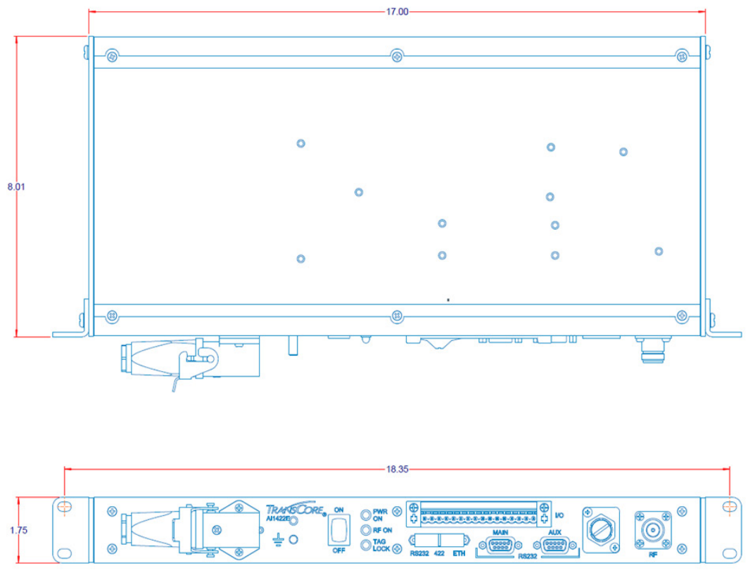

C
Lantronix® Ethernet
Module Configuration

AI1422E Reader
TransCore Proprietary 81
Appendix C
Lantronix® Ethernet Module Configuration
The AI1422E incorporates an Embedded Ethernet to Serial server from Lantronix ®. In order
to configure the Ethernet to Serial server, Lantronix software is required. The user guide for
the Lantronix ® XPort ® Direct + Embedded Serial-to-Ethernet server can be found at www.
lantronix.com/wp-content/uploads/pdf/XPort-Direct-Plus_UG.pdf.
The easiest way to connect to the AI1422E is by using the Lantronix ® CPR (Com Port
Redirector) software, which will allow connecting directly to the AI1422E through the
Ethernet Interface from a Windows computer. The Lantronix ® CPR software can be found
at http://ltxfaq.custhelp.com/app/answers/detail/a_id/928 and documentation of this
software can be found in the Lantronix ® CPR Quick Start Guide, located at www.lantronix.
com/wp-content/uploads/pdf/Com-Port-Redirector _QS.pdf
Other methods of communicating through the Lantronix ® module exist. Contact Lantronix ®
with questions.
Embedded Device: Lantronix ® XPort ® Direct + Embedded Serial-to-Ethernet
Lantronix ® Technical Support
Hours: 6:00am – 5:00pm Pacific Time
Mon. – Fri. (excluding holidays)
Tel: (800) 422-7044 (US Only)
Tel: (949) 453-7198
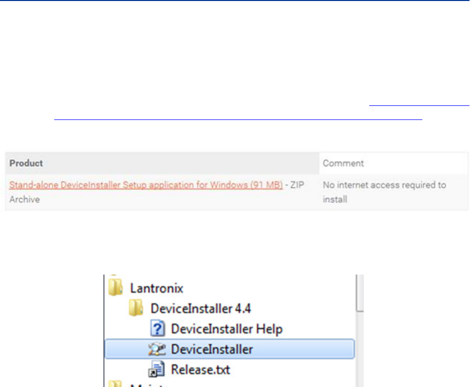
User Guide
TransCore Proprietary 82
Interface through Ethernet Port
To interface through the Ethernet port of the AI1442E, connect via the M12 Ethernet port
(Use an M12 to RJ45 adapter if required). A static IP address will need to be assigned to
your local host if directly connected or the reader may be attached to your network.
Setting up Local Host
1. Install the stand-alone DeviceInstaller (Figure 29) from the following link: This is
needed to know the IP address of the Ethernet to serial converter. http://ltxfaq.custhelp.
com/app/answers/detail/a_id/644?_ga=1.59440430.2035039615.1475511776
Figure 29 Install the Stand-alone DeviceInstaller
2. Once installed, launch DeviceInstaller (Figure 30) from the Start menu.
Figure 30 Launch DeviceInstaller from the Start Menu
3. If connecting directly to the computer’s Ethernet port, go to the computer’s network
setting and change the IP address and Subnet mask of the network interface controller
(NIC) card you are connecting to as shown in Figure 31 .
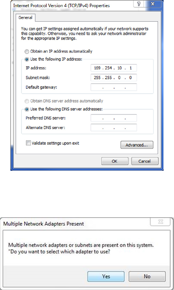
AI1422E Reader
TransCore Proprietary 83
Figure 31 Change IP Address and Submet Mask of NIC Card.
4. If the computer has multiple NIC cards, you might see a prompt similar to the prompt
shown in Figure 32. Select Yes.
Figure 32 Prompt if Computer has Multiple NIC cards
Choose the desired adapter and then select OK (Figure 33).
If you are connecting directly to your computer’s Ethernet port, choose the network
adapter with the 169.254.10.1 address.
If you are connecting to your corporate network, choose the Local Area Connection.
The selection can be changed at any time through the Options menu.
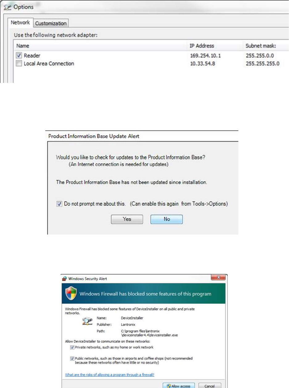
User Guide
TransCore Proprietary 84
Figure 33 NIC Card Options Screen
5. If you are not connecting through a network, configure the IP Address and the Subnet
mask as described in Step 3.
6. If prompted to check for updates, select No (Figure 34).
Figure 34 Check for Updates Prompt
7. If a firewall is present, disable it to allow access (Figure 35).
Figure 35 Disable Firewall to Allow Access
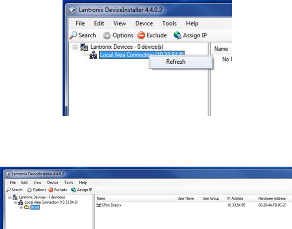
AI1422E Reader
TransCore Proprietary 85
Finding IP address of Reader
1. From the Lantronix DeviceInstaller right-click on the connection you choose and hit
refresh Figure 36).
Figure 36 Lantronix DeviceInstaller Menu
2. The Xport Direct+ device will populate on the right side of the window (Figure 37).
Figure 37 Finding the IP address of a Reader
3. Use the IP address to configure your terminal emulator Connection (Ex: PuTTY). Use
Telnet and Port 10001 Figure 37).
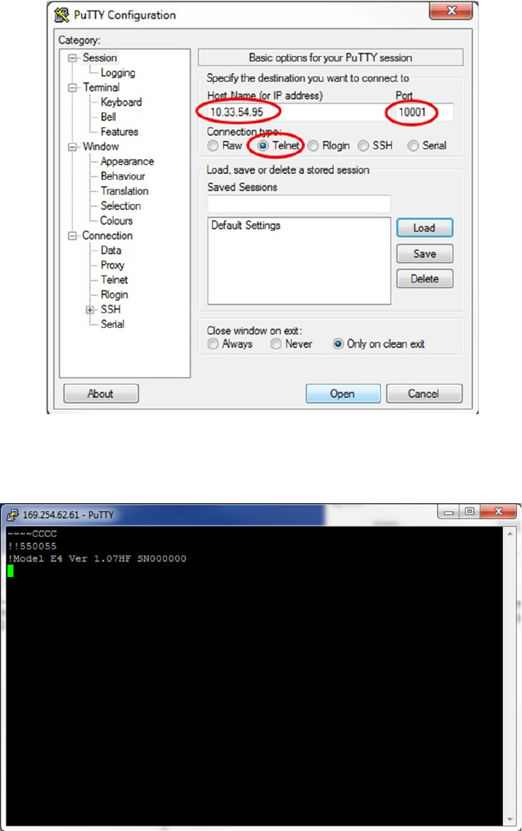
User Guide
TransCore Proprietary 86
Figure 38 PuTTY Configuration Screen
4. The opened connection is similar to a serial connection.
5. Ignore the local echo of the typed characters, if using PuTTY.
Figure 39 PuTTY Connection Screen

D
Command Quick Reference

User Guide
TransCore Proprietary 88
Appendix D
Command Quick Reference
This appendix lists the default configuration settings for the AI1422E and its commands.
Commands are listed both numerically and alphabetically.
Command Syntax
The command numbers consist of from 2 to 4 hex digits. The letters N or S may follow a
command number. The letter N indicates that part of the command number is variable.
The letter S indicates the requirement for an alphanumeric data string that is to be
included immediately following the command number. Hex digits (0–9, A–F) in either
uppercase or lowercase characters may be used in data strings and for hex digits A–F.
Table 30 lists factory default settings. Table 32 lists all of the commands available to users
in numerical order. Table 33 lists the same commands in alphabetical order by command
name.
Factory Default Settings
Note: Table 30 lists the factory default settings for the AI1422E.
Table 30 AI1422E Default Configuration Settings
Parameter Setting Command
Operating mode Data 00
Baud rate 9600 1005
Stop bits 1 1010
Parity None 1020
Time and data appended Enabled 302
Auxiliary information appended Disabled 310
Unique ID code criteria Separation of 1 ID 4100
Valid ID code criteria Acquisition of 1 ID 4200
Uniqueness time-out 2 minutes 441
Tag translation mode Disabled 452
Multi-tag sort Disabled 454
SeGo protocol tag initialization during
multi-tag sort
Enabled 456
Alternate Group Select Disabled 490
Reader ID number 00 6000
Communications protocol Basic 610

AI1422E Reader
TransCore Proprietary 89
Parameter Setting Command
Error protocol (ECP) timeout 12.7 sec 612FE
Echo mode Enabled 6171
Output Control Disabled 6200
Predefined Output Control Enabled 621
RF-by-input control Enabled By Sense 6421
ATA operating range (distance) Maximum 6431F
RF attenuation Full power(10-1422-5XX/10-
1422-8XX)
64400/64403
SeGo protocol operating range (distance) Maximum 6451F
Output Pulse Duration 67C
Presence without tag reports Disabled 6900
RF-o control Timeout or no presence 6922
RF timeout Never true 693F
Input inversion Disabled 6940
Serial number SSSSSS 695
Store hardware configuration Hardware configuration not
known
696
Automatic periodic RF status report Disabled 830
NOTE: Frequency doesn’t have a factory default and must be programmed by the
end user.
Legacy Commands
Legacy AI1422 commands will echo after a carriage return with echo o enabled. This
emulates how the legacy AI1422 performed. Refer to Table 31

User Guide
TransCore Proprietary 90
Table 31 Legacy Commands
Command Function Echo On Response Echol O Response
~~CC Enter Diagnostic
Mode (CC must be
upper case)
(no response) (no response)
!100x Baud rate select
1001 = 300 baud
1002 = 1200
baud
1003 = 2400
baud
1004 = 4800
baud
1005 = 9600
baud
1006 = 19200
baud
!Done !100X
!Done
!20hh:mm:ss Set the time in the
real-time clock
!Done !20hh:mm:ss
!Done
!21MM/DD/YY Set the date in the
real-time clock
!Done !21MM/DD/YY
!Done
!22 Display time and date !hh:mm:ss.hh MM/DD/
YY
!22
!hh:mm:ss.hh MM/DD/
YY
!40 Disable transmit all
tag ID codes
!Done !40
!Done
!41 Transmit all tag ID
codes
!Done !41
!Done
!505 Report firmware
version number
!Model E4 Ver
X.XXHFb2
SNXXXXXX
!505
!Model E4 Ver
X.XXHFb2
SNXXXXXX

AI1422E Reader
TransCore Proprietary 91
Command Function Echo On Response Echol O Response
!521 Report number of
handshakes
!RDID XX !RDID XX
!640 Disable RF !Done !640
!Done
!641 Enable RF !Done !641
!Done
!642 RF on by sense input !Done !642
!Done
!661 Manufacturing
Diagnostic RAM
Check (Not for
customer use)
!DIAG RX EX DX CX !DIAG RX EX DX CX
!662 Exit Diagnostic Mode !Done !662
Numerical Command List
The following conventions are used in Table 32:
• Items in bold italics identify factory default settings.
• Only the command-related data portion of the reader message is shown.
Refer to “Communications Protocols” on page 21 for the complete syntax of commands
and messages.
Table 32 AI1422E Commands Listed Numerically
Number Command Name Reader Message
00 Switch to data mode Done
01 Switch to command mode
1002 Set baud rate = 1200 baud Done
1003 Set baud rate = 2400 baud Done
1004 Set baud rate = 4800 baud Done
1005 Set baud rate = 9600 baud Done
1006 Set baud rate = 19.2 K baud Done
1007 Set baud rate = 38.4 K baud Done
1010 Use one stop bit Done
1011 Use two stop bits Done

User Guide
TransCore Proprietary 92
Number Command Name Reader Message
1020 Disable parity Done
1021 Select even parity Done
1022 Select odd parity Done
20 Set time Done
21 Set date Done
22 Display time and date Time and date
300 No time and date appended Done
302 Time and date appended Done
310 Disable aux info append Done
311 Enable aux info append Done
40 Disable Transmission All IDs Done
41 Transmit all IDs Done
4100 Select one ID separation Done
4101 Select two ID separation Done
4102 Select three ID separation Done
4103 Select four ID separation Done
4200 Select 1 valid ID code Done
4201 Select 2 valid ID codes Done
4202 Select 3 valid ID codes Done
4203 Select 4 valid ID codes Done
440 Reset uniqueness Done
441 Set uniqueness time-out to 2
minutes
Done
442 Set uniqueness time-out to 15
seconds
Done
443 Set uniqueness time-out to 30
seconds
Done
452 Disable tag translation mode Done
453 Enable tag translation mode Done
454 Disable multi-tag sort Done
455 Enable multi-tag sort Done

AI1422E Reader
TransCore Proprietary 93
Number Command Name Reader Message
456 Enable SeGo protocol tag
initialization during multi-tag
sort
Done
457 Disable SeGo protocol tag
initialization during multi-tag
sort
Done
480 Disable ATA Done if AI1422E model supports this
tag protocol. Error if tag protocol is
unsupported.
481 Enable ATA Done if AI1422E model supports this
tag protocol. Error if tag protocol is
unsupported.
484 Disable SeGo Done if AI1422E model supports this
tag protocol. Error if tag protocol is
unsupported.
485 Enable SeGo Done if AI1422E model supports this
tag protocol. Error if tag protocol is
unsupported.
488 Disable eATA Done if AI1422E model supports this
tag protocol. Error if tag protocol is
unsupported.
489 Enable eATA Done if AI1422E model supports this
tag protocol. Error if tag protocol is
unsupported.
505 Display version Model [model]
Ver [version no.] SN [serial no.]
506 Display hardware configuration
information
S...S
S...S = ASCII string (maximum length of
20 characters)
520 Display power fail bit PWRB Px R0
P0 = no power fail has occurred
P1 = power fail has occurred
R0 = not applicable to the AI1422E
521 Display reader ID number RDID xx
xx = 00–FF

User Guide
TransCore Proprietary 94
Number Command Name Reader Message
522 Display comm port parameters MAIN Bx Sx Px D0
B2 = 1200
B3 = 2400
B4 = 4800
B5 = 9600
B6 = 19.2
B7 = 38.4
S0 = one stop bit
S1 = two stop bits
P0 = no parity
P1 = even
P2 = odd
D0 = EOL delay of 0 ms
524 Display appended info status IDAP T0 D0 Xx
T0 = time not appended
T1 = time appended
D0 = date not appended
D1 = date appended
X0 = aux info not appended
X1 = aux info appended
525 Display comm protocol ECPS Px Txx Xx S0
P0 = basic
P1 = ECP
Txx = ECP timeout
ms = 50 * xx
FF = disabled ECP timeout
X0 = no flow control
X1 = software flow control
S0 = som character is #

AI1422E Reader
TransCore Proprietary 95
Number Command Name Reader Message
527 Display RF status RFST Cx Ox Tx Fxxx Rxx Gxx Axx I04
C0 = RF controlled by host
C1 = RF-by-presence sensor
O0 = RF o
O1 = RF on
T1 = uniqueness timeout of 2 min
T2 = uniqueness timeout of 15 sec
T3 = uniqueness timeout of 30 sec
Fxxx = RF output frequency, xxx = 000
to 118
Rxx = Tag decoder range (distance) for
ATA tags, 00 to 1F hexadecimal range
value
Gxx = Tag decoder range (distance) for
eGo Plus Tags, 00 to 1F hexadecimal
range value
Axx = RF power attenuation, 00 max to
0A min (10 dB less than max)
I04 = fixed
Note If you enter RF settings using
command #642NN, the display
command for RF output frequency,
F is “Fxx” and indicates use of the
backward-compatible frequency entry
method.

User Guide
TransCore Proprietary 96
Number Command Name Reader Message
529 Display presence input status PRST Px D0 Ax Tx Ix
P0 = disable presence w/o tag reports
P1 = enable presence w/o tag reports
D0 = min presence true period of 0 ms
A0 = RF o on timeout
A1 = RF o on timeout or tag
A2 = RF o on timeout or no presence
T0: RF timeout of 0 ms (always expired)
T1: RF timeout of 4 ms
T2: RF timeout of 8 ms
T3: RF timeout of 12 ms
T4: RF timeout of 20 ms
T5: RF timeout of 24 ms
T6: RF timeout of 32 ms
T7: RF timeout of 48 ms
T8: RF timeout of 60 ms
T9: RF timeout of 92 ms
TA: RF timeout of 152 ms
TB: RF timeout of 300 ms
TC: RF timeout of 452 ms
TD: RF timeout of 600 ms
TE: RF timeout of 752 ms
TF: RF timeout infinite, never expires
(factory default)
I0 = Input inversion disabled (factory
default)
I1 = Input inversion enabled
530 Display RF0 filter status RF0S Ux V0
U0 = one ID separation (factory default)
U1 = two ID separation
U2 = transmit all IDs
U3 = buer all IDs
V0 = valid ID code criteria of one
acquisition (factory default)
V1 = valid ID code criteria of two
acquisitions
V2 = valid ID code criteria of three
acquisitions
V3 = valid ID code criteria of four
acquisitions
534 Display tag translation mode
status
TT <0 to 1>
0 = tag translation mode disabled
1 = tag translation mode enabled

AI1422E Reader
TransCore Proprietary 97
Number Command Name Reader Message
537 Display echo status ECHO x
0 = disabled (factory default)
1 = enabled
540 Display flash checksum PCKS I0000 Exxxx
xxxx = 4-byte ASCII checksum
543 Display boot checksum BCKS xxxx
xxxx = 4-byte ASCII checksum
549 Get user-programmable group
select equals (GSE) filter data
The response data is formatted similar to
the data in the configuration command.
552 Request sensor status change Reader response:
MUX x<0 to 3> <AI1422E>
where
x = 0 antenna multiplexing disabled, RF
on port 0 only
x = 1 antenna multiplexing between RF
ports 0 and 1 when sense0 active
x = 2 antenna multiplexing between RF
ports 0 and 1 when sense0 active and
RF port 2 when sense1 active
x = 3 antenna multiplexing between RF
ports 0 and 1 when sense0 active and
RF ports 2 and 3 when sense1 active
AI1422E = AI1422E mode selected
560 Display input status change SSTC Ex Mx
E0 = status change reports disabled
E1 = status change reports enabled
M0 = no reporting
M1 = report change on Input 0
M2 = report change on Input 1
M3 = report change on either input
570 Display operating mode status ATA:<E, D> eGo:<I, F, D>
SeGo:<I, F, D> IAG:<E, D>
Sort:<E, D>
I = ID (64 bits)
E = Enabled
F = Full transaction (eATA)
D = Disabled
577 Report buered handshakes XX = number of handshakes

User Guide
TransCore Proprietary 98
Number Command Name Reader Message
60NN Set reader ID number NN =
00–FF
(00 = factory default)
Done
610 Select basic protocol Done
611 Select ECP protocol Done
612NN Set ECP timeout
NN = 01–FE (1–255)
timeout = 50 ms * NN
(if NN = FF, timeout is disabled)
Done
6140 Disable flow control Done
6141 Enable software flow control Done
6170 Disable echo Done
6171 Enable echo Done
63 Reset reader Model [model]
Ver [version no.] SN [serial no.]
Copyright [date]
TransCore
640 Turn o RF Done
641 Turn on RF Done
642 Select RF-by-input
control
Done
642NN Select RF operating frequency Done
643NN Set ATA operating range
(distance) NN = 00 (shortest) to
1F (longest)
1F = default
Done
644NN Set RF attenuation NN = 00 to 0A Done
645NN Set SeGo protocol operating
range (distance)
NN = 00 (shortest) to 1F (longest)
Done
647XXX Select RF operating frequency
from 860 to 930 in 250 kHz
steps
XXX = 000 - 118 (hexadecimal)
Done
65 Reset power fail bit Done

AI1422E Reader
TransCore Proprietary 99
Number Command Name Reader Message
66F Load default operating
parameters (except RF
operating frequency)
Done
661 Manufacturing Diagnostic RAM
Check (Not for customer use)
Command !661 is to be used by
manufacturing. Not for customer use.
662 Exits Command Mode.
6900 Disable presence without tag
reports
Done
6901 Enable presence without tag
reports
Done
6920 Turn RF o on timeout Done
6921 Turn RF o on timeout/tag Done
6922 Turn RF o on timeout/no
presence
Done
693N Set RF timeout
N = 0–F
(always expired, 4,8,12,20,24,
32,48,60,92,152, 300,452,
600,752, infinite)
Done
693F Set RF timeout = infinite Done
6940 Disable input inversion Done
6941 Enable input inversion Done
695S...S Set serial number
S...S = ASCII string (maximum
length of 6 characters)
Done
696S...S Store hardware configuration
string
S...S = ASCII string (maximum
length of 20 characters)
Done

User Guide
TransCore Proprietary 100
Number Command Name Reader Message
697 Set user-programmable group
select equals (GSE) filter
697 MM AA
DDDDDDDDDDDDDDDD
where
MM = determines which of the
eight comparison data bytes
are to be compared for the
Group Select filter
AA = determines the start
address in the tag memory for
the comparison data
D...D = 8-byte field (16 charac-
ters) used by the tag as the
comparison data for the group
select filter
Done
8110 Switch on RF port 0, fire o
check tag address 0 on check
tag pin 0
Done
8111 Switch on RF port 1, fire o
check tag address 1 on check
tag pin 0
Done
8112 Switch on RF port 2, fire o
check tag address 0 on check
tag pin 1
Done
8113 Switch on RF port 3, fire o
check tag address 1 on check
tag pin 1
Done
8142X Set check tag character on
check tag pin 0
Done
8143X Set check tag character on
check tag pin 1
Done
8150 Set check tag address to 0 on
check tag pin 0
Done
8151 Set check tag address to 1 on
check tag pin 0
Done
8152 Set check tag address to 0 on
check tag pin 1
Done
8153 Set check tag address to 1 on
check tag pin 1
Done

AI1422E Reader
TransCore Proprietary 101
Number Command Name Reader Message
830 Disable automatic periodic
RF status report
Done
831 Enable automatic periodic RF
status report
Done

User Guide
TransCore Proprietary 102
Alphabetical Command List
The following conventions are used in :
• Items in bold italics identify factory default settings.
• Only the command-related data portion of the reader message is shown.
Refer to “Command Codes” on page 24“Command Codes” on page 24 for the complete
syntax of commands and messages.
Table 33 AI1422E Commands Listed Alphabetically
Command Name Code Reader Message
All IDs transmit 41 Done
Appended info status display 524 IDAP T0 D0 Xx
T0 = time not appended
T1 = time appended
D0 = date not appended
D1 = date appended
X0 = aux info not appended
X1 = aux info appended
ATA disable 480 Done if AI1422E model supports this tag
protocol. Error if tag protocol is unsupported.
ATA enable 481 Done if AI1422E model supports this tag
protocol. Error if tag protocol is unsupported.
ATA operating range set
NN = 00 (shortest) to 1F
(longest)
1F = default
643NN Done
Automatic periodic RF status
report disable
830 Done
Automatic periodic RF status
report enable
831 Done
Aux info append disable 310 Done
Aux info append enable 311 Done
Basic protocol select 610 Done
Baud rate = 1200 baud set 1002 Done
Baud rate = 19.2 K baud set 1006 Done
Baud rate = 2400 baud set 1003 Done
Baud rate = 38.4 K baud set 1007 Done

AI1422E Reader
TransCore Proprietary 103
Command Name Code Reader Message
Baud rate = 4800 baud set 1004 Done
Baud rate = 9600 baud set 1005 Done
Boot checksum display 543 BCKS xxxx
xxxx = 4-byte ASCII checksum
Buered handshake report 577 XX = number of handshakes
Comm port parameters display 522 MAIN Bx Sx Px D0
B0 = 110
B1 = 300
B2 = 1200
B3 = 2400
B4 = 4800
B5 = 9600
B6 = 19.2
B7 = 38.4
S0 = one stop bit
S1 = two stop bits
P0 = no parity
P1 = even
P2 = odd
D0 = EOL delay of 0 ms
Comm protocol display 525 ECPS Px Txx Xx S0
P0 = basic
P1 = ECP
Txx = ECP timeout
ms = 50 * xx
TFF = disabled ECP timeout
X0 = no flow control
X1 = software flow control
S0 = SOM character is #
Command mode switch 01
Data mode switch 00 Done
Date set 21 Done
Default operating parameters
load (except RF operating
frequency)
66F Done
Default operating parameters
load (except RF operating
frequency)
66F Done
Disable Transmission All IDs 40 Done

User Guide
TransCore Proprietary 104
Command Name Code Reader Message
eATA disable 488 Done if AI1422E model supports this tag
protocol. Error if tag protocol is unsupported.
eATA enable 489 Done if AI1422E model supports this tag
protocol. Error if tag protocol is unsupported.
Echo disable 6170 Done
Echo enable 6171 Done
Echo status display 537 ECHO x
0 = disabled
1 = enabled
ECP protocol select 611 Done
ECP timeout set = 12.7 sec 612FE Done
ECP timeout set
NN = 01–FE (1–255)
timeout = 50 ms * NN
(if NN = FF, timeout is disabled)
612NN Done
Even parity select 1021 Done
Flash checksum display 540 PCKS I0000 Exxxx
xxxx = 4-byte ASCII checksum
Flow control disable 6140 Done
Get user-programmable group
select equals (GSE) filter data
549 The response data is formatted similar to the
data in the configuration command.
Hardware configuration
information display
506 S...S
S...S = ASCII string (maximum length of 20
characters)
Hardware configuration
string store
S...S = ASCII string (maximum
length of 20 characters)
696S...S Done
Input inversion disable 6940 Done
Input inversion enable 6941 Done
Input status change display 560 SSTC Ex Mx
E0 = status change reports disabled
E1 = status change reports enabled
M0 = no reporting
M1 = report change on Input 0
M2 = report change on Input 1
M3 = report change on either input
Multi-tag sort disable 454 Done

AI1422E Reader
TransCore Proprietary 105
Command Name Code Reader Message
Multi-tag sort enable 455 Done
Odd parity select 1022 Done
Operating mode status display 570 ATA:<E, D>
eGo:<I, F, D>
SeGo:<I, F, D>
IAG:<E, D>
Sort:<E, D>
I = ID (64 bits) E = Enabled
F = Full transaction (eATA) D = Disabled
Parity disable 1020 Done
Power fail bit display 520 PWRB Px R0
P0 = no power fail has occurred
P1 = power fail has occurred
R0 = not applicable
Power fail bit reset 65 Done
Presence input status display 529 PRST Px D0 Ax Tx Ix
P0 = disable presence w/o tag reports
P1 = enable presence w/o tag reports
D0 = min presence true period of 0 ms
A0 = RF o on timeout
A1 = RF o on timeout or tag
A2 = RF o on timeout or no presence
T0: RF timeout of 0 ms (always expired)
T1: RF timeout of 4 ms
T2: RF timeout of 8 ms
T3: RF timeout of 12 ms
T4: RF timeout of 20 ms
T5: RF timeout of 24 ms
T6: RF timeout of 32 ms
T7: RF timeout of 48 ms
T8: RF timeout of 60 ms
T9: RF timeout of 92 ms
TA: RF timeout of 152 ms
TB: RF timeout of 300 ms
TC: RF timeout of 452 ms
TD: RF timeout of 600 ms
TE: RF timeout of 752 ms
TF: RF timeout infinite, never expires
(factory default)
I0 = Input inversion disabled (factory default)
I1 = Input inversion enabled

User Guide
TransCore Proprietary 106
Command Name Code Reader Message
Presence without tag reports
disable
6900 Done
Presence without tag reports
enable
6901 Done
Reader ID number display 521 RDID xx
xx = 00–FF
Reader ID number set NN =
00-FF
(00 = factory default)
60NN Done
Reader reset 63 Model [model]
Ver [version no.] SN [serial no.]
Copyright [date]
TransCore
Report changes both 823 Done
RF attenuation set NN = 00 to 0A 644NN Done
RF o on timeout 6920 Done
RF o on timeout/no presence 6922 Done
RF o on timeout/tag 6921 Done
RF turn o 6400 Done
RF turn on 6401 Done
RF on by input control 641 Done
RF operating frequency
from 860 to 930 in 250 kHz
steps select XXX = 000 - 118
(hexadecimal)
647XXX Done
RF operating frequency select 642NN Done

AI1422E Reader
TransCore Proprietary 107
Command Name Code Reader Message
RF status display 527 RFST Cx Ox Tx Fxxx Rxx Gxx Axx I04
C0 = RF controlled by host
C1 = RF-by-presence sensor
O0 = RF o
O1 = RF on
T1 = uniqueness timeout of 2 min
T2 = uniqueness timeout of 15 sec
T3 = uniqueness timeout of 30 sec
Fxxx = RF output frequency, xxx = 000 to 118
Rxx = Tag decoder range (distance) for ATA
tags, 00 to 1F hexadecimal range value
Gxx = Tag decoder range (distance) for eGo
Plus Tags, 00 to 1F hexadecimal range value
Axx = RF power attenuation, 00 max to 0A
min (10 dB less than max)
I04 = fixed
Note: If you enter RF settings using
command #642NN, the display command
for RF output frequency, F is “Fxx” and
indicates use of the backward- compatible
frequency entry method.
RF timeout = infinite set 693F Done
RF timeout set
N = 0–F
(always expired 4, 8, 12, 20, 24,
32, 48, 60, 92, 152, 300, 452,
600, 752 ms, infinite)
693N Done
RF0 filter status display 530 RF0S Ux V0
U0 = one ID separation
U1 = two ID
U2 = transmit all
SeGo disable 484 Done if AI1422E model supports this tag
protocol. Error if tag protocol is unsupported.
SeGo enable 485 Done if AI1422E model supports this tag
protocol. Error if tag protocol is unsupported.
SeGo protocol operating range
set NN = 00 (shortest) to 1F
(longest)
645NN Done
SeGo protocol tag
initialization during multi-tag
sort
456 Done

User Guide
TransCore Proprietary 108
Command Name Code Reader Message
SeGo protocol tag initialization
during multi-tag sort disable
457 Done
Serial number set S...S = ASCII
string (maximum length of 6
characters)
695S...S Done
Set check tag character on
check tag pin 0
8142X Done
Set check tag character on
check tag pin 1
8143X Done
Set check tag address to 0 on
check tag pin 0
8150 Done
Set check tag address to 1 on
check tag pin 0
8151 Done
Set check tag address to 0 on
check tag pin 1
8152 Done
Set check tag address to 1 on
check tag pin 1
8153 Done
Set user-programmable group
select equals (GSE) filter
697 MM AA
DDDDDDDDDDDDDDDD
where
MM = determines which of the
eight comparison data bytes
are to be compared for the
Group Select filter
AA = determines the start ad-
dress in the tag memory for the
comparison data
D...D = 8-byte field (16 charac-
ters) used by the tag as the
com- parison data for the
group select filter
697 Done
Software flow control enable 6141 Done
Stop bit use one 1010 Done
Stop bit use two 1011 Done
Switch on RF port 0, fire o
check tag address 0 on check
tag pin 0
8110 Done
Switch on RF port 1, fire o
check tag address 1 on check
tag pin 0
8111 Done

AI1422E Reader
TransCore Proprietary 109
Command Name Code Reader Message
Switch on RF port 2, fire o
check tag address 0 on check
tag pin 1
8112 Done
Switch on RF port 3, fire o
check tag address 1 on check
tag pin 1
8113 Done
Tag ID separation select four 4103 Done
Tag ID separation select one 4100 Done
Tag ID separation select three 4102 Done
Tag ID separation select two 4101 Done
Tag translation mode status
display
534 TT <0 to 1>
0 = tag translation mode disabled
1 = tag translation mode enabled
Time and date appended 302 Done
Time and date display 22 Time and date
Time and date not appended 300 Done
Time set 20 Done
Uniqueness reset 440 Done
Uniqueness time-out set to 2
minutes
441 Done
Uniqueness time-out set to 15
seconds
442 Done
Uniqueness time-out set to 30
seconds
443 Done
Valid ID code select four 4203 Done
Valid ID code select one 4200 Done
Valid ID code select three 4202 Done
Valid ID code select two 4201 Done
Version display 505 Model [model]
Ver [ver no.] SN [serial no.]
Command Name Code Reader Message
SeGo protocol tag initialization
during multi-tag sort disable
457 Done
Serial number set S...S = ASCII
string (maximum length of 6
characters)
695S...S Done
Set check tag character on
check tag pin 0
8142X Done
Set check tag character on
check tag pin 1
8143X Done
Set check tag address to 0 on
check tag pin 0
8150 Done
Set check tag address to 1 on
check tag pin 0
8151 Done
Set check tag address to 0 on
check tag pin 1
8152 Done
Set check tag address to 1 on
check tag pin 1
8153 Done
Set user-programmable group
select equals (GSE) filter
697 MM AA
DDDDDDDDDDDDDDDD
where
MM = determines which of the
eight comparison data bytes
are to be compared for the
Group Select filter
AA = determines the start ad-
dress in the tag memory for the
comparison data
D...D = 8-byte field (16 charac-
ters) used by the tag as the
com- parison data for the
group select filter
697 Done
Software flow control enable 6141 Done
Stop bit use one 1010 Done
Stop bit use two 1011 Done
Switch on RF port 0, fire o
check tag address 0 on check
tag pin 0
8110 Done
Switch on RF port 1, fire o
check tag address 1 on check
tag pin 0
8111 Done

For more information:
Sales Support
800.923.4824
Technical Support
505.856.8007
transcore.com
Trusted Transportation Solutions
© 2017 TransCore L.P. All rights reserved. TRANSCORE is a registered trademark, and
is used under license. All other trademarks listed are the property of their respective
owners. Contents subject to change. Printed in the U.S.A.