TransCore AP411805430 Low power RFID tag programmer transmitter User Manual AP4118 TagProg
TransCore Low power RFID tag programmer transmitter AP4118 TagProg
UserManual.wiki
>
TransCore
>
AP411805430 User Manual
USERS MANUAL
Navigation menu
Upload a User Manual
Namespaces
Wiki Guide
HTML
PDF
Info
Views
User Manual
Discussion / Help
Navigation


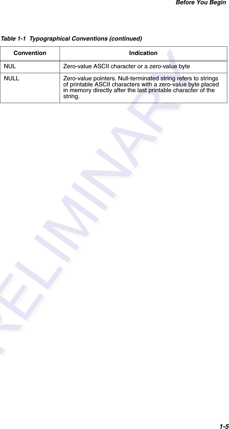


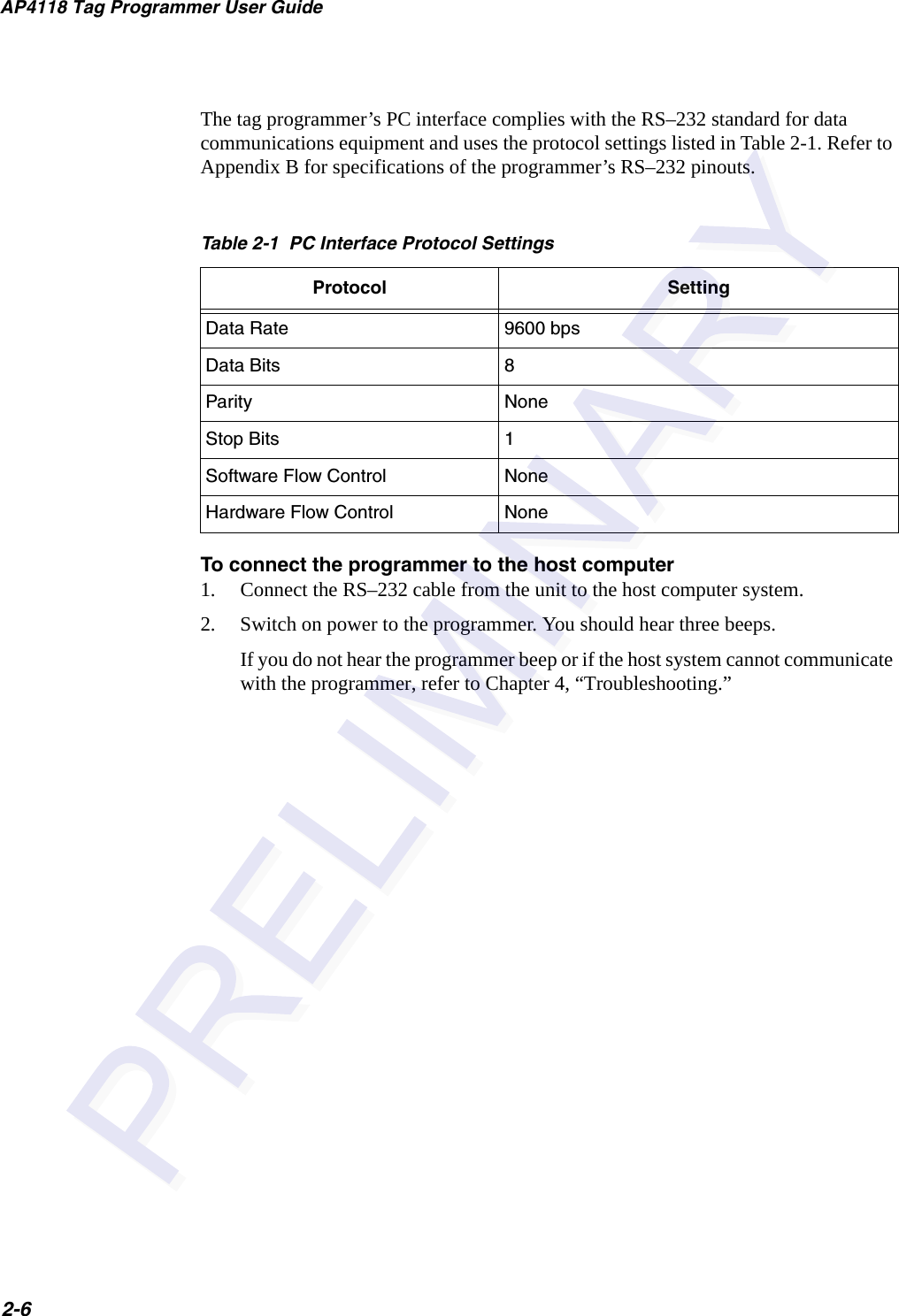


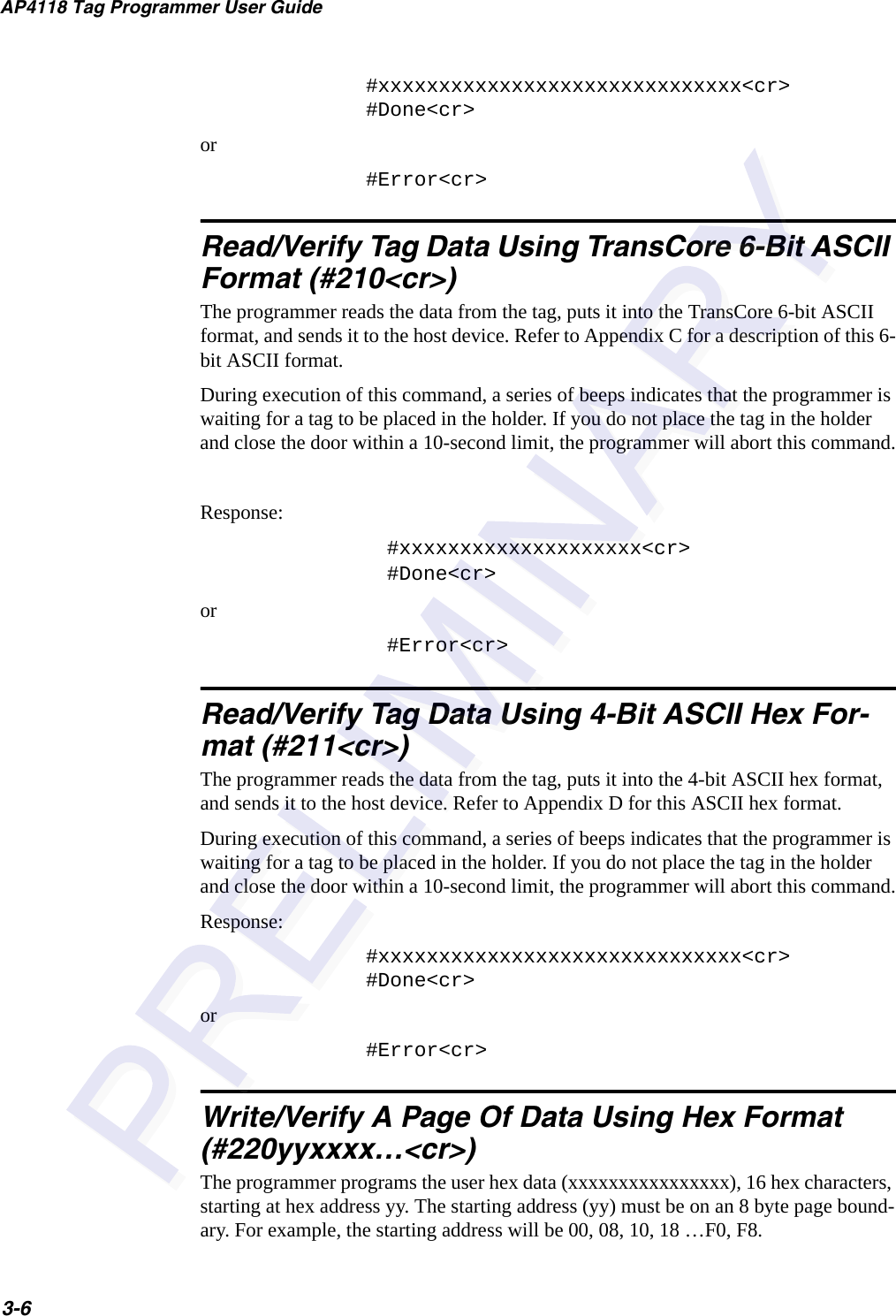


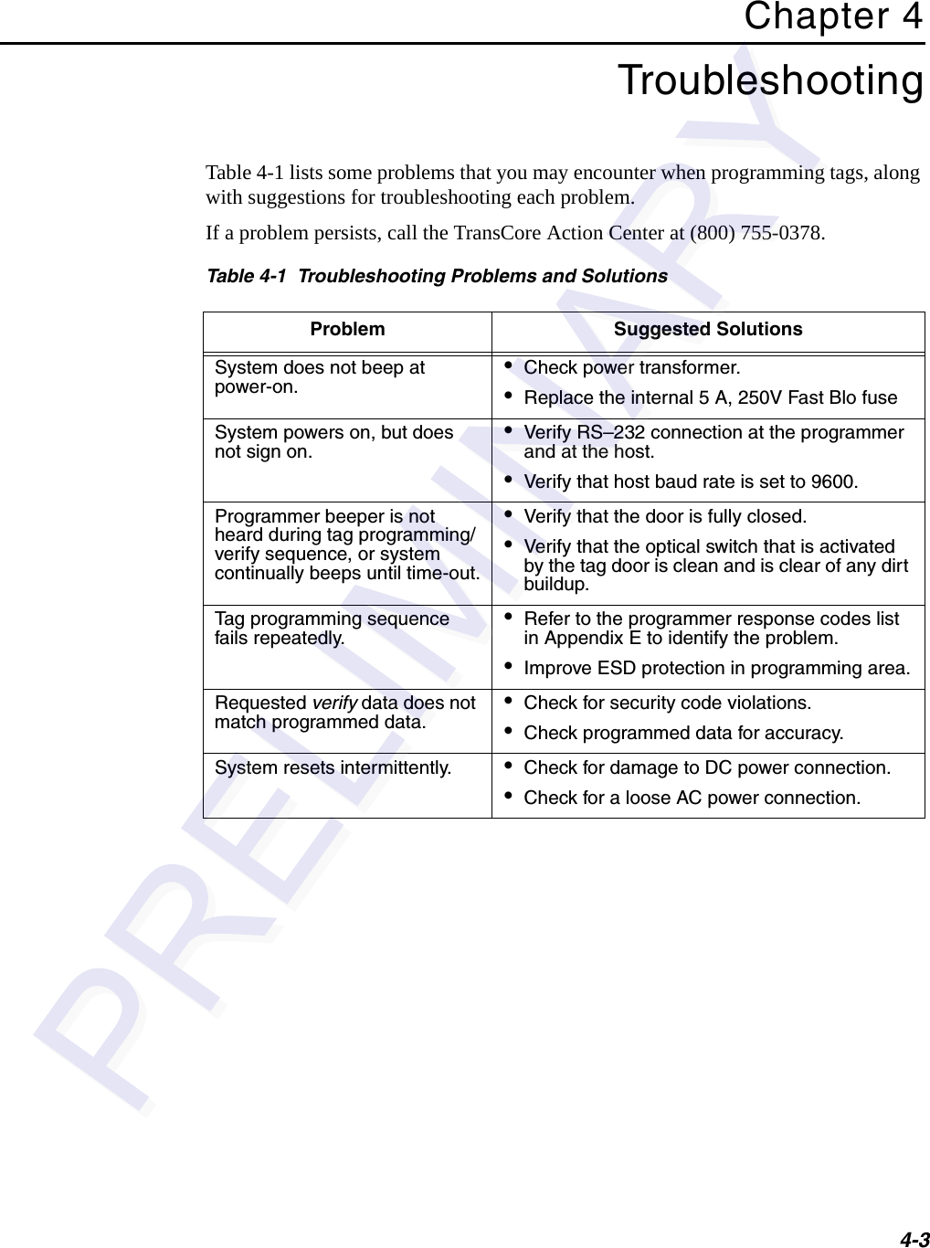


![F-3Appendix FSecurity CharactersYou may enter security characters into an Amtech tag if your programmer has been configured at the factory to perform the security character function. These ASCII security characters are encoded in the Amtech 6-bit data encoding scheme, and are listed in Table F-1.Table F-1 ASCII Security CharactersCharacter 6-bit Code!000001"000010#000011$000100%000101&000110'000111(001000)001001+001011,001100:011010;011011<011100=011101>011110?011111@100000[111011\111100]111101^111110_111111space 000000](https://usermanual.wiki/TransCore/AP411805430/User-Guide-537730-Page-61.png)
