TransCore AP411805430 Low power RFID tag programmer transmitter User Manual AP4118 TagProg
TransCore Low power RFID tag programmer transmitter AP4118 TagProg
USERS MANUAL

AP4118 Tag Programmer User
Guide
TransCore, Inc.
19111 Dallas Parkway, Suite 300
Dallas, Texas 75287-3106
March 2005
P/N 411854


©2005 TC IP, Ltd. All rights reserved. TRANSCORE and AMTECH are registered trademarks of TC IP, Ltd.,
and are used under license. All other trademarks listed are the property of their respective owners. Contents are
subject to change. Printed in the U.S.A.
For further information, contact:
TransCore
19111 Dallas Parkway, Suite 300
Dallas, Texas 75287-3106 USA
Phone: (972) 733-6600
Fax: (972) 733-6699
TransCore Action Center (TrAC)
19111 Dallas Parkway, Suite 300
Dallas, Texas 75287-3106 USA
Phone: (800) 755-0378
Fax: (972) 733-6695

WARNING TO USERS IN THE UNITED STATES
FEDERAL COMMUNICATIONS COMMISSION (FCC) RADIO FREQUENCY
INTERFERENCE STATEMENT
47 CFR §15.105(a)
NOTE: This equipment has been tested and found to comply with the limits for a Class A digital device
pursuant to Part 15 of the Federal Communications Commission (FCC) rules. These limits are designed to
provide reasonable protection against harmful interference when the equipment is operated in a
commercial environment. This equipment generates, uses, and can radiate radio frequency (RF) energy and
may cause harmful interference to radio communications if not installed and used in accordance with the
instruction manual. Operating this equipment in a residential area is likely to cause harmful interference, in
which case, depending on the laws in effect, the users may be required to correct the interference at their
own expense.
NO UNAUTHORIZED MODIFICATIONS
47 CFR §15.21
CAUTION: This equipment may not be modified, altered, or changed in any way without permission
from TransCore, Inc. Unauthorized modification may void the equipment authorization from the FCC and
will void the TransCore warranty.
USE OF SHIELDED CABLES IS REQUIRED
47 CFR §15.27(a)
Shielded cables must be used with this equipment to comply with FCC regulations.
A license issued by the FCC is required to operate this RF identification device in the United States.
Contact TransCore, Inc. for additional information concerning licensing requirements for specific devices.
TransCore, Inc.
USA

Contents


vii
Contents
1 Before You Begin
Purpose of This Guide. . . . . . . . . . . . . . . . . . . . . . . . . . . . . . . . . . . . . . . . . . . . . 1-3
Intended Audience . . . . . . . . . . . . . . . . . . . . . . . . . . . . . . . . . . . . . . . . . . . . . . . . 1-3
Related Documents . . . . . . . . . . . . . . . . . . . . . . . . . . . . . . . . . . . . . . . . . . . . . . . 1-3
Guide Topics . . . . . . . . . . . . . . . . . . . . . . . . . . . . . . . . . . . . . . . . . . . . . . . . . . . . 1-3
Typographical Conventions . . . . . . . . . . . . . . . . . . . . . . . . . . . . . . . . . . . . . . . . 1-4
2 Setting up the Programmer
Required Supplies to Operate the Tag Programmer . . . . . . . . . . . . . . . . . . . . 2-3
Preventing Electrostatic Discharge Damage. . . . . . . . . . . . . . . . . . . . . . . . . . . 2-3
Antistatic Workstation . . . . . . . . . . . . . . . . . . . . . . . . . . . . . . . . . . . . . . . . . . . . 2-4
Using the ESD Wrist Strap . . . . . . . . . . . . . . . . . . . . . . . . . . . . . . . . . . . . . . 2-4
Antistatic Mat . . . . . . . . . . . . . . . . . . . . . . . . . . . . . . . . . . . . . . . . . . . . . . . . 2-5
Ionized Air Blower. . . . . . . . . . . . . . . . . . . . . . . . . . . . . . . . . . . . . . . . . . . . . 2-5
ESD-Safe Tags Container . . . . . . . . . . . . . . . . . . . . . . . . . . . . . . . . . . . . . . 2-5
Connecting the Host Device . . . . . . . . . . . . . . . . . . . . . . . . . . . . . . . . . . . . . . . . 2-5
3 Operating the Programmer
Before You Program Tags. . . . . . . . . . . . . . . . . . . . . . . . . . . . . . . . . . . . . . . . . . 3-3
Indicator Lights . . . . . . . . . . . . . . . . . . . . . . . . . . . . . . . . . . . . . . . . . . . . . . . . . . 3-3
Sign-On . . . . . . . . . . . . . . . . . . . . . . . . . . . . . . . . . . . . . . . . . . . . . . . . . . . . . . . . . 3-4
Command Execution Protocol . . . . . . . . . . . . . . . . . . . . . . . . . . . . . . . . . . . . . . 3-4
RS–232 Command Set . . . . . . . . . . . . . . . . . . . . . . . . . . . . . . . . . . . . . . . . . . . . . 3-4
Enable Tone Generator (#120<cr>) . . . . . . . . . . . . . . . . . . . . . . . . . . . . . . . . . 3-5
Disable Tone Generator (#121<cr>) . . . . . . . . . . . . . . . . . . . . . . . . . . . . . . . . . 3-5
Program Tag Using TransCore 6-Bit ASCII Format (#200xxx...<cr>) . . . . . . . . 3-5

AP4118 Tag Programmer User Guide
viii
Program Tag Using 4-Bit ASCII Hex Format (#201xxx...<cr>) . . . . . . . . . . . . . 3-5
Read/Verify Tag Data Using TransCore 6-Bit ASCII Format (#210<cr>) . . . . . 3-6
Read/Verify Tag Data Using 4-Bit ASCII Hex Format (#211<cr>) . . . . . . . . . . 3-6
Write/Verify A Page Of Data Using Hex Format (#220yyxxxx…<cr>). . . . . . . . 3-6
Write/Verify A Byte Of Data Using Hex Format (#221yyxx<cr>) . . . . . . . . . . . . 3-7
Read A Page Of Data Using Hex Format (#230yy<cr>) . . . . . . . . . . . . . . . . . . 3-7
Read A Byte Of Data Using Hex Format (#231yy<cr>). . . . . . . . . . . . . . . . . . . 3-8
System Reset (#30<cr>) . . . . . . . . . . . . . . . . . . . . . . . . . . . . . . . . . . . . . . . . . . 3-8
Display System Status (#40<cr>) . . . . . . . . . . . . . . . . . . . . . . . . . . . . . . . . . . . 3-9
Display Tag Door Switch Status (#42<cr>) . . . . . . . . . . . . . . . . . . . . . . . . . . . . 3-9
Programming a Tag . . . . . . . . . . . . . . . . . . . . . . . . . . . . . . . . . . . . . . . . . . . . . . . 3-9
Verifying Tag Data . . . . . . . . . . . . . . . . . . . . . . . . . . . . . . . . . . . . . . . . . . . . . . . 3-10
Security Characters . . . . . . . . . . . . . . . . . . . . . . . . . . . . . . . . . . . . . . . . . . . . . . 3-11
4 Troubleshooting
A Tag Programmer Specifications
Environmental . . . . . . . . . . . . . . . . . . . . . . . . . . . . . . . . . . . . . . . . . . . . . . . . . . A-3
B RS–232 Connector Pin-outs
C TransCore 6-Bit ASCII Format
D 4-Bit ASCII Hex Codes
E Programmer Response Codes
F Security Characters

Contents
ix
List of Figures
Figure 2-1 Programming Workstation with ESD Controls . . . . . . . . . . . . . . . . . . . . . . . . . . . . 2-4
Figure 2-2 Serial Interface Connector . . . . . . . . . . . . . . . . . . . . . . . . . . . . . . . . . . . . . . . . 2-5
Figure 3-1 AP4118 Programmer Indicator Lights . . . . . . . . . . . . . . . . . . . . . . . . . . . . . . . . . 3-3
Figure 3-2 Tag in Tag Holder . . . . . . . . . . . . . . . . . . . . . . . . . . . . . . . . . . . . . . . . . . . . . 3-10
List of Tables
Table 1-1 Typographical Conventions . . . . . . . . . . . . . . . . . . . . . . . . . . . . . . . . . . . . . . . . 1-4
Table 2-1 PC Interface Protocol Settings . . . . . . . . . . . . . . . . . . . . . . . . . . . . . . . . . . . . . . 2-6
Table 4-1 Troubleshooting Problems and Solutions . . . . . . . . . . . . . . . . . . . . . . . . . . . . . . . 4-3
Table A-1 AP4118 Tag Programmer Physical and Environmental Specifications . . . . . . . . . . . . A-3
Table B-1 RS–232 Connector Pin-outs . . . . . . . . . . . . . . . . . . . . . . . . . . . . . . . . . . . . . . . . B-3
Table C-1 6-Bit ASCII Codes . . . . . . . . . . . . . . . . . . . . . . . . . . . . . . . . . . . . . . . . . . . . . . . C-3
Table D-1 4-Bit ASCII Hex Codes . . . . . . . . . . . . . . . . . . . . . . . . . . . . . . . . . . . . . . . . . . . . D-3
Table E-1 Programmer Response Codes . . . . . . . . . . . . . . . . . . . . . . . . . . . . . . . . . . . . . . . E-3
Table F-1 ASCII Security Characters . . . . . . . . . . . . . . . . . . . . . . . . . . . . . . . . . . . . . . . . . F-3

AP4118 Tag Programmer User Guide
x

1
Before You Begin


1-3
Chapter 1
Before You Begin
The AP4118 Tag Programmer User Guide provides information
necessary for installing, operating, and troubleshooting the AP4118 Tag
Programmer.
Purpose of This Guide
This AP4118 Tag Programmer User Guide discusses the proper setup and operation
of the AP4118 Tag Programmer. This guide also provides procedures useful in trou-
bleshooting any problems encountered after installation.
Intended Audience
The AP4118 Tag Programmer User Guide is designed to be used by technical person-
nel responsible for installing and operating AP4118 Tag Programmer and related soft-
ware.
Related Documents
AP4118 Tag Programming Software User’s Guide
Guide Topics
This document presents the following information:
Chapter 1 – Before You
Begin
Describes the purpose, intended audience, guide topics, related
documentation, and document conventions.
Chapter 2 – Setting Up
the Programmer
Provides instructions for setting up the tag programmer, preventing
electrostatic discharge damage, and connecting the programmer to a host
computer system.
Chapter 3 – Operating
the Programmer
Describes how to program a tag and how to verify or read the data. This
chapter also lists the RS–232 command set and describes the security
character operation.
Chapter 4 – Trouble-
shooting Procedures
Lists problems that may be encountered during tag programmer operation and
suggested solutions.
Appendix A – Program-
mer Specifications
Provides the programmer’s physical and environmental specifications.
AP4118 Tag Programmer User Guide
1-4
Typographical Conventions
Table 1-1 lists the conventions used in this manual.
Appendix B – RS–232
Connector Pin-outs
Describes the interface configuration to a host computer.
Appendix C – TransCore
6-Bit ASCII Format
Lists TransCore’s 6-bit ASCII character codes.
Appendix D – 4-Bit ASCII
Hex Codes
Lists TransCore’s 4-bit hexadecimal formats.
Appendix E – Program-
mer Response Codes
Lists the tag programmer response codes.
Appendix F – Security
Characters
Lists the 6-bit security character codes.
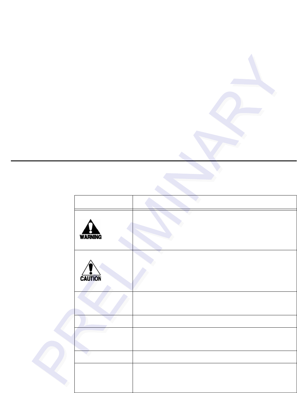
Table 1-1 Typographical Conventions
Convention Indication
This procedure might cause harm to the equipment and/or
the user.
Concerns about a procedure
Code Code, including keywords and variables within text and as
separate paragraphs, and user-defined program elements
within text appear in courier typeface.
Dialog Box Title Title of a dialog box as it appears on screen
Function Start with the characters, G4, and are in mixed case with no
underscores, and include parentheses after the name, as in
G4FunctionName().
Menu Item Appears on a menu. Capitalization follows the interface.
Note Auxiliary information that further clarifies the current
discussion. These important points require the user’s
attention. The paragraph is in italics and the word Note is
boldface.

Before You Begin
1-5
NUL Zero-value ASCII character or a zero-value byte
NULL Zero-value pointers. Null-terminated string refers to strings
of printable ASCII characters with a zero-value byte placed
in memory directly after the last printable character of the
string.
Table 1-1 Typographical Conventions (continued)
Convention Indication

AP4118 Tag Programmer User Guide
1-6

2
Setting up the Programmer


2-3
Chapter 2
Setting up the Programmer
This chapter provides instructions for setting up the tag programmer,
preventing electrostatic discharge (ESD) damage to tags, and
connecting to a host computer.
Required Supplies to Operate the Tag Programmer
The programmer is shipped with the items listed below. When unpacking your order,
make sure all of the following items are included.
•AP4118 Tag Programmer
•Tag Programming software compact disk (CD)
•AP4118 Tag Programming Software User Guide
•Power transformer and cable to convert AC voltage to 12V DC
•Static-suppression wrist strap
•Programmer-to-PC RS–232 connecting cable
If any of the above items are missing from your order, contact your TransCore
distributor.
Either a host system—such as a personal computer (PC)—or a communications
terminal is required to operate the programmer. TransCore does not supply this
equipment for the AP4118 Tag Programmer.
Preventing Electrostatic Discharge Damage
Caution
TransCore tags are sensitive to ESD, and precautions are necessary to ensure
proper tag programming operation. Use the grounded ESD static-suppression wrist
strap whenever using the programmer. Additional protection from ESD is recom-
mended where practicable.
Static is generated by friction. Some causes of static include the following:
•Shoes moving across a carpeted or plastic floor
•Hot air blowing into a room from a hot-air duct
•Rubbing tags together
AP4118 Tag Programmer User Guide
2-4
•Rubbing tags across a table top
•Wearing certain types of clothing
Electrostatic discharge may cause significant damage to the tag and will adversely
affect a tag’s operating performance. Typical symptoms of ESD include the
following:
•Inability to program the tag
•Greatly reduced operating range
•Tag operating failure
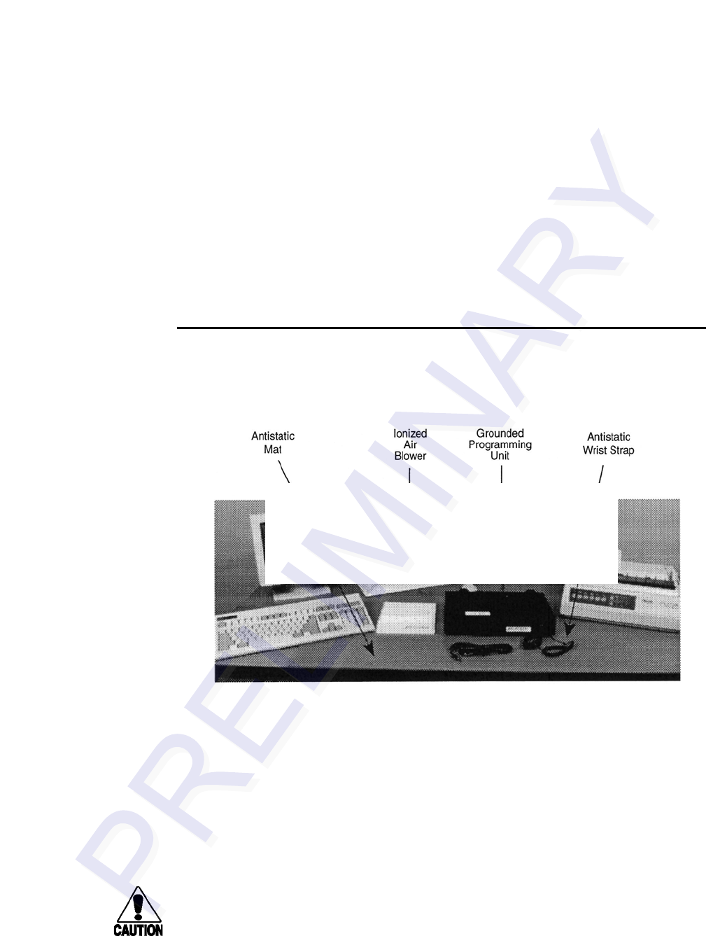
Antistatic Workstation
In a factory or fixed indoor environment, position the programmer in an antistatic
workstation. Well-designed workstations use a system of multiple precautions against
ESD. Figure 2-1 shows an antistatic workstation.
Figure 2-1 Programming Workstation with ESD Controls
Contact the TransCore Action Center at (800) 755-0378 if you have any questions
concerning the suitability of your programming station or environment.
You can take several precautions to prevent ESD from affecting programming
operations. The most effective precautions are listed below. The potential for ESD
damage decreases when two or more precautions are used together.
Using the ESD Wrist Strap
Caution
You should always attach the ESD wrist strap before beginning programming oper-
ations in any setting.
1. Be sure the programmer is connected to an earth ground.
NEW PHOTO TO BE SUPPLIED FOR
FINAL DOCUMENT
Setting up the Programmer
2-5
2. Connect the banana plug of the ESD wrist strap to the ESD jack on the front of
the unit.
3. Attach the ESD strap to your wrist by adjusting the hook and loop material.
Antistatic Mat
The antistatic work mat on which your programmer sits should be connected to earth
ground through the standard 1 M-ohm resistance that should be provided with the mat.
The mat should also be clean and free of any electrical path to direct earth ground.
Ionized Air Blower
You may choose to set up an ionized air blower at your workstation to provide
additional ESD protection. Ionized air blowers neutralize tags from static build-up
before programming.
ESD-Safe Tags Container
Keep tags in the original box on an antistatic mat or within an ESD-safe container
until they are programmed. Grounded metallic containers are best for inhibiting ESD.
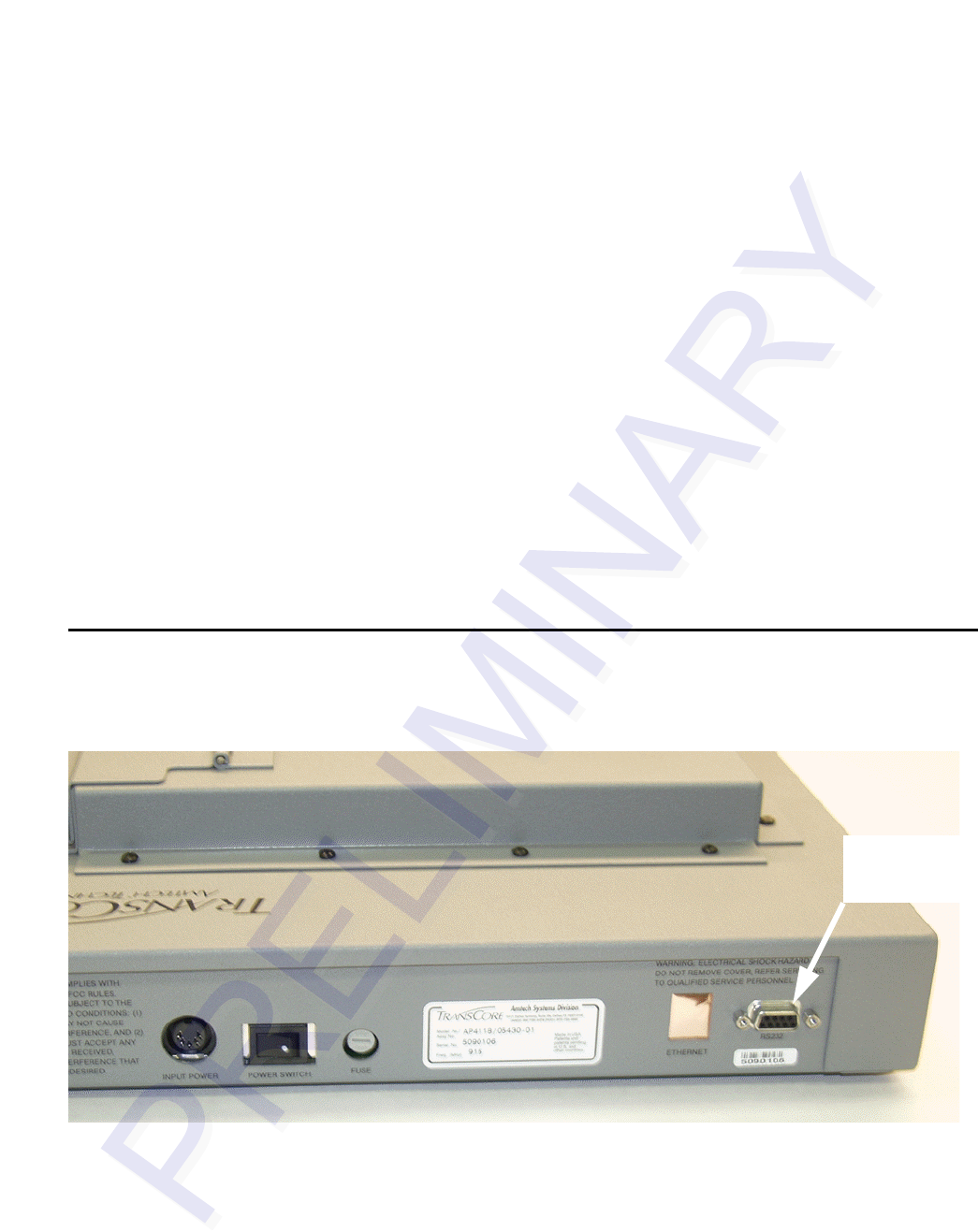
Connecting the Host Device
The programmer requires connection to a host device—a host computer or
communications terminal—for normal operation. Figure 2-2 shows the connector
from the programmer to the host.
Figure 2-2 Serial Interface Connector
If the host system is a PC or a communications terminal, then a null modem will not
be required.
Serial
Interface
Connector

AP4118 Tag Programmer User Guide
2-6
The tag programmer’s PC interface complies with the RS–232 standard for data
communications equipment and uses the protocol settings listed in Table 2-1. Refer to
Appendix B for specifications of the programmer’s RS–232 pinouts.
To connect the programmer to the host computer
1. Connect the RS–232 cable from the unit to the host computer system.
2. Switch on power to the programmer. You should hear three beeps.
If you do not hear the programmer beep or if the host system cannot communicate
with the programmer, refer to Chapter 4, “Troubleshooting.”
Table 2-1 PC Interface Protocol Settings
Protocol Setting
Data Rate 9600 bps
Data Bits 8
Parity None
Stop Bits 1
Software Flow Control None
Hardware Flow Control None

3
Operating the Programmer

3-3
Chapter 3
Operating the Programmer
This chapter describes how to program a tag and how to verify or read
back the data. This chapter also lists the RS–232 command set and
describes the security character operation.
Before You Program Tags
Before programming, the programmer system must be set up as specified in Chapter
2, “Setting Up the Programmer.” The programmer must be connected either to a host
system running Tag Programming (TP) software or to a communications terminal.
You will need to manually enter the RS–232 control commands if you are using a
communications terminal.
To load and use the TP software for programming tags, refer to the AP4118 Tag
Programming Software User Guide provided with the programmer.
To operate the programmer using a communications terminal or a personal computer
that does not use TP software, follow the steps in the Tag Programming Sequence and/
or Tag Verification Sequence sections of this chapter, as appropriate to your task. Use
the programmer commands listed in the RS–232 Command Set in this chapter.
The programmer is powered by 110 V AC/12 V DC 50/60 Hz. Refer to Chapter 2,
“Setting Up the Programmer,” or to Appendix A, Programmer Specifications, for
additional information.
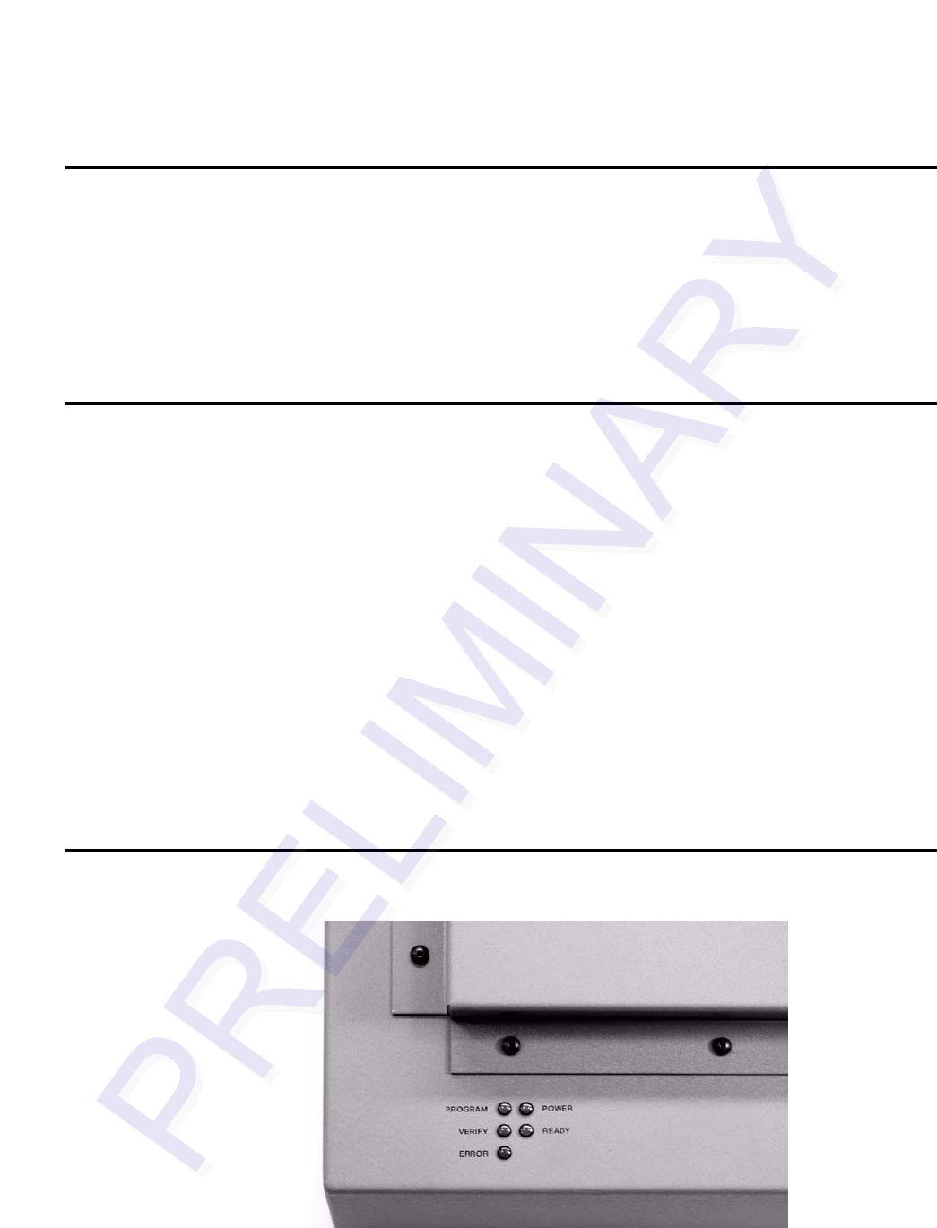
Indicator Lights
Figure 3-1 shows the indicator lights used by the programmer during operation
Figure 3-1 AP4118 Programmer Indicator Lights

AP4118 Tag Programmer User Guide
3-4
PROGRAM The tag is being programmed.
VERIFY The programmer has read and verified the tag
identification (ID) code.
ERROR An error has occurred while programming the current tag.
POWER The programmer is receiving power.
READY The programmer is ready to program tags.
Sign-On
You should expect to see the following sign-on message on the screen of the host
system or a communications terminal upon power-up or after you send the
programmer command #30:
#Model AP4118 Ver X.XX
#Copyright 2005 TransCore
where X.XX is the current software version.
Command Execution Protocol
The programmer sends an appropriate acknowledgment to the host device upon the
successful or unsuccessful execution of any command received.
All programmer commands are in the following format:
#abcxxxxxx...xxxxxx<cr>
where
# start of command character. All commands must start with this
character.
abc the command
xxx... user data
<cr> carriage return
If command execution is successful, the programmer sends the response
#Done<cr>
If command execution is unsuccessful, the programmer sends the response
#Error<cr>
RS–232 Command Set
Programmer commands are listed below. Use these commands following the format
described in the Command Execution Protocol section above.

Operating the Programmer
3-5
Enable Tone Generator (#120<cr>)
The default state of the audible tone generator is tone enabled. The tone generator
creates audible responses described as beep, triple beep, and solid tone. This
command re-enables the programmer’s audible response capability after it has been
disabled by the #121 command.
Response:
#Done<cr>
Disable Tone Generator (#121<cr>)
This command disables the programmer’s audible response capability. The default
state of the audible tone generator is tone enabled.
Response:
#Done<cr>
Program Tag Using TransCore 6-Bit ASCII Format
(#200xxx...<cr>)
The programmer programs the user’s data (xxx...) into the tag using the TransCore 6-
bit ASCII format. This format requires 20 characters of data. Refer to Appendix C for
a description of this format.
During execution of this command, a series of beeps indicates that the programmer is
waiting for a tag to be placed in the holder. If you do not place the tag in the holder
and close the door within a 10-second limit, the programmer will abort this command.
Response:
#xxxxxxxxxxxxxxxxxxxx<cr>
#Done<cr>
or
#Error<cr>
Program Tag Using 4-Bit ASCII Hex Format
(#201xxx...<cr>)
The programmer programs the user’s data (xxx...) into the tag using the 4-bit ASCII
hexadecimal (hex) format. This format requires 30 characters of data. Refer to
Appendix D for a description of this ASCII hex format.
During execution of this command, a series of beeps indicates that the programmer is
waiting for a tag to be placed in the holder. If you do not place the tag in the holder
and close the door within a 10-second limit, the programmer will abort this command.
Response:

AP4118 Tag Programmer User Guide
3-6
#xxxxxxxxxxxxxxxxxxxxxxxxxxxxxx<cr>
#Done<cr>
or
#Error<cr>
Read/Verify Tag Data Using TransCore 6-Bit ASCII
Format (#210<cr>)
The programmer reads the data from the tag, puts it into the TransCore 6-bit ASCII
format, and sends it to the host device. Refer to Appendix C for a description of this 6-
bit ASCII format.
During execution of this command, a series of beeps indicates that the programmer is
waiting for a tag to be placed in the holder. If you do not place the tag in the holder
and close the door within a 10-second limit, the programmer will abort this command.
Response:
#xxxxxxxxxxxxxxxxxxxx<cr>
#Done<cr>
or
#Error<cr>
Read/Verify Tag Data Using 4-Bit ASCII Hex For-
mat (#211<cr>)
The programmer reads the data from the tag, puts it into the 4-bit ASCII hex format,
and sends it to the host device. Refer to Appendix D for this ASCII hex format.
During execution of this command, a series of beeps indicates that the programmer is
waiting for a tag to be placed in the holder. If you do not place the tag in the holder
and close the door within a 10-second limit, the programmer will abort this command.
Response:
#xxxxxxxxxxxxxxxxxxxxxxxxxxxxxx<cr>
#Done<cr>
or
#Error<cr>
Write/Verify A Page Of Data Using Hex Format
(#220yyxxxx…<cr>)
The programmer programs the user hex data (xxxxxxxxxxxxxxxx), 16 hex characters,
starting at hex address yy. The starting address (yy) must be on an 8 byte page bound-
ary. For example, the starting address will be 00, 08, 10, 18 …F0, F8.

Operating the Programmer
3-7
If the tag is not already in the tag holder, a series of beeps indicates that the program-
mer is waiting for a tag to be placed in the holder. If you do not place the tag in the
holder, and close the door within a 10-second limit, the programmer will abort this
command.
The programmer will not program the data if the programmer does not have permis-
sion to write to the memory area of the tag that is requested by the user. Each pro-
grammer will be assigned permissions at the factory, or will use a permissions tag that
must be placed in to the programmer at pre-specified intervals.
Response:
#xxxxxxxxxxxxxxxx<cr>
#Done<cr>
or
#Error<cr>
Write/Verify A Byte Of Data Using Hex Format
(#221yyxx<cr>)
The programmer programs the user hex data (xx), 2 hex characters, at hex address yy.
If the tag is not already in the tag holder, a series of beeps indicates that the program-
mer is waiting for a tag to be placed in the holder. If you do not place the tag in the
holder, and close the door within a 10-second limit, the programmer will abort this
command.
The programmer will not program the data if the programmer does not have permis-
sion to write to the memory area of the tag that is requested by the user. Each pro-
grammer will be assigned permissions at the factory, or through the use of a
permissions tag that must be inserted into the programmer at pre-specified intervals.
Response:
#xx<cr>
#Done<cr>
or
#Error<cr>
Read A Page Of Data Using Hex Format
(#230yy<cr>)
The programmer reads hex data (xxxxxxxxxxxxxxxx), 16 hex characters, starting at
hex address yy. The starting address (yy) must be on an 8 byte page boundary. For
example, the starting address will be 00, 08, 10, 18 …
If the tag is not already in the tag holder, a series of beeps indicates that the program-
mer is waiting for a tag to be placed in the holder. If you do not place the tag in the
holder, and close the door within a 10-second limit, the programmer will abort this
command.

AP4118 Tag Programmer User Guide
3-8
The programmer will not read the data if the programmer does not have permission to
read the memory area of the tag that is requested by the user. Each programmer will be
assigned permissions at the factory, or through the use of a permissions tag that must
be placed in to the programmer at pre-specified intervals.
Response:
#xxxxxxxxxxxxxxxx<cr>
#Done<cr>
or
#Error<cr>
Read A Byte Of Data Using Hex Format
(#231yy<cr>)
The programmer reads a byte of hex data (xx), 2 hex characters, from hex address yy.
If the tag is not already in the tag holder, a series of beeps indicates that the program-
mer is waiting for a tag to be placed in the holder. If you do not place the tag in the
holder, and close the door within a 10-second limit, the programmer will abort this
command.
The programmer will not read the data if the programmer does not have permission to
read the memory area of the tag that is requested by the user. Each programmer will be
assigned permissions at the factory, or through the use of a permissions tag that must
be placed in to the programmer at pre-specified intervals.
Response:
#xx<cr>
#Done<cr>
or
#Error<cr>
System Reset (#30<cr>)
The command resets the programmer to its original power-on state with the self-test.
Response (system sign-on message):
#Model AP4118 Ver X.XX
#Copyright 2005 TransCore
where X.XX is the current software version
or
#Error<cr>

Operating the Programmer
3-9
Display System Status (#40<cr>)
This command requests a 2-digit status response code from the programmer indicating
the status of the last operation performed. Refer to Appendix E for a description of the
programmer response codes that refer to system status.
Response:
#xx<cr>
where XX is the 2-digit response code. The code 00 indicates that the programmer
performed the last operation without error.
Display Tag Door Switch Status (#42<cr>)
This command requests a 2-digit status response from the programmer indicating the
status of its tag door switch.
Response:
#01<cr>door closed
#00<cr>door open
Programming a Tag
To program a tag
1. Send the programmer the appropriate #200<cr> or #201<cr> command along
with the user data you want to program onto the tag. Use command #200 if you
are using the TransCore 6-bit format for your data; use command #201 for the 4-
bit hex data format.
2. When the programmer begins its 10-second timer, indicated by an audible beep
once every second, slide the tag you want to program into the tag holder and
close the door (Figure 3-2).
AP4118 Tag Programmer User Guide
3-10
Figure 3-2 Tag in Tag Holder
If the tag is placed within the 10-second period, the programmer programs the user
data, verifies the user data, and sends a response to the host system. If the tag is
not placed within the 10-second period, the programmer aborts the command,
sends the #Error<cr> response to the host, and emits a continuous audible tone.
When the tag is successfully programmed, the programmer responds with a triple beep
and with the following response:
xxx...<cr>
#Done<cr>
where XXX... is the tag data read from the tag and encoded in the specified format.
If the tag programming process fails, the programmer responds with a continuous
audible tone and with #Error<cr>.
If you receive this response, repeat this sequence beginning at step 1.
Verifying Tag Data
To verify the data on a tag
1. Send the programmer the appropriate #210<cr> or #211<cr> command. Use
command #210 if you are using the TransCore 6-bit format for your data; use
command #211 for the 4-bit hex data format.
2. When the programmer begins its 10-second timer indicated by an audible beep
once every second, slide the proper tag into the tag holder and close the door.
If you place the tag within the 10-second period, the programmer reads the tag
data, checks for data integrity, and sends the tag data and a #Done response to the
host system. If you do not place the tag down within the 10-second period, the
programmer aborts the command and sends the #Error<cr> response to the host.
If the verification process is not successful, repeat this sequence beginning at step 1.

Operating the Programmer
3-11
Security Characters
The tag security character function prevents the use of unauthorized tags in any
TransCore electronic identification system. All AP4118 tag programmers have the
capability, when enabled, to program specific, predefined security characters into a
tag. This capability is enabled at the factory if it is specified in an authorized order.
Security characters are available for American Trucking Associations (ATA) and
International Standards Organization (ISO) tag data formats.
Note: The security character function may only be used when you program your tag
data in the 4-bit hex format using command #201. The security character function
may NOT be used if you program your tag data with the 6-bit ASCII format using
command #200, even though the security characters are 6-bit characters.
When enabled, the security character function stores two characters, specific 6-bit
patterns designated for security coding purposes, in the programmer's nonvolatile
memory. These characters, selected at the factory for each programmer, may be two
specific characters from the list of security characters in Appendix F or one character
each from Appendix F and Appendix C.
When a tag programmer has tag security enabled, all tags programmed contain the
assigned security characters in the designated positions of the tag data. Security
characters comprise the second half of the 26th character through the first half of the
29th character when data is in the 4-bit hex format.
The programmer places security characters into their associated tag data locations
when security characters in the tag data entered with command #201 match the
internal security characters stored in the programmer by factory personnel.
The programmer will not store onto a tag security codes that differ from those stored
in the programmer’s internal memory. If you attempt to program the tag with security
characters that do not match the internal security characters of the programmer (i.e.,
incorrect or improperly obtained codes), the programmer automatically programs the
space character into both security character locations.
When you input security characters while using TransCore’s Tag Programming
software, those security characters will not be visible on the monitor.

AP4118 Tag Programmer User Guide
3-12

4
Troubleshooting


4-3
Chapter 4
Troubleshooting
Table 4-1 lists some problems that you may encounter when programming tags, along
with suggestions for troubleshooting each problem.
If a problem persists, call the TransCore Action Center at (800) 755-0378.
Table 4-1 Troubleshooting Problems and Solutions
Problem Suggested Solutions
System does not beep at
power-on. •Check power transformer.
•Replace the internal 5 A, 250V Fast Blo fuse
System powers on, but does
not sign on. •Verify RS–232 connection at the programmer
and at the host.
•Verify that host baud rate is set to 9600.
Programmer beeper is not
heard during tag programming/
verify sequence, or system
continually beeps until time-out.
•Verify that the door is fully closed.
•Verify that the optical switch that is activated
by the tag door is clean and is clear of any dirt
buildup.
Tag programming sequence
fails repeatedly. •Refer to the programmer response codes list
in Appendix E to identify the problem.
•Improve ESD protection in programming area.
Requested verify data does not
match programmed data. •Check for security code violations.
•Check programmed data for accuracy.
System resets intermittently. •Check for damage to DC power connection.
•Check for a loose AC power connection.

AP4118 Tag Programmer User Guide
4-4

A
Tag Programmer Specifications


A-3
Appendix A
Tag Programmer Specifications
This appendix lists the AP4118 Tag Programmer physical and
environmental specifications.
Table A-1 lists the AP4118 Tag Programmer parameters and specifications.
Environmental
The programmer is designed to operate in typical office environment conditions. The
programmer performs to the specifications listed in Table A-1 and is ready to program
with a warm-up time of not more than three minutes.
Table A-1 AP4118 Tag Programmer Physical and Environmental Specifications
Parameter Specification
Size (W x H x D) 14.3 x 3.2 x 11.5 in (36.3 x 8.1 x 29.2 cm)
Weight 6.8 lb (3.1 kg)
Input Voltage 12V DC
Power Consumption 12 W
Excessive Current Protection 5 A, 250V Fast Blo fuse
Operating Temperature 32°F to +122°F (0°C to +50°C)
Storage Temperature -4°F to +185°F (-20°C to +85°C)
Humidity 95% noncondensing @77°F to 131°F (25°C to 55°C)
Enclosure Dustproof
Operational Vibration 1.04 Grms, 5-500 Hz, power spectral density-uniform
0.0022 G2/Hz, 1 hour per axis
Shock N/A
PC-to-Programmer Cable RS–232 (data terminal equipment or with adapters)
RF Power Tag holder: 50 mW
FCC Classification Part 15, site license not required

AP4118 Tag Programmer User Guide
A-4

B
RS–232 Connector Pin-outs


AP4118 Tag Programmer User Guide
B-4

C
TransCore 6-Bit ASCII Format


C-3
Appendix C
TransCore 6-Bit ASCII Format
In TransCore’s 6-bit ASCII format, each ASCII data character is represented by a cer-
tain 6-bit pattern. These bit patterns are placed in specific groups of six consecutive
bits within the tag. The ASCII characters and their corresponding 6-bit codes are listed
in Table C-1. TransCore's 6-bit ASCII codes are produced by subtracting 00100000
from the character's 8-bit ASCII value.
Table C-1 6-Bit ASCII Codes
Character 6-Bit Code Character 6-Bit Code
(space) 000000 G100111
*001010 H101000
-001101 I101001
.001110 J101010
/001111 K101011
0010000 L101100
1010001 M101101
2010010 N101110
3010011 O101111
4010100 P110000
5010101 Q110001
6010110 R110010
7010111 S110011
8011000 T110100
9011001 U110101
A100001 V110110
B100010 W110111
C100011 X111000
D100100 Y111001
E100101 Z111010
F100110

AP4118 Tag Programmer User Guide
C-4

D
4-Bit ASCII Hex Codes


D-3
Appendix D
4-Bit ASCII Hex Codes
In TransCore’s 4-bit hex format, each ASCII character is represented by a certain 4-bit
pattern. These bit patterns are placed in specific groups of four consecutive bits within
the tag. The ASCII characters and their corresponding 4-bit hex codes are listed in
Table D-1.
Table D-1 4-Bit ASCII Hex Codes
Character 4-bit Code
00000
10001
20010
30011
40100
50101
60110
70111
81000
91001
A1010
B1011
C1100
D1101
E1110
F1111

AP4118 Tag Programmer User Guide
D-4

E
Programmer Response Codes


E-3
Appendix E
Programmer Response Codes
The programmer returns one of these codes in response to command #40, Display
System Status. Table E-1 lists the response codes.
Table E-1 Programmer Response Codes
Code Description
00 Operation Successful/No Error: The last operation performed by
the programmer was executed without errors.
01 Illegal Command: The command sent to the programmer was
not a valid command.
02 Invalid Tag Data: The user data sent to the programmer was in
the incorrect format (such as an illegal hex character).
03 Presence Time-out on Program Cycle: The programmer did not
recognize the placement of a tag on the programming head
during the 10-sec period prior to a programming sequence.
04 Presence Time-out on Verify Cycle: The programmer did not
recognize the placement of a tag on the programming head
during the 10-sec period prior to a verification sequence.
05, 06, 07 Reserved
08 Data Compare Error: During a programming sequence, the data
read from the tag did not correspond to the user data that was
written to the tag.
09 Locked Tag: The programmer has detected a lock condition of
the tag. The tag data is stored permanently and cannot be
changed.
0A No Frame Marker: The programmer could not decipher a frame
marker from the tag. Either the tag is not present, is damaged, or
is not making contact with the programming head pins.
0B Bad Tag Parity: The checksum bits read from the tag did not
correspond to the checksum that the programmer calculated
from the tag data.
0C Security Code Operation: The AP4118 has detected an attempt
to write illegal security characters to the security character
positions of the tag’s ATA frame data. The AP4118 has then
coded the SPACE character in the positions therefore altering
the user’s original tag data.
0D Invalid Permissions: This programmer does not have permission
to write data to the tag address that the user requested.

AP4118 Tag Programmer User Guide
E-4

F
Security Characters


F-3
Appendix F
Security Characters
You may enter security characters into an Amtech tag if your programmer has been
configured at the factory to perform the security character function. These ASCII
security characters are encoded in the Amtech 6-bit data encoding scheme, and are
listed in Table F-1.
Table F-1 ASCII Security Characters
Character 6-bit Code
!000001
"000010
#000011
$000100
%000101
&000110
'000111
(001000
)001001
+001011
,001100
:011010
;011011
<011100
=011101
>011110
?011111
@100000
[111011
\111100
]111101
^111110
_111111
space 000000

AP4118 Tag Programmer User Guide
F-4