TransCore IT241005422 Low power RFID tag programmer transmitter User Manual 411360 002 IT2410 Tag Programmer UG
TransCore Low power RFID tag programmer transmitter 411360 002 IT2410 Tag Programmer UG
UserManual.wiki
>
TransCore
>
IT241005422 User Manual
users manual
Navigation menu
Upload a User Manual
Namespaces
Wiki Guide
HTML
PDF
Info
Views
User Manual
Discussion / Help
Navigation


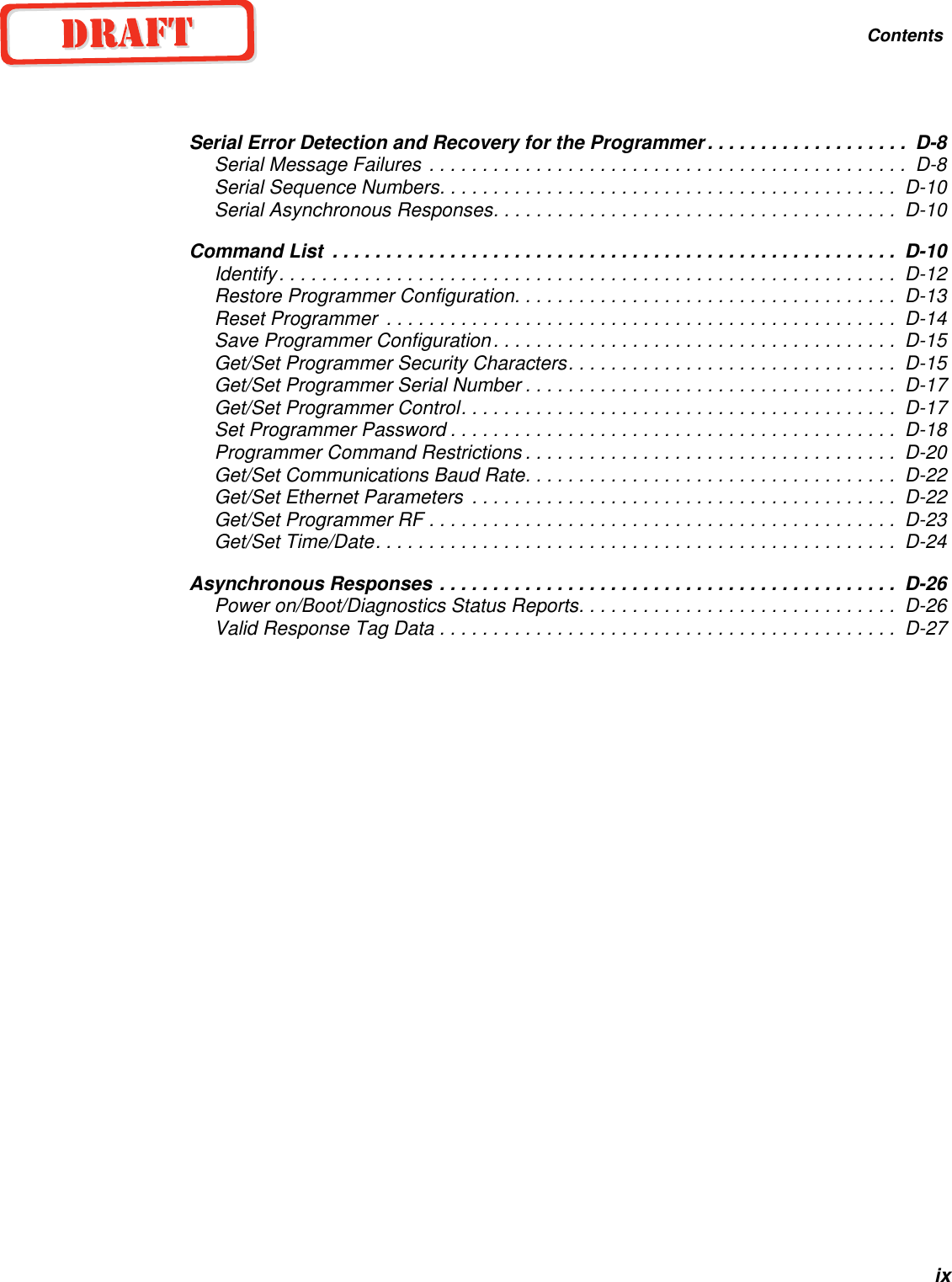


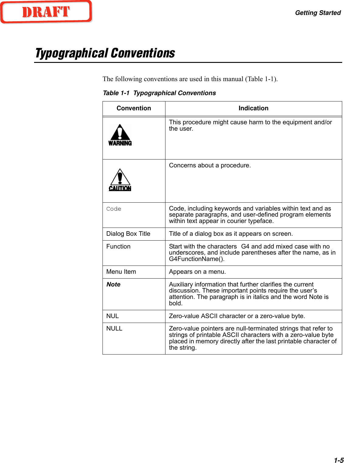


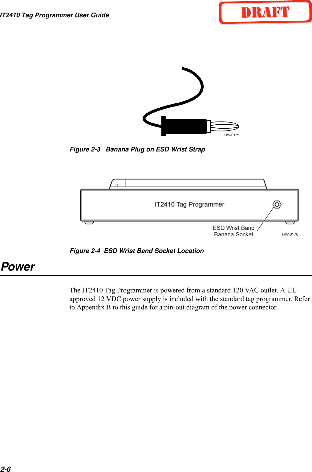
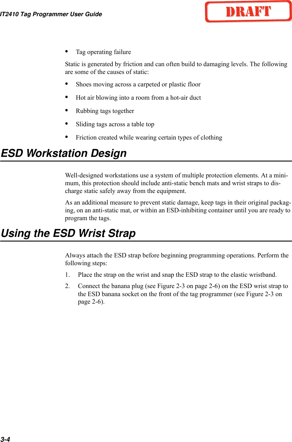


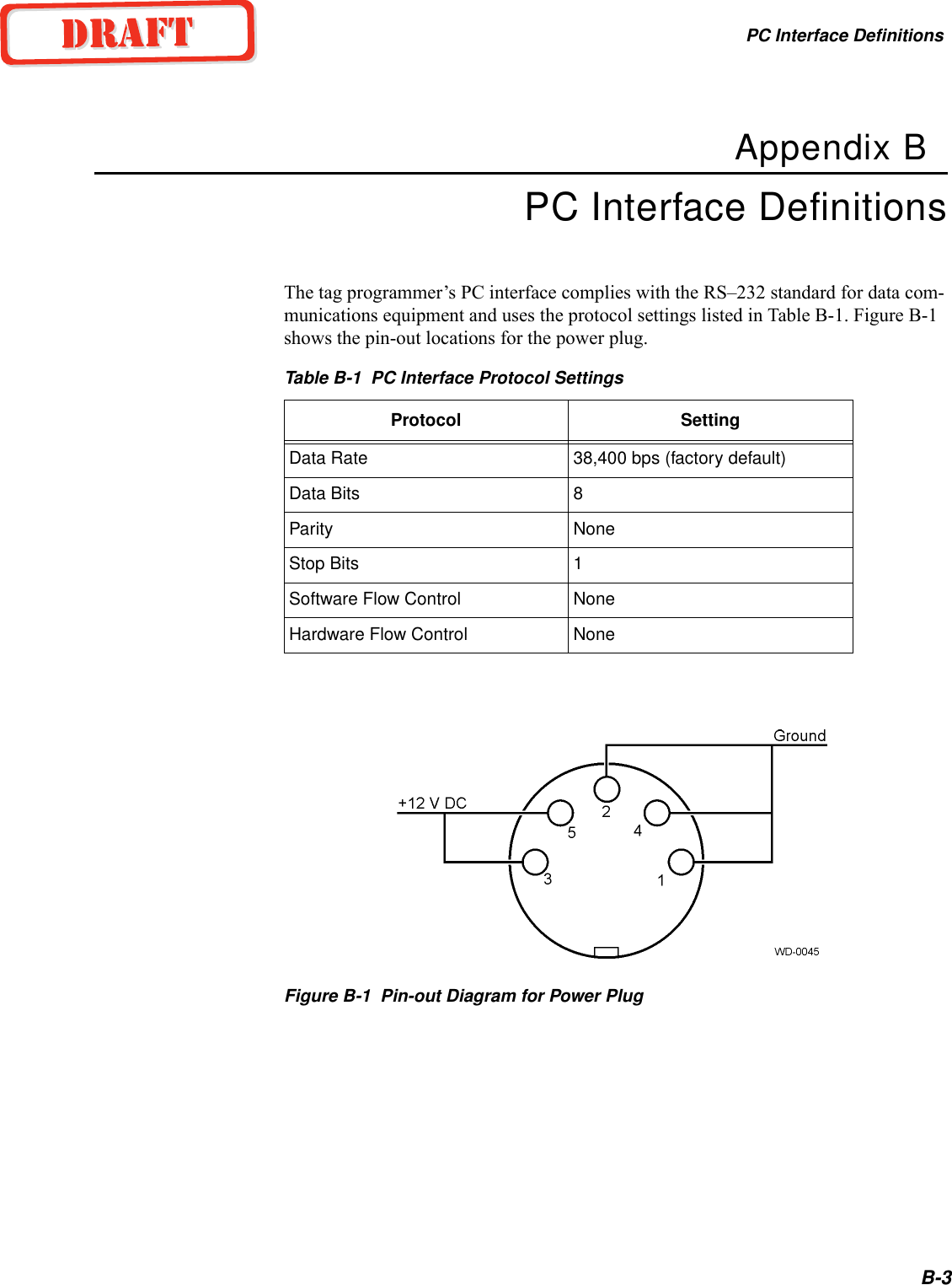


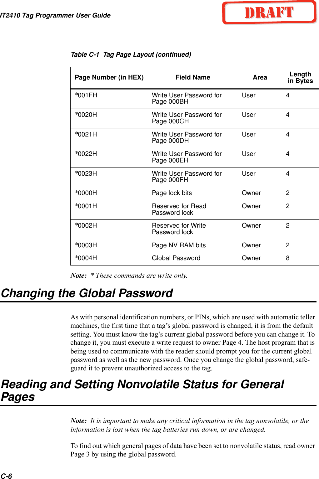
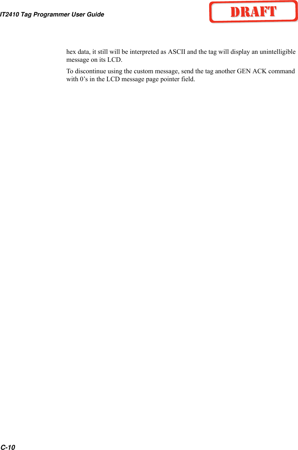


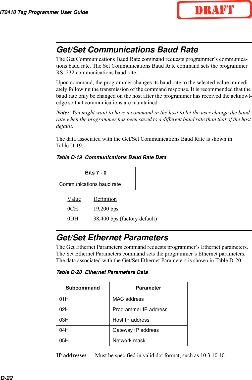
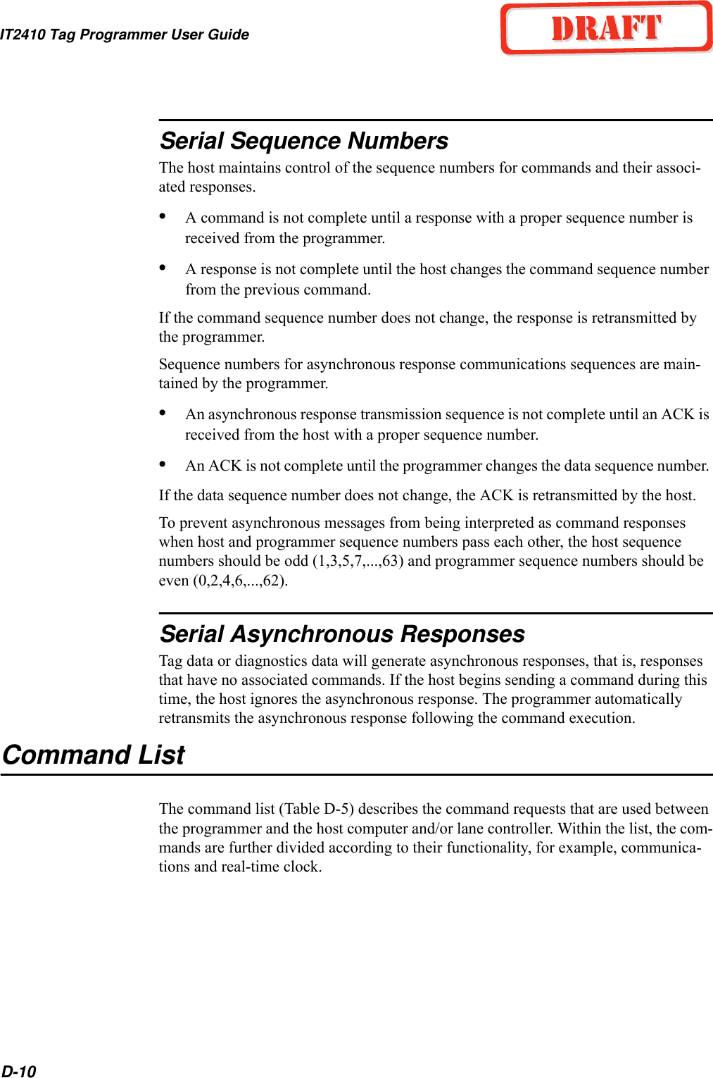
![Application Program InterfaceD-5Binary-coded integer messages are contained in a protocol defined by:<som> <seq #> <len> <resp> [<data>] <crc> <eom> where<som> - start of message is used to find the start of the next message following a mes-sage time-out or following the end of the previous message. All data is ignored until the <som> is detected. The start of message is defined as the ASCII character &.<seq #> - a combination of <seq #> and <len> makes 16 bits or 2 bytes of data. The sequence number is 6 bits and the length is 10 bits. The sequence number is used for the error detection scheme. The value for sequence number may represent any number between 0 and 63 with the following restrictions: •The sequence number for command responses matches the sequence number of the last received command. •The sequence numbers for asynchronous messages are 0,2,4,6,...,62 and is incre-mented after each new asynchronous message.<len> - length is a group of 10 binary bits that specifies the number of bytes in the response and data fields.<resp> - response is 2 bytes long to indicate the status of the command received by the programmer from the host. Responses are described in Table D-2.](https://usermanual.wiki/TransCore/IT241005422/User-Guide-410856-Page-59.png)
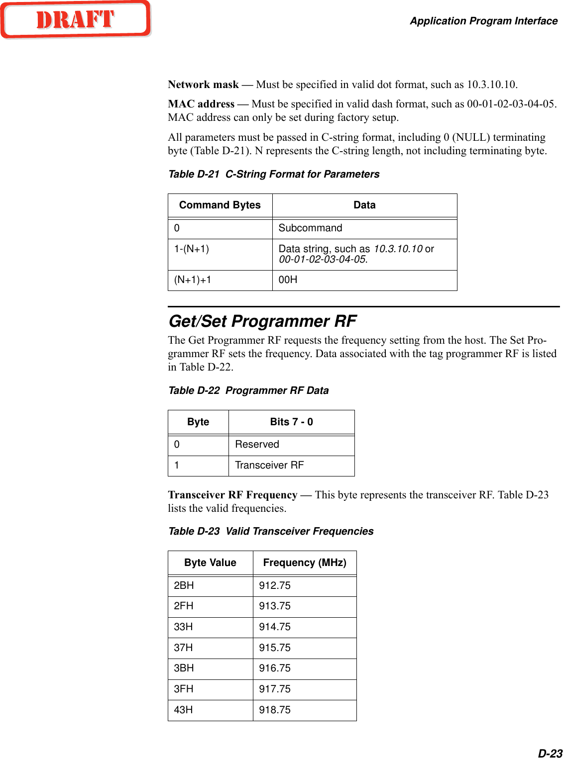
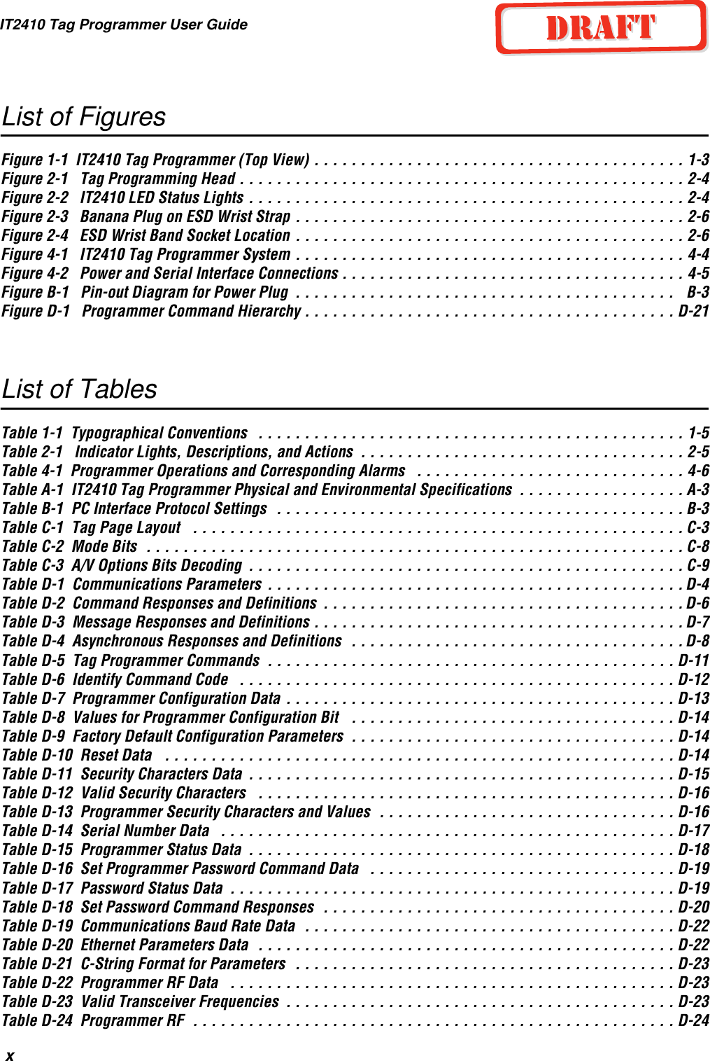
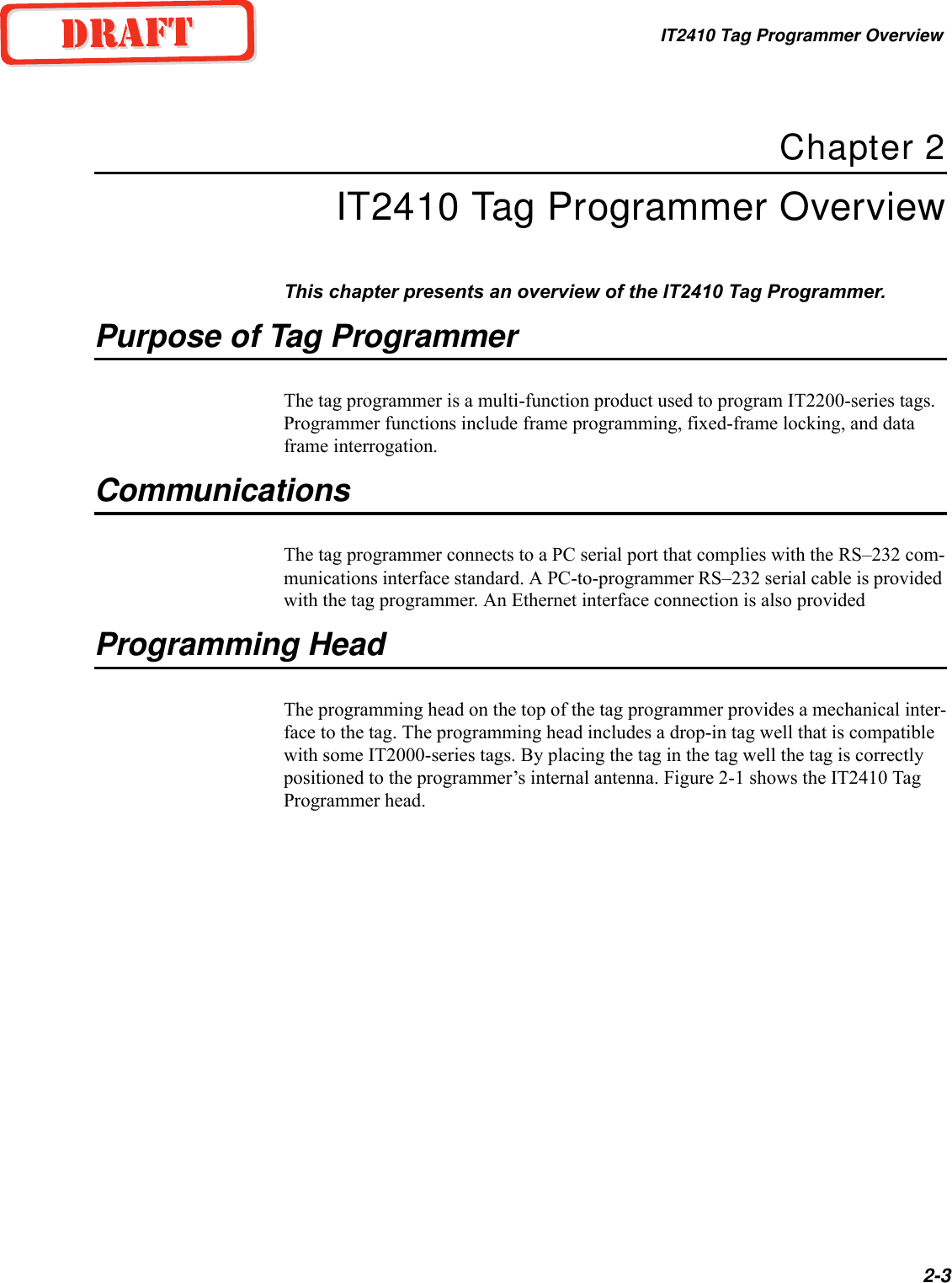
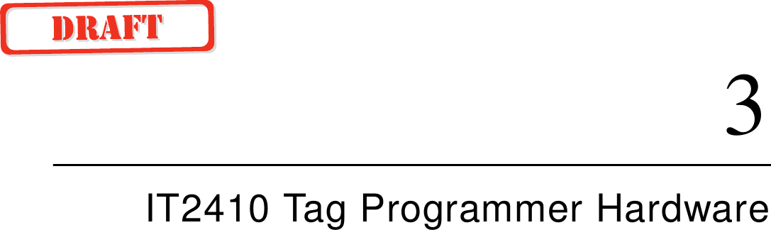
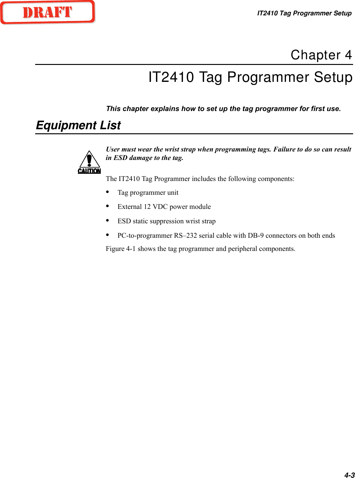
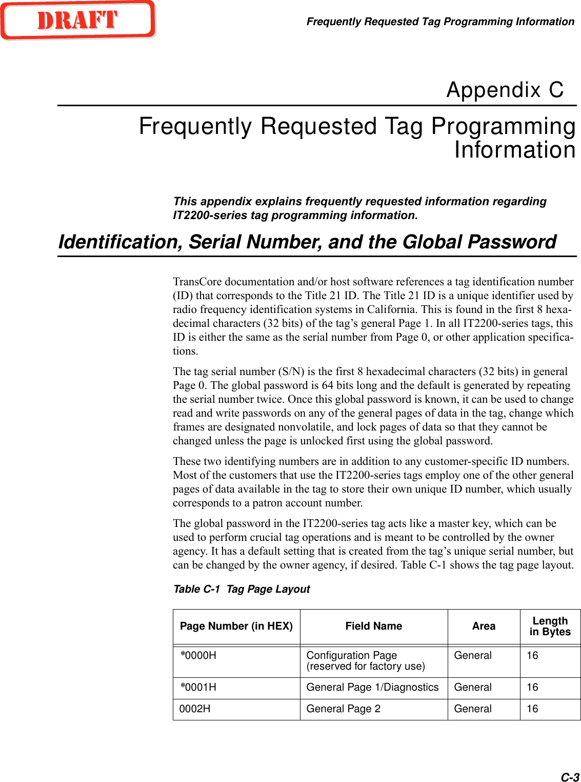
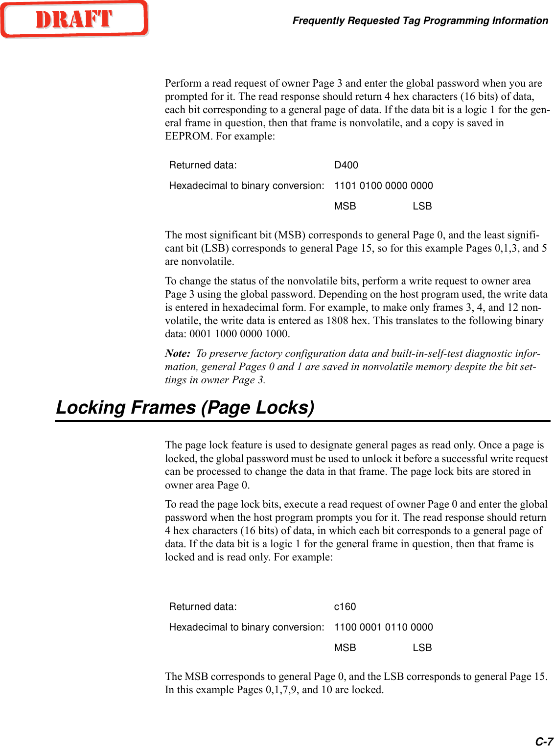
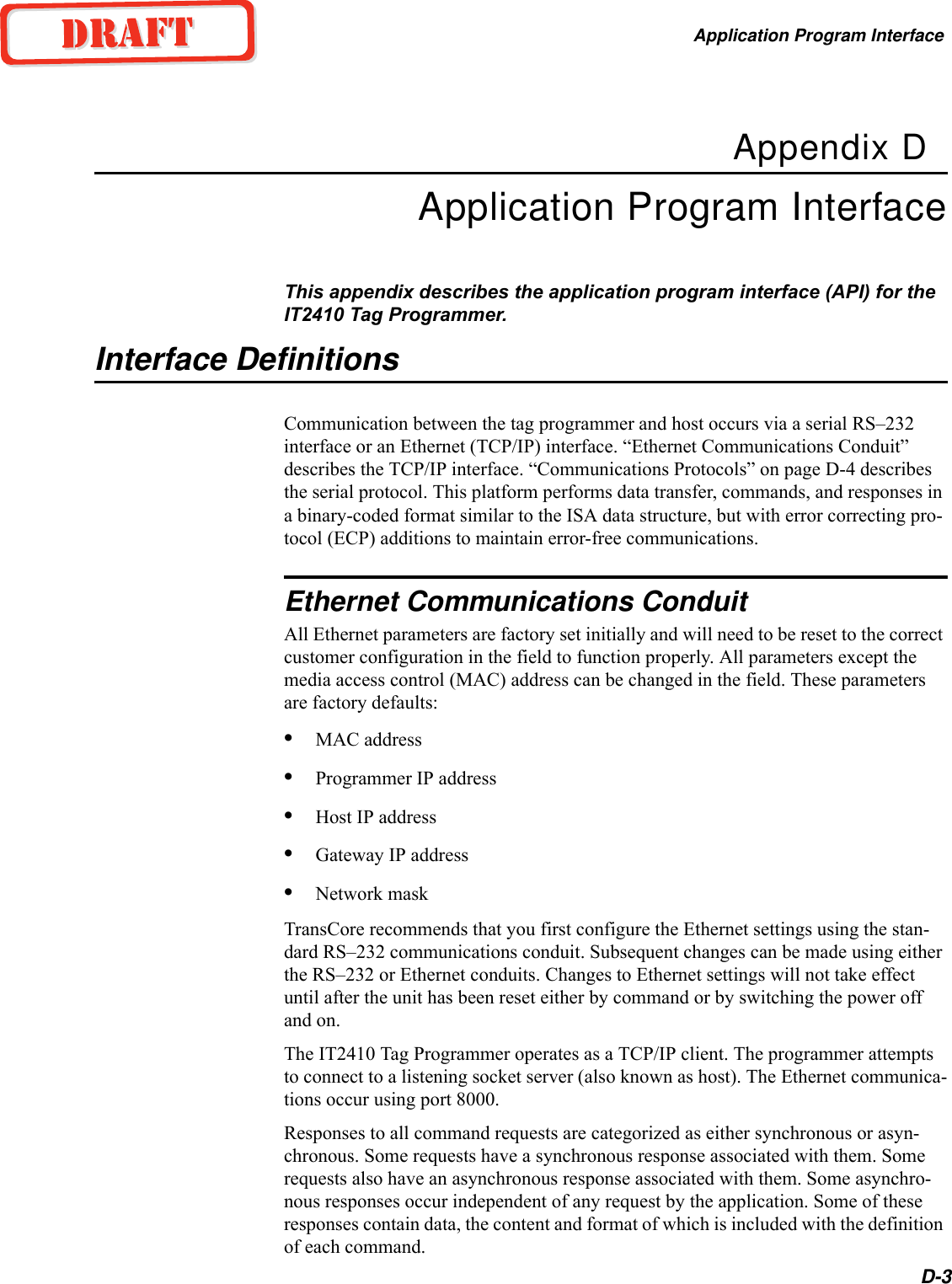
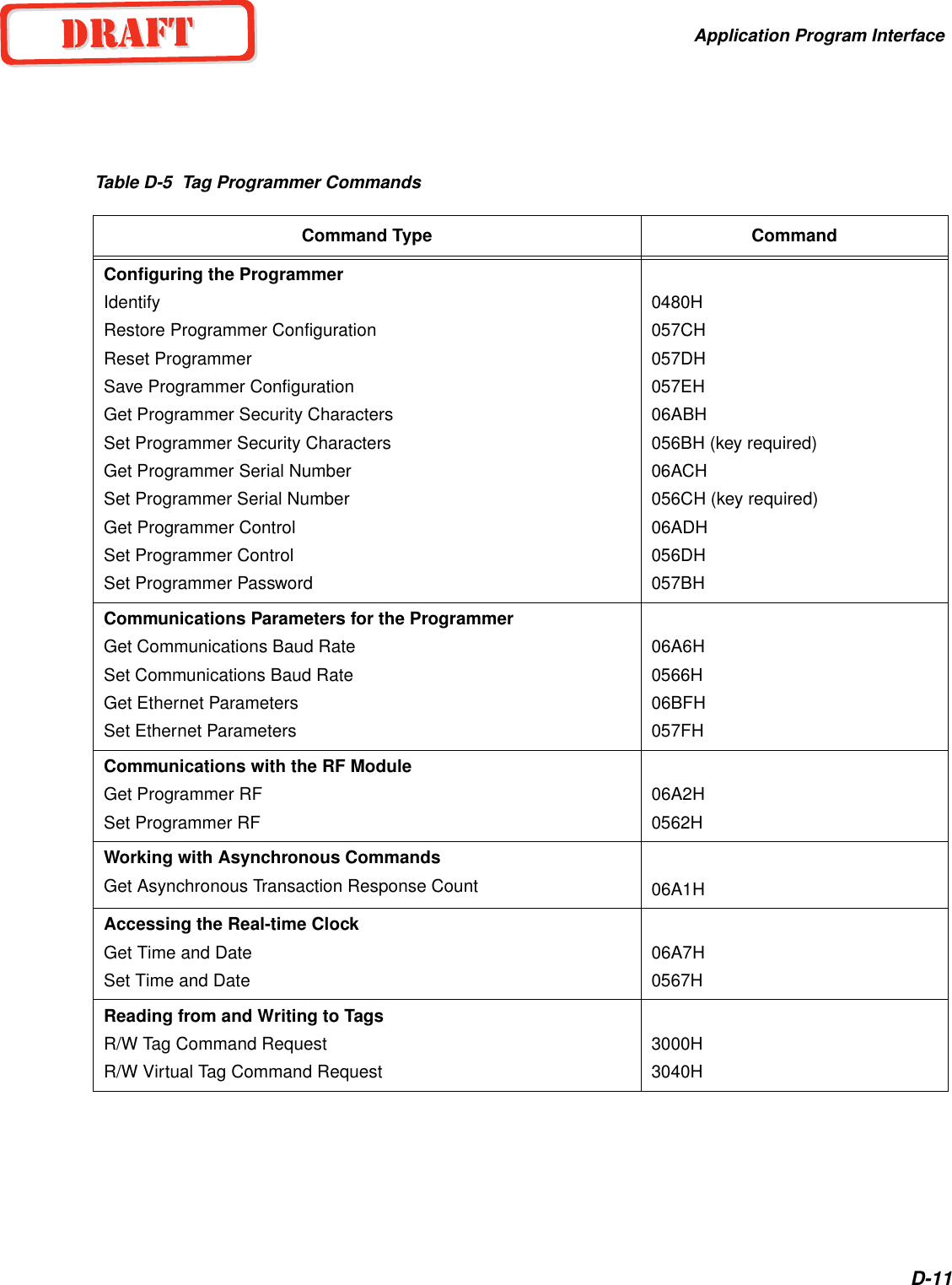
![IT2410 Tag Programmer User GuideD-6Table D-2 Command Responses and Definitions[<data>] - the data field may be of length from 0 to 1021 bytes and is associated with each specific response. See “Command List” on page D-10, for a complete list-ing of tag commands.<crc> - cyclic redundancy check, or CRC, is 2 bytes or 16 binary bits long, denoting a CRC-XMODEM result generated on each message byte exclusive of the <som> and <eom>. The polynomial for the CRC calculation is X16+X12+X5+1 with a feedback of 1021H for a XMODEM type CRC.<eom> - end of message aids in finding the end of the message. All data after the <eom> is ignored until the next <som> is detected. The end of message is defined as the ASCII character %.Serial Data AcknowledgeThe programmer and host interface use the data acknowledge protocol as noted below. Binary-coded integer messages contained in a protocol are defined by:<som> <seq #> <len> <resp> <crc> <eom>where<som> - start of message finds the start of the next message following a message time-out or following the end of the previous message. All data is ignored until the <som> is detected. The start of message is defined as the ASCII character &.Response Meaning0000H Command complete0001H Command in progress0002H Command data invalid0003H Command invalid0004H Command aborted3XXXH Tag data3000H No-Tag Data Status Code 3001H IT2200 Tag Data Status Code 3002H Reserved8XXXH Diagnostic data8000H Power-Up Diagnostic Report Status Code 8001H Background Diagnostic Report Status Code8002H Download ActiveAXXXH Diagnostics Statistical Data](https://usermanual.wiki/TransCore/IT241005422/User-Guide-410856-Page-60.png)
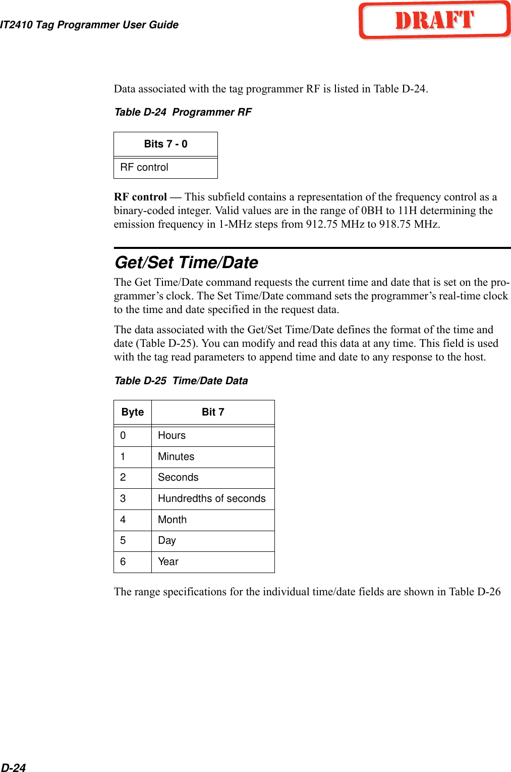
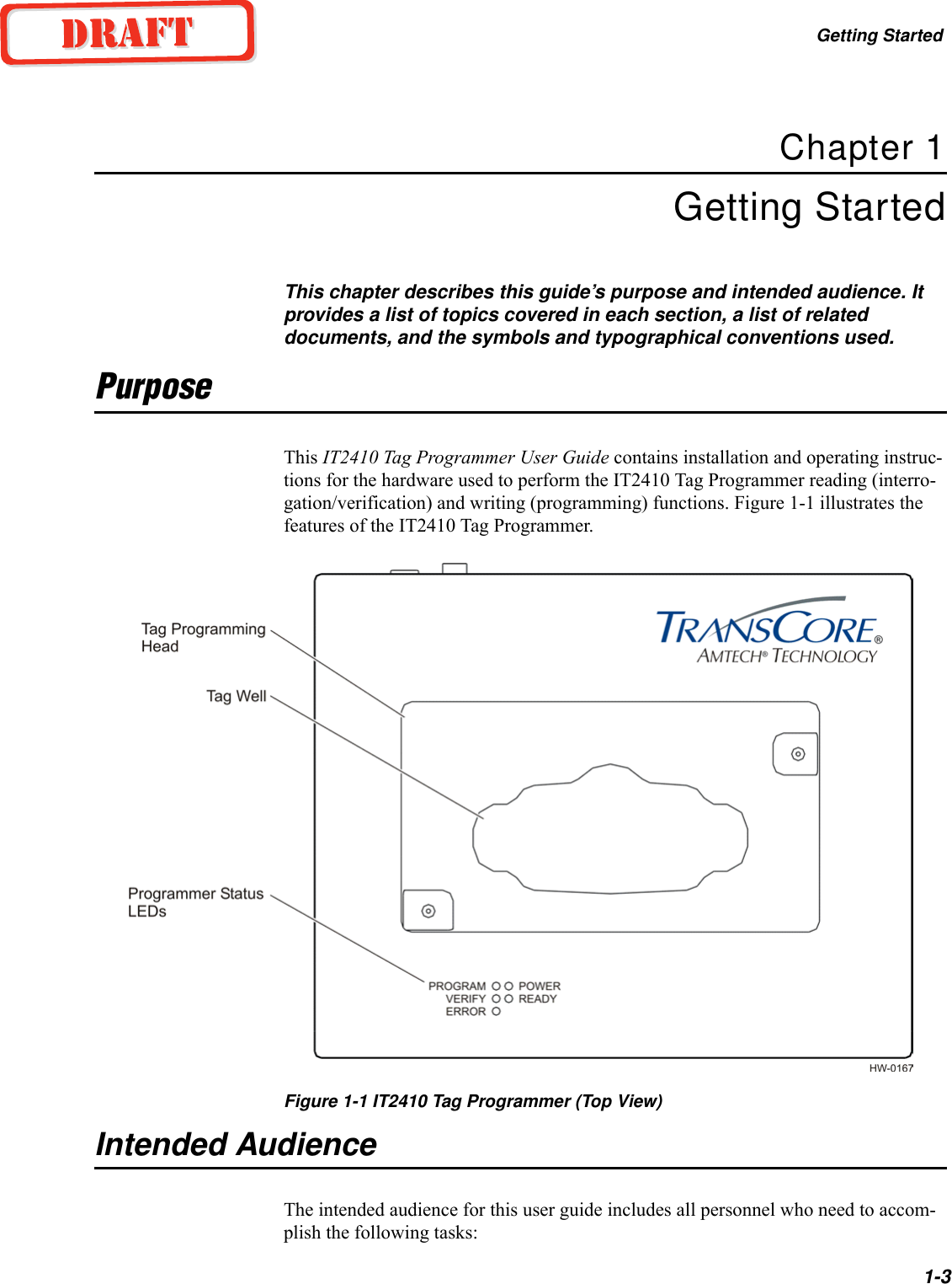
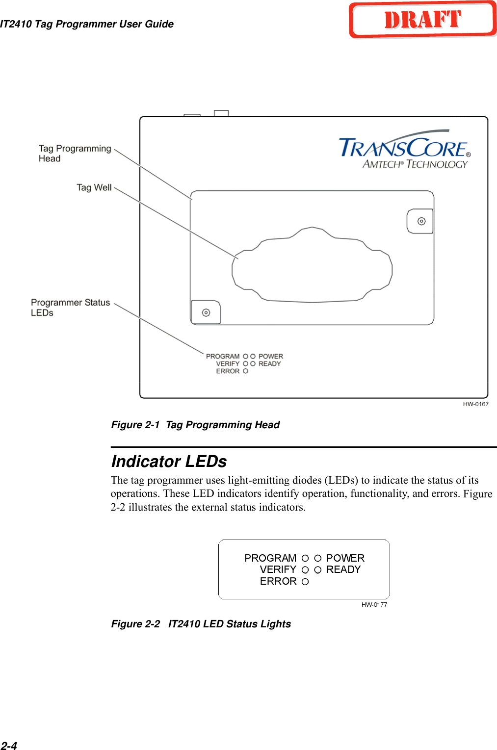
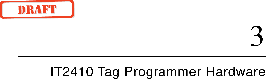
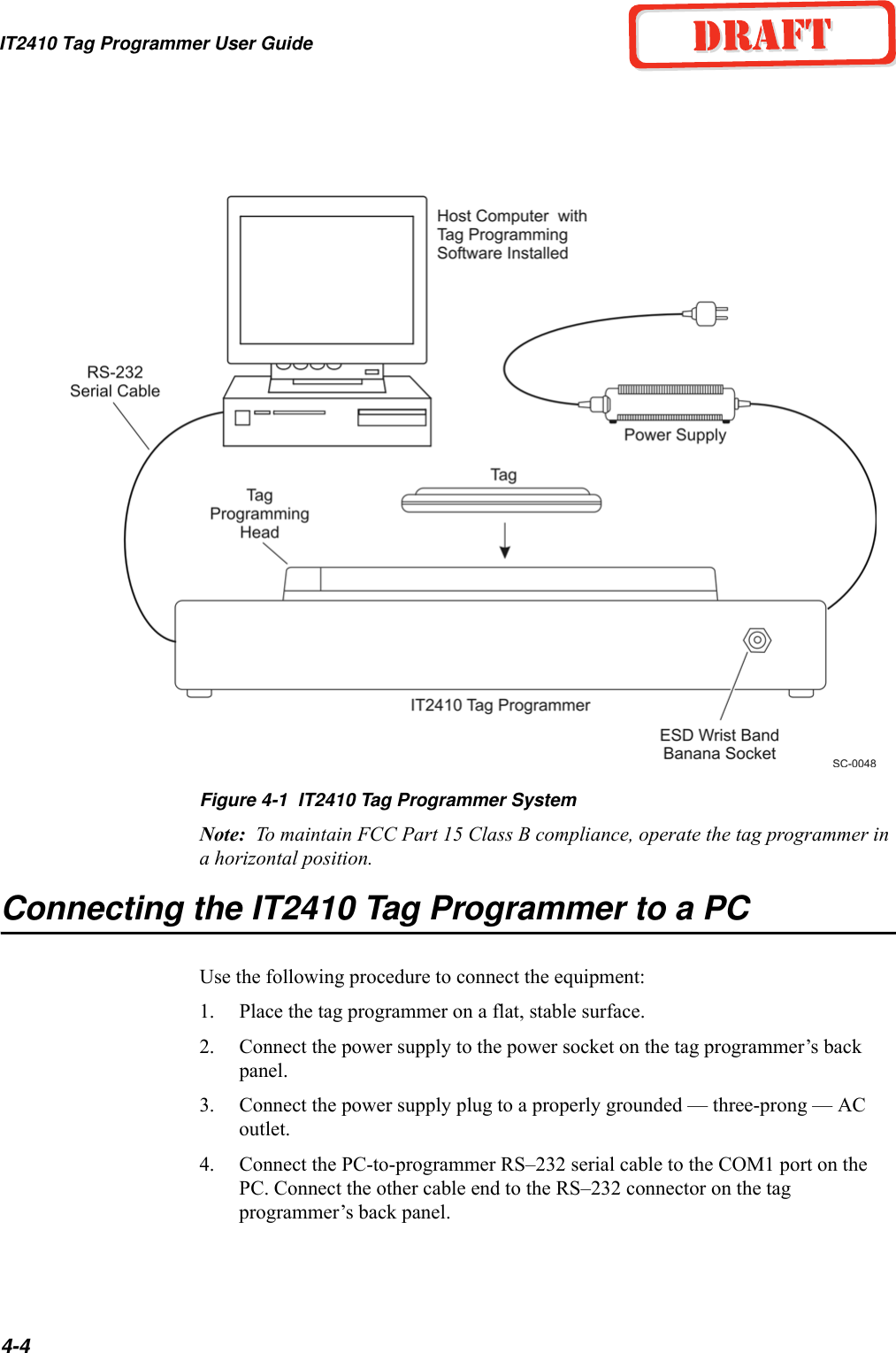
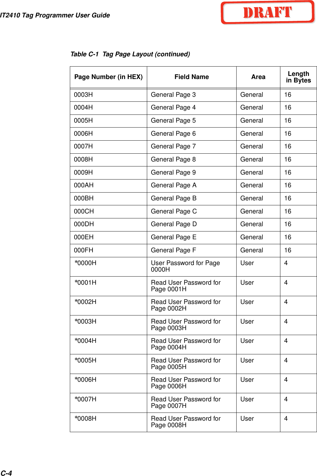
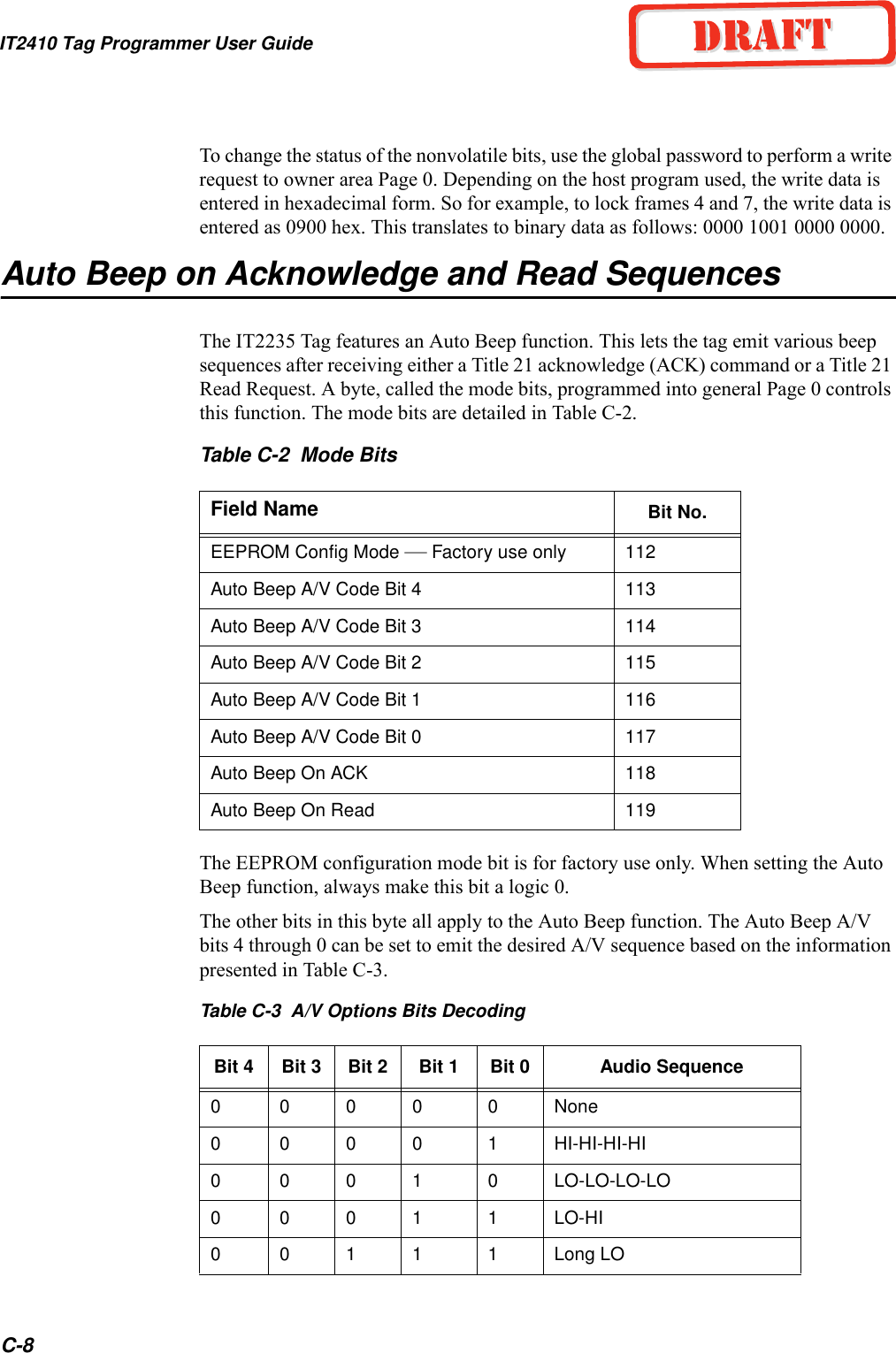
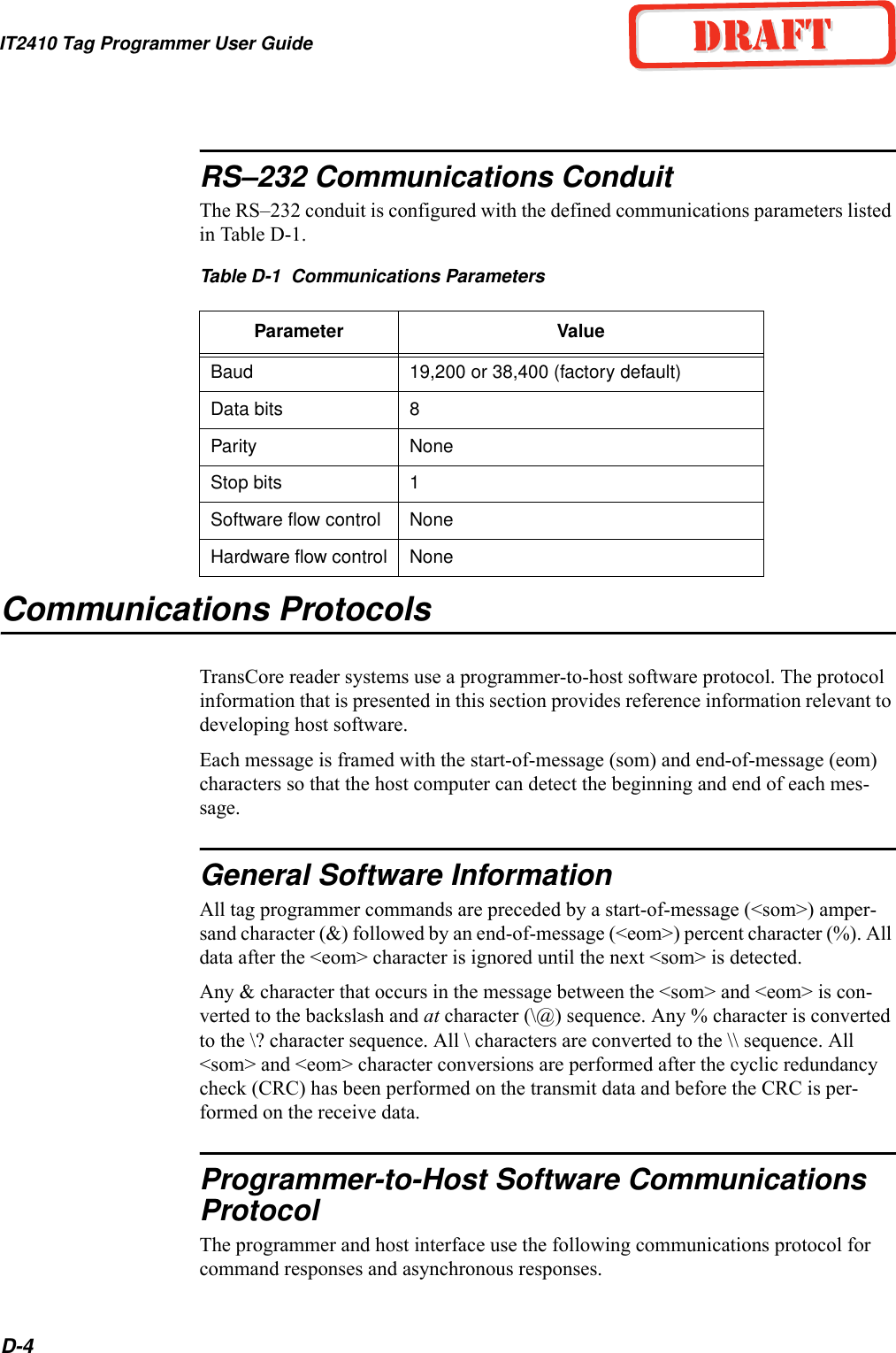
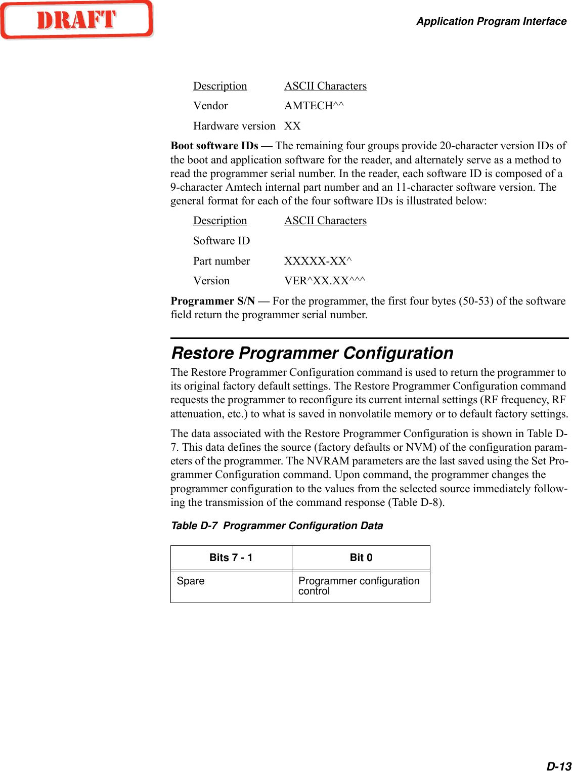
![Application Program InterfaceD-7<seq #> - a combination of <seq #> and <len>, makes 16 bits or 2 bytes of data. The sequence number is 6 bits and the length is 10 bits. The sequence number is used for the error detection scheme. The value for sequence number may represent any number between 0 and 63. The sequence number for the acknowledge (ACK)/not acknowledge (NACK) message matches the sequence number of the last received message.<len> - length is a group of 10 binary bits that specifies the number of bytes in the response. The value of length is 1 for ACK/NACK responses.<resp> - response is 1 byte long to indicate the status of the data response received by the programmer from the host. Table D-3 lists the responses.Table D-3 Message Responses and Definitions<crc> - cyclic redundancy check, or CRC, is 2 bytes, or 16 binary bits long, denoting a CRC-XMODEM result generated on each message byte exclusive of the <som> and <eom>. The polynomial for the CRC calculation is X16+X12+X5+1 with a feedback of 1021H for a XMODEM type CRC.<eom> - end of message aids in finding the end of the message. All data after the <eom> is ignored until the next <som> is detected. The end of message is defined as the ASCII character %.Ethernet Asynchronous Command and Response ProtocolTag data or diagnostics data generate asynchronous or command responses. Asyn-chronous responses have no associated commands. An interrupt occurs notifying the lane controller or host computer of a response to read data from the first-in-first-out (FIFO) data I/O address if interrupt mode is enabled. Otherwise, polling the FIFO buffer status register notifies the lane controller or host computer to asynchronous responses. The reader and host interface use the communications protocol for com-mand responses and asynchronous responses shown here. Binary-coded integer mes-sages contained in a protocol are defined by:<len> <resp> [<data>]where<len> - length specifies the number of bytes in the response and data fields. The range for this field is 2 to 1022.<resp> - response is one-word long to indicate the status of the command received by the host from the reader. The responses are shown in Table D-4.Response MeaningDDH Data acknowledge (ACK)EEH Data invalid (NACK)](https://usermanual.wiki/TransCore/IT241005422/User-Guide-410856-Page-61.png)
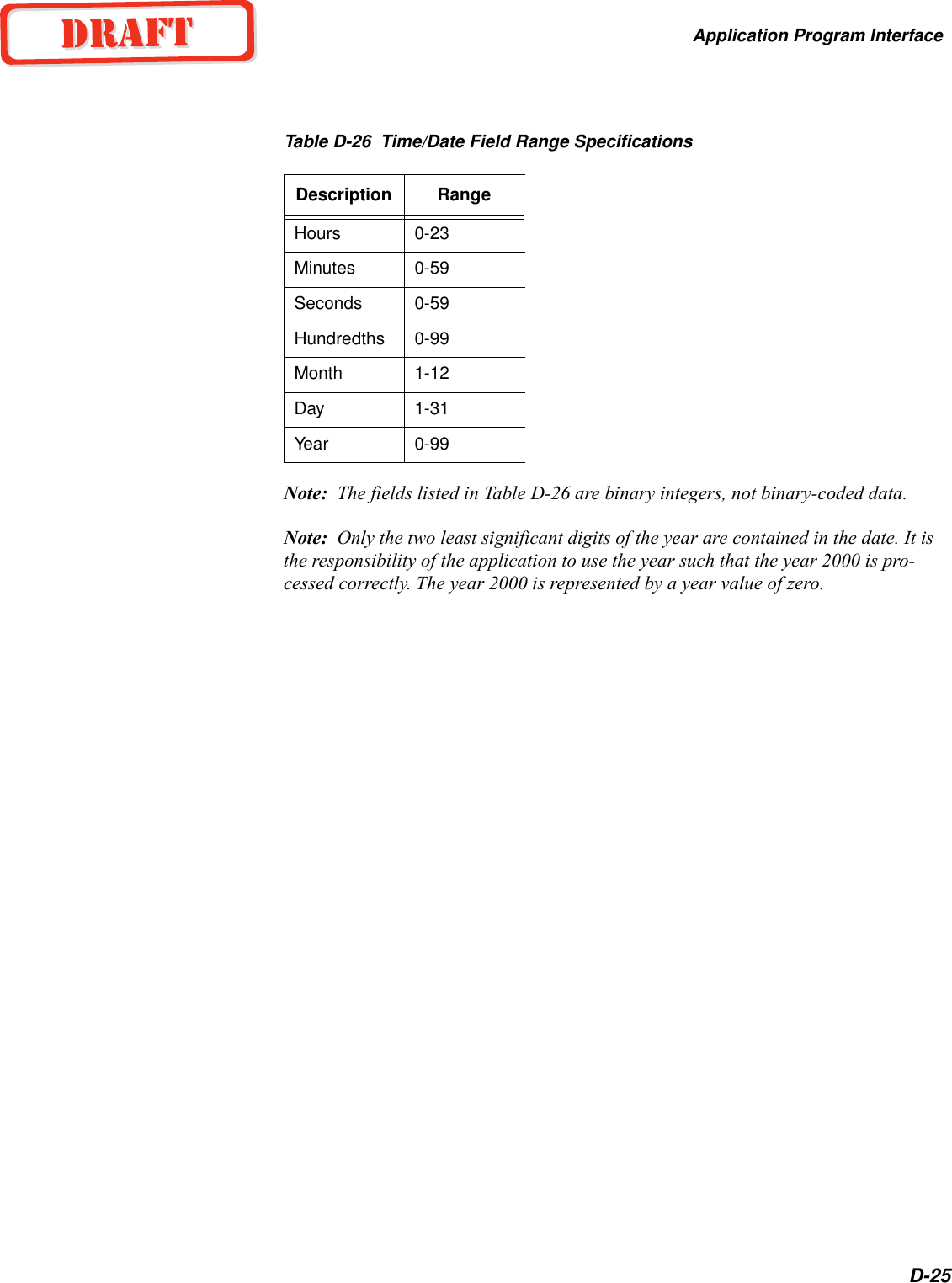
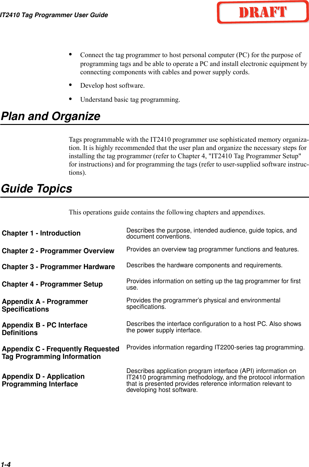
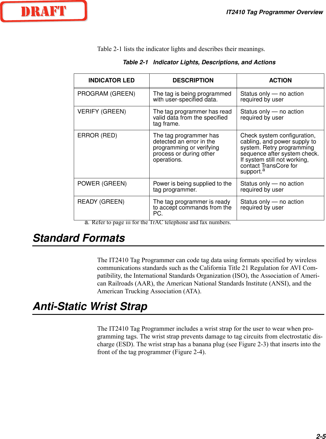
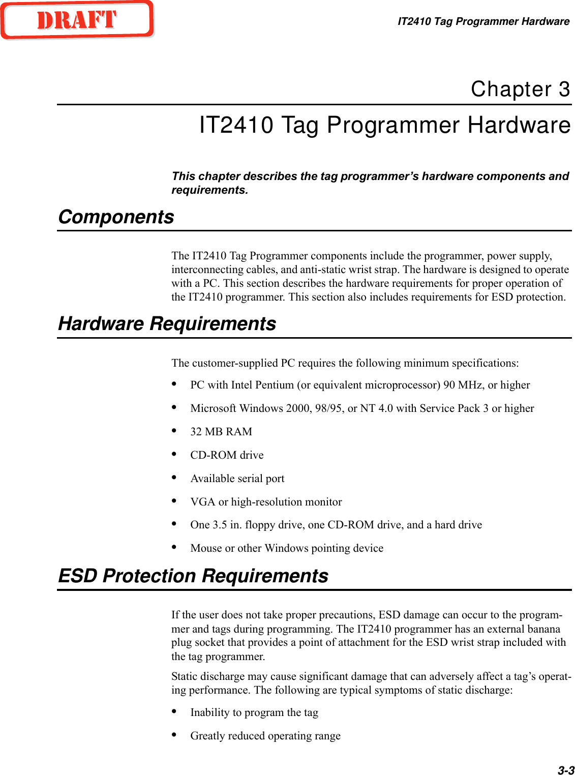
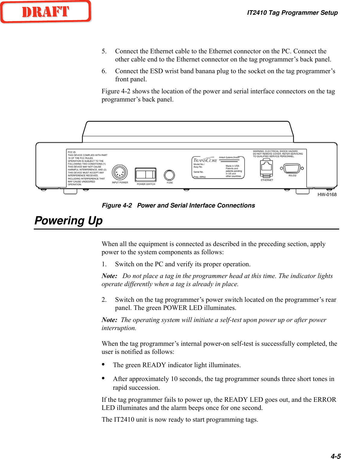
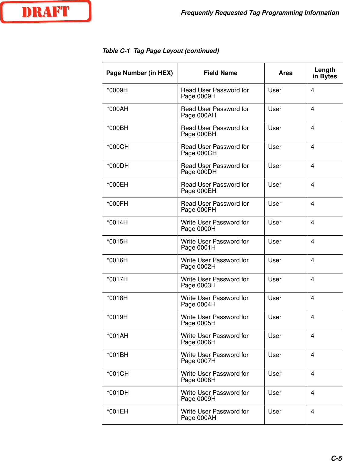
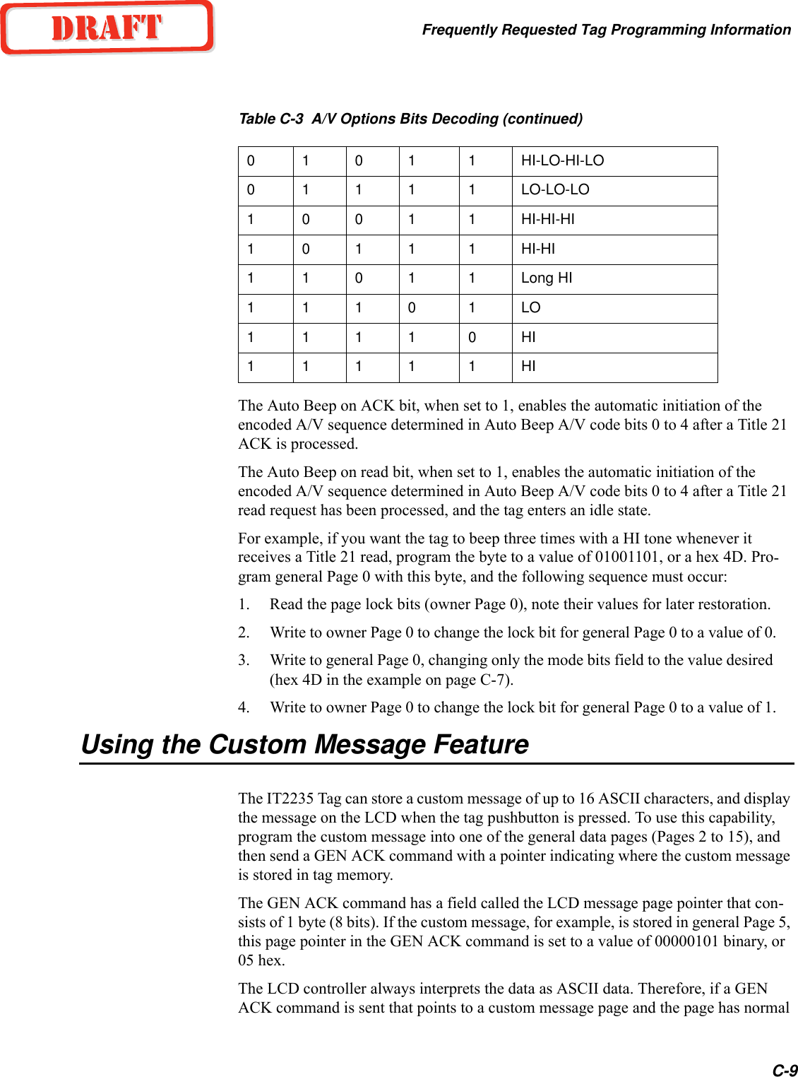
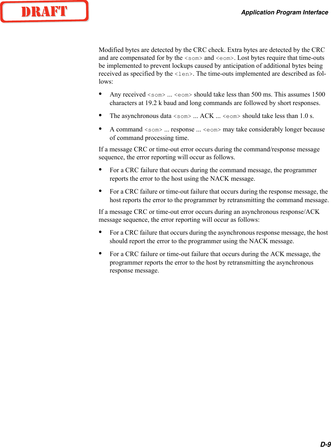
![IT2410 Tag Programmer User GuideD-8Table D-4 Asynchronous Responses and Definitions[<data>] - data field may be of length from 0 to 1020 bytes and is associated with each specific response. See the “Command List” on page D-10 for more information.Serial Error Detection and Recovery for the ProgrammerRather than implementing a complex ECP, the IT2410 Tag Programmer uses a method of error detection and recovery, which consists of a combination of CRC, sequence numbers, a simple structured protocol with message delimiters, a message length, and message time-outs. By using this combination of error detection and structured com-munications protocol, a high-level of confidence is obtained without the overhead associated with standard ECP.These methods are described in the following sections.Serial Message FailuresSerial data transmission failures can occur in one the three forms:•Modified byte•Extra byte•Lost byte Response Meaning0000H Command complete0001H Command in progress0002H Command data invalid0003H Command invalid0004H Command aborted3XXXH Valid read tag data3000H No-tag data status code3001H IT2200 Read/write tag data status code3002H Reserved8XXXH Diagnostic data8000H Power-up diagnostic report status code8001H Background diagnostic report status code8002H Download activeAXXXH Diagnostics statistical data](https://usermanual.wiki/TransCore/IT241005422/User-Guide-410856-Page-62.png)

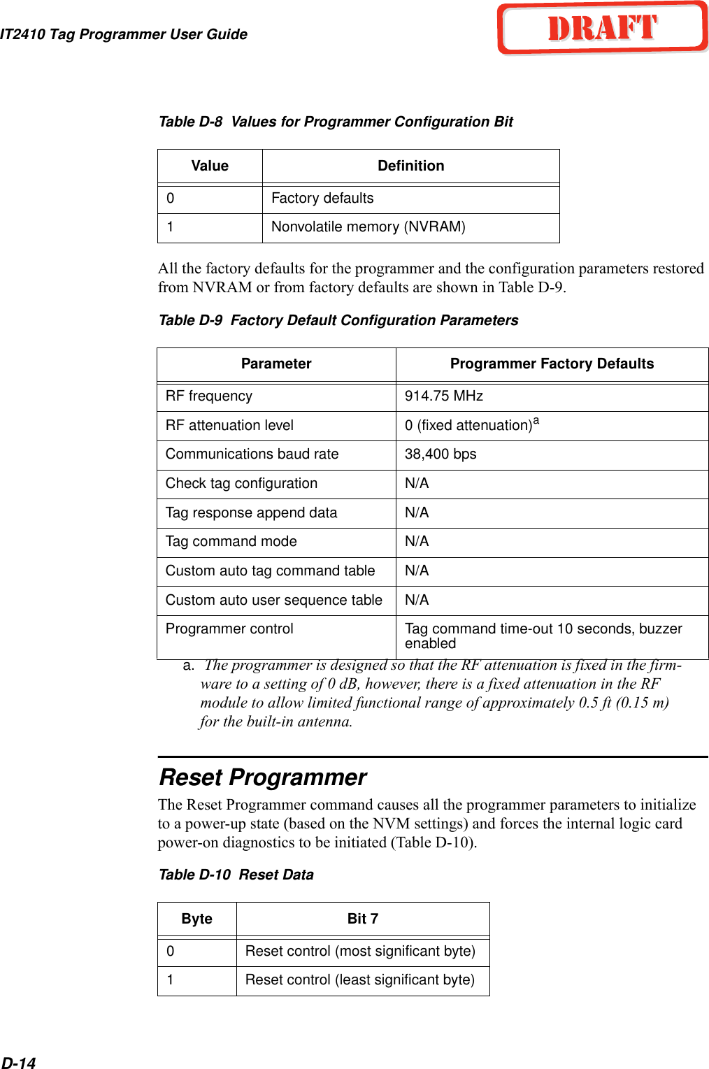
![IT2410 Tag Programmer User GuideD-16Valid security characters and their associated ASCII (hex) representations are shown in Table D-12.Table D-12 Valid Security CharactersThe location of these security bits within the 128-bit page, based on automatic vehicle identification standards, including AAR and ISO, consist of two distinct 6-bit groups comprising the 106 through 111 and 112 through 117 bit positions. These correspond to the 18th and 19th character locations based on the 6-bit AVI standards.Security characters stored in the programmer's NVM can be set to one of two combi-nations. At least one of the security character positions must be programmed to cus-tomer-specific security characters from the security character set for customer programmers (see Table D-13).Table D-13 Programmer Security Characters and ValuesSecurity Character ASCII (Hex) Security Character ASCII (Hex)(space) 20 :3A!21 ;3B"22 <3C#23 =3D$24 >3E%25 ?3F&26 @40'27 [5B(28 \5C)29 ]5D+2B ^5E,2C _5FProgrammer Security 1 Programmer Security 2 DescriptionSecurity character Security character Valid customer combinationSecurity character Normal character Valid customer combinationNormal character Security character Valid customer combinationNormal character Normal character Invalid combinationSpace Space Reserved](https://usermanual.wiki/TransCore/IT241005422/User-Guide-410856-Page-70.png)