TransCore IT241005422 Low power RFID tag programmer transmitter User Manual 411360 002 IT2410 Tag Programmer UG
TransCore Low power RFID tag programmer transmitter 411360 002 IT2410 Tag Programmer UG
users manual

IT2410 Tag Programmer
User Guide
TransCore, Inc.
19111 Dallas Parkway, Suite 300
Dallas, Texas 75287-3106
October 2003
P/N 411360-002

Information in this document is subject to change and does not represent a commitment on the part of
TC IP, Ltd.
©2004 TC IP, Ltd. All rights reserved. TRANSCORE and Amtech are registered trademarks of TC IP, Ltd.
and are used under license. All other trademarks listed are the property of their respective owners. Contents
subject to change. Printed in the U.S.A.
For further information, contact:
TransCore
19111 Dallas Parkway, Suite 300
Dallas, Texas 75287-3106 USA
Phone: (972) 733-6600
Fax: (972) 733-6699
TransCore Action Center (TrAC)
19111 Dallas Parkway, Suite 300
Dallas, Texas 75287-3106 USA
Phone: (800) 755-0378
Fax: (972) 733-6695
For comments or questions about this document, e-mail tech.pubs@transcore.com.
WARNING TO USERS IN THE UNITED STATES
FEDERAL COMMUNICATIONS COMMISSION (FCC) RADIO FREQUENCY
INTERFERENCE STATEMENT
47 CFR §15.105(a)
NOTE: This equipment has been tested and found to comply with the limits for a Class A digital device
pursuant to Part 15 of the Federal Communications Commission (FCC) rules. These limits are designed to
provide reasonable protection against harmful interference when the equipment is operated in a
commercial environment. This equipment generates, uses, and can radiate radio frequency (RF) energy and
may cause harmful interference to radio communications if not installed and used in accordance with the
instruction manual. Operating this equipment in a residential area is likely to cause harmful interference, in
which case, depending on the laws in effect, the users may be required to correct the interference at their
own expense.
NO UNAUTHORIZED MODIFICATIONS
47 CFR §15.21
CAUTION: This equipment may not be modified, altered, or changed in any way without permission
from TransCore, Inc. Unauthorized modification may void the equipment authorization from the FCC and
will void the TransCore warranty.
USE OF SHIELDED CABLES IS REQUIRED
47 CFR §15.27(a)
Shielded cables must be used with this equipment to comply with FCC regulations.
A license issued by the FCC is required to operate this RF identification device in the United States.
Contact TransCore, Inc. for additional information concerning licensing requirements for specific devices.
TransCore, Inc.
USA

Contents

vii
Contents
1 Getting Started
Purpose. . . . . . . . . . . . . . . . . . . . . . . . . . . . . . . . . . . . . . . . . . . . . . . . . . . . . . . . . . . . 1-3
Intended Audience . . . . . . . . . . . . . . . . . . . . . . . . . . . . . . . . . . . . . . . . . . . . . . . . . . . 1-4
Plan and Organize . . . . . . . . . . . . . . . . . . . . . . . . . . . . . . . . . . . . . . . . . . . . . . . . . . . 1-4
Guide Topics . . . . . . . . . . . . . . . . . . . . . . . . . . . . . . . . . . . . . . . . . . . . . . . . . . . . . . . 1-4
Typographical Conventions . . . . . . . . . . . . . . . . . . . . . . . . . . . . . . . . . . . . . . . . . . . 1-5
2 IT2410 Tag Programmer Overview
Purpose of Tag Programmer. . . . . . . . . . . . . . . . . . . . . . . . . . . . . . . . . . . . . . . . . . . 2-3
Communications . . . . . . . . . . . . . . . . . . . . . . . . . . . . . . . . . . . . . . . . . . . . . . . . . . . . 2-3
Programming Head . . . . . . . . . . . . . . . . . . . . . . . . . . . . . . . . . . . . . . . . . . . . . . . . . . 2-3
Indicator LEDs. . . . . . . . . . . . . . . . . . . . . . . . . . . . . . . . . . . . . . . . . . . . . . . . . . . . . 2-4
Standard Formats . . . . . . . . . . . . . . . . . . . . . . . . . . . . . . . . . . . . . . . . . . . . . . . . . . . 2-5
Anti-Static Wrist Strap . . . . . . . . . . . . . . . . . . . . . . . . . . . . . . . . . . . . . . . . . . . . . . . . 2-5
Power . . . . . . . . . . . . . . . . . . . . . . . . . . . . . . . . . . . . . . . . . . . . . . . . . . . . . . . . . . . . . 2-6
3 IT2410 Tag Programmer Hardware
Components . . . . . . . . . . . . . . . . . . . . . . . . . . . . . . . . . . . . . . . . . . . . . . . . . . . . . . . . 3-3
Hardware Requirements . . . . . . . . . . . . . . . . . . . . . . . . . . . . . . . . . . . . . . . . . . . . . . 3-3
ESD Protection Requirements . . . . . . . . . . . . . . . . . . . . . . . . . . . . . . . . . . . . . . . . . 3-3
ESD Workstation Design. . . . . . . . . . . . . . . . . . . . . . . . . . . . . . . . . . . . . . . . . . . . . . 3-4
Using the ESD Wrist Strap . . . . . . . . . . . . . . . . . . . . . . . . . . . . . . . . . . . . . . . . . . . . 3-4

IT2410 Tag Programmer User Guide
viii
4 IT2410 Tag Programmer Setup
Equipment List . . . . . . . . . . . . . . . . . . . . . . . . . . . . . . . . . . . . . . . . . . . . . . . . . . . . . . 4-3
Connecting the IT2410 Tag Programmer to a PC . . . . . . . . . . . . . . . . . . . . . . . . . . 4-4
Powering Up . . . . . . . . . . . . . . . . . . . . . . . . . . . . . . . . . . . . . . . . . . . . . . . . . . . . . . . . 4-5
Programming Cycle . . . . . . . . . . . . . . . . . . . . . . . . . . . . . . . . . . . . . . . . . . . . . . . . . . 4-6
Verifying Cycle . . . . . . . . . . . . . . . . . . . . . . . . . . . . . . . . . . . . . . . . . . . . . . . . . . . . . . 4-6
A Tag Programmer Specifications
Environmental . . . . . . . . . . . . . . . . . . . . . . . . . . . . . . . . . . . . . . . . . . . . . . . . . . . . . A-3
Mean Time Between Failure (MTBF) . . . . . . . . . . . . . . . . . . . . . . . . . . . . . . . . . A-4
Maintainability. . . . . . . . . . . . . . . . . . . . . . . . . . . . . . . . . . . . . . . . . . . . . . . . . . . A-4
B PC Interface Definitions
C Frequently Requested Tag Programming Information
Identification, Serial Number, and the Global Password . . . . . . . . . . . . . . . . . . . . C-3
Changing the Global Password . . . . . . . . . . . . . . . . . . . . . . . . . . . . . . . . . . . . . . . . C-6
Reading and Setting Nonvolatile Status for General Pages . . . . . . . . . . . . . . . . . C-7
Locking Frames (Page Locks) . . . . . . . . . . . . . . . . . . . . . . . . . . . . . . . . . . . . . . . . . C-7
Auto Beep on Acknowledge and Read Sequences . . . . . . . . . . . . . . . . . . . . . . . . C-8
Using the Custom Message Feature . . . . . . . . . . . . . . . . . . . . . . . . . . . . . . . . . . . C-10
D Application Program Interface
Interface Definitions. . . . . . . . . . . . . . . . . . . . . . . . . . . . . . . . . . . . . . . . . . . . . . . . . . D-3
Ethernet Communications Conduit . . . . . . . . . . . . . . . . . . . . . . . . . . . . . . . . . . . . . D-3
RS–232 Communications Conduit . . . . . . . . . . . . . . . . . . . . . . . . . . . . . . . . . . . . . D-4
Communications Protocols . . . . . . . . . . . . . . . . . . . . . . . . . . . . . . . . . . . . . . . . . . . D-4
General Software Information . . . . . . . . . . . . . . . . . . . . . . . . . . . . . . . . . . . . . . . . . D-4
Programmer-to-Host Software Communications Protocol . . . . . . . . . . . . . . . . . . . D-4
Serial Data Acknowledge . . . . . . . . . . . . . . . . . . . . . . . . . . . . . . . . . . . . . . . . . . D-6
Ethernet Asynchronous Command and Response Protocol. . . . . . . . . . . . . . . . . . D-7
Contents
ix
Serial Error Detection and Recovery for the Programmer . . . . . . . . . . . . . . . . . . . D-8
Serial Message Failures . . . . . . . . . . . . . . . . . . . . . . . . . . . . . . . . . . . . . . . . . . . . . D-8
Serial Sequence Numbers. . . . . . . . . . . . . . . . . . . . . . . . . . . . . . . . . . . . . . . . . . . D-10
Serial Asynchronous Responses. . . . . . . . . . . . . . . . . . . . . . . . . . . . . . . . . . . . . . D-10
Command List . . . . . . . . . . . . . . . . . . . . . . . . . . . . . . . . . . . . . . . . . . . . . . . . . . . . . D-10
Identify. . . . . . . . . . . . . . . . . . . . . . . . . . . . . . . . . . . . . . . . . . . . . . . . . . . . . . . . . . D-12
Restore Programmer Configuration. . . . . . . . . . . . . . . . . . . . . . . . . . . . . . . . . . . . D-13
Reset Programmer . . . . . . . . . . . . . . . . . . . . . . . . . . . . . . . . . . . . . . . . . . . . . . . . D-14
Save Programmer Configuration. . . . . . . . . . . . . . . . . . . . . . . . . . . . . . . . . . . . . . D-15
Get/Set Programmer Security Characters. . . . . . . . . . . . . . . . . . . . . . . . . . . . . . . D-15
Get/Set Programmer Serial Number . . . . . . . . . . . . . . . . . . . . . . . . . . . . . . . . . . . D-17
Get/Set Programmer Control. . . . . . . . . . . . . . . . . . . . . . . . . . . . . . . . . . . . . . . . . D-17
Set Programmer Password . . . . . . . . . . . . . . . . . . . . . . . . . . . . . . . . . . . . . . . . . . D-18
Programmer Command Restrictions . . . . . . . . . . . . . . . . . . . . . . . . . . . . . . . . . . . D-20
Get/Set Communications Baud Rate. . . . . . . . . . . . . . . . . . . . . . . . . . . . . . . . . . . D-22
Get/Set Ethernet Parameters . . . . . . . . . . . . . . . . . . . . . . . . . . . . . . . . . . . . . . . . D-22
Get/Set Programmer RF . . . . . . . . . . . . . . . . . . . . . . . . . . . . . . . . . . . . . . . . . . . . D-23
Get/Set Time/Date. . . . . . . . . . . . . . . . . . . . . . . . . . . . . . . . . . . . . . . . . . . . . . . . . D-24
Asynchronous Responses . . . . . . . . . . . . . . . . . . . . . . . . . . . . . . . . . . . . . . . . . . . D-26
Power on/Boot/Diagnostics Status Reports. . . . . . . . . . . . . . . . . . . . . . . . . . . . . . D-26
Valid Response Tag Data . . . . . . . . . . . . . . . . . . . . . . . . . . . . . . . . . . . . . . . . . . . D-27

IT2410 Tag Programmer User Guide
x
List of Figures
Figure 1-1 IT2410 Tag Programmer (Top View) . . . . . . . . . . . . . . . . . . . . . . . . . . . . . . . . . . . . . . . . 1-3
Figure 2-1 Tag Programming Head . . . . . . . . . . . . . . . . . . . . . . . . . . . . . . . . . . . . . . . . . . . . . . . . 2-4
Figure 2-2 IT2410 LED Status Lights . . . . . . . . . . . . . . . . . . . . . . . . . . . . . . . . . . . . . . . . . . . . . . . 2-4
Figure 2-3 Banana Plug on ESD Wrist Strap . . . . . . . . . . . . . . . . . . . . . . . . . . . . . . . . . . . . . . . . . . 2-6
Figure 2-4 ESD Wrist Band Socket Location . . . . . . . . . . . . . . . . . . . . . . . . . . . . . . . . . . . . . . . . . . 2-6
Figure 4-1 IT2410 Tag Programmer System . . . . . . . . . . . . . . . . . . . . . . . . . . . . . . . . . . . . . . . . . . 4-4
Figure 4-2 Power and Serial Interface Connections . . . . . . . . . . . . . . . . . . . . . . . . . . . . . . . . . . . . . 4-5
Figure B-1 Pin-out Diagram for Power Plug . . . . . . . . . . . . . . . . . . . . . . . . . . . . . . . . . . . . . . . . . B-3
Figure D-1 Programmer Command Hierarchy . . . . . . . . . . . . . . . . . . . . . . . . . . . . . . . . . . . . . . . . D-21
List of Tables
Table 1-1 Typographical Conventions . . . . . . . . . . . . . . . . . . . . . . . . . . . . . . . . . . . . . . . . . . . . . . 1-5
Table 2-1 Indicator Lights, Descriptions, and Actions . . . . . . . . . . . . . . . . . . . . . . . . . . . . . . . . . . . 2-5
Table 4-1 Programmer Operations and Corresponding Alarms . . . . . . . . . . . . . . . . . . . . . . . . . . . . . 4-6
Table A-1 IT2410 Tag Programmer Physical and Environmental Specifications . . . . . . . . . . . . . . . . . . A-3
Table B-1 PC Interface Protocol Settings . . . . . . . . . . . . . . . . . . . . . . . . . . . . . . . . . . . . . . . . . . . . B-3
Table C-1 Tag Page Layout . . . . . . . . . . . . . . . . . . . . . . . . . . . . . . . . . . . . . . . . . . . . . . . . . . . . . C-3
Table C-2 Mode Bits . . . . . . . . . . . . . . . . . . . . . . . . . . . . . . . . . . . . . . . . . . . . . . . . . . . . . . . . . . C-8
Table C-3 A/V Options Bits Decoding . . . . . . . . . . . . . . . . . . . . . . . . . . . . . . . . . . . . . . . . . . . . . . . C-9
Table D-1 Communications Parameters . . . . . . . . . . . . . . . . . . . . . . . . . . . . . . . . . . . . . . . . . . . . . D-4
Table D-2 Command Responses and Definitions . . . . . . . . . . . . . . . . . . . . . . . . . . . . . . . . . . . . . . . D-6
Table D-3 Message Responses and Definitions . . . . . . . . . . . . . . . . . . . . . . . . . . . . . . . . . . . . . . . . D-7
Table D-4 Asynchronous Responses and Definitions . . . . . . . . . . . . . . . . . . . . . . . . . . . . . . . . . . . . D-8
Table D-5 Tag Programmer Commands . . . . . . . . . . . . . . . . . . . . . . . . . . . . . . . . . . . . . . . . . . . . D-11
Table D-6 Identify Command Code . . . . . . . . . . . . . . . . . . . . . . . . . . . . . . . . . . . . . . . . . . . . . . . D-12
Table D-7 Programmer Configuration Data . . . . . . . . . . . . . . . . . . . . . . . . . . . . . . . . . . . . . . . . . . D-13
Table D-8 Values for Programmer Configuration Bit . . . . . . . . . . . . . . . . . . . . . . . . . . . . . . . . . . . D-14
Table D-9 Factory Default Configuration Parameters . . . . . . . . . . . . . . . . . . . . . . . . . . . . . . . . . . . D-14
Table D-10 Reset Data . . . . . . . . . . . . . . . . . . . . . . . . . . . . . . . . . . . . . . . . . . . . . . . . . . . . . . . D-14
Table D-11 Security Characters Data . . . . . . . . . . . . . . . . . . . . . . . . . . . . . . . . . . . . . . . . . . . . . .D-15
Table D-12 Valid Security Characters . . . . . . . . . . . . . . . . . . . . . . . . . . . . . . . . . . . . . . . . . . . . .D-16
Table D-13 Programmer Security Characters and Values . . . . . . . . . . . . . . . . . . . . . . . . . . . . . . . . D-16
Table D-14 Serial Number Data . . . . . . . . . . . . . . . . . . . . . . . . . . . . . . . . . . . . . . . . . . . . . . . . .D-17
Table D-15 Programmer Status Data . . . . . . . . . . . . . . . . . . . . . . . . . . . . . . . . . . . . . . . . . . . . . . D-18
Table D-16 Set Programmer Password Command Data . . . . . . . . . . . . . . . . . . . . . . . . . . . . . . . . . D-19
Table D-17 Password Status Data . . . . . . . . . . . . . . . . . . . . . . . . . . . . . . . . . . . . . . . . . . . . . . . .D-19
Table D-18 Set Password Command Responses . . . . . . . . . . . . . . . . . . . . . . . . . . . . . . . . . . . . . . D-20
Table D-19 Communications Baud Rate Data . . . . . . . . . . . . . . . . . . . . . . . . . . . . . . . . . . . . . . . . D-22
Table D-20 Ethernet Parameters Data . . . . . . . . . . . . . . . . . . . . . . . . . . . . . . . . . . . . . . . . . . . . . D-22
Table D-21 C-String Format for Parameters . . . . . . . . . . . . . . . . . . . . . . . . . . . . . . . . . . . . . . . . . D-23
Table D-22 Programmer RF Data . . . . . . . . . . . . . . . . . . . . . . . . . . . . . . . . . . . . . . . . . . . . . . . . D-23
Table D-23 Valid Transceiver Frequencies . . . . . . . . . . . . . . . . . . . . . . . . . . . . . . . . . . . . . . . . . . D-23
Table D-24 Programmer RF . . . . . . . . . . . . . . . . . . . . . . . . . . . . . . . . . . . . . . . . . . . . . . . . . . . . D-24
Contents
xi
Table D-25 Time/Date Data . . . . . . . . . . . . . . . . . . . . . . . . . . . . . . . . . . . . . . . . . . . . . . . . . . . .D-24
Table D-26 Time/Date Field Range Specifications . . . . . . . . . . . . . . . . . . . . . . . . . . . . . . . . . . . . . D-25
Table D-27 Programmer Status Report Data . . . . . . . . . . . . . . . . . . . . . . . . . . . . . . . . . . . . . . . . .D-26
Table D-28 Subfields of Programmer Status . . . . . . . . . . . . . . . . . . . . . . . . . . . . . . . . . . . . . . . . . D-26
Table D-29 Tag Data Report Status Codes . . . . . . . . . . . . . . . . . . . . . . . . . . . . . . . . . . . . . . . . . .D-27
IT2410 Tag Programmer User Guide
xii

1
Getting Started
Getting Started
1-3
Chapter 1
Getting Started
This chapter describes this guide’s purpose and intended audience. It
provides a list of topics covered in each section, a list of related
documents, and the symbols and typographical conventions used.
Purpose
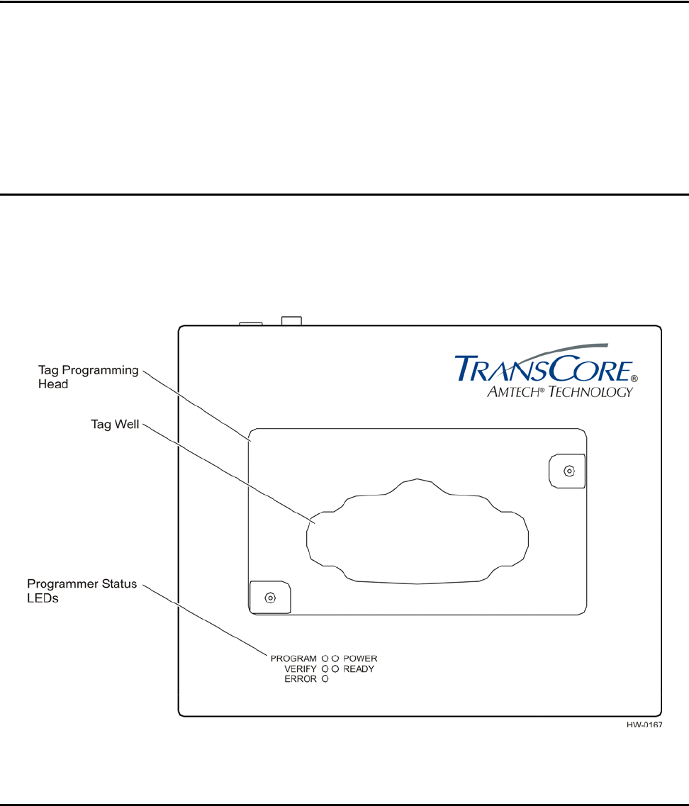
This IT2410 Tag Programmer User Guide contains installation and operating instruc-
tions for the hardware used to perform the IT2410 Tag Programmer reading (interro-
gation/verification) and writing (programming) functions. Figure 1-1 illustrates the
features of the IT2410 Tag Programmer.
Figure 1-1 IT2410 Tag Programmer (Top View)
Intended Audience
The intended audience for this user guide includes all personnel who need to accom-
plish the following tasks:

IT2410 Tag Programmer User Guide
1-4
•Connect the tag programmer to host personal computer (PC) for the purpose of
programming tags and be able to operate a PC and install electronic equipment by
connecting components with cables and power supply cords.
•Develop host software.
•Understand basic tag programming.
Plan and Organize
Tags programmable with the IT2410 programmer use sophisticated memory organiza-
tion. It is highly recommended that the user plan and organize the necessary steps for
installing the tag programmer (refer to Chapter 4, "IT2410 Tag Programmer Setup"
for instructions) and for programming the tags (refer to user-supplied software instruc-
tions).
Guide Topics
This operations guide contains the following chapters and appendixes.
Chapter 1 - Introduction Describes the purpose, intended audience, guide topics, and
document conventions.
Chapter 2 - Programmer Overview Provides an overview tag programmer functions and features.
Chapter 3 - Programmer Hardware Describes the hardware components and requirements.
Chapter 4 - Programmer Setup Provides information on setting up the tag programmer for first
use.
Appendix A - Programmer
Specifications
Provides the programmer’s physical and environmental
specifications.
Appendix B - PC Interface
Definitions
Describes the interface configuration to a host PC. Also shows
the power supply interface.
Appendix C - Frequently Requested
Tag Programming Information
Provides information regarding IT2200-series tag programming.
Appendix D - Application
Programming Interface
Describes application program interface (API) information on
IT2410 programming methodology, and the protocol information
that is presented provides reference information relevant to
developing host software.
Getting Started
1-5
Typographical Conventions
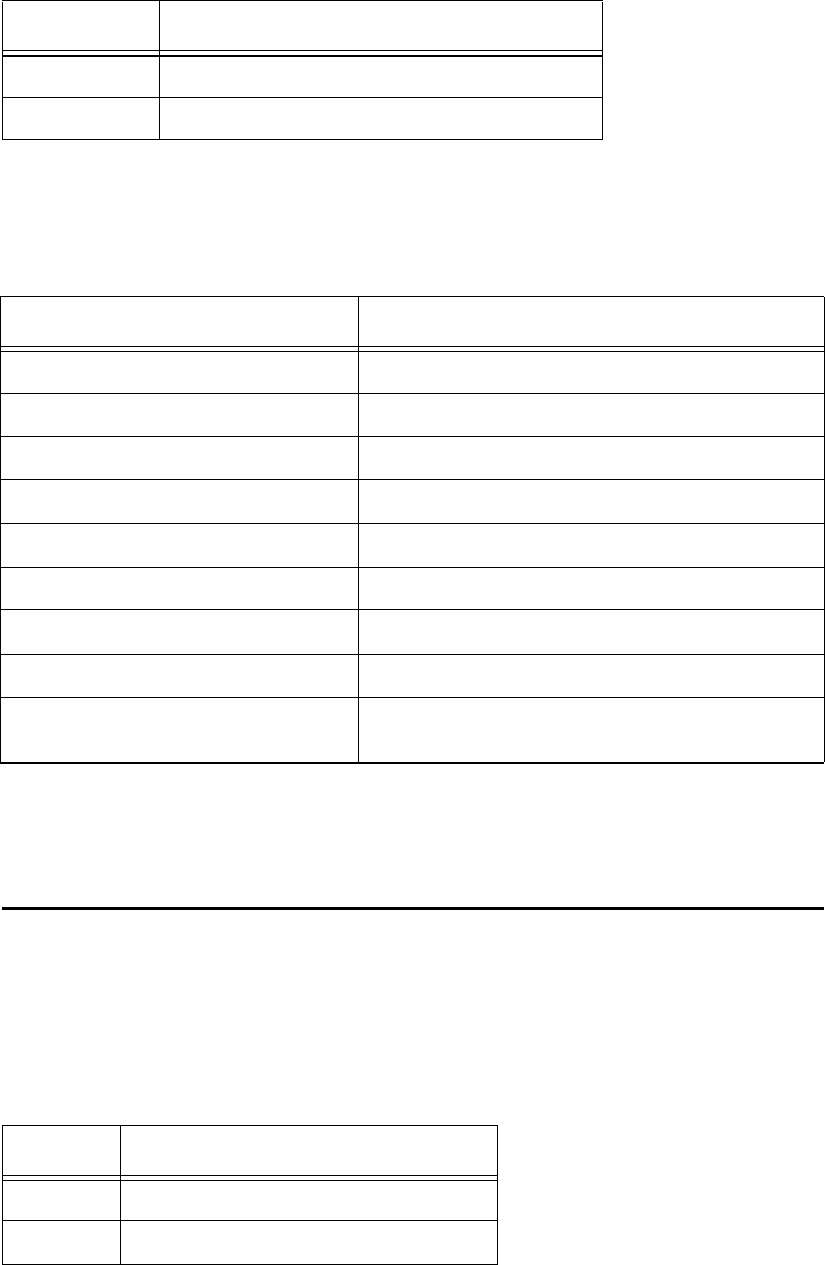
The following conventions are used in this manual (Table 1-1).
Table 1-1 Typographical Conventions
Convention Indication
This procedure might cause harm to the equipment and/or
the user.
Concerns about a procedure.
Code Code, including keywords and variables within text and as
separate paragraphs, and user-defined program elements
within text appear in courier typeface.
Dialog Box Title Title of a dialog box as it appears on screen.
Function Start with the characters G4 and add mixed case with no
underscores, and include parentheses after the name, as in
G4FunctionName().
Menu Item Appears on a menu.
Note Auxiliary information that further clarifies the current
discussion. These important points require the user’s
attention. The paragraph is in italics and the word Note is
bold.
NUL Zero-value ASCII character or a zero-value byte.
NULL Zero-value pointers are null-terminated strings that refer to
strings of printable ASCII characters with a zero-value byte
placed in memory directly after the last printable character of
the string.
IT2410 Tag Programmer User Guide
1-6

2
IT2410 Tag Programmer Overview

IT2410 Tag Programmer Overview
2-3
Chapter 2
IT2410 Tag Programmer Overview
This chapter presents an overview of the IT2410 Tag Programmer.
Purpose of Tag Programmer
The tag programmer is a multi-function product used to program IT2200-series tags.
Programmer functions include frame programming, fixed-frame locking, and data
frame interrogation.
Communications
The tag programmer connects to a PC serial port that complies with the RS–232 com-
munications interface standard. A PC-to-programmer RS–232 serial cable is provided
with the tag programmer. An Ethernet interface connection is also provided
Programming Head
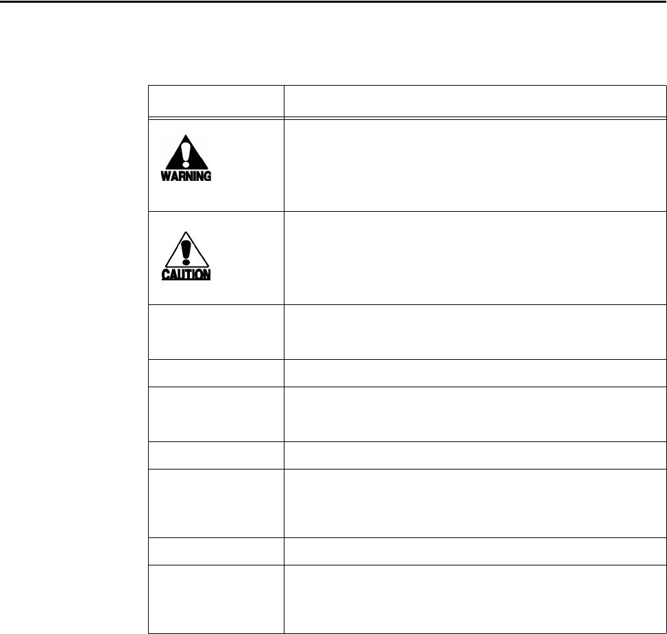
The programming head on the top of the tag programmer provides a mechanical inter-
face to the tag. The programming head includes a drop-in tag well that is compatible
with some IT2000-series tags. By placing the tag in the tag well the tag is correctly
positioned to the programmer’s internal antenna. Figure 2-1 shows the IT2410 Tag
Programmer head.
IT2410 Tag Programmer User Guide
2-4
Figure 2-1 Tag Programming Head
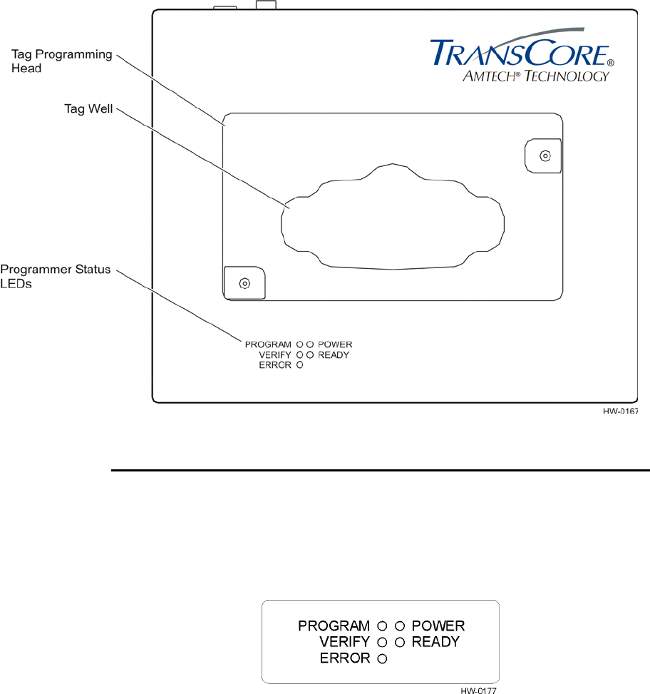
Indicator LEDs
The tag programmer uses light-emitting diodes (LEDs) to indicate the status of its
operations. These LED indicators identify operation, functionality, and errors. Figure
2-2 illustrates the external status indicators.
Figure 2-2 IT2410 LED Status Lights

IT2410 Tag Programmer Overview
2-5
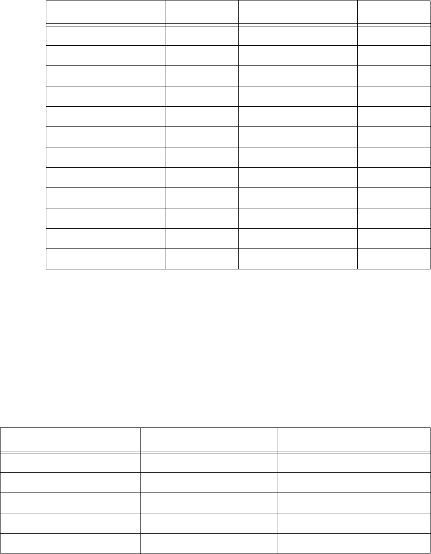
Table 2-1 lists the indicator lights and describes their meanings.
Standard Formats
The IT2410 Tag Programmer can code tag data using formats specified by wireless
communications standards such as the California Title 21 Regulation for AVI Com-
patibility, the International Standards Organization (ISO), the Association of Ameri-
can Railroads (AAR), the American National Standards Institute (ANSI), and the
American Trucking Association (ATA).
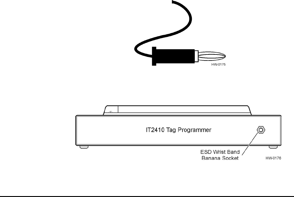
Anti-Static Wrist Strap
The IT2410 Tag Programmer includes a wrist strap for the user to wear when pro-
gramming tags. The wrist strap prevents damage to tag circuits from electrostatic dis-
charge (ESD). The wrist strap has a banana plug (see Figure 2-3) that inserts into the
front of the tag programmer (Figure 2-4).
Table 2-1 Indicator Lights, Descriptions, and Actions
INDICATOR LED DESCRIPTION ACTION
PROGRAM (GREEN) The tag is being programmed
with user-specified data. Status only — no action
required by user
VERIFY (GREEN) The tag programmer has read
valid data from the specified
tag frame.
Status only — no action
required by user
ERROR (RED) The tag programmer has
detected an error in the
programming or verifying
process or during other
operations.
Check system configuration,
cabling, and power supply to
system. Retry programming
sequence after system check.
If system still not working,
contact TransCore for
support.a
POWER (GREEN) Power is being supplied to the
tag programmer. Status only — no action
required by user
READY (GREEN) The tag programmer is ready
to accept commands from the
PC.
Status only — no action
required by user
a. Refer to page iii for the TrAC telephone and fax numbers.
IT2410 Tag Programmer User Guide
2-6
Figure 2-3 Banana Plug on ESD Wrist Strap
Figure 2-4 ESD Wrist Band Socket Location
Power
The IT2410 Tag Programmer is powered from a standard 120 VAC outlet. A UL-
approved 12 VDC power supply is included with the standard tag programmer. Refer
to Appendix B to this guide for a pin-out diagram of the power connector.

3
IT2410 Tag Programmer Hardware

IT2410 Tag Programmer Hardware
3-3
Chapter 3
IT2410 Tag Programmer Hardware
This chapter describes the tag programmer’s hardware components and
requirements.
Components
The IT2410 Tag Programmer components include the programmer, power supply,
interconnecting cables, and anti-static wrist strap. The hardware is designed to operate
with a PC. This section describes the hardware requirements for proper operation of
the IT2410 programmer. This section also includes requirements for ESD protection.
Hardware Requirements
The customer-supplied PC requires the following minimum specifications:
•PC with Intel Pentium (or equivalent microprocessor) 90 MHz, or higher
•Microsoft Windows 2000, 98/95, or NT 4.0 with Service Pack 3 or higher
•32 MB RAM
•CD-ROM drive
•Available serial port
•VGA or high-resolution monitor
•One 3.5 in. floppy drive, one CD-ROM drive, and a hard drive
•Mouse or other Windows pointing device
ESD Protection Requirements
If the user does not take proper precautions, ESD damage can occur to the program-
mer and tags during programming. The IT2410 programmer has an external banana
plug socket that provides a point of attachment for the ESD wrist strap included with
the tag programmer.
Static discharge may cause significant damage that can adversely affect a tag’s operat-
ing performance. The following are typical symptoms of static discharge:
•Inability to program the tag
•Greatly reduced operating range

IT2410 Tag Programmer User Guide
3-4
•Tag operating failure
Static is generated by friction and can often build to damaging levels. The following
are some of the causes of static:
•Shoes moving across a carpeted or plastic floor
•Hot air blowing into a room from a hot-air duct
•Rubbing tags together
•Sliding tags across a table top
•Friction created while wearing certain types of clothing
ESD Workstation Design
Well-designed workstations use a system of multiple protection elements. At a mini-
mum, this protection should include anti-static bench mats and wrist straps to dis-
charge static safely away from the equipment.
As an additional measure to prevent static damage, keep tags in their original packag-
ing, on an anti-static mat, or within an ESD-inhibiting container until you are ready to
program the tags.
Using the ESD Wrist Strap
Always attach the ESD strap before beginning programming operations. Perform the
following steps:
1. Place the strap on the wrist and snap the ESD strap to the elastic wristband.
2. Connect the banana plug (see Figure 2-3 on page 2-6) on the ESD wrist strap to
the ESD banana socket on the front of the tag programmer (see Figure 2-3 on
page 2-6).

4
IT2410 Tag Programmer Setup

IT2410 Tag Programmer Setup
4-3
Chapter 4
IT2410 Tag Programmer Setup
This chapter explains how to set up the tag programmer for first use.
Equipment List
User must wear the wrist strap when programming tags. Failure to do so can result
in ESD damage to the tag.
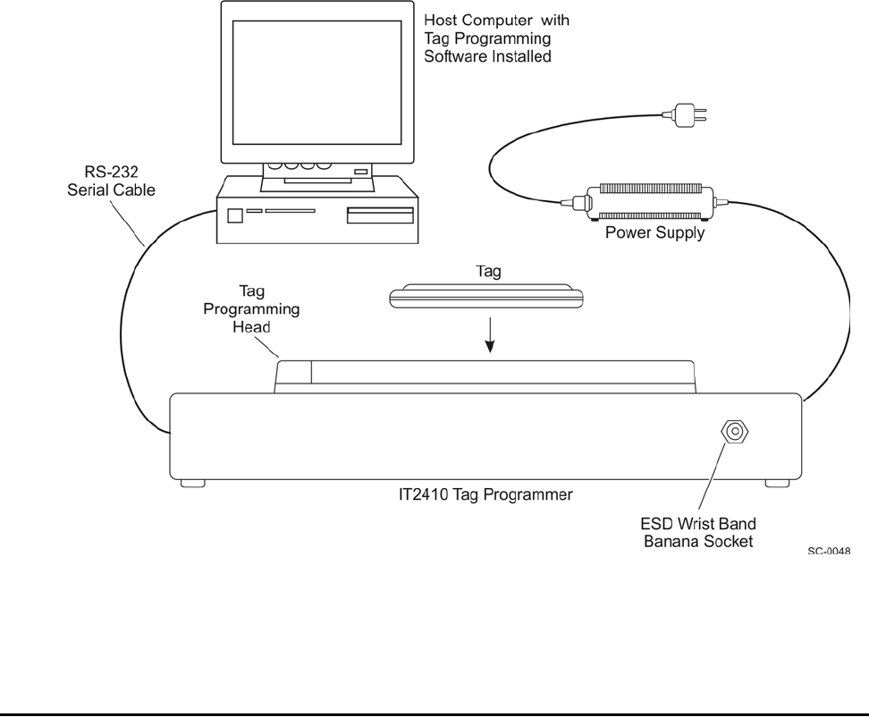
The IT2410 Tag Programmer includes the following components:
•Tag programmer unit
•External 12 VDC power module
•ESD static suppression wrist strap
•PC-to-programmer RS–232 serial cable with DB-9 connectors on both ends
Figure 4-1 shows the tag programmer and peripheral components.
IT2410 Tag Programmer User Guide
4-4
Figure 4-1 IT2410 Tag Programmer System
Note: To maintain FCC Part 15 Class B compliance, operate the tag programmer in
a horizontal position.
Connecting the IT2410 Tag Programmer to a PC
Use the following procedure to connect the equipment:
1. Place the tag programmer on a flat, stable surface.
2. Connect the power supply to the power socket on the tag programmer’s back
panel.
3. Connect the power supply plug to a properly grounded — three-prong — AC
outlet.
4. Connect the PC-to-programmer RS–232 serial cable to the COM1 port on the
PC. Connect the other cable end to the RS–232 connector on the tag
programmer’s back panel.
IT2410 Tag Programmer Setup
4-5
5. Connect the Ethernet cable to the Ethernet connector on the PC. Connect the
other cable end to the Ethernet connector on the tag programmer’s back panel.
6. Connect the ESD wrist band banana plug to the socket on the tag programmer’s
front panel.
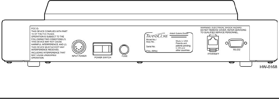
Figure 4-2 shows the location of the power and serial interface connectors on the tag
programmer’s back panel.
Figure 4-2 Power and Serial Interface Connections
Powering Up
When all the equipment is connected as described in the preceding section, apply
power to the system components as follows:
1. Switch on the PC and verify its proper operation.
Note: Do not place a tag in the programmer head at this time. The indicator lights
operate differently when a tag is already in place.
2. Switch on the tag programmer’s power switch located on the programmer’s rear
panel. The green POWER LED illuminates.
Note: The operating system will initiate a self-test upon power up or after power
interruption.
When the tag programmer’s internal power-on self-test is successfully completed, the
user is notified as follows:
•The green READY indicator light illuminates.
•After approximately 10 seconds, the tag programmer sounds three short tones in
rapid succession.
If the tag programmer fails to power up, the READY LED goes out, and the ERROR
LED illuminates and the alarm beeps once for one second.
The IT2410 unit is now ready to start programming tags.

IT2410 Tag Programmer User Guide
4-6
Programming Cycle
When the programming cycle is initiated by the remote host system, the PROGRAM
LED illuminates and the alarm beeps for an approximate duration of 0.25 seconds,
once a second, for a 10-s period, or until the programming operation has completed.
The operator has an approximate 10-s time-out period in which to place an operating
IT2200-series tag on the programming head fixture. Once the tag is in the fixture and
the programmer detects the valid RF data, the programmer executes the specific write
command from the host.
If the programming is successful then the PROGRAM LED goes out and the alarm
sounds three times for approximately 0.25 seconds each.
If the programming cycle is unsuccessful or a tag is not detected within the 10-s
period, the ERROR LED illuminates and the alarm sounds once for approximately 1
second.
Verifying Cycle
When the verify cycle is initiated by the remote host system, the VERIFY LED illumi-
nates and the alarm beeps each second for an approximate 10-s period or until the ver-
ify operation is complete.
The operator has a 10-s time-out period in which to place an operating IT2200-series
tag on the programming head. Once the tag is placed in the fixture and the program-
mer can detect the valid RF data, the programmer executes the specific read command
from the host.
If the verifying is successful the VERIFY LED goes out and the alarm sounds three
short beeps.
If the verifying cycle is unsuccessful or if a tag is not detected within the 10-s period,
the ERROR LED illuminates and the alarm beeps for 1 second.
The tag programmer incorporates an audible indicator that is controlled by software.
The indicator’s sound is pleasing to the ear (2200 Hz) and can be easily heard while
operating near the unit under normal conditions. The alarm audibly indicates the status
of programmer operations. Table 4-1 lists the various programmer operations and the
corresponding alarms that sound as an audible operation verification.
Table 4-1 Programmer Operations and Corresponding Alarms
Programmer Operation Audible Alarm Beep Duration Duty (%)
Successful Self Test 3 beeps 0.25 s 50
Failed Self Test 1 beep 3.0 s 100

IT2410 Tag Programmer Setup
4-7
Programming Cycle 1 beep per second for 10 s 0.25 s each 25
Successful Programming Cycle 3 beeps 0.25 s each 50
Unsuccessful Programming Cycle 1 beep 3.0 s 100
VERIFY Cycle 1 beep per second for 10 s 0.25 s each 25
Successful VERIFY Cycle 3 beeps 0.25 s each 50
Unsuccessful VERIFY Cycle 1 beep 3.0 s 100
Table 4-1 Programmer Operations and Corresponding Alarms (continued)
Programmer Operation Audible Alarm Beep Duration Duty (%)
IT2410 Tag Programmer User Guide
4-8

A
Tag Programmer Specifications

Tag Programmer Specifications
A-3
Appendix A
Tag Programmer Specifications
This appendix lists the tag programmer physical and environmental
specifications.
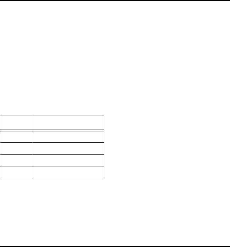
Table A-1 lists the IT2410 Tag Programmer parameters and specifications.
Environmental
The programmer is designed to operate in typical office environment conditions. The
programmer performs to the specifications listed in Table A-1 and is ready to program
with a warm-up time of not more than three minutes.
Table A-1 IT2410 Tag Programmer Physical and Environmental Specifications
Parameter Specification
Size (W x H x D) 14.3 x 3.2 x 11.5 in
(36.3 x 8.1 x 29.2 cm)
Weight 6.8 lbs (3.1 kg)
Input Voltage 120 VAC
Power Consumption 36 W
Operating Temperature 32°F to +131°F
(0°C to +55°C)
Storage Temperature -4°F to +185°F
(-20°C to +85°C)
Humidity 95% noncondensing (within 77°F to
131°F (25°C to 55°C))
Enclosure Dustproof
Operational Vibration 1.04 Grms, 5-500 Hz, power spectral
density-uniform 0.0022 G2/Hz, 1 hour
per axis
Shock 4 Gzero-to-peak by 11 ms half-sine
duration in all 3 axes
PC-to-Programmer Cable RS–232 (DTE)
RF Power Programming head: 1.0 mW
FCC Classification Part 15, site license not required
IT2410 Tag Programmer User Guide
A-4
Mean Time Between Failure (MTBF)
The programmer has a minimum MTBF of 20,000 hours.
Maintainability
The interval for periodic maintenance is least one year. The mean time to repair
(MTTR) is less than 30 minutes.

B
PC Interface Definitions
PC Interface Definitions
B-3
Appendix B
PC Interface Definitions
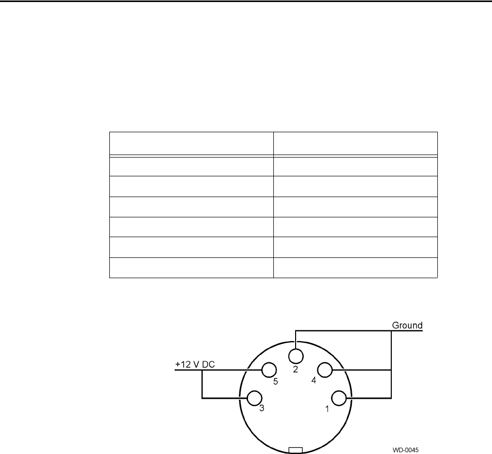
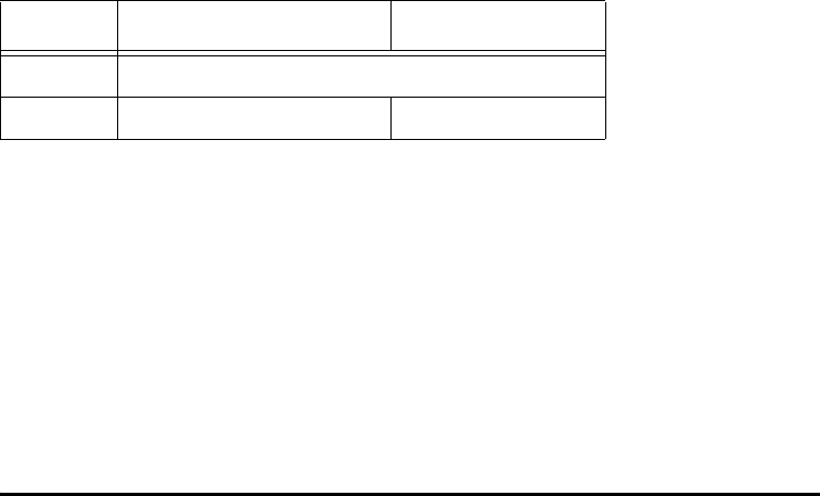
The tag programmer’s PC interface complies with the RS–232 standard for data com-
munications equipment and uses the protocol settings listed in Table B-1. Figure B-1
shows the pin-out locations for the power plug.
Figure B-1 Pin-out Diagram for Power Plug
Table B-1 PC Interface Protocol Settings
Protocol Setting
Data Rate 38,400 bps (factory default)
Data Bits 8
Parity None
Stop Bits 1
Software Flow Control None
Hardware Flow Control None
IT2410 Tag Programmer User Guide
B-4

C
Frequently Requested Tag
Programming Information

Frequently Requested Tag Programming Information
C-3
Appendix C
Frequently Requested Tag Programming
Information
This appendix explains frequently requested information regarding
IT2200-series tag programming information.
Identification, Serial Number, and the Global Password
TransCore documentation and/or host software references a tag identification number
(ID) that corresponds to the Title 21 ID. The Title 21 ID is a unique identifier used by
radio frequency identification systems in California. This is found in the first 8 hexa-
decimal characters (32 bits) of the tag’s general Page 1. In all IT2200-series tags, this
ID is either the same as the serial number from Page 0, or other application specifica-
tions.
The tag serial number (S/N) is the first 8 hexadecimal characters (32 bits) in general
Page 0. The global password is 64 bits long and the default is generated by repeating
the serial number twice. Once this global password is known, it can be used to change
read and write passwords on any of the general pages of data in the tag, change which
frames are designated nonvolatile, and lock pages of data so that they cannot be
changed unless the page is unlocked first using the global password.
These two identifying numbers are in addition to any customer-specific ID numbers.
Most of the customers that use the IT2200-series tags employ one of the other general
pages of data available in the tag to store their own unique ID number, which usually
corresponds to a patron account number.
The global password in the IT2200-series tag acts like a master key, which can be
used to perform crucial tag operations and is meant to be controlled by the owner
agency. It has a default setting that is created from the tag’s unique serial number, but
can be changed by the owner agency, if desired. Table C-1 shows the tag page layout.
Table C-1 Tag Page Layout
Page Number (in HEX) Field Name Area Length
in Bytes
*0000H Configuration Page
(reserved for factory use) General 16
*0001H General Page 1/Diagnostics General 16
0002H General Page 2 General 16

IT2410 Tag Programmer User Guide
C-4
0003H General Page 3 General 16
0004H General Page 4 General 16
0005H General Page 5 General 16
0006H General Page 6 General 16
0007H General Page 7 General 16
0008H General Page 8 General 16
0009H General Page 9 General 16
000AH General Page A General 16
000BH General Page B General 16
000CH General Page C General 16
000DH General Page D General 16
000EH General Page E General 16
000FH General Page F General 16
*0000H User Password for Page
0000H User 4
*0001H Read User Password for
Page 0001H User 4
*0002H Read User Password for
Page 0002H User 4
*0003H Read User Password for
Page 0003H User 4
*0004H Read User Password for
Page 0004H User 4
*0005H Read User Password for
Page 0005H User 4
*0006H Read User Password for
Page 0006H User 4
*0007H Read User Password for
Page 0007H User 4
*0008H Read User Password for
Page 0008H User 4
Table C-1 Tag Page Layout (continued)
Page Number (in HEX) Field Name Area Length
in Bytes

Frequently Requested Tag Programming Information
C-5
*0009H Read User Password for
Page 0009H User 4
*000AH Read User Password for
Page 000AH User 4
*000BH Read User Password for
Page 000BH User 4
*000CH Read User Password for
Page 000CH User 4
*000DH Read User Password for
Page 000DH User 4
*000EH Read User Password for
Page 000EH User 4
*000FH Read User Password for
Page 000FH User 4
*0014H Write User Password for
Page 0000H User 4
*0015H Write User Password for
Page 0001H User 4
*0016H Write User Password for
Page 0002H User 4
*0017H Write User Password for
Page 0003H User 4
*0018H Write User Password for
Page 0004H User 4
*0019H Write User Password for
Page 0005H User 4
*001AH Write User Password for
Page 0006H User 4
*001BH Write User Password for
Page 0007H User 4
*001CH Write User Password for
Page 0008H User 4
*001DH Write User Password for
Page 0009H User 4
*001EH Write User Password for
Page 000AH User 4
Table C-1 Tag Page Layout (continued)
Page Number (in HEX) Field Name Area Length
in Bytes

IT2410 Tag Programmer User Guide
C-6
Note: * These commands are write only.
Changing the Global Password
As with personal identification numbers, or PINs, which are used with automatic teller
machines, the first time that a tag’s global password is changed, it is from the default
setting. You must know the tag’s current global password before you can change it. To
change it, you must execute a write request to owner Page 4. The host program that is
being used to communicate with the reader should prompt you for the current global
password as well as the new password. Once you change the global password, safe-
guard it to prevent unauthorized access to the tag.
Reading and Setting Nonvolatile Status for General
Pages
Note: It is important to make any critical information in the tag nonvolatile, or the
information is lost when the tag batteries run down, or are changed.
To find out which general pages of data have been set to nonvolatile status, read owner
Page 3 by using the global password.
*001FH Write User Password for
Page 000BH User 4
*0020H Write User Password for
Page 000CH User 4
*0021H Write User Password for
Page 000DH User 4
*0022H Write User Password for
Page 000EH User 4
*0023H Write User Password for
Page 000FH User 4
*0000H Page lock bits Owner 2
*0001H Reserved for Read
Password lock Owner 2
*0002H Reserved for Write
Password lock Owner 2
*0003H Page NV RAM bits Owner 2
*0004H Global Password Owner 8
Table C-1 Tag Page Layout (continued)
Page Number (in HEX) Field Name Area Length
in Bytes

Frequently Requested Tag Programming Information
C-7
Perform a read request of owner Page 3 and enter the global password when you are
prompted for it. The read response should return 4 hex characters (16 bits) of data,
each bit corresponding to a general page of data. If the data bit is a logic 1 for the gen-
eral frame in question, then that frame is nonvolatile, and a copy is saved in
EEPROM. For example:
The most significant bit (MSB) corresponds to general Page 0, and the least signifi-
cant bit (LSB) corresponds to general Page 15, so for this example Pages 0,1,3, and 5
are nonvolatile.
To change the status of the nonvolatile bits, perform a write request to owner area
Page 3 using the global password. Depending on the host program used, the write data
is entered in hexadecimal form. For example, to make only frames 3, 4, and 12 non-
volatile, the write data is entered as 1808 hex. This translates to the following binary
data: 0001 1000 0000 1000.
Note: To preserve factory configuration data and built-in-self-test diagnostic infor-
mation, general Pages 0 and 1 are saved in nonvolatile memory despite the bit set-
tings in owner Page 3.
Locking Frames (Page Locks)
The page lock feature is used to designate general pages as read only. Once a page is
locked, the global password must be used to unlock it before a successful write request
can be processed to change the data in that frame. The page lock bits are stored in
owner area Page 0.
To read the page lock bits, execute a read request of owner Page 0 and enter the global
password when the host program prompts you for it. The read response should return
4 hex characters (16 bits) of data, in which each bit corresponds to a general page of
data. If the data bit is a logic 1 for the general frame in question, then that frame is
locked and is read only. For example:
The MSB corresponds to general Page 0, and the LSB corresponds to general Page 15.
In this example Pages 0,1,7,9, and 10 are locked.
Returned data: D400
Hexadecimal to binary conversion: 1101 0100 0000 0000
MSB LSB
Returned data: c160
Hexadecimal to binary conversion: 1100 0001 0110 0000
MSB LSB

IT2410 Tag Programmer User Guide
C-8
To change the status of the nonvolatile bits, use the global password to perform a write
request to owner area Page 0. Depending on the host program used, the write data is
entered in hexadecimal form. So for example, to lock frames 4 and 7, the write data is
entered as 0900 hex. This translates to binary data as follows: 0000 1001 0000 0000.
Auto Beep on Acknowledge and Read Sequences
The IT2235 Tag features an Auto Beep function. This lets the tag emit various beep
sequences after receiving either a Title 21 acknowledge (ACK) command or a Title 21
Read Request. A byte, called the mode bits, programmed into general Page 0 controls
this function. The mode bits are detailed in Table C-2.
The EEPROM configuration mode bit is for factory use only. When setting the Auto
Beep function, always make this bit a logic 0.
The other bits in this byte all apply to the Auto Beep function. The Auto Beep A/V
bits 4 through 0 can be set to emit the desired A/V sequence based on the information
presented in Table C-3.
Table C-2 Mode Bits
Field Name Bit No.
EEPROM Config Mode — Factory use only 112
Auto Beep A/V Code Bit 4 113
Auto Beep A/V Code Bit 3 114
Auto Beep A/V Code Bit 2 115
Auto Beep A/V Code Bit 1 116
Auto Beep A/V Code Bit 0 117
Auto Beep On ACK 118
Auto Beep On Read 119
Table C-3 A/V Options Bits Decoding
Bit 4 Bit 3 Bit 2 Bit 1 Bit 0 Audio Sequence
0000 0None
0000 1HI-HI-HI-HI
0001 0LO-LO-LO-LO
0001 1LO-HI
0011 1Long LO

Frequently Requested Tag Programming Information
C-9
The Auto Beep on ACK bit, when set to 1, enables the automatic initiation of the
encoded A/V sequence determined in Auto Beep A/V code bits 0 to 4 after a Title 21
ACK is processed.
The Auto Beep on read bit, when set to 1, enables the automatic initiation of the
encoded A/V sequence determined in Auto Beep A/V code bits 0 to 4 after a Title 21
read request has been processed, and the tag enters an idle state.
For example, if you want the tag to beep three times with a HI tone whenever it
receives a Title 21 read, program the byte to a value of 01001101, or a hex 4D. Pro-
gram general Page 0 with this byte, and the following sequence must occur:
1. Read the page lock bits (owner Page 0), note their values for later restoration.
2. Write to owner Page 0 to change the lock bit for general Page 0 to a value of 0.
3. Write to general Page 0, changing only the mode bits field to the value desired
(hex 4D in the example on page C-7).
4. Write to owner Page 0 to change the lock bit for general Page 0 to a value of 1.
Using the Custom Message Feature
The IT2235 Tag can store a custom message of up to 16 ASCII characters, and display
the message on the LCD when the tag pushbutton is pressed. To use this capability,
program the custom message into one of the general data pages (Pages 2 to 15), and
then send a GEN ACK command with a pointer indicating where the custom message
is stored in tag memory.
The GEN ACK command has a field called the LCD message page pointer that con-
sists of 1 byte (8 bits). If the custom message, for example, is stored in general Page 5,
this page pointer in the GEN ACK command is set to a value of 00000101 binary, or
05 hex.
The LCD controller always interprets the data as ASCII data. Therefore, if a GEN
ACK command is sent that points to a custom message page and the page has normal
0101 1HI-LO-HI-LO
0111 1LO-LO-LO
1001 1HI-HI-HI
1011 1HI-HI
1101 1Long HI
1110 1LO
1111 0HI
1111 1HI
Table C-3 A/V Options Bits Decoding (continued)
IT2410 Tag Programmer User Guide
C-10
hex data, it still will be interpreted as ASCII and the tag will display an unintelligible
message on its LCD.
To discontinue using the custom message, send the tag another GEN ACK command
with 0’s in the LCD message page pointer field.

D
Application Program Interface

Application Program Interface
D-3
Appendix D
Application Program Interface
This appendix describes the application program interface (API) for the
IT2410 Tag Programmer.
Interface Definitions
Communication between the tag programmer and host occurs via a serial RS–232
interface or an Ethernet (TCP/IP) interface. “Ethernet Communications Conduit”
describes the TCP/IP interface. “Communications Protocols” on page D-4 describes
the serial protocol. This platform performs data transfer, commands, and responses in
a binary-coded format similar to the ISA data structure, but with error correcting pro-
tocol (ECP) additions to maintain error-free communications.
Ethernet Communications Conduit
All Ethernet parameters are factory set initially and will need to be reset to the correct
customer configuration in the field to function properly. All parameters except the
media access control (MAC) address can be changed in the field. These parameters
are factory defaults:
•MAC address
•Programmer IP address
•Host IP address
•Gateway IP address
•Network mask
TransCore recommends that you first configure the Ethernet settings using the stan-
dard RS–232 communications conduit. Subsequent changes can be made using either
the RS–232 or Ethernet conduits. Changes to Ethernet settings will not take effect
until after the unit has been reset either by command or by switching the power off
and on.
The IT2410 Tag Programmer operates as a TCP/IP client. The programmer attempts
to connect to a listening socket server (also known as host). The Ethernet communica-
tions occur using port 8000.
Responses to all command requests are categorized as either synchronous or asyn-
chronous. Some requests have a synchronous response associated with them. Some
requests also have an asynchronous response associated with them. Some asynchro-
nous responses occur independent of any request by the application. Some of these
responses contain data, the content and format of which is included with the definition
of each command.

IT2410 Tag Programmer User Guide
D-4
RS–232 Communications Conduit
The RS–232 conduit is configured with the defined communications parameters listed
in Table D-1.
Table D-1 Communications Parameters
Communications Protocols
TransCore reader systems use a programmer-to-host software protocol. The protocol
information that is presented in this section provides reference information relevant to
developing host software.
Each message is framed with the start-of-message (som) and end-of-message (eom)
characters so that the host computer can detect the beginning and end of each mes-
sage.
General Software Information
All tag programmer commands are preceded by a start-of-message (<som>) amper-
sand character (&) followed by an end-of-message (<eom>) percent character (%). All
data after the <eom> character is ignored until the next <som> is detected.
Any & character that occurs in the message between the <som> and <eom> is con-
verted to the backslash and at character (\@) sequence. Any % character is converted
to the \? character sequence. All \ characters are converted to the \\ sequence. All
<som> and <eom> character conversions are performed after the cyclic redundancy
check (CRC) has been performed on the transmit data and before the CRC is per-
formed on the receive data.
Programmer-to-Host Software Communications
Protocol
The programmer and host interface use the following communications protocol for
command responses and asynchronous responses.
Parameter Value
Baud 19,200 or 38,400 (factory default)
Data bits 8
Parity None
Stop bits 1
Software flow control None
Hardware flow control None
Application Program Interface
D-5
Binary-coded integer messages are contained in a protocol defined by:
<som> <seq #> <len> <resp> [<data>] <crc> <eom>
where
<som> - start of message is used to find the start of the next message following a mes-
sage time-out or following the end of the previous message. All data is ignored until
the <som> is detected. The start of message is defined as the ASCII character &.
<seq #> - a combination of <seq #> and <len> makes 16 bits or 2 bytes of data.
The sequence number is 6 bits and the length is 10 bits. The sequence number is used
for the error detection scheme. The value for sequence number may represent any
number between 0 and 63 with the following restrictions:
•The sequence number for command responses matches the sequence number of
the last received command.
•The sequence numbers for asynchronous messages are 0,2,4,6,...,62 and is incre-
mented after each new asynchronous message.
<len> - length is a group of 10 binary bits that specifies the number of bytes in the
response and data fields.
<resp> - response is 2 bytes long to indicate the status of the command received by
the programmer from the host. Responses are described in Table D-2.

IT2410 Tag Programmer User Guide
D-6
Table D-2 Command Responses and Definitions
[<data>] - the data field may be of length from 0 to 1021 bytes and is associated
with each specific response. See “Command List” on page D-10, for a complete list-
ing of tag commands.
<crc> - cyclic redundancy check, or CRC, is 2 bytes or 16 binary bits long, denoting
a CRC-XMODEM result generated on each message byte exclusive of the <som> and
<eom>. The polynomial for the CRC calculation is X16+X12+X5+1 with a feedback of
1021H for a XMODEM type CRC.
<eom> - end of message aids in finding the end of the message. All data after the
<eom> is ignored until the next <som> is detected. The end of message is defined as
the ASCII character %.
Serial Data Acknowledge
The programmer and host interface use the data acknowledge protocol as noted below.
Binary-coded integer messages contained in a protocol are defined by:
<som> <seq #> <len> <resp> <crc> <eom>
where
<som> - start of message finds the start of the next message following a message time-
out or following the end of the previous message. All data is ignored until the <som>
is detected. The start of message is defined as the ASCII character &.
Response Meaning
0000H Command complete
0001H Command in progress
0002H Command data invalid
0003H Command invalid
0004H Command aborted
3XXXH Tag data
3000H No-Tag Data Status Code
3001H IT2200 Tag Data Status Code
3002H Reserved
8XXXH Diagnostic data
8000H Power-Up Diagnostic Report Status Code
8001H Background Diagnostic Report Status Code
8002H Download Active
AXXXH Diagnostics Statistical Data
Application Program Interface
D-7
<seq #> - a combination of <seq #> and <len>, makes 16 bits or 2 bytes of data.
The sequence number is 6 bits and the length is 10 bits. The sequence number is used
for the error detection scheme. The value for sequence number may represent any
number between 0 and 63. The sequence number for the acknowledge (ACK)/not
acknowledge (NACK) message matches the sequence number of the last received
message.
<len> - length is a group of 10 binary bits that specifies the number of bytes in the
response. The value of length is 1 for ACK/NACK responses.
<resp> - response is 1 byte long to indicate the status of the data response received
by the programmer from the host. Table D-3 lists the responses.
Table D-3 Message Responses and Definitions
<crc> - cyclic redundancy check, or CRC, is 2 bytes, or 16 binary bits long, denoting
a CRC-XMODEM result generated on each message byte exclusive of the <som> and
<eom>. The polynomial for the CRC calculation is X16+X12+X5+1 with a feedback of
1021H for a XMODEM type CRC.
<eom> - end of message aids in finding the end of the message. All data after the
<eom> is ignored until the next <som> is detected. The end of message is defined as
the ASCII character %.
Ethernet Asynchronous Command and Response
Protocol
Tag data or diagnostics data generate asynchronous or command responses. Asyn-
chronous responses have no associated commands. An interrupt occurs notifying the
lane controller or host computer of a response to read data from the first-in-first-out
(FIFO) data I/O address if interrupt mode is enabled. Otherwise, polling the FIFO
buffer status register notifies the lane controller or host computer to asynchronous
responses. The reader and host interface use the communications protocol for com-
mand responses and asynchronous responses shown here. Binary-coded integer mes-
sages contained in a protocol are defined by:
<len> <resp> [<data>]
where
<len> - length specifies the number of bytes in the response and data fields. The
range for this field is 2 to 1022.
<resp> - response is one-word long to indicate the status of the command received by
the host from the reader. The responses are shown in Table D-4.
Response Meaning
DDH Data acknowledge (ACK)
EEH Data invalid (NACK)

IT2410 Tag Programmer User Guide
D-8
Table D-4 Asynchronous Responses and Definitions
[<data>] - data field may be of length from 0 to 1020 bytes and is associated with
each specific response. See the “Command List” on page D-10 for more information.
Serial Error Detection and Recovery for the Programmer
Rather than implementing a complex ECP, the IT2410 Tag Programmer uses a method
of error detection and recovery, which consists of a combination of CRC, sequence
numbers, a simple structured protocol with message delimiters, a message length, and
message time-outs. By using this combination of error detection and structured com-
munications protocol, a high-level of confidence is obtained without the overhead
associated with standard ECP.
These methods are described in the following sections.
Serial Message Failures
Serial data transmission failures can occur in one the three forms:
•Modified byte
•Extra byte
•Lost byte
Response Meaning
0000H Command complete
0001H Command in progress
0002H Command data invalid
0003H Command invalid
0004H Command aborted
3XXXH Valid read tag data
3000H No-tag data status code
3001H IT2200 Read/write tag data status code
3002H Reserved
8XXXH Diagnostic data
8000H Power-up diagnostic report status code
8001H Background diagnostic report status code
8002H Download active
AXXXH Diagnostics statistical data
Application Program Interface
D-9
Modified bytes are detected by the CRC check. Extra bytes are detected by the CRC
and are compensated for by the <som> and <eom>. Lost bytes require that time-outs
be implemented to prevent lockups caused by anticipation of additional bytes being
received as specified by the <len>. The time-outs implemented are described as fol-
lows:
•Any received <som> ... <eom> should take less than 500 ms. This assumes 1500
characters at 19.2 k baud and long commands are followed by short responses.
•The asynchronous data <som> ... ACK ... <eom> should take less than 1.0 s.
•A command <som> ... response ... <eom> may take considerably longer because
of command processing time.
If a message CRC or time-out error occurs during the command/response message
sequence, the error reporting will occur as follows.
•For a CRC failure that occurs during the command message, the programmer
reports the error to the host using the NACK message.
•For a CRC failure or time-out failure that occurs during the response message, the
host reports the error to the programmer by retransmitting the command message.
If a message CRC or time-out error occurs during an asynchronous response/ACK
message sequence, the error reporting will occur as follows:
•For a CRC failure that occurs during the asynchronous response message, the host
should report the error to the programmer using the NACK message.
•For a CRC failure or time-out failure that occurs during the ACK message, the
programmer reports the error to the host by retransmitting the asynchronous
response message.

IT2410 Tag Programmer User Guide
D-10
Serial Sequence Numbers
The host maintains control of the sequence numbers for commands and their associ-
ated responses.
•A command is not complete until a response with a proper sequence number is
received from the programmer.
•A response is not complete until the host changes the command sequence number
from the previous command.
If the command sequence number does not change, the response is retransmitted by
the programmer.
Sequence numbers for asynchronous response communications sequences are main-
tained by the programmer.
•An asynchronous response transmission sequence is not complete until an ACK is
received from the host with a proper sequence number.
•An ACK is not complete until the programmer changes the data sequence number.
If the data sequence number does not change, the ACK is retransmitted by the host.
To prevent asynchronous messages from being interpreted as command responses
when host and programmer sequence numbers pass each other, the host sequence
numbers should be odd (1,3,5,7,...,63) and programmer sequence numbers should be
even (0,2,4,6,...,62).
Serial Asynchronous Responses
Tag data or diagnostics data will generate asynchronous responses, that is, responses
that have no associated commands. If the host begins sending a command during this
time, the host ignores the asynchronous response. The programmer automatically
retransmits the asynchronous response following the command execution.
Command List
The command list (Table D-5) describes the command requests that are used between
the programmer and the host computer and/or lane controller. Within the list, the com-
mands are further divided according to their functionality, for example, communica-
tions and real-time clock.

Application Program Interface
D-11
Table D-5 Tag Programmer Commands
Command Type Command
Configuring the Programmer
Identify
Restore Programmer Configuration
Reset Programmer
Save Programmer Configuration
Get Programmer Security Characters
Set Programmer Security Characters
Get Programmer Serial Number
Set Programmer Serial Number
Get Programmer Control
Set Programmer Control
Set Programmer Password
0480H
057CH
057DH
057EH
06ABH
056BH (key required)
06ACH
056CH (key required)
06ADH
056DH
057BH
Communications Parameters for the Programmer
Get Communications Baud Rate
Set Communications Baud Rate
Get Ethernet Parameters
Set Ethernet Parameters
06A6H
0566H
06BFH
057FH
Communications with the RF Module
Get Programmer RF
Set Programmer RF
06A2H
0562H
Working with Asynchronous Commands
Get Asynchronous Transaction Response Count 06A1H
Accessing the Real-time Clock
Get Time and Date
Set Time and Date
06A7H
0567H
Reading from and Writing to Tags
R/W Tag Command Request
R/W Virtual Tag Command Request
3000H
3040H

IT2410 Tag Programmer User Guide
D-12
Note: Command 3000H (host tag command) has an extended command set that par-
allels the tag-reader command set for the interface between the reader and tag on the
RF interface.
Identify
The Identify command requests the identification (ID) and version numbers of the
programmer application firmware, the RF module firmware, and the programmer
hardware version.
Data associated with Identify command for the programmer is shown in Table D-6.
Vendor — The first group of eight ASCII characters provides the host with a vendor
name, AMTECH, followed by two spaces. The symbol ^ indicates a space or an ASCII
character 20H in this document.
Hardware version — The next two bytes provide a version of the hardware. The gen-
eral format of the vendor and hardware version is illustrated below:
Reserved/Sparea
Spare
Spare
Spare
Reserved
Spare
Spare
Reserved
05601H
0564H-0565H
0572H-0579H
057FH
06A4H-06A5H
06B2H-06BEH
06BFH
a. These commands have not been delegated a command type and are not listed in this section.
Table D-5 Tag Programmer Commands (continued)
Table D-6 Identify Command Code
Byte Bit 7
0-7 Vendor
8-9 Hardware version
10-29 Boot S/W ID
30-49 Application S/W ID
50-69 S/N on programmer
70-89 Reserved field on programmer

Application Program Interface
D-13
Description ASCII Characters
Vendor AMTECH^^
Hardware version XX
Boot software IDs — The remaining four groups provide 20-character version IDs of
the boot and application software for the reader, and alternately serve as a method to
read the programmer serial number. In the reader, each software ID is composed of a
9-character Amtech internal part number and an 11-character software version. The
general format for each of the four software IDs is illustrated below:
Description ASCII Characters
Software ID
Part number XXXXX-XX^
Version VER^XX.XX^^^
Programmer S/N — For the programmer, the first four bytes (50-53) of the software
field return the programmer serial number.
Restore Programmer Configuration
The Restore Programmer Configuration command is used to return the programmer to
its original factory default settings. The Restore Programmer Configuration command
requests the programmer to reconfigure its current internal settings (RF frequency, RF
attenuation, etc.) to what is saved in nonvolatile memory or to default factory settings.
The data associated with the Restore Programmer Configuration is shown in Table D-
7. This data defines the source (factory defaults or NVM) of the configuration param-
eters of the programmer. The NVRAM parameters are the last saved using the Set Pro-
grammer Configuration command. Upon command, the programmer changes the
programmer configuration to the values from the selected source immediately follow-
ing the transmission of the command response (Table D-8).
Table D-7 Programmer Configuration Data
Bits 7 - 1 Bit 0
Spare Programmer configuration
control
IT2410 Tag Programmer User Guide
D-14
Table D-8 Values for Programmer Configuration Bit
All the factory defaults for the programmer and the configuration parameters restored
from NVRAM or from factory defaults are shown in Table D-9.
Table D-9 Factory Default Configuration Parameters
Reset Programmer
The Reset Programmer command causes all the programmer parameters to initialize
to a power-up state (based on the NVM settings) and forces the internal logic card
power-on diagnostics to be initiated (Table D-10).
Table D-10 Reset Data
Value Definition
0Factory defaults
1Nonvolatile memory (NVRAM)
Parameter Programmer Factory Defaults
RF frequency 914.75 MHz
RF attenuation level 0 (fixed attenuation)a
a. The programmer is designed so that the RF attenuation is fixed in the firm-
ware to a setting of 0 dB, however, there is a fixed attenuation in the RF
module to allow limited functional range of approximately 0.5 ft (0.15 m)
for the built-in antenna.
Communications baud rate 38,400 bps
Check tag configuration N/A
Tag response append data N/A
Tag command mode N/A
Custom auto tag command table N/A
Custom auto user sequence table N/A
Programmer control Tag command time-out 10 seconds, buzzer
enabled
Byte Bit 7
0Reset control (most significant byte)
1Reset control (least significant byte)

Application Program Interface
D-15
A command complete response is associated with this command, followed by a
8000H asynchronous response type data code with the results of the power-on diag-
nostics test. All buffered tag responses will be deleted after execution of this com-
mand. Execution time is approximately 10 s.
Reset Control — This field contains a unique value to prevent a bit error from inad-
vertently causing a soft reset of the programmer. This field must contain the hexadeci-
mal value A5A5 to invoke a reset of the programmer.
Save Programmer Configuration
The Save Programmer Configuration command causes the current configuration of
the programmer to be saved to NVM. There is no data associated with the Save Pro-
grammer Configuration command. See the “Restore Programmer Configuration” on
page D-13 for a listing of the parameters that are saved and the factory default values
for each.
Get/Set Programmer Security Characters
Unique security characters are programmed into each customer tag programmer at the
time of manufacture and are assigned and tracked by TransCore. Each security charac-
ter set is linked to a programmer serial number, also assigned and managed by
TransCore. The security codes are programmed at the factory prior to shipment.
The Get Programmer Security Character command requests the programmer’s
assigned security characters. Security characters are bit patterns in predetermined
positions in the American Trucking Association page. The Set Programmer Security
Character command sets the programmer security characters.
Invalid security characters are reported using command data invalid response code as
specified in the “Ethernet Asynchronous Command and Response Protocol” on page
D-7.
The data associated with the Get/Set Programmer Security Characters command is
shown in Table D-11.
Table D-11 Security Characters Data
Security character — This field contains a two-byte quantity indicating that the
security characters are assigned to the programmer. These security characters may be
used to aid in controlling fraudulent use of any reader system. The hardware program-
ming key is required to perform the set programmer security characters command suc-
cessfully.
Byte Bits 7 - 0
0Security character 0
1Security character 1
IT2410 Tag Programmer User Guide
D-16
Valid security characters and their associated ASCII (hex) representations are shown
in Table D-12.
Table D-12 Valid Security Characters
The location of these security bits within the 128-bit page, based on automatic vehicle
identification standards, including AAR and ISO, consist of two distinct 6-bit groups
comprising the 106 through 111 and 112 through 117 bit positions. These correspond
to the 18th and 19th character locations based on the 6-bit AVI standards.
Security characters stored in the programmer's NVM can be set to one of two combi-
nations. At least one of the security character positions must be programmed to cus-
tomer-specific security characters from the security character set for customer
programmers (see Table D-13).
Table D-13 Programmer Security Characters and Values
Security Character ASCII (Hex) Security Character ASCII (Hex)
(space) 20 :3A
!21 ;3B
"22 <3C
#23 =3D
$24 >3E
%25 ?3F
&26 @40
'27 [5B
(28 \5C
)29 ]5D
+2B ^5E
,2C _5F
Programmer Security 1 Programmer Security 2 Description
Security character Security character Valid customer combination
Security character Normal character Valid customer combination
Normal character Security character Valid customer combination
Normal character Normal character Invalid combination
Space Space Reserved
Application Program Interface
D-17
Get/Set Programmer Serial Number
The Get Programmer Serial Number command requests the factory-programmed
serial number. The Set Programmer Serial Number command sets the programmer
serial number.
Programmer serial numbers are individually programmed into each programmer at the
time of manufacture. Serial numbers are related to a set of security characters that
have been assigned to the programmer. Serial numbers are identified in the unique
released document for each customer programmer.
The data associated with the get/set programmer serial number commands is shown in
Table D-14.
Table D-14 Serial Number Data
Serial numbers are programmed by the Host command, which can only be accom-
plished, as with security characters, using the master key.
Serial number byte — This field contains a four-byte quantity. It indicates the serial
number that is to be assigned to the programmer at the factory. The hardware pro-
gramming key is required to perform the set programmer serial number command suc-
cessfully.
Get/Set Programmer Control
The Get Programmer Control command requests the tag command time-out and pro-
grammer audio buzzer settings. The Set Programmer Control command enables or
disables the programmer control of the tag time-out and audio buzzer.
The tag command time-out instructs the programmer to continue sending a tag com-
mand (read, write) over the RF link for a specified period of time. These values are
stored in the programmer’s NVM. The data associated with the Get/Set Programmer
Control commands is shown in Table D-15.
Byte Bit 7
0Serial number (MSB)
1Serial number
2Serial number
3Serial number (LSB)
IT2410 Tag Programmer User Guide
D-18
Table D-15 Programmer Status Data
Tag command time-out — This byte indicates the time-out period for tag commands
in increments of 100 ms. This field is a binary-coded integer with values in the range
of 0 to 255. A value of 0 represents a time-out of 100 ms. A value of 255 represents a
time-out of 25.6 s. This tag command time-out determines the length of time that the
programmer continues to send tag commands over the RF link after having received
the tag command request from the host. The factory default value for the tag command
time-out is 10 s.
Buzzer disable — This bit is used to control the status of the audible indicator for the
programmer. When set to 1, the buzzer functions for the programmer are disabled. The
factory default for the buzzer disable is 0, or buzzer enabled.
Set Programmer Password
The Set Programmer Password command sets and verifies the user password. The user
password can only be changed by resending the set programmer password command
within two seconds of password verification.
Note: Any host software should prompt the user to reenter, or verify, the new pass-
word prior to sending a change to the programmer.
These commands are applicable to the programmer only. This command is not linked
with a get command. This maintains the integrity of the password.
The programmer maintains the current user password in NVM that is supplied by the
host. The programmer only responds to a limited command set until the password sup-
plied by the host matches the one stored in NVM. The user password is used to initiate
a programming session. The data associated to the set programmer password com-
mand is provided in Table D-16.
Byte Bits 7 - 1 Bit 0
0Tag command time-out
1Spare Buzzer disable

Application Program Interface
D-19
Table D-16 Set Programmer Password Command Data
Password byte — This subfield contains a six-byte quantity. It provides the password
that is to be assigned to the programmer. All programmer passwords are set to a fac-
tory default of PROGMR at the time of manufacture. This nonvolatile parameter is
capable of being changed by the user of the host software. Once changed, the new
password is activated.
A backdoor password is available from the factory for customers who lose or forget
their password. The backdoor password is only valid for a limited period of time. Per-
form an update of the programmer password after use of this backdoor password so
that the current password is known. Table D-17 lists the backdoor password status
data.
Table D-17 Password Status Data
A new programmer password may be set when you issue a Set Programmer Password
command immediately following (within two seconds) the initial Set Programmer
Password command request. The initial command request may contain either the valid
programmer password or the backdoor password.
The response associated with the Set Password Command is shown in Table D-18.
Only limited programmer commands are available until the user password is verified.
Once the backdoor password has been verified, only limited programmer commands
are available until the user password is changed.
Byte Bits 7 - 0
0Password byte 0
1Password byte 1
2Password byte 2
3Password byte 3
4Password byte 4
5Password byte 5
Bits 7 - 0
Password status

IT2410 Tag Programmer User Guide
D-20
Table D-18 Set Password Command Responses
Programmer Command Restrictions
This section describes the interaction of commands and functions.
During manufacturing of the programmer, the security characters, Ethernet parame-
ters, and serial number are set. The security characters, MAC address, and serial num-
ber are written to the programmer and can only be changed at the factory.
Each time the programmer is powered on it performs a self-test and awaits an
acknowledgement from the host. Only the select commands are valid until the Set
Time/Date command is issued. Further restrictions apply until the programmer pass-
word is verified using the Set Programmer Password command.
The Identify, Reset Programmer, and Get/Set Time/Date commands are always avail-
able regardless of password status. The Set Programmer Password command is only
available after the time and date have been set and validated. The Set Serial Number
and Set Security Characters commands are available only to the factory. Limited tag
commands are available until the programmer password has been verified. Virtually
all commands are available once the programmer password has been verified.
Figure D-1 illustrates the precedence of these functions. The Time/Date is set in per-
manent programmer memory. Once set and saved using Save Programmer Configura-
tion, the Time/Date no longer need to be set.
Value Description
0Invalid password
1Backdoor password verified
2User password verified
3User password changed
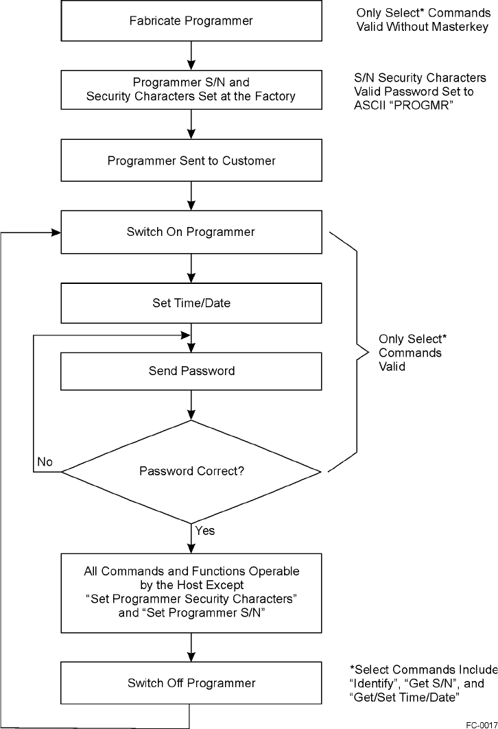
Application Program Interface
D-21
Figure D-1 Programmer Command Hierarchy
IT2410 Tag Programmer User Guide
D-22
Get/Set Communications Baud Rate
The Get Communications Baud Rate command requests programmer’s communica-
tions baud rate. The Set Communications Baud Rate command sets the programmer
RS–232 communications baud rate.
Upon command, the programmer changes its baud rate to the selected value immedi-
ately following the transmission of the command response. It is recommended that the
baud rate only be changed on the host after the programmer has received the acknowl-
edge so that communications are maintained.
Note: You might want to have a command in the host to let the user change the baud
rate when the programmer has been saved to a different baud rate than that of the host
default.
The data associated with the Get/Set Communications Baud Rate is shown in
Table D-19.
Table D-19 Communications Baud Rate Data
Value Definition
0CH 19,200 bps
0DH 38,400 bps (factory default)
Get/Set Ethernet Parameters
The Get Ethernet Parameters command requests programmer’s Ethernet parameters.
The Set Ethernet Parameters command sets the programmer’s Ethernet parameters.
The data associated with the Get/Set Ethernet Parameters is shown in Table D-20.
IP addresses — Must be specified in valid dot format, such as 10.3.10.10.
Bits 7 - 0
Communications baud rate
Table D-20 Ethernet Parameters Data
Subcommand Parameter
01H MAC address
02H Programmer IP address
03H Host IP address
04H Gateway IP address
05H Network mask
Application Program Interface
D-23
Network mask — Must be specified in valid dot format, such as 10.3.10.10.
MAC address — Must be specified in valid dash format, such as 00-01-02-03-04-05.
MAC address can only be set during factory setup.
All parameters must be passed in C-string format, including 0 (NULL) terminating
byte (Table D-21). N represents the C-string length, not including terminating byte.
Get/Set Programmer RF
The Get Programmer RF requests the frequency setting from the host. The Set Pro-
grammer RF sets the frequency. Data associated with the tag programmer RF is listed
in Table D-22.
Transceiver RF Frequency — This byte represents the transceiver RF. Table D-23
lists the valid frequencies.
Table D-21 C-String Format for Parameters
Command Bytes Data
0Subcommand
1-(N+1) Data string, such as 10.3.10.10 or
00-01-02-03-04-05.
(N+1)+1 00H
Table D-22 Programmer RF Data
Byte Bits 7 - 0
0Reserved
1Transceiver RF
Table D-23 Valid Transceiver Frequencies
Byte Value Frequency (MHz)
2BH 912.75
2FH 913.75
33H 914.75
37H 915.75
3BH 916.75
3FH 917.75
43H 918.75
IT2410 Tag Programmer User Guide
D-24
Data associated with the tag programmer RF is listed in Table D-24.
Table D-24 Programmer RF
RF control — This subfield contains a representation of the frequency control as a
binary-coded integer. Valid values are in the range of 0BH to 11H determining the
emission frequency in 1-MHz steps from 912.75 MHz to 918.75 MHz.
Get/Set Time/Date
The Get Time/Date command requests the current time and date that is set on the pro-
grammer’s clock. The Set Time/Date command sets the programmer’s real-time clock
to the time and date specified in the request data.
The data associated with the Get/Set Time/Date defines the format of the time and
date (Table D-25). You can modify and read this data at any time. This field is used
with the tag read parameters to append time and date to any response to the host.
Table D-25 Time/Date Data
The range specifications for the individual time/date fields are shown in Table D-26
Bits 7 - 0
RF control
Byte Bit 7
0Hours
1Minutes
2Seconds
3Hundredths of seconds
4Month
5Day
6Year

Application Program Interface
D-25
Table D-26 Time/Date Field Range Specifications
Note: The fields listed in Table D-26 are binary integers, not binary-coded data.
Note: Only the two least significant digits of the year are contained in the date. It is
the responsibility of the application to use the year such that the year 2000 is pro-
cessed correctly. The year 2000 is represented by a year value of zero.
Description Range
Hours 0-23
Minutes 0-59
Seconds 0-59
Hundredths 0-99
Month 1-12
Day 1-31
Year 0-99

IT2410 Tag Programmer User Guide
D-26
Asynchronous Responses
Asynchronous responses to tag commands, programmer modes, errors, and failure
conditions are sent from the programmer to the host.
Power on/Boot/Diagnostics Status Reports
The programmer status is reported asynchronously once at powerup and whenever
any change has occurred during background self-test processing.
If a fault message occurs, a bit representing the fault is set in the diagnostic report
data. The status codes associated with the diagnostic reports are as follows:
•The command code at powerup or after the issue of a reset command for the diag-
nostic report status code is 8000H.
•The command code for background diagnostic report status code is 8001H.
The data associated with the power-on and background status reports for the program-
mer is specified in Table D-27.
Table D-27 Programmer Status Report Data
Programmer status — This field contains the subfields associated with the program-
mer as shown in Table D-28.
Table D-28 Subfields of Programmer Status
Boot flash test — This bit indicates a failure of the IT2410 boot sector of the flash
memory logic module when set to 1. Tests are automatically and continually run inter-
nally by the programmer.
Application flash test — This bit indicates a failure of the IT2410 logic module
application sector flash memory when set to 1. Tests are automatically and continually
run internally by the programmer.
Reserved — Reserved for future use.
RFI RAM test — This bit indicates a failure of the IT2410 RFI RAM logic module
when set to 1. Tests are automatically and continually run internally by the program-
Byte Bits 7 - 0
0Programmer status
Byte Bit 7 Bit 6 Bit 5 Bit 4 Bit 3 Bit 2 Bit 1 Bit 0
0Boot
flash test Application
flash test Reserved RFI RAM
test Processor
RAM test Check
tag test Spare Spare
Application Program Interface
D-27
mer.
Processor RAM test — This bit indicates a failure of the IT2410 processor RAM
logic module when set to 1. Tests are automatically and continually run internally by
the programmer.
Check tag test — This bit indicates a check tag failure when set to 1.
Valid Response Tag Data
Valid response tag data is reported asynchronously when a tag is detected. The status
codes associated with the tag data reports are shown in Table D-29.
Table D-29 Tag Data Report Status Codes
When a tag is detected, tag data is sent to the host computer or lane controller. If it
passes the CRC check, the tag data is assumed to not be corrupted.
Code Description
3000H No-tag data status
3001H IT2200 R/W tag data status
3002H Reserved
IT2410 Tag Programmer User Guide
D-28