TransCore MPI6000 LMS TRANSMITTER User Manual 411880
TransCore LMS TRANSMITTER 411880
UserManual.wiki
>
TransCore
>
MPI6000 User Manual
USERS MANUAL
Navigation menu
Upload a User Manual
Namespaces
Wiki Guide
HTML
PDF
Info
Views
User Manual
Discussion / Help
Navigation


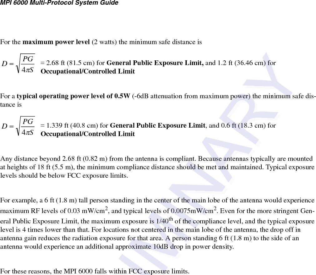

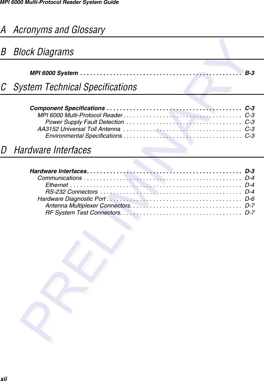


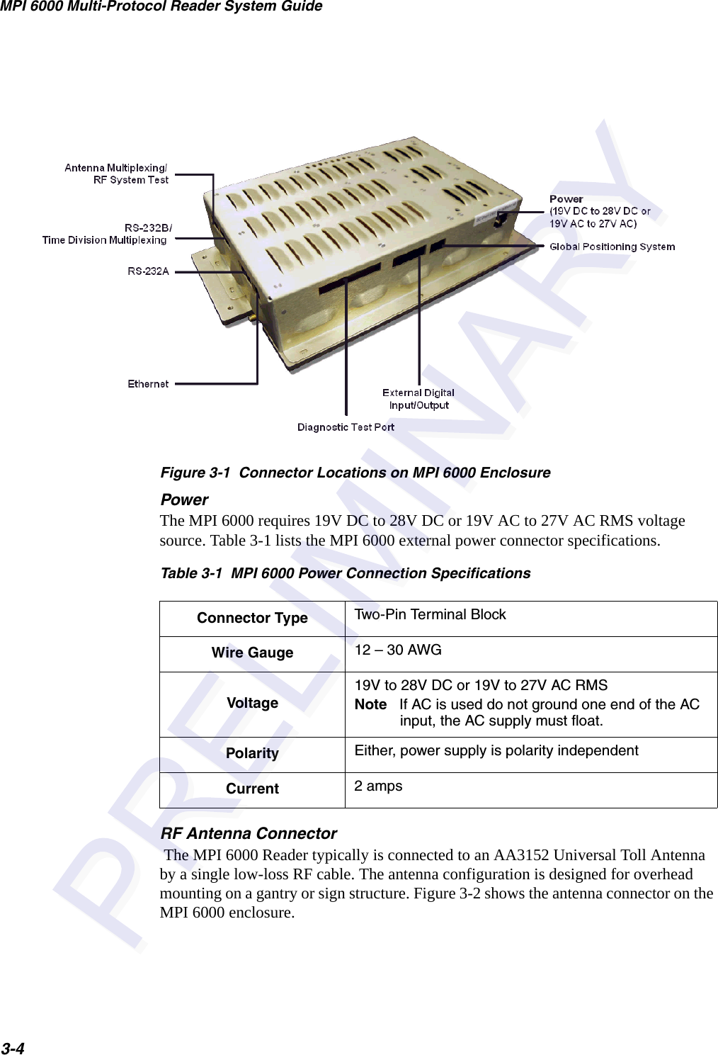


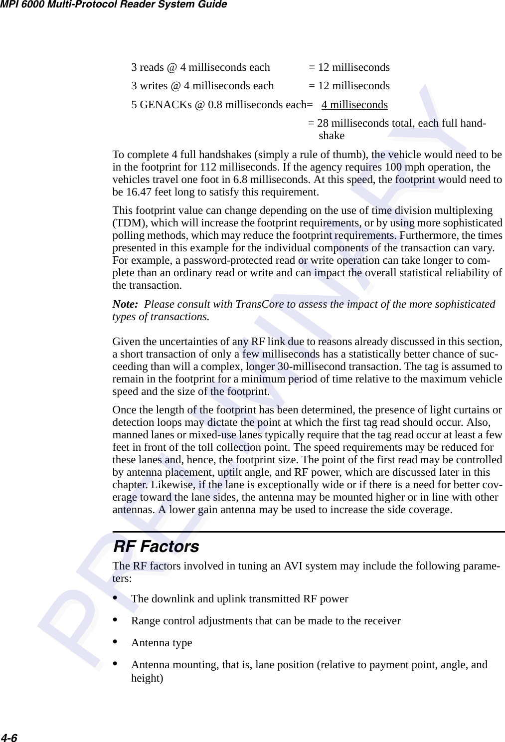
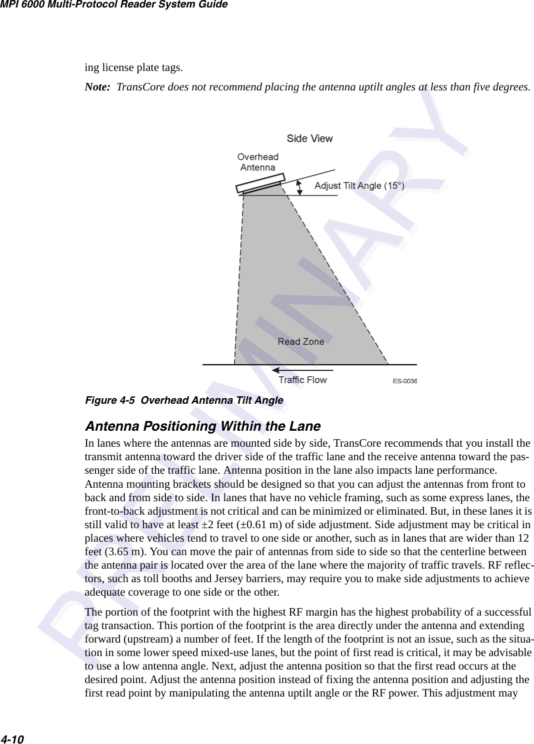


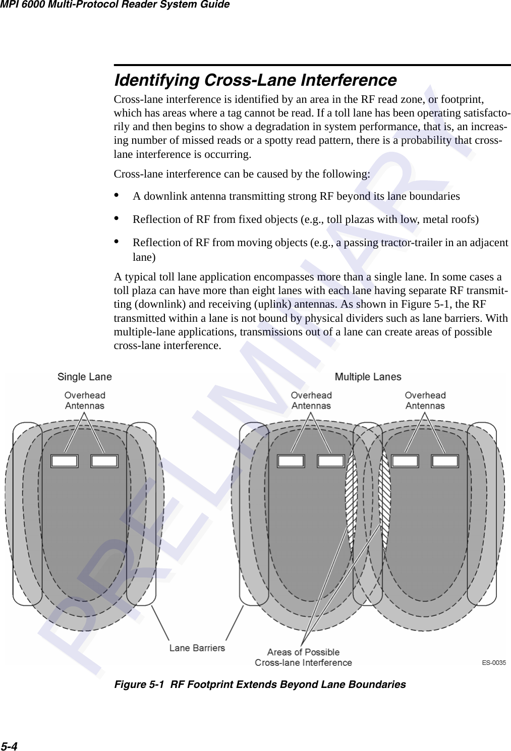
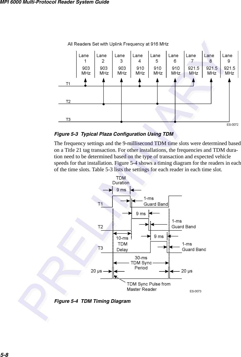

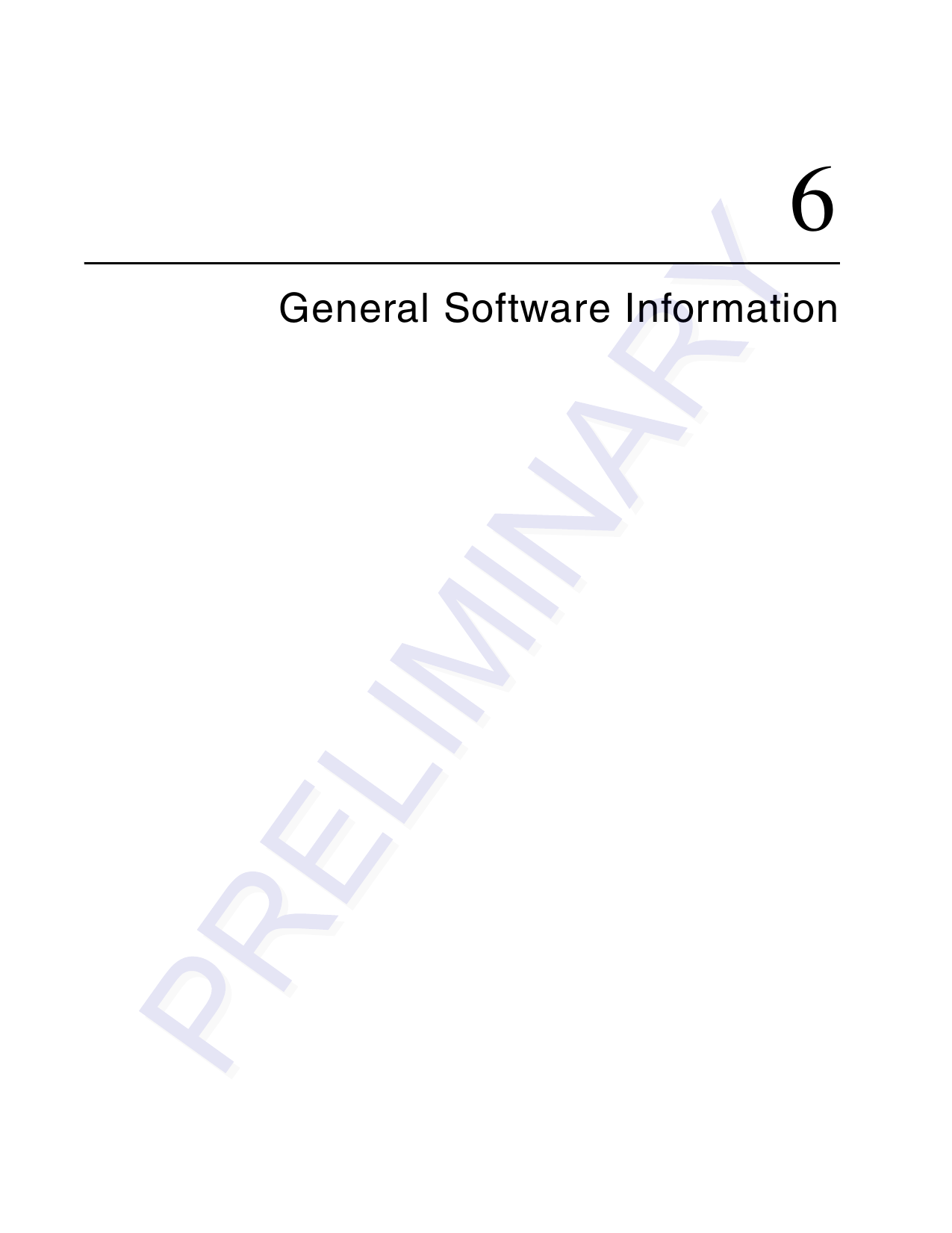

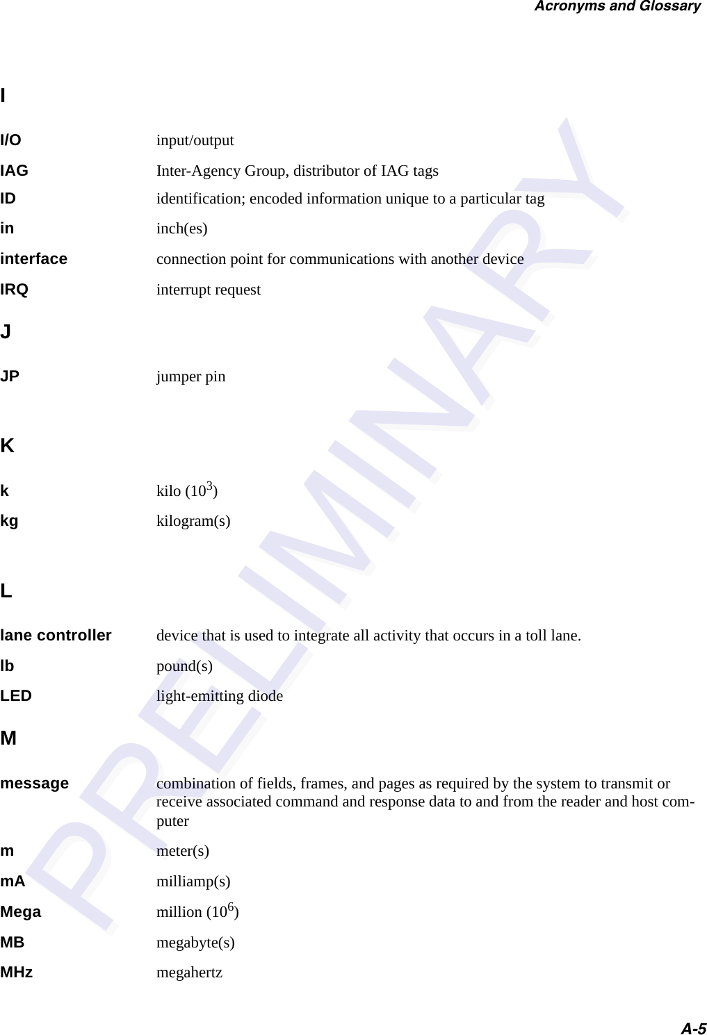
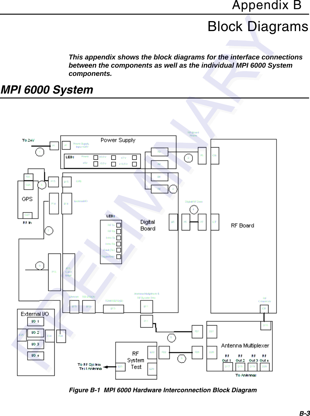
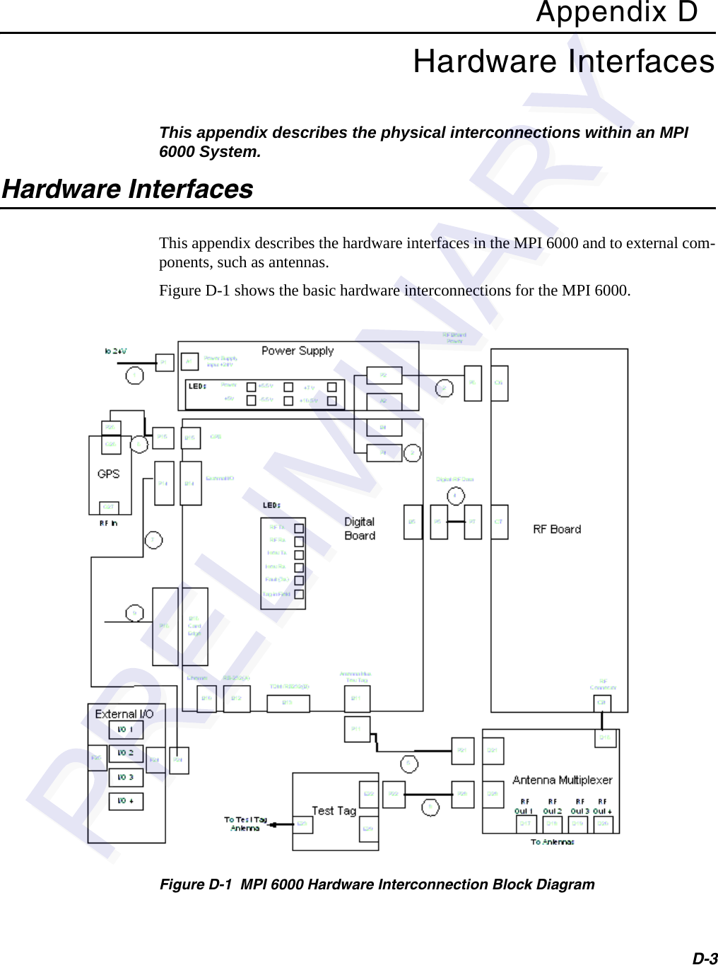
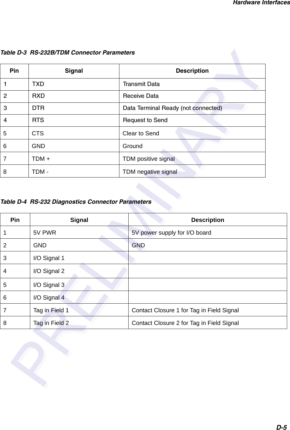
![General Software Information6-7software flow control messages to the host. The host on receiving command response messages, asynchronous response messages and software flow control messages from the MPI 6000 sends data acknowledge messages to the MPI 6000.Additionally, the MPI 6000 sends unsolicited status messages to the host. The host on receiving unsolicited status messages from the MPI 6000 sends data acknowledge messages to the MPI 6000.The MPI 6000 implements message sequence numbers and command sequence num-bers in all of the message types (e.g. command request, data acknowledge, command response, asynchronous response, software flow control and unsolicited status). The host and the MPI 6000 must implement independent transmit and receive counters for both the message sequence numbers and the command sequence numbers. The trans-mit counters are used in the generation of the transmitted messages and the receive counters are used in the received message out-of-sequence error checking. An out-of-sequence error indicates that a message has been missed.The host’s message sequence numbers independently track the number of messages sent to the MPI 6000. The MPI 6000’s message sequence numbers independently track the number of messages sent to the host. These message sequence numbers are used on the receiving end to determine if a message has been missed. See the software communication sequence number controls section for more details.The host’s command sequence numbers for each command group independently track the number of command request messages sent to the MPI 6000. The MPI 6000’s command sequence numbers for each command group independently track the num-ber of software flow control and unsolicited status messages sent to the host. These command sequence numbers are used on the receiving end to determine if the appro-priate message as specified above has been missed. See the software communication sequence number controls section for more details.UDP/IP Fast Ethernet Communications ProtocolThe UDP/IP fast Ethernet communications protocol implements the UDP/IP fast Ethernet protocol as specified in the RealFast UDP/IP Core Design Specification (RealFast Document Number RFHC04026-V042).Command Request MessageThe host sends command request messages to the MPI 6000 as required for system operation. The host and the MPI 6000 uses the following UDP/IP fast Ethernet com-munications command request message shown here:<len> <msgSeqNum> <cmd> <cmdSeqNum> [<data>] <checksum>where<len> = length, a word that specifies the number of bytes in the entire message.<msgSeqNum> = message sequence number, a byte that specifies the message sequence number of the message. See the software communication sequence number controls section for details.](https://usermanual.wiki/TransCore/MPI6000/User-Guide-603235-Page-63.png)
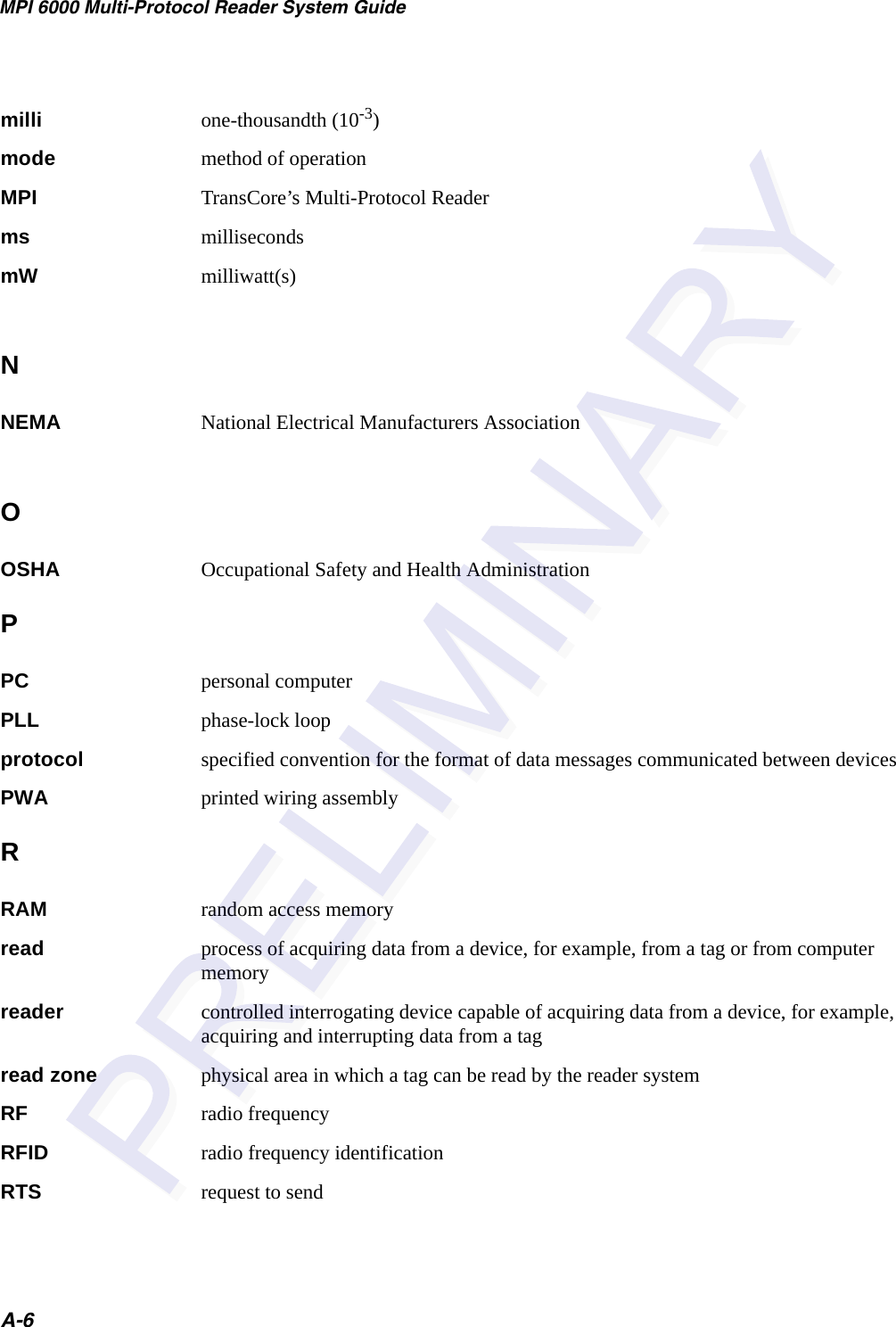
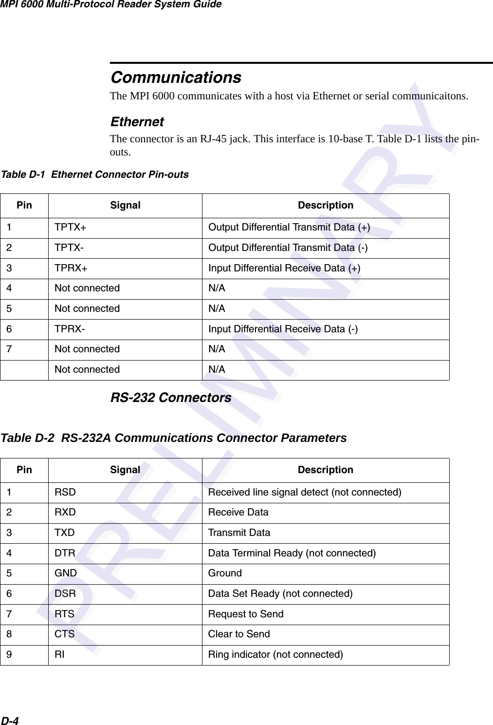
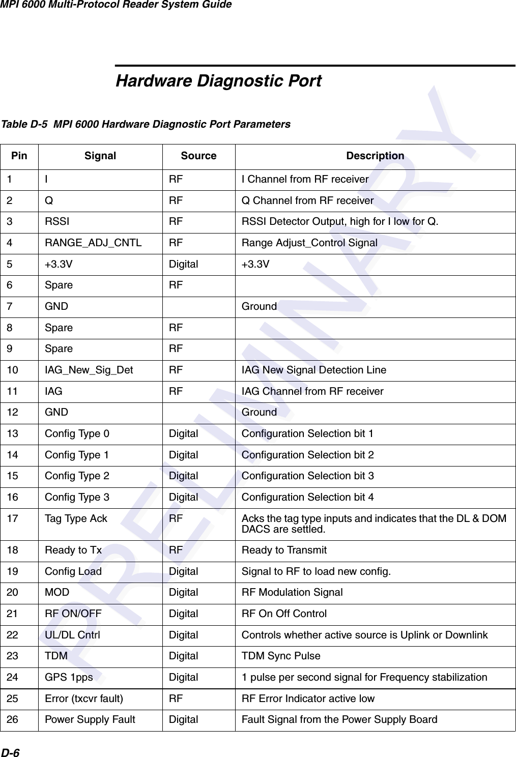
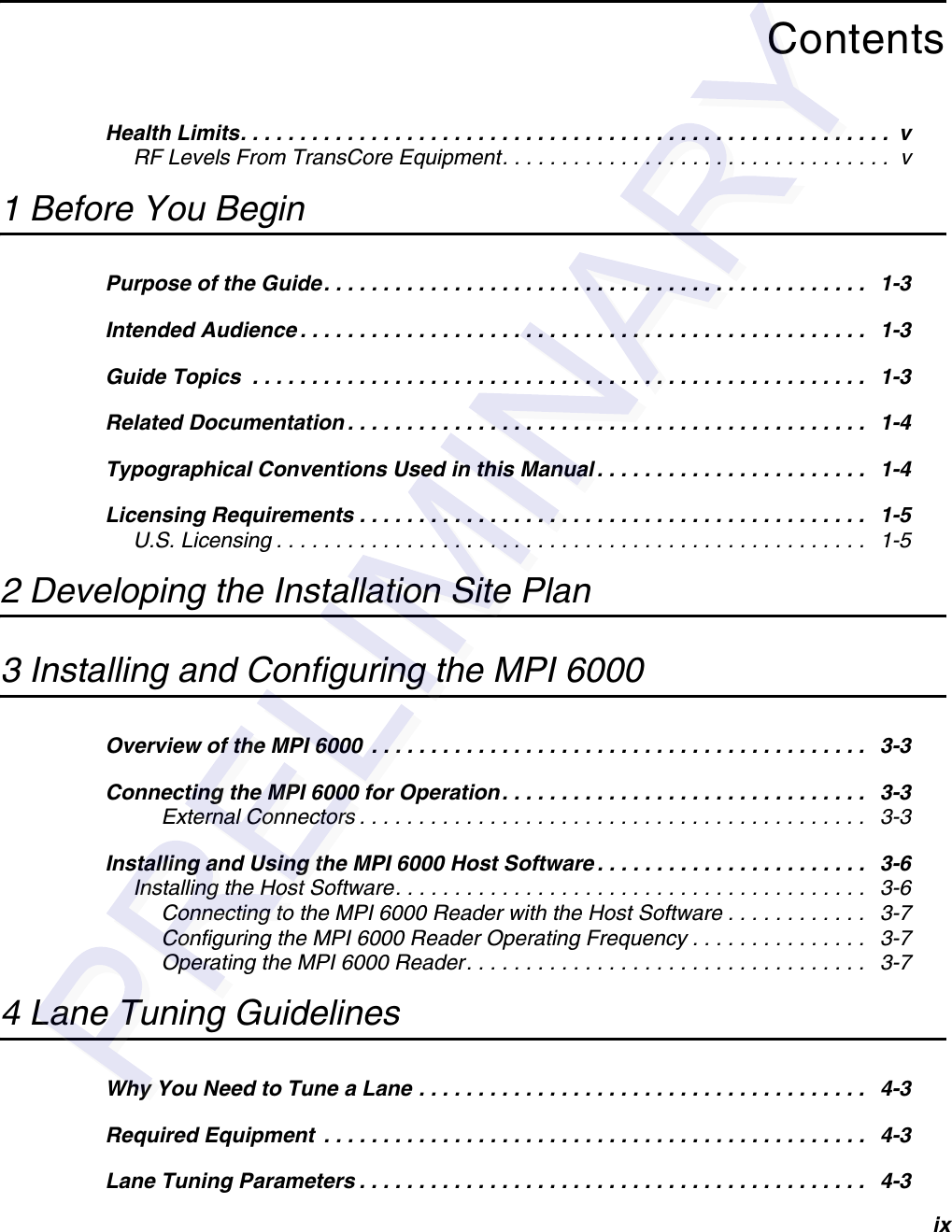
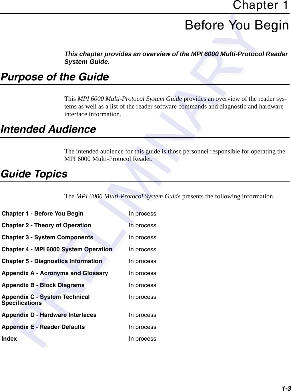
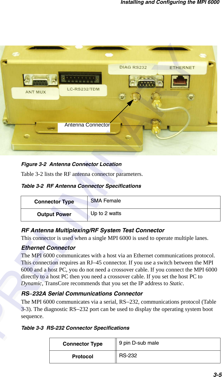
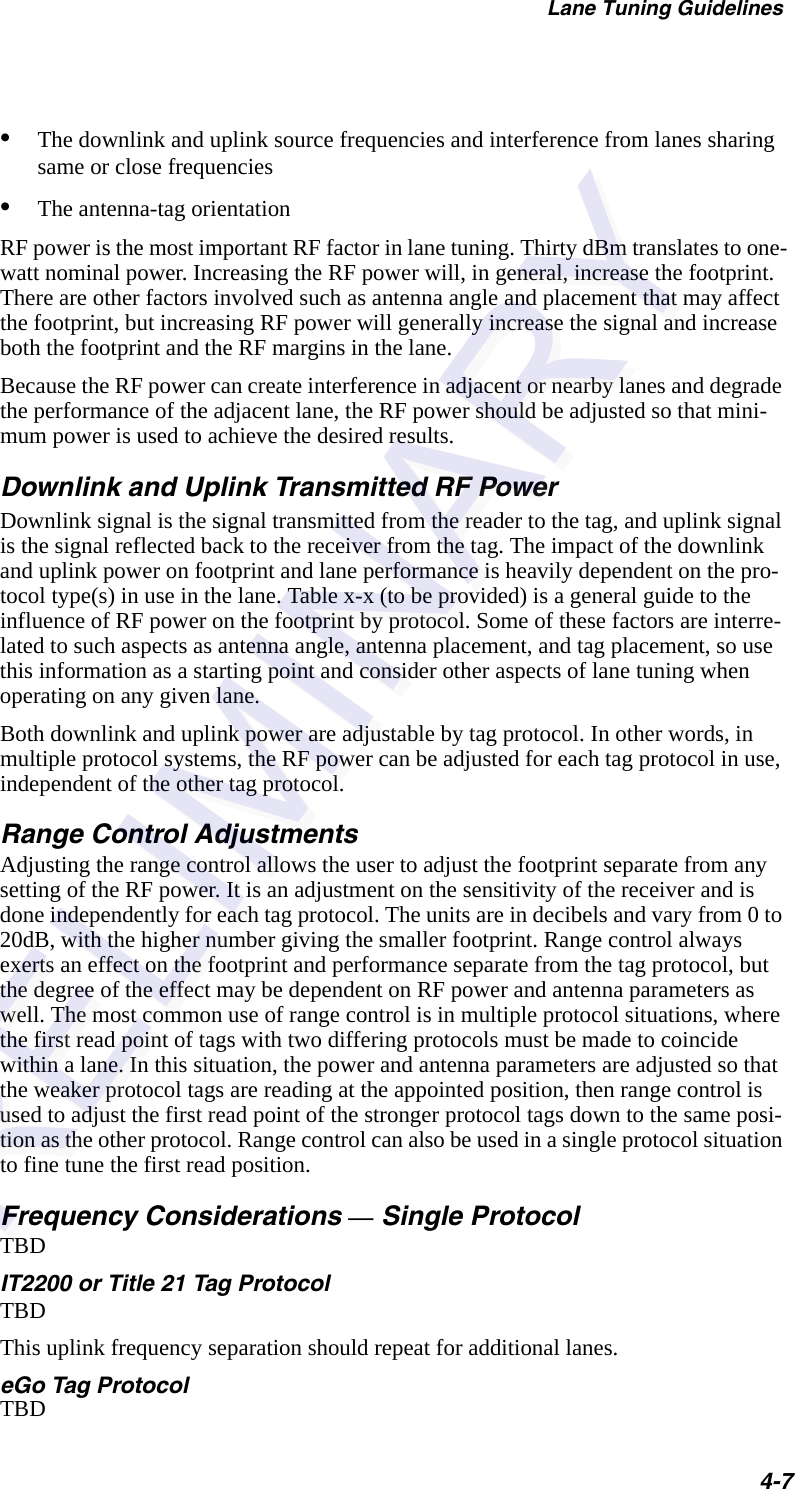
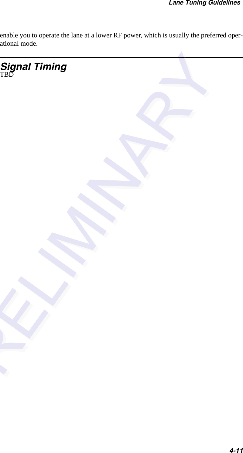
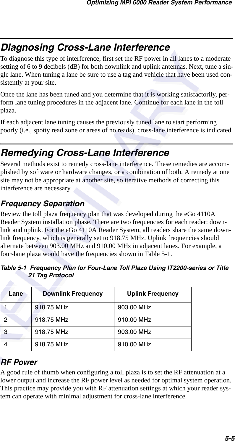
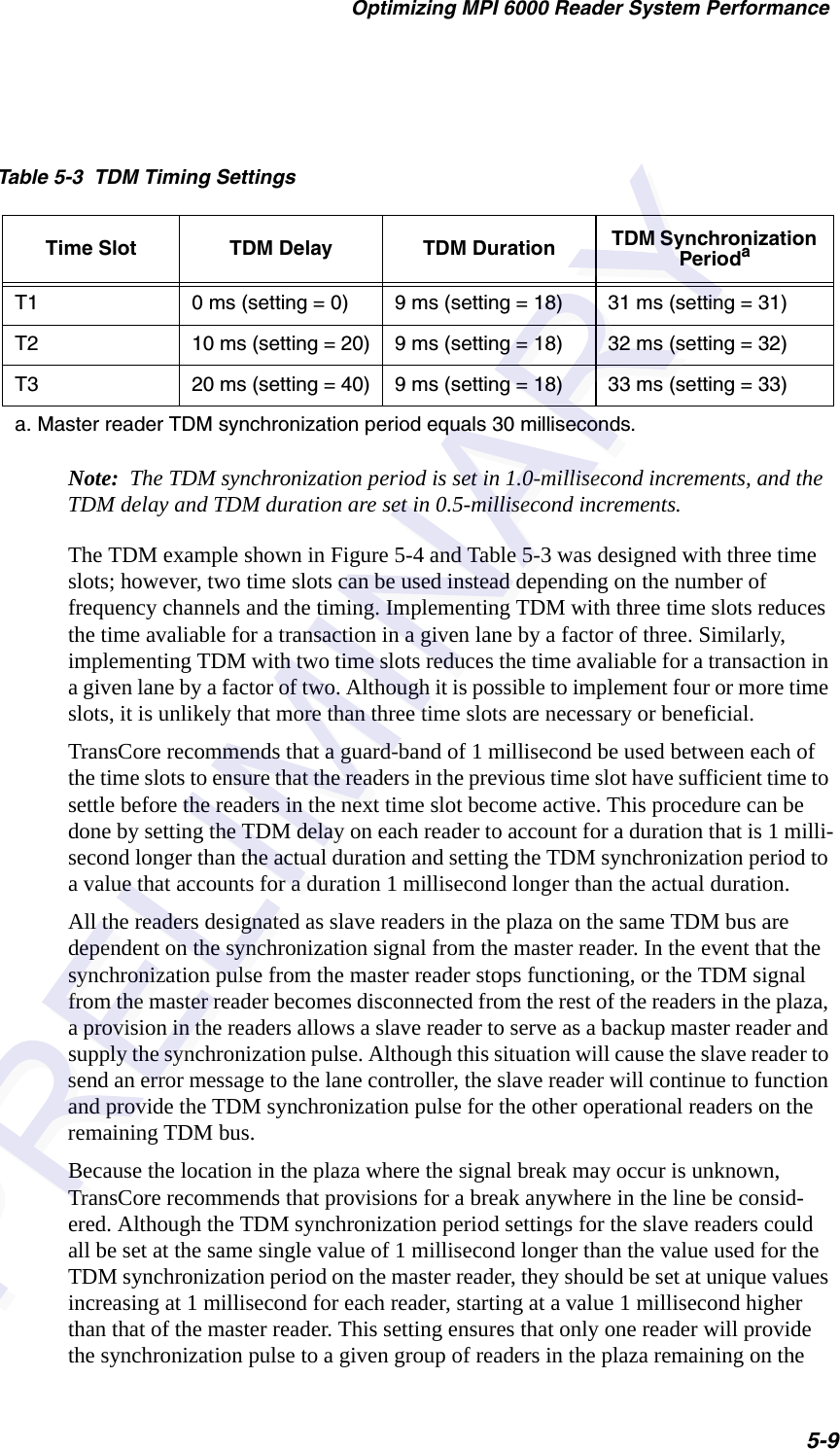
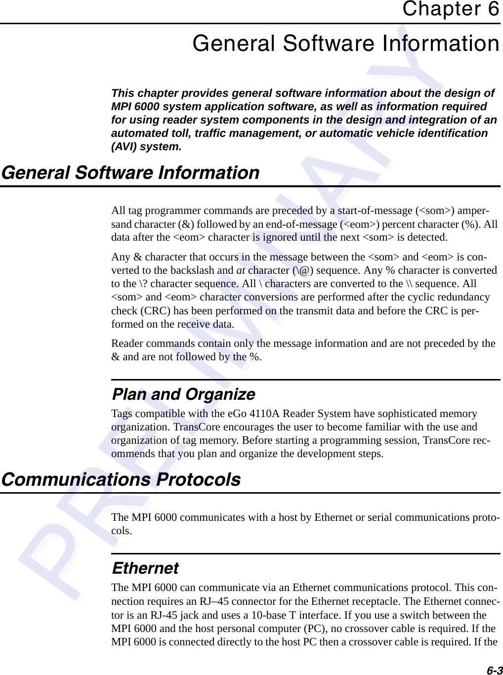
![MPI 6000 Multi-Protocol Reader System Guide6-8<cmd> = command, a word that specifies the system command. See the command sections for details.<cmdSeqNum> = command sequence number, a byte that specifies the command sequence number of the message. See the software communication sequence number controls section for details.[<data>] = optional data payload that varies in length from 0 to 65 bytes and is asso-ciated with each specific command. See the command sections for details.<checksum> = checksum, a byte that specifies the checksum of the message.Data Acknowledge MessageThe MPI 6000 sends data acknowledge messages to the host after receiving command request messages from the host.The host sends data acknowledge messages to the MPI 6000 after receiving command response messages, asynchronous response messages, software flow control messages and unsolicited status messages from the MPI 6000. The host and the MPI 6000 uses the following UDP/IP fast Ethernet communications data acknowledge message as shown here:<len> <msgSeqNum> <cmd> <cmdSeqNum> <resp> <msgSeqNumAck> <checksum>where<len> - length, word that specifies the number of bytes in the entire message.<msgSeqNum> - message sequence number, byte that specifies the message sequence number of the message. See the software communication sequence number controls section for details.<cmd> - command, word that specifies the system command. See the command sec-tions for details.<cmdSeqNum> - command sequence number, byte that specifies the command sequence number of the message. See the software communication sequence number controls section for details.<resp> - response, word that specifies the system response. See the response sections for details.<msgSeqNumAck> - message sequence number acknowledge, byte that specifies the message sequence number of the message being acknowledged. See the software communication sequence number controls section for details.<checksum> - checksum, byte that specifies the checksum of the message.Command Response MessageThe MPI 6000 after receiving command request messages from the host sends com-mand response messages to the host.The host and the MPI 6000 uses the following UDP/IP fast Ethernet communications command response message shown here:](https://usermanual.wiki/TransCore/MPI6000/User-Guide-603235-Page-64.png)
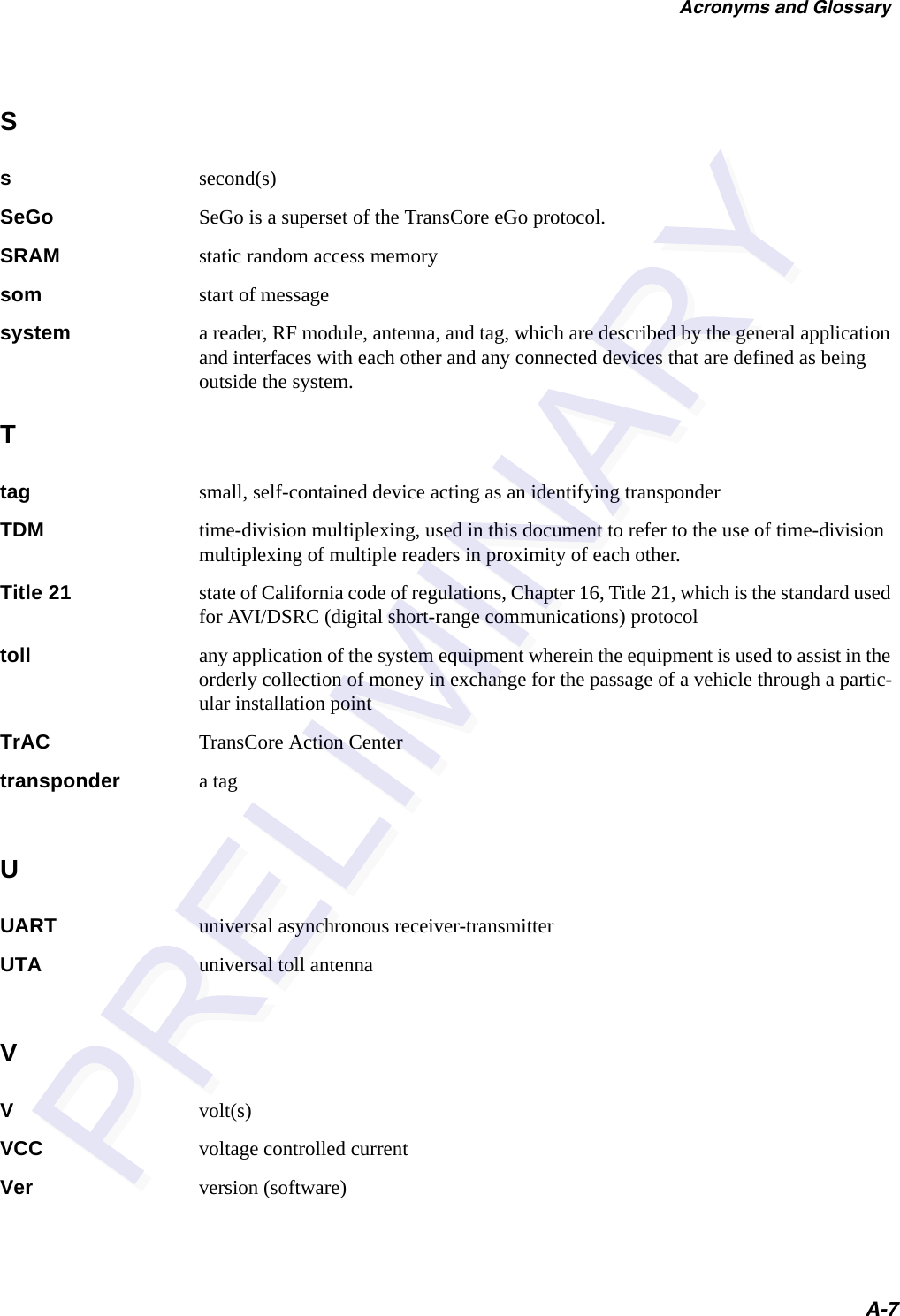
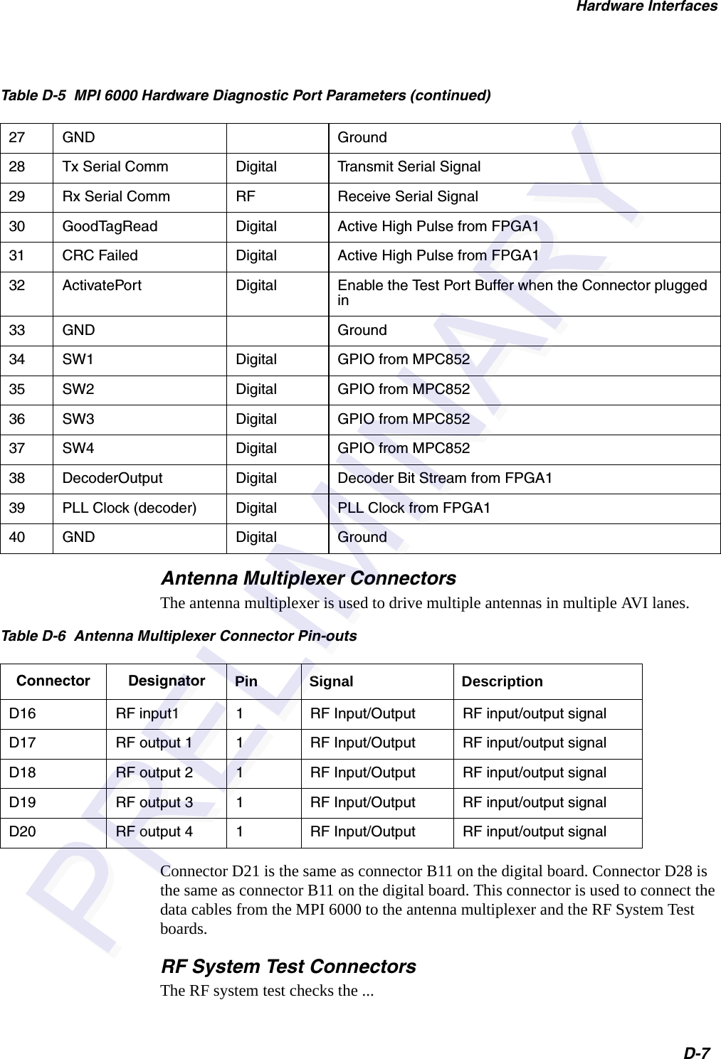
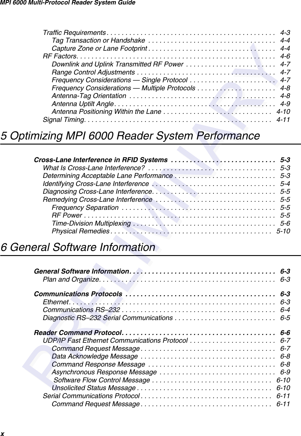
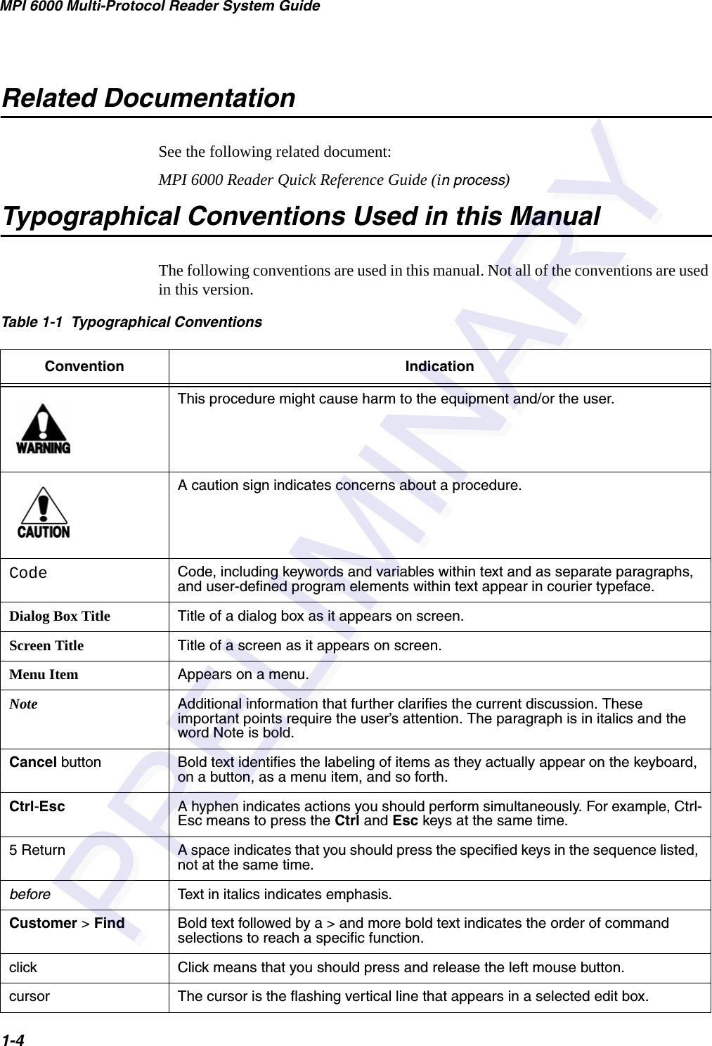
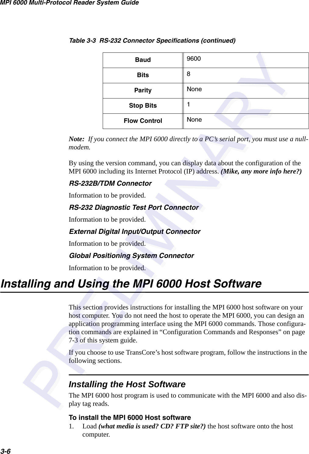
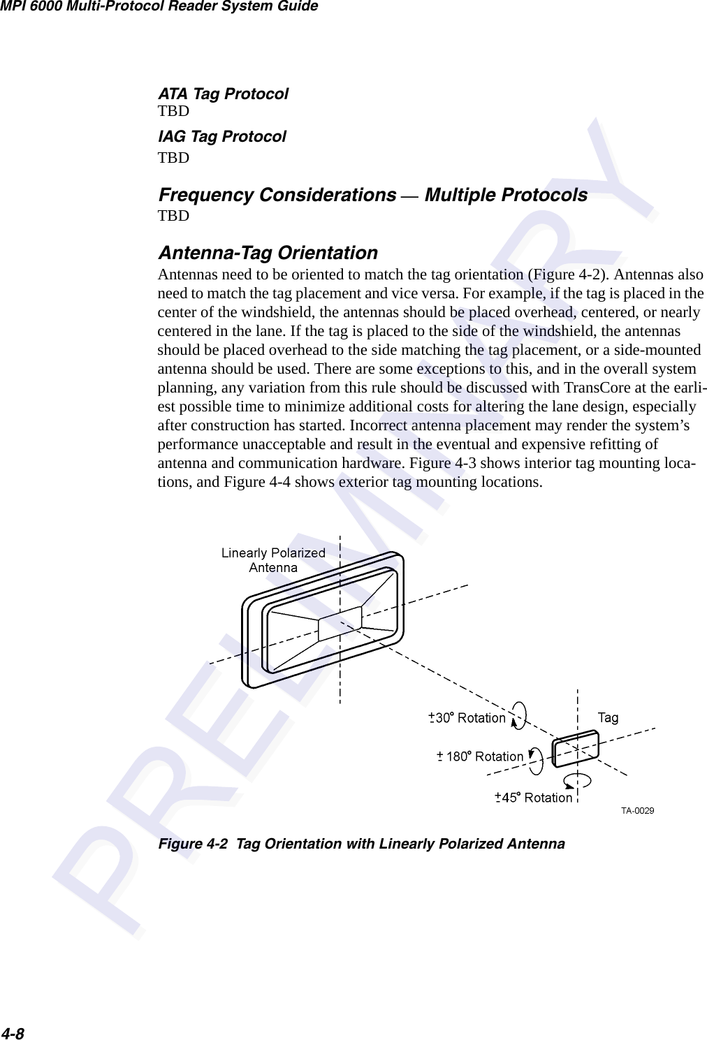
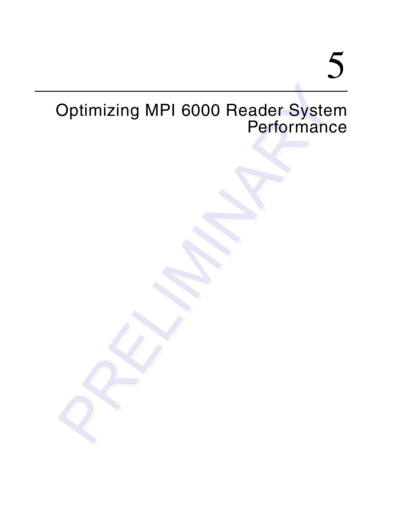
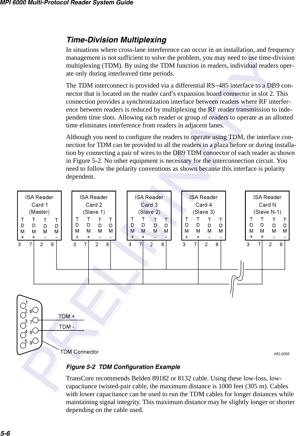
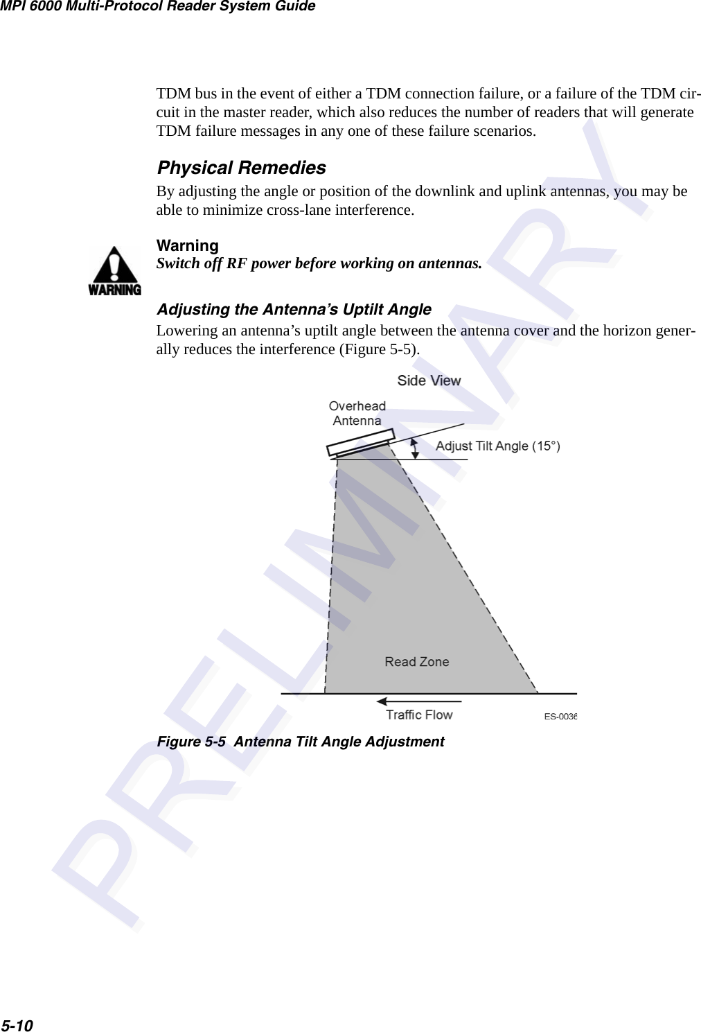
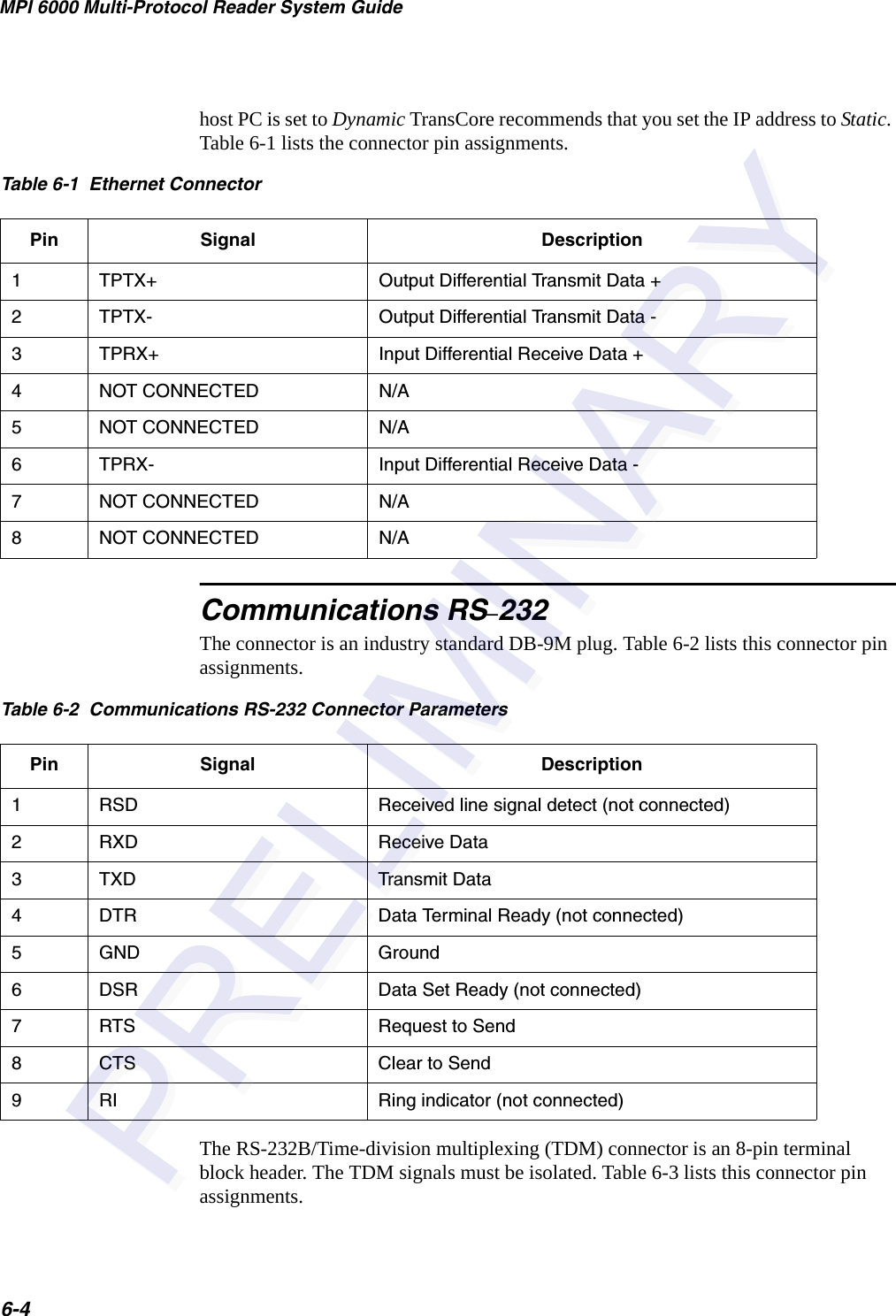
![General Software Information6-9<len> <msgSeqNum> <cmd> <cmdSeqNum> <resp> [<data>] <checksum>where<len> = length, a word that specifies the number of bytes in the entire message.<msgSeqNum> = message sequence number, a byte that specifies the message sequence number of the message. See the software communication sequence number controls section for details.<cmd> = command, word that specifies the system command. See the command sec-tions for details.<cmdSeqNum> = command sequence number, a byte that specifies the command sequence number of the message. See the software communication sequence number controls section for details.<resp> = response, a word that specifies the system response. See the response sec-tions for details.[<data>] = optional data payload that varies in length from 0 to 63 bytes and is asso-ciated with each specific response. See the response sections for details.<checksum> = checksum, a byte that specifies the checksum of the message.Asynchronous Response MessageThe MPI 6000 after receiving command request messages from the host optionally sends asynchronous response messages to the host.The host and the MPI 6000 uses the following UDP/IP fast Ethernet communications asynchronous response message shown here:<len> <msgSeqNum> <cmd> <cmdSeqNum> <resp> [<data>] <checksum>where<len> = length, a word that specifies the number of bytes in the entire message.<msgSeqNum> = message sequence number, a byte that specifies the message sequence number of the message. See the software communication sequence number controls section for details.<cmd> = command, word that specifies the system command. See the command sec-tions for details.<cmdSeqNum> = command sequence number, a byte that specifies the command sequence number of the message. See the software communication sequence number controls section for details.<resp> = response, a word that specifies the system response. See the response sec-tions for details.[<data>] - optional data payload that varies in length from 0 to 63 bytes and is associ-ated with each specific response. See the response sections for details.<checksum> = checksum, a byte that specifies the checksum of the message.](https://usermanual.wiki/TransCore/MPI6000/User-Guide-603235-Page-65.png)
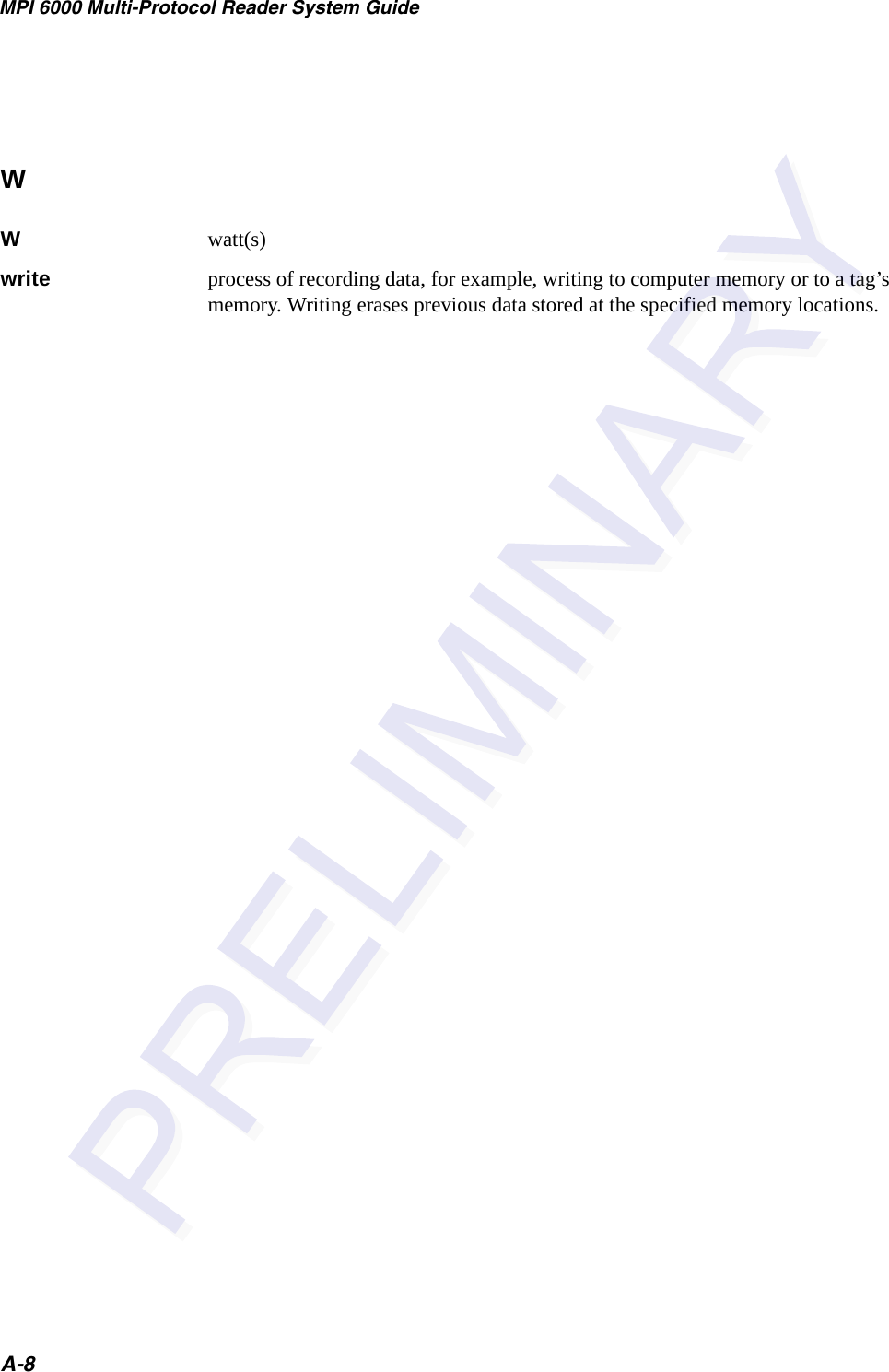
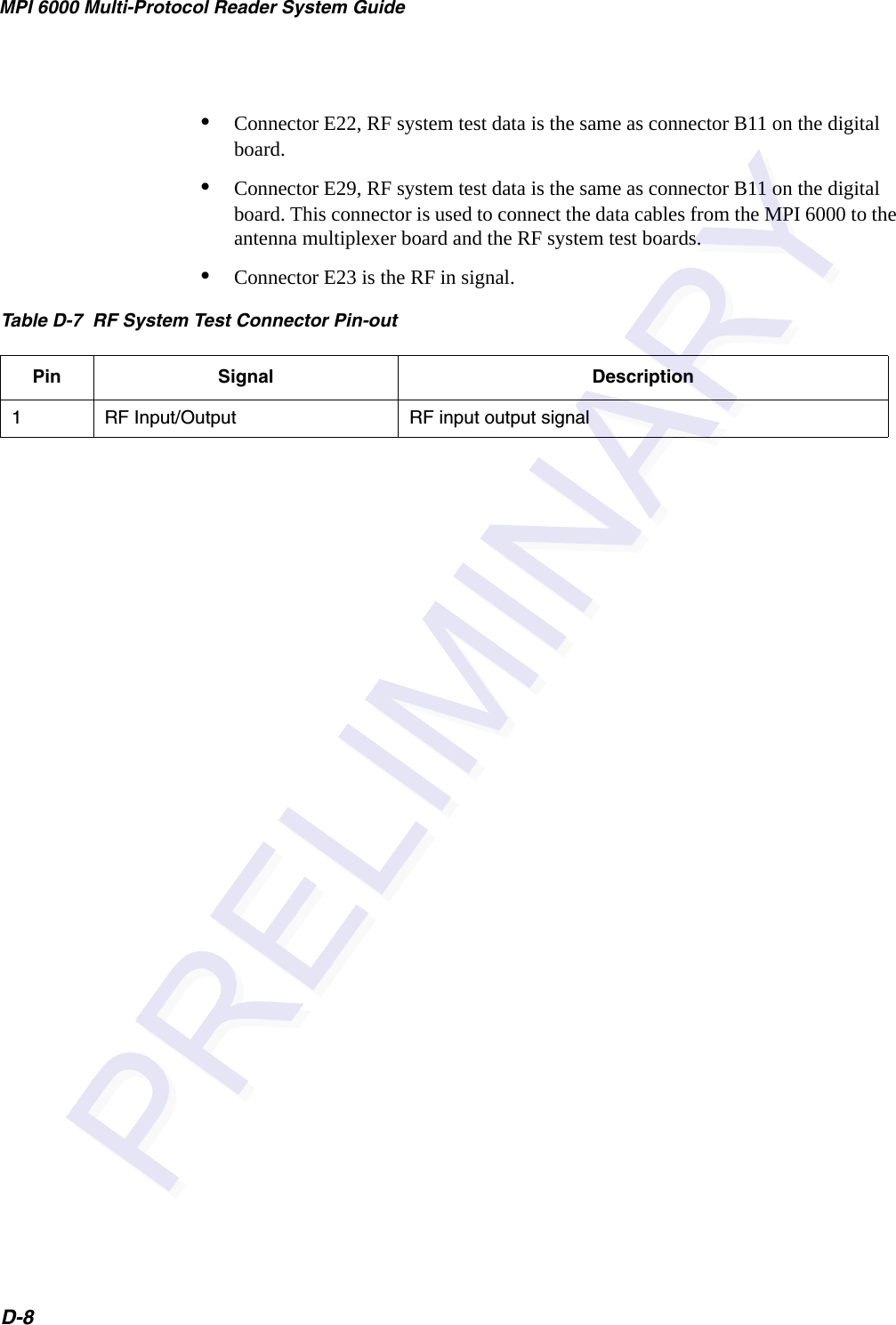
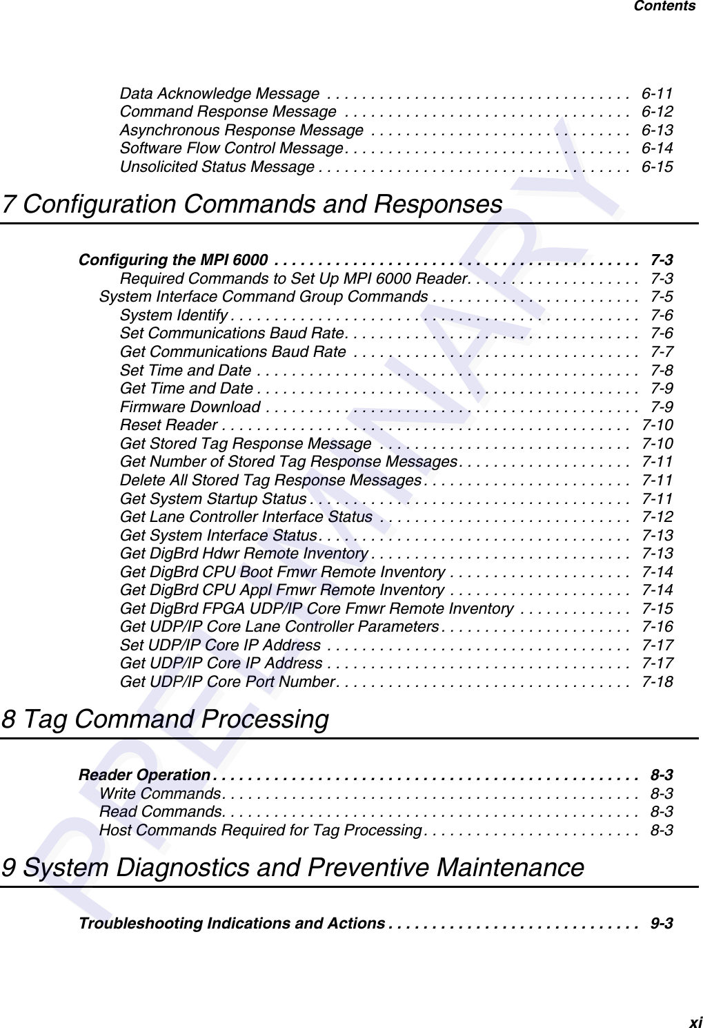
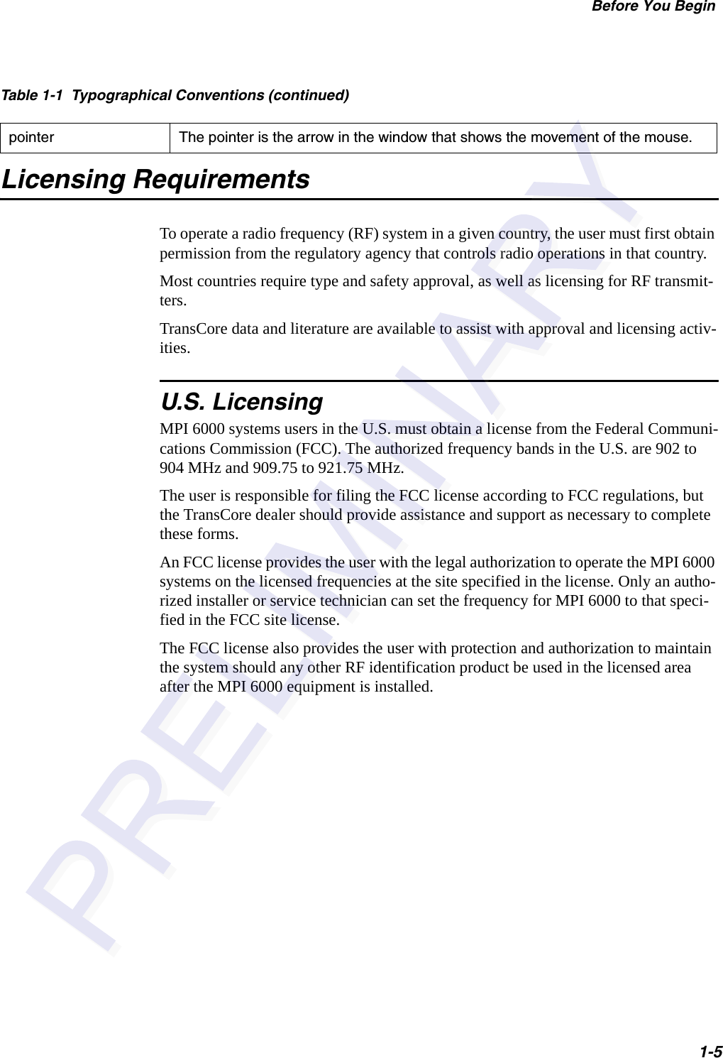
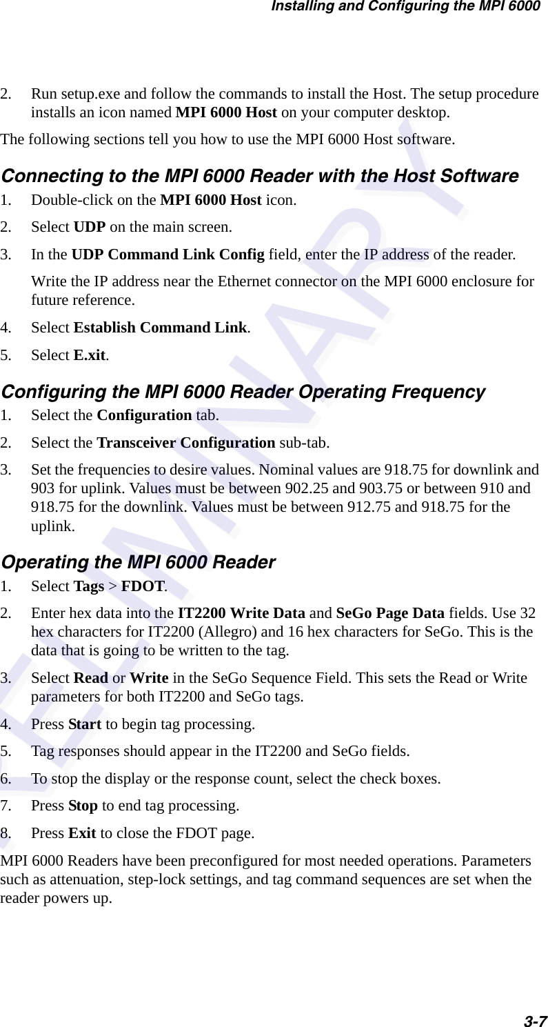
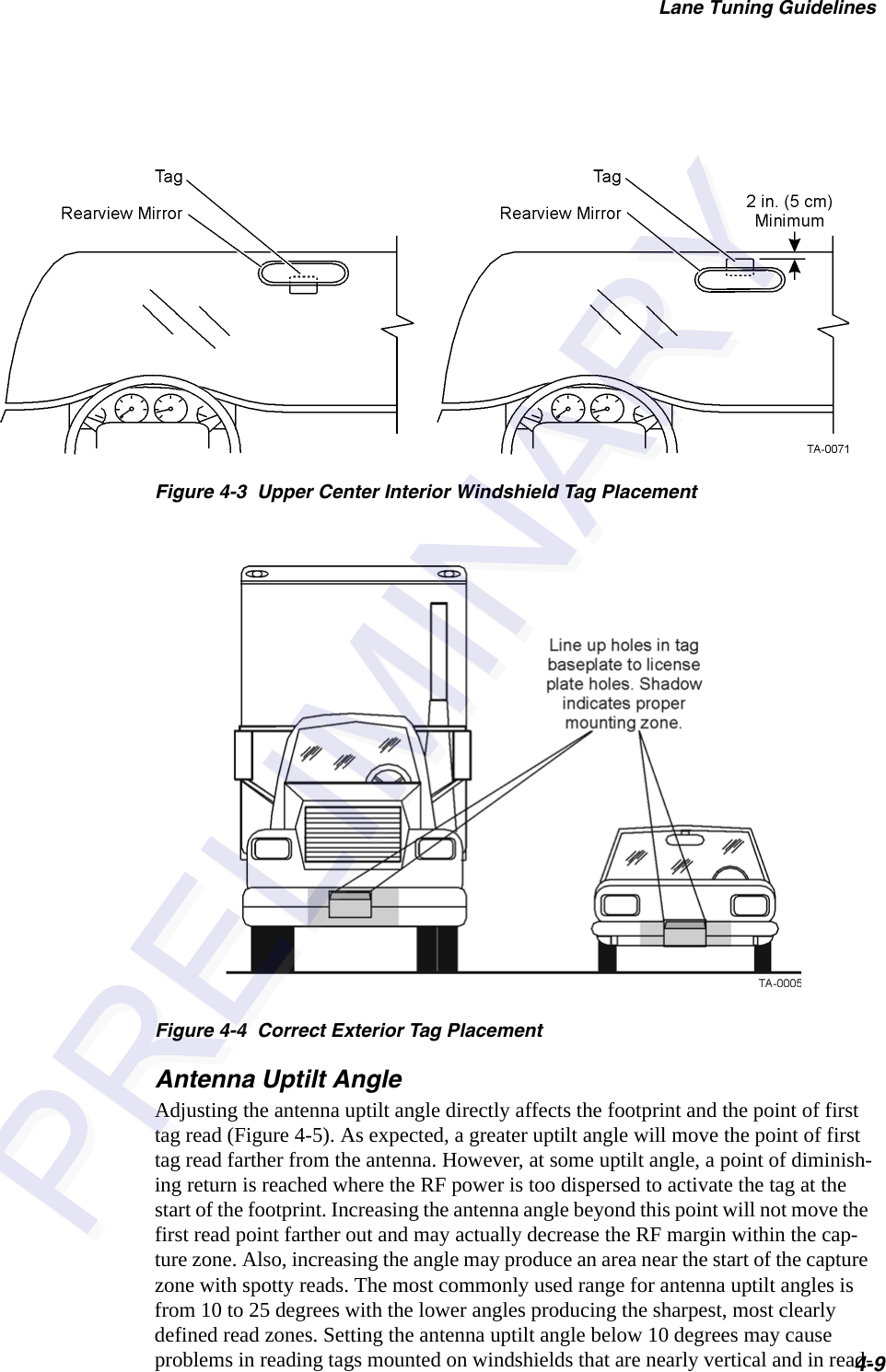
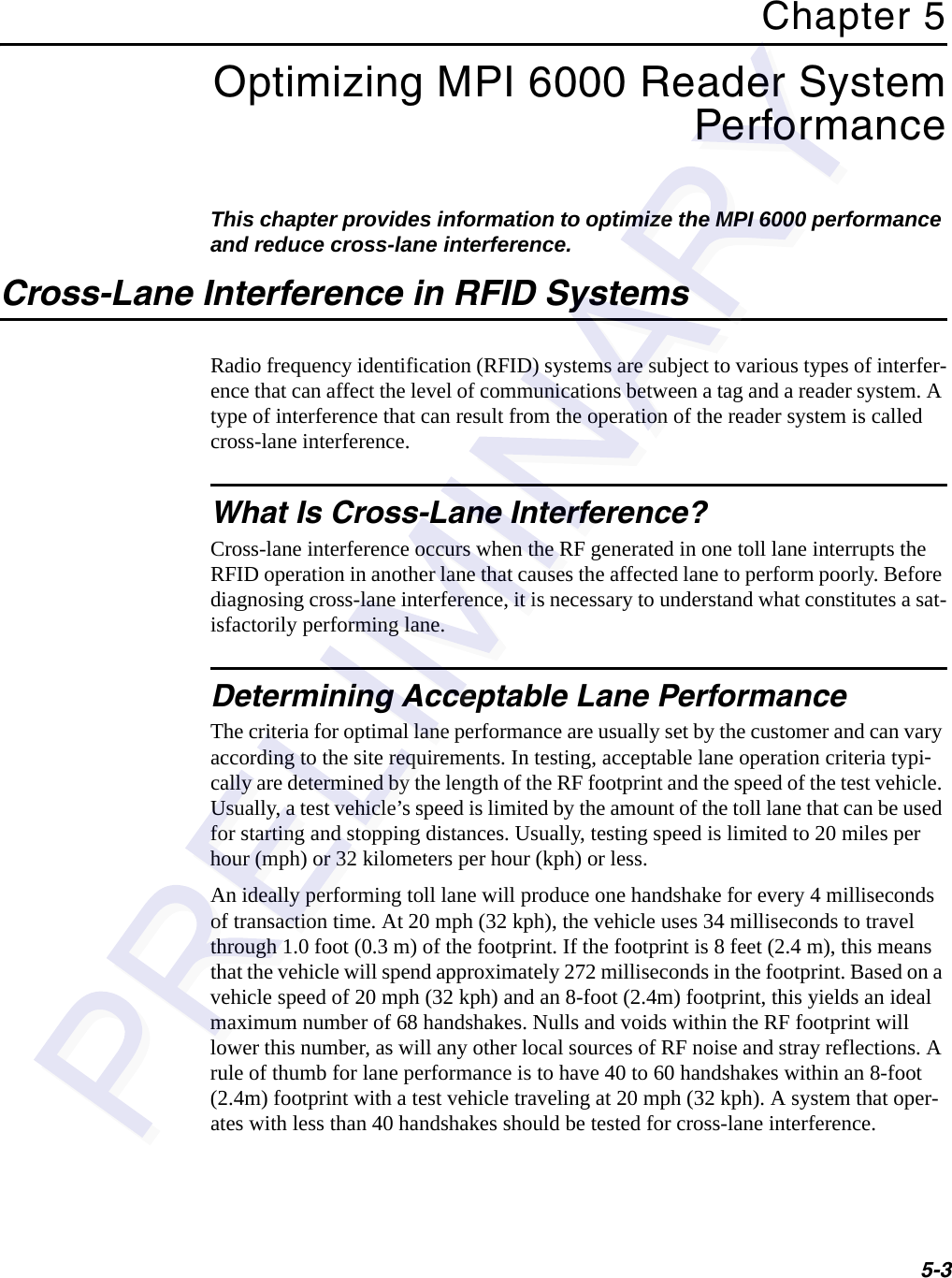
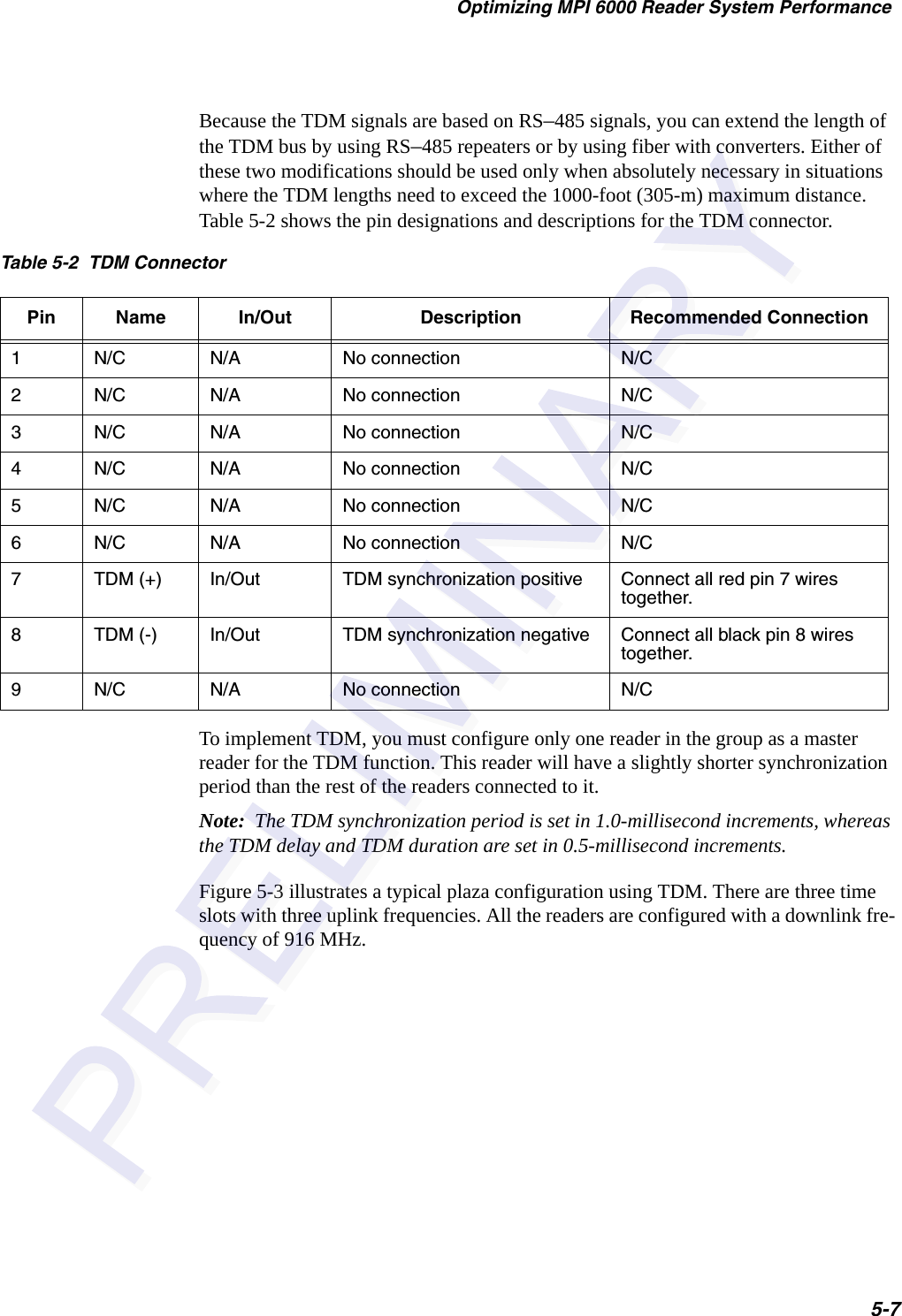
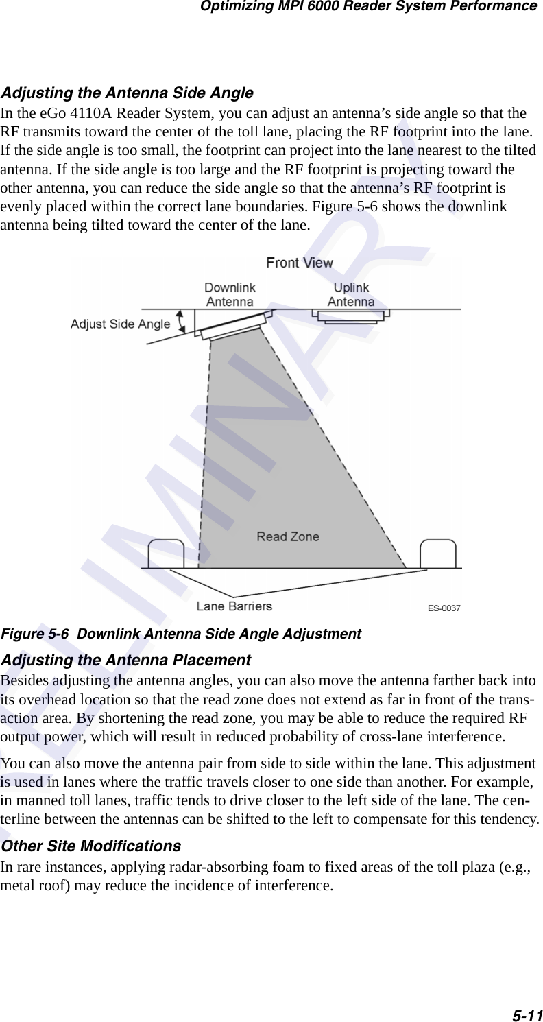
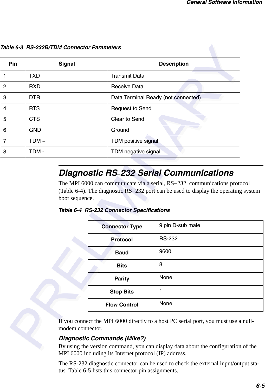
![MPI 6000 Multi-Protocol Reader System Guide6-10 Software Flow Control MessageThe MPI 6000 after receiving command request messages from the host optionally sends software flow control messages to the host as required for system operation.The host optionally sends software flow control messages to the MPI 6000 as required for host operation. The host and the MPI 6000 uses the following UDP/IP fast Ethernet communications software flow control message shown here:<len> <msgSeqNum> <cmd> <cmdSeqNum> <resp> <checksum>where<len> = length, a word that specifies the number of bytes in the entire message.<msgSeqNum> = message sequence number, a byte that specifies the message sequence number of the message. See the software communication sequence number controls section for details.<cmd> = command, a word that specifies the system command. See the command sections for details.<cmdSeqNum> - command sequence number, a byte that specifies the command sequence number of the message. See the software communication sequence number controls section for details.<resp> = response, a word that specifies the system response. See the response sec-tions for details.<checksum> = checksum, a byte that specifies the checksum of the message.Unsolicited Status MessageThe MPI 6000 sends unsolicited status messages to the host as required for system operation.The host and the MPI 6000 uses the following UDP/IP fast Ethernet communications unsolicited status message shown here:<len> <msgSeqNum> <cmd> <cmdSeqNum> <status> [<data>] <checksum>where<len> = length, a word that specifies the number of bytes in the entire message.<msgSeqNum> = message sequence number, a byte that specifies the message sequence number of the message. See the software communication sequence number controls section for details.<cmd> = command, a word that specifies the system command. See the command sections for details.<cmdSeqNum> = command sequence number, a byte that specifies the command sequence number of the message. See the software communication sequence number controls section for details.](https://usermanual.wiki/TransCore/MPI6000/User-Guide-603235-Page-66.png)
![General Software Information6-11<status> = status, a word that specifies the system status. See the response sections for details.[<data>] = optional data payload that varies in length from 0 to 63 bytes and is asso-ciated with each specific response. See the response sections for details.<checksum> = checksum, a byte that specifies the checksum of the message.Serial Communications ProtocolThe serial communications protocol implements the TransCore error correction proto-col (ECP) serial standard.Command Request MessageThe host sends command request messages to the MPI 6000 as required for system operation.The host and the MPI 6000 uses the following serial communications command request message as shown here:<som> <len> <msgSeqNum> <cmd> <cmdSeqNum> [<data>] <crc16> <eom>where<som> - start of message, byte that specifies the start of the message which is defined as the ASCII character &.<len> - length, word that specifies the number of bytes in the entire message.<msgSeqNum> - message sequence number, byte that specifies the message sequence number of the message. See the software communication sequence number controls section for details.<cmd> - command, word that specifies the system command. See the command sec-tions for details.<cmdSeqNum> - command sequence number, byte that specifies the command sequence number of the message. See the software communication sequence number controls section for details.[<data>] - optional data payload that varies in length from 0 to 65 bytes and is associ-ated with each specific command. See the command sections for details.<crc16> - 16 bit cyclic redundancy check, word that specifies the 16 bit cyclic redun-dancy check of the message exclusive of the <som> and <eom> bytes. The polyno-mial for the CRC calculation is X16+X12+X5+1 with a divisor polynome of 1021H and an initial value of FFFFH for a CCITT16 type CRC.<eom> - end of message, byte that specifies the end of the message which is defined as the ASCII character %.](https://usermanual.wiki/TransCore/MPI6000/User-Guide-603235-Page-67.png)
![MPI 6000 Multi-Protocol Reader System Guide6-12Data Acknowledge MessageThe MPI 6000 after receiving command request messages from the host sends data acknowledge messages to the host.The host after receiving command response messages, asynchronous response mes-sages, software flow control messages and unsolicited status messages from the MPI 6000 sends data acknowledge messages to the MPI 6000. The host and the MPI 6000 uses the following serial communications data acknowl-edge message as shown here:<som> <len> <msgSeqNum> <cmd> <cmdSeqNum> <resp> <msgSeqNumAck> <crc16> <eom>where<som> - start of message, byte that specifies the start of the message which is defined as the ASCII character &.<len> - length, word that specifies the number of bytes in the entire message.<msgSeqNum> - message sequence number, byte that specifies the message sequence number of the message. See the software communication sequence number controls section for details.<cmd> - command, word that specifies the system command. See the command sec-tions for details.<cmdSeqNum> - command sequence number, byte that specifies the command sequence number of the message. See the software communication sequence number controls section for details.<resp> - response, word that specifies the system response. See the response sections for details.<msgSeqNumAck> - message sequence number acknowledge, byte that specifies the message sequence number of the message being acknowledged. See the software communication sequence number controls section for details.<crc16> - 16 bit cyclic redundancy check, word that specifies the 16 bit cyclic redun-dancy check of the message exclusive of the <som> and <eom> bytes. The polyno-mial for the CRC calculation is X16+X12+X5+1 with a divisor polynome of 1021H and an initial value of FFFFH for a CCITT16 type CRC.<eom> - end of message, byte that specifies the end of the message which is defined as the ASCII character %.Command Response MessageThe MPI 6000 after receiving command request messages from the host sends com-mand response messages to the host.The host and the MPI 6000 uses the following serial communications command response message as shown here:<som> <len> <msgSeqNum> <cmd> <cmdSeqNum> <resp> [<data>] <crc16> <eom>](https://usermanual.wiki/TransCore/MPI6000/User-Guide-603235-Page-68.png)
![General Software Information6-13where<som> - start of message, byte that specifies the start of the message which is defined as the ASCII character &.<len> - length, word that specifies the number of bytes in the entire message.<msgSeqNum> - message sequence number, byte that specifies the message sequence number of the message. See the software communication sequence number controls section for details.<cmd> - command, word that specifies the system command. See the command sec-tions for details.<cmdSeqNum> - command sequence number, byte that specifies the command sequence number of the message. See the software communication sequence number controls section for details.<resp> - response, word that specifies the system response. See the response sections for details.[<data>] - optional data payload that varies in length from 0 to 63 bytes and is associ-ated with each specific response. See the response sections for details.<crc16> - 16 bit cyclic redundancy check, word that specifies the 16 bit cyclic redun-dancy check of the message exclusive of the <som> and <eom> bytes. The polyno-mial for the CRC calculation is X16+X12+X5+1 with a divisor polynome of 1021H and an initial value of FFFFH for a CCITT16 type CRC.<eom> - end of message, byte that specifies the end of the message which is defined as the ASCII character %.Asynchronous Response MessageThe MPI 6000 after receiving command request messages from the host optionally sends asynchronous response messages to the host.The host and the MPI 6000 uses the following serial communications asynchronous response message as shown here:<som> <len> <msgSeqNum> <cmd> <cmdSeqNum> <resp> [<data>] <crc16> <eom>where<som> - start of message, byte that specifies the start of the message which is defined as the ASCII character &.<len> - length, word that specifies the number of bytes in the entire message.<msgSeqNum> - message sequence number, byte that specifies the message sequence number of the message. See the software communication sequence number controls section for details.<cmd> - command, word that specifies the system command. See the command sec-tions for details.](https://usermanual.wiki/TransCore/MPI6000/User-Guide-603235-Page-69.png)
![MPI 6000 Multi-Protocol Reader System Guide6-14<cmdSeqNum> - command sequence number, byte that specifies the command sequence number of the message. See the software communication sequence number controls section for details.<resp> - response, word that specifies the system response. See the response sections for details.[<data>] - optional data payload that varies in length from 0 to 63 bytes and is associ-ated with each specific response. See the response sections for details.<crc16> - 16 bit cyclic redundancy check, word that specifies the 16 bit cyclic redun-dancy check of the message exclusive of the <som> and <eom> bytes. The polyno-mial for the CRC calculation is X16+X12+X5+1 with a divisor polynomial of 1021H and an initial value of FFFFH for a CCITT16 type CRC.<eom> - end of message, byte that specifies the end of the message which is defined as the ASCII character %.Software Flow Control MessageThe MPI 6000 after receiving command request messages from the host optionally sends software flow control messages to the host as required for system operation.The host optionally sends software flow control messages to the MPI 6000 as required for host operation.The host and the MPI 6000 uses the following serial communications software flow control message as shown here:<som> <len> <msgSeqNum> <cmd> <cmdSeqNum> <resp> <crc16> <eom>where<som> - start of message, byte that specifies the start of the message which is defined as the ASCII character &.<len> - length, word that specifies the number of bytes in the entire message.<msgSeqNum> - message sequence number, byte that specifies the message sequence number of the message. See the software communication sequence number controls section for details.<cmd> - command, word that specifies the system command. See the command sec-tions for details.<cmdSeqNum> - command sequence number, byte that specifies the command sequence number of the message. See the software communication sequence number controls section for details.<resp> - response, word that specifies the system response. See the response sections for details.<crc16> - 16 bit cyclic redundancy check, word that specifies the 16 bit cyclic redun-dancy check of the message exclusive of the <som> and <eom> bytes. The polyno-mial for the CRC calculation is X16+X12+X5+1 with a divisor polynome of 1021H and an initial value of FFFFH for a CCITT16 type CRC.](https://usermanual.wiki/TransCore/MPI6000/User-Guide-603235-Page-70.png)
![General Software Information6-15<eom> - end of message, byte that specifies the end of the message which is defined as the ASCII character %.Unsolicited Status MessageThe MPI 6000 sends unsolicited status messages to the host as required for system operation.The host and the MPI 6000 uses the following serial communications unsolicited sta-tus message as shown here:<som> <len> <msgSeqNum> <cmd> <cmdSeqNum> <status> [<data>] <crc16> <eom>where<som> - start of message, byte that specifies the start of the message which is defined as the ASCII character &.<len> - length, word that specifies the number of bytes in the entire message.<msgSeqNum> - message sequence number, byte that specifies the message sequence number of the message. See the software communication sequence number controls section for details.<cmd> - command, word that specifies the system command. See the command sec-tions for details.<cmdSeqNum> - command sequence number, byte that specifies the command sequence number of the message. See the software communication sequence number controls section for details.<status> - status, word that specifies the system status. See the response sections for details. [<data>] - optional data payload that varies in length from 0 to 63 bytes and is asso-ciated with each specific response. See the response sections for details.<crc16> - 16 bit cyclic redundancy check, word that specifies the 16 bit cyclic redun-dancy check of the message exclusive of the <som> and <eom> bytes. The polyno-mial for the CRC calculation is X16+X12+X5+1 with a divisor polynomial of 1021H and an initial value of FFFFH for a CCITT16 type CRC.<eom> - end of message, byte that specifies the end of the message which is defined as the ASCII character %.](https://usermanual.wiki/TransCore/MPI6000/User-Guide-603235-Page-71.png)