TransCore MPRX Multiprotocol Reader Extreme User Manual
TransCore Multiprotocol Reader Extreme
UserManual.wiki
>
TransCore
>
MPRX User Manual
User Manual
Navigation menu
Upload a User Manual
Namespaces
Wiki Guide
HTML
PDF
Info
Views
User Manual
Discussion / Help
Navigation
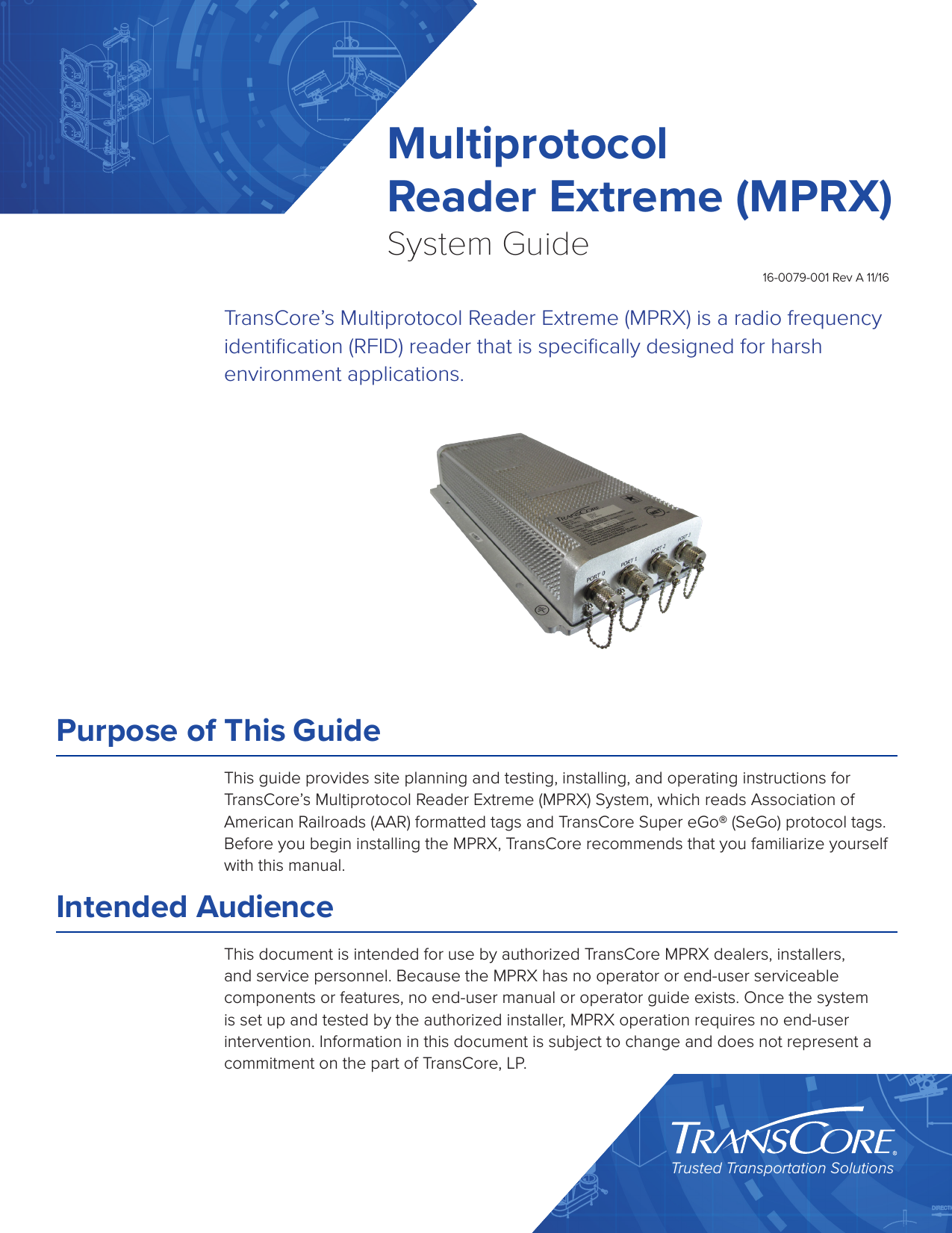
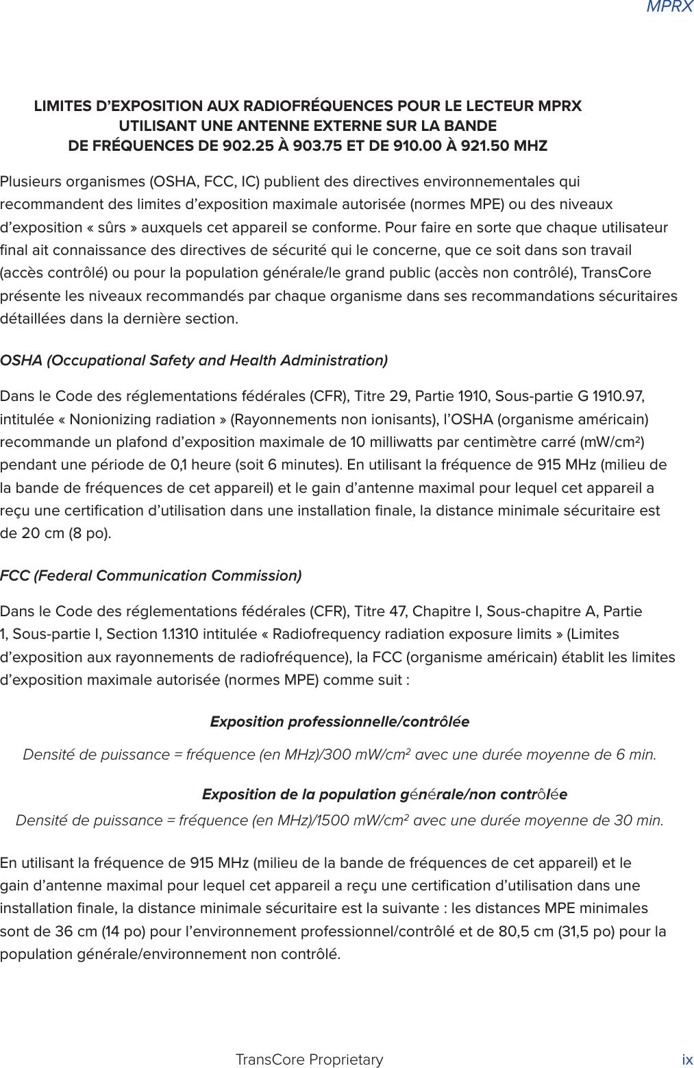

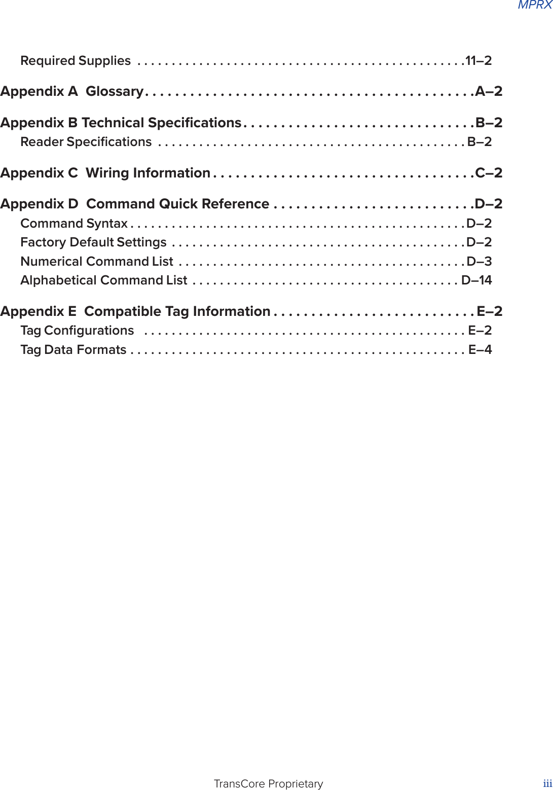
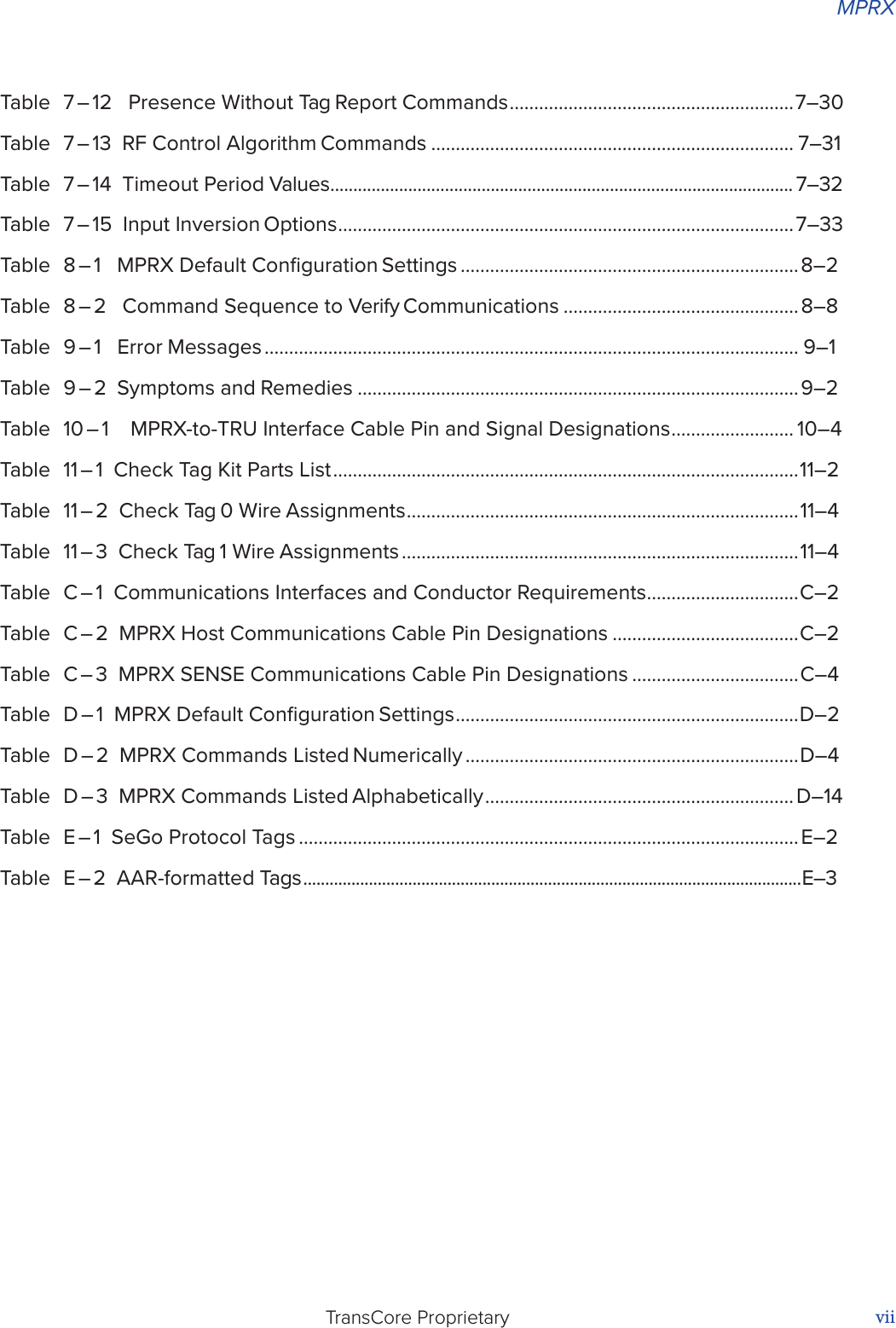


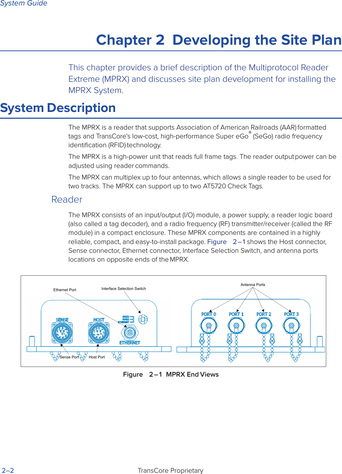
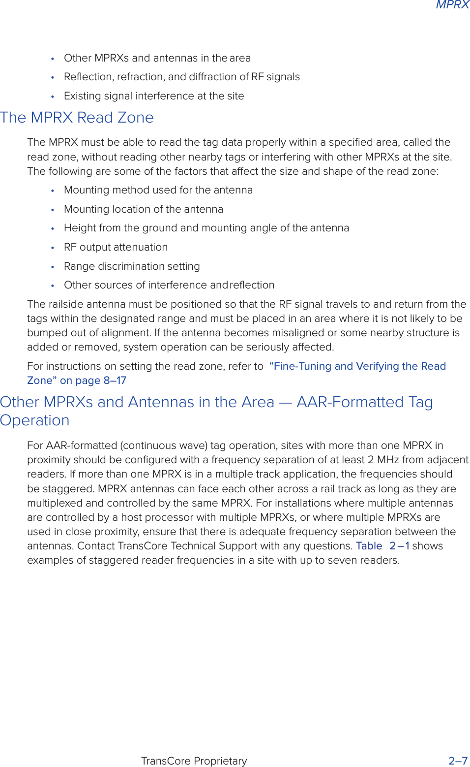
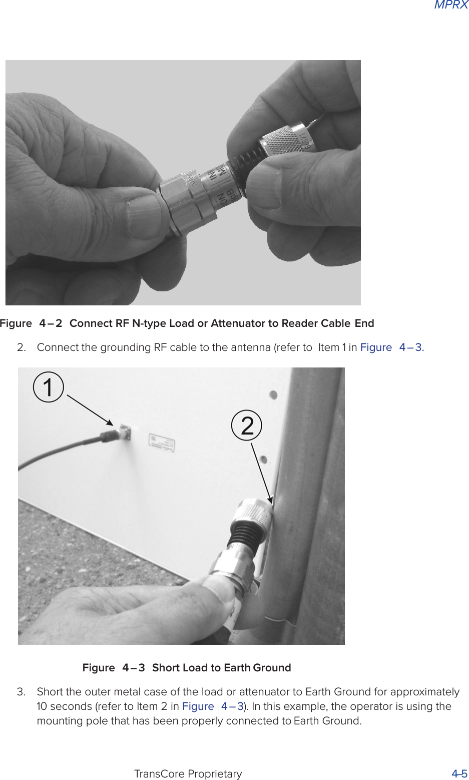
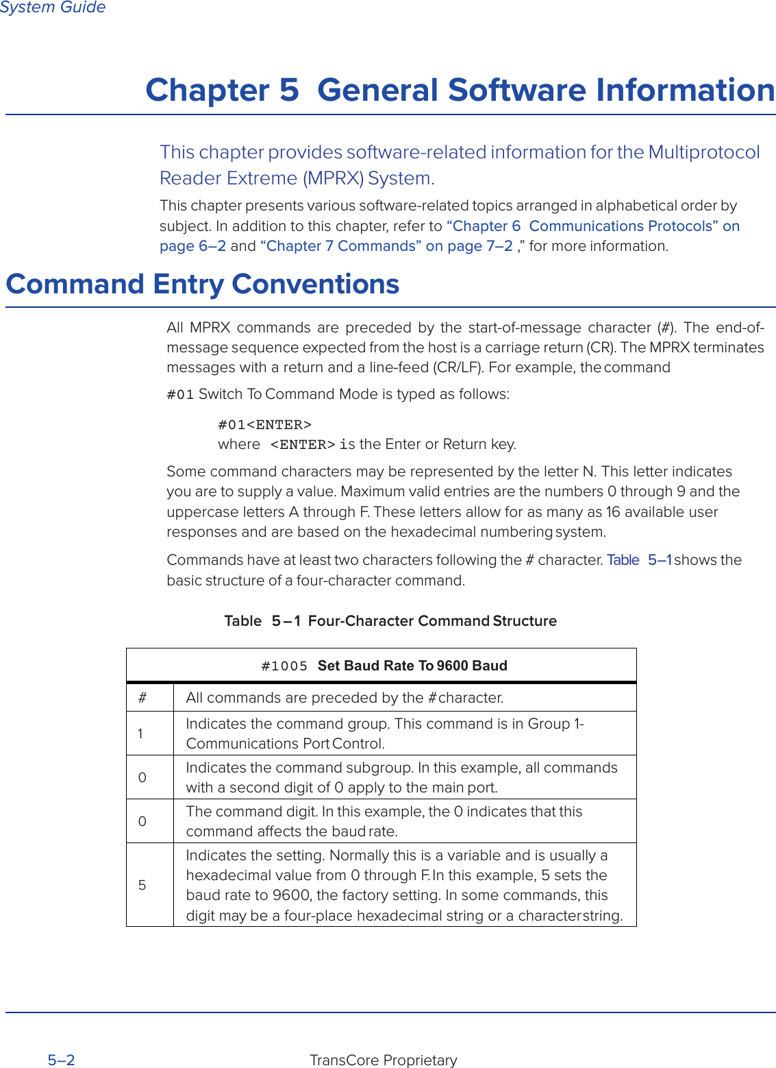
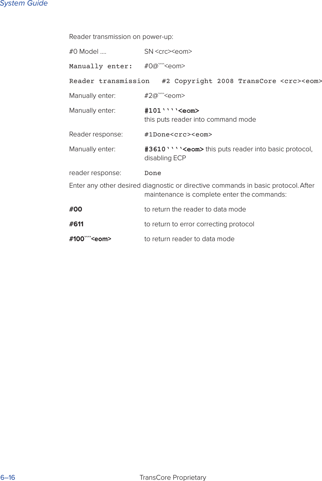
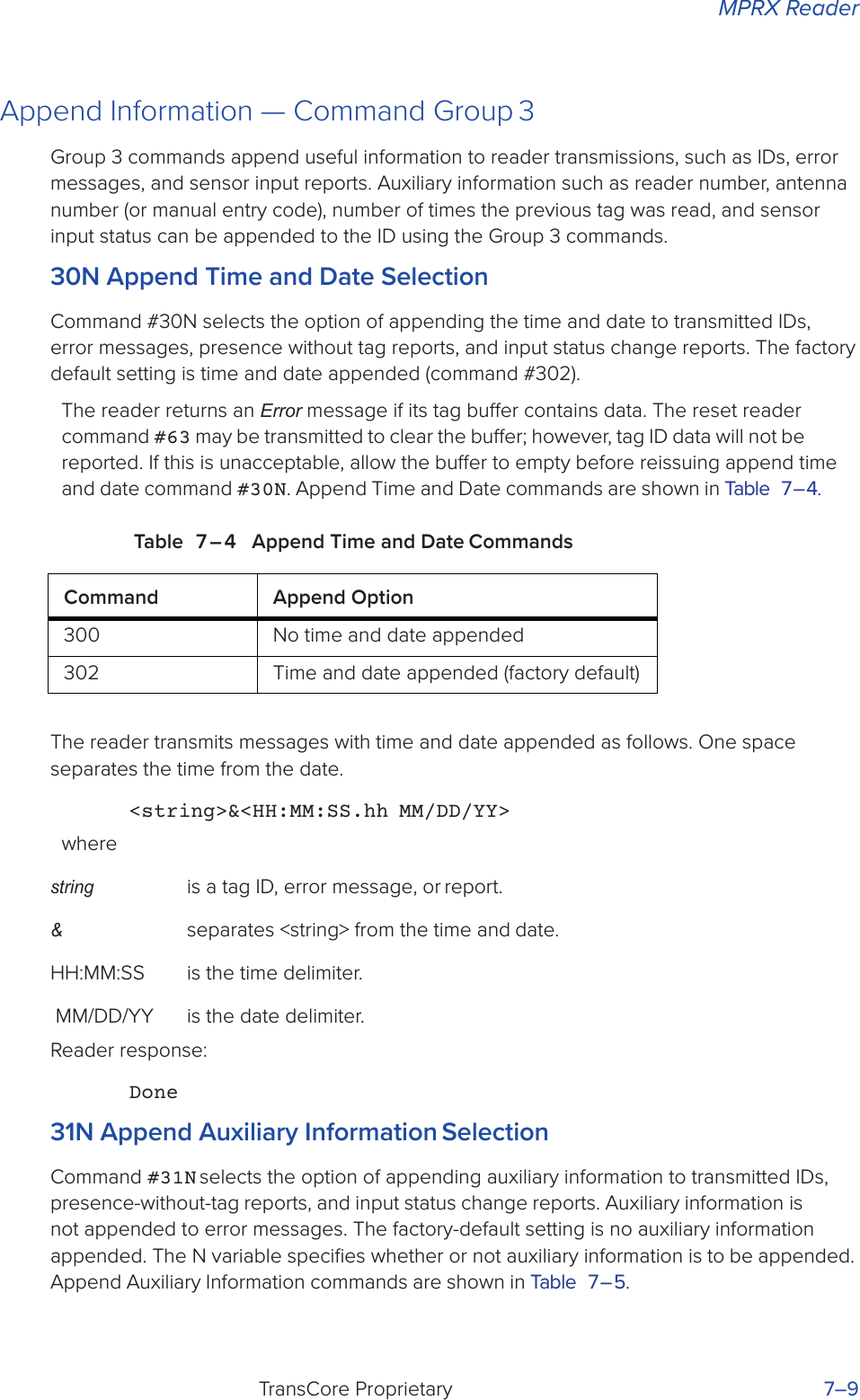
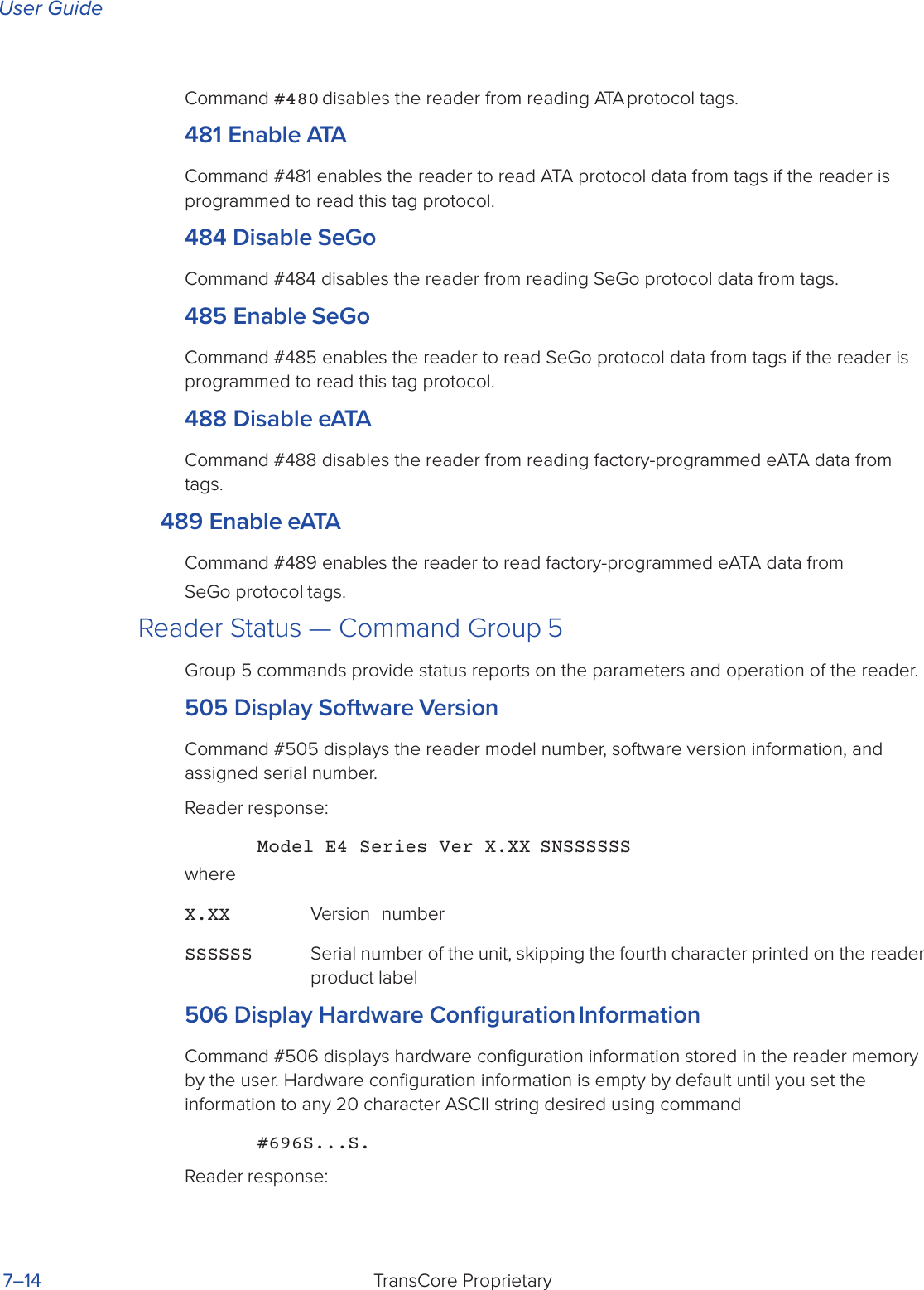
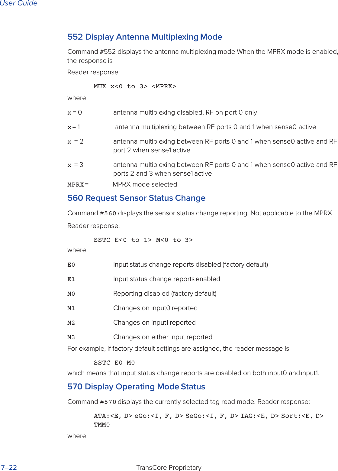
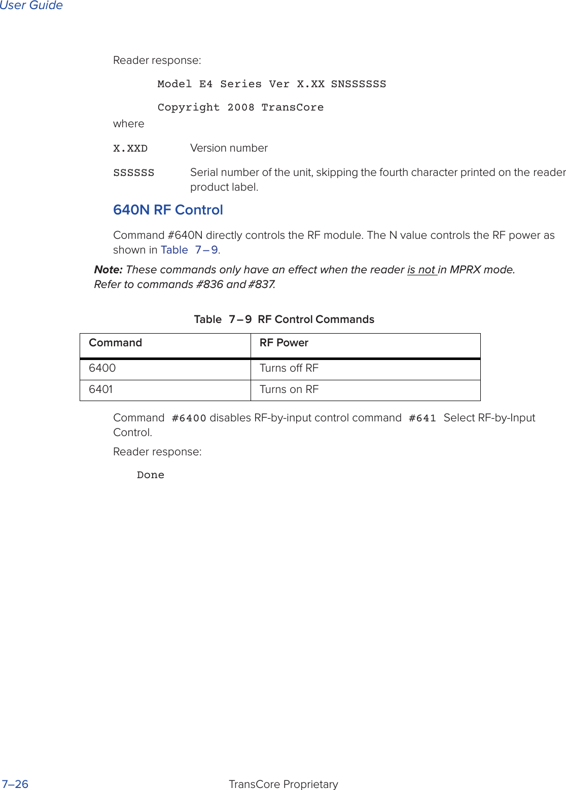
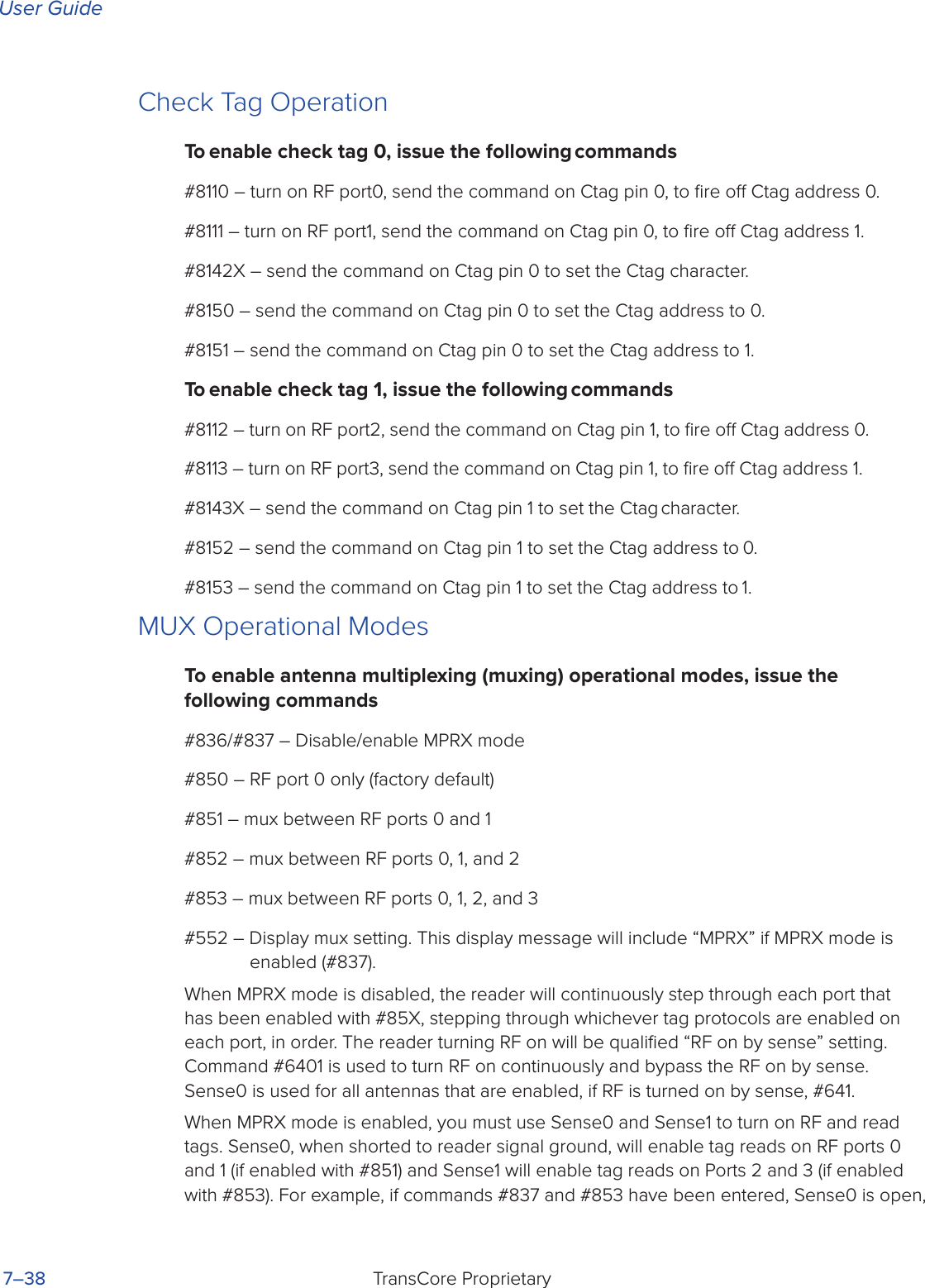
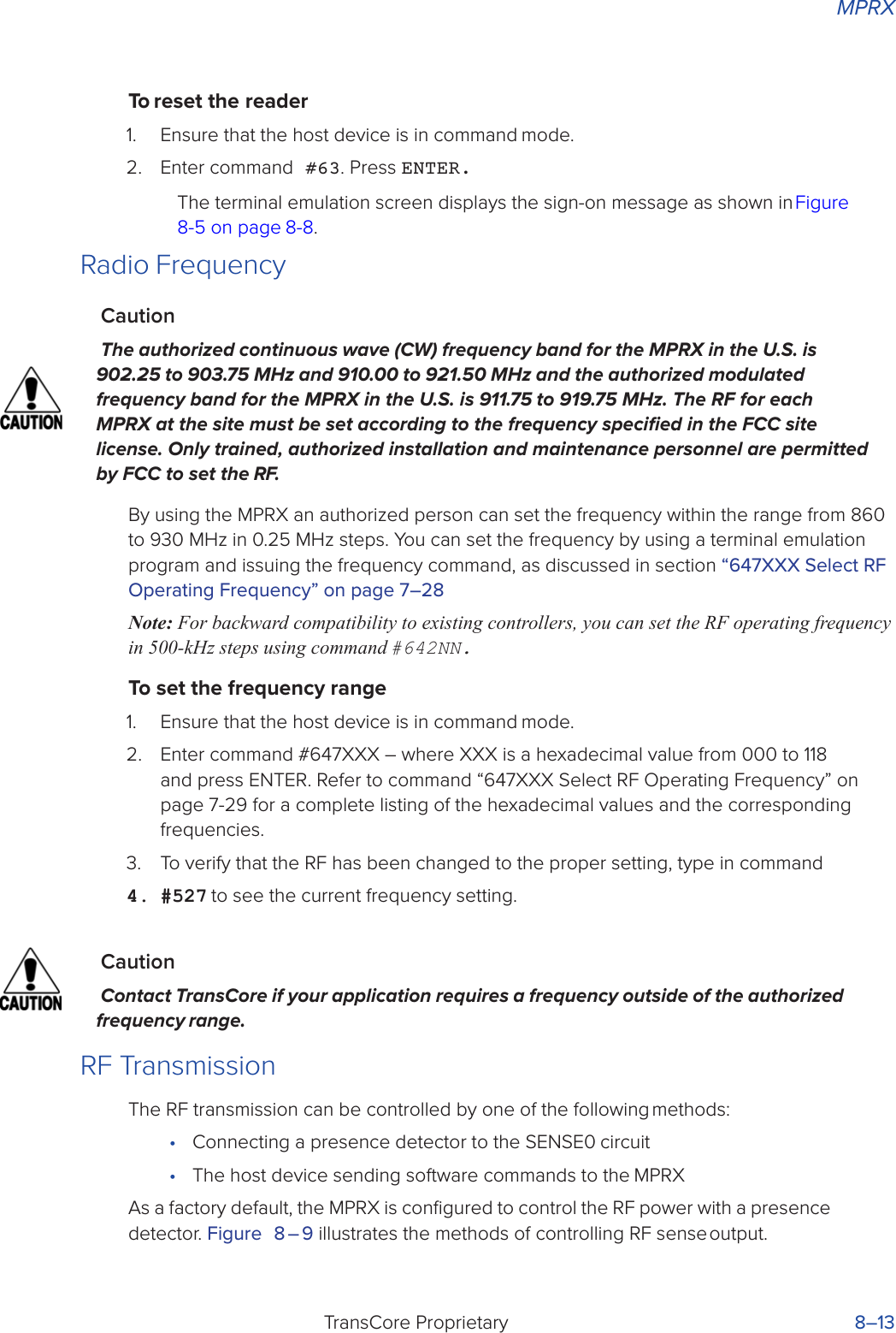
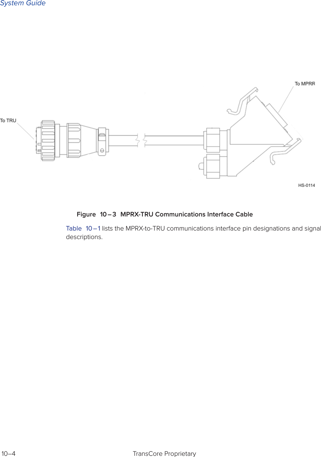
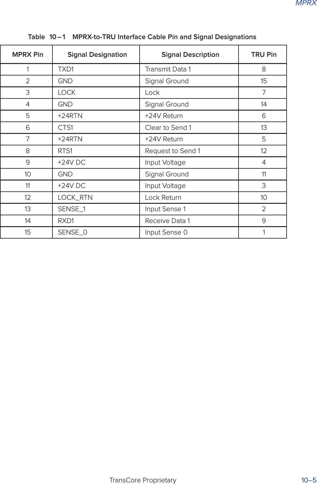
![System GuideTransCore Proprietary 2–6Figure 2 – 4 Antenna Location Relative to Tag PositionAntenna SelectionThis section contains guidelines to assist in antenna selection for an MPRX installation. The following antennas are compatible with the MPRX installation.AA3110 ParapanelAppropriate for installations with the following requirements and conditions:• 902 to 928 MHz operation• Exposure to harsh environments• Broad radiation pattern in one dimension, narrow in the other• Low antenna profile• Horizontal polarizationAA3140 PCB Log PeriodicAppropriate for installations with the following requirements and conditions:• 845 to 950 MHz operation• Exposure to harsh environments• Maximum coverage at close range (<20 ft [6.1 m])• Vertical or horizontal polarizationSite Layout and Trac FlowThe following site layout and trac flow considerations are critical when determining MPRX installation locations:• The MPRX read zone](https://usermanual.wiki/TransCore/MPRX/User-Guide-3202352-Page-29.png)
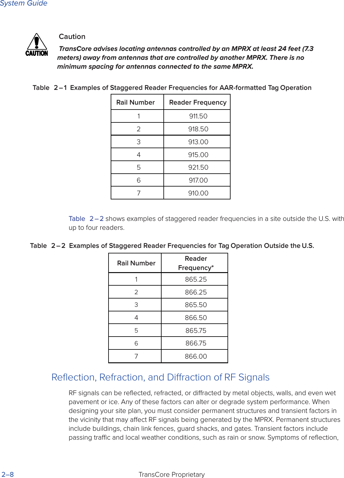


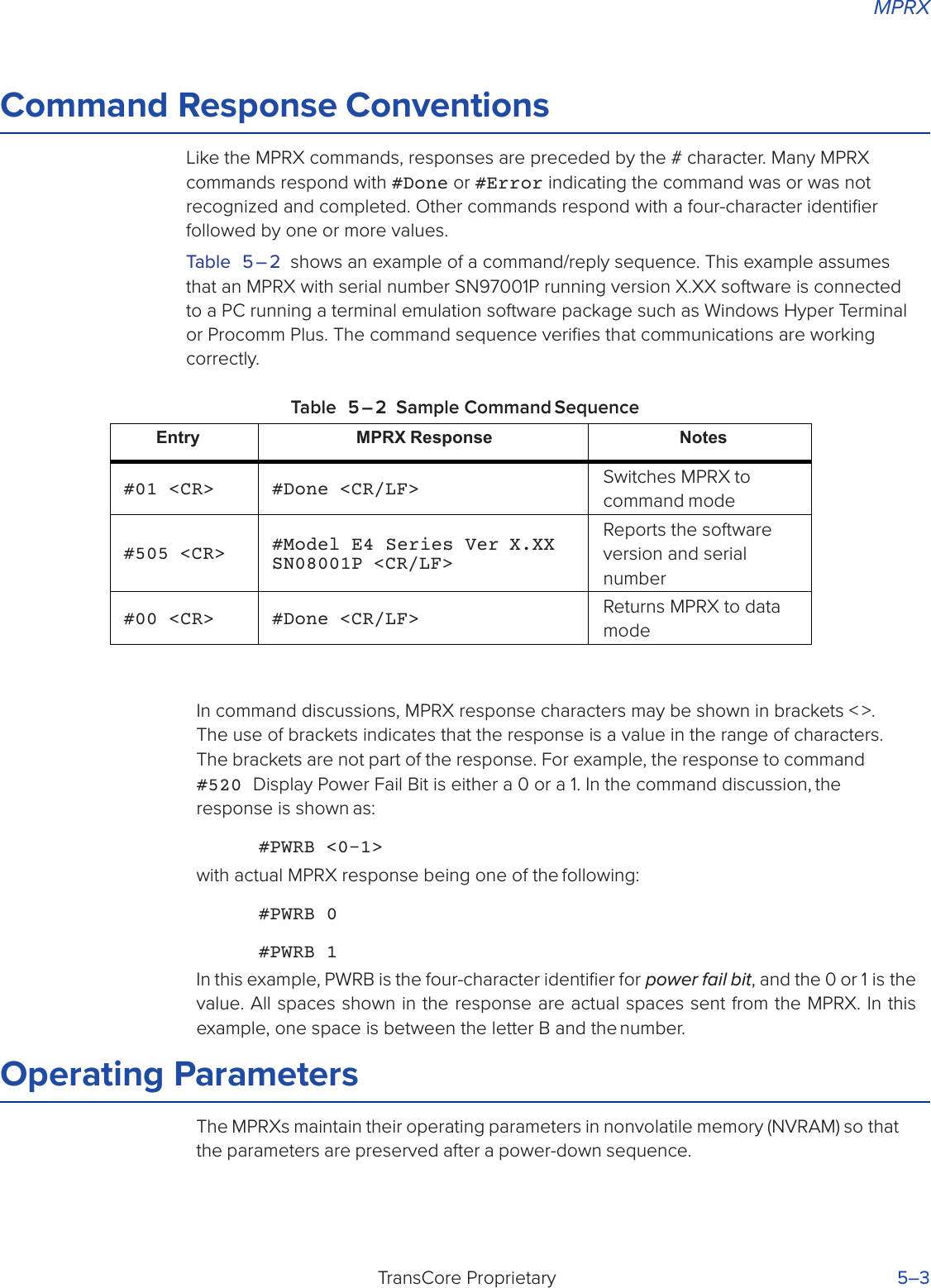
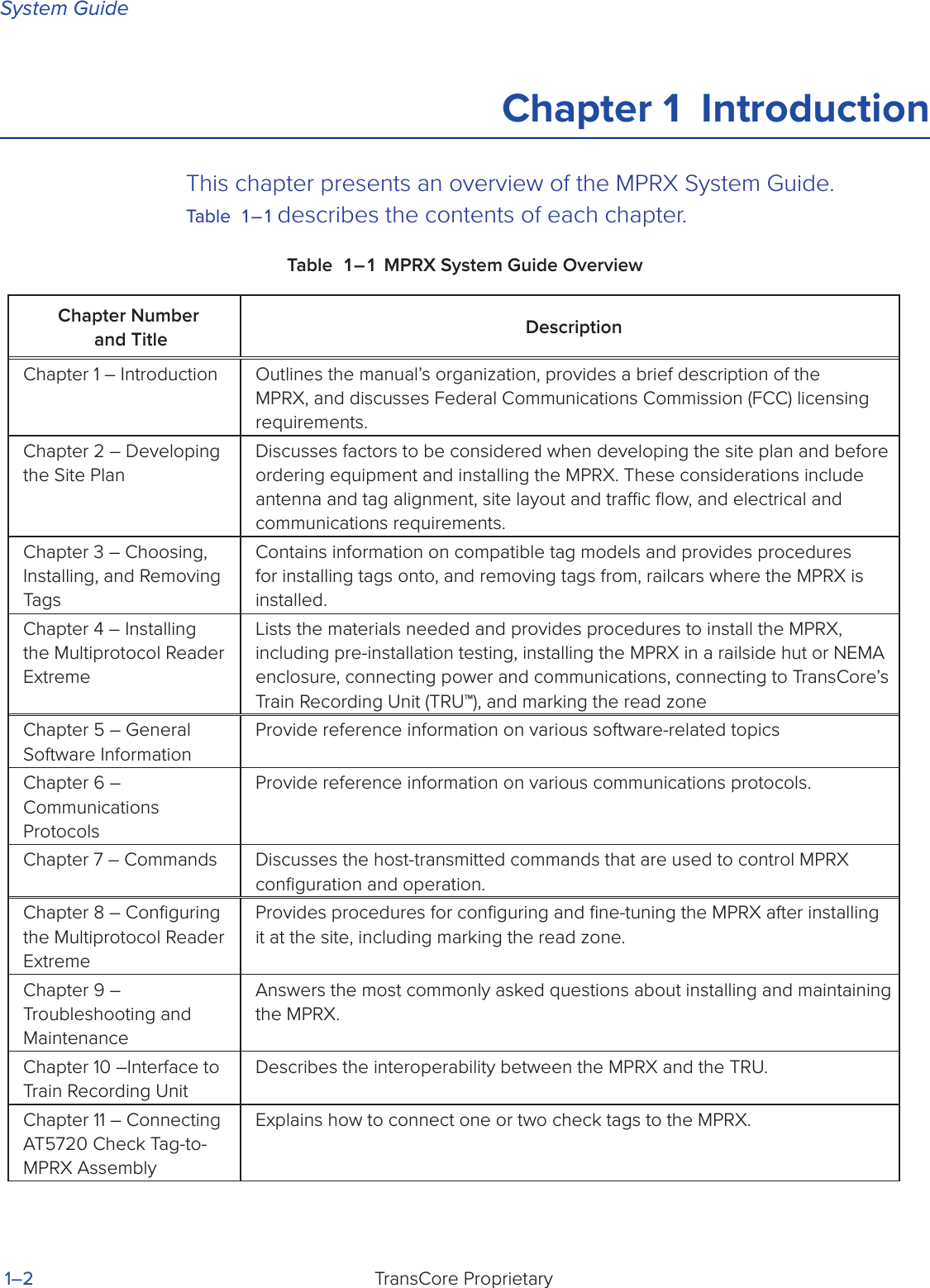
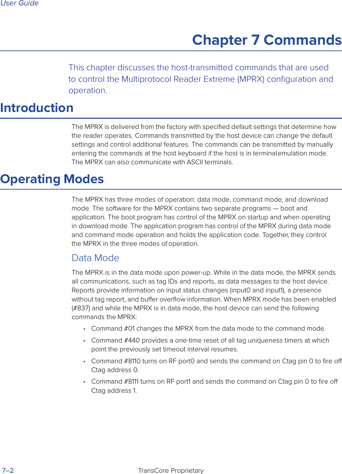
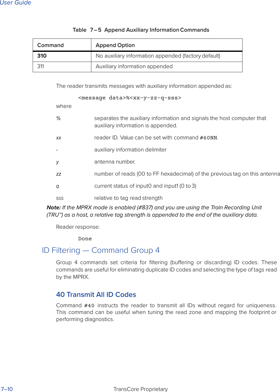
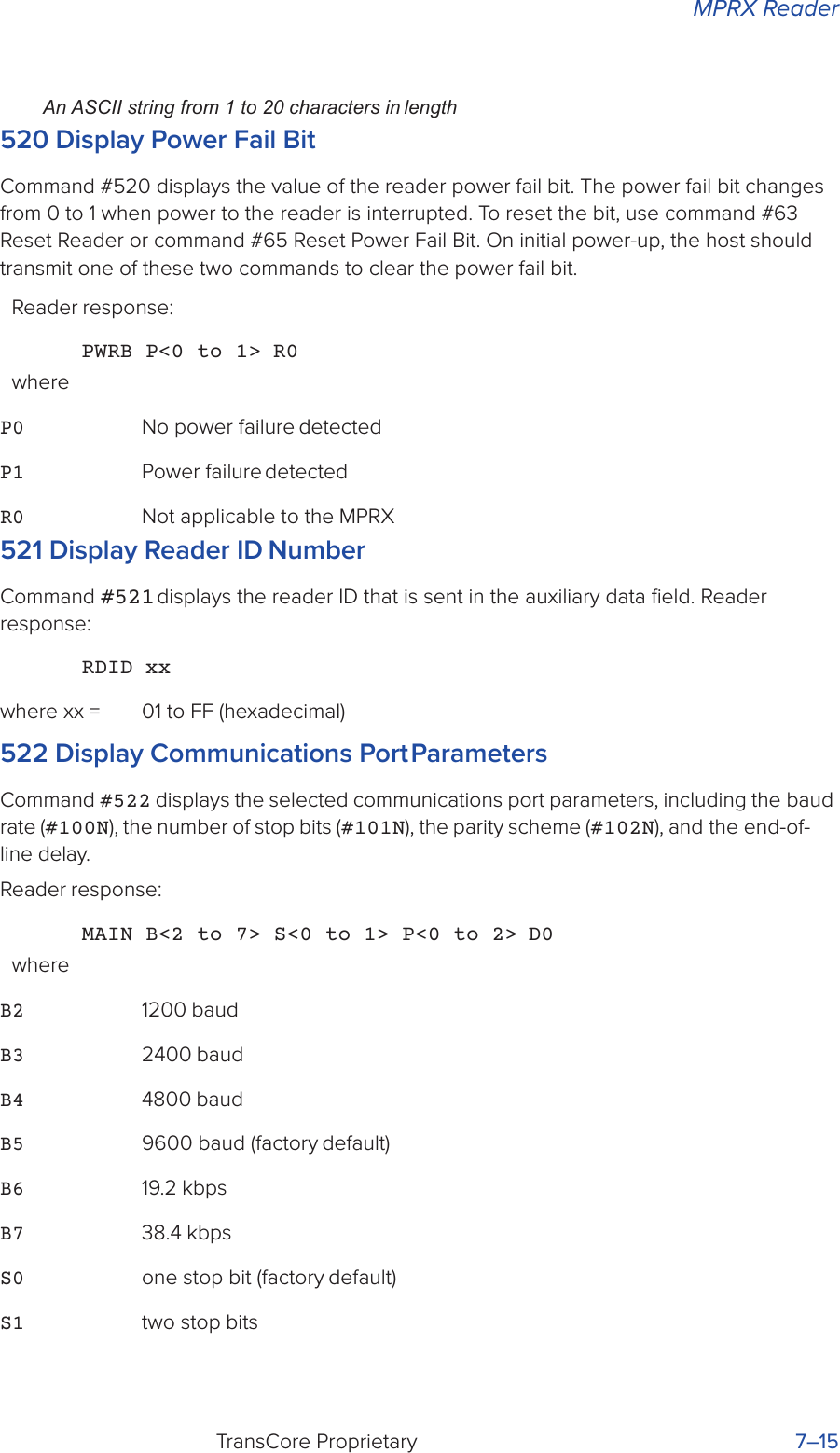
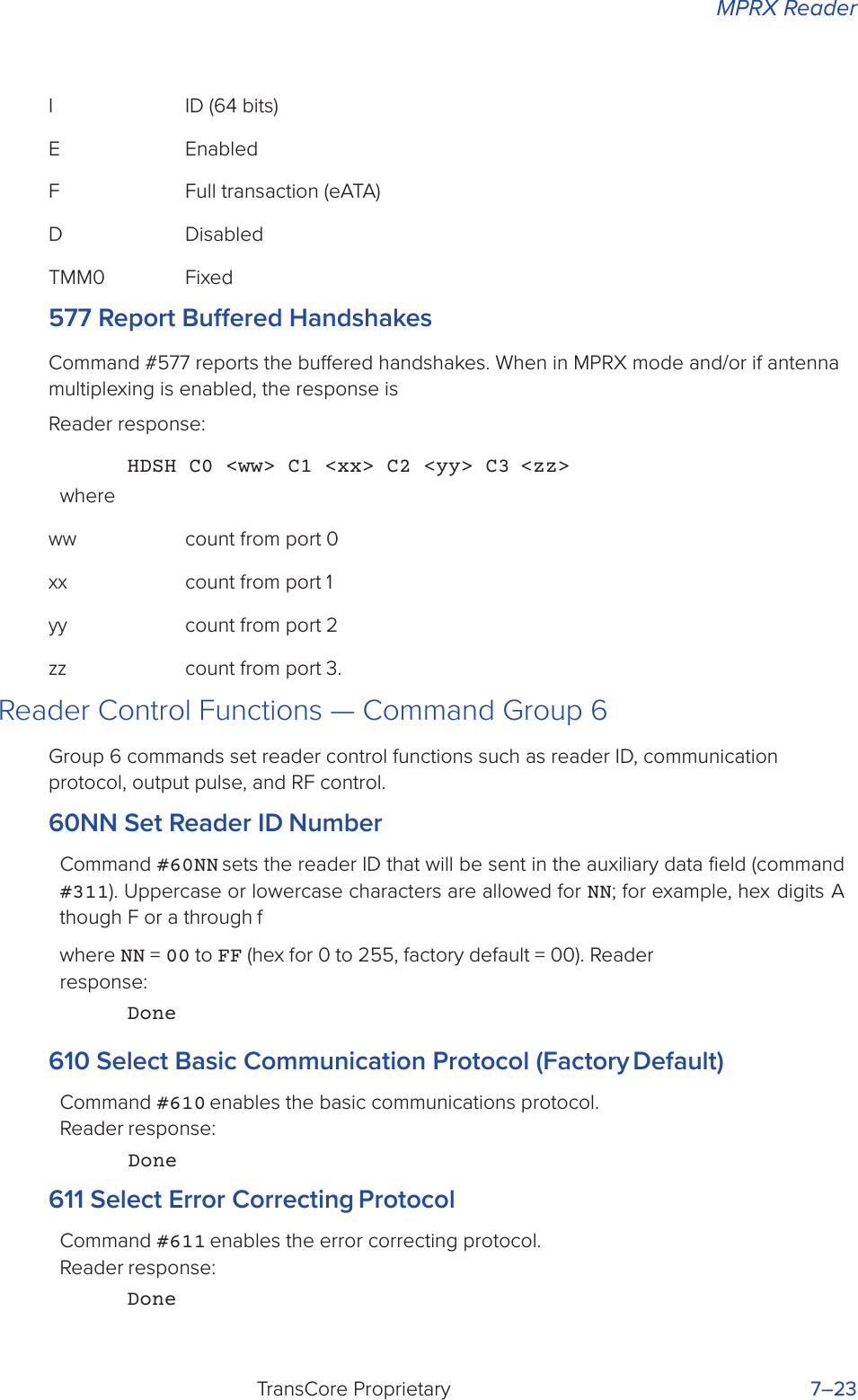
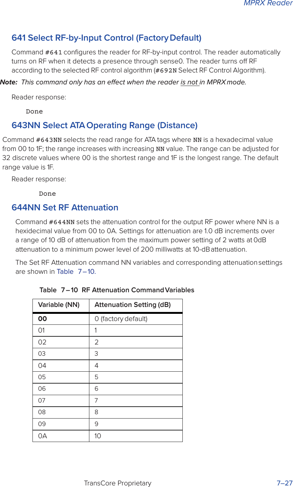
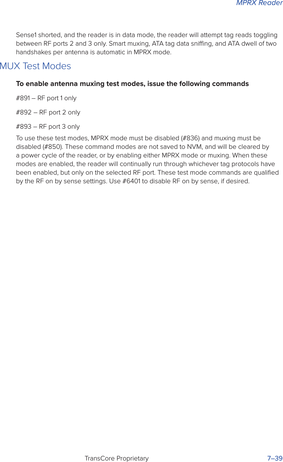
![System GuideTransCore Proprietary 5–4Power FailThe system maintains a power fail flag. The host transmits command #520 Display Power Fail Bit to determine if a power down has occurred. This flag is cleared by both command #63 Reset Reader and command #65 Reset Power Fail Bit.Program DownloadProgram download stores the MPRX application software into the reader’s flash memory. Program download is used to install program upgrades, add features, and to recover from corrupted program data.Note: Program download is a custom TransCore utility hosted process.Download ConsiderationsYou should consider the following factors when performing program download:• The MPRX does not process tags while in download mode.• The MPRX does not accept any program data unless a successful erase of flash memory has been performed before transmitting the data. Erasing the flash memory typically takes two seconds.• Cycling reader power after exiting from download mode re-executes startup. If the new software has been loaded without errors, the MPRX comes up in data mode. If a flash checksum error is detected, the MPRX reenters download mode and transmits a sign-on message with a boot version of 0.00x and without a serial number.Note: The MPRX uses default boot communications parameters when operating in download mode – 38400 baud, 8 data bits, 1 stop bit, no parity, basic protocol – and does not echo commands.Download ProceduresIf TransCore releases a new version of the MPRX software or if the MPRX does not appear to be working properly, you may need to download the software to the MPRX. Contact technical support or your TransCore MPRX sales representative.StartupUpon startup, MPRX transmits a sign-on message or a boot ROM failure message.Sign-On MessageIf startup is successful, the sign-on message appears as follows:Model E4 Series [software version] SNSSSSSS [Copyright notice]where SSSSSS is the serial number assigned to the MPRX unit being used.](https://usermanual.wiki/TransCore/MPRX/User-Guide-3202352-Page-68.png)
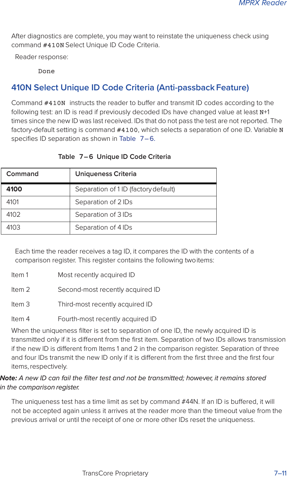
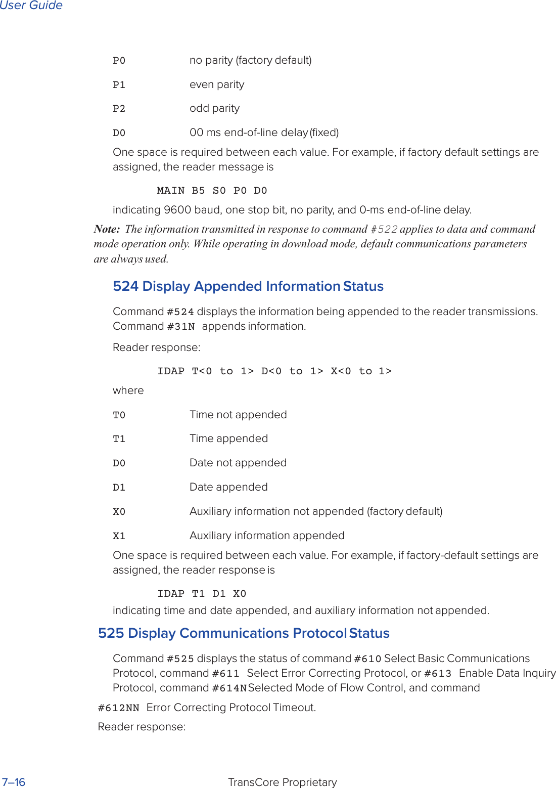
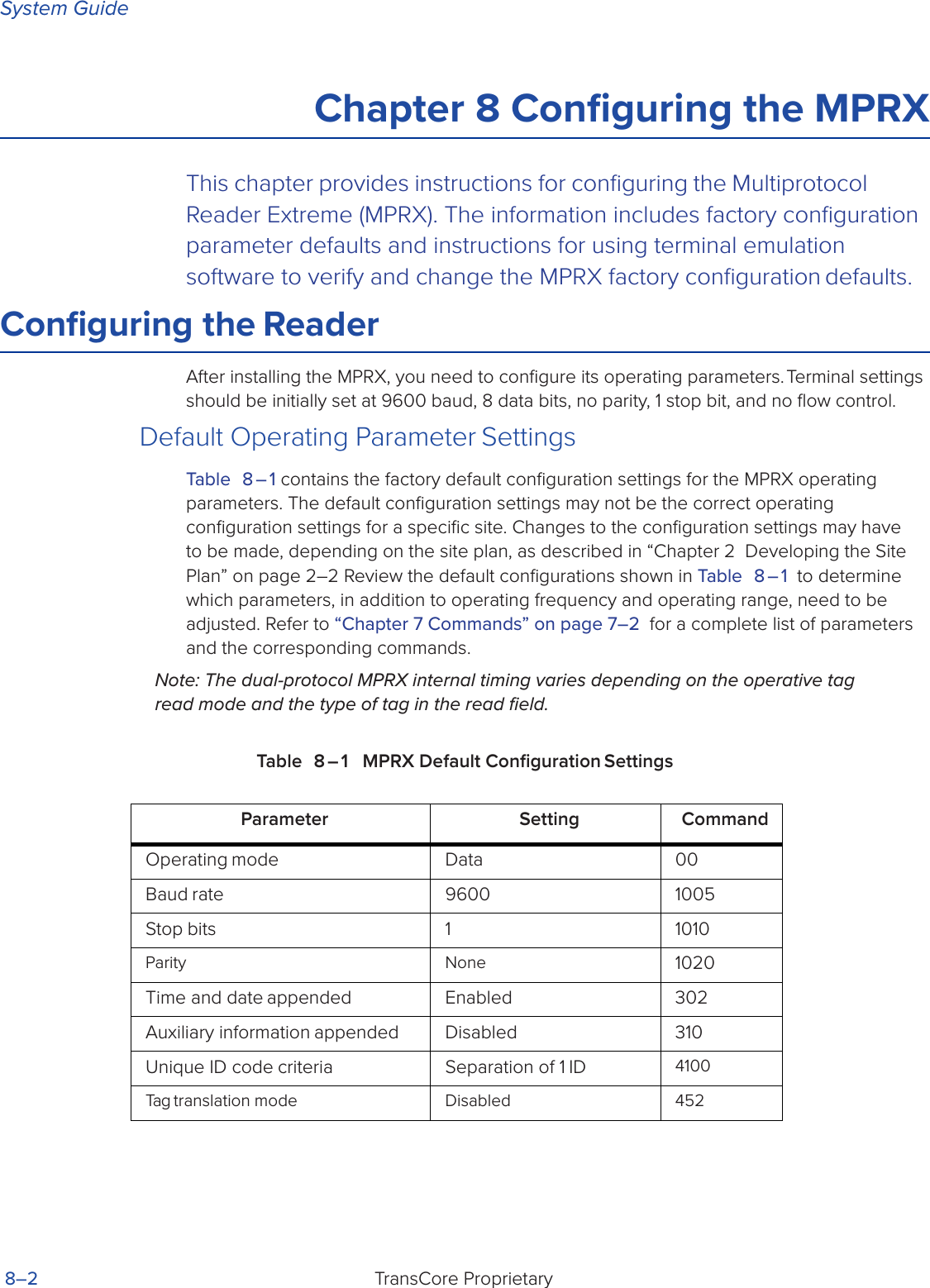
![MPRXTransCore Proprietary 5–5Serial number 000000 is the default setting and is not a valid number. If this number appears in the sign-on message, the serial number has never been stored into reader memory. The serial number must be assigned by factory-authorized personnel using command #695S...S Set Serial Number. Because only six digits are allowed in the software, when setting the serial number skip the fourth (middle) digit of the seven-digit number shown on the reader label.If the flash memory checksum does not indicate verification, the sign-on message appears as follows at a baud rate fixed at 38,400 bps:Model [E4] Ver 0.00x [Copyright notice]Boot Failure MessageUpon powering up, the software performs a checksum verification on itself. The function returns a specific value for the particular version of software. If the value returned is not correct, the boot code assumes that the application code has been corrupted and a failure condition exists. If the failure message does not transmit, a communications error has occurred or the boot has failed to the extent that it cannot transmit the failure message.If the failure message version number equals 0.00 and no serial number exists, the flash memory checksum has failed, and the MPRX is operating out of boot ROM. In this case, the MPRX automatically enters download mode and waits for a new program to be loaded into the flash memory. Contact TransCore Technical Support at 505-856-8007 for assistance.Tag/Message BuerMPRXs maintain a tag buer in battery backed RAM to save tag IDs acquired when data inquiry protocol is used. This buer holds up to 500 time-stamped messages.When the buer fills, subsequent tag IDs will be lost.](https://usermanual.wiki/TransCore/MPRX/User-Guide-3202352-Page-69.png)


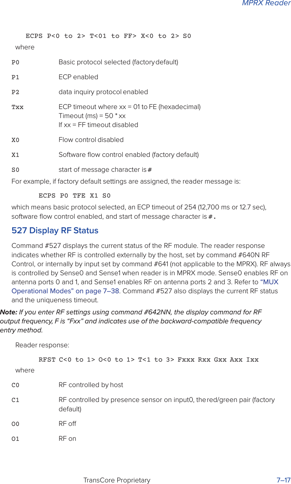
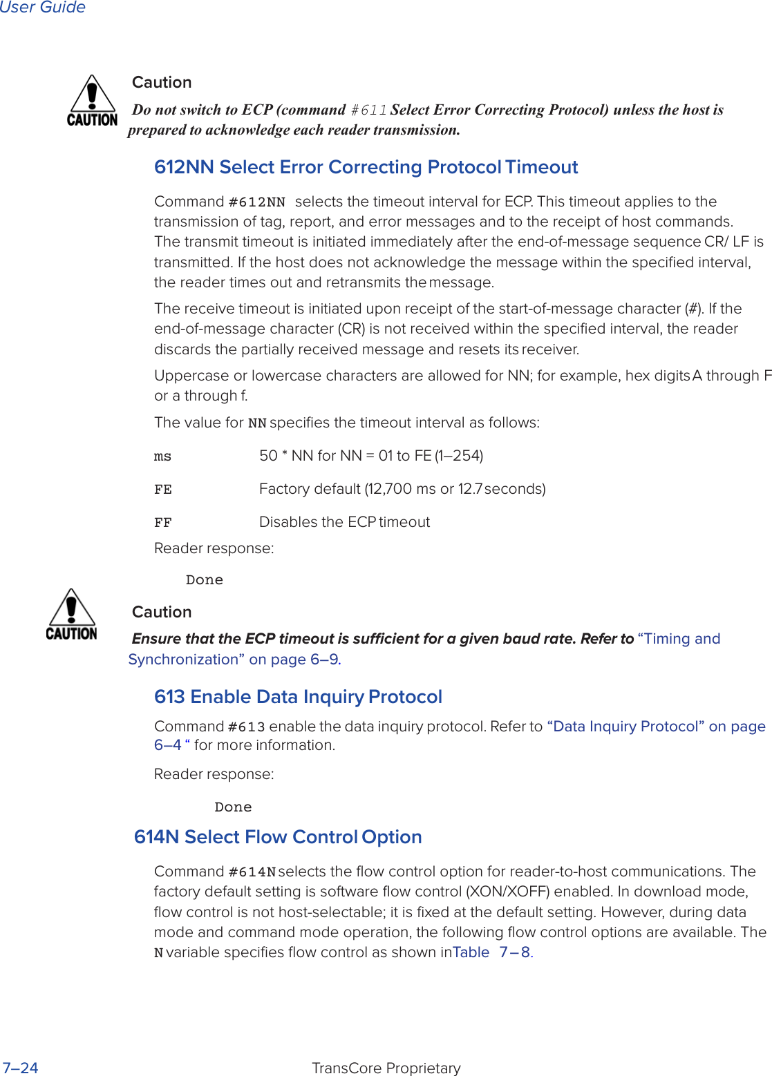
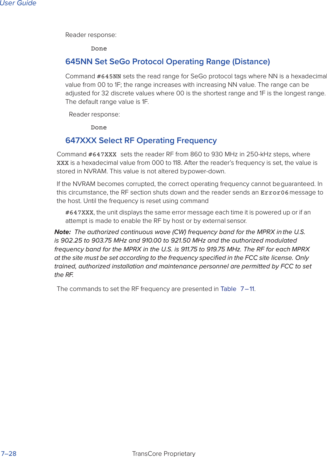
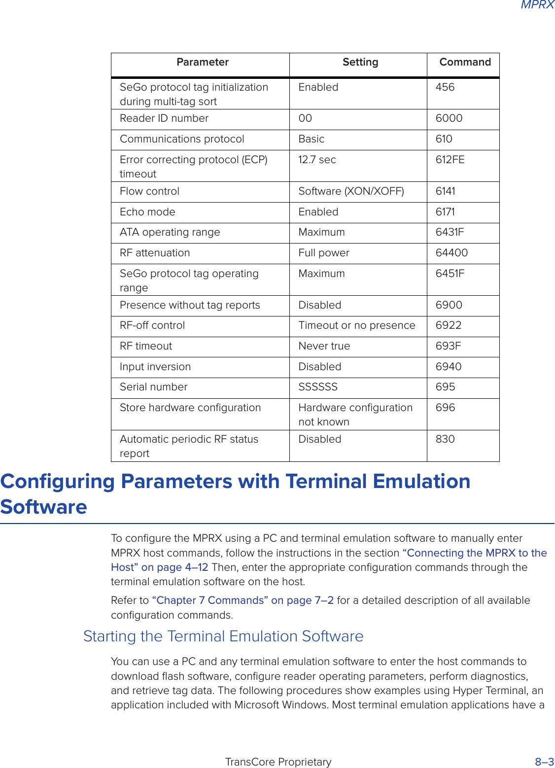
![System GuideTransCore Proprietary6–4Data Inquiry ProtocolData inquiry protocol is a basic protocol option that allows the host to control transmission of reader tag data. The selection of data inquiry protocol aects data mode operation. As MPRX acquires tags, it buers them but does not transmit them. Instead, the host must poll MPRX for each tag by sending a CTRL-E character (hex 5 digit). MPRX transmits one message (tag ID or report data) for each CTRL-E it receives until the buer is empty.Each tag request message sent by the host consists only of the CTRL-E character; no som or eom characters are sent. MPRX data transmission (tag ID and report data) format is the same as for basic protocol.Selection of data inquiry protocol does not aect command mode operation.Basic Protocol and ECP FormatNote: In the following text, the symbols < and > are used to represent required variable message data, and the symbols [and] are used to represent optional data. These symbols are not part of the message syntax.Reader TransmissionsThe basic protocol format and the data inquiry protocol format are as follows:<som><data><eom>The ECP format is as follows:<som><seq><data><crc><eom>where<som> Start-of-message (ASCII # character)<seq> Sequence number (ASCII hex) that represents an even number in the range 0–9, A–F (0, 2, 4, 6, 8, A, C, E). The MPRX maintains the number. The host must acknowledge reader transmissions by sending an ACK message with the same sequence number received from the MPRX. The MPRX updates its sequence number upon receipt of a valid host ACK. If an ACK is not received, the MPRX retransmits the message. A reader transmission sequence is not considered complete until the MPRX receives an ACK and updates its sequence number.<data> ASCII string up to 72 characters long. This string may contain tag data; a presence without tag report; an input status change report; an Error06, Error07, Error08, or Error11 message; or a sign-on message. Auxiliary data may also be included.<crc> Field containing four ASCII digits that represent the 16-bit CRC value calculated on the message. The CRC value is calculated on bytes between the som character and the first <crc> byte.](https://usermanual.wiki/TransCore/MPRX/User-Guide-3202352-Page-74.png)
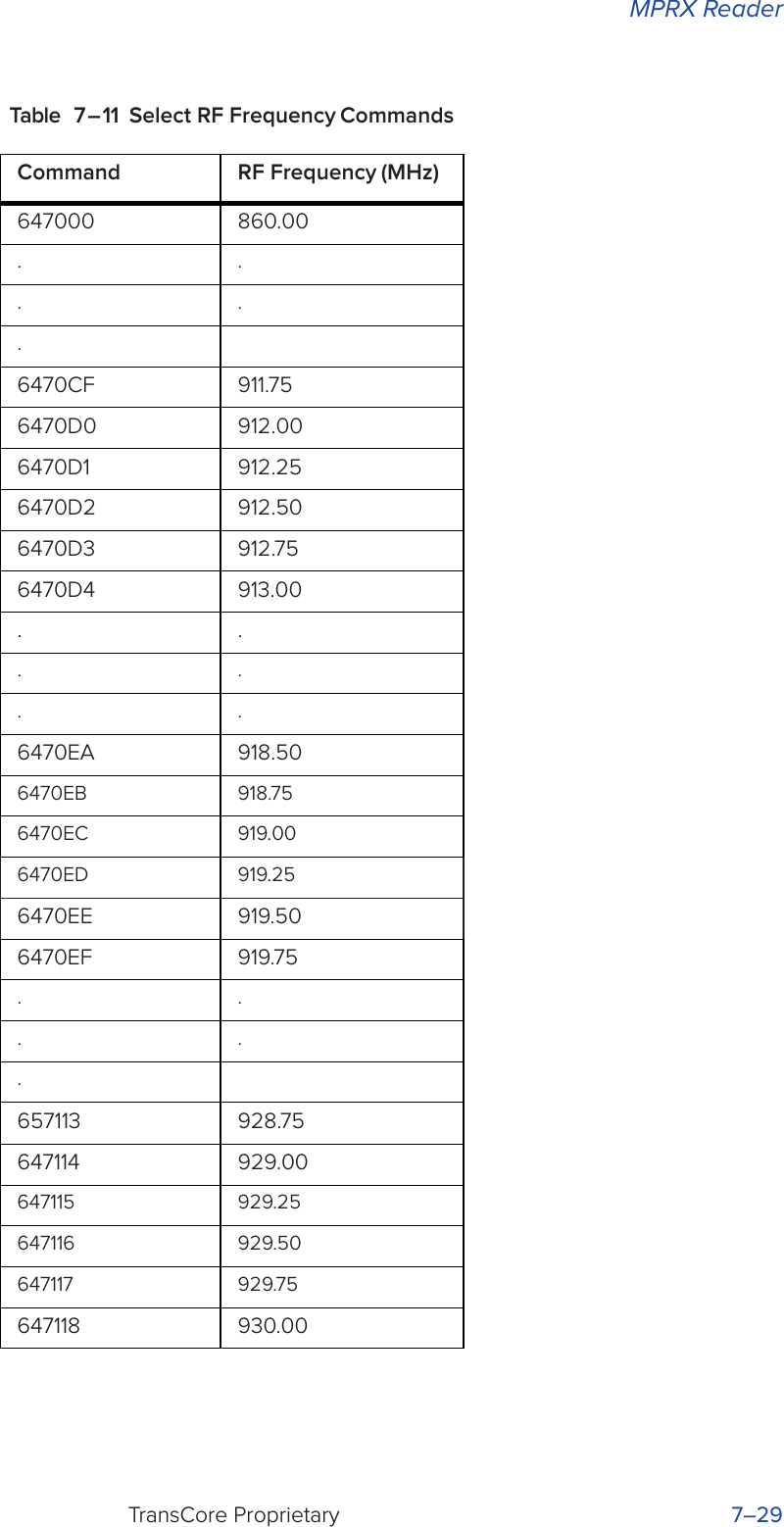
![System GuideTransCore Proprietary6–6 If the timeout delay expires before the MPRX receives an ACK or NAK message from the host, a logical NAK condition will be declared. If the MPRX receives a NAK or timeout, the reader retransmits the data message. When the MPRX receives an ACK message, the system software treats the message as having been properly received by the host. The software increments the sequence number, and advances pointers to the next message in the MPRX’s message queue to prepare for sending the next message.Switch to Command Mode RequestThe host device may issue command #01 Switch to Command Mode while in data mode.The basic protocol format is as follows:<som><cmd><eom>The ECP format is as follows:<som><seq><cmd><crc><eom>where<som> Start-of-message (ASCII # character)<seq> Sequence number generated by the host device separately from that appearing in data messages transmitted by the MPRX<cmd> Switch to command mode (ASCII characters 01)<crc> CRC value for the message<eom> End-of-message character (ASCII CR)Host TransmissionThe host device initiates synchronous communications between the MPRX and the host. The host begins a sequence by issuing a command; the MPRX responds accordingly.The data inquiry protocol format is as follows:<CTRL-E>The basic protocol format is as follows:<som><cmd>[<data>]<eom>The ECP format is as follows:<som><seq><cmd>[<data>]<crc><eom>where<CTRL-E> ASCII Control E (hex 5 digit). When in data inquiry mode, each transmission of a CTRL-E by the host causes the MPRX to transmit one tag ID.](https://usermanual.wiki/TransCore/MPRX/User-Guide-3202352-Page-76.png)
![MPRXTransCore Proprietary 6–7<som> Start-of-message (ASCII # character)<seq> Sequence number (ASCII hex digit) that represents an odd number in the range 0–9, A–F (1, 3, 5, 7, 9, B, D, F). The host should use odd sequence numbers in its command since the MPRX uses even sequence numbers in its transmissions. This method eliminates the possibility of a synchronous host command and an asynchronous reader transmission having the same sequence number. Upon receiving a host command in ECP, the MPRX replies using the command’s sequence number in its response. Therefore, the host device updates its sequence number upon receipt of a valid reader response. If the sequence number is not updated before transmission of the next command, the MPRX will not service the new command; it will retransmit its previous message. A command/message sequence is not complete until the host updates its sequence number.<cmd> Command code, a string that contains from two to four ASCII hex characters[<data>] Optional data field, an ASCII string of as many as 20 characters in length. For example, the store hardware configuration string command is #696S...S or command #696 Store Hardware Configuration String followed by the data string S...S.]<crc> CRC value for the message<eom> End-of-message character (ASCII CR)Reader Command ResponseThe basic protocol format is<som><resp><eom>The ECP format is<som><seq><resp><crc><eom>where<som> Start-of-message (ASCII # character)<seq> Echo of sequence number received in host command message<resp> Response string. The MPRX returns Done, Error, or another ASCII string depending on the host transmission. This string can be up to 72 characters long.<crc> CRC value for the message<eom> End-of-message character (ASCII CR and LF)Sample Messages](https://usermanual.wiki/TransCore/MPRX/User-Guide-3202352-Page-77.png)
![MPRXTransCore Proprietary 6–9Host Command TransmissionsBasic protocol host transmission#647XXX<eom>Reader response#Done<eom> or #Error<eom>#Error<eom> is returned if the host transmission is not a legal command with legal data.ECP host transmission#7647XXX<crc><eom>where# Start-of-message character7 Message sequence number647XXX Select RF Operating Frequency command where 647XXX is the command and XXX is a hexadecimal value from 000 to 118. In this example, XXX sets the RF frequency to 903 MHz.<crc> CRC value for the message<eom> End-of-message characterDone Command has been invoked by the MPRXReader response#7Done<crc><eom> or #7Error<eom>For some commands, the MPRX responds with data that relates to the command, such as T0F 0, to indicate the mode enabled for a #570 Display Operating Mode Status command.#7Error<eom> will be returned if host transmission is not a legal command with legal data.Timing and SynchronizationThe ECP is largely independent of baud rate. The timeout delays previously described are a function of baud rate.The MPRX supports an ECP timeout, which applies equally to both transmit and receive.The receiver’s minimum timeout delay equals the time to transmit/receive the longest anticipated message at the current baud rate setting. Additional margin should be included for idle periods between characters; for example, processing overhead, if any. The timeout delay period can be expressed as follows:Τrec (ms) = L x [Τchar + Τidle]](https://usermanual.wiki/TransCore/MPRX/User-Guide-3202352-Page-79.png)
![System GuideTransCore Proprietary6–10whereΤchar (ms) 1000 x [ Bc / Rb ]Bc Bits per character, typically 10Rb Baud rate, 1200–38.4 KL Length of message in charactersΤidle Maximum idle period between characters (ms)Note: The MPRX supports baud rates between 1200 and 38.4 K.Likewise, the sender must set a timeout delay equal to the delay of nine characters at the current baud rate setting. For example, the time required to shift out the <eom> character plus the time to shift in the ACK or NAK message to be received plus a processing allowance for the receiver to process the message and check for error conditions.Thus, the sending timeout delay can be expressed as follows:Τsend (ms) = 9 * Τchar + ΤerrchkwhereΤerrckh (ms) Processing period to perform error checking by receiverThe host device can remotely set the MPRX’s communications parameters while in the command mode, but TransCore does not recommend this action if communications conditions are marginal.After the MPRX receives new communications parameters, the MPRX issues the Done message and switches to the new configuration immediately. The host device switches its communications parameters immediately after the transaction is complete.As noted, the message initiator, such as the MPRX in data mode and the host device in command mode, starts a timeout counter at the time a message is transmitted. If the timeout expires before receiving an acknowledgment message, a logical NAK condition is declared, and the initiator assumes the message was received in error. In this instance, the message is retransmitted until an acknowledgment message is received.The message recipient, such as the host device in data mode and the MPRX in command mode, starts a timeout counter when a <som> character is received. If the timeout expires without the receipt of an <eom>, the message acquisition is aborted (reset), and the receiver waits for the next <som> character.If the message recipient receives a second <som> character before an <eom> character, the message acquisition is aborted (reset), and retransmission of the previous message is assumed to be underway.These strategies allow for recovery during periods when communications are marginal or lost completely.](https://usermanual.wiki/TransCore/MPRX/User-Guide-3202352-Page-80.png)
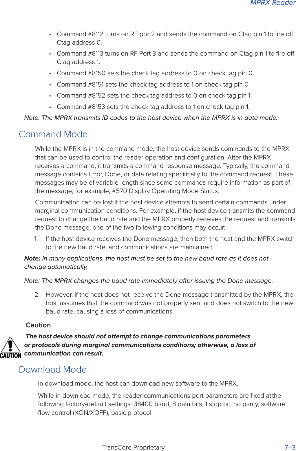
![MPRXTransCore Proprietary 6–13unsigned short calccrc(char *message){unsigned short crc = 0;for ( ; *message != (char)0;message++) crc = updcrc(*message & 0xff, crc);return (crc)}Example 2 shows an example of UPDCRC that does not require a lookup table.#dene BITS_PER_CHAR 8unsigned short updcrc (unsigned short ch, unsigned short crc){register short counter = BITS_PER_CHAR; register short temp = crc;while (--counter >= 0) if (temp & 0x8000) {temp <<= 1;temp += (((ch <<= 1) & 0x0100) != 0);temp ^= 0x1021;}else { temp <<= 1;temp += (((ch <<= 1) & 0x0100) != 0);}return(temp);}Example 3 contains an example of UPDCRC that does require a lookup table.#dene updcrc(cp, crc)( crctab[((crc >> 8) & 255)]^ (crc << 8) ^ cp static unsigned short crctab [256] = {0x0000, 0x1021, 0x2042, 0x3063, 0x4048, 0x50a5, 0x60c6, 0x70e7,0x8108, 0x9129, 0xa14a, 0xb16b, 0xc18c, 0xd1ad, 0xe1ce, 0xf1ef,0x1231, 0x0210, 0x3273, 0x2252, 0x52b5, 0x4294, 0x72f7, 0x62d6,0x9339, 0x8318, 0xb37b, 0xa35a, 0xd3bd, 0xc39c, 0xf3ff, 0xe3de,0x2462, 0x3443, 0x0420, 0x1401, 0x64e6, 0x74c7, 0x44a4, 0x5485,0xa56a, 0xb54b, 0x8528, 0x9509, 0xe5ee, 0xf5cf, 0xc5ac, 0xd58d,0x3653, 0x2672, 0x1611, 0x0630, 0x76d7, 0x66f6, 0x5695, 0x46b4,0xb75b, 0xa77a, 0x9719, 0x8738, 0xf7df, 0xe7fe, 0xd79d, 0xc7bc,0x48c4, 0x58e5, 0x6886, 0x78a7, 0x0840, 0x1861, 0x2802, 0x3823,0xc9cc, 0xd9ed, 0xe98e, 0xf9af, 0x8948, 0x9969, 0xa90a, 0xb92b,0x5af5, 0x4ad4, 0x7ab7, 0x6a96, 0x1a71, 0x0a50, 0x3a33, 0x2a12,0xdbfd, 0xcbdc, 0xfbbf, 0xeb9e, 0x9b79, 0x8b58, 0xbb3b, 0xab1a,0x6ca6, 0x7c87, 0x4ce4, 0x5cc5, 0x2c22, 0x3c03, 0x0c60, 0x1c41,](https://usermanual.wiki/TransCore/MPRX/User-Guide-3202352-Page-83.png)
![System GuideTransCore Proprietary6–140xedae, 0xfd8f, 0xcdec, 0xddcd, 0xad2a, 0xbd0b, 0x8d68, 0x9d49,0x7e97, 0x6eb6, 0x5ed5, 0x4ef4, 0x3e13, 0x2e32, 0x1e51, 0x0e70,0xff9f, 0xefbe, 0xdfdd, 0xcffc, 0xbf1b, 0xaf3a, 0x9f59, 0x8f78,0x9188, 0x81a9, 0xb1ca, 0xa1eb, 0xd10c, 0xc12d, 0xf14e, 0xe16f,0x1080, 0x00a1, 0x30c2, 0x20e3, 0x5004, 0x4025, 0x7046, 0x6067,0x83b9, 0x9398, 0xa3fb, 0xb3da, 0xc33d, 0xd31c, 0xe37f, 0xf35e,0x02b1, 0x1290, 0x22f3, 0x32d2, 0x4235, 0x5214, 0x6277, 0x7256,0xb5ea, 0xa5cb, 0x95a8, 0x8589, 0xf56e, 0xe54f, 0xd52c, 0xc50d,0x34e2, 0x24c3, 0x14a0, 0x0481, 0x7466, 0x6447, 0x5424, 0x4405,0xa7db, 0xb7fa, 0x8799, 0x97b8, 0xe75f, 0xf77e, 0xc71d, 0xd73c,0x26d3, 0x36f2, 0x0691, 0x16b0, 0x6657, 0x7676, 0x4615, 0x5634,0xd94c, 0xc96d, 0xf90e, 0xe92f, 0x99c8, 0x89e9, 0xb98a, 0xa9ab,0x5844, 0x4865, 0x7806, 0x6827, 0x18c0, 0x08e1, 0x3882, 0x28a3,0xcb7d, 0xdb5c, 0xeb3f, 0xfb1e, 0x8bf9, 0x9bd8, 0xabbb, 0xbb9a,0x4a75, 0x5a54, 0x6a37, 0x7a16, 0x0af1, 0x1ad0, 0x2ab3, 0x3a92,0xfd2e, 0xed0f, 0xdd6c, 0xcd4d, 0xbdaa, 0xad8b, 0x9de8, 0x8dc9,0x7c26, 0x6c07, 0x5c64, 0x4c45, 0x3ca2, 0x2c83, 0x1ce0, 0x0cc1,0xef1f, 0xff3e, 0xcf5d, 0xdf7c, 0xaf9b, 0xbfba, 0x8fd9, 0x9ff8,0x6e17, 0x7e36, 0x4e55, 0x5e74, 0x2e93, 0x3eb2, 0x0ed1, 0x1ef0,};Example 4 shows an example of a function that creates the lookup table.#include <stdio.h>#dene MAX_CHAR 256#dene BITS_CHAR 8#dene SIGN_BIT 0x8000#dene POLY 0x1021 unsigned short crctab [MAX_CHAR]; main (){unsigned short ch; unsigned short workval; unsigned short bit; unsigned short carry;for (ch = 0; ch != MAX_CHAR; ch++) { workval = ch << BITS_CHAR;for (bit = BITS_CHAR; bit != 0; bit--) { carry = (workval & SIGN_BIT);workval <<= 1; if (carry) workval ^= POLY;](https://usermanual.wiki/TransCore/MPRX/User-Guide-3202352-Page-84.png)
![MPRXTransCore Proprietary 6–15}crctab[ch] = workval;}for (ch = 0; ch != MAX_CHAR; ch++) printf(“0x%04x\n”, crctab[ch]);}Manually Disabling ECP for MaintenanceUnder certain conditions, communications between the host and MPRX may be lost temporarily and maintenance may be required. The reader or host is sending out a message and waiting for an acknowledgment. When the acknowledgment is not received, the message is sent again. Additional messages are also buered. Often the first indication that the MPRX software is in an ECP “loop” is when the user/technician sees a recurring display of the same message repeated on the monitor. The procedure described in the following paragraphs enables the maintenance technician to change configuration or test tag reading manually.Assuming that the ECP timeout is at the factory default of 12.7 seconds (or other value that allows enough time for the commands to be manually entered) the following command sequence may be used to break out of an ECP loop. This command sequence uses four ASCII < ` > characters (60 hex) as wild card CRC values.Note: The ASCII <`> character (60 hex) is commonly located on the ~ key.You must acknowledge existing messages by issuing commands with the generic format:#x@‘‘‘‘<eom>where# Start-of-message characterx Message sequence number. This must be the same as the sequence number of the message being acknowledged@ ACK (acknowledgment character)<‘‘‘‘> Wild card CRC value for the message<eom> End-of-message characterThe following is a typical sequence after power-on limiting buered messages.Note: Ensure that no tags are in the field when you are performing this troubleshooting procedure.CautionTo avoid damage to the MPRX, ensure that you have connected the antenna or a dummy load to the reader before applying power to the reader.](https://usermanual.wiki/TransCore/MPRX/User-Guide-3202352-Page-85.png)


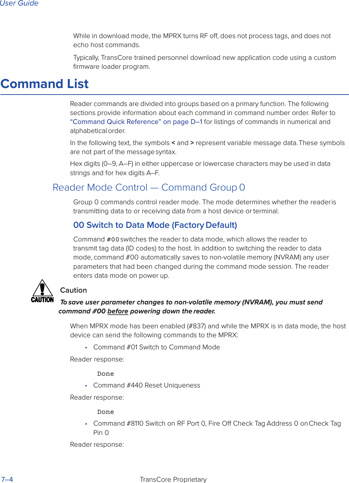
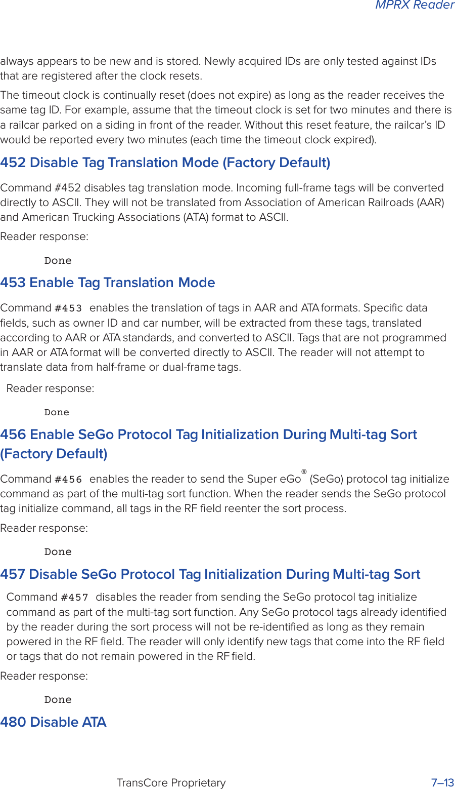
![User GuideTransCore Proprietary 7–12Reader response:Done420N Select Valid ID Code CriteriaCommand #420N directs the reader to validate an ID received only after it has been obtained a specified number of times in sequence. Values for N are 1 through 4 (Table 7 – 7). The factory setting is one acquisition (N = 0).Table 7 – 7 Select Valid Code Commands and FramesThe validation procedure is executed before the unique ID test (Select Unique ID Code Criteria [#410N] commands). IDs that do not pass the validation test are not reported.For example, command #4203 specifies that the same ID must be obtained from the antenna/RF module 4 times in succession before it is considered for the uniqueness test. This feature is useful in installations where RF reflections may cause a single tag to be read multiple times or where an occasional ID might be read from fringe areas440 Reset UniquenessCommand 440 causes the ID filtering process set by Select Unique ID Code Criteria (#410N) to restart. It is used in conjunction with the Set Uniqueness Timeout#44N) commands. This command provides a one-time reset at which point the previously set timeout interval resumes. This command can be sent in data or command mode.44N Set Uniqueness TimeoutPlaces a time limit on the uniqueness criterion set by Select Unique ID Code Criteria (#410N). The parameter N sets the number of minutes on the timeout clock. The factory setting is two minutes (N = 1).Command Timeout Clock#441 2 minutes (factory setting)#442 15 seconds#443 30 secondsEntering these commands eectively expires the timeout clock, which erases all current IDs in the comparison register. In eect, the first ID that is acquired after the clock expires Command Valid Code Frames4200 1 (factory default)4201 24202 34203 4](https://usermanual.wiki/TransCore/MPRX/User-Guide-3202352-Page-99.png)
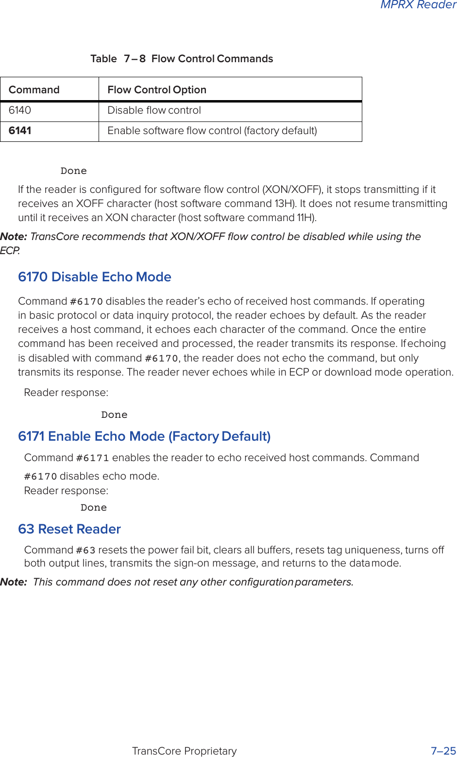

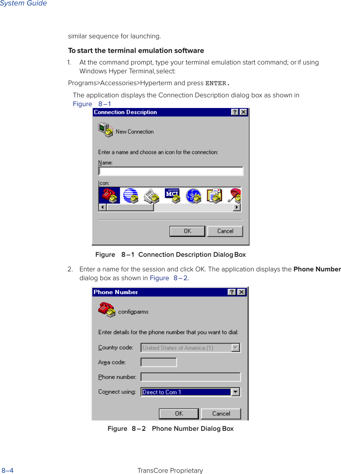
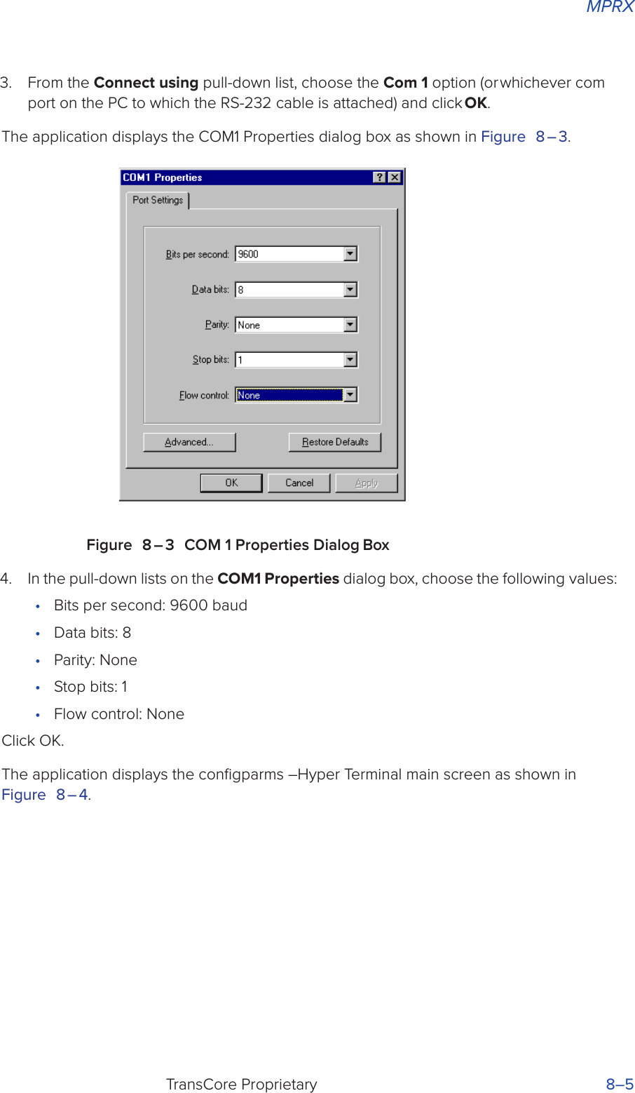
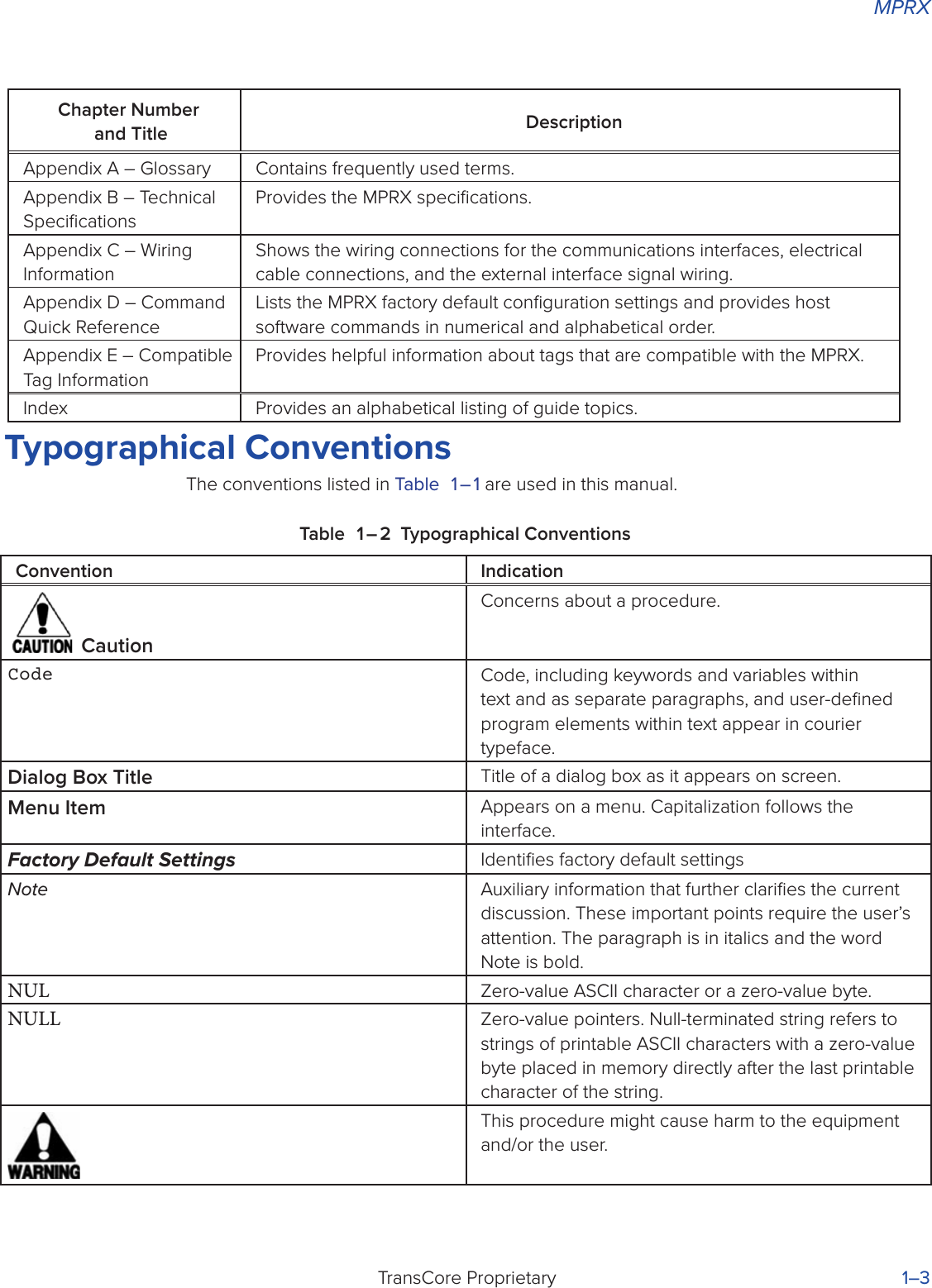
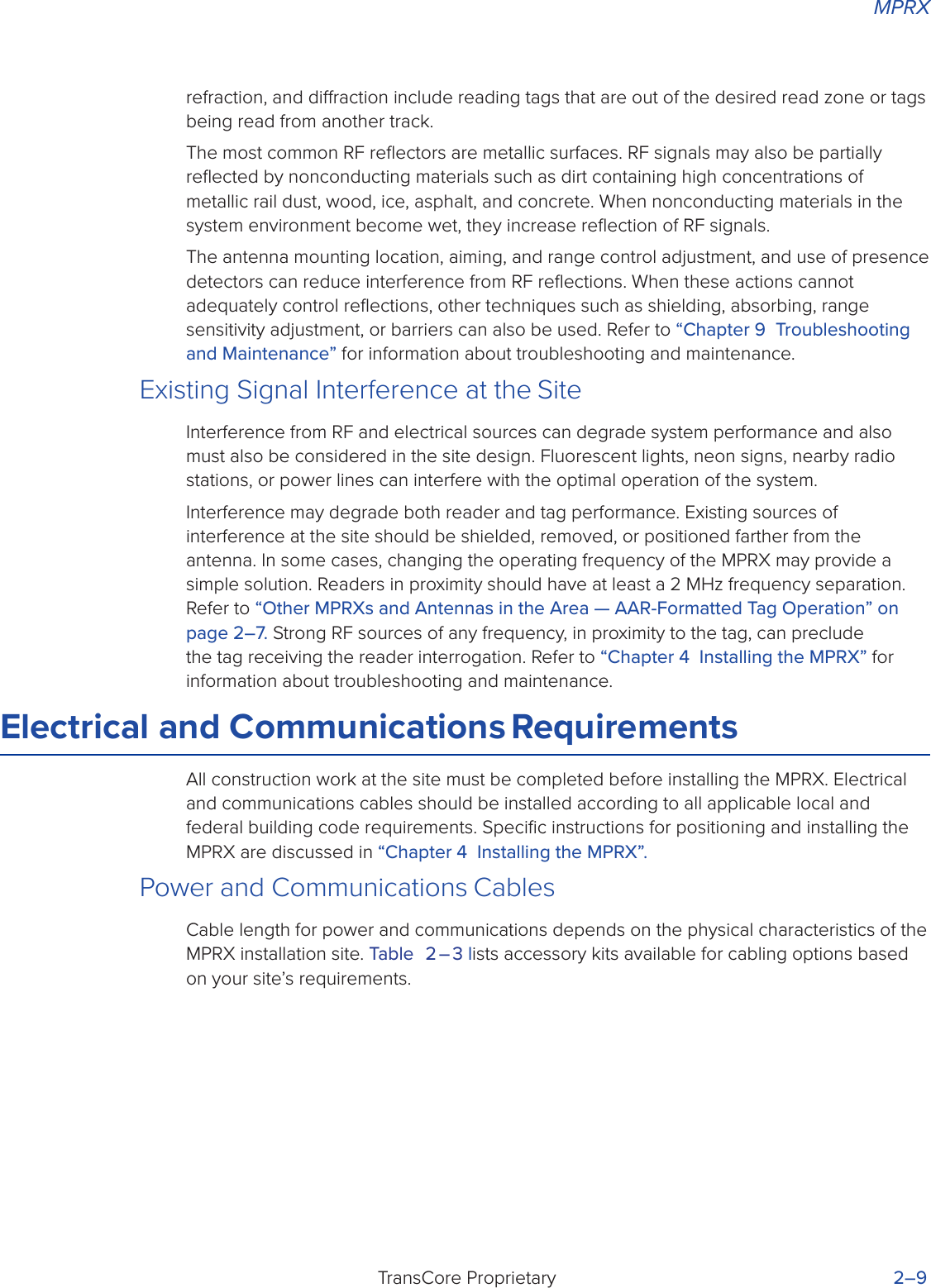
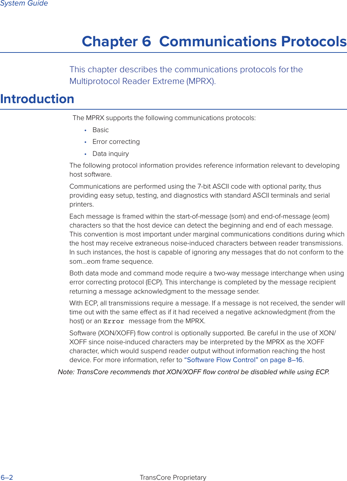
![MPRXTransCore Proprietary 8–7Figure 8 – 5 Sign-on MessageThe sign-on message appears as follows at a baud rate of 38,400 bps:Model [software version] SNSSSSSS [Copyright notice]where SSSSSS is the serial number assigned to the MPRX skipping the fourth character printed on the reader product label.Serial number 000000 is the default setting and is not a valid number. If this number appears in the sign-on message, the serial number has not been stored into reader memory. Contact TransCore Technical Support at 505-856-8007.If the flash memory checksum is not verifiable, the sign-on message appears as follows:Model [E4 BOOT] Ver 0.00 A[Copyright notice]If the failure message version number equals 0.00 E and no serial number exists, the flash memory checksum has failed, and the MPRX is operating out of boot ROM. In this case, the MPRX automatically enters download mode and waits for a new program to be loaded into the flash memory. Follow the instructions in “Program Download” on page 5–4 .Communications can also be verified by using the command sequence in Table 8 – 2.](https://usermanual.wiki/TransCore/MPRX/User-Guide-3202352-Page-133.png)

![MPRXTransCore Proprietary 9–3Symptom NumberaSymptom Remedy3When testing the MPRX, all the wires are connected correctly but the unit does not respond.The MPRX may not have the software loaded inside the unit. Contact Technical Support as described on page 9-6.If you are using a terminal emulation program, check that the terminal emulation setting on the MPRX is VT100.Check that the MPRX communication cable is connected to the correct COM port.Verify that the external antenna is connected correctly.Also, check the position of the Interface Selection Switch.4Strange signal responses come from the MPRX when tested with the PC.Ensure that the reader is in the correct interface mode for the test tag, that is, AAR for an AAR-formatted tag.Check the system defaults using a terminal emulation program. Both PC and reader should be set to 9600 baud, 8 bits, 1 stop bit, and no parity.5 Nothing happens when the test tag is passed in front of the MPRX RF antenna.Ensure that the MPRX is powered onVerify that the reader is set to RF ON (#6401). Verify that the antenna is connected correctly.6The MPRX came from another site and does not work the way the factory defaults indicate that it should.Dierent commands were probably used to support the other site’s specific configuration. You can restore the factory defaults by using a terminal emulation program to switch to command mode and issuing command #66F Load Default Operating Parameters. All factory defaults except RF frequency will be restored.7When connected to a PC that is running terminal communications software, a just-powered up MPRX displays one of the following messages:#Model E4 Series X.XX SNSSSSSS#[Copyright notice]The MPRX works. The software is now loaded. SSSSSS is the TransCore-assigned serial number for this MPRX. However, if SSSSSS = 000000, a serial number has never been assigned. If a serial number has not been assigned to your MPRX, contact TransCore Technical Support.](https://usermanual.wiki/TransCore/MPRX/User-Guide-3202352-Page-149.png)


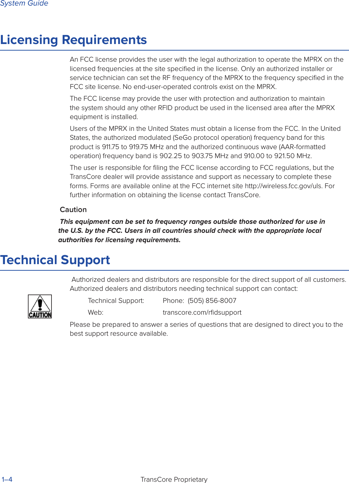
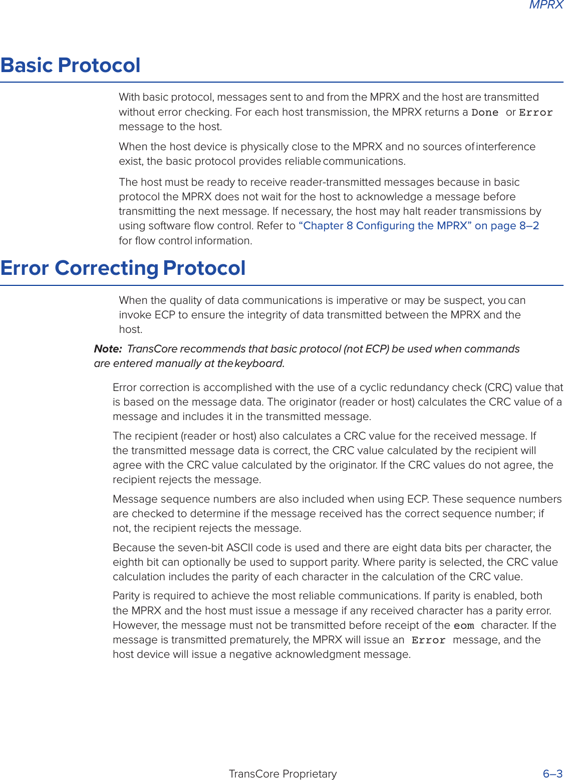
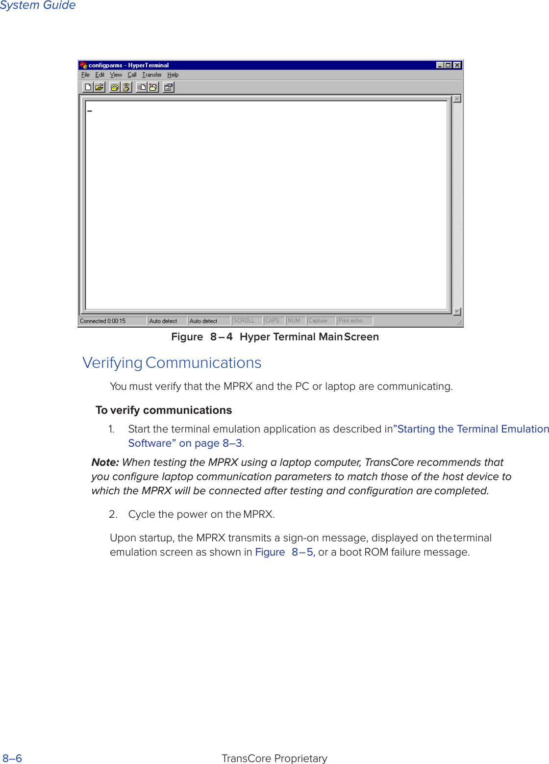
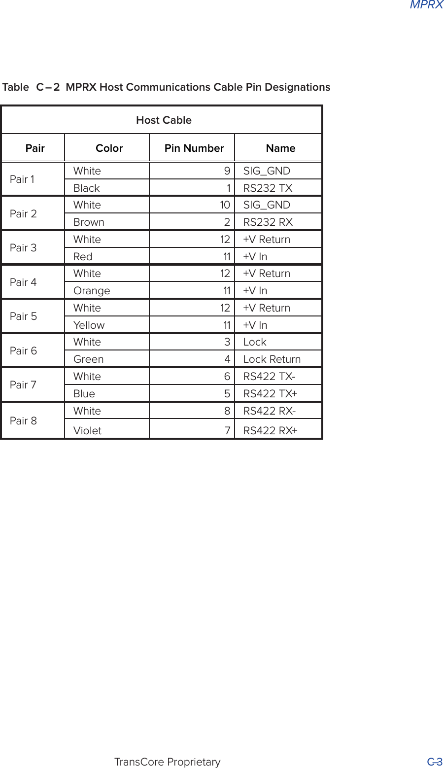
![System GuideTransCore ProprietaryC–2Appendix C Wiring InformationThis appendix contains a graphical representation showing the wiring connector pin-outs as well as any wiring signal tables used to test and install the Multiprotocol Reader Extreme (MPRX) for a non-Train Recording Unit installation.Communications InterfacesTable C – 1 lists the interfaces available with the MPRX.Table C – 1 Communications Interfaces and Conductor RequirementsTable C – 2 lists the MPRX Host Communications Cable Pin Designations. The interface cable is TransCore P/N (6-foot [1.8-m] cable assembly, no TRU) or (20-foot [6.1-m] cable assembly, no TRU).Interface Number of ConductorsRS–232 3RS-422 5Ethernet 4](https://usermanual.wiki/TransCore/MPRX/User-Guide-3202352-Page-176.png)
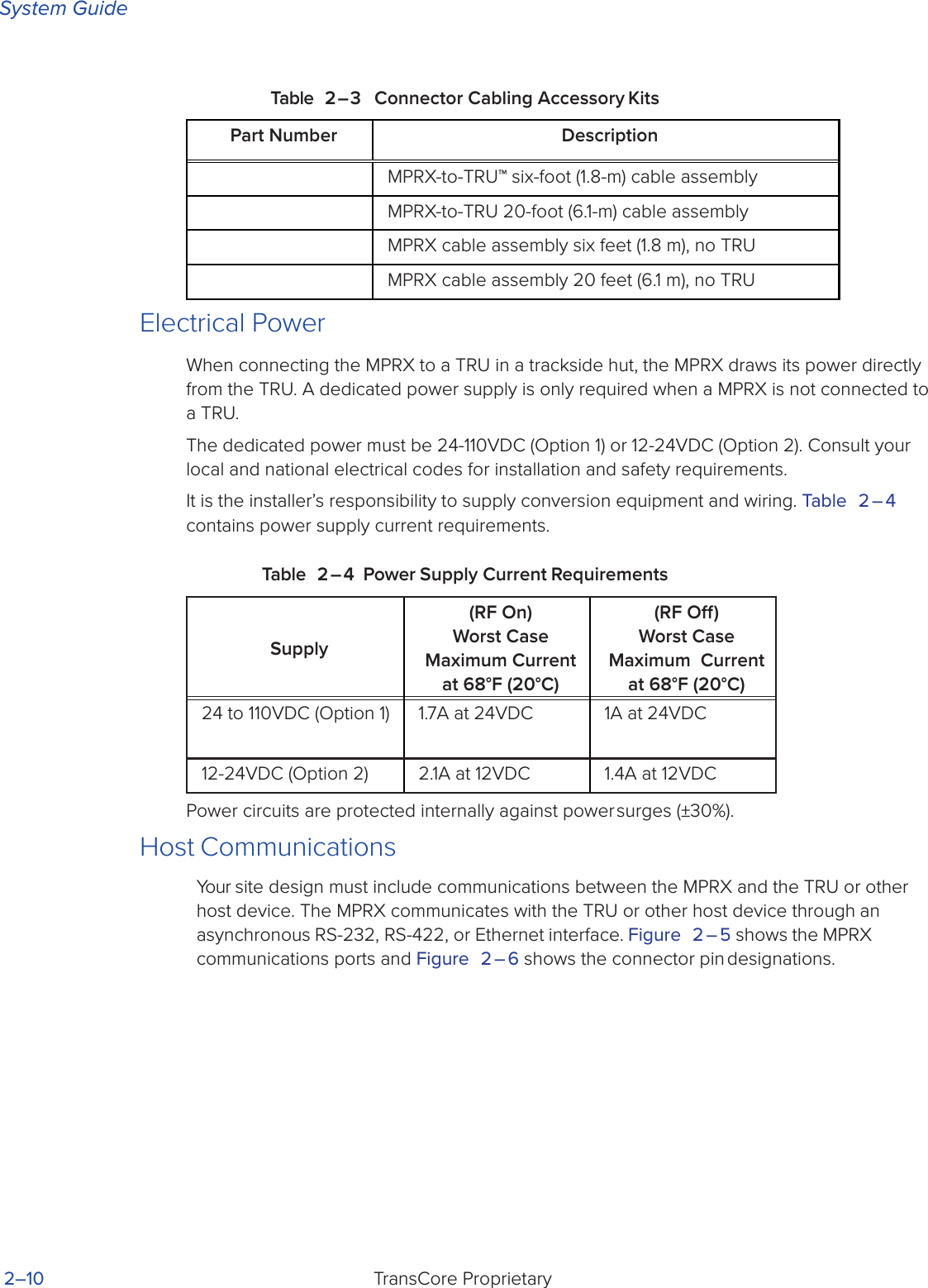
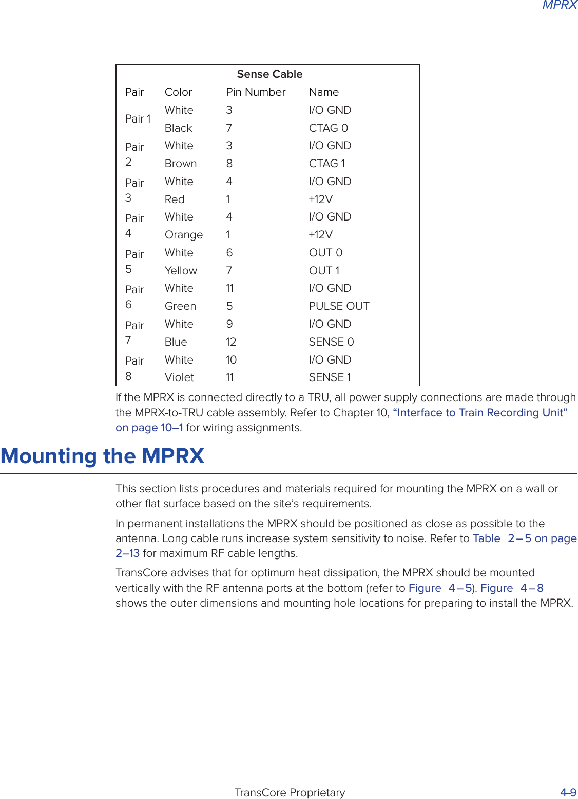
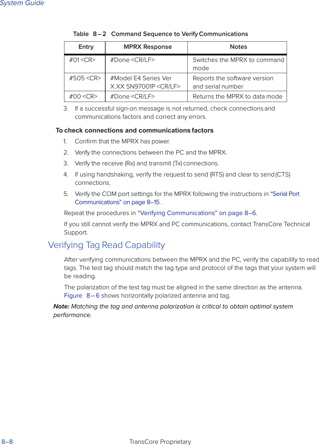
![System GuideTransCore ProprietaryC–4Table C – 3 lists the MPRX Sense Communications Cable Pin Designations. The interface cable is TransCore P/N (6-foot [1.8-m] cable assembly, no TRU) or (20-foot [6.1-m] cable assembly, no TRU).Table C – 3 MPRX SENSE Communications Cable Pin DesignationsSense CablePair Color Pin Number NamePair 1 White 3 I/O GNDBlack 7 CTAG 0Pair 2 White 3 I/O GNDBrown 8 CTAG 1Pair 3 White 4 I/O GNDRed 1 +12VPair 4 White 4 I/O GNDOrange 1 +12VPair 5 White 6 OUT 0Yellow 2 OUT 1Pair 6 White 11 I/O GNDGreen 5 PULSE OUTPair 7 White 9 I/O GNDBlue 12 SENSE 0Pair 8 White 10 I/O GNDViolet 11 SENSE 1](https://usermanual.wiki/TransCore/MPRX/User-Guide-3202352-Page-178.png)

![MPRXTransCore Proprietary D–5Number Command Name Reader Message440 Reset uniqueness Done441 Set uniqueness time-out to 2 minutesDone442 Set uniqueness time-out to 15 secondsDone443 Set uniqueness time-out to 30 secondsDone452 Disable tag translation mode Done453 Enable tag translation mode Done454 Disable multi-tag sort Done455 Enable multi-tag sort Done456 Enable SeGo protocol tag initialization during multi-tag sortDone457 Disable SeGo protocol tag initialization during multi-tag sortDone480 Disable ATA Done if MPRX model supports this tag protocol. Error if tag protocol is unsupported.481 Enable ATA Done if MPRX model supports this tag protocol. Error if tag protocol is unsupported.484 Disable SeGo Done if MPRX model supports this tag protocol. Error if tag protocol is unsupported.485 Enable SeGo Done if MPRX model supports this tag protocol. Error if tag protocol is unsupported.488 Disable eATA Done if MPRX model supports this tag protocol. Error if tag protocol is unsupported.489 Enable eATA Done if MPRX model supports this tag protocol. Error if tag protocol is unsupported.505 Display version Model [model]Ver [version no.] SN [serial no.]](https://usermanual.wiki/TransCore/MPRX/User-Guide-3202352-Page-183.png)
![MPRXTransCore Proprietary D–11Number Command Name Reader Message612FE Set ECP timeout = 12.7 sec Done613 Enable data inquiry protocol Done6140 Disable flow control Done6141 Enable software flow control Done6170 Disable echo Done6171 Enable echo Done63 Reset reader Model [model]Ver [version no.] SN [serial no.] Copyright [date]TransCore6400 Turn o RF Done6401 Turn on RF Done641 Select RF-by-input control Done642NN Select RF operating frequency Done643NN Set ATA operating range (distance) NN = 00 (shortest) to 1F (longest) 1F = defaultDone644NN Set RF attenuation NN = 00 to 0ADone645NN Set SeGo protocol operating range (distance)NN = 00 (shortest) to 1F (longest)Done647XXX Select RF operating frequency from 860 to 930 in 250 kHz stepsXXX = 000 - 118 (hexadecimal)Done65 Reset power fail bit Done](https://usermanual.wiki/TransCore/MPRX/User-Guide-3202352-Page-189.png)
![System GuideTransCore Proprietary D–20Command Name Code Reader MessageReader ID number set NN = 00-FF(00 = factory default)60NN DoneReader reset 63 Model [model]Ver [version no.] SN [serial no.] Copyright [date]TransCoreReport changes both 823 DoneRF attenuation set NN = 00 to 0A 644NN DoneRF o on timeout 6920 DoneRF o on timeout/no presence 6922 DoneRF o on timeout/tag 6921 DoneRF turn o 6400 DoneRF turn on 6401 DoneRF on by input control 641 DoneRF operating frequency from 860 to 930 in 250 kHz steps select XXX = 000 - 118 (hexadecimal)647XXX DoneRF operating frequency select 642NN Done](https://usermanual.wiki/TransCore/MPRX/User-Guide-3202352-Page-198.png)
![System GuideTransCore Proprietary D–24Command Name Code Reader MessageTag translation mode status display534 TT <0 to 1>0 = tag translation mode disabled1 = tag translation mode enabledTime and date appended 302 DoneTime and date display 22 Time and dateTime and date not appended 300 DoneTime set 20 DoneUniqueness reset 440 DoneUniqueness time-out set to 2 minutes441 DoneUniqueness time-out set to 15 seconds442 DoneUniqueness time-out set to 30 seconds443 DoneValid ID code select four 4203 DoneValid ID code select one 4200 DoneValid ID code select three 4202 DoneValid ID code select two 4201 DoneVersion display 505 Model [model]Ver [ver no.] SN [serial no.]](https://usermanual.wiki/TransCore/MPRX/User-Guide-3202352-Page-202.png)