Transact Campus LWI30XX001 2.4GHz TRANSCEIVER User Manual 1135 20050419 1041
Blackboard Inc. 2.4GHz TRANSCEIVER 1135 20050419 1041
UserManual.wiki
>
Transact Campus
>
LWI30XX001 User Manual
USERS MANUAL
Navigation menu
Upload a User Manual
Namespaces
Wiki Guide
HTML
PDF
Info
Views
User Manual
Discussion / Help
Navigation
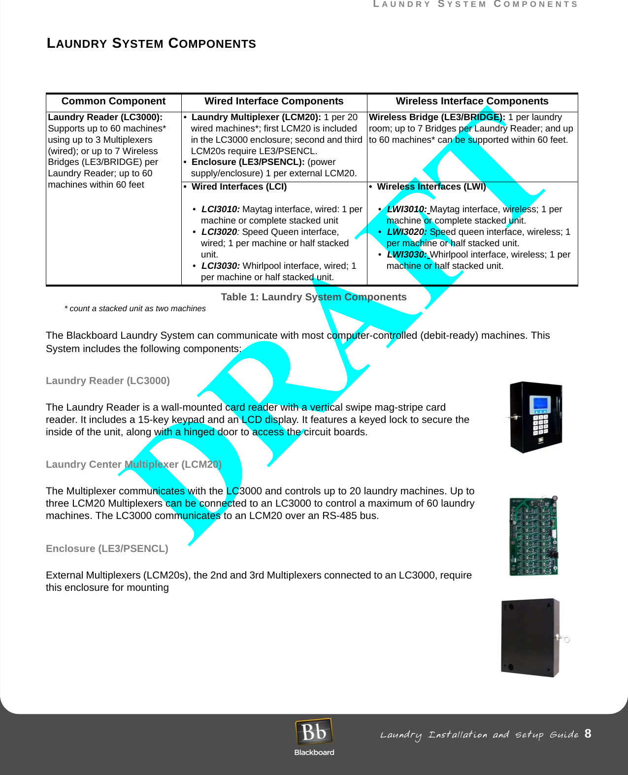
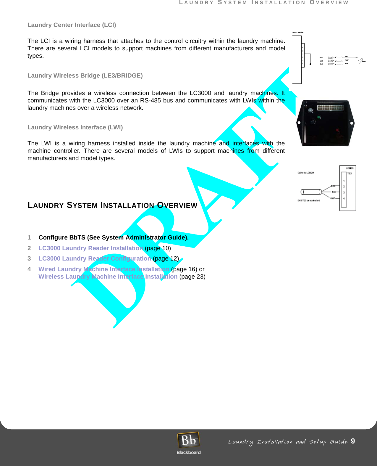
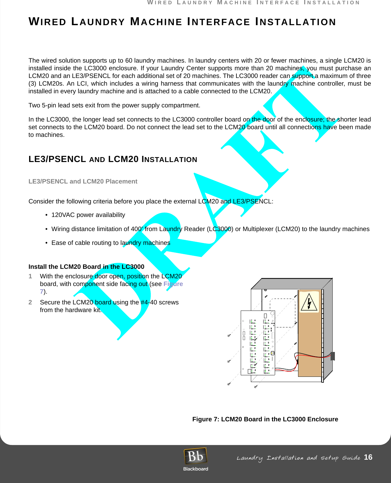
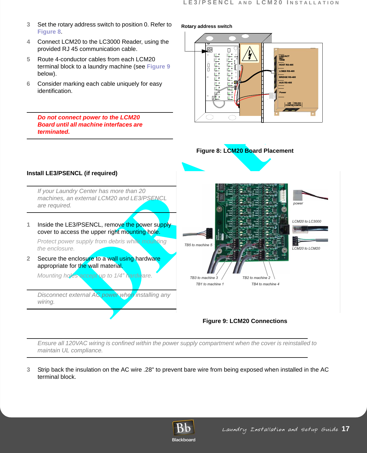
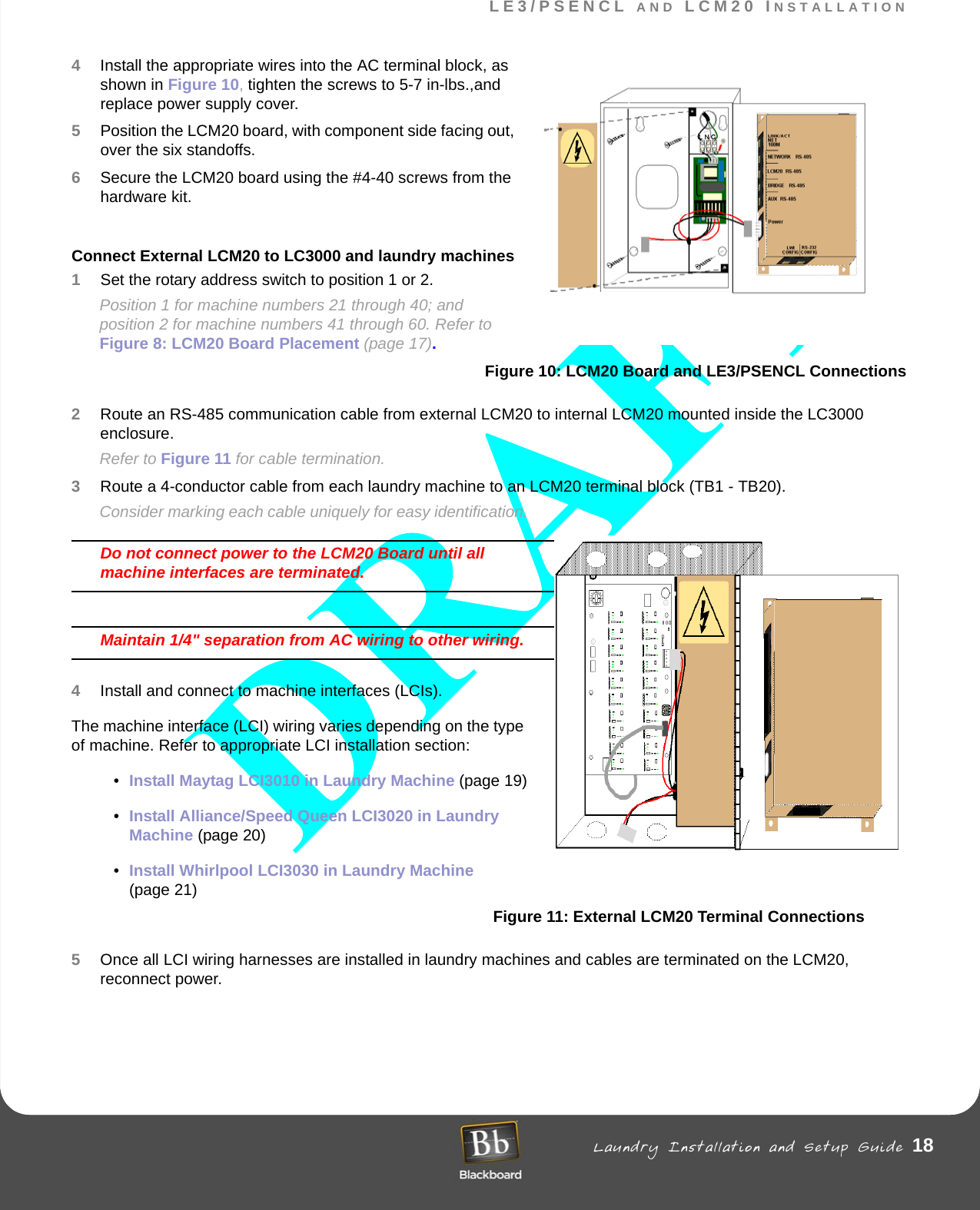
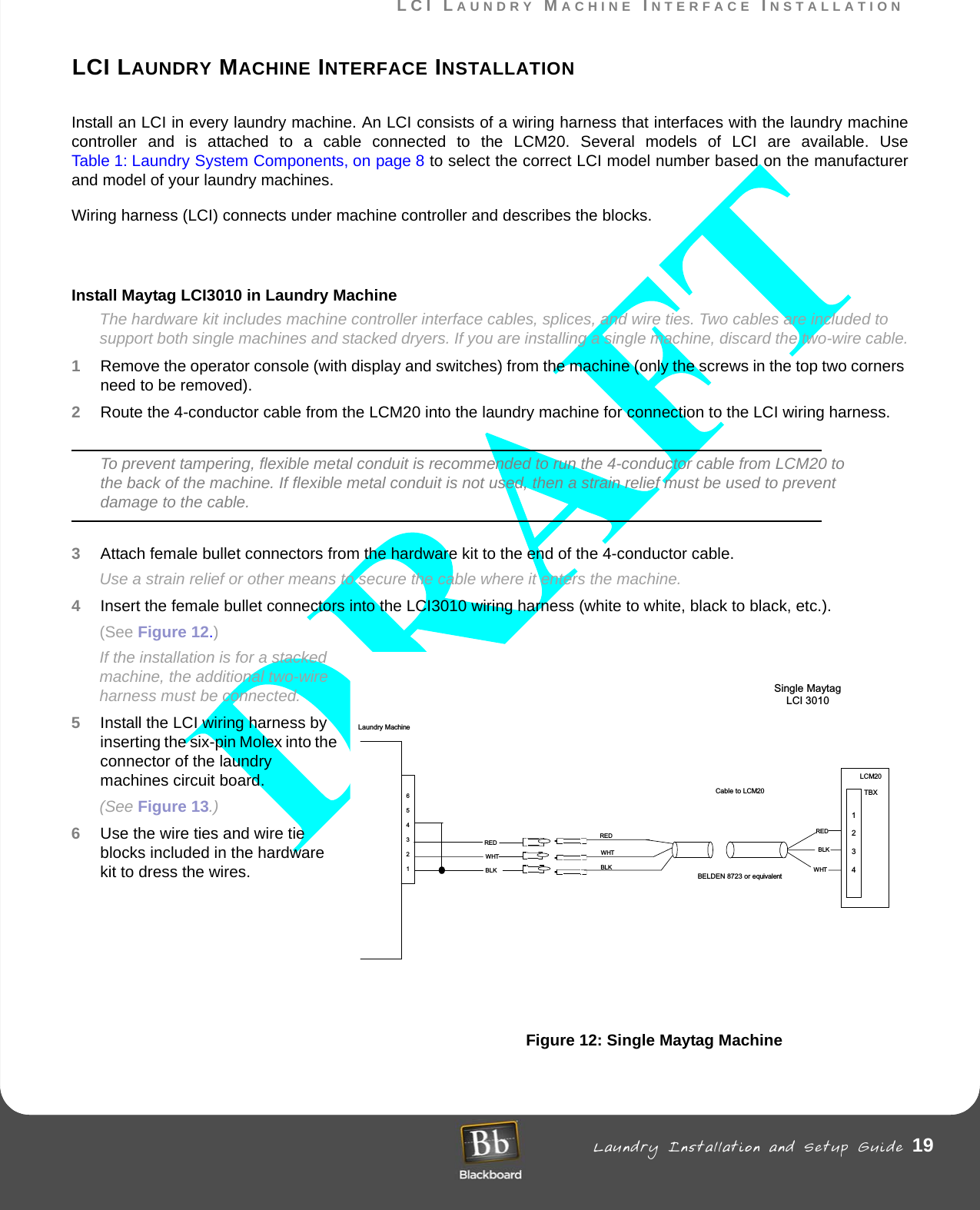
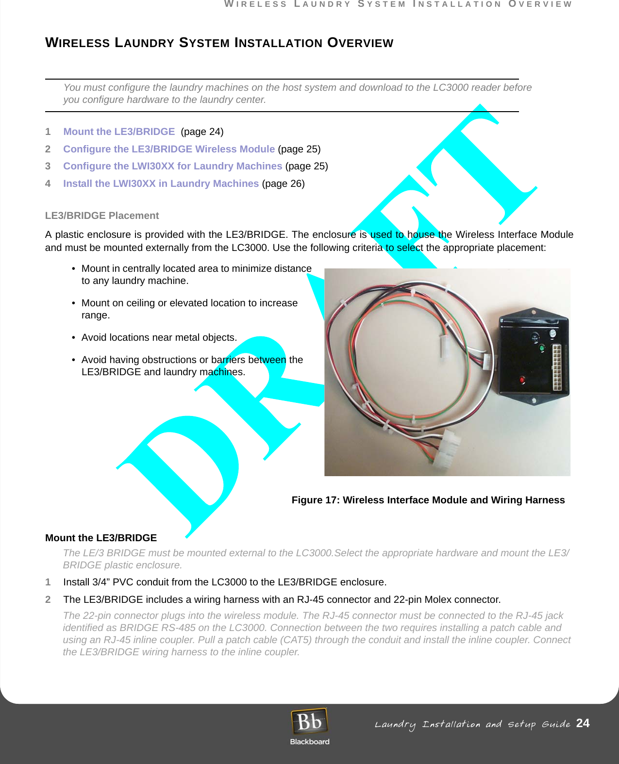
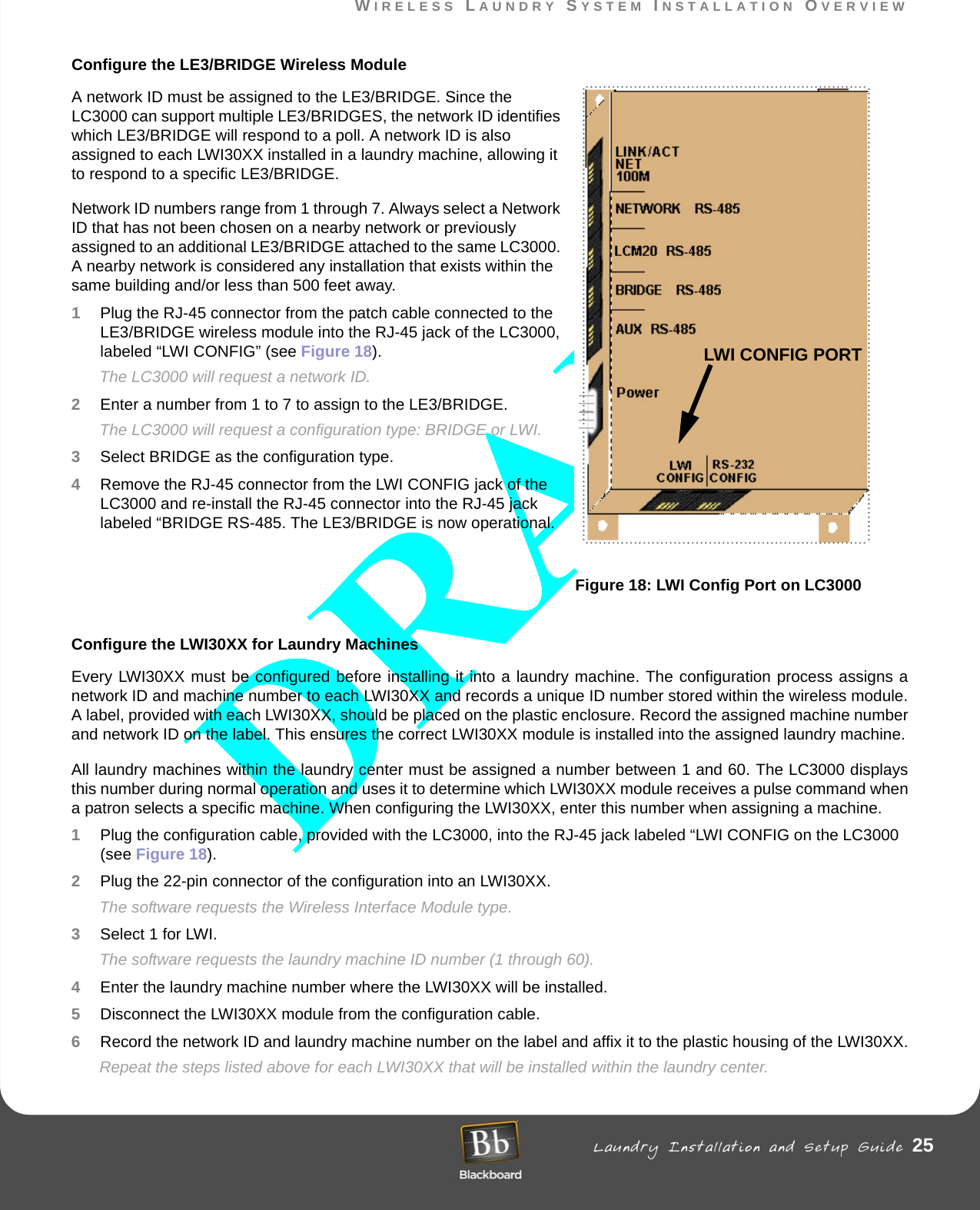
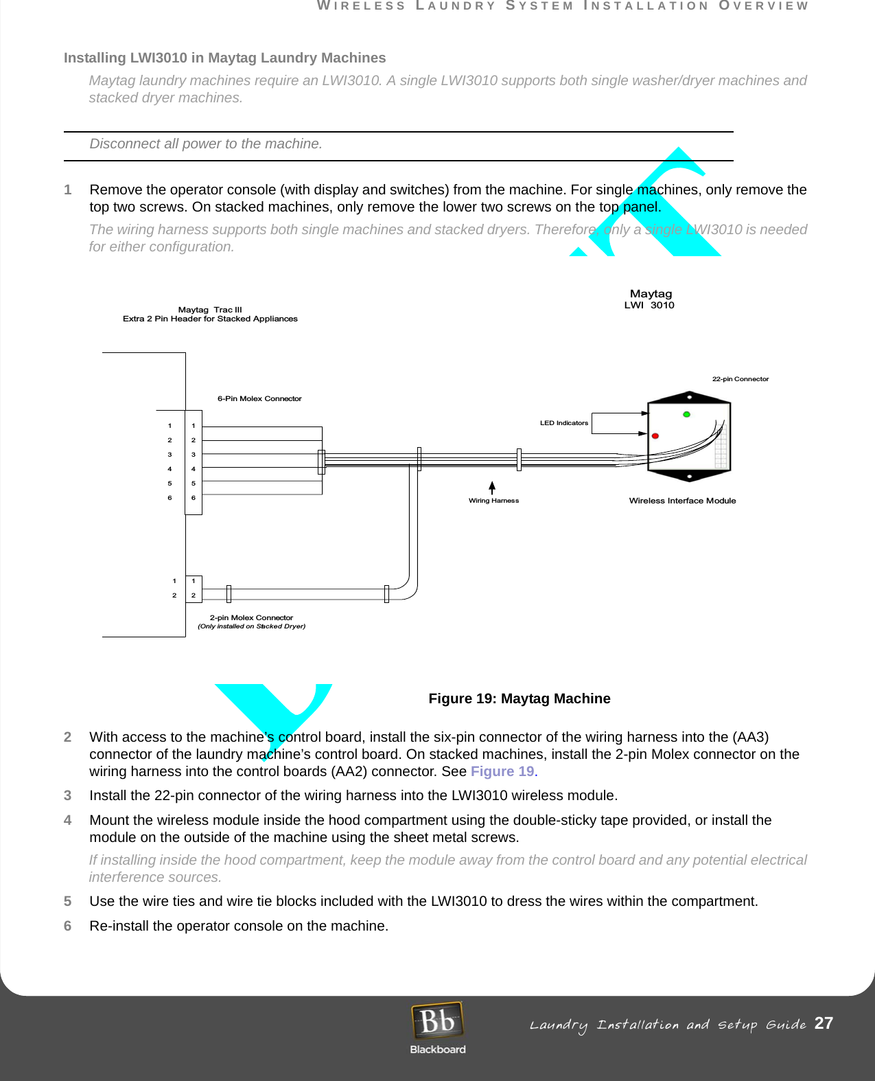
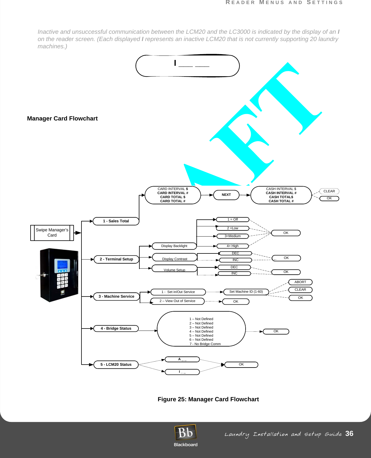
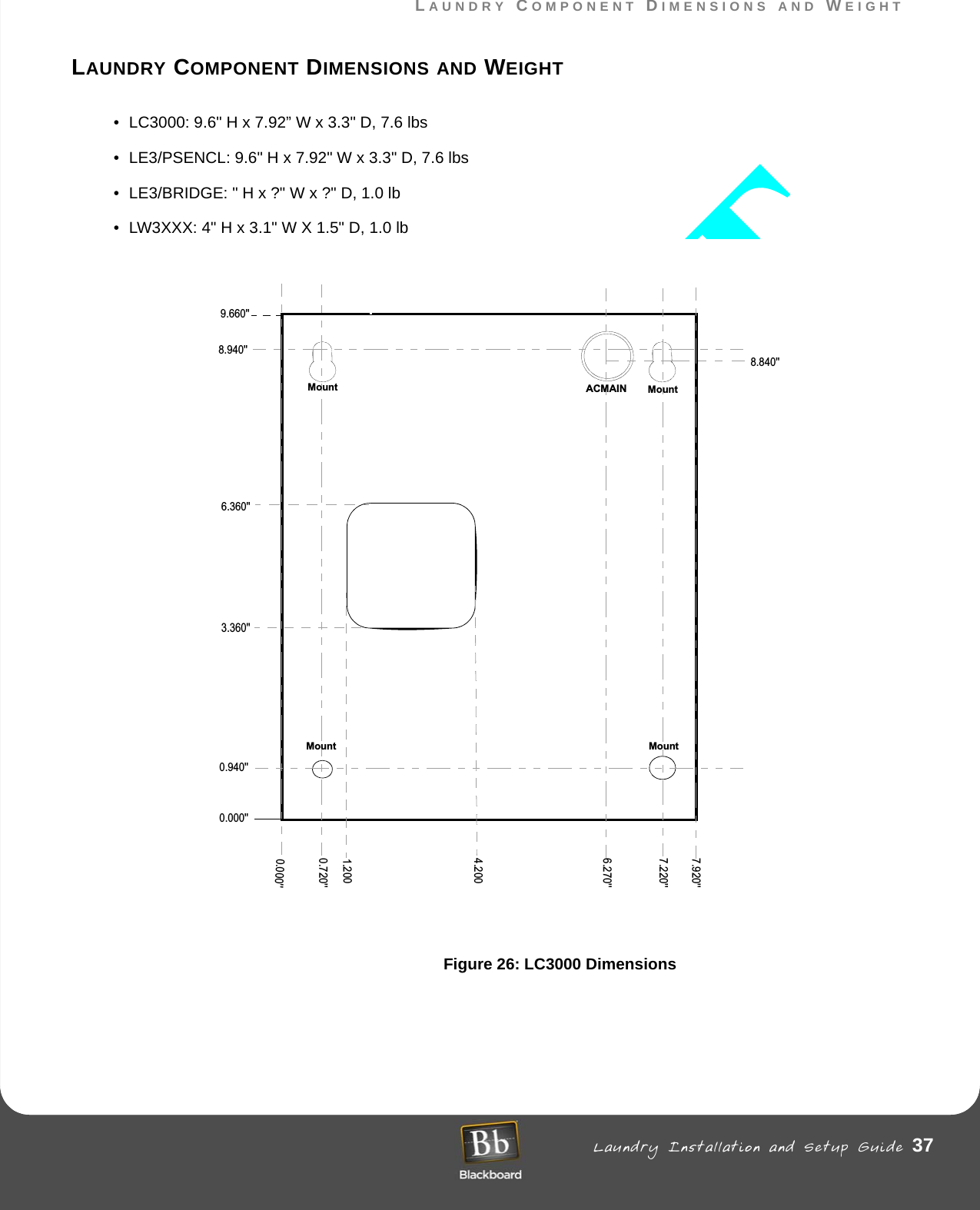
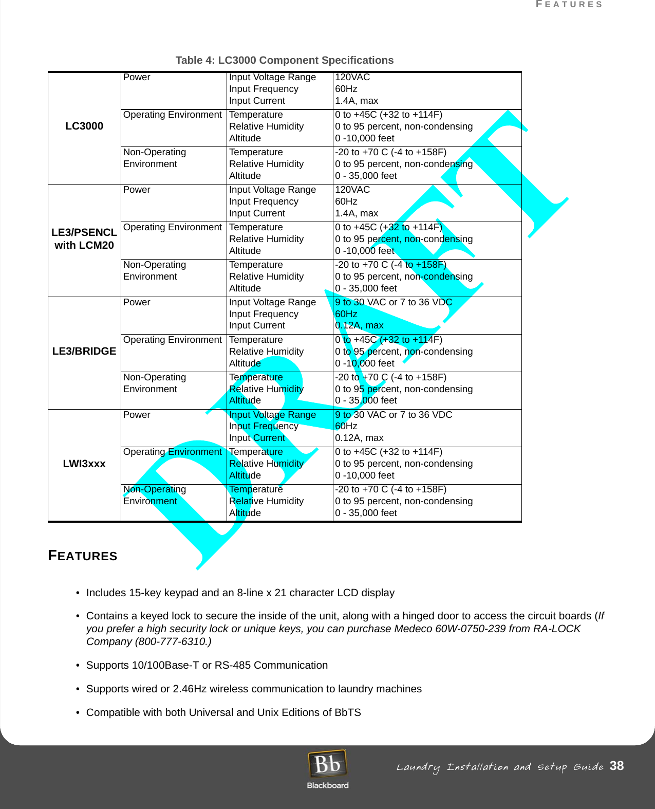
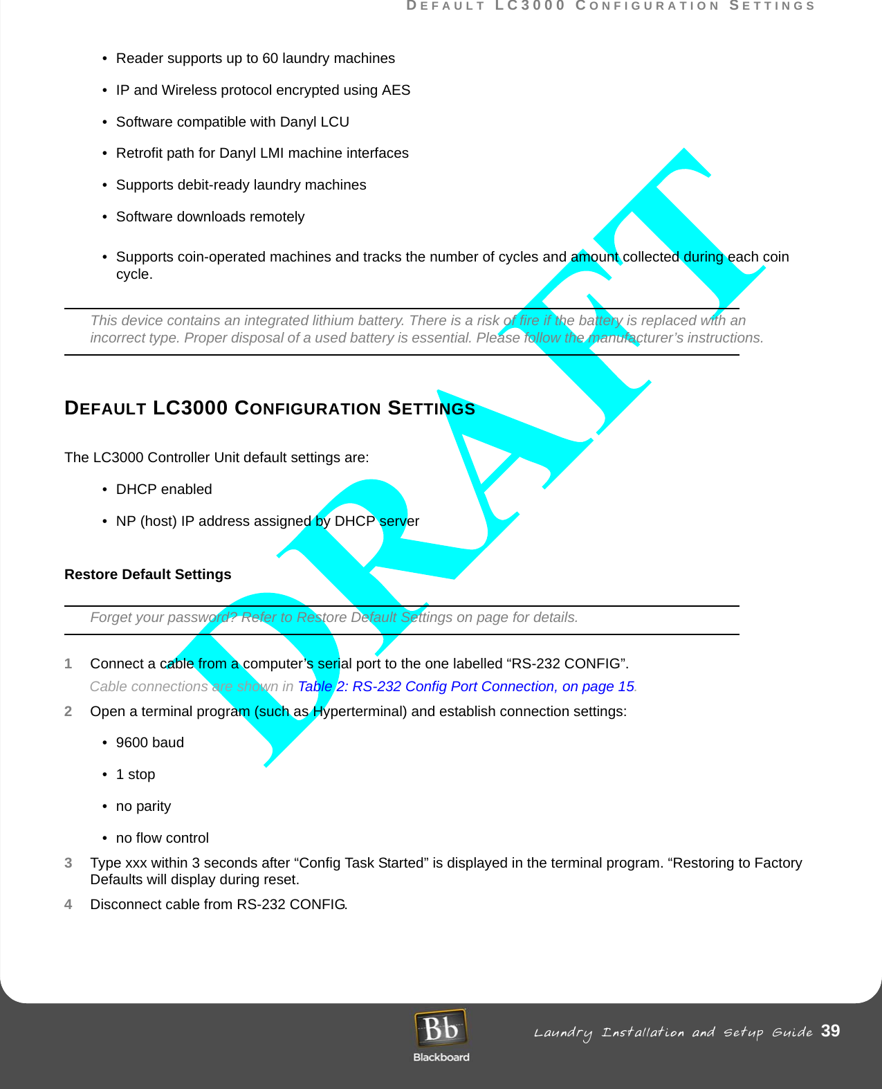
![RETROFITS Laundry Installation and Setup Guide 41RETROFITSRETROFITSMW9010/MW9012 LCR Retrofits (For Wired Laundry Centers only)If you have an existing system equipped with an MW9010/MW9012 laundry reader, you will need to have retrofits installed. The LC3000 can communicate with laundry machines through LCM2, LCM20, and LWI and is intended to support retrofit or new installations. This support is managed locally by the LC3000.The LC3000, as shipped from Blackboard, is configured for up to 60 machines on up to 3 LCM20s. If LCM2 support is required, it may be changed in the reader with the “machine” command. This command can be used either from the RS-232 CONFIG or using Telnet.Each of the 60 machines can reside on an LCM2, LCM20, or LWI. The machine command usage is as follows:machine [machine number] [lcm2|1cm20]To change machine 5 from LCM20 to a LCM2, type the following:machine 5 lcm2In addition, all machines can be changed simultaneously from one interface to another. For example:machine alllcm20 machine alllcm2By typing “machines”, you list all the machine interfaces for all 60 machines.Each LWI or Wireless Bridge is not required to use this machine command. When the LC3000 updates the local machine definition, they are also configured with the LWI Config.The local machine interface definitions permanently remain within the reader and are not affected by any other command.Danyl Retrofits](https://usermanual.wiki/Transact-Campus/LWI30XX001/User-Guide-590377-Page-41.png)