Transact Campus LWI30XX001 2.4GHz TRANSCEIVER User Manual 1135 20050419 1041
Blackboard Inc. 2.4GHz TRANSCEIVER 1135 20050419 1041
USERS MANUAL

LC3000 Laundry System
Installation and Setup Guide

Copyright © 2005 Blackboard Inc.® All rights reserved. No part of this publication may be reproduced or used
in any form or by any means—graphic, electronic, or mechanical including photocopying, recording, taping, or
information storage and retrieval systems—without the express written permission of Blackboard Inc.
Information contained in this document is subject to change without notice.
The following information applies to wired LC3000 systems equipped with LCM20s only.
The following information applies to wireless systems equipped with LWIs and LE3/BRIDGES only.
This device complies with Part 15 of the FCC Rules. Operation is subject to the following two conditions: (1) This
device may not cause harmful interference, and (2) this device must accept any interference received, including
interference that may cause undesired operation.
Part 15.21: Changes or modifications not expressly approved by the party responsible for compliance could void the user’s
authority to operate the equipment.
NOTE: The manufacturer is not responsible for any radio or TV interference caused by unauthorized modifications to this
equipment. Such modifications could void the user’s authority to operate the equipment.
Blackboard Inc. LC3000
Tested To Comply
With FCC Standards
FOR HOME OR OFFICE USE
This Class A digital apparatus complies with
Canadian ICES-003
Date: 9-9-05 Doc. No.: 1135

TABLE OF CONTENTS
Laundry Installation and Setup Guide 3
TABLE OF CONTENTS
TABLE OF CONTENTS
5OVERVIEW
8 Laundry System Components
9 Laundry System Installation Overview
10 INSTALL AND CONFIGURE LC3000
10 LC3000 Laundry Reader Installation
11 Install the LC3000 Enclosure
12 LC3000 Laundry Reader Configuration
14 Configure LC3000 Reader Using Front Panel Keyboard
14 Configure LC3000 Reader Using RS-232
15 Configure LC3000 Reader Using Telnet
16 WIRED LAUNDRY MACHINE INTERFACE INSTALLATION
16 LE3/PSENCL and LCM20 Installation
16 Install the LCM20 Board in the LC3000
17 Install LE3/PSENCL (if required)
18 Connect External LCM20 to LC3000 and laundry machines
19 LCI Laundry Machine Interface Installation
19 Install Maytag LCI3010 in Laundry Machine
20 Install Alliance/Speed Queen LCI3020 in Laundry Machine
21 Install Whirlpool LCI3030 in Laundry Machine
23 WIRELESS LAUNDRY MACHINE INTERFACE INSTALLATION
24 Wireless Laundry System Installation Overview
24 Mount the LE3/BRIDGE
25 Configure the LE3/BRIDGE Wireless Module
25 Configure the LWI30XX for Laundry Machines
26 Install the LWI30XX in Laundry Machines
31 APPENDIX
31 Reader Operations
31 Laundry Reader Usage
34 Reader Menus and Settings
34 Manager Card
38 Laundry Component Dimensions and Weight
39 Features

TABLE OF CONTENTS
Laundry Installation and Setup Guide 4
TABLE OF CONTENTS
40 Default LC3000 Configuration Settings
40 Restore Default Settings
41 Error Messages (Unix only)
41 Error Messages (windows only)
42 Retrofits
42 MW9010/MW9012 LCR Retrofits (For Wired Laundry Centers only)
42 Danyl Retrofits
42 LC3000 Drill Template

OVERVIEW
Laundry Installation and Setup Guide 5
OVERVIEW
OVERVIEW
This manual provides instructions for selecting, installing, and configuring the Blackboard Laundry System, using the LC3000
Laundry Reader. Recommendations on selecting an installation location are included. Wiring diagrams show you how to con-
nect the LC3000 Laundry System.
The LC3000 Laundry Reader activates and monitors washers and dryers across a laundry center network. The
LC3000 is designed to work with the Blackboard Transaction System (BbTS) and provides user interface through a
display, keypad, and mag-stripe reader. The network connections are 10/100 Base-T or RS-485.
The LC3000 supports new installations for wired or wireless laundry centers. Information for retrofits is available in the
“Appendix” on page 31.
OVERVIEW
Laundry Installation and Setup Guide 6
OVERVIEW
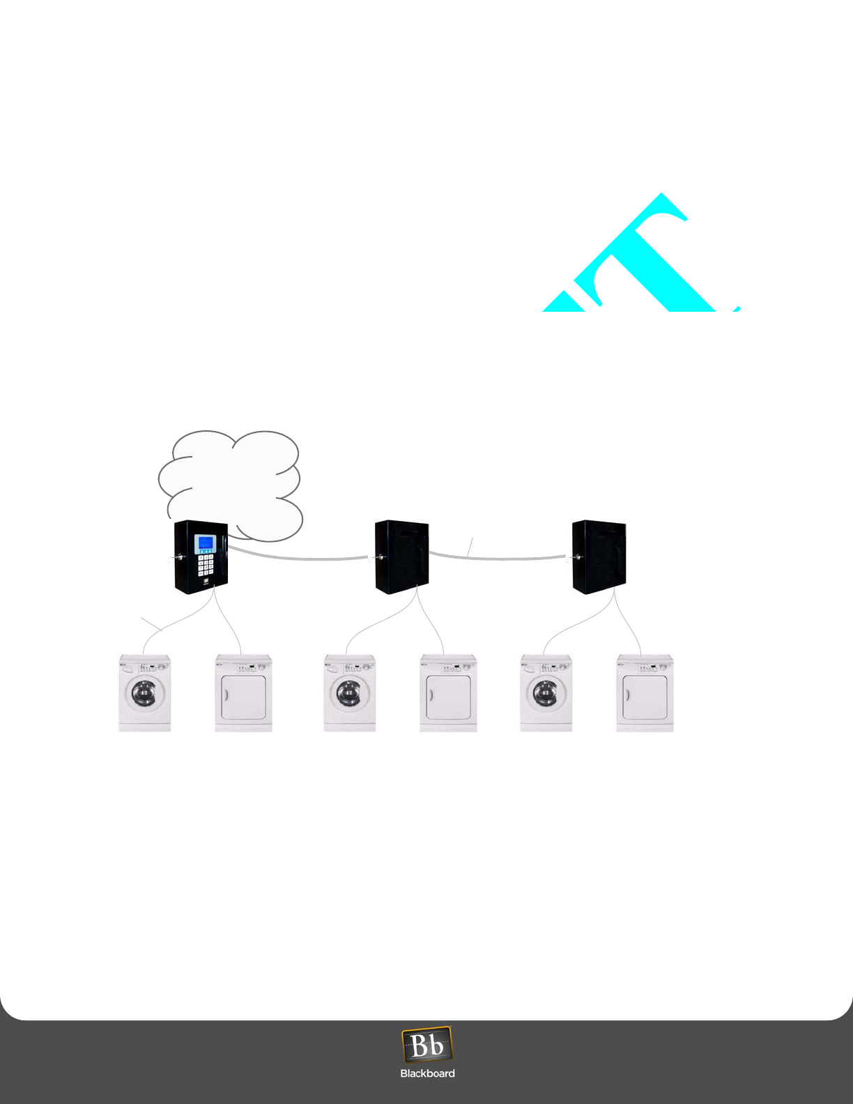
Wired Solution
The wired solution supports up to 60 laundry machines (see Figure 1 below). In laundry centers with 20 or fewer
machines, you only need a single LCM20, which is installed inside the LC3000 enclosure. If your laundry center
supports more than 20 machines, a multiplexer (an LCM20) and an enclosure (LE3/PSENCL) are needed for each
additional set of 20 laundry machines. The LC3000 reader can support a maximum of three (3) multiplexers.
A machine interface (an LCI), which is a wiring harness that communicates with the laundry machine controller, is
connected to a cable within a multiplexer (LCM20). This machine interface must be installed in every laundry machine
to facilitate communication between the laundry machines and the LC3000 laundry reader unit. Several models of
machine interfaces are available. Use Table 1 (on page 8) to determine the correct machine interface (LCI) model
number, based on the manufacturer and model of your laundry machines.
Figure 1: Wired Laundry Center Solution
Campus
Network
Laundry Reader
(LC3000)
w/
Multiplexer
(LMC20)
Multiplexer
(LCM20)
w/
Enclosure
(LE3/PSENCL)
Multiplexer
(LCM20)
w/
Enclosure
(LE3/PSENCL)
Belden 5502UE cable
or equivilant
4-conductor cable
Laundry Center Interface
(LCI)
installed in each machine
1 ---------------------- 20 21 -------------------- 40 41 -------------------- 60
(400’ max)
OVERVIEW
Laundry Installation and Setup Guide 7
OVERVIEW
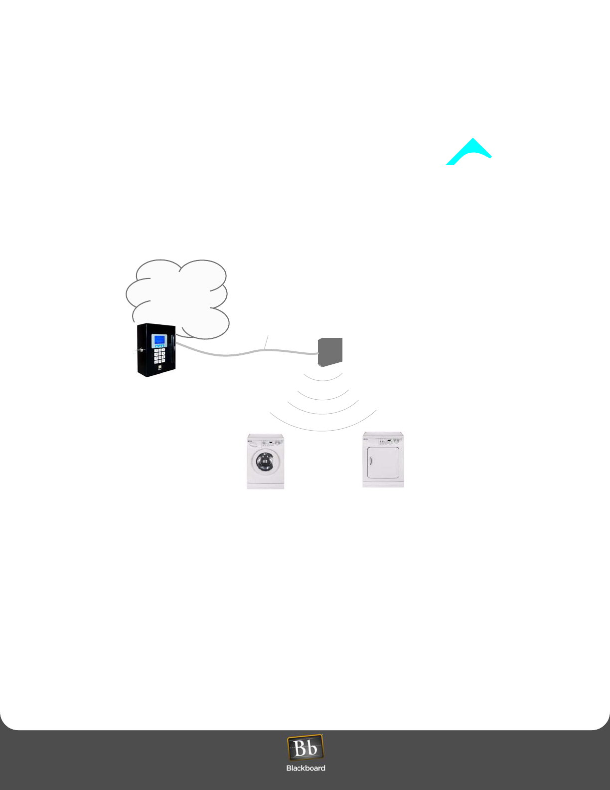
Wireless Solution
The wireless solution supports up to 60 laundry machines, using a wireless bridge (LE3/BRIDGE). See Figure 2 below.
A laundry wireless interface (LWI) must be installed in every laundry machine to facilitate communication between the
laundry machines and the LC3000 Laundry Reader. The LWI includes a Wireless Interface Module and a wiring
harness. Several models of LWIs are available. Use Table 1 (on page 8) to select the correct LWI model number based
on the manufacturer and model of your laundry machines.
Figure 2: Wireless Laundry Center Solution
Campus
Network
Laundry Reader
(LC3000)
(machines 1 - 60)
Belden 5502UE cable
or equivilant
Laundry Wireless Interface
(LWI)
installed in each machine
Wireless Bridge
(LE3/BRIDGE)
(60 feet)
1 ------------------------------------------ 60
LAUNDRY SYSTEM COMPONENTS
Laundry Installation and Setup Guide 8
LAUNDRY SYSTEM COMPONENTS
LAUNDRY SYSTEM COMPONENTS
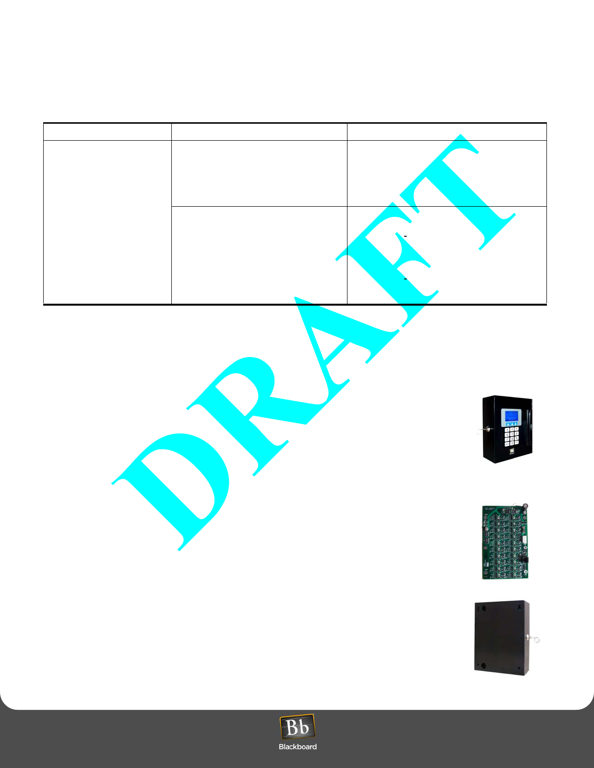
Table 1: Laundry System Components
* count a stacked unit as two machines
The Blackboard Laundry System can communicate with most computer-controlled (debit-ready) machines. This
System includes the following components:
Laundry Reader (LC3000)
The Laundry Reader is a wall-mounted card reader with a vertical swipe mag-stripe card
reader. It includes a 15-key keypad and an LCD display. It features a keyed lock to secure the
inside of the unit, along with a hinged door to access the circuit boards.
Laundry Center Multiplexer (LCM20)
The Multiplexer communicates with the LC3000 and controls up to 20 laundry machines. Up to
three LCM20 Multiplexers can be connected to an LC3000 to control a maximum of 60 laundry
machines. The LC3000 communicates to an LCM20 over an RS-485 bus.
Enclosure (LE3/PSENCL)
External Multiplexers (LCM20s), the 2nd and 3rd Multiplexers connected to an LC3000, require
this enclosure for mounting
Common Component Wired Interface Components Wireless Interface Components
Laundry Reader (LC3000):
Supports up to 60 machines*
using up to 3 Multiplexers
(wired); or up to 7 Wireless
Bridges (LE3/BRIDGE) per
Laundry Reader; up to 60
machines within 60 feet
•Laundry Multiplexer (LCM20): 1 per 20
wired machines*; first LCM20 is included
in the LC3000 enclosure; second and third
LCM20s require LE3/PSENCL.
•Enclosure (LE3/PSENCL): (power
supply/enclosure) 1 per external LCM20.
Wireless Bridge (LE3/BRIDGE): 1 per laundry
room; up to 7 Bridges per Laundry Reader; and up
to 60 machines* can be supported within 60 feet.
• Wired Interfaces (LCI)
•LCI3010: Maytag interface, wired: 1 per
machine or complete stacked unit
•LCI3020: Speed Queen interface,
wired; 1 per machine or half stacked
unit.
•LCI3030: Whirlpool interface, wired; 1
per machine or half stacked unit.
• Wireless Interfaces (LWI)
•LWI3010: Maytag interface, wireless; 1 per
machine or complete stacked unit.
•LWI3020: Speed queen interface, wireless; 1
per machine or half stacked unit.
•LWI3030: Whirlpool interface, wireless; 1 per
machine or half stacked unit.
LAUNDRY SYSTEM INSTALLATION OVERVIEW
Laundry Installation and Setup Guide 9
LAUNDRY SYSTEM INSTALLATION OVERVIEW
Laundry Center Interface (LCI)
The LCI is a wiring harness that attaches to the control circuitry within the laundry machine.
There are several LCI models to support machines from different manufacturers and model
types.
Laundry Wireless Bridge (LE3/BRIDGE)
The Bridge provides a wireless connection between the LC3000 and laundry machines. It
communicates with the LC3000 over an RS-485 bus and communicates with LWIs within the
laundry machines over a wireless network.
Laundry Wireless Interface (LWI)
The LWI is a wiring harness installed inside the laundry machine and interfaces with the
machine controller. There are several models of LWIs to support machines from different
manufacturers and model types.
LAUNDRY SYSTEM INSTALLATION OVERVIEW
1Configure BbTS (See System Administrator Guide).
2LC3000 Laundry Reader Installation (page 10)
3LC3000 Laundry Reader Configuration (page 12)
4Wired Laundry Machine Interface Installation (page 16) or
Wireless Laundry Machine Interface Installation (page 23)
6
5
4
3
2
1
RED
WHT
BLK
Laundry Machine
RED
WHT
BLK

INSTALL AND CONFIGURE LC3000
Laundry Installation and Setup Guide 10
INSTALL AND CONFIGURE LC3000
INSTALL AND CONFIGURE LC3000
LC3000 LAUNDRY READER INSTALLATION
Select a mounting method based on the application and the network mode of the reader. The LC3000 enclosure is
designed to mount on a wall: it can be flush-mounted (wiring can come from the interior of the wall); or it can be
surface-mounted (wiring can run through conduit on the exterior of the wall).
LC3000 Mounting Location Considerations
Use the following criteria to select the best mounting location for the LC3000:
Connect to 120 VAC @ 60 Hz. Connect only to a 15A maximum branch circuit protection or equivalent.
Use a circuit breaker or switch to disconnect power when installing or removing the LC3000.
• 120VAC power availability
• Network communications availability (RS-485 or 10/100 Base T)
• Wiring distance limitations
RS-485 Communications 4000' total per loop
10/100 Base-T Communications 300'
• Ease of cable routing to Laundry machines (if wired configuration)
• Installation height regulations
Mounting Requirements
Mounting hardware, .25” appropriate to surface.
LC3000 LAUNDRY READER INSTALLATION
Laundry Installation and Setup Guide 11
LC3000 LAUNDRY READER INSTALLATION
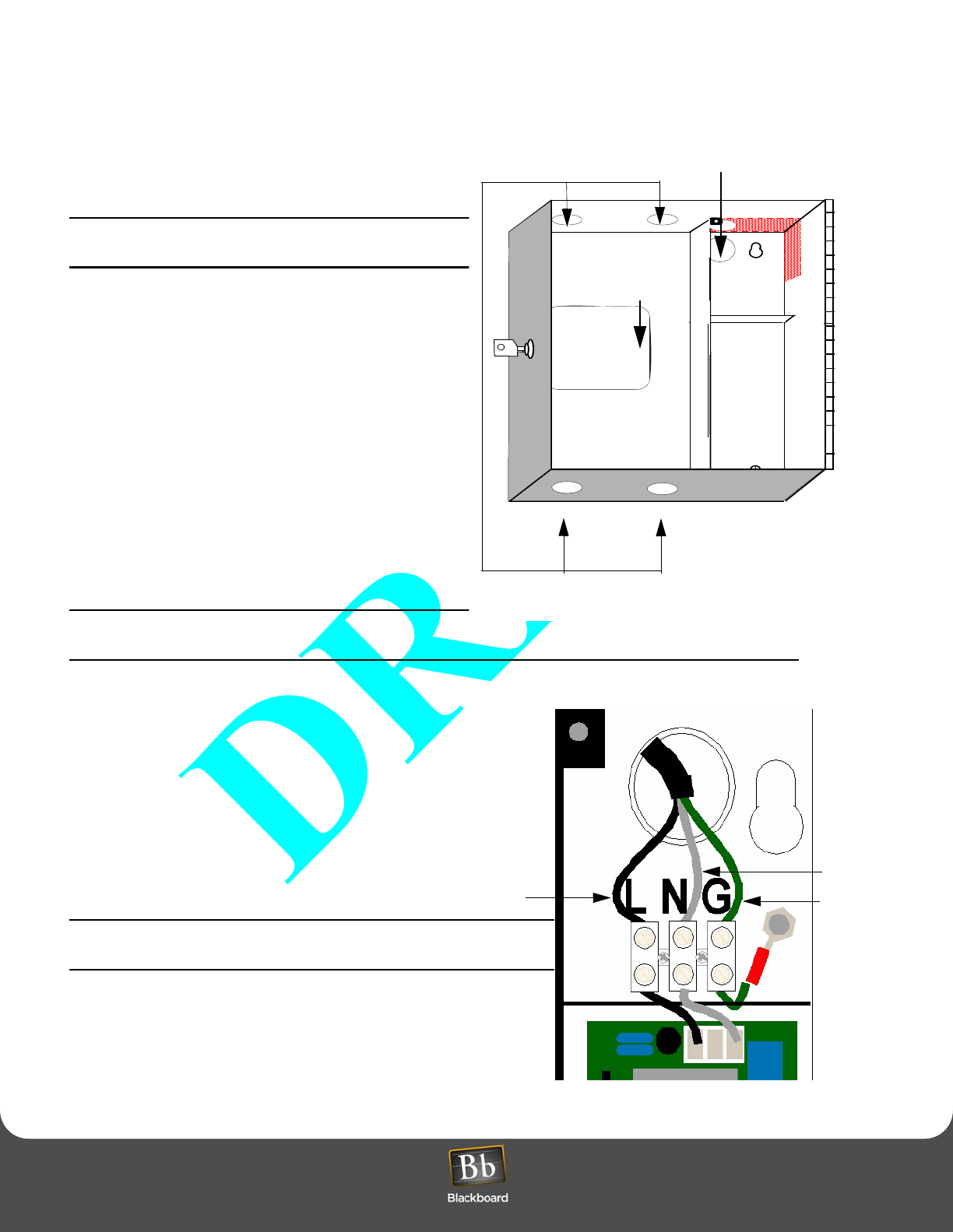
Preparing the Enclosure
Before mounting the enclosure, remove all
necessary knockouts to route wires and/or attach
conduits.
Remove only the knockouts required for your
installation.
• All knockouts are dimensioned for 1/2” conduit
fittings.
Flush-mounted enclosure: If installing a wired
laundry center, route machine wires through the
“3x3” cutout.
Surface-mounted enclosure: Remove conduit
knockouts, located on the top and bottom of the
enclosure, to route wire to the laundry machines.
• The enclosure provides two knockouts, in the upper
right, for power.
Flush-mounted enclosure: Remove the knockout
on the back side.
Surface-mounted enclosure: Remove the
knockout on the top.
Maintain 1/4" separation from AC wiring to other
wiring.
Install the LC3000 Enclosure
1Inside the LC3000, remove the power supply cover
to access the upper right mounting hole.
Protect power supply from debris while mounting the
enclosure.
2Secure the enclosure to a wall using hardware
appropriate for the wall material.
Mounting holes accept up to 1/4” hardware.
Disconnect external AC power when installing any
wiring.
Figure 4: Power Supply Installation
ACMAIN
Mount Mount
Flush-mount
“3x3” cutout
Figure 3: Knockout areas
Surface-mount knockouts
AC Main Power
Line Ground
Neutral

LC3000 LAUNDRY READER CONFIGURATION
Laundry Installation and Setup Guide 12
LC3000 LAUNDRY READER CONFIGURATION
3Strip back the insulation on the AC wire .28" to prevent bare wire from being exposed when installed in the AC
terminal block.
4Install the appropriate wires into the AC terminal block, as shown in Figure 4, tighten the screws to 5 - 7 in-lbs., and
replace power supply cover.
Ensure all 120VAC wiring is confined within the power supply compartment when the cover is reinstalled to
maintain UL compliance.
5Reconnect external AC power.
Maintain 1/4" separation from AC wiring to other wiring.
6Connect to Network.
The LC3000 board provides both 10/100 Base-T TCP/IP and RS-485 network connections for communications
with the BbTS (NP, Network Processor). Select a connection based on the local network.
Once you connect the LC3000 to the network, configure the LC3000 for the network. Refer to the LC3000
Laundry Reader Configuration (page 13) for details on configuring the unit.
LC3000 LAUNDRY READER CONFIGURATION
Configuration Methods
The Laundry Reader must be configured to interface with the BbTS network. Configure the Reader using either the
front panel of the Reader or the configuration port (see Figure 5: LC3000 Laundry Reader Configuration (page 13).
Future configuration modifications can be one using Telnet, if enabled.
Default Settings
The LC3000 Controller Unit default settings are:
• DHCP enabled
• NP (host) IP address assigned by DHCP server
Configure the LC3000 Laundry Reader to interface with BbTS, using one of three modes:
•Front Panel Keyboard
•Config Port - provides for RS-232 connection to a computer with Hyperterminal software
•Telnet via IP if using Ethernet connections
LC3000 LAUNDRY READER CONFIGURATION
Laundry Installation and Setup Guide 13
LC3000 LAUNDRY READER CONFIGURATION
Figure 5: LC3000 Laundry Reader Configuration
LC3000Config
MAC Address
IP Address
DHCP Status
Communication
Mode
DHCP
Reader Address Baud Rate
RS-485 Communications
I P C o m m u n i c a t i o n s
IP Address
Subnet Mask
Default Router/
Gateway Host IP Address
Disabled
Enabled
Host DHCP Telnet Enable Service Card
Enable
Save
Disable
LC3000 LAUNDRY READER CONFIGURATION
Laundry Installation and Setup Guide 14
LC3000 LAUNDRY READER CONFIGURATION
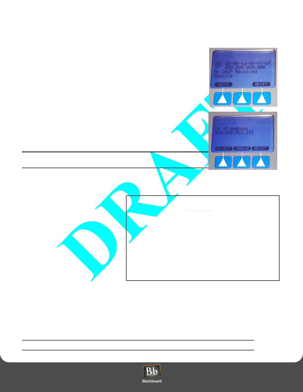
Configure LC3000 Reader Using Front Panel Keyboard
1Swipe the specially encoded service card and press the NEXT key on the
terminal to start the configuration process.
2Adjust each of the setup parameters, as appropriate, using the keys displayed
on the Terminal.
•ACCEPT - Accept displayed value and advance to next setting.
•CHANGE - Change displayed value.
•ABORT - Abort configuration process.
To update the IP address and related information, press the CHANGE key
when the parameter is displayed; then type in the number using zeroes (0) as
placeholders.
3Press SAVE when prompted to save the new settings and reboot the terminal.
The terminal may be offline for several minutes until it resynchornizes with the
Host.
An asterisk (*) displayed in the second to the last position of the first line
indicates the terminal is offline.
Figure 6: Front panel configuration menus
Configure LC3000 Reader Using RS-232
1Connect a cable from a computer’s serial
port to labelled “RS-232 CONFIG”.
Cable connections are shown in Table 2.
2Open a terminal program (such as
Hyperterminal) and establish connection
settings:
• 9600 baud
•1 stop
• no parity
• no flow control
3Log in using the default password:
IPrdr4U.
The password is case sensitive. Consider
changing the password.
4At the prompt, type the following command and press Enter to start configuration:
config to configure the LC3000. Refer to Figure 5: LC3000 Laundry Reader Configuration (page 13), LC3000
Laundry Reader Configuration.
5Disconnect cable from RS-232 CONFIG.
Other commands are available on the menu (see Figure 7).
Blackboard LC3000 Configuration
Enter Password > *******
LC3000
Command Reference -
config - Configure master controller parameters
showconfig - Display master controller parameters
door - Configure door controller parameters
showdoor - Display door controller parameters
status - Display reader status
ping <ip_addr> - Ping another IP device
netstats - Display network statistics
netclear - Clear network statistics counters
password - Change config utility password
ipreboot - Reboot reader
exit - Log out of session
Type command, followed by 'Enter' key >
Figure 7: Controller Configuration Menu
IPrdr4U

LC3000 LAUNDRY READER CONFIGURATION
Laundry Installation and Setup Guide 15
LC3000 LAUNDRY READER CONFIGURATION
Configure LC3000 Reader Using Telnet
1Open a Telnet session to the LC3000 Reader’s IP address.
2Log in using the default password: IPrdr4U.
The password is case sensitive. Consider changing the password.
3At the prompt, type the following command and press Enter to start configuration:
config to configure the LC3000. Refer to Figure 5: LC3000 Laundry Reader Configuration (page 13),LC3000
Laundry Reader Configuration.
Other available commands are displayed on the menu (see Figure 7 on page 14).
Forget your password? Refer to Restore Default Settings on page for details.
Now, you are ready to install the machine interface components. Based on your network selection, refer to one of the
following sections:
•Wired Laundry Machine Interface Installation (page 16)
•Wireless Laundry Machine Interface Installation (page 23)
Table 2: RS-232 Config Port Connection
LC3000 Reader (RJ-12) PC Serial Port
DB9 Connector Signal
Pin 1 Pin 5 Ground
Pin 3 Pin 3 Receive (RX)
Pin 4 Pin 2 Transmit (TX)

WIRED LAUNDRY MACHINE INTERFACE INSTALLATION
Laundry Installation and Setup Guide 16
WIRED LAUNDRY MACHINE INTERFACE INSTALLATION
WIRED LAUNDRY MACHINE INTERFACE INSTALLATION
The wired solution supports up to 60 laundry machines. In laundry centers with 20 or fewer machines, a single LCM20 is
installed inside the LC3000 enclosure. If your Laundry Center supports more than 20 machines, you must purchase an
LCM20 and an LE3/PSENCL for each additional set of 20 machines. The LC3000 reader can support a maximum of three
(3) LCM20s. An LCI, which includes a wiring harness that communicates with the laundry machine controller, must be
installed in every laundry machine and is attached to a cable connected to the LCM20.
Two 5-pin lead sets exit from the power supply compartment.
In the LC3000, the longer lead set connects to the LC3000 controller board on the door of the enclosure; the shorter lead
set connects to the LCM20 board. Do not connect the lead set to the LCM20 board until all connections have been made
to machines.
LE3/PSENCL AND LCM20 INSTALLATION
LE3/PSENCL and LCM20 Placement
Consider the following criteria before you place the external LCM20 and LE3/PSENCL:
• 120VAC power availability
• Wiring distance limitation of 400’ from Laundry Reader (LC3000) or Multiplexer (LCM20) to the laundry machines
• Ease of cable routing to laundry machines
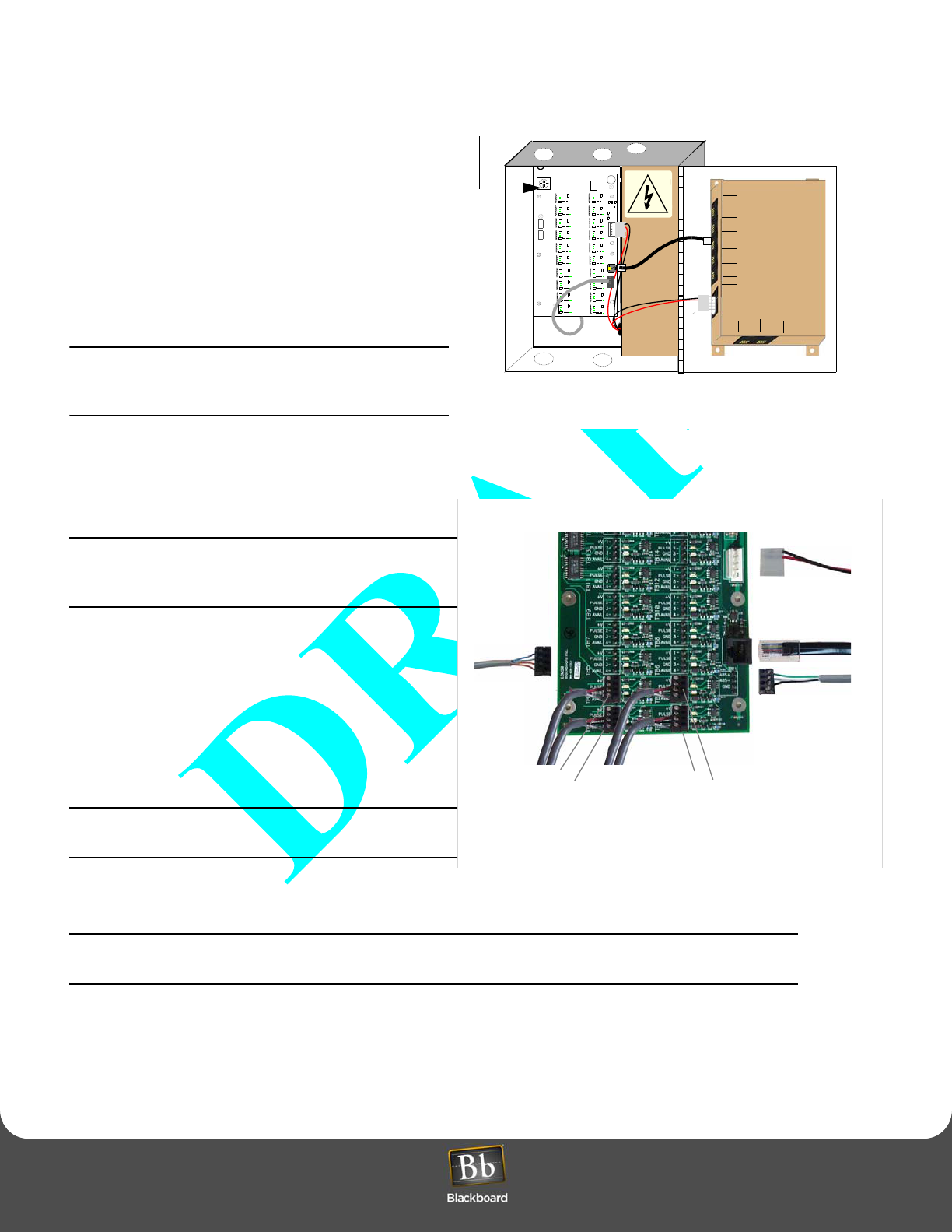
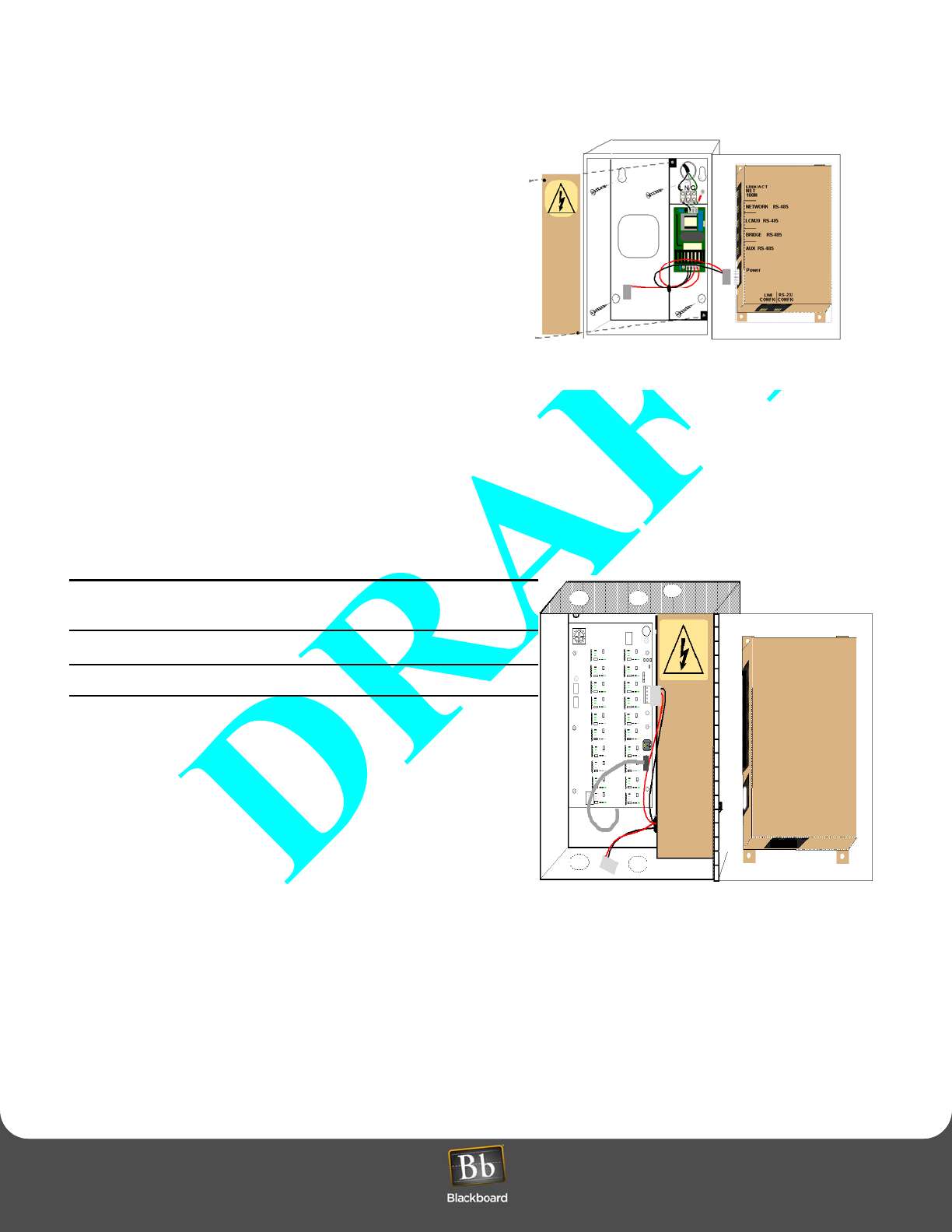
Install the LCM20 Board in the LC3000
1With the enclosure door open, position the LCM20
board, with component side facing out (see Figure
7).
2Secure the LCM20 board using the #4-40 screws
from the hardware kit.
Figure 7: LCM20 Board in the LC3000 Enclosure
ACMAIN
L N G
LE3/PSENCL AND LCM20 INSTALLATION
Laundry Installation and Setup Guide 17
LE3/PSENCL AND LCM20 INSTALLATION
3Set the rotary address switch to position 0. Refer to
Figure 8.
4Connect LCM20 to the LC3000 Reader, using the
provided RJ 45 communication cable.
5Route 4-conductor cables from each LCM20
terminal block to a laundry machine (see Figure 9
below).
6Consider marking each cable uniquely for easy
identification.
Do not connect power to the LCM20
Board until all machine interfaces are
terminated.
Figure 8: LCM20 Board Placement
Install LE3/PSENCL (if required)
If your Laundry Center has more than 20
machines, an external LCM20 and LE3/PSENCL
are required.
1Inside the LE3/PSENCL, remove the power supply
cover to access the upper right mounting hole.
Protect power supply from debris while mounting
the enclosure.
2Secure the enclosure to a wall using hardware
appropriate for the wall material.
Mounting holes accept up to 1/4” hardware.
Disconnect external AC power when installing any
wiring.
Figure 9: LCM20 Connections
Ensure all 120VAC wiring is confined within the power supply compartment when the cover is reinstalled to
maintain UL compliance.
3Strip back the insulation on the AC wire .28" to prevent bare wire from being exposed when installed in the AC
terminal block.
power
TB1 to machine 1 TB4 to machine 4
TB3 to machine 3 TB2 to machine 2
TB5 to machine 5
LCM20 to LC3000
LCM20 to LCM20
ACMAIN
L N G
0123
4
5
6
7
8
9
A
B
C
D
EF
LINK/ACT
NET
100M
HOST RS-485
LCM20 RS-485
BRIDGE RS-485
AUX RS-485
Power
LWI
CONFIG
RS-232
CONFIG
Rotary address switch
LE3/PSENCL AND LCM20 INSTALLATION
Laundry Installation and Setup Guide 18
LE3/PSENCL AND LCM20 INSTALLATION
4Install the appropriate wires into the AC terminal block, as
shown in Figure 10, tighten the screws to 5-7 in-lbs.,and
replace power supply cover.
5Position the LCM20 board, with component side facing out,
over the six standoffs.
6Secure the LCM20 board using the #4-40 screws from the
hardware kit.
Connect External LCM20 to LC3000 and laundry machines
1Set the rotary address switch to position 1 or 2.
Position 1 for machine numbers 21 through 40; and
position 2 for machine numbers 41 through 60. Refer to
Figure 8: LCM20 Board Placement (page 17).
Figure 10: LCM20 Board and LE3/PSENCL Connections
2Route an RS-485 communication cable from external LCM20 to internal LCM20 mounted inside the LC3000
enclosure.
Refer to Figure 11 for cable termination.
3Route a 4-conductor cable from each laundry machine to an LCM20 terminal block (TB1 - TB20).
Consider marking each cable uniquely for easy identification.
Do not connect power to the LCM20 Board until all
machine interfaces are terminated.
Maintain 1/4" separation from AC wiring to other wiring.
4Install and connect to machine interfaces (LCIs).
The machine interface (LCI) wiring varies depending on the type
of machine. Refer to appropriate LCI installation section:
•Install Maytag LCI3010 in Laundry Machine (page 19)
•Install Alliance/Speed Queen LCI3020 in Laundry
Machine (page 20)
•Install Whirlpool LCI3030 in Laundry Machine
(page 21)
Figure 11: External LCM20 Terminal Connections
5Once all LCI wiring harnesses are installed in laundry machines and cables are terminated on the LCM20,
reconnect power.

LCI LAUNDRY MACHINE INTERFACE INSTALLATION
Laundry Installation and Setup Guide 19
LCI LAUNDRY MACHINE INTERFACE INSTALLATION
LCI LAUNDRY MACHINE INTERFACE INSTALLATION
Install an LCI in every laundry machine. An LCI consists of a wiring harness that interfaces with the laundry machine
controller and is attached to a cable connected to the LCM20. Several models of LCI are available. Use
Table 1: Laundry System Components, on page 8 to select the correct LCI model number based on the manufacturer
and model of your laundry machines.
Wiring harness (LCI) connects under machine controller and describes the blocks.
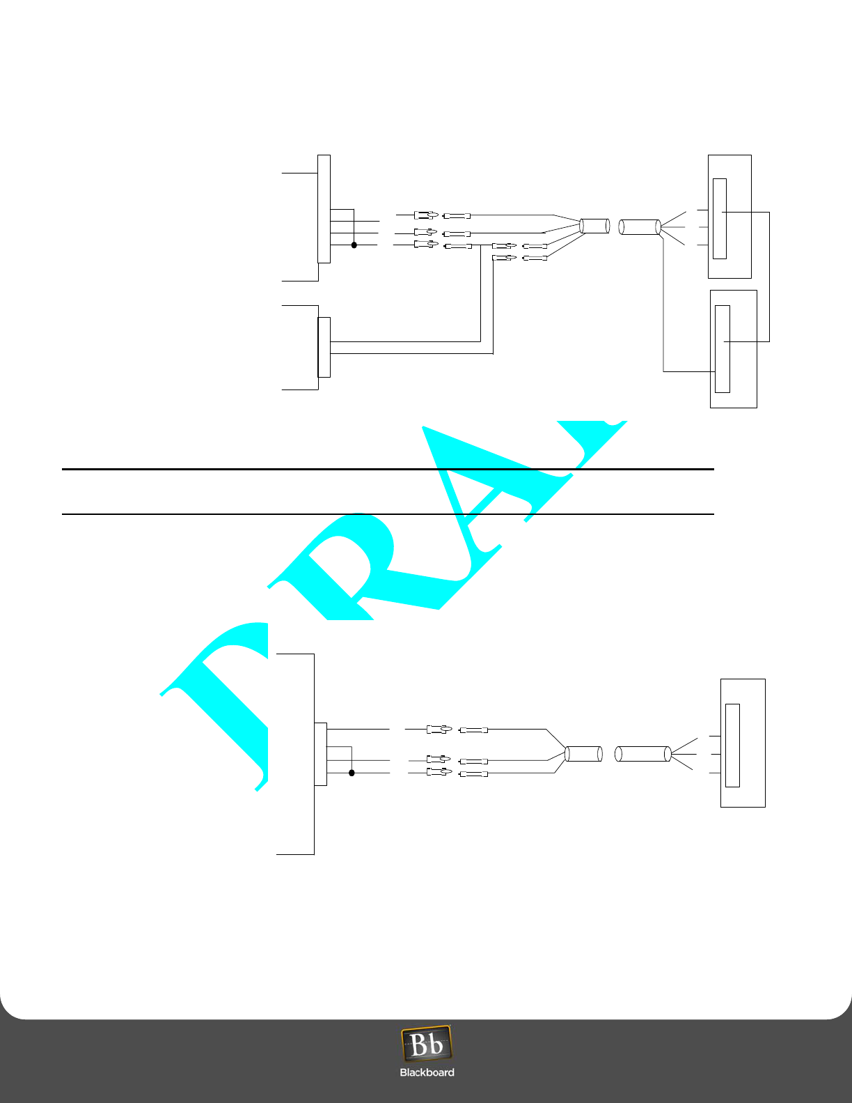
Install Maytag LCI3010 in Laundry Machine
The hardware kit includes machine controller interface cables, splices, and wire ties. Two cables are included to
support both single machines and stacked dryers. If you are installing a single machine, discard the two-wire cable.
1Remove the operator console (with display and switches) from the machine (only the screws in the top two corners
need to be removed).
2Route the 4-conductor cable from the LCM20 into the laundry machine for connection to the LCI wiring harness.
To prevent tampering, flexible metal conduit is recommended to run the 4-conductor cable from LCM20 to
the back of the machine. If flexible metal conduit is not used, then a strain relief must be used to prevent
damage to the cable.
3Attach female bullet connectors from the hardware kit to the end of the 4-conductor cable.
Use a strain relief or other means to secure the cable where it enters the machine.
4Insert the female bullet connectors into the LCI3010 wiring harness (white to white, black to black, etc.).
(See Figure 12.)
If the installation is for a stacked
machine, the additional two-wire
harness must be connected.
5Install the LCI wiring harness by
inserting the six-pin Molex into the
connector of the laundry
machines circuit board.
(See Figure 13.)
6Use the wire ties and wire tie
blocks included in the hardware
kit to dress the wires.
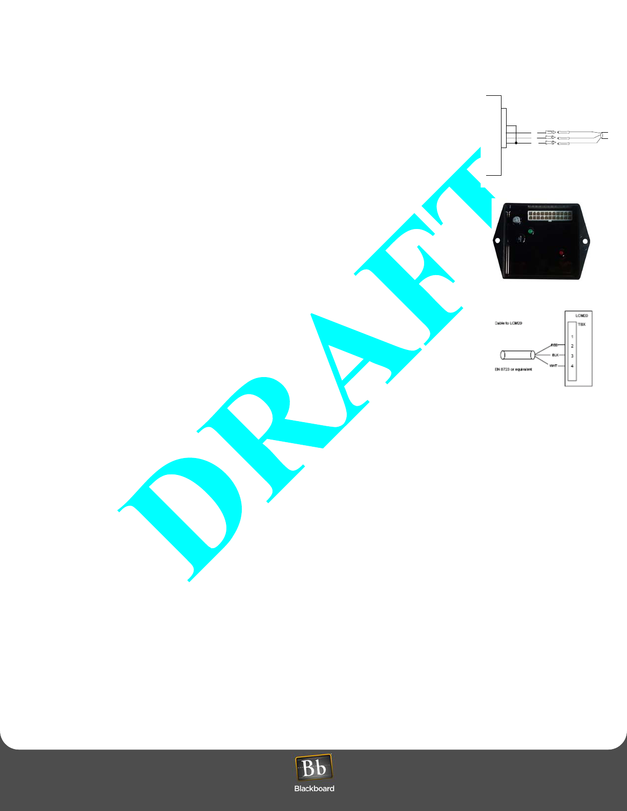
Figure 12: Single Maytag Machine
BELDEN 8723 or equivalent
Single Maytag
LCI 3010
Cable to LCM20
6
5
4
3
2
1
1
2
3
4
LCM20
TBX
RED
BLK
WHT
RED
WHT
BLK
Laundry Machine
RED
WHT
BLK
LCI LAUNDRY MACHINE INTERFACE INSTALLATION
Laundry Installation and Setup Guide 20
LCI LAUNDRY MACHINE INTERFACE INSTALLATION
7Terminate 4-conductor
cable at the LCM20, using
the 1 x 4 terminal block
provided in the hardware
kit.
Refer to Figure 9: LCM20
Connections (page 17).
8Replace laundry machine
operator console.
Figure 13: Maytag Stacked Machine
Depending on the labeling of upper and lower dryers and Maytag control board software version, pins may
need to be swapped to correctly match available signal with machine identifier.
Install Alliance/Speed Queen LCI3020 in Laundry Machine
The hardware kit includes a machine controller interface cable, splices and wire ties. Two LCI3020s must be
ordered when wiring to a stacked dryer.
1Remove the operator
console (with display and
switches) from the machine.
Refer to the appropriate
Speed Queen service
manual.
2Route the 4-conductor
cable from the LCM20 into
the machine (see Figure
14).
If the installation is for a
stacked machine, two
cables are required.
Figure 14: Alliance/Speed Queen Machine
BELDEN 8723 or equivalent
Cable to LCM20
6
5
4
3
2
1
1
2
3
4
LCM20
TBX
RED
BLK
WHT
RED
WHT
BLK
Laundry Machine
RED
WHT
BLK
2
1
1
2
3
4
LCM20
TBX
GRN
BLK
GRN
Laundry Machine
BLK
GRN
1
2
BELDEN 8723 or equivalent
LCI 3020
Cable to LCM20
4
3
2
1
1
2
3
4
LCM20
TBX
RED
BLK
WHT
WHT
RED
BLK
Laundry Machine
WHT
RED
BLK
4-pinMolex

LCI LAUNDRY MACHINE INTERFACE INSTALLATION
Laundry Installation and Setup Guide 21
LCI LAUNDRY MACHINE INTERFACE INSTALLATION
To prevent tampering, flexible metal conduit is recommended to run the 4-conductor cable from LCM20 to
the back of the machine. If flexible metal conduit is not used, then a strain relief must be used to prevent
damage to the cable.
3Attach female bullet connectors from the hardware kit to the end of the 4-conductor cable.
Use a strain relief or other means to secure the cable where it enters the machine.
4Insert the female bullet connectors into the LCI3020 wiring harness (white to white, black to black, etc.).
If the installation is for a stacked machine,perform the same process on the second cable.
5Insert the four-pin Molex connector into the circuit board, as illustrated in Figure 14.
If the installation is for a stacked machine, insert the second four-pin Molex connector into the circuit board.
6Use the wire ties and wire tie blocks included in the hardware kit to dress the wires.
7Terminate 4-conductor cable at the LCM20, using the 1 x 4 terminal block provided in the hardware kit; and install
the terminal block on the terminal header of the LCM20.
Refer to Figure 9: LCM20 Connections (page 17).
8Replace laundry machine operator console.
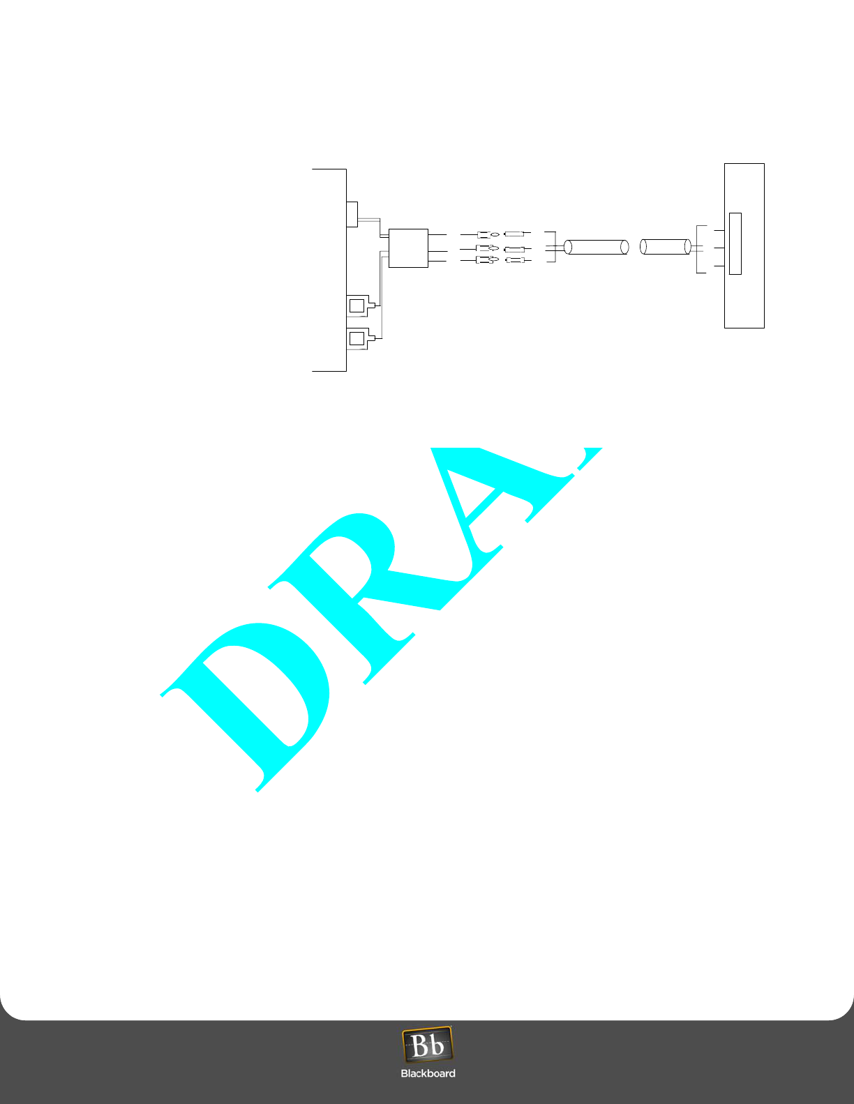
Install Whirlpool LCI3030 in Laundry Machine
The hardware kit includes a machine controller interface cable, splices, and wire ties. You will need to have two
LCI3030s on hand when wiring to a stacked dryer.
1Remove the operator console (with display and switches) from the machine.
Refer to appropriate service manual.
2Route the 4-conductor cable from the LCM20 into the machine.
If the installation is for a stacked machine, route two cables.
To prevent tampering, flexible metal conduit is recommended to run the 4-conductor cable from LCM20 to
the back of the machine. If flexible metal conduit is not used, then a strain relief must be used to prevent
damage to the cable.
3Attach female bullet connectors from the hardware kit to the end of the 4-conductor cable.
Use a strain relief or other means to secure the cable where it enters the machine.
4Insert the female bullet connectors into the LCI3030 wiring harness (white to white, black to black, etc.).
If the installation is for a stacked machine, the additional two-wire harness must be connected as shown in Figure
15: Whirlpool/Advantech Machine (page 22). You must also insert the second four-pin Molex connector into the
circuit board.
LCI LAUNDRY MACHINE INTERFACE INSTALLATION
Laundry Installation and Setup Guide 22
LCI LAUNDRY MACHINE INTERFACE INSTALLATION
5Attach the orange wire with the
female disconnect to the
spade lug on the controller
board identified with the letter
M1.
Figure 15: Whirlpool/Advantech Machine
6Attach the black wire with the female disconnect to the spade lug on the controller board identified with the letter
M2.
7Connect the 4-pin Molex connector from the wiring harness to the mating connector on the laundry machine
controller board identified as COIN #1.
8Use the wire ties and wire tie blocks, included in the hardware kit, to dress the wires.
9Terminate 4-conductor cable at the LCM20, using the 1 x 4 terminal block provided in the hardware kit; and install
the terminal block on the terminal header of the LCM20.
Refer to Figure 11: External LCM20 Terminal Connections (page 18). Be sure terminal block numbers match
laundry machine numeric identifiers.
10 Replace laundry machine operator console.
BELDEN 8723 or equivalent
Whirlpool
LCI 3030
Cable to LCM20
1
2
3
4
LCM20
RED
BLK
WHT
Whirlpool Circuit Board
4-pin Molex Connector
M1
M2
TBX
RED
BLK
WHT
Install Female Bullet Splices
RED
BLK
WHT
ORG
BLK
WIRELESS LAUNDRY MACHINE INTERFACE INSTALLATION
Laundry Installation and Setup Guide 23
WIRELESS LAUNDRY MACHINE INTERFACE INSTALLATION
WIRELESS LAUNDRY MACHINE INTERFACE INSTALLATION
A wireless laundry center can support up to 60 laundry machines (see Figure 2 on page 7). The configuration uses a
Wireless Bridges (LE3/BRIDGE) to connect to the LC3000 Reader and Laundry Wireless Interface (LWI30XX) installed
in each laundry machine. THe LE3/BRIDGE and LWI30XX communicate over an RF radio link, eliminating the need for
wiring between the reader and laundry machines. The Wireless Laundry System components are listed and explained
below.
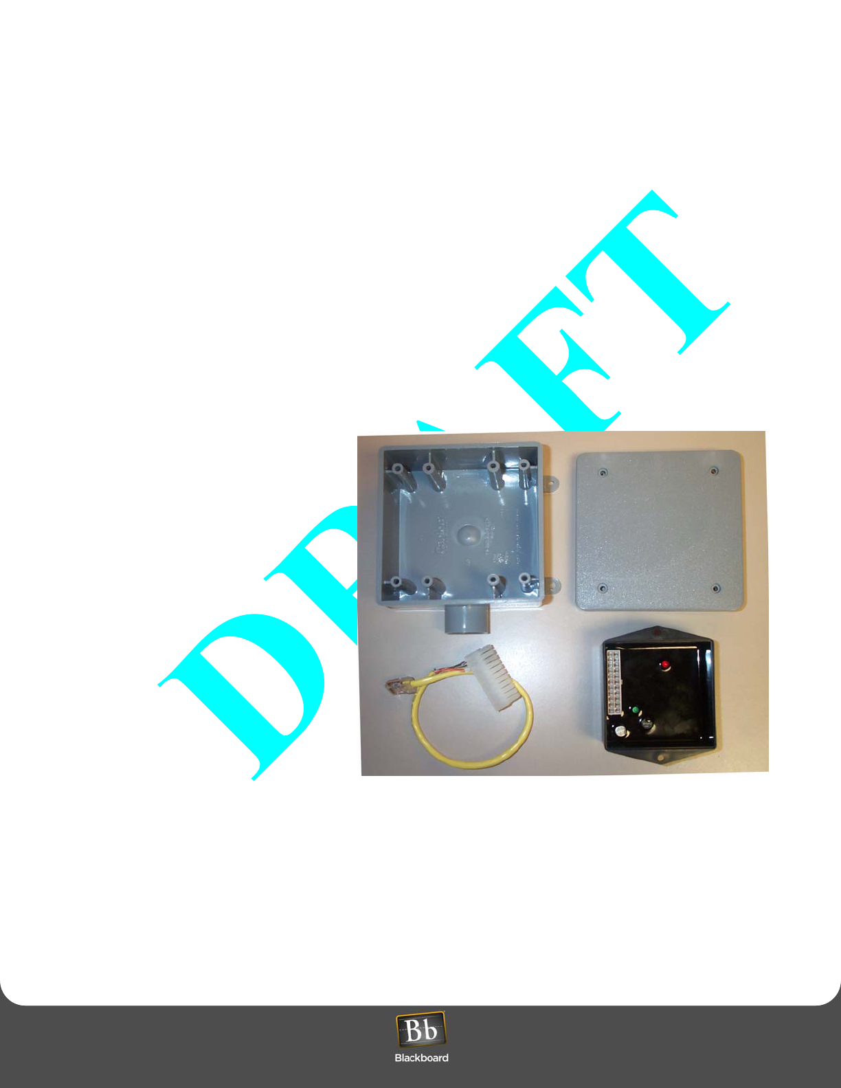
Wireless Bridge (LE3/BRIDGE)
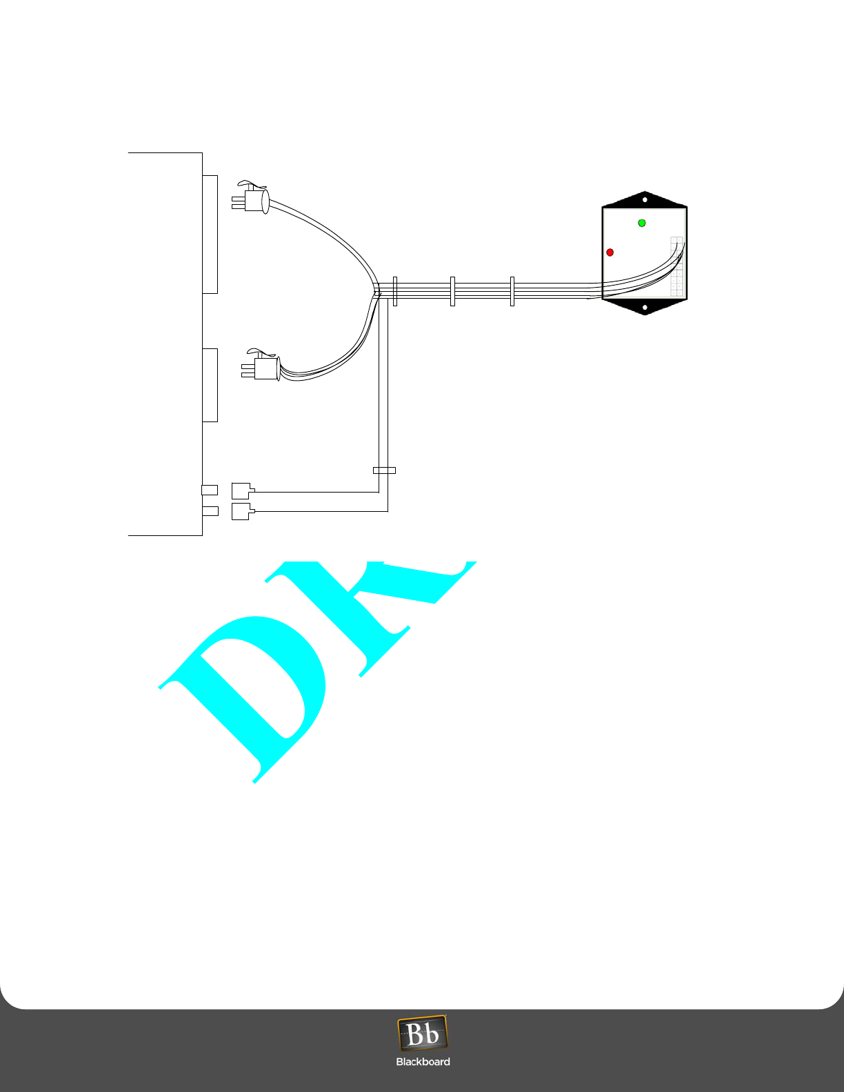
An LE3/BRIDGE includes a Wireless Interface Module, an enclosure, and a cable, as shown in Figure 16. The Bridge
accepts commands from the LC3000 over RS-485 and communicates to LWI30XXs installed in the laundry machines.
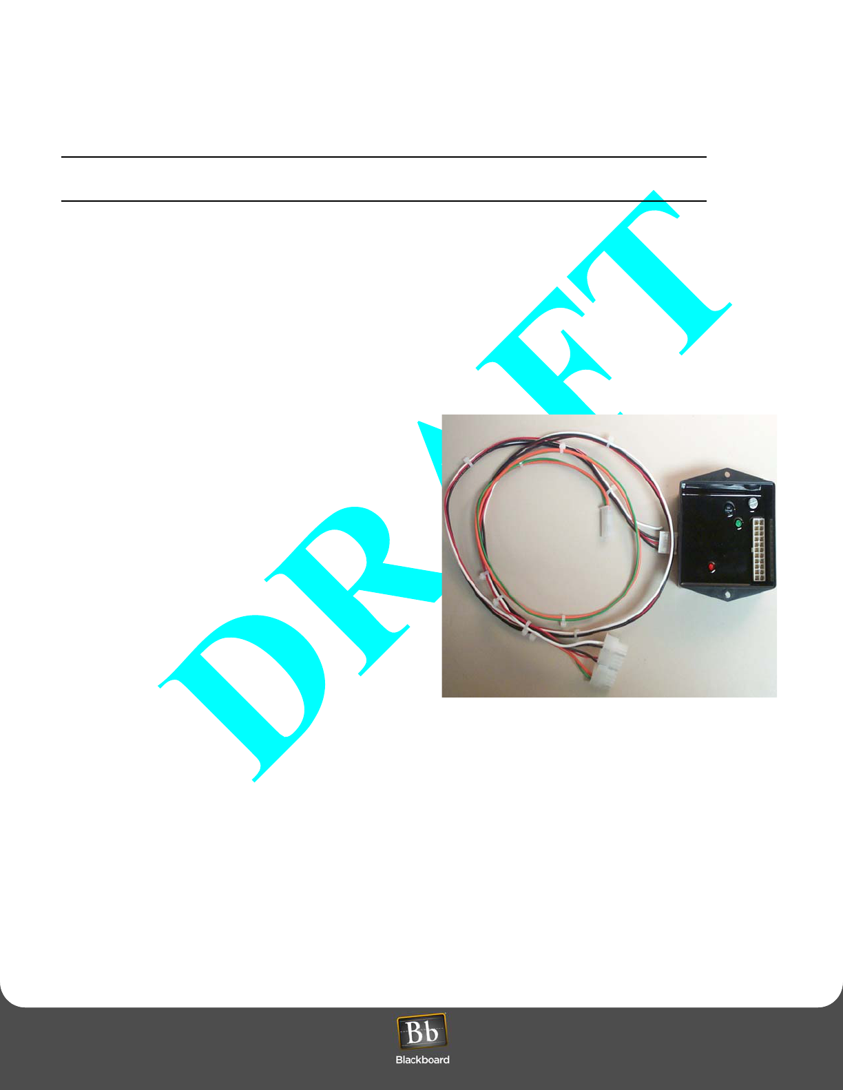
Laundry Wireless Interface (LWI30xx)
An LWI30XX includes a Wireless Interface
Module and a wiring harness (see Figure 17:
Wireless Interface Module and Wiring
Harness (page 24). The wiring harness
connects the Wireless Interface Module to the
control board of the laundry machine. Before
your installation, select the appropriate
LWI30XX model number based on the
manufacturer and model number of each
laundry machine (see Table 1: Laundry
System Components, on page 8).
Figure 16: Wireless Bridge component (LE3/BRIDGE)
WIRELESS LAUNDRY SYSTEM INSTALLATION OVERVIEW
Laundry Installation and Setup Guide 24
WIRELESS LAUNDRY SYSTEM INSTALLATION OVERVIEW
WIRELESS LAUNDRY SYSTEM INSTALLATION OVERVIEW
You must configure the laundry machines on the host system and download to the LC3000 reader before
you configure hardware to the laundry center.
1Mount the LE3/BRIDGE (page 24)
2Configure the LE3/BRIDGE Wireless Module (page 25)
3Configure the LWI30XX for Laundry Machines (page 25)
4Install the LWI30XX in Laundry Machines (page 26)
LE3/BRIDGE Placement
A plastic enclosure is provided with the LE3/BRIDGE. The enclosure is used to house the Wireless Interface Module
and must be mounted externally from the LC3000. Use the following criteria to select the appropriate placement:
• Mount in centrally located area to minimize distance
to any laundry machine.
• Mount on ceiling or elevated location to increase
range.
• Avoid locations near metal objects.
• Avoid having obstructions or barriers between the
LE3/BRIDGE and laundry machines.
Figure 17: Wireless Interface Module and Wiring Harness
Mount the LE3/BRIDGE
The LE/3 BRIDGE must be mounted external to the LC3000.Select the appropriate hardware and mount the LE3/
BRIDGE plastic enclosure.
1Install 3/4” PVC conduit from the LC3000 to the LE3/BRIDGE enclosure.
2The LE3/BRIDGE includes a wiring harness with an RJ-45 connector and 22-pin Molex connector.
The 22-pin connector plugs into the wireless module. The RJ-45 connector must be connected to the RJ-45 jack
identified as BRIDGE RS-485 on the LC3000. Connection between the two requires installing a patch cable and
using an RJ-45 inline coupler. Pull a patch cable (CAT5) through the conduit and install the inline coupler. Connect
the LE3/BRIDGE wiring harness to the inline coupler.
WIRELESS LAUNDRY SYSTEM INSTALLATION OVERVIEW
Laundry Installation and Setup Guide 25
WIRELESS LAUNDRY SYSTEM INSTALLATION OVERVIEW
Configure the LE3/BRIDGE Wireless Module
A network ID must be assigned to the LE3/BRIDGE. Since the
LC3000 can support multiple LE3/BRIDGES, the network ID identifies
which LE3/BRIDGE will respond to a poll. A network ID is also
assigned to each LWI30XX installed in a laundry machine, allowing it
to respond to a specific LE3/BRIDGE.
Network ID numbers range from 1 through 7. Always select a Network
ID that has not been chosen on a nearby network or previously
assigned to an additional LE3/BRIDGE attached to the same LC3000.
A nearby network is considered any installation that exists within the
same building and/or less than 500 feet away.
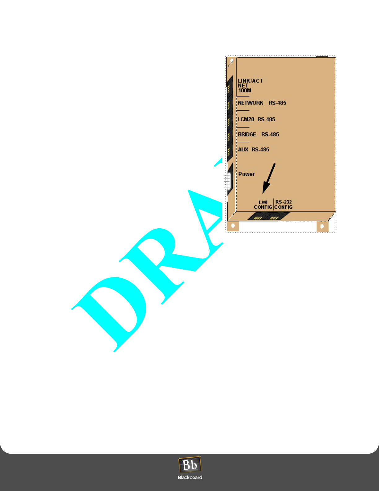
1Plug the RJ-45 connector from the patch cable connected to the
LE3/BRIDGE wireless module into the RJ-45 jack of the LC3000,
labeled “LWI CONFIG” (see Figure 18).
The LC3000 will request a network ID.
2Enter a number from 1 to 7 to assign to the LE3/BRIDGE.
The LC3000 will request a configuration type: BRIDGE or LWI.
3Select BRIDGE as the configuration type.
4Remove the RJ-45 connector from the LWI CONFIG jack of the
LC3000 and re-install the RJ-45 connector into the RJ-45 jack
labeled “BRIDGE RS-485. The LE3/BRIDGE is now operational.
Figure 18: LWI Config Port on LC3000
Configure the LWI30XX for Laundry Machines
Every LWI30XX must be configured before installing it into a laundry machine. The configuration process assigns a
network ID and machine number to each LWI30XX and records a unique ID number stored within the wireless module.
A label, provided with each LWI30XX, should be placed on the plastic enclosure. Record the assigned machine number
and network ID on the label. This ensures the correct LWI30XX module is installed into the assigned laundry machine.
All laundry machines within the laundry center must be assigned a number between 1 and 60. The LC3000 displays
this number during normal operation and uses it to determine which LWI30XX module receives a pulse command when
a patron selects a specific machine. When configuring the LWI30XX, enter this number when assigning a machine.
1Plug the configuration cable, provided with the LC3000, into the RJ-45 jack labeled “LWI CONFIG on the LC3000
(see Figure 18).
2Plug the 22-pin connector of the configuration into an LWI30XX.
The software requests the Wireless Interface Module type.
3Select 1 for LWI.
The software requests the laundry machine ID number (1 through 60).
4Enter the laundry machine number where the LWI30XX will be installed.
5Disconnect the LWI30XX module from the configuration cable.
6Record the network ID and laundry machine number on the label and affix it to the plastic housing of the LWI30XX.
Repeat the steps listed above for each LWI30XX that will be installed within the laundry center.
LWI CONFIG PORT

WIRELESS LAUNDRY SYSTEM INSTALLATION OVERVIEW
Laundry Installation and Setup Guide 26
WIRELESS LAUNDRY SYSTEM INSTALLATION OVERVIEW
When configuring an LWI for a stacked dryer unit, enter the odd number for the lower half of the stack dryer.
The LC3000 will internally configure the upper (even-numbered) half of the stack dryer unit. For example, a
Maytag Stack Dryer, labelled as machines 3 and 4, lower and upper halves respectively, would specify
machine number 3 as the half requiring configuration.
Install the LWI30XX in Laundry Machines
Before installing the LWI30XX inside a laundry machine, the module must be configured (see Configure the LWI30XX
for Laundry Machines (page 25). Verify the completion of this step before attempting to install the LWI30XX. Also ensure
the machine number assigned to the LWI30XX during the configuration process matches the number assigned to the
laundry machine. The machine number should be recorded on the label of the LWI30XX wireless module.
For any installation, either the hood or front panel of the laundry machine must be removed to gain access to the
electronic control board. Consult the manufacturer’s manual for steps to perform this task. Each LWI30XX contains a
wiring harness for connecting the wireless module to the laundry machine’s control board. All wiring harnesses support
both single and stacked machines. When performing an installation for a single machine, some connectors may not be
used.
In a typical installation, the wireless module can be installed inside the machine. However, if the laundry machine is more
than 50 feet from the LE3/BRIDGE, it may be necessary to mount the module on the outside of the laundry machine for
best reception. Sheet metal screws are provided with the LWI30XX to attach the module.
WIRELESS LAUNDRY SYSTEM INSTALLATION OVERVIEW
Laundry Installation and Setup Guide 27
WIRELESS LAUNDRY SYSTEM INSTALLATION OVERVIEW
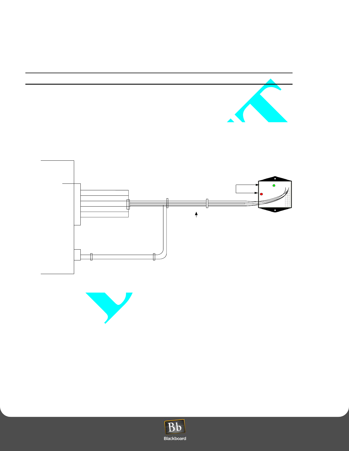
Installing LWI3010 in Maytag Laundry Machines
Maytag laundry machines require an LWI3010. A single LWI3010 supports both single washer/dryer machines and
stacked dryer machines.
Disconnect all power to the machine.
1Remove the operator console (with display and switches) from the machine. For single machines, only remove the
top two screws. On stacked machines, only remove the lower two screws on the top panel.
The wiring harness supports both single machines and stacked dryers. Therefore, only a single LWI3010 is needed
for either configuration.
Figure 19: Maytag Machine
2With access to the machine’s control board, install the six-pin connector of the wiring harness into the (AA3)
connector of the laundry machine’s control board. On stacked machines, install the 2-pin Molex connector on the
wiring harness into the control boards (AA2) connector. See Figure 19.
3Install the 22-pin connector of the wiring harness into the LWI3010 wireless module.
4Mount the wireless module inside the hood compartment using the double-sticky tape provided, or install the
module on the outside of the machine using the sheet metal screws.
If installing inside the hood compartment, keep the module away from the control board and any potential electrical
interference sources.
5Use the wire ties and wire tie blocks included with the LWI3010 to dress the wires within the compartment.
6Re-install the operator console on the machine.
Maytag Trac III
Extra 2 Pin Header for Stacked Appliances
Wiring Harness
Maytag
LWI 3010
1
2
1
2
3
4
5
6
1
2
3
4
5
6
22-pin Connector
Wireless Interface Module
1
2
2-pin Molex Connector
(Only installed on Stacked Dryer)
6-Pin Molex Connector
LED Indicators

WIRELESS LAUNDRY SYSTEM INSTALLATION OVERVIEW
Laundry Installation and Setup Guide 28
WIRELESS LAUNDRY SYSTEM INSTALLATION OVERVIEW
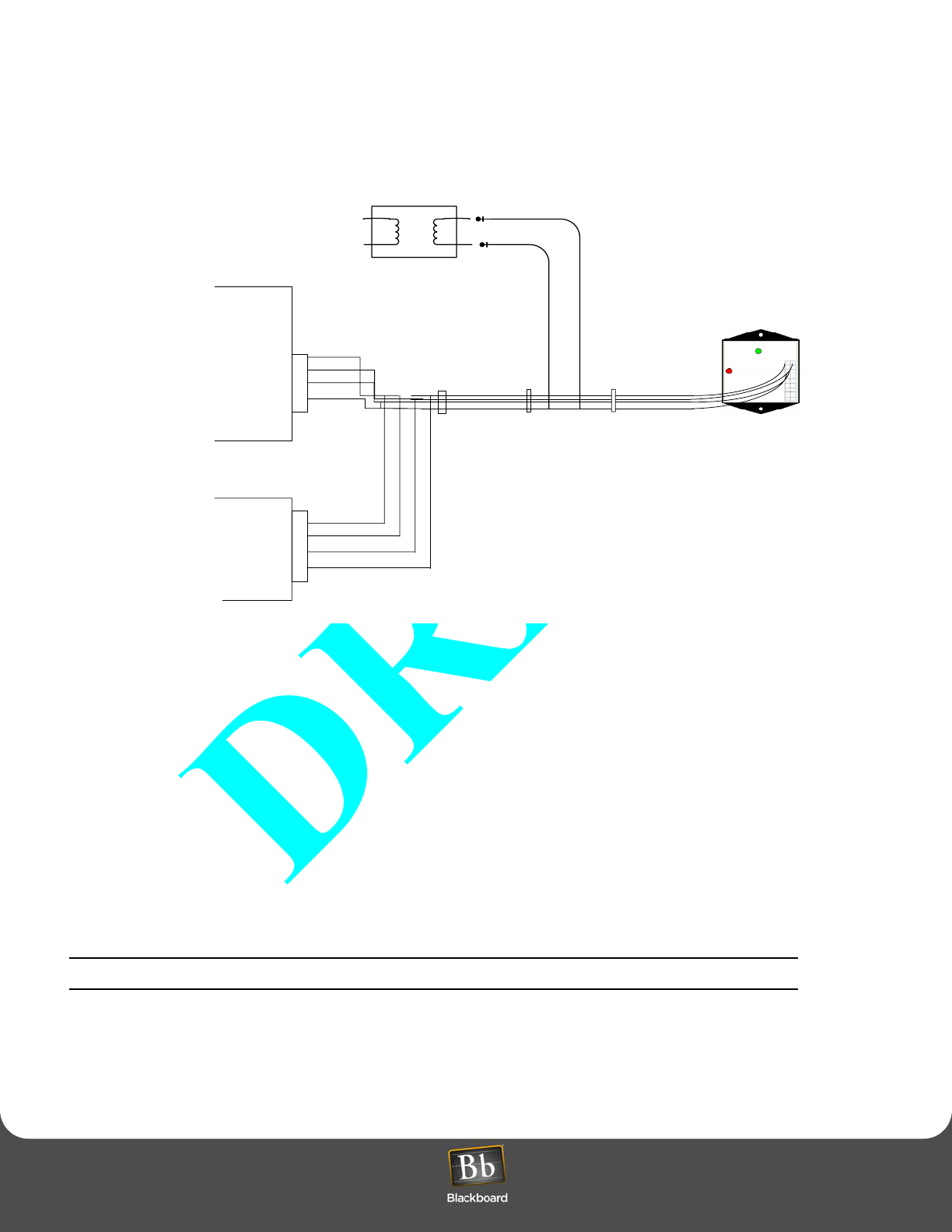
Installing LWI3020 in Alliance/Speed Queen Laundry Machines
Alliance/Speed Queen laundry machines require an LWI3020. A single LWI3020 supports both single washer/dryer
machines and stacked dryer machines. Before installing an LWI3020, verify that the transformer in the machine is the
correct type. The transformer should have 4 red wires on the secondary side. If there are only 2 wires, then the
transformer must be replaced.
If the 4th alphanumeric digit is A,C, D, F, H, J, L, X, or Y you have the correct dual transformer. If the 4th
alphanumeric digit is B, T, or Z, you must have the existing transformer replaced. The correct transformer
can be ordered from Alliance Laundry Systems or through your laundry supplier. The correct transformer
part number is 201375P.
Disconnect all power to the machine.
1Remove the operator console (with display and switches) from the machine. For single machines, remove only the
top two screws.
2With access to the machine’s control board, install the 4-pin connector of the wiring harness labeled “Odd
Numbered Machine” onto the (H5) connector of the laundry machine’s control board. The H5 connector may be
either 4 or 7 pin. If the connector has 7 pins, the connector must be installed on pins 1 through 4.
When installing the LWI3020 into a stacked machine, the connector identified with label “Even Numbered Machine”
must be installed into the control board of the even-numbered machine. For example, if the stacked machine is
assigned machines 3 and 4 within the laundry center, then the connector would be installed in the control board
identified as machine 3 and the other connector would be installed in the control board of the machine identified as
machine 4.
3Install the 2-Molex pins connected to the RED and RED wires on the wiring harness into the two open positions of
the transformer’s secondary output connector. It is an AC output, therefore the pins are interchangeable (see
Figure 20: Alliance/Speed Queen Machine (page 29).
WIRELESS LAUNDRY SYSTEM INSTALLATION OVERVIEW
Laundry Installation and Setup Guide 29
WIRELESS LAUNDRY SYSTEM INSTALLATION OVERVIEW
4Install the 22-pin connector of the wiring harness into the LIW3020 wireless module.
Figure 20: Alliance/Speed Queen Machine
5Mount the wireless module inside the hood compartment using the double-sticky tape provided or install the
module on the outside of the machine, using the sheet metal screws.
If installing inside the hood compartment, keep the module away from the control board and any potential electrical
interference sources.
6Use the wire ties and wire tie blocks included with the LWI3020 to dress the wires within the compartment.
7Re-install the operator console on the machine.
Install Whirlpool/Advantech LWI3030 in Laundry Machines
Whirlpool/Advantech laundry machines require an LWI3030.
Disconnect all power to the machine.
Refer to the appropriate service manual to remove the control hood cover and gain access to the controller board in
the laundry machine.The wiring harness supports both single machines and stacked dryers. Therefore, only a
single LWI3030 is needed for either configuration.
Alliance/Speed Queen
Control Board #1
Alliance/ Speed Queen
1
2
3
4
1
2
3
4
22-pin Connector
Wireless Interface Module
Control Board #2
Odd-Numbered
Machine
Even-Numbered
Machine
RED
RED
TRANSFORMER
WIRELESS LAUNDRY SYSTEM INSTALLATION OVERVIEW
Laundry Installation and Setup Guide 30
WIRELESS LAUNDRY SYSTEM INSTALLATION OVERVIEW
1Attach the orange wire with the female disconnect to the spade lug on the controller board identified with the letter
M1 (see Figure 21).
Figure 21: Whirlpool/Advantech Machine
2Attach the black wire with the female disconnect to the spade lug on the controller board identified with the letter
M2 (see).
3Connect the 4-pin connector from the wiring harness to the mating connector on the laundry machine controller
board.
4Connect the 6-pin connector from the wiring harness to the mating connector on the laundry machine controller
board.
5Mount the Wireless Interface Module using double-sticky tape or the two-sheet metal screws from the hardware kit.
Select a location near an outer panel and away from any heat source. The location must not exceed the reach of
the wiring harness (3 ft.). The LWI should be orientated vertically to get maximum range from the RF transceiver.
6Plug the 22-pin Molex connector into the LWI.
7Use the wire ties and wire tie blocks included in the hardware kit to dress the wires.
1
2
3
4
1
2
3
4
5
6
22-pin Connector
Wireless Interface Module
Female Spade Lugs
6-Pin Molex Connector
4-Pin Molex Connector
M1
M2
ORG
BLK
APPENDIX
Laundry Installation and Setup Guide 31
APPENDIX
APPENDIX
READER OPERATIONS
Laundry Reader Usage
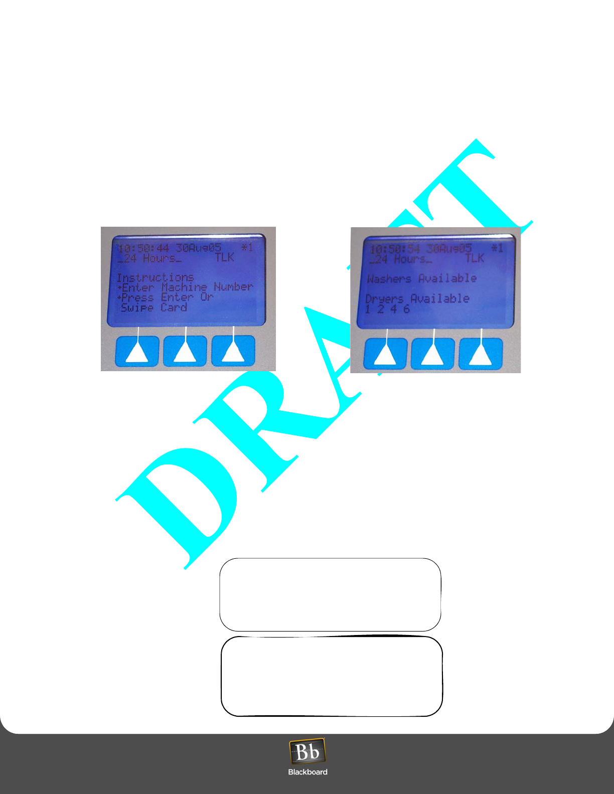
The LC3000 Laundry Reader displays online messages to offer a cardholder instructions on the use of the laundry
machines. The system toggles back and forth with the following messages:
Figure 22: LC3000 Laundry Reader Online Messages
Offline messages are only available on the reader when the system verifies that offline operations with the host are
allowed and cardholders’ ID numbers are valid.
Operating a Washer
1Select one of the available washers from the display (see Figure 22).
2Use the reader’s numeric keypad to select the machine. The reader immediately displays a message to inform a
cardholder of the status of the selected machine: Available or Out of Service. If an invalid number is used, the
reader displays a “Machine Unavailable” message.
3Swipe card. Once a laundry machine is activated for use, the reader displays the machine number.
Washer 05
Total $1.00
Please Swipe Card
Machine 05
Please load clothes
Start Machine

READER OPERATIONS
Laundry Installation and Setup Guide 32
READER OPERATIONS
Once the system accepts the card swipe, the appropriate amount for the transaction is deducted from the
cardholder’s account. The reader displays a message to confirm the valid transaction.
If a card is not swiped or no other response is made within 10 seconds, the reader aborts the transaction.
The machine begins its cycle once you swipe your card and the system recognizes the transaction as valid. If the
time limit lapses, power is turned off for the selected machine. However, the amount is deducted from the
cardholder’s account regardless of where the machine operated or not.
Refunds to a cardholder’s account are at the site’s discretion. They do not occur automatically.
Canceling a Transaction
To cancel a transaction, press the softkey, labeled “Clear” any time before swiping a card.
Operating a Dryer
1Select one of the available dryers from the display (see Figure 22).
2Use the reader’s numeric keypad, to select a machine. The reader immediately displays a message to inform a
cardholder of the status of the selected machine: Available, In Use, or Out of Service. If an invalid number is used,
the reader displays a “Machine Unavailable” message.
3Swipe card. Once a laundry machine is activated, the reader displays a message.
Machine 07
Total ......$1.25
Please Swipe Card
Once the system accepts the card swipe, the appropriate amount for the transaction is deducted from the
cardholder’s account. The reader displays a message to confirm the valid transaction.
Machine 07
Please Load Clothes
And Start Machine
If a card is not swiped or no other response is made within 10 seconds, the reader cancels the transaction.
The machine begins its cycle once you swipe your card and the system recognizes the transaction as valid. If the
time limit lapses, power is turned off for the selected machine. However, the amount is deducted from the
cardholder’s account regardless of whether the machine operated or not.

READER OPERATIONS
Laundry Installation and Setup Guide 33
READER OPERATIONS
Adding Dry Time
Additional drying time may be added at the beginning of the transaction or any time during the drying cycle.
To add time at the beginning of the transaction, complete the following steps:
1Use the keypad to select the machine’s number.
The reader displays the machine number, the cost of the current cycle, and the cost of additional cycle time:
2Press the Add Time softkey. Then swipe card. The reader sends the transaction to the System and returns with a
new total amount.
Additional minutes can be added (up to 99 minutes).
Status Messages
If you select a machine that is currently in use, the reader displays the following message:
Machine 03 In Use
If you select a machine that is out of service or is turned off, the reader displays the following message:
Machine 09
Out of Service
READER MENUS AND SETTINGS
Laundry Installation and Setup Guide 34
READER MENUS AND SETTINGS
READER MENUS AND SETTINGS
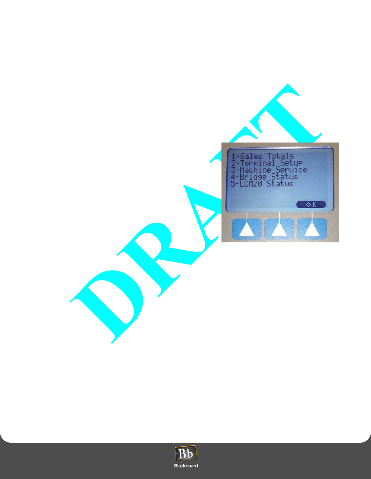
Manager Card
Using a Manager’s card, administrators or designated staff can access menus on the LC3000 to obtain sales
information and to modify reader settings. Those menu items are briefly explained below (see Figure 25: Manager
Card Flowchart (page 36)).
Obtaining Sales Totals
To obtain Sales Totals for your Laundry Center, complete the following
steps:
1Swipe the manager’s card.
2Press 1 on the keypad. Once the sales options display, make a
selection and then follow the screen instructions.
Refer to the Reader Menu flowchart for more details on this menu
option.
Changing Terminal Setup
To change the reader’s display (backlight and contrast) and the
volume, complete the following steps:
1Press 2 on the keypad. Make a selection and then follow the
screen instructions.
Figure 23: Manager Card Menu
Changing Machine Service
Set In/Out Service
This menu allows you to set a machine in or out of service.
1Press 3 on the key pad.
2Press 1 - Set In/Out Service.
3Set Machine ID by entering a laundry machine number (available machines are numbered from 1 through 60).
4Press 1 for Out of Service or press 2 for In Service.
5Press OK to accept the selection, press Clear to change the selection, or press Abort to cancel the selection.
View Out of Service
To view machines currently out of service, complete the following steps:
1From the main Manager’s Menu, press 3.
2Then, press 2 to view all machines currently out of service at that time. The reader displays all machines currently
out of service at the time of the request.
READER MENUS AND SETTINGS
Laundry Installation and Setup Guide 35
READER MENUS AND SETTINGS
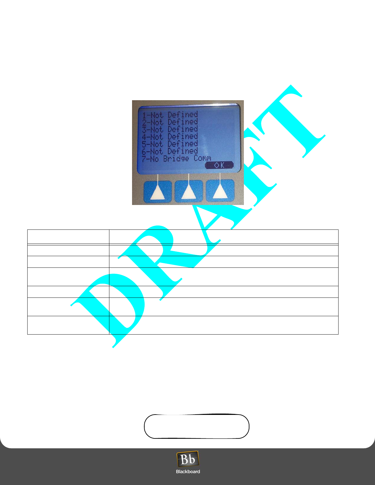
Modifying and Viewing Bridge Status
To determine whether or not a Bridge has been configured and is properly communicating with the LC3000, complete
the following steps:
1Press 4 on the keypad.
The reader displays seven available Bridge listings and their existing status, as shown in Figure 24 below.
Figure 24: Bridge Status Display
Viewing LCM20 Status
To determine the current communication status of any LCM20 to your LC3000 reader, complete the following steps:
1From the main Manager’s menu, press 5 on the keypad.
The reader displays the status of any existing LCM20.
Active and successful communication between the LCM20 and the LC3000 is indicated by the display of an A on
the reader screen. (Each displayed A represents an active LCM20 that supports 20 laundry machines.)
A ___ ___
Bridge Display Message Description
Not Defined This Bridge is not configured by the LWI CONFIG port.
No Bridge Comm This Bridge is configured, but is not successfully community on the BRIDGE RS-485 port.
No LWIs Defined This Bridge is successfully communicating on the BRIDGE RS-485 port, but no LWIs are
defined for this Bridge.
No LWI Communication One or more LWIs are defined for this Bridge, but no LWI communication exists.
LWI Communication OK One or more LWIs are configured for this Bridge and all are successfully communicating
with the Bridge.
LWI Communication One or more LWIs are configured for this Bridge, but some of the LWIs are not successfully
communicating with the Bridge.
Table 3: Bridge Status Menu
READER MENUS AND SETTINGS
Laundry Installation and Setup Guide 36
READER MENUS AND SETTINGS
Inactive and unsuccessful communication between the LCM20 and the LC3000 is indicated by the display of an I
on the reader screen. (Each displayed I represents an inactive LCM20 that is not currently supporting 20 laundry
machines.)
I ___ ___
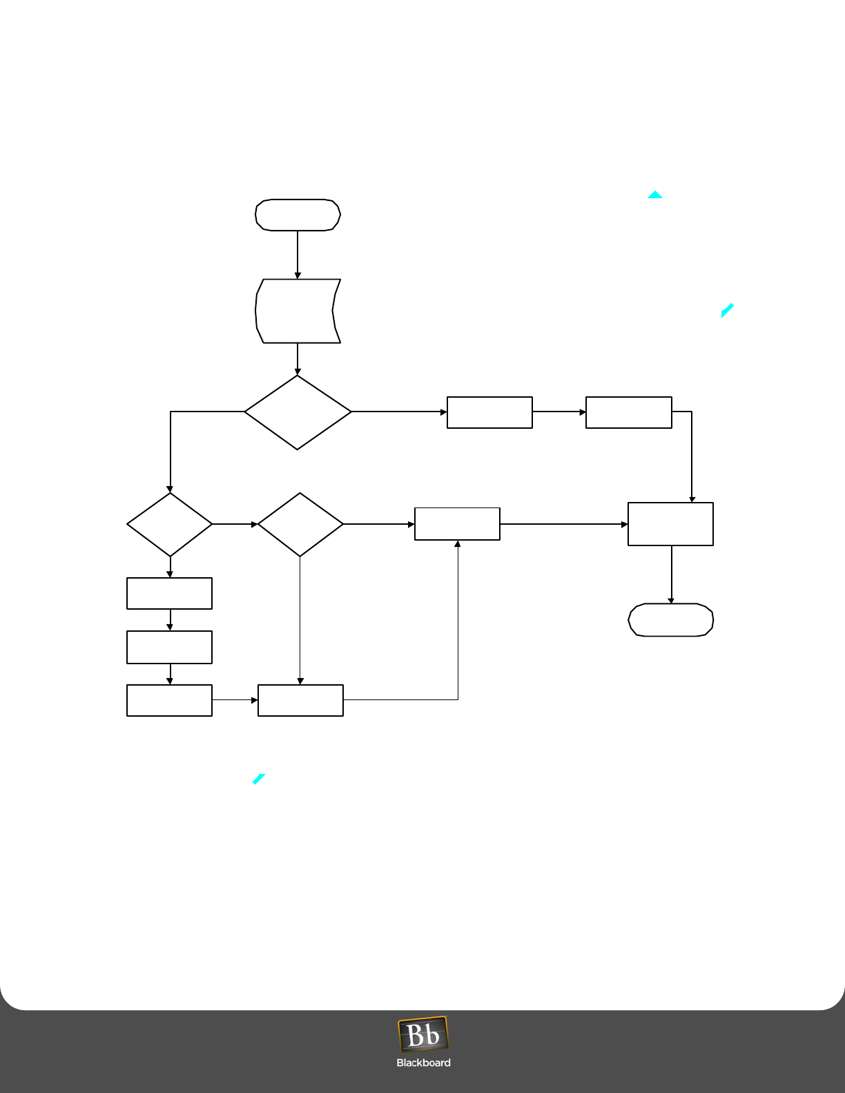
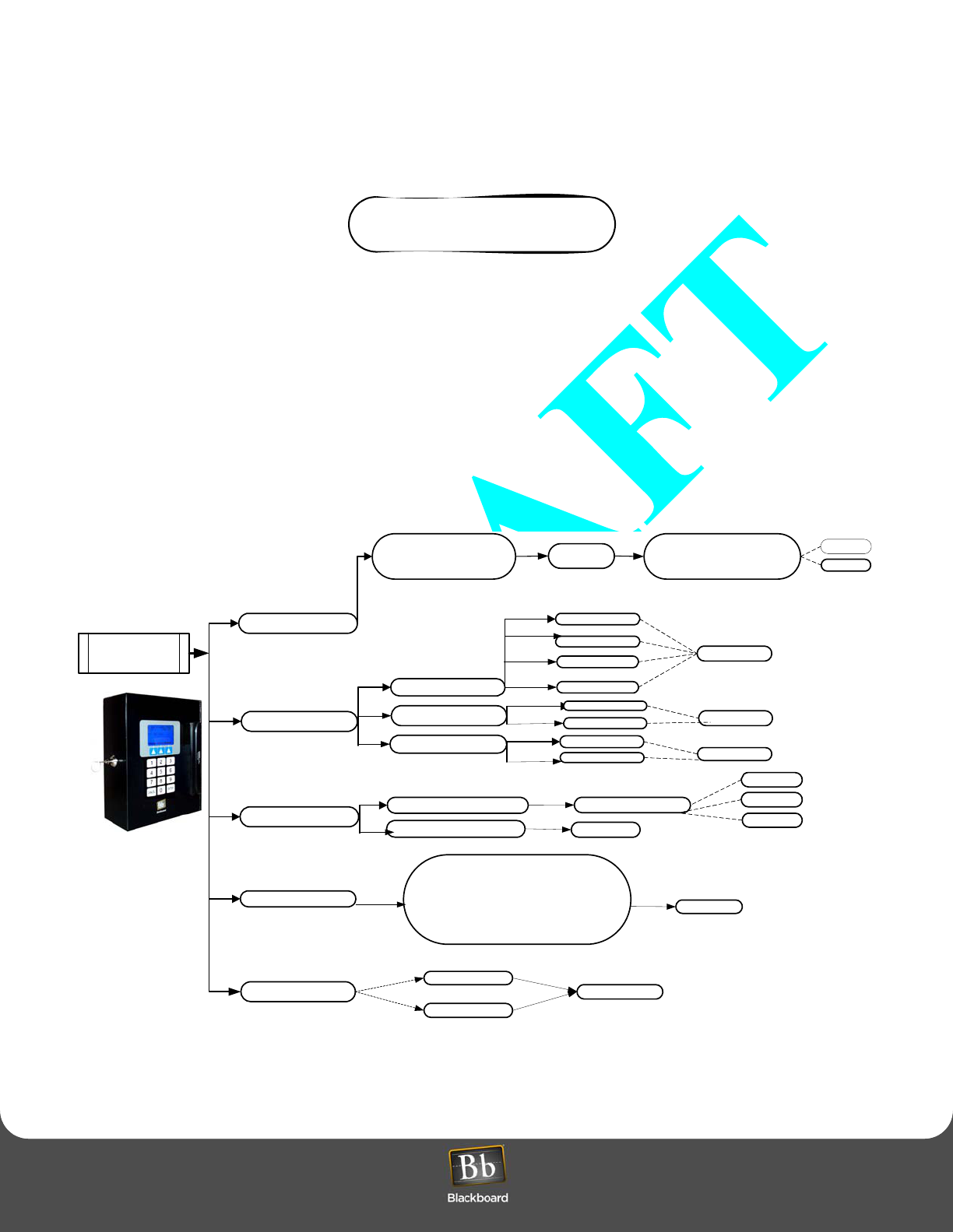
Manager Card Flowchart
Figure 25: Manager Card Flowchart
1 - Sales Total
3 - Machine Service
2 - Terminal Setup
5 - LCM20 Status
4 - Bridge Status
Swipe Manager’s
Card
CARD INTERVAL $
CARD INTERVAL #
CARD TOTAL $
CARD TOTAL #
Set Machine ID (1-60)
1 - Set in/Out Service
2 – View Out of Service
CLEAR
OK
ABORT
OK
A _ _
I _ _
OK
Display Backlight
Display Contrast
Volume Setup
INC OK
DEC
INC OK
DEC
4= High
1 = Off
2 =Low
3=Medium OK
NEXT
CASH INTERVAL $
CASH INTERVAL #
CASH TOTAL$
CASH TOTAL #
CLEAR
OK
1 – Not Defined
2 – Not Defined
3 – Not Defined
4 – Not Defined
5 – Not Defined
6 – Not Defined
7 - No Bridge Comm
OK
LAUNDRY COMPONENT DIMENSIONS AND WEIGHT
Laundry Installation and Setup Guide 37
LAUNDRY COMPONENT DIMENSIONS AND WEIGHT
LAUNDRY COMPONENT DIMENSIONS AND WEIGHT
• LC3000: 9.6" H x 7.92” W x 3.3" D, 7.6 lbs
• LE3/PSENCL: 9.6" H x 7.92" W x 3.3" D, 7.6 lbs
• LE3/BRIDGE: " H x ?" W x ?" D, 1.0 lb
• LW3XXX: 4" H x 3.1" W X 1.5" D, 1.0 lb
Figure 26: LC3000 Dimensions
7.220''
6.270''
0.720''
8.940''
0.940''
0.000''
8.840''
0.000''
ACMAIN
Mount
Mount
Mount Mount
9.660''
3.360''
6.360''
1.200
4.200
7.920''

FEATURES
Laundry Installation and Setup Guide 38
FEATURES
FEATURES
• Includes 15-key keypad and an 8-line x 21 character LCD display
• Contains a keyed lock to secure the inside of the unit, along with a hinged door to access the circuit boards (If
you prefer a high security lock or unique keys, you can purchase Medeco 60W-0750-239 from RA-LOCK
Company (800-777-6310.)
• Supports 10/100Base-T or RS-485 Communication
• Supports wired or 2.46Hz wireless communication to laundry machines
• Compatible with both Universal and Unix Editions of BbTS
Table 4: LC3000 Component Specifications
LC3000
Power Input Voltage Range
Input Frequency
Input Current
120VAC
60Hz
1.4A, max
Operating Environment Temperature
Relative Humidity
Altitude
0 to +45C (+32 to +114F)
0 to 95 percent, non-condensing
0 -10,000 feet
Non-Operating
Environment Temperature
Relative Humidity
Altitude
-20 to +70 C (-4 to +158F)
0 to 95 percent, non-condensing
0 - 35,000 feet
LE3/PSENCL
with LCM20
Power Input Voltage Range
Input Frequency
Input Current
120VAC
60Hz
1.4A, max
Operating Environment Temperature
Relative Humidity
Altitude
0 to +45C (+32 to +114F)
0 to 95 percent, non-condensing
0 -10,000 feet
Non-Operating
Environment Temperature
Relative Humidity
Altitude
-20 to +70 C (-4 to +158F)
0 to 95 percent, non-condensing
0 - 35,000 feet
LE3/BRIDGE
Power Input Voltage Range
Input Frequency
Input Current
9 to 30 VAC or 7 to 36 VDC
60Hz
0.12A, max
Operating Environment Temperature
Relative Humidity
Altitude
0 to +45C (+32 to +114F)
0 to 95 percent, non-condensing
0 -10,000 feet
Non-Operating
Environment Temperature
Relative Humidity
Altitude
-20 to +70 C (-4 to +158F)
0 to 95 percent, non-condensing
0 - 35,000 feet
LWI3xxx
Power Input Voltage Range
Input Frequency
Input Current
9 to 30 VAC or 7 to 36 VDC
60Hz
0.12A, max
Operating Environment Temperature
Relative Humidity
Altitude
0 to +45C (+32 to +114F)
0 to 95 percent, non-condensing
0 -10,000 feet
Non-Operating
Environment Temperature
Relative Humidity
Altitude
-20 to +70 C (-4 to +158F)
0 to 95 percent, non-condensing
0 - 35,000 feet

DEFAULT LC3000 CONFIGURATION SETTINGS
Laundry Installation and Setup Guide 39
DEFAULT LC3000 CONFIGURATION SETTINGS
• Reader supports up to 60 laundry machines
• IP and Wireless protocol encrypted using AES
• Software compatible with Danyl LCU
• Retrofit path for Danyl LMI machine interfaces
• Supports debit-ready laundry machines
• Software downloads remotely
• Supports coin-operated machines and tracks the number of cycles and amount collected during each coin
cycle.
This device contains an integrated lithium battery. There is a risk of fire if the battery is replaced with an
incorrect type. Proper disposal of a used battery is essential. Please follow the manufacturer’s instructions.
DEFAULT LC3000 CONFIGURATION SETTINGS
The LC3000 Controller Unit default settings are:
• DHCP enabled
• NP (host) IP address assigned by DHCP server
Restore Default Settings
Forget your password? Refer to Restore Default Settings on page for details.
1Connect a cable from a computer’s serial port to the one labelled “RS-232 CONFIG”.
Cable connections are shown in Table 2: RS-232 Config Port Connection, on page 15.
2Open a terminal program (such as Hyperterminal) and establish connection settings:
• 9600 baud
•1 stop
• no parity
• no flow control
3Type xxx within 3 seconds after “Config Task Started” is displayed in the terminal program. “Restoring to Factory
Defaults will display during reset.
4Disconnect cable from RS-232 CONFIG.

ERROR MESSAGES (UNIX ONLY)
Laundry Installation and Setup Guide 40
ERROR MESSAGES (UNIX ONLY)
ERROR MESSAGES (UNIX ONLY)
When a transaction cannot be completed successfully, the reader displays the TRANSACTION INVALID message
followed by an explanation:
Card Deleted: The cardholder’s card number has been deleted from BbTS and is no longer valid at the reader.
Card Expired: The card has expired.
Card Invalid: LS#; The issue code on the card does not match the issue code the System is expecting.
Card Invalid: LS; The card has been reported lost or stolen.
Card Not in System: The card is not entered in the System.
Card Suspended: The card account does not have a sufficient balance or credit to cover the purchase. The remaining
balance is displayed.
If the account has a negative balance, the balance is displayed with a minus sign; for example, -5.00.
Invalid Location: The privilege plan rules deny the use of the privilege at the location where the cardholder has
attempted to use it.
Invalid On Holiday: The system is programmed to recognize holidays. The privilege plan rules do not allow the use of
the privilege during a holiday.
Over Credit Limit: The cardholder’s transaction goes over the credit limit defined in the privilege plan rules, or, the
cardholder’s personal credit limit has exceeded.
Over Daily Limit: The cardholder’s transaction goes over the amount limited per transaction as defined in the privilege
plan rules.
Plan Expired: A cardholder’s privilege plan has expired.
Plan Suspended: A cardholder’s privilege plan has been suspended.
Privilege Expired: A cardholder’s privilege has expired.
Privilege Suspended: The cardholder has the privilege, but the privilege has been suspended for some reason.
Privilege Unassigned: The privilege the cardholder attempted to use is not assigned to the cardholder.
ERROR MESSAGES (UNIVERSAL EDITION)
Insufficient Funds?

RETROFITS
Laundry Installation and Setup Guide 41
RETROFITS
RETROFITS
MW9010/MW9012 LCR Retrofits (For Wired Laundry Centers only)
If you have an existing system equipped with an MW9010/MW9012 laundry reader, you will need to have retrofits
installed. The LC3000 can communicate with laundry machines through LCM2, LCM20, and LWI and is intended to
support retrofit or new installations. This support is managed locally by the LC3000.
The LC3000, as shipped from Blackboard, is configured for up to 60 machines on up to 3 LCM20s. If LCM2 support is
required, it may be changed in the reader with the “machine” command. This command can be used either from the
RS-232 CONFIG or using Telnet.
Each of the 60 machines can reside on an LCM2, LCM20, or LWI. The machine command usage is as follows:
machine [machine number] [lcm2|1cm20]
To change machine 5 from LCM20 to a LCM2, type the following:
machine 5 lcm2
In addition, all machines can be changed simultaneously from one interface to another. For example:
machine alllcm20
machine alllcm2
By typing “machines”, you list all the machine interfaces for all 60 machines.
Each LWI or Wireless Bridge is not required to use this machine command. When the LC3000 updates the
local machine definition, they are also configured with the LWI Config.
The local machine interface definitions permanently remain within the reader and are not affected by any other
command.
Danyl Retrofits

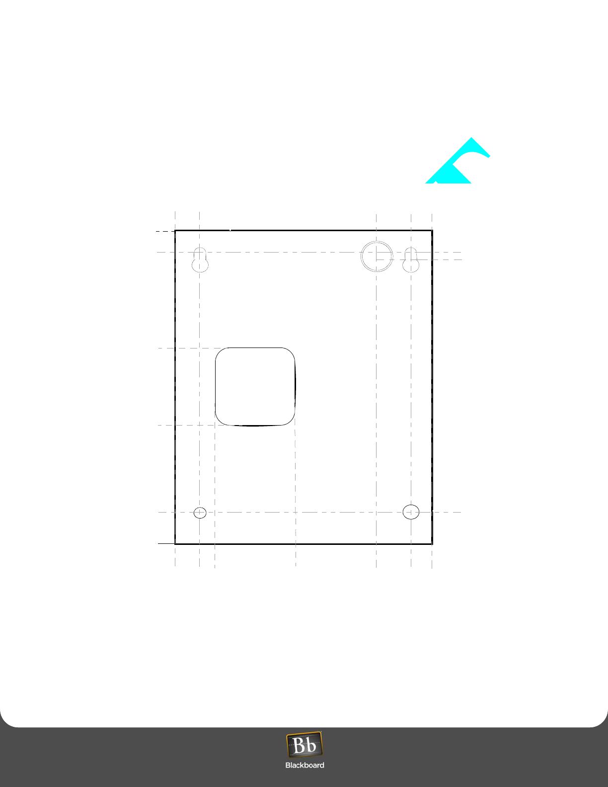
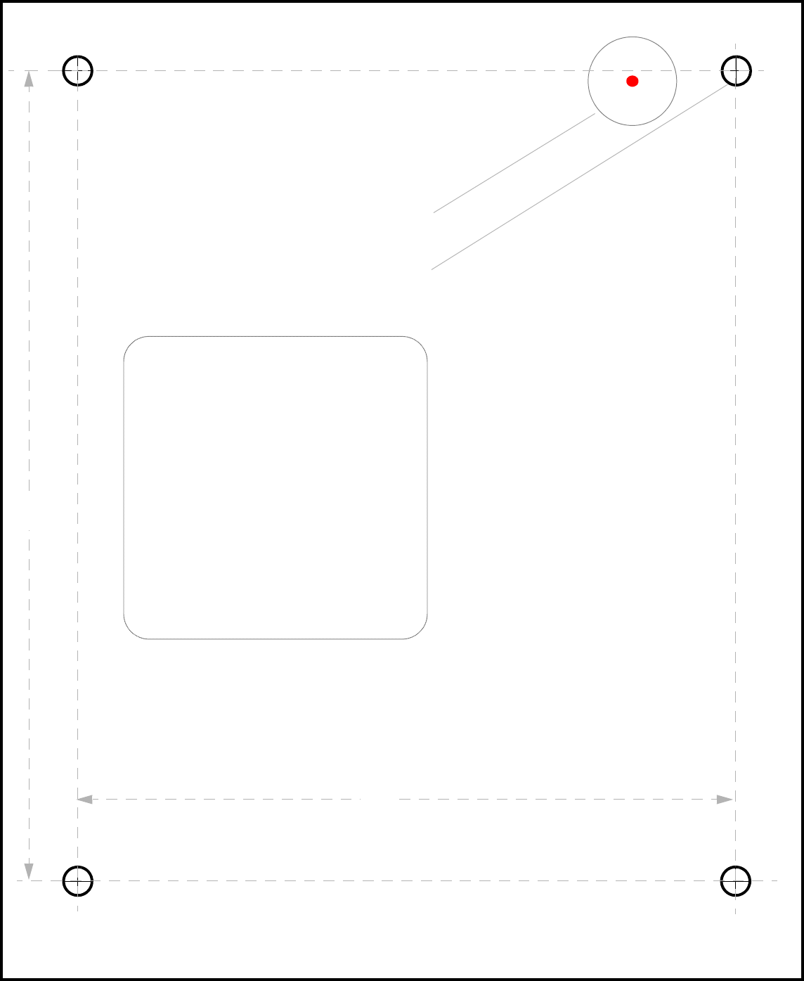
LC3000 DRILL TEMPLATE
Laundry Installation and Setup Guide 42
LC3000 DRILL TEMPLATE
LC3000 DRILL TEMPLATE
ACMAIN
Mount
Mount
Mount Mount
LC3000
Drill Template
6.5''
8''
accepts 1/4'' mounting h/w
3'' x 3'' cable opening
accepts 1/2'' conduit fitting
Top