Transact Campus MF4100X004 Multi-Function Reader User Manual 1295 MF4100 InstallAdmin
Blackboard Inc. Multi-Function Reader 1295 MF4100 InstallAdmin
User Manual

DRAFT
MF4100
Installation Guide

DRAFT
This device complies with Part 15 of the FCC Rules. Operation is subject to the following two conditions: (1) This
device may not cause harmful interference, and (2) this device must accept any interference received, including
interference that may cause undesired operation.
Part 15.21: Changes or modifications not expressly approved by the party responsible for compliance could void the user’s
authority to operate the equipment.
NOTE: The manufacturer is not responsible for any radio or TV interference caused by unauthorized modifications to this
equipment. Such modifications could void the user’s authority to operate the equipment.
This equipment complies with the FCC radiation exposure limits set forth for an uncontrolled environment. End users must
follow the specific operating instructions for satisfying RF exposure compliance. The antenna(s) used for this transmitter must
be installed to provide a separation distance of at least 20 cm from all persons and must not be co-located or operating in
conjunction with any other antenna or transmitter.
This Class B digital apparatus complies with
Canadian ICES-003
Cet appareill numérique de la classes B est conform
à la norme NMB-003 du Canada

DRAFT
Contents
PRINTED N OVEMBER 3, 2009 I
1MF4100 INSTALLATION GUIDE
1 Overview
3 VESA Mounting Bracket Overview
3 Mounting Options
3 Screw Positions
4 Assembly Details
5 Mount the MF4100
6 Wall Mount Installation
6 Attended Wall Mount Installation
8 Unattended Wall Mount Installation
10 Table Top Mount Installation
10 Table Top Mount With The VESA Mounting Bracket
12 Table Top Mount Without The VESA Mounting Bracket
13 MF4100 Features and Specifications

DRAFT
FIGURES
PRINTED N OVEMBER 3, 2009 II
Figure 1-1 Multi-Function Reader MF4100..................................................................1
Figure 1-2 Cat-5 Cable and Power Supply ..................................................................2
Figure 1-3 MF4100 Hardware Kit ................................................................................2
Figure 1-4 VESA Bracket.............................................................................................2
Figure 1-5 VESA Bracket Screw Position - Attended ..................................................3
Figure 1-6 VESA Bracket Screw Position - Unattended ..............................................4
Figure 1-7 VESA Bracket Assembly Details ................................................................4
Figure 1-8 Wall Mount Options ....................................................................................5
Figure 1-9 Table Top Mount Options............................................................................5
Figure 1-10 VESA Bracket - Attended Wall Mount ........................................................6
Figure 1-11 MF4100 Cable Ports ..................................................................................7
Figure 1-12 Attended Wall Mount VESA Bracket Orientation........................................7
Figure 1-13 Reader Secured to Pivot Plate - Attended Wall Mount...............................8
Figure 1-14 VESA Bracket - Unattended Wall Mount....................................................8
Figure 1-15 Unattended Wall Mount VESA Bracket Orientation....................................9
Figure 1-16 VESA Bracket Rubber Feet......................................................................10
Figure 1-17 Table Top Mount - With VESA Bracket Cable Route................................11
Figure 1-18 Reader Rubber Feet Installation Locations ..............................................12
Figure 1-19 Table Top Mount - No VESA Bracket Cable Route ..................................12
DRAFT
MULTI-FUNCTION READER MF4100 INSTALLATION GUIDE
DOCUMENT 1295 REV 01
PRINTED N OVEMBER 3 , 2 0 0 9 1-1
MF4100 INSTALLATION GUIDE
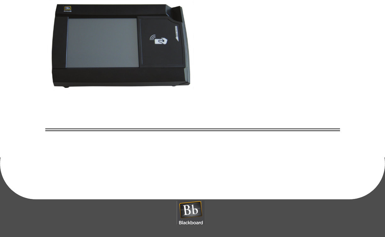
OVERVIEW
The Blackboard MF4100 Multi-function reader incorporates both contactless and magnetic stripe reader
capabilities, and can function as a:
• Copy Reader
• Laundry Reader
• POS Terminal
The MF4100 supports full video and audio playback allowing for a rich video experience for:
• Advertising
• Alerts and notifications
• Other special messages via a full color touch screen
For MF4100 features, see: MF4100 Features and Specifications (Page: 13).
Figure 1-1 Multi-Function Reader MF4100
OBJECTIVES
After reading this guide you can:
• Wall mount the MF4100 •Table top mount the MF4100
DRAFT
OVERVIEW
PRINTED N OVEMBER 3, 2009 1-2
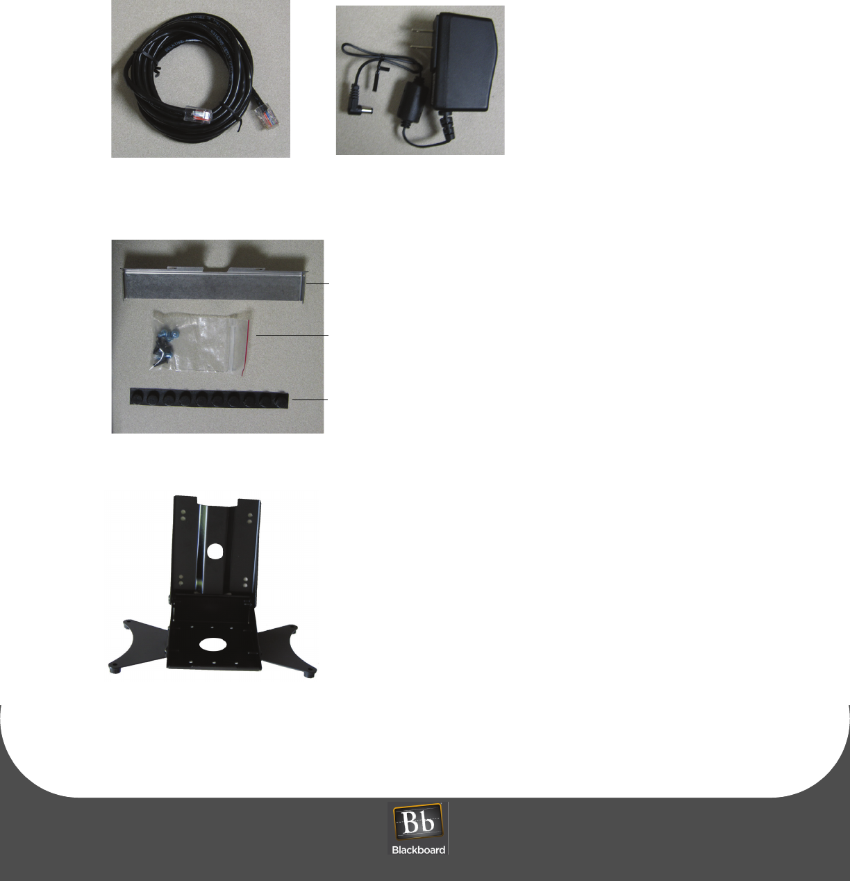
WHAT’S INCLUDED
A hardware kit is provided with a security plate, rubber feet, and screws to aid in mounting the unit.
Figure 1-2 Cat-5 Cable and Power Supply
Figure 1-3 MF4100 Hardware Kit
Figure 1-4 VESA Bracket
Cat-5 Cable Wall Mount Power Supply
Security Plate
Screw kit
Rubber Feet
DRAFT
MULTI-FUNCTION READER MF4100 INSTALLATION GUIDE
DOCUMENT 1295 REV 01
PRINTED N OVEMBER 3 , 2 0 0 9 1-3
VESA MOUNTING BRACKET OVERVIEW
The MF4100 Multi-Function Reader ships with a VESA style mounting bracket. The mounting bracket is
optional, but simplifies installation on vertical and horizontal surfaces. The VESA mounting bracket is
adjustable to allow the MF4100 to be positioned at different angles.
Mounting Options
The VESA Mounting Bracket can be mounted in the following ways:
• Wall mount
• Onto an electrical gang box (attended or unattended)
• Directly to a wall (use suitable anchors)
• Table top mount
• With VESA bracket (fixed 15 degree or adjustable angle)
• Without VESA bracket
The holes in the center of the base and pivot plate allow cables to be routed out of the assembly.
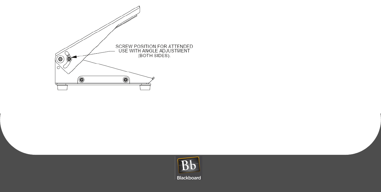
Screw Positions
The VESA bracket has provisions for Attended or Unattended mounting positions. To use in attended
locations, the top pivot plate can be used in any position by placing the lock screws in the position shown
below.
Figure 1-5 VESA Bracket Screw Position - Attended
DRAFT
VESA MOUNTING BRACKET OVERVIEW
PRINTED N OVEMBER 3, 2009 1-4
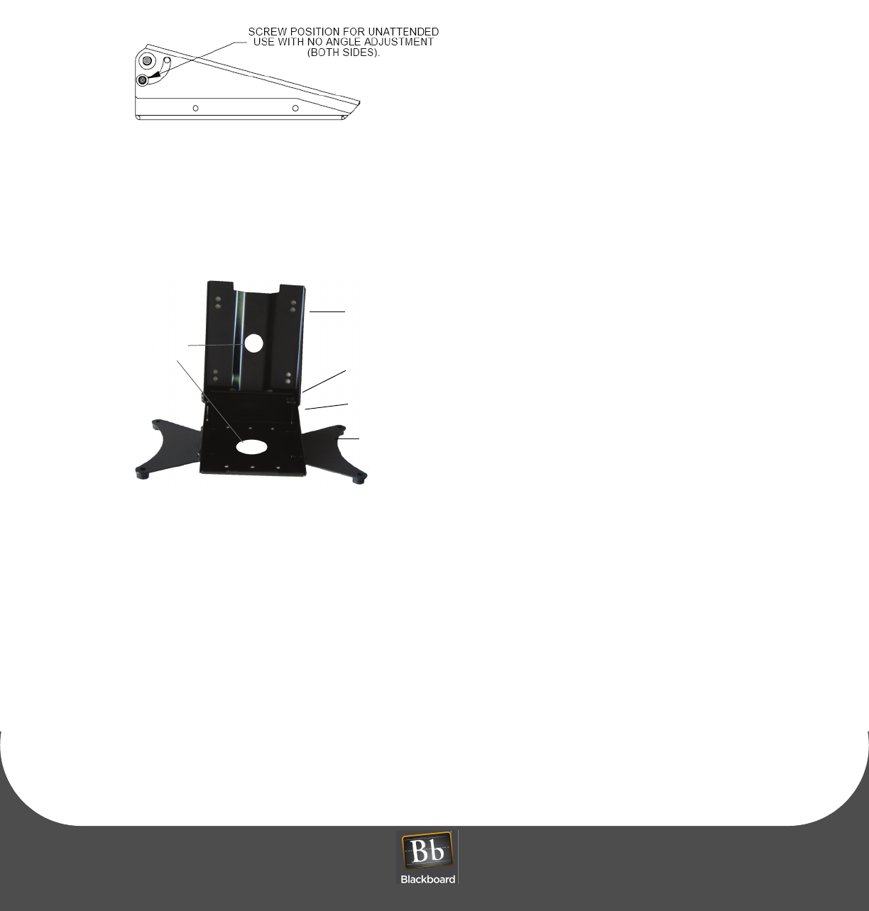
For Unattended use, the mounting position can be fixed by placing the lock screws in the position shown
below. This locked position conceals the cables from sight, and secures them from being tampered with.
Figure 1-6 VESA Bracket Screw Position - Unattended
Assembly Details
Figure 1-7 VESA Bracket Assembly Details
Base extensions
Locking screws
Pivot Plate
Base
Cable Holes
DRAFT
MULTI-FUNCTION READER MF4100 INSTALLATION GUIDE
DOCUMENT 1295 REV 01
PRINTED N OVEMBER 3 , 2 0 0 9 1-5
MOUNT THE MF4100
MF4100 MOUNTING OPTIONS:
• Wall Mount Installation (Page: 6)
• Table Top Mount Installation (Page: 10)
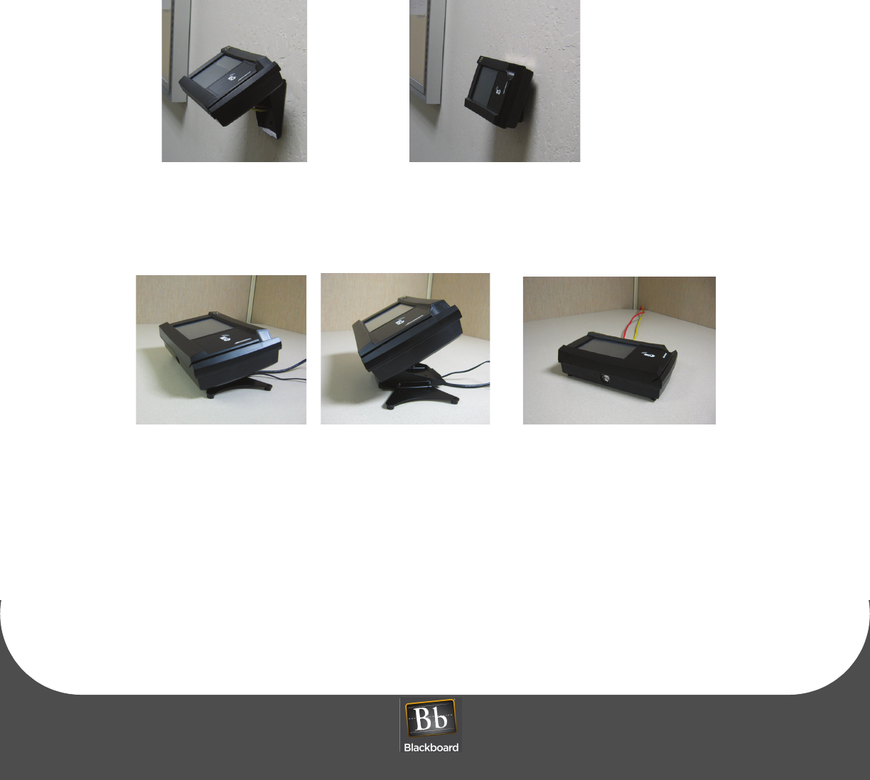
Figure 1-8 Wall Mount Options
Figure 1-9 Table Top Mount Options
Unattended wall mountAttended wall mount
Fixed 15 degree angle Adjustable angle No VESA bracket
DRAFT
WALL MOUNT INSTALLATION
PRINTED N OVEMBER 3, 2009 1-6
WALL MOUNT INSTALLATION
The VESA mounting bracket allows for two wall mount installation options:
•Attended Wall Mount Installation (Page: 6)
•Unattended Wall Mount Installation (Page: 8)
Attended Wall Mount Installation
1Find a location on a single gang box to mount the MF4100.
Ensure there is enough clearance for the operator to access the touchscreen and swipe cards.
2Remove the two base extensions by removing the 4 screws (1/8” Pin hex driver).
See: VESA Bracket Assembly Details (Page: 4).
3Place the two locking screws in the position that allows the tilt plate to pivot (1/8” Pin hex driver).
See: VESA Bracket Screw Position - Attended (Page: 3).
4Route the required cables through the VESA bracket cable hole, and then the pivot bracket hole.
Note the orientation of the VESA bracket to the wall.
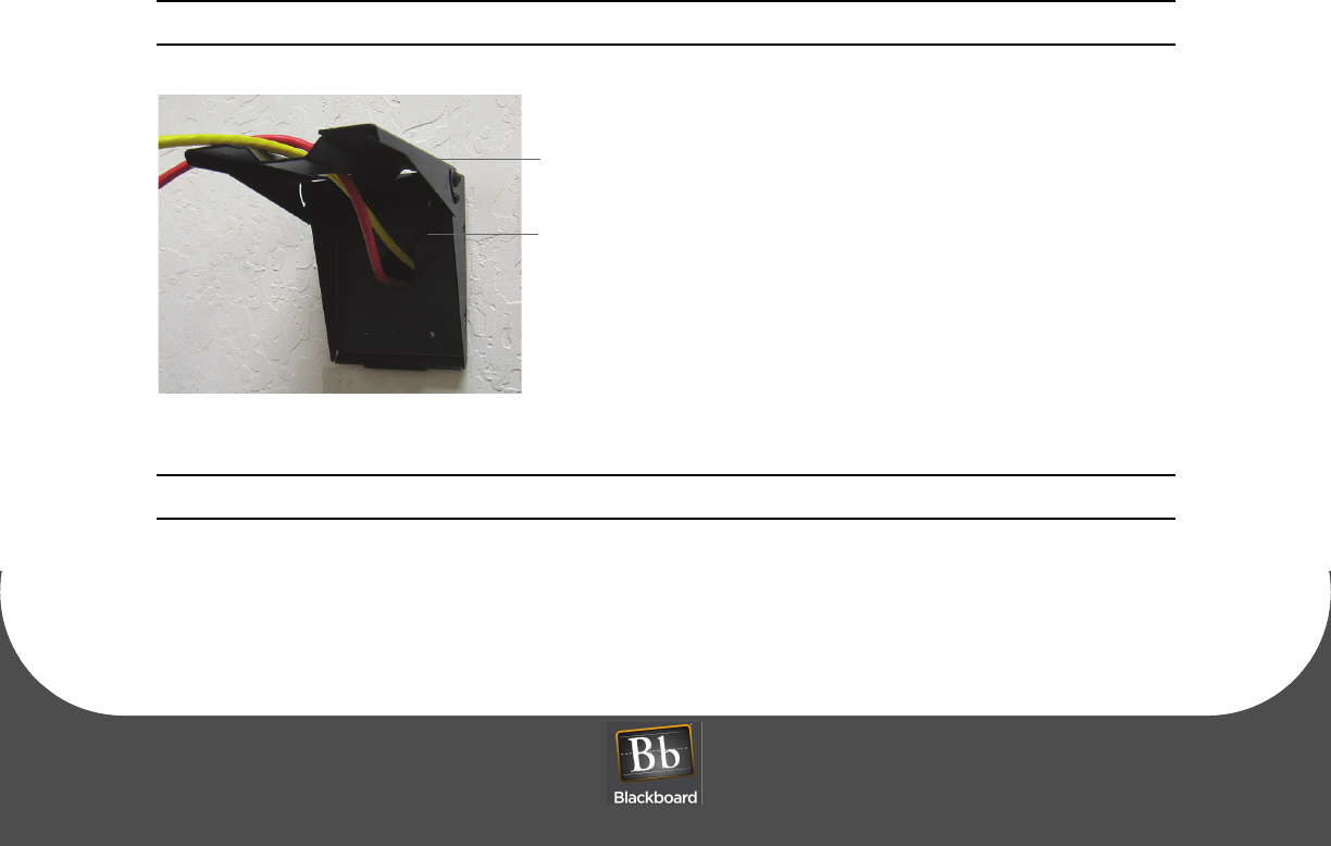
Figure 1-10 VESA Bracket - Attended Wall Mount
Note: The pivot plate attaches to the bottom of the MF4100 reader.
5Attach the mounting base to the gang box using the two #6-32 pin hex screws provided in the
hardware kit.
6Install cables to the connectors of the MF4100.
Route Cables
Pivot Plate
DRAFT
MULTI-FUNCTION READER MF4100 INSTALLATION GUIDE
DOCUMENT 1295 REV 01
PRINTED N OVEMBER 3 , 2 0 0 9 1-7
The MF4100 can be powered using the +12 Volt wall mount power supply (included), or Power
Over Ethernet (POE) switch. The power supply requires a dedicated 110 VAC outlet. POE
provides power through the network cable, and reduces cable clutter. A CAT-5 cable must be
connected between the POE switch to the RJ-45 connector on the MF4100 labeled Network,
see the diagram below. When providing power with POE, the maximum LAN cable length
must not exceed 100 meters.
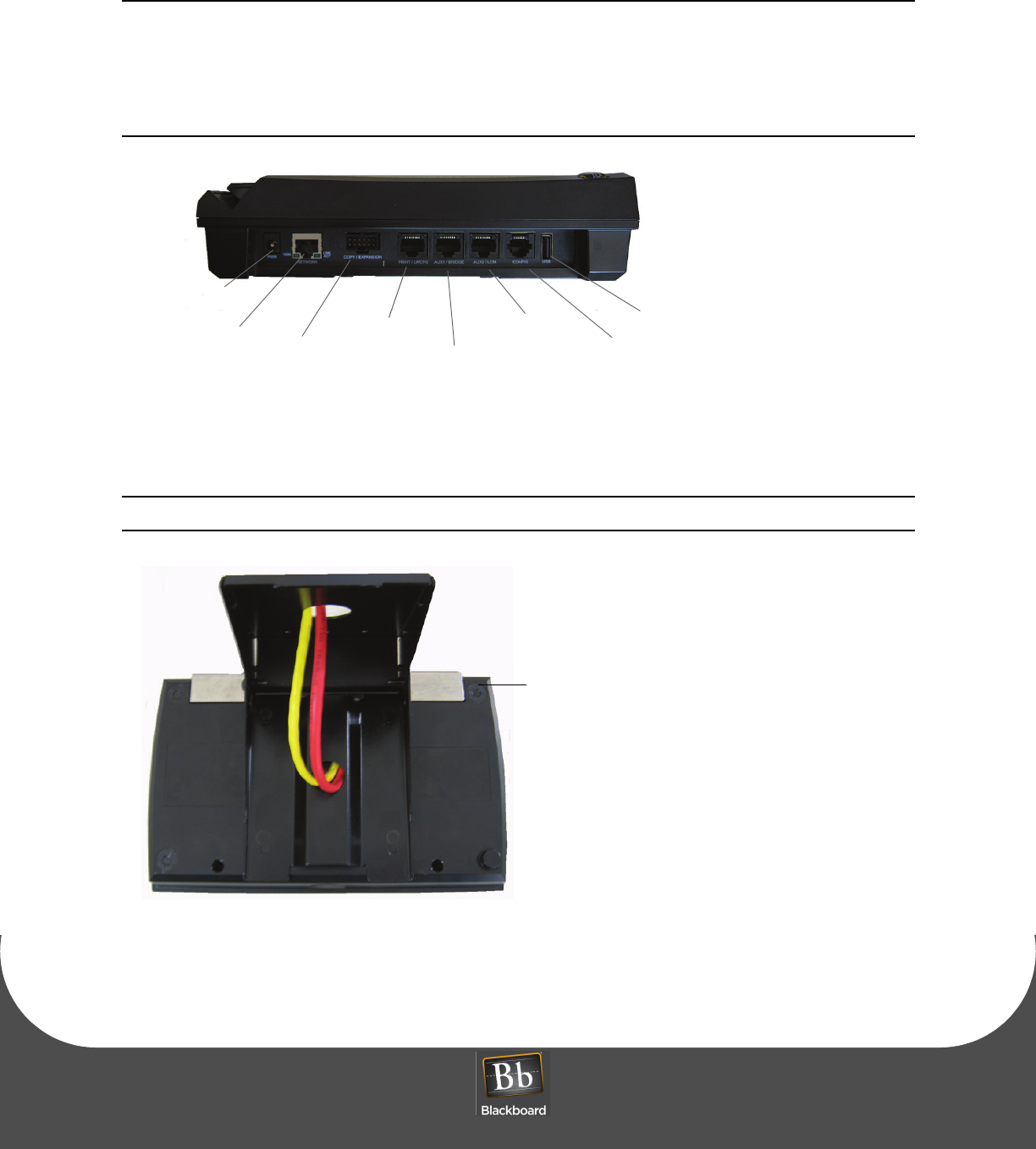
Figure 1-11 MF4100 Cable Ports
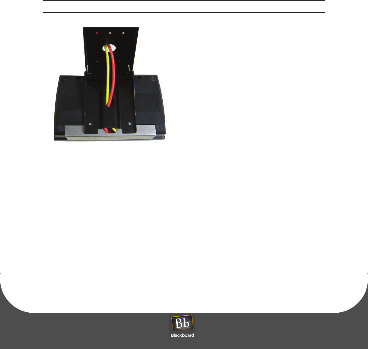
7Place the security plate onto the MF4100, and then route the cables through the plate opening.
Note the orientation of the VESA bracket to the security plate.
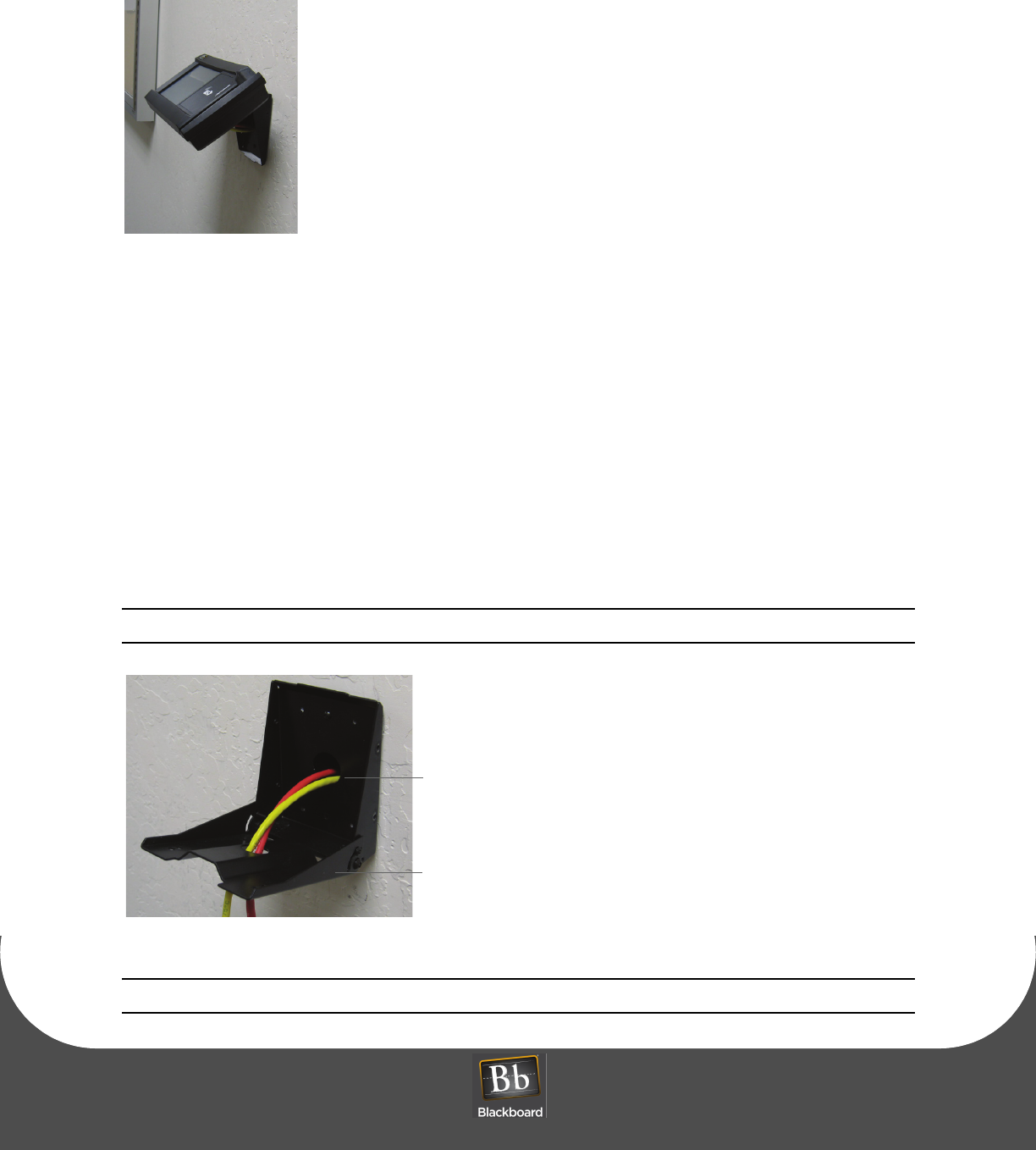
Figure 1-12 Attended Wall Mount VESA Bracket Orientation
8Place the MF4100 assembly on the pivot plate, and then secure using four M4 x 6mm machine screws
provided in the hardware kit.
Power Supply
Network/POE Copy Print/LWCFG
AUX1/Bridge
AUX2/LCM
Config
USB
Expansion
Security plate
DRAFT
WALL MOUNT INSTALLATION
PRINTED N OVEMBER 3, 2009 1-8
Figure 1-13 Reader Secured to Pivot Plate - Attended Wall Mount
9Position the pivot plate to the desired angle, and then tighten the 2 locking screws (1/8” pin hex driver).
Unattended Wall Mount Installation
1Find a location on a single gang box to mount the MF4100.
Ensure there is enough clearance for the operator to access the touchscreen and swipe cards.
2Remove the two base extensions by removing the 4 screws (1/8” pin hex driver).
See: VESA Bracket Assembly Details (Page: 4).
3Route the required cables through the VESA bracket cable hole, and then the pivot bracket hole.
Note the orientation of the VESA bracket to the wall.
Figure 1-14 VESA Bracket - Unattended Wall Mount
Note: The pivot plate attaches to the bottom of the MF4100 reader.
Route Cables
Pivot Plate
DRAFT
MULTI-FUNCTION READER MF4100 INSTALLATION GUIDE
DOCUMENT 1295 REV 01
PRINTED N OVEMBER 3 , 2 0 0 9 1-9
4Attach the mounting base to the gang box using the two #6-32 pin hex screws provided in the
hardware kit.
5Install cables to the connectors of the MF4100.
See: MF4100 Cable Ports (Page: 7).
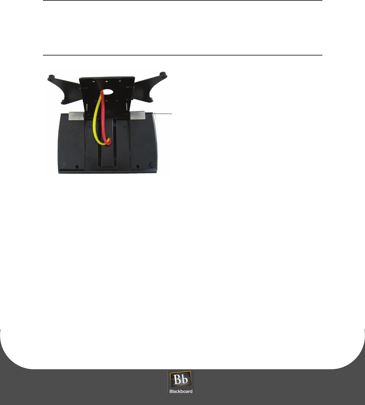
6Place the security plate onto the MF4100, and then route the cables through the plate opening.
Note the orientation of the VESA bracket to the security plate.
Figure 1-15 Unattended Wall Mount VESA Bracket Orientation
7Place the MF4100 assembly on the pivot plate, and then secure using four M4 x 6mm machine screws
provided in the hardware kit.
8Position the pivot plate to the desired angle, and then tighten the 2 locking screws (1/8” pin hex driver).
Security plate
DRAFT
TABLE TOP MOUNT INSTALLATION
PRINTED N OVEMBER 3, 2009 1-10
TABLE TOP MOUNT INSTALLATION
MF4100 table top mounting installation options:
•Table Top Mount With The VESA Mounting Bracket (Page: 10)
•Table Top Mount Without The VESA Mounting Bracket (Page: 12)
Table Top Mount With The VESA Mounting Bracket
1Find a location on a table or elsewhere to mount the MF4100.
Ensure there is enough clearance for the operator to access the touchscreen and swipe cards.
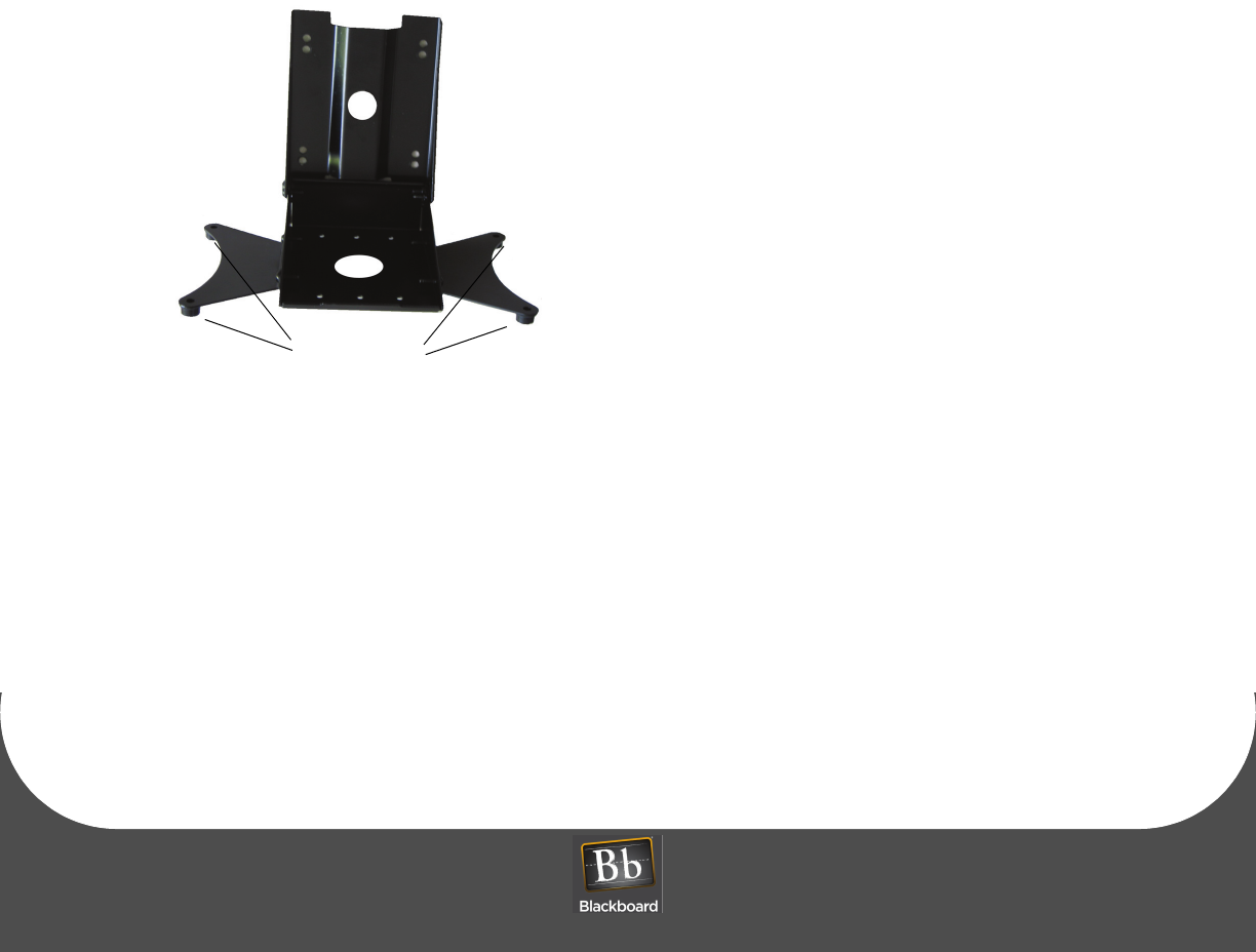
2Install the rubber feet provided in the hardware kit to each corner of the base extensions.
The rubber feet are self-adhesive. Use the holes in the base extension to center each foot.
Figure 1-16 VESA Bracket Rubber Feet
3Route the required cables through the VESA bracket cable hole, and then the pivot bracket hole.
4Install cables to the connectors of the MF4100.
See: MF4100 Cable Ports (Page: 7).
5Place the security plate onto the MF4100, and then route the cables through the plate opening.
Rubber Feet
DRAFT
MULTI-FUNCTION READER MF4100 INSTALLATION GUIDE
DOCUMENT 1295 REV 01
PRINTED N OVEMBER 3 , 2 0 0 9 1-11
For a fixed 15 degree angle, install the MF4100 so the security plate is located near the hinge
of the VESA mounting bracket. Place the locking screws in the unattended position.
See: VESA Bracket Screw Position - Unattended (Page: 4)
For an adjustable angle, install the MF4100 so the speaker opening is located near the hinge
of the VESA mounting bracket. Place the locking screws in the attended position.
See: VESA Bracket Screw Position - Attended (Page: 3)
Figure 1-17 Table Top Mount - With VESA Bracket Cable Route
6Secure the VESA bracket using four M4 x 6mm machine screws provided in the hardware kit.
7Tighten the 2 locking screws (1/8” pin hex driver).
Security plate
DRAFT
TABLE TOP MOUNT INSTALLATION
PRINTED N OVEMBER 3, 2009 1-12
Table Top Mount Without The VESA Mounting Bracket
1Find a location on a table or elsewhere to mount the MF4100.
Ensure there is enough clearance for the operator to access the touchscreen and swipe cards.
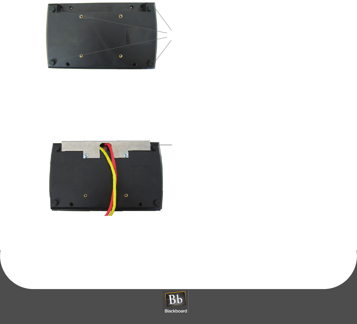
2Install the rubber feet provided in the hardware kit to each corner of the MF4100 plastic bottom cover.
The rubber feet are self-adhesive. The bottom cover has round depressions in the plastic to locate the
rubber feet. Install a rubber foot at each of the four corners.
Figure 1-18 Reader Rubber Feet Installation Locations
3Install the required cables to the connectors of the MF4100.
See: MF4100 Cable Ports (Page: 7).
4Place the security plate onto the MF4100, and then route the cables through the opening.
Figure 1-19 Table Top Mount - No VESA Bracket Cable Route
5Secure the security plate onto the MF4100 using two M4 x 6mm machine screws provided in the
hardware kit.
Rubber feet (4)
Security Plate

DRAFT
MULTI-FUNCTION READER MF4100 INSTALLATION GUIDE
DOCUMENT 1295 REV 01
PRINTED N OVEMBER 3 , 2 0 0 9 1-13
MF4100 FEATURES AND SPECIFICATIONS
FEATURES:
• Host communications via 10/100 Base-T ethernet (IP) or 802.11 b/g wireless
• Encrypted and authenticated IP communications
• VESA mounting bracket for table top or wall mount installation
• Display visible in all light conditions with adjustable backlight level
• Displays balance, account warnings, and other messages after transactions
• 5.7” VGA TFT-LCD panel
• Configuration via touchscreen/display, CONFIG port or web server
• Touchscreen configuration access can be disabled
• Adjustable volume setting
SPECIFICATIONS:
Physical Size: 9.0” W x 5.5”H x 2.21” D (without bracket) 1.7 pounds
Input Power: 12 VDC 750 mA max (max 9W) - DC Input Voltage
36-57 VDC - POE Input Voltage
Operating : Temperature: 0 to + 60 degrees Celsius
Relative Humidity: 0 to 95 percent, non-condensing
Altitude: 0 -10,000 feet
Non-Operating: Temperature:-20 to + 70 degrees Celsius
Relative Humidity: 0 to 95 percent, non-condensing
Altitude: 0 - 35,000 feet