Transact Campus PR5000X011 Point of Sale Reader User Manual PR5000 HW Install Guide
Blackboard Inc. Point of Sale Reader PR5000 HW Install Guide
User Manual

403-002-018 Rev A
Point of Sale Reader (PR5000)
Hardware Installation Guide
403-002-018 Rev A
Table 0-1: Revision History
Bb Document Part Number Rev. Description Date
403-002-018 AECO10431. Initial Release. PENDING

403-002-018 Rev A
Federal Communications Commission (FCC) statement
This device complies with Part 15 of the FCC Rules. Operation is subject to the following
two conditions:
1. This device may not cause harmful interference.
2. This device must accept any interference received, including interference that may
cause undesired operation.
Note: This equipment has been tested and found to comply with the limits for a Class A
digital device, pursuant to Part 15 of the FCC Rules. These limits are designed to provide
reasonable protection against harmful interference when the equipment is operated in a
commercial environment. This equipment generates, uses, and can radiate radio
frequency energy, and if it is not installed and used in accordance with the instruction
manual, it may cause harmful interference to radio communications. Operation of this
equipment in a residential area is likely to cause harmful interference, in which case the
user will be required to correct the interference at his own expense.
Modifications: Any modifications made to this device that are not approved by
Blackboard Inc. may void the authority granted to the user by the FCC to operate this
equipment.
IMPORTANT NOTE: This equipment complies with the FCC radiation exposure limits set
forth for an uncontrolled environment. End users must follow the specific operating
instructions for satisfying RF exposure compliance. The antenna(s) used for this
transmitter must be installed to provide a separation distance of at least 20 cm from all
persons and must not be co-located or operating in conjunction with any other antenna or
transmitter.
Contains:
FCC ID: VPYLB1DX Murata WLAN + Bluetooth Combo Module (LBEE5KL1DX-883)
FCC ID: WAP2005 Cypress Semiconductor Bluetooth Low-Energy Module (CYBLE-222014-01)

403-002-018 Rev A
Industry Canada Class A emission compliance statement
This Class A digital apparatus complies with Canadian ICES-003.
Cet appareil numérique de la classe A est conforme à la norme NMB-003 du Canada.
This device complies with Industry Canada licence-exempt RSS standard(s). Operation is subject to the
following two conditions: (1) this device may not cause interference, and (2) this device must accept any
interference, including interference that may cause undesired operation of the device.
Le présent appareil est conforme aux CNR d'Industrie Canada applicables aux appareils radio exempts de
licence. L'exploitation est autorisée aux deux conditions suivantes : (1) l'appareil ne doit pas produire de
brouillage, et (2) l'utilisateur de l'appareil doit accepter tout brouillage radioélectrique subi, même si le
brouillage est susceptible d'en compromettre le fonctionnement.
Contains:
Contient des IC: 772C-LB1DX and 7922A-2005
Australia and New Zealand Class A statement
Attention: This is a Class A product. In a domestic environment this product may cause radio interference
in which case the user may be required to take adequate measures.
Radiation Exposure Statement
This equipment complies with radiation exposure limits set forth for uncontrolled environment. The
antenna(s) used for this transmitter must be installed to provide a separation distance of at least 20 cm
from all persons and must not be collocated or operating in conjunction with any other antenna or
transmitter.
Déclaration d'exposition aux radiations
Cet appareil se conforme aux limites d'exposition aux rayonnements pour un environnement non contrôlé.
L'antenne (s) qui est utilisé pour cet émetteur doit être installé pour produire une distance de séparation
d'au moins 20 cm de toutes personnes et ne doit pas être installé à proximité ou utilisé en conjonction avec
une autre antenne ou émetteur.
IC: 772C-LB1DX Murata WLAN + Bluetooth Combo Module (LBEE5KL1DX-883)
IC: 7922A-2005 Cypress Semiconductor Bluetooth Low-Energy Module (CYBLE-222014-01)

403-002-018 Rev A
Note: The regulatory compliance information above can be viewed on the reader’s display. To
view this information on the reader, at the Main Menu, press the Regulatory Information
button.

Contents
403-002-018 Rev A I
1 BLACKBOARD POINT OF SALE READER (PR5000) HARDWARE INSTALLATION GUIDE
1 Overview
1Features:
2 PR5000 Functional Overview
2 Inputs and Outputs:
2 Functional Overview - Bottom
3 Functional Overview - Top
4 PR5000 Mount Kit
5 INSTALLING THE PR5000 READER
5 Reader Installation Overview and Wiring Considerations
5 Wiring and Power Considerations:
6 Tabletop Installation
6 Install the reader on a tabletop
7 Wall Mount Installation
8 Installing the Mount Kit
10 Connecting Cables
11 Technical Specifications
OVERVIEW
1-1
403-002-018 Rev A
BLACKBOARD POINT OF SALE READER (PR5000)
HARDWARE INSTALLATION GUIDE
OVERVIEW
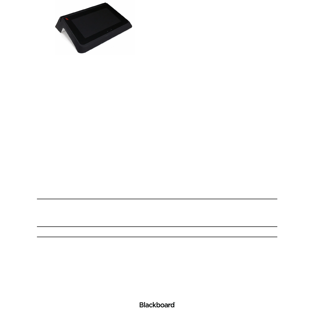
The Blackboard Point of Sale (POS) Reader PR5000 is an Android-based reader. When configured, the
PR5000 communicates with the Blackboard Transaction System (BbTS), and incorporates both
contactless and magnetic stripe reader capabilities. The reader can be set up as either an attended or
unattended device.
Features:
• Bluetooth Classic and BLE compatible.
• Large LCD capacitive touchscreen.
• Adjustable screen backlight.
• Manual screen rotation (180°).
• Wireless communication to the host.
• A real time clock.
• LEDs at the bottom of the unit for illumination.
LED options:
• a - Device Idle
• b - Valid Transaction
• c - Invalid Transaction
The LED options are configurable. When enabled, the color and brightness are adjustable.
• Discernible tones for valid and invalid transactions.
• Stereo speakers (2).
• The PR5000 supports: Sony Felica, MIFARE Classic, MIFARE DESFire EV1 & EV2, and Blackboard Mobile
Credentials (Android only).
The following is the list of features that are included, but will not be operational for the first phase. Look for
future releases that enable these features.
• Ambient Light Sensor - The display dims and brightens based on ambient light in the device location.
• Camera - Captures an image with each transaction. This enables the ability to view an image with a transaction for
situations such as investigating fraud claims, to determine cause of damage to the device, etc.
• Microphone - This is an ADA feature. Use this feature to call for assistance when encountering issues during a transaction
or to have any questions answered.
• Proximity Sensor - Motion wakes up the device to either display the beginning transaction screen (varies based on device
software running) or play video/images from the Media Server.
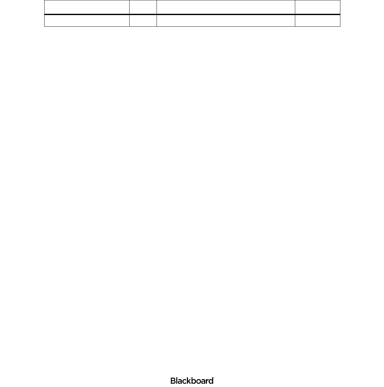
Figure 1-1 PR5000 Reader
PR5000 FUNCTIONAL OVERVIEW
1-2
403-002-018 Rev A
PR5000 FUNCTIONAL OVERVIEW
Inputs and Outputs:
• One RJ-45 connector that is utilized for Power over Ethernet standard 802.3af at 15.40 W.
• Two USB 2.0 Type A connectors.
• One USB Type C connector that support USB 2.0 high speed data transfer.
• 12V - 15W DC Power Input
• Two 2W stereo speakers
Functional Overview - Bottom
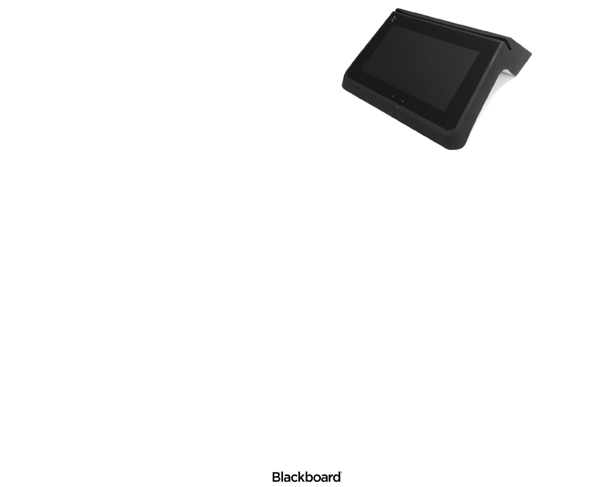
Figure 1-2 Functional Overview - Bottom
Bottom of the PR5000 Reader
LEDs (4)
Stereo Speakers (2)
USB 2.0 Type A
USB Type C
Micro SD Card
Connector
DC Power Input
RJ-45
Reset
Button
PR5000 FUNCTIONAL OVERVIEW
1-3
403-002-018 Rev A
Functional Overview - Top
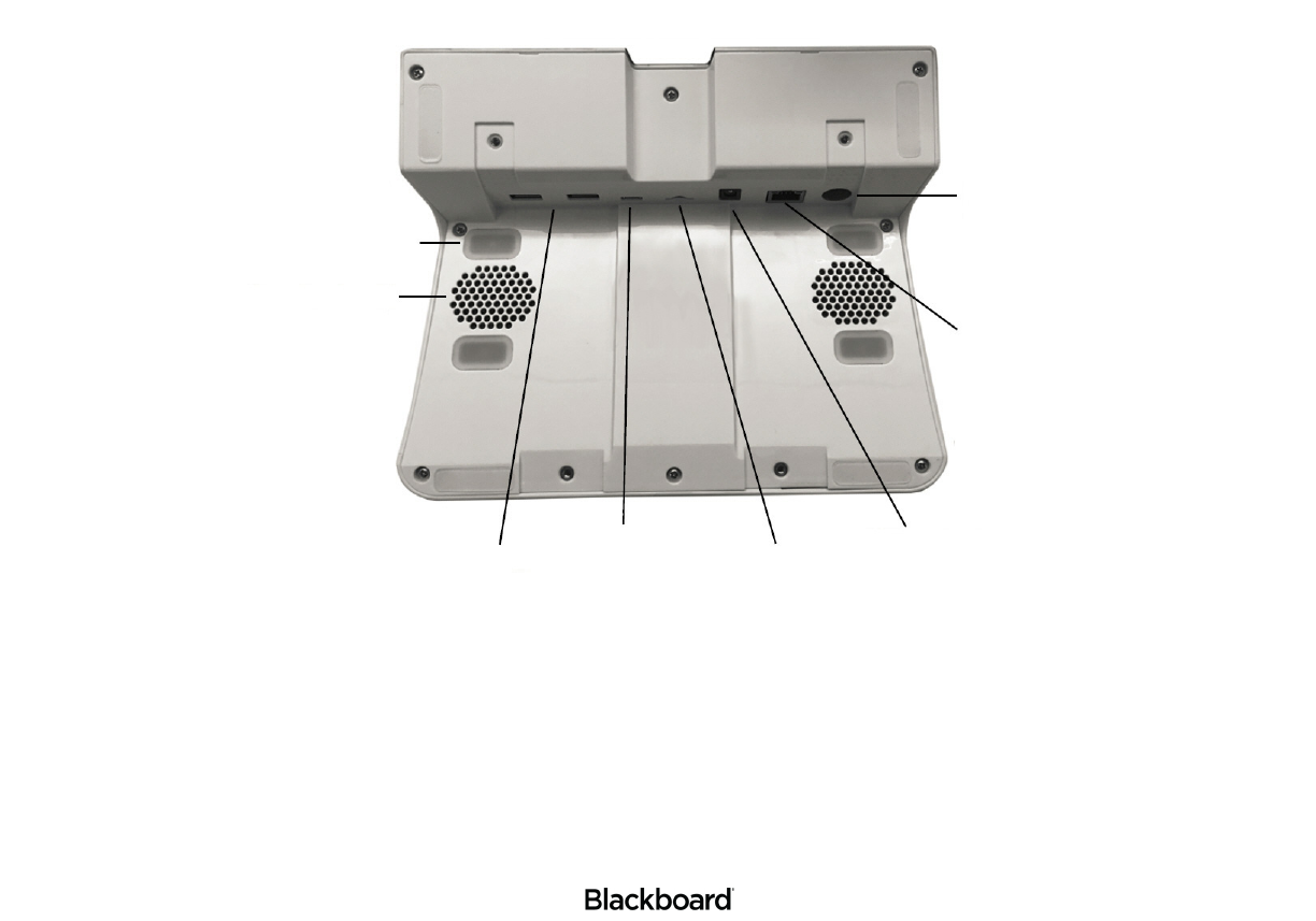
Figure 1-3 Functional Overview - Top
LCD Captive
Touchscreen
Proximity and
Ambient Light Sensor
Microphone
Camera
Magnetic
Card Reader
Microphone
PR5000 MOUNT KIT
1-4
403-002-018 Rev A
PR5000 MOUNT KIT
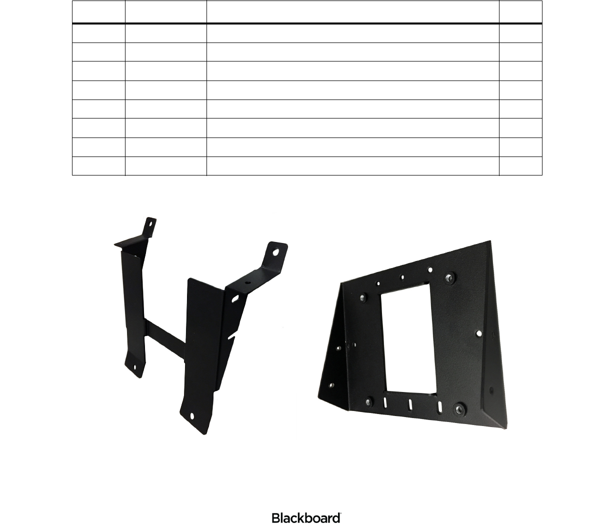
A mount kit is provided to aid in mounting the reader to a wall. Open the packaging, and then verify that all
parts are included. If there are any discrepancies, contact your Blackboard Client Manager.
Figure 1-4 PR5000 Mount Kit
Table 1-1: List of parts
ITEM NO. PART NUMBER DESCRIPTION QTY.
1 044-028-C34 M4 X 6MM PANHEAD MACHINE SCREW, ZINC PLATED 5
2 044-028-E39 6-32 X 3/4 TRUSS HEAD PHILLIPS MACHINE SCREW 5
3 044-028-E40 6-32 X 1_4 SS FLAT HEAD PHILLIPS MACHINE SCREW 5
4 044-042-041 RJ45 CAT5e 10' PATCH CABLE, BLACK 1
5 044-046-E03 6-32 X 1/2 TAMPER PROOF SCREW 5
6 044-051-000 12V, 30W INERNATIONAL POWER SUPPLY, ENERGYSTAR LEV5 1
7 044-059-119 PR5000 MOUNT BASE 1
8 044-059-120 PR5000 MOUNT 1
PR5000 Mount PR5000 Mount Base

READER INSTALLATION OVERVIEW AND WIRING CONSIDERATIONS
1-5
403-002-018 Rev A
INSTALLING THE PR5000 READER
The Blackboard PR5000 Reader can be placed on a tabletop or secured to a wall.
This section includes the following:
•Reader Installation Overview and Wiring Considerations (page 1-5)
•Tabletop Installation (page 1-6)
•Wall Mount Installation (page 1-7)
READER INSTALLATION OVERVIEW AND WIRING CONSIDERATIONS
Wiring and Power Considerations:
• Wall Wart power supply. (included)
• The power supply requires a dedicated outlet.
• Power Over Ethernet. (POE)
• POE provides power through the network cable, and reduces cable clutter.
• When providing POE, the maximum LAN cable length must not exceed 100 meters (328 Feet).
• Both the POE switch and PR5000 must be installed within the same building or structure.
• A CAT-5 cable must be connected between the POE switch and the port on the PR5000. (RJ-45)
Note: For a more details, see: the Blackboard Transact System Implementation Guide.
TABLETOP INSTALLATION
1-6
403-002-018 Rev A
TABLETOP INSTALLATION
Figure 1-5 PR5000 Tabletop Installation
The PR5000 Reader can be placed on a tabletop for events such as a fundraiser or a library book sale.
This section includes the instructions for installing the PR5000 Reader on a tabletop. Please review the
tabletop installation considerations before continuing.
Tabletop installation considerations:
• Wiring and Power Considerations reviewed.
• The location and the height of the reader should be selected to permit easy access.
• Ensure that Americans with Disabilities Act (ADA) requirements are met.
• In warm climates, the reader should be shaded from direct sunlight.
• The maximum external temperature of the reader must not exceed 104°F (40°C) to ensure that the internal temperature
limit is not exceeded.
• Ensure there is enough clearance for the operator to access the screen and swipe cards.
Install the reader on a tabletop
To install the reader on a tabletop
1Connect power, network, and communication cables to the reader.
See: PR5000 Functional Overview (page 1-2) and Connecting Cables (page 1-10).
Note: Connecting power is not required when using the battery option.
2Place the reader on the tabletop, and then neatly route all cables underneath the reader and out of the
way.
Optionally use cable ties to keep all cables together.
3Connect the power cord to a grounded outlet or power strip.
Tabletop installation is complete. See: the Point of Sale (PR5000) Configuration Guide to complete
your set up.
WALL MOUNT INSTALLATION
1-7
403-002-018 Rev A
WALL MOUNT INSTALLATION
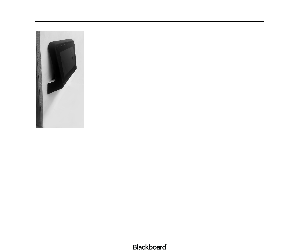
The PR5000 Reader ships with a mount kit. The kit is optional, but simplifies wall installation. Follow the
instructions in this section to properly mount your PR5000 Reader to a wall. Please review the wall mount
installation considerations before continuing. The Mount Kit is compatible with Video Electronics Standards
Association (VESA) 75 mounts (not included).
Note: The PR5000 includes a feature that allows you to rotate the screen 180 degrees. This is
helpful when mounting the reader to a wall. See: the Point of Sale (PR5000) Reader
Configuration Guide for instructions on how to enable and disable this feature.
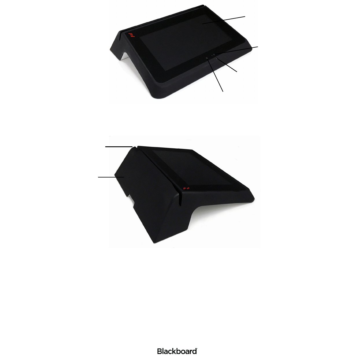
Figure 1-6 Wall Mount Installation
Wall mount installation considerations:
• Wiring and Power Considerations reviewed.
• An electrical gang box to provide power and a route for communication cables.
The reader will be attached to this gang box.
Note: The electrical gang box and wiring should be installed by a trained technician.
• The location and the height of the reader should be selected to permit easy access.
• Ensure that Americans with Disabilities Act (ADA) requirements are met.
• In warm climates, the reader should be shaded from direct sunlight.
• The maximum external temperature of the reader must not exceed 104°F (40°C) to ensure that the internal temperature
limit is not exceeded.
• Ensure there is enough clearance for the operator to access the screen and swipe cards.
WALL MOUNT INSTALLATION
1-8
403-002-018 Rev A
Installing the Mount Kit
To install the Mount Kit
1If you haven’t already, open the Mount Kit packaging, and then verify that all parts are included.
See: PR5000 Mount Kit (page 1-4) for the list of parts.
Note: If there are any discrepancies, contact your Blackboard Client Manager.
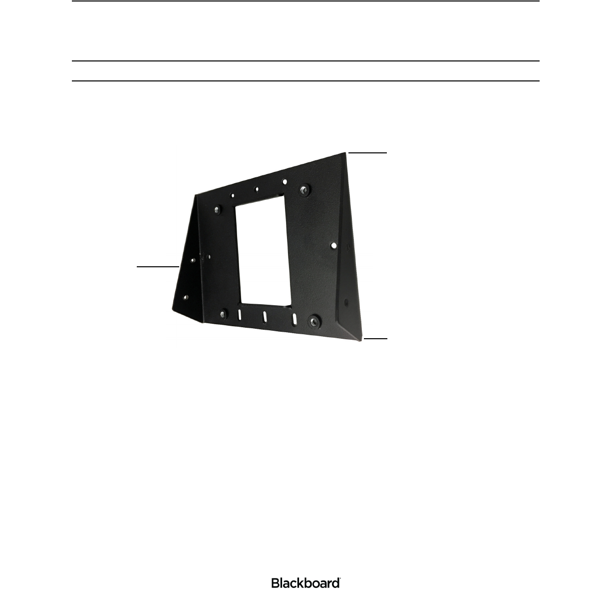
2Obtain the PR5000 Mount Base (Blackboard Part No. 044-059-119) or VESA 75 mount (not included).
When using the PR5000 Mount Base, review Figure 1-7 before continuing.
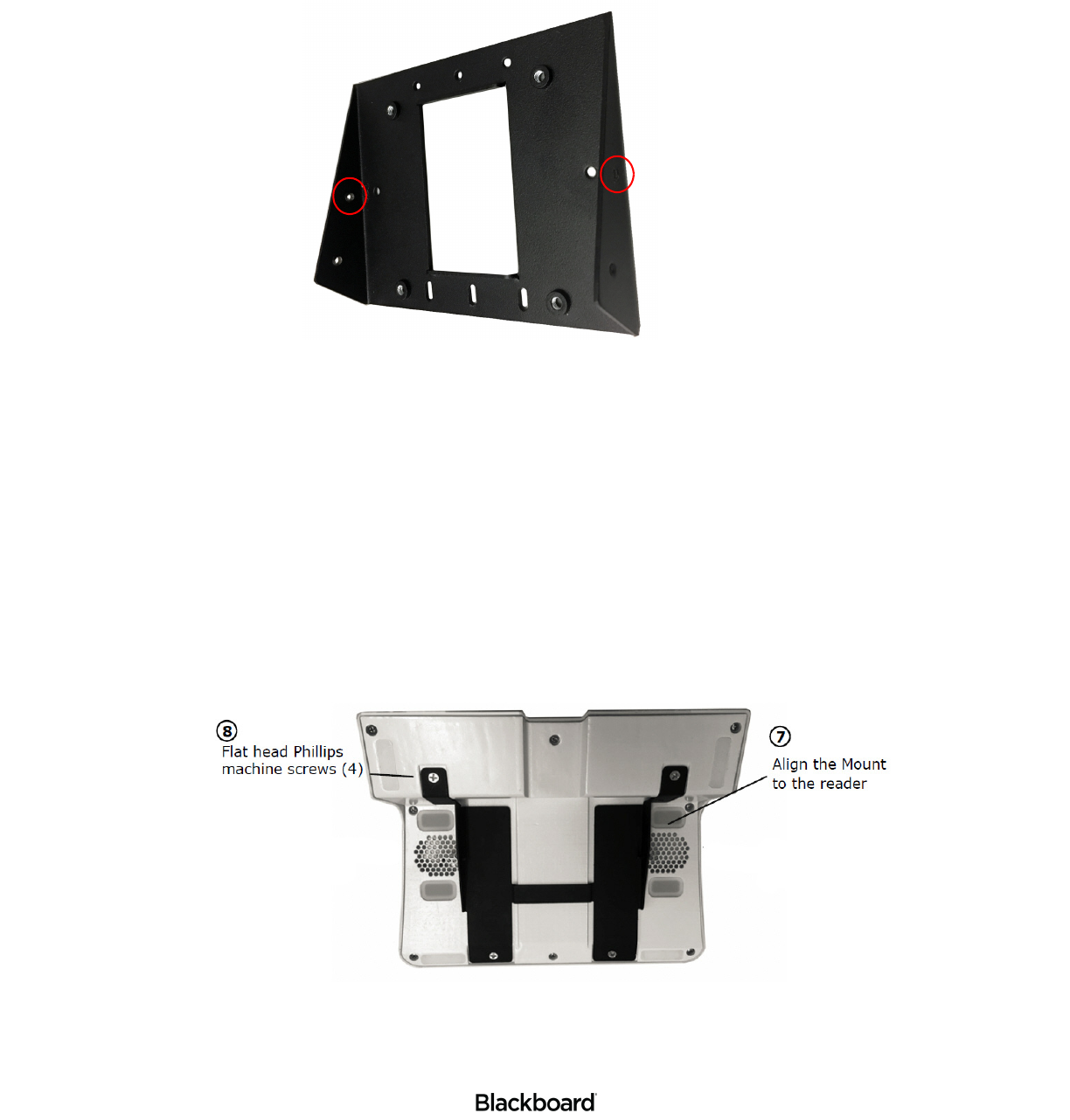
Figure 1-7 PR5000 Mount Base
3Attach the Mount Base or VESA 75 mount to the electrical gang box.
For the PR5000 Mount Base, use the 6-32 X 3/4 Truss Head Phillips machine screws (4).
For a VESA mount, use the M4 X 6mm Panhead machine screws (4).
Bottom
Top
Front
WALL MOUNT INSTALLATION
1-9
403-002-018 Rev A
Figure 1-8 Mount Base Installation
4Tighten all screws.
5Loosely install 6-32 X 1/2 Tamper Proof screws (2) in the upper screw holes shown in Figure 1-8.
The remaining Tamper Proof screws will be installed later.
6Obtain the PR5000 Reader and the PR5000 Mount included (Blackboard Part No. 044-059-120).
7Place the reader on a tabletop with the front of the reader facing downward.
Blackboard recommends using a towel or soft cloth underneath the reader to avoid scratches.
8Align the Mount with the reader as shown in Figure 1-9.
9Attach the Mount to the reader using the 6-32 X 1/4 SS Flat Head Phillips machine screws (4).
Figure 1-9 PR5000 Mount and Reader
Loosely install Tamper
Proof Screws (2) in the
upper screw holes.
WALL MOUNT INSTALLATION
1-10
403-002-018 Rev A
Connecting Cables
10 Connect cables to the PR5000. Refer to Figure 1-2.
Note: When using the PR5000 Reader as an Authorization Reader, configure the Transaction
Terminal Options in TS, see: the Blackboard Transaction System Administration Guide
(Hardware chapter). The reader provides data output through AUX1. A serial connection from
AUX1 to third-party hardware is required.
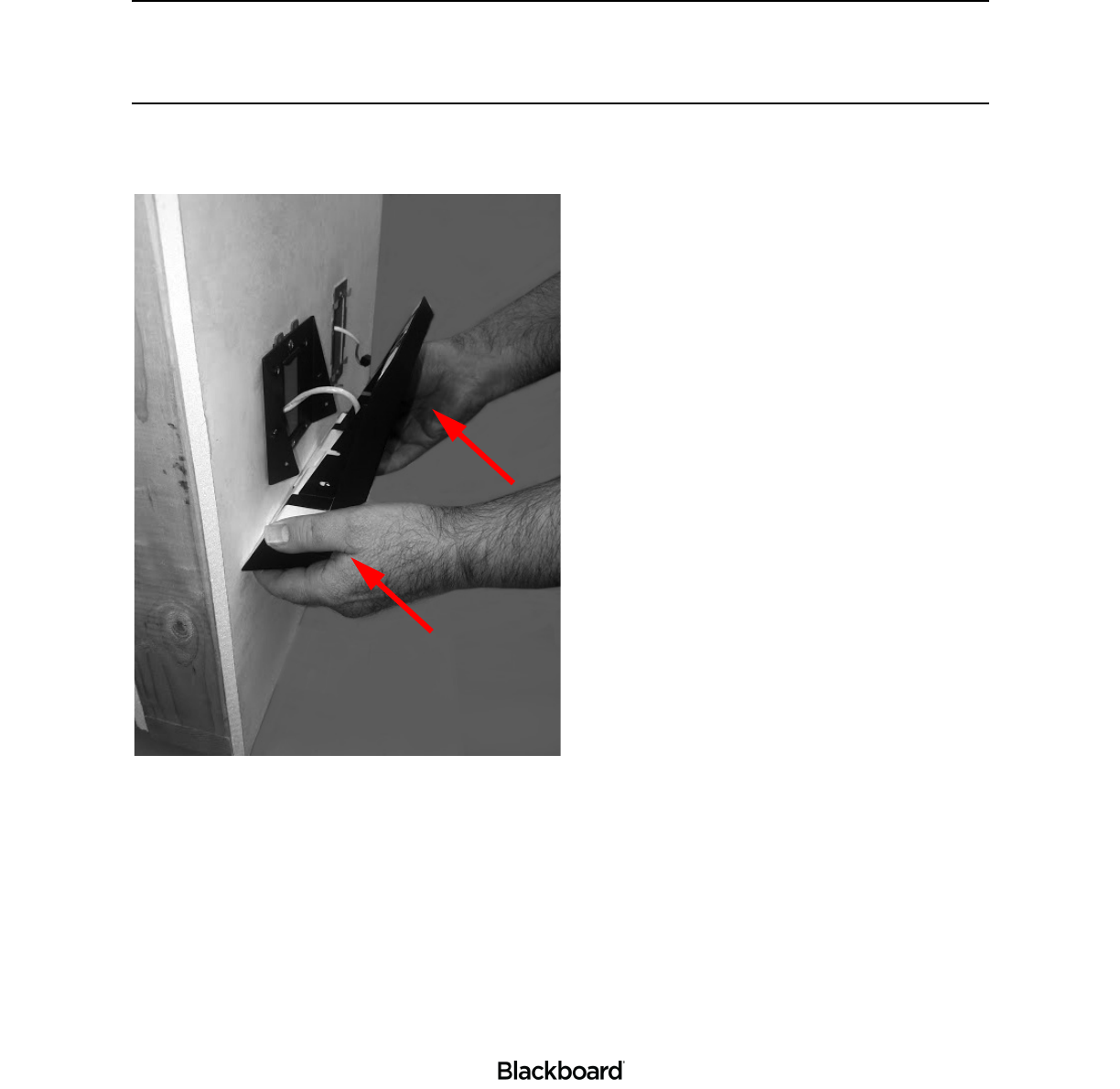
11 Place the PR5000 Reader on the Mount Base by sliding the Mount’s open slots over the loosely
attached screws previously installed.
Figure 1-10 Installing the PR5000 to Wall
12 Install two more 6-32 X 1/2 Tamper Proof screws into the lower slotted holes.
13 Tighten all four Tamper Proof screws.
14 Verify that the reader is secure.
Wall mount installation is complete. See: the Point of Sale (PR5000) Configuration Guide to complete
your setup.
TECHNICAL SPECIFICATIONS
1-11
403-002-018 Rev A
TECHNICAL SPECIFICATIONS
Table 1-2: PR5000 Technical Specifications
Dimensions: 9.0" x 7.5" x 2.3"
Weight: 1.55 lbs. (0.70 kg)
Input Power: 12 VDC 1.1 Amp. Maximum
Operating: Temperature range: 0 to 40 degrees Celsius.
Non-Operation: Temperature range: -20 to 70+ degrees Celsius.
Regulatory Compliance: US & Canada: FCC Part 15 Class A, CSA/UL 62368-1 Ed 2.0
Europe: EN 62368-1 Ed 2.0, CE Mark.
Australia/New Zealand: IEC 62368-1 Ed 2.0
USB 2.0 Type A Connectors (2): 5 Volts at 1 A
USB Type C Connector: 5 Volts at 1 A
Ethernet Connection: RJ-45 (POE). 802.3af at 15.40W.
Processor: i.MX 6 quad core processor
IP - Ingress Protection rating: IP 54
Operating system (OS): Android Lollipop 5.1.1
Host communication: 10/100 Base-T ethernet (IP) or wireless.
Display: 7 inch TFT LCD 1024 x 600 display.