Transamerica Broadcasting EM250DIG 250 Watt FM Broadcast Transmitter User Manual manual ING v1 1 EM 250CD
Transamerica International Broadcasting Inc 250 Watt FM Broadcast Transmitter manual ING v1 1 EM 250CD
Contents
- 1. User Manual Part 1
- 2. user Manual Part 2
user Manual Part 2
06/06/02 OMB Eng. Dpt.
Driver FM v1.2
7W FM Driver 05.01.01.000
1 2 34
A
B
C
D
4
321
D
C
B
A
Drawn
Checked
Standards
Date Name Signature:
Scale:Title Drawing nr:
Replace:
Replaced with:
Sistemas Electrónicos S.A.
FM Transmitter
Sistemas Electrónicos S.A EM 250 COMPACT DIG
Technical Manual - v1.1 - February 2006 37
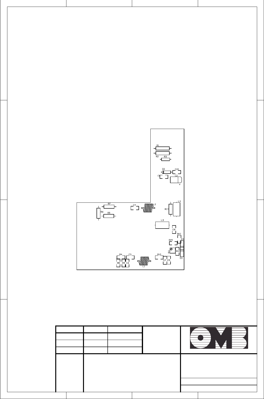
FM 300W Power Amplifier
DESCRIPTION REFERENCE QUANTITY
Cap. 33pF SMD 1206 100V C1 1
Cap. 470pF SMD 1210 5% 200V NPO C2, C11-C14 5
Cap. 1nF SMD 1206 100V C3-C6, C16,C20 6
Cap. 150pF 100V Ceramic C7,C8 2
Cap. 100uF SMD t50V Electrolytic C15 1
Cap. 22nF SMD 1206 200V Ceramic X7R C17 1
Cap. 47pF SMD 1210 5% 500V C17 C18 1
Cap. 15pF SMD 1210 5% 500V C17 C19 1
Diode BAT54 SMD SOT-23 D1,D2 2
Zener diode 10V SMD 0.35W D4 1
Thread 0.8mm Cu-Ag 30mm. approx. Material for L1 and TR2 fixing
Thread 1mm Cu enamelled 250mm. approx. Material for L2
Thread 1.5mm Cu-Ag 50mm. approx. Material for L5 and TR1 fixing
Axial ferrite L3,l4 2
Output transformer core L5 1
22: SMD 1206 1/4W r2,r3 2
Potentiometer 1turn 1K 3/8” R4 1
Metal 1 : / 2W L=12mm =3.9mm
Non-inductive
R5 1
Res. 10: SMD 1206 1/4W R6-R9 4
Res. 10: Coal 2W L=16mm =5.5mm Non-inductive R10 1
Res. 330: SMD 1206 R11 1
Res. 110: SMD 1206 R12 1
Res. 1K8: SMD 1206 R14 1
Res. 10: SMD 0805 R15 1
Output Transformer TR1 1
Input Transformer TR2 1
Connection terminals tab 2.8x0.5 CON1,CON2 2
Female-female hex. separator 10mm Brass-Nickel CON3 1
MOSFET, N 108MHz 300W SALD BLF278 Q1 1
04/05/04 M. Tsvelev
MODPOT v1.3 04.04.01.003
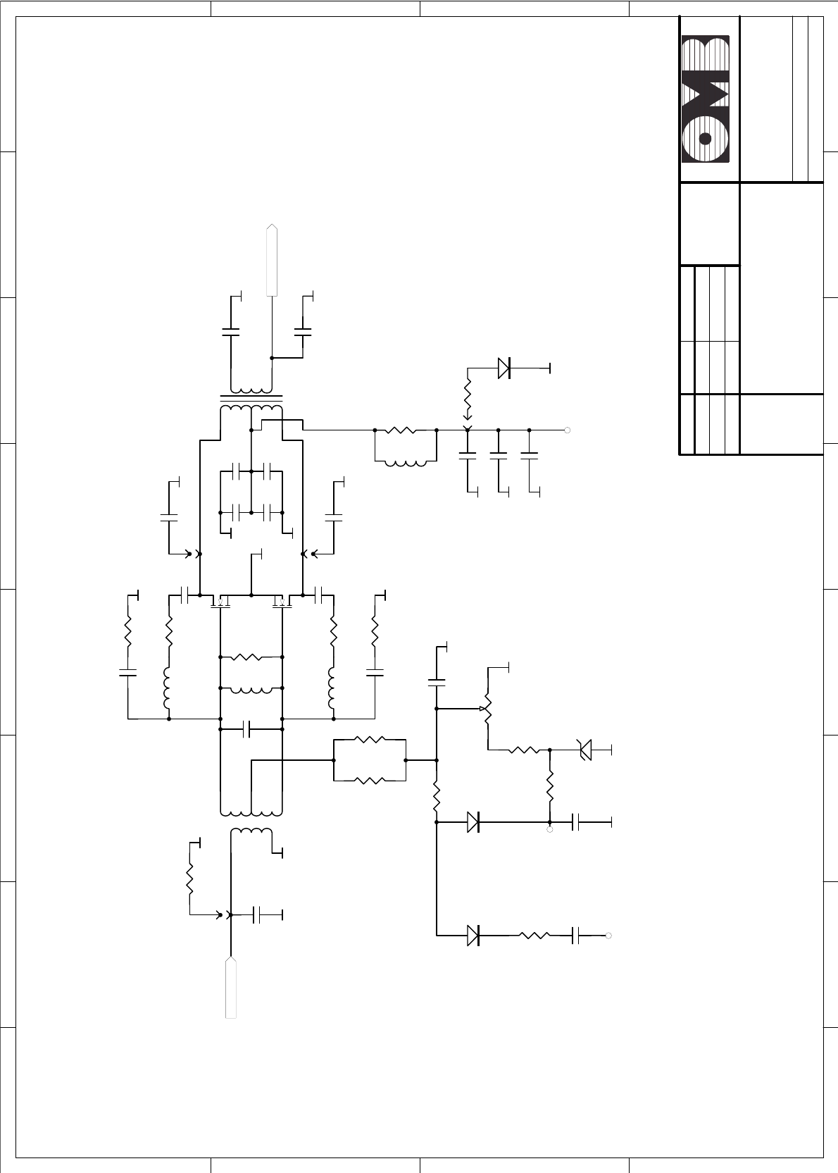
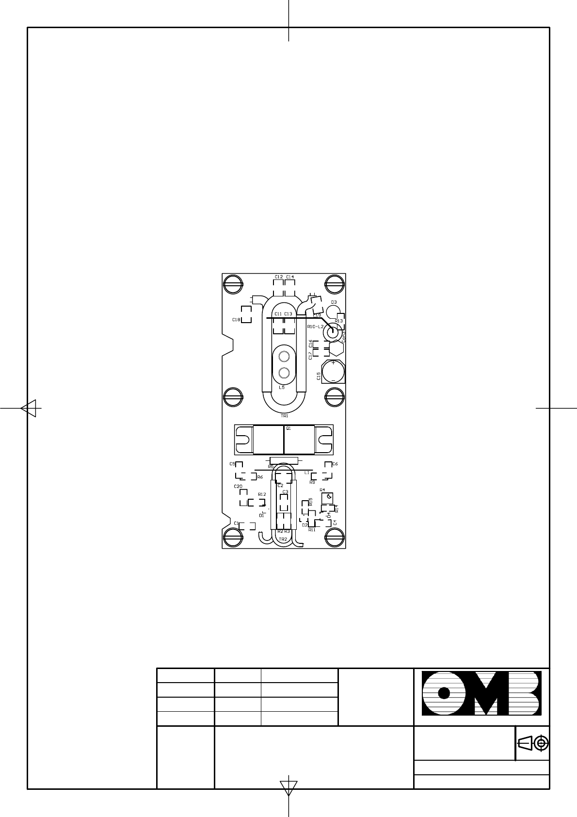
300W R.F. Power Amplifier
1 2 3 4 5 6 78
A
B
C
D
8
7654321
D
C
B
A
Drawn
Checked
Standards
Date Name Signature:
Scale :Title: Drawing nr:
Replace:
Replaced with:
Sistemas Electrónicos S.A.
R1
300*
C1
33pF
TR2
Input Transf.
C2
470pF
C5
1nF
C7
150pF
C9
12pF*
C11
470pF
C18
47pF
C19
15pF
C3
1nF
R5
1R 2W
R6
51
R7
RF 100 Ohm
R2
22
R3
22
R11
330
GND GND
D2
BAT54
R4
P1K
GND
C4
1nF
GND
+12V Polarization
L1
Bridge
GND
GND
GND
C6
1nF
C8
150pF
R9
51
R8
RF 100 Ohm
GND
C10
12pF* GND
TR2
Output Transf.
GND
GND
GND
GND
L2
Dext8 8turns Dcable 0.8-1
R10
10 Ohm 2W
C15 100uF
C16 1nF
C17
22nF
GND
GND
GND
+48v
GND
C12
470pF
C13
470pF
C14
470pF
GND
D1
BAT54
R12
110
BIAS Off
C20
1nF
R13
10K*
D3
LED*
GND
RF In
RF Out
Elements with * are optional
Q1
BLF278
L3
Ferrite
L4
Ferrite
L5 Core
D4
BZX84C10
R14
1K8
GND
R15
10
Date
Drawn
Checked
Name
Standards
Signature:
Scale:Title:Drawing nr:
Replace:
Replaced with:
Sistemas Electrónicos S.A.
04/05/04 M. Tsvelev
MODPOT v1.3
300W R.F. Power Amplifier
06/06/02 OMB Eng. Dpt.
EM 250 COMPACT DIG 05.04.02.000
300W FM FIlter
1 2 3 4 5 6 78
A
B
C
D
8
7654321
D
C
B
A
Drawn
Checked
Standards
Date Name Signature:
Scale :Title: Drawing nr:
Replace:
Replaced with:
Sistemas Electrónicos S.A.
RF IN
L3
3V D9mm d1.5mm
L2
3V D9mm d1.5mm
L1
4V D9mm d1.5mm
TL1
50 Ohm
TL4 Forward Power TL2 Monitor
TL3 Reflected Power
RF Out
Output Coupling
Monitor
R11
120R
R3
51R
R5 1K
R7
10K
R9
120R
R2
51R
R1
51R
R4
51R
R6
1K R8
10K
R10
120R
C8
1nF
C9
1nF
C10
1nF
C11
1nF
C7
22pF
C5
22pF
C6
22pF
D2
BAT54
D1
BAT54
C2
51pF
500V RF
C1
25pF
500V RF
C3
51pF
500V RF
C4
25pF
500V RF
C12
4.7pF
500V RF
C14
12pF 500V RF
C13
9.1pF 500V RF
Reflected Coupling
In case of using AD250 substrate
C15= 6.8pF ;C14= 2x 5.6pF
R9=R10=R11=150 ohms
FM Transmitter
Sistemas Electrónicos S.A EM 250 COMPACT DIG
Technical Manual - v1.1 - February 2006 41
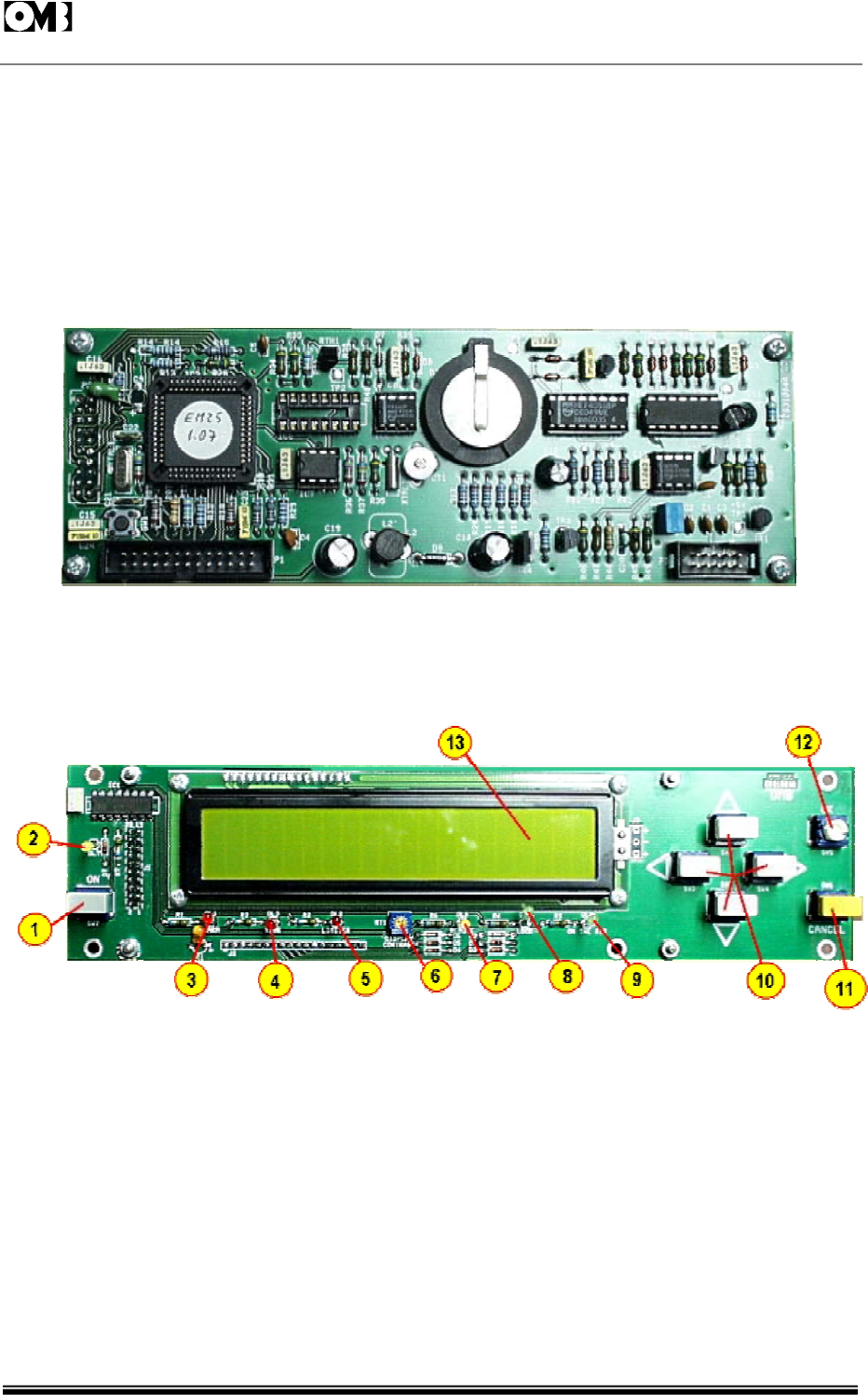
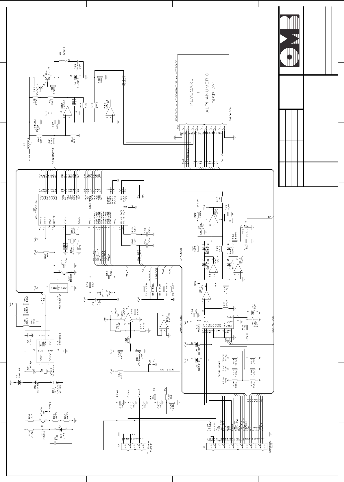
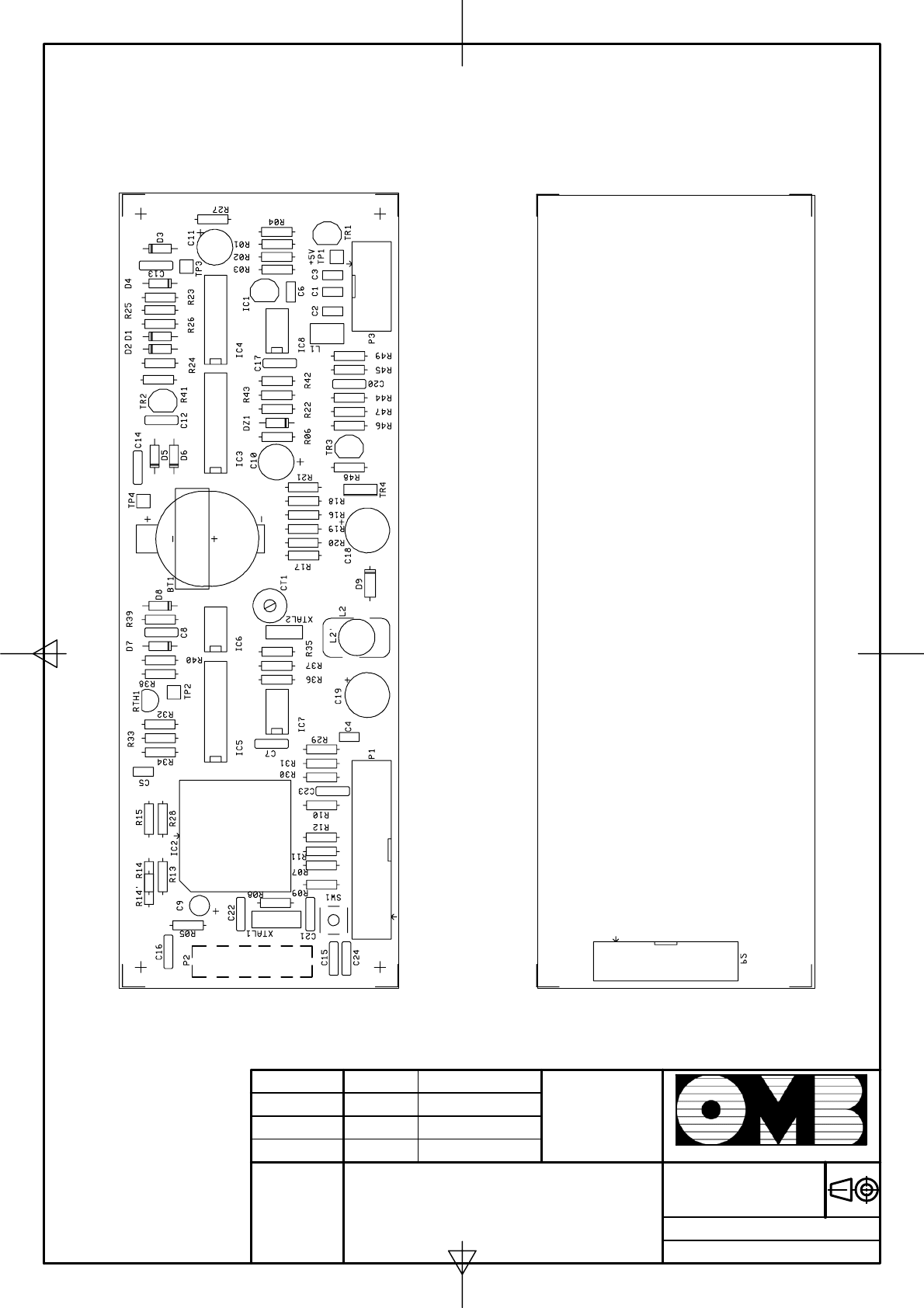
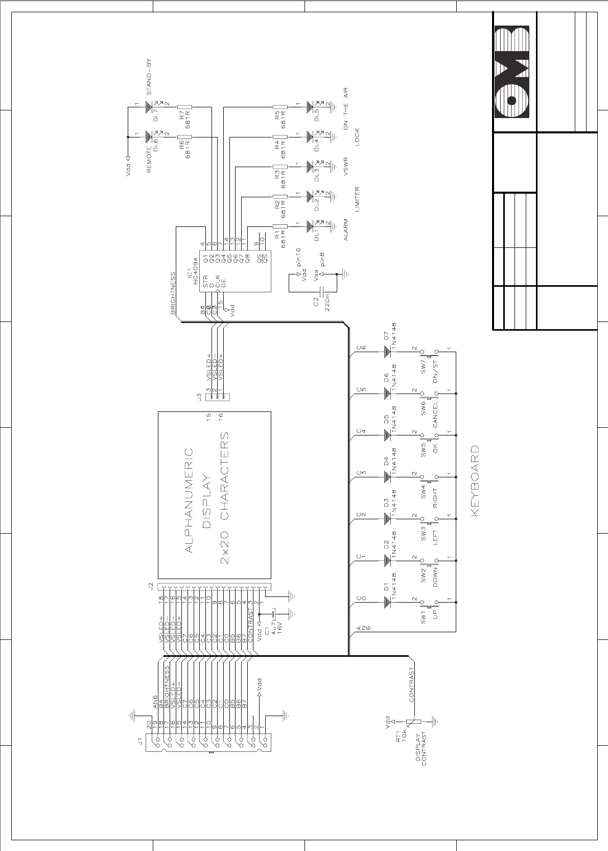
2.6 Control unit and display board.
This circuit board is basically simple.It contains the Microcontroller,the keyboard and few other circuits
which we will briefly discuss.Control and Display Units are shown in Figure 2-7 below. The Microcontroller
has 3 digital 8-bit ports and an analog one. This latter is the interface with the analog signals that must
be measured in the transmitter. A fast peak rectifier built around IC4 drives one of these analog lines.
All audio or baseband modulation plus some steady state signals are multiplexed to its input by IC3, so
requiring only one peak rectifier and increasing the number of the analog channels. One analog
channel reads the internal temperature through the optional TR3 sensor.
Fig. 2-7: DETAILED VIEW OF CONTROL UNIT.
The simple specialized IC6 performs clock and date functions as a stand-alone unit, backed-up by a
NiMnh battery which keeps circuit active for a long time when the power is removed.
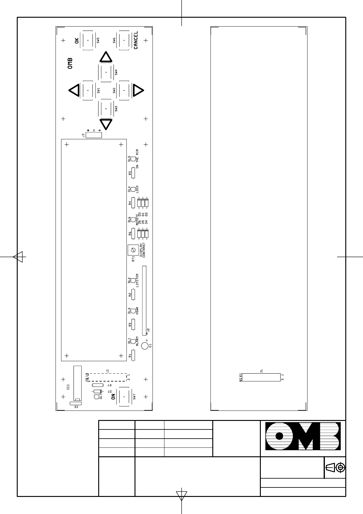
Fig. 2-8: DETAILED VIEW OF DISPLAY and EXTERNAL CONTROL BOARD.
Elements numbered in Figure 2-8 are the following:
1 - MAIN/STANDBY push button switch.
2 - STANDBY indicator LED.
3 - ALARM indicator LED.
4 - VSWR indicator LED.
5 - LIMITER indicator LED.

FM Transmitter
Sistemas Electrónicos S.A EM 250 COMPACT DIG
Technical Manual - v1.1 - February 2006 42
6 - DISPLAY CONTRAST adjustment potentiometer.
7 - REMOTE operation indicator LED.
8 - LOCK indicator LED.
9 - ON THE AIR indicator LED.
10 - External control keyboard.
11 - CANCEL key, to suppress any order or command.
12 - OK data entering key, to confirm any order or command.
13 - Two-row, backlighted alphanumeric LCD display.
The keyboard switch set is sequentially interrogated one hundred times in a second to determine if a
key was pushed. IC5,a serial to parallel converter, drives the front-panel LEDs and the display
backlighting with TR2.
The alphanumeric display is a separate module, connected to the board by a small flat-ribbon cable,
as shown in Figure 2-8. 11 digital lines from the Microcontroller drive this module. The internal
board potentiometer RT1 regulates the LCD contrast and may be used to change it for different
situations. A separate power supply current for the backlight LEDs is provided by R41 and R42: these
resistors become quite hot when the display is full on and their heat someway influence the internal
temperature read by TR3.
No other regulation is provided on the board.The precision of the measurements is guaranteed by
design by the precision of the components and the reference voltage source IC1.
18/04/03 OMB Eng. Dpt.
EM 250 COMPACT DIG
Control unit
1 2 3 4 5 6 78
A
B
C
D
8
7654321
D
C
B
A
Drawn
Checked
Standards
Date Name Signature:
Scale :Title: Drawing nr:
Replace:
Replaced with:
Sistemas Electrónicos S.A.
Date
Drawn
Checked
Name
Standards
Signature:
Scale:Title:Drawing nr:
Replace:
Replaced with:
Sistemas Electrónicos S.A.
18/04/03 OMB Eng. Dpt.
EM 250 COMPACT DIG
Control unit
Component side Solder side
16/07/02 OMB Eng. Dpt.
EM 250 COMPACT DIG
Keyboard/display interface
1 2 3 4 5 6 78
A
B
C
D
8
7654321
D
C
B
A
Drawn
Checked
Standards
Date Name Signature:
Scale :Title: Drawing nr:
Replace:
Replaced with:
Sistemas Electrónicos S.A.
Date
Drawn
Checked
Name
Standards
Signature:
Scale:Title:Drawing nr:
Replace:
Replaced with:
Sistemas Electrónicos S.A.
16/07/02 OMB Eng. Dpt.
EM 250 COMPACT DIG
Keyboard / display interface
COMPONENT SIDE
SOLDER SIDE
FM Transmitter
Sistemas Electrónicos S.A EM 250 COMPACT DIG
Technical Manual - v1.1 - February 2006 47
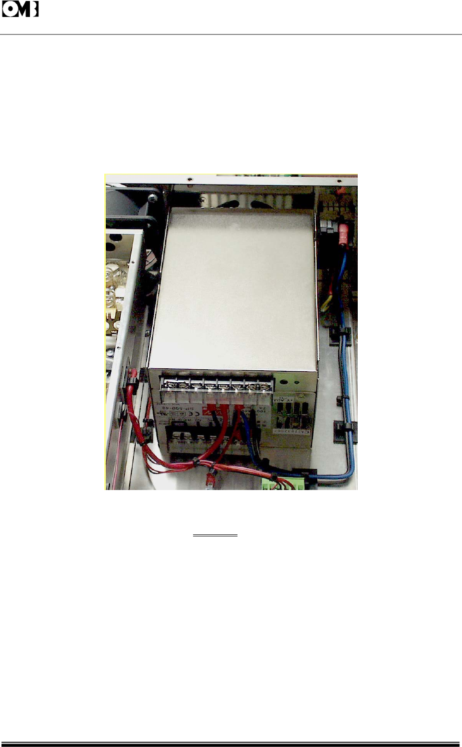
2.7 Power supply units.
2.7.1 MAIN UNIT.
The main power supply regulator is a sturdy SP-500/48 unit having a high-efficiency, direct mains
switching-mode type. The power supply accepts mains input varying in the range of 90~260VAC,
generating an unregulated DC voltage which is used by the regulator as input voltage. This unit is
intended to be replaced as a whole unit in event of damage, and not to be repaired in the field. This
power supply delivers +48VDC to the load, at a nominal power rate of 500W.
Fig. 2-9: MAIN +48VDC POWER SUPPLY.
WARNING
IN THIS UNIT, MAINS VOLTAGE AND OTHER DANGEROUS VOLTAGES ARE PRESENT. DO NOT MAKE ANY
INTERVENTION ON THE BOARD WHEN IT IS CONNECTED TO MAINS. SERVICE IS LIMITED TO LABORATORIES
ONLY.
FM Transmitter
Sistemas Electrónicos S.A EM 250 COMPACT DIG
Technical Manual - v1.1 - February 2006 48
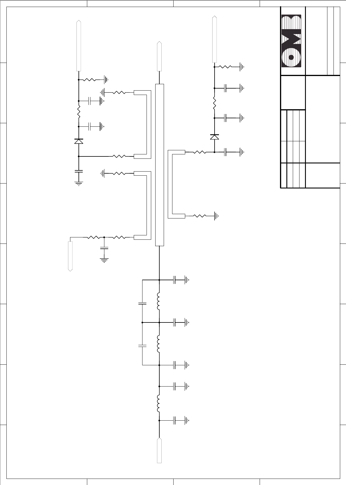
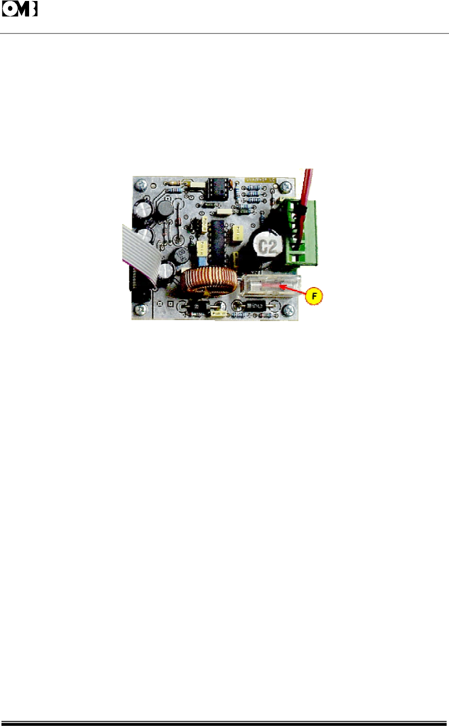
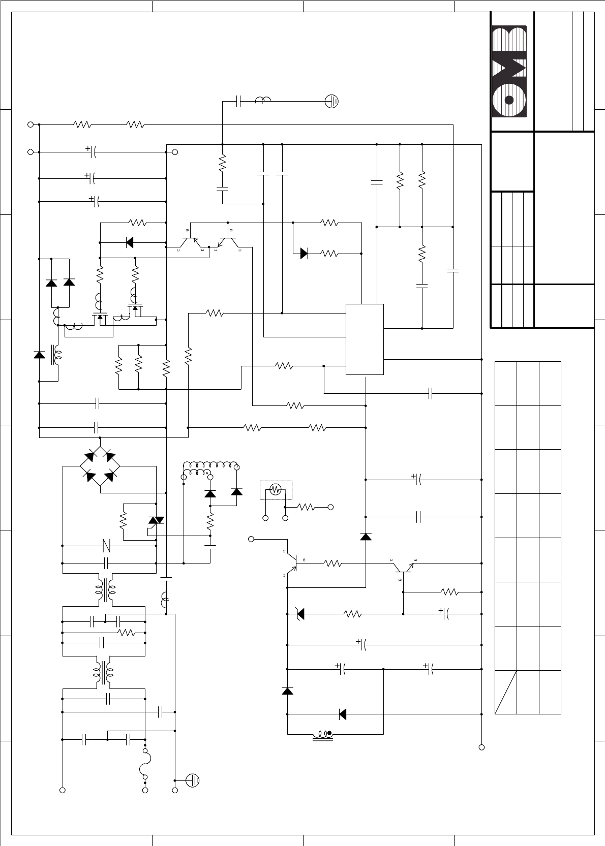
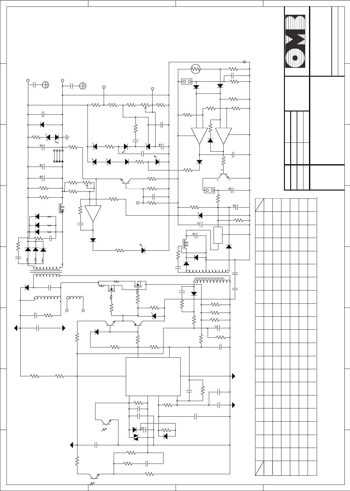
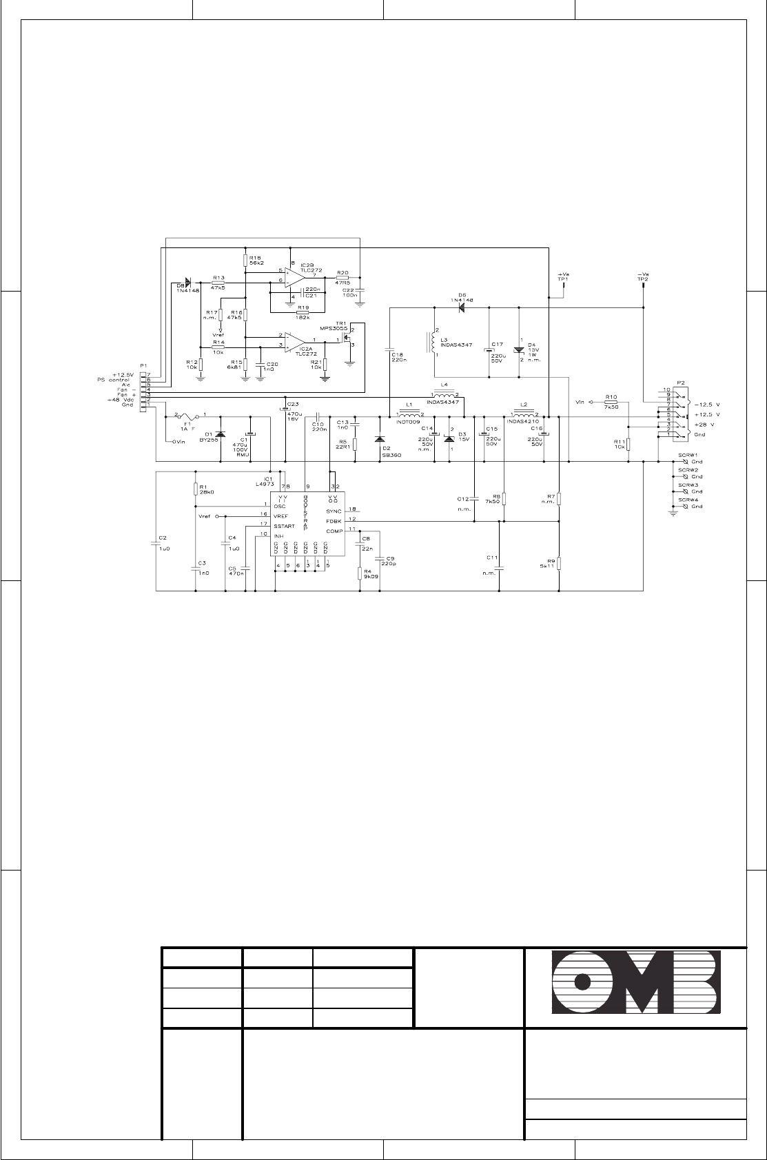
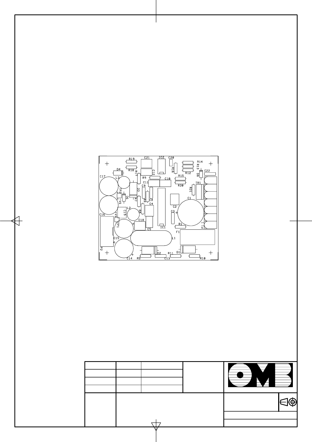
2.7.2 AUXILIARY UNIT.
This unit delivers ± 12V to feed Control and Display units, and to develop the fast bias cutoff of -12V
in order to protect the Power Amplifier components from an irreversible damage in event of a
sudden increase of VSWR or other failure that may appear during Equipment's normal
operation.
A detailed view of this unit is given in Figure 2-10. Note that this unit is fitted with a protection fuse (F) to
protect it in case of any overload. Always replace this fuse with the same type and rating, in order to
keep active this protection.
Fig. 2-10: VIEW OF AUXILIARY POWER SUPPLY.
18/07/00
EM 250 COMPACT DIG
Switching Power Supply SP-500/48A
1 2 3 4 5 6 78
A
B
C
D
8
7654321
D
C
B
A
Drawn
Checked
Standards
Date Name Signature:
Scale :Title: Drawing nr:
Replace:
Replaced with:
Sistemas Electrónicos S.A.
SP-500A DIFFERENT COMPONENT:
PART NO.
MODEL
R31
ZD4
2.2u/50V
C25
CN2
V-
2.2u/50V
C24
HER104
D7
TR134
L1
HER104
D8
NC(PSF)
P5
Terminal
R+
30K/2W
R18
220u/25V
C17
104/100V
C21
C1815
Q7
470u/25V
C23
1K
R24
2K2
R23
1N4001
D2
R31
A562
Q8
ZD4
CN4
XX X
8.9V 8.9V 8.9V
13.5V12V 15V
2K2
R25
2.2u/50V
C22
24V 27V 48V
XX
8.9V 8.9V 8.9V
C32
221/250VAC
C16
472/250VAC C1 474/250VAC
AC/L
FG
TF-360
LF1
FS1
F10A/250VAC
C31
AC/N
C3
CN2
B
104/100V
C6
C15
C5
104/250VAC
471
ZNR1
C2
474/250VAC
C4
222/250VACX2
TF-360
LF2
680K/1/2/W
R1
10/5W
R2
15A/600V
BD1
474/250VAC
C7
T-
BTA16-600B
TRC1
CN2
R-
30K/2W
R17
HER104
D4 T+
F+
51/2W
R4 HER104
D6
CN2
C8
474/250VAC
0.33/2W
R5
0.22/2W
R6 5.1
R11
1N5819
D5
IRFP460
Q2
IRFP460
Q1
5K1
R12
150u/400V
C26
102/50V
C11
A1020
Q3
C2655
Q4
0.33/2W
R7
499K/1/2W
R8
499K/1/2W
R9
TR134
L1
1N5406
D9
RHRP1650
D1
RHRP1650
D1
5.1
R10
499K/1/2W
R14
CN2
V+ CN1
V+
150u/400V
C9
150u/400V
C10
499K/1/2W
R15
CN1
V-
10K
R16
471/1KV
C12
C14
222/250VAC
X1K
9.1V/1W
54AD
103/100V
C67
473/50VC19
1N4148
D3
100
R26
680
R27
15
6
8
423
7
IAC
GTDR
VAout Vs
CAoutMout
Vcc
GND
LT1249
U1
474/50V
C18
330K
R30
5.1/1/2W
R21
100
R32
472/50V
C13
221/1KV
C20
22KR28
270K
R29
20/04/01
EM 250 COMPACT DIG
Switching Power Supply SP-500/48B
1 2 3 4 5 6 78
A
B
C
D
8
7654321
D
C
B
A
Drawn
Checked
Standards
Date Name Signature:
Scale :Title: Drawing nr:
Replace:
Replaced with:
Sistemas Electrónicos S.A.
/1KV
331
/1KV
471
24V
27V
48V
27/1W
22/1W TR130
TR131
221
/1KV D920239/1W TR132
12V
13.5V
222
/500V
15V
MODEL
/500V
/500V
222
222
C71,72
SP-500B DIFFERENT COMPONENT:
PART NO. L51R80,81 D60,61
62
C25P06Q
C25P06Q
10/1W
10/1W
TR12915/1W D9202
TR127
TR127
1K
/35V
1000u
/35V
1000u
/35V
1K
1K
220
220
/2W
/2W
270
/2W 1000u
V-
C
CN2
R86
C73,74
75
R82,83 C80R95R94
1u/50V
1u/50V
1K8
1K5
10K
6K8
10K 1K5 1u/50V
3K3
/2W /1/2W/63V 6K8220u
1000u
/35V
/50V
470u
680
/2W
/2W
1K 2K2
2K2 20K
24K
2K
2K
1u/50V
224
/100V
1K536K /100V
224
104/100V
C60
1N4148
D54
C55 102/50V
C56
1u/50V
1N4148
D53
R71
5K1
103/50V
C57
1KR73
330
R72
MOC3022
U51
1M
R69
100
R56
680
R57
R74
75K
22K
R70
C54 103/50V
R67
24K
C65
8
7
6
5
4
3
2
1
U55
3845
C58
R68 1K
R66
471/100V
C61
68K
R65
C59
471/1KV
0.82/2W R64
100u/35V
C62
0.22/2W
R63
0.22/2W
R62
D55
HER104
R61
1R
15/1/2W
R60 C63
222/500V
17
4
HER204
D75
HER204
D69
222/500V
C87
22/1/2W
R112
16
18
5
18V/1W
ZD51
5K1
R58
5.1
R59
2SK1358
Q52
D
G
S
2SK1358
Q51
51
R115
PC123
U53
A1020
Q54
68K
R89
2SC1815
Q56
2K R111
U51
MOC3022 22
R91
1N4148
D64
RC
5K1 R117
R116
2K
C88
103/50V
100
R106
DR005
L52
47u/50V
C86
1u/50V
C85
5.1V/1W
ZD55
51/2W
R110
CN51
2.2/1/2W
R109
FAN
78
7812
RG51
C2120
Q55
33V/1W
12V/1W
18V/1W
12.9V
15V/1W18V/1W
15V/1W
TF403
TF402
J2,J3TF404910
910
820
J1,J2
J3
J1,J2
J3
33V/1W27V/1W
J3,J4
J1,J2
TF400
TF407
J1,J2
J3,J4
J3,J4
J1,J2
1K2 TF401
1K2
910
C101
222/250VAC
10mm
R87 1.40
T51 ZD53ZD52 ZD54
C102
222/250VAC
JUMP18V/1W JUMP
JUMP
JUMP
16.1V
12.9V
JUMP
JUMP
1K5
1K8
8K2
10K
6K8
1K8
5.4V
5.4V
5.4V
R84 R50
HER104
D76
560/1/2W
R120
ZD60
47u/50V
C83
47u/50V
C84
C92
X
X
X
16.1V
10.6V
10.6V 6K8
6K8
10K1K2
1K1
1K
X
X
221/1KV
R49
JUMP
200K/1/2W
R52
200K/1/2W
R51
104/630V
C64
15/1/2W
R54
B
104/100V
C53
PC123
U52
CN2
PC123
U53
V-
T-
T+
1N4148
D52
2SC2655
Q53
5.1
R55
3
2
7
100P/1KV
C51
100/2W
R53
9
V+ C71
D60
HER308
D51
BD
R80
13-15
8
D62
D61
T51
BD
510-12
C52
103/2KV
D60
R81
D61
D62
C73
BD
BD
C72
R82
R83
89
10
L51
104/100V
C79
-
+
LM324
U54
JUMP
D70
R84
R50
R88
1K
SVR2
JUMP
ZD52
J3
J4
LED1
R87
10
R93
TB1
ZD54
1K
R90
ZD53
C74
C75
J2
J1
ZD60
HER203
D63
104/100V
C76
R86
473/630V
C77
+V
TB1
TB1
473/630V
C78
-V
+S
RC-
820
R105
104/100V
C81
820
R104
6K8
R103
2K
R102
103/50V
C82
7
14
5
2
3
1N4148
D68
1N4148
D67 -
+
LM324
U54
15K
R108
2K7
R101
3K9
R100
1N4148
D65
-
+
LM324
U54
1N4148
D66
1K
R107
11 6
CN4
2.2u/50V
C91
10
R96
C92
C
A
R
TL431
SHR1
C90
PC123
U52
C80
1K
R92
1K
SVR1
TB1
R94
R95
-S
RT
RTH2
5K
R+
R-
23/04/03 OMB Eng. Dpt.
EM 250 COMPACT DIG
Aux. Power Supply
1 2 34
A
B
C
D
4
321
D
C
B
A
Drawn
Checked
Standards
Date Name Signature:
Scale:Title Drawing nr:
Replace:
Replaced with:
Sistemas Electrónicos S.A.
Date
Drawn
Checked
Name
Standards
Signature:
Scale:Title:Drawing nr:
Replace:
Replaced with:
Sistemas Electrónicos S.A.
23/04/03 OMB Eng. Dpt.
EM 250 COMPACT DIG
Aux. Power Supply

FM Transmitter
Sistemas Electrónicos S.A EM 250 COMPACT DIG
Technical Manual - v1.1 - February 2006 53
CONTE
N
T
S :
3.1 Introduction . . . . . . . . . . . . . . . . . . 54
3.2 System connection . . . . . . . . . . . . . . . 54
3.3 Audio Base Band connections and settings . . . 56
3.4 Operation . . . . . . . . . . . . . . . . . . . . 59
3.5 Service and maintenance . . . . . . . . . . . 62
S
Se
ec
ct
ti
io
on
n3
3
I
IN
NS
ST
TA
AL
LL
LA
AT
TI
IO
ON
NA
AN
ND
D
M
MA
AI
IN
NT
TE
EN
NA
AN
NC
CE
E

FM Transmitter
Sistemas Electrónicos S.A EM 250 COMPACT DIG
Technical Manual - v1.1 - February 2006 54
3.1 Introduction.
Install the transmitter in a dry, ventilated and possibly dust-free environment, so that it will operate in the
+10 ~ +35°C temperature range.
Connect the Transmitter to the load and audio source using suitable cables and connectors, which
should be periodically inspected. The EM-250 COMPACT DIG has many features of a HI-FI Transmitter
and should be installed and audio-wired with the same care, avoiding earth loops as much as
possible. When these conditions are met,the transmitter performs superbly.
This Transmitter is adequately shielded and can be installed close to the program Studios without fear
that it will affect the audio equipment. This arrangement has the advantage that the audio level,
deviation and power parameters can be continually monitored. EM-250 COMPACT DIG can also be
installed away from the studio and connected with several meters of LF coaxial cables with no adverse
effect on modulation quality. A remote installation usually requires a STL (Studio -to -Transmitter Link).
As the final modulation performance is dependent on the whole system arrangement, carefully
consider the whole system planning.
3.2 System connection.
1.- Connect the N-type output connector, marked “RF OUT ” to the antenna or RF Power Amplifier with
low-loss 50: coaxial cable, tested to 500W of peak-power rating in the frequency range used. Andrew
LDF4 or 1/2" Heliax line can be used in some short hops.
2.- Connect the audio inputs as required for operation and detailed in the following chapters for
various situations. If needed, connect the serial and / or parallel remote control I/O ports as
required,or jump this step to a subsequent moment.
3.- Switch off the mains rear switch and connect the transmitter to mains and ground system.
4.- Before turning on Transmitter in the system, pre-set if possible frequency and power separately on a
dummy load, to avoid system problems at the first turn-on of the equipment. If this cannot be done,
check that the transmitter's maximum output power (250~300W) does not harm any external
supplementary amplifier stage (if any).
5.- Turn on the rear panel mains switch, then push-on the front panel on/stand-by switch to operate the
transmitter and check that:
• All LEDs and the display briefly lights on and off for the initial check.
• The yellow <STAND-BY> LED turns off.
• The green <LOCK> LED must light up after a very short time, when frequency is locked at
PLL.
Once locked, the RF power will rapidly increase to the pre-set level in a mild increasing mode. Once
preset power is reached, the <ON THE AIR> LED will light completely, if the power is set >5W (at least
5.1W). Till that moment it will turn off and on, signalling the RF power is present but not correct.
Equipment is now functioning in the pre-set mode, delivers power and can be accessed to be
programmed or simply to monitor its functions with the front panel display.

FM Transmitter
Sistemas Electrónicos S.A EM 250 COMPACT DIG
Technical Manual - v1.1 - February 2006 55
The first request it will do will be entering the password for the required level of authorization/security.The
equipment is factory pre-set with the first 2 passwords levels disabled: this will allow to set most of the
operating parameters, including power, frequency, input levels, clock and date. Some more critical
parameters it will require the upper 3rd level: be sure to know it if you need this access.
NOTE: EM-250 COMPACT DIG WILL ALWAYS TURN ON IN THE SAME STATE AS IT WAS IN THE LAST TIME IT
WAS TURNED OFF FROM MAINS,I.E.POWER,FREQUENCY AND EVEN ON OR STAND-BY CONDITION. AS
SOON YOU TURN ON THE REAR PANEL MAINS SWITCH BE PROMPT TO THAT, EVEN WHEN JUST FACTORY
DELIVERED.
6.- The first task to manage when turning on the equipment as factory delivered is to set up the
passwords. At least the 3rd (the highest) level must be immediately changed:
because, if any unauthorized people change it or you lose it, there is no way to change it for security
reasons and the equipment may become unmanageable.Gaining again access to the equipment
will require factory reprogramming or changing of the internal Microcontroller unit. For this reason be
sure to write down and keep it immediately in a secure place: there is no way to read it after you have
programmed down and confirmed.
For practically any parameters that may require some setting in the field, the 2nd level password is
enough and may be used for any standard service requirement . The main purpose of the
existence of the 3rd level is a security assurance for the user if he loses control on the lower password
levels.
7.- If not already done,adjust frequency and RF power as required and check reflected power on the
transmitter's display.
To this aim search for RF power menu and read the corresponding value of direct and reflected
output power.
For proper operation, the reflected power reading should typically be less than 10%of the direct power
value, (< 25W max). Any higher reading may indicate that the antenna is not properly connected or
the subsequent amplifier input needs to be tuned.
8.- Check and/or set clock and data and all transmission parameters as required, i.e.channel
sensitivity and deviation, mono/stereo, preemphasis etc. Refer to the appropriate section of the
Manual.

FM Transmitter
Sistemas Electrónicos S.A EM 250 COMPACT DIG
Technical Manual - v1.1 - February 2006 56
3.3 Audio Base Band connections and settings.
3.3.1 Baseband Connection and Wiring and Impedance
Selection.
EM-250 COMPACT DIG supports balanced or unbalanced signals with selectable input impedance.
The audio inputs are basically balanced and have selectable 600/10k: resistive impedance, factory
pre-set at 10k:.They can be connected to the balanced output of a professional mixer console or to
the unbalanced one of a cheaper unit without appreciable degradation.
Audio mono or stereo channels inputs are XLR female connectors.They should be connected to the
output of the mixer console, or of any audio processor that drives it, by a balanced coaxial cable
connected to pin 3(+) and pin 2(-). The cable shield, connected to the ground of the driving
equipment,has to be connected to pin 1.
In case of unbalanced drive, input pin 2 shall be short-circuited with ground and shield on pin 1, while
the signal shall be available on pin 3. Higher impedance selection, in this case, will be 5k: instead of
10k:.
With balanced driving signals,the connecting cables to the audio source may be well more than
100m long.
Mpx or an externally processed signal, usually an unbalanced signal, can be fed to the female BNC
connector, marked <MPX>, which is internally parallel-wired with the <RIGHT> channel connector:for
this reason it is not possible to connect signals to these two connectors at the same time. Higher
impedance position is 5k: in this case too.
Connect this input with a 50: (RG58) cable for a short distance; if the distance exceeds several tens
of meters, use 75: (RG59) or 92: (RG62) coaxial cables.
The auxiliary-channel connector is also of the grounded BNC female type. Use 50: (RG58) or 75:
(RG59) cables to connect to the driver. The same applies to the monitor "MODULATION" output, If
needed.
3.3.2 Pre-emphasis setting.
Non-precoded low frequency mono and stereo channel signals have to be adequately pre-
emphasized. Standard preemphasis time constant is 50 and 75µs, the former being usually factory
pre-set for Europe countries.
Check whether this is correct for your country (it is usually correct for any European country and part of
the Pacific areas). It is not correct for USA and Center and South America standards,which require
75µs.
If above correction is needed, simply set it on the <MODE> frame of the transmitter menu, which also
includes mono/stereo operation and frequency. See appropriate section further on in this Manual.

FM Transmitter
Sistemas Electrónicos S.A EM 250 COMPACT DIG
Technical Manual - v1.1 - February 2006 57
3.3.3 Audio Baseband Input Level Range, Setting and
Requirements.
In the following paragraph we will refer to 0dBm as the audio signal which produce 1mW on 600:, i.e.
a 775mVRMS / 2200mVpp sinusoidal. Irrespective of the impedance, we will continue to assume 0dBm
as an audio signal whose peak is +(or -)1100 mV.
In the same way, when talking of the modulation, we will assume as 0dB the signal which produces
100% maximum allowed modulation, i.e. 75kHz deviation.
There is no absolute worldwide standard regarding audio peak level as modulation signal for a
transmitter,nor for the mean deviation. Many Broadcasters use 0 or +6dBm as LF peak level for
100%modulation, USA often uses +4 or +10dBm.
Many European countries specify +6dBm for 40kHz deviation (which is assumed to be a "mean"
modulation). This allows for 5.5dB headroom to max. 75kHz deviation, i.e.+11.5dBm for
100%modulation.
A higher level minimize system and ambient noise. A level too high may over-stress the input circuitry
of the transmitter, reducing the dynamic distortion-free range over the nominal level (headroom). It
may also be costly to produce with high quality.
For this reason OMB recommends,whenever possible,to adopt +6 ~ +11.5dBm as nominal peak level
for audio modulation purposes.
EM-250 COMPACT DIG transmitters allows an input audio level on the main channel/s ranging -3.5 ~
+12.5dBm to be set for 100% modulation, with almost no difference in modulation performances, if
high quality signal is provided. Even at the higher level,at least +6dB headroom is additionally allowed:
i.e.up to 150kHz deviation, with no distortion.
Obviously this deviation is not currently allowed by the broadcast standards and the limiter threshold
must be set at its maximum to permit undistorted performance.
The auxiliary channel ’s level ranges -12 ~ +4dBm to produce 10% modulation,i.e.7.5kHz deviation.
Consequently typical input levels for an SCA-type signal (10%max. admissible deviation) are 0.2 ~
1.0VRMS // 696 ~ 2200mVpp, when the input is set between -11.5 and +2.5dB. All the same, an RDS-
type signal could be accommodated in the 0.052 ~ 0.33VRMS //150 ~ 930mVpp level range, to
produce the standard peak deviation of 2kHz, as above.
Regulating the nominal input level for 0dB modulation on the transmitter is an easy task. From the
proper menu screen it may be seen varying the modulation in real-time with the level adjustment,in
0,5dB steps. The modulation is reported as deviation in kHz and in dB, referred to 75kHz.
In this screen, the reported deviation includes any other auxiliary signal as pilot tone, when in stereo,
and RDS or SCA signals applied at the same time. To measure only the audio channel signal, go to
the Left / Right level menu screen. The auxiliary channel level is slightly less immediate to set, being
measured in dB only. Remember that 0dB corresponds to 7.5kHz deviation, i.e. 10%max allowed total
modulation. The typical level for RDS so being 11.5 for 2kHz deviation. This menu screen accounts only
for deviation due to auxiliary signal. To see the added effect on the total deviation, go to the MPX
menu.
The exciter’s internal limiter is of the peak-clipping type; this means that as soon at it cuts in,
modulation distortion increases sharply. For this reason, the modulation signal should be kept under
control to prevent intervention of the limiter.

FM Transmitter
Sistemas Electrónicos S.A EM 250 COMPACT DIG
Technical Manual - v1.1 - February 2006 58
The cut-in limiter threshold, when enabled, is factory pre-set to +2.5dB (100kHz peak value). It may be
set from 0dB (75kHz) up to +7.1dB (170kHz). This threshold value is mostly specified in the various
national standards, and tolerance to short over-modulating peaks varies from country to country.
Some countries do not permit the user to disable the limiter or change the level. Note that the limiter
action begins slightly after the pre-set level, with no action at all till that. The difference between the
threshold level and hard clipping is some 0.5dB.
In any case,the modulation peak value that is internationally admitted for FM is 75kHz for peaks that
are not extremely short. For this reason,the limiter’s cut-in threshold should never be too high.
It is highly recommended to use an external multi-band limiter to optimize modulation, with higher
tolerance for any audio-signal peaks. Such devices momentarily reduce the amplifier circuits’ gain if
the threshold is exceeded and prevent severe, significant distortion.
Any external compressor, limiter, audio or modulation meter must be frequency-compensated with
the same time constant of the pre-emphasis to modulate or monitor deviation properly.
Therefore, the audio level shall be constantly and correctly monitored and adjusted, to prevents as
much as possible, the internal limiter from cutting in. On the other hand, the audio level should be as
high as possible, to achieve the best signal/noise ratio on reception.
The tendency to over-process audio signals is common in many local broadcasting stations:some sort
of processing is advisable and we recommend using a top grade multiband compressor, but not to
compress the signal too much as this impairs the original dynamics.
The audio response of the EM-250 COMPACT DIG transmitter is extremely flat, without perceivable loss
on low and high audio frequency: for this reason large frequency alterations of the audio signal
supplied by using a so-called “frequency equalizer,” are not advisable. An increase of the low and
high frequency contents of the audio signal by more than a few dB can cause general degradation
of modulation dynamics and improper functioning of the limiter.
3.3.4 RS232 Serial Port.
The RS232 port manages only Tx, Rx and Return data signals, with no handshake. Being the two former
signals wired inverted to the port, it need a simple straight wired serial cable with appropriate
connectors:usually a female DB-9 or DB-25 female to the PC port and a male DB-9 connector at the
transmitter end. Appropriate software is needed for communication. OMB can provide this software
and also Telemetry Equipment at request. Do not connect the cable with neither transmitter or PC
energized.
FM Transmitter
Sistemas Electrónicos S.A EM 250 COMPACT DIG
Technical Manual - v1.1 - February 2006 59
3.3.5 Parallel REMOTE Port.
Remember that this port accommodates some lines for simple direct control /monitor on a DB-9 male
connector. See next table for details.
PIN FUNCTION
1 GND
2 ON THE AIR.
A +12V /10k: signals that the transmitter is delivering substantial RF power.
3 FWD PWR.
A signal proportional to transmitted power is present, with a pseudo square law.
Range is 0-5VDC /10K: impedance.On EM-250 COMPACT DIG 5V stands for
250W.
4 -
5 GND
6 RF ENABLE.
A shorted circuit to ground disables RF. Signal level +10VDC/1mA max.
7 FAILURE.
Logic low signal means alarm. Correct functioning is signalled by +12V /10K:
Maximum current sinking capability <10mA.
8 GND
9 -
3.4 Operation.
3.4.1 Monaural Broadcasting,from a Monophonic Audio
Source through Main Monaural Channel.
1.- Connect the “right ”(or mono) input connector to the corresponding audio source as described in
the "system connection" section. No connection to the "left" channel input is needed. The signal runs
through the channel processor and is 15kHz filtered and pre-emphasized.
2.- Select the <MODE> command menu screen (see relevant section on the manual) and select
<MONO> operating mode. Confirm or change also 50 or 75µs preemphasis as required.
3.4.2 Monaural Broadcasting, from a Stereophonic Audio
Source through the Optional Internal Stereo Encoder.
1.- Connect both the <LEFT>and <RIGHT> input connector to the corresponding audio source as
required for stereo transmission as described above. The audio signals will run through the channel
processors and will be 15kHz filtered and pre-emphasized. The internal stereo-encoder will blend the
stereo input source to transmit in monaural mode. In this case the transmitter is already preset for
stereo operation if needed, simply reversing transmission mode to <STEREO>.
2.- Select the <MODE> command menu screen and select <MONO L+R> operating mode.Confirm
or change also 50 or 75µs preemphasis as required.

FM Transmitter
Sistemas Electrónicos S.A EM 250 COMPACT DIG
Technical Manual - v1.1 - February 2006 60
3.4.3 Mono or Stereo Broadcasting from a STL Receiver or
an External Encoder.
1.- In this case, the signal is already multiplexed and pre-emphasized. Use the <MPX> BNC input
connector. The signal skips the coding and filtering stage and therefore is not pre-emphasized.
2.- Select the <MODE> command menu screen and select <EXT MPX> operating mode. While it is
anyway advisable to select the proper preemphasis time-constant as required for your country, in this
position this selection is not influent.
3.4.4 Stereo Broadcasting from a Stereophonic Audio
Source through the Optional Internal Stereo Encoder.
1.- Connect the XLR-type modulation input connectors, marked <LEFT> (channel) and <RIGHT>
(channel), to the output of the two channels from the mixer console or stereo source. They will be
internally 15kHz filtered and pre-emphasized.
2.- Select the <MODE> command menu screen and select <STEREO> operating mode. Confirm or
change 50 or 75µs preemphasis as required.
3.4.5 Operation with a RDS or SCA Encoder.
1.- Connect the BNC-type <AUX> connector to the output of the RDS or SCA Encoder. If the internal
optional stereo coder is used, connect the <LF MONITOR> BNC output to the pilot tone
synchronization input of the RDS coder, if present.
2.- Select the <AUX> command menu screen and push <OK> to vary the channel sensitivity.
Adjust both transmitter sensitivity and/or the level of the external generator for the deviation required, as
explained in the previous Manual sections. Consider that 0dB modulation reading (not the input level)
in this field means 10% total modulation or 7.5kHz deviation, i.e.the standard setting for a SCA auxiliary
channel. In the case of RDS,a reading of -11.5dB or 2kHz is the correct value of modulation.
3.- Total modulation and deviation may be read in the <MPX> display screen, with the addition of
any other composite signal simultaneously present. If only the final modulation due to the auxiliary
signal requires to be measured, momentarily disconnect every other baseband signals present on the
inputs and change mode to <MONO> or <MPX EXT> mode, for the measuring operation only. This is
not required when you display only the auxiliary signal.
4.- If you have changed transmission mode selection or removed any input signal for check purpose,
reverse to the original setting and reconnect any previously disconnected signal.
3.4.6 Modulation Adjustment with Broadcast Signal.
Check the overall modulation level for adequacy,as follows:
1.- Select the display menu screen <MPX>: The total modulation will be displayed, both in dB and as
deviation in kHz. An analog moving bar and a digital peak reading are shown at the same time.

FM Transmitter
Sistemas Electrónicos S.A EM 250 COMPACT DIG
Technical Manual - v1.1 - February 2006 61
2.- Send a sufficiently constant-level music signal to modulator input, and check that the measure
hovers around 0dBm and moves into the upper range during signal peak only and by no more than 1
or 2 dB. For any other reading, adjust the mixer console’s "MASTER" or output attenuator until the above
conditions are obtained. The red <LIMITER> alarm LED should never or rarely light up, as this would
indicate distortion.
If the limiter is set just above 75kHz, the red LED will light up above 0dB and the modulation measured
will never show a much greater value. Factory pre-set is 100kHz (+2.5dB).
3.4.7 Check of Pilot Tone on Stereophonic Broadcast.
In case of internal stereo coder, no allowance is externally provided to change the pilot tone level,
which is usually internally pre-set for 9~10%of modulation, i.e. -21 ~ -20dB or 7 ~ 7.5kHz deviation.
In case it is externally provided by a separate stereo coder, it must be measured in absence of audio
modulationand any other auxiliary signal as below described:
1.- Disconnect any signal from the external stereo-encoder input and any RDS or SCA signal.
2.- Select the display menu screen <MPX> and check the pilot tone, which must be now the only
signal present. The standard level is that previously stated,i.e.: 9~10% or -21 ~ -20dB,and may be
adjusted accordingly on the external stereo encoder to suit the request.
3.- Connect again any previously disconnected signals as done.

FM Transmitter
Sistemas Electrónicos S.A EM 250 COMPACT DIG
Technical Manual - v1.1 - February 2006 62
3.5 Service and maintenance.
Since the EM-250 COMPACT DIG is cooled by forced air, it is subject to clogging by dust. It is very
important to keep clean and dust-free both heat sink fins and cooling fan, to assure a good cooling of
RF Power Module.
Install the equipment on a stable stand/rack, in such a way to permit good air circulation and hot air
exhaust. If needed, cabinet may be externally cleaned with a soft brush and a wet cloth, with the
Equipment turned off.
Other than this, because of the high-quality materials used in their manufacture, if it is installed as it has
been explained before it will not require special maintenance for quite some time. Only periodical
cooling fan and heat sink inspection, and fan replacement after 2 years of continuous service, even if
it's yet in good conditions.
Minimum maintenance inspection is set monthly, containing the following aspects:
Throughly clean Equipment externally. Clean Equipment's room and Transmitter's
environment. Check that internal humidity and room's temperature not to exceed the
allowable limits.
Check by visual inspection the operational conditions of Antennas system and external
environmental conditions of Station site and building.
Take all possible readings from LCD Display and log it in the Station's log book. If any
trouble is detected, it must be solved before leaving the site.
Each six months, or when an anomaly is externally detected, perform a througly check of
Antenna system and transmission line, including VSWR check, frequency response curve,
Return losses, etc. Log all checks in Station's log book.
After a few years of continuous service, it is recommended that the equipment be overhauled in the
factory or in a OMB specialized laboratory.
It is especially important that the Main Power Supply be overhauled when the Transmitter have been
working at high temperatures, over 30 ~ 35°C.
WARNING
Never change the internal calibrations to avoid altering Transmitter Specifications.

FM Transmitter
Sistemas Electrónicos S.A EM 250 COMPACT DIG
Technical Manual - v1.1 - February 2006 63
CONTE
N
T
S :
4.1 Introduction . . . . . . . . . . . . . . . . . . 64
4.2 Passwords . . . . . . . . . . . . . . . . . . . . 64
4.3 Description of menus and commands . . . . . 65
S
Se
ec
ct
ti
io
on
n4
4
S
SE
ET
TT
TI
IN
NG
GS
S

FM Transmitter
Sistemas Electrónicos S.A EM 250 COMPACT DIG
Technical Manual - v1.1 - February 2006 64
4.1 Introduction.
EM-250 COMPACT DIG allows an exhaustive control of all transmission parameters and a complete
programmability and monitoring through the various software controls via the front panel keyboard
and display.The same functions are remotely addressable with proper software, which is not included
as a standard option other than some simple demo programs.
For a description of remote capability see the proper section on the manual. In this section we will
examine the front panel menu-driven operational capability.
4.2 Passwords.
The passwords organization is set in 3 security levels, each with its own password. A higher level permits
to change the lower levels authorizations and passwords.
The password is composed by 4 alphanumeric characters, including extended capital and lowercase
ones and several special symbols. We suggest using a wide range of characters as the security level
raises, to increase the possible combinations. No password is ever shown: it is always masked by
dummy characters as "...." or "****".
Nevertheless it may be always changed with the higher level authorization. Here is the purpose of
each level:
LEVEL 1: Lower security level. It is needed to access to most of the monitoring and control menu
screens, not permitting to alter or programming any operating parameter. It is set to "off" state as
default, allowing anybody to navigate freely through exciter's monitoring menu information. OMB
suggests leaving it in this state if a high "privacy" level is not required.
If set to "on", it will show the default menu screen #00, requiring password for any other information or
pre-set.
Failure to insert a correct password of any level will impede any other access to the commands for the
time-out length (usually 3 minutes). No change to the operational mode is done in case of incorrect
password input. No information is available on the display regarding the transmitter functioning.
LEVEL 2: Service level.This password is needed for any functioning set-up as frequency and
power,sensitivities, clock and date etc. Its use is reserved only to service technicians who need wide
access to the transmitter presets and functions.
Although the default factory state is "off", OMB suggests changing the default state and password
immediately at the first power on, to prevent to unauthorized people to tamper with transmitter
commands, if the default word is known or the status is set to "off".
LEVEL 3: Highest security level. It is always "on" by default and reset anyway to "on" after the display
time-out, for security purposes. Its knowledge is deserved only to very few people and must be
immediately registered after setup and kept in a secure place: there is no way to read it after you
have setup and confirmed on the exciter.
This password must be immediately changed at the first pre-set of the equipment: if any unauthorized
people tampers with it or you lose it, there is no way to change it if you do not know the correct word
for security reasons and the apparatus may become unmanageable.

FM Transmitter
Sistemas Electrónicos S.A EM 250 COMPACT DIG
Technical Manual - v1.1 - February 2006 65
WARNING
Gaining again access to the equipment will require Factory reprogramming or changing the internal
Control Unit .
For practically any parameters that may require some setting in the field, the 2nd level password is
enough and may be used for any standard service requirement. The main purpose of the existence of
the 3rd level is a security assurance for the user if he loses control on the lower password levels.
Only very few critical parameters, like limiter permission or frequency step control requires this
password, as in some countries this functions are not allowed to be freely chosen.
4.2.1 Factory Default Passwords.
These are the factory default passwords:
Level 1: P001
Level 2: P002
Level 3: ABCD
For what previously said, be sure to change at least the 3rd and possibly the 2nd level as soon as you
receive and turn on the equipment.
For security purpose the 3rd level password may be factory changed from the default value before the
transmitter is shipped, in consequence of a specific final customer request.
4.3 Description of menus and commands.
The hierarchical tree of the menu is depicted in the following Figure 4-1, with a small number near the
left side of each field for easy reference. In the following pages we will examine each menu field and
option.
All of the first column fields require the first level password authorization to be navigated. In a similar
way, practically all the second column fields require the second level authorization, as some in the
third column. The third level is required only by some functions in this last column. Navigation through
the menu screens is quite straightforward and natural, with the direction keyboard. "Up" and "Down"
keys vertically scrolling the screens, while the "Left" and "Right" keys horizontally scrolls the menu.
Moving to the right may be impeded by the password permission,while returning to left is always
possible.
The <OK> key changes from scrolling to programming mode, if allowed in the field. Another push on
the <OK > key will confirm the input data. When in program mode, the up and down keys will change
the character, while the left and right keys will move the cursor on the field.
Pushing on the <CANCEL> key will abort the input while repeated escape commands will reset the
menu screen to the default one (# 00).
A local input time-out will automatically cancel the command mode resetting input data if this is not
confirmed in 60 seconds after the last variation.

FM Transmitter
Sistemas Electrónicos S.A EM 250 COMPACT DIG
Technical Manual - v1.1 - February 2006 66
ENTER PASSWORD
CODE
Few minutes of tests will enable most users to gain confidence with control keys and menu and to be
able to access to all main feature of the transmitter,without any previous training.
Anyway it is impossible to discover hidden functions without the proper password permission.
4.3.1 Start menu.
The start menu screen is the unnumbered one on the top of the menu tree.It is shown only when the
equipment is turned on from mains or software reset. It will show the software version and the
initialization step, when all the LEDs and the display will be turned on and off for testing purpose. Any
subsequent key input will turn this menu field on the next, requesting a password code.
4.3.2 Menu #11: Initial Password.
This screen requests to input a valid password code. When the input is confirmed by the <OK> key,
the word will be compared with the memorized passwords and, if recognized,the corresponding
security level will be allowed. If the password is incorrect or the input is terminated by a <CANCEL>,
the password will be signalized as invalid and the security level allowed will be as actually in
memory,i.e.0 (no permission at all),1 or 2.
If the security level is already pre-set to "off" for the 1st level and "on" for the 2nd one, as usual, there is
no need to input any password to freely navigate in the menu tree without altering any parameter.
When the password is recognized as valid and the corresponding level is displayed, press on
<CANCEL>key will turn on the default menu field #00.
FM Transmitter
Sistemas Electrónicos S.A EM 250 COMPACT DIG
Technical Manual - v1.1 - February 2006 67
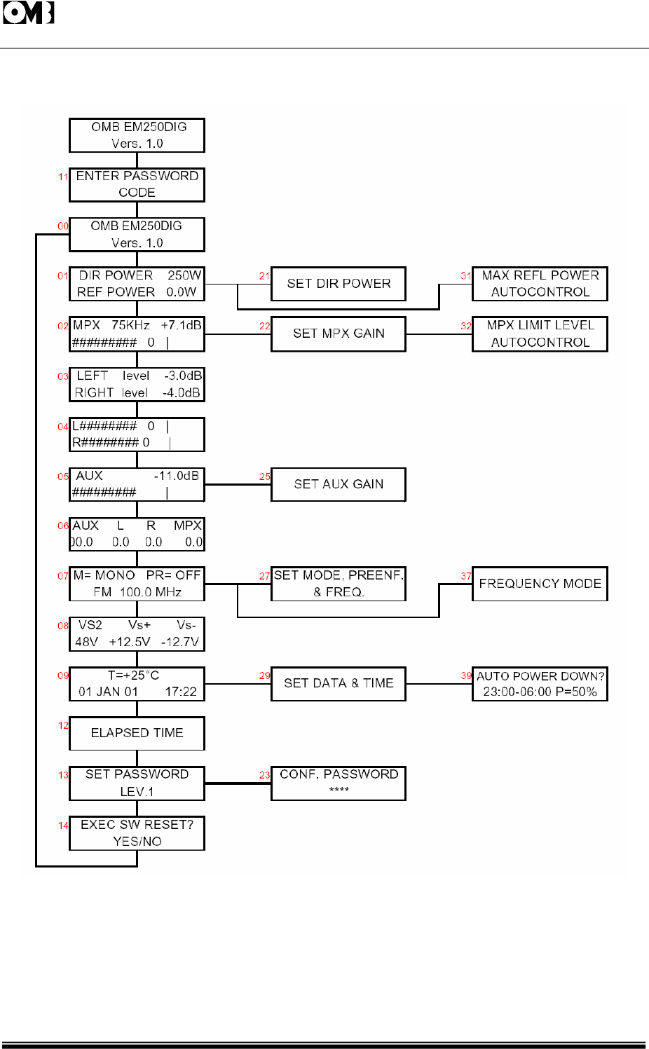
Fig. 4-1: SEQUENCE OF MENUS DISPLAYED BY SCREEN. HYERARCHICAL TREE.
FM Transmitter
Sistemas Electrónicos S.A EM 250 COMPACT DIG
Technical Manual - v1.1 - February 2006 68
dir. power ; 250
W
REF. POWER: 0.0 W
MPX 75KHz +7.1 DB
I
LEFT level -3.0 db
right level -4.0 db
OMB EM-250 COMPACT DIG
VER 1.0
4.3.3 Menu #00: Default Message.
This screen shows the default message and the software release.It is the field that will be initially set, or
to which it will return back after repeated CANCEL commands.
If authorized by the 3rd level permission, going in the command mode (inputting <OK>) will permit to
edit the first row of this field with a custom message e.g.your organization name.
4.3.4 Menu #01: Direct and Reflected Power.
This screen shows the direct and reflected power actually delivered.Going in the command mode,
with the 2nd level password authorization, will permit to set a new direct RF output power. See menu
#21.
4.3.5 Menu #02: Multiplex Signal Level (Output Modulation).
This screen shows the actual peak modulation in dB referred to 75kHz and as deviation in kHz. A
pseudo-analog moving bar contemporary fast changes with the modulation, leaving a peak mark at
its end for 1 or 2 seconds. A vertical bar (|)on this line marks the 0dB position.
Command mode, with the 2nd level password authorization, permits to set LF input channel sensitivity,
or modulation depth. See Menu #22.
Right key,with the 3rd level password authorization, permits to access to limiter setup and threshold. See
Menu #32.
4.3.6 Menu #03: Left and Right Signal Level in dB.
This screen shows the actual left and right peak modulation in dB referred to 75kHz. The reading is
adequately accurate with real audio signals. Some steady state test tone especially at very low audio
FM Transmitter
Sistemas Electrónicos S.A EM 250 COMPACT DIG
Technical Manual - v1.1 - February 2006 69
L I
rI
aux -11.0 db
I
aux l r mp
x
00.0 0.0 0.0 0.0
m=mono pr=off
fm 101.10 mhz
frequency may beat with the discrete A/D conversion sometimes producing some reading uncertainty.
In this case the MPX level reading will anyway produce correct overall modulation measure.
4.3.7 Menu #04: Left and Right Signal Levels Seen as
Analog Moving Bar.
This screen shows the actual left and right peak modulation as two moving bars. A vertical line marks
0dB position and the same considerations as the previous menu are still valid.
4.3.8 Menu #05: Auxiliary Signal Modulation Level
(SCA,RDS).
This screen shows the actual modulation due to an auxiliary (SCA,RDS) signal in dB referred to 7.5kHz or
10% of max peak modulation. Usual level for SCA signal is 0dB (7.5kHz) while a standard RDS
modulation is set at -11.5dB (2kHz).
Command mode,with the 2nd level password authorization, permits to set auxiliary input channel
sensitivity. See menu #25.
4.3.9 Menu #06: Aux, Left, Right and MPX level in dB.
This screen simultaneously summarizes the actual modulation in dB due to auxiliary, left, right and
multiplex signal as seen in their own menu screens.
4.3.10 Menu #07: Transmission Modes and Frequency.
This screen shows the transmission mode,i.e."MONO R", "STEREO", "MONO L+R", "EXT MPX". It also
displays the preemphasis constant time and the transmission frequency.
Entering in command mode, with the 2nd level password authorization, permits to set every of this
transmission parameters. See menu #27.
FM Transmitter
Sistemas Electrónicos S.A EM 250 COMPACT DIG
Technical Manual - v1.1 - February 2006 70
v
s 2 v s + v s --
48.0v +12.5v --12.6v
t= +25°c
01 jan 02 17 : 00
elapsed time
set password
lev. 1
Only 3rd level authorization permits,pressing "Right" key, to change the frequency variation between 10
and 100kHz /step. See menu #37.
4.3.11 Menu #08: Internal Voltages.
This screen shows the internal regulated voltages.In the EM-250 COMPACT DIG they are +48
±0.8V,+12.5 ±0.3V, -13.0 ±1.0V. A marked difference from these values, especially regarding VS2,
may indicate misfunctioning or very low mains voltage.
4.3.12 Menu #09: Temperature, Data and Clock.
This screen shows the internal temperature, the actual data and clock. To set data and clock it is
required to go in command mode, with the 2nd level password authorization. See Menu #29.
The temperature sensor is optional and,when present,in the case of EM-250 COMPACT DIG reads the
internal temperature slightly behind the front panel. It is usual it reads some 20°C higher than external
ambient temperature at full output power: i.e. some +65°C assuming an external temperature of
+45°C (the maximum allowed).
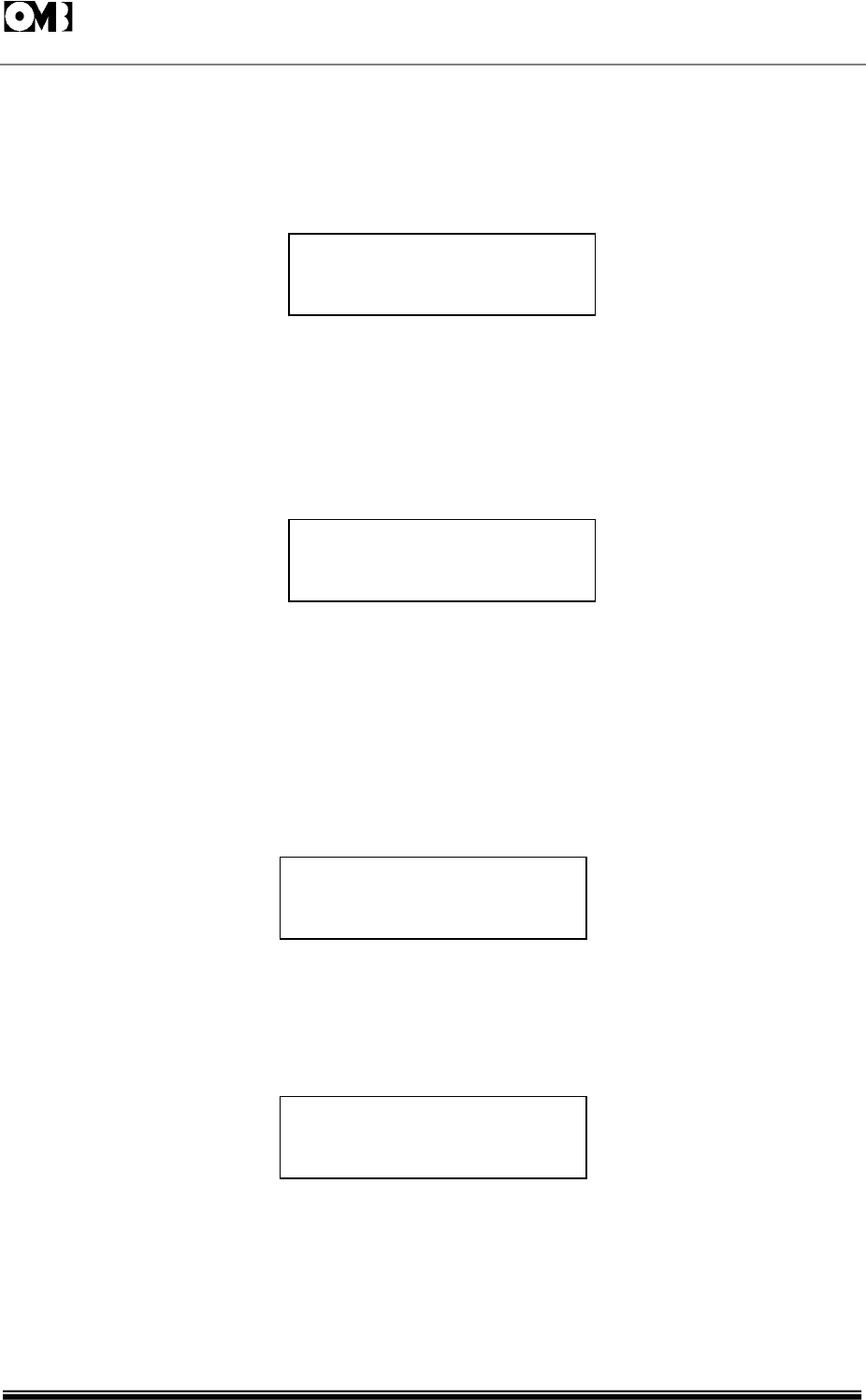
4.3.13 Menu #12: Elapsed Time.
This screen shows the elapsed time whether the exciter is on the air or in stand-by with the mains
applied. There is no way to change the reading.
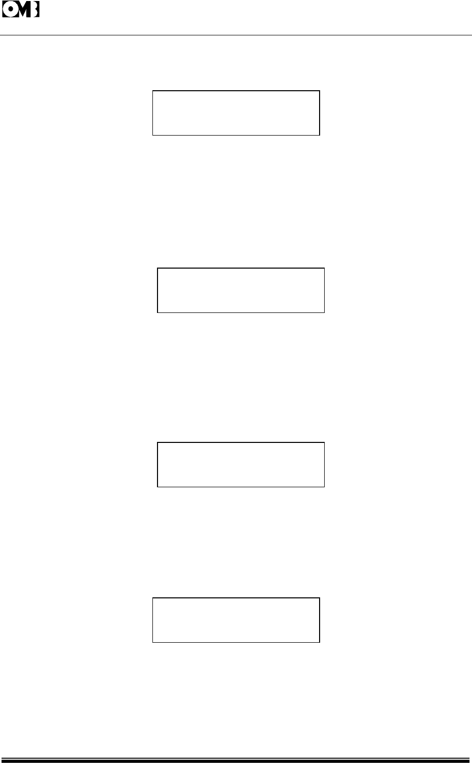
4.3.14 Menu #13: Password Management.
This screen shows the password status and permits to change the code and/or the status in command
mode, when in possession of the necessary level authorization. No code is ever shown and no access
is permitted to a level higher than the current authorization.
If the code or the status is changed, it is always required to confirm the correct password for that level.
If the password is unknown, lost or tamperers changed it, it is possible to change status and code

FM Transmitter
Sistemas Electrónicos S.A EM 250 COMPACT DIG
Technical Manual - v1.1 - February 2006 71
exec. sw reset ?
yes/no
set dir power
when in possession of the higher password. In this case the lower level password code must be
changed and confirmed: no possibility still being to know what was the old password.
In case a lower password permission is actually set in regard to the needed action, it is possible to
input the higher level password either performing a software reset, if permitted, or turning off and on
the mains voltage through the rear mains switch or an external switch.
The 3rd level authorization, when set, will stay valid only till a display time-out is performed,i.e.usually 3
minutes after the last command.Simply navigating through the menu or performing some action will
prolong the time-out.
If the password status is set to on for the level 1,a hung-up may follow after the time-out. This may be
intentional to prevent unauthorized people from browsing the exciter parameters. Exciter performance
will be unaffected by this condition. Any attempt to access the exciter will cause the password
request:if an invalid password in entered,it needs to wait for the time-out to permit a new attempt or to
remove the mains power to the equipment,causing a hardware reset. Even in this case, the first
request will be a valid password input.
4.3.15 Menu #14: Software Reset.
This screen permits to execute a software reset if in possession at least of level 1 password
authorization. The main purpose of this reset is permitting to input a new password level; its action is
similar to turning off and on the mains to the equipment. A software reset will lead to a small
interruption of the RF output power which will be re-established in few seconds, while lock on frequency
will not be lost.No transmission or sensitivity parameter is lost in consequence of software or hardware
reset.
4.3.16 Menu #21: Output Power Set.
This screen derives from #01, in command mode. The direct power value blinks and acting on up and
down keys the numeric value varies. The output power will vary in real time.Confirming the final value
with an "OK" will write the new setting in the non-volatile memory of the equipment. Escaping
(<CANCEL>) will abort the change.
A local time-out will automatically escape the input if not confirmed in 30 seconds from the last
change performed.
FM Transmitter
Sistemas Electrónicos S.A EM 250 COMPACT DIG
Technical Manual - v1.1 - February 2006 72
set mpx gain
set aux. gain
set mode, preemph.
& freq.
conf. password
* * * *
4.3.17 Menu #22: Multiplex, Left and Right Input Level Set.
This screen in command mode, with the 2nd level password authorization, permits to set LF input
channels sensitivity, i.e.multiplex, left and right channel. Take present that multiplex and left signals
share the same channel and the sensitivity is set to the same value for both left (or multiplex)and right
channel,with a differential error <0.2dB at any level. Allowed range is -3.5 ~ +12.5dBm.
The first line of the display shows the actual modulation,while the bottom line shows the input level for
100% modulation.Increasing the input level will accordingly decrease the modulation.
4.3.18 Menu #23: Password Confirmation.
This screen is displayed when password code or mode is changed on menu #13. It requires inputting
the same password code as in the current level which is to be changed.Failure to do so will show the
message:ERROR PASSWORD.
This display stops input mode for 5 seconds and than permits to exit (and possibly to try again) with the
<CANCEL> key.
4.3.19 Menu #25: Auxiliary Channel Input Level Set.
This screen in command mode, with the 2nd level password authorization, permits to set the auxiliary
channels input sensitivity. Allowed range is -12 ~ +4dBm to produce 10%modulation, i.e. 7.5kHz
deviation or 0dB in the upper line of the display.
4.3.20 Menu #27: Operation Mode, Preemphasis and
Frequency Set.
In this screen it is possible to set the transmission "modes" (MONO R, STEREO, MONO L+R, EXT MPX), the
preemphasis time constant (0,25,50 and 75µs) and the frequency in step of 10 or 100kHz as preset on
the menu #37. To access to this last menu, the 3rd authorization level is required, from the main
frequency menu # 07.
Left and right keys change the input fields whilst the up and down keys change the various options or
increase/decrease the frequency.

FM Transmitter
Sistemas Electrónicos S.A EM 250 COMPACT DIG
Technical Manual - v1.1 - February 2006 73
set data & time
max. refl. powe
r
autocontrol
mpx limit level
autocontrol
frequency mode
4.3.21 Menu #29: Data and Time Set.
This screen is the command mode display of menu #09, with the 2nd level password authorization and
permits to set correct data and time.
As in the last menu,the left and right keys change the input fields while the up and down keys
increase/decrease the date and time.
4.3.22 Menu #31: Maximum Reflected Power Set.
This screen permits to set the maximum reflected power level. Default value is 15.0W and in any case
this power is hardware limited to 25W for security reason.
Auto Control on the lower line is not operative and could be absent in other software releases.
4.3.23 Menu #32: Limiter Set.
This screen, with the 3rd level authorization, permits to set the limiter action. The right/left keys toggles
limiter on and off. The up/down keys vary the threshold level.
Auto Control on the lower line is not operative in some software releases. When it is, it will dynamically
reduce the input sensitivity to allow distorsionless limiting if pre-set to ON. Even in this case it will be wise
not to exceed the limiter threshold to avoid "pumping" effect on the modulation.
4.3.24 Menu #37: Frequency Change Mode.
This screen, with the 3rd level authorization, permits to set the frequency step variation between 100
and 10kHz.

FM Transmitter
Sistemas Electrónicos S.A EM 250 COMPACT DIG
Technical Manual - v1.1 - February 2006 74
auto power down ?
23:00 - 06:00 p=50%
4.3.25 Menu #39: Power-Down Setup.
This screen, with the 2nd level authorization, allows to preset the "power-down" mode. If this mode is on,
the output power will be automatically decreased to the pre-set percentage in the time period set on
the bottom line.
The scaled power is approximate and must be tested and/or adjusted before final setup, if critical.

FM Transmitter
Sistemas Electrónicos S.A EM 250 COMPACT DIG
Technical Manual - v1.1 - February 2006 75
INTENTIONALLY BLANK