Transparent Technologies 610M1B01SSL Meter Management Information System User Manual TRANSPARENT TECHNOLOGIES
Transparent Technologies, Inc. Meter Management Information System TRANSPARENT TECHNOLOGIES
UserManual.wiki
>
Transparent Technologies
>
610M1B01SSL User Manual
Users Manual
Navigation menu
Upload a User Manual
Namespaces
Wiki Guide
HTML
PDF
Info
Views
User Manual
Discussion / Help
Navigation
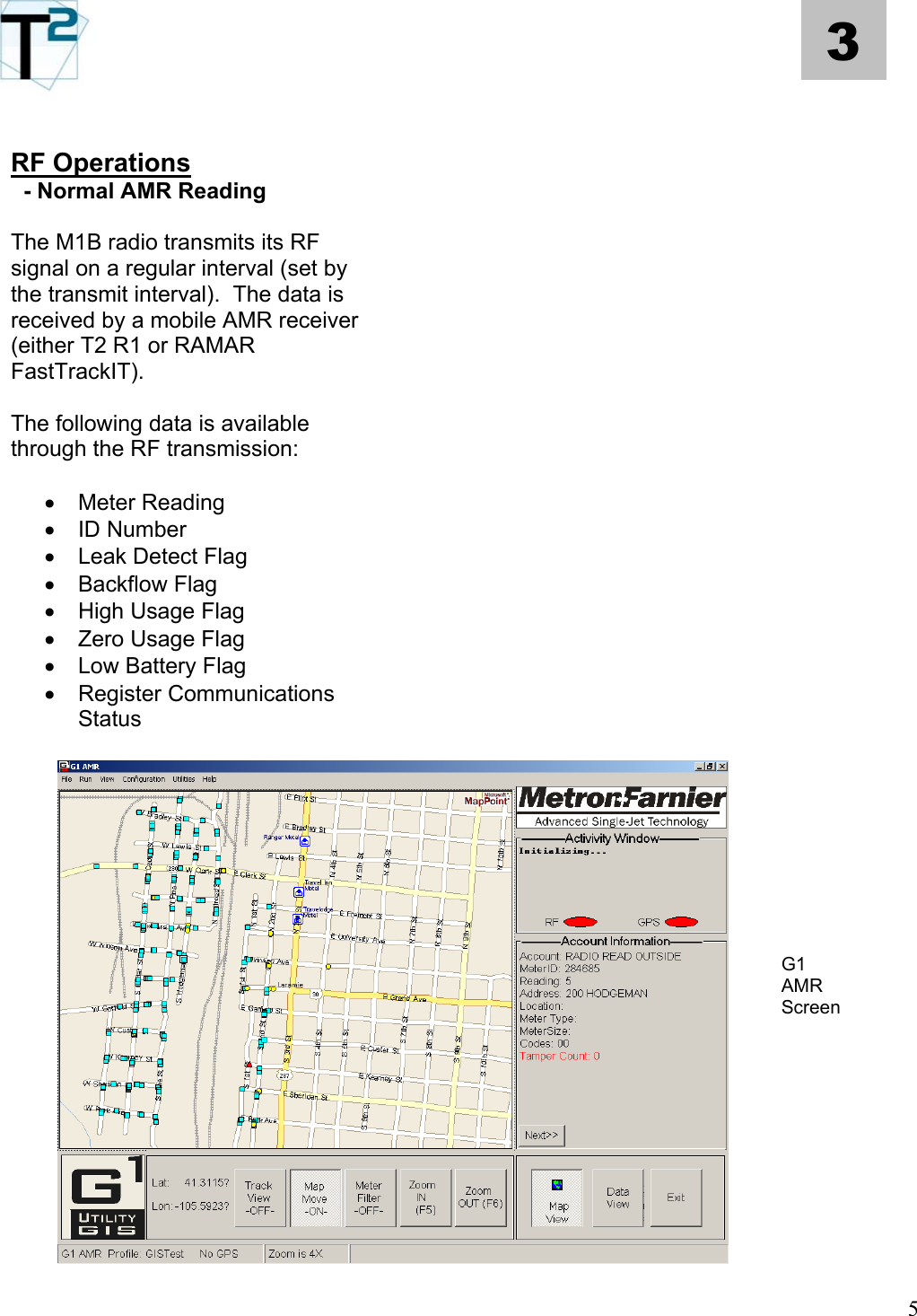
![4 3 ] Datalogging The M1B radio logs data as an enhanced data function. The basic data functions of the M1B radio – leak detection, backflow, high usage – are all detectable through the normal remote AMR operations (via the reading system). The datalogging function offers a first-hand customer-service tool to examine the consumption pattern of a specific meter. For instance, if a customer has been flagged as having a possible leak, the water utility can use the FPDA to download the meter/radio’s data and immediately discuss the site’s usage data. Data Logging PDA Screen The FPDA will allow the user to view the data in a time bucket format (2, 4, 6, 12 or 24 hr) consumption bar chart format or in a flowrate line graph (for pulse-based systems only)](https://usermanual.wiki/Transparent-Technologies/610M1B01SSL/User-Guide-554993-Page-15.png)