Transparent Technologies 610M1B01SSL Meter Management Information System User Manual TRANSPARENT TECHNOLOGIES
Transparent Technologies, Inc. Meter Management Information System TRANSPARENT TECHNOLOGIES
Users Manual

TRANSPARENT TECHNOLOGIES
M1B Utility Radio Transmitter
Operations Manual
Transparent Technologies, Inc
5665 Airport Blvd
Boulder, CO 80301
720-406-1294
Disclaimer
In no event shall Transparent Technologies be liable for any incidental, indirect,
or consequential damages or other damages including without limitation loss of
profits, loss of revenue, loss of data, loss of use of the product or any associated
equipment, downtime, and user’s time associated with the use of this product,
the resale hardware or its software.
Use of Hardware
In no event shall Transparent Technologies be liable for damages resulting from
the use of its hardware or the malfunction of that hardware. Specifications for
the hardware are subject to change at any time without notice.
Copyrights /Trademarks
Transparent Technologies reserves the names T2, M1 and UDA.
References are made to Sony®, Clie™and Palm©.
Version
M1B Version 1.00a
May 2005
M1B
Utility
Radio
Transmitter
Operations
Manual
OVERVIEW 1
INSTALLATION & WIRING 2
OPERATION 3
BATTERY 4
APPENDIX 5
1
OVERVIEW
M1B
Utility
Radio
Transmitter
Univeral Basic Specifications
The M1 radio is a universal AMR
device designed for every utility.
Encoder and digital inputs for all
major water meter registers.
Transmission: One-Way DTS
(unregulated)
Regulatory: FCC 15.247
Simple Temperature: -40°F to 158°F
The M1 operates in an unlicensed
mode in the 900-Mhz range which
requires no utility regulation. The
radio is easily configured and
interfaced with an off-the-shelf PDA.
(-40°C to +70°C)
Humidity: 100%
Submersion: IP-68 Rating
Packaging: PCB 100%
Powerful encapsulated
In addition to reliable meter reading,
the M1 also provides powerful
datalogging, consumption profiling
and leak detection. The M1 transmit
basic meter and leak detection
information through the RF signal.
Housing: Smoke or Clear
Polycarbonate
Interface: All Major Encoders
All Major SC/Pulse
See Compatability
Battery: Replaceable
19.0 A-hr D-cell
Battery Life: Up to 20 years
1
2
1
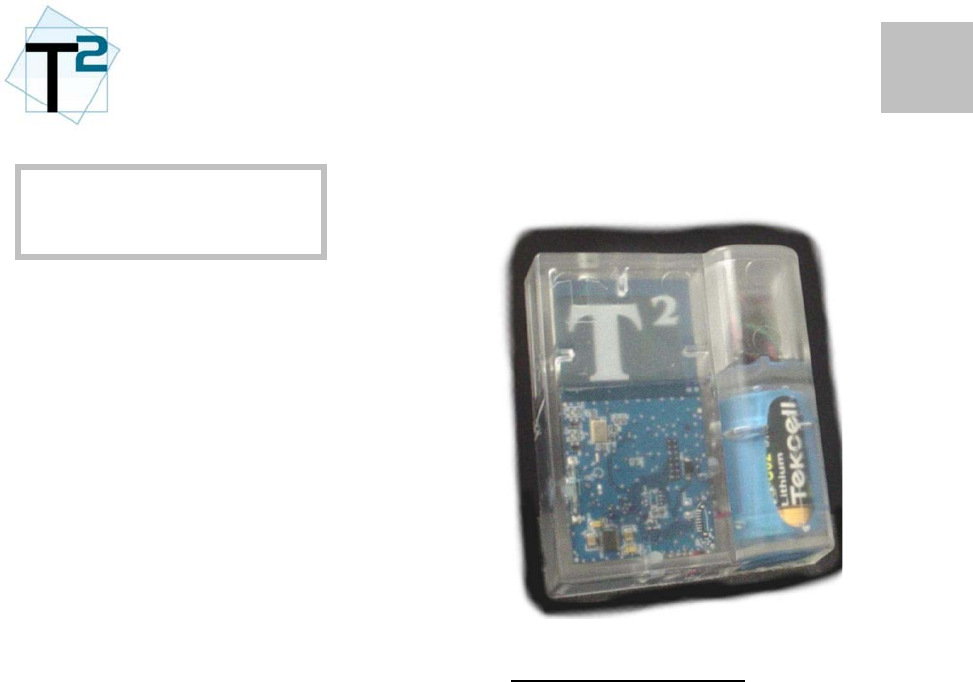
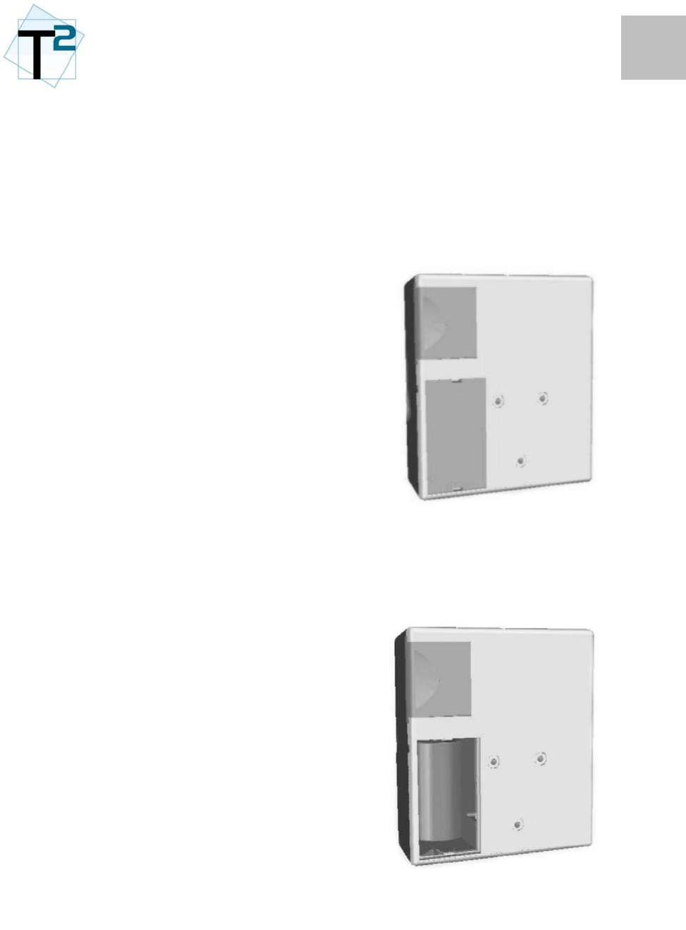
M1B Packaging
The M1B is housed in a
polycarbonate shell with multiple
levels of waterproofing. The
housing is available in either a clear
or smoke tint.
The housing is assembled with a
UV-cure adhesive which provides
the first level of environmental
protection. The radio electronics
are 100% encapsulated in a
dielectric gel for 100% moisture
protection. Finally, all cable
entry/exit points are sealed with gel
grommets to protect against long-
term moisture penetration.
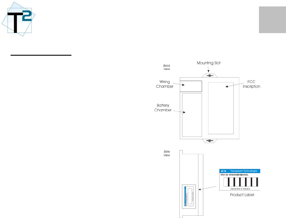
The rear of the radio unit provides
the access chambers for the wiring
connections and the replaceable
battery.
The product label indicates a model
number, a lot/serial number and the
FCC identifier.
1
2
INSTALLATION &
Installation
The M1A is designed for all
environments and can be installed
either in indoor or outdoor
environments.
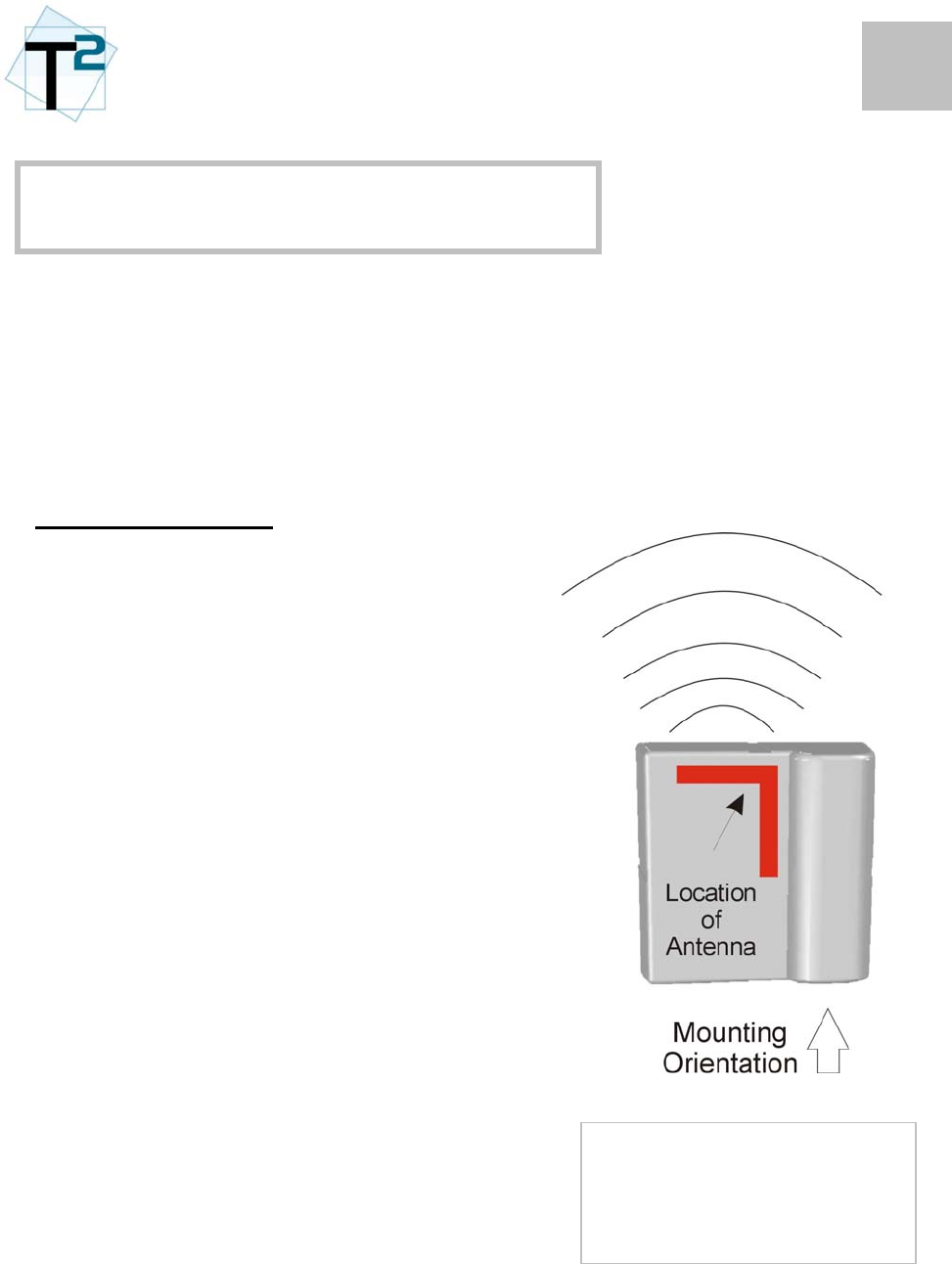
Mounting Orientation
The most important consideration is
to keep the M1B radio unit
UPRIGHT when it is installed.
The antenna is located on the top of
the radio board and the RF
transmission pattern is optimized
with an upright orientation.
In the UPRIGHT position:
• The hanging slot is at the top of
the unit
• The T2 logo will be readable at
the top of the housing
• The battery will be at the bottom
Other primary considerations for
optimum transmission:
• Avoid mounting the radio unit
directly against metal surfaces
(pipes, valves, etc.)
In all cases, the installer
should experiment with
mounting techniques and RF
performance prior to quantity
installation.
• Avoid mounting the unit below
typical water levels.
• Do NOT drive screws or
mounting hardware into the
unit’s plastic housing.
• Always mount the unit at the
highest grade possible.
2
2
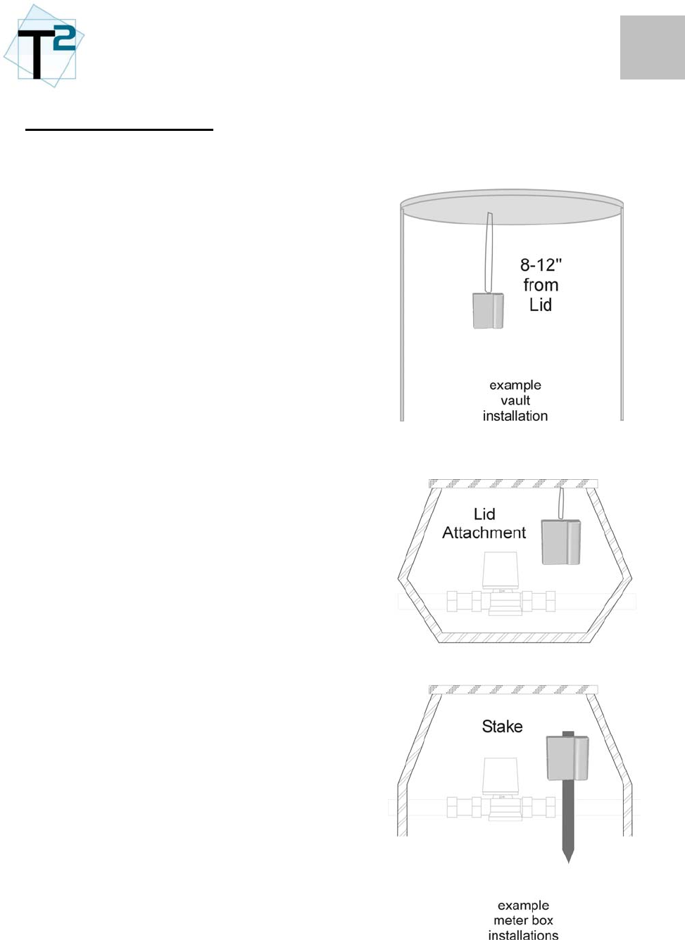
Pit & Vault Installations
For best transmission, the unit
should not be mounted directly on
any metal surfaces, such as pipes
or valves, or mounted below know
water levels.
The M1B has multiple mounting
options, including a slot for wire ties
which can be used to hang the M1A,
attach on a plastic stake or screw
directly onto a wall.
An effective mounting technique for
commercial meter vaults is to hang
the M1A unit from a fixture (such as
a ladder rung or the lid itself) near
the top of the vault. Proper
mounting in these types of vaults is
essential for good RF performance.
For smaller vaults and meter boxes,
a variety of acceptable mounting
options are available. Two simple
methods are hanging from the
lid/cover and staking into the ground.
If time and space are available, the
M1A can also be mounted on the
side of a pit with a wall bracket.
For vaults or pits with metals lids,
the M1B should be optimally
mounted 6-18 inches below the
lid/cover.
3
2
Indoor & Wall Installations
For best transmission, the unit
should not be mounted backing on
metal surfaces, reinforced concrete
or other dense surfaces.
In indoor mounting situations, a
higher mounting site will improve
RF performance.
In below grade sites (e.g.
basements), the installer should
experiment with the best location
before the final mounting. In these
instances, the direction/bearing of
the receiver should be considered.
For instance, if a unit is to be
mounted in a basement with
reinforced concrete walls, the best
mounting location could be on the
opposite wall, although this
increases the overall distance.
4
2
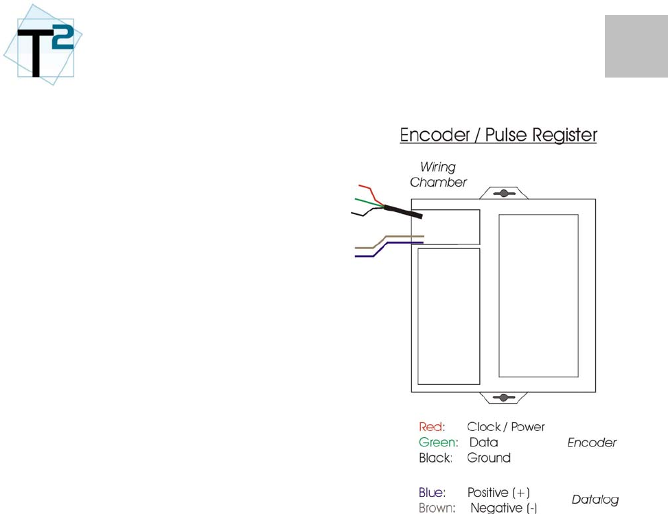
Wiring
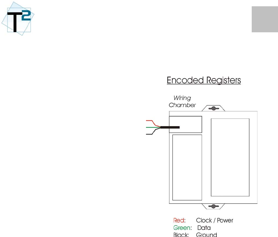
Encoders
As a default communication The
M1B utilizes the ECR-II
communications defacto-standard
wiring conventions for encoder
interfaces:
Red: Clock/PWR
Green: Data
Black: Ground
This wiring convention should be
consistent with all Metron-Farnier,
ECR-II and ECR-III registers.
The unit can be ordered with a pre-
wired cable in 5-ft increments. In
this case, the cable with leads will
exit on the side or bottom of the unit.
For field retrofit applications, the unit
can be ordering with leads ready for
splicing in the wiring chamber.
Wire Connections
The wiring connections are critical
for reliable radio-to-register
communications.
T2 recommends the use of 3m gel-
cap type terminations. These
connectors and the crimping tools
are available at many hardware
stores and online distributors.
Follow directions included with the
gel-cap packaging to ensure proper
terminations.
5
2
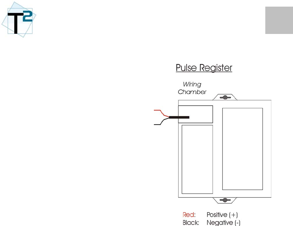
Pulse Wiring
For standard pulse wiring, the red
and black wires should be
connected to the pulse output of the
register.
Check the T2 wiring guide for color
coding for most registers.
Wire Connections
The wiring connections are critical
for reliable radio-to-register
communications.
T2 recommends the use of 3m gel-
cap type terminations. These
connectors and the crimping tools
are available at many hardware
stores and online distributors.
Follow directions included with the
gel-cap packaging to ensure proper
terminations.
6
2
Dual Enconder / Pulse
Metron-Farnier offers a unique
register that supplies a encoder-
output for meter reading purposes
and a pulse output for datalogging
purposes.
This special-order unit will have
multiple wiring connections: one for
the encoder output and one for the
switch closure output.
Wire Connections
The wiring connections are critical
for reliable radio-to-register
communications.
T2 recommends the use of 3m gel-
cap type terminations. These
connectors and the crimping tools
are available at many hardware
stores and online distributors.
Follow directions included with the
gel-cap packaging to ensure proper
terminations.
1
3
OPERATION
Operation
The M1B radio operation is covered
in three topics:
• ON/OFF Control
• Configuration
• Meter Reading
• Datalogging
• RF Operations
Refer to the FPDA Manual for
detailed instructions on the
operation of the M1B radio.
This manual only provides an
overview on these topics.
ON/OFF Control
Standby: The RF transmission
function is off but the meter interface
and all data functions are on. The unit
will monitor the IrDA port for ON/OFF
commands.
If the M1B radio has been
purchased as a separate unit, it will
be shipped in the default setting.
This will be in the OFF mode.
The Field PDA provides the ability to
set the M1B into one of three modes: ON: The RF transmission, meter
interface and all data functions are on.
The unit will monitor the IrDA port for
ON/OFF commands.
OFF: The RF transmission, meter
interface and all data functions are
off. The unit will monitor the IrDA
port for ON/OFF commands.

2
3
Configuration
The M1B radio is a flexible unit with
configuration options available for
tailoring the unit for a specific
utility’s needs.
Field PDA
The configuration is performed by
the T2 Field PDA (FPDA). Refer to
the FPDA Manual for detailed
instructions on the configuration
process.
Configurable Parameters
The following items are configurable
on the M1B radio:
Meter Settings
This screen allows the user to
customize the settings the radio
uses for the meter interface.
Transmit Settings
This screen allows the user to
customize the settings the radio
uses during its RF transmission.
Log Settings
This screen allows the user to
customize the settings the radio
uses during its data functions:
- Datalogging
- Leak Detection
- High Usage
- Zero Usage
M1B Configuration Parameters
Meter Settings
ID Type
Input Type
Encoder Value
Pulse Value
Meter Units
Meter Size
Meter Type
Meter Read (Pulse Inputs)
Transmit Settings
Transmit Scaling
Transmit Period
Group ID
Log Settings
Query Interval
Log Interval.
Leak Detection
• Leak Window
• Leak Period
High Usage
• High Usage Threshold
• Conservation Days
3
3
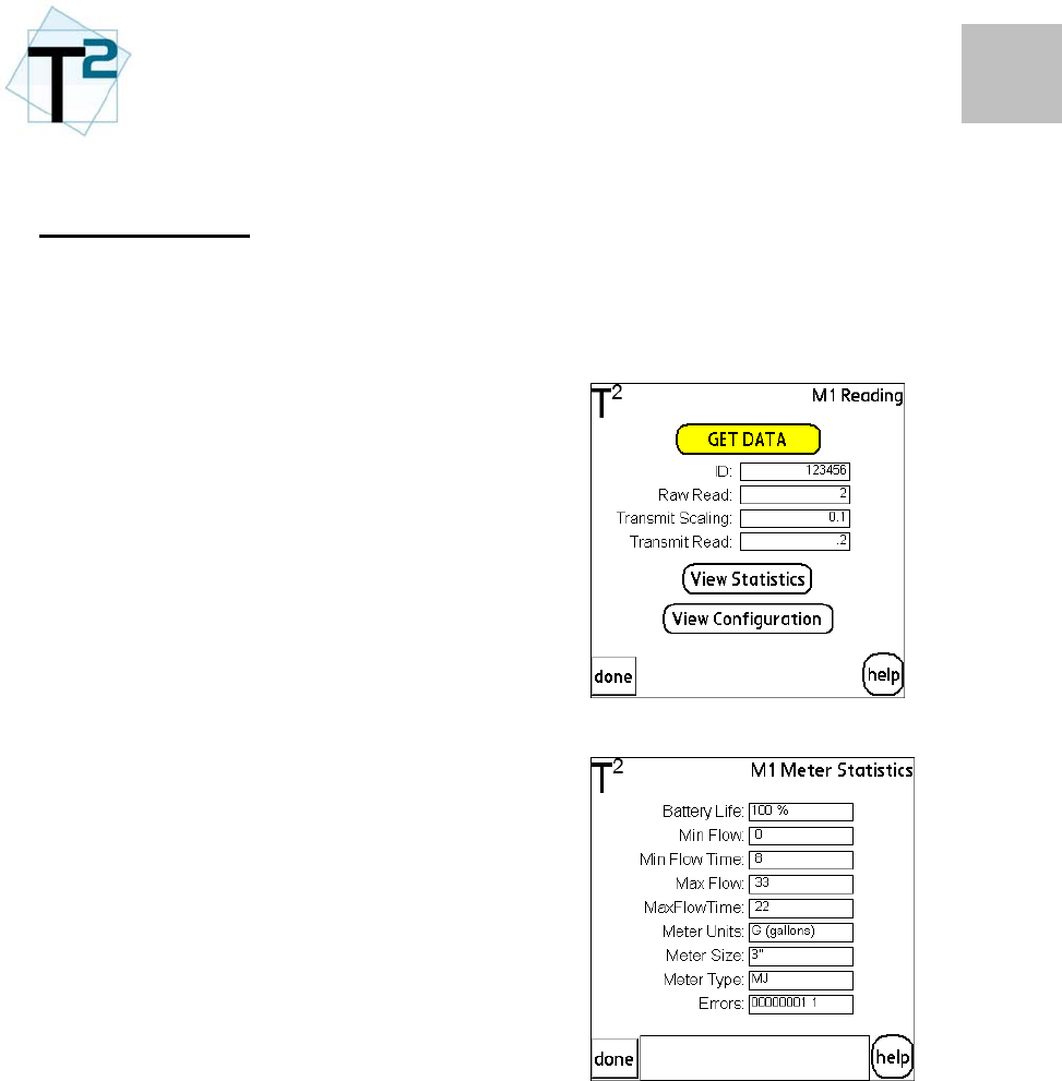
Meter Reading
Local Data Access
The M1B radio can be read locally
via a standard Palm-OS based PDA.
The T2 FPDA software is required
for this function.
Meter
Reading
PDA
Screen
All configuration, meter reading and
datalogs are accessible with the
PDA software.
Meter
Statistics
PDA
Screen
4
3
]
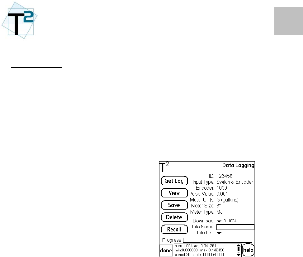
Datalogging
The M1B radio logs data as an
enhanced data function.
The basic data functions of the M1B
radio – leak detection, backflow,
high usage – are all detectable
through the normal remote AMR
operations (via the reading system).
The datalogging function offers a
first-hand customer-service tool to
examine the consumption pattern of
a specific meter. For instance, if a
customer has been flagged as
having a possible leak, the water
utility can use the FPDA to
download the meter/radio’s data and
immediately discuss the site’s usage
data.
Data
Logging
PDA
Screen
The FPDA will allow the user to view
the data in a time bucket format (2,
4, 6, 12 or 24 hr) consumption bar
chart format or in a flowrate line
graph (for pulse-based systems only)
5
3
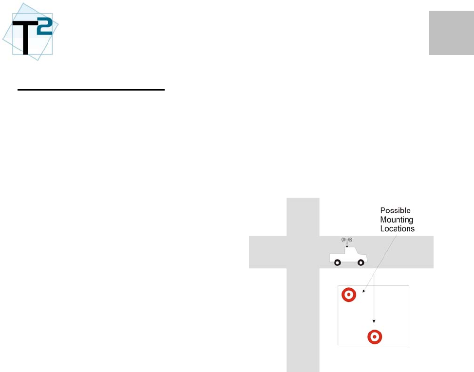
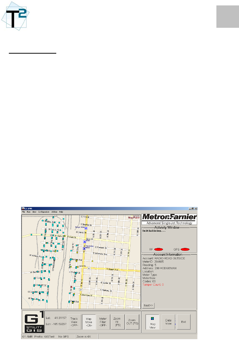
RF Operations
- Normal AMR Reading
The M1B radio transmits its RF
signal on a regular interval (set by
the transmit interval). The data is
received by a mobile AMR receiver
(either T2 R1 or RAMAR
FastTrackIT).
The following data is available
through the RF transmission:
• Meter Reading
• ID Number
• Leak Detect Flag
• Backflow Flag
• High Usage Flag
• Zero Usage Flag
• Low Battery Flag
• Register Communications
Status
G1
AMR
Screen
4
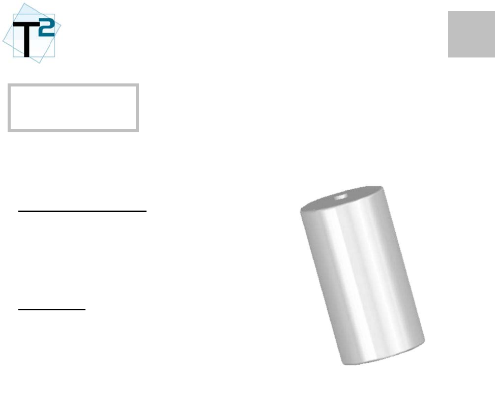
BATTERY
The M1B radio has a replaceable
battery.
Battery Specifications
Mfg: Tekcell
Type: Thionyl Lithium Chloride
Size: D-cell
Capacity: 19.0 A-hr
Battery Life
All battery calculations include a
20% environmental impact factor
and use a baseline of regular
function usage (PDA reads,
datalogging, etc.)
The M1B’s transmit period is directly
related to the battery life of the M1
radio. The RF transmission is the
largest power consumer and thus
drives battery life.
1
4
Battery Replacement
Transparent Technologies can
provide replacement batteries for
M1B radios.
The battery is replaced by first
removing the battery cover and then
removing the battery cell. The
battery is connected to the board
with a quick disconnect plug.
The replacement battery will come
with the identical plug.
Once the replacement battery has
been re-installed, the battery
chamber will need to be filled with
commercial grade silicone filler for
waterproofing.
2

3
4

6
A
PPENDIX
FCC Information The party responsible for the equipment, as
detailed in §2.909 of this chapter, shall ensure
that these special accessories are provided with
the equipment. The instruction manual for such
devices shall include appropriate instructions on
the first page of the text concerned with the
installation of the device that these special
accessories must be used with the device. It is
the responsibility of the user to use the needed
special accessories supplied with the equipment.
Information to user. - The users manual or
instruction manual for an intentional or
unintentional radiator shall caution the user
that changes or modifications not expressly
approved by the party responsible for
compliance could void the user's authority
to operate the equipment.
Special accessories.
(a) Equipment marketed to a consumer
must be capable of complying with the
necessary regulations in the configuration
in which the equipment is marketed.
Where special accessories, such as shielded
cables and/or special connectors, are
required to enable an unintentional or
intentional radiator to comply with the
emission limits in this part, the equipment
must be marketed with, i.e., shipped and
sold with, those special accessories.
However, in lieu of shipping or packaging
the special accessories with the
unintentional or intentional radiator, the
responsible party may employ other
methods of ensuring that the special
accessories are provided to the consumer,
without additional charge, at the time of
purchase. Information detailing any
alternative method used to supply the
special accessories shall be included in the
application for a grant of equipment
authorization or retained in the verification
records, as appropriate.
(b) If a device requiring special accessories is
installed by or under the supervision of the
party marketing the device, it is the
responsibility of that party to install the
equipment using the special accessories. For
equipment requiring professional installation, it
is not necessary for the responsible party to
market the special accessories with the
equipment. However, the need to use the
special accessories must be detailed in the
instruction manual, and it is the responsibility
of the installer to provide and to install the
required accessories.
(c) Accessory items that can be readily
obtained from multiple retail outlets are not
considered to be special accessories and are not
required to be marketed with the equipment.
The manual included with the equipment must
specify what additional components or
accessories are required to be used in order to
ensure compliance with this part, and it is the
responsibility of the user to provide and use
those components and accessories.
(d) The resulting system, including any
accessories or components marketed with the
equipment, must comply with the regulations.
1

2
6
FCC Definitions
Class A digital device. A digital device
that is marketed for use in a commercial,
industrial or business environment,
exclusive of a device which is marketed for
use by the general public or is intended to
be used in the home.
Class B digital device. A digital device
that is marketed for use in a residential
environment notwithstanding use in
commercial, business and industrial
environments. Examples of such devices
include, but are not limited to, personal
computers, calculators, and similar
electronic devices that are marketed for use
by the general public.
NOTE: The responsible party may also
qualify a device intended to be marketed
in a commercial, business or industrial
environment as a Class B device, and in
fact is encouraged to do so, provided the
device complies with the technical
specifications for a Class B digital
device. In the event that a particular type
of device has been found to repeatedly
cause harmful interference to radio
communications, the Commission may
classify such a digital device as a Class B
digital device, regardless of its intended
use.
For a Class A digital device or peripheral,
the instructions furnished the user shall
include the following or similar statement,
placed in a prominent location in the text of
the manual:
This equipment has been tested and found
to comply with the limits for a Class A
digital device, pursuant to Part 15 of the
FCC Rules. These limits are designed to
provide reasonable protection against
harmful interference when the equipment
is operated in a commercial environment.
This equipment generates, uses, and can
radiate radio frequency energy and, if not
installed and used in accordance with the
instruction manual, may cause harmful
interference to radio communications.
Operation of this equipment in a residential
area is likely to cause harmful interference in
which case the user will be required to correct
the interference at his own expense.
For a Class B digital device or peripheral, the
instructions furnished the user shall include the
following or similar statement, placed in a
prominent location in the text of the manual:
This equipment has been tested and found to
comply with the limits for a Class B digital
device, pursuant to Part 15 of the FCC Rules.
These limits are designed to provide
reasonable protection against harmful
interference in a residential installation. This
equipment generates, uses and can radiate
radio frequency energy and, if not installed
and used in accordance with the instructions,
may cause harmful interference to radio
communications. However, there is no
guarantee that interference will not occur in a
particular installation. If this equipment does
cause harmful interference to radio or
television reception, which can be determined
by turning the equipment off and on, the user
is encouraged to try to correct the interference
by one or more of the following measures:
- Reorient or relocate the receiving antenna.
- Increase the separation between the
equipment and receiver.
- Connect the equipment into an outlet on a
circuit different from that to which the
receiver is connected.
- Consult the dealer or an experienced
radio/TV technician for help.
The provisions of paragraphs (a) and (b) of this
section do not apply to digital devices exempted
from the technical standards under the
provisions of §15.103.