Tranzeo Wireless Technologies 2458NT2G WIRELESS NETWORKING DEVICE User Manual Multipoint UG v1 170706 pub
Tranzeo Wireless Technologies, Inc WIRELESS NETWORKING DEVICE Multipoint UG v1 170706 pub
UserManual.wiki
>
Tranzeo Wireless Technologies
>
2458NT2G User Manual
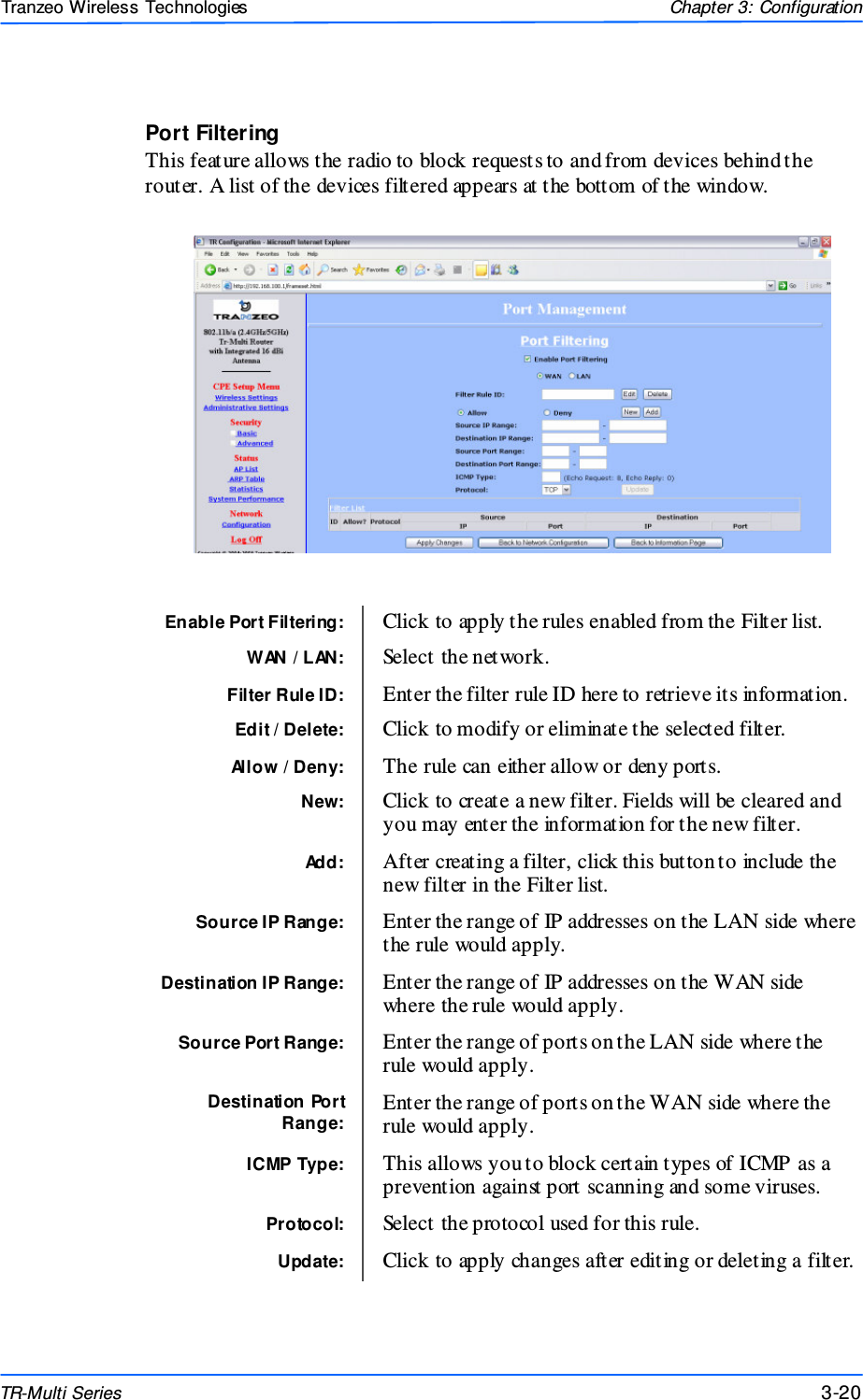
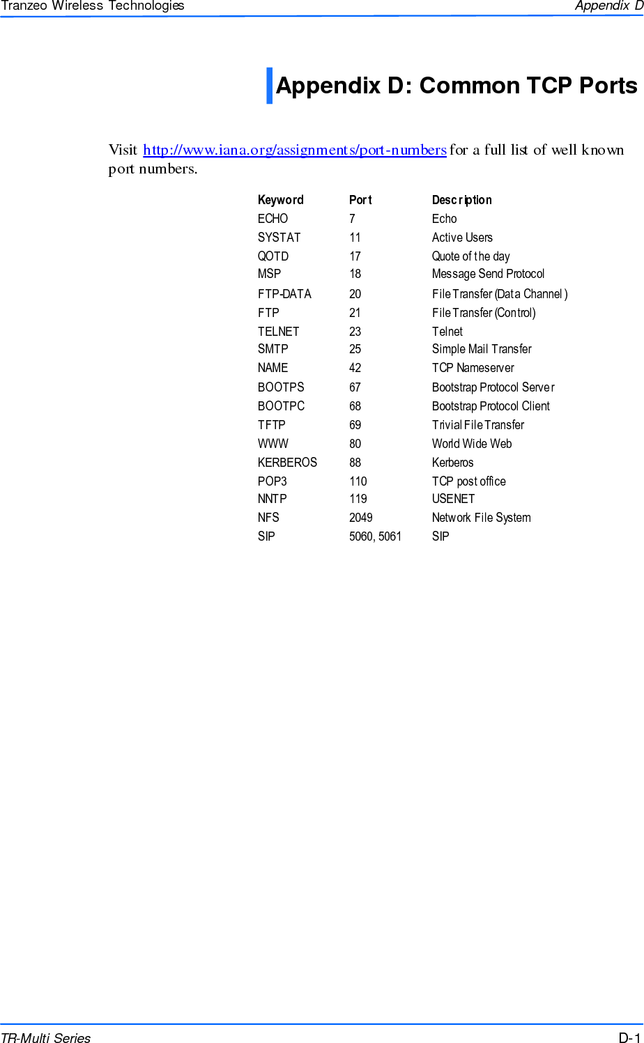
USERS MANUAL
Navigation menu
Upload a User Manual
Namespaces
Wiki Guide
HTML
PDF
Info
Views
User Manual
Discussion / Help
Navigation