Tranzeo Wireless Technologies CU900NT3 900 MHz WIRELESS NETWORK ADAPTER User Manual
Tranzeo Wireless Technologies, Inc 900 MHz WIRELESS NETWORK ADAPTER Users Manual
UserManual.wiki
>
Tranzeo Wireless Technologies
>
CU900NT3 User Manual
>
Users Manual
Contents
1.
USERS MANUAL
2.
Users Manual
Users Manual
Navigation menu
Upload a User Manual
Namespaces
Wiki Guide
HTML
PDF
Info
Views
User Manual
Discussion / Help
Navigation
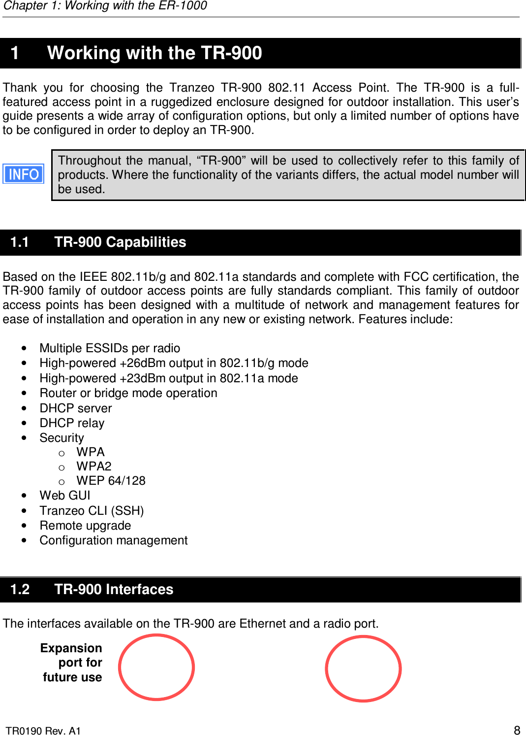
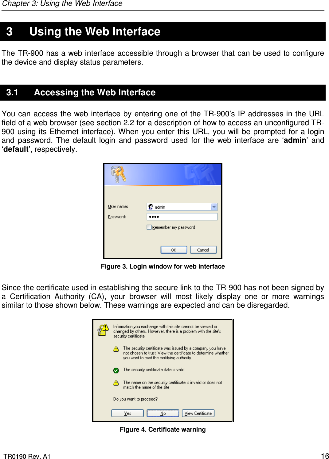
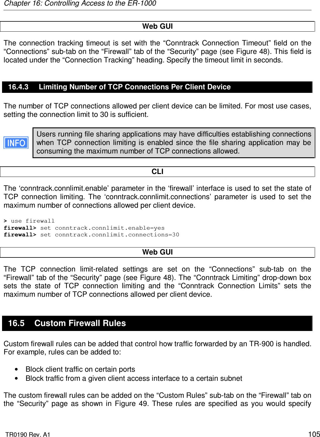
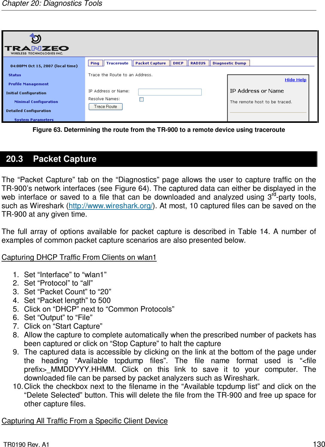
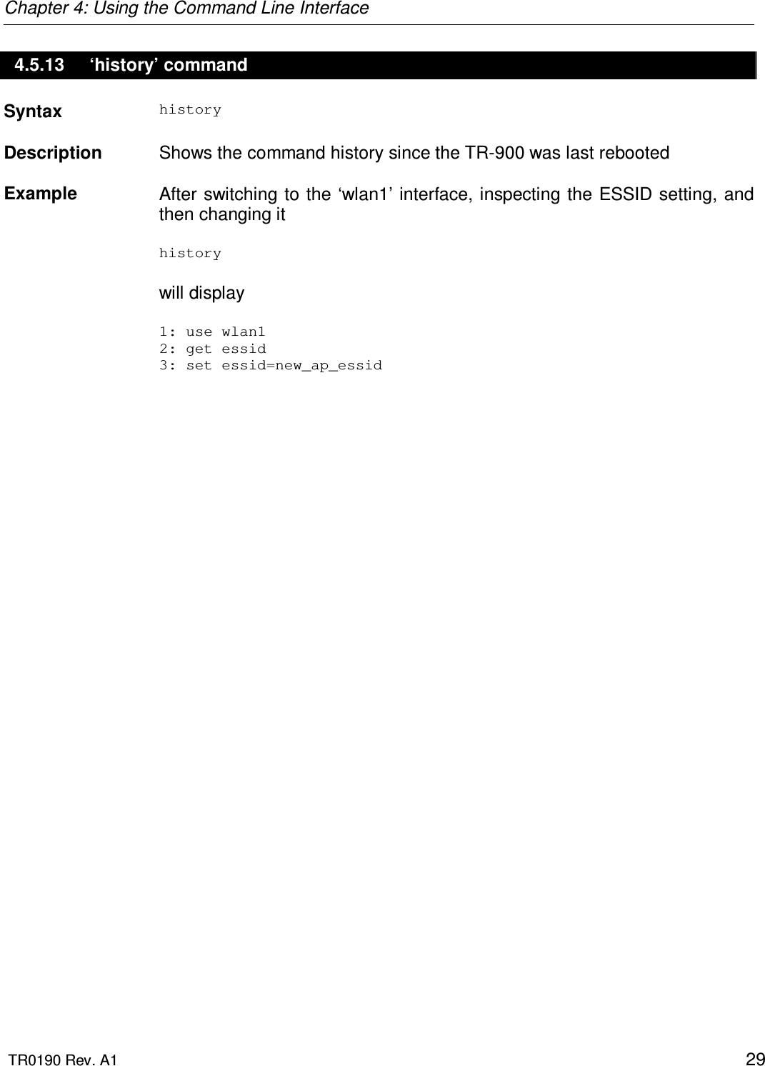
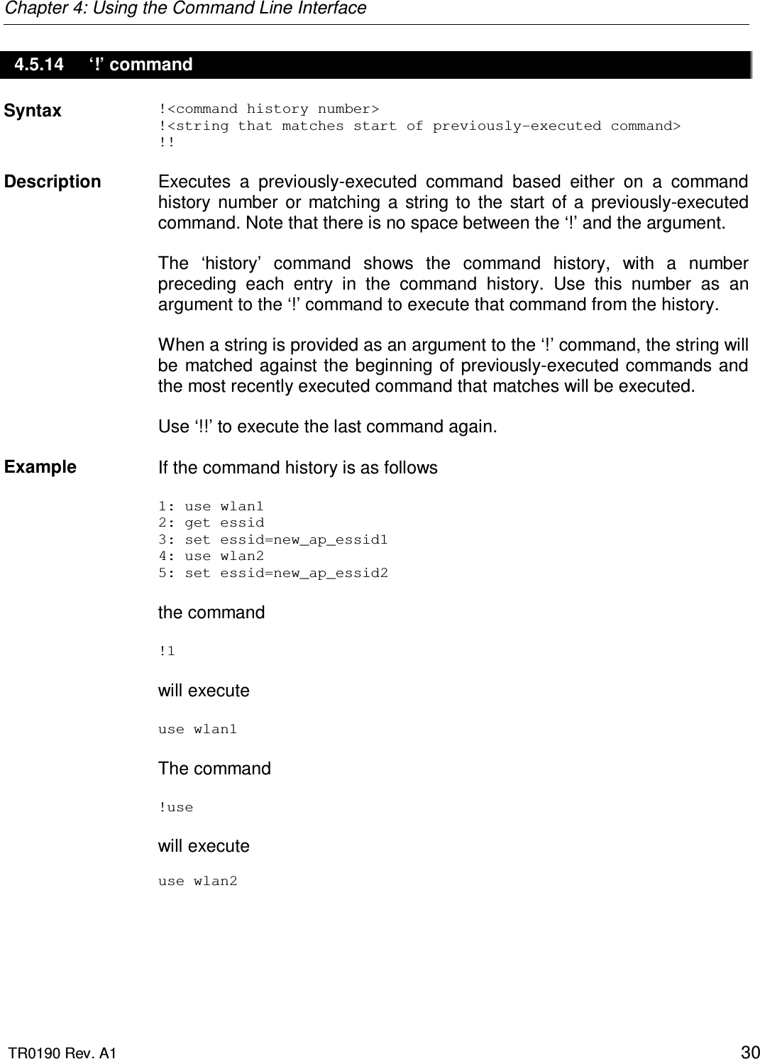
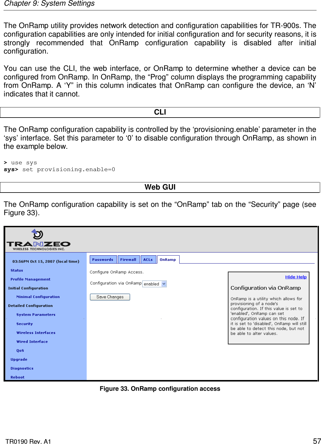
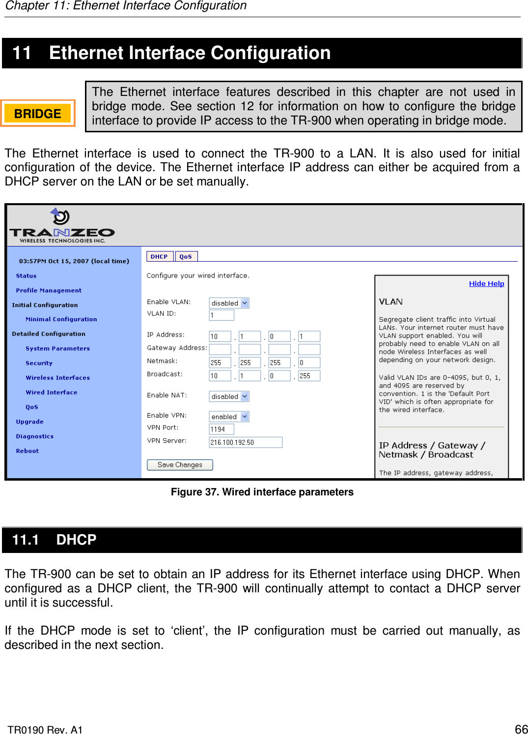
![Chapter 4: Using the Command Line Interface TR0190 Rev. A1 23 4.4.3 Searching the Command History The command history can be searched by pressing Ctrl+R and entering a search string. The most recently executed command that matches the string entered will be displayed. Press ‘Enter’ to execute that command. 4.4.4 Executing a Previous Command By using the up and down arrow keys you can select previously executed commands. When you find the command you wish to execute, you can either edit it or press ‘Return’ to execute it. 4.5 CLI Commands The usage of all CLI commands is explained in the following subsections. The command syntax used is command <mandatory argument> command [optional argument] 4.5.1 ‘?’ command Syntax ? Description Pressing ‘?’ at any time in the CLI will display a help menu that provides an overview of the commands that are described in this section. It is not necessary to press ‘Enter’ after pressing ‘?’. 4.5.2 ‘whoami’ command Syntax whoami Description Displays the name of the user you are logged in as.](https://usermanual.wiki/Tranzeo-Wireless-Technologies/CU900NT3.Users-Manual/User-Guide-1079556-Page-23.png)
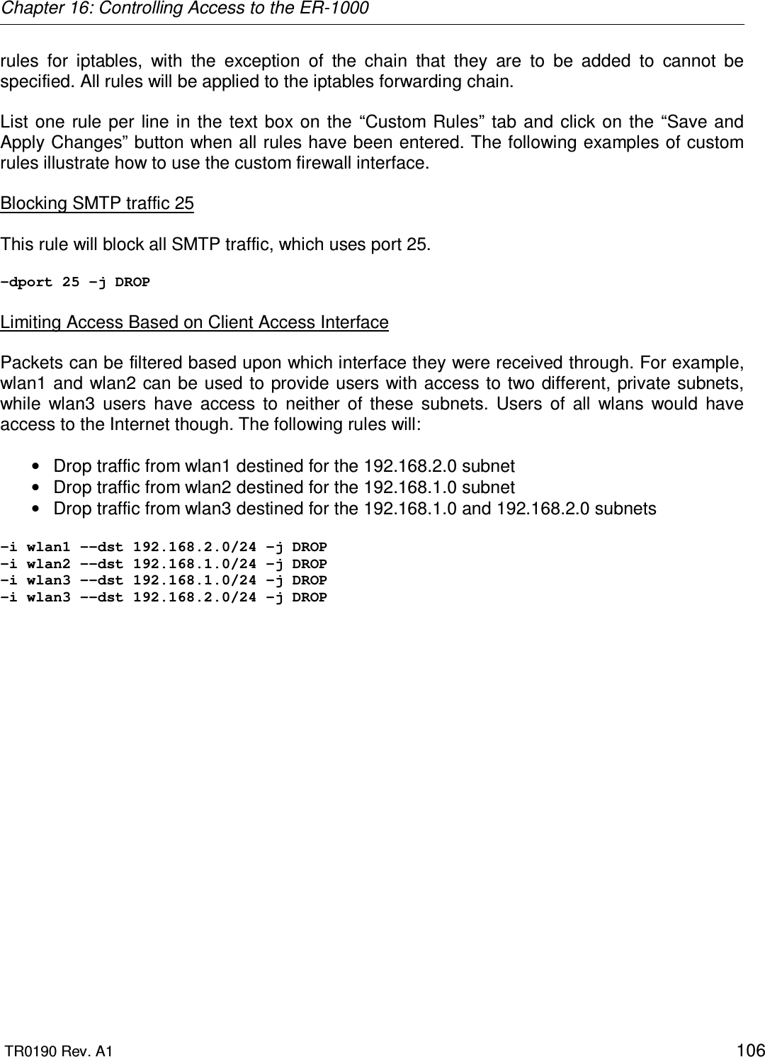
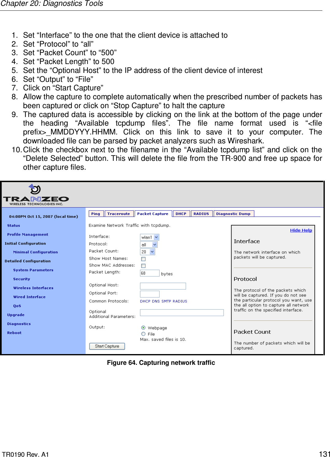
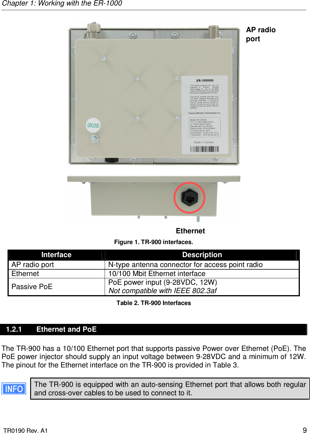
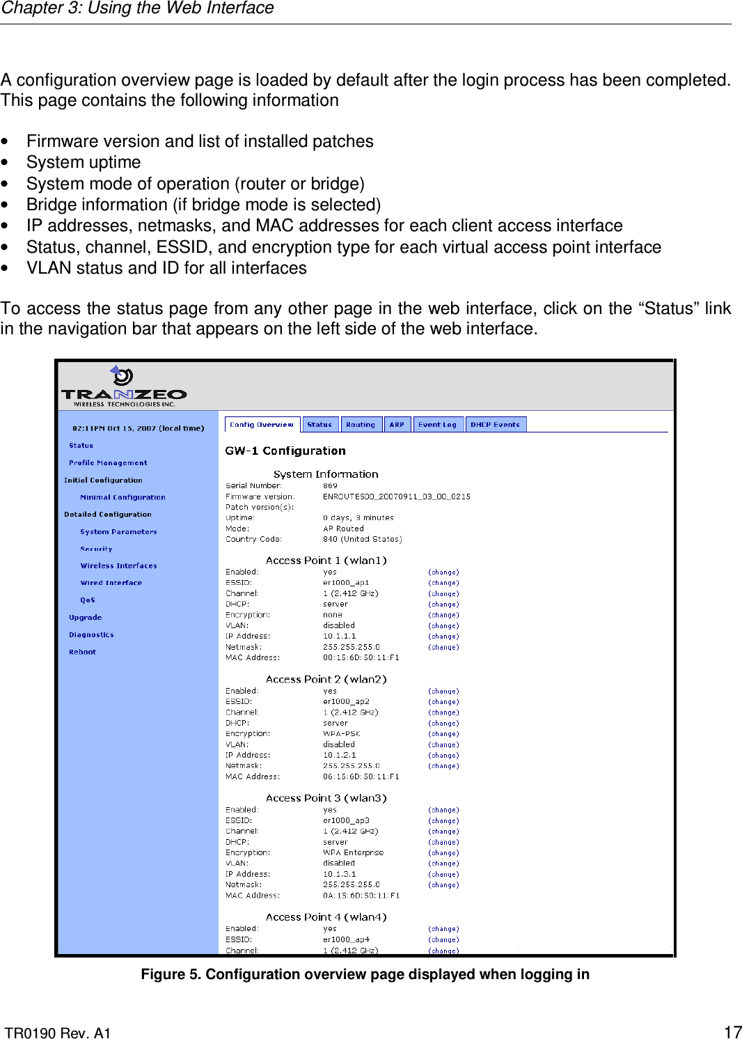
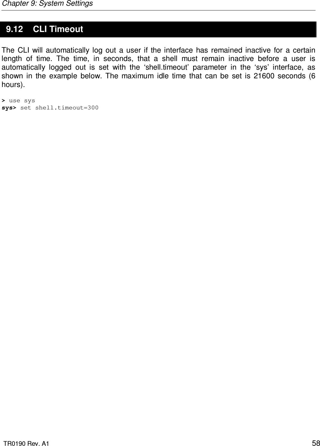
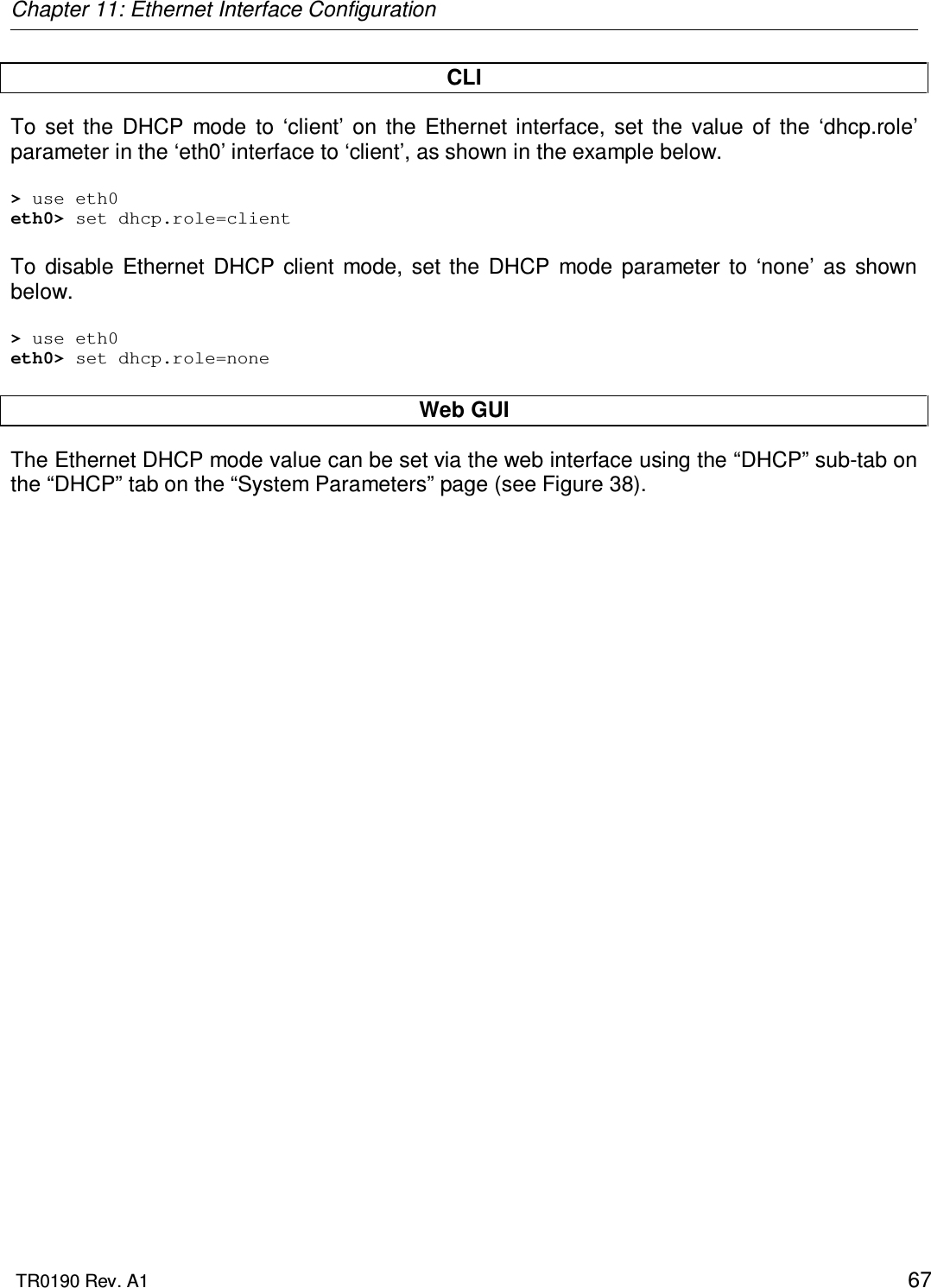
![Chapter 4: Using the Command Line Interface TR0190 Rev. A1 24 4.5.3 ‘help’ command Syntax help [command|parameter] where the optional argument is either one of the CLI commands (“[command]”) or a parameter in the currently selected interface (“[parameter]”). Description When no argument follows the help command, a help menu showing a list of available commands is displayed. When a command is supplied as the argument, a help message for that particular command is displayed. When a parameter in the current interface is specified as the argument, help information for it is displayed. Example help get will display the help information for the ‘get’ command. With the ‘sys’ interface selected sys> help scheme displays help information about that ‘scheme’ parameter, as shown below scheme : wireless node type 4.5.4 ‘show’ command Syntax show Description Displays all available interfaces. An interface in this list can be selected with the ‘use’ command.](https://usermanual.wiki/Tranzeo-Wireless-Technologies/CU900NT3.Users-Manual/User-Guide-1079556-Page-24.png)
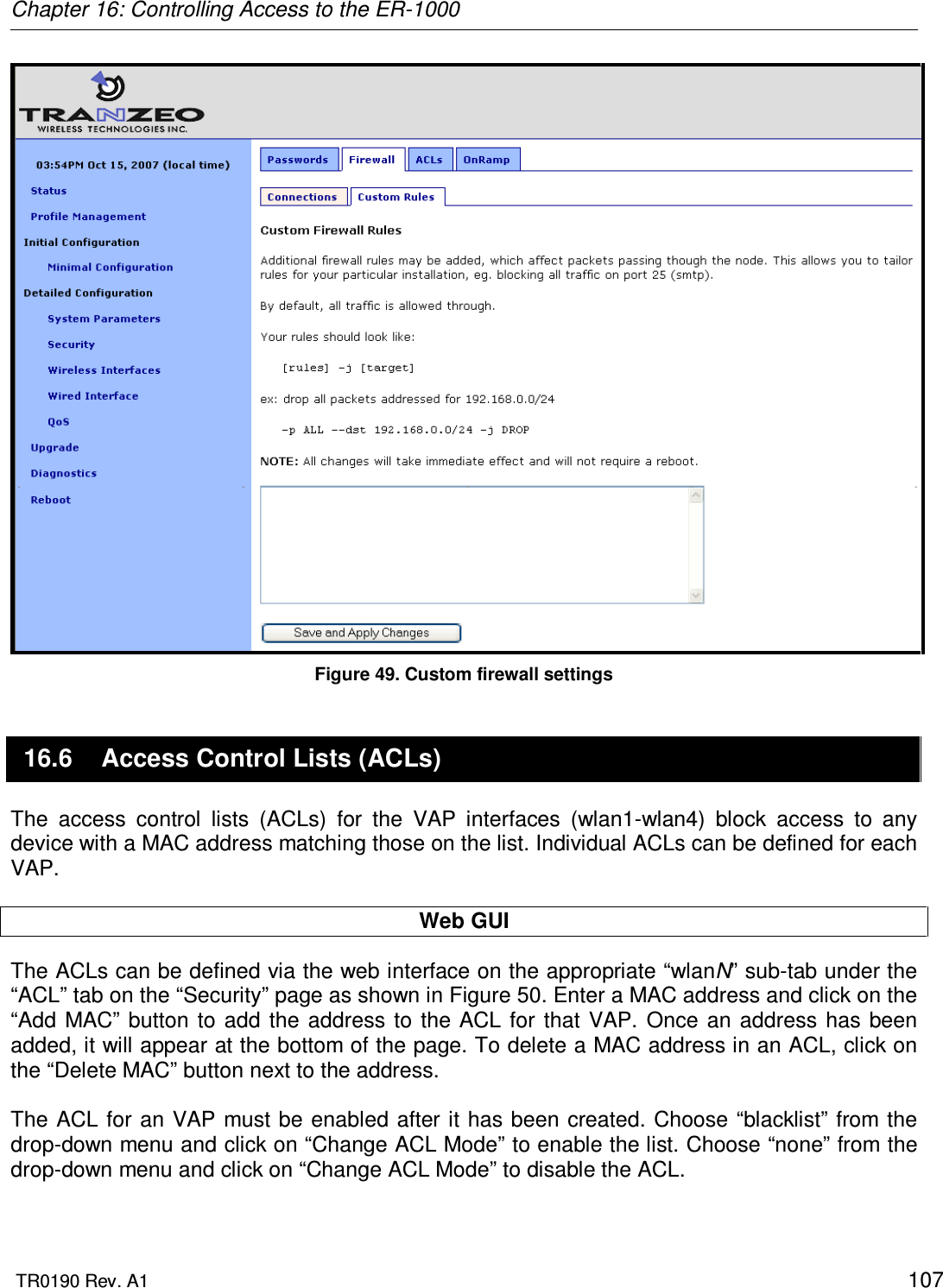
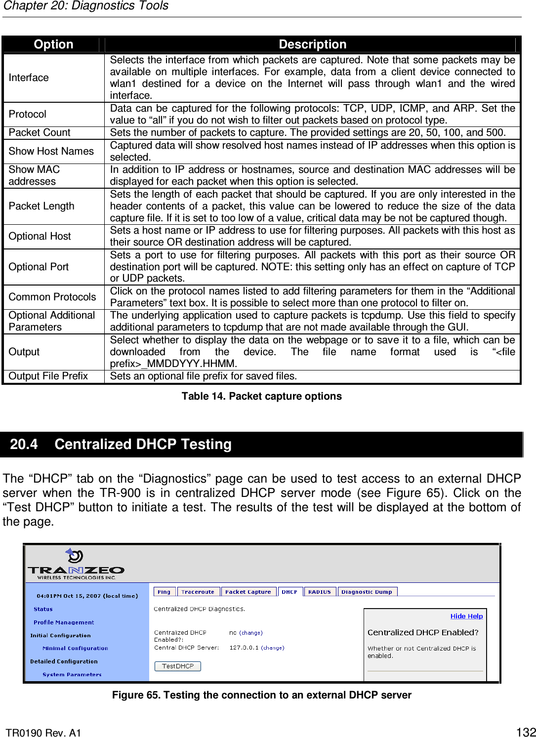
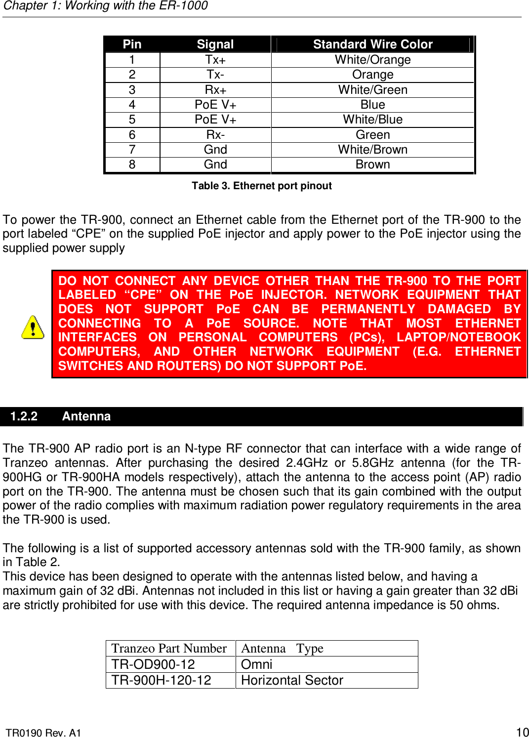
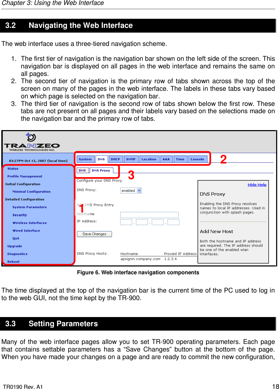
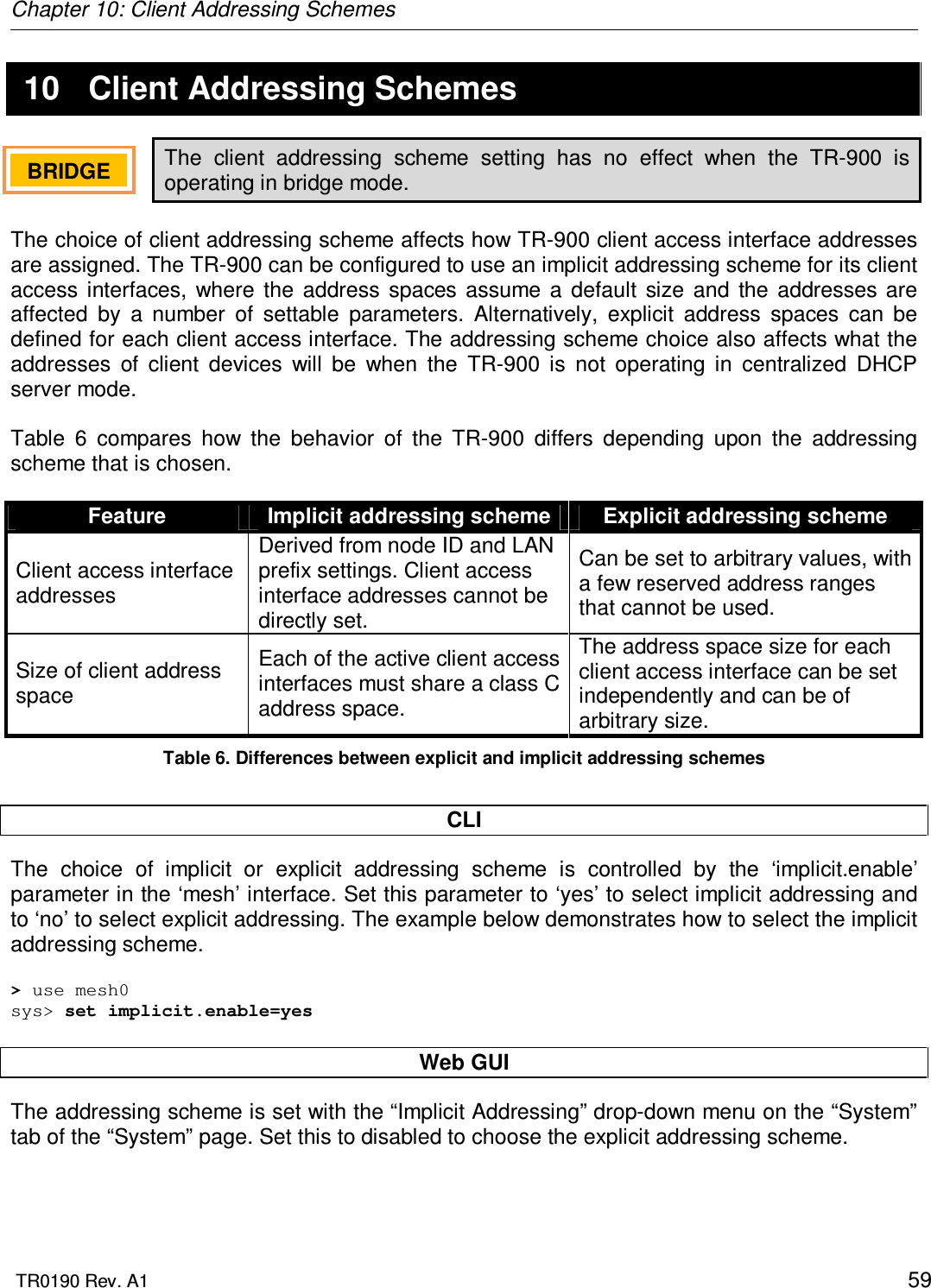
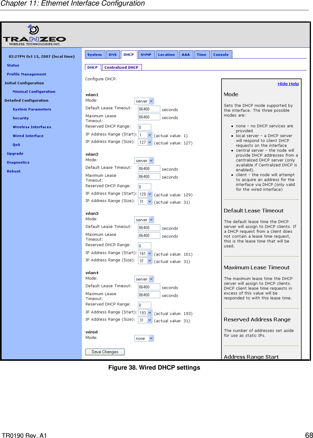
![Chapter 4: Using the Command Line Interface TR0190 Rev. A1 26 4.5.7 ‘get’ command Syntax get <parameter> where <parameter> is the parameter whose value is being fetched. Description Gets the value of one or more configuration parameters for the currently selected interface. The ‘*’ character can be used to specify wildcard characters. This allows multiple values to be fetched with a single command. Example With the ‘eth0’ interface selected get ip.address will return the Ethernet interface’s IP address, while get ip.* will return all parameters that begin with ‘ip.’ ip.address = 10.6.0.1 [read-only] ip.address_force = ip.broadcast = 10.6.0.255 [read-only] ip.broadcast_force = ip.gateway = [read-only] ip.gateway_force = ip.implicit.size.actual = 31 [read-only] ip.implicit.size.requested = 31 ip.implicit.start.actual = 225 [read-only] ip.implicit.start.requested = 225 ip.netmask = 255.255.255.0 [read-only] ip.netmask_force =](https://usermanual.wiki/Tranzeo-Wireless-Technologies/CU900NT3.Users-Manual/User-Guide-1079556-Page-26.png)
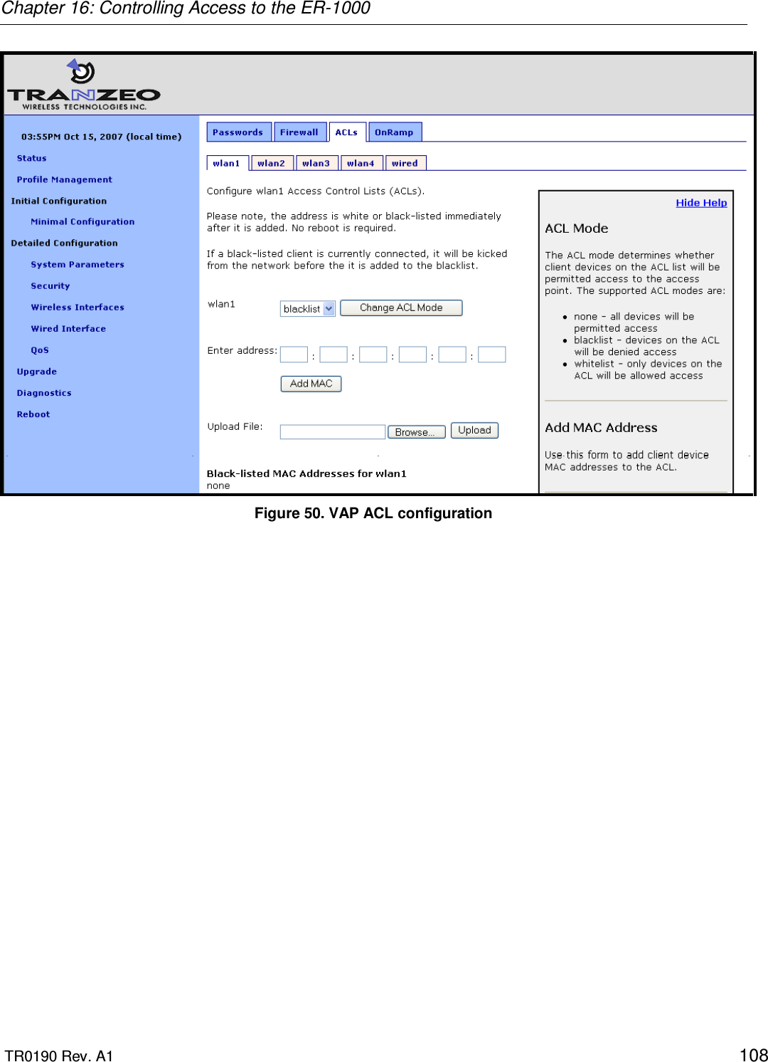
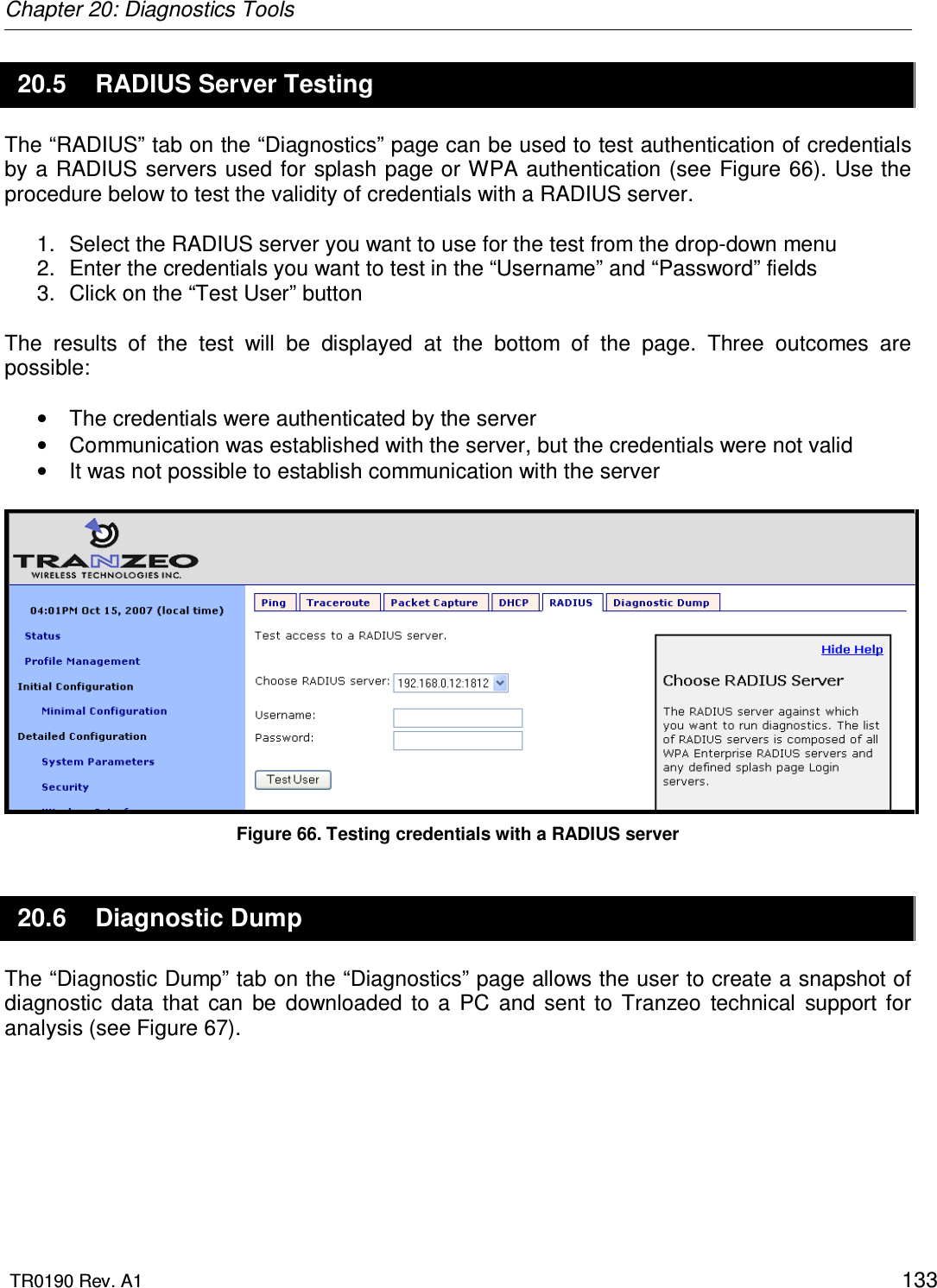
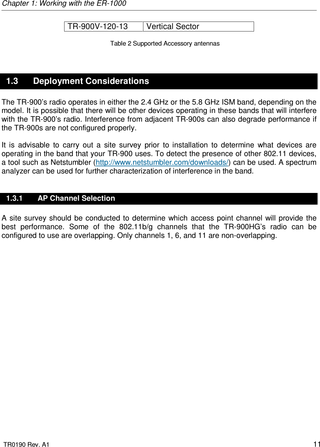
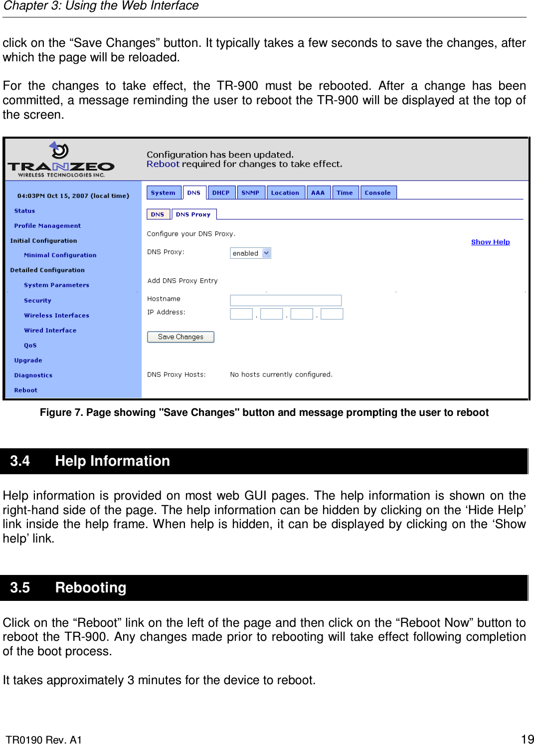
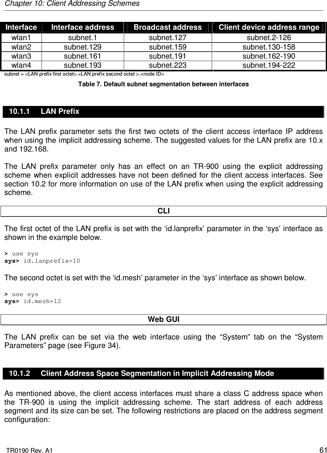
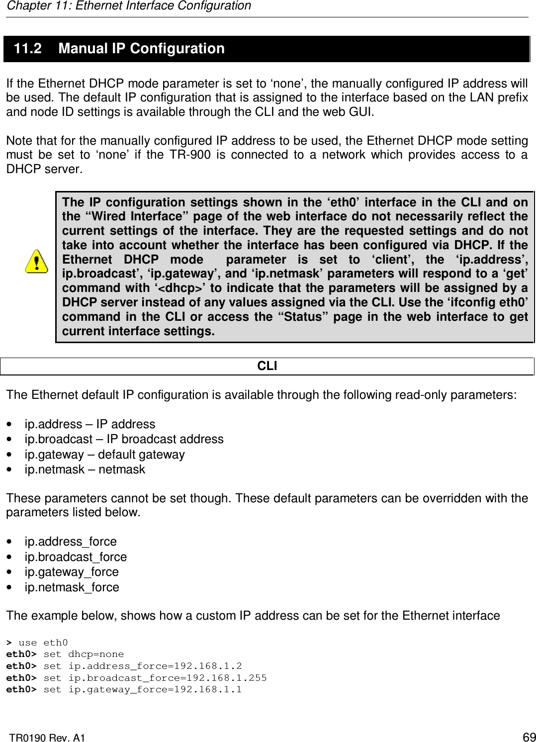
![Chapter 4: Using the Command Line Interface TR0190 Rev. A1 27 4.5.8 ‘list’ command Syntax list Description Lists all parameters for the selected interface Example With the ‘eth0’ interface selected list will display acl.mode : access control list mode dhcp.default_lease_time : default dhcp lease expiration in… dhcp.max_lease_time : maximum requestable dhcp lease… dhcp.relay.enable : use dhcp relay (if sys.dhcp.relay.enable=yes) dhcp.reserve : ip addresses to reserve at bottom of range… dhcp.role : interface dhcp role (none, client, server) enable : interface is enabled ip.address : IP address [read-only] ip.address_force : override .ip.address (or blank) ip.broadcast : broadcast address [read-only] ip.broadcast_force : override .ip.broadcast (or blank) ip.gateway : gateway [read-only] ip.gateway_force : override .ip.gateway (or blank) ip.implicit.size.actual : actual size of address range ip.implicit.size.requested : requested size of address range… ip.implicit.start.actual : actual interface fourth octet ip.implicit.start.requested : requested interface fourth octet… ip.netmask : network mask [read-only] ip.netmask_force : override .ip.netmask (or blank) routes.static : static routes for this interface vlan.enable : use a vlan? vlan.id : vlan id (avoid 0 and 1 normally) vpn.enable : enable vpn on gateway node vpn.keyfile : base name of crt/key files vpn.port : port number for vpn vpn.server : hostname or ip address of the vpn server 4.5.9 ‘ping’ command Syntax ping <IP address or hostname> Description Pings a remote network device. Halt pinging with Ctrl+C Example ping 172.29.1.1](https://usermanual.wiki/Tranzeo-Wireless-Technologies/CU900NT3.Users-Manual/User-Guide-1079556-Page-27.png)
![Chapter 4: Using the Command Line Interface TR0190 Rev. A1 28 4.5.10 ‘ifconfig’ command Syntax ifconfig <eth0|wlan[1-4]> Description Displays information, such as IP address and MAC address, for the specified network interface. Example ifconfig wlan1 will display wlan1 Link encap:Ethernet HWaddr 00:15:6D:52:01:FD inet addr:10.2.10.1 Bcast:172.29.255.255 Mask:255.255.0.0 UP BROADCAST RUNNING MULTICAST MTU:1500 Metric:1 RX packets:0 errors:0 dropped:0 overruns:0 frame:0 TX packets:2434 errors:0 dropped:0 overruns:0 carrier:0 collisions:0 txqueuelen:0 RX bytes:0 (0.0 b) TX bytes:233128 (227.6 Kb) 4.5.11 ‘route’ command Syntax route Description Displays the current route table. 4.5.12 ‘clear’ command Syntax clear Description Clears the screen](https://usermanual.wiki/Tranzeo-Wireless-Technologies/CU900NT3.Users-Manual/User-Guide-1079556-Page-28.png)

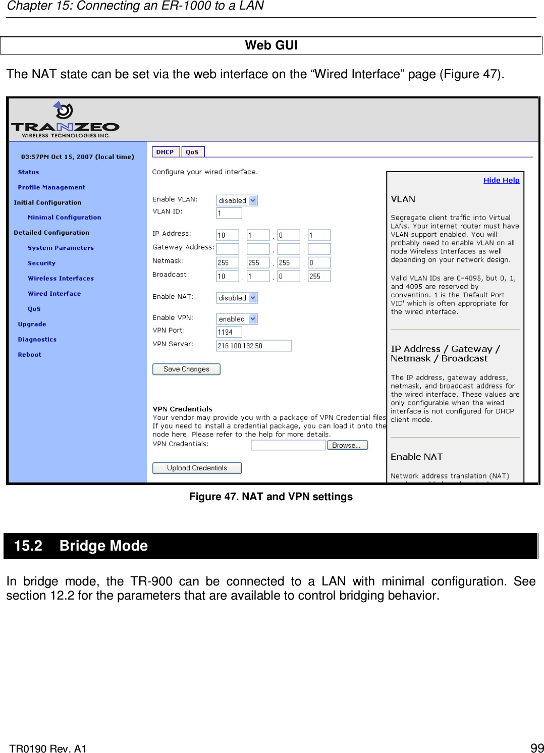
![Chapter 13: Virtual Access Point (VAP) Configuration TR0190 Rev. A1 76 10.1.1). Set the netmask by changing the client address space segments as described in 10.1.2. CLI You can view the IP settings for the VAP interfaces with the ‘ip.*’ parameters in the appropriate ‘wlanN’ interface as shown in the example below. > use wlan1 wlan1> get ip.* ip.address = 10.2.4.1 [read-only] ip.address_force = ip.broadcast = 10.2.4.127 [read-only] ip.broadcast_force = ip.gateway = [read-only] ip.gateway_force = ip.netmask = 255.255.255.0 [read-only] ip.netmask_force = ip.implicit.size.actual = [read-only] ip.implicit.size.requested = 31 ip.implicit.start.actual = [read-only] ip.implicit.start.requested = 1 When an TR-900 is using the implicit addressing scheme, the VAP IP settings can be changed by altering the ‘id.node’, ‘id.mesh’, and ‘id.lanprefix’ parameters in the ‘sys’ interface and the ‘ip.implicit.start.requested’ parameter in the appropriate ‘wlanN’ interface. When an TR-900 is using the explicit addressing scheme, the IP address, netmask, gateway address, and broadcast address can be set using the ‘ip.address_force’, ‘ip.netmask_force’, ‘ip.gateway_force’, and ‘ip.broadcast_force’ parameters in the appropriate ‘wlanN’ interface as shown in the example below. > use wlan1 wlan1> set ip.address_force=10.12.8.1 wlan1> ip.broadcast_force=10.12.8.255 wlan1> ip.gateway_force= wlan1> ip.netmask_force=255.255.255.0 Web GUI The current VAP IP settings can be viewed through the web interface on the “Config Overview” tab on the “Status” page. When using the implicit addressing scheme, the VAP IP settings can be changed by altering the node ID and LAN prefix settings on the “System” parameters tab on the “System Parameters” page. In explicit addressing mode, the IP parameters can be set on the appropriate tab on the “Wireless Interface” page.](https://usermanual.wiki/Tranzeo-Wireless-Technologies/CU900NT3.Users-Manual/User-Guide-1079556-Page-76.png)