Tranzeo Wireless Technologies G54DNT523 4.9GHz WIRELESS NETWORK ADAPTER User Manual TR 49 v2
Tranzeo Wireless Technologies, Inc 4.9GHz WIRELESS NETWORK ADAPTER TR 49 v2
UserManual.wiki
>
Tranzeo Wireless Technologies
>
G54DNT523 User Manual
USERS MANUAL
Navigation menu
Upload a User Manual
Namespaces
Wiki Guide
HTML
PDF
Info
Views
User Manual
Discussion / Help
Navigation
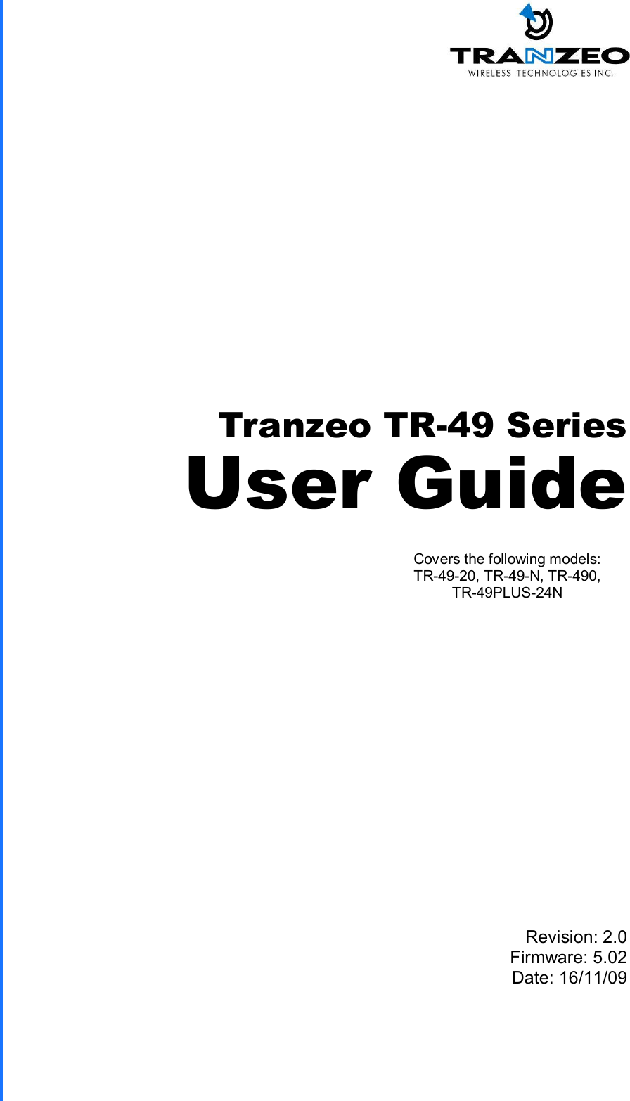

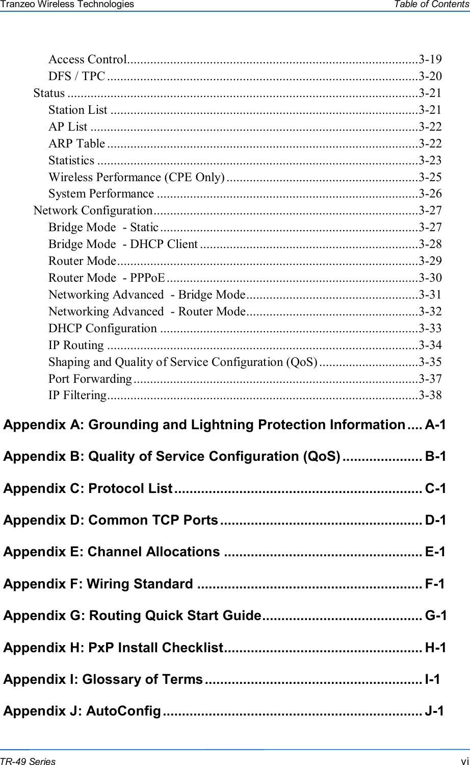


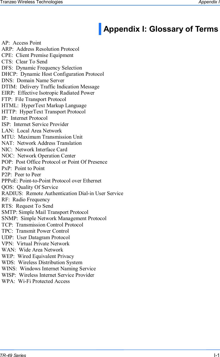
![555 This document is intended for Public Distribution 19473 Fraser Way, Pitt Meadows, B.C. Canada V3Y 2V4 Appendix J J-5 TR-49 Series Tranzeo Wireless Technologies # ************************** # Auto Configuration for TR6 # Version: 1.0.1 # Date: July 9, 2007 # Version: 1.0.2 # Date: January 29, 2009 # Version: 1.0.3 # Date: October 20, 2009 # Author: Patrick Ping Xu # ************************** # ----------------------------------------------------------------------------------- # Format Instruction: # (There is no complete validation for the configuration in the firmware. # The value in an invalid format might be ignored or causing an unexpected value.) # [STRING.maxlen] a string with maximum length # [IP] ip address or mask # [MAC] mac address of 12 hex characters # [INT.min-max] integer in range from min to max # [TOKEN] a string of userid:password # the maximum length of userid and password is 15 # [key1 | key2] a string in the key list # [RATE] an integer value as below # 0: Best # 2: 1M # 4: 2M # 11: 5.5M # 22: 11M # 12: 6M # 18: 9M # 24: 12M # 36: 18M # 48: 24M # 72: 36M # 96: 48M # 108: 54M # [RATES] a string of 4 hex characters # bit 0: 1M # bit 1: 2M # bit 2: 5.5M # bit 3: 11M # bit 4: 6M # bit 5: 9M # bit 6: 12M # bit 7: 18M # bit 8: 24M # bit 9: 36M # bit10: 48M # bit11: 54M # [STATS] a string of 2 hex characters # bit 0: LMAC TX/RX # bit 1: LMAC Interrupt # bit 2: LMAC Media # bit 3: Ethernet # [WEP_KEY] a string of 10 or 26 hex characters # -----------------------------------------------------------------------------------](https://usermanual.wiki/Tranzeo-Wireless-Technologies/G54DNT523/User-Guide-1652406-Page-77.png)
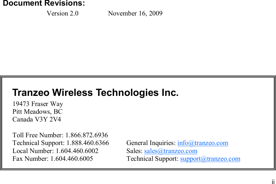
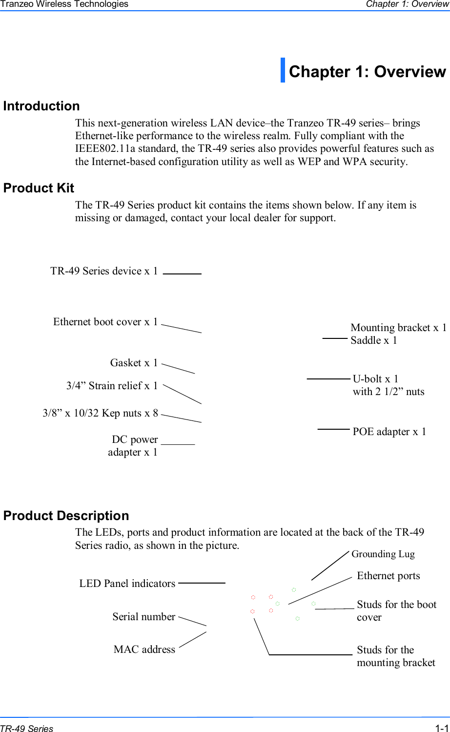
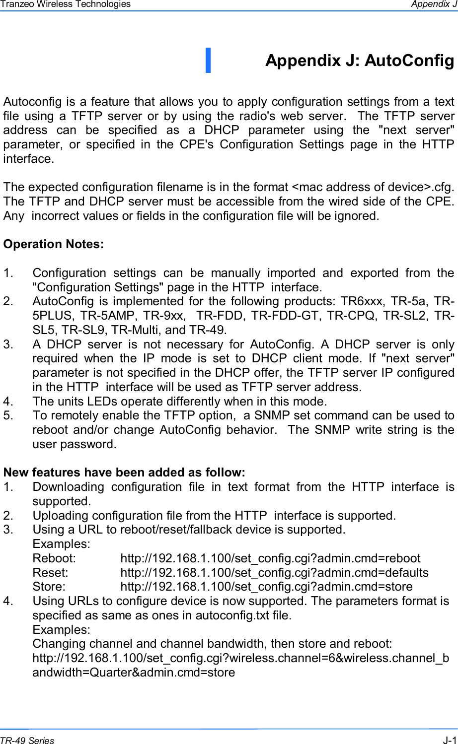
![666 This document is intended for Public Distribution 19473 Fraser Way, Pitt Meadows, B.C. Canada V3Y 2V4 Appendix J J-6 TR-49 Series Tranzeo Wireless Technologies # -------------------- # admin. # -------------------- admin.device_name = TR6Rt # [STRING.19] admin.admin_token = admin:default # [TOKEN] admin.super_token = recover:recover # [TOKEN] admin.led_enabled = Yes # [Yes | No] admin.snmp_read_community = public # [STRING.14] admin.snmp_sys_location = Location # [STRING.29] admin.snmp_sys_contact = Contact # [STRING.29] admin.snmp_traffic_format = Counter32 # [Counter32 | Integer64 | Counter64] admin.block_locator_access = No # [Yes | No] admin.auto_config_enabled = No # [Yes | No] (not used) admin.auto_config_timeout = 60 # [INT.5-255] unit:second admin.auto_config_server = 192.168.1.170 # [IP] admin.auto_config_filename = "" # [STRING.32] (blank when using {MAC_ADDRESS}.cfg as default) # -------------------- # net. # -------------------- net.network_mode = Bridge # [Bridge | Router] net.ip_mode = DHCP # [Static | DHCP | PPPoE] net.ip_address = 192.168.1.100 # [IP] net.subnet_mask = 255.255.255.0 # [IP] net.gateway = 192.168.1.1 # [IP] net.dns1 = 0.0.0.0 # [IP] net.dns2 = 0.0.0.0 # [IP] net.domain_name = "" # [STRING.59] net.mac_clone_enabled = No # [Yes | No] net.mac_clone_address = 000000000000 # [MAC] net.eth1_mode = Auto # [Auto | 10Auto | 10Full | 10Half | 100Auto | 100Full | 100Half] net.eth2_mode = Auto # [Auto | 10Auto | 10Full | 10Half | 100Auto | 100Full | 100Half] net.reassociate_on_dhcp = No # [Yes | No] net.vlan_enabled = No # [Yes | No] net.vlan_id = 0 # [INT.0-4095] net.reverse_dhcp_block = No # [Yes | No] net.shaping_rate = 0 # [INT.0-65535] unit:Kbps net.shaping_policy = mgmt,icmp # [bypass,mgmt,icmp,mcast] (bitmap) # -------------------- # net.router. # -------------------- net.router.lan_ip_address = 192.168.100.1 # [IP] net.router.lan_subnet_mask = 255.255.255.0 # [IP] net.router.allow_ping = Yes # [Yes | No] net.router.allow_web = Yes # [Yes | No] net.router.web_port = 80 # [INT.1-65535] net.router.web_timeout = 60 # [INT.0-65535] net.router.mtu_use_default = Yes # [Yes | No] net.router.mtu = 1500 # [INT.500-3000]](https://usermanual.wiki/Tranzeo-Wireless-Technologies/G54DNT523/User-Guide-1652406-Page-78.png)
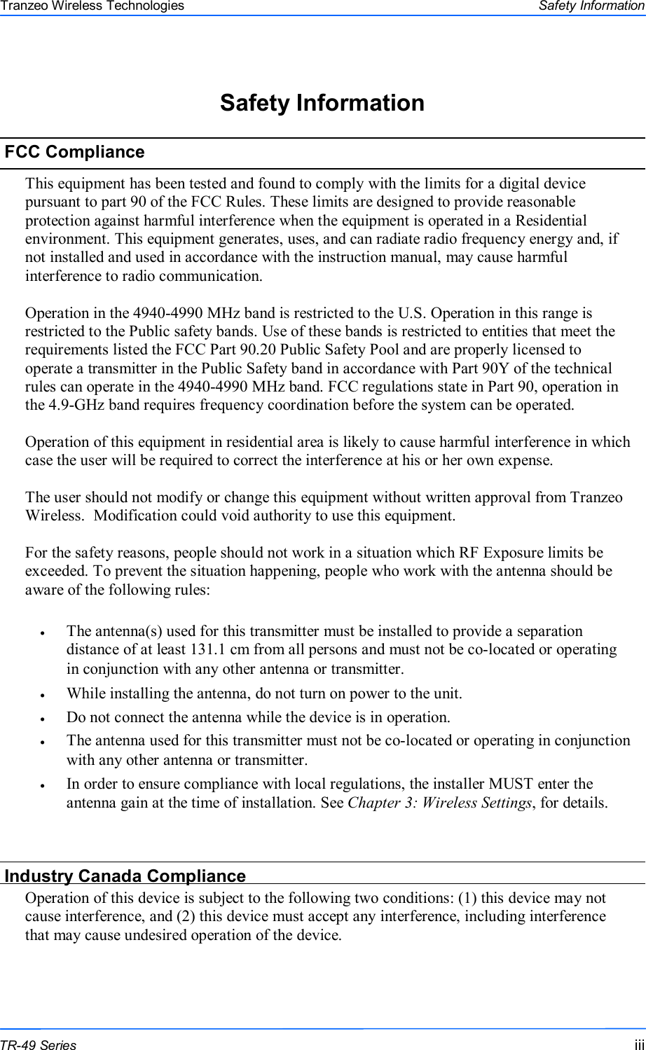
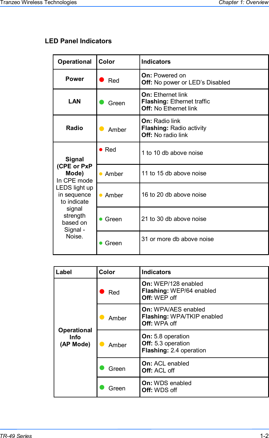
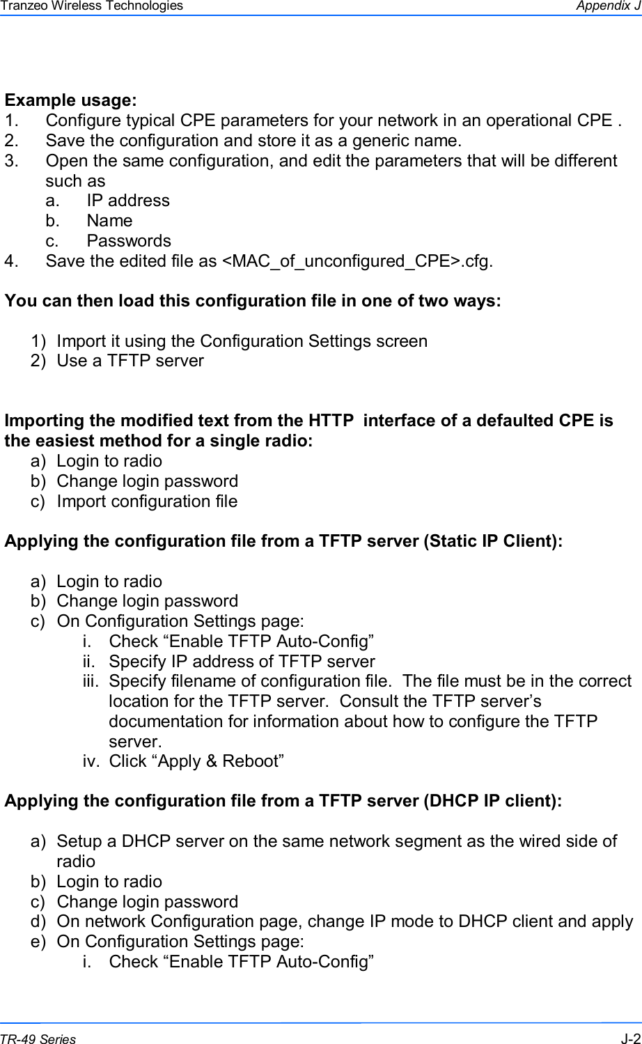
![777 This document is intended for Public Distribution 19473 Fraser Way, Pitt Meadows, B.C. Canada V3Y 2V4 Appendix J J-7 TR-49 Series Tranzeo Wireless Technologies net.router.nat_enabled = Yes # [Yes | No] # -------------------- # net.router.route. # -------------------- net.router.route.user_gateway_enabled = No # [Yes | No] net.router.route.user_gateway_interface = WAN # [WAN | LAN] net.router.route.user_gateway = 0.0.0.0 # [IP] ; entries 0-7 net.router.route.interface.0 = None # [WAN | LAN | None] net.router.route.ip_address.0 = 0.0.0.0 # [IP] net.router.route.subnet_mask.0 = 0.0.0.0 # [IP] net.router.route.gateway.0 = 0.0.0.0 # [IP] net.router.route.metric.0 = 0 # [INT.0-255] # -------------------- # net.router.ip_filter. # -------------------- ; it must be enabled before entry fields net.router.ip_filter.enabled = No # [Yes | No] ; entries 0-31 net.router.ip_filter.access.0 = Allow # [Allow | Deny] net.router.ip_filter.interface.0 = WAN # [WAN | LAN] net.router.ip_filter.protocol.0 = TCP # [TCP | UDP | ICMP] net.router.ip_filter.icmp_type.0 = 0 # [INT.0-255] net.router.ip_filter.source_ip_start.0 = 0.0.0.0 # [IP] net.router.ip_filter.source_ip_end.0 = 0.0.0.0 # [IP] net.router.ip_filter.source_port_start.0 = 0 # [0-65535] net.router.ip_filter.source_port_end.0 = 0 # [0-65535] net.router.ip_filter.destination_ip_start.0=0.0.0.0 # [IP] net.router.ip_filter.destination_ip_end.0 = 0.0.0.0 # [IP] net.router.ip_filter.destination_port_start.0 = 0 # [0-65535] net.router.ip_filter.destination_port_end.0 = 0 # [0-65535] # -------------------- # net.router.port_forward. # -------------------- ; it must be enabled before entry fields net.router.port_forward.enabled = No # [Yes | No] ; entries 0-31 net.router.port_forward.actived.0 = No # [Yes | No] net.router.port_forward.protocol.0 = TCP # [TCP | UDP] net.router.port_forward.external_port.0 = 0 # [0-65535] net.router.port_forward.internal_address.0=0.0.0.0 # [IP] net.router.port_forward.internal_port.0 = 0 # [0-65535] # -------------------- # net.router.dhcp_server. # -------------------- net.router.dhcp_server.enabled = Yes # [Yes | No] net.router.dhcp_server.range_start=192.168.100.100 # [IP] net.router.dhcp_server.range_length = 100 # [INT.0-255] net.router.dhcp_server.lease_time = 1440 # [INT.0-65535] unit:minute net.router.dhcp_server.gateway_use_default = Yes # [Yes | No] net.router.dhcp_server.gateway = 192.168.100.1 # [IP] net.router.dhcp_server.dns_use_wan_assigned = No # [Yes | No]](https://usermanual.wiki/Tranzeo-Wireless-Technologies/G54DNT523/User-Guide-1652406-Page-79.png)
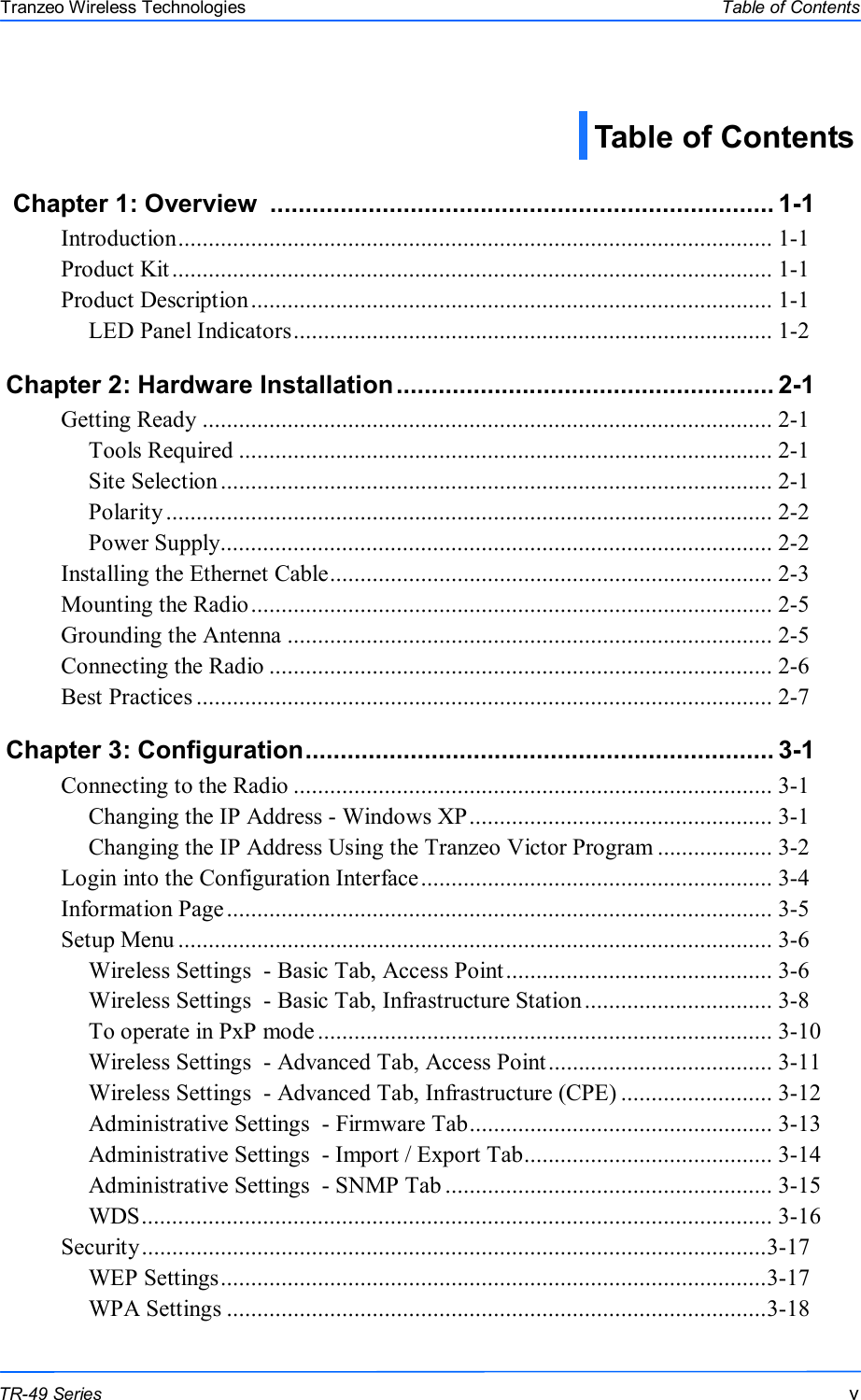
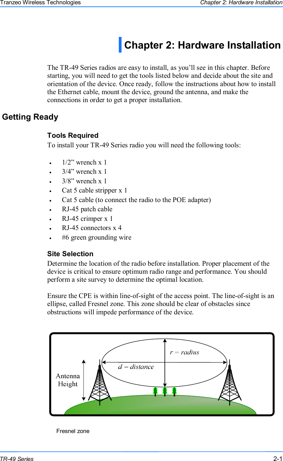
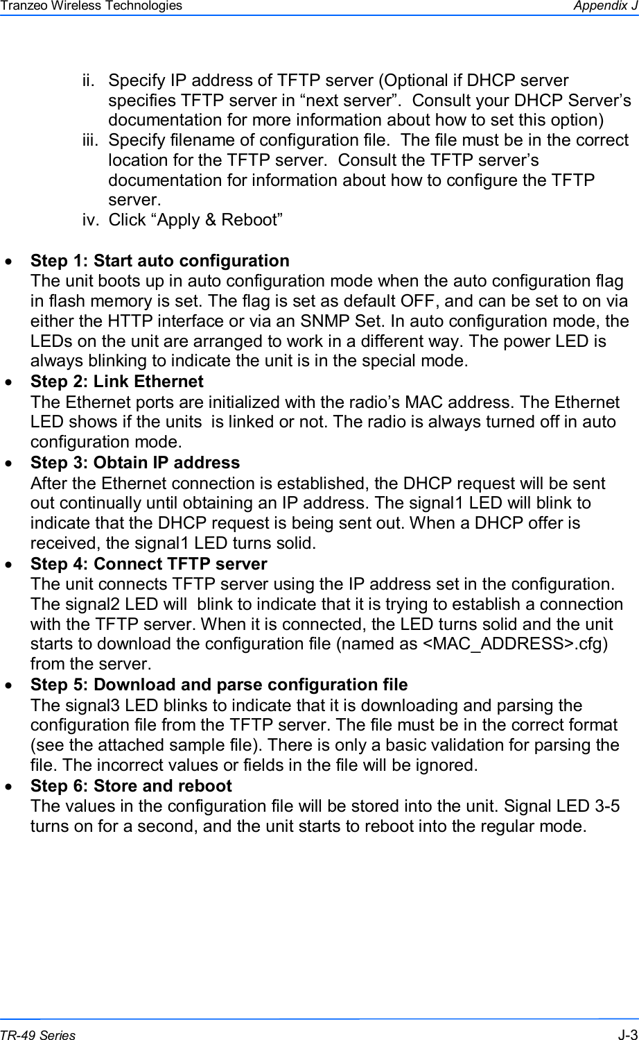
![888 This document is intended for Public Distribution 19473 Fraser Way, Pitt Meadows, B.C. Canada V3Y 2V4 Appendix J J-8 TR-49 Series Tranzeo Wireless Technologies net.router.dhcp_server.dns1 = 0.0.0.0 # [IP] net.router.dhcp_server.dns2 = 0.0.0.0 # [IP] net.router.dhcp_server.dns_relay_enabled = Yes # [Yes | No] net.router.dhcp_server.domain_use_wan_assigned = No # [Yes | No] net.router.dhcp_server.domain_name = localdomain # [STRING.59] net.router.dhcp_server.wins_use_wan_assigned = No # [Yes | No] net.router.dhcp_server.wins1 = 0.0.0.0 # [IP] net.router.dhcp_server.wins2 = 0.0.0.0 # [IP] # -------------------- # net.router.qos. # -------------------- net.router.qos.enabled = No # [Yes | No] net.router.qos.uplink_speed = 4096 # [INT.0-65535] unit:Kbps net.router.qos.auto_classify = Yes # [Yes | No] net.router.qos.dynamic_fragmentation = Yes # [Yes | No] ; entries 0-7 net.router.qos.actived.0 = No # [Yes | No] net.router.qos.priority.0 = 0 # [INT.0-255] net.router.qos.name.0 = "" # [STRING.15] net.router.qos.protocol.0 = 0 # [INT.0-255] net.router.qos.source_ip_start.0 = 0.0.0.0 # [IP] net.router.qos.source_ip_end.0 = 0.0.0.0 # [IP] net.router.qos.source_port_start.0 = 0 # [0-65535] net.router.qos.source_port_end.0 = 0 # [0-65535] net.router.qos.destination_ip_start.0 = 0.0.0.0 # [IP] net.router.qos.destination_ip_end.0 = 0.0.0.0 # [IP] net.router.qos.destination_port_start.0 = 0 # [0-65535] net.router.qos.destination_port_end.0 = 0 # [0-65535] # -------------------- # net.router.pppoe. # -------------------- net.router.pppoe.service_name = "" # [STRING.15] net.router.pppoe.username = "" # [STRING.40] net.router.pppoe.password = "" # [STRING.15] net.router.pppoe.ip_address = 0.0.0.0 # [IP] net.router.pppoe.subnet_mask = 0.0.0.0 # [IP] net.router.pppoe.gateway = 0.0.0.0 # [IP] net.router.pppoe.dns1 = 0.0.0.0 # [IP] net.router.pppoe.dns2 = 0.0.0.0 # [IP] net.router.pppoe.max_idle_time = 0 # [INT.0-65535] unit:minute net.router.pppoe.reconnect_mode = Demand # [Always | Demand | Manual] net.router.pppoe.user_settings_enabled = No # [Yes | No] # -------------------- # wireless. # -------------------- wireless.mode = CPE # [AP | CPE] wireless.ssid = default # [STRING.32] wireless.secondary_ssid = "" # [STRING.32] wireless.channel = 50 # [INT.0-255] wireless.channel_bandwidth = Full # [Full | Half | Quarter] wireless.gmode_enabled = No # [Yes | No] wireless.indoor_mode = Yes # [Yes | No] wireless.turbo = No # [Yes | No]](https://usermanual.wiki/Tranzeo-Wireless-Technologies/G54DNT523/User-Guide-1652406-Page-80.png)
![999 This document is intended for Public Distribution 19473 Fraser Way, Pitt Meadows, B.C. Canada V3Y 2V4 Appendix J J-9 TR-49 Series Tranzeo Wireless Technologies wireless.country_code = US # [STRING.3] wireless.tx_rate = 0 # [RATE] wireless.tx_supported_rates = 0003 # [RATES] wireless.rts_threshold = 3000 # [INT.0-3000] wireless.beacon_period = 100 # [INT.0-65535] unit:ms wireless.burst_time = 0 # [INT.0-65535] wireless.fragmentation_threshold = 2346 # [INT.256-2346] wireless.dot11d_enabled = No # [Yes | No] wireless.dot11h_mode = None # [None | User | Auto] wireless.invisibility = No # [Yes | No] wireless.dtim_interval = 1 # [INT.0-255] wireless.wds_enabled = No # [Yes | No] wireless.wds_mac_address.0 = 000000000000 # [MAC] wireless.wds_mac_address.1 = 000000000000 # [MAC] wireless.wds_mac_address.2 = 000000000000 # [MAC] wireless.wds_mac_address.3 = 000000000000 # [MAC] wireless.wds_mac_address.4 = 000000000000 # [MAC] wireless.wds_mac_address.5 = 000000000000 # [MAC] wireless.pxp_enabled = No # [Yes | No] wireless.pxp_mac_address = 000000000000 # [MAC] wireless.extended_info_enabled = Yes # [Yes | No] wireless.block_inter_client_traffic = Yes # [Yes | No] wireless.power_cap = 60 # [INT.-60-+60] unit:0.5dBm wireless.antenna_gain = 60 # [INT.0-200] unit:0.5dBi wireless.ack_timeout = 740 # [INT.0-4195] =distance(km)/0.15 wireless.ack_tuning = 0 # [INT.-100-100] =us wireless.long_preamble = No # [Yes | No] wireless.stats_mode = 04 # [STATS] wireless.wds_stats = 0 # [INT.0-7] wireless.cpe_stats = 0 # [INT.0-7] # -------------------- # wireless.security. # -------------------- wireless.security.mode = WPA # [None | WEP | WPA | WPA2] ; WEP parameters are used only when the mode is WEP ; all WEP key entries (0-3) must have same length wireless.security.wep_authentication = Open # [Open | Shared] wireless.security.wep_key_index = 0 # [INT.0-3] wireless.security.wep_key.0 = 1234567890 # [WEP_KEY] wireless.security.wep_key.1 = 1234567890 # [WEP_KEY] wireless.security.wep_key.2 = 1234567890 # [WEP_KEY] wireless.security.wep_key.3 = 1234567890 # [WEP_KEY] ; WPA parameters are used only when the mode is WPA or WPA2 ; For WPA, the cipher can only be either TKIP or AES ; For WPA2, the cipher can only be either AES(WPA2 only) or TKIP_AES(WPA2) ; the cipher must be defined after wireless.security.mode wireless.security.wpa_cipher = TKIP # [TKIP | AES | TKIP_AES] ; the wpa_compatible must be defined after wireless.security.wpa_cipher wireless.security.wpa_compatible = No # [Yes | No] wireless.security.wpa_psk = password # [STRING.63] wireless.security.wpa_update_interval = 3600 # [INT.0-65535] unit:second wireless.security.radius_enabled = No # [Yes | No] wireless.security.radius_server_address = 0.0.0.0 # [IP] wireless.security.radius_server_port = 1812 # [INT.0-65535] wireless.security.radius_timeout = 60 # [INT.0-65535]](https://usermanual.wiki/Tranzeo-Wireless-Technologies/G54DNT523/User-Guide-1652406-Page-81.png)
![101010 This document is intended for Public Distribution 19473 Fraser Way, Pitt Meadows, B.C. Canada V3Y 2V4 Appendix J J-10 TR-49 Series Tranzeo Wireless Technologies wireless.security.radius_shared_secret = password # [STRING.64] wireless.security.radius_auth_mac = Yes # [Yes | No] # -------------------- # wireless.access_control. # -------------------- ; it must be enabled before entry fields wireless.access_control.enabled = No # [Yes | No] ; entries 0-255 wireless.access_control.mac.0 = FFFFFFFFFFFF # [MAC] wireless.access_control.access.0 = Allow # [Allow | Deny] # -------------------- # duplex. # (NOTE: only available for FDD) # -------------------- ; 0=MASTER, 1=SLAVE duplex.rx_master = Yes # [Yes | No] (NOTE: wireless.mode is not available for FDD) duplex.rx_channel = 165 # [INT.1-255] (NOTE: wireless.channel is not available for FDD) duplex.ssid.0 = FDD_MST # [STRING.32] (NOTE: wireless.ssid is not available for FDD) duplex.ssid.1 = FDD_SLV # [STRING.32] duplex.pxp_mac_address.0 = 000000000000 # [MAC] (NOTE: wireless.pxp_enabled and wireless.pxp_mac_address is not available for FDD) duplex.pxp_mac_address.1 = 000000000000 # [MAC] duplex.mac_clone_enabled.0 = No # [Yes | No] (NOTE: net.mac_clone_enabled is not available for FDD) duplex.mac_clone_enabled.1 = No # [Yes | No] duplex.mac_clone_address.0 = 000000000000 # [MAC] (NOTE: net.mac_clone_address is not available for FDD) duplex.mac_clone_address.1 = 000000000000 # [MAC]](https://usermanual.wiki/Tranzeo-Wireless-Technologies/G54DNT523/User-Guide-1652406-Page-82.png)